temperature-dependent internal friction of clay in a …hueckel/papers2/geot9p124-3.pdf ·...
TRANSCRIPT

Delivered by ICEVirtualLibrary.com to:
IP: 152.3.68.8
On: Tue, 15 Feb 2011 21:40:20
Hueckel, T. et al. Geotechnique [doi: 10.1680/geot.9.P.124]
1
Temperature-dependent internal friction of clay in a cylindrical heatsource problem
T. HUECKEL�, B. FRANCOIS† and L. LALOUI‡
The effect of the temperature dependence of the internalfriction angle is studied in a boundary value problemsimulating the impact of a cylindrical heat source on thesoil mass in which it is embedded. This follows a previousstudy which shows that such temperature dependencemay substantially affect the interpretation of thermalfailure in laboratory experiments. Even if the thermalincrease of the internal friction is quite modest (less than20% in terms of the critical state parameter, M), itaffects quite significantly the effective stress path nearthe heat source. The effective stress path approaches theyield locus and the critical state at significantly higherprincipal stress difference values for the variable internalfriction than for the M const case. The ‘mean effectivestress distance from the critical state’ is substantiallyreduced during heating, which in the case of smallperturbations of any parameter may lead to potentiallyunstable or statically inadmissible behaviour. The solu-tions obtained allow one to identify zones of influencearound the heat source of several variables of interest.The two fields most affected by the thermal sensitivity ofM are that of the axial stress, dropping significantly nearthe heat source, and that of the appearance of thethermoplastic strain. Both zones of influence are reducedin size by almost half when the friction angle is increasedby 20% over 708. The presented results may be ofrelevance to the design of prototype in situ installationsand their monitoring, and eventually of actual facilitiesfor nuclear waste disposal.
KEYWORDS: clays; failure; friction; numerical modelling;temperature effects
On etudie l’effet de la temperature sur l’angle de frotte-ment interne dans le cadre d’un probleme aux limitessimulant l’impact d’une source de chaleur cylindriquesur la masse de sol dans laquelle elle est enfuie. Cetteetude fait suite a une etude precedente qui illustre lafacon dont cet effet de la temperature risque d’affecterconsiderablement l’interpretation de ruptures thermiquesdans le cadre d’experiences en laboratoire. Meme lorsquel’augmentation thermique est plutot modeste (moins de20% pour le parametre d’etat critique M), elle affecte defacon significative le chemin de contraintes a proximitede la source de chaleur. Le chemin des contrainteseffectives s’approche du point de plastification et de l’etatcritique en presence de differences de contrainte princi-pales beaucoup plus elevees dans le cas du frottementinterne variable que dans celui de M constant. La« distance entre la contrainte effective moyenne et l’etatcritique » se reduit de facon significative au cours duchauffage, ce qui, dans le cas de perturbations limiteesd’un quelconque des parametres, risque d’engendrer uncomportement potentiellement instable ou statiquementinadmissible. Les solutions obtenues permettent d’identi-fier des zones d’influence autour de la source de chaleurde plusieurs variables interessantes. Les deux champs lesplus affectes par la sensibilite thermique de M sont lacontrainte axiale, qui diminue sensiblement a proximitede la source de chaleur, et l’aspect de la contraintethermoplastique. La taille des deux zones d’influencediminue presque de moitie lorsque l’angle de frottementaugmente de 20% a plus de 708C. Les resultats presentespourront etre pertinent dans l’etude et le controle deprototype d’installations in-situ – et eventuellement – dedispositifs de stockage de dechets nucleaires.
INTRODUCTIONThe influence of temperature on internal friction angle maynot be numerically large, but as demonstrated in a recentpaper (Hueckel et al., 2009a), a 10% temperature-inducedincrease in critical state coefficient M(˜T) over 908C leadsto a complete pattern change in the triaxial compressivestrength, producing an increase in its value of up to 25%,compared with the case of a temperature-independent fric-tion angle. Experimental studies of the triaxial strength ofclays show that remoulded kaolin clay and natural BoomClay exhibit temperature dependence of their internal fric-tion, whereas this is not the case for largely smectitic or
illitic clays (Hueckel & Baldi, 1990; Hueckel & Pellegrini,1991; Cekerevac & Laloui, 2004). Interestingly, the effectsof the thermal variation of internal friction depend heavilyon the history of heating and loading. In particular, the stateof stress at which heating is performed, including the soiloverconsolidation ratio, impacts on the ensuing variation ofstrength (Hueckel et al., 2009a). Constitutive postulates forthe thermal variation of the internal friction angle, theirmathematical representation within the thermal Cam-Claymodel (Hueckel & Borsetto, 1990) and their limitations areaddressed by Hueckel et al. (2009b).
Emerging technologies concerning thermally affected soilmasses often involve prototype installations, the long-termperformance of which requires intense monitoring. Suchtechnologies include: nuclear waste disposal; energy storagein subsoil using geostructures such as piles, walls and slabs;alternating seasonal heating and cooling of buildings; oilrecovery from high-pressure, high-temperature reservoirs;and underground pipes and cables. The monitoring systemsneed to be placed in the ground early during the construc-tion phase for such installations. Their design includes thetype, sensitivity and configuration of sensors. This is basedlargely on numerical prediction of the evolution of variables
Manuscript received 9 October 2009; revised manuscript accepted15 October 2010.Discussion on this paper is welcomed by the editor.� Department of Civil and Environmental Engineering, DukeUniversity, Durham, NC, USA.† Building, Architecture and Town Planning Department (BATir),Universite Libre de Bruxelles, Belgium.‡ Laboratory of Soil Mechanics, Ecole Polytechnique Federale deLausanne, Switzerland.
Delivered by ICEVirtualLibrary.com to:
IP: 152.3.68.8
On: Tue, 15 Feb 2011 21:40:20
of interest characterising the response of the thermallyaffected soil mass.
This paper presents numerical investigations of the effectof temperature on the thermomechanical response of asaturated soil mass at the scale of a boundary value problemof a cylindrical heat source embedded in soil. Additionalfactors affect the response of the soil mass compared withthe laboratory experiments. These are time-dependent heatconduction, and the permeability-dependent rate of dissipa-tion of thermally generated pore pressure. The presentedsolution shows the utility of numerical predictions aimed atoptimisation of the monitoring systems and devices. Itdemonstrates the predictive capabilities of the numericalsimulator, and points to various consequences of tempera-ture-dependent friction angle affecting the field of stress anddisplacement components, pore water pressure and waterflow rate components in functionally selected locations andpossible points of special interest. Notably, it shows that therole of the friction angle is not limited to the failure states,but that, as it controls the shape of the yield locus prior toreaching failure state, it is also important for the entire pre-failure elasto-plastic process.
OUTLINE OF THE MODELThe central assumption of the model is that the critical
state parameter M representing the internal friction angle,�9, is a function of temperature difference with respect tothe reference temperature T0, ˜T ¼ T � T0 (Laloui, 1993).All quantities marked with a subscript ‘0’ are the values atthe reference state.
M ¼ M0 þ g˜T
M ¼ 6 sin�9
3 � sin�9
M0 ¼ 6 sin�903 � sin�90
(1)
where the coefficient g is constant. The variation of Maffects the evolution of the yield locus, chosen here as theclassical Cam-Clay form (Schofield & Wroth, 1968), chang-ing mainly its aspect ratio, qmax=p9max,
f ¼ q
Mp9þ ln
2:718 p9
p9c
� �� 1 ¼ 0 (2)
where p9 and q are the mean and deviatoric effective stressinvariants. Stresses are considered positive when compres-sive.
The other parameter controlling the locus evolution is theapparent preconsolidation pressure p9c, which depends on theaccumulated irreversible volumetric plastic strain and tem-perature, represented here by a specific function originatedby Laloui & Cekerevac (2003),
p9c ¼ p9c0 exp ��pv
� �1 � ª log 1 þ ˜T
T0
� �� �. 0 (3)
where p9c0 is an initial preconsolidation pressure, usuallyreferred to the in situ state, and ª and � are constitutivecoefficients of thermal softening and of isothermal isotropicirreversible compression.
The hypo-elastic (incrementally reversible) part of thestrain increment is expressed as
d�ev ¼ 1
Kd p9� �9sdT
d�ed ¼ 1
3Gdq
(4)
where the volumetric and deviatoric elastic strain invariantsare defined as
�ev ¼ �e
1 þ �e2 þ �e
3;
�ed ¼ 2
3ee
ijeeij
� �1=2
;
eeij ¼ �e
ij � 13�e
kk�ij
(5)
where K and G are the incremental bulk and shear hypo-elasticity moduli respectively. To reflect their well-knownand pronounced variability with the depth in situ, they areboth postulated as functions of p9
K ¼ Kref p9=p9refð Þn9
G ¼ Gref p9=p9refð Þm9
where p9ref is the reference pressure at which Kref and Gref
are measured (Hujeux, 1985; Laloui & Francois, 2009). �9s isthe volumetric thermal (reversible) expansion coefficient ofthe solid skeleton.
From the analyses presented in Hueckel et al. (2009a), ittranspires that in a process of continuous (thermoplastic)yielding during heating, an interesting balance of plasticstraining, temperature change and effective stress changearises, driven by the balance between the various compo-nents of hardening contributions, and expressed throughPrager’s consistency equation for thermoplasticity (Prager,1958; Hueckel & Borsetto, 1990)
d f ¼ @ f
@~�9
: d~�9
þ @ f
@ p9c
@ p9c
@�pv
d�pv þ
@ p9c
@TdT
� �þ @ f
@M
@M
@TdT ¼ 0
(6)
When temperature is controlled, as in a homogeneouslyheated specimen, under constant stress, a one-to-one rela-tionship can be established between temperature history andthe resulting thermoplastic strain. Various examples of suchprocesses and corresponding experimental data have beendiscussed for homogeneous, homogeneously stressed andhomogeneously heated specimens by Hueckel et al. (2009a),showing characteristic patterns of behaviour for both drainedand undrained conditions.
In the present study, which focuses on analogous phenom-ena, but on a larger scale of a boundary value problem, theprocess is additionally affected by non-uniform and time-dependent effects of heat conduction, resulting in a non-uniform distribution of temperature, thermal expansion ofwater, and ensuing pore water pressure change, triggering inturn a flux of pore water and time-dependent dissipation ofpore pressure. The pore pressure is clearly coupled, by wayof the effective stress principle, with the evolution of theeffective stress. In addition, the evolution of pore waterpressure is constrained by the thermally induced volumetricstrains of the porous soil skeleton, under both thermoelastic(expansive) and thermoplastic (contractile) regimes.
THERMOPLASTIC BOUNDARY VALUE PROBLEMThe thermo-hydro-mechanical response of a soil mass
around a cylindrical heat source has been the subject of
2 HUECKEL, FRANCOIS AND LALOUI

Delivered by ICEVirtualLibrary.com to:
IP: 152.3.68.8
On: Tue, 15 Feb 2011 21:40:20
numerous studies in the past, with different levels of complex-ity, from the classical analytical thermoelastic solution ofGoodier (1937) (see also Timoshenko & Goodier, 1934),through other analytical solutions for various thermal loadings(Booker & Savvidou, 1985; McTigue, 1986; Zhou et al.,1998) to more recent finite element computations includingthermoelasticity (Britto et al., 1989; Carter & Booker, 1989)or thermoplasticity (Hueckel et al., 1987; Borsetto et al.,1993; Giraud, 1993; Ma & Hueckel, 1993; Picard, 1994;Seneviratne et al., 1994; Francois et al., 2009). In the presentstudy an isolated vertical cylindrical heat source is considered,and its thermo-hydro-mechanical effects on the surroundingclay mass are studied. The soil material of choice is Boomclay, a possible host formation for nuclear waste disposal inBelgium, and well characterised from both the mechanicaland thermomechanical points of view (Baldi et al., 1991;Hueckel & Pellegrini, 1992; see also Hueckel et al., 2009a).
The finite-element method was chosen to study the globalcoupled thermo-hydro-mechanical processes governing thephenomena. The field equations considered represent themedium as a deformable two-phase material (i.e. a water-saturated medium), in which heat and mass transfers occur(Lewis & Schrefler, 1987; Olivella et al., 1994; Gawin etal., 1995; Collin et al., 2002). ACMEG-T, which is anelasto-thermoplastic constitutive model (Laloui & Francois,2009) that can be simplified to a thermal Cam-Clay model(equations (1)–(4)) as a particular case, has been implemen-ted in the finite-element code LAGAMINE, developed atLiege University (Charlier, 1987; Charlier et al., 2001;Collin, 2003). Readers interested in the finite-element for-mulation of the LAGAMINE code may refer to Collin et al.(2002).
Eight-node, two-dimensional, large-strain finite elementsare used. Such elements possess five degrees of freedom ateach node: two solid displacements, liquid water pressure,gas (dry air + vapour) pressure, and temperature. Neverthe-less, the gas pressure is not considered as a degree offreedom, because water saturation conditions are assumed allalong the THM processes.
A horizontal unit height slice of Boom clay is considered,placed in the mid-plane of the heating source. The slice ismeshed, assuming radial (horizontal) propagation of thermaland hydraulic fluxes as well as the plane-strain configuration(no vertical deformation). The computation domain is axi-symmetric around the vertical axis of the heat source (Fig.1). The heater has an interface with soil at a radius of
0.095 m. The modelled domain is contained between theinternal boundary, corresponding to the external radius ofthe heater, and an external, fictitious boundary, which isplaced at a sufficient distance (100 m) to limit as much aspossible its location influence on the computation results.
Although the boundary value problem chosen is very simple(axial symmetry, plane strain), it epitomises many of charac-teristics of the fully developed ‘realistic’ field problems.
The initial conditions for the boundary value problem arechosen to replicate those for the planned repository in BoomClay, and are reported in Table 1 (Francois et al., 2009). Asexpounded in Hueckel et al. (2009a), the thermomechanicalresponse of clays is heavily dependent on the mechanicaland thermal history of the material. Thus it is desired torepresent the pre-simulation history of the soil mass asfaithfully as possible.
The initial state is defined as follows. The initial in situBoom Clay stress state is reproduced as slightly anisotropic,with K0 ¼ 0.8 under the assumption that �r ¼ �t (see Table1). The initial overconsolidation ratio of the clay is about2.4: hence the initial stress state is elastic. This state ofstress, and that of zero initial (pre-induced) plastic strain,does not account for possible changes in those variables(and permeability) induced by both the excavation stressrelief and damage. No established data on these effects areavailable at present.
The heating phase consists in a gradual increase of tem-perature from 16.58C (i.e. in situ temperature of Boom Clayat the level of the HADES underground laboratory) to96.58C within 30 days. Then a constant temperature of
Adiabatic boundary
Boundary with constant pore water pressure
Constrained displacements perpendicular to boundary
Impervious boundary
100 m
z
r
Heaters
z
r heater 0·095 m�
24·905 m500 elements
25 m200 elements
25 m50 elements
25 m20 elements
t
Zoom
Fig. 1. Modelled domain and boundary condition in the r (radial), t (circumferential) and z (axial) axis system. Details of the finite-element size
Table 1. Initial state of Boom Clay considered in the computa-tions.
Variable Value
Vertical total stress, �z: MPa 4.87Horizontal total stress, �r ¼ �t: MPa 4.30Pore water pressure, pw: MPa 2.02Vertical effective stress, � 9z: MPa 2.85Horizontal effective stress, � 9r ¼ � 9t: MPa 2.28Mean effective stress, p9: MPa 2.47K0 0.8Initial preconsolidation pressure, p9c0 : MPa 6Temperature, T: 8C 16.5Initial void ratio, e0 0.6
TEMPERATURE-DEPENDENT INTERNAL FRICTION OF CLAY 3

Delivered by ICEVirtualLibrary.com to:
IP: 152.3.68.8
On: Tue, 15 Feb 2011 21:40:20
96.58C is maintained for 2 years. In terms of numericalsolutions, the relatively low velocity of the thermal loadingwith respect to the size of the mesh and the permeability ofthe medium avoids any numerical oscillations of the porepressure, without requiring specific stabilisation techniques.
The boundary conditions are summarised in Table 2 andFig. 1.
Tables 3 and 4 report the mechanical and diffusivematerial parameters respectively. The permeability of water,k, is assumed to be dependent on water viscosity �w,k ¼ kw/�w, which in turn is a function of temperature (Table4). The thermal expansion coefficient of pore water is alsoassumed to be constant and equal to that of tap water. Theeffects of non-linearity of the thermal expansion coefficientand those of the presence of adsorbed water (Baldi et al.,
1988) are neglected. Boom Clay exhibits an increase of Mwith temperature (from 0.8 at 16.58C to 1.16 at 96.58C),resulting in a positive parameter g.
RESULTS AND DISCUSSIONSPore water pressure and flux
Given the very low permeability of Boom Clay, the short-term response of the field around the heat source developsin conditions very close to undrained ones. Hence, as thereis very little water outflow, the pore water pressure evolutionis controlled mainly by the difference between the thermalexpansion of water and the much smaller expansion of thesolid skeleton. This produces a pore water pressure increase,initially following a familiar, highly localised temperaturedistribution around the heat source until about 50 days ofheating (Figs 2(a) and 2(b)). In this initial period of about 2months, the temperature and pore pressure affect a limitedvolume of soil, not exceeding 1.5 m in radius. However, in alater period, the pore pressure increase covers a much widerzone than the temperature. More than a 1.5 MPa waterpressure growth is seen in the volume of diameter nearly6 m (Fig. 2(b)). Also, in the later stage, the effects of thehydraulic boundary condition at the source/soil interface ofno flux are felt more strongly than initially, resulting in apore pressure gradient that is nearly zero (but is nevernegative, as it would be in the case of cooling following theheating period), and hence in virtually no flow near thesource. Notably, near the source the pore pressure valuestarts to decrease, after reaching a maximum value at about50 days (Figs 2(c) and 3(b)). In contrast, in a more remoterange at more than about r ¼ 1.75 m, the trend is opposite:the pore pressure grows monotonically. The transition pointbetween these two types of evolution corresponds approxi-mately to a zero curvature point (as in the one-dimensionalconsolidation equation), which also is approximately thelocation of the maximum water flux point (Fig. 3(a)). Asseen, the flux is initially in a classical form of front, whereaslater it diffuses. This has very important implications forpotential mass transport of a possible prematurely releasedradioactive contaminant in a nuclear waste repository. Be-cause of such a low thermally activated water flux in thevicinity of the heat source, the possible radionuclide trans-port would then occur almost entirely through diffusion, withminimal enhancement through advection (which would inany case be subsequently inverted during cooling, which isnot considered here).
The influence of mechanics on the thermal field is knownto be very limited, as it is induced via changes in porosity.As these changes are small, the temperature distributionseems to be independent of deformation, and of whether Mis constant or variable (Fig. 2(a)). This is not exactly thecase for pore pressure (Figs 2(b) and 2(c)).
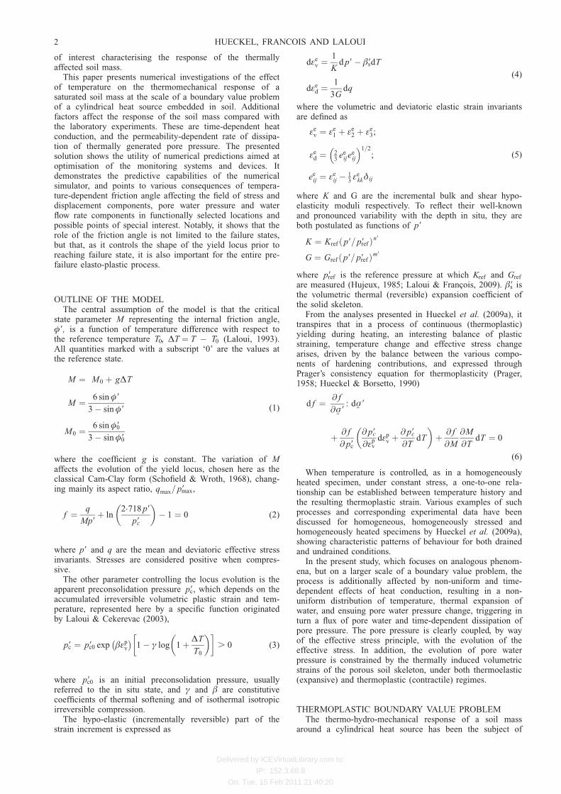
Pore pressure is generated by the differential expansion ofwater and clay solids, which enclose the pore containingwater. The expansion of the solid skeleton is either smallerthan that of water, or even negative, in the case of thermo-plastic collapse (Fig. 4). Total volumetric deformation isclearly dominated by the thermoelastic strain, again with thedifference determined by the extent of the elastic rangeaffected by the evolution of M.
A limited dependence on the internal friction variation isseen, as explained below. Notably, the episode of plasticstrain change is very short in time.
The pore pressure evolution in time near the heat source(Fig. 3(b)) for the case M ¼ 0.8 ¼ const (that for a variableM differs only slightly) shows a process that is quite uniformspatially, with the differences in terms of the pressure valueat a given moment being of the order of 0.1 MPa. Despite
Table 2. Thermo-hydro-mechanical boundary conditions of themodelled domain
Mechanical Hydraulic Thermal
r ¼ 0.095 m ur ¼ 0 No flux T ¼ Timp
r ¼ 100 m ur ¼ 0 pw ¼ pw in situ No fluxLateral uz ¼ 0 No flux No flux
Table 3. Mechanical parameters of Boom Clay used in compu-tations
Parameter Value
Elastic parametersKref : MPa 130Gref : MPa 130n9 0.4m9 0.4�9s: 8C�1 5 3 10�5
Isotropic plastic parameters� 16ª 0.55Deviatoric plasticity parameters�90: degrees 20.6g 4.5 3 10�3
Table 4. Thermal and hydraulic diffusion parameters of Boomclay used in computations
Parameter Value
rw0: kg/m3 1000rs: kg/m3 2670n 0.39kw: m2 2 3 10�19
�w: Pa 2.2 3 109
�9w: 8C�1 3.5 3 10�4
�w0: Pa.s 0.001ÆT : 8C�1 0.011cp,w: J.kg/8C 4186cp,s: J.kg/8C 732ºw: W/(m 8C) 0.57ºs: W/(m 8C) 2.42
Values extracted from SCK-CEN (1997), Bastiaens et al. (2006)and Bernier et al. (2007) (see also Francois et al., 2009).Subscripts w and s refer to water and solid respectively. Waterviscosity, �w ¼ �w0[1 � ÆT (T � T0)]; �w0 and ÆT are materialconstants; thermal diffusivity, ˆ ¼ nºw þ (1 � n)ºs. n is theporosity.
4 HUECKEL, FRANCOIS AND LALOUI

Delivered by ICEVirtualLibrary.com to:
IP: 152.3.68.8
On: Tue, 15 Feb 2011 21:40:20
087654321 87654321
2·01·51·00·5
t 1 day�
t 5 days�
t 10 days�
t 50 days�
t 100 days�
t 200 days�
t 400 days�
t 720 days�
3·6
3·7
3·8
3·9
4·0
4·1
4·2
0
Por
e w
ate
r pr
essu
re: M
Pa
Radial distance: m(c)
Bold line: MM M T
const.Dashed line: ( )
�
�
20
40
60
80
100
0
Tem
pera
ture
: °C
Radial distance: m(a)
2·0
2·5
3·0
3·5
4·0
4·5
0
Radial distance: m(b)
Por
e w
ate
r pr
essu
re: M
Pa
Fig. 2. Evolution of: (a) temperature (identical for both M const and M(˜T)); (b) pore water pressure distributionaround heat source (negligible dependence on M(˜T) over most of field); (c) pore water pressure in closest vicinity of heatsource, showing limited dependence on M
87654321 10001001010·12·0
2·5
3·0
3·5
4·0
4·5
0·01
r 0·095 m�
r 0·244 m�
r 0·494 m�
Por
e w
ate
r pr
essu
re: M
Pa
Time: days(b)
t 1 day�
t � 5 days
t � 10 days
t � 50 days
t � 100 days
t � 200 days
t � 400 days
t � 720 days
0
5 � 10�8
1 � 10�7
1·5 � 10�7
2 � 10�7
2·5 � 10�7
3 10� �7
0Radial distance: m
(a)
Vol
umet
ric fl
ux o
fw
ate
r: m
/s
Fig. 3. For M 0.8 const: (a) evolution of volumetric flux of water; (b) evolution of pore pressure with time at r 9.5 cm,24.4 cm and 50.4 cm (0 cm, 14.9 cm and 40.9 cm from heat source perimeter)
TEMPERATURE-DEPENDENT INTERNAL FRICTION OF CLAY 5
Delivered by ICEVirtualLibrary.com to:
IP: 152.3.68.8
On: Tue, 15 Feb 2011 21:40:20
this relative uniformity of pore pressure, the effective stressevolution exhibits quite a different pattern.
Effective and total stress trajectoriesThe relatively weak dependence of pore pressure on the
variations of the internal friction (or M) can be best ex-plained by considering its coupling to the effective stressevolution. Understanding the effective stress trajectory, parti-cularly near the heat source, is crucial from the point ofview of the stress analysis and structural safety of the soilmass supporting the heat source thermally and structurally.
To start with, it should be reiterated that the principalstress directions are: parallel to the symmetry axis, along theradius and tangential to the circumferential coordinate. Sec-ond, all the material behaviour characteristics are assumed tobe independent of the third effective stress invariant (orLode angle, ŁL), but the plane-strain states are not. There-fore, a proper representation of stress trajectories is providedin what follows in q, p9, ŁL space, while the yield locus andcritical state locus are independent of ŁL. The Lode angle,0 , ŁL , 608 (following Chen & Han, 1988, but using thecompression-positive sign convention), measures a declina-tion on the octahedral plane, � 91 þ � 92 þ � 93 ¼ const, fromthe direction of the major principal compressive stress.ŁL ¼ 08 corresponds to the case � 92 ¼ � 93, and ŁL ¼ 608 isreached for � 91 ¼ � 92.
The effective stress field arises in response to the thermalpore pressure generation, subjected to the constraints ofequilibrium and boundary conditions imposed on the totalstress field. Therefore, the effective stress field evolution inthe first (immediate, nearly undrained) stage is, like that ofthe pore pressure field, controlled mainly by the heat diffu-sion or temperature field evolution. In a later, much slowerand longer phase, owing to a decreasing pore pressuregradient (see Fig. 3(a)), the controlling factor becomes the(very slow) outflow of the pore water.
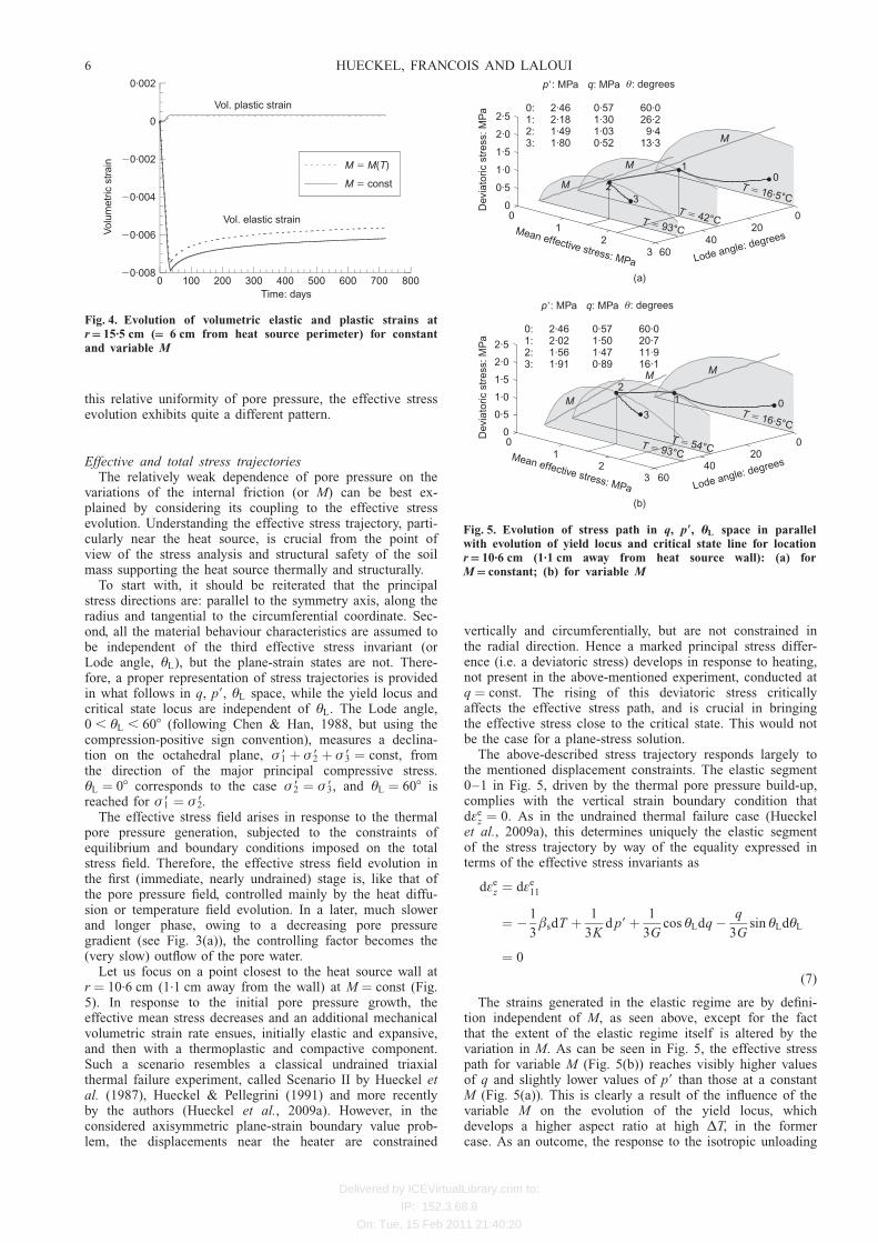
Let us focus on a point closest to the heat source wall atr ¼ 10.6 cm (1.1 cm away from the wall) at M ¼ const (Fig.5). In response to the initial pore pressure growth, theeffective mean stress decreases and an additional mechanicalvolumetric strain rate ensues, initially elastic and expansive,and then with a thermoplastic and compactive component.Such a scenario resembles a classical undrained triaxialthermal failure experiment, called Scenario II by Hueckel etal. (1987), Hueckel & Pellegrini (1991) and more recentlyby the authors (Hueckel et al., 2009a). However, in theconsidered axisymmetric plane-strain boundary value prob-lem, the displacements near the heater are constrained
vertically and circumferentially, but are not constrained inthe radial direction. Hence a marked principal stress differ-ence (i.e. a deviatoric stress) develops in response to heating,not present in the above-mentioned experiment, conducted atq ¼ const. The rising of this deviatoric stress criticallyaffects the effective stress path, and is crucial in bringingthe effective stress close to the critical state. This would notbe the case for a plane-stress solution.
The above-described stress trajectory responds largely tothe mentioned displacement constraints. The elastic segment0–1 in Fig. 5, driven by the thermal pore pressure build-up,complies with the vertical strain boundary condition thatd�e
z ¼ 0. As in the undrained thermal failure case (Hueckelet al., 2009a), this determines uniquely the elastic segmentof the stress trajectory by way of the equality expressed interms of the effective stress invariants as
d�ez ¼ d�e
11
¼ � 1
3�sdT þ 1
3Kd p9þ 1
3Gcos ŁLdq � q
3Gsin ŁLdŁL
¼ 0
(7)
The strains generated in the elastic regime are by defini-tion independent of M, as seen above, except for the factthat the extent of the elastic regime itself is altered by thevariation in M. As can be seen in Fig. 5, the effective stresspath for variable M (Fig. 5(b)) reaches visibly higher valuesof q and slightly lower values of p9 than those at a constantM (Fig. 5(a)). This is clearly a result of the influence of thevariable M on the evolution of the yield locus, whichdevelops a higher aspect ratio at high ˜T, in the formercase. As an outcome, the response to the isotropic unloading
800700600500400300200100�0·008
�0·006
�0·004
�0·002
0
0·002
0
Vol. plastic strain
Vol. elastic strain
Vol
umet
ric s
trai
n
Time: days
M const�
( )M M T�
Fig. 4. Evolution of volumetric elastic and plastic strains atr 15.5 cm ( 6 cm from heat source perimeter) for constantand variable M
(a)
M
p�: MPa
2·462·181·491·80
0:1:2:3:
q: MPa
0·571·301·030·52
θ: degrees
60·026·29·4
13·3
6040
2000
12
3
0
0·5
1·0
1·5
2·0
2·5
Lode angle: degreesMean effective stress: MPa
Dev
iato
ric s
tres
s: M
Pa
T 16·5°C�
T 42°C�
T 93°C�
M
M
01
23
M
Lode angle: degrees
(b)
p�: MPa
2·462·021·561·91
0:1:2:3:
q: MPa
0·571·501·470·89
θ: degrees
60·020·711·916·1
6040
2000
12
3
0
0·5
1·0
1·5
2·0
2·5
Mean effective stress: MPaD
evia
toric
str
ess:
MP
a
T 16·5°C�
T 54°C�T 93°C
�
MM
012
3
Fig. 5. Evolution of stress path in q, p9, ŁL space in parallelwith evolution of yield locus and critical state line for locationr 10.6 cm (1.1 cm away from heat source wall): (a) forM constant; (b) for variable M
6 HUECKEL, FRANCOIS AND LALOUI

Delivered by ICEVirtualLibrary.com to:
IP: 152.3.68.8
On: Tue, 15 Feb 2011 21:40:20
due to the pore water pressurisation is elastic over a longerpart of the process than in the case of M ¼ const. Conse-quently, yielding (point 1) starts at quite different tempera-tures: at T ¼ 428C for M ¼ const, and at 548C forM ¼ M(˜T). In other words, the thermally induced increaseof internal friction delays the onset of yielding by over 128Cin the considered boundary value problem.
Yielding opens the door to an interaction of three possiblehardening mechanisms:
(a) apparent preconsolidation temperature softening, al-ready active in the elastic range, postulated asmonotonic, and characterised by the inequality(@ f =@ p9c)(@ p9c=@T ) . 0
(b) plastic strain-hardening(c) a possible effect of the variation of the critical stress
state (or friction angle variation), also already active inthe elastic range.
The subsequent stress increment is a resultant of this inter-action, and in this case is most likely to be directed inwardof the yield locus of the moment. This produces an abruptturnaround in the stress trajectory. When a compressivevolumetric plastic strain rate arises, the plane-strain con-straint changes into a rate condition, d�p
z ¼ �d�ez, which
alters the course of the effective stress trajectory. Indeed, theabove stated constraint, together with the consistency equa-tion, determines the following stress increments. This can bebest seen for the case of M ¼ const.
d f ¼ @ f
@ p9d p9þ @ f
@qdq þ d¸
@ f
@�pv
@ f
@ p9þ @ f
@ p9c
@ p9c
@TdT ¼ 0
(8)
d¸@ f
@ p
1
3þ @ f
@qsin ŁLð Þ
� �
¼ 1
3�sdT � 1
3Kd p9� 1
3Gcos ŁLdq þ q
3Gsin ŁLdŁL
(9)
Eliminating the multiplier d¸, an incremental expression forthe effective stress trajectory during the plasticity phase isarrived at expressed in terms of the invariants dq, dp9 anddŁL for a given temperature increment.
As the stress range in which the effective stress pathreaches yielding (see Figs 5(a) and 5(b)) corresponds to thetop parts of the yield loci, with a minuscule plastic volu-metric strain component (i.e. the horizontal component ofthe local yield locus normal), the expected contribution fromthe plastic strain-hardening is indeed very small (compareFig. 4).
As the stress point moves through plastic states near thecritical locus, the volumetric component of the plastic strainrate progressively decreases even further. Notably, the caseof variable M is characterised by the compensatory rolecarried mainly by M(˜T) hardening: hence the overall soft-ening is less evident. The M ¼ const case, in addition to amore evident softening, is characterised by reaching veryclose to the critical state line.
At 958C the source temperature stops increasing (andhence so does the pore pressure) in the imposed heatingprogramme, and soon after this the pore pressure starts todecrease, owing to water outflows. At the same time, theyield locus is arrested at the location corresponding to themaximum imposed temperature (point 2). Although the porewater stops expanding, it continues its outflow, but in alimited quantity, given that the pore pressure gradient isquite small. The pore pressure hence starts to decrease at avery low rate, while the effective stress state re-enters theelastic domain, producing an effective stress trajectory seg-
ment 2–3, nearly parallel to the original elastic loadingsegment 0–1.
It is interesting to note how short (in terms of time) theplastic episode is (e.g. seen as the segment of the variablevolumetric plastic strain in Fig. 4), compared with the elasticunloading period driven by water pressure dissipation, butalso how remarkable the plasticity effect is in terms of thechange in the effective stress trajectory. Fig. 6 shows projec-tions of the effective stress paths on the plane ŁL ¼ 08,which is the plane of the initial stress state. As discussedearlier, the constitutive properties of the material are allindependent of ŁL.
First, the conclusion from Fig. 5 can be now extended tofurther locations, indicating that thermoplastic yielding af-fects the effective stress path. The figures show also thedifferences between the effective stress trajectories at threelocations within the plastic strain range, at a relatively smalldistance from the heat source (40 cm away from the inter-face at most). Most prominently, the figures demonstrate thedifference in the evolution of the yield locus between theM ¼ const case and the variable-M case.
It is clear that when M grows, and hence the aspect ratioof the yield locus qmax/pmax increases, the value of themaximum deviatoric stress reached is higher, and the subse-quent drop in the deviatoric stress component during thethermoplastic yielding process is consistently much morelimited, than in the M ¼ const case. Hence the ensuingsoftening at a given location for a given stress history ismuch less pronounced, or practically non-existent, as seen inFig. 7.
It is also instructive to note that only a portion of the porepressure increase of about 1.2 MPa (1.24 MPa for constantM and 1.13 MPa for variable M) between the onset ofyielding at point 1 and the end of yielding at point 2 isaccommodated by the response in terms of the effectivemean stress change, which is about 0.6 MPa (0.61 MPa forconstant M and 0.59 MPa for variable M). The rest of thedifference affects the total stress development. This can beseen in Fig. 6 as a difference in the abscissa between therespective points of the effective and total stresses, whichcorresponds exactly to the pore pressure value. Indeed,starting at the point of yielding (1), the total mean stressexhibits an abrupt increase for both cases of M, causing thetotal stress trajectory to make a turn. However, this turn isopposite to that exhibited by the effective stress path.
The corresponding deviatoric stress–strain curves areshown in Figs 7(a) and 7(b) for the two cases of Mvariability at the three locations. It is seen that in these casesthere is a modest amount of the total deviatoric strain ofabout 0.5%, or 0.4% of which nearly 3
4is irreversible at the
hottest location, 1.1 cm away from the wall, whereas there isscarcely any plasticity for the location at 40 cm from theheat source.
Interestingly, the variable M produces less deviatoricplastic strain, and clearly more elastic strain, as discussedabove. The terminal amounts of deviatoric strain are nearlythe same, but for the variable M case most of this is anelastic locked-in strain. While these amounts of permanentshear strain are not by any means large, they indicate thatthe material suffered a certain amount of damage in a zoneof nearly 80 cm diameter around the heat source. Note that,in the problem studied, the weight of the heat source is notconsidered, for simplicity and the two-dimensional characterof the problem. However, the weight of the heat source maybecome an issue, as it may increase the deviatoric stress andinduce further deviatoric strain.
For more remote locations, at r ¼ 25.6 and 50.4 cm, theeffective and total stress paths shown in Fig. 6 present asomewhat different picture. For the variable-M case, the
TEMPERATURE-DEPENDENT INTERNAL FRICTION OF CLAY 7

Delivered by ICEVirtualLibrary.com to:
IP: 152.3.68.8
On: Tue, 15 Feb 2011 21:40:20
plasticity episode 1–2 is much less significant, with lessplastic deviatoric strain. For the M ¼ const case there ismore plasticity at both locations, and more deviatoric plasticstrain.
Most remarkably, for both cases and for all three loca-tions, the effective stress path comes very close to thecritical state line, at the end of the plastic process and themaximum attained temperature. In terms of mean effectivestress, the distance from the critical states amounts to aslittle as 0.1 MPa. While there is no established quantitativecriterion for the margin of safety in such a situation, itcertainly is not a healthy situation. In other words, themargin of safety, in whatever terms it is expressed, for these
more remote locations is alarmingly low. Any adverse localmaterial inhomogeneity or random load fluctuation maybring the effective stress trajectory to the other side of thecritical state locus, where the material behaviour may be-come unstable, or non-unique, or statically inadmissible(Bigoni & Hueckel, 1991; Hueckel et al., 2009b). Counter-intuitively, these locations are not locations where the high-est (spatially) temperature or highest pore pressure isattained. The temperature value is much below the maximumat the heater of 96.58C. Indeed, it is only 808C atr ¼ 25.6 cm and 688C at r ¼ 50.4 cm. Consequently, the totalstress trajectory is much less articulated than its counterpartcloser to the heater.
654321
3
x 0·106 m�
654321
654321
1
654321
Effective stress
x 0·504 m�
654321
1
654321
0
0·5
1·0
1·5
2·0
0
Dev
iato
ric s
tres
s: M
Pa
Mean stress: MPa
M T( 16·5°C) 0·8� �
f T( 16·5°C)�
f T( � 61°C)
f T( � 68°C)
M T( 68°C)�� 1·03
0
0·5
1·0
1·5
2·0
0
Dev
iato
ric s
tres
s: M
Pa
Mean stress: MPa(b)
M T( 16·5°C) 0·8� �
f T( 16·5°C)�
f T( � 49°C)
f T( � 52°C)
M T( 52°C)�� 0·96
M T( 93°C)�� 1·14
0
0·5
1·0
1·5
2·0
0
Dev
iato
ric s
tres
s: M
Pa
Mean stress: MPa
M const = 0·8�
f T( 16·5°C)�
f T( 42°C)�
f T( � 93°C)
0
0·5
1·0
1·5
2·0
0
Dev
iato
ric s
tres
s: M
Pa
Mean stress: MPa
M const = 0·8�
f T( 16·5°C)�
f T( � 45°C)
f T( � 68°C)
0
0·5
1·0
1·5
2·0
0
Dev
iato
ric s
tres
s: M
Pa
Mean stress: MPa(a)
M const 0·8� �
f T( 16·5°C)�
f T( � 43°C)
f T( � 52°C)
0
0·5
1·0
1·5
2·0
0
Dev
iato
ric s
tres
s: M
Pa
Mean stress: MPa
M const = 0·8�
f T( 16·5°C)�
f T( � 54°C)
f T( � 93°C)
1
2
3
0
1
2
3
0 0
1 1
22
3 3
0 0
1 1
22
3 0 0
1 1
2 2
33
0 0
1
2 2
3 3
0 0
1
2 2
3 3
x 0·256 m�
x 0·504 m�
x 0·256 m�
x 0·106 m�
Total stress
Fig. 6. Evolution of the stress path in q, p9 space in parallel with evolution of yield locus and critical state linefor different locations within zone of thermo-plasticity (r 10.6 cm, r 25.6 cm and r 50.4 cm): (a) for M constant;(b) for variable M
8 HUECKEL, FRANCOIS AND LALOUI

Delivered by ICEVirtualLibrary.com to:
IP: 152.3.68.8
On: Tue, 15 Feb 2011 21:40:20
Evolution of stress and strain state distributionThe deviatoric stress invariant distribution along the radius
is shown in Fig. 8. During the elastic phase the distributionfollows that of the temperature, with a maximum value nearthe contact with the heat source (at 10 days in Fig. 8). Soon
after yielding starts, the value at the contact drops by almosthalf, and the maximum is at the interface between the elasticand plastic range.
The maximum growth in q is about 12.5% higher for thevariable-M case. It is easy to see in the same figure that theyielding zone is more than twice as large in the M ¼ constcase than for variable M: 1.8 m against 0.8 m.
As far as the individual effective stress components areconcerned,. the evolution of axial stress (Fig. 9) is stronglyrelated to the kinematic constraint of plane strain (�z ¼ 0)and the generation of thermoelastic expansion first, and lateraccompanied by thermoplastic axial compression, whichreduces the reacting compressive stress. Notably, upon entryinto the plastic range, the plane-strain constraint, �z ¼ 0,converts into a rate condition: d�p
z ¼ �d�ez. Both elastic and
plastic axial strains have components proportional to tem-perature rate and the rate of change of the effective stress.The latter is influenced largely by the development of porewater pressure, owing to a substantial thermal expansion ofwater. Note that, as mentioned earlier, the pore pressure inthe vicinity of the heat source (r , 0.5 m) stops growing at50 days, and after that starts to dissipate. This inducestransfer of a portion of the load on to the solid phase (interms of compressive effective stress). Interestingly, in con-trast to the nearest vicinity of the heater, for radii larger thanabout 1.0 m the pore pressure increases monotonically allthe time: see Fig. 2(b). As a result, the effective compressivestress also decreases there, albeit by less, because of thelower temperatures.
As a result, directly near the heat source wall, the axialeffective stress initially increases in response to thermalexpansion, and then after about 15 days drops by over0.90 MPa with respect to the in situ value to 1.95 MPa, forthe M ¼ const case. In the case of variable M, the drop issomewhat less (0.60 MPa) after about 20 days. Indeed,yielding occurs significantly later (as the yield locus changesits aspect ratio significantly). The drop is confined to about0.5 m initially, and after about 50 days another developmenttakes place in an outer ring of the plastic range, betweenradii of 0.8 and 0.2 m. The drop is clearly related to theappearance of plastic strains, which counteract the thermalexpansion effect.
The onset of yielding, occurring after 30 days of heating,
0·0060·0050·0040·0030·0020·001
0·0060·0050·0040·0030·0020·001
0·4
0·6
0·8
1·0
1·2
1·4
1·6
0
Dev
iato
ric s
tres
s: M
Pa
Deviatoric strain(a)
r 0·106 m�
r 0·256 m�
r 0·504 m�
0·4
0·6
0·8
1·0
1·2
1·4
1·6
0
Dev
iato
ric s
tres
s: M
Pa
Deviatoric strain(b)
r 0·106 m�
r 0·256 m�
r 0·504 m�
Fig. 7. Deviatoric stress–strain curve at locations near heatsource, showing amount of plastic strain: (a) for M constant;(b) for variable M
87654321 87654321
t � 1 day
t � 5 days
t � 10 days
t � 50 days
t � 100 days
t � 200 days
t � 400 days
t � 720 days
0·4
0·6
0·8
1·0
1·2
1·4
1·6
0
Radial distance: m(a)
Dev
iato
ric s
tres
s: M
Pa
0·4
0·6
0·8
1·0
1·2
1·4
1·6
0
Radial distance: m(b)
Dev
iato
ric s
tres
s: M
Pa
Fig. 8. Distribution of deviatoric stress invariant: (a) for M constant; (b) for variable M
TEMPERATURE-DEPENDENT INTERNAL FRICTION OF CLAY 9

Delivered by ICEVirtualLibrary.com to:
IP: 152.3.68.8
On: Tue, 15 Feb 2011 21:40:20
leads to an abrupt and quite substantial change in axialeffective stress distribution. Between day 10 and day 50there is a ‘rapid’ change of about 0.8 MPa in axial stress.
For the case of variable M, the stress increases by over0.2 MPa at the interface between the plastic and elasticzones, whereas in the M ¼ const case it generally drops, orincreases imperceptibly, at the very end of the process.Consequently, the resulting range of axial stress affected bythe thermoplastic developments is larger for the variable-Mcase (Fig. 9(b)), even if the plastic strain zone itself issmaller in the case of variable M, as seen in Figs 8(a) and8(b) (the elasto-plastic interface position).
There are almost no differences between the two cases ofM in terms of the horizontal radial effective stress distribu-tion. Numerically, this effective stress component exhibitsmuch higher changes than other components, that is, nearly1.25 MPa, mainly concentrated in the plastic zone, andgradually fading out in more remote regions (Fig. 10(a)).The zone affected by a change of more than 0.50 MPa ineffective horizontal radial stress is quite extensive in bothcases: it reaches almost 8 m in diameter for variable M.More modest (and nearly identical to each other for the twocases of M) are the changes in horizontal circumferentialeffective stresses (Fig. 10(b)). A 0.5 MPa change extendsover 16 m in diameter.
Implications for monitoring system design and spacing ofheating devices
The conducted simulations make it possible to study theextent of the zones of influence of the triggered phenomenaaround a heat source. Proper assessment of such zones iscrucial for rational design of monitoring systems. It is vitalfor meaningful monitoring to measure variables where theyreach extreme values. A good monitoring system is also onethat measures the variables using sensors with adequatesensitivity.
The numerical study presented here, although based on a setof actual data concerning the material properties of a specificclay, is not to be construed as a simulation of a specifictechnical project. Rather, it is to be treated as an academicstudy, not necessarily technically realistic. In particular, thecontained analysis is only one-dimensional, the boundaryconditions may not be realistic from the point of view ofsimulating the effect of a nuclear waste disposal facility on theclay mass (e.g. zero displacement at the contact with the heatsource), and the heating programme may be too limited (lackof the cooling phase). This simulation also ignores the effectsof the weight of the heat source. Depending on the type ofheat-emitting device, and on the application in general, theweight effect may be crucial in a situation that involvesthermoplastic yielding, damaging the closest neighbourhood
87654321 87654321
2·90
2·85
2·80
2·75
Eff
ectiv
e ax
ial s
tres
s: M
Pa
543210Radial distance: m
(c)
2·90
2·85
2·80
2·75
Eff
ectiv
e ax
ial s
tres
s: M
Pa
543210Radial distance: m
(d)
2·95
t � 1 day
t � 5 days
t � 10 days
t � 50 days
t � 100 days
t � 200 days
t � 400 days
t � 720 days
1·8
2·0
2·2
2·4
2·6
2·8
3·0
0
Eff
ectiv
e ax
ial s
tres
s: M
Pa
1·8
2·0
2·2
2·4
2·6
2·8
3·0
0Radial distance: m
(b)Radial distance: m
(a)
Eff
ectiv
e ax
ial s
tres
s: M
Pa
3·00
Fig. 9. Distribution of effective axial stress: (a) for M constant; (b) for variable M. (c) and (d) are magnifications of(a) and (b) respectively
10 HUECKEL, FRANCOIS AND LALOUI

Delivered by ICEVirtualLibrary.com to:
IP: 152.3.68.8
On: Tue, 15 Feb 2011 21:40:20
of the heat source. Finally, the induced excavation damagezone (EDZ) due to the borehole production, which could haveimplications for the thermoplastic behaviour of the host mater-ial, has not been considered. Therefore the numerical valuesof the extent of the influence zones apply only to the boundaryvalue problem being considered. However, the concept of thezone of influence, as depicted in Fig. 11 and discussed below,remains critical for good monitoring system design.
The size of the zone of influence of thermoplastic yield-ing (about 1.6 m in diameter) is most worrying from thepoint of view of the structural safety of the soil mass.Equally troublesome is the extent of the zone (about 1.0 m)in which the effective stress state is less than 0.1 MPa awayin terms of the mean effective stress from the critical state.While a rigorous criterion for the safety margin is still to beestablished for a soil mass, this is probably the most criticalfinding from this simulation. The largest zone of influence(6.6 m in diameter) is that of the thermally elevated porepressure of up to 1.5 MPa, and a significant change in theeffective stress components.
The former finding is of particular relevance for thedesign of heat-generating facilities, where multiple heatsources may overlap in terms of their influence zones, givingrise to higher values in the areas of overlap, and affectingother parameters of the performance. It is customary todesign such multi-source facilities based on a non-interactioncriterion of the heat fields only. It is clear that the heatinfluence zone is the smallest of both the hydraulic andmechanical fields, hence rendering the heat non-interactioncriterion the least safe criterion.
It is clear that any variable of interest should be mon-itored within its zone of influence, and with a sensor that issufficiently sensitive to operate in the range indicated. Also,for the simulation of actual repositories, the ranges of thezones of influence will be affected by the actual heatingprogramme (including cooling) corresponding to a variety ofwaste emplacement histories, and realistic boundary condi-tions, as well as a possible superposition of multiple heatsources.
Further considerations of thermal failure at the field scaleIn the numerical simulations it was shown that, indepen-
dently of the temperature dependence of coefficient M during
heating up to 96.58C, thermal pressurisation of the pore waterbrings the effective stress path very close to the critical state.Although the amount of associated irreversible deviatoricstrain does not pose any threat to the embedded structure,small heterogeneities in material properties as well as smallperturbations in the load parameters may easily cause avariation of the effective stress path, such that the stress statemay migrate to the ‘wet’ side of the yield locus. This maylead to a possible instability, strain localisation and/or non-uniqueness of response, or alternatively a statically in-admissible response (Hueckel et al., 2009b). First, such anoccurrence is more likely to take place when M ¼ const,rather than when the material internal friction is thermallystrengthened by temperature. Second, the likelihood of suchan occurrence is at least equally plausible in the entire zoneof plasticity. Indeed, in the considered case it is highest at thedistance of 40.9 cm from the wall of the heat source, whichis the most remote of the considered points in the yieldingzone. Finally, in the studied case, the effective stress state isclosest to the critical state at the end of the plastic process,which is arrested by an ‘arbitrarily imposed’ end of heating.The notion of a thermal global failure is still awaiting arigorous treatment, but what probably is true is that theaforementioned local criterion is a necessary condition for aglobal failure to take place. No rigorous criteria exist forthermomechanical instability, especially in the presence ofpore pressure. An attempt was made by Benallal & Bigoni(2004), but limited to isothermal and adiabatic processes,which would not apply to the present boundary value prob-lem. In this paper the authors have adopted an intuitivecriterion of a ‘mean effective stress distance from the criticalstate’ as a measure of instability. The issues of proper local(and global) criteria of thermoplastic stability, as well as thatof margin of safety in a boundary value problem, criticallyrequire further intense attention.
As for the influence of the temperature dependence of theinternal friction (and the coefficient of the critical state M)with temperature, the main findings are as follows. Thebiggest impact of the evolution of the internal friction is onthe effective stress trajectory. In general, as might be ex-pected, the growth of the internal friction lowers the possi-bility that the effective stress may reach the critical state.This happens mainly because a higher internal frictionallows a larger portion of the response to be elastic, by
87654321 87654321
Eff
ectiv
e ho
rizon
tal r
adia
l str
ess:
MP
a
Eff
ectiv
e ho
rizon
tal c
ircum
fere
ntia
l str
ess:
MP
a
t � 1 day
t � 5 days
t � 10 days
t � 50 days
t � 100 days
t � 200 days
t � 400 days
t � 720 days
0·8
1·2
1·6
2·0
2·4
0
Radial distance: m(a)
1·2
1·4
1·6
1·8
2·0
2·2
2·4
0Radial distance: m
(b)
Fig. 10. Distribution of (a) horizontal radial and (b) horizontal circumferential effective stress components for variableM. Distributions for M constant differ minimally
TEMPERATURE-DEPENDENT INTERNAL FRICTION OF CLAY 11

Delivered by ICEVirtualLibrary.com to:
IP: 152.3.68.8
On: Tue, 15 Feb 2011 21:40:20
increasing the aspect ratio of the yield locus. Second, theincreasing friction angle decreases almost by half the zoneof influence of axial stress alteration around the heat source.Finally, the rising internal friction reduces, again almost byhalf, the amount of deviatoric plastic strain at the mostheated locations. As is seen, even if the thermal increase inthe internal friction is quite modest (less than 20% in termsof M), its effect on several key quantificators of the solutionof prime importance to the mechanical behaviour of the soilmass around the heat source may be paramount, such asreducing by half the extension of the plastic zone. Thisemphasises the need for attention to be paid to properdetection and quantification of a possible thermally inducedvariation of this soil characteristics.
CONCLUSIONSThe performed simulations, which use the actual param-
eters identified for a numerical model of an actual clay,make it possible to reveal
(a) general features of the mechanical fields generated by aheat source in the clay mass surrounding it, and inparticular the proximity of the stress state to failurecondition
(b) the effect of the dependence of one of the key soilmechanical parameters, the internal friction, on tem-perature
(c) a quantitative extent of the influence zones of variousvariables of relevance.
The first of the above findings is of paramount importancein such applications as geological nuclear waste disposal andunderground heat storage, and emphasises the need for moreattention to be paid to the margin of safety of the heatsource embedded in the soil. The second finding suggeststhat even a relatively modest thermal sensitivity of a keyparameter may play a large role in a boundary valueproblem (that is, at the field scale). Previous laboratorystudies have shown that this temperature dependence is notvery strong. Indeed, in many experimental studies on differ-ent soils it was considered to be marginally significant.However, several known clay materials consistently exhibit aresponse that, without considering a thermal dependence ofinternal friction, would at least be confusing.
The last finding offers a foundation for rational design ofthe relevant monitoring system in a heated soil mass. It is
also crucial for the design of spacing of heat emittersensuring limited superposition of a series of effects ofneighbouring devices. It is clear that designing the heatsource spacing based on the temperature field alone is quiteinadequate. We have furthermore shown that the thermoplas-tic effects produce an increase of the thermally inducedexcess pore water pressure with a subsequent increase ofwater flux. This has very important implications for potentialmass transport of a possible prematurely released radioactivecontaminant in a nuclear waste repository. Hence properidentification of the amplitude of thermoplastic processes isof critical importance.
It is sometimes argued in the nuclear waste disposalcommunity that a thermal pressurisation pulse of pore wateraround the heat source is irrelevant, because of its shortduration. There is merit in this statement from the hydraulics(or a potential radionuclide transport) point of view. How-ever, analysis of the resulting effective stress trajectoryshows that, despite its short duration, the pore pressureincrease causes the effective stress path to approach thecritical state, and hence substantially reduces the structure’smargin of safety. While the present study is not a simulationof a nuclear waste disposal facility, the relevance of theeffective stress path should not be missed in stress analysesof repositories. Indeed, the simulations suggest that for someactual materials at a realistic initial state and some boundaryconditions it is quite possible that the effective stress nearthe heat source may be quite close to the critical state.
ACKNOWLEDGEMENTSFrederic Collin of the University of Liege (Belgium) is
acknowledged for his contribution in the discussions of theresults of the simulations. Tomasz Hueckel acknowledgesthe invitation and support of EPFL during his VisitingProfessorship in June and July 2009 while working on thispaper at the Laboratory of Soil Mechanics.
NOTATIONcp,w heat capacity of watercp,s heat capacity of solid
e void ratioe0 initial void ratio
f yield limitG incremental shear modulus
z
[1] Yielding-induced axial stress drop[2] 60°C[3] Less than 0·1 MPa of effective stress
from the critical state[4] Yielding-induced axial stress increase[5] Affected by plastic strain[6] Pore pressure change over 1·5 MPa[7] Circumferential stress change over 0·5 MPa
∆T �
Hea
t sou
rce
d 0·35 m [1]�
d 8 m [7]�d 6·6 m [6]�
d 4 m [5]�d 3·6 m [4]�
d 1 m [3]�d 0·6 m [2]�
z
(b)
[1] Yielding-induced axial stress drop[2] 60°C[3] Less than 0·2 MPa of effective stress
from the critical state[4] Yielding-induced axial stress increase[5] Affected by plastic strain[6] Pore pressure change over 1·5 MPa[7] Circumferential stress change over 0·5 MPa
∆T �
Hea
t sou
rce
d 0·35 m [1]�
d 8 m [7]�
d 6·6 m [6]�d 1·6 m [5]�d 1·4 m [4]�
d 1 m [3]�d 0·6 m [2]�
r
(a)
Fig. 11. The extent of zones of interest in considered case study: (a) for M constant; (b) for variable M
12 HUECKEL, FRANCOIS AND LALOUI

Delivered by ICEVirtualLibrary.com to:
IP: 152.3.68.8
On: Tue, 15 Feb 2011 21:40:20
g parameter for evolution of slope of critical state line withtemperature
K incremental bulk modulusK0 coefficient of earth pressure at restkw water permeabilityM slope of critical state line in p9–q planem9 exponent for evolution of incremental shear modulus with
mean effective stressn porosity
n9 exponent for evolution of incremental bulk modulus withmean effective stress
p9 mean effective stressp9c preconsolidation pressure
p9c0 initial apparent preconsolidation pressurepmax major semi-axis of yield locus
pw pore water pressureq deviatoric stress
qmax minor semi-axis of yield locusT temperature
T0 initial temperature˜T temperature variation
u displacementÆT material parameter for evolution of dynamic viscosity of
water with temperature� plastic compressibility of soil�9s volumetric thermal expansion coefficient of solid�9w volumetric thermal expansion coefficient of waterª material parameters for evolution of preconsolidation
pressure with temperature
~�e elastic strain
~�p plastic strainŁL Lode angle¸ plastic multiplierºs thermal conductivity of solidºw thermal conductivity of water�w0 dynamic viscosity of water at initial temperaturers bulk density of solid
rw0 initial bulk density of water
~� total stress
~�9 effective stress�9 internal friction angle�w bulk modulus of water
Subscriptsd deviatoricr radial (horizontal)t circumferential (horizontal)v volumetricz axial (vertical)
REFERENCESBaldi, G., Hueckel, T. & Pellegrini, R. (1988). Thermal volume
change of the mineral-water system in low-porosity clay soils.Can. Geotech. J. 25, No. 4, 807–825.
Baldi, G., Hueckel, T., Peano, A. & Pellegrini, R. (1991). Develop-ments in modelling of thermo-hydro-mechanical behaviour ofBoom clay and clay-based buffer materials, Vols 1 and 2, EUR13365/1 and 13365/2. Luxembourg: Commission of the Eur-opean Communities.
Bastiaens, W., Bernier, F. & Li, X. L. (2006). An overview of long-term HM measurements around HADES URF. Proceedings ofEUROCK 2006: Multiphysics Coupling and Long Term Behav-iour In Rock Mechanics, Liege, 15–26.
Benallal, A. & Bigoni, D. (2004). Effects of temperature andthermo-mechanical couplings on material instabilities and strainlocalization of inelastic materials. J. Mech. Phys. Solids 52, No.3, 725–753.
Bernier, F., Li, X. L. & Bastiaens, W. (2007). Twenty-five years’geotechnical observation and testing in the Tertiary Boom Clayformation. Geotechnique 57, No. 2, 229–237, doi: 10.1680/geot.2007.57.2.229.
Bigoni, D. & Hueckel, T. (1991). Uniqueness and localization: I.Associative and non-associative elastoplasticity. Int. J. SolidsStructs 28, No. 2, 197–213.
Booker, J. R. & Savvidou, C. (1985). Consolidation around a pointheat source. Int. J. Numer. Analyt. Methods Geomech. 9, No. 2,173–184.
Borsetto, M., Peano, A., Pellegrini, R., Mazza, G. & Pedroni, G.(1993). Numerical simulation of thermo-hydro-elasto-plasticbehaviour of clay mass in a nuclear waste repository.Proceedings of the international workshop on thermo-mechanicsof clays and clay barriers, Seriate (Bergamo), Session 3, pp.1–23.
Britto, A. M., Savvidou, C., Maddocks, D. V., Gunn, M. J. &Booker, J. R. (1989). Numerical and centrifuge modeling ofcoupled heat-flow and consolidation around hot cylinders buriedin clay. Geotechnique 39, No. 1, 13–25, doi: 10.1680/geot.1989.39.1.13.
Carter, J. P. & Booker, J. R. (1989). Finite element analysis ofcoupled thermoelasticity. Comput. Structs 31, No. 1, 73–80.
Cekerevac, C. & Laloui, L. (2004). Experimental study of thermaleffects on the mechanical behaviour of a clay. Int. J. Numer.Analyt. Methods Geomech. 28, No. 3, 209–228.
Charlier, R. (1987). Approche unifiee de quelques problemes nonlineaires de mecanique des milieux continus par la methode deselements finis. PhD thesis, Universite de Liege, Belgium.
Charlier, R., Radu, J. P. & Collin, F. (2001). Numerical modellingof coupled transient phenomena. Rev. Fr. Genie Civ. 5, No. 6,719–741.
Chen, W. F. & Han, D. A. (1988). Plasticity for structural engineer-ing. New York, NY, USA: Springer-Verlag.
Collin, F. (2003). Couplages thermo-hydro-mecaniques dans les solset les roches tendres partiellement satures. PhD thesis, Univer-site de Liege, Belgium.
Collin, F., Li, X., Radu, J. P. & Charlier, R. (2002). Thermo-hydro-mechanical coupling in clay barriers. Engng Geol. 64, Nos 2–3,179–193.
Francois, B., Laloui, L. & Laurent, C. (2009). Thermo-hydro-mech-anical simulation of ATLAS in-situ large scale test in BoomClay. Comput. Geotech. 36, No. 4, 626–640.
Gawin, D., Baggio, P. & Schrefler, B. A. (1995). Coupled heat,water and gas-flow in deformable porous-media. Int. J. Numer.Analyt. Methods Fluids 20, Nos 8–9, 969–987.
Giraud, A. (1993). Thermo-hydro-mechanical couplings in low per-meability porous media: application to deep clays. PhD thesis,ENPC, Paris.
Goodier, J. N. (1937). On the integration of the thermo-elasticequations. Phil. Mag. 23, No. 157, Special Issue 7th Series,1017–1032.
Hueckel, T. & Baldi, G. (1990). Thermoplasticity of saturated clays:experimental constitutive study. J. Geotech. Engng 116, No. 2,1778–1796.
Hueckel, T. & Borsetto, M. (1990). Thermo-plasticity of saturatedsoils and shales: constitutive equations. J. Geotech. Engng 116,No. 12, 1778–1796.
Hueckel, T. & Pellegrini, R. (1991). Thermoplastic modeling ofundrained failure of saturated clay due to heating. Soils Found.31, No. 3, 1–16.
Hueckel, T. & Pellegrini, R. (1992). Effective stress and waterpressure in saturated clays during heating-cooling cycles. Can.Geotech. J. 29, No. 6, 1095–1102.
Hueckel, T., Borsetto, M. & Peano, A. (1987). Modelling ofcoupled thermo-elasto-plastic-hydraulic response of clays sub-jected to nuclear waste heat. In Numerical methods in transi-ent and coupled problems (eds R. W. Lewis, E. Hinton, P.Bettess and B. A. Schreffler), pp. 213–235. Chichester: JohnWiley.
Hueckel, T., Francois, B. & Laloui, L. (2009a). Explaining thermalfailure in saturated clays. Geotechnique 59, No. 3, 197–212,doi: 10.1680/geot.2009.59.3.197.
Hueckel, T., Laloui, L. & Francois, B. (2009b). Implications ofthermal sensitivity of the static internal friction angle. Proc. 1stInt. Symp. on Computational Geomechanics (ComGeo I), Juan-les-Pins, 104–115.
Hujeux, J. C. (1985). Une loi de comportement pour le chargementcyclique des sols. In Genie parasismique (eds V. Davidovici etal.), pp. 287–303. Paris: Les editions de l’E.N.P.C.
Laloui, L. (1993). Modelisation du comportement thermo-hydro-mecanique des milieux poreux anelastique. PhD thesis, EcoleCentrale de Paris.
TEMPERATURE-DEPENDENT INTERNAL FRICTION OF CLAY 13

Delivered by ICEVirtualLibrary.com to:
IP: 152.3.68.8
On: Tue, 15 Feb 2011 21:40:20
Laloui, L. & Cekerevac, C. (2003). Thermo-plasticity of clays:an isotropic yield mechanism. Comput. Geotech. 30, No. 8, 649–660.
Laloui, L. & Francois, B. (2009). ACMEG-T: soil thermo-plasticitymodel. J. Engng Mech. 135, No. 9, 932–944.
Lewis, R. W. & Schrefler, B. A. (1987). The finite element methodin the deformation and consolidation of porous media. Chiche-ster: John Wiley & Sons.
Ma, C. M. & Hueckel, T. (1993). Thermomechanical effects onadsorbed water in clays around a heat-source. Int. J. Numer.Analyt. Methods Geomech. 17, No. 3, 175–196.
McTigue, D. F. (1986). Thermoelastic response of fluid-saturatedporous rock. J. Geophys. Res. 91, No. B9, 9533–9542.
Olivella, S., Carrera, J., Gens, A. & Alonso, E. E. (1994). Non-isothermal multiphase flow of brine and gas through salinemedia. Transp. Porous Media 15, No. 3, 271–293.
Picard, J. M. (1994). Ecrouissage thermique des argiles saturees:
application au stockage de dechets radioactifs. PhD thesis,ENPC, Paris.
Prager, W. (1958). Non-isothermal plastic deformation. K. Ned.Akad. Wet. Te Amsterdam B 61, 176–182.
Schofield, A. & Wroth, P. (1968). Critical state soil mechanics.London: McGraw-Hill.
SCK-CEN (1997). HADES tour guide. Notebook, 5th edn.Seneviratne, H. N., Carter, J. P. & Booker, J. R. (1994). Analysis of
fully coupled thermomechanical behaviour around a rigid cylin-drical heat source buried in clay. Int. J. Numer. Analyt. MethodsGeomech. 18, No. 3, 177–203.
Timoshenko, S. P. & Goodier, J. N. (1934). Theory of elasticity.New York: McGraw-Hill.
Zhou, Y., Rajapaske, K. N. D. & Graham, J. (1998). Coupledconsolidation of a porous medium with a cylindrical or aspherical cavity. Int. J. Numer. Analyt. Methods Geomech. 22,No. 6, 449–475.
14 HUECKEL, FRANCOIS AND LALOUI