temperature-controlled bending of a gun tube
TRANSCRIPT

I •
I_
ARMY RESEARCH LABORATORY
ARL-MR-315
Temperature-Controlled Bending of a Gun Tube
Mark Bundy
APPROVED RlR PUBUC RELEASE; DIS1RIBliT10N IS UNLIMITED.
June 1996

Page intentionally blank

REPORT DOCUMENTATION PAGE Fonn ApproWJd OMS No. 0704-()188
1 ""'"oc~"""""!'l DU!aM! *-~-couec~ ~· •":"""~'•-m.~.a to_,.,. t hOUr per ,.,o~-~ tlle~for rwl~~ -hlng -.na a.taiOU._ galllertng Cld IMinlllnlllg tile dal8 needed, end complellng ancl rwlewlng tile ccllectlon 01 ..,_ llond-la nprcllng lhla burden .umete or.,, o111w apect otlltll ccllectlon OllriiOnMtlon, Including 111n-u- tor NCMing thltl burden, to Wallington Helldqu- &em-. Dl-for lnlonnllkln Opemlons end 11epor1a, 1211 ~ Devlallahww. 8ulte t z04. ArUnalon. YA 22202-4302. end to tile Otllce of Man.-ent and Budaet. "- <Mit ReGJctlon Prolect!0704-01881. Wahlnaton. DC 20103.
1. AGENCY USE Of.IL Y {LfNIWJ blsnlc} 12. REPORT DATE 3. REPORT TYPE AND DATES COVERED
June 1996 Final, Dec 1994- 1995 4. nTLE AND SUBTITLE 5. FUNDING NUMBERS Temperature-Controlled Bending of a Gun Tube
PR: 1L162618AH80
8. AUTHOR(S}
Mark Bundy
7. PERFORMING ORGANIZATION NAME(S} AND ADDRESS(ES) 8. PERFORMING ORGANIZATION U.S. Army Research Laboratory REPORT NUMBER
ATTN: AMSRL-Wf-PB Aberdeen Proving Ground, MD 21005-5066 ARL-MR-315
8. SPONSORING/MONITORING AGENCY NAMES(S) AND ADDRESS(ES} 10.SPONSORING/MONITORING AGENCY REPORT NUMBER
11. SUPPLEMENTARY NOTES
128. DISTRIBUTION/AVAILABILITY STATEMENT 12b. DISTRIBUTION CODE
Approved for public release~ distribution is unlimited.
13. ABSTRACT (Msxlmum 2()() ~)
For some ammunition types, the projectile impact location appears to be gun tube dependent, even though the aim point, barrel mount, and ammunition lot may be the same. It is thought that such barrel dependency is due to manufactUred differences in the straightness of each tube. To test this hypothesis, we have devised a means to reversibly control the· centerline curvature of a gun tube. This preliminary report describes how a series of heating pads, adhered to the external surface of the barrel, can be used to change the bore centerline curvature. Several centerline alterations are demonstrated on a 120-mm M256 tank cannon. The theoretical prediction for each of several heat-pad-induced centerline changes compares favorably with borescope measurements of the muzzle angle change and dial-indicator measurements of the outer-wall barrel displacement. Future gun firings of this temperature-controlled barrel will be used to examine the correlation between shot impact location and centerline curvature.
14. SUBJECT TERMS 15. NUMBER OF PAGES
accuracy, modeling, gun barrel, controlled centerline bend, distortion 29 18. PRICE CODE
17. SECURITY CLASSIFICATION 18. SECURITY CLASSIFICATION 18. SECURITY CLA8SIFICATION 20. UMITATION OF ABSTRACT OF REPORT OFTHI8PAGE OF ABSTRACT
UNCLASSIFIED UNCLASSIFIED UNCLASSIFIED UL N5N 7540-01- !?tand!U'd_ Form~ (~ev. 2_-89) .
Presalbed by ANSI Sid. 239-18 · 296-102

INTENTIONALLY LEFT BLANK
ii

TABLE OF CONTENTS
LISf OF FIGURES ........................................................................ v ~ ~
1. IN'rRODUCfiON ........................................................................... 1
2. INSIRUMENTATION .................................................................... 3
3. TUBE SlfAPES .............................................................................. 3
3.1 Straight ................................................................................ 4
3.2 Half Sine Wave ...................................................................... 9
3.3 Ftlll Sine Wave ...................................................................... 11
4. CONCLUSIONS ............................................................................ 13
4. REFERENCES .............................................................................. 15
DIS'f'RIBUTION LIST ................................... , ................................ 17
ill

INTENTIONALLY LEFT BLANK
iv

LIST OF FIGURES
1. Illustrating the effect of recoil on a curved bore centerline ............ 1
2. Change in shot impacts and muzzle point angle during four 25-round bursts, with 2 min between bursts ........................ 2
3. Illustration of temperature-controlled M256 gun barrel. ............... 3
4. Comparison of centerline straightness for a relatively straight M256, serial number 2971, vs. a more typical M256 barrel, serial number 4088 ........................................................... 4
5. CBTD needed to further straighten M256 serial number 2971 in the vertical (top) and horizontal (bottom) planes ....................... 6
6. Temperature-controlled straightening of M256 serial number 2971 in the vertical (top) and horizontal (bottom) planes .............. 7
7. Comparison of CBTD-based prediction vs. measurement of muzzle angle and muzzle displacement induced by heating pad pattern used to further straighten M256 serial number 2971 ............................................................................................ 8
8. Heat-pad-induced CBTD proflle used to create a half sine wave bore centerline curvature ..................................................... 9
9. Change in bore straightness due to Figure 8 heating .................... 10
10. Comparison of prediction vs. measurement over time ................... 10
11. Centerline change due to left-sided heating of Figure 8, compared to the natural horizontal curvature of tube 2971 .......... 11
12. CBTD pattern used to create a sine-wave-like thermal distortion of the barrel. ................................................................ 12
13. Predicted bore centerline change. relative to the straight-line muzzle-to-chamber chord, due to the CBTD pattern of Figure 12 ...................................................................... 12
14. Comparison of CBTD-based prediction vs. measurement of lateral barrel displacement induced by heating profile of Figure 12 ..................................................................................... 13
v

INTENTIONALLY LEFT BLANK
vi
L _____ _

1. INTRODUCTION
The difference between where a gun is aimed (correcting for gravity drop,
wind, and drag) and where the projectile actually strikes the target is referred
to as projectile jump. Factors that contribute to projectile jump include, but
·are not limited to (Bornstein et al. 1988): (1) the muzzle angle and (2) its
transverse velocity at shot exit, as well as (3) asymmetric sabot discard (for
kinetic-energy-type ammunition). The followillg intuitive arguments describe
how these factors could depe~d. to some extent, on bore straightness.
The explosion of gun gases in the chamber moves the projectile forward
and the barrel rearward (recoil). The transmission of recoil forces along a
curved barrel creates longitudinal and transverse components of force, and
hence acceleration, as depicted in Figure 1. Since transverse motion of the
muzzle will be imparted to the projectile at shot exit, it can affect projectile
jump. Indeed, such circumstances could help explain the results of a recent
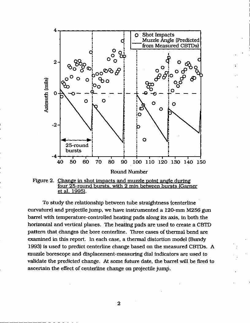
25-mm M242 accuracy test (Garner et al. 1995). Cross-barrel temperature
differences (CBTDs) indicated that during rapid fire, thermal distortion of the
gun barrel increased the curvature of the bore centerline to the gunner's left,
while at the same time, the round impacts moved (in general) to the gunner's
right, Figure 2. It can be reasoned that the correlation between change in
preflring bore curvature and change in projectile impact location resulted from
transverse motion of the muzzle that was imparted to the projectile at shot exit.
Muzzle
Transverse
Vibration
Figure 1. Illustratin~ the effect of recoil on a curved bore centerline.
In the case of saboted rounds, forcing the projectile to follow the lateral
oscillations of a curved bore centerline is thought to produce an asymmetric
distribution of compressional energy loads within the elastic &abot petals. This
is believed to affect the symmetry of sabot petal separation from the central
long rod penetrator, and hence affect the symmetry of aerodynamic side forces
(created by shock waves from the discarding sabot petals [Plostins, Bornstein,
and Celmins 1991)) on the penetrator before it enters free flight.
1
en i ........
~ ::s ~-
4
2
0
-.2
. I I • • I q • I • I I I I 0 . q 0~ I
~co8 l Oo
COo . o <Oi oo CbCO § o 0 o oPq., 0 ~ i0 o
-<!L 0
•• • 25-round bursts
I I
I
- -0
-
o··. Sl:lot Impacts ....:.._Muzzle Angle (Predicted
from Measured: CBTDs)
I
cf 0 ~ 0 a· ~ c9 o §' 0 . o9 iO .
I cP CP ~ ! 00 ! 0
0 IO -0-E)--t--
. 0 !o
-4~--~--~-L~---r--~--~---T---T_.-T--~~~
40 50 60 70 80 90 100 110 120 130 140 150
Round Number
Figure 2. Chani!e in shot impacts and muzzle point ani!le durini! four 25-round bursts. with 2 min between bursts (Gamer et al. 1995).
To study the relationship between tube straightness (centerline curvature) and projectile jump, we have instrumented a 120-mm M256 gun barrel with temperature-controlled heating pads along its axis, in both .the horizontal and vertical planes. The heating pads are_used to create a CBTD pattern that changes the bore centerline. Three cases of thermal bend are examined in this report. In each case, a thermal distortion model (Bundy 1993) is used to predict centerline change based on the measured CBTDs. A muzzle borescope and displacement-measuring dial indicators are used to validate the predicted change. At some future date, the barrel will be fired to ascertain the· effect of centerline change on projectile jump.
2
:.
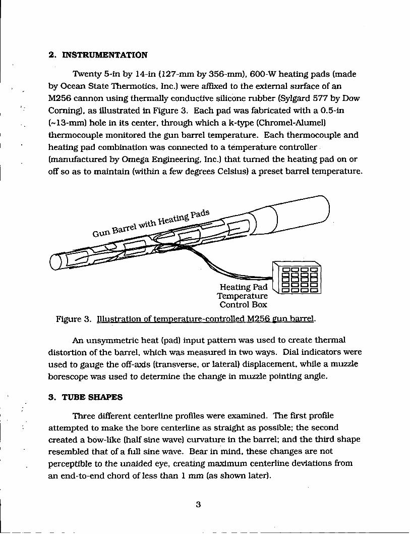
2. INSTRUMENTATION
Twenty 5-in by 14-in (127-mm by 356-mm), 600-W heating pads (made
by Ocean State Thermotics, Inc.) were affiXed to the external surface of an
M256 cannon using thermally conductive silicone rubber (Sylgard 577 by Dow
Corning), as illustrated in Figure 3. Each pad was fabricated with a 0.5-in
(-13-mm) hole in its center, through which a k-type (Chromel-Alumel)
thermocouple monitored the gun barrel temperature. Each thermocouple and
heating pad combination was connected to a temperature controller . (manufactured by Omega Engineering, Inc.) that turned the heating pad on or
off so as to maintain (within a few degrees Celsius) a preset barrel temperature.
Heating Pad Temperature Control Box
c::n::::H::::H:::::J BBBB CJCJCJI:J CJCJCJCJ
Figure 3. Illustration of temperature-controlled M256 ~un barrel.
An unsymmetric heat (pad) input pattern was used to create thermal distortion of the barrel, which was measured in two ways. Dial indicators were
used to gauge the off-axis (transverse, or lateral) displacement, while a muzzle
borescope was used to determine the change in muzzle pointing angle.
3. TUBE SHAPES
Three different centerline profiles were examined. The first profile attempted to make the bore centerline as straight as possible: the second created a bow-like (half sine wave) curvature in the barrel: and the third shape resembled that of a full sine wave. Bear in mind, these changes are not
perceptible to the unaided eye, creating maximum centerline deviations from an end-to-end chord of less than 1 mm (as shown later).
3
._____ _________ --- - - -

3.1 Straight
The particular barrel chosen for this study (M256 serial number 2971) was manufactured relatively straight. In fact, "2971" is straighter than all 20 of the M256 barrels studied by Wilkerson (1995) in his report on barrel straightness and accuracy. Figure 4 shows a comparison of 2971's centerline with that of a typical barrel in the Wilkerson study (e.g., serial number 4088). The displacement in both planes in Figure 4 is measured relative to a straightline chord drawn from the muzzle end of the bore, to the chamber end (specifically, from -230 mm to - 4630 mm from the muzzle, which delimits the range of the bore centerline measuring device). A positive value means the bore centerline is displaced above the chord in the vertical plane, and to the
(gunner's) right of the chord in the horizontal plane.
0.4
1 0.3
1:"8 8.8 0.2 ~() ~"0 'at:: .~ C:z:J 0.1 06 (I)~ 0
1~ -0.1----
()J:::
e Tube 2971 Horz. Plane
-- •--- Tube 2971 Vert. Plane --o- Tube 4088 Harz. Plane -- -<>--- Tube 4088 ·Vert. Plane
-0.2~-------r-------,--------~------~------~
0 1000 2000 3000 4000 5000
Distance from Muzzle (mm)
Figure 4. Comparison of centerline strai~htness for a relatively strai~ht M256. serial number 2971. vs. a more typical M256 barrel. serial number 4088.
4

I I
I
In spite of its inherent straightness. the heating pads were used to make 2971 even straighter. This was accomplished with the measured CBTD
distribution shown in Figure 5. Note, there is a difference between the preset value for the CBTD and the measured CBTD. This is due, in part, to the fact that each temperature controller will tum on and off within a 1-2° C temperature range about the preset value. But a larger share of the disparity,
. particularly in the vertical plane, where m:ore heating pads were installed, is due to the fact. that heat from each pad migrates axially and circumferentially
to the location of nearby he~ting pads. Furthermore, gravity predisposes the top of the barrel to be hotter than the bottom. As a result, each heating pad
must compensate for heat input from nearby heating pads and gravity effects
in order. to obtain the sought-after CBTD profile.
It should also be pointed out that there is only one measured CBTD for every pair of laterally opposed heating pads. Nevertheless. close inspection of
Figure 5 reveals that three CBTDs have been apportioned to the region spanned by each pad. The assignment of three CBTDs from a singular measurement is based on the a priori assumption that the region of the barrel under the central third of the pad is at the measured CBTD. while the outer two thirds are assu.med to have half of this value. As is shown later, this prescription for assigning CBTDs leads to reasonably good agreement between theory and experiment. particularly in the horizontal plane. We shall henceforth refer to the assigned CBTDs as simply the measured CBTDs.
Figure 6 displays the predicted effect on straightness of two measured CBTD profiles. one of which is shown in Figure 5. The square-shaped symbols mark the inherent (manufactured) centerline curvature for tube 2971. The diamond-shaped symbols ·outline the·predicted c~nterline change brought
about by measured CBTDs from two different trials; and the circle-shaped symbols are a summation of the manufactured curvature with the CBTD
induced curvature.
Even though there is variation in the level of straightness from one trial to the next in Figure 6 (due· to the on-off tolerance level in each temperaturecontrolling device), there is at least a twofold increase in straightness of 2971
that is brought about by use of the heating pads.
l-~----5---

~ Preset CBTD
10 12] Measured CBTD
Distance from Muzzle (mm)
Figure 5. Cross barrel temperature difference (CBTDl needed to further strai~hten M256 serial number 2971 in the vertical (top plot) and horizontal (bottom plot) planes.
6
. I

·.
l__
0.2
- 0.15 ~~ =-s-e 0.1 GJ 0 ~.t:l -u 0.05 Sl.GJ -~ 'R QN
0 v::i ;§~ ~ ~ -0.05 s::l.t:l GJO ()GJ -0.1 -2:! moo 0
=e e -0.15 ~~
-0.2
0.2
~~ s _ o.15
~"2 .!lo 01 Sl.,t:: •
a~ GJ 'H 0.05 s::IN
;:::1::::2
~~ 0 =.s ~ ~ -0.05
~~ 0 Ol -0.1
.5:3 e ~ ~ -0.15
.na·•• a e.·
,~. ~ ..... -~ol--
....... <> ............... .. trial 1 . trial 2
Inherent Curvature
Heat Pad Distortion
---.0--·····•··· Summed Curvature
-0.24-------~--------------~--------~----~
0 1000 2000 3000 4000 5000
Chord Axis (mm)
Figure 6. Temperature-controlled strai~htenin~ of M256 serial number 2971. in the vertical (top) and horizontal (bottom) planes.
7

We would expect the summed curves in Figure 6 to be close to that which could be measured during these heating pad trials, if it were it not for the fact that critical optical components in the centerline measuring device will not function properly in the turbulent bore atmosphere created by heating the barrel. Since it is not possible to directly measure the bore straightness with the heating pads in operation, the model is validated by comparing predictions with measurements of the muzzle angle and off-axis displacement of the outer barrel wall (using standard machinist's dial indicators). Figure 7 shows such a
comparison.
0.5
0.4
0.3
0.2
0.1
0
•
trial2
trial I
Predicted Muzzle Dspl. (mm)
Measured Muzzle Dspl. (mm)
• Measured Muzzle Angle (mils)
+ Predicted Muzzle Angle (mils)
04-~==~====~====~====~~--0 0.1 0.2 0.3 0.4 0.5
Figure 7. Comparison of CBTD-based prediction vs. measurement of muzzle an21e and muzzle displacement induced by heatin2 pad pattern used to further strai2hten M256 serial number 2971.
As can be seen, the angular difference between theory and experiment is at most 0.1 mil, while the displacement difference can vary by 0.2 mm (0.008 in). In general, the agreement is better in the horizontal plane than in
the vertical plane. Additional comparisons will be shown for other tube shapes.
8

3.2 Half Sine Wave
Many bore centerlines have a simple bow, or half sine wave shape (Wilkerson 1995), perhaps 50o/o. The heating pattern shown in Figure 8 was used to create such a shape in 2971. It can be seen that CBTDs greater than 20° C can be obtained with the heating pads. (For comparison, a CBTD of 26° C was observed when rain-like precipitation impinged on a hot, post-fired barrel [Bundy 1987]). Figure 9 shows how this type of left-sided heating pattern deflected the barrel to the right, relative to the unheated state. As
shown, the measured and predicted displacement differed by less than 0.1 mm at two arbitrarily chosen locations on the barrel.
30 -~ -~ 0 ~
8 ~ ct:: 0 ~ riJ
~ -1 ::E ~
~ ~
-20
Distance from Muzzle (mm)
Figure 8. Heat-pad-induced CBTD profile used to create a half sine wave bore centerline curvature.
Figure 9references a particular time during heating; Figure 10 shows how theory and experiment compare over time during the heating process. In general, the muzzle angle comp(,Uison agrees within 0.1 mil, while the muzzle .displacement agrees within 0.2 mm, as was the case in Figure 7.
9

Predicted Centerline Displacement (mm)
• Measured " " (mm)
~-t-----------------·
0 1000 2000 3000 4000 5000 6000 Distance From Muzzle (mm)
Figure 9. Chan~e in bore strai~htness due to Fi~ure 8 heatin~.
2
1.5
1
0.5
o·' ..
·' .--·· .. I
0········ . . ·· .. ········--... 0 . ..
rl---·············+··············-~---······ ;t_ .... -··· . . ....... ..... -·· __ ..,.~=------------, ····0·· ·· Predicted Muzzle Dspl. (nun)
• Measured Muzzle Dspl. (mm)
+ Measured Muzzle Angle (mils)
····+··· Predicted Muzzle Angle (mils)
2 4 6 8 10 Heating Time (min)
Figure 10. Comparison of prediction vs. measurement over time.
10
-.
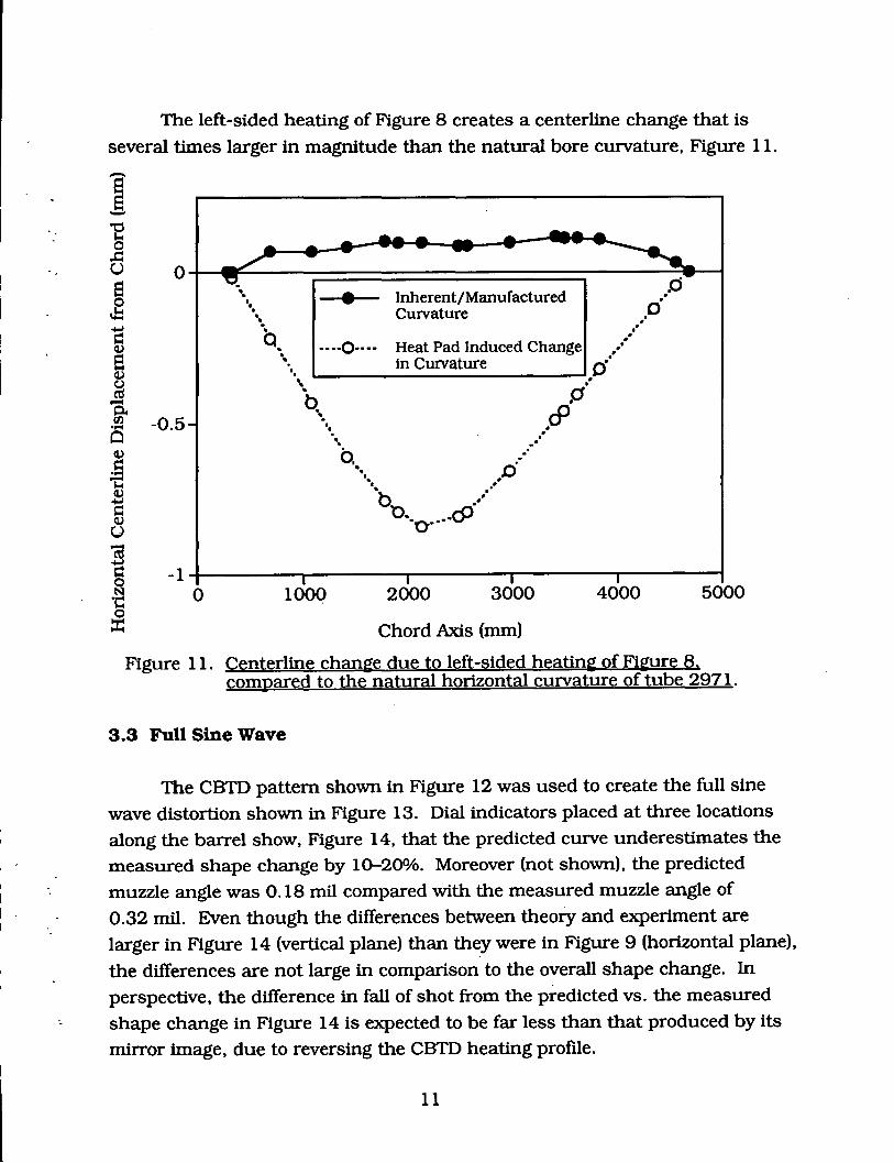
The left-sided heating of Figure 8 creates a centerline change that is
several times larger in magnitude than the natural bore curvature, Figure 11.
Oj-~~----~==================~----~~~· ~ \ e Inherent/Manufactured
0.·
-0.5
\ Curvature ,• . ~ a. ~ ----0---- Heat Pad Induced Change •' " in Curvature o···
'• .... . .b [:J'
...... .cf' •. b.
•··... . .•. o· bo -··
··o----<9
.· ,• -·
-1~--------~--------~------~--------~--------~
0 1000 2000 3000 4000 5000
Chord Axis (mm)
Figure 11. Centerline change due to left-sided heating of Figure 8. compared to the natural horizontal curvature of tube 2971.
3.3 Full Sine Wave
The CBTD pattern shown in Figure 12 was used to create the full sine
wave distortion shown in Figure 13. Dial indicators placed at three locations
along the barrel show, Figure 14, that the predicted curve underestimates the
measured shape change by 10-20%. Moreover (not shown), the predicted
muzzle angle was 0.18 mil compared with the measured muzzle angle of
0.32 mil. Even though the differences between theory and experiment are
larger in Figure 14 (vertical plane) than they were in Figure 9 (horizontal plane),
the differences are not large in comparison to the overall shape change. In
perspective, the difference in fall of shot from the predicted vs. the measured
shape change in Figure 14 is expected to be far less than that produced by its
mirror image, due to reversing the CBTD heating profile.
11

~ Preset CBTD lEI Measured CBTD
Figure 12. CBTD pattern used to create a sine-wave-like thermal distortion of the barrel.
0.4
~ s:: 0.3 Q) e-~j
0.2 -0-!"'0 rtJ\-t -o O..c= Q)(.)
0.1 .s "'0 -cs:: Q)(J:l ~I s::.s 0 Q)l (.)"'0 cas:: (jtl:l =ee -0.1 ~~
-0.2 0 1000 2000 3000 4000
Chord Axis (mm)
5000
Figure 13. Predicted bore centerline chan~. relative to the strai~ht-line muzzle-to-chamber chord. due to the CBTD pattern of Fie-ure 12.
12

I __
1 0.5 • Predicted Centerline Dspl. (mm)
Measured .. .. (nun)
0
•
1000 2000 3000 4000 5000 6000
Distance From Muzzle (mm)
Figure 14. Comparison of CBTD-based prediction vs. measurement of lateral barrel displacement induced by heatin(! profile of Figure 12.
4. CONCLUSIONS
Heating pads were used to thermally distort the barrel, as demonstrated by creating three different tube shapes, viz., a straight tube, a half, and a full sine wave shape.
A thermal distortion model, based on measurements of the cross-barrel temperature differences, CBTDs, was used to predict/estimate the overall centerline shape change. It was not possible to measure the CBTD-induced shape change with a conventional (optically based) centerline measuring instrument, due to hot-air turbulence in the bore. Instead, the thermal distortion model was validated by comparing the predicted vs. measured muzzle angle (using a muzzle borescope). as well as the predicted vs. measured off-axis barrel displacement (using dial indicators).
13

As a whole, the prediction and measurement agreed fairly well-the muzzle
angle values were within 0.1 mil (for comparison, the error in the muzzle scope
reading is considered to be 0.05 mils), and the displacement values were within
0.2 mm (0.008 in).
Elaborating, the agreement between theory and experiment appeared to
be better in the horizontal plane than in the vertical plane. It could be the case
that the postulated distribution of barrel temperature beneath the pad is not as
universal as was assumed. That is, the barrel section under the middle third of the
heating pad was assigned the pad-centered CBTD measurement; whereas the
barrel sections beneath the outer two thirds of the pad were assigned half the
measured value. This assumed distribution of barrel temperature across the
pad, based on one central-pad measurement, seems to provide better results in the
horizontal plane, where the spacing between pads is slightly greater, than in the
vertical plane. Nevertheless, the magnitude of the discrepancy is not sufficient to
warrant further refinement in the predictive procedure at this time. It is expected
that a bow-, or s-shaped, curve to the right vs. left, up, or down, will have a far larger
affect on shot impact than the 10-20% discrepancy between the predicted and
measured/ actual barrel curvature.
Future live-frre tests will examine the influence of centerline shape on
projectile impact locations by firing, for example, a bow shape to the right vs.
left, and noting the difference, if any, in the fall-of-shot pattem.
14

4. REFERENCES
Bundy, M. L. "Improved Thermal Shroud Protection for Tank Cannon
from Internal and External Heat Flux Asymmetries." BRL-TR-2777, U.S.
Army Ballistic Research Laboratory, Aberdeen Proving Ground, MD,
February 1987.
Bundy, M. L. "Gun Barrel Cooling and Thermal Droop Modeling." ARL
TR-189, U.S. Army Research Laboratory, Aberdeen Proving Ground, MD,
August 1993.
Bornstein, J., I. Celmins, P. Plostins, and E. M. Schmidt. ''Techniques for
the Measurement ofTank Cannon Jump." BRL-MR-3715, U.S. Army
Ballistic Research Laboratory, Aberdeen Proving Ground, MD, December
1988.
Garner, J. M., M. L. Bundy, D. W. Webb, and B. J. Patton. 'Variation in
Muzzle Pointing Angle and Shot Impact of M2452 Chain Gun."
ARL-TR-785, U.S. Army Research Laboratory, Aberdeen Proving
Ground, MD, July 1995.
Plostins, P., J. A. Bornstein, and I. Celmins. 'The Effect of Sabot Wheelbase
and Position on the Launch Dynamics of Fin-Stabilized Kinetic Energy
Ammunition." BRL-TR-3225, U.S. Army Ballistic Research Laboratory,
Aberdeen Proving Ground, MD, April1991.
Wilkerson, S. "Possible Effects of Gun Tube Straightness on Dispersion."
ARL-TR-767, U.S. Army Research Laboratory, Aberdeen Proving Ground,
MD, June 1995.
15
- ~- - - ----------------------------------

·,
INTENTIONALLY LEFT BLANK
16
---------
NO. OF COPIES ORGANIZATION
2 DEFENSE TECHNICAL INFO CfR AITN OTIC DDA 8725 JOHN 1 KINGMAN RD STE 0944 Ff BELVOIR VA 22060-6218
1 DIRECTOR US ARMY RESEARCH LAB AITN AMSRL OP SD TA 2800 POWDER MILL RD ADELPID MD 20783-1145
3 DIRECTOR US ARMY RESEARCH LAB AITN AMSRL OP SD TL 2800 POWDER MILL RD ADELPID MD 20783-1145
1 DIRECTOR US ARMY RESEARCH LAB AITN AMSRL OP SD TP 2800 POWDER MILL RD ADELPID MD 20783-1145
ABERDEEN PROVING GROUND
2 DIR USARL AITN AMSRL OP AP L (305)
17
NO. OF NO. OF COPIES ORGANIZATION COPIES ORGANIZATION
4 COMMANDER 7 COMMANDER US ARMY ARMOR CENTER TANK MAIN ARMAMENT SYS ATTN ATSB CD ATTN SFAE AR TMA ATSB SBE ORSA VROSAMILIA FORT KNOX KY 40121 R BILLINGTON
WKATZ 5 COMMANDER RJOINSON
US ARMY TACOM CROLLER ATTN AMSTA CA EKOPACZ AMSTACF K RUBEN AMSTACU PICATINNY ARSENAL NJ AMSTA UW 07806-5000 AMSTA UE WARREN MI 48397-5000 5 COMMANDER
US ARMY ARDEC 2 PEO FOR ARMAMENTS ATTN AMSTA AR AE
ATTN SFAEAR AMSTA AR FSF GD K PFLEGER SFAE AR D AMSTA AR FSF BV PICATINNY ARSENAL NJ VGALGANO 07806-5000 C GONZALES
CLANGEN 8 PEO FOR ARMORED SYS MOD PICATINNY ARSENAL NJ
ATTN SFAE ASM 07806-5000 SFAE ASMAB SFAE ASM AB SW 4 COMMANDER SFAEASMAB S US ARMY ARDEC SFAEASMAG ATTN AMSTA AR CCH V SFAE ASM SS CMANDALA SFAE ASM BT E FENNELL SFAEASMFV AGOWARTY WARREN MI 48397-5000 J PETTY
PICATINNY ARSENAL NJ 1 HEADQUARTERS 07806-5000
US ARMY MATERIEL CMD A TIN AMCICP AD M FISETTE 1 COMMANDER 5001 EISENHOWER AVE US ARMY ARDEC ALEXANDRIA VA 22333-0001 ATIN AMSTA AR AEE B S BERNSTEIN
PICA TINNY ARSENAL NJ US ARMY BMDS CMD 07806-5000 ADVANCED TECHLGY CI'R PO BOX 1500 4 COMMANDER HUNTSVILLE AL 35807-3801 US ARMY ARDEC
ATTN AMSTA AR QAT A 1 OFC OF THE PRODUCT MGR L DULISSI
155MM HOWITZER M109A6 PALADIN CPATEL ATTN SFAE AR HIP IP RROESER MR R DE KLEINE G MAGISTRO PICA TINNY ARSENAL NJ PICA TINNY ARSENAL NJ 07806-5000 07806-5000
18

I
NO. OF COPffiS ORGA~TION
5
2
2
2
COMMANDER US ARMY ARDEC AITN AMSTA AR AEE J LANNON PICA TINNY ARSENAL NJ 07806-5000
COMMANDER US ARMY ARDEC ATIN AMSTA AR ATE A STAN KAHN PICATINNY ARSENAL NJ 07806-5000
COMMANDER US ARMY ARDEC ATIN SFAE FAS AF COL D NAPOLIELLO LYUNG TKURIATA EDELCOCO HTRAN PICA TINNY ARSENAL NJ 07806-5000
COMMANDER US ARMY ARDEC A TIN AMSTA AR FSF BD RMEENAN J DELABAR PICATINNY ARSENAL NJ 07806-5000
COMMANDER US ARMY ARDEC ATIN AMSTA AR FSS A LMUND LPINDER PICA TINNY ARSENAL NJ 07806-5000
COMMANDER US ARMY ARDEC AITN AMSTA AR FSS E J BROOKS M ENNIS PICA TINNY ARSENAL NJ 07806-5000
COMMANDER US ARMY ARDEC ATI'N AMSTA ,AR FSE T GORA PICA TINNY ARSENAL NJ 07806-5000
19
NO. OF COPffiS ORG~TION
3
4
2
1
2
COMMANDER US ARMY ARDEC AITN AMSTA AR TO RPRICE VLINDNER C SPINELLI PICATINNY ARSENAL NJ 07806-5000
COMMANDER US ARMY ARDEC A 1TN F MCLAUGHLIN PICATINNY ARSENAL NJ 07806-5000
COMMANDER US ARMY ARDEC ATIN AMSTA AR CCH T S MUSALLI P CHRISTIAN RCARR N KRASNOW PICA TINNY ARSENAL NJ 07806-5000
COMMANDER US ARMY ARDEC ATIN AMSTA AR CCH J DELORENZO PICA TINNY ARSENAL NJ 07806-5000
COMMANDER US ARMY ARDEC ATIN AMSTA AR CC J HEDDERICH COL SINCLAIR PICATINNY ARSENAL NJ 07806-5000
COMMANDER US ARMY ARDEC A TIN AMSTA AR CCH P J LUTZ PICA TINNY ARSENAL NJ 07806-5000
COMMANDER US ARMY ARDEC ATIN AMSTA AR FSA M DDEMELLA FDIORIO PICATINNY ARSENAL NJ 07806-5000
L-~--· -- - ~------------------------------

NO. OF NO. OF COPIES ORGANIZATION COPIES ORGANIZATION
2 COMMANDER PROGRAM MANAGER US ARMY ARDEC US ARMY TACOM ATTN AMSTA AR FSA ATINAMCPM ABMS T DEAN A WARNASH WARREN MI 48092-2498 B MACHAK. PICA TINNY ARSENAL NJ PROGRAM MANAGER 07806-5000 US ARMY TACOM
ATTN SFAE ASM BV 20 DIRECTOR FIGHTING VEHICLE SYSTEMS
US ARMY ARDEC WARREN MI 48397-5000 ATTN AMSTA AR CCB C KITCHENS 2 COMMANDER J KEANE US ARMY TACOM J BATTAGLIA ATTN SFAE ASM AB SW J VASILAKIS DR PATTISON G PFLEGL MAJ M PADGETT G FRIAR WARREN MI 48397-5000 V MONTVOIR PO'HURA PROGRAM MANAGER DPORTER ABRAMS TANK SYSTEM MWITHESELL ATTN SFAE ASM AB ROAST WARREN MI 48397-5000 CAANDRADE JHAAS COMMANDANT A GABRIEL US ARMYCMD& P VOTIS GEN STAFF COLLEGE J HIGGINS FORT LEAVENWORTH KS 66027 F HEISER J WRZOCHALSKI COMMANDANT R HASENBEIN US ARMY SPCL WARFARE SCHL AMSTA AR CCB T S SOPOK ATTN REV AND TRNG LIT DIV BENET LABS FORT BRAGG NC 28307 WATERVLIET NY 12189
COMMANDER COMMANDER RADFORD ARMY AMMUNffiON PLANT US ARMY ARDEC ATTN SMCAR QA HI LIB ATTN AMSMC PBM K RADFORD VA 24141-0298 PROD BASE MODERN ACTY PICA TINNY ARSENAL NJ 1 COMMANDER 07806-5000 US ARMYNGIC
ATTN AMXST MC 3 2 DIRECTOR 220 SEVENTH STREET NE
BENET WEAPONS LABS CHARLOTTESVILLE VA 22901-5396 ATTN AMSTA AR CCB Dl C RINALDI AMSTA AR CCB RP G CAPSINALIS COMMANDANT WATERVLIET NY 12189-4050 US ARMY FIELD ARTLRY CIR
&SCHOOL 1 COMMANDER ATTN ATSF CD COL T STRICKLIN
USACECOM FORT SILL OK 73503-5600 ATTN ASQNC ELC IS L R MYER CIR R&D TECH LIB FORT MONMOUTH NJ 07703-5301
20

NO. OF NO. OF COPIES ORGANIZATION COPIES ORGANIZATION
COMMANDANT 1 HQDA US ARMY FIELD ARTLRY CTR & SCHOOL PENTAGON AITN ATSF CN P GROSS AITN SARD TT DR F MILTON FORT SILL OK 73503-5600 WASHINGTON DC 20310-0103
1 COMMANDANT HQDA US ARMY ARMOR SCHOOL PENTAGON AITN A1ZK CD MS M FALKOVITCH AITN SARD TR DR R CHAIT ARMOR AGENCY WASHINGTON DC 20310-0103 FORT.KNOX KY 40121-5215
HQDA DIRECTOR PENTAGON US ARMY ARMOR SCHOOL ATTN SARDTR ATI'N ATSB WP ORSA A POMEY MSKKOMINOS WEAPONS DEPT WASHINGTON DC 30310-0103 FORT KNOX KY 40121-5212
DIRECTOR 2 PMAFAS US ARMY RESEARCH LAB
AITN SFAE ASM AF ATTN AMSRL CP CA D SNIDER
LTC A ELLIS 2800 POWDER MILL RD
LTC BELLIS ADELPID MD 20783
PICA TINNY ARSENAL NJ 07806-5000 COMMANDER
US ARMY TACOM 3 OFFICE OF THE PM ATTN AMSTA JSK S GOODMAN
M109/AG PALADIN WARREN MI 48397-5000 ATTN SFAE AR HIP J CARBONE 1 COMMANDER KHURBAN ATTN SMCWV QAE Q C HOWD · SWALL BLDG 44 WATERVLIET ARSNL PICA TINNY ARSENAL NJ WATERVLIET NY 12189-4050
07806-5000 1 COMMANDER
COMMANDER ATTN SMCWV SPM T MCCLOSKEY
USA ARMAMENT MUNTNS & CHEMCL CMD BLDG 25 3 WTRVL T ARSNL ATTN AMSMC DSD C J O'DONNELL WATERVLIET NY 12189-4050
ROCK ISLAND IL 61299-6000 COMMANDER
3 COMMANDANT WATERVLIET ARSENAL US ARMY FIELD ARTILLERY SCHOOL ATTN SMCWV QA QS K INSCO
ATTN ATSF CC R LILLARD WATERVLIET NY 12189-4050
ATSF GD ATSF CT J GEIST 1 COMMANDER FORT SILL OK 73503-5600 US ARMY BELVOIR RD&E CTR
ATTN STRBE JBC 1 DIRECTOR FORT BEL VOIR VA 22060-5606
US ARMY FIELD ARTILLERY BOARD US ARMY COLD REGIONS RSCH & ATTN ATZR BDW ENGINEERING LABORATORY FORT SILL OK 73503 ATTNPDUTTA
72LYMERD HANOVER NH 03755
21
- ·- ---------------------------------------

NO. OF NO. OF COPIES ORGANIZATION COPIES ORGANIZATION
1 DIRECTOR 2 PEO FIELD ART SYS US ARMY RESEARCH LAB ATTN SFAE FAS PM ATTN AMSRL WT L DADAMS DWOODBURY T MCWILLIAMS 2800 POWDER Mll..L RD PICA TINNY ARSENAL NJ ADELPID MD 20783-1145 07806-5000
2 US ARMY RESEARCH OFFICE PEO FIELD ART SYS ATTN A CROWSON ATTN SFAE FAS PM I CHANDRA HGOLDMAN PO BOX 12211 PICATINNY ARSENAL NJ RESEARCH TRIANGLE PARK NC 07806-5000 27709-2211
2 PMAFAS 3 COMMANDER ATTN G DELCOCO
US ARMY MISSILE COMMAND J SHIELDS ATTN AMSMI RD W MCCORKLE PICATINNY ARSENAL NJ AMSMI RD ST P DOYLE 07806-5000 AMSMI RD ST CN TV ANDIVER REDSTONE ARSENAL AL 35898 2 PROGRAM MANAGER
GROUND WEAPONS MCRDAC 3 US ARMY RESEARCH OFFICE CBGT
ATTN R SINGLETON QUANTICO VA 22134-5000 G ANDERSON KIYER 2 COMMANDER ENGINEERING SCIENCES DIV NAVAL SEA SYSTEMS CMD PO BOX 12211 ATTN SEA 62R RESEARCH TRIANGLE PARK NC SEA64 27709-2211 WASHINGTON DC 20362-5101
2 PROffiCT MANAGER 1 COMMANDER SAD ARM NAVAL AIR SYSTEMS CMD PICATINNY ARSENAL NJ ATTN AIR 954 TECH LIBRARY 07806-5000 WASHINGTON DC 20360
2 PM TANK MAIN ARM SYS 4 COMMANDER ATTN SFAE AR TMA NAVAL RSRCH LAB COL BREGARD ATTN TECHNICAL LIBRARY KKIMKER CODE 4410 PICA TINNY ARSENAL NJ K KAILASANATE 07806-5000 J BORIS
EORAN 3 PM TANK MAIN ARM SYS WASHINGTON DC 20375-5000
ATTN SFAE AR TMA MD RKOWALSKI OFFICE OF NAVAL RSRCH BHELD ATTN CODE 473 R S Mll..LER B DACEY 800 N QUINCY ST PICATINNY ARSENAL NJ ARLINGTON VA 22217-5000 07806-5000
22

NO. OF NO. OF COPIES ORGANIZATION COPIES ORGANIZATION
OFFICE OF NAVAL TECHLGY COMMANDER ATIN ONT 213 D SIEGEL NAVAL SURFACE WARFARE CTR 800 N QUINCY ST A TIN JOSEPH H FRANCIS ARLINGTON VA 22217-5000 CODE G30
DAHLGREN VA 22448 COMMANDER NAVAL SURFACE WARFARE CTR COMMANDER A TIN CODE 730 NAVAL SURFACE WARFARE CTR SILVER SPRING MD 20903-5000 A TIN JOHN FRA YSSE
CODE G33 COMMANDER DAHLGREN VA 22448 NAVAL SURFACE WARFARE CTR A TIN CODE R 13 R BERNECK.ER COMMANDER SILVER SPRING MD 20903-5000 . NAVAL SURFACE WARFARE CTR
ATIN MARY E LACY CODE D4 7 COMMANDER. 17320 DAHLGREN RD
NAVAL SURFACE WARFARE CTR DAHLGREN VA 22448 ATIN T C SMITII KRICE 2 COMMANDER S MITCHELL NAVAL AIR WARFARE CTR S PETERS ATIN CODE 388 JCONSAGA CFPRICE C GOTZMER TBOGGS TECH LIB CHINA LAKE CA 93555-6001 INDIAN HEAD MD 20640-5000
2 COMMANDER COMMANDER NAVAL AIR WARFARECTR NAVAL SURFACE WARFARE CTR A TIN CODE 3895 A TIN CODE G30 GUNS & TPARR MUNITIONS DIY RDERR DAHLGREN VA 22448-5000 CHINA LAKE CA 93555-6001
COMMANDER COMMANDER NAVAL SURFACE WARFARE CTR NAVAL AIR WARFARE CTR. A TIN CODE G32 GUNS SYSTEMS DIY INFORMATION SCIENCE DIY DAHLGREN VA 22448-5000 CHINA LAKE CA 93555-6001
1 COMMANDER 1 OFFICE OF NAVAL RESEARCH NAVAL SURFACE WARFARE CTR ATIN YAPA RAJAPAKSE A TIN CODE G33 T DORAN MECH DIY CODE 1132SM DAHLGREN VA 22448-5000 ARLINGTON VA 22217
COMMANDER NAVAL ORDNANCE STATION NAVAL SURFACE WARFARE CTR ATIN D HOLMES ATIN CODE E23 TECH LIB CODE 2011 DAHLGREN VA 22448-5000 ADVANCED SYS TECH BR
LOUISVILLE KY 40214-5245 2 COMMANDER
NAVAL SURFACE WARFARE CTR 2 DAVID TAYLOR RESEARCH CTR A TIN CODE G33 ATI'N R ROCKWELL DAHLGREN DIY W PHYILLAIER DAHLGREN VA 22448 . BETHESDA MD 20054-5000
23

NO. OF NO. OF COPIES ORGANIZATION COPIES ORGANIZATION
EXPED W ARF DIY N85 1 DEFENSE NUCLEAR AGENCY ATIN DR FRANK SHOUP ATIN LTC JYUJI D HEWITT 2000 NAVY PENTAGON INNOVATIVE CONCEPTS DIV WASHINGTON DC 20350-2000 6801 TELEGRAPH RD
ALEXANDRIA VA 22310-3398 OFFICE OF NAVAL RESEARCH ATIN MR. DAVID SIEGEL 351 1 DIRECTOR 800 N QUINCY ST SANDIA NA TL LABS ARLINGTON VA 22217-5660 A'ITNMBAER
DEPARTMENT 1512 COMMANDER PO BOX 5800 NAY AL SEA SYSTEMS CMD ALBUQUERQUE NM 87185 ATIN DLIESE 2531 JEFFERSON DAVIS HWY DIRECTOR ARLINGTON VA 22242-5160 SANDIA NATL LABS
A'ITN R CARLING SDIO TNI COMBUSTION RSRCH FACILITY PENTAGON LIVERMORE CA 94551-0469 ATIN L H CAVENY WASHINGTON DC 20301-7100 DIRECTOR
SANDIA NATL LABS SDIO DA A'ITN 8741 G A BENEDITTI PENTAGON PO BOX 969 ATTNEGERRY LIVERMORE CA 94551-0969 WASHINGTON DC 21301-7100
2 DIRECTOR 2 HQDNA LAWRENCE LIVERMORE NA TL LABS
ATTNDLEWIS ATIN L 355 A FAHEY A BUCKINGHAM 6801 TELEGRAPH RD MFINGER ALEXANDRIA VA 22310-3398 PO BOX 808
LIVERMORE CA 94550-0622 2 CPIAJHU
ATTN H J HOFFMAN DIRECTOR TCHRISTIAN LOS ALAMOS NATL LAB 1~30LITTLEPATUXENTPWY ATTN T3 D BUTLER STE 202 PO BOX 1663 COLUMBIA MD 21044-3200 LOS ALAMOS NM 87544
2 NASA LANGLEY RESEARCH CTR DIRECTOR ATTN AMSRL VS LOS ALAMOS NATL LAB WELBER ATTN M DMSION B CRAIG F BARTLETT JR PO BOX 1663 MS 266 LOS ALAMOS NM 87544 HAMPTON VA 23681-0001
1 GENERAL APPLIED SCIENCES LAB DEFENSE NUCLEAR AGENCY ATTN J ERDOS ATIN DR R ROHR 77 RAYNOR AVE INNOVATIVE CONCEPTS DIV RONKONKAMA NY 11779-6649 6801 TELEGRAPH RD ALEXANDRIA VA 22310-3398
24
L_ _____ _

NO. OF NO. OF COPIES ORGANIZATION COPIES ORGANIZATION
DIRECfOR 1 AFELM 1HE RAND CORP LOSALAMOSNATLLAB ATIN LffiRARY D ATIN D RABERN 1700 MAIN ST MEE 13 MS J 576 SANTA MONICA CA 90401-3297 PO BOX 1633 LOS ALAMOS NM 87545 2 AAI CORPORATION
ATIN J. FRANKLE THE UNIV OF AUSTIN TEXAS DCLEVELAND ATIN T M KIEHNE PO BOX 126 INSTITUTE FOR ADVANCED TECHLGY HUNT VALLEY MD 21030-0126 4030 2 W BRAKER LAND AUSTIN TX 78759-5329 . 8 ALLIANT TECHSYSTEMS INC
ATIN R E TOMPKINS 4 PENNSYLVANIA STATE UNIV J KENNEDY
ATINVYANG JBODE KKUO CCANDLAND C MERKLE LOSGOOD G SETTLES R BURETTA DEPT OF MECHANICAL ENGRG R BECKER UNIVERSITY PARK PA 16802-7501 MSWENSON
600 SECOND ST NE PRINCETON COMBUSTION RSRCH LABS INC HOPKINS MN 55343 A TIN N A MESSINA PRINCETON CORPORATE PLAZA 4 ALLIANT TECHSYSTEMS INC 11 DEERPARK DR BLDG IV SUITE 119 ATINHHULS MONMOUTH JUNCTION NJ 08852 R JOHNSON
TROCKNE RENSSELAER POL YTECH INST WDAVIS A TIN R B PIPES 7225 NORTHLAND DR PRES OFC PITTSBURGH BLDG BROOKLYN PK MN 55428 TROY NY 12180-3590
GENERAL ELECTRIC COMPANY 2 BATTELLE ATIN J MANDzy
A TIN lWSTIAC TACTICAL SYSTEM DEPT VLEVIN 100 PLASTICS AVE 505 KING AVE PITTSFIELD MA 01201-3698 COLUMBUS OH 43201-2693
LOCKHEED MARTIN BATTELLE PNL ATTN JIM TALLEY ATTN MR. MARK GARNICH ROOM 1309 PO BOX999 LAKESIDE AVE RICHLAND WA 99352 BURLINGTON VT 05401
BATTELLE 1 OLIN ORDNANCE ATTN C R HARGREAVES ATTN A SAITTA 505 KING AVE 10101 9TH ST NORTH COLUMBUS OH 43201-2681 ST PETERSBURG FL 33716
BATTELLE PNL ATIN M SMITH PO BOX999 RICHLAND WA 99352
25
NO. OF NO. OF COPIES ORGANIZATION COPIES ORGANIZATION
3 OLIN ORDNANCE 4 VERITAY TECHLGY INC AITN E I KIRSCHKE AITN E B FISHER AFGONZALEZ A CRICKENBERGER D W WORTHINGTON I BARNES PO BOX 222 I Z TALLEY ST MARKS FL 32355-0222 PO BOX 305
4845 Mll..LERSPORT HWY 1 OLIN ORDNANCE EAST AMHERST NY 14501-0305
AITN H A MCELROY 10101 9TH ST NORTH 1 UNIVERSAL PROPULSION COMPANY ST PETERSBURG FL 33716 AITN HI MCSPADDEN
25401 NORTH CENTRAL AVE PHYSICS INTRNATL LIBRARY PHOENIX AZ 85027-7837 AITN H WAYNE WAMPLER PO BOX 5010 SRI INTERNATIONAL SAN LEANDRO CA 94577-0599 A 1TN TECH LIB
PROPULSION SCIENCES DIV 3 ROCKWELL INTRNTL 333 RAVENWOOD AVE
ATTN BAOS MENLO PARK CA 94025-3493 I FLANAGAN I GRAY 1 CHAMBERLAIN MANUF CORP RBEDELMAN ATTN M TOWNSEND ROCKETDYNE DIY RSCH & DEY DIV 6633 CANOGA AVE PO BOX 2545 CANOGA PARK CA 91303-2703 550 ESTHER ST
WATERLOO lA 50704 2 ROCKWELL INTRNTL SCIENCE CfR
ATTN DRS CHAKRAVARTHY GENERAL DYNAMICS DR S PALANISWAMY AITN D BARTLE 1049 CAMINO DOS RIOS LAND SYSTEMS DIVISION PO BOX 1085 PO BOX 1901 THOUSAND OAKS CA 91360 WARREN MI 48090
SAIC 1 PM ADVANCED CONCEPTS AITN M PALMER AITN R TAYLOR 2109 AIR PARK RD LORAL VOUGHT SYSTEMS ALBUQUERQUE NM 87106 PO BOX 650003 MS WT 21
DALLAS TX 76265-0003 1 SOUTHWEST RSRCH INSTITUTE
ATTN I P RIEGEL 2 LORAL VOUGHT SYSTEMS 6220 CULEBRA RD ATTN G JACKSON PO DRAWER 28510 KCOOK SAN ANTONIO TX 78228-0510 1701 W MARSHALL DR
GRAND PRAIRIE TX 75051 3 THIOKOL CORPORATION
A TIN R WILLER 2 UNITED DEFENSE LP R BIDDLE ATI'NPPARA TECH LIB GTHOMAS ELKTON DIVISION 1107 COLEMAN AVE BOX 367 PO BOX 241 SAN JOSE CA 95103 ELKTON MD 21921-0241
26

NO. OF COPIES ORGANIZATION
ABERDEEN PROVING GROUND
3 DIR USAMSAA ATIN AMXSY GA
WBROOKS B SIEGEL
AMXSYRA CHEATWOLD
2 CDR USA TECOM A ITN AMSTE SI F
AMS'fETAR
4 DIR USA ATC AITN STECS CC PCP DURKIN
STECS LIS STECS AS STECS ASH
5 DIR USARL ATIN AMSRL WT P
A HORST 390A AMSRLWTPD
TERLINE 390 D HOPKINS 390 S WILKERSON 390
AMSRLWTWB F BRANDON 120

INTENTIONALLY LEFT BLANK.
28
-.
USER EVALUATION SHEET/CHANGE OF ADDRESS
This Laboratory undertakes a continuing effort to improve the quality of the reports it publishes. Your comments/answers to the items/questions below will aid us in our efforts.
1. ARL Report Number/Author ARL-MR-315 <Bundy) Date of Report June 1996
2. Date Report Received-------------------------------
3. Does this report satisfy a need? (Comment on purpose, related project, or other area of interest for which the report will reused.) _______________________________________________________________ __
4. Specifically, how is the report being used? (Information source, design data, procedure, source of ideas, etc.) __
5. Has the information in this report led to any quantitative savings as far as man-hours or dollars saved, operating costs
avoided, or efficiencies achieved, etc? If so, please elaborate. --------------------
6. General Comments. What do you think should be changed to improve future reports? (Indicate changes to
organization, technical content, format, etc.)-------------------------
CURRENT ADDRESS
Organization
Name
Street or P.O. Box No.
City, State, Zip Code
7. If indicating a Change of Address or Address Correction, please provide the Current or Correct address above and the
Old or Incorrect address below.
OLD ADDRESS
Organization
Name
Street or P.O. Box No.
City, State, Zip Code
l ___ ~ (Remove this sheet, fold as indicated, tape closed, and mail.)
(DO NOT STAPLE)

DEPARnMENTOFTHEARMY
OFRCIAL BUSINESS
BUSINESS REPLY MAIL FIRST CLASS PERMIT NO 0001 ,APG,MD
POSTAGE WILL BE PAID BY ADDRESSEE
DIRECTOR U.S. ARMY RESEARCH LABORATORY ATTN: AMSRL·WT·PB ABERDEEN PROVING GROUND, MD 21005-5066
IIIII I NO POSTAGE NECESSARY IF MAILED
IN THE UNITED STATES