telephone exchange
DESCRIPTION
for electronics and communication students done training in DLWTRANSCRIPT

VOCATIONAL TRAINING Report
D.L.W. VARANSI
NAME - VINOD KUMAR
BRANCH - ELECTRONICS ENGINEERING
YEAR - 2
ROLL NO. – 10105EN066
COLLEGE - IT-BHU VARANASI
2012

1. Acknowledgment
2. Preface
3. Introduction to D.L.W.
4. Telephone Exchange
5. AC Plant
6. Electronics Lab
7. Assembly Shop
8. Conclusion
INDEX

ACKNOWLEDGMENT
I would sincerely like to thank the employees and the officers of DLW, VARANASI for their help and support during the vocationaltraining. Despite their busy schedules, they took time out for us andexplained to us the various aspects of the working of the plant, from the production shops.
I would sincerely like to thank Shri Amit Kumar(ACWI/Elect.) andMr. Rajendra P.Srivastava(SSE/AC Plant),Mis. Ratna Singh(SSE/Telephone Exchange) who was instrumental in arranging thevocational training at DLW Varanasi, and without whose help andguidance the training could not have materialized.
I express my deep sense of gratitude toMr. S. P. Singh (Principal,TTC) for given me such a great opportunity

The objectives of the practical training are to learn something aboutindustries practically and to be familiar with the working style of atechnical person to adjust simply according to the industrial environment.
It is rightly said practical life is far away from theoretical one.We learn in class room can give the practical exposure or real lifeexperience no doubt they help in improving the personality of thestudent, but the practical exposure in the field will help the student inlong run of life and will be able to implement the theoreticalknowledge.
As, a part of academic syllabus of four year degree course inElectronics Engineering, every student is required to undergo a practical training.
I am student of Second year Electronics and this report is written on the basis of practical knowledge acquired by me during the periodof practical training taken atDiesel Locomotive Works, Varanasi

Introduction to D.L.W.Background – Diesel Locomotive Works (DLW) is production unitunder the ministry of railways. This was setup in collaboration withAmerican locomotive company (ALCO) USA in 1961 and the firstlocomotive was rolled out in 1964. This unit produces diesel electroniclocomotives and DG sets for Indian railways and other customers in Indiaand Abroad.
Subsequently a contract for transfer of technology of 4000 HPMicroprocessor Controlled AC/AC Freight (GT 46 MAC) / passenger (GT 46 PAC) locomotives and family of 710 engines has been signedwith electro motive division of general motors of USA for manufacturein DLW. the production of these locomotives has now started and thusDLW is the only manufacturers of Diesel Electric Locomotives with bothALCO and General motors technologies in the world.
Brief History
•Set up in 1961 as a green-field project in technical collaboration with ALCO/USA to Manufacture Diesel Electric Locomotives.
•First locomotive rolled out and dedicated to nation in January,1964.
•Transfer-of-Technology agreement signed with General Motors/ USAin October,95 to manufacture state-of-the-art high traction AC-ACdiesel locomotives.
•A flagship company of Indian Railways offering complete range of flanking products in its area of operation

•State-of-the art Design and Manufacturing facility to manufacturemore than 150 locomotives per annum with wide range of related products viz. components and sub-assemblies.
•Unbeatable trail-blazing track record in providing cost-effective, eco-friendly and reliable solutions to ever-increasing transportation needsfor over three decades.
•Fully geared to meet specific transportation needs by putting Price-Value-Technology equation perfectly right.
•A large base of delighted customers among many countries viz. SriLanka, Malaysia, Vietnam, Bangladesh, Tanzania to name a few, bearing testimony to product leadership in its category.
SALIENT FEATURES: Annual production capacity 25 Locomotives Annual turn-over (Rs) 5000 million Total number of staff 223 Workshop land 89 Hectares Township area 211 Hectares Covered area in shops 86300 Sq.m Covered area of other service buildings 73700 Sq.m Electrical power requirement 3468 KVA (Average maximum demand) Electrical energy consumption (units/year) 19.8 million Stand by power generation capacity 3000 KW
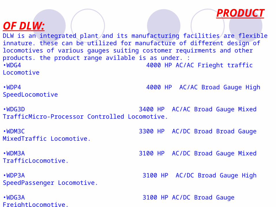
PRODUCT OF DLW:DLW is an integrated plant and its manufacturing facilities are flexible innature. these can be utilized for manufacture of different design of locomotives of various gauges suiting costomer requirments and other products. the product range avilable is as under. :•WDG4 4000 HP AC/AC Frieght traffic Locomotive
•WDP4 4000 HP AC/AC Broad Gauge High SpeedLocomotive
•WDG3D 3400 HP AC/AC Broad Gauge Mixed TrafficMicro-Processor Controlled Locomotive.
•WDM3C 3300 HP AC/DC Broad Broad Gauge MixedTraffic Locomotive.
•WDM3A 3100 HP AC/DC Broad Gauge Mixed TrafficLocomotive.
•WDP3A 3100 HP AC/DC Broad Gauge High SpeedPassenger Locomotive.
•WDG3A 3100 HP AC/DC Broad Gauge FreightLocomotive.
•WDM2 2600 HP AC/DC Broad Gauge Mixed TrafficLocomotive.
•WDP1 2300 HP AC/DC Broad Gauge Intercity ExpressLocomotive.
•WDM7 2150 HP DC/DC Broad Gauge Mixed TrafficLocomotive.


PARTS OF EXCHANGE
1. Charger
2. Battery
3. Exchange (switching system)
4. Internal Distribution Frame (IDF)
5. Main Distribution Frame (MDF)
6. Distribution box (DB)
7. Distribution Pole (DP)
8. Consumers
9. Facilities Provided to Consumer
10.Transmission Bridge

Types Of Telephone Exchange
MAX1 MAX2 MAX3
SAX
PAX - Private Auto Exchange
PBY - Private Branch Exchange
1. Main Auto Exchange
2. 100 – 600 lines
3. Cabinet type
1. Small Auto Exchange
2. Less than 5 – 50lines

Telephone Exchange - This Is the place form where extension of phone line distribute to the user.
Internal Distribution Frame(IDF)- In if the framing of jumper is done . The cables which are coming out of the exchange are terminated in IDF and in MDF
1. Crown type 2. Block type
Main Distibution Frame(MDF)- Exchange is also provided in the rack type of tag block which is called MDF which is the main distribution frame. In MDF we mount the fuse hold tag at the Back of the Block and jumper in front.
Distribution Board(DB)- it is the box board in which cable pads are distributed according to the number which are to be provided near the distribution .DB are installed after accretion interval of the distance making a proper distribution of cable which is easier with the consumer.
Distribution Pole- Distribution poles are much nearer to the consumer here it is easier to take cables from the consumer

There are three types of faults-
1. Line Contacts – It mean that the drop wire is connected either with a pole or a tree if is broken down and a husky voice is obtain when we ring.
2. Line Earth – It means that drop wire breaks on its own when it touches a pole or a tree ,a soft humming sound comes when we dial a number.
3. Line Disc - The wire has been broken down.

Telephone Exchange
BSNL Modem
DSLAM
DB
Splitter
Phone
Computer
Load Balance
Load Balance
Load Balance

21 3 4 1
1
2 43
32 54
1 2
obc
TTC
800A
D&D AC plant 800A
Tele Ac plant 800A
Spare 800A
BC 1600A
LTDB No.2 800A
West wing 800A
ADM?AC PLANT ILCT TR.2 1600A
D&D w/s shop 800A
COMPUTER 800A
I/C TR-I
1600A
I/C TR-2
1600AI/C TR-I
1600A
East wing 800A
Spare 800A
I&C SF/1 400A
100A G.M. AC
ADMS STREAT LIGHT 100A
Central Wing 200A
Staff Canteen 100A

Cooling
Tower
Liquid refrigerant Line Chiller water Line
MOTOR COMP.
CONDENSER
Condenser water Line
COND.
PUMP
Chiller
EXP.
VALVE
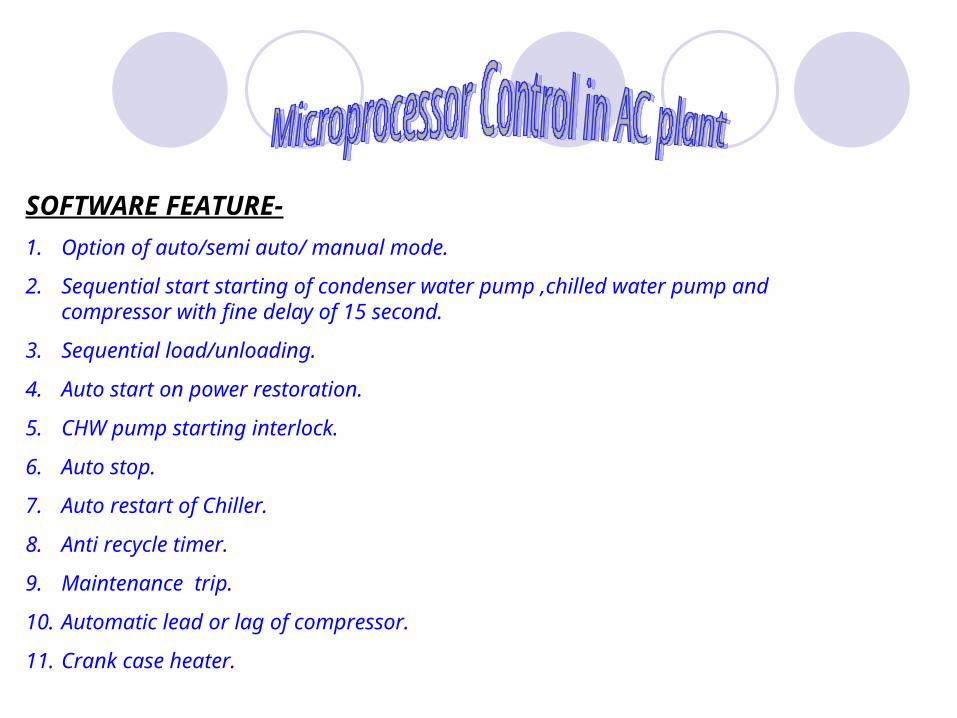
SOFTWARE FEATURE-
1. Option of auto/semi auto/ manual mode.
2. Sequential start starting of condenser water pump ,chilled water pump and compressor with fine delay of 15 second.
3. Sequential load/unloading.
4. Auto start on power restoration.
5. CHW pump starting interlock.
6. Auto stop.
7. Auto restart of Chiller.
8. Anti recycle timer.
9. Maintenance trip.
10. Automatic lead or lag of compressor.
11. Crank case heater.

12. Analog input error.
13. One gear programming.
14. Scheduling .
15. Under lower current and voltage trip.
16. condenser/C.T. Fan cycling.
17. Delay star to delta change over.
18. Easy diagnosis.
19. Continuous display of all reliant parameter.
20. Fault indication

Electronics Lab1. FET (FIELD EFFECT TRANSISTOR) Amplifier
2. Digital Ohm-Meter
3. Cascaded Amplifier
4. Cascoded Amplifier
5. Electro Optical
6. SCR Speed control of Universal AC/DC Motor.
7. Digital Logic
8. D.O.R. Single Phase Motor
9. Thermo Couple
10.Digital IC Training

FET Amplifier
INTRODUCTION :
The FET transistor is a semiconductor device which depend for its operation on the control of current by an electric field.
TYPES :
1. JUNCTION FET TRANSISTOR(JFET)
2. Metal-oxide-semiconductor (MOSFET)
FET Vs. FJT
1. Its operation depends upon flow of majority carrier only .So it is a unipolar device
2. It is simpler to fabricate and occupies less space in integrated form.
3. It exhibits a high input resistance,tepically many maga ohm.
4. It is less noisy than a bipolar device.

P P
P SUBSTRATE
N SUBSTRATE
GATEDRAIN
SOURCE
SINGLE ENDED GEOMETRY JUNCTION FET
VGS
VDS
VGG
VDDIG
IDG
S
D
CKT OF FET Amplifier
D
G
S
IG
ID
DRAIN
GAIN
G Current
SOURCE
D Current

CASCADED AMPLIFIER
RE RE
RcRc
RB
VCE cE
CC
VO
VCC
A CASCADED Amplifier is the combination of Common emitter- Common emitter Transistor. The output of first transistor act as out put of second transistor.

CASCODED AMPLIFIER
RL
VO
VI
The CASCODED amplifier is the combine Common emitter transistor and common base transistor.
In this common emitter’s output will work as the input of the Common base Transistor.
This is an AC circuit equivalent with batteries and the capacitor replaced by short circuit