telene part and mold design guide · telene part and mould design guide ... i.e. applied not only...
TRANSCRIPT

TELENE SAS 4, Rue Marie Curie
59910 Bondues - [email protected]
TELENE PART AND MOULD DESIGN GUIDE
Version VA – WM – 2015/02

Page 2 of 62
warranties of any kind are made as to its accuracy, suitability for particular applications or the results to be
obtained. Full-scale testing and end product performance are the responsibility of the user. TELENE SAS
Important Notice
The information contained herein is believed to be reliable, but no representations, guarantees or
shall not be liable for and the customer assumes all risk and any use or handling of any material beyond
TELENE SAS direct control.
Nothing contained herein is to be considered as permission, recommendation, nor as an inducement to
without permission of the patent owner.practice any patented invention
Page 3 of 62
6
6
Contents1. Design Criteria ....................................................................................................................6
1.1 Polymer Properties ......................................................................................................
Proper
6
6
ties at Low Temperature .........................................................................................
Properties at High Temperature ........................................................................................
Fire Behaviour.....................................................................................................................
Aging
Behaviour
..................................................................................................................................7
Creep ................................
TELENE 1650 Tensile creep @ 60°C ................................................................................ 8
................................................................................ 8
TELENE 1650 Tensile creep @ RT.................................................................................... 8
Fatigue Behaviour ..............................................................................................................9
Chemical Properties 9
9
............................................................................................................
Electrical Properties................................
11
............................................................................
Heat Capacity of Telene Polymer of Non-Reinforced Grades ......................................... 10
1.2 Design Criteria............................................................................................................11
1.3 Finite Element Analysis (FEA).....................................................................................
An Example of a FEA Model
An
............................................................................................ 12
Example of Boundary Conditions 12
12
...............................................................................
Static and Quasi
13
13
-Static Analysis .......................................................................................
An Example of a Static Case.............................................................................................
Modal Analysis
14
alysis
..................................................................................................................
Dynamic Response Analysis.............................................................................................. 14
Impact Simulations ...........................................................................................................
Thermal An 15
15
...............................................................................................................
1.4
16
Thermal Deformation ...............................................................................................
2. Part Design .......................................................................................................................
2.1 Part
16
design 16.................................................................................................................
Visible Surface Considerations
16
.........................................................................................
Thickness...........................................................................................................................
Polymerization Shrinkage 16................................................................................................
Ribs 17....................................................................................................................................
Bosses 18................................................................................................................................
Fillets and Radii
20
................................................................................................................ 19
Edge Design for Deflashing ............................................................................................. 19
Draft..................................................................................................................................
Page 4 of 62
Undercuts.......................................................................................................................... 22
Moulded Openings........................................................................................................... 22
Mechanical Fastening of a Telene Part............................................................................ 22
Overmoulded Inserts..................................................................................................... 23
Post-Mould Installed Inserts ......................................................................................... 25
Self-Tapping Screws......................................................................................................26
Tolerance on Moulded Part Dimensions .................................................................. 272.2
2.3 Bonded Structures ..................................................................................................... 27
Adhesives .......................................................................................................................... 27
2.4 Overmoulded Polymer Inserts...................................................................................28
2.5 TELENE Part Identification ........................................................................................28
3. Mould Design ...................................................................................................................29
3.1 Part Size / Clamping Force.........................................................................................29
3.2 Mould Design for Telene 1600 Series .......................................................................29
Mould Material Selection.................................................................................................29
Wood (or MDF Mould) .................................................................................................30
Resin ..............................................................................................................................30
Cast Aluminium.............................................................................................................30
Cast Kirksite ..................................................................................................................30
Wrought Aluminium..................................................................................................... 31
Nickel Shell .................................................................................................................... 31
Steel............................................................................................................................... 32
Mould Material Comparison ............................................................................................ 32
rinkage.......................................................................................................................... 32Sh
Heating / Cooling Line Design ......................................................................................... 33
Mould Layout ...................................................................................................................34
Guide Pins ......................................................................................................................... 35
Parting Line ......................................................................................................................36
Gasket ...............................................................................................................................36
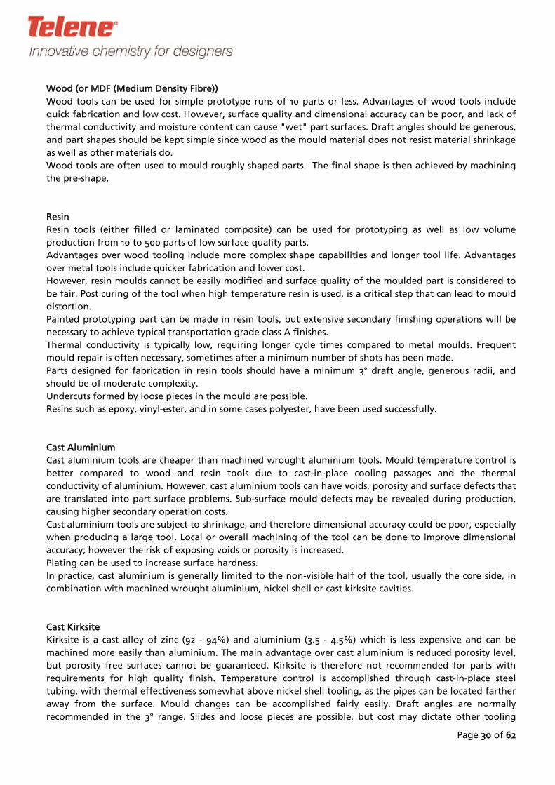
Flash Design...................................................................................................................... 37
Vents .................................................................................................................................39
Moulded Openings...........................................................................................................40
Handling Devices .............................................................................................................. 41
Page 5 of 62
Demoulding Behaviour .................................................................................................... 41
Drag Plate/Stripper Plate Operating Concept..............................................................42
Air Ejection....................................................................................................................44
3.3 Mould Gate Design for TELENE Resins (1600 Series) ................................................46
Gate ..................................................................................................................................46
Flow Restrictor..................................................................................................................47
Runner ..............................................................................................................................49
Gate Location ...................................................................................................................49
Rod Gate Calculation ....................................................................................................50
Coat-Hanger Gate Calculation .....................................................................................52
3.4 Multiple Cavity Mould Design ..................................................................................54
A List of Suppliers.................................................................................................................... 57
1. Cleaning products before painting .............................................................................. 57
2. Paint Systems................................................................................................................. 57
Water Based Paint system ................................................................................................ 57
3. Adhesive System ........................................................................................................... 57
Fillers & Repairing Accessories......................................................................................584.
5. Mould Polish .................................................................................................................58
6. Mould Release Agent ...................................................................................................58
7. Mould Makers EMEA ....................................................................................................58
8. Mould Makers North America..................................................................................... 60
9. Inserts ............................................................................................................................62
10. DCPD Vapour Adsorption .........................................................................................62
REFERENCES.............................................................................................................................62
Page 6 of 62
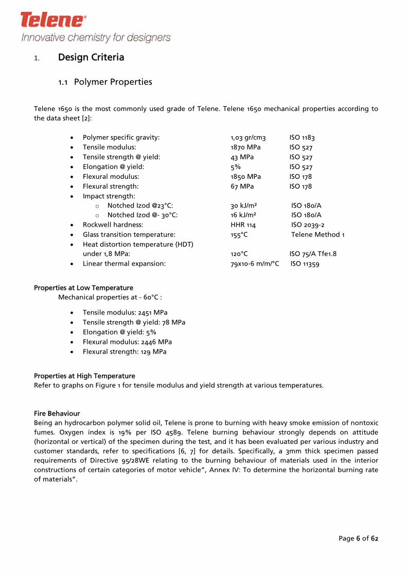
Design Criteria1.
1.1 Polymer Properties
Telene 1650 is the most commonly used grade of Telene. Telene 1650 mechanical properties according to
the data sheet [2]:
Polymer specific gravity: 1,03 gr/cm3 ISO 1183
Tensile modulus: 1870 MPa ISO 527
Tensile strength @ yield: 43 MPa ISO 527
Elongation @ yield: 5% ISO 527
Flexural modulus: 1850 MPa ISO 178
Flexural strength: 67 MPa ISO 178
Impact strength:
o
o
Rockwell hardness:
Notched Izod @23°C: 30 kJ/m² ISO 180/A
Notched Izod @- 30°C: 16 kJ/m² ISO 180/A
HHR 114 ISO 2039-2
Glass transition temperature: 155°C Telene Method 1
Heat distortion temperature (HDT)
under 1,8 MPa: 120°C ISO 75/A Tfe1.8
Linear thermal expansion: 79x10-6 m/m/°C ISO 11359
Properties at Low Temperature
Mechanical properties at - 60°C :
Tensile modulus: 2451 MPa
Tensile strength @ yield: 78 MPa
Elongation @ yield: 5%
Flexural modulus: 2446 MPa
Flexural strength: 129 MPa
Properties at High Temperature
Refer to graphs on Figure 1 for tensile modulus and yield strength at various temperatures.
Fire Behaviour
Being an hydrocarbon polymer solid oil, Telene is prone to burning with heavy smoke emission of nontoxic
fumes. Oxygen index is 19% per ISO 4589. Telene burning behaviour strongly depends on attitude
(horizontal or vertical) of the specimen during the test, and it has been evaluated per various industry and
customer standards, refer to specifications [6, 7] for details. Specifically, a 3mm thick specimen passed
requirements of Directive 95/28WE relating to the burning behaviour of materials used in the interior
constructions of certain categories of motor vehicle”, Annex IV: To determine the horizontal burning rate
of materials”.

Page 7 of 62
Aging
Aging of Telene originates in oxidation. When oxygen diffuses in the polymer, it reacts with the remaining
double bonds to create oxidized groups, especially when activated by heat and UV. The phenomenon is
limited by the oxygen diffusion in the polymer. Below the glass transition temperature, the degree of
diffusion reaches a plateau and stabilizes. A layer of paint limits the rate of oxidation and protects the
polymer from the UV.
Aging results in changes of the properties such as decreased :
elongation at break : 4% (from initial 25-30%)
impact resistance : 20 kJ/m² that is 65% of the initial value,
and increased :
tensile and flexural Modulus + 10 %
tensile and flexural Stress at Yield + 10 %
HDT: +10 °C
Refer to [5] for more information.
Figure 1

Page 8 of 62
Creep behaviour
Creep is the tendency of a solid material to move slowly or deform permanently under the influence of
mechanical stresses. It can occur as a result of long-term exposure to high levels of stress that are still below
the yield strength of the material. Unlike brittle fracture, creep deformation does not occur suddenly upon
the application of stress. Instead, strain accumulates as a result of long-term stress. Therefore, creep is a
"time-dependent" deformation.
Creep, as a material property, is normally expressed as percentage of elongation under constant stress level
as a time function. It depends on temperature and initial level of stress. Some graphs outlining creep
behaviour of Telene are shown at Figure 2 and Figure 3.
TELENE 1650 Tensile creep @ RT
Figure 2
TELENE 1650 Tensile creep @ 60°C
Figure 3
Page 9 of 62
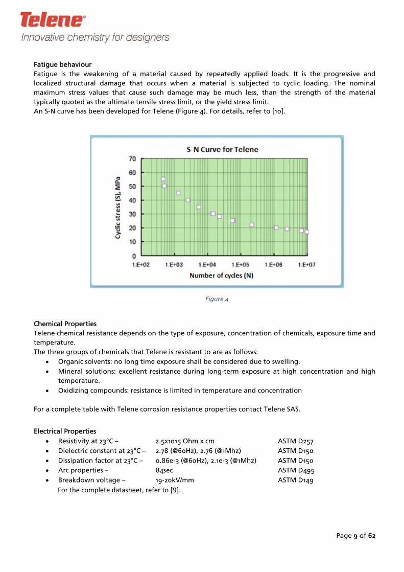
Fatigue behaviour
Fatigue is the weakening of a material caused by repeatedly applied loads. It is the progressive and
localized structural damage that occurs when a material is subjected to cyclic loading. The nominal
maximum stress values that cause such damage may be much less, than the strength of the material
typically quoted as the ultimate tensile stress limit, or the yield stress limit.
An S-N curve has been developed for Telene (Figure 4). For details, refer to [10].
Figure 4
Chemical Properties
Telene chemical resistance depends on the type of exposure, concentration of chemicals, exposure time and
temperature.
The three groups of chemicals that Telene is resistant to are as follows:
Organic solvents: no long time exposure shall be considered due to swelling.
Mineral solutions: excellent resistance during long-term exposure at high concentration and high
temperature.
Oxidizing compounds: resistance is limited in temperature and concentration
For a complete table with Telene corrosion resistance properties contact Telene SAS.
Electrical Properties
Resistivity at 23°C – 2.5x10¹⁵ Ohm x cm ASTM D257
Dielectric constant at 23°C – 2.78 (@60Hz), 2.76 (@1Mhz) ASTM D150
Dissipation factor at 23°C – 0.86e-3 (@60Hz), 2.1e-3 (@1Mhz) ASTM D150
Arc properties – 84sec ASTM D495
Breakdown voltage – 19-20kV/mm ASTM D149
For the com plete datasheet, refer to [9].
Page 10 of 62
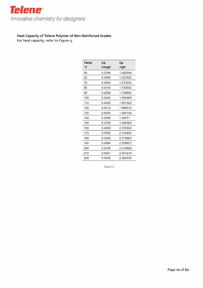
Heat Capacity of Telene Polymer of Non-Reinforced Grades
For heat capacity, refer to Figure 5.
Figure 5

Page 11 of 62
1.2 Design Criteria
Prior to designing, application requirements should be collected to evaluate all constrains applicable to the
part throughout its life cycle, i.e. applied not only during service life, but also during transportation,
storage, installation and at the end of part’s life. Special attention must be paid to cases when Telene
replaces other materials, e.g. steel, when, as practice shows, requirements can be easily missed.
Part’s specifications may include, but is not limited to:
-
-
a definition whether the part belongs to the primary or secondary (“cosmetic”) structures;
a description of the way the part joints or interferes with other surrounding components or
structures;
-
-
loads acting upon the part;
other operating conditions like, for instance, temperature and environment exposure.
1.3 Finite Element Analysis (FEA)
Finite element analysis is an engineering calculation method that allows a design engineer to simulate
Behaviour of the part under well-defined loading conditions. The quality of simulation is highly dependent
on the quality of finite element mesh, adequacy of constraints and loads applied to the model of the part,
as well as on the input data needed to perform the analysis. Numerical results of an FEA analysis are post-
processed to visualize, for instance, stress distribution, and displacements at each point of the part, thus
allowing the design engineer to check the deformed mode of the part versus material properties and/or
boundary and loading conditions. In most of the cases, Telene part deformation is large enough to require
a non-linear analysis.
Glossary :
o Model: a mesh model is created from the CAD model. Different types of finite elements can
be chosen: 2D (with 3, 4 or more nodes) or 3D (4, 6, 8 or more nodes). Usually, especially at
early design stages, small geometrical features, such as fillets, can be omitted while
generating a FE-model of the part. They can be implemented at later stages as appropriate.
o Material properties: materials are modelled by some values as Young modulus, Poisson
ratio, and more (for plasticity, creep, etc...). They can depend on temperature.
o Boundary conditions: constraints need to be defined at each location where the part
contacts its supporting structures and/or surrounding components. In other words, one has
to take away appropriate degrees of freedom from appropriate points of the model.
Contact conditions are available.
o
o
Operating conditions: Usually limited to temperature conditions.
Load cases: combinations of the loads, boundary conditions and operating conditions
applied to the model.
o Types of loads: they can be, for instance, static or dynamic (vibration, rotating forces, etc...),
local or distributed forces (per unit length, unit surface, pressure, volumic load like
acceleration, temperature map and others). They need to be defined accordingly.
Page 12 of 62
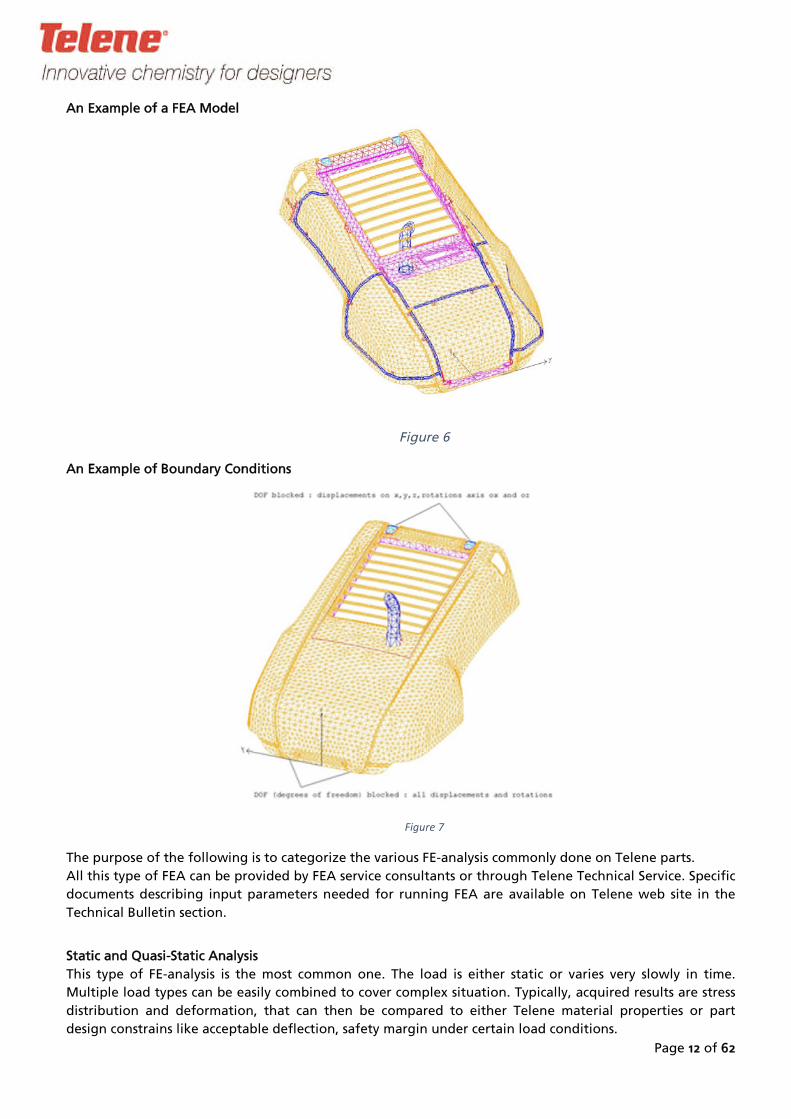
An Example of a FEA Model
Figure 6
An Example of Boundary Conditions
Figure 7
The purpose of the following is to categorize the various FE-analysis commonly done on Telene parts.
All this type of FEA can be provided by FEA service consultants or through Telene Technical Service. Specific
documents describing input parameters needed for running FEA are available on Telene web site in the
Technical Bulletin section.
Static and Quasi-Static Analysis
This type of FE-analysis is the most common one. The load is either static or varies very slowly in time.
Multiple load types can be easily combined to cover complex situation. Typically, acquired results are stress
distribution and deformation, that can then be compared to either Telene material properties or part
design constrains like acceptable deflection, safety margin under certain load conditions.

Page 13 of 62
As with all polymers, Telene is prone to creep; this is taken into account through the design allowable:
o
o
Creep situation: 10 % of the yield stress
Temporary or intermittent load : less than 4% elongation
Example of An a Static Case
Figure 8
Modal Analysis
Modal analysis is a key type of analysis for body panels. The results of such analysis are eigen mode shapes
and frequencies of the part during free vibration for certain boundary conditions. Modal analysis is an
easier and faster FEA to perform than any other types of FEA, and it is often a good start to design/analyse
the part.
Often, only the lowest frequency mode is considered that then can be compared to the part design
specification, e.g. “No eigen frequency below 15 Hz”. Deformed and undeformed shapes are shown
overlaid below.
Figure 9
Page 14 of 62
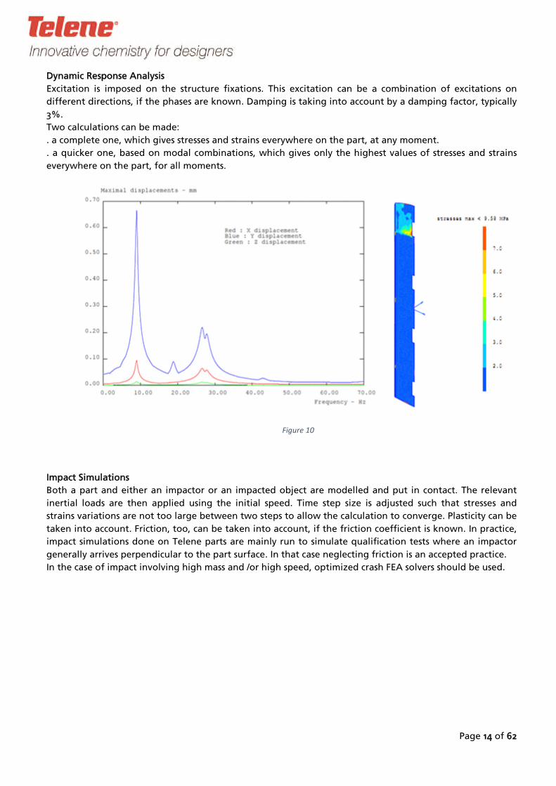
Dynamic Response Analysis
Excitation is imposed on the structure fixations. This excitation can be a combination of excitations on
different directions, if the phases are known. Damping is taking into account by a damping factor, typically
3%.
Two calculations can be made:
. a complete one, which gives stresses and strains everywhere on the part, at any moment.
. a quicker one, based on modal combinations, which gives only the highest values of stresses and strains
everywhere on the part, for all moments.
Figure 10
Impact Simulations
Both a part and either an impactor or an impacted object are modelled and put in contact. The relevant
inertial loads are then applied using the initial speed. Time step size is adjusted such that stresses and
strains variations are not too large between two steps to allow the calculation to converge. Plasticity can be
taken into account. Friction, too, can be taken into account, if the friction coefficient is known. In practice,
impact simulations done on Telene parts are mainly run to simulate qualification tests where an impactor
generally arrives perpendicular to the part surface. In that case neglecting friction is an accepted practice.
In the case of impact involving high mass and /or high speed, optimized crash FEA solvers should be used.

Page 15 of 62
Figure 11
Thermal Analysis
Thermo-mechanical and thermal analysis
It is possible to simulate deformations due to temperature along to mechanically induced deformation.
The temperature distribution can be heterogeneous throughout the part and given as a temperature map
resulting from an experience or calculated as a result of conductive, convective or radiative processes.
1.4 Thermal Deformation
Thermal expansion is an intrinsic property of all materials. Typically, for non-reinforced grades of Telene
coefficient of linear thermal expansion (CLTE) is about 80-6 m/m/°C, and much less for reinforced grades. As
an example, for a 1m long part, which is a typical dimension for a vehicle body panel, it results in a 8mm
elongation/contraction within a 100°C temperature range, e.g. -40…+60°C. Therefore, fastening such a part
to the structure needs to have some play.
Deformation due to thermal expansion can be handled. One of the most efficient methods is to design the
part, in purpose, slightly curved, so that the thermal deformation is absorbed by a change of radius.
In the case of flat parts, S-like distortion may happen and make the deformation highly noticeable.
If a flat part design is not avoidable, it is recommended to fix the part at its centre, and arrange movable
supports on its sides (slots, flexible fixations, and so on).
A CLTE calculation sheet is available on request to Telene Technical service.

Page 16 of 62
2. Part Design
2.1 Part design
Parts manufactured from Telene have no theoretical size limit. While Telene 1650 has been designed for
parts weighing up to 25-30kg, assuming a 100kg/min RIM-equipment, special grades of lower reactivity can
be supplied. In combination with a more powerful RIM-unit, this significantly widens the range of part
sizes. Parts weighing a few hundred kilos are routinely produced.
Visible Surface Considerations
The designer should understand some specifics of the DCPD RIM-process affecting quality of the part
surfaces. It should be kept in mind that the higher quality surface is obtained on the hotter part of the
mould. For parts similar to body panels, one usually considers an outer visible surface (A-surface) and an
inner/back surface (B-surface) of the part, with higher surface quality requirements to the outer side. As a
rule, this is the cavity side of the mould. The surface formed by the core of the tool would be of lower
quality.
Thickness
Minimum recommended thickness for Telene part is 3mm. The value is based on the temperature peak
during polymerization and aging of Telene. Polymerization of Telene releases heat that allows the polymer
to fully convert and to reach its ultimate properties. Thickness below 3mm results in a significant
percentage of heat being lost into the mould therefore reducing conversion and affecting physical
properties. Also, reducing Telene thickness increases the relative percentage of polymer that is affected by
surface oxidation.
Wall thickness variation for the same part can be rather wide, but should be designed with care to avoid
visible shrink marks (see Polymerization Shrinkage).
Polymerization Shrinkage
Polymerization shrinkage is a physical phenomenon determined by arrangement of molecular chains.
Linear shrinkage depends on the relative speed of polymerization in the various directions mainly
determined by the mass of reacting material and the temperature profile of the tool.
Shrinkage should be taken into account early in the part design stage to prevent:
- shrink marks on A-side of the part due to abrupt thickness changes or similar geometric
features of the part;
- distortion due to overall part geometry, and inappropriate thickness distribution.
Approximately 1% linear mould shrinkage can be expected both parallel and perpendicular to the flow
direction. The bulk of the volume change goes through the thickness, i.e. perpendicular to the surface
direction.
In addition to the polymerization shrinkage, thermal shrinkage linked to the operating temperature of the
tool should be taken into account. Refer to the “Mould Design” section for practical shrinkage values.
A rapid increase or decrease in part thickness may cause a local shrinkage effect. This would be visible and
might adversely affect the aesthetics of the part. Some examples of such rapid changes of thickness are
reinforcement ribs on the back of a panel, bosses for inserts and sharp angles instead of gradual
increase/reduction of thickness of a curved part.
To minimize the effect of shrink marks the designer should follow principles illustrated in Figure 12:
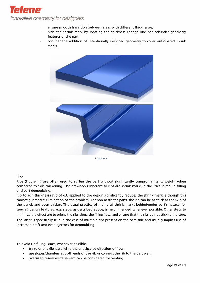
-
-
ensure smooth transition between areas with different thicknesses;
hide the shrink mark by locating the thickness change line behind/under geometry
features of the part;
- consider the addition of intentionally designed geometry to cover anticipated shrink
marks.
Ribs
Ribs (Figure 13) are often used to stiffen the p
compared to skin thickening. The drawbacks inhe
and part demoulding.
Rib to skin thickness ratio of 0.6 applied to the d
cannot guarantee elimination of the problem. Fo
the panel, and even thicker. The usual practice o
special) design features, e.g. steps, as described a
m inim ize the effect are to orient the ribs along the
T he latter is specifically true in the case of multip
increased draft and even ejectors for demoulding.
To avoid rib filling issues, whenever possible,
try to orient ribs parallel to the anticipated
use slopes/chamfers at both ends of the rib
oversized reservoirs/false vent can be cons
Page 17 of 62
art without significantly compromising its weight when
rent to ribs are shrink marks, difficulties in mould filling
esign significantly reduces the shrink mark, although this
r non-aesthetic parts, the rib can be as thick as the skin of
f hiding of shrink marks behind/under part’s natural (or
bove, is recommended whenever possible. O ther steps to
filling flow , and ensure that the ribs do not stick to the core.
le ribs present on the core side and usually implies use of
direction of flow;
or connect the rib to the part wall;
idered for venting.
Figure 12

Bosses
Bosses are typically used to provide fixation p
bosses as well. To improve venting, top ventin
Figure 15 respectively.
Page 18 of 62
oints. The previous suggestions on designing ribs apply to
g rings gussets and can be used as shown on Figure 14 and
Figure 14
Figure 15
Figure 13
Page 19 of 62
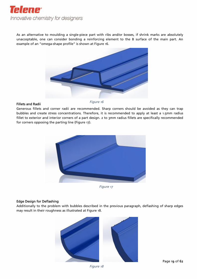
As an alternative to moulding a single-piece part with ribs and/or bosses, if shrink marks are absolutely
unacceptable, one can consider bonding a reinforcing element to the B surface of the main part. An
example of an “omega-shape profile” is shown at Figure 16.
Fillets and Radii
Generous fillets and corner radii are recommended. Sharp corners should be avoided as they can trap
bubbles and create stress concentrations. Therefore, it is recommended to apply at least a 1.5mm radius
fillet to exterior and interior corners of a part design. 2 to 3mm radius fillets are specifically recommended
for corners opposing the parting line (Figure 17).
Edge Design for Deflashing
Additionally to the problem with bubbles described in the previous paragraph, deflashing of sharp edges
may result in their roughness as illustrated at Figure 18.
Figure 16
Figure 17
Figure
18
To prevent rough edges, it is recommended to maintain regular thickness of the part as shown at Figure 19.
Page 20 of 62
Figure 19

Draft
Draft primarily serves to facilitate part demoulding and to prevent part surface damage/marring by the
mould. In usual process conditions (mould run with hotter cavity side than core side), the temperature
differential tends to maintain the part on the cavity side. A minimum draft angle of 3° is recommended on
the cavity side of the mould (Figure 21), and 1.5° on the core side (Figure
Figure 20
Figure 21
20).
Due to shrinkage of the part, outer walls of the part may have no draft on the cavity side.
In the case of deep pockets or recesses located on the cavity side, shrinkage will have tendency to lock the
part on the cavity. Therefore, one has to consider increasing the draft angle on cavity to 7° or more in order
to facilitate the demoulding. Alternatively, ejectors can be implemented to facilitate demoulding.
Several typical shrinkage cases, assuming a cold core and hot cavity, are as follows.
1. Shrinkage helps demoulding. A 0° draft is acceptable (Figure 22)
Figure 22
Page 21 of 62

2. Shrinkage works against demoulding (Figure 23). A 3° draft is acceptable, if the recess is -
a. less than 30mm deep, or
b. open on two sides, or
c. large enough to be flexible.
3. Comments on case #2 are also valid for case #3 (Figure 24). Shrinkage in this example is
worse when the distance between the two recesses is increased.
Undercuts
Undercuts naturally cause a problem during the demo
blocks within the mould. Refer to section “Mould Des
Moulded Openings
Moulded openings can be incorporated into the desig
the area of the opening feature must be considered, r
Mechanical Fastening of a Telene Part
The most common way of assembling/mounting a Te
tapping screws are covered in this section of the guid
require anti-creep washers or spacers. Other types of
25), are outside the scope of this guide, as they usually
Figure 23
Page 22 of 62
ulding stage. The standard solution assumes movable
ign”.
n of a Telene part. Appropriate venting of the part in
efer to section “Mould Design” for details.
lene part is via mechanical fasteners. Inserts and self-
e. Holes and slots used to assemble a Telene part may
fastening, for example clips and cage nuts (see Figure
do not require any special design.
Figure 24

Page 23 of 62
Figure 25
A part can be designed with integral fasteners. Depending on aesthetic requirements, and potential
moulding constraints (usually undercuts or die lock), fasteners may also be located on omega
reinforcements or smaller individual blocks that are bonded in place during finishing operations.
The most commonly used type of mechanical fasteners are overmoulded or post-fixed inserts providing
reusable threaded connections, as well as screws described below.
Overmoulded Inserts
As a rule, encapsulated inserts are used when high torque resistance is required. They are positioned in the
open mould, and are then mechanically locked in place during the polymer curing stage. A minimum
thickness of 5 mm of Telene should be provided around the insert to avoid high stress in the polymer.
Inserts are usually made of steel, and can be plated for corrosion protection purposes. Inserts that have
shown good functionality include those with peripheral knurling or other interlocking means, as well as
some kind of direct pull-out protection such as a shoulder, step, enlarged head-like area, etc. Typical
designs are shown on Figure 27 and Figure 28.
Use of inserts in a mould requires proper mould design and process procedures to avoid mould damage.
There are several ways to secure inserts into the tool. As the inserts are most often located on the upper
half of the mould (in process position), a combination of metal pin and magnet is widely used. Plastic insert
holders are also very common (see Figure 26). When the insert axis cannot be orientated in the demoulding
direction, use of intermediate mould components or movable pins are required.
Figure 26
Overmoulded inserts should be carefully located to minimize shrink marks on the cosmetic surface of the
part. Directly opposite from design lines and features, or part edges are preferred locations for
encapsulated inserts. For class A surface applications and designs, additional Telene pieces that include all
the inserts are normally bonded on the B side of the class A skin to prevent any read-through on the
cosmetic surface.
Pull-out strength and torque resistance of several insert designs are summarized in

Page 24 of 62
. These values have been obtained with 5 to 6 mm of Telene surrounding the insert. Table 1
Figure 27
Figure 28

Page 25 of 62
Table 1
Insert Type Telene Thickness,
mm
Pullout Strength,
N
Torque Resistance, N-
m
M5 B/R 5 2370 -
M6 B/P 6 3750 15
M8 B/R 5.5 4040 25
M8 B/P 5 4290 25
M10 5 14780 70
M12 5.5 19690 130
Post-Mould Installed Inserts
Unlike overmoulded inserts, this type of fastener is installed during finishing operations after the part is
demoulded, thus decreasing the moulding cycle time, and eliminating potential tool damage due to poor
insert handling. They are often used when medium pull-out and torque resistance are required. The inserts
are either screwed or forced in place in a prepared location, with the choice between the two methods
depending on the pull out requirements.
Refer to supplier’s Technical literature for performance of inserts and recommended dimensions of
installation bore.
Figure 29 and Figure 30 show some post-moulding fixed inserts examples (courtesy Tappex Thread Inserts
Ltd and EJOT GmbH & Co. KG).
Figure 29
Figure 30
Page 26 of 62
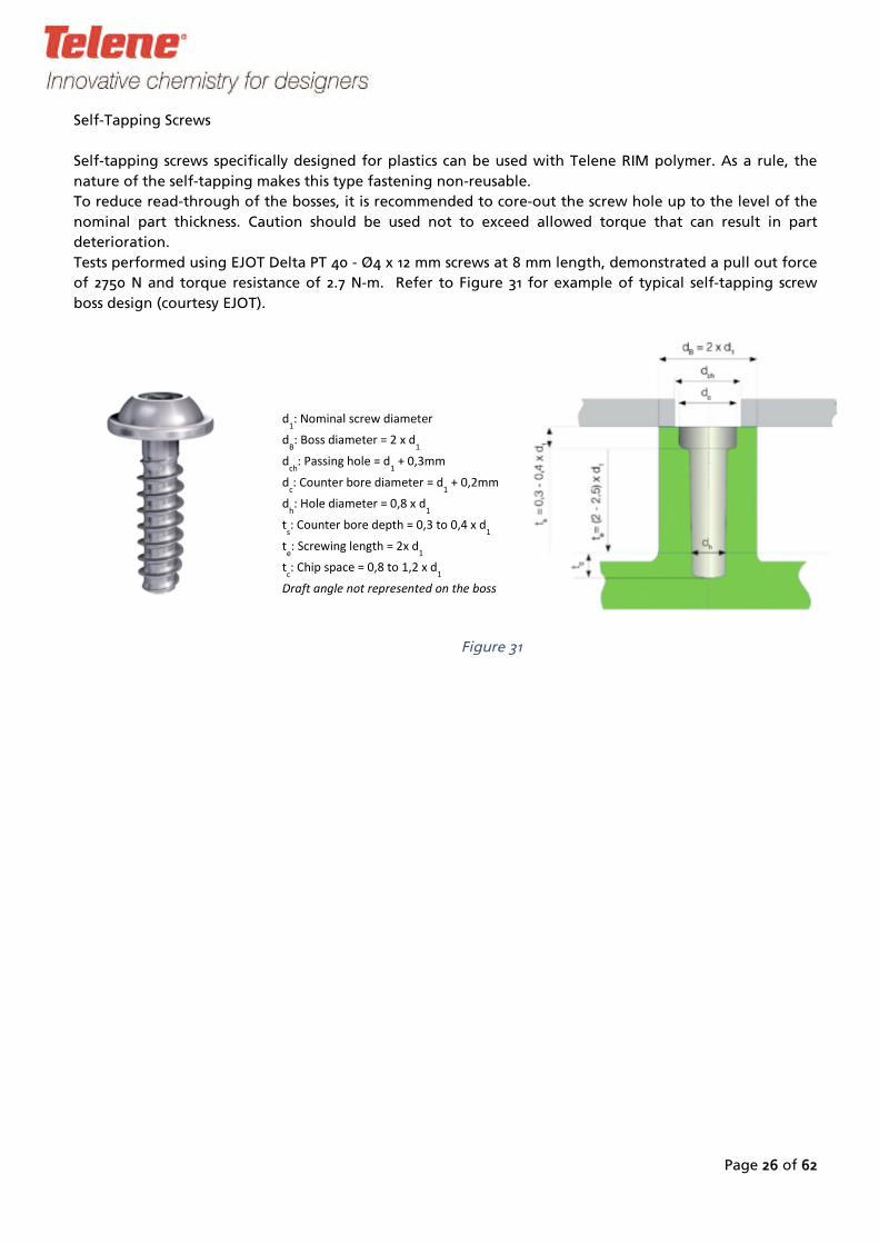
Self-Tapping Screws
Self-tapping screws specifically designed for plastics can be used with Telene RIM polymer. As a rule, the
nature of the self-tapping makes this type fastening non-reusable.
To reduce read-through of the bosses, it is recommended to core-out the screw hole up to the level of the
nominal part thickness. Caution should be used not to exceed allowed torque that can result in part
deterioration.
Tests performed using EJOT Delta PT 40 - Ø4 x 12 mm screws at 8 mm length, demonstrated a pull out force
of 2750 N and torque resistance of 2.7 N-m. Refer to Figure 31 for example of typical self-tapping screw
boss design (courtesy EJOT).
d1: N om inal screw diam eter
dB: Boss diam eter = 2 x d
1
dch
: P assing hole = d1
+ 0,3m m
dc: Counterbore diam eter = d
1+ 0,2m m
dh: Hole diam eter = 0,8 x d
1
ts: Counterbore depth = 0,3 to 0,4 x d
1
te: S crew ing length = 2x d
1
tc: Chip space = 0,8 to 1,2 x d
1
Draft angle not represented on the boss
31Figure

Page 27 of 62
2.2 Tolerance on Moulded Part Dimensions
As a general rule, use +/-0.2% tolerance for linear dimensions. This results in better tolerance than
prescribed by commonly accepted standards for plastic parts, e.g. DIN 16901. For quality assurance purposes,
the dimensions should not be measured before 48H after moulding. Wrong selection of the mould
shrinkage coefficient may adversely affect the dimensions, resulting in out-of-tolerance parts (refer to
“Mould Design” section). For a part of variable thickness, selection of the mould shrinkage coefficient is
always a compromise between different options. RIM process parameters may also affect the dimensions up
to a certain degree.
2.3 Bonded Structures
Telene parts can be easily bonded with many adhesives. Both substrate to substrate bonds and metal to
substrate bonds are routinely performed. Acrylic, epoxy, urethane, methacrylate and silyl modified polymer
(MS polymer) based adhesives are commonly used.
Due to relatively low modulus and yield/ultimate stress values, plastics generally require a generous bond
line area to withstand loads. Bond lines should be designed to minimize peel type loads. This is usually
accomplished by providing an extended area on one of the bonded members typically in the range of 20 to
25 mm. Bond line stand-offs can be moulded in to the respective members insuring proper bond line
thickness without additional parts or spacers. Spacer height depends on the type of adhesive used, and is
usually between 0.5 to 3 mm. It is recommended to avoid continuous stand-offs to allow adhesive excess
outflow.
Metal to plastic bonding is best accomplished with a high elongation adhesive that can accommodate the
differential in coefficients of thermal expansion. The larger/longer the bonded areas, the greater the
possibility that some bond line failure may result from this difference. Thicker bonded joints will help
accommodate thermal induced stress. This is especially critical for plastic to metal bonds made prior to
painting (paint line thermal cycling). Bonded structures creating a closed volume should not be allowed as
the thermal expansion of the enclosed air volume creates surface distortion or induces unnecessary stress in
the bonded area.
Common Telene bonded structures typically include a relatively thin Telene skin, and one or more bonded
“top-hat” (also called omega shape) reinforcements. If the reinforcement is located on a large flat surface
some bond line area read-through may be seen. This visible line can be greatly reduced by appropriate
bonding line design, adhesive selection, and accurate bonding fixtures.
Protecting bond lines from peel forces is recommended for all bonded structures. A thorough knowledge
of loads on the part, as well as the properties of the adhesive materials and substrates is necessary. It is
recommended to perform a finite element analysis of bonded structures to insure proper bond line
orientation, stresses, dimensions and locations. Prototyping of production parts is often used for validation.
Adhesives
Various substrates can be bonded to Telene. The most common are metals and other Telene parts. Surface
preparation is extremely important in obtaining consistent results.
Polyurethane and epoxy adhesives work well on Telene along with methacrylate systems. Silyl modified
polymer based products offer a flexible isocyanate free system.
Recent developments with methacrylate systems have resulted in materials giving very strong adhesion to
Telene without the need to sand the bonded surface. This provides a significant cost reduction for finishing
operations.
Page 28 of 62
Selection of an adhesive depends on multiple properties that are linked to part requirements, design
criteria (possible joint design) and acceptance by the part manufacturer. Criteria such as required strength,
temperature resistance, thermal expansion in service, substrate to be bonded, surface preparation,
handling, and curing time are key factors to consider when selecting an adhesive. Evaluation and testing
should be performed with all substrates to determine bond strength, and should be carried out according
to the adhesive manufacturer mixing and application instructions. Adhesive failure can be either adhesive
or cohesive. Type of failure and failure level will guide adhesive selection.
Refer to Telene Process Book for processing details [1].
2.4 Overmoulded Polymer Inserts
The only two polymer families that Telene has adhesion to are polyethylene and polypropylene, as well as
some co-polymer derivatives. The level of adhesion depends mainly on the thermal properties of the chosen
polymer in relation to the heat generated during polymerization. As an indication, a 5 mm Telene thickness
has been found sufficient to give adhesion to most of the PE or PP based inserts. For more detailed
recommendations it is recommended to contact Telene Technical Department.
2.5 TELENE Part Identification
According to ISO 11649 – “Plastics - Generic identification and marking of plastics products” – and ISO/DIS
1043-1.2 – “Plastics - Symbols Part 1 : Basis polymers and their special characteristics” - Telene parts shall be
marked as follows:
> P DCP D <
Where applicable, refer to local standards for part identification.

Page 29 of 62
3. Mould
3.1
Design
Part Size / Clamping Force
The size of the part naturally drives the size of the mould, and therefore the size of the platens and
daylight of the press holding the mould. The press should develop a clamping force greater than the one
needed to keep the mould just closed during filling or polymerization, whichever develops higher pressure
in the mould. This pressure depends a lot on the operating conditions and choice of formulation reactivity,
allowing to use relatively low closing force per press platen surface unit for press design, typically in the
range of 1.5 to 2 kg/cm².
3.2 Mould
When designing a Telene RIM mould, the following parameters that affect part quality and mould cost
Design for Telene 1600 Series
should be taken into account:
-
-
Mould material selection
Parting line / Gasket
Gate location-
- Venting
Flash design-
Other parameters that will affect the processing performance of the tool are as follows:
-
-
Heating / cooling lines design
Guide pins
- Handling devices
This section will cover most of these key points, including mould shrinkage. Refer to section “Mould Gate
Design” for additional information on gate design and location.
Mould Material Selection
There are many factors to be considered when selecting tooling material, and among them are such criteria
as the required part surface quality, production volume, part size, mould cost and ability to change or
repair tools.
This section provides only generalized rules. Tooling material selection and tool design must be evaluated
on a part-by-part basis.
Metal spray is not listed below, as this technology cannot be used with Telene resins. The metal grains
resulting from the spraying process can be easily removed from the metal spray skin. This will create small
undercuts, making part demoulding more and more difficult and leading to the metal spray skin
destruction.
Commonly used materials for serial production are wrought aluminium alloys, cast aluminium alloys, and
nickel shell.
Page 30 of 62
Wood (or MDF (Medium Density Fibre))
Wood tools can be used for simple prototype runs of 10 parts or less. Advantages of wood tools include
quick fabrication and low cost. However, surface quality and dimensional accuracy can be poor, and lack of
thermal conductivity and moisture content can cause "wet" part surfaces. Draft angles should be generous,
and part shapes should be kept simple since wood as the mould material does not resist material shrinkage
as well as other materials do.
Wood tools are often used to mould roughly shaped parts. The final shape is then achieved by machining
the pre-shape.
Resin
Resin tools (either filled or laminated composite) can be used for prototyping as well as low volume
production from 10 to 500 parts of low surface quality parts.
Advantages over wood tooling include more complex shape capabilities and longer tool life. Advantages
over metal tools include quicker fabrication and lower cost.
However, resin moulds cannot be easily modified and surface quality of the moulded part is considered to
be fair. Post curing of the tool when high temperature resin is used, is a critical step that can lead to mould
distortion.
Painted prototyping part can be made in resin tools, but extensive secondary finishing operations will be
necessary to achieve typical transportation grade class A finishes.
Thermal conductivity is typically low, requiring longer cycle times compared to metal moulds. Frequent
mould repair is often necessary, sometimes after a minimum number of shots has been made.
Parts designed for fabrication in resin tools should have a minimum 3° draft angle, generous radii, and
should be of moderate complexity.
Undercuts formed by loose pieces in the mould are possible.
Resins such as epoxy, vinyl-ester, and in some cases polyester, have been used successfully.
Cast Aluminium
Cast aluminium tools are cheaper than machined wrought aluminium tools. Mould temperature control is
better compared to wood and resin tools due to cast-in-place cooling passages and the thermal
conductivity of aluminium. However, cast aluminium tools can have voids, porosity and surface defects that
are translated into part surface problems. Sub-surface mould defects may be revealed during production,
causing higher secondary operation costs.
Cast aluminium tools are subject to shrinkage, and therefore dimensional accuracy could be poor, especially
when producing a large tool. Local or overall machining of the tool can be done to improve dimensional
accuracy; however the risk of exposing voids or porosity is increased.
Plating can be used to increase surface hardness.
In practice, cast aluminium is generally limited to the non-visible half of the tool, usually the core side, in
combination with machined wrought aluminium, nickel shell or cast kirksite cavities.
Cast Kirksite
Kirksite is a cast alloy of zinc (92 - 94%) and aluminium (3.5 - 4.5%) which is less expensive and can be
machined more easily than aluminium. The main advantage over cast aluminium is reduced porosity level,
but porosity free surfaces cannot be guaranteed. Kirksite is therefore not recommended for parts with
requirements for high quality finish. Temperature control is accomplished through cast-in-place steel
tubing, with thermal effectiveness somewhat above nickel shell tooling, as the pipes can be located farther
away from the surface. Mould changes can be accomplished fairly easily. Draft angles are normally
recommended in the 3° range. Slides and loose pieces are possible, but cost may dictate other tooling

Page 31 of 62
alternatives if tool movements become too expensive. The main drawbacks to the use of Kirksite tools are
the increased weight (specific gravity approximately 6), and easily damaged tool surface due to the softness
of the material.
Wrought Aluminium
Wrought aluminium is a widely used tooling material due to its uniform texture, ready availability, and
ease of machining. High thermal conductivity and lighter weight as compared to steel also make it a good
candidate for RIM tooling systems. Good to excellent surface quality can be obtained, and tool life of over
50,000 parts is possible. Almost any part design can be executed in wrought aluminium tooling including
complex shapes, minimum draft angles, and undercuts formed by loose pieces (part) and / or slides. Cost of
tooling is usually less than steel tooling, and can be less than nickel shell tooling for shallow parts optimally
matching the sizes of commonly available aluminium blanks for tooling material.
Some corrosion has been seen on tools made of alloys of the 2000 series containing a high level of copper,
when associated with poor tool maintenance.
Recommended alloys for tooling application are: 5083, 6061, 6082, 7075, or commercial trade names such
as Duramould-2, Duramould-5, Alumould, and M1.
Plating can be used to harden aluminium surface and increase chemical resistance. It is important to select a
plating treatment that does not deteriorate the thermal conductivity of the tool, as the anodizing process
does.
Nickel Shell
Nickel shell tooling is often a cost effective alternative tool for large or deep Class A parts. A master model
is prepared via electronic data or by traditional pattern making means. Material and mould shrinkage is
added during the model fabrication process. A metallic nickel layer is deposited on the model by electro
deposition or vacuum deposition. Typical thickness of the nickel layer ranges from 4 to 10 mm, depending
on the technology used. Soft models used in the electro deposition process are typically destroyed during
removal from the nickel shell. More expensive aluminium models used in the vacuum deposition process
can be re-used to generate a new nickel shell later on, if needed. The nickel shell is usually backed with
metal filled epoxy, or concrete depending on expected tool life, cost constraints, and tool manufacturer’s
preference.
Mould temperature control is usually accomplished by copper tubing fixed or welded on the skin and
embedded in the backing matrix of the tool. The temperature control is better than for epoxy tools, and
can be as good as for all-metal tools with proper design and planning.
Surface finish can be exceptional. Class A parts are paintable with little or no secondary finishing on the
nickel shell moulded surface. The core side of the tool (the part of the tool forming the rear, backside or B
side of the part) is usually made of cast aluminium to decrease the cost. Most draft angles can be
accommodated, but manufacturers typically request approximately 3° of draft. Sharp edges or small radii
are usually not recommended.
Undercuts are possible, but are not normally recommended. The cost of numerous inserts and/or slides may
negate the cost advantages of this tooling material.
The inability to easily make changes or repairs is the major disadvantage. Therefore, if prototyping is
required, less expensive tools are recommended. A combination of production nickel shell matrix and epoxy
prototype core can be used, saving some of the total program costs.
This technology is less expensive than steel tooling, and depending on the starting point (CAD data,
existing master, or engineering drawings ) can be less expensive than aluminium tooling especially for
deeper class A or painted parts.

of
requirement to match the surrounding components. Usually, the operating temperature of the tool is
Page 32 62
Steel
Machined steel moulds are usually a higher initial cost alternative than aluminium tooling due to longer
machining times caused by the inherent hardness of steel. Steel also has lower thermal conductivity than
aluminium, is considerably heavier, and more difficult to process.
These disadvantages are offset by durability of a steel mould and its surface finish over long production
runs. An ability to incorporate slides and moving cores is one of the major advantages of this mould
material.
Therefore, steel can be selected when parts are complex, requiring several cores, moving cores or when
very high production volumes are involved.
As they are subject to corrosive attack, steel tools should be plated with chrome or nickel, as the most
common options.
Mould Material Comparison
Table 2
Materials Projected
Tool Life
(No. of
Parts)
Part
Surface
Quality
Mould
Surface
Hardness
(*)
Heat
Thermal
Conduct.
W/(m. °C )
Comments
Wood <10 Poor 75-100 RM 0,11 Concept evaluation
Resin <500 Fair 80-110 RM 0,09 Prototyping, short
production runs
Cast
Aluminium
<10,000 OK 60-100 BN 85 to 200 Production of non-class
A parts
Wrought
Aluminium
>50,000 Good 60-90 BN 200 Series Production
capability, most
commonly used material
Nickel Shell >100,000 Excellent 90-120 BN 58 Economical in deep
draw parts. Difficult to
change or repair.
Steel >200,000 Excellent 130-160 BN 43 Very high volume, best
surface (requires
plating)
*: RM = Rockwell Hardness "M" scale; BN = Brinell Number
Shrinkage
To produce a part of certain “as designed” dimension, the appropriate tool dimensions must be somewhat
bigger to compensate for both the polymerization shrinkage and tool thermal expansion. The
polymerization shrinkage depends on the part thickness, and the tool thermal expansion depends on the
tooling material and operating temperature.
In practice, a shrinkage ratio, applied per half of the tool, takes into account both above-mentioned
phenomena. The ratio is always a compromise that considers part’s thickness variation, as well as a
Page 33 of 62
about 60°C/80°C for the core and cavity respectively, and the shrinkage ratio is usually different for the
core and for the cavity to take into account the temperature difference. As the ratio applied on the core
half is usually greater than the one used for the cavity such a tool design requires careful handling during
storage and warm-up stage. Spacers keeping the mould open may be used to eliminate the risk of tool
damage if mishandled.
An excel sheet is available upon request from Telene Technical Service. Some indicative values measured
from a plate tool made of machined aluminium alloy are presented in Table 3. For greater thickness,
shrinkage will depend more on process parameters and mould temperature control.
Table 3
Part thickness % Shrinkage, from cold part to
cold tool
3 to 4 mm 0,85 %
5 to 7 mm 0,90 %
8 to 12 mm 1,0 %
Variable thickness of the part can itself be a cause of additional deformation due to differential shrinkage
across the part.
Heating / Cooling Line Design
General quality of a Telene part depends mostly on thermal regulation that defines such temperature
related factors as Telene components reaction, shrinkage/distortion, surface quality, cycle time, demoulding
Behaviour.
Typical mould temperature is 70 °C to 80 °C on the cavity, and 55°C to 65°C on the core. The gate and
runner area should also be included in the heating / cooling system design.
Surface quality, demoulding Behaviour, and cycle time can be affected by poor temperature control of the
tool.
Different heating / cooling line designs have been successfully tested for tools of different materials and
constructions.
If the lines are located very close to the mould surface, it is always preferable to reduce the line diameter
and to increase the number of lines, in order to avoid hot spots that can be seen on the part surface. Lines
could be as close as 50 mm to each other. Best results have been obtained when connecting the water lines
through a distribution manifold that creates a parallel water flow.
For machined tools, recommended dimensions for water channels sizing and positioning are as follows:
25-50 mm from the print surface
Space between channel and print surface must be as homogenous as
possible
Channel diameter: usually around 16mm
Space between channels: 70 to 100mm
For casting tools, water pipes should be used, and are typically smaller diameter and spaced closer
together. The distance from the print surface is usually less than 25mm.

Page 34 of 62
Mould Layout
For mould layout, the design engineer needs to consider location of the mixing head and gate, flash and
gasket, vents, and centring devices.
A typical layout is shown at Figure 32 through Figure 34.
Figure 32
Figure 33

Page 35 of 62
Figure 34
Guide Pins
All moulds should have guide pins installed to ensure proper core and cavity alignment, thus preventing
any damage to the mould during closing and opening.
They need to be designed and located to minimize stresses induced by running the tool with a temperature
differential between the two halves. Therefore, it is recommended to use rectangular guides so-called
“square guide bar” or “square interlocks” that provide guiding in only one direction and locate them as
close as possible in the centre of the tool sides.
We have found that it is more convenient to have the male portion of the guide located on the upper half
of the mould.
A typical design is shown on Figure 35.
Figure 35

Page 36 of 62
Parting Line
Mould cost and part quality are very sensitive to parting line location.
Venting and demoulding as well as potential undercuts and class A surfaces are the main factors to
consider. In some cases, local limited undercuts can be demoulded by taking advantage of the Telene
polymer shrinkage characteristics. Contact Telene Technical Service for design assistance in that case.
For a flat part, the parting line will not have a serious effect on the mould cost, but for a 3D shaped part,
the parting line can impact the amount (volume) of the mould material needed. However, the primary
consideration for the choice of a parting line should be given to mouldability and quality of the part.
A typical design of the parting line for a nickel shell tool is shown at
Figure 39.
Gasket
The entire mould cavity, including the vents and mixing head, should be held within a rubber gasket. This
increases internal pressure in the tool at the end of the shot, preventing any dissolved nitrogen from
coming out of solution. Besides, the gasket prevents air aspiration around the mixing head and runner.
Selective openings in the gasket may be used to facilitate venting control.

The groove cross section area should be larger than th
The gasket groove needs to be carefully designed and located to optimize moulding operation and gasket
life.
The gasket should be located as close as possible to the gate and runner, and follow the contour (see
section ‘Flash’). It can be located on either face of , but the best location by far is on the core face
to avoid damage during demoulding. However, in some cases, part geometry or machining capability make
it impossible to locate the gasket on the core side.
dimensions. Sharp corners (either horizontal (Figure 37
be avoided as they lead to damage to the gasket, as
closing the tool.
the core and cavity. In the case of a vertical corner,
maintain sealing (see Figure 36), or move the gaske
corner. A draft minimum of 7° should be kept on gas
Compression height depends on the precision of the m
is 0.5 mm for a mould of wrought aluminium alloy, an
All types of conventional rubber gasket can be us
hardness depends on its diameter. Typical hardness is 7
40 shore A is commonly used for 8 mm diameter.
In the case of venting adjustments during moulding, a
to create a local vent. Therefore hollow gaskets are n
with Telene during the shot, if the gasket is cut out
needed to prepare the mould between shots, as well a
A typical design is shown on Figure 38. Groove cross
gasket’s, to reduce the risk of gasket damage. The
diameter rubber seal. Groove dimensions should be m
Cavity the corner
Core
No sealing in
Gasket
Figu
the tool
Page 37 of 62
at of the gasket, including tolerances on the gasket
) or vertical (Figure 36)) on the groove design should
well as to loss of sealing in case of a corner between
create at least a 5 mm radius in the parting line to
t groove further from the part to avoid the sharp
keted vertical walls to prevent gasket damage when
ould production process. Typical compression height
d is higher for casting technology.
ed depending on
0 shore A for 5 mm diameter, whereas a hardness of
mould temperature. The gasket
small piece of the gasket can be cut out or flattened
ot recommended as the hollow section will be filled
or flattened down. This will result in a longer time
s in variations of venting from one shot to another.
section must be squared and slightly larger than the
gasket groove dimensions are shown for a 5.0 mm
odified to fit with other seal diameters. The groove
Core
Sealing OK
Cavity
Minimum 5mm
Gasket
Radius
Figure 36
re 37

Page 38 of 62
flash areas and sealing surfaces are critical to successful RIM
part periphery allows a larger processing window. This flash normally serves to capture bubbles, allows
some parting line venting, and can minimize mould
ing process.
Flash is specifically required in areas where the flow ends perpendicularly to the edge of the part.
It is important to have flash thick enough to stay with the part during de
mould cleaning operations, and
Flash shall be machined on the core side in order to ease mould
utilizing a 5mm gasket is shown at Figure 38 and
cross section should be at least equal to the maximum gasket cross section (nominal section area plus
tolerance). For this reason square gasket profiles are not recommended.
Flash Design
Mould moulding. A small flash area around the
cleaning frequency. Lastly, flash helps in the
demould
moulding to avoid time-
consuming yet designed to be easily removable during trimming.
cleaning and part deflashing. A typical
design
Figure 39.
Page 39 of 62
Figure
Figure 39
38
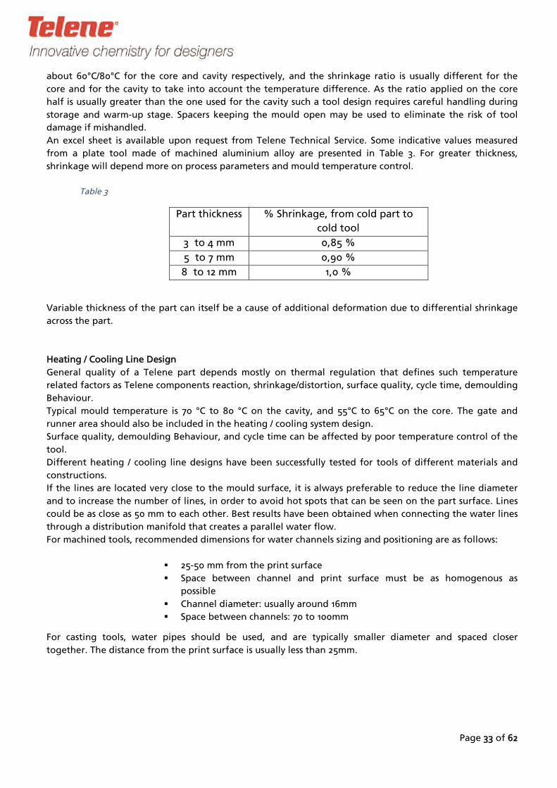
The location where flash needs to be foreseen depends on the geometry of the part. In areas where a
would
substantial amount of venting is needed, a reservoir (dumpwell) can be milled into the mould. The flash
then only channel the air towards the reservoir. The reservoir does not necessarily need to be fully
filled, but it allows a larger processing window to solve venting issues.
Page 40 of 62
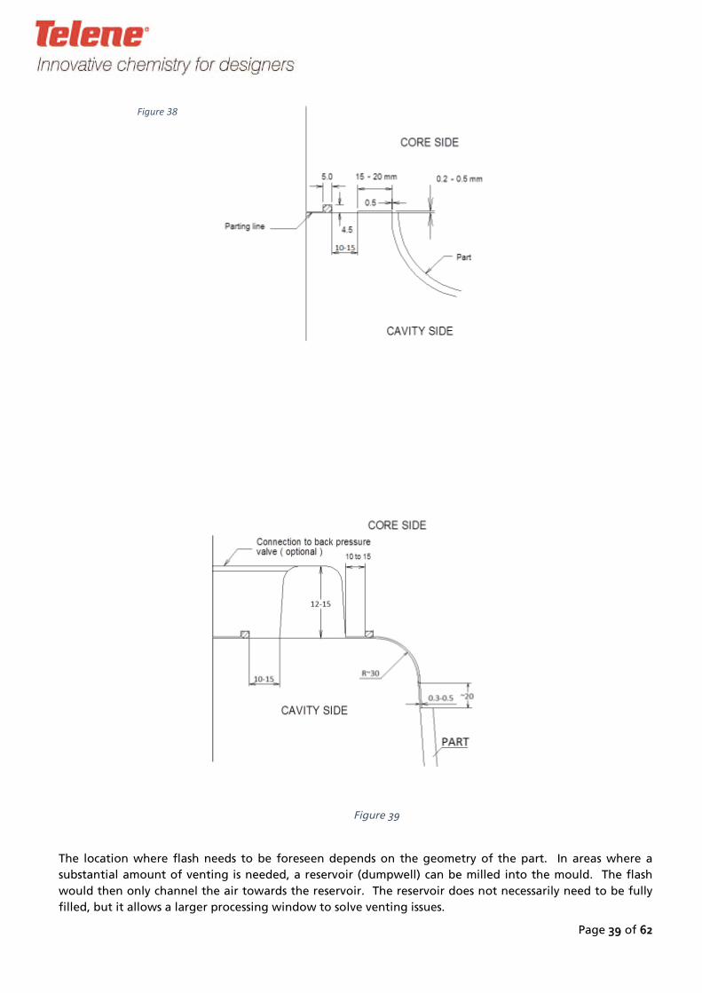
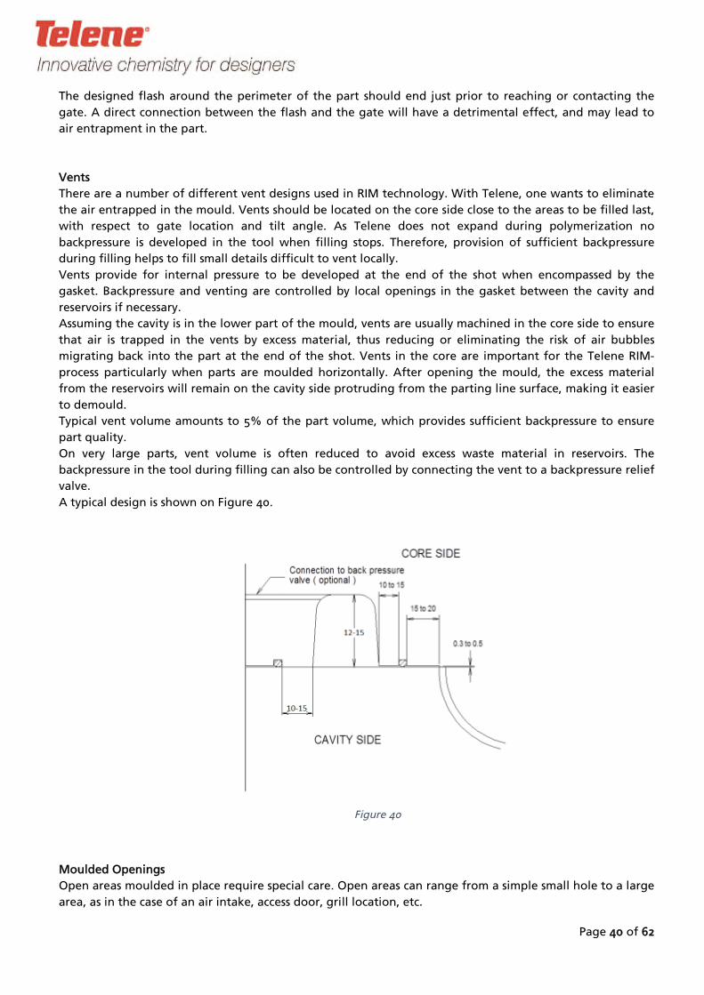
There are a number of different vent designs used in RIM technology. With Telene
. Vents should be located on the core side close to the areas to be filled last,
Telene
ed in the tool when filling stops. Therefore, provision of sufficient backpressure
to be developed at the end of the shot when encompassed by the
gasket. Backpressure and venting are controlled by local openings in the gasket
lower part of the mould, vents are usually machined in the core si
excess material, thus reducing or
to the part at the end of the shot. Vents in the core are important
moulded horizontally. After opening the
The designed flash around the perimeter of the part should end just prior to reaching or contacting the
gate. A direct connection between the flash and the gate will have a detrimental effect, and may lead to
air entrapment in the part.
Vents
, one wants to eliminate
backpressure in the tool during filling can also be controlled by connecting the vent to a backpressure relief
the air entrapped in the mould
with respect to gate location and tilt angle. As does not expand during polymerization no
backpressure is develop
during filling helps to fill small details difficult to vent locally.
Vents provide for internal pressure
between the cavity and
reservoirs if necessary.
Assuming the cavity is in the de to ensure
that air is trapped in the vents by eliminating the risk of air bubbles
migrating back in for the Telene RIM-
process particularly when parts are mould, the excess material
from the reservoirs will remain on the cavity side protruding from the parting line surface, making it easier
to demould.
Typical vent volume amounts to 5% of the part volume, which provides sufficient backpressure to ensure
part quality.
On very large parts, vent volume is often reduced to avoid excess waste material in reservoirs. The
valve.
A typical design is shown on Figure 40.
Figure 40
Moulded Openings
Open areas moulded in place require special care. Open areas can range from a simple small hole to a large
area, as in the case of an air intake, access door, grill location, etc.
Page 41 of 62
Ideally, the inner edges should have flash provided at the location where the anticipated flow ends
perpendicularly or almost perpendicularly to the moulded opening. Depending on the space available a
reservoir and a gasket groove should be integrated to prevent knitting flow fronts from pushing air
bubbles forward into the part along the flow path. By providing a reservoir in the shutoff area, air bubbles
formed by the knitting flow fronts will instead be directed away from the flow path and moulded part. In
the case of a large reservoir volume, it may turn to be desirable to connect the vent to the atmosphere
through the mould core, to prevent pressurized air in the closed reservoir to re-enter the part.
A typical example of vent design for
Design of
a horizontal cut-out is shown on Figure 41.
Figure 41
cut-outs on a sloped wall is similar to that of horizontal cut-outs
minimum thickness of 0.5mm to provide local venting. This type of cut-out is prone to bubbles on the
. If the wall is becoming closer to
vertical, the internal reservoir and gasket can be omitted. Instead, design flash in the open area to a
edges, therefore it is recommended to round over the edges with as large a fillet radius as allowable.
Almost vertical contacts or shut offs between aluminium surfaces of the mould can be an issue and may
result in premature wearing of the mould. Therefore, ,
otherwise it is often preferable to mould the part solid and trim or machine the opening during finishing
a minimum 7° draft angle should be incorporated
operations.
For further information on a case-by-case basis, please contact your Telene technical representative.
Handling Devices
All moulds should be designed for ease of installation and removal by using forks or a crane. Both halves of
the tool should be secured by appropriate clamps or metal brackets.
Demoulding Behaviour
Due to curing, the part has a natural tendency to stay on the warm side of the mould. When moulding a
part that requires high surface quality on one side, the warm face on the tool must be the show face of the
part. Usually this is the cavity side.
After injection, normal operations are as follows:
Opening of the tool.
Removal of the peripheral flash, allowing the linear shrinkage to take place.

Page 42 of 62
Putting inserts in place for the next moulding, if applicable. This prevents inserts from accidentally
mould surface. Instead, they would fall onto the part waiting to be demould
l of the part using the flash to extract the part from the cavity.
polymer achieves all its mechanical and thermal properties in the tool during the curing step.
special care should be taken when designing a tool to anticipate potential de
problems due to the combination of shrinkage contraction and high modulus. Because of their rigidity
stripped from the cavity like PU ones.
ing problems occur when the part sticks to the tool due to shrinkage. Various shapes can
create such sticking, e.g. bosses, inserts, ribs, and grills created on the cavity side. In this case, ejectors need
moulding, unless generous draft angle can be arranged at these areas. As the
ing force is directly related to part shrinkage, the distance between potential locking areas located
on the cavity side is a critical point when considering the need for ejection.
Friction induced by shrinkage should be reduced as much as possible. Therefore, a good mould
geometry areas is important. For a core, 240-320 grain sand paper (US specification
B3) or equivalent treatment is recommended. For cavity, 400 grain (B2) is typically used
falling onto the
Figure
ed.
Remova
The Telene
Therefore, moulding
,
Telene parts cannot be
As a rule, demould
to be used to help de
demould
surface
finish in critical
approximately SPI
along with 600 grain (B1) as needed for local areas.
In many cases where difficult part geometry is encountered, compressed air can be used to decrease the
stripping (demoulding) force required.
Demoulding Behaviour is illustrated on Figure 42 and Figure 43.
42
Page 43 of 62
Figure 43
Figure to 42 demonstrates the tendency of the part to stick the hotter part of the tool.
how demoulding Behaviour depends on shape of the part.
Figure 43 shows
Drag Plate/Stripper Plate Operating Concept
can be used to facilitate de
is closed, the plate is forced against the core by the hydraulic cylinders (
A concept of a drag plate (also called a stripper plate) moulding. The following
illustrations demonstrate operation of a drag plate.
When the mould Figure 44).
Figure 44
While opening the mould, the cylinders force the plate down to maintain the part in the core while the
press opens (Figure 45).
Page 44 of 62
Figure 45
When the press opens completely, the part stays on the core with flash exposed outside (Figure 46).
Figure 46
Part’s shrinkage helps to easily demould it from the core (Figure 47).
d mould
Various vents are cleaned and flash is
remove before sticking the plate to the core and closing the again for the next shot.
Page 45 of 62
Figure 47
moulding that can be used is air ejection of the part. Figure
air ejector. Self-contained “poppet”-style are also commonly used, and
mould component supply companies.
Air Ejection
Another means to facilitate de 48 and Figure 49
demonstrate operation of a typical
are readily available through
Figure 48

Figure 49
Page 46 of 62
Page 47 of 62
In the reaction injection moulding process, impingement mixing occurs in the mixing chamber of the high-
3.3 Mould Gate Design for TELENE Resins (1600 Series)
Gate
pressure mixhead. This turbulent mix must then be transformed into laminar flow as the resin enters the
cavity in order to minimize
Transition from turbulent to laminar flow is accomplished by a gate system located between the mixhead
mould
mould mould
cavity. As Telene components have the same viscosity, they are easy to mix and do not
require high mixing pressure or a complex after m
ing defects.
and the
ixer.
There are 2 major types of gates for RIM: a direct gate & a film gate
The direct gate type is not recommended for
conditions:
Telene resins.
If there is no other economical way to design the gate, the direct gate can be used under the following
- part thickness in the gate area should not be greater than 3 mm;
- a very good seal between the mould and the mixhead is needed in order to prevent air
suction in the gate;
- an L-shape mixhead which provides laminar flow from the mixhead, is strongly
recommended.
The film gate is the most recommended type of gate for Telene.
There are several types of film gate that can be used:
- rod or sprue gate;
- dam gate or coat hanger gate ;
- fan gate.
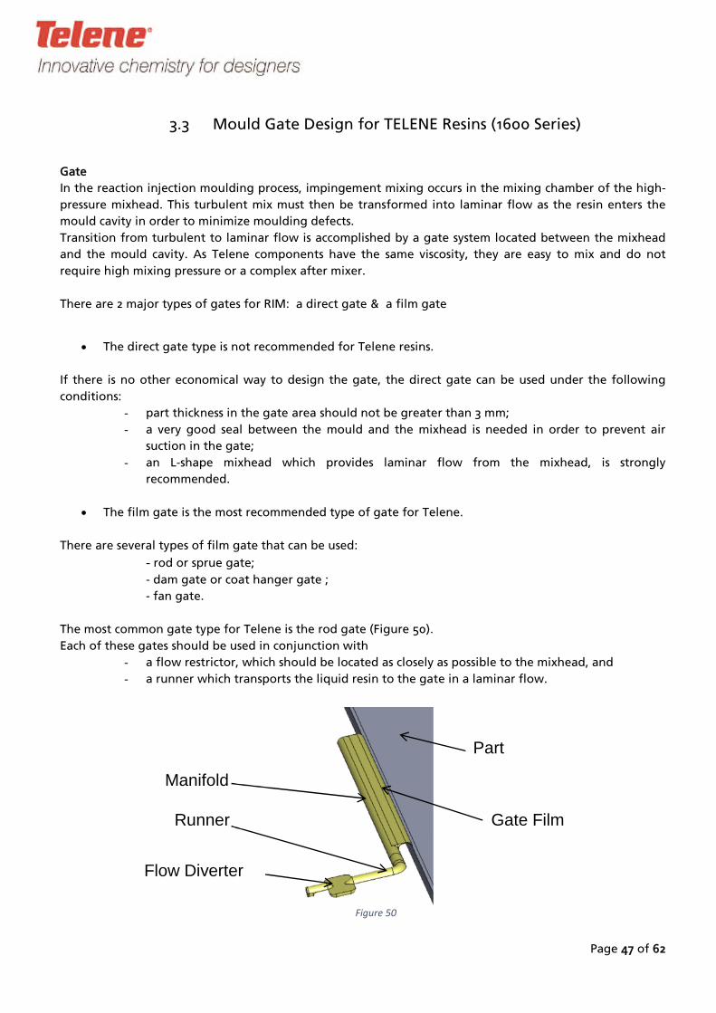
The most common gate type for Telene is the rod gate (Figure 50).
Each of these gates should be used in conjunction with
- a flow restrictor, which should be located as closely as possible to the mixhead, and
- a runner which transports the liquid resin to the gate in a laminar flow.
Manifold
Runner
Flow Diverter
Gate Film
Part
50Figure
Dimensions of the flow restrictor depend on the mixhead size whereas the design of the gate and the
runner depends on the gate location and the injection output.
mportant parameters to ensure backpressure in the gate and laminar flow when material enters the part:
IPage 48 of 62
mixer or a sharp 90° angle.
Flow velocity in the gate:
o < 4 m/s for thin parts (wall thickness is < 6 mm next to the gate)
o < 2 m/s for thick parts (wall thickness is > 6 mm next to the gate)
Reynolds number calculated on the flow leaving the gate, Re must be >10
Film gate to manifold pressure drop ratio at least 1.5
Flow Restrictor
A flow restrictor prevents material jetting down to the runner and provides backpressure in the mixhead
which promotes complete and thorough mixing.
The type of flow restrictor depends mainly on the way the mixhead is connected to the runner.
If the mixhead is mounted at a 90° angle to the runner axis, it can be a disc like area directly below the
mixhead. See Figure 51 for an example of disk like transition and related calculation sheet.
If the mixhead runs directly end-on to the runner the restriction can be a flow diverter (Figure 52), an after-

Page 49 of 62
Figure 51

Page 50 of 62
Figure 52
Runner
The runner is a feeding channel connecting the mixing head and the gate. The runner can typically be a
semi-circular, or a semi-lenticular channel, and the latter is a better choice for easier demoulding.
Gate Location
The gate is better to locate close to the lowest point of the tool (taking into account possible mould tilting)
next to a vertical wall of the part to minimize flow effect on part surface quality close to the gate. If this is
not possible, it is recommended to consider the gate connected to an edge of the part on a B-side of the
part.
While selecting a place for the gate, it is recommended to foresee potential location of vents. Ribs and
alike geometrical features ideally should be oriented along the flow from the gate.

Rod Gate Calculation
53
See Figure 53 and Figure
54 for an example of rod
gate design sheet and
illustration of the rod
gate design and
dimensions.
Figure
Page 51 of 62
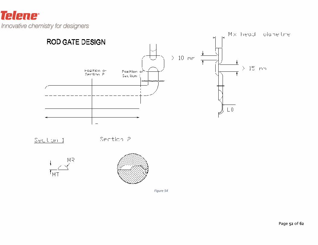
Page 52 of 62
54Figure
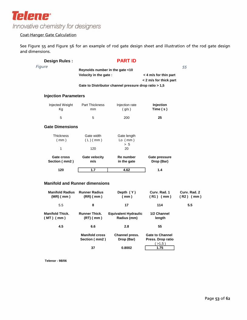
Page 53 of 62
Injected Weight Part Thickness Injection rate Injection
Kg mm ( g/s ) Time ( s )
5 5 200 25
Gate Dimensions
Thickness Gate width Gate length ( mm ) ( L ) ( mm ) Lo ( mm )
> 51 120 20
Gate cross Gate velocity Re number Gate pressureSection ( mm2 ) m/s in the gate Drop (Bar)
120 1.7 4.62 1.4
Manifold and Runner dimensions
Manifold Radius Runner Radius Depth ( Y ) Curv. Rad. 1 Curv. Rad. 2(MR) ( mm ) (RR) ( mm ) ( mm ) ( R1 ) ( mm ) ( R2 ) ( mm )
5.5 8 17 114 5.5
Manifold Thick. Runner Thick. Equivalent Hydraulic 1/2 Channel(RT) ( mm ) Radius (mm) length
4.5 6.6 2.8 55
Manifold cross Channel press. Gate to Channel Section ( mm2 ) Drop (Bar) Press. Drop ratio
( >1,5 )37 0.8002 1.75
Design Rules : PART ID
Reynolds number in the gate <10
Velocity in the gate : < 4 m/s for thin part
< 2 m/s for thick part
Gate to Distributor channel pressure drop ratio > 1,5
Injection Parameters
( MT ) ( mm )
Telenor - 98/06
Coat-Hanger Gate Calculation
55
See Figure 55 and Figure 56 for an example of rod gate design sheet and illustration of the rod gate design
and dimensions.
Figure
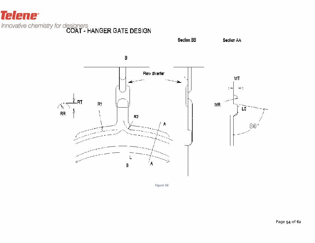
Page 54 of 62
Figure 56
Page 55 of 62
as this would lead to air flowing back from one print to the other in case of back pressure difference. Making
decision as to gate location is more difficult as one has to consider proximity of other prints next to the gate.
All the prints together must be surrounded by the gasket, oriented to ensure proper filling and venting. If
necessary, a compromise between mould material saving and desired gate location should be found.
Except for the machine output, the process window (the range of values taken by the various parameters
controlling the process that produces good quality part) is usually reduced.
The main runner splits in as many runners as the number of prints in the mould. The gates must be sized to
maintain backpressure in all the channels that requires a special calculation. The basic rule is:
main runner section = (sum of all split runners)x1.05
Multiple print gate design is relatively simple to calculate in the case of symmetrical parts, for example left and
right panels, or when print have similar weigh. It is much more complicated in the case of more than 2 prints or
when prints are of very different weight.
For an example of the calculation sheet for a 2 print mould gate see Figure 57, and for an example of multiple
mould layout see Figure 58.
3.4 Multiple Cavity Mould Design
Multiple cavity moulds are often used when weight of the single part is too small for the available RIM-
equipment. In that case, a multiple cavity mould will allow getting around very small injection time (< 3 sec) as
well as reducing the moulding fixed cost per part. Number of prints needs to be carefully evaluated, as too
many prints will increase material loss in the runners and demoulding time.
For general mould layout, the same rules apply to each of the print as to a single print tool, including the
gasket, flash, reservoirs and gate positioning. Reservoirs must not be shared between the neighboring prints,
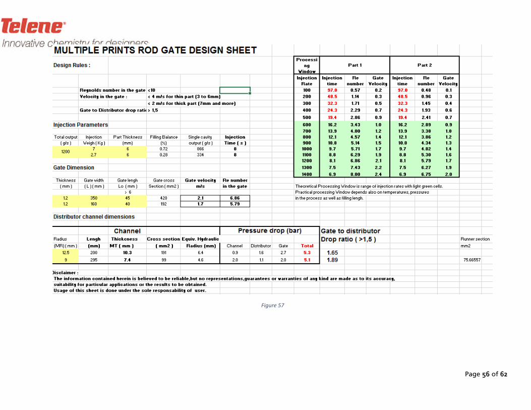
Page 56 of 62
Figure 57

Page 57 of 62
58Figure
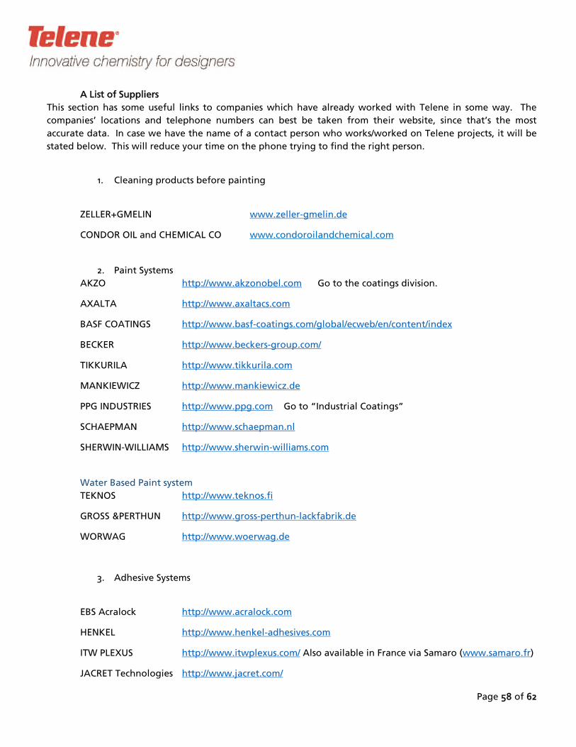
Page 58 of 62
A List of Suppliers
This section has some useful links to companies which have already worked with Telene in some way. The
accurate data. In case we have the nam
companies’ locations and telephone numbers can best be taken from their website, since that’s the most
e of a contact person who works/worked on
1.
Telene projects, it will be
stated below. This will reduce your time on the phone trying to find the right person.
Cleaning products before painting
ZELLER+GMELIN www.zeller-gmelin.de
CONDOR OIL and CHEMICAL CO www.condoroilandchemical.com
2. Paint Systems
AKZO http://www.akzonobel.com Go to the coatings division.
AXALTA http://www.axaltacs.com
BASF COATINGS http://www.basf-coatings.com/global/ecweb/en/content/index
BECKER http://www.beckers-group.com/
TIKKURILA http://www.tikkurila.com
MANKIEWICZ http://www.mankiewicz.de
PPG INDUSTRIES http://www.ppg.com Go to “Industrial Coatings”
SCHAEPMAN http://www.schaepman.nl
SHERWIN-WILLIAMS http://www.sherwin-williams.com
Water Based Paint system
TEKNOS http://www.teknos.fi
GROSS &PERTHUN http://www.gross-perthun-lackfabrik.de
WORWAG http://www.woerwag.de
3. Adhesive Systems
EBS Acralock http://www.acralock.com
HENKEL http://www.henkel-adhesives.com
ITW PLEXUS http://www.itwplexus.com/ Also available in France via Samaro (www.samaro.fr)
JACRET Technologies http://www.jacret.com/

Page 59 of 62
SCIGRIP http://www.scigrip.com
SCOTT BADER http://www.scottbader.com
SIKA INDUSTRIES http://www.sika.com/
4. Fillers & Repairing Accessories
DEVCON http://www.devcon.com
3 M http://www.3m.com
5.
UNIPOL
Mould Polish
-LIPPERT http://www.lippert-unipol.com Reference Langsol A407
I.C.R. http://www.icrsprint.it
6. Mould Release Agent
F.IN.CO s.r.l
via Assiano, 11
I
Tel (00 39) 02 335 122 89
- 20019 SETIMO MILANESE (MI)
http://www.fincosrl.it/
BP 335 – Z.I Rue des Plantes
7. Mould Makers EMEA
CERO - France
85303 Challans Cedex
Tel : +33 (0)2 51 49 79 10
http://www.cero.fr

Page 60 of 62
CI-ESSE - Italy
Via Marsala 34, 20052 Monza (Milano)
Tel: +39 039 2007881
http://www.ci-esse.eu/en
49450 SAINT-MACAIRE-EN-MAUGES
C.M.O - France
Z.I. La Courbière
Tél : 02 41 55 34 43
Fax : 02 41 55 34 57
Email : [email protected]
http://www.moule-outillage.com
Baltimore Road, Great Barr, Birmingham B42 1DD
ELKINGTON BROTHERS – United Kingdom
Tel: 0121-
www.elkingtonbrothers.com
358 2431, Fax : 0121-358 7527
FORMEC – Sweden
Fabriksgatan 6, Skövde
Tel: +46 500 434285
http://www.formec.se
LANULFI S.R.L. - Italy
Via dell’Industria n. 1 –
36010 Monticello Conte Otto VI
Tel:(+39) 0444 1831163
www.lanulfi.com

Page 61 of 62
PAGANI s.r.l. - Italy
Via Monte Misma 17, 19, 21
I 24050 Calcinate (BG)-
Direct: +39 3477897117
http://www.paganistampi.co
WILHEM FUNKE GmbH -
m
German
Tel: +49 5181 7090
y
Röllinghauser Str. 44, 31061 Alfeld (Leine)
http://w-funke.de/index.php/en/
8. Mould Makers North America
BEVERLY PATTERN INC
31 Park St.
- USA
Beverly, MA 01915
978-927-0052
978
www.beverlypattern.biz
-927-8806 Fax
WESTOOL CORPORATION -
- -
USA
7383 Sulier Dr
Temperance, MI 48182
734 847 2520 ph
- -734 847 9180 fax
www.westools.com

Page 62 of 62
PARAGON DIE AND ENGINEERING -
5225 33rd St. SE
Grand Rapids, MI 49512
USA
Phone: (616) -
-Fax: (616) 949 2536
949-2220
www.paragonde.com
MODEL DIE AND MOULD
Fax: 616-243-9874
INC - USA
3859 Roger B Chaffee Memorial Dr SE
Wyoming MI 49548, USA
Phone: 616-243-6996
www.modeldie.com
CENTURY TOOL AND GAGE - USA
200 S. Alloy Drive
Fenton, MI 48430
-629-
810-629-0784
810 9284 Fax
www2.centurytool.com
WEBER MANUFACTURING TECHNOLOGIES INC - CANADA
16566 Hwy 12
L4r 4L1
-526-
Midland, Ontario, Canada
705 7896
705-526-3818 Fax
www.webermfg.ca
Page 63 of 63
FET ENGINEERING INC - USA
903 Nutter Dr - Bardstown, KY 40004
502-348-2130
502-348-7040 Fax
www.fetusa.com
9. Inserts
TAPPEX www.tappex.co.uk
STANLEY Eng. Fastening www.stanleyengineeredfastening.com
Tri-Star Industries www.tristar-inserts.com
VMP Inc. www.vmpinc.com
Penn Engineering www.pemnet.com
Yardley Products www.yardleyproducts.com
Rotaloc www.rotaloc.com
10. DCPD Vapour Adsorption
ALPHA-CHEM http://www.alpha-chem.fr/
CHEMVIRON http://www.chemvironcarbon.com/en/
NORIT Activated Carbon http://www.norit.com/
2014_03 Fatigue Test JIS K7119
REFERENCES
1. Process Book 2015
2. Data Sheet 1620, 1650, 1651
3. 2007_11 TELENE 1650 test - 60°C flexural and tensile EN FR
4. Impact resistance of Telene at various temperatures
5. Ageing properties
6. Burning behaviour of DCPD Directive 9528WE Annex 4
7. Fire behaviour
8. Heat Capacity
9. Electric Properties – Telene Document
10.