telematics chapter 2: introduction...simplex medium duplex medium half-duplex medium univ.-prof....
TRANSCRIPT

Beispielbild
Telematics
Chapter 2: Introduction
Univ.-Prof. Dr.-Ing. Jochen H. Schiller
Computer Systems and Telematics (CST)
Institute of Computer Science
Freie Universität Berlin
http://cst.mi.fu-berlin.de
Data Link Layer
Presentation Layer
Session Layer
Physical Layer
Network Layer
Transport Layer
Application Layer
Data Link Layer
Presentation Layer
Session Layer
Physical Layer
Network Layer
Transport Layer
Application Layer
Data Link Layer
Physical Layer
Network Layer
User watching video clip
Server with video clips

2.2
Contents
● Data Communication
● What is Digital Data?
● Why Data Communication?
● Networking Principles
● Non-technical Aspects of Networking
● Communication Protocols
● The ISO/OSI Reference Model
● The TCP/IP Reference Model
● OSI vs. TCP/IP
● Standardization
● Evolution of Computer Networks
● Classification of Computer Networks
Univ.-Prof. Dr.-Ing. Jochen H. Schiller ▪ cst.mi.fu-berlin.de ▪ Telematics ▪ Chapter 2: Introduction

2.3
Data Communication
Univ.-Prof. Dr.-Ing. Jochen H. Schiller ▪ cst.mi.fu-berlin.de ▪ Telematics ▪ Chapter 2: Introduction

2.4
Data Communication
Univ.-Prof. Dr.-Ing. Jochen H. Schiller ▪ cst.mi.fu-berlin.de ▪ Telematics ▪ Chapter 2: Introduction
Source Transmitter
Transmission System Receiver
Destination
10100111001101011100110101110011010101000001110101
1110001...
Data Communication
Data communication is the processing and the transport of digital data over connections between computers and/or other devices. Data communication comprises two topical areas.
1. Computer Networks
● How to connect several computers? ● Which media can be used for data transport? ● How to represent digital data on the medium? ● How to coordinate the access of several computers to the medium?
2. Communication Protocols
● Design of uniform data units for transfer
● How to achieve a reliable and efficient transfer?

2.5
Signals, Data, and Information
Univ.-Prof. Dr.-Ing. Jochen H. Schiller ▪ cst.mi.fu-berlin.de ▪ Telematics ▪ Chapter 2: Introduction

2.6
The Term of Data
● Data (universal)
● Representation of facts, concepts, and statements in a formal way which is suitable for communication, interpretation, and processing by human beings or technical means.
● Examples for data representation
● Spoken language
● Sign language
● Written language
Representation in a formal way
Conventions for
the
representation
of objects of
thought.
Objects of thought
Facts, Concepts,
Ideas, Models, etc.
Univ.-Prof. Dr.-Ing. Jochen H. Schiller ▪ cst.mi.fu-berlin.de ▪ Telematics ▪ Chapter 2: Introduction

2.7
The Term of Information
● Information
● Generally, information is whatever is capable of causing a human mind to
change its opinion about the current state of the real world. Formally, and
especially in science and engineering, information is whatever contributes to a
reduction in the uncertainty of the state of a system; in this case,
uncertainty is usually expressed in an objectively measurable form.
(Oxford Reference Online)
● The communication or reception of knowledge or intelligence
● Attention: The notion of “Information” is defined for humans
● Information has to be distinguished from any medium that is capable of
carrying it
● Humans and machines can handle data, however only humans can handle
information
Univ.-Prof. Dr.-Ing. Jochen H. Schiller ▪ cst.mi.fu-berlin.de ▪ Telematics ▪ Chapter 2: Introduction

2.8
The Term of Signal
● Signal
● A signal is the physical
representation of data by spatial
or timely variation of physical
characteristics
● The variable parameter that contains
information and by which information
is transmitted in an electronic system
or circuit.
● The signal is often a voltage source
in which the amplitude,
frequency, and waveform can be
varied.
● Signal is the real physical
representation of an abstract
representation
abstract
World
physical
World
Data in formal representation
Conventions for the
representation of
objects of thought
Objects of thought
Facts, Concepts, …
Signals as real representation of data
Conventions for
the representation
of data
Univ.-Prof. Dr.-Ing. Jochen H. Schiller ▪ cst.mi.fu-berlin.de ▪ Telematics ▪ Chapter 2: Introduction
2.9
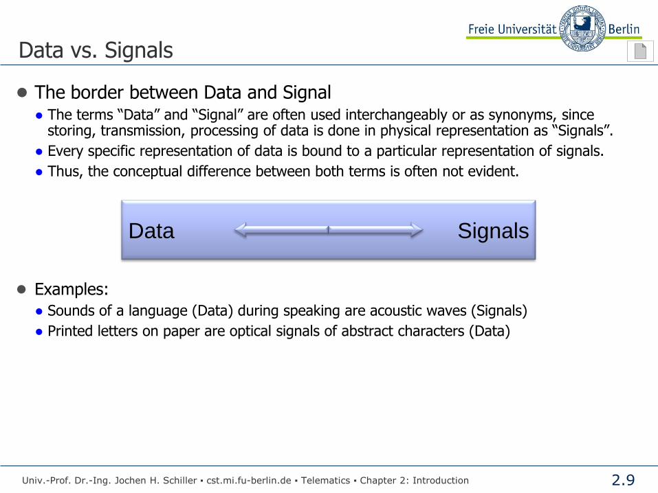
Data vs. Signals
● The border between Data and Signal ● The terms “Data” and “Signal” are often used interchangeably or as synonyms, since
storing, transmission, processing of data is done in physical representation as “Signals”.
● Every specific representation of data is bound to a particular representation of signals.
● Thus, the conceptual difference between both terms is often not evident.
● Examples:
● Sounds of a language (Data) during speaking are acoustic waves (Signals)
● Printed letters on paper are optical signals of abstract characters (Data)
Data Signals
Univ.-Prof. Dr.-Ing. Jochen H. Schiller ▪ cst.mi.fu-berlin.de ▪ Telematics ▪ Chapter 2: Introduction
2.10
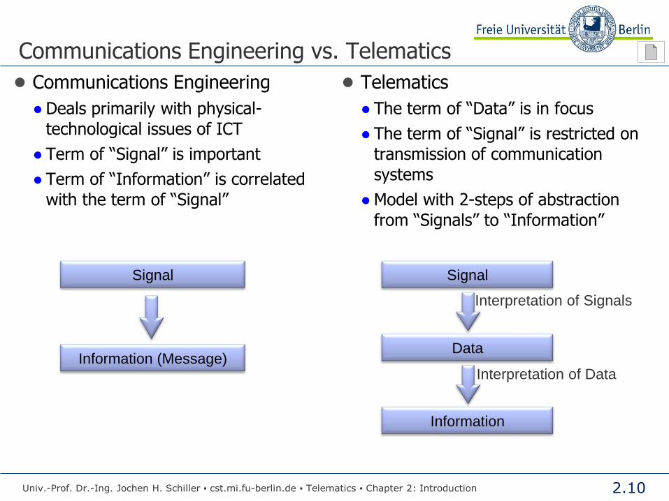
Communications Engineering vs. Telematics
● Communications Engineering
● Deals primarily with physical-
technological issues of ICT
● Term of “Signal” is important
● Term of “Information” is correlated
with the term of “Signal”
● Telematics
● The term of “Data” is in focus
● The term of “Signal” is restricted on
transmission of communication
systems
● Model with 2-steps of abstraction
from “Signals” to “Information”
Signal
Information (Message)
Signal
Data
Information
Interpretation of Signals
Interpretation of Data
Univ.-Prof. Dr.-Ing. Jochen H. Schiller ▪ cst.mi.fu-berlin.de ▪ Telematics ▪ Chapter 2: Introduction

2.11
Why Data Communication?
Univ.-Prof. Dr.-Ing. Jochen H. Schiller ▪ cst.mi.fu-berlin.de ▪ Telematics ▪ Chapter 2: Introduction

2.12
Evolution of Data Communication
● Sharing resources saves costs:
● By communication, one can access resources of other parties
this reduces the costs (compared to buying own resources)
● Several institutions can share expensive resources which cannot be completely
utilized by a single institution
● Requirements:
● Efficient mechanisms for data exchange between components of a distributed system
● Mechanisms for efficient interaction
● The “driving power” for the enormous increase of data communication:
● Decreasing costs for hardware…
… while the computing power increases.
How do several communication partners interact?
Univ.-Prof. Dr.-Ing. Jochen H. Schiller ▪ cst.mi.fu-berlin.de ▪ Telematics ▪ Chapter 2: Introduction

2.13
Networking Principles
Univ.-Prof. Dr.-Ing. Jochen H. Schiller ▪ cst.mi.fu-berlin.de ▪ Telematics ▪ Chapter 2: Introduction

2.14
Communication Peers
● Unicast: Two communication
peers communicate over a
Point-to-Point connection.
● Multicast: One sender
communicates to several
receivers, which are known.
● Broadcast: One sender transmits
to all other peers.
● Typically the other peers are
(partially) unknown.
● Others: Anycast, Geocast, etc.
Univ.-Prof. Dr.-Ing. Jochen H. Schiller ▪ cst.mi.fu-berlin.de ▪ Telematics ▪ Chapter 2: Introduction
2.15
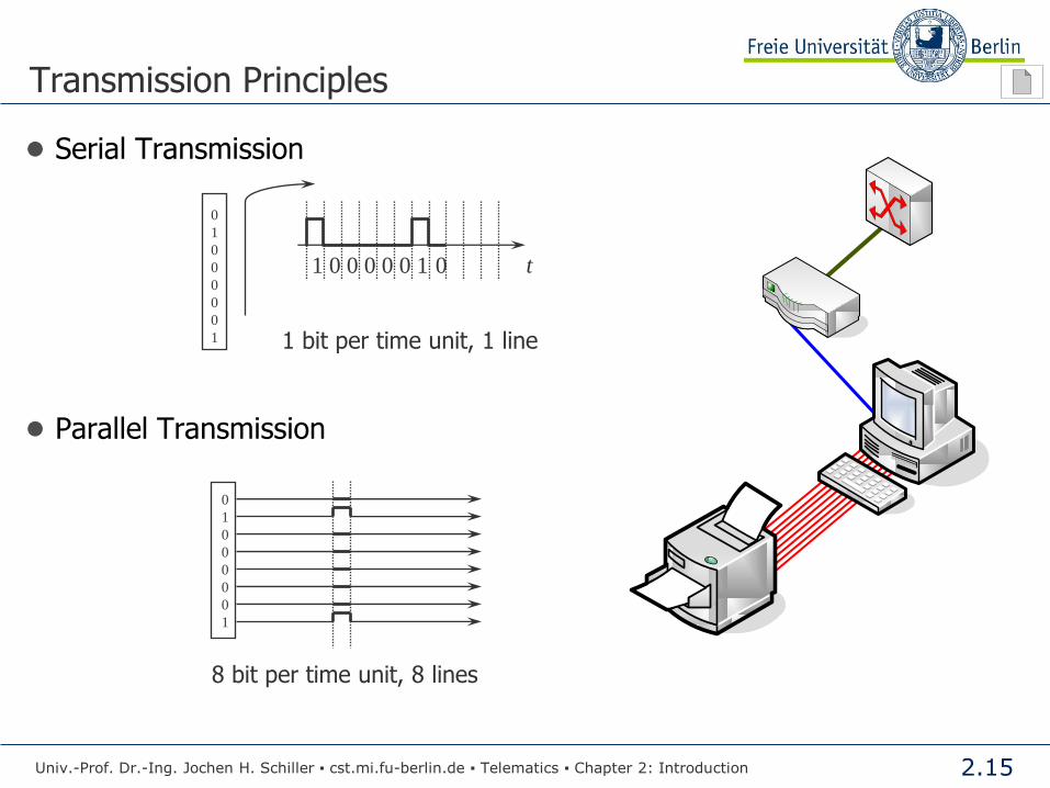
Transmission Principles
● Serial Transmission
● Parallel Transmission
0
1
0
0
0
0
0
1
8 bit per time unit, 8 lines
0
1
0
0
0
0
0
1
1 0 0 0 0 0 1 0 t
1 bit per time unit, 1 line
Univ.-Prof. Dr.-Ing. Jochen H. Schiller ▪ cst.mi.fu-berlin.de ▪ Telematics ▪ Chapter 2: Introduction

2.16
Transmission Principles
● Asynchronous Transmission: Transmission in which each
block/frame/character is individually synchronized
● Example on Physical Layer
- Data transmitted as one character at a time Character set ASCII
- Synchronization must only be maintained for each character
● Example on Data Link Layer (HDLC…)
- Blocks of bits (frame)
● Synchronous Transmission: Transmission in which the time of occurrence
of each signal representing a bit is related to a fixed time frame
● Example GSM, ISDN…
idle Start bit
data6
data5
data4
data3
data2
data1
data0
Stop bit
idle
Flag Control Data (n bits) Control Flag
One character (7 bits)
Univ.-Prof. Dr.-Ing. Jochen H. Schiller ▪ cst.mi.fu-berlin.de ▪ Telematics ▪ Chapter 2: Introduction
user 1
user 2
user 3
user 4
user 5
user 6
user 7
user 8
user 1
user 2
user 3

2.17
Transmission Principles: ASCII Table
● American Standard Code for Information Interchange (ASCII)
● Character encoding based on English
● Printable, non-printable, and control characters
Univ.-Prof. Dr.-Ing. Jochen H. Schiller ▪ cst.mi.fu-berlin.de ▪ Telematics ▪ Chapter 2: Introduction
2.18
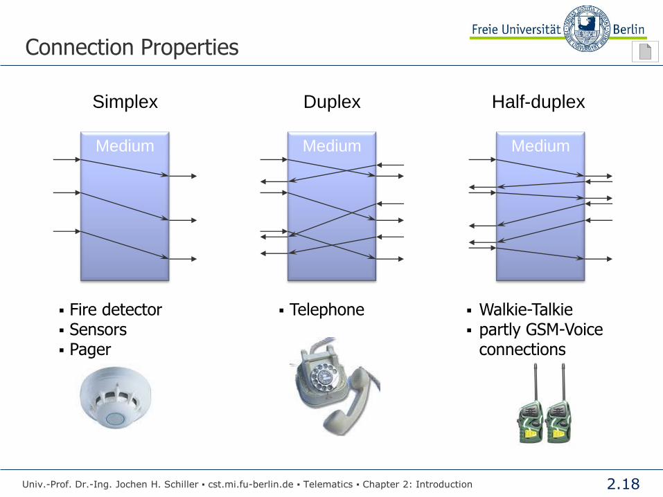
Connection Properties
Fire detector Sensors Pager
Telephone Walkie-Talkie partly GSM-Voice
connections
Simplex
Medium
Duplex
Medium
Half-duplex
Medium
Univ.-Prof. Dr.-Ing. Jochen H. Schiller ▪ cst.mi.fu-berlin.de ▪ Telematics ▪ Chapter 2: Introduction
2.19
Multiplexing Basics
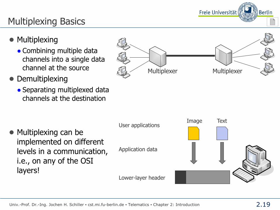
● Multiplexing
● Combining multiple data
channels into a single data
channel at the source
● Demultiplexing
● Separating multiplexed data
channels at the destination
● Multiplexing can be
implemented on different
levels in a communication,
i.e., on any of the OSI
layers!
Multiplexer Multiplexer
Text Image User applications
Application data
Lower-layer header
Univ.-Prof. Dr.-Ing. Jochen H. Schiller ▪ cst.mi.fu-berlin.de ▪ Telematics ▪ Chapter 2: Introduction

2.20
Quality
● Besides the functional aspects and usability, the following quality
requirements are important:
● Technical Performance
● Required transmission performance, delay, jitter, throughput, data rate, etc.
● Costs
● Investment costs, cost of operation, etc.
● Reliability
● Fault tolerance, system stability, immunity, availability, etc.
● Security and Protection
● Eavesdropping, authentication, denial of service, etc.
Univ.-Prof. Dr.-Ing. Jochen H. Schiller ▪ cst.mi.fu-berlin.de ▪ Telematics ▪ Chapter 2: Introduction

2.21
Quality: Technical Performance
● Delay
● Measured in seconds [s]
d1 = t‘1 – t1
● Round-trip-time (RTT)
● Measured in seconds [s]
r1 = t2 – t1
Univ.-Prof. Dr.-Ing. Jochen H. Schiller ▪ cst.mi.fu-berlin.de ▪ Telematics ▪ Chapter 2: Introduction
A B
t1
t„1
t2
Time
2.22
Quality: Technical Performance
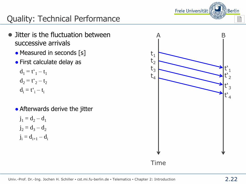
● Jitter is the fluctuation between
successive arrivals
● Measured in seconds [s]
● First calculate delay as
d1 = t‘1 – t1
d2 = t‘2 – t2
di = t‘i – ti
● Afterwards derive the jitter
j1 = d2 – d1
j2 = d3 – d2
ji = di+1 – di
Univ.-Prof. Dr.-Ing. Jochen H. Schiller ▪ cst.mi.fu-berlin.de ▪ Telematics ▪ Chapter 2: Introduction
A B
t1
t2
t3
t4
t„1
t„2
t„3
t„4
Time

2.23
Quality: Technical Performance
● Throughput
● Measured in bits per second [bps]
Univ.-Prof. Dr.-Ing. Jochen H. Schiller ▪ cst.mi.fu-berlin.de ▪ Telematics ▪ Chapter 2: Introduction
A B
t1
t2
t3
t4
t„1
t„2
t„3
t„4
t
dataT
i
Time

2.24
Quality: Technical Performance
Throughput (“bandwidth”, data rate) =
Number of transmitted bits per second [bps, bit/s]
Univ.-Prof. Dr.-Ing. Jochen H. Schiller ▪ cst.mi.fu-berlin.de ▪ Telematics ▪ Chapter 2: Introduction
Attention: Delay-Bandwidth-Product =
Store capacity of the line
Bit
send
Distance in meter
t Delay in seconds
Bit
receive Transmission Line
Example: Store capacity of the transmission line
DSL connection: 1 Mbps, 200 ms delay: 1 Mbps × 0.2 s = 200 kBit
Ethernet 100 Mbps: 100 Mbps, 100 ms: 100 Mbps × 0.1 s = 10 Mbit

2.25
Quality: Security and Protection
● Safety measures
● Encryption
(cryptographic codes)
● Trustworthy systems
(Authentication, Authorization)
Normal Data Flow
Data Source Data Destination
S D
Passive:
Eavesdropping
S D
A
Active:
Modifying
S D
A
Masquerade
S D
A
Interruption
S D
A
Univ.-Prof. Dr.-Ing. Jochen H. Schiller ▪ cst.mi.fu-berlin.de ▪ Telematics ▪ Chapter 2: Introduction
2.26
Delivery Principles
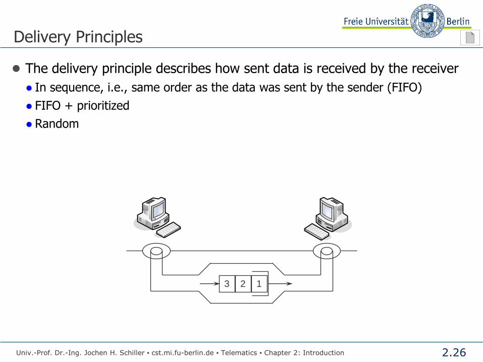
● The delivery principle describes how sent data is received by the receiver
● In sequence, i.e., same order as the data was sent by the sender (FIFO)
● FIFO + prioritized
● Random
Univ.-Prof. Dr.-Ing. Jochen H. Schiller ▪ cst.mi.fu-berlin.de ▪ Telematics ▪ Chapter 2: Introduction
1 2 3

2.27
The Client/Server Principle
Client Server
Request
Reply
Univ.-Prof. Dr.-Ing. Jochen H. Schiller ▪ cst.mi.fu-berlin.de ▪ Telematics ▪ Chapter 2: Introduction
Client Process
Server Process
Advantages of the Client/Server principle
Cost reduction
Better usage of resources
Modular extensions
Reliability by redundancy

2.28
The Client/Server Principle
● Server
● Program (process) which offers a service over a network.
Servers receive requests and return a result to the inquiring party. The services
offered include simple operations (e.g. name server) or a complex set of
operations (e.g. web server).
● Client
● Program (process) which uses a service offered by a server.
Examples for Client/Server Systems
Client Server
Web Browser Web Server
E-Mail Program Domain Name System (DNS)
FTP Client FTP Server
Univ.-Prof. Dr.-Ing. Jochen H. Schiller ▪ cst.mi.fu-berlin.de ▪ Telematics ▪ Chapter 2: Introduction

2.29
Peer-to-Peer Principle
● The P2P Principle
● Equal partners, no fixed client and server roles
● Connections between any pair of computers
● Establishment of a network of connections
● Example: File Sharing, e.g., Napster, Gnutella
Univ.-Prof. Dr.-Ing. Jochen H. Schiller ▪ cst.mi.fu-berlin.de ▪ Telematics ▪ Chapter 2: Introduction

2.30
Non-technical Aspects of Networking
Univ.-Prof. Dr.-Ing. Jochen H. Schiller ▪ cst.mi.fu-berlin.de ▪ Telematics ▪ Chapter 2: Introduction

2.31
Non-technical Aspects of Networking
Univ.-Prof. Dr.-Ing. Jochen H. Schiller ▪ cst.mi.fu-berlin.de ▪ Telematics ▪ Chapter 2: Introduction
Computer Networks
Communication networks enable a fast and cheap exchange/distribution of information. There is however a large number of social, ethical, cultural, juridical ... side effects.
Side effects …
Eventually dubious or forbidden contents
Responsibility
Juridical aspects (legislation)
Potential censorship?
Control over the productivity of employees, of the whereabouts of people
Annoyance through anonymous or unwanted messages (SPAM)
...

2.32
Communication Protocols
Univ.-Prof. Dr.-Ing. Jochen H. Schiller ▪ cst.mi.fu-berlin.de ▪ Telematics ▪ Chapter 2: Introduction
2.33
What is a Protocol?
● Human protocols:
● “What’s the time?”
● “I have a question”
● Introductions
● In General
● … specific messages sent
● … specific actions taken when
messages received or other events
happen
● Network protocols:
● Machines rather than humans
● All communication activities in the
Internet is governed by protocols
● In General
● Protocols define format, order of
messages sent and received among
network entities, and actions taken
on message transmission and
receipt
Univ.-Prof. Dr.-Ing. Jochen H. Schiller ▪ cst.mi.fu-berlin.de ▪ Telematics ▪ Chapter 2: Introduction

2.34
What is a Protocol?
connection request
connection response
get page X
page X
Hi
Hi
Time?
11:00
Univ.-Prof. Dr.-Ing. Jochen H. Schiller ▪ cst.mi.fu-berlin.de ▪ Telematics ▪ Chapter 2: Introduction
2.35
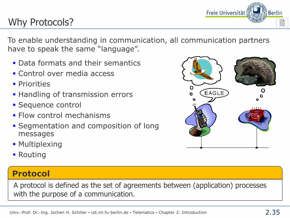
To enable understanding in communication, all communication partners have to speak the same “language”.
Data formats and their semantics
Control over media access
Priorities
Handling of transmission errors
Sequence control
Flow control mechanisms
Segmentation and composition of long messages
Multiplexing
Routing
Why Protocols?
Univ.-Prof. Dr.-Ing. Jochen H. Schiller ▪ cst.mi.fu-berlin.de ▪ Telematics ▪ Chapter 2: Introduction
Protocol
A protocol is defined as the set of agreements between (application) processes with the purpose of a communication.

2.36
Implementation of Protocols
Univ.-Prof. Dr.-Ing. Jochen H. Schiller ▪ cst.mi.fu-berlin.de ▪ Telematics ▪ Chapter 2: Introduction
Solution 1
Write one large “Communication Program” which fulfills all requirements needed to establish a communication process.
Advantage: efficient data exchange for a given application.
Disadvantage: No flexibility! Adoptions require large efforts.
Solution 2
Write a set of small programs specialized to special tasks of the communication process. For each application, the needed programs can be combined.
Advantage: Very flexible, since single components can be exchanged.
Disadvantage: Fixed structures of program interworking; adds more complexity and overhead.
Accepted today: Solution 2
The implementation takes place in layer models.

2.37
Example: Exchange of Ideas between Philosophers
Philosopher A
Language: Chinese
Interpreter A
additionally: English
Recognizes single
characters and sends
them in Morse code
Network
Thoughts about world politics
Uninterpreted sentences,
i.e. no knowledge about politics
Uninterpreted characters
in correct order
Electrical signals
Technical Expert A
Language: Chinese
Philosopher B
Language: Spanish
Interpreter B
additionally: English
Recognizes single
characters and sends
them in Morse code
Technical Expert B
Language: Spanish
protocols service
Univ.-Prof. Dr.-Ing. Jochen H. Schiller ▪ cst.mi.fu-berlin.de ▪ Telematics ▪ Chapter 2: Introduction
2.38
Services and Protocols
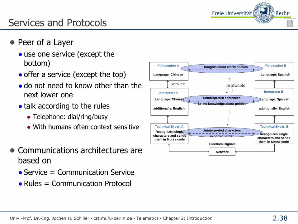
● Peer of a Layer
● use one service (except the
bottom)
● offer a service (except the top)
● do not need to know other than the
next lower one
● talk according to the rules
● Telephone: dial/ring/busy
● With humans often context sensitive
● Communications architectures are
based on
● Service = Communication Service
● Rules = Communication Protocol
Univ.-Prof. Dr.-Ing. Jochen H. Schiller ▪ cst.mi.fu-berlin.de ▪ Telematics ▪ Chapter 2: Introduction
Philosopher A
Language: Chinese
Interpreter A
additionally: English
Recognizes single
characters and sends
them in Morse code
Network
Thoughts about world politics
Uninterpreted sentences,
i.e. no knowledge about politics
Uninterpreted characters
in correct order
Electrical signals
Technical Expert A
Language: Chinese
Philosopher B
Language: Spanish
Interpreter B
additionally: English
Recognizes single
characters and sends
them in Morse code
Technical Expert B
Language: Spanish
protocolsservice
2.39
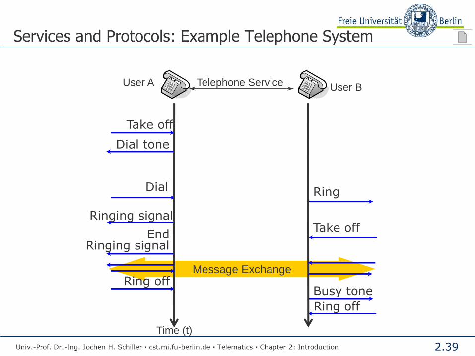
Message Exchange
Services and Protocols: Example Telephone System
Time (t)
Take off
Dial tone
Dial
Ringing signal
Ring
Take off
Ring off Busy tone
Ring off
End Ringing signal
User A User B Telephone Service
Univ.-Prof. Dr.-Ing. Jochen H. Schiller ▪ cst.mi.fu-berlin.de ▪ Telematics ▪ Chapter 2: Introduction

2.40
Message Exchange
Services and Protocols: Example Telephone System
Time (t)
Take off
Dial tone
Dial
Ringing signal
Ring
Take off
Ring off Busy tone
Ring off
End Ringing signal
User A User B Telephone Service
Univ.-Prof. Dr.-Ing. Jochen H. Schiller ▪ cst.mi.fu-berlin.de ▪ Telematics ▪ Chapter 2: Introduction

2.41
Services and Protocols: Example Telephone System
● Signaling protocol in the plain old telephone service (POTS)
Network
Tim
e (
t)
...
User A User B
Take off
Dial tone
Dial
Ringing signal Ring
Take off
Ring off Busy tone
Ring off
End Ringing signal
Access point Access point
Message Exchange
Univ.-Prof. Dr.-Ing. Jochen H. Schiller ▪ cst.mi.fu-berlin.de ▪ Telematics ▪ Chapter 2: Introduction
2.42
The Notion of Service
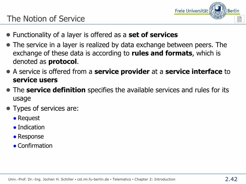
● Functionality of a layer is offered as a set of services
● The service in a layer is realized by data exchange between peers. The
exchange of these data is according to rules and formats, which is
denoted as protocol.
● A service is offered from a service provider at a service interface to
service users
● The service definition specifies the available services and rules for its
usage
● Types of services are:
● Request
● Indication
● Response
● Confirmation
Univ.-Prof. Dr.-Ing. Jochen H. Schiller ▪ cst.mi.fu-berlin.de ▪ Telematics ▪ Chapter 2: Introduction

2.43
The Notion of Service
Abstract Medium Mi
Communication Instance
I1i+1
...
Interface events
Service
Interface Si
Service
Access
Point
Communication Instance
I2i+1
Communication Instance
In-1i+1
Communication Instance
Ini+1
Univ.-Prof. Dr.-Ing. Jochen H. Schiller ▪ cst.mi.fu-berlin.de ▪ Telematics ▪ Chapter 2: Introduction

2.44
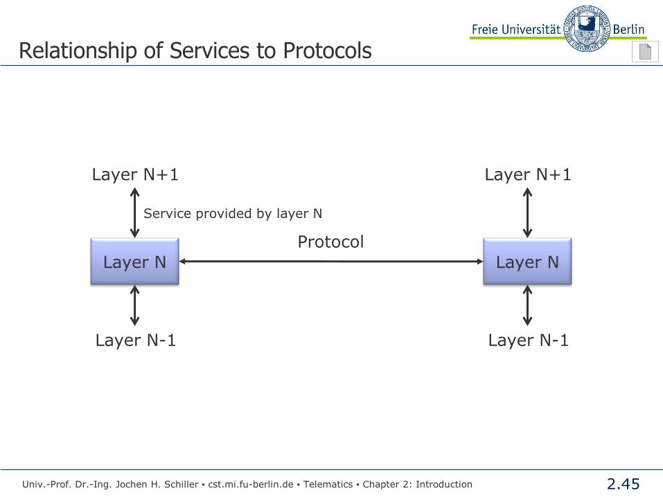
Service of Layer N
● Layer-(N) Service
● Set of functions, which Layer-(N) provides to the (N+1)-Instances at the
interface between Layer-(N) and Layer-(N+1)
● Vertical communication
● The (N)-Instances provide the functions of Layer-(N) by exchanging of particular
data
● Horizontal communication
● For this, they use the services of Layer-(N-1)
● The implementation of the service on Layer-(N) is hidden from Layer-(N+1)
Univ.-Prof. Dr.-Ing. Jochen H. Schiller ▪ cst.mi.fu-berlin.de ▪ Telematics ▪ Chapter 2: Introduction
2.45
Relationship of Services to Protocols
Layer N
Layer N+1
Layer N-1
Layer N
Layer N+1
Layer N-1
Protocol
Service provided by layer N
Univ.-Prof. Dr.-Ing. Jochen H. Schiller ▪ cst.mi.fu-berlin.de ▪ Telematics ▪ Chapter 2: Introduction

2.46
Horizontal vs. Vertical Communication
Philosopher A
Language: Chinese
Interpreter A
additionally: English
Recognizes single
characters and sends
them in Morse code
Network
Technical Expert A
Language: Chinese
Philosopher B
Language: Spanish
Interpreter B
additionally: English
Recognizes single
characters and sends
them in Morse code
Technical Expert B
Language: Spanish
service
Horizontal Communication
Horizontal Communication
Horizontal Communication
Vertic
al C
om
munic
atio
n
Vertic
al C
om
munic
atio
n
Univ.-Prof. Dr.-Ing. Jochen H. Schiller ▪ cst.mi.fu-berlin.de ▪ Telematics ▪ Chapter 2: Introduction

2.47
Types of Services
● Unacknowledged Service
● Modeled after the postal service
● Initiated by the service user
● Initiated by the service provider
● Acknowledged Service
● Transaction
● Initiated by the service user
Univ.-Prof. Dr.-Ing. Jochen H. Schiller ▪ cst.mi.fu-berlin.de ▪ Telematics ▪ Chapter 2: Introduction
t t
Indication Indication
Request
Indication
t t
Request
Indication
t t
Confirmation
Response

2.48
Types of Services
● Connection-oriented Service
● Modeled after the telephone system
● Before the instances on Layer-(N) can
exchange data, a connection on
Layer-(N-1) has to be established
● Request of such a connection is done by
the services provided by Layer-(N-1)
● Negotiation of protocol parameters
● Buffer size
● Quality of Service (QoS)
● Routes, etc.
● Exchange of data happens in respect
to these parameters
● Communication context
● Connectionless Service
● Modeled after the postal service
● No establishment of connection on
a lower layer required
● Each data exchange is independent
from others
● No communication context
Univ.-Prof. Dr.-Ing. Jochen H. Schiller ▪ cst.mi.fu-berlin.de ▪ Telematics ▪ Chapter 2: Introduction

2.49
Connection-oriented Service
3 Phase Principle
1. Connection establishment
● Context creation
● End systems
● Network
2. Data exchange (simplex)
● Data transmission is done within
the context
3. Connection termination
● Context release
● Resource release
Univ.-Prof. Dr.-Ing. Jochen H. Schiller ▪ cst.mi.fu-berlin.de ▪ Telematics ▪ Chapter 2: Introduction
Disconnect Request
Disconnect Indication
Service Request
Service Indication
Connection Request
Connection Indication
Connection Confirmation
Connection Response
Service Request
Service Indication

2.50
Connectionless Service
● Connectionless Service is also called Datagram Service
● Does not provide relationship between transmissions
● Does not guarantee the sequence of send data
● Does not provide reliability
● No acks!
Medium UnitData.Req( Source address, Dest address, Parameter, Data )
UnitData.Ind( Source address, Dest address, Parameter, Data )
Univ.-Prof. Dr.-Ing. Jochen H. Schiller ▪ cst.mi.fu-berlin.de ▪ Telematics ▪ Chapter 2: Introduction
UnitData.Req( Source address, Dest address, Parameter, Data )
UnitData.Ind( Source address, Dest address, Parameter, Data )
UnitData.Req( Source address, Dest address, Parameter, Data )
UnitData.Ind( Source address, Dest address, Parameter, Data )
2.51
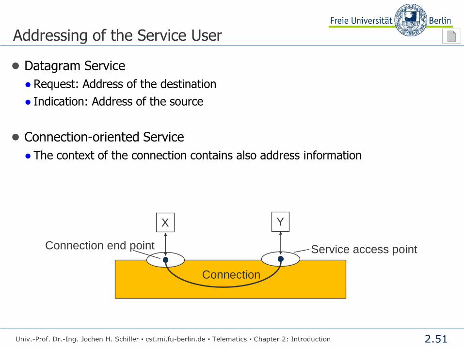
Addressing of the Service User
● Datagram Service
● Request: Address of the destination
● Indication: Address of the source
● Connection-oriented Service
● The context of the connection contains also address information
Univ.-Prof. Dr.-Ing. Jochen H. Schiller ▪ cst.mi.fu-berlin.de ▪ Telematics ▪ Chapter 2: Introduction
Service access point
Connection
Connection end point
Y X

2.52
Types of Services: Example Services
Service Example
Reliable message stream Sequence of pages
Reliable byte stream Remote login
Unreliable connection Digitized voice
Unreliable datagram Electronic junk mail
Acknowledged datagram Registered mail
Request-reply Database query
Connection-oriented
Connection-less
Univ.-Prof. Dr.-Ing. Jochen H. Schiller ▪ cst.mi.fu-berlin.de ▪ Telematics ▪ Chapter 2: Introduction
2.53
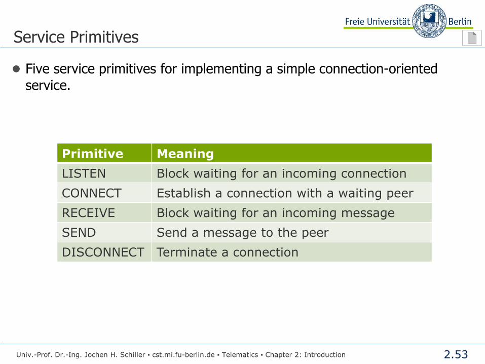
Service Primitives
● Five service primitives for implementing a simple connection-oriented
service.
Primitive Meaning
LISTEN Block waiting for an incoming connection
CONNECT Establish a connection with a waiting peer
RECEIVE Block waiting for an incoming message
SEND Send a message to the peer
DISCONNECT Terminate a connection
Univ.-Prof. Dr.-Ing. Jochen H. Schiller ▪ cst.mi.fu-berlin.de ▪ Telematics ▪ Chapter 2: Introduction

2.54
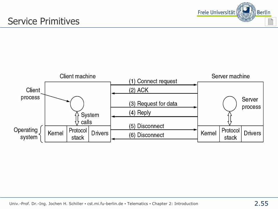
Service Primitives
Client Server
Connection-Req.
Listen
Connect
Connection-Accepted Receive
Send Data
Receive Send
Data
Disconnect Disconnection-Req.
Receive
Disconnect Disconnection-Accepted
Receive
Univ.-Prof. Dr.-Ing. Jochen H. Schiller ▪ cst.mi.fu-berlin.de ▪ Telematics ▪ Chapter 2: Introduction
2.55
Service Primitives
Univ.-Prof. Dr.-Ing. Jochen H. Schiller ▪ cst.mi.fu-berlin.de ▪ Telematics ▪ Chapter 2: Introduction

2.56
The ISO/OSI Reference Model
Univ.-Prof. Dr.-Ing. Jochen H. Schiller ▪ cst.mi.fu-berlin.de ▪ Telematics ▪ Chapter 2: Introduction

2.57
Layer 5 and 6 are rarely implemented
Application 7
Presentation 6
Session 5
Transport 4
Network 3
Data Link 2
1
Common services for the end user
Network-independent end-to-end data transfer
Addressing and routing of “packets”
Securing of “frames”, Flow Control
Physical Signal representation, character transmission
Criticism of the model
The 7 ISO/OSI layers:
Transmission medium (“Layer 0”)
Generally too much overhead – some details are unnecessary, some layers are overloaded
Reduce the complexity of a communication process through layers.
The ISO/OSI Reference Model
Univ.-Prof. Dr.-Ing. Jochen H. Schiller ▪ cst.mi.fu-berlin.de ▪ Telematics ▪ Chapter 2: Introduction
2.58
Layer Tasks
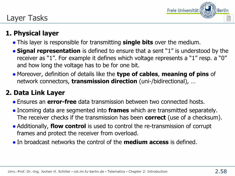
1. Physical layer
● This layer is responsible for transmitting single bits over the medium.
● Signal representation is defined to ensure that a sent “1” is understood by the
receiver as “1”. For example it defines which voltage represents a “1” resp. a “0”
and how long the voltage has to be for one bit.
● Moreover, definition of details like the type of cables, meaning of pins of
network connectors, transmission direction (uni-/bidirectional), …
2. Data Link Layer
● Ensures an error-free data transmission between two connected hosts.
● Incoming data are segmented into frames which are transmitted separately.
The receiver checks if the transmission has been correct (use of a checksum).
● Additionally, flow control is used to control the re-transmission of corrupt
frames and protect the receiver from overload.
● In broadcast networks the control of the medium access is defined.
Univ.-Prof. Dr.-Ing. Jochen H. Schiller ▪ cst.mi.fu-berlin.de ▪ Telematics ▪ Chapter 2: Introduction
2.59
Layer Tasks
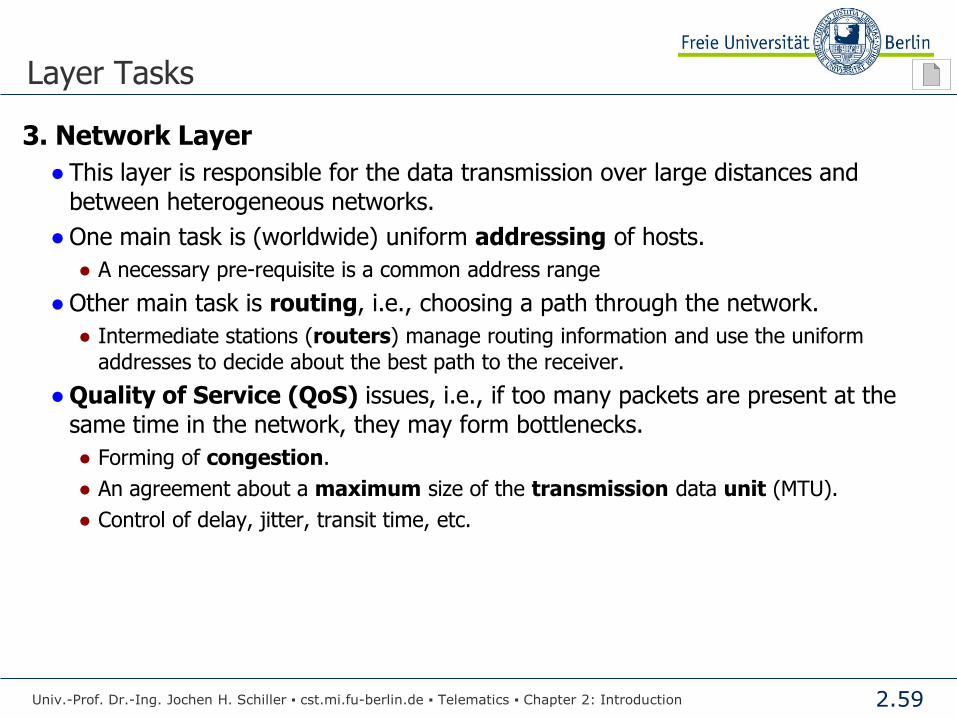
3. Network Layer
● This layer is responsible for the data transmission over large distances and
between heterogeneous networks.
● One main task is (worldwide) uniform addressing of hosts.
● A necessary pre-requisite is a common address range
● Other main task is routing, i.e., choosing a path through the network.
● Intermediate stations (routers) manage routing information and use the uniform
addresses to decide about the best path to the receiver.
● Quality of Service (QoS) issues, i.e., if too many packets are present at the
same time in the network, they may form bottlenecks.
● Forming of congestion.
● An agreement about a maximum size of the transmission data unit (MTU).
● Control of delay, jitter, transit time, etc.
Univ.-Prof. Dr.-Ing. Jochen H. Schiller ▪ cst.mi.fu-berlin.de ▪ Telematics ▪ Chapter 2: Introduction
2.60
Layer Tasks
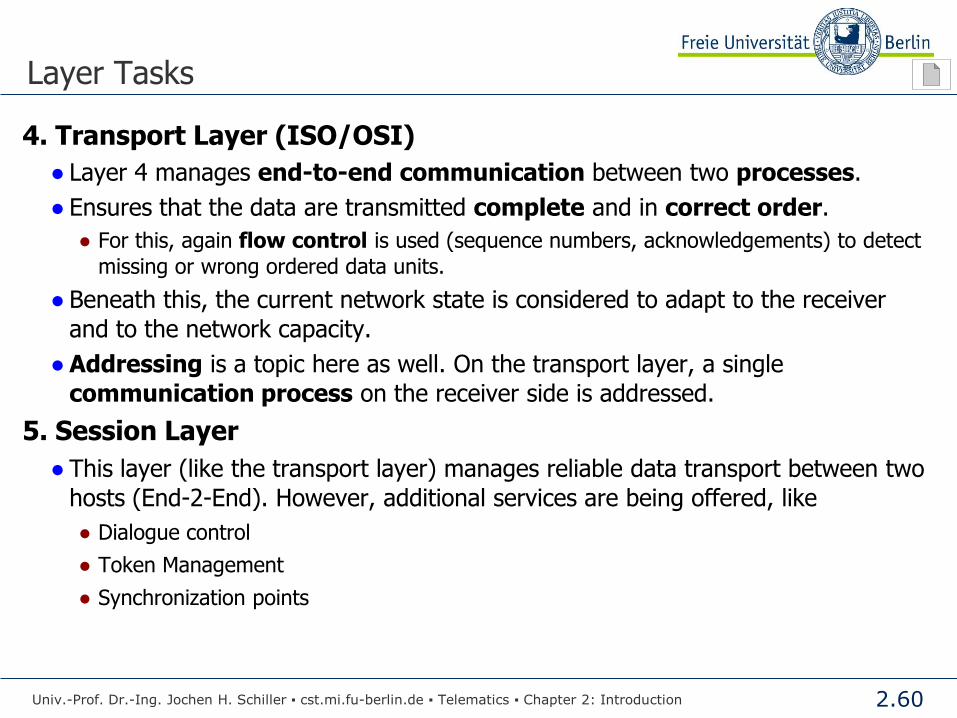
4. Transport Layer (ISO/OSI)
● Layer 4 manages end-to-end communication between two processes.
● Ensures that the data are transmitted complete and in correct order.
● For this, again flow control is used (sequence numbers, acknowledgements) to detect
missing or wrong ordered data units.
● Beneath this, the current network state is considered to adapt to the receiver
and to the network capacity.
● Addressing is a topic here as well. On the transport layer, a single
communication process on the receiver side is addressed.
5. Session Layer
● This layer (like the transport layer) manages reliable data transport between two
hosts (End-2-End). However, additional services are being offered, like
● Dialogue control
● Token Management
● Synchronization points
Univ.-Prof. Dr.-Ing. Jochen H. Schiller ▪ cst.mi.fu-berlin.de ▪ Telematics ▪ Chapter 2: Introduction

2.61
Layer Tasks
6. Presentation Layer
● Represent the data in an platform independent format
● Some computers code a string with ASCII others use Unicode, some use for integers the
1-complement others the 2-complement.
● Instead of defining a new transmission syntax and –semantics for every application, the
goal is to provide a universally valid solution.
● Data are encoded in an abstract (and commonly recognized) data format
before the transmission and are coded back by the receiver into its own data
format.
7. Application Layer (ISO/OSI)
● In this layer (standard-) protocols are provided which can be used from a set of
applications and computer systems, e.g., file transfer.
● On the application layer a universally valid protocol including an interface to file
transfer is provided. For systems from different manufacturers only the link-up
into the local file system has to be realized.
Univ.-Prof. Dr.-Ing. Jochen H. Schiller ▪ cst.mi.fu-berlin.de ▪ Telematics ▪ Chapter 2: Introduction

2.62
Interplay between the Layers
● Layer (N-1) offers its functionality to the above lying layer N as a communication service.
● Layer N enhances the data to be sent with control information (Header) and sends the data together with the header as Protocol Data Units (PDU).
● Two communication partners on layer N exchange PDUs by using the communication service of the lower layer (N-1).
● For layer (N-1), these PDUs are the data to be transmitted.
Univ.-Prof. Dr.-Ing. Jochen H. Schiller ▪ cst.mi.fu-berlin.de ▪ Telematics ▪ Chapter 2: Introduction
Layer (N-1) Layer (N-1)
Layer N Layer N N-PDU
Data H
(N-1)-PDU H: Header, e.g., control information of the layer

2.63
The whole Communication Process
Physical Layer
Data Link Layer
Network Layer
Transport Layer
Session Layer
Presentation Layer
Application Layer
Physical Layer
Data Link Layer
Network Layer
Transport Layer
Session Layer
Presentation Layer
Application process
Data
Data H
A-PDU H
P-PDU H
S-PDU H
T-PDU H
N-PDU H
Transmission medium
Bit stream (100110010110…010101101)
T
Application process
Application Layer
Univ.-Prof. Dr.-Ing. Jochen H. Schiller ▪ cst.mi.fu-berlin.de ▪ Telematics ▪ Chapter 2: Introduction
2.64
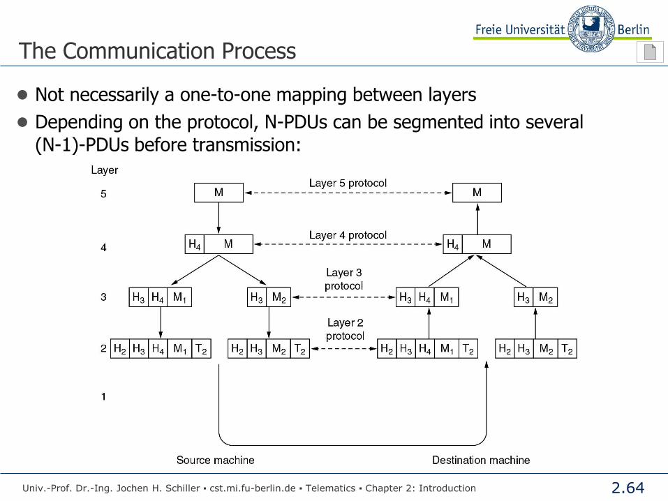
The Communication Process
● Not necessarily a one-to-one mapping between layers
● Depending on the protocol, N-PDUs can be segmented into several
(N-1)-PDUs before transmission:
Univ.-Prof. Dr.-Ing. Jochen H. Schiller ▪ cst.mi.fu-berlin.de ▪ Telematics ▪ Chapter 2: Introduction

2.65
Host A Host B
Transport Protocol
Session Protocol
Presentation Protocol
Application Protocol
The OSI Reference Model in the Network
Physical Layer
Data Link Layer
Network Layer
Transport Layer
Session Layer
Presentation Layer
Application process
Application Layer
Physical Layer
Data Link Layer
Network Layer
Transport Layer
Session Layer
Presentation Layer
Application process
Application Layer
Univ.-Prof. Dr.-Ing. Jochen H. Schiller ▪ cst.mi.fu-berlin.de ▪ Telematics ▪ Chapter 2: Introduction
Network Protocol
Data Link Protocol
Physical Protocol
Physical Layer
Data Link Layer
Network Layer
Physical Layer
Data Link Layer
Network Layer
Router A Router B
Internal Protocols

2.66
The TCP/IP Reference Model
Univ.-Prof. Dr.-Ing. Jochen H. Schiller ▪ cst.mi.fu-berlin.de ▪ Telematics ▪ Chapter 2: Introduction
2.67
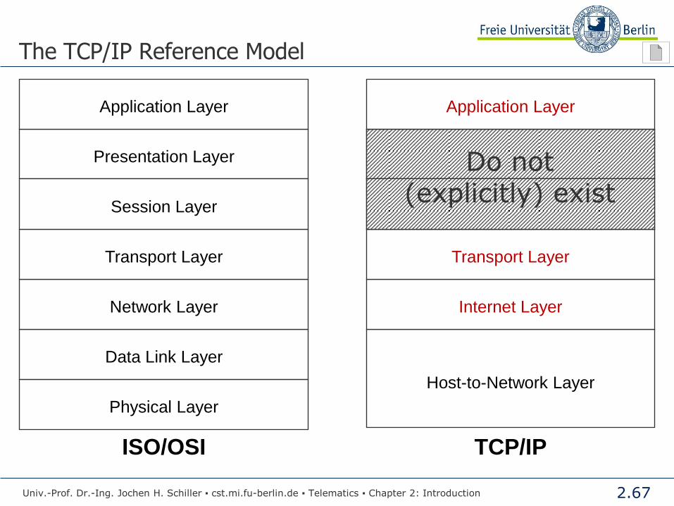
The TCP/IP Reference Model
Host-to-Network Layer
Application Layer Application Layer
Presentation Layer
Session Layer
Transport Layer Transport Layer
Network Layer Internet Layer
Data Link Layer
Physical Layer
ISO/OSI TCP/IP
Univ.-Prof. Dr.-Ing. Jochen H. Schiller ▪ cst.mi.fu-berlin.de ▪ Telematics ▪ Chapter 2: Introduction
Do not (explicitly) exist
2.68
The Tasks of the TCP/IP Layers
● Host-to-Network Layer (corresponds to ISO/OSI 1-2)
● Not defined exactly. The design does not matter, it is only required that a host
must be connected to the network via a protocol in a way that it is able to send and
receive IP datagrams. The protocol design is left over to other standards to cover
heterogeneous networks of all kinds.
● Internet Layer (corresponds to ISO/OSI 3)
● The term Internet refers here to the interworking of different networks, therefore
not to the Internet itself.
● The protocol enables communication between hosts over the own network borders.
● In the Internet, the transmission is connectionless, i.e., data are segmented into packets
which are addressed and sent independently into the network.
● At each network border, a router takes over the forwarding of the packets. The choice of path
can be dynamic, depending on the current network load.
● As a result, single packets can get lost by overload situations or received in wrong order. Such
faults are not handled, this task is left over to the transport layer (best effort).
● In contrast to ISO, only one packet format is defined, together with a connectionless
protocol, the Internet Protocol (IP).
Univ.-Prof. Dr.-Ing. Jochen H. Schiller ▪ cst.mi.fu-berlin.de ▪ Telematics ▪ Chapter 2: Introduction

2.69
The Layers of TCP/IP
● Transport Layer (corresponds to ISO/OSI 4)
● This layer covers the communication between the end systems. To adapt to different applications, two protocols are defined.
● TCP (Transmission Control Protocol) is a reliable, connection-oriented protocol to protect the transmission of a byte stream between two hosts. ● The byte stream is segmented to fit into IP packets.
● On the receiving side the packets are re-assembled in the original order with the purpose of restoring the original data (byte) stream.
● It also includes flow control to adapt to the capabilities of the receiver and to overcome the faults caused by the connectionless IP.
● UDP (User Datagram Protocol) is an unreliable and connectionless protocol (best effort). No error correction is integrated, thus the transmission is used when the speed of the data transmission is more important than the reliability (speech, video).
● Application Layer (corresponds to ISO/OSI 7)
● This layer defines common communication services. This comprises TELNET (remote work on another computer), FTP (file transfer), SMTP (electronic mail), DNS (“phonebook” for the Internet), HTTP (used for World Wide Web), etc.
Univ.-Prof. Dr.-Ing. Jochen H. Schiller ▪ cst.mi.fu-berlin.de ▪ Telematics ▪ Chapter 2: Introduction

2.70
The TCP/IP Reference Model
Application
Transport
Network
Physical + Data Link
Wireless LAN Ethernet Token Ring Token Bus
FTP Telnet SMTP DNS SNMP HTTP
UDP TCP
IP
Univ.-Prof. Dr.-Ing. Jochen H. Schiller ▪ cst.mi.fu-berlin.de ▪ Telematics ▪ Chapter 2: Introduction

2.71
OSI vs. TCP/IP
Univ.-Prof. Dr.-Ing. Jochen H. Schiller ▪ cst.mi.fu-berlin.de ▪ Telematics ▪ Chapter 2: Introduction

2.72
OSI vs. TCP/IP
● Time
● The TCP/IP protocols were already widely used before OSI had finished the
standardization activities.
● Freedom from obligation
● A “reference model” like OSI is free from obligation. It only defines what is to be
done, but not how to do it.
incompatibility of products.
● Complicatedness
● Very high and partly unneeded expense in the OSI specification (thousands of
pages of specification descriptions).
● By the wish to consider all special cases, lots of options were included, making
the products lavish, unhandy, and far too expensive
“The option is the enemy of the standard”!
Univ.-Prof. Dr.-Ing. Jochen H. Schiller ▪ cst.mi.fu-berlin.de ▪ Telematics ▪ Chapter 2: Introduction
2.73
OSI vs. TCP/IP
● Political reasons
● OSI was dominated too much by Europe – especially from the national
telecommunication companies which had lucrative monopolies. The real market
power was in the USA – nobody was interested in OSI over there.
● Hurriedly product implementation
● The first OSI products were implemented too fast (driven by the success of
TCP/IP protocols), were covered with faults, and had an overall low
performance.
● In contrast, the “theoretically far more unmodern” TCP/IP protocols were
continuously modified and improved. They were of high quality level and
successfully tested before deployment and cheap to buy due to high production
numbers.
Univ.-Prof. Dr.-Ing. Jochen H. Schiller ▪ cst.mi.fu-berlin.de ▪ Telematics ▪ Chapter 2: Introduction
2.74
Standardization
Univ.-Prof. Dr.-Ing. Jochen H. Schiller ▪ cst.mi.fu-berlin.de ▪ Telematics ▪ Chapter 2: Introduction
2.75
Standardization
● Standardization is indispensable for the area-wide practical use of
communication systems
● On the national as well as the international level!
● Successful standardization is quite difficult due to:
● Complex technical problems have to be solved
● The involved parties, e.g., companies are often working against each other
● Confidentially restrictions slow down/hinder the information flow
● Consequence
● Standardization processes are very slow (due to many, often non-technical
reasons).
● Two types of standards
● De facto standards
● De jure standards
Univ.-Prof. Dr.-Ing. Jochen H. Schiller ▪ cst.mi.fu-berlin.de ▪ Telematics ▪ Chapter 2: Introduction
2.76
Standardization: The Global Players
● ITU www.itu.int
International Telecommunication Union
United Nations agency for information and communication technologies
● Radiocommunication (ITU-R)
● Standardization (ITU-T)
● Development (ITU-D)
● ISO www.iso.org
International Organization for Standardization (ISO Greek “uniform”)
● ISO coordinates the standardization except from PTT
● W3C http://www.w3.org
● World Wide Web Consortium: Develops standards for the web.
● DIN www.din.de
(Deutsches Institut für Normung)
● German partner of the ISO
Univ.-Prof. Dr.-Ing. Jochen H. Schiller ▪ cst.mi.fu-berlin.de ▪ Telematics ▪ Chapter 2: Introduction

2.77
Standardization: ISO
●International Organization for Standardization (ISO)
● Organization, which is working on a volunteer basis (since 1946).
● Members: standards organizations of approx. 90 countries
● Deals with a very broad range of standards
● 200 Technical Committees (TC) for specific tasks (e.g. TC97 for computer and information processing)
● TCs consist of subcommittees comprising in turn several working groups
● Interworking with ITU-T regarding telecommunication standards, (ISO is a member of ITU-T).
● Pioneering work of ISO regarding data communication: the ISO/OSI
reference model
● Open Systems Interconnection (OSI)
● Notice: only the concept is pioneering, not the products developed from those concepts!
Univ.-Prof. Dr.-Ing. Jochen H. Schiller ▪ cst.mi.fu-berlin.de ▪ Telematics ▪ Chapter 2: Introduction
www.iso.org

2.78
Standardization: ISO
● WG-Meetings:
● Every 6-9 months to give the national organizations time to check the proposals.
● The process of standardization ● DP: Draft Proposal
● DIS: Draft International Standard
● IS: International Standard
● A proposal gets higher in the hierarchy after an international vote and the incorporation of critics.
A very slow process!!!
ISO
Technical Committee (TC)
SubCommittee (SC)
Working Group (WG)
. . . . . . . .
. . . . . . . .
. . . . . . . .
Univ.-Prof. Dr.-Ing. Jochen H. Schiller ▪ cst.mi.fu-berlin.de ▪ Telematics ▪ Chapter 2: Introduction
2.79
Standardization: IETF
● Internet Engineering Task Force (IETF)
● Forum for the technical coordination of the work regarding ARPANET, the precursor of the Internet (since 1986).
● Evolution to a large, open, and international community of administrators, vendors, and researchers.
● Works on evolution of the Internet architecture and the smooth operation of the Internet.
● Several working groups on Internet protocols, applications, routing, security, …
● Standard draft proposals can become a full standard only if an implementation of the proposal is successfully tested at two independent locations for at least four month.
● Result of such a standardization process: the resounding success of the Internet protocols TCP/IP
www.ietf.org
Univ.-Prof. Dr.-Ing. Jochen H. Schiller ▪ cst.mi.fu-berlin.de ▪ Telematics ▪ Chapter 2: Introduction
2.80
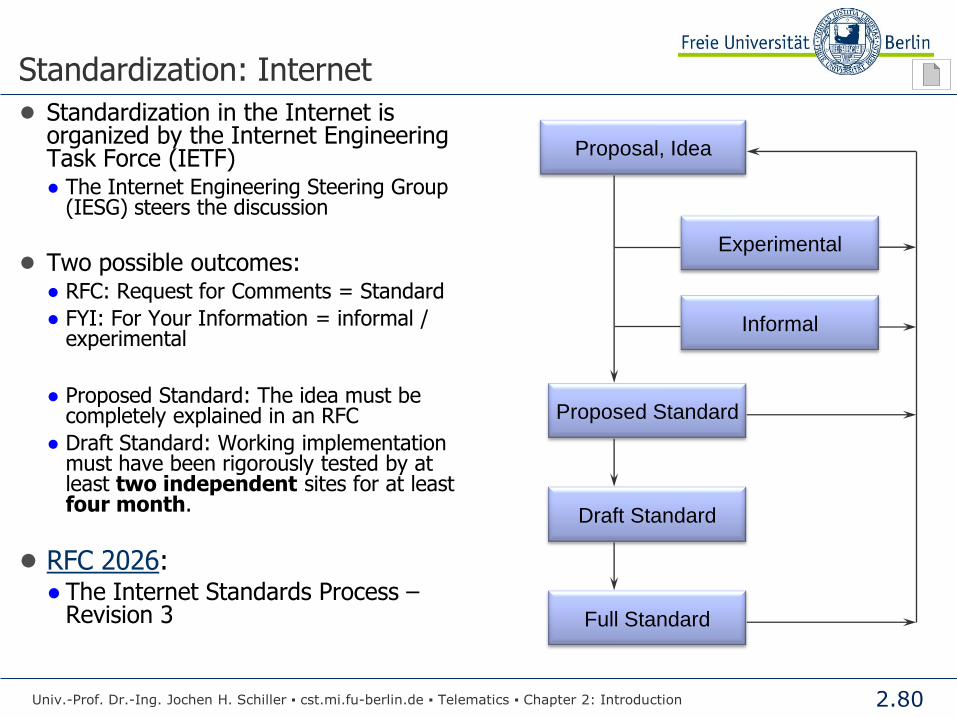
Standardization: Internet
● Standardization in the Internet is organized by the Internet Engineering Task Force (IETF) ● The Internet Engineering Steering Group
(IESG) steers the discussion
● Two possible outcomes: ● RFC: Request for Comments = Standard
● FYI: For Your Information = informal / experimental
● Proposed Standard: The idea must be
completely explained in an RFC
● Draft Standard: Working implementation must have been rigorously tested by at least two independent sites for at least four month.
● RFC 2026: ● The Internet Standards Process –
Revision 3
Proposal, Idea
Proposed Standard
Draft Standard
Full Standard
Experimental
Informal
Univ.-Prof. Dr.-Ing. Jochen H. Schiller ▪ cst.mi.fu-berlin.de ▪ Telematics ▪ Chapter 2: Introduction
2.81
Standardization: Internet
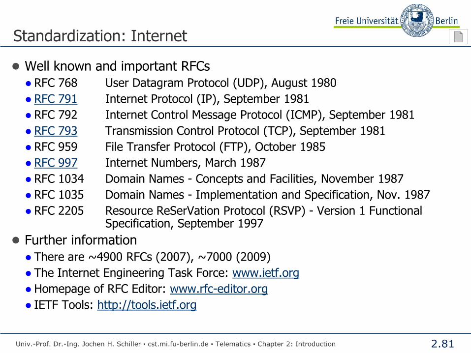
● Well known and important RFCs
● RFC 768 User Datagram Protocol (UDP), August 1980
● RFC 791 Internet Protocol (IP), September 1981
● RFC 792 Internet Control Message Protocol (ICMP), September 1981
● RFC 793 Transmission Control Protocol (TCP), September 1981
● RFC 959 File Transfer Protocol (FTP), October 1985
● RFC 997 Internet Numbers, March 1987
● RFC 1034 Domain Names - Concepts and Facilities, November 1987
● RFC 1035 Domain Names - Implementation and Specification, Nov. 1987
● RFC 2205 Resource ReSerVation Protocol (RSVP) - Version 1 Functional Specification, September 1997
● Further information
● There are ~4900 RFCs (2007), ~7000 (2009)
● The Internet Engineering Task Force: www.ietf.org
● Homepage of RFC Editor: www.rfc-editor.org
● IETF Tools: http://tools.ietf.org
Univ.-Prof. Dr.-Ing. Jochen H. Schiller ▪ cst.mi.fu-berlin.de ▪ Telematics ▪ Chapter 2: Introduction
2.82
Standardization: Internet
Univ.-Prof. Dr.-Ing. Jochen H. Schiller ▪ cst.mi.fu-berlin.de ▪ Telematics ▪ Chapter 2: Introduction
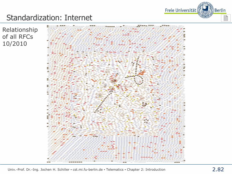
Relationship of all RFCs 10/2010
2.83
Standardization: Internet
Univ.-Prof. Dr.-Ing. Jochen H. Schiller ▪ cst.mi.fu-berlin.de ▪ Telematics ▪ Chapter 2: Introduction
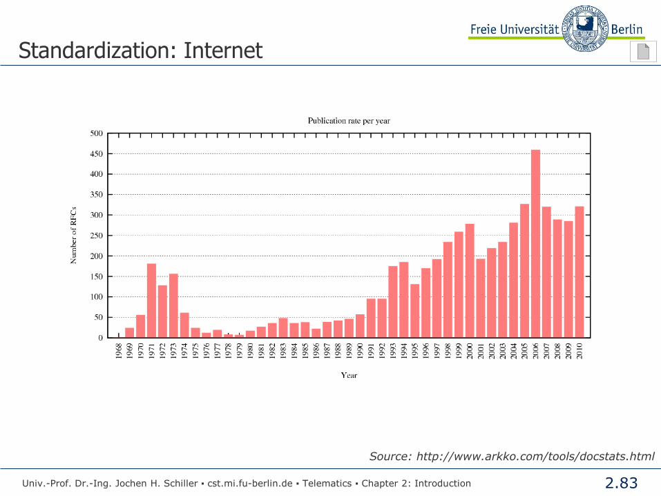
Source: http://www.arkko.com/tools/docstats.html
2.84
Standardization: IEEE
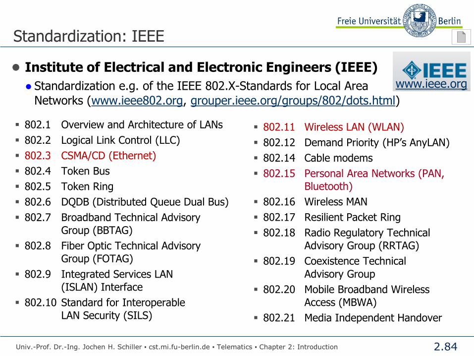
● Institute of Electrical and Electronic Engineers (IEEE)
● Standardization e.g. of the IEEE 802.X-Standards for Local Area
Networks (www.ieee802.org, grouper.ieee.org/groups/802/dots.html)
802.1 Overview and Architecture of LANs
802.2 Logical Link Control (LLC)
802.3 CSMA/CD (Ethernet)
802.4 Token Bus
802.5 Token Ring
802.6 DQDB (Distributed Queue Dual Bus)
802.7 Broadband Technical Advisory
Group (BBTAG)
802.8 Fiber Optic Technical Advisory
Group (FOTAG)
802.9 Integrated Services LAN
(ISLAN) Interface
802.10 Standard for Interoperable
LAN Security (SILS)
802.11 Wireless LAN (WLAN)
802.12 Demand Priority (HP’s AnyLAN)
802.14 Cable modems
802.15 Personal Area Networks (PAN,
Bluetooth)
802.16 Wireless MAN
802.17 Resilient Packet Ring
802.18 Radio Regulatory Technical
Advisory Group (RRTAG)
802.19 Coexistence Technical
Advisory Group
802.20 Mobile Broadband Wireless
Access (MBWA)
802.21 Media Independent Handover
Univ.-Prof. Dr.-Ing. Jochen H. Schiller ▪ cst.mi.fu-berlin.de ▪ Telematics ▪ Chapter 2: Introduction
www.ieee.org

2.85
Evolution of Computer Networks
Univ.-Prof. Dr.-Ing. Jochen H. Schiller ▪ cst.mi.fu-berlin.de ▪ Telematics ▪ Chapter 2: Introduction

2.86
First Generation Computer Networks
Univ.-Prof. Dr.-Ing. Jochen H. Schiller ▪ cst.mi.fu-berlin.de ▪ Telematics ▪ Chapter 2: Introduction
MainframeOperator
PeripheralsTerminals
Rest of
the world
Computing Center
Terminals
MultiplexerDemultiplexer
Telephone lines

2.87
Introduction of Local Area Networks
Univ.-Prof. Dr.-Ing. Jochen H. Schiller ▪ cst.mi.fu-berlin.de ▪ Telematics ▪ Chapter 2: Introduction
MainframeOperator
PeripheralsTerminals
Computing Center
Fixed lines
Router
Building C
Building B
Building A
Rest of
the world

2.88
Global Networking
Univ.-Prof. Dr.-Ing. Jochen H. Schiller ▪ cst.mi.fu-berlin.de ▪ Telematics ▪ Chapter 2: Introduction
Mainframe
Peripherals
Computing Center
Fixed lines,
Router
Building A
Router
Switch
Clients
LocalServer
Building B
Router
Switch
Clients
LocalServer Switch
Router Server Network and system
administrator
Backbone
Rest of the world
(Internet)
ISDN, Provider ...

2.89
Classification of Computer Networks
Univ.-Prof. Dr.-Ing. Jochen H. Schiller ▪ cst.mi.fu-berlin.de ▪ Telematics ▪ Chapter 2: Introduction

2.90
Classification of Networks
Classification of networks by distance:
Local Area Network (LAN)
Metropolitan Area Network (MAN)
Wide Area Network (WAN)
Body/Personal Area Network (B/PAN)
Internet
Distance Example
1 m Body
10 m Room
100 m Building
1 km Campus
10 km Town
100 km Country
1000 km Continent
10000 km Planet
Univ.-Prof. Dr.-Ing. Jochen H. Schiller ▪ cst.mi.fu-berlin.de ▪ Telematics ▪ Chapter 2: Introduction
2.91
Local Area Networks
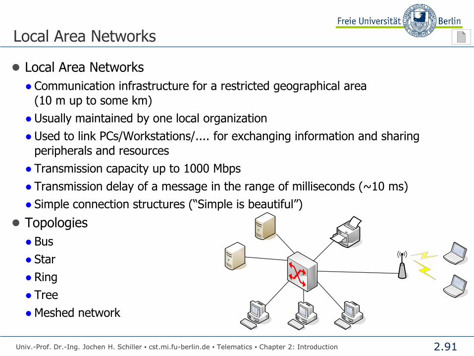
● Local Area Networks
● Communication infrastructure for a restricted geographical area
(10 m up to some km)
● Usually maintained by one local organization
● Used to link PCs/Workstations/.... for exchanging information and sharing
peripherals and resources
● Transmission capacity up to 1000 Mbps
● Transmission delay of a message in the range of milliseconds (~10 ms)
● Simple connection structures (“Simple is beautiful”)
● Topologies
● Bus
● Star
● Ring
● Tree
● Meshed network
Univ.-Prof. Dr.-Ing. Jochen H. Schiller ▪ cst.mi.fu-berlin.de ▪ Telematics ▪ Chapter 2: Introduction

2.92
Metropolitan Area Network (MAN)
● Designed for larger distances than a LAN
● usage e.g. in a whole town
● Similar technologies as in a LAN
● In general, only 1 or 2 cables without additional components
● Main difference to LANs: Time slots
Univ.-Prof. Dr.-Ing. Jochen H. Schiller ▪ cst.mi.fu-berlin.de ▪ Telematics ▪ Chapter 2: Introduction

2.93
Wide Area Network (WAN)
● Bridging of any distance
● Connects LANs and MANs over large distances
● Irregular topology, based on current needs
● Consists out of stations (routers) which are connected through point-to-
point links with each other
● Mostly complex interconnection of subnetworks, which are owned by
independent organizations
Univ.-Prof. Dr.-Ing. Jochen H. Schiller ▪ cst.mi.fu-berlin.de ▪ Telematics ▪ Chapter 2: Introduction
Router
Host LAN

2.94
Important Terms
● Switch
● A switch has several connectors. From each connector a cable can be drawn to a
computer. These computers are linked to a (small) network. The switch knows
which computer is plugged in at which connector (address of the network
interface card) and forwards data to a destination computer.
● Router
● A switch only knows directly connected computers. To send data to a distant
computer, some other instance is needed that knows the way to the destination
over several other computers or switches. Routers are used to manage global
address information and forward data through networks.
● Backbone
● A backbone is a set of computers (usually routers) which are connected by point-
to-point links over large distances. A backbone serves for covering a large region
with a communication network which can interconnect (small) local networks of
single institutions.
Univ.-Prof. Dr.-Ing. Jochen H. Schiller ▪ cst.mi.fu-berlin.de ▪ Telematics ▪ Chapter 2: Introduction
2.95
Classification of Networks
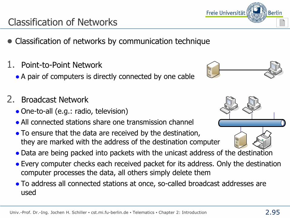
● Classification of networks by communication technique
1. Point-to-Point Network
● A pair of computers is directly connected by one cable
2. Broadcast Network
● One-to-all (e.g.: radio, television)
● All connected stations share one transmission channel
● To ensure that the data are received by the destination,
they are marked with the address of the destination computer
● Data are being packed into packets with the unicast address of the destination
● Every computer checks each received packet for its address. Only the destination
computer processes the data, all others simply delete them
● To address all connected stations at once, so-called broadcast addresses are
used
Univ.-Prof. Dr.-Ing. Jochen H. Schiller ▪ cst.mi.fu-berlin.de ▪ Telematics ▪ Chapter 2: Introduction
2.96
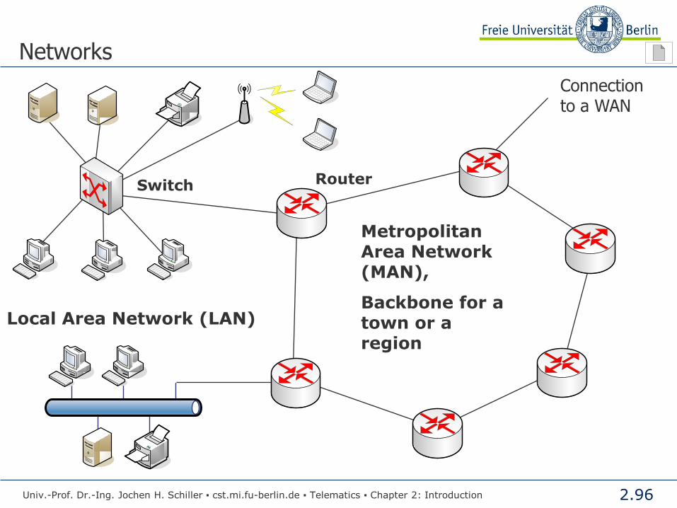
Networks
Switch
Local Area Network (LAN)
Metropolitan Area Network (MAN),
Backbone for a town or a region
Router
Connection to a WAN
Univ.-Prof. Dr.-Ing. Jochen H. Schiller ▪ cst.mi.fu-berlin.de ▪ Telematics ▪ Chapter 2: Introduction

2.97
Leipzig
Berlin
Frankfurt
Karlsruhe
Garching
Kiel
Dresden
Aachen
Regensburg
Kaiserslautern
Augsburg
Hannover
ErlangenHeidelberg
IlmenauWürzburg
Magdeburg
Oldenburg
Essen
St. Augustin
Rostock
Global Upstream
GEANT
Hamburg
Stuttgart
Braunschweig
Marburg
Bielefeld
GöttingenLeipzig
Berlin
Frankfurt
Karlsruhe
Garching
Kiel
Dresden
Aachen
Regensburg
Kaiserslautern
Augsburg
Hannover
ErlangenHeidelberg
IlmenauWürzburg
Magdeburg
Oldenburg
Essen
St. Augustin
Rostock
Global Upstream
GEANT
Hamburg
Stuttgart
Braunschweig
Marburg
Bielefeld
Göttingen
Networks
Point-to-Point connections
Backbone in Germany (till end of 2005)
27 nodes 10 Gbps 2,4 Gbps
2,4 Gbps
Univ.-Prof. Dr.-Ing. Jochen H. Schiller ▪ cst.mi.fu-berlin.de ▪ Telematics ▪ Chapter 2: Introduction

2.98
Networks
● Research backbone in
Germany
● Since 2006 X-WIN
● Connected to the European
Backbone GÉANT
● More than 50 nodes
● Capacities
● 100Mbps
● 200Mbps
● 1Gbps
● 10Gbps
Univ.-Prof. Dr.-Ing. Jochen H. Schiller ▪ cst.mi.fu-berlin.de ▪ Telematics ▪ Chapter 2: Introduction

2.99
Networks
Central node Frankfurt – connection to the European research network Géant.
Also in Frankfurt and Hamburg: intercontinental connections.
Univ.-Prof. Dr.-Ing. Jochen H. Schiller ▪ cst.mi.fu-berlin.de ▪ Telematics ▪ Chapter 2: Introduction

2.100
Summary
● Computer networks have many applications
● Sharing of resources
● Exchange of information
● Computer networks are complex and consists of two parts
● Software
● Hardware
● Model of layers is applied to simplify the complexity
● ISO/OSI
● TCP/IP
● There are many global players in computer networking
● Standardization
● Computer networks
● Different kinds of computer networks exist
● Classification based on distance
● Classification based on communication principle
Univ.-Prof. Dr.-Ing. Jochen H. Schiller ▪ cst.mi.fu-berlin.de ▪ Telematics ▪ Chapter 2: Introduction
2.101
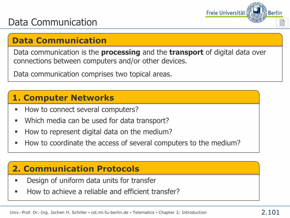
Data Communication
Univ.-Prof. Dr.-Ing. Jochen H. Schiller ▪ cst.mi.fu-berlin.de ▪ Telematics ▪ Chapter 2: Introduction
1. Computer Networks
How to connect several computers?
Which media can be used for data transport?
How to represent digital data on the medium?
How to coordinate the access of several computers to the medium?
2. Communication Protocols
Design of uniform data units for transfer
How to achieve a reliable and efficient transfer?
Data Communication
Data communication is the processing and the transport of digital data over connections between computers and/or other devices.
Data communication comprises two topical areas.

2.102
Data Communication
Univ.-Prof. Dr.-Ing. Jochen H. Schiller ▪ cst.mi.fu-berlin.de ▪ Telematics ▪ Chapter 2: Introduction
Source Transmitter
Transmission System Receiver
Destination
10100111001101011100110101110011010101000001110101
1110001...