telco cloud platform - 5g edition reference architecture
TRANSCRIPT
Telco Cloud Platform - 5G Edition Reference Architecture Guide 2.0
VMware Telco Cloud Platform - 5G Edition 2.0
You can find the most up-to-date technical documentation on the VMware website at:
https://docs.vmware.com/
VMware, Inc.3401 Hillview Ave.Palo Alto, CA 94304www.vmware.com
Copyright ©
2021 VMware, Inc. All rights reserved. Copyright and trademark information.
Telco Cloud Platform - 5G Edition Reference Architecture Guide 2.0
VMware, Inc. 2
Contents
1 About the Telco Cloud Platform 5G Reference Architecture Guide 5
2 Architecture Overview 7Telco 5G Architecture 9
Physical Tier 10
Workload Domain Architecture 11
Network Architecture 12
Storage Architecture 16
Platform Tier 16
Virtual Infrastructure Overview 17
Resource Orchestration Tier 21
Tanzu Standard for Telco Overview 21
vRealize Orchestrator 28
Cloud Automation Tier 28
Telco Cloud Automation Architecture Overview 29
Operations Management Tier 34
Operations Management Overview 34
3 Solution Design 36Physical Design 36
Physical ESXi Host Design 37
Physical Network Design 39
Physical Storage Design 41
Platform Design 43
vCenter Server Design 44
Workload Domains and vSphere Clusters Design 46
Network Virtualization Design 51
NSX Design 56
Shared Storage Design 63
Resource Orchestration Design 64
Tanzu Kubernetes Cluster Design 65
Workload Profile and Tanzu Kubernetes Cluster Sizing 70
Cloud Native Networking Design 74
Cloud Native Storage Design 78
Service and Workload Plane Design 81
Cloud Automation Design 87
Telco Cloud Automation Design 88
TCA VM and Node Config Automation Design 94
VMware, Inc. 3
Container Registry Design 97
CNF Design 100
Operations Management Design 103
vRealize Log Insight Design 104
vRealize Operations Manager Design 106
vRealize Network Insight Design 108
Telco Cloud Platform - 5G Edition Reference Architecture Guide 2.0
VMware, Inc. 4
About the Telco Cloud Platform 5G Reference Architecture Guide 1This reference architecture guide provides guidance for designing and creating a telco cloud by using VMware Telco Cloud Platform™ – 5G Edition.
Intended Audience
This guide is intended for telecommunications and solution architects, sales engineers, field consultants, advanced services specialists, and customers who are responsible for the Virtualized Network Functions (VNFs), Cloud Native Network Functions (CNFs), and the environment in which they run.
Acronyms and Definitions
The following table lists the acronyms used frequently in this guide.
Acronym Definition
AMF Access and Mobility Management Function
AUSF Authentication Server Function
CBRS Citizens Broadband Radio Service
CNTT Common NFVI Telco Task Force
CSP Communications Service Provider
DHCP Dynamic Host Configuration Protocol
DPDK Data Plane Development Kit, an Intel-led packet processing acceleration technology
ETSI European Telecommunications Standards Institute
LCM Life Cycle Management
NFV Network Functions Virtualization
NRF NF Repository Function
N-VDS NSX-managed Virtual Distributed Switch
N-VDS (E) NSX-managed Virtual Distributed Switch in Enhanced Data Path mode
PCIe Peripheral Component Interconnect Express
PCF Policy Control Function
PCRF Policy and Charging Rule Function
VMware, Inc. 5
Acronym Definition
QCI Quality of Service Class Identifier
SMF Session Management Function
SBA Service-Based Architecture
SBI Service-Based Interface
SR-IOV Single Root Input/Output Virtualization
STP Spanning Tree Protocol
SVI Switched Virtual Interface
ToR Switch Top-of-Rack Switch
UDM Unified Data Management
UDR Unified Data Repository
VDS vSphere Distributed Switch
VNF Virtual Network Function
Cloud Native Acronyms
Acronym Definition
CAPV Cluster API Provider vSphere
CMK CPU Manager for Kubernetes
CNI Container Network Interface
CNCF Cloud Native Computing Foundation, a Linux Foundation project designed to help advance the container technology
CNF Cloud Native Network Function executing within a Kubernetes environment
CSAR Cloud Service Archive
CSI Container Storage Interface. vSphere CSI exposes vSphere storage to containerized workloads on container orchestrators, such as Kubernetes. It enables vSAN and other types of vSphere storage.
CNS Cloud Native Storage, a storage solution that provides comprehensive data management for Kubernetes stateful applications.
K8s Kubernetes
PSP Pod Security Policy
TCA Telco Cloud Automation
TCA-CP Telco Cloud Automation-Control Plane
Telco Cloud Platform - 5G Edition Reference Architecture Guide 2.0
VMware, Inc. 6
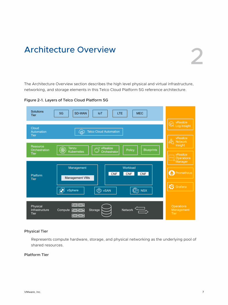
Architecture Overview 2The Architecture Overview section describes the high level physical and virtual infrastructure, networking, and storage elements in this Telco Cloud Platform 5G reference architecture.
Figure 2-1. Layers of Telco Cloud Platform 5G
vRealize Orchestrator
Operations Management Tier
Physical Infrastructure Tier
Platform Tier
Resource Orchestration Tier
Cloud Automation Tier
Solutions Tier 5G SD-WAN LTE MECIoT
Telco Cloud Automation
Tanzu Kubernetes Policy Blueprints
Management VMsCNF CNF CNF
Management Workload
vSphere vSAN NSX
vRealize Log Insight
vRealize Network Insight
vRealize Operations Manager
Compute Storage Network
Prometheus
Grafana
Physical Tier
Represents compute hardware, storage, and physical networking as the underlying pool of shared resources.
Platform Tier
VMware, Inc. 7
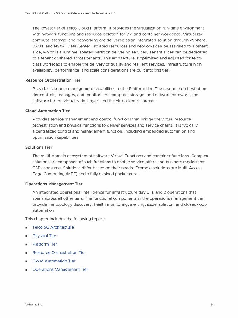
The lowest tier of Telco Cloud Platform. It provides the virtualization run-time environment with network functions and resource isolation for VM and container workloads. Virtualized compute, storage, and networking are delivered as an integrated solution through vSphere, vSAN, and NSX-T Data Center. Isolated resources and networks can be assigned to a tenant slice, which is a runtime isolated partition delivering services. Tenant slices can be dedicated to a tenant or shared across tenants. This architecture is optimized and adjusted for telco-class workloads to enable the delivery of quality and resilient services. Infrastructure high availability, performance, and scale considerations are built into this tier.
Resource Orchestration Tier
Provides resource management capabilities to the Platform tier. The resource orchestration tier controls, manages, and monitors the compute, storage, and network hardware, the software for the virtualization layer, and the virtualized resources.
Cloud Automation Tier
Provides service management and control functions that bridge the virtual resource orchestration and physical functions to deliver services and service chains. It is typically a centralized control and management function, including embedded automation and optimization capabilities.
Solutions Tier
The multi-domain ecosystem of software Virtual Functions and container functions. Complex solutions are composed of such functions to enable service offers and business models that CSPs consume. Solutions differ based on their needs. Example solutions are Multi-Access Edge Computing (MEC) and a fully evolved packet core.
Operations Management Tier
An integrated operational intelligence for infrastructure day 0, 1, and 2 operations that spans across all other tiers. The functional components in the operations management tier provide the topology discovery, health monitoring, alerting, issue isolation, and closed-loop automation.
This chapter includes the following topics:
n Telco 5G Architecture
n Physical Tier
n Platform Tier
n Resource Orchestration Tier
n Cloud Automation Tier
n Operations Management Tier
Telco Cloud Platform - 5G Edition Reference Architecture Guide 2.0
VMware, Inc. 8
Telco 5G Architecture
This section describes the high-level deployment topology most commonly used by Telco CSPs.
Multi-Tier and Distributed Architecture
The 5G network must be dynamic and programmable to meet defined business objectives. Network operators need the ability to provision virtual network slices on-demand with QoS to honor SLA, provision flexible functions to increase capacity using industry-standard APIs, and re-route traffic during congestion predictively and securely.
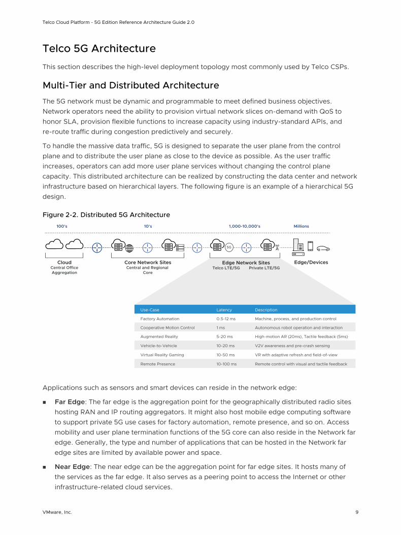
To handle the massive data traffic, 5G is designed to separate the user plane from the control plane and to distribute the user plane as close to the device as possible. As the user traffic increases, operators can add more user plane services without changing the control plane capacity. This distributed architecture can be realized by constructing the data center and network infrastructure based on hierarchical layers. The following figure is an example of a hierarchical 5G design.
Figure 2-2. Distributed 5G Architecture
5G
Use-Case Latency Description
Factory Automation 0.5-12 ms Machine, process, and production control
Cooperative Motion Control 1 ms Autonomous robot operation and interaction
Augmented Reality 5-20 ms High-motion AR (20ms), Tactile feedback (5ms)
Virtual Reality Gaming 10-50 ms VR with adaptive refresh and field-of-view
Vehicle-to-Vehicle 10-20 ms V2V awareness and pre-crash sensing
Remote Presence 10-100 ms Remote control with visual and tactile feedback
100’s 10’s 1,000-10,000’s Millions
CloudCentral OfficeAggregation
Core Network SitesCentral and Regional
Core
Edge Network SitesTelco LTE/5G Private LTE/5G
Edge/Devices
Applications such as sensors and smart devices can reside in the network edge:
n Far Edge: The far edge is the aggregation point for the geographically distributed radio sites hosting RAN and IP routing aggregators. It might also host mobile edge computing software to support private 5G use cases for factory automation, remote presence, and so on. Access mobility and user plane termination functions of the 5G core can also reside in the Network far edge. Generally, the type and number of applications that can be hosted in the Network far edge sites are limited by available power and space.
n Near Edge: The near edge can be the aggregation point for far edge sites. It hosts many of the services as the far edge. It also serves as a peering point to access the Internet or other infrastructure-related cloud services.
Telco Cloud Platform - 5G Edition Reference Architecture Guide 2.0
VMware, Inc. 9
The Central or core layer hosts infrastructure components such as Kubernetes Cluster Management, CICD pipeline, OSS, central monitoring tools, Kubernetes image repository, and so on. Depending on the 5G deployment, control plane functions of the 5G core, subscriber database, and so on, can only reside in the core or regional data center.
Service-Based Architecture
Containers gained immense popularity as a portable and lightweight virtualization solution for 5G Service-Based Architecture (SBA). Kubernetes is one of the components to consider when delivering Carrier-Grade Container as a Service (CaaS). A Carrier-Grade CaaS platform requires a complex ecosystem of solutions and functions to form a pre-set business and operating model. The modernization of the cloud infrastructure changes not only the business model in service agility and metered revenue models, but also challenges the silo operating model.
The basic principles of SBA are independent of vendors, products, and technologies. A service is a discrete unit of functionality that can be accessed remotely and acted upon and updated independently. SBAs improve the modularity of products. The software can be broken down into communicating services. With this approach, users can mix and match services from different vendors into a single product.
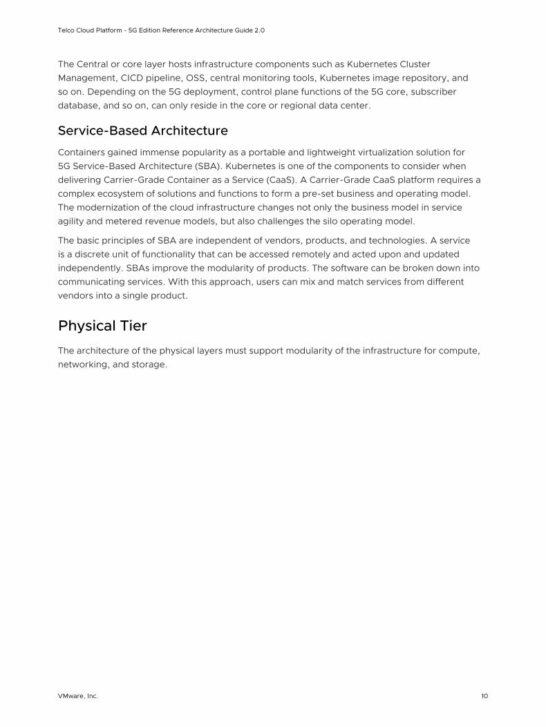
Physical Tier
The architecture of the physical layers must support modularity of the infrastructure for compute, networking, and storage.
Telco Cloud Platform - 5G Edition Reference Architecture Guide 2.0
VMware, Inc. 10
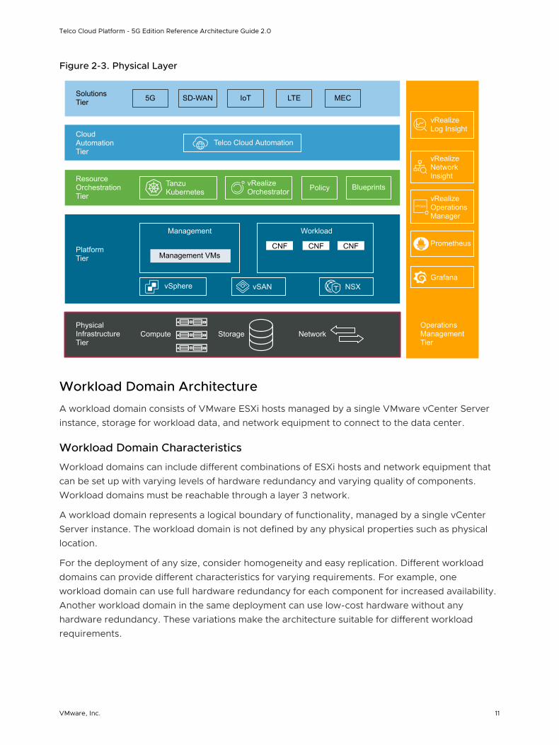
Figure 2-3. Physical Layer
vRealize Orchestrator
Operations Management Tier
Physical Infrastructure Tier
Platform Tier
Resource Orchestration Tier
Cloud Automation Tier
Solutions Tier 5G SD-WAN LTE MECIoT
Telco Cloud Automation
Tanzu Kubernetes Policy Blueprints
Management VMsCNF CNF CNF
Management Workload
vSphere vSAN NSX
vRealize Log Insight
vRealize Network Insight
vRealize Operations Manager
Compute Storage Network
Prometheus
Grafana
Workload Domain Architecture
A workload domain consists of VMware ESXi hosts managed by a single VMware vCenter Server instance, storage for workload data, and network equipment to connect to the data center.
Workload Domain Characteristics
Workload domains can include different combinations of ESXi hosts and network equipment that can be set up with varying levels of hardware redundancy and varying quality of components. Workload domains must be reachable through a layer 3 network.
A workload domain represents a logical boundary of functionality, managed by a single vCenter Server instance. The workload domain is not defined by any physical properties such as physical location.
For the deployment of any size, consider homogeneity and easy replication. Different workload domains can provide different characteristics for varying requirements. For example, one workload domain can use full hardware redundancy for each component for increased availability. Another workload domain in the same deployment can use low-cost hardware without any hardware redundancy. These variations make the architecture suitable for different workload requirements.
Telco Cloud Platform - 5G Edition Reference Architecture Guide 2.0
VMware, Inc. 11
Figure 2-4. Workload DomainsManagement Workload Domain
Virtual Machine
ManagementvCenter
Virtual Machine
ComputevCenter
Virtual Machine
NSXManager
Virtual Machine
Telco CloudAutomation
Virtual Machine
vRealizeLog Insight
Virtual Machine
vRealizeOperationsManager
vSAN Datastore
ESXivSAN
ESXivSAN
ESXivSAN
MGMT VDS
MGMT vMotion vSAN
Management Cluster
Compute Cluster 1
Kubernetes Node
CNF
Kubernetes Node
CNF
Kubernetes Node
CNF
vSAN Datastore
ESXivSAN
ESXivSAN
ESXivSAN
MGMT vMotion vSAN
Compute01 VDS(E)
Overlay Overlay Overlay Overlay
Compute Cluster 2
Kubernetes Node
CNF
Kubernetes Node
CNF
Kubernetes Node
CNF
vSAN Datastore
ESXivSAN
ESXivSAN
ESXivSAN
MGMT vMotion vSAN
Compute02 VDS(E)
Overlay Overlay Overlay Overlay
Virtual Machine
NSXEdge Node
Virtual Machine
NSXEdge Node
vSAN Datastore
ESXivSAN
ESXivSAN
ESXivSAN
Edge VDS
MGMT vMotion vSAN
Edge Cluster
VLANTrunking
Compute Workload Domain
Network Architecture
You can implement the switch fabric at the physical layer by providing Layer 2 or Layer 3 transport services. For a scalable and vendor-neutral data solution, use a Layer 3 transport.
Telco Cloud Platform - 5G Edition Reference Architecture Guide 2.0
VMware, Inc. 12
Both layer 2 and layer 3 transport have their own sets of benefits and drawbacks. When deciding on an architecture, consider the following benefits and drawbacks of each transport.
Layer 2 Transport Considerations
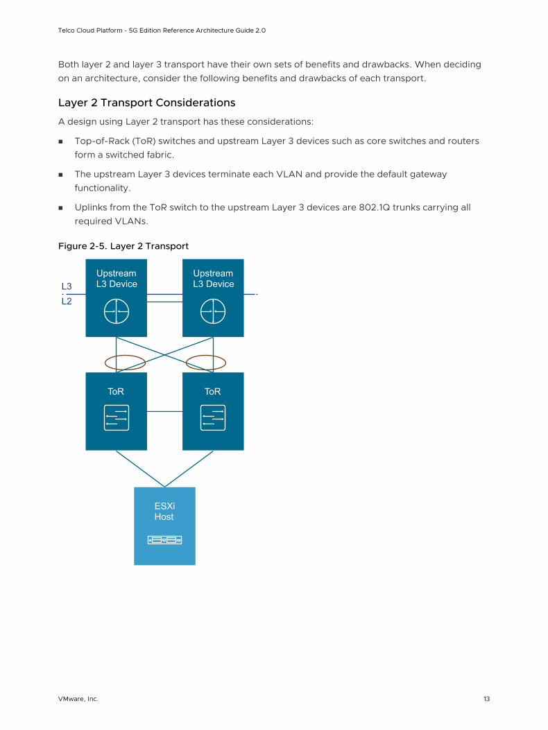
A design using Layer 2 transport has these considerations:
n Top-of-Rack (ToR) switches and upstream Layer 3 devices such as core switches and routers form a switched fabric.
n The upstream Layer 3 devices terminate each VLAN and provide the default gateway functionality.
n Uplinks from the ToR switch to the upstream Layer 3 devices are 802.1Q trunks carrying all required VLANs.
Figure 2-5. Layer 2 Transport
Upstream L3 DeviceL3
L2
ToR
Upstream L3 Device
ToR
ESXi Host
Telco Cloud Platform - 5G Edition Reference Architecture Guide 2.0
VMware, Inc. 13
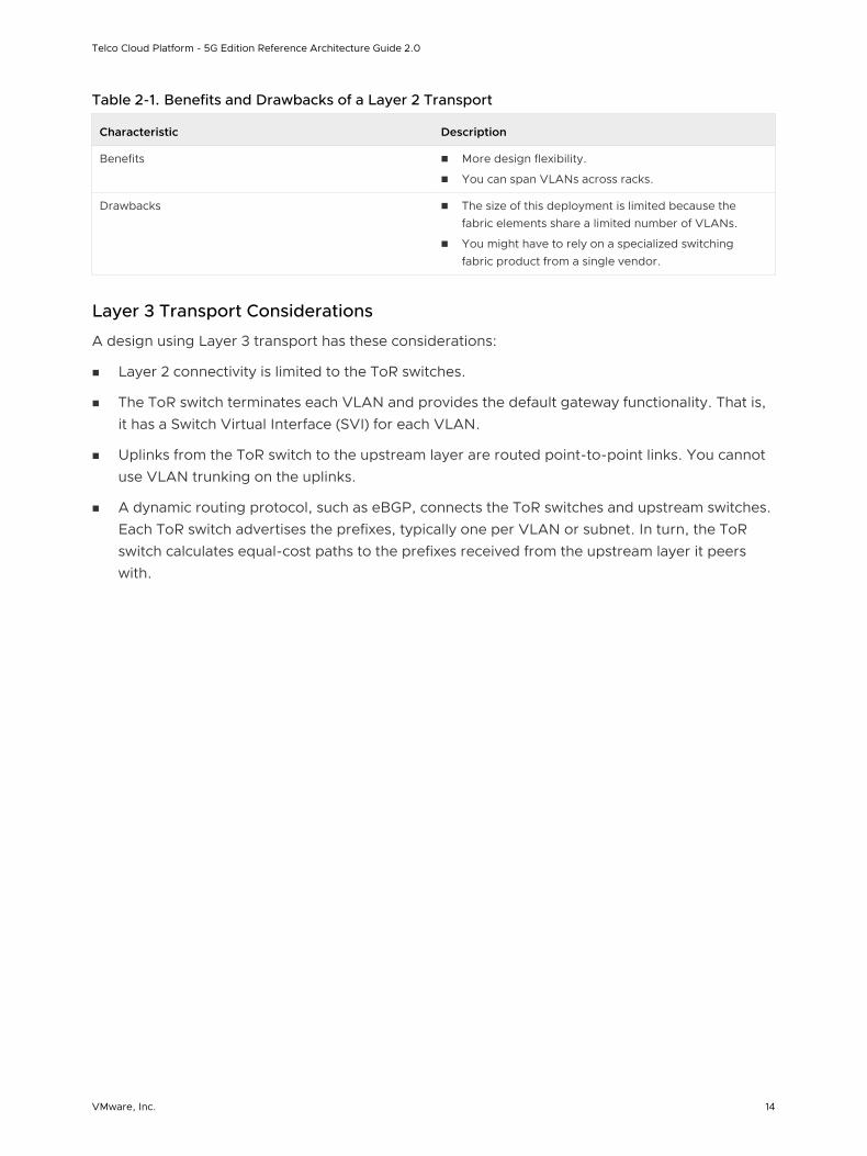
Table 2-1. Benefits and Drawbacks of a Layer 2 Transport
Characteristic Description
Benefits n More design flexibility.
n You can span VLANs across racks.
Drawbacks n The size of this deployment is limited because the fabric elements share a limited number of VLANs.
n You might have to rely on a specialized switching fabric product from a single vendor.
Layer 3 Transport Considerations
A design using Layer 3 transport has these considerations:
n Layer 2 connectivity is limited to the ToR switches.
n The ToR switch terminates each VLAN and provides the default gateway functionality. That is, it has a Switch Virtual Interface (SVI) for each VLAN.
n Uplinks from the ToR switch to the upstream layer are routed point-to-point links. You cannot use VLAN trunking on the uplinks.
n A dynamic routing protocol, such as eBGP, connects the ToR switches and upstream switches. Each ToR switch advertises the prefixes, typically one per VLAN or subnet. In turn, the ToR switch calculates equal-cost paths to the prefixes received from the upstream layer it peers with.
Telco Cloud Platform - 5G Edition Reference Architecture Guide 2.0
VMware, Inc. 14
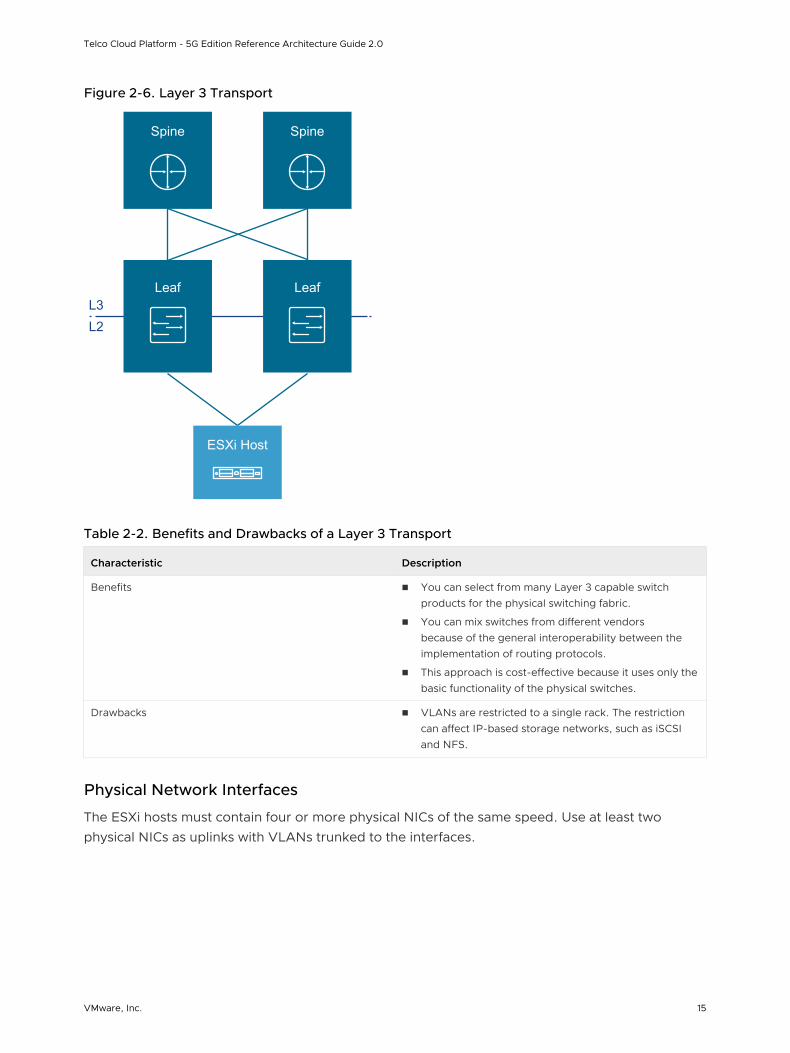
Figure 2-6. Layer 3 Transport
Spine
L3L2
Leaf
Spine
Leaf
ESXi Host
Table 2-2. Benefits and Drawbacks of a Layer 3 Transport
Characteristic Description
Benefits n You can select from many Layer 3 capable switch products for the physical switching fabric.
n You can mix switches from different vendors because of the general interoperability between the implementation of routing protocols.
n This approach is cost-effective because it uses only the basic functionality of the physical switches.
Drawbacks n VLANs are restricted to a single rack. The restriction can affect IP-based storage networks, such as iSCSI and NFS.
Physical Network Interfaces
The ESXi hosts must contain four or more physical NICs of the same speed. Use at least two physical NICs as uplinks with VLANs trunked to the interfaces.
Telco Cloud Platform - 5G Edition Reference Architecture Guide 2.0
VMware, Inc. 15
The VMware vSphere Distributed Switch supports several NIC teaming options. Load-based NIC teaming supports the optimal use of available bandwidth and redundancy in case of a link failure. Use a minimum of 10 GbE connections, with 25 GbE or larger connections recommended, for each ESXi host in combination with a pair of ToR switches. 802.1Q network trunks can support as many VLANs as required. Link aggregation such as LACP must not be used between the ESXi hosts and the physical switches.
Storage Architecture
VMware vSAN is used in both management and compute workload domains to provide highly available shared storage to vSphere clusters.
vSAN uses the local disks, all-flash devices, or flash and standard magnetic hard drives in each ESXi host to create a highly available shared datastore for the vSphere cluster. vSAN reduces storage costs, especially in remote or edge locations where a dedicated array is impractical.
When using vSAN, you can use all flash or a combination of flash and magnetic hard drives and compatible I/O controllers including the firmware level of each component from the VMware vSAN hardware compatibility list or use vSAN Ready Nodes.
vSAN Ready Nodes
VMware vSAN Ready Node is a validated server configuration in a certified hardware form-factor for vSAN deployment, jointly recommended by the server OEM and VMware. For examples about standardized configurations from different vSAN partners, see the vSAN Ready Node documentation.
Platform Tier
The virtual infrastructure is the foundation of the platform. It contains the software-defined infrastructure, software-defined networking, and software-defined storage.
In the virtual infrastructure layer, access to the underlying physical infrastructure is controlled and allocated to the management and customer workloads. The platform layer consists of hypervisors on the physical hosts and the hypervisor management components. The management components consist of elements in the virtual management layer, network and storage layers, business continuity, and security areas.
Telco Cloud Platform - 5G Edition Reference Architecture Guide 2.0
VMware, Inc. 16
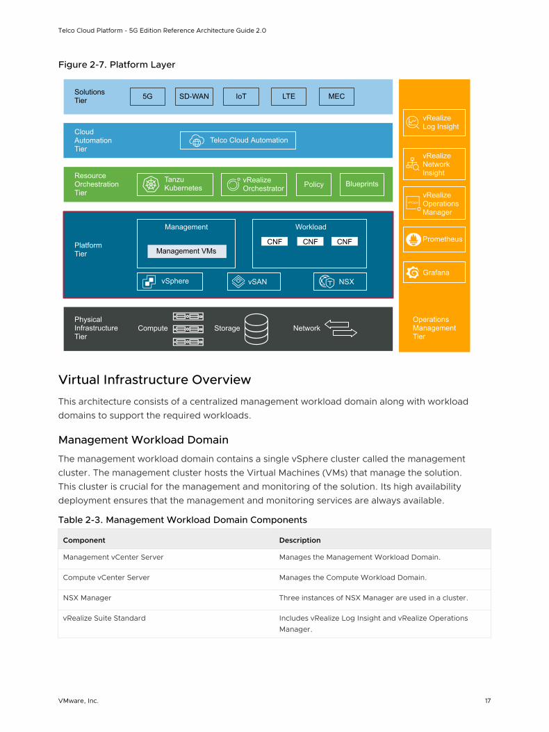
Figure 2-7. Platform Layer
vRealize Orchestrator
Operations Management Tier
Physical Infrastructure Tier
Platform Tier
Resource Orchestration Tier
Cloud Automation Tier
Solutions Tier 5G SD-WAN LTE MECIoT
Telco Cloud Automation
Tanzu Kubernetes Policy Blueprints
Management VMsCNF CNF CNF
Management Workload
vSphere vSAN NSX
vRealize Log Insight
vRealize Network Insight
vRealize Operations Manager
Compute Storage Network
Prometheus
Grafana
Virtual Infrastructure Overview
This architecture consists of a centralized management workload domain along with workload domains to support the required workloads.
Management Workload Domain
The management workload domain contains a single vSphere cluster called the management cluster. The management cluster hosts the Virtual Machines (VMs) that manage the solution. This cluster is crucial for the management and monitoring of the solution. Its high availability deployment ensures that the management and monitoring services are always available.
Table 2-3. Management Workload Domain Components
Component Description
Management vCenter Server Manages the Management Workload Domain.
Compute vCenter Server Manages the Compute Workload Domain.
NSX Manager Three instances of NSX Manager are used in a cluster.
vRealize Suite Standard Includes vRealize Log Insight and vRealize Operations Manager.
Telco Cloud Platform - 5G Edition Reference Architecture Guide 2.0
VMware, Inc. 17
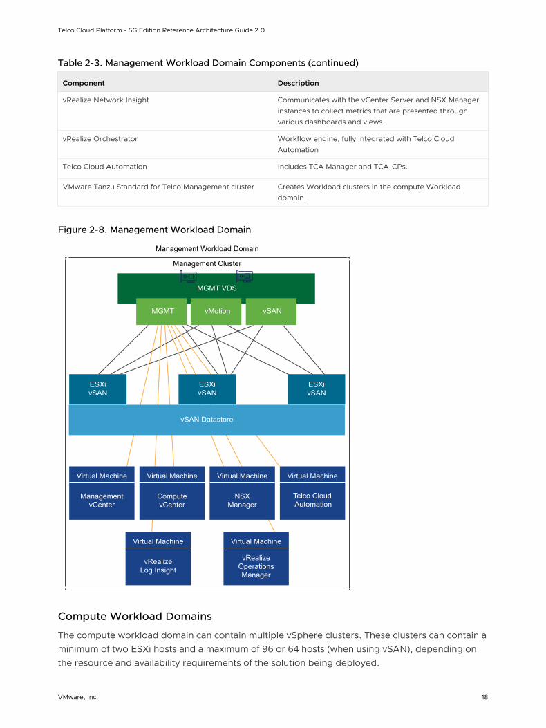
Table 2-3. Management Workload Domain Components (continued)
Component Description
vRealize Network Insight Communicates with the vCenter Server and NSX Manager instances to collect metrics that are presented through various dashboards and views.
vRealize Orchestrator Workflow engine, fully integrated with Telco Cloud Automation
Telco Cloud Automation Includes TCA Manager and TCA-CPs.
VMware Tanzu Standard for Telco Management cluster Creates Workload clusters in the compute Workload domain.
Figure 2-8. Management Workload Domain
Management Workload Domain
Virtual Machine
ManagementvCenter
Virtual Machine
ComputevCenter
Virtual Machine
NSXManager
Virtual Machine
Telco CloudAutomation
Virtual Machine
vRealizeLog Insight
Virtual Machine
vRealizeOperationsManager
vSAN Datastore
ESXivSAN
ESXivSAN
ESXivSAN
MGMT VDS
MGMT vMotion vSAN
Management Cluster
Compute Workload Domains
The compute workload domain can contain multiple vSphere clusters. These clusters can contain a minimum of two ESXi hosts and a maximum of 96 or 64 hosts (when using vSAN), depending on the resource and availability requirements of the solution being deployed.
Telco Cloud Platform - 5G Edition Reference Architecture Guide 2.0
VMware, Inc. 18
The Edge cluster, which hosts NSX Edge VMs, is part of the compute workload domain. This cluster provides virtualized network services such as load balancers and the north-south routing infrastructure to support the workloads.
Each compute workload domain can support a maximum of 2000 ESXi hosts and 25,000 VMs. If you use other management and monitoring tools, the vCenter maximums do not apply and the actual number of ESXi hosts and VMs per workload domain might be less.
Telco Cloud Platform - 5G Edition Reference Architecture Guide 2.0
VMware, Inc. 19
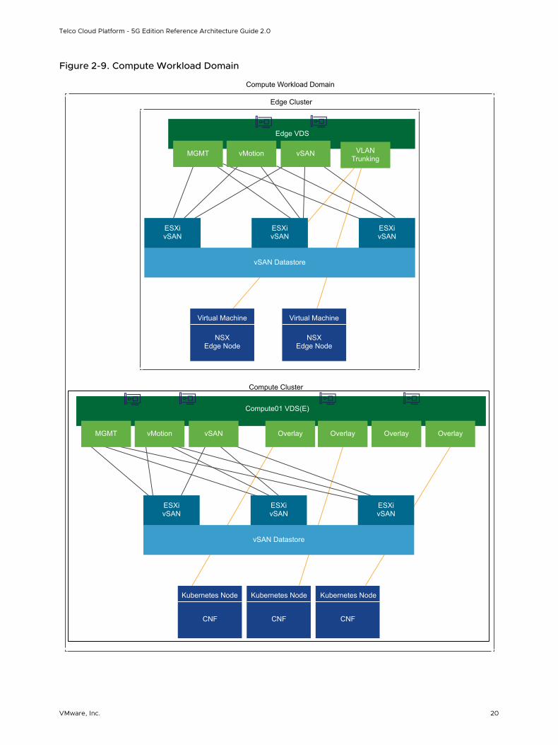
Figure 2-9. Compute Workload Domain
Compute Cluster
Kubernetes Node
CNF
Kubernetes Node
CNF
Kubernetes Node
CNF
vSAN Datastore
ESXivSAN
ESXivSAN
ESXivSAN
MGMT vMotion vSAN
Compute01 VDS(E)
Overlay Overlay Overlay Overlay
Virtual Machine
NSXEdge Node
Virtual Machine
NSXEdge Node
vSAN Datastore
ESXivSAN
ESXivSAN
ESXivSAN
Edge VDS
MGMT vMotion vSAN
Edge Cluster
VLANTrunking
Compute Workload Domain
Telco Cloud Platform - 5G Edition Reference Architecture Guide 2.0
VMware, Inc. 20
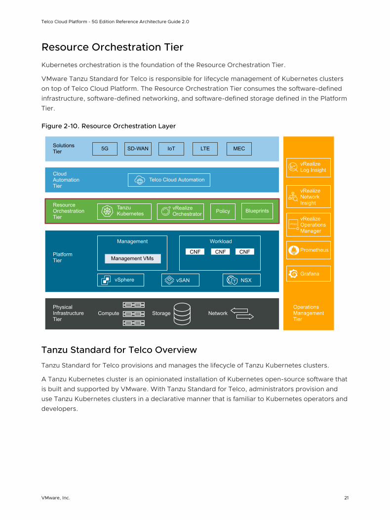
Resource Orchestration Tier
Kubernetes orchestration is the foundation of the Resource Orchestration Tier.
VMware Tanzu Standard for Telco is responsible for lifecycle management of Kubernetes clusters on top of Telco Cloud Platform. The Resource Orchestration Tier consumes the software-defined infrastructure, software-defined networking, and software-defined storage defined in the Platform Tier.
Figure 2-10. Resource Orchestration Layer
vRealize Orchestrator
Operations Management Tier
Physical Infrastructure Tier
Platform Tier
Resource Orchestration Tier
Cloud Automation Tier
Solutions Tier 5G SD-WAN LTE MECIoT
Telco Cloud Automation
Tanzu Kubernetes Policy Blueprints
Management VMsCNF CNF CNF
Management Workload
vSphere vSAN NSX
vRealize Log Insight
vRealize Network Insight
vRealize Operations Manager
Compute Storage Network
Prometheus
Grafana
Tanzu Standard for Telco Overview
Tanzu Standard for Telco provisions and manages the lifecycle of Tanzu Kubernetes clusters.
A Tanzu Kubernetes cluster is an opinionated installation of Kubernetes open-source software that is built and supported by VMware. With Tanzu Standard for Telco, administrators provision and use Tanzu Kubernetes clusters in a declarative manner that is familiar to Kubernetes operators and developers.
Telco Cloud Platform - 5G Edition Reference Architecture Guide 2.0
VMware, Inc. 21
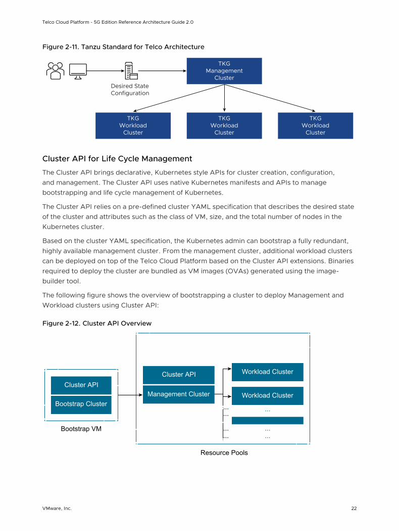
Figure 2-11. Tanzu Standard for Telco Architecture
TKGManagement
Cluster
TKGWorkload
Cluster
TKGWorkload
Cluster
TKGWorkload
Cluster
Desired StateConfiguration
Cluster API for Life Cycle Management
The Cluster API brings declarative, Kubernetes style APIs for cluster creation, configuration, and management. The Cluster API uses native Kubernetes manifests and APIs to manage bootstrapping and life cycle management of Kubernetes.
The Cluster API relies on a pre-defined cluster YAML specification that describes the desired state of the cluster and attributes such as the class of VM, size, and the total number of nodes in the Kubernetes cluster.
Based on the cluster YAML specification, the Kubernetes admin can bootstrap a fully redundant, highly available management cluster. From the management cluster, additional workload clusters can be deployed on top of the Telco Cloud Platform based on the Cluster API extensions. Binaries required to deploy the cluster are bundled as VM images (OVAs) generated using the image-builder tool.
The following figure shows the overview of bootstrapping a cluster to deploy Management and Workload clusters using Cluster API:
Figure 2-12. Cluster API Overview
Cluster API
Bootstrap Cluster
Bootstrap VM
Cluster API
Management Cluster
Resource Pools
Workload Cluster
Workload Cluster
Telco Cloud Platform - 5G Edition Reference Architecture Guide 2.0
VMware, Inc. 22
Tanzu Standard for Telco Management and Workload Clusters
n Tanzu Kubernetes Management Cluster is a Kubernetes cluster that functions as the primary management and operational center for the Tanzu Standard for Telco instance. In this management cluster, the Cluster API runs to create Tanzu Kubernetes clusters and you configure the shared and in-cluster services that the clusters use.
n Tanzu Kubernetes Workload Cluster is a Kubernetes cluster that is deployed from the Tanzu Kubernetes management cluster. Tanzu Kubernetes clusters can run different versions of Kubernetes, depending on the CNF workload requirements. Tanzu Kubernetes clusters support multiple types of CNIs for Pod-to-Pod networking, with Antrea as the default CNI and the vSphere CSI provider for storage by default. When deployed through Telco Cloud Automation, VMware NodeConfig Operator is bundled into every workload cluster to handle the node Operating System (OS) configuration, performance tuning, and OS upgrades required for various types of Telco CNF workloads.
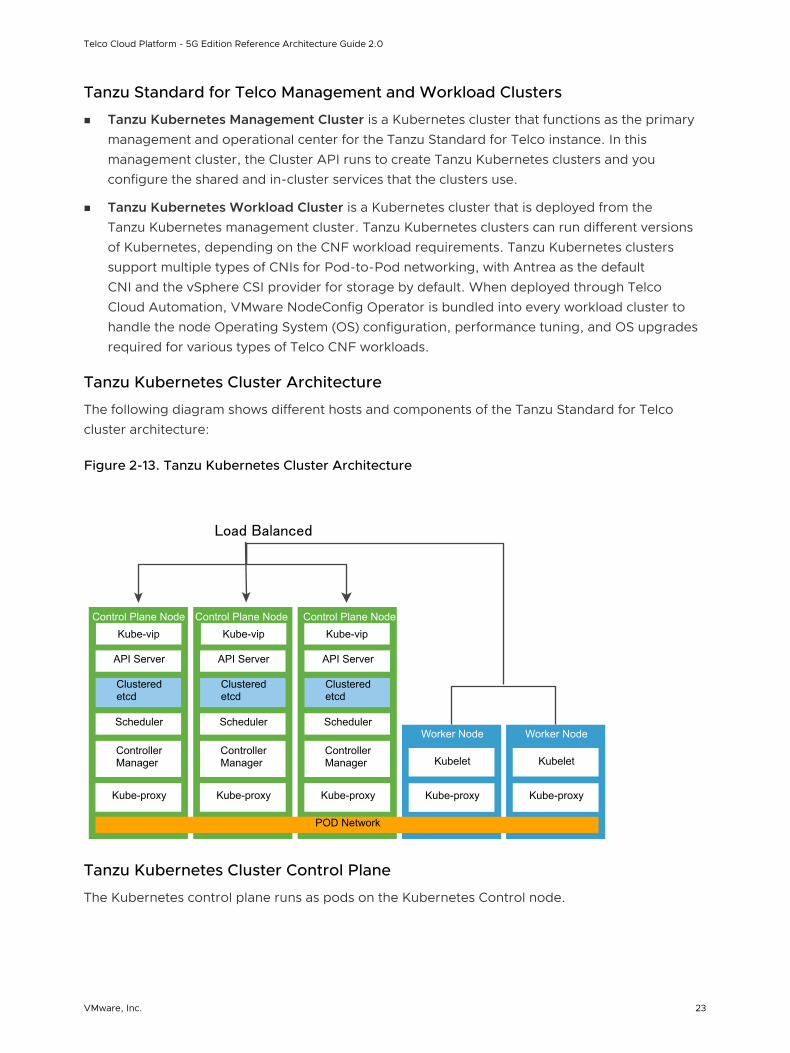
Tanzu Kubernetes Cluster Architecture
The following diagram shows different hosts and components of the Tanzu Standard for Telco cluster architecture:
Figure 2-13. Tanzu Kubernetes Cluster Architecture
Kubelet
Worker Node
Kubelet
Worker Node
API Server
Controller Manager
Scheduler
Clustered etcd
Control Plane Node
Kube-proxy Kube-proxy Kube-proxy Kube-proxy Kube-proxy
API Server
Controller Manager
Scheduler
Clustered etcd
Control Plane Node
API Server
Controller Manager
Scheduler
Clustered etcd
Control Plane Node
Load Balancer
POD Network
Kube-vip Kube-vip Kube-vip
Load Balanced
Tanzu Kubernetes Cluster Control Plane
The Kubernetes control plane runs as pods on the Kubernetes Control node.
Telco Cloud Platform - 5G Edition Reference Architecture Guide 2.0
VMware, Inc. 23
Etcd is a distributed key-value store that stores the Kubernetes cluster configuration, data, API objects, and service discovery details. For security reasons, etcd must be accessible only from the Kubernetes API server. Etcd runs as a service as part of the control node. For deployment environments with large churn, consider using dedicated standalone VM worker nodes on hosts with SSD-based datastores.
Kubernetes API server is the central management entity that receives all API requests for managing Kubernetes objects and resources. The API server serves as the frontend to the cluster and is the only cluster component that communicates with the etcd key-value store. For added redundancy and availability, a load balancer is required for the control plane nodes. The load balancer performs health checks of the API server to ensure that the external clients such as kubectl connect to a healthy API server even during the cluster degradation.
Kubernetes controller manager is a daemon that embeds the core control loops shipped with Kubernetes. A control loop is a non-terminating loop that regulates the state of the system. The controllers that are shipped with Kubernetes are the replication controller, endpoints controller, namespace controller, and service accounts controller.
Kube-VIP is used to load balance API requests for the Kubernetes API server and is a replacement for HAproxy used in the 1.1.x version of the TKG deployment. Kube-VIP runs as a static Pod on the control plane nodes and uses the leader election functionality to elect a member as the leader. The elected leader owns the VIP address and is responsible for load-balancing API requests to Kubernetes API servers.
Note VMware Telco Cloud Platform also bundles the VM and NodeConfig Operators as custom controllers for Telco workload node customization.
Kubernetes schedulers know the total resources available in a Kubernetes cluster and the workload allocated on each worker node in the cluster. The API server invokes the scheduler every time there is a need to modify a Kubernetes pod. Based on the operational service requirements, the scheduler assigns the workload on a node that best fits the resource requirements.
Tanzu Kubernetes Cluster Data Plane
Tanzu Kubernetes Cluster Data Plane consists of worker nodes that run as VMs. A worker node consists of the container runtime, kube-proxy, and kubelet daemon to function as a member of the Kubernetes cluster.
Telco Cloud Platform requires that all worker nodes are running a Linux distribution with Kernel version that is compatible with tooling required to bootstrap, manage, and operate the Kubernetes cluster. Depending on the type of Telco workloads, the worker nodes might require specialized hardware and software to support advanced network capabilities. DPDK, SR-IOV, multiple network interfaces are often requirements on the data plane.
In alignment with the Cloud Infrastructure Telco Task Force (CNTT), the following hardware and compute profile modes are depicted in this solution architecture:
Telco Cloud Platform - 5G Edition Reference Architecture Guide 2.0
VMware, Inc. 24
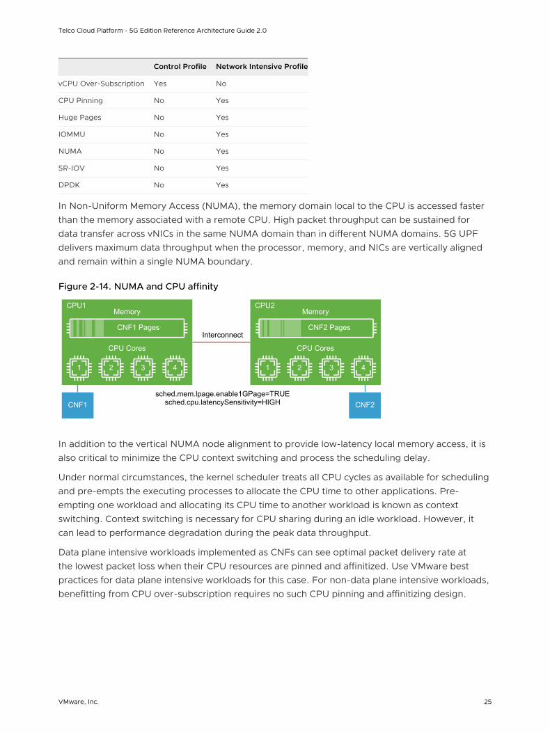
Control Profile Network Intensive Profile
vCPU Over-Subscription Yes No
CPU Pinning No Yes
Huge Pages No Yes
IOMMU No Yes
NUMA No Yes
SR-IOV No Yes
DPDK No Yes
In Non-Uniform Memory Access (NUMA), the memory domain local to the CPU is accessed faster than the memory associated with a remote CPU. High packet throughput can be sustained for data transfer across vNICs in the same NUMA domain than in different NUMA domains. 5G UPF delivers maximum data throughput when the processor, memory, and NICs are vertically aligned and remain within a single NUMA boundary.
Figure 2-14. NUMA and CPU affinity
1 2
CPU Cores
CNF1 CNF2
CNF1 Pages CNF2 Pages
MemoryCPU1
3 4 1 2
CPU Cores
Interconnect
sched.mem.lpage.enable1GPage=TRUE sched.cpu.latencySensitivity=HIGH
MemoryCPU2
3 4
In addition to the vertical NUMA node alignment to provide low-latency local memory access, it is also critical to minimize the CPU context switching and process the scheduling delay.
Under normal circumstances, the kernel scheduler treats all CPU cycles as available for scheduling and pre-empts the executing processes to allocate the CPU time to other applications. Pre-empting one workload and allocating its CPU time to another workload is known as context switching. Context switching is necessary for CPU sharing during an idle workload. However, it can lead to performance degradation during the peak data throughput.
Data plane intensive workloads implemented as CNFs can see optimal packet delivery rate at the lowest packet loss when their CPU resources are pinned and affinitized. Use VMware best practices for data plane intensive workloads for this case. For non-data plane intensive workloads, benefitting from CPU over-subscription requires no such CPU pinning and affinitizing design.
Telco Cloud Platform - 5G Edition Reference Architecture Guide 2.0
VMware, Inc. 25
Huge Pages
Translation Lookaside Buffer (TLB) is a small hardware cache used to map virtual pages to physical hardware memory pages. If the virtual address is found in the TLB, the mapping can be determined quickly. Otherwise, a TLB miss occurs and the system moves to a slow software-based translation.
5G CNFs such as the UPFs are sensitive to memory access latency and require a large amount of memory, so the TLB miss must be reduced. To reduce the TLB miss, huge pages are used on the compute nodes that host memory sensitive workload. In the VMware stack, ensure that the VM's memory reservation is configured to the maximum value so that all the vRAMs can be pre-allocated when VMs are powered-on.
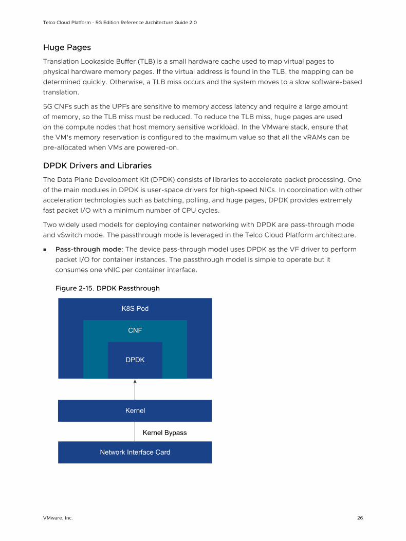
DPDK Drivers and Libraries
The Data Plane Development Kit (DPDK) consists of libraries to accelerate packet processing. One of the main modules in DPDK is user-space drivers for high-speed NICs. In coordination with other acceleration technologies such as batching, polling, and huge pages, DPDK provides extremely fast packet I/O with a minimum number of CPU cycles.
Two widely used models for deploying container networking with DPDK are pass-through mode and vSwitch mode. The passthrough mode is leveraged in the Telco Cloud Platform architecture.
n Pass-through mode: The device pass-through model uses DPDK as the VF driver to perform packet I/O for container instances. The passthrough model is simple to operate but it consumes one vNIC per container interface.
Figure 2-15. DPDK Passthrough
Network Interface Card
K8S Pod
CNF
DPDK
Kernel
Kernel Bypass
Telco Cloud Platform - 5G Edition Reference Architecture Guide 2.0
VMware, Inc. 26

n vSwitch mode: In the vSwitch model, a soft switch such as OVS sends packets. Each container instance uses a DPDK virtual device and a virtio-user to communicate with the soft switch. The vSwitch model offers high density but requires advanced QoS within the vSwitch to ensure fairness. The additional layer of encapsulation and decapsulation required by the vSwitch introduces additional switching overhead and also impacts the overall CNF throughput.
Figure 2-16. DPDK vSwitch
DPDK
NIC
K8S Pod
CNF
virtio-user
vhost-user
K8S Pod
CNF
virtio-user
vhost-user
K8S Pod
CNF
virtio-user
vhost-user
DPDK Soft Switch
DPDK
NIC
IO Memory Management Units (IOMMUs) protects system memory between I/O devices, by mediating access to physical memory from CNF network interfaces. Without an IOMMU, devices can access any portion of the system memory and can corrupt the system memory. Memory protection is important in the container and virtual environments that use shared physical memory. In the VMware stack, depending on the type of DPDK driver, the hardware-assisted I/O MMU virtualization might be required on the VM setting.
Note Any DPDK kernel modules to be used (igb_uio, kni, and so on) must be compiled with the same kernel as the one running on the target.
Cloud Native Networking Overview
In Kubernetes Networking, every Pod has a unique IP and all the containers in that Pod share the IP. The IP of a Pod is routable from all the other Pods, regardless of the nodes they are on. Kubernetes is agnostic to reachability, L2, L3, overlay networks, and so on, as long as the traffic can reach the desired pod on any node.
CNI is a container networking specification adopted by Kubernetes to support pod-to-pod networking. The specification defines a Linux network namespace. The container runtime first allocates a network namespace to the container and then pass numerous CNI parameters to the network driver. The network driver then attaches the container to a network and reports the assigned IP address to the container runtime. Multiple plugins may be run at a time with a container joining networks driven by different plugins.
Telco Cloud Platform - 5G Edition Reference Architecture Guide 2.0
VMware, Inc. 27
Telco workloads typically require a separation of the control plane and data plane. Also, a strict separation between the Telco traffic and the Kubernetes control plane requires multiple network interfaces to provide service isolation or routing. To support those workloads that require multiple interfaces in a Pod, additional plugins are required. A CNI meta plugin or CNI multiplexer that attaches multiple interfaces can be used to provide multiple Pod NICs support. The CNI plugin that serves pod-to-pod networking is called the primary or default CNI (a network interface that every Pod is created with). In case of 5G, the SBI interfaces are managed by the primary CNI. Each network attachment created by the meta plugin is called the secondary CNI. SR-IOV or N-VDS (E) NICs configured for passthrough are managed by supported secondary CNIs.
While there are numerous container networking technologies and unique ways of approaching them, Telco Cloud and Kubernetes admins want to eliminate manual CNI provisioning in containerized environments and reduce the number of container plugins to maintain. Calico or Antrea are often used as the primary CNI plugin. MACVLAN and Host-device can be used as secondary CNI together with a CNI meta plugin such as Multus. The following table summarizes the CNI requirements based on the workload type:
5G control Profile 5G Data Plane Node
Primary CNI (Calico/Antrea) Required Required
Secondary CNI
(Multus/MACVLAN/Host-device)
Not Required in generally. Can be leveraged to simplify CNF connectivity.
Required
vRealize Orchestrator
VMware vRealize Orchestrator automates the virtualization management system processes across different third-party and VMware solutions.
VMware vRealize Orchestrator extends ETSI-MANO standard automation capabilities with custom workflows. Through vRealize Orchestrator, VMware Telco Cloud Platform provides a library of extensible workflows to create and run automated, configurable processes to manage VMware products and third-party technologies. vRealize Orchestrator is deployed as a standalone appliance and integrated into Telco Cloud Platform to trigger and design new custom workflows. Existing VNF workflows created through the vRealize Orchestrator can be used with TCA with minimal updates.
Cloud Automation Tier
The Cloud Automation Tier deploys the network core and edge sites with multi-layer automation, from the physical infrastructure to cloud native network services. It onboards and orchestrates NFV workloads seamlessly from VM and container-based infrastructures for adaptive service-delivery through pre-built integrations with multiple Virtual Infrastructure Managers (VIM) and Kubernetes.
VMware Telco Cloud Automation (TCA) applies a cloud-first, vendor-neutral approach to telco network orchestration and automation. It eases interoperability and simplifies the transition of telco requirements to a rapidly evolving multi-cloud ecosystem.
Telco Cloud Platform - 5G Edition Reference Architecture Guide 2.0
VMware, Inc. 28
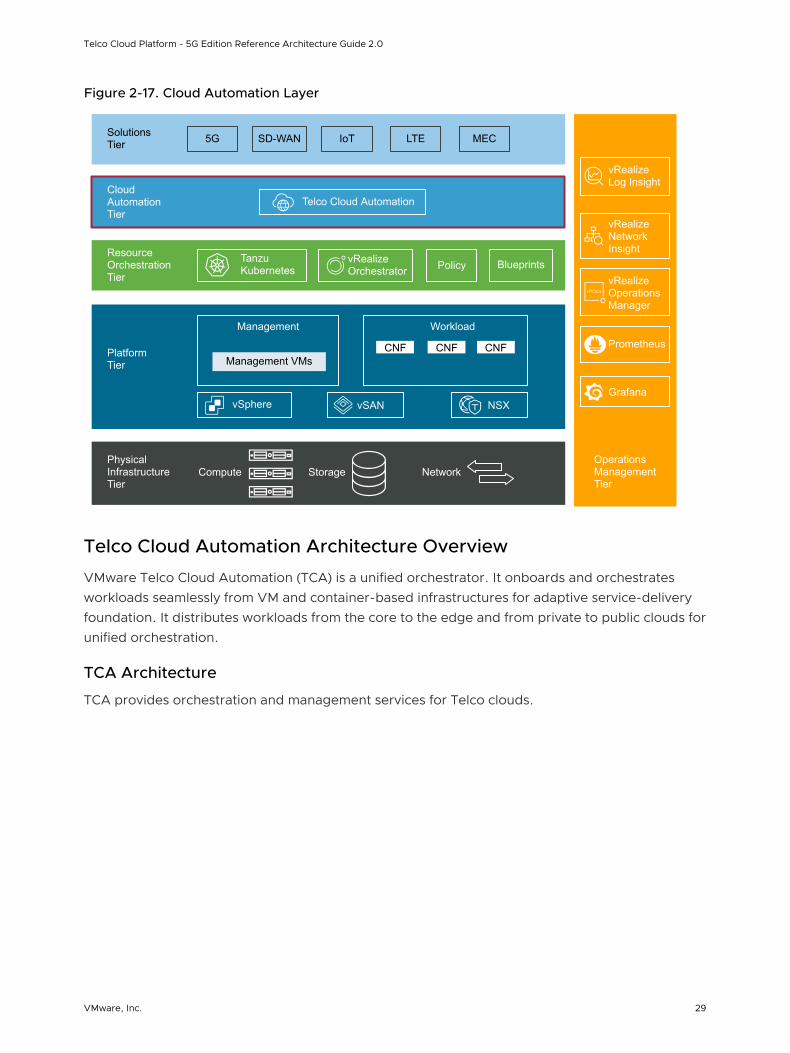
Figure 2-17. Cloud Automation Layer
vRealize Orchestrator
Operations Management Tier
Physical Infrastructure Tier
Platform Tier
Resource Orchestration Tier
Cloud Automation Tier
Solutions Tier 5G SD-WAN LTE MECIoT
Telco Cloud Automation
Tanzu Kubernetes Policy Blueprints
Management VMsCNF CNF CNF
Management Workload
vSphere vSAN NSX
vRealize Log Insight
vRealize Network Insight
vRealize Operations Manager
Compute Storage Network
Prometheus
Grafana
Telco Cloud Automation Architecture Overview
VMware Telco Cloud Automation (TCA) is a unified orchestrator. It onboards and orchestrates workloads seamlessly from VM and container-based infrastructures for adaptive service-delivery foundation. It distributes workloads from the core to the edge and from private to public clouds for unified orchestration.
TCA Architecture
TCA provides orchestration and management services for Telco clouds.
Telco Cloud Platform - 5G Edition Reference Architecture Guide 2.0
VMware, Inc. 29
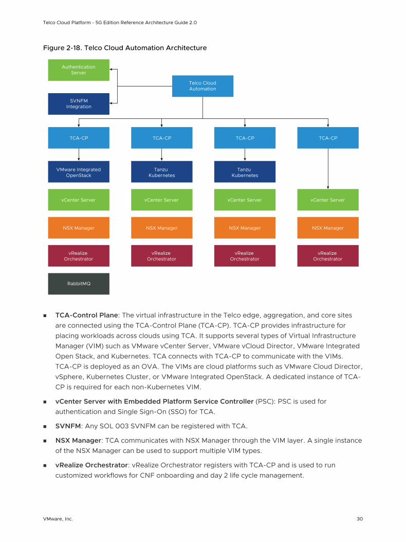
Figure 2-18. Telco Cloud Automation Architecture
AuthenticationServer
SVNFMIntegration
TCA-CP TCA-CP TCA-CP TCA-CP
VMware IntegratedOpenStack
Tanzu Kubernetes
Tanzu Kubernetes
vCenter Server vCenter Server vCenter Server vCenter Server
NSX Manager NSX Manager NSX Manager NSX Manager
vRealize Orchestrator
vRealize Orchestrator
vRealize Orchestrator
vRealize Orchestrator
RabbitMQ
Telco CloudAutomation
n TCA-Control Plane: The virtual infrastructure in the Telco edge, aggregation, and core sites are connected using the TCA-Control Plane (TCA-CP). TCA-CP provides infrastructure for placing workloads across clouds using TCA. It supports several types of Virtual Infrastructure Manager (VIM) such as VMware vCenter Server, VMware vCloud Director, VMware Integrated Open Stack, and Kubernetes. TCA connects with TCA-CP to communicate with the VIMs. TCA-CP is deployed as an OVA. The VIMs are cloud platforms such as VMware Cloud Director, vSphere, Kubernetes Cluster, or VMware Integrated OpenStack. A dedicated instance of TCA-CP is required for each non-Kubernetes VIM.
n vCenter Server with Embedded Platform Service Controller (PSC): PSC is used for authentication and Single Sign-On (SSO) for TCA.
n SVNFM: Any SOL 003 SVNFM can be registered with TCA.
n NSX Manager: TCA communicates with NSX Manager through the VIM layer. A single instance of the NSX Manager can be used to support multiple VIM types.
n vRealize Orchestrator: vRealize Orchestrator registers with TCA-CP and is used to run customized workflows for CNF onboarding and day 2 life cycle management.
Telco Cloud Platform - 5G Edition Reference Architecture Guide 2.0
VMware, Inc. 30
n RabbitMQ: RabbitMQ is used to track VMware Cloud Director and VMware Integrated OpenStack notifications and is not required for Telco Cloud Platform.
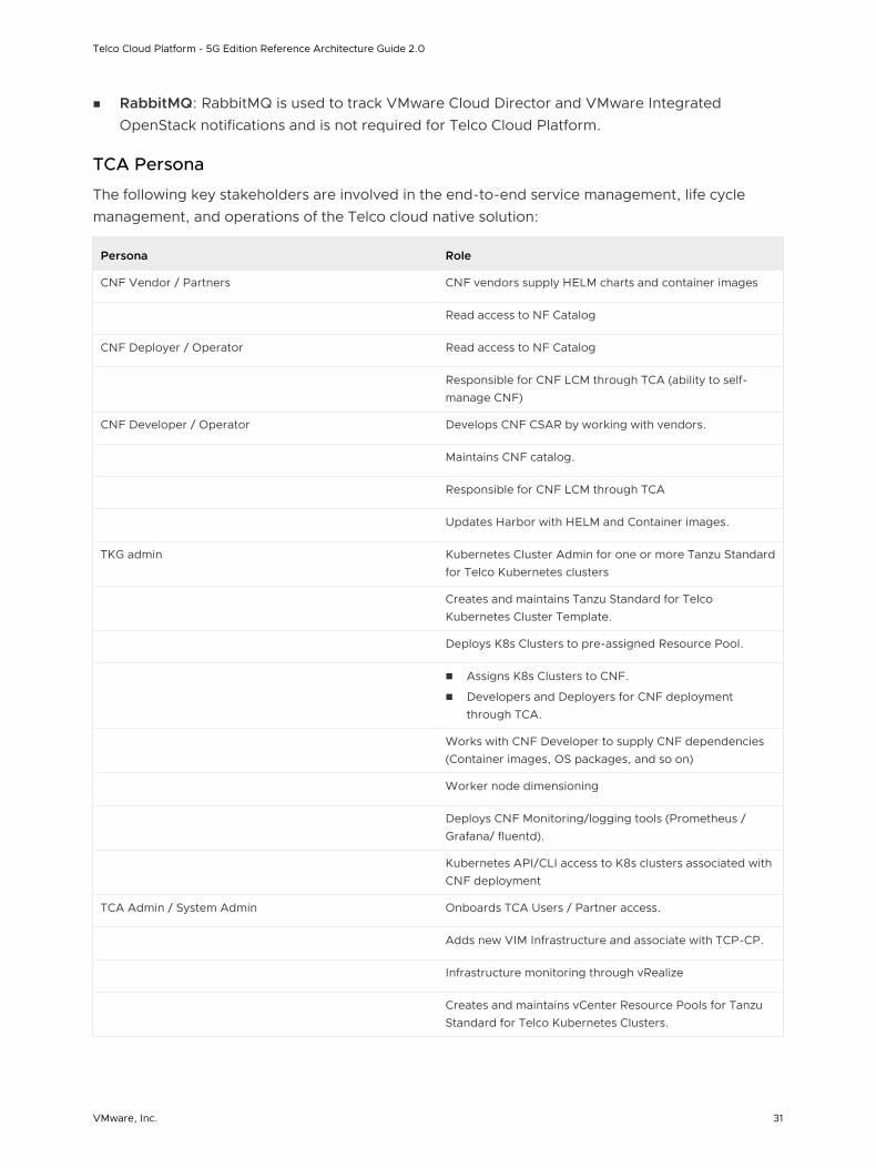
TCA Persona
The following key stakeholders are involved in the end-to-end service management, life cycle management, and operations of the Telco cloud native solution:
Persona Role
CNF Vendor / Partners CNF vendors supply HELM charts and container images
Read access to NF Catalog
CNF Deployer / Operator Read access to NF Catalog
Responsible for CNF LCM through TCA (ability to self-manage CNF)
CNF Developer / Operator Develops CNF CSAR by working with vendors.
Maintains CNF catalog.
Responsible for CNF LCM through TCA
Updates Harbor with HELM and Container images.
TKG admin Kubernetes Cluster Admin for one or more Tanzu Standard for Telco Kubernetes clusters
Creates and maintains Tanzu Standard for Telco Kubernetes Cluster Template.
Deploys K8s Clusters to pre-assigned Resource Pool.
n Assigns K8s Clusters to CNF.
n Developers and Deployers for CNF deployment through TCA.
Works with CNF Developer to supply CNF dependencies (Container images, OS packages, and so on)
Worker node dimensioning
Deploys CNF Monitoring/logging tools (Prometheus / Grafana/ fluentd).
Kubernetes API/CLI access to K8s clusters associated with CNF deployment
TCA Admin / System Admin Onboards TCA Users / Partner access.
Adds new VIM Infrastructure and associate with TCP-CP.
Infrastructure monitoring through vRealize
Creates and maintains vCenter Resource Pools for Tanzu Standard for Telco Kubernetes Clusters.
Telco Cloud Platform - 5G Edition Reference Architecture Guide 2.0
VMware, Inc. 31
Persona Role
Creates and maintains Tanzu Standard for Telco Kubernetes Cluster Template.
Deploys and Maintains Harbor repository.
Deploys and maintains Tanzu Standard for Telco Kubernetes bootstrap process.
Performs TCA/TCA-CP/Harbor/Infra/Infra Monitoring upgrades.
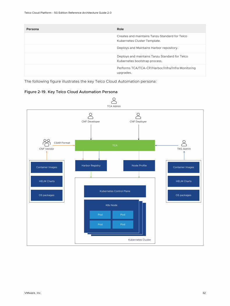
The following figure illustrates the key Telco Cloud Automation persona:
Figure 2-19. Key Telco Cloud Automation Persona
Harbor Registry
CSAR Format
TKG Admin
CNF Developer
K8s Node
Pod
Pod
Pod
Pod
Kubernetes Control Plane
Kubernetes Cluster
Node Profile
TCA
CNF Deployer
HELM Charts
OS packages
Container Images
CNF Vendor
HELM Charts
OS packages
Container Images
TCA Admin
Telco Cloud Platform - 5G Edition Reference Architecture Guide 2.0
VMware, Inc. 32
Virtual Infrastructure Management
TCA Administrators can onboard, view, and manage the entire Telco Cloud Platform virtual infrastructure through the TCA console. Details about each cloud such as Cloud Name, Cloud URL, Cloud Type, Tenant Name, Connection Status, and Tags can be displayed as an aggregate list or graphically based on the geographic location. TCA Admin can then use roles, permissions, and tags to provide resource separation between the VIM, Users, and Network Functions.
CaaS Subsystem Overview
The CaaS subsystem allows Telco Cloud Platform operators to create and manage Kubernetes clusters and Cloud-native 5G workloads. VMware Telco Cloud platform uses VMware Tanzu Standard for Telco to create Kubernetes clusters.
Using VMware Telco Cloud Automation, the TCA admins can create Telco management and workload templates to reduce repetitive parts of Kubernetes cluster creation while standardizing cluster sizing and capabilities. A typical template can include a grouping of workers nodes through Node Pool, control and worker node sizing, Container Networking, Storage class, and CPU affinity policies.
After the TCA Admin publishes the Kubernetes Cluster templates, the TKG admin can consume those templates by deploying and managing various types of Kubernetes clusters on different vCenter servers ESXi hosts that best meet CNF requirements.
The CaaS subsystem access control is fully backed by RBAC. The TKG admins have full access to Kubernetes clusters under their management, including direct console access to Kubernetes nodes and API. CNF developers and deployers can gain deployment access to Kubernetes cluster through the TCA console.
CNF Management Overview
Cloud-native Network Function (CNF) management encompasses onboarding, designing, and publishing of the SOL001-compliant CSAR packages to the TCA Network Function catalog. TCA maintains the CSAR configuration integrity and provides a Network Function Designer for CNF developers to update and release newer iterations in the Network Function catalog.
Network Function Designer is a visual design tool within VMware Telco Cloud Automation. It generates SOL001-compliant TOSCA descriptors based on the 5G core deployment requirements. A TOSCA descriptor consists of instantiation parameters and operational behaviors of the CNF for life cycle management.
Network functions from different vendors have their own and unique set of infrastructure requirements. A CNF developer can include the CSAR package infrastructure requirements to instantiate and operate a 5G CNF. VMware Telco Cloud Automation attempts to customize worker node configuration based on those requirements through the VMware Telco NodeConfig Operator. The NodeConfig Operator is a K8s operator that handles the node OS customization, performance tuning, and upgrade. Instead of static resource pre-allocation during the Kubernetes
Telco Cloud Platform - 5G Edition Reference Architecture Guide 2.0
VMware, Inc. 33
cluster instantiation, the NodeConfig Operator defers resource binding of expensive network resources such as SR-IOV VF and Huge Pages to the CNF instantiation. When new workloads are instantiated through TCA, TCA automatically assigns more resources to the Kubernetes cluster to accommodate new workloads.
Access policies for CNF Catalogs and Inventory are roles and permissions based. Custom policies can be created in TCA to offer self-managed capabilities required by CNF Developers and Deployers.
Operations Management Tier
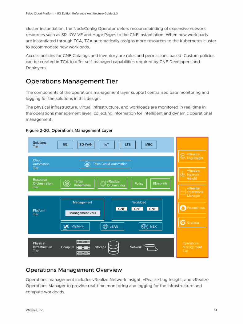
The components of the operations management layer support centralized data monitoring and logging for the solutions in this design.
The physical infrastructure, virtual infrastructure, and workloads are monitored in real time in the operations management layer, collecting information for intelligent and dynamic operational management.
Figure 2-20. Operations Management Layer
vRealize Orchestrator
Operations Management Tier
Physical Infrastructure Tier
Platform Tier
Resource Orchestration Tier
Cloud Automation Tier
Solutions Tier 5G SD-WAN LTE MECIoT
Telco Cloud Automation
Tanzu Kubernetes Policy Blueprints
Management VMsCNF CNF CNF
Management Workload
vSphere vSAN NSX
vRealize Log Insight
vRealize Network Insight
vRealize Operations Manager
Compute Storage Network
Prometheus
Grafana
Operations Management Overview
Operations management includes vRealize Network Insight, vRealize Log Insight, and vRealize Operations Manager to provide real-time monitoring and logging for the infrastructure and compute workloads.
Telco Cloud Platform - 5G Edition Reference Architecture Guide 2.0
VMware, Inc. 34
vRealize Network Insight
vRealize Network Insight collects and analyzes information about the operation of network data sources such as NSX-T Data Center and vCenter Server. Users access this information by using dashboards.
vRealize Log Insight
vRealize Log Insight collects data from ESXi hosts using the syslog protocol. vRealize Log Insight has the following capabilities:
n Connects to other VMware products such as vCenter Server to collect events, tasks, and alarm data.
n Integrates with vRealize Operations Manager to send notification events and enable launch in context.
n Functions as a collection and analysis point for any system that sends syslog data.
To collect additional logs, you can install an ingestion agent on Linux or Windows servers or use the preinstalled agent on specific VMware products. Preinstalled agents are useful for custom application logs and operating systems such as Windows that do not natively support the syslog protocol.
vRealize Operations Manager
vRealize Operations Manager tracks and analyzes the operation of multiple data sources by using specialized analytic algorithms. These algorithms help vRealize Operations Manager learn and predict the behavior of every object it monitors. Users access this information by using views, reports, and dashboards.
Telco Cloud Platform - 5G Edition Reference Architecture Guide 2.0
VMware, Inc. 35
Solution Design 3Solution Design considers both physical and virtual infrastructure design elements.
This chapter includes the following topics:
n Physical Design
n Platform Design
n Resource Orchestration Design
n Cloud Automation Design
n Operations Management Design
Physical Design
The physical design includes the physical ESXi hosts, storage, and network design.
VMware, Inc. 36

Figure 3-1. Physical Layer
vRealize Orchestrator
Operations Management Tier
Physical Infrastructure Tier
Platform Tier
Resource Orchestration Tier
Cloud Automation Tier
Solutions Tier 5G SD-WAN LTE MECIoT
Telco Cloud Automation
Tanzu Kubernetes Policy Blueprints
Management VMsCNF CNF CNF
Management Workload
vSphere vSAN NSX
vRealize Log Insight
vRealize Network Insight
vRealize Operations Manager
Compute Storage Network
Prometheus
Grafana
Physical ESXi Host Design
Ensure that the physical specifications of the ESXi hosts allow for successful deployment and operation of the design.
Physical Design Specification Fundamentals
The configuration and assembly process for each system is standardized, with all components installed in the same manner on each ESXi host. Because the standardization of the physical configuration of the ESXi hosts removes variability, you can operate an easily manageable and supportable infrastructure. Deploy ESXi hosts with identical configuration across all vSphere cluster members, including storage and networking configurations. For example, consistent PCI card slot placement, especially for network controllers, is essential for accurate alignment of physical to virtual I/O resources. By using identical configurations, you can balance the VM storage components across storage and compute resources.
The sizing of physical servers that run ESXi requires special considerations when you use vSAN storage. The design provides details on using vSAN as the primary storage system for the vSphere management and compute clusters. This design also uses vSAN ReadyNodes.
Telco Cloud Platform - 5G Edition Reference Architecture Guide 2.0
VMware, Inc. 37
ESXi Host Memory
The amount of memory required for vSphere compute clusters varies according to the workloads running in the cluster. When sizing the memory of hosts in the compute cluster, consider the admission control setting (n+1) that reserves the resources of a host for failover or maintenance. In addition, leave at least 8% of the resources for ESXi host operations.
The number of vSAN disk groups and disks managed by an ESXi host determines the memory requirements. To support the maximum number of disk groups, 32 GB RAM is required for vSAN.
ESXi Boot Device
The following considerations apply when you select a boot device type and size for vSAN:
n vSAN does not support stateless vSphere Auto Deploy.
n Device types supported as ESXi boot devices.
n USB or SD embedded devices. The USB or SD flash drive must be at least 8 GB.
n SATADOM devices. The size of the boot device per host must be at least 16 GB.
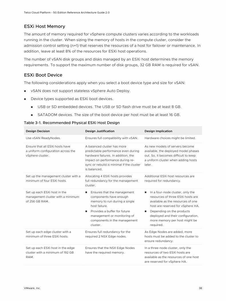
Table 3-1. Recommended Physical ESXi Host Design
Design Decision Design Justification Design Implication
Use vSAN ReadyNodes. Ensures full compatibility with vSAN. Hardware choices might be limited.
Ensure that all ESXi hosts have a uniform configuration across the vSphere cluster.
A balanced cluster has more predictable performance even during hardware failures. In addition, the impact on performance during re-sync or rebuild is minimal if the cluster is balanced.
As new models of servers become available, the deployed model phases out. So, it becomes difficult to keep a uniform cluster when adding hosts later.
Set up the management cluster with a minimum of four ESXi hosts.
Allocating 4 ESXi hosts provides full redundancy for the management cluster.
Additional ESXi host resources are required for redundancy.
Set up each ESXi host in the management cluster with a minimum of 256 GB RAM.
n Ensures that the management components have enough memory to run during a single host failure.
n Provides a buffer for future management or monitoring of components in the management cluster.
n In a four-node cluster, only the resources of three ESXi hosts are available as the resources of one host are reserved for vSphere HA.
n Depending on the products deployed and their configuration, more memory per host might be required.
Set up each edge cluster with a minimum of three ESXi hosts.
Ensures full redundancy for the required 2 NSX Edge nodes.
As Edge Nodes are added, more hosts must be added to the cluster to ensure redundancy.
Set up each ESXi host in the edge cluster with a minimum of 192 GB RAM.
Ensures that the NSX Edge Nodes have the required memory.
In a three-node cluster, only the resources of two ESXi hosts are available as the resources of one host are reserved for vSphere HA.
Telco Cloud Platform - 5G Edition Reference Architecture Guide 2.0
VMware, Inc. 38
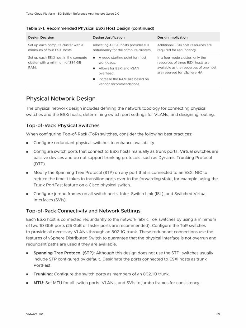
Table 3-1. Recommended Physical ESXi Host Design (continued)
Design Decision Design Justification Design Implication
Set up each compute cluster with a minimum of four ESXi hosts.
Allocating 4 ESXi hosts provides full redundancy for the compute clusters.
Additional ESXi host resources are required for redundancy.
Set up each ESXi host in the compute cluster with a minimum of 384 GB RAM.
n A good starting point for most workloads.
n Allows for ESXi and vSAN overhead.
n Increase the RAM size based on vendor recommendations.
In a four-node cluster, only the resources of three ESXi hosts are available as the resources of one host are reserved for vSphere HA.
Physical Network Design
The physical network design includes defining the network topology for connecting physical switches and the ESXi hosts, determining switch port settings for VLANs, and designing routing.
Top-of-Rack Physical Switches
When configuring Top-of-Rack (ToR) switches, consider the following best practices:
n Configure redundant physical switches to enhance availability.
n Configure switch ports that connect to ESXi hosts manually as trunk ports. Virtual switches are passive devices and do not support trunking protocols, such as Dynamic Trunking Protocol (DTP).
n Modify the Spanning Tree Protocol (STP) on any port that is connected to an ESXi NIC to reduce the time it takes to transition ports over to the forwarding state, for example, using the Trunk PortFast feature on a Cisco physical switch.
n Configure jumbo frames on all switch ports, Inter-Switch Link (ISL), and Switched Virtual Interfaces (SVIs).
Top-of-Rack Connectivity and Network Settings
Each ESXi host is connected redundantly to the network fabric ToR switches by using a minimum of two 10 GbE ports (25 GbE or faster ports are recommended). Configure the ToR switches to provide all necessary VLANs through an 802.1Q trunk. These redundant connections use the features of vSphere Distributed Switch to guarantee that the physical interface is not overrun and redundant paths are used if they are available.
n Spanning Tree Protocol (STP): Although this design does not use the STP, switches usually include STP configured by default. Designate the ports connected to ESXi hosts as trunk PortFast.
n Trunking: Configure the switch ports as members of an 802.1Q trunk.
n MTU: Set MTU for all switch ports, VLANs, and SVIs to jumbo frames for consistency.
Telco Cloud Platform - 5G Edition Reference Architecture Guide 2.0
VMware, Inc. 39
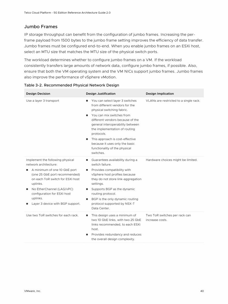
Jumbo Frames
IP storage throughput can benefit from the configuration of jumbo frames. Increasing the per-frame payload from 1500 bytes to the jumbo frame setting improves the efficiency of data transfer. Jumbo frames must be configured end-to-end. When you enable jumbo frames on an ESXi host, select an MTU size that matches the MTU size of the physical switch ports.
The workload determines whether to configure jumbo frames on a VM. If the workload consistently transfers large amounts of network data, configure jumbo frames, if possible. Also, ensure that both the VM operating system and the VM NICs support jumbo frames. Jumbo frames also improve the performance of vSphere vMotion.
Table 3-2. Recommended Physical Network Design
Design Decision Design Justification Design Implication
Use a layer 3 transport n You can select layer 3 switches from different vendors for the physical switching fabric.
n You can mix switches from different vendors because of the general interoperability between the implementation of routing protocols.
n This approach is cost-effective because it uses only the basic functionality of the physical switches.
VLANs are restricted to a single rack.
Implement the following physical network architecture:
n A minimum of one 10 GbE port (one 25 GbE port recommended) on each ToR switch for ESXi host uplinks.
n No EtherChannel (LAG/vPC) configuration for ESXi host uplinks.
n Layer 3 device with BGP support.
n Guarantees availability during a switch failure.
n Provides compatibility with vSphere host profiles because they do not store link-aggregation settings.
n Supports BGP as the dynamic routing protocol.
n BGP is the only dynamic routing protocol supported by NSX-T Data Center.
Hardware choices might be limited.
Use two ToR switches for each rack. n This design uses a minimum of two 10 GbE links, with two 25 GbE links recommended, to each ESXi host.
n Provides redundancy and reduces the overall design complexity.
Two ToR switches per rack can increase costs.
Telco Cloud Platform - 5G Edition Reference Architecture Guide 2.0
VMware, Inc. 40
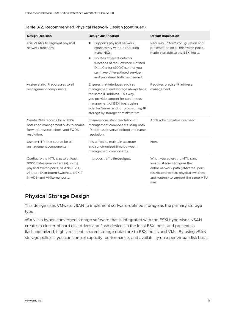
Table 3-2. Recommended Physical Network Design (continued)
Design Decision Design Justification Design Implication
Use VLANs to segment physical network functions.
n Supports physical network connectivity without requiring many NICs.
n Isolates different network functions of the Software-Defined Data Center (SDDC) so that you can have differentiated services and prioritized traffic as needed.
Requires uniform configuration and presentation on all the switch ports made available to the ESXi hosts.
Assign static IP addresses to all management components.
Ensures that interfaces such as management and storage always have the same IP address. This way, you provide support for continuous management of ESXi hosts using vCenter Server and for provisioning IP storage by storage administrators
Requires precise IP address management.
Create DNS records for all ESXi hosts and management VMs to enable forward, reverse, short, and FQDN resolution.
Ensures consistent resolution of management components using both IP address (reverse lookup) and name resolution.
Adds administrative overhead.
Use an NTP time source for all management components.
It is critical to maintain accurate and synchronized time between management components.
None.
Configure the MTU size to at least 9000 bytes (jumbo frames) on the physical switch ports, VLANs, SVIs, vSphere Distributed Switches, NSX-T N-VDS, and VMkernel ports.
Improves traffic throughput. When you adjust the MTU size, you must also configure the entire network path (VMkernel port, distributed switch, physical switches, and routers) to support the same MTU size.
Physical Storage Design
This design uses VMware vSAN to implement software-defined storage as the primary storage type.
vSAN is a hyper-converged storage software that is integrated with the ESXi hypervisor. vSAN creates a cluster of hard disk drives and flash devices in the local ESXi host, and presents a flash-optimized, highly resilient, shared storage datastore to ESXi hosts and VMs. By using vSAN storage policies, you can control capacity, performance, and availability on a per virtual disk basis.
Telco Cloud Platform - 5G Edition Reference Architecture Guide 2.0
VMware, Inc. 41
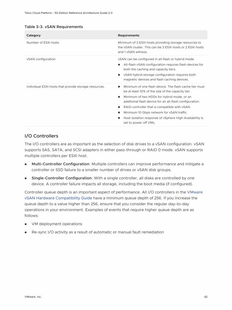
Table 3-3. vSAN Requirements
Category Requirements
Number of ESXi hosts Minimum of 3 ESXi hosts providing storage resources to the vSAN cluster. This can be 3 ESXi hosts or 2 ESXi hosts and 1 vSAN witness.
vSAN configuration vSAN can be configured in all-flash or hybrid mode.
n All-flash vSAN configuration requires flash devices for both the caching and capacity tiers.
n vSAN hybrid storage configuration requires both magnetic devices and flash caching devices.
Individual ESXi hosts that provide storage resources. n Minimum of one flash device. The flash cache tier must be at least 10% of the size of the capacity tier.
n Minimum of two HDDs for hybrid mode, or an additional flash device for an all-flash configuration.
n RAID controller that is compatible with vSAN.
n Minimum 10 Gbps network for vSAN traffic.
n Host isolation response of vSphere High Availability is set to power off VMs.
I/O Controllers
The I/O controllers are as important as the selection of disk drives to a vSAN configuration. vSAN supports SAS, SATA, and SCSI adapters in either pass-through or RAID 0 mode. vSAN supports multiple controllers per ESXi host.
n Multi-Controller Configuration: Multiple controllers can improve performance and mitigate a controller or SSD failure to a smaller number of drives or vSAN disk groups.
n Single-Controller Configuration: With a single controller, all disks are controlled by one device. A controller failure impacts all storage, including the boot media (if configured).
Controller queue depth is an important aspect of performance. All I/O controllers in the VMware vSAN Hardware Compatibility Guide have a minimum queue depth of 256. If you increase the queue depth to a value higher than 256, ensure that you consider the regular day-to-day operations in your environment. Examples of events that require higher queue depth are as follows:
n VM deployment operations
n Re-sync I/O activity as a result of automatic or manual fault remediation
Telco Cloud Platform - 5G Edition Reference Architecture Guide 2.0
VMware, Inc. 42
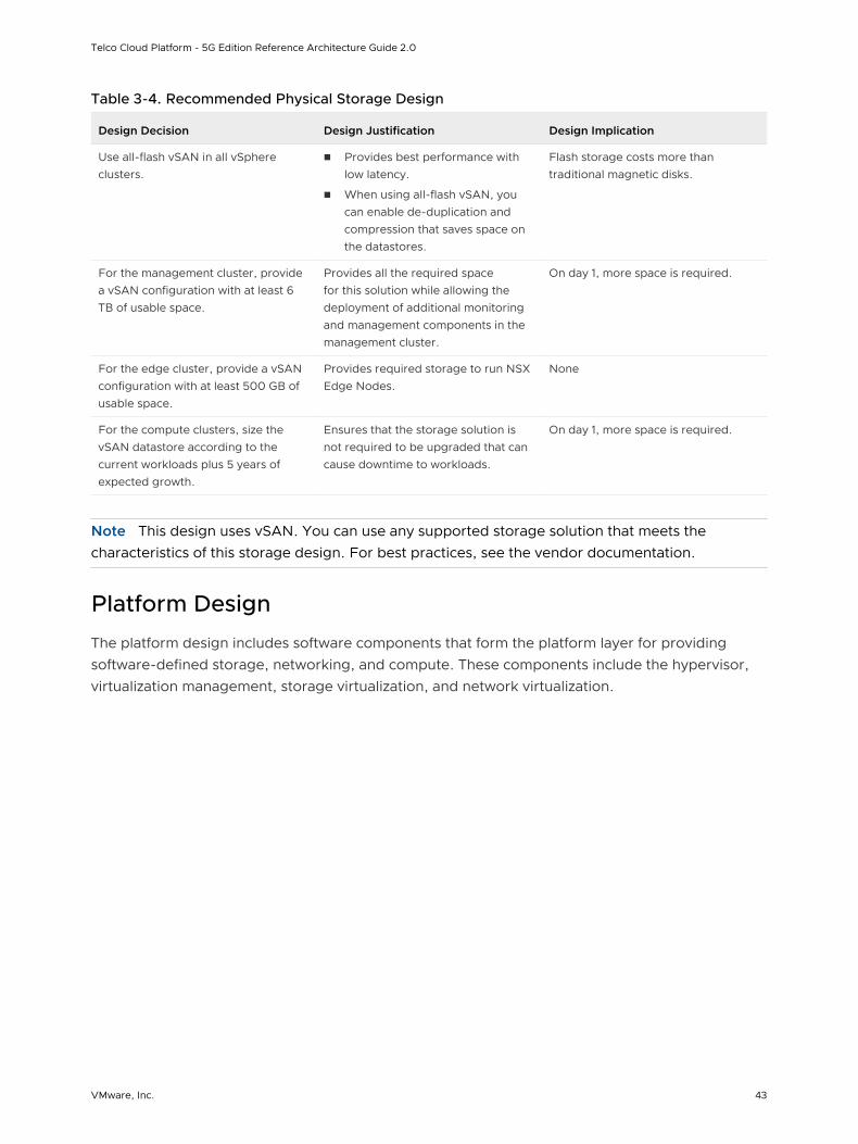
Table 3-4. Recommended Physical Storage Design
Design Decision Design Justification Design Implication
Use all-flash vSAN in all vSphere clusters.
n Provides best performance with low latency.
n When using all-flash vSAN, you can enable de-duplication and compression that saves space on the datastores.
Flash storage costs more than traditional magnetic disks.
For the management cluster, provide a vSAN configuration with at least 6 TB of usable space.
Provides all the required space for this solution while allowing the deployment of additional monitoring and management components in the management cluster.
On day 1, more space is required.
For the edge cluster, provide a vSAN configuration with at least 500 GB of usable space.
Provides required storage to run NSX Edge Nodes.
None
For the compute clusters, size the vSAN datastore according to the current workloads plus 5 years of expected growth.
Ensures that the storage solution is not required to be upgraded that can cause downtime to workloads.
On day 1, more space is required.
Note This design uses vSAN. You can use any supported storage solution that meets the characteristics of this storage design. For best practices, see the vendor documentation.
Platform Design
The platform design includes software components that form the platform layer for providing software-defined storage, networking, and compute. These components include the hypervisor, virtualization management, storage virtualization, and network virtualization.
Telco Cloud Platform - 5G Edition Reference Architecture Guide 2.0
VMware, Inc. 43
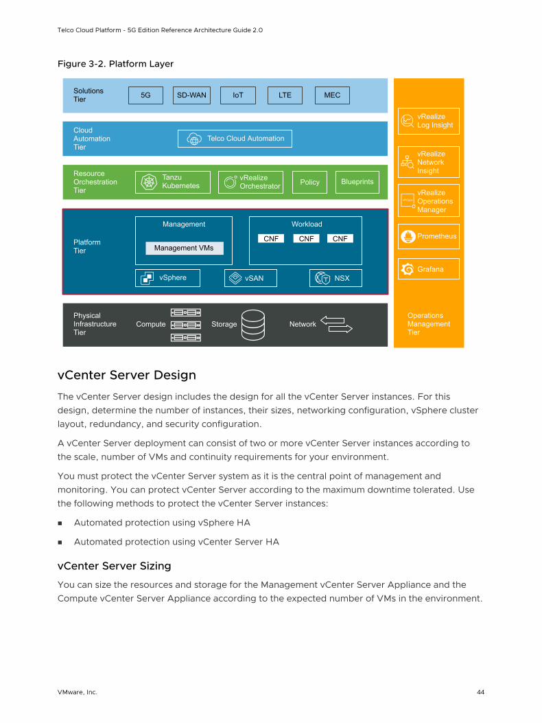
Figure 3-2. Platform Layer
vRealize Orchestrator
Operations Management Tier
Physical Infrastructure Tier
Platform Tier
Resource Orchestration Tier
Cloud Automation Tier
Solutions Tier 5G SD-WAN LTE MECIoT
Telco Cloud Automation
Tanzu Kubernetes Policy Blueprints
Management VMsCNF CNF CNF
Management Workload
vSphere vSAN NSX
vRealize Log Insight
vRealize Network Insight
vRealize Operations Manager
Compute Storage Network
Prometheus
Grafana
vCenter Server Design
The vCenter Server design includes the design for all the vCenter Server instances. For this design, determine the number of instances, their sizes, networking configuration, vSphere cluster layout, redundancy, and security configuration.
A vCenter Server deployment can consist of two or more vCenter Server instances according to the scale, number of VMs and continuity requirements for your environment.
You must protect the vCenter Server system as it is the central point of management and monitoring. You can protect vCenter Server according to the maximum downtime tolerated. Use the following methods to protect the vCenter Server instances:
n Automated protection using vSphere HA
n Automated protection using vCenter Server HA
vCenter Server Sizing
You can size the resources and storage for the Management vCenter Server Appliance and the Compute vCenter Server Appliance according to the expected number of VMs in the environment.
Telco Cloud Platform - 5G Edition Reference Architecture Guide 2.0
VMware, Inc. 44
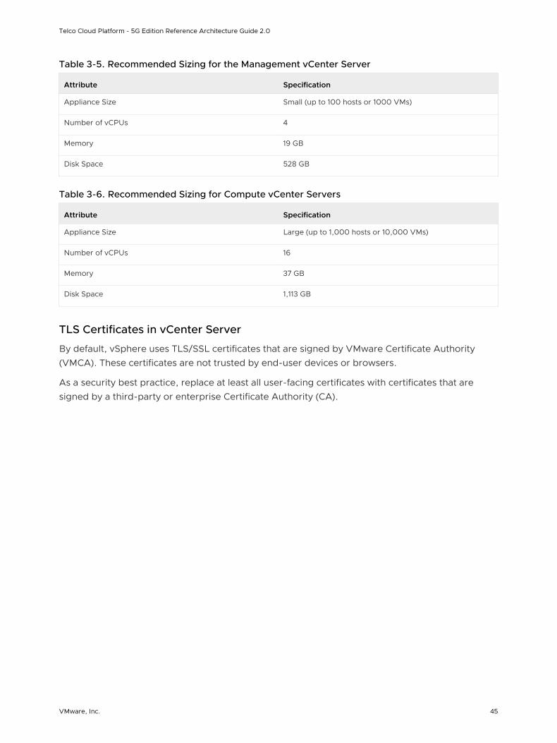
Table 3-5. Recommended Sizing for the Management vCenter Server
Attribute Specification
Appliance Size Small (up to 100 hosts or 1000 VMs)
Number of vCPUs 4
Memory 19 GB
Disk Space 528 GB
Table 3-6. Recommended Sizing for Compute vCenter Servers
Attribute Specification
Appliance Size Large (up to 1,000 hosts or 10,000 VMs)
Number of vCPUs 16
Memory 37 GB
Disk Space 1,113 GB
TLS Certificates in vCenter Server
By default, vSphere uses TLS/SSL certificates that are signed by VMware Certificate Authority (VMCA). These certificates are not trusted by end-user devices or browsers.
As a security best practice, replace at least all user-facing certificates with certificates that are signed by a third-party or enterprise Certificate Authority (CA).
Telco Cloud Platform - 5G Edition Reference Architecture Guide 2.0
VMware, Inc. 45
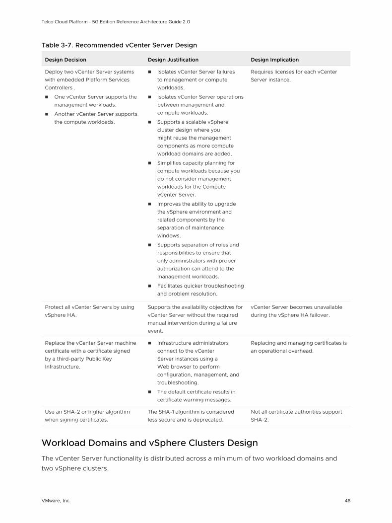
Table 3-7. Recommended vCenter Server Design
Design Decision Design Justification Design Implication
Deploy two vCenter Server systems with embedded Platform Services Controllers .
n One vCenter Server supports the management workloads.
n Another vCenter Server supports the compute workloads.
n Isolates vCenter Server failures to management or compute workloads.
n Isolates vCenter Server operations between management and compute workloads.
n Supports a scalable vSphere cluster design where you might reuse the management components as more compute workload domains are added.
n Simplifies capacity planning for compute workloads because you do not consider management workloads for the Compute vCenter Server.
n Improves the ability to upgrade the vSphere environment and related components by the separation of maintenance windows.
n Supports separation of roles and responsibilities to ensure that only administrators with proper authorization can attend to the management workloads.
n Facilitates quicker troubleshooting and problem resolution.
Requires licenses for each vCenter Server instance.
Protect all vCenter Servers by using vSphere HA.
Supports the availability objectives for vCenter Server without the required manual intervention during a failure event.
vCenter Server becomes unavailable during the vSphere HA failover.
Replace the vCenter Server machine certificate with a certificate signed by a third-party Public Key Infrastructure.
n Infrastructure administrators connect to the vCenter Server instances using a Web browser to perform configuration, management, and troubleshooting.
n The default certificate results in certificate warning messages.
Replacing and managing certificates is an operational overhead.
Use an SHA-2 or higher algorithm when signing certificates.
The SHA-1 algorithm is considered less secure and is deprecated.
Not all certificate authorities support SHA-2.
Workload Domains and vSphere Clusters Design
The vCenter Server functionality is distributed across a minimum of two workload domains and two vSphere clusters.
Telco Cloud Platform - 5G Edition Reference Architecture Guide 2.0
VMware, Inc. 46
This solution uses two vCenter Server instances: one for the management workload domain and another for the first compute workload domain. The compute workload domain can contain multiple vSphere clusters.
The cluster design must consider the workloads that the cluster handles. Different cluster types in this design have different characteristics. When you design the cluster layout in vSphere, consider the following guidelines:
n Use a few large-sized ESXi hosts or more small-sized ESXi hosts.
n A scale-up cluster has fewer large-sized ESXi hosts.
n A scale-out cluster has more small-sized ESXi hosts.
n Compare the capital costs of purchasing few large-sized ESXi hosts with more small-sized ESXi hosts. Costs vary between vendors and models.
n Evaluate the operational costs for managing a few ESXi hosts with more ESXi hosts.
n Consider the purpose of the cluster.
n Consider the total number of ESXi hosts and cluster limits.
vSphere High Availability
VMware vSphere High Availability (vSphere HA) protects your VMs in case of an ESXi host failure by restarting VMs on other hosts in the cluster. During the cluster configuration, the ESXi hosts elect a primary ESXi host. The primary ESXi host communicates with the vCenter Server system and monitors the VMs and secondary ESXi hosts in the cluster.
The primary ESXi host detects different types of failure:
n ESXi host failure, for example, an unexpected power failure.
n ESXi host network isolation or connectivity failure.
n Loss of storage connectivity.
n Problems with the virtual machine OS availability.
The vSphere HA Admission Control Policy allows an administrator to configure how the cluster determines available resources. In a small vSphere HA cluster, a large proportion of the cluster resources is reserved to accommodate ESXi host failures, based on the selected policy.
The following policies are available:
Cluster resource percentage
Reserves a specific percentage of cluster CPU and memory resources for recovery from host failures.
With this type of admission control, vSphere HA ensures that a specified percentage of aggregate CPU and memory resources is reserved for failover.
Slot policy
Telco Cloud Platform - 5G Edition Reference Architecture Guide 2.0
VMware, Inc. 47
vSphere HA admission control ensures that a specified number of hosts can fail and sufficient resources remain in the cluster to fail over all the VMs from those hosts.
A slot is a logical representation of memory and CPU resources. By default, it is sized to satisfy the requirements for any powered-on VM in the cluster.
vSphere HA determines the current failover capacity in the cluster. The failover capacity specifies the number of hosts that can fail and leave enough slots for all the powered-on VMs.
Dedicated failover hosts
When a host fails, vSphere HA attempts to restart its VMs on any of the specified failover hosts.
vSphere Distributed Resource Scheduler
The distribution and usage of CPU and memory resources for all hosts and VMs in the cluster are continuously monitored. The vSphere Distributed Resource Scheduler (DRS) compares these metrics to an ideal resource usage given the attributes of the cluster’s resource pools and virtual machines, the current demand, and the imbalance target. DRS then provides recommendations or performs VM migrations accordingly.
DRS supports the following modes of operation:
Manual
n Initial placement: Recommended host is displayed.
n Migration: Recommendation is displayed.
Partially Automated
n Initial placement: Automatic.
n Migration: Recommendation is displayed.
Fully Automated
n Initial placement: Automatic.
n Migration: Recommendation is run automatically.
Resource Pools
A resource pool is a logical abstraction for flexible management of resources. Resource pools can be grouped into hierarchies and used to hierarchically partition available CPU and memory resources.
Each DRS cluster has an (invisible) root resource pool that groups the resources of that cluster. The root resource pool does not appear because the resources of the cluster and the root resource pool are always the same.
Telco Cloud Platform - 5G Edition Reference Architecture Guide 2.0
VMware, Inc. 48
Users can create child resource pools of the root resource pool or any user-created child resource pool. Each child resource pool owns some of the parent’s resources and can, in turn, have a hierarchy of child resource pools to represent successively smaller units of computational capability.
A resource pool can contain child resource pools, VMs, or both. You can create a hierarchy of shared resources. The resource pools at a higher level are called parent resource pools. Resource pools and VMs that are at the same level are called siblings. The cluster represents the root resource pool. If you do not create child resource pools, only the root resource pools exist.
Scalable Shares allows the resource pool shares to dynamically scale as VMs are added or removed from the resource pool hierarchy.
vSphere Cluster Services
vSphere Cluster Services (vCLS) is enabled by default and runs in all vSphere clusters. vCLS ensures that if vCenter Server becomes unavailable, cluster services remain available to maintain the resources and health of the workloads that run in the clusters.
vSphere DRS is a critical feature of vSphere which is required to maintain the health of the workloads running inside vSphere Cluster. DRS depends on the availability of vCLS VMs.
vCLS VMs are always powered-on because vSphere DRS depends on the availability of these VMs. These VMs should be treated as system VMs. No operations are blocked on vCLS VMs. However, any disruptive operation can result in failure of vSphere DRS. To avoid failure of cluster services, avoid performing any configuration or operations on the vCLS VMs.
vSphere Lifecycle Manager
vSphere Lifecycle Manager allows for the management of software and firmware lifecycle of the ESXi hosts in a cluster with a single image. vSphere Lifecycle Manager images are a new functionality that provides a simplified and unified workflow for patching and upgrade of ESXi hosts. You can also use vSphere Lifecycle Manager images for bootstrapping purposes and firmware updates.
An image defines the exact software stack to run on all ESXi hosts in a cluster. When you set up an image, you select an ESXi version and a vendor add-on from the vSphere Lifecycle Manager depot. If no ESXi base images and vendor add-ons are available in the vSphere Lifecycle Manager depot, you must populate the depot with software updates by synchronizing the depot or uploading updates to the depot manually.
Telco Cloud Platform - 5G Edition Reference Architecture Guide 2.0
VMware, Inc. 49
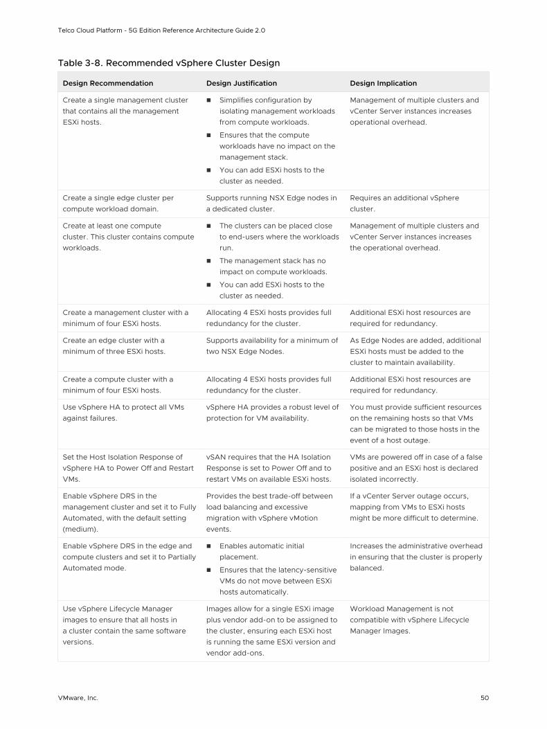
Table 3-8. Recommended vSphere Cluster Design
Design Recommendation Design Justification Design Implication
Create a single management cluster that contains all the management ESXi hosts.
n Simplifies configuration by isolating management workloads from compute workloads.
n Ensures that the compute workloads have no impact on the management stack.
n You can add ESXi hosts to the cluster as needed.
Management of multiple clusters and vCenter Server instances increases operational overhead.
Create a single edge cluster per compute workload domain.
Supports running NSX Edge nodes in a dedicated cluster.
Requires an additional vSphere cluster.
Create at least one compute cluster. This cluster contains compute workloads.
n The clusters can be placed close to end-users where the workloads run.
n The management stack has no impact on compute workloads.
n You can add ESXi hosts to the cluster as needed.
Management of multiple clusters and vCenter Server instances increases the operational overhead.
Create a management cluster with a minimum of four ESXi hosts.
Allocating 4 ESXi hosts provides full redundancy for the cluster.
Additional ESXi host resources are required for redundancy.
Create an edge cluster with a minimum of three ESXi hosts.
Supports availability for a minimum of two NSX Edge Nodes.
As Edge Nodes are added, additional ESXi hosts must be added to the cluster to maintain availability.
Create a compute cluster with a minimum of four ESXi hosts.
Allocating 4 ESXi hosts provides full redundancy for the cluster.
Additional ESXi host resources are required for redundancy.
Use vSphere HA to protect all VMs against failures.
vSphere HA provides a robust level of protection for VM availability.
You must provide sufficient resources on the remaining hosts so that VMs can be migrated to those hosts in the event of a host outage.
Set the Host Isolation Response of vSphere HA to Power Off and Restart VMs.
vSAN requires that the HA Isolation Response is set to Power Off and to restart VMs on available ESXi hosts.
VMs are powered off in case of a false positive and an ESXi host is declared isolated incorrectly.
Enable vSphere DRS in the management cluster and set it to Fully Automated, with the default setting (medium).
Provides the best trade-off between load balancing and excessive migration with vSphere vMotion events.
If a vCenter Server outage occurs, mapping from VMs to ESXi hosts might be more difficult to determine.
Enable vSphere DRS in the edge and compute clusters and set it to Partially Automated mode.
n Enables automatic initial placement.
n Ensures that the latency-sensitive VMs do not move between ESXi hosts automatically.
Increases the administrative overhead in ensuring that the cluster is properly balanced.
Use vSphere Lifecycle Manager images to ensure that all hosts in a cluster contain the same software versions.
Images allow for a single ESXi image plus vendor add-on to be assigned to the cluster, ensuring each ESXi host is running the same ESXi version and vendor add-ons.
Workload Management is not compatible with vSphere Lifecycle Manager Images.
Telco Cloud Platform - 5G Edition Reference Architecture Guide 2.0
VMware, Inc. 50
Network Virtualization Design
This network virtualization design uses the vSphere Distributed Switch (VDS) along with Network I/O Control.
Design Goals
The following high-level design goals apply regardless of your environment.
n Meet diverse needs: The network must meet the diverse requirements of different entities in an organization. These entities include applications, services, storage, administrators, and users.
n Reduce costs: Reducing costs is one of the simpler goals to achieve in the vSphere infrastructure. Server consolidation reduces network costs by reducing the number of required network ports and NICs, but a more efficient network design is required. For example, configuring two 25 GbE NICs might be more cost-effective than configuring four 10 GbE NICs.
n Improve performance: You can achieve performance improvement and decrease the maintenance time by providing sufficient bandwidth, which in turn reduces the contention and latency.
n Improve availability: A well-designed network improves availability by providing network the redundancy.
n Support security: A well-designed network supports an acceptable level of security through controlled access and isolation, where required.
n Enhance infrastructure functionality: You can configure the network to support vSphere features such as vSphere vMotion, vSphere High Availability, and vSphere Fault Tolerance.
Network Best Practices
Follow these networking best practices throughout your environment:
n Separate the network services to achieve high security and better performance.
n Use Network I/O Control and traffic shaping to guarantee bandwidth to critical VMs. During the network contention, these critical VMs receive a high percentage of the bandwidth.
n Separate the network services on a vSphere Distributed Switch by attaching them to port groups with different VLAN IDs.
n Keep vSphere vMotion traffic on a separate network. When a migration using vSphere vMotion occurs, the contents of the memory of the guest operating system is transmitted over the network. You can place vSphere vMotion on a separate network by using a dedicated vSphere vMotion VLAN.
n Ensure that physical network adapters that are connected to the same vSphere Standard or Distributed Switch are also connected to the same physical network.
Network Segmentation and VLANs
Separate the different types of traffic for access security and to reduce the contention and latency.
Telco Cloud Platform - 5G Edition Reference Architecture Guide 2.0
VMware, Inc. 51
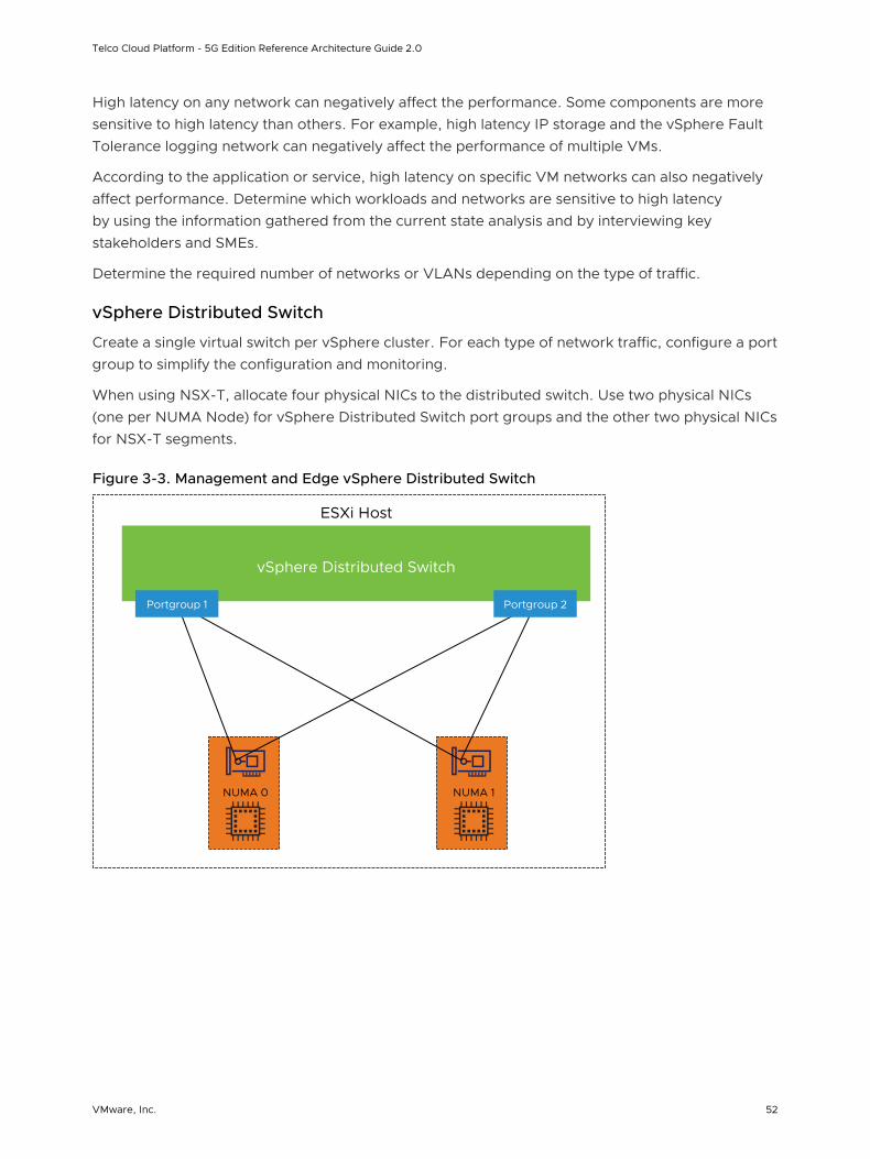
High latency on any network can negatively affect the performance. Some components are more sensitive to high latency than others. For example, high latency IP storage and the vSphere Fault Tolerance logging network can negatively affect the performance of multiple VMs.
According to the application or service, high latency on specific VM networks can also negatively affect performance. Determine which workloads and networks are sensitive to high latency by using the information gathered from the current state analysis and by interviewing key stakeholders and SMEs.
Determine the required number of networks or VLANs depending on the type of traffic.
vSphere Distributed Switch
Create a single virtual switch per vSphere cluster. For each type of network traffic, configure a port group to simplify the configuration and monitoring.
When using NSX-T, allocate four physical NICs to the distributed switch. Use two physical NICs (one per NUMA Node) for vSphere Distributed Switch port groups and the other two physical NICs for NSX-T segments.
Figure 3-3. Management and Edge vSphere Distributed Switch
ESXi Host
vSphere Distributed Switch
NUMA 1NUMA 0
Portgroup 2Portgroup 1
Telco Cloud Platform - 5G Edition Reference Architecture Guide 2.0
VMware, Inc. 52
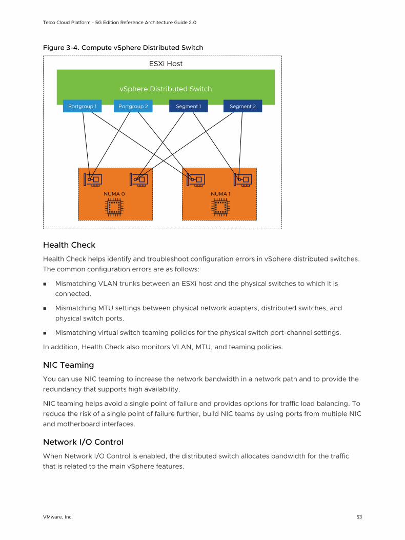
Figure 3-4. Compute vSphere Distributed Switch
ESXi Host
vSphere Distributed Switch
Portgroup 1
NUMA 1NUMA 0
Portgroup 2 Segment 1 Segment 2
Health Check
Health Check helps identify and troubleshoot configuration errors in vSphere distributed switches. The common configuration errors are as follows:
n Mismatching VLAN trunks between an ESXi host and the physical switches to which it is connected.
n Mismatching MTU settings between physical network adapters, distributed switches, and physical switch ports.
n Mismatching virtual switch teaming policies for the physical switch port-channel settings.
In addition, Health Check also monitors VLAN, MTU, and teaming policies.
NIC Teaming
You can use NIC teaming to increase the network bandwidth in a network path and to provide the redundancy that supports high availability.
NIC teaming helps avoid a single point of failure and provides options for traffic load balancing. To reduce the risk of a single point of failure further, build NIC teams by using ports from multiple NIC and motherboard interfaces.
Network I/O Control
When Network I/O Control is enabled, the distributed switch allocates bandwidth for the traffic that is related to the main vSphere features.
Telco Cloud Platform - 5G Edition Reference Architecture Guide 2.0
VMware, Inc. 53
When the network contention occurs, Network I/O Control enforces the share value specified for different traffic types. Network I/O Control applies the share values set to each traffic type. As a result, less important traffic, as defined by the share percentage, is throttled while granting access to more network resources to more important traffic types.
Network I/O Control supports bandwidth reservation for system traffic based on the capacity of physical adapters on an ESXi host. It also enables fine-grained resource control at the VM network adapter. Resource control is similar to the CPU and memory reservation model in vSphere DRS.
TCP/IP Stack
Use the vMotion TCP/IP stack to isolate the traffic for vSphere vMotion and to assign a dedicated default gateway for the vSphere vMotion traffic.
By using a separate TCP/IP stack, you can manage vSphere vMotion and cold migration traffic according to the network topology, and as required by your organization.
n Route the traffic for the migration of VMs (powered on or off) by using a default gateway. The default gateway is different from the gateway assigned to the default stack on the ESXi host.
n Assign a separate set of buffers and sockets.
n Avoid the routing table conflicts that might appear when many features are using a common TCP/IP stack.
n Isolate the traffic to improve security.
SR-IOV
SR-IOV is a specification that allows a single Peripheral Component Interconnect Express (PCIe) physical device under a single root port to appear as multiple separate physical devices to the hypervisor or the guest operating system.
SR-IOV uses Physical Functions (PFs) and Virtual Functions (VFs) to manage global functions for the SR-IOV devices. PFs are full PCIe functions that can configure and manage the SR-IOV functionality. VFs are lightweight PCIe functions that support data flow but have a restricted set of configuration resources. The number of VFs provided to the hypervisor or the guest operating system depends on the device. SR-IOV enabled PCIe devices require appropriate BIOS, hardware, and SR-IOV support in the guest operating system driver or hypervisor instance.
In vSphere, a VM can use an SR-IOV virtual function for networking. The VM and the physical adapter exchange data directly without using the VMkernel stack as an intermediary. Bypassing the VMkernel for networking reduces the latency and improves the CPU efficiency for high data transfer performance.
Telco Cloud Platform - 5G Edition Reference Architecture Guide 2.0
VMware, Inc. 54
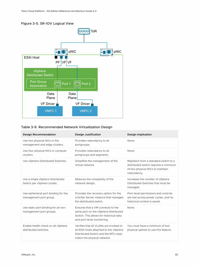
Figure 3-5. SR-IOV Logical View
ESXi Host
vSphere Distributed Switch
Port GroupAssociation
ToR
PF VF VF
Port 1 Port 2
pNIC pNIC
DataPlane
DataPlane
VNFC 1
VF Driver
VNFC 2
VF Driver
Table 3-9. Recommended Network Virtualization Design
Design Recommendation Design Justification Design Implication
Use two physical NICs in the management and edge clusters.
Provides redundancy to all portgroups.
None
Use four physical NICs in compute clusters.
Provides redundancy to all portgroups and segments.
None
Use vSphere Distributed Switches. Simplifies the management of the virtual network.
Migration from a standard switch to a distributed switch requires a minimum of two physical NICs to maintain redundancy.
Use a single vSphere Distributed Switch per vSphere cluster.
Reduces the complexity of the network design.
Increases the number of vSphere Distributed Switches that must be managed.
Use ephemeral port binding for the management port group.
Provides the recovery option for the vCenter Server instance that manages the distributed switch.
Port-level permissions and controls are lost across power cycles, and no historical context is saved.
Use static port binding for all non-management port groups.
Ensures that a VM connects to the same port on the vSphere Distributed Switch. This allows for historical data and port-level monitoring.
None
Enable health check on all vSphere distributed switches.
Verifies that all VLANs are trunked to all ESXi hosts attached to the vSphere Distributed Switch and the MTU sizes match the physical network.
You must have a minimum of two physical uplinks to use this feature.
Telco Cloud Platform - 5G Edition Reference Architecture Guide 2.0
VMware, Inc. 55
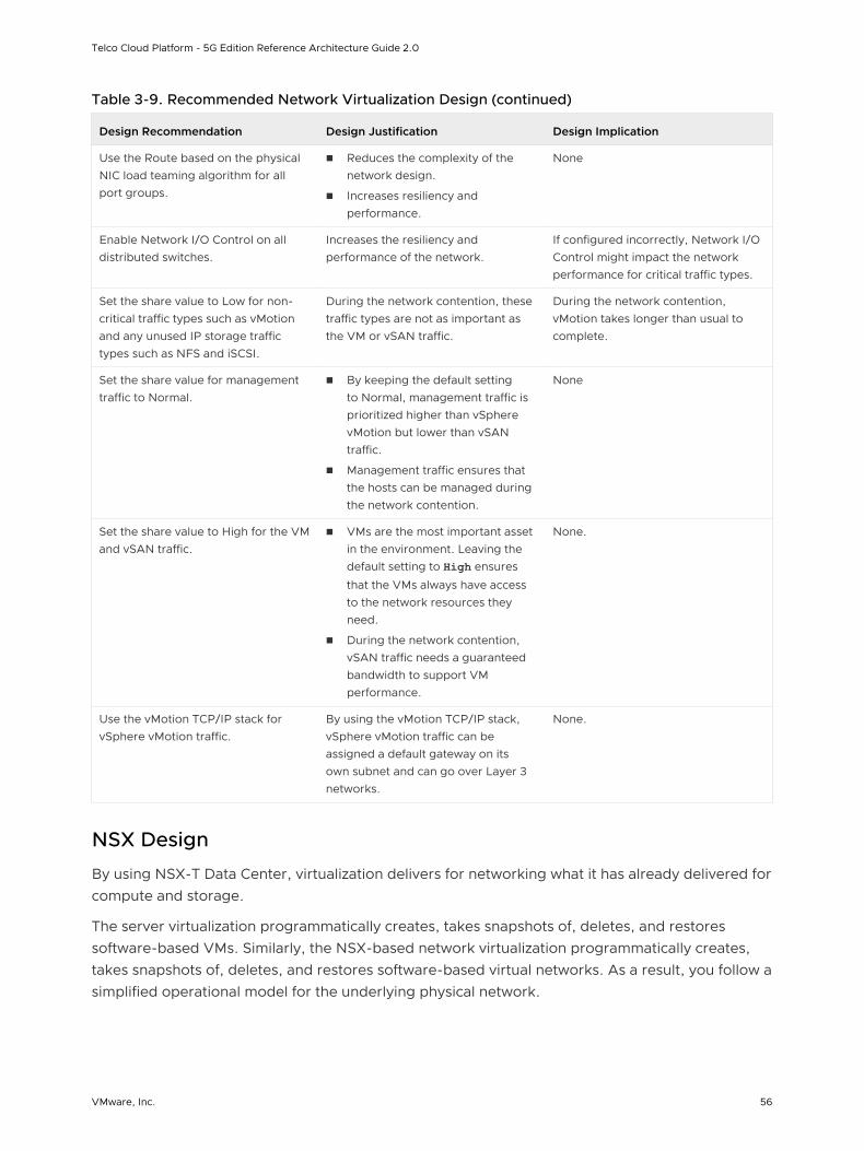
Table 3-9. Recommended Network Virtualization Design (continued)
Design Recommendation Design Justification Design Implication
Use the Route based on the physical NIC load teaming algorithm for all port groups.
n Reduces the complexity of the network design.
n Increases resiliency and performance.
None
Enable Network I/O Control on all distributed switches.
Increases the resiliency and performance of the network.
If configured incorrectly, Network I/O Control might impact the network performance for critical traffic types.
Set the share value to Low for non-critical traffic types such as vMotion and any unused IP storage traffic types such as NFS and iSCSI.
During the network contention, these traffic types are not as important as the VM or vSAN traffic.
During the network contention, vMotion takes longer than usual to complete.
Set the share value for management traffic to Normal.
n By keeping the default setting to Normal, management traffic is prioritized higher than vSphere vMotion but lower than vSAN traffic.
n Management traffic ensures that the hosts can be managed during the network contention.
None
Set the share value to High for the VM and vSAN traffic.
n VMs are the most important asset in the environment. Leaving the default setting to High ensures
that the VMs always have access to the network resources they need.
n During the network contention, vSAN traffic needs a guaranteed bandwidth to support VM performance.
None.
Use the vMotion TCP/IP stack for vSphere vMotion traffic.
By using the vMotion TCP/IP stack, vSphere vMotion traffic can be assigned a default gateway on its own subnet and can go over Layer 3 networks.
None.
NSX Design
By using NSX-T Data Center, virtualization delivers for networking what it has already delivered for compute and storage.
The server virtualization programmatically creates, takes snapshots of, deletes, and restores software-based VMs. Similarly, the NSX-based network virtualization programmatically creates, takes snapshots of, deletes, and restores software-based virtual networks. As a result, you follow a simplified operational model for the underlying physical network.
Telco Cloud Platform - 5G Edition Reference Architecture Guide 2.0
VMware, Inc. 56
NSX-T Data Center is a non-disruptive solution. You can deploy it on any IP network such as traditional networking models and next-generation fabric architectures, regardless of the vendor. This is accomplished by decoupling the virtual networks from their physical counterparts.
NSX Manager
NSX Manager is the centralized network management component of NSX-T Data Center. It implements the management and control plane for the NSX infrastructure.
NSX Manager provides the following:
n The Graphical User Interface (GUI) and the RESTful API for creating, configuring, and monitoring NSX-T components, such as segments and gateways.
n An aggregated system view.
n A method for monitoring and troubleshooting workloads attached to virtual networks.
n Configuration and orchestration of the following services:
n Logical networking components, such as logical switching and routing
n Networking and edge services
n Security services and distributed firewall
n A RESTful API endpoint to automate consumption. Because of this architecture, you can automate all configuration and monitoring operations using any cloud management platform, security vendor platform, or automation framework.
Some of the components of the NSX Manager are as follows:
n NSX Management Plane Agent (MPA): Available on each ESXi host. The MPA persists the desired state of the system and communicates Non-Flow-Controlling (NFC) messages such as configuration, statistics, status, and real-time data between transport nodes and the management plane.
n NSX Controller: Controls the virtual networks and overlay transport tunnels. The controllers are responsible for the programmatic deployment of virtual networks across the entire NSX-T architecture.
n Central Control Plane (CCP): Logically separated from all data plane traffic. A failure in the control plane does not affect existing data plane operations. The controller provides configuration to other NSX Controller components such as the segments, gateways, and edge VM configuration.
Telco Cloud Platform - 5G Edition Reference Architecture Guide 2.0
VMware, Inc. 57
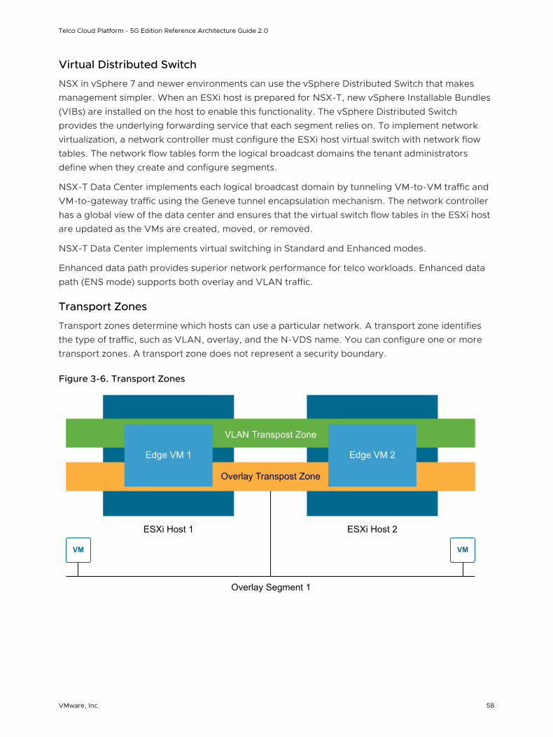
Virtual Distributed Switch
NSX in vSphere 7 and newer environments can use the vSphere Distributed Switch that makes management simpler. When an ESXi host is prepared for NSX-T, new vSphere Installable Bundles (VIBs) are installed on the host to enable this functionality. The vSphere Distributed Switch provides the underlying forwarding service that each segment relies on. To implement network virtualization, a network controller must configure the ESXi host virtual switch with network flow tables. The network flow tables form the logical broadcast domains the tenant administrators define when they create and configure segments.
NSX-T Data Center implements each logical broadcast domain by tunneling VM-to-VM traffic and VM-to-gateway traffic using the Geneve tunnel encapsulation mechanism. The network controller has a global view of the data center and ensures that the virtual switch flow tables in the ESXi host are updated as the VMs are created, moved, or removed.
NSX-T Data Center implements virtual switching in Standard and Enhanced modes.
Enhanced data path provides superior network performance for telco workloads. Enhanced data path (ENS mode) supports both overlay and VLAN traffic.
Transport Zones
Transport zones determine which hosts can use a particular network. A transport zone identifies the type of traffic, such as VLAN, overlay, and the N-VDS name. You can configure one or more transport zones. A transport zone does not represent a security boundary.
Figure 3-6. Transport Zones
ESXi Host 1 ESXi Host 2
Edge VM 1
VM
Edge VM 2
Overlay Transpost Zone
VLAN Transpost Zone
VM
Overlay Segment 1
Telco Cloud Platform - 5G Edition Reference Architecture Guide 2.0
VMware, Inc. 58
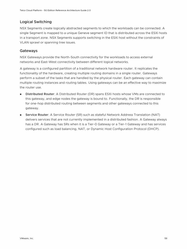
Logical Switching
NSX Segments create logically abstracted segments to which the workloads can be connected. A single Segment is mapped to a unique Geneve segment ID that is distributed across the ESXi hosts in a transport zone. NSX Segments supports switching in the ESXi host without the constraints of VLAN sprawl or spanning tree issues.
Gateways
NSX Gateways provide the North-South connectivity for the workloads to access external networks and East-West connectivity between different logical networks.
A gateway is a configured partition of a traditional network hardware router. It replicates the functionality of the hardware, creating multiple routing domains in a single router. Gateways perform a subset of the tasks that are handled by the physical router. Each gateway can contain multiple routing instances and routing tables. Using gateways can be an effective way to maximize the router use.
n Distributed Router: A Distributed Router (DR) spans ESXi hosts whose VMs are connected to this gateway, and edge nodes the gateway is bound to. Functionally, the DR is responsible for one-hop distributed routing between segments and other gateways connected to this gateway.
n Service Router: A Service Router (SR) such as stateful Network Address Translation (NAT) delivers services that are not currently implemented in a distributed fashion. A Gateway always has a DR. A Gateway has SRs when it is a Tier-0 Gateway or a Tier-1 Gateway and has services configured such as load balancing, NAT, or Dynamic Host Configuration Protocol (DHCP).
Telco Cloud Platform - 5G Edition Reference Architecture Guide 2.0
VMware, Inc. 59
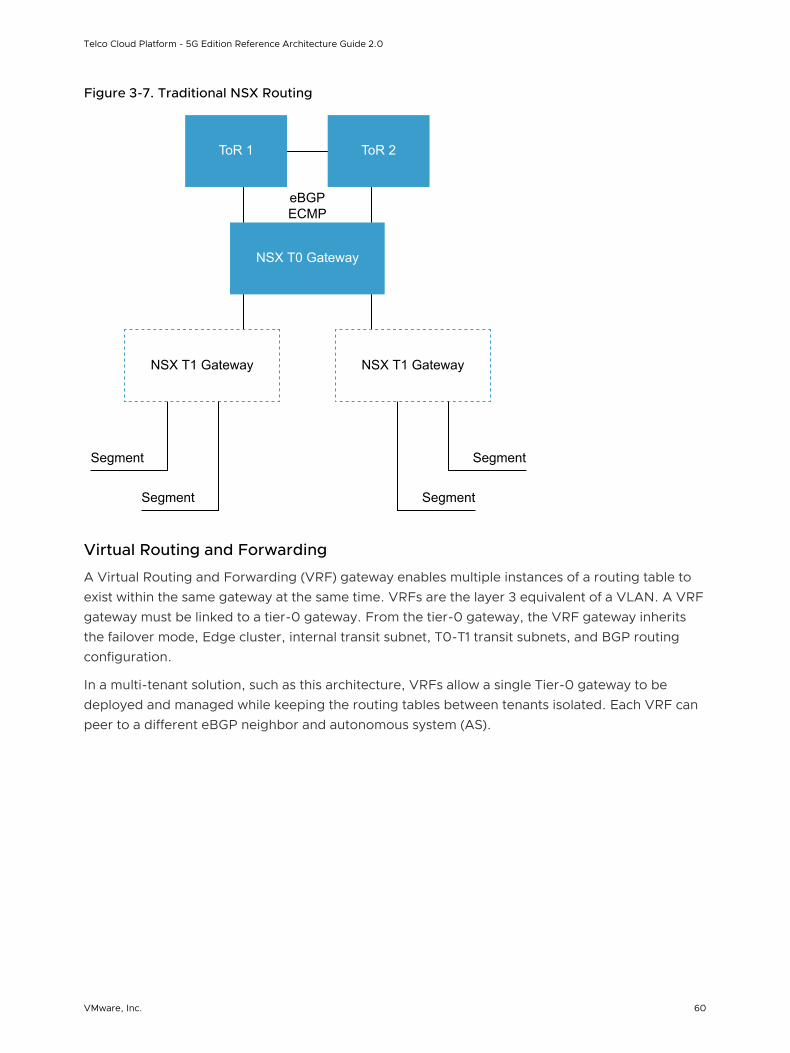
Figure 3-7. Traditional NSX Routing
Segment
ToR 1 ToR 2
NSX T0 Gateway
NSX T1 Gateway NSX T1 Gateway
eBGPECMP
Segment
Segment
Segment
Virtual Routing and Forwarding
A Virtual Routing and Forwarding (VRF) gateway enables multiple instances of a routing table to exist within the same gateway at the same time. VRFs are the layer 3 equivalent of a VLAN. A VRF gateway must be linked to a tier-0 gateway. From the tier-0 gateway, the VRF gateway inherits the failover mode, Edge cluster, internal transit subnet, T0-T1 transit subnets, and BGP routing configuration.
In a multi-tenant solution, such as this architecture, VRFs allow a single Tier-0 gateway to be deployed and managed while keeping the routing tables between tenants isolated. Each VRF can peer to a different eBGP neighbor and autonomous system (AS).
Telco Cloud Platform - 5G Edition Reference Architecture Guide 2.0
VMware, Inc. 60
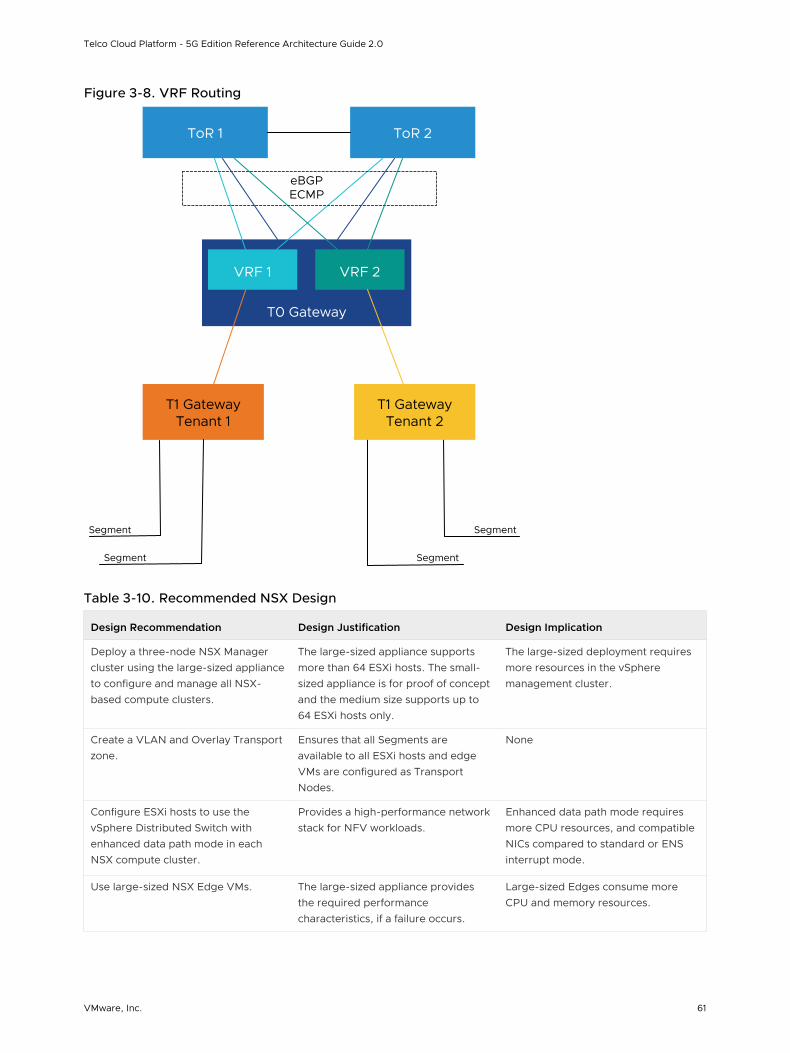
Figure 3-8. VRF Routing
ToR 1 ToR 2
T0 Gateway
VRF 2
T1 Gateway Tenant 1
VRF 1
eBGP ECMP
Segment
Segment
T1 Gateway Tenant 2
Segment
Segment
Table 3-10. Recommended NSX Design
Design Recommendation Design Justification Design Implication
Deploy a three-node NSX Manager cluster using the large-sized appliance to configure and manage all NSX-based compute clusters.
The large-sized appliance supports more than 64 ESXi hosts. The small-sized appliance is for proof of concept and the medium size supports up to 64 ESXi hosts only.
The large-sized deployment requires more resources in the vSphere management cluster.
Create a VLAN and Overlay Transport zone.
Ensures that all Segments are available to all ESXi hosts and edge VMs are configured as Transport Nodes.
None
Configure ESXi hosts to use the vSphere Distributed Switch with enhanced data path mode in each NSX compute cluster.
Provides a high-performance network stack for NFV workloads.
Enhanced data path mode requires more CPU resources, and compatible NICs compared to standard or ENS interrupt mode.
Use large-sized NSX Edge VMs. The large-sized appliance provides the required performance characteristics, if a failure occurs.
Large-sized Edges consume more CPU and memory resources.
Telco Cloud Platform - 5G Edition Reference Architecture Guide 2.0
VMware, Inc. 61
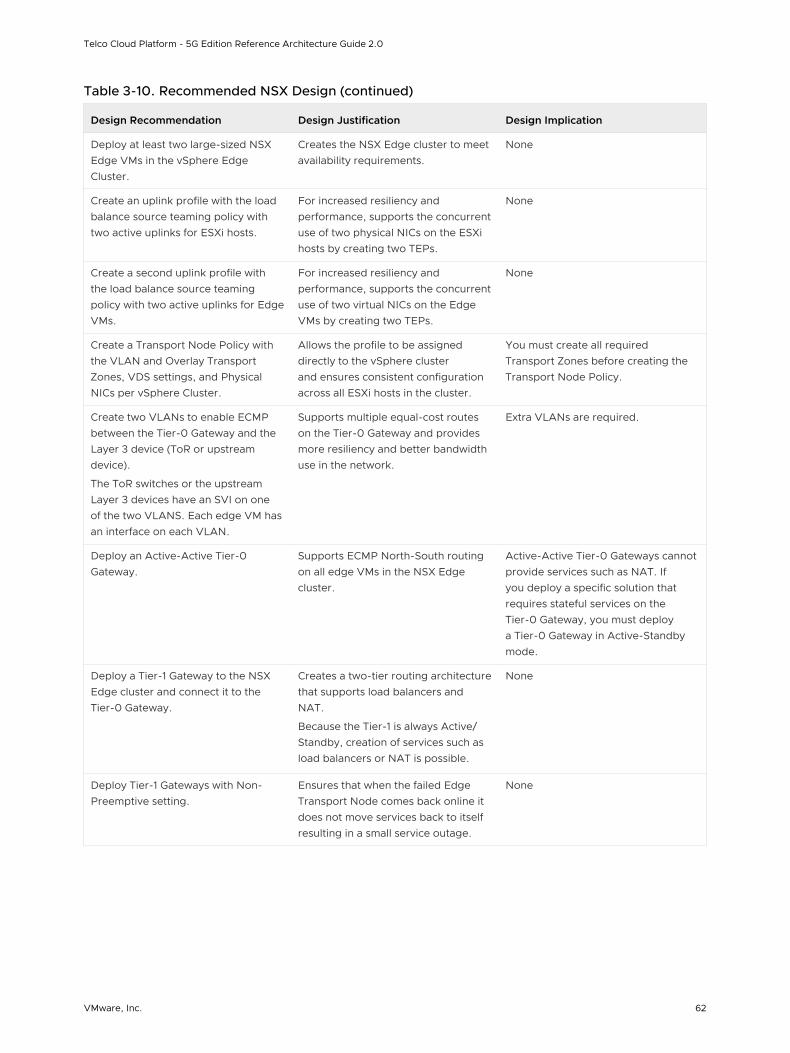
Table 3-10. Recommended NSX Design (continued)
Design Recommendation Design Justification Design Implication
Deploy at least two large-sized NSX Edge VMs in the vSphere Edge Cluster.
Creates the NSX Edge cluster to meet availability requirements.
None
Create an uplink profile with the load balance source teaming policy with two active uplinks for ESXi hosts.
For increased resiliency and performance, supports the concurrent use of two physical NICs on the ESXi hosts by creating two TEPs.
None
Create a second uplink profile with the load balance source teaming policy with two active uplinks for Edge VMs.
For increased resiliency and performance, supports the concurrent use of two virtual NICs on the Edge VMs by creating two TEPs.
None
Create a Transport Node Policy with the VLAN and Overlay Transport Zones, VDS settings, and Physical NICs per vSphere Cluster.
Allows the profile to be assigned directly to the vSphere cluster and ensures consistent configuration across all ESXi hosts in the cluster.
You must create all required Transport Zones before creating the Transport Node Policy.
Create two VLANs to enable ECMP between the Tier-0 Gateway and the Layer 3 device (ToR or upstream device).
The ToR switches or the upstream Layer 3 devices have an SVI on one of the two VLANS. Each edge VM has an interface on each VLAN.
Supports multiple equal-cost routes on the Tier-0 Gateway and provides more resiliency and better bandwidth use in the network.
Extra VLANs are required.
Deploy an Active-Active Tier-0 Gateway.
Supports ECMP North-South routing on all edge VMs in the NSX Edge cluster.
Active-Active Tier-0 Gateways cannot provide services such as NAT. If you deploy a specific solution that requires stateful services on the Tier-0 Gateway, you must deploy a Tier-0 Gateway in Active-Standby mode.
Deploy a Tier-1 Gateway to the NSX Edge cluster and connect it to the Tier-0 Gateway.
Creates a two-tier routing architecture that supports load balancers and NAT.
Because the Tier-1 is always Active/Standby, creation of services such as load balancers or NAT is possible.
None
Deploy Tier-1 Gateways with Non-Preemptive setting.
Ensures that when the failed Edge Transport Node comes back online it does not move services back to itself resulting in a small service outage.
None
Telco Cloud Platform - 5G Edition Reference Architecture Guide 2.0
VMware, Inc. 62
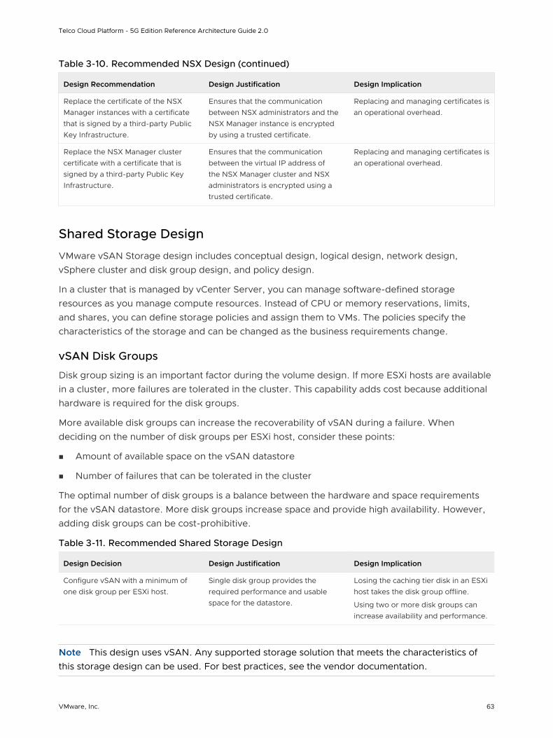
Table 3-10. Recommended NSX Design (continued)
Design Recommendation Design Justification Design Implication
Replace the certificate of the NSX Manager instances with a certificate that is signed by a third-party Public Key Infrastructure.
Ensures that the communication between NSX administrators and the NSX Manager instance is encrypted by using a trusted certificate.
Replacing and managing certificates is an operational overhead.
Replace the NSX Manager cluster certificate with a certificate that is signed by a third-party Public Key Infrastructure.
Ensures that the communication between the virtual IP address of the NSX Manager cluster and NSX administrators is encrypted using a trusted certificate.
Replacing and managing certificates is an operational overhead.
Shared Storage Design
VMware vSAN Storage design includes conceptual design, logical design, network design, vSphere cluster and disk group design, and policy design.
In a cluster that is managed by vCenter Server, you can manage software-defined storage resources as you manage compute resources. Instead of CPU or memory reservations, limits, and shares, you can define storage policies and assign them to VMs. The policies specify the characteristics of the storage and can be changed as the business requirements change.
vSAN Disk Groups
Disk group sizing is an important factor during the volume design. If more ESXi hosts are available in a cluster, more failures are tolerated in the cluster. This capability adds cost because additional hardware is required for the disk groups.
More available disk groups can increase the recoverability of vSAN during a failure. When deciding on the number of disk groups per ESXi host, consider these points:
n Amount of available space on the vSAN datastore
n Number of failures that can be tolerated in the cluster
The optimal number of disk groups is a balance between the hardware and space requirements for the vSAN datastore. More disk groups increase space and provide high availability. However, adding disk groups can be cost-prohibitive.
Table 3-11. Recommended Shared Storage Design
Design Decision Design Justification Design Implication
Configure vSAN with a minimum of one disk group per ESXi host.
Single disk group provides the required performance and usable space for the datastore.
Losing the caching tier disk in an ESXi host takes the disk group offline.
Using two or more disk groups can increase availability and performance.
Note This design uses vSAN. Any supported storage solution that meets the characteristics of this storage design can be used. For best practices, see the vendor documentation.
Telco Cloud Platform - 5G Edition Reference Architecture Guide 2.0
VMware, Inc. 63
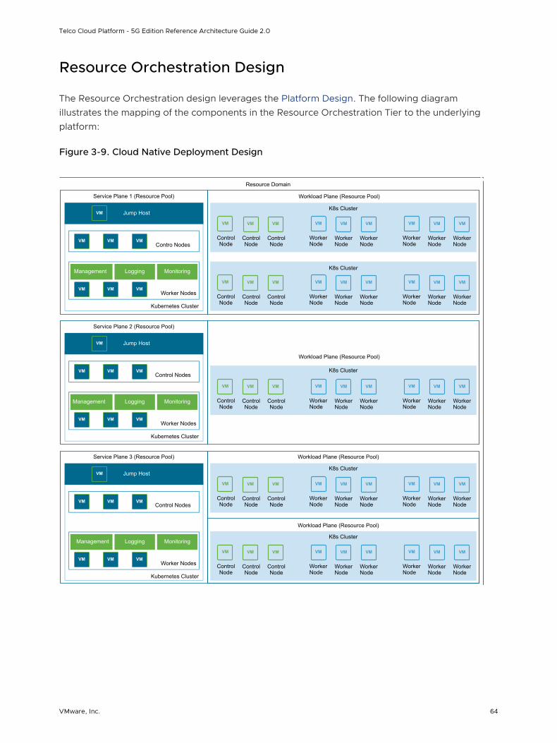
Resource Orchestration Design
The Resource Orchestration design leverages the Platform Design. The following diagram illustrates the mapping of the components in the Resource Orchestration Tier to the underlying platform:
Figure 3-9. Cloud Native Deployment Design
Resource Domain
VM VM VM VM VM VM VM VM VM
K8s Cluster
Workload Plane (Resource Pool)
Control Node
Worker Node
Worker Node
Control Node
Control Node
Worker Node
Worker Node
Worker Node
Worker Node
VM VM VM VM VM VM VM VM VM
VM VM VM VM VM VM VM VM VM
K8s Cluster
K8s Cluster
Control Node
Workload Plane (Resource Pool)
Workload Plane (Resource Pool)
Control Node
Control Node
Control Node
Worker Node
Worker Node
Worker Node
Worker Node
Control Node
Control Node
Worker Node
Worker Node
Worker Node
Worker Node
Worker Node
Worker Node
Worker Node
Worker Node
VM VM VM VM VM VM VM VM VM
Control Node
Workload Plane (Resource Pool)
K8s Cluster
Control Node
Worker Node
Worker Node
Control Node
Worker Node
Worker Node
Worker Node
Worker Node
VM VM VM VM VM VM VM VM VM
Control Node
Control Node
Worker Node
Worker Node
Control Node
Worker Node
Worker Node
Worker Node
Worker Node
K8s Cluster
Service Plane 1 (Resource Pool)
VMContro Nodes
VM VM
VMWorker Nodes
VM VM
Management Logging Monitoring
Kubernetes Cluster
VM Jump Host
Service Plane 2 (Resource Pool)
VMControl Nodes
VM VM
VMWorker Nodes
VM VM
Management Logging Monitoring
Kubernetes Cluster
VM Jump Host
Service Plane 3 (Resource Pool)
VMControl Nodes
VM VM
VMWorker Nodes
VM VM
Management Logging Monitoring
Kubernetes Cluster
VM Jump Host
Telco Cloud Platform - 5G Edition Reference Architecture Guide 2.0
VMware, Inc. 64
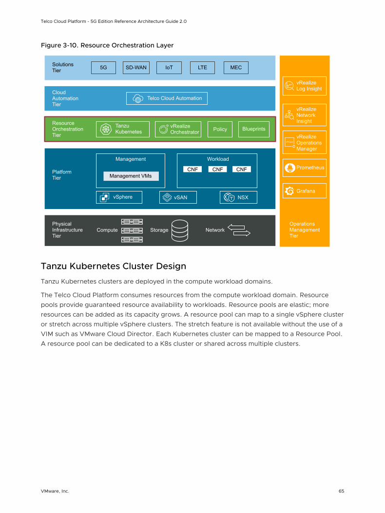
Figure 3-10. Resource Orchestration Layer
vRealize Orchestrator
Operations Management Tier
Physical Infrastructure Tier
Platform Tier
Resource Orchestration Tier
Cloud Automation Tier
Solutions Tier 5G SD-WAN LTE MECIoT
Telco Cloud Automation
Tanzu Kubernetes Policy Blueprints
Management VMsCNF CNF CNF
Management Workload
vSphere vSAN NSX
vRealize Log Insight
vRealize Network Insight
vRealize Operations Manager
Compute Storage Network
Prometheus
Grafana
Tanzu Kubernetes Cluster Design
Tanzu Kubernetes clusters are deployed in the compute workload domains.
The Telco Cloud Platform consumes resources from the compute workload domain. Resource pools provide guaranteed resource availability to workloads. Resource pools are elastic; more resources can be added as its capacity grows. A resource pool can map to a single vSphere cluster or stretch across multiple vSphere clusters. The stretch feature is not available without the use of a VIM such as VMware Cloud Director. Each Kubernetes cluster can be mapped to a Resource Pool. A resource pool can be dedicated to a K8s cluster or shared across multiple clusters.
Telco Cloud Platform - 5G Edition Reference Architecture Guide 2.0
VMware, Inc. 65
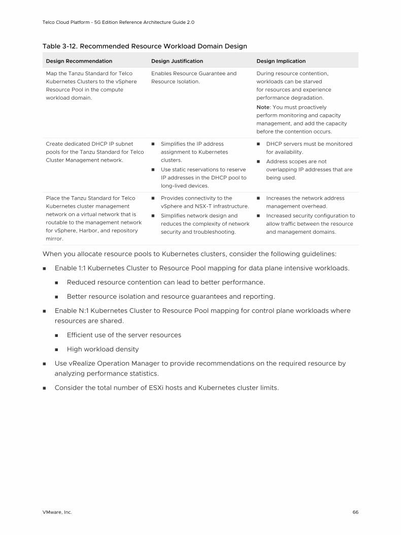
Table 3-12. Recommended Resource Workload Domain Design
Design Recommendation Design Justification Design Implication
Map the Tanzu Standard for Telco Kubernetes Clusters to the vSphere Resource Pool in the compute workload domain.
Enables Resource Guarantee and Resource Isolation.
During resource contention, workloads can be starved for resources and experience performance degradation.
Note: You must proactively perform monitoring and capacity management, and add the capacity before the contention occurs.
Create dedicated DHCP IP subnet pools for the Tanzu Standard for Telco Cluster Management network.
n Simplifies the IP address assignment to Kubernetes clusters.
n Use static reservations to reserve IP addresses in the DHCP pool to long-lived devices.
n DHCP servers must be monitored for availability.
n Address scopes are not overlapping IP addresses that are being used.
Place the Tanzu Standard for Telco Kubernetes cluster management network on a virtual network that is routable to the management network for vSphere, Harbor, and repository mirror.
n Provides connectivity to the vSphere and NSX-T infrastructure.
n Simplifies network design and reduces the complexity of network security and troubleshooting.
n Increases the network address management overhead.
n Increased security configuration to allow traffic between the resource and management domains.
When you allocate resource pools to Kubernetes clusters, consider the following guidelines:
n Enable 1:1 Kubernetes Cluster to Resource Pool mapping for data plane intensive workloads.
n Reduced resource contention can lead to better performance.
n Better resource isolation and resource guarantees and reporting.
n Enable N:1 Kubernetes Cluster to Resource Pool mapping for control plane workloads where resources are shared.
n Efficient use of the server resources
n High workload density
n Use vRealize Operation Manager to provide recommendations on the required resource by analyzing performance statistics.
n Consider the total number of ESXi hosts and Kubernetes cluster limits.
Telco Cloud Platform - 5G Edition Reference Architecture Guide 2.0
VMware, Inc. 66
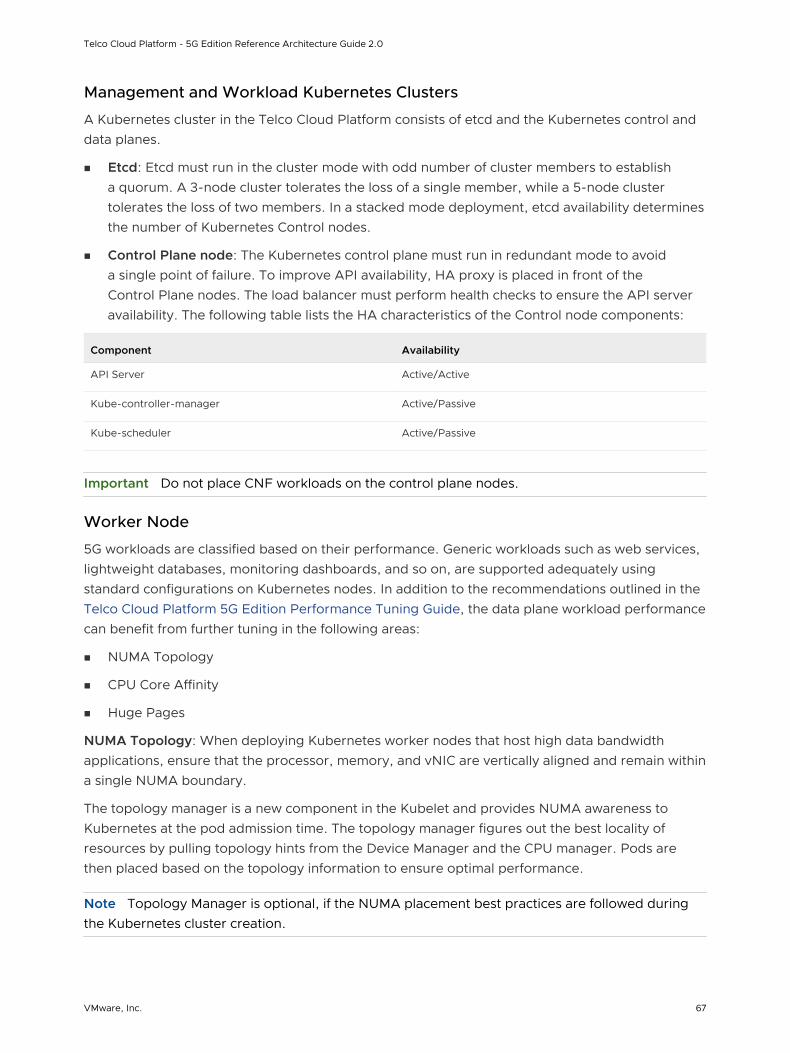
Management and Workload Kubernetes Clusters
A Kubernetes cluster in the Telco Cloud Platform consists of etcd and the Kubernetes control and data planes.
n Etcd: Etcd must run in the cluster mode with odd number of cluster members to establish a quorum. A 3-node cluster tolerates the loss of a single member, while a 5-node cluster tolerates the loss of two members. In a stacked mode deployment, etcd availability determines the number of Kubernetes Control nodes.
n Control Plane node: The Kubernetes control plane must run in redundant mode to avoid a single point of failure. To improve API availability, HA proxy is placed in front of the Control Plane nodes. The load balancer must perform health checks to ensure the API server availability. The following table lists the HA characteristics of the Control node components:
Component Availability
API Server Active/Active
Kube-controller-manager Active/Passive
Kube-scheduler Active/Passive
Important Do not place CNF workloads on the control plane nodes.
Worker Node
5G workloads are classified based on their performance. Generic workloads such as web services, lightweight databases, monitoring dashboards, and so on, are supported adequately using standard configurations on Kubernetes nodes. In addition to the recommendations outlined in the Telco Cloud Platform 5G Edition Performance Tuning Guide, the data plane workload performance can benefit from further tuning in the following areas:
n NUMA Topology
n CPU Core Affinity
n Huge Pages
NUMA Topology: When deploying Kubernetes worker nodes that host high data bandwidth applications, ensure that the processor, memory, and vNIC are vertically aligned and remain within a single NUMA boundary.
The topology manager is a new component in the Kubelet and provides NUMA awareness to Kubernetes at the pod admission time. The topology manager figures out the best locality of resources by pulling topology hints from the Device Manager and the CPU manager. Pods are then placed based on the topology information to ensure optimal performance.
Note Topology Manager is optional, if the NUMA placement best practices are followed during the Kubernetes cluster creation.
Telco Cloud Platform - 5G Edition Reference Architecture Guide 2.0
VMware, Inc. 67
CPU Core Affinity: CPU pinning can be achieved in different ways. Kubernetes built-in CPU manager is the most common. The CPU manager implementation is based on cpuset. When a VM host initializes, host CPU resources are assigned to a shared CPU pool. All non-exclusive CPU containers run on the CPUs in the shared pool. When the Kubelet creates a container requesting a guaranteed CPU, CPUs for that container are removed from the shared pool and assigned exclusively for the life cycle of the container. When a container with exclusive CPUs is terminated, its CPUs are added back to the shared CPU pool.
The CPU manager includes the following two policies:
n None: Default policy. The kubelet uses CFS quota to enforce pod CPU limits. The workload can move between different CPU cores depending on the load on the Pod and the available capacity on the worker node.
n Static: With the static policy enabled, the CPU request results in the container getting allocated the whole CPU and no other container can schedule on that CPU.
Note For data plane intensive workloads, the CPU manager policy must be set to static to guarantee an exclusive CPU core on the worker node.
CPU Manager for Kubernetes (CMK) is another tool used by selective CNF vendors to assign the core and NUMA affinity for data plane workloads. Unlike the built-in CPU manager, CMK is not bundled with Kubernetes binaries and it requires separate download and installation. CMK must be used over the built-in CPU manager if required by the CNF vendor.
Huge Pages: For Telco workloads, the default huge page size can be 2 MB or 1 GB. To report its huge page capacity, the worker node determines the supported huge page sizes by parsing the /sys/kernel/mm/hugepages/hugepages-{size}kB directory on the host. Huge pages must
be set to pre-allocated for maximum performance. Pre-allocated huge pages reduce the
amount of available memory on a worker node. A node can only pre-allocate huge pages for the default size. The Transport Huge Pages must be disabled.
Container workloads requiring huge pages use hugepages-<hugepagesize> in the Pod
specification. As of Kubernetes 1.18, multiple huge page sizes are supported per Pod. Huge Pages allocation occurs at the pod level.
Recommended tuning details:
Telco Cloud Platform - 5G Edition Reference Architecture Guide 2.0
VMware, Inc. 68
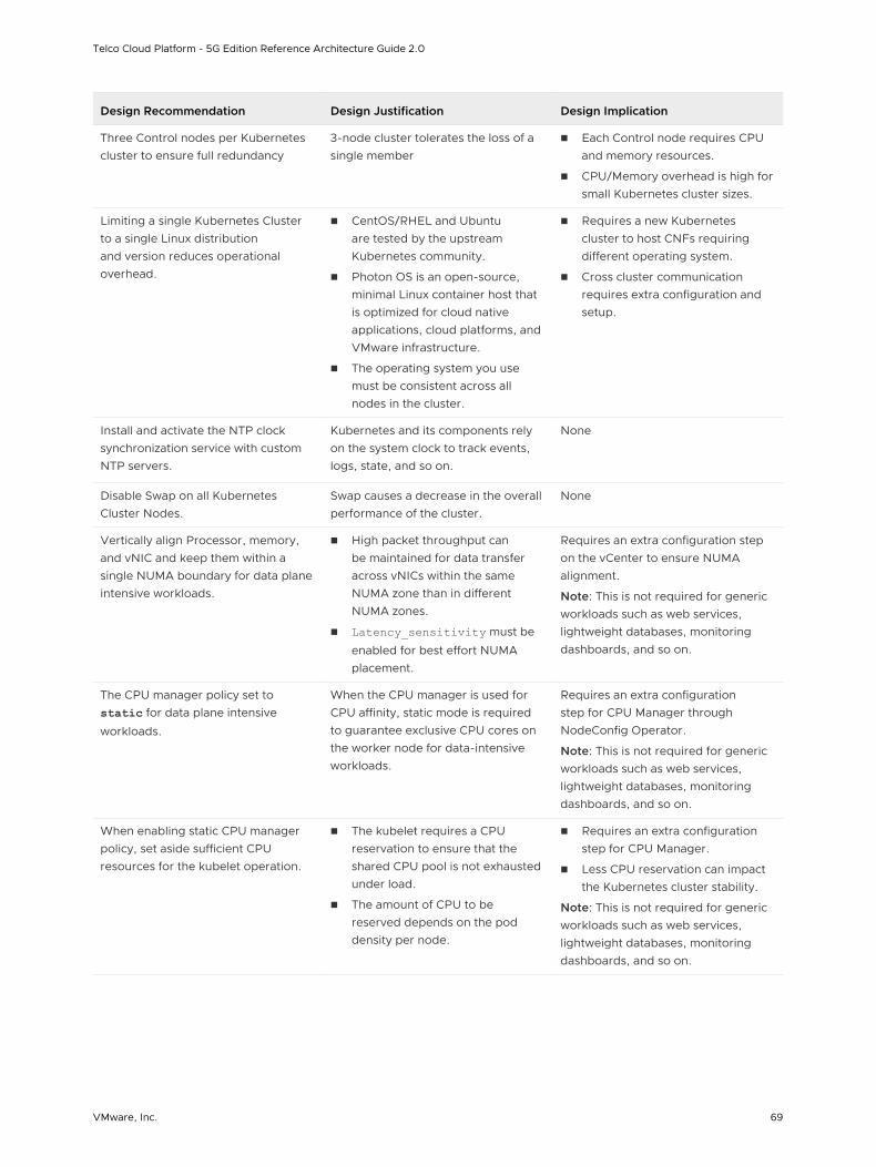
Design Recommendation Design Justification Design Implication
Three Control nodes per Kubernetes cluster to ensure full redundancy
3-node cluster tolerates the loss of a single member
n Each Control node requires CPU and memory resources.
n CPU/Memory overhead is high for small Kubernetes cluster sizes.
Limiting a single Kubernetes Cluster to a single Linux distribution and version reduces operational overhead.
n CentOS/RHEL and Ubuntu are tested by the upstream Kubernetes community.
n Photon OS is an open-source, minimal Linux container host that is optimized for cloud native applications, cloud platforms, and VMware infrastructure.
n The operating system you use must be consistent across all nodes in the cluster.
n Requires a new Kubernetes cluster to host CNFs requiring different operating system.
n Cross cluster communication requires extra configuration and setup.
Install and activate the NTP clock synchronization service with custom NTP servers.
Kubernetes and its components rely on the system clock to track events, logs, state, and so on.
None
Disable Swap on all Kubernetes Cluster Nodes.
Swap causes a decrease in the overall performance of the cluster.
None
Vertically align Processor, memory, and vNIC and keep them within a single NUMA boundary for data plane intensive workloads.
n High packet throughput can be maintained for data transfer across vNICs within the same NUMA zone than in different NUMA zones.
n Latency_sensitivity must be
enabled for best effort NUMA placement.
Requires an extra configuration step on the vCenter to ensure NUMA alignment.
Note: This is not required for generic workloads such as web services, lightweight databases, monitoring dashboards, and so on.
The CPU manager policy set to static for data plane intensive
workloads.
When the CPU manager is used for CPU affinity, static mode is required to guarantee exclusive CPU cores on the worker node for data-intensive workloads.
Requires an extra configuration step for CPU Manager through NodeConfig Operator.
Note: This is not required for generic workloads such as web services, lightweight databases, monitoring dashboards, and so on.
When enabling static CPU manager policy, set aside sufficient CPU resources for the kubelet operation.
n The kubelet requires a CPU reservation to ensure that the shared CPU pool is not exhausted under load.
n The amount of CPU to be reserved depends on the pod density per node.
n Requires an extra configuration step for CPU Manager.
n Less CPU reservation can impact the Kubernetes cluster stability.
Note: This is not required for generic workloads such as web services, lightweight databases, monitoring dashboards, and so on.
Telco Cloud Platform - 5G Edition Reference Architecture Guide 2.0
VMware, Inc. 69
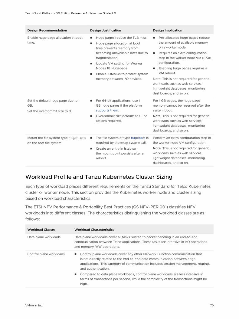
Design Recommendation Design Justification Design Implication
Enable huge page allocation at boot time.
n Huge pages reduce the TLB miss.
n Huge page allocation at boot time prevents memory from becoming unavailable later due to fragmentation.
n Update VM setting for Worker Nodes 1G Hugepage.
n Enable IOMMUs to protect system memory between I/O devices.
n Pre-allocated huge pages reduce the amount of available memory on a worker node.
n Requires an extra configuration step in the worker node VM GRUB configuration.
n Enabling huge pages requires a VM reboot.
Note: This is not required for generic workloads such as web services, lightweight databases, monitoring dashboards, and so on.
Set the default huge page size to 1 GB.
Set the overcommit size to 0.
n For 64-bit applications, use 1 GB huge pages if the platform supports them.
n Overcommit size defaults to 0, no actions required.
For 1 GB pages, the huge page memory cannot be reserved after the system boot.
Note: This is not required for generic workloads such as web services, lightweight databases, monitoring dashboards, and so on.
Mount the file system type hugetlbfs on the root file system.
n The file system of type hugetlbfs is required by the mmap system call.
n Create an entry in fstab so the mount point persists after a reboot.
Perform an extra configuration step in the worker node VM configuration.
Note: This is not required for generic workloads such as web services, lightweight databases, monitoring dashboards, and so on.
Workload Profile and Tanzu Kubernetes Cluster Sizing
Each type of workload places different requirements on the Tanzu Standard for Telco Kubernetes cluster or worker node. This section provides the Kubernetes worker node and cluster sizing based on workload characteristics.
The ETSI NFV Performance & Portability Best Practices (GS NFV-PER 001) classifies NFV workloads into different classes. The characteristics distinguishing the workload classes are as follows:
Workload Classes Workload Characteristics
Data plane workloads Data plane workloads cover all tasks related to packet handling in an end-to-end communication between Telco applications. These tasks are intensive in I/O operations and memory R/W operations.
Control plane workloads n Control plane workloads cover any other Network Function communication that is not directly related to the end-to-end data communication between edge applications. This category of communication includes session management, routing, and authentication.
n Compared to data plane workloads, control plane workloads are less intensive in terms of transactions per second, while the complexity of the transactions might be high.
Telco Cloud Platform - 5G Edition Reference Architecture Guide 2.0
VMware, Inc. 70
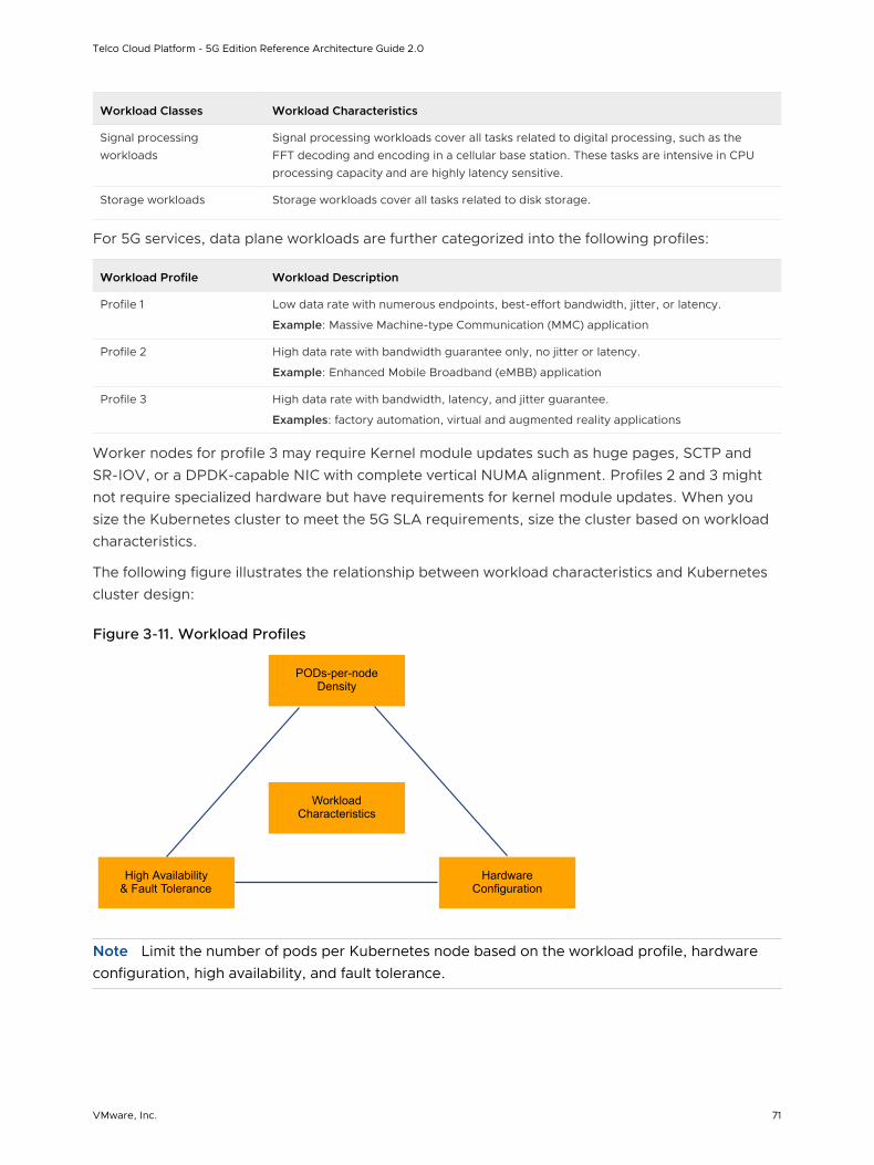
Workload Classes Workload Characteristics
Signal processing workloads
Signal processing workloads cover all tasks related to digital processing, such as the FFT decoding and encoding in a cellular base station. These tasks are intensive in CPU processing capacity and are highly latency sensitive.
Storage workloads Storage workloads cover all tasks related to disk storage.
For 5G services, data plane workloads are further categorized into the following profiles:
Workload Profile Workload Description
Profile 1 Low data rate with numerous endpoints, best-effort bandwidth, jitter, or latency.
Example: Massive Machine-type Communication (MMC) application
Profile 2 High data rate with bandwidth guarantee only, no jitter or latency.
Example: Enhanced Mobile Broadband (eMBB) application
Profile 3 High data rate with bandwidth, latency, and jitter guarantee.
Examples: factory automation, virtual and augmented reality applications
Worker nodes for profile 3 may require Kernel module updates such as huge pages, SCTP and SR-IOV, or a DPDK-capable NIC with complete vertical NUMA alignment. Profiles 2 and 3 might not require specialized hardware but have requirements for kernel module updates. When you size the Kubernetes cluster to meet the 5G SLA requirements, size the cluster based on workload characteristics.
The following figure illustrates the relationship between workload characteristics and Kubernetes cluster design:
Figure 3-11. Workload Profiles
WorkloadCharacteristics
PODs-per-nodeDensity
High Availability& Fault Tolerance
HardwareConfiguration
Note Limit the number of pods per Kubernetes node based on the workload profile, hardware configuration, high availability, and fault tolerance.
Telco Cloud Platform - 5G Edition Reference Architecture Guide 2.0
VMware, Inc. 71
Control Node Sizing
By default, dedicate Control nodes to the control plane components only. All control plane nodes deployed have a taint applied to them.
This taint instructs the Kubernetes scheduler not to schedule any user workloads on the control plane nodes. Assigning nodes in this way improves security, stability, and management of the control plane. Isolating the control plane from other workloads significantly reduces the attack surface as user workloads no longer share a kernel with Kubernetes components.
By following the above recommendation, the size of the Kubernetes control node depends on the size of the Kubernetes cluster. When sizing the control node for CPU, memory, and disk, consider both the number of worker nodes and the total number of Pods. The following table lists the Kubernetes control node sizing estimations based on the cluster size:
Cluster Size Control Node vCPU Control Node Memory
Up to 10 Worker Nodes 2 8 GB
Up to 100 Worker Nodes 4 16 GB
Up to 250 Worker Nodes 8 32 GB
Up to 500 Worker Nodes 16 64 GB
Note Kubernetes Control nodes in the same cluster must be configured with the same size.
Worker Node Sizing
When sizing a worker node, consider the number of Pods per node. For low-performance pods (Profile 1 workload), ensuring Kubernetes pods are running and constant reporting of pod status to the Control node contributes to majority of the kubelet utilization. High pod counts lead to higher kubelet utilization. Kubernetes official documentation recommends limiting Pods per node to less than 100. This limit can be set high for Profile 1 workload, based on the hardware configuration.
Profile 2 and Profile 3 require dedicated CPU, memory, and vNIC to ensure throughput, latency, or jitter. When considering the number of pods per node for high-performance pods, use the hardware resource limits as the design criteria. For example, if a data plane intensive workload requires dedicated passthrough vNIC, the total number of Pods per worker node is limited by the total number of available vNICs.
As a rule, allocate 1 vCPU and 10 GB memory for every 10 running Pods for CPU and memory for generic workloads. In scenarios where 5G CNF vendor has specific vCPU and memory requirements, the worker node must be sized based on CNF vendor recommendations.
Tanzu Kubernetes Cluster Sizing
When you design a Tanzu Kubernetes cluster for workload with high availability, consider the following:
n Number of failed nodes to be tolerated at once
Telco Cloud Platform - 5G Edition Reference Architecture Guide 2.0
VMware, Inc. 72
n Number of nodes available after a failure
n Remaining capacity to reschedule pods of the failed node
n Remaining Pod density after rescheduling
Based on failure tolerance, Pods per node, workload characteristics, worker nodes to deploy for each workload profile can be generalized using the following formula:
Worker Node (Z)= (pods * D) + (N+1)
n Z specifies workload profile 1 - 3
n N specifies the number of failed nodes that can be tolerated
n D specifies the max density. 1/110 is the K8s recommendation for generic workloads.
For example, if each node supports 100 Pods, building a cluster that supports 100 pods with a failure tolerance of one node requires two worker nodes. Supporting 200 pods with a failure tolerance of one node requires three worker nodes.
Total Worker node = Worker Nodes (profile 1) + Worker Nodes (profile 2) + Worker Nodes (profile 3)
Total worker node per cluster is the sum of worker nodes required for each profile. If a cluster supports only one profile, the number of worker nodes required to support other two profiles is set to zero.
Design Recommendation Design Justification Design Implication
Dedicate the Kubernetes Control node to Kubernetes control components only.
Improved security, stability, and management of the control plane.
n Special taints must be configured on the Control nodes to indicate that scheduling is not allowed on Control nodes.
n Special toleration must be applied to override the taint for control plane pods such as the cloud provider.
Kubernetes Control node VMs in the same cluster must be sized identically based on the maximum number of Pods and nodes in a cluster.
n Control node sizing is based on the size of the cluster and pod.
n Insufficient CPU/Memory/Disk in the Control node can lead to unpredictable performance.
Idle resources as only the Kubernetes API server runs active/active under the steady state.
Telco Cloud Platform - 5G Edition Reference Architecture Guide 2.0
VMware, Inc. 73
Design Recommendation Design Justification Design Implication
Set the maximum number of Pods per worker node based on the HW profile.
n Not all clusters are built using the same CPU/Memory/Disk sizing.
n Larger nodes reduce the number of nodes to manage by supporting more pod per node. Smaller nodes minimize the blast radius but cannot support numerous Pods per node.
K8s cluster-wide setting does not work properly in a heterogeneous cluster.
Use failure tolerance, workload type, and pod density to plan the minimum cluster size.
n Kubernetes enforces a cluster-wide pod/worker node ratio.
n To honor SLA, the remaining capacity after the node failure must be greater than the number of pods needing to reschedule.
High failure tolerance can lead to low server utilization.
Cloud Native Networking Design
5G CNFs require advanced networking services to support receive and transmit at high speed with low latency. The realization of advanced network capabilities must be achieved without deviating from the default networking abstraction provided by Kubernetes. The Cloud Native Networking design focuses on the ability to support multiple NICS in a Pod, where the primary NIC is dedicated to Kubernetes for management and the ability to attach additional networks dedicated to data forwarding.
Kubernetes Primary Interface with Antrea
Each node must have a management interface. The management and pod IP addresses must be routable for the Kubernetes health check to work. After the Tanzu Kubernetes cluster is deployed, Antrea networking is the default CNI for Pod-to-Pod communication within the cluster.
Telco Cloud Platform - 5G Edition Reference Architecture Guide 2.0
VMware, Inc. 74
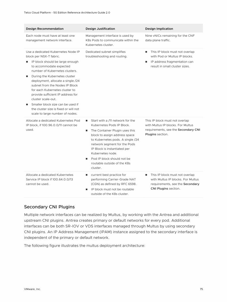
Design Recommendation Design Justification Design Implication
Each node must have at least one management network interface.
Management interface is used by K8s Pods to communicate within the Kubernetes cluster.
Nine vNICs remaining for the CNF data plane traffic.
Use a dedicated Kubernetes Node IP block per NSX-T fabric.
n IP block should be large enough to accommodate expected number of Kubernetes clusters.
n During the Kubernetes cluster deployment, allocate a single /24 subnet from the Nodes IP Block for each Kubernetes cluster to provide sufficient IP address for cluster scale-out.
n Smaller block size can be used if the cluster size is fixed or will not scale to large number of nodes.
Dedicated subnet simplifies troubleshooting and routing.
n This IP block must not overlap with Pod or Multus IP blocks.
n IP address fragmentation can result in small cluster sizes.
Allocate a dedicated Kubernetes Pod IP block, if 100.96.0.0/11 cannot be used.
n Start with a /11 network for the Kubernetes Pods IP Block.
n The Container Plugin uses this block to assign address space to Kubernetes pods. A single /24 network segment for the Pods IP Block is instantiated per Kubernetes node.
n Pod IP block should not be routable outside of the K8s cluster.
This IP block must not overlap with Multus IP blocks. For Multus requirements, see the Secondary CNI Plugins section.
Allocate a dedicated Kubernetes Service IP block if 100.64.0.0/13 cannot be used.
n current best practice for performing Carrier-Grade NAT (CGN) as defined by RFC 6598.
n IP block must not be routable outside of the K8s cluster.
n This IP block must not overlap with Multus IP blocks. For Multus requirements, see the Secondary CNI Plugins section.
Secondary CNI Plugins
Multiple network interfaces can be realized by Multus, by working with the Antrea and additional upstream CNI plugins. Antrea creates primary or default networks for every pod. Additional interfaces can be both SR-IOV or VDS interfaces managed through Multus by using secondary CNI plugins. An IP Address Management (IPAM) instance assigned to the secondary interface is independent of the primary or default network.
The following figure illustrates the multus deployment architecture:
Telco Cloud Platform - 5G Edition Reference Architecture Guide 2.0
VMware, Inc. 75

Figure 3-12. Multus Deployment
VM User Space
VM Kernel
Guest VMs
K8s Pod
P SS
K8s Pod
P SS
Antrea
vNIC vNIC vNIC vNICvNIC
pNIC
Hypervisor VDS VDS / SRIOV
pNIC
P - Primary I/F - VDS based • Managed by Antrea • Interface in VM Kernel S - Secondary I/F - SRIOV/VDS based • Managed by Multus and secondary CNI • Direct (VM Kernel bypass) SRIOV/VDS DPDK poll mode I/F for CNF K8s Pod
Design Recommendation Design Justification Design Implication
Enable Multus integration with the Kubernetes API server to provision both Kernel-based and passthrough network devices to a data plane CNF.
n Multus CNI enables the attachment of multiple network interfaces to a Pod.
n Multus acts as a "meta-plugin", a CNI plugin that can call multiple other CNI plugins.
Multus is an upstream plugin and follows the community support model.
Deploy the SR-IOV network device plugin to enable DPDK passthrough for workloads that require SR-IOV or ENS.
The SR-IOV network device plugin is a Kubernetes device plugin for discovering and advertising SR-IOV and ENS network virtual functions that are available on a Kubernetes host.
n SR-IOV is an upstream plugin and follows the community support model.
n Passthrough requires a dedicated NIC for each pod interface. The total number of available vNICs limits the maximum pod per worker node.
Ensure that only vNICs that meet performance requirements are exposed to the CNI and device plugin.
Based on the type of vNICs or passthrough interfaces, update the SR-IOV device plugin configMap to allow vNICs intended to be available to the Kubernetes scheduler and Kubelet.
None
Telco Cloud Platform - 5G Edition Reference Architecture Guide 2.0
VMware, Inc. 76

Design Recommendation Design Justification Design Implication
Deploy the host-device CNI plugin to attach SR-IOV or ENS VF to a pod without DPDK.
n Host-device CNI is a generic CNI for host devices. VF assignment to VM is performed at the hypervisor level.
n Host-device CNI allows for post binding of device driver after container instantiation, without requiring cloud admin to preload the DPDK device driver on a vNIC.
n Host-device CNI is an upstream plugin and follows the community support model.
n Host-device CNI must be version 0.8.3 and above.
n The container must be run in the privileged mode so that it can bind the interface.
Assign a dedicated IP block for additional container interfaces.
Note: IP address management for additional interface must be separate from the primary container interface.
n Specify a /16 network for the Multus IP Block for additional container interfaces.
n The SR-IOV host-device CNI or macvlan Container Plugin uses this IP block to assign addresses to additional Kubernetes pod interfaces. A single /24 network segment can be assigned to each node.
n Default host-local IPAM scope is per node instead of global.
n Cluster-wide IPAM is available but requires additional out-of-the-box installation.
n Additional care must be given to avoid IP address conflicts.
External Service Access
By default, 5GC components deployed in a Tanzu Kubernetes cluster have private IPs routable only within the cluster. To expose services outside the cluster, NodePort or Ingress can be used.
Telco Cloud Platform - 5G Edition Reference Architecture Guide 2.0
VMware, Inc. 77
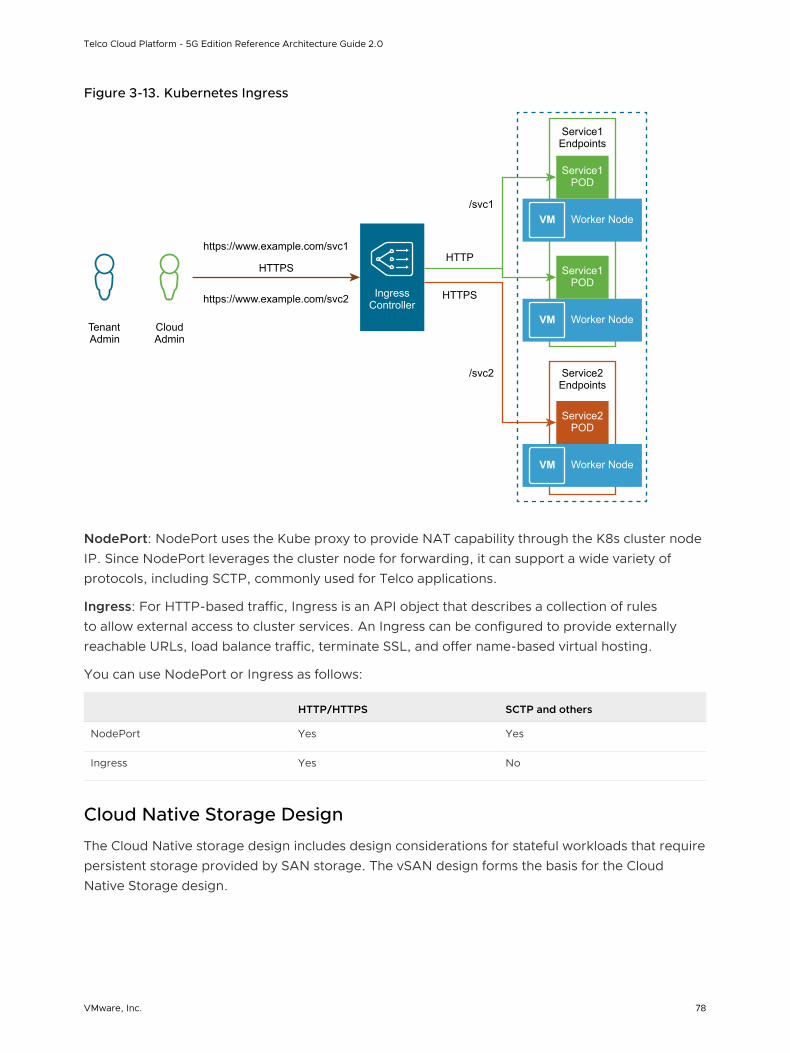
Figure 3-13. Kubernetes Ingress
VM
VM
VM
Service1 POD
Worker Node
Service1 POD
HTTPS
https://www.example.com/svc1
https://www.example.com/svc2
/svc1
/svc2
HTTP
HTTPSIngress Controller
Worker Node
Service2 POD
Service2 Endpoints
Service1 Endpoints
Worker Node
Tenant Admin
Cloud Admin
NodePort: NodePort uses the Kube proxy to provide NAT capability through the K8s cluster node IP. Since NodePort leverages the cluster node for forwarding, it can support a wide variety of protocols, including SCTP, commonly used for Telco applications.
Ingress: For HTTP-based traffic, Ingress is an API object that describes a collection of rules to allow external access to cluster services. An Ingress can be configured to provide externally reachable URLs, load balance traffic, terminate SSL, and offer name-based virtual hosting.
You can use NodePort or Ingress as follows:
HTTP/HTTPS SCTP and others
NodePort Yes Yes
Ingress Yes No
Cloud Native Storage Design
The Cloud Native storage design includes design considerations for stateful workloads that require persistent storage provided by SAN storage. The vSAN design forms the basis for the Cloud Native Storage design.
Telco Cloud Platform - 5G Edition Reference Architecture Guide 2.0
VMware, Inc. 78
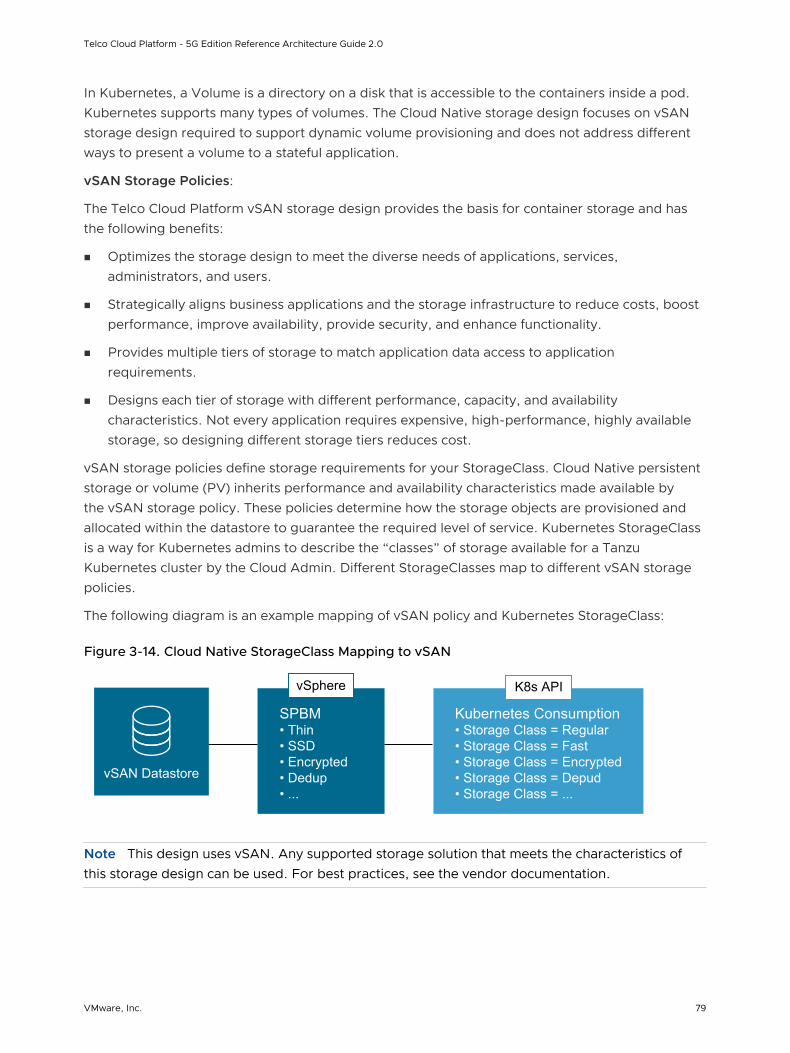
In Kubernetes, a Volume is a directory on a disk that is accessible to the containers inside a pod. Kubernetes supports many types of volumes. The Cloud Native storage design focuses on vSAN storage design required to support dynamic volume provisioning and does not address different ways to present a volume to a stateful application.
vSAN Storage Policies:
The Telco Cloud Platform vSAN storage design provides the basis for container storage and has the following benefits:
n Optimizes the storage design to meet the diverse needs of applications, services, administrators, and users.
n Strategically aligns business applications and the storage infrastructure to reduce costs, boost performance, improve availability, provide security, and enhance functionality.
n Provides multiple tiers of storage to match application data access to application requirements.
n Designs each tier of storage with different performance, capacity, and availability characteristics. Not every application requires expensive, high-performance, highly available storage, so designing different storage tiers reduces cost.
vSAN storage policies define storage requirements for your StorageClass. Cloud Native persistent storage or volume (PV) inherits performance and availability characteristics made available by the vSAN storage policy. These policies determine how the storage objects are provisioned and allocated within the datastore to guarantee the required level of service. Kubernetes StorageClass is a way for Kubernetes admins to describe the “classes” of storage available for a Tanzu Kubernetes cluster by the Cloud Admin. Different StorageClasses map to different vSAN storage policies.
The following diagram is an example mapping of vSAN policy and Kubernetes StorageClass:
Figure 3-14. Cloud Native StorageClass Mapping to vSAN
vSAN Datastore
vSphere
SPBM• Thin• SSD• Encrypted• Dedup• ...
K8s API
Kubernetes Consumption• Storage Class = Regular• Storage Class = Fast• Storage Class = Encrypted• Storage Class = Depud• Storage Class = ...
Note This design uses vSAN. Any supported storage solution that meets the characteristics of this storage design can be used. For best practices, see the vendor documentation.
Telco Cloud Platform - 5G Edition Reference Architecture Guide 2.0
VMware, Inc. 79
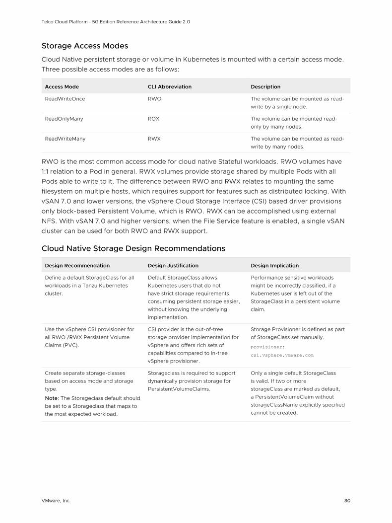
Storage Access Modes
Cloud Native persistent storage or volume in Kubernetes is mounted with a certain access mode. Three possible access modes are as follows:
Access Mode CLI Abbreviation Description
ReadWriteOnce RWO The volume can be mounted as read-write by a single node.
ReadOnlyMany ROX The volume can be mounted read-only by many nodes.
ReadWriteMany RWX The volume can be mounted as read-write by many nodes.
RWO is the most common access mode for cloud native Stateful workloads. RWO volumes have 1:1 relation to a Pod in general. RWX volumes provide storage shared by multiple Pods with all Pods able to write to it. The difference between RWO and RWX relates to mounting the same filesystem on multiple hosts, which requires support for features such as distributed locking. With vSAN 7.0 and lower versions, the vSphere Cloud Storage Interface (CSI) based driver provisions only block-based Persistent Volume, which is RWO. RWX can be accomplished using external NFS. With vSAN 7.0 and higher versions, when the File Service feature is enabled, a single vSAN cluster can be used for both RWO and RWX support.
Cloud Native Storage Design Recommendations
Design Recommendation Design Justification Design Implication
Define a default StorageClass for all workloads in a Tanzu Kubernetes cluster.
Default StorageClass allows Kubernetes users that do not have strict storage requirements consuming persistent storage easier, without knowing the underlying implementation.
Performance sensitive workloads might be incorrectly classified, if a Kubernetes user is left out of the StorageClass in a persistent volume claim.
Use the vSphere CSI provisioner for all RWO /RWX Persistent Volume Claims (PVC).
CSI provider is the out-of-tree storage provider implementation for vSphere and offers rich sets of capabilities compared to in-tree vSphere provisioner.
Storage Provisioner is defined as part of StorageClass set manually.
provisioner: csi.vsphere.vmware.com
Create separate storage-classes based on access mode and storage type.
Note: The Storageclass default should be set to a Storageclass that maps to the most expected workload.
Storageclass is required to support dynamically provision storage for PersistentVolumeClaims.
Only a single default StorageClass is valid. If two or more storageClass are marked as default, a PersistentVolumeClaim without storageClassName explicitly specified cannot be created.
Telco Cloud Platform - 5G Edition Reference Architecture Guide 2.0
VMware, Inc. 80
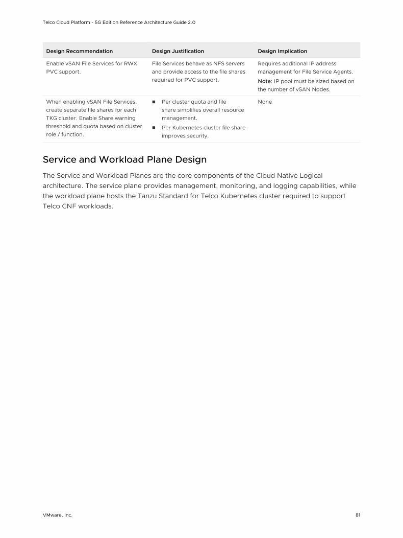
Design Recommendation Design Justification Design Implication
Enable vSAN File Services for RWX PVC support.
File Services behave as NFS servers and provide access to the file shares required for PVC support.
Requires additional IP address management for File Service Agents.
Note: IP pool must be sized based on the number of vSAN Nodes.
When enabling vSAN File Services, create separate file shares for each TKG cluster. Enable Share warning threshold and quota based on cluster role / function.
n Per cluster quota and file share simplifies overall resource management.
n Per Kubernetes cluster file share improves security.
None
Service and Workload Plane Design
The Service and Workload Planes are the core components of the Cloud Native Logical architecture. The service plane provides management, monitoring, and logging capabilities, while the workload plane hosts the Tanzu Standard for Telco Kubernetes cluster required to support Telco CNF workloads.
Telco Cloud Platform - 5G Edition Reference Architecture Guide 2.0
VMware, Inc. 81
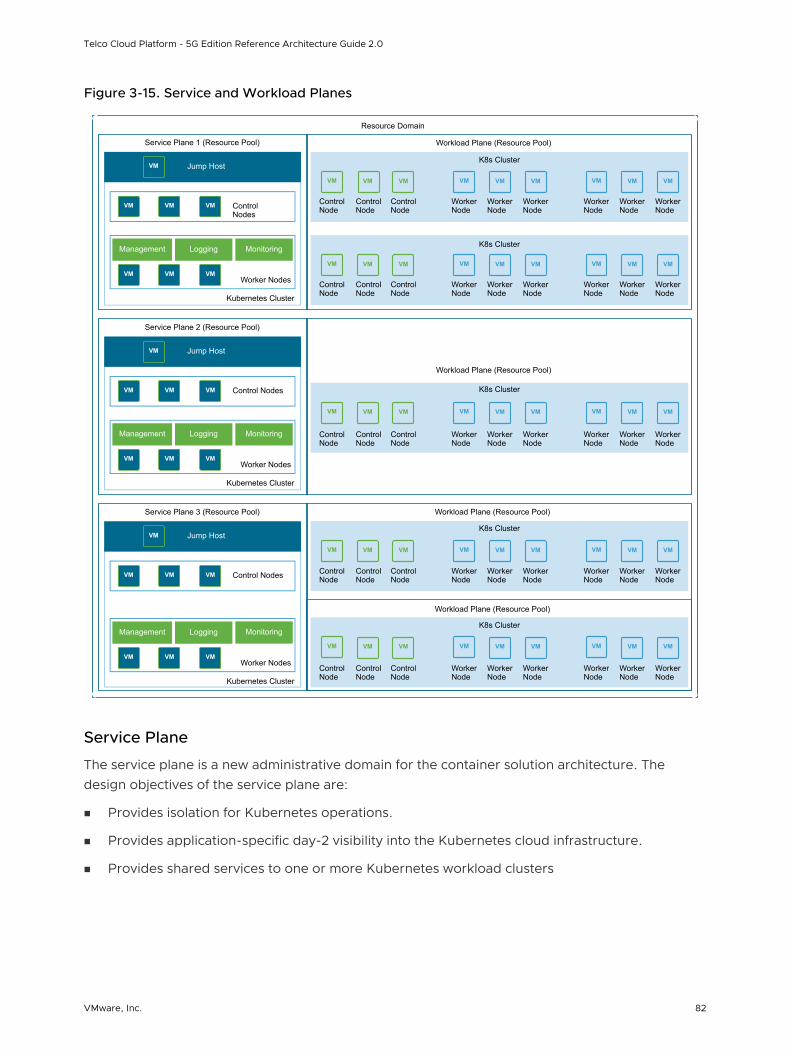
Figure 3-15. Service and Workload Planes
Resource Domain
VM VM VM VM VM VM VM VM VM
K8s Cluster
Workload Plane (Resource Pool)
VM VM VM VM VM VM VM VM VM
VM VM VM VM VM VM VM VM VM
K8s Cluster
K8s Cluster
Workload Plane (Resource Pool)
Workload Plane (Resource Pool)
VM VM VM VM VM VM VM VM VM
Control Node
Control Node
Control Node
Workload Plane (Resource Pool)
K8s Cluster
Worker Node
Worker Node
Worker Node
Worker Node
Worker Node
Worker Node
Control Node
Control Node
Control Node
Worker Node
Worker Node
Worker Node
Worker Node
Worker Node
Worker Node
Control Node
Control Node
Control Node
Worker Node
Worker Node
Worker Node
Worker Node
Worker Node
Worker Node
Control Node
Control Node
Control Node
Worker Node
Worker Node
Worker Node
Worker Node
Worker Node
Worker Node
Control Node
Control Node
Control Node
Worker Node
Worker Node
Worker Node
Worker Node
Worker Node
Worker Node
VM VM VM VM VM VM VM VM VM
K8s Cluster
Service Plane 1 (Resource Pool)
VM Control Nodes
VM VM
VMWorker Nodes
VM VM
Management Logging Monitoring
Kubernetes Cluster
VM Jump Host
Service Plane 2 (Resource Pool)
VM Control NodesVM VM
VMWorker Nodes
VM VM
Management Logging Monitoring
Kubernetes Cluster
VM Jump Host
Service Plane 3 (Resource Pool)
VM Control NodesVM VM
VMWorker Nodes
VM VM
Management Logging Monitoring
Kubernetes Cluster
VM Jump Host
Service Plane
The service plane is a new administrative domain for the container solution architecture. The design objectives of the service plane are:
n Provides isolation for Kubernetes operations.
n Provides application-specific day-2 visibility into the Kubernetes cloud infrastructure.
n Provides shared services to one or more Kubernetes workload clusters
Telco Cloud Platform - 5G Edition Reference Architecture Guide 2.0
VMware, Inc. 82
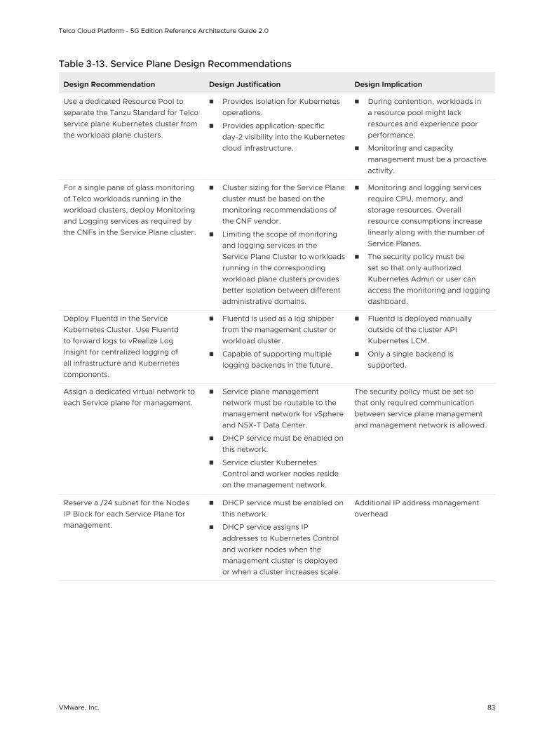
Table 3-13. Service Plane Design Recommendations
Design Recommendation Design Justification Design Implication
Use a dedicated Resource Pool to separate the Tanzu Standard for Telco service plane Kubernetes cluster from the workload plane clusters.
n Provides isolation for Kubernetes operations.
n Provides application-specific day-2 visibility into the Kubernetes cloud infrastructure.
n During contention, workloads in a resource pool might lack resources and experience poor performance.
n Monitoring and capacity management must be a proactive activity.
For a single pane of glass monitoring of Telco workloads running in the workload clusters, deploy Monitoring and Logging services as required by the CNFs in the Service Plane cluster.
n Cluster sizing for the Service Plane cluster must be based on the monitoring recommendations of the CNF vendor.
n Limiting the scope of monitoring and logging services in the Service Plane Cluster to workloads running in the corresponding workload plane clusters provides better isolation between different administrative domains.
n Monitoring and logging services require CPU, memory, and storage resources. Overall resource consumptions increase linearly along with the number of Service Planes.
n The security policy must be set so that only authorized Kubernetes Admin or user can access the monitoring and logging dashboard.
Deploy Fluentd in the Service Kubernetes Cluster. Use Fluentd to forward logs to vRealize Log Insight for centralized logging of all infrastructure and Kubernetes components.
n Fluentd is used as a log shipper from the management cluster or workload cluster.
n Capable of supporting multiple logging backends in the future.
n Fluentd is deployed manually outside of the cluster API Kubernetes LCM.
n Only a single backend is supported.
Assign a dedicated virtual network to each Service plane for management.
n Service plane management network must be routable to the management network for vSphere and NSX-T Data Center.
n DHCP service must be enabled on this network.
n Service cluster Kubernetes Control and worker nodes reside on the management network.
The security policy must be set so that only required communication between service plane management and management network is allowed.
Reserve a /24 subnet for the Nodes IP Block for each Service Plane for management.
n DHCP service must be enabled on this network.
n DHCP service assigns IP addresses to Kubernetes Control and worker nodes when the management cluster is deployed or when a cluster increases scale.
Additional IP address management overhead
Telco Cloud Platform - 5G Edition Reference Architecture Guide 2.0
VMware, Inc. 83
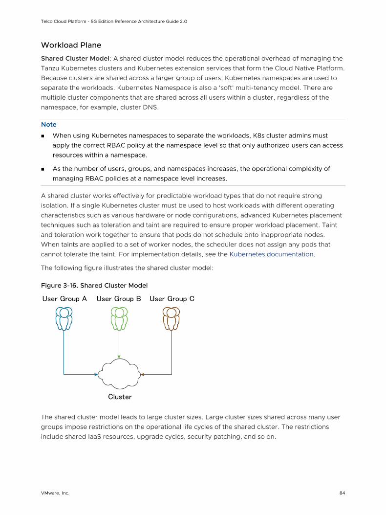
Workload Plane
Shared Cluster Model: A shared cluster model reduces the operational overhead of managing the Tanzu Kubernetes clusters and Kubernetes extension services that form the Cloud Native Platform. Because clusters are shared across a larger group of users, Kubernetes namespaces are used to separate the workloads. Kubernetes Namespace is also a 'soft' multi-tenancy model. There are multiple cluster components that are shared across all users within a cluster, regardless of the namespace, for example, cluster DNS.
Note
n When using Kubernetes namespaces to separate the workloads, K8s cluster admins must apply the correct RBAC policy at the namespace level so that only authorized users can access resources within a namespace.
n As the number of users, groups, and namespaces increases, the operational complexity of managing RBAC policies at a namespace level increases.
A shared cluster works effectively for predictable workload types that do not require strong isolation. If a single Kubernetes cluster must be used to host workloads with different operating characteristics such as various hardware or node configurations, advanced Kubernetes placement techniques such as toleration and taint are required to ensure proper workload placement. Taint and toleration work together to ensure that pods do not schedule onto inappropriate nodes. When taints are applied to a set of worker nodes, the scheduler does not assign any pods that cannot tolerate the taint. For implementation details, see the Kubernetes documentation.
The following figure illustrates the shared cluster model:
Figure 3-16. Shared Cluster Model
Cluster
User Group A User Group B User Group C
The shared cluster model leads to large cluster sizes. Large cluster sizes shared across many user groups impose restrictions on the operational life cycles of the shared cluster. The restrictions include shared IaaS resources, upgrade cycles, security patching, and so on.
Telco Cloud Platform - 5G Edition Reference Architecture Guide 2.0
VMware, Inc. 84
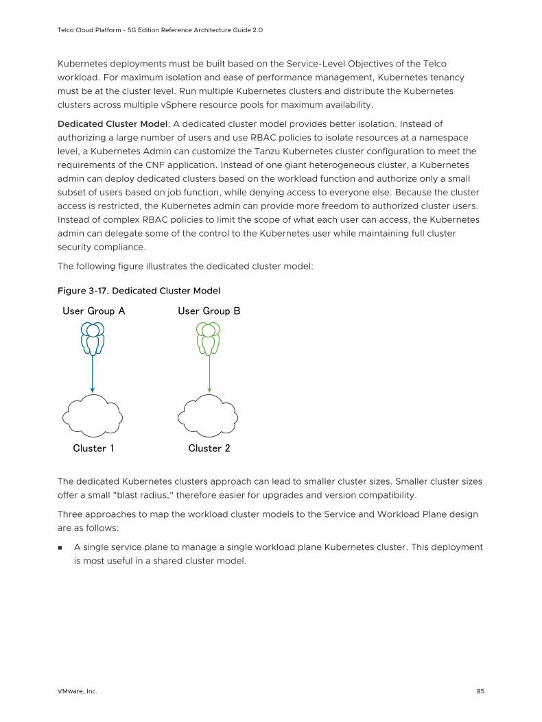
Kubernetes deployments must be built based on the Service-Level Objectives of the Telco workload. For maximum isolation and ease of performance management, Kubernetes tenancy must be at the cluster level. Run multiple Kubernetes clusters and distribute the Kubernetes clusters across multiple vSphere resource pools for maximum availability.
Dedicated Cluster Model: A dedicated cluster model provides better isolation. Instead of authorizing a large number of users and use RBAC policies to isolate resources at a namespace level, a Kubernetes Admin can customize the Tanzu Kubernetes cluster configuration to meet the requirements of the CNF application. Instead of one giant heterogeneous cluster, a Kubernetes admin can deploy dedicated clusters based on the workload function and authorize only a small subset of users based on job function, while denying access to everyone else. Because the cluster access is restricted, the Kubernetes admin can provide more freedom to authorized cluster users. Instead of complex RBAC policies to limit the scope of what each user can access, the Kubernetes admin can delegate some of the control to the Kubernetes user while maintaining full cluster security compliance.
The following figure illustrates the dedicated cluster model:
Figure 3-17. Dedicated Cluster Model
Cluster 1 Cluster 2
User Group A User Group B
The dedicated Kubernetes clusters approach can lead to smaller cluster sizes. Smaller cluster sizes offer a small "blast radius," therefore easier for upgrades and version compatibility.
Three approaches to map the workload cluster models to the Service and Workload Plane design are as follows:
n A single service plane to manage a single workload plane Kubernetes cluster. This deployment is most useful in a shared cluster model.
Telco Cloud Platform - 5G Edition Reference Architecture Guide 2.0
VMware, Inc. 85
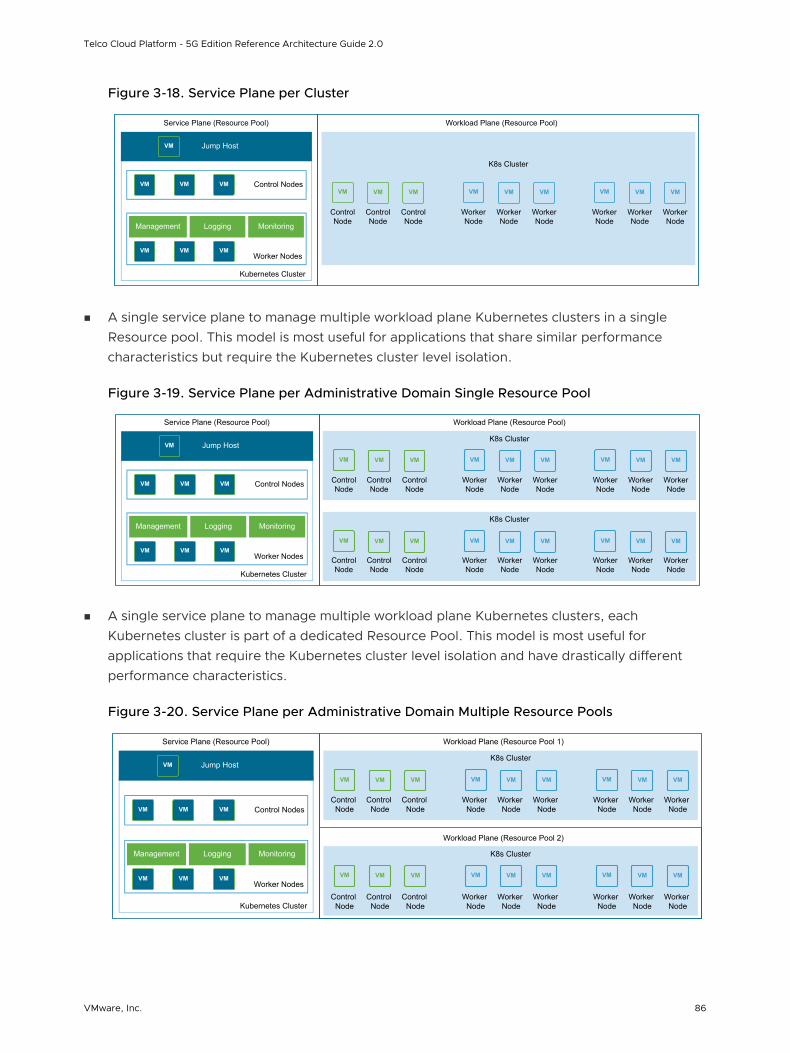
Figure 3-18. Service Plane per Cluster
K8s Cluster
Workload Plane (Resource Pool)
ControlNode
ControlNode
ControlNode
WorkerNode
WorkerNode
WorkerNode
WorkerNode
WorkerNode
WorkerNode
VM VM VM VM VM VM VM VM VM
Service Plane (Resource Pool)
VM Control NodesVM VM
VMWorker Nodes
VM VM
Management Logging Monitoring
Kubernetes Cluster
VM Jump Host
n A single service plane to manage multiple workload plane Kubernetes clusters in a single Resource pool. This model is most useful for applications that share similar performance characteristics but require the Kubernetes cluster level isolation.
Figure 3-19. Service Plane per Administrative Domain Single Resource Pool
Workload Plane (Resource Pool)
VM VM VM VM VM VM VM VM VM
Control Node
Control Node
Control Node
K8s Cluster
Worker Node
Worker Node
Worker Node
Worker Node
Worker Node
Worker Node
Control Node
Control Node
Control Node
Worker Node
Worker Node
Worker Node
Worker Node
Worker Node
Worker Node
VM VM VM VM VM VM VM VM VM
K8s Cluster
Service Plane (Resource Pool)
VM Control NodesVM VM
VMWorker Nodes
VM VM
Management Logging Monitoring
Kubernetes Cluster
VM Jump Host
n A single service plane to manage multiple workload plane Kubernetes clusters, each Kubernetes cluster is part of a dedicated Resource Pool. This model is most useful for applications that require the Kubernetes cluster level isolation and have drastically different performance characteristics.
Figure 3-20. Service Plane per Administrative Domain Multiple Resource Pools
K8s Cluster
K8s Cluster
Control Node
Control Node
Control Node
Workload Plane (Resource Pool 1)
Workload Plane (Resource Pool 2)
Worker Node
Worker Node
Worker Node
Worker Node
Worker Node
Worker Node
Control Node
Control Node
Control Node
Worker Node
Worker Node
Worker Node
Worker Node
Worker Node
Worker Node
VM VM VM VM VM VM VM VM VM
VM VM VM VM VM VM VM VM VM
Service Plane (Resource Pool)
VM Control NodesVM VM
VMWorker Nodes
VM VM
Management Logging Monitoring
Kubernetes Cluster
VM Jump Host
Telco Cloud Platform - 5G Edition Reference Architecture Guide 2.0
VMware, Inc. 86
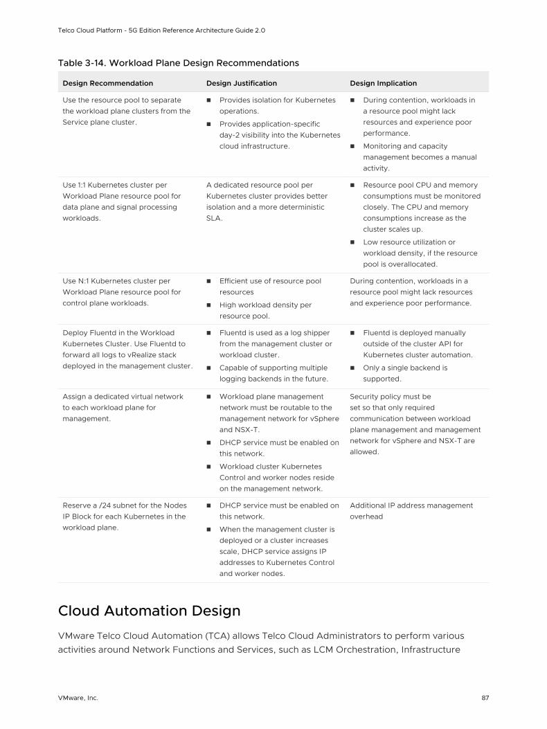
Table 3-14. Workload Plane Design Recommendations
Design Recommendation Design Justification Design Implication
Use the resource pool to separate the workload plane clusters from the Service plane cluster.
n Provides isolation for Kubernetes operations.
n Provides application-specific day-2 visibility into the Kubernetes cloud infrastructure.
n During contention, workloads in a resource pool might lack resources and experience poor performance.
n Monitoring and capacity management becomes a manual activity.
Use 1:1 Kubernetes cluster per Workload Plane resource pool for data plane and signal processing workloads.
A dedicated resource pool per Kubernetes cluster provides better isolation and a more deterministic SLA.
n Resource pool CPU and memory consumptions must be monitored closely. The CPU and memory consumptions increase as the cluster scales up.
n Low resource utilization or workload density, if the resource pool is overallocated.
Use N:1 Kubernetes cluster per Workload Plane resource pool for control plane workloads.
n Efficient use of resource pool resources
n High workload density per resource pool.
During contention, workloads in a resource pool might lack resources and experience poor performance.
Deploy Fluentd in the Workload Kubernetes Cluster. Use Fluentd to forward all logs to vRealize stack deployed in the management cluster.
n Fluentd is used as a log shipper from the management cluster or workload cluster.
n Capable of supporting multiple logging backends in the future.
n Fluentd is deployed manually outside of the cluster API for Kubernetes cluster automation.
n Only a single backend is supported.
Assign a dedicated virtual network to each workload plane for management.
n Workload plane management network must be routable to the management network for vSphere and NSX-T.
n DHCP service must be enabled on this network.
n Workload cluster Kubernetes Control and worker nodes reside on the management network.
Security policy must be set so that only required communication between workload plane management and management network for vSphere and NSX-T are allowed.
Reserve a /24 subnet for the Nodes IP Block for each Kubernetes in the workload plane.
n DHCP service must be enabled on this network.
n When the management cluster is deployed or a cluster increases scale, DHCP service assigns IP addresses to Kubernetes Control and worker nodes.
Additional IP address management overhead
Cloud Automation Design
VMware Telco Cloud Automation (TCA) allows Telco Cloud Administrators to perform various activities around Network Functions and Services, such as LCM Orchestration, Infrastructure
Telco Cloud Platform - 5G Edition Reference Architecture Guide 2.0
VMware, Inc. 87
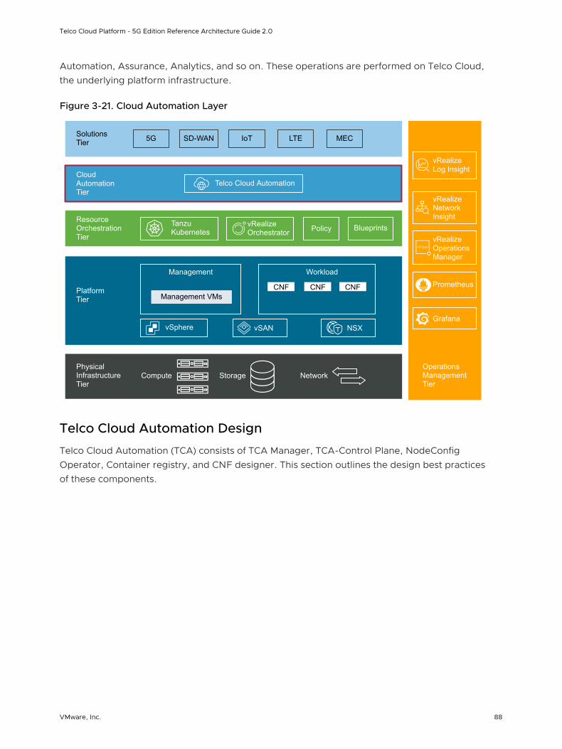
Automation, Assurance, Analytics, and so on. These operations are performed on Telco Cloud, the underlying platform infrastructure.
Figure 3-21. Cloud Automation Layer
vRealize Orchestrator
Operations Management Tier
Physical Infrastructure Tier
Platform Tier
Resource Orchestration Tier
Cloud Automation Tier
Solutions Tier 5G SD-WAN LTE MECIoT
Telco Cloud Automation
Tanzu Kubernetes Policy Blueprints
Management VMsCNF CNF CNF
Management Workload
vSphere vSAN NSX
vRealize Log Insight
vRealize Network Insight
vRealize Operations Manager
Compute Storage Network
Prometheus
Grafana
Telco Cloud Automation Design
Telco Cloud Automation (TCA) consists of TCA Manager, TCA-Control Plane, NodeConfig Operator, Container registry, and CNF designer. This section outlines the design best practices of these components.
Telco Cloud Platform - 5G Edition Reference Architecture Guide 2.0
VMware, Inc. 88
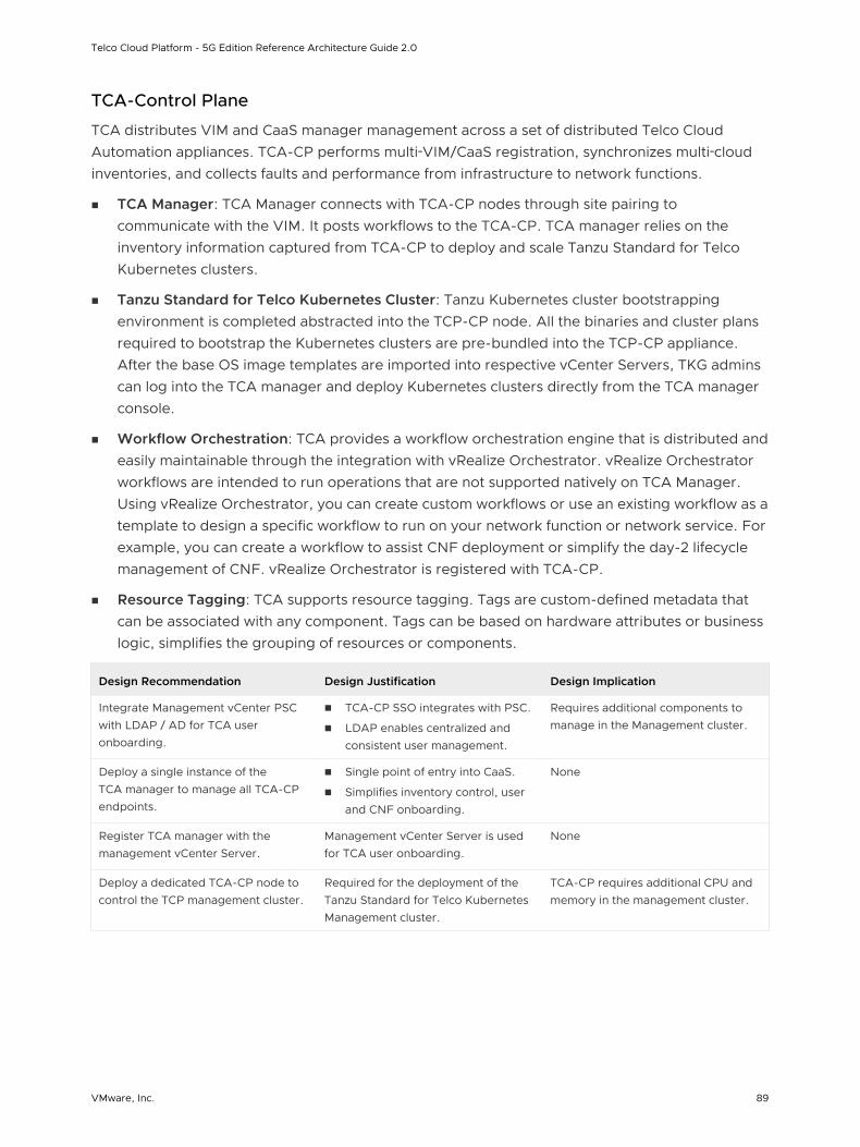
TCA-Control Plane
TCA distributes VIM and CaaS manager management across a set of distributed Telco Cloud Automation appliances. TCA-CP performs multi‑VIM/CaaS registration, synchronizes multi‑cloud inventories, and collects faults and performance from infrastructure to network functions.
n TCA Manager: TCA Manager connects with TCA-CP nodes through site pairing to communicate with the VIM. It posts workflows to the TCA-CP. TCA manager relies on the inventory information captured from TCA-CP to deploy and scale Tanzu Standard for Telco Kubernetes clusters.
n Tanzu Standard for Telco Kubernetes Cluster: Tanzu Kubernetes cluster bootstrapping environment is completed abstracted into the TCP-CP node. All the binaries and cluster plans required to bootstrap the Kubernetes clusters are pre-bundled into the TCP-CP appliance. After the base OS image templates are imported into respective vCenter Servers, TKG admins can log into the TCA manager and deploy Kubernetes clusters directly from the TCA manager console.
n Workflow Orchestration: TCA provides a workflow orchestration engine that is distributed and easily maintainable through the integration with vRealize Orchestrator. vRealize Orchestrator workflows are intended to run operations that are not supported natively on TCA Manager. Using vRealize Orchestrator, you can create custom workflows or use an existing workflow as a template to design a specific workflow to run on your network function or network service. For example, you can create a workflow to assist CNF deployment or simplify the day-2 lifecycle management of CNF. vRealize Orchestrator is registered with TCA-CP.
n Resource Tagging: TCA supports resource tagging. Tags are custom-defined metadata that can be associated with any component. Tags can be based on hardware attributes or business logic, simplifies the grouping of resources or components.
Design Recommendation Design Justification Design Implication
Integrate Management vCenter PSC with LDAP / AD for TCA user onboarding.
n TCA-CP SSO integrates with PSC.
n LDAP enables centralized and consistent user management.
Requires additional components to manage in the Management cluster.
Deploy a single instance of the TCA manager to manage all TCA-CP endpoints.
n Single point of entry into CaaS.
n Simplifies inventory control, user and CNF onboarding.
None
Register TCA manager with the management vCenter Server.
Management vCenter Server is used for TCA user onboarding.
None
Deploy a dedicated TCA-CP node to control the TCP management cluster.
Required for the deployment of the Tanzu Standard for Telco Kubernetes Management cluster.
TCA-CP requires additional CPU and memory in the management cluster.
Telco Cloud Platform - 5G Edition Reference Architecture Guide 2.0
VMware, Inc. 89
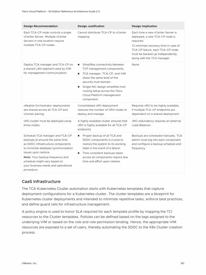
Design Recommendation Design Justification Design Implication
Each TCA-CP node controls a single vCenter Server. Multiple vCenter Servers in one location require multiple TCA-CP nodes.
Cannot distribute TCA-CP to vCenter mapping
Each time a new vCenter Server is deployed, a new TCA-CP node is required.
To minimize recovery time in case of TCA-CP failure, each TCA-CP node must be backed up independently, along with the TCA manager.
Deploy TCA manager and TCA-CP on a shared LAN segment used by VIM for management communication.
n Simplifies connectivity between TCP management components.
n TCA manager, TCA-CP, and VIM share the same level of the security trust domain.
n Single NIC design simplifies host routing setup across the Telco Cloud Platform management component.
None
vRealize Orchestrator deployments are shared across all TCA-CP and vCenter pairing.
Consolidated vRO deployment reduces the number of VRO nodes to deploy and manage.
Requires vRO to be highly available, if multiple TCA-CP endpoints are dependent on a shared deployment
vRO cluster must be deployed using three nodes.
A highly available cluster ensures that vRO is highly available for all TCA-CP endpoints
vRO redundancy requires an external Load Balancer.
Schedule TCA manager and TCA-CP backups at around the same time as SDDC infrastructure components to minimize database synchronization issues upon restore.
Note: Your backup frequency and schedule might vary based on your business needs and operational procedure.
n Proper backup of all TCA and SDDC components is crucial to restore the system to its working state in the event of a failure.
n Time consistent backups taken across all components require less time and effort upon restore.
Backups are scheduled manually. TCA admin must log into each component and configure a backup schedule and frequency.
CaaS Infrastructure
The TCA Kubernetes Cluster automation starts with Kubernetes templates that capture deployment configurations for a Kubernetes cluster. The cluster templates are a blueprint for Kubernetes cluster deployments and intended to minimize repetitive tasks, enforce best practices, and define guard rails for infrastructure management.
A policy engine is used to honor SLA required for each template profile by mapping the TCI resources to the Cluster templates. Policies can be defined based on the tags assigned to the underlying VIM or based on the role and role permission binding. Hence, the appropriate VIM resources are exposed to a set of users, thereby automating the SDDC to the K8s Cluster creation process.
Telco Cloud Platform - 5G Edition Reference Architecture Guide 2.0
VMware, Inc. 90
TCA CaaS Infrastructure automation consists of the following components:
n TCA Kubernetes Cluster Template Designer: TCA admin uses the TCA Kubernetes Cluster designer to create Kubernetes Cluster templates to help deploy the Kubernetes cluster. Kubernetes Cluster template defines the composition of the Kubernetes cluster. Attributes such as the number and size of Control and worker nodes, Kubernetes CNI, Kubernetes storage interface, and Helm version makes up a typical Kubernetes cluster template. The TCA Kubernetes Cluster template designer does not capture CNF-specific Kubernetes attributes but instead leverages the VMware NodeConfig operator through late binding. For late binding details, see TCA VM and Node Config Automation Design.
n SDDC Profile and Inventory Discovery: The Inventory management component of TCA can discover the underlying infrastructure for each VIM associated with a TCA-CP appliance. Hardware characteristics of the vSphere node and vSphere cluster are discovered using the TCA inventory service. The platform inventory data is made available by the discovery service to the Cluster Automation Policy engine to assist the Kubernetes cluster placement. TCA admin can add tags to the infrastructure inventory to provide additional business logic on top of the discovered data.
n Cluster Automation Policy: The Cluster Automation policy defines the mapping of the TCA Kubernetes Cluster template to infrastructure. VMware Telco Cloud Platform allows TCA admins to map the resources using a Cluster Automation Policy to identify and group the infrastructure to assist users in deploying higher-level components on them. The Cluster Automation Policy indicates the intended usage of the infrastructure. During the cluster creation time, TCA validates whether the Kubernetes template requirements are met by the underlying infrastructure resources.
n K8s Bootstrapper: When the deployment requirements are met, TCA generates a deployment specification. The K8s Bootstrapper uses the Kubernetes cluster APIs to create the Cluster based on the deployment specification. Bootstrapper is a component of the TCA-CP.
Telco Cloud Platform - 5G Edition Reference Architecture Guide 2.0
VMware, Inc. 91

Figure 3-22. TCA CaaS Workflow
TKG K8sTemplate
Kubernetes Cluster Template
CSI
Device
DriversDrivers
Perf
OS
Kernel
Node and ClusterProfile
Tag
Tag
Tag
Tag
Tag
Tag
Tag
Tag
Tag
Tag Tag
Cluster AutomationPolicies
K8s Bootstrapper
TKG workload Cluster
Resource TaggingSDDC Infra Discovery
Telco Cloud Platform - 5G Edition Reference Architecture Guide 2.0
VMware, Inc. 92
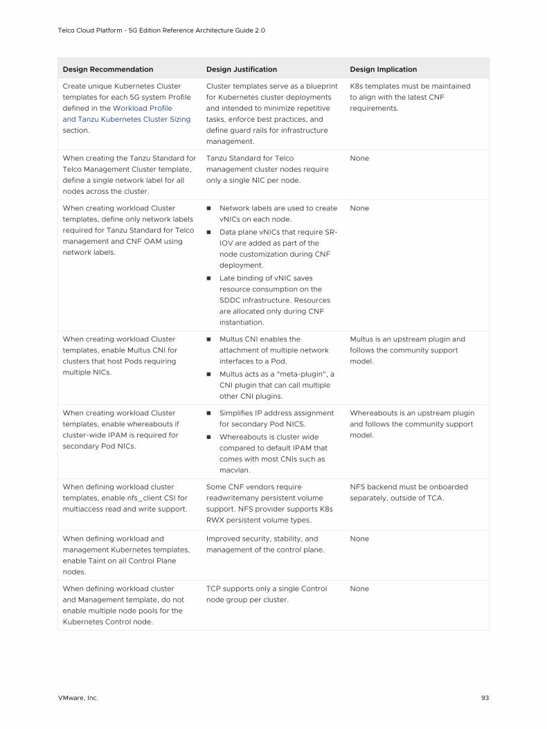
Design Recommendation Design Justification Design Implication
Create unique Kubernetes Cluster templates for each 5G system Profile defined in the Workload Profile and Tanzu Kubernetes Cluster Sizing section.
Cluster templates serve as a blueprint for Kubernetes cluster deployments and intended to minimize repetitive tasks, enforce best practices, and define guard rails for infrastructure management.
K8s templates must be maintained to align with the latest CNF requirements.
When creating the Tanzu Standard for Telco Management Cluster template, define a single network label for all nodes across the cluster.
Tanzu Standard for Telco management cluster nodes require only a single NIC per node.
None
When creating workload Cluster templates, define only network labels required for Tanzu Standard for Telco management and CNF OAM using network labels.
n Network labels are used to create vNICs on each node.
n Data plane vNICs that require SR-IOV are added as part of the node customization during CNF deployment.
n Late binding of vNIC saves resource consumption on the SDDC infrastructure. Resources are allocated only during CNF instantiation.
None
When creating workload Cluster templates, enable Multus CNI for clusters that host Pods requiring multiple NICs.
n Multus CNI enables the attachment of multiple network interfaces to a Pod.
n Multus acts as a "meta-plugin", a CNI plugin that can call multiple other CNI plugins.
Multus is an upstream plugin and follows the community support model.
When creating workload Cluster templates, enable whereabouts if cluster-wide IPAM is required for secondary Pod NICs.
n Simplifies IP address assignment for secondary Pod NICS.
n Whereabouts is cluster wide compared to default IPAM that comes with most CNIs such as macvlan.
Whereabouts is an upstream plugin and follows the community support model.
When defining workload cluster templates, enable nfs_client CSI for multiaccess read and write support.
Some CNF vendors require readwritemany persistent volume support. NFS provider supports K8s RWX persistent volume types.
NFS backend must be onboarded separately, outside of TCA.
When defining workload and management Kubernetes templates, enable Taint on all Control Plane nodes.
Improved security, stability, and management of the control plane.
None
When defining workload cluster and Management template, do not enable multiple node pools for the Kubernetes Control node.
TCP supports only a single Control node group per cluster.
None
Telco Cloud Platform - 5G Edition Reference Architecture Guide 2.0
VMware, Inc. 93
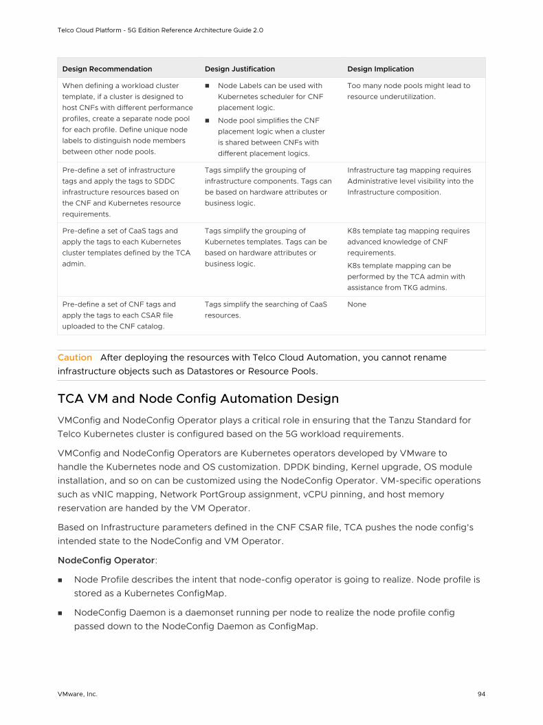
Design Recommendation Design Justification Design Implication
When defining a workload cluster template, if a cluster is designed to host CNFs with different performance profiles, create a separate node pool for each profile. Define unique node labels to distinguish node members between other node pools.
n Node Labels can be used with Kubernetes scheduler for CNF placement logic.
n Node pool simplifies the CNF placement logic when a cluster is shared between CNFs with different placement logics.
Too many node pools might lead to resource underutilization.
Pre-define a set of infrastructure tags and apply the tags to SDDC infrastructure resources based on the CNF and Kubernetes resource requirements.
Tags simplify the grouping of infrastructure components. Tags can be based on hardware attributes or business logic.
Infrastructure tag mapping requires Administrative level visibility into the Infrastructure composition.
Pre-define a set of CaaS tags and apply the tags to each Kubernetes cluster templates defined by the TCA admin.
Tags simplify the grouping of Kubernetes templates. Tags can be based on hardware attributes or business logic.
K8s template tag mapping requires advanced knowledge of CNF requirements.
K8s template mapping can be performed by the TCA admin with assistance from TKG admins.
Pre-define a set of CNF tags and apply the tags to each CSAR file uploaded to the CNF catalog.
Tags simplify the searching of CaaS resources.
None
Caution After deploying the resources with Telco Cloud Automation, you cannot rename infrastructure objects such as Datastores or Resource Pools.
TCA VM and Node Config Automation Design
VMConfig and NodeConfig Operator plays a critical role in ensuring that the Tanzu Standard for Telco Kubernetes cluster is configured based on the 5G workload requirements.
VMConfig and NodeConfig Operators are Kubernetes operators developed by VMware to handle the Kubernetes node and OS customization. DPDK binding, Kernel upgrade, OS module installation, and so on can be customized using the NodeConfig Operator. VM-specific operations such as vNIC mapping, Network PortGroup assignment, vCPU pinning, and host memory reservation are handed by the VM Operator.
Based on Infrastructure parameters defined in the CNF CSAR file, TCA pushes the node config's intended state to the NodeConfig and VM Operator.
NodeConfig Operator:
n Node Profile describes the intent that node-config operator is going to realize. Node profile is stored as a Kubernetes ConfigMap.
n NodeConfig Daemon is a daemonset running per node to realize the node profile config passed down to the NodeConfig Daemon as ConfigMap.
Telco Cloud Platform - 5G Edition Reference Architecture Guide 2.0
VMware, Inc. 94
n NodeConfig Operator is a k8s operator that handles the node OS configuration, performance tuning, OS upgrade. NodeOperator monitors config update events and forwards events to backend Daemon plugins. There are multiple Daemon plugins. Each plugin is responsible for a specific type of event such as Tuning, Package updates, SR-IOV device management, and so on. After each plugin processes the update events, node labels are used to filter out a set of nodes to receive the node profile.
VMConfig Operator:
n VMConfig Operator is a K8s operator that handles VM configurations for TKG cluster as the CAPV/CAPI extension. VMConfig Operator runs in the TKG management cluster.
n VMConfig Operator consists of
n VM Controller: Monitors VMConfig and CAPI/CAPV events and configures K8s worker nodes on the target workload cluster.
n ESXInfoController: Responsible for hardware capabilities discovery on an ESXi host.
TCA is the single source of truth for both VMConfig and NodeConfig operators. Based on the infrastructure requirements defined in the network function catalog TOSCA YAML (CSAR file), TCA generates a node profile that describes the intended node config the operator is going to realize. The NodeConfig operator runs as K8s Daemonsets on Kubernetes nodes and configures the worker node to realize the desired states specified by TCA.
Telco Cloud Platform - 5G Edition Reference Architecture Guide 2.0
VMware, Inc. 95
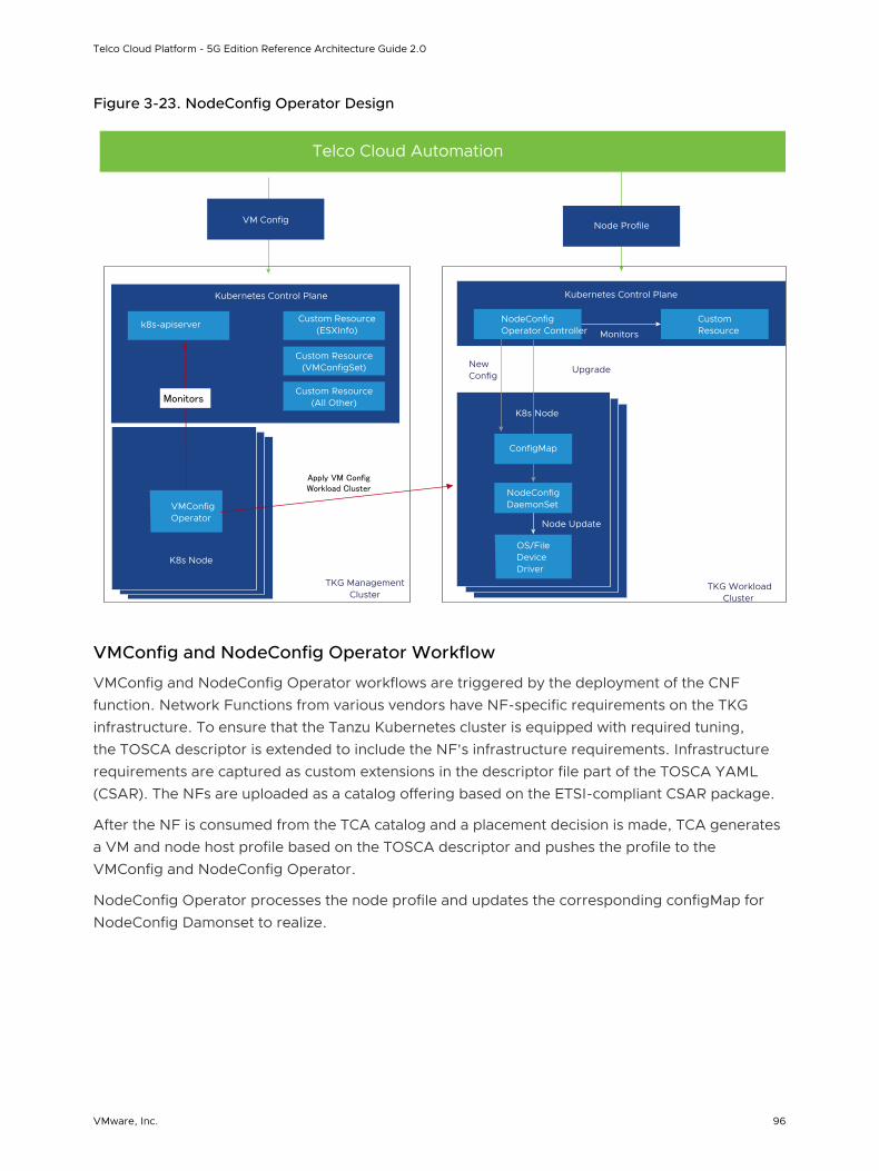
Figure 3-23. NodeConfig Operator Design
Kubernetes Control Plane
K8s Node
OS/File Device Driver
TKG Workload Cluster
Node Profile
Custom Resource
NodeConfig Operator Controller Monitors
New Config
Upgrade
Node Update
ConfigMap
NodeConfig DaemonSet
Kubernetes Control Plane
K8s Node
VMConfig Operator
TKG Management Cluster
VM config
Custom Resource (ESXInfo)
k8s-apiserver
Custom Resource (VMConfigSet)
Custom Resource (All Other)
Apply VM Config Workload Cluster
Monitors
VM Config
Telco Cloud Automation
VMConfig and NodeConfig Operator Workflow
VMConfig and NodeConfig Operator workflows are triggered by the deployment of the CNF function. Network Functions from various vendors have NF-specific requirements on the TKG infrastructure. To ensure that the Tanzu Kubernetes cluster is equipped with required tuning, the TOSCA descriptor is extended to include the NF's infrastructure requirements. Infrastructure requirements are captured as custom extensions in the descriptor file part of the TOSCA YAML (CSAR). The NFs are uploaded as a catalog offering based on the ETSI-compliant CSAR package.
After the NF is consumed from the TCA catalog and a placement decision is made, TCA generates a VM and node host profile based on the TOSCA descriptor and pushes the profile to the VMConfig and NodeConfig Operator.
NodeConfig Operator processes the node profile and updates the corresponding configMap for NodeConfig Damonset to realize.
Telco Cloud Platform - 5G Edition Reference Architecture Guide 2.0
VMware, Inc. 96
Design Recommendation Design Justification Design Implication
Do not update node profile or cluster ConfigMap outside of TCA.
n VMConfig and NodeConfig Operators are part of TCA.
n Manual changes to the NodeConfig and VMConfig operators are not supported.
n ConfigMap is maintained by TCA only.
None
Container Registry Design
5G consists of CNFs in the form of container images and Helm charts from 5G network vendors. This section outlines the recommendations to deploy and maintain a secure container image registry using VMware Harbor.
5G consists of CNFs in the form of container images and Helm charts from 5G network vendors. Container images and Helm charts must be stored in registries that are always available and easily accessible. Public or cloud-based registries lack critical security compliance features to operate and maintain carrier-class deployments. Harbor solves those challenges by delivering trust, compliance, performance, and interoperability.
Telco Cloud Platform - 5G Edition Reference Architecture Guide 2.0
VMware, Inc. 97
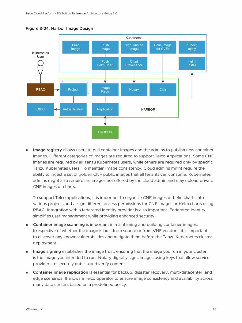
Figure 3-24. Harbor Image Design
Project Image Repo
Authentication
RBAC
OIDC Replication
HARBOR
Notary Clair
Push Helm Chart
Chart Provenance
helm install
Build Image
Push Image
Sign Trusted Image
Scan Image for CVEs
Kubectl apply
HARBOR
Kubernetes
Kubernetes User
n Image registry allows users to pull container images and the admins to publish new container images. Different categories of images are required to support Telco Applications. Some CNF images are required by all Tanzu Kubernetes users, while others are required only by specific Tanzu Kubernetes users. To maintain image consistency, Cloud admins might require the ability to ingest a set of golden CNF public images that all tenants can consume. Kubernetes admins might also require the images not offered by the cloud admin and may upload private CNF images or charts.
To support Telco applications, it is important to organize CNF images or helm charts into various projects and assign different access permissions for CNF images or Helm charts using RBAC. Integration with a federated identity provider is also important. Federated identity simplifies user management while providing enhanced security.
n Container image scanning is important in maintaining and building container images. Irrespective of whether the image is built from source or from VNF vendors, it is important to discover any known vulnerabilities and mitigate them before the Tanzu Kubernetes cluster deployment.
n Image signing establishes the image trust, ensuring that the image you run in your cluster is the image you intended to run. Notary digitally signs images using keys that allow service providers to securely publish and verify content.
n Container image replication is essential for backup, disaster recovery, multi-datacenter, and edge scenarios. It allows a Telco operator to ensure image consistency and availability across many data centers based on a predefined policy.
Telco Cloud Platform - 5G Edition Reference Architecture Guide 2.0
VMware, Inc. 98
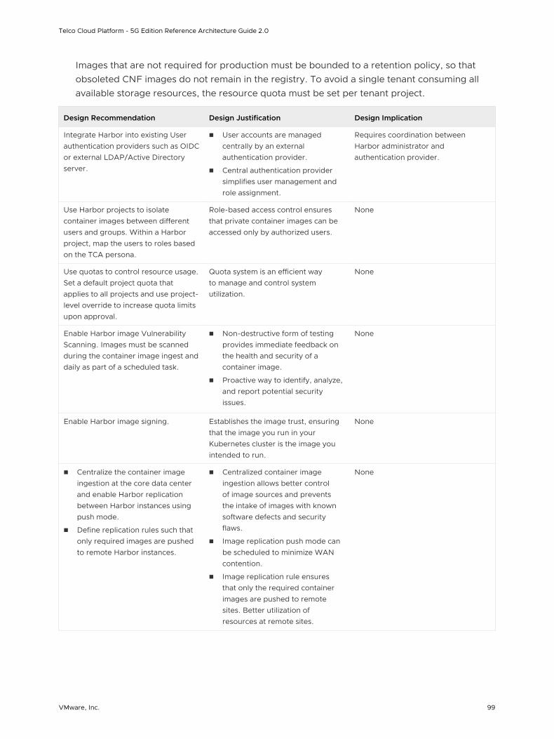
Images that are not required for production must be bounded to a retention policy, so that obsoleted CNF images do not remain in the registry. To avoid a single tenant consuming all available storage resources, the resource quota must be set per tenant project.
Design Recommendation Design Justification Design Implication
Integrate Harbor into existing User authentication providers such as OIDC or external LDAP/Active Directory server.
n User accounts are managed centrally by an external authentication provider.
n Central authentication provider simplifies user management and role assignment.
Requires coordination between Harbor administrator and authentication provider.
Use Harbor projects to isolate container images between different users and groups. Within a Harbor project, map the users to roles based on the TCA persona.
Role-based access control ensures that private container images can be accessed only by authorized users.
None
Use quotas to control resource usage. Set a default project quota that applies to all projects and use project-level override to increase quota limits upon approval.
Quota system is an efficient way to manage and control system utilization.
None
Enable Harbor image Vulnerability Scanning. Images must be scanned during the container image ingest and daily as part of a scheduled task.
n Non-destructive form of testing provides immediate feedback on the health and security of a container image.
n Proactive way to identify, analyze, and report potential security issues.
None
Enable Harbor image signing. Establishes the image trust, ensuring that the image you run in your Kubernetes cluster is the image you intended to run.
None
n Centralize the container image ingestion at the core data center and enable Harbor replication between Harbor instances using push mode.
n Define replication rules such that only required images are pushed to remote Harbor instances.
n Centralized container image ingestion allows better control of image sources and prevents the intake of images with known software defects and security flaws.
n Image replication push mode can be scheduled to minimize WAN contention.
n Image replication rule ensures that only the required container images are pushed to remote sites. Better utilization of resources at remote sites.
None
Telco Cloud Platform - 5G Edition Reference Architecture Guide 2.0
VMware, Inc. 99
CNF Design
This section outlines the CNF requirements and how CNF can be onboarded and instantiated in TCP.
HELM Charts
Helm is the default package manager in Kubernetes, and it is widely leveraged by CNF vendors to simplify container packaging. With Helm charts, dependencies between CNFs are handled in the formats agreed upon by the upstream community; allowing Telco operators to consume CNF packages in a declarative and easy to operate manner. With proper version management, Helm charts also simplify workload updates and inventory control.
Helm repository is a required component in the Telco Cloud Platform. Production CNF Helm charts must be stored centrally and accessible by the Tanzu Standard for Telco Kubernetes clusters. To reduce the number of management endpoints, the Helm repository must work seamlessly with container images. A container registry must be capable of supporting both container image and Helm charts.
CSAR Design
Network Function (NF) Helm charts are uploaded as a catalog offering wrapped around the ETSI-compliant TOSCA YAML (CSAR) descriptor file. The descriptor file includes the structure and composition of the NF and supporting artifacts such as Helm charts version, provider, and set of pre-instantiation jobs. 5GC Network Functions have sets of prerequisite configurations on the underlying Kubernetes cluster. Those requirements are also defined in the Network Function CSAR. The summary of features supported by the CSAR extension is:
n SR-IOV Interface configuration and addition, along with DPDK binding
n NUMA Alignment of vCPUs and Virtual Functions
n Latency Sensitivity
n Custom Operating system package installations
n Full GRUB configuration
The following table outlines those extensions in detail:
Telco Cloud Platform - 5G Edition Reference Architecture Guide 2.0
VMware, Inc. 100
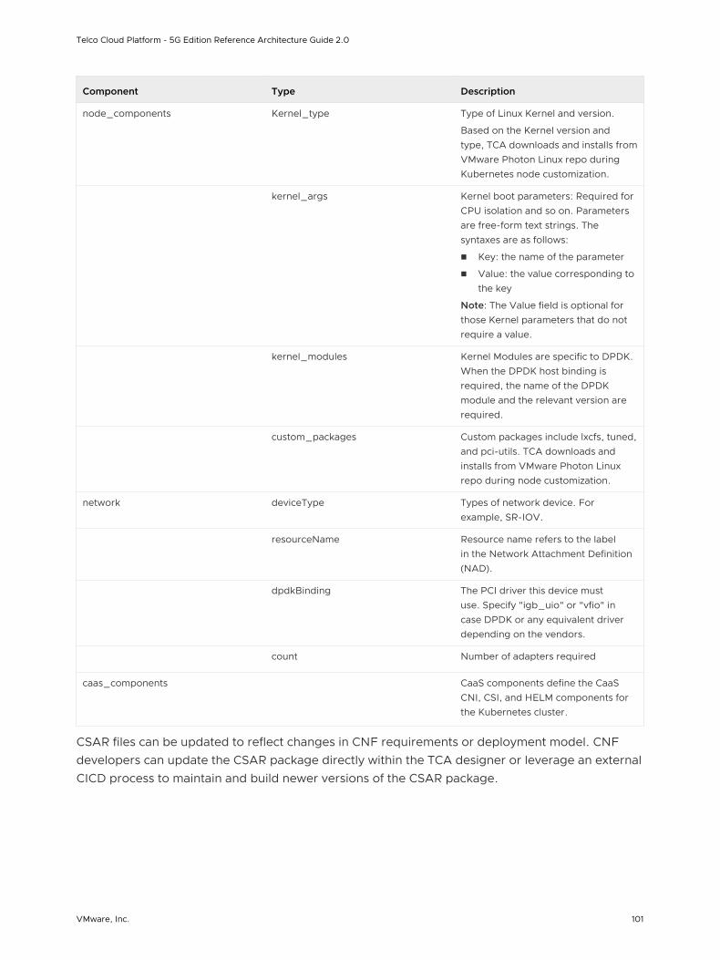
Component Type Description
node_components Kernel_type Type of Linux Kernel and version.
Based on the Kernel version and type, TCA downloads and installs from VMware Photon Linux repo during Kubernetes node customization.
kernel_args Kernel boot parameters: Required for CPU isolation and so on. Parameters are free-form text strings. The syntaxes are as follows:
n Key: the name of the parameter
n Value: the value corresponding to the key
Note: The Value field is optional for those Kernel parameters that do not require a value.
kernel_modules Kernel Modules are specific to DPDK. When the DPDK host binding is required, the name of the DPDK module and the relevant version are required.
custom_packages Custom packages include lxcfs, tuned, and pci-utils. TCA downloads and installs from VMware Photon Linux repo during node customization.
network deviceType Types of network device. For example, SR-IOV.
resourceName Resource name refers to the label in the Network Attachment Definition (NAD).
dpdkBinding The PCI driver this device must use. Specify "igb_uio" or "vfio" in case DPDK or any equivalent driver depending on the vendors.
count Number of adapters required
caas_components CaaS components define the CaaS CNI, CSI, and HELM components for the Kubernetes cluster.
CSAR files can be updated to reflect changes in CNF requirements or deployment model. CNF developers can update the CSAR package directly within the TCA designer or leverage an external CICD process to maintain and build newer versions of the CSAR package.
Telco Cloud Platform - 5G Edition Reference Architecture Guide 2.0
VMware, Inc. 101
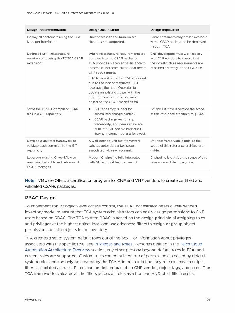
Design Recommendation Design Justification Design Implication
Deploy all containers using the TCA Manager interface.
Direct access to the Kubernetes cluster is not supported.
Some containers may not be available with a CSAR package to be deployed through TCA.
Define all CNF infrastructure requirements using the TOSCA CSAR extension.
When infrastructure requirements are bundled into the CSAR package, TCA provides placement assistance to locate a Kubernetes cluster that meets CNF requirements.
If TCA cannot place the CNF workload due to the lack of resources, TCA leverages the node Operator to update an existing cluster with the required hardware and software based on the CSAR file definition.
CNF developers must work closely with CNF vendors to ensure that the infrastructure requirements are captured correctly in the CSAR file.
Store the TOSCA-compliant CSAR files in a GIT repository.
n GIT repository is ideal for centralized change control.
n CSAR package versioning, traceability, and peer review are built into GIT when a proper git-flow is implemented and followed.
Git and Git-flow is outside the scope of this reference architecture guide.
Develop a unit test framework to validate each commit into the GIT repository.
A well-defined unit test framework catches potential syntax issues associated with each commit.
Unit test framework is outside the scope of this reference architecture guide.
Leverage existing CI workflow to maintain the builds and releases of CSAR Packages.
Modern CI pipeline fully integrates with GIT and unit test framework.
CI pipeline is outside the scope of this reference architecture guide.
Note VMware Offers a certification program for CNF and VNF vendors to create certified and validated CSARs packages.
RBAC Design
To implement robust object-level access control, the TCA Orchestrator offers a well-defined inventory model to ensure that TCA system administrators can easily assign permissions to CNF users based on RBAC. The TCA system RBAC is based on the design principle of assigning roles and privileges at the highest object level and use advanced filters to assign or group object permissions to child objects in the inventory.
TCA creates a set of system default roles out of the box. For information about privileges associated with the specific role, see Privileges and Roles. Personas defined in the Telco Cloud Automation Architecture Overview section, any other persona beyond default roles in TCA, and custom roles are supported. Custom roles can be built on top of permissions exposed by default system roles and can only be created by the TCA Admin. In addition, any role can have multiple filters associated as rules. Filters can be defined based on CNF vendor, object tags, and so on. The TCA framework evaluates all the filters across all rules as a boolean AND of all filter results.
Telco Cloud Platform - 5G Edition Reference Architecture Guide 2.0
VMware, Inc. 102
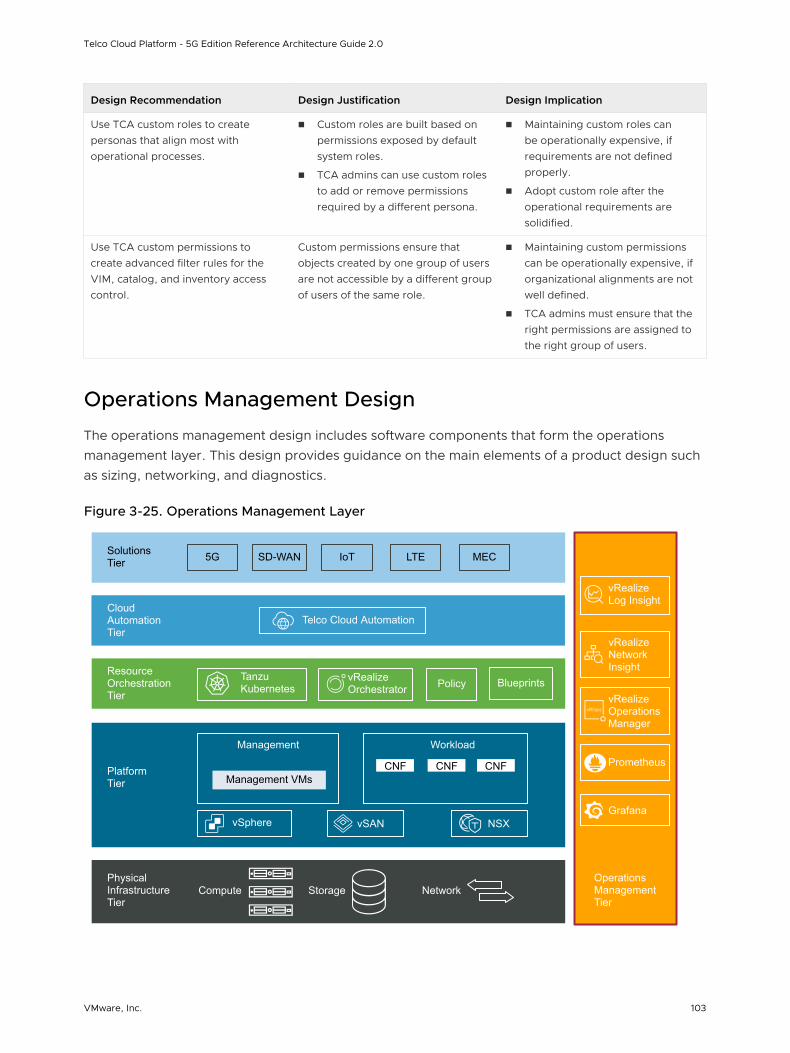
Design Recommendation Design Justification Design Implication
Use TCA custom roles to create personas that align most with operational processes.
n Custom roles are built based on permissions exposed by default system roles.
n TCA admins can use custom roles to add or remove permissions required by a different persona.
n Maintaining custom roles can be operationally expensive, if requirements are not defined properly.
n Adopt custom role after the operational requirements are solidified.
Use TCA custom permissions to create advanced filter rules for the VIM, catalog, and inventory access control.
Custom permissions ensure that objects created by one group of users are not accessible by a different group of users of the same role.
n Maintaining custom permissions can be operationally expensive, if organizational alignments are not well defined.
n TCA admins must ensure that the right permissions are assigned to the right group of users.
Operations Management Design
The operations management design includes software components that form the operations management layer. This design provides guidance on the main elements of a product design such as sizing, networking, and diagnostics.
Figure 3-25. Operations Management Layer
vRealize Orchestrator
Operations Management Tier
Physical Infrastructure Tier
Platform Tier
Resource Orchestration Tier
Cloud Automation Tier
Solutions Tier 5G SD-WAN LTE MECIoT
Telco Cloud Automation
Tanzu Kubernetes Policy Blueprints
Management VMsCNF CNF CNF
Management Workload
vSphere vSAN NSX
vRealize Log Insight
vRealize Network Insight
vRealize Operations Manager
Compute Storage Network
Prometheus
Grafana
Telco Cloud Platform - 5G Edition Reference Architecture Guide 2.0
VMware, Inc. 103
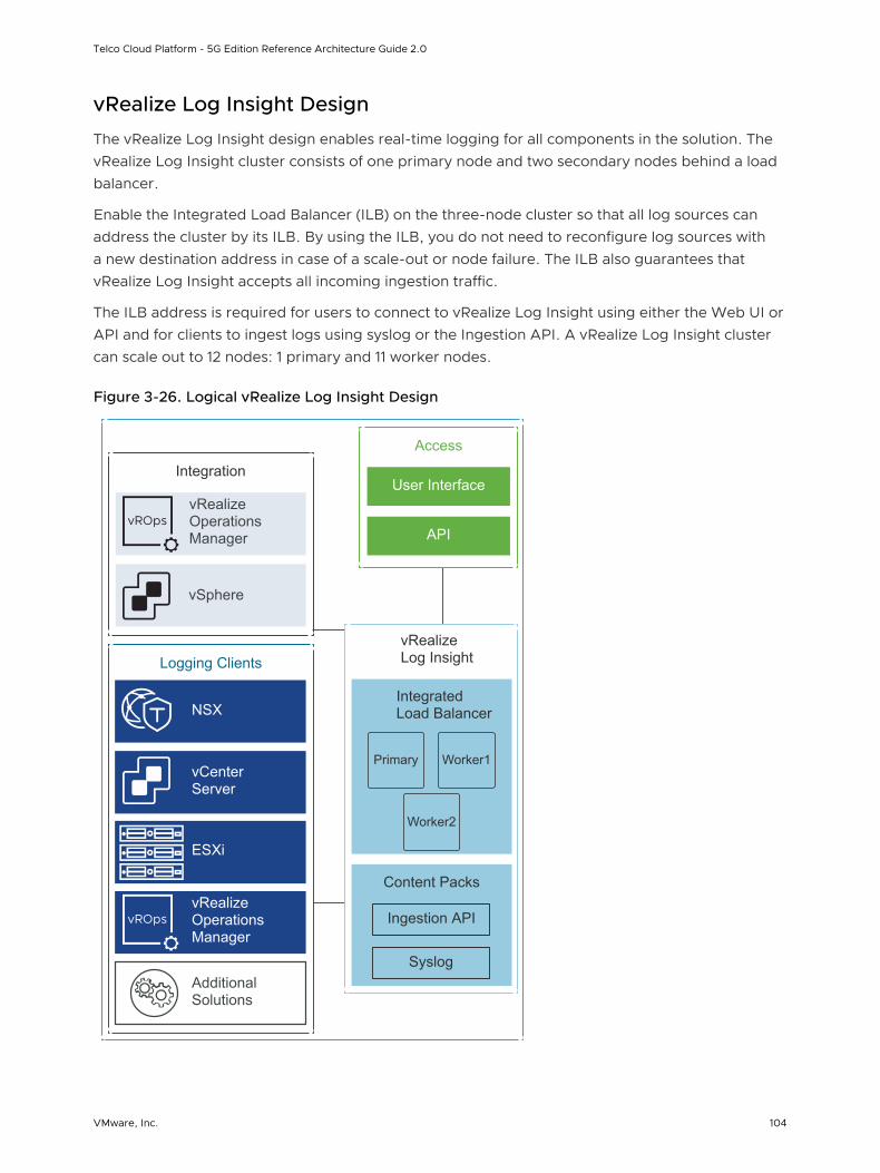
vRealize Log Insight Design
The vRealize Log Insight design enables real-time logging for all components in the solution. The vRealize Log Insight cluster consists of one primary node and two secondary nodes behind a load balancer.
Enable the Integrated Load Balancer (ILB) on the three-node cluster so that all log sources can address the cluster by its ILB. By using the ILB, you do not need to reconfigure log sources with a new destination address in case of a scale-out or node failure. The ILB also guarantees that vRealize Log Insight accepts all incoming ingestion traffic.
The ILB address is required for users to connect to vRealize Log Insight using either the Web UI or API and for clients to ingest logs using syslog or the Ingestion API. A vRealize Log Insight cluster can scale out to 12 nodes: 1 primary and 11 worker nodes.
Figure 3-26. Logical vRealize Log Insight Design
Integrated Load Balancer
Access
User Interface
API
Content Packs
Syslog
Ingestion API
vRealize Log Insight
Primary Worker1
Worker2
Integration
vSphere
vRealize Operations Manager
vRealize Operations Manager
Logging Clients
vCenter Server
ESXi
NSX
Additional Solutions
Telco Cloud Platform - 5G Edition Reference Architecture Guide 2.0
VMware, Inc. 104
To accommodate all log data in the solution, size the compute resources and storage for the Log Insight nodes correctly.
By default, the vRealize Log Insight appliance uses the predefined values for small configurations: 4 vCPUs, 8 GB virtual memory, and 530.5 GB disk space. vRealize Log Insight uses 100 GB disk space to store raw data, index, metadata, and other information.
vRealize Log Insight supports the following alerts that trigger notifications about its health and the monitored solutions:
n System Alerts: vRealize Log Insight generates notifications when an important system event occurs. For example, when the disk space is almost exhausted and vRealize Log Insight must start deleting or archiving old log files.
n Content Pack Alerts: Content packs contain default alerts that can be configured to send notifications. These alerts are specific to the content pack and are disabled by default.
n User-Defined Alerts: Administrators and users can define alerts based on the data ingested by vRealize Log Insight.
Table 3-15. Recommended vRealize Log Insight Design
Design Decision Design Justification Design Implication
Deploy vRealize Log Insight in a cluster configuration of three nodes with an integrated load balancer:
n one primary node
n two worker nodes
n Provides high availability.
n The integrated load balancer:
n Prevents a single point of failure.
n Simplifies the vRealize Log Insight deployment and subsequent integration.
n Simplifies the vRealize Log Insight scale-out operations reducing the need to reconfigure existing logging sources.
n You must deploy a minimum of three medium nodes.
n You must size each node identically.
n If the capacity of your vRealize Log Insight cluster must expand, identical capacity must be added to each node.
Deploy vRealize Log Insight nodes of medium size.
Accommodates the number of expected syslog and vRealize Log Insight Agent connections from the following sources:
n Management and Compute vCenter Servers
n Management and Compute ESXi hosts
n NSX-T Components
n vRealize Operations Manager components
n Telco Cloud Automation
Using medium-size appliances ensures that the storage space for the vRealize Log Insight cluster is sufficient for 7 days of data retention.
If you configure vRealize Log Insight to monitor additional syslog sources, increase the size of the nodes.
Telco Cloud Platform - 5G Edition Reference Architecture Guide 2.0
VMware, Inc. 105
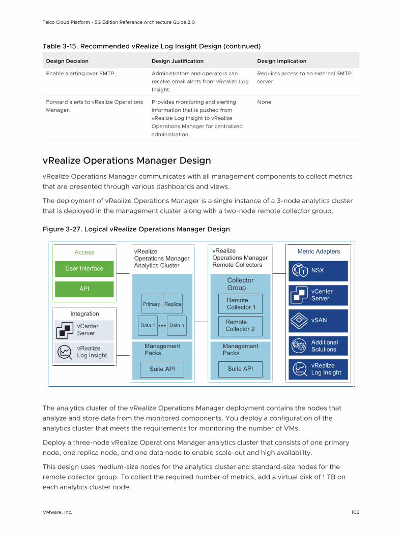
Table 3-15. Recommended vRealize Log Insight Design (continued)
Design Decision Design Justification Design Implication
Enable alerting over SMTP. Administrators and operators can receive email alerts from vRealize Log Insight.
Requires access to an external SMTP server.
Forward alerts to vRealize Operations Manager.
Provides monitoring and alerting information that is pushed from vRealize Log Insight to vRealize Operations Manager for centralized administration.
None
vRealize Operations Manager Design
vRealize Operations Manager communicates with all management components to collect metrics that are presented through various dashboards and views.
The deployment of vRealize Operations Manager is a single instance of a 3-node analytics cluster that is deployed in the management cluster along with a two-node remote collector group.
Figure 3-27. Logical vRealize Operations Manager Design
Access
User Interface
API
Integration
vCenter Server
vRealize Log Insight
vCenter Server
Metric Adapters
vRealize Log Insight
Additional Solutions
NSX
vSAN
vRealize Operations Manager Analytics Cluster
Management Packs
Suite API
Primary Replica
Data 1 Data n
vRealize Operations Manager Remote Collectors
Collector Group
Management Packs
Suite API
Remote Collector 2
Remote Collector 1
The analytics cluster of the vRealize Operations Manager deployment contains the nodes that analyze and store data from the monitored components. You deploy a configuration of the analytics cluster that meets the requirements for monitoring the number of VMs.
Deploy a three-node vRealize Operations Manager analytics cluster that consists of one primary node, one replica node, and one data node to enable scale-out and high availability.
This design uses medium-size nodes for the analytics cluster and standard-size nodes for the remote collector group. To collect the required number of metrics, add a virtual disk of 1 TB on each analytics cluster node.
Telco Cloud Platform - 5G Edition Reference Architecture Guide 2.0
VMware, Inc. 106
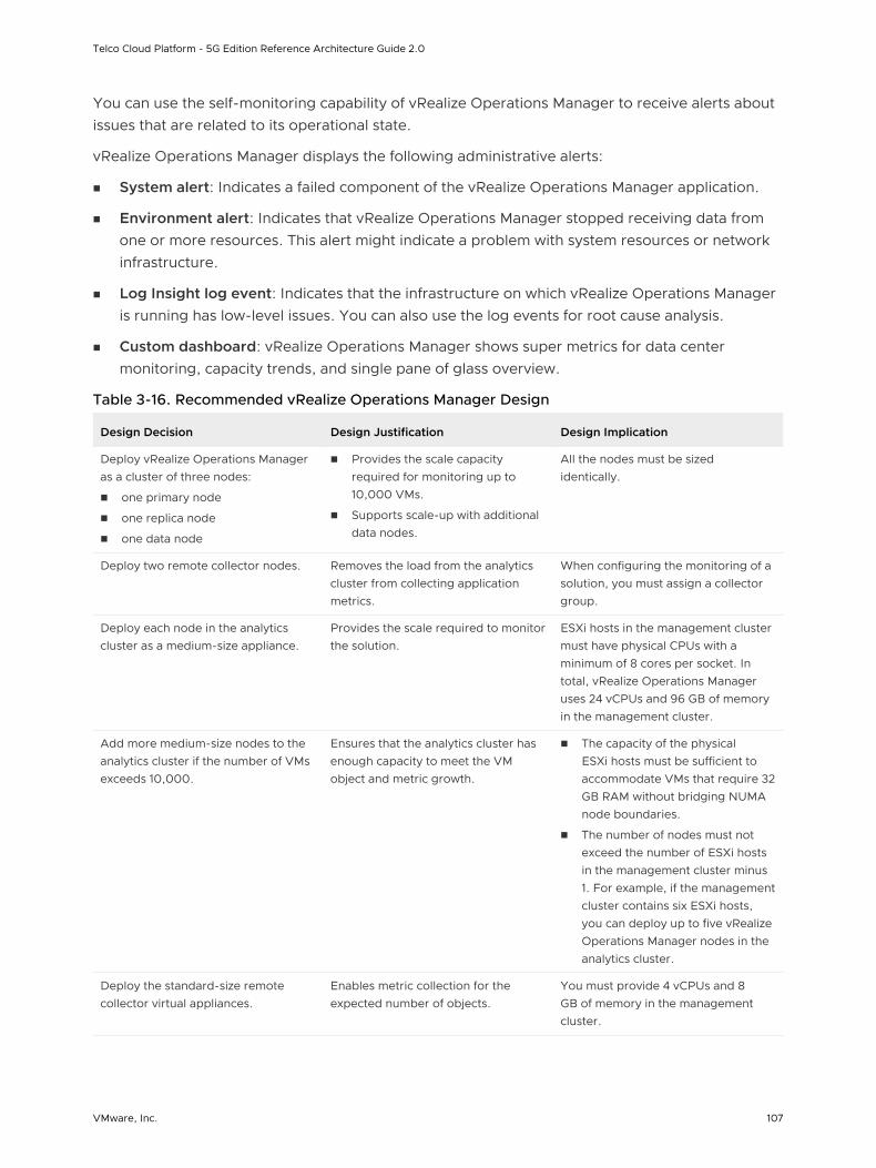
You can use the self-monitoring capability of vRealize Operations Manager to receive alerts about issues that are related to its operational state.
vRealize Operations Manager displays the following administrative alerts:
n System alert: Indicates a failed component of the vRealize Operations Manager application.
n Environment alert: Indicates that vRealize Operations Manager stopped receiving data from one or more resources. This alert might indicate a problem with system resources or network infrastructure.
n Log Insight log event: Indicates that the infrastructure on which vRealize Operations Manager is running has low-level issues. You can also use the log events for root cause analysis.
n Custom dashboard: vRealize Operations Manager shows super metrics for data center monitoring, capacity trends, and single pane of glass overview.
Table 3-16. Recommended vRealize Operations Manager Design
Design Decision Design Justification Design Implication
Deploy vRealize Operations Manager as a cluster of three nodes:
n one primary node
n one replica node
n one data node
n Provides the scale capacity required for monitoring up to 10,000 VMs.
n Supports scale-up with additional data nodes.
All the nodes must be sized identically.
Deploy two remote collector nodes. Removes the load from the analytics cluster from collecting application metrics.
When configuring the monitoring of a solution, you must assign a collector group.
Deploy each node in the analytics cluster as a medium-size appliance.
Provides the scale required to monitor the solution.
ESXi hosts in the management cluster must have physical CPUs with a minimum of 8 cores per socket. In total, vRealize Operations Manager uses 24 vCPUs and 96 GB of memory in the management cluster.
Add more medium-size nodes to the analytics cluster if the number of VMs exceeds 10,000.
Ensures that the analytics cluster has enough capacity to meet the VM object and metric growth.
n The capacity of the physical ESXi hosts must be sufficient to accommodate VMs that require 32 GB RAM without bridging NUMA node boundaries.
n The number of nodes must not exceed the number of ESXi hosts in the management cluster minus 1. For example, if the management cluster contains six ESXi hosts, you can deploy up to five vRealize Operations Manager nodes in the analytics cluster.
Deploy the standard-size remote collector virtual appliances.
Enables metric collection for the expected number of objects.
You must provide 4 vCPUs and 8 GB of memory in the management cluster.
Telco Cloud Platform - 5G Edition Reference Architecture Guide 2.0
VMware, Inc. 107
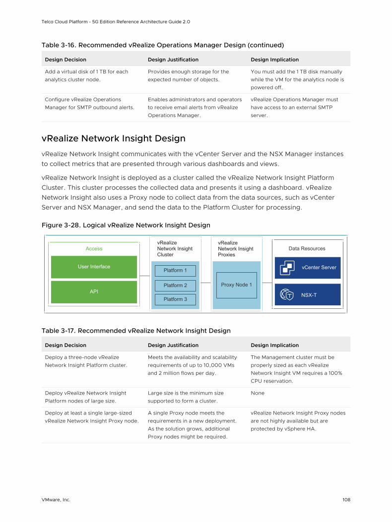
Table 3-16. Recommended vRealize Operations Manager Design (continued)
Design Decision Design Justification Design Implication
Add a virtual disk of 1 TB for each analytics cluster node.
Provides enough storage for the expected number of objects.
You must add the 1 TB disk manually while the VM for the analytics node is powered off.
Configure vRealize Operations Manager for SMTP outbound alerts.
Enables administrators and operators to receive email alerts from vRealize Operations Manager.
vRealize Operations Manager must have access to an external SMTP server.
vRealize Network Insight Design
vRealize Network Insight communicates with the vCenter Server and the NSX Manager instances to collect metrics that are presented through various dashboards and views.
vRealize Network Insight is deployed as a cluster called the vRealize Network Insight Platform Cluster. This cluster processes the collected data and presents it using a dashboard. vRealize Network Insight also uses a Proxy node to collect data from the data sources, such as vCenter Server and NSX Manager, and send the data to the Platform Cluster for processing.
Figure 3-28. Logical vRealize Network Insight Design
Access
User Interface
APINSX-T
Data Resources
vCenter ServerPlatform 1
Platform 2
Platform 3
vRealize Network Insight Cluster
Proxy Node 1
vRealize Network Insight Proxies
Table 3-17. Recommended vRealize Network Insight Design
Design Decision Design Justification Design Implication
Deploy a three-node vRealize Network Insight Platform cluster.
Meets the availability and scalability requirements of up to 10,000 VMs and 2 million flows per day.
The Management cluster must be properly sized as each vRealize Network Insight VM requires a 100% CPU reservation.
Deploy vRealize Network Insight Platform nodes of large size.
Large size is the minimum size supported to form a cluster.
None
Deploy at least a single large-sized vRealize Network Insight Proxy node.
A single Proxy node meets the requirements in a new deployment. As the solution grows, additional Proxy nodes might be required.
vRealize Network Insight Proxy nodes are not highly available but are protected by vSphere HA.
Telco Cloud Platform - 5G Edition Reference Architecture Guide 2.0
VMware, Inc. 108