technology focus electronics/computers - nasa · pdf filetechnology focus...
TRANSCRIPT

Technology Focus
Electronics/Computers
Software
Materials
Mechanics
Machinery/Automation
Manufacturing
Bio-Medical
Physical Sciences
Information Sciences
Books and Reports
05-05 May 2005
https://ntrs.nasa.gov/search.jsp?R=20110014878 2018-05-22T08:13:46+00:00Z


NASA Tech Briefs, May 2005 1
INTRODUCTIONTech Briefs are short announcements of innovations originating from research and develop-
ment activities of the National Aeronautics and Space Administration. They emphasizeinformation considered likely to be transferable across industrial, regional, or disciplinary linesand are issued to encourage commercial application.
Availability of NASA Tech Briefs and TSPsRequests for individual Tech Briefs or for Technical Support Packages (TSPs) announced herein shouldbe addressed to
National Technology Transfer CenterTelephone No. (800) 678-6882 or via World Wide Web at www2.nttc.edu/leads/
Please reference the control numbers appearing at the end of each Tech Brief. Information on NASA’s Commercial Technology Team, its documents, and services is also available at the same facility or on the World Wide Web at www.nctn.hq.nasa.gov.
Innovative Partnerships Offices are located at NASA field centers to provide technology-transfer access toindustrial users. Inquiries can be made by contacting NASA field centers and Mission Directorates listed below.
Ames Research CenterLisa L. Lockyer(650) [email protected]
Dryden Flight Research CenterGregory Poteat(661) [email protected]
Goddard Space Flight CenterNona Cheeks(301) [email protected]
Jet Propulsion LaboratoryKen Wolfenbarger(818) [email protected]
Johnson Space CenterHelen Lane(713) [email protected]
Kennedy Space CenterJim Aliberti(321) [email protected]
Langley Research CenterRay P. Turcotte(757) [email protected]
John H. Glenn Research Center atLewis FieldRobert Lawrence(216) [email protected]
Marshall Space Flight CenterVernotto McMillan(256) [email protected]
Stennis Space CenterJohn Bailey(228) 688-1660 [email protected]
Carl RaySmall Business Innovation Research Program (SBIR) &Small Business TechnologyTransfer Program (STTR)(202) [email protected]
Frank SchowengerdtInnovative Partnerships Program(Code TD)(202) [email protected]
John MankinsExploration Systems Researchand Technology Division(202) [email protected]
Terry HertzAeronautics and Space MissionDirectorate(202) [email protected]
Glen MucklowMission and Systems Management Division (SMD)(202) [email protected]
Granville PaulesMission and Systems Management Division (SMD)(202) [email protected]
Gene TrinhHuman Systems Research andTechnology Division (ESMD)(202) [email protected]
John RushSpace Communications Office(SOMD)(202) [email protected]
NASA Field Centers and Program Offices
NNAASSAA MMiissssiioonn DDiirreeccttoorraatteess
At NASA Headquarters there are four Mission Directorates underwhich there are seven major program offices that develop andoversee technology projects of potential interest to industry:


5 Technology Focus:Fastening/Joining
5 Fastener Starter
5 Multifunctional Deployment HingesRigidified by Ultraviolet
6 Temperature-Controlled Clamping andReleasing Mechanism
7 Electronics/Computers7 Long-Range Emergency Preemption of
Traffic Lights
7 High-Efficiency Microwave Power Amplifier
8 Improvements of ModalMax High-FidelityPiezoelectric Audio Device
8 Alumina or Semiconductor RibbonWaveguides at 30 to 1,000 GHz
9 HEMT Frequency Doubler With Output at 300 GHz
10 Single-Chip FPGA Azimuth Pre-Filter for SAR
13 Software13 Autonomous Navigation by a Mobile Robot
13 Software Would Largely Automate Designof Kalman Filter
13 Predicting Flows of Rarefied Gases
13 Centralized Planning for MultipleExploratory Robots
13 Electronic Router
15 Mechanics15 Piezo-Operated Shutter Mechanism Moves
1.5 cm
16 Two SMA-Actuated Miniature Mechanisms
19 Machinery/Automation19 Vortobots
20 Ultrasonic/Sonic Jackhammer
21 Bio-Medical21 Removing Pathogens Using Nano-Ceramic-
Fiber Filters
21 Satellite-Derived Management Zones
23 Physical Sciences23 Digital Equivalent Data System for XRF
Labeling of Objects
24 Identifying Objects via Encased X-Ray-Fluorescent Materials — the Bar Code Inside
25 Vacuum Attachment for XRF Scanner
26 Simultaneous Conoscopic Holography andRaman Spectroscopy
27 Adding GaAs Monolayers to InAs Quantum-Dot Lasers on (001) InP
28 Vibrating Optical Fibers To Make LaserSpeckle Disappear
29 Information Sciences29 Adaptive Filtering Using Recurrent Neural
Networks
30 Applying Standard Interfaces to a Process-Control Language
05-05 May 2005
NASA Tech Briefs, May 2005 3
This document was prepared under the sponsorship of the National Aeronautics and Space Administration. Neither the United States Govern-ment nor any person acting on behalf of the United States Government assumes any liability resulting from the use of the information containedin this document, or warrants that such use will be free from privately owned rights.


NASA Tech Briefs, May 2005 5
The Fastener Starter is a creative solu-tion to prevent the loss of small fasten-ers during their installation. This is theonly currently available tool that canfirmly grip and hold a single screw, bolt,nut, washer, spacer, or any combinationof these parts. Other commercially avail-able fastener starters are unable to ac-commodate a variety of parts simultane-ously. The Fastener Starter is a morecapable and easier tool to use than priortools. Its compact size allows it to beused effectively in cramped, difficult-to-see locations. Its design also allows it tobe used with or without handles and ex-tenders in other difficult-to-reach loca-tions. It provides better protectionagainst cross threading and loss of fas-teners and associated parts. The Fas-tener Starter is non-magnetic and doesnot off-gas, thus meeting flight hard-ware requirements.
The Fastener Starter incorporates acombination of features of several com-mercially available tools, providing animproved means of installing small fas-teners. The Fastener Starter includes acustom molded insert that can be re-moved easily and replaced with a con-
ventional tool bit (e.g., a screwdriver orhex-driver bit). When used with the in-sert, the Fastener Starter prevents crossthreading and damage to internalthreaded holes. This is achieved by al-lowing the fastener to slip within thetool insert when used without a conven-tional tool bit. Alternatively, without theinsert and with a tool bit, the FastenerStarter can torque a fastener. The Fas-tener Starter has a square recess holethat accepts a conventional square drivehandle or extension to accommodate avariety of applications by providing flex-ibility in handle style and length.
In a typical operation sequence, theuser opens the tool, places a screw,screw/washer combination, nut, ornut/washer combination against andwithin the insert (or tool bit), andcloses the tool, which firmly grasps thehardware. The user then guides the fas-tener to its destination and turns thetool to attach the fastener. Once the fas-tener is attached, the user simply pullsback on the tool to open it and releasethe fastener.
In tests that involved the installationof more than 300 screws and washers, in
several orientations and at different dis-tances from the users, the tool did notdrop any parts. In addition, most of theusers participating in the tests expressedtheir preference to use this tool ratherthan only their hands to start a fastenerinstallation.
This work was done by Faith Chandler,Harry Garton, Bill Valentino, and MikeAmett of The Boeing Company for KennedySpace Center.
Title to this invention, covered by U.S.Patent No. 6,606,924, has been waivedunder the provisions of the National Aero-nautics and Space Act {42 U.S.C. 2457(f)},to The Boeing Company. Inquiries concern-ing licenses for its commercial developmentshould be addressed to:
Terrance Mason, Boeing Patent LicensingProfessionalBoeing Management Co. Mail Stop 1650-700215460 Laguna Canyon RoadIrvine, CA 92618Phone No.: (949) 790-1331E-mail: [email protected] to KSC-12224, volume and number
of this NASA Tech Briefs issue, and thepage number.
Technology Focus: Fastening/Joining
Fastener StarterThis tool is superior to prior screw and nut starters.John F. Kennedy Space Center, Florida
Multifunctional hinges have been de-veloped for deploying and electricallyconnecting panels comprising planararrays of thin-film solar photovoltaiccells. In the original intended applica-tion of these hinges, the panels wouldbe facets of a 32-sided (and approxi-mately spherical) polyhedral mi-crosatellite (see figure), denoted a Pow-erSphere, that would be delivered toorbit in a compact folded configura-tion, then deployed by expansion of gasin inflation bladders. Once deploymentwas complete, the hinges would be
rigidified to provide structural connec-tions that would hold the panels intheir assigned relative positions withoutbacklash. Such hinges could also beused on Earth for electrically connect-ing and structurally supporting solarpanels that are similarly shipped incompact form and deployed at theirdestinations.
As shown in section A-A in the fig-ure, a hinge of this type is partly inte-grated with an inflation bladder andpartly integrated with the frame of asolar panel. During assembly of the
hinge, strip extensions from a flexiblecircuit harness on the bladder are con-nected to corresponding thin-filmconductors on the solar panel by useof laser welding and wrap-around con-tacts. The main structural componentof the hinge is a layer of glass fiber im-pregnated with an ultraviolet-curableresin. After deployment, exposure toultraviolet light from the Sun curesthe resin, thereby rigidifying thehinge. 1. In the original intended satellite ap-
plication, it would protect the under-
Multifunctional Deployment Hinges Rigidified by UltravioletThese hinges provide both structural support and electrical connections. John H. Glenn Research Center, Cleveland, Ohio

6 NASA Tech Briefs, May 2005
lying polymeric components againsterosion by monatomic oxygen in loworbit around the Earth;
2. It is sufficiently ultraviolet-transmis-sive to enable curing of the resin byexposure to ultraviolet light from theSun or another suitable source;
3. It exhibits improved (relative to priorcoating materials) transmittance of visi-ble light for collection by solar cells; and
4. It resists darkening under long-termexposure to ultraviolet light. This work was done by Thomas W. Ker-
slake of Glenn Research Center; Ed-ward J. Simburger, James Matusmoto,Thomas W. Giants, and Alexander Garciaof The Aerospace Corporation; Alan Perry,Suraj Rawal, and Craig Marshall of Lock-heed Martin Corp.; and John Kun HungLin, Jonathan Robert Day, and Stephen
Emerson Scarborough of ILC Dover, Inc.Further information is contained in a TSP(see page 1).
Inquiries concerning rights for the com-mercial use of this invention should be ad-dressed to NASA Glenn Research Center,Commercial Technology Office, Attn: SteveFedor, Mail Stop 4-8, 21000 BrookparkRoad, Cleveland, Ohio 44135. Refer toLEW-17476-1.
A Polyhedral Assembly of Solar Panels would be deployed from compact stowage in two stacks, each containing ten hexagonal and six pentagonal pan-els. The deployment hinges between the panels would be key components that would accommodate the unfolding during deployment, hold the panels intheir proper alignments after deployment, and provide electrical connections for the panels.
Wrap-Around Contact
Thin-FilmSolar Cell
Section A-A
Deployed
Packed
Laser WeldFlexible
Conductor
Indium Tin Oxide/Magnesium Fluoride Coating
Indium Tin Oxide/Magnesium Fluoride
Coating
Bladder
AAAA
Hinge
Solar Panel
Fiberglass CompositeFrame of Solar Panel
LEW-17476ABPI
12-16-03 bs
Gas-FilledInflation Bladder
Temperature-Controlled Clamping and Releasing MechanismNASA’s Jet Propulsion Laboratory, Pasadena, California
A report describes the developmentof a mechanism that automaticallyclamps upon warming and releasesupon cooling between temperaturelimits of ≈180 K and ≈293 K. Themechanism satisfied a need specific toa program that involved repeated ex-cursions of a spectrometer between aroom-temperature atmospheric envi-ronment and a cryogenic vacuum test-ing environment. The mechanism wasalso to be utilized in the intended ap-plication of the spectrometer, in which
the spectrometer would be clampedfor protection during launch of aspacecraft and released in the cold ofouter space to allow it to assume itsnominal configuration for scientificobservations. The mechanism is pas-sive in the sense that its operationdoes not depend on a control systemand does not require any power otherthan that incidental to heating andcooling. The clamping and releasingaction is effected by bolt-preloadedstacks of shape-memory-alloy (SMA)
cylinders. In designing this mecha-nism, as in designing other, similarSMA mechanisms, it was necessary toaccount for the complex interplayamong thermal expansion, elastic andinelastic deformation under load, andSMA thermomechanical properties.
This work was done by David Rosing andVirginia Ford of Caltech for NASA’s JetPropulsion Laboratory. Further informationis contained in a TSP (see page 1). Further in-formation is contained in a TSP (see page 1).NPO-40541

NASA Tech Briefs, May 2005 7
Electronics/Computers
High-Efficiency Microwave Power AmplifierHigh efficiency is achieved through class-D operation.Marshall Space Flight Center, Alabama
A high-efficiency power amplifier thatoperates in the S band (frequencies ofthe order of a few gigahertz) utilizestransistors operating under class-D biasand excitation conditions. Class-D oper-ation has been utilized at lower frequen-cies, but, until now, has not been ex-ploited in the S band.
Nominally, in class D operation, atransistor is switched rapidly between“on” and “off” states so that at any giveninstant, it sustains either high current orhigh voltage, but not both at the sametime. In the ideal case of zero “on” resist-ance, infinite “off” resistance, zero in-ductance and capacitance, and perfectswitching, the output signal would be aperfect square wave. Relative to the tra-ditional classes A, B, and C of amplifieroperation, class D offers the potential toachieve greater power efficiency. In addi-tion, relative to class-A amplifiers, class-D
The Output Waveform of the amplifier is of an intermediate form achieved in an effort to obtain asquare-wave output from a sinusoidal input.
0.0–2.0
–1.0
0.0
1.0
2.0
0.1 0.2Time, ns
Inp
ut
or
Ou
tpu
t V
olt
age,
Arb
itra
ry U
nit
s
0.3 0.4 0.5
Output
Input
MFS31455
9-6-02 bs
Long-Range Emergency Preemption of Traffic LightsAddition of a forwarding system could improve preemption performance.NASA’s Jet Propulsion Laboratory, Pasadena, California
A forwarding system could prove ben-eficial as an addition to an electroniccommunication-and-control system thatautomatically modifies the switching oftraffic lights to give priority to emer-gency vehicles. A system to which the for-warding system could be added could be any of a variety of emergency traffic-signal-preemption systems: these include systems now used in some mu-nicipalities as well as advanced develop-mental systems described in severalNASA Tech Briefs articles in recent years.
Because of a variety of physical and de-sign limitations, emergency traffic-sig-nal-preemption systems now in use areoften limited in range to only one inter-section at a time: in a typical system, onlythe next, closest intersection is pre-empted for an emergency vehicle. Sim-ulations of gridlock have shown thatsuch systems offer minimal advantagesand can even cause additional delays.
In analogy to what happens in fluid dy-namics, the forwarding system insures thatflow at a given location is sustained byguaranteeing downstream flow along thepredicted route (typically a main artery)and intersecting routes (typically, sidestreets). In simplest terms, the forwardingsystem starts by taking note of any preemp-tion issued by the preemption system towhich it has been added. The forwardingsystem predicts which other intersectionscould be encountered by the emergencyvehicle downstream of the newly pre-empted intersection. The system then for-wards preemption triggers to those inter-sections.
Beyond affording a right of way for theemergency vehicle at every intersectionthat lies ahead along any likely routefrom the current position of the vehicle,the forwarding system also affords thebenefit of clearing congested roads farahead of the vehicle. In a metropolitan
environment with heavy road traffic, for-warding of preemption triggers couldgreatly enhance the performance of apre-existing preemption system.
This work was done by Aaron Bachelder ofCaltech for NASA’s Jet Propulsion Labora-tory. Further information is contained in aTSP (see page 1).
In accordance with Public Law 96-517,the contractor has elected to retain title to thisinvention. Inquiries concerning rights for itscommercial use should be addressed to:
Innovative Technology Assets ManagementJPLMail Stop 202-2334800 Oak Grove DrivePasadena, CA 91109-8099(818) 354-2240E-mail: [email protected] to NPO-40492, volume and number
of this NASA Tech Briefs issue, and thepage number.

8 NASA Tech Briefs, May 2005
amplifiers are less likely to go into oscil-lation.
In order to design this amplifier, itwas necessary to derive mathematicalmodels of microwave power transistorsfor incorporation into a larger mathe-
matical model for computational simu-lation of the operation of a class-Dmicrowave amplifier. The design incor-porates state-of-the-art switching tech-niques applicable only in the microwavefrequency range. Another major novel
feature is a transmission-line power split-ter/combiner designed with the help ofphasing techniques to enable an ap-proximation of a square-wave signal(which is inherently a wideband signal)to propagate through what would, if de-signed in a more traditional manner, be-have as a more severely band-limited de-vice (see figure).
The amplifier includes an input, adriver, and a final stage. Each stage con-tains a pair of GaAs-based field-effecttransistors biased in class D. The inputsignal can range from –10 to +10 dBminto a 50-ohm load. The table summa-rizes the performances of the threestages.
This work was done by William H. Sims ofMarshall Space Flight Center.
This invention has been patented by NASA(U.S. Patent No.6,388,512). Inquiries con-cerning nonexclusive or exclusive license forits commercial development should be ad-dressed to Sammy Nabors, MSFC Commer-cialization Assistance Lead, at (256) 544-5226 or [email protected]. Refer toMFS-31455.
Several Measurements were made on each amplifier stage to characterize its performance.
Measurement
Input VoltageStanding-WaveRatio
Gain, dB
DC-to-RFEfficiency, Percent
Power-AddedEfficiency, Percent
Input Stage
1.0023:1
13.3
54.2
51.7
Driver Stage
1.9:1
8.8
42.6
36.9
Final Stage
33:1
9.6
58.6
52.2
MFS31455 Table
9-6-02 bs
Improvements of ModalMax High-Fidelity Piezoelectric Audio DeviceLangley Research Center, Hampton, Virginia
ModalMax audio speakers have beenenhanced by innovative means of tailor-ing the vibration response of thin piezo-electric plates to produce a high-fidelityaudio response. The ModalMax audiospeakers are 1 mm in thickness. The de-vice completely supplants the need tohave a separate driver and speakercone. ModalMax speakers can performthe same applications of cone speakers,but unlike cone speakers, ModalMaxspeakers can function in harsh environ-
ments such as high humidity or ex-treme wetness. New design featuresallow the speakers to be completely sub-mersed in salt water, making them wellsuited for maritime applications. Thesound produced from the ModalMaxaudio speakers has sound spatial resolu-tion that is readily discernable for head-set users. [The ModalMax product linewas described in “High-Fidelity Piezo-electric Audio Device” (LAR-15959),NASA Tech Briefs, Vol. 27, No. 8 (August
2003), page 36.] Other improvementsof the ModalMax audio speakers in-clude methods to reduce size, reducepower demand, and increase audio fi-delity by increasing vibrational re-sponses at the low and high ends of theaudio frequency range.
This work was done by Stanley E. Woodard ofLangley Research Center. Further informa-tion is contained in a TSP (see page 1).LAR-16321-1
Alumina or Semiconductor Ribbon Waveguides at 30 to 1,000 GHzThe waveguides would be configured to exploit low-loss electromagnetic modes.NASA’s Jet Propulsion Laboratory, Pasadena, California
Ribbon waveguides made of aluminaor of semiconductors (Si, InP, or GaAs)have been proposed as low-loss trans-mission lines for coupling electroniccomponents and circuits that operate atfrequencies from 30 to 1,000 GHz. Inaddition to low losses (and a concomi-
tant ability to withstand power levelshigher than would otherwise be possi-ble), the proposed ribbon waveguideswould offer the advantage of compati-bility with the materials and structuresnow commonly incorporated into inte-grated circuits.
Heretofore, low-loss transmissionlines for this frequency range have beenunknown, making it necessary to resortto designs that, variously, place circuitsand components to be coupled in prox-imity of each other and/or provide forcoupling via free space through bulky

and often lossy optical elements. Evenchip-to-chip interconnections have beenproblematic in this frequency range.Metal wave-guiding structures (e.g., mi-crostriplines and traditional wave-guides) are not suitable for this fre-quency range because the skin depths ofelectromagnetic waves in this frequencyrange are so small as to give rise to highlosses. Conventional rod-type dielectricwaveguide structures are also not suit-able for this frequency range because di-electric materials, including ones thatexhibit ultralow losses at lower frequen-cies, exhibit significant losses in this fre-quency range.
Unlike microstripline structures ormetallic waveguides, the proposed rib-bon waveguides would be free of metaland would therefore not be subject toskin-depth losses. Moreover, althoughthey would be made of materials that aremoderately lossy in the frequency rangeof interest, the proposed ribbon wave-guides would cause the propagating elec-tromagnetic waves to configure them-selves in a manner that minimizes losses.
The basic principle for minimizinglosses was described in “Ceramic Rib-bons as Waveguides at Millimeter Wave-lengths” (NPO-21001), NASA Tech Briefs,Vol. 25, No. 4 (April 2001), page 49. To
recapitulate: The cross-sectional geome-try of a waveguide ribbon would be cho-sen in consideration of the permittivityof the ribbon material to support anelectromagnetic mode in which most ofthe energy would propagate, parallel tothe ribbon, through the adjacent freespace and only a small fraction wouldpropagate within the ribbon. As a result,the interaction of the propagating wavewith the dielectric core (and thus the at-tenuation) would be minimal.
For straight runs, the ribbon waveguideswould be uncoated. However, since mostof the guided power would be carried inthe nearly lossless air just outside the rib-bon, a significant portion of the guidedpower could be expected to be radiated(and thus lost) where the guiding ribbonwas sharply curved (for example, to bendit around a corner). In such a case, theshort length of the ribbon containing thecurve could be coated with a layer of apolymer having a suitable permittivity in-termediate between that of air and that ofthe ribbon, so that most of the powerwould not be radiated but would remainconfined within the polymer layer (see fig-ure) while propagating around the corner.
This work was done by Cavour Yeh, DanielRascoe, Fred Shimabukuro, Michael Tope, andPeter Siegel of Caltech for NASA’s Jet Propul-sion Laboratory. Further information is con-tained in a TSP (see page 1)..
In accordance with Public Law 96-517, thecontractor has elected to retain title to this in-vention. Inquiries concerning rights for itscommercial use should be addressed to:
Innovative Technology Assets ManagementJPL Mail Stop 202-2334800 Oak Grove DrivePasadena, CA 91109-8099(818) 354-2240E-mail: [email protected] to NPO-30339, volume and number
of this NASA Tech Briefs issue, and thepage number.
NASA Tech Briefs, May 2005 9
Normalized Power Densities were computed for a dominant eHE11 mode on a ribbon waveguide madeof alumina (having assumed relative permittivity of 10), both uncoated and coated with various thick-nesses polytetrafluoroethylene (having assumed relative permittivity of 2.06). The unit of thicknessused in the computations was the free-space wavelength, λ0.
NPO-30339ABPI
9-10-03 es
00
0.2
0.4
0.6
0.8
1.0
1.2
0.1λ0 0.2λ0 0.3λ0 0.4λ0 0.5λ0 0.6λ0
y
No
rmal
ized
Po
wer
Dis
trib
uti
on
λ0= 1 cmε1 = 10.0ε2 = 2.06ε0 = 1.0
t = 0
t = 0.225λ0t = 0.075λ0
Alumina
AluminaThickness
0.062λ0
Polytetrafluoroethylene
PolytetrafluoroethyleneThickness t
y
x
ε0
ε0
ε1
ε2
ε2
HEMT Frequency Doubler With Output at 300 GHzThis is the highest-frequency HEMT doubler reported to date.NASA’s Jet Propulsion Laboratory, Pasadena, California
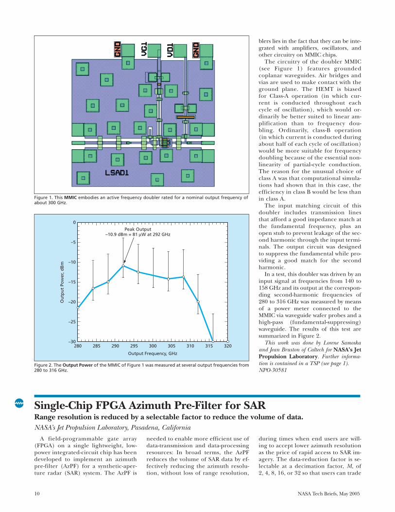
An active frequency doubler in theform of an InP-based monolithic mi-crowave integrated circuit (MMIC) con-taining a high-electron-mobility transis-tor (HEMT) has been demonstrated inoperation at output frequencies in thevicinity of 300 GHz. This is the highest-
frequency HEMT doubler reported todate, the next-highest-frequency activeHEMT doubler having been previouslyreported to operate at 180 GHz. Whilethe output power of this frequency dou-bler is less than that of a typical Schottkydiode, this frequency doubler is consid-
ered an intermediate product of a con-tinuing effort to realize the potential ofactive HEMT frequency doublers to op-erate with conversion efficiencies greaterthan those of passive diode frequencydoublers. An additional incentive for de-veloping active HEMT frequency dou-
10 NASA Tech Briefs, May 2005
Figure 1. This MMIC embodies an active frequency doubler rated for a nominal output frequency ofabout 300 GHz.
Figure 2. The Output Power of the MMIC of Figure 1 was measured at several output frequencies from280 to 316 GHz.
0
–5
–10
–15
–20
–25
–30280 285 290 295 300
Output Frequency, GHz
Ou
tpu
t Po
wer
, dB
m
305 310 315 320
Peak Output–10.9 dBm = 81 µW at 292 GHz
NPO-30581 fig. 1ABPI
4-26-04 cc
blers lies in the fact that they can be inte-grated with amplifiers, oscillators, andother circuitry on MMIC chips.
The circuitry of the doubler MMIC(see Figure 1) features groundedcoplanar waveguides. Air bridges andvias are used to make contact with theground plane. The HEMT is biasedfor Class-A operation (in which cur-rent is conducted throughout eachcycle of oscillation), which would or-dinarily be better suited to linear am-plification than to frequency dou-bling. Ordinarily, class-B operation(in which current is conducted duringabout half of each cycle of oscillation)would be more suitable for frequencydoubling because of the essential non-linearity of partial-cycle conduction.The reason for the unusual choice ofclass A was that computational simula-tions had shown that in this case, theefficiency in class B would be less thanin class A.
The input matching circuit of thisdoubler includes transmission linesthat afford a good impedance match atthe fundamental frequency, plus anopen stub to prevent leakage of the sec-ond harmonic through the input termi-nals. The output circuit was designedto suppress the fundamental while pro-viding a good match for the secondharmonic.
In a test, this doubler was driven by aninput signal at frequencies from 140 to158 GHz and its output at the correspon-ding second-harmonic frequencies of280 to 316 GHz was measured by meansof a power meter connected to theMMIC via waveguide wafer probes and ahigh-pass (fundamental-suppressing)waveguide. The results of this test aresummarized in Figure 2.
This work was done by Lorene Samoskaand Jean Bruston of Caltech for NASA’s JetPropulsion Laboratory. Further informa-tion is contained in a TSP (see page 1).NPO-30581
Single-Chip FPGA Azimuth Pre-Filter for SARRange resolution is reduced by a selectable factor to reduce the volume of data.NASA’s Jet Propulsion Laboratory, Pasadena, California
A field-programmable gate array(FPGA) on a single lightweight, low-power integrated-circuit chip has beendeveloped to implement an azimuthpre-filter (AzPF) for a synthetic-aper-ture radar (SAR) system. The AzPF is
needed to enable more efficient use ofdata-transmission and data-processingresources: In broad terms, the AzPFreduces the volume of SAR data by ef-fectively reducing the azimuth resolu-tion, without loss of range resolution,
during times when end users are will-ing to accept lower azimuth resolutionas the price of rapid access to SAR im-agery. The data-reduction factor is se-lectable at a decimation factor, M, of2, 4, 8, 16, or 32 so that users can trade

NASA Tech Briefs, May 2005 11
resolution against processing andtransmission delays.
In principle, azimuth filtering couldbe performed in the frequency domainby use of fast-Fourier-transform proces-sors. However, in the AzPF, azimuth fil-tering is performed in the time domainby use of finite-impulse-response filters.The reason for choosing the time-do-main approach over the frequency-do-main approach is that the time-domainapproach demands less memory and alower memory-access rate.
The AzPF operates on the raw digi-tized SAR data. The AzPF includes a dig-ital in-phase/quadrature (I/Q) demod-ulator. In general, an I/Q demodulatoreffects a complex down-conversion of itsinput signal followed by low-pass filter-ing, which eliminates undesired side-bands. In the AzPF case, the I/Q de-modulator takes offset video range echodata to the complex baseband domain,ensuring preservation of signal phasethrough the azimuth pre-filteringprocess. In general, in an SAR I/Q de-
modulator, the intermediate frequency(fI) is chosen to be a quarter of therange-sampling frequency and thepulse-repetition frequency (fPR) is cho-sen to be a multiple of fI.
The AzPF also includes a polyphasespatial-domain pre-filter comprisingfour weighted integrate-and-dump fil-ters with programmable decimation fac-tors and overlapping phases. To preventaliasing of signals, the bandwidth of theAzPF is made 80 percent of fPR/M. Thechoice of four as the number of overlap-ping phases is justified by prior researchin which it was shown that a filter oflength 4M can effect an acceptabletransfer function.
The figure depicts prototype hard-ware comprising the AzPF and ancillaryelectronic circuits. The hardware wasfound to satisfy performance require-ments in real-time tests at a samplingrate of 100 MHz.
This work was done by Mimi Gudim,Tsan-Huei Cheng, Soren Madsen, RobertJohnson, Charles T-C Le, Mahta Moghad-dam, and Miguel Marina of Caltech forNASA’s Jet Propulsion Laboratory. Fur-ther information is contained in a TSP (seepage 1).NPO-30741
The Prototype Circuit Board measures 6 by 10 in. (15.2 by 25.4 cm). The AzPF integrated circuit mountedon the board measures only about 2.5 in. (≈6.4 cm) square and consumes a power <1 W. The perform-ance requirements are as follows: (1) Range resolution: No degradation in range resolution; (2) Azimuthresolution: 1/M of original resolution for a single look; (3) Peak to side-lobe ratio (PSLR) after Hammingwindow: -25 dB; and (4) Integrated side-lobe ratio (ISLR) after Hamming window: -15 dB.
Input:Sample (8 bit Offset Video Signal, 8192-Samples Per Line)Sample Clock (100 MHz)First LineLine (Line Interval = 2 kHz PRF)Rest Flag
Output:I, Q interleavedat Sample Rate fs/4
Doppler Correction(To Be Added) Serial Interface:
1. M (Data Volume Reduction) = {1,2,4,8,16,32} (M=1 for By-Pass Mode)2. I/Q Input Through By-Pass Mode3. Doppler Correction (Future, Not in Current Implementation)
Power < 1 watt
NPO-30741 ABPI
04-27-04 LE


NASA Tech Briefs, May 2005 13
Software
Autonomous Navigation by aMobile Robot
ROAMAN is a computer program forautonomous navigation of a mobile roboton a long (as much as hundreds of me-ters) traversal of terrain. Developed for useaboard a robotic vehicle (rover) exploringthe surface of a remote planet, ROAMANcould also be adapted to similar use on ter-restrial mobile robots. ROAMAN imple-ments a combination of algorithms for (1)long-range path planning based on imagesacquired by mast-mounted, wide-baselinestereoscopic cameras, and (2) local pathplanning based on images acquired bybody-mounted, narrow-baseline stereo-scopic cameras. The long-range path-plan-ning algorithm autonomously generates aseries of waypoints that are passed to thelocal path-planning algorithm, whichplans obstacle-avoiding legs between thewaypoints. Both the long- and short-rangealgorithms use an occupancy-grid repre-sentation in computations to detect obsta-cles and plan paths. Maps that are main-tained by the long- and short-rangeportions of the software are not shared be-cause substantial localization errors can ac-cumulate during any long traverse. ROA-MAN is not guaranteed to generate anoptimal shortest path, but does maintainthe safety of the rover.
This program was written by TerranceHuntsberger and Hrand Aghazarian of Cal-tech for NASA’s Jet Propulsion Labora-tory. Further information is contained in aTSP (see page 1).
This software is available for commercial li-censing. Please contact Karina Edmonds ofthe California Institute of Technology at (818)393-2827. Refer to NPO-30532.
Software Would Largely Automate Design of Kalman Filter
Embedded Navigation Filter AutomaticDesigner (ENFAD) is a computer programbeing developed to automate the most dif-ficult tasks in designing embedded soft-ware to implement a Kalman filter in a nav-igation system. The most difficult tasks areselection of error states of the filter andtuning of filter parameters, which are time-consuming trial-and-error tasks that re-quire expertise and rarely yield optimumresults. An optimum selection of errorstates and filter parameters depends onnavigation-sensor and vehicle characteris-
tics, and on filter processing time. ENFADwould include a simulation module thatwould incorporate all possible error stateswith respect to a given set of vehicle andsensor characteristics. The first of two itera-tive optimization loops would vary the se-lection of error states until the best filterperformance was achieved in Monte Carlosimulations. For a fixed selection of errorstates, the second loop would vary the filterparameter values until an optimal perform-ance value was obtained. Design con-straints would be satisfied in the optimiza-tion loops. Users would supply vehicle andsensor test data that would be used to re-fine digital models in ENFAD. Filter pro-cessing time and filter accuracy would becomputed by ENFAD.
This program was written by Jason C. H.Chuang of Marshall Space Flight Centerand William J. Negast, formerly of Gray Re-search, Inc. Further information is containedin a TSP (see page 1). MFS-31967-1
Predicting Flows of Rarefied Gases
DSMC Analysis Code (DAC) is a flexible,highly automated, easy-to-use computerprogram for predicting flows of rarefiedgases — especially flows of upper-atmos-pheric, propulsion, and vented gases im-pinging on spacecraft surfaces. DAC imple-ments the direct simulation Monte Carlo(DSMC) method, which is widely recog-nized as standard for simulating flows atdensities so low that the continuum-basedequations of computational fluid dynamicsare invalid. DAC enables users to modelcomplex surface shapes and boundary con-ditions quickly and easily. The discretiza-tion of a flow field into computational gridsis automated, thereby relieving the user ofa traditionally time-consuming task whileensuring (1) appropriate refinement ofgrids throughout the computational do-main, (2) determination of optimal set-tings for temporal discretization and othersimulation parameters, and (3) satisfactionof the fundamental constraints of themethod. In so doing, DAC ensures an accu-rate and efficient simulation. In addition,DAC can utilize parallel processing to re-duce computation time. The domain de-composition needed for parallel process-ing is completely automated, and thesoftware employs a dynamic load-balancingmechanism to ensure optimal parallel effi-ciency throughout the simulation.
This work was done by Gerald J. LeBeau ofJohnson Space Center and Richard G.Wilmoth of Langley Research Center. For fur-ther information, contact the Johnson Innov-ative Partnerships Office at (281) 483-3809.MSC-23445
Centralized Planning forMultiple Exploratory Robots
A computer program automaticallygenerates plans for a group of robotic ve-hicles (rovers) engaged in geological ex-ploration of terrain. The program rapidlygenerates multiple command sequencesthat can be executed simultaneously bythe rovers. Starting from a set of high-level goals, the program creates a se-quence of commands for each roverwhile respecting hardware constraintsand limitations on resources of eachrover and of hardware (e.g., a radio com-munication terminal) shared by all therovers. First, a separate model of eachrover is loaded into a centralized plan-ning subprogram. The centralized plan-ning software uses the models of therovers plus an iterative repair algorithmto resolve conflicts posed by demands forresources and by constraints associatedwith the all the rovers and the sharedhardware. During repair, heuristics areused to make planning decisions that willresult in solutions that will be better andwill be found faster than would otherwisebe possible. In particular, techniquesfrom prior solutions of the multiple-trav-eling-salesmen problem are used asheuristics to generate plans in which thepaths taken by the rovers to assigned sci-entific targets are shorter than they wouldotherwise be.
This program was written by Tara Estlin,Gregg Rabideau, Steve Chien, and AnthonyBarrett of Caltech for NASA’s Jet Propul-sion Laboratory. Further information iscontained in a TSP (see page 1).
This software is available for commercial li-censing. Please contact Karina Edmonds ofthe California Institute of Technology at (818)393-2827. Refer to NPO-35192.
Electronic Router Electronic Router (E-Router) is an
application program for routing docu-ments among the cognizant individu-als in a government agency or other or-ganization. E-Router supplants a prior

14 NASA Tech Briefs, May 2005
system in which paper documents wererouted physically in packages by use ofpaper slips, packages could be lost,routing times were unacceptably long,tracking of packages was difficult, andthere was a need for much photocopy-ing. E-Router enables a user to create adigital package to be routed. Input ac-cepted by E-Router includes the title ofthe package, the person(s) to whomthe package is to be routed, attachedfiles, and comments to reviewers. Elec-
tronic mail is used to notify reviewersof needed actions. The creator of thepackage can, at any time, see the statusof the package in the routing struc-ture. At the end of the routing process,E-Router keeps a record of the packageand of approvals and/or concurrencesof the reviewers. There are commercialprograms that perform the generalfunctions of E-Router, but they aremore complicated. E-Router is Web-based, easy to use, and does not re-
quire the installation or use of clientsoftware.
This program was written by Jason Crusanof Indyne, Inc., for Glenn Research Cen-ter. For further information, contact JasonCrusan at [email protected].
Inquiries concerning rights for the commer-cial use of this invention should be addressedto NASA Glenn Research Center, InnovativePartnerships Office, Attn: Steve Fedor, MailStop 4-8, 21000 Brookpark Road, Cleveland,Ohio 44135. Refer to LEW-17497-1

NASA Tech Briefs, May 2005 15
Mechanics
Piezo-Operated Shutter Mechanism Moves 1.5 cmThis shutter is designed for use as part of an atomic clock.NASA’s Jet Propulsion Laboratory, Pasadena, California
The figure shows parts of a shuttermechanism designed to satisfy a numberof requirements specific to its original in-tended application as a component of anatomic clock to be flown in outer space.The mechanism may also be suitable foruse in laboratory and industrial vacuumsystems on Earth for which there are sim-ilar requirements. The requirements in-clude the following:• To alternately close, then open, a 1.5-
cm-diameter optical aperture twiceper second, with a stroke time of nomore than 15 ms, during a total oper-ational lifetime of at least a year;
• To attenuate light by a factor of at least1012 when in the closed position;
• To generate little or no magnetic field;• To be capable of withstanding bakeout
at a temperature of 200 °C to minimizeoutgassing during subsequent opera-tion in an ultrahigh vacuum; and
• To fit within a diameter of 12 in. (≈305mm) — a size limit dictated by the sizeof an associated magnetic shield.The light-attenuation requirement is
satisfied by use of overlapping shutterblades. The closure of the aperture in-volves, among other things, insertion of asingle shutter blade between a pair ofshutter blades. The requirement to mini-mize the magnetic field is satisfied by useof piezoelectric actuators. Because piezo-electric actuators cannot withstand bake-out, they must be mounted outside thevacuum chamber, and, hence, motionmust be transmitted from the actuators tothe shutter levers via a vacuum-chamber-wall diaphragm.
The mechanism inside the vacuumchamber must be fabricated in onepiece to eliminate pockets from whichtrapped gas could later escape, ruiningthe ultrahigh vacuum. The smallnessof the displacement produced by thepiezoelectric actuators gives rise to aneed for mechanical amplification ofthe stroke by a factor of about 700. Therequirement for mechanical amplifica-tion is satisfied by use of two pairs oflever arms that are mirror images ofeach other. The requirement for one-piece construction dictates the use offlexures, instead of bearings, to accom-
modate the pivoting of the levers.The piezoelectric actuators, which are
also mirror images of each other, aremounted outside the vacuum system (un-derneath the frame shown in the figure),where they are connected to the lowerends of the lower levers. The upper endsof the lower levers are coupled to theupper ends of the upper levers through across-coupled flexing intertie, which is
also connected to supports to fix thepivot locations and to hold the di-aphragm against atmospheric pressure.The shutter blades are mounted on thelower ends of the upper levers.
This work was done by Robert Glaser andRobert Bamford of Caltech for NASA’s JetPropulsion Laboratory. Further informa-tion is contained in a TSP (see page 1).NPO-40394
The Shutter Is Open in this view. To close the shutter, the levers are pivoted such that the single shut-ter blade on the left side and the pair of shutter blades on the right side are both brought to the cen-ter, so that the blades overlap to block the central aperture.
NPO40394ABPI
8-6-04 CC
Intertie
Upper Lever ArmsLower Lever
Arms
Pair of Shutter Blades
Single Shutter Blade
Intertie
Upper Lever ArmsLower Lever
Arms
Pair of Shutter Blades
Single Shutter Blade

16 NASA Tech Briefs, May 2005
Two SMA-Actuated Miniature MechanismsThese mechanisms represent two different approaches to latch/release operation.Goddard Space Flight Center, Greenbelt, Maryland
The figures depict two miniaturemechanisms actuated by strips made ofshape-memory alloy (SMA). A typicalSMA is a nickel-titanium alloy known bythe trade name “Flexinol” or “Nitinol.” In
preparation for a typical application, asuitably sized and shaped piece of anSMA is deformed by a predeterminedamount at the lower of two operatingtemperatures, then mounted in a mecha-
nism. When stroking of the mechanismin one direction is desired, the piece ofSMA is heated above a transition temper-ature to make it return to the “remem-bered” undeformed state. When stroking
Figure 1. Two Bent SMA Strips act as two halvesof a clamp that retains the knob. Both SMAstrips are supposed to straighten when heatedto release the knob. However, even if only oneSMA strip straightens, the knob is released.
Flexible LatchAttachment
Deformed CantileverSMA Strips
SMA StripNot Heated
SMA Strip Heated toOriginal Shape
GSC-14705-1 Fig 1 ABPI
5-14-03 es
Figure 2. A Torsion Bias Spring and a Twisted SMA Strip cause the shaft holding the latch pin to ro-tate through a 90° angle to a release position when the SMA strip is heated above its transition tem-perature.
0.50 inch(12.7 mm)
0.30 inch(7.6 mm)
CoverRetained
Shaft
Latch Pin inLatching Position
TorsionBias Spring
Twisted SMA Strip(Not Heated)
Latch Pin inRelease Position
CoverReleased
SMA StripStraightened by
Heating
GSC-14705-1 Fig 2ABPI
2-1-03 es

NASA Tech Briefs, May 2005 17
of the mechanism in the opposite direc-tion is desired, the SMA is cooled belowthe transition temperature to make it re-turn to the deformed state.
Also, the SMA alloy chosen for a spe-cific application is one that has a transi-tion temperature somewhat above the am-bient temperature, so that stroking in onedirection or the opposite direction can beachieved by heating the SMA, or refrain-ing from heating the SMA, respectively,above the transition temperature. In thepresent mechanisms as in typical otherSMA mechanisms, the heating is effectedby electric currents applied via electricalcontacts at the ends of the SMA strips.
The purpose served by the mecha-nism of Figure 1 is to lock or release a
flexible latch attachment. In prepara-tion for use in this mechanism, two ini-tially straight SMA strips are deformedinto curved springs that, whenmounted in the mechanism at ambienttemperature, clamp the knob at thelower end of the flexible latch attach-ment. When heated above their transi-tion temperature by an electric cur-rent, the SMA strips return to theiroriginal straight configuration, therebyreleasing the knob. This mechanism isredundant in the sense that as long asat least one of the two SMA stripsstraightens when commanded to do so,the knob is released.
The mechanism of Figure 2 is suitedto any of a variety of applications in
which there are requirements for asmall mechanism that affords low-torque rotary actuation through a finiteangular range. As shown here, themechanism is used to rotate a cover-latch pin to a release position. In thiscase, a straight and flat SMA strip is tor-sionally deformed to a twist angle ofabout 90° by use of a torsion biasspring. When the SMA strip is heated, itrotates to its original straight and flatcondition.
This work was done by Cliff E. Willey ofJohns Hopkins University Applied Physics Lab-oratory for Goddard Space Flight Center.For further information contact Nona Cheeks [email protected]

NASA Tech Briefs, May 2005 19
The term “vortobots” denotes pro-posed swimming robots that would havedimensions as small as micrometers oreven nanometers and that would movein swarms through fluids by generatingand exploiting vortices in a cooperativemanner. Vortobots were conceived asmeans of exploring confined or other-wise inaccessible fluid environments:they are expected to be especially attrac-tive for biomedical uses like examining
the interiors of blood vessels.The main advantage of the vortobot
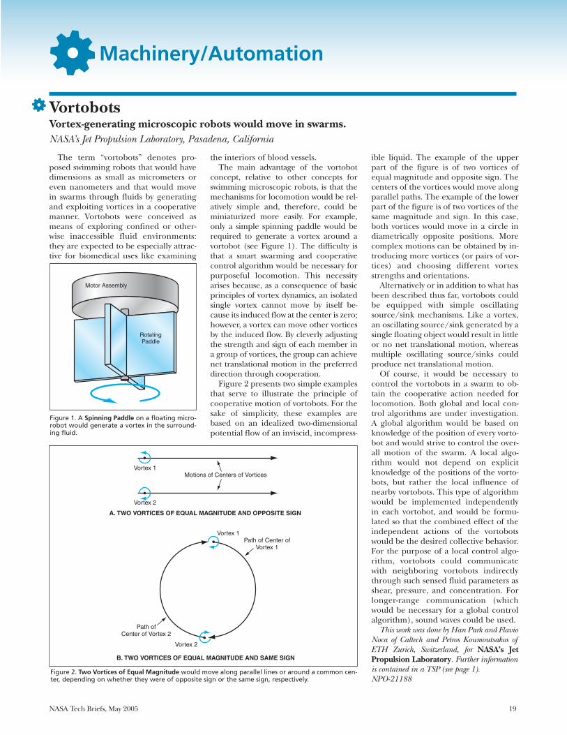
concept, relative to other concepts forswimming microscopic robots, is that themechanisms for locomotion would be rel-atively simple and, therefore, could beminiaturized more easily. For example,only a simple spinning paddle would berequired to generate a vortex around avortobot (see Figure 1). The difficulty isthat a smart swarming and cooperativecontrol algorithm would be necessary forpurposeful locomotion. This necessityarises because, as a consequence of basicprinciples of vortex dynamics, an isolatedsingle vortex cannot move by itself be-cause its induced flow at the center is zero;however, a vortex can move other vorticesby the induced flow. By cleverly adjustingthe strength and sign of each member ina group of vortices, the group can achievenet translational motion in the preferreddirection through cooperation.
Figure 2 presents two simple examplesthat serve to illustrate the principle ofcooperative motion of vortobots. For thesake of simplicity, these examples arebased on an idealized two-dimensionalpotential flow of an inviscid, incompress-
ible liquid. The example of the upperpart of the figure is of two vortices ofequal magnitude and opposite sign. Thecenters of the vortices would move alongparallel paths. The example of the lowerpart of the figure is of two vortices of thesame magnitude and sign. In this case,both vortices would move in a circle indiametrically opposite positions. Morecomplex motions can be obtained by in-troducing more vortices (or pairs of vor-tices) and choosing different vortexstrengths and orientations.
Alternatively or in addition to what hasbeen described thus far, vortobots couldbe equipped with simple oscillatingsource/sink mechanisms. Like a vortex,an oscillating source/sink generated by asingle floating object would result in littleor no net translational motion, whereasmultiple oscillating source/sinks couldproduce net translational motion.
Of course, it would be necessary tocontrol the vortobots in a swarm to ob-tain the cooperative action needed forlocomotion. Both global and local con-trol algorithms are under investigation.A global algorithm would be based onknowledge of the position of every vorto-bot and would strive to control the over-all motion of the swarm. A local algo-rithm would not depend on explicitknowledge of the positions of the vorto-bots, but rather the local influence ofnearby vortobots. This type of algorithmwould be implemented independentlyin each vortobot, and would be formu-lated so that the combined effect of theindependent actions of the vortobotswould be the desired collective behavior.For the purpose of a local control algo-rithm, vortobots could communicatewith neighboring vortobots indirectlythrough such sensed fluid parameters asshear, pressure, and concentration. Forlonger-range communication (whichwould be necessary for a global controlalgorithm), sound waves could be used.
This work was done by Han Park and FlavioNoca of Caltech and Petros Koumoutsakos ofETH Zurich, Switzerland, for NASA’s JetPropulsion Laboratory. Further informationis contained in a TSP (see page 1).NPO-21188
Machinery/Automation
VortobotsVortex-generating microscopic robots would move in swarms.NASA’s Jet Propulsion Laboratory, Pasadena, California
Figure 1. A Spinning Paddle on a floating micro-robot would generate a vortex in the surround-ing fluid.
Motor Assembly
RotatingPaddle
NPO21188 Fig 1
8-9-02 bs
Figure 2. Two Vortices of Equal Magnitude would move along parallel lines or around a common cen-ter, depending on whether they were of opposite sign or the same sign, respectively.
A. TWO VORTICES OF EQUAL MAGNITUDE AND OPPOSITE SIGN
Vortex 1Motions of Centers of Vortices
Vortex 2
Vortex 1
Vortex 2
Path of Center ofVortex 1
Path ofCenter of Vortex 2
NPO21188 Fig 2
8-9-02 bs
B. TWO VORTICES OF EQUAL MAGNITUDE AND SAME SIGN

An ultrasonic/sonic jackhammer (USJ)is the latest in a series of related devices, thefirst of which were reported in “Ultra-sonic/Sonic Drill/Corers With IntegratedSensors” (NPO-20856), NASA Tech Briefs,Vol. 25, No. 1 (January 2003), page 38.Each of these devices cuts into a brittle ma-terial by means of hammering and chisel-ing actions of a tool bit excited with a com-bination of ultrasonic and sonic vibrations.A small-scale prototype of the USJ has beendemonstrated. A fully developed, full-scaleversion of the USJ would be used for cut-ting through concrete, rocks, hard asphalt,and other materials to which conventionalpneumatic jackhammers are applied, but
the USJ would offer several advantagesover conventional pneumatic jackham-mers, as discussed below.
In the USJ (see figure) as in the previ-ously reported ultrasonic/sonic drill/corers (USDCs) and related devices, theactuator assembly includes a piezoelec-tric stack and a horn for mechanical am-plification of the piezoelectric displace-ment. A cylindrical shank of achisel-shaped tool bit is mounted on thelower end of the horn. A bobbin-likecylindrical mass is free to move axiallythrough a limited range between thelower end of the horn and the upper endof the blade portion of the tool bit. Thesharp edge of the bit is placed in contactwith the rock or other hard material tobe cut. Unlike a pneumatic jackhammer,the USJ need not be heavy because itsprinciple of operation does not require alarge contact force.
The piezoelectric stack is electricallydriven at its resonance frequency, and abolt holds the stack in compression toprevent fracture during operation. Thefree mass bounces between hard stops atthe limits of its range of motion at a sonicfrequency. The impacts of the free masson the hard stops create stress pulses thatpropagate along the horn, to andthrough the tool bit, to the tool-bit/rockinterface. The rock becomes fracturedwhen its ultimate strain is exceeded.
A conventional pneumatic jackham-mer generates enormous amounts ofnoise, along with severe vibrations thatpropagate back into the operator’sbody and that are so strong as to some-times injure the operator. Every objectencountered by the tool bit is dam-aged. This indiscriminate cutting ac-tion is particularly disadvantageous in
situations in which there is a need tocut through concrete or asphalt with-out damaging such embedded objectsas pipes, cables, and reinforcing steelbars.
In contrast, even a full-scale USJ wouldgenerate much less noise and much lessback-propagating vibration. The full-scale USJ would also demand less averagepower. Moreover, on the basis of experi-ence with the USDCs, it is expected thatsuch relatively flexible materials as wood,plastics, metals, and human tissues willnot be damaged by brief contact with thetool bit of the operating USJ. Yet anotheradvantage is that like a USDC as de-scribed in the noted prior NASA TechBriefs article, the USJ could be instru-mented with mechanical-impedance sen-sors that could be used to obtain feed-back to optimize the electrical excitationfor cutting and/or to utilize the vibra-tions to probe the hard material in thevicinity of the tool bit.
This work was done by Yoseph Bar-Cohenand Stewart Sherrit of Caltech and Jack Herzof CTC for NASA’s Jet Propulsion Labora-tory. Further information is contained in aTSP (see page 1).
In accordance with Public Law 96-517, thecontractor has elected to retain title to this in-vention. Inquiries concerning rights for itscommercial use should be addressed to:
Innovative Technology Assets ManagementJPLMail Stop 202-2334800 Oak Grove DrivePasadena, CA 91109-8099(818) 354-2240E-mail: [email protected] to NPO-40771, volume and number
of this NASA Tech Briefs issue, and thepage number.
20 NASA Tech Briefs, May 2005
The Ultrasonic/Sonic Jackhammer is driven elec-trically instead of pneumatically. It offers severaladvantages over a conventional pneumatic jack-hammer.
NPO-40771 ABPI
06-03-04 LE
Actuator
Handle
Horn
Free Mass
Tool Bit
Ultrasonic/Sonic JackhammerAdvantages include low noise, low vibration, and low average power demand.NASA’s Jet Propulsion Laboratory, Pasadena, California

NASA Tech Briefs, May 2005 21
Bio-Medical
Removing Pathogens Using Nano-Ceramic-Fiber FiltersFilters remove greater than 99.9999 percent of viruses and bacteria from wastewater.Lyndon B. Johnson Space Center, Houston, Texas
A nano-aluminum-oxide fiber of only2 nanometers in diameter was used todevelop a ceramic-fiber filter. Thefibers are electropositive and, when for-mulated into a filter material (NanoCe-ram®), would attract electronegativeparticles such as bacteria and viruses.The ability to detect and then removeviruses as well as bacteria is of concernin space cabins since they may be car-ried onboard by space crews. Moreover,an improved filter was desired thatwould polish the effluent from con-densed moisture and wastewater, pro-ducing potable drinking water. A labo-ratory-size filter was developed that wascapable of removing greater than99.9999 percent of bacteria and virus.Such a removal was achieved at flowrates hundreds of times greater thanthose through ultraporous membranesthat remove particles by sieving. Be-cause the pore size of the new filter wasrather large as compared to ultra-porous membranes, it was found to bemore resistant to clogging.
Additionally, a full-size cartridge isbeing developed that is capable of serv-ing a full space crew. During this on-going effort, research demonstrated thatthe filter media was a very efficient ad-sorbent for DNA (deoxyribonucleicacid), RNA (ribonucleic acid), and en-dotoxins. Since the adsorption is basedon the charge of the macromolecules,there is also a potential for separatingproteins and other particulates on thebasis of their charge differences. Theseparation of specific proteins is a majornew thrust of biotechnology.
The principal application of NanoCe-ram® filters is based on their ability to re-move viruses from water. The removal ofmore than 99.9999 percent of viruseswas achieved by a NanoCeram® polish-ing filter added to the effluent of an ex-isting filtration device. NanoCeram® iscommercially available in laboratory-sizefilter discs and in the form of a syringefilter. The unique characteristic of thefilter can be demonstrated by its abilityto remove particulate dyes such as
Metanyl yellow. Its particle size is only 2nanometers, about the size of a DNAmolecule, yet the NanoCeram® syringefilter is capable of retaining the dyes asthe fluid is passed through the syringe,without much backpressure. Endotox-ins, which are contaminants that are partof the residue of destroyed bacteria, cancause toxic shock and are therefore ofmajor concern in pharmaceutical prod-ucts. The NanoCeram® syringe filter iscapable of removing greater than 99.96percent of the endotoxins.
This work was done by Frederick Tepperand Leonid Kaledin of Argonide Corp. forJohnson Space Center.
In accordance with Public Law 96-517,the contractor has elected to retain title to thisinvention. Inquiries concerning rights for itscommercial use should be addressed to:
Argonide Corporation291 Power CourtSanford, FL 32771Refer to MSC-23478, volume and number
of this NASA Tech Briefs issue, and thepage number.
The term “satellite-derived manage-ment zones” (SAMZ) denotes agricul-tural management zones that are subdi-visions of large fields and that arederived from images of the fields ac-quired by instruments aboard Earth-or-biting satellites during approximatelythe past 15 years. “SAMZ” also denotesthe methodology and the software thatimplements the methodology for creat-ing such zones. The SAMZ approach isone of several products of continuingefforts to realize a concept of precisionagriculture, which involves optimalvariations in seeding, in application ofchemicals, and in irrigation, plus deci-sions to farm or not to farm certainportions of fields, all in an effort tomaximize profitability in view of spatial
and temporal variations in the growthand health of crops, and in the chemi-cal and physical conditions of soils.
As used here, “management zone” sig-nifies, more precisely, a subdivision of afield within which the crop-productionbehavior is regarded as homogeneous.From the perspective of precision agri-culture, management zones are thesmallest subdivisions between which theseeding, application of chemicals, andother management parameters are to bevaried.
In the SAMZ approach, the mainsources of data are the archives of satel-lite imagery that have been collectedover the years for diverse purposes. Oneof the main advantages afforded by theSAMZ approach is that the data in these
archives can be reused for purposes ofprecision agriculture at low cost. De facto,these archives contain information onall sources of variability within a field, in-cluding weather, crop types, crop man-agement, soil types, and water drainagepatterns.
The SAMZ methodology involves theestablishment of a Web-based interfacebased on an algorithm that generatesmanagement zones automatically andquickly from archival satellite imagedata in response to requests from farm-ers. A farmer can make a request by ei-ther uploading data describing a fieldboundary to the Web site or else draw-ing the boundary on a reference image.Hence, a farmer can start to engage inprecision farming shortly after gaining
Satellite-Derived Management ZonesPrecision agriculture can be practiced at low cost.Stennis Space Center, Mississippi
22 NASA Tech Briefs, May 2005
access to the Web site, without the needfor incurring the high costs of conven-tional precision-agriculture data-collec-tion practices that include collecting soilsamples, mapping electrical con-
ductivity of soil, and compiling multi-year crop-yield data.
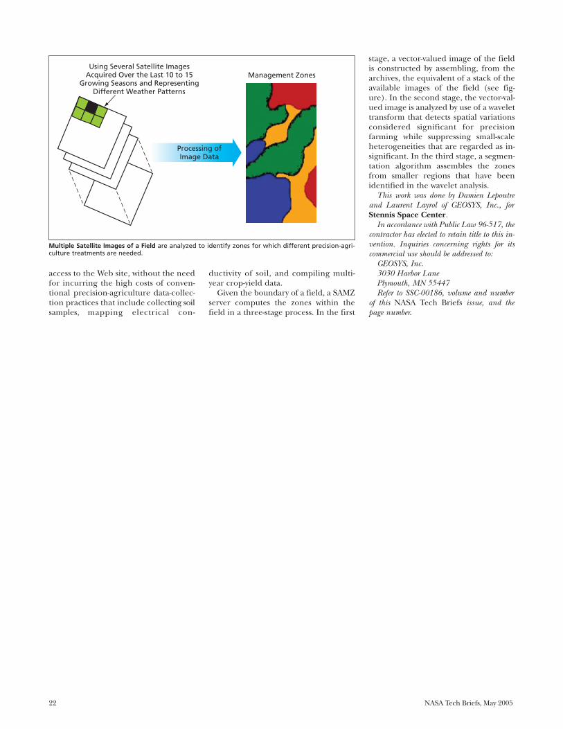
Given the boundary of a field, a SAMZserver computes the zones within thefield in a three-stage process. In the first
stage, a vector-valued image of the fieldis constructed by assembling, from thearchives, the equivalent of a stack of theavailable images of the field (see fig-ure). In the second stage, the vector-val-ued image is analyzed by use of a wavelettransform that detects spatial variationsconsidered significant for precisionfarming while suppressing small-scaleheterogeneities that are regarded as in-significant. In the third stage, a segmen-tation algorithm assembles the zonesfrom smaller regions that have beenidentified in the wavelet analysis.
This work was done by Damien Lepoutreand Laurent Layrol of GEOSYS, Inc., forStennis Space Center.
In accordance with Public Law 96-517, thecontractor has elected to retain title to this in-vention. Inquiries concerning rights for itscommercial use should be addressed to:
GEOSYS, Inc.3030 Harbor LanePlymouth, MN 55447Refer to SSC-00186, volume and number
of this NASA Tech Briefs issue, and thepage number.
Multiple Satellite Images of a Field are analyzed to identify zones for which different precision-agri-culture treatments are needed.
Using Several Satellite ImagesAcquired Over the Last 10 to 15
Growing Seasons and RepresentingDifferent Weather Patterns
Processing ofImage Data
SSC-00186ABPI
12-8-03 es
Management Zones

NASA Tech Briefs, May 2005 23
A digital equivalent data system(DEDS) is a system for identifying objectsby means of the x-ray fluorescence (XRF)spectra of labeling elements that are en-cased in or deposited on the objects. Assuch, a DEDS is a revolutionary newmajor subsystem of an XRF system. ADEDS embodies the means for convert-ing the spectral data output of an XRFscanner to an ASCII alphanumeric or bar-code label that can be used to identify (orverify the assumed or apparent identityof) an XRF-scanned object.
A typical XRF spectrum of interestcontains peaks at photon energies associ-ated with specific elements on the Peri-
odic Table (see figure). The height ofeach spectral peak above the local back-ground spectral intensity is proportionalto the relative abundance of the corre-sponding element. Alphanumeric valuesare assigned to the relative abundancesof the elements. Hence, if an object con-tained labeling elements in suitably cho-sen proportions, an alphanumeric repre-sentation of the object could beextracted from its XRF spectrum. Themixture of labeling elements and forreading the XRF spectrum would becompatible with one of the labeling con-ventions now used for bar codes and bi-nary matrix patterns (essentially, two-di-
mensional bar codes that resemblecheckerboards). A further benefit ofsuch compatibility is that it would enablethe conversion of the XRF spectral out-put to a bar or matrix-coded label, ifneeded. In short, a process previouslyused only for material compositionanalysis has been reapplied to the worldof identification. This new level of verifi-cation is now being used for “authentica-tion.”
The DEDS as described thus farwould be used to process XRF spectraldata output only. In one of several alter-natives, an object could be labeled withboth a conventional bar or matrix codeand an XRF tag, so that the XRF tagcould be used to provide redundant, ad-ditional, or confirmatory information.In that case, the DEDS would analyzethe XRF tag and convert the readings toalphanumeric data in a recognized for-mat. In yet another alternative, the XRFscanner would be used to acquire anXRF spectrum of not only the XRF tagbut also the substrate material sur-rounding the tag. In that case, the spec-tral data output from the substratewould constitute an additional set ofdata that could be combined with theXRF label data and the bar-code or ma-trix readout to obtain an alphanumericlabel unique to the labeled object or tothe class that it represents.
Authentication is the natural evolu-tion of the identification process as secu-rity technologies are combined with it.The XRF DEDS provides a unique set ofmethods to determine if an object is gen-uine. The respective sets of informationcannot be duplicated and answers thequestion “is that the original object.”
Authentication using XRF DEDS isexpected to have no negative impact onexisting networks as its conversion is inASCII format, and convertible to barcode or other symbology formats. In factit is expected to simply “fit in” withother members of the identificationtechnology family. It is intended as aprocess to eliminate counterfeits andknock-offs, enabling the routine datacollection in the downstream process
Physical Sciences
Digital Equivalent Data System for XRF Labeling of ObjectsConventions for XRF labels and converting XRF spectra to alphanumeric data leads to newidentification method.Marshall Space Flight Center, Alabama
The Coordinates of Each Peak in an XRF Spectrum of a label would contribute information on the con-tents of the label: The horizontal coordinate would indicate a photon energy and, hence, the identityof an element; the vertical coordinate would indicate the spectral intensity and, hence, the abundanceof the element.
3,000
2,500
2,000
1,500
1,000
500
0
0 2 4 6 8 10 12
Energy—KeV (1000 eletron Volts)
Inte
nsi
ty—
Tota
l Un
its
14 16 18 20 22
FeKα
CrKα
AgLα
NiKα
AsKα
MoKα
PdKαAgKα
MFS-31886
ABPI
01-28-04 LE
5.21*1025
6.25*2815
7.30*0385
XRF Spectral Data�Output Format
5.21*1025 => (example matrix)
5.21*1025-6.25*2815-7.30*0385 => (example matrix)
XRF Spectral Data Output Display Numerically Equivalent Value

Systems for identifying objects bymeans of x-ray fluorescence (XRF) ofencased labeling elements have beendeveloped. The XRF spectra of objectsso labeled would be analogous to the ex-ternal bar code labels now used to trackobjects in everyday commerce. In con-junction with computer-based trackingsystems, databases, and labeling conven-tions, the XRF labels could be used inessentially the same manner as that ofbar codes to track inventories and torecord and process commercial transac-tions. In addition, as summarized brieflybelow, embedded XRF labels could beused to verify the authenticity of prod-ucts, thereby helping to deter counter-feiting and fraud.
A system, as described above, is calledan “encased core product identificationand authentication system” (ECPIAS).
The ECPIAS concept is a modified ver-sion of that of a related recently initiatedcommercial development of handheldXRF spectral scanners that would iden-tify alloys or detect labeling elements de-posited on the surfaces of objects. Incontrast, an ECPIAS would utilize label-ing elements encased within the objectsof interest.
The basic ECPIAS concept is best illus-trated by means of an example of one ofseveral potential applications: labeling ofcultured pearls by labeling the seed par-ticles implanted in oysters to grow thepearls. Each pearl farmer would be as-signed a unique mixture of labeling ele-ments that could be distinguished fromthe corresponding mixtures of otherfarmers. The mixture would be either in-corporated into or applied to the sur-faces of the seed prior to implantation in
the oyster. If necessary, the labeled seedwould be further coated to make it non-toxic to the oyster. After implantation,the growth of layers of mother of pearlon the seed would encase the XRF labels,making these labels integral, permanentparts of the pearls that could not be re-moved without destroying the pearlsthemselves. The XRF labels would beread by use of XRF scanners, the spectraldata outputs of which would be con-verted to alphanumeric data in a digitalequivalent data system (DEDS), which isthe subject of the previous article. Thesealphanumeric data would be used totrack the pearls through all stages ofcommerce, from the farmer to the retailcustomer.
In another potential application (seefigure), an ECPIAS would be used to tracksoftballs. Softball cores and covers are typ-
ically manufactured in the UnitedStates and shipped offshore where thecovers are sewn on. At present, inorder to verify the origin of a shipmentof assembled softballs returning to theUnited States, it is necessary to takesome balls as samples, cut their coversoff, and examine their cores. In con-trast, the ECPIAS would make it possi-ble to verify the origin of the ballsquickly and nondestructively. TheECPIAS concept could also be appliedto other products in which XRF labelscould be permanently encased. Exam-ples include balls used in high-profilesports, tires, printed-circuit compo-nents, layered clothing items (e.g.,shoes), and critical aircraft compo-nents.
The ECPIAS is a “next logicalstep” technology that gives an OEMa new safeguard for product liability.With the bar code inside the part oreven mixed with the material of the
24 NASA Tech Briefs, May 2005
using bar codes and matrix codes to bemuch more secure. Finally, it is ex-pected to find its way into the court-room, having the unique insight as towhich object is genuine and which isnot. Authentication using XRF DEDSmay well be the next-generation expertwitness in product liability cases.
This work was done by Harry F. Schrammof Marshall Space Flight Center and BruceKaiser of Keymaster Technologies, Inc. For fur-ther information, contact Sammy Nabors,MSFC Commercialization Assistance Lead, [email protected].
In accordance with Public Law 96-517, thecontractor has elected to retain title to this in-
vention. Inquiries concerning rights for itscommercial use should be addressed to:
Keymaster Technologies, Inc.415 N. Quay Street, Suite 1Kennewick, WA 99336Refer to MFS-31886, volume and number
of this NASA Tech Briefs issue, and thepage number.
Softball Cores and Covers Would Be Labeled by mixtures of elements having unique XRF spectra. The ballswould be tracked through the stages of manufacture and transport by using the spectra to verify theiridentities.
Apply label material to core.
Apply other coatings as
necessary to protect core.
Scan core, register label, and verify
registration with lot or control quantity in
database.
Mark inside surface of cover
with label material.
Scan cover, register tag, and verify
registration with lot or control quantity in database.
Send core and cover to remote location for sewing cover on
core.
Receive ball with cover sewn on
core.Scan ball, register tags
on core-and-cover combination, and verify registration in database.
Mix elements, make label material, assign
to lot or control quantity, form DEDS
database.
MFS318909-13-02 bs
XRFScanner
Identifying Objects via Encased X-Ray-Fluorescent Materials —the Bar Code InsideXRF spectra would be used as labels, similarly to bar codes, inside a product.Marshall Space Flight Center, Alabama

Vacuum apparatuses have been devel-oped for increasing the range of ele-ments that can be identified by use of x-ray fluorescent (XRF) scanners of thetype mentioned in the two immediatelypreceding articles. As a consequence ofthe underlying physical principles, inthe presence of air, such an XRF scanneris limited to analysis of chlorine and ele-ments of greater atomic number. Whenthe XRF scanner is operated in a vac-uum, it extends the range of analysis tolower atomic numbers — even as far asaluminum and sodium. Hence, more el-ements will be available for use in XRFlabeling of objects as discussed in thetwo preceding articles.
The added benefits of the extendedcapabilities also have other uses forNASA. Detection of elements of lowatomic number is of high interest to theaerospace community. High-strengthaluminum alloys will be easily analyzedfor composition. Silicon, a major con-taminant in certain processes, will bedetectable before the process is begun,possibly eliminating weld or adhesionproblems. Exotic alloys will be evalu-ated for composition prior to beingplaced in service where lives depend onthem. And in the less glamorous appli-cations, such as bolts and fasteners, sub-standard products and counterfeititems will be evaluated at the receivingfunction and never allowed to enter theoperation.
Both hand-held and tabletop XRFportable scanners have been developed.The vacuum apparatus is compact andlightweight and does not detract fromthe portability of either XRF scanner. Itis attached to and detached from theaperture end of either XRF scanner.
The upper part of the figure schemati-cally depicts the hand-held XRF scanner.The XRF scanner and vacuum apparatuswould be connected to a portable (belt-mounted) control unit that would contain
a power supply and a vacuum pump. Thelower part of the figure is a simplified, en-larged cross-sectional view of a vacuum ap-paratus attached to the aperture end ofthe XRF scanner. The side wall of the vac-uum apparatus would include a flexibleportion that would support a seal flangeand seal bead, which would be pressedagainst an object to be scanned to form anair-tight seal. While holding the seal and
pressing the aperture of the XRF scanneragainst the object to be scanned, the oper-ator would press a switch, thereby startingthe process. The switch would turn on thepump and keep it on for as long as neededto maintain the vacuum needed for theXRF scan.
The vacuum enhanced version of thehand-held XRF, already in use in theshuttle program, takes the chemistry lab
NASA Tech Briefs, May 2005 25
part, authentication can be attainedwith a simple scan. For those who haveever tried to put a barcode inside apearl, ECPIAS may sound like a goodalternative.
This work was done by Harry F. Schrammof Marshall Space Flight Center, and
Bruce Kaiser of Keymaster Technologies, Inc.For further information, contact SammyNabors, MSFC Commercialization AssistanceLead, at [email protected].
In accordance with Public Law 96-517, thecontractor has elected to retain title to this in-vention. Inquiries concerning rights for its
commercial use should be addressed to:Keymaster Technologies, Inc.415 N. Quay Street, Suite 1Kennewick, WA 99336Refer to MFS-31890, volume and number
of this NASA Tech Briefs issue, and thepage number.
A Compact Vacuum Apparatus attached to the aperture end of a hand-held XRF scanner would enablevacuum XRF analysis without the need to mount the entire XRF scanner in a vacuum chamber.
MFS31898
9-12-02 bs
Rigid Portion ofVacuum-Chamber
WallVacuumApparatus
Flexible Portion ofVacuum-Chamber
Wall
Seal Bead
Seal Flange
Object To Be Scanned
Aperture of XRF Scanner
Vacuum Hose
PowerSupply
VacuumPump
Timer
Control Unit
Vacuum Hose
Hand-HeldXRF Scanner
Switch VacuumApparatus
Vacuum Attachment for XRF ScannerA greater range of elements could be analyzed.Marshall Space Flight Center, Alabama

26 NASA Tech Briefs, May 2005
to the shop floor, something that wasnot practical to do before with largeproducts such as external tanks, spaceshuttle main engines, and solid rocketboosters. From label scanning to mate-rial analysis, the vacuum enhanced XRFis a welcome addition to the NASA tool-box of capabilities.
This work was done by Harry F. Schrammof Marshall Space Flight Center andBruce Kaiser of Keymaster Technologies, Inc.For further information, contact SammyNabors, MSFC Commercialization AssistanceLead, at [email protected].
In accordance with Public Law 96-517, thecontractor has elected to retain title to this in-
vention. Inquiries concerning rights for itscommercial use should be addressed to:
Keymaster Technologies, Inc.415 N. Quay Street, Suite 1Kennewick, WA 99336Refer to MFS-31898, volume and number
of this NASA Tech Briefs issue, and thepage number.
Simultaneous Conoscopic Holography and Raman SpectroscopyBoth the topography and the chemistry of surfaces would be mapped.NASA’s Jet Propulsion Laboratory, Pasadena, California
A new instrument was developed forchemical characterization of surfacesthat combines the analytical power ofRaman spectroscopy with the three-di-mensional topographic information pro-vided by conoscopic holography. The fig-ure schematically depicts the proposedhybrid instrument. The output of theconoscopic holographic portion of theinstrument is a topographical map of thesurface; the output of the Raman portionof the instrument is hyperspectral Ramandata, from which the chemical and/or bi-ological composition of the surfacewould be deduced. By virtue of the basicprinciples of design and operation of theinstrument, the hyperspectral image datawould be inherently spatially registeredwith the topographical data.
In conoscopic holography, the objectand reference beams of classical hologra-phy are replaced by the ordinary and ex-
traordinary components generated by asingle beam traveling through a birefrin-gent, uniaxial crystal. In the basic cono-scopic configuration, a laser light is pro-jected onto a specimen and the resultingilluminated spot becomes a point sourceof diffuse light that propagates in everydirection. The laser beam is raster-scanned in two dimensions (x and y) per-pendicular to the beam axis (z), and ateach x,y location, the pattern of interfer-ence between the ordinary and extraor-dinary rays is recorded. The recorded in-terferogram constitutes the conoscopichologram. Of particular significance forthe proposed instrument is that theconoscopic hologram contains informa-tion on the z coordinate (height) of theilluminated surface spot. Hence, a topo-graphical map of the specimen is con-structed point-by-point by rastering thelaser beam in the x and y directions and
correlating the x and y coordinates withthe z information obtained from the in-terferograms. Conoscopic imaging is anestablished method, and conoscopic lab-oratory instruments for surface metrol-ogy are commercially available.
In Raman spectroscopy of a surface,one measures the spectrum of laser lightscattered inelastically from a laser-illumi-nated spot on the surface. The wave-lengths of the inelastically scattered lightdiffer from that of the incident laserbeam by amounts that correspond to theenergies of molecular vibrations. The re-sulting vibrational spectrum can be usedto identify the molecules. Raman spec-troscopy is a standard laboratory tech-nique for identifying mineralogical, bio-logical, and other specific chemicalcompositions.
In the design and construction ofthe proposed instrument, a commer-cially available laboratory conoscopicholographic imaging system would beintegrated with a Raman spectrometer(see figure). The on-axis back-scat-tered laser light would be used by theimaging system to generate the cono-scopic hologram of the illuminatedspot. Part of the off-axis back-scatteredlaser light would be collected by a lens,which would couple the light into anoptical fiber, which, in turn, wouldfeed the collected light to the Ramanspectrometer. The lateral (x,y) resolu-tion of the instrument would typicallybe of the order of microns, the exactvalue being determined primarily bythe size of the laser-illuminated spoton the specimen. In one of two config-urations, the Raman-excitation andconoscopic-holography beams wouldbe generated by two different lasersand would be aligned and focused to-gether on the same spot on the speci-men. In a simpler configuration thatwould entail less weight, complexity,
A Spot on a Specimen Would Be Illuminated by a laser beam (or by two coincident laser beams) thatwould be raster-scanned across the surface in x and y. Laser light back-scattered from the surfacewould be used to map the surface height (z) and chemical composition as functions of x and y.
NPO-30751ABPI
10-1-03 es
ConoscopicCamera and Laser
Raman Laser(Optional)
RamanSpectrometer
Lens
Filter
Beam Splitter(Needed if
Raman LaserIs Used)
SampleSurface
OpticalFiber
y
x

NASA Tech Briefs, May 2005 27
size, and cost, the same laser beamwould be used for both conoscopicholography and Raman spectroscopy.The two-laser configuration would bepreferable in cases in which the illumi-nation needed for Raman excitationsignificantly exceeds that needed forconoscopic holography and, hence, itbecomes necessary to alternate be-tween conoscopic and Raman analysisof each scan spot.
The proposed instrument would becapable of mapping topography andchemical composition at lateral scalesfrom microns to meters, with nanometerheight resolution. Thus, the instrumentcould provide information on composi-
tion, roughness, porosity, and fractal di-mension of specimens ranging from finedust to large rocks, without need for anypreparation of the specimens. The in-strument would be mechanically nonin-vasive in that there would be no need formechanical contact between a solidprobe and a specimen. Because theprobe would be a narrow laser beam, itwould be possible to profile features atthe bottoms of steep, narrow holes forinstance, crevices in a rock. The pro-posed instrument could also be com-bined with other optical spectroscopicinstruments.
This work was done by Mark S. Andersonof Caltech for NASA’s Jet Propulsion Lab-
oratory. Further information is contained ina TSP (see page 1).
In accordance with Public Law 96-517, thecontractor has elected to retain title to this in-vention. Inquiries concerning rights for itscommercial use should be addressed to:
Innovative Technology Assets ManagementJPLMail Stop 202-2334800 Oak Grove DrivePasadena, CA 91109-8099(818) 354-2240E-mail: [email protected] to NPO-30751, volume and number
of this NASA Tech Briefs issue, and thepage number.
Adding GaAs Monolayers to InAs Quantum-Dot Lasers on (001) InPModifications enable long-wavelength lasing at higher temperatures.NASA’s Jet Propulsion Laboratory, Pasadena, California
In a modification of the basic config-uration of InAs quantum-dot semicon-ductor lasers on (001)lnP substrate, athin layer (typically 1 to 2 monolayerthick) of GaAs is incorporated into theactive region. This modification en-hances laser performance: In particu-lar, whereas it has been necessary tocool the unmodified devices to tem-peratures of about 80 K in order to ob-tain lasing at long wavelengths, themodified devices can lase at wave-lengths of about 1.7 µm or more nearroom temperature.
InAs quantum dots self-assemble, as aconsequence of the lattice mismatch,during epitaxial deposition of InAs onln0.53Ga0.47As/lnP. In the unmodified de-vices, the quantum dots as thus formedare typically nonuniform in size. Strain-energy relaxation in very large quantumdots can lead to poor laser performance,especially at wavelengths near 2 µm, forwhich large quantum dots are needed.In the modified devices, the thin layersof GaAs added to the active regions con-stitute potential-energy barriers thatelectrons can only penetrate by quan-tum tunneling and thus reduce the hotcarrier effects. Also, the insertion of thinGaAs layer is shown to reduce the degreeof nonuniformity of sizes of the quan-tum dots.
In the fabrication of a batch of modi-fied InAs quantum-dot lasers, the thin ad-ditional layer of GaAs is deposited as an
interfacial layer in an InGaAs quantumwell on (001) InP substrate. The deviceas described thus far is sandwiched be-tween InGaAsPy waveguide layers, thenfurther sandwiched between InPcladding layers, then further sandwichedbetween heavily Zn-doped (p-type) InGaAscontact layer.
Once a wafer comprisingthe layers described abovehas been formed, the waferis processed into laserdiodes by standard fabrica-tion techniques. Results ofpreliminary tests of experi-mental modified quantum-dot lasers have been inter-preted as signifying thatthese devices lase at wave-lengths from 1.60 to about1.74 µm. The devices werefound to be capable of con-tinuous-wave operation attemperatures up to 260 Kand pulse operation (dura-tion 1 ms, repetition rate 1kHz) at temperatures up to280 K. It is anticipated thatfuture such devices contain-ing multiple stacks of quan-tum dots (instead of singlestacks in these experimentaldevices) would be able tolase, at a wavelength of 2µm. In addition, the multi-ple-stack devices are ex-
pected to perform better at room tem-perature.
This work was done by Yueming Qiu, Re-becca Chacon, David Uhl, and Rui Yang ofCaltech for NASA’s Jet Propulsion Labora-tory. Further information is contained in aTSP (see page 1).NPO-40243
This Energy-Band Profile of a modified InxGa1-xAs/lnP quantum-dot structure shows the energy effect of the additional thinGaAs layer.
InP InP
GaAs
PhotonInAs
QuantumDot
-
+
Electron
Hole
Depth
Elec
tro
n E
ner
gy
NPO-40243 ABPI
06-19-03 LE

28 NASA Tech Briefs, May 2005
In optical systems in which laser illu-mination is delivered via multimode op-tical fibers, laser speckle can be ren-dered incoherent by a simple but highlyeffective technique. The need to elimi-nate speckle arises because speckle canmake it difficult to observe edges andother sharp features, thereby making itdifficult to perform precision align-ment of optical components.
The basic ideas of the technique is tovibrate the optical fiber(s) to cause shift-ing of electromagnetic modes within thefiber(s) and consequent shifting of thespeckle pattern in the light emergingfrom the fiber(s). If the frequency of vi-bration is high enough, a human eyecannot follow the shifting speckle pat-tern, so that instead of speckle, a humanobserver sees a smoothed pattern oflight corresponding to a mixture ofmany electromagnetic modes.
If necessary, the optical fiber(s)could be vibrated manually. However,
in a typical laboratory situation, itwould be more practical to attach a vi-brating mechanism to the fiber(s) forroutine use as part of the fiber-optic il-luminator. In experiments, a commer-cially available small, gentle, quiet, vari-able-speed vibratory device was used inthis way, with the result that the appear-
ance of speckle was eliminated, as ex-pected. Figures 1 and 2 illustrate thedifference.
This work was done by Matthew McGilland V. Stanley Scott of Goddard SpaceFlight Center. Further information is con-tained in a TSP (see page 1).GSC-14680-1
Figure 1. A Laboratory Image of the output of a100-mm diameter multimode fiber is shown illu-minated at 532 nm. Notice the speckle makesedges difficult to discern.
Figure 2. The Same Image Is Improved with thefiber being randomly vibrated. Now the edgesand intensity distribution are clearly visible.
Vibrating Optical Fibers To Make Laser Speckle DisappearRapid shifting of speckle makes it appear to be smoothed away.Goddard Space Flight Center, Greenbelt, Maryland
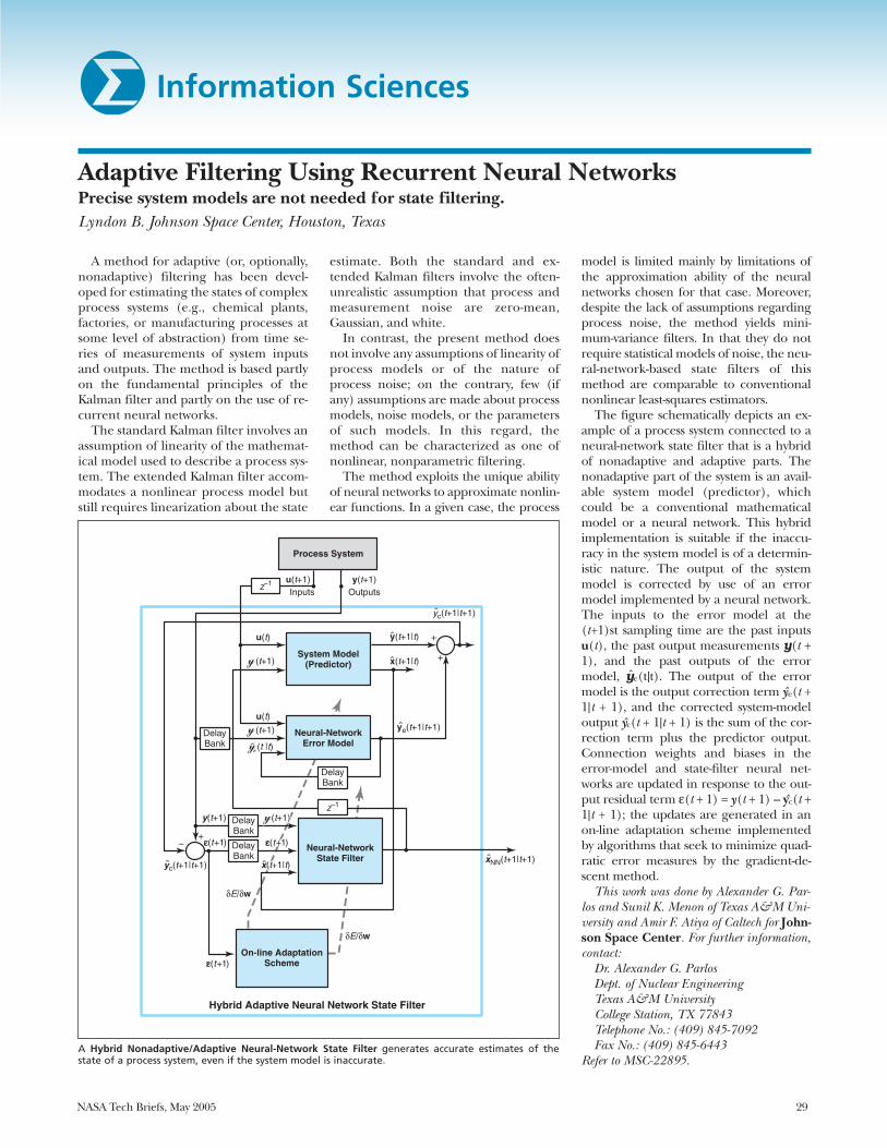
NASA Tech Briefs, May 2005 29
Adaptive Filtering Using Recurrent Neural NetworksPrecise system models are not needed for state filtering.Lyndon B. Johnson Space Center, Houston, Texas
A method for adaptive (or, optionally,nonadaptive) filtering has been devel-oped for estimating the states of complexprocess systems (e.g., chemical plants,factories, or manufacturing processes atsome level of abstraction) from time se-ries of measurements of system inputsand outputs. The method is based partlyon the fundamental principles of theKalman filter and partly on the use of re-current neural networks.
The standard Kalman filter involves anassumption of linearity of the mathemat-ical model used to describe a process sys-tem. The extended Kalman filter accom-modates a nonlinear process model butstill requires linearization about the state
estimate. Both the standard and ex-tended Kalman filters involve the often-unrealistic assumption that process andmeasurement noise are zero-mean,Gaussian, and white.
In contrast, the present method doesnot involve any assumptions of linearity ofprocess models or of the nature ofprocess noise; on the contrary, few (ifany) assumptions are made about processmodels, noise models, or the parametersof such models. In this regard, themethod can be characterized as one ofnonlinear, nonparametric filtering.
The method exploits the unique abilityof neural networks to approximate nonlin-ear functions. In a given case, the process
model is limited mainly by limitations ofthe approximation ability of the neuralnetworks chosen for that case. Moreover,despite the lack of assumptions regardingprocess noise, the method yields mini-mum-variance filters. In that they do notrequire statistical models of noise, the neu-ral-network-based state filters of thismethod are comparable to conventionalnonlinear least-squares estimators.
The figure schematically depicts an ex-ample of a process system connected to aneural-network state filter that is a hybridof nonadaptive and adaptive parts. Thenonadaptive part of the system is an avail-able system model (predictor), whichcould be a conventional mathematicalmodel or a neural network. This hybridimplementation is suitable if the inaccu-racy in the system model is of a determin-istic nature. The output of the systemmodel is corrected by use of an errormodel implemented by a neural network.The inputs to the error model at the(t+1)st sampling time are the past inputsu(t), the past output measurements y(t +1), and the past outputs of the errormodel, ye(t|t). The output of the errormodel is the output correction term ye(t +1|t + 1), and the corrected system-modeloutput yc(t + 1|t + 1) is the sum of the cor-rection term plus the predictor output.Connection weights and biases in theerror-model and state-filter neural net-works are updated in response to the out-put residual term ε(t + 1) = y(t + 1) – yc(t +1|t + 1); the updates are generated in anon-line adaptation scheme implementedby algorithms that seek to minimize quad-ratic error measures by the gradient-de-scent method.
This work was done by Alexander G. Par-los and Sunil K. Menon of Texas A&M Uni-versity and Amir F. Atiya of Caltech for John-son Space Center. For further information,contact:
Dr. Alexander G. ParlosDept. of Nuclear EngineeringTexas A&M UniversityCollege Station, TX 77843Telephone No.: (409) 845-7092Fax No.: (409) 845-6443
Refer to MSC-22895.A Hybrid Nonadaptive/Adaptive Neural-Network State Filter generates accurate estimates of thestate of a process system, even if the system model is inaccurate.
Process System
System Model(Predictor)
Neural-NetworkError Model
Neural-NetworkState Filter
DelayBank
DelayBank
+–
z–1
z–1
+
+
DelayBank
DelayBank
u(t)
u(t+1)Inputs
y(t+1)Outputs
u(t)
(t+1)
(t+1)
y(t+1) ((tt+1+1))
εε((tt+1+1))
xx((tt+1+1||tt))
(t+1)
(t |t)
x(t+1|t)yc(t+1|t+1)
ye(t+1|t+1)
yc(t+1|t+1)
x(t+1|t)
y(t+1|t)
δE/δw
δE/δw
On-line AdaptationScheme
Hybrid Adaptive Neural Network State Filter
xNN(t+1|t+1)
MSC22895
6-17-99 bs
Information Sciences

30 NASA Tech Briefs, May 2005
Applying Standard Interfaces to a Process-Control LanguageLyndon B. Johnson Space Center, Houston, Texas
A method of applying open-operating-system standard interfaces to the NASAUser Interface Language (UIL) has beendevised. UIL is a computing languagethat can be used in monitoring and con-trolling automated processes: for exam-ple, the Timeliner computer program,written in UIL, is a general-purpose soft-ware system for monitoring and control-ling sequences of automated tasks in atarget system. In providing the major ele-
ments of connectivity between UIL andthe target system, the present method of-fers advantages over the prior method.Most notably, unlike in the prior method,the software description of the target sys-tem can be made independent of the ap-plicable compiler software and need notbe linked to the applicable executablecompiler image. Also unlike in the priormethod, it is not necessary to recompilethe source code and relink the source
code to a new executable compilerimage. Abstraction of the description ofthe target system to a data file can be de-fined easily, with intuitive syntax, andknowledge of the source-code languageis not needed for the definition.
This work was done by Richard T. Bertholdof Draper Laboratory for Johnson SpaceCenter. For further information, contactRobert A. Brown at (617) 258-3118. MSC-22971


National Aeronautics andSpace Administration