technologies and materials for recovering waste heat in ... · pdf filerecuperator used on an...
TRANSCRIPT

ORNL/TM-2014/619
Technologies and Materials for Recovering Waste Heat in Harsh Environments
Sachin U. Nimbalkar Arvind C. Thekdi Benjamin M. Rogers Orion L. Kafka Thomas J. Wenning December 15, 2014
Approved for public release; distribution is unlimited.

DOCUMENT AVAILABILITY Reports produced after January 1, 1996, are generally available free via US Department of Energy (DOE) SciTech Connect. Website http://www.osti.gov/scitech/ Reports produced before January 1, 1996, may be purchased by members of the public from the following source: National Technical Information Service 5285 Port Royal Road Springfield, VA 22161 Telephone 703-605-6000 (1-800-553-6847) TDD 703-487-4639 Fax 703-605-6900 E-mail [email protected] Website http://www.ntis.gov/help/ordermethods.aspx Reports are available to DOE employees, DOE contractors, Energy Technology Data Exchange representatives, and International Nuclear Information System representatives from the following source: Office of Scientific and Technical Information PO Box 62 Oak Ridge, TN 37831 Telephone 865-576-8401 Fax 865-576-5728 E-mail [email protected] Website http://www.osti.gov/contact.html
This report was prepared as an account of work sponsored by an agency of the United States Government. Neither the United States Government nor any agency thereof, nor any of their employees, makes any warranty, express or implied, or assumes any legal liability or responsibility for the accuracy, completeness, or usefulness of any information, apparatus, product, or process disclosed, or represents that its use would not infringe privately owned rights. Reference herein to any specific commercial product, process, or service by trade name, trademark, manufacturer, or otherwise, does not necessarily constitute or imply its endorsement, recommendation, or favoring by the United States Government or any agency thereof. The views and opinions of authors expressed herein do not necessarily state or reflect those of the United States Government or any agency thereof.

ORNL/TM-2014/619
Energy and Transportation Science Division
TECHNOLOGIES AND MATERIALS FOR RECOVERING WASTE HEAT
IN HARSH ENVIRONMENTS
Sachin U. Nimbalkar
Arvind C. Thekdi
Benjamin M. Rogers Orion L. Kafka
Thomas J. Wenning
Date Published: December 15, 2014
Prepared by OAK RIDGE NATIONAL LABORATORY
Oak Ridge, Tennessee 37831-6283
managed by UT-BATTELLE, LLC
for the
US DEPARTMENT OF ENERGY under contract DE-AC05-00OR22725


iii
CONTENTS
Page
LIST OF FIGURES ................................................................................................................................. v LIST OF TABLES ................................................................................................................................ vii ABBREVIATIONS, ACRONYMS, AND INITIALISMS ...................................................................... ix ACKNOWLEDGMENT ........................................................................................................................ xi 1. INTRODUCTION ........................................................................................................................ 1-1
1.1 WASTE HEAT IN EXHAUST GASES AND HEAT RECOVERY ISSUES ....................... 1-1 1.2 METHODOLOGY USED FOR SHORT-LISTING INDUSTRIES AND INDUSTRIAL
HEATING PROCESSES .................................................................................................... 1-1 1.3 REFERENCES ................................................................................................................. 1-12
2. EXISTING TECHNOLOGIES USED FOR RECOVERING WASTE HEAT FROM HIGH TEMPERATURE EXHAUST GASES ......................................................................................... 2-1 2.1 EXISTING WHR TECHNOLOGIES FOR HIGH-TEMPERATURE HARSH
ENVIRONMENTS ............................................................................................................. 2-1 2.2 EXISTING WHR TECHNOLOGIES FOR HIGH-TEMPERATURE APPLICATIONS
AND THEIR LIMITATIONS ............................................................................................. 2-1 2.3 REFERENCES ................................................................................................................... 2-6
3. CURRENTLY USED MATERIALS AND THEIR LIMITATIONS ............................................. 3-1 3.1 SELECTING MATERIALS FOR HIGH-TEMPERATURE HARSH
ENVIRONMENTS ............................................................................................................. 3-1 3.2 HIGH TEMPERATURE MATERIALS .............................................................................. 3-1
3.2.1 High-temperature Steels and Superalloys ................................................................ 3-2 3.2.2 High-temperature Refractory Metals ....................................................................... 3-2 3.2.3 High-temperature Ceramic Materials ...................................................................... 3-3 3.2.4 Refractory Bricks and other Shapes......................................................................... 3-3 3.2.5 High-temperature Coatings ..................................................................................... 3-4
3.3 TYPES OF HIGH-TEMPERATURE CORROSION ........................................................... 3-4 3.3.1 Oxidation ................................................................................................................ 3-5 3.3.2 Sulfidation: ............................................................................................................. 3-5 3.3.3 Halogenation .......................................................................................................... 3-6 3.3.4 Carburization .......................................................................................................... 3-6 3.3.5 Nitriding ................................................................................................................. 3-6 3.3.6 Molten Product Corrosion ....................................................................................... 3-7
3.4 REFERENCES ................................................................................................................. 3-13 4. STEEL INDUSTRY ..................................................................................................................... 4-1
4.1 BLAST FURNACES .......................................................................................................... 4-1 4.1.1 Background and Potential Opportunity .................................................................... 4-1 4.1.2 Current Methods of Waste Heat Recovery............................................................... 4-3 4.1.3 Limitations of Existing Methods of Waste Heat Recovery from Blast Furnaces ....... 4-9 4.1.4 Conclusions .......................................................................................................... 4-10
4.2 ELECTRIC ARC FURNACES ......................................................................................... 4-11 4.2.1 Background and Potential Opportunity .................................................................. 4-11 4.2.2 Limitations of Existing Technologies of Waste Heat Recovery from EAFs............ 4-17 4.2.3 Approach for Effective Scrap Preheating............................................................... 4-18 4.2.4 EAF Waste Heat Recovery—Advanced Concepts ................................................. 4-19 4.2.5 Detailed Technical Description of the Proposed System ........................................ 4-20 4.2.6 Conclusions .......................................................................................................... 4-22

iv
4.2.7 Acknowledgement ................................................................................................ 4-23 4.3 References ........................................................................................................................ 4-23
5. ALUMINUM INDUSTRY .............................................................................................................. 1 5.1 ALUMINUM MELTING FURNACES .................................................................................. 1
5.1.1 Background and Potential Opportunity ....................................................................... 1 5.1.2 Current Methods of Waste Heat Recovery from Aluminum Melting Furnaces ............ 2 5.1.3 Barriers and Limitations of Existing Waste Heat Recovery Technologies for
Aluminum Melting Furnaces ................................................................................ 5-11 5.1.4 Conclusions .......................................................................................................... 5-12
5.2 REFERENCES ................................................................................................................. 5-12 6. GLASS INDUSTRY .................................................................................................................... 6-1
6.1 GLASS MELTING REGENERATIVE SYSTEM ............................................................... 6-1 6.1.1 Background and Potential Opportunity .................................................................... 6-1 6.1.2 Current Methods ..................................................................................................... 6-3 6.1.3 Barriers and Limitations of Existing Technologies .................................................. 6-7 6.1.4 Conclusions ............................................................................................................ 6-9
6.2 REFERENCES ................................................................................................................. 6-10 7. CEMENT-LIME INDUSTRY ...................................................................................................... 7-1
7.1 CEMENT AND LIME KILNS ............................................................................................ 7-1 7.1.1 Background and Potential Opportunity .................................................................... 7-1 7.1.2 Current Methods of Waste Heat Recovery............................................................... 7-4 7.1.3 Barriers and Limitations of Existing Technologies ................................................ 7-11 7.1.4 Conclusions .......................................................................................................... 7-14 7.1.5 References ............................................................................................................ 7-14
APPENDIX A. WASTE HEAT SOURCES FROM MAJOR INDUSTRIAL SECTORS .................... A-1 APPENDIX B. CALCULATIONS FOR RECOVERABLE HEAT FROM SELECTED
PROCESSES ............................................................................................................................... B-1

v
LIST OF FIGURES
Figure Page
Figure 1-1. Sankey diagram of process energy flow in the US manufacturing sector [1]. ....................... 1-2 Figure 1-2. Range of process temperatures for some commonly used heating processes in
manufacturing [6]. ............................................................................................................. 1-4 Figure 2-1. Recuperator used on an aluminum melting furnace. Note bent and broken tubes in the
first row and missing refractory on the upper end of the tubes [4]. ...................................... 2-2 Figure 3-1. Selecting materials for high temperature harsh environments [3] ......................................... 3-2 Figure 3-2. Regenerator chamber used in recovering waste heat from glass melting furnaces [5] ........... 3-3 Figure 3-3. High temperature oxidation of recuperator tubes exposed to aluminum melting furnace
exhaust gases (Cross-sections showing significant wall thinning and thick internal
oxide) [7]. .......................................................................................................................... 3-4 Figure 3-4. Internal surface of the failed reboiler heater tubes due to sulfidation, (a) corrosion
products as heavy scaling and (b) dramatic wall thinning of the tube from process side
and subsequent failure [10]. ............................................................................................... 3-4 Figure 3-5. Sulfidation of the tubes as well as the recuperator floor on the exit side of a recuperator
installed on a slab-reheating furnace combusting mixed gas (BFG + COG + BOF gas)
as a fuel [10]. ..................................................................................................................... 3-5 Figure 4-1. Inside the blast furnace. [5] ................................................................................................. 4-1 Figure 4-2. An example of heat balance carried out in a blast furnace. [8] ............................................. 4-3 Figure 4-3. Venturi scrubber (wet type scrubber). [10] .......................................................................... 4-5 Figure 4-4. An example of heat balance carried out on an EAF using electrical energy as well as
carbon injection, oxy-fuel burners and additional oxygen during the melting operation
(mT= tonne). ................................................................................................................... 4-11 Figure 4-5. AIST 2014 EAF Roundup—startup year and average heat size (tonne) ............................. 4-13 Figure 4-6. Comparison of consumption of useful heat for scrap heating, scrap meltdown, and
heating of metal to tapping temperature. .......................................................................... 4-17 Figure 4-7. Benefits of effective scrap preheating—percentage of total electric heat required vs
scrap temperature............................................................................................................. 4-19 Figure 4-8. A system for recovery of sensible and chemical heat from EAF exhaust gases with
integrated clean charge preheating. .................................................................................. 4-21 Figure 4-9. A system for recovery of sensible and chemical heat from EAF exhaust gases with
integrated clean charge preheating (scrap with oil and combustibles)................................ 4-22 Figure 5-1. Heat analysis of aluminum melting furnace. [3] ..................................................................... 2 Figure 5-2. Convection recuperator (six bundles). [6]............................................................................... 3 Figure 5-3. Double shell radiation recuperator. [3] ................................................................................... 3 Figure 5-4. Cross section of tubular radiation recuperator [3] ................................................................... 3 Figure 5-5. Aluminum shaft, or stack furnace [10] ................................................................................... 5 Figure 6-1. An example energy or heat distribution for an R/R glass furnace. [6] .................................. 6-2 Figure 6-2. Diagram of a classic regenerator for glass furnaces. [10] ..................................................... 6-5 Figure 6-3. Diagram of metallic radiator type recuperator, using a counter flow heat exchanger. [13] .... 6-5 Figure 7-1. Simple diagram of a lime shaft kiln. Section A is the preheating area, B the calcining
area, and C the cooling area. [6] ......................................................................................... 7-2 Figure 7-2. Example heat distribution from a rotary cement kiln. [12] ................................................... 7-3 Figure 7-3. An example heat or energy distribution in a rotary lime kiln. [10] ....................................... 7-4 Figure 7-4. Schematic of a parallel flow regenerative kiln. (A) Fuel ports. (B) Combustion air ports.
(C) Cooling air inlet. (D) Stacks. (E) Cross-flow duct. (F) Shaft wall one. (G) Shaft
wall two. [6] .................................................................................................................... 7-10

vi

vii
LIST OF TABLES
Table Page
Table 1.1. Characteristics and descriptions of waste heat streams (exhaust gases) from process
heating systems.................................................................................................................. 1-5 Table 1.2. Exhaust gas temperatures and characteristics from steel industry heating processes—
equipment .......................................................................................................................... 1-6 Table 1.3. Exhaust gases identified as harsh environments from selected industrial processes ............... 1-9 Table 1.4. Total recoverable heat estimate for exhaust gases from selected industrial processes........... 1-10 Table 1.5. Recoverable waste heat from selected harsh environment waste gas streams ....................... 1-11 Table 2.1. Commonly used primary WHR systems [5] .......................................................................... 2-3 Table 3.1. High-temperature waste heat sources and typical process conditions causing corrosion ......... 3-8 Table 3.2. High-temperature waste heat sources and off-gas composition .............................................. 3-9 Table 3.3. Currently used waste heat recovery equipment and materials .............................................. 3-10 Table 3.4. High-temperature metal alloys............................................................................................ 3-11 Table 3.5. High-temperature ceramic/refractory materials ................................................................... 3-12 Table 4.1. Existing and emerging waste heat recovery techniques/methods from blast furnace off-
gases.................................................................................................................................. 4-7 Table 4.2. Existing waste heat recovery techniques/methods from high temperature EAF off-gases .... 4-14 Table 5.1. Existing waste heat recovery techniques/methods from aluminum melting furnaces.............. 5-8 Table 6.1. US glass industry production by furnace type and glass segment (2007 data). [1].................. 6-2 Table 6.2. Example exhaust gas compositions from a petroleum coke (PC) and natural gas (NG)
burning glass furnace [7].................................................................................................... 6-2 Table 6.1. Existing and emerging waste heat recovery technologies for R/R glass furnaces ................... 6-4 Table 7.1. Existing and emerging waste heat recovery technologies for cement kilns ............................ 7-5 Table 7.2. Existing and emerging waste heat recovery technologies under consideration for lime
kilns .................................................................................................................................. 7-7

viii

ix
ABBREVIATIONS, ACRONYMS, AND INITIALISMS
AIST Association for Iron and Steel Technology BFG blast furnace gass
BF blast furnace
BOF basic oxygen furnace
DOE Department of Energy EAF electric arc furnace
EIA Energy Information Administration
EPA Environmental Protection Agency EU-27 European Union with 27 member countries
HRSG heat recovery steam generator
HVAC heating, ventilation, and air-conditioning MECS Manufacturing Energy Consumption Survey
ORC organic Rankine cycle
rpm revolutions per minute
R/R regenerative & recuperative scf standard cubic foot
TRG thermoelectric generators
tonne metric ton (1,000 kilogram) US United States
USGS US Geological Survey
WHR waste heat recovery

x

xi
ACKNOWLEDGMENT
The authors gratefully acknowledge the support and guidance of Mark Johnson, Joseph Cresko, Stephen Sikirica, and Bob Gemmer of the US Department of Energy’s Advanced Manufacturing Office. The
authors also thank Dane Wilson, Lonnie Love, Craig Blue, Ron Ott, Jennifer Travis, and Deborah Counce
of Oak Ridge National Laboratory who assisted in the development and review of this report. Also, it is a
pleasure to acknowledge the help of William Morrow (Lawrence Berkeley National Laboratory), Alberta Carpenter (National Renewable Energy Laboratory), Eric Masanet (Northwest University), Diane
Graziano (Argonne National Laboratory), and Matthew Riddle (Argonne National Laboratory), who
reviewed a draft of this report and provided valuable comments.

xii
1-1
1. INTRODUCTION
1.1 WASTE HEAT IN EXHAUST GASES AND HEAT RECOVERY ISSUES
A large amount (7,204 TBtu/year) [1] of energy is used for process heating by the manufacturing sector in
the United States (US). This energy is in the form of fuels—mostly natural gas with some coal or other
fuels—and steam generated using fuels such as natural gas, coal, by-product fuels, and some others.
Combustion of these fuels results in the release of heat, which is used for process heating, and in the generation of combustion products that are discharged from the heating system. All major US industries
use heating equipment such as furnaces, ovens, heaters, kilns, and dryers. The hot exhaust gases from this
equipment, after providing the necessary process heat, are discharged into the atmosphere through stacks.
The temperature of the exhaust gases discharged into the atmosphere from heating equipment depends on
the process temperature and whether a waste heat recovery (WHR) system is used to reduce the exhaust
gas temperature. The temperature of discharged gases varies from as low as 200°F to as high as 3000°F. Combustion products themselves, generated from well-designed and well-operated burners using gaseous
and light liquid fuels, are relatively clean and do not contain particles or condensable components that
may require “cleanup” before discharge into the atmosphere. However, during the heating process, the
combustion products may react or mix with the product being heated and may pick up constituents such as reactive gases, liquid vapors, volatiles from low-melting-temperature solid materials, particulates,
condensable materials, and the like. Some or all of these constituents, particularly at high temperatures,
may react with materials used in the construction of downstream heat WHR equipment and create significant problems. Potential issues include chemical reaction of exhaust gases and their solid or vapor
content with the materials used in the WHR equipment; deposit of particulates in or on surfaces of WHR
equipment; condensation of organics such as tars and inorganic vapors such as zinc oxides and boron on heat exchanger surfaces; and erosion of heat exchanger components by the solids in the exhaust gases.
Many of these problems are compounded by the high temperature of the exhaust gases, uneven flow
patterns of the hot gases inside the heat exchanger, and operating variations such as frequent heating and
cooling of the heat exchanger.
This project deals with identification of industries and industrial heating processes in which the exhaust
gases are at high temperature (>1200°F), contain all of the types of reactive constituents described, and
can be considered as harsh or contaminated. It also identifies specific issues related to WHR for each of these processes or waste heat streams.
1.2 METHODOLOGY USED FOR SHORT-LISTING INDUSTRIES AND INDUSTRIAL
HEATING PROCESSES
As shown in Figure 1.1, a large percentage (approximately 36%) of the total energy used for process heating is discharged as process losses. Waste heat contained in exhaust gases from a fuel fired or
electrically heated heating systems such as furnaces, ovens, heaters, and boilers is the single largest heat
loss from manufacturing plants [2].
Some of these hot gases are clean, or contamination free, and can be used in properly designed WHR
equipment without major problems. However, in many processes, the exhaust gases are at high
temperature and/or contain reactive constituents, and it is difficult to recover heat from them. These types of gases are termed “harsh environments” in this report. This section further defines harsh environments
based on their characteristics and identifies specific industries and processes in which such environments
are present. Heat recovery from these harsh gases using commercially available WHR systems such as
recuperators, regenerators, heat recovery steam generators (boilers), water heaters, economizers, and heat pipes may result in excessive maintenance, short equipment life, or in some cases, safety risks.

1-2
Figure 1-1. Sankey diagram of process energy flow in the US manufacturing sector [1].
Previous studies [3 and 4] have shown that WHR from combustion products at temperatures lower than 1,600°F and containing no harmful constituents can be achieved using many commercially available
WHR systems. Several different types of WHR systems are used for many heating processes discharging
clean exhaust gases without any major issues. (Specific types of WHR equipment and their performance are discussed in refs. 3, 5, and 6.) However, because of the limitations of the available equipment and
technologies, attempts to recover heat from exhaust gases in harsh environments from a number of
industrial processes that use large amounts of energy have been unsuccessful. To identify industries and
specific processes in which such harsh environments are encountered, it is necessary to define the characteristics of gases that fall into this category.
One of the most important parameters used to define waste gas streams is the temperature of the gases.
Several definitions have been used in the past. A report prepared by BCS in 2008 [3] used the following definitions:
High temperature: 1,200°F (649°C) and higher
Medium temperature: between 450°F (232°C) and 1,200°F (649°C)
Low temperature: 450°F (232°C) and lower
More recently, two reports related to waste heat from industrial heating processes have been prepared for
the US Department of Energy (DOE) [3 and 4]. In 2011, Thekdi [4] conducted an extensive survey of US industries for the DOE by visiting manufacturing plants in various industries. Discussions with industry
representatives and the industry organizations suggested that the definitions of exhaust temperatures need
to be expanded to identify gases in two more categories, one on each end of the temperature spectrum
(i.e., lower and higher). Hence this report uses the following five temperature regimes for classification of waste heat sources:
Ultra-low temperature: below 250°F. The lower temperature for this range is usually
ambient temperature or the temperature of a cooling medium such as cooling tower water or
other water used for cooling systems. The upper limit is based on several considerations, such as the condensation temperature of combustion products or flue gases (usually below 180°F
for natural gas combustion products); the applicability of low-temperature, materials such as

1-3
aluminum or non-metallic materials such as polymers or plastics; or the use of low-
temperature WHR systems such as heat pumps.
Low temperature: between 250 and 450°F, as defined in the BCS report [3].
Medium temperature: between 450 and 1,200°F, as defined in the BCS report [3].
High temperature: between 1,200 and 1,600°F.
Ultra-high temperature: greater than 1,600°F. WHR from streams above 1,600°F requires
the use of special high-temperature materials that can be metallic or nonmetallic, such as
ceramics. The selection of material and equipment design is very critical in many cases; as
such streams contain a large amount of contaminants.
The exhaust gas temperature from industrial heating systems is primarily related to process temperatures
that range from as low 150°F to as high as 3,000°F. Figure 1.2 [6] shows typical process temperatures for
commonly used heating processes in various industries. References [3] and [4] provide detailed
information for the estimated amount and quality of heat wasted as exhaust gases from many of these processes.
Typically, the primary considerations for selecting WHR methods and equipment are exhaust gas
temperature and chemical composition. In most fuel-fired industrial heating processes, combustion of fuel (mostly natural gas in the United States) generates relatively clean combustion products for use in many
different types of WHR systems. However, during a heating process, combustion gases come into contact
with product/charge materials being heated, resulting in the addition of various solid and gaseous
constituents that could damage or interfere with WHR equipment. (Specific issues related to material corrosion are discussed in detail in Section 2 of this report.)
The quantity and quality of exhaust gases from industrial heating processes depend on many factors
related to the operation and design of heating equipment. Exhaust gases can be classified in many different categories based on their temperature, reactivity with WHR equipment materials, and ease or
difficulty in recovering heat from these gases. Thekdi [4] developed a classification system based on
visits to several industrial plants in different industries, contacts with personnel during the visits, and communication with engineering and operating personnel during conferences and discussions. Table 1.1
provides descriptions and examples for each waste heat category.
Several documents [2, 3, and 7] and representatives from industrial plants identified the waste heat
sources shown in Table 1.5. It provides details regarding how much energy is used in these sectors and the quantity of the heat losses. During this project, a detailed study was conducted to contribute to this
knowledge base by identifying waste heat sources in the form of high-temperature exhaust gases with a
variety of contaminants. The shortlisted industries are
steel
petroleum
chemicals
glass
aluminum (secondary)
cement
lime

1-4
Figure 1-2. Range of process temperatures for some commonly used heating processes in manufacturing [6].
1-5
Table 1.1. Characteristics and descriptions of waste heat streams (exhaust gases) from process heating
systems
Category Waste heat stream
characteristic Description and examples of sources
1 Clean combustion products a Waste gases from natural gas–fired heating systems (e.g., steam
generators, furnaces, ovens, process heaters)
2
Combustion products with
presence of relatively large
proportion (>1%) of combustible gases b
Waste gases from gas- or oil-fired heating systems in which the
combustion process is not controlled properly, resulting in sub-
stoichiometric combustion or reactions in selected areas of the heating
system Examples: furnaces, ovens, process heaters
3
Combustion products
containing fuel-based
corrosive gases (e.g., SO2,
HCl)
Waste gases from heating systems fired byproduct gases (e.g., refinery
gases, coke oven gas, blast furnace gas)
Examples: heating systems including boilers used in chemical,
petroleum refining, paper industry
4
Combustion products
containing fuel-based ash,
unburned carbon, soot, and so
on
Waste gases from fuel-fired equipment using coal and other solid fuels,
byproduct liquid fuels and some untreated gaseous streams.
Examples: boilers, steel reheating furnaces; mostly used outside North
America
5
Combustion products
(categories 1–4) mixed with
process- or product-
generated solids, liquids
volatiles, and vapors (contaminants)c
Waste gases from heating processes in which charge materials are in
solid, liquid, sludge or slurry form and in direct contact with combustion
products. These may use clean gaseous fuels such as natural gas or other
types of fuels (mostly fuel oil)
Examples: glass melting furnaces, secondary aluminum melting furnaces, cement and lime kilns
6
Other types of process
equipment in which the
process and/or fuels generate
combustible material (gases,
volatiles, using mostly solid
fuels
Waste gases from process equipment in which the “fuel” is a process
reactant and produces waste gases containing combustible gases, solids,
and condensable vapors
Examples: blast furnaces, coke ovens, cokers, coke calciners
a Containing CO2, H2O, N2, O2 with very small (<0.1%) amount of combustibles (e.g., CO, H2, CH4). b CO, H2, CH4 and gaseous hydrocarbons. c Product-generated contaminants include solids, liquid vapors, or vapors of organic or inorganic materials generated or entrained from the product or process.
The analysis includes a list of major heating processes, exhaust gas temperatures for those processes, and
exhaust gas characteristics (Table 1.1). The analysis results are provided in Appendix A (Tables A1.1 to
A1.6).
Table 2.2 gives examples from the steel industry. The temperature ranges for exhaust gases are from
widely used heating equipment at the heating system exit. For example, the temperature range of exhaust
gas (commonly known as off-gas) at the fourth hole of an electric arc furnace (EAF) is 2,700 to 3,000°F
(1,500 to 1,700°C). This range is observed before the gases are used in any WHR system, such as a scrap preheater, or mixed with dilution or cooling air.
Information from Tables A1.1 to A1.6 in Appendix A is used to identify exhaust gas streams that can be
classified as harsh environments, those that present technical challenges and economic issues. Specific examples of harsh environments where recovery of sensible and chemical heat has been difficult or absent
are EAF off-gases, basic oxygen furnace (BOF) exhaust, flue gases from aluminum melting furnaces,
some cement and lime kilns, and blast furnace exhaust.

1-6
Table 1.2. Exhaust gas temperatures and characteristics from steel industry heating processes—equipment
Waste heat source a
Temperature
(°F)
Temperature
(°C)
Exhaust gas
characteristics
(as defined in Table
1.1)
Blast furnace stove exhaust gases 400 to 600 200 to 320 6
EAF exhaust gases 2,700 to 3,000 1,500 to 1,700 5
Ladle preheater exhaust gases a 1,650 to 2,300 900 to 1,250 1
Tundish heaters a 1,650 to 2,300 909 to 1,250 1
Basic oxygen process 2,300 to 3,000 1,250 to 1,700 5
Reheat furnace (with recuperator) a 850 to 1,000 450 to 550 1
Reheat furnace (with regenerative
burners) a
400 to 750 200 to 400 1
Annealing furnace a 1,100 to 1,300 600 to 750 1
Galvanizing—galangal furnace a 750 to 1,100 400 to 600 1
Other heat treating a 575 to 1,475 300 to 800 1
Gas (combustion) turbine exhaust
gases a
1,650 to 1,830 900 to 1,100 1
Boiler flue gases 350 to 575 175 to 300 1 a Assumes natural gas or other gaseous fuel or light oil is used as fuel for the burners.
The following are common characteristics of the gases classified as harsh environments.
1. High gas temperature (>1,600F): Although the process temperature might be less than 1,600°F, the presence of combustible components such as CO, H2, or hydrocarbons in flue gases, and their
combustion in the presence of air that could leak into the flue gas ducts or into a WHR system such as
a recuperator, could increase the localized temperature that may exceed temperature limit of the heat
recovery system component. Examples include EAF and BOF exhaust gases and flue gases from “over-fired” aluminum melting furnaces.
2. Presence of highly corrosive fluxing agents (e.g., chlorides, fluorides, etc.): The types and amounts of
fluxing agents or their compounds depend on the heating process and the final product specifications. These fluxing agents can remove oxide layers from metal parts (or surfaces) that may promote
degradation of materials in WHR equipment. For example: due to the presence of fluxing agents,
chemical reactions between the corrosive atmosphere and metal tubes in a recuperator could result in an extremely short life for the recuperator. The use of advanced or exotic materials that would extend
the recuperator life is uneconomical for most applications.
3. Presence of particulates (e.g., metal oxides, carbon or soot particles, fluxing materials, slag,
aluminum oxide, magnesium oxide, manganese): Fine particles entrained in flue gases may react with the heat exchanger materials (metallic or nonmetallic), resulting in reduction of heat transfer and in
damaging reactions with heat exchanger materials. The net effect of these reactions is a shorter life
for recuperator parts and, often, premature failure of metals at critical locations. In some cases, such as in boilers, it is possible to remove the material buildup by soot blowing, but this is not possible for
all types of heat recovery systems.
4. Presence of combustibles (e.g., CO, H2, hydrocarbons): The presence of combustibles in flue gases could result in higher-than-design temperatures for heat exchangers owing to air leaks or the addition

1-7
of diluent or cooling air to flue gases. In cases where no cooling or diluting air is used, the presence
of combustibles still presents severe problems. The combustibles may react with constituents (such as nickel) of high-temperature alloys to form soot that deposits on heat transfer surfaces and reacts with
metal leading to shortened life of equipment components.
5. Presence of combustible volatiles from charge material such as scrap used for aluminum melting
furnaces and EAF: The scrap is obtained from a variety of sources and the plants use separation processing of scrap to remove combustible materials such as oils, paint, paper, plastic, and rubber.
However, some of these materials end up in the charge material. Incomplete combustion, or
breakdown of these organic materials results in the presence of combustible gases or solids, and they have the same effects on heat recovery equipment as the combustible materials described in item 4.
6. Variations in flow, temperature and composition of gases: Most heating equipment using a large
amount of energy, such as EAFs, BOFs, and many aluminum melting furnaces, operates in a batch or semi-continuous mode. This results in variations in temperature, flow, and the composition of flue
gases leaving the furnace. Variations in flue gas temperature could result in thermal fatigue of metals,
which reduces the lifetime of the heat recovery equipment. Additionally, these variations could result
in cyclic thermal expansion and the premature failure of welds or other metal-joints within the heat exchanger. These conditions could lead in turn to air leakage from the higher-pressure combustion
side to the flue gas side and affect metal–gas or gas–gas reactions on the flue gas side. Using a heat
exchanger to preheat combustion air could also change the air-fuel ratio for the burner and result into sub-stoichiometric combustion that forms combustible gases or soot in the flue gases.
At this time the industry uses several practices for managing or dealing with exhaust gases classified as
harsh environments:
1. No heat recovery but treating (scrubbing, cooling by blending with cold air or mist cooling) exhaust
gases to meet regulatory requirements. Examples are EAF and BOF exhaust gases.
2. Partial WHR due to materials limitations, design issues and space considerations. An example is
preheating of glass melting furnace combustion air using regenerators.
3. Partial heat recovery due to other limitations such as safety, maintenance, lifetime. Examples are use
of scrap preheaters for EAFs and use of steam generation for BOF installations.
4. Partial or no heat recovery due to high capital cost, limited operating hours, or other operating and economic reasons. Examples are small glass and aluminum melting furnaces and cement and lime
kilns.
5. Loss of sensible heat and loss of certain condensable organic materials (e.g., tar, condensable liquids,
volatiles) during treatment of exhaust gases, and use of chemical heat after drying the gases as fuels. Examples are blast furnaces and coke ovens.
Information from Tables A1.1–A1.6 in Appendix A was used to identify exhaust gas streams that can be
classified as harsh environments. For this report, the following parameters were used to define a harsh environment.
Waste heat stream temperature in the high or ultra-high category—at least 1,200°F.
Waste heat characterization category 3 to 6 with a strong inclination toward
categories 5 and 6 (see Table 1.1).
1-8
Information from Tables A1.1 to A1.6 was used to select five major industries in which large amounts of
waste heat are available but are not being recovered at this time because of the quality of the heat and the difficulty of using WHR equipment to recover it. The selection was based on quantity of recoverable heat,
possibilities for recovering considerably more heat than is recovered currently, and lack of availability of
acceptable WHR options. Selection of these industries does not mean that all their waste heat is or can be
recovered without any technical or economic hurdles.
These industries are
1. iron and steel—blast furnaces, BOF and EAF operations
2. glass—melting furnaces 3. aluminum—secondary melting furnaces
4. cement
5. lime
Table 1.3 summarizes information about the waste heat in exhaust gases identified as harsh environments
resulting from selected processes in those industries.
Calculations were performed for recoverable waste heat from harsh environment gases for each of these
industrial sectors. The calculations were based on available information from various sources identified in the report. The results from the calculations and the data used for arriving at the results are provided in
Appendix B. The total amounts of recoverable heat from the exhaust gases listed in Table 1.3 are shown
in Table 1.4.
An example of the calculation methodology used to estimate recoverable waste heat for EAF operations
in the steel industry is given below.
Temperature of off-gases from an EAF: 2,700 to 3,000°F (1,500 to 1,600°C) [8]
Steel production in the United States (March 2013–March 2014): 8,000 tons/month (average,
or 96,000 tons/year [9]
EAF steel production as percentage of total US steel production: 67% [10]
Energy input: 742 kWh/ton or 2.535 MM Btu/ton of billet (or molten steel)
Sensible heat: 16.7% or 0.423 MMBtu/ton
Chemical heat: 21.4% or 0.542 MMBtu/ton
Total waste heat: 0.423 + 0.542 = 0.965 MMBtu/ton
Total recoverable heat for US EAF industry: 0.965 96,000 0.67 = 62,068.8 MMBtu/year
or approximately 62.1 TBtu/year
These calculations used information from Evenston et al. [11]. Note that there is an error in the
summation in that document, and this report uses the corrected figure.

1-9
Table 1.3. Exhaust gases identified as harsh environments from selected industrial processes
Criteria: Exhaust gases considered either >1200F (650C) and/or containing combustibles and contaminants
Industry Waste heat source Temp.
range (°F) Characteristics
WHR technology/system
status
Production
(MM
tons/year)
Exhaust
gas flow
Steel Blast furnace gases 400 to 600 Contain combustibles, particulates, etc.
Available and widely used–partial WHR
30 Constant
EAF exhaust gases 2,700 to 3,000
Contain combustibles, particulates, etc.
Available, not widely used–partial WHR
64.32 Varying
Basic oxygen process
2,250 to 3,000
Contain combustibles, particulates, etc.
Available, not widely used–partial WHR
31.68 Varying
Glass Flat glass 800 to 2,600
Contain particulates, etc.
Available for air-fuel combustion only and
widely used–partial WHR
5.00 Constant
Container glass 800 to 2,600
Contain particulates, condensable vapors, etc.
Available for air-fuel combustion only and widely used—partial WHR
10.00 Constant
Glass fiber (all types)
1,800 to 2,600
Contain particulates, condensable vapors,
etc.
Available for air-fuel combustion only and
partially used–partial WHR
3.00 Constant
Specialty glass 800 to 2,600
Contain particulates, condensable vapors, etc.
Available for partial heat recovery but rarely used
2.00 Constant
Aluminum Al melting furnaces
(fuel fired)
1,400 to 1,700
Contain combustibles, particulates, etc.
Available, not widely used– partial WHR
10.00 Constant
Anode baking 570 to 930 Contain combustibles, particulates, polycyclic organic matter, etc.
Available but NOT demonstrated
2.22 Constant
Calcining 570 to 930 Particulates, fuel combustion products,
etc.
Available but NOT demonstrated
– –
Cement
(Clinker)
Cement kiln exhaust gases from modern clinker making operation
390 to 750 Contain particulates, etc. Relatively easy to handle
Available, not widely used–partial WHR
69.3 Constant
Lime Lime kiln exhaust gases based on
commonly used rotary kiln type operation
390 to 1,100
Contain particulates, etc. Relatively easy to
handle
Available, not widely used– partial WHR
20.9 Constant
A similar method was used to calculate total recoverable waste heat from other waste heat sources listed in Table 1.4 for which harsh environments are present. The details for these calculations are provided in
Appendix B.

1-10
Table 1.4. Total recoverable heat estimate for exhaust gases from selected industrial processes
Criteria: Exhaust gases considered either >1200F (650C) and/or containing combustibles and contaminants
Industry Waste heat source Temp. range (°F)
Recoverable—potential TBtu/year
a Exhaust gas
flow Sensible Chemical Total
Steel Blast furnace gases 400 to 600 15.49 172.69 188.2 Constant
EAF exhaust gases 2,700 to 3,000 27.21 34.86 62.1 Varying
Basic oxygen process 2,250 to 3,000 4.47 25.22 29.7 Varying
Glass Flat glass 800 to 2,600 12.38 Negligible 12.4 Constant
Container glass 800 to 2,600 19.30 Negligible 19.3 Constant
Glass fiber (all types) 1,800 to 2,600 3.65 Negligible 3.7 Constant
Specialty glass 800 to 2,600 7.60 Negligible 7.6 Constant
Aluminum Al melting furnaces (fuel fired)
1,400 to 1,700 15.88 Small/site-specific 15.9 Constant
Anode baking 570 to 930
1.88 Small/site-specific (unknown)
1.9 Constant
Calcining 570 to 930 – – – –
Cement
(Clinker)
Cement kiln exhaust gases
from modern clinker making operation
390 to 750 53.02 Negligible 53.0 Constant
Lime Lime kiln exhaust gases based on commonly used rotary kiln type operation
390 to 1,100 40.7 Negligible 40.7 Constant
a In few cases, a small quantity of waste heat is already being recovered using the existing WHR technologies.
Waste
heat source
Temperature range (°F)
Characteristics
Production
(MM tons/year)
Unit energy use
(MM Btu/ton)
Percentage in waste
gas (sensible + chemical)
Heat in waste gas /ton of
steel (MM Btu/ton
of iron) sensible
Heat in waste gas /ton of
steel (MM Btu/ton
of iron) chemical
Energy in waste
gases (TBtu/ year)
EAF exhaust gases**
2,700 to 3,000
Contain combustibles, particulates, etc.
64.32 2.535 38.1% 0.423 0.542 62.1
Table 1.5 summarizes information about the recoverable waste heat from the processes listed in Table 1.4.
The total recoverable heat (the sum of sensible and chemical heat) from 11 short-listed high-temperature waste heat sources is approximately 430 TBtu/year. At present, some of this waste heat is recovered by
using the available WHR equipment—in spite of major issues with maintenance and frequent replacement
costs—even when the heat recovery for a few selected cases is less than 40% of the total recoverable heat. Note that even with the development of advanced materials and innovative designs, and even in light of
the justifiable cost of WHR systems, it may be possible to recover only about 70% of the heat identified
as recoverable. The level of recoverability is based on the results of a parallel program at Oak Ridge National Laboratory (ORNL) that addresses the novel design of heat recovery system for EAF exhaust
gases. The value of potentially recoverable heat—about 300 TBtu/year—is about $1.2 to $1.5 billion per
year based on $4 to $5 per MMBtu for a replaced fuel source such as natural gas.

1-1
1
Table 1.5. Recoverable waste heat from selected harsh environment waste gas streams
Criteria: Exhaust gases considered either >1200F (650C) and/or containing combustibles and contaminants
Industry Waste heat source Temp. range
(°F) Characteristics
WHR technology/system
status
Production**
(MM
tons/year)
Waste Heat Recovery Potential
TBtu/year* Exhaust gas flow
Sensible Chemical Total
Steel Blast furnace gases 400 to 600 Contain combustibles,
particulates, etc.
Available and widely used–
partial WHR
30 15.49 172.69 188.2 Constant
EAF exhaust gases 2,700 to 3,000 Contain combustibles,
particulates, etc.
Available, not widely used–
partial WHR
64.32 27.21 34.86 62.1 Varying
Basic oxygen process 2,250 to 3,000 Contain combustibles,
particulates, etc.
Available, not widely used–
partial WHR
31.68 4.47 25.22 29.7 Varying
Glass Flat glass 800 to 2,600 Contain particulates, etc. Available for air-fuel
combustion only and widely
used–partial WHR***
5.00 12.38 Negligible 12.4 Constant
Container glass 800 to 2,600 Contain particulates,
condensable vapors, etc.
Available for air-fuel
combustion only and widely
used–partial WHR***
10.00 19.30 Negligible 19.3 Constant
Glass fiber (all types) 1,800 to 2,600 Contain particulates,
condensable vapors, etc.
Available for air-fuel
combustion only and partially
used–partial WHR***
3.00 3.65 Negligible 3.7 Constant
Specialty glass 800 to 2,600 Contain particulates,
condensable vapors, etc.
Available for partial heat
recovery but rarely used.
2.00 7.60 Negligible 7.6 Constant
Aluminum Al melting furnaces 1,400 to 1,700
Contain combustibles,
particulates, etc.
Available, not widely used–
partial WHR
10.00 15.88 Small - site
specific
15.9 Constant
(fuel fired)
Anode baking 570 to 930 Contain combustibles,
particulates, polycyclic
organic matter, etc.
Available but NOT
demonstrated
2.22 1.88 Small/site
specific
(unknown)
1.9 Constant
Calcining 570 to 930 Particulates, fuel
combustion products,
etc.
Available but NOT
demonstrated
Data not available at this time
Cement
(Clinker)
Cement kiln exhaust
gases from modern
clinker making
operation
390 to 750 Contain particulates, etc.
Relatively easy to
handle
Available, not widely used–
partial WHR
69.3 53.02 Negligible 53.0 Constant
Lime Lime kiln exhaust
gases based on
commonly used rotary
kiln type operation
390 to 1,100 Contain particulates, etc.
Relatively easy to
handle
Available, not widely used–
partial WHR
20.9 40.7 Negligible 40.7 Constant
Total 434.4
* For few waste heat sources (particularly in steel, aluminum, and glass industry), a small quantity of waste heat is already being recovered using the existing WHR technologies. ** Production data for steel industry is from 2013, glass industry 2002, aluminum industry 2012, and for cement and lime industry production data is from 2013. *** WHR technologies currently not available/used for oxy-fuel fired systems.

1-12
A large number of heat recovery systems and items of equipment based on various technologies have
been proposed, and some of them have been used for recovery of waste heat from exhaust gases identified as harsh environments in the past. Available heat recovery systems and issues associated with their use
are discussed in Section 3.
1.3 REFERENCES
1. US Energy Information Administration, Manufacturing Energy Consumption Survey, Energy Information Administration, Department of Energy, 2010.
2. Sabine Brueske, Ridah Sabouni, Chris Zach, and Howard Andres, US Manufacturing Energy Use and
Greenhouse Gas Emissions Analysis, ORNL/TM-2012/504, Energetics, Inc., prepared for Oak Ridge National Laboratory, November 2012.
3. DOE, 2008. Waste Heat DOE, 2008. Waste Heat Recovery: Technology and Opportunities in U.S.
Industry, prepared by BCS, Incorporated, prepared for U.S. Department of Energy, Industrial Technologies Program, March 2008.
4. Arvind Thekdi and Sachin Nimbalkar, “Industrial Crosscutting Research and Development Priorities
to Address Waste Energy Minimization and Recovery”, prepared for Oak Ridge National Laboratory,
in press, ORNL/TM-2014/622, December 2014.
5. Industrial Heating Equipment Association, Improving Process Heating System Performance: A
Sourcebook for Industry, 2nd ed., prepared for Office of Energy Efficiency and Renewable Energy,
US Department of Energy, 2007.
6. Arvind Thekdi and Richard Bennett, “Identifying opportunities for waste heat reduction,” Energy
Matters (2005).
7. PNNL, 2006. V.V. Viswanthan et al., Opportunity Analysis for Recovering Energy from Industrial Waste Heat and Emissions, Pacific Northwest National Laboratory, April 2006.
8. M. Kirschen, H. Pfeifer, F. J. Wahlers, H. Mees, “Off-gas measurements for mass and energy
balances of a stainless steel EAF,” in 2001 Electric Furnace Proceedings, PR-325-56, Institute for
Industrial Furnaces, Aachen, Germany, AIST 2001.
9. Association for Iron and Steel Technology, “US production capability, imports, and inventories, Iron
and Steel Technology, July, p. 18 (2014).
10. Eric Stuart, “Environment and energy impacting U.S. EAF steelmaking sector, presented at Steel Forum 2012, Steel Manufacturers Association, October 18, 2012.
11. Euan J. Evenston, Howard D. Goodfellow and Michael J. Kempe, “EAF process optimization through
off-gas analysis and closed-loop process control at Deacero, Saltillo, Mexico,” 2000 Electric Furnace
Proceedings, PR-324-005, 2000.

2-1
2. EXISTING TECHNOLOGIES USED FOR RECOVERING WASTE HEAT FROM HIGH
TEMPERATURE EXHAUST GASES
2.1 EXISTING WHR TECHNOLOGIES FOR HIGH-TEMPERATURE HARSH
ENVIRONMENTS
Many technologies and much equipment are available to recover waste heat from high-temperature
exhaust gases discharged by industrial heating systems. Selection of heat recovery technology and equipment largely depends upon the category of exhaust gases. A review of available literature [1–3]
indicates that heat recovery from gases at low to high temperatures is cost-effective. However, based on
communications with industry contacts and their feedback, it is difficult to obtain equipment that offers a long life at a justifiable cost to recover a large percentage (>50%) of the heat contained in high-
temperature and ultra-high-temperature exhaust gases (as defined in Section 1). Heat recovery systems for
harsh environments use high-temperature materials (alloys and in some cases ceramic or refractory materials) with a high capital cost. They also present operation–maintenance issues that require frequent
attention and much expense. For category 4 and 5 exhaust gases, these issues are difficult to manage; as a
result, there is little or no WHR from exhaust gases from systems that are large energy users, such as
EAF, BOF, and secondary aluminum melting furnaces.
The most commonly used items of WHR equipment (not all) are
recuperators
regenerators
economizers—non-condensing and condensing
direct-contact or indirect water heaters
air heaters for heating, ventilation, and air-conditioning (HVAC) or process applications
waste heat boilers for steam generation
steam-based electrical power generation systems
organic Rankin cycle–based electrical power generation systems
cascade systems to recover heat from high-temperature gases for lower-temperature processes
load or charge preheating
There are many other systems, such as heat pipes, heat pumps, and thermoelectric generators, that are
used only in a very few cases for industrial applications. A detailed review of these devices is available in refs.4–6.
All of this equipment has been used for heat recovery from clean gases and combustion products in the
temperature range from 400°F up to 1,600°F. Depending upon design and maintenance practices, some equipment such as radiation recuperators, steam generators, and water heaters can handle small amounts
of combustibles and particulates. However, attempts to use any of these types of equipment for high-
temperature gases containing contaminants such as particulates, corrosive gases, or condensable
compounds have resulted in a short life (less than one year) and frequent maintenance (often every few months). Hence use of such equipment for the exhaust gases from processes listed in Table 1.5 is very
limited.
2.2 EXISTING WHR TECHNOLOGIES FOR HIGH-TEMPERATURE APPLICATIONS AND
THEIR LIMITATIONS
The commonly used WHR systems shown in Table 2.1 [7] are available from several suppliers and are
used with industrial waste heat sources. In most cases, these systems are proven; however, the equipment
2-2
used in high-temperature and ultra-high temperature ranges needs significant improvement to offer better
performance and longer lives. The needed improvements are in the following areas:
Use of advanced materials to improve heat transfer performance, increase performance life,
or reduce maintenance cost
Design changes to enable survival in harsh conditions for different or previously untested
applications
Design changes to offer higher thermal efficiency with a smaller footprint or size
Cost reduction through better design and manufacturing techniques
Improved seals to reduce maintenance or extend seal life
Some plants have used tubular metallic recuperators to preheat combustion air using heat from exhaust gases for aluminum melting furnaces. An investigation of the use of recuperators at a large aluminum
plant [4] indicated that these recuperators have very short lives because of corrosion of metals, localized
high temperatures resulting from the combustion of combustible gases in exhaust gases, deposits of dross
and other flux material particles, and other issues. The life expectancy has been less than 2 years, and they
require frequent maintenance (see Figure 2.1). Overall
heat recovery efficiency (recovered heat as percentage of recoverable heat) is in the range of 45–55%, so a
large amount of heat is left in exhaust gases from a
furnace. In a few cases, small specialty glass furnaces
use recuperators.
The glass industry has used radiation recuperators to
preheat combustion air for glass melting furnaces in the
glass fiber and specialty glass sectors. These recuperators have large passages for flue gases and can
withstand relatively heavy particulate content in exhaust
gases. In harsh environments, radiation recuperators experience metal corrosion and fouling-related issues.
“Fouling” refers to the deposition of material on a heat
transfer surface, usually resulting in increased resistance
to heat transfer and subsequent loss of thermal exchange capacity in the heat transfer equipment. The heat
recovery efficiency of recuperators is in the range of 45–
55%, so that percentage of the heat in the gases leaving the recuperator remains unrecovered.
Figure 2-1. Recuperator used on an aluminum melting furnace. Note bent and broken tubes in
the first row and missing refractory on the upper
end of the tubes [4].

2-3
Table 2.1. Commonly used primary WHR systems [5]
Commonly used primary waste-heat recovery systems
Temperature range
Ultra-high temperature
(>1600F)
High temperature
(1,200–1600F)
Medium temperature
(600–1,200F)
Low temperature (250–
600F)
Ultra-low temperature
(<250F)
Refractory (ceramic)
regenerators
Convection recuperator
(metallic)—mostly
tubular
Convection recuperators
(metallic) of many
different designs
Convection recuperators
(metallic) of many
different designs
Shell and tube type heat
exchangers
Heat recovery boilers Radiation recuperator Finned tube heat
exchangers (economizer)
Finned tube heat
exchangers (economizer)
Plate type heat
exchangers
Regenerative burners Regenerative burners
Shell and tube heat
exchangers for water or
liquid heating
Shell and tube heat
exchangers for water or
liquid heating
Air heaters for waste heat
from liquids
Radiation recuperator Heat recovery boilers Self-recuperative and
regenerative burners Heat pumps Heat pumps
Waste heat to power
using boilers and steam
turbine-generators
Waste heat to power
using boilers and steam
turbine-generators
Waste heat boilers for
steam or hot water-
condensate
Metallic heat wheels
HVAC applications (i.e.
recirculation water
heating or glycol-water
recirculation)
Load or charge
preheating
Ceramic heat wheels
(regenerative system)
Load-charge (convection
section) preheating
Condensing water
heaters or heat
exchangers
Direct contact water
heaters
Load or charge
preheating Heat pipe exchanger Heat pipe exchangers
Non-metallic heat
exchangers
Metallic heat wheel Direct contact water heaters

2-4
Several regenerator designs are used to preheat combustion air using waste heat in exhaust gases.
Stationary regenerators using refractory shapes (bricks and crucibles) are widely used for glass melting furnaces that use air-fuel combustion. They have a long history—over 100 years of use in the glass
industry. The regenerator system consists of two regenerator units located on the side of a melting
furnace. At any one time, exhaust gases flow through one of the units and heat the refractory shapes while
combustion air is preheated using heat contained in the refractory shapes. This operation lasts for about 20 minutes and then the flows of exhaust gases and combustion air are switched from one unit to the
other. More than 80% of melting furnaces in the flat glass sector, 55% of furnaces for container glass, and
26% of furnaces for specialty glass use stationary regenerators. These regenerators cannot be used for furnaces that use oxy-fuel firing systems. Their main applications are in the flat glass and container glass
sectors. These regenerators can withstand very high or ultra-high temperatures and can recover 60–70%
of the furnace exhaust gases, which may contain large amount of particulates and corrosive–reactive gases. They have very long lives—in the range of 10 to 20 years with periodic maintenance. They are
massive and occupy a large volume of space, often two to three times that of the melting section of a
furnace. The industry has made several advancements in materials, construction, and cleaning methods
during its long history of using regenerators. At this time, the glass industry is the only industry using stationary regenerators. Generally these regenerators experience fouling or deposition-related (sodium
sulfide and ash) issues.
Another application of a similar regenerator design, commonly known as a blast furnace stove, is preheating blast or combustion air for blast furnaces. In this case, the refractory material is heated by
firing fuel in one unit while the other unit is being cooled by blast air used in the blast furnace. These
units are switched at a lower frequency. Since these regenerators use clean fuels such as cleaned blast furnace gas, cleaned coke oven gas, natural gas, or in some cases fuel oil, the degradation of materials is
not as much an issue as in glass furnace regenerators.
Another form of regenerator system, the regenerative burner, is comparatively small and a relatively new
development. Regenerative burners, which include a regenerator section as an integral part, are used on aluminum melting furnaces to preheat combustion air. The burners are used in pairs and are switched
frequently (usually every 20 seconds) The regenerator section contains small (about 1 in. diameter)
ceramic balls or media (high-alumina spheres) packed loosely to avoid a large pressure drop for the gas and air flows. These regenerators can recover 65–75% of the exhaust gas heat, resulting in an exhaust gas
temperature of less than 400°F from the regenerators. In many cases, part of the combustion products at a
high temperature, close to the furnace interior temperature, must be discharged from an axillary stack to
maintain the mass balance for the gases passing through the regenerative sections. In these cases, the overall heat recovery is lower than for gases passing through the regenerator. These units present the
same problems of plugging and a need for frequent cleaning of the media. Other limitations are a need for
cycling hardware and limited operating temperatures due to hot-side valving [7]. To extend the use of regenerative burners, investigation of extended-temperature-range valving—such as ceramic or specialty
alloys flappers and special bearing designs—is needed [7]. The cost of a regenerative burner system,
particularly for retrofit situations, is quite high—as much as twice that of recuperators, considering the energy savings for the furnace.
Rotary regenerators are rarely, if ever, used for harsh environments or exhaust gases from high-
temperature furnaces.
Almost all integrated steel mills in the United States use clean blast furnace gas mixed with coke oven gas (where available) and natural gas in steam boilers. Steam from these boilers is used for process heating in
the plant and for electrical power generation. Recently, as a result of lower natural gas costs,
environmental and economic issues related to treatment and transportation of blast furnace gases, and lack of coke oven gas availability, many plants are discontinuing the use of blast furnace gas in their furnaces

2-5
and seeking alternate uses of blast furnace gas. One example is the use of blast furnace gas for electrical
power generation at ArcelorMittal’s Indiana plant [8]. This project, supported by DOE is using 46 billion ft
3 of waste blast furnace gases to generate 350,000 lb of steam per hour and 333,000 MWh of power per
year [8].
Heat recovery steam generators (HRSGs) or boilers are used to recover heat from BOF exhaust gases in
several integrated steel plants. The challenges of high temperature, variability in available waste heat, and particulates and corrosive gases make it very difficult to justify the use of such systems. Several
installations outside the US use blast furnace gas in combustion turbines, followed by a waste heat boiler
to generate electrical power [9]. The use of waste heat boilers to recover waste heat from cement and lime kilns is common in countries such as China and India. In those cases, the gases are at a relatively lower
temperature, usually below 1200°F, and contain particulates of alkaline compounds, coal ash, SO2, HCl,
and other reactive gases. At lower temperatures, sulfuric acid corrosion in the boiler is very common. All these issues require high maintenance and frequent replacement of boiler interior parts. Use of waste heat
boilers in the US cement industry is almost nonexistent. The relatively lower cost of electrical power and
fossil fuels (e.g., coal, natural gas) and the requirement for shorter payback periods, usually less than 2
years, makes it difficult to justify the use of WHR boilers on cement or lime kilns.
The use of economizers (other than on fuel-fired boilers), heat pipes, heat pumps, water heating using
direct or indirect water heaters, or organic Rankine cycle (ORC) -based power generation from high-
temperature gases containing several contaminants is practically nonexistent in the United States.
The use of exhaust gas waste heat for load or charge preheating is an area of interest and activity for high-
temperature industrial heating systems. “Charge” refers to materials such as scrap, mixed batch, or raw
materials introduced into a furnace or kiln. This heat recovery method offers several advantages, such as reduced energy use (electricity and fuel), reduced melting or processing times, increased productivity, and
in some cases reduced emissions. However, in the past, several issues related to installation cost, safety,
production equipment downtime, high maintenance costs, and process controllability have prevented wide
use of this WHR method [10]. Many of the problems are related to unavailability of appropriate materials at an affordable cost and performance unpredictability due to the variability and lack of consistency or
control of incoming charge material, which makes it difficult to design and operate the equipment. A
prime example is use of scrap preheaters for EAFs: charge preheaters offer many economic advantages, but the issues mentioned limit their application to about 10% of EAF installations in the US. Similar
situations exist for the glass and aluminum industries.
The use of raw material preheating in cement plants, using four to six preheaters and a precalciner, is
becoming standard throughout the world. Scrap preheating for EAFs and aluminum melters, cullet and batch preheating for glass-melting furnaces, and raw material preheating for cement plants are other
examples of this type of WHR. Preheating of charge material is increasing in small to medium size
melters (2000 to 5000 lb/h molten metal tap rate) [5]; furnace flue gases are commonly used to dry and preheat aluminum charge material (mostly purchased or in-house scrap). Results show that scrap
preheating using exhaust gases from a melting furnace, directly or after a combustion air preheater, results
in productivity and safety gains for the plant.
As shown in Table 1.5, total recoverable heat is approximately 430 TBtu/year for the heating processes
described for the steel, glass, aluminum, and cement-lime industries. Some portion of this heat is already
recovered using the equipment or methods discussed. It is difficult to estimate exactly how much of this
heat is currently recovered, but a best estimate is that approximately 35% of total recoverable heat is recovered. This heat recovery is achieved using equipment that may have substantial issues related to
maintenance and life expectancy. If a potential for an additional 35% heat recovery is assumed, total
recoverable heat is about 300 TBtu/year. Given a potential heat recovery efficiency of 70% using

2-6
appropriate and innovative materials and heat recovery systems, and an energy cost of $5 per MM Btu,
potential cost savings from WHR could be over a billion dollars per year.
At this time the industry uses several practices for managing or dealing with exhaust gases classified as
harsh environments:
1. No heat recovery, but treatment (scrubbing or cooling by blending with cold air or mist cooling) of
exhaust gases to meet regulatory requirements. Example: EAF and BOF exhaust gases.
2. Only partial heat recovery because of materials limitations, design issues, and space considerations
(as in the case of glass melting furnaces using regenerators)
3. Only partial heat recovery because of other limitations such as safety, maintenance, and lifetime, as in the use of scrap preheaters for EAFs and steam generation for BOFs
4. Partial or no heat recovery because of high capital cost, limited operating hours, or other operating
and economic issues, as in case of small glass and aluminum melting furnaces and cement and lime kilns
5. Loss of sensible heat and loss of certain condensable organic materials (e.g., tars, condensable liquids,
volatiles) during treatment of exhaust gases, and use of chemical heat as fuel after drying of the gases,
as in the case of blast furnaces and coke ovens
2.3 REFERENCES
1. BCS, Waste Heat Recovery: Technology and Opportunities in U.S. Industry, Industrial Technologies
Program, US Department of Energy, March 2008.
2. Arvind Thekdi and Richard Bennett, “Identifying opportunities for waste heat reduction,” Energy
Matters (2005).
3. Arturo Villar, Juan Jose´ Arribas, and Jorge Parrondo, “Waste-to-energy technologies in continuous process industries,” Clean Technology Environmental Policy, 2011.
4. J. Peter Gorog, James Keiser, Arvind Thekdi, et.al., Materials for Industrial Heat Recovery Systems:
Task 1: Improved Materials and Operation of Recuperators for Aluminum Melting Furnaces, Oak
Ridge National Laboratory, September 2007.
5. Arvind Thekdi and Sachin Nimbalkar, “Industrial Crosscutting Research and Development Priorities
to Address Waste Energy Minimization and Recovery”, prepared for Oak Ridge National Laboratory,
in press, ORNL/TM-2014/622, December 2014.
6. Robert Goldstick and Albert Thumann, Principles of Waste Heat Recovery, Fairmont Press, Lilburn,
Georgia, 1986.
7. David Schalles, Regenerative Heat Recovery/Burner System as a Replacement for Conventional
Recuperators, Bloom Engineering Co., n.d. Available at http://content.lib.utah.edu/utils/getfile/collection/AFRC/id/14365/filename/14386.pdf. Accessed
November 2014.

2-7
8. AccelorMittal, “ArcelorMittal commissions US $63.2m energy recovery and reuse project” Available
at http://corporate.arcelormittal.com/news-and-media/news/2012/dec/18-12-2012. Accessed November 2014.
9. Robert Jones, Jeffrey Goldmeer, and Bruno Monetti, “Addressing gas turbine fuel flexibility,” GE
Energy. Available at http://www.ge-
energy.com/content/multimedia/_files/downloads/Fuel%20Flexibility%20White%20Paper.pdf
10. Association for Iron and Steel Technology, “Electric arc furnace roundup,” Iron and Steel
Technology, January, pp. 138–159 (2014).


3-1
3. CURRENTLY USED MATERIALS AND THEIR LIMITATIONS
This section describes materials used for various types of heat recovery equipment in WHR systems. WHR systems employ both metallic and nonmetallic materials with a variety of technical limitations. The
discussion includes descriptions of material properties required to enable optimum heat recovery from
harsh environment gases. The descriptions include knowledge gaps regarding (1) the characteristics of
harsh environments (e.g., issues related to variability in scrap and charge material) and (2) materials properties such as the effects of certain gas constituents on the lifetimes of materials. Unfortunately, the
lack of available information limits the depth of the discussion of this topic.
3.1 SELECTING MATERIALS FOR HIGH-TEMPERATURE HARSH ENVIRONMENTS
Materials for WHR equipment are selected on the basis of service requirements, notably strength, and
corrosion resistance (stability). WHR equipment must be strong and resilient against the unique stresses
imposed on them, which include those arising from significant temperature changes and thermal gradients in many high-temperature applications. Choosing appropriate materials requires knowing what materials
are available and the extent to which they are suited to the specific application. The decisions are
complex, and the choice is significantly affected by the use environment and the intended use, whether for
recuperators, boiler tubes, fluidized beds surfaces, regenerator bricks, crucibles, shields, ducts, or other equipment types. The user or designer must properly understand that the off-gas environment dictates the
materials selection approach at all stages of the process or application. For example, an alloy that
performs well at the service temperature may corrode because of dew point corrosion (condensation of water vapor) at lower temperatures during off-load periods, or because faulty design details or poor
maintenance procedures introduce local air drafts that cool the WHR system (e.g., at access doors or
inspection ports) [1]. For optimum performance, a supplier must be aware of the application, and the user must be aware of the general range of available materials and the limitations of the design or operating
conditions. Otherwise, severe problems can result. In considering traditional materials, it is important for
the WHR equipment designer and user to be fully aware of the mechanical limits of a material. [2] For
example, type 304 steel is intended for use in a pressure vessel at up to 1,500°F (815°C). Based upon ASME tables, for a load of 17 MPa (2.5 ksi) at 1,400°F (760°C), the expected design life is 24 years; at
1,450°F (788°C), the life falls to 7 years; and at 1,500°F (815°C), it is only 2.2 years. Thus a short-term
temperature excursion can have a significant effect on equipment life. [2]
3.2 HIGH TEMPERATURE MATERIALS
Figure 3.1 [3] shows high-temperature materials currently used by industry. They are
high-temperature steels
high-temperature, oxidation-resistant FeCrAl steels
superalloys based on nickel, cobalt, iron, and chromium
oxide-dispersion-strengthened alloys
refractory metals and alloys
intermetallic compounds for high-temperature use
coatings
metal matrix composites
ceramic matrix composites
ceramics

3-2
Figure 3-1. Selecting materials for high temperature harsh environments [3]
3.2.1 High-temperature Steels and Superalloys
High-temperature steels and superalloys demonstrate higher strength at higher temperatures than do
conventional ferrous alloys (carbon steel, stainless steel, etc.). High-temperature alloys are typically based
on iron, nickel, or cobalt and contain >20% chromium, which is sufficient to form a protective oxide
against further oxidation. In general, oxidation protection in engineering materials is provided by chromia to about 1,470°F (800°C) and alumina above that temperature. The basic alloys include various
additional elements that aid corrosion resistance, notably aluminum (typically >4% to develop an alumina
scale), silicon (up to 5% to develop an amorphous [glass-like] scale that is complementary to chromia), and rare earth elements (typically <1%, e.g., yttrium, cerium, and lanthanum to improve scale adhesion).
Other additions, such as reactive and refractory metals and carbon, primarily improve mechanical
properties. However, at higher levels of strengthening alloying elements, the alloys must be cast rather than wrought. The latest advance to avoid high-temperature creep by grain boundary sliding is the
development of directionally solidified and single-crystal alloys. [4] Typically, the temperature capability
of these alloys has risen by 570°F (300°C) over the past 30–40 years (Figure 3.1). Newer developments
are oxide-dispersion alloys, which are strengthened by oxide particles that are insoluble in the matrix and thus stable to higher temperatures than directionally solidified or single-crystal alloys. However, oxide-
dispersion-strengthened alloys generally are anisotropic, are not weldable, and have limited tensile
strength up to 1,830°F (1,000°C) and poor thermal fatigue characteristics.
3.2.2 High-temperature Refractory Metals
Refractory metals provide attractive high-temperature strength but are handicapped by their very poor
oxidation resistance, which is mainly due to volatile or molten oxides. All of the refractory metals
(tungsten, tantalum, niobium, and molybdenum) may experience catastrophic oxidation as temperatures exceed about 1,300°F (700°C). Catastrophic oxidation rapidly renders a metal into a useless powdery
High and ultra-high temperature range >1,200°F (or 650°C)

3-3
oxide. Damage is worse in stagnant conditions and appears to be exacerbated when sodium oxide is
present (e.g., from insulation). Silicide coatings have shown to offer some resistance to this catastrophic (“pest”) oxidation; but should the coating become damaged, the consequences of allowing the
environment to access the underlying metallic component are disastrous.
3.2.3 High-temperature Ceramic Materials
Monolithic ceramics, particularly silicon nitride (Si3N4) and silicon carbide (SiC), show potential for application as high-temperature structural materials. They are stronger than the nickel superalloys
discussed 1000°C (1,830°F), have superior creep strength and oxidation resistance, and are potentially
cheaper. In addition, they are less than half as dense as the superalloys (typically 3.2 gm/m3 compared
with 7.9 gm/m3 for superalloys). The Achilles heel of these materials is their intrinsic flaw sensitivity,
brittleness, and consequent lack of reliability.
Fiber-reinforced ceramic matrix composites have recently received a great deal of attention for use in
high-temperature structural applications. The
reason is the assumption that strong ceramic fibers
can prevent catastrophic brittle failure in ceramics by providing various energy-absorbing processes
during a crack advance and thus can provide some
defect tolerance.
3.2.4 Refractory Bricks and other Shapes
The refractory materials include Si3N4, SiC/Al2O3
composites, high-alumina silicates, and high-magnesia silicates, among others. (Table 3.5 lists
high-temperature refractory and ceramic materials.)
Although refractory materials are not commonly
used to construct traditionally used heat exchangers or WHR equipment, they are widely used for a
special class of heat recovery system—the
stationary regenerator (Figure 3.2)—used in high-temperature gases exhausted from glass melting
and iron making systems. These large regenerators
are used for exhaust gases classified under harsh
environments and can withstand very high temperatures, up to 3,400°F (1,870°C). Refractory
materials retain their high compressive strength at
high temperatures. However, these materials are not normally used in tensile stress circumstances as
they have less tensile strength. Hence they are used
in applications with relatively low loads and little or no thermal cycling, such as in glass melting
furnaces. Thermal cycling effect is related to their
thermal expansion and possible changes in crystal
structure. If the coefficient of thermal expansion is low to very low and there is limit to no crystal structure changes, then these materials can withstand thermal cycling. These types of designs offer special
advantages for harsh environments but are a poor choice for relatively clean and lower-temperature
(<1,800°F) exhaust gases. Recent developments in use of ceramics in WHR equipment include regenerative burners used for high temperature furnaces and internal recuperators. Regenerative burners
Figure 3-2. Regenerator chamber used in recovering
waste heat from glass melting furnaces [5]
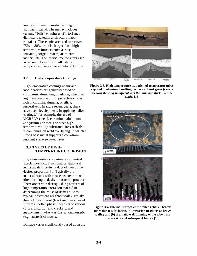
3-4
use ceramic matrix made from high
alumina material. The matrix includes ceramic “balls” or spheres of 1 to 2 inch
diameter packed in a refractory lined
container. These units are used to recover
75% to 80% heat discharged from high temperature furnaces such as steel
reheating, forge furnaces, aluminum
melters, etc. The internal recuperators used in radiant tubes are specially shaped
recuperators using sintered Silicon Nitride.
3.2.5 High-temperature Coatings
High-temperature coatings or surface
modifications are generally based on
chromium, aluminum, or silicon, which, at
high temperatures, form protective oxides rich in chromia, alumina, or silica,
respectively. In more recent years, there
have been developments in applying “alloy coatings,” for example, the use of
MCRALY (metal, chromium, aluminum,
and yttrium) on steels or other high-temperature alloy substrates. Research also
is continuing on weld overlaying, in which a
strong base metal supports a corrosion-
resistant surface-coated layer.
3.3 TYPES OF HIGH-
TEMPERATURE CORROSION
High-temperature corrosion is a chemical attack upon solid functional or structural
materials that results in degradation of the
desired properties. [6] Typically the
material reacts with a gaseous environment, often forming undesirable reaction products.
There are certain distinguishing features of
high-temperature corrosion that aid in determining the cause of damage. Some
typical indications are thick scales, grossly
thinned metal, burnt (blackened) or charred surfaces, molten phases, deposits of various
colors, distortion and cracking, and
magnetism in what was first a nonmagnetic
(e.g., austenitic) matrix.
Damage varies significantly based upon the
Figure 3-3. High temperature oxidation of recuperator tubes
exposed to aluminum melting furnace exhaust gases (Cross-
sections showing significant wall thinning and thick internal
oxide) [7].
Figure 3-4. Internal surface of the failed reboiler heater
tubes due to sulfidation, (a) corrosion products as heavy
scaling and (b) dramatic wall thinning of the tube from
process side and subsequent failure [10].
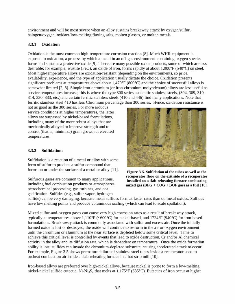
3-5
environment and will be most severe when an alloy sustains breakaway attack by oxygen/sulfur,
halogen/oxygen, oxidant/low-melting fluxing salts, molten glasses, or molten metals.
3.3.1 Oxidation
Oxidation is the most common high-temperature corrosion reaction [8]. Much WHR equipment is
exposed to oxidation, a process by which a metal in an off-gas environment containing oxygen species
forms and sustains a protective oxide [9]. There are many possible oxide products, some of which are less desirable; for example, wustite (FeO), an oxide of iron, forms rapidly at about 1,000°F (540°C) on steel.
Most high-temperature alloys are oxidation-resistant (depending on the environment), so price,
availability, experience, and the type of application usually dictate the choice. Oxidation presents significant problems at temperatures above about 1,470°F (800°C) and the choice of successful alloys is
somewhat limited [2, 8]. Simple iron-chromium (or iron-chromium-molybdenum) alloys are less useful as
service temperatures increase; this is where the type 300 series austenitic stainless steels, (304, 309, 310, 314, 330, 333, etc.) and certain ferritic stainless steels (410 and 446) find many applications. Note that
ferritic stainless steel 410 has less Chromium percentage than 300 series. Hence, oxidation resistance is
not as good as the 300 series. For more arduous
service conditions at higher temperatures, the latter alloys are surpassed by nickel-based formulations,
including many of the more robust alloys that are
mechanically alloyed to improve strength and to control (that is, minimize) grain growth at elevated
temperatures.
3.3.2 Sulfidation:
Sulfidation is a reaction of a metal or alloy with some
form of sulfur to produce a sulfur compound that
forms on or under the surface of a metal or alloy [11].
Sulfurous gases are common to many applications, including fuel combustion products or atmospheres,
petrochemical processing, gas turbines, and coal
gasification. Sulfides (e.g., sulfur vapor, hydrogen sulfide) can be very damaging, because metal sulfides form at faster rates than do metal oxides. Sulfides
have low melting points and produce voluminous scaling (which can lead to scale spallation).
Mixed sulfur-and-oxygen gases can cause very high corrosion rates as a result of breakaway attack,
typically at temperatures above 1,110°F (~600°C) for nickel-based, and 1724°F (940°C) for iron-based formulations. Break-away attack is commonly associated with sulfur and excess air. Once the initially
formed oxide is lost or destroyed, the oxide will continue to re-form in the air or oxygen environment
until the chromium or aluminum at the near surface is depleted below some critical level. Time to achieve this critical level is controlled by events that lead to oxide destruction, Cr and/or Al chemical
activity in the alloy and its diffusion rate, which is dependent on temperature. Once the oxide formation
ability is lost, sulfides can invade the chromium-depleted substrate, causing accelerated attack to occur. For example, Figure 3.5 shows premature failure of stainless steel tubes inside a recuperator used to
preheat combustion air inside a slab-reheating furnace in a hot strip mill [10].
Iron-based alloys are preferred over high-nickel alloys, because nickel is prone to form a low-melting
nickel-nickel sulfide eutectic, Ni-Ni3S2 that melts at 1,175°F (635°C). Eutectics of iron occur at higher
Figure 3-5. Sulfidation of the tubes as well as the
recuperator floor on the exit side of a recuperator
installed on a slab-reheating furnace combusting
mixed gas (BFG + COG + BOF gas) as a fuel [10].

3-6
temperatures 1,805°F (985°C) [2]. Alloys containing aluminum and silicon are useful in sulfidizing
environments. Many alloys classified as candidates for sulfidation do well only if oxides are able to form first.
3.3.3 Halogenation
Halogen (e.g., chlorine, fluorine, bromine) attack commonly manifests as a combination of scale
spallation with internal alloy damage, including voids that form as a result of highly volatile species (e.g. chlorine or hydrogen chloride, fluorine or hydrogen fluoride) [12]. Halogens are readily soluble and
diffuse rapidly into metals at high temperatures, and they can cause high-temperature corrosion. The
solubility-diffusivity product (NxDx) for fluorine in nickel is about five times that for oxygen in nickel and about twice that for chlorine in nickel at 1,380°F (750°C) [12]. Oxidizing chlorine environments
(e.g., air and 2% chlorine) are more damaging at 1,650°F (900°C) than reducing environments (e.g., Ar-
25% H2-10% HCl-5% CO-1% CO2). Alumina-forming alloys are often the best choice overall; but acid-resistant alloys—rich in chromium and refractory metal—show reasonable performance in reducing
atmospheres, unlike pure iron, for example [12].
3.3.4 Carburization
Carburization is a high-temperature corrosion phenomenon caused by the unwanted ingress of carbon into alloys used in the process and heat-treating industries. It occurs as a result of the presence of CO2,
methane, and hydrocarbon gases in off-gases. Damage usually manifests as internal carbides, notably in
grain boundaries, and is generally worst above 1,922°F (1,050°C). When carburizing conditions alternate with oxidizing ones, carbides can become oxidized to form oxides, yielding carbon monoxide that can
weaken the grain boundaries in an alloy. Such an alloy fails by “green rot,” a name for the green fractured
surface that results (chromium oxide). Strongly carburizing atmospheres (i.e., those that have a carbon activity >1) can cause a metal to form coke-like layers, often of a dusty form. This form of attack, termed
“metal dusting,” commonly occurs between 790°F and 1,470°F (425-800°C) and can be very rapid
(occurring in days, not months). Damage is either general or localized, as dictated by the ability of the
alloy to form a surface oxide. Carbon steels and alloy steels are normally uniformly thinned by metal dusting; more highly alloyed materials usually display localized outgrowths of coke that broaden with
time. Cast iron-nickel-chromium alloys are widely used for carburizing applications, including more
recently developed alloys containing 1–2% silicon and 1.5% niobium (the HP Mod alloys) [2, 12]. High-nickel alloys (with low solubility for carbon) find many applications in carburizing conditions. Stronger
nickel-based alloys with high chromium and silicon contents are useful in more demanding environments.
Highly alloyed ferritic stainless steels (which are able to more rapidly form a thin oxide film) tend to
outperform austenitic steels.
3.3.5 Nitriding
Due to nitridation, performance of certain materials gets weakened (e.g. embrittlement) as a result of the
formation of internal nitrides in the alloy. It is common to expect damage with nitrides at the elevated temperatures [1,290–1,650°F (700–900°C)]. Nitrides appear generally as needle-like precipitates in the
alloy matrix. Nickel- and cobalt-rich alloys appear to be primary candidates for resisting nitride attack
because of the low solubility of nitrogen in these base metals. Iron tends to be detrimental, as do aluminum and titanium in low concentrations. Silicon forms a brittle intermetallic compound with
nitrogen and can contribute to scale spallation, especially in applications at low oxygen concentrations
(potentials), in which thin oxides can form, and during thermal cycling [2].

3-7
3.3.6 Molten Product Corrosion
The mechanisms of molten product corrosion are complex. Deposits are a common product in many high-temperature applications, including boilers, waste incinerators, fluidized-bed combustors, and gas
turbines. A whole series of reactions is possible should deposits become molten, and no single mechanism
can be applied generally to characterize such damage. The types of damage include fuel-ash corrosion
(sulfates, including acid and basic fluxing reactions, and vanadic slag attack), molten salt corrosion (chlorides, nitrates, and carbonates), and molten glass corrosion. Liquid metal attack is yet another special
category. An example of molten product corrosion is the rapid degradation of alumina and silicon carbide
refractories at very high temperature (probably > 1,800°F) due to the presence of zinc (likely from the galvanized material included in the scrap) in electric arc furnace systems.

3-8
Table 3.1. High-temperature waste heat sources and typical process conditions causing corrosion
Industry Waste heat source Temp. range
(°F) Characteristics
Type(s) of corrosion
O S C Cl/F N Slag Melt Other
Steel Blast furnace gases 750 to 1,100 Contain dust, sulfur, cyanide
compounds, and other
contaminants
X X
EAF exhaust gases 2,700 to 3,000 Contain combustibles,
particulates, etc.
X X X X X X X
Basic oxygen process 2,250 to 3,000 Contain combustibles,
particulates, etc.
X X X X X X X
Glass Regenerative system 750 to 1,100 Contain particulates; HCl, HF,
boron vapors can be expected
X X X X X
Oxy-fuel system 2,700 to 2,820 Contain particulates,
condensable vapors, etc.
X X X X X
Nonregenerative +
other systems
2,700 to 2,820 Contain particulates,
condensable vapors, etc.
X X X X X
Aluminum Al melting furnaces (fuel fired)
1,400 to 1,700 Combustibles, particulates, polycyclic organic matter,
fluxing agents (chlorine,
fluorine, etc.).
X X X X X X X
Anode baking 570 to 930 Particulates, fuel combustion
products, etc.
X X X X X
Calcining 570 to 930 Particulates, fuel combustion
products, etc.
Cement Cement kiln exhaust
gases from modern
clinker making
operations
390 to 750 Exhaust gases contain
particulates, etc.
Relatively easy to handle
X X X X
Lime Lime kiln exhaust
gases from commonly
used rotary kiln type
operations
390 to 1,100 Exhaust gases contain
particulates, etc.
Relatively easy to handle
X X X X

3-9
Table 3.2. High-temperature waste heat sources and off-gas composition
Industry Waste heat source Temp. range
(°F) Characteristics
Off-gas composition (% by volume)
O2 CO H2 CO2 H2O CH4 N2 Other Source
Steel Blast furnace gases 750 to 1,100 Contain dust, sulfur,
cyanide compounds, and
other contaminants
– 20–28 1–5 17–25 – – 50–55 – [13]
EAF exhaust gases 2,700 to
3,000
Contain combustibles,
particulates, etc.
– 22 5 8 2 3 60 – [14]
Basic oxygen process 2,250 to
3,000
Contain combustibles,
particulates, etc.
– 70 2 13 2 1 13 – [15]
Glass Regenerative system 750 to 1,100 Contain particulates; HCl,
HF, boron vapors can be
expected
4–10 – – 7–11 4-10 – 73-76 – [16]
Oxy-fuel system 2,700 to
2,820
Contain particulates,
condensable vapors, etc.
1–2 – – – – Calculations
– ESC
Nonregenerative + other systems
2,700 to 2,820
Contain particulates, condensable vapors, etc.
4–10 – – 7–11 4–10 – 73–76
Aluminum Al melting furnaces
(fuel fired)
1,400 to
1,700
Combustibles, particulates,
polycyclic organic matter,
fluxing agents (chlorine,
fluorine, etc.)
4–10 50–55 42–49 – 0–2 Calculations
Anode baking 570 to 930 Particulates, fuel
combustion products, etc.
6–10 ~0.2 ~0.1 6–7 11–12 80–84 O2 from
[3.3] and
calculations
Calcining 570 to 930 Particulates, fuel
combustion products, etc.
Cement Cement kiln exhaust
gases from modern
clinker making
operations
390 to 750 Particulates, combustibles,
NOx and SO2
1.8 – – 27.4 – – 70.8 – [17]
Lime Lime kiln exhaust
gases from commonly used rotary kiln type
operations
390 to 1,100 Particulates, combustibles,
NOx and SO2
4–10 – – 7–11 4–10 – 73–76 4–10 Combustion
calculations based on O2
content and
different
fuels

3-1
0
Table 3.3. Currently used waste heat recovery equipment and materials
Industry Waste heat source Temp.
range (°F) Characteristics WHR related equipment
Steel Blast furnace gases 750 to 1,100 Contain dust, sulfur, cyanide
compounds, and other
contaminants
Scrubbers, top gas pressure recovery
turbines, and recuperator hot blast stoves
EAF exhaust gases 2,700 to
3,000
Contain combustibles,
particulates, etc.
Consteel scrap preheaters, Bucket types
scrap preheaters, Twin-shell furnaces,
Fuchs shaft furnaces, and Evaporative
Cooling (ECS) technology
Basic oxygen process 2,250 to
3,000
Contain combustibles,
particulates, etc.
Boiler or HRSGs, BOF gas cooling
devices, dedusting devices, etc.
Glass Regenerative system 750 to 1,100 Contain particulates; HCl, HF,
boron vapors can be expected
Stationary regenerators, cullet preheaters,
HRSGs, Organic Rankine Cycle (ORC) equipment
Oxy-fuel system 2,700 to
2,820
Contain particulates, condensable
vapors, etc.
Batch/Cullet preheaters, HRSGs, ORC
equipment
Nonregenerative + other
(approx. values)
2,700 to
2,820
Contain particulates, condensable
vapors, etc.
Aluminum Al melting furnaces
(fuel fired)
1,400 to
1,700
Combustibles, particulates,
polycyclic organic matter, fluxing
agents (chlorine, fluorine, etc.).
Conventional recuperators, regenerative
burners, charge preheaters, HRSGs
Anode baking 570 to 930 Particulates, fuel combustion
products, etc.
Thermoelectric generators, sidewall heat
exchangers, combustion air preheaters
Calcining 570 to 930 Particulates, fuel combustion
products, etc.
Cyclones and fluidized bed alumina
coolers
Cement Cement kiln exhaust
gases from modern
clinker making
operations
390 to 750 Particulates, combustibles, NOx
and SO2
Waste heat recovery boilers, shaft type
charge preheaters
Lime Lime kiln exhaust gases
from commonly used
rotary kiln type operations
390 to 1,100 Particulates, combustibles, NOx
and SO2
Waste heat recovery boilers, shaft type
charge preheaters

3-1
1
Table 3.4. High-temperature metal alloys
Alloy Fe Ni Cr Mo Co Al C Mn Si Zr Ti Other
Tensile at max
use temp
(ksi)
Yield at max
use temp
(ksi)
Max use
temp
(F)
Carpenter
Waspalloy 2.0 M Bal 18–21 3.5–
5.0 12–15 1.2–1.6
0.02–
0.10 0.10 M 0.15 M
0.02–
0.08 3.00
79 60 1600
Haynes Intl.
Haynes 214 3.0 Bal 16
4.5 0.05 0.5 M 0.2 M 0.1 M l
4.3 2.1 2200
Haynes 224 27.5 Bal 20
3.8
???
Haynes 230 3 M Bal 22 2 5 M 0.3 0.10
0.40
14 W, 0.02
La 13.2 6.8 2100
Hastelloy X 18.0 Bal 22 9 2
0.10 1 M 1 M
0.6 W 14.0 6.4 2000
Rolled Alloys
602CA 9.5 Bal 25
2.2 0.18 0.15 M 0.5 M 0.08 0.15 0.09 Y 5.8 5.0 2200
Sandvik Matl.
353MA Bal 35 25
0.05 1.50 1.60
0.05 Ce, 0.16 N
2100
APMT Bal
21 3
5.0 0.08 M 0.4 M 0.7 M
2280
Sanicro 61
60 23
1.3 0.03 0.60 0.30
~7 ~3 2100
Sanicro 70 9.5 72.5 16.5
0.06 0.80 0.40
0.15
NA
Special metals
Inconel 601 14.0 62 23
1.4 0.05
~5 ~3 2100
Inconel 617 3.0 M 44.5 M 20–24 8–10 10–15 0.8–1.5 0.05–0.15
1.0 M 1.0 M
0.6 M 0.5 Cu, 0.006 B
0.73 0.45 1800
Inconel 693 2.5–6.0 Bal 27–31
2.5–4.0 0.15 M 1.0 M 0.5 M
1.0 M 0.5 Cu ~7 ~3 2000
Inconel 702 2.0 M Bal 14–17
2.75–
3.75
0.25–
1.0 NA
Note: M – Maximum and Bal - Balance

3-1
2
Table 3.5. High-temperature ceramic/refractory materials
Material Type Producer
Chemistry Physical properties Service
temp oF
Thermal
conductivity
(W/mK) Cost and
availability
Al2O3 SiO2 SiC CaO Fe2O3 MgO TiO2 P2O5 Alkali Other Density
(g/cm3)
Porosity
%
MOR
MPa
Cc
MPa High Low
ALAKAST
85-ULC
High
alumina,
ULC
Riverside 85.71 9.27 – 1.39 0.76 0.01 2.33
0.09 0.44 2.85 15–16 17 95 3,100 3.47 2.91
AlAKAST
95-LC-P
High
alumina, LC Riverside 90–95
5–10
<5
Metpump
C-192
High
alumina,
cement free
Magneco-
Metrel 91.7 7.7 – 0.1 0.1 – 0.1
0.2 – 2.95 14 15 > 110 3,250 5 3.5
Metpump
Delta
High
alumina, SiC
Magneco-
Metrel 85.4 7.3 4.6 0.1 0.4 – 2
0.1 – 3.1 14 15 96.6 3,200
F-1408 High
magnesia MinTeq 0.1 2.2 – 5 0.6 91.4 – 0.7 – – 2.68 21 19 52 3,000
Monofrax L Fusion cast
spinel Monofrax 53.6 0.44 – 0.35 – 44.9 –
0.23 – 3.08 < 2
3,400 17.75 5.75
Monofrax M Fusion cast
alumina Monofrax 94 1 – – – – –
4 < 1 3.4 < 2 24 124 3,400 4.8
MORCOCA
ST 85 LC
High
alumina, LC MORCO 84–86 9–10 – < 2 < 2 – < 3
– < 1 2.8 14–16
93 3,250
TCON TC1 SiC/Al2O3
composite Fireline 37
50
(13%
Al/Si) 2.93 9 25
TCON TC2 SiC/Al2O3
composite Fireline 33
55
(12%
Al/Si) 3.05 4 21
Note: MOR – Modulus of Rupture, Cc – Compression index, ULC – Ultra Low Carbon, and LC – Low Carbon.
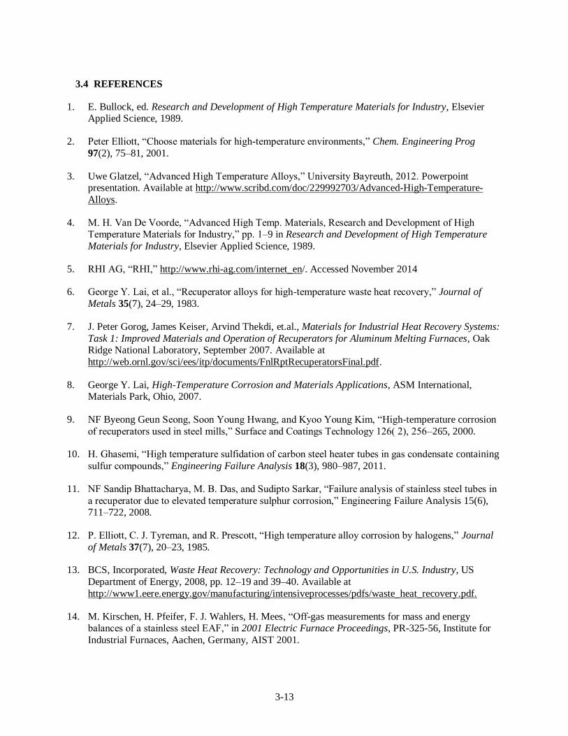
3-13
3.4 REFERENCES
1. E. Bullock, ed. Research and Development of High Temperature Materials for Industry, Elsevier Applied Science, 1989.
2. Peter Elliott, “Choose materials for high-temperature environments,” Chem. Engineering Prog
97(2), 75–81, 2001.
3. Uwe Glatzel, “Advanced High Temperature Alloys,” University Bayreuth, 2012. Powerpoint presentation. Available at http://www.scribd.com/doc/229992703/Advanced-High-Temperature-
Alloys.
4. M. H. Van De Voorde, “Advanced High Temp. Materials, Research and Development of High Temperature Materials for Industry,” pp. 1–9 in Research and Development of High Temperature
Materials for Industry, Elsevier Applied Science, 1989.
5. RHI AG, “RHI,” http://www.rhi-ag.com/internet_en/. Accessed November 2014
6. George Y. Lai, et al., “Recuperator alloys for high-temperature waste heat recovery,” Journal of
Metals 35(7), 24–29, 1983.
7. J. Peter Gorog, James Keiser, Arvind Thekdi, et.al., Materials for Industrial Heat Recovery Systems:
Task 1: Improved Materials and Operation of Recuperators for Aluminum Melting Furnaces, Oak Ridge National Laboratory, September 2007. Available at
http://web.ornl.gov/sci/ees/itp/documents/FnlRptRecuperatorsFinal.pdf.
8. George Y. Lai, High-Temperature Corrosion and Materials Applications, ASM International, Materials Park, Ohio, 2007.
9. NF Byeong Geun Seong, Soon Young Hwang, and Kyoo Young Kim, “High-temperature corrosion
of recuperators used in steel mills,” Surface and Coatings Technology 126( 2), 256–265, 2000.
10. H. Ghasemi, “High temperature sulfidation of carbon steel heater tubes in gas condensate containing
sulfur compounds,” Engineering Failure Analysis 18(3), 980–987, 2011.
11. NF Sandip Bhattacharya, M. B. Das, and Sudipto Sarkar, “Failure analysis of stainless steel tubes in
a recuperator due to elevated temperature sulphur corrosion,” Engineering Failure Analysis 15(6), 711–722, 2008.
12. P. Elliott, C. J. Tyreman, and R. Prescott, “High temperature alloy corrosion by halogens,” Journal
of Metals 37(7), 20–23, 1985.
13. BCS, Incorporated, Waste Heat Recovery: Technology and Opportunities in U.S. Industry, US
Department of Energy, 2008, pp. 12–19 and 39–40. Available at
http://www1.eere.energy.gov/manufacturing/intensiveprocesses/pdfs/waste_heat_recovery.pdf.
14. M. Kirschen, H. Pfeifer, F. J. Wahlers, H. Mees, “Off-gas measurements for mass and energy balances of a stainless steel EAF,” in 2001 Electric Furnace Proceedings, PR-325-56, Institute for
Industrial Furnaces, Aachen, Germany, AIST 2001.

3-14
15. JFE 21st Century Foundation, “Smelting, Refining and Continuous Casting,” 2003, http://www.jfe-
21st-cf.or.jp/chapter_2/2f_2.html. Accessed November 2014.
16. Zhiwei Li, et al, “Design of a flat glass furnace waste heat power generation system,” Applied
Thermal Engineering 63(1), 290–296, 2014.
17. Tahsin Engin and Vedat Ari. “Energy auditing and recovery for dry type cement rotary kiln
systems—A case study.” Energy Conversion and Management 46(4), 551–562, 2005.


4-1
4. STEEL INDUSTRY
4.1 BLAST FURNACES
4.1.1 Background and Potential Opportunity
The purpose of a blast furnace is to convert iron oxides into liquid iron through a series of chemical
reactions. Hot liquid metal production in a blast furnace is one of the most energy-consuming processes.
In the US, the iron and steel industry account for 34% of energy use [1]. Blast furnaces that have been installed vary in size (working volume), ranging from less than 100 m
3 (3,531.5 ft
3) to more than 5000 m
3
(176.573 ft3). [2] In 2014, there are total 22 blast furnaces installed in the US and their rated capacities
vary between 1.2 to 2.8 million metric ton (tonne) per year. [3]
A blast furnace is a shaft that is charged from the top with a combination of iron ore sinter, coke and lime.
The lime is used to remove impurities. [1] Hot compressed air is injected from the sides near the bottom
end of the furnace using tuyeres (see Figure 4.1). The hot air entering the furnace is provided by several auxiliary hot blast stoves. Blast furnace gases and coke oven gases are combusted in these blast stoves to
generate heat, which is transferred to a checker work regenerator. When the regenerator reaches a specific
temperature, the flow of gases is reversed and cold air flows through the regenerator. This transfers the
heat to the cold air, which can then be injected into the lower section of the blast furnace. [4] The charged materials work their way down the furnace through various zones, and the materials undergo a series of
chemical reactions as they move down.
Figure 4-1. Inside the blast furnace. [5]

4-2
The bottom part of the furnace is the hottest zone; there the coke is gasified, creating high-temperature
reducing gases that are necessary for the chemical reactions to reduce iron ore. The heat content of the gases decreases as they approach the top of the furnace. The gases exchange heat with the charge
materials moving down the furnace.
Molten iron trickles down to the base of the furnace, forming a porous mass at 2,192F (1200C). Impurities in this molten iron are removed by a chemical reaction with fluxes such as calcium oxide. The
reactions form a slag that floats on top of the molten iron because it is less dense. Silica that does not react with the calcium oxide is reduced by carbon. The coke chemical reactions produce carbon monoxide
(CO) and other combustible gases as part of the gas mixture flowing toward the top section. After all the
necessary reactions are complete, molten iron can be tapped and the slag removed. The final product is liquid iron, commonly known as pig iron, that can be tapped and used to make steel in a separate process
vessel. [1]
Figure 4.2 shows an example of heat balance carried out in a blast furnace. As seen in the image, over
39% of the total heat input may be discharged as sensible and chemical heat in off-gases. In this case, the chemical heat is 29% of the discharged heat, higher than the percentage of sensible heat, indicating the
presence of a large amount of combustible gases. These blast furnace gases are released through the top of
the furnace if no recovery system is used. A typical blast furnace produces around 1,320–2,210 Nm3
(46,615 to 78,045 ft3) of furnace gas per ton of pig iron, containing 20–28% CO and 1–5% H2 at an
average gas temperature range of 400–600F (200–320C). [6] The practical minimum energy use for a blast furnace is 10.4 GJ/t (9.86 MMBtu/t). [3] Based on information obtained from six efficient hot blast
stoves and blast stoves around the world, the average total primary energy requirement for a blast furnace
system is reported to be 13.4 GJ/t of liquid iron. This energy use includes 1.8 GJ/t hot metal (1.71 MMBtu/t) for the hot blast stoves and 11.6 GJ/t-hot metal (11 MMBtu/t) for the blast furnace itself.
[7].

4-3
Figure 4-2. An example of heat balance carried out in a blast furnace. [8]
4.1.2 Current Methods of Waste Heat Recovery
In blast furnaces without recovery systems, a great deal of energy is wasted in the form of off-gases. Both
chemical and sensible heat is lost. As mentioned earlier, 29% of the total input energy is wasted in the form of blast furnace gases (chemical heat). Another 11% is wasted as sensible heat. This is a significant
amount of energy simply being released as waste. Many blast furnace plants today incorporate WHR
systems that can recover some of the sensible and chemical heat for use in the steel making process. This not only reduces the amount of exhaust gases but also can potentially save a great deal of money and fuel.
There are many existing WHR methods in use by the steel industry, which will be explored and analyzed
in this section. Table 4.1 summarizes these methods and examines the advantages, disadvantages, and heat recovery potentials.
Recovery of chemical heat from blast furnace (BF) top gases: One major WHR method involves the
recovery of blast furnace top gases. Most of the heat lost is in the form of chemical heat being released
through the top of the blast furnace. A typical blast furnace produces about 1,320 to 2,210 Nm3 (46,615–
78,045 ft3) of gas per ton of pig iron, [9] consisting of 20–28% CO, 1–5% H2, 50–55% N2, and 17–25%
CO2, as well as dust, sulfur, cyanide compounds, and other contaminants. [15] The gases being released
have the potential to be used as fuel and/or used to generate electricity in a gas turbine. This method of recovery involves cooling or “washing” the blast furnace off-gases using a scrubber and then storing
them. [7] Scrubbers remove about 60% of particulates from blast furnace gases. [9] Figure 4.2 shows a
Venturi scrubber, a type of scrubber that can be used in this process. [10] After scrubbing, dry gases can
then be distributed as fuel, mixed with other fuels (e.g., natural gas, coke oven gas) for the heating processes within the plant. The energy content in blast furnace gases ranges from 2.3–3.4 kBtu/Nm
3 (2.7–
4.0 MJ/Nm3). The amount of energy in these gases varies depending on the concentration of CO. The
blast furnace gas usually has only about 10% of the energy content of natural gas (2.8 kBtu/m3 vs. 28-38
kBtu/m3); therefore, it is usually enriched by coke oven gases or natural gas before it is used in order to
boost its energy content. [7] By recovering blast furnace top gases, cleaning them, and storing them for
later use, it is possible to reduce emissions by 4.0 kg CO2/t hot metal. [11]
The recovery technology for this method is currently available and widely used by many blast furnace
plants in the US. The top-gas recovery system is fairly simple and well established. Site-specific variables
Off-Gas Sensible Waste Heat
622.78 kWh/ton (11%)
Off-Gas Chemical Waste Heat
1659.44 kWh/ton (29%)
Iron 3,059.72 kWh/ton
(53%)
Slag 142.50 kWh/ton
(2%)
Condensate 283.06 kWh/ton
(5%)
Shell 55.56 kWh/ton
(1%)

4-4
may affect costs. A top-gas recovery system has been installed on a furnace in the Netherlands at a cost of
$0.43/ton ($0.47/tonne) of hot metal, and the energy savings have been estimated to be approximately 17 kWh/ton (0.066 GJ/tonne) (0.058 MMBtu/ton) of hot metal. [5] Clearly, this WHR method has several
advantages; however, a few issues and barriers are associated with it. Although a significant amount of
chemical heat is recovered, a great deal of the sensible heat is lost, so only a portion of the waste heat is
being recovered. Sensible heat has the potential to be useful for preheating combustion fuels in several other recovery methods; however, it is lost because of requirement that particulates be removed through
washing or scrubbing. Another issue with this recovery method is the disposal of scrubber water. In the
wet scrubber, down-flow water sprays clean the dust from up-flowing gases. The wastewater contains 1000–10000 mg/l (0.0083–0.083 lb/gal) of suspended solids, [12] and its disposal may pose a challenge.
Top gas pressure recovery—use of turbines to generate electric power: Top gas pressure recovery, a
second major WHR method, uses a turbine to recover energy from higher-pressure gases through pressure reduction. [7] The physical energy of high-pressure blast furnace top gases is converted into electricity by
using an expansion turbine (Top pressure Recovery Turbine – TRT) [13]; electric power is generated by
using the top gases to drive a turbine-generator as they expand from furnace top pressure to atmospheric
pressure. Top gas pressures in most blast furnaces are approximately 6–36 psig (0.25–2.5 bar gauge). [7] The pressure differential between the furnace and the atmosphere is low, but the large volume of gas
makes this method economical. [9] These systems can be either wet or dry, depending on the method used
to remove the dust particles, which is necessary for proper turbine operation. [3] Dry system utilizes the BF gas heat and pressure energy to drive a turbine. Dry systems use less water and electricity and
typically produce 25 to 30% more power, but they are more expensive than wet systems. Wet system
utilizes only the BF gas pressure energy to drive a turbine. Wet systems are more common in the US. [9] Pressure recovery system is used for cooled gases. The gases must be cooled and “cleaned” to remove
major particles content before they enter the pressure recovery turbine. Figure 4.3 shows a diagram of a
Venturi scrubber (a wet scrubber), commonly used in blast furnace top pressure recovery. Wet scrubbers
use water to remove very small dust particles. [17] Top pressure recovery systems have good operational reliability and are abrasive-resistant. [6] A wet turbine system of this type has the potential to produce
approximately 14 to 36 kWh/ton (0.054 to 0.14 GJ/tonne) (0.048 to 0.123 MMBtu/ton) of hot metal. [6]
Also, 40–60 kWh (0.136–0.205 MMBtu) of electricity can be produced per ton of hot metal. [9] This output can supply around 30% of all the electricity needs of all blast furnace equipment. [14]. Essentially,
the waste gases at the top of a blast furnace are used to generate electricity rather than simply being
exhausted into the atmosphere, reducing emissions as well as the cost of powering the blast furnace.
Cost is a significant issue to examine in considering use of top gas recovery. A typical investment for the turbine is approximately $28.4/ton hot metal ($31.3/tonne). Such a project would have an estimated
payback time of 30 years. [6] Although that is a long period of time, many would argue that it is a good
long-term investment because of the economic and environmental benefits. Another barrier associated with top gas pressure recovery is that blast furnaces do not operate at extremely high pressures, which can
make top gas recovery somewhat difficult. [7] Although the top pressure in most US furnaces is too low
for recovery, future furnace upgrades may result in pressures high enough to allow economic recovery. [6] For now, these systems are suitable only for large furnaces (in excess of 1 million tonne/year) and
high-pressure gases. [6] This technology is available but is not widely used, especially in the US. [14]
Dry type recovery turbines have already been commercialized; however, they are significantly more
expensive than wet type systems and are not likely to be used in the US soon. [4] This technology is considered to have a high application potential for China, India, and the US, particularly for new plants.
The final issue is that it is often difficult to retrofit existing blast furnaces to use top gas pressure recovery
technology. [14]

4-5
Figure 4-3. Venturi scrubber (wet type scrubber). [10]
Recuperator hot blast stove: A third WHR method uses a recuperator system to recover the heat from flue
gases from the hot blast stove to preheat the blast furnace. The energy from the stove flue gases pre-heats
the combustion fuel and air entering the blast stoves. The stove flue gases typically have a temperature of
about 482F (250C). [7] Preheating can lead to an energy saving of approximately 87.92 kWh/ton (0.3 MMBtu/ton) of pig iron. Fuel savings can be from 20 to 21 kWh/ton (0.068 to 0.072 MMBtu/ton) of hot
metal at a cost of approximately $19 to 21/MMBtu ($18 to $20/GJ) saved. This results in a payback
period of about 8.7 years. [6] This method can allow an efficient hot blast stove to run without the need for natural gas. Another advantage of preheating is that the hotter combustion air results in a higher flame
temperature. A higher flame temperature will result in a higher blast temperature of the blast furnace air.
A specific medium-size WHR system located in Japan, consisting of two heat exchangers, achieved a
recovery rate of sensible heat of 40–50%. This 1 tonne/year blast furnace system realized a savings of 0.125GJ/t of pig iron (0.118 MMBtu/ton) and a reduction in heat consumption of about 31.65 kWh/ton
(0.108 MMBtu/ton) of pig iron. [15] An issue with this WHR method is that costs are high and depend
considerably on the size of the blast furnace. [6] This technology has been installed at most steel plants in Japan. Candidate countries for this technology include China, India, Central/South America, and Eastern
Europe countries [7]. Currently there is low potential for this technology in the US. [16]
BF gas preheating system using recuperator: A fourth WHR method uses a recuperator system to recover
heat from blast furnace gases to preheat the combustion air for the blast furnace. This method is similar to the third method discussed, except that it uses recuperators to recover heat from the blast furnace gases
leaving the top of the furnace rather than from the blast stove flue gases. The concept of preheating
combustion fuel and air entering the stove are the same, but the heat is recovered from two different places using a system of recuperators. The two places are: (i) heat recovery from blast furnace top gases
leaving the blast furnace; and (ii) exhaust gases or combustion products leaving the blast furnace stove
itself. Blast furnace gas preheating systems use low- and medium-temperature waste heats 340 – 430F
(170–220C). The heat exchange is difficult because of corrosion

4-6
Of working surfaces. An existing blast furnace gas preheating system at POSCO in South Korea was able
to reduce fuel input by 102 kcal/kWh (0.30 kcal/Btu) (427.07 kJ/kWh) and increase the thermal efficiency of the furnace by 3.3%. Studies have shown that these systems are fairly reliable and stable. [9] A few
barriers are associated with this method, mainly involving the recuperators. There are several different
types of recuperators, each with their own set of barriers. Corrosion is very common because of chemical
reactions that occur with the solid particulates suspended in the gases and the recuperator. To counter this problem, some companies, including POSCO in South Korea, have developed anti-corrosion systems.
This method is currently considered an emerging commercial technology. [9]
[T
yp
e a qu
ote
fro
m the
do
cume
nt
or the
su
m
ma

4-7
Table 4.1. Existing and emerging waste heat recovery techniques/methods from blast furnace off-gases
Existing method
of waste heat
recovery
Brief description
WHR
technology/system
status
Advantage Barrier/disadvantage Waste heat recovery
potential
Recovery of
chemical heat
from blast
furnace (BF) top
gases
Cooling or washing of
BF off-gases using a
scrubber and then
storage and/or
distribution of dry gases as fuel mixed with other
fuels (e.g., natural gas,
coke oven gas) [7]
Available and widely
used [11]
Relatively simple and well
established. Emissions can
be reduced by 4.0 kg CO2/t
of hot metal [10]. Potential
energy savings up to 17 kWh/t of hot metal (US
EPA 2010) [6]
Loss of sensible heat [6],
disposal of scrubber
water [12]
Potential energy saving up to
17 kWh/t of hot metal [6]
Top gas pressure
recovery—use of
turbines to
generate electric
power
BF top gases are at
higher pressure (0.1 to
0.25 MPa gage or 15.5 to
31 psig). Turbine
recovers energy from
higher-pressure gases
through pressure
reduction. [7]
Available but not widely
used, particularly in US
[6]
Electrical power generation
[6]. Suitable for large
furnaces and high-
temperature gases. Good
operational reliability,
abrasion resistant [9]
US BFs do not operate at
high pressure.
Uneconomical, and
retrofit is difficult [6]
Existing facilities using the
technology have experienced
net primary energy savings of
2,052,000,000 kWh (7 Tbtu)
(as of 1997).[16] Turbine may
produce ~14 to 36 kWh/ton
(0.054 to 0.14 GJ/tonne) of hot
metal [7]. 40–60 kWh of
electricity can be produced per
ton of hot metal and their output can meet around 30% of
all electricity needs for the BF
equipment [9]
Recuperator hot
blast stove
Hot blast stove flue gases
are used to preheat the
BF [6].
Commercial status.
Medium application
potential in China and
India, and low potential
for the US. [15]
An efficient hot blast stove
can run without the need for
natural gas. Energy savings
are ~0.3 MMBtu/ton pig
iron. Fuel savings vary from
80–85 MJ/t hot metal [6]
Payback time is about
8.7 years [6]. Costs are
high and depend heavily
on the size of the BF [9]
Preheating can lead to energy
savings of ~87.92 kWh/ton pig
iron (0.3 MMBtu/ton pig iron
or 0.35 GJ/tonne) [6]. Can
reduce energy demand by
66.67 kWh/ton of hot metal
(0.24 GJ/t) [15]

4-8
Table 4.1. Existing and emerging waste heat recovery techniques/methods from blast furnace off-gases (continued)
Existing method
of waste heat
recovery
Brief description
WHR
technology/system
status
Advantage Barrier/disadvantage Waste heat recovery
potential
BF gas preheating
system using
recuperator
The exit temperature of
the flue gases, ~480F
(250C), can be recovered to preheat the
combustion air of the
stoves [9]
Emerging technology [9] Economic recovery for low-
to medium-temperature
grade heat.
102 kcal/kWh reduction in fuel input; 3.3% thermal
efficiency increase.
Energy savings of 3–5% for
boiler with payback period
of within 1.5 years [9]
Recuperator corrosion is
common [9]
102 kcal/kWh reduction in fuel
input; 3.3% thermal efficiency
increase of 3.3%
Energy savings of 3–5% for boiler with payback period of
within 1.5 years [9]

4-9
4.1.3 Limitations of Existing Methods of Waste Heat Recovery from Blast Furnaces
Despite the advantages attributed to blast furnace WHR methods, the use of some of these technologies is quite limited in the US, as well as in the rest of the world. The lack of use can be explained based on the
following reasons:
In each WHR method, only a portion of the waste heat is recovered. For example, during
cooling or washing of off-gases in the recovery of chemical heat from top gases, most of the
sensible heat is lost. Although a significant amount of chemical energy is recovered, a great deal of the sensible heat from the gases being recovered is lost to the atmosphere.
US blast furnaces do not operate at extremely high pressures, which can make top gas
recovery somewhat difficult and uneconomical. The gases leaving the top of the furnace are
approximately 0.25–2.5 bar (25,000–250,000 N/m2) and have a temperature of around 392F
(200C). [2] This pressure and temperature are comparatively quite low. Top gas pressure recovery is suitable only for large furnaces and high-temperature gases.
Retrofit may be difficult for some recovery methods, such as top pressure recovery methods.
In such cases, the technology may have a higher application potential for new plants because of the difficulty of retrofitting existing plants. [3]
It may be challenging to dispose of wastewater used to wash dirty off-gases to recover
chemical energy. The wastewater in a wet scrubber contains 1000–10000 mg/l (0.0083–0.083
lb/gal) of suspended solids. [12]
Recovery of sensible heat using heat exchangers is difficult because of a lack of suitable
technology in the US. Recuperators, in particular, present a number of issues with preheating
systems, depending on the type of recuperator used. [18] (Discussed in more detail in the
paragraph following this list.)
Recovery system components such as recuperators often experience corrosion as a result of
high temperatures and the presence of particulates. Corrosion of recuperators can reduce the amount of heat transfer from the off-gases to the combustion air. [9]
Preheating systems, including hot blast stove and blast furnace gas preheating systems, are an excellent
way to recover waste heat to preheat combustion air. The incorporation of recuperators in these recovery systems has resulted in reduced fuel consumption, increased cost effectiveness, and short payback
periods. Although recuperators can be very beneficial, they also present many issues that create key
barriers for the recovery systems in which they are used. Several different types of recuperators are available for use. They are classified according to the material of which they are made (metallic or
ceramic) and the dominant mode of heat transfer. Each type of recuperator has its own set of drawbacks
and issues that can prove to be significant barriers to a recovery system. The type of recuperator used in a
recovery system depends on several variables, including the furnace size and temperature and the primary mode of heat transfer used. Convection recuperators are generally deployed when flue gas temperatures
are fairly high. An air-type convection recuperator consists of a bundle of several hundred tubes outside
which flue gas passes, guided by baffle plates. These recuperators are easily affected by dust, and their tubes are sensitive to abrasive wear caused by the solid suspended particles from the flue gases. In a gas-
tube type convection recuperator, the diameter of the heating tubes is much larger than in an air-tube type;
however, these recuperators experience more gas leaks than the air type. Ceramic recuperators are
typically used for temperatures exceeding 2012F (1100C). Ceramic materials are better solutions for

4-10
durable heat exchangers; however, they are more prone to fouling. Fouling, a common problem for
recuperators, is the deposition of material on a heat transfer surface. It results in an increase in the resistance to heat transfer. Fouling is primarily due to the variety of gaseous species present in
combustion gases; many of those species are condensable and some are corrosive. [10]
4.1.4 Conclusions
The use of blast furnace off-gas heat to preheat combustion air, generate electricity, and recover chemical heat offers several benefits. The methods discussed can save energy, reduce emissions, and save money.
Although there are many benefits, there are also several issues and barriers that should be considered for
each method. The barriers depend on the WHR method being used, as well as the size of the blast furnace. Some plants cannot be retrofitted to accommodate some types of systems, and some WHR methods are
suitable only for large furnaces and high-temperature gases. Costs and maintenance are issues for some
blast furnace off-gas systems. Some of the methods discussed are currently being used by several companies, whereas others are still emerging technologies. New and existing WHR methods are still
being developed and studied, and some of them have great potential to improve industrial processes.

4-11
4.2 ELECTRIC ARC FURNACES
4.2.1 Background and Potential Opportunity
The US steel industry has experienced significant growth in the production of liquid steel from recycled
scrap using EAFs, which accounted for about 60.3% of US steel production in 2011. [19] The process
uses electricity as well as fossil fuels, primarily natural gas and some carbon, to supply process energy
requirements. Large amounts of exhaust gas at temperatures greater than 3,000F (1,650C) are discharged from a furnace during the EAF melting cycle. At different times during the melt cycle, these exhaust gases contain CO2, water vapor (H2O), CO, H2, O2, and hydrocarbons. The exhaust also contains
small amounts of metallic and nonmetallic solid particles of varying sizes. The heat content of off-gases
varies during a cycle, commonly known as the tap-to-tap time, which varies typically from 50 to 60 minutes. The exact heat content depends on a number of factors such as the fuel used, amount of oxygen
present, scrap temperature, and type of charge material. Figure 4.4 shows an example of heat balance
carried out on an EAF using electrical energy as well as carbon injection, oxy-fuel burners, and additional
oxygen during the melting operation.
As seen in Figure 4.4, over 38% of the total heat input may be discharged as sensible and chemical heat in
off-gases. In this case, chemical heat makes up 22% of the total; it is higher than the sensible heat,
indicating the presence of a large amount of combustible gas. Although Figure 4.4 shows data for a specific operation, based on our literature review, off-gases often contain exhaust gases that are
responsible for energy losses of about 25 to 35% of the total heat input.
Figure 4-4. An example of heat balance carried out on an EAF using electrical energy as well as carbon
injection, oxy-fuel burners and additional oxygen during the melting operation (mT= tonne).
Based on a conservative estimate of 30% off-gas heat loss; US steel production of 80.5 million
tonne/year, 61.3% by EAF; and average energy use of 606 kWh/tonne of steel, the total heat loss from EAFs is estimated at 9.0 billion kWh or 31 trillion Btu/year using a 3,412 Btu/kWh conversion factor, or
95 trillion Btu/h using a conversion factor of 10,500 Btu/kWh that includes electricity generation,
Off-Gas - Sensible
124 kWh/mT
(16.7%)
Off-Gas - Chemical
159 kWh/mT
(21.4%)
Electrical Losses in wires
13 kWh/mT (1.7%)
W/C Panels
59 kWh/mT
(7.9%)
Slag Layer
23 kWh/mT (3.1%)
Water Evaporation
3 kWh/mT (0.4%)
Steel Heating & Melting
407 kWh/mT
(52%)

4-12
transmission, and distribution losses. The actual number is somewhere between 31 and 95 trillion Btu/h
and depends on the proportion of electrical and chemical energy used. The total sensible heat loss via exhaust gases would be approximately 14.0 petaJoule (or 13.3 trillion Btu/year).
According to an EAF roundup conducted by AIST [20], there are approximately 173 EAFs in the US. The
characteristics of these 173 EAFs are shown in Figure 4.5. Approximately 42% of the EAFs were built
before 1990, and over 56% are large furnaces with an average melting capacity ≥50 tonne. These numbers show there is a significant opportunity for replacing old EAFs with new energy-efficient EAFs and thus
saving a significant amount of energy.
In the vast majority (>90% in the US) of installations [20], it is common practice to collect EAF exhaust gases, mix them with ambient air to oxidize the combustible materials, and then drop the temperature of
the gases to less than 400F (or 200C). These relatively low-temperature gases are then passed through a pollution control device such as a baghouse before being discharged into the atmosphere. The capacity of
these direct evacuation systems is typically 35,315 standard ft3/h (or 1,000 Nm
3/h) per tonne of furnace
capacity. The exhaust gas system may include a “drop out” box to drop out large particles, a quench or cold air mixing system, and an exhaust fan that uses hundreds of horsepower of electrical energy. The
entire exhaust gas direct evacuation system requires frequent cleaning and other types of maintenance. In
addition, fourth-hole direct evacuation systems do not always operate as designed. For example, a change in furnace pressure may cause fumes to escape through doors, ports, roof–sidewall joints, and electrode
openings, bypassing the direct evacuation system. Hence many EAF operations also use a deep
rectangular canopy hood over the furnace to capture the fumes generated during charging, tapping,
melting, and refining. These types of systems typically have capacities of 12 to 30 million standard ft3/h
(or 340,000 to 850,000 Nm3/hour) per tonne and consume a significant amount of electrical energy.
In some cases (<10% of the total EAFs in the US), the waste heat from EAF off-gases is recovered and
used for either scrap preheating or steam generation. According to the electric arc furnace roundup [20], there are total of nine EAFs (seven operational, one idled, and one under construction) with Consteel
scrap preheating systems. There also are a total of nine EAFs (one EAF is not melting) with shaft, twin
shaft, and twin shell types of scrap preheating systems. Among the WHR technologies used today, scrap preheating is a commonly used WHR method for EAFs. Therefore, this subsection focuses mainly on
scrap preheating technologies and compares them with proposed concepts for advanced WHR. In the case
of EAFs with scrap preheating technologies, exhaust gases from the furnace are passed through a scrap
preheating system in which the gases supply heat to the charge material to raise its temperature before it is charged into the EAF vessel. Scrap preheating typically raises the temperature of the scrap several
hundred degrees above the ambient temperature and thus reduces the amount of energy required for
melting it. Several charge preheating system designs are used by the steel industry:
CONSTEEL technologies
scrap preheating in a charging bucket
Fuch’s shaft preheater
Fuch’s double shaft preheater, finger shaft furnace, etc.
BBC-Brusa rotary tube-type scrap preheating furnace
Table 4.2 lists all major WHR techniques/methods currently available for recovering waste heat from
high-temperature EAF off-gases, along with their advantages and disadvantages. Although several other
WHR systems (e.g., chemical recuperators, evaporative cooling, steam or power generation) are available for recovering waste heat from EAFs, this section focuses mainly scrap preheating technologies, as they
are commonly used and widely accepted.

4-13
Figure 4-5. AIST 2014 EAF Roundup—startup year and average heat size (tonne)
Use of charge preheating offers several benefits, including reduced use of energy in EAFs (megawatts),
reduced melt time, and increased productivity per megawatt (tonne/hour/MW). [21, 22, 23, and 24] The
systems listed in Table 2.2 and used at a few plants include heating of scrap in buckets, in shafts, or on a
conveyor specially designed to withstand high temperatures. In all cases, only a part of the exhaust gas heat is transferred to the charge material; a relatively large amount of heat is still left in the exhaust gases
leaving the charge preheater (Figure 4.6). Users also have identified several issues with currently
available scrap heating systems. Commonly used scrap preheating systems require frequent maintenance and may result in the uneven heating of scrap and localized melting of steel in the scrap preheater itself,
resulting in operational problems. In many systems, operators prefer low to no preheating of the scrap
material to avoid heat deformation of the charging bucket and resulting maintenance issues, or the occurrence of white smoke or a bad smell as a result of preheating certain types of scrap. Some scrap
preheating systems may increase combustion gas pressure under the furnace roof. In those cases, a highly
sensitive furnace pressure control is required to avoid unacceptable pressure in the furnace, which would
lead to CO gas escaping through any gaps in the furnace and associated plant equipment. Many of these problems are due to uncontrolled gas temperatures and the presence of combustibles, together with
unpredictable air flow patterns that may result in uncontrolled combustion of combustible gases. Hence
there is a need for the development of systems that overcome issues and problems experienced with the use of currently available designs.

4-1
4
Table 4.2. Existing waste heat recovery techniques/methods from high temperature EAF off-gases
Existing method of
waste heat recovery Brief description Advantage Disadvantage
Waste heat recovery
potential
Scrap preheating in
charging bucket
Hot furnace off-gases are delivered
to a scrap charging bucket from the
fourth hole in the EAF through a
special hood over the charging
bucket. Typically the scrap is
preheated to a range of 600 to
850F (315 to 450C) [21] Recovery of waste heat and
decreased electrical consumption
to melt steel scrap, increased
productivity, removal of moisture
from the scrap, reduced electrode
and refractory consumption.
Some of the furnace dust is
trapped by the scrap and returned
to the furnace, thus reducing EAF
dust generation and disposal [25]
Recovers only part of the
sensible and chemical heat. Still
requires large amounts of cooling/mixing air.
Inconvenience of operation (e.g.,
scrap sticking to bucket, poor
controllability of preheating due
to cycling of the off-gas
temperature and flow rate).
Capital expense is not justifiable
for tap-to-tap times of less than
70 minutes.
If there are organic substances in
the scrap, such as plastics, odors
and/or dioxins may be formed. Many systems in the past have
experienced operating issues and
problems related to safety,
maintenance, and localized
melting
Can recover 30 to 45% of
the waste heat leaving the
furnace [21].
The medium mass
temperature of heated scrap
ranges from 600–840F (315
to 450C). Scrap preheating reduced
tap-to-tap time by 9–10%
and the electrical energy
consumption of the furnace
by 72–78 kWh/tonne [26];
double shaft furnace: 100–120 kWh/tonne [25]
Fuchs shaft preheater
In a batch type preheater situated
on top of the EAF, scrap is
preheated in the shaft by low-velocity off-gases and then dropped
into the EAF. It can reduce
electricity consumption by up to
18%, increase production by 17 to
20%, and reduce dust by ~20%
Fuchs double shaft
preheater
Two furnaces each with a shaft and
one common electrode mast and set
of electrodes to serve both furnaces.
Tap-to-tap cycles have been
reported to be as low as 40 minutes
Fuchs finger shaft
furnace
The finger shaft design uses a
unique scrap retaining system with
fingers, allowing the preheating of 100% of the scrap [27]
Through utilization of the furnace
off-gas during the heat cycle,
scrap can be preheated to ~800°C
(1,472°F) before the final melting
in the furnace vessel. This means considerable energy and cost
savings with a substantial
reduction in tap-to-tap times
Energy savings depend on the
scrap used and the degree of post-combustion of off-gases
Fuchs systems make almost
100% scrap preheating
possible, leading to potential energy savings of 90–110
kWh/tonne [28]

4-1
5
Table 4.2. Existing waste heat recovery techniques/methods from high-temperature EAF off-gases (continued)
Existing method of
waste heat recovery Brief description Advantage Disadvantage
Waste heat recovery
potential
BBC-Brusa (Italy)
rotary tube-type scrap
preheating furnace
A rotary kiln inclined 12º to the
horizontal and positioned so that
the scrap exiting the kiln drops into
the EAF through the roof.
Decreased energy, electrode, and
refractory consumption
Can operate only using properly
prepared, fragmented scrap.
At higher temperatures, the
scrap sticks, making it difficult
to move the scrap through the
kiln. Large equipment
Can heat scrap to 450°C (or
850°F) [21]
CONSTEEL technology for scrap
preheating
Counter-flow heat exchanging
conveyor tunnel, continuous scrap feeding. Consteel technology is
perhaps the most widely used
method of scrap preheating
worldwide
Decreased energy and tap-to-tap
times, low electrode consumption, reduced harmonic and flicker
problems, reduction in dust
generation (20 to 30%), reduced
shop noise
Uses radiation as major mode of
heat transfer in a tunnel and
heats only the top layer of scrap on a conveyor, in some cases
localized melting of scrap on the
conveyor belt
Can recover up to 50% of
the waste heat leaving the furnace [6]. Electricity use
can be reduced to
approximately 335–355
kWh/tonne [26]
Tenova’s cvaporative
cooling (ECS)
technology
ECS technology uses off-gas waste
heat to generate steam for vacuum
degassing system and/or power
generation [29]
ECS is a proven technology (e.g.,
BOFs, walking beam reheat
furnaces).
Steam can be used for many
purposes (i.e. process steam,
heating, compressor operation,
and power generation) [29]
Because of the extremely high
dust load of EAF waste gas, the
design of the waste heat boiler
must be planned very carefully.
Recovers only part of the
sensible and chemical heat [29]
High-pressure steam
generation— average 20
tonne/hour at 13
bar/192°C and 28 bar/230°C
[29]

4-1
6
Table 4.2. Existing waste heat recovery techniques/methods from high-temperature EAF off-gases (continued)
Existing method of
waste heat recovery Brief description Advantage Disadvantage
Waste heat recovery
potential
Continuous optimized
shaft system (COSS)
by Fuchs Technology
Combines the benefits of the
SHAFT systems—high scrap
preheating—with those of the
CONSTEEL process—continuous
scrap feeding.
The COSS EAF can operate with
or without the shaft, which is
connected to the EAF by means
of a removable car.
Scrap can be charged into the
shaft without interrupting the power input.
Less maintenance cost compared
with the CONSTEEL process and
Fuchs Shaft.
The short power-off time, the
high energy input due to the flat
bath operation, and the much
higher scrap preheating
temperatures compared with the
shaft furnace systems and CS
guarantee very low conversion
cost figures and higher productivity [32].
Recovers only part of the
sensible and chemical heat. To
control preheating temperature,
off-gases are routed through a
bypass off-gas regulation system
100% scrap preheating
possible with reduced
electrical energy
consumption by 80–100
kWh/tonne.
Average productivity 114
tonne per hour [28]
Telescopic roof
furnace for single-
charge EAF operation
by Fuchs Technology
Innovative EAF concept for single
bucket application, telescope
principle for gantry and roof lifting
minimizes electrode length [30]
The telescopic roof allows for a
larger furnace volume, depending
on the scrap density that is
currently available without the
need of longer electrodes.
Productivity increases due to a
reduced power-off time (single
bucket charge) and less required
power-on time (energy savings
due to scrap preheating).
Recovers only part of the
sensible and chemical heat.
Inconvenient to operate.
Capital expense cannot be
justified
Energy savings compared
with standard EAFs in the
range of 20–30 kWh /tonne
[10] or 30–40 kWh/tonne
[30] are possible

4-17
4.2.2 Limitations of Existing Technologies of Waste Heat Recovery from EAFs
Compared with using the heat of off-gases to deliver hot water or steam or electricity, scrap heating can be a much more attractive option, since the return of lost heat directly to the heating and melting process
ensures not only reduced energy consumption but also a significant increase in the productivity
(tonne/h/MW) of the EAF. Figure 4.6 shows enthalpy or heat content as kWh/tonne (expressed as kWh/t)
of solid and liquid iron at temperatures for the melting process in an EAF. Approximately 294 kWh/tonne of energy is needed to heat scrap to the melting point of 1,530–1,540°C (2,780–2,800°F), 75 kWh/tonne
is needed for melting, and about 25 kWh/tonne is needed to heat molten steel from the melting point to
the tapping temperature. Thus 75% of all the required heat is used to heat the scrap to the melting point and only 25% to melt and heat liquid to the tapping temperature.
Figure 4-6. Comparison of consumption of useful heat for scrap heating, scrap meltdown, and heating of
metal to tapping temperature.
Despite the advantages attributed to scrap preheating, use of scrap preheating technologies is quite limited in the US and in the rest of world. This can be explained based on the following reasons:
Use of currently available scrap preheating systems can recover only a portion of the heat
recovery potential from the total heat of off-gases. As shown in Figure 4.6 (green band),
existing scrap preheating technologies can recover between 25 and 120 kWh/tonne (390–
1,200F [200–650C]), depending upon technology, size, and scrap quality.
Many systems in the past have experienced operating issues and problems related to safety,
maintenance, and localized melting.
Oil and other flammable contaminants present in the scrap emit a lot of heat while burning
out. This results in undesirable consequences. Even when moderate-temperature (1,800–
2,200ºF or 1,000–1,200C) gas is used to preheat scrap, pockets of burning and melting of small fractions can be formed in the heated layer. When this occurs, the separate scrap lumps

4-18
are welded together, forming “bridges” that obstruct normal charging of preheated scrap into
the furnace.
At temperatures higher than 1,470–1,650F (800–900C), the fine scrap is oxidized intensely
because of its very large surface area. This decreases the yield and can create dangerous situations during charging of scrap into the furnace. Charging of large quantities of fine,
highly oxidized scrap into the liquid bath can cause an explosion-like release of CO.
When scrap is preheated, it is likely that highly toxic compounds of halogens with
hydrocarbons of varying composition, known under the general name of dioxins, may form.
The Consteel technology, which uses a conveyor in a tunnel to heat scrap, uses radiation as a
major mode of heat transfer (and a negligible amount of convection on the scrap top layer)
that heats only the top layer of scrap on a conveyor. Using Consteel, the average preheating
temperature of scrap in the tunnel is 750–1,100°F (400–600°C) resulting in potential savings of 80–120 kWh of sensible heat energy per liquid ton of steel. [31] As shown in Figure 4.6,
the total enthalpy (sensible + chemical) of EAF off-gases may go up to 282 kWh/tonne.
Hence, at best, Consteel recovers less than 50% of the total available waste heat, and about
50–70% of the off-gas energy remains untapped.
According to data from Tenova studies, the optimal hot heel weight in Consteel furnaces
comprises 50–60% of the total capacity [23], which exceeds the general practice for many
EAFs by two to three times. The necessity to keep an enormous hot heel in Consteel furnaces
may increase the heat losses. [26]
Although the hourly productivity per megawatt (tonne/h/MW) of Consteel furnaces is higher
than that of EAFs, the rate of scrap melting (ton/h) is approximately 1.4 times lower than in
EAFs. [26] The productivity defined by tonne/h/MW is higher only because the power
(megawatts) is lower.
4.2.3 Approach for Effective Scrap Preheating
During the last few decades, researchers have attempted to implement different practices for WHR,
including preheating scrap using EAF off-gases. Nevertheless, the practices did not yield results that,
compared with EAF without scrap preheating, could justify the use of sophisticated equipment requiring additional maintenance and attention. Hence it may be necessary to rethink and potentially redesign EAF
WHR, including scrap preheating systems. Scrap preheating is definitely an attractive option, and
Figure 4.7 clearly shows the benefits of effective scrap preheating. If the scrap temperature is increased from 200 to 600°C (390 to 1,110°F), the amount of electric energy needed to melt the scrap drops by over
15%. But to achieve effective, controlled scrap preheating, the following guidelines should be considered:
Achieve maximum possible heat recovery with minimum exhaust gas volume.
Achieve complete, controlled combustion of off-gas combustibles at a controlled
temperature.
Produce relatively clean gases.
Use convection heating of scrap using clean, combustible free moderate temperature (800–
900°C [1,470–1,650°F]) gases.

4-19
Provide supplemental fuel heat using burners to maintain a constant scrap temperature
entering the EAF.
Attain better control and predictable scrap preheating process conditions and uniform heating
of scrap across the scrap “depth,” and avoid localized scrap overheating or melting.
Effectively clean scrap preheater gases if necessary.
Provide flexibility to allow use of different types of scrap.
Figure 4-7. Benefits of effective scrap preheating—percentage of total electric heat required vs scrap
temperature
Current research at ORNL is aimed at developing and testing new concepts and materials that allow
maximum cost-effective recovery of sensible and chemical heat from high-temperature contaminated
gases discharged from EAFs. The remainder of this section explains new concepts that follow the guidelines and may enable maximum recovery of total waste heat from EAFs.
4.2.4 EAF Waste Heat Recovery—Advanced Concepts
The goal of the research at ORNL is to develop innovative WHR concepts to preheat scrap when required and justifiable, generate steam if it is required in the plant, and produce electrical power simultaneously.
The proposed heat recovery systems discussed in this section aim to eliminate many problems associated
with currently used practices and provide an opportunity to recover sensible and chemical heat through
controlled oxidation of combustibles in the EAF off-gases. The proposed WHR systems include controlled combustion of the combustible content of EAF exhaust gases and removal of a large
percentage of the particulates, resulting in relatively clean hot gases. These gases can be used for scrap or
charge preheating and to produce steam and electrical power usable by the plant.
The systems include a number of new features and thus differ from conventional systems in the following
ways:
0%
20%
40%
60%
80%
100%
120%
0 200 400 600 800 1000 1200
Per
cen
t o
f To
tal E
lect
ric
Hea
t R
equ
ired
(%
)
Scrap Temperature, T (degree C)

4-20
Preconditioning of exhaust gases to process (or oxidize) combustible gases at controlled
temperature and to remove a large percentage of particulates so that the gases can be used in a
heat recovery system. This results in clean or combustibles-free gases for use in heat recovery systems.
Extraction of off-gases from the furnace while keeping the off-gas pressure under the furnace
roof nearly constant.
Controlled temperature and gas composition during transfer of heat in a WHR system.
Use of a WHR system, as opposed to use of a large volume of cooling air, to reduce the
exhaust gas temperature.
Use of a heat transfer system that provides heat accumulator capability to reduce the effects
of variations in the sensible and chemical heat content of EAF exhaust gases during a heat or
the cycle.
Scrap preheating using hot gases that contain no combustible material and are at a controlled
temperature to enable convective heating of scrap or charge for heating the entire mass of
scrap before charging in an EAF.
Use of clean exhaust gases in a steam generator that includes auxiliary fuel firing to deliver a
fairly constant amount of steam for use in the plant.
Use of steam to generate electrical power to offset some power costs, if economically
justified.
4.2.5 Detailed Technical Description of the Proposed System
The proposed systems for recovering sensible and chemical heat from EAF exhaust gases consist of
several modules. They are shown in Figures 4.8 and 4.9 and described as follows.
1. A heat recovery subsystem is used to condition exhaust gases. This is designed to complete the
combustion of gases containing chemical heat under controlled temperature using the minimum amount of combustion and cooling air. It consists of a heat source module from which heat from hot
gases is transferred to a heat transfer medium that can withstand high temperatures and can store heat.
2. A heat transfer module (heat sink) transfers heat stored in the medium from the heat source module to air or other fluid. The heat transfer module is used to cool the heat transfer medium that is then
recycled to the heat source module.
3. A particulate removal or dropping arrangement is in or outside the heat transfer modules. Particulate removal is accomplished using a proper geometrical configuration and/or the use of a cleaning
medium such as compressed air, mechanical scrubbing, or other methods to remove particulates
attached to or mixed with the heat transfer medium.
4. A mixture of hot air from the heat sink module and hot and relatively clean gases, free of combustibles and vapors but including small amount of particulates, is used at a controlled
temperature in the secondary heat recovery subsystem.

4-21
5. The secondary heat recovery system may include a scrap or charge preheater and/or a steam
generator.
6. The gases are distributed to the scrap preheater and/or to a steam generator based on heat demand in
the scrap preheater, with excess gases going to the steam generator. The exact use, distribution, and
control of the heat depends on specific plant requirements.
7. Scrap preheater exhaust gases are recirculated to the heat source module, in which the temperature is well above 982°C (or 1,800 ºF) to combust any combustible gases or volatile organic compounds
mixed with heating gases in the scrap or charge preheater.
8. A steam generator uses clean, hot gases and air from the heat sink to produce steam. The steam generator may fire an auxiliary fuel, such as natural gas, to maintain constant steam production when
the heat content of hot gas and air is not adequate to deliver the desired steam production.
9. The steam produced is used in the plant or for other applications, if required (e.g., the vacuum degassing system, vacuum pumps). Or the steam can be used for power generation using a
conventional steam turbine–generator system.
10. Clean, lower-temperature exhaust gases from the steam generator are directed to the baghouse or
another type of pollution control equipment at a controlled temperature by using dilution air if necessary.
11. If necessary, a gas treatment device, such as injection of activated carbon, can be used to reduce the
concentration of pollutants such as dioxin and furan to meet environmental control regulations.
Figure 4-8. A system for recovery of sensible and chemical heat from EAF exhaust gases with integrated clean
charge preheating.

4-22
Figure 4-9. A system for recovery of sensible and chemical heat from EAF exhaust gases with integrated clean
charge preheating (scrap with oil and combustibles).
4.2.6 Conclusions
Use of EAF off-gas heat to preheat scrap in EAFs offers several benefits, including continuous charging, lower use of energy (power level, megawatts) in the EAF, and increased productivity (t/h/MW). At this
time, use of scrap preheating with heat from EAF off-gases is practiced by a very small number (<15%)
of EAF operators in the US. In these cases, only a part of the off-gas heat is transferred to the charge
material, and a relatively large amount of heat is left in the exhaust gases that leave the scrap preheater. Commonly used scrap preheating systems require frequent maintenance and may result in uneven heating
of scrap and localized melting of steel, resulting in operational problems. Many of these problems are due
to varying gas temperatures and the presence of combustibles, together with unpredictable air flow patterns that may result in uncontrolled burning of combustible gases. Hence there is a need for the
development of systems that overcome the issues and problems associated with the use of currently
available designs and recover the maximum possible waste heat.
ORNL has developed innovative WHR concepts that can be used to recover a large percentage (>70%) of off-gas heat to preheat scrap; generate steam; and, if it can be done economically, produce electrical
power. The proposed WHR systems aim to eliminate many problems associated with currently used
practices and provide an opportunity to recover sensible and chemical heat through controlled burning of combustibles in the gases via the use of integral heat recovery. These proposed WHR systems also
include removal of a large percentage of particulates, which will result in hot and relatively clean gases.
These gases can be used for charge preheating and to produce steam and electrical power that are usable by the plant. The ORNL team expects to test one or more systems in collaboration with industrial partners
and end users.

4-23
4.2.7 Acknowledgement
This work was supported by DOE’s Advanced Manufacturing office under contract number–field work proposal number CEED 210, Project 19864, Agreement 19128. The authors acknowledge the technical
support and guidance provided by Tenova Core, Fuchs Technology, Gerdau Knoxville Steel Mill, and
ArcelorMittal Steel Company.
4.3 References
1. E. Worrell, P. Blinde, M. Neelis, E. Bloman, and E. Masanet, Energy Efficiency Improvement and
Cost Saving Opportunities for the U.S. Iron and Steel Industry, pp.11–12, 2010. Available at
http://www.energystar.gov/ia/business/industry/Iron_Steel_Guide.pdf?25eb-abc5
2. Institute for Industrial Productivity, Industrial Efficiency Technology Database, Blast Furnace System. Available at http://ietd.iipnetwork.org/content/blast-furnace-system
3. 2014 AIST Directory—Iron and Steel Plants, Association for Iron and Steel Technology, 2014.
4. BCS, Inc., Waste Heat Recovery: Technology and Opportunity in U.S. Industry, pp 12–19 and
39–40, Department of Energy, 2008. Available at http://www1.eere.energy.gov/ manufacturing/intensiveprocesses/pdfs/waste_heat_recovery.pdf
5. SSAB, Coking plant and blast furnaces. Available at http://www.ssab.com/en/Investor--
Media/About-SSAB/Steel-making-process/The-metallurgical-process/Ore-based-hot-metal-
and-steel/Cokoing-plant-and-blast-furnaces.
6. US Environmental Protection Agency, Available and Emerging Technologies for Reducing Greenhouse Gas Emissions from the Iron and Steel Industry, Sector Policies and Programs
Division, Office of Air Quality Planning and Standards, pp. 18–19 September 2012.
http://www.epa.gov/nsr/ghgdocs/ironsteel.pdf
7. E. Worrell, P. Blinde, M. Neelis, E. Bloman, and E. Masanet, Energy Efficiency Improvement and Cost Saving Opportunities for the U.S. Iron and Steel Industry, pp. 81–84, 2010. Available at
http://www.energystar.gov/ia/business/industry/Iron_Steel_Guide.pdf?25eb-abc5
8. Kurt Johnson, “Steel Process Heating Energy Balance Worksheet,” final draft, ArcelorMittal,
2012.
9. Lawrence Berkeley National Laboratory and American Iron and Steel Institute, The State–of-the-Art Clean Technologies (SOACT) for Steelmaking Handbook, 2nd Edition, pp. 40–51, December
2007. Available at http://www.asiapacificpartnership.org/pdf/Projects/Steel/SOACT-1-7-08.pdf
10. Forbes Group, “Gas Scrubbers,” http://www.esi.info/detail.cfm/Forbes/Gas-scrubbers/_/R-
29906_PE339AS. Accessed November 2014.
11. Institute for Industrial Productivity, Industrial Efficiency Technology Database, Improved
Recovery of Blast Furnace Gas. Available at http://ietd.iipnetwork.org/content/improved-
recovery-blast-furnace-gas
12. Gitam University, “Steel Plant Wastes,” http://www.gitam.edu/eresource/environmental/ iwm_tsrinivas/steel_plant.htm. Accessed November 2014
13. A. Villar, J. Arribas, and J. Parrondo, “Waste-to-energy technologies in continuous process
industries,” Clean Technologies and Environmental Policy, 14(1), 29–39, February 2012.
Available at http://link.springer.com/article/10.1007%2Fs10098-011-0385-x#page-1
14. Institute for Industrial Productivity, Industrial Efficiency Technology Database, Top Pressure Recovery Turbines. Available at http://ietd.iipnetwork.org/content/top-pressure-recovery-turbine
15. New Energy and Industrial Technology Development, Global Warming Countermeasures:
Japanese Technologies for Energy Savings /GHG Emissions Reduction, pp.71–72, 2008. Available at
http://ietd.iipnetwork.org/sites/ietp/files/Japanese%20Technologies%20for%20Energy%20Saving

4-24
16. Institute for Industrial Productivity, Industrial Efficiency Technology Database, Heat
Recuperation from Hot Blast Stoves. Available at http://ietd.iipnetwork.org/content/heat-recuperation-hot-blast-stoves
17. E. Worrell, L. Price, and N. Martin, “Energy efficiency and carbon dioxide emissions reduction
opportunities in the US iron and steel sector,” Energy, 26(5), 513–536, 2001. Available at
http://www.sciencedirect.com/science/article/pii/S0360544201000172
18. H. Sharma, A. Kumar, and S. Khurana, “A review of metallic radiation recuperators for thermal exhaust heat recovery,” Journal of Mechanical Science and Technology, 28(3), 1099–1111,
2014. Available at http://link.springer.com/article/10.1007/s12206-013-1186-4#page-1
19. United States Geological Survey, Iron and Steel, 2011 data.
http://minerals.usgs.gov/minerals/pubs/commodity/iron_&_steel/mcs-2014-feste.pdf.
20. Association for Iron and Steel Technology, “AIST 2014 Electric Arc Furnace Roundup,” Iron
and Steel Technology, 138–159, January 2014.
21. “Electric Arc Furnace Scrap Preheating,” EPRI Center for Materials Production, 1997,
http://infohouse.p2ric.org/ref/10/09048.pdf. Accessed November 2014
22. F. Memoli, C. Giavani, A. Grasselli , “Consteel EAF and conventional EAF: A comparison in maintenance practices,” La Metallurgia Italiana - n. 7-8/2010.
23. F. Memoli, M. Guzzon, C. Giavani, “The evolution of preheating and the importance of hot heel
in supersized Consteel in Europe,” AISTech Conference, Indianapolis. 2011.
24. F. Memoli, J. A. T. Jones, and F. Picciolo, “How changes in scrap mix affect Consteel charging of an EAF,” Steel Times International, November/December 2013.
25. J. A. T. Jones, B. Bowman, and P. A. Lefrank, “Electric furnace steelmaking,” in The Making,
Shaping and Treating of Steel, Vol. 1, ed. V. B. Ginzburg (1998).
26. Yuri N. Toulouevski and Ilyaz Y. Zinurov, Innovation in Electric Arc Furnaces: Scientific Basis
for Section, 2nd edition, Springer, 2013.
27. P. Voss-Spilker, J. Ehle, K. Rummler, “Emission Prevention and Energy Saving in Electric Arc
Furnaces by the Fuchs Shaft Furnace Technology,” Steel and the Environment in the 21st
Century, 1996, UK–London on April 2-3, pp 43-54. (Data is taken from Department of
Environment, Malaysia, “Best Available Techniques Guidance Document on Iron & Steel Industry,” 2014).
28. Matthias Siebert, “The COSS process and technology, from scrap to liquid steel,” Powerpoint
presentation shared by Fuchs Engineering GmbH, Germany, 2014. Reference available on
request.
29. H. Schliephake, C. Born, R. Granderath, and F. Memoli, “Heat Recovery for the EAF of
Georgsmarienhütte, Germany,” AISTech Conference Proceedings, PR-358-073 – Pittsburgh,
May 2011.
30. Fuchs Technology, http://www.fuchstechnology.net/en/download/FUCHS%20Telescope%20EAF.pdf and
http://www.fuchstechnology.net/en/download/FUCHS%20at%20a%20glance.pdf. [4.2.6] F.
Memoli, J. A.T. Jones, and F. Picciolo, “How changes in scrap mix affect Consteel charging of an EAF,” Steel Times International, November/December 2013.
31. Paolo Argenta and Mauro Ferri, “The EAF technology evolution and the Consteel system,”
presented at the 2nd International Conference on New Developments in Metallurgical Process
Technology, Riva del Garda, Italy, September 2005.
32. Kevin Kennedy Associates,“New Energy Saving Electric Arc Furnace Designs,” http://www.kevinkennedyassociates.com/new-energy-saving-electric-arc-furnace-designs.
Accessed November 2014

4-25
33. Scenarios for a Clean Energy Future, Interlaboratory Working Group on Energy-Efficient and
Clean-Energy Technologies, Office of Energy Efficiency and Renewable Energy, US Department of Energy, pp 5.4–5.5, November 2000.
34. Carsten Born and Ralf Granderath, “Analysis of Potential and Specific Problems of Heat
Recovery in Steel Plants,” Tenova Re Energy GmbH, PR-360-098, AISTech Conference
Proceedings, May 2011, Indianapolis.
35. Thomas Steinparzer and Markus Haider, et.al., “Electric arc furnace off-gas heat recovery and experience with a testing plant,” Steel Research International 84, no. 9999 (2013).
36. Allan Dicion, “Innovative Energy Conservation through Scrap Pre-heating in an Electric Arc
Furnace,” in Proceedings of the Thirty-Fifth Industrial Energy Technology Conference, New
Orleans, May 21–24, 2013.

1
5. ALUMINUM INDUSTRY
5.1 ALUMINUM MELTING FURNACES
5.1.1 Background and Potential Opportunity
There are currently more than 300 aluminum production plants in the US [1], which consume about 770
TBtu (2.26•1011
kWh of energy per year. [1] Aluminum production relies on two different technologies.
The primary production method, refining aluminum from bauxite, relies on electrolytic cells that are very energy-intensive. Secondary aluminum production involves recycling aluminum scrap and aluminum
metal received from primary production plants. This method requires only about one-sixth of the energy
that the primary method requires. The scrap consists of both new scrap (created in aluminum processing steps) and old scrap (disposed at the end of life). In 2013, aluminum recovered from purchased scrap in
the US totaled about 3.27 million tons, of which about 56% was new scrap and 44% old scrap. [2] This
scrap is first preheated to remove any contaminants and then sent to an aluminum melting furnace, in which it is melted and impurities are removed through fluxing. [1] The heat is produced by burning fossil
fuels, typically natural gas. [3] NaCl and KCl are mixed with the molten scrap in the furnace to separate
impurities and prevent oxidation of the aluminum in the furnace. [1]
Commonly used aluminum alloys melt at about 1,254F (678C) and are usually poured at 84.2 to 122F
(29 to 50C) above the melting point. The temperature of flue gases from an aluminum melting furnace
ranges from 1900 to 2200F (1,038–1,204C), with a very large amount of energy content. [3] The temperature range for flue gases can result in as much as 60% of the energy input being lost (sensible
heat) to flue gas waste heat, depending on the furnace. [1] On average, flue gases contain 50 to 70% of the total furnace heat input. [3] Thermal conduction heat losses through furnace walls account for 2–12%
of the total furnace heat input. The heat loss due to dross production is around 1–2% of the total furnace
heat input. Heat used for actual aluminum melting ranges from 11 to 40% of the total furnace heat input,
depending on the furnace. [4] There are additional heat losses through insulated walls, radiation, and other losses. The latter may account for 5 to 10% of the total heat input. [3] Figure 5.1 shows an example of a
heat balance carried out in an aluminum melting furnace. Most of the heat loss numbers from this figure
are close to the percentage ranges stated. The flue gas heat loss increases linearly as the flue gas temperature increases. Flue gas heat loss also depends on the molar fraction of combustion products and
the total moles of flue gas. [4] The flue gas heat losses will therefore vary from furnace to furnace. From
Figure 5.1, it can be seen that a large amount of heat is escaping as waste off-gas. Recovery of this heat can open up opportunities to reduce emissions, save money, and save energy. Several heat recovery
technologies are available that can help capture these savings.
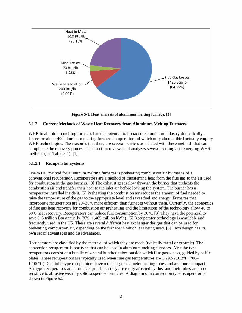
2
Figure 5-1. Heat analysis of aluminum melting furnace. [3]
5.1.2 Current Methods of Waste Heat Recovery from Aluminum Melting Furnaces
WHR in aluminum melting furnaces has the potential to impact the aluminum industry dramatically.
There are about 400 aluminum melting furnaces in operation, of which only about a third actually employ WHR technologies. The reason is that there are several barriers associated with these methods that can
complicate the recovery process. This section reviews and analyzes several existing and emerging WHR
methods (see Table 5.1). [1]
5.1.2.1 Recuperator systems
One WHR method for aluminum melting furnaces is preheating combustion air by means of a
conventional recuperator. Recuperators are a method of transferring heat from the flue gas to the air used for combustion in the gas burners. [3] The exhaust gases flow through the burner that preheats the
combustion air and transfer their heat to the inlet air before leaving the system. The burner has a
recuperator installed inside it. [5] Preheating the combustion air reduces the amount of fuel needed to
raise the temperature of the gas to the appropriate level and saves fuel and energy. Furnaces that incorporate recuperators are 20–30% more efficient than furnaces without them. Currently, the economics
of flue gas heat recovery for combustion air preheating and the limitations of the technology allow 40 to
60% heat recovery. Recuperators can reduce fuel consumption by 30%. [3] They have the potential to save 3–5 trillion Btu annually (879–1,465 million kWh). [5] Recuperator technology is available and
frequently used in the US. There are several different heat exchanger designs that can be used for
preheating combustion air, depending on the furnace in which it is being used. [3] Each design has its
own set of advantages and disadvantages.
Recuperators are classified by the material of which they are made (typically metal or ceramic). The
convection recuperator is one type that can be used in aluminum melting furnaces. Air-tube type
recuperators consist of a bundle of several hundred tubes outside which flue gases pass, guided by baffle
plates. These recuperators are typically used when flue gas temperatures are 1,292-2,012F (700–
1,100C). Gas-tube type recuperators have much larger-diameter heating tubes and are more compact. Air-type recuperators are more leak proof, but they are easily affected by dust and their tubes are more sensitive to abrasive wear by solid suspended particles. A diagram of a convection type recuperator is
shown in Figure 5.2.
Flue Gas Losses 1420 Btu/lb
(64.55%) Wall and Radiation
200 Btu/lb (9.09%)
Misc. Losses 70 Btu/lb (3.18%)
Heat in Metal 510 Btu/lb (23.18%)
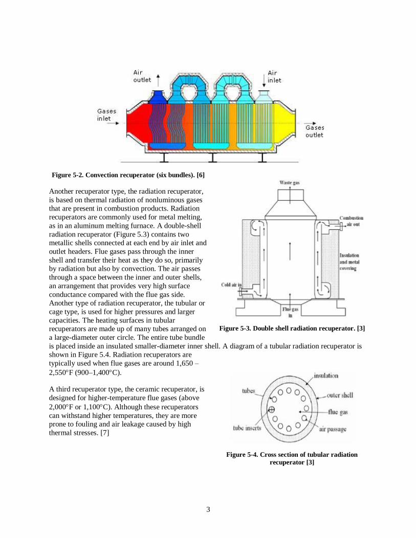
3
Figure 5-2. Convection recuperator (six bundles). [6]
Another recuperator type, the radiation recuperator,
is based on thermal radiation of nonluminous gases that are present in combustion products. Radiation
recuperators are commonly used for metal melting,
as in an aluminum melting furnace. A double-shell
radiation recuperator (Figure 5.3) contains two metallic shells connected at each end by air inlet and
outlet headers. Flue gases pass through the inner
shell and transfer their heat as they do so, primarily by radiation but also by convection. The air passes
through a space between the inner and outer shells,
an arrangement that provides very high surface
conductance compared with the flue gas side. Another type of radiation recuperator, the tubular or
cage type, is used for higher pressures and larger
capacities. The heating surfaces in tubular recuperators are made up of many tubes arranged on
a large-diameter outer circle. The entire tube bundle
is placed inside an insulated smaller-diameter inner shell. A diagram of a tubular radiation recuperator is shown in Figure 5.4. Radiation recuperators are
typically used when flue gases are around 1,650 –
2,550F (900–1,400C).
A third recuperator type, the ceramic recuperator, is
designed for higher-temperature flue gases (above
2,000F or 1,100C). Although these recuperators
can withstand higher temperatures, they are more prone to fouling and air leakage caused by high
thermal stresses. [7]
Figure 5-3. Double shell radiation recuperator. [3]
Figure 5-4. Cross section of tubular radiation
recuperator [3]

4
5.1.2.2 Regenerative burner systems
Another means of WHR for aluminum melting furnaces is preheating combustion air by means of a pair of regenerative burners. Like the other methods, it uses exhaust gases from the furnace to preheat the
combustion air. In regenerative burner systems, a pair of burners connected to an integral heat storage
medium is used to recover heat and transfer it to the combustion air. The two burners are installed on the
melting furnace. Each of them has a heat storage device, such as packed ceramic spheres. The burners take turns firing. While burner one is firing, the other burner exhausts the flue gases from it. The hot gases
pass over the heat storage device and transfer the heat to the heat storage medium, which cools the flue
gases as it heats. After a short period, usually around 15–20 seconds, the flow is reversed. The burner that previously was exhausting begins to fire, and the burner that was firing begins exhausting. The burner that
is firing receives combustion air that has been preheated by passing over the hot heat storage medium.
This continuous cycling recovers heat from the flue gases. [3] The heat storage medium in a burner cools as its burner fires.
Regenerative burner systems are reasonably practical and reliable. [8] A system can recover 72–75% of
the heat in exhaust gases and can reduce fuel consumption by approximately 40%. [3] Regenerators have
the ability to heat the combustion air to a higher temperature. [7] The entire regenerative system (regenerative bed, burners, associated valves, linkages, and furnace temperature controls) is estimated to
be about 1.5 times more expensive than a simple recuperator system; however, the life cycle cost analysis
and payback period with current energy prices justifies the higher initial costs. According to one source [3] and assuming current energy prices are $7 to $10 per MM Btu, the estimated payback period is
usually less than one year. It could be even shorter if the economics of increased production is considered.
[3] Use of regenerative burners is becoming common in many parts of the world for new installations. Rotary regenerators have been developed and commercialized in Europe, but they have not been
commercialized in the US because of their high capital costs. [1] Only a few companies are installing
regenerative recovery systems on existing furnaces that represent 65 to 75% of the operating capacity in
the US.
Several issues associated with regenerators can cause problems within an aluminum melting furnace. One
problem is plugging of the bed. This occurs when the furnace is operated with dirty scrap, which causes it
to generate high amounts of dross and soot particles. It is necessary to clean the bed to avoid performance issues. The equipment and installation costs for retrofit applications are high. Floor space requirements
can also be an issue. More maintenance must be done on systems with regenerators, which can lead to
more work and expenses. There is also very little flexibility in the furnace heating system designs to
accommodate regenerators. For example, the location of the burners and flue gas discharge cannot vary much from furnace to furnace. [3]
5.1.2.3 Load or charge preheating systems
Aluminum melting furnaces also use load or charge preheating to recover heat from flue gases. A typical charge preheating system uses flue gases from the furnace to preheat the charge material in a separate
preheater device or in an extension of the furnace charge system. The charge material is typically heated
from 500 to 800F (260 to 427C) before being charged manually or by a conveyor system. The preheating process removes moisture and volatile organic compounds in the charge material. This method
can offer energy savings of 20 to 35% if the heat used for preheating comes from flue gases. [3] It is possible to increase the production level of the furnace by 25.5% using charge preheating. [9]
The idea behind charge preheating is that if the exhaust gases leaving a furnace can be brought into
contact with the cooler incoming air, the heat can be transferred straight to the load. Preheating the load reduces the amount of energy consumed. There are different ways of accomplishing load preheating. One

5
technique uses an unfired load preheat section, bringing furnace flue gases into contact with the incoming
load in an extended part of the furnace. Another approach uses an external preheater box in which high-temperature flue gases are used to dry and/or preheat the charge before it is loaded into the furnace. A
third approach uses a counter-current flow design in the furnace: the burner gases flow in the opposite
direction from the load being heated.
Figure 5-5. Aluminum shaft, or stack furnace [10]
The stack melter efficiency is improved by better sealing of the furnace and the use of the flue gases to preheat the charge materials. The charge materials slide down the shaft and reach the melting zone where
they are melted by the burners, and the molten metal flows down to the holding area. The hot exhaust
gases from the melting zone flow through the shaft to preheat the incoming charge, improving the energy
efficiency of the stack furnace by 40 to 50%. Melt loss is also dramatically reduced from 4-8% in a reverberatory furnace, down to 1% or less in a well operated stack melter.
The amount of energy savings from charge preheating is higher than the amount of actual heat transferred
to the load. The net heat delivered to the load accounts for the efficiency of the furnace. Furnace efficiency never exceeds 100%; therefore, the energy savings always exceeds the energy picked up by the
load. Charge preheating increases the furnace production. [9] It has the highest potential efficiency of any
waste gas recovery system.
Load preheating does present problems that should be considered. Some charge preheating systems and methods are difficult to install as retrofits, particularly if an external box or system is not used. This
method is bested suited for continuous furnaces, rather than batch furnaces such as aluminum melting
furnaces. [11] Capital costs for these systems may be high, and there can be difficulties in controlling product quality when they are used. [1]

6
Charge preheaters are not common in the US but are widely used in other countries, including Japan,
Europe, India, and China. Most of the charge preheating done in the US involves heating in a separate charge dryer to remove moisture from the charge. [3]
5.1.2.4 Steam generation from waste heat
Recovered heat from a furnace can be used to generate steam in a waste heat boiler. Waste heat boilers
can be used on most furnace designs. This method is especially helpful for plants that need a source of hot water or steam. [10] Waste heat boilers are water boilers that use medium- to high-temperature exhaust
gases to create steam. They are available in a variety of capacities. These boilers can allow for gas intake
levels ranging from 1,000 to 1 million ft3 min (28.3 to 28,317 m
3 min
). The steam generated by the boiler
can be used for process heating or for power generation. [1] The process of converting waste heat into
electricity is a multistep process. First, the dirty hot gases are converted to clean hot gases using a heat
exchanger. Next, the clean hot air is converted to steam using the waste heat boiler. Finally, the steam is used to generate electricity using a turbine or a generator. The electricity then can be passed to the grid if
desired.
An example shows the effects of steam generation from waste heat. Assume that an aluminum melting
system wastes 12 million Btu of heat per hour (3,500 kW). If the overall efficiency of the entire system is assumed to be about 41%, then 5 million Btu (1,400 kW) of the 12 million Btu could be used to be
converted into electricity. Assume that this level of energy is produced 24 hours per day, 7 days per week,
and that the utility grid will pay 10 cents per kilowatt-hour for the electricity. The results of the calculations show that 12 million kWh (41 TBtu) can be generated in one year. This amounts to
$1.2 million in energy costs savings per year, or $2.4 million in savings over a 2 year payback period.
[12] This method of heat recovery is now a commercialized process. [13]
Although this method of heat recovery has many advantages, there are also several barriers associated
with it. One barrier is that steam can be generated only while the aluminum melting furnace is in
operation. [11] Installing such a system could be costly because of the capital costs of heat exchangers,
boilers, and turbines/generators and the installation costs. The amount of maintenance needed for the furnace would increase. Further, designing the process would take company time and management
attention. [12]
5.1.2.5 Oxygen-enriched combustion
Oxygen-enriched combustion is a way of reducing waste heat, rather than recovering it. Oxygen-enriched
combustion is used within the aluminum melting furnace. When fuel is burned in the furnace, oxygen
combines with hydrogen and carbon in the fuel to form water and CO2. This process releases heat. During combustion, nitrogen in the air dilutes the reactive oxygen and carries away some of the energy from the
combustion exhaust gas. If the amount of oxygen in the air is increased during combustion, less energy is
lost in the exhaust gases. The basic idea is to increase oxygen to increase the heating system efficiency. Although this method does not actually recover waste heat, it does reduce flue gas losses and waste heat
that escapes the furnace. Most furnaces use either liquid oxygen to increase the oxygen content or vacuum
pressure swing absorption (VSA) units to remove some of the nitrogen and increase the amount of oxygen. [14] VSA oxygen systems use an air oxy-natural gas burner. [15] Some systems use oxy-fuel
burners in which oxygen is added to the air entering the burner just before the air meets the fuel for
combustion. Oxygen-enriched combustion has the ability to increase efficiency because there is less
nitrogen to carry heat away from the furnace, resulting in less heat in exhaust gases. This method also can lower emissions (nitrogen oxides, CO, and hydrocarbons), improve heat transfer, and increase

7
productivity. Efficiency improvement depends on the exhaust gas temperature and percentage of oxygen
in the combustion air. [14]
In 1999, a VSA system used to enrich oxygen combustion was able to achieve a 30% increase in furnace
productivity and a 40% reduction in specific fuel consumption relative to air-fuel operation. Potential
savings in 2015 could reach 1.76 billion to 2.34 billion kWh (6–8 Tbtu). The enrichment range was 35–
50% oxygen, which optimized the burner thermal performance. Field tests showed that this technology has the ability to meet a target of 0.323 lb NO2/ton of aluminum (146.5 g NO2/ton of aluminum). The
VSA oxygen supply lowers oxygen production costs by using a sieve-filled vessel that stores oxygen
during periods of low demand from the furnace. The oxygen is used when demands are high. This technology can be easily retrofitted to existing aluminum melting furnaces. The technology is adaptable
to different configurations. [15] One of the most important issues for oxygen-enriched combustion is cost.
High costs have resulted in very few oxygen-enriching systems being used in the US today.

Table 5.1. Existing waste heat recovery techniques/methods from aluminum melting furnaces
Existing
method of
waste heat
recovery
Brief description
WHR
technology/system
status
Advantage Barrier/disadvantage Waste heat recovery potential
Combustion
air preheating
using
conventional
recuperator
Use of conventional
metallic tube type of
heat exchanger to
preheat combustion air using heat from
furnace exhaust gases
[5]
Available and frequently
used in the US [3]
Heat is recycled and there
is synchronization—
matching between the heat
demand and supply. Furnaces with
recuperators typically
show 20–30% energy
savings [3]. Method has
the potential to save 3–5
trillion Btu annually [5]
High maintenance because of
tube failure. Very high
maintenance costs. Corrosion
occurs from chlorides and fluorides released during
fluxing operations.
Overheating may occur [1].
Some metallic tubes have a
lifetime of only 6–9 months
[3]
Furnaces with recuperators are
typically 20–30% more energy
efficient than those without them.
Fuel consumption can be reduced by ~ 25 to 30% using
recuperators [5]. Preheating
allows 40–60% heat recovery
from flue gases [3]
Combustion
air preheating
using
regenerative
burners
Use of a pair of
regenerative burners.
While one burner is
firing, the other is
exhausting the
furnace gases. The
heat from the exhaust gas is transferred to
the inlet air [5]
Available. Rotary
regenerators were
developed and
commercialized in
Europe. Efforts to
commercialize in the US
have been unsuccessful owing to high capital
costs. Fixed regenerators
are becoming more
common in the US [1]
High degree of heat
recovery. Fuel is saved.
Higher combustion
efficiency is obtained [3]
High capital cost; difficult to
retrofit; bed plugging occurs
where the charge material
contains particles;
maintenance cost for cleaning
the heat transfer media can add
up; This process may not be as efficient as it seems initially
because of the bed plugging.
Economic feasibility is
application-specific [3]
Burners have an efficiency of 72–
75% and have the ability to
reduce fuel consumption by about
40% [3]

Table 5.1. Existing waste heat recovery techniques/methods from aluminum melting furnaces (continued)
Existing
method of
waste heat
recovery
Brief description
WHR
technology/system
status
Advantage Barrier/disadvantage Waste heat recovery potential
Charge
preheating
Flue gases from the
furnace are used to
preheat the charge material in a
separate preheater or
extension of the
furnace charge
system [3]
Not common in the US
but extensively used in
other parts of the world, including Japan,
Europe, and China [3]
Reduces energy use,
increases productivity
through reduction in melt time. Ideally suited for
virgin aluminum such as
sows [3]
There are high capital costs.
Method may not be feasible
for installations where the scrap quality, size and
composition (e.g., presence
of oils) varies considerably.
There are difficulties
associated with controlling
product quality [1]
Recovery potentials vary
depending on the plant and the
system used to preheat the exhaust gas [1]. Potential
savings also depend on flue gas
temperature and rise in
combustion air temperature or
effectiveness of the air preheater
used. At this time, flue gas heat
recovery for combustion air
preheating allows 40–60% heat
recovery. Energy savings can be
from 20–35% if heat comes
from flue gases [3]. It is possible to increase productions by
25.5% [9]
Use of oxy-
fuel burner
for aluminum
melting
The use of enriched
oxygen in furnace
combustion is
expected to improve
heat transfer to the
melt as well as
reduce emissions
[15]
The system is currently
in the demonstration
phase and is expected to
reach commercial
viability in the near
future (1999) [14].
Not common in the US
but used some in other
parts of the world [3]
The use of enriched air in
furnace combustion is
expected to improve heat
transfer to the melt as
well as reduce emissions.
The goal is to increase
melting productivity by
30%. [15] This is a
process heating best
practice that can improve furnace efficiency by
10% to 12% [16]
Major barrier is cost.
<2% furnaces using oxygen
enriched combustion today
Potential savings in 2015 could
reach 1.76 billion to 2.34 billion
kWh (6–8 Tbtu) [15] Furnace
efficiency can be improved by
10–12% [16] Melting
productivity can be increased by
30% [15]

Table 5.1. Existing waste heat recovery techniques/methods from aluminum melting furnaces (continued)
Existing
method of
waste heat
recovery
Brief description
WHR
technology/system
status
Advantage Barrier/disadvantage Waste heat recovery potential
Use of waste
heat boiler to
generate
steam
Waste heat boilers
are water boilers that
use medium- to high-temperature
exhaust gases to
create steam.
The steam
generated by the
boiler can be used
for process heating
or for power
generation [1]
Commercial status [13] The steam generated by
the boiler can be used for
process heating or for power generation. Waste
heat can be converted to
useful energy [1]. Boilers
can be used on most
furnace applications [11]
Steam can only be generated
while the furnace is in
operation [11]. There are high capital costs owing to the
expense of the boiler, heat
exchangers, and
turbine/generators that may
be associated with the boiler.
The amount of furnace
maintenance needed would
increase [12]
Information not found

5-11
5.1.3 Barriers and Limitations of Existing Waste Heat Recovery Technologies for Aluminum
Melting Furnaces
Despite the advantages attributed to the aluminum melting furnace WHR methods, use of some of these
technologies is quite limited in the US as well as the rest of the world. This can be explained by the
following barriers.
Cost is a huge issue with every WHR method currently being used in aluminum melting
furnaces. Capital and maintenance costs can be very high. Cleaning costs may also become significant because of particle remnants from dirty gases. [1, 3]
In most WHR methods, only a portion of the waste heat is recovered and put to use. In many
cases, such as preheating combustion air, <50% of the sensible heat is recovered. [1, 3]
It is difficult to retrofit heat recovery systems onto existing installations. It may not be
possible to use reliable and long-life (>2 year) systems in situations where the scrap quality, size, and composition vary considerably. [1]
Maintenance and upkeep of recovery systems can be very problematic and costly. When
conventional metallic tube type heat exchangers are used, corrosion often occurs from the
chemicals released during fluxing. Overheating due to occasional combustion of products of incomplete combustion can become an issue. Plugging of heat exchangers or media beds
occurs in regenerative systems in which regenerators are used when the charge material
contains particles. These issues can lead to many problems and extra expenses. [1, 3]
Economic feasibility is application-specific. Some recovery methods work well with some
furnaces but not with others. [3]
Many of the problems involved in aluminum melting furnace WHR are a direct result of the dirty gases
and very high temperatures associated with the furnaces. The most widely used WHR devices are
recuperators and regenerators, which are particularly affected by high temperatures and dirty gases. The performance of recuperators in the melting furnaces depends greatly on flue gas temperature,
requirements for duty cycle, composition of furnace flue gases (O2 and/or the presence of combustibles
such as CO, H2, and hydrocarbons), presence of particulates, and furnace operating practices. [3] Recuperator tubes and plates become fouled and damaged by the high-temperature gases over time.
Fouling requires periodic cleaning of the heat transfer surfaces to prevent damage as well as improve heat
transfer efficiency. [17] Studies have shown that the lifetimes of metallic recuperator tubes in the highest-
temperature furnaces are often about 6–9 months. The short life is primarily due to the exposure of the recuperator heat transfer surfaces to high-temperature air and corrosive fluxing agents such as fluorine
and chlorine. Replacing recuperators creates additional cost and work. In response to the short lifetimes,
many companies and laboratories are conducting studies to find alternate materials or operating procedures that could extend the lifetimes of these tubes. [3] The different types of recuperators and their
respective barriers were discussed in a previous section.
Regenerators, on the other hand, operate intermittently and must use a high-temperature heat storage material (such as ceramic balls). The difficulty is that this operation requires maintenance, and the
ceramic balls need periodic cleaning to reduce the pressure drop across the regenerator. [17] This process
also may not be as efficient as it seems initially, because of bed plugging when the charge material
contains particles. [3] The use of both recuperators and regenerators increases the combustion temperature and hence the production of NOx and other pollutants. [17] These problems can greatly complicate the
process of melting aluminum.

5-12
5.1.4 Conclusions
Secondary aluminum production using an aluminum melting furnace (fuel-fired furnace) is a very important process that produces large amounts of aluminum. Use of the furnace off-gas heat to preheat
combustion air, charge preheating, and other options such as generation of electricity using waste heat
offers potential benefits such as increased thermal efficiency, lower greenhouse gas emissions, and
increased furnace productivity. The methods discussed in this section have the ability to save energy and save money. Although there are many positive effects of heat recovery, there are also many barriers that
can cause problems and complicate the aluminum production process. It is important to understand and
study these barriers so that improvements can be made to eliminate them. The purpose of this report is to provide information regarding the many waste heat recovery methods that are available and point out the
shortcomings of each method. Future work can focus on improving these technologies. Currently, many
companies and laboratories are researching alternate materials or operating procedures to improve heat recovery and reduce or eliminate the barriers. New developments and technologies for WHR have the
potential to change industrial processes.
5.2 REFERENCES
1. DOE, 2008. Waste Heat DOE, 2008. Waste Heat Recovery: Technology and Opportunities in U.S. Industry, prepared by BCS, Incorporated, prepared for U.S. Department of Energy, Industrial
Technologies Program, March 2008.
2. US Geological Survey, Mineral Commodity Summaries, pp. 16–17, 2014. http://minerals.usgs.gov/minerals/pubs/commodity/aluminum/mcs-2014-alumi.pdf. Accessed
November 2014
3. J. Peter Gorog, James Keiser, Arvind Thekdi, et.al., Materials for Industrial Heat Recovery Systems: Task 1: Improved Materials and Operation of Recuperators for Aluminum Melting Furnaces, Oak
Ridge National Laboratory, September 2007. Available at
http://web.ornl.gov/sci/ees/itp/documents/FnlRptRecuperatorsFinal.pdf.
4. Subodh Das, et al., Improving Energy Efficiency in Aluminum Melting, US Department of Energy, pp. 20–21, 2007. Available at http://www.phinix.net/services/
Energy_Management/Improving_Energy_Efficiency.pdf.
5. S. Tangjitsitcharoen, et al., “Investigation of regenerative and recuperative burners for different sizes of reheating furnaces,” International Journal of Mechanical, Aerospace, Industrial, and
Mechatronics Engineering 7(10), 952–956, 2013. Available at
http://www.waset.org/Publication/investigation-of-regenerative-and-recuperative-burners-for-
different-sizes-of-reheating-furnaces/17138.
6. Kalfrisa, “Convective recuperators,” 2014, Available at
http://www.kalfrisa.com/convectiverecuperators.aspx. Accessed November 2014
7. Harshdeep Sharma, Anoop Kumar, and Sourabh Khurana, “A review of metallic radiation recuperators for thermal exhaust heat recovery,” Journal of Mechanical Science and Technology
28(3), 1099–1111, 2014. Available at http://link.springer.com/article/10.1007/s12206-013-1186-
4#page-1.

5-13
8. Al Kennedy, “Aluminum Melt Furnaces: Principles of Fuel Economy,” Kennedy Eurotech, Inc.
http://www.alkennedy.net/sitebuildercontent/sitebuilderfiles/aluminummeltfurnaces.pdf. Accessed November 2014
9. US Department of Energy, Office of Energy Efficiency and Renewable Energy, Energy Tips—
Process Heating, Process Heating Tip Sheet #9: Load Preheating Using Flue Gases from a Fuel-
Fired Heating System, January 2006. Available at https://www1.eere.energy.gov/manufacturing/tech_assistance/pdfs/38852.pdf.
10. US Department of Energy, Energy Efficiency and Renewable Energy, Energy Tips—Process
Heating, Process Heating Tip Sheet #8: Install Waste Recovery Systems for Fuel-Fired Furnaces, September 2005. Available at
http://www.energy.gov/sites/prod/files/2014/05/f16/install_waste_heat_process_htgts8.pdf.
11. Modern Equipment Company – Basics of Stack Melting. Available at http://www.moderneq.com/stack-melting.html
12. John Norton, Waste Heat Recovery in the Aluminum Melting Furnaces. Energy Technology 2011:
Carbon Dioxide and Other Greenhouse Gas Reduction Metallurgy and Waste Heat Recovery, John
Wiley & Sons, 2011, pp. 49–53. Available at http://onlinelibrary.wiley.com/doi/10.1002/9781118061886.ch5/summary.
13. Environmental Protection Agency, Combined Heat and Power Partnership, Waste Heat to Power
Systems, 2012, p. 9. Available at http://www.epa.gov/chp/documents/waste_heat_power.pdf.
14. US Department of Energy, Office of Energy Efficiency and Renewable Energy, Energy Tips—
Process Heating, Process Heating Tip Sheet #3: Oxygen-Enriched Combustion, September 2005.
Available at http://www.energy.gov/sites/prod/files/ 2014/05/f16/oxygen_enriched_combustion_process_htgts3.pdf.
15. US Department of Energy, Office of Energy Efficiency and Renewable Energy, Aluminum Project
Fact Sheet: High-Efficiency, High-Capacity, Low-NOx Aluminum Melting Using Oxygen-Enhanced
Combustion, October 2000. Available at https://www1.eere.energy.gov/ manufacturing/industries_technologies/combustion/pdfs/relevant_aluminum.pdf.
16. US Department of Energy, Save Energy Now Assessment Report ESA-E051-5, 2010.
17. A. Atreya, “A Novel Method of Waste Heat Recovery from High Temperature Furnaces,” ACEEE Summer Study on Energy Efficiency in Industry, 2007, pp. 6-10–6-18. Available at
http://pauthoring.energytaxincentives.org/files/proceedings/2007/data/papers/67_6_063.pdf.
6-1
6. GLASS INDUSTRY
6.1 GLASS MELTING REGENERATIVE SYSTEM
6.1.1 Background and Potential Opportunity
The US glass industry can be classified in four major subsectors: flat glass (25% of total annual
production), container glass (50%), specialty glass (10%), and glass fiber products (e.g., insulation) (15%)
[1]. Furnaces used by each of these subsectors can be grouped into four categories: regenerative and recuperative, oxy-fuel, non-regenerative, and other. Table 6.1 shows this distribution in both percentages
and total production statistics. A different array of furnace types is deployed by each subsector; however,
of primary interest here are regenerative and recuperative (R/R) furnaces. These furnaces account for about 59.1% of the total glass production capacity throughout the US, across the subsectors [1]. Primary
contributors to this total are flat glass and container glass furnaces, which employ 80 and 70% R/R type
furnaces, respectively. Specialty and glass fiber furnaces produce only 26% and 10% of their respective output with R/R furnaces. Total production by R/R furnaces in the US is 11.82 MM tons/year. [1].
A significant amount of energy is expended to produce this glass. The specific energy consumption across
segments using R/R furnaces averages 2,088 kWh/ton (or about 7.125 MMBtu/ton). From this, the total
energy use is determined to be about 13.45 billion kWh year-1
(or 45.91 trillion Btu/year). [1] In an average furnace, about 45% of the total overall energy input is used to melt the charge material consisting
of fresh batch and cullet, and 34% is lost in exhaust gases. [1, 2]This is illustrated by Figure 6.1, a
diagram demonstrating an energy distribution for an example R/R furnace. The three primary contributors to waste heat losses are convective and radiative losses from the furnace walls, radiative losses from open
ports and gaps, and flue/exhaust gas losses. [3, 4, 5] Figure 6.1 shows that for this furnace, 27.2% of the
energy input is expended in the exhaust gases. The specifics of these numbers depend upon the furnace, whether a recuperator (less efficient) or a regenerator (more efficient) is used, the batch/cullet ratio,
moisture in the batch, the fuel, and other parameters. [6] From production data, it was estimated that a
little less than 9 billion kWh/year, or 31 trillion Btu/year, of waste heat in exhaust gases is lost from R/R
furnaces, assuming a 25°C reference temperature. [1] (Note that these production data are from 1988–1997. No newer data could be found.)
Although they are mechanically different, the goal of regenerative and recuperative furnaces is the same:
both strive to capture or recover a part of the heat of exhaust gases to preheat combustion air used in the furnaces. Even after recovery of heat from the exhaust gases, the exhaust gas stream from an R/R system
is typically still at a moderate temperature, between 400 and 600°C. [1] The temperature and composition
of exhaust gas are defining factors in the material and design considerations in all WHR systems. Exhaust
gases from R/R furnaces typically contain a variety of chemical compounds and a large amount of particulates and contaminants that affect the lives of the materials used. The specifics of exhaust gas
composition depend upon the type of fuel used, composition of the charge material, and operation of the
furnace. For example, a glass melting furnace burning coal, oil, or gas could produce exhaust gas containing combustion products such as CO2, H2O, SOx, NOx, O2, and N2, combined with other products
such as HCl, hydrogen fluoride, and boron vapors. [7, 8] The combustion product composition of the
exhaust gases depends upon the type of fuel used. For example, melters using coal or petroleum coke have high concentrations of SO2, whereas melters using natural gas have negligible amounts of SO2.
[6.1:7] Compounds from the glass melt are present as well: NaOH, vanadium, and SiO2 carryover can all
be expected, along with ash and other nonflammable substances. [7, 8] Two example exhaust gas
compositions may be illustrative. Table 6.2 presents the chemical compositions of exhaust from two 1,200 tonne/day furnaces, one burning natural gas and the other burning petroleum coke.

6-2
Table 6.1. US glass industry production by furnace type and glass segment (2007 data). [1]
Furnace type Regen/recup
MM t/year (%)
Oxy-fuel
MM t/year (%)
Nonregenerative
MM t/year (%)
Other
MM t/year (%) Industry segment
Flat glass 4 (20%) 1 (5%) — —
Container glass 7 (35%) 3 (15%) — —
Specialty glass 0.52 (2.6%) 0.7 (3.5%) 0.68 (3.4%) 0.1 (0.5%)
Glass fiber 0.3 (1.5%) 1.05 (5.25%) — 1.65 (8.25)
Totals 11.82 (59.1%) 5.75 (28.8%) 0.68 (3.4%) 1.75 (8.75%)
Grand total 20 (100%)
Table 6.2. Example exhaust gas compositions from a petroleum coke (PC) and natural gas (NG) burning glass
furnace [7]
Compound Volume fraction PC (%) Volume fraction NG (%)
O2 10.00 10.00
CO2 10.91 7.15
H2O 4.00 9.49
N2 75.58 73.36
SO2 0.27 —
Figure 6-1. An example energy or heat distribution for an R/R glass furnace. [6]
Heat of Melt 445 kWh/t
(44%)
Endothermic Reactions 33 kWh/t
(3%)
Evaporating Water in Pre-Heaters
19 kWh/t (2%)
Regenerator Heat Losses
29 kWh/t (3%)
Cooling and Leakage Losses
34 kWh/t (3%)
Furnace Wall Losses 180 kWh/t
(18%)
Waste Gas Heat Losses
277 kWh/t (27%)

6-3
6.1.2 Current Methods
R/R furnaces are classified as such because they use either a regenerator or a recuperator to capture waste heat. However, as has been shown, they capture only a portion of the medium- to high-grade waste heat
from the glass melting operation. Thus the potential exists to capture substantially more energy. A
number of these systems to recover waste heat have been developed, of which the three most prominent
are discussed in this section. Table 6.3 shows a comprehensive accounting of existing and emerging WHR technologies for R/R glass furnaces identified in this study. The three primary methods are
1. More efficient regenerators and recuperators
2. Batch and cullet preheating 3. Steam and/or electricity generation
6.1.2.1 Regenerators and Recuperators
The most notable WHR technology is increasingly more efficient regenerators and recuperators. Regenerators have been studied for many years, and the research has resulted in continuous and
incremental performance increases. [9] The use of more modern and efficient R/R systems would result in
potential WHR of between 60 and 80% for regenerative systems and slightly less for recuperative
systems. [9]
Regenerators alternate passing hot exhaust gases and cold combustion air through a matrix of high-heat-
capacity material (usually ceramic blocks termed “checkers”). Cycles usually last between 20 and 30
minutes (see Figure 6.2). [10] This direct impingement method of preheating the combustion gases usually decreases the exhaust gas temperature to 400 to 600°C and heats the incoming gases to at most
1450°C. [10, 11] In a regenerator with a specific energy consumption of about 1.11 kWh/kg of glass,
about 0.42 kWh/kg of glass is recovered via combustion air heating, or about 37.8%. [9] A target recovery rate of 54% was set by Sardeshpande et al. [9]. It was not reached because of a number of
constraints, including blocking of the regenerator, which reduced the heat transfer area, and temperature
limits due to material concerns. [9, 12] Materials used in regenerators must be able to resist chemical
attack and bonding from alkali, V2O5, and SiO2 while resisting creep deformation and experiencing low thermal expansion. [2] Wall materials must have low thermal conductivity to reduce wall heat losses,
whereas checkers must have high thermal conductivity to efficiently transfer heat to and from the
surrounding gases. [12] Continuing research to optimize regenerator materials has resulted in incremental improvement in efficiency and effectiveness; however, materials that can better cope with the oxidizing
condensates present in cooled exhaust gases are not yet widely accepted. [12]
In recuperators, heat exchangers are employed to transfer heat from the exhaust gases to the cold
combustion air. Incoming combustion air can be heated to between 600 and 980°C; the exhaust gas temperature is lowered to about 800°C, depending upon the system. [13, 14] Metallic radiation
recuperators are most often used in glass furnaces. These systems are usually of a double-shell design, in
which hot exhaust gases pass through the inner shell at low velocity and cold combustion gases pass between the outer and inner shells at relatively high velocity, as shown in Figure 6-3. [13, 14] Designs of
heat exchangers for recuperators include heat pipe and shell-and-tube configurations. Recuperators are
typically 1.3 m in diameter and 10 m tall. [13] Along with designs, materials for high-temperature applications must be carefully selected. Metals such as alloys 625, HR120, and AL20-25+Nb have been
considered for metallic recuperators. [15] Thin films for high-temperature corrosion resistance, such as
Cr3C2-NiCr, cited by Sharma et al., are currently of primary interest. [13] Earlier recuperators are cited at
between 35 and 40% thermal efficiency. For example, two 1991 articles claim 30 and 38% fuel savings, as reported by Sharma et al. [13]. More recent papers, also covered in Sharma et al., indicate efficiencies
of 34 to 40%. [13]

6-4
Table 6.1. Existing and emerging waste heat recovery technologies for R/R glass furnaces
Methods of
waste heat
recovery
Brief description WHR technology/
system status Advantages Barriers/disadvantages
Waste heat recovery
potential
Regenerators for
primary heat
recovery
Stationary regenerators (one
pair of two) are used to
recover ~60 to 70% of the
waste heat from exhaust
gases from a glass melting furnace
Available and used
commonly
Relatively high
recovery percentage of
waste heat; can handle
particulates; long life
(>10 years); and relatively low
maintenance
Unrecovered heat still represents a large
amount of heat (outlet gases can still be
300– 600°C) [18]. Large size. Requires
rebuild of furnace. High cost. Blockages,
air leaks, and heat loss from the walls hinder the efficiency of regenerators [9]
Typically 60– 70% heat
recovery is expected for a
well-designed system. 46%
recovery was actually
achieved [9] in a 130 tonne/day furnace
Radiation type
recuperators for
combustion air
preheating
Radiation recuperator
consists of unobstructed flue
gas passages. Uses gas
radiation (from CO2 and
H2O) with some convection
from flue gases to the heat
exchanger walls
Available and
widely used. Most
often used for glass
and glass fiber,
though often
smaller
Relatively low cost
compared with
regenerators. Does not
require use of ceramic
refractory materials
Lower heat recovery (usually less than
40%). Some maintenance related to
cleaning of inner surface of the heat
exchanger [13]
Sharma [13] gives an example
of 34 and 40% fuel reduction
and cites a fuel reduction of
10–30%, depending on the
system
Batch/cullet
preheating
Use of exhaust gases to
preheat and dry the glass
furnace batch/cullet before
they enter the furnace. This can be done via direct
contact between the gases or
via a heat exchanger
Available but not
used extensively in
the US. Used in
more than 10 container furnaces
[18]. Used only in
container furnaces
Reduces energy
required and increases
productivity. Can be
secondary WHR system to increase
overall efficiency.
Reduces NOx
emissions [9]
Not proven for all types of glass batch
compositions. Several operating problems
for fresh batch vs recycled glass (cullet).
Difficult to justify the overall economics. Good/clean sources of cullet are
sometimes scarce (for example, see [12]).
Worrell et al., [17] cites overall costs and
dry batch carryover as concerns.
60–80% of waste heat could
be recovered. [1] Energy
savings of 12–25% overall
[18]. Potential for 30% energy savings over state-of-the-art
regenerative systems [16]
Electric power
generation using
melting furnace
exhaust gases
Use of conventional steam
generator to produce high-
pressure steam and use of
steam to generate electrical
power (can be synonymous
with cogeneration) [23]
Available but not
used extensively in
the US. All float
glass furnaces in
Germany have such
systems
Electrical power
generation
High maintenance for boilers. Not yet
well proven. Large capital expense.
Installation costs of 1,100–4,000 $/kW
and operating and maintenance costs
0.060–0.125 $/kWh [1, 19]
Some systems report 31
million kWh per annum [7]
production with the attached
boiler (1,200 t/day Chinese
facility)
Electric power
generation using
exhaust gases
from primary heat recovery
unit
Use of exhaust gases from
regenerators at ~430–540°C
to generate electricity using
steam generators or organic Rankine cycle
Available but
seldom used
Relatively high heat
recovery potential and
availability of electric
power
Cost; unproven technology for gases
containing particulates
Thermal recovery efficiency
between 30 and 60%. This
could account for about 10%
fuel saving over regenerative systems [7, 23]

6-5
Figure 6-2. Diagram of a classic regenerator for glass furnaces. [10]
Figure 6-3. Diagram of metallic radiator type recuperator, using a counter flow heat exchanger. [13]
A thermochemical recuperator design was proposed by Rongen et al., with the CelSian and Hygear corporations [16]. This recuperator design uses waste heat to reform the combustion gases to produce H2,
with the goal of producing more efficient firing. The group reports 25–35% energy savings potential, with
a commensurate decrease in CO2 emissions. [16]

6-6
For both regenerators and recuperators, difficulties include frequent maintenance because particulate
buildup on heat transfer surfaces results in poor system efficiency. Sardeshpande et al., indicate that a 50% blockage of the recuperators could result in a 7% reduction in regenerator efficiency [9]. Both types
of systems are large and expensive; however, recuperators are less expensive and require less extensive
furnace rebuilds to install than regenerators. In each case, the capital expense may be prohibitive. [11]
6.1.2.2 Batch and Cullet Preheating
Charge material preheating is a WHR technique used primarily in container glass furnaces. It is used
more extensively in Europe and Asia than in the US. [1] A number of manufacturers produce preheaters,
including Interprojekt, Zippe, Sorg, and Praxair; each product differs slightly. The method primarily involves radiation heat exchange between a counter-flow of exhaust gas from the furnace that directly
impinges upon incoming (moving bed) charge material. Indirect heating is also used; in an indirect
system, a parallel plate heat exchanger radiates heat between the charge material and the exhaust gases. [1, 11, 13, and 17] Another design drops the batch or cullet through a heat exchanger, allowing the
material to heat as it falls through the exhaust gases. Some designs combine electrified filtering units with
such preheaters. More than 10 preheater systems are in use in container glass furnaces in the US; these
systems can be used for oxy-fuel glass furnaces as well, although they are more common among air-fuel furnaces at this time. [18] Kobayashi et al., cites 13 specific cases of preheaters installed since 1988 on
container glass furnaces worldwide, eight of which are in Germany. [18]
Batch or cullet preheating offers moderate to high potential for waste heat recovery from exhaust gas. Charge materials are preheated to between 300 and 500°C, depending upon the technology employed.
Cullet can be preheated to a higher temperature than can batch, as it suffers less from sticking/melting
problems. Worrell et al., reports that overall plant energy efficiency increases of up to 25% could be realized using batch or cullet preheating [6.19]. Beerkens indicates that 12–20% energy savings have been
achieved for regenerative air-fired furnaces. [6]. For one example project, the payback period for a
packaging glass plant in the Netherlands was 2.6 years on a $1.4 million project (assuming a natural gas
price of $3.8/MMBtu and electricity price of 0.05 $/kWh). [19] Such systems could also be used as secondary heat recovery systems, i.e., in combination with some other form of WHR like electric power
generation or recuperators.
One important characteristic for batch and cullet preheating systems is the batch to cullet ratio. The systems must operate at above 35% cullet. A high batch-to-cullet ratio can result in clumping, which can
cause poor product quality; likewise, very fine cullet can result in clumping. [9] Thus relatively high
cullet percentage (usually greater than 50%) is used. This causes concerns over the availability of high-
quality, cullet of the correct composition. Note that the use of cullet reduces furnace energy requirements by 337 kWh/tonne of cullet. [20] A concern that dry batch could be trapped in the system and
contaminate later melts has also been expressed. [17]
6.1.2.3 Electricity Generation
Electricity generation provides a third WHR opportunity. Waste heat–to-power technologies, including
those used in exhaust gas heat capture, can largely be divided into three categories: steam cycle generator,
ORC, and Kalina cycle generator systems. Each use exhaust gases to heat a working fluid via a heat exchanger; the working fluid is then used to mechanically generate electricity. In such systems, high-
temperature exhaust gas is used in a WHR boiler or steam generator to produce high-pressure steam or
drive an ORC or Kalina cycle. Steam cycle generators are used with high-grade waste heat sources
(>600°C), whereas ORCs use a cycle well adapted for low- to medium-grade waste heats (between 100 and 600°C). The Kalina cycle uses a mix of steam and ammonia suited for a larger range of moderate
temperatures (about 100–800°C) and has the highest theoretical efficiency; however, Kalina systems are

6-7
not well suited to small installations. [1, 21, 22] ORC systems operate at lower temperatures than steam
cycles and are more expensive. Steam cycles are the most familiar and well proven, but they require more physical space and greater operational supervision. [22] In any case, the infrastructure required to
implement any such scheme is extensive.
Installation and operating/maintenance costs vary between technologies and generator size. Installation
costs between 1,100 and 4,000 $/kW are common for waste heat electrical generation systems. Typical operating/maintenance costs are between 0.005 $/kWh and 0.020 $/kWh (for a 400 kW to 5MW capacity
range and accounting for different technologies). [1, 21] Installation costs depend upon the technology
and the capacity (large systems are generally less expensive when normalized for production capacity). [19] Accounting for the amortized installation costs, the total normalized price could total as much as
0.060 to 0.125 $/kWh. [23] Moreover, such a system must compete with the utility grid electricity price to
be cost-effective: if the electricity production cost, including amortized installation expense, is greater than the price to purchase electricity from the grid, such systems could be economically unjustifiable.
Steam and ORC generators have been deployed mostly outside the US. Relatively high energy prices
drive development in Europe, and energy prices and environmental regulations drive development in
China for these types of systems, [7, 21] The energy capture potential is reasonable, with Li et al., reporting 31 million kWh of electrical production from a 1200 ton/day flat glass furnace; this system was
designed to operate with an exhaust gas heat of 450°C, an expected temperature for regenerative furnace
exhaust gases. [7] Thermal efficiencies for OCR systems are usually between 15 and 25% and are often over 30% for steam systems. [22, 30]
6.1.3 Barriers and Limitations of Existing Technologies
As indicated in Table 6.3, WHR techniques have both advantages and disadvantages. Mediation of the disadvantages or barriers to implementation of these systems has been the primary goal of extensive and
ongoing research surrounding WHR systems. Broadly, the disadvantages and barriers can be classified as
related to either structure/design or materials. Often construction materials and designs must
accommodate the components that are exposed to the chemical compositions present in exhaust gases. The specifics of exhaust gas composition depend upon the fuel being burned and the composition of the
charge material. It is likely that boric acid and SO2 are both present. [7] Li et al., emphasizes the
importance of the furnace fuel in exhaust gas WHR device design. [7] For example, most recuperators are limited by materials: the inflow and outflow gas temperature must be maintained between defined
threshold values to avoid damage to the device either from the caustic/corrosive agents in the exhaust gas
or property degradation from the temperature.
Costs
An overarching challenge with WHR technologies is capital investment and operating expenses. These
systems require a large capital expense. For example, Worrell et al. cites an expense of $1 million for a
steam-based electrical generation system. [17] As another example, expenses measured in US dollars per kilowatt range between $1,100/kW and $3,500/kW, depending upon the technology employed for
electrical power generators (steam generators usually are the least expensive and OCR generators are
usually the most expensive). [1] Another source cites $1,200/kWh to $4,950/kWh for ORC generators capable of 0.2 to 2 MWe output; however, these figures are not specifically for the glass industry. [24] For
smaller operations, these costs may not be justifiable; and for larger operations, the system must represent
a justifiable investment. [24] Payback times vary between technologies but are most often measured in
years. For example, in the system analyzed by Li et al., the payback period was between 1.3 and 1.5 years, although this is an optimistic estimate. [7] Initial capital expense is governed by factors such as the
system design, materials required, and other fixed costs; however, payback time is also influenced by the
system efficiency, productivity and yield improvements, product quality–related returns, and life of the

6-8
system. Thus design and materials also determine, to a large extent, the economic viability of WHR
technologies.
Regenerators and Recuperators
Regenerative systems are limited by availability and by the ability of the designer to make changes in the
system design parameters, such as system size, cost, life, and maintenance.[6, 9, 11, 17, 23] Installation of
these systems requires a furnace rebuild. [18]. Sardeshpande et al., enumerates many of the difficulties with regenerative systems. [9] Current regenerator designs suffer from potential blockages: the exiting
flue gas contains a substantial amount of dust, which is deposited along the exhaust gas path.
Accumulations of dust can develop within regenerator checkers, limiting fluid flow and heat transfer into and out of the matrix material. Material degradation concerns limit material choices for checker blocks.
[24] Blockage development also affects the pressure drop and chemical composition within the
regenerator, resulting in frequent maintenance requirements. Regenerator efficiency is further limited by air leaks, reducing the exhaust gas temperature and again altering the chemical composition. During the
exhaust cycle, regenerators have reduced pressure due to flue draft; therefore, air infiltration occurs
through cracks in the regenerator body, cooling the system and reducing efficiency [9]. Convective and
radiative losses through the walls limit the efficiency potential of regenerative systems. The heat capacity and the heat transfer coefficient of the checker bricks under transient heating absorption and rejection
governs the absolute efficiency of a regenerative system. [9] The material used in this component is of
fundamental importance. The material must have a high heat capacity and high heat transfer coefficients. Moreover, it must be resistant to extreme temperatures (exhaust temperatures are typically about 1,500°C
before entering the regenerator) and to abrasion, inhibit dust accumulation, and resist the actions of
alkaline gases and volatiles within the exhaust gas.
Recuperators are primarily limited by material concerns that largely influence the system designs.
Recuperators, much like regenerative systems, cannot be installed ex post facto. They have many of the
same limitation as regenerators for similar reasons. Fouling from dust in exhaust gases reduces the
effectiveness of heat transfer in both radiative and convective recuperators. [27] Recuperators are limited by the convective and radiative heat transfer properties of their components: the solid and the fluid
properties of the exchanger determine the effectiveness of the recuperator. The systems may experience
air leaks that reduce the temperature of the heated combustion air and the exhaust gases. Thermal stress is a primary concern in the design of recuperator heat exchangers; however, pressure drop through a
recuperator must also be considered: the development of air leaks necessitates pressure control to
maintain operational effectiveness. [28] Exhaust gas temperatures above 1,100°C are difficult to use
effectively use. [13] Advanced materials are required for recuperators to operate effectively at such high temperatures. These require extensive research and, once commercially available, often have high
production and machining costs. [13, 15, 16]
The thermochemical system presented by Rongen et al., is not suited well to installations requiring large combustion air throughput. It is currently undergoing proof of concept and pilot-scale testing. In furnaces
using this system, an altered combustion reaction would cause higher water vapor concentrations than in a
conventional furnace. This may impact NaOH and NOx emissions as well as sulfate fining. Additionally, modified flame properties may cause difficulties for some furnace configurations. [16]
Batch and Cullet Preheating
Batch/cullet preheating has the potential to recapture a large amount of waste heat. However, there are
difficulties and limitations with implementing such a scheme. In this case, the difficulties are mostly design related, with the primary concern being operational. Batch melts more easily than cullet. Typically,
>50% of cullet is used to avoid sticking and localized melting. A range of batch/cullet ratios are used.

6-9
However, use of less than 35% cullet or more than 90% cullet is not feasible. [18, 23] This fundamentally
limits the temperature to which charge materials can be heated. Transportation of the hot charge material requires careful design. Fluidized bed designs have been suggested for such applications. It may be
difficult to operate at high cullet ratios, as high-quality sources of pure cullet can be difficult and/or
uneconomical to obtain. Thus preheaters are used primarily in container glass furnaces, where higher
degrees of impurities and higher ratios of discolored glass can be tolerated than in flat glass, specialty glass, or glass fiber furnaces. Colored glass, often used in container furnaces, is more resilient against
foreign matter that may be present in cullet. Additionally, concerns about dry batch carryover (fine-grain
batch material trapped within the preheater and deposited in later melts) and volatilization of batch materials (conversion of batch into vapor, contaminating the preheater and reducing operational
efficiency of the furnace) limit the application of preheaters in some cases. [18, 23] Cullet preheaters have
been assessed; however, they offer limited potential for efficiency gains, as a mix of batch/cullet must be used in a melt. The primary factor prohibiting widespread adoption of batch/cullet preheating is
operational and installation expense. These systems are large and expensive to install, as is typical of
WHR systems. Moreover, preheaters are complex and require frequent maintenance, making them largely
undesirable because of the downtime they impose. [23]
Electricity Generation
The primary difficulty with waste heat–to-power systems is cost. Techniques that produce electricity must
compete with conventional electricity purchase prices. In addition, these systems are large and difficult to site: optimally, they will be as close to the exhaust gas source as possible. [1, 7, 11, 17, 21, 26, 27, 28, 29]
Most of the materials and design problems are encountered at the waste heat collection stage of
generation, as the technologies and techniques for producing useful energy from heat are have been well developed for generators served by more conventional heat sources. [21] Therefore, steam, ORC, and
Kalina cycles share many difficulties. [22] They require constant sources of heat: noncontinuous
operation substantially reduces their effectiveness. As with all systems requiring heat exchangers, high
levels of maintenance are required. [23] Each system is limited by the fundamental efficiency of the cycle it employs. [21, 30]
The primary barriers to deployment of WHR technologies and systems with R/R glass furnaces are
material and structural. Material concerns are often due to the high-temperature and particulate-laden environment in which these systems must operate. These factors are compounded by the reactivity of the
chemicals in the waste heat stream. Structural limitations include size requirements, siting concerns, and a
requirement for easily maintained devices with few points of failure. Further material handling
requirements constrain these systems. Finally, high capital costs provide a disincentive to investment in WHR system installation.
6.1.4 Conclusions
Regenerative and recuperative systems make up a significant portion of glass furnaces, yet their efficiency remains limited, with only about 45% of the fuel energy being used to melt the incoming batch
and cullet. Of the wasted heat, about a third is embodied in exhaust gases. The current state of technology
for recapturing exhaust gas waste heat in R/R furnaces was examined. A number of technologies have been identified from the literature, with an emphasis on identifying weakness and limitations of current
technologies. The foremost technologies include improved-efficiency regenerators and recuperators,
batch/cullet preheating, and electricity/steam generation. Further, structural/design and materials issues
with these WHR techniques are identified and enumerated. A need for further development of materials and designs suited to the needs of such applications has been identified. For example, further
development of ceramic materials for use in regenerator checkers and walls could increase regenerator
efficiencies, reduce problems with blockages, reduce maintenance requirements, and increase life

6-10
expectancy. For recuperators, development of more temperature- and corrosion-resistant metallic material
would allow for high-efficiency devices by permitting a larger temperature drop in the exhaust gases so that more of the sensible energy could be extracted.
6.2 REFERENCES
1. BCS, Inc., Waste Heat Recovery: Technology and Opportunities in U.S. Industry, US Department of
Energy, 2008. Available at http://www1.eere.energy.gov/manufacturing/intensiveprocesses/pdfs/waste_heat_recovery.pdf.
2. K. Khoshmanesh, et al., “Reduction of fuel consumption in an industrial glass melting furnace,” pp.
1–4 in TENCON 2007, 2007 IEEE Region 10 Conference, 2007.
3. B. Kauffman, et al., Energy Assessment Protocol for Glass Furnaces, prepared for E. Levine,
Department of Energy Office of Industrial Technology, n.d. Available at
http://www.icet.msstate.edu/historic/reports/Energy_Assessment.pdf.
4. A. Kozlov, et al., Exergy Balance of Glass-Melting Furnaces, prepared for State Scientific Research
Institute of Glass (Ukrainian), 1985.
5. V. Sardeshpande, U. N. Gaitonde, and R. Banerjee, “Model based energy benchmarking for glass
furnace,” Energy Conversion and Management 48(10), 2718–2738, 2007.
6. R. Beerkens, Energy Saving Options for Glass Furnaces & Recovery of Heat from their Flue Gases
and Experiences with Batch & Cullet Pre-Heaters Applied in the Glass Industry, 69th Conference on
Glass Problems, pp. 143–162, 2009.
7. Z. Li, et al., “Design of a flat glass furnace waste heat power generation system,” Applied Thermal
Engineering 63(1), 290–296, 2014.
8. G. Heilemann, et al., “New solutions for checkers working under oxidizing and reducing conditions,” in 67th Conference on Glass Problems: Ceramic Engineering and Science Proceedings, Volume 28,
no. 1, p. 183. John Wiley & Sons, 2009.
9. V. Sardeshpande, et al., “Performance analysis for glass furnace regenerator,” Applied Energy 88(12),
4451–4458, 2011.
10. P. Mullinger and B. Jenkins, Industrial and Process Furnaces: Principles, Design and Operation, 1st
ed., pp. 11–13, 2008.
11. C. P. Ross and, G. L. Tincher, Glass Melting Technology: A Technical and Economic Assessment. Glass Manufacturing Industry Council, prepared for the US Department of Energy Industrial
Technologies Program, 2004.
12. A. Sommers, et al., “Ceramics and ceramic matrix composites for heat exchangers in advanced
thermal systems—A review,” Applied Thermal Engineering, 1277–1291, 2010.
13. H. Sharma, et al., “A review of metallic radiation recuperators for thermal exhaust heat recovery,”
Journal of Mechanical Science and Technology 28(3), 1099–1111, 2014.

6-11
14. H. Sharma, A. Kumar, and V. Goel, “Performance model of metallic concentric tube recuperator with
counter flow arrangement,” Heat and Mass Transfer 46(3), 295–304, 2010.
15. P. Maziasz, et al., “Advanced alloys for compact, high-efficiency, high-temperature heat-
exchangers,” International Journal of Hydrogen Energy 32(16), 3622–3630, 2007.
16. M. Rongen, et al., Glass Production Dedicated Thermochemical Recuperator. Product presentation,
CelSian – Glass & Solar. Available at http://www.icg2013prague.cz/gallery/815/17.00pdf_icg2013_-_tcr_v2.pdf
17. E. Worrell, et al., Emerging Energy-Efficient Industrial Technologies, LBNL-46900, Lawrence
Berkeley National Laboratory, Berkeley, Calif., October 2000.
18. H. Kobayashi, E. Evenson, and Y. Xue, “Development of an advanced batch/cullet preheater for oxy‐fuel fired glass furnaces,” in 68th Conference on Glass Problems: Ceramic Engineering and Science
Proceedings, vol. 543, p. 137. John Wiley & Sons, 2011.
19. E. Worrell, et al., Energy Efficiency Improvement and Cost Saving Opportunities for the Glass
Industry. LBNL-57335, Lawrence Berkeley National Laboratory, Berkeley, Calif., March 2008.
20. E. Giacone and S. Mancò, “Energy efficiency measurement in industrial processes,” Energy 38, no. 1,
331–345, 2012.
21. EPA Combined Heat and Power Partnership, Waste Heat to Power Systems, 2012. Available at
http://www.epa.gov/chp/documents/waste_heat_power.pdf.
22. S. Quoilin, et al., “Techno-economic survey of Organic Rankine Cycle (ORC) systems,” Renewable and Sustainable Energy Reviews 22, 168–186, 2013.
23. D. M. Rue, J. Servaites, and W. Wolf, Industrial Glass Bandwidth Analysis, Gas Technology
Institute, Des Plaines, Ill., 2007.
24. S. Postrach, et al., “Conception of modern glass furnace regenerators,” in 72nd Conference on Glass Problems: Ceramic Engineering and Science Proceedings, Volume 33, pp. 73–89. John Wiley &
Sons, Inc., 2012.
25. F. Velez, et al., “A technical, economical and market review of organic Rankine cycles for the conversion of low-grade heat for power generation,” Renewable and Sustainable Energy Reviews 16,
no. 6, 4175–4189, 2012.
26. Southern California Gas Company and E3M Inc., Generate Electric Power from Waste Heat, May 2012. Available at http://www.gosolarcalifornia.ca.gov/tools/newCalcSys/
Description/Generate%20power%20from%20waste%20heat.pdf.
27. Joan L. Pelligrino, Glass Industry of the Future: Energy and Environmental Profile of the U.S. Glass
Industry, DOE/GO-102002-1590, Energetics, Incorporated, Columbia, Md., April 2002.. Available at http://www.energy.gov/sites/prod/files/2013/11/f4/glass2002profile.pdf.
28. D. Aquaro and M. Pieve, “High temperature heat exchangers for power plants: Performance of
advanced metallic recuperators,” Applied Thermal Engineering 27(2), 389–400, 2007.

6-12
29. C. C. S. Reddy, S. V. Naidu, and G. P. Rangaiah, “Waste heat recovery methods and technologies,”
Chemical Engineering 120(1), 28–38, 2013.
30. Francesco Calise, et al., “Thermoeconomic analysis and off-design performance of an organic
Rankine cycle powered by medium-temperature heat sources,” Solar Energy 103, 595–609, 2014.

7-1
7. CEMENT-LIME INDUSTRY
7.1 CEMENT AND LIME KILNS
7.1.1 Background and Potential Opportunity
The US produced about 77.8 million tonne (metric ton) of cement and about 19.0 million tonne of lime in
2013. [1, 2] Worldwide, production was 4.0 billion tonne of cement and 350 million tonne of lime. [1, 2]
The cement and lime production processes are similar: both use fuel-fired kilns to process raw materials at high temperatures, and both are energy-intensive, continuous-production industrial processes. The
specific energy use of cement and lime kilns varies depending upon the type of kiln, the reactants, and the
fuel; energy use for cement kilns is between 798 kWh/tonne of clinker (2.5 MMBtu/ton of clinker) for a dry kiln with preheater and precalciner and 2,843 kWh/tonne of clinker (8.8 MMBtu/ton of clinker) for a
wet kiln without preheater. [3] With such substantial energy expenditures, reduction and recovery of the
energy lost within such processes is an appealing prospect. This section outlines the emerging and existing WHR techniques for exhaust gases from cement and lime kilns, with a focus on identifying
material and structural/design barriers to these technologies.
In both cement and lime production facilities, there are many energy-intensive processes; however, this
report focuses on the kiln, and specifically on the exhaust gas waste heat from the kiln. This is because kilns use a substantial amount of the heat energy required for these processes; e.g. for cement production,
kilns consume about 74% of the total energy required. [4, 5] Raw material preparation of cement takes
between 25 and 35 kWh/tonne of electrical energy, compared with 798 kWh/tonne for kilning. [3] Two primary types of kilns are used: rotary and shaft. Rotary kiln technologies can be further defined by
material moisture content and existence of a preheater on the kiln. Rotary kilns of both the wet and dry
types, with and without preheaters are examined. Shaft kilns also are discussed, as they are often used in the quicklime production process. [6]
A rotary kiln consists of an annulus oriented at about 3° to 4° from the horizontal and rotating at between
1 and 3 rpm. [7] Production rate is determined by size (length and diameter), slope, and rotation rate. In
such kilns, the raw materials migrate from the high end to the low end of the annulus. The burner is located at the low end, and combustion gas is released from the high end. Thus as the raw material falls, it
is heated by the escaping burner gases. Rotary kilns are used when high-quality, smaller-size feed
materials in large quantities are used. [6] Often rotary kilns complement shaft kilns. [6] Shaft kilns are also used in the cement industry, although rotary kilns are the dominant technology, as they produce more
chemically uniform materials. [3] Shaft kilns, and their variants, are often used for lime, as they tend to be
more energy-efficient and simpler than rotary kilns. Conventional shaft kilns have raw material charged
into the top of the kiln, in a preheating zone, where combustion products heat the raw materials. In the calcining zone, fuel and combustion air are ignited to heat the raw material to the temperatures required to
affect a dissociation of the reactants. The final zone cools the reactants; the cooling air used to do so is
drawn through the shaft to supplement the combustion air and provide additional heat to the reaction. A vertical shaft kiln is outlined in Figure 7-1. [6]

7-2
For cement, three primary phases are encountered in this
heating process: drying, calcining, and sintering. [3, 6] Each of these phases requires heat energy input. Calcining is an
endothermic chemical process in which carbonate is
decomposed into oxide and CO2. Flame temperatures are
1,800–2,000°C, and sintering takes place at 1,480°C in the production of clinker. The hot clinker exits at the lowest end
of the kiln and enters an air quenching phase. [7] Two
processes are primarily used: wet and dry. The wet process starts with a slurry input material with a moisture content of
about 35%, requiring significantly more energy to dry. The
more modern dry process has been enabled by developments in process control techniques in grinding and processing
phases and results in feed material with about 0.5% moisture
content. [8]
Lime kilns operate with similar principles to cement kilns but with different reactants and reaction temperatures. Lime
calcination, the decomposition of CaCO3 to CaO, requires
temperatures of at least 900°C but no more than 1,100°C. [9, 10] Lime kilns can be divided into two general groups: shaft
type and rotary type. Lime rotary kilns operate in the same
way as cement rotary kilns. Shaft kilns can be described as having three primary zones: at the top of the process stack is
the preheating zone, where limestone in 50–100 mm particle
sizes is injected and exhaust gases exit; these particles then
enter the calcination zone, where temperatures are sufficient to drive the decomposition reaction required; after the
reaction concludes, the material is deposited below the
burners in the cooling zone, where secondary cooling air is injected. [8, 9, 5] Quicklime is collected at the bottom of the
kiln shaft. [10] Most lime kilns are of the shaft type, and the
largest share of these are parallel flow regenerative kilns
(described in the following section with regenerative systems). [11] In the EU-27 (all European Union member states in 2013), 46% of lime production uses parallel flow regenerative kilns, although in the US
most lime production is in rotary kilns. [12, 13]
A significant portion of the fuel input energy is wasted in kilns. Figure 7.2 shows an example energy distribution (rounded to whole numbers) for a 6,364 tonne/year (7,128 ton/day) capacity, 5.5 m diameter,
66 m long rotary cement kiln. [12] This kiln has a total estimated specific energy consumption of about
1,040 kWh/tonne of clinker. Engin and Ari report 19.15% energy rejection from exhaust gases (after a preheating system) in a 600 tonne/day dry-type rotary kiln in Turkey. [14] A similar, but less discretized,
distribution of heat from a lime kiln is shown in Figure 7.3 (rounded to whole numbers). This is for a 24
tonne/day shaft lime kiln. [10] A second shaft kiln is also presented by Gutierrez et al. [10]. This one,
with a production rate of 100 tonne/day, indicates higher efficiency (enthalpy of reaction is 71.6% of energy use); however, the exhaust gas losses are 23.2% of the input energy. Another source cites that, for
a rotary type lime kiln, between 20 and 25% of the input energy is lost in exhaust gases. [9] Atmaca and
Yumrutas [15] cite 32.6% energy losses from exhaust gas from a 4.2 m diameter, 59 m long rotary kiln. Rotary kilns are commonly fitted with preheaters (most often of the cyclone type, described below) to
help reduce energy requirements. [15]
Figure 7-1. Simple diagram of a lime shaft
kiln. Section A is the preheating area, B the
calcining area, and C the cooling area. [6]

7-3
A range of fuels are used to provide for the energy requirements of cement and lime kilns, including
petroleum coke, coal, natural gas, fuel oil, diesel fuel, and others. [8] The exhaust gas from cement kilns typically consists of CO2, NO2, H2O, Ar, NOx, SO2, O2, and dust. [15, 16] Engin and Ari cite 1.8% O2,
27.4% CO2, and 70.8% N2 post-preheater exhaust gas composition by weight for a kiln burning dried
coal. [14] A significant amount of dust is also produced; for example, in a 2.7 m diameter, 55 m long, 500
tonne of clinker per day kiln analyzed by Sen et al., [17], the preheaters exhausted 2.559 kg/kg of clinker of gas and 0.035 kg/kg of clinker of dust, or about 1.4% of the exhaust gas. [17] This represents
17.5 tonne of dust per day. In a kiln assessed by Ari, 0.165 kg/kg of clinker of dust was produced. [12] A
broad study of rotary cement and lime kilns in the European Union reported dust emissions between 0.27 and 30 mg/Nm
3 after filtering. [11] Systems with preheaters typically have lower dust emissions. Dust
typically consists of CaO, Al2O3, Fe2O3, SiO2, and ash; this is largely contaminated clinker, much of
which is recycled using dust collectors. [15] However, volatile compounds are released as the raw meal is heated; this results in volatile organic compounds, volatile metals, and other chemical species in the kiln.
These either are decomposed in higher-temperature zones or recondense, most often within the
preheaters. [11] This process results in negligible emissions, although the environment within the kiln
contains substantial amounts of particulates and combustibles. [11] For lime kilns, exhaust components are similar—generally CO, CO2, H2O, SO2, NOx O2, HCl, and N2 are expected. [10, 11] A large amount
of dust is also produced, which must be filtered from the exhaust gas. SO2 and NOx emissions are
typically low, with less than 500 mg/Nm3 produced from lime kilns. Depending upon the type of lime
produced, NO2 emissions could be greater than 800 mg/Nm3. [6] Emission of significant quantities of
other dangerous or hazardous particulates is negligible. [6]
Figure 7-2. Example heat distribution from a rotary cement kiln. [12]
Formation of Clinker
496 kWh/t (55%)
Heat Loss from Kiln Surfaces
28 kWh/t (3%)
Kiln Exhaust Gas 181 kWh/t
(20%)
Moisture in Raw Material 15 kWh/t
(2%)
Hot Air from Cooler
116 kWh/t (13%)
Heat Loss by Dust 18 kWh/t
(2%)
Clinker Discharge 20 kWh/t
(2%)
Unaccounted losses
30 kWh/t (3%)
7-4
Figure 7-3. An example heat or energy distribution in a rotary lime kiln. [10]
7.1.2 Current Methods of Waste Heat Recovery
A variety of exhaust gas WHR techniques exist or are being developed for kilns in the cement and lime
industries. The most extensively employed WHR technique for kilns is stack preheaters, often of the
cyclone configuration. Also frequently used are precalciners. Kiln exhaust gases have also been used for steam/electrical generation. A complete listing of existing and emerging technologies for WHR in cement
kilns is presented in Table 7.1; Table 7.2 presents these technologies for the lime industry. Although
many of the technologies presented are the same, application to the slightly different processes of lime
kilns necessitates slightly different approaches. Further, some technologies have been proposed only for lime kilns or for cement kilns, though transfer is often possible. [6]
Raw material preheating
The most prominent WHR technique, currently employed in nearly all modern dry process rotary cement kilns and lime kilns, is preheating the charge material with exhaust gas. This takes the form of a series of
suspension preheaters, called cyclones, that drop the incoming solids through the exhaust gases before
they enter the kiln. [18] Preheating is performed in stages, with each cyclone unit progressively increasing
the temperature of the charge material. Up to six such units have been used. [3, 4, 7, 19, 20] Shaft type preheaters are also used. In wet process cement kilns, slurry driers can be used. These use waste heat from
the exhaust gases, via a traveling gate design. [3] A fuel consumption reduction of 452 kWh/tonne of
clinker was achieved for a cement kiln. [3] A kiln using a four-stage cyclone preheater consumed only 77% of the energy used by an equivalent long dry process kiln without preheaters. In cement kilns with
four or more preheaters, precalciners are often employed. The devices contain relatively small secondary
burners to heat the charge material to calcining temperatures before their entry into the kiln proper. The addition of precalciners requires a significant plant rebuild; however, the technologies enable energy
savings of 11–14% and a capacity increase of 80–100%. [21] A kiln with a six-stage preheater, a
precalciner, and a high-efficiency clinker cooler used 64% of the energy used in a long dry process kiln.
[4] However, the addition of preheaters to a plant increases maintenance requirements. Preheaters are expensive to install, which may prohibit their use in small production facilities.
Quicklime 63 kWh/t
(5%)
Exhuast Gas 388 kWh/t
(29%)
Formation of Quicklime 752 kWh/t
(56%)
Wall Losses 149 kWh/t
(11%)

7-5
Table 7.1. Existing and emerging waste heat recovery technologies for cement kilns
WHR
method Brief description
WHR technology/system
status Advantages Barriers/Disadvantages Waste heat recovery potential
Steam
generation
from heat
Exhaust gases generate
steam in a waste heat
recovery boiler. Flash
steam, duel-pressure
steam, Kalina, and ORC cycles have all been
proposed [22, among
others]
Available and used at a very
few locations in the US.
Widely used elsewhere
(especially China). Used
with long dry kilns. Efficiencies are better in
kilns without preheaters and
precalciners
Large percentage
heat recovery
from exhaust gases
High capital cost, added
operating cost. Can be applied
only in cases where low-
pressure steam is required.
May require maintenance of
boiler because of particulates. Typical costs for steam are
$1,100–1,400/kW; for Kalina
$1,100–1,500/kW; for ORC
$1,500–3,500/kW [5]
Recovery potential is medium to
high. [5] Limited to 20–25%
efficiency without modifying the
kiln: 8–22 kWh/t clinker
electrical production. If kiln is
modified, up to 45 kWh/t [19] According to Engin, cost savings
of $540,000 /year is possible
(1.38 year simple payback
period) [14]
Organic
Rankine
Cycle
(ORC) for
electricity
ORC uses waste heat to
vaporize a refrigerant,
which drives a turbine
generator [33]
Available, not frequently
used outside of China [4]
Captures low- to
medium-grade
waste heat.
Relatively high
efficiency
Expensive. ORC can be twice
the cost per kilowatt of a steam
cycle generator
ORC efficiency is limited to
about 20–25% electrical
generation (maximum).
However, 70% of the exhaust gas
energy can be captured [23]
Preheating/
precalcining
and drying
of charge
material
Use of shaft type or
cyclone type charge
preheater at the gas exit
(charging) end of the kiln
Available and used widely in
modern plants. Sometimes
retrofitted to older plants
Large percentage
of heat recovered
Economics, use of selective
feed material. Limited use with
wet process. Increased
maintenance
1–1.3 MMBtu/ton of clinker is
recovered [5]
Fuel
moisture
removal or
drying
Use of hot gases to dry fuel
and reduce moisture
content before fuel
combustion.
Available and used widely
where applicable
Improves heating
value and
increases
available heat
with higher
overall efficiency
[21]
Overall economics. Difficult to
design, and operational issues
with process equipment
Such a scheme can increase
efficiency up to 10%. [38]
However, this is for furnaces in
general, not specifically for a
cement kiln
Thermo-
electric
regenerator
Uses materials to produce
electricity directly from a
thermal gradient
Not demonstrated. Still under
development
Avoids
steam/ORC/
Rankin boiler and
moving parts
Very high cost; cannot be used
with gases. Short lifetime.
Costs can be as high as 10
M$/kW. Contamination
concerns [5]
Inefficient—typically < 10%
efficiency [25]

7-6
Table 7.1. Existing and emerging waste heat recovery technologies for cement kilns (continued)
WHR
method Brief description
WHR technology/system
status Advantage Barrier/Disadvantage Waste heat recovery potential
District
heating
(steam or
hot water)
Waste heat is used to
supply residential heat
through the production of
steam or high-temperature
water
Deployed in some places
(Europe and China mostly).
Still under study [26]
Good heat
recovery from
low-grade heat;
displaces other
heaters
District heating is not
prevalent; without district
heating initially, system is not
feasible to implement. Low
percentage of available heat used
Only about 5% of waste heat
used. Sogut et al. cites coal and
natural gas consumption overall
were reduced by 52% and 63%
respectively [26]
Clinker
cooling air
heat
recovery
Clinker material is cooled
via cross-flow of air. The
air is then used to heat
combustion air; several
designs exist
Commonly used, though
more efficient and modern
techniques are being
developed [3]
Good heat
recovery; need to
cool clinker
anyway
Improved heat recovery may
alter product quality and kiln
emissions. Cost depends on
plant size; more efficient
designs may not be available to
smaller kilns
As high as 70–75% heat
recuperation potential. Lower
potentials are above 50% [4]

7-7
Table 7.2. Existing and emerging waste heat recovery technologies under consideration for lime kilns
Waste heat
recovery
method
Brief description WHR technology/
system status Advantage Barrier/Disadvantage
Waste heat recovery
potential
Steam generation from
exhaust gases
Exhaust gases are used to
generate steam in a waste heat recovery boiler. Steam
has been used for district
heating in Sweden
Available and used at only a few
locations
Large percentage heat recovery from exhaust
gases
High initial deployment cost, added operating cost. Produces
only low-pressure steam. Heat
exchangers foul quickly
Recovery potential is medium
to high where an innovative heat recovery system can be
used to generate steam using
ORC or other similar power
generation system
District heating
(hot water or
steam)
Warm water heater installed
directly in the flue gas
channel. Hot water or steam
used for district heating
Used selectively in
Europe and China
Displaces other sources
of home heating. Can be
used with low-grade heat
Low amount of heat recovered.
Feasible only in limited
locations/situations
Relatively low. About 5% of
heat energy is used. Also see
district heating entry for
cement [26]
Organic
Rankine cycle generators
ORC uses waste heat to
vaporize a refrigerant,
which drives a turbine generator [10, 16]
Available and in
use in a few places;
development is to reduce costs and
increase efficiency
Can be used with lower-
temperature waste heat.
Relatively large amount of heat recovered
More expensive than
comparable steam generator.
Best for low- to medium-grade waste heat
ORC efficiency is limited to
~20–25% efficiency for
electrical generation. 70% of the exhaust gas energy
captured [23]
Preheating
charge material
Use of shaft type charge
preheater at the gas exit
(charging) end of a rotary
kiln. Cyclone preheaters are
usually used. Up to 6
preheater stages can be
applied
Available and used
in modern plants
As in Table 7.1 for
cement
Installation expense. Use for
selective feed material. Cannot
be used with wet process
1–1.3 MMBtu per ton of
clinker is recovered [5]
Preheat
combustion air
(recuperators)
High-temperature exhaust
gases are recirculated to
heat the combustion air
In use More efficient
combustion
Cost. Smaller facilities cannot
justify the initial expense. Can
result in excess dust creation
About 5% reduction in fuel
use possible [27]
Regenerators
In parallel flow
regenerative system, one shaft is burning while the
other is non-burning.
Airflow is alternated
between them to preheat the
air. [5]
Available and in
use [11]
Highly efficient. Good conditions for low-burn-
temperature limes.
Operates with a variety
of fuels
Limited producers of such kilns. Difficulty handling small
or large stone sizes. Some
difficulties with fouling with
poor-quality feed material
Regenerative heat recovery
increases efficiency by 15–25% [6]. Off-gas temperature
is 100°C, and 3.02
MMBtu/ton-lime is required
[9]

7-8
Table 7.2. Existing and emerging waste heat recovery technologies under consideration for lime kilns (continued)
Waste heat
recovery
method
Brief description WHR technology/
system status Advantage Barrier/Disadvantage
Waste heat recovery
potential
Waste heat as
process driver (carbon capture)
Waste heat (flue gases) is
used to drive a
carbonization process to
convert Mg to Mg(OH)2. [28] Mg(OH)2 then reacts
exothermically with CO2 to
make MgCO3. This
captures CO2
Lab-scale test; ref.
[28] discusses scale-up to pilot
Currently (theoretically)
capable of 178 kg CO2/hour conversion
[28]
Economics; technical
development required.
Materials to cope with the
harsh reactor environment (very basic, high pressure [up
to 8000 kPa]) are needed.
Condensate forms ammonium
sulfate salts [28]
Much of the waste heat used
[28]. In a plant with capacity
of 2740 t/day, 4.9 MW of electricity generated from
waste heat with 78.5% of CO2
captured [16]

7-9
Fuel drying and preheating
A similar technique to raw material preheating is fuel drying/preheating. It is used with coal, the most commonly used fuel for cement kilns. [20] Coal is transported with a high moisture content (5–10%) to
avoid dangerous dust formation. Drying of coal with waste heat from off-gases is usually done by passing
relatively low-temperature gases through the coal mill. Using one technique, the theoretical coal
requirements of a cement plant were reduced from 1,650 to 1,230 tonne/day in a 6,850 tonne/day cement kiln. [21]
Power generation
An often discussed WHR technology is power generation. The technique uses heat exchangers to collect the mid-grade exhaust gas waste heat and use that energy to power a steam, ORC, or Kalina cycle turbine.
[22] A conventional steam Rankine cycle is optimized for higher-temperature sources than unmodified
kilns. Steam turbines have undergone extensive development for other applications and are a proven technology. Steam systems are the most common WHR power generation technology. [7] Although steam
systems require a waste heat source with a temperature above 260°C, they have the lowest price for the
electrical generation potential. [5, 7] ORC and Kalina turbines are designed to operate efficiently with
less available heat: they are more efficient than conventional steam turbines when both are operated with exhaust gases at temperatures of 310°C or less. [7, 29] ORC turbines cannot operate at temperatures
below 150°C. [7, 29] Kalina cycles operate in a moderate temperature regime, at 95–535°C. [7] However,
the Kalina system has not yet achieved widespread use, even though at the same temperatures it can be 15–25% more efficient than ORCs. [30] This is potentially due to price and state of development.
Waste heat–to-power systems have yet to be used widely outside China. A total of 865 WHR systems
have been installed in cement kilns worldwide, and 739 of those are in China. [7] WHR systems are installed in 48.8% of production facilities worldwide and assist more than 50% of cement production
capability. [7] Of all power generation installations, 99% are steam, with nine ORC and only two Kalina
systems in use. [7] Gaozuo et al., report optimal thermal cycling efficiency of 24.6% for a steam cycle
producing 5,700 kW, from a cement kiln with preheaters that produces 2,790 tonne/day. [30] However, efficiencies of between 10 and 20% are more common. [19] This would result in an electrical production
potential of between 8 and 22 kWh/tonne of clinker. [19] Payback periods for these projects depend upon
a number of factors but are typically between 3 and 4 years. [7] They are more economically feasible in larger facilities. [11] High costs are prohibitive to the installation of power generation systems. Further,
the heat exchangers require maintenance, and steam turbines require a full-time operator. The moisture
content of the feed material must also be considered, as it affects the waste heat temperature. [6, 19] More
efficient processes and working fluids for the generators are being developed. [19]
Regenerative shaft kilns
Another technology unique to shaft kilns is the regenerator. The device is typically a double shaft with
combustion alternating between the two shafts. In parallel flow regenerative kilns (see Figure 7-4), combustion air and fuel are added to one stack, and the exhaust gases (at about 1,050°C) are ejected
through the second stack, where much of the heat is absorbed. [6] Each burn typically lasts between 8 and
15 minutes, and then the process is reversed. This process increases thermal efficiency by 15–25%. [6] The Maerz system operates with an exhaust gas temperature of about 100°C and heat content of
approximately 290 kJ/kg. [9] Energy efficiencies of 85% are possible. [9] These kilns work best with
relatively small stone sizes. Typical load capacities are between 50 and 100 tons per day. These systems
are optimized for kilning highly reactive lime products, which require lower burn temperatures. [6] Regenerative systems are more costly to deploy than are more conventional lime kilns. Further, these
systems are not capable of producing some types of lime (i.e., hard burnt). [9]

7-10
Thermoelectric generation
A WHR technique currently under development is the use of thermoelectric generation (TEG) devices to directly convert heat into
electricity. With equal applicability to either cement or lime kilns,
these devices use the Seebeck effect to produce electricity.
Efficiencies of these systems are low, between 2 and 5%. [6] Durability, cost, and scalability are a few examples of the limitations
on TEG implementation in industry. [25, 31, 32] Current research
has been focused on producing more efficient devices. [6] WHR from exhaust gases requires the use of a heat exchanger, further
reducing efficiency, increasing complexity, and adding to
maintenance requirements. One study of TEGs examined the recovery potential of a system of generators recovering energy from
the wall of a kiln using a heat exchanger and heating rods to apply a
high temperature to one side of the device and a water cooling loop
to keep the other side cool. The maximum operating temperature was 250°C, and the devices were operated at an optimal temperature
difference of 179°C. [31] The maximum thermoelectric efficiency
was about 3.5%, and the maximum output of the system was 48 W. [31]
District heating
A less well developed WHR scheme is district heating. In this application, waste heat is converted to steam or hot water, which is
used to heat local buildings. Such systems require sufficient density
of heat users to be feasible; they are often supplemental to or
supplemented by other heat sources. [33] District heating has been evaluated for a Turkish community, and the conclusion was that
about 678 residences could be heated from a cement kiln with
average clinker production of 948 tonne/day. [26] This study considered waste heat captured from the surface of the kiln,
primarily, rather than exhaust gases. Kilkovsky et al., studied flue
gas heat recovery from a waste/biomass incinerator for combined
heat and power with applications in district heating. [34] This burner has a similar exhaust gas temperature to cement and lime kilns (low
temperature of 250°C). In this example, heat exchangers are used to
capture waste heat, which provides steam to a district heating distribution network. The primary difficulty with district heating is
distribution, although challenges with contamination of heat exchangers exist as well. [11]
Recuperators
In lime kilns, shaft burners with recuperators are in use. In an annular shaft kiln presented by Senegacnik
et al., exhaust gas excess air was recirculated in a recuperator to preheat combustion air. This system
resulted in an overall fuel use reduction of 4.6% for a 150 tonne/day lime kiln. [27] However, this system
decreases the overall burn temperature and can result in increased dust accumulation within the kiln. [27]
Figure 7-4. Schematic of a parallel
flow regenerative kiln. (A) Fuel
ports. (B) Combustion air ports. (C) Cooling air inlet. (D) Stacks. (E)
Cross-flow duct. (F) Shaft wall one.
(G) Shaft wall two. [6]

7-11
Clinker cooler heat recovery
Cement clinkers exit rotary kilns at about 1,200°C and are rapidly cooled to about 100°C (82°C in the most efficient systems). [3] To achieve this, cement kilns employ several clinker cooler designs. In each
design, large quantities of air are forced past the clinker. The most common cooler designs are
reciprocating grate, planetary, and traveling gate (less used). Grate coolers are the most efficient and are
the preferred equipment for large-capacity kilns. [3] The air exiting these coolers is at elevated temperature and has been used to heat combustion air or air used for precalciners. Energy savings are
between 13.9 and 44.4 kWh/tonne of clinker, depending upon the system and its parameters. [4] Modern
reciprocating grate coolers, the most efficient cooler option currently installed, have 70–75% heat recuperation efficiency, with up to 8% fuel consumption reduction possible. [4] The cost of installation of
a cooler, according to a 2009 estimate, is between $11 and $13.9/tonne of clinker, with annual plant
operation costs increasing by $0.22–0.55/tonne of clinker. [4] However, this is accompanied by a 20% increase in throughput. [4]
Process modification
Another WHR technique used is process modification using waste heat for reduction of CO2 emissions.
One example, the heat contained within exhaust gases from a 6.6 tonne/day lime kiln was used to drive a process that captures CO2. [28] This technique has only been presented in one case and is undergoing
scale-up to a pilot plant. Other sources cite using waste heat for CO2 capture; however, the cases
discussed in these other sources (e.g. [16]) power a capture process using an ORC electrical generator, which was discussed earlier. The process proposed by Slotte et al., [28] uses the exhaust gas waste heat,
via a heat exchanger, to drive several endothermic carbonation reactions. A complete description of the
process is available in Slotte et al., [28] but is outside the scope of this paper. The system is able to sequester 187 kg of CO2/h. [28] Although Slotte et al., used a lime kiln, the process could be adapted to
other exhaust gas waste heat sources without much ado. Carbon capture potential is limited by available
heat, and the efficiency of the system is limited by compressor limitations, heat exchanger limitations, and
heat transportation losses.
7.1.3 Barriers and Limitations of Existing Technologies
Many common barriers exist among WHR technologies, as several problematic technologies are shared
among the various WHR techniques outlined. The foremost of these is the heat exchanger, which is used in many WHR technologies. Fundamental materials and design challenges limit the effectiveness of these
devices in such harsh environments. In the following paragraphs, limitations, barriers, and weaknesses of
each of the technologies will be discussed, with a focus upon materials and structural/design concerns.
Raw material preheaters
Although preheaters are ubiquitous among modern rotary cement and lime kilns, the technologies
nevertheless have limitations and barriers. The primary barrier is capital expense; while in the long term,
charge material preheating reduces the operating cost of a kiln, the capital cost associated with the installation of preheaters is high. The initial cost for installing a preheater was estimated at $25–155/ton
of clinker annually, depending upon the kiln setup before installation. [3] In the calculation, adding
preheater stages is represented by the low price, and complete retrofitting is represented by the high price. The amount of preheating is limited by the moisture content of the raw material. With moderately wet
material (above 8%), fewer preheater stages can be employed; and in the wet production process, options
for preheating are further reduced. [3, 20] Preheaters are associated with a pressure drop, as they inhibit
flow; so the efficiency of the kiln can be improved with preheater upgrades to be a more modern system with less pressure drop. Decreasing pressure drop increases the efficiency of the system and abates other

7-12
difficulties commonly associated with large pressure differentials. Energy is lost from the preheater in the
form of radiation and convection; a reduction of these losses with the development of better insulating materials would improve the efficiency of these systems. [3] The environment in which preheaters
operate is abrasive, and the exhaust gases contain potentially corrosive species (primarily sulfur). Thus
the temperature drop must avoid condensation of these chemicals, limiting the potential heat recovery. An
increase in dust due to the installation of preheaters has also been a concern. [3] Similar issues exist with a precalciner; however, the installed cost of a precalciner is typically less than the cost of preheaters, at
$8.5 to $26/ton of clinker-annually. [3]
Fuel drying
Fuel drying applies only to coal-fired kilns. Barriers primarily include the efficiency of the dryer and the
efficiency of the waste heat capture technique. As the technology is not widely discussed, limited
information is available with which to determine barriers and limitations.
Power generation
Power generation using waste heat is primarily limited by the fundamental efficiency of the
thermodynamic cycle used. This is governed primarily by the working fluid. Research continues to
identify increasing more efficient working fluids for Rankine cycles operating in the temperature ranges required for cement and lime kilns. [35, 36] Barriers to adoption are primarily expense considerations: the
capital required is a disincentive to installation of the devices. [36] ORC systems are typically more
expensive than steam cycles; the total cost of ORC systems varies between about $2,800 and $5,500/kW, with the specific price inversely dependent upon designed output. [37] For a general waste heat–to-power
generating facility (not specifically for cement and lime kilns), power costs (including
operating/maintenance and amortized capital costs) are between $0.060 and $0.125 per kWh. [30] Working fluids that are flammable or toxic, relatively lower efficiencies (compared with steam cycles),
and a relatively high “back work ratio” (the ratio between pump consumption and turbine output power)
inhibit ORC turbines. Steam turbines are a more fully developed technology; however, such systems still
are limited by the working fluid boiling temperature (thus the requirement for high-grade waste heat sources for steam cycles). Low working fluid density requires a large installation (due to higher
volumetric flow rate) and complex system design, and results in the corrosion of metallic parts. [37]
Further limiting the efficiency of these systems is the heat exchanger required to supply energy from exhaust gases.
Heat exchangers
Efficiency-limiting factors in heat exchangers are both structural and material. In moderate- to high-
temperature environments (800–1,500°C), materials in heat exchangers are challenged. The large amounts of particulates in cement and lime kiln exhaust gases tend to inhibit heat exchangers. Particulate
buildup and fouling on heat exchange surfaces, such as those required for TEG systems, significantly
reduce the amount of heat transfer that can occur. [39] At high temperatures, the chemical species present in the exhaust gases react with the material used in the heat exchanger, resulting in corrosion. Operating
cycles can accelerate age-hardening and embrittlement of the material. Creep deformation is also a
concern, as it can deleteriously affect the structure of the device. [40] Recent development and current research yield high-temperature materials designed for such applications: the effectiveness of both
metallic alloys and ceramics in heat exchanger applications has improved. [34, 36, 40, 41] With these
advanced materials, care must be taken to select the correct material, coating, and geometric design,
although material concerns have been mitigated. [34] Nevertheless, elevated levels of maintenance are required if heat exchangers are employed (Refer to Chapter 3 for material considerations).

7-13
Shaft kiln regenerators
Regenerators are only used with shaft kilns. These systems are more expensive than a conventional single-shaft lime kiln. Because the exhaust gases must pass through a crossover channel, poor-quality
feed material can cause excessive fouling, resulting in a need for increased maintenance. The systems
produced by Maerz operate under pressure and so must be closed during operation, adding complexity
and decreasing the effective efficiency. Alternate flow between two stacks and control of a number of parameters require a high degree of active control of the kiln. [9] The kilns operate best with a small stone
size range. However, many of these potential barriers are shared among all shaft kilns. Although in some
cases it is possible to install a regenerative system with a furnace rebuild, in many cases the only way to install such a system is the development of a new kiln. [9]
Thermoelectric generation
TEGs are hindered by many factors, including efficiency, expense, inability to operate in harsh environment, longevity, and lack of compactness. Contemporary TEG devices have low operating
efficiency, less than a 10% heat-to–electrical energy ratio for the most advanced systems, limiting the
potential for heat recovery. [5, 25] TEGs also are expensive, primarily owing to the use of exotic and
expensive materials and heat exchangers. TEGs operate best when applied to a hot solid; thus a heat exchanger is required, which introduces the limitations of heat exchangers detailed earlier. The particulars
of system costs vary depending upon material costs, but the least expensive TEG systems cost about
$6,000/kW and the most expensive can be more than $600,000/kW. [32] Further concerns about TEGs include their performance in the harsh environments presented by industrial heat recovery applications.
Mechanical concerns (e.g., brittleness, hardness, and compressive and shear strength) are being addressed
in ongoing research. [25] Oxidization can significantly affect the operability of TEG devices. The systems must also resist high levels of atmospheric dust and other particulate contaminants. Concerns regarding
the ability of TEGs to maintain electrical productivity over a long time period (a prerequisite for
investment in the devices) exist as well. The energy generation capacity density of TEG devices is also
limited, making them difficult to deploy in significant quantity in industrial applications. [32]
District heating
The primary limiting factor for district heating is infrastructural: waste heat sources must be located
proximally to consumer locations. Efficiencies of heat transport vary between 25 and 75%, depending upon travel distance, among other things. [33] Maximum travel distance is often quite limited (e.g.,
10 km, perhaps up to 40 km). [33] Further, without preexisting district heating, such a system is often
impractical. This combination of factors severely restricts the implementation of these systems. They
incorporate heat exchangers and thus experience the difficulties outlined for those devices. A relatively low percentage of the available heat is used in these systems, which have an ~5% capture rate. [9]
Recuperators
Recuperators are typically not employed in rotary kilns, as the exhaust gas port location is substantially removed from the burner, making recuperator implementation impractical. In the shaft kilns used for lime
burning, exhaust gas recuperators are employed. Shaft-type kilns in general have lower yield and produce
lower-quality lime; this is offset by higher thermal efficiency and larger stone size acceptance. One difficulty with adding a recuperator—in this case, directly employing exhaust gases for preheating—is an
increase in dust buildup within the kiln, requiring more maintenance. [27] A mechanical dust separator is
required for such a system.
7-14
Clinker coolers
Although upgrading clinker coolers for higher heat recovery efficiency is relatively less expensive than, for example, installing a steam generator, the change may be inefficient economically for a plant
operating at less than 500 tons/day. [4] Additionally, improving the cooling efficiency may deleteriously
affect the emissions and quality of product of the kiln; no specific data for these changes have been
identified.
In general, the barriers and limitations associated with WHR for cement and lime kilns are material,
structural, and economic. Material limitations include mechanical issues; surface degradation from
chemical wear and ablation, high temperatures, and fouling concerns. Structural and infrastructural challenges such as siting, size, feed material, kiln type, and fuel type must be considered. Finally, the
payback of any project must justify its expense; this can be a challenge for many novel projects. For
example, electrical generating techniques must be able to produce electricity at a net operating cost competitive with grid prices.
7.1.4 Conclusions
Exhaust gas WHR technologies for cement and lime kilns, with a focus on rotary kilns, have been
assessed, with a detailed evaluation of the barriers and limitations of these technologies. In each of these industries, waste heat from exhaust gases represents a significant portion (20–30%) of the energy input to
the burner. Thus substantial amounts of energy are available for capture. WHR techniques from the extant
literature have been identified and enumerated, including electrical generation and raw material preheating/precalcining. Barriers to each technology and its implementation have been outlined, with a
focus on material and structural limitations.
7.1.5 References
1. USGS, Mineral Commodity Summaries, pp. 38–39, 2014. Available at
http://minerals.usgs.gov/minerals/pubs/commodity/cement/mcs-2014-cemen.pdf . Accessed
November 2014)
2. USGS, Mineral Commodity Summaries, pp. 92–93, 2014. Available at http://minerals.usgs.gov/minerals/pubs/commodity/lime/mcs-2014-lime.pdf. Accessed November
2014.
3. Worrell, E., Kermeli, K., Galitsky, C., Energy Efficiency Improvement and Cost Saving Opportunities for Cement Making, An ENERGY STAR® Guide for Energy and Plant Managers, 430-R-13-009,
August 2013. Available at
http://www.energystar.gov/sites/default/files/tools/ENERGY%20STAR%20Guide%20for%20the%2
0Cement%20Industry%2027_08_2013_Rev%20js%20reformat%2011192014.pdf.
4. N. Madlool, et al., “An overview of energy savings measures for cement industries,” Renewable and
Sustainable Energy Reviews 19, 18–29, 2013.
5. BCS, Incorporated, Waste Heat Recovery: Technology and Opportunities in U.S. Industry, US Department of Energy, 2008. Available at
http://www1.eere.energy.gov/manufacturing/intensiveprocesses/pdfs/waste_heat_recovery.pdf.
6. T. Oates, Lime and Limestone, Kirk-Othmer Encyclopedia of Chemical Technology, pp. 1–53, 2010.
7-15
7. International Finance Corporation and Institute for Industrial Productivity, Waste Heat Recovery for
the Cement Sector: Market and Supplier Analysis, 2014. Available at http://www.ifc.org/wps/wcm/connect/topics_ext_content/ifc_external_corporate_site/ifc+sustainabilit
y/learning+and+adapting/knowledge+products/publications/report_waste_heat_recovery_for_the_ce
ment_sector_market_and_supplier_analysis.
8. N. Madlool, et al., “A critical review on energy use and savings in the cement industries,” Renewable and Sustainable Energy Reviews 15(4), 2042–2060, 2011.
9. Maerz Ofenbau AG, The MAERZ Parallel Flow Regenerative Lime Kiln, 2002. Available at
http://www.maerz.com/downloads/downloads_brochures/pfr.pdf. Accessed July 9, 2014
10. A. S. Gutierrez, J. B. C. Martinez, and C. Vandecasteele, “Energy and exergy assessments of a lime
shaft kiln,” Applied Thermal Engineering 51(1), 273–280, 2013.
11. European Commission, Best Available Techniques (BAT) Reference Document for the Production of Cement, Lime and Magnesium Oxide, Joint Research Centre, European IPPC Bureau, 2013.
12. V. Ari, “Energetic and exergetic assessments of a cement rotary kiln system,” Scientific Research and
Essays 6(6), 1428–1438, 2011.
13. Research Triangle Institute Center for Economics Research, Lime Production: Industry Profile, 2000. Available at http://www.epa.gov/ttn/ecas/regdata/IPs/Lime%20Manufacturing_IP.pdf.
14. Tahsin Engin and Vedat Ari. “Energy auditing and recovery for dry type cement rotary kiln
systems—A case study,” Energy Conversion and Management 46(4), 551–562, 2005.
15. A. Atmaca and R. Yumrutas, “Analysis of the parameters affecting energy consumption of a rotary
kiln in cement industry,” Applied Thermal Engineering 66(1), 435–444, 2014.
16. R. Dong, et al., “Recovery of waste heat in cement plants for the capture of CO2,” Frontiers of Chemical Science and Engineering 6(1), 104–111, 2012.
17. D. Sen, et al., “Thermodynamic analysis and cogeneration of a cement plant in India—A case study,”
in IEEE 2013 International Conference on Energy Efficient Technologies for Sustainability
(ICEETS), pp. 641–646, 2013.
18. A. Hasanbeigi, L. Price, and E. Lin, Emerging Energy-Efficiency and CO2 Emission-Reduction
Technologies for Cement and Concrete Production, Lawrence Berkeley National Laboratory,
Berkeley, Calif., 2012. Available at http://escholarship.org/uc/item/9td3v9sk.
19. European Cement Research Academy, Development of State of the Art-Techniques in Cement
Manufacturing: Trying to Look Ahead, Cement Sustainability Initiative, World Business Council for
Sustainable Development, 2009.
20. E. Worrell and C. Galitsky, Energy Efficiency Improvement and Cost Saving Opportunities for Cement Making, LBNL-54036, Lawrence Berkeley National Laboratory, Berkeley, Calif., March
2008.
21. Ube Industries, Ltd., High-moisture (Low-grade) Coal Waste Heat Drying Project in Cement Factories, 2011. Available at http://www.nedo.go.jp/content/100494438.pdf.

7-16
22. J. Wang, Y. Dia, and L. Gao, “Exergy analyses and parametric optimizations for different
cogeneration power plants in cement industry,” Applied Energy 86(6), 941–948, 2009.
23. S. Karellas, et al., “Energetic and exergetic analysis of waste heat recovery systems in the cement
industry,” Energy 58, 147–156, 2013.
24. A. Amiri, and M. Vaseghi, “Waste heat recovery power generation systems for cement production
process,” in Cement Industry Technical Conference (CIC), 2013 IEEE-IAS/PCA, pp. 1–13, 2013.
25. EPA Combined Heat and Power Partnership, Waste Heat to Power Systems, 2012. Available at
http://www.epa.gov/chp/documents/waste_heat_power.pdf.
26. Z. Sogut, Z. Oktay, and H. Karakoc, “Mathematical modeling of heat recovery from a rotary kiln,” Applied Thermal Engineering 30(8), 817–825, 2010.
27. B. Senegacnik, J. Oman, and B. Sirok, “Annular shaft kiln for lime burning with kiln gas
recirculation,” Applied Thermal Engineering 28(7), 785–792, 2008.
28. M. Slotte, I. Romao, and R. Zevenhoven, “Integration of a pilot-scale serpentinite carbonation process
with an industrial lime kiln,” Energy 62, 142–149, 2013.
29. V. Karamarkovic, et al. “Recuperator for waste heat recovery from rotary kilns,” Applied Thermal
Engineering 54(2), 470–480, 2013.
30. Zhang Gaozuo, Zhu Guozhen, and Wang Chunli, “A new application of waste heat recovery power
generation in clinker kiln,” in Cement Industry Technical Conference Record, 2009 IEEE, pp. 1–7,
2009.
31. J. Zhu, et al., “Experimental study of a thermoelectric generation system,” Journal of Electronic
Materials 40(5), 744–752, 2011.
32. S. LeBlanc, S. Yee, M. Scullin, D. Dames, and K. Goodson, “Material and manufacturing cost considerations for thermoelectrics,” Renewable and Sustainable Energy Reviews, pp. 313–327, 2014.
33. G. Hammond, and J. Norman, “Heat recovery opportunities in UK industry,” Applied Energy 116,
387–397, 2014.
34. A. Kilkovsky, et al., “Heat exchangers for energy recovery in waste and biomass to energy technologies–I. Energy recovery from flue gas,” Applied Thermal Engineering 64(1), 213–223, 2014.
35. F. Velez, et al., “A technical, economical and market review of organic Rankine cycles for the
conversion of low-grade heat for power generation,” Renewable and Sustainable Energy Reviews 16(6), 4175–4189, 2012.
36. Southern California Gas Company and E3M, Inc., Generate Electric Power from Waste Heat, May
2012. Available at
http://www.gosolarcalifornia.ca.gov/tools/newCalcSys/Description/Generate%20power%20from%20waste%20heat.pdf.
37. S. Quoilin, et al., “Techno-economic survey of organic Rankine cycle (ORC) systems,” Renewable
and Sustainable Energy Reviews 22, 168–186, 2013.

7-17
38. B. C. S. Reddy, S. V. Naidu, and G. P. Rangaiah, “Waste heat recovery methods and technologies,”
Chemical Engineering, 28–38, 2013.
39. A. Aquaro and M. Pieve, “High temperature heat exchangers for power plants: Performance of
advanced metallic recuperators,” Applied Thermal Engineering 27(2), 389–400, 2007.
40. P. Maziasz, et al., “Advanced alloys for compact, high-efficiency, high-temperature heat-
exchangers,” International Journal of Hydrogen Energy 32(16), 3622–3630, 2007.
41. A. Sommers, et al., “Ceramics and ceramic matrix composites for heat exchangers in advanced
thermal systems—A review,” Applied Thermal Engineering, 1277–1291, 2010.

A-1
APPENDIX A. WASTE HEAT SOURCES FROM MAJOR
INDUSTRIAL SECTORS

A-2

A-3
APPENDIX A. WASTE HEAT SOURCES FROM MAJOR INDUSTRIAL SECTORS
Table A.1. Exhaust gas temperature and characteristic of exhaust gases from GLASS industry heating
processes—equipment
Waste heat sourcea
Temperature
(°C)
Temperature
(°F)
Exhaust gas characteristics
(as defined in Table 1.1)
Glass melting and refining furnace
exhaust gases
Regenerative system 400 to 600 750 to 1100 5
Oxy-fuel system 1500 to 1550 2730 to 2820 5
Non regen + other (approximate
values) 1500 to 1550 2730 to 2820 5
Conditioning 740 to 1400 1370 to 2550 1
Annealing furnacea 500 to 900 930 to 1650 1
Tempering furnacea 550 to 700 1020 to 1290 1
a Assumes that natural gas or other gaseous fuel or light oil is used as fuel for the burners.
Table A.1. Exhaust gas temperature and characteristic of exhaust gases from STEEL industry heating
processes—equipment
Waste heat source a
Temperature
(°C)
Temperature
(°F)
Exhaust gas
characteristics
(as defined in Table 1.1)
Blast furnace stove exhaust gases 200 to 320 400 to 600 6
EAF exhaust gases 1,500 to 1,700 2,700 to 3,000 5
Ladle preheater exhaust gases a 900 to 1,250 1,650 to 2,300 1
Tundish heaters a 909 to 1,250 1,650 to 2,300 1
Basic oxygen process 1,250 to 1,700 2,300 to 3,000 5
Reheat furnace (with recuperator) a 450 to 550 850 to 1,000 1
Reheat furnace (with regenerative burners) a 200 to 400 400 to 750 1
Annealing furnace a 600 to 750 1,100 to 1,300 1
Galvanizing—galangal furnace a 400 to 600 750 to 1,100 1
Other heat treating a 300 to 800 575 to 1,475 1
Gas (combustion) turbine exhaust gases a 900 to 1,100 1,650 to 1,830 1
Boiler flue gases 175 to 300 350 to 575 1
aAssumes that natural gas or other gaseous fuel or light oil is used as fuel for the burners.
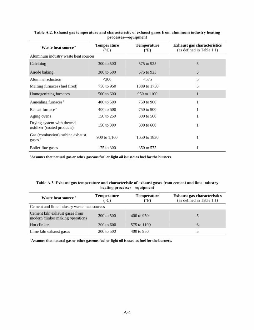
A-4
Table A.2. Exhaust gas temperature and characteristic of exhaust gases from aluminum industry heating
processes—equipment
Waste heat source a
Temperature
(°C)
Temperature
(°F)
Exhaust gas characteristics
(as defined in Table 1.1)
Aluminum industry waste heat sources
Calcining 300 to 500 575 to 925 5
Anode baking 300 to 500 575 to 925 5
Alumina reduction <300 <575 5
Melting furnaces (fuel fired) 750 to 950 1389 to 1750 5
Homogenizing furnaces 500 to 600 950 to 1100 1
Annealing furnaces a 400 to 500 750 to 900 1
Reheat furnace a 400 to 500 750 to 900 1
Aging ovens 150 to 250 300 to 500 1
Drying system with thermal
oxidizer (coated products) 150 to 300 300 to 600 1
Gas (combustion) turbine exhaust
gases a 900 to 1,100 1650 to 1830 1
Boiler flue gases 175 to 300 350 to 575 1
aAssumes that natural gas or other gaseous fuel or light oil is used as fuel for the burners.
Table A.3. Exhaust gas temperature and characteristic of exhaust gases from cement and lime industry
heating processes—equipment
Waste heat source a
Temperature (°C)
Temperature (°F)
Exhaust gas characteristics (as defined in Table 1.1)
Cement and lime industry waste heat sources
Cement kiln exhaust gases from
modern clinker making operations 200 to 500 400 to 950 5
Hot clinker 300 to 600 575 to 1100 6
Lime kiln exhaust gases 200 to 500 400 to 950 5
aAssumes that natural gas or other gaseous fuel or light oil is used as fuel for the burners.

A-5
Table A.4. Exhaust gas temperature and characteristic of exhaust gases from petroleum refining industry
heating processes—equipment
Waste heat source a
Temperature
(°C)
Temperature
(°F)
Exhaust gas characteristics
(as defined in Table 1.1)
Petroleum refining industry waste heat sources
Process heaters 200 to 300 400 to 900 1
Calciners (coke) 300 to 500 575 to 930 2
Flared gases 200 to 400 400 to 750 2
Reactors—crackers 200 to 400 400 to 750 1
Gas (combustion) turbine exhaust
gases a 900 to 1100 1650 to 1830 1
Waste heat and fuel fired
boilers—flue gases 175 to 300 350 to 575 1
aAssumes that natural gas or other gaseous fuel or light oil is used as fuel for the burners.
Table A.5. Exhaust gas temperature and characteristic of exhaust gases from chemical industry heating
processes—equipment
Waste heat source a
Temperature
(°C)
Temperature
(°F)
Exhaust gas characteristics
(as defined in Table 1.1)
Chemical industry waste heat sources
Pyrolysis furnaces 200 to 300 400 to 575 1
Process (fired) heaters 200 to 480 400 to 900 2
Reactors (incl. fluidized beds) 200 to 400 400 to 750 2
Thermal oxidizers 300 to 400 575 to 750 1
Gas (combustion) turbine exhaust
gases a 900 to 1100 1650 to 1830 1
Waste heat and fuel fired
boilers—flue gases 175 to 300 350 to 575 1
aAssumes that natural gas or other gaseous fuel or light oil is used as fuel for the burners.

A-6

B-1
APPENDIX B. CALCULATIONS FOR RECOVERABLE HEAT
FROM SELECTED PROCESSES

B-2
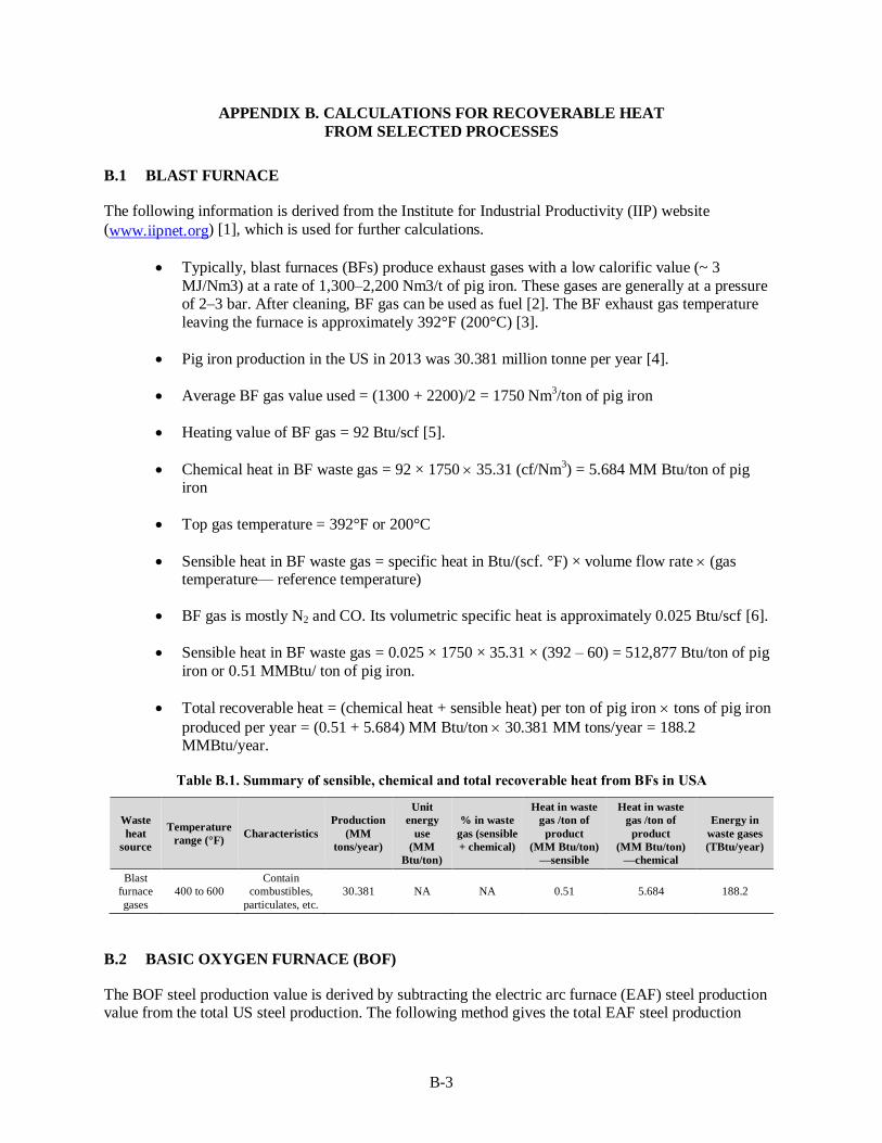
B-3
APPENDIX B. CALCULATIONS FOR RECOVERABLE HEAT
FROM SELECTED PROCESSES
B.1 BLAST FURNACE
The following information is derived from the Institute for Industrial Productivity (IIP) website
(www.iipnet.org) [1], which is used for further calculations.
Typically, blast furnaces (BFs) produce exhaust gases with a low calorific value (~ 3
MJ/Nm3) at a rate of 1,300–2,200 Nm3/t of pig iron. These gases are generally at a pressure of 2–3 bar. After cleaning, BF gas can be used as fuel [2]. The BF exhaust gas temperature
leaving the furnace is approximately 392°F (200°C) [3].
Pig iron production in the US in 2013 was 30.381 million tonne per year [4].
Average BF gas value used = (1300 + 2200)/2 = 1750 Nm3/ton of pig iron
Heating value of BF gas = 92 Btu/scf [5].
Chemical heat in BF waste gas = 92 × 1750 35.31 (cf/Nm3) = 5.684 MM Btu/ton of pig
iron
Top gas temperature = 392°F or 200°C
Sensible heat in BF waste gas = specific heat in Btu/(scf. °F) × volume flow rate (gas temperature— reference temperature)
BF gas is mostly N2 and CO. Its volumetric specific heat is approximately 0.025 Btu/scf [6].
Sensible heat in BF waste gas = 0.025 × 1750 × 35.31 × (392 – 60) = 512,877 Btu/ton of pig
iron or 0.51 MMBtu/ ton of pig iron.
Total recoverable heat = (chemical heat + sensible heat) per ton of pig iron tons of pig iron
produced per year = (0.51 + 5.684) MM Btu/ton 30.381 MM tons/year = 188.2 MMBtu/year.
Table B.1. Summary of sensible, chemical and total recoverable heat from BFs in USA
Waste
heat
source
Temperature
range (°F) Characteristics
Production
(MM
tons/year)
Unit
energy
use
(MM
Btu/ton)
% in waste
gas (sensible
+ chemical)
Heat in waste
gas /ton of
product
(MM Btu/ton)
—sensible
Heat in waste
gas /ton of
product
(MM Btu/ton)
—chemical
Energy in
waste gases
(TBtu/year)
Blast
furnace
gases
400 to 600
Contain
combustibles,
particulates, etc.
30.381 NA NA 0.51 5.684 188.2
B.2 BASIC OXYGEN FURNACE (BOF)
The BOF steel production value is derived by subtracting the electric arc furnace (EAF) steel production value from the total US steel production. The following method gives the total EAF steel production
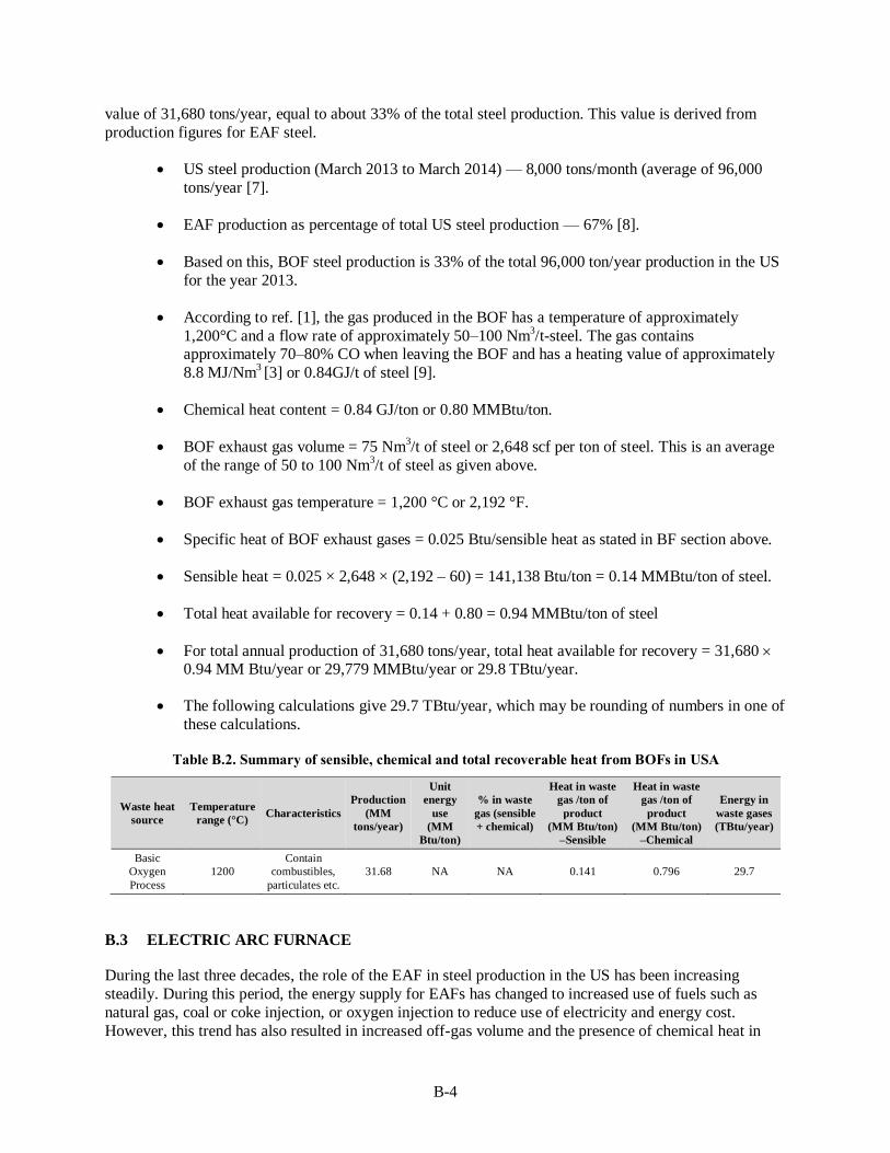
B-4
value of 31,680 tons/year, equal to about 33% of the total steel production. This value is derived from
production figures for EAF steel.
US steel production (March 2013 to March 2014) — 8,000 tons/month (average of 96,000
tons/year [7].
EAF production as percentage of total US steel production — 67% [8].
Based on this, BOF steel production is 33% of the total 96,000 ton/year production in the US
for the year 2013.
According to ref. [1], the gas produced in the BOF has a temperature of approximately
1,200°C and a flow rate of approximately 50–100 Nm3/t-steel. The gas contains
approximately 70–80% CO when leaving the BOF and has a heating value of approximately
8.8 MJ/Nm3 [3] or 0.84GJ/t of steel [9].
Chemical heat content = 0.84 GJ/ton or 0.80 MMBtu/ton.
BOF exhaust gas volume = 75 Nm3/t of steel or 2,648 scf per ton of steel. This is an average
of the range of 50 to 100 Nm3/t of steel as given above.
BOF exhaust gas temperature = 1,200 °C or 2,192 °F.
Specific heat of BOF exhaust gases = 0.025 Btu/sensible heat as stated in BF section above.
Sensible heat = 0.025 × 2,648 × (2,192 – 60) = 141,138 Btu/ton = 0.14 MMBtu/ton of steel.
Total heat available for recovery = 0.14 + 0.80 = 0.94 MMBtu/ton of steel
For total annual production of 31,680 tons/year, total heat available for recovery = 31,680 0.94 MM Btu/year or 29,779 MMBtu/year or 29.8 TBtu/year.
The following calculations give 29.7 TBtu/year, which may be rounding of numbers in one of
these calculations.
Table B.2. Summary of sensible, chemical and total recoverable heat from BOFs in USA
Waste heat
source
Temperature
range (°C) Characteristics
Production
(MM
tons/year)
Unit
energy
use
(MM
Btu/ton)
% in waste
gas (sensible
+ chemical)
Heat in waste
gas /ton of
product
(MM Btu/ton)
–Sensible
Heat in waste
gas /ton of
product
(MM Btu/ton)
–Chemical
Energy in
waste gases
(TBtu/year)
Basic
Oxygen
Process
1200
Contain
combustibles,
particulates etc.
31.68 NA NA 0.141 0.796 29.7
B.3 ELECTRIC ARC FURNACE
During the last three decades, the role of the EAF in steel production in the US has been increasing
steadily. During this period, the energy supply for EAFs has changed to increased use of fuels such as
natural gas, coal or coke injection, or oxygen injection to reduce use of electricity and energy cost.
However, this trend has also resulted in increased off-gas volume and the presence of chemical heat in

B-5
off-gases. This has increased waste heat discharge from EAFs. In some cases (for <10% of the total EAFs
in the US), the waste heat from EAF off-gases is recovered and used for either scrap preheating or steam generation. In the vast majority (>90% in US) of installations [10], it is common practice to collect EAF
exhaust gases, mix them with ambient air to oxidize the combustible materials, and then drop the
temperature of the gases to less than 400F (or 200C). These relatively low-temperature gases are then passed through a pollution control device such as a baghouse before being discharged into the
atmosphere.
The following section describes the methodology used for calculating recoverable waste heat from EAF
installations in the US. The data used for these calculations has been derived from various sources.
Typical temperature range of EAF off-gases — 1,500 to 1,600°C [9, 50].
US steel production (March 2013 to March 2014) — 8 million tonnes/month (average or 96
million tonnes/year [10].
EAF production as percentage of total US steel production — 67% [8].
Energy input = 742 kWh/tonne or 2.535 MMBtu/tonne molten steel.
Sensible heat in EAF exhaust gases = 16.7% or 0.423 MMBtu/tonne
Chemical heat in EAF exhaust gases = 21.4% or 0.542 MMBtu/tonne
Total waste heat in EAF exhaust gases = 0.423 + 0.542 = 0.965 MMBtu/tonne.
Total waste heat for the EAF industry in USA = 0.965 96,000,000 0.67 = 62,068,800
MMBtu/year or 62.1 TBtu/year. Details of heat used or wasted and off-gas temperature during a heat are shown in Figure B.1.
In few cases (for <10% of the total EAFs in the US) the waste heat from EAF off-gases is
recovered and used for either scrap preheating or steam generation. As per the electric arc
furnace roundup [10], there are total 9 EAFs (7 operational, 1 idled, and 1 under construction) with Consteel scrap preheating system. Also, there are total 9 EAFs (1 EAF is not melting)
with shaft, twin shaft, and twin shell type of scrap preheating systems. These EAFs produce
19% of the total steel produced using all EAFs.
A summary of sensible, chemical and total recoverable heat is given in the following Table
B.3.
Table B.3. Summary of sensible, chemical and total recoverable heat from EAFs in US
Waste heat
source
Temperature
range (°C) Characteristics
Production
(MM
tons/year)
Unit
energy
use
(MM
Btu/ton)
% in waste
gas (sensible
+ chemical)
Heat in waste
gas /ton of
product
(MM Btu/ton)
—sensible
Heat in waste
gas /ton of
product
(MM Btu/ton)
—chemical
Energy in
waste gases
(TBtu/year)
EAF exhaust
gases 1,500 to 1,600
Contain
combustibles,
particulates, etc.
64.32 2.535 38.1% 0.423 0.542 62.1

B-6
Figure B.1. Details of heat used or wasted and off-gas temperature during an EAF heat. Source: [11]*
*Note that there is an error in the summation and this is a corrected figure.
B.4 GLASS MELTING AND REFINING
Glass melting is the largest energy user in various glass manufacturing processes for the glass industry. The glass industry is classified according to main products supplied by a plant. They are flat glass,
container glass, glass fiber, and specialty glass. Each of these sectors uses a variety of fuel-fired furnaces.
They include regenerative, oxy-fuel, direct-fired (without use of preheated air or oxygen), electrical, or furnaces with electric boost. Each of these furnaces discharges a large amount (from 25 to 70%) of the
total heat input as waste heat in the form of hot exhaust gases. These gases contain large amounts of
particulates, volatiles and, in some cases, condensable vapors.
The following methodology is used to calculate total recoverable waste heat in the form of harsh environments, mainly from glass melting furnaces.
1. Obtain total energy used by the US glass industry.
2. Calculate how much of this energy is used for glass melting furnaces that produce waste heat in the form of harsh environments.

B-7
3. Find distribution of total energy used for glass melting for each of the four glass sectors: flat glass,
container glass, glass fiber, and specialty glass.
4. Use the type of furnace or firing used for each of these sectors. The main types of furnaces are
regenerative, oxy-fuel, electric (total or boost), recuperative, and direct-fired with no heat recovery.
5. Identify energy intensity for each type of firing or furnace system.
6. Calculate available heat for each furnace type, based on exhaust gas temperature and firing method
and use this information to calculate heat losses, which are equal to [energy intensity (1 – available heat)].
7. Calculate waste heat content in exhaust gases. Note that the glass furnace waste heat stream does not
contain any chemical heat. The entire amount of heat is sensible heat.
Total energy used by the glass industry in the US and various process steps, as collected and published by
the Energy Information Agency (EIA) of the US Department of Energy (DOE) [12] is given in
Figure B.2. The main data point used for the further calculations is the glass industry’s total energy
consumption—200 TBtu/year (2010 data).
Figure B.2. Energy consumption in glass manufacturing by fuel (2010 data). [12]
The share of melting furnaces is derived by using information developed by Energetics, Inc. [13]; it is
given in Table B.4. This information is for the year 2002, so it is used to derive the energy used for
melting furnaces as a percentage of the total energy used by the glass industry. The glass melting and refining area in a plant uses almost 49.4% of the total plant energy used. Note that the other plant areas
use fuel energy that discharges waste heat at a relatively lower temperature; and that exhaust does not
contain significant amounts of constituents that require specially designed heat recovery equipment, as opposed to the gases classified as harsh environments.
Glass production data in million ton/year (MM ton/year) were obtained from an EPA document prepared
by Lawrence Berkeley National Laboratory [14] and a DOE report prepared by the Gas Technology
Institute [15]. These date are provided in Table B.5. This table also gives the distribution of glass production by the type of furnace or firing system used. This information is used to obtain production

B-8
(MM tons/year) data for each type of furnace heating system. The table shows that a large percentage,
almost 60%, of glass is melted in regenerative furnaces. The “other” category includes furnaces with straight electric heating and without the use of any type of heat recovery equipment. Nonregenerative
systems include furnaces with recuperative heat recovery systems.
Table B.4. Share of energy use by different sectors of the US glass industry [13]
Process step Annual energy use 10^12 Btu/year Percentage
Batch preparation 13.7
Sub Total 13.7 4.8%
Melting–flat glass 42.9
Melting–container 53.1
Melting–pressed-blown 18.1
Melting–fiber 25.6
Sub Total 139.7 49.4%
Forming–flat glass 7.5
Forming–container 38.4
Forming–pressed-blown 13.2
Forming–fiber 21.9
Sub Total 81 28.6%
Post forming–flat glass 11.1
Post forming–container 17.8
Post forming–pressed-blown 7.5
Post forming–fiber 12
Subtotal 48.4 17.1%
Grand total 282.8 100.0%
Table B.5. Glass production data by various sectors and type of heating system used [14, 15]
Glass industry
Production a Regen/recup Oxy-fuel Nonregen Other
Total
MM
tons/year % % distribution–firing method a
Flat glass 5 25% 80% 20% 0% 0%
Container glass 10 50% 70% 30% 0% 0%
Specialty glass 2 10% 26% 35% 34% 5%
Fiber glass 3 15% 10% 35% 0% 55%
20 100%
Production MM ton/year 11.82 5.75 0.68 1.75 20
% production by each system 59.1% 28.8% 3.4% 8.8% 100%
a Ernst Warrell, Christina Galitsky, Eric Masanet, and Wina Graus, Energy Efficiency Improvement and Cost Saving Opportunities for Glass Industry, US Environmental Protection Agency, August 2008 b David M. Rue, James Servaites, and Warren Wolf, Final Report, Industrial Glass Bandwidth Analysis, Gas Technology Institute, Energy Utilization Center, August 2007.
Total heat in the waste heat stream for each sector of the glass industry and each type of furnace used is
calculated using the following steps. Each of these steps, with the source of information used, is given in
Table B.6.
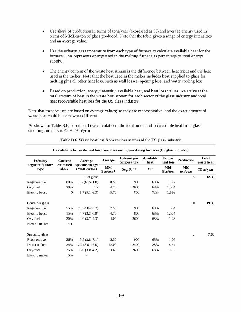
B-9
Use share of production in terms of tons/year (expressed as %) and average energy used in
terms of MMBtu/ton of glass produced. Note that the table gives a range of energy intensities
and an average value.
Use the exhaust gas temperature from each type of furnace to calculate available heat for the
furnace. This represents energy used in the melting furnace as percentage of total energy
supply.
The energy content of the waste heat stream is the difference between heat input and the heat
used in the melter. Note that the heat used in the melter includes heat supplied to glass for
melting plus all other heat loss, such as wall losses, opening loss, and water cooling loss.
Based on production, energy intensity, available heat, and heat loss values, we arrive at the
total amount of heat in the waste heat stream for each sector of the glass industry and total
heat recoverable heat loss for the US glass industry.
Note that these values are based on average values; so they are representative, and the exact amount of waste heat could be somewhat different.
As shown in Table B.6, based on these calculations, the total amount of recoverable heat from glass
smelting furnaces is 42.9 TBtu/year.
Table B.6. Waste heat loss from various sectors of the US glass industry
Calculations for waste heat loss from glass melting—refining furnaces (US glass industry)
Industry
segment/furnace
type
Current
estimated
share
Average
specific energy
(MMBtu/ton)
Average Exhaust gas
temperature
Available
heat
Ex. gas
heat loss Production
Total
waste heat
MM
Btu/ton * Deg. F. ** ***
MM
Btu/ton
MM
ton/year TBtu/year
Flat glass 5 12.38
Regenerative 80% 8.5 (6.2-11.8) 8.50 900 68% 2.72
Oxy-fuel 20% 4.7 4.70 2600 68% 1.504
Electric boost 0 5.7 (5.1–6.3) 5.70 800 72% 1.596
Container glass 10 19.30
Regenerative 55% 7.5 (4.8–10.2) 7.50 900 68% 2.4
Electric boost 15% 4.7 (3.3–6.0) 4.70 800 68% 1.504
Oxy-fuel 30% 4.0 (3.7–4.3) 4.00 2600 68% 1.28
Electric melter n.a.
Specialty glass 2 7.60
Regenerative 26% 5.5 (3.8–7.1) 5.50 900 68% 1.76
Direct melter 34% 12.0 (8.0–16.0) 12.00 2400 28% 8.64
Oxy-fuel 35% 3.6 (3.0–4.2) 3.60 2600 68% 1.152
Electric melter 5% –

B-10
Table B.7. Waste heat loss from various sectors of the U S glass industry (continued)
Calculations for waste heat loss from glass melting - refining furnaces (US glass industry)
Industry
segment/ furnace
type
Current
estimated
share
Average
specific energy
(MMBtu/ton)
Average Exhaust gas
temperature
Available
heat
Ex. gas
heat loss Production
Total
waste heat
MM Btu/ton
a
F b
c MM
Btu/ton
MM
ton/year TBtu/year
Glass fiber insulation d 1.5 1.53
Electric melter 55% – –
Recuperative 10% 7.0 (6.0–8.0) 7.00 1800 44% 3.92
Oxy-fuel 35% 5.6 (3.4–7.8) 5.60 2600 68% 1.792
Textile/reinforcement fibers d 1.5 2.12
Recuperative 25% 10.5 (6.0–15.0) 0.50 1800 44% 0.28
Oxy-fuel 75% 5.6 (3.4–7.8) 5.60 2600 68% 1.792
Total waste heat loss (TBtu/year) 42.93
Source: US Department of Energy (2002) [13]; Rue et al., (2006) [15] a Ernst Warrell, Christina Galitsky, Eric Masanet, and Wina Graus, Energy Efficiency Improvement and Cost Saving Opportunities
for Glass Industry, US Environmental Protection Agency, August 2008. b Average of BCS data [16] and actual measurements at two glass furnaces at container glass manufacturing plant. c Richard J. Reed, North American Combustion Handbook, Vol 1 and vol 2, North American Manufacturing Company 1952 [17]. d Assumes 50% each of the total for fiber glass production of 3 MM ton/year.
B.5 ALUMINUM MELTING
There are more than 300 aluminum production plants in the US [16]. These plants consume about
770 TBtu (2.26 1011
kWh) of energy per year. Aluminum production is carried out in primary and secondary plants. In each case, aluminum is used in the molten state and involves holding and/or
reheating liquid metal from the primary melting site, melting “solid” aluminum in the form of sows or
other shapes obtained from the primary plant, melting of in-plant aluminum scrap, or melting of purchased scrap such as used beverage cans and other scrap collected from various sources. Production
and use of aluminum in the US has varied significantly during the past 10 years, depending on economic
conditions. Currently available data (year 2012) from the Aluminum Association [18] are given in
Table B.7. However, the table does not supply data for the value of aluminum metal melted in the US.
Table B.8 Aluminum supply data from Aluminum Association (2012)
It is difficult to obtain exact values for the total weight of aluminum melted, since in some cases
aluminum metal is melted or heated several times during the production process. Figure B.3 shows
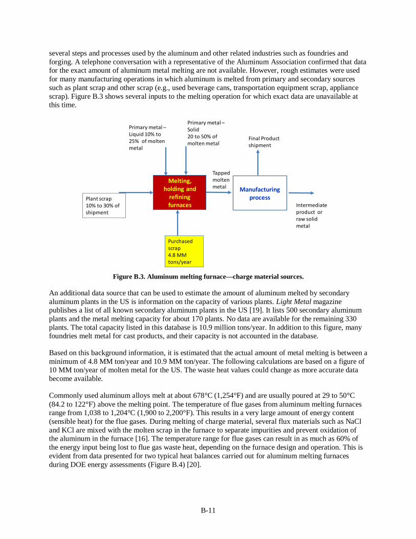
B-11
several steps and processes used by the aluminum and other related industries such as foundries and
forging. A telephone conversation with a representative of the Aluminum Association confirmed that data for the exact amount of aluminum metal melting are not available. However, rough estimates were used
for many manufacturing operations in which aluminum is melted from primary and secondary sources
such as plant scrap and other scrap (e.g., used beverage cans, transportation equipment scrap, appliance
scrap). Figure B.3 shows several inputs to the melting operation for which exact data are unavailable at this time.
Figure B.3. Aluminum melting furnace—charge material sources.
An additional data source that can be used to estimate the amount of aluminum melted by secondary
aluminum plants in the US is information on the capacity of various plants. Light Metal magazine publishes a list of all known secondary aluminum plants in the US [19]. It lists 500 secondary aluminum
plants and the metal melting capacity for about 170 plants. No data are available for the remaining 330
plants. The total capacity listed in this database is 10.9 million tons/year. In addition to this figure, many foundries melt metal for cast products, and their capacity is not accounted in the database.
Based on this background information, it is estimated that the actual amount of metal melting is between a
minimum of 4.8 MM ton/year and 10.9 MM ton/year. The following calculations are based on a figure of 10 MM ton/year of molten metal for the US. The waste heat values could change as more accurate data
become available.
Commonly used aluminum alloys melt at about 678°C (1,254°F) and are usually poured at 29 to 50°C
(84.2 to 122°F) above the melting point. The temperature of flue gases from aluminum melting furnaces range from 1,038 to 1,204°C (1,900 to 2,200°F). This results in a very large amount of energy content
(sensible heat) for the flue gases. During melting of charge material, several flux materials such as NaCl
and KCl are mixed with the molten scrap in the furnace to separate impurities and prevent oxidation of the aluminum in the furnace [16]. The temperature range for flue gases can result in as much as 60% of
the energy input being lost to flue gas waste heat, depending on the furnace design and operation. This is
evident from data presented for two typical heat balances carried out for aluminum melting furnaces
during DOE energy assessments (Figure B.4) [20].
Melting, holding and
refining furnaces
Primary metal –Liquid 10% to 25% of molten metal
Primary metal –Solid20 to 50% of molten metal
Plant scrap10% to 30% of shipment
Purchased scrap4.8 MM tons/year
Tapped molten metal Manufacturing
process
Final Product shipment
Intermediate product or raw solid metal

B-12
Figure B.4. Typical heat balances carried out on aluminum melting furnaces during US DOE energy saving
assessments. [20]
On average, flue gases contain 50 to 70% of the total furnace heat input [16].
Energy use for aluminum melting varies from 1,200 to 3,000 Btu/lb [20].
One of the heat balances shows an energy use of 2,200 Btu/lb of molten metal. For
calculations of waste heat, this report used an average value of 2,100 Btu/lb energy required
for a melter not using any heat recovery.
Reference [21] shows a melting energy use between 1,800 Btu/lb at full production and 2,800
Btu/lb at low production conditions.
Reference [21] shows 1,800 to 1,900 Btu/lb.
Based on these values, 1,800 Btu/lb was used as an average value.
The heat loss in exhaust gases is calculated by using exhaust gas temperatures from aluminum melting
furnaces that do not use any heat recovery equipment and from those using recuperators and regenerative
burners.
The population of furnaces using each of the three different types of heating systems was derived based on one-on-one discussions with a combustion equipment supplier (Bloom Engineering) [22]. The
discussions included typical exhaust gas temperatures, as listed in Table B.6, and average values of excess
air. Note that almost all aluminum melting furnaces are semi-continuous since the liquid metal is tapped at a certain frequency and continuously. This results in changes in the firing rate (burner input) and air-
fuel ratio. This factor and changes in air leakage in the furnace due to negative pressure at the low firing
rate result in a high oxygen percentage or high “apparent” excess air. A value of 30% was used for these calculations. Heat in exhaust gases was calculated based on the calculation of available heat from the
heating system (furnace) and the amount of heat left in the exhaust gases. The available heat and
corresponding heat in exhaust gases depend on the exhaust gas temperature, excess air, and combustion
air temperature used for each type of heating system. Note that the control volume includes the furnace and heat recovery equipment. Total aluminum liquid metal production is based on the population of
furnaces using each of the three types of heating systems.
Exhaust gas heat loss calculations include the following steps:

B-13
Heat input used per lb of liquid metal.
Calculation of available heat using the information discussed above.
Calculation of heat in exhaust gas per lb of liquid metal using the following equation:
o Heat in exhaust gas per lb = (heat input per lb) (1– available heat %)
Total heat in exhaust gases = Heat in exhaust gas per lb total metal produced per year based on furnace population.
Note that the exhaust gases from aluminum melting furnaces do not contain significant amounts of
chemical heat. Only in rare cases, while the furnace is not operating properly, it is possible to detect high values for combustibles and hence the presence of chemical heat in exhausts gases. These are
unaccounted for in these calculations.
Table B.8 summarizes the results of these calculations. It shows that the estimated waste heat content in
exhaust gases from aluminum melting furnaces in the US is 15.88 TBtu/year.
Table B.9. Estimate of exhaust gas heat from aluminum melting furnaces in the US (2012 data)
Aluminum metal melted—secondary melting Million tonne/year 10.00 [18] See text for source and
explanation
Item
Non
recup. Recup. Regen. Comment
Flue gas temp at the stack after heat recovery equipment
1700 1000 700 Avg. for regen
Comb air temp ()F) 80 80 80
% excess air average 30% 30% 30%
Average heat 45% 65% 70% From avg. heat graphs
Flue gas losses 55% 35% 30%
% of total population 65% 25% 10%
Production from each category of furnace
MM tons/year 6.50 2.50 1.00
Heat in flue gases based on energy use, production and heat loss TBtu/year
12.87 2.36 0.65
Total flue gas loss For the furnace
population 15.88 TBtu/year
Average value—flue gas loss % For the furnace
population 48% %
Energy use per lb of molten aluminum metal tapped
Item Type of furnace Btu/lb. Notes
Average energy use for melting Non-recuperative furnaces
1,800 Baseline—see text for explanation
Furnaces with recuperators
1,350 Fuel saving—25% based on exhaust gas temperature
Furnaces with regen. burners
1,080 Fuel saving—40% based on exhaust gas temperature

B-14
B.6 ANODE MAKING
Carbon anodes are used in the electrolysis of alumina to carry the electrical current used in the process. Anodes are made using petroleum coke and tar-pitch. The manufacturing process requires baking of the
anodes between 1,250 and 1450°C (2,280 and 2,640°F). The heating system is a ring furnace
(Figure B.5), which itself can be considered as a counter-flow heating system to maximize the use of the
heating value of tar and pitch and minimize fuel use. The process results in exhaust gases that are at high temperatures and contain large amounts of particles and combustible gases with a fairly high heating
value. Currently, the heat content of these gases is not used.
Figure B.5. Design of an open top anode baking furnace. [23]
The following calculations were used to estimate the total recoverable heat from anode baking facilities.
The calculations are based on available information for anode use per kg of aluminum metal produced
(0.415 lb of anode per lb of aluminum produced) as given in ref. [24]. The energy required (external, not accounting for volatiles from the “green” or unbaked anode, is 2.57 GJ/metric ton of anode or 2.18
MMBtu/ton of anode [25]. The other required information in the following list also was obtained from
ref. [25].
Exhaust gas temperature: 300°C (572°F).
Heat in exhaust gas (average of three readings): 1 GJ/metric ton or 0.85 MMBtu/metric ton of
anode.
This represents 39% (= 0.85 MM Btu in exhaust gas /2.18 MMBtu input per metric ton of
anode) of the heat input in the kiln.
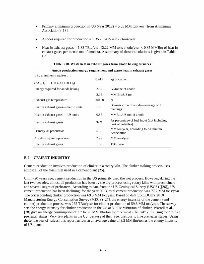
B-15
Primary aluminum production in US (year 2012) = 5.35 MM ton/year (from Aluminum
Association) [18].
Anodes required for production = 5.35 0.415 = 2.22 tons/year.
Heat in exhaust gases = 1.88 TBtu/year (2.22 MM tons anode/year 0.85 MMBtu of heat in exhaust gases per metric ton of anodes). A summary of these calculations is given in Table
B.9.
Table B.10. Waste heat in exhaust gases from anode baking furnaces
Anode production energy requirement and waste heat in exhaust gases
1 kg aluminum requires . . .
(2Al2O3 + 3 C = 4 Al + 3CO2)
0.415 kg of carbon
Energy required for anode baking 2.57 GJ/tonne of anode
2.18 MM Btu/US ton
Exhaust gas temperature 300.00 °C
Heat in exhaust gases—metric units 1.00 GJ/metric ton of anode—average of 3
readings
Heat in exhaust gases —US units 0.85 MMBtu/US ton of anode
Heat in exhaust gases 39% As percentage of fuel input (not including
heat of volatiles)
Primary Al production 5.35 MM ton/year, according to Aluminum
Association
Anodes required–produced 2.22 MM tons/year
Heat in exhaust gases 1.88 TBtu/year
B.7 CEMENT INDUSTRY
Cement production involves production of clinker in a rotary kiln. The clinker making process uses
almost all of the fossil fuel used in a cement plant [25].
Until ~20 years ago, cement production in the US primarily used the wet process. However, during the
last two decades, almost all production has been by the dry process using rotary kilns with precalciners
and several stages of preheaters. According to data from the US Geological Survey (USGS) ([26]), US cement production has been declining; for the year 2013, total cement production was 77.2 MM tons/year.
The corresponding clinker production was 69.3 MM ton/year. Based on data from DOE’s 2010
Manufacturing Energy Consumption Survey (MECS) [27], the energy intensity of the cement (and
clinker) production process was 235 TBtu/year for clinker production of 59.8 MM ton/year. The survey sets the energy intensity for clinker production in the US at 3.92 MMBtu/ton of clinker. Warrell et al.,
[28] give an energy consumption of 2.7 to 3.0 MM Btu/ton for “the most efficient” kilns using four to five
preheater stages. Very few plants in the US, because of their age, use four to five preheater stages. Using these two sets of values, this report arrives at an average value of 3.5 MMBtu/ton as the energy intensity
of US plants.

B-16
The kiln exhaust gases contain large amounts of CO2 and water vapor (~30% of the exhaust gases) from
moisture in the raw material. Both of these gases have a high specific heat, resulting in much higher heat content than combustion products from coal or natural gas combustion.
Flue gas from the kiln contains dust, commonly known as cement kiln dust, and several gaseous
components such as sulfur dioxide (SO2), nitrogen oxides (NOX), hydrogen chloride (HCl), and volatile
organic compounds, all of which are subject to regulation by the Environmental Protection Agency (EPA). The SO2 content of the flue gas is a function of the sulfur content in the fuel and the mineral raw
materials, as well as the design and operating conditions of the cement kiln. When medium- or high-sulfur
coal is used as the fuel, the SO2 content of the flue gas is likely to exceed air-quality-emission limitations. The active ingredients of cement kiln dust are primarily the oxides of calcium, magnesium, and
potassium. In addition, there are considerable amounts of inert compounds, such as silica, as well as
traces of carbon resulting from incomplete fuel combustion.
All of these factors make it extremely difficult to use conventional WHR equipment in these plants
without encountering major operating and maintenance issues. It is necessary to develop equipment that
uses proper design and materials to reduce the operating and maintenance problems.
Waste heat from clinker production comes from two major sources: kiln exhaust gases and clinker cooler air. In modern plants in countries such as China and India, this waste heat is recovered by using various
heat recovery methods, including power generation. However, very few plants in the US can justify
capital investments for power generation from waste heat.
The average waste gas temperature given in a BCS, Inc., report [16] is from 640 to 840°F. Typically, the
clinker coolers release large amounts of heated air at 250 to 340°C (480 to 645°F) directly into the
atmosphere [28]. At the kiln charging side, the 300 to 400°C (570 to 750°F) kiln gas coming off the preheaters is typically used to dry material in the raw mill and/or the coal mill and is then sent to
electrostatic precipitators or bag filter houses to remove dust before it is finally vented to the atmosphere.
The amount of waste heat available for recovery depends on kiln system design and production, the
moisture content of the raw materials, and the amount of heat required for drying in the raw mill system, solid fuel system, and cement mill.
For commonly used preheater kilns, according to a report from the International Finance Corporation
[29], the waste heat is 0.904 GJ/tonne of clinker produced. Table B.10 shows the calculation method used to estimate the total waste heat from cement kilns.
Table B.11. Parameters used for calculation of waste heat from kilns in cement industry
Clinker production (MM TPY) 69.3 From 2014 USGS data [26]
Waste heat GJ/tonne of clinker 0.904 From IFC June 2014 report [29]
Waste heat MMBtu/tonne of
clinker 0.77 Calculated
Heat in waste gases (TBtu/year) 53.02 Calculated
Note that this value is substantially lower than the value given in a BCS report [16], which uses a cement production value of 99 MM ton/year for 2005. Cement production in the US has declined significantly
and is at 77 MM tons/year with clinker production of 69.2 MM ton/year. In addition, because of energy
saving measures taken during the past 9 years, the amount of waste heat value has declined considerably.

B-17
B.8 LIME INDUSTRY
Quicklime is produced by the thermal decomposition of limestone. It consists mainly of calcium oxide, with magnesium oxide as a secondary component. Limestone is a high-purity, high-calcium or dolomitic
limestone containing of at least 95% mass of total carbonate (CaCO3+MgCO3). Normally used quicklime
is produced by providing heat at temperatures >900°C (1,650°F) to dissociate calcium and magnesium
carbonates into their respective oxides and CO2. Calcination of calcium carbonate is a highly endothermic reaction, requiring 3.16 GJ of heat input to produce a tonne of lime (CaO). The reaction begins only when
the temperature is above the dissociation temperature, typically between 1,440 and 2,450F (780 and
1,340C), of the carbonates in the limestone or lime mud.
According to the USGS [30], lime production in the US has been steadily increasing, with a total
production of 19 MM tonne or 20.9 MM ton per year by the year 2013.
Based on the 2010 MECS survey data [12], energy use in 2010 for the lime industry was approximately 96 TBtu/year. Production of lime in 2010, according to USGS, was 18.3 million tonne/year. Note that the
data used are for the year 2010 for consistency of energy intensity calculations. Based on these data,
energy intensity or use for lime production is 5.24 MMBtu/tonne. As shown in Table B.11, energy use is 5.5 to 13.0 GJ/tonne lime for commonly used lime kilns (short rotary kilns and long rotary kilns) and
7.2 GJ/t in Canada [31] and in lime kilns in US pulp mills [32]. (A tonne is a metric ton, 2,240 lb, rather
than a US ton, 2,000 lb.)
Table B.12. Energy intensities of commonly used lime kilns [33]
Design of kiln Energy use range (GJ/tonne)
Long rotary kilns (typically with no preheat) 7.0 – 13.0
Rotary hearth kilns (calcimatic) 6.0 – 9.0
Short rotary kilns (typically with preheaters) 5.5 – 8.0
Shaft or vertical kilns 5.0 – 7.0
Double shaft or annular shaft kilns 4.0 – 4.5
Source: Canadian Lime Institute, Energy Efficiency Opportunity Guide in the Lime Industry, 2001.
Based on these data, for the US and Canada, energy use can be approximated as 6.09 MMBtu/US ton.
Waste heat loss from kilns depends on many variables, including type of fuel used, combustion practices,
kiln design, and operating condition. The best available information is provided by Moffat and Walmsley
[34], which indicates flue gas losses as 32% of the total heat input (Figure B.6).

B-18
Figure B.6. Heat balance on a typical lime kiln [34].
The following calculations, based on the data presented above, are used to calculate the total recoverable
heat content of the waste heat in exhaust gases from lime kilns.
Total lime production in the US (2013) = 20.9 MM ton/year
Energy intensity used = 6.09 MMBtu/ton
Total energy used = 20.9 6.09 = 127.28 TBtu/year Exhaust gas loss = 32% of the heat input
Exhaust gas heat loss for the US lime industry = (32/100) 127.28 = 40.73 TBtu/year
The calculations are summarized in Table B.12.
Table B.13. Calculations for waste heat loss for the US lime industry (2013)
Item and units Value Year 2013 data
Lime production (MM ton/year) 20.90 From 2014 USGS data [26]
Energy intensity (MMBtu/ton) 6.09 Average (5.5 to 8.0 GJ/tonne) from various sources—see Chapter 7 of this report for
details
Total energy used (TBtu/year) 127.28 Calculated from data in Appendix B8 of this
report
Exhaust gas losses (% of total input energy) 32% Data from a reference—see Chapter 7 of this
report
Waste heat loss (TBtu/year) 40.7 Calculated from data in Appendix B8 of this
report
Depending on the type of kiln used, the exhaust gas temperature is in the range of 150 to 350°C (300 to
660°F) [35].
The kiln exhaust gases contain large amounts of CO2 and water vapor (almost 50% of the exhaust gases)
from moisture in the raw materials. Both of these gases have a high specific heat, resulting in much higher
heat content than in combustion products from coal or natural gas combustion.
Flue gas from the kiln contains dust and several gaseous components such as sulfur dioxide (SO2),
nitrogen oxides (NOX), hydrogen chloride (HCl), and volatile organic compounds, all of which are subject
0.0%
10.0%
20.0%
30.0%
40.0%
50.0%
60.0%
Flue gasloss
Shell loss Misc.losses
Calcination Productlosses
He
at L
oss
/Use
(% o
f in
pu
t)

B-19
to EPA regulation. The SO2 content of the flue gas is a function of the sulfur content in the fuel and the
mineral raw materials, as well as the design and operating conditions of the cement kiln. When medium- or high-sulfur coal is used as the fuel, the SO2 content of the flue gas is likely to exceed air-quality-
emission limitations. The active ingredients of the kiln dust are primarily oxides of calcium, magnesium,
and potassium. In addition, there are considerable amounts of inert compounds, such as silica, as well as
traces of carbon resulting from incomplete fuel combustion.
All of these factors make it extremely difficult to use conventional WHR equipment in these plants
without encountering major operating and maintenance issues. It is necessary to develop equipment that
uses proper design and materials to reduce the operating and maintenance problems.
Table B.13 provides a summary of waste heat sources.

B-2
0
Table B.14. Waste heat recovery potential from selected harsh environment waste gas streams
Criteria: Exhaust gases considered either >1200F (650C) and/or containing combustibles and contaminants
Industry Waste heat source Temp.
range (°F) Characteristics
WHR technology/system
status
Production**
(MM
tons/year)
Waste Heat Recovery Potential
TBtu/year* Ex. gas flow
Sensible Chemical Total
Steel Blast furnace gases 400 to 600 Contain combustibles,
particulates, etc.
Available and widely used,
partial WHR
30 15.49 172.69 188.2 Constant
EAF exhaust gases 2,700 to
3,000
Contain combustibles,
particulates, etc.
Available, not widely used,
partial WHR
64.32 27.21 34.86 62.1 Varying
Basic oxygen process 2,250 to
3,000
Contain combustibles,
particulates, etc.
Available, not widely used,
partial WHR
31.68 4.47 25.22 29.7 Varying
Glass Flat glass 800 to 2,600 Contain particulates, etc. Available for air-fuel
combustion only and widely
used, partial WH***
5.00 12.38 Negligible 12.4 Constant
Container glass 800 to 2,600 Contain particulates,
condensable vapors, etc.
Available for air-fuel
combustion only and widely
used, partial WHR***
10.00 19.30 Negligible 19.3 Constant
Fiber glass (all types) 1,800 to
2,600
Contain particulates,
condensable vapors, etc.
Available for air-fuel
combustion only and partially
used, partial WHR***
3.00 3.65 Negligible 3.7 Constant
Specialty glass 800 to 2,600 Contain particulates,
condensable vapors, etc.
Available for partial heat
recovery but rarely used.
2.00 7.60 Negligible 7.6 Constant
Aluminum Al melting furnaces 1,400 to
1,700
Contain combustibles,
particulates, etc.
Available, not widely used,
partial WHR
10.00 15.88 Small/site
specific
15.9 Constant
(fuel fired)
Anode baking 570 to 930 Contain combustibles,
particulates, polycyclic
organic matter, etc.
Available but NOT
demonstrated
2.22 1.88 Small/site
specific
(unknown)
1.9 Constant
Calcining 570 to 930 Particulates, fuel
combustion products, etc.
Available but NOT
demonstrated
Data not available
at this time
Cement
(Clinker)
Cement kiln exhaust
gases from modern
clinker making
operations
390 to 750 Exhaust gases contain
particulates, etc.
Relatively easy to handle
Available, not widely used,
partial WHR
69.3 53.02 Negligible 53.0 Constant
Lime Lime kiln exhaust
gases based on
commonly used rotary
kiln type operations
390 to 1,100 Exhaust gases contain
particulates, etc.
Relatively easy to handle
Available, not widely used,
partial WHR
20.9 40.7 Negligible 40.7 Constant
Grand total 434.4
* For few waste heat sources (particularly in steel, aluminum, and glass industry), a small quantity of waste heat is already being recovered using the existing WHR technologies. ** Production data for steel industry is from 2013, glass industry 2002, aluminum industry 2012, and for cement and lime industry production data is from 2013. *** WHR technologies currently not available/used for oxy-fuel fired systems.

B-21
References
1. Industrial Efficiency Technology Data Base—Iron and Steel, Institute for Industrial Productivity website: http://ietd.iipnetwork.org.
2. E. Worrell, et al., Energy Efficiency Improvement and Cost Saving Opportunities for the U.S. Iron
and Steel Industry. LBNL-4779E, Lawrence Berkeley National Laboratory, Berkeley, Calif., October
2010.
3. NEDO, “Global warming countermeasures: Japanese Technologies for Energy Savings/GHG
emissions reduction, revised edition,” 2008. Available at
http://www.iipnetwork.org/Japanese_Technologies_for_Energy_Savings.pdf.
4. World Steel Association, “Iron production—December 2013,”
http://www.worldsteel.org/dms/internetDocumentList/iron-stats/2013/Iron-
excel/Iron%20December%202013.xls (accessed November 2014).
5. Association of Iron and Steel Engineers, The Making, Shaping and Treating of Steel, Tenth Edition,
1985.
6. American Gas Association, Gas Engineer’s Handbook, Industrial Press, New York, 1965.
7. Association for Iron and Steel Technology, “US production capability, imports, and inventories, Iron and Steel Technology, July, p. 18 (2014).
8. Steel Manufacturers Association, “2013–2014 public policy statement.” Available at
http://steelnet.org/docs/public_policy.pdf.
9. US EPA, “Available and emerging technologies for reducing greenhouse gas emissions from the iron
and steel industry,” prepared by the Sector Policies and Programs Division, Office of Air Quality
Planning and Standards, September 2012. Available at http://www.epa.gov/nsr/ghgdocs/ironsteel.pdf.
10. AIST, “2014 Electric Arc Furnace Roundup,” Iron & Steel Technology, 138–159, January 2014.
Available at http://digital.library.aist.org/iron-and-steel-tech.html.
11. Euan Evenson, Howard Goodfellow, and Michale Kempe, “EAF process optimization through off-
gas analysis and closed-loop process control at Deacero, Saltillo, Mexico,” paper presented at the 2000 Electric Furnace Conferences, 2000. Available at http://digital.library.aist.org/pages/PR-324-
005.htm.
12. US Energy Information Administration, “Glass manufacturing is an energy-intensive industry mainly fueled by natural gas,” Manufacturing Energy Consumption Survey 2010, August 2013. Available at
http://www.eia.gov/todayinenergy/detail.cfm?id=12631.
13. Energetics Incorporated, Energy and Environmental Profile of the US Glass Industry, prepared for
US DOE, Energy Efficiency and Renewable Energy, Office of Industrial Technologies, April 2002.
14. E. Worrell, et al., Energy Efficiency Improvement and Cost Saving Opportunities for the Glass
Industry. LBNL-57335, Lawrence Berkeley National Laboratory, Berkeley, Calif., March 2008.

B-22
15. D. M. Rue, J. Servaites, and W. Wolf, Industrial Glass Bandwidth Analysis, Gas Technology
Institute, Des Plaines, Ill., 2007.
16. BCS, Waste Heat Recovery: Technology and Opportunities in U.S. Industry, Industrial Technologies
Program, US Department of Energy, March 2008.
17. Richard J. Reed, North American Combustion Handbook, Vol 1 and vol 2, North American
Manufacturing Company 1952.
18. Aluminum Association, www.aluminum.org (accessed November 2014).
19. “Secondary Aluminum Smelters of the World,” Light Metal Age, 2014. Available at
http://www.lightmetalage.com/producers.php.
20. A. C. Thekdi, “US DOE Energy Assessment Survey reports” prepared for two aluminum company
plants. Assessments carried out during the years 2008 to 2010.
21. Al Kennedy, “Aluminum melt furnaces: Principles of fuel economy,” http://www.alkennedy.net/sitebuildercontent/sitebuilderfiles/aluminummeltfurnaces.pdf (accessed
November 2014).
22. Private communications with Bloom Engineering Company and Arvind Thekdi. March 2011.
23. Riedhammer, “Carbon Baking Technology: Open Top Anode Baking Furnace,” http://www.riedhammer.de/System/00/00/95/9565/ed_deDE/Internetversion.pdf (accessed November
2014).
24. Energetics, Inc., Energy and Environmental Profile of the Aluminum Industry, US Department of Energy, Energy Efficiency and Renewable Energy ,Office of Industrial Technologies, July 1997.
25. Thekdi, A. C., “Energy efficiency improvement and emission control in Chinese cement industry,”
presented at Asia Pacific Partnership on Clean Development and Climate workshop, Beijing, July 2009.
26. USGS, Mineral Commodity Summaries, pp. 38–39, 2014.
http://minerals.usgs.gov/minerals/pubs/commodity/cement/mcs-2014-cemen.pdf (accessed February
2014).
27. US Energy Information Administration, Manufacturing Energy Consumption Survey, Energy
Information Administration, Department of Energy, 2010.
28. E. Worrell and C. Galitsky, Energy Efficiency Improvement and Cost Saving Opportunities for Cement Making. LBNL-54036, Lawrence Berkeley National Laboratory, Berkeley, Calif., March
2008.
29. International Finance Corporation and Institute for Industrial Productivity, Waste Heat Recovery for
the Cement Sector: Market and Supplier Analysis, June 2104.
30. USGS, Mineral Commodity Summaries, pp. 92–93, 2014.
http://minerals.usgs.gov/minerals/pubs/commodity/lime/mcs-2014-lime.pdf (accessed February
2014).

B-23
31. Canadian Lime Institute, Energy Efficiency Opportunity Guide in the Lime Industry, 2001. Available
at http://www.rncan.gc.ca/sites/oee.nrcan.gc.ca/files/files/pdf/industrial/Lime_Eng_qxp.pdf.
32. Intergovernmental Panel on Climate Change, Climate Change 2007, Fourth Assessment Report,
Working Group III: Mitigation of Climate Change, Section 7.4.5.2, 2007.
33. Canadian Lime Institute, Energy Efficiency Opportunity Guide in the Lime Industry, 2001. Available
at http://www.rncan.gc.ca/sites/oee.nrcan.gc.ca/files/files/pdf/industrial/Lime_Eng_qxp.pdf.
34. Wicky Moffat and M. R. W. Walmsley, “Understanding Lime Calcination Kinetics for Energy Cost
Reduction,” presented at the 59th Appita Annual Conference and Exhibition, Auckland, New
Zealand, May 2005.
35. T. Oates, Lime and Limestone, Kirk-Othmer Encyclopedia of Chemical Technology, pp. 1–53, 2010.
36. Energetics, Incorporated, “Energy use and loss analysis—U.S. Manufacturing and Mining,” 2004.
Available at http://www.swagelokenergy.com/download/ELAUSInd.pdf.
37. Arvind Thekdi and Sachin Nimbalkar, “Industrial Crosscutting Research and Development Priorities
to Address Waste Energy Minimization and Recovery”, prepared for Oak Ridge National Laboratory,
in press, ORNL/TM-2014/622, December 2014.
38. Improving Process Heating System Performance: A Sourcebook for Industry, US DOE Industrial Technologies Program (ITP), 2nd Edition, 2007.
39. Arvind Thekdi and Richard Bennett, “Identifying opportunities for waste heat reduction,” Energy
Matters (2005).
40. A. Thekdi, “Waste Heat Recovery for process heating equipment—Review of Current Status,”
presented at IHEA-DOE conference, Indianapolis, Ind., November 1, 2005.
41. Sabine Brueske, Ridah Sabouni, Chris Zach, and Howard Andres, US Manufacturing Energy Use and Greenhouse Gas Emissions Analysis, ORNL/TM-2012/504, Oak Ridge National Laboratory,
November 2012.
42. S. Nimbalkar, A. Thekdi, J. Keiser, J. Storey, “Waste Heat Recovery from High Temperature Off-
Gases From Electric Arc Furnaces,” AISTech Conference Proceedings, Indianapolis, May 2014.
43. Arturo Villar, Juan José Arribas, and Jorge Parrondo. “Waste-to-energy technologies in continuous
process industries.” Clean Technologies and Environmental Policy 14(1), published online May 25,
2011.
44. J. Peter Gorog, et.al., Final Technical Report: Materials for Industrial Heat Recovery Systems—Task
1, Improved Materials and Operation of Recuperators for Aluminum Melting Furnaces, Oak Ridge
National Laboratory, Oak Ridge, Tenn., September 2007. Available at
http://web.ornl.gov/sci/ees/itp/documents/FnlRptRecuperatorsFinal.pdf.
45. Robert Goldstick and Albert Thumann, Principles of Waste Heat Recovery, Fairmont Press, Lilburn,
Georgia, 1986.

B-24
46. AccelorMittal, “ArcelorMittal commissions US $63.2M energy recovery and reuse project,”
http://corporate.arcelormittal.com/news-and-media/news/2012/dec/18-12-2012. Accessed November 2014
47. Robert Jones, Jeffrey Goldmeer, and Bruno Monetti, “Addressing gas turbine fuel flexibility, rev. B,”
GER4601, GE Energy, May 2011.
48. Association for Iron and Steel, 2013 Directory—Iron and Steel Plants, Warrendale, Pa.
49. Bryan Warren and Arvind Thekdi and Unpublished reports for Southern California Gas Company –
Sempra Energy, Energy assessments at aluminum melting facilities in Southern California.
50. M. Kirschen, H. Pfeifer, et. al., “Off-gas Measurements for Mass and Energy Balances of a Stainless Steel EAF,” AIST Electric Furnace Proceedings, 2001.