technician guidelines for antilock braking systems - iicl · pdf filetechnician guidelines for...
TRANSCRIPT
■ ■ ■ ■ ■ ■ ■ ■ ■ ■ ■ ■ ■ ■ ■ ■ ■ ■ ■
■ ■ ■ ■ ■ ■ ■ ■
FHWA-MC-98-008
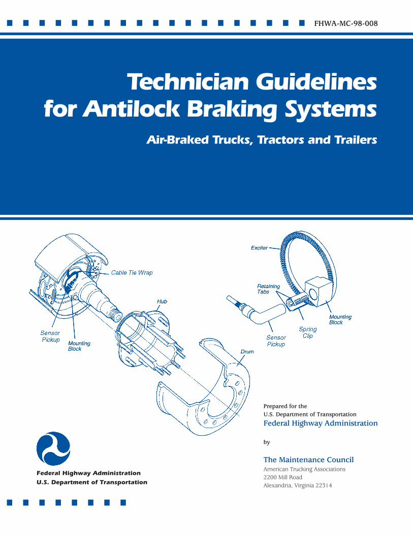
Technician Guidelinesfor Antilock Braking Systems
Air-Braked Trucks, Tractors and Trailers
Prepared for theU.S. Department of Transportation
Federal Highway Administration
by
The Maintenance CouncilAmerican Trucking Associations2200 Mill RoadAlexandria, Virginia 22314
Federal Highway Administration
U.S. Department of Transportation
TechnicianGuidelinesFor AntilockBrakingSystemsAir-Braked Trucks, Tractors, and Trailers
■ ■ ■ ■ ■ ■ ■ ■ ■ ■ ■ ■ ■ ■ ■ ■ ■ ■ ■
Prepared for theU.S. Department of TransportationFederal Highway Administration
400 Seventh Street , S.W.Washington, D.C. 20590
by
The Maintenance CouncilAmerican Trucking Associations2200 Mill RoadAlexandria, Virginia 22314(703) 838-1763
■ ■ ■ ■ ■ ■ ■ ■ ■ ■ ■ ■ ■ ■ ■
FHWA-MC-98-008
1. Report No. 2. Government Accession No. 3. Recipient’s Catalog No.
4. Title and Subtitle 5. Report Date
6. Performing Organization Code
7. Author(s)8. Performing Organization Report No.
10. Work Unit No.
11. Contract or Grant No.
13. Type of Report & Period Covered
14. Sponsoring Agency Code
9. Performing Organization Name and Address
12. Sponsoring Agency Name and Address
15. Supplementary Notes
16. Abstract
17. Key Words 18. Distribution Statement
19. Security Classification (of report) 20. Security Classification (of this page) 21. No. of pages 22. Price
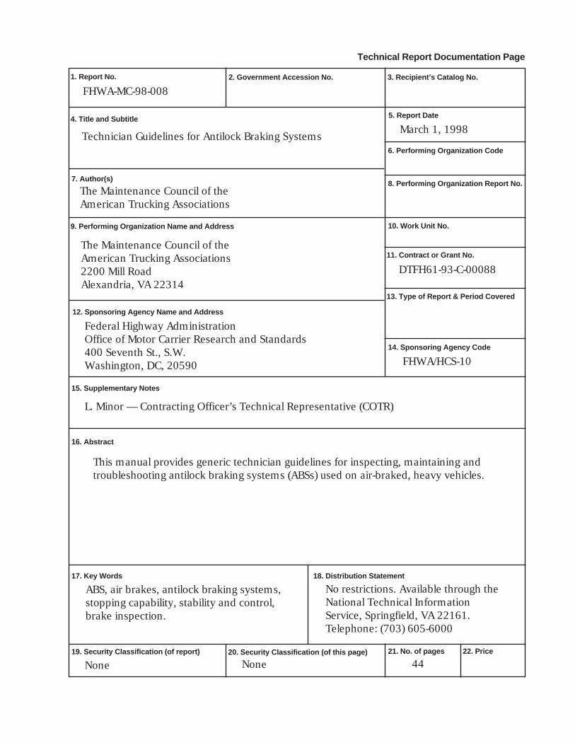
Technician Guidelines for Antilock Braking Systems
The Maintenance Council of theAmerican Trucking Associations
The Maintenance Council of theAmerican Trucking Associations2200 Mill RoadAlexandria, VA 22314
Federal Highway AdministrationOffice of Motor Carrier Research and Standards400 Seventh St., S.W.Washington, DC, 20590
This manual provides generic technician guidelines for inspecting, maintaining andtroubleshooting antilock braking systems (ABSs) used on air-braked, heavy vehicles.
ABS, air brakes, antilock braking systems,stopping capability, stability and control,brake inspection.
44
Technical Report Documentation Page
FHWA-MC-98-008
DTFH61-93-C-00088
L. Minor — Contracting Officer’s Technical Representative (COTR)
No restrictions. Available through theNational Technical InformationService, Springfield, VA 22161.Telephone: (703) 605-6000
None None
March 1, 1998
FHWA/HCS-10
PURPOSEThe purpose of this document is to provide truck techni-
cians with general guidelines for ABS operation, maintenance,inspection and troubleshooting. Technicians should alwaysconsult the appropriate vehicle or component manufacturer’sinformation for specific ABS procedures.
DISCLAIMERThis document is disseminated under the sponsorship of
the Department of Transportation in the interest of informationexchange. The United States Government assumes no liabilityfor its contents or use thereof. The contents of this documentdo not necessarily reflect the official policy of the Departmentof Transportation. This publication does not constitute astandard, specification or regulation.
The Maintenance Council and the Trucking ResearchInstitute have made a reasonable effort to ensure the accuracyof information contained in this publication. However, allequipment users should satisfy themselves that the proceduresoutlined herein are appropriate for their own use.
The United States Government does not endorse productsor manufacturers. Trade or manufacturers’ names appearherein only because they are considered essential to the objectof this document.
ACKNOWLEDGMENTThe authors extend their thanks to the following organiza-
tions which contributed to the development of this document.
• American Trucking Associations’ Engineering Dept.• The ATA Foundation• Bendix/AlliedSignal Corporation• Eaton-Bosch• Federal Highway Administration• Midland-Grau• Rockwell WABCO• The Maintenance Council’s ABS/EBS Task Force and
S.6 Chassis Study Group.
■■1
Technician Guidelines for Antilock Braking Systems■ ■ ■ ■ ■ ■ ■ ■ ■ ■ ■ ■ ■ ■ ■ ■ ■ ■ ■ ■ ■ ■ ■ ■ ■ ■ ■ ■ ■ ■ ■ ■ ■ ■
TABLE OF CONTENTS
I. AN INTRODUCTION TO ANTILOCK BRAKING............ 3A. What is an ABS? ............................................... 3B. How Do ABSs Work?......................................... 5C. How Should I Drive an ABS-equipped Vehicle During Road Tests? ........................................... 6D. What Are the Features and Benefits of ABSs? ..... 7
II. ABS COMPONENT DESCRIPTIONS ANDOPERATION ......................................................... 8A. Electronic Control Unit (ECU) ............................. 8B. Modulator Valves ............................................ 10C. Wheel Speed Sensors ...................................... 11D. ABS Malfunction Indicator Lamps..................... 12E. ABS Diagnostics .............................................. 12F. Traction Control Systems ................................. 13
III. ABS TROUBLESHOOTING, MAINTENANCE ANDINSPECTION ....................................................... 14
A. ABS Troubleshooting ...................................... 141. General Diagnostic Principles ..................... 142. Notes on Electrical/Electronic Connections .. 193. Error Detection Methods ............................ 234. Causes of Common ABS Sensor Problems .... 25
B. ABS Maintenance and Inspection ..................... 271. ABS Sensor Pickup Adjustment ................... 272. ABS Sensor Pickup Removal and Installation 273. Sensor Pickup Removal—Front Axle ............ 274. Sensor Pickup Installation—Front Axle ........ 275. Sensor Pickup Removal—Rear Axle ............. 286. Sensor Pickup Installation—Rear Axle ......... 287. Proper ABS Sensor Resistance ..................... 298. Modulator Valves/Routine Inspection.......... 299. Modulator Valve Removal and Installation .. 3010. Proper ABS Modulator Valve Resistance .... 30
IV. ABS SPEC’ING CONSIDERATIONS ......................... 31
V. GLOSSARY OF ABS TERMS ................................... 33
VI. INDEX................................................................ 42

■■2
Technician Guidelines for Antilock Braking Systems■ ■ ■ ■ ■ ■ ■ ■ ■ ■ ■ ■ ■ ■ ■ ■ ■ ■ ■ ■ ■ ■ ■ ■ ■ ■ ■ ■ ■ ■ ■ ■ ■ ■
■■3
Technician Guidelines for Antilock Braking Systems■ ■ ■ ■ ■ ■ ■ ■ ■ ■ ■ ■ ■ ■ ■ ■ ■ ■ ■ ■ ■ ■ ■ ■ ■ ■ ■ ■ ■ ■ ■ ■ ■ ■■ ■ ■ ■ ■ ■ ■ ■ ■ ■ ■ ■ ■ ■ ■ ■ ■ ■ ■ ■ ■ ■ ■ ■ ■ ■ ■ ■ ■ ■ ■ ■ ■ ■
■■3
I. AN INTRODUCTION TO ANTILOCK BRAKING
This section reviews several basic antilock braking system(ABS) concepts. When you complete this section, you should beable to answer the following questions:
• What is an ABS?
• Why are antilock braking systems (ABSs) standard onmost new commercial vehicles?
• How does an ABS work?
• What are the major features and benefits of ABSs?
• How should I drive an ABS-equipped vehicle during aroad test?
A. What is an ABS?Antilock braking systems (ABSs) are electronic systems that
monitor and control wheel slip during vehicle braking. ABSscan improve vehicle control during braking, and reducestopping distances on slippery (split or low coefficient offriction) road surfaces by limiting wheel slip and minimizinglockup. Rolling wheels have much more traction than lockedwheels. Reducing wheel slip improves vehicle stability andcontrol during braking, since stability increases as wheel slipdecreases.
ABSs can be applied to nearly all types of vehicles and canbe successfully integrated into hydraulic and air brake systems(including air over hydraulic). This document applies to theABSs used with air brake systems on commercial vehicles.
The National Highway Traffic Safety Administration(NHTSA) requires—through FMVSS 121, “Air Brake Systems”and FMVSS 105, “Hydraulic Brake Systems”—that ABSs beinstalled on commercial vehicles built (built meaning the officialdate of manufacture) on or after:
• March 1, 1997, for air-braked truck-tractors.
• March 1, 1998, for other air-braked vehicles (trucks,buses, trailers and converter dollies).
• March 1, 1999, for hydraulically braked trucks andbuses with gross vehicle weight ratings of more than10,000 lbs.
The equipment requirements of FMVSS 121 specify thatABSs on truck-tractors and full trailers must control the brake
Antilock brakingsystems (ABSs) areelectronic systems thatmonitor and controlwheel slip during vehiclebraking.
Reducing wheel slipimproves vehiclestability and controlduring braking, sincestability increases aswheel slip decreases.
■■4
Technician Guidelines for Antilock Braking Systems■ ■ ■ ■ ■ ■ ■ ■ ■ ■ ■ ■ ■ ■ ■ ■ ■ ■ ■ ■ ■ ■ ■ ■ ■ ■ ■ ■ ■ ■ ■ ■ ■ ■
pressures to at least one front axle and one rear axle. The ABSson semi-trailers and dollies must control at least one axle of thevehicle. Additionally, the ABSs on tractors must control one ofthe rear axles with two modulator valves so that the brakepressure on one end of the axle is independent of the brakepressure on the other end. The performance requirements ofFMVSS 121 can require an ABS on additional axles.
NHTSA defines an ABS as a portion of a service brakesystem that automatically controls the degree of rotationalwheel slip during braking by:
• Sensing the rate of angular wheel rotation.
• Transmitting signals regarding the rate of wheelrotation to one or more devices, which interpret thesesignals and generate responsive controlling outputsignals.
• Transmitting those signals to one or more deviceswhich adjust braking forces in response to the signals.
Other aspects of NHTSA’s rule stipulate that:
• ABSs on trailers be capable of being powered by thetrailer’s stop lamp circuit.
• New tractors—built on or after March 1, 1997—provide constant electrical power to a tractor-to-trailerelectrical connector for powering trailer ABSs.
• Vehicles required to have an ABS also have a yellowABS malfunction indicator lamp which lights up toindicate most malfunctions.
• The power unit’s ABS malfunction lamp be “in front ofand in clear view” of the driver. It lights when theignition key is first switched “on” for a bulb check.
• The ABS malfunction lamp on trailers be mounted onthe left side of the trailer, near the rear side markerlamp. On dollies, the lamp is located on the left sidewhere it can be seen by someone standing about 10feet from the lamp. The lamp lights for a short bulbcheck when the vehicle is stopped and the ABS startsreceiving electrical power. This lamp will no longer berequired after February 2009.
• Air-braked tractors and trucks which tow other air-braked vehicles—built on or after March 1, 2001—have an in-cab warning lamp which indicates
■■5
Technician Guidelines for Antilock Braking Systems■ ■ ■ ■ ■ ■ ■ ■ ■ ■ ■ ■ ■ ■ ■ ■ ■ ■ ■ ■ ■ ■ ■ ■ ■ ■ ■ ■ ■ ■ ■ ■ ■ ■
malfunctions in any towed trailer’s or dolly’s ABS. Itslocation and function are the same as for the poweredunit’s ABS malfunction lamp.
• Trailer and dolly ABSs—built on or after March 1,2001—have the equipment needed to send an ABSmalfunction signal to the towing vehicle. A towingtrailer must also be able to relay an ABS malfunctionsignal from the vehicle it is towing to the vehicletowing it.
B. How Do ABSs Work?An ABS consists of several key components: electronic
control unit (ECU), wheel speed sensors, modulator valves, andexciter rings. Here’s how these components work together:
1. Wheel speed sensors constantly monitor and sendelectrical pulses to the ECU at a rate proportional tothe wheel speed.
2. When the pulse rates indicate impending wheellockup, the ECU signals the modulator valve(s) toreduce and/or hold the brake application pressure tothe wheel(s) in question.
3. The ECU then adjusts pressure, seeking one whichgives maximum braking without risking wheel lockup.
4. When the ECU acts to modulate the brake pressure, itwill also (on most vehicles) turn off the retarder (if soequipped) until the risk of lockup is over.
5. The ECU continually checks itself for properoperation. If it detects a malfunction/failure in theelectrical/electronic system, it will shut down that partof the ABS affected by the problem—or the entireABS—depending upon the system and the problem.When this happens, the ABS malfunction lamp lights.
An ABS adjusts brake pressure much faster and moreaccurately than can drivers. It’s faster because:
• electronic controls are very fast and
• ABS modulator valves are physically closer to thebrakes than is the driver’s foot brake valve.
It is more effective, too, because an ABS can tailor the brakepressure to each wheel or set of wheels to provide maximum
Electronic controls allowan ABS to adjust brakepressure faster and moreaccurately than candrivers.
An ABS is more effectiveon slippery roadsbecause it tailors thebrake pressure at thewheel to maximizevehicle braking andstability.
■■6
Technician Guidelines for Antilock Braking Systems■ ■ ■ ■ ■ ■ ■ ■ ■ ■ ■ ■ ■ ■ ■ ■ ■ ■ ■ ■ ■ ■ ■ ■ ■ ■ ■ ■ ■ ■ ■ ■ ■ ■
braking/stability. Some vehicles also use a traction controlsystem in conjunction with the ABS. Traction control helps theABS improve vehicle traction by minimizing wheel slip on thedrive axle during acceleration. If a wheel on the drive axle startsto slip, the traction control system automatically brakes thewheel slightly, transferring engine torque to the wheels withbetter traction. If all the drive wheels start to slip, the tractioncontrol system may also reduce engine power.
Traction control systems are referred to by several differentnames, depending on the manufacturer. These include:
• Automatic Traction Control (ATC)
• Traction Control (TC)
• Automatic Slip Regulation/Anti-Spin Regulation (ASR)
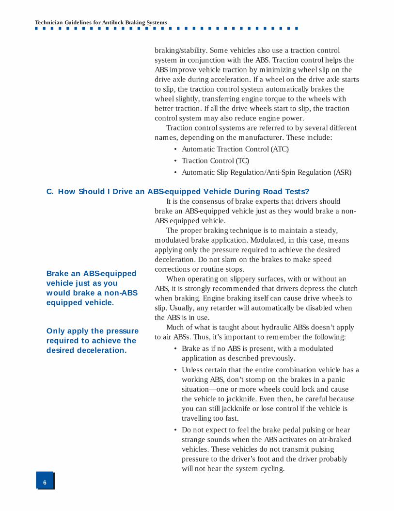
C. How Should I Drive an ABS-equipped Vehicle During Road Tests?It is the consensus of brake experts that drivers should
brake an ABS-equipped vehicle just as they would brake a non-ABS equipped vehicle.
The proper braking technique is to maintain a steady,modulated brake application. Modulated, in this case, meansapplying only the pressure required to achieve the desireddeceleration. Do not slam on the brakes to make speedcorrections or routine stops.
When operating on slippery surfaces, with or without anABS, it is strongly recommended that drivers depress the clutchwhen braking. Engine braking itself can cause drive wheels toslip. Usually, any retarder will automatically be disabled whenthe ABS is in use.
Much of what is taught about hydraulic ABSs doesn’t applyto air ABSs. Thus, it’s important to remember the following:
• Brake as if no ABS is present, with a modulatedapplication as described previously.
• Unless certain that the entire combination vehicle has aworking ABS, don’t stomp on the brakes in a panicsituation—one or more wheels could lock and causethe vehicle to jackknife. Even then, be careful becauseyou can still jackknife or lose control if the vehicle istravelling too fast.
• Do not expect to feel the brake pedal pulsing or hearstrange sounds when the ABS activates on air-brakedvehicles. These vehicles do not transmit pulsingpressure to the driver’s foot and the driver probablywill not hear the system cycling.
Brake an ABS-equippedvehicle just as youwould brake a non-ABSequipped vehicle.
Only apply the pressurerequired to achieve thedesired deceleration.
■■7
Technician Guidelines for Antilock Braking Systems■ ■ ■ ■ ■ ■ ■ ■ ■ ■ ■ ■ ■ ■ ■ ■ ■ ■ ■ ■ ■ ■ ■ ■ ■ ■ ■ ■ ■ ■ ■ ■ ■ ■
• Operate mixed combination vehicles (with and withoutan ABS) the same way one would operate totally non-ABS combination vehicles. Apply only the brakepressure needed to achieve the desired decelerationwhile ensuring vehicle stability. Monitor thecombination vehicle behavior and back off the brakepedal, if possible, to keep the units under control.
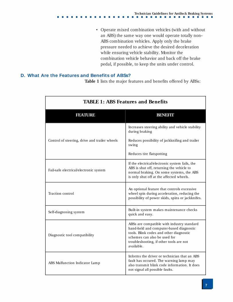
D. What Are the Features and Benefits of ABSs?Table 1 lists the major features and benefits offered by ABSs:
TABLE 1: ABS Features and Benefits
FEATURE BENEFIT
Control of steering, drive and trailer wheels
Increases steering ability and vehicle stability during braking
Reduces possibility of jackknifing and trailer swing
Reduces tire flatspotting
Fail-safe electrical/electronic system
If the electrical/electronic system fails, the ABS is shut off, returning the vehicle to normal braking. On some systems, the ABS is only shut off at the affected wheels.
Traction controlAn optional feature that controls excessive wheel spin during acceleration, reducing the possibility of power skids, spins or jackknifes.
Self-diagnosing systemBuilt-in system makes maintenance checks quick and easy.
Diagnostic tool compatibility
ABSs are compatible with industry standard hand-held and computer-based diagnostic tools. Blink codes and other diagnostic schemes can also be used for troubleshooting, if other tools are not available.
ABS Malfunction Indicator Lamp
Informs the driver or technician that an ABS fault has occured. The warning lamp may also transmit blink code information. It does not signal all possible faults.
■■8
Technician Guidelines for Antilock Braking Systems■ ■ ■ ■ ■ ■ ■ ■ ■ ■ ■ ■ ■ ■ ■ ■ ■ ■ ■ ■ ■ ■ ■ ■ ■ ■ ■ ■ ■ ■ ■ ■ ■ ■
II. ABS COMPONENT DESCRIPTIONS & OPERATIONThis section describes the design and operation of ABS
components.When you complete this section, you should understand the
purpose and function of all major ABS parts including: the ECU,the modulator valve, the wheel speed sensor, ABS malfunction/indicator lamp, ABS diagnostic components, and tractioncontrol.
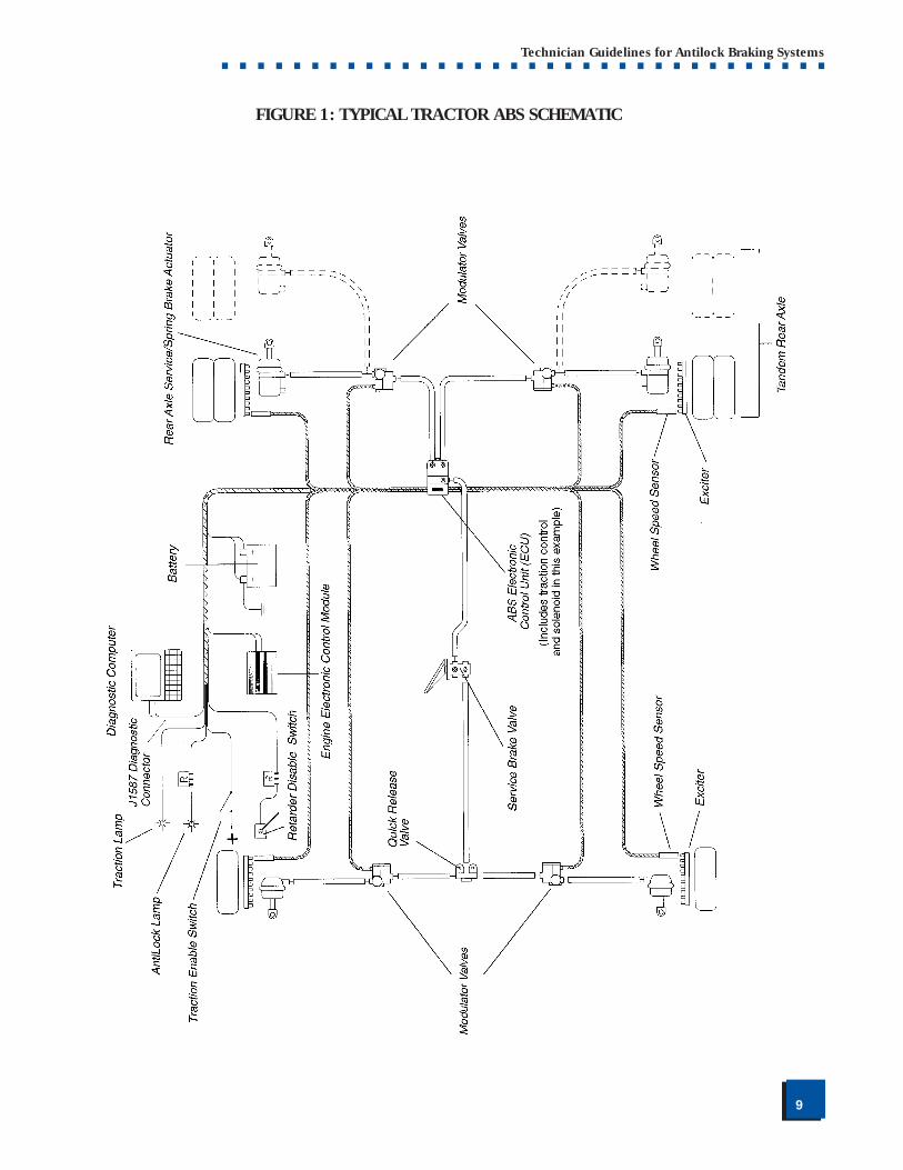
Modern antilock braking systems all feature the followingmajor components (See Fig. 1 on page 9 for typical system):
• Electronic Control Unit (ECU)
• Modulator Valves
• Wheel Speed Sensors (pickup and exciter)
• ABS Malfunction Indicator Lamps
• Diagnostics
A. Electronic Control Unit (ECU)The ECU processes all ABS information and signal functions.
It receives and interprets voltage pulses generated by thesensor pickup as the exciter teeth pass by, and uses thisinformation to determine:
• impending wheel lock-up and
• when/how to activate the ABS modulator valves.
The ECU connects to the following ABS components: wheelspeed sensors, ABS modulator valves, power source, ground,warning lamps, blink code switch, J1587* diagnostic connector,and retarder control device (usually by relay or the J1922**/J1939*** datalink.) The ECU also makes self-diagnostic checksduring normal operation.
During braking, the ECU uses voltage pulses from eachwheel speed sensor to determine wheel speed changes. If theECU determines that the pulse rate of the sensed wheelsindicates imminent lock-up, it cycles the ABS modulator valvesto modify brake air pressure as needed to provide the bestbraking possible.
The ECU sends signals to the ABS malfunction indicatorlamp or blink code lamp to communicate ABS faults. It alsosends signals to the retarder control to disengage the retarderwhen the ABS is working. When the ABS stops modulating thebrake pressure, the ECU permits retarder use once again.
* SAE J1587, Joint SAE/TMC RecommendedPractice for Electronic DataInterchange BetweenMicrocomputer Systems inHeavy-duty VehicleApplications. (See Glossaryof ABS Terms for definitionof SAE.)
**SAE J1922, PowertrainControl Interface forElectronic Controls Used inMedium- and Heavy-dutyDiesel On-highwayApplications.
***SAE J1939, A series ofSAE RecommendedPractices that definearchitecture and protocolfor a serial control andcommunications networkfor various equipmenttypes.
■■9
Technician Guidelines for Antilock Braking Systems■ ■ ■ ■ ■ ■ ■ ■ ■ ■ ■ ■ ■ ■ ■ ■ ■ ■ ■ ■ ■ ■ ■ ■ ■ ■ ■ ■ ■ ■ ■ ■ ■ ■
FIGURE 1: TYPICAL TRACTOR ABS SCHEMATIC
■■10
Technician Guidelines for Antilock Braking Systems■ ■ ■ ■ ■ ■ ■ ■ ■ ■ ■ ■ ■ ■ ■ ■ ■ ■ ■ ■ ■ ■ ■ ■ ■ ■ ■ ■ ■ ■ ■ ■ ■ ■
Technicians can communicate with the ECU through astandard SAE J1587 diagnostic connector (See Fig. 1).Technicians can read and clear fault codes stored in the ECUand run various diagnostic tests with this connector.
The type of ECU used and its location (in-cab or frame) varyby manufacturer and application. A detailed description of allthe different ECU types used today is beyond the scope of thismanual. Consult either the vehicle or componentmanufacturer’s service information for specifics.
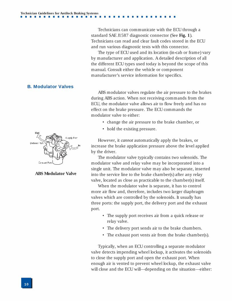
B. Modulator ValvesABS modulator valves regulate the air pressure to the brakes
during ABS action. When not receiving commands from theECU, the modulator valve allows air to flow freely and has noeffect on the brake pressure. The ECU commands themodulator valve to either:
• change the air pressure to the brake chamber, or
• hold the existing pressure.
However, it cannot automatically apply the brakes, orincrease the brake application pressure above the level appliedby the driver.
The modulator valve typically contains two solenoids. Themodulator valve and relay valve may be incorporated into asingle unit. The modulator valve may also be separate, insertedinto the service line to the brake chamber(s) after any relayvalve, located as close as practicable to the chamber(s) itself.
When the modulator valve is separate, it has to controlmore air flow and, therefore, includes two larger diaphragmvalves which are controlled by the solenoids. It usually hasthree ports: the supply port, the delivery port and the exhaustport.
• The supply port receives air from a quick release orrelay valve.
• The delivery port sends air to the brake chambers.
• The exhaust port vents air from the brake chamber(s).
Typically, when an ECU controlling a separate modulatorvalve detects impending wheel lockup, it activates the solenoidsto close the supply port and open the exhaust port. Whenenough air is vented to prevent wheel lockup, the exhaust valvewill close and the ECU will—depending on the situation—either:
ABS Modulator Valve
■■11
Technician Guidelines for Antilock Braking Systems■ ■ ■ ■ ■ ■ ■ ■ ■ ■ ■ ■ ■ ■ ■ ■ ■ ■ ■ ■ ■ ■ ■ ■ ■ ■ ■ ■ ■ ■ ■ ■ ■ ■
Exciter or Tooth Wheel
ABS Sensor Pickup
• keep the supply port closed to maintain existingpressure, or
• open the supply port to allow brake applicationpressure to increase and repeat the cycle.
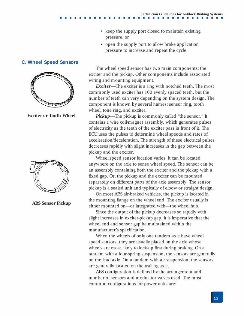
C. Wheel Speed SensorsThe wheel speed sensor has two main components: the
exciter and the pickup. Other components include associatedwiring and mounting equipment.
Exciter—The exciter is a ring with notched teeth. The mostcommonly used exciter has 100 evenly spaced teeth, but thenumber of teeth can vary depending on the system design. Thecomponent is known by several names: sensor ring, toothwheel, tone ring, and exciter.
Pickup—The pickup is commonly called “the sensor.” Itcontains a wire coil/magnet assembly, which generates pulsesof electricity as the teeth of the exciter pass in front of it. TheECU uses the pulses to determine wheel speeds and rates ofacceleration/deceleration. The strength of these electrical pulsesdecreases rapidly with slight increases in the gap between thepickup and the exciter.
Wheel speed sensor location varies. It can be locatedanywhere on the axle to sense wheel speed. The sensor can bean assembly containing both the exciter and the pickup with afixed gap. Or, the pickup and the exciter can be mountedseparately on different parts of the axle assembly. The sensorpickup is a sealed unit and typically of elbow or straight design.
On most ABS air-braked vehicles, the pickup is located inthe mounting flange on the wheel end. The exciter usually iseither mounted on—or integrated with—the wheel hub.
Since the output of the pickup decreases so rapidly withslight increases in exciter-pickup gap, it is imperative that thewheel end and sensor gap be maintained within themanufacturer’s specification.
When the wheels of only one tandem axle have wheelspeed sensors, they are usually placed on the axle whosewheels are most likely to lock-up first during braking. On atandem with a four-spring suspension, the sensors are generallyon the lead axle. On a tandem with air suspension, the sensorsare generally located on the trailing axle.
ABS configuration is defined by the arrangement andnumber of sensors and modulator valves used. The mostcommon configurations for power units are:
■■12
Technician Guidelines for Antilock Braking Systems■ ■ ■ ■ ■ ■ ■ ■ ■ ■ ■ ■ ■ ■ ■ ■ ■ ■ ■ ■ ■ ■ ■ ■ ■ ■ ■ ■ ■ ■ ■ ■ ■ ■
• four sensors/four modulators (4S/4M),
• six sensors/four modulators (6S/4M), and
• six sensors/six modulators (6S/6M).Common configurations for trailers are 2S/1M, 2S/2M, 4S/
2M and 4S/3M.
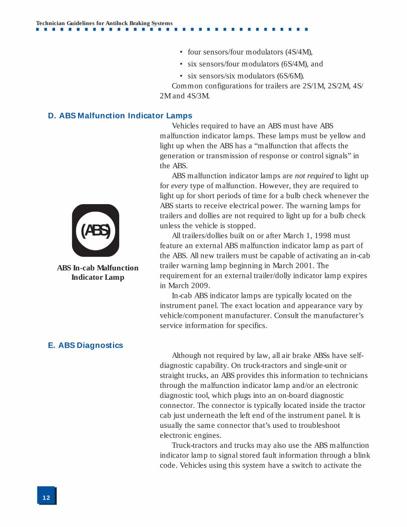
D. ABS Malfunction Indicator LampsVehicles required to have an ABS must have ABS
malfunction indicator lamps. These lamps must be yellow andlight up when the ABS has a “malfunction that affects thegeneration or transmission of response or control signals” inthe ABS.
ABS malfunction indicator lamps are not required to light upfor every type of malfunction. However, they are required tolight up for short periods of time for a bulb check whenever theABS starts to receive electrical power. The warning lamps fortrailers and dollies are not required to light up for a bulb checkunless the vehicle is stopped.
All trailers/dollies built on or after March 1, 1998 mustfeature an external ABS malfunction indicator lamp as part ofthe ABS. All new trailers must be capable of activating an in-cabtrailer warning lamp beginning in March 2001. Therequirement for an external trailer/dolly indicator lamp expiresin March 2009.
In-cab ABS indicator lamps are typically located on theinstrument panel. The exact location and appearance vary byvehicle/component manufacturer. Consult the manufacturer’sservice information for specifics.
E. ABS DiagnosticsAlthough not required by law, all air brake ABSs have self-
diagnostic capability. On truck-tractors and single-unit orstraight trucks, an ABS provides this information to techniciansthrough the malfunction indicator lamp and/or an electronicdiagnostic tool, which plugs into an on-board diagnosticconnector. The connector is typically located inside the tractorcab just underneath the left end of the instrument panel. It isusually the same connector that’s used to troubleshootelectronic engines.
Truck-tractors and trucks may also use the ABS malfunctionindicator lamp to signal stored fault information through a blinkcode. Vehicles using this system have a switch to activate the
ABS In-cab MalfunctionIndicator Lamp
(ABS)
■■13
Technician Guidelines for Antilock Braking Systems■ ■ ■ ■ ■ ■ ■ ■ ■ ■ ■ ■ ■ ■ ■ ■ ■ ■ ■ ■ ■ ■ ■ ■ ■ ■ ■ ■ ■ ■ ■ ■ ■ ■
blink code system. Other ABSs may also have light-emittingdiode (LED) lamps on the ECU to indicate problems.
ABSs used on trailers sometimes have a place to connect anelectronic diagnostic tool. The connector is either on a pigtail tothe ECU, on the outside of the ECU, or inside the ECU box.Others have either LED lamps on the ECU box or numbercodes displayed inside the ECU which give diagnosticinformation.
F. Traction Control SystemsTraction control systems are designed to prevent wheel spin
in the power mode. Traction control attempts to regain tractionby braking the spinning wheels, and sometimes throttling backengine power. Unlike an ABS, traction control can automaticallyapply the brakes. The driver does not need to depress the brakepedal for traction control to engage.
Traction control electronics are integrated into the ABS ECU.The system applies the brakes on the spinning wheel(s) whenthe wheel speed sensors tell the ECU that a wheel isaccelerating at a much faster speed than the wheel on the otherend of the axle. It does this by energizing a solenoid valve,which directs reservoir pressure to the relay valve andsimultaneously activates the modulator valves to keep airpressure from the brake chambers. The ECU then directs themodulator valve to open, and pulse air into the brake chamberon the spinning wheel until wheel speed balance is regained.
On some systems, the ECU will throttle back engine powerif both wheels are spinning too fast. If all the drive wheels on atractor are spinning too fast, the tractor can become unstable,spin or jackknife. Traction control is especially valuable when alight drive wheel load might allow the wheels to spin underpower, or when a tractor is pulling multiple trailers.
Traction control systemsare designed to preventwheel spin in the powermode.
Unlike an ABS, tractioncontrol can apply thebrakes automatically.The driver does notneed to depress thebrake pedal for tractioncontrol to engage.
Traction control is notrequired by law, but it isa common ABS option.
■■14
Technician Guidelines for Antilock Braking Systems■ ■ ■ ■ ■ ■ ■ ■ ■ ■ ■ ■ ■ ■ ■ ■ ■ ■ ■ ■ ■ ■ ■ ■ ■ ■ ■ ■ ■ ■ ■ ■ ■ ■
III. ABS TROUBLESHOOTING, MAINTENANCE &INSPECTION
Although an ABS generally requires no routinemaintenance, it should be checked periodically like othercomponents of the air brake system.
In this section, we review various aspects of ABStroubleshooting, maintenance and inspection. When youcomplete this section, you should understand:
• General ABS troubleshooting principles
• Special concerns about connector repairs
• ABS error detection methods
• Common ABS errors and causes
• General ABS component adjustment, installation andremoval procedures
A. ABS Troubleshooting
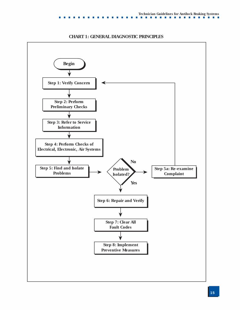
1. General Diagnostic PrinciplesThis section describes general principles of electrical,
electronic, and air system diagnostics to provide technicianswith a plan of action for ABS troubleshooting. Chart 1 on page15 illustrates these diagnostic principles in flow chart form. Thefollowing sub-sections—based on The Maintenance Council’sRecommended Practice TMC RP 1406, “Basic Electrical/Electronic Diagnostic Procedures”—cover this process in detail.
Step 1: Verify the problem or driver concern.Establish the connection between the symptom and the
underlying cause of the problem. Use the vehiclemanufacturer’s recommended information collection methodsfor verification.
Step 2: Perform preliminary checks.Operational, visual and audio checks are generally easy to
perform, do not require the use of special tools and may resultin a quick diagnosis. This is a critical step in the diagnosticprocess.
■■15
Technician Guidelines for Antilock Braking Systems■ ■ ■ ■ ■ ■ ■ ■ ■ ■ ■ ■ ■ ■ ■ ■ ■ ■ ■ ■ ■ ■ ■ ■ ■ ■ ■ ■ ■ ■ ■ ■ ■ ■
➤
➤➤
➤
➤➤➤
➤➤
➤
CHART 1: GENERAL DIAGNOSTIC PRINCIPLES
No
Yes
Step 1: Verify Concern
➤
Begin
Step 2: PerformPreliminary Checks
Step 3: Refer to ServiceInformation
Step 4: Perform System Checks
Step 4: Perform Checks ofElectrical, Electronic, Air Systems
Step 5: Find and IsolateProblems
Step 5a: Re-examineComplaint
ProblemIsolated?
Step 6: Repair and Verify
Step 7: Clear AllFault Codes
Step 8: ImplementPreventive Measures
■■16
Technician Guidelines for Antilock Braking Systems■ ■ ■ ■ ■ ■ ■ ■ ■ ■ ■ ■ ■ ■ ■ ■ ■ ■ ■ ■ ■ ■ ■ ■ ■ ■ ■ ■ ■ ■ ■ ■ ■ ■
Step 3: Refer to service information.Vehicle manufacturers provide service procedures which
must be followed to ensure proper repair. Training/serviceinformation is readily available from various sources such as:
• Bulletins
• Service newsletters
• Videotapes
• Service manuals
• Manufacturers’ and dealers’ “Help Line PhoneNumbers”
• Troubleshooting guides
Be sure to confirm that the reference material is applicableto the specific problem or vehicle being diagnosed. Also, ensureinformation is current. Vehicle and supplier manufacturers’service information—specifically bulletins and newsletters—isvery effective and may help shorten diagnosis.
Hands-on training may also be available from the vehicle/ABS manufacturer at dealer locations or on site at the fleet. TheBrake Training Resource Directory contains a list of braketraining resources in North America. It is available from theOffice of Motor Carriers, Federal Highway Administration, 4007th St., S.W., Washington, DC 20590, (202) 366-4009 or fromThe Maintenance Council by calling (800) ATA-LINE or (703)838-1763.
Step 4: Perform electrical, electronic and air system checks.Systems checks found in service manuals provide a systematic
approach to identifying the probable cause of a system fault.This step is important to properly define the correct approachfor the repair and to avoid unnecessary time-consumingrepairs. Additionally, systems checks will help to define whatthe problem is not. Systems checks may require the use of originalequipment manufacturer (OEM) service tools and should isolatea particular component in the system as a probable cause.
i. Electrical diagnostic proceduresElectrical problems are a common cause of ABS faults. It is
beyond the scope of this document to explain electricaldiagnostic procedures for all ABSs and vehicle manufacturers ingreat detail. References for diagnosing electrical systems can bereadily obtained from component, vehicle, and test equipment
■■17
Technician Guidelines for Antilock Braking Systems■ ■ ■ ■ ■ ■ ■ ■ ■ ■ ■ ■ ■ ■ ■ ■ ■ ■ ■ ■ ■ ■ ■ ■ ■ ■ ■ ■ ■ ■ ■ ■ ■ ■
manufacturers. (TMC Recommended Practice 129, “Heavy-Duty Vehicle Systems Wiring Checks,” is a good source ofgeneral information on electrical diagnostic procedures.)
ii. Electronic diagnostic proceduresTo diagnose an electronic system properly, specialized test
equipment approved by the electronic system manufacturermay be required. Failure to use the correct diagnostic tool mayresult in inaccurate or incomplete diagnosis or cause ECU damage.
iii. Air system diagnostics It is beyond the scope of this document to explain air
system diagnostic procedures in great detail. However, severalTMC Recommended Practices—such as RP 619, “Air SystemInspection Procedure”—are a good source of generalinformation on this topic. Other references for diagnosing airbrake systems can be readily obtained from component,vehicle, and test equipment manufacturers.
Chart 2 on page 18 is an example of a troubleshooting flowchart for a common modulator valve problem.
Step 5: Find and isolate problemFor an active problem, the diagnosis should narrow and/or
eliminate possible causes. Find and isolate the faulty part of thesystem or circuit by breaking the problem into smaller pieces.For an intermittent problem, attempt to simulate/recreate theconditions where the fault would exist. Monitor suspect circuitsand components to pinpoint the probable cause while theproblem is occurring.
Step 5a: Reexamine complaintReview all information describing the complaint. When did
the problem occur? What conditions are present when thesymptom occurs (weather conditions, driving conditions, etc.)?Contact the driver, if necessary, to gather more information orto arrange a “show me” or test drive interview.
Step 6: Repair and verifyOnce the suspect component is found, carefully disconnect
the old component and inspect its connections to the harness.If the component connections are OK, temporarily connect aknown good component (without installing) to ensure theproblem is corrected.
Technician Tip—
If a suspect part can beeasily installed andremoved, remove andtemporarily replace itwith a known good partto see if the problemremains.
If the problemdisappears, reinstall thesuspect component tosee if the problemreturns. If so, replacethe suspect component.
■■18
Technician Guidelines for Antilock Braking Systems■ ■ ■ ■ ■ ■ ■ ■ ■ ■ ■ ■ ■ ■ ■ ■ ■ ■ ■ ■ ■ ■ ■ ■ ■ ■ ■ ■ ■ ■ ■ ■ ■ ■
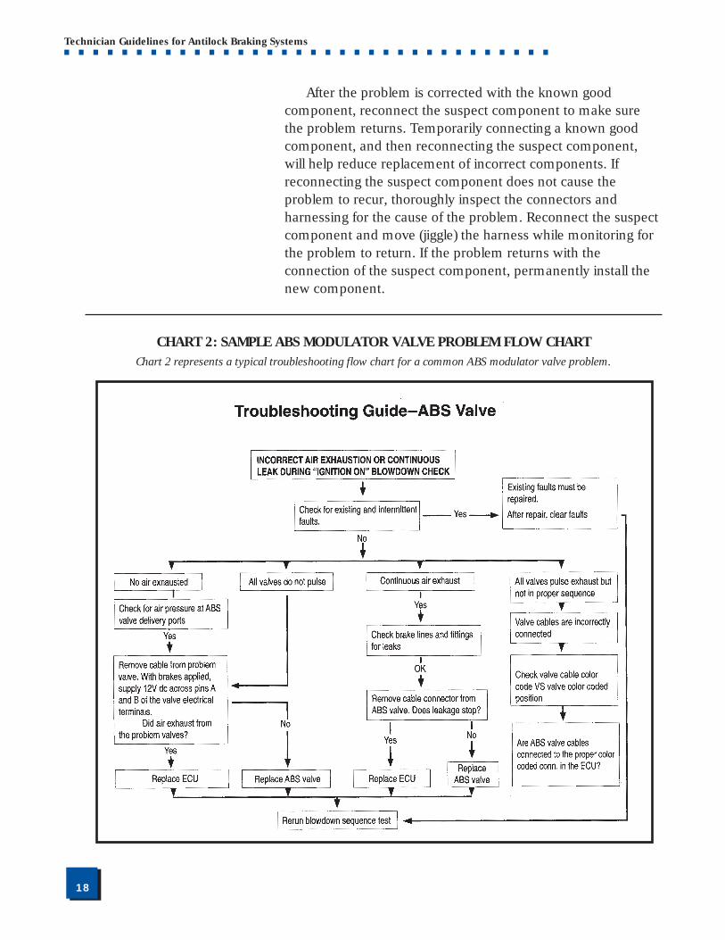
CHART 2: SAMPLE ABS MODULATOR VALVE PROBLEM FLOW CHART
After the problem is corrected with the known goodcomponent, reconnect the suspect component to make surethe problem returns. Temporarily connecting a known goodcomponent, and then reconnecting the suspect component,will help reduce replacement of incorrect components. Ifreconnecting the suspect component does not cause theproblem to recur, thoroughly inspect the connectors andharnessing for the cause of the problem. Reconnect the suspectcomponent and move (jiggle) the harness while monitoring forthe problem to return. If the problem returns with theconnection of the suspect component, permanently install thenew component.
Chart 2 represents a typical troubleshooting flow chart for a common ABS modulator valve problem.
■■19
Technician Guidelines for Antilock Braking Systems■ ■ ■ ■ ■ ■ ■ ■ ■ ■ ■ ■ ■ ■ ■ ■ ■ ■ ■ ■ ■ ■ ■ ■ ■ ■ ■ ■ ■ ■ ■ ■ ■ ■
Step 7: Clear fault codes.Clear any codes stored in the ECU identifying the problem.
Step 8: Implement any possible preventive measures.Review the vehicle maintenance schedule for required
service intervals and perform necessary maintenance. Checkfor other areas of apparent concern and notify the fleetmanager—or fix—prior to release of vehicle.
2. Notes on Electrical/Electronic ConnectionsThe following section contains general service information
that should be considered if electrical/electronic connectionsneed repair during ABS servicing.
a. Wiring Termination TechniquesTermination is the process of either ending a wire or
attaching a device to be used at the end of a wire. Wiringterminations are made in a variety of ways. Wires can beterminated with butt splices, the application of a terminal, andby simply “tinning” or sealing the wire’s end.
The primary considerations during a termination aremechanical strength, vibration resistance, electrical integrity,and environmental protection.
• Mechanical Strength—Whenever a wire is terminated,the mechanical strength of the termination shouldmeet or exceed the mechanical strength of theconductor without the termination.
• Vibration Protection—Always place conductors back inany holding device that they were in prior to themodification/repair or attach the conductors to thevehicle in a manner which will prevent the conductorfrom vibrating during operation.
• Electrical Integrity—The termination must be able tofulfill the electrical needs of the circuit (for example,current-carrying capability, minimal voltage drop).Whenever a termination or splice is made in aconductor, an inherent voltage drop will be present.Special connectors are available to minimize thevoltage drop, but these connectors normally are costprohibitive. Terminations made carefully normallyprovide an acceptable voltage drop.
■■20
Technician Guidelines for Antilock Braking Systems■ ■ ■ ■ ■ ■ ■ ■ ■ ■ ■ ■ ■ ■ ■ ■ ■ ■ ■ ■ ■ ■ ■ ■ ■ ■ ■ ■ ■ ■ ■ ■ ■ ■
• Environmental Protection—Whenever a termination ismade in a conductor which disturbs the integrity of theinsulation on the conductor, measures must be takento ensure that the termination is not susceptible tomoisture damage or other damage which may resultfrom the conductor or termination being exposed to itsnormal operating environment. Additionally,consideration must be given to the type of insulatingmaterial being used to ensure that it has an acceptableheat range and is compatible with the intendedenvironment.
• Electromagnetic/Radio Frequency InterferenceProtection—The ECU contains components that candetect radio waves and other electromagnetic “noise”and unintenionally send false signals because of them.To prevent radio frequency interference (RFI) andelectromagnetic interference (EMI), ABS cables containspecial shielding. When making repairs, take care toensure the integrity of the shielding is notcompromised.
For terminations that are made to a threaded stud which isexposed to salt spray or other corrosive environments, asuitable coating material should be applied to the connection toensure adequate service life.
Conventional Terminations—Conventional terminations areterminations made using commercially available terminals suchas ring terminals, spade terminals, etc. Terminals of this typeare available through many different outlets.
Selection of good quality terminals is crucial to making adependable connection. The selection should include theconsiderations mentioned in “Wiring Termination Techniques,”as well as specific considerations about the location of thetermination on the vehicle (for example, heat exposure). Somefleets have established specific methods for makingterminations. These methods were developed to ensureconsistent terminations which will yield an acceptable servicelife. These recommendations should be followed whenapplicable.
Proprietary Terminations—Proprietary terminations areterminations made using proprietary terminals and connector
■■21
Technician Guidelines for Antilock Braking Systems■ ■ ■ ■ ■ ■ ■ ■ ■ ■ ■ ■ ■ ■ ■ ■ ■ ■ ■ ■ ■ ■ ■ ■ ■ ■ ■ ■ ■ ■ ■ ■ ■ ■
bodies. These terminations are very common on commercialvehicles and come in a variety of configurations. Multipleconnections in one connector body are typical. Also, varioustypes of proprietary terminations on the same vehicle arecommon. When repairing or replacing these terminations,special techniques are needed. These techniques include tools,special assembly methods and, many times, special training.
When servicing special connectors, use of OEMrecommended tools is critical to making a good termination.Repair or replacement of these special terminations should notbe attempted without the specific tools recommended.Manufacturers’ service manuals and bulletins typically detail thetechniques to be used for proper repair.
Butt Splices—A butt splice is any splice where wires are joinedtogether “end-to-end.” In this case, the wires may be eithertwisted together and soldered, or crimped together using acommercially available terminal. Butt splices should always becovered with insulation and heat shrink tubing which has ameltable inner liner or another suitable protective insulation.The use of pressure sensitive tape is not recommended as thetape will likely deteriorate with time.
Conductor Terminations—Terminations of conductors aremade to attach the conductor to another conductor or to adevice on the vehicle. These terminations must be carefullymade in order to provide acceptable serviceability. Attaching awire to another wire (not using a butt splice) is an example of aconductor termination.
Terminations Without Terminals—Occasionally a wire isterminated without a terminal to facilitate the attachment of thewire to an accessory. If this situation is unavoidable, the wireshould be “tinned” to prevent fraying and breakage at the pointof connection. Using a heat shrink process at the end of thewire is also acceptable.
b. Grounding RecommendationsGrounding problems occur in a variety of ways (such as
corrosion or inadequate current-carrying capacity). As a result,grounding terminations should be coated with a suitablematerial to prevent corrosion as a result of exposure to saltspray or other corrosive environments.
Technician Tip—
Whenever an additionalgrounding point is to beestablished on thevehicle, consult thevehicle manufacturer toensure that the plannedalteration does notresult in an inadequateground path for othercomponents on thevehicle.
■■22
Technician Guidelines for Antilock Braking Systems■ ■ ■ ■ ■ ■ ■ ■ ■ ■ ■ ■ ■ ■ ■ ■ ■ ■ ■ ■ ■ ■ ■ ■ ■ ■ ■ ■ ■ ■ ■ ■ ■ ■
Whenever an additional grounding point is to be establishedon the vehicle, consult the vehicle manufacturer to ensure thatthe planned alteration does not result in an inadequate groundpath for other components on the vehicle. This is especiallyimportant when establishing a grounding point between chassisand body.
c. Wiring Damage Caused During RepairMechanical damage to wiring must be avoided during
vehicle repair. Insulation cuts and “pinch points” are commonproblems which may cause failure.
Conductor insulation should not be pierced whiletroubleshooting electrical problems. Piercing of the protectivecovering results in corrosion which can cause circuit failure. Ifpiercing of the insulation is unavoidable, suitable insulation toavoid water entry must be used at the point where theconductor was pierced.
d. Vehicle Repairs—Special CareMany times vehicle repairs include welding operations. All
welding on a vehicle should be done using methods andtechniques which are acceptable to the OEM in order to avoiddamage to the electrical and electronic system of the vehicle.This damage normally occurs due to unwanted circuit paths orto voltage spikes created in the electrical and electronic systemswhich cause component failure.
CAUTION: When welding on an ABS-equipped vehicle,disconnect power and ground leads from the ECU to avoidunintended grounding through the ECU which will damageelectronic components. Other damage may occur to vehiclesystems as a result of heat generated during the weldingprocess. Special care must be taken to ensure that heat buildupdoes not melt conductors and other susceptible electricalcomponents.
e. MiscellaneousThe use of “star washers” in the electrical path is
discouraged. Often, an open circuit or high resistance resultswhen the “points” of the washer are exposed to salt spray andother corrosive materials. If the use of star washers cannot beavoided, a suitable material should be applied to theconnections to ensure as much protection from corrosion aspossible.
■■23
Technician Guidelines for Antilock Braking Systems■ ■ ■ ■ ■ ■ ■ ■ ■ ■ ■ ■ ■ ■ ■ ■ ■ ■ ■ ■ ■ ■ ■ ■ ■ ■ ■ ■ ■ ■ ■ ■ ■ ■
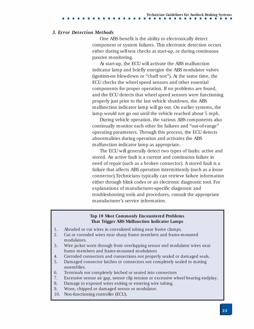
3. Error Detection MethodsOne ABS benefit is the ability to electronically detect
component or system failures. This electronic detection occurseither during self-test checks at start-up, or during continuouspassive monitoring.
At start-up, the ECU will activate the ABS malfunctionindicator lamp and briefly energize the ABS modulator valves(ignition-on blowdown or “chuff test”). At the same time, theECU checks the wheel speed sensors and other essentialcomponents for proper operation. If no problems are found,and the ECU detects that wheel speed sensors were functioningproperly just prior to the last vehicle shutdown, the ABSmalfunction indicator lamp will go out. On earlier systems, thelamp would not go out until the vehicle reached about 5 mph.
During vehicle operation, the various ABS components alsocontinually monitor each other for failures and “out-of-range”operating parameters. Through this process, the ECU detectsabnormalities during operation and activates the ABSmalfunction indicator lamp as appropriate.
The ECU will generally detect two types of faults: active andstored. An active fault is a current and continuous failure inneed of repair (such as a broken connector). A stored fault is afailure that affects ABS operation intermittently (such as a looseconnector).Technicians typically can retrieve failure informationeither through blink codes or an electronic diagnostic tool. Forexplanations of manufacturer-specific diagnostic andtroubleshooting tools and procedures, consult the appropriatemanufacturer’s service information.
Top 10 Most Commonly Encountered ProblemsThat Trigger ABS Malfunction Indicator Lamps
1. Abraded or cut wires in convuluted tubing near frame clamps.2. Cut or corroded wires near sharp frame members and frame-mounted
modulators.3. Wire jacket worn through from overlapping sensor and modulator wires near
frame members and frame-mounted modulators4. Corroded connectors and connections not properly sealed or damaged seals.5. Damaged connector latches or connectors not completely sealed to mating
assemblies.6. Terminals not completely latched or seated into connectors7. Excessive sensor air gap, sensor clip tension or excessive wheel bearing endplay.8. Damage to exposed wires exiting or entering wire tubing.9. Worn, chipped or damaged sensor or modulator.10. Non-functioning controller (ECU).
■■24
Technician Guidelines for Antilock Braking Systems■ ■ ■ ■ ■ ■ ■ ■ ■ ■ ■ ■ ■ ■ ■ ■ ■ ■ ■ ■ ■ ■ ■ ■ ■ ■ ■ ■ ■ ■ ■ ■ ■ ■
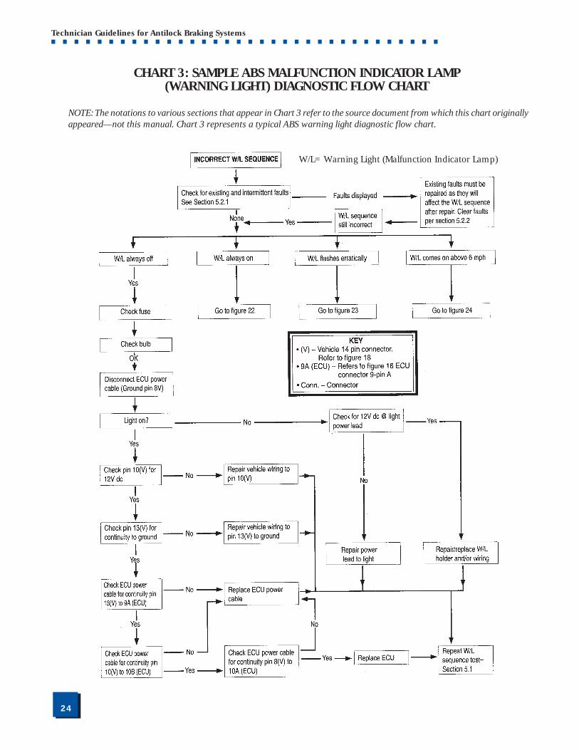
CHART 3: SAMPLE ABS MALFUNCTION INDICATOR LAMP(WARNING LIGHT) DIAGNOSTIC FLOW CHART
NOTE: The notations to various sections that appear in Chart 3 refer to the source document from which this chart originallyappeared—not this manual. Chart 3 represents a typical ABS warning light diagnostic flow chart.
W/L=Warning Light (Malfunction Indicator Lamp)
■■25
Technician Guidelines for Antilock Braking Systems■ ■ ■ ■ ■ ■ ■ ■ ■ ■ ■ ■ ■ ■ ■ ■ ■ ■ ■ ■ ■ ■ ■ ■ ■ ■ ■ ■ ■ ■ ■ ■ ■ ■
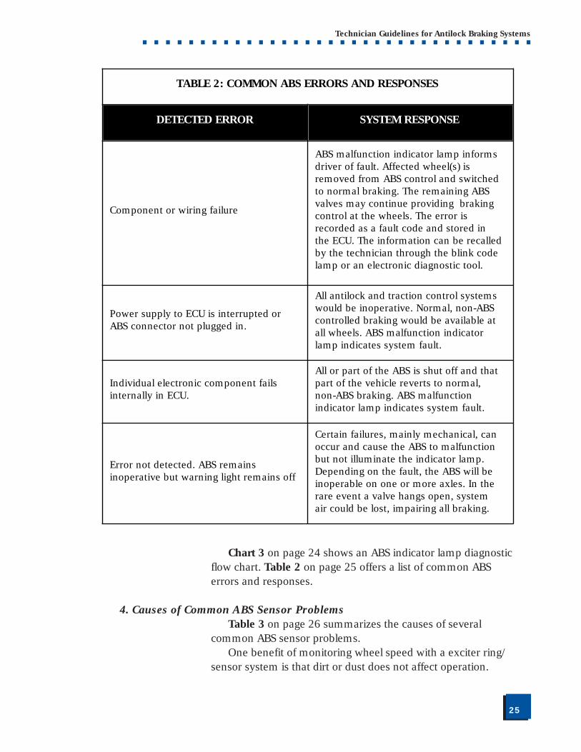
TABLE 2: COMMON ABS ERRORS AND RESPONSES
DETECTED ERROR SYSTEM RESPONSE
Component or wiring failure
ABS malfunction indicator lamp informs driver of fault. Affected wheel(s) is removed from ABS control and switched to normal braking. The remaining ABS valves may continue providing braking control at the wheels. The error is recorded as a fault code and stored in the ECU. The information can be recalled by the technician through the blink code lamp or an electronic diagnostic tool.
Power supply to ECU is interrupted or ABS connector not plugged in.
All antilock and traction control systems would be inoperative. Normal, non-ABS controlled braking would be available at all wheels. ABS malfunction indicator lamp indicates system fault.
Individual electronic component fails internally in ECU.
All or part of the ABS is shut off and that part of the vehicle reverts to normal, non-ABS braking. ABS malfunction indicator lamp indicates system fault.
Error not detected. ABS remains inoperative but warning light remains off
Certain failures, mainly mechanical, can occur and cause the ABS to malfunction but not illuminate the indicator lamp. Depending on the fault, the ABS will be inoperable on one or more axles. In the rare event a valve hangs open, system air could be lost, impairing all braking.
Chart 3 on page 24 shows an ABS indicator lamp diagnosticflow chart. Table 2 on page 25 offers a list of common ABSerrors and responses.
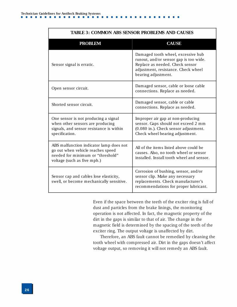
4. Causes of Common ABS Sensor ProblemsTable 3 on page 26 summarizes the causes of several
common ABS sensor problems.One benefit of monitoring wheel speed with a exciter ring/
sensor system is that dirt or dust does not affect operation.
■■26
Technician Guidelines for Antilock Braking Systems■ ■ ■ ■ ■ ■ ■ ■ ■ ■ ■ ■ ■ ■ ■ ■ ■ ■ ■ ■ ■ ■ ■ ■ ■ ■ ■ ■ ■ ■ ■ ■ ■ ■
TABLE 3: COMMON ABS SENSOR PROBLEMS AND CAUSES
PROBLEM CAUSE
Sensor signal is erratic.
Damaged tooth wheel, excessive hub runout, and/or sensor gap is too wide. Replace as needed. Check sensor adjustment, resistance. Check wheel bearing adjustment.
Open sensor circuit. Damaged sensor, cable or loose cable connections. Replace as needed.
Shorted sensor circuit. Damaged sensor, cable or cable connections. Replace as needed.
One sensor is not producing a signal when other sensors are producing signals, and sensor resistance is within specification.
Improper air gap at non-producing sensor. Gaps should not exceed 2 mm (0.080 in.). Check sensor adjustment. Check wheel bearing adjustment.
ABS malfunction indicator lamp does not go out when vehicle reaches speed needed for minimum or “threshold” voltage (such as five mph.)
All of the items listed above could be causes. Also, no tooth wheel or sensor installed. Install tooth wheel and sensor.
Sensor cap and cables lose elasticity, swell, or become mechanically sensitive.
Corrosion of bushing, sensor, and/or sensor clip. Make any necessary replacements. Check manufacturer’s recommendations for proper lubricant.
Even if the space between the teeth of the exciter ring is full ofdust and particles from the brake linings, the monitoringoperation is not affected. In fact, the magnetic property of thedirt in the gaps is similar to that of air. The change in themagnetic field is determined by the spacing of the teeth of theexciter ring. The output voltage is unaffected by dirt.
Therefore, an ABS fault cannot be remedied by cleaning thetooth wheel with compressed air. Dirt in the gaps doesn’t affectvoltage output, so removing it will not remedy an ABS fault.
■■27
Technician Guidelines for Antilock Braking Systems■ ■ ■ ■ ■ ■ ■ ■ ■ ■ ■ ■ ■ ■ ■ ■ ■ ■ ■ ■ ■ ■ ■ ■ ■ ■ ■ ■ ■ ■ ■ ■ ■ ■
B. ABS Maintenance and Inspection
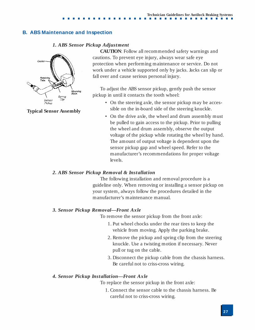
1. ABS Sensor Pickup AdjustmentCAUTION: Follow all recommended safety warnings and
cautions. To prevent eye injury, always wear safe eyeprotection when performing maintenance or service. Do notwork under a vehicle supported only by jacks. Jacks can slip orfall over and cause serious personal injury.
To adjust the ABS sensor pickup, gently push the sensorpickup in until it contacts the tooth wheel:
• On the steering axle, the sensor pickup may be acces-sible on the in-board side of the steering knuckle.
• On the drive axle, the wheel and drum assembly mustbe pulled to gain access to the pickup. Prior to pullingthe wheel and drum assembly, observe the outputvoltage of the pickup while rotating the wheel by hand.The amount of output voltage is dependent upon thesensor pickup gap and wheel speed. Refer to themanufacturer’s recommendations for proper voltagelevels.
2. ABS Sensor Pickup Removal & InstallationThe following installation and removal procedure is a
guideline only. When removing or installing a sensor pickup onyour system, always follow the procedures detailed in themanufacturer’s maintenance manual.
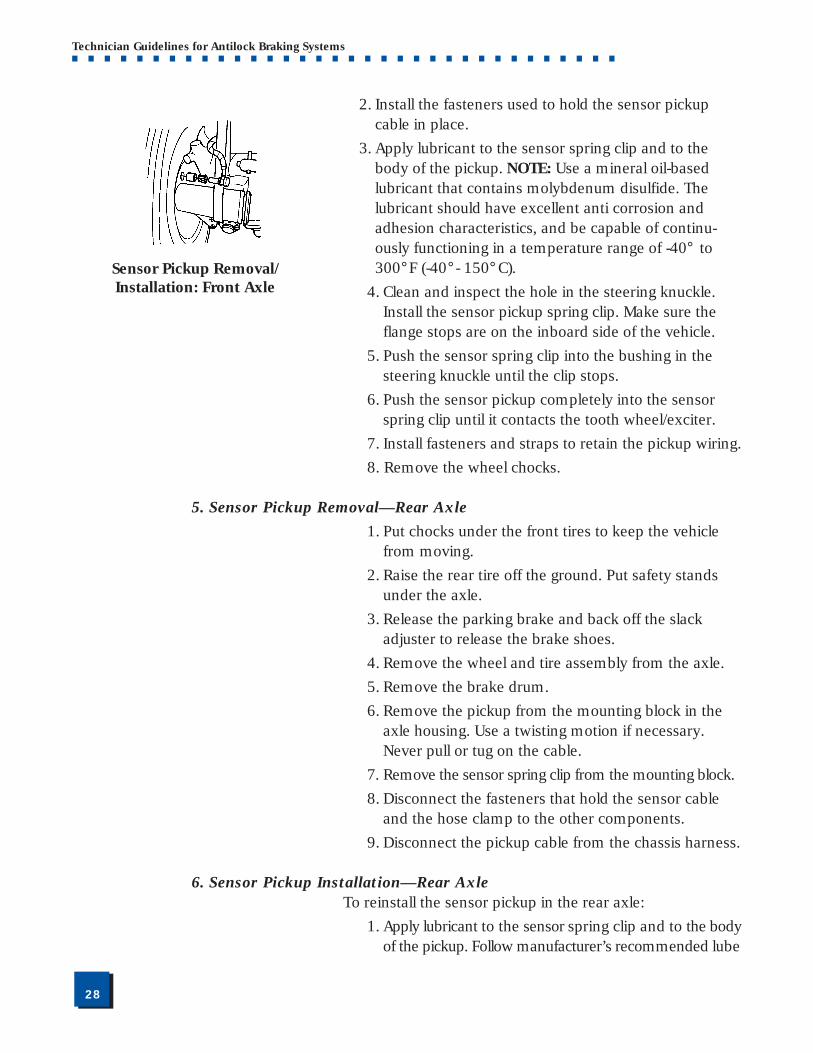
3. Sensor Pickup Removal—Front AxleTo remove the sensor pickup from the front axle:
1. Put wheel chocks under the rear tires to keep thevehicle from moving. Apply the parking brake.
2. Remove the pickup and spring clip from the steeringknuckle. Use a twisting motion if necessary. Neverpull or tug on the cable.
3. Disconnect the pickup cable from the chassis harness.Be careful not to criss-cross wiring.
4. Sensor Pickup Installation—Front AxleTo replace the sensor pickup in the front axle:
1. Connect the sensor cable to the chassis harness. Becareful not to criss-cross wiring.
Typical Sensor Assembly
■■28
Technician Guidelines for Antilock Braking Systems■ ■ ■ ■ ■ ■ ■ ■ ■ ■ ■ ■ ■ ■ ■ ■ ■ ■ ■ ■ ■ ■ ■ ■ ■ ■ ■ ■ ■ ■ ■ ■ ■ ■
2. Install the fasteners used to hold the sensor pickupcable in place.
3. Apply lubricant to the sensor spring clip and to thebody of the pickup. NOTE: Use a mineral oil-basedlubricant that contains molybdenum disulfide. Thelubricant should have excellent anti corrosion andadhesion characteristics, and be capable of continu-ously functioning in a temperature range of -40° to300°F (-40° - 150° C).
4. Clean and inspect the hole in the steering knuckle.Install the sensor pickup spring clip. Make sure theflange stops are on the inboard side of the vehicle.
5. Push the sensor spring clip into the bushing in thesteering knuckle until the clip stops.
6. Push the sensor pickup completely into the sensorspring clip until it contacts the tooth wheel/exciter.
7. Install fasteners and straps to retain the pickup wiring.
8. Remove the wheel chocks.
5. Sensor Pickup Removal—Rear Axle
1. Put chocks under the front tires to keep the vehiclefrom moving.
2. Raise the rear tire off the ground. Put safety standsunder the axle.
3. Release the parking brake and back off the slackadjuster to release the brake shoes.
4. Remove the wheel and tire assembly from the axle.
5. Remove the brake drum.
6. Remove the pickup from the mounting block in theaxle housing. Use a twisting motion if necessary.Never pull or tug on the cable.
7. Remove the sensor spring clip from the mounting block.
8. Disconnect the fasteners that hold the sensor cableand the hose clamp to the other components.
9. Disconnect the pickup cable from the chassis harness.
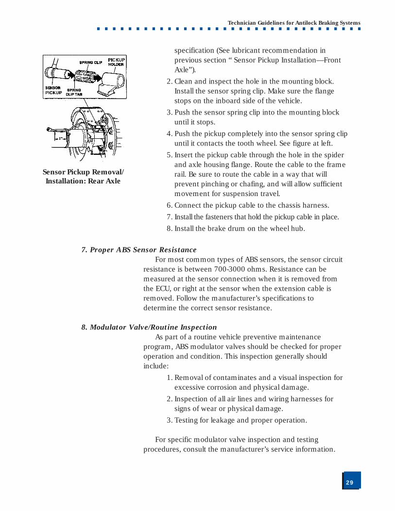
6. Sensor Pickup Installation—Rear AxleTo reinstall the sensor pickup in the rear axle:
1. Apply lubricant to the sensor spring clip and to the bodyof the pickup. Follow manufacturer’s recommended lube
Sensor Pickup Removal/Installation: Front Axle
■■29
Technician Guidelines for Antilock Braking Systems■ ■ ■ ■ ■ ■ ■ ■ ■ ■ ■ ■ ■ ■ ■ ■ ■ ■ ■ ■ ■ ■ ■ ■ ■ ■ ■ ■ ■ ■ ■ ■ ■ ■
specification (See lubricant recommendation inprevious section “ Sensor Pickup Installation—FrontAxle”).
2. Clean and inspect the hole in the mounting block.Install the sensor spring clip. Make sure the flangestops on the inboard side of the vehicle.
3. Push the sensor spring clip into the mounting blockuntil it stops.
4. Push the pickup completely into the sensor spring clipuntil it contacts the tooth wheel. See figure at left.
5. Insert the pickup cable through the hole in the spiderand axle housing flange. Route the cable to the framerail. Be sure to route the cable in a way that willprevent pinching or chafing, and will allow sufficientmovement for suspension travel.
6. Connect the pickup cable to the chassis harness.
7. Install the fasteners that hold the pickup cable in place.
8. Install the brake drum on the wheel hub.
7. Proper ABS Sensor ResistanceFor most common types of ABS sensors, the sensor circuit
resistance is between 700-3000 ohms. Resistance can bemeasured at the sensor connection when it is removed fromthe ECU, or right at the sensor when the extension cable isremoved. Follow the manufacturer’s specifications todetermine the correct sensor resistance.
8. Modulator Valve/Routine InspectionAs part of a routine vehicle preventive maintenance
program, ABS modulator valves should be checked for properoperation and condition. This inspection generally shouldinclude:
1. Removal of contaminates and a visual inspection forexcessive corrosion and physical damage.
2. Inspection of all air lines and wiring harnesses forsigns of wear or physical damage.
3. Testing for leakage and proper operation.
For specific modulator valve inspection and testingprocedures, consult the manufacturer’s service information.
Sensor Pickup Removal/Installation: Rear Axle
■■30
Technician Guidelines for Antilock Braking Systems■ ■ ■ ■ ■ ■ ■ ■ ■ ■ ■ ■ ■ ■ ■ ■ ■ ■ ■ ■ ■ ■ ■ ■ ■ ■ ■ ■ ■ ■ ■ ■ ■ ■
9. Modulator Valve Removal and InstallationThe following removal and installation information is
offered as a guideline only. Always refer to the manufacturer’sspecific instructions when removing or installing ABSmodulator valves.
Removal
1. Disconnect the harness connector from the modulatorvalve. Be careful not to criss-cross wiring.
2. Disconnect the air supply and air delivery lines fromtheir respective ports.
3. Remove modulator valve mounting fasteners.
4. Remove the modulator valve.
Installation
1. Install the modulator valve with appropriate mountingfasteners. Tighten to specified torque.
2. Connect the air supply and air delivery lines at theirrespective ports.
3. Connect the harness connector to the modulatorvalve. Be careful not to criss-cross wiring.
4. Check installation by applying the brakes, listening forleaks at the modulator valve.
5. Turn the ignition on, and listen for the modulatorvalve to cycle. If the valve fails to cycle, check theelectrical connection and any stored or active faultcodes. Drive the vehicle to verify that the ABS and itsmalfunction lamp operate properly.
10. Proper ABS Modulator Valve ResistanceFor most ABS modulator valves, the resistance range
between each valve solenoid coil terminal and the ground onthe ABS valve connector is between 3-10 ohms. To test thisresistance, disconnect the wiring connector from the modulatorand test the resistance between the two pins of each solenoid.Follow the manufacturer’s instructions for determining valveresistance.
■■31
Technician Guidelines for Antilock Braking Systems■ ■ ■ ■ ■ ■ ■ ■ ■ ■ ■ ■ ■ ■ ■ ■ ■ ■ ■ ■ ■ ■ ■ ■ ■ ■ ■ ■ ■ ■ ■ ■ ■ ■
IV. ABS SPEC’ING CONSIDERATIONSThe Federal Government’s requirement for full-time
electrical power to ABSs has prompted both equipment usersand manufacturers to reconsider the way trailers are suppliedwith such power. Since a particular powering configuration isnot required in the ABS rule, manufacturers and equipmentusers can decide for themselves how to achieve the full-timepower requirement.
There are several different methods of supplying full timepower to the trailer ABS:
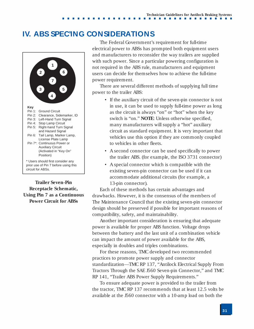
• If the auxiliary circuit of the seven-pin connector is notin use, it can be used to supply full-time power as longas the circuit is always “on” or “hot” when the keyswitch is “on.” NOTE: Unless otherwise specified,many manufacturers will supply a “hot” auxiliarycircuit as standard equipment. It is very important thatvehicles use this option if they are commonly coupledto vehicles in other fleets.
• A second connector can be used specifically to powerthe trailer ABS. (for example, the ISO 3731 connector)
• A special connector which is compatible with theexisting seven-pin connector can be used if it canaccommodate additional circuits (for example, a13-pin connector).
Each of these methods has certain advantages anddrawbacks. However, it is the consensus of the members ofThe Maintenance Council that the existing seven-pin connectordesign should be preserved if possible for important reasons ofcompatibility, safety, and maintainability.
Another important consideration is ensuring that adequatepower is available for proper ABS function. Voltage dropsbetween the battery and the last unit of a combination vehiclecan impact the amount of power available for the ABS,especially in doubles and triples combinations.
For these reasons, TMC developed two recommendedpractices to promote power supply and connectorstandardization—TMC RP 137, “Antilock Electrical Supply FromTractors Through the SAE J560 Seven-pin Connector,” and TMCRP 141, “Trailer ABS Power Supply Requirements.”
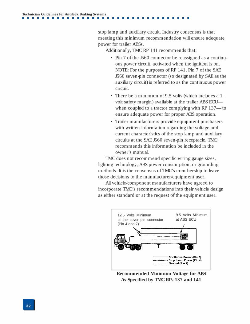
To ensure adequate power is provided to the trailer fromthe tractor, TMC RP 137 recommends that at least 12.5 volts beavailable at the J560 connector with a 10-amp load on both the
62
3 5
7
4
1
KeyPin 1: Ground CircuitPin 2: Clearance, Sidemarker, IDPin 3: Left-Hand Turn SignalPin 4: Stop Lamp CircuitPin 5: Right-hand Turn Signal
and Hazard SignalPin 6: Tail Lamp, Marker Lamp,
License Plate LampPin 7*: Continuous Power or
Auxiliary Circuit(Activated in “Key On”Position)
* Users should first consider anyprior use of Pin 7 before using thiscircuit for ABSs.
Trailer Seven-PinReceptacle Schematic,
Using Pin 7 as a ContinuousPower Circuit for ABSs
■■32
Technician Guidelines for Antilock Braking Systems■ ■ ■ ■ ■ ■ ■ ■ ■ ■ ■ ■ ■ ■ ■ ■ ■ ■ ■ ■ ■ ■ ■ ■ ■ ■ ■ ■ ■ ■ ■ ■ ■ ■
stop lamp and auxiliary circuit. Industry consensus is thatmeeting this minimum recommendation will ensure adequatepower for trailer ABSs.
Additionally, TMC RP 141 recommends that:
• Pin 7 of the J560 connector be reassigned as a continu-ous power circuit, activated when the ignition is on.NOTE: For the purposes of RP 141, Pin 7 of the SAEJ560 seven-pin connector (so designated by SAE as theauxiliary circuit) is referred to as the continuous powercircuit.
• There be a minimum of 9.5 volts (which includes a 1-volt safety margin) available at the trailer ABS ECU—when coupled to a tractor complying with RP 137— toensure adequate power for proper ABS operation.
• Trailer manufacturers provide equipment purchaserswith written information regarding the voltage andcurrent characteristics of the stop lamp and auxiliarycircuits at the SAE J560 seven-pin receptacle. TMCrecommends this information be included in theowner’s manual.
TMC does not recommend specific wiring gauge sizes,lighting technology, ABS power consumption, or groundingmethods. It is the consensus of TMC’s membership to leavethose decisions to the manufacturer/equipment user.
All vehicle/component manufacturers have agreed toincorporate TMC’s recommendations into their vehicle designas either standard or at the request of the equipment user.
9.5 Volts Minimumat ABS ECU
12.5 Volts Minimumat the seven-pin connector(Pin 4 and 7)
Recommended Minimum Voltage for ABSAs Specified by TMC RPs 137 and 141
■■33
Technician Guidelines for Antilock Braking Systems■ ■ ■ ■ ■ ■ ■ ■ ■ ■ ■ ■ ■ ■ ■ ■ ■ ■ ■ ■ ■ ■ ■ ■ ■ ■ ■ ■ ■ ■ ■ ■ ■ ■
V. GLOSSARY OF ABS TERMS
The following terms are used by one or more manufacturers todescribe different aspects of ABSs:
Antilock Braking System (ABS) A system that monitors and controls wheel speed during brak-ing so as to minimize wheel lockup while maximizing vehiclelateral stability. Plural form—ABSs.
ABS Configuration The arrangement of antilock braking system components,which varies by the number of sensors and modulator valvesused. The following configurations for tractors are common-place: 4S/4M, 6S/4M, and 6S/6M. For trailers, 2S/1M.,2S/2M, 4S/2M and 4S/3M. (S=sensor. M=modulator.)
ABS Inline Valve A modulator valve located in the service brake delivery linenear the wheel’s brake chamber which modifies brake pressureduring an ABS event. Also see ABS Modulator Valve or ABSRelay Valve.
ABS Modulator Valve An electro-pneumatic control valve that contains the solenoidsused to precisely modulate brake air pressure during an ABSevent. Also see ABS Inline Valve or ABS Relay Valve.
ABS Relay Valve A valve that performs the service relay function as well as theABS modulator valve function to modify brake air pressureduring an ABS event. Also see ABS Modulator Valve or ABSInline Valve.
Anti-Spin Regulation (ASR) See Traction Control.
Automatic Traction Control (ATC) See Traction Control.
Axle Control That mode of ABS control whereby one modulator controls theair pressure to the brake chambers on both ends of a givenaxle. Also referred to as axle-by-axle control.
Bracket Mounting The means of installing the ABS modulator-controller on thehost vehicle by using a supplied, pre-formed bracket.
■■34
Technician Guidelines for Antilock Braking Systems■ ■ ■ ■ ■ ■ ■ ■ ■ ■ ■ ■ ■ ■ ■ ■ ■ ■ ■ ■ ■ ■ ■ ■ ■ ■ ■ ■ ■ ■ ■ ■ ■ ■
Brake Proportioning The limiting of brake air pressure to a specific axle or tandemto compensate for varying vehicle loading. Brake proportioningis most beneficial during bobtail tractor operation.
Braked Wheel Behavior The study of wheel reactions during braking, particularly be-tween the road surface and the tire.
Category (I, II, & III) A means of categorizing ABS performance used in Europe.
Chamber Pressure The air pressure in the brake chambers during a brakeapplication.
Channel The electrical connection between the ECU and the modulator.The term is also used to describe the number of individualmodulators in a particular antilock system.
Chuff Test Also called ignition blowdown test. A test—designed to simplifydiagnostics—used to exercise the ABS modulator(s) upon initialpower-up. The “chuff” sound is made by air escaping fromrapid exercising of the exhaust solenoid (and supply solenoid)on each modulator.
Coefficient of Friction A measure of the friction (such as between a tire and the roadsurface) available to use as surface retardation. The ratio isdefined as “Force Required to Overcome Friction/Weight” andis denoted by the Greek letter µ. See also “Mu.”
Control Algorithm The specific configuration of logical decisions implemented todetermine the characteristics of an ABS cycle. Apply, release,hold, etc., determinations are made in the control algorithm,which is implemented in the ABS software contained in theelectronic control unit (ECU).
Control Pressure The air pressure applied from the foot/hand valve which con-trols the brake application pressure either directly or through arelay valve. The ABS interrupts this pressure by adding a modu-lator in series such that the air pressure at the individual brakechambers may vary from the control pressure. During ABSoperation, therefore, chamber pressure may be equal to or lessthan the control pressure.
Controller Another name for the electronic control unit (ECU). SeeElectronic Control Unit.
■■35
Technician Guidelines for Antilock Braking Systems■ ■ ■ ■ ■ ■ ■ ■ ■ ■ ■ ■ ■ ■ ■ ■ ■ ■ ■ ■ ■ ■ ■ ■ ■ ■ ■ ■ ■ ■ ■ ■ ■ ■
Current Current represents the flow of electrons through a conductingmedium, such as copper. Current is measured in amperes oramps and can be derived through the following formula: Amp = Volt/Ohm or I=V/R.
Cycle A single sequence of pressure application and release duringABS operation. This cycle repeats during an ABS event as longas impending wheel lock-up is identified. Also referred to as“cycling.”
Data Link The TMC/SAE J1708/J1587 Serial Data Link Standard used inmost vehicle-mounted ECUs.
Diagnostics A method of identifying faulty components or parameters. Forexample, a series of LED lights may be used to identify specificABS components that need to be serviced or corrected.
Diagonal Split The case in which ABS is disabled on both the specific wheelwith an ABS failure and its diagonal counterpart to maintainvehicle control during emergency stops.
Dynamic Fault A fault detected with the wheel speed sensors or modulatorswhen the wheels are rotating. See Static Fault.
Electronic Control Unit (ECU) An on-board vehicle computer that controls the ABS, tractioncontrol and diagnostic functions. The ECU receives input sig-nals, processes the information, and sends output signals to thenecessary ABS components.
Electromagnetic Interference Electromagnetic interference (EMI) disrupts the proper opera-tion of an electronic device or system. EMI is caused by electro-magnetic field(s).
EPROM EPROM stands for Erasable Programmable Read Only Memory.The term refers to an integrated circuit that contains the ABScontrol algorithm.
Exciter A metal ring, normally with 100 evenly spaced teeth, althoughsometimes with 80 or 120 teeth, depending on tire size. It isusually attached to the barrel of the hub on each ABS-moni-tored wheel. When the wheel rotates, the teeth move past thewheel speed sensor pickup to create an electrical signal that theECU uses to determine wheel speed. Also called a Tooth Wheel.
■■36
Technician Guidelines for Antilock Braking Systems■ ■ ■ ■ ■ ■ ■ ■ ■ ■ ■ ■ ■ ■ ■ ■ ■ ■ ■ ■ ■ ■ ■ ■ ■ ■ ■ ■ ■ ■ ■ ■ ■ ■
Failure Lamp An indicator lamp that indicates ABS operational status. SeeMalfunction Indicator Lamp.
FMVSS Federal Motor Vehicle Safety Standard. FMVSS 121, “Air BrakeSystems,” is the regulation that applies to air brakes used oncommercial vehicles.
Four-Channel ABS A system that has four sensors and four modulators (4S/4M) orsix sensors and four modulators (6S/4M).
Full-Time Power This term refers to an ABS design in which a circuit connectsthe tractor and trailer to supply constant electrical power for anABS. See Stop-lamp Power.
Ghost Sensing In-axle Speed Sensing Systems where one wheel/axle is sensedand the differential gear is sensed. The ECU uses these twoinputs to calculate the speed of the unsensed wheel (i.e., theghost sensor). Ghost Sensed Speed = (2)(Average) - Individual.
In-Axle Sensor/Sensing The practice of locating wheel speed sensing devices inside thedrive axle housing of the ABS-equipped vehicle. This sensingoption offers additional environmental protection for the wheelspeed sensor, but presents special service considerations forequipment users.
ISO Connector A multi-pin tractor-trailer electrical connector used in Europethat meets International Standards Organization (ISO) require-ments. This connector carries power, failure lamp status, andserial communications to and from European trailer ABSs. TheISO 7638 connector, for example, provides a dedicated ABSpower source for European tractor-trailers. The ISO 3731connector is used by a North American manufacturer for ABSsas well.
J560 Connector See Seven-Pin Connector.
J1587 An SAE Recommended Practice for applications dealing withthe J1708 serial data bus. This standard deals with the assign-ment of specific parameter codes including diagnostics andother system attributes. SAE J1587 and J1708 must be usedtogether to fully implement the noncritical data exchange onheavy vehicles. See J1708.
■■37
Technician Guidelines for Antilock Braking Systems■ ■ ■ ■ ■ ■ ■ ■ ■ ■ ■ ■ ■ ■ ■ ■ ■ ■ ■ ■ ■ ■ ■ ■ ■ ■ ■ ■ ■ ■ ■ ■ ■ ■
J1708 An SAE Recommended Practice for serial exchange of vehicle-based, noncritical parametric information. This standard estab-lishes the hardware and protocol requirements for the serialdata bus. See J1587.
Jackknife A condition that can occur when either tractor, trailer, or tractorand trailer wheels lose traction and lateral vehicle stabilitycannot be maintained.
Lateral Stability The resistance of a vehicle to forces which attempt to change itsdirection of travel. Maximum lateral stability is achieved at zeropercent wheel slip (free rolling travel).
LED Light-emitting diode used in some ABS diagnostic systems toconvey diagnostic information.
Malfunction Indicator Lamp A lamp that becomes active whenever an ABS is not fullyfunctional. The tractor/truck lamp is on the instrument panel. Atrailer/dolly in-cab indicator is not required by law until March2001. However, an external trailer/dolly indicator lamp isrequired, effective March 1998. By March 2009, the externallamp will no longer be required. Also called Warning Lamp orFailure Lamp.
Manifold The central device on which the modulators of a two- or three-channel system may be commonly mounted.
Microcontroller An application-specific microprocessor geared around a specificcontrol function. Also referred to as “computer chips.”
Modulator See ABS Modulator Valve.
Mu Refers to the Greek letter µ which represents coefficient offriction. See Coefficient of Friction.
NHTSA National Highway Traffic Safety Administration. This division ofthe U.S. Department of Transportation regulates the safety ofnew vehicles. NHTSA is the federal agency that requires theinstallation of ABSs on new commercial vehicles.
Non-Volatile Memory (NOVRAM) Solid-state electronics capable of retaining electrical informationin the absence of system power. This is how diagnostics infor-mation is saved in the ABS ECU.
■■38
Technician Guidelines for Antilock Braking Systems■ ■ ■ ■ ■ ■ ■ ■ ■ ■ ■ ■ ■ ■ ■ ■ ■ ■ ■ ■ ■ ■ ■ ■ ■ ■ ■ ■ ■ ■ ■ ■ ■ ■
Power Jackknife A non-braking induced condition whereby the drive wheels of atractor will spin under engine power, resulting in a loss oflateral stability.
Quick-Release Valve A commonly used valve located close to a brake chamber thatdecreases the time required to exhaust air pressure from it.
Reference Speed An ideal rate of wheel speed deceleration (optimum wheel slip)calculated by the ECU and based on actual wheel speed infor-mation at the moment that the ABS is activated. The ECUcompares actual wheel speed to the reference wheel speedduring an ABS event and adjusts the brake application pressurein an attempt to match the actual wheel speed with the idealreference speed.
Relay Valve See ABS Relay Valve for definition as it pertains to ABSs.
Retarder Control A system which prevents the tractor drive axle(s) from lockingon slippery surfaces by disabling the engine retarder during anABS event.
RFI Radio frequency interference. A type of electromagnetic inter-ference (EMI) that occurs only in the radio frequency band. SeeElectromagnetic Interference.
SAE Society of Automotive Engineers. An organization that setsvoluntary engineering standards for automotive and aerospacecomponents, systems, and vehicles. See J560, J1587 andJ1708.
Select High A system design in which ABS bases all control decisions torelease or apply brakes to an axle or tandem on the highestmeasured wheel speed. Under this design, ABS won’t startcycling until all sensed wheels experience a tendency to lock.
Select Low A system design in which the ABS bases all control decisions torelease or apply brakes to an axle or tandem on the lowestmeasured wheel speed. If only one wheel locks, the ABS on allother controlled wheels on that axle or tandem will also cycle.
Sensor Bushing The friction spring device that is first inserted into the sensorblock, allowing the sensor pickup to be adjusted and holding itin position during vehicle operation. Also called a spring clip.
■■39
Technician Guidelines for Antilock Braking Systems■ ■ ■ ■ ■ ■ ■ ■ ■ ■ ■ ■ ■ ■ ■ ■ ■ ■ ■ ■ ■ ■ ■ ■ ■ ■ ■ ■ ■ ■ ■ ■ ■ ■
Seven-Pin Connector An electrical connector used between units of combinationvehicles in North America to conduct electrical power for theStop Lamps, Turn Signals, Running Lamps, Ground, and Auxil-iary (or ABS) circuits. Also known as the SAE J560 connector
Side-by-Side Control A control system that uses one modulator valve on each side ofan axle or axle group to control brake pressures independently,to improve braking performance on split-co road surfaces.
Six-Channel ABS A system that has six sensors and six modulators (6S/6M).
Skid Number A term representing the coefficient of friction ( µ) of a givensurface as a whole number by multiplying the coefficient offriction by 100: 0.70µ x 100 = 70 Skid Number.
Software As applied to ABSs, the complete package of programs consist-ing of the ABS algorithm, error checking diagnostics, enginemanagement interface, and the structure which links every-thing together. Software, which is contained in the EPROM(s)inside the ECU, is a specific set of instructions that the ECU willexecute to perform a particular task.
Solenoid A device that converts an electrical signal into mechanicalmovement. It consists of a coil with a moveable core thatchanges positions by means of electromagnetism when currentflows through the coil.
Split-Co Split coefficient of friction. A condition in which one side of avehicle is on a high coefficient of friction while the other side ison a low coefficient of friction (e.g., one side of the vehicle ondry pavement and one side on wet or icy pavement). Thiscondition is most likely to cause the vehicle to experience yawor a twisting/turning action during a stop without an operationalABS.
Spring Clip See Sensor Bushing.
Static Fault A fault detected with the wheel speed sensors or modulatorswhen the wheels are not rotating. See Dynamic Fault.
Stop-Lamp Power A design in which the ABS is powered only by the stop lampcircuit and requires no additional dedicated connector. See Full-Time Power.
■■40
Technician Guidelines for Antilock Braking Systems■ ■ ■ ■ ■ ■ ■ ■ ■ ■ ■ ■ ■ ■ ■ ■ ■ ■ ■ ■ ■ ■ ■ ■ ■ ■ ■ ■ ■ ■ ■ ■ ■ ■
Stopping Distance The distance required to stop a vehicle. Stopping distancemeasurements begin when application (control) pressure firstbegins to increase, and end when the vehicle comes to a com-plete stop.
Tandem Control An ABS design in which the four wheels of the tandem axle arecontrolled by only one modulator.
TMC The Maintenance Council of the American Trucking Associa-tions. An industry group which develops voluntary recom-mended practices on maintenance- and operation-relatedissues pertaining to commercial vehicles, based on input fromequipment users, vehicle manufacturers, component suppliers,academia, and government representatives.
TMC RP 137 TMC Recommended Practice 137 is a voluntary standard thatstates tractors should deliver a minimum power level of 12.5volts at 10 amps load to the trailer half of the tractor-to-trailerelectrical connector.
TMC RP 141 TMC Recommended Practice 141 is a voluntary standard thatstates at least 9.5 volts (which includes a 1.0-volt safety margin)must be available at the trailer ABS ECU to ensure properoperation.
Tone Ring See Exciter.
Traction Control A system to minimize drive wheel slip (improve traction) underacceleration. Traction control uses the ABS to apply brakingpressure to a spinning wheel, transferring engine power to thewheel(s) with better traction. Should all the drive wheels start toslip, traction control system can improve vehicle traction byreducing engine torque. Traction control systems are referredto by several different names, depending on the manufacturer.These include:
• Automatic Traction Control (ATC)
• Traction Control (TC)
• Automatic Slip Regulation or Anti-Spin Regulation(ASR)
Tooth Wheel See Exciter.
■■41
Technician Guidelines for Antilock Braking Systems■ ■ ■ ■ ■ ■ ■ ■ ■ ■ ■ ■ ■ ■ ■ ■ ■ ■ ■ ■ ■ ■ ■ ■ ■ ■ ■ ■ ■ ■ ■ ■ ■ ■
Vehicle Power The voltage and current delivered to various electrical and/orelectronic devices on a vehicle. Typical vehicle power in NorthAmerica is 9.0-16.0 volts direct current. European vehiclestypically operate from 18.0-32.0 VDC. TMC RecommendedPractice 137 establishes a voluntary standard that tractorsshould deliver a minimum power level of 12.5 volts at 10 ampsload. TMC Recommended Practice 141 establishes a voluntarystandard that at least 9.5 volts (which includes a 1.0-volt safetymargin) must be available at the trailer ABS ECU to ensureproper operation.
Warning Lamp See Malfunction Indicator Lamp
Wheel-by-Wheel Control A type of ABS control in which each wheel is controlledindividually.
Wheel Slip The difference between vehicle speed and wheel speed, ex-pressed as a percentage. The formula is: Wheel Slip =(100)(Vehicle Speed-Wheel Speed)/(Vehicle Speed).
Wheel Speed The measured velocity of an individual (sensed) wheel which isderived by the ABS ECU. Wheel speed may differ from vehiclespeed during wheel slip. See Wheel Slip.
Wheel Speed Sensor Pickup A magnetic pickup-type sensor—coupled with an exciter ortooth wheel—that produces a signal to indicate wheel speed tothe ECU. A permanent magnet and passing metal teeth com-bine to produce an electrical signal with a frequency propor-tional to the wheel speed. The teeth alter the magnetic fieldproduced by the sensor. The changing magnetic field producesan AC voltage in pickup coil within the sensor.
■■42
Technician Guidelines for Antilock Braking Systems■ ■ ■ ■ ■ ■ ■ ■ ■ ■ ■ ■ ■ ■ ■ ■ ■ ■ ■ ■ ■ ■ ■ ■ ■ ■ ■ ■ ■ ■ ■ ■ ■ ■
Antilock Braking System (ABS)........................... 3adequate power ................................................. 31-32benefits ...................................................................... 7common problems ................................................... 23common sensor errors .............................................. 26common system errors ............................................. 25component descriptions ........................................ 8-13connector standardization ........................................ 31configuration ................................................ 11-12, 33defined ................................................................... 3-4driving technique ....................................................... 6fail-safe ....................................................................... 7features ...................................................................... 7faults ........................................................................ 23inspection ........................................................... 27-30maintenance ....................................................... 27-30mandate .................................................................... 3operation ................................................................... 5requirements for new vehicles ................................. 3-4self-diagnostic capability ........................................... 12spec’ing considerations ............................................ 31troubleshooting .................................................. 14-19welding cautions related to ABS ............................... 22
Connectors ........................................... 19, 31-32ISO Connectors .................................................. 31, 36Seven-pin Connector (J560)........................... 31-32, 39
Diagnostics ................................ 12, 14-19, 22-23general principles ................................................ 14-18tool compatibility ........................................................ 7
Disclaimer.......................................................... 2
Electrical/Electronic Connectionsservice recommendations .................................... 19-22
Electronic Control Unit (ECU) ............................. 8defined ................................................................ 8, 35location.................................................................... 10operation ................................................................... 8
Error Detection ........................................... 23-25
Exciter .............................................................11
FMVSS 121 .................................................. 3, 36
Glossary of Terms ............................................ 33
VI. INDEX
■■43
Technician Guidelines for Antilock Braking Systems■ ■ ■ ■ ■ ■ ■ ■ ■ ■ ■ ■ ■ ■ ■ ■ ■ ■ ■ ■ ■ ■ ■ ■ ■ ■ ■ ■ ■ ■ ■ ■ ■ ■
Grounding Recommendations .......................... 21
Inspection, ABS .......................................... 27-30modulator valves ...................................................... 29
J560 ..................................................... 31-32, 36
J1587 .......................................................8,9, 36
J1708 ..............................................................37
J1922 ................................................................ 8
J1939 ................................................................ 8
Maintenance, ABS....................................... 27-30modulator valves ................................................. 29-30sensor pickup adjustment ......................................... 27sensor pickup removal and installation ................. 27-29
Malfunction Indicator Lamp .............. 7, 12, 23-24defined .............................................................. 12, 37diagnostic flowchart (typical) .................................... 24problems ............................................................. 23-24requirements ........................................................ 4, 12
Modulator Valves ............................................. 10diagnostic flowchart (typical) .................................... 18inspection ................................................................ 29installation................................................................ 30operation ................................................................. 10proper resistance ...................................................... 30removal.................................................................... 30
National Highway Traffic SafetyAdministration (NHTSA) ........................... 3-4, 37
Pickup ..................................... See Sensor Pickup
RP 137 ....................................................... 31-32
RP 141 ....................................................... 31-32
Sensor Pickup ....................................... 11, 27-29adjustment ............................................................... 27defined .............................................................. 11, 41exciter ring ............................................................... 11gap ..................................................................... 26-27installation........................................................... 27-29lubricant .................................................................. 28
■■44
Technician Guidelines for Antilock Braking Systems■ ■ ■ ■ ■ ■ ■ ■ ■ ■ ■ ■ ■ ■ ■ ■ ■ ■ ■ ■ ■ ■ ■ ■ ■ ■ ■ ■ ■ ■ ■ ■ ■ ■
Sensor Pickup (Continued)operation ................................................................. 11problems ............................................................. 25-26removal............................................................... 27-28resistance ................................................................. 29
Seven-Pin Connector ............................. 31-32, 39
Spec’ing, ABS Considerations ...................... 31-32
Termination Techniques, Wiring .................. 19-21
Tooth Wheel ....................................... See Exciter
Traction Control ...............................................13defined .................................................................... 13operation ................................................................. 13
Warning Lamp .... See Malfunction Indicator LampWelding, ABS-Related Cautions ................................. 22
Wheel Speed Sensors ......... 11, See Sensor Pickup
Wiring Considerations................................. 19-22butt splices ............................................................... 21grounding recommendations ................................... 21repair damage ......................................................... 22seven-pin connector ............................................ 31-32star washers, use of .................................................. 22termination techniques............................................. 19wiring recommendations ......................................... 32
■ ■ ■ ■ ■ ■ ■ ■
■ ■ ■ ■ ■ ■ ■ ■ ■ ■ ■ ■ ■ ■ ■ ■ ■ ■ ■
Federal Highway Administration400 Seventh Street, S.W.Washington, D.C. 20590Publication No. FHWA-MC-98-008HCS-10/12-97(500)