technical white paper - hammer huawei - · pdf filehuawei oceanstor 9000 scale-out nas...
TRANSCRIPT
Huawei OceanStor 9000 Scale-Out NAS
Technical White Paper
Issue 05
Date 2016-03-20
HUAWEI TECHNOLOGIES CO., LTD.
Issue 05 (2016-03-20) Huawei Proprietary and Confidential
Copyright © Huawei Technologies Co., Ltd.
i
Copyright © Huawei Technologies Co., Ltd. 2016. All rights reserved.
No part of this document may be reproduced or transmitted in any form or by any means without prior written consent of Huawei Technologies Co., Ltd.
Trademarks and Permissions
and other Huawei trademarks are trademarks of Huawei Technologies Co., Ltd.
All other trademarks and trade names mentioned in this document are the property of their respective holders.
Notice
The purchased products, services and features are stipulated by the contract made between Huawei and
the customer. All or part of the products, services and features described in this document may not be
within the purchase scope or the usage scope. Unless otherwise specified in the contract, all statements,
information, and recommendations in this document are provided "AS IS" without warranties, guarantees or representations of any kind, either express or implied.
The information in this document is subject to change without notice. Every effort has been made in the
preparation of this document to ensure accuracy of the contents, but all statements, information, and recommendations in this document do not constitute a warranty of any kind, express or implied.
Huawei Technologies Co., Ltd.
Address: Huawei Industrial Base
Bantian, Longgang
Shenzhen 518129
People's Republic of China
Website: http://e.huawei.com

Huawei OceanStor 9000 Scale-Out NAS
Technical White Paper Contents
Issue 05 (2016-03-20) Huawei Proprietary and Confidential
Copyright © Huawei Technologies Co., Ltd.
ii
Contents
1 Introduction .............................................................................................................................. 1
2 Hardware, Software, and Network ........................................................................................ 3
2.1 Hardware and Software Architectures .................................................................................................................... 3
2.2 Network Overview ................................................................................................................................................ 5
2.2.1 10GE Networking (10GE Front-End and 10GE Back-End).................................................................................. 7
2.2.2 InfiniBand Networking (InfiniBand Front-End and InfiniBand Back-End) ........................................................... 7
2.2.3 Mixed Networking (10GE Front-End and InfiniBand Back-End) ......................................................................... 8
2.3 System Running Environment................................................................................................................................ 9
3 Distributed File System Architecture .................................................................................. 10
3.1 Architecture Overview ..........................................................................................................................................10
3.1.1 Distributed File System Service .........................................................................................................................12
3.1.2 Storage Resource Pool Plane ..............................................................................................................................12
3.1.3 Management Plane ............................................................................................................................................13
3.2 Metadata Management ..........................................................................................................................................13
3.3 Distributed Data Reliability Technologies .............................................................................................................15
3.3.1 Data Striping .....................................................................................................................................................15
3.3.2 Clustered Object-based Storage System..............................................................................................................15
3.3.3 N+M Data Protection .........................................................................................................................................16
3.4 Global Cache ........................................................................................................................................................20
3.4.1 Components of Global Cache .............................................................................................................................20
3.4.2 Implementation Principle ...................................................................................................................................21
3.5 File Writing ..........................................................................................................................................................22
3.6 Load Balancing ....................................................................................................................................................24
3.6.1 Intelligent IP Address Management ....................................................................................................................24
3.6.2 Diverse Load Balancing Policies ........................................................................................................................26
3.6.3 Zone-based Node Management ..........................................................................................................................26
3.7 Data Recovery ......................................................................................................................................................27
4 System Advantages ................................................................................................................ 28
4.1 Outstanding Performance ......................................................................................................................................28
4.2 Flexible Expansion ...............................................................................................................................................28
4.3 Open and Converged ............................................................................................................................................29

Huawei OceanStor 9000 Scale-Out NAS
Technical White Paper Contents
Issue 05 (2016-03-20) Huawei Proprietary and Confidential
Copyright © Huawei Technologies Co., Ltd.
iii
5 Acronyms and Abbreviations ............................................................................................... 31
Huawei OceanStor 9000 Scale-Out NAS
Technical White Paper 1 Introduction
Issue 05 (2016-03-20) Huawei Proprietary and Confidential
Copyright © Huawei Technologies Co., Ltd.
1
1 Introduction
In the data explosion era, data available to people has been increasing exponentially.
Traditional standalone file systems have to add more disks to expand their capacity. Such file
systems are no longer capable of meeting modern storage requirements in terms of capacity
scale, capacity growth speed, data backup, and data security. New storage models are
introduced to resolve this issue:
Centralized storage
File metadata (data that provides information about other data, such as the file location
and size) and data information are stored centrally. Back-end SAN and NAS are mounted
to front-end NFS. This model of storage system is difficult to expand, not to mention
providing petabytes of capacity.
Asymmetrical distributed storage
It has only one metadata service (MDS) node, and stores file metadata and data
separately. Such storage systems include Lustre and MooseFS. One issue with a single
MDS node is single point of failure, which can be avoided using heartbeat mechanism,
but the performance bottleneck with single-point access is inevitable.
Fully symmetrical distributed storage
It employs a fully symmetrical, decentralized, and distributed architecture. Files on
storage devices can be located using the consistent hash algorithm, an implementation of
distributed hash table (DHT). Therefore, this model of storage system does not need to
have an MDS node. It has storage nodes only and does not differentiate between
metadata and data blocks. However, it requires ensured efficiency, balance, and consistency for the consistent hash algorithm in node expansion and failure scenarios.
Huawei OceanStor distributed file system (DFS) storage has a fully symmetrical,
decentralized, and distributed architecture, but it does not use DHT to locate files on storage
nodes. Each node of an OceanStor DFS storage system can provide MDS and data service as
well as client agent for external access. OceanStor DFS has no dedicated MDS nodes,
eliminating single point of failure and performance bottlenecks. It enables smooth
switchovers during node expansion or failures, and the switchover process is transparent to
services. OceanStor DFS provides a unified file system space for application servers, allowing
them to share data with each other. A storage device that works in distributed cluster mode
typically uses dual-controller or multi-controller nodes to provide services. Each node
supports a specific service load. When the capacity is insufficient, disk enclosures are added
to expand the capacity. On such storage devices, services and nodes are bonded. As a result, a
service and the associated file system run on only one node. This easily leads to load
imbalance within the system. Furthermore, the capacity expansion approach is essentially
scale-up, which aims to improve the performance of a single node but fails to improve the whole system performance linearly as the capacity increases.
Huawei OceanStor 9000 Scale-Out NAS
Technical White Paper 1 Introduction
Issue 05 (2016-03-20) Huawei Proprietary and Confidential
Copyright © Huawei Technologies Co., Ltd.
2
As the software basis of OceanStor 9000, OceanStor DFS (originally called Wushan FS)
works in all-active share-nothing mode, where data and metadata (management data) are
distributed evenly on all nodes. This prevents system resource contentions and eliminates
system bottlenecks. Even if a node fails, OceanStor 9000 automatically identifies the failed
node and restores its data, making the failure transparent to services. In this way, service
continuity is ensured. OceanStor 9000 adopts a networking mechanism featuring full
redundancy and full mesh, employs a symmetrical distributed cluster design, and provides a
globally unified namespace, allowing nodes to concurrently access any file stored on
OceanStor 9000. In addition, OceanStor 9000 supports fine-grained global locking within
files and allows multiple nodes to concurrently access different parts of the same file,
implementing high access concurrency at a high performance level.

Huawei OceanStor 9000 Scale-Out NAS
Technical White Paper 2 Hardware, Software, and Network
Issue 05 (2016-03-20) Huawei Proprietary and Confidential
Copyright © Huawei Technologies Co., Ltd.
3
2 Hardware, Software, and Network
2.1 Hardware and Software Architectures
Huawei OceanStor 9000 employs a fully symmetrical architecture. In OceanStor 9000, nodes
of the same type adopt the same hardware and software configurations. Such a design
facilitates customers' initial purchase and future capacity expansion, where only the number
of required nodes needs to be calculated (at least 3, except that 2 for C72 nodes) nodes must
be configured for the initial purchase, without the need to consider independent metadata
servers or independent network management servers.
An OceanStor 9000 storage system consists of switching devices and OceanStor 9000
hardware nodes. No extra devices are needed. Figure 2-1 shows the OceanStor 9000 product
structure.
Figure 2-1 OceanStor 9000 product structure
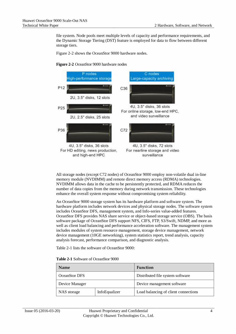
OceanStor 9000 provides different types of hardware nodes for different application scenarios,
for example, P nodes for performance-intensive applications and C nodes for large-capacity
applications. Different types of nodes can be intermixed to achieve an optimal effect. In an
intermixed deployment, at least three nodes of each type are required. OceanStor 9000 has different node pools for different hardware nodes, centralizing each type of nodes in a single
Huawei OceanStor 9000 Scale-Out NAS
Technical White Paper 2 Hardware, Software, and Network
Issue 05 (2016-03-20) Huawei Proprietary and Confidential
Copyright © Huawei Technologies Co., Ltd.
4
file system. Node pools meet multiple levels of capacity and performance requirements, and
the Dynamic Storage Tiering (DST) feature is employed for data to flow between different
storage tiers.
Figure 2-2 shows the OceanStor 9000 hardware nodes.
Figure 2-2 OceanStor 9000 hardware nodes
All storage nodes (except C72 nodes) of OceanStor 9000 employ non-volatile dual in-line
memory module (NVDIMM) and remote direct memory access (RDMA) technologies. NVDIMM allows data in the cache to be persistently protected, and RDMA reduces the
number of data copies from the memory during network transmission. These technologies
enhance the overall system response without compromising system reliability.
An OceanStor 9000 storage system has its hardware platform and software system. The
hardware platform includes network devices and physical storage nodes. The software system
includes OceanStor DFS, management system, and Info-series value-added features.
OceanStor DFS provides NAS share service or object-based storage service (OBS). The basis
software package of OceanStor DFS support NFS, CIFS, FTP, S3/Swift, NDMP, and more as
well as client load balancing and performance acceleration software. The management system
includes modules of system resource management, storage device management, network
device management (10GE networking), system statistics report, trend analysis, capacity
analysis forecast, performance comparison, and diagnostic analysis.
Table 2-1 lists the software of OceanStor 9000:
Table 2-1 Software of OceanStor 9000
Name Function
OceanStor DFS Distributed file system software
Device Manager Device management software
NAS storage InfoEqualizer Load balancing of client connections
Huawei OceanStor 9000 Scale-Out NAS
Technical White Paper 2 Hardware, Software, and Network
Issue 05 (2016-03-20) Huawei Proprietary and Confidential
Copyright © Huawei Technologies Co., Ltd.
5
Name Function
value-added features
InfoTurbo Performance acceleration
InfoAllocator Quota management
InfoTier Automatic storage tiering
InfoLocker WORM
InfoStamper Snapshot
InfoReplicator Remote replication
InfoScanner Antivirus
InfoRevive Video image restore
InfoMigrator File migration
Object storage
value-added features
Object-level deduplication
Multi-tenant
Transmission encryption
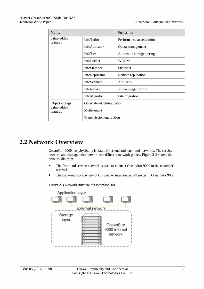
2.2 Network Overview
OceanStor 9000 has physically isolated front-end and back-end networks. The service
network and management network use different network planes. Figure 2-3 shows the
network diagram.
The front-end service network is used to connect OceanStor 9000 to the customer's network.
The back-end storage network is used to interconnect all nodes in OceanStor 9000.
Figure 2-3 Network structure of OceanStor 9000
Huawei OceanStor 9000 Scale-Out NAS
Technical White Paper 2 Hardware, Software, and Network
Issue 05 (2016-03-20) Huawei Proprietary and Confidential
Copyright © Huawei Technologies Co., Ltd.
6
For OceanStor 9000, the cluster back-end network can be set up based on 10GE or InfiniBand,
and the front-end network can be set up based on GE, 10GE, or InfiniBand, meeting various
networking requirements. Network redundancy is implemented for each node of OceanStor
9000 in all network types, enabling OceanStor 9000 to keep working properly in case a single
network port or switch fails.
The front-end network and back-end network can use different physical network adapters for
network isolation. The Intelligent Platform Management Interface (IPMI) ports provided by
OceanStor 9000 allow users to access the device management interface.
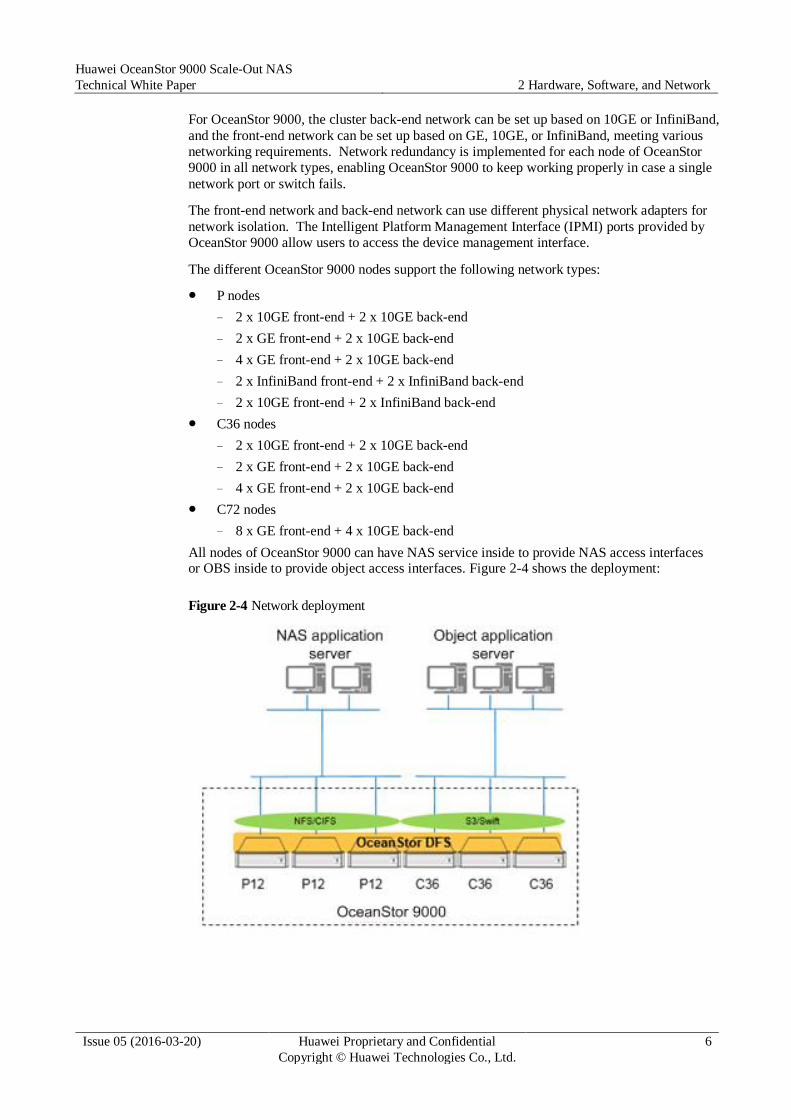
The different OceanStor 9000 nodes support the following network types:
P nodes
− 2 x 10GE front-end + 2 x 10GE back-end
− 2 x GE front-end + 2 x 10GE back-end
− 4 x GE front-end + 2 x 10GE back-end
− 2 x InfiniBand front-end + 2 x InfiniBand back-end
− 2 x 10GE front-end + 2 x InfiniBand back-end
C36 nodes
− 2 x 10GE front-end + 2 x 10GE back-end
− 2 x GE front-end + 2 x 10GE back-end
− 4 x GE front-end + 2 x 10GE back-end
C72 nodes
− 8 x GE front-end + 4 x 10GE back-end
All nodes of OceanStor 9000 can have NAS service inside to provide NAS access interfaces or OBS inside to provide object access interfaces. Figure 2-4 shows the deployment:
Figure 2-4 Network deployment
Huawei OceanStor 9000 Scale-Out NAS
Technical White Paper 2 Hardware, Software, and Network
Issue 05 (2016-03-20) Huawei Proprietary and Confidential
Copyright © Huawei Technologies Co., Ltd.
7
The system supports intermixed node deployments. An intermixed deployment must
have at least three nodes of the same type and configuration (except for C72 nodes, whose minimum configuration is 2).
OceanStor 9000 can concurrently provide NAS storage and OBS services, which are
deployed on different nodes. When the two services co-exist on an OceanStor 9000
storage system, NAS service requires at least three nodes whereas OBS requires at least
two. When OceanStor 9000 has only NAS storage or OBS service but not both, it requires at least three nodes.
A node provides only one access interface, NAS, Amazon S3, or OpenStack Swift.
OBS and NAS storage service have independent value-added features, which work on nodes that provide compatible interfaces.
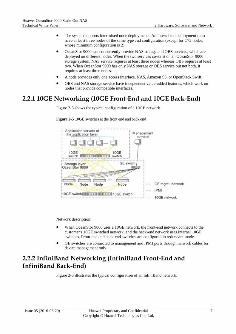
2.2.1 10GE Networking (10GE Front-End and 10GE Back-End)
Figure 2-5 shows the typical configuration of a 10GE network.
Figure 2-5 10GE switches at the front end and back end
Network description:
When OceanStor 9000 uses a 10GE network, the front-end network connects to the
customer's 10GE switched network, and the back-end network uses internal 10GE
switches. Front-end and back-end switches are configured in redundant mode.
GE switches are connected to management and IPMI ports through network cables for device management only.
2.2.2 InfiniBand Networking (InfiniBand Front-End and InfiniBand Back-End)
Figure 2-6 illustrates the typical configuration of an InfiniBand network.
Huawei OceanStor 9000 Scale-Out NAS
Technical White Paper 2 Hardware, Software, and Network
Issue 05 (2016-03-20) Huawei Proprietary and Confidential
Copyright © Huawei Technologies Co., Ltd.
8
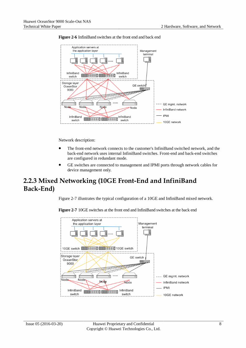
Figure 2-6 InfiniBand switches at the front end and back end
Network description:
The front-end network connects to the customer's InfiniBand switched network, and the
back-end network uses internal InfiniBand switches. Front-end and back-end switches are configured in redundant mode.
GE switches are connected to management and IPMI ports through network cables for
device management only.
2.2.3 Mixed Networking (10GE Front-End and InfiniBand Back-End)
Figure 2-7 illustrates the typical configuration of a 10GE and InfiniBand mixed network.
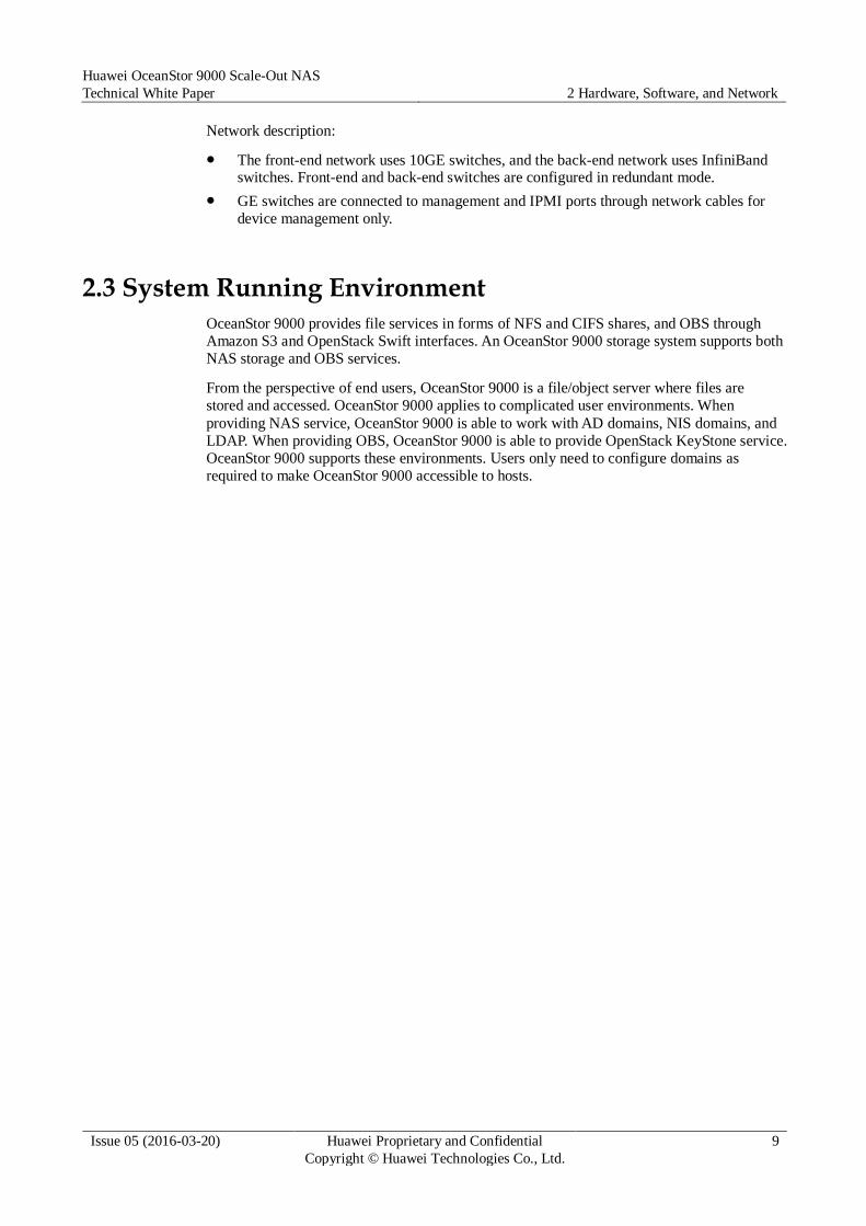
Figure 2-7 10GE switches at the front end and InfiniBand switches at the back end
Huawei OceanStor 9000 Scale-Out NAS
Technical White Paper 2 Hardware, Software, and Network
Issue 05 (2016-03-20) Huawei Proprietary and Confidential
Copyright © Huawei Technologies Co., Ltd.
9
Network description:
The front-end network uses 10GE switches, and the back-end network uses InfiniBand switches. Front-end and back-end switches are configured in redundant mode.
GE switches are connected to management and IPMI ports through network cables for
device management only.
2.3 System Running Environment OceanStor 9000 provides file services in forms of NFS and CIFS shares, and OBS through
Amazon S3 and OpenStack Swift interfaces. An OceanStor 9000 storage system supports both
NAS storage and OBS services.
From the perspective of end users, OceanStor 9000 is a file/object server where files are
stored and accessed. OceanStor 9000 applies to complicated user environments. When
providing NAS service, OceanStor 9000 is able to work with AD domains, NIS domains, and
LDAP. When providing OBS, OceanStor 9000 is able to provide OpenStack KeyStone service. OceanStor 9000 supports these environments. Users only need to configure domains as
required to make OceanStor 9000 accessible to hosts.
Huawei OceanStor 9000 Scale-Out NAS
Technical White Paper 3 Distributed File System Architecture
Issue 05 (2016-03-20) Huawei Proprietary and Confidential
Copyright © Huawei Technologies Co., Ltd.
10
3 Distributed File System Architecture
3.1 Architecture Overview
OceanStor DFS is the core component of OceanStor 9000. It consolidates the disks of all
nodes into a unified resource pool and provides a unified namespace. OceanStor DFS
provides cross-node, cross-rack, and multi-level data redundancy protection. This ensures
high disk utilization and availability and avoids the chimney-style data storage of traditional
storage systems.
On a single file system, OceanStor DFS provides directory-level service control, which
configures the protection level, quota, and snapshot features on a per directory basis. The
directory-level service control meets diversified and differentiated service requirements.
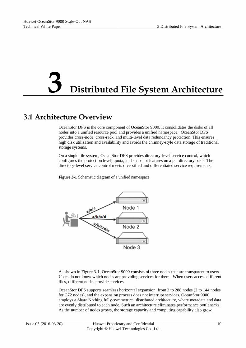
Figure 3-1 Schematic diagram of a unified namespace
As shown in Figure 3-1, OceanStor 9000 consists of three nodes that are transparent to users.
Users do not know which nodes are providing services for them. When users access different
files, different nodes provide services.
OceanStor DFS supports seamless horizontal expansion, from 3 to 288 nodes (2 to 144 nodes
for C72 nodes), and the expansion process does not interrupt services. OceanStor 9000
employs a Share Nothing fully-symmetrical distributed architecture, where metadata and data
are evenly distributed to each node. Such an architecture eliminates performance bottlenecks.
As the number of nodes grows, the storage capacity and computing capability also grow,

Huawei OceanStor 9000 Scale-Out NAS
Technical White Paper 3 Distributed File System Architecture
Issue 05 (2016-03-20) Huawei Proprietary and Confidential
Copyright © Huawei Technologies Co., Ltd.
11
delivering linearly increased throughput and concurrent processing capability for end users.
OceanStor 9000 supports thin provisioning, which allocates storage capacity to applications
on demand. When the storage capacity of an application becomes insufficient due to the data
growth of an application, OceanStor 9000 adds storage capacity to the application from the
back-end storage pool. The thin provisioning function makes best use of storage capacity.
Figure 3-2 Linear capacity and performance growth
OceanStor DFS provides CIFS, NFS, FTP, and S3/Swift access and a unified namespace,
allowing users to easily access the OceanStor 9000 storage system. Additionally, OceanStor
DFS offers inter-node load balancing and cluster node management. Combined with a
symmetrical architecture, these functions enable each node of OceanStor 9000 to provide
global service access, and failover occurs automatically against single points of failure.
Figure 3-3 shows the logical architecture of OceanStor DFS:
Figure 3-3 Logical architecture of OceanStor DFS
OceanStor DFS has three planes: service plane, storage resource pool plane, and management
plane.
Service plane: provides the distributed files system service and OBS.
Huawei OceanStor 9000 Scale-Out NAS
Technical White Paper 3 Distributed File System Architecture
Issue 05 (2016-03-20) Huawei Proprietary and Confidential
Copyright © Huawei Technologies Co., Ltd.
12
The distributed file system service provides value-added features associated with NAS
access and file systems. It has a unified namespace to provide storage protocol–based access as well as NDMP and FTP services.
OBS supports Amazon S3 and OpenStack Swift.
Storage resource pool plane: allocates and manages all physical storage resources of clustered storage nodes.
Data of NAS storage and object storage is all stored in the unified storage resource pool.
The storage resource pool employs distributed technology to offer consistent, cross-node,
and reliable key value (KV) storage service for the service plane. The storage resource
pool plane also provides cross-node load balancing and data repair capabilities. With
load balancing, the storage system is able to leverage the CPU processing, memory
cache, and disk capacity capabilities of newly added nodes to make the system throughput and IOPS linearly grow as new nodes join the cluster.
The storage resource pool plane provides both the distributed file system service and
OBS with data read and write. That allows OceanStor 9000 to offer NAS service and
OBS in the same physical cluster, sharing physical storage space with two services.
Management plane: provides a graphical user interface (GUI) and a command-line interface (CLI) tool to manage cluster status and configure system data.
The functions provided by the management plane include hardware resource
configuration, performance monitoring, storage system parameter configuration, user
management, hardware node status management, and software upgrade.
3.1.1 Distributed File System Service
The distributed file system service layer consists of the protocol & value-added service
module, CA module, and MDS module.
Protocol & value-added service module
Responsible for semantic parsing and execution of NAS protocol.
CA module
Provides standard file system read and write interfaces for the protocol & value-added service module.
MDS module
Manages the file system metadata and the directory tree of the file system namespace.
OceanStor DFS supports up to 100 PB of global namespace. Users do not need to manage
multiple namespaces, simplifying storage management. In addition, one unified namespace
eliminates data islands caused by multiple namespaces.
The service layer of the distributed file system is distributed on each node of the cluster. It
uses the fully symmetrical distributed technology to offer a global unified namespace,
allowing connection to any node to access any file in the file system. Additionally, the
fine-grained global lock on a file enables multiple nodes to concurrently access the same file
(each node accesses a different segment of the file), enabling highly concurrent reads and
writes and therefore delivering a high-performance access.
3.1.2 Storage Resource Pool Plane
The storage resource pool plane allocates and manages all physical storage resources of
clustered storage nodes. It consolidates clustered nodes into multiple node pools.
The InfoProtector feature of OceanStor DFS provides N+M data protection, where N
represents how many of nodes data is segmented to and M the maximum allowed number of

Huawei OceanStor 9000 Scale-Out NAS
Technical White Paper 3 Distributed File System Architecture
Issue 05 (2016-03-20) Huawei Proprietary and Confidential
Copyright © Huawei Technologies Co., Ltd.
13
failed nodes or disks. M is user-definable, and N is subject to the cluster size, growing along
with the number of nodes. When +M data protection is enabled, data corruption occurs only
when M+1 or more nodes in a node pool fail or M+1 or more disks fail. Also, the data
corruption possibility is dramatically reduced after the storage cluster is divided into multiple
node pools. Such a protection method enables files to be distributed to the whole cluster,
providing a higher concurrent data access capability and concurrent data reconstruction
capability. When disks or nodes fail, the system finds which segments of which files are
affected and assigns multiple nodes into the reconstruction. The number of disks and CPUs
that participate in the reconstruction is much larger than that supported by RAID technology,
shortening the fault recovery time.
OceanStor DFS provides different types of (intermixed) hardware nodes for applications. It
centralizes each type of nodes in a single file system, meeting multiple levels of capacity and
performance requirements, and the DST feature is employed for data to flow between
different storage tiers.
3.1.3 Management Plane
As increasing data and larger-scale devices need to be managed, simplifying management
becomes a key point. OceanStor 9000 supports maintenance activities, such as one-stop
system management, online capacity expansion, and online upgrade, enabling users to
maintain OceanStor 9000 easily. OceanStor 9000 does not require an independent
management server, helping reduce hardware costs. The management service provided by
OceanStor 9000 is able to interwork with the management service provided by the customer
through SNMP.
OceanStor 9000 provides GUI and CLI options. The GUI and CLI allow users to query
information such as the status, capacity, resource usage, and alarms. Also, users can configure
and maintain OceanStor 9000 on the GUI and CLI. User roles in the GUI and CLI are
classified into super administrator, administrator, and read-only user, meeting different user
access requirements. The GUI integrates commonly used functions. Besides the functions
provided by the GUI, the CLI provides advanced functions oriented to advanced system
maintenance personnel and those system configuration functions that are not commonly used.
The cluster management subsystem leverages Paxos algorithm to design a consistency
election algorithm, which synchronizes the node status among all nodes in the system. To
monitor the reliability of the metadata cluster, each node runs a monitoring process, and those
monitoring processes form a cluster to monitor and synchronize nodes' and software modules'
status. When a new node joins in the cluster or a node/software module fails, the system
generates event information to inform administrators of paying attention to those subsystems
or modules whose status has changed.
The configuration management cluster subsystem is responsible for service management,
service status monitoring, and device status monitoring. Under normal circumstances, only
one node provides services. When that node fails, the management service can be switched
over to another normal node. The switchover process is transparent to clients. After a
switchover is complete, the IP address used to provided services remains the original one.
3.2 Metadata Management OceanStor DFS supports ultra-large directories, each of which can have millions of files in it.
The access response to an ultra-large directory does not have a distinct difference from that to
a common directory.

Huawei OceanStor 9000 Scale-Out NAS
Technical White Paper 3 Distributed File System Architecture
Issue 05 (2016-03-20) Huawei Proprietary and Confidential
Copyright © Huawei Technologies Co., Ltd.
14
OceanStor DFS employs a dynamic sub tree to manage metadata, as shown in Figure 3-4.
Same as data protection, metadata protection uses redundant copies across nodes. The
difference lies in that metadata protection uses mirroring. Specifically, each copy is
independent and complete. By default, metadata protection is one level higher than data
protection for OceanStor 9000.
OceanStor DFS employs a unified namespace. The directory structure of the file system is a
tree structure, and the cluster consists of equal physical nodes. The file system tree is divided
into multiple sub trees, and the MDS module of each physical node manages a different sub
tree.
The directory tree structure is divided into multiple sub trees. Each sub tree belongs to one
MDS module and one MDS module can have multiple sub trees.
Sub tree splitting is dependent on directory splitting. A directory is split when either of the
following conditions is met:
Condition 1: The weighted access frequency of the directory has exceeded the threshold.
Each time metadata is accessed, the directory weighted access frequency is increased in
the memory based on the access type, and is decreased as time goes by. When the
weighted access frequency has exceeded the threshold, the directory is split.
Condition 2: The directory has an excessive number of files.
A split directory is marked as dir_frag. When the previous conditions are no long met, split
directories are merged to avoid too many directory segments.
If a split directory is the root of a sub tree, the directory splitting is actually sub tree splitting.
A split sub tree is still stored on the original metadata server and periodically experiences a
load balancing test. If load imbalance is detected, the split sub tree will be migrated from one
metadata server to another.
To sum up, when an ultra-high directory is accessed frequently, it is split into multiple
dir_frag directories, which correspond to multiple sub trees. Those sub trees will be
distributed to multiple metadata servers, eliminating metadata access bottlenecks.
Figure 3-4 Sub trees of a namespace
Huawei OceanStor 9000 Scale-Out NAS
Technical White Paper 3 Distributed File System Architecture
Issue 05 (2016-03-20) Huawei Proprietary and Confidential
Copyright © Huawei Technologies Co., Ltd.
15
3.3 Distributed Data Reliability Technologies The InfoProtector feature of OceanStor 9000 provides data protection across nodes. It enables
OceanStor 9000 to work normally when multiple disks or nodes fail. When data is stored on
different disks on different nodes from different node pools, it is protected with the cross-node
reliability and fault recovery capabilities.
3.3.1 Data Striping
To implement data protection and high-performance access, OceanStor DFS performs data
striping by node. When creating a file, the file system selects the nodes that comply with the
configured protection level. Then the file system distributes data to the nodes evenly. In a data
reading scenario, the file system reads data from all nodes concurrently.
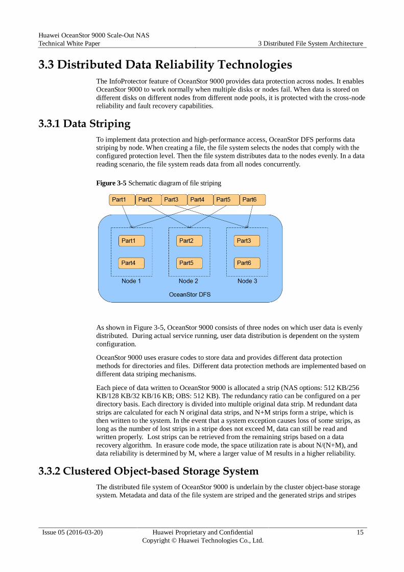
Figure 3-5 Schematic diagram of file striping
As shown in Figure 3-5, OceanStor 9000 consists of three nodes on which user data is evenly
distributed. During actual service running, user data distribution is dependent on the system
configuration.
OceanStor 9000 uses erasure codes to store data and provides different data protection
methods for directories and files. Different data protection methods are implemented based on
different data striping mechanisms.
Each piece of data written to OceanStor 9000 is allocated a strip (NAS options: 512 KB/256
KB/128 KB/32 KB/16 KB; OBS: 512 KB). The redundancy ratio can be configured on a per
directory basis. Each directory is divided into multiple original data strip. M redundant data
strips are calculated for each N original data strips, and N+M strips form a stripe, which is
then written to the system. In the event that a system exception causes loss of some strips, as
long as the number of lost strips in a stripe does not exceed M, data can still be read and
written properly. Lost strips can be retrieved from the remaining strips based on a data
recovery algorithm. In erasure code mode, the space utilization rate is about N/(N+M), and
data reliability is determined by M, where a larger value of M results in a higher reliability.
3.3.2 Clustered Object-based Storage System
The distributed file system of OceanStor 9000 is underlain by the cluster object-base storage
system. Metadata and data of the file system are striped and the generated strips and stripes

Huawei OceanStor 9000 Scale-Out NAS
Technical White Paper 3 Distributed File System Architecture
Issue 05 (2016-03-20) Huawei Proprietary and Confidential
Copyright © Huawei Technologies Co., Ltd.
16
are written in the form of objects to disks. Figure 3-6 shows strips and objects, with a file
under 3+1 protection as an example.
In Figure 3-6, a vertical dashed-line box indicates a disk, a horizontal dashed-line box
indicates a data stripe, and the part of a data stripe that resides in a single disk is a strip.
Figure 3-6 Strips and objects
In the internal storage resource pool of OceanStor 9000, all data is stored in the unit of object
(the object here is not the object concept in OBS), making OceanStor 9000 a distributed
storage system. The object-based storage system of OceanStor 9000 formats all OceanStor
9000 devices into object-based storage devices and interconnects them to form a clustered
system.
OceanStor DFS continuously monitors the node and disk status in the system. If a disk or
node fails, the clustered object-based storage system automatically discovers the failure and
initiates object-level data recovery. In this type of data recovery, only real data is restored,
instead of performing full disk reconstruction as traditional RAID does. Therefore, the
recovery efficiency is higher. In addition, different nodes and disks are selected as targets for
concurrent recovery of damaged objects. Compared with traditional RAID that recovers data
to only one hot spare disk, object-level data recovery is much faster.
3.3.3 N+M Data Protection
Compared with traditional RAID, OceanStor 9000 provides a higher reliability as well as a
higher disk utilization rate. Traditional data protection technology uses RAID to store data to
different disks that belong to the same RAID group. If a disk fails, RAID reconstruction is
implemented to recover data previously stored on the failed disk.
Huawei OceanStor 9000 Scale-Out NAS
Technical White Paper 3 Distributed File System Architecture
Issue 05 (2016-03-20) Huawei Proprietary and Confidential
Copyright © Huawei Technologies Co., Ltd.
17
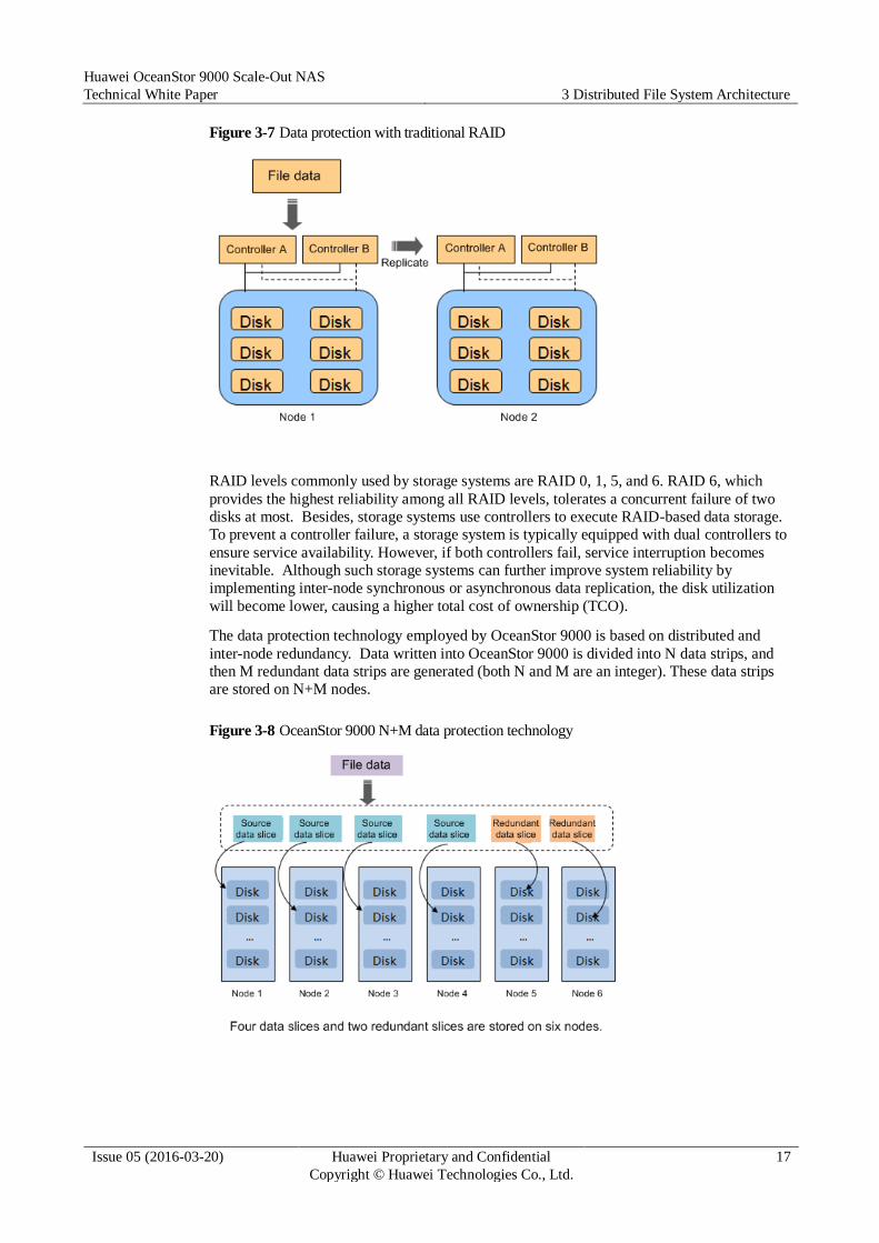
Figure 3-7 Data protection with traditional RAID
RAID levels commonly used by storage systems are RAID 0, 1, 5, and 6. RAID 6, which
provides the highest reliability among all RAID levels, tolerates a concurrent failure of two
disks at most. Besides, storage systems use controllers to execute RAID-based data storage.
To prevent a controller failure, a storage system is typically equipped with dual controllers to
ensure service availability. However, if both controllers fail, service interruption becomes
inevitable. Although such storage systems can further improve system reliability by
implementing inter-node synchronous or asynchronous data replication, the disk utilization
will become lower, causing a higher total cost of ownership (TCO).
The data protection technology employed by OceanStor 9000 is based on distributed and
inter-node redundancy. Data written into OceanStor 9000 is divided into N data strips, and
then M redundant data strips are generated (both N and M are an integer). These data strips
are stored on N+M nodes.
Figure 3-8 OceanStor 9000 N+M data protection technology
Huawei OceanStor 9000 Scale-Out NAS
Technical White Paper 3 Distributed File System Architecture
Issue 05 (2016-03-20) Huawei Proprietary and Confidential
Copyright © Huawei Technologies Co., Ltd.
18
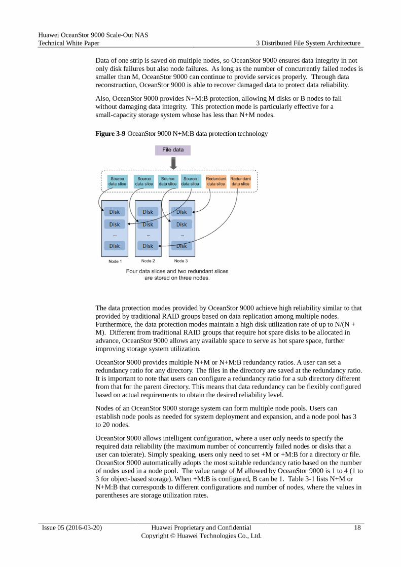
Data of one strip is saved on multiple nodes, so OceanStor 9000 ensures data integrity in not
only disk failures but also node failures. As long as the number of concurrently failed nodes is
smaller than M, OceanStor 9000 can continue to provide services properly. Through data
reconstruction, OceanStor 9000 is able to recover damaged data to protect data reliability.
Also, OceanStor 9000 provides N+M:B protection, allowing M disks or B nodes to fail
without damaging data integrity. This protection mode is particularly effective for a
small-capacity storage system whose has less than N+M nodes.
Figure 3-9 OceanStor 9000 N+M:B data protection technology
The data protection modes provided by OceanStor 9000 achieve high reliability similar to that
provided by traditional RAID groups based on data replication among multiple nodes.
Furthermore, the data protection modes maintain a high disk utilization rate of up to N/(N +
M). Different from traditional RAID groups that require hot spare disks to be allocated in
advance, OceanStor 9000 allows any available space to serve as hot spare space, further
improving storage system utilization.
OceanStor 9000 provides multiple N+M or N+M:B redundancy ratios. A user can set a
redundancy ratio for any directory. The files in the directory are saved at the redundancy ratio.
It is important to note that users can configure a redundancy ratio for a sub directory different
from that for the parent directory. This means that data redundancy can be flexibly configured
based on actual requirements to obtain the desired reliability level.
Nodes of an OceanStor 9000 storage system can form multiple node pools. Users can
establish node pools as needed for system deployment and expansion, and a node pool has 3
to 20 nodes.
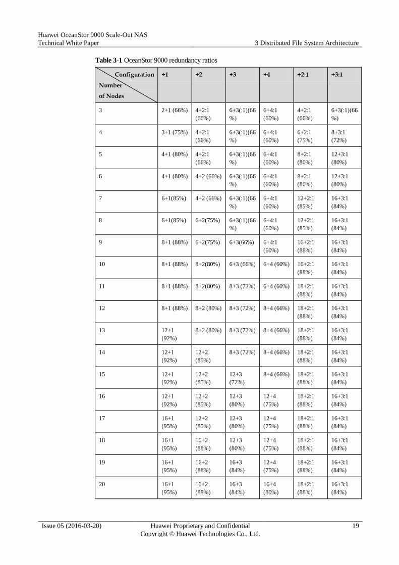
OceanStor 9000 allows intelligent configuration, where a user only needs to specify the
required data reliability (the maximum number of concurrently failed nodes or disks that a
user can tolerate). Simply speaking, users only need to set +M or +M:B for a directory or file. OceanStor 9000 automatically adopts the most suitable redundancy ratio based on the number
of nodes used in a node pool. The value range of M allowed by OceanStor 9000 is 1 to 4 (1 to
3 for object-based storage). When +M:B is configured, B can be 1. Table 3-1 lists N+M or
N+M:B that corresponds to different configurations and number of nodes, where the values in
parentheses are storage utilization rates.
Huawei OceanStor 9000 Scale-Out NAS
Technical White Paper 3 Distributed File System Architecture
Issue 05 (2016-03-20) Huawei Proprietary and Confidential
Copyright © Huawei Technologies Co., Ltd.
19
Table 3-1 OceanStor 9000 redundancy ratios
Configuration
Number
of Nodes
+1 +2 +3 +4 +2:1 +3:1
3 2+1 (66%) 4+2:1
(66%)
6+3(:1)(66
%)
6+4:1
(60%)
4+2:1
(66%)
6+3(:1)(66
%)
4 3+1 (75%) 4+2:1
(66%)
6+3(:1)(66
%)
6+4:1
(60%)
6+2:1
(75%)
8+3:1
(72%)
5 4+1 (80%) 4+2:1
(66%)
6+3(:1)(66
%)
6+4:1
(60%)
8+2:1
(80%)
12+3:1
(80%)
6 4+1 (80%) 4+2 (66%) 6+3(:1)(66
%)
6+4:1
(60%)
8+2:1
(80%)
12+3:1
(80%)
7 6+1(85%) 4+2 (66%) 6+3(:1)(66
%)
6+4:1
(60%)
12+2:1
(85%)
16+3:1
(84%)
8 6+1(85%) 6+2(75%) 6+3(:1)(66
%)
6+4:1
(60%)
12+2:1
(85%)
16+3:1
(84%)
9 8+1 (88%) 6+2(75%) 6+3(66%) 6+4:1
(60%)
16+2:1
(88%)
16+3:1
(84%)
10 8+1 (88%) 8+2(80%) 6+3 (66%) 6+4 (60%) 16+2:1
(88%)
16+3:1
(84%)
11 8+1 (88%) 8+2(80%) 8+3 (72%) 6+4 (60%) 18+2:1
(88%)
16+3:1
(84%)
12 8+1 (88%) 8+2 (80%) 8+3 (72%) 8+4 (66%) 18+2:1
(88%)
16+3:1
(84%)
13 12+1
(92%)
8+2 (80%) 8+3 (72%) 8+4 (66%) 18+2:1
(88%)
16+3:1
(84%)
14 12+1
(92%)
12+2
(85%)
8+3 (72%) 8+4 (66%) 18+2:1
(88%)
16+3:1
(84%)
15 12+1
(92%)
12+2
(85%)
12+3
(72%)
8+4 (66%) 18+2:1
(88%)
16+3:1
(84%)
16 12+1
(92%)
12+2
(85%)
12+3
(80%)
12+4
(75%)
18+2:1
(88%)
16+3:1
(84%)
17 16+1
(95%)
12+2
(85%)
12+3
(80%)
12+4
(75%)
18+2:1
(88%)
16+3:1
(84%)
18 16+1
(95%)
16+2
(88%)
12+3
(80%)
12+4
(75%)
18+2:1
(88%)
16+3:1
(84%)
19 16+1
(95%)
16+2
(88%)
16+3
(84%)
12+4
(75%)
18+2:1
(88%)
16+3:1
(84%)
20 16+1
(95%)
16+2
(88%)
16+3
(84%)
16+4
(80%)
18+2:1
(88%)
16+3:1
(84%)
Huawei OceanStor 9000 Scale-Out NAS
Technical White Paper 3 Distributed File System Architecture
Issue 05 (2016-03-20) Huawei Proprietary and Confidential
Copyright © Huawei Technologies Co., Ltd.
20
3.4 Global Cache
OceanStor DFS provides a globally accessible consistent cache. It enables the memory spaces
of all storage servers to form a unified memory resource pool. Data cached on any storage
server can be hit in the global cache if another storage server receives a request for accessing
that data. In addition, only one copy of all user data is cached in the cluster, without parity
data caching.
The cache capacity of OceanStor DFS linearly grows as the number of nodes increases. When
the global capacity increases, more hotspot data can be hit, reducing the I/Os directed to disks
and delivering high performance and low latency for various application scenarios.
3.4.1 Components of Global Cache
Level-1 Cache
Level-1 cache resides in the distributed file system's client agent layer that interworks with the
protocol service. This layer caches file data on a per file stripe basis. Level-1 cache is
typically used to prefetch file data and accelerate caching of hotspot file stripes after a
file-oriented access model forecast. Level-1 cache is globally shared within a system. If a
node receives a request for accessing file stripe data cached on another node, the former node
can hit the data from level-1 cache.
Typically, in a large-scale distributed file system, only a few files are hotspot files, and most
files are cold files. Therefore, hotspot data caching and data prefetching leverage cache
advantages, mitigate the access stress on back-end disks, and accelerate service response.
Level-2 Cache
Level-2 cache provides data block metadata and data block caching. It consists of SSDs and
only caches hotspot data on all disks of the local node. Level-2 cache accelerates access to
strips and stripes on the local node, mitigates the disk stress caused by frequent hotspot data
access, and accelerates response to data block requests. For example, level-2 cache provides
caching for each disk's super blocks, object and object set descriptors, and descriptors of key
objects.
NVDIMM
NVDIMMs are mainly used as write cache resources. After data in level-1 cache is refreshed
upon a write operation performed by a client, data is sliced and redundant data is generated.
Then, all data slices are sent to the NVDIMM of each node through the back-end storage
network. After that, a response is immediately returned to the client, indicating that the write
operation is successful. Data stored in NVDIMMs is secure. Therefore, deduplication and
merge can be performed for such data without the need to flush the data to the corresponding
disks immediately. To be specific, if a piece of data has been modified for multiple times, only
the latest data needs to be flushed to a disk, and previously modified data can be discarded. If
multiple data blocks belong to the same object and they are logically consecutive, these data
blocks can be written to physically consecutive disks to allow sequential disk access,
improving data access performance.

Huawei OceanStor 9000 Scale-Out NAS
Technical White Paper 3 Distributed File System Architecture
Issue 05 (2016-03-20) Huawei Proprietary and Confidential
Copyright © Huawei Technologies Co., Ltd.
21
Distributed Lock Management
Distributed Lock Management (DLM) ensures the sharing and consistency of global cache for
global cache to run properly. DLM creates a DLM data structure that includes shared-resource
lock requests, shared storage resources, and lock types. As long as a process requests a
resource to be locked, a shared resource always exists. The distributed lock manager deletes a
resource only when no process requests the resource to be locked. If a process is terminated
abnormally, the lock related to the process is also terminated, and the corresponding resource
is freed too.
3.4.2 Implementation Principle
Figure 3-10 Working principles of global cache
D indicates a strip of an original file.
S indicates a super block of a file system.
M indicates metadata that manages strip data on a disk.
P indicates parity strip data generated in file striping.
Caching and Reading
Upon receiving a data read request, the file system service on node 1 applies for a stripe
resource read lock from the distributed lock server. After obtaining the lock, the file system
service checks whether the target data resides in the global cache and on which node the target
data is cached. If the file stripe resource resides in the cache of node 2, the file system service
obtains the data from the global cache of node 2 and returns it to the client agent. If the target
data is not in the global cache, the file system service on node 1 obtains all the strips of the
stripe from each node, constructs the stripe, and returns the stripe to the client agent.
Caching and Writing
Upon receiving a data write request, the client agent on node 1 applies for a stripe resource
write lock from the distributed lock server. After obtaining the lock, the client agent places
data to the global cache of node 1, slices the data based on the protection level configured for the file, generates parity data strips for the original data strips according to the erasure code

Huawei OceanStor 9000 Scale-Out NAS
Technical White Paper 3 Distributed File System Architecture
Issue 05 (2016-03-20) Huawei Proprietary and Confidential
Copyright © Huawei Technologies Co., Ltd.
22
mechanism, and then writes all the strips to the NVDIMMs of the corresponding nodes to
complete the write operation.
When the client agent on another node needs to access the file stripe later, the client agent can
directly read the file stripe from the global cache of node 1, instead of reading all strips from
the corresponding nodes.
Cache Releasing Data reclamation
After cached data is modified by a client, the client CA adds a write lock to the data.
When the nodes caching the data read the lock, their corresponding cache space is reclaimed.
Data aging
When cache space reaches its aging threshold, the cached data that has not been accessed
for the longest period of time will be released according to the least recently used (LRU) statistics.
The global cache function of OceanStor DFS consolidates the cache space of each storage
server to logically form a unified global cache resource pool. Only one copy of user data is
stored in the distributed storage system. For a file stripe, only its data strips are cached; parity
strips are not cached. As long as the file stripe data that a client agent attempts to access
resides in the cache of any storage server, the cached file stripe data can be hit, regardless
which storage server the client agent goes through to access the data. In this way, access
priority is given to the data cached in the global cache. If the requested data cannot be hit in
the global cache, data is read from disks.
Compared with existing technologies, the global cache function of OceanStor 9000 allows
users to leverage the total cache space across the entire system. OceanStor 9000 prevents
unnecessary disk I/Os and network I/Os related to hotspot data, maximizing access
performance.
3.5 File Writing OceanStor DFS software runs on each node and each node is equal. Any file read or write
operation may span multiple nodes. For easy understanding, the following I/O model is used
to represent service I/O modules on each node.
Figure 3-11 I/O model

Huawei OceanStor 9000 Scale-Out NAS
Technical White Paper 3 Distributed File System Architecture
Issue 05 (2016-03-20) Huawei Proprietary and Confidential
Copyright © Huawei Technologies Co., Ltd.
23
As shown in Figure 3-11, the software layer consists of the upper file system service and the
lower storage resource pool. The file system service processes NAS protocol parsing, file
operation semantic parsing, and file system metadata management. The storage resource pool
allocates nodes' disk resources and processes persistent data storage.
When a client connects to a physical node to write a file, this write request is first processed
by the file system service. The file system queries the metadata of the file based on the file
path and file name to obtain the file layout and protection level information.
OceanStor DFS protects file data across nodes and disks. A file is first divided into stripes,
each of which consists of N strips and M redundancy parity strips. Different strips of a stripe
are stored on different disks on different nodes.
As illustrated in Figure 3-12, after the file system service obtains the file layout and protection
level information, it calculates redundancy data strips based on the stripe granularity. Then it
writes strips concurrently to different disks on different nodes over the back-end network,
with only one strip on each disk.
Figure 3-12 Data write process
Seen from the previous write process, we can conclude:
OceanStor DFS has a high concurrent processing capability. Each physical node can
process concurrent client connections, allowing connected client to access a file concurrently.
OceanStor DFS delivers high bandwidth. OceanStor DFS divides each file into stripes,
and each stripe is assigned to a different disk on a different node. Along with an efficient
file layout, different stripes of a file can be distributed on different disks, making the
multiple disks across nodes into full play to maximize file access performance.

Huawei OceanStor 9000 Scale-Out NAS
Technical White Paper 3 Distributed File System Architecture
Issue 05 (2016-03-20) Huawei Proprietary and Confidential
Copyright © Huawei Technologies Co., Ltd.
24
3.6 Load Balancing OceanStor 9000's load balancing service is based on domain name requests. The service
works only when domain names are requested and does not participate in actual data flow
services. Therefore, the load balancing service will not be a system performance bottleneck. Different from traditional DNS load balancing, this load balancing service integrates the DNS
query function, eliminating your need to deploy the DNS service.
3.6.1 Intelligent IP Address Management
OceanStor 9000 manages access IP addresses, provided externally by clustered nodes, in a
unified manner. OceanStor 9000 automatically assigns an IP address to a newly added node
and supports failover and failback of node IP addresses. A user only needs to configure an IP
address pool for OceanStor 9000, instead of allocating an IP address to each node one by one.
This management method simplifies IP address management and facilitates cluster expansion,
as described below.
Each OceanStor 9000 node has a static IP address and a dynamic IP address. After a
failed node recovers, its static IP address remains the same. However, its original
dynamic IP address is lost, and a new dynamic IP address will be assigned to the node.
During deployment, a deployment tool is used to configure static IP addresses. Dynamic
IP addresses are assigned by the load balancing service in a unified manner based on an
IP address pool. Figure 3-13 shows how IP addresses are assigned to nodes.
Figure 3-13 How IP addresses are assigned to nodes
When a node is added, the load balancing service obtains an idle IP address from the IP
address pool and assigns it to the newly added node. If no idle IP address is available, the
load balancing service determines whether any existing clustered node has multiple IP
addresses. If yes, the load balancing service deprives the clustered node of one IP
address and assigns it to the newly added node, ensuring that the new node takes part in
load balancing. If no, an alarm is generated, asking the OceanStor 9000 system
administrator to add idle IP addresses to the IP address pool. Figure 3-14 shows how IP addresses are assigned to newly added nodes.
Huawei OceanStor 9000 Scale-Out NAS
Technical White Paper 3 Distributed File System Architecture
Issue 05 (2016-03-20) Huawei Proprietary and Confidential
Copyright © Huawei Technologies Co., Ltd.
25
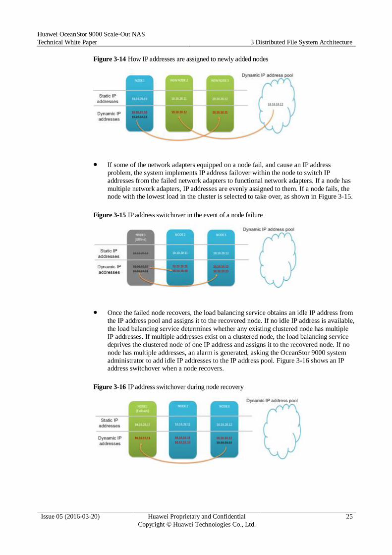
Figure 3-14 How IP addresses are assigned to newly added nodes
If some of the network adapters equipped on a node fail, and cause an IP address
problem, the system implements IP address failover within the node to switch IP
addresses from the failed network adapters to functional network adapters. If a node has
multiple network adapters, IP addresses are evenly assigned to them. If a node fails, the node with the lowest load in the cluster is selected to take over, as shown in Figure 3-15.
Figure 3-15 IP address switchover in the event of a node failure
Once the failed node recovers, the load balancing service obtains an idle IP address from
the IP address pool and assigns it to the recovered node. If no idle IP address is available,
the load balancing service determines whether any existing clustered node has multiple
IP addresses. If multiple addresses exist on a clustered node, the load balancing service
deprives the clustered node of one IP address and assigns it to the recovered node. If no
node has multiple addresses, an alarm is generated, asking the OceanStor 9000 system
administrator to add idle IP addresses to the IP address pool. Figure 3-16 shows an IP address switchover when a node recovers.
Figure 3-16 IP address switchover during node recovery
Huawei OceanStor 9000 Scale-Out NAS
Technical White Paper 3 Distributed File System Architecture
Issue 05 (2016-03-20) Huawei Proprietary and Confidential
Copyright © Huawei Technologies Co., Ltd.
26
3.6.2 Diverse Load Balancing Policies
The OceanStor 9000 load balancing service supports diverse load balancing policies, which
can be configured according to user requirements.
Round robin (the default load balancing policy)
CPU usage
Node connection count
Node throughput
Node capability
The capability of a node is determined by the static capability value and the dynamic load
status. If the load on a node is heavy, the capability value of the node decreases. If the load on
a node is light, the capability value of the node increases. Nodes are selected to process client
connection requests based on their capability values. A node with a larger capability value is
more likely to be selected. If a node has multiple IP addresses, the IP address with the larger
capability value is selected first.
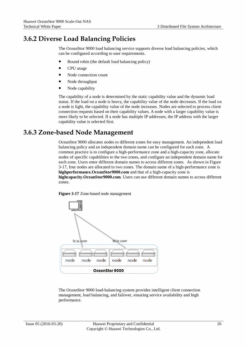
3.6.3 Zone-based Node Management
OceanStor 9000 allocates nodes to different zones for easy management. An independent load
balancing policy and an independent domain name can be configured for each zone. A
common practice is to configure a high-performance zone and a high-capacity zone, allocate
nodes of specific capabilities to the two zones, and configure an independent domain name for
each zone. Users enter different domain names to access different zones. As shown in Figure
3-17, four nodes are allocated to two zones. The domain name of a high-performance zone is
highperformance.OceanStor9000.com and that of a high-capacity zone is
highcapacity.OceanStor9000.com. Users can use different domain names to access different
zones.
Figure 3-17 Zone-based node management
The OceanStor 9000 load-balancing system provides intelligent client connection
management, load balancing, and failover, ensuring service availability and high
performance.
Huawei OceanStor 9000 Scale-Out NAS
Technical White Paper 3 Distributed File System Architecture
Issue 05 (2016-03-20) Huawei Proprietary and Confidential
Copyright © Huawei Technologies Co., Ltd.
27
OceanStor 9000 employs intelligent IP address management. When a node is added, an IP
address is automatically allocated to it. When a node is removed, its IP address is
automatically migrated. In this way, changes in node quantity are not perceived by users, but
the performance is improved.
3.7 Data Recovery When a disk or node in the storage system fails, the system initiates a data recovery process. It
conducts an erasure code calculation on undamaged data to obtain the data block that needs to
be recovered, and writes the data block to other normal disks. OceanStor 9000 can provide up
to four redundant copies for a piece of data and tolerate the concurrent failure of four disks.
During data recovery, OceanStor can divide data on a disk into data objects and recover these
data objects to other disks, achieving concurrent data recovery and increasing the
reconstruction speed (1 TB per hour).
Huawei OceanStor 9000 Scale-Out NAS
Technical White Paper 4 System Advantages
Issue 05 (2016-03-20) Huawei Proprietary and Confidential
Copyright © Huawei Technologies Co., Ltd.
28
4 System Advantages
4.1 Outstanding Performance
OceanStor 9000 adopts a full redundancy and full mesh networking mechanism, employs a
symmetric distributed cluster design, and provides a globally unified namespace, allowing
nodes to concurrently access any stored file. OceanStor 9000 also supports fine-grained global
locking within files and allows multiple nodes to concurrently access different parts of the
same file, delivering high access concurrency with impressive performance.
It is known that reading and writing data in the cache is much faster than on disks. The cache
technology with OceanStor DFS provides an ultra-large cache pool for service systems. It
increases the data hit ratio and improves the overall system performance. The OceanStor
hardware leverages SSDs to store metadata, increasing the metadata access speed and
improving the system capability of processing small files. The InfoTurbo technology provides
up to 2.5 GB/s bandwidth for a client. Inside OceanStor 9000, the 10GE full-IP
interconnection minimizes the internal network latency and dramatically shortens the
response latency for upper-layer services. OceanStor 9000 offers 5 million operations per
second (OPS) and over 400 GB/s total bandwidth as well as extremely short latencies. It
applies to performance-intensive scenarios such as high-performance computing and media
editing. In addition to the high performance on individual nodes, the whole OceanStor 9000
system performance can grow as new nodes are added, making OceanStor 9000 ready to
support any possible service growth.
4.2 Flexible Expansion OceanStor DFS supports dynamic and non-disruptive node expansion, from 3 to 288 nodes.
The storage capacity and computing capability grow as more nodes are added, delivering
linearly increasing bandwidth and concurrency to end users. OceanStor DFS provides a global
cache that increases capacity linearly as the number of nodes increases. More nodes bring a
higher cache hit ratio of hotspot data, greatly reducing the frequency of disk I/Os and
improving system performance.
Traditional storage systems bring about time-consuming planning, upgrade, and maintenance
activities. Increasing storage capacity and performance for them requires horizontal expansion
and reconfiguration of application programs, which interrupt production and cause work
efficiency and income losses. OceanStor DFS offers a global namespace, which is represented
as a single file system even during expansion. Without multiple advanced functions including
automatic load balancing, an expansion process can be non-disruptively completed within
Huawei OceanStor 9000 Scale-Out NAS
Technical White Paper 4 System Advantages
Issue 05 (2016-03-20) Huawei Proprietary and Confidential
Copyright © Huawei Technologies Co., Ltd.
29
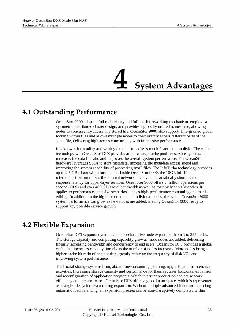
minutes, without the need to modify system configurations, change server or client mount
points, or alter application programs.
Figure 4-1 Seamless expansion
OceanStor DFS provides different types of nodes to adapt to various application scenarios.
Those nodes can be configured on demand. They are centrally managed, simplifying system
management and enabling easy resource scheduling to reduce the customer's investment.
For an emerging enterprise, the business volume is not great at the early stage. Therefore,
such an enterprise typically needs a small-scale IT infrastructure and does not have a big IT
budget. However, the enterprise may require high performance. The initial configuration of
OceanStor 9000 meets an enterprise's capacity and performance requirements at a relatively
low TCO. As the enterprise grows, it has increasing IT requirements. In this scenario, the
original IT investment will not be wasted. Instead, the enterprise can easily meet increasingly
demanding requirements by expanding the capacity of OceanStor 9000 in a simple way.
4.3 Open and Converged
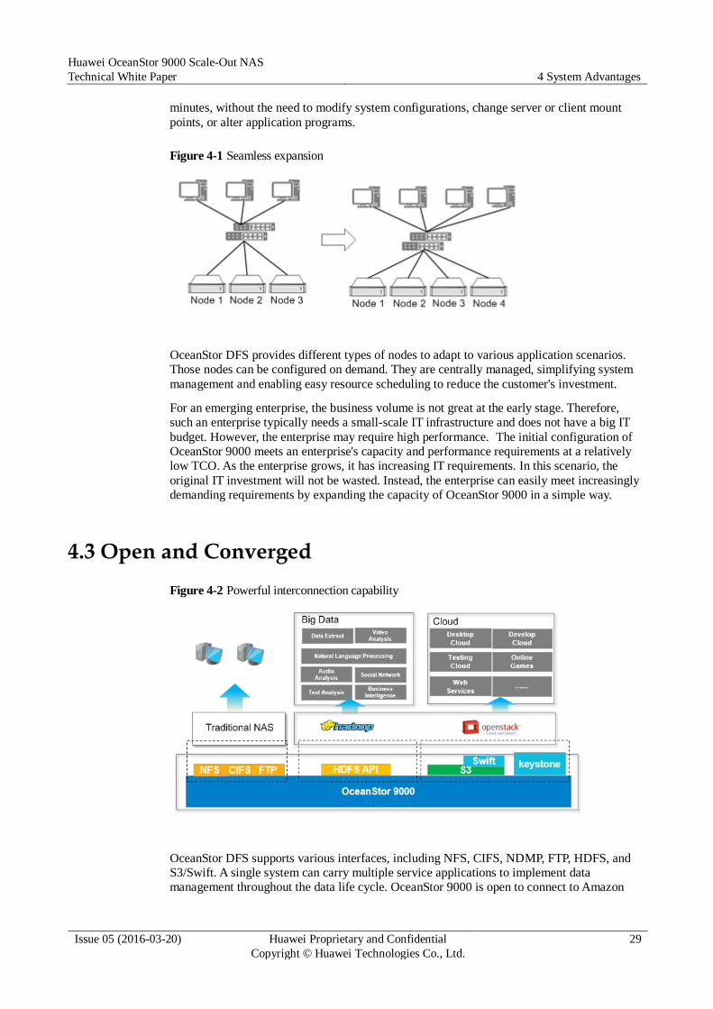
Figure 4-2 Powerful interconnection capability
OceanStor DFS supports various interfaces, including NFS, CIFS, NDMP, FTP, HDFS, and
S3/Swift. A single system can carry multiple service applications to implement data management throughout the data life cycle. OceanStor 9000 is open to connect to Amazon

Huawei OceanStor 9000 Scale-Out NAS
Technical White Paper 4 System Advantages
Issue 05 (2016-03-20) Huawei Proprietary and Confidential
Copyright © Huawei Technologies Co., Ltd.
30
and OpenStack public cloud ecosystems. New application features can be added to OceanStor
9000 by plug-ins to easily meet customers' new requirements. All applications are centrally
scheduled and managed in OceanStor 9000.

Huawei OceanStor 9000 Scale-Out NAS
Technical White Paper 5 Acronyms and Abbreviations
Issue 05 (2016-03-20) Huawei Proprietary and Confidential
Copyright © Huawei Technologies Co., Ltd.
31
5 Acronyms and Abbreviations
Table 5-1 Acronyms and abbreviations
AD Active Directory
CLI command-line interface
DAS Direct-Attached Storage
DNS Domain Name System
EC Erasure code
FTP File Transfer Protocol
GID group ID
GUI graphical user interface
HTTP Hypertext Transport Protocol
IPMI Intelligent Platform Management Interface
LDAP Lightweight Directory Access Protocol
NAS Network Attached Storage
NIS Network Information Service
NVDIMM non-volatile dual in-line memory module
RAID Redundant Arrays of Inexpensive Disks
RDMA Remote Direct Memory Access
SAN Storage Area Network
SAS Serial Attached SCSI
SATA Serial Advanced Technology Attachment
SSD Solid State Disk
TCP Transmission Control Protocol
UID user identity