technical specifications for water main, hydrant, and ...€¦ · technical specifications for...
TRANSCRIPT

P E N N I C H U CK W A T E R W O R K S
Merrimack, New Hampshire
Technical Specifications for Water Main,
Hydrant, and Service Installations
Revision – 2018

Foreword
These Technical Specifications for Water Main, Hydrant, and Service Installations are the standards
for construction for Pennichuck Water Works Contract Administrators in the administration of
Pennichuck construction projects. The Pennichuck companies are: Pennichuck Water Works
(PWW), Pennichuck East Utilities (PEU), Pennichuck Water Service Company (PWSC), and
Pittsfield Aqueduct Company (PAC).
These are techniques and methods that will assist Pennichuck personnel in accomplishing the
satisfactory completion of water works projects in accordance with the controlling Drawings,
Specifications, and other Contract documents, and in ensuring proper quality and quantity control.
These Technical Specifications for Water Main, Hydrant, and Service Installations are a
compilation of the best water line construction practice based on the experience of Pennichuck
Water Works Engineers. Only after the Drawings and Specifications have been read and
understood will the Specifications serve their purpose. Each water works employee and Contractor
will be expected to become thoroughly familiar with the contents of these Specifications and to
study them carefully to achieve a well-rounded knowledge of the operations employed by the
industry and good judgment in applying these Specifications in the administration of Pennichuck
Water Works Contracts.
General Note: These Technical Specifications for Water Main, Hydrant, and Service Installations
reference the latest version of the State of New Hampshire, Department of Transportation, NHDOT
Standard Specifications for Road and Bridge Construction. Wherever the NHDOT Specifications
are referenced by section or subsection, that section or subsection of the NHDOT Specifications
shall be considered part of these Pennichuck Water Works Technical Specifications for Water Main,
Hydrant, and Service Installations.
P E N N I C H U C K W A T E R W O R K S
Technical Specifications for Water Main, Hydrant, and Service Installations TOC-1
Technical Specifications for Water Main,
Hydrant, and Service Installations
Master Table of Contents
Section 01000 ............. Special Conditions
Section 01100 ............. General Specifications
Section 12000 ............. Temporary Facilities
Section 13000 ............. Clearing and Grubbing
Section 01400 ............. Earth Excavation, Backfill, Fill, and Grading
Section 01500 ............. Blasting, Rock Excavation, and Disposal
Section 01600 ............. Water Main Pipe and Fittings
Section 01625 ............. Polyethylene Encasement
Section 01650 ............. Water Service and Air Release Materials
Section 01670 ............. Asbestos Cement Pipe
Section 01680 ............. Temporary Water Mains and Services
Section 01800 ............. Crushed Gravel
Section 01900 ............. Gravel Aggregate for Road Base and Water Main Backfill
Section 02000 ............. Common Borrow
Section 02100 ............. Sand
Section 02200 ............. Loam & Seed
Section 02300 ............. Paving
Section 02400 ............. Concrete Thrust Blocks
Section 02450 ............. Styrofoam Insulation
Section 02500 ............. Managing Water Flow during Construction

P E N N I C H U C K W A T E R W O R K S
TOC-2 Technical Specifications for Water Main, Hydrant, and Service Installations
Section 02550 ............. Dust Control
Section 02600 ............. Clean Up
Appendix A ................. Hydrant and Valve Opening Direction

P E N N I C H U C K W A T E R W O R K S
Technical Specifications for Water Main, Hydrant, and Service Installations 01000-1
SECTION 01000
Special Conditions
Table of Contents
A. ................................. GENERAL
B. ................................. RESOLVING CONFLICTS OR INCONSISTENCIES
C. ................................. TRAFFIC CONTROL
D. ................................. PAVING OPERATIONS
E. ................................. INSURANCE COVERAGE
F. ................................. CURRENT RECORD DRAWINGS

P E N N I C H U C K W A T E R W O R K S
01000-2 Technical Specifications for Water Main, Hydrant, and Service Installations
A
GENERAL
1. Water Main and Water Service Shutdowns
The Contractor must notify the Engineer a minimum of 72 hours before shutting down any
water main and 24 hours before shutting down any water service.
Pennichuck will provide the necessary crews at no cost to the Contractor to operate the water
valves required for each water main shutdown and for the reactivation of the water main. In no
case shall a water main be shut down for more than 12 hours. If an emergency or anticipated
shut down requires that a water main be shut down for more than 12 hours, the Contractor shall
provide 2 gallons of bottled water to each affected resident.
2. Permits
Permits and licenses of a temporary nature necessary for the prosecution of the work shall be
obtained and paid for by the Contractor. Permit types may include the following:
Construction Dewatering Permit
EPA Dewatering Permit
Municipal Street Opening Permit
Municipal Emergency Permit
Notice of Intent (NOI) to discharge wastewater from construction sites
Stormwater Pollution Prevention Plan (SWPPP)
Asbestos Cement Pipe
3. Conforming to Plans and Specifications
All work shall conform to these Specifications and/or the accompanying Project Drawings.

P E N N I C H U C K W A T E R W O R K S
Technical Specifications for Water Main, Hydrant, and Service Installations 01000-3
4. Site Visits
Before submitting a bid, the Contractor shall visit the work site or sites. These work sites shall
be available for viewing at the Contractor’s convenience. During such visits, the Contractor
shall examine the existing conditions and thoroughly acquaint themselves with the obstacles and
advantages of performing the work.
The Contractor shall also study the construction documents and compare them with the
information gathered during the site examination. No extra compensation will be authorized for
extra work caused by the Contractor’s unfamiliarity with the site, the construction documents, or
conditions that may be unusual to the project.
5. Submittals
The Contractor shall submit digital copies of complete and acceptable shop Drawings to the
Owner for approval a minimum of two weeks before the intended use for the following Items:
All pipe, fittings, and valves
Construction schedule (If required)
The schedule shall present a critical path with dates for critical phases of the work.
If required, the Contractor shall submit compliance certification for the American Iron and Steel
(AIS) provision that requires Clean Water State Revolving Fund (CWSRF) and Drinking Water
State Revolving Fund (DWSRF) assistance recipients to use iron and steel products that are
produced in the United States.
AIS compliance certifications must include the following information:
Project name
Specific product description
Nation of origin
Reference to AIS requirements
Manufacturer or vendor representative’s signature
P E N N I C H U C K W A T E R W O R K S
01000-4 Technical Specifications for Water Main, Hydrant, and Service Installations
B
RESOLVING CONFLICTS OR INCONSISTENCIES
If there are any conflicts or inconsistencies between the provisions of the Special Conditions and the
provisions of the other Contract Documents, the provisions of the Special Conditions shall prevail.
If there is any conflict or inconsistency between the provisions of the Agreement and the provisions
of any of the Contract Documents other than the Special Conditions, the conditions of the
Agreement shall prevail. In all cases, the judgement of the Pennichuck representative shall
supersede all other conditions.
C
TRAFFIC CONTROL
All traffic control will be provided by municipal Police Departments or by others approved
by the municipal Police Department.
Flaggers shall to be certified by the ATSSA (American Traffic Safety Services Association)
or a comparable organization. Flaggers must provide proof of certification upon request.
Flagging organizations should provide copies, up front, of their employee certifications with
other submittals.
Flaggers must be equipped with PPE, traffic control signage, flags, barriers, barricades and
any other required MUTCD devices for traffic control purposes. Flaggers must be provided
with appropriate breaks for lunch, relief from weather conditions, and other necessities.
The work hour schedule shall be in accordance with municipal requirements.
Signage shall be in accordance with the Drawings or as approved by the municipal Police
Department, the municipal Public Works Department, and the Manual of Uniform Traffic
Control Devices (MUTCD).
P E N N I C H U C K W A T E R W O R K S
Technical Specifications for Water Main, Hydrant, and Service Installations 01000-5
D
PAVING OPERATIONS
1. Paving Restoration
All paving restoration shall be carried out in accordance with the Drawings and Specifications.
2. Dust Control
The Contractor shall always provide dust control for each street during construction and shall be
responsible for maintaining the road in a level, passable condition. Upon completion of the base
asphalt pavement, the Contractor will only be responsible for dust control and sweeping due to
their construction-related activities.
3. Asphalt Cement Price Adjustments
Adjustments for increases or decreases in Asphalt Cement prices for Pennichuck Water Works
capital projects only will be carried out in accordance with the latest NH DOT Special Attention
with regards to Asphalt Cement Adjustment as posted on the NH DOT web site on the day of
the bid opening.
E
INSURANCE COVERAGE
The local municipality and Pennichuck shall be provided with insurance certificates, naming both
parties as additional named insured in accordance with general conditions. For Developer projects,
insurance coverage requirements are specified in the main Extension Agreement.

P E N N I C H U C K W A T E R W O R K S
01000-6 Technical Specifications for Water Main, Hydrant, and Service Installations
F
CURRENT RECORD DRAWINGS
During the Work, the Contractor and applicable Subcontractors shall continually maintain a set of
legibly-marked prints, Drawings, and sketches showing any changes made during the construction
process. This set of prints shall be incorporated into one complete set of full D-size paper Drawings
by the Contractor following completion of work. The Contractor shall make any revisions required
by the Engineer to make the Record Drawings complete and up-to-date.
After acceptance by the Engineer, the full-size paper Drawings shall be given to the Engineer.
These record Drawings shall be completed in every way with attention given to properly delineating
concealed work which would be difficult to measure later. Change orders, addenda Items, and field
changes should be noted where applicable. Additional specific requirements relative to Record
Drawings may be called for in the individual sections of these Specifications.

P E N N I C H U C K W A T E R W O R K S
Technical Specifications for Water Main, Hydrant, and Service Installations 01100-1
SECTION 01100
General Specifications
Table of Contents
A. ................................. DEFINITIONS
B. ................................. ABBREVIATIONS
C. ................................. HANDLING AND DISTRIBUTING MATERIALS
D. ................................. SAMPLING AND INSPECTING MATERIALS
E. ................................. CONTRACTOR’S SHOP AND WORKING DRAWINGS
F. ................................. OCCUPYING PRIVATE LAND
G. ................................. INTERFERENCE WITH AND PROTECTION OF STREETS
H. ................................. STORING MATERIALS AND EQUIPMENT
I. .................................. SAFETY MEASURES
J. .................................. SANITARY REGULATIONS
K. ................................. ESTABLISHING LINES, GRADES, AND MEASUREMENTS
L. ................................. DIMENSIONS OF EXISTING STRUCTURES
M. ................................ CONFORMING TO LINES, LEVELS, AND GRADES
N. ................................. PIPE AND FITTING LOCATIONS
O. ................................. LIMITS OF NORMAL EXCAVATION
P. ................................. COMPUTING QUANTITIES
Q. ................................. PLANNING AND PROGRESS SCHEDULES
R. ................................. PRECAUTIONS DURING ADVERSE WEATHER
S. ................................. ELECTRIC POWER
T. ................................. PRE-CONSTRUCTION ASSESSMENT
U. ................................. NHDOT SPECIFICATION REFERENCES

P E N N I C H U C K W A T E R W O R K S
01100-2 Technical Specifications for Water Main, Hydrant, and Service Installations
A
DEFINITIONS
Wherever the words defined in this section or pronouns used in their stead occur in the Contract
Documents, they shall have the meanings herein given.
Wherever in the Contract Documents, or on the Drawings, the words “As directed,” “As ordered,”
“As requested,” “As required,” “As permitted,” or words of like import are used, it shall be
understood that the direction, order, request, requirement, or permission of the Owner’s
Representative is intended. Similarly, the words “approved,” “acceptable,” “suitable,”
“satisfactory,” and words of like import shall mean approved by, acceptable to, suitable to, or
satisfactory to the Owner’s Representative.
1. Elevation
The figures given on the Drawings or in the other Contract Documents after the word
“elevation” or abbreviation of it shall mean the distance in feet above the datum specified by the
Owner’s Representative.
2. Rock
The word “rock,” wherever used as the name of an excavated material or material to be
excavated, shall mean only boulders and pieces of concrete or masonry exceeding one cubic
yard in volume, or solid ledge rock which, in the opinion of the Owner’s Representative,
requires for its removal, drilling and blasting, wedging, sledging, barring, or breaking up with a
power-operated tool. No soft or disintegrated rock which may be removed with a hand pick or
power-operated excavator or shovel, no loose, shaken, or previously blasted rock or broken
stone in rock fillings or elsewhere, and no rock exterior to the maximum limits of measurement
allowed, which may fall into the excavation, will be measured or allowed as “rock.”
3. Earth
The word “earth”, wherever used as the name of an excavated material or material to be
excavated, shall mean all kinds of material other than rock as previously defined.

P E N N I C H U C K W A T E R W O R K S
Technical Specifications for Water Main, Hydrant, and Service Installations 01100-3
4. Owners
Pennichuck Water Works (Pennichuck Water Works), Pennichuck East Utilities (PEU),
Pennichuck Water Service Company (PWSC), or Pittsfield Aqueduct Company (PAC).
5. Owner’s Representative
A Manager, Engineer, or Field Inspector employed by Pennichuck Water Works with delegated
responsibility for the project.
6. Contractor
The company responsible for the installation of the water main, services, and appurtenances.
7. Engineer
The Engineer of Record for the project.
8. Developer
A transitional owner of a project requiring the installation of a water main or water services.
B
ABBREVIATIONS
Where any of the following abbreviations are used in the Contract Documents, they shall have the
meaning set forth as follows:
125-lb. ANS ................ American National Standard for Cast-iron
250-lb. ANS ................ American National Standard for Pipe Flanges and Flanged Fittings
(Designation B16.1-1975, for the appropriate class)
AASHTO .................... American Association of State Highway and Transportation Officials
AC ............................... Asbestos Cement
ACI.............................. American Concrete Institute
AISC ........................... American Institute of Steel Construction
AIS .............................. American Iron and Steel – Provisions

P E N N I C H U C K W A T E R W O R K S
01100-4 Technical Specifications for Water Main, Hydrant, and Service Installations
ANS ............................ American National Standard
ANSI ........................... American National Standards Institute
ASCE .......................... American Society of Civil Engineers
ASTM ......................... American Society for Testing and Materials
AWG ........................... American or Brown and Sharpe Wire Gauge
BV ............................... Butterfly Valve
CL ............................... ANSI Pipe Thickness Class
CMP ............................ Corrugated Metal Pipe
CT ............................... Copper Tubing
CTS ............................. Copper Tubing Sized
DI ................................ Ductile Iron
DIPCL ......................... Ductile Iron Pipe Cement-Lined
DIPS ............................ Ductile Iron Pipe Sized
GV ............................... Gate Valve
HDPE .......................... High-Density Polyethylene Pipe
IP ................................. Iron Pipe
IPS ............................... Iron Pipe Sized
L.A.R.O.W.. ................ Limited Access Right-of-Way
MJ ............................... Mechanical Joint
NHDOT ...................... New Hampshire Department of Transportation
NPT ............................. National Pipe Thread
OL ............................... Open Left
OR ............................... Open Right
OS & Y ....................... Outside Screw and Yoke
PE ................................ Polyethylene Pipe
PJ ................................. Pack Joint
P E N N I C H U C K W A T E R W O R K S
Technical Specifications for Water Main, Hydrant, and Service Installations 01100-5
PRV ............................. Pressure Reducing Valve
PVC ............................. Polyvinyl Chloride
RS................................ Resilient Seat
SS ................................ Stainless Steel
TOP ............................. Top of Pipe
C
HANDLING AND DISTRIBUTING MATERIALS
The Contractor shall handle, haul, and distribute all materials and all surplus materials on the
different portions of the Work, as necessary or required. They shall provide suitable and adequate
storage room for materials and equipment during the progress of the Work, and be responsible for
the protection, loss of, or damage to materials and equipment furnished by them, and those provided
by the Owner for use by the Contractor, until the Final Completion date and acceptance of the
Work.
Facilities and labor for the storage, handling, and inspection of all materials and equipment shall be
furnished by the Contractor. Defective materials and equipment shall be removed immediately
from the site of the Work.
Storage and demurrage charges by transportation companies and vendors shall be borne by the
Contractor.
D
SAMPLING AND INSPECTING MATERIALS
Unless otherwise expressly provided on the Drawings or in any of the other Contract Documents,
only new materials and equipment shall be incorporated in the Work. All materials and equipment
furnished by the Contractor to be incorporated in the Work shall be subject to the inspection of the
Owner’s Representative. No material shall be processed or fabricated for the Work or delivered to
the Work site without prior concurrence of the Owner’s Representative.

P E N N I C H U C K W A T E R W O R K S
01100-6 Technical Specifications for Water Main, Hydrant, and Service Installations
As soon as possible after execution of the Agreement, the Contractor shall submit to the Owner’s
Representative the names and addresses of the manufacturers and suppliers of all materials and
equipment that they propose to incorporate into the Work. When Shop and Working Drawings are
required as specified below, the Contractor shall submit data in sufficient detail to enable the
Owner’s Representative to determine whether the manufacturer and/or the supplier have the ability
to furnish a product meeting the Specifications. Once the manufacturer and/or supplier have been
approved, the Contractor shall then submit their Shop and Working Drawings.
As requested, the Contractor shall also submit data relating to the materials and equipment that they
propose to incorporate into the Work in sufficient detail to enable the Owner’s Representative to
identify and evaluate the particular product and to determine whether it conforms to the Contract
requirements. Such data shall be submitted in a manner similar to that specified for submission of
Shop and Working Drawings.
If the Owner’s Representative so requires, either prior to or after commencement of the Work, the
Contractor shall submit samples of materials for such special tests as the Owner’s Representative
deems necessary to demonstrate that they conform to the Specifications. Except as otherwise
expressly specified, the Owner shall plan for, and pay for, these tests.
All samples shall be properly packed so that they reach their destination in good condition, and shall
be labeled to indicate the material represented, the name of the work and location for which the
material is intended, and the name of the Contractor submitting the sample. To ensure consideration
of samples, the Contractor shall notify the Owner’s Representative that the samples have been
shipped and shall properly describe the samples.
The Contractor shall submit data and samples, or place their orders, sufficiently early to permit
consideration, inspection, and testing before the materials and equipment are needed for
incorporation in the Work. The consequences of their failure to do so shall be the Contractor’s sole
responsibility.
When required, the Contractor shall furnish to the Owner’s Representative duplicate sworn copies
of manufacturer’s shop or mill tests (or reports from independent testing laboratories) relative to
materials, equipment performance ratings, and concrete data.
After review of the samples, data, etc., the materials and equipment used on the Work shall in all
respects conform to these Specifications.

P E N N I C H U C K W A T E R W O R K S
Technical Specifications for Water Main, Hydrant, and Service Installations 01100-7
E
CONTRACTOR’S SHOP AND WORKING DRAWINGS
The Contractor’s Shop and Working Drawings shall be submitted as designated in each
Specification section.
F
OCCUPYING PRIVATE LAND
In the absence of written consent from the proper parties, the Contractor shall not enter or occupy
with personnel, tools, materials, or equipment, any land outside the rights-of-way, or property of the
Owner. A copy of the written consent shall be submitted to Pennichuck Water Works.
Pennichuck Water Works will not be responsible for any restoration costs or fees associated with
land subject to the written consent agreement.
G
MAINTAINING ACCESS TO THE TRAVELLED RIGHT-OF-WAY
The Contractor shall not close or obstruct any portion of a street, road, or private way without
obtaining permits therefore from the proper authorities. If any street, road or private way shall be
rendered unsafe by the Contractor’s operations, they shall make such repairs or provide such
temporary ways or guards as shall be acceptable to the proper authorities.
Streets, roads, private ways, and walks not closed shall be maintained passable and safe by the
Contractor, who shall assume and have full responsibility for the adequacy and safety of provisions
made therefore.

P E N N I C H U C K W A T E R W O R K S
01100-8 Technical Specifications for Water Main, Hydrant, and Service Installations
The Contractor shall comply fully with all NHDOT and/or local municipality standards and
Specifications for posting of roadways as related to the type of work. Areas requiring stripping of
pavement shall also be posted and reconstructed in accordance with NHDOT and/or local
municipality standards and Specifications.
H
STORING MATERIALS AND EQUIPMENT
All excavated materials and equipment to be incorporated in the Work shall be placed so as not to
injure any part of the Work or existing facilities and so that free access can be had at all times to all
parts of the Work and to all public utility installations in the vicinity of the Work. Materials and
equipment shall be kept neatly piled and compactly stored in such locations as will cause a
minimum of inconvenience to public travel and adjoining owners, tenants and occupants.
Confinements such as erosion control measures shall also be employed where required by the
Owner’s Representative at no extra cost to the Owner.
I
SAFETY MEASURES
The Contractor shall take all necessary precautions and provide all necessary safeguards to prevent
personal injury and property damage. The Contractor shall provide protection for all persons
including but not limited to their employees and employees of other Contractors or subcontractors;
members of the public; and employees, agents, and representatives of the Owner, the Owner’s
Representative, and regulatory agencies that may be on or about the Work. The Contractor shall
provide protection for all public and private property including but not limited to structures, pipes,
and utilities, above and below ground.
The Contractor shall provide and maintain all necessary safety equipment such as fences, barriers,
signs, lights, walkways, guards, and fire prevention and fire-fighting equipment, and shall take such
other action as is required to fulfill their obligations under this subsection.
P E N N I C H U C K W A T E R W O R K S
Technical Specifications for Water Main, Hydrant, and Service Installations 01100-9
The Contractor shall comply with all applicable Federal, State and local laws, ordinances, rules and
regulations and lawful orders of all authorities having jurisdiction for the safety of persons and
protection of property. This includes, but is not limited to, current excavation shoring standards as
outlined by OSHA, the use of hard hats, safety vests, etc.
All such safety equipment will be provided and maintained in “good” condition by the Contractor at
no expense to the Owner. Failure to comply with current safety standards and requirements subjects
the Contractor to immediate suspension of Work and requires them to pay of any and all fines,
penalties, and assessments levied against them by the party having jurisdiction.
Contractors employed by the owner will be subject to immediate suspension of work when unsafe
working conditions on the work site are present or indicated. Safety violations shall be documented
for contractors not employed by the owner who are involved with unsafe working conditions on the
work site.
The Contractor shall designate a responsible member of their organization at the site whose duty
shall be the implementation of safety measures and prevention of accidents. This responsible
person shall have the authority to take immediate action to correct any unsafe or hazardous
conditions and to enforce all safety precautions and programs.
J
SANITARY REGULATIONS
The Contractor shall provide adequate sanitary facilities for the use of those employed on the
project. Such facilities shall be made available when the first employees arrive on the site of the
Work, shall be properly secluded from public observation, and shall be constructed and maintained
during the progress of the Work in suitable numbers at such points and in such manner as may be
required by the Owner’s Representative.
The Contractor shall always maintain the sanitary facilities in a satisfactory and sanitary condition
and shall enforce their use. They shall rigorously prohibit the committing of nuisances on the site of
the Work, on the lands of the Owner, or any adjacent property.
P E N N I C H U C K W A T E R W O R K S
01100-10 Technical Specifications for Water Main, Hydrant, and Service
Installations
K
ESTABLISHING LINES, GRADES, AND MEASUREMENTS
The Contractor shall employ a competent person to establish all lines, elevations, reference marks,
batter boards, etc., needed by the Contractor during the progress of the Work, and from time-to-
time, to verify such marks by instrument or other appropriate means.
The Contractor is responsible for all layout including, but not limited to, clearing limits and re-
staking the centerline. The Owner’s Representative shall always be permitted to check the lines,
elevations, reference marks, batter boards, etc., set by the Contractor, who shall correct any errors in
lines, elevations, reference marks, batter boards, etc., disclosed by such a check.
However, this evaluation shall not be construed to be an approval of the Contractor’s work and shall
not relieve or diminish in any way the responsibility of the Contractor for the accurate and
satisfactory construction and completion of the entire Work.
The Contractor shall produce, verify, and be responsible for all measurements and dimensions
necessary for the proper construction of the Work and the prevention of any misalignments in the
pipe run.
L
DIMENSIONS OF EXISTING STRUCTURES
Where the dimensions and locations of existing structures are of importance in the installation or
connection of any part of the Work, the Contractor shall verify such dimensions and locations in the
field before the fabrication of any material or equipment which is dependent on the correctness of
such information.

P E N N I C H U C K W A T E R W O R K S
Technical Specifications for Water Main, Hydrant, and Service Installations 01100-11
M
CONFORMING TO LINES, LEVELS, AND GRADES
During its progress and on its completion, the Work shall conform truly to the lines, levels, and
grades indicated on the Drawings or given by the Owner’s Representative. The Work shall be built
in a thoroughly substantial and workmanlike manner, in strict accordance with the Drawings,
Specifications, other Contract Documents, and the directions given from time-to-time by the
Owner’s Representative.
All work done without instructions having been given by the Owner’s Representative, without
proper lines or levels, or performed during the absence of the Owner’s Representative, will not be
estimated or paid for except when such work is authorized by the Owner’s Representative in
writing. Work so done may be ordered uncovered or taken down, removed, and replaced at the
Contractor’s expense.
N
PIPE AND FITTING LOCATIONS
Exterior pipelines will be located as indicated on the Drawings, but the right is reserved to the
Owner’s Representative to make such modifications in location as may be found desirable to avoid
interference with existing structures or for other appropriate reasons.
Where fittings, etc., are noted on the Drawings, such notation is for the Contractor’s convenience
and does not relieve them from laying and jointing different or additional Items where required.
Grades shown are for control purposes. Deflections shown on the Drawings are approximate and
may vary in the field. The Contractor shall always maintain the cover specified over the top of pipe.

P E N N I C H U C K W A T E R W O R K S
01100-12 Technical Specifications for Water Main, Hydrant, and Service
Installations
O
LIMITS OF NORMAL EXCAVATION
The normal excavation limits are subject to the discretion of the Contractor, based on their safety,
environmental, and Contract obligations. The normal excavation width for the water main shall be
a maximum of 6 feet, as measured from the vertical planes which constitute the trench sidewalls
unless otherwise designated on the Plans. The normal trench depth shall be as detailed on the Plans
and as measured from the existing pavement at the roadway shoulder.
Pipes shall be installed within the confines of this trench as detailed on the Plans.
For concrete placed directly against undisturbed earth, the normal width and depth of the excavation
for such concrete shall be measured to the neat lines of the concrete as indicated on the Drawings or
as ordered. No excavation outside of the limits of normal excavation for concrete shall be made
without permission of the Owner’s Representative.
For concrete placed against rock surfaces resulting from rock excavation, the normal width and
depth of the excavation shall be measured to 4 inches outside the neat lines of the concrete as
indicated on the Drawings or as ordered. No excavation outside of the limits of normal excavation
for concrete shall be made without permission of the Owner’s Representative.
Ledge excavation may be authorized beyond the limits of the normal trench width as requested by
the Owner’s Representative to remove broken or loose rock.
For other appurtenances, such as branch lines, hydrants, and additional services, the normal width
shall be measured between vertical planes 1 feet outside the neat lines of the appurtenances, except
that the width shall not be less than 4 feet. The normal depth shall be determined in the same
manner as that specified above. No extra payment shall be made for these appurtenances even
where excavation occurs outside the normal trench limits.

P E N N I C H U C K W A T E R W O R K S
Technical Specifications for Water Main, Hydrant, and Service Installations 01100-13
P
COMPUTING QUANTITIES
The computation of the volume of prismoids shall be by the method of average end-areas.
Q
PLANNING AND PROGRESS SCHEDULES
Before starting the Work and from time-to-time during its progress, as the Owner’s Representative
may request, the Contractor shall submit to the Owner’s Representative a written description of the
methods they plan to use in doing the Work and the various steps they intend to take.
Within five days after the date of formal execution of the Agreement, the Contractor shall prepare
and submit to the Owner’s Representative a written schedule fixing the dates on which additional
Drawings, if any, will be needed by the Contractor and a written schedule fixing the respective dates
for the start and completion of various parts of the Work. Each such schedule shall be subject to
review from time-to-time during the progress of the Work.
R
TAKING PRECAUTIONS DURING ADVERSE WEATHER
During adverse weather and against the possibility thereof, the Contractor shall take all necessary
precautions so that the Work may be properly done and satisfactory in all respects. When required,
protection shall be provided by use of tarpaulins, wood and building paper shelters, or other suitable
means.
P E N N I C H U C K W A T E R W O R K S
01100-14 Technical Specifications for Water Main, Hydrant, and Service
Installations
S
ELECTRIC POWER
The Contractor shall make all necessary applications and arrangements and pay all fees and charges
for electric power and lighting necessary for the proper completion of the Work and during its entire
progress. The Contractor shall provide and pay for all temporary wiring, switches, connections, and
meters.
T
PRE-CONSTRUCTION ASSESSMENT
Prior to the deployment of any equipment or materials to the project site, the Contractor shall
conduct a project-wide assessment of conditions, noting any existing damage and deficiencies
within the right-of-way and on private property immediately adjacent to the right-of-way.
The Contractor shall compile a detailed digital video recording of each street, made at a walking
pace to ensure that all conditions are comprehensively documented. The Contractor shall also
endeavor to make a digital video recording immediately following a significant rain event to
document any existing drainage issues in the area that may occur. The digital video recording shall
be date and time stamped. The Contractor shall provide the owner with a copy of the digital video
recording and a copy of the Contractor’s assessment of pre-construction conditions.
U
NHDOT SPECIFICATION REFERENCES
These Specifications reference the latest version of the State of New Hampshire, Department of
Transportation, Standard Specifications for Road and Bridge Construction. Wherever the State of
New Hampshire Specifications are referenced by Section, that Section of the Specification shall be
considered part of these Specifications.

P E N N I C H U C K W A T E R W O R K S
Technical Specifications for Water Main, Hydrant, and Service Installations 01200-1
SECTION 01200
Temporary Facilities
Table of Contents
A. ................................. GENERAL
B. ................................. TEMPORARY FACILITY WATER SUPPLY
C. ................................. TEMPORARY FACILITY ELECTRICITY
D. ................................. TEMPORARY FACILITY SANITARY ACCOMMODATIONS
E. ................................. SIGNAGE
F. ................................. BARRICADES AND GUARD LIGHTS
G. ................................. CONTRACTOR’S BUILDING

P E N N I C H U C K W A T E R W O R K S
01200-2 Technical Specifications for Water Main, Hydrant, and Service Installations
A
GENERAL
The Contractor shall provide all temporary facilities necessary for the proper completion of the
Work, as necessary and as specified. The Contractor shall adhere to the requirements of the General
Specifications specified under “Sanitary Regulations”, “Precautions During Adverse Weather”, and
“Electrical Energy.”
B
TEMPORARY FACILITY WATER SUPPLY
The Contractor, with the approval of the Owner, may make connection to a fire hydrant within the
project area and use this supply for construction purposes. The Contractor shall bear the cost of
water used for construction purposes. The Owner shall install a water meter on the fire hydrant that
the Contractor intends to use. The Contractor shall install a backflow preventer on this connection.
The Contractor must first obtain approval for making the hydrant connection from Pennichuck by
contacting Customer Service at (603) 882 – 5191 and requesting the “Construction Hydrant Water
Meter” form. The Contractor shall return this completed form to Pennichuck with a deposit in the
amount of $330.00, $200.00 of which is refundable when the meter is returned in acceptable
condition when operations have concluded. Invoices for water usage shall be submitted to the
Contractor each month.
The time limit for the use a of construction meter is 90 days. If the Contractor requires use of the
hydrant connection past 90 days, they shall contact Customer Service again to request additional
time.
All connections required for temporary water shall be furnished by the Contractor at their expense.
Refer to Standard Detail T01 for more information.

P E N N I C H U C K W A T E R W O R K S
Technical Specifications for Water Main, Hydrant, and Service Installations 01200-3
C
TEMPORARY FACILITY ELECTRIC POWER
The Contractor shall arrange for, furnish, maintain, and pay for the electricity used for pumping,
lighting, powering tools, and the electrification of the field offices, up to the time of final
acceptance.
D
TEMPORARY FACILITY SANITARY ACCOMMODATIONS
Sanitary accommodations for the use of all persons employed on the work, properly screened from
public observation, shall be provided in sufficient numbers, in such a manner, and at such locations
deemed acceptable to the Owner’s Representative. The contents shall be removed and disposed of
in a manner and at a frequency acceptable to the public health agency having jurisdiction. The
proper maintenance of sanitary conveniences shall be the obligation and responsibility of the
Contractor until the completion of the Work.
E
SIGNAGE
All signs required by regulatory agencies shall be furnished, installed, and maintained by the
Contractor. Any permits required to erect signs shall be obtained by the Contractor. The Contractor
shall submit copies of signage plans as required in the Special Conditions section of these
Specifications.
P E N N I C H U C K W A T E R W O R K S
01200-4 Technical Specifications for Water Main, Hydrant, and Service Installations
F
INSTALLING BARRICADES AND GUARD LIGHTS
Barricades, signs, fences, and similar safety and warning devices shall be provided as required to
ensure the protection of the public, as well as employees of the Contractor, the Owner, and the
Owner’s Representative. Guard lights shall be furnished and installed at all barricades, obstructions
in streets and sidewalks, and at all trenches and pits adjacent to public roads. All directional and
warning devices furnished shall conform with the MUTCD.
G
PROVIDING TEMPORARY CONTRACTOR FACILITIES
The Contractor shall provide temporary office, storage, and fabrication facilities for their use as
required and obtain all necessary applicable permits and/or approvals required for their use. The
location or locations of such buildings shall be the responsibility of the Contractor and shall be
completely removed at the completion of work.
Any costs due to relocation shall be the responsibility of the Contractor.
Drinking water, satisfactorily cooled, shall also be provided by the Contractor at the temporary
facility.

P E N N I C H U C K W A T E R W O R K S
Technical Specifications for Water Main, Hydrant, and Service Installations 01300-1
SECTION 01300
Clearing and Grubbing
Table of Contents
A. ................................. GENERAL
B. ................................. RELATED WORK
C. ................................. EXECUTION

P E N N I C H U C K W A T E R W O R K S
01300-2 Technical Specifications for Water Main, Hydrant, and Service Installations
A
GENERAL
This work by the Contractor shall consist of clearing, grubbing, removing, and disposing of all
vegetation and debris within the limits shown on the Plans or as specified below, except such
objects as are designated to remain or are to be removed in accordance with the other sections of
these Specifications. This work shall also include the preservation from injury or defacement of all
vegetation and objects designated to remain.
B
RELATED WORK
Section 01400 ............. Earth Excavation, Backfill, Fill, and Grading
Section 01900 ............. Gravel Aggregate for Road Base and Water Main Backfill
Section 02200 ............. Loam & Seed
C
EXECUTION
1. Removing Trees and Shrubs
All trees, shrubs, and stumps shall be removed from within the grubbing areas as designated on the
Plans. No trees or shrubs shall be removed from outside the designate clearing area without the
written consent of the Owner’s Representative. Any trees or shrubs located outside of the clearing
limits which are cut or scarred during the construction process shall be painted with an approved
wound dressing or treated per other accepted arboricultural practices.

P E N N I C H U C K W A T E R W O R K S
Technical Specifications for Water Main, Hydrant, and Service Installations 01300-3
2. Removing Stumps and Large Roots
All stumps and large roots within the clearing area shall be removed to a depth of 6 inches below
the invert of the water main. All stumps and large roots must be removed completely under areas to
be backfilled with structural fill.
3. Properly Disposing of Solid Waste
All stumps, roots, branches, brush, weeds, and other grubbings shall be removed from the site and
disposed of by an approved method. The Contractor’s attention is directed to New Hampshire
Revised Statute § 149-M:4* regarding the fact that stumps and roots from grubbing operations have
been classified as solid waste. As such, these stumps shall be disposed of in permitted sites through
firms having facilities and the ability to process the stumps and roots in accordance with NHDES
regulations. It is the responsibility of the Contractor to obtain all permits required to comply with
the New Hampshire Solid Waste Rules and Design standards in effect at the time of the disposal.
4. Filling Excavated Areas
All excavated areas outside the limits of the structural fill placement resulting from grubbing
operations shall be filled with common borrow. Borrow shall be placed and compacted to conform
to the surrounding ground.
5. Wood Harvesting Rights
The property owner shall have the first right of refusal for any useful wood harvested during any
wood-clearing operations.
* 2015 New Hampshire Revised Statutes, Title X - PUBLIC HEALTH, Chapter 149-M - SOLID
WASTE MANAGEMENT, Section 149-M:4 – Definitions.

P E N N I C H U C K W A T E R W O R K S
01300-4 Technical Specifications for Water Main, Hydrant, and Service Installations
[This page has been left intentionally blank]

P E N N I C H U C K W A T E R W O R K S
Technical Specifications for Water Main, Hydrant, and Service Installations 01400-1
SECTION 01400
Earth Excavation, Backfill, Fill, and Grading
Table of Contents
A .................................. GENERAL
B .................................. RELATED PRODUCTS
C .................................. QUALITY ASSURANCE
D .................................. SAFETY
E .................................. PRODUCTS
F ................................. EXECUTION

P E N N I C H U C K W A T E R W O R K S
01400-2 Technical Specifications for Water Main, Hydrant, and Service Installations
A
GENERAL
Pipe trench excavations shall be made to the depth and width specified in the Drawings and Details.
Excavation work shall also include backfilling such excavations, making miscellaneous earth
excavations, and performing miscellaneous grading.
B
RELATED WORK
Section 01000 ............. Special Conditions
Section 01300 ............. Clearing and Grubbing
Section 01500 ............. Blasting, Rock Excavation, and Disposal
Section 01600 ............. Ductile Iron Pipe Installation
Section 01800 ............. Crushed Gravel
Section 01900 ............. Gravel Aggregate for Road Base and Water Main Backfill
Section 02000 ............. Common Borrow
Section 02200 ............. Loam and Seed
Section 02400 ............. Concrete Thrust Blocks

P E N N I C H U C K W A T E R W O R K S
Technical Specifications for Water Main, Hydrant, and Service Installations 01400-3
C
QUALITY ASSURANCE
1. Determining Soil Compaction
Wherever a percentage of compaction is indicated or specified, use percent of maximum density at
optimum moisture as determined by the requirements of ASTM D 1557, Standard Test Methods for
Laboratory Compaction Characteristics of Soil Using Modified Effort (56,000 ft-lbf/ft3 (2,700 kN-
m/m3)).
2. Open Trench Length
The length of trench open at any one time will be controlled by conditions and subject to any limits
that may be prescribed by the Owner’s Representative. In general, open lengths of trench will be
kept to a minimum.
3. Underground Utilities
There may be pipes, drains, and other utilities in certain locations not indicated on Drawings. The
completeness or accuracy of information given is not guaranteed.
Important: Final confirmation of all underground utilities and their location on public property is
the responsibility of the Contractor and shall be confirmed through the Dig Safe System, Inc.
notification process. If a utility is not a member of “Dig Safe,” then the Contractor shall confirm
utility locations through the municipality, or the third party that either owns or maintains the utility.
The Contractor is also responsible for locating utilities on private property.
4. Preventing Damage to Existing Items
All existing pipes, poles, wires, fences, curbing, property line markers, and other structures which
the Owner’s Representative decides must be preserved in place without being temporarily or
permanently relocated, shall be carefully supported and protected from damage by the Contractor.
Should such items be damaged, they shall be restored by the Contractor, without compensation
therefore, to at least as good condition as that in which they were found immediately before the
work was begun.

P E N N I C H U C K W A T E R W O R K S
01400-4 Technical Specifications for Water Main, Hydrant, and Service Installations
5. Previously Unknown Structures
Whenever the Contractor encounters certain existing structures within the normal scope of work not
previously identified (as described below and is so ordered in writing), they shall do the whole or
such portions of the work as he may be directed to change the location of, remove and later restore,
or replace such structures, or to assist the Owner thereof in so doing. For all such work the
Contractor shall be paid under such Items of work as may be applicable, otherwise it shall be
reimbursed as Extra Work.
These previously unknown structures may include pipes, wires, and other structures which meet all
of the following criteria:
The structures are not indicated on the Drawings or otherwise provided for.
The structures encroach upon or are encountered near and substantially parallel to the edge of
the excavation.
The structures, in the opinion of the Owner’s Representative, will impede progress to such an
extent that satisfactory construction cannot proceed until they have been changed in location,
removed (to be later restored), or replaced.
6. New Materials
In removing existing pipes or other structures, the Owner’s Representative shall include for
payment only those new materials which, in his judgment, are necessary to replace those
unavoidably damaged.
7. Restoring Existing Property
Restoration of existing property or structures shall be done as promptly as practicable. All disturbed
drives, walkways and roadways shall be returned to service at the end of each workday unless
otherwise approved by the Owner’s Representative.
8. Disposing Surplus Materials
Surplus excavated materials not needed as specified above shall be hauled away and dumped by the
Contractor, at their expense, to locations approved by authorities having jurisdiction and in
accordance with arrangements made by the Contractor.
P E N N I C H U C K W A T E R W O R K S
Technical Specifications for Water Main, Hydrant, and Service Installations 01400-5
9. Minimizing the Generation and Dispersion of Dust
During progress of work, Contractor shall conduct their operations and maintain their area of
activities, including sweeping and sprinkling of streets as necessary, to minimize the generation and
dispersion of dust.
10. Temporary Roadway Structures
The Contractor shall, at their own expense, provide suitable and safe temporary roadway structures,
such as bridges and other crossings, where required for accommodation of travel. The Contractor
shall provide access to private property during construction activities, and shall remove any
temporary roadway structures thereafter.
11. Using Temporary Steel Plate Trench Bridging
The use of temporary steel plate trench bridging shall be governed by the requirements of the local
municipality.
12. Managing Cut and Fill Materials
In general, and unless other material is indicated on Drawings or specified, material used for
backfilling trenches and excavations around structures shall be material which was previously
removed while making the construction excavations. Excavated materials shall not be stockpiled on
or within the travelled way.
Important: These excavated materials may be used only if they meet or exceed the Specifications
for common borrow.
The nature of the excavated material will govern both its acceptability for backfill, and methods best
suited for its placement and compaction in backfill. If sufficient suitable material is not available
from the excavations, the backfill material shall be structural gravel, gravel aggregate, or common
borrow as directed by the Owner’s Representative.
P E N N I C H U C K W A T E R W O R K S
01400-6 Technical Specifications for Water Main, Hydrant, and Service Installations
D
SAFETY
The Contractor shall supply all necessary safety equipment for the work, including trench boxes,
shields, vests, hard hats, ladders, and any additional safety-related equipment, instructions, and
materials required to comply fully with all current State, Federal and local laws and ordinance
regarding safety in excavation projects. The Owner’s Representative may stop work at any time,
without written notice, to correct safety violations and substandard conditions.
Note: Any losses incurred by the Contractor as a direct result of a work stoppage because of safety
issues will be at the sole liability of the Contractor with no additional compensation forthcoming
from the Owner.
E
PRODUCTS
All material, whether from excavations or from borrow, after being placed and properly compacted,
shall make a dense stable fill that contains no vegetation, no individual roots more than 10 inches
long or more than ½ inch in diameter, no stones over 6 inches in diameter, or any porous matter.
Organic matter of any type is not acceptable.
Refer to the appropriate Specification Sections for definitions of structural gravel aggregate for base
and gravel aggregate for sub-base and around main and common borrow.
P E N N I C H U C K W A T E R W O R K S
Technical Specifications for Water Main, Hydrant, and Service Installations 01400-7
F
EXECUTION
1. Description
a. The Contractor shall conduct their excavation operations, including any de-watering,
sheeting, or bracing, in such a manner as to eliminate all possibility of undermining or
disturbing foundations of existing structures or of work previously completed under this
contract.
b. The Contractor shall excavate to the width dimensions specified on the Drawings for laying
and jointing piping, and furnishing and placing all sheeting, bracing, and supports. The
Contractor shall conduct proper coffer dam operations, including pumping, draining, and
rendering the bottom excavation surfaces firm, dry, and acceptable in all respects.
c. The Contractor shall not use machinery to plow, scrape, or dig earth near to finished
subgrade that may result in disturbance of any material below subgrade, unless indicated or
specified. Before placing pipe, masonry, or other structures, any additional material to be
excavated shall be carefully removed by hand with pick and shovel.
d. The Contractor shall conduct all excavation operations in the open, except as otherwise
specified or permitted.
2. Removing Pavement and Topsoil
a. The Contractor shall remove only the amount of existing pavement that is necessary for
prosecution of the Work.
b. The Contractor shall carefully remove loam and topsoil from excavated areas and store these
materials separately for further use or they must furnish equivalent loam and topsoil.
P E N N I C H U C K W A T E R W O R K S
01400-8 Technical Specifications for Water Main, Hydrant, and Service Installations
3. Installing Bracing and Trench Boxes
a. The Contractor shall furnish, install, and maintain trench boxes, bracing, etc., as may be
necessary to provide for personnel safety when working in the excavated area. This
includes the prevention of any soil movement which could diminish the width of the
excavation to less than that necessary for proper construction operations, proper support for
the sides of the excavation, and the avoidance any conditions that could otherwise endanger
adjacent structures, cause personnel injury, or delay work.
Important: All bracing and trench boxes shall comply with current OSHA requirements.
Neglect or improper implementation of bracing or trench boxes on the part of the Contractor
may result in the Owner’s Representative immediately stopping the progress of work. Any
losses incurred by the Contractor as a direct result of a work stoppage because of bracing or
trench box safety issues will be at the sole liability of the Contractor with no additional
compensation forthcoming from the Owner.
b. The Contractor shall carefully remove all sheeting and bracing not to be left in place so as
not to compromise the construction operations or other structures. Voids left or caused by
the withdrawal of sheeting shall be immediately backfilled using suitable materials as
specified and properly compacted.
4. Drainage Discharge
a. The Contractor shall provide and maintain suitable water pumping units and employ any
other means necessary to intercept and/or promptly remove and properly dispose of all water
entering trenches and other excavations. Excavations shall be kept dry until the pipes,
appurtenances, and structures to be built therein have been completed to such an extent that
they will not be floated or otherwise damaged by water intrusions. The Contractor shall
have spare pumping units ready for immediate use in case of any unanticipated mechanical
breakdowns.
b. The Contractor shall dispose of all pumped or drained water without causing undue
interference to other work, or damage to pavements, other surfaces, or property. The
Contractor shall provide suitable temporary pipes, flumes, or channels for water that may
flow along or across the work site. Drainage shall be discharged in accordance with all
State and EPA regulations.

P E N N I C H U C K W A T E R W O R K S
Technical Specifications for Water Main, Hydrant, and Service Installations 01400-9
5. Trench Excavation Work
a. The Contractor shall use machinery to excavate each trench to the specified subgrade. If
material below the subgrade is significantly disturbed, the Owner’s Representative may
require the Contractor to compact the disturbed material before the placement of any
backfill.
b. The Contractor shall excavate trenches to the elevations indicated on Drawings, and at
uniform slopes between indicated elevations. The Owner’s Representative may modify the
trench dimensions to accommodate field conditions as the work progresses.
c. The Contractor shall excavate trenches per the Details indicated the Drawings with
approximately vertical sides for pipes, unless otherwise specified. The Contractor shall not
widen the pipe trench by scraping or loosening materials from the sides. They shall make
every effort to ensure that the sides of trench remain firm and undisturbed until backfilling
has been completed and consolidated.
6. Excavation Work near Existing Structures
When excavation operations occur near existing pipes, conduits, or other underground structures,
the Contractor shall discontinue mechanical digging. Any additional material to be excavated shall
be carefully removed by hand with pick and shovel. Manual excavation shall be included in work
to be done, when incidental to normal excavation and under Items involving normal excavation.
7. Property Restoration
a. The Contractor shall ensure that trees to be retained adjacent to the work site will not be
injured by any excavation operations, especially their overhanging branches and limbs. The
Contractor shall also ensure that materials and equipment are not stored adjacent to the work
site such that trees are damaged.
b. The Contractor shall ensure that all branches, limbs, and roots are cut smoothly and neatly,
without splitting or crushing. Grafting wax or other types of tree healing paint shall be
applied to injured cuts when directed.
c. The Contractor shall ensure that cultivated hedges, shrubs, and plants to be retained on or
adjacent to the work site will not be injured by any excavation operations. If necessary,
hedges, shrubs, and plants shall be removed and properly stored and cared for. Once
excavation operations are complete, they shall be replanted in their original locations and
cared for until growth has been reestablished.
P E N N I C H U C K W A T E R W O R K S
01400-10 Technical Specifications for Water Main, Hydrant, and Service Installations
Hedges, shrubs, and plants that have been injured to such a degree that their growth has been
curtailed or their beauty or usefulness have been diminished shall be replaced by the same
Items, equal in kind and quality. The vegetation at the work site shall be left in the
condition that existed at the start of the work.
d. The Contractor shall properly restore all surfaces which have been disturbed by their
excavation operations to a condition at least equal to that in which they were found
immediately before work commenced. Suitable materials and methods shall be used for
such restoration.
8. Backfilling Excavations Made Beyond the Project Limits
If, during their operations, the Contractor takes the bottom of an excavation beyond the specified
project limits, the excavation shall be backfilled with thoroughly compacted gravel aggregate to a
minimum Proctor of 95% as required by ASTM D1557. Any losses incurred by the Contractor as a
direct result of a work beyond the excavation limits will be at the sole liability of the Contractor
with no additional compensation forthcoming from the Owner.
9. Disposing Surplus Excavated Materials
The Contractor shall use surplus excavated materials suitable for backfill to backfill pipe trenches in
areas requiring “Common Borrow” as referenced by the Trench Details located on the Drawings.
Excess excavated material must be properly disposed of by the Contractor, as previously approved,
with no additional compensation forthcoming from the Owner.
10. General Backfilling Parameters
a. The Contractor shall not use any frozen materials when conducting backfilling operations,
nor shall they place backfill on any frozen material. Any previously frozen material shall
either be removed and disposed of or properly thawed before any new backfill is placed.
b. The Contractor shall place backfill material in maximum 12 inch lifts and compacted to the
specified percent Proctor indicated on the Plans and in the Specifications. The Owner may
test each lift to ensure that the specified level of compaction has been achieved, with the
testing cost borne by the Owner.

P E N N I C H U C K W A T E R W O R K S
Technical Specifications for Water Main, Hydrant, and Service Installations 01400-11
c. The Contractor shall use only suitable quantities of stones and rock fragments in backfill
material. As part of the work done under the Items involving earth excavation and rock
excavation as appropriate, they shall furnish and place all other necessary backfill material.
The Contractor shall ensure that larger stones and lumps do not become “nested” and that all
voids between stones are properly filled with fine material regardless of compacting method.
d. The Contractor shall completely backfill all voids left by removal of sheeting with suitable
backfill materials and ensure their proper compaction.
11. Placing and Compacting Pipe Trench Backfill Materials
a. The Contractor shall start placing backfill as soon as practicable after the pipeline has been
laid, and structures such as thrust blocks have had sufficient time to cure, and then proceed
until backfilling operations are complete.
b. The Contractor shall use mechanical rolling or tamping to compact the backfill above the
zone around the pipeline in accordance with nature of the backfill material and the
compaction requirements for the remainder of trench. The Contractor shall backfill the zone
around the pipe with materials that adhere to the limits indicated on the Drawings,
compacting the material to 95% Proctor as indicated on the Plans and in the Specifications.
c. The Contractor shall deposit and spread backfill material in uniform parallel layers with a
thickness not exceeding 12 inches when the material is to be compacted by tamping or
rolling. Before next layer is placed, the new layer shall be tamped as required to obtain a
thoroughly compacted mass. The Contractor shall ensure that the backfill material close to
the bank, as well as in all other portions of trench, is thoroughly compacted. The Contractor
may compact the backfill material using approved rollers, tractors, or similar powered
equipment instead of tamping when the trench width and the depth allow their effective use
without damaging or dislodging the pipeline.
d. The Contractor shall wet backfill material by sprinkling with water when necessary to
ensure its proper compaction by tamping or rolling. However, the Contractor shall conduct
no compaction operations when the backfill material is too wet from either rain or over-
application of water to be compacted properly. Work shall be postponed until new and
previously placed materials have dried out sufficiently to permit proper compaction, or other
actions have been implemented to obtain proper compaction.

P E N N I C H U C K W A T E R W O R K S
01400-12 Technical Specifications for Water Main, Hydrant, and Service Installations
e. The Contractor shall not place stone or rock fragments larger than 6 inches in the backfill
nor drop large masses of backfill material into the trench. Pieces of bituminous pavement
shall not be permitted for use in backfill.
f. The Contractor is required to backfill and compact the entire trench as part of the scope of
work. If an issue such as a leaking pipe joint is discovered upon testing the pipe after the
trench has been backfilled and compacted, it shall be the Contractor’s responsibility to re-
excavate, expose, and repair the leaking joint, and then backfill and compact the trench to
the original Specifications. The Contractor shall consider this situation to be part of the
“normal scope of work.” Any losses incurred by the Contractor as a direct result of a work
to re-excavate a trench will be at the sole liability of the Contractor with no additional
compensation forthcoming from the Owner.
g. The Contractor shall leave all bracing, trench boxes, and other safety measures in place until
the Owner has satisfactorily completed compaction testing.
12. Placing and Compacting Embankment Materials
a. Once the subgrade has been prepared as specified, the Contractor shall place and build up
embankment materials in successive layers until the material has reached the required
elevation.
b. The Contractor shall place embankment materials in layers with a thickness not exceeding
12 inches before compaction and having a slight downward slope away from structures. In
other embankments, layers shall be placed with a slight downward slope away from the
center of the embankment. In general, finer and less pervious materials should be placed
against structures or in the center, and coarser and more pervious materials to be placed on
the outer parts of embankments.
c. The Contractor shall compact each layer of embankment material using rollers or other
approved means to secure a dense, stable, and thoroughly compacted mass. Places that
cannot be reached by mobile mechanical equipment shall be compacted thoroughly by
suitable power-driven tampers.

P E N N I C H U C K W A T E R W O R K S
Technical Specifications for Water Main, Hydrant, and Service Installations 01400-13
d. The Contractor shall wet embankment material by sprinkling with water when necessary to
ensure its proper compaction by tamping or rolling. However, the Contractor shall conduct
no compaction operations when the embankment material is too wet from either rain or
over-application of water to be compacted properly. Work shall be postponed until new and
previously placed materials have dried out sufficiently to permit proper compaction, or other
actions have been implemented to obtain proper compaction.
e. The Contractor shall ensure that all other embankment materials are compacted to 95%
Proctor as indicated on the Plans and in the Specifications.

P E N N I C H U C K W A T E R W O R K S
01400-14 Technical Specifications for Water Main, Hydrant, and Service Installations
[This page has been left intentionally blank]
P E N N I C H U C K W A T E R W O R K S
Technical Specifications for Water Main, Hydrant, and Service Installations 01500-1
SECTION 01500
Blasting, Rock Excavation, and Disposal
Table of Contents
A. ................................. GENERAL
B. ................................. RELATED WORK
C. ................................. EXECUTION

P E N N I C H U C K W A T E R W O R K S
01500-2 Technical Specifications for Water Main, Hydrant, and Service Installations
A
GENERAL
The Contractor shall furnish all labor, materials, tools, and equipment necessary to do all blasting
and excavation of rock where encountered, and to ensure conformance with the lines and grades
indicated on the Drawings or as directed. The Contractor shall properly dispose of the excavated
material and shall furnish acceptable material for backfill material in place of the excavated rock as
specified.
Important: The Contractor is responsible for obtaining any permits required by local, State and
Federal regulations in disposing of excavated material.
The Contractor shall excavate rock in pipe trenches to allow a clearance of not less than 12 inches
from the bottom of the pipe and not less than 12 inches from each side of the pipe after it has been
laid. These dimensions shall also be used for the payment widths and depths. Before the pipe is
laid, the trench shall be backfilled to the correct subgrade with thoroughly compacted bedding
material for pipe, furnished and placed at the Contractor’s expense.
B
RELATED WORK
Section 01400 ............. Earth Excavation, Backfill, Fill and Grading
Section 01900 ............. Gravel Aggregate for Road Base and Water Main Backfill

P E N N I C H U C K W A T E R W O R K S
Technical Specifications for Water Main, Hydrant, and Service Installations 01500-3
C
EXECUTION
1. Pre-Blast Survey
The Blasting Contractor shall conduct a pre-blast survey and supply all equipment, labor, and
materials necessary to drill and blast rock or to pneumatically remove the rock in accordance
with all Federal, State, and municipality safety regulations and requirements.
2. Blasting Safety
a. The Blasting Contractor shall keep explosives and explosives materials on-site only in such
quantity as may be necessary for work under way and only during times that explosives are
being used. The Owner’s Representative shall be notified in advance of any plans to store
and use explosives. Explosives shall be stored in a secure manner, separate from all other
tools and equipment. Caps or detonators shall be stored in a secure place that is more than
100 feet away from the explosive storage area.
Once the explosives work has been completed, all remaining explosives material shall be
promptly removed from the premises and work site.
b. The Blasting Contractor shall observe all State, Federal, and municipal laws, ordinances,
and regulations relating to the transportation, storage, handling, and use of explosives. If
any of the these laws, ordinances, or regulations requires a Licensed Blaster to perform or
supervise the blasting work, they shall ensure that their license is on-site and available for
examination thereof by the Owner’s Representative or any other officials having
jurisdiction.
c. The Blasting Contractor shall conduct operations involving explosives with all possible care
to avoid injury to persons and property. Blasting shall be done only with such quantities and
strengths of explosives, and in such manner, as to break rock approximately at intended lines
and grades, leaving rock to be excavated in an unshattered condition.
The Blasting Contractor shall endeavor to avoid excessive cracking of rock upon or against
which any structure will be built, and prevent injury to existing pipes or other structure and
property above or below ground during blasting operations. To avoid flying pieces of rock,
rock shall be well-covered with mats where required.
P E N N I C H U C K W A T E R W O R K S
01500-4 Technical Specifications for Water Main, Hydrant, and Service Installations
d. The Blasting Contractor shall provide sufficient warning to all persons in vicinity of the
work before any charge is detonated.
e. The Blasting Contractor shall identify the presence of any two-way radios, stray electrical
currents, or other conditions that may adversely affecting blasting operations and implement
necessary precautions to prevent accidents and premature blasts.
f. The Contractor shall provide all appropriate signs and cones to insure traffic safety in the
blasting operations area and in accordance with the regulations found in the latest version of
the NHDOT Standard Specifications for Road and Bridge Construction.
g. The Contractor shall keep an accurate record of each blast, noting the general location of the
blast, the number and depth of drill holes, the type and quantity of explosives used, and any
other data that may be required. The Contractor shall submit all blast records to the
Owner’s Representative.
h. Seismic monitoring of the blasting operations shall be conducted in accordance with all
State and municipal regulations and requirements.
3. Excess Rock Excavation
If the Contractor excavates rock beyond the limits of payment indicated on the Drawings, or
otherwise specified or authorized in writing by the Owner’s Representative, the excess excavation,
whether resulting from overbreakage or other causes, shall be properly backfilled by the Contractor
as specified under Section 01400, Earth Excavation, Backfill, Fill, and Grading. Any losses
incurred by the Contractor as a direct result of a work beyond the rock excavation limits will be at
the sole liability of the Contractor with no additional compensation forthcoming from the Owner.
4. Disposing of Rock
The Contractor shall properly dispose of all blasted and pneumatically removed rock at the
Contractor’s expense.

P E N N I C H U C K W A T E R W O R K S
Technical Specifications for Water Main, Hydrant, and Service Installations 01600-1
SECTION 01600
Water Main Pipe and Fittings
Table of Contents
A .................................. GENERAL
B. ................................. RELATED WORK
C. ................................. PRODUCTS
D .................................. PRODUCT DELIVERY, STORAGE, AND HANDLING
E. ................................. EXECUTION
F .................................. TESTING

P E N N I C H U C K W A T E R W O R K S
01600-2 Technical Specifications for Water Main, Hydrant, and Service Installations
A
GENERAL
The Contractor shall furnish and install pipe and fittings as indicated on the Drawings and as
detailed in the Specifications. Ductile iron pipe shall be specified for all projects unless otherwise
indicated or approved by the Owner’s Representative. Cast iron fittings shall not be used.
Important: PVC pipe, HDPE pipe, and ductile iron pipe, valves, fittings, and related materials not
subject to the AIS requirements must be manufactured in North America, unless otherwise
previously approved. Additional restrictions may apply due to issues with funding sources.
B
RELATED WORK
Section 01400 ............. Earth Excavation, Backfill, Fill, and Grading
Section 01500 ............. Blasting, Rock Excavation, and Disposal
Section 01625 ............. Polyethylene Encasement
Section 01900 ............. Gravel Aggregate for Road Base and Water Main Backfill
Section 02400 ............. Concrete Thrust Blocks
C
PRODUCTS
1. Ductile Iron Pipe
a. Ductile iron pipe shall meet the requirements of American Water Works Association AWWA
C151/A21.51-91, American National Standard for Ductile-Iron Pipe, Centrifugally Cast, for
Water or Other Liquids.
P E N N I C H U C K W A T E R W O R K S
Technical Specifications for Water Main, Hydrant, and Service Installations 01600-3
b. Ductile iron pipe shall be, at minimum, Thickness Class 52, zinc-coated.
c. The exterior of the pipe shall be petroleum asphaltic-coated with a minimum of 4 mils dry
film thickness over electro-deposited metallic zinc plating. The petroleum asphaltic coating
shall be continuous, smooth, neither brittle when cold nor sticky when exposed to the sun,
and strongly adherent to the fitting.
The zinc plating shall meet the requirements of ISO 8179-1, Ductile iron pipes, fittings,
accessories and their joints - External zinc-based coating - Part 1: Metallic zinc with
finishing layer.
The zinc plating shall be electro-deposited metallic zinc with a purity of 99.99%. The zinc
plating shall be applied at a minimum thickness of 6 ounces per square yard.
Each segment of zinc-plated pipe shall be properly identified as such by the manufacturer.
d. The nominal laying length of ductile iron pipe shall average no less than 18 feet per pipe
section.
e. The interior surfaces of ductile iron pipe shall be double-cement-mortar lined with a
thickness of at least ⅛ inch to meet the requirements of AWWA C602, Cement-Mortar
Lining of Water Pipelines in Place - 4 In. (100 mm) and Larger.
f. The interior surfaces of ductile iron pipe shall receive a 4-mil thick seal coating to meet the
requirements of AWWA C104.
g. Where required, ductile iron pipe and fittings shall be encased in Polyethylene to meet the
requirements of AWWA C105. Refer to Section 01625 Polyethylene Encasement for more
information.
h. The Contractor shall provide sufficient quantities of fully-gauged ductile iron pipe to make
all fitting nipples.
i. The pipe manufacturer shall provide gaskets and gasket lubricants for push-on joint ductile
iron pipe sections.
j. The pipe supplier shall furnish two bronze wedges per pipe joint.
P E N N I C H U C K W A T E R W O R K S
01600-4 Technical Specifications for Water Main, Hydrant, and Service Installations
2. PVC Pipe
a. PVC pipe shall meet the requirements of AWWA C900, Pressure Class 305 psi (DR 14).
b. PVC pipe with push-on joints shall meet the requirements of ASTM D3139, Standard
Specification for Joints for Plastic Pressure Pipes Using Flexible Elastomeric Seals.
c. PVC pipe joint gaskets shall meet the requirements of ASTM F477, Standard Specification
for Elastomeric Seals (Gaskets) for Joining Plastic Pipe.
d. The nominal laying length of PVC pipe shall average no less than 20 feet per pipe section.
e. The pipe manufacturer shall furnish gaskets and gasket lubricants for push-on joint PVC
pipe sections.
f. The Contractor shall use ductile iron mechanical joint compact fittings in the PVC piping
run in all locations where couplings or bends are specified. Injection-molded PVC fittings
shall not be used.
g. The Contractor shall lay insulated 10-gauge solid core tracer wire and detectable warning
tape in the trench at the top of the bedding sand above all PVC piping runs.
3. High Density Polyethylene Pipe (HDPE) Pipe
a. HDPE pipe for water mains shall be Polyethylene (PE) 4710, DR 11 (200 psi rated); ductile
iron pipe sized (DIPS). HDPE pipe shall meet the requirements of NSF/ANSI Standard 61.
b. HDPE Pipe shall meet the requirements of ANSI/AWWA C901, Polyethylene (PE) Pressure
Pipe and Tubing, 3/4 In. (19 mm) Through 3 In. (76 mm), for Water Service and
ANSI/AWWA C906, Polyethylene (PE) Pressure Pipe and Fittings, 4 In. Through 65 In.
(100 mm Through 1,650 mm), for Waterworks
c. All material shall be manufactures from a PE 4710 resin listed with the Plastic Pipe Institute
as TR-4. The resin materials shall meet the specifications of ASTM D3350 with a minimum
cell classification of 445474C. HDPE pipe and fittings shall contain no recycled
compounds except that generated in the manufacturer’s own plant from resin of the same
specifications. HDPE products shall be homogeneous throughout and free of visible
imperfections.

P E N N I C H U C K W A T E R W O R K S
Technical Specifications for Water Main, Hydrant, and Service Installations 01600-5
d. HDPE pipe shall be color-coded with a permanent blue stripe on the exterior of the pipe to
designate its use for water.
e. All HDPE joints must be made by a Fusion Technician trained and certified to use the
equipment required to fuse the pipe size as specified for this project. The Certificate must
be provided to Pennichuck prior to starting the project. Both butt fusion and electrofusion
equipment must be maintained and calibrated per their respective manufacture’s
requirements and recommendations.
f. All HDPE fittings shall be made of HDPE material with a minimum material designation
code of PE 4710 and meet the requirements of AWWA C901 or C906.
g. The Contractor shall lay insulated 10-gauge solid-core tracer wire and detectable warning
tape in the trench at the top of the bedding sand above all HDPE pipe. Any splices shall be
brought up inside an accessible valve box.
4. Mechanical Joint Compact Fittings
a. Mechanical joint compact fittings and solid sleeve couplings shall be Ductile Iron Class 350
(350 psi rated working pressure) and meet the requirements of AWWA C153, Ductile-Iron
Compact Fittings for Water Service for fitting sizes of 3 inches to 24 inches in diameter
inclusive.
b. Acceptable coatings and lining combinations are as follows, in order of preference:
i. Fusion-Bonded Epoxy (FBE) – Fusion-bonded epoxy shall be used to coat exterior and
interior surfaces and shall be applied at a minimum thickness of 8 mils. Fusion-bonded
epoxy shall meet the requirements of AWWA C116/A21.16-15 and AWWA C550-17,
Protective Interior Coatings for Valves and Hydrants.
Fusion-bonded epoxy coatings shall be applied without defect.
ii. Zinc Coated – The exterior of the pipe shall be petroleum asphaltic-coated with a
minimum of 4 mils dry film thickness over zinc-rich primer coating. The petroleum
asphaltic coating shall be continuous, smooth, neither brittle when cold nor sticky when
exposed to the sun, and strongly adherent to the fitting.

P E N N I C H U C K W A T E R W O R K S
01600-6 Technical Specifications for Water Main, Hydrant, and Service Installations
The zinc coating shall meet the requirements of ISO 8179-2, Ductile iron pipes, fittings,
accessories and their joints - External zinc-based coating - Part 2: Zinc-rich paint.
Fitting interiors shall be double-cement mortar-lined per the requirements of
ANSI/AWWA C104/A21.4-16, Cement-Mortar Lining for Ductile Iron Pipe and Fittings.
The cement mortar lining shall be seal-coated with a minimum thickness of 4 mils dry
film in accordance with the requirements of AWWA C104/A21.4-16.
Zinc-coated fittings that meet the requirements of ISO 8179-2 shall be sealed in
Polyethylene encasement per the requirements of Section 01625 Polyethylene
Encasement.
iv. Standard Asphaltic Coating – Exterior surfaces shall be petroleum asphaltic coating
applied at a minimum thickness of 4 mils dry film. The petroleum asphaltic coating
shall be continuous, smooth, neither brittle when cold nor sticky when exposed to the
sun, and strongly adherent to the fitting.
Interior surfaces shall be double-cement mortar-lined per the requirements of
ANSI/AWWA C104/A21.4-16. The cement mortar lining shall be seal-coated with a
minimum thickness of 4 mils dry film in accordance with the requirements of AWWA
C104/A21.4-16.
c. The Contractor shall provide sufficient quantities of fully-gauged ductile iron pipe to make
all fitting nipples.
d. The Contractor shall furnish Cor-Ten nuts and bolts for all mechanical joints and flanged
joints, unless otherwise specified.
e. All fittings shall be of Standard Grade 70-25-05 Ductile Iron construction with the following
minimum characteristics: 70,000 psi minimum tensile strength; 50,000 psi minimum yield
strength; and 5% minimum elongation. Manufacturer’s test results shall be made available
upon request. Cast iron fittings shall not be used.
f. The Contractor shall provide approved restrained gland assemblies for all fittings when
connected to ductile iron pipe or “PVC restrainer glands or equivalent” unless otherwise
specified.
g. Solid sleeves shall be “long body” style without a pipe stop.
P E N N I C H U C K W A T E R W O R K S
Technical Specifications for Water Main, Hydrant, and Service Installations 01600-7
5. Mechanical Joint Resilient Wedge Gate Valves
a. Approved mechanical joint resilient wedge gate valves shall include the following models
for sizes 4 inches to 12 inches in diameter inclusive:
AMERICAN Flow Control Model 2500 (Waterous Series 500)
U.S. Pipe Metroseal
AVK Series 25
Mueller Co. A-2361
The use of any resilient wedge gate valves other than these requires prior written approval
from Pennichuck Water Works.
b. All mechanical joint resilient wedge gate valve body and bonnet bolts shall be high-strength
stainless steel.
c. All mechanical joint resilient wedge gate valve bodies shall be coated on both the interior
and exterior surfaces with a two-part thermoset epoxy cover to a nominal thickness of 10
mils.
d. All ductile iron mechanical joint resilient wedge gate valve stems shall be non-rising and
equipped with operating nuts that are 2-inch square. The opening direction for hydrants and
valves is dependent on the particular municipality in which they are installed. Refer to
Appendix A, Hydrant and Valve Opening Direction for more information.
e. All resilient wedge tapping valves used in mechanical joint tapping shall be capable of
accepting a full-size tapping cutter.
f. All resilient wedge tapping valves shall conform to the Specifications for mechanical joint
resilient wedge valves, with the exception that one end of the valve shall be flanged and one
end shall be a mechanical joint.
6. Mechanical Joint Butterfly Valves
a. Butterfly valve manufacturers considered by Pennichuck Water Works shall have a
minimum of five years of experience in the manufacture of butterfly valves for the size and
type of service as required in these Specifications.

P E N N I C H U C K W A T E R W O R K S
01600-8 Technical Specifications for Water Main, Hydrant, and Service Installations
b. All mechanical joint butterfly valves from 16 inches through 72 inches diameter inclusive
shall be the rubber-seated tight-closing type and shall meet the requirements of AWWA
C504, Rubber-Seated Butterfly Valves, 3 In. (75 mm) through 72 In. (1,800 mm).
c. All mechanical joint butterfly valves must use the full AWWA C504, Class 150B valve shaft
diameter and full Class 250 underground service operator torque rating throughout the entire
travel to provide capability for emergency service operation.
d. All ductile iron mechanical joint butterfly valve bodies shall conform to the requirements of
AWWA C111/A21.11-17, Rubber-Gasket Joints for Ductile-Iron Pressure Pipe and Fittings.
e. All mechanical joint butterfly valves shall be equipped with operating nuts that are 2-inch
square. The opening direction for hydrants and valves is dependent on the particular
municipality in which they are installed. Refer to Appendix A, Hydrant and Valve Opening
Direction for more information.
f. All mechanical joint butterfly valve bodies shall have integral hubs for housing shaft
bearings and seals.
g. All mechanical joint ends shall conform to the requirements of AWWA C111/A21.11-17.
h. All mechanical joint butterfly valves shall be supplied with standard mechanical joint
accessories unless otherwise specified on the Plans.
i. All butterfly valve discs shall be of the “off-set” design to provide a full 360° seating surface
uninterrupted by shaft holes. There shall be no external ribs to the flow.
j. All butterfly valve bodies and valve discs shall be constructed of Grade 65-45-12 Ductile
Iron that meets the requirements of ASTM A53/A53M, Standard Specification for Pipe,
Steel, Black and Hot-Dipped, Zinc-Coated, Welded and Seamless. Non-metallic butterfly
valve discs shall not be used in any Pennichuck Water Works projects.
k. All resilient seats shall be Buna-N or natural rubber designed to provide tight shutoff at the
specified pressures. The rubber seat may be on the disc edge or in the valve body but in
either case, must be retained by positive mechanical means with corrosion-resistant
hardware.
P E N N I C H U C K W A T E R W O R K S
Technical Specifications for Water Main, Hydrant, and Service Installations 01600-9
Resilient seats must be capable of mechanical adjustment in either direction without the use
of special tools and be capable of complete replacement in the field without chipping,
grinding, or burning out the old seat or its retaining mechanism. The rubber mating surface
in all cases must be, at minimum, 300 Series Stainless Steel.
l. All mechanical joint butterfly valve shafts shall be of single piece “through” type
construction. The shafts shall be fabricated from round stock, 18-8 Stainless Steel Type 304
material.
m. All mechanical joint butterfly valve assemblies shall be furnished with a single two-way
thrust bearing designed to center the disc in the body at all times and absorb thrust forces.
The drive end shaft shall be of the cartridge type with O-rings to provide positive sealing.
n. All mechanical joint butterfly valves shall be tested per AWWA C504-10, including
hydrostatic, performance, and leakage tests.
o. All ductile iron components of mechanical joint butterfly valves shall have their internal and
external surfaces coated with a high performance, one-part, heat-curable, thermosetting
epoxy coating that has a minimum thickness of 9 mils, except for furnished bearing
surfaces. This epoxy coating material shall meet the requirements of NSF/ANSI Standard
61: Drinking Water System Components – Health Effects.
p. All mechanical joint butterfly valve actuators shall be integrally mounted on the valve
mounting flange and shall be of the self-locking traveling nut type in accordance with
AWWA C504.
7. Couplings
a. Approved couplings shall include these from the following manufacturers:
Romac Industries, Inc. Alpha Couplings
Romac Industries, Inc. Macro HP Couplings
Romac Industries, Inc. 501 Couplings

P E N N I C H U C K W A T E R W O R K S
01600-10 Technical Specifications for Water Main, Hydrant, and Service Installations
Romac Industries, Inc. XR 501 Couplings
Romac Industries, Inc. 400 Couplings, with ⅜ inch wall thickness × 10 inches long
center ring
Ford Meter Box Co. FC2A Couplings
Ford Meter Box Co. FC2W Couplings
Mueller Co. Maxi-Range Couplings
JCM Industries Model 203 Transition Couplings
JCM Industries Model 215 Couplings
JCM Industries Model 241 Couplings
JCM Industries Model 242 Couplings
b. Couplings with limited approval shall include these from the following manufacturers:
Viking Johnson QuickFit Couplings
Viking Johnson MaxiFit Couplings
Viking Johnson MegaFit Couplings
Krausz USA HYMAX Couplings
Krausz USA HYMAX 2 Couplings
Krausz USA HYJOINT Couplings
c. All couplings listed in this subsection shall be manufactured in North America. Couplings
with limited approval must be approved for use in advance and on a case-by-case basis.
d. Couplings must be NSF/ANSI Standard 61 approved for use with potable water supplies and
meet the requirements of AWWA C219.
P E N N I C H U C K W A T E R W O R K S
Technical Specifications for Water Main, Hydrant, and Service Installations 01600-11
e. The coupling body length shall be equal to or longer than the nominal diameter of the pipe,
but in no case shall be less than 6 inches in length.
f. Coupling bodies shall be fabricated from Ductile Iron Grade 65-45-12 or Steel Grade
ASTM A53.
g. Coupling bodies shall have a coating of fusion-bonded epoxy or Nylon 11.
h. End rings shall be fabricated from Ductile Iron Grade 65-45-12 or Steel Grade ASTM
A283.
i. End rings shall have a similar coating as the coupling body or have an electro-deposited
epoxy coating.
j. Couplings with bituminous coatings, primer coatings, or “shop” coatings shall be fully
encased in Polyethylene after installation.
k. Nuts and bolts shall be stainless steel or high-strength, low-alloy steel that meets the
requirements of ANSI/AWWA C111/A21.11, Standard for Rubber-Gasket Joints for Ductile
Iron Pressure Pipe and Fittings. High-strength, low-alloy steel nuts and bolts shall receive
a corrosion-inhibiting coating.
l. All gaskets used in the coupling assembly shall be Virgin SBR (Styrene Butadiene Rubber)
for water service in accordance with the requirements of ASTM D2000 MBA 710.
8. Ductile Iron Mechanical Joint Tapping Sleeves
a. All mechanical joint tapping sleeves shall be mechanical joint split sleeves with an outlet
flange that meets the requirements of AWWA C110, Sections 10 – 14.
b. All mechanical joint tapping sleeves shall be of ductile iron construction and include a ¾
inch F.I.P. threaded test plug so that both the sleeve and valve can be pressure-tested before
any tap is made.
c. All mechanical joint tapping sleeves up to a size of 12 inches × 12 inches shall be rated for a
minimum working pressure of 200 psig.

P E N N I C H U C K W A T E R W O R K S
01600-12 Technical Specifications for Water Main, Hydrant, and Service Installations
d. All side rubber gaskets used in mechanical joint tapping sleeves shall be rectangular in
cross-section and fit into grooved channels in the casting. These gaskets shall extend the
entire length of the sleeve and shall not require cutting or trimming to match mechanical
joint end gaskets.
e. All mechanical joint tapping sleeves shall be furnished with standard accessories, including
glands, gaskets, and Cor-Ten T-bolts and nuts or their equivalent. All flange bolts shall be
Type 316 stainless steel.
f. Exterior surfaces shall be petroleum asphaltic coating applied at a minimum thickness of 4
mils dry film. The petroleum asphaltic coating shall be continuous, smooth, neither brittle
when cold nor sticky when exposed to the sun, and strongly adherent to the fitting.
Interior surfaces shall be double-cement mortar-lined per the requirements of ANSI/AWWA
C104/A21.4-16. The cement mortar lining shall be seal-coated with a minimum thickness of
4 mils dry film in accordance with the requirements of AWWA C104/A21.4-16.
g. All ductile iron mechanical joint tapping sleeves shall be encased in Polyethylene. Refer to
Section 01625 Polyethylene Encasement for more information.
9. Stainless Steel Tapping Sleeves
a. Stainless steel tapping sleeves are allowed for use on ductile iron pipe if the diameter of the
tap is one-half the diameter or less of the existing pipe.
b. Stainless steel tapping sleeves are allowed for use on pre-1930s cast iron pipe 16 inches or
24 inches in diameter if the diameter of the tap is one-half the diameter or less of the existing
pipe.
c. Stainless steel tapping sleeves shall have either a stainless steel or ductile iron flange. If a
ductile iron flange is used, it shall receive a factory-applied enamel coating.
d. Stainless steel tapping sleeves shall be rated for a minimum working pressure of 200 psig.
e. All lugs, bolts, nuts, washers, lifter bars, and armor for stainless steel tapping sleeves shall
be fabricated from Type 304 Stainless Steel.

P E N N I C H U C K W A T E R W O R K S
Technical Specifications for Water Main, Hydrant, and Service Installations 01600-13
f. Stainless steel tapping sleeves shall meet the requirements of NSF/ANSI Standard 61.
g. Stainless steel tapping sleeves shall feature an included ¾ inch FIP threaded test plug for
pressure testing purposes.
10. Steel Tapping Sleeves for 16-inch and 24-inch Asbestos Cement Pipe
a. Steel tapping sleeves shall be Romac Industries, Inc., FTS425 Fabricated Steel Tapping
Sleeves.
b. Steel tapping sleeves are allowed for use on 16-inch diameter and 24-inch asbestos cement
pipe.
c. Steel tapping sleeves shall meet the requirements of NSF/ANSI Standard 61.
d. As steel tapping sleeves are fabricated to order, the Contractor shall verify the outer
diameter of the existing asbestos cement pipe.
e. Bolts and nuts for steel tapping sleeves shall be high-strength low-alloy steel that meets the
requirements of AWWA C111.
f. Steel tapping sleeves shall be lined with a fusion epoxy coating that is 8 to 12 mils in
thickness.
g. Flanges shall be AWWA Class D plate flanges, ANSI Class 150.
11. Valve Boxes and Covers
a. All valve boxes shall be grey cast iron, two-piece sliding type with a top flange and a
minimum inside shaft diameter of 5 inches.
b. The bottom section of the valve box shall be 36 inches long, unless otherwise specified on
the Drawings, and provided with a belled (buffalo) base. The top section of the valve box
shall be 26 inches long and designed to slide over the base section.
Refer to Standard Detail M14 for more information.
P E N N I C H U C K W A T E R W O R K S
01600-14 Technical Specifications for Water Main, Hydrant, and Service Installations
d. All valve box covers shall be cast ductile iron, non-tilting heavy 2-inch drop-type. Valve
box covers shall be recessed in the box top to prevent any snowplow damage. Valve box
covers shall feature two pick holes to facilitate easy removal and the word “WATER” shall
be cast to properly identify them.
e. All valve box components shall be generously coated with a corrosion-resistant bituminous
coating.
f. All valve box components shall be manufactured in North America.
12. Megalug Mechanical Joint Restraints
a. Megalug mechanical joint restraints shall be one of the following types, or their equivalent:
EBAA Iron Series 1100 for Ductile Iron pipe
EBAA Iron Series 2000PV for PVC pipe
b. Megalug® mechanical joint restraints shall be used in conjunction with all mechanical joint
fittings mated to ductile iron and PVC pipe unless otherwise specified. Megalug mechanical
joint restraints shall be installed in place of MJ glands.
Important: Joint flexibility must be retained after the jointing operations have been
completed.
c. Megalug mechanical joint restraints shall be cast ductile iron and meet the requirements of
ASTM A536-84, Standard Specification for Ductile Iron Castings.
d. Megalug mechanical joint restraints shall permit proper clearance for the use of standard MJ
Bell and “T” head bolts.
e. Megalug mechanical joint restraints shall be designed to accommodate up to 250 psi of
working pressure with a 2:1 safety factor.
f. Megalug mechanical joint restraints shall employ twist-off nuts to ensure proper actuation of
the restraining lugs.
P E N N I C H U C K W A T E R W O R K S
Technical Specifications for Water Main, Hydrant, and Service Installations 01600-15
13. Grip Ring Pipe Restraints
a. Grip ring pipe restraints shall be manufactured by EBAA Iron or its equivalent and shall be
used in conjunction with all MJ fittings mated to PVC pipe unless otherwise specified.
b. Grip ring pipe restraints shall be cast ductile iron and meet the requirements of ASTM A536-
84.
Important: Joint flexibility must be retained after the jointing operations have been
completed.
c. Grip ring pipe restraints shall be installed in place of MJ glands.
d. Grip ring glands shall be used as recommended by the ring pipe restraints manufacturer and
painted yellow to differentiate them from Standard MJ glands.
14. Hydrants
a. Hydrants shall be one of the following types:
Mueller Co. Super Centurion 250™ with A-423 5¼ inch Valve
AMERICAN Flow Control 5¼ inch Waterous Pacer® WB67-250
U.S. Pipe Metropolitan® M94 with 5¼ inch Main Valve.
b. All hydrants shall be configured to be buried to a depth of 6 feet.
c. All hydrants shall have working drain holes, breakaway flanges, and 1½ inch pentagonal
operating nuts. The opening direction for hydrants and valves is dependent on the particular
municipality in which they are installed. Refer to Appendix A, Hydrant and Valve Opening
Direction for more information.
d. All hydrants shall be factory-primed and coated with an approved yellow finish.
e. All hydrants shall be ULFM approved.
P E N N I C H U C K W A T E R W O R K S
01600-16 Technical Specifications for Water Main, Hydrant, and Service Installations
D
PRODUCT DELIVERY, STORAGE, AND HANDLING
a. All pipe shall be shipped to the work site in stacks cushioned by work separators such that
pipe-to-pipe contact is prevented during the transit and storage of the pipe. Once delivered
to the work site, all pipe shall be stacked in a safe and acceptable manner.
b. The Contractor shall ensure that care is taken during the loading, trucking, unloading, and
handling of all pipe and fittings so as not to damage the materials or surrounding area. Pipe
and fittings shall not be dropped directly from the truck to the ground. The Contractor
assumes responsible for any pipe or fittings damaged during delivery, handling, or storage.
All damaged materials shall be removed from the work site immediately.
c. Pipe sections may not be placed in position along the line of work unless approved by the
Owner’s Representative. Pipe and fittings must be stored in such a manner that they do not
obstruct any roadways, driveways, sidewalks, etc.
d. The Contractor shall keep all materials in the right-of-way with written permission from the
municipality or on private property with written permission from the property owner.
e. Pennichuck Water Works is not responsible for any agreements made between the
Contractor and private land owners.
E
EXECUTION
1. Assembling Push-on Joint Pipe Runs
The Contractor shall assemble push-on joint pipe runs in strict observance with the manufacturer’s
instructions as follows:
a. Thoroughly clean any dirt or foreign material from the groove and bell socket and insert the
gasket, verifying that the gasket faces the proper direction and is correctly seated.
P E N N I C H U C K W A T E R W O R K S
Technical Specifications for Water Main, Hydrant, and Service Installations 01600-17
b. Thoroughly clean any dirt or foreign material from the plain end and apply lubricant that
meets the requirements of NSF/ANSI Standard 61 in accordance with the pipe
manufacturer’s recommendations.
Note: The lubricant is supplied in sterile cans and every effort shall be made to keep it
sterile.
c. Verify that the plain end of the pipe is beveled; as square or sharp edges may damage or
dislodge the gasket and cause leakage. When pipe is cut in the field, the plain end shall be
beveled with a grinder to remove all sharp edges.
Push the plain end into the bell of the pipe, keeping the pipe straight while pushing. Any
allowable deflection from the pipe alignment may be made after the joint is assembled.
Two bronze wedges shall be inserted at each joint.
d. A timber header should be used between the pipe and jack or backhoe bucket to avoid any
damage to the pipe.
e. The cleanliness of each pipe section must be maintained at all times during assembly. The
Contractor shall prevent any dirt or foreign material from entering the pipe while it is being
placed in the trench. No debris, tools, clothing, or any other material shall be allowed to be
placed in the pipe at any time.
f. As each pipe section is placed in the trench, it shall be properly connected to the previous
pipe section and the pipe run brought to correct line and grade.
g. Pipe shall be laid with the bells facing the direction in which work is progressing.
h. To avoid infiltration with any water, dirt, or foreign material, pipe sections that have an open
end exposed when work is not in progress shall be closed with a temporary watertight pipe
plug or by other means approved by Pennichuck Water Works. If the trench is inundated,
the Contractor shall ensure that pipe flotation does not occur and that pipe plugs remain in
place until the trench has been dewatered.
i. When it is necessary to deflect the pipeline from a straight line in either the horizontal or
vertical plane, the amount of deflection shall not exceed 80% of the maximum allowable
deflection as specified by the manufacturer. Since deflections are cumulative in the
horizontal and vertical planes, allowable typical cumulative pipe deflection allowances shall
also be made based on the pipe manufacturer’s Specifications.
P E N N I C H U C K W A T E R W O R K S
01600-18 Technical Specifications for Water Main, Hydrant, and Service Installations
j. The Contractor shall install air release valves as detailed on the Drawings at all high points
on the pipeline, or as otherwise directed by the Owner’s Representative. If a high point on
the pipeline is created by the Contractor at a point other than those designated on the
Drawings, installation of an air release valve must be approved by the Owner’s
Representative for payment purposes. Air release valves shall be installed at the end of all
“dead end” water mains.
2. Installing Mechanical Joint Fittings
a. All mechanical joint fittings shall be inspected prior to installation to ensure the gasket seats
are free of excess coating. The Contractor shall manually remove any excess coating to
ensure that the gasket will seal properly. All bare metallic surfaces exposed as the result of
removing the excess coating shall be re-coated with similar material to prevent any
corrosion.
b. The Contractor shall install “compact” fittings as required in the “Mechanical Joint Fittings”
Subsection for all fittings sizes from 3 inches to 24 inches.
c. All mechanical joint fittings shall be placed, supported, and installed in strict accordance
with the manufacturer’s instructions and as directed by Pennichuck Water Works.
d. After bolted connections in the mechanical joint have been made finger tight, the Contractor
shall tighten diametrically opposite nuts in the joint progressively and uniformly around the
joint with a properly calibrated torque wrench to the manufacturer’s recommended values as
specified above.
e. The Contractor shall ensure that all back-up bends, tees, and other mechanical joint fittings
subject to movement from internal pressures are properly braced by precast concrete thrust
blocks that are in turn supported by compacted gravel aggregate unless otherwise specified.
Refer to Section 02400, Precast Concrete Thrust Blocks of these Specifications for more
information. Refer also to standard thrust block details on the Drawings for more
information.
f. The Contractor shall ensure that all mechanical joint fittings separated by pipe lengths of
less than 10 feet shall be restrained by an appropriate number of ¾ inch to 1 inch diameter
stainless steel threaded rod and nut assemblies as directed by the Owner’s Representative.
Unless otherwise restrained with threaded rods as specified, each MJ joint shall be installed
with Megalug or PVC grip ring retainers.

P E N N I C H U C K W A T E R W O R K S
Technical Specifications for Water Main, Hydrant, and Service Installations 01600-19
Table 1600-A – Mechanical Joint Fitting Restraints
Pipe Size (in) No. of
Rods
Rod Diameter
(in)
10 or less 2 ¾
12 – 16 4 ¾
24 or more 4 1
g. The maximum allowed deflection per mechanical joint shall not exceed the limits indicated
in the manufacturer’s Specifications.
3. Installing Mechanical Joint Resilient Wedge Valves and Butterfly Valves
a. The Contractor shall ensure that all resilient wedge and butterfly valve bodies are installed
with their operators plumb and level.
b. The Contractor shall ensure that all resilient wedge and butterfly valve joints are assembled
following the installation requirements outlined in the “Mechanical Joint Fittings”
Subsection. All joint bolts shall be torqued using a calibrated torque wrench in accordance
with the manufacturer’s Specifications.
c. The Contractor shall ensure that the fusion-bonded epoxy coated exterior is not damaged.
Any damaged areas shall be repaired by the contractor in accordance with the
manufacturer’s recommendation, at the sole expense of the Contractor.
d. The Contractor shall ensure that all resilient wedge and butterfly valves are restrained by
means of stainless steel threaded rod and nut assemblies to the nearest fitting if the length of
pipe between the valve and the fitting is less than 10 feet. The Contractor shall use Megalug
retainer glands if the length of pipe is greater than 10 feet. Refer to Table 1600-A –
Mechanical Joint Fitting Restraints for more information.
e. The Contractor shall ensure that all resilient wedge and butterfly valves are installed
complete with valve box and cover. Valve boxes and covers shall be installed following the
guidelines in “Installing Valve Boxes and Covers” Subsection. Refer to standard valve box
and cover details on the Drawings for more information.
P E N N I C H U C K W A T E R W O R K S
01600-20 Technical Specifications for Water Main, Hydrant, and Service Installations
4. Installing Ductile Iron Couplings
a. The Contractor shall install ductile iron couplings in strict accordance with the
manufacturer’s instructions.
b. Before installing ductile iron couplings, the Contractor shall descale and clean the end of
each ductile iron pipe section, with the cleaned area extending 12 inches from the end.
c. The Contractor shall begin the ductile iron coupling installation process by slipping the
follower and gasket over the pipe to 6 inches from the end, and then placing the middle ring
on the pipe end until it is centered over the joint. The Contractor shall use reference marks
to determine the exact center location.
5. Installing Tapping Sleeves and Valves
a. The Contractor shall install all tapping sleeves and valves in strict accordance with the
manufacturer’s instructions. The Contractor shall pressure-test all tapping sleeves and
valves before beginning tapping operations.
b. The Contractor shall ensure that tapping sleeves are installed such that the flanged face of
the sleeve is plumb.
c. The Contractor shall ensure that all tapping sleeves subject to movement from internal
pressures are properly braced by precast concrete thrust blocks that are in turn supported by
compacted gravel aggregate unless otherwise specified. Refer to Section 02400, Precast
Concrete Thrust Blocks of these Specifications for more information. Refer also to standard
thrust block details on the Drawings for more information.
d. The Contractor shall ensure that the outlet of the valve is made up in accordance with the
manufacturer’s Specifications and that the valve is installed in accordance with the standard
valve installation detail on the Drawings.
e. The Contractor shall use the type of gland on the outlet end of the valve specified on the
Drawings.
f. The Contractor shall ensure that all body bolts are tightened to the torque values specified by
the manufacturer.

P E N N I C H U C K W A T E R W O R K S
Technical Specifications for Water Main, Hydrant, and Service Installations 01600-21
g. The Contractor shall retain the section of cut pipe, or coupon, that results from the tapping
operation and submit it to the Owner’s Representative.
6. Installing Valve Boxes and Covers
a. The Contractor shall ensure that all valve boxes are installed such that they are concentric to
the operating nut and plumb. The belled base section shall be placed on blocking in such a
way that no additional loading is transferred to the valve.
b. The Contractor shall ensure that longer valve box bottoms and/or tops are specified as
required for water mains installed at depths that exceed the limitations of the valve box.
c. The Contractor shall ensure that all valve boxes located in traveled ways are left flush with
the pavement or gravel shoulder unless otherwise specified. Valve boxes located in other
non-paved areas shall be left flush with finish grade unless otherwise specified.
d. Extension rings shall not be used for adjusting new gate boxes to the proper grade.
7. Installing Megalug Mechanical Joint Restraints
a. The Contractor shall ensure that all Megalug mechanical joint restraints are installed in
accordance with the manufacturer’s Specifications and with “Megalug Mechanical Joint
Restraints” Subsection.
b. Once the Megalug gland has been made up, proceed to tighten the twist-off lugs on the
restraining lugs in a diametric pattern, twisting the lugs until each one is in contact with the
pipe before completing the tightening process. Tighten the heads in a diametric pattern until
all the twist-off heads have been removed.
8. Installing Hydrants
a. The Contractor shall ensure that all hydrants are installed as shown on the Drawings and in
the Standard Details.
b. The Contractor shall ensure that all hydrants are installed such that they are plumb.
P E N N I C H U C K W A T E R W O R K S
01600-22 Technical Specifications for Water Main, Hydrant, and Service Installations
c. The Contractor shall ensure that all hydrants are installed with their traffic safety flange
located from 4 inches to 6 inches above the finished grade surrounding the hydrant.
d. The Contractor shall ensure that all hydrant bases are installed in a 3 foot × 3 foot × 3 foot
cube of 1½ inch crushed stone to allow for the free drainage of any water leaking from the
hydrant’s drain hole. A layer of 6-mil Polyethylene sheeting or geotechnical fabric shall be
laid on the surface of the stone before completing the backfilling of the hydrant.
9. Installing PVC Grip Ring Restrainers
a. Before installing PVC grip ring retainers, the Contractor shall bevel and clean the end of
each PVC pipe section.
b. The Contractor shall begin the installation of PVC grip ring retainers by sliding the gland,
grip ring, and MJ gasket on to the end of the pipe, verifying that the tapered side of the grip
ring faces the gland.
c. Next, insert the pipe end into the MJ fitting and slide the gasket into the MJ socket as far as
possible. The gland and grip ring may be used to tap the gasket into the socket if necessary.
d. Slide the grip ring up the pipe until its face is against the MJ gasket, then slide the gland up
the pipe until it engages the grip ring.
e. Install T-bolts in the MJ fitting and gland, then hand-tighten all the nuts.
f. Using a torque wrench, tighten the nuts in a star pattern to the manufacture’s recommended
torque value. Wait ten minutes after tightening the last bolt and then re-torque the bolts.
P E N N I C H U C K W A T E R W O R K S
Technical Specifications for Water Main, Hydrant, and Service Installations 01600-23
F
TESTING
1. Conducting Pressure and Leakage Testing
a. The Contractor shall hire a certified testing company to perform pressure and leakage testing
in accordance with the applicable AWWA Standards and Specifications. The Contractor’s
testing company shall submit certified leakage testing results to Pennichuck Water Works
for each section of water main tested.
Important: All water mains, appurtenances, and hydrant branches shall be pressurized by
the testing company to a minimum of 1½ times the normal working pressure of the water
main or 150 psi, whichever is greater, for at least 2 hours.
b. If a section of water main piping fails pressure and leakage testing, the Contractor shall
locate, uncover, and repair or replace the defective section of pipe, fitting, valve, or joint at
no additional expense to the Owner and without any time extension. The testing company
shall then conduct additional testing until satisfactory test results are achieved.
2. Conducting Flushing and Disinfection Operations
The testing company shall conduct flushing and disinfection operations using methods and
procedures that meet the requirements of AWWA C601, Standard for Disinfecting Water Mains.
All costs associated with flushing and disinfecting the water main shall be borne by the
Contractor.
Samples from the disinfected water main shall be taken by the testing company for
bacteriological analysis. If the testing company determines that the sample results indicate high
bacteria levels, they shall immediately inform the Contractor and the Owner’s Representative.
The testing company shall then perform additional flushing and disinfection operations until
subsequent test samples indicate safe bacteria levels.

P E N N I C H U C K W A T E R W O R K S
01600-24 Technical Specifications for Water Main, Hydrant, and Service Installations
Any additional flushing and disinfection operations by the testing company shall be conducted
at the Contractor’s expense.
The Contractor shall install suitable taps at the end of the disinfected water main to enable the
collection of samples for bacteriological testing. The Contractor shall remove these taps and
plug the water main with brass corporation plugs upon the successful completion of the
disinfection operations and verification by Pennichuck Water Works.

P E N N I C H U C K W A T E R W O R K S
Technical Specifications for Water Main, Hydrant, and Service Installations 01625-1
SECTION 01625
Polyethylene Encasement
Table of Contents
A .................................. GENERAL
B .................................. RELATED PRODUCTS
C .................................. SAFETY
D .................................. PRODUCTS
E .................................. EXECUTION

P E N N I C H U C K W A T E R W O R K S
01625-2 Technical Specifications for Water Main, Hydrant, and Service Installations
A
GENERAL
The Contractor shall furnish and install Polyethylene encasement at all locations specified, or as
directed by the Owner.
B
RELATED WORK
Section 01600 ............. Water Main Pipe and Fittings
Section 01650 ............. Water Service/Air Release Materials
C
PRODUCTS
1. Polyethylene Encasement Materials
a. The Contractor shall supply Polyethylene encasement film in tubular or sheet form. The
Polyethylene film shall meet the requirements of AWWA C105, Polyethylene Encasement
for Ductile-Iron Pipe Systems. The film shall be free of tears, breaks, holidays, or defects.
The film shall also have a 2.5% to 3.0% carbon black content, either low or high-density.

P E N N I C H U C K W A T E R W O R K S
Technical Specifications for Water Main, Hydrant, and Service Installations 01625-3
b. Low-density Polyethylene film shall be manufactured from virgin Polyethylene material that
meets the following requirements of ASTM D4976, Standard Specification for Polyethylene
Plastics Molding and Extrusion Materials:
Group 2 (Linear)
Class C (Black)
Density: 0.910 to 0.935 g/cm3
Dielectric Volume Resistivity: 1015
ohm-cm (min.)
Low-density Polyethylene film shall have the following physical properties:
Tensile Strength: 3,600 psi (min.)
Elongation: 800% (min.)
Dielectric Strength: 800 V/mil thickness (min.)
Thickness: 0.008 inch, nominal
c. High-density, cross-laminated Polyethylene film shall be manufactured from virgin
Polyethylene material that meets the following requirements of ASTM D4976:
Group 2 (Linear)
Class C (Black)
Density: 0.940 to 0.960 g/cm3
Dielectric Volume Resistivity: 1015
ohm-cm (min.)

P E N N I C H U C K W A T E R W O R K S
01625-4 Technical Specifications for Water Main, Hydrant, and Service Installations
High-density, cross-laminated Polyethylene film shall have the following physical
properties:
Tensile Strength: 6,300 psi (min.)
Elongation: 100% (min.)
Dielectric Strength: 800 V/mil thickness (min.)
Thickness: 0.004 inch, nominal
d. Polyethylene tape used to join sheets of Polyethylene film shall be 3 inches wide (minimum
2 inches) plastic-backed adhesive tape. The adhesive material shall be suitable for long-
term contact with Polyethylene film without damaging it.
D
EXECUTION
1. Preparing to Install Polyethylene Encasement
a. The Contractor shall ensure that the pipe and valve surfaces that are to receive Polyethylene
encasement are clean and free of any soil, mud, clay, cinders, or other foreign materials
before any encasement operations are started.
The Contractor shall also ensure that no foreign materials are inadvertently trapped between
the pipe and the Polyethylene film during the process.
b. The Contractor shall ensure that the Polyethylene film is applied to the contour of the pipe to
affect a snug but not tight fit with minimum space between Polyethylene film and the pipe.
The Contractor shall allow sufficient slack in the contouring to prevent stretching the
Polyethylene film where it bridges irregular surfaces such as bell spigot interfaces, bolted
joints, or fittings. Overlaps and end joints shall be secured with Polyethylene adhesive tape
to hold the Polyethylene encasement in place until backfilling operations have been
completed.

P E N N I C H U C K W A T E R W O R K S
Technical Specifications for Water Main, Hydrant, and Service Installations 01625-5
Important: All efforts shall be made to prevent damage to the Polyethylene film due to
backfilling operations.
c. For water main installations below the water table or in areas subject to tidal action, the
Contractor shall ensure that both ends of the Polyethylene tube are properly sealed with
Polyethylene adhesive tape at the overlap joint.
2. Installing Polyethylene Encasement
a. Tubular Polyethylene (Method A)
i. The Contractor shall cut the Polyethylene tube to length approximately 2 feet longer
than the pipe section. Slip the tube around the pipe, centering it to provide a 1 foot
overlap on each adjacent pipe section, and then bunching the film tube “accordion”
fashion lengthwise until it clears the pipe ends.
ii. Lower the pipe section into the trench and make a pipe joint with the preceding section
of pipe. Make shallow bell holes at the joints to facilitate installation of the
Polyethylene tube.
iii. After assembling the pipe joint, make an overlap of Polyethylene tube. Pull bunched
Polyethylene film from the preceding length of pipe, slip it over the end of the adjoining
length of pipe and then secure it in place. Slip the end of the Polyethylene from the
adjoining pipe section over the end of the first wrap until it overlaps the joint end of the
preceding pipe, and then secure the overlap in place. Take up the slack width at the top
of the pipe to make a snug, but not tight, fit along the barrel of the pipe, securing the fold
with Polyethylene tape at quarter points along the length of the pipe.
iv. Repair any cuts, tears, punctures, or other damage to the Polyethylene film, and then
proceed with installation of the next section of pipe in the same manner.
b. Tubular Polyethylene (Method B)
i. The Contractor shall cut the Polyethylene tube to length approximately 1 foot shorter
than the pipe section. Slip the tube around the pipe, centering the tube to provide 6
inches of bare pipe on each end. Take up the slack width at the top of the pipe to make a
snug, but not tight, fit along the barrel of the pipe, securing the fold with Polyethylene
tape at quarter points along the length of the pipe.
P E N N I C H U C K W A T E R W O R K S
01625-6 Technical Specifications for Water Main, Hydrant, and Service Installations
ii. Before making up the joint, slip a 3-foot length of Polyethylene film tube over the end of
the preceding pipe section, bunching it in “accordion” fashion lengthwise along the pipe.
After assembling the joint, pull the 3-foot length of Polyethylene film over the joint,
overlapping the Polyethylene previously placed on each adjacent section of pipe by at
least 1 foot. Make each end snug and secure.
iii. Repair any cuts, tears, punctures, or other damage to the Polyethylene film, and then
proceed with installation of the next section of pipe in the same manner.
c. Polyethylene Sheet
i. The Contractor shall cut the Polyethylene sheet to length approximately 2 feet longer
than the pipe section. Center the length to provide 1 foot overlap on each adjacent pipe
section, bunching the sheet until it clears the pipe ends. Wrap the Polyethylene sheet
around the pipe so that the sheet circumferentially overlaps the top quadrant of the pipe,
and then secure the cut edge of the Polyethylene sheet at 3-foot intervals.
ii. Lower the wrapped pipe into the trench and make up the pipe joint with the preceding
section of pipe. Make a shallow bell hole at the joints to facilitate installation of the
Polyethylene. After completing the joint, make the overlap and secure the ends.
d. Pipe-shaped Appurtenances
The Contractor shall ensure that all bends, reducers, offsets, and other pipe-shaped
appurtenances are properly encased in Polyethylene film in the same manner as pipe
sections.
e. Odd-shaped Appurtenances
The Contractor shall ensure that valves, tees, crosses, and other odd- shaped appurtenances,
which may not be encased using tube type Polyethylene, are properly wrapped with flat
sheet Polyethylene film and split lengths of Polyethylene tubing by passing the sheet around
the appurtenance and encasing it. Make seams by bringing the edges together, folding them
over twice and then taping them down. Tape Polyethylene securely in place at valve stems
and other penetrations.

P E N N I C H U C K W A T E R W O R K S
Technical Specifications for Water Main, Hydrant, and Service Installations 01625-7
f. Encasement Openings
The Contractor shall ensure that encasement openings for branches, service taps, blow offs,
air valves, and similar appurtenances added after the pipe has been installed are made by
making an X-shaped cut in the Polyethylene and temporarily folding back the film. After
the new appurtenance is installed, any slack in the film shall be taped securely to the
appurtenance. Any cuts, as well as any other damaged areas in the Polyethylene, shall be
properly repaired with Polyethylene tape. Service taps may also be made directly through
the Polyethylene, with damaged areas being repaired as specified.
g. Junctions between Wrapped and Unwrapped Pipes
The Contractor shall ensure that when joining Polyethylene encased pipe to adjacent pipe
that is not wrapped, the Polyethylene wrap is extended to cover the adjacent pipe for a
distance of at least 3 feet. Ends shall be secured with circumferential turns of the tape.
Service lines of dissimilar metals shall be wrapped with Polyethylene film or suitable
dielectric tape for a minimum clear distance of 3 feet away from cast or ductile iron pipe.
3. Repairs
The Contractor shall ensure that any cuts, tears, punctures, or damage to Polyethylene film are
repaired with adhesive tape or with a short length of Polyethylene sheet, wrapped around the pipe to
cover the damaged area, and properly secured in place.

P E N N I C H U C K W A T E R W O R K S
01625-8 Technical Specifications for Water Main, Hydrant, and Service Installations
[This page has been left intentionally blank]

P E N N I C H U C K W A T E R W O R K S
Technical Specifications for Water Main, Hydrant, and Service Installations 01650-1
SECTION 01650
Water Service and Air Release Materials
Table of Contents
A .................................. GENERAL
B .................................. RELATED PRODUCTS
C .................................. PRODUCTS
D .................................. EXECUTION
E .................................. TESTING
P E N N I C H U C K W A T E R W O R K S
01650-2 Technical Specifications for Water Main, Hydrant, and Service Installations
A
GENERAL
The Contractor shall furnish and install all water service replacements and reconnections as
indicated on the Drawings and as detailed in the Specifications. All service line fittings shall be
brass or copper, and all brass and copper parts in contact with water shall be designated lead-free
with less than 0.25% lead content. All water service and air release materials must be manufactured
in North America.
B
RELATED WORK
Section 01400 ............. Earth Excavation, Backfill, Fill and Grading
Section 02100 ............. Sand
C
PRODUCTS
1. Copper Tubing
a. All copper tubing shall be Type “K” and meet the requirements of AWWA C800.
b. Copper tubing in sizes from 1 inch through 1½ inches shall be of the soft, coiled type and
shall conform with the requirements of ASTM B88, Standard Specification for Seamless
Copper Water Tube. 2-inch copper tubing shall be supplied in straight lengths.
2. Polyethylene Tubing
a. Where the use of Polyethylene tubing is permitted, it shall be Copper Tubing Sized (CTS)
and rated for a working pressure of 200 psi.
P E N N I C H U C K W A T E R W O R K S
Technical Specifications for Water Main, Hydrant, and Service Installations 01650-3
b. The Contractor shall lay insulated 10-gauge solid-core tracer wire in the trench at the top of
the bedding sand above all Polyethylene tubing runs. Detectable warning tape shall be
installed 18 inches to 24 inches below finished grade.
c. Polyethylene tubing shall be reinforced with stainless steel insert reinforcements where
fittings are attached to the Polyethylene tubing.
d. Only approved brass compression-style fittings shall be used in conjunction with
Polyethylene tubing.
3. Corporation Valves
a. The Contractor shall install corporation valves that meet the requirements of NSF/ANSI 61
Certification and AWWA C800.
Approved corporation valve manufactures include the following:
Mueller Co.® 300™ Ball Type Corporation Valves, with Mueller Co. 110 Compression
Connection fittings
Ford Meter Box Co. Ballcorps and Corporation Stops [Ford w/ “T” Compression Nut]
Cambridge Brass™ Corporation Stops
A.Y. McDonald Manufacturing Co. Corporation Valves
Corporation valves from other manufacturers must be pre-approved for use by Pennichuck
Water Works.
b. The Contractor shall ensure that all corporation valves have a Teflon-coated brass ball stop
and are rated for a working pressure of 300 psi.
c. The Contractor shall ensure that all corporation valves have a CC inlet thread and a copper
pack joint compression outlet.
d. Plug-style corporation valves shall not be used.

P E N N I C H U C K W A T E R W O R K S
01650-4 Technical Specifications for Water Main, Hydrant, and Service Installations
4. Curb Stops
a. The Contractor shall install curb stops that meet the requirements of NSF/ANSI 61
Certification and AWWA C800.
Approved curb stops manufactures include the following:
Mueller Co. 300™ Ball Curb Valves, with Mueller Co. 110 Compression Connection
fittings
Ford Meter Box Co. Ball Valve Curb Stops [Ford w/ “T” Compression Nut]
Cambridge Brass Curb Stops and Meter Valves, with Series 202 Compression
Couplings
A.Y. McDonald Manufacturing Co. Curb Stops
Curb stops from other manufacturers must be pre-approved for use by Pennichuck Water
Works.
b. The Contractor shall ensure that all curb stops have a Teflon-coated quarter turn brass ball
stop and are rated for a working pressure of 300 psi.
c. The Contractor shall ensure that all curb stops open “left” and feature a ¼ turn stop.
d. The Contractor shall ensure that all curb stops have no drain holes.
e. Plug-style curb stops shall not be used.

P E N N I C H U C K W A T E R W O R K S
Technical Specifications for Water Main, Hydrant, and Service Installations 01650-5
5. Service Saddles
a. The Contractor shall install service saddles that meet the requirements of AWWA C800.
Approved service saddle manufactures include the following:
Mueller Co. DR2S, Epoxy-coated, double stainless steel strap
Ford Meter Box Co. FS202, Epoxy-coated, double stainless steel strap
Romac Industries, Inc. Style 202NS, Nylon-coated, double stainless steel strap
Smith-Blair Model 317, Nylon-coated, double stainless steel strap
Service saddles from other manufacturers must be pre-approved for use by Pennichuck
Water Works.
b. The Contractor shall ensure that all saddles are provided with a female CC thread.
6. Service Boxes
a. The Contractor shall install service boxes that are arch style (“Erie”) pattern with a 5-foot to
6-foot slide-type adjustable riser, unless otherwise specified on the Drawings. Service boxes
shall have a minimum I.D. of 1 inch.
b. The Contractor shall ensure that all service boxes are supplied with a plug-style cover. The
cover shall be cast or ductile iron and shall screw onto the service box riser. The cover shall
have “WATER” integrally cast into the cover. The plug shall be cast bronze or brass with a
“rope” thread.
c. The Contractor shall ensure that all service boxes are furnished with a Type 304 Stainless
Steel service box rod, ½ inch diameter by 30 inches long. A brass or stainless steel cotter
pin shall be provided to secure the service box rod to the curb stop.
d. The Contractor shall ensure that all service boxes are coated with a bituminous coating that
meets the requirements of AWWA C110, Ductile-Iron and Gray-Iron Fittings.

P E N N I C H U C K W A T E R W O R K S
01650-6 Technical Specifications for Water Main, Hydrant, and Service Installations
7. Brass Goods
a. The Contractor shall ensure that all brass goods meet the requirements of NSF/ANSI
Standard 61.
Approved brass goods manufactures include the following:
Mueller Co.
Ford Meter Box Co. (T-style)
A.Y. McDonald Manufacturing Co.
Cambridge Brass
Brass goods from other manufacturers must be pre-approved for use by Pennichuck Water
Works.
b. The Contractor shall ensure that all brass goods are supplied with iron pipe threads or
compression couplings.
c. The Contractor shall ensure that all brass goods are rated for a minimum working pressure
of 150 psi.
D
EXECUTION
1. Installing Copper Tubing
a. The Contractor shall ensure that all copper tubing water services are bedded in at least 6
inches of sand, above and below the tubing.
b. The Contractor shall ensure that all copper tubing is installed with brass compression fittings
unless otherwise detailed on the Drawings.

P E N N I C H U C K W A T E R W O R K S
Technical Specifications for Water Main, Hydrant, and Service Installations 01650-7
c. The Contractor shall ensure that all copper tubing is installed without the occurrence of any
kinks or egg-shaped anomalies. If any kinks or egg-shaped anomalies are found, the
Contractor shall remove that particular section of copper tubing and then properly repair it.
The Owner’s Representative shall have the final decision on any issues that may arise
regarding the installation of copper tubing.
d. Underground soldered fittings shall not be used.
e. The use of crimping tools on copper tubing shall not be permitted.
2. Installing Compression Couplings
The Contractor shall ensure that all compression couplings are installed and tightened in accordance
with the manufacturer’s recommendations, with care taken to prevent over-tightening.
3. Installing Corporation Valves
a. The Contractor shall ensure that corporation valves are installed on all water services at the
service tap into the water main.
b. The Contractor shall ensure that properly-sized corporation valves that are directly tapped
into ductile iron water mains meet the size requirements specified in the following table:
Table 1625A – Water Mains and Tap Sizes
Tap Size (in) Main Size (in)
1 6 and larger
2 12 and larger
c. The Contractor shall ensure that all corporation valves that cannot be directly tapped into
ductile iron water mains instead shall be tapped through a tapping saddle. On 2-inch PVC
pipe, 2-inch copper tubing, or 2-inch HDPE pipe the Contractor shall cut in a FIP Brass Tee
with a compression fitting.

P E N N I C H U C K W A T E R W O R K S
01650-8 Technical Specifications for Water Main, Hydrant, and Service Installations
4. Installing Curb Stops
a. The Contractor shall ensure that all curb stops are installed with a curb box assembly and
rods as specified.
b. The Contractor shall ensure that all curb stops are installed inside the municipal ROW
within 1 foot of the edge of the ROW, or as close as is possible
c. The Contractor shall ensure that all curb stops are installed plumb.
d. The Contractor shall ensure that all curb stops are set upon pressure-treated wood blocking
measuring 2 inches × 6 inches × 12 inches or upon a flat rock with similar dimensions.
5. Installing Service Boxes
a. The Contractor shall ensure that all service box bases, placed on the same blocking or flat
surface as the curb stop, are centered over the curb stop and are plumb.
b. The Contractor shall ensure that all service box tops are flush with the existing finished
grade.
c. The Contractor shall ensure that all service boxes installed in sidewalks, drives, or pavement
are installed inside a gate box top.
E
TESTING
1. Conducting Pressure Tests
a. The Owner’s Representative shall conduct a thorough visual inspection of all newly-placed
water services after the Contractor has completed their installation work and before any
backfill operations begin.

P E N N I C H U C K W A T E R W O R K S
Technical Specifications for Water Main, Hydrant, and Service Installations 01650-9
b. The Contractor shall ensure that all corporation valves, curb stops, and couplings are left
exposed for monitoring as the pressure test proceeds.
c. The Contractor shall conduct the pressure test by filling and pressuring the system to the
specified rating and visually inspecting each fitting, valve, hydrant, cap, and plug along the
system to verify that no leakage has occurred.
P E N N I C H U C K W A T E R W O R K S
01650-10 Technical Specifications for Water Main, Hydrant, and Service Installations
[This page has been left intentionally blank]

P E N N I C H U C K W A T E R W O R K S
Technical Specifications for Water Main, Hydrant, and Service Installations 01670-1
SECTION 01670
Asbestos Cement Pipe
Table of Contents
A .................................. GENERAL

P E N N I C H U C K W A T E R W O R K S
01670-2 Technical Specifications for Water Main, Hydrant, and Service Installations
A
GENERAL
Asbestos cement pipe, also referred to as Transite pipe, is a known health risk to anyone who comes
in contact with airborne asbestos particles and fibers. Since these are hazardous materials, there are
special handling requirements in place by law and by best recommended practices for handling and
disposing asbestos cement products.
Important: These handling requirements shall be observed in all instances when working with
asbestos cement pipe.
Any individual who handles, cuts, or works with asbestos cement pipe must be licensed to do so by
the governing authority.
It is the intent of the Owner that, to the extent possible, existing asbestos cement pipe coming out of
service shall be abandoned in place with brick and mortar closures at all open ends of the pipe or
closures by other suitable means.
Cutting of asbestos cement pipe must be conducted under the supervision of a New Hampshire
Certified Asbestos Abatement Supervisor or a New Hampshire Certified Asbestos Abatement
Contractor, and must be performed by New Hampshire Certified Asbestos Abatement Workers.
At a minimum, each crew working with asbestos cement pipe shall have a New Hampshire
Certified Asbestos Abatement Inspector on hand to identify any asbestos hazards.
Important: All asbestos cement pipe that is disturbed in the course of work shall be removed from
the work site.
All asbestos cement pipe, fragments, and materials removed from the site shall be properly handled
and their removal properly documented at each step of the disposal process. At a minimum, the
documentation shall effectively track the material’s chain of custody, key dates and times,
transportation agents, and any interruptions or difficulties encountered during the transportation and
final disposition of the hazardous materials.
Copies of all completed asbestos cement pipe disposal documentation shall be submitted to
Pennichuck Water Works.
P E N N I C H U C K W A T E R W O R K S
Technical Specifications for Water Main, Hydrant, and Service Installations 01680-1
SECTION 01680
Temporary Water Mains and Services
Table of Contents
A .................................. GENERAL
B .................................. RELATED PRODUCTS
C .................................. PRODUCTS
D .................................. EXECUTION
E .................................. TESTING

P E N N I C H U C K W A T E R W O R K S
01680-2 Technical Specifications for Water Main, Hydrant, and Service Installations
A
GENERAL
The Contractor shall furnish all materials, equipment, incidental Items, and labor necessary to
install, maintain, and remove temporary water mains and services as indicated on the Drawings and
as detailed in the Specifications.
The Contractor shall hook up temporary water services to every building along the temporary water
main route using a minimum pipe size of ¾ inch inside diameter unless otherwise specified on the
Drawings. Temporary water service shall be provided through exterior sill cocks or through the
existing water service pipe in accordance with the Drawings.
B
RELATED WORK
Section 01400 ............. Earth Excavation, Backfill, Fill, and Grading
Section 01670 ............ Cleaning and Lining of Cast Iron Water Mains
C
PRODUCTS
1. Temporary Water Mains
a. All temporary water main pipes shall be of the size specified by the Engineer.
b. All temporary water main fittings and connections shall be rated for a minimum working
pressure of 200 psi.
c. Temporary water mains not specified by the Engineer shall be designed by the Contractor
and approved by the Engineer.
P E N N I C H U C K W A T E R W O R K S
Technical Specifications for Water Main, Hydrant, and Service Installations 01680-3
2. Temporary Water Service
All temporary water service pipes shall be 1-inch diameter CTS high-density Polyethylene or its
approved equivalent, unless otherwise approved by the Engineer. All temporary water service
pipes shall have a minimum inside diameter of ¾ inch.
D
EXECUTION
1. Phasing the Work
a. All temporary water mains shall be installed as approved by the Engineer. The installation
of all temporary water mains shall be phased based on the availability of feed water for the
temporary water main. All temporary water mains must be installed, chlorinated, and tested
for bacterial contamination testing prior to connecting any temporary water services.
b. When the Contractor has completed construction of the new water main system, they shall
remove all temporary water mains and service and restore all damaged roads, sidewalks,
drives, curbs, lawns, and other areas that have been disturbed by the Contractor’s
construction operations to their original condition.
2. Constructing Temporary Water Mains
a. If the Contractor decides to install a temporary water main in a location or fashion different
from that approved by the Engineer, the Contractor shall prepare Drawings showing the
alternate layout together with details of the connections to the point of supply, materials to
be used (type and size), details of crossing the traveled way, precautionary measures for the
protection of the temporary bypass lines, public health and safety
b. The Contractor shall ensure that all dead ends on temporary water mains are provided with a
valve and a blow-off that can be used when filling or flushing the temporary water main.
c. The Contractor shall install a pressure-reducing valve on any temporary water main where
the anticipated pressure may exceed 80 psi at its low point. The pressure-reducing valve
shall be the same size as the temporary water main.

P E N N I C H U C K W A T E R W O R K S
01680-4 Technical Specifications for Water Main, Hydrant, and Service Installations
d. The Contractor shall submit to the Owner an emergency response plan for dealing with any
problems that may occur with the temporary water main system while in service. The
emergency response plan shall be cover the work site 24 hours per day and seven days per
week with a maximum response time of 30 minutes. The emergency response plan shall be
approved and in place before beginning work on installing the temporary water main
system.
e. The Contractor shall ensure that all temporary water mains are buried at each street crossing.
Temporary water mains shall be ramped at each driveway crossing and each sidewalk
crossing per Standard Detail T04. The Contractor shall deploy watchmen, lights barriers,
signs, and such other methods as may be necessary or required to prevent injury to persons
and property and to comply with all Federal, State and municipal safety codes, ordinances,
and regulations.
f. The Contractor shall ensure that all temporary water mains are located outside of the
traveled way except where impractical. The temporary water main shall be placed in a
location where it will cause the least obstruction and inconvenience and where it will be
subject to the least amount of possible damage.
g. Fire Department connections shall be provided in locations specified by the Engineer and as
shown on Standard Detail T03.
3. Constructing Temporary Water Service Lines
a. The Contractor shall ensure that temporary water service lines are hooked up to every
building along the temporary water main route. Temporary water service shall be provided
through exterior sill cocks or through the existing service.
b. The Contractor shall ensure that all sill cock connections are made using a “Siamese”
connection with two shut-off valves. The first shut-off valve shall be used to control the
temporary water service flow and second shut-off valve shall have a standard hose bib
thread to allow for the continued use of the sill cock for any outside watering requirements.
c. The Contractor shall ensure that all sill cock connections are made with sufficient slack left
in the temporary water service line to allow for movement of at least 3 feet in either
direction from its original location to facilitate any lawn and yard maintenance.
d. The Contractor shall ensure that each temporary water service line is connected to the
temporary water main with a ball-style corporation shut-off valve.

P E N N I C H U C K W A T E R W O R K S
Technical Specifications for Water Main, Hydrant, and Service Installations 01680-5
e. When the Contractor has completed construction of the new water main system, they shall
remove all temporary water mains and service lines and restore all damaged roads,
sidewalks, drives, curbs, lawns, and other areas that have been disturbed by the Contractor’s
construction operations to their original condition.
E
TESTING
1. Conducting Pressure Tests
a. The Owner’s Representative shall conduct a thorough visual inspection of all newly-placed
temporary water services after the Contractor has completed their installation work and
before any backfill operations begin.
2. Conducting Flushing and Disinfection Operations
The Contractor shall conduct flushing and disinfection operations using methods and procedures
that meet the requirements of AWWA C601. All costs associated with flushing and disinfecting
the temporary water main shall be borne by the Contractor.
Samples from the disinfected water main shall be submitted to an EPA approved laboratory for
bacteriological analysis. If the sample fails bacteriological testing, the Contractor shall then
perform additional flushing and disinfection operations until subsequent test samples indicate
safe bacteria levels.
Any additional flushing and disinfection operations shall be conducted at the Contractor’s
expense.
The Contractor shall install suitable taps at the end of the disinfected water main to enable the
collection of samples for bacteriological testing.

P E N N I C H U C K W A T E R W O R K S
01680-6 Technical Specifications for Water Main, Hydrant, and Service Installations
[This page has been left intentionally blank]

P E N N I C H U C K W A T E R W O R K S
Technical Specifications for Water Main, Hydrant, and Service Installations 01800-1
SECTION 01800
Crushed Gravel
Table of Contents
A .................................. GENERAL
B .................................. RELATED WORK
C .................................. PRODUCT
D ................................. EXECUTION

P E N N I C H U C K W A T E R W O R K S
01800-2 Technical Specifications for Water Main, Hydrant, and Service Installations
A
GENERAL
The Contractor shall furnish, place, and compact crushed gravel in authorized excavations as
ordered by the Owner’s Representative and as indicated on the Plans.
B
RELATED WORK
Section 02300 ............. Paving
C
PRODUCT
The Contractor shall use crushed gravel that has been screened and well-graded in sizes from ⅜ inch
to ¾ inch, or other such sizes as may be approved by the Engineer. Approved gravel shall consist of
clean, hard, and durable particles or fragments. Approved gravel shall be free of dirt, vegetable
matter, or any other objectionable materials, and shall not have an excess of soft, thin, elongated,
laminated, or disintegrated pieces.
Gravel shall meet or exceed the requirements of the New Hampshire DOT General Specifications
for Item No. 304.3, Crushed Gravel or Item No. 304.4, Crushed Stone (Fine). The Contractor may
substitute the use of screened crushed gravel with suitably sized and graded crushed stone with the
Engineer’s approval. The Specifications in this section shall apply to both aggregate types.

P E N N I C H U C K W A T E R W O R K S
Technical Specifications for Water Main, Hydrant, and Service Installations 01800-3
D
EXECUTION
a. The Contractor shall ensure that the crushed gravel is spread in layers of uniform thickness
not greater than 12 inches, and then thoroughly compacted by means of a suitable vibrator
or mechanical tamper. The Contractor shall ensure that the crushed gravel is compacted to
at least 95% maximum dry density and meets the requirements of ASTM D1557, Standard
Test Methods for Laboratory Compaction Characteristics of Soil Using Modified Effort
(56,000 ft-lbf/ft3 (2,700 kN-m/m
3)).
b. The Contractor shall ensure that all subgrade lifts are rolled with a vibratory roller capable
of producing a dynamic force of 27,000 lbs, making four passes over the subgrade prior to
placing the crushed gravel.
c. The Owner shall assume the responsibility for employing a competent and licensed Soils
Engineering firm to conduct testing and analysis as may be required. The Contractor shall
provide access for Soils Engineer to the crushed gravel to be used on this job a minimum of
two weeks prior to the placement of any structural fill so that the maximum soil density may
be properly determined.
P E N N I C H U C K W A T E R W O R K S
01800-4 Technical Specifications for Water Main, Hydrant, and Service Installations
[This page has been left intentionally blank]

P E N N I C H U C K W A T E R W O R K S
Technical Specifications for Water Main, Hydrant, and Service Installations 01900-1
SECTION 01900
Gravel Aggregate for Road Base and Water Main Backfill
Table of Contents
A .................................. GENERAL
B .................................. RELATED WORK
C .................................. PRODUCT
D .................................. EXECUTION

P E N N I C H U C K W A T E R W O R K S
01900-2 Technical Specifications for Water Main, Hydrant, and Service Installations
A
GENERAL
The Contractor shall furnish, place, and compact bank run gravel as indicated on the Drawings or as
ordered by the Engineer
B
RELATED WORK
Section 01400 ............. Earth Excavation, Backfill, Fill, and Grading
Section 01600 ............. Water Main Pipe and Fittings
Section 01800 ............. Crushed Gravel
C
PRODUCT
The Contractor shall use bank run gravel that is granular material, well-graded in sizes from fine to
coarse, with a maximum size of 6 inches. Bank run gravel shall meet or exceed the requirements of
the New Hampshire DOT General Specifications for Item No. 304.2, Gravel. The Contractor shall
ensure that bank run gravel is obtained from approved natural deposits and unprocessed except for
the removal of unacceptable materials and stones larger than the maximum size permitted.
D
EXECUTION
Bank run gravel shall be spread in layers of uniform thickness not exceeding 12 inches before
compaction and moistened or allowed to dry as directed. Then it shall be thoroughly compacted by
means of suitable power driven tampers or other power driven equipment to at least 95% maximum
dry density to meet the requirements of ASTM D1557.
P E N N I C H U C K W A T E R W O R K S
Technical Specifications for Water Main, Hydrant, and Service Installations 02000-1
SECTION 02000
Common Borrow
Table of Contents
A .................................. GENERAL
B .................................. RELATED WORK
C .................................. PRODUCT
D ................................. EXECUTION
P E N N I C H U C K W A T E R W O R K S
02000-2 Technical Specifications for Water Main, Hydrant, and Service Installations
A
GENERAL
The Contractor shall furnish, place, and compact selected borrow as indicated or directed. In most
cases, common borrow will be generally classified as material (other than rock) excavated from the
trench unless deemed unsatisfactory by the Engineer due to the presence of substantial amounts of
clay, vegetable matter, or other deleterious material.
If additional common borrow is required beyond that available from normal excavation activities,
then such common borrow shall meet the minimum requirements specified in this Section.
B
RELATED WORK
Section 01400 ............. Earth Excavation, Backfill, Fill, and Grading
C
PRODUCT
The Contractor shall use common borrow that meets the following requirements:
Common borrow shall be inorganic natural soils and/or rock having not more than 5% by
weight passing the No. 200 sieve.
Common borrow shall have a maximum stone size of 6 inches and material well-graded
throughout entire site range.
Common borrow shall be free from roots, leaves, and other organic materials.
Common borrow shall be free from ice or frost with no frozen soil particles
Common borrow shall have a moisture content that is ±4% of the optimum moisture content at
the borrow source.

P E N N I C H U C K W A T E R W O R K S
Technical Specifications for Water Main, Hydrant, and Service Installations 02000-3
D
EXECUTION
The Contractor shall spread selected borrow in layers of uniform thickness not exceeding 12 inches
before compaction and moistened or allowed to dry as directed. The Contractor shall compact
common borrow thoroughly by means of suitable power-driven tampers or other power-driven
equipment. Refer to Standard Detail M02 for more information.

P E N N I C H U C K W A T E R W O R K S
02000-4 Technical Specifications for Water Main, Hydrant, and Service Installations
[This page has been left intentionally blank]
P E N N I C H U C K W A T E R W O R K S
Technical Specifications for Water Main, Hydrant, and Service Installations 02100-1
SECTION 02100
Sand
Table of Contents
A .................................. GENERAL
B .................................. RELATED WORK
C .................................. PRODUCT
D ................................. EXECUTION
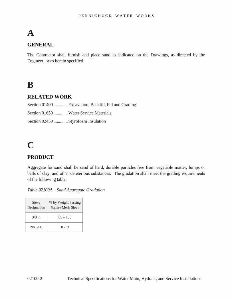
P E N N I C H U C K W A T E R W O R K S
02100-2 Technical Specifications for Water Main, Hydrant, and Service Installations
A
GENERAL
The Contractor shall furnish and place sand as indicated on the Drawings, as directed by the
Engineer, or as herein specified.
B
RELATED WORK
Section 01400 ............. Excavation, Backfill, Fill and Grading
Section 01650 ............. Water Service Materials
Section 02450 ............. Styrofoam Insulation
C
PRODUCT
Aggregate for sand shall be sand of hard, durable particles free from vegetable matter, lumps or
balls of clay, and other deleterious substances. The gradation shall meet the grading requirements
of the following table:
Table 02100A – Sand Aggregate Gradation
Sieve
Designation
% by Weight Passing
Square Mesh Sieve
3/8 in 85 – 100
No. 200 0 -10
P E N N I C H U C K W A T E R W O R K S
Technical Specifications for Water Main, Hydrant, and Service Installations 02100-3
D
EXECUTION
The Contractor shall spread sand in layers of uniform thickness not exceeding 12 inches before
compaction and moistened or left in natural state as directed. The Contractor shall thoroughly
compact the sand by means of suitable power-driven tampers or other power-driven compaction
equipment.

P E N N I C H U C K W A T E R W O R K S
02100-4 Technical Specifications for Water Main, Hydrant, and Service Installations
[This page has been left intentionally blank]

P E N N I C H U C K W A T E R W O R K S
Technical Specifications for Water Main, Hydrant, and Service Installations 02200-1
SECTION 02200
Loam and Seed
Table of Contents
A .................................. GENERAL
B .................................. SUBMITTALS AND TESTING
C .................................. PRODUCT
D .................................. EXECUTION
E .................................. MAINTENANCE AND ACCEPTANCE

P E N N I C H U C K W A T E R W O R K S
02200-2 Technical Specifications for Water Main, Hydrant, and Service Installations
A
GENERAL
The Contractor shall furnish all labor, materials, tools, and equipment necessary to do all loaming
and seeding and temporary seeding where indicated on the Drawings and as herein specified.
B SUBMITTALS AND TESTING
1. Loam
a. The Contractor shall provide two representative 5-gallon topsoil samples to the Owner’s
Representative 15 days prior to its use on-site. Samples shall indicate the location of the
source material. If additional sources shall be used during the project, the Contractor shall
provide samples for all locations. At the Owner’s Representative’s request, the Contractor
shall have the topsoil sample tested for physical properties and pH (or lime requirement),
organic matter, available phosphoric acid, and available potash, in accordance with standard
practices of soils testing for agricultural uses.
b. All topsoil shall be screened clear of all stones greater than ½ inch, as well as sticks, plants
and all other foreign materials before being spread. 100% of the material shall pass the ½
inch sieve and at least 90% shall pass the No. 10 sieve.
c. All topsoil shall have a pH range between 6 – 7.

P E N N I C H U C K W A T E R W O R K S
Technical Specifications for Water Main, Hydrant, and Service Installations 02200-3
C
PRODUCT
1. Loam
a. Loam shall be a good grade of topsoil from a site approved by the Owner’s Representative.
The loam shall be loose and friable and shall be free from admixtures of subsoil, refuse,
large stones, clods or roots, or any other undesirable foreign matter. Muck, peat, or other
excessively acidic soils containing undue proportions of either clay or sand will not be
accepted.
The Owner’s Representative will have final determination as to whether the topsoil is
representative of the submitted topsoil samples. If any materials are found to be inadequate,
the Owner’s Representative will reject them and the rejected topsoil will be removed from
the site at the Contractor’s expense.
b. When designated on the Plans or as directed, existing topsoil found within the lines of
improvement in excavation areas, embankment areas, or both, shall be excavated and
stockpiled by the Contractor for later use as loam on slopes and other areas, or on future
work. Stockpiles shall be placed at designated locations.
Additional loam to complete the project, if required, shall be obtained by the Contractor
from sources beyond the site. Unless designated for future work, salvaged topsoil not
required for use on slopes shall be graded to match the surrounding terrain and the area
seeded and mulched.
2. Permanent Seed
a. Seed shall be certified as to its proper mixture, germination, and purity qualities. Each
variety of seed shall have germination rate of at least 80%, a purity of at least 85%, and a
weed content of no more than 1%. All seed shall be from the same or previous year's crop
unless recent tests by an approved testing agency demonstrate that older seed meets the
above requirements.

P E N N I C H U C K W A T E R W O R K S
02200-4 Technical Specifications for Water Main, Hydrant, and Service Installations
b. The seed mixture shall consist of seed proportioned percent by weight as follows:
Method Number 1 – Park Mixture
Creeping Red Fescue 50%
Kentucky Bluegrass 30%
Annual Ryegrass 20%
3. Temporary Seed
Temporary seed shall be Winter Rye.
4. Mulch
a. Hay or straw mulch shall consist of long-fibered hay or straw, reasonably free from noxious
weeds and other undesirable material. No material shall be used which is so wet, decayed,
or compacted as to inhibit even and uniform spreading. No chopped hay, grass clippings, or
any other short-fibered material shall be used unless directed.
b. Cellulose fiber mulch shall consist of elongated virgin wood fibers capable of producing a
strong yellow-brown reaction with Graff C Stain for the presence of lignin in accordance
with TAPPI Test T 401 OS-74. The ash content shall not exceed 2.0%.
c. The material shall be non-toxic to plants and animals upon contact and shall contain a green
color sufficient to provide a definite contrast with the ground surface for metering purposes.
It shall be supplied in uniform moisture resistant package not exceeding 100 pounds each
and marked to show the air-dried weight for tank mixing purposes.

P E N N I C H U C K W A T E R W O R K S
Technical Specifications for Water Main, Hydrant, and Service Installations 02200-5
D
EXECUTION
1. Loam
Loam shall be spread uniformly on prepared areas to the depth of 4 inches as shown on the
Plans or as directed. Any remaining clods, roots, stones measuring over ½ inch, and all other
foreign matter, shall be removed. All loam shall be brought to a true, even surface, meeting the
required grade.
2. Seeding Method for Permanent Seed
a. Preparing the Soil. After the loamed or un-loamed areas to be seeded have been brought to
grade, all ground not loose and friable shall be scarified to a depth of at least 2 inches
immediately before seeding or mulching. All stones measuring over ½ inch and all objects
which would be detrimental to mowing shall be removed and disposed of as directed. Hand
raking will not be required provided an acceptable surface can be obtained by other means.
b. Fertilizing and Applying Agricultural Ground Limestone. Fertilizer and agricultural ground
limestone shall be applied at a rate of 30 pounds of 10-10-10 fertilizer per 1,000 square feet
of loamed area. Ground limestone shall be applied at a rate of 25 pounds per 1,000 square
feet of loamed area.
c. Sowing Seed. The seed shall be sown as specified in the NHDOT Standard Specifications
for Road and Bridge Construction unless otherwise indicated on the Plans or as approved.
The seed shall be Park Mixture as specified above and shall be applied at a minimum rate of
3 pounds per 1,000square feet of loamed area.
d. Mulching. Mulch shall be applied as specified in the NHDOT Standard Specifications for
Road and Bridge Construction unless otherwise indicated on the Plans or as directed. Mulch
should be applied at a rate of 1 to 2 tons per acre in a uniform blanket. Clumped or thick
mulch shall be thinned.
3. Seeding Method for Temporary Seed
a. Sowing Seed. The seed shall be sown as specified in the NHDOT Standard Specifications
for Road and Bridge Construction unless otherwise indicated on the Plans or as directed.

P E N N I C H U C K W A T E R W O R K S
02200-6 Technical Specifications for Water Main, Hydrant, and Service Installations
b. Mulching. Mulch shall be applied as specified in the NHDOT Standard Specifications for
Road and Bridge Construction unless otherwise indicated on the Plans or as directed.
4. Hydroseeding
Hydroseeding with a cellulose fiber mulch applied as a waterborne slurry at a rate of 60 pounds
of mulch per 1,000 square feet of area, when mixed with proper quantities and types of seed,
fertilizer, and agricultural limestone, may be used in lieu of separate mulching and seeding.
E
MAINTENANCE AND ACCEPTANCE
1. Seeding, Watering, and Repairs
Seeding shall be done by either method between the dates of March 31st to September 30
th,
inclusive. The Contractor shall maintain each seeded area until acceptance of the individual
area.
Important: Maintenance shall include watering the newly-seeded area until permanent grass
growth is established over 85% of the disturbed area.
The Contractor is responsible for all cost of watering; including the cost of the water.
Maintenance shall also consist of providing protection by erecting necessary signs or barriers
and by repairing damaged areas as directed. Damaged areas shall be repaired by reestablishing
the grade of the area prior to damage and by reapplying mulch. Refertilizing and reseeding will
not be required during this period.
Necessary maintenance or repairs will not be paid for but shall be considered incidental to the
Contract. Areas fertilized, seeded, and mulched by either method between October 1st and
March 31st will be accepted only upon attainment of a reasonably thick uniform stand of grass
free from sizable thin or bare spots.

P E N N I C H U C K W A T E R W O R K S
Technical Specifications for Water Main, Hydrant, and Service Installations 02200-7
2. Maintaining Seeded Areas
When all other work on the project has been completed and some seeded areas still have not
been accepted, the Contractor shall maintain those areas for an additional 60 days, exclusive of
the periods from November 15th to April 15
th. The seeded areas will be accepted upon
attainment of a reasonably thick uniform stand of grass.
If unaccepted areas still remain at or near the end of the 60-day maintenance period, the
Owner’s Representative may direct a final reseeding by the Contractor or may deduct the
Contract value of the unaccepted area from payment due the Contractor. In either event, the
Contractor's responsibility for the seeded areas will terminate at the end of 60 days and the
seeded areas will be accepted as complete.
3. Acceptance
The acceptance of any seeded area shall be in writing. After acceptance, the Contractor will be
relieved of further expense for maintaining the areas, except for damage resulting from their
own or their Subcontractor's operations.

P E N N I C H U C K W A T E R W O R K S
02200-8 Technical Specifications for Water Main, Hydrant, and Service Installations
[This page has been left intentionally blank]
P E N N I C H U C K W A T E R W O R K S
Technical Specifications for Water Main, Hydrant, and Service Installations 02300-1
SECTION 02300
Paving
Table of Contents
A .................................. GENERAL
B .................................. RELATED WORK
C .................................. QUALITY ASSURANCE
D .................................. SUBMITTALS
E .................................. PRODUCT
F .................................. EXECUTION

P E N N I C H U C K W A T E R W O R K S
02300-2 Technical Specifications for Water Main, Hydrant, and Service Installations
A
GENERAL
The Contractor shall provide all labor, tools, equipment and materials required to pave the all areas
to the thickness and types as defined on the Plans. All paving construction methodologies shall
meet or exceed those defined in Section 401, Plant Mix Pavements – General of the current
NHDOT Standard Specifications for Road and Bridge Construction.
B
RELATED WORK
Section 01400 ............. Earth Excavation, Backfill, Fill, and Grading
Section 01800 ............. Crushed Gravel
Section 01900 ............. Gravel Aggregate for Road Base and Water Main Backfill
Section 02600 ............. Clean Up
C
QUALITY ASSURANCE
The Contractor shall ensure that their paving operations conform to the requirements of Section 304
– Aggregate Base Course and Section 403 – Hot Bituminous Paving of the current NHDOT
Standard Specifications for Road and Bridge Construction.
The Engineer reserves the right to inspect all paving materials and the preparation of paving
materials at the paving plant.
The Contractor shall ensure that paving operations are conducted in accordance with all State and
local requirements.

P E N N I C H U C K W A T E R W O R K S
Technical Specifications for Water Main, Hydrant, and Service Installations 02300-3
D
SUBMITTALS
The Contractor shall submit a paving mix design with laboratory tests certifying conformance with
Specifications for the bituminous paving materials to the Engineer.
The Contractor shall submit a certification by the bituminous paving material plant of conformance
with all referenced standards.
The Contractor shall submit plant batch slips with each batch of bituminous paving material
delivered to the work site to the Engineer.
E
PRODUCT
1. Bituminous Paving Materials
The Contractor shall that ensure that all bituminous paving materials are supplied in accordance
with Section 401 – Plant Mix Pavements – General and Section 403 – Hot Bituminous Paving
of the current NHDOT Standard Specifications for Road and Bridge Construction. Specific
types of bituminous paving materials to be placed shall be as specified on the Drawings or in the
Standards Details.
The Contractor shall that ensure that bituminous paving materials meet all State and local
requirements.
2. Aggregate Base Course Materials
The Contractor shall that ensure that all aggregate base course materials are supplied in
accordance with Division 300, Section 304 – Aggregate Base Course of the current NHDOT
Standard Specifications for Road and Bridge Construction.

P E N N I C H U C K W A T E R W O R K S
02300-4 Technical Specifications for Water Main, Hydrant, and Service Installations
F
EXECUTION
1. Placing Aggregate Base Course
a. The Contractor shall ensure that all aggregate base course used as fill and backfill is the
proper type for the pavement type it is designed to support. Backfill shall meet the
requirements of Section 01400 Earth Excavation, Backfill, Fill, and Grading.
b. The Contractor shall ensure that the aggregate base course surface is properly maintained in
an undisturbed condition until the pavement has been placed. The Contractor shall ensure
that any damaged or eroded aggregate base course is properly repaired and restored to grade
before commencing paving operations.
2. Placing Bituminous Paving
a. The Engineer shall inspect the bituminous paving material at the paving plant and determine
its suitability for the project.
b. The Contractor shall saw cut all existing pavement where it will match into the new
pavement as indicate on the Drawings. The Contractor shall ensure that the saw cutting
operations meet the requirements of Section 628, Sawed Pavement of the NHDOT Standard
Specifications for Road and Bridge Construction.
c. The Contractor shall place and compact bituminous paving at the thickness specified or as
directed by the Engineer. The Contractor shall verify that the pavement has been compacted
to the proper thickness once compaction operations have concluded.
d. The Contractor shall ensure that the position of all manhole covers, catch basin grates, valve
boxes, and similar Items in the paved area are adjusted as necessary to conform with the
finished pavement grade or as directed by Engineer.
e. The Contractor shall ensure that all joints between the existing pavement and the new
pavement are tack coated in accordance with Section 401 of the NHDOT Standard
Specifications for Road and Bridge Construction.

P E N N I C H U C K W A T E R W O R K S
Technical Specifications for Water Main, Hydrant, and Service Installations 02300-5
f. The Contractor shall furnish, install, maintain, and later remove all safety devices necessary
to ensure public safety as they conduct their paving operations as required and in accordance
with the Specifications.
g. The Contractor shall ensure that all surplus and unsuitable materials are removed and
disposed of properly.
h. Core samples may be required to confirm the quality and design parameters of the
bituminous paving materials. The Owner is responsible for the cost of taking and testing
core samples. Failed core sample tests are the Contractor’s responsibility.

P E N N I C H U C K W A T E R W O R K S
02300-6 Technical Specifications for Water Main, Hydrant, and Service Installations
[This page has been left intentionally blank]

P E N N I C H U C K W A T E R W O R K S
Technical Specifications for Water Main, Hydrant, and Service Installations 02400-1
SECTION 02400
Concrete Thrust Blocks
Table of Contents
A .................................. GENERAL
B .................................. RELATED WORK
C .................................. PRODUCT
D .................................. EXECUTION

P E N N I C H U C K W A T E R W O R K S
02400-2 Technical Specifications for Water Main, Hydrant, and Service Installations
A
GENERAL
The Contractor shall ensure that all mechanical joint fittings, including elbows, tees, hydrants, and
branches, are protected against separation caused by unbalanced hydrostatic and hydrodynamic
thrust forces. The Contractor shall supply all materials, labor, and equipment as required to install
cast-in-place or precast concrete thrust blocks backed by undisturbed or properly compacted soil to
ensure the integrity of the joint fittings at the locations indicated on the Drawings or as directed by
the Engineer.
The Contractor shall ensure that cast-in-place or precast concrete thrust blocks meet the
requirements of ACI 304R-00 - Guide for Measuring, Mixing, Transporting, and Placing Concrete.
All cast-in-place concrete thrust blocks shall be of the “mass” design utilizing no reinforcing steel,
except for hooks as required for resistance-type thrust blocks.
B
RELATED WORK
Section 01400 ............. Earth Excavation, Backfill, Fill and Grading
Section 01600 ............. Water Main Pipe and fittings
Section 01900 ............. Gravel Aggregate for Road Base and Water Main Backfill

P E N N I C H U C K W A T E R W O R K S
Technical Specifications for Water Main, Hydrant, and Service Installations 02400-3
C
PRODUCTS
1. Concrete Thrust Blocks
a. All cast-in-place and precast concrete thrust blocks shall be fabricated with Type III A air-
entrained portland cement and be plant-batched. The concrete shall be Class A with a
minimum 28-day compressive strength of 3,000 psi, a maximum water/cement ratio (gallons
per bag of cement) of 0.53 and a maximum slump no greater than 6 inches.
b. All cast-in-place concrete thrust blocks shall be sized as designated on the Drawings, but no
cast-in-place concrete thrust block shall have a volume of less than ¾ cubic yard.
c. All precast concrete thrust blocks shall have the following minimum dimensions: 2-foot
width × 3-foot length × 2-foot height, or as specified by the Owner’s Representative.
D
EXECUTION
1. Installing Cast-in-Place Concrete Thrust Blocks
a. The Contractor shall ensure that fresh concrete is placed within 1½ hours after mixing, with
no water added to the mix at the job site. The Contractor shall ensure that the concrete’s
specified maximum water content is not exceeded.
b. The Contractor shall ensure that the fresh concrete is placed such that it is not allowed to fall
freely more than 5 feet to avoid aggregate segregation.
c. The Contractor shall ensure that the fresh concrete is consolidated by spading or by
mechanical vibration.
d. The Contractor shall ensure that the fresh concrete has cured for at least one hour prior to
commencing any backfilling operations. The concrete forms may be left in place while
backfilling.
P E N N I C H U C K W A T E R W O R K S
02400-4 Technical Specifications for Water Main, Hydrant, and Service Installations
2. Installing Precast Concrete Thrust Blocks
a. The Contractor shall ensure that precast concrete thrust blocks are installed directly behind
the joint fitting it is restraining, with the face of the block at right angles to the total force
vector.
b. The Contractor shall ensure that precast concrete thrust blocks are installed with aggregate
base course between the thrust block and undisturbed earth. The Contractor shall ensure
that the aggregate base course meet the requirements of Section 01900 Gravel Aggregate for
Road Base and Water Main Backfill. The aggregate base course shall be placed in lifts that
have a maximum thickness of 12 inches and compacted to a minimum Proctor of 95%.
Hand tamping and rodding shall be used to drive the crushed gravel into all voids
surrounding the thrust block.
P E N N I C H U C K W A T E R W O R K S
Technical Specifications for Water Main, Hydrant, and Service Installations 02450-1
SECTION 02450
Styrofoam Insulation
Table of Contents
A .................................. GENERAL
B .................................. RELATED WORK
C .................................. PRODUCT
D .................................. EXECUTION

P E N N I C H U C K W A T E R W O R K S
02450-2 Technical Specifications for Water Main, Hydrant, and Service Installations
A
GENERAL
All pipelines that have been buried with less than 4 feet of cover shall have Styrofoam™ board
insulation mounted over the top of the water main to provide frost protection in accordance with the
details on the Drawings.
Styrofoam board insulation shall be installed near all catch basins and storm drains to provide frost
protection. Refer to Standard Detail M16, Standard Detail M17, Standard Detail M18, and
Standard Detail M19 for more information.
B
RELATED WORK
Section 01600 ............. Water Main Pipe and Fittings
Section 01900 ............. Gravel Aggregate for Road Base and Water Main Backfill
Section 02100 ............. Sand
C
PRODUCT
1. Specifying Styrofoam Insulation Board Parameters
a. All Styrofoam insulation used shall be board type, with a minimum thickness of 2 inches
and minimum dimensions of 2 feet width × 8 feet length.
b. All Styrofoam insulation used shall be closed cell, high density insulation suitable for direct
burial in the ground.

P E N N I C H U C K W A T E R W O R K S
Technical Specifications for Water Main, Hydrant, and Service Installations 02450-3
D
EXECUTION
a. The Contractor shall ensure that water mains buried less than 4 feet deep are first covered by
a layer of properly compacted sand with a thickness of 6 inches. The Contractor shall then
install Styrofoam insulation boards laid side-by-side to achieve a minimum width of 4 feet
with staggered seams, centered over the water main.
b. The Contractor shall ensure that Styrofoam insulation boards are installed adjacent to catch
basins and storm drains as shown on the Drawings. Aggregate base course may then be
placed directly on the insulation and properly compacted for the roadway base.
c. Styrofoam insulation shall be installed above all water service lines that run beneath
driveways and parking lots.
d. Styrofoam insulation shall be installed vertically at specified locations in the field as
directed by the Owner’s Representative.

P E N N I C H U C K W A T E R W O R K S
02450-4 Technical Specifications for Water Main, Hydrant, and Service Installations
[This page has been left intentionally blank]

P E N N I C H U C K W A T E R W O R K S
Technical Specifications for Water Main, Hydrant, and Service Installations 02500-1
SECTION 02500
Managing Water Flow During Construction
Table of Contents
A .................................. GENERAL
B .................................. RELATED WORK
C .................................. PRODUCT
D .................................. EXECUTION

P E N N I C H U C K W A T E R W O R K S
02500-2 Technical Specifications for Water Main, Hydrant, and Service Installations
A
GENERAL
The Contractor shall assume the responsibility of managing the flow of water and dewatering
excavations at the work site during construction activities. The Contractor shall provide and deploy
all necessary equipment and personnel, including pumping apparatus to accomplish this.
B
PERMITS
Permits for managing water flow during construction shall be obtained and paid for by the
Contractor. Permits required may include the following:
New Hampshire RSA 485-A:17 – Terrain Alteration (a site-specific permit concerning water
quality)
Construction Dewatering Permit
EPA Dewatering Permit
C
EXECUTION
1. Dewatering Excavations
The Contractor shall ensure that all excavation work below ground water level is dewatered by
approved methods to prevent saturated soil from flowing into the excavation, undermining
existing structures, breaking up the naturally undisturbed earth in the banks, or loosening
foundation materials. The Contractor shall lower the water level in advance of excavation and
maintain a level such that any structures may be placed on a firm and dry foundation.

P E N N I C H U C K W A T E R W O R K S
Technical Specifications for Water Main, Hydrant, and Service Installations 02500-3
2. Deploying Pumping Apparatus
a. The Contractor shall deploy personnel and pumping apparatus with adequate power and
capacity to remove all water which may be encountered in their excavation work. The
Contractor shall also keep additional pumps of sufficient power and capacity on hand and at
the ready at the work site to provide backup for any unanticipated equipment breakdown or
handle flooding issues.
b. The Contractor shall ensure that all pumped water is discharged at a location and in such a
way that there is no adverse impact on the environment. If the water being discharged
contains sediment, it shall be pumped through appropriately-sized erosion control facilities
such as hay bales or silt fences.
3. Constructing and Maintaining Temporary Water Control Structures
a. The Contractor shall develop Drawings and details for any temporary water control
structures, especially in jacking and receiving pits, to the Owner’s Representative for their
review and approval. The Contractor shall submit their proposal for temporary water
control structures at least two weeks in advance of any construction work.
b. The Contractor shall ensure that the construction of any temporary water control structures,
the maintenance and proper operation of the same, and all other operations connected
therewith, are carried out in a satisfactory manner. The Engineer may at any time require
the Contractor to increase the precautions taken or to demand additional steps to make the
temporary works adequate, substantial, and secure. Such directions or instructions given
from time-to-time by the Engineer shall in no way relieve the Contractor from their entire
responsibility for the efficiency and safety of these works.
c. The Contractor shall make their own estimates of the necessary size, strength, and
configuration of temporary water control structures, and shall assume all expenses and
losses which may result from their inadequacy or from failure due to any cause whatsoever.
Any work destroyed or damaged thereby shall be repaired or replaced by the Contractor at
their expense.

P E N N I C H U C K W A T E R W O R K S
02500-4 Technical Specifications for Water Main, Hydrant, and Service Installations
4. Monitoring Water Turbidity
In waters that are used as a source of public water supply or used for trout, salmon, or other
game or forage fish spawning or nursery, control measures must be adequate to assure that
turbidity in the receiving water will not be increased more than allowed by applicable Federal,
State, and local regulations.

P E N N I C H U C K W A T E R W O R K S
Technical Specifications for Water Main, Hydrant, and Service Installations 02550-1
SECTION 02550
Dust Control
Table of Contents
A .................................. GENERAL
B .................................. RELATED WORK
C .................................. PRODUCT
D .................................. EXECUTION

P E N N I C H U C K W A T E R W O R K S
02500-2 Technical Specifications for Water Main, Hydrant, and Service Installations
A
GENERAL
This section of the Specifications covers the control of dust with Calcium chloride and water.
B
RELATED WORK
Section 01400 ............. Earth Excavation, Backfill, Fill and Grading
Section 01600 ............. Water Main Pipe and Fittings
C
PRODUCTS
1. Calcium Chloride
a. Calcium chloride used for dust control shall meet the requirements of AASHTO M 144,
Standard Specification for Calcium Chloride and ASTM D98, Standard Specification for
Calcium Chloride.
b. Calcium chloride shall be securely packaged in moisture-proof bags marked with the
following information:
Manufacturer
Product name
Net weight
Percentage of Calcium Chloride guaranteed by the manufacturer

P E N N I C H U C K W A T E R W O R K S
Technical Specifications for Water Main, Hydrant, and Service Installations 02550-3
c. Calcium chloride shall be delivered to the work site in a dry condition. Calcium Chloride
that has been improperly packaged, stored, or handled resulting in it becoming caked or
sticky, or otherwise compromised by excessive moisture, shall be rejected for use by the
Owner.
2. Water
Water used for dust control shall be clean, fresh not brackish, and free of any oils, acid or
alkaline chemicals, vegetable matter, or other debris.
D
EXECUTION
1. Applying Calcium Chloride for Dust Control
a. The Contractor shall apply Calcium chloride for dust control when ordered to do so by the
Owner’s Representative. The Contractor shall ensure that Calcium chloride is applied only
in areas which will not be adversely affected by the application.
b. The Contractor shall ensure that Calcium chloride is applied at a rate of 1½ pounds per
square yard or at any other rate as directed by the Owner, using a mechanical spreader or
other approved method. The number and frequency of Calcium chloride applications shall
be determined by the Owner.
2. Spraying Water for Dust Control
a. The Contractor shall ensure that water sprayed for dust control is dispersed through a nozzle
with a minimum pressure of 20 psi gauge.
b. The Contractor shall use a sprayer with a nozzle-equipped spray bar that is connected to a
water tank and a pump.
c. The Contractor is responsible for the cost of water drawn from hydrants for use in dust
control.

P E N N I C H U C K W A T E R W O R K S
02500-4 Technical Specifications for Water Main, Hydrant, and Service Installations
[This page has been left intentionally blank]

P E N N I C H U C K W A T E R W O R K S
Technical Specifications for Water Main, Hydrant, and Service Installations 02600-1
SECTION 02600
Work Site Clean Up
Table of Contents
A .................................. EXECUTION

P E N N I C H U C K W A T E R W O R K S
02600-2 Technical Specifications for Water Main, Hydrant, and Service Installations
A
EXECUTION
1. Conducting Work Site Clean Up Operations
a. The Contractor shall ensure that the work site and adjacent areas are maintained in an
orderly condition, and kept cleaned up, with all rubbish, surplus materials, and unneeded
construction equipment removed as necessary. Any property damage caused by the
Contractor’s operations shall be repaired in a way that inconveniences the public and
property owners as little as possible.
b. The Contractor shall ensure that any material or debris that has washed into or may be found
in existing watercourses, ditches, gutters, drains, pipes, or other structures, and caused by the
Contractor’s work, is entirely removed and satisfactorily disposed of, in a timely manner.
All ditches, channels, drains, pipes, and other structures shall be left in a clean and neat
condition upon completion of the work.
c. The Contractor shall ensure that, on or before the completion of the work, all temporary
buildings and structures are removed, unless otherwise permitted in writing by the Owner’s
Representative. The Contractor shall ensure that all temporary works, tools, machinery, and
any other construction equipment furnished by them is removed.
d. The Contractor shall ensure that all rubbish generated by their operations is removed and
properly disposed of in a roll-off container, daily. Roll-offs used shall be removed from the
work area once they are filled. The Contractor shall ensure that all organic matter that may
be found in, under, and around privies, houses, and other buildings used by them is
removed, acceptably disinfected, and covered.
e. The Contractor shall ensure that all roads, shoulders, grounds, and all parts of the premises
and adjacent property affected by their operations are left in a neat and satisfactory
condition, as required by the Contract and the approval of the Engineer. The Contractor
shall ensure that all disturbed property is returned to its original grade and cover unless
specified otherwise in the Drawings and Specifications or approved by the Engineer.
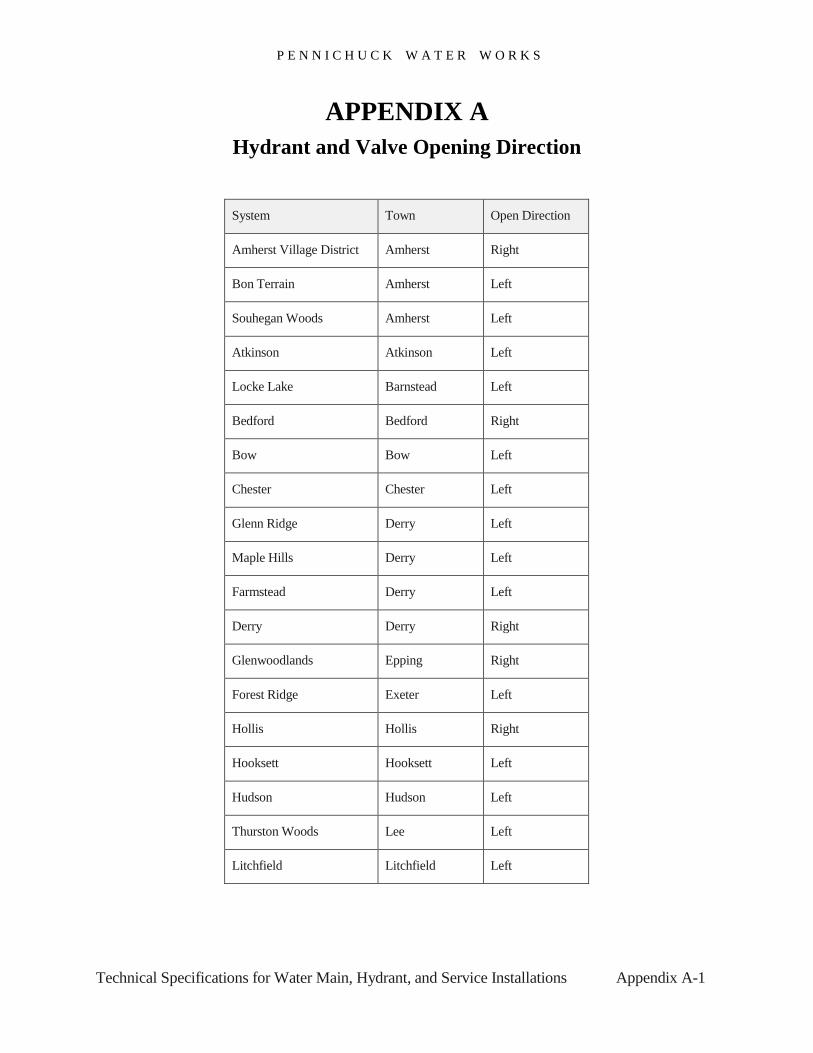
P E N N I C H U C K W A T E R W O R K S
Technical Specifications for Water Main, Hydrant, and Service Installations Appendix A-1
APPENDIX A
Hydrant and Valve Opening Direction
System Town Open Direction
Amherst Village District Amherst Right
Bon Terrain Amherst Left
Souhegan Woods Amherst Left
Atkinson Atkinson Left
Locke Lake Barnstead Left
Bedford Bedford Right
Bow Bow Left
Chester Chester Left
Glenn Ridge Derry Left
Maple Hills Derry Left
Farmstead Derry Left
Derry Derry Right
Glenwoodlands Epping Right
Forest Ridge Exeter Left
Hollis Hollis Right
Hooksett Hooksett Left
Hudson Hudson Left
Thurston Woods Lee Left
Litchfield Litchfield Left
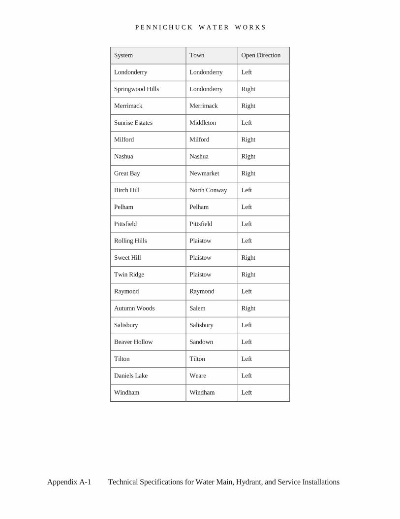
P E N N I C H U C K W A T E R W O R K S
Appendix A-1 Technical Specifications for Water Main, Hydrant, and Service Installations
System Town Open Direction
Londonderry Londonderry Left
Springwood Hills Londonderry Right
Merrimack Merrimack Right
Sunrise Estates Middleton Left
Milford Milford Right
Nashua Nashua Right
Great Bay Newmarket Right
Birch Hill North Conway Left
Pelham Pelham Left
Pittsfield Pittsfield Left
Rolling Hills Plaistow Left
Sweet Hill Plaistow Right
Twin Ridge Plaistow Right
Raymond Raymond Left
Autumn Woods Salem Right
Salisbury Salisbury Left
Beaver Hollow Sandown Left
Tilton Tilton Left
Daniels Lake Weare Left
Windham Windham Left