technical specification of materials for · 2.0.1 survey (detail & check, estimating of...
TRANSCRIPT

Tech. Specification NIT No. NESCO Utility/ Elephant Corridor/12/ 26.8.19 Page 1
SECTION-IV
TECHNICAL SPECIFICATION OF MATERIALS
FOR
STRENGTHANING OF
INFRASTRUCTURE IN
ELEPHANT CORRIDER FOR
SAFETY MEASURES FOR
AVOIDING ELECTROCUTION OF
ELEPHANTS
TENDER N O T I C E NO:- NESCO Utility / Elephant Corridor/ 12/19-20/10876
Date:26.8.19

Tech. Specification NIT No. NESCO Utility/ Elephant Corridor/12/ 26.8.19 Page 2
TECHNICAL SPECIFICATION FOR STRENGHENING 33KV, 11KV HT LINES AND LT DISTRIBUTION LINES.
1.0 NATURE OF WORK
The work covered by this Specification is for Strengthening of 33KV lines with interposing poles, 11KV lines renovation with HT insulated conductor & interposing poles , LT distribution lines with AB cables and making the said lines electrocution proof for elephants inside the elephant corridors in Balasore , Jajpur , Mayurbhanj and Keonjhar District of Odisha as specified herein and in the attached Schedules. 1.1 SCOPE OF WORK
The scope of work Package wise under the District for which Strengthening of 33KV lines with interposing poles, 11KV lines renovation with HT insulated conductor & interposing poles , LT distribution lines with AB cables in details mentioned below:
Pack
age
Dist
rict
33KV
Inte
rpos
ing
(Q
ty in
No.
)
11 K
V In
terp
osin
g
(Qty
in N
o.)
Reno
vatio
n 11
KV li
ne w
ith H
T In
sula
ted
Cond
ucto
r (99
sqm
m) i
n CK
m
18m
m H
T St
ay C
ompl
ete
( i
n Se
t)
LT In
terp
osin
g P
ole
( Q
ty in
No.
) 3-
Ph LT
AB
Cabl
e (3
x50+
1x35
+1x1
6mm
2)
( in
Km)
16m
m L
T S
tay
Com
plet
e
( in
Set)
Spik
e (2
nos.
Per
set p
er P
ole)
in N
o.
Coup
ing
of P
ole
in N
o.
Fenc
ing
of S
ub-s
tatio
n
(in N
o.)
11KV
VCB
with
CT,
PT &
CRP
in N
o.
11 m
tr P
SC
13 m
tr R
S Jo
ist
10 m
tr P
SC
11 m
tr P
SC
9 m
tr P
SC
Pkg-1
Bala
sore
0 0 0 145 11.65 90 72 12.60 35 217 217 13 0
Pkg-2 0 0 0 185 9.35 92 157 6.15 75 342 342 23 4
Pkg-3
Jajp
ur
20 0 0 154 6.52 42 128 12.921 27 331 59 43 1
Pkg-4
May
urbh
anj
11 0 247 5 6 138 120 8.2 82 500 296 52 1
Pkg-5 0 0 75 0 16 57 20 1.2 11 62 35 93 0
Pkg-6 0 0 58 71 14.4 110 120 14.1 121 258 340 30 0
Pkg-7 0 0 18 118 16.4 136 141 12.2 122 272 270 17 2
Pkg-8 150 0 435 45 1 208 346 9.1 120 1134 916 17 0
Pkg-9 0 40 537 78 1 213 276 10.1 109 1240 807 10 0
Pkg-10
Keon
jhar
0 0 162 0 22.53 69 0 0 0 324 389 15 0

Tech. Specification NIT No. NESCO Utility/ Elephant Corridor/12/ 26.8.19 Page 3
Pkg-11 0 0 94 0 20.91 45 0 0 0 188 80 0 0
Pkg-12 0 0 137 0 19.09 37 0 0 0 274 208 22 0
Pkg-13 0 0 139 0 19.8 20 0 0 0 278 14 0 0
Pkg-14 0 0 101 0 19.8 18 0 0 0 202 16 0 0
Pkg-15 0 0 257 0 17.61 94 0 0 0 514 966 34 0
Pkg-16 0 0 180 0 20.15 68 0 0 0 360 80 2 0
Pkg-17 0 0 160 0 16.78 72 0 0 0 320 116 0 0
Pkg-18 0 0 317 0 14.34 179 0 0 0 634 898 71 0
Pkg-19 0 0 263 0 17.04 105 0 0 0 526 267 0 0
Pkg-20 0 0 91 0 26.4 13 0 0 0 182 14 0 0
TOTAL PACKAGE (20 Nos)
181 40 3271 801 296.77 1806 1380 86.57 702 8158 6330 442 8
1.2 Location details : District wise and Package wise location with scope of work for infrastructure development in elephant corridor mentioned in separate file attached for reference of the bidder. 1.3 Item Description : The electrical installation work to be carried out for avoiding electrocution of Elephants inside Elephant corridor, on “turnkey‟ basis with supply of materials . Details item description shall include the material Sl no. Item Particulars Include the supply materials
1 i) Supply & Erection of 33KV interposing Poles.
(Using 11mtr 330Kg PSC Pole with all accessories)
11 mtr long, 300Kg PSC Pole 33 KV 'V' Cross Arm (22 Kg each) Back Clamp for 'V' Cross Arm (1.7 Kg each) 33 KV Pole Top Bracket 100X50mm MS Channel (5.5 Kg each) 33 KV top bracket Clamp 33 KV Pin Insulator 33 KV G.I. Pin Nuts & Bolts Coil Earthing Padding for PSC pole

Tech. Specification NIT No. NESCO Utility/ Elephant Corridor/12/ 26.8.19 Page 4
ii) Supply & Erection of 33KV interposing Poles.
(Using 13mtr RS Joist with all accessories)
13 mtr long,(150x150mm) R.S Joist 33 KV 'V' Cross Arm (22 Kg each) Back Clamp for 'V' Cross Arm (1.7 Kg each) 33 KV Pole Top Bracket 100X50mm MS Channel (5.5 Kg each) 33 KV top bracket Clamp 33 KV Pin Insulator (Polymer type) Nuts & Bolts Coil Earthing Padding for PSC pole
2 i) Supply & Erection of 11KV interposing Poles.
(Using 10mtr 330Kg PSC Pole with all accessories)
10 mtr long, 330Kg PSC Pole 11 KV 'V' Cross Arm (10.2 Kg each) Back Clamp for 'V' Cross Arm (1.2 Kg each) 11 KV Pole Top Bracket 75X40mm MS Channel (2.8 Kg each)
11 KV Pin Insulator (Polymer type) Nuts & Bolts Coil Earthing Padding per PSC pole
ii) Supply & Erection of 11KV interposing Poles.
(Using 11mtr 300Kg PSC Pole with all accessories)
11 mtr long, 300Kg PSC Pole 11 KV 'V' Cross Arm (10.2 Kg each) Back Clamp for 'V' Cross Arm (1.2 Kg each) 11 KV Pole Top Bracket 75X40mm MS Channel (2.8 Kg each) 11 KV Pin Insulator 11 KV G.I. Pin Nuts & Bolts Coil Earthing Padding per PSC pole
3 Renovation of 11KV line with supply & erection of HT insulated conductor and all accessories in compete.
(Using 99mm² AAAC HT insulated conductor with all accessories)
HT insulated conductor (99 mm² AAAC) 11KV polymer insulator (10KN) 11KV 70KN Disc insulator (Polymer type) with hard-ware fittings Cable Ties (Top & Side) for 11KV polymeric insulators
IPC for covered conductor, Nut & bolts , Surge Arrestor , ‘T’ joint tap off , 11KV jointing kit , termination kit etc. where required Replacement of old 11 KV Pole Top Bracket 50x8 flat to 75X40mm MS Channel (2.8 Kg each)
4 Supply & Erection of 18mm HT Stay Set Complete
18 mm HT Stay Set 7/8 Stay Wire HT Stay Clamp Nuts & Bolts HT Stay Insulator Concreting of Stay (1m X 0.5m X 0.5m)

Tech. Specification NIT No. NESCO Utility/ Elephant Corridor/12/ 26.8.19 Page 5
5 Supply & Erection of LT interposing Poles.
(Using 9mtr 300Kg PSC Pole with all accessories)
9mtr long, 300Kg PSC Pole Pole Clamp for Eye Hook Eye Hook for AB Cable Nuts & Bolts
6 Conversion of 3-Ph AB Cable (3x50+1x35+1x16)mm2 with all accessories
(3X50+1X35+1X16)mmsq LT AB Cable Suspension Clamp with Eye hook Dead End Clamp
Sundries
7 Supply & Erection of 16mm LT Stay Set Complete
16 mm Stay Set 7/12 Stay Wire LT Stay Clamp Nuts & Bolts LT Stay Insulator Concreting of Stay (1m X 0.5m X 0.5m)
8 Poles to be Spiked
(Provision of 2 nos. Spikes per Pole)
2 nos. spikes per Set for one pole . Each G.I spike clamp made up 50x6 mm flat and 8 mm square bar (solid type). One spike means one pair of spike clamp and 2 pairs of spike clamp to be used per pole , details of spike clamp diagram enclosed.
9 Couping of Pole Cupping of Poles (including Supply of Materials) (1m X 0.5m X 0.5m)
10 Fencing of Sub-station with barbed wire
Fencing of S/S (including Supply of barbed wire & other materials) .If it comes under Elephant corridor ( name of elephant corridor to be mentioned)
11 11 KV VCB
11KV VCB with CT, PT ,Structure with CR Panel for feeder protection including construction of Plinth . The manufacturer of the VCB should be Siemens/ ABB/CGL/Schneider/BHEL/Vijay Electricals/ Megawin/ Bieccolawrie Ltd./ L&T/ Stelmec Ltd./ Pascal(India) Pvt. Ltd./ Tosiba (India) Ltd.
N.B : 1. All MS materials should be hot dip galvanized as per IS : 2629
2. The bidders should be furnished type test reports of offered major materials with bid such as polymer insulator, Stay wire , AB Cable, ,AB cable accessories, HT insulated conductor , Hardware fitting , termination Kit, VCB etc to be used in the turnkey project . The bid shall accompanying with type-test reports conducted at Central Power Research Institute / NABL accredited laboratory for offered materials conducted within Five years before the date of opening of the tender. Bid not accompanied with type test reports conducted within five years & the drawings of the offered Materials duly approved by the Type Testing Agency shall not be considered for evaluation. For other offered materials should have been Inspected/Tested by any Distribution Utility/ Reputed Private Organization/ State Govt./ Central Govt. or their undertaking(s)/NABL or CPRI.
3. The bidders should furnish GTP formats duly filled and signed for the offered
materials with bid .
Tech. Specification NIT No. NESCO Utility/ Elephant Corridor/12/ 26.8.19 Page 6
Methodology:- The complete procedures for the execution of the project are explained herewith;
i. Detailed survey of substation, line and preparation of SLD & BOQ. ii. Complete manufacture details, including shop testing & supply of materials from the approved vendors (materials which are to be supplied by the bidder) as per technical specification on prior approval of the NESCO Utility. iii. Providing Engineering drawing, data, operational manual, etc wherever applicable for the NESCO Utility ‟s approval; iv. Packing and transportation from the manufacturer‟s works to the site. v. Receipt, storage, preservation and conservation of equipment at the site. vi. Pre-assembly, if any, erection testing and commissioning of all the equipment; vii. Reliability tests and performance and guarantee tests on completion of commissioning; viii. Loading, unloading and transportation as required. ix. Erection of interposing PSC Poles in HT line & LT line. x. Renovation of 11KV line with HT insulated conductor xi. Fitting of spikes in the poles with proper welding the clamp to prevent theft. xii. Couping of pole. xiii. Fencing of S/S with Barbed wire. xiv. Conversion of Bare LT line to AB Cables. xv. During execution of erection work any damaged or inclined / defective materials or pole on existing system found at adjacent site to be replaced/ rectified by the agency for strengthening of network. xvi. Testing, Commissioning of lines / installations. xvii. Getting the lines inspected by Electrical Inspector after completion of work including deposit of
required inspection fees without claim to NESCO Utility. xviii. All expenditure towards inspection of materials at manufacturers site and inspection of work after
completion shall be borne by the executive agency. xix. Dismantling of existing electrical network if any and return of these dismantled items at the
NESCO Utility’s stores including transportation cost. For details the Technical Specification specified in Section-IV may be
referred.
2.0.1 SURVEY (detail & check, estimating of quantities & spotting of Poles)
Walk over survey shall have to be carried out to ascertain the location wise nature of work to
be executed.
2.0.2 GENERAL: The Right of way shall be resolved by the contractor and all expenses
there of shall be borne by him. However, NESCO Utility shall render all helps in co-ordination
with law and order and forest department for solving the same.
2.0.3 Provisional quantities/numbers of different types of work have been estimated and
indicated in the BOQ Schedule given. However final quantities for work shall be as
determined by the successful bidder, on completion of the detail survey.
2.0.4 After completing the detailed survey, the contractor shall submit the final survey report

Tech. Specification NIT No. NESCO Utility/ Elephant Corridor/12/ 26.8.19 Page 7
for approval of the employer. .
2.0.5 (a) Optimization of Pole Location I. Pole Spotting
The contractor shall spot the interposing poles in such a way so that proper ground
clearance should be maintained and there shall be minimum s ag in a span.
II. Anti-climbing Devices (Spikes) The vendor shall provide and install anti-climbing device on all 11 KV DP Structures, and at all poles as per CEA guide lines. This shall be done with modified spikes as specified. The spike clamp to be fitted with pole by bolting and welding in such a way to avoid theft. The spike clamp is made up 50x6 mm III. Fittings Common to all Line
Pin Insulator Binding: The contractor shall use AL. Binding wire for binding shall be as per REC Construction Standards No. C-5 or better thereof.
IV. Stringing of Aerial Bunched Cable (ABC)
2.0.6 Fixing of Suspension & Tension/ Dead end fittings to the Poles. The suspension clamp is to be hung on eye hook/ suspension hook, which is fixed to the pole
at a minimum distance of 0.15 mt. from top end of the pole. The messenger wire of bunched
cable resting on a pulley is separated from the cable by separating wedges and inserted
in the conductor groove of the suspension clamp.
The bolt is tightened to a torque of 20 N after which the pulley and wedges are to be removed. The cable is tied to the messenger wire with nylon tie on both sides of clamps. Pole clamps
50 x 8 mm flat shall be used. Eye hook of 16mm dia MS rod to be used as per the drawing.
The pole clamp shall be made to suite the pole width. This shall be installed as per Fig. No. 2
(a) of REC Construction Standard. All ferrous items shall be hot dip galvanized with zinc
coating of 610gms / m2. 2.0.7 Fittings & Accessories of AB Cables:
The following hardware fittings and accessories shall be used to install, erect & join the aerial
bunched cable.
a) Suspension Clamp with Eye-Hook – The Contractor shall install the suspension clamp with
eye hook. This hook shall be used to attach the AB cable on the pole by means of a dead end
clamp in terminal poles and for attaching a suspension clamp suitable for holding AB cables
of size 35mm2 to 95mm2 in straight lines and angle up to 90 Deg.- b) Suspension fittings & the corresponding eye hook shall be as per REC Construction
Tech. Specification NIT No. NESCO Utility/ Elephant Corridor/12/ 26.8.19 Page 8
Standard No. e –34. The eye hooks shall be made from minimum 16mm dia MS rods with
eye on one end and the other end being suitably flattened with two holes for M16 bolt & nut
to fix with the back clamps made from minimum 50x8mm flats as per drawing. The eye
hook, back clamp and bolts & nuts are to be hot dip galvanized.
c) Dead End fittings shall be bolted type as per REC Construction Standard No. E-35 & the
corresponding eye hook shall be as specified above. The dead clamps are to be anchored with
the pole with similar arrangement of eye hook & back clamp. In this case, the back clamp
shall have two nos. of holes on both sides for M16 bolts. One side of the clamp shall be used
for holding the eye hook with dead end clamp and the other side shall be used for anchoring
the Stay.
d) Nylon Tie- The contractor shall supply nylon ties. These ties shall be used for
tying the conductors with the messenger wire to prevent the phase conductors from
chatting against suspension clamp. The nylon tie is made of weather resistant black nylon.
e) Connectors- The contractor shall supply connector. These shall be used as non-tension aluminum to aluminum connections for conductor joints. f) Plastic Covers for Connectors- The contractor shall install Plastic Covers for Connectors. These covers shall be used with aluminum/aluminum connectors to protect connectors against corrosion caused by climatic conditions. 2.0.8 Installation of Cable
The contractor shall be fully responsible for all activities related to installation of AB cable. His responsibilities consists of handling, pulling, stringing & jointing of the cable and effecting service connection to consumers as per direction of the Engineer-in-charge.
2.0.9 Handling of AB Cable
The contractor shall observe following precautions while handling the AB Cable: The cable drums must be stored and transported in an upright position. While loading/unloading, the drums shall not be thrown from transport vehicles. Cable contact with sharp articles shall be avoided. In order to prevent damage to the insulation, the cable shall not be dragged on the ground.
Pulleys shall be used for this purpose.
In order to prevent strands from spreading, always cut the cable with a cutter.
Use nylon ties or electrical tape to prevent the cable from spreading away from messenger
wire after the cutting. Staple the end of the cable on to the drum in order to prevent loosening.
Do not remove the protective boards from the cable drum before the cable is pulled
off the drum.

Tech. Specification NIT No. NESCO Utility/ Elephant Corridor/12/ 26.8.19 Page 9
While moving the drum by rolling it on ground, always roll the drum in the direction
indicated by the arrow on the flange. When pulling the cable, the spinning direction must be
opposite.
Do not store the drums on wet soil, sandy or humid places.
Store the accessories in good order for quick easy and correct handling. 2.10 Pulling the Cable
The principle is to pull the cable under mechanical tension so that contact with the ground
or any other obstacles is avoided. The cable drum should be perfectly in alignment with line
to be strung and fixed about 15-20 mts
From the holding the first pulley. Open the cover of the drum to check and ensure
that the insulation is not damaged.
The pulling which is sent up upto the cable drum is about 15-20 mts from the pole holding
to the last pulley. The pulleys are directly hung to such hook on the poles. The pulley
tandem is to be used on angle poles if the line is deviating more than 60º Pull the guiding
rope through all the pulleys. Normal care shall be taken to assume a smooth passage of whole cable through the
pulleys, especially in the first pole and on angle poles. One worker should act s brakeman at
the cable drum so that the cable is not loosened during the pulling. One worker should follow
the cable going through the pulleys and stop the pulling if anything goes wrong. 2.11 Final Checking, Testing and Commissioning After stringing have been done as approved by the engineer, to ensure that everything is
complete in all respects, the works shall be thoroughly inspected keeping in view the
following main points.
All the bolts and nuts should be of hot dip galvanized materials as per relevant IS.
The stringing of the cable has been done as per the approved sag and desired
clearances are achieved.
No damage, minor or major to the cable, messenger wire and accessories
The contractor shall submit a report to the above effect to the Engineer in Charge, who shall
inspect and verify the correctness of the report. In case it is noticed that some or any of the
above is not fulfilled, the engineer shall get such items rectified by the contractor no extra

Tech. Specification NIT No. NESCO Utility/ Elephant Corridor/12/ 26.8.19 Page 10
cost to the purchaser. After final checking, the line shall be tested for insulation resistance
in accordance with IS 1255:1983.
All arrangements for such testing or any other test desired by the Engineer-in-charge shall be
done by the contractor and necessary labour, transport and equipment shall be provided by
him. Any defect found out as a result of such tests shall be rectified by the contractor,
forthwith at no extra cost to the purchaser.
In addition to the above, the contractor shall be responsible for testing and ensuring
that the total and relative sags of the cable as within the specified tolerance. Such tests shall be
carried out at selected points along the route as required by the Engineer-in-charge and
the contractor shall provide all necessary equipment and labour to enable the tests to be
carried out. After satisfactory test on the line and approval by the Engineer in Charge, the line
shall be energized at full operating voltage before handling over. The cable shall be megger
tested before and after jointing. The AB cable shall be tested for.
i) Continuity of messenger wire and conductors
ii) Absence of cross phasing
iii) Insulation resistance to earth
iv) Insulation resistance between conductors
v) DC Resistance
vi) Capacitance
As per the latest issue IS 1255:1983 and as per manufacturer‟s instructions. Sufficient backfilled
earth covers each foundation pit and is adequately compacted.
All poles are used strictly according to final approved drawing and are free of any
defect or damage whatsoever.
The stringing of the conductors and earth wire has been done as per the approved
sag and tension charts and desired clearances are clearly available.
All conductor and messenger wire accessories are properly installed.
The insulation of the line as a whole is tested by the Contractor through provision of his own
equipment, labour etc., to the satisfaction of the NESCO Utility.
3.0 PSC POLES In case of 33KV,11KV and LT lines the conventional PSC poles may be used. . The
materials must conform to IS: 800. All the test on materials and fabrication etc will be as per
the relevant Indian standards

Tech. Specification NIT No. NESCO Utility/ Elephant Corridor/12/ 26.8.19 Page 11
4.0 ERECTION WORK
When the survey is approved, the contractor shall submit to the employer a complete detail schedule of all materials to be used in the line. Size and length of conductor etc. are also to be given in the list. This schedule is very essential for finalizing the quantities of all line materials. The contractor shall furnish the same. 4.1 SCHEDULE OF ERECTION PROGRAMME
After due approval of the detailed and check survey, the contractor shall submit to the
employer a complete detailed schedule of erection programme with a Bar-Chart for
construction of the lines indicating there in the target date of completion.
5.0 CONSTRUCTION OF FOUNDATION FOR PSC POLES 5.0.1 ERECTION OF POLE, CONCRETING OF POLES AND COMPACTION OF
SOIL Drawing for the excavation of pits, Foundation of both wet and Black cotton soil is
enclosed which are to be adopted. If better design with less volume approved or tested
by any other distribution agencies will also be acceptable.
5.0.2 Following arrangement shall be adopted for proper erection of poles and properly
compacting of the soil around the base / foot of the poles, under this package.
(a) Excavation has to done as per the drawing to the required depth and size. After final
excavation the pit should be dressed properly so that uneven portion and loose soil
should be removed before PCC (M-7.5) i.e 1:4:8 of thickness 75 mm is laid. The base
footing of the pole concreting RCC (M-12.5) i.e 1:3:6 has to be done by proper alignment and
verticality.
(b) The verticality and leveling of pole/structure should be done by the help of plum bob or
with theodolite and leveling instrument.
(c) In case of PSC pole RCC Pre –cast slab of size (450 x 4 50 x 75) mm has
to be provided over the Lean concrete.
5.0.3 CEMENT CONCRETE AND BACK FILLING etc. A) Materials
All materials whether to be consumed in the work or used temporarily shall conform to relevant
IS specification, unless stated otherwise, and shall be of the best approved
quality.
B) Cement
Cement to be used in the work under the contract shall generally conform to IS:269/455-
1989. Cement bags shall be stored by the contractor in a water tight well ventilated store
sheds on raised wooden platform (raised at least 150 mm above ground level) in such a
manner as to prevent deterioration due to moisture or intrusion of foreign matter. Cements to

Tech. Specification NIT No. NESCO Utility/ Elephant Corridor/12/ 26.8.19 Page 12
be used within three months from the date of manufacture. Sub-standard or partly set cement
shall not be used and shall be removed from the site by the contractor at his cost.
C) Coarse Aggregates i.e Stone chips or stone ballast. For M15 concrete (mix 1:2:4) the
aggregate will be in the ranges from 12mm to 20mm.size and for M7.5 concrete (mix
1:4:8) these will be from 25mm to 40mm size. D) Pole erection
1. After proper alignment, checking of verticality and leveling, the pole or structure should
be properly tied before placing of base concrete of required height. Again the
verticality and leveling should be checked.
2. The PCC pedestal concrete (M-12.5) is to be done by providing good quality of
shutters, so that there will no leakage of cement slurry during concreting. The cooping height
should be 450 mm above the existing ground level . The top portion of the cooping should be
made tapered.
3. The back filling of locations should be done by using the excavated soil only in layers
(each layer should not be more than 500 mm) by putting water and ramming by using
wooden rammers. In no case stone of size more than 75mm used for back filling. Back-filling
has to be done 75mm above ground level or as specified.6. 5.0.4 All the persons working on p o l e s shall wear safety helmet, safety belt
and safety shoes, Similarly all the persons working on ground shall wear safety helmet and
safety shoes.
5.0.4.1. If there is any LT/HT power line near the vicinity of erection, necessary
shutdown of the power line shall be obtained in writing from the concerned Agency in order
to avoid electrical hazards caused by accidental touching of stay/Guy ropes with power line.
5.0.4.2 Safety precaution Safety shall be given utmost importance during stringing. The
following need to be ensured.
5.0.4.3 Safe working conditions shall be provided at the stringing site.
5.0.4.4 Full proof communication through walky- talkie / mobile phones shall be used
in order to avoid any damage to workmen or public on ground.
5.0.5 In case of 33KV, 11KV and LT lines (PSC) 5.0.5 (A) PSC Pole (9Mtr x 300 Kg , 10Mtr x 330Kg, 11Mtr x 300 Kg)
TECHNICAL SPECIFICATIONS

Tech. Specification NIT No. NESCO Utility/ Elephant Corridor/12/ 26.8.19 Page 13
I. Qualification Criteria of Sub Vendor / Manufacturer:-
The prospective bidder may source PSC Poles from manufacturers. The bidder should enclose Performance Certificates from the users, issued in favour of the Sub Vendor / manufacturer, as proof of successful operation in field. Applicable Standard: The Poles shall comply with latest standards as under: REC Specification No. 15/1979, REC Specification No. 24/1983, IS 1678, IS 2905, IS 7321.
II.Materi
als :
Cement Cement to be used in the manufacture of pre-stressed concrete poles shall be ordinary for rapid hardening Portland cement confirming to IS: 269-1976 (Specification for ordinary and low heat Portland cement) or IS: 8041 E-1978 (Specification for rapid hardening Portland cement). Aggregates Aggregates to be used for the manufacture of pre-stressed concrete poles shall confirm to IS: 383 (Specification for coarse and fine aggregates from natural sources for concrete) .The nominal maximum sizes of aggregates shall in no case exceed 12 mm. Water Water should be free from chlorides, sulphates, other salts and organic matter. Potable water will be generally suitable. Admixture Admixture should not contain Calcium Chloride or other chlorides and salts which are likely to promote corrosion of pre-stressing steel. The admixture shall conform to IS: 9103. Pres-Stressing Steel Pre-stressing steel wires including those used as un tensioned wires should conform to IS:1785 (Part-I) (Specification for plain hard-drawn steel wire for pre-stressed concrete, Part-I cold drawn stress relieved wire).IS:1785 (Part-II)(Specification for plain hard-drawn steel wire) or IS:6003 (Specification for indented wire for pre-stressed concrete).The type design given in the annexure are for plain wires of 4 mm diameter with a guaranteed ultimate strength of 160 kg/mm². All pre-stressing steel shall be free from splits, harmful scratches, surface flaw, rough, aged and imperfect edges and other defects likely to impair its use in pre-stressed concrete. Concrete Mix Concrete mix shall be designed to the requirements laid down for controlled concrete (also called design mix concrete) in IS: 1343-1980 (Code of practice for pre-stressed concrete) and IS: 456 – 1978 (Code of practice for plain and reinforced concrete) subject to the following special conditions: Minimum works cube strength at 28 days should be at least 420 Kg/cm². The concrete strength at transfer should be at least 210 Kg/cm². The mix should contain at least 380 Kg of cement per cubic meter of concrete. The mix should contain as low water content as is consistent with adequate workability. It becomes necessary to add water to increase the workability the cement content also should be raised in such a way that the original value of water cement ratio is maintained.

Tech. Specification NIT No. NESCO Utility/ Elephant Corridor/12/ 26.8.19 Page 14
III. Design Requirements The poles shall be designed for the following requirements: The poles shall be planted directly in the ground with a planting depth as per IS: 1678. Wherever, planting depth is required to be increased beyond the specified limits or alternative arrangements are required to be made on account of ground conditions e.g. water logging etc., the same shall be in the scope of the bidder at no extra cost to NESCO Utility. The bidder shall furnish necessary design calculations/details of alternative arrangements in this regard. The working load on the poles should correspond to those that are likely to come on the pole during their service life. The factor of safety for all poles 9.0Mts. Shall not be less than 2.0 and for 8.0 M poles, the factor of safety shall not be less than 2.5. The average permanent load shall be 40% of the working load. The F.O.S. against first load shall be 1.0. At average permanent load, permissible tensile stress in concrete shall be 30 kg/cm². At the design value of first crack load, the modulus of rupture shall not exceed 53.0kg/cm² for M-40. The ultimate moment capacity in the longitudinal direction should be at least one fourth of that in the transverse direction. The maximum compressive stress in concrete at the time of transfer of pre-stress should not exceed 0.8 times the cube strength. The concrete strength at transfer shall not be less than half, the 28 days strength ensured in the design, i.e. 420x0.5=210kg/cm². For model check calculations on the design of poles, referred to in the annexure, a reference may be made to the REC “Manual on Manufacturing of solid PCC poles, Part-I-Design Aspects”. IV. Dimensions and Reinforcements The cross-sectional dimensions and the details of pre-stressing wires should conform to the particulars given in the enclosed drawing. The provisions of holes for fixing cross-arms and other fixtures should conform to the REC specification No.15/1979. All pre-stressing wires and reinforcements shall be accurately fixed as shown in drawings and maintained in position during manufacture. The un-tensioned reinforcement as indicated in the drawings should be held in position by the use of stirrups which should go round all the wires. All wires shall be accurately stretched with uniform pre-stressed in each wire. Each wire or group of wires shall be anchored positively during casing. Care should be taken to see that the anchorages do not yield before the concrete attains the necessary strength. V. Cover The cover of concrete measured from the outside of pre-stressing tendon shall be normally 20 mm. VI. Welding and Lapping of Steel The high tensile steel wire shall be continuous over the entire length of the tendon. Welding shall not be allowed in any case. However, joining or coupling may be permitted provided the strength of the joint or coupling is not less than the strength of each individual wire. VII. Compacting Concrete shall be compacted by spinning, vibrating, shocking or other suitable mechanical means. Hand compacting shall not be permitted. VIII. Curing The concrete shall be covered with a layer of sacking, canvass, Hessian or similar absorbent material and kept constantly wet up to the time when the strength of concrete is at least equal to the minimum strength of concrete at transfer of pre-stress. Thereafter, the pole may be removed from the mould and watered at intervals to prevent surface cracking of the unit the interval should

Tech. Specification NIT No. NESCO Utility/ Elephant Corridor/12/ 26.8.19 Page 15
depend on the atmospheric humidity and temperature. The pre-stressing wires shall be de- tensioned only after the concrete has attained the specified strength at transfer (i.e. 200 or 210 kg/cm² as applicable).The cubes cast for the purpose of determining the strength at transfer should be coursed, a sear as possible, under condition similar to those under which the poles are cured. The transfer stage shall be determined based on the daily tests carried out on concrete cubes till the specified strength indicated above is reached. Thereafter the test on concrete shall be carried out as detailed in IS: 1343(code of practice for pre-stressed concrete). The manufacture shall supply, when required by the NESCO Utility or his representative, result of compressive test conducted in accordance with IS: 456 (Code of practice for plain and reinforced concrete) on concrete cubes made from the concrete used for the poles. If the manufacture so desired, the manufacture shall supply cubes for test purpose and such cubes shall be tested in accordance with IS: 456 (Code of practice for plain and reinforced concrete). IX. Lifting Eye-Hooks or Holes Separate eye-hooks or hoes shall be provided for handling the transport, one each at a distance of 0.15 times the overall length, from either end of the pole. Eye-hooks, if provided, should be properly anchored and should be on the face that has the shorter dimension of the cross-section. Holes, if provided for lifting purpose, should be perpendicular to the broad face of the pole. X. Holes for Cross Arms etc Sufficient number of holes shall be provided in the poles for attachment of cross arms and other equipments. XI. Stacking & Transportation Stacking should be done in such a manner that the broad side of the pole is vertical. Each tier in the stack should be supported on timber sleeper located as 0.15 times the overall length, measured from the end. The timber supported in the stack should be aligned in vertical line. XII. Earthing (a) Earthing shall be provided by having length of 8 / 6 SWG GI wire embedded in Concrete during manufacture and the ends of the wires left projecting from the pole to a length of 100mm at 250 mm from top and 1000 mm below ground level. (b) Earth wire shall not be allowed to come in contract with the pre-stressing wires
B. PSC Pole ( 9 Mtr x 300 Kg 10 Mtr x 330 Kg & 11 Mtr. x 300 Kg) GUARANTEED TECHNICAL PARTICULARS (To be submitted along with offer in line with the Standard Design)
Description
Unit
Bidder’s Offer
9 Mtr X 300 Kg 10Mtr X 330 Kg 11Mtr X 300 Kg
1 2 Factor of Safety 3 Overall Length of
Pole Meters
meters
4 Working Load Kg Kg 5 Overall
Dimensions
A Bottom Depth mm

Tech. Specification NIT No. NESCO Utility/ Elephant Corridor/12/ 26.8.19 Page 16
B Top Depth C Breadth 6 Reinforcement
Detail:
7 Diameter of prestressing wire
8 No. of Tensioned Wires
9 No. of Untensioned wire
10 Length of each untensioned wire
11 Concrete Detail A Cement Type B Grade C Type D
Quantity Cubic meter/pole
E Standard confirming to:
12 Steel Quality Kg/Pole
A Ultimate Tensile Strength (UTS)
Km/Cm²
B Weight
Signature of the bidder with Seal 5.0.5.1 All the poles shall be provided with a RCC block base having dimensions as mentioned at 5.0.2 © as per the site requirement to be decided by Engineer in Charge. The decision of Engineer in Charge will be Final. 5.0.5.2 The poles shall then be lifted to the pit with the help of wooden supports. The pole shall then be kept in the vertical position with the help of 25 mm (min.) manila ropes, which will act as the temporary anchor. The verticality of the pole shall be checked by spirit level in both
longitudinal & transverse directions. The temporary anchor shall be removed only when poles set
properly in the pit for foundation concreting & backfilling with proper compacting the soil.
5.0.5.3 Concreting of foundation up to a minimum height of 1/6 th of the height of the pole from the
bottom of the pit with a circular cross-section of radius 0.25 mtrs. (volume of 0.3 cu.mtr. per pole)
in the ratio of 1:3:6 shall be done at the following locations: The depth has to be increased
to 2mtr or as required at site condition if poles more than 11 Mts. are to be used.
i) At all the tapping points and dead end poles. ii) At all the points as per REC construction dwg. No. A-10 (for the diversion angle of 10-60
degree) or better there of as per the instruction of Engineer in charge. The decision of Engineer in
charge will be final.
iii)Both side poles at all the crossing for road, Nallaha railway crossings etc. iv)Where Rail poles, Joist poles, double pole and four pole structures are to be erected.

Tech. Specification NIT No. NESCO Utility/ Elephant Corridor/12/ 26.8.19 Page 17
6.0 CROSS ARMS “V” and straight Cross Arms should be made by using G I 100x50 I S M C mm for 33 KV & 75 x 40 ISMC for 11 KV line. 33KV , 11 KV “V” CROSS ARM, BACK CLAMP FOR “V”CROSS ARM &
POLE TOP BRACKET (F CLAMP)
TECHNICAL SPECIFICATIONS
6.0.1 Qualifying Criteria :- The prospective bidder may source the above items from manufacturers /suppliers full filling the technical specification. a) Hot Dip Galvanised Cross arms and Pole Top Brackets for both 33KV & 11KV construction at intermediate and light angle pole shall be fabricated from grade 43A mild steel of channel section and for heavy angle poles, end poles and section poles fabricated from grade 43A mild steel of angle section. The grades of structural steel shall conform to IS – 226: 1975. b) The Back Clamp for both 33KV & 11 KV shall be made out of 50 x 8 GI Flat and shall be suitably designed to fit PSC Pole 9 Mtr x 300 Kg , 8 Mtr x 200 Kg.and 9 mtrx415kg c)The Pole Top Bracket (F Clamp) shall be made out of 100x50 mm MS Channel (GI) for 33 KV & 75x40 MS channel (GI) suitably designed to fit PSC Pole 9 Mtr x 300 Kg ,10X Mtr x 425 Kg.& 9mtrx415 kg. Except where otherwise indicated all dimensions are subject to the following tolerances: dimensions up to and including 50mm:+1mm: and dimensions greater than 50mm: +2% All steel members and other parts of fabricated material as delivered shall be free of warps, local deformation, unauthorized splices, or unauthorized bends. Bending of flat strap shall be carried out cold. Straightening shall be carried out by pressure and not by hammering. Straightness is of particular importance if the alignment of bolt holes along a member is referred to its edges. Holes and other provisions for field assembly shall be properly marked and cross referenced. Where required, either by notations on the drawing or by the necessity of proper identification and fittings for field assembly, the connection shall be match marked. A tolerance of not more than 1mm shall be permitted in the distance between the center lines of bolt holes. The holes may be either drilled or punched and, unless otherwise stated, shall be not more than

Tech. Specification NIT No. NESCO Utility/ Elephant Corridor/12/ 26.8.19 Page 18
2mm greater in diameter than the bolts. When assembling the components force may be used to bring the bolt holes together (provided neither members nor holes are thereby distorted) but all force must be removed before the bolt is inserted. Otherwise strain shall be deemed to be present and the structure may be rejected even though it may be, in all other respects, in conformity with the specification. The back of the inner angle irons of lap joints shall be chamfered and the ends of the members cut where necessary and such other measures taken as will ensure that all members can be bolted together without strain or distortion. In particular, steps shall be taken to relieve stress in cold worked steel so as to prevent the onset of embitterment during galvanizing. Similar parts shall be interchangeable. Shapes and plates shall be fabricated and assembled in the shop to the greatest extent practicable. Shearing flame cutting and chipping shall be done carefully, neatly and accurately. Holes shall be cut, drilled or punched at right angles to the surface and shall not be made or enlarged by burning. Holes shall be clean-cut without torn or ragged edges, and burrs resulting from drilling or reaming operations shall be removed with the proper tool. Shapes and plates shall be fabricated to the tolerance that will permit field erection within tolerance, except as otherwise specified. All fabrication shall be carried out in a neat and workmanlike manner so as to facilitate cleaning, painting, galvanizing and inspection and to avoid areas in which water and other matter can lodge. Contact surfaces at all connections shall be free of loose scale, dirt, burrs, oil and other foreign materials that might prevent solid seating of the parts.
6.0.2 Fabrication has to be made as per drg. of „ V „ X-arm, Back clamp & „ F „ clamp. GALVANISING All type of cross arms back clamps, F clamps & stay clamps shall be hot dip galvanized, are as following: All galvanizing shall be carried out by the hot dip process, in accordance with Specification IS 2629. However, high tensile steel nuts, bolts and spring washer shall be electro galvanized to Service Condition 4. The zinc coating (610 gms per sq.mt) shall be smooth, continuous and uniform. It shall be free from acid spot and shall not scale, blister or be removable by handling or packing. There shall be no impurities in the zinc or additives to the galvanic bath which could have a detrimental effect on the durability of the zinc coating. Before picking, all welding, drilling, cutting, grinding and other finishing operations must be completed and all grease, paints, varnish, oil, welding slag and other foreign matter completely
Tech. Specification NIT No. NESCO Utility/ Elephant Corridor/12/ 26.8.19 Page 19
removed. All protuberances which would affect the life of galvanizing shall also be removed. The weight of zinc deposited shall be in accordance with that stated in Standard IS 2629 and shall not less than 0.61kg/m² with a minimum thickness of 86 microns for items of thickness more than 5mm, 0.46kg/m² (64 microns) for items of thickness between 2mm and 5mm and 0.33kg/m² (47 microns) for items less than 2mm thick. Parts shall not be galvanized if their shapes are such that the pickling solutions cannot be removed with certainty or if galvanizing would be unsatisfactory or if their mechanical strength would be reduced. Surfaces in contact with oil shall not be galvanized unless they are subsequently coated with an oil resistant varnish or paint. In the event of damage to the galvanizing the method used for repair shall be subject to the approval of the Engineer in Charge or that of his representative. In no case the repair of galvanisation on site will be permitted. The threads of all galvanized bolts and screwed rods shall be cleared of spelter by spinning or brushing. A die shall not be used for cleaning the threads unless specifically approved by the Engineer in Charge. All nuts shall be galvanized. The threads of nuts shall be cleaned with a tap and the threads oiled. Partial immersion of the work shall not be permitted and the galvanizing tank must therefore be sufficiently large to permit galvanizing to be carried out by one immersion. After galvanizing no drilling or welding shall be performed on the galvanized parts of the equipment excepting that nuts may be threaded after galvanizing. To avoid the formation of white rust galvanized materials shall be stacked during transport and stored in such a manner as to permit adequate ventilation. Sodium dichromate treatment shall be provided to avoid formation of white rust after hot dip galvanization. The galvanized steel shall be subjected to test as per IS-2633. 6.0.3 11 KV V CROSS ARM

Tech. Specification NIT No. NESCO Utility/ Elephant Corridor/12/ 26.8.19 Page 20
GURANTEED TECHNICAL PARTICULARS (To be submitted along with offer)
Sl. No.
Description Unit Unit Bidder’s offer
11 KV 33 KV 1 Type of cross arm 2 Grade of steel 3 Steel standard 4 Fabrication Standard 5 Dimensions Mm 6 Steel section utilized 7 Steel tensile strength N/cm² 8 Working load Kg 9 Details of galvanizing method utilized and
standard/specification conforming to?
10 Weight of cross arm Kg 11 Whether drawing has been submitted with the
bid
Signature of the bidder with Seal 6.0.4 POLE TOP BRACKETS (F CLAMP)
GURANTEED TECHNICAL PARTICULARS (To be submitted along with offer)
Sl. No.
Description Unit Unit Bidder‟s offer
11 Kv 33 Kv 1 Type of crossarm 2 Grade of steel 3 Steel standard 4 Fabrication Standard 5 Dimensions Mm 6 Steel section utilized 7 Steel tensile strength N/cm² 8 Working load Kg 9 Details of galvanizing method utilized and
standard/specification conforming to?
10 Weight of Top bracket Kg 11 Whether drawing has been submitted with the
bid
Signature of the bidder with Seal
6.0.5 BACK CLAMP FOR “V” CROSS ARM GURANTEED TECHNICAL PARTICULARS

Tech. Specification NIT No. NESCO Utility/ Elephant Corridor/12/ 26.8.19 Page 21
(To be submitted along with offer)
Sl. No.
Description Unit Unit Bidder‟s offer
11 Kv 33 Kv 1 Type of Clamp 2 Grade of steel 3 Steel standard 4 Fabrication Standard 5 Dimensions Mm 6 Steel section utilized 7 Steel tensile strength N/cm² 8 Working load Kg 9 Details of galvanizing method utilized and
standard/specification conforming to?
10 Weight of back clamp Kg 11 Whether drawing has been submitted with the
bid
Signature of the bidder with Seal
6.0.6 Fixing of Cross Arms After the erection of supports and providing guys, the cross-arms are to be mounted on the
support with necessary clamps, bolts and nuts. The practice of fixing the cross arms before the
pole erection should be followed. 8.0 INSTALLATION OF LINE MATERIALS
8.0.1 Insulator and Bindings - These materials are to be procured from the approved
vendors only subsequent to the design approval. 8.0.2 Insulator hoisting
a) Insulators shall be completely cleaned with soft and clean cloth.
b) It shall be verified that there is no crack or any other damage to insulators. The pins for insulators shall be fixed in the holes provided in the cross-arms and the pole top
brackets. The insulators shall be mounted in their places over the pins and tightened. In the
case of strain or angle supports, where strain fittings are provided for this purpose, one strap of
the strain fittings is placed over the cross-arm before placing the bolt in the hole of cross-arms.
The nut of the straps shall be so tightened that the strap can move freely in horizontal direction.
All materials, which are to be supplied by the contractor should be procured from the
approved Manufacture/suppliers only. Procurement from any suppliers will not be

Tech. Specification NIT No. NESCO Utility/ Elephant Corridor/12/ 26.8.19 Page 22
permitted. All the related drawings of materials have to be approved by department.
All the materials has to be tested in presence of authorized representative of department
as well as officers of third party engaged by Government if any also.
9.0 Stringing of AB Cables
9.1 Fixing of Suspension & Tension/ Dead end fittings to the Poles. The suspension clamp is to be hung on eye hook/ suspension hook, which is fixed to the pole
at a minimum distance of 0.15 mt. from top end of the pole. The messenger wire of bunched
cable resting on a pulley is separated from the cable by separating wedges and inserted in
the conductor groove of the suspension clamp. The bolt is tightened to a torque of 20 N after
which the pulley and wedges are to be removed. The cable is tied to the messenger wire with
nylon tie on both sides of clamps. A hole of minimum diameter is to be made through poles
for erection of suspension clamp. In case, drilling is not possible to make hole through poles,
pole clamps/eye hook 50 x 6 mm flat shall be used. Eye/hook pole clamp shall be made to
suite the pole width. This shall be installed as per Fig. No. 2 (a) & 2(b) of REC Construction
Standard No. E-34 for suspension clamps and as Fig. No. 2 (a) of REC Construction Standard
No. E-35 for tension (Dead end)clamps. 9.2 Fittings & Accessories The following hardware fittings and accessories shall be used to install, erect & join the aerial
bunched cable. a) Suspension Hook (Eye-Hook) – The Contractor shall install the suspension hook (eye hook). This hook shall be used to attach the AB cable on the pole by means of a dead end clamp in
terminal poles and for attaching a suspension clamp in straight lines and angle up to 90 Deg.-
b) Suspension fittings & the corresponding eye hook shall be as per REC Construction Standard No. e –34.
c) Dead End fittings shall be bolted type & the corresponding eye hook shall be as per
REC Construction Standard No. E-35.
d) Nylon Tie- The contractor shall supply nylon ties. These ties shall be used for tying
the conductors with the messenger wire to prevent the phase conductors from chatting against
suspension clamp. The nylon tie is made of weather resistant black nylon.
e) Connectors- The contractor shall supply connector. These shall be used as non-
tension aluminum to aluminum connections for conductor joints.

Tech. Specification NIT No. NESCO Utility/ Elephant Corridor/12/ 26.8.19 Page 23
f) Plastic Covers for Connectors- The contractor shall install Plastic Covers for Connectors.
These covers shall be used with aluminum/aluminum connectors to protect connectors
against corrosion caused by climatic conditions.
9.3 Installation of Cable The contractor shall be fully responsible for all activities related to installation of AB cable.
His responsibilities consists of Handling of the cable Pulling of the cable Stringing of the
cable Jointing of the cable
Handling of AB Cable. The contractor shall observe following precautions while handling the AB Cable: The cable drums must be stored and transported in an upright position. While
loading/unloading, the drums shall not be thrown from transport vehicles. Cable contact with
sharp articles shall be avoided. In order to prevent damage to the insulation, the cable shall
not be dragged on the ground. Pulleys shall be used for this purpose. In order to prevent
strands from spreading, always cut the cable with a cutter.
Use nylon ties or electrical tape to prevent the cable from spreading away from messenger
wire after the cutting. Staple the end of the cable on to the drum in order to prevent loosening.
Do not remove the protective boards from the cable drum before the cable is pulled off
the drum. While moving the drum by rolling it on ground, always roll the drum in the
direction indicated by the arrow on the flange. When pulling the cable, the spinning direction
must be opposite. Do not store the drums on wet soil, sandy or humid places. Store the
accessories in
good order for quick easy and correct handling. b) Pulling the Cable. The principle is to pull the cable under mechanical tension so that contact with the ground
or any other obstacles is avoided. The cable drum should be perfectly in alignment with line
to be strung and fixed about 15-20 mts. from the holding the first pulley. Open the cover of
the drum to check and ensure that the insulation is not damaged .The pulling which is sent up
up-to the cable drum is about 15-20 mts from the pole holding to the last pulley.
The pulleys are directly hung to such hook on the poles. The pulley tandem is to be used
on angle poles if the line is deviating more than 60º Pull the guiding rope through all the
pulleys.Normal care shall be taken to assume a smooth passage of whole cable through the

Tech. Specification NIT No. NESCO Utility/ Elephant Corridor/12/ 26.8.19 Page 24
pulleys, especially in the first pole and on angle poles. One worker should act s brakeman at
the cable drum so that the cable is not loosened during the pulling. One worker should follow
the cable going through the pulleys and stop the pulling if anything goes wrong.
TECHNICAL SPECIFICATION FOR 11KV AND 33KV
POLYMER PIN INSULATOR
Scope : This specification cover the design, manufacturing, testing at manufacturers works, transport to site, insurance, unloading & storage of 11 KV & 33KV Polymer Pin Insulator suitable for use in 11 KV & 33KV Overhead Lines situated in any part of under jurisdiction of NESCO Utility.
General Requirements:
1. The Composite insulators will be used on lines on which the conductor will be size of
conductor u p t o 232 Sq.mm. The insulators should withstand the conductor tension, the reversible wind load as well as the high frequency vibrations due to wind.
2. Insulator shall b e s u i t a b l e for 3 Phase, 50 Hz effectively earthed 11KV Overhead Lines and 33
KV Impedance Grounded distribution systems in a moderately/heavily polluted atmosphere.
3. Bidder must be an indigenous manufacturer and supplier of composite insulators of rating 11KV or above o r must have developed proven in house technology and manufacturing process for composite insulators of above rating. The Bidder shall furnish necessary evidence in support of the above a l o n g with the bid, which can be in the form of certification from the utilities concerned, or any other documents to the satisfaction of the owner.
4. Insulator shall be suitable for the long Rod Type.
5. Insulators shall have s h e d s w i t h good self-cleaning properties. Insulator shed profile, spacing, projection etc. and selection in respect o f p o l l u t e d conditions shall be generally in accordance with the commendation of IEC- 60815/ IS: 13134.
6. The tolerances on all dimensions e.g. diameter, length and creepage distance shall be allowed as
follows in line with-IEC 61109: ± (0.04d + 1.5) mm when d ≤ 300 mm ± (0.025d+6) mm when d > 300 mm
Where, d being the dimensions in millimeters for diameter, length or creepage distance as the case may
be. However, no negative tolerance shall be applicable to creepage distance. 7. The composite insulators including the end fitting connection shall be standard design suitable for use
with the hardware fittings of any make conforming to relevant IEC/IS standards. 8. All surfaces shall be clean, smooth, without cuts, abrasions or projections. No part shall be subjected
to excessive localized pressure. The insulator and metal parts shall be so designed and manufactured that it shall avoid local corona formation and not generate any radio interference beyond specified limit under the operating conditions.
Service condition : The insulators to be supplied against this specification shall be suitable for satisfactory continuous operation under the following topical condition :
a ) Max. ambient temperature : 50 º C b ) Min. ambient temperature : -5 º C c ) Relative humidity : 10 % to 100 % d ) Avarage number of rainy days : 100 / annum. e ) Max. Anual Rainfall : 1500 mm

Tech. Specification NIT No. NESCO Utility/ Elephant Corridor/12/ 26.8.19 Page 25
f ) Max. Wind Pressure : 150 Kg/ sq. Meter g ) Max. Wind Velocity : 50 Km/ hour h ) Max. Altitude above MSL : 1000 Meter. i ) Seismic level : 0.3 g ( Horizontal acceleration ) j ) Avarage Thunder storm : 45 Days per annum. k ) Climatic condition : Moderately hot and humid tropical climate,
conductive to rust and fungus groth. Polution level is high. Some area with seashores having saline atmosphere
System Parameters:
a ) Nominal system voltage : 11 KV & 33 KV. b ) Highest system voltage : 12 KV & 36 KV. c ) Power frequency : 50 Hz.
d ) Number of Phases : Three. e ) System earthing : 11 KV Solidly earthed,
33 KV Impedence earth. Standard : The following Indian / International Standards with latest revisions and amendments shall be referred while accessing conformity of insulators with this specification.
Sl. No.
Indian Standard
Title International Standard
1. Definition, test methods and acceptance criteria for composite insulators for a.c. overhead lines above 1000V
IEC : 61109
2. IS : 731 Porcelain insulators for overhead power lines with a nominal voltage greater than 1000V
IEC : 60383
3. IS : 2071 Methods of High Voltage Testing IEC : 60060-1 4. IS : 2486 Specification for insulator fittings for
overhead power lines with a nominal voltage greater than 1000V General Requirements and Tests Dimensional Requirements Locking Devices
IEC : 60120 IEC : 60372
5. Thermal Mechanical Performance test and mechanical performance test on string insulator units
IEC : 60575
6. IS : 13134 Guide for the selection of insulators in respect of polluted conditions
IEC : 60815
7. Characteristics of string insulator units of the long rod type
IEC : 60433
8. Hydrophobicity classification guide STRI guide 1.92/1 9. Radio interference characteristics of overhead
power lines and high-voltage equipment CISPR:18-2 part2
10. IS : 8263 Methods of RI Test of HV Insulators IEC : 60437
11. Standard for insulators – Composite- Distribution Dead-end type
ANSI C29 13- 2000
12. IS : 4759 Hot dip zinc coatings on structural steel & other allied products
ISO : 1459 ISO : 1461
13. IS : 2629 Recommended Practice for Hot, Dip Galvanization for iron and steel
ISO-1461 (E)
14. IS : 6745 Determination of weight of zinc coating on zinc coated iron and steel articles
ISO : 1460

Tech. Specification NIT No. NESCO Utility/ Elephant Corridor/12/ 26.8.19 Page 26
15. IS : 3203 Methods of testing of local thickness of electroplated coatings
ISO : 2178
16. IS : 2633 Testing of Uniformity of coating of zinc coated articles
17 Standard specification for glass fiber strands ASTMD 578-05 18 Standard test method for compositional
analysis by Thermo-gravimetric ASTM E 1131-03
19 IS : 4699 Specification for refined secondary zinc Technical Requirement: 1. Composite Insulators shall be designed to meet the light quality, safety and reliability and are capable of withstanding a wide range of environmental conditions.
(a) Core : The internal insulating part (b) Housing : The external insulating part. (c) Metal end fittings: For attaching to hardware to support conductor.
Core: It shall be a glass-fibber reinforced epoxy resin rod of high strength (FRP rod). Glass fibbers and resin shall be optimized in the FRP rod. Glass fibbers shall be Boron free electrically corrosion resistant (ECR) glass fibber or Boron free E-Glass and shall exhibit both high electrical integrity and high resistance to acid corrosion. The matrix of the FRP rod shall be Hydrolysis resistant. The FRP shall be manufactured through Pultrusion process. The FRP rod shall be void free. Housing (Sheath): The FRP rod shall be covered by a seamless sheath of a silicone elastometric compound or silicone alloy compound of a thickness of 3 mm minimum. It shall be one-piece housing using injection Moulding Principle to cover the core. The elastomer housing shall be designed to provide the necessary creepage distance and protection against environmental influences, external pollution and humidity. Housing shall conform to the requirement of IEC 61109/92-93 with latest amendments. It shall be extruded or directly moulded on core and shall have chemical bonding with the FRP rod. The strength of the bond shall be greater than the tearing strength of the polymer. Sheath material in the bulk as well as in the sealing / bonding area shall be free from voids. Manufacturer should furnish a description of its quality assurance programme including fabrication; testing and inspection for any material (i.e rubber) Components (i.e rod) or hardware (i.e. end filings). The manufacturer has had fabricated by others should also be included. Manufacturing methods and material composition documentation will be a part of Technical Bid to be submitted along with offer.
WEATHERSHEDS: The composite polymer Weathersheds made of silicone elastometric compound or silicon alloy shall be firmly bonded to the sheath, vulcanized to the sheath or moulded as part of the sheath and shall be free from imperfections. The weathersheds should have silicon content of minimum 30% by weight. The strength of the weathershed to sheath interface shall be greater than the tearing strength of the polymer. The interface, if any, between sheds and sheath (housing) shall be free from voids.
METAL END FITTINGS: End fittings transmit the mechanical load to the core. Hardware of respective specified mechanical load and shall be hot dip galvanized in Zinc coated with minimum 99.95 % purity of electrolytic high grade Zinc in accordance with IS 2629. The material used in fittings shall be corrosion resistant.
Metal end fittings shall be uniform and without sharp edges or corners and shall be free of cracks, flakes, silvers, slag, blow-holes shrinkages defects and localized porosity. They shall be connected to the rod by means of a controlled compression technique. As the main duty of the end fittings is the transfer of mechanical loads to the core the fittings should be property attached to the core by a coaxial or hexagonal compression process and should not damage the individual fibers or crack the core. The gap between fittings and sheath shall be sealed by flexible silicone elastometric compound or silicone alloy compound sealant, system of attached of end fitting to the rod shall provide superior sealing performance between housing, i.e. seamless sheath and metal connection. The

Tech. Specification NIT No. NESCO Utility/ Elephant Corridor/12/ 26.8.19 Page 27
sealing must be moisture proof. The dimensions of end fittings of insulators shall be in accordance with the standard dimensions stated in IEC: 60120/IS:2486 Part-II/1989. Nominal dimensions of the pin insulator shall be in accordance with the Specific Technical Particulars. No joints in pin will be allowed. Outer portion of Pin should be Zinc coated with minimum 99.95% purity of electrolytic high grade Zinc. The finished surface shall be smooth and shall have a good performance. The surface shall not crack or get chipped due to ageing effect under normal and abnormal service conditions or while handling during transit or erection. The design of the fittings and the insulators shall be such that there is no local corona formation or discharges likely to cause the interference to either should or vision transmission. Bottom end metal fitting (Shank) of Pin Insulator should be as per IS: 2486. Length of thread on shank should be minimum 110 mm f o r 1 1 K V P i n and 130 mm for 33 KV Pin insulator. Shank diameter is 20 mm for 11 KV Pin Insulator & 24 mm for 33 KV Pin Insulator. Minimum Collar diameter should be 40 mm and its minimum thickness should be of 5 mm. Two numbe r n uts as per IS 1363 (P-III) and 4 mm thick Spring Washer shall be as per IS 3063 with latest amendments if any, Nuts and spring washer shall be hot dip galvanized. Workmanship :
a ) All the materials shall be of latest design and conform to the best engineering practices adopted in the high voltage filed. Bidders shall offer only such insulators as are guaranteed by them to be satisfactory and suitable for continued good service in power transmission lines.
b ) The design, manufacturing process and material control at various stages shall be such as to give maximum working load, highest mobility, best resistance to corrosion, good finish and elimination of sharp edges and corners.
c ) The design of the insulators shall be such that stresses due to expansion and contraction in any part of the insulator shall not lead to deterioration.
d ) The core shall be sound and free of cracks and voids that may adversely affect the insulators. e ) Weather sheds shall be uniform in quality. They shall be clean, sound and smooth and shall be
free from defects and excessive flashing at parting lines. f ) End fittings shall be free from cracks, seams, shrinks, air holes and rough edges. End fittings
should be effectively sealed to prevent moisture ingress. Effectiveness of sealing system must be supported by test documents. All surfaces of the metal parts shall be perfectly smooth without projecting points or irregularities, which may cause corona. All load bearing surfaces shall be smooth and uniform so as to distribute the loading stresses uniformly.
g ) All ferrous parts shall be hot dip galvanized to give a minimum average coating of zinc equivalent
to 610 gm/sq.m. or 87µm thickness and shall be in accordance with the requirement of IS:4579. The zinc used for galvanizing shall be of purity 99.5% as per IS : 4699. The zinc coating shall be uniform, adherent, smooth, reasonably bright continuous and free from imperfections such as flux, ash rust stains, bulky white deposits and blisters. The galvanized metal parts shall be guaranteed to withstand at least four successive dips each lasting for one (1) minute duration under the standard preece test. The galvanizing shall be carried out only after any machining.
Drawing : The bidder shall furnish along with the bid the outline drawing of each insulator unit including a cross sectional view of the long rod insulator unit. The drawing shall include but not be limited to the following information : (a) Long rod diameter with manufacturing tolerances (b) Minimum Creepage distance with positive tolerance (c) Protected creepage distance (d) Eccentricity of the long rod unit (i) Axial run out
(ii) Radial run out (e) Unit mechanical and electrical characteristics (f) Weight of composite long rod units

Tech. Specification NIT No. NESCO Utility/ Elephant Corridor/12/ 26.8.19 Page 28
(g) Identification mark (h) Manufacturer’s catalogue number
Marking: Each insulator shall be legibly and indelibly marked (embossing/engraved) to show the following:
a ) Name & Trade mark of the manufacturer b ) Month & Year of manufacturing c ) Voltage & Type d ) Minimum Failling Load ( in KN) e ) “NESCO Utility” marking
N.B. Marking with sticker/written by Ink is not acceptable.
Type Test: The following Type Test shall have to be conducted on insulator unit, omponents, materials or complete strings;
a ) Dry Positive & Negative Lightning Impulse voltage withstand test b ) Dry Positive & Negative Lightning Impulse Flashover voltage test c ) Dry & Wet Power Frequency Voltage withstand test d ) Dry & Wet Power Frequency Voltage Flashover test e ) Mechanical Failing Load test. f ) Radio Interference test g ) Recovery of Hydrophobicity test h ) Dye Penetration Test.
i ) Water Diffusion Test j ) Chemical composition test for Silicon content k ) Brittle facture resistance test.
Routine Test :
a ) Identification of marking b ) Visual inspection c ) Mechanical routine test
Acceptance Test : The following test will be carried out at manufacturers works during inspection of the offered insulators before delivery :
a ) Visual examination b ) Verification of dimension c ) Galvanizing test d ) Mechanical performance test e ) Mechanical Failing Load test
Inspection : All Acceptance tests shall be carried out at manufacturer’s works in presence of the NESCO’s and manufacturers representatives. In addition to above, all routine tests are also to be carried on the insulator as per relevant IS / IEC. The entire cost of acceptance and routine test that to be carried out as per relevant IS / IEC shall be treated as included in the quoted price of Insulator. The manufacturer shall give at least 15(Fifteen) days advance notice intimating the actual date of inspection and details of all tests that are to be carried out from the date when the tests will be carried out.Routine tests on all insulators shall be carried out as per IEC / IS and test reports shall be submitted along with respective inspection offer to A G M (C&P), NESCO Utility. Sampling & Rejection during inspection:
The sampling and rejection procedure for Acceptance Test shall be as per IEC 61109.

Tech. Specification NIT No. NESCO Utility/ Elephant Corridor/12/ 26.8.19 Page 29
Packing : a ) All insulators shall be packed in strong corrugated box of min. 7 ply duly palette
or wooden crates. The gross weight of the crates along with the material shall not normally exceed 100 Kg to avoid handling problem. The crates shall be suitable for outdoor storage under wet climate during rainy season.
b ) The packing shall be of sufficient strength to withstand rough handling during transit, storage at site and subsequent handling in the field.
c ) Suitable cushioning, protective padding or dunn age or spacers shall be provided to prevent damage or deformation during transit and handling.
d ) Each wooden case / crate / corrugated box shall have all the markings stenciled on it in indelible ink.
e) The bidder shall provide instructions regarding handling and storage precautions to be taken at site.
Tech. Specification NIT No. NESCO Utility/ Elephant Corridor/12/ 26.8.19 Page 30
Guarantee : In the event of any defect in the equipment / materials arising out of faulty design, materials, workmanship within
a period of 24 (twelve) months of commissioning or 30(eighteen) months from the date of last despatch of any integral part of the equipment / materials whichever is earlier the supplier shall guarantee to replace or repair the same to the satisfaction of the purchaser.
If the supplier fail to do so within a reasonable time, NESCO Utility reserves the right to effect repair or replacement by any other agency and recover charges for repair or replacement from the supplier.
Quality Assurance Plan: 1. The successful bidder shall submit following information along with the bid. 2. Test certificates of the raw materials and bought out accessories. 3. Statement giving list of important raw material, their grades along with names of sub- suppliers for raw materials,
list of standards according to which the raw materials are tested. List of tests normally carried out on raw materials in presence of bidder’s representative.
4. List of manufacturing facilities available. 5. Level of automation achieved and lists of areas where manual processing exists. 6. List of areas in manufacturing process, where stage inspections are normally carried out for quality control and
details of such tests and inspections. 7. List of testing equipments available with the bidder for final testing equipment along with valid calibration
reports. 8. The manufacturer shall submit Manufacturing Quality Assurance Plan (QAP) for approval & the same shall be
followed during manufacture and testing. 9. The successful bidder shall submit the routine test certificates of bought out raw materials/accessories and central
excise passes for raw material at the time of inspection. 10. The Owner’s representative shall at all times be entitled to have access to the works and all places of
manufacture, where insulator, and its component parts shall be manufactured and the representatives shall have full facilities for unrestricted inspection of the Supplier’s and sub- Supplier’s works, raw materials, manufacture of the material and for conducting necessary test as detailed herein.
11. The material for final inspection shall be offered by the Supplier only under packed condition. The owner shall select samples at random from the packed lot for carrying out acceptance tests. The lot offered for inspection shall be homogeneous and shall contain insulators manufactured in 3-4 consecutive weeks.
12. The Supplier shall keep the Owner informed in advance of the time of starting and the progress of manufacture
of material i/n their various stages so that arrangements could be made for inspection. 13. No material shall be dispatched from its point of manufacture before it has been satisfactorily inspected and
tested unless the owner in writing waives off the inspection. In the later case also the material shall be dispatched only after satisfactory testing specified herein has been completed.
14. The acceptance of any quantity of material shall in no way relieve the Supplier of his responsibility for meeting
all the requirements of the specification and shall not prevent subsequent rejection, if such materials are later found to be defective.
ANNEXURE: A
Tech. Specification NIT No. NESCO Utility/ Elephant Corridor/12/ 26.8.19 Page 31
Test on Insulator units
1. RIV Test (Dry): The insulator string along with complete hardware fittings shall have a radio interference voltage level below 100 micro volts at one MHz when subjected to 50 Hz voltage of 10 kV & 30 kV for 11 kV & 33 kV class insulators respectively under dry c o n d i t i o n . The test p r o c e d u r e s h a l l b e i n a c c o r d a n c e w i t h I S : 8263/IEC: 437/CISPR 18-2.
2. Brittle Fracture Resistance Test: Brittle fracture test shall be carried out on naked rod along with end fittings
by applying “1n HNO3 acid” (63 g conc. HNO3 added to 937 g water) to the rod. The rod should be held at 80% of SML for the duration of the test. The rod should not fail within the 96 Hour test duration. Test arrangement should ensure continuous wetting of the rod with Nitric acid.
3. Recovery of Hydrophobicity & Corona Test:
i) The surface of selected samples shall be cleaned with isopropyl alchohol. Allow the surface to dry and spray with water. Record the Hydrophobicity classification in line with STRI guide for Hydrophobicity classification (Extract enclosed at Annexure-D) Dry the sample surface.
(ii) The sample shall b e subjected to mechanical stress by bending the Sample over a ground electrode.
Corona is continuously generated by applying 12 kV to a needle like electrode placed 1 mm above the sample surface. Tentative arrangement shall be as shown in Annexure- E. The test shall be done for 100 hrs.
(iii) Immediately after the corona treatment, spray the surface with Water and record the HC classification. Dry
the surface and repeat the corona treatment as at Clause-2 above. Note HC classification. Repeat the cycle for 1000 Hrs. or until an HC of 6 or 7 is obtained. Dry the sample surface.
(iv) Allow the sample to recover and repeat hydrophobicity Measurement at several time intervals.
Silicone rubber should recover to HC 1 – HC 2 within 24 to 48 hours, depending on the Material and the intensity of the corona treatment.
4. Chemical composition test for Silicon content:
The content of silicon in the composite polymer shall be evaluated by EDX (Energy Dispersion X-ray) Analysis or Thermo-gravimetric analysis. The test may be carried out at CPRI or any other NABL accredited laboratory. GUARANTED TECHNICAL PARTICULARS FOR 11 KV PIN INSULATOR(POLYMER TYPE)

Tech. Specification NIT No. NESCO Utility/ Elephant Corridor/12/ 26.8.19 Page 32
Sl. No. Particulars 11 KV Pin Insulator Bidders Offer
1 Type of insulator Polymeric composite Pin Insulator
2 Reference Standard IEC 61109 3 Material of FRP Rod Borron free ECR 4 Material of sheds Silicon Rubber 5 Material of Top End Fittings SGCI /MCI/ FORGED STEEL 6 Material of Bottom End Fittings FORGED STEEL 7 Material of sealing compound RTV Silicon 8 Colour of sheds Grey 9 Rated voltage 11 KV 10 Highest voltage 12 KV 11 Dry Power Frequency Withstand
voltage 60 KV
12 Wet Power Frequency Withstand voltage
35 KV
13 Dry Power Frequency Flashover Voltage 75 KV 14 Wet Power Frequency Flashover
Voltage 45 KV
15 Dry Lightning Impulse withstand voltage
Positive : 75 KV Negative : 80 KV
16 Dry Lightning Impulse Flashover voltage
Positive : 95 KV Negative : 100 KV
17 RIV at 1 MHz when energised at 10 KV / 30 KV (rms) under dry condition
< 50 microvolt
18 Creepage distance ( min ) 320 mm 19 Min Failing load 5 KN 20 Dia of FRP Rod 20 mm 21 Length of FRP Rod (min) 165 mm 22 Dia of weather sheds 100 mm 23 Thickness of housing 3 mm 24 Dry arc distance 150 mm 25 Method of fixing sheds to housing Injection moulding 26 Visible Discharge Voltage (PF) 9 KV 27 No of weather sheds (min) Three 28 Type of sheds Aerodynamic 29 Dia of bottom end fitting 20 mm 30 Thread length of bottom end fitting 110 mm (min) 31 Type of packing Wooden / Corrugated box 32 No of insulator in each pack Thirty 33 Guarantee 24 months from commissioning
or 30 months from the date of last despatch.
Signature of the Bidder with Seal
GUARANTED TECHNICAL PARTICULARS FOR 33 KV PIN INSULATOR(POLYMER TYPE)

Tech. Specification NIT No. NESCO Utility/ Elephant Corridor/12/ 26.8.19 Page 33
Sl. No. Particulars 33 KV Pin insulator Bidders Offer
1 Type of insulator Polymeric composite Pin Insulator
2 Reference Standard IEC 61109 3 Material of FRP Rod Borron free ECR 4 Material of sheds Silicon Rubber 5 Material of Top End Fittings SGCI /MCI/ FORGED STEEL 6 Material of Bottom End Fittings FORGED STEEL 7 Material of sealing compound RTV Silicon 8 Colour of sheds Grey 9 Rated voltage 33 KV 10 Highest voltage 36 KV 11 Dry Power Frequency Withstand
voltage 95 KV
12 Wet Power Frequency Withstand voltage
75 KV
13 Dry Power Frequency Flashover Voltage 130 KV 14 Wet Power Frequency Flashover
Voltage 90 KV
15 Dry Lightning Impulse withstand voltage
Positive : 170 KV Negative : 180 KV
16 Dry Lightning Impulse Flashover voltage
Positive : 210 KV Negative : 230 KV
17 RIV at 1 MHz when energised at 10 KV / 30 KV (rms) under dry condition
< 70 microvolt
18 Creepage distance ( min ) 900 mm 19 Min Failing load 10 KN 20 Dia of FRP Rod 24 mm 21 Length of FRP Rod (min) 300 mm 22 Dia of weather sheds 110 mm 23 Thickness of housing 3 mm 24 Dry arc distance 300 mm 25 Method of fixing sheds to housing Injection moulding 26 Visible Discharge Voltage (PF) 27 KV 27 No of weather sheds (min) Eight 28 Type of sheds Aerodynamic 29 Dia of bottom end fitting 24 mm 30 Thread length of bottom end fitting 130 mm (min) 31 Type of packing Wooden / Corrugated box 32 No of insulator in each pack Twenty 33 Guarantee 24 months from commissioning
or 30 months from the date of last despatch.
Signature of the Bidder with Seal
Technical specification of Composite Disc Insulators (B&S)Polymer type SCOPE :

Tech. Specification NIT No. NESCO Utility/ Elephant Corridor/12/ 26.8.19 Page 34
This specification covers the design, manufacture, testing and supply of 11KV Composite Insulators. The composite insulators shall be of the following type:
i) Long rod insulators for conductors in tension application at angle / cut points the insulators shall be
of Ball & Socket type. ii) Line post insulators or pin insulators for straight line locations 2) SERVICE CONDITIONS : The insulators to be supplied against this specification shall be suitable for satisfactory continuous
operation under the following tropical conditions.
Maximum ambient temperature (Degree C) … 50 Minimum ambient temperature (Degree C) … 5
Relative Humidity (%) … 95 Maximum Annual Rainfall (mm) … 1450
Maximum Wind pressure (kg/m.sq.) … 260 Maximum wind velocity (km/hour) … 50
Maximum altitude above mean sea level (meter) … 1000 Isoceraunic level (days/year) … 50
Seismic level (Horizontal acceleration) … 0.3 g Moderately hot and humid tropical climate
Conductive to rust and fungus growth
3) SYSTEM PARTICULARS:
a) Nominal System Voltage
11 kV
22 kV 33 kV
b) Corresponding highest system Voltage 12 kV 24kV 36 kVc) Frequency 50 Hz with 3% tolerance
d) Number of phase 3 3 3 e) Neutral earthing effectively grounded.
4) STANDARDS : Unless otherwise specified elsewhere in the specifications insulators shall confirm to the latest revisions
of all relevant standards available at the time of placement of the order. The standards are listed in Annexure ‘A’.
5) GENERAL REQUIREMENTS
i) The composite insulators shall generally conform to latest Standards as listed in Annexure ‘A ii) The Composite Insulators will be used on lines on which the conductors will be AAA
Conductor of size up to 232 sq. mm. and AAAC of any size up to Panther (0.2 sq. inch copper equivalent). The insulators should withstand the conductor tension, the reversible wind load as well as the high frequency vibrations due to wind.

Tech. Specification NIT No. NESCO Utility/ Elephant Corridor/12/ 26.8.19 Page 35
iii) Supplier must be an indigenous manufacturer and manufacturer of composite insulators of rating 33 kV or above OR must have developed proven in house technology and manufacturing process for composite insulators of above rating OR possess technical collaboration /association with a manufacturer of composite insulators of rating 33kV or above. The Manufacturer shall furnish necessary evidence in support of the above, which can be in the form of certification from the utilities concerned, or any other documents to the satisfaction of the Employer.
iv) Insulator shall be suitable for both the suspension and strain type of load & shall be of Ball & Socket type. The diameter of Composite Insulator shall be less than 200 mm. The center-to-center distance between B&S shall be max. 300 mm for 11 kV, 450 mm for 22 kV & 550 mm for 33 kV composite Insulator.
v) Insulators shall have sheds with good self-cleaning properties. Insulator shed profile, spacing, projection etc. and selection in respect of polluted conditions shall be generally in accordance with the recommendation of IEC-60815/IS: 13134.
vi) The size of Composite insulator, minimum creepage distance and mechanical strength along
with hardware fittings shall be as follows: Sr. No.
Type of Composite insulators
Nomin
al System Voltag e kV (rms)
Highest System Voltage kV(rms )
Visible Discharg
e Test Voltage kV(rms)
Wet
Power Frequency Withstand
Voltage kV(rms)
Impulse Withstand
voltage kV(rms)
Minimum Creepage
Distance (mm) (Heavily Polluted 25mm/k
V)
Center to
Center Distance Between
B&S (mm)
Min. Failing
load kN
Shed Diamet
er (mm)
( min)
i.
Long Rod insulator
11 12 9 35 75 320 300 45 100
22
24
18
55
125
600
450 70/90
100
33 36 27 75 170 900 550 70 100
ii.
Post/Pin Insulator
11 12 9 35 75 320 5 22 24 18 55 125 560 10 33 36 27 75 170 900 10
vii) Dimensional Tolerance of Composite Insulators
The tolerances on all dimensions e.g. diameter, length and creepage distance shall be allowed as follows in line with-IEC 61109:
(0.04d+1.5) mm when d≤300mm. (0.025d+6) mm when d>300 mm. Where, d being the dimensions in millimeters for diameter, length or creepage distance as the case may be. However no negative tolerance shall be applicable to creepage distance.
viii) Interchange ability:
The composite insulator together with the Ball & Socket fittings shall be of standard design suitable for use with the hardware of any other indigenous make conforming to relevant standards referred above.
Tech. Specification NIT No. NESCO Utility/ Elephant Corridor/12/ 26.8.19 Page 36
ix) Corona and RI Performance
All surfaces shall be clean, smooth, without cuts, abrasions or projections. No part shall be subjected to excessive localized pressure. The insulator and metal parts shall be so designed and manufactured that it shall avoid local corona formation and not generate any radio interference beyond specified limit under the operating conditions.
6) TECHNICAL DESCRIPTION OF COMPOSITE INSULATORS
Polymeric Insulators shall be designed to meet the high quality, safety and reliability and are capable of withstanding a wide range of environmental conditions. Polymeric Insulators shall consist of THREE parts, at least two of which are insulating parts:- (a) Core- the internal insulating part (b) Housing- the external insulating part (c) Metal end fittings.
i) CORE
It shall be a glass-fiber reinforced epoxy resin rod of high strength (FRP rod). Glass fibers and resin shall be optimized in the FRP rod. Glass fibers shall be Boron free electrically corrosion resistant (ECR) glass fiber or Boron free E-Glass and shall exhibit both high electrical integrity and high resistance to acid corrosion. The matrix of the FRP rod shall be Hydrolysis resistant. The FRP rod shall be manufactured through Pultrusion process. The FRP rod shall be void free.
ii) HOUSING:
The FRP rod shall be covered by a seamless sheath of a silicone elastometric compound or silicone alloy compound of a thickness of 3mm minimum. It shall be one-piece housing using Injection Molding Principle to cover the core. The elastomer housing shall be designed to provide the necessary creepage distance and protection against environmental influences. Housing shall conform to the requirements of IEC61109/92-93 with latest amendments
iii) WEATHERSHEDS
The composite polymer weather sheds made of a silicone elastometric compound or silicone alloy compound shall be firmly bonded to the sheath, vulcanized to the sheath or molded as part of the sheath and shall be free from imperfections It should protect the FRP rod against environmental influences, external pollution and humidity. The weather sheds should have silicon content of minimum 30% by weight. The strength of the weather shed to sheath interface shall be greater than the tearing strength of the polymer. The interface, if any, between sheds and sheath (housing) shall be free from voids.
iv) METAL END FITTINGS:
End fitting transmit the mechanical load to the core. They shall be made of spheroidal graphite cast iron, malleable cast iron or forged steel or aluminum alloy. They shall be connected to the rod by means of a controlled compression technique. Metal end fittings shall be suitable for Ball & Socket hard wares of respective specified mechanical load and shall be hot dip galvanized after, all fittings have been completed. The material used in fittings shall be corrosion resistant. As the main duty of the end fittings is the transfer of mechanical loads to the core the fittings should be properly attached to the core by a coaxial or hexagonal compression process & should not damage the individual fibers or crack the core. The

Tech. Specification NIT No. NESCO Utility/ Elephant Corridor/12/ 26.8.19 Page 37
gap between fitting and sheath shall be sealed by a flexible silicone elastomeric compound or silicone alloy compound sealant. System of attachment of end fitting to the rod shall provide superior sealing performance between housing, i.e. seamless sheath and metal connection. The sealing must be moisture proof. The dimensions of end fittings of insulators shall be in accordance with the standard dimensions stated in IEC: 60120/ IS: 2486 - Part-II /1989.
7) WORKMANSHIP
7.1 All the materials shall be of latest design and conform to the best engineering practices
adopted in the high voltage field. Manufacturers shall offer only such insulators as are guaranteed by them to be satisfactory and suitable for continued good service in power transmission lines.
7.2 The design, manufacturing process and material control at various stages shall be such as to give maximum working load, highest mobility, best resistance to corrosion, good finish and elimination of sharp edges and corners.
7.3 The design of the insulators shall be such that stresses due to expansion and
contraction in any part of the insulator shall not lead to deterioration.
7.4 The core shall be sound and free of cracks and voids that may adversely affect the insulators.
7.5 Weather sheds shall be uniform in quality. They shall be clean, sound, smooth and shall
be free from defects and excessive flashing at parting lines.
7.6 End fittings shall be free from cracks, seams, shrinks, air holes and rough edges. End fittings should be effectively sealed to prevent moisture ingress; effectiveness of sealing system must be supported by test documents. All surfaces of the metal parts shall be perfectly smooth with out projecting points or irregularities, which may cause corona.
All load bearing surfaces shall be sooth and uniform so as to distribute the loading stresses uniformly.
7.7 All ferrous parts shall be hot dip galvanized to give a minimum average coating of zinc
equivalent to 610 gm/sq.m. or 87 microm thickness and shall be in accordance with the requirement of IS:4759. the zinc used for galvanizing shall be of purity 99.5% as per IS:4699. The zinc coating shall be uniform, adherent, smooth, reasonably bright continuous and free from imperfections such as flux, ash rust stains, bulky white deposits and blisters. The galvanized metal parts shall be guaranteed to withstand at least four successive dips each lasting for one (1) minute duration under the standard preece test. The galvanizing shall be carried out only after any machining.
8) TESTS AND STANDARDS
Insulators offered shall be manufactured with the same configuration & raw materials as used in the insulators for which design & type test reports are submitted. The manufacturer shall submit a certificate for the same. The design & type test reports submitted shall not be more than five years old.
8.1 DESIGN TESTS :
For polymeric insulators it is essential to carry out design test as per clause 4.1 of IEC

Tech. Specification NIT No. NESCO Utility/ Elephant Corridor/12/ 26.8.19 Page 38
61109 / 92-93 with latest amendments. The design tests are intended to verify the suitability of the design, materials and method of manufacture (technology). When a composite insulator is submitted to the design tests, the result shall be considered valid for the whole class of insulators, which are represented by the one tested and having the following characteristics:
• Same materials for the core, and sheds and same manufacturing method; • Same material of the fittings, the same design, the same method of attachment;
Same or greater layer thickness of the shed material over the core (including a sheath where used );
• Same or smaller ratio of the highest system voltage to insulation length; • Same or smaller ratio of all mechanical loads to the smallest core diameter between fittings • Same or greater diameter of the core.
The tested composite insulators shall be identified by a drawing giving all the dimensions with the manufacturing tolerances. Manufacturer should submit test reports for Design Tests as per IEC – 61109 (clause – 5). Additionally following tests shall be carried out or reports for the tests shall be submitted after award of contract: UV test: the test shall be carried out in line with clause 7.2 of ANSI C29.13.
8.2 TYPE TESTS :
The type tests are intended to verify the main characteristics of a composite insulator.
The type tests shall be applied to composite insulators, the class of which has passed the design tests.
8.2.1 Following Type test shall be conducted on a suitable number of individual insulator units, components, materials or complete strings:
SI. No
Description of type test Test procedure / standard
1 Dry lightning impulse withstand voltage testAs per IEC 61109(Clause 6.1) 2 Wet power frequency test As per IEC 61109(Clause 6.2) 3 Mechanical load-time test As per IEC 61109(Clause 6.4) 4 Radio interference test As per IEC 61109(Clause 6.5)
Revised 5 Recovery of Hydrophobicity test Annexure – B This test may be
repeated every 3yrs by the manufacturer
6 Chemical composition test for siliconcontent
Annexure – B Or any other test method acceptable to the Employe
7 Brittle fracture resistance test Annexure – B
The Manufacturer shall submit type test reports as per IEC 61109. Additional type tests required if any shall be carried out by the manufacturer, after award of contract for which no additional charges shall be payable. In case, the tests have already been carried out, the manufacturer shall submit reports for the same.
8.3 ACCEPTANCE TESTS :
The test samples after having withstood the routine test shall be subject to the following acceptance tests in order indicated below:

Tech. Specification NIT No. NESCO Utility/ Elephant Corridor/12/ 26.8.19 Page 39
(a) Verification of dimensions : Clause 7.2 IEC: 61109, (b) Verification of the locking system : Clause 7.3 IEC: 61109,
(if applicable) (c) Verification of tightness of the interface : Clause 7.4 IEC: 61109
Between end fittings & Insulator housing amendment 1of 1995 (d) Verification of the specified : Clause 7.4 IEC: 61109,
mechanical load amendment 1of 1995 (e) Galvanizing test : IS:2633/IS:6745
8.4 ROUTINE TESTS:
Sr.No. Description Standard 1 Identification of marking As per IEC: 61109 Clause 8.1 2 Visual Inspection As per IEC: 61109 Clause 8.2 3 Mechanical routine test As per IEC: 61109 Clause 8.3
Every polymeric insulator shall withstand mechanical routine test at ambient temperature tensile load at RTL corresponding to at least 50 % of the SML for at least 10 sec.
8.5 TESTS DURING MANUFACTURE:
Following tests shall also be carried out on all components as applicable (a) Chemical analysis of zinc used for galvanizing (b) Chemical analysis, mechanical, metallographic test and magnetic particle
inspection for malleable castings. (c) Chemical analysis, hardness tests and magnetic particle inspection for forgings.
8.6 SAMPLE BATCH FOR TYPE TESTING :
The Manufacturer shall offer material for sample selection for type testing only after getting Quality Assurance Plan approved by Employer. The sample for type testing will be manufactured strictly in accordance with the approved Quality Assurance Plan.
9) QUALITY ASSURANCE PLAN :
9.1 The Manufacturer shall submit following information:
i) Test certificates of the raw materials and bought out accessories.
ii) Statement giving list of important raw material, their grades along with names of sub-
Manufacturers for raw materials, list of standards according to which the raw materials are tested. List of tests normally carried out on raw materials in presence of Manufacturer’s representative.
iii) List of manufacturing facilities available.
iv) Level of automation achieved and lists of areas where manual processing exists.
v) List of areas in manufacturing process, where stage inspections are normally carried out for quality control and details of such tests and inspections.
vi) List of testing equipments available with the Manufacturer for final testing of

Tech. Specification NIT No. NESCO Utility/ Elephant Corridor/12/ 26.8.19 Page 40
equipment along with valid calibration reports.
vii) The manufacturer shall submit Manufacturing Quality Assurance Plan (QAP) for approval & the same shall be followed during manufacture and testing.
9.2 The Manufacturer shall submit the routine test certificates of bought out raw
materials/accessories and central excise passes for raw material at the time of inspection. 9.3 The Employer’s representative shall at all times be entitled to have access to the works
and all places of manufacture, where insulator, and its component parts shall be manufactured and the representatives shall have full facilities for unrestricted inspection of the Manufacturer’s and sub-Manufacturer’s works, raw materials, manufacture of the material and for conducting necessary test as detailed herein.
9.4 The material for final inspection shall be offered by the Manufacturer only under packed condition. The Employer shall select samples at random from the packed lot for carrying out acceptance tests. The lot offered for inspection shall be homogeneous and shall contain insulators manufactured in 3-4 consecutive weeks.
9.5 The Manufacturer shall keep the Employer informed in advance of the time of starting and the
progress of manufacture of material in their various stages so that arrangements could be made for inspection.
9.6 No material shall be dispatched from its point of manufacture before it has been satisfactorily inspected and tested unless the Employer in writing waives off the inspection. In the later case also the material shall be dispatched only after satisfactory testing specified herein has been completed.
9.7 The acceptance of any quantity of material shall in no way relieve the Manufacturer of his
responsibility for meeting all the requirements of the specification and shall not prevent subsequent rejection, if such material are later found to be defective
10) TEST CERTIFICATE :
The manufacturer shall furnish detailed type test reports of the offered composite Insulators as per clause 8.2 of the Technical Specifications at the NABL approved laboratories to prove that the composite Insulators offered meet the requirements of the specification. These Type Tests should have been carried out within five years prior to the date of opening of this manufacturer.
The Employer reserves right to demand repetition of some or all the Type Test in presence of Employer’s representative. For this purpose, the manufacturer shall quote unit rates for carrying out each Type Test. However, such unit rates will not be considered for evaluation of the offer. In case the unit fails in the Type Tests, the complete supply shall be rejected.
11) TESTING FACILITIES :
The manufacturer must clearly indicate what testing facilities are available in the works of the manufacturer and whether facilities are adequate to carry out all Routine & acceptance Tests. These facilities should be available to Employer’s Engineers if deputed or carry out or witness the tests in the manufacturer works. The insulators shall be tested in accordance with the procedure detailed in IEC 61109 / 92-93 with latest amendments.

Tech. Specification NIT No. NESCO Utility/ Elephant Corridor/12/ 26.8.19 Page 41
12) DRAWINGS :
(i) The Manufacturer shall furnish full description and illustration of the material offered. (ii) The
Manufacturer shall furnish the outline drawing (3 copies) of each insulator unit including a cross sectional view of the long rod insulator unit. The drawing shall include but not be limited to the following information:
Long rod diameter with manufacturing tolerances Minimum Creepage distance with positive tolerance Protected creepage distance Eccentricity of the long rod unit Axial run out Radial run out Unit mechanical and electrical characteristics Size and weight of ball and socket Weight of composite long rod units Materials Identification mark
Manufacturer’s catalogue number
(iii) After placement of award the Manufacturer shall submit fully dimensioned insulator crate
drawing for different type of insulators for approval of the Employer.
13) RETEST AND REJECTION:
13.1 Sample Procedure for testing of insulators shall be as per clause 7.1 to 7.6 of IEC 61109 for Acceptance & Routine Tests.
For the sampling tests, two samples are used, E1and E2. The sizes of these samples are indicated in the table below.
Lot Size (N) Sample Size E1 E2
N < 300 Subject to agreement 300 < N < 2000 4 3 2000< N < 5000 8 4 5000< N < 10000 12 6
If more than 10000 insulators are concerned, they shall be divided into an optimum number of lots comprising between 2000 and 10000 insulators. The results of the tests shall be evaluated separately for each lot.
The insulators shall be selected by the Employer’s representative from the lot at random.
The samples shall be subjected to the applicable sampling tests.
The sampling tests are:
Verification of dimensions - (E1 + E2) Verification of the locking system - (E2) Verification of tightness of the interface between - (E2) end fittings & Insulator housing

Tech. Specification NIT No. NESCO Utility/ Elephant Corridor/12/ 26.8.19 Page 42
Verification of the specified mechanical load SML - (E1) Galvanizing test - (E2)
In the event of a failure of the sample to satisfy a test, the retesting procedure shall be as follows :
If only one insulator or metal part fails to comply with the sampling tests, a new sample equal to twice the quantity originally submitted to the tests shall be subjected to retesting. The retesting shall comprise the test in which failure occurs. If two or more insulator or metal parts fail to comply with any of the sampling tests or if any failure occurs during the retesting, the complete lot is considered as not complying with this standard and shall be withdrawn by the manufacturer. Provided the cause of the failure can be clearly identified, the manufacturer may sort the lot to eliminate all the insulators with these defects. The sorted lot then be resubmitted for testing. The number then selected shall be three times the first chosen quantity for tests. If any insulators fail during this retesting, the complete lot is considered as not complying with this standard and shall be withdrawn by the manufacturer.
13.2 Verification of dimensions (E1 + E2)
The dimensions given in the drawings shall be verified. The tolerances given in the drawing are valid. If no tolerances are given in the drawings the values mentioned in this specification shall hold good.
13.3 Verification of the locking system (E2)
This test applies only to the insulators equipped with socket coupling as specified by IEC 120 and is performed according to IEC 383.
13.4 Verification of tightness of the interface between end fittings & Insulator housing (E2) One
insulator selected randomly from the sample E2, shall be subjected to crack indication by dye penetration, in accordance with ISO 3452,on the housing in the zone embracing the complete length of the interface between the housing and metal fitting and including an additional area, sufficiently extended beyond the end of the metal part. The indication shall be performed in the following way. (i) the surface shall be properly pre-cleaned with the cleaner ; (ii) the penetrant, which shall act during 20 minutes, shall be applied on the cleaned surface; (iii) with in 5 minutes after the application of the penetrant, the insulator shall be
subjected, at the ambient temperature, to a tensile load of 70 % of the SML, applied between the metal fittings; the tensile load shall be increased rapidly but smoothly from zero up to 70 % of the SML, and then maintained at this value for 1 minute;
(iv) the surface shall be cleaned with the excess penetrant removed, and dried; (v) the developer shall be applied if necessary; (vi) the surface shall be inspected.
Some housing materials may be penetrated by the penetrant. In such cases evidence shall be provided to validate the interpretation of the results.
After the 1 min. test at 70 % of the SML, if any cracks occur, the housing and, if necessary, the metal fittings and the core shall be cut, perpendicularly to the crack in the middle of the widest of the indicated cracks, into two halves. The surface of the two halves shall then be investigated for the depth of the cracks.

Tech. Specification NIT No. NESCO Utility/ Elephant Corridor/12/ 26.8.19 Page 43
13.5 Verification of the specified mechanical load SML
The insulators of the sample E1 shall be subjected at ambient temperature to a t ensile load, applied between the couplings. The tensile load shall be increased rapidly but smoothly from zero to approximately 75 % of the SML, and then be gradually increased to the SML in a time between 30 sec. to 90 sec.
If 100 % of the SML is reached in less than 90 s, the load (100 % of the SML) shall be maintained for the remainder of the 90 s. (This test is considered to be equivalent to a 1min withstand test at the SML.) The insulators have passed the test at 13.4 & 13.5 above if:
No failure (breakage or complete pull out of the core, or fracture of the metal fitting) occurs either during the 1 min. 70 % withstand test (a) or during the 1 min.100 % withstand test (b).
No cracks are indicated after the dye penetration method described in 13.4 above. The investigation of the halves described in 13.4 above shows clearly that the cracks do
not reach the core. 13.6 Galvanizing test
This test shall be performed according to IS: 2633/IS: 6745 on galvanized parts. 14) MARKINGS :
14.1 Each insulator shall be legibly and indelibly marked with the following details as per IEC- 61109:
a) Name or trademark of the manufacturer. b) Voltage & Type c) Month and year of manufacturing. d) Min. failing load/guaranteed mechanical strength in kilo Newton followed by the word ‘KN’ to facilitate easy identification. e) Saubhagya ‘Employer Name’. Marking
14.2 One 10 mm thick ring or 20 mm thick spot of suitable quality of paint shall be marked on the
end fitting of each composite long rod of particular strength for easy identification. The paint shall not have any deteriorating effect on the insulator performance.
Following codes shall be used as identification mark:
For 45 KN long rod units : Blue For 90 KN long rod units : Red
15) PACKING :
15.1 All insulators shall be packed in strong corrugated box of min. 7 ply duly paletted or wooden
crates. The gross weight of the crates along with the material shall not normally exceed 100 Kg to avoid hackling problem. The crates shall be suitable for outdoor storage under wet climate during rainy season.
15.2 The packing shall be of sufficient strength to withstand rough handling during transit, storage at site and subsequent handling in the field.
15.3 Suitable cushioning, protective padding, or Dunn age or spacers shall be provided to prevent
damage or deformation during transit and handling.
15.4 All packing cases shall be marked legibly and correctly so as to ensure safe arrival at their destination and to avoid the possibility of goods being lost or wrongly dispatched on account of faulty packing and faulty or illegible markings. Each wooden case /crate/corrugated box shall have all the markings stenciled on it in indelible ink.

Tech. Specification NIT No. NESCO Utility/ Elephant Corridor/12/ 26.8.19 Page 44
15.5 The Manufacturer shall provide instructions regarding handling and storage precautions to be taken at site.
16) GUARANTEE The Manufacturer of insulators shall guarantee overall satisfactory performance of the insulators. The manufacturer shall furnish in the form attached (Schedule ’A’) all the guaranteed technical particulars.
GUARANTED TECHNICAL PARTICULARS FOR 11 KV DISC INSULATOR
11 KV Disc Type of insulator Polymeric composite
Disc Insulator
Reference Standard IEC 61109 Material of FRP Rod Boron free ECR Material of sheds Silicon Rubber Type of metal end fittings Ball & Socket Nominal Ball Pin Diameter 16 mm Material of end fittings SGCI / MCI Material of sealing compound RTV Silicon Colour of sheds Grey Rated voltage 11 KV Highest voltage 12 KV Dry Power Frequency Withstand voltage
60 KV
Wet Power Frequency Withstand voltage
35 KV
Dry Power Frequency Flashover Voltage
75 KV
Visible Discharge Voltage (PF) 9 KV Wet Power Frequency Flashover Voltage
45 KV
Dry Lightning Impulse withstand voltage
Positive : 75 KV Negative :80 KV
Dry Lightning Impulse Flashover voltage
Positive : 95 KV Negative : 100 KV
RIV at 1 MHz when energised at 10 KV / 30 KV (rms) under dry condition
< 50 microvolt
Creepage distance ( min ) 320 mm Min Failing load 45 KN Dia of FRP Rod 16 mm Length of FRP Rod ( min ) 200 mm Dia of weather sheds 100 mm

Tech. Specification NIT No. NESCO Utility/ Elephant Corridor/12/ 26.8.19 Page 45
Thickness of housing 3 mm Dry arc distance 170 mm Method of fixing sheds to housing
Injection moulding
No of weather sheds (min) Three Type of sheds Aerodynamic Type of packing Wooden/Corrugated
box
No of insulator in each pack Thirty Guarantee 24 months from
commissioning or 30 months from the date
of last despatch.
Signature of the Bidder with Seal
TECHINICAL SPECIFICATIONS LT XLPE AB CABLE
Part-I 1. SCOPE:
This specification covers the design, manufacturing, testing, supply, delivery and performance
requirements of LV overhead ISI marked Aerial Bunched Cable (ABC) of different sizes
indicated in our Schedule of Requirements for use in the LV network of NESCO.
The materials offered shall have been successfully type tested and the design shall have been in
satisfactory operation for a period of not less than two years on the date of bid opening.
Tech. Specification NIT No. NESCO Utility/ Elephant Corridor/12/ 26.8.19 Page 46
Compliance shall be demonstrated by submitting with the bid (i) authenticated copies of the type
test reports and (ii) performance certificates from the users.
However where the bidder offers similar but not identical material but higher size to that which
has been type tested, the difference shall be stated in Test Certificate Schedule. The purchaser
shall adjudge whether to accept or reject the offered material and type test data presented.
The scope of supply includes the provision of type tests. Rates for type tests shall be given in the
appropriate price schedule of the bidding document and shall be considered for evaluation. The
purchaser reserves the right to waive type tests as indicated in the section on Quality Assurance,
Inspection and Testing in this specification.
The Aerial Bunched Cable shall conform in all respects to highest standards of engineering,
design, workmanship, this specification and the latest revisions of relevant standards at the time
of offer and the Purchaser shall have the power to reject any work or material, which, in his
judgment is not in full accordance therewith.
2. STANDARDS:
Except where modified by this specification, the Aerial Bunched Cable shall be designed,
manufactured and tested in accordance with the latest editions of the following standards.
IES/ISO Indian Standard Material
IEC: 1089 IS: 398/1994 Round wire concentric lay
Overhead electrical
Stranded Conductors.
IS: 398(Part-4)/1994 All Aluminum Alloy
Conductors, Quality
ISO: 9000 Management Systems.
IS: 8130/1984 Conductors for insulated
Electric cables.
IS: 10810/1984 Method of Tests for cables.
IEC: 502 IS:7098/1998 XLPE Insulated PVC.
Sheathed power cables.
IS:14255/1995 Aerial Bunched Cables for
Tech. Specification NIT No. NESCO Utility/ Elephant Corridor/12/ 26.8.19 Page 47
working voltage up to and
including 1100 volts.
The Bidder may propose alternative standards, provided it is demonstrated that they give a
degree of quality and performance equivalent to or better than the referenced standards. The
purchaser shall adjudge whether to accept or reject any standards.
The Bidder shall furnish a copy of the alternative standard proposed along with his bid. If the
alternative standard is in a language other than English, an English translation shall be submitted
with the standard.
In case of conflict the order of the precedence shall be (1) IEC or ISO standards, (2) Indian
Standards, (3) Other alternative standards. This list is not to be considered exhaustive and
reference to a particular standard or recommendation in this specification does not relieve the
Contractor or the necessity of providing the goods complying with other relevant standards or
recommendation.

Tech. Specification NIT No. NESCO Utility/ Elephant Corridor/12/ 26.8.19 Page 48
3.0 SERVICE CONDITIONS:
The service conditions shall be as follows:
Maximum altitude above sea level 500m
Maximum ambient air temperature 500C
Maximum daily average ambient air temperature 350C
Maximum ambient air temperature 50C
Maximum temperature attainable by an object exposed to sun 600C
Maximum yearly weighted average ambient temperature 320C
Maximum relative humidity 100%
Average number of thunderstorm days per annum 70
Average number of rainy days per annum 120
Average annual rainfall 150cm
Wind pressure as per IS:5613(Part-I/Sec.I) 1985
Wind Zones IS:5613 Part-I/Sec-I
Light Medium Heavy
Terrain Category 100 Kg/m2 150 Kg/m2 200 Kg/m2
Environmentally, the region where the work will take place includes coastal areas, subject to
high relative humidity, which can give rise to condensation. Onshore winds will frequently be
salt laden. On occasions, the combination of salt and condensation may create pollution
conditions for outdoor insulators.
Therefore, outdoor material shall be designed and protected for use in exposed, heavily polluted
salty corrosive and humid coastal atmosphere.
4. SYSTEM CONDITIONS:
The materials shall be suitable for installation in supply systems of the following characteristics.
Frequency 50Hz
Nominal System Voltage 400/230V
Maximum System Voltage LV System 440/250 V
Minimum LV Voltage 370 V
Power frequency one minute withstand 2KV (set & dry)
Neutral Earthing arrangement LV System Solidly earthed

Tech. Specification NIT No. NESCO Utility/ Elephant Corridor/12/ 26.8.19 Page 49
Part-2: TECHNICAL
5.0 GENERAL/ TECHNICAL
The design of Aerial Bunched Cable offered shall comprise a compacted, standard, hard drawn H2 / H4 grade aluminum phase conductor as applicable under IS-8130 / 84 with cross linked polyethylene (XLPE) insulation 0.65 to 1.1. KV class, having of carbon black content 2.5% ± 0.5%. The sizes and number of cores required are: 3x50mm2 + 1x35mm2 + 1x16mm2
The type of Bunched Cables shall be three phase and street lighting insulated bundled. All Aluminum Conductors combined with a neutral and catenaries (bare) which shall be of heat treated aluminum magnesium silicon alloy wires containing approximately 0.5% each of magnesium and silicon respectively. The catenaries must have an ultimate tensile stress of not less than that specified in the table of technical requirements.
The Bidder shall specify the standard to which this bundle shall be manufactured.
The conductor bundle offered shall be designed to meet the requirements set out in this specification taking note of safety factors pertaining to conductor or catenary tensioning and NESCO specification: General Technical Requirements for LV overhead lines.
However, a bid of Aerial Bunched Cables shall not be considered, unless it is accompanied by a
list of all special tools and equipments necessary to complete the installation.
6.0 CONDUCTORS:
(a) The phase & street light conductors shall be of multi-stranded aluminum of compacted circular cross section. The aluminum shall comply with IS 8130:1984. The messenger conductor shall be of multi-stranded Aluminum Alloy conforming to IS 398 (Part 4) – 1994. In addition to meeting all requirement of relevant ISS the LT XLPE AB Cables supplied shall satisfy following general requirements.
FOR PHASE AND STREET LIGHT CONDUCTORS
Sl. No.
Specified Cross
Sectional Area
(mm2)
No. of Stran
ds
Minimu m Dia Of
each strand in
mm
Minimum. Over all dia. Of conducting
part of the compacted
conductor. (mm)
Maxm. D.C Registance at 20
degree centigrade.( Ohm
/ Km)
Nominal Insulation thickness
(mm)
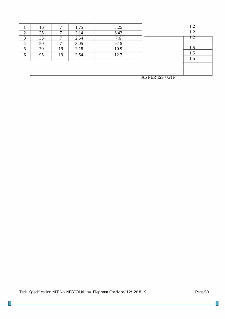
Tech. Specification NIT No. NESCO Utility/ Elephant Corridor/12/ 26.8.19 Page 50
1 16 7 1.75 5.25 2 25 7 2.14 6.42 3 35 7 2.54 7.6 4 50 7 3.05 9.15 5 70 19 2.18 10.9 6 95 19 2.54 12.7
AS PER ISS / GTP
1.2 1.2 1.2 1.5 1.5 1.5

Tech. Specification NIT No. NESCO Utility/ Elephant Corridor/12/ 26.8.19 Page 51
FOR MESSANGER CONDUCTORS
Sl. No.
Phase Conductor Size of the
LT AB Cable in
mm2
Specified Cross
Sectional Area of the Messanger Conductor
(mm2)
No. of Strands
Nominal dia Of each
strand
Appx. Over all dia. Of
conducting part of the compacted conductor.
(mm)
Maxm. D.C Resistance of
the messenger at
20 degree centigrade.( Ohm / Km)
Appx. Mass ( Kg / Km.) for
the messanger
1 16 25 7 2.14 5.2 AS PER ISS/GTP
65 2 50 35 7 2.54 7.6 95 3 70 50 7 3.05 9.15 136 4 95 70 7 3.6 10.8 191.8
6.0 (b) The bidder must take required precaution to ensure that the average diameter of each strand of
conductor shall be ascertained through physical measurement of dimensions of finished cables at ambient temperature during pre-dispatch inspection or / and verification at NESCO Store by consignee and the value so obtained shall have a tolerance limit with reference to the nominal diameter of each strand of conductor as stated in the tables above.
7.0 TOLERANCES: The measurement of strand diameter of the finished AB Cable shall not be less 0.03mm for
strands up to and including 3.00mm diameter. For strands above that size, measurement of strand diameter shall not be less than 1% of the nominal strand diameter.
For the purpose of checking compliance with the above requirement, the diameter shall be determined by two measurements at right angles taken at the same cross section. The physical measurement of strands shall be conducted after opening the strands of a finished AB Cable offered for inspection.
8.0 SPLICES IN WIRES:
Splices in Wires shall generally comply with requirements of IEC 1089. The aluminum alloy rods may be spliced by cold pressure but welding before drawing provided the manufacturer can guarantee that the splice can develop 90% of the tensile strength of the unsliced rod. Wires which break during stranding may be sliced by cold pressure butt-welding provided that: No two splices in the completed conductor occur within 15m of each other and no two splices in any individual wire are less than 150m apart. The splice shall be done with high skilled workmanship. The finished splice shall be smooth and at no point shall the cross sectional area be less than that of the un sliced wire. Splicing of the alloy wires on the stranding machine in order to utilize lengths of wires on reels shall not be permitted.
9.0 STRANDING AND CORE LAY:

Tech. Specification NIT No. NESCO Utility/ Elephant Corridor/12/ 26.8.19 Page 52
The conductor cores shall be stranded and the direction of lay must be as defined in IEC: 1089. 10.0 INSULATION:
The Aerial Bunched Cables shall be insulated for a voltage class of 0.65/1.1 KV and shall be capable of operating permanently at 1.2KV. The insulation wall thickness shall be determined in accordance with Table-4 (Clause-7.2 and Clause 7.3) of IS: 14255/1995.
The insulating material shall be black and suitable to resist ultra violet radiation, salt laden sprays, chemical pollution, ageing effects, abrasion and mechanical shocks and mechanical and electrical stress at temperature up to 90˚C in normal operation and 2500C under short circuit conditions per IEC: 502/1994. The carbon black content in the XLPE insulation shall be 2.5% ± 0.5%
11.0 PHASE IDENTIFICATION:
The individual insulated conductors within a bundle shall be identified by means of longitudinal projections.
The three phase conductors shall be marked by one, two or three longitudinal projections, indicating the R,Y,B phases .respectively. The projections shall have the following dimensions.
The distance between the tips of two adjacent projections, where there is more than one,
shall be between 1.0 and 1.5. The width of the projection at the base shall be 1.0mm; and
The height of the projections shall be 0.5mm.

Tech. Specification NIT No. NESCO Utility/ Elephant Corridor/12/ 26.8.19 Page 53
12.0 INSULATION MARKINGS: Each individual conductor comprising a bundle shall have the range of non-erasable distinct markings listed below legibly printed on the insulation surface at one meter intervals. The embossing should be very clear & easily visible to naked eye.
ISI Mark, IS 14255-95, Manufacturer‟s B.I.S License No. legibly embossed on the insulation. Name of the Purchaser.
P.O No. & Date
Manufacturer’s trademark identification for example “UCXLPE50”
Year of manufacture: last two digits are sufficient:
Designation of conductor type
Size: for example “3x50”
Shape of conductor.
Rated voltage class: 0.65/1.1KV
Back up conductor identification: conductors with one, two and three projections shall be marked R, Y and B respectively. The conductor with no projection shall be marked N and
The height of the printed lettering shall be not less than 20% of the overall diameter of the conductor
13.0 TWIST:
The direction of lay of the conductors comprising the bundle shall be left-handed and the lay ration shall comply with IEC: 1089.
With a bare catenaries configuration the insulated phase cables together with the street lighting cores shall be twisted round the neutral catenaries to form the ABC. This cable bundle is then strung directly onto the distribution poles supported by the catenaries with standard approved hardware.
14.0 CABLE DRUM LENGTH:
The cable shall be supplied in 500m or 1000 m Drum Lengths as the case may be for different sizes of LT XLPE AB Cable.
15.0 TESTS: 15.1 General
Where not specified, all tests and test results shall conform to the requirements of IEC 502/1994 or IS 7098 (Part-I) 1998, IS 10810/1984, IS: 398(Part-IV) and IS: 14255/1955. Unless expressly stated otherwise, the ambient temperature for routine tests as well as voltage tests shall be 20 + 150C and for all other tests be 20 + 150C.
The frequency of the alternating test voltage shall be 49 Hz to 51Hz. The voltage wave form

Tech. Specification NIT No. NESCO Utility/ Elephant Corridor/12/ 26.8.19 Page 54
should be sinusoidal. 15.2 Type Tests
The test sample shall be 10m to 15m in length. All cores of the bundles shall be tested.
Insulation resistance at ambient temperature.
Insulation resistance at operating temperature.
AC voltage test.
The insulation resistance test at ambient temperature shall be carried out in a water bath at ambient temperature. The insulation resistance test at a operating temperature shall be conducted in a water bath at 900C. The longitudinal projections used for phase identification shall be ignored. The results of this test shall be used to calculate the volume receptivity and the results conform to the requirements of IEC: 502/1994 or IS 10810 (Part-43).
The AC voltage test shall be carried out by applying 1.95KV (3U0) for four hours to the sample, which shall be submerged in a water bath at ambient temperature, having been steeped for a period not less than one hour. The test shall only be deemed to have been passed if no breakdown occurs.
Furthermore, the following non-electrical type tests shall also be carried out:
Insulation wall thickness: the longitudinal projections used for phase 1 identifications shall be ignored as per IS 10810 (Part-6);
Ageing test, consisting of an evaluation of the retention of the mechanical properties of the insulation after ageing.
Wrapping test: as per IS 10810 (Part-3);
Tests for bleeding and blooming of pigment as per IS 10810 (Part-9) Thermal expansion of insulation. Measurement of carbon black content as per IS 10810 (Part-32).
Water absorption by the XLPE insulation, shrinking of the XLPE insulation.
Tensile test: adhesion between conductor and insulation. The adhesion test requires a tensile testing machine. A sample of at least 300mm length shall be selected and straightened out. The insulation shall be removed for a length of 150mm. The insulated end shall be held in the upper grip head and the bare conductor on the lower grip head. Tension shall be applied at a speed of 500mm/ min until the conductor first begins to slide within the insulation. The test shall have been passed if the conductor and insulation combination can stand 75N/mm2 without slippage occurring.
The neutral conductor/catenaries shall be type tested in accordance with the requirements of IS

Tech. Specification NIT No. NESCO Utility/ Elephant Corridor/12/ 26.8.19 Page 55
398 (Part-IV) 1994. 15.3 Routine Tests
The following measurement or tests shall be carried out on all drums and coils of Bunched cable:
Conductor resistance Voltage test.
The conductor to be tested for conductor resistance shall be stored for at least 12 hours in a room at particular constant temperature. If it cannot be established that the conductors have reached the room temperature, the test should be postponed for a period of further 12 hours. Alternatively, the test can be carried out on short sample after remaining one hour in a temperature controlled water bath. The test shall be carried out and the conversion factors used to convert the resistance value to a base of 2000C and one Km. The DC resistance of each
conductor shall not exceed the appropriate maximum values specified in IEC:228/IS:6474.
The voltage test shall be conducted by applying to each core 3.5KV AC (2.5 U0 plus 2 KV) or
8.4 KV DC for 5 minutes with the specimen lying in a water bath at ambient temperature. The conductor shall pass the test if no electrical breakdown occurs.
15.4 Acceptance Tests
The following sample check, measurements and test shall be carried out in addition to the
Acceptance Tests as per IS 14255 – 1955, IS : 398 ( Part – IV ) 1994, IS 8130 / 1984
Measurement of insulation wall thickness;
Measurement of diameter of each strand, overall outside dia & Cross Sectional Area of the conducting Part out of the finished product during pre-dispatch inspection.
Thermal expansion test;
Check of physical characteristics

Tech. Specification NIT No. NESCO Utility/ Elephant Corridor/12/ 26.8.19 Page 56
Tensile strength of individual wires of conductor.
High Voltage Test on drums immersed in water(apply voltage 3.5 KV AC for 5 min)
These tests should be carried out on one length form each production batch of the same sample.
The thickness of the insulation wall shall be measured on a piece removed from each end of the sample length. If either means or minimum values are not met, two further samples shall be removed at 0.5m form the end corresponding to the failed specimen. If these samples do not satisfy the mean and minimum thickness requirements, the test shall be deemed to have been failed.
The longitudinal projections used for phase identifications shall be ignored. The thermal expansion test need only be carried out on one core.
In relation to the tensile test, the tensile strength of the aluminum wires before stranding and that of the finished conductor shall comply with IEC: 1089.
15.5 Test on the Catenary (messenger) Conductor
Breaking load, elongation and resistance tests shall be completed on the aluminum alloy catenaries conductor in accordance with the requirements of IS:398 (Part-IV)/1994 or IEC:1089.
15.6 Bending Test on a complete cable
This test shall be performed on a sample of completed cable. The sample shall be bent around a test mandrel at room temperature for at least on turn. It shall then be unwound and the process shall be repeated after turning the cable sample around its axis by 1800. This process shall be repeated twice more. There shall be no signs of breaking or cracking of the cable insulation during this test.
The diameter of the mandrel shall be:
10 (D+d)
Where D = Actual diameter of the cable (mm)
d = Actual diameter of the conductor (mm)

Tech. Specification NIT No. NESCO Utility/ Elephant Corridor/12/ 26.8.19 Page 57
15.7 Rejection and Retests
Should any one of the test pieces first selected fail to pass the tests, two further samples from the same batch shall be selected for testing, one of which shall be from the length from which the original test sample was taken unless the length has been withdrawn by the supplier.
Should the test pieces from both of these additional samples satisfy the requirements of the tests, the batch represented by these samples shall be deemed to comply with the standard. Should the test pieces from either of the two additional samples fail, the batch represented shall be deemed to have failed.
16.0 COMPLIANCE WITH SPECIFICATION:
The Aerial Bunched Cable shall comply in all respects with the requirements of this specification. However, any minor departure from the provisions of the specification shall be disclosed at the time of bidding in the Non-compliance Schedule of this document.
17.0 COMPLIANCE WITH REGULATIONS:
All the cables shall comply in all respects with the Indian Regulations and Acts in force. The cables and connections shall be designed and arranged to minimize the risk of fire and any damage, which might be caused in the event of fire.
18.0 NON-CONFORMING PRODUCT:
The Purchaser reserves the right for decisions regarding acceptance, modification or rejection of
non-conforming items.
19.0 INSPECTION AND TESTING:
The Purchaser or his authorized representative has free entry at all times, while work on the contract is being performed, to all parts of the manufacturer’s works which concerns the processing of the cables ordered. The manufacturer shall afford the purchaser or his authorized representatives without charge, all reasonable facilities to ensure that the cable being furnished is in accordance with these specifications.
The cables shall successfully pass all the routine tests & acceptance Tests referred to in the section on tests and those listed in the most recent edition of the standards given in the specification.

Tech. Specification NIT No. NESCO Utility/ Elephant Corridor/12/ 26.8.19 Page 58
The Purchaser reserves the right to reject any of the cables if the test results do not comply with the values specified or with the date given in the Technical data schedule.
Type Test Certificates for the tests conducted earlier shall be submitted with the bid for evaluation. The requirements of additional type tests will be at the discretion of the Purchaser
The Purchaser shall witness routine tests . In order to facilitate this, the contractor shall give the purchaser of 15days notice that the material is ready for inspection & testing. The supplier shall extend all assistance to the representative of the Purchaser during his inspection & testing of samples at his works. The materials shall be dispatched only after approval of such Test Reports and issue of Dispatch clearance by the Purchaser. However the Purchaser reserves the right to retest the materials after delivery at any NABL Accredited Testing Laboratory in case of any disputes regarding size & quality of supplied materials at a later date during guarantee period. The cost of such retesting shall be borne by the supplier.
All costs in connection with the testing, including any necessary retesting shall be borne by the Contractor, who shall provide the Purchaser with all the test shall have the right to select the samples for test and shall also have the right to ensure that the testing apparatus is correct. Measuring apparatus for routine tests shall be calibrated at the expense of the contractor at an approved laboratory and shall be approved by the purchaser before testing. The Contractor shall be responsible for the proper testing of the materials supplied by sub- Contractor to the same extent as if the materials were completed or supplied by the contractor.
Any cost incurred by the Purchaser in connection with inspection or retesting as a result of failure of the equipment under test or damaged during transport or off loading shall be to the account of the Contractor.
The Contractor shall submit to the Purchaser three signed copies of the test Certificates, giving the results of the tests as required. No materials shall be dispatched until the Purchaser has received the test certificate and the contractor has been informed that they are acceptable.
The test certificate must show the actual values obtained from the tests, in the units used in this specification, and most merely confirm that the requirements have been met.
In the case of components for which specific type tests or routine tests are not given in this specification, the Contractor shall include a list of the tests normally required for these components. All materials used in the Contract shall withstand and shall be certified to have satisfactorily passed such tests. No inspection or lack of inspection or passing by the Purchaser’s representative of equipment or materials whether supplied by the Contractor or sub- Contractor, shall relieve the contractor from his liability to complete the contract works in accordance with contract or exonerate him from any of his guarantees.
20.0 GUARANTEE:
The contractor shall guarantee the following:

Tech. Specification NIT No. NESCO Utility/ Elephant Corridor/12/ 26.8.19 Page 59
Quality and strength of materials used.
Satisfactory operation during the guarantee period of 24 months from the date of commissioning
or 30 months from the date of receipt of the cables at NESCO‟s store whichever is earlier.
Performance figures as supplied by the bidder in the technical data sheet. 21.0 PACKING AND SHIPPING:
The cable shall be wound on strong drums or reels capable of withstanding all normal
transportation and handing.
Each length of cable shall be durably sealed before shipment to prevent ingress of moisture. The
drums reels or coils shall be lagged or covered with suitable material to provide physical
protection for the cable during transit or during storage and handling operations.
In the case of steel drums adequate precautions shall be taken to prevent damage being caused by
direct contact between the cable sheath and the steel. These precautions hall be subject to the
approval of the Purchaser

Tech. Specification NIT No. NESCO Utility/ Elephant Corridor/12/ 26.8.19 Page 60
If wooden drums are used then the wood shall be treated to prevent deterioration from
attack by termites and fungi. Each drum or reel shall carry or be marked with following information:
Individual serial number
Standard ISI Mark, 14255-95, Manufacturer B.I.S License No.
Name of the Purchaser : NESCO
Destination
Purchase Order No. & Date
Manufacturer’s name
Year of manufacture
Cable size and type
Length of conductor (meters)
Net and Gross mass of conductor (Kg)
All necessary slinging and stacking instructions
Destination
Country of origin The direction of rolling as indicated by an arrow shall be marked on a flange. 22.0 STORAGE:
The site selected for the storage of cable drums shall be well drained and preferably
have a concrete/ firm surface which will prevent the drums sinking into the ground or being
subjected to excess water thus causing flange rot. All drums shall stand on battens, in the upright position and in such a manner to allow sufficient space between them for adequate air circulation. During storage the drums shall
be rotated 900 every three months. In no instances shall be the drums be stored “flat” on their flanges or one on top of each other.
23.0 SHIPPING:
The Contractor shall be responsible for the shipping of all cables, drums and reels supplied
from abroad to the ports of entry and for the transport of all goods to various specified
destinations including customs clearance, off loading, warehousing and insurance.

Tech. Specification NIT No. NESCO Utility/ Elephant Corridor/12/ 26.8.19 Page 61
The Contractor shall inform himself fully as to all relevant transport facilities and
requirements and loading gauges and ensure that the equipment as packed for transport
shall conform to these limitations. The contractor shall also be responsible for verifying the
access facilities specified. The contractor shall be responsible for transportation of all the loads associated with the
contract and shall take all reasonable steps to prevent damage of any highway or bridges
by his vehicles by selecting routes, choosing proper vehicles for use and restricting and
distributing loads to avoid the risk of damage. The Contractor shall immediately report to
the Purchaser any claims made against the contractor arising out of alleged damage to a
highway or bridge. All items of equipments shall be securely clamped against movement to ensure safe transit from
the manufacturer’s facilities to the specified destinations. 24.0 HAZARDOUS SUBSTANCES:
The Contractor shall submit safety data sheets for all hazardous substance used with
the equipment. The contractor shall give an assurance that there are no other substances
classified as hazardous in the equipment supplied. He shall also take responsibility for the
disposal of such hazardous substances that may be found for any injuries resulting from
those substances. 25.0 SUBMITTALS:
The following shall be required in duplicate along with the bid:
Completed technical data sheets;
Descriptive literature giving full technical details of equipment offered.
Outline dimension drawing for each type of conductor, for each bundle
showing the conductor strand, composition and the bundle twist;
Type test certificates, where available, and sample routine test reports;
Detailed reference list of customers already using equipment offered during
the last five years with particular emphasis on units of similar design and rating;
Performance reports from the customers for the supplied LT XLPE AB Cables.
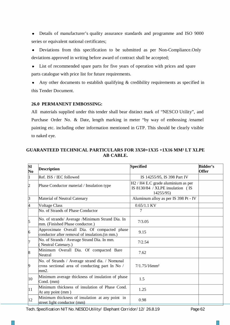
Tech. Specification NIT No. NESCO Utility/ Elephant Corridor/12/ 26.8.19 Page 62
Details of manufacturer’s quality assurance standards and programme and ISO 9000
series or equivalent national certificates;
Deviations from this specification to be submitted as per Non-Compliance.Only
deviations approved in writing before award of contract shall be accepted;
List of recommended spare parts for five years of operation with prices and spare
parts catalogue with price list for future requirements.
Any other documents to establish qualifying & credibility requirements as specified in
this Tender Document. 26.0 PERMANENT EMBOSSING:
All materials supplied under this tender shall bear distinct mark of “NESCO Utility”, and
Purchase Order No. & Date, length marking in meter “by way of embossing /enamel
painting etc. including other information mentioned in GTP. This should be clearly visible
to naked eye.
GUARANTEED TECHNICAL PARTICULARS FOR 3X50+1X35 +1X16 MM² LT XLPE
AB CABLE.
Sl No
Description Specified Bidder’s Offer
1 Ref. ISS / IEC followed IS 14255/95, IS 398 Part IV
2
Phase Conductor material / Insulation type H2 / H4 E.C grade aluminium as per IS 8130/84 / XLPE insulation ( IS
14255/95)
3 Material of Neutral Catenary Aluminum alloy as per IS 398 Pt - IV
4 Voltage Class 0.65/1.1 KV No. of Strands of Phase Conductor 7
5 No. of strands/ Average /Minimum Strand Dia. In mm. (Finished Phase conductor.)
7/3.05
6 Approximate Overall Dia. Of compacted phase conductor after removal of insulation.(in mm.)
9.15
7 No. of Strands / Average Strand Dia. In mm. ( Neutral Catenary.)
7/2.54
8 Minimum Overall Dia. Of compacted Bare
Neutral Caternary .(in mm.)
7.62
9
No. of Strands / Average strand dia. / Nomunal cross sectional area of conducting part In No / mm2. ( St. Light Conductor)
7/1.75/16mm²
10 Minimum average thickness of insulation of phase Cond. (mm)
1.5
11 Minimum thickness of insulation of Phase Cond. At any point (mm )
1.25
12 Minimum thickness of insulation at any point in street light conductor (mm)
0.98

Tech. Specification NIT No. NESCO Utility/ Elephant Corridor/12/ 26.8.19 Page 63
13 Maximum DC resistance of Phase conductor at 20
o C ohmn/ KM
0.64
14 Maximum DC resistance of street light conductor Ω/ Km
1.91
15 Maximum DC resistance of neutral cond. Ω / Km 0.986 16 Ultimate tensile strength of neutral conductor (KN) 14 17 Maximum temperature (Continuous) 90°C for phase and 75 °C for neutral 18
Embossing on insulation at each one meter interval
Distinct Non-erasable ISI Mark, IS 14255-95, Manufacturer‟s B.I.S
License No., Name of the Purchaser, Name of the manufacturer, Size of
cable, voltage Grade along with sequential marking of length..
19 Cable drum length 500 / 1000m 20 Volume Resistivity of insulation at 27°C 1X10¹³Ώ - cm min.
21 Volume Resistivity of insulation at 70°C 1X10¹¹Ώ - cm min.
Signature of the bidder with Seal
Suspension Clamp Dead End Clamp Pole Clamp with Eye Hook
1.0 Scope
This specification covers the design, manufacture, assembly, testing and supply of Suspension Clamp, Dead end Clamp & Eye hook for making connections to Aerial Bunched Cables rated 1100 volts and insulated with cross-linked polyethylene.
2.0 Standard
The design, performance and test requirements shall confirm to this specification and
the following standards. However in case of any conflict, the requirements of this specification shall prevail.
1) REC Specification 32/1984
2) REC Specification 84/2010 (dead end & Suspension clamp)
The devices shall also be compatible with the cables of sizes & dimensions as defined in the cable Specifications for the cables with which they are intended to be used.
3.0 Type Test For all accessories, the Type Test Report should be submitted from an Independent NABL Accredited Laboratory like CPRI

Tech. Specification NIT No. NESCO Utility/ Elephant Corridor/12/ 26.8.19 Page 64
The Test report shall include the Model Number, Applicable size Range, and GA Drawing showing the principal parts and dimensions of the connector.
4.0 Acceptance Test
The Acceptance Tests & sampling plan to be conducted as per REC Spec. 83/ 2010 and as per relevant IS Specifications.
4.4 Drawings & Samples:
GA drawing and other particulars along with samples are to be submitted along with offer.
ANCHOR (DEAD END) & SUSPENSION CLAMPS 5.0 Scope This specification covers the design, manufacture, assembly, testing and supply of Accessories for anchoring & suspending Aerial Bunched Cables rated 1100 volts and insulated with cross-linked polyethylene and aluminum alloy bare messenger.
Description Application
a)
Dead end Clamp ( as per REC Construction standard E-35)
For fitting onto a pole for anchoring the end of a length of ABC, or for a major change in direction.
b)
Suspension Clamp (Bolted Type asper REC Construction standard E-34)
For supporting a length of ABC at an intermediate pole in a length, with small angle of deviation.
5.1 Cable Data
The standard sizes and characteristics of the phase and street lighting conductors, messenger wires shall be as specified in REC specification 32/1984 or IS: 14255-1995. The strength of the messenger shall be not less than the Value shown in Table 1.
Table-1
Conductor Size (mm2.)
Messenger Rating (as per IS 14255)
35 9.8 KN
70 17.5 KN
5.2. Marking / Embossing
Anchoring Clamp, Suspension clamp should bear
- Manufacturers trade mark and logo

Tech. Specification NIT No. NESCO Utility/ Elephant Corridor/12/ 26.8.19 Page 65
- Name of Purchaser, P.O. No. & Date. - Product Code or Reference
- Traceability Code/Batch Number 5.3. Type Test For Dead End & Suspension clamps, the Type Test Report s should be submitted from an Independent NABL Accredited Laboratory / CPRI as per REC Spec-84/2010.
5.4 Acceptance Tests
The Acceptance Tests & sampling plan to be conducted as per REC Spec. 84/ 2010. & as per relevant
IS Specifications.. 5.5 Drawings & Samples:
GA drawing and other particulars along with samples are to be submitted along with offer.
6.0 EYE HOOKS
a) Eye hooks shall be as per REC construction standard E-35 (Type – A) b) It should be made of forged hot dip galvanized steel as per IS-1570 c) The clamp corrosion resistance should conform to standards IS 2629 & IS 2633. d) Minimum breaking Load should be 20 KN.
6.1 Type Test For Eye hooks, the Type Test Report s should be submitted from an Independent NABL Accredited Laboratory / CPRI as REC Spec-32/1984 & 84/2010 and as per relevant IS Specifications.
6.2 Acceptance Tests
The Acceptance Tests & sampling plan to be conducted as per REC Spec. 32/ 1984. &
84/2010 and as per relevant IS Specifications. 6.2 Drawings & Samples:
GA drawing and other particulars along with samples are to be submitted along with offer.
GUARANTEED TECHNICAL PARTICULARS FOR SUSPENSION CLAMP FOR BARE MESSENGER WIRE
Sl. No.
Description
Guaranteed particulars to be submitted by
the Vendors along with offer
1
Name and address of the manufacturer

Tech. Specification NIT No. NESCO Utility/ Elephant Corridor/12/ 26.8.19 Page 66
2
Applicable standard
3
Type of clamp
4
Type of design
5
Voltage Grade(kV)
6
Loop anchor attachment(open/close)
7
Installation (with/without dis-assembly)
8 Type & grade (metallic/non-metallic material)
9 Type of hot dip galvanizing & thickness of Zinc coating
10
Marking
11
Colour of non-metallic parts
12
Dimensions
13
Approximate weight
14
Minimum Breaking Load (KN)
15
Maximum allowable load(KN)
16 Max. angle of deviation of conductor (degrees)
17
18
Method of casting
Are GA drawing & samples enclosed
Signature of the bidder with Seal
GUARANTEED TECHNICAL PARTICULARS FOR DEAD END CLAMP FOR BARE MESSENGER WIRE (To be submitted along with offer)
Sl..
Description
Guaranteed particulars to be submitted by the Vendors
1
Name and address of the manufacturer
2
Applicable standard
3
Type of clamp
4
Type of design

Tech. Specification NIT No. NESCO Utility/ Elephant Corridor/12/ 26.8.19 Page 67
5
Voltage Grade(kV)
6
Loop anchor attachment(open/close)
7
Installation (with/without dis-assembly)
8 Type & grade (metallic/non-metallic material)
9 Type of hot dip galvanizing & thickness of Zinc coating
10
Marking
11
Colour of non-metallic parts
12
Dimensions
13
Approximate weight
14
Ultimate tensile strength(KN)
15
Maximum allowable load(KN)
16
Slip Strength (KN)
17
18
Method of casting Operating temperature (deg.cent) a) Continuous Operation b) Short circuit condition
Are GA drawing & samples enclosed
Signature of the bidder with Seal
Guaranteed Technical Particulars of Eye Hook
Sl. No.
Description
Guaranteed Technical Particulars submitted by
Vendors
1
Name and Address of the Manufacturer
2 Type of Hooks

Tech. Specification NIT No. NESCO Utility/ Elephant Corridor/12/ 26.8.19 Page 68
3 Maximum weight span for 4x95's Maximum weight span for 4x50's
4 Horizontal pull out load
5 Types of Facades for which it is suitable
6 Stand off from Facade
7 Method of fixing to Façade
8 Installation(with/without disassembly)
9 Type and grade of Metallic Material
10 Type of Hot Dip Galvanizing Thickness of Zinc Coating
11 Markings:- As specified in IEC - 947
12 Dimensions
13 Net Weight 14 Ultimate tensile strength
15 Acceptance tests
Signature of the bidder with Seal
Barbed Wire TECHNICAL SPECIFICATION FOR G.I. BARBED WIRE STANDARDS: Unless otherwise specified elsewhere in this specification, the rating as well as performance and testing of the G.I.Barbed wire shall conform to the latest revisions available at the time of placement of order of all the relevant standards but not limited to as listed below. IS:280:1978 Mild steel wire for general engineering purposes (third revision) IS:1340:1977 Code of practice for chromate conversion coating of zinc and cadmium coated articles and zinc base alloys (first revision) IS:1521:1972 Method for tensile testing of steel wire (first revision) IS:1755:1983 Method for wrapping test for metallic wire (first revision) IS:2633:1986 Method for testing uniformity of coating of zinc coated articles(second revision) IS:4826:1979 Hot dipped galvanized coating on round steel wires (first revision) IS:12753:1989 Electro galvanized coatings on round steel wire – Specification 3. GENERAL TECHNICAL REQUIREMENTS: GI Barbed wire shall be 2 PLY with a 2.5mm diameter. The barbs shall have a 2mm diameter and be 12.5mm in length. The barbs shall have four points and shall be formed by twisting two point wires,

Tech. Specification NIT No. NESCO Utility/ Elephant Corridor/12/ 26.8.19 Page 69
each two turns, tightly around both line wires making altogether four complete turns. G.I. Barbed wire shall be of type IOWA with size and dimensions as under:- Line wire - 2.5 mm Point wire - 2.0 mm Distance between two bars shall be 75 mm ( + 12 mm ). SPECIFIC TECHNICAL PARTICULARS FOR 2.5 MM X 2.0 MM G.I.BARBED WIRE
Sl.No. Particulars Particulars Specified Bidders Offer 1 Size of wire- mm Line wire- 2.5 mm + 0.08 mm
Point wire- 2.0 mm + 0.08 mm
2 Type of Barbed Wire Iowa Type 3 Tensile strength of line
wire 390 to 590 N/mm²
4 Minimum breaking load of completed Barbed wire
3.7 KN
5 Mass of complete Barbed wire (minimum)
115 gms / Mtr.
6 Distance between two Barbs
(75 + 12 ) mm
7 No. of lays between the Barbs ( minimum )
4
8 Method of Galvanising Hot dipped according to IS:4826 /1979 with medium coating.
9 Mass of coating (minimum) Line wire- 110 gms/Mtr² Point wire- 105 gms/Mtr² ( testing after barbing )
10 No. of dips the wire is able to withstand without copper coating
( testing after barbing )
A) For Line Wire 2 dip in Min B) For Point Wire 2 dip in Min
Signature of the bidder with Seal
SUB-STATION FENCING WITH BARBED WIRE: For Sub-Station fencing with Barbed wire refer attached Drawing MATERIALS HANDLING AND INSURANCE The contractor shall deliver all equipment/materials against this contract to his site stores under cover of Transit Insurance to be taken in his name. Cost of such insurance is to be borne by the contractor. Cost of transportation of all materials from contractor‟s store to the site of work as well as department supply items like Conductors, AB cables, Power cables, etc shall be borne by the contractor irrespective of mode of transportation and site condition.The contractor has to bear the cost of premiums on insurance for all materials, tower accessories and total erection cost of the line including cement, rods for foundation.

Tech. Specification NIT No. NESCO Utility/ Elephant Corridor/12/ 26.8.19 Page 70
It will be the responsibility of the contractor to report to the concerned Police Station about all incidents of thefts and lodge, pursue and settle all claims with Insurance Company in case of damage/loss due to theft, pilferage, flood and fire etc. and the employer of the work shall be kept informed promptly in writing about all such incidents. The loss, if any, on this account shall be recoverable from the contractor if the claims are not lodged and properly pursued in time or if the claims are not settled by the insurance company due to lapses on the part of the contractor. The contractor shall have to replenish promptly damaged, stolen tower members and accessories conductors, earth wire, hardware‟s etc. and repair/re-erect the damaged lines, free of cost to the employer so as to maintain the programme of work. The employer will not be responsible in any way for such loss of materials.
TECHNICAL SPECIFICATIONS FOR 11 KV COVERED CONDUCTORS
INTRODUCTION:
These Specifications lay down the Constructional, Dimensional and Performance
Requirements for Covered Conductors which consist of a Conductor surrounded by a Covering made of Insulating Material (as described hereunder) as protection against Accidental temporary Contacts with Grounded Parts such as Tree Branches and with other Covered Conductors and etc.
CONSTRUCTION REQUIREMENTS:
1) CONDUCTOR:
CONDUCTOR MATERIAL: Aluminium Alloy (AAAC)
NOMINAL CROSS SECTION: 99 sq mm for AAAC
CONDUCTOR DESIGN: The Conductor shall be stranded, round and should be
Non Compacted. Non Compacted Conductors shall comply with all the requirements of EN 50397- 1-2006. The D.C. Resistance of the conductor shall not exceed that given in EN 50397-1- 2006 by more than 5%.
2) FILLING (WATER BLOCKING):
The Stranded Conductor shall be longitudinally water blocked by means of a water blocking material incorporated during the extrusion process. The use of grease / water swellable tape / water swellable powder etc is not permitted. The water blocking material shall be stable at maximum operating conductor temperature of 90 Deg. Centigrade.

Tech. Specification NIT No. NESCO Utility/ Elephant Corridor/12/ 26.8.19 Page 71
The water blocking compound shall be compatible with the conductor material aswell as the semi conducting polymer screen layer above it and not adversely affect its electrical or mechanical properties.
3) SEMICONDUCTING SCREEN:
A semi conductive polymeric screen should be applied over the filled stranded conductor to ensure a lower voltage stress on the Insulation applied over the screen. The thickness of the semi conductive polymeric screen should be between 0.2 mm and 0.4 mm.
4) INSULATION: The Insulation should be dual layered with the Inner Layer being XLPE with a nominal thickness of 1.2 mm for voltage 11KV and the Outer Layer being a suitable Polymer which is UV Resistant, Non Tracking and Erosion Resistant with a nominal wall thickness of 1.1 mm for Voltage 11KV. The nominal combined Insulation Thickness of both Layers should be 2.3 mm for 11 KV. The conductor manufacturing and stranding process shall incorporate the longitudinal water blocking also.
The Semi Conducting Screen, Inner Insulation and Outer Insulation should be extruded in one step ie triple extrusion to ensure a good, permanent bond between the three layers and also with the conductor. It shall be possible to remove the Semi Conducting Screen, Inner and Outer Insulation Layers without damage to the conductor, but there shall be no slippage between the layers. The Cross Section of a Covered Conductor with AAAC Conductor as shown in the figure.
FIGURE ( AAAC )

Tech. Specification NIT No. NESCO Utility/ Elephant Corridor/12/ 26.8.19 Page 72
5) INSULATION MARKING / EMBOSSING :
Each individual cable shall have the markings on insulation at 1 mtr intervals listed below :-
• Purchaser’s Name : NESCO Ut il i ty • Manufacturer’s trademark : • Year of manufacture : • Designation of Cable Type : • Size of Cable :
The height of printed lettering shall be not less than 20% of the over all diameter of the conductor.
6) TYPE TESTS:
TEST FOR COVERED CONDUCTORS as per EN 50397-1-2006
i. Conductor Resistance Test ii. Thickness of Insulation & Covering iii. Tensile strength iv. Percentage Elongation at break of Insulation before ageing, after ageing &
Completed v. Cable ageing Carbon black content test on outer covering (If applicable) Shrinkage test
on outer covering. vi. Shrinkage test on Insulation
vii. Hot set test on Insulation
viii. Water Absorption test on Insulation
ix. Test for longitudinal water tightness
x. AC High Voltage test xi. Leakage Current Measurement xii. Tracking Resistance test xiii. Slippage Test xiv. Marking :
ELECTRICAL TESTS:
A) Conductor Resistance Test: To be done as a Routine as well as Type Test as per
EN 50397-1-2006.
B) High Voltage Test as per EN 50397-1-2006. – Type test
Test Voltage --- Phase to Phase Voltage of the System for which the Covered Conductor is used. No. of Specimens --- One Length of Specimen (minimum) ---- 5 metres

Tech. Specification NIT No. NESCO Utility/ Elephant Corridor/12/ 26.8.19 Page 73
Duration of Immersion in Water (minimum) ---- 1 Hour Temperature of Water ---- (20 +/- 5) Degrees Centigrade Test Duration --------------- 4 Hours for Routine Test 48 Hours for Type Test
Requirement: No Breakdown
C) Spark Test on Covering: Routine test
Test Voltage 0.7 X Phase to Phase Voltage of System (A, C,) or
Phase to Phase Voltage of System (D. C.) Requirement: No Breakdown D) Leakage Current Test - Type test
Test Voltage 0.7 X Phase to Phase Voltage of System (A. C.)
Requirement: Maximum Leakage Current 1mA
E) Tracking Resistance: - Type test
NON – ELECTRICAL TESTS ON COVERING: Type tests
A) Mechanical Properties :
a) Before Ageing of Sample: As per Table 1 (as per EN 50397-1-2006)
b) After Ageing of Sample: As per Table 1 (as per EN 50397-1-2006)
c) Ageing of Complete Product Sample: As per Table 1 (as per EN 50397-1-2006)
d) Hot-Set-Test: As per Table 1 and in accordance to (as per EN 50397-1-2006)
e) Pressure Test at High Temperature: As per Table 1 and in accordance with EN 60811- 3-1, Sub Clause 6.1.
h) Water Absorption: As per Table 1 and in accordance with EN 50397-1-2006
TEST FOR LONGITUDINAL WATER TIGHTNESS
a) As Type Test with Heat Cycle and in accordance with 50397-1-2006. No of Specimen – 1
Length of Specimen – 3 metres
Test Duration -- 24 hours
Bending Radius – 20 X Diameter of Covered Conductor
Requirement – No Leakage
b) As Routine Test without Heat Cycle and in accordance with IEC 60502 -2

Tech. Specification NIT No. NESCO Utility/ Elephant Corridor/12/ 26.8.19 Page 74
No of Specimen – 1
Length of Specimen – 1 metre
Test Duration – 1 Hour
7) MARKING:
The packed cable drum having length of 500 mtr. -1000 mtr. shall carry the following information, clearly painted or stenciled
a) The letters NESCO Utility
b) Reference to Standard and ISI mark
c) Manufacturer’s Name or trade mark.
d) Type of cable & voltage grade
e) Number of cores
f) Nominal cross-sectional area of conductor.
g) Cable code
h) Length of cable on the drum
i) Gross weight
j) Country of Manufacture
k) Year of Manufacture
l) Purchase order and date
m) Address of consignee
8) Guaranteed Technical Particulars (GTP)
Bidder shall confirm by signing with stamp on the GTP
GUARANTEED TECHNICAL PARTICULARS OF 11KV INSULATED CONSUCTOR
Si.No.
Parameters
offered Values for specified
covered conductor
1 Cable Size 2 Manufacturer & Address 3 Trade Name 4 Conductor type 5 Applicable specification & Standards 6 Voltage Class 7 Lay up of Conductors (mm) 8 Conductor Dia (mm) 9 Inner Semiconducting Layer thickness (mm) 10 Inner XLPE Layer thickness (mm) 11 Outer UV Resistance - XLPE Thickness (mm)

Tech. Specification NIT No. NESCO Utility/ Elephant Corridor/12/ 26.8.19 Page 75
12 Over all diameter (Min-Max) (mm) 13 Weight (Kg/Km) 14 Rated Operated Voltage (KV) 15 DC-resistance at 20 Degree C, Maximum (Ohm/KM) 16 Resistance Temperature coefficient (/0C) 17
Lightening Impulse withstand strength of XLPE Layer (KV) 18 Maximum Continuos Operating temperature (0C)
19 Max load(IEC 61597), cond.temp 80 °C, air temp. 40 °C, wind speed 0.5 m/s, Solar radiation 1045W/m², Approximate value (A)
20 Max short circuit current, 1 sec (KA) 21 Tensile Strength of Conductors (kN) 22 Conductor/ Insulation Screening i) Type ii) Material iii) Nominal thickness iv) Continuous working temperature 23 Drum length
Name & Signature of Bidder with Seal
Other Requirements The offered triple extruded AAAC ( AlMgSi alloy ) conductor shall be suitable for use under operating condition as specified below:
1. Ambient air temperature : 40 deg C 2. Maximum temperature of conductor at rated current : 80 deg C 3. Wind condition at site : 0.5 meter / sec 4. Solar radiation at site : 1045 watts / sq m 5. Maximum allowable temperature under Short circuit condition : 250 deg C
Tech. Specification NIT No. NESCO Utility/ Elephant Corridor/12/ 26.8.19 Page 76
TECHNICAL SPECIFICATION FOR 11 KV OUTDOOR VACUUM CIRCUIT BREAKERS
1. SCOPE
1.1 This specification covers design, engineering, manufacture, testing, inspection before dispatch
packing, forwarding, transportation, insurance during transit, delivery to site/ stores of 11 KV
Outdoor Vacuum Circuit Breakers for use the 33/11KV primary substations for feeder
protection under the distribution networks of NESCO.
1.2 All vacuum circuit breakers must be manufactured by ISO 9000 certified Organization and shall
have been type tested at CPRI or any NABL Accredited laboratory/PHELA/KERI/KEMA/CESI
laboratory within five years as on the date of bid opening and in satisfactory operation for a
period not less than three years. The Bidder shall demonstrate compliance with this requirement
by supplying with the bid, copies of the type test certificates together with performance
certificates from purchasers/ users.
1.3 The scope of supply includes the provision of type tests at CPRI or any NABL Accredited
laboratory/PHELA/KERI/KEMA/CESI laboratory within last five years.
1.4 The scope also includes the circuit breaker and current and potential transformers, supporting
structures, operating mechanism, local/ remote control cabinet, relay control panel, foundation
bolts, all the accessories and auxiliary equipment mandatory spares and special tools for
satisfactory installation and operation.
1.5 The circuit breakers shall conform in all respects to the highest standards of engineering, design,
workmanship, this specification and the latest revisions of relevant standards at the time of offer
and the purchaser shall have the power to reject any work or materials, which, in his judgment,
is not in full accordance therewith.
2. STANDARDS
Expect where modified by this specification, the circuit breakers and the accessories shall be
designed, manufactured and tested in accordance with latest editions of the following standards.

Tech. Specification NIT No. NESCO Utility/ Elephant Corridor/12/ 26.8.19 Page 77
IEC/ISO/BS
IS Subject
IEC: 56 IEC:62271-100& 200
IS: 13118 High voltage alternating current circuit breakers general
requirement.
IEC: 694
IS: 12729 Common clauses of high voltage switch-gear and control gear
standards (for voltage exceeding 1000 V). IEC: 60
IS: 9135 High Voltage testing techniques.
IEC: 427 IS: 13516 Method of synthetic testing of HV .A.C circuit breakers. IEC: 1233
HV. AC. Circuit breakers- inductive load switching.
IEC: 17A/CD:474
HV. AC. Circuit breakers- capacitive switching.
IEC: 529
IS: 13947 Degree of protection provided by enclosure.
IEC: 137
IS: 2099 Insulating bushing for A.C. voltages above 1000V
IEC: 233
IS : 5621 Hollow insulators for use in electrical equipment & testing.
IEC: 273
IS: 5350 Characteristics of indoor and outdoor post insulators for systems
with nominal voltages greater than 1000V. IEC: 815
IS: 13134 Guide for selection of insulators in respect of polluted conditions.
IEC: 34
IS: 996 A.C motors
ISO: 1460 BS: 729
IS: 2629 Hot dip galvanizing
IS: 2633 Method of testing uniformity of zinc coated articles.
IS: 5 Colour for ready missed paints and enamels
IS: 6005 Code of practice for phosphating or iron and steel.
IEC: 227
IS: 1554 P.V.C Insulated cables for voltages up to and including 1100 Volt.
IEC: 269
IS: 13703 Low voltage fuses for voltages not exceeding 1000volt.
ISO: 800
IS: 1300 Phenolic moulding materials.
IS: 13118 Guide for uniform marking and identification of conductors and
apparatus terminals. IEC: 185
IS: 2705 Current transformers.
IEC: 296
IS: 335 Specification for unused insulating oil for transformer and
switchgear. IEC:186
IS: 3156 Potential transformers.

Tech. Specification NIT No. NESCO Utility/ Elephant Corridor/12/ 26.8.19 Page 78
CBIP Technical Report No. 88
revised July, 1996 read with
amendment issued (April, 99,
September, 99 and also any other
amendment thereafter)
Specification for AC Static Electrical Energy Meter.
This list is not to be considered exhaustive and reference to a particular standard or
recommendation in this specification does not relieve the Supplier of the necessity of providing
the goods and services complying with other relevant standards or recommendations.
3. REQUIREMENTS
The circuit breakers to be supplied against this specification shall be required to control the
secondary side of 33/11 KV power transformers in the primary sub-stations or Bus coupler or
the outgoing feeders in these sub-stations. The circuit breakers shall be suitable for 3 phase 50Hz
solidly grounded neutral system and shall have normal current carrying capacity and
symmetrical short circuit current breaking capability as mentioned hereunder.
The required 11 KV Vacuum Circuit Breakers suitable for outdoor installations are to be quoted
by Manufacturers only with a valid ISO 9000 certification.
3.1 BASIC TECHNICAL REQUIREMENTS:
The vacuum circuit breakers are required to meet the following basic technical requirements.
(Reference standards IEC: 56,IEC:62271-100&200, IS:13118 and associated standards listed in
this specification.
Basic Technical Requirements
Sl. No
Particulars Requirements
1 Service type Outdoor 2 No. of Poles 3 3 Nominal system voltage 11 KV 4 Highest system voltage 12 KV 5 Rated normal current at 500C i) For Bus-bar of Circuit Breaker 800 A ii) For Interrupter 1250 A
iii) For Outgoing Feeders/Transformer 1250 A 6 Rated short circuit breaking current (rms) 25KA 7 Rated short circuit making current (peak) 63KA 8 Rated short time current withstand capability for 3 sec. 25KA 9. Rated insulation level: i) One minute power frequency withstand voltage to earth (wet and 28 KV

Tech. Specification NIT No. NESCO Utility/ Elephant Corridor/12/ 26.8.19 Page 79
dry) rms ii) Impulse withstand voltage to earth with 1.2/50sec, wave of +ve and
–ve polarity (Peak) 75 KV
10 First – pole – to clear factor 1.5 11 Rated operating sequence (for auto reclosing) O-0.3 Sec- CO-3 min-CO 12 Maximum break time 3 cycles 13 Rated out of phase breaking current 25% of the symmetrical
short circuit breaking current
14 Maximum pole scatter 10 mille seconds 15 Rated Auxiliary supply for spring charge motor, lamp & heater
circuit. 230V A.C
16 Rated supply voltage for trip/close coil 24V D.C 17 Minimum creepage distance (mm) 350 mm 18 Minimum protected creepage distance (mm) 280 mm
4. SERVICE CONDITIONS:
The service conditions shall be as follows:
Maximum a altitude above sea level 1,000m
Maximum ambient air temperature 500C
Maximum daily average ambient air temperature 350C
Minimum ambient air temperature 50C
Maximum temperature attainable by an object exposed to the sun 600C
Maximum yearly weight average ambient temperature 320C
Maximum relative humidity 100%
Average number of thunderstorm days per annum (isokeraunic level) 70
Average number of rainy days per annum 120
Average annual rainfall
1500mm
Maximum wind pressure
260Kg/m2
5. 11 KV VACUUM CIRCUIT BREAKERS
5.1 General
The circuit breakers shall be structure mounted open type with vacuum as interrupting media
incorporating separate interrupters of 1250 A rating for each phase mounted on single frame.
There shall be a common drive mechanism actuating the interrupters, which must work in
synchronism. These breakers shall be provided with suitable local control while provision shall
be made for remote control.

Tech. Specification NIT No. NESCO Utility/ Elephant Corridor/12/ 26.8.19 Page 80
The circuit breakers shall be fitted with spring mechanism. The inherent design of these circuit
breakers shall be such that they shall satisfactorily perform all test duties and interrupt out-of-
phase current and produce very low over voltage (<2.0p.u.) on all switching circuits, capacitive
and inductive to IEC:56, IS:13118 and other associated standards mentioned in the clause of this
specification.
The terminal pads shall have silver-plating of at least 50 micron thickness. The design of the
circuit breakers shall be such that inspection and replacement of contracts, coils, vacuum bottles
and any worn or damaged components can be carried out quickly and this ease. The contract gaps
shall be adjustable to allow for wear.
The mechanism and the connected interrupters shall satisfy the mechanical endurance
requirements of IEC: 56, IS: 13118 and all additional requirements specified herein.
5.2 Porcelain Insulator
External parts of the circuit breakers, which are under continuous electrical stress, shall be of
hollow porcelain. The creepage and flashover distance of the insulators shall be dimensioned
and the type and profile designed in accordance with IEC:815 or IS: 13134 and shall be suitable
for the worst environmental conditions specified in this specification. The creepage distance
across the interrupting chambers shall suite the outdoor service conditions mentioned in the
relevant standards for heavily polluted atmosphere and shall be not less than 350 mm with
minimum protected creepage distance 280 mm. Internal surfaces of hollow insulators shall also
be glazed. The insulators shall comply with IS:5621 and tested in accordance with IEC:233.
All porcelain whether, used on the interrupting chamber or on the support insulator shall have
the following properties:
Higher strength, homogeneity, uniform glaze, free from cavities and other flaws and high quality
uniform finish porcelain components and shall withstand the maximum expected static and
dynamic loads to which the circuit breakers may be subjected during their service life. 5.3
Interrupting media 5.3.1
Vacuum:
In vacuum circuit breakers, facilities shall be provided for monitoring the contract erosion and
any change in contact gap. The vacuum bottles shall be easily replaceable on site and the
mechanism shall be conveniently adjustable to permit resetting the contact gap.
The vacuum circuit breaker poles shall be sealed to prevent contamination of the spaces
surrounding the interrupters. The Bidder shall demonstrate how this is achieved by supplying
technical details with the bid. 5.4
Auxiliary contracts

Tech. Specification NIT No. NESCO Utility/ Elephant Corridor/12/ 26.8.19 Page 81
12 auxiliary contacts (6N.O.+6N.C.) of 24 Volt D.C grade and 10 amps DC rating shall be
provided in each circuit breaker. 5.5
Indication
A mechanically operated circuit breaker position indicator of non corroding material shall be
provided in a location visible from the operating side of the breaker without the necessity to
open the mechanism door. The word „OFF‟ in white letter on green background shall be used to
indicate that the breaker is in the opening position and the word „ON‟ in white letters on a red
background to indicate that the breaker is in the closed position. The drive for the device shall be
positive in both directions and provision shall be made for local and remote electrical indication.
Indication of spring charging condition shall be provided as mentioned in this specification.
Mechanical counters to record the number of closing operations shall be provided for each
circuit breaker mechanism. 5.7 Operation and controls
The breaker shall normally be operated by remote electrical control with electrical tripping by
shunt trip coil. Provision shall be made for local electrical operation and mechanical operation.
The following facilities shall be provided in the circuit breaker local control cabinet:
LOCAL/ REMOTE selector switch of stay put type. The selection of „local‟ operation
shall inhibit the operation of the breaker from any remote source.
ON/NEUTRAL/ OFF control switch or ON and OFF push buttons. The push buttons
shall be momentary contract type with rear terminal connections. The close push button
shall be of green colour and the open push button red colour.
MECHANICAL EMERGENCY TRIP DEVICE: suitable for manual operation in the
event of failure of electrical supplies. The device shall be accessible without opening
any access doors and distinctly labelled. It shall be shrouded and protected against
inadvertent operation.
Means shall be provided for manual operation of these circuit breakers during failure of
auxiliary power in addition to electrical operation.
Means shall be provided to prevent the mechanism from responding to a close signal when the trip coil is energized or to reclosing from a sustained close signal either
opening due to a trip signal or failure to hold in the closed position.
The circuit breaker shall be able to perform 10,000 operating cycles at no load in
accordance with IEC: 17A/474/CD for circuit breakers for auto reclosing duties.

Tech. Specification NIT No. NESCO Utility/ Elephant Corridor/12/ 26.8.19 Page 82
6. CURRENT TRANSFORMERS
Current transformers, three per circuit breaker, shall be of outdoor, single phase oil immersed
dead tank type and shall comply with IEC:185 and IS:2705, suitable for operation in hot and
humid atmospheric conditions described in service condition. They shall be mounted on the
bracket. The CT tank should be Hot Dip galvanized as per relevant ISS to prevent corrosion of
all exposed metal parts. 6.1 Core
High grade non- ageing cold rolled grain oriented (CRGO M4 or better grade) silicon steel of
low hysteresis loss and permeability shall be used for the core so as to ensure specified accuracy
at both normal and over currents. The flux density shall be limited to ensure that there is no
saturation during normal service.
The instrument security factor of the core shall be low enough so as not to cause damage to the
instruments in the event of maximum short circuit current. 6.2 Windings
The secondary windings shall be made of electrolytic copper with suitable insulation. The
conductor shall be of adequate cross- section so as to limit the temperature rise even during short
circuit conditions. The insulation of windings and connections shall be free from composition
liable to soften coze, shrink or collapse during service.
Polarity shall be indelibly marked on each current transformer and at the lead and termination at
associated terminal blocks. CTs with multi ratio winding shall be clearly tabulated to show the
connections required for different ratios. Similar numbers shall be marked on terminal block
arrangement and wiring diagram. Apart from the above marking and those to be provided as per
IEC 185 or IS 2705, other markings shall be provided in consultation with owner.
The continuous current rating of the primary winding shall be one hundred and fifty percent of
the normal rated current. Secondary windings of current transformers shall be used for metering,
instrumentation and protection and shall be rated for continuous current of one hundred and fifty
percent of normal rated current of primary winding. 6.3 Construction
The current transformer enclosures shall be made of high quality steel and shall be hot dip
galvanized and shall be able to withstand and stresses occurring during transportation and the
terminal and mechanical stresses resulting from maximum short circuit current in service. The
primary winding and terminals shall be in a tank and supported by a hollow porcelain insulator.
The secondary connection shall be conducted through the hollow insulator and terminated in a
terminal box mounted on the base plate.

Tech. Specification NIT No. NESCO Utility/ Elephant Corridor/12/ 26.8.19 Page 83
6.4 Hermetic sealing
Each current transformer shall be supplied filled with insulating oil complying with IEC: 296 or
IS: 335 and shall be hermetically sealed to prevent atmosphere coming in contact with oil,
avoiding frequent filtration and change of oil. Nitrogen or any oil inert gas above the oil level
shall be provided to permit expansion and contraction of oil without any contract with the
atmosphere.
The current transformers shall have provision for draining and re-filling insulation oil after
drying.
6.5 Insulating oil
The current transformer shall be complete with new insulating oil. The quantity of insulating oil
for first filling of the equipment and complete specification of oil proposed to be used shall be
stated in the bid. The oil shall conform to the requirements of latest issue of IEC: 296 or IS: 335.
6.6 Fittings and accessories
Fittings and accessories listed below shall be supplied with each current transformer:
Oil level gauge;
Oil filling hole and cap;
Pressure relief device;
HV terminal connectors;
Two earthing terminals and strips with necessary nut, bolts and washers;
Name and rating plate;
Terminal box with LV terminal connections;
Mounting nuts, bolts and washers;
Any other fittings deemed essential by the Supplier shall also be supplied with each current
transformer.
The oil level gauge shall be mounted in such a way that the oil level can be clearly seen from
ground level.
A dust, vermin and weather proof terminal box shall be provided at the lower end of the current
transformer for terminating the secondary windings. The box shall have a bolted cover plate
complete with gaskets. The terminal box shall have terminal blocks, cable gland plate and cable
glands with shrouds suitable for different sizes of PVC insulated control cables 650/1100V
grade as per IEC:227 or IS:1554. The terminal blocks shall have covering of moulded insulation
materials complete with brass studs, washers, nuts and lock nuts suitable for termination of
2X2.5 sqmm wires. The termination shall be made by crimping lugs or bare wire with insulating
sleeves at ends.
The terminal box enclosure shall have protection as per class IP 55 as defined in IEC: 529 or IS:
13947.
6.7 CT Junction Box/Console Box

Tech. Specification NIT No. NESCO Utility/ Elephant Corridor/12/ 26.8.19 Page 84
Each set of 3 current transformers for three phase shall be provided with a common junction box
mounted on the circuit breaker supporting structure at a convenient position to accommodate the
secondary wire of CT and other control cables of Purchaser. Separate terminals for testing the
relays and instruments and short circuiting of each current transformer secondary wires shall be
provided in it. The junction box enclosure shall have the same protection features as for the
terminal box. It shall be provided with terminal blocks, gland plates and glands suitable for
different sizes of cables. Facilities shall be provided for earthing the CT secondary wires in the
junction box.
6.8 Hollow porcelain insulators
The insulators of the current transformers shall conform to latest edition of IS: 5621 and shall be
subjected to and successfully pass the tests listed in this standard and in IEC: 233. The hollow
porcelain insulators shall be brown glazed and shall meet the requirements indicated in this
specification. The insulators shall be cemented with Portland cement to the flanges resulting in
high mechanical, tensile and breaking strength.
6.9 Insulation level
The current transformers shall be designed to withstand impulse test voltages and power
frequency test voltages as specified in this specification.
6.10 Terminal connections
The CTs shall be provided with bi-metallic solderless clamp and rigid type terminal connectors
on the top tank for connection to the HV terminals. The other requirements shall be same as for
the terminal connectors of the circuit breaker described in this specification. They shall be
universal type suitable for both horizontal and vertical connections.
Two earthing terminals complete with necessary hardware shall be provided on each CT for
connecting to earth continuity conductor to be provided. The earthing terminals shall be
identified by means of appropriate symbol marked in a legible and indelible manner adjacent to
the terminals. The terminals shall be adequately sized to meet the full earth fault current
envisaged.
Basic technical requirement 6.11
Ratings: The CTs shall conform to the following ratings and other particulars of the circuit
breakers:

Tech. Specification NIT No. NESCO Utility/ Elephant Corridor/12/ 26.8.19 Page 85
Technical Requirements
Sl. No Description Requirements 1 Rated voltage : 12 KV 2 Insulation level : a) Impulse withstand voltage : 75 KVP b) One minute power frequency with voltage on : i) Primary winding : 28KV rms ii) Secondary winding : 3KV rms 3 Frequency : 50Hz 4 Rated continuous thermal current : 120% of rated primary current 5 Short time thermal rating and its duration : 25KA for 3 sec. 6 Transformation ratio of CTs i) Category- A: 600-300-150-1-1-1A Core-I Core-II Core-III a) Rated output 15VA 15VA - b) Class of accuracy 0.5 5P PS c) Accuracy limit factor - 20 d) Purpose Metering Protection Protection e) Maximum exciting current at Vk/2 30mA f) Max. Instrument Security Factor 10 - - ii) Category- B 400-200-100/1-1 A : Core-I Core-II a) Rated output 15VA 15VA b) Class of accuracy 5P 0.5 c) Accuracy limit factor 20 d) Purpose Protection Metering e) Max. of Instrument security factor : - 10 7 Type : Single phase, outdoor, Dead tank, oil
filled & hermetically sealed
6.12 Tests and inspection
The CTs shall be tested in accordance with the requirements of the type tests and routine tests as per
the latest issues IEC: 185 or IS: 2705.
The tests to be conducted shall include:
6.12.1 Type Tests:
Lightning impulse voltage:
Power frequency wet withstand voltage;
Temperature rise;
Short time current;

Tech. Specification NIT No. NESCO Utility/ Elephant Corridor/12/ 26.8.19 Page 86
Composite error;
Accuracy test (for measuring core);
Instrument security current (for measuring core);
Current error and phase displacement (for protection core)
6.12.2 Routine tests
Verification of terminal marking and polarity;
Power frequency dry withstand test on primary windings;
Power frequency dry withstand test on secondary windings;
Power frequency dry withstand test between sections;
Over voltage inter-turn test;
Composite error;
Turn ratio;
Accuracy test (for measuring core);
Current error and phase displacement (for protection core);
Knee point voltage and magnetizing current test (for PS class);
Secondary winding resistance (for PS class).
Insulation Resistance Test.

Tech. Specification NIT No. NESCO Utility/ Elephant Corridor/12/ 26.8.19 Page 87
7.0 POTENTIAL TRANSFORMER 7.1 BASIC TECHNICAL REQIREMENTS
The 11 KV outdoor voltage transformers are required to meet the following basic technical
requirements (Reference standards: IEC:186, IS:3156 and associated standards listed in the
specification):
Sl. No
Particulars Requirements
1 Type Single phase, outdoor, oil filled & hermetically sealed
2 Nominal system voltage, phase to phase 11 KV 3 Application Instrumentation, Metering and Protection 4 Number of secondary windings 1 5 Rated normal burden* 100VA 6 Rated primary voltage 12 KV 7 Rated secondary voltage 110V 8 Class of accuracy 0.5 9 One min. power frequency withstand voltage for
primary 70 KV (rms)
10 One minute power frequency withstand voltage of
secondary winding (rms) 3 KV (rms)
11 Rated voltage factor i) Continuous 1.2 ii) For 30 seconds 1.5 12 Creepage distance to earth in mm per KV of
highest phase to phase system voltage 25
* The burden indicated is the minimum acceptable to the Employer. The supplier shall ensure
that the rated output of the voltage transformers is adequate to meet at least 120 percent of the
connected load (burden).
7.2 GENERAL
The voltage transformers to be supplied under this specification shall be of outdoor, single phase dead tank double wound, oil immersed type, complying with IEC:185 and IS:3156 suitable for operation in hot and humid atmospheric conditions described in this document. To prevent corrosion of the exposed surfaces, the tank should be not dip galvanized. They shall have separate HV and LV windings and shall be suitable for use as bus VTs in 33/11KV primary substations.
7.3 Duty requirement
11 KV Voltage transformer for all the indicating instruments and measuring meters in the
primary substation on 11 KV side.
7.4 Porcelain Insulator

Tech. Specification NIT No. NESCO Utility/ Elephant Corridor/12/ 26.8.19 Page 88
External parts of the voltage transformers which are under continuous electrical stress shall be
of hollow porcelain insulators complying with latest edition of IS:6521 tested as per IEC:233.
The creepage and flashover distance of the insulators shall be dimensioned and the type and
profile designed in accordance with IEC:815 or IS:13134 and shall be suitable for the worst
environmental conditions for heavily polluted atmosphere and shall be not less than 25mm per
KV of highest phase to phase system voltage.. Internal surfaces of hollow insulators shall also
be glazed.
The insulators shall be cemented with Portland cement to the flanges resulting in high
mechanical, tensile and breaking strength.
All porcelain used on the voltage transformers shall have the following properties high strength,
homogeneity, uniform glaze, free from cavities and other flaws and a high quality uniform
finish porcelain components shall withstand the maximum expected static and dynamic loads to
which the voltage transformers may be subjected during their service life.
The insulation of the hollow porcelain insulators shall be coordinated with that of the voltage
transformers to ensure that any flash over occurs only externally.
7.5 Core
High grade non-ageing cold rolled grain oriented silicone steel of low hysteresis loss and
permeability shall be used for core so as to ensure accuracy at both normal and or over
Voltages. The flux density shall be limited to 1.6 Tesla at normal voltage and frequency. There
shall be no saturation at any stage during operation.
The instrument security factor of the core shall be low enough so as not to cause damage to the
instruments in the event of maximum short circuit current or over voltages.
7.6 Windings
The primary and secondary windings shall be electrolytic copper of high purity and conductivity and covered with double paper insulation. The conductor shall be of adequate cross-section so as to limit the temperature rise even during maximum over voltages. The insulation of windings and connections shall be free from composition liable to soften, ooze, shrink or collapse during service. The current rating of the primary winding shall be one hundred and fifty percent of the normal rated burden and the windings shall be suitable to withstand continuously the maximum system voltage. The secondary windings of the voltage transformers shall also be suitable for continuous over voltage corresponding to the maximum system voltage at the primary winding. The winding supports shall be suitably reinforced to withstand normal handling and the thermal and dynamic stresses during operation without damage. The voltage transformer secondary circuits will be taken out to form the star point and earthed
at one point outside the voltage transformers.

Tech. Specification NIT No. NESCO Utility/ Elephant Corridor/12/ 26.8.19 Page 89
Both primary and secondary winding terminals shall be clearly and indelibly marked to show
polarity in accordance with IEC: 186. The connections required for different secondary
windings in case of multi-winding voltage transformers shall be clearly indicated in terminal
blocks and the wiring diagrams.
7.7 Tank
Both expansion chamber and tank of the voltage transformers shall be made of high quality
steel and shall be hot dip galvanized and shall be able to withstand the stress occurring during
transit and all thermal and mechanical stresses resulting from maximum short circuit current
during operation.
7.8 Insulating Oil
The voltage transformers shall be supplied filled with new insulating oil. The oil shall conform
to the requirements of latest issue of IEC:296 of IS:335. The quantity of insulating oil for first
filling of the equipment and complete specification of oil proposed to be used shall be stated in
the bid.
7.9 Hermetic Sealing
The voltage transformers shall be supplied filled with insulating oil and shall be hermetically
sealed to prevent atmosphere coming in contact with oil, avoiding filtration and change of oil.
Nitrogen or other inert gas shall be provided above the oil surface to permit expansion and
contraction of oil. Provision shall be made for draining and re-filling the insulating oil.
7.10 Fitting and Accessories
Fittings and accessories listed below shall be supplied with each voltage transformer:
Oil level gauge.
Oil drain, sampling and filling hole with cap;
Pressure relief device;
HV terminals;
Two earthing terminals with necessary nuts, bolts and washers;
Name and rating plate;
Secondary terminal box with LV terminal connections;
Mounting nuts, bolts and washers;
L.V HRC cartridge fuses for the protection of secondary winding;
Any other fitting deemed essential by the contractor shall also be supplied along with each voltage transformer: The oil level gauge shall be mounted in such a way that the oil level can be clearly seen from the ground level. The name and rating plate shall contain all the particulars as provided in IEC:186 and also the name of the employer and year of manufacture. They shall comply with the clause termed label in this specification.
7.11 SECONDARY TERMINAL BOX

Tech. Specification NIT No. NESCO Utility/ Elephant Corridor/12/ 26.8.19 Page 90
A dust, vermin and weather proof terminal box shall be provided at the lower end of each
voltage transformer for terminating the secondary windings. The box shall have a bolted
removable cover plate complete with gaskets. The terminal box shall have cable gland plate and
cable glands with shrouds suitable for entry of 4 core x2.5mm2 PVC insulated control cables as
per IEC:227 or IS:1554.
The terminal box enclosure shall have protection of class IP 55 as defined in IEC:529 or
IS:13947 and shall be painted or galvanized in accordance with specification of Surface
Treatment.
7.12 Terminal blocks
Terminal blocks of brass studs rated for 10 Amps continuous current, 650 Volt grade enclosed
in moulded insulating materials shall be provided with adequate electrical clearance for
terminating the secondary wiring and outgoing connections. The terminal blocks shall be
suitable for termination of 2.5mm2 wires. The termination shall be made by crimping Jugs or
bare wire with insulating sleeves at ends. All terminals must be marked with numbers and wire
termination provided with numbered ferrules for identification.
7.13 Fuse protection
The secondary windings shall be protected by HRC cartridge fuses in fuse holder consisting of
carriers and bases. The carriers and bases shall be of high grade flame retarding and non
hygroscopic molded insulating materials with hard glass surface. Each fuse shall be identified
with engraved plastic label.
7.14 Circuit diagram
A durable copy of the circuit wiring diagram shall be affixed to the inner side of the terminal
box cover. Labels shall be provided inside the cover to describe the functions of various items
of equipments.
7.15 TERMINATION
The equipment shall be supplied with HV electrical connection terminals of a size and rating
appropriate for all the duties, including overload duty specified for the equipment. The
terminals shall be of the bi-metallic type, suitable for connection of all aluminium alloy
conductor (AAAC) or aluminium conductor steel reinforced (ACSR). In general connections
using palm type solder less sockets shall be preferred. The proposed method of connections
shall be stated in the offer and shall be subject to approval by the Purchaser. Where the
terminals are of the clamp type, they shall be suitable for taking a range of conductors
appropriate to the rating of the equipment.
All nuts, bolts, washers and spring washers required to complete the connection shall be
supplied with the equipment.
7.16 EARTHING TERMINAL

Tech. Specification NIT No. NESCO Utility/ Elephant Corridor/12/ 26.8.19 Page 91
Two earthing terminals complete with necessary hardware shall be provided on each voltage
transformer for connecting to earth continuity conductors of the Employer. They shall be of
electroplated brass and of adequate size to carry the earth fault current.
The earthing terminals shall be identified by means of appropriate symbol marked in a legible
and indelible manner adjacent to the terminals.
7.17 TEST AND INSPECTIONS
The voltage transformers shall be tested in accordance with the requirements of the type tests
and routine tests as provided in the latest issues of IEC: 186 or IS: 3516.
The tests to be conducted shall include;
7.17.1 Type tests:
Lightning impulse voltage test;
High voltage power frequency wet withstand voltage;
Temperature rise test;
Short circuit withstand capability test;
Determination of limits of voltage error and phase displacement.
7.17.2 Routine tests:
Verification of terminal marking and polarity;
Power frequency withstand tests on primary winding;
Power frequency dry withstand tests on secondary winding;
Power frequency withstand tests between sections;
Determination of limits of voltage errors and phase displacement;
Partial discharge measurement.
Insulating Resistance measurement.
7.18 TEMPERATURE RISE
The temperature rise of any part of the voltage transformer under continuous operating and
exposed in the direct rays of the sun shall not exceed the permissible limits as provided in IEC
publication 186 or IS: 3156. These shall not be exceeded when corrected for the difference
between the ambient temperature at site and the ambient temperature specified in the standard.
The correction proposed shall be stated in the bid.
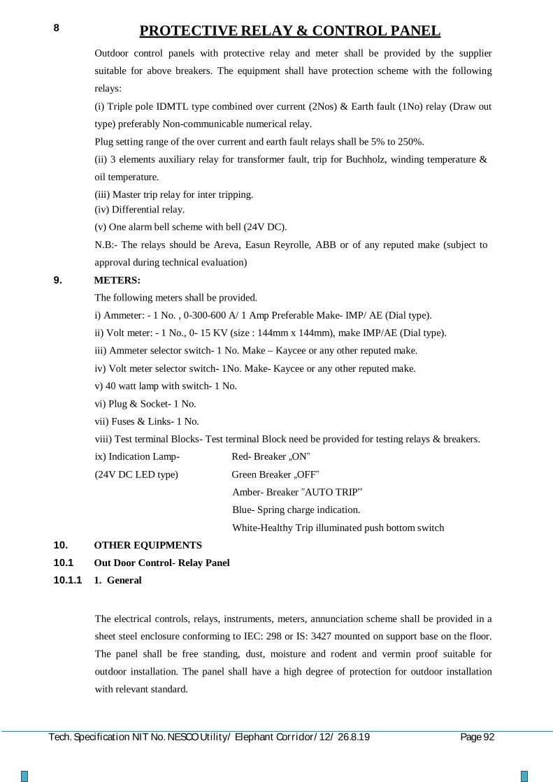
Tech. Specification NIT No. NESCO Utility/ Elephant Corridor/12/ 26.8.19 Page 92
8 PROTECTIVE RELAY & CONTROL PANEL
Outdoor control panels with protective relay and meter shall be provided by the supplier
suitable for above breakers. The equipment shall have protection scheme with the following
relays:
(i) Triple pole IDMTL type combined over current (2Nos) & Earth fault (1No) relay (Draw out
type) preferably Non-communicable numerical relay.
Plug setting range of the over current and earth fault relays shall be 5% to 250%.
(ii) 3 elements auxiliary relay for transformer fault, trip for Buchholz, winding temperature &
oil temperature.
(iii) Master trip relay for inter tripping. (iv) Differential relay.
(v) One alarm bell scheme with bell (24V DC).
N.B:- The relays should be Areva, Easun Reyrolle, ABB or of any reputed make (subject to
approval during technical evaluation)
9. METERS:
The following meters shall be provided.
i) Ammeter: - 1 No. , 0-300-600 A/ 1 Amp Preferable Make- IMP/ AE (Dial type).
ii) Volt meter: - 1 No., 0- 15 KV (size : 144mm x 144mm), make IMP/AE (Dial type).
iii) Ammeter selector switch- 1 No. Make – Kaycee or any other reputed make.
iv) Volt meter selector switch- 1No. Make- Kaycee or any other reputed make.
v) 40 watt lamp with switch- 1 No.
vi) Plug & Socket- 1 No.
vii) Fuses & Links- 1 No.
viii) Test terminal Blocks- Test terminal Block need be provided for testing relays & breakers.
ix) Indication Lamp- Red- Breaker „ON‟
(24V DC LED type) Green Breaker „OFF‟
Amber- Breaker ‟AUTO TRIP‟
Blue- Spring charge indication.
White-Healthy Trip illuminated push bottom switch
10. OTHER EQUIPMENTS
10.1 Out Door Control- Relay Panel
10.1.1 1. General
The electrical controls, relays, instruments, meters, annunciation scheme shall be provided in a
sheet steel enclosure conforming to IEC: 298 or IS: 3427 mounted on support base on the floor.
The panel shall be free standing, dust, moisture and rodent and vermin proof suitable for
outdoor installation. The panel shall have a high degree of protection for outdoor installation
with relevant standard.

Tech. Specification NIT No. NESCO Utility/ Elephant Corridor/12/ 26.8.19 Page 93
Each panel shall comprise of rigid welded structure frame enclosed completely by metal sheet
of thickness not less than 2.5mm. The sheets shall be cold rolled with smooth finish leveled and
free from flaws. The structural frame and all load bearing members of the enclosure shall have
minimum thickness of 2.5mm.
The control & relay panel board shall consist of panel, vertical independent, structure mounted
with equipment mounted & wiring access on front and having double door protection (inside
door to be glass covered) to prevent water entry inside the panel. Doors shall have handles with
built in locking facility. All door panels and removable covers shall be gasketed all round with
neoprene bonded gasket. Vewntilating louvers shall be provided to limit the temperature rise as
provided in IEC: 694 and 298 or IS: 12729 and 3427. They shall be provided with filters
encased in fine wire screens for non-ferrous metal or stainless steel unaffected by moisture and
rain water. A 230V AC heater with auto temperature control shall be provided in the cabinet to
prevent moisture condensation.
The housing shall be surface treated and painted in accordance with the clause on Surface
Treatment of this specification. 10.1.2 Panel wiring and accessories.
10.1.3 Wiring
Each panel shall be supplied with all internal wiring complete.
Panel wiring shall be suitably bunched and clamped for neat appearance. The conductors used
for wiring purpose shall be PVC insulated 650/1100 volt grade semi-flexible heat resistant,
flame retardant and vermin proof electrolytic copper cable conforming to IEC:227, 502 or
IS:1554. The wiring shall be securely supported and taken though PVC through PVC troughs.
Each wire shall be continuous from end to end without any joint in between. All panel wiring
shall be capable of withstanding a voltage of 2KV AC 50Hz for one minute.
Cable and wire for connections within the switchgear and between the switchgear and terminal
blocks shall have a minimum temperature rating of 90 degree Celsius. The size of the
conductors for panel wiring shall be not less than 2.5mm2. For CT secondary wiring, two such
wires shall be used in parallel.
10.1.4 Panel wiring protection

Tech. Specification NIT No. NESCO Utility/ Elephant Corridor/12/ 26.8.19 Page 94
The panels shall be equipped with links and HRC cartridge fuses conforming to IEC:269 or
IS:13703 in 650 Volt grade phenolic moulded fuse holder consisting of fuse carrier and base or
miniature circuit breakers conforming to IEC:947-2 or IS:13947-2 at appropriate locations. The
carriers and bases shall be made of high grade flame retardant and non hygroscopic phenolic
moulded material with hard glass surface. Each fuse or MCB shall be identified with engraved
plastic label.
In general, fuses and MCBs shall be limited to the minimum required for safety. The protection
scheme shall include fuses for VT secondary circuits and DC supply to each panel and fuses for
MCB for spring charging motor and incoming AC supply.
10.1.5 Terminal blocks
Terminal blocks of brass studs rated for 10 amps continuous current, 650 volt DC grade
covered by moulded insulating materials with adequate electrical clearances shall be provided
for terminating the panel wiring and outgoing connections. The termination shall be made by
crimping lugs or bare conductor with insulating sleeves at ends. The arrangement can be
horizontal or vertical as per standard practice adopted by the manufacturer. All terminals must
be numbered and wire termination provided with numbered ferrules for identification. All
numbering and marking including those in wiring diagram shall follow the guidelines provided
in IS: 11353. All circuit breaker auxiliary contracts including spare contacts shall be wired to
the terminal blocks. Ten percent spare terminals shall be provided.
10.1.6 Colour and numbering
The wiring used for 230V AC supply for illumination lamp, panel heater and other devices shall
be coloured red for phase wire and black for the neutral. The colour of wires connecting directly
to Earth shall be black. All other panel wires shall be of one colour to be approved.
Engraved core identification plastic ferrules marked to correspond with the panel wiring
diagram shall be fixed at both ends of each wire. Ferrules shall fit tightly on the wire and shall
not fall off when the wire is disconnected from the terminal block. Numbers 6 and 9, if used
shall be under scored to enable differentiation.
10.1.7 Circuit diagram
A durable copy of the circuit wiring diagram shall be affixed to the inner side of the door of the
switchgear compartment. Labels shall be provided inside the compartment to describe the
functions of the various items of equipment.
The scope of the supply shall include the panel mounting base plate and all special equipment,
bolts, nuts and washers necessary for making the supporting.
10.2 Supporting Structure

Tech. Specification NIT No. NESCO Utility/ Elephant Corridor/12/ 26.8.19 Page 95
The supply of the material shall be complete with mounting structures of mild steel sections
conforming to IS: 226 or equivalent ISO. The supporting structure shall be designed and
constructed to withstand the maximum combined effects of the circuit breaker dead weight, its
maximum dynamic load and maximum effect of wind loading. The supporting structure shall be
hot dip galvanized as per IS 2629.
10.3 CT mounting bracket
The supporting structure shall be fitted with a bracket for supporting three oil filled 11 KV
single phase current transformers as per enclosed GA drawing. The support bracket shall be
provided opposite the circuit breaker poles and shall ensure adequate clearance between the
breaker poles and the CTs as well as between the CTs. The CTs shall be supplied by the
Supplier as per specification above and is included in the scope. The drawings of the structure
with bracket shall be subject to Purchaser‟s approval before fabrication.
The CT mounting bracket shall be hot dip galvanized as per IS-2629.
10.4 Local control cabinet
The operating mechanism, local controls and monitoring shall be provided in a metal clad
control cabinet fitted to the same structure supporting the breaker and mounted at a convenient
height for safe operation from ground level or from platform to be supplied under the contract.
The cabinet shall be made of minimum 2.00mm sheet steel and shall be constructed as a dust,
weather and vermin proof outdoor housing with protection of IP-54 class as defined in IEC:529
or IS:13947. It shall have single door and transparent windows for reading the circuit breaker
ON or OFF position and spring charge position without opening the door. The door and any
removable covers shall be gasketed all round with neoprene bonded gaskets. A ventilating
louver shall be provided with fine wire non-ferrous metal or stainless steel screen and filter. A
230V AC heather with auto temperature control shall be provided in the cabinet to prevent
moisture condensation and also a 230 volt lamp for internal illumination with door operated
switch.
The local control cabinet shall be subjected to surface treatment and painting as per clause on
surface treatment of this specification.
10.5 Panel wiring and accessories
Panel wiring shall be suitably bunched and clamped for neat appearance. The conductor used
for wiring purpose shall be PVC insulated 650 volt/ 1100V grade semi-flexible copper cable
conforming to IEC: 227 or IS: 1554, heat resistant, flame, vermin and rodent proof. The wiring
shall be securely supported and taken through PVC troughs. All panel wiring shall be capable
of withstanding a voltage of 2KV AC 50Hz for 1 minute. Each wire shall be continuous from
end to end without any joint in between.
The sizes of the control cable for wiring in the cabinet shall be not less than 2.5mm2. CT
secondary wiring shall be though two such wires in parallel.
10.5.1 Fuse protection

Tech. Specification NIT No. NESCO Utility/ Elephant Corridor/12/ 26.8.19 Page 96
The cabinet shall be equipped with links and HRC cartridge fuses in 650 volt grade fuse holders
consisting of fuse carrier and base. The holders shall be made of high grade, flame retardant and
non hygroscopic phenolic moulded material of dark brown colour with hard glass surface. Each
fuse shall be identified with engraved plastic labels.
10.5.2 Terminal blocks
Terminal blocks rated for 10 amps continuous current, 650 volt grade covered by moulded
insulating materials with adequate electrical clearances shall be provided for terminating the
panel wiring and outgoing connections. The termination shall be made by crimping lugs or bare
wire with insulating sleeves at ends. The arrangement can be horizontal or vertical as per
standard practice adopted by the manufacturer. All terminals must be numbered and wire
termination provided with numbered ferrule for identification. All numbering and marking
include those in wiring diagram shall follow the guidelines provided in IS: 11353. Ten percent
spare terminals shall be provided.
10.5.3 Colours
The wiring used for AC supply for illumination lamp and heater shall be differently coloured
from control wiring so that these can be distinguished from each other. The colour of all earth
wire shall be black.
10.6 Circuit diagram
A durable copy of the circuit wiring diagram shall be affixed to the inner side of the control
cabinet. Labels shall be provided inside the cabinet to describe the functions of the various
items of equipment.
10.7 Cable Entry
A removable gland plate shall be provided at the bottom of the cabinet for entry of Purchaser‟s
control and auxiliary power cables in the cabinet. Required number of electroplated brass cable
glands of appropriate sizes with shrouds shall be provided in consultation with the Purchaser in
the gland plate for the control and power cables. Provision shall be make for earthing of the
cable armours in the gland.
11 OPERATING MECHANISM
11.1 General
The operating mechanism of the circuit breaker shall be motor wound spring charged type. It
shall be electrically and mechanically trip free with anti pumping device (as per IEC: 694
definitions). All working parts in the mechanism shall be of corrosion resistant material. Self
lubricating, wearing resistant bearings shall be provided in the mechanism.

Tech. Specification NIT No. NESCO Utility/ Elephant Corridor/12/ 26.8.19 Page 97
The mechanism shall fully close the circuit breaker and sustain it in the closed position against
the forces of the rated making current and shall fully open the circuit breaker without undue
contact bounce at a speed commensurate with that shown by tests to be necessary to achieve the
rated breaking capacity in accordance with IEC:56 or IS:13118. The mechanism shall be
capable of being locked in either the open or closed position. The mechanism shall be capable
of fully closing and opening again after the auto-reclose time interval specified as 0.3 second in
this specification.
11.2 Spring mechanism
The spring operating mechanism shall be with spring charging motor, opening and closing
springs with limit switches and all accessories necessary for automatic charging. In normal
operation, recharging of the operating springs shall commence immediately and automatically
upon completion of the closing operation so that a complete sequence of closing and opening
operation should be possible.
It shall be possible to hand charge the operating spring with the circuit breaker in either the
open or closed position conveniently from the ground level. Closure whilst a spring charging
operation is in progress shall be prevented and release of the springs shall not be possible until
they are fully charged.
The state of charge of the operating springs shall be indicated by a mechanical device showing
„SPRING CHARGED‟ when closing spring is fully charged and operation is permissible and
„SPRING FREE‟ when closing spring is not fully charged and the operation is not possible.
Provision shall be made for remote electrical indication of „Spring Charged‟ and „Spring Free‟
conditions.
The operating mechanism shall be such that the failure of any auxiliary spring shall not cause
tripping or closing the circuit breaker but shall not prevent tripping against trip command.
Closing action of the circuit breaker shall charge the opening spring ready for tripping. From
the close position with spring charged, one open-close-open operation shall be possible without
recharging the spring.
11.3 Motor
The motor for spring charging shall be single phase 230 Volt A. C motor. Continuous motor
rating shall be at least ten percent above the maximum load demand of the driven equipment. It
shall remain within its rated capacity at all operating points that will arise in service. It shall be
protected by H.R.C cartridge fuses or MCB. The motor shall comply with IEC: 34 or IS: 996.
12. AUXILIARY POWER SUPPLY
The operating mechanism shall be suitable to operate with the following auxiliary power
supplies.
a) 230V, 50Hz Single phase A.C- For spring charging motor
b) DC supply 24 Volts- For close and open coils, indication & Alarm
(Power pack input supply: 230V & 110V AC and Output:24V DC)

Tech. Specification NIT No. NESCO Utility/ Elephant Corridor/12/ 26.8.19 Page 98
The DC supply shall be from a Power Pack. The Input to Power Pack is 110V from PT and
230V from main supply. The power pack should be capable for minimum 3 Trippings even if
input to power pack is failed.
The mechanism shall be designed to operate satisfactorily despite fluctuations of auxiliary
power supplies as under:
AC supply: Voltage From 115% to 85% of normal voltage
Frequency From 105% to 95% of normal frequency
Combined voltage and
frequency variation
From 115% to 85% of normal
DC supply: Voltage From 120% to 70% of normal voltage
13. INTERLOCKS
The circuit breaker shall be capable of being mechanically and electrically interlocked with the
associated line isolator so that the isolator cannot be operated with the breaker in the closed
position.
All doors or shutters which give access to live parts shall be interlocked in such a way that these
cannot be opened unless the circuit breaker is in the open position.
Other interlocks shall be provided as deemed necessary for safety.
15. TERMINAL CONNECTOR
Suitable terminal connectors of bi-metallic type suitable for both horizontal and vertical
connection shall be provided on the terminal pad both on the incoming and the outgoing side
for connection of jumpers of ACSR or AAAC conductor. The size of the conductor may vary
between 50mm2 and 232mm2 depending upon the location of the circuit breaker. The terminal
connection drawing and details are to be approved by the Purchaser before fabrication. The
terminal connectors shall be bi-metallic type to avoid bi-metallic corrosion.
INSULATION AND CLEARANCE 16.
a) The insulation to ground, the insulation between open contacts and insulation between phases
of the circuit breaker shall be capable of satisfactorily withstanding dielectric test voltages.
b) The minimum clearance in open air shall be as follows:
Phase to phase spacing in
switchyard i.e. interpole spacing
for Breaker (min)
Ground clearance from the
lowest line terminal if both the
terminals are not in same
horizontal plane (min)
17. TEMPERATURE RISE
- 320 mm - 2700mm

Tech. Specification NIT No. NESCO Utility/ Elephant Corridor/12/ 26.8.19 Page 99
The temperature rise and the maximum temperature of any part of the circuit breaker under
continuous load condition and exposed in the direct rays of the sun shall not exceed the
permissible limits as provided in Table V of IEC publication 694 or table 4 of IS:12729. These
limits shall not be exceeded when corrected for the difference between the ambient temperature
at site and the ambient temperature specified in the standard. The correction proposed shall be
stated in the tender.
18. TESTS
18.1 Type and routine tests
The circuit breakers shall be subjected to routine and type tests in accordance with the standards
listed in this specification including the following IEC and IS standards with the latest
amendments:
Circuit breaker IEC: 56 and IS:13118 and relevant other standards
Porcelain insulator IEC: 233 and IS: 5621 and relevant other standards
The tests shall include but not limited to the following:
18.2 Short circuit tests
The circuit breaker shall satisfactorily perform the out of phase and short circuit duties specified
in IEC:56, IEC:17A(Sectt.) and IEC:17A/CD/474, IS-13118 and IS:13516.
The circuit breaker shall be capable of performing at least twenty five (25) open operations at
the rated short circuit current before maintenance or inspection is required.
18.3 Capacitive current switching
Capacitive switching tests shall be performed in accordance with IEC:56 or IS:13118 and
IEC:17A/CD/474 at 1.3U preferably by direct test method or alternatively using synthetic
method to IEC:427 or IS:13516. The test circuits shall simulate the most onerous site
conditions.
18.4 Reactor Switching
In addition to the capacitive current switching tests to IEC:56 or IS:13118 and
IEC:17A/CD/474, the circuit breakers shall be tested for shunt reactor switching in accordance
with IEC:1233, Examination of the interrupter after the tests shall not show any evidence of
surface tracking or erosion of contracts.
18.5 Dielectric tests
At zero gauge loss of vacuum inside the interrupter chamber, the open contracts shall withstand
continuously, the rated phase to ground voltage and it shall be possible to break normal current
in these conditions. During the dielectric type tests, no flashover external or internal shall be
acceptable.
The circuit breakers shall be subjected to a power frequency AC voltage test for one minute in
dry and wet conditions and there shall be no external flash over to earth.
18.6 Mechanical endurance

Tech. Specification NIT No. NESCO Utility/ Elephant Corridor/12/ 26.8.19 Page 100
In addition to the requirements of IEC:56, an extended mechanical endurance test is required to
show that the circuit breaker is capable of at least 10,000 operations at no load in accordance with
IEC:17A/474/CD. Between the specified test series in IEC: 17A/474/CD, some maintenance
such as lubrication and mechanical adjustment is allowed and shall be performed in accordance
with manufacturer‟s instructions. Change of contracts is not permitted.
18.7 Low current switching
The circuit breakers shall produce very low over voltage (<2.0 pu) on all switching circuits
inductive current including reactor switching to IEC-1233 and capacitive current switching to
IEC:17A (Secretariat) 438 and IEC 17A/CD/474 the circuit breaker shall be re-ignition or re-
strike free for all duties.
18.8 Duty requirement tests
Apart from auto-reclosing and the other duties mentioned above, the breakers shall be able to
perform the following duties for which type tests are to be conducted as per IEC:56 or
IS:13118.
1. Breaking the steady and the transient magnetising current of the transformer.
2. Breaking 25% of rated fault current at twice the rated voltage as per IEC/IS.
3. Cable charging breaking current.
4. Back-to-back capacitor bank breaking current.
5. Single capacitor bank breaking current.
6. Capacitor bank in rush making current.
Test for the resistance of the main circuit shall also be conducted.
18.9 Temperature rise test
Temperature rise test is to be conducted on the circuit breaker and the accessories in accordance
with IEC:56 or IS:13118. The temperature rise shall be limited as per this specification.
19. PERFORMANCE REQUIREMENTS
The supplier shall declare the circuit breaker opening and closing times at 120 percent, 100 percent
and 70 per cent of the rated voltage of the opening and closing devices when measured at the
terminals of the trip and closing coils. The minimum make break time at rated voltage and total
break time of the CB shall be stated. The total break time must not exceed 60m. sec.
20. EARTHING
All metal parts not intended for carrying current or not alive shall be connected to duplicate earthing system and suitable electroplated brass earthing terminals shall be provided on each circuit breaker in conformity with IEC:56 or IS:13118. Suitable identification mark for the earth terminals shall be provided adjacent to the terminal. Earth continuity conductors shall be provided down to the ground level for earth connection to purchaser‟s earthing grid. It shall have sufficient cross sectional area to afford a low resistance path for the full fault current envisaged. Such conductor shall also be provided for the CTs up to the ground level.
The size of the earth continuity conductor shall be large enough to reduce the potential rise of
the metal frame of the breaker in the event of fault to minimum but in any case not more than

Tech. Specification NIT No. NESCO Utility/ Elephant Corridor/12/ 26.8.19 Page 101
10V. The size of the conductor shall also be adequate to restrict the temperature rise without
causing any damage to the earth connection in the case of fault. No riveted joints in the earth
conducting path shall be permissible and only bolted joints of adequate size shall be provided
with nuts, bolts and plain and spring washers. The surfaces to be jointed shall be perfectly flat
without any unevenness to ensure that there is no contact resistance.
An earth bus bar of copper strip shall be provided inside the local control cabinet to which all
earthing connections must be made. The earth bus bar shall be terminated into two electroplated
brass earthing terminals of adequate size with nuts, bolts and washers for connecting to earth
continuity conductor mentioned above.
TECHINICAL DATA SCHEDULE FOR 11 KV OUTDOOR VACUUM CIRCUIT

Tech. Specification NIT No. NESCO Utility/ Elephant Corridor/12/ 26.8.19 Page 102
BREAKER
SL NO
DESCRIPTION As Per Specifications
UNITS
BIDDER'S OFFER
1 GENERAL - Name of manufacture - Manufacturer‟s type designation Out-Door type
- Governing standards IS : 13118, IEC- 62271-100
- No. of poles of circuit breaker 3 no. - No. of breaks per phase 1 no. Type – Vacuum Vacuum 2. NOMINAL VOLTAGES
- Rated voltage 11 KV - Maximum(continuous)service
rated voltage 12 KV
3. RATED NORMAL CURRENT - Under normal condition 800 Amps - Under site condition 800 Amps 4. SHORT CIRCUIT
PERFORMANCES
- Rated short circuit breaking current:
- Symmetrical, rms 25 KA - Asymmetrical including DC
component 30 KA
- Rated short circuit making current; peak
62.5 KA
- Short time current withstand capability:
Peak value 62.5 KA Rms value 25 KA Duration 3 Sec
5 MAX. TEMP. RISE OVER AMBIENT OF 500C
- At normal continuous current As Per IS 0C - After performing the operating
sequence 0C
6. MAKE AND BREAK TIMES Total break times - At 10% rupturing capacity
< 60 milli- sec
- At rated rupturing capacity < 60 milli-
sec
- Arcing time at rated breaking current
15 (Max)
milli- sec
- Make time from giving close command
< 60 milli-
sec
- Minimum re-closing time at full rated interrupting Capacity from trip coil energisation
300 milli- sec

Tech. Specification NIT No. NESCO Utility/ Elephant Corridor/12/ 26.8.19 Page 103
- Minimum dead time for 3 phase reclosing
milli- sec
- Circuit breaker opening time: at 125% of rated voltage of
opening device
< 60 milli- sec
at 100% of rated voltage of opening device
< 60
milli- sec
at 70% of rated voltage of opening device
< 60
milli- sec
7 RESTRIKING VOLTAGES FOR 100% RATED CAPACITY
- Amplitude factor 62 KV - Phase factor 3 - Natural frequency Hz - Rate of rise of recovery Kv/µs voltage
8 RATED INSULATION LEVEL - Dry and wet power frequency
withstand test voltage for one minute, rms:
- Between live terminals and grounded objects
28 KV
- Between terminals with breaker contacts open
28 KV
- 1.2/50 µs full wave impulse withstand voltage +ve and – ve polarity, peak
- Between live terminals and grounded object
75 KVp
- Between terminals with breaker contacts open
75 KVp
- One mimute power frequency voltage of auxiliary wiring
2 KV
9 OPERATING PERFORMANCE
- Rated transient recovery voltage
KVp
- Rated cable charging breaking current
25 Amps.
- Rated single capacitor bank breaking current
400 Amps
- Rated back-to-back capacitor bank breaking current
400 Amps
- Rated capacitor bank in-rush making current
20 KA
- Rated small inductive breaking current
25 KA
- First pole-to-clear factor 1.5 - Rated operating sequence O-0.3sec-CO-3min-
CO

Tech. Specification NIT No. NESCO Utility/ Elephant Corridor/12/ 26.8.19 Page 104
- Rated out-of-phase breaking current
KA
- Re-ignition and Re-strike free
Yes/No
10 NUMBER OF OPERATION POSSIBLE WITHOUT MAINTENANCE
- at full rated interrupting current
>100 no.
- at 50% of rated interrupting current
>100 no
- at 100% of full load current >10000 no - at no load no
11 MINIMUM CLRARANCE IN AIR
- Between phases >150 mm - Live parts to earth >120 mm - Live parts to ground level mm
12 WEIGHTS AND DIMENSIONS
Total weight of one complete breaker, including mounting structure
Kg
Mounting structure weight Kg Control cabinet weight Kg Dimensions: Height mm Width, mm Depth mm Drawings must be provided Yes / No
13 HOLLOW INSULATOR HOUSING
Type and make of insulators. Power frequency withstand test
voltage for one minute:
- Dry 28 KV - Wet 28 KV Flash over value - Dry 75 KVp - Wet 75 KVp 1.2/50 impulse voltage withstand
capability
- positive polarity 75 KVp - negative polarity 75 KVp Creepage distance total >300 mm Creepage distance protected >280 mm Weight of assembled housing Kg
14 SUPPORT INSULATOR Type and make of insulators Power frequency withstand test
voltage for one minute:
- Dry 28 KV

Tech. Specification NIT No. NESCO Utility/ Elephant Corridor/12/ 26.8.19 Page 105
- Wet 28 KV Flash over value - Dry 75 KV - Wet 75 KV 1.2/50 impulse voltage withstand
capability
- positive polarity 75 KVp - negative polarity 75 KVp Creepage distance, total >300 mm Creepage distance, protected >280 mm Weight of assembled housing Kg Corona shield provided or not Yes / No
15 CONTACTS - Type of main contacts - Type of auxiliary
contacts
- Material of auxiliary contacts
Copper
- Type of plating, if any Silver - Thickness of plating 20 Micron - Contact pressure gm/
sq.mm
No of auxiliary contacts provided: 6 NO + 6 NC Those closed when breaker is
closed 6 no
Those open when breaker is closed
6 no
Those adjustable no 16 OPERATING MECHANISM
Opening type Shunt Trip Closing type Motor / Manual spring
charge, Shunt/Magnetic actuator operation
Force applied by charged spring for closing
Kg / N
Time taken by motor for charging the spring form fully Discharged to fully charged position
<30 sec
Full sequence of operation 0-0.3sec-CO-3min- CO
Whether limit switches are provided with spring
Yes/No
Whether spring limit switches start stop the motor
Yes/No
Type and material of spring employed
Whether trip free Yes/No Whether anti pumping device
provided Yes
17 AUXILIARY AND CONTROL POWER SUPPLY
- Normal auxiliary A.C supply voltage
230 Volts

Tech. Specification NIT No. NESCO Utility/ Elephant Corridor/12/ 26.8.19 Page 106
- Voltage limits for proper operation
Maximum 115% Volts Minimum 85% Volts - Frequency limits for proper
operation
Maximum 105% Hz Minimum 95% Hz - Normal control circuit
voltage
24 Volts
- DC Voltage limits for proper operation
Maximum 120% Volts Maximum 70% Volts - Power required for trip coil 300 Watts - Power required for closing
coil 300 Watts
18 LOCAL CONTROL PANEL - Material - Degree of protection - Vermin proof provisions Yes/No - Weather proof provision Yes/No - Dust proof provision Yes/No - Ventilation provision Yes/No - Thickness of sheet
materials used 3 mm
- Overall dimensions mm - Total weight Kg - Mounting arrangement
19 TERMINAL CONNECTOR - Material - Bi-metallic or not Yes/No - Weight Kg - Dimensions mm - Size and type of
conductor it can accommodate 100 sq mm
- Terminal pads silver plated or not
Yes/No
- Thickness of silver plating
microns
20 CORROSION PREVENTION SYSTEM FOR CIRCUIT BREAKER AND CONTROL CABINET
- Surface preparation - Rust inhibition - Zinc thickness/paint
thickness Microns
- Treatment of fasteners 21 CORROSION PREVENTION
SYSTEM FOR SUPPORT STRUCTURE
Hot Dip Galvanized

Tech. Specification NIT No. NESCO Utility/ Elephant Corridor/12/ 26.8.19 Page 107
Surface preparation Rust inhibition Zinc thickness Treatment of fasteners. Microns
22 VACUUM CIRCUIT BREAKER SEALING
Degree of protection of circuit breaker pole enclosure (IEC 529, IS 13947).
Method of sealing the circuit breaker pole enclosure.
23 CURRENT TRANSFORMER 1 Category A; 600-300-150 / 1-1-
1A
Make and type of transformer Out type, 1 ph, Oil cooled, Dead Tank
Ratio 600-300-150/ 1-1-1 A
Core1. VA burden 15 VA Accuracy class 0.5 Saturation factor Instrument security factor 10 Accuracy limit factor Core 2. VA burden 15 VA Accuracy class 5P Saturation factor Accuracy limit factor 20 Core 3. Accuracy class PS Saturation factor Accuracy limit factor Knee point voltage (Vk) > = 150 Volts Magnetizing current at
Vk/2
< 30 mA at 0.5 Vk Milli Amps
Secondary resistance Rct Ohms Short time current rating, time 25 KA for 3 sec KA /
Sec.
Impulse voltage withstand level 75 KV Power frequency voltage
withstand level
Primary winding 28 KV Secondary winding 3 KV Weight of CT complete Kg 2 Category B: 400-200-100/1-1A
Make and type of Transformer Out type, Oil cooled, 1 ph, Dead Tank
Ratio Core 1. VA burden 15 VA Accuracy class 0.5 Saturation factor Instrument security
factor 10

Tech. Specification NIT No. NESCO Utility/ Elephant Corridor/12/ 26.8.19 Page 108
Accuracy limit factor Core 2. VA burden 15 VA Accuracy class 5P Saturation factor Accuracy limit factor 20 Short time current rating:
Current time 25 KA for 3 sec KA,
Sec
Impulse voltage withstand level 75 KV Power frequency voltage
withstand level
Primary winding 28 KV Secondary winding 3 KV Weight of CT complete Kg
24 11 KV VOLTAGE TRANSFORMER
a. GENERAL. - Make Out type, Oil cooled,
1 ph, Dead Tank
- Rated normal voltage 11 / √3 KV - Rated maximum voltage 12 / √3 KV - Rated primary voltage 11 / √3 KV - Rated secondary voltage 110 / √3 Volts - V A burden 100 VA - Accuracy class 0.5 - Ratio error - Phase displacement
positive or negative Min
- Saturation factor - Instrument security
factor
- Short time current rating Rms value KA Period Sec Peak value KA - Impulse voltage
withstand level 75 KVp
- One minute power frequency voltage withstand level of primary winding
28 KV
- Weight of core and winding
Kg
- Total weight Kg - Overall dimensions Mm - Rated voltage factor Continuous 1.2 For 30 seconds 1.5 - Temperature rise above
the ambient of 500C 40 0C
- Correction factor

Tech. Specification NIT No. NESCO Utility/ Elephant Corridor/12/ 26.8.19 Page 109
- Partial discharge level pC b. CORE
- Material composition (CRGO-M4 or better)
- Flux density at normal voltage and frequency
<1.2 Telsa
- Lamination thickness 0.27 mm c. WINDINGS
- Purity of copper used Electrolytic Percent - Type of insulation - Power frequency
withstand level
Secondary winding to earth
3 KV
Primary winding to earth 28 KV d. SECONDARY TERMINAL
BOX
- Degree of protection Yes/No - Vermin proof provision Yes/No - Weather proof provision Yes/No - Dust proof provision Yes/No - Thickness of metal used 3 mm - Overall dimensions mm - Mounting arrangement e. H V TERMINAL
- Material - Bi-metallic or not Yes/no - Dimensions, mm - Size and type of
conductor it can accommodate 100 Sq. mm
25 INSTRUMENTS & METERS (Ammeter , Volt Meter & Energy Meter)
A. 1. Type & make of Ammeter & voltmeter
Analogue type ,AE make
2. Size 144x144 3. Whether
magnetically shielded or not Yes
4. Limits or error in the effective range
± 2 %
5. Scale length 90 Deg. 6. Whether
Tropicalised
7. Short time overload rating
200%
8. V A Burden. i) Current coil VA ii) Potential coil VA 9. Power consumption
current & potential coil Watt

Tech. Specification NIT No. NESCO Utility/ Elephant Corridor/12/ 26.8.19 Page 110
B. Energy Meter Type:
(3 Ph ,4 wire with Alpha numerical
display)
Make Secure meter/ L & T C. BACK UP RELAYS 1 Type of relay 2 O/C +1 E/F, self
actuated ,1 Amp, Aux. Volt-24 V DC/ Numerical & Non
Communicable Type
Make AREVA, ER, ABB make
2 Current coil rating 1 Amp 3 Tap range 5% to 250 % 4 V A Burden Highest tap
& lowest tap 3
5 Power consumption Highest tap & lowest tap
Watt
6 Time of operation at maximum time dial setting at
7 5 times tap setting current 1.6-1.9 Sec 8 10 times tap setting
current 1.3 Sec
9 Type of characteristic IDMTL 10 Whether draw out type or not Yes
11 Trip contact ratings Amps.
5 A continuous Amp
12 Whether seal in contacts provided or not
Yes/No
13 No. of contacts 2 NO+2 NC 14 Flag/LED Required D. Three element voltage operated
Aux. Relay
Type & make of the Relay AREVA, ER, ABB make
Voltage coil rating 24 V DC Volts No. of elements 3 No.
Mounting Flush Aux. Contact on each pole 1 NO + 1 NC Flag Required Purpose Trf protection
E. High speed Tripping Relay Type & make of the Relay AREVA, ER,
ABB make
Voltage coil rating 24 V DC Volts Contact(Hand reset) 3 NO +1 NC Flag Required
F. High speed Harmonic Restraint Differential Relay

Tech. Specification NIT No. NESCO Utility/ Elephant Corridor/12/ 26.8.19 Page 111
Type & make of the Relay AREVA, ER, ABB make
Voltage coil rating 24 V DC Volts Aux. Contacts(Hand reset) 2 NO Mounting Flush CT secondary 1 Amp. Differential current setting 15% Bias setting 15-30-40 % Flag Required G. POWER PACKS (2 X 12 V inbuilt
Battery)
1. Rated AC voltage.(Input 230 V AC or 110 V. AC ).
230 /110 Volt AC
Volt
2. Single phase or three phase. Single phase 3. Capacity(VA) 300 4. Power factor 5. Type of transformer used, if
any, to supply input to the rectifier
6. Transformation ratio 7. Type of rectification
employed, full wave or half wave Full wave
8. Type of rectifier connection Bridge 9. Ripple factor 10. Type of filter employed 11. Ratings of capacitor 12. Time of retention of charge
by capacitor
13. Value of DC constant. 14. Out put voltage(DC) 24 + 15% Volt 15. Capacity (Watt-sec) 16. No of closing & tripping taken by
this pack. >10
Signature of the Bidder with Seal

Tech. Specification NIT No. NESCO Utility/ Elephant Corridor/12/ 26.8.19 Page 112
GUARANTEED TECHNICAL PARTICULARS OF INSULATING PIERCING CONNECTOR Sl.
No. Particulars Specified Requirement Details furnished by the bidder
1 Name of Manufacturer 2 Place of manufacture
3
Is manufacturer of accessories as ISO 9001-2000 company
a) copies Certificate enclosed b) Are GA drawing enclosed
4 Product designation MV 240-95
5 Applicable standard As per NFC 33 020-1998
6 Range of cable sizes: Main & Tap
Main : 95-240 (99) mm2
Branch: 35-70-(99) mm2
7
Materials Composition a) Body- Nylon b) Contact plates- Tinned copper c) Bolt-Steel d) Seals & end caps - Elastomer
8 Is any metallic part carrying potential in operation exposed during installation
9 Are end caps of branch cable a) Slide on type b) Rigid
10 Are torque limiting shear heads provided to tightening bolts
11
Marking a) Make b) Main range c) Tap range
12 Rated current 600 A 13 Voltage withstand under water emersion in 15 KV for 1 min 14 Rated Tightening torque in 19 to 25 Nm 15 Dimensions
Signature of the bidder with Seal

Tech. Specification NIT No. NESCO Utility/ Elephant Corridor/12/ 26.8.19 Page 113
GUARANTEED TECHNICAL PARTICULARS OF 11KV STRING HARDWARE Sl.
No. Particulars Specified Requirement Details furnished by the bidder
1 Name of Manufacturer 2 Address of manufacturer 3 Voltage class 11KV 4 Type Single Tension 5 Applicable standards IS:2486 6 Insulator Coupling Ball & Socket type
7
Material : a. Ferrous parts HDG b. Bolts, Nuts & Washers HDG c. Spring washer EG d.Split pin e. Bolted Type Tension clamp/ Suspension clamp
8
Ultimate Strength a.Complete Assembly b. Anchor Shackle c. Ext. Link d. 4U-Bolted type Tension clamp
9 Purity of zinc used for galvanising %
10 Min. No of dips in standard preece test the ferrous parts can withstand
Signature of the bidder with Seal
GUARANTEED TECHNICAL PARTICULARS OF 11KV INDDOR/OUTDOOR TERMINATION KIT
& MID SPAN JOINT Sl.
No. Particulars Specified Requirement Details furnished by the bidder
1 Name of Manufacturer 2 Applicable Standards EN-50397-2 3 a. Rated voltage of cable accessories
b. Max operating voltage of cable accessories 12 KV
4 AC High voltage withstand 5 Impulse voltage 170 KVp 6 Max. load current 7 Short circuit current 8 Type of Tubing's & Molded parts 9 Material of Tubing's & Molded parts
10 Non tracking material- Termination only 11 Type of Ferrule 12 Type of Lug
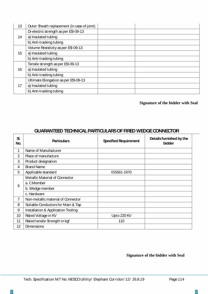
Tech. Specification NIT No. NESCO Utility/ Elephant Corridor/12/ 26.8.19 Page 114
13 Outer Sheath replacement (in case of joint)
14 Di-electric strength as per ESI-09-13 a) Insulated tubing b) Anti-tracking tubing
15 Volume Resistivity as per ESI-09-13 a) Insulated tubing b) Anti-tracking tubing
16 Tensile strength as per ESI-09-13 a) Insulated tubing b) Anti-tracking tubing
17 Ultimate Elongation as per ESI-09-13 a) Insulated tubing b) Anti-tracking tubing
Signature of the bidder with Seal
GUARANTEED TECHNICAL PARTICULARS OF FIRED WEDGE CONNECTOR Sl.
No. Particulars Specified Requirement Details furnished by the bidder
1 Name of Manufacturer 2 Place of manufacture 3 Product designation 4 Brand Name 5 Applicable standard IS 5561-1970
6
Metallic Material of Connector a. C Member b. Wedge member c. Hardware
7 Non-metallic material of Connector 8 Suitable Conductors for Main & Tap 9 Installation & Application Tooling
10 Rated Voltage in KV Upto 220 KV 11 Rated tensile Strength in kgf 110 12 Dimensions
Signature of the bidder with Seal

Tech. Specification NIT No. NESCO Utility/ Elephant Corridor/12/ 26.8.19 Page 115
GUARANTEED TECHNICAL PARTICULARS FOR LT GUY STRAIN
INSULATOR (TYPE_A)
Sl.
Particulars Requirement Bidder’s offer 1 Name of Manufacturer. & Address To be specified by
the bidder
2 Location of type testing To be specified by the bidder
3 Applicable standard IS: 5300-1969 or the latest version thereof
4 Nominal System Voltage 400/230 V
5 Highest System voltage 440/250 V
6 Length 90 mm
7 Diameter 65 mm
8 Cable hole diameter 16 ± 1.5
9 1min. power frequency withstand Voltage (Dry)
18 KV (rms)
10 1min. power frequency withstand Voltage (Wet)
8 KV
11 Minimum failing load 44 KN
12 Minimum creepage distance 41 mm
13 Drawing To be submitted
by bidder
14 Conforming standard As per IS
NB- Every insulator should bear the marking of manufacturer’s name andISI mark
Name & Signature of Agency with seal

Tech. Specification NIT No. NESCO Utility/ Elephant Corridor/12/ 26.8.19 Page 116
GUARANTEED TECHNICAL PARTICULARS FOR 11 KV GUY STRAIN INSULATOR (TYPE_C)
Sl.
No.
Particulars Requirement Bidder’s offer
1 Name of Manufacturer. & Address To be specified by the bidder
2 Location of type testing To be specified by the bidder
3 Applicable standard IS: 5300-1969 or the latest version thereof
4 Nominal System Voltage 11 KV
5 Highest System voltage 12 KV
6 Length 140 mm
7 Diameter 85mm
8 Cable hole diameter 25 ± 1.5
9 1min. power frequency withstand Voltage (Dry)
27 KV (rms)
10 1min. power frequency withstand Voltage (Wet)
13 KV
11 Minimum failing load 88 KN
12 Minimum creepage distance 57 mm
13 Drawing To be submitted
by bidder
14 Conforming standard As per IS
NB- Every insulator should bear the marking of manufacturer’s name and ISI mark
Name & Signature of Bidder with seal

Tech. Specification NIT No. NESCO Utility/ Elephant Corridor/12/ 26.8.19 Page 117
GURANTEED TECHNICAL PARTICULARS OF LT STAY SETS
Sl No.
Item
Description
Specified Parameters
Material
Bidder’s
offer Section Tolerances
Fabrication Tolerances
Manufacture’s Name & Address
To be specified by the bidders
1. Anchor Plate
6mm thick +2.5%-5%
200x200mm+1% GS Plate 6 mm thick
2. Anchor Rod
16mm dia +5%- 3%
Length 1800mm + 0.5%
GS Round 16mm dia
Rounded Eye 40 mm inside dia +3% Threading 40mm+ 11%-5%
GS Round 16mm dia
3. Turn Buckle Bow
16mm dia +5%-3%
995mm+1% GS Round 16mm dia.
Length180mm +1%
GS Angle 50x50x6 mm
4. Eye Bolt Rod
16mm dia +5%-3%
Length 450mm + 1%
GS Round 16 mm dia
Threading 300mm +1% Round Eye 40mm inside dia+3%
5 Galvanisatio n thickness
All galvanization shall be carried out in accordance with IS: 2629 . The weight of Zinc deposited shall be in accordance with IS: 2629 and shall not less than 0.61 kg/m² with a minimum thickness of 86 microns for items of thickness more than 5 mm, 0.46kg/m²(64 microns) for items of thickness between 2 mm & 5 mm& 0.33kg/m²(47 microns) for items less than 2 mm thickness.
a Anchor Plate
b Anchor Rod
c TurnBuckle Bow
d Eye Bolt Rod
6 Thimble 2 nos. to be made of 1.5 mm thick G.S Sheet into a size 75x22x40 mm & shape as per standard.
7
Hexagonal Nut
One G.S Hexagonal Nut confirming to IS:1363 & 1367 with one square washer of size 50x50x6 mm (G.S) along with Anchor Rod.
8 Two G.S Hexagonal Nuts of suitable size along with Eye Bolt Rod.
Name & Signature of Agency with seal

Tech. Specification NIT No. NESCO Utility/ Elephant Corridor/12/ 26.8.19 Page 118
GURANTEED TECHNICAL PARTICULARS OF 11KV HT STAY SETS
Sl No.
Item
Description
Specified Parameters
Material
Bidder’s offer
Section Tolerances
Fabrication Tolerances
Manufacture’s Name & Address
To be specified by the bidder
1 Anchor Plate
8 mm thick +2.5%-5%
300x300mm+1% GS Plate 8 mm thick
2 Anchor Rod
18 mm dia +5%- 3%
Length 1800mm + 0.5%
GS Round 18mm dia
Rounded Eye 40 mm inside dia +3% Threading 40mm+ 11%-5%
GS Round 18mm dia
3. Turn Buckle Bow
18mm dia +5%-3%
995mm+1% GS Round 18mm dia.
Length200mm +1%
GS Channel 100x50x4.7mm
4. Eye Bolt Rod
18 mm dia +5%-3%
Length 450mm + 1%
GS Round 18 mm dia
Threading 300mm +1% Round Eye 40mm inside dia+3%
5 Galvanisatio n thickness
All galvanization shall be carried out in accordance with IS: 2629 . The weight of Zinc deposited shall be in accordance with IS: 2629 and shall not less than 0.61 kg/m² with a minimum thickness of 86 microns for items of thickness more than 5 mm, 0.46kg/m²(64 microns) for items of thickness between 2 mm & 5 mm& 0.33kg/m²(47 microns) for items less than 2 mm thickness.
a Anchor Plate
b Anchor Rod
c TurnBuckle Bow
d Eye Bolt Rod
6 Thimble 2 nos. to be made of 1.5 mm thick G.S Sheet into a size 75x22x40 mm & shape as per standard.
7
Hexagonal Nut
One G.S Hexagonal Nut confirming to IS:1363 & 1367 with one square washer of size 50x50x6 mm (G.S) along with Anchor Rod.
8 Two G.S Hexagonal Nuts of suitable size along with Eye Bolt Rod.
Name & Signature of Agency with seal

Tech. Specification NIT No. NESCO Utility/ Elephant Corridor/12/ 26.8.19 Page 119
GURANTEED TECHNICAL PARTICULARS STAY WIRE (7/8 SWG)
Sl. No.
Description Specified Bidder’s offer
1. Manufacturer’s name & address To be specified by the Bidder
2 Nominal diameter of wire in mm 4.0 3 Tolerance in diameter in mm + 2.5% 4 Minimum breaking load in Kg 5960.26 5 Tensile strength Kgf/mm² 71.40 6 Overall diameter of stranded wire in mm 12.0 7 Sectional Area (in mm².) 113.14 8 Coating Test a Type of zinc coating whether heavy or light Heavy b Weight of coating in g/m² 476
9 a Length of wire in each coil in mtr. 117
b Tolerance + 5% 10 No. of dips the coating is able to withstand
as 18 ± 20ºC 3 dip in min.
11 Adhesion Test (Wrap Test at 1 turn per second coiling while stress not exceeding % nominal tensile strength)
a Min. complete turn of wrap To be specified by bidder
b Dia of mandrel on which wrapped - do - 12 Bend Test a Angle - do - b Dia round a format to be bent - do -
13 Freedom from defect - do - 14 Chemical composition the MS Wire used
shall not exceed
a Sulphur 0.060% - do - b Phosphorous 0.065% - do -
15 a Weight of each coil in Kg 70 to 100
b Tolerance + 5%
16 a Weight of wire in Kg/Km 750 b Tolerance + 5%
17 Standard according to which the solid wire is manufactured and tested
ISS: 2141/1992 & ISS: 4826/1979
Name & Signature of Agency with seal

Tech. Specification NIT No. NESCO Utility/ Elephant Corridor/12/ 26.8.19 Page 120
GURANTEED TECHNICAL PARTICULARS STAY WIRE (7/12 SWG)
Sl. No.
Description Specified Bidder’s offer
1. Manufacturer’s name & address To be specified by the Bidder
2 Nominal diameter of wire in mm 2.50 3 Tolerance in diameter in mm + 2.5% 4 Minimum breaking load in Kg 2331.07 5 Tensile strength Kgf/mm² 71.40 6 Overall diameter of stranded wire in mm 7.50 7 Sectional Area (in mm².) 44.19 8 Coating Test a Type of zinc coating whether heavy or light Heavy b Weight of coating in g/m² 476
9 a Length of wire in each coil in mtr. 298
b Tolerance + 5% 10 No. of dips the coating is able to withstand
as 18 ± 20ºC 3 dip in min.
11 Adhesion Test (Wrap Test at 1 turn per second coiling while stress not exceeding % nominal tensile strength)
a Min. complete turn of wrap To be specified by bidder
b Dia of mandrel on which wrapped - do - 12 Bend Test a Angle - do - b Dia round a format to be bent - do -
13 Freedom from defect - do - 14 Chemical composition the MS Wire used
shall not exceed
a Sulphur 0.060% - do - b Phosphorous 0.065% - do -
15 a Weight of each coil in Kg 70 to 100
b Tolerance + 5%
16 a Weight of wire in Kg/Km 310 b Tolerance + 5%
17 Standard according to which the solid wire is manufactured and tested
ISS: 2141/1992 & ISS: 4826/1979
Name & Signature of Agency with seal
