technical specification for on track multipurpose tamper for...
TRANSCRIPT

Page 1 of 34
Technical Specification for on track Multipurpose Tamper for B.G. (1676mm Gauge)
(Specification No: TM/HM/MPT-367 Rev.01 of 2015)
1. General: 1.1 With the mechanization of track maintenance activities on Indian railway, machines
are required for spot tamping of concrete / other sleepers on plane plain track and turnouts and special locations like switch expansion joints, glued joints, L-Xing with check rails, ballasted track with Guard Rails on Bridges, Curve etc. without removing check/guard rails. These machines have to be very sturdy and suitable for heavy duty operation to tamp the modern concrete sleepers‟ turnouts and plain track with concrete sleepers. Simultaneously the machine has to be suitable for the transport of engineering materials, equipments and workmen for day to day working. These specifications have been designed for such a multi-purpose machine hereinafter called “machine‟‟.
1.2 The technical specifications have been drafted to reflect the performance and quality
requirements of the machine in a neutral manner without bias to any specific manufacturer. Bidders are requested to carefully study the specification and assure that their machine fully comply therewith. If a bidder feels that his machine can substantially meet the performance and quality requirements of the machine but does not fully satisfy a particular system specification, he should mention the same in the statement of deviation from the specifications, giving the details how the functional requirements are going to be met with.
1.3 The bidder shall specify the make/model offered and furnish a detailed technical
description of the same. System/ Subsystem of the working mechanism of the machine as per Para 3.0 in particular and all the items of the specifications in general shall be described in detail in the “technical description” along with sketches to show the manner in which the requirements of the specifications are accomplished by the machine (model) offered.
1.4 Photograph of the type of the machine offered, in working mode shall be enclosed with the offer. These shall also show the close-ups of various working assemblies/ systems and the full machine. The tenderer shall furnish a video cassette/compact disc or DVD or USB showing the working of machine in real time under field condition. Tenderer shall also submit the names of countries & Railways where the offered machines are working and where their working at site can be visited by Indian Railway officials. 2.0 Dimensional and operating requirement: 2.1 The diesel powered self propelled machine shall be of latest design, robust, reliable
and suitable for working on the Indian railway plain track, transition and curved track (up to 10°) and Turn Outs and special locations as mentioned at Para 1.1 above on broad gauge (1676 mm). It should be at least four axles & two bogies type basic tamping machine for tamping of plain track as well as points and Xing, with workmen
Page 2 of 34
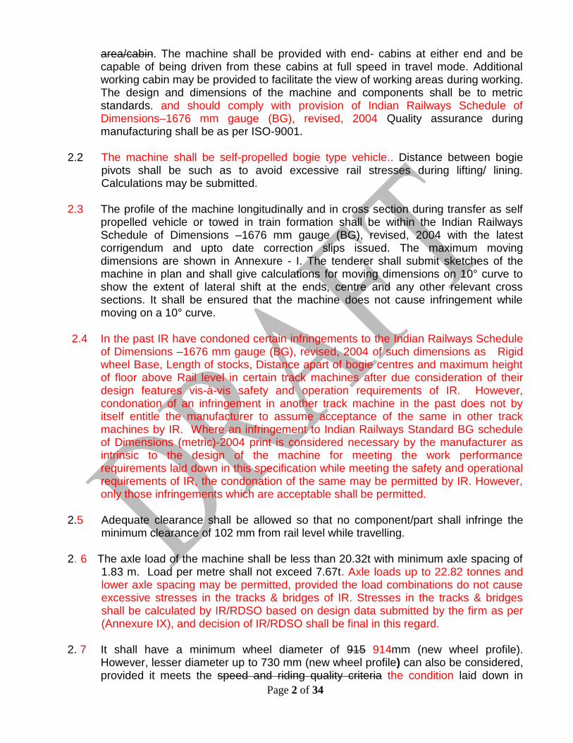
area/cabin. The machine shall be provided with end- cabins at either end and be capable of being driven from these cabins at full speed in travel mode. Additional working cabin may be provided to facilitate the view of working areas during working. The design and dimensions of the machine and components shall be to metric standards. and should comply with provision of Indian Railways Schedule of Dimensions–1676 mm gauge (BG), revised, 2004 Quality assurance during manufacturing shall be as per ISO-9001.
2.2 The machine shall be self-propelled bogie type vehicle.. Distance between bogie
pivots shall be such as to avoid excessive rail stresses during lifting/ lining. Calculations may be submitted.
2.3 The profile of the machine longitudinally and in cross section during transfer as self
propelled vehicle or towed in train formation shall be within the Indian Railways Schedule of Dimensions –1676 mm gauge (BG), revised, 2004 with the latest corrigendum and upto date correction slips issued. The maximum moving dimensions are shown in Annexure - I. The tenderer shall submit sketches of the machine in plan and shall give calculations for moving dimensions on 10° curve to show the extent of lateral shift at the ends, centre and any other relevant cross sections. It shall be ensured that the machine does not cause infringement while moving on a 10° curve.
2.4 In the past IR have condoned certain infringements to the Indian Railways Schedule
of Dimensions –1676 mm gauge (BG), revised, 2004 of such dimensions as Rigid wheel Base, Length of stocks, Distance apart of bogie centres and maximum height of floor above Rail level in certain track machines after due consideration of their design features vis-à-vis safety and operation requirements of IR. However, condonation of an infringement in another track machine in the past does not by itself entitle the manufacturer to assume acceptance of the same in other track machines by IR. Where an infringement to Indian Railways Standard BG schedule of Dimensions (metric)-2004 print is considered necessary by the manufacturer as intrinsic to the design of the machine for meeting the work performance requirements laid down in this specification while meeting the safety and operational requirements of IR, the condonation of the same may be permitted by IR. However, only those infringements which are acceptable shall be permitted.
2.5 Adequate clearance shall be allowed so that no component/part shall infringe the
minimum clearance of 102 mm from rail level while travelling. 2. 6 The axle load of the machine shall be less than 20.32t with minimum axle spacing of
1.83 m. Load per metre shall not exceed 7.67t. Axle loads up to 22.82 tonnes and lower axle spacing may be permitted, provided the load combinations do not cause excessive stresses in the tracks & bridges of IR. Stresses in the tracks & bridges shall be calculated by IR/RDSO based on design data submitted by the firm as per (Annexure IX), and decision of IR/RDSO shall be final in this regard.
2. 7 It shall have a minimum wheel diameter of 915 914mm (new wheel profile).
However, lesser diameter up to 730 mm (new wheel profile) can also be considered, provided it meets the speed and riding quality criteria the condition laid down in

Page 3 of 34
Clause 2.9 5 at its condemnation limit and rail wheel contact stresses for 72 UTS rails are within permissible limits. Forged wheels to Indian Railways profile shall be provided on the machine It is desirable that 50mm margin between new and permitted worn wheel diameter should be available, but this should not be less than 20mm.The worn out wheel diameter (condemning worn out diameter) based on the criteria of rail wheel contact stresses for various maximum axle loads are as under:
Maximum Axle load (tonne) Minimum worn out wheel diameter (mm)
22.82 908
22.00 878
21.50 860
21.00 841
20.32 816mm
20.0 805mm
19.5 787mm
19.0 768mm
18.5 750mm
18.0 732mm
17.5 713mm
17. 4 710
17.00 700mm
16.5 680mm
Permitted worn out wheel diameter should be specified by the manufacturer. The
diameter of wheel for assessment of permitted axle load will be the worn out wheel diameter.
2.8 The new wheel profile in the machine shall be as per Indian Railway standard
drawing attached as Annexure-VI which is titled as “WORN WHEEL PROFILE‟ 2. 9 It shall be capable of negotiating curves up to 10° curvature (176m radius), super
elevation up to 185 mm and gradients up to 3% in travel mode. The supplier shall specify the minimum attainable speed under the above limiting conditions, which in any case should not be less than 40 Kmph.
2.10 It shall be capable of continuous operation during the varying atmospheric and
climatic conditions encountered occurring throughout the year in India. The range of climatic conditions is as follows:
Ambient temperature : - 5°C to 55° C
Altitude : sea level to 700 1750 m above mean sea level Humidity : 40 to 100% Maximum rail temperature : 70° C
All the system components on the tamping machine shall be covered by roof or other suitable covering so that no water leakage occurs in the system & components vulnerable to moisture ingress are not adversely affected by rain water of the

Page 4 of 34
machine during rains and the machine is able to work continuously even during rains.
2.911 During transfer from one station to another, it shall be capable of travelling on its own and haul a camping coach/wagon/BFR at a speed of 80 kmph and at a speed of 100 kmph when hauled in a train formation as last vehicle without any adverse effect on machine‟s driving mechanism, on a track with gradients upto 1 in 500 and curve upto 1 degree. Since the machine is likely to cover long distances on their own power, the travel drive system should be robust to sustain these requirements during the life of the machine. without any break down/failure. It shall be possible to drive the machine in both directions at the same speed. The machine should be capable of hauling an 8-wheeler coach/Wagon (90 ton approximately) at a maximum speed of not less than 50kmph.
2.12 The machine as well as all its accessories shall be capable of working without
requiring power block in electrified sections. 25KV AC A current power supply is used for traction through an overhead wire at 5.5 m above rail level. On bridges and tunnels, the height is restricted to 4.8 m.
2.13 The machine or its any part shall not infringe the adjoining track as per „Indian
Railways Schedule of Dimensions, 1676mm gauge (BG), revised-2004 with the latest corrigendum and up to date correction slips issued‟, while opening and closing of work. While working, also it shall not infringe the adjoining track and it shall be possible to permit trains at full speed on that track. Minimum spacing of tracks is 4.265 m centre to centre.
2.14 The machine should be capable of carrying about 12 P. way workmen along with their
tools. Suitable seating arrangement and adequate space shall be provided.
2.15 There should be one loading platform for keeping the tools and small P. way materials/machines at one end of the machine of length not less than 7.0 meters so as to carry the half length of rails (6.5 mtrs). The width of this open platform should be equal to the width of the machine as per the permitted schedule of dimension prevalent on Indian Railways as mentioned above. The loading platform should be provided all-around with a sidewall/ Railing of about 45 to 60 centimeters height to protect the men and materials from falling. The approximate gross tonnage expected on this loading platform shall be limited up to 7 tonnes and the detail of engineering tools & materials required on this loading platform is as given in annexure-5 attached.
2.15 The machine shall be equipped with pneumatically operated block brakes acting on
all wheels. The machine shall be equipped with a mechanically operated parking brake. All operations for work and travel shall be controlled from a spacious fully enclosed cabin permitting unobstructed view in both directions.
3.0 Working Mechanism: 3.1 The machine should be capable of tamping plain track for spot attention as well as
for spot attention of points and Xings and other miscellaneous track locations,

Page 5 of 34
handling of P. way material including rails, sleepers, switches & Xings, their stacking on the material platform. It shall be capable to tamp effectively the special track locations such as level crossing with check rails, SEJ portion, ballasted track with Guard Rails on Bridges, Glued joint, curve locations etc. For handling of engineering materials & equipments a suitable tirfor / chain pulley (working capacity 1.5t) arrangement may be provided at one end of the material platform.
3.2 The machine shall be capable of automatic lifting, levelling, lining and tamping of
track to achieve the laid down track geometry standards, with proper packing for various kind of track structures.
3.3 Separate split head tamping unit shall be provided for each rail, each unit comprising
of tamping tools operated hydraulically. Each of the two halves of the tamping units should be able to be lowered and put into action separately from the other. Additionally, both halves of the unit should be able to be displaced laterally. The tamping units shall be provided with necessary arrangements for lateral shifting to adjust them on the rails in curves, and turnout, SEJ and other such special track locations. The minimum lateral adjustment of tamping unit should not be less than 270 mm min both inside and outside from its normal position shall be possible to tamp all four rails of the switch up to heel block. It should be possible to rotate and adjust tamping unit from operator‟s seat for tamping of slanting sleepers in turnout.Since the machine is predominantly to be used for spot attention and tamping on such spots may be required to be done without any general lift, the tamping system should be capable of giving effective tamping at spots and correct the track geometry even when no general lift is given.
3.4 Tamping action shall be based on vibratory squeeze principle to achieve a durable
compaction with tamping tools operating under the same pressure but independent of one another.
3.5 Amplitude and of vibration, vibration pressure, vibration frequency, squeezing
pressure, squeezing time and tamping depth of tamping tools in tamping units frequency of the tamping tools shall be such that durable compaction under the sleeper is achieved. Details of all the above parameters will be submitted in the offer The values of amplitude and vibration frequency, under the optimum compaction and method to measure these should be specified by the tenderer.
3.6 The squeezing action shall stop automatically after the tamping tools encounter the
resistance from the ballast to the pre-selected squeezing pressure. The squeezing pressure and squeezing time shall be variable so that it can be adjusted according to ballast conditions.
3.7 The lifting system shall be such that the track can be lifted without bearing on the
ballast. It shall be possible to lift track upto 150 mm in one go depending on the requirement. While working on track with no limitation of space, the lifting system should hold the rail continuously rather than releasing and re-lifting the rail at every tamping cycle. To ensure easy lift at all locations the machine should be provided with lifting hooks and lifting rollers clamp both or any similar device capable of lifting the track as mentioned above. However, the lifting/lining system and actual tamping

Page 6 of 34
should be so synchronized that the track is stiffly held in position and there is no movement in the track when the tamping tool is inserted for tamping. This is required to ensure that the lift and slew are not altered during the process while track is being tamped. It shall also be capable to lift properly the Glued (insulated joint), Switch expansion joint and Special one meter fish plated joint.
3.8 The working cabin should be so located that the operator faces towards the direction
of movement of machine to facilitate tamping of plain track. The lifting/ lining units should normally be so located that it is visible to the operator from the working cabin and its operation by operator should not require assistance of other person. Camera with monitor shall be provided for the assistance of operator if required.
3.9 The free rail length between the two bogies should be long enough to permit the track
lifting and lining up to 150 mm in one go, having 60 kg rails on concrete sleeper, without excessive stresses in the rail or on the lifting mechanism.
3.10 The machine shall be provided with automatic leveling equipment which will permit
correct leveling of the track and points & xing including provision of super elevation along with tamping.
3.11 The tamping tool holding arrangement in tamping arm of tamping bank should be
cylindrical compressible type with bolting and dowel arrangement such that no hammering is normally required for fixing and removing the tamping tools.
3.12 The machine shall be fitted with automatic lining equipment capable of carrying out
lining simultaneously with leveling. It shall be possible to adjust the lining unit longitudinally depending upon the position of sleepers and fittings etc, in the turnout. If required, the machine shall be able to slew the track up to 150 mm in one go. The lining unit should have two rollers for each rail or other suitable arrangement to avoid derailing of the lining rollers.
3.13 The machine shall be able to achieve the following tolerance :
Unevenness : + 1 mm on 3.6 m Chord Cross level : + 1 mm Alignment : + 2 mm on 7.2m Chord Twist : 1mm/m
3.14 The machine shall be capable of carrying out on plain track, automatic lifting, leveling, tamping and lining of 1000 sleepers or more in an hour of working and wWhen tamping turnouts, it shall be capable of tamping one 1 in 12 turnout complete with 10 sleepers on straight portion on the approaches of the turnouts in an hour of working at the following machine parameters:
a) Squeezing time of 0.6 sec or more b) Squeezing pressure of 120 kg/cm 2 or more. c) Tamping depth upper edge of tool blade should be 15-20 mm below the
bottom of the sleeper

Page 7 of 34
The time shall be counted from start to finish of tamping work at work place. Stoppage of work not attributable to machine shall be discounted. The setting up time and winding uptime shall be measured and the total time taken by the two operations of setting up and winding up of the machine together shall not exceed 10 minutes.
3.15 The machine shall be capable of automatic leveling, lining and tamping of turnouts
with CMS and built up crossing of angles 1 in 8.1/2 ( Eight and half), 1 in 12 and 1 in 16 laid on wooden, steel or concrete sleepers without dismantling the turnout.
3.146 The machine shall be capable of tamping, lifting and lining up to 60 Kg/m long
welded rails ,short welded rails and fish-plated track with rails laid on pre-stressed concrete sleepers, steel trough sleepers, CST-9 or wooden sleepers. As the minimum clear distance between the joint sleepers is 50 mm, the machine shall be able to tamp these two sleepers together. The normal sleeper spacing in different track structures on Indian Railways is 55 cm to 75 cm.
3.157 The ballast depth ranging from 300 mm to 350 mm shall be effectively compacted
having zone of influence of tamping confined to app. 150 mm layer below the bottom of sleepers. There shall be provision for stepless adjustment of the depth of tamping tools to suit different type of sleepers. The maximum depth of concrete sleeper is equal to 210mm.At deep screening or at renewal site it shall be possible to undertake tamping upto 300 mm or more in layers by tamping of first 150 mm layer followed by filling of ballast and tamping of another top 150 mm layer.
3.18 For handling of engineering materials & equipments a suitable telescopic crane
arrangement may be provided at one end of the material platform. The crane shall be capable of lifting. 1.0 5 t load over front at such a minimum lifting radius upto 3.0 m that it is possible to load & unload 60 kg CMS crossing, 6.5 mtr long 60 kg Rail, & concrete sleeper (details as per annexure-5) from machine to the Railway track below & vice versa. It should be possible to work with this crane in electrified sections of Indian Railway without taking power block. Proper slings or any other equivalent arrangement required for picking up rails, sleepers or crossings shall be supplied as part of the crane.
3.19 The crane operation should be such that there is no infringement to over head
electric equipment during crane manoeuvring/extension/shortening and there is no infringement to the Indian Railways Schedule of Dimensions – 1676mm gauge (BG), revised, 2004 with latest corrigendum and up to date correction slips issued, on the adjacent track at 4265 mm track centres. In case there is a possibility of boom getting lifted to infringe the Overhead Electric Equipment, suitable safety device to prevent such an eventuality should be provided.
3.18 The tenderer may be required to show the working of his machine under field
conditions for which the names of countries where such a demonstration is feasible shall be given.
3.20 The working cabins of the machine shall be air-conditioned. The air-conditioning
provided shall be of robust industrial design capable of operating in highly dust laden

Page 8 of 34
environment. However, the electronic equipments shall be so designed that it shall be able to work without air conditioning under the climatic conditions described in Para no. 2.8 10 of the specification.
3.21 The machine shall be provided with a computerized unit for the overall control of its
working system for all possible track geometry. The system shall be so designed that for working on tracks with pre-decided target geometry, the standard track geometry data as well as correction values can be entered prior to work either directly on system or via USB, CD or DVD. For working on tracks with unknown target geometry, it shall be possible to determine the correction values by making a measuring run and subsequent geometry compensation of the recorded data considering obligatory point and constrains of lifting and lining etc. Interactive processing of the target profile by the operator shall be possible. The machine shall be capable of measuring and recording the longitudinal level of both rails, alignment of datum rail (Versine), cross level (Super Elevation) and twist in real time before and after the tamping by the machine. These parameters shall be displayed on screen and its print out (printing arrangement to be provided) could be taken whenever required. It shall also record progress vis-a-vis time and it should be possible to take all the above data on USB drive. The software shall be Windows based. The hardware shall be sturdy for operations under conditions of shock, vibrations, dust, electromagnetic influences from outside and interruption of power supply. The unit shall have adequate memory to keep records of minimum 100 km of work performed, new track geometry obtained and enables transfer of the data via USB, CD or DVD as required.
3.22 In addition to the computer system provided on the machine for its own controls, the
machine shall be provided with an industrial quality heavy duty portable computer (Laptop-tough book) for keeping record of overall aspects of working, spares management and reporting. The detailed specifications of the laptop are enclosed as Annexure-VII.
3.23 Important tamping Parameters like Datum Rail, General lift, single insertion or
double insertion, design or smoothening mode, time of start and finish of work, squeezing pressure, squeezing time, vibration pressure and tamping depth etc shall be shown on a display in the working cabin. It shall be possible to draw these data from the system itself after work via USB port on a memory stick for the purpose of record.
3.24 A programmable logic control system shall be provided in the machine so that the
work like lifting, lining, tamping and work drive of machine will commence only when all conditions for their working /movement is fulfilled.
3.25 To monitor the working of machines, closely from anywhere in the country from any location, suitable number of IP based cameras are to be installed. The camera should be fixed on machine at such location that the live video of the important working units of machine which are working on track, location of worksite and post-work track can be seen by the authorized person with commonly used browsers in India over the internet. Camera should be password protected and be decentralized,

Page 9 of 34
IP based. It should have recording function built-in and thus can record directly to any standard storage media, such as SD cards. Internal memory space of 500GB should also be available.
3.26 In case of failure of the up and down cylinders of tamping unit, there should be an arrangement for lifting the tamping units mechanically by lifting equipment like trifor/chain pulley etc.. Any other alternative arrangement for mechanically lifting tamping unit in such failures may also be provided.
3.27 The machine should be equipped with a centralised computer based control and monitoring system which shall monitor the health of machine working system such as engine (lub oil pressure, temperature, rpm etc.),hydraulics (hydraulic pressure in different units, temperature, oil level in tank etc), pneumatic (pressure of different units), electricals (charging/discharging rate, voltage etc.). All these data should be displayed on a monitor installed in working cabin. Arrangement for providing 3G/4G internet connection for sending data in soft format directly from the computer should also be available.
4.0 Diesel Engine: 4.1 The machine shall be powered by diesel engines preferably indigenous with proven
record of service in tropical countries with wide service network in India. Robust construction and low maintenance cost are of particular importance. Adequate allowance shall be made for de-rating of diesel engine under the most adverse climatic conditions mentioned in the specification elsewhere.
4.2 The supplier shall furnish the details of diesel engine and its controls to assess its
conformity with the engines already operating on track machines on Indian Railways. If the machine-design incorporates an engine not already operating with the purchaser, the model of the engine is liable for change as per the technical requirements and the maintenance logistics with the purchaser after technical negotiations with the supplier. Nothing extra shall be payable on this account.
4.3 High speed diesel oil to Indian standard specification shall normally be used. A
minimum fuel tank capacity sufficient for continuous operation for eight hours but not less than 1400 liters shall be provided. will be desirable.
4.4 Sight glass type fuel measuring gauge preferably of full height shall be provided on
the fuel tank. 4.5 For starting the engine, storage batteries of well known indigenous make with wide
service network in India shall be provided. The engine shall normally be push/pull button start type or key type.
4.6 Since the engine is to work outdoor under extreme dusty conditions, the air intake
system shall be designed suitably so as not to allow dust through air intake system. 4.7 There is a likelihood of dust deposition over the engine body and surrounding area
over the lubricants spills over. These should be easy to access for daily cleaning and routine maintenance. In case, air cooled engines are proposed by the supplier,

Page 10 of 34
maintenance equipment for cleaning and maintenance of the air cooling fins shall be provided by the supplier along with the machine.
4.8 The engine parameter monitoring gauges like temperature, rpm, and lub. oil
pressure shall be direct reading type mounted on the engine backed up by electrical/mechanical gauges in the operator‟s cabin showing the absolute readings along with safe limits suitably coloured. There shall be audiovisual warning (safety mechanism) to the operators in case of any of these parameters exceeding the safe limit and engine shut down circuit in case of operator‟s failure to respond.
4.9 Suitable and rugged mechanism should be provided to start the prime mover at
minimalum/ no load and gradual loading after the start of the prime mover. A fail safe clutch mechanism, if required may be provided to meet this requirement. The engine shall be mounted on suitable Anti-Vibration Mountings.
4.10 The engine should have Electronic Control Module (ECM) or similar arrangement for taking out operating parameters on real time basis such as RPM, load, fuel consumption, temperature, pressure maintenance and diagnostic data as well as trip and historical data. These data should be displayable on a centralized computer based control and monitoring system as mentioned in para 3.27 above. It should also be possible to transfer these data on USB device.
5.0 Driving Mechanism:
5.1 The machine should be provided with an efficient traction drive system for traction
during the operation. It shall be equipped with separate power train circuits for high speed travelling in traveling mode and slow cyclic movement in working mode.
5.2 The driving mechanism for travel drive should be rugged to perform satisfactorily
during the life cycle of the machine. The machine‟s driving system shall be through hydro dynamically / hydraulic coupled power/transmission arrangement capable of achieving full speeds in travel mode in both the directions. However, the system should be so designed that all the driving wheels work in synchronization and there is no slippage/skidding of the wheels during the work drive.
5.3 The driving mechanism, in working mode, shall be adequately designed to handle
the acceleration and braking forces at each tamping cycle. A suitable synchronization circuit to control the synchronization of lifting/lining/tamping process with the machine drive/braking system in working mode shall be provided to prevent any damage to the machine systems on account of non-synchronization.
5.4 Suitable differential systems may be provided between coupled wheels on the same
bogie.
5.5 Suitable flow divider/throttling arrangement may be provided to equalize the tractive effort amongst different bogies. Adequate gauges shall be provided to indicate the power sharing among different driving bogies to prevent overstressing of any traction bogie or its components.

Page 11 of 34
5.6 The supplier tenderer shall provide the necessary technical details including circuit diagrams to confirm the above requirements.
5.7 Adequate gauges should be provided in working and driving cabins near operator‟s
seat. (flow meter), and Solenoid valves shall be provided near linkage assembly,for indication, flow control and carrying out necessary adjustment in the field.
5.8 To the extent possible hydraulic and pneumatic component/assembly should be
fixed at suitable location preferably on the side frame of the machine so as to avoid the need of going on top of the machine for day-today maintenance schedules.
5.9 The pneumatic circuit should be provided with air dryer for the smooth working of
pneumatic components.
5.10 The machine shall be equipped with adequate safety circuit such that if any unit/part which may endanger the safety is unlocked, the machine shall not move during run drive. The indication of locking and unlocking of all units should be displayed in the cabin.
5.11 Onboard system for online filtration and monitoring the quality of hydraulic oil in
hydraulic circuit should be provided. The gauge should clearly indicate if the hydraulic oil is contaminated beyond the permissible limits and requires immediate replacement.
6.0 Cooling System: 6.1 The cooling system shall be efficient and designed for a maximum ambient
temperature of 55°C. Supplier shall note that the machine shall be working under extreme dusty conditions and the cooling mechanism shall be maintainable under these conditions.
6.2 Adequate heat transfer arrangement for the hydraulic system shall be designed and
provided so that under extreme heat conditions as mentioned in 2.8 above, the
system oil temperature does not go beyond 85C specified range of the engine. . 7.0 Brakes: 7.1 The machine shall be fitted with the compressed air brakes applying brakes equally
on all wheels and provision shall be made to connect air brake system of the machine to that of camping coach/wagons when the machine is hauling it. Fail safe braking mechanism system shall be provided so that in case of any failure of brake circuit will result in automatic application of brake. The brakes shall be protected from ingress of water, grease, oil or other substances, which may have an adverse effect on them. The brake lining shall be suitable for high ambient temperature of 55° C. The force required for operating the brake shall not exceed 10 Kg. at the handle while applying by hand and 15 Kgs. on the pedal, when applied by foot. In addition, mechanical brakes shall also be provided for use in an eventuality of failure of air brakes as well as for parking brakes.

Page 12 of 34
7.2 Machine shall be equipped with suitable arrangement of braking air brake valves so that while attached working in train formation, machine can be braked by traction vehicle having compressed air braking system. In addition, the machine shall be equipped with suitable air brake system in the driving cabins so that the attached wagon or camping coach while being hauled by machine, can be braked.
7.3 There should be provision of emergency brake application in the machine either
travelling alone or coupled with the camp coach/wagons, in addition to the normal braking system of the machine, using the compressed air. The emergency braking distance (EBD) of the machine on the Indian Railway Track, at the maximum design speed on level track shall not be more than approximately 600m. In this regard necessary design calculations for the braking effort and EBD at the maximum design speed of the machine should be provided by the supplier. Design calculations for the braking effort and EBD at the maximum design speed of the machine on level track & at falling grade of 1 in 33 should be provided by the supplier. Brake design details are to be submitted as per Annexure VIII.
7.4 Clearly visible brake lights shall be provided at both the ends of the machine, which
will be automatically operated when brake is applied and switched off when brake is released. This will be to alert the operator of machine following this machine when the machines are working in groups.
8.0 Horn, Hooter and Safety switches: 8.1 The equipment machine shall be provided with dual tone (low tone & high tone)
electric/pneumatic horns/hooters facing outwards at each end of the machine at suitable locations for use during travelling to warn the workmen of any impending danger at the work spot or from oncoming train. Control shall be provided in close proximity to the driver permitting the driver to operate either horn individually or both horns simultaneously. The horns shall be distinctly audible from a distance of at-least 400 m from the machine and shall produce sound of 120-125 dB at a distance of 5 meter from driver‟s cab horn (source of sound). The higher tone horn shall have fundamental frequency of 370 ±15 hertz. These electric horns/hooters shall be operated by means of push buttons provided near the both side exit gates on the machine.
The lookout man sitting on the machine should be able to have clear view on
the adjacent track so that he can operate the electric horn/hooters to warn the staff working on/around the machine about approaching train on adjoining track. Adequate numbers of safety stop switches should be provided all around so that in case of any danger to worker during working, the working can be stopped immediately.
8.2 Safety equipments like jacks, pullars, trifor and other such equipments specific to the
machine for restoring failed units of the machine during working shall be provided on the machine.

Page 13 of 34
8.3 Machine shall be provided with emergency backup system to wind up the machine in the event of failure of prime mover or power transmission system of the machine. The emergency backup system should be able to be operated manually also.
8.4 Pneumatically/electrically operated hooters capable of producing intensity of sound
between 105-110 dB at a distance of 5 meter (when measured in still air in a closed room) and variation in intensity of sound shall not be more than 5 dB. The hooter shall be provided facing outwards at each end of the machine at suitable locations, operated by means of push buttons provided in the cabins to warn the staff working on/around the machine about approaching train on adjoining track. Additionally switches for such hooter shall be provided outside on the machine frame and near the both side exit gates so that it can be operated by staff present at work site near the machine. The hooter shall also be operatable from remote point at a distance of at least 300 m from the hooter.
8.5 Adequate numbers of safety stop/ switches should be provided all around so that in
case of any danger to worker as well as hitting of any obstructions by working unit like signalling cable, joggle fish plate etc.during work,so that the operator can be warned or the machine can be stopped immediately.
9.0 Hooks and buffers: The machine shall be fitted with hooks and buffers of IRS design on both ends for
coupling the machine with other vehicles and running it in train formation and for attachment with the coach, locomotives and wagon.
10.0 Suspension System
The suspension system shall be preferably of two-stage type with suitable spring and damping arrangement. Springs for primary and secondary suspension shall be designed to cater for actual service conditions. Effective measures shall be adopted to minimize the weight transfer while starting, stopping and during runs. Any other proven design of similar suspension may be accepted provided it meets the functional requirements of speed and ride quality mentioned elsewhere in this specification.
11.0 Electric equipment and lighting: The electrical equipment to be provided shall conform to relevant standard
specifications and shall be suitable for Indian climatic conditions. The machine shall be equipped with twin beam headlight assembly, conforming to RDSO specification No. ELRS/SPEC/PR/0024 Revision–1, September, 2004 with the latest amendments ensuring a light intensity of 3.2 lux at ground level at track centre at a distance of 305 mts. away on a clear dark night, at each end and with two front and rear parking lights, which can be switched to red or white according to the direction of the travel. Powerful swiveling floodlights shall also be provided to illuminate the working area sufficiently bright for efficient working during night. In addition minimum eight power point locations (24 volt DC/15 amp socket) shall be provided on outside frame of the machine two in front, two in rear and two on both sides for providing lighting

Page 14 of 34
arrangements during night working. The amber colour LED based flasher lights producing not less than 500 lux at 1 meter and 55 lux at 3 meter in line measurement in axial direction from flasher light shall be provided on both ends of the machine to give indication for the train arriving on other line about any impending danger.
12.0 Cabins: 12.1 The machine shall be equipped with fully enclosed and pressurized sound and heat
insulated cabins with safety glass windows at both ends and working cabin shall be air conditioned. In view of the high ambient temperature prevailing in India, special attention shall be paid to free circulation of air and ventilation in the driver‟s cabin. However, the electronic equipments shall be so designed that it shall be able to work without air conditioning under the climatic conditions described in Para 2.810. It shall be possible to have a clear view of the track ahead while driving the machine in both the directions from the cabins at either end. The cabin layout shall be such that, before leaving the machine, the operating staff has full view on both the sides, to avoid any danger to them from trains on the adjacent track. Additional driver‟s cabins shall be provided if the view while driving is not clear for safe travel in both directions.
12.2 The gauges, panel‟s instruments and controls shall be suitably located in the
operator‟s cab so that they can be observed without undue fatigue to the operator. 12.3 The operator‟s cabin shall be ergonomically designed to have easy access to all the
controls. The operator shall have a full view of the working area from the operating seat to have a full control over the work.
12.4 Screen wipers preferably operated by compressed air or electrically operated shall
be provided on the windscreens on both sides. 12.5 Suitable number of fire extinguisher (dry chemical type) shall be provided in all the
cabins. 12.6 The machine shall be provided with well designed adequate space for keeping the
tools and spares required for onsite repair of the machine to attend the breakdowns and other working requirements.
12.7 Necessary inter-communication system shall be provided inter-connecting all the
cabins and should be so oriented that the operator, seating on the seat of either cabins/working cabin, can distinctly hear the conversation.
13.0 Chassis and under-frame: The chassis shall be of standard welded steel sections and of steel sheets, so as to
permit transportation of the machine in train formation without endangering safety of the train. The under-frame shall be constructed with rolled steel section and/or plates and shall be designed to withstand a maximum static squeeze test load of 200, 102 t i.e. 51 t at each buffing point without any permanent distortion. The under frame

Page 15 of 34
shall be sufficiently robust for safe travel of the machine in train formation and not necessarily as the last vehicle.
14.0 Tools and Instruction Manuals: 14.1 Each machine shall be supplied with a complete kit of tools required by the operator
in emergency and for normal working of the machine. The list of tools to be provided shall also include all tools necessary for maintenance and repair of the entire machine including specialized equipment. All special tools shall be listed and catalogued illustrating the method of application. The tenderer shall along with his offer submit the list of tools to be supplied along with each machine. The list can be modified to suit the purchaser‟s requirement, while examining the offer
14.2 Detailed operating manual maintenance and service manual, user manual indicating
capabilities of machine, prepared in English language and three four hard copies & soft copies of each of the same shall be supplied with each machine. One set of all the manuals and diagrams (one set for a group of similar machines) should be sent to Principal/ IRTMTC, Allahabad and one (one set for a group of similar machines) to be sent to EDTM / TMM directorate RDSO Lucknow.
14.3 The supplier manufacturer shall also supply circuit diagrams of electrical, hydraulic,
pneumatic and electronic circuits used on the machine. Trouble shooting diagram/table shall also be supplied. In addition, the supplier shall provide dimensional drawings with material description of items like rubber seals washers, springs, bushes, metallic pins etc., main features such as type, rpm & discharge etc of items like hydraulic pumps, motors and such other bought out components/assemblies shall be furnished by the tenderer. These shall be specially prepared in english language and four copies of these shall be provided with each machine.
14.4 The tenderer shall along with his offer, submit the list of tools, manuals, circuit
diagrams and other technical literature/drawings in English language to be supplied along with each machine as above, for operation, servicing, maintenance, assembly overhauling, periodic overhauling and troubleshooting guides/manuals. The list can be modified to suit the purchaser‟s requirement, while examining the offer.
14.5 While offering the machine for first inspection, the supplier shall submit three copies
one copy of complete technical literature in English language including operation, service and maintenance manual/instructions and complete electrical, electronic hydraulic & pneumatic circuit diagrams, trouble shooting charts, component drawings/ description and other relevant technical details so as to maintain master copies of these documents in Indian Railway Institutions and a reference documents as reference document for the inspecting officer.
14.6 One portable diesel operated D.C. welding plant (with the provision of auxiliary
output of minimum 2.5 KW, 230 V AC for lighting) of reputed make (preferably made in India) with a minimum 11 KW/16 H.P 5 KVA capacity capable of welding upto 5 mm. electrode (dia) at 60% duty cycle shall be supplied. Sufficient cable or lead shall

Page 16 of 34
be provided with the welding plant machine for day to day repairing of machine and its wearing parts. The diesel tank capacity shall be not less than 15 litre.
14.7 The firm shall provide detailed technical drawings and specifications of wheels and
axles used in the machine along with detailed code of procedure for ultrasonic testing of wheels and axles of all types. The above details shall be provided in four sets with each machine.
14.8 One set of all the manuals and diagrams should also be sent to the
Principal/IRTMTC, Allahabad, one set to ED/TMM, RDSO, Lucknow, one set to DTK (MC)/Railway Board and one set to Director/IRICEN/Pune along with supply of first machine of similar group. In case, there is any subsequent amendment in above documents based on field performance, the amendment/amended documents should also be sent to above mentioned authorities.
14.9 A draft copy of all documents to be supplied with the machine should be sent 3
months in advance of inspection of the first machine to RDSO for their review regarding adequacy and manner of detailing. Necessary modifications and further detailing as per RDSO‟s comments should be carried out and compliance should be reported to RDSO as well as the Inspecting officer of the first machine.
15.0 Spare parts: 15.1 The tenderer should quote, apart from main equipment, separately for the mandatory
spares as well as for recommended spares required for two years of operation along with description, part number, quantity, cost, whether imported or indigenous. The expected life of components/spare parts shall be advised along with their condemning limits. The machine shall be supplied with the necessary spare parts for the operation and maintenance of the machine for a period of two years i.e. working for about 2000 hrs. The tenderer along with the offer shall furnish required spare parts details in a separate list indicating description, part number, quantity, cost, whether imported or indigenous and their source of supply (OEM details). The supplier shall be responsible for the subsequent availability of spare parts to ensure trouble free service for the life of the machine (15 years).
15.2 For indigenous parts and brought out components and assemblies, the source
(original equipment manufacturer‟s reference and part no.) and other relevant technical details shall be supplied while offering the first machine for inspection.
16.0 Maker’s test certificates: Copies of maker‟s certificate guaranteeing the performance of the machines should
be supplied in duplicate along with the delivery of each machine. 17.0 Operators: The number of operators and allied staff for working of the machine under normal
working condition may be indicated, specifying their duties and minimum qualifications.

Page 17 of 34
18.0 Optional Equipment: Tenderer is expected to quote for optional equipment separately for each item giving
the advantages/functions of such optional equipment. Tenderer shall also indicate whether such equipments are already in use on machines elsewhere indicating the user Railway system.
19.0 Warranty Guarantee:
In addition to the clause 9 of the special conditions of contract dealing with warranty, the following will apply. The machine shall be warranted for 1200 effective working hours or 18 months from date of commissioning and proving test of equipment or 24 months from date of delivery at ultimate destination in India whichever shall be earlier. Effective working hours for this purpose will be traffic block time during which machine is deployed for tamping work. Should any design modification be made in any part of the equipment offered, the warranty period of 24 18 months would commence from the date of the modified part is commissioned in service for the purpose of that part and those parts which may get damaged due to defects in the new replaced part. The cost of such modification should be borne by the supplier.
20.0 Inspection of the Machine: 20.1 While inspecting the machine before despatch from the supplier‟s premises, the
inspecting officer shall verify the conformity of the machine with respect to individual specification as above. The machine‟s conformity /nonconformity with respect to each item shall be jointly recorded before issue of the inspection certificate and approval for despatch of the machine as per Annexure – III enclosed.
20.2 Following arrangements shall be made by the supplier/Manufacturer at the
inspection premises for carrying out inspection of the machine by inspecting officials:
Machine to be stabled on straight & level BG track. The length of the track should be at least 10 m more than buffer to buffer length of machine.
In order to check Maximum Moving dimensions in cross section, a Sturdy frame of IR Max Moving Dimensions shall be provided by the manufacturer and passed over the machine holding it perpendicular to track, centre aligned with track centre. Adequate arrangements shall be made to the satisfaction of inspecting official.
20.3 The following documents shall be provided to the Inspecting Officer at least 30 days
before the proposed date of inspection.
i) One copy of complete technical literature mentioned in clause 14, in English
language, including operation, service and field maintenance manuals/instructions
and complete electrical, hydraulic and pneumatic circuit diagrams, trouble shooting

Page 18 of 34
charts, component drawings/ description and other relevant technical details as a
reference documents in soft & hard copies for the inspecting officer.
ii) Cross section of the machine super imposed on IR maximum moving dimensions envelope shall be provided to IO in advance.
iii) Clause by clause comments of the manufacturer to be sent to Inspecting Officer (IO) in advance for his review. Comments should state manufacturer‟s conformity of compliance of each of the requirement stated in each clause, elaborating where necessary the details/manner in which the requirement has been complied. The proforma for the clause-wise comments is given below:
Clause Clause no. Comments of Supplier/ manufacturer
Comments of Inspecting Officer
iv) Manufacturer‟s Internal Quality Inspection Report of the machine.
v) Manufacturer‟s quality certificate and/or test reports for bought out assemblies/sub-
assemblies to be provided to IO, containing serial number wherever applicable.
vi) Draft Inspection Report to be prepared by the manufacturer, containing all annexure
mentioned at para 20.4
vii) Details of arrangements made for checking Maximum Moving Dimensions for his
approval.
Supplier will incorporate amendments/further clarification in the above documents to the satisfaction of the Inspecting Officer keeping in view the Inspecting Officer‟s comments, if any.
20.4 List of documents to be annexed in the draft Inspection Report should include:
i. Maker‟s Test Certificate. ii. Manufacturer‟s Internal Quality Inspection Report iii. Quality Certificates of Bought out assemblies/sub-assemblies iv. Cross section of the machine super imposed on the IR MMD v. Vogel‟s diagram vi. List of spare parts to be dispatched along with the machine vii. List of tools to be dispatched along with the machine viii. List of Manuals, Drawings, Spare Parts Catalogues, etc. to be dispatched along
with the machine, duly indicating the number of sets of each. These above documents in soft & hard copies shall be part of final inspection
report

Page 19 of 34
21.0 Service Engineers: 21.1 The contractor shall provide at his own expense the services of competent
engineers during the warrantee period for warrantee related issues. The service engineers shall be available for the commissioning of the machine for regular service, and for training to the operating, repairing and maintenance staff of the machine. The engineers shall also advise the Railways on appropriate maintenance, testing, operating, repair and staff training facilities that are necessary for the efficient performance of the machines.
22.0 Acceptance Test:
22.1 In addition to verification of the various items of specifications covered earlier the
purchaser‟s nominee shall carry out the following tests in India at the purchaser‟s premises at the time of commissioning of the machine. The pre-commissioning tests shall be completed and the machine shall be commissioned within 90 days of its arrival at the premises of the final consignee.
22.1.1The Dimensional check of loading gauge, i.e. maximum moving dimensions, buffer
heights, clearances, length of machine bogie distance etc. 22.1.2 Testing for negotiability 10° curve and on 1 in 8½ turnout. 22.4 Running speed tests on the Indian Railway main line track on the first machine in
accordance with procedure outlined in annexure-II with the machine running upto speed 10% higher than the maximum speed mentioned in para 2.9 above.
22.1.3 Construction and engineering of the machine and its ability to perform all the
functions as laid down in the specification. 22.1.4 Actual output and performance test to be conducted on the first machine..
The general conditions of tests shall be as follows: a) Machine crew shall be either trained personnel of Indian Railways or the staff
of the supplier. b) Dry weather, ambient temperature between +5°C to + 40°C c) Plain Track on curve minimum 1000m radius. d) Straight track with gradient up to 5 per thousand. e) Rails and sleepers in good conditions and properly fastened. f) Concrete/wooden/steel sleepers. g) Clean ballast cushion up to 100mm 150 mm in sufficient quantity below the
bottom of the sleepers and generally not cemented. h) LWR track. i) Regular sleeper spacing of 60/65 cm with a tolerance of
+ 3 cm on straight track. j) Formation good.

Page 20 of 34
k) General lift up to 20mm. l) Maximum slew up to +10 mm.
Test to be conducted:
m) At the parameters specified by the tenderer against clause 3.14 tThe machine shall be capable of carrying out on plain track, automatic lifting, leveling, tamping and lining of 1000 sleepers or more in an hour of working. When tamping turnouts, it shall be capable of tamping one 1 in 12 turnout complete with 10 sleepers on straight portion on the approaches of the turnouts in an hour of working. Stoppage of work not attributable to machine shall be discounted. The time shall be counted from the time the machine arrives at the place of work to the time it is ready to start back from work after winding up operation. The setting up time and winding uptime shall be measured and the total time taken by the two operations of setting up and winding up of the machine together shall not exceed 10 minutes.
22.2 Should any modification be found necessary as a result of the tests, these shall be carried out by the supplier at his own expenses.
22.3 Running speed tests on the Indian Railway main line track on one of the machine
within warranty period in accordance with procedure outlined in Annexure-II .
23.0 Issue of Provisional Speed Certificate: Whenever a new rolling stock is introduced in Indian Railways, a provisional speed
certificate is issued by RDSO based on certain design parameters of the vehicle. Final speed clearance of the vehicle is given after conducting detailed oscillation trials of the vehicle, which is a time taking process. Therefore, issue of provisional speed certificate for the vehicle becomes a necessity and based on the same the approval of running of the vehicle on Indian Railway track is taken from Commissioner of Railway Safety. For issue of provisional speed certificate, following actions are required to be taken by the suppliers.
a) Current supplier, whose models are approved: The supplier shall give details of the model, year of introduction in Indian railway,
details of speed certificate issued etc. The supplier shall certify that no change has taken place in the model being offered with respect to design of undercarriage i.e. suspension system/ arrangement, wheel & axle assembly, bogie braking arrangement loading pattern of the vehicle etc and the distribution of axle loads, lateral forces, unstrung mass and braking force coming on rail is the same if, there is any change in above respect, the action shall be taken as detailed in Para (b) below.
b) Current Supplier, whose models are not approved/ or new: As soon as the supplier completes the design of the machine as per specification,
the technical details as per Annexure (IV- A&B ) which in no case should be more than six months from signing of contract, shall be supplied to Track Machine and Monitoring Directorate of RDSO for processing of provisional speed certificate for the machine so that it can be permitted to move on track on case- to – case basis, more technical details ( other than mentioned in Annexure IV- A&B ) can also be asked for issue of provisional speed certificate for the machine .

Page 21 of 34
c) New supplier, whose models are new: The technical details shall be supplied as detailed in para (b) above.
24.0 MARKING & COLOUR OF MACHINE:
24.1 The machine body shall be painted in golden yellow colour,
24.2 Following should be written in black on the machine at appropriate location i) India Railways logo of height between 300 mm to 600 mm as suitable on all four faces
of the machine in English & Hindi as per direction of Indian Railway official.
ii) On both side faces and below the Indian Railways logo, the text “ INDIAN RAILWAYS” to be written in Bold and in Black colour of size equal to or slightly smaller than the size of logo but of size not less than 250 mm.
iii) Below the text “INDIAN RAILWAYS” mentioned above, Machine model and manufacturing Year should be written in black colour and in letter of size less than the size in which Indian Railways is written but not less than 200 mm in any case.
iv) If required, the Manufacturers Name may be written in size not more than 150 mm and should not be at more than four locations. Also the Manufacturers Logo may be provided at not more than two Locations and should be of size less than 200mm.
*******************

Page 22 of 34
Annexure I

Page 23 of 34

Page 24 of 34
ANNEXURE III
INSPECTION CERTIFECATE
CERTIFECATE OF INSPECTION OF TECHNICAL SPECIFECATION FOR ON TRACK MULTIPURPOSE
TEMPERS (Model No. ……….) BY INSPECTING OFFICAL AND APPROVAL FOR
DESPATCH OF MACHINE
( strike out whichever not applicable )
This is to certify that I have inspected the Multipurpose temper……………. bearing Sl.No. ………….. from
(date) ………….to ……………..at (place ) ………………..for its conformity / non –conformity with respect to
the laid down Technical Specification on contract Agreement No. …………………..dated
……………….between president of india through Director ………………………./ RDSO/ Lucknow and M/s .
(Name of contractor ) …………………………….
The detailed inspection Note regarding its conformity / non conformity to the laid specification is
enclosed along with as annexure „A” . It is observed that (strike out whichever is not applicable) :-
The Multi purpose Tamper conforms to all the laid down specifications.
The Multipurpose Tempers conforms to all the laid down specifications except those at
sl. No………………
The above deviations are miner / major affecting / not affecting the performance of the equipment
in substantial way .
The following T and P / manuals drawings are to be supplied along with the machine.
1……………………………….
2……………………………….
3……………………………….
Based on the above the multipurpose tamper is certified /no certified to be conforming to the
specifications.
The Multipurpose Temper is approved/ not approved for dispatch to …………..( consignee) Indian
Railway.
For M/s …………………. SIGNATURE AND DATE
……………………………. INSPECTING OFFICIAL
(NAME AND DESIGNAQTION )
For and on Behalf of President of India

Page 25 of 34
Annexure IV-A Particulars Required in Respect of the Rolling Stock Under Consideration
1. A diagram showing elevation salient dimensions :
Wheel spacing, Wheel diameter, bogie centres, and axle load.
a) i) Over all length of the vehicle :
ii) Length over head stock : iii)Length over buffers : iv) Distance apart for Centre of buffers : v) Max./Min. height of centers of buffers
above rail level : b) i) Wheel base :
ii) Axle load (max) : iii) Bogie Centres :
2. Wheel dimension : i) New : ii) Worn out : 3. i) Tread and flange profile of the wheel : indicating clearly whether it is Indian Railway standard profile or differs from standard flange profile.
ii) Wheel gauge dimension – : (back to back of tyre flange).
4. Whether the stock is designed to be used as : a general purpose or in a closed circuit in specified sections under defined conditions.
5. Maximum design speed
i) Own Power : ii) In train formation :
6. Unsprung weight per axle in tonnes
i) Driving axle : ii) Running axle :
7. Expected lateral force in tonnes per axle : At maximum design speed.
8. Method of operation - :

Page 26 of 34
Whether single only or coupling together is possible. If coupling is possible, the number which can be coupled and what is trailing load. 9. Maximum tractive effort at start and at the speed of operation - i) at working drive at start : at operation speed : ii) at transfer drive at start : at maximum speed :
10. Maximum braking force coming on to the rails per wheel
a) at working axle : b) at transfer axle :
11. Drawing indicating suspension arrangement details :
of bogie and axle.
12. Height of centre of gravity from rail level : 13. Height of floor from rail level : 14. Type of coupler provided -Indian Railways Standard
Coupling :
Buffer :
15. Any infringement to the moving dimensions :
Sketch provided in the Indian Railways Standard Schedule of Dimensions – Chapter IV (A).

Page 27 of 34
Annexure IV B Following information as detailed below is also required along with the information required for processing the case for issue of provisional speed certificate for new vehicles
S.No. Item
1. a) Brake System details
b) Gross Braking Ratio
2. Brake rigging arrangement drawing and calculation of braking force
3. Maximum Braking Effort. at start and at the speed of operation - a) at working drive at start :
at operation speed : b) at transfer drive at start
at maximum speed :
4. Characteristics of springs used in suspension indicating free height, working height, dynamic range, stiffness and locations etc.
5. Characteristics of the dampers if used, and over all damping factors and locations of dampers. Calculation of the following frequency of the vehicle to be attached :- Bouncing ii) Pitching iii) Rolling Wave length of free axle and bogie
6. Write up and salient design calculation on suspension system, type of suspension- whether it is of coil suspension with or without dampers and laminated bearing springs and double link suspension.
7. What are lateral clearance of axle box / horn, wheel flange/rail and other locations for the negotiability of the vehicle on curve and turn out (enclose Vogels Diagram for negotiability on maximum degree of curve and turn out permitted on Indian Railways) of new and worn out wheel.
8. Wheel and axle assembly drawings
9. Calculation for flange force
10. Technical specifications of Vehicle supplied.
11. Calculation of natural frequency
12. Calculation of spring characteristics and critical speed of the vehicle.
13. Simulation result showing ride index, lateral force and acceleration results.
14. A certificate regarding the speed of the vehicle for which it has been designed.

Page 28 of 34
ANNEXURE- V
Different Engineering materials of IR -Required to be loaded on the machine
Sl. No. Description Length
(mm) Width (mm)
Height (mm)
Weight (kg.) (approx.)
i. 1.
Concrete Sleeper 2750 150 220 300
2. Wooden Sleeper 2750 250 130 100
3. Steel trough Sleeper 2680 257 106 79
4. 60 kg Rail (2 nos.) 6500 150 172 785
5. 60kg 1in 12 CMS crossing 4350 521 172 980
6. Abrasive rail Cutter 1070 420 950 30
7. Rail Drilling Machine 1030 450 570 60
8. Rail Tensor 1700 400 300 700
9. Alumino Thermit welding kit with two gas cylinders (one LPG & one Acetylene )
Minor item 200
10. Weld trimmer 1200 620 280 150
11. Rail profile weld grinder 1020 460 350 80
12. 60 Kg Fish Plates, 2 pairs (4 pieces ) 610 Minor 70
13. Torque wrench Minor items
14. Fish bolts Minor Items
15. Gang tools i.e Crow bars, hammers,rail tongs etc
Minor Items
Note : 1. A combination of the items listed above shall required to be carried on the loading
platform of the machine as narrated in paragraph 2.13 of the specification and these items should be in the working reach of the crane described in paragraph 3.16 above.
2. Maximum load on the platform may be restricted upto 7 Tonnes, so, under frame and suspension may be designed accordingly.
3. The loading platform should be provided all-around with a sidewall/ Railing of about 45 to 60 centimeters height to protect the men and materials from falling.

Page 29 of 34
ANNEXURE-VI

Page 30 of 34
Annexure VII
Specifications of Heavy duty Industrial Quality Water proof & shock proof Laptop (Tough book)
CPU Intel Core i-5 processo, speed 2.4 GHz or higher version
Operating System Windows 7 professional or higher version
RAM 2 GB or more and expandable upto 8GB
Storage Shock mounted flex connect hard drive with quick release 1000 GB or More
Display Minimum 13” high definition LED or better with anti reflective and anti glare treatment
Keyboard Backlit 61 key QWERTY keyboard. Touchpad with vertical scrolling support.
Wireless Integrated Gobi 2000 mobile broadband or better, Bluetooth V 4.0 or better.
Durability features Product shall be durable and meet the latest MIL standard. Moisture and dust resistant screen, Key board and touch pad.
Pre Loaded Softwares Antivirus software for 18 months validity Microsoft office 2007 complete bundle
Power supply Long life Li-ion battery, minimum 5400 m AH
Warranty 3-year warranty

Page 31 of 34
Annexure VIII
BRAKE DESIGN DETAILS OF THE MACHINE FOR CALCULATION OF EMERGENCY BRAKING DISTANCE
Tare & gross weight of the machine in Kilograms
Brake power in Kilograms
Type of Brake blocks
Brake block area in Square Centimetres
Brake Rigging Diagram
Type of Brake system

Page 32 of 34
MPT.Rev-2014 Page 33 of 34
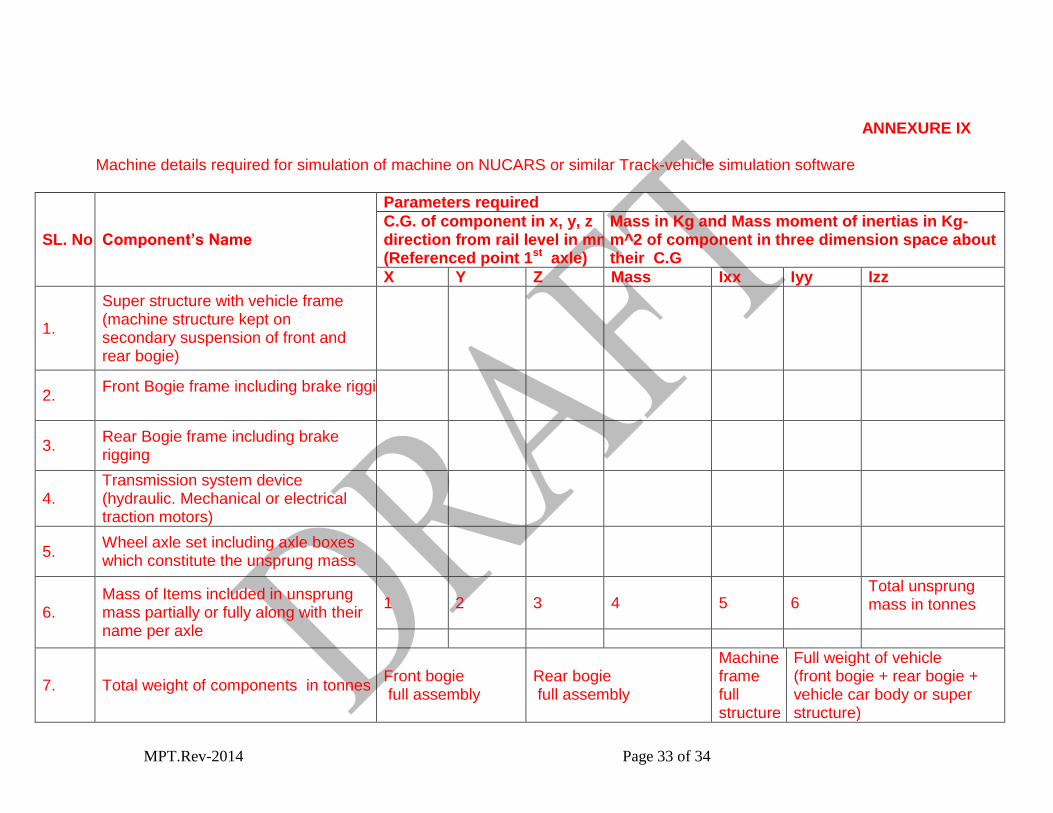
ANNEXURE IX
Machine details required for simulation of machine on NUCARS or similar Track-vehicle simulation software
SL. No. Component’s Name
Parameters required
C.G. of component in x, y, z direction from rail level in mm (Referenced point 1st axle)
Mass in Kg and Mass moment of inertias in Kg- m^2 of component in three dimension space about their C.G
X Y Z Mass Ixx Iyy Izz
1.
Super structure with vehicle frame (machine structure kept on secondary suspension of front and rear bogie)
2. Front Bogie frame including brake rigging
3. Rear Bogie frame including brake rigging
4. Transmission system device (hydraulic. Mechanical or electrical traction motors)
5. Wheel axle set including axle boxes which constitute the unsprung mass
6. Mass of Items included in unsprung mass partially or fully along with their name per axle
1 2 3 4 5 6 Total unsprung mass in tonnes
7. Total weight of components in tonnes Front bogie full assembly
Rear bogie full assembly
Machine frame full structure
Full weight of vehicle (front bogie + rear bogie + vehicle car body or super structure)
MPT.Rev-2014 Page 34 of 34
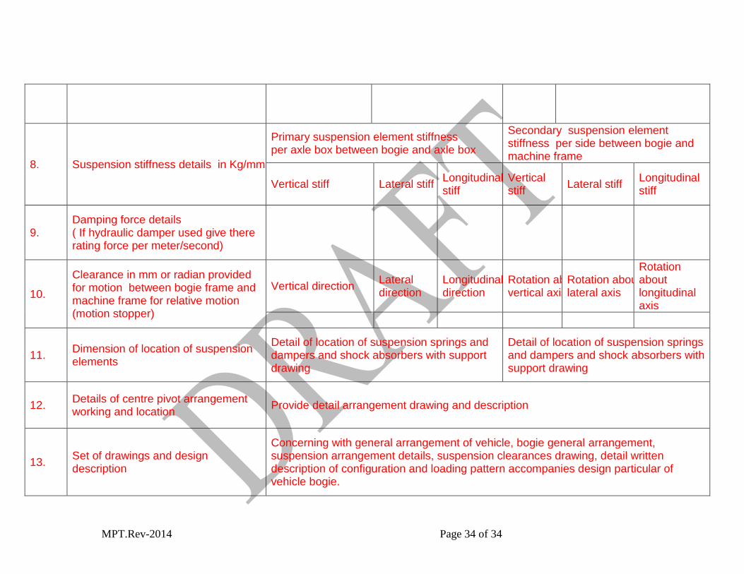
8. Suspension stiffness details in Kg/mm
Primary suspension element stiffness per axle box between bogie and axle box
Secondary suspension element stiffness per side between bogie and machine frame
Vertical stiff Lateral stiff Longitudinal stiff
Vertical stiff
Lateral stiff Longitudinal stiff
9. Damping force details ( If hydraulic damper used give there rating force per meter/second)
10.
Clearance in mm or radian provided for motion between bogie frame and machine frame for relative motion (motion stopper)
Vertical direction Lateral direction
Longitudinal direction
Rotation about vertical axis
Rotation about lateral axis
Rotation about longitudinal axis
11. Dimension of location of suspension elements
Detail of location of suspension springs and dampers and shock absorbers with support drawing
Detail of location of suspension springs and dampers and shock absorbers with support drawing
12. Details of centre pivot arrangement working and location
Provide detail arrangement drawing and description
13. Set of drawings and design description
Concerning with general arrangement of vehicle, bogie general arrangement, suspension arrangement details, suspension clearances drawing, detail written description of configuration and loading pattern accompanies design particular of vehicle bogie.