technical service manual - medical equipment … 9029623 revision 10.0 emergency care •...
TRANSCRIPT
6173.3
9029623
Revision 10.0
Because you careEmergency Care • Perioperative Care • Critical Care • Perinatal Care • Home Care
Technical Service ManualBabylog 8000/8000SC/8000 plus
Intensive Care Ventilator

Copyright by Dräger Medical AG & Co. KGaA, Lübeck, Germany.
No reproduction allowed for commercial purposes.
Read and understand the Instructions for Use/Operator’s Manual.
This Technical Documentation does not replace the Instructions for Use/Operator’s
Manual.
The warranty and liability conditions of the general terms and conditions for business
transactions of Dräger Medical AG & Co. KGaA are not extended by this Technical
Documentation.
Observe all applicable technical laws and regulations.
Insofar as reference is made to laws, regulations or standards, these are based on the
legal system of the Federal Republic of Germany. Observe the laws and regulations
applicable in your country.

Dräger Medical AG & Co. KGaA Contents
All
rig
hts
reserv
ed.
Copyright
rese
rved.
GB
K61
733
XX
IEC
IVZ
.fm
18
.05
.05
I
Contents
General
1 Notes 9
1.1 Symbols and Definitions ......................................................................................................... 9
Function Description
1 General 13
1.1 Ventilation Modes ................................................................................................................. 13
1.2 Additional Functions ............................................................................................................. 13
1.3 Monitoring ............................................................................................................................. 13
2 Block Diagrams 14
2.1 Block Diagram of the Components in
Babylog 8000/Babylog 8000 SC with LC Display 14
2.2 Block Diagram of the Components in
Babylog 8000/Babylog 8000 plus with EL Display 15
2.3 Block Diagram of the Babylog 8000/ Babylog 8000 plus/Babylog 8000 SC ........................ 16
3 Airway Monitoring 17
3.1 Airway Pressure ................................................................................................................... 17
3.2 Trigger Signal ....................................................................................................................... 17
3.3 Measurement of the Fraction of Inspired O2 ....................................................................... 17
3.4 Patient Flow (Babylog 8000/Babylog 8000 plus) .................................................................. 18
4 Monitoring Functions 19
4.1 Fraction of inspired O2 (FiO2) ............................................................................................... 19
4.1.1 O2 Measurement .................................................................................................... 19
4.1.2 O2 Calibration ......................................................................................................... 19
4.2 Gas Supplies ........................................................................................................................ 20
4.3 Airway Pressure Monitoring ................................................................................................. 20
4.4 Disconnect Monitoring .......................................................................................................... 20
4.5 Overpressure and Low Pressure Alarms ............................................................................. 21

All rig
hts
rese
rve
d. C
op
yrig
ht re
se
rve
d.
GB
K6
173
3X
XIE
CIV
Z.fm
18
.05
.05
II Dräger Medical AG & Co. KGaA Contents
Contents
4.5.1 Babylog 8000 up to Software Version 3.0 ...............................................................21
4.5.2 Dynamic Stenosis Limit ...........................................................................................21
4.6 Minute Volume Monitoring (Babylog 8000/Babylog 8000 plus) ............................................23
4.6.1 Babylog 8000 with Software Versions 2 and 3 .......................................................23
4.6.2 Babylog 8000 Software with Version 4.0 or Higher ................................................23
4.6.3 Babylog 8000 plus ..................................................................................................23
4.7 Audible Alarm Generator Monitoring ....................................................................................23
4.8 Operating Voltage Monitoring ...............................................................................................23
4.9 Rotary Potentiometer Monitoring ..........................................................................................23
4.10 ROM Test ..............................................................................................................................24
4.11 RAM Test ..............................................................................................................................24
4.12 Temperature Monitoring ........................................................................................................24
4.13 Relay and Valve Monitoring ..................................................................................................24
4.14 Battery Monitoring ................................................................................................................24
4.15 Flow Measurement Monitoring (Babylog 8000/ Babylog 8000 plus) ....................................24
5 Alarms, Cautions and Advisory Messages 25
5.1 Message Display ..................................................................................................................25
5.2 Display and Menu .................................................................................................................25
5.2.1 Babylog 8000/Babylog 8000 SC with LC Display ...................................................26
5.2.2 Babylog 8000/Babylog 8000 plus with EL Display ..................................................26
6 Function of the Control Elements 27
6.1 Potentiometers (Rotary Knobs) ............................................................................................27
6.1.1 Fraction of inspired O2 (O2 vol.%) ..........................................................................27
6.1.2 Inspiratory time (TI) .................................................................................................27
6.1.3 Expiratory time (TE) ................................................................................................27
6.1.4 Inspiratory flow (Insp. Flow) ....................................................................................27
6.1.5 Inspiratory pressure limit (Pinsp) .............................................................................27
6.1.6 PEEP/CPAP ............................................................................................................27
6.2 Keys ......................................................................................................................................28

Dräger Medical AG & Co. KGaA Contents
All
rig
hts
reserv
ed.
Copyright
rese
rved.
GB
K61
733
XX
IEC
IVZ
.fm
18
.05
.05
III
Contents
6.2.1 CPAP ...................................................................................................................... 28
6.2.2 IPPV/IMV (CMV) (up to software version 4.n) ........................................................ 28
6.2.3 Man. Insp. ............................................................................................................... 28
6.2.4 2-min Silence .......................................................................................................... 28
6.2.5 Reset/Check (OK) .................................................................................................. 28
6.2.6 Backlight On/Off (Babylog 8000/8000 SC with LC Display) ................................... 28
6.2.7 "Cal. Config." (as of software version 5.n) .............................................................. 29
6.2.8 Keys ....................................................................................................................... 29
7 Cold Start/Warm Start Behavior 30
7.1 Cold-Start Behavior .............................................................................................................. 30
7.2 Warm-Start Behavior ............................................................................................................ 30
8 Description of Pneumatic Functions 31
8.1 Gas Supplies ........................................................................................................................ 31
8.2 Controlled Ventilation ........................................................................................................... 32
8.2.1 Inspiration ............................................................................................................... 32
8.2.2 Expiration ............................................................................................................... 33
8.2.3 PEEP ...................................................................................................................... 33
8.2.4 CPAP ...................................................................................................................... 33
9 Measurement of the Ventilation Parameters 34
9.1 O2 Measurement .................................................................................................................. 34
9.2 Measurement of the Airway Pressure .................................................................................. 34
9.3 Pneumatics Control PCB ...................................................................................................... 35
9.4 Pneumatics Analog PCB ...................................................................................................... 36
9.5 Patient System Heater ......................................................................................................... 37
9.6 Pressure Sensor Base PCB ................................................................................................. 37
9.7 O2 Amplifier PCB ................................................................................................................. 37
10 Components of the Electronic Assembly 38
10.1 Power Supply Unit ................................................................................................................ 38

All rig
hts
rese
rve
d. C
op
yrig
ht re
se
rve
d.
GB
K6
173
3X
XIE
CIV
Z.fm
18
.05
.05
IV Dräger Medical AG & Co. KGaA Contents
Contents
10.2 Motherboard PCB .................................................................................................................38
10.3 CPU 68000 PCB ...................................................................................................................39
10.4 I/O PCB ................................................................................................................................40
10.5 Flow PCB (Babylog 8000/Babylog 8000 plus) (optional) ......................................................41
10.6 Monitoring PCB ....................................................................................................................42
10.6.1 Measurement of Analog Signals .............................................................................42
10.6.2 Measurement of Digital Inputs ................................................................................42
10.6.3 Measurement of Digital Outputs .............................................................................42
10.7 Front Adapter PCB ...............................................................................................................45
10.8 Front Controller PCB
(Babylog 8000/Babylog 8000 SC with LC Display) 46
10.9 Front PCB (Babylog 8000/Babylog 8000 plus with EL Display) ...........................................47
10.10Display PCB (Babylog 8000/Babylog 8000 SC with LC Display) .........................................48
10.11 EL display (Babylog 8000/Babylog 8000 plus with EL Display) ...........................................49
10.12Potentiometer Field ..............................................................................................................50
10.13Display Field .........................................................................................................................50
10.14Communication PCB ............................................................................................................51
10.15Interface PCB .......................................................................................................................52
11 Sensors 53
11.1 Pressure Sensors .................................................................................................................53
11.2 Y-Piece with Flow Sensor (Babylog 8000/Babylog 8000 plus) .............................................53
11.2.1 Measuring Principle of the Flow Measuring Bridge ................................................54
11.3 O2 Sensor ............................................................................................................................55

Dräger Medical AG & Co. KGaA Contents
All
rig
hts
reserv
ed.
Copyright
rese
rved.
GB
K61
733
XX
IEC
IVZ
.fm
18
.05
.05
V
Contents
Replacing Non Repairable Items
1 Important Information 59
2 Cleaning or Replacing the Cooling Air Filter Every 4 Weeks 60
3 Replacing the O2 Sensor Capsule 61
3.1 O2 Sensor Calibration ........................................................................................................... 61
3.2 Calibrating the O2 Sensor After Replacement ...................................................................... 61
3.3 Disposing of the O2 Sensor Capsule .................................................................................... 63
4 Replacing the Lip Seals Every 2 Years 64
5 Replacing the NiCd Battery (Power Failure Alarm) Every 2 Years 65
6 Replacing the Pressure Reducer Every 6 Years 67
Schematics and diagrams
1 Schematics and Diagrams 77
Error List
1 Error messages 91
2 List of device error messages 92
Annex
Spare parts list 97
Test List 97
Technical Information according to EMC standard IEC/EN 60601-1-2:2001 97

All rig
hts
rese
rve
d. C
op
yrig
ht re
se
rve
d.
GB
K6
173
3X
XIE
CIV
Z.fm
18
.05
.05
VI Dräger Medical AG & Co. KGaA Contents
Contents

7
General

8

Dräger Medical AG & Co. KGaA 6173.3
All
rig
hts
reserv
ed.
Copyright
rese
rved.
Ve
rsio
n 1
.0_ R
ele
ase
d_
Prin
ted
on_
18.0
5.0
5_
GB
K61
73
3X
XA
01
.fm
9
Babylog 8000 General
1 Notes This Technical Documentation/Service Manual conforms to the International
Standard IEC 60601-1.
Read each step in every procedure thoroughly before beginning any test.
Always use the proper tools and specified test equipment. If you deviate from
the instructions and/or recommendations in this Technical Documenta-
tion/Service Manual, the equipment may operate improperly or unsafely, or
the equipment could be damaged.
Use only original Dräger parts and supplies.
The maintenance procedures described in this Technical Documenta-
tion/Service Manual may be performed by qualified service personnel only.
These maintenance procedures do not replace inspections and servicing by
Dräger Medical AG & Co. KGaA.
1.1 Symbols and Defini-tions
Strictly follow the Instructions for Use/Operating Instructions! This
Technical Documentation does not replace the Instructions for
Use/Operating Instructions. Any use of the product requires full
understanding and strict observation of the product-specific Instruc-
tions for Use/Operating Instructions.
Unless otherwise stated, reference is made to laws, regulations or stan-
dards (as amended) applicable in the Federal Republic of Germany.
This symbol indicates a warning.
This symbol indicates tips and useful information.
This symbol is used to alert against unsafe practices when handling elec-
trostatic sensitive devices (ESD).
Definitions according to German standard DIN 31051:
Inspection = examination of actual condition
Maintenance = measures to maintain specified condition
Repair = measures to restore specified condition
Servicing = inspection, maintenance, and repair

All
rig
hts
re
se
rve
d.
Co
pyrig
ht
rese
rve
d.
Vers
ion
1.0
_ R
ele
ase
d_
Pri
nte
d o
n_
18
.05
.05
_G
BK
61
73
3X
XA
01
.fm
10 Dräger Medical AG & Co. KGaA 6173.3
General Babylog 8000

11
Function Description

12

Dräger Medical AG & Co. KGaA 6173.3
All
rig
hts
reserv
ed.
Copyright
rese
rved.
_ _
Pri
nte
d o
n_
18
.05
.05
_F
61
73
3X
XT
01
.fm
13
Function description Babylog 8000
1 General
Babylog 8000/Babylog 8000 plus has a flow measurement function. The Babylog 8000 SC can be
upgraded to a Babylog 8000 using the "flow measurement conversion kit.
1.1 Ventilation Modes
Babylog 8000/Babylog 8000 plus/8000 SC provides the following ventilation modes:
IPPV (Intermittent Positive Pressure Ventilation), controlled and assisted constant-volume ventilation
SIPPV (Synchronized Intermittent Positive Pressure Ventilation), synchronized controlled and
assisted constant-volume ventilation
IMV (Intermittent Mandatory Ventilation)
SIMV (Synchronized Intermittent Mandatory Ventilation) weaning method for spontaneously
breathing patients
CPAP (Continuous Positive Airway Pressure) spontaneous breathing with positive airway pressure
PSV (Pressure Support Ventilation) (optional as of software version 5.n)
1.2 Additional Functions
Babylog 8000/Babylog 8000 plus/8000 SC provides the following (optional) additional functions:
High-frequency ventilation (HV) (as of software version 4.n)
Volume guarantee (VG) (as of software version 5.n)
1.3 Monitoring
Babylog 8000/Babylog 8000 plus/8000 SC has integrated monitoring functions for:
Fraction of inspired O2 (FiO2)
Airway pressure (Paw)
Flow ( ) (Babylog 8000/Babylog 8000 plus)
Minute volume (MV)
Tidal volume (VT)
All
rig
hts
re
se
rve
d.
Co
pyrig
ht
rese
rve
d.
_ _
Pri
nte
d o
n_
18
.05
.05
_F
617
33X
XT
01
.fm
14 Dräger Medical AG & Co. KGaA 6173.3
Function description Babylog 8000
2 Block Diagrams
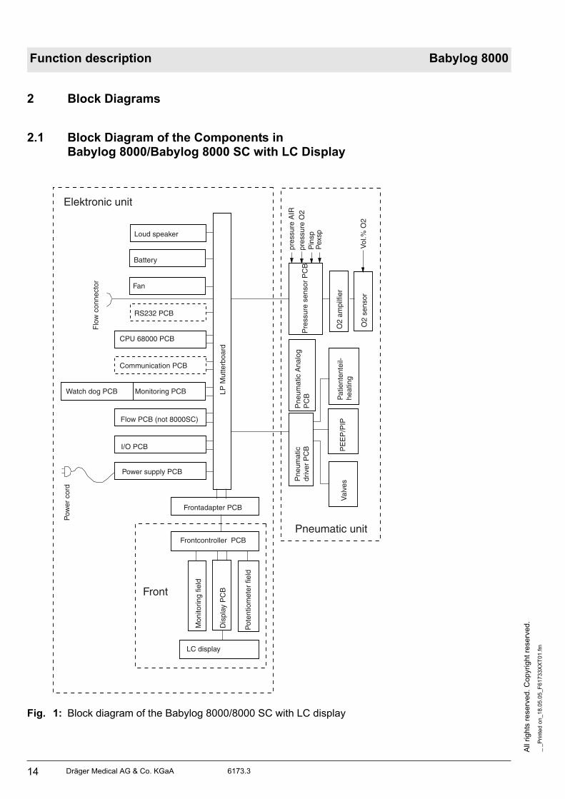
2.1 Block Diagram of the Components inBabylog 8000/Babylog 8000 SC with LC Display
Fig. 1: Block diagram of the Babylog 8000/8000 SC with LC display
Elektronic unit
Front
Pneumatic unit
Loud speaker
Battery
Fan
RS232 PCB
CPU 68000 PCB
Communication PCB
Watch dog PCB Monitoring PCB
Flow PCB (not 8000SC)
I/O PCB
Power supply PCB
Flo
w c
onne
ctor
LP M
utte
rboa
rd
Frontadapter PCB
Frontcontroller PCB
Mon
itorin
g fie
ld
Dis
play
PC
B
Pot
entio
met
er fi
eld
LC display
Pre
ssur
e se
nsor
PC
B
O2
ampi
lfier
O2
sens
or
Pne
umat
ic A
nalo
gP
CB
Pne
umat
icdr
iver
PC
B
Pat
ient
ente
il-he
atin
gP
EE
P/P
IPV
alve
s
pres
sure
AIR
pres
sure
O2
Pin
spP
exsp
Vol
.% O
2
Pow
er c
ord

Dräger Medical AG & Co. KGaA 6173.3
All
rig
hts
reserv
ed.
Copyright
rese
rved.
_ _
Pri
nte
d o
n_
18
.05
.05
_F
61
73
3X
XT
01
.fm
15
Function description Babylog 8000
2.2 Block Diagram of the Components inBabylog 8000/Babylog 8000 plus with EL Display
Fig. 2: Block diagram of the Babylog 8000/Babylog 8000 plus with EL display
Elektronic unit
Front
Pneumatic unit
Loud speaker
Battery
Fan
RS232 PCB
CPU 68000 PCB
Ccommunication PCB
Watch dog PCB Monitoring PCB
Flow PCB
I/O PCB
Power supply PCB
Flo
w c
onne
ctor
LP M
utte
rboa
rd
Frontadapter PCB
Front PCB
Mon
itorin
g fie
ld
ELD
con
vert
er
Pot
entio
met
er fi
eld
EL display
Pre
ssur
e se
nsor
PC
B
O2
ampl
ifier
O2
sens
or
Pne
umat
icA
nalo
g P
CB
Pne
umat
ic a
mpl
ifier
PC
B
Pat
ient
uni
the
atin
gP
EE
P/P
IPV
alve
s
pres
sure
AIR
pres
sure
O2
Pin
spP
exsp
Vol
.% O
2
Pow
er c
ord

All
rig
hts
re
se
rve
d.
Co
pyrig
ht
rese
rve
d.
_ _
Pri
nte
d o
n_
18
.05
.05
_F
617
33X
XT
01
.fm
16 Dräger Medical AG & Co. KGaA 6173.3
Function description Babylog 8000
2.3 Block Diagram of the Babylog 8000/ Babylog 8000 plus/Babylog 8000 SC
Fig. 3: Block Diagram of the Babylog 8000/Babylog 8000 plus/Babylog 8000 SC
LEDs 2 red Alarm LEDs
Potentiometer
Front
CPU (Master)
I/O
Communication
FlowBabylog 8000Babylog 8000 plus
EV
EV
EP
EP
EP
EP
EO
EO
Monitoring
Battery
Reserve horn
LC d
ispl
ay
EL
disp
lay
(Bab
ylog
800
0/B
abyl
og 8
000
plus
)
keys
Flow sensor
PAIR PO2 O2-SensorPexsp Pinsp+27 V +5 V
&
24 Ventile
Valve amplifier
Valve monitoring
PEEP/PIP valve
Dräger Medical AG & Co. KGaA 6173.3
All
rig
hts
reserv
ed.
Copyright
rese
rved.
_ _
Pri
nte
d o
n_
18
.05
.05
_F
61
73
3X
XT
01
.fm
17
Function description Babylog 8000
3 Airway Monitoring
In the ventilation modes IPPV/IMV and CPAP, the airway pressure (Paw), the flow at the Y-piece VT
(Babylog 8000/Babylog 8000 plus), and the fraction of inspired O2 (FiO2) are measured.
Depending on the selected mode and the menu settings, the parameters are monitored and displayed on
the screen. Pressure and flow curves as well as their storage can be displayed graphically on the LC
display or EL display. In all ventilation modes, the chronological sequence of the airway pressure (Paw) is
displayed in the LED bargraph.
3.1 Airway Pressure
Two internal pressure sensors measure the pressure at the inspiratory outlet (Pinsp) and the pressure at
the expiratory inlet (Pexp). The airway pressure is calculated as follows:
Paw = Pinsp – 0.7 (Pinsp – Pexp)
The following pressures are calculated from the Paw pressure signal:
Peak pressure (Peak)
Mean airway pressure (Pmean)
Positive end-expiratory pressure (PEEP)
The peak pressure is the maximum positive pressure of the most recent respiratory cycle. After 30 s, at
the latest, a new respiratory cycle must be recognized and a new measured value for the peak pressure
must be generated, otherwise the current measured value is no longer valid and is removed from the
display.
The mean airway pressure is the initial value of a software digital filter.
The PEEP is either the pressure value during the expiratory phase at a zero expiratory flow or the last
measured value before the next inspiration. Like the peak pressure, the PEEP is no longer valid after 30 s
and is removed from the display if a new measured value is not generated within the 30-s period.
3.2 Trigger Signal
In order to generate a trigger signal, the inspiratory flow must be integrated during spontaneous breathing
and compared to the adjustable trigger threshold.
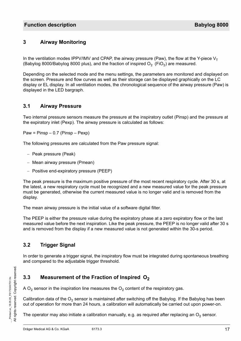
3.3 Measurement of the Fraction of Inspired O2
A O2 sensor in the inspiration line measures the O2 content of the respiratory gas.
Calibration data of the O2 sensor is maintained after switching off the Babylog. If the Babylog has been
out of operation for more than 24 hours, a calibration will automatically be carried out upon power-on.
The operator may also initiate a calibration manually, e.g. as required after replacing an O2 sensor.

All
rig
hts
re
se
rve
d.
Co
pyrig
ht
rese
rve
d.
_ _
Pri
nte
d o
n_
18
.05
.05
_F
617
33X
XT
01
.fm
18 Dräger Medical AG & Co. KGaA 6173.3
Function description Babylog 8000
A two-step calibration with 21% and 100% O2 is always carried out in order to achieve a higher
measurement accuracy over the whole concentration range and/or to be able to recognize a spent sensor
cell.
The calibration procedure is described under section "4 Monitoring Functions".
If the O2 measurement fails, the Babylog generates an alarm. This alarm status is shown in the status
field of the screen by the flashing indication "FiO2".
3.4 Patient Flow (Babylog 8000/Babylog 8000 plus)
A direction-sensitive hot-wire flowmeter integrated into the Y-piece measures the inspiratory and
expiratory flows through the tube. This measurement function must be reactivated each time after
switching on Babylog 8000/Babylog 8000 plus and after each replacement of the sensor by calibrating the
sensor. The flow signal is used to calculate the following values:
Tidal volume (VT)
Minute volume (MV)
Percentage of the MV uptake through spontaneous breathing
Tube leakage
The tidal volume is the expiratory flow signal applied between two breathing phase cycles.
Unlike the tidal volume, the minute volume is not related to a respiratory cycle. In the same way the
inspiratory MV is calculated for leak rate detection. The expiratory minute volume is displayed. In addition
to the complete minute volume, Babylog also calculates the expiratory minute volume uptake through
spontaneous breathing.
Babylog calculates the percentage by comparing the total minute volume and the minute volume uptake
through spontaneous breathing:
spont. = (MVspontaneous/MV) * 100%
The leakage at the tube can be estimated by comparing the inspiratory and the expiratory minute volume.
The leakage at the tube L is calculated as follows:
L= (MVinsp _ MVexp)/(MVinsp + MVexp) * 100.
The respiratory rate f is measured through the inspiratory respiratory phase cycles.
All measured values derived from the patient flow become valid only after successful calibration of the
flow sensor.
If the flow sensor or the measuring electronics fails, an alarm is generated. However, Babylog can still be
used without the functions depending on the flow measurement. This alarm status is shown in the status
field of the screen by the flashing indication "flow".

Dräger Medical AG & Co. KGaA 6173.3
All
rig
hts
reserv
ed.
Copyright
rese
rved.
_ _
Pri
nte
d o
n_
18
.05
.05
_F
61
73
3X
XT
01
.fm
19
Function description Babylog 8000
4 Monitoring Functions
The system checks whether limit values are kept and all functions are ok. If a function fails or if the limit
values are not met, Babylog will generate an alarm.
4.1 Fraction of inspired O2 (FiO2)
4.1.1 O2 Measurement
The measured O2 value is checked against upper and lower limit values. The alarm limits are
automatically set at ±4 vol.% below the set FiO2value. A time delay makes sure no alarm is activated
when the set value (O2) is changed or when the O2 sensor is calibrated.
The absolute sensor voltages are checked. The differential voltage between the two sensor cells must be
lower than (U1 + U2)/8 +1 mV. The output voltage of each individual cell must be between 9.5 mV and
123.6 mV.
4.1.2 O2 Calibration
The O2 sensor is either automatically calibrated 24 hours after the last calibration or manually after
selection from the mode menu.
If the O2 sensor is replaced during operation the new O2 sensor will be calibrated automatically. However,
Babylog cannot detect a sensor replacement if the unit is switched off. In this particular case, the operator
has to calibrate the new O2 sensor manually.
By switching over a valve the sensor is separated from the respiratory gas flow and purged with the
calibration gas (O2). This leads to a change in concentration at the O2 sensor. This change in
concentration allows the Babylog to recognize the activation of the calibration valve.
The calibration valve is deactivated as soon as the calibration is completed.
A two-step calibration with 21% O2 and 100% O2 is carried out in order to achieve a higher measurement
accuracy over the whole concentration range and to be able to recognize a spent sensor cell.
During the calibration procedure the microprocessor system processes (synchronizes) one of the two O2
sensor channels. The O2 channels are then submitted to a specific sequence of states controlled by one
of the microprocessor systems and monitored for correct sequence and maximum period by the other. For
instance, searching of the calibration values for 21% or 100% must not last longer than 3.5 minutes each.
The calibration value for 21% must be between 9.2 mV and 26 mV, and for 100% between 43.6 mV and
123.6 mV; this applies to both channels. The zero voltage resulting from both values must be between
–6 mV and +6 mV.
After calibration is completed, the software checks whether the limit values respond correctly.
Calibration stops if a control gas fails.
All
rig
hts
re
se
rve
d.
Co
pyrig
ht
rese
rve
d.
_ _
Pri
nte
d o
n_
18
.05
.05
_F
617
33X
XT
01
.fm
20 Dräger Medical AG & Co. KGaA 6173.3
Function description Babylog 8000
4.2 Gas Supplies
The current measured values of the O2 and AIR gas supplies are considered when the valve bank is
adjusted. The inlet pressure for O2 and AIR is 1.7 bar.
If the pressure falls below the limit value, a visible and audible alarm is generated. The operator is
informed about the cause of the alarm by a plain text message on the display. If the adjusted O2
concentration is 21% or 100%, only an advisory message (no alarm) is displayed if the non-added gas
type fails.
If the pressure exceeds the limit value, the safety venting mechanism is activated and the continuous flow
is switched off. The Babylog will continue to operate only when the pressure has decreased to a
permissible level.
If the AIR supply fails, the Babylog control switches to O2 supply. If the O2 supply fails, Babylog switches
to AIR supply.
4.3 Airway Pressure Monitoring
Depending on the selected mode and parameter settings, a certain airway pressure time profile is set. If
the actual profile deviates from the set profile, the Babylog generates an alarm.
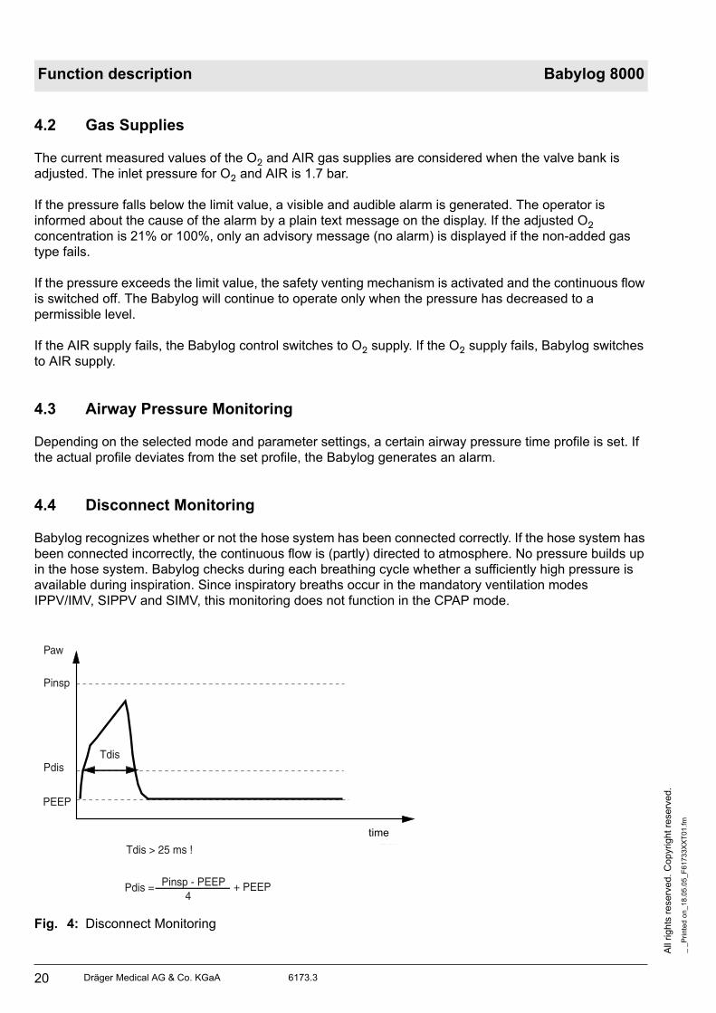
4.4 Disconnect Monitoring
Babylog recognizes whether or not the hose system has been connected correctly. If the hose system has
been connected incorrectly, the continuous flow is (partly) directed to atmosphere. No pressure builds up
in the hose system. Babylog checks during each breathing cycle whether a sufficiently high pressure is
available during inspiration. Since inspiratory breaths occur in the mandatory ventilation modes
IPPV/IMV, SIPPV and SIMV, this monitoring does not function in the CPAP mode.
Fig. 4: Disconnect Monitoring
Zeit
Paw
Pinsp
Pdis
PEEP
Tdis
Tdis > 25 ms !
Pdis = Pinsp - PEEP4
+ PEEP
time

Dräger Medical AG & Co. KGaA 6173.3
All
rig
hts
reserv
ed.
Copyright
rese
rved.
_ _
Pri
nte
d o
n_
18
.05
.05
_F
61
73
3X
XT
01
.fm
21
Function description Babylog 8000
During each mandatory breath, the level of the disconnection pressure (Pdis) must be exceeded without
interruption for at least the disconnection time (Tdis), otherwise an alarm will be generated. Pdis is a
function of the settings Pinsp and PEEP. If Pinsp is set considerably higher than the actually attained
pressure, the Pdis alarm level likewise increases.
Depending on the flow and the inspiration time settings, the level might not be attained any more.
Babylog 8000 generates an alarm even if there is no leakage in the breathing system.
4.5 Overpressure and Low Pressure Alarms
During the inspiratory and expiratory phases, the airway pressure (Paw) must not exceed the set pressure
limit by more than 10 mbar. If the set pressure limit is exceeded by 10 mbar to 20 mbar, Babylog
generates an alarm and, at the same time, reduces the inspiratory breath time. The remaining time is
added to the CPAP phase. If the set pressure limit is exceeded by more than 20 mbar, an alarm is
activated and the breathing system is vented.
In the CPAP phase, the airway pressure must be 4 mbar of the set PEEP/CPAP. Otherwise an alarm will
be generated. If the limit is exceeded by more than 10 mbar, venting is carried out as during the
inspiratory phase even if the pressure falls below the absolute level of —2 mbar.
These overpressure and low pressure alarms apply to all ventilation modes.
4.5.1 Babylog 8000 up to Software Version 3.0
Fig. 5: Alarms
4.5.2 Dynamic Stenosis Limit
The dynamic stenosis limit applies to Babylog 8000 units with software version 4.0 and Babylog 8000 SC
10 mbar
10 mbar
6 mbar
4 mbar
4 mbar
-2 mbar Zeit
PEEP
Pinsp
Paw
Stenose 2 (Notentlüftung)
Stenose 1 (Inspiration Exspiration)
Entlüftung
time

All
rig
hts
re
se
rve
d.
Co
pyrig
ht
rese
rve
d.
_ _
Pri
nte
d o
n_
18
.05
.05
_F
617
33X
XT
01
.fm
22 Dräger Medical AG & Co. KGaA 6173.3
Function description Babylog 8000
units with software version 1.0.
The limit value is (Pinsp + 5 mbar).
If this limit value is exceeded, the microprocessor system reads in the actual measured value at 8.3-ms
intervals (sampling frequency). The limit value (Pinsp + 5 mbar) is subtracted from each of the actual
measured values and entered in a summer.
As soon as the sum of 40 mbar (stenosis 1) is reached, Babylog switches over from inspiratory phase to
expiratory phase. If a sum of 70 mbar is reached, despite of the safety measure (stenosis 1), the system
will carry out an emergency venting.
Fig. 6: Dynamic stenosis limit
Paw
Pinsp + 5 mbar
Pinsp
PEEP
8,3
8,3 ms
8,3 Zeit
Σ = 40 mbar Stenose 1
Σ = 70 mbar Stenose 2
time

Dräger Medical AG & Co. KGaA 6173.3
All
rig
hts
reserv
ed.
Copyright
rese
rved.
_ _
Pri
nte
d o
n_
18
.05
.05
_F
61
73
3X
XT
01
.fm
23
Function description Babylog 8000
4.6 Minute Volume Monitoring (Babylog 8000/Babylog 8000 plus)
The abbreviation MV (for minute volume) is used in the following text.
4.6.1 Babylog 8000 with Software Versions 2 and 3
The monitoring menu is used to set the upper and lower alarm limits in the range of 0.03 L/min to
15 L/min. The upper and lower alarm limits are continuously compared with the measured MV value. If the
value exceeds the upper alarm limits or falls below the lower alarm limit, the system will activate an alarm.
Monitoring is deactivated during calibration of the flow sensor (Babylog 8000) to allow the measured MV
value to stabilize. If the flow measurement system fails, the MV monitoring becomes ineffective.
4.6.2 Babylog 8000 Software with Version 4.0 or Higher
The monitoring menu is used to set the upper and lower alarm limits in the range of 0.00 L/min to
15 L/min. The upper and lower alarm limits are continuously compared with the measured MV value. If the
value exceeds the upper alarm limits or falls below the lower alarm limit, the system will activate an alarm.
Monitoring is deactivated during calibration of the flow sensor (Babylog 8000) to allow the measured MV
value to stabilize. If the flow measurement system fails, the MV monitoring becomes ineffective.
4.6.3 Babylog 8000 plus
Babylog 8000 plus has the software 5.n.
4.7 Audible Alarm Generator Monitoring
Babylog has two audible alarm generators (loudspeaker and piezo). During normal operation, the
loudspeaker is the audio interface to the operator in the event of alarms. The piezo is only used in the
event of power or loudspeaker failure.
At the end of the self-test, the loudspeaker is triggered with a test signal. This test signal is monitored with
a microphone. If there is no feedback, Babylog generates error 817.
4.8 Operating Voltage Monitoring
During operation, Babylog uses comparators to continuously monitors whether the operating voltages are
within specified limits.
When Babylog is switched on, these comparators are checked by a defined changing of the comparator
reference voltage.
4.9 Rotary Potentiometer Monitoring
Input via rotary potentiometers are processed by two channels. Two microprocessor systems read the
input via independent channels and compare the results.

All
rig
hts
re
se
rve
d.
Co
pyrig
ht
rese
rve
d.
_ _
Pri
nte
d o
n_
18
.05
.05
_F
617
33X
XT
01
.fm
24 Dräger Medical AG & Co. KGaA 6173.3
Function description Babylog 8000
4.10 ROM Test
During operation, the ROM area used is summed up per byte in a long word variable (long word = 32 bits)
which is compared to the check sum stored in the ROM. If the check sums do not match, an error
message will be displayed.
4.11 RAM Test
During operation the RAM area used is tested with a simple algorithm. By writing 55 hex or AAhex in each
cell every bit is checked for settability and resettability.
4.12 Temperature Monitoring
A temperature sensor measures the internal temperature of the Babylog. If the temperature is not within
the range of –20 °C to 75 °C, an alarm will be generated. If the temperature is too high, a message will
inform the operator about a possible failure of the fan.
4.13 Relay and Valve Monitoring
An excess-current monitoring function is integrated into the trigger electronics of the valves. The excess-
current monitoring function is tested after switching on Babylog. If a valve is switched on and operated
with the operate voltage for an excessive period of time, the excess-current monitoring function responds
within a specific time.
The relay which enables de-energizing of the whole pneumatics assembly is also tested once after power-
on. For this purpose, the relay is switched on and off once and the voltages at the relay contact are
measured.
During operation, the system checks whether the voltage at the relay contact corresponds to the switching
condition.
4.14 Battery Monitoring
Babylog has a rechargeable Nicd battery for power failure alarms.
The battery is recharged automatically during operation and its charge checked periodically.
An error message is displayed if the voltage is too high or too low.
4.15 Flow Measurement Monitoring (Babylog 8000/ Babylog 8000 plus)
During operation, the flow sensor is checked for correct functioning, freedom of damage and intact
contacts.

Dräger Medical AG & Co. KGaA 6173.3
All
rig
hts
reserv
ed.
Copyright
rese
rved.
_ _
Pri
nte
d o
n_
18
.05
.05
_F
61
73
3X
XT
01
.fm
25
Function description Babylog 8000
5 Alarms, Cautions and Advisory Messages
The alarm structure of the Babylog has three priority levels:
The priority level is indicated by the different tone sequences of the individual audible alarm.
5.1 Message Display
When an alarm occurs the corresponding message is displayed as plain text message in a window of the
display. The message can be canceled momentarily by pressing the Reset/Check key (or OK key as of
software version 5.n). After a certain time out, the message appears again if its cause still exists.
If several alarms have occurred simultaneously, the highest-level alarm is shown on the display. Other
alarms will be queued. A message whose cause no longer exist will not be displayed any more.
5.2 Display and Menu
The display shows parameters and text messages. The functions of Babylog are set with keys and
potentiometers.
The screen is separated into different areas:
Fig. 7: Screen display structure
The graphics field displays real-time curves.
The measured-value field displays monitoring parameter in digital representation.
The status field displays the operating mode and other status information.
The menu line displays the current function of the keys below the screen.
In some cases, the graphics and measured-value fields are combined to form one large field.
Alarm - Immediate action required.
Caution - Checking required.
Advisory - Information for the operator.
Grafic field Measurementfield
Status field
Menü line
All
rig
hts
re
se
rve
d.
Co
pyrig
ht
rese
rve
d.
_ _
Pri
nte
d o
n_
18
.05
.05
_F
617
33X
XT
01
.fm
26 Dräger Medical AG & Co. KGaA 6173.3
Function description Babylog 8000
5.2.1 Babylog 8000/Babylog 8000 SC with LC Display
The Monitoring/Mode key and the six keys below the LC display are used for the menu. The
Monitoring/Mode key toggles between the two main menus, the monitoring menu and the mode menu.
This works from any menu status always reaching the basic status of the other main menu. The function
of the keys depends on the respective menu status and is indicated in the menu line of the display by an
abbreviation or a symbol.
5.2.2 Babylog 8000/Babylog 8000 plus with EL Display
The key "Vent. Mode" activates the menu for the ventilation modes. The key "Vent. Option" activates the
menu for the additional functions of the ventilation modes.

Dräger Medical AG & Co. KGaA 6173.3
All
rig
hts
reserv
ed.
Copyright
rese
rved.
_ _
Pri
nte
d o
n_
18
.05
.05
_F
61
73
3X
XT
01
.fm
27
Function description Babylog 8000
6 Function of the Control Elements
The control elements comprise the potentiometers (rotary knobs) and the keys.
6.1 Potentiometers (Rotary Knobs)
6.1.1 Fraction of inspired O2 (O2 vol.%)
This potentiometer is used to set the fraction of inspired O2 to a value between 21 vol.% and 100 vol.%.
The adjusted value becomes effective immediately.
6.1.2 Inspiratory time (TI)
This potentiometer is used to set the inspiratory time to a value between 0.1 s and 2 s. The adjusted value
becomes effective at the end of the current respiratory cycle.
6.1.3 Expiratory time (TE)
This potentiometer is used to set the expiratory time to a value between 0.2 s and 30 s. The adjusted
value becomes effective at the end of the current respiratory cycle.
6.1.4 Inspiratory flow (Insp. Flow)
This potentiometer is used to set the inspiratory flow to a value between 1 L/min and 30 L/min. The
adjusted value becomes effective immediately.
6.1.5 Inspiratory pressure limit (Pinsp)
This potentiometer is used to set the inspiratory pressure limit to a value between 10 mbar and 80 mbar.
A value above 40 mbar must be confirmed by pressing the Reset/Check key (or OK key as of software
version 5.n). A message is displayed. This pressure limit is also effective when a manual breath is
applied. The adjusted value becomes effective immediately.
6.1.6 PEEP/CPAP
This potentiometer is used to set the end-expiratory pressure for controlled ventilation or to set the
continuous positive airway pressure for spontaneous breathing to a value between 0 mbar and 15 mbar
(or 25 mbar as of software version 4.n). A value above 8 mbar must be confirmed by pressing the
Reset/Check key (or OK key as of software version 5.n). A message is displayed. The adjusted value
becomes effective immediately.

All
rig
hts
re
se
rve
d.
Co
pyrig
ht
rese
rve
d.
_ _
Pri
nte
d o
n_
18
.05
.05
_F
617
33X
XT
01
.fm
28 Dräger Medical AG & Co. KGaA 6173.3
Function description Babylog 8000
6.2 Keys
6.2.1 CPAP
Pressing this key will activate the CPAP mode. The current respiratory cycle is stopped before a new
mode becomes active (for example, IPPV/IMV). This key is protected against unintentional operation by a
software-controlled locking. After power-on, Babylog will automatically enter the most recent mode
selected.
6.2.2 IPPV/IMV (CMV) (up to software version 4.n)
Pressing this key will activate the controlled ventilation mode. This key is protected against unintentional
operation by a software-controlled locking. If CPAP was set before, the first mandatory breath is applied
after the last expiratory phase has been completed (zero expiratory flow) or after a zero flow has been
measured at the Y-piece for one second.
The CPAP and IPPV/IMV keys deactivate each other. The selected ventilation mode is indicated by a
green LED on the respective key.
6.2.3 Man. Insp.
Pressing this key will apply a breath at the set inspiratory flow rate and the set pressure limit (Pinsp). This
breath is stopped when the key is released or when a fixed time limit of 5 s is reached. The next manual or
mandatory breath can only be applied after an expiratory phase (IPPV/IMV) has been completed. If a
manual breath is stopped by the time limit, the next mandatory or manual breath can only be applied after
a fixed time-out (5 s).
6.2.4 2-min Silence
Pressing this key will silence the audible alarm for 2 minutes. This status is indicated by the yellow LED
on the key. Pressing the key again within the silence time will reactivate the audible alarm.
6.2.5 Reset/Check (OK)
Pressing the Reset/Check key (or OK key as of software version 5.n) will confirm or cancel text messages
shown on the display. The message currently shown on the display will be cancelled and the audible
alarm will be silenced.
Pressing the key for a longer period of time (approx. 2 s) will start a display test and an audible alarm
generator test.
6.2.6 Backlight On/Off (Babylog 8000/8000 SC with LC Display)
Pressing this key will switch the LCD backlight on or off.

Dräger Medical AG & Co. KGaA 6173.3
All
rig
hts
reserv
ed.
Copyright
rese
rved.
_ _
Pri
nte
d o
n_
18
.05
.05
_F
61
73
3X
XT
01
.fm
29
Function description Babylog 8000
6.2.7 "Cal. Config." (as of software version 5.n)
Pressing this key will activate the calibration mode.
6.2.8 Keys
The keys below the display have no fixed function. Their function depends on the operating status of the
menu.
Additional Key on the Operator Panel
This key has not been assigned a function yet. It is reserved for future extensions.

All
rig
hts
re
se
rve
d.
Co
pyrig
ht
rese
rve
d.
_ _
Pri
nte
d o
n_
18
.05
.05
_F
617
33X
XT
01
.fm
30 Dräger Medical AG & Co. KGaA 6173.3
Function description Babylog 8000
7 Cold Start/Warm Start Behavior
A distinction is made between an intentional switch-off with the power switch and a power failure. If a
power failure is recognized, the position of the low voltage contacts of the power switch is evaluated.
7.1 Cold-Start Behavior
When Babylog is switched off, all set parameters and data on the power switch state are stored. When
switching on the Babylog, this information is reloaded and a "cold start" is carried out. Babylog initializes,
carries out its function tests, indicates the results of these tests, and starts ventilation.
7.2 Warm-Start Behavior
A "warm start" is carried out after a power failure. Babylog does not carry out a self-test, but starts
ventilation immediately. It continues to work with the previously set parameters. A visible and audible
alarm is active during power failure.

Dräger Medical AG & Co. KGaA 6173.3
All
rig
hts
reserv
ed.
Copyright
rese
rved.
_ _
Pri
nte
d o
n_
18
.05
.05
_F
61
73
3X
XT
01
.fm
31
Function description Babylog 8000
8 Description of Pneumatic Functions
8.1 Gas Supplies
AIR and O2 flow through the filters F 1.1 and F 1.2 and the check valves D 1.1 and D1.2 to the pressure
regulators DR 1.1 and DR 1.2 which regulate the gases to a constant system pressure.
From the pressure regulators DR 1.1 and DR 1.2 the gases flow to the mixing and flow-control unit. The
gas mixture created there flows through the inspiratory line to the patient.
AIR and O2 are taken downstream of the pressure regulators DR 1.1 and DR 1.2 and delivered to the
solenoid Y 1.1. If one of the gases fails, this solenoid switches over to the other one.
If the power supply is interrupted or if a stenosis 2 situation has occurred, solenoid Y 1.2 switches over to
emergency venting.
The gas for O2 calibration flows through solenoid Y 1.3.
The gas required to control the ejector flows through solenoid Y 1.4.
Fig. 8: Compressed-gas connection
AIR
O2F1.2
F1.1
DR1.2
DR1.1
D1.2
D1.1
Y1.1
Y1.2
Y1.3
Y1.4
Y1.5
6
5
4
3
1
2
To mixing and flow-control unit
To mixing and flow-control unit
All
rig
hts
re
se
rve
d.
Co
pyrig
ht
rese
rve
d.
_ _
Pri
nte
d o
n_
18
.05
.05
_F
617
33X
XT
01
.fm
32 Dräger Medical AG & Co. KGaA 6173.3
Function description Babylog 8000
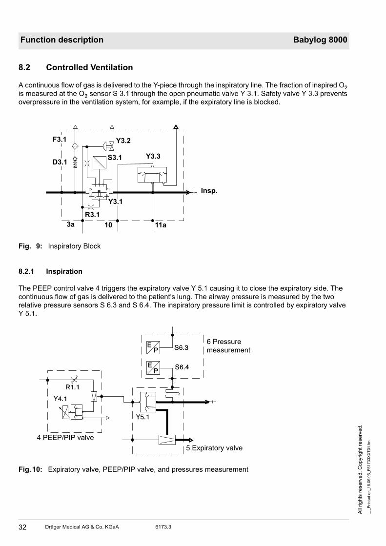
8.2 Controlled Ventilation
A continuous flow of gas is delivered to the Y-piece through the inspiratory line. The fraction of inspired O2
is measured at the O2 sensor S 3.1 through the open pneumatic valve Y 3.1. Safety valve Y 3.3 prevents
overpressure in the ventilation system, for example, if the expiratory line is blocked.
Fig. 9: Inspiratory Block
8.2.1 Inspiration
The PEEP control valve 4 triggers the expiratory valve Y 5.1 causing it to close the expiratory side. The
continuous flow of gas is delivered to the patient’s lung. The airway pressure is measured by the two
relative pressure sensors S 6.3 and S 6.4. The inspiratory pressure limit is controlled by expiratory valve
Y 5.1.
Fig.10: Expiratory valve, PEEP/PIP valve, and pressures measurement
Insp.
3a 10 11a
R3.1
Y3.1
Y3.3
Y3.2F3.1
D3.1S3.1
6 Pressure
measurement
5 Expiratory valve
4 PEEP/PIP valve
Y5.1
Y4.1
R1.1
S6.3
S6.4P
E
EP
Dräger Medical AG & Co. KGaA 6173.3
All
rig
hts
reserv
ed.
Copyright
rese
rved.
_ _
Pri
nte
d o
n_
18
.05
.05
_F
61
73
3X
XT
01
.fm
33
Function description Babylog 8000
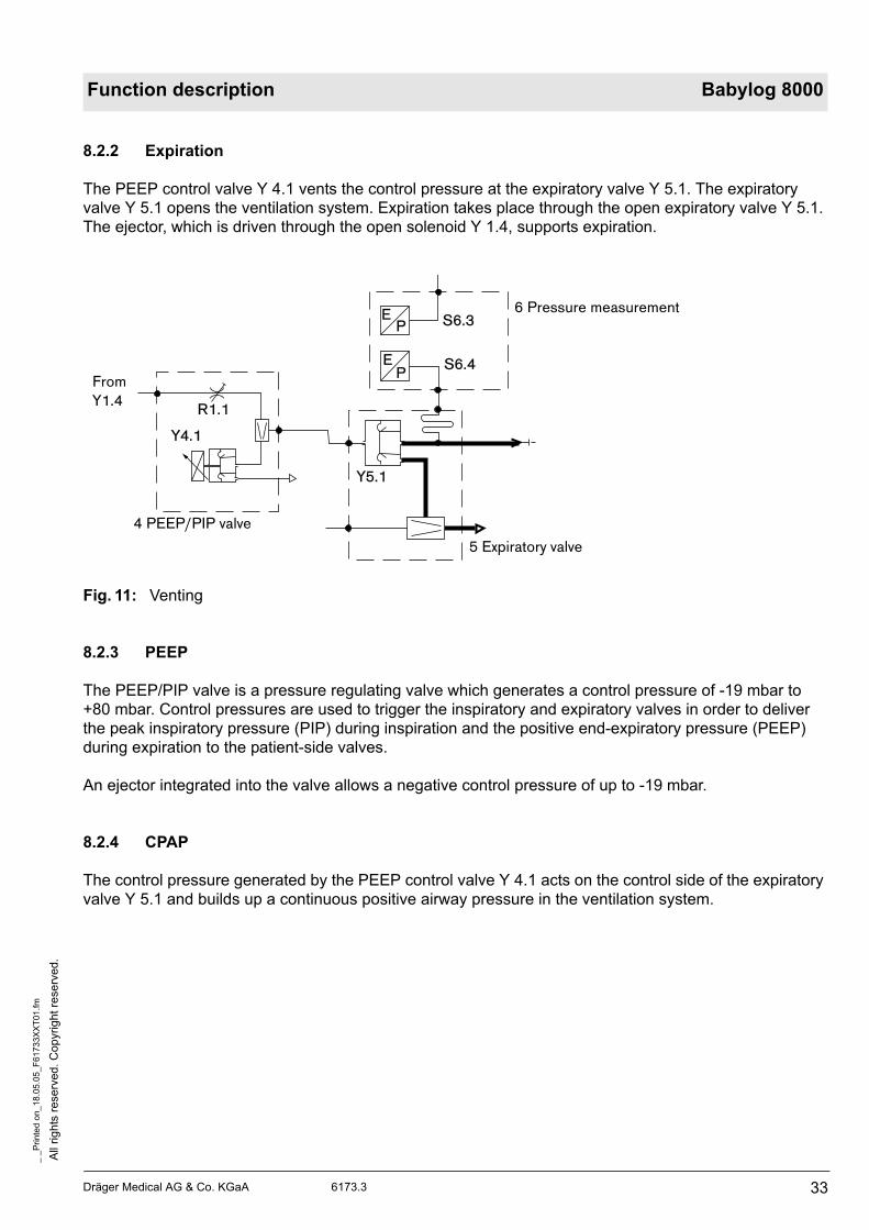
8.2.2 Expiration
The PEEP control valve Y 4.1 vents the control pressure at the expiratory valve Y 5.1. The expiratory
valve Y 5.1 opens the ventilation system. Expiration takes place through the open expiratory valve Y 5.1.
The ejector, which is driven through the open solenoid Y 1.4, supports expiration.
Fig. 11: Venting
8.2.3 PEEP
The PEEP/PIP valve is a pressure regulating valve which generates a control pressure of -19 mbar to
+80 mbar. Control pressures are used to trigger the inspiratory and expiratory valves in order to deliver
the peak inspiratory pressure (PIP) during inspiration and the positive end-expiratory pressure (PEEP)
during expiration to the patient-side valves.
An ejector integrated into the valve allows a negative control pressure of up to -19 mbar.
8.2.4 CPAP
The control pressure generated by the PEEP control valve Y 4.1 acts on the control side of the expiratory
valve Y 5.1 and builds up a continuous positive airway pressure in the ventilation system.
6 Pressure measurement
5 Expiratory valve
4 PEEP/PIP valve
Y5.1
Y4.1
R1.1
S6.3
S6.4P
E
EP
From
Y1.4

All
rig
hts
re
se
rve
d.
Co
pyrig
ht
rese
rve
d.
_ _
Pri
nte
d o
n_
18
.05
.05
_F
617
33X
XT
01
.fm
34 Dräger Medical AG & Co. KGaA 6173.3
Function description Babylog 8000
9 Measurement of the Ventilation Parameters
9.1 O2 Measurement
The O2 sensor continuously measures the fraction of inspired O2 through the open pneumatic valve Y 3.1.
Fig.12: Measurement of the fraction of inspired O2.
An automatic two-step calibration is carried out at 24-hour intervals.
AIR is supplied to the pneumatic valve Y 3.1 through solenoids Y 1.1, Y 1.2, and Y 1.3. The pneumatic
valve Y 3.1 closes the connection between the O2 sensor S 3.1 and the inspiratory line. The pneumatic
valve Y 3.2 is opened while, at the same time, the O2 sensor is purged with AIR through the restrictor
R 3.2 for approximately 2.5 minutes.
Then, purging with O2 is carried out in the same way. After calibration, the solenoid Y 1.1 switches back to
AIR, the solenoid Y 1.3 closes, the pneumatics valve Y 3.2 closes, too, and the pneumatics valve Y 3.1
reconnects the O2 sensor to the inspiratory line.
9.2 Measurement of the Airway Pressure
Due to the continuous flow, the inspiratory measurement results in a value that is higher than the value
measured at the Y-piece. Since an expiratory measurement results in a value which is too low, an
average value is calculated from the measured values of the relative pressure sensors and displayed on
the screen.
A bactericidal metering pipe prevents contamination of the pressure sensor with expiratory gas.
Insp.
3a 10 11a
R3.1
Y3.1
Y3.3
Y3.2F3.1
D3.1S3.1

Dräger Medical AG & Co. KGaA 6173.3
All
rig
hts
reserv
ed.
Copyright
rese
rved.
_ _
Pri
nte
d o
n_
18
.05
.05
_F
61
73
3X
XT
01
.fm
35
Function description Babylog 8000
9.3 Pneumatics Control PCB
The Pneumatics Control PCB is the output unit of the CPU 68000. It receives serial data from the I/O PCB
and triggers the corresponding valves.
Further functions of Pneumatics Control PCB: voltage supply to the patient system heater, power supply
to the PEEP/PIP valve.
Fig.13: Block diagram of the Pneumatics Control PCB
Motherboard
Input logic
Controlsignals
Relaycontrol
Valvevoltage
PEEP-voltage
Pneumatic analog PCB
Current and amplifier monitoring
PEEPvalve
Pneumatic
Ser
iel p
aral
lel c
onve
rter
Out
put
Inpu
t blo
ckV
alve
blo
ck O
2V
alve
blo
ck A
IR

All
rig
hts
re
se
rve
d.
Co
pyrig
ht
rese
rve
d.
_ _
Pri
nte
d o
n_
18
.05
.05
_F
617
33X
XT
01
.fm
36 Dräger Medical AG & Co. KGaA 6173.3
Function description Babylog 8000
9.4 Pneumatics Analog PCB
The Pneumatics Analog PCB controls and monitors the operate voltage and the withstand voltage to the
valves. The Pneumatics Analog PCB is installed on the Pneumatics Control PCB.
Fig.14: Block diagram of the Pneumatics Analog PCB
Fig.15: Block diagram of the Pneumatics Analog PCB
Current controlCurrent of the valve
Amplifier control
State of valve
+ Ref. Valve voltage + Ref.
Stop clock
Switchregulator

Dräger Medical AG & Co. KGaA 6173.3
All
rig
hts
reserv
ed.
Copyright
rese
rved.
_ _
Pri
nte
d o
n_
18
.05
.05
_F
61
73
3X
XT
01
.fm
37
Function description Babylog 8000
9.5 Patient System Heater
The patient system heater consists of a heating resistor located at the expiratory-valve connection.
9.6 Pressure Sensor Base PCB
The Pressure Sensor Base PCB has four pressure sensors for the measurement of Pinsp, Pexp, AIR and
O2 supply pressures and for coordination of the pressure and the O2 measurement signals.
9.7 O2 Amplifier PCB
The O2 Amplifier PCB amplifies the sensor signals directly at the sensor.
All
rig
hts
re
se
rve
d.
Co
pyrig
ht
rese
rve
d.
_ _
Pri
nte
d o
n_
18
.05
.05
_F
617
33X
XT
01
.fm
38 Dräger Medical AG & Co. KGaA 6173.3
Function description Babylog 8000
10 Components of the Electronic Assembly
The electronic assembly consists of the following printed circuit boards and subassemblies:
Power supply unit
Motherboard PCB
CPU 68000 PCB
I/O PCB
Flow PCB (Babylog 8000) (optional)
Monitoring PCB/Watchdog PCB
Front Adapter PCB
Front Controller PCB (Babylog 8000/Babylog 8000 SC with LC display )
Front PCB (Babylog 8000/Babylog 8000 plus with EL Display)
Display PCB (Babylog 8000/Babylog 8000 SC with LC display )
EL display (Babylog 8000/Babylog 8000 plus with EL display)
Potentiometer field
Display field
Communication PCB (optional)
Interface PCB (optional)
10.1 Power Supply Unit
The power supply unit supplies Babylog with the following voltages:
+5 V
+15 V
–15 V
+27 V
The power supply unit comprises the mains connection, the ON/OFF switch, and the fuses.
10.2 Motherboard PCB
All electrical connections between the individual printed circuit boards are led through the Motherboard
PCB. Cable connections go to the front panel, to the pneumatic assembly, and to the rear panel, which
contains the rechargeable battery, the fan, the loudspeaker, and the flow-sensor connection.
Dräger Medical AG & Co. KGaA 6173.3
All
rig
hts
reserv
ed.
Copyright
rese
rved.
_ _
Pri
nte
d o
n_
18
.05
.05
_F
61
73
3X
XT
01
.fm
39
Function description Babylog 8000
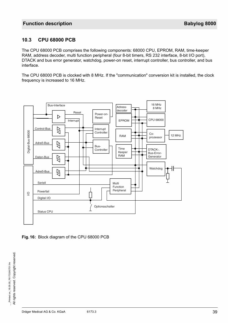
10.3 CPU 68000 PCB
The CPU 68000 PCB comprises the following components: 68000 CPU, EPROM, RAM, time-keeper
RAM, address decoder, multi function peripheral (four 8-bit timers, RS 232 interface, 8-bit I/O port),
DTACK and bus error generator, watchdog, power-on reset, interrupt controller, bus controller, and bus
interface.
The CPU 68000 PCB is clocked with 8 MHz. If the "communication" conversion kit is installed, the clock
frequency is increased to 16 MHz.
Fig.16: Block diagram of the CPU 68000 PCB
I/OD
igita
l-Bus
680
00
Bus-Interface
Reset
Control-Bus
Adreß-Bus
Daten-Bus
Adreß-Bus
Powerfail
Digital I/O
Status CPU
Optionsschalter
Watchdog
DTACK-, Bus-Error-Generator
12 MHzCo-prozessor
CPU 68000
16 MHz 8 MHzAdress-
decoder
EPROM
RAM
TimeKeeper RAM
MultiFunctionPeripheral
Power-on-Reset
InterruptController
Bus-Controller
Interrupt
Seriell
All
rig
hts
re
se
rve
d.
Co
pyrig
ht
rese
rve
d.
_ _
Pri
nte
d o
n_
18
.05
.05
_F
617
33X
XT
01
.fm
40 Dräger Medical AG & Co. KGaA 6173.3
Function description Babylog 8000
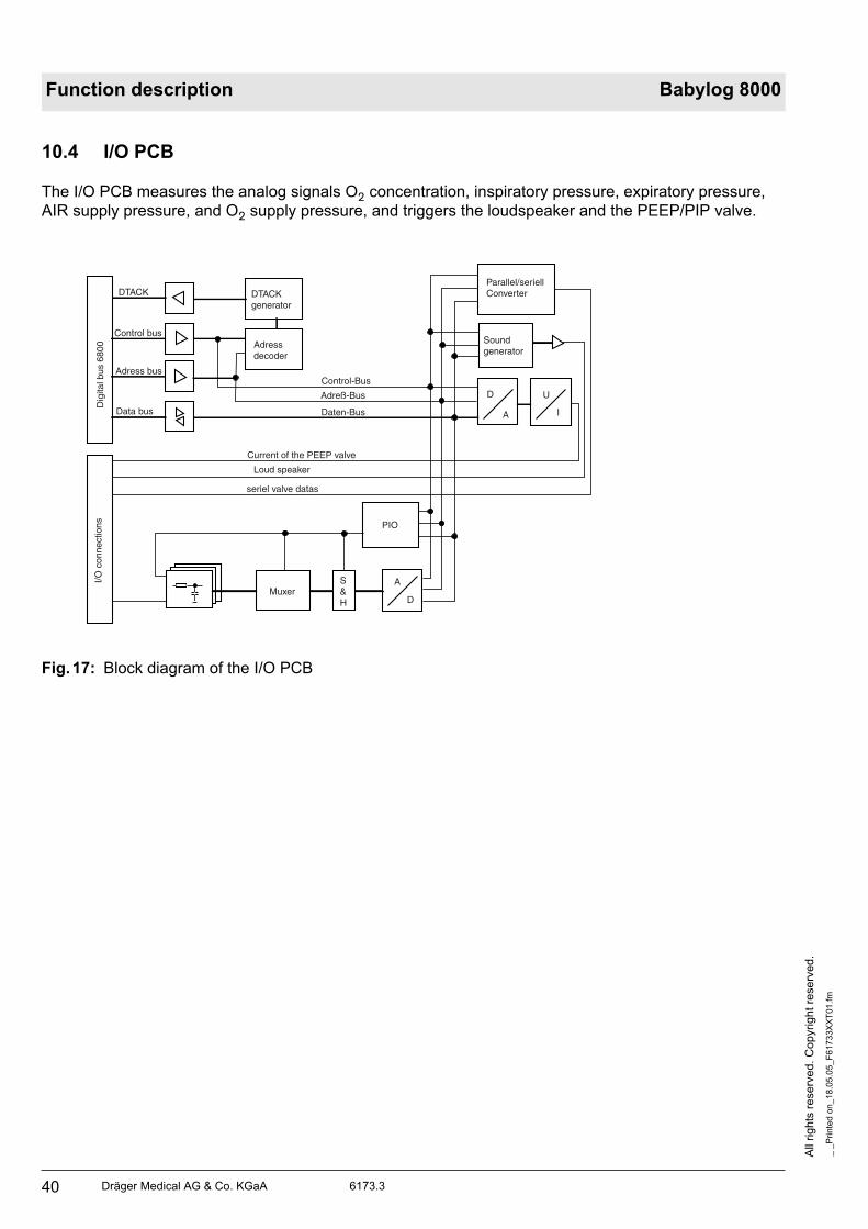
10.4 I/O PCB
The I/O PCB measures the analog signals O2 concentration, inspiratory pressure, expiratory pressure,
AIR supply pressure, and O2 supply pressure, and triggers the loudspeaker and the PEEP/PIP valve.
Fig.17: Block diagram of the I/O PCB
Dig
ital b
us 6
800
I/O c
onne
ctio
ns
DTACK
Control bus
Adress bus
Data bus
DTACKgenerator
Adressdecoder
Control-Bus
Adreß-Bus
Daten-Bus
Soundgenerator
D
A
U
I
MuxerS&H
A
D
PIO
Current of the PEEP valve
Parallel/seriell Converter
Loud speaker
seriel valve datas

Dräger Medical AG & Co. KGaA 6173.3
All
rig
hts
reserv
ed.
Copyright
rese
rved.
_ _
Pri
nte
d o
n_
18
.05
.05
_F
61
73
3X
XT
01
.fm
41
Function description Babylog 8000
10.5 Flow PCB (Babylog 8000/Babylog 8000 plus) (optional)
The Flow PCB in Babylog 8000/Babylog 8000 plus measures the flow. It provides the following function
blocks: sensor bridges with sensor amplifiers, analog-to-digital converter, microprocessor Z80 minimum
system, Z80-68000 bus interface.
Fig.18: Block diagram of the Flow PCB
Dig
ital b
us 6
8000
DTACK
Control bus
Adress bus
Data bus
DTACKgenerator
Adressdecoder
Adressdecoder
EPROM64 k / 32 k
RAM8 k / 2 k
Dual-Port-RAM
6 MHz
Z80CPU
Timer
Watchdog
Control bus
Adress bus
Data bus
System reset
Flo
w s
enso
r
MuxerS&H
A
D
PIO
Analog 1
Analog 4
Status flow
Control bus
Adress bus
Data bus

All
rig
hts
re
se
rve
d.
Co
pyrig
ht
rese
rve
d.
_ _
Pri
nte
d o
n_
18
.05
.05
_F
617
33X
XT
01
.fm
42 Dräger Medical AG & Co. KGaA 6173.3
Function description Babylog 8000
10.6 Monitoring PCB
The Monitoring PCB measures and monitors all measurement and status signals. The Monitoring PCB
compares these signals with the signals from the CPU 68000. If an error occurs, the Monitoring PCB
switches off the valves, activates the audible alarm generator, and resets the CPU PCB.
A Z80 microprocessor (minimum system) controls the Monitoring PCB. The Monitoring PCB
communicates with the CPU 68000 via a bus interface.
10.6.1 Measurement of Analog Signals
O2 concentration
Potentiometers (O2, Vinsp, TI, TE, Pinsp, PEEP/CPAP)
Pressure Pinsp
System temperature
Supply voltages (potentiometer reference, rechargeable battery, GNDA, GND reference, 27 V)
Valve voltage
10.6.2 Measurement of Digital Inputs
STATUS CPU 68000 (reset)
STATUS flow (reset)
STATUS I/O (printed circuit board is available)
STATUS valves (current and drive monitoring on the Pneumatics Analog PCB)
Powerfail
Position of power switch
10.6.3 Measurement of Digital Outputs
Alarm LEDs (2 LEDs on the Display PCB)
Flow test 1 and 2 (for Flow PCB)
Switching on of valve relays K1 and K2 (voltage supply to valves and PEEP/PIP valve on the
Pneumatics Control PCB)
CPU PCB reset
7-segment status display for error messages
Standby audible alarm generator
Loudspeaker monitoring via microphone
Battery charging and testing circuit
Test of the supply voltages +5 V, +15 V, –15 V (Display PCB)

Dräger Medical AG & Co. KGaA 6173.3
All
rig
hts
reserv
ed.
Copyright
rese
rved.
_ _
Pri
nte
d o
n_
18
.05
.05
_F
61
73
3X
XT
01
.fm
43
Function description Babylog 8000
Fig.19: Block diagram of the Monitoring PCB
Block diagram of the Watchdog PCB of the Monitoring PCB (in new boards the Watchdog PCB is
integrated into the Monitoring PCB).
Dig
ital b
us 6
8000
Bus interface
DTACKQ
Control bus
Adress bus
Data bus
INTQDTACKQgenerator
Z80-Bus
EPROM64 k
RAM8 k
Dual-Port-RAM
4 MHz
Z 80CPU
Timer
Watchdog
Control bus
Adress bus
I/O c
onne
ctio
ns
Analog Input
Digital Input
S & H
(Filter)
PIO
A
D
PIO
Adressdecoder
Adressdecoder
Watch dogPCB
Statusdisplay

All
rig
hts
re
se
rve
d.
Co
pyrig
ht
rese
rve
d.
_ _
Pri
nte
d o
n_
18
.05
.05
_F
617
33X
XT
01
.fm
44 Dräger Medical AG & Co. KGaA 6173.3
Function description Babylog 8000
Fig.20: Block diagram of the Watchdog PCB
+-
voltages
URef
sounddecoder
Signal sound generator monitoring
rechargeable battery
Alarm LED power

Dräger Medical AG & Co. KGaA 6173.3
All
rig
hts
reserv
ed.
Copyright
rese
rved.
_ _
Pri
nte
d o
n_
18
.05
.05
_F
61
73
3X
XT
01
.fm
45
Function description Babylog 8000
10.7 Front Adapter PCB
The Front Adapter PCB connects the CPU 68000 to the front panel. The front panels provides the control
and display elements.
The Front Adapter PCB reduces the 16-bit data bus to 8 bits, generates control signals for the front panel,
and controls the LC display (VIDEO RAM and LCD controller) or the EL display.
The power supply and the analog signals are led from the Motherboard PCB to the front panel through the
Front Adapter PCB.
Fig.21: Block diagram of the Front Adapter PCB
Dig
ital b
us 6
8000
DTACKQ
Control bus
Adress bus
Data bus
DTACK generator
Adressdecoder
LCD-Controller
Dual-Port-RAM
Daten-Bus (16 bit)
seriell Datas to LC display
Fron
tcon
trol
ler
Adress and Control bus
Data bus (8 bit)
I/O c
onne
ctio
ns
Ansteuerung Alarm LED
analog current power
Potentiometer monitoring

All
rig
hts
re
se
rve
d.
Co
pyrig
ht
rese
rve
d.
_ _
Pri
nte
d o
n_
18
.05
.05
_F
617
33X
XT
01
.fm
46 Dräger Medical AG & Co. KGaA 6173.3
Function description Babylog 8000
10.8 Front Controller PCB(Babylog 8000/Babylog 8000 SC with LC Display)
The Front Controller PCB reads in the keys of the potentiometer and display field, controls the LEDs of
the potentiometer and display field, powers the LC display with operating voltage (contrast), controls the
LC display backlight, and generates the control signal for the bargraph.
Fig.22: Block diagram of the Front Controller PCB (Babylog 8000/8000 SC with LC display)
D
A
DC
AC
Contrast adjustment of LC display
LC display
voltage fordisplay illumination
key port
LED driver
AmplifierBargraph
Keys of the front panel and options switches
LEDs of the front panel
Alarm LEDs
Bargraph of the front panel
URef
A
D6x
Adressdecoder
Potentiometer of the front panel
UB
Data bus
Control bus andAdress bus
Test
A/D
con
vert
er
Dräger Medical AG & Co. KGaA 6173.3
All
rig
hts
reserv
ed.
Copyright
rese
rved.
_ _
Pri
nte
d o
n_
18
.05
.05
_F
61
73
3X
XT
01
.fm
47
Function description Babylog 8000
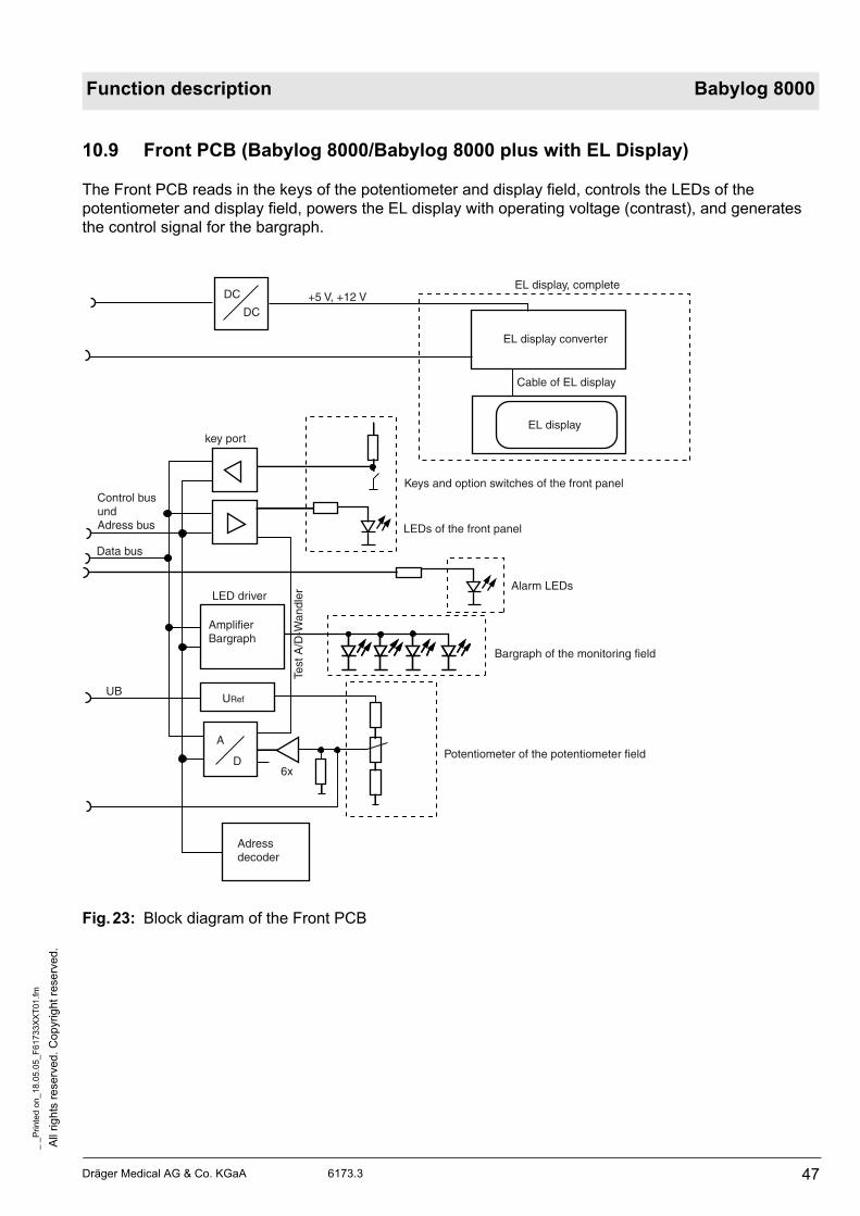
10.9 Front PCB (Babylog 8000/Babylog 8000 plus with EL Display)
The Front PCB reads in the keys of the potentiometer and display field, controls the LEDs of the
potentiometer and display field, powers the EL display with operating voltage (contrast), and generates
the control signal for the bargraph.
Fig.23: Block diagram of the Front PCB
DC
DC+5 V, +12 V
EL display, complete
EL display converter
EL display
Cable of EL display
key port
Keys and option switches of the front panel
LEDs of the front panel
Alarm LEDs
Bargraph of the monitoring field
Potentiometer of the potentiometer field
LED driver
AmplifierBargraph
URef
A
D6x
Adressdecoder
UB
Control busundAdress bus
Data bus
Test
A/D
-Wan
dler

All
rig
hts
re
se
rve
d.
Co
pyrig
ht
rese
rve
d.
_ _
Pri
nte
d o
n_
18
.05
.05
_F
617
33X
XT
01
.fm
48 Dräger Medical AG & Co. KGaA 6173.3
Function description Babylog 8000
10.10 Display PCB (Babylog 8000/Babylog 8000 SC with LC Display)
The Display PCB contains the control electronics for the LED array of the bargraph.
Fig.24: Block diagram of the Display PCB
RAM
Modul 06
Data bus
Adress bus
Chip Select

Dräger Medical AG & Co. KGaA 6173.3
All
rig
hts
reserv
ed.
Copyright
rese
rved.
_ _
Pri
nte
d o
n_
18
.05
.05
_F
61
73
3X
XT
01
.fm
49
Function description Babylog 8000
10.11 EL display (Babylog 8000/Babylog 8000 plus with EL Display)
The EL display (Electro Luminescence Display) consists of the EL display, the EL display converter, and the
EL display connecting cable. The EL display displays the signals and other information. The EL display
converter generates the (200-240 V a.c.) voltage for the luminescence voltage of the EL display. The EL
display and the converter are ”matched”.
Fig.25: Components of EL display
pn 45363667
EL display
EL display connecting cable
EL display converter

All
rig
hts
re
se
rve
d.
Co
pyrig
ht
rese
rve
d.
_ _
Pri
nte
d o
n_
18
.05
.05
_F
617
33X
XT
01
.fm
50 Dräger Medical AG & Co. KGaA 6173.3
Function description Babylog 8000
10.12 Potentiometer Field
The Potentiometer Field comprises the following components:
6 potentiometers (O2 vol.%, TI, TE, Insp. Flow , Pinsp, PEEP/CPAP)
9 LEDs (O2 vol.%, TI, TE, Insp. Flow , Pinsp, PEEP/CPAP, CPAP, IPPV, reserve)
3 keys (CPAP, IPPV, reserve) (Vent. Mode, Vent. Option, reserve as of software version 5.n
10.13 Display Field
The display field contains the following components:
11 keys (silence, reset, man./insp., menu, keys 1 to 6, light). The "light" key is only available on
Babylog 8000 with LC display. The key signals are read in via the Front Controller PCB or the Front
PCB.
LED array of the bargraph. The LED array is controlled via the Display PCB.
7 LEDs (warning (yellow), mode, monitoring, silence, triggers 1 to 3). The LEDs are controlled via the
Front Controller PCB or the Front PCB.
2 red alarm LEDs. The LEDs are controlled via the Monitoring PCB/Watchdog PCB.

Dräger Medical AG & Co. KGaA 6173.3
All
rig
hts
reserv
ed.
Copyright
rese
rved.
_ _
Pri
nte
d o
n_
18
.05
.05
_F
61
73
3X
XT
01
.fm
51
Function description Babylog 8000
10.14 Communication PCB
The Communication PCB controls an external printer, a computer, and an analog recorder. The
Communication PCB is equipped with an RS232 interface, two 12-bit D/A outputs, and one digital trigger
output. All outputs are electrically isolated from the electronics. Software version 3.00 or higher, a CPU
PCB with 16 MHz (the CPU PCB with 8 MHz was standard until end of 1992) and the Interface PCB with
outputs on the rear panel are minimum requirements for operation.
Fig.26: Block diagram of the Communication PCB
System connector
Digital bus 68000 I/O connections
DTA
CK
Con
trol
bus
Adr
ess
bus
Dat
a bu
s
DC
DC
EE
PR
OM
MF
P*
DTA
CK
ge
nera
tor
Adr
ess
deco
der
2,5
kV e
lect
rical
isol
atio
n
Par
alle
l/ser
iell
conv
erte
rR
egis
ter
D
A
Ana
log
Out
put
Trig
ger
RS
232
Nur
se c
all
*MF
P=
Mul
ti F
unct
ion
Pro
zess
or
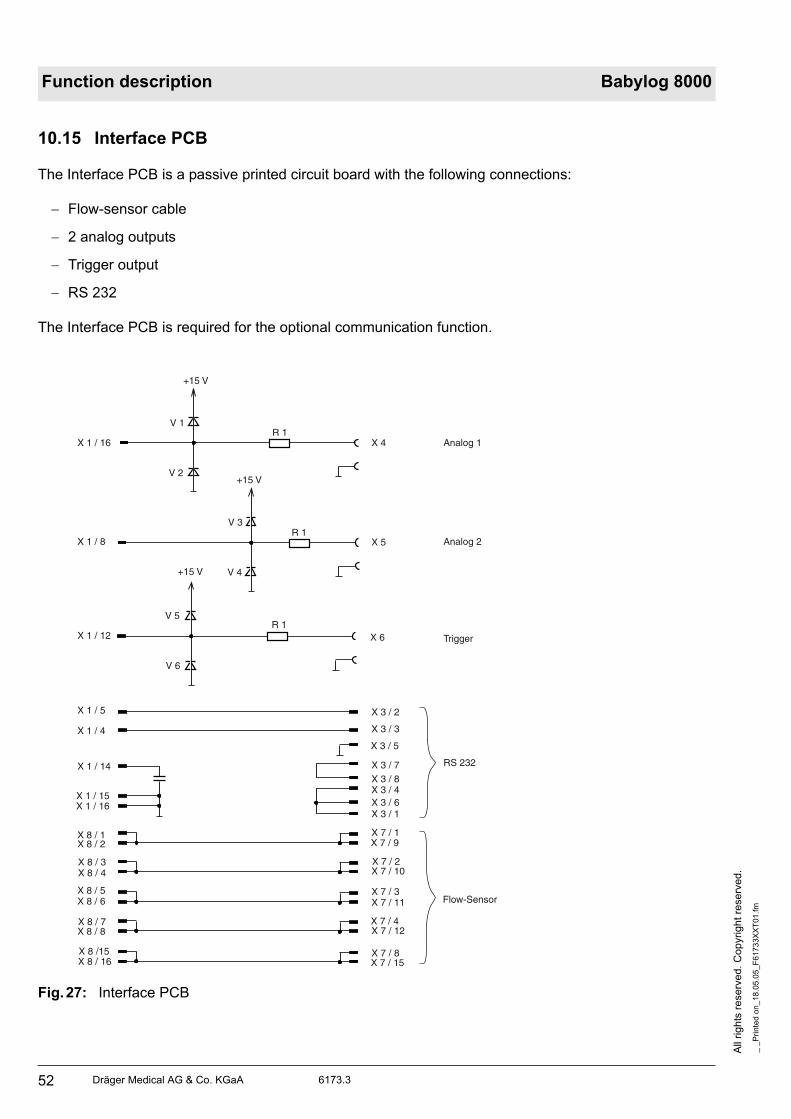
All
rig
hts
re
se
rve
d.
Co
pyrig
ht
rese
rve
d.
_ _
Pri
nte
d o
n_
18
.05
.05
_F
617
33X
XT
01
.fm
52 Dräger Medical AG & Co. KGaA 6173.3
Function description Babylog 8000
10.15 Interface PCB
The Interface PCB is a passive printed circuit board with the following connections:
Flow-sensor cable
2 analog outputs
Trigger output
RS 232
The Interface PCB is required for the optional communication function.
Fig.27: Interface PCB
X 8 / 16X 8 /15
X 8 / 8X 8 / 7
X 8 / 6X 8 / 5
X 8 / 4X 8 / 3
X 8 / 2X 8 / 1
X 1 / 16X 1 / 15
X 1 / 14
X 1 / 4
X 1 / 5
X 1 / 12
X 1 / 8
X 1 / 16
X 7 / 15X 7 / 8
X 7 / 12X 7 / 4
X 7 / 11X 7 / 3
X 7 / 10X 7 / 2
X 7 / 9X 7 / 1
X 3 / 1X 3 / 6X 3 / 4X 3 / 8X 3 / 7
X 3 / 5
X 3 / 3
X 3 / 2
X 6
X 5
X 4
V 6
V 5R 1
R 1
R 1
V 4
V 3
V 2
V 1
+15 V
+15 V
+15 V
Analog 1
Analog 2
Trigger
RS 232
Flow-Sensor

Dräger Medical AG & Co. KGaA 6173.3
All
rig
hts
reserv
ed.
Copyright
rese
rved.
_ _
Pri
nte
d o
n_
18
.05
.05
_F
61
73
3X
XT
01
.fm
53
Function description Babylog 8000
11 Sensors
11.1 Pressure Sensors
The pressure sensors function according to the piezoresistive principle. An approximately 4 mm into
4 mm silicon chip has 4 ion implanted resistors. The silicon chip is also equipped with a pressure
diaphragm.
11.2 Y-Piece with Flow Sensor (Babylog 8000/Babylog 8000 plus)
The Y-piece with integrated flow sensor is used in pediatric respiratory gas systems. This Y-piece
connects the respiratory gas hoses of Babylog 8000/Babylog 8000 plus to the patient catheter
connection.
Fig.28: Flow sensor
The flow sensor works according to the hot-wire flowmeter principle. It has an additional measuring wire
for direction recognition.
Inspiration Exspiration
Hot wire flowmeter for direction recognition
Hot wire flowmeter

All
rig
hts
re
se
rve
d.
Co
pyrig
ht
rese
rve
d.
_ _
Pri
nte
d o
n_
18
.05
.05
_F
617
33X
XT
01
.fm
54 Dräger Medical AG & Co. KGaA 6173.3
Function description Babylog 8000
11.2.1 Measuring Principle of the Flow Measuring Bridge
The flow sensor incorporates two hot-wire flowmeters. A separate wire is used for direction recognition.
Both wires are evaluated on the Flow PCB by two separate measuring channels.
Fig.29: Principle diagram of the flow measuring bridge
The measuring bridge comprises the resistors R 54, R 72, R 70, and the measuring wire of the sensor.
The measuring wire is kept at a constant resistance. This means that the amount of heat dissipated by the
gas flow has to be readjusted. As system deviation the voltage passes through the node R 54/R72 and
the measuring wire R 70. If the voltage is adjusted to "0", the current flowing through the measuring wire
and the R70 is a measure for the heat dissipated. The controllable power source is made with V7. N7 is a
controller with PI behavior. To adjust the bridge a current can be injected via the D/A converter D 24 into
the node R54/R72. The current through the bridge is changed such that the wire begins to glow. Burning
out of the wire is prevented by a current limiter. The current limiter compares the voltages and switches
the current source off, if required. Current limitation is effected through the comparator which is connected
to the input of V7. The current through the flow measuring bridge is changed for test purposes. R 70 is a
current measuring resistor (four-wire measurement) which measures the heating current (proportional
voltage).
+
-
UB
Flow test
12 Bit
R 54
Hot wire glowing
R 72 R 70Umeß
PI regulator
Hot wire
Comparator
RDRD 24
V 7
N 7

Dräger Medical AG & Co. KGaA 6173.3
All
rig
hts
reserv
ed.
Copyright
rese
rved.
_ _
Pri
nte
d o
n_
18
.05
.05
_F
61
73
3X
XT
01
.fm
55
Function description Babylog 8000
11.3 O2 Sensor
The O2 sensor is a double cell which functions according to the fuel-cell principle, that is, it is an
electrochemical cell which generates a voltage by means of an ion current. The cell consists of a capsule
which incorporates electrolytes, lead anodes and two gold cathodes with Teflon diaphragm.
Fig.30: O2 sensor cell
The oxygen to be measured diffuses through the Teflon diaphragm, undergoes a chemical reaction at the
gold cathode and produces lead oxide and water at the lead anode. During this chemical process an
electric voltage is generated which is proportional to the oxygen partial pressure. The gold cathodes are
negative, the lead anode is positive. The internal resistance is determined by the surface of the
electrodes, the oxygen diffusion velocity, and the distances. Under normal condition, the internal
resistance is 700 ohms.
Like most chemical processes, this process is also temperature-dependent. Therefore, compensation
resistors are connected in parallel to the sensor. These resistors correct the measuring voltage in relation
to the internal resistance. Two voltages are generated which are identical within specified tolerances. The
voltages are compared to each other. The two gold cathodes are arranged separately. The two voltages
do not influence each other. If one gold cathode fails, the other carries out the measurement. In this case,
the electronics would report a malfunction.
cathode 1
cathode 2
O2
Plastic housing
Alkali-Elektrolyt
anode

All
rig
hts
re
se
rve
d.
Co
pyrig
ht
rese
rve
d.
_ _
Pri
nte
d o
n_
18
.05
.05
_F
617
33X
XT
01
.fm
56 Dräger Medical AG & Co. KGaA 6173.3
Function description Babylog 8000

57
Replacing Non Repairable Items

58

Dräger Medical AG & Co. KGaA 6173.3
All
rig
hts
reserv
ed.
Copyright
rese
rved.
_ _
Pri
nte
d o
n_
18
.05
.05
_G
BK
61
73
3X
XV
01.f
m
59
Replacing Non-Repairable Items Babylog 8000
1 Important Information
Follow the instructions in this manual and carefully read and observe all statements following a warning or
info symbol. If you ignore the warning statements, this may lead to personal injury and/or device damage.
Non-repairable items should only be replaced by qualified service personnel.
Before removing the rear panel, unplug the power plug from the mains supply and disconnect the device
from the central gas supply.
Observe antistatic precautions prior to and during any corrective procedure.
After performing any repair or inspection on medical devices, carry out a final check before returning the
devices to normal use.

All
rig
hts
re
se
rve
d.
Co
pyrig
ht
rese
rve
d.
_ _
Pri
nte
d o
n_
18
.05
.05
_G
BK
617
33X
XV
01.f
m
60 Dräger Medical AG & Co. KGaA 6173.3
Babylog 8000 Replacing Non-Repairable Items
2 Cleaning or Replacing the Cooling Air Filter Every 4 Weeks
• Pull out the cooling air filter 1 from its mount in the rear panel.
• Insert a new cooling air filter or wash the old one in warm water with a few drops of dish-washing
liquid. Dry well.
• Insert the cooling air filter 1 into the mount (make sure it is free of folds).
Fig. 1: Cooling Air Filter
1
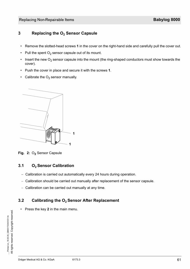
Dräger Medical AG & Co. KGaA 6173.3
All
rig
hts
reserv
ed.
Copyright
rese
rved.
_ _
Pri
nte
d o
n_
18
.05
.05
_G
BK
61
73
3X
XV
01.f
m
61
Replacing Non-Repairable Items Babylog 8000
3 Replacing the O2 Sensor Capsule
• Remove the slotted-head screws 1 in the cover on the right-hand side and carefully pull the cover out.
• Pull the spent O2 sensor capsule out of its mount.
• Insert the new O2 sensor capsule into the mount (the ring-shaped conductors must show towards the
cover).
• Push the cover in place and secure it with the screws 1.
• Calibrate the O2 sensor manually.
Fig. 2: O2 Sensor Capsule
3.1 O2 Sensor Calibration
Calibration is carried out automatically every 24 hours during operation.
Calibration should be carried out manually after replacement of the sensor capsule.
Calibration can be carried out manually at any time.
3.2 Calibrating the O2 Sensor After Replacement
• Press the key 2 in the main menu.
1
1
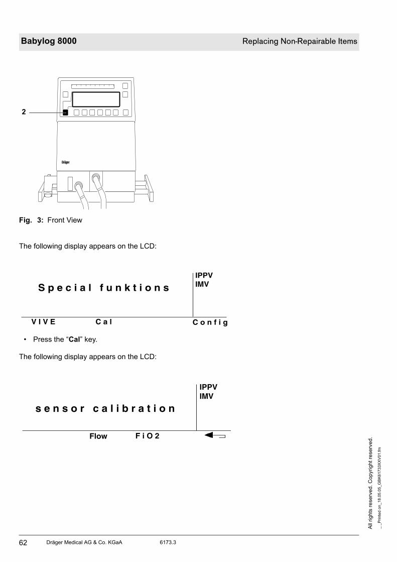
All
rig
hts
re
se
rve
d.
Co
pyrig
ht
rese
rve
d.
_ _
Pri
nte
d o
n_
18
.05
.05
_G
BK
617
33X
XV
01.f
m
62 Dräger Medical AG & Co. KGaA 6173.3
Babylog 8000 Replacing Non-Repairable Items
Fig. 3: Front View
The following display appears on the LCD:
• Press the “Cal” key.
The following display appears on the LCD:
D
2
S p e c i a l f u n k t i o n sIPPVIMV
C o n f i gV I V E C a l
IPPVIMV
F i O 2
s e n s o r c a l i b r a t i o n
Flow
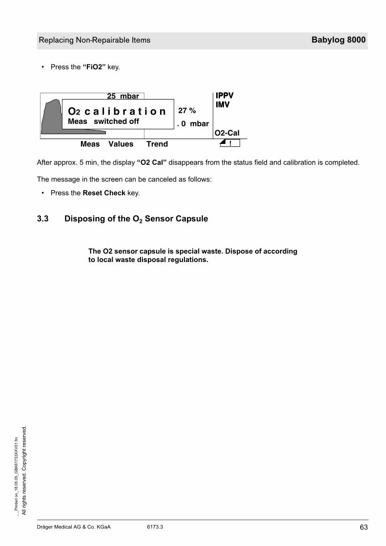
Dräger Medical AG & Co. KGaA 6173.3
All
rig
hts
reserv
ed.
Copyright
rese
rved.
_ _
Pri
nte
d o
n_
18
.05
.05
_G
BK
61
73
3X
XV
01.f
m
63
Replacing Non-Repairable Items Babylog 8000
• Press the “FiO2” key.
After approx. 5 min, the display “O2 Cal” disappears from the status field and calibration is completed.
The message in the screen can be canceled as follows:
• Press the Reset Check key.
3.3 Disposing of the O2 Sensor Capsule
The O2 sensor capsule is special waste. Dispose of according
to local waste disposal regulations.
IPPVIMV
27 %
. 0 mbar
IPPVIMV
!
O2-CalMeas Values Trend
25 mbar IPPVIMV
O2 c a l i b r a t i o nMeas switched off

All
rig
hts
re
se
rve
d.
Co
pyrig
ht
rese
rve
d.
_ _
Pri
nte
d o
n_
18
.05
.05
_G
BK
617
33X
XV
01.f
m
64 Dräger Medical AG & Co. KGaA 6173.3
Babylog 8000 Replacing Non-Repairable Items
4 Replacing the Lip Seals Every 2 Years
• Lift the toggle 1 and take out the expiratory valve.
Fig. 4: Removing the Expiratory Valve
• Use, for example, a spherical-head 2.5 mm screwdriver to remove the old lip seals 2. Insert the new
lip seals and make sure they fit properly.
Fig. 5: Location of the Lip Seals
• Re-mount the expiratory valve. To do so, lift up the toggle and place the expiratory valve to the front
using the guide rods.
• Lock the expiratory valve with the toggle 1.
D
1
D
2 2 2

Dräger Medical AG & Co. KGaA 6173.3
All
rig
hts
reserv
ed.
Copyright
rese
rved.
_ _
Pri
nte
d o
n_
18
.05
.05
_G
BK
61
73
3X
XV
01.f
m
65
Replacing Non-Repairable Items Babylog 8000
5 Replacing the NiCd Battery (Power Failure Alarm) Every 2 Years
• Remove the screw 1 on the fan/loudspeaker cover.
Fig. 6: Opening the Loudspeaker Cover
• Gently lower the cover 3.
• Disconnect the cable connection 2 and place the cover 3 aside.
• Remove the screws 4 on the battery mount.
Fig. 7: Removing the Loudspeaker Cover
1
2
3
4 4

All
rig
hts
re
se
rve
d.
Co
pyrig
ht
rese
rve
d.
_ _
Pri
nte
d o
n_
18
.05
.05
_G
BK
617
33X
XV
01.f
m
66 Dräger Medical AG & Co. KGaA 6173.3
Babylog 8000 Replacing Non-Repairable Items
• Remove the battery 5 and install a new one.
Fig. 8: Replacing the Battery
• Re-assemble the Babylog 8000/Babylog 8000 plus/Babylog 8000 SC. The battery for power failure
alarm is recharged automatically during operation.
After replacing the battery, allow the device to operate for at least half an hour in order to sufficiently
charge the battery.
No acoustic alarm will sound in the event of power failure if
the battery is not sufficiently charged. Risk of severe injury or
death. Allow the device to operate for at least half an before
clinical application.
5

Dräger Medical AG & Co. KGaA 6173.3
All
rig
hts
reserv
ed.
Copyright
rese
rved.
_ _
Pri
nte
d o
n_
18
.05
.05
_G
BK
61
73
3X
XV
01.f
m
67
Replacing Non-Repairable Items Babylog 8000
6 Replacing the Pressure Reducer Every 6 Years
• Disconnect the Babylog 8000/Babylog 8000 plus/Babylog 8000 SC from the mains supply.
• Disconnect the gas supply hoses from the central gas supply/gas cylinder.
• Disengage the Babylog 8000/Babylog 8000 plus/Babylog 8000 SC from the trolley. To do so, loosen
the knurled nuts 1 on the rear panel.
Fig. 9: Location of the Knurled Nuts
Fig.10: Disengaging the Babylog 8000/Babylog 8000 plus/Babylog 8000 SC
1 1
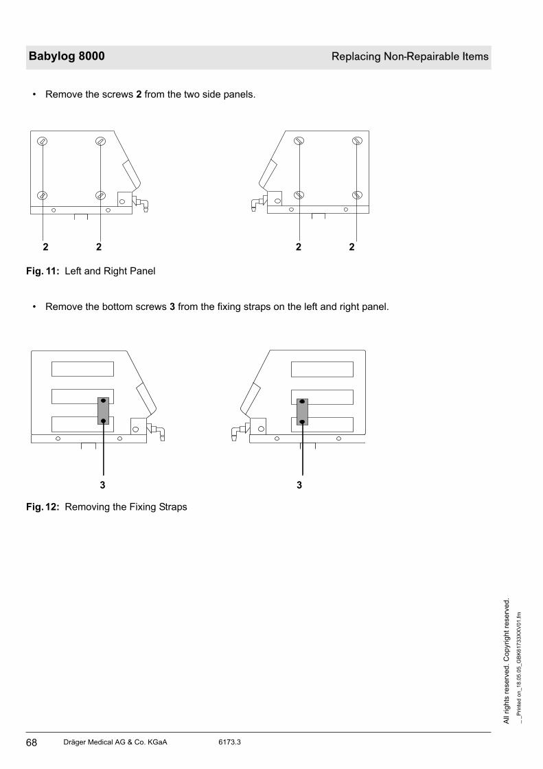
All
rig
hts
re
se
rve
d.
Co
pyrig
ht
rese
rve
d.
_ _
Pri
nte
d o
n_
18
.05
.05
_G
BK
617
33X
XV
01.f
m
68 Dräger Medical AG & Co. KGaA 6173.3
Babylog 8000 Replacing Non-Repairable Items
• Remove the screws 2 from the two side panels.
Fig. 11: Left and Right Panel
• Remove the bottom screws 3 from the fixing straps on the left and right panel.
Fig.12: Removing the Fixing Straps
2 2 2 2
3 3
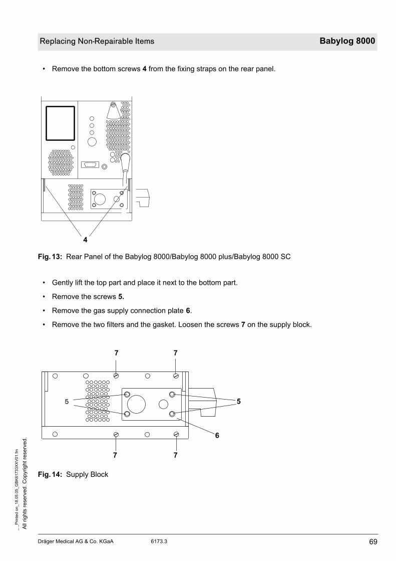
Dräger Medical AG & Co. KGaA 6173.3
All
rig
hts
reserv
ed.
Copyright
rese
rved.
_ _
Pri
nte
d o
n_
18
.05
.05
_G
BK
61
73
3X
XV
01.f
m
69
Replacing Non-Repairable Items Babylog 8000
• Remove the bottom screws 4 from the fixing straps on the rear panel.
Fig.13: Rear Panel of the Babylog 8000/Babylog 8000 plus/Babylog 8000 SC
• Gently lift the top part and place it next to the bottom part.
• Remove the screws 5.
• Remove the gas supply connection plate 6.
• Remove the two filters and the gasket. Loosen the screws 7 on the supply block.
Fig.14: Supply Block
4
6
7 7
55
77

All
rig
hts
re
se
rve
d.
Co
pyrig
ht
rese
rve
d.
_ _
Pri
nte
d o
n_
18
.05
.05
_G
BK
617
33X
XV
01.f
m
70 Dräger Medical AG & Co. KGaA 6173.3
Babylog 8000 Replacing Non-Repairable Items
• Slightly tilt the supply block 8. Make sure not to damage the hoses or the printed circuit boards.
Fig.15: Pneumatic Assembly of the Babylog 8000/Babylog 8000 plus/Babylog 8000 SC
Tilting the supply block excessively will cause damage to the
hoses and/or printed circuit boards. Do not tilt the supply
block more than necessary.
8
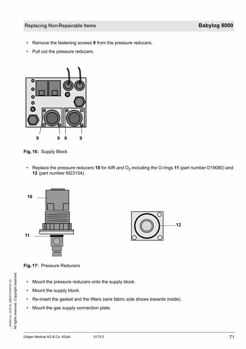
Dräger Medical AG & Co. KGaA 6173.3
All
rig
hts
reserv
ed.
Copyright
rese
rved.
_ _
Pri
nte
d o
n_
18
.05
.05
_G
BK
61
73
3X
XV
01.f
m
71
Replacing Non-Repairable Items Babylog 8000
• Remove the fastening screws 9 from the pressure reducers.
• Pull out the pressure reducers.
Fig.16: Supply Block
• Replace the pressure reducers 10 for AIR and O2 including the O-rings 11 (part number D19080) and
12 (part number M23154).
Fig.17: Pressure Reducers
• Mount the pressure reducers onto the supply block.
• Mount the supply block.
• Re-insert the gasket and the filters (wire fabric side shows towards inside).
• Mount the gas supply connection plate.
9 9 9 9
10
12
11

All
rig
hts
re
se
rve
d.
Co
pyrig
ht
rese
rve
d.
_ _
Pri
nte
d o
n_
18
.05
.05
_G
BK
617
33X
XV
01.f
m
72 Dräger Medical AG & Co. KGaA 6173.3
Babylog 8000 Replacing Non-Repairable Items
• Unlock the pressure reducers by pulling the adjusting rings 1 in direction of A.
• Turn the adjusting rings 1 counterclockwise in direction of B as far as they will go (pressure reducers
will be closed).
Fig.18: Pneumatic Assembly
• Connect to the air supply only and switch on the Babylog 8000/ Babylog 8000 plus/Babylog 8000 SC.
• Adjust the following parameters:
Mode = CPAP; PEEP/CPAP adjuster = 0 mbar; insp. flow = 1 L/min
1
A
B
O2
Air

Dräger Medical AG & Co. KGaA 6173.3
All
rig
hts
reserv
ed.
Copyright
rese
rved.
_ _
Pri
nte
d o
n_
18
.05
.05
_G
BK
61
73
3X
XV
01.f
m
73
Replacing Non-Repairable Items Babylog 8000
Fig.19: Air-Supply Test Set-Up
• Carry out the measurement with a manometer and a secretion sightglass at the pneumatics outlet.
• Slowly turn the adjusting ring of the air pressure reducer clockwise. The message “no compressed
air” on the LCD disappears.
• Set the pressure reducer to 1.7 -0.1 bar.
• Set the insp. flow adjuster to 30 L/min. The manometer should indicate at least 1.3 bar.
• Disconnect the Babylog 8000/Babylog 8000 plus/Babylog 8000 SC from the air supply and connect it
to the oxygen supply.
• Adjust the following parameters:
Mode = CPAP; PEEP/CPAP adjuster = 0 mbar; insp. flow = 1 L/min.
Fig.20: O2-Supply Test Set-Up
• Carry out the measurement with a manometer and a secretion sightglass at the pneumatics outlet.
• Slowly turn the adjusting ring of the O2 pressure reducer clockwise. The message “no oxygen” on the
LCD disappears.
D
D

All
rig
hts
re
se
rve
d.
Co
pyrig
ht
rese
rve
d.
_ _
Pri
nte
d o
n_
18
.05
.05
_G
BK
617
33X
XV
01.f
m
74 Dräger Medical AG & Co. KGaA 6173.3
Babylog 8000 Replacing Non-Repairable Items
• Set the pressure reducer to 1.7 -0.1 bar.
• Set the insp. flow adjuster to 30 L/min. The manometer should indicate at least 1.3 bar.
• Lock both adjusting rings by pressing them in direction of the arrows C.
• Make sure that the hose system is free of leaks.
Fig.21: Locking the Pressure Reducer
• Re-assemble the Babylog 8000/Babylog 8000 plus/Babylog 8000 SC and it return it to service ready-
for-use.
CC

75
Schematics and diagrams

76

Dräger Medical AG & Co. KGaA 6173.3
All
rig
hts
reserv
ed.
Copyright
rese
rved.
_ _
Pri
nte
d o
n_
18
.05
.05
_G
BK
61
73
3X
XD
01
.fm
77
Schematics and diagrams Babylog 8000
1 Schematics and Diagrams
Fig. 1: Function Diagram of Babylog 8000 „Version 0“
6 P
ressu
re m
easu
rem
en
t
1 G
as s
up
ply
blo
ck
6 V
alv
e b
lock
5 E
xpir
ato
ry v
alv
e
3 I
nsp
irato
ry b
lock
6 P
ressu
re
me
asu
rem
en
t
Air
O2
F3
.1
F1
.2
F1
.1
D4
.1
D3.1
D1
.2
D1
.1
DR
1.2
DR
1.1
Insp
.
Exp
.
Y1
.5
6
Y1
.4
Y1
.3Y1
.2
Y1
.1
nc
c
c
no
no
5
4321
EP
PE
S6
.2S
6.1
7a
8a
R2
.11
R2
.12
R2
.20
R2
.10
R2
.2R
2.1
Y2
.20
Y2
.12
Y2
.11
Y2
.10
Y2
.2Y
2.1
1a 87
2a
4a
R1
.1
4 P
EE
P/P
IP v
alv
e
Y4
.1
10
a
R3
.3
Y5
.1
10
b
5a
12
12
a
E E
O2
PPS
6.3 S
6.41
11
1a
E
99a
3a
10
S3
.1
Y3
.3
Y3
.1
R3
.1R3.2
n
Ve
rsio
n 0
va
lid
up
to
se
ria
l n
o.
AR
DK
(Se
p. 9
1)
incl. s
pring (
25
mbar
in Y
3.3
)
incl. p
ressu
re lim
itin
g v
alv
e (
85
mb
ar)
in
PE
EP
/PIP
va
lve
,
Y3
.2
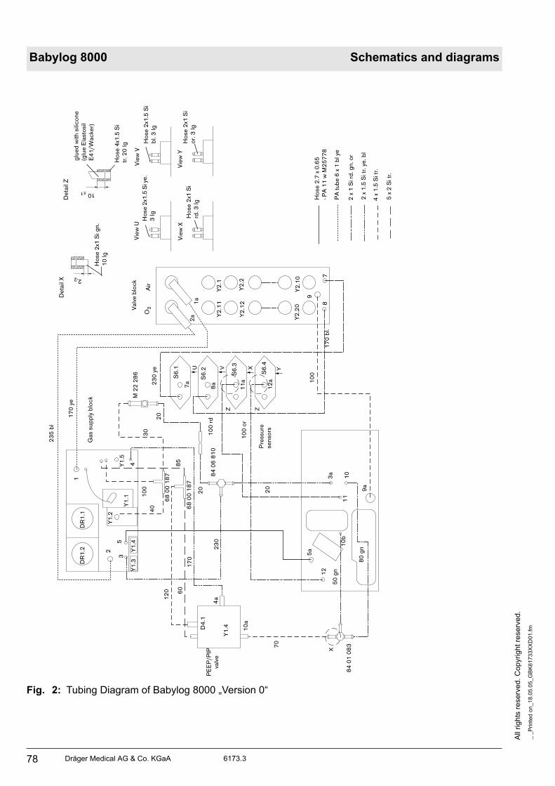
All
rig
hts
re
se
rve
d.
Co
pyrig
ht
rese
rve
d.
_ _
Pri
nte
d o
n_
18
.05
.05
_G
BK
617
33X
XD
01
.fm
78 Dräger Medical AG & Co. KGaA 6173.3
Babylog 8000 Schematics and diagrams
Fig. 2: Tubing Diagram of Babylog 8000 „Version 0“
YXVZ Z
U
X
12
0 60
23
5 b
l
17
0 y
e
17
0
70
50
gn
80
gn
10
0
20
10
0 o
r
10
0 r
d
17
0 b
l.
23
0 y
e
23
0
20
20
30
De
tail
X
Ho
se
2x1
Si g
n.
10
lg
2-2
glu
ed
with
sili
co
ne
(glu
e E
lasto
sil
E4
1/W
ac
ke
r)
Ho
se
4x1
.5 S
i
tr. 2
0 lg
De
tail
Z
10 ±1
Vie
w Y
Vie
w X
Vie
w U
Vie
w V
Ho
se
2x1
Si
or.
3 lg
Ho
se
2x1
Si
rd. 3
lg
Ho
se
2x1
.5 S
i ye
.
3 lg
Ho
se
2x1
.5 S
i
bl.
3 lg
O2
Air
2a
1a
Y2
.10
Y2
.20
Y2
.12
Y2
.2
Y2
.1Y
2.1
1
78
9
12
aS
6.4
S6
.1
S6
.2
S6
.3
11
a
8a7a
M 2
2 2
86
84
06
81
0
Gas s
up
ply
blo
ck
68
00
18
7
40
10
0
1D
R1
.2D
R1
.1
53
2 Y1
.4Y
1.3
Y1
.5Y
1.1
Y1
.2
4
68
00
18
7
85
Y1
.4D4
.1
4a
10
a
84
01
08
3
12
5a
10
b1
1
3a
10
9a
PE
EP
/PIP
valv
e
Pre
ssu
re
se
nso
rs
Valv
e b
loc
k
Ho
se
2.7
x 0
.65
- PA
11
w M
25
77
8
PA
tu
be
6 x
1 b
l ye
2 x
1 S
i rd
. g
n. o
r
2 x
1.5
Si tr
. ye
. b
l
4 x
1.5
Si tr
.
5 x
2 S
i tr
.

Dräger Medical AG & Co. KGaA 6173.3
All
rig
hts
reserv
ed.
Copyright
rese
rved.
_ _
Pri
nte
d o
n_
18
.05
.05
_G
BK
61
73
3X
XD
01
.fm
79
Schematics and diagrams Babylog 8000
Fig. 3: Function Diagram of Babylog 8000 „Version 1“
5 E
xpir
ato
ry v
alv
e
5a
10
bE
xp.
Insp
.
11
a
11
E
P
Y5
.1
12
12
a
6 P
ressu
re
me
asu
rem
en
t
P
E
S6
.4
S6
.3R
3.3
R3
.1
10
3 I
nsp
irato
ry b
lock
O2
E
Y3
.1Y3
.2
F3
.1
D3.1
R3
.2
10
a
Y4
.1
4 P
EE
P/P
IP v
alv
e
R1
.1
6 V
alv
e b
lock
Y2
.11
Y2
.12
Y2
.20
R2
.11
R2
.12
R2
.20
R2
.10
R2
.2R
2.1Y
2.1
Y2
.2Y
2.1
0
1a 7 8 2a
2
4a
S6
.2
PE 8
a7
a
S6
.1
PE
6 P
ressu
re m
easu
rem
en
t
O2
Air
F1
.2
F1
.1
D1
.2
D1
.1
DR
1.2
DR
1.1
Y1
.5
6n
oc
nc
Y1
.2
no
Y1
.1
c
5
1 G
as s
up
ply
blo
ck
Y1
.4
4
Y1
.3
3
nc
nc
9
9a
Y3
.3
Ve
rsio
n 1
up
to
AR
DL
(O
ct.
91
)
with
ou
t spri
ng
(2
5m
ba
r in
va
lve
Y 3
.3
with
ou
t P
ressu
re lim
itin
g v
alv
e (
85
mb
ar)
at

All
rig
hts
re
se
rve
d.
Co
pyrig
ht
rese
rve
d.
_ _
Pri
nte
d o
n_
18
.05
.05
_G
BK
617
33X
XD
01
.fm
80 Dräger Medical AG & Co. KGaA 6173.3
Babylog 8000 Schematics and diagrams
Fig. 4: Tubing Diagram of Babylog 8000 „Version 1“
YXVZ Z
U
X
15
0
60
23
5 b
l.
17
0 y
e
23
0
70
50
gn
10
0
20
10
0 o
r
10
0 r
d
17
0 b
l.
23
0 y
e
20
20
De
tail
X
Ho
se
2x1
Si g
n.
10
lg
2-2
glu
ed
with
sili
co
ne
(g
lue
Ela
sto
sil
E4
1/W
acke
r)
Ho
se
4x1
.5 S
i tr
.
20
lg
De
tail
Z 10 ±1
Vie
w Y
Vie
w X
Vie
w U
Vie
w V
Ho
se
2x1
Si
rd. 3
lg
Ho
se
2x1
.5 S
i
ye. 3
lg
Valv
e b
loc
k
O2
Air
2a
1a Y
2.1
0Y
2.2
0
Y2
.12
Y2
.2
Y2
.1Y
2.1
1
78
9
12
a
S6
.4
S6
.1
S6
.2
S6
.3
11
a
8a7a
M 2
2 2
86
84
06
81
0
Gas s
up
ply
blo
ck
68
00
18
7
40
1001
DR
1.2
DR
1.1
532
Y1
.4Y
1.3
Y1
.5Y
1.1
Y1
.2
4 68
00
18
7
85
Y4
.1
D4
.1
4a
10
a
12
5a
10
b1
1
3a
10
9a
PE
EP
/PIP
valv
e
Pre
ssu
re
se
nso
rs8
4 0
53
63
Ho
se
2x1
S
rd. 3
lg
Ho
se
2x1
.5 S
i
bl.
3 lg
84 01083
Ho
se
2.7
x 0
.65
- PA
11
w M
25
77
8
PA
tu
be
6 x
1 b
l. ye
2 x
1 S
i rd
. g
n. o
r
2 x
1.5
Si tr
. ye
. b
l.
4 x
1.5
Si tr
.
5 x
2 S
i tr
.

Dräger Medical AG & Co. KGaA 6173.3
All
rig
hts
reserv
ed.
Copyright
rese
rved.
_ _
Pri
nte
d o
n_
18
.05
.05
_G
BK
61
73
3X
XD
01
.fm
81
Schematics and diagrams Babylog 8000
Fig. 5: Function Diagram of Babylog 8000 „Version 2“
6 P
ressu
re m
easu
rem
en
t
1 G
as s
up
ply
blo
ck
6 V
alv
e b
lock
5 E
xpir
ato
ry v
alv
e
6 P
ressu
re
me
asu
rem
en
t
Air
O2
F3
.1
F1
.2
F1
.1
D3.1
D1
.2
D1
.1
DR
1.2
DR
1.1
Insp
.
Exp
.
Y1
.5
6
Y1
.4
Y1
.3
Y1
.2
Y1
.1n
c
ccn
o
no 5
43
EP
PE
S6
.2S
6.1 7a
R2
.11
R2
.12
R2
.20
R2
.10
R2
.2R
2.1
Y2
.20
Y2
.12
Y2
.11
Y2
.10
Y2
.2Y
2.1
1a 87 2a
4a
R1
.1
4 P
EE
P/P
IP v
alv
e
Y4
.1
10
a
R3
.3
Y5
.1
10
b
5a
12
12
a
E E
O2
PPS
6.3
S6
.4
11
11
a
E
99a
10
S3
.1Y
3.3
Y3
.1
R3
.1
R3
.2
nc ncn
c
Ve
rsio
n 2
(a
s o
f 1
99
2)
with
ou
t spri
ng
(25
mba
r in
va
lve
Y 3
.3)
with
ou
t P
ressu
re lim
itin
g v
alv
e (
85
mb
ar)
in
PE
EP
valv
e
4,8
mL
D 4
.1
Y3
.23 I
nsp
irato
ry b
loc
k
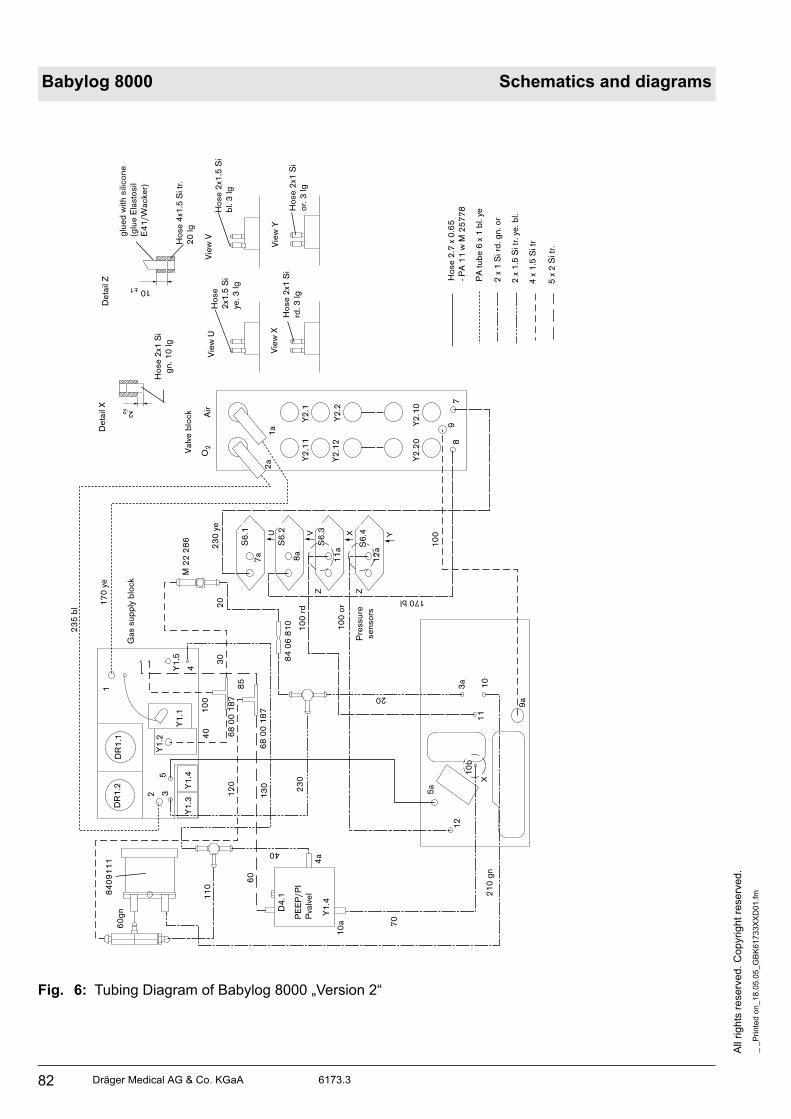
All
rig
hts
re
se
rve
d.
Co
pyrig
ht
rese
rve
d.
_ _
Pri
nte
d o
n_
18
.05
.05
_G
BK
617
33X
XD
01
.fm
82 Dräger Medical AG & Co. KGaA 6173.3
Babylog 8000 Schematics and diagrams
Fig. 6: Tubing Diagram of Babylog 8000 „Version 2“
YXVZ Z
U
X
12
0
60
23
5 b
l 17
0 y
e
13
0
70
21
0 g
n
10
0
20
10
0 o
r
10
0 r
d
170 bl
23
0 y
e
23
0
20
30
De
tail
X
Ho
se
2x1
Si
gn
. 1
0 lg
2-2
glu
ed
with
sili
co
ne
(glu
e E
lasto
sil
E4
1/W
ac
ke
r)
Ho
se
4x1
.5 S
i tr
.
20
lg
De
tail
Z
10±1
Vie
w Y
Vie
w X
Vie
w U
Vie
w V
Ho
se
2x1
Si
or.
3 lg
Ho
se
2x1
Si
rd. 3
lg
Ho
se
2x1
.5 S
i
ye. 3
lg
Ho
se
2x1
.5 S
i
bl.
3 lg
Valv
e b
loc
k
O2
Air
2a
1a
Y2
.10
Y2
.20
Y2
.12
Y2
.2
Y2
.1Y
2.1
1
78
9
12
a
S6
.4
S6
.1
S6
.2
S6
.3
11
a
8a
7a
M 2
2 2
86
84
06
81
0
Gas s
up
ply
blo
ck
68
00
18
7
40
10
0
1
DR
1.2
DR
1.1
532
Y1
.4Y
1.3
Y1
.5Y
1.1
Y1
.2
4
68
00
18
7
85
Y1
.4
D4
.1
4a
10
a
12
5a
10
b
11
3a
10
9a
PE
EP
/PI
Pva
lve
l
Pre
ssu
re
se
nso
rs
Ho
se
2.7
x 0
.65
- PA
11
w M
25
77
8
PA
tu
be
6 x
1 b
l. ye
2 x
1 S
i rd
. g
n. o
r
2 x
1.5
Si tr
. ye
. b
l.
4 x
1.5
Si tr
5 x
2 S
i tr
.
11
0
40
84
09
11
1
60
gn

Dräger Medical AG & Co. KGaA 6173.3
All
rig
hts
reserv
ed.
Copyright
rese
rved.
_ _
Pri
nte
d o
n_
18
.05
.05
_G
BK
61
73
3X
XD
01
.fm
83
Schematics and diagrams Babylog 8000
Fig. 7: Function Diagram of Babylog 8000/Babylog 8000 SC „Version 3“
6 P
ressu
re m
easu
rem
en
t
1 G
as s
up
ply
blo
ck
6 V
alv
e b
lock
5 E
xpir
ato
ry v
alv
e
6 P
ressu
re
me
asu
rem
en
t
Air
O2
F3
.1
F1
.2
F1
.1
D3.1
D1
.2
D1
.1
DR
1.2
R1
.1
Insp
.
Exp
.
Y1
.5
6
Y1
.4
Y1
.3
Y1
.2
Y1
.1n
c c
cn
o
no 5
43
EP
P
E
S6
.2S
6.1 7a
R2
.11
R2
.12
R2
.20
R2
.10
R2
.2R
2.1
Y2
.20
Y2
.12
Y2
.11
Y2
.10
Y2
.2Y
2.1
1a
87
2a
4a
R1
.1
4 P
EE
P/P
IP v
alv
e
Y4
.1
10
a
R3
.3
Y5
.1
10
b
5a
12
12
a
E E
O2
PPS
6.3
S6
.4
11
11
a
E
99a
10
S3
.1
Y3
.3
Y3
.1
R3
.1
R3
.2
nc
nc
nc
Ve
rsio
n 3
(s
am
e a
s V
ers
ion
2 +
a n
eb
uli
ze
r)
A n
eb
uliz
er
ca
n b
e r
etr
ofitt
ed
in
Ve
rsio
ns 0
, 1
an
d 2
.
4,8
m
D 4
.1
DR
1.1
Y 1
.6
Y3
.23 I
nsp
irato
ry b
lock
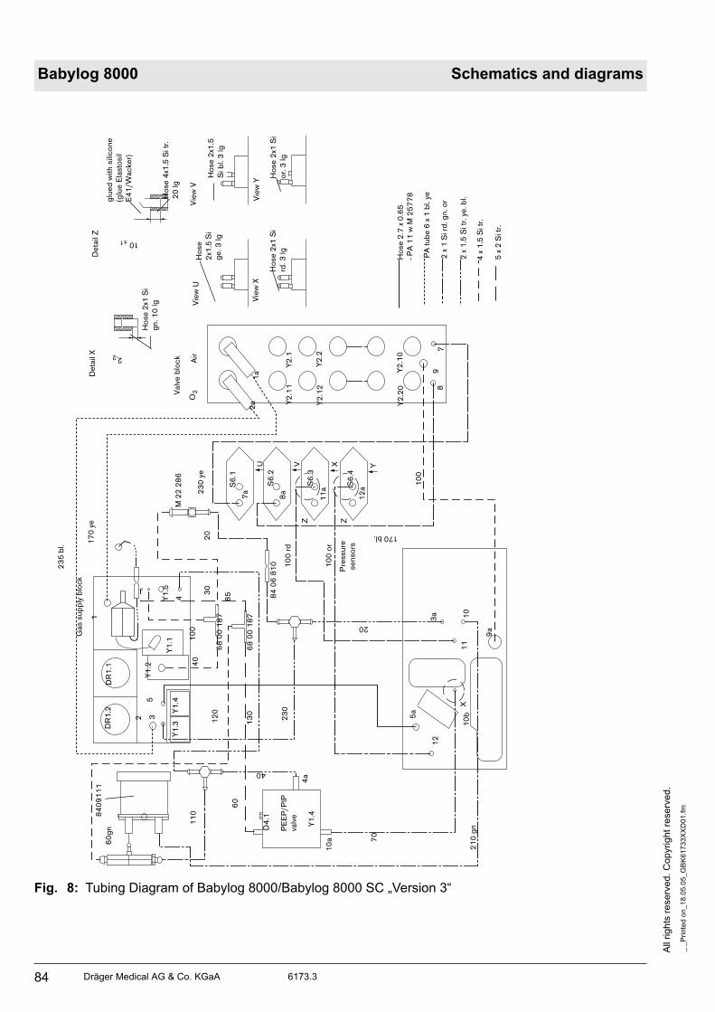
All
rig
hts
re
se
rve
d.
Co
pyrig
ht
rese
rve
d.
_ _
Pri
nte
d o
n_
18
.05
.05
_G
BK
617
33X
XD
01
.fm
84 Dräger Medical AG & Co. KGaA 6173.3
Babylog 8000 Schematics and diagrams
Fig. 8: Tubing Diagram of Babylog 8000/Babylog 8000 SC „Version 3“
YXVZ Z
U
X
12
0
60
23
5 b
l.
17
0 y
e
13
0
70
21
0 g
n
10
0
20
10
0 o
r
10
0 r
d
170 bl.
23
0 y
e
23
0
20
30
De
tail
X
Ho
se
2x1
Si
gn
. 1
0 lg
2-2
glu
ed
with
sili
co
ne
(glu
e E
lasto
sil
E4
1/W
ac
ke
r)
Ho
se
4x1
.5 S
i tr
.
20
lg
De
tail
Z
10±1
Vie
w Y
Vie
w X
Vie
w U
Vie
w V
Ho
se
2x1
Si
or.
3 lg
Ho
se
2x1
Si
rd. 3
lg
Ho
se
2x1
.5 S
i
ge
. 3
lg
Ho
se
2x1
.5
Si b
l. 3
lg
Valv
e b
loc
k
O2
Air
2a
1a Y
2.1
0Y
2.2
0
Y2
.12
Y2
.2
Y2
.1Y
2.1
1
78
9
12
a
S6
.4
S6
.1
S6
.2
S6
.3
11
a
8a
7a
M 2
2 2
86
84
06
81
0
Gas s
up
ply
blo
ck
68
00
18
7
40
10
0
1
DR
1.2
DR
1.1
532
Y1
.4Y
1.3
Y1
.5Y
1.1
Y1
.2
4
68
00
18
7
85
Y1
.4
D4
.1
4a
10
a
12
5a
10
b1
1
3a 10
9a
PE
EP
/PIP
valv
e
Pre
ssu
re
se
nso
rs
Ho
se
2.7
x 0
.65
- PA
11
w M
25
77
8
PA
tu
be
6 x
1 b
l. ye
2 x
1 S
i rd
. g
n. o
r
2 x
1.5
Si tr
. ye
. b
l.
4 x
1.5
Si tr
.
5 x
2 S
i tr
.
11
0
40
84
09
11
1
60
gn

Dräger Medical AG & Co. KGaA 6173.3
All
rig
hts
reserv
ed.
Copyright
rese
rved.
_ _
Pri
nte
d o
n_
18
.05
.05
_G
BK
61
73
3X
XD
01
.fm
85
Schematics and diagrams Babylog 8000
Fig. 9: Function Diagram of Babylog 8000/Babylog 8000 SC „Version 3“ with
conversion kit „purge flow“
Important: This conversion kit is only necessary when pressure measuring problems
occur in the HFV mode while the Aquamod is connected.
6 P
ressu
re m
easu
rem
en
t
1 G
as s
up
ply
blo
ck
6 V
alv
e b
loc
k
5 E
xpir
ato
ry v
alv
e
6 P
ressu
re m
easu
rem
en
t
Air
O2
F3
.1
F1
.2
F1
.1
D3.1
D1
.2
D1
.1
DR
1.2
R1
.1
Insp
.
Exp
.
Y1
.5
6
Y1
.4
Y1
.3
Y1
.2
Y1
.1n
c c
cn
o
no
5
43
EP
PE
S6
.2S
6.1
7a
R2
.11
R2
.12
R2
.20
R2
.10
R2
.2R
2.1
Y2
.20
Y2
.12
Y2
.11
Y2
.10
Y2
.2Y
2.1
1a
87
2a
4a
R1
.1
4 P
EE
P/P
IP v
alv
e
Y4
.1
10
a
R3
.3
Y5
.1
10
b
5a
12
12
a
E E
O2
PPS
6.3
S6
.4
11
11
a
E
99a
10
S3
.1
Y3
.3
Y3
.1
R3
.1
R3
.2
nc
nc
nc
Ve
rsio
n 3
(s
am
e a
s V
ers
ion
2 +
a n
eb
uli
ze
r) w
ith
co
nve
rsio
n k
it “
pu
rge
flo
w”
4,8
D 4
.1
DR
1.1
Y 1
.6
Y3
.23 In
sp
irato
ry b
lock

All
rig
hts
re
se
rve
d.
Co
pyrig
ht
rese
rve
d.
_ _
Pri
nte
d o
n_
18
.05
.05
_G
BK
617
33X
XD
01
.fm
86 Dräger Medical AG & Co. KGaA 6173.3
Babylog 8000 Schematics and diagrams
Fig.10: Tubing Diagram of Babylog 8000/ Babylog 8000 SC (Version 3 with
conversion kit „purge flow“)
The restrictor for the purge flow is integrated in the silicone hose (84 11 459)
YXVZ Z
U
X
12
0
60
17
0 y
e
13
0
70
21
0 g
n
10
0
20
10
0 o
r
10
0 r
d
170 bl.
23
0 y
e
23
0
20
30
De
tail
X
Ho
se
2x1
Si
gn
. 1
0 lg
2-2
glu
ed
with
sili
co
ne
(glu
e E
lasto
sil
E4
1/W
acke
r)
Ho
se
4x1
.5 S
i tr.
20
lg
De
tail
Z
10 ±1
Vie
w Y
Vie
w X
Vie
w U
Vie
w V
Ho
se
2x1
Si
or.
3 lg
Ho
se
2x1
Si
rd. 3
lg
Ho
se
2x1
.5 S
i
ge
. 3
lg
Ho
se
2x1
.5 S
i
bl.
3 lg
Valv
e b
loc
k
O2
Air
2a
1a Y
2.1
0Y
2.2
0
Y2
.12
Y2
.2
Y2
.1Y
2.1
1
78
9
12
aS6
.4
S6
.1
S6
.2
S6
.3
11
a
8a
7a
M 2
2 2
86
84
06
81
0
Ga
s s
up
ply
blo
ck
68
00
18
7
40
10
0
1
DR
1.2
DR
1.
532
Y1
.4Y
1.3
Y1
.5Y
1.1
Y1
.2
4
68
00
18
7
85
Y1
.4
D4
.1
4a
10
a
12
5a
10
b1
1
3a 10
9a
PE
EP
/PI
Pva
lve
Pre
ssu
re
se
nso
rs
Ho
se
2.7
x 0
.65
- PA
11
w M
25
77
8
PA
tu
be
6 x
1 b
l. ye
2 x
1 S
i rd
. g
n. o
r
2 x
1.5
Si tr
. ye
. b
l.
4 x
1.5
Si tr
.
5 x
2 S
i tr
.
11
040
84
09
11
16
0g
n
84 11 459

Dräger Medical AG & Co. KGaA 6173.3
All
rig
hts
reserv
ed.
Copyright
rese
rved.
_ _
Pri
nte
d o
n_
18
.05
.05
_G
BK
61
73
3X
XD
01
.fm
87
Schematics and diagrams Babylog 8000
Fig. 11: Function Diagram of Babylog 8000/Babylog 8000 plus/Babylog 8000 SC „Version 3.10“
6 P
ressu
re m
easu
rem
en
t
1 G
as s
up
ply
blo
ck
6 V
alv
e b
loc
k
5 E
xpir
ato
ry v
alv
e
6 P
ressu
re
me
asu
rem
en
t
Air
O2
F3
.1
F1
.2
F1
.1
D3.1
D1
.2
D1
.1
DR
1.2
R1
.1
Insp
.
Exp
.
Y1
.5
6
Y1
.4
Y1
.3
Y1
.2
Y1
.1n
c c
cn
o
no
5
43
EP
P
E
S6
.2S
6.1 7a
R2
.11
R2
.12
R2
.20
R2
.10
R2
.2R
2.1
Y2
.20
Y2
.12
Y2
.11
Y2
.10
Y2
.2Y
2.1
1a
87
2a
4a
R1
.1
4 P
EE
P/P
IP v
alv
e
Y4
.1
10
a
R3
.3
Y5
.1
10
b
5a
12
12
a
E E
O2
PPS
6.3
S6
.4
11
11
a
E
99a
1
S3
.1
Y3
.3
Y3
.1
R3
.1
R3
.2
nc
nc
nc
Ve
rsio
n 3
.10
Ve
rsio
n 3
.10
with
le
aka
ge
co
mp
en
sa
tio
n (
avo
ids a
su
bse
qu
etn
4,8
mL
D 4
.1
DR
1.1
Y 1
.6
Y3
.3 I
nsp
irato
ry b
lock
R6
.1R
6.2

All
rig
hts
re
se
rve
d.
Co
pyrig
ht
rese
rve
d.
_ _
Pri
nte
d o
n_
18
.05
.05
_G
BK
617
33X
XD
01
.fm
88 Dräger Medical AG & Co. KGaA 6173.3
Babylog 8000 Schematics and diagrams
Fig.12: Tubing Diagram of Babylog 8000/Babylog 8000 plus/Babylog 8000 SC „Version 3.10“
YXVZ Z
U
X
12
0
60
23
5 b
l. 17
0 y
e
13
0
70
21
0 g
n
10
020
10
0 o
r
10
0 r
d
170 bl.
16
0 y
e
23
0
20
30
De
tail
X
Ho
se
2x1
Si g
n. 1
0 lg
2-2
glu
ed
with
sili
co
ne
(glu
e E
lasto
sil
E4
1/W
ac
ke
r)
Ho
se
4x1
.5 S
i
tr. 2
0 lg
De
tail
Z
10±1
Vie
w Y
Vie
w X
Vie
w U
Vie
w V
Ho
se
2x1
Si
or.
3 lg
Ho
se
2x1
Si rd
. 3
lg
Ho
se
2x1
.5 S
i
ge
. 3
lg
Ho
se
2x1
.5
Si b
l. 3
lg
Valv
e b
loc
k
O2
Air
2a
1a Y2
.10
Y2
.20
Y2
.12
Y2
.2
Y2
.1Y
2.1
1
78
9
12
a
S6
.4
S6
.1
S6
.2
S6
.3
11
a
8a
7a
M 2
2 2
86
84
06
81
0
Gas s
up
ply
68
00
18
7
40
10
0
1
DR
1.
DR
1.
532
Y1
.4Y
1.3
Y1
.Y
1.1
Y1
.2
4
68
00
18
7
85
Y1
.4
D4
.1
4a
10
a
12
5a
10
b1
1
3a
10
9a
PE
EP
/PI
Pva
lve
Pre
ssu
re
se
nso
rs
Ho
se
2.7
x 0
.65
- PA
11
w M
25
77
8
PA
tu
be
6 x
1 b
l. ye
2 x
1 S
i rd
. g
n. o
r
2 x
1.5
Si tr
. ye
. b
l.
4 x
1.5
Si tr
5 x
2 S
i tr
.
11
0
40
84
09
11
16
0g
n
20
20
20
84
11
41
1
40 bl.
84
11
41
1
110 bl.

89
Error List

90

Dräger Medical AG & Co. KGaA
All
rig
hts
reserv
ed.
Copyright
rese
rved.
_ _
Pri
nte
d o
n_
18
.05
.05
_G
B_K
617
33
XX
FL
1.f
m
91
Error List Babylog 8000
1 Error messages
If the system detects a hardware or software error, it displays an error number on the LC display.
The error numbers are subdivided into the following ranges:
Number Range
000 to 999 CPU PCB 68000
100 to 199 Flow PCB
200 to 299 Monitoring PCB
300 to 399 I/O PCB
400 to 499 Communication PCB
500 to 599 CPU PCB 68000
600 to 699 Flow PCB
700 to 799 Monitoring PCB
800 to 899 Errors detected by the Monitoring PCB. If this error
occurs, partly more detailed error numbers are
displayed on the 7-segment display of the Monitoring
PCB.

All
rig
hts
re
se
rve
d.
Co
pyrig
ht
rese
rve
d.
_ _
Pri
nte
d o
n_
18
.05
.05
_G
B_K
61
733
XX
FL
1.f
m
92 Dräger Medical AG & Co. KGaA
Babylog 8000 Error List
2 List of device error messages
If an error occurs, read the Babylog 8000/8000 SC error messages
on the 7-segment display of the Monitoring PCB!
Table 1: Device error messages
Display error
number
Monitoring PCB
error number
Meaning
000 CPU PCB ROM error
001 CPU PCB RAM error
002 One or more keys jammed
(continuously pressed).
003 Data transmission between
CPU PCB and the dual-port RAM
of the Monitoring PCB is
interfered.
004 Watchdog error or CPU PCB reset
005 CPU PCB error: The CPU PCB is
in the boot phase although the
Monitoring PCB is running in the
background (e.g. by a CPU PCB
reset).
006 Vector error or CPU PCB reset
500 Software error: Incorrect operating
mode, for example, error in
storage of operational data in the
time-keeper RAM on the CPU
PCB.
501 Monitoring PCB does not function
correctly
502 Flow PCB does not function
correctly
503 CPU PCB software error:
Impermissible breathing phase
504 CPU PCB software error

Dräger Medical AG & Co. KGaA
All
rig
hts
reserv
ed.
Copyright
rese
rved.
_ _
Pri
nte
d o
n_
18
.05
.05
_G
B_K
617
33
XX
FL
1.f
m
93
Error List Babylog 8000
Display error
number
Monitoring PCB
error number
Meaning
505 CPU PCB software error
506 to 513 CPU PCB software error.
800 FiO2 too high by more than 10
vol.%.
801 FiO2 too low by more than 10
vol.%.
802 FiO2 measurement deviation
between master (CPU PCB and
I/O PCB) and Monitoring PCB is
too high.
803 Measured Pinsp to potentiometer
setting Pinsp too high by more
than 25 mbar (cmH2O).
804 Pinsp greater than 110 mbar
(cmH2O).
805 Pinsp less than -5 mbar (cmH2O)
806 Flow measurement on the Flow
PCB is faulty
807 Potentiometer evaluation is faulty:
Master (CPU PCB and
Frontcontroller PCB) and
Monitoring PCB read different
values.
809 Battery or battery charge faulty
(battery voltage < 7 V)
Table 1: Device error messages

All
rig
hts
re
se
rve
d.
Co
pyrig
ht
rese
rve
d.
_ _
Pri
nte
d o
n_
18
.05
.05
_G
B_K
61
733
XX
FL
1.f
m
94 Dräger Medical AG & Co. KGaA
Babylog 8000 Error List
Display error
number
Monitoring PCB
error number
Meaning
810 Mains switch auxiliary contact is
faulty, (battery voltage > 12 V)
811 Safety relay on the Pneumatic
Control PCB is faulty.
During the boot sequence, master
CPU PCB and Monitoring PCB do
not run synchronously.
813 Valves driver monitoring on the
Pneumatic Analog PCB faulty.
Applies to software versions 3.n
and 4.n only: Air and O2 pressure
supplies are not connected upon
power-on.
815 +27 V voltage supply is faulty.
816 Valve drive is faulty.
817 Loudspeaker or feedback is faulty.
818 Babylog 8000/8000 SC device
temperature is too high.
819 Temperature measurement is
faulty.
820 +15 V comparator is faulty.
Table 1: Device error messages

Dräger Medical AG & Co. KGaA
All
rig
hts
reserv
ed.
Copyright
rese
rved.
_ _
Pri
nte
d o
n_
18
.05
.05
_G
B_K
617
33
XX
FL
1.f
m
95
Error List Babylog 8000
Display error
number
Monitoring PCB
error number
Meaning
-15 V comparator is faulty.
+5 V comparator is faulty.
+27 V comparator is faulty.
822 O2 calibration sequence is faulty.
823 The CPU PCB is not functioning
properly, according to the
Monitoring PCB.
824 Timer in time-keeper RAM on the
CPU PCB is faulty.
825 Power pack is faulty, +15 V error.
Power pack is faulty, -15 V error.
Power pack is faulty, +5 V error.
Power pack is faulty, +27 V error.
The Monitoring PCB is faulty.
Table 1: Device error messages

All
rig
hts
re
se
rve
d.
Co
pyrig
ht
rese
rve
d.
_ _
Pri
nte
d o
n_
18
.05
.05
_G
B_K
61
733
XX
FL
1.f
m
96 Dräger Medical AG & Co. KGaA
Babylog 8000 Error List
Display error
number
Monitoring PCB
error number
Meaning
RAM on Monitoring PCB is faulty.
ROM on Monitoring PCB is faulty.
Powerfail from the power pack.
Watchdog test on Monitoring PCB
after power-on.
Watchdog test on Monitoring PCB
completed.
Master (CPU PCB) did not start
after the Babylog 8000/8000 SC
start.
Table 1: Device error messages
97
Annex
Spare parts list
Test List
Technical Information according to EMC standard IEC/EN 60601-1-2:2001

98

Spare parts catalogue
Babylog 8000
Because you careEmergency Care - OR/Anesthesia - Critical Care - Perinatal Care - Home Care
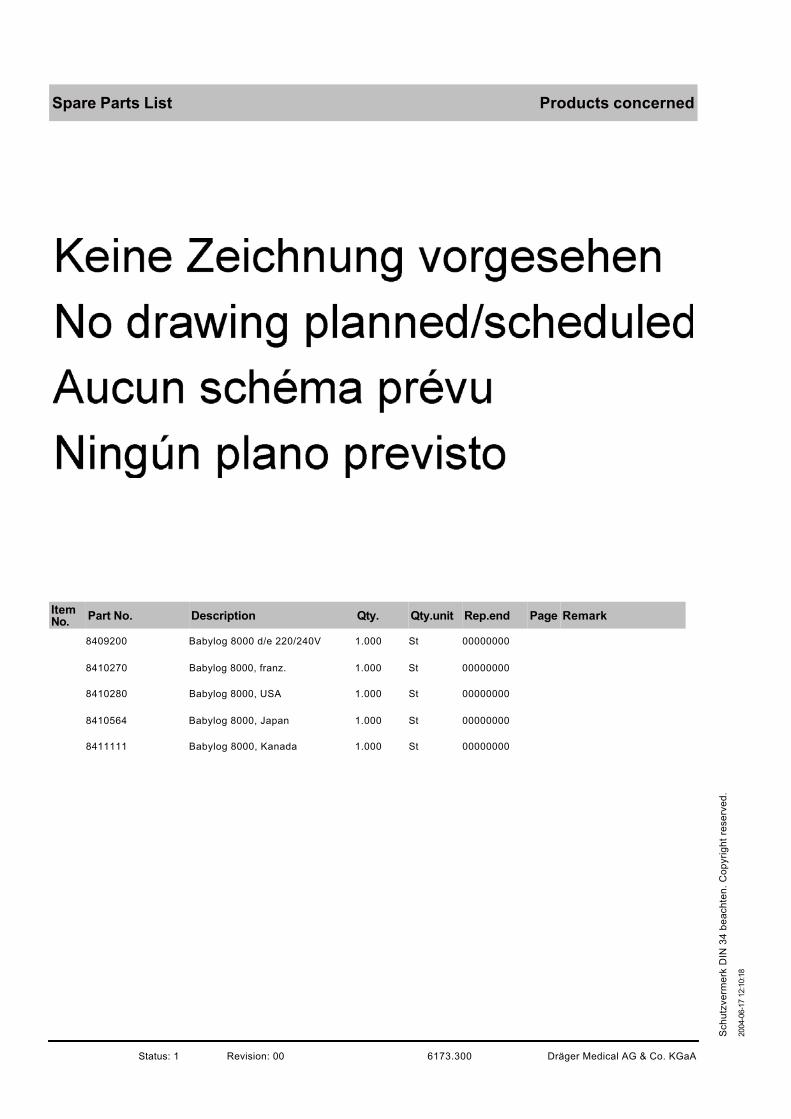
Products concernedSpare Parts List
ItemNo.
Part No. Description Qty. Qty.unit Rep.end Page Remark
8409200 Babylog 8000 d/e 220/240V 1.000 St 00000000
8410270 Babylog 8000, franz. 1.000 St 00000000
8410280 Babylog 8000, USA 1.000 St 00000000
8410564 Babylog 8000, Japan 1.000 St 00000000
8411111 Babylog 8000, Kanada 1.000 St 00000000
Dräger Medical AG & Co. KGaA6173.300Revision: 00Status: 1
2004-0
6-1
7 1
2:1
0:1
8
Sch
utz
ve
rme
rk D
IN 3
4 b
ea
ch
ten
. C
op
yri
gh
t re
se
rve
d.
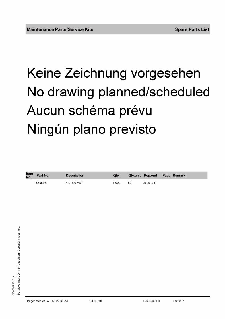
Maintenance Parts/Service Kits Spare Parts List
ItemNo.
Part No. Description Qty. Qty.unit Rep.end Page Remark
8305367 FILTER MAT 1.000 St 29991231
Dräger Medical AG & Co. KGaA 6173.300 Revision: 00 Status: 1
2004-0
6-1
7 1
2:1
0:1
8
Sch
utz
ve
rme
rk D
IN 3
4 b
ea
ch
ten
. C
op
yri
gh
t re
se
rve
d.

Accessories for operationSpare Parts List
ItemNo.
Part No. Description Qty. Qty.unit Rep.end Page Remark
8410813 SCHLAUCHSET AQUAMOD 1.000 St 00000000
8411148 SCHLAUCHSET AQUAMOD HFV 1.000 St 00000000
2M85337 COMPACT RAIL 1.000 St 00000000
8410718 WANDKONSOLE BABYLOG 8000 1.000 St 00000000
2M19460 AUFNAHMEPLATTE 1.000 St 00000000
8409609 HINGED ARM 240-DEGR. 1.000 St 00000000
8411075 SCHLAUCHHALTER 1.000 St 00000000
8410565 AQUAMOD 100V 1.000 St 20051231
8410600 Anfeuchtermodul 1.000 St 00000000
8410535MODULHALTER F.INKUBATOR8000
1.000 St 00000000
8410536 Modulhalter 1.000 St 00000000
M29239 AIR-CONNECTING HOSE 3M 1.000 St 00000000
M29259 AIR-CONNECTING HOSE 5M 1.000 St 00000000
8410250 AQUAMOD 220-240 V 1.000 St 00000000
Dräger Medical AG & Co. KGaA6173.300Revision: 00Status: 1
2004-0
6-1
7 1
2:1
0:1
8
Sch
utz
ve
rme
rk D
IN 3
4 b
ea
ch
ten
. C
op
yri
gh
t re
se
rve
d.

Accessories for operation Spare Parts List
ItemNo.
Part No. Description Qty. Qty.unit Rep.end Page Remark
M29231 O2-CONNECTION HOSE 3M 1.000 St 00000000 3m blue
M29251 O2-CONNECTING HOSE 5M 1.000 St 00000000
Dräger Medical AG & Co. KGaA 6173.300 Revision: 00 Status: 1
2004-0
6-1
7 1
2:1
0:1
8
Sch
utz
ve
rme
rk D
IN 3
4 b
ea
ch
ten
. C
op
yri
gh
t re
se
rve
d.

optional accessorySpare Parts List
ItemNo.
Part No. Description Qty. Qty.unit Rep.end Page Remark
8407475 PEEP-Valve (Ambu-PEEP) 1.000 St 00000000
2105438SAUERSTOFFSCHLAUCH(1190520) RE
1.000 St 20001231
8409738 KONDENSATABSCHEIDER (IN/EX)1.000 St 00000000
8411025 RUESTSATZ 1.000 St 00000000
8411023 KUPPLUNG 1.000 St 00000000
8405752 CONE 22A 1.000 St 29991231
M19351KONNEKTORF.TRACHEALTUB.11
1.000 St 00000000
8411024 Dichtstopfen 1.000 St 00000000
8405000MEDICAMENT NEBULIZER (PNEU)
1.000 St 20051231
2120941 Baby-Resutator 2000 1.000 St 00000000
Dräger Medical AG & Co. KGaA6173.300Revision: 00Status: 1
2004-0
6-1
7 1
2:1
0:1
8
Sch
utz
ve
rme
rk D
IN 3
4 b
ea
ch
ten
. C
op
yri
gh
t re
se
rve
d.

Sets for stirilisatio Spare Parts List
ItemNo.
Part No. Description Qty. Qty.unit Rep.end Page Remark
8410813 SCHLAUCHSET AQUAMOD 1.000 St 00000000
8411148 SCHLAUCHSET AQUAMOD HFV 1.000 St 00000000
8408950 EXSP.-Ventil Babylog 8000 1.000 St 00000000
8410185 Y-Stueck mit Flow-Sensor 1.000 St 00000000
8409625 WASSERSCHLAUCH AQUAMOD 1.000 St 00000000
8409840 Pumpenaggregat Aquamod 1.000 St 00000000
8408647 Temp.-Sensor Aquamod 1.000 St 00000000
Dräger Medical AG & Co. KGaA 6173.300 Revision: 00 Status: 1
2004-0
6-1
7 1
2:1
0:1
8
Sch
utz
ve
rme
rk D
IN 3
4 b
ea
ch
ten
. C
op
yri
gh
t re
se
rve
d.

Maintenance- and SparepartsSpare Parts List
ItemNo.
Part No. Description Qty. Qty.unit Rep.end Page Remark
8410813 SCHLAUCHSET AQUAMOD 1.000 St 00000000
8411148 SCHLAUCHSET AQUAMOD HFV 1.000 St 00000000
8408950 EXSP.-Ventil Babylog 8000 1.000 St 00000000
8410185 Y-Stueck mit Flow-Sensor 1.000 St 00000000
8410179 Flowsensor 5er Set BL8000 1.000 St 00000000
8411130 ISO15 Flow-Sensor-Geh. 1.000 St 00000000
6850645CAPSULE FOR O2-DETECTOR(DW)
1.000 St 00000000
8409875TEMPERATURSENSORKABEL 1,2M
1.000 St 00000000
8305367 FILTER MAT 1.000 St 29991231
8410600 Anfeuchtermodul 1.000 St 00000000
8409626 Anschlusskabel Flowsensor 1.000 St 00000000
8409680 Silikonschlauch K 0,12m 1.000 St 00000000
8409636 Siliconschlauch K 0,25m 1.000 St 00000000
8403070 Silikonschlauch K 0,35m 1.000 St 29991231
Dräger Medical AG & Co. KGaA6173.300Revision: 00Status: 1
2004-0
6-1
7 1
2:1
0:1
8
Sch
utz
ve
rme
rk D
IN 3
4 b
ea
ch
ten
. C
op
yri
gh
t re
se
rve
d.

Maintenance- and Spareparts Spare Parts List
ItemNo.
Part No. Description Qty. Qty.unit Rep.end Page Remark
8403073 Siliconschlauch K 0,6m 1.000 St 29991231
8403080 Siliconschlauch K 1,0m 1.000 St 29991231
8410819 Schlauch (leicht) 0,12m 1.000 St 00000000
8410817 SCHLAUCH,(LEICHT)0,25M 1.000 St 00000000
8410816 SCHLAUCH,(LEICHT) 0,40M 1.000 St 00000000
8410814 SCHLAUCH,(LEICHT) 0,65M 1.000 St 00000000
8410815 SCHLAUCH,(LEICHT)1,00 M 1.000 St 00000000
8410818 SCHLAUCH,(LEICHT)1,20M 1.000 St 19981231
8409897 DOPPELKONUS 11A 1.000 St 00000000
Dräger Medical AG & Co. KGaA 6173.300 Revision: 00 Status: 1
2004-0
6-1
7 1
2:1
0:1
8
Sch
utz
ve
rme
rk D
IN 3
4 b
ea
ch
ten
. C
op
yri
gh
t re
se
rve
d.
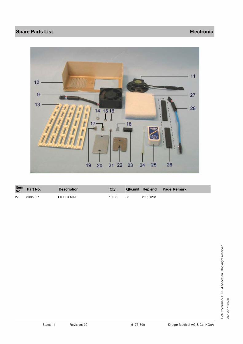
ElectronicSpare Parts List
ItemNo.
Part No. Description Qty. Qty.unit Rep.end Page Remark
27 8305367 FILTER MAT 1.000 St 29991231
Dräger Medical AG & Co. KGaA6173.300Revision: 00Status: 1
2004-0
6-1
7 1
2:1
0:1
8
Sch
utz
ve
rme
rk D
IN 3
4 b
ea
ch
ten
. C
op
yri
gh
t re
se
rve
d.

Cables Spare Parts List
ItemNo.
Part No. Description Qty. Qty.unit Rep.end Page Remark
1 8409626 Anschlusskabel Flowsensor 1.000 St 00000000
Dräger Medical AG & Co. KGaA 6173.300 Revision: 00 Status: 1
2004-0
6-1
7 1
2:1
0:1
8
Sch
utz
ve
rme
rk D
IN 3
4 b
ea
ch
ten
. C
op
yri
gh
t re
se
rve
d.

Trolley normal Spare Parts List
ItemNo.
Part No. Description Qty. Qty.unit Rep.end Page Remark
1-3 8409280 Fahrgestell Babylog 8000 1.000 St 00000000 complete
Dräger Medical AG & Co. KGaA 6173.300 Revision: 00 Status: 1
2004-0
6-1
7 1
2:1
0:1
8
Sch
utz
ve
rme
rk D
IN 3
4 b
ea
ch
ten
. C
op
yri
gh
t re
se
rve
d.

Trolley internationalSpare Parts List
ItemNo.
Part No. Description Qty. Qty.unit Rep.end Page Remark
1-4 8418097 Fahrgestell int. Bl 8000 1.000 St 00000000
Dräger Medical AG & Co. KGaA6173.300Revision: 00Status: 1
2004-0
6-1
7 1
2:1
0:1
8
Sch
utz
ve
rme
rk D
IN 3
4 b
ea
ch
ten
. C
op
yri
gh
t re
se
rve
d.

Instructions for use Spare Parts List
ItemNo.
Part No. Description Qty. Qty.unit Rep.end Page Remark
9028004 GA BL 8000 Schnittstelle de/en 1.000 St 00000000
9028117 GA KOMMUNIKATION E 1.000 St 00000000
9028085 GA-BABYLOG 8000 D/E 1.000 St 00000000
9028175 GA-BABYLOG 8000 D 1.000 St 00000000
9028220 GA-BABYLOG 8000 E 1.000 St 00000000
9028884 GA Babylog 8000 plus 5.n EN 1.000 St 00000000
9028885 GA Babylog 8000 SW 5.N FR 1.000 St 00000000
9028886 GA Babylog 8000 plus 5.N ES 1.000 St 00000000
9028887 GA Babylog 8000 plus 5.N IT 1.000 St 00000000
9028888 GA Babylog 8000 plus 5.N SV 1.000 St 00000000
9028889 GA Babylog 8000 SW 5.n enUS 1.000 St 00000000
9029032 GA Babylog 8000 plus 5.n NL 1.000 St 00000000
9029053 GA-BABYLOG 8000 SW 5.N D 1.000 St 00000000
9029054 GA-BABYLOG 8000 SW 5.N E 1.000 St 00000000
Dräger Medical AG & Co. KGaA 6173.300 Revision: 00 Status: 1
2004-0
6-1
7 1
2:1
0:1
8
Sch
utz
ve
rme
rk D
IN 3
4 b
ea
ch
ten
. C
op
yri
gh
t re
se
rve
d.

Instructions for useSpare Parts List
ItemNo.
Part No. Description Qty. Qty.unit Rep.end Page Remark
9029058 GA Babylog 8000 SW 5.n enCA 1.000 St 00000000
9029427 GA BABYLOG 8000 plus 5.n RU 1.000 St 00000000
9029599 GA BABYVIEW SW 1.n NL 1.000 St 00000000
9037162 Beiblatt f.GAs Babylog 8000 de 1.000 St 00000000
9037447 GA Babylog 8000 plus 5.n hu 1.000 St 00000000
Dräger Medical AG & Co. KGaA6173.300Revision: 00Status: 1
2004-0
6-1
7 1
2:1
0:1
8
Sch
utz
ve
rme
rk D
IN 3
4 b
ea
ch
ten
. C
op
yri
gh
t re
se
rve
d.

Products concernedSpare Parts List
ItemNo.
Part No. Description Qty. Qty.unit Rep.end Page Remark
8411014 Grundversion Babylog 8000 SC J 1.000 St 00000000
8411219 Grundversion Babyl.8000 SC F 1.000 St 00000000
8411220 Grundversion BL 8000 SC d/e 1.000 St 00000000
Dräger Medical AG & Co. KGaA6173.300Revision: 00Status: 1
2004-0
6-1
7 1
2:1
0:1
8
Sch
utz
ve
rme
rk D
IN 3
4 b
ea
ch
ten
. C
op
yri
gh
t re
se
rve
d.
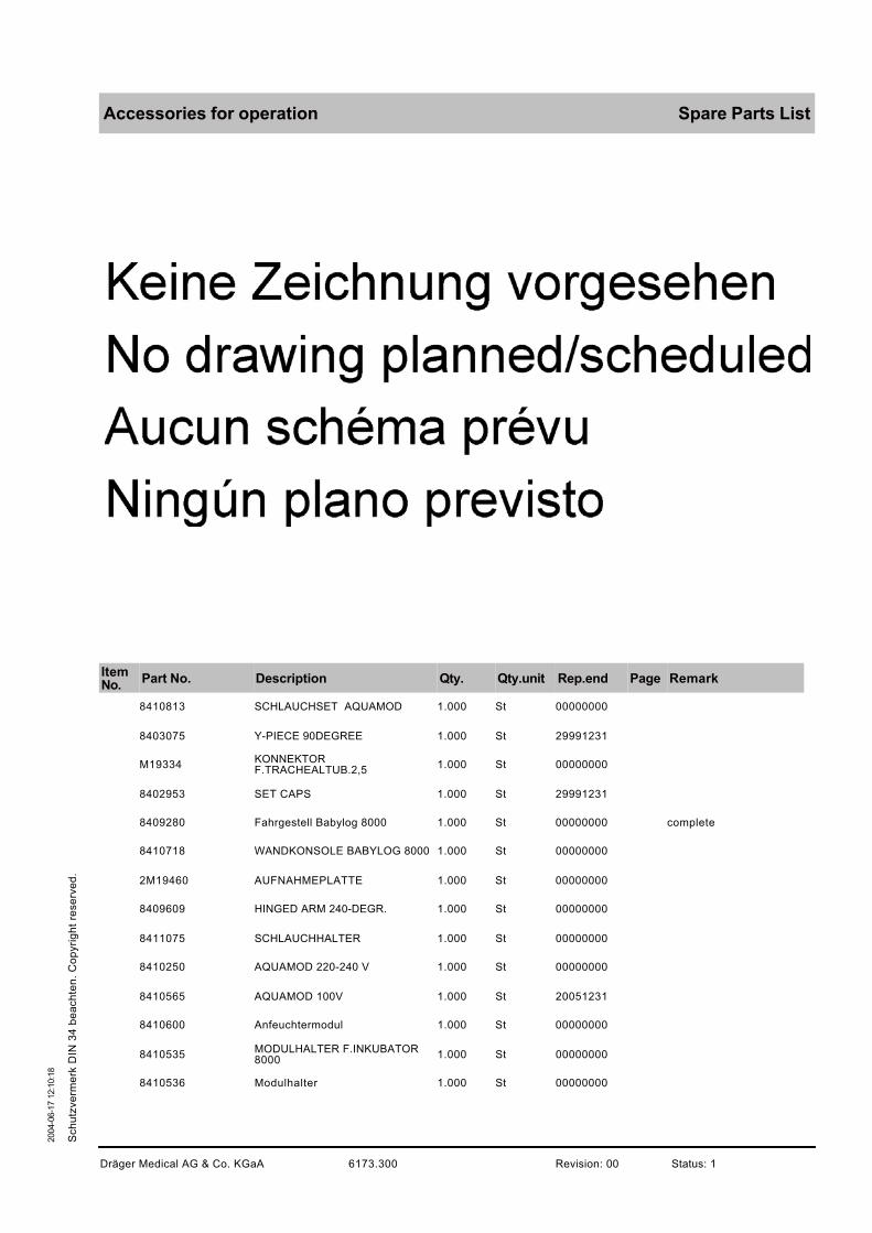
Accessories for operation Spare Parts List
ItemNo.
Part No. Description Qty. Qty.unit Rep.end Page Remark
8410813 SCHLAUCHSET AQUAMOD 1.000 St 00000000
8403075 Y-PIECE 90DEGREE 1.000 St 29991231
M19334KONNEKTORF.TRACHEALTUB.2,5
1.000 St 00000000
8402953 SET CAPS 1.000 St 29991231
8409280 Fahrgestell Babylog 8000 1.000 St 00000000 complete
8410718 WANDKONSOLE BABYLOG 8000 1.000 St 00000000
2M19460 AUFNAHMEPLATTE 1.000 St 00000000
8409609 HINGED ARM 240-DEGR. 1.000 St 00000000
8411075 SCHLAUCHHALTER 1.000 St 00000000
8410250 AQUAMOD 220-240 V 1.000 St 00000000
8410565 AQUAMOD 100V 1.000 St 20051231
8410600 Anfeuchtermodul 1.000 St 00000000
8410535MODULHALTER F.INKUBATOR8000
1.000 St 00000000
8410536 Modulhalter 1.000 St 00000000
Dräger Medical AG & Co. KGaA 6173.300 Revision: 00 Status: 1
2004-0
6-1
7 1
2:1
0:1
8
Sch
utz
ve
rme
rk D
IN 3
4 b
ea
ch
ten
. C
op
yri
gh
t re
se
rve
d.

Accessories for operationSpare Parts List
ItemNo.
Part No. Description Qty. Qty.unit Rep.end Page Remark
M29239 AIR-CONNECTING HOSE 3M 1.000 St 00000000
M29259 AIR-CONNECTING HOSE 5M 1.000 St 00000000
M29231 O2-CONNECTION HOSE 3M 1.000 St 00000000 3m blue
M29251 O2-CONNECTING HOSE 5M 1.000 St 00000000
Dräger Medical AG & Co. KGaA6173.300Revision: 00Status: 1
2004-0
6-1
7 1
2:1
0:1
8
Sch
utz
ve
rme
rk D
IN 3
4 b
ea
ch
ten
. C
op
yri
gh
t re
se
rve
d.

Optional accessory Spare Parts List
ItemNo.
Part No. Description Qty. Qty.unit Rep.end Page Remark
2120941 Baby-Resutator 2000 1.000 St 00000000
8407475 PEEP-Valve (Ambu-PEEP) 1.000 St 00000000
2105438SAUERSTOFFSCHLAUCH(1190520) RE
1.000 St 20001231
8409738 KONDENSATABSCHEIDER (IN/EX)1.000 St 00000000
8412628AIR WATER TRAP MEDIUMDIN/DIN
1.000 St 00000000
8412448 ADAPTER 2K 1.000 St 00000000
8411025 RUESTSATZ 1.000 St 00000000
8411023 KUPPLUNG 1.000 St 00000000
8405752 CONE 22A 1.000 St 29991231
M19351KONNEKTORF.TRACHEALTUB.11
1.000 St 00000000
8405000MEDICAMENT NEBULIZER (PNEU)
1.000 St 20051231
Dräger Medical AG & Co. KGaA 6173.300 Revision: 00 Status: 1
2004-0
6-1
7 1
2:1
0:1
8
Sch
utz
ve
rme
rk D
IN 3
4 b
ea
ch
ten
. C
op
yri
gh
t re
se
rve
d.

Sets for stirilisationSpare Parts List
ItemNo.
Part No. Description Qty. Qty.unit Rep.end Page Remark
8410813 SCHLAUCHSET AQUAMOD 1.000 St 00000000
8408950 EXSP.-Ventil Babylog 8000 1.000 St 00000000
8409625 WASSERSCHLAUCH AQUAMOD 1.000 St 00000000
8409840 Pumpenaggregat Aquamod 1.000 St 00000000
8408647 Temp.-Sensor Aquamod 1.000 St 00000000
Dräger Medical AG & Co. KGaA6173.300Revision: 00Status: 1
2004-0
6-1
7 1
2:1
0:1
8
Sch
utz
ve
rme
rk D
IN 3
4 b
ea
ch
ten
. C
op
yri
gh
t re
se
rve
d.
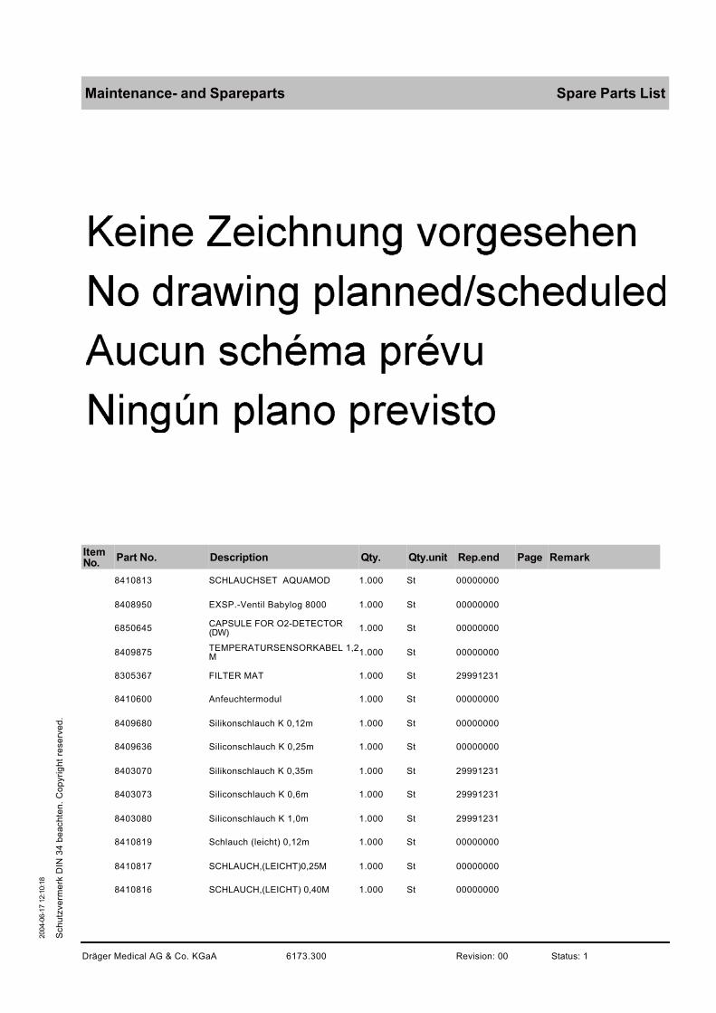
Maintenance- and Spareparts Spare Parts List
ItemNo.
Part No. Description Qty. Qty.unit Rep.end Page Remark
8410813 SCHLAUCHSET AQUAMOD 1.000 St 00000000
8408950 EXSP.-Ventil Babylog 8000 1.000 St 00000000
6850645CAPSULE FOR O2-DETECTOR(DW)
1.000 St 00000000
8409875TEMPERATURSENSORKABEL 1,2M
1.000 St 00000000
8305367 FILTER MAT 1.000 St 29991231
8410600 Anfeuchtermodul 1.000 St 00000000
8409680 Silikonschlauch K 0,12m 1.000 St 00000000
8409636 Siliconschlauch K 0,25m 1.000 St 00000000
8403070 Silikonschlauch K 0,35m 1.000 St 29991231
8403073 Siliconschlauch K 0,6m 1.000 St 29991231
8403080 Siliconschlauch K 1,0m 1.000 St 29991231
8410819 Schlauch (leicht) 0,12m 1.000 St 00000000
8410817 SCHLAUCH,(LEICHT)0,25M 1.000 St 00000000
8410816 SCHLAUCH,(LEICHT) 0,40M 1.000 St 00000000
Dräger Medical AG & Co. KGaA 6173.300 Revision: 00 Status: 1
2004-0
6-1
7 1
2:1
0:1
8
Sch
utz
ve
rme
rk D
IN 3
4 b
ea
ch
ten
. C
op
yri
gh
t re
se
rve
d.
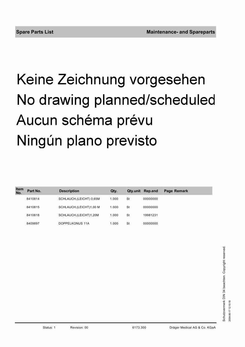
Maintenance- and SparepartsSpare Parts List
ItemNo.
Part No. Description Qty. Qty.unit Rep.end Page Remark
8410814 SCHLAUCH,(LEICHT) 0,65M 1.000 St 00000000
8410815 SCHLAUCH,(LEICHT)1,00 M 1.000 St 00000000
8410818 SCHLAUCH,(LEICHT)1,20M 1.000 St 19981231
8409897 DOPPELKONUS 11A 1.000 St 00000000
Dräger Medical AG & Co. KGaA6173.300Revision: 00Status: 1
2004-0
6-1
7 1
2:1
0:1
8
Sch
utz
ve
rme
rk D
IN 3
4 b
ea
ch
ten
. C
op
yri
gh
t re
se
rve
d.

Instructions for useSpare Parts List
ItemNo.
Part No. Description Qty. Qty.unit Rep.end Page Remark
9028004 GA BL 8000 Schnittstelle de/en 1.000 St 00000000
9028563 GA Babylog 8000 SC de (CE) 1.000 St 00000000
9028706 GA Babylog 8000 SC SW 1.n fr 1.000 St 00000000
9028741 GA Babylog 8000 SC en 1.000 St 00000000
9028881 GA Babylog 8000 SC SW 1.n es 1.000 St 00000000
9028882 GA Babylog 8000 SC SW 1.n it 1.000 St 00000000
9029520 GA Babylog 8000 SC SW 1.n nl 1.000 St 00000000
9029599 GA BABYVIEW SW 1.n NL 1.000 St 00000000
9037162 Beiblatt f.GAs Babylog 8000 de 1.000 St 00000000
9037230 GA Babylog 8000 SC RU 1.000 St 00000000
Dräger Medical AG & Co. KGaA6173.300Revision: 00Status: 1
2004-0
6-1
7 1
2:1
0:1
8
Sch
utz
ve
rme
rk D
IN 3
4 b
ea
ch
ten
. C
op
yri
gh
t re
se
rve
d.

Accessories for operation Spare Parts List
ItemNo.
Part No. Description Qty. Qty.unit Rep.end Page Remark
8411041 Schlauchset F&P 1.000 St 00000000
8411153 Schlauchset F&P HFV 1.000 St 00000000
8409280 Fahrgestell Babylog 8000 1.000 St 00000000 complete
2M85337 COMPACT RAIL 1.000 St 00000000
8410718 WANDKONSOLE BABYLOG 8000 1.000 St 00000000
2M19460 AUFNAHMEPLATTE 1.000 St 00000000
8409609 HINGED ARM 240-DEGR. 1.000 St 00000000
8411075 SCHLAUCHHALTER 1.000 St 00000000
8418285 F&P MR 730 AGU Befeuchter (d) 1.000 St 20121231
8418281 F&P MR 700 AGM Humidifier /AEU1.000 St 20121231
8411047 HUMIDIFIER CHAMBER MR 340 1.000 St 00000000
8418282 F&P MR290 disp.chamber (10p.) 1.000 St 00000000
M29231 O2-CONNECTION HOSE 3M 1.000 St 00000000 3m blue
M29251 O2-CONNECTING HOSE 5M 1.000 St 00000000
Dräger Medical AG & Co. KGaA 6173.300 Revision: 00 Status: 1
2004-0
6-1
7 1
2:1
0:1
8
Sch
utz
ve
rme
rk D
IN 3
4 b
ea
ch
ten
. C
op
yri
gh
t re
se
rve
d.

Accessories for operationSpare Parts List
ItemNo.
Part No. Description Qty. Qty.unit Rep.end Page Remark
M29239 AIR-CONNECTING HOSE 3M 1.000 St 00000000
M29259 AIR-CONNECTING HOSE 5M 1.000 St 00000000
M34402 O2-HOSE NIST 3M DIN PROBE 1.000 St 00000000
M34403 O2-HOSE NIST 5M DIN PROBE 1.000 St 00000000
M34408 AIR-HOSE NIST 3M DIN PROBE 1.000 St 00000000
M34409 AIR-HOSE NIST 5M DIN PROBE 1.000 St 00000000
Dräger Medical AG & Co. KGaA6173.300Revision: 00Status: 1
2004-0
6-1
7 1
2:1
0:1
8
Sch
utz
ve
rme
rk D
IN 3
4 b
ea
ch
ten
. C
op
yri
gh
t re
se
rve
d.

Optional accessory Spare Parts List
ItemNo.
Part No. Description Qty. Qty.unit Rep.end Page Remark
8407475 PEEP-Valve (Ambu-PEEP) 1.000 St 00000000
2105438SAUERSTOFFSCHLAUCH(1190520) RE
1.000 St 20001231
8409738 KONDENSATABSCHEIDER (IN/EX)1.000 St 00000000
8412628AIR WATER TRAP MEDIUMDIN/DIN
1.000 St 00000000
8412448 ADAPTER 2K 1.000 St 00000000
8411025 RUESTSATZ 1.000 St 00000000
8411023 KUPPLUNG 1.000 St 00000000
8411024 Dichtstopfen 1.000 St 00000000
8411030 Medikamentenvernebler 1.000 St 00000000
2120941 Baby-Resutator 2000 1.000 St 00000000
Dräger Medical AG & Co. KGaA 6173.300 Revision: 00 Status: 1
2004-0
6-1
7 1
2:1
0:1
8
Sch
utz
ve
rme
rk D
IN 3
4 b
ea
ch
ten
. C
op
yri
gh
t re
se
rve
d.
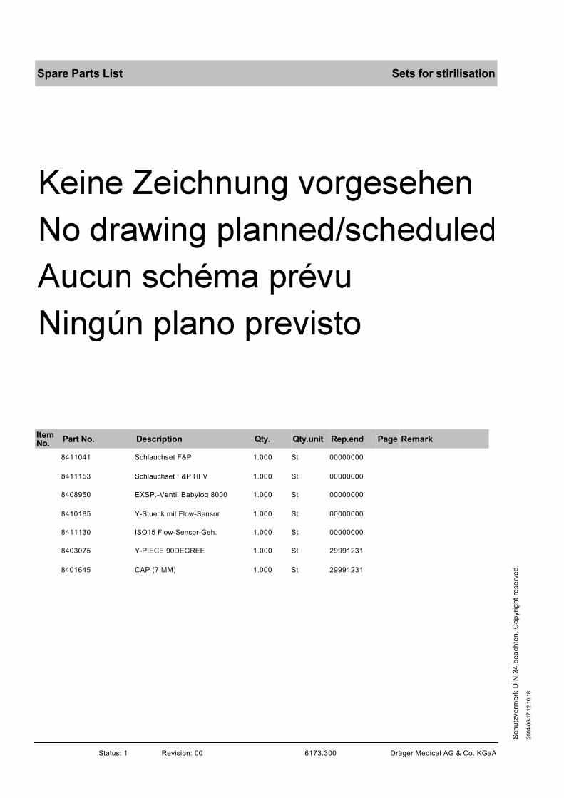
Sets for stirilisationSpare Parts List
ItemNo.
Part No. Description Qty. Qty.unit Rep.end Page Remark
8411041 Schlauchset F&P 1.000 St 00000000
8411153 Schlauchset F&P HFV 1.000 St 00000000
8408950 EXSP.-Ventil Babylog 8000 1.000 St 00000000
8410185 Y-Stueck mit Flow-Sensor 1.000 St 00000000
8411130 ISO15 Flow-Sensor-Geh. 1.000 St 00000000
8403075 Y-PIECE 90DEGREE 1.000 St 29991231
8401645 CAP (7 MM) 1.000 St 29991231
Dräger Medical AG & Co. KGaA6173.300Revision: 00Status: 1
2004-0
6-1
7 1
2:1
0:1
8
Sch
utz
ve
rme
rk D
IN 3
4 b
ea
ch
ten
. C
op
yri
gh
t re
se
rve
d.

Maintenance- and Spareparts Spare Parts List
ItemNo.
Part No. Description Qty. Qty.unit Rep.end Page Remark
8411041 Schlauchset F&P 1.000 St 00000000
8411153 Schlauchset F&P HFV 1.000 St 00000000
8408950 EXSP.-Ventil Babylog 8000 1.000 St 00000000
8410185 Y-Stueck mit Flow-Sensor 1.000 St 00000000
8410179 Flowsensor 5er Set BL8000 1.000 St 00000000
8411130 ISO15 Flow-Sensor-Geh. 1.000 St 00000000
8403075 Y-PIECE 90DEGREE 1.000 St 29991231
8401645 CAP (7 MM) 1.000 St 29991231
8411048DUAL AIRWAY TEMP. SENSOR1,45M
1.000 St 00000000
8411050 DRAW WIRE 1,50 M 900 MR 070 1.000 St 00000000
8411045 HOSE HEATER 1,1M 900 MR511 1.000 St 00000000
8411154 HEATER WIRE 0,70M HFV-F&P 1.000 St 00000000
8305367 FILTER MAT 1.000 St 29991231
8409626 Anschlusskabel Flowsensor 1.000 St 00000000
Dräger Medical AG & Co. KGaA 6173.300 Revision: 00 Status: 1
2004-0
6-1
7 1
2:1
0:1
8
Sch
utz
ve
rme
rk D
IN 3
4 b
ea
ch
ten
. C
op
yri
gh
t re
se
rve
d.

Maintenance- and SparepartsSpare Parts List
ItemNo.
Part No. Description Qty. Qty.unit Rep.end Page Remark
8409680 Silikonschlauch K 0,12m 1.000 St 00000000
8409636 Siliconschlauch K 0,25m 1.000 St 00000000
8403070 Silikonschlauch K 0,35m 1.000 St 29991231
8403073 Siliconschlauch K 0,6m 1.000 St 29991231
8403080 Siliconschlauch K 1,0m 1.000 St 29991231
8410819 Schlauch (leicht) 0,12m 1.000 St 00000000
8410817 SCHLAUCH,(LEICHT)0,25M 1.000 St 00000000
8410816 SCHLAUCH,(LEICHT) 0,40M 1.000 St 00000000
8410814 SCHLAUCH,(LEICHT) 0,65M 1.000 St 00000000
8410815 SCHLAUCH,(LEICHT)1,00 M 1.000 St 00000000
8410818 SCHLAUCH,(LEICHT)1,20M 1.000 St 19981231
8409897 DOPPELKONUS 11A 1.000 St 00000000
8411044PROBE-THERMOMETERHOUSING DRAE
1.000 St 00000000
8418405 Temp. Sensoraufnahme D15/D10 1.000 St 00000000
Dräger Medical AG & Co. KGaA6173.300Revision: 00Status: 1
2004-0
6-1
7 1
2:1
0:1
8
Sch
utz
ve
rme
rk D
IN 3
4 b
ea
ch
ten
. C
op
yri
gh
t re
se
rve
d.

Instructions for useSpare Parts List
ItemNo.
Part No. Description Qty. Qty.unit Rep.end Page Remark
9028004 GA BL 8000 Schnittstelle de/en 1.000 St 00000000
9028884 GA Babylog 8000 plus 5.n EN 1.000 St 00000000
9028885 GA Babylog 8000 SW 5.N FR 1.000 St 00000000
9028886 GA Babylog 8000 plus 5.N ES 1.000 St 00000000
9028887 GA Babylog 8000 plus 5.N IT 1.000 St 00000000
9028888 GA Babylog 8000 plus 5.N SV 1.000 St 00000000
9028889 GA Babylog 8000 SW 5.n enUS 1.000 St 00000000
9029032 GA Babylog 8000 plus 5.n NL 1.000 St 00000000
9029053 GA-BABYLOG 8000 SW 5.N D 1.000 St 00000000
9029054 GA-BABYLOG 8000 SW 5.N E 1.000 St 00000000
9029058 GA Babylog 8000 SW 5.n enCA 1.000 St 00000000
9029427 GA BABYLOG 8000 plus 5.n RU 1.000 St 00000000
9029599 GA BABYVIEW SW 1.n NL 1.000 St 00000000
9037162 Beiblatt f.GAs Babylog 8000 de 1.000 St 00000000
Dräger Medical AG & Co. KGaA6173.300Revision: 00Status: 1
2004-0
6-1
7 1
2:1
0:1
8
Sch
utz
ve
rme
rk D
IN 3
4 b
ea
ch
ten
. C
op
yri
gh
t re
se
rve
d.
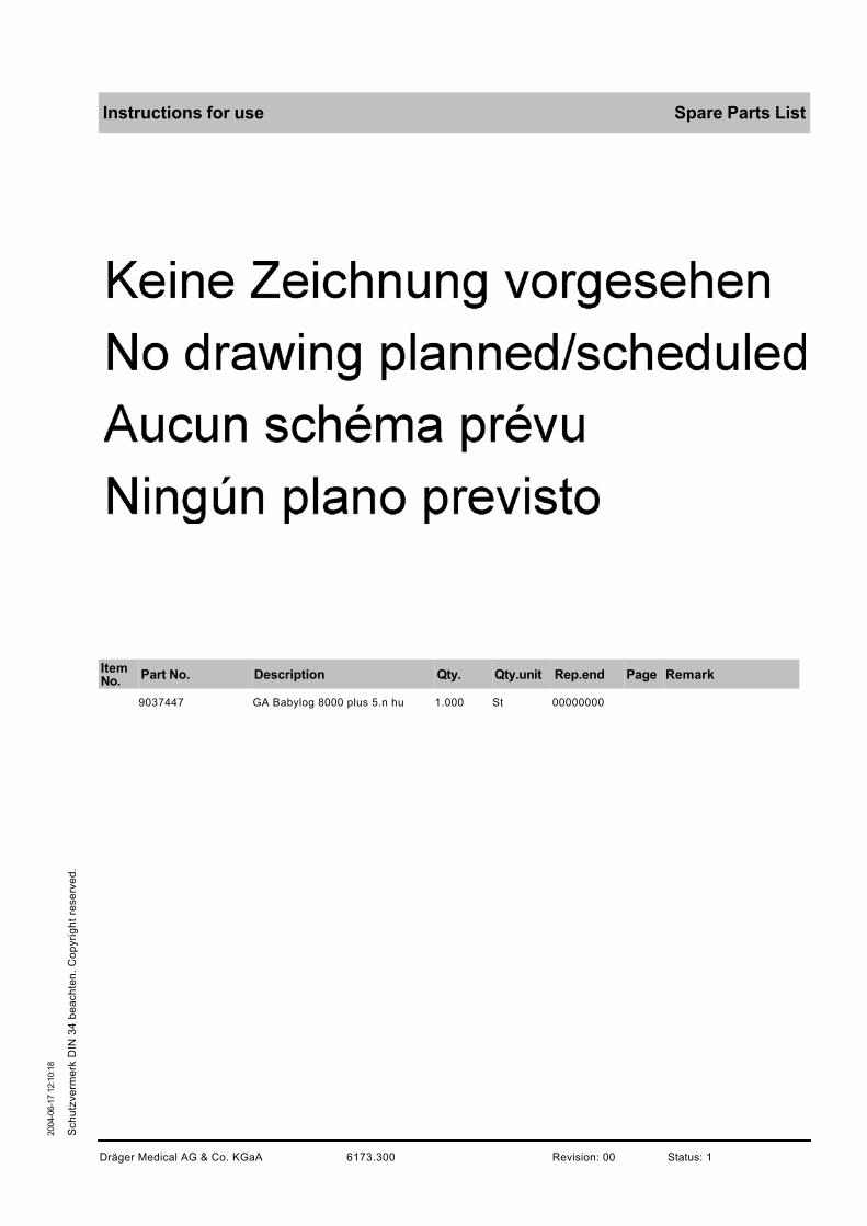
Instructions for use Spare Parts List
ItemNo.
Part No. Description Qty. Qty.unit Rep.end Page Remark
9037447 GA Babylog 8000 plus 5.n hu 1.000 St 00000000
Dräger Medical AG & Co. KGaA 6173.300 Revision: 00 Status: 1
2004-0
6-1
7 1
2:1
0:1
8
Sch
utz
ve
rme
rk D
IN 3
4 b
ea
ch
ten
. C
op
yri
gh
t re
se
rve
d.


This Test List does not replace inspections and servicing by Dräger Medical AG & Co. KGaA
6173.3 Babylog 8000/8000 plus/8000 SC 12/00 General Page 1
Copyright
reserv
ed.
Repro
du
ction allo
wed f
or
non-c
om
merc
ial
purp
oses
only
.
GB
K6
17
33
XX
TL
1.f
m 0
7.0
7.0
5
Serial no.: —————————
Installation site: —————————
Reset�Check�
��
Trigger�
�
man.�Insp.�
Alarm�
Monitoring�
Mode�
-10� 0� 20� 40� 60�Paw�mbar�
CPAP�
IPPV�
PEEP/CPAP�
5�
0�
10�
15 mbar�
40�
50�
60 mbar�
30�
20�
7,5�
5�
3�
0�
10�
20�
30 L/min�
50�
40�
25�21�
80�
90�
100 �
0,6�
0,4�
0,3�
0,1�
0,8�
1,0�
2x�
30�
60�70�
0,2� 1,5�
1,0�
0,8�
0,6�
0,2�
2�
6�
30x�0,4� 15�
Insp. Flow V�
O2-Vol.%� TI� TE�
General
Babylog 8000/Babylog 8000 plus/Babylog 8000 SC
Folder no.:
6173.3
Edition:
12/94

6173.3 Babylog 8000/8000 plus/8000 SC 12/00 General Page 2
For
inte
rnal use o
nly
. C
opyri
ght re
se
rved.
GB
K6
17
33
XX
TL
1.f
m 0
7.0
7.0
5
1 Test Equipment
2 Accompanying Documents
Instructions for Use (according to software version) for Babylog 8000/ Babylog
8000 plus (with flow measurement)
Instructions for Use of analog and digital interfaces
Check List
Instructions for Use (according to software version) of Babylog 8000 SC (wit-
hout flow measurement)
Check List
Measuring Range Accuracy Class
(according to VDE/VDI
3513)
Manometer 0 to 5 bar 1.0
Manometer –30 to +120 mbar 1.0
Test pressure
reducer
Flowmeter 10 to 120 L/min 1.6
Secretion sightglass
Tracheal tube
Bellows (children)
T-piece

6173.3 Babylog 8000/8000 plus/8000 SC 12/00 General Page 3
For
inte
rnal use o
nly
. C
opyri
ght re
se
rved.
GB
K6
17
33
XX
TL
1.f
m 0
7.0
7.0
5
3 General Condition of Babylog 8000/8000 plus/ 8000 SC
Rear Panel
O2/AIR inlet block
Connection socket for flow sensor cable
Fan cover
Filter mat for fan
ON/OFF switch with locking device
Power cable
RS232 connection port (if available)
2 analog outputs and 1 pulse output (if available)
Central-alarm output (if available)
Drug nebulizer output (if available)
Side Panels
Front Electronics/Pneumatics Assembly
Potentiometer field flap
Potentiometer field
Display field
Front pneumatic assembly
Inspiratory block
Inspiratory connection port
O2 sensor mount
Filter for emergency respiratory equipment
Base plate for adaptation of the expiratory valve
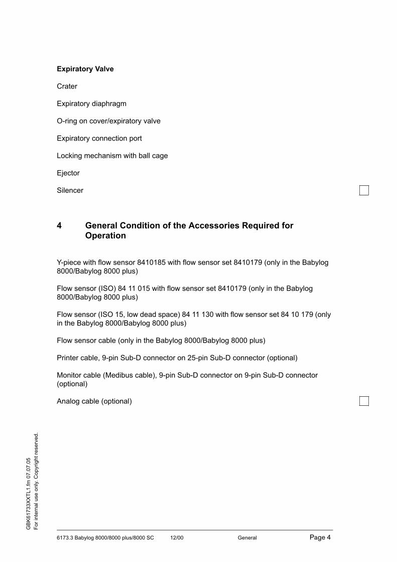
6173.3 Babylog 8000/8000 plus/8000 SC 12/00 General Page 4
For
inte
rnal use o
nly
. C
opyri
ght re
se
rved.
GB
K6
17
33
XX
TL
1.f
m 0
7.0
7.0
5
Expiratory Valve
Crater
Expiratory diaphragm
O-ring on cover/expiratory valve
Expiratory connection port
Locking mechanism with ball cage
Ejector
Silencer
4 General Condition of the Accessories Required for Operation
Y-piece with flow sensor 8410185 with flow sensor set 8410179 (only in the Babylog
8000/Babylog 8000 plus)
Flow sensor (ISO) 84 11 015 with flow sensor set 8410179 (only in the Babylog
8000/Babylog 8000 plus)
Flow sensor (ISO 15, low dead space) 84 11 130 with flow sensor set 84 10 179 (only
in the Babylog 8000/Babylog 8000 plus)
Flow sensor cable (only in the Babylog 8000/Babylog 8000 plus)
Printer cable, 9-pin Sub-D connector on 25-pin Sub-D connector (optional)
Monitor cable (Medibus cable), 9-pin Sub-D connector on 9-pin Sub-D connector
(optional)
Analog cable (optional)

6173.3 Babylog 8000/8000 plus/8000 SC 12/00 General Page 5
For
inte
rnal use o
nly
. C
opyri
ght re
se
rved.
GB
K6
17
33
XX
TL
1.f
m 0
7.0
7.0
5
5 General Condition of the Accessories
Trolley 0.5 B
Short rail for humidifier
Platform with rails type 1 0.5 B
Monitor support (Incubator 8000)
Humidifier
Hinged arm
Hinged arm (Incubator 7500)
Central gas supply connecting hoses for O2 and AIR
Water trap Ex
Bacterial filter with connecting set
Drug nebulizer
6 General Condition of the Special Accessories
Resutator bag (baby)
PEEP valve for Resutator bag (baby)
1.8 m hose for Resutator bag (baby)
Insp./exp. water trap set

6173.3 Babylog 8000/8000 plus/8000 SC 12/00 General Page 6
For
inte
rnal use o
nly
. C
opyri
ght re
se
rved.
GB
K6
17
33
XX
TL
1.f
m 0
7.0
7.0
5
7 Functional Check
Connect the Babylog 8000/Babylog 8000 plus/Babylog 8000 SC to the central gas
supply and switch on the device.
The software version will be displayed as soon as the self-test has been completed.
8 Testing the Emergency AIR Valve
Switch off the Babylog 8000/Babylog 8000 plus/Babylog 8000 SC and prepare the fol-
lowing test set-up (see Figure below).
Fig. 1: Emergency AIR Valve
• Slowly pull the test bellows.
The bellows must fill up.
a.) Babylog 8000 SW 2.0 and SW 3.00
The opening pressure is –1.5 mbar to 0 mbar
T-piece
Corrugated hose 100 mm
Bellows
Manometer –30 to 120 mbar
Test set-up

6173.3 Babylog 8000/8000 plus/8000 SC 12/00 General Page 7
For
inte
rnal use o
nly
. C
opyri
ght re
se
rved.
GB
K6
17
33
XX
TL
1.f
m 0
7.0
7.0
5
9 Testing the Safety Valve
The Babylog 8000/Babylog 8000 plus/Babylog 8000 SC is switched off. Remove the
expiratory valve.
(Important: There are two variants of the safety valve.)
Variant A: opening pressure 25 mbar
Variant B: opening pressure 100 mbar
(You can recognize the relevant variant by the test value measured.)
Fig. 2: Safety Valve
b.) Babylog 8000 SW 2.02, SW 3.02, SW 4.n without HFV
The opening pressure is –4 mbar to 0 mbar
c.) Babylog 8000 SW 4.n with HFV
The opening pressure is –4 to –2 mbar
T-piece
Corrugated hose 100 mm
Bellows
Manometer –30 to 120 mbar
Test set-up
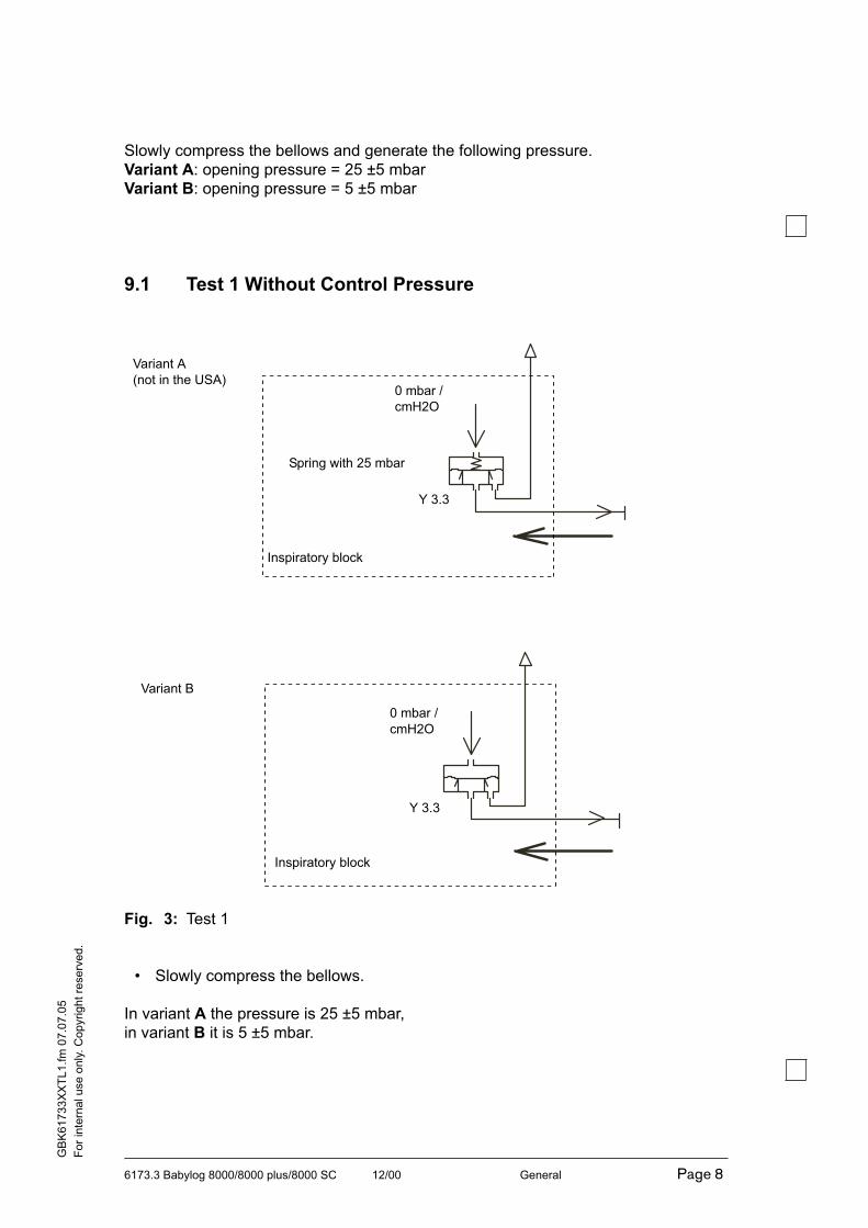
6173.3 Babylog 8000/8000 plus/8000 SC 12/00 General Page 8
For
inte
rnal use o
nly
. C
opyri
ght re
se
rved.
GB
K6
17
33
XX
TL
1.f
m 0
7.0
7.0
5
Slowly compress the bellows and generate the following pressure.
Variant A: opening pressure = 25 ±5 mbar
Variant B: opening pressure = 5 ±5 mbar
9.1 Test 1 Without Control Pressure
Fig. 3: Test 1
• Slowly compress the bellows.
In variant A the pressure is 25 ±5 mbar,
in variant B it is 5 ±5 mbar.
Variant A
(not in the USA)
Variant B
0 mbar /
cmH2O
0 mbar /
cmH2O
Spring with 25 mbar
Y 3.3
Y 3.3
Inspiratory block
Inspiratory block

6173.3 Babylog 8000/8000 plus/8000 SC 12/00 General Page 9
For
inte
rnal use o
nly
. C
opyri
ght re
se
rved.
GB
K6
17
33
XX
TL
1.f
m 0
7.0
7.0
5
9.2 Test 2 With Control Pressure
Use the same test set-up as in Test 1 and proceed as follows:
Remove the bottom plate from the Babylog 8000/Babylog 8000 plus/
Babylog 8000 SC and disconnect the hose from connection 4 on the gas connection
block. Apply a pressure of 1.5 bar ±0.1 bar into this hose (see Figure below).
Fig. 4: Test 2
4x1.5 Si nf hose
Babylog hose disconnected from
connection 4 on the gas
connection block.
PEEP/PIP-
Valve
Valv
e b
lock
Insp. block
Gas connection block
4
4
View: Gas connection block tilted by 90°

6173.3 Babylog 8000/8000 plus/8000 SC 12/00 General Page 10
For
inte
rnal use o
nly
. C
opyri
ght re
se
rved.
GB
K6
17
33
XX
TL
1.f
m 0
7.0
7.0
5
Babylog 8000/Babylog 8000 plus/Babylog 8000 SC Test Performance:
Fig. 5: Test Performance
Important: If during Test 1 the variant A and during Test 2 the variant B (pressure
values possibly too high) is recognized, then it is a B variant with a non-permissible
spring mounted in the valve Y 3.3. This spring must be removed and the test be
repeated. Mount the bottom cover.
• Slowly compress the bellows and generate the following pressure:
Variant A : 25 mbar ±5 mbar.
Variant B : 100 mbar ±10 mbar.
1.5 bar
/21.3 psi
1.5 bar
/21.3 psi
Variant A (not in the USA)
Variant B
Inspiratory block
Inspiratory block
Y 3.3
Y 3.3
25 mbar /
cmH2O
100 mbar /
cmH2O

6173.3 Babylog 8000/8000 plus/8000 SC 12/00 General Page 11
For
inte
rnal use o
nly
. C
opyri
ght re
se
rved.
GB
K6
17
33
XX
TL
1.f
m 0
7.0
7.0
5
10 Calibration / LED / Potentiometer Test
• Assemble the Babylog 8000/Babylog 8000 plus/Babylog 8000 SC including the
tubing system but without the humidifier.
• Switch the device on.
• Note the software version and the operating hours down.
Communication conversion kit y/n (is displayed under the operating hour indication
after power-on).
Important: 8306065 or 8411108 (see nameplate option field) without central-alarm
function. The sockets for the communication interface may be present even if this
function is not available.
• O2 calibration.
• Flow sensor calibration (only in the Babylog 8000).
LED and horn test (press and hold the “Reset Check” : after 2 s, each LED and the
stand-by horn are triggered.).
Important:
Alarm LEDs = 1 yellow and 2 red LEDs
Trigger LEDs = 3 yellow LEDs
Display backlight.
• Testing the keys (check respective reaction of the equipment).
Potentiometers (no fault message about potentiometer malfunction).

6173.3 Babylog 8000/8000 plus/8000 SC 12/00 General Page 12
For
inte
rnal use o
nly
. C
opyri
ght re
se
rved.
GB
K6
17
33
XX
TL
1.f
m 0
7.0
7.0
5
11 Leak Test
• Adjust the following parameters on the Babylog 8000/
Babylog 8000 plus/Babylog 8000 SC (see Figure below):
Fig. 6: Leak Test
• Select pressure from the menu “pressure curve” and “measured values”.
• Switch off occurring alarms and warnings by pressing the “Reset/Check” key.
• Press and hold the manual inspiration key.
A pressure is now built up for 5 s. During this time, a pressure of at least 75 mbar
must be achieved.
60 1 2
1 80 0
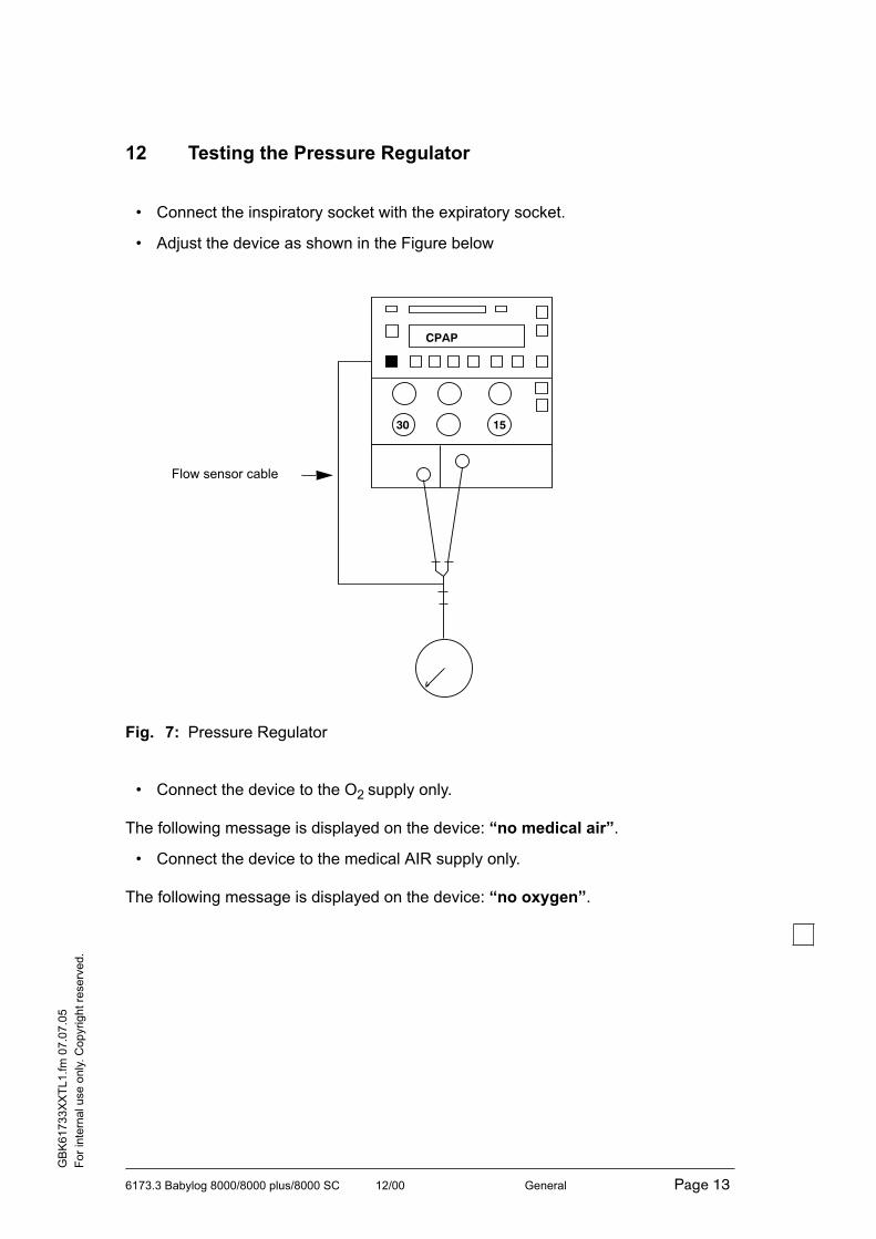
6173.3 Babylog 8000/8000 plus/8000 SC 12/00 General Page 13
For
inte
rnal use o
nly
. C
opyri
ght re
se
rved.
GB
K6
17
33
XX
TL
1.f
m 0
7.0
7.0
5
12 Testing the Pressure Regulator
• Connect the inspiratory socket with the expiratory socket.
• Adjust the device as shown in the Figure below
Fig. 7: Pressure Regulator
• Connect the device to the O2 supply only.
The following message is displayed on the device: “no medical air”.
• Connect the device to the medical AIR supply only.
The following message is displayed on the device: “no oxygen”.
30 15
CPAP
Flow sensor cable

6173.3 Babylog 8000/8000 plus/8000 SC 12/00 General Page 14
For
inte
rnal use o
nly
. C
opyri
ght re
se
rved.
GB
K6
17
33
XX
TL
1.f
m 0
7.0
7.0
5
13 Airway Pressure Measurement
• Test set-up (see Figure below):
Fig. 8: Airway Pressure Measurement
• Select the functions “setting” and “measured value” from the “list” menu:
Setting Measured value Manometer
PEEP = 0 mbar
Pinsp = 30 ±2 mbar
Pinsp = 60 mbar
PEEP = 5 mbar
PEEP = 10 mbar
PEEP = 15 mbar
0 ±1 mbar
30 ±1 mbar
60 ±2 mbar
5 ±1 mbar
10 ±1 mbar
15 ±1 mbar
0 ±2 mbar
30 ±2 mbar
60 ±3 mbar
5 ±2 mbar
10 ±2 mbar
15 ±2 mbar
30 2 2
10 varvar
2x 1/2 corrugated hose 100mm
Manometer –30 to 120 mbar
Flow sensor cable 4x1.5 Si nf hose, max. 500 mm
Y-piece with flow sensor
Tracheal tube

6173.3 Babylog 8000/8000 plus/8000 SC 12/00 General Page 15
For
inte
rnal use o
nly
. C
opyri
ght re
se
rved.
GB
K6
17
33
XX
TL
1.f
m 0
7.0
7.0
5
14 Testing the Mixer
• Carry out an O2 calibration.
• Test set-up (see Figure below):
Fig. 9: Mixer
• Select the following inspiratory flows from the “list” menu: 1.2 / 1.3 / 1.4 / 1.5 / 1.6
/ 1.7 / 1.8 / 1.9 / 2.0 / 4 / 5 / 6 / 8 / 9 / 9.9 / 11 / 12 / 13 / 14 / 15 / 30
Allow approx. 1 min between setting and measurement of flow values (< 2 L/min). If
no values is set, the alarm “FiO2 deviation” is allowed to occur.
15 Testing the Patient System Heating
• Put your hand against the expiratory valve block.
The temperature should exceed the room temperature.
var 5
CPAP
60
30
Flow sensor cable

6173.3 Babylog 8000/8000 plus/8000 SC 12/00 General Page 16
For
inte
rnal use o
nly
. C
opyri
ght re
se
rved.
GB
K6
17
33
XX
TL
1.f
m 0
7.0
7.0
5
16 Testing the Fan
• Put your hand on the upper right corner of the rear panel of the
Babylog 8000/Babylog 8000 plus/Babylog 8000 SC.
You should feel an AIR flow through the filter mat.
17 Testing the Power Failure Alarm
• Unplug the power plug from the wall outlet.
The acoustic alarm should start.
18 Testing the Gas Failure Alarm
O2 Failure Alarm
• Set the O2 adjuster to 100 vol.% and disconnect the O2 supply.
• Switch on the Babylog 8000/Babylog 8000 SC:
Message on the device: “no oxygen”
Medical AIR Failure Alarm
• Re-connect the O2 supply.
• Set the O2 adjuster to 21 vol.% and disconnect the medical AIR supply:
Message on the device: “no medical air”
• Re-connect the medical AIR supply.
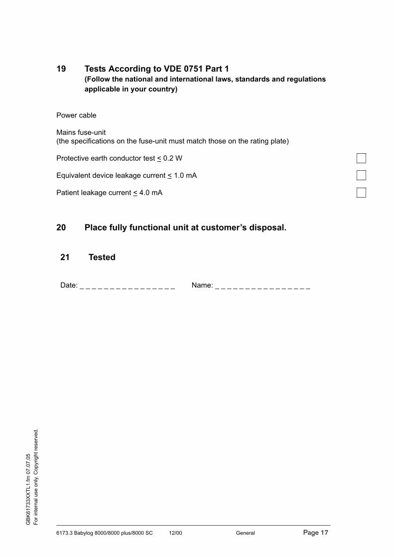
6173.3 Babylog 8000/8000 plus/8000 SC 12/00 General Page 17
For
inte
rnal use o
nly
. C
opyri
ght re
se
rved.
GB
K6
17
33
XX
TL
1.f
m 0
7.0
7.0
5
19 Tests According to VDE 0751 Part 1(Follow the national and international laws, standards and regulations
applicable in your country)
Power cable
Mains fuse-unit
(the specifications on the fuse-unit must match those on the rating plate)
Protective earth conductor test < 0.2 W
Equivalent device leakage current < 1.0 mA
Patient leakage current < 4.0 mA
20 Place fully functional unit at customer’s disposal.
21 Tested
Date: _ _ _ _ _ _ _ _ _ _ _ _ _ _ _ _ Name: _ _ _ _ _ _ _ _ _ _ _ _ _ _ _ _


Page 1 of 4
Technical Information
Technical Documentation for Babylog 8000 plusaccording to EMC standard IEC/EN 60601-1-2: 2001
General Information
The EMC conformity includes the use of following external cables, transducers and accessories (see thefollowing table):
Designation Order no.
Flow sensor 8410185
Flow sensor connecting cable 8409626
Communication conversion kit 8411108
Analog cable 8306487
MIB connecting cable 5198952
Additionally, accessories may be used which do not affect EMC compliance, if no other reasons interdict theuse of them (see chapter Order List in the Instructions for Use manual). Non-compliance may result inincreased emissions or decreased immunity of the Babylog 8000 plus.
Babylog 8000 plus should not be used adjacent to or stacked with other equipment. If adjacent or stackeduse is inevitable, Babylog 8000 plus should be observed to verify normal use in the configuration in which itwill be used.
Other equipment which can be used adjacent to or stacked with the Babylog 8000 plus are listed in theInstructions for Use manual, in the Order List chapter or in the following table.
Designation Order no.
Fisher & Paykel humidifier - accessories 84 14 144
Optional graphic screen 84 15 834
ECG monitoring Various, on demand
2004-09-24
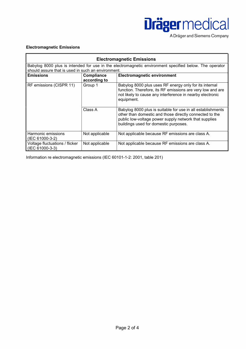
Page 2 of 4
Electromagnetic Emissions
Electromagnetic Emissions
Babylog 8000 plus is intended for use in the electromagnetic environment specified below. The operatorshould assure that is used in such an environment.
Emissions Complianceaccording to
Electromagnetic environment
RF emissions (CISPR 11) Group 1 Babylog 8000 plus uses RF energy only for its internalfunction. Therefore, its RF emissions are very low and arenot likely to cause any interference in nearby electronicequipment.
Class A Babylog 8000 plus is suitable for use in all establishmentsother than domestic and those directly connected to thepublic low-voltage power supply network that suppliesbuildings used for domestic purposes.
Harmonic emissions(IEC 61000-3-2)
Not applicable Not applicable because RF emissions are class A.
Voltage fluctuations / flicker(IEC 61000-3-3)
Not applicable Not applicable because RF emissions are class A.
Information re electromagnetic emissions (IEC 60101-1-2: 2001, table 201)
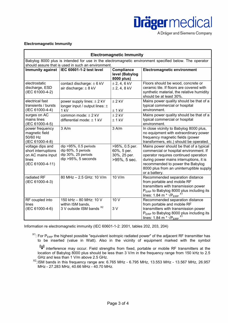
Page 3 of 4
Electromagnetic Immunity
Electromagnetic Immunity
Babylog 8000 plus is intended for use in the electromagnetic environment specified below. The operatorshould assure that is used in such an environment.
Immunity against IEC 60601-1-2 test level Compliancelevel (Babylog8000 plus)
Electromagnetic environment
electrostaticdischarge, ESD(IEC 61000-4-2)
contact discharge: ± 6 kV
air discharge: ± 8 kV
± 2, 4, 6 kV
± 2, 4, 8 kV
Floors should be wood, concrete orceramic tile. If floors are covered withsynthetic material, the relative humidityshould be at least 30%.
electrical fasttransients / bursts(IEC 61000-4-4)
power supply lines: ± 2 kV
longer input / output lines: ±1 kV
± 2 kV
± 1 kV
Mains power quality should be that of atypical commercial or hospitalenvironment.
surges on ACmains lines(IEC 61000-4-5)
common mode: ± 2 kV
differential mode: ± 1 kV
± 2 kV
± 1 kV
Mains power quality should be that of atypical commercial or hospitalenvironment.
power frequencymagnetic field50/60 Hz(IEC 61000-4-8)
3 A/m 3 A/m In close vicinity to Babylog 8000 plus,no equipment with extraordinary powerfrequency magnetic fields (powertransformers, etc.) should be operated.
voltage dips andshort interruptionson AC mains inputlines(IEC 61000-4-11)
dip >95%, 0.5 periods
dip 60%, 5 periods
dip 30%, 25 periods
dip >95%, 5 seconds
>95%, 0.5 per.60%, 5 per.30%, 25 per.
>95%, 5 sec.
Mains power should be that of a typicalcommercial or hospital environment. Ifoperator requires continued operationduring power mains interruptions, it isrecommended to power the Babylog8000 plus from an uninterruptible supplyor a battery.
radiated RF(IEC 61000-4-3)
80 MHz – 2.5 GHz: 10 V/m 10 V/m Recommended separation distancefrom portable and mobile RFtransmitters with transmission powerPEIRP to Babylog 8000 plus including its
lines: 1.84 m * √PEIRPX1
RF coupled intolines(IEC 61000-4-6)
150 kHz – 80 MHz: 10 Vwithin ISM bands,
3 V outside ISM bands X2
10 V
3 V
Recommended separation distancefrom portable and mobile RFtransmitters with transmission powerPEIRP to Babylog 8000 plus including its
lines: 1.84 m * √PEIRPX1
Information re electromagnetic immunity (IEC 60601-1-2: 2001, tables 202, 203, 204)
X1: For PEIRP the highest possible "equivalent isotropic radiated power" of the adjacent RF transmitter has
to be inserted (value in Watt). Also in the vicinity of equipment marked with the symbol
interference may occur. Field strengths from fixed, portable or mobile RF transmitters at thelocation of Babylog 8000 plus should be less than 3 V/m in the frequency range from 150 kHz to 2.5GHz and less than 1 V/m above 2.5 GHz.
X2:ISM bands in this frequency range are: 6.765 MHz - 6.795 MHz, 13.553 MHz - 13.567 MHz, 26.957MHz - 27.283 MHz, 40.66 MHz - 40.70 MHz.

Page 4 of 4
Recommended separation distances
Recommended separation distances between portable and mobile RF telecommunicationdevices and Babylog 8000 plus
max.
PEIRP (W)
3 V/m
distance*
(m)
1 V/m
distance*
(m)
Note
0.001 0.06 0.17
0.003 0.10 0.30
0.010 0.18 0.55
0.030 0.32 0.95 e.g. WLAN 5250 / 5775 (Europe)
0.100 0.58 1.73 e.g. WLAN 2440 (Europe), Bluetooth
0.200 0.82 2.46 e.g. WLAN 5250 (not in Europe)
0.250 0.91 2.75 e.g. DECT devices
1.000 1.83 5.48 e.g. GSM 1800- / GSM 1900- / UMTS- mobiles,
WLAN 5600 (not in Europe)
2.000 2.60 7.78 e.g. GSM 900 mobiles
3.000 3.16 9.49
Information re separation distances (IEC 60601-1-2: 2001, tables 205 and 206)
* 3 V/m distance to transmitters with frequencies from 150 kHz to 2.5 GHz, otherwise 1 V/m distance.

Dräger Medical AG & Co. KGaA
Moislinger Allee 53 – 55
D-23542 Lübeck
Germany
Tel: (++49) (0) 1805-3723437
Fax: (++49) 451/882 - 3779
Subject to change without notice.
Will not be replaced in the event of modifications.