technical service guide - applianceassistant.com...90 10970 blower (i.d.) wj73x10059 capacitor, i.d....
TRANSCRIPT

Case
Zoneline unitFront
PUB # 31-9089 01/02
MODEL SERIES:AZ75E09DACAZ75H09DACAZ75E09EACAZ75H09EACAZ75E12DACAZ75H12DACAZ75E12EACAZ75H12EACAZ75E18DACAZ75H18DACAZ75E18EACAZ75H18EAC
TECHNICAL SERVICE GUIDE
GE Consumer Home Services Training
Zoneline VerticalAir Conditioners

IMPORTANT SAFETY NOTICEThe information in this service guide is intended for use by
individuals possessing adequate backgrounds of electrical, elec-tronic, and mechanical experience. Any attempt to repair a majorappliance may result in personal injury and property damage. Themanufacturer or seller cannot be responsible for the interpretationof this information, nor can it assume any liability in connectionwith its use.
WARNINGTo avoid personal injury, disconnect power before servicing
this product. If electrical power is required for diagnosis or testpurposes, disconnect the power immediately after performing thenecessary checks.
RECONNECT ALL GROUNDING DEVICESIf grounding wires, screws, straps, clips, nuts, or washers
used to complete a path to ground are removed for service, theymust be returned to their original position and properly fastened.
GE Consumer Home Services TrainingTechnical Service Guide
Copyright © 2002
All rights reserved. This service guide may not be reproduced in whole or inpart in any form without written permission from the General Electric Company.
!

– 1 –
Table of ContentsTable of Contents
Introduction ................................................................................................ 2
Nomenclature ............................................................................................. 3
Electrical Specifications .............................................................................. 4
Technical Data ............................................................................................. 6
Features and Operation .............................................................................. 8ON/OFF Switch ....................................................................................... 8Dip Switches........................................................................................... 8Main Board Terminal Strip ...................................................................... 9Remote Thermostat Control ................................................................. 10Central Desk Control (CDC) ................................................................. 10Temperature Limiting ........................................................................... 11Freeze Sentinel .................................................................................... 11Fan Speed (Indoor Fan) ........................................................................ 12Energy Management System ................................................................ 13Door Sensor (kit) .................................................................................. 13Motion Sensor (kit) ............................................................................... 14Room Air Sensor (kit) ............................................................................ 14Automatic Defrosting of Indoor and Outdoor Coils ............................... 15Ventilation Control ................................................................................ 15Cool Mode Operation ........................................................................... 16Heat Mode Operation ........................................................................... 17
Slide-Out Chassis ...................................................................................... 18Front Removal ...................................................................................... 18Side Removal ....................................................................................... 18
Components .............................................................................................. 19Main Board ........................................................................................... 19Driver Board......................................................................................... 19Fuse ..................................................................................................... 19Sub Board ............................................................................................ 19Compressor and Capacitor ................................................................... 20Filter/Dryer ........................................................................................... 20Resistance Heaters .............................................................................. 22Indoor Fan and Capacitor ..................................................................... 25Outdoor Fan and Capacitor .................................................................. 28Reversing Valve ................................................................................... 30Transformer .......................................................................................... 32Thermistors .......................................................................................... 33Thermostatic Drain Valve ..................................................................... 33
Dead Unit Troubleshooting ....................................................................... 34
Schematics and Wiring Diagrams............................................................... 36
Component Locator Views ........................................................................ 40
Parts List ................................................................................................... 43
Care and Cleaning ..................................................................................... 51
Warranty .................................................................................................... 52

– 2 –
Introduction
The new Zoneline Vertical Air Conditioners are ideal for hotel/motel installations. Programmable forcentral desk control, electric heat, freeze sentinel, fan speed, and temperature limiting, these units allowfor efficient control of power usage. The Energy Management System is also available, providingautomatic comfort at peak energy efficiency.
The information on the following pages will help you service the Zoneline Vertical Air Conditionerseffectively and efficiently.
Case
Zoneline unitFront

– 3 –
Nomenclature
Model Number
Serial Number
The first two characters of the serial numberidentify the month and year of manufacture.Example: AD123456 = January, 2002
A - JAN 2005 - HD - FEB 2004 - GF - MAR 2003 - FG - APR 2002 - DH - MAY 2001 - AL - JUN 2000 - ZM - JUL 1999 - VR - AUG 1998 - TS - SEP 1997 - ST - OCT 1996 - RV - NOV 1995 - MZ - DEC 1994 - L
Note: The technical sheet is located on the frontleft side of the unit under the model/serial tag.
The letter designatingthe year repeats every12 years.
Example:
T - 1974T - 1986T - 1998
The model/serial tag is located on the frontupper left-hand corner of the unit. This tagcontains important information such as:
• Model/serial number• Refrigerant charge• Voltage rating• Heat and cool amperes• Heat resistance amperes• BTU/hR
AZ 75 E 09 D A C
Zoneline®
D = 230/208 VE = 265 V
BTU/hr09 = 900012 = 1200018 = 18000
E = Cooling w/Electric Resistance Heat
H = Cooling w/Heat Pump and Electric Resistance Heat
Chassis Series
Model/Serial Tag Location
A = Revision C = Corrosion
– 4 –
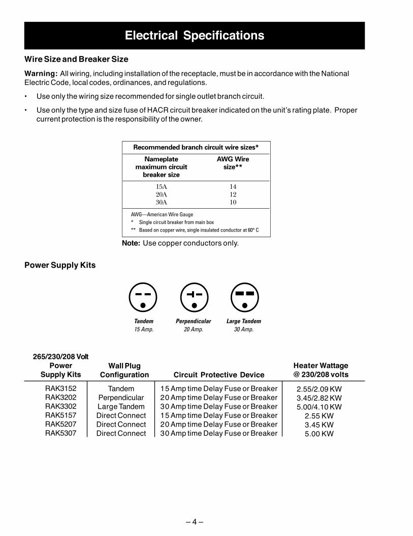
Electrical SpecificationsWire Size and Breaker SizeWarning: All wiring, including installation of the receptacle, must be in accordance with the NationalElectric Code, local codes, ordinances, and regulations.
• Use only the wiring size recommended for single outlet branch circuit.
• Use only the type and size fuse of HACR circuit breaker indicated on the unit’s rating plate. Propercurrent protection is the responsibility of the owner.
Recommended branch circuit wire sizes*
Nameplate AWG Wiremaximum circuit size**
breaker size
15A 1420A 1230A 10
AWG—American Wire Gauge* Single circuit breaker from main box** Based on copper wire, single insulated conductor at 60° C
Note: Use copper conductors only.
Power Supply Kits
Tandem15 Amp.
Perpendicular20 Amp.
Large Tandem30 Amp.
265/230/208 VoltPower
Supply KitsWall Plug
Configuration Circuit Protective DeviceHeater Wattage@ 230/208 volts
RAK3152RAK3202RAK3302RAK5157RAK5207RAK5307
TandemPerpendicularLarge TandemDirect ConnectDirect ConnectDirect Connect
15 Amp time Delay Fuse or Breaker20 Amp time Delay Fuse or Breaker30 Amp time Delay Fuse or Breaker15 Amp time Delay Fuse or Breaker20 Amp time Delay Fuse or Breaker30 Amp time Delay Fuse or Breaker
2.55/2.09 KW3.45/2.82 KW5.00/4.10 KW
2.55 KW3.45 KW5.00 KW

– 5 –
Direct Connection
208 VAC
230 VAC
265 VAC

– 6 –
Technical DataHeat Pump Model AZ75H12DAC
DISCONNECT POWER BEFORE SERVICINGIMPORTANT - RECONNECT ALL GROUNDING DEVICESAll parts of this appliance capable of conducting electricalcurrent are grounded. If grounding wires, screws, straps,clips, nuts or washers used to complete a path to ground areremoved for service, they must be returned to their originalposition and properly fastened.
WARNING DISCONNECT UNIT FROM ELECTRICAL POWERSUPPLY BEFORE MAKING ANY ELECTRICAL CHECKS.MAXIMUM CURRENT LEAKAGE: 0.75 MILLIAMPMAXIMUM GROUND PATH RESISTANCE: 0.1 OHM
POWER SUPPLYRATED VOLTAGE VOLTAGE LIMITS
230/208 187-253
Pub. No. 31-60807 Page Z-1202
FILTERCheck for cleanliness.
WIRING - COMPRESSOR DIRECT CHECKCAUTION:1. Keep head clear of terminal
area when cover is removed.2. Check windings first. If open
or grounded, “DO NOT”apply power to compressorterminals.
REPLACEMENT PARTSDESCRIPTION CAT. NO.
CONDENSER1. Check for blockage with dirt,
or other material.2. Check for corrosion.
BLACKC
R
S
O
REDWHITE
BLACK
COMPRESSOROVERLOAD
COMPRESSOR WIRING
TEST CAPACITOR
RATEDVOLTAGE
COMPRESSORTERMINALS
START
RUN S CR
COMMON
TEST KITGROUND GROUND
TO UNIT
RUN CAPACITOR CHECK1. Replace unit run
capacitor with a knowngood test capacitorwhich may be 10 MFDhigher than specifiedand attempt to startcompressor.
2. If compressor starts,install a new runcapacitor which hasa rating specified forthe unit.
IMPORTANT SAFETY NOTICEThis information is intended for use by individuals possessing adequatebackgrounds of electrical, electronic and mechanical experience. Anyattempt to repair a major appliance may result in personal injury andproperty damage. The manufacturer or seller cannot be responsible forthe interpretation of this information, nor can it assume any liability inconnection with its use.
RUNNING CURRENTWith unit in case, operate for ten minutes on Hi-Cool.Following are the operating limits:
CURRENT-TEMPERATURE CHECK DATAAIR TEMPERATURE COOLING CURRENTCONDENSER IN °F 230V-MIN. MAX. 208V-MIN. MAX.
80 4.6 5.0 4.8 5.395 5.3 5.9 5.5 6.1
110 6.2 6.9 6.8 7.6
TEMPERATURE DIFFERENTIAL - COOLINGUnit must operate for one hour with thermostat at coldestsetting prior to measuring air temperatures. Following arethe normal limits:
TEMPERATURE DIFFERENTIAL CHECK DATAEVAPORATOR EVAPORATOR AIR TEMPERATURE
AIR TEMPERATURE OUT °F IN °F 230V-MIN. MAX. 208V-MIN. MAX.
70 48 52 46 5080 58 62 58 6290 65 69 65 69
RUNNING CURRENTWith unit in case, operate for ten minutes on Hi-Heat.Following are the operating limits:
CURRENT-TEMPERATURE CHECK DATAAIR TEMPERATURE REVERSE CYCLE HEATING CURRENT
OUTDOOR COIL IN °F 230V-MIN. MAX. 208V-MIN. MAX.47 4.0 4.4 4.1 4.560 4.3 4.8 4.6 5.175 4.6 5.0 4.9 5.4
TEMPERATURE DIFFERENTIAL - HEATINGUnit must operate for one hour in reverse cycle heating priorto measuring air temperatures. Following are the normal limits:
TEMPERATURE DIFFERENTIAL CHECK DATAINDOOR COIL INDOOR COIL AIR TEMPERATURE
AIR TEMPERATURE OUT °FIN °F 230V-MIN. MAX. 208V-MIN. MAX.
70 89 93 91 9575 98 102 100 10480 106 110 108 112
SENSOR RESISTANCE (OHM)°F INDOOR COIL OUTDOOR COIL OUTDOOR AIR10 94900 28030 2803030 51940 15340 1534032 49330 14570 1457050 29960 8850 885070 17930 5300 530090 10970 3280 3280
BLOWER (I.D.) WJ73X10059CAPACITOR, I.D. MOTOR WJ20X10070CAPACITOR, O.D. MOTOR WP20X10005CAPILLARY (4) (CUT TO 11 1/2") WJ53X128COMPRESSOR WJ98X10006CONDENSER WJ88X10078DRIVE PWB WJ26X10071EVAPORATOR WJ87X10085FAN (O.D.) WJ73X10060FILTER/DRYER WJ56X104FUSE, TRANSFORMER PRIMARY WJ23X10003HEATER ASSEMBLY WJ70X10038MAIN PWB WJ26X10070MOTOR, BLOWER (I.D.) WJ73X10062MOTOR, FAN (O.D.) WJ73X10061PROTECTOR, COMPRESSOR WP23X10005PROTECTOR, HEATER-1 (resettable) WP28X10005PROTECTOR, HEATER-2 (one-time) WP28X10007REVERSING VALVE WJ58X10020REVERSING VALVE COIL WJ31X10011RUN CAPACITOR WJ20X748SUB PWB WJ26X10072THERMISTOR WJ28X10027TRANSFORMER WP27X10023VARISTOR WP27X10002

– 7 –
Electric Resistance Heat Model AZ75E12DAC
DISCONNECT POWER BEFORE SERVICINGIMPORTANT - RECONNECT ALL GROUNDING DEVICESAll parts of this appliance capable of conducting electricalcurrent are grounded. If grounding wires, screws, straps,clips, nuts or washers used to complete a path to ground areremoved for service, they must be returned to their originalposition and properly fastened.
WARNING DISCONNECT UNIT FROM ELECTRICAL POWERSUPPLY BEFORE MAKING ANY ELECTRICAL CHECKS.MAXIMUM CURRENT LEAKAGE: 0.75 MILLIAMPMAXIMUM GROUND PATH RESISTANCE: 0.1 OHM
POWER SUPPLYRATED VOLTAGE VOLTAGE LIMITS
230/208 187-253
FILTERCheck for cleanliness.
REPLACEMENT PARTSDESCRIPTION CAT. NO.
CONDENSER1. Check for blockage with dirt,
or other material.2. Check for corrosion.
IMPORTANT SAFETY NOTICEThis information is intended for use by individuals possessing adequatebackgrounds of electrical, electronic and mechanical experience. Anyattempt to repair a major appliance may result in personal injury andproperty damage. The manufacturer or seller cannot be responsible forthe interpretation of this information, nor can it assume any liability inconnection with its use.
RUNNING CURRENTWith unit in case, operate for ten minutes on Hi-Cool.Following are the operating limits:
CURRENT-TEMPERATURE CHECK DATAAIR TEMPERATURE COOLING CURRENTCONDENSER IN °F 230V-MIN. MAX. 208V-MIN. MAX.
80 4.6 5.0 4.8 5.395 5.3 5.9 5.5 6.1
110 6.2 6.9 6.8 7.6
TEMPERATURE DIFFERENTIAL - COOLINGUnit must operate for one hour with thermostat at coldestsetting prior to measuring air temperatures. Following arethe normal limits:
TEMPERATURE DIFFERENTIAL CHECK DATAEVAPORATOR EVAPORATOR AIR TEMPERATURE
AIR TEMPERATURE OUT °F IN °F 230V-MIN. MAX. 208V-MIN. MAX.
70 48 52 46 5080 58 62 58 6290 65 69 65 69
TEST CAPACITOR
RATEDVOLTAGE
COMPRESSORTERMINALS
START
RUN S CR
COMMON
TEST KITGROUND GROUND
TO UNIT
RUN CAPACITOR CHECK1. Replace unit run
capacitor with a knowngood test capacitorwhich may be 10 MFDhigher than specifiedand attempt to startcompressor.
2. If compressor starts,install a new runcapacitor which hasa rating specified forthe unit.
SENSOR RESISTANCE (OHM)°F INDOOR COIL10 9490030 5194032 4933050 2996070 1793090 10970
BLOWER (I.D.) WJ73X10059CAPACITOR, I.D. MOTOR WP20X10070CAPACITOR, O.D. MOTOR WP20X10005CAPILLARY (2) (CUT TO 21") WJ53X128COMPRESSOR WJ98X10006CONDENSER WJ88X10079DRIVE PWB WJ26X10073EVAPORATOR WJ87X10085FAN (O.D.) WJ73X10060FILTER/DRYER WJ56X104FUSE, TRANSFORMER PRIMARY WP23X10003HEATER ASSEMBLY WJ70X10038MAIN PWB WJ26X10070MOTOR, BLOWER (I.D.) WJ73X10062MOTOR, FAN (O.D.) WJ73X10061PROTECTOR, COMPRESSOR WP23X10005PROTECTOR, HEATER-1 (resettable) WJ28X10005PROTECTOR, HEATER-2 (one-time) WJ28X10007RUN CAPACITOR WJ20X748SUB PWB WJ26X10072THERMISTOR WJ28X10028TRANSFORMER WP27X10023VARISTOR WP27X10002
BLACKC
R
S
O
REDWHITE
BLACK
COMPRESSOROVERLOAD
COMPRESSOR WIRING
WIRING - COMPRESSOR DIRECT CHECKCAUTION:1. Keep head clear of terminal
area when cover is removed.2. Check windings first. If open
or grounded, “DO NOT”apply power to compressorterminals.

– 8 –
Features and Operation
ON/OFF SwitchWarning: ON/OFF switch does not disconnectpower from all circuits.
The ON/OFF switch is located on the electronicscover behind the front case panel. The ON/OFFswitch disables all relays but does not disconnectpower from all circuits. No functions are availablewhen the switch is off.
Dip SwitchesThe dip switches are located behind the front casepanel, through an opening on the front of the unit.The top row of dip switches control TemperatureLimiting. The bottom row of dip switches controlthe heat pump lockout, Freeze Sentinel, constantfan, Energy Management System, and indoor fanspeed.
The dip switches will be set in the down positionfrom the factory.
ALL I2R (All Electric Heat) (on some models)FREEZ S (Freeze Sentinel)
CONST FAN (Constant ON Fan)
TL1 (H) (Temp. Limit 1–Heat)TL2 (H) (Temp. Limit 2–Heat)TL3 (H) (Temp. Limit 3–Heat)
TL1 (C) (Temp. Limit 1–Cool)TL2 (C) (Temp. Limit 2–Cool)TL3 (C) (Temp. Limit 3–Cool)
No Function (Reserved for future use)DUCT (Blower Fan)OCCUPIED (Occupancy Sensor)
CONST FANWhen this switch is up, the fan runs continuouslyat high speed even if unit is off.
ALL I2R (Heat pump lockout)When this switch is up, heatpump operation is locked out.Only electric resistance heat isavailable when switch is up.Note: Not all models areequipped with heat pumps. Referto the Nomenclature chapter todetermine if your model isequipped with a heat pump.
FREEZ S (Freeze Sentinel)Refer to the Freeze Sentinel sectionof this chapter for more information.
OCCUPIEDRefer to the Energy ManagementSystem section of this chapter formore information.
DUCTThis switch, in conjunction with thethermostat connection, controls indoorfan speed.Refer to the Fan Speed section of thischapter for more information.
NOT USED
DipSwitches
ON/OFF Switch

– 9 –
Main Board Terminal StripCaution: Improper wiring may damage theZoneline electronics. Damage or erratic operationmay result. No common busing is permitted. Aseparate wire pair must be run from eachseparate controlling switch to each individualZoneline.
The terminal connections are located behind thefront case panel.
Insert the building hookup wires into the bottom ofthe terminal and tighten screw securely to makethe desired connections.
Route any wires from the terminal connectionsthrough the case loop.
Room Air SensorMotion Sensor
Door SensorCentral Desk Control
Common–GroundWhite–HeaterYellow–CompressorBlack–Reversing ValveGreen–High Speed FanGreen–Low Speed FanRed–24 V AC only
Common - Ground
Room Air SensorMotion Sensor
Door SensorCentral Desk
Control
White - Heat SignalYellow - Cool SignalUnusedGreen - High Speed FanGreen - Low Speed FanRed - 24 VAC Only
ON/OFF Switch
GEA01240
TerminalConnections

– 10 –
Remote Thermostat ControlThe unit is controlled by an externally mounted, remote thermostat.
The Zoneline thermostat connections provide 24 VAC only. If using a digital/electronic wall thermostat, itmust be set to the 24 VAC setting. Refer to the thermostat installation instructions for details.
Note: Some thermostats can be programmed to energize the reversing valve in heating mode or coolmode. If the thermostat is not programmed correctly, the unit will heat when the thermostat is set tocool and cool when the thermostat is set to heat. Refer to the instructions provided with the thermostatfor thermostat programming procedures. Also refer to the Reversing Valve section of the Componentschapter for more information.
Central Desk Control (CDC)
Red–24 V AC onlyGreen–Low Speed FanGreen–High Speed FanBlack–Reversing Valve
Yellow–CompressorWhite–Heater
Common–Ground
Red - 24 VAC OnlyGreen - Low Fan SpeedGreen - High Fan Speed
UnusedYellow - Cool SignalWhite - Heat SignalCommon - Ground
MAINBOARD
13
14
15
11
10
9
12
24 V
FAN (L)
FAN (H)
COOL
HEATCOMCL
ASS
2 RE
MOT
E TH
ERM
OST
AT
GEA01248

– 11 –
Central DeskControl
TL1 (C) (Temp. Limit 1–Cool)TL2 (C) (Temp. Limit 2–Cool)TL3 (C) (Temp. Limit 3–Cool)
TL1 (H) (Temp. Limit 1–Heat)TL2 (H) (Temp. Limit 2–Heat)TL3 (H) (Temp. Limit 3–Heat)
MAINBOARDCDC SWITCH
7
8
GEA01218
When a CDC switch is connected to the mainboard terminal strip, the unit can be turned on andoff from a remote location. Up to 2000 feet of wiremay be used to connect a remote CDC switch tothe unit.
A separate wire pair must be run from each CDCswitch to each Zoneline. Multiple units cannot berun from the same CDC switch.
The remote CDC switch will be closed when theunit is off.
REMOTE CDC SWITCH CLOSED = UNIT OFF
REMOTE CDC SWITCH OPEN = UNIT ON
Note: The Freeze Sentinel is still operationalwhen the remote CDC switch has turned the unitoff (room air sensor must be installed and FreezeSentinel dip switch must be in the down positionfor the Freeze Sentinel to operate).
Temperature LimitingTemperature limiting limits the lowest temperature that can be set for cooling and the highesttemperature that can be set for heating. The dip switches are used to control temperature limiting.
Temperature limiting is dependent on the Room Air Sensor (kit). If the Room Air Sensor (kit) is notinstalled, temperature limiting will not operate. Temperature limiting is not dependent on the Occupieddip switch, Motion Sensor (kit), or Door Sensor (kit).
Freeze Sentinel
edoMlooCgniruDgnitimiLerutarepmeT
pU nwoD muminiM mumixaM
enoN 3,2,1 F°06 F°58
1 3,2 F°46 F°58
2,1 3 F°66 F°58
2 3,1 F°86 F°58
3,2 1 F°07 F°58
3,2,1 enoN F°27 F°58
3,1 2 F°47 F°58
3 2,1 F°67 F°58
edoMtaeHgniruDgnitimiLerutarepmeT
pU nwoD muminiM mumixaM
enoN 6,5,4 F°06 F°58
4 6,5 F°06 F°08
5,4 6 F°06 F°87
5 6,4 F°06 F°67
6,5 4 F°06 F°47
6,5,4 enoN F°06 F°27
6,4 5 F°06 F°07
6 5,4 F°06 F°56

– 12 –
The Freeze Sentinel is enabled by a dip switchand is dependant on the Room Air Sensor (kit). Ifthe Room Air Sensor (kit) is not installed, theFreeze Sentinel will not operate. The FREEZE Sdip switch must be down for Freeze Sentineloperation.
FREEZE S SWITCH DOWN = ON
FREEZE S SWITCH UP = OFF
The Freeze Sentinel turns on the resistanceheater(s) and indoor fan when the Room AirSensor (kit) sees 41 °F. When the temperature ofthe room has risen to 46 °F, the unit will turn off.
The Freeze Sentinel will remain enabled when theunit has been turned off by the remote CentralDesk Control.
Fan Speed (Indoor Fan)The Indoor fan operates at one speed during unitoperation. The duct dip switch, in conjunction withthe thermostat connection, controls at what speedthe indoor fan operates.
When the green thermostat wire is connected tothe high speed fan (GH) terminal:
DUCT SWITCH UP = HIGH FAN SPEED
DUCT SWITCH DOWN = MEDIUM FAN SPEED
When the green thermostat wire is connected tothe low speed fan (GL) terminal:
DUCT SWITCH UP = MEDIUM FAN SPEED
DUCT SWITCH DOWN = LOW FAN SPEED
FREEZE S(Freeze Sentinel)
ALL I2R(All Electric Heat)
CONST FAN
OCCUPIED
DUCT
Door SensorFan Speed

– 13 –
Energy Management SystemThe following conditions must exist for the EnergyManagement System to operate:
• OCCUPIED dip switch is up.
• Room Air Sensor (kit) is installed.
• Door Sensor (kit) is installed.
• Motion Sensor (kit) is installed.
The Energy Management System uses input fromthe Door Sensor (kit) and Motion Sensor (kit) toestablish if the room is occupied or unoccupied.When the Energy Management System hasestablished that the room is unoccupied, it usesinput from the Room Air Sensor (kit) and allowsthe temperature of the room to lower to 68 °F (heatmode) or raise to 78 °F (cool mode). When theroom becomes occupied, the Energy ManagementSystem will return to thermostat-controlledoperation and will return the room to thetemperature set on the thermostat.
Door Sensor
DOOR OPEN = SENSOR (SWITCH) CLOSED
DOOR CLOSED = SENSOR (SWITCH) OPEN
MAIN BOARD OUTPUT TODOOR SENSOR = 24 VAC
Schematic shown with unit on, door closed, andmotion sensed.
MAINBOARD
2
3
4
1ROOM AIR SENSOR
MOTION SENSOR
CDC SWITCH
DOOR SWITCH 5
6
7
89
GEA01211
Door Sensor (kit)The door sensor has a two-wire circuit that isconnected to the main board terminal strip. Whenthe door opens, the door sensor (switch) closes.
When the Energy Management System sees thedoor sensor circuit close (door opened), theEnergy Management System will then check themotion sensor circuit.
Note: The Energy Management System isdependent on the Room Air Sensor, MotionSensor, and Door Sensor. If the Room Air Sensor,Motion Sensor, and Door Sensor are not installed,the Energy Management System will not operate.
The following conditions must existfor the energy management system
to operate:• Occupied dip switch is up.• Room Air Sensor (kit) installed.• Door Sensor (kit) installed.• Motion Sensor (kit) installed.
When the door opens, theunit will check the motion sensor.
Unit switches to Room AirSensor control. Unit will lowertemperature of room to 68 ˚F
(heat mode) or raise thetemperature of room to 78 ˚F
(cool mode).
Unit continues tobe controlled by
thermostat.
No motiondetected by
motion sensor.
Motion detected bymotion sensor.

– 14 –
Room AirSensor
Motion Sensor (kit)The motion sensor has a 2-wire circuit that isconnected to the main board terminal strip. Themotion sensor is an electronic sensor that, whenmotion is sensed, closes a switch (internal to thesensor), completing the motion sensor circuit.
After the Energy Management System has seenthe door sensor circuit closed (door opened), it willcheck the motion sensor circuit. If the EnergyManagement System sees the motion sensorcircuit closed (no motion detected by the sensor),it will then check the temperature being reportedby the room air sensor. If the Energy ManagementSystem sees the motion sensor circuit open(motion detected by sensor), the unit will continueto be thermostat-controlled.
Note: The Energy Management System isdependent on the Room Air Sensor, MotionSensor, and Door Sensor. If the Room Air Sensor,Motion Sensor, and Door Sensor are not installed,the Energy Management System will not operate.
Motion Sensor
NO MOTION = SENSOR (SWITCH) CLOSED
MOTION = SENSOR (SWITCH) OPEN
MAIN BOARD OUTPUT TOMOTION SENSOR = 24 VAC
MAIN BOARD OUTPUT TOROOM AIR SENSOR = 5 VDC
rosneSriAmooRseulaVecnatsiseR
erutarepmeT ecnatsiseR
F°23 k06 !
F°86 k02 !
F°77 k01 !
F°68 k9 !
F°59 k8 !
Room Air Sensor (kit)The room air sensor is a thermistor with anegative coefficient (as temperature rises,resistance goes down). The sensor has a 2-wirecircuit that is connected to the main board terminalstrip.
The room air sensor is used for TemperatureLimiting and for the Energy Management System.
When the Energy Management System sees thedoor sensor circuit close and then the motionsensor circuit close (room unoccupied), theEnergy Management System will ignore thethermostat and check the temperature reported bythe room air sensor. Based on the input from theroom air sensor, the Energy Management Systemwill allow the temperature of the room to lower to68 °F (heat mode) or raise to 78 °F (cool mode).
Note: The Energy Management System isdependent on the Room Air Sensor, MotionSensor, and Door Sensor. If the Room Air Sensor,Motion Sensor, and Door Sensor are not installed,the Energy Management System will not operate.

– 15 –
Automatic Defrosting of Indoor and Outdoor CoilsDuring continued compressor operation, there is potential for ice to form on the indoor coil when in coolmode and for ice to form on the outdoor coil when in heat mode. The Zoneline is equipped withAutomatic Defrost to eliminate this potential problem.
Indoor coil defrost will occur when the indoor coil thermistor reads a temperature of 34 °F or less for aduration of 5 minutes. The main board will automatically shut the compressor off, allowing the indoorcoil temperature to rise. The fans will continue to operate throughout the defrost cycle for continued aircirculation. When the indoor coil thermistor detects a temperature of 50 °F or above, the compressorwill resume normal operation. A 3-minute minimum compressor off time will be in effect.
Outdoor coil defrost will occur for one of the following reasons:
• The outdoor temperature thermistor reads a temperature of 14 °F or less for a duration of 2 hoursand 59 minutes.
• The accumulated run time of the compressor is greater that 3 hours with an outdoor temperatureof 32 °F or less.
The outdoor coil is defrosted by reverse cycle defrosting (reversing the direction of the refrigerantflowing through the sealed system). This will cause hot refrigerant flowing through the outdoor coil toquickly and efficiently melt any ice that has formed. Outdoor coil defrosting will terminate when theoutdoor coil thermistor reads a temperature of 68 °F or when a period of 9 minutes has elapsed,whichever comes first. When outdoor defrosting has been completed, the resistance heater(s) andfans will run for a minimum of 90 seconds or until the room has reached the thermostat set point.
Ventilation ControlThe ventilation control lever is located on the leftside of the Zoneline unit, behind the front casepanel.
When the lever is in the CLOSE position, only airinside the room is circulated and filtered.
When the lever is in the OPEN position, someoutdoor air will be drawn into the room. This willreduce the heating or cooling efficiency.
Vent control(push lever downand pull forward
or back tooperate)
Open
Close

– 16 –
Cool Mode OperationNote:
• Minimum compressor/fans off time is 3 minutes +/- 10 seconds.
• Reversing valve is energized at all times in cool mode. Reversing valve is not de-energizedwhen thermostat is satisfied.
• Indoor and outdoor fans always operate at the same time in cool mode.
Currently CoolingIndoor fan, outdoorfan, compressor,reversing valve
energized.
Thermostatsatisfied.
Indoor fan, outdoorfan, compressor
off.
Compressorenergized.Currently Off
Set thermostat tocool. Adjust
thermostat to settingbelow roomtemperature.
Indoor fan, outdoorfan, reversing
valve energized.Thermostat not
satisfied.
Indoor fan, outdoorfan energized.
3 SECOND DELAY
3SECONDDELAY

– 17 –
Heat Mode OperationNote:
• Minimum compressor/fans off time is 3 minutes +/- 10 seconds.
• Heat pump will not operate if outdoor thermistor sees 25 °F or less.
• Heat pump and resistance heater(s) do not operate at the same time.
• Indoor and outdoor fans operate at the same time, with the following exception: Should theindoor coil temperature reach 131 °F, the outdoor fan will stop until the indoor coil temperaturelowers to 126 °F.
Heat pump modelcurrently heating with
an outdoor temperatureabove 25 ˚F.
Indoor fan, outdoorfan, compressor
energized.Thermostatsatisfied.
Indoor fan, outdoorfan, compressor
off.Thermostat not
satisfied.
Indoor fan, outdoorfan on.Compressor on. 3 SECOND DELAY
Nonheat pump modelcurrently heating
or heat pump model
currently heating withan outdoor temperature
below 25 ˚F.
Heat pump modelcurrently off with anoutdoor temperature
above 25 ˚F.
Set thermostat toheat mode. Adjust
thermostat tosetting above
room temperature.
Indoor fan, outdoorfan, resistance
heaters energized.
Indoor fan, outdoorfan, resistance
heaters energized.Thermostatsatisfied.
Indoor fan, outdoorfan, resistance
heaters off.
Thermostatsatisfied.
Indoor fan, outdoorfan, resistance
heaters off.
Thermostat notsatisfied.
Indoor fan, outdoorfan, resistance
heaters energized.Thermostatsatisfied.
Nonheat pump modelcurrently off
or heat pump model
currently off with anoutdoor temperature
below 25 ˚F.
Set thermostat toheat mode. Adjust
thermostat tosetting above
room temperature.

– 18 –
Slide-Out Chassis
Side RemovalNote: If slide-out chassis cannot be removed fromthe front, perform the first 4 steps of FrontRemoval above and proceed with Side Removalbelow.
1. Remove 8 screws and the cabinet side plate.
2. Move the chassis out of the front of the cabinetapproximately 2 inches.
3. Slide the chassis out from the side of thecabinet.
Pull ChassisForward
Slide Out Side
WARNING: Case ground bolt at front of chassismust be installed to ensure proper grounding ofthe unit. Case ground screw on left hand cabinetside plate and/or right hand cabinet side platemust be installed to ensure proper grounding ofthe unit.
Front Removal1. Remove 6 screws and the front panel.
2. Remove the 5/16-in. (case ground) boltfastening the chassis to the base of thecabinet.
3. Remove the case ground screw from the left-hand side cabinet side plate and/or the right-hand cabinet side plate.
4. Turn 4 screws on the cabinet top platecounterclockwise to the raise duct connectorto stop.
5. Slide the chassis out of the cabinet.
Cabinet Top Plate
5/16-in. Bolt (Case Ground)
Screws
5/16-in. Bolt (Case Ground)
Case Ground ScrewCase Ground Screw

– 19 –
Components
Main BoardTo access the main board:
1. Remove 6 screws and the front panel.
2. Unplug the heater connector.
WARNING: Do not touch the capacitors after theelectronics cover is removed.
Caution: When removing electronics cover, pullthe right side out a few inches to avoid damage tothe switch wires.
3. Remove 4 screws from the electronics cover.
4. Lift the electronics cover to access the subboard. Unplug the ON/OFF switch from thesub board at connector CN202 and remove thecover.
Driver BoardTo access the driver board:
Remove the electronics cover (see Main Boardsection).
FuseA 4-amp fuse is located on the driver board, and iscommon to the transformer circuit. If this fuseblows (open), all relays and the remote thermostatwill not function.
Sub BoardTo access the sub board:
Remove the electronics cover (see Main Boardsection).
Heater Connector
ON/OFF Switch
Electronics Cover
Driver BoardMain Board Sub Board
FuseFuse

– 20 –
Compressor and CapacitorThe Zoneline compressor is a rotary type thatoperates on 265/230/208 VAC. After thecompressor has cycled off, it will not attempt torestart for 3 minutes +/-10 seconds, regardless ofthe state of the thermostat. This will allow internalpressure to equalize and prevent the compressorfrom stalling by trying to start against highpressure in the sealed system.
Current flow into the compressor is monitored bythe main board to determine if the compressor isrunning or locked. If the run signal is sent and alocked condition is detected for 4 seconds, the runsignal will stop and a 3-minute count will begin.After the 3-minute count, the run signal is sentagain. If the compressor starts, the count is resetand the unit functions normally. If the compressordoes not start after 4 consecutive attempts, thecontrol will determine that a compressor failurehas occurred and a beeping alarm will sound. Thealarm will continue until the compressor failurecondition is reset by turning the unit off at the ON/OFF switch or by removing power to the unit.
The compressor overload is internal to thecompressor for 18000 BTU models and is locatedunder the relay/overload cover for 9000 and 12000BTU models. Should the overload trip (open) it willopen the common line to the compressor,stopping compressor operation.
A copper process tube is provided for access tothe low-pressure side of the refrigeration system.
The compressor capacitor is located under theelectronics cover, above the driver board.
Filter/DryerThe filter/dryer for heat pump models is located inthe horizontal section of the discharge tubebetween the compressor and reversing valve.
The filter dryer for electric resistance heat modelsis located in the liquid tube between the condenserand the capillaries.
Compressor Capacitor
Compressor
seulaVecnatsiseRrosserpmoC
rosserpmoCeziS
gnidniWRotC
gnidniWSotC
UTB0009CAV802/032 4.3 ! 8.5 !
UTB00021CAV802/032 3.2 ! 1.2 !
UTB00081CAV802/032 2 ! 2.2 !

– 21 –
Compressor Troubleshooting
54321
208/230VAC
RY102RY101 RY103
DRIVER BOARD
MAINBOARD
CN2
SUBBOARD
RY202BR
COMP.MOTOR
9
C
OR
BL
GR
GY
R
S
O. L. P.
BK
RUN. CAP.
876
1
54321
265VAC
9BL
GR
GY
876
1
1
GEA01247
1
32
Note: On 18000 BTU models, overload protection is internal to the compressor.
Is the compressorshort cycling
ornot operating at
all?
Unplug the unit. Move theblack wire from upper left-
hand terminal (terminal 4) ofrelay RY101 to lower right-
hand terminal (terminal 3) ofrelay RY101. Turn the ON/OFF switch OFF. Plug theunit in. Turn the switch ON.
Does compressor come on?
NOTOPERATING
Check for line voltageat compressor
between the C and Rterminals?
Voltage present?
NO
Check:• Circuit from RY101 to compressor.• Circuit from RY202 to compressor.• Driver board power-supply circuit
from relay RY102 to relay RY101.
NO
Check for 24 VAC frommain board terminal strip
terminal 13 to terminal 15.
Voltage present?
YES
Thermostat orwiring.
NO
YES
Check for 5 VDCat main board CN2between terminals
1 and 10.
Voltage present?
Replace mainboard. NO
Replace driverboard.
YES
Note: Compressor willremain off for 3minutes. When
compressor comes on,check lines to indoor
coil.
Are compressor linescold?
SHORTCYCLING
Reversing valve isstuck in the heat
position. Diagnosereversing valve.
NO
Compressor orCapacitor.YES
Compressor andoverload are
suspect. Checkcompressor and
overload.
YESReplace the blackwire from the lowerright-hand terminal
(terminal 3) ofrelay RY101 to the
upper left-handterminal (terminal4) of relay RY101.
Note: Minimum comp./fans-off time is 3 min.
Fan-on may be delayed.
Set the thermostat to heatmode or cool mode.
Adjust the temperature setpoint so that the unit will
begin to cool or heat.
Are both fans running?
Go to Dead Unittroubleshooting.NO
YES

– 22 –
Resistance HeatersThe heaters consist of three 265 VAC or 230/208 VAC resistance heating coils fastened together in asingle assembly. The heaters are located behind the indoor coil and are protected against overheatingby 2 thermal protectors. An L185-30 thermal protector is used as a temperature regulator. A one-shotL248 thermal protector is used as a backup in case the temperature regulating thermal protector fails(stuck closed).
Heat Pump models will utilize electric resistance heat upon initial heat mode startup or when a poweroutage has occurred with the unit in heat mode. The electric heaters will be energized until the roomtemperature reaches the thermostat setting. Once the thermostat temperature setting is attained, theunit will cycle off and automatically switch over to heat pump operation. The heat pump will provide allheating requirements for subsequent cycles unless one of the following conditions occur:
• The dip switch has been placed in the I2R (ALL ELECTRIC HEAT) position. When the dip switch isplaced in the up position, heat pump operation will be locked out. Only electric resistance heat willbe available.
• A temperature differential of approximately 2 °F (temperature differential varies by thermostatmanufacturer) is detected between the thermostat set point and the room air temperature. If adifferential of approximately 2 °F is detected, due to thermostat adjustment or falling room airtemperature, the electric heaters will be energized (heat pump off) until the thermostat is satisfied.Once the thermostat has been satisfied, the unit will automatically revert back to heat pumpoperation for subsequent cycles.
• The outdoor temperature falls below 25 °F. If the outdoor temperature falls below 25 °F, the unit willautomatically switch from heat pump operation to resistance heat operation. A 7 °F hysteresis loopwill be in effect; therefore, the unit will operate in resistance heat mode until an outdoor temperatureof 32 °F or higher is detected.
Electric resistance heat and heat pump operation will never occur at the same time.
Models without heat pump feature will meet heating requirements by use of electric resistance heatingcoils.
54321
230/208VAC
BLWHGRRDGYBRBK
BK
WH
RD BK
RY102
CN2
RY103
PROTECTOR
PROT
ECTO
R
LOW
ER
HEATERCONN
RD
MID
DLE
UPPE
R
HEAT
ER U
NIT
DRIVERBOARD
MAINBOARD
9876 13 2
13 2
2 3
2 3
2 3
GEA01253
Tandem15 Amp.Tandem15 Amp.
Perpendicular20 Amp.
Perpendicular20 Amp.
Large Tandem30 Amp.
Large Tandem30 Amp.
987
6
5
43
2
1
BKBKW
HW
H
GY
GY
RD
RD
GR
GR
987
6
5
43
2
1
BKBKW
HW
H
GY
GY
RD
RD
GR
GR
987
6
5
43
2
1
BKBKW
HW
H
GY
GY
BLBL
RD
RD
GR
GR
seulaVecnatsiseRretaeH
rotcennoctadekcehcnehW retaehtadekcehcnehW
otkcalBetihW
02:CAV562 !61:CAV802/032 ! lioCreppU 92:CAV562 !
02:CAV802/032 !
otkcalBdeR
82:CAV562 !12:CAV802/032 !
elddiMlioC
54:CAV562 !13:CAV802/032 !
lioCrewoL 07:CAV562 !84:CAV802/032 !

– 23 –
Resistance Heater Troubleshooting
Note: Normal heat is provided by heat pump operation when outdoor temperature is above 25 °F.The number of heaters that operate is dependant on the Power Supply Kit used.
• Tandem - 1 heater• Perpendicular - 2 heaters• Large Tandem - 3 heaters
Place dip switch in I2R lockout.
Do heaters come on?YES
Check heater resistance atheater connector.
265 VACBK to R =28 BK to W = 20 230/208 VAC
BK to R = 21 BK to W = 16
Resistance OK?
NO
Replace heater.
Check for 5 VDCbetween CN2 pin3 to CN2 pin 10.
5 VDC present?
NO
Replace mainboard.
Place thermostat in heat mode. Setthermostat to setting 5 ˚F above room
temperature.
Do heaters come on?
YES
Replacethermostat.
Monitor heateroperation.
Do heaters shortcycle?
NO
Check for 24 VAC at main boardterminal strip (CN5) between
terminal 14 (white) and terminal15 (common).
Is 24 VAC present?
Replace faultythermal protector.YES
Normal operation
NO
YES
NO
Check forcontinuity through
both thermalprotectors.
Continuity?
YES
Replace faultyprotector. NO
NO
With thermostatcalling for heat,
check for line voltagebetween RY102
(orange wire/brownwire) and RY103
(black wire).
Line voltage present?
YESCheck for open wire between RY103 and
heaters. Check for open wire between RY102and power cord connector. Check for open wire
between power cord connector and heaters.YES
NO
Check for 5 VDCbetween CN2 pin2 to CN2 pin 10.
5 VDC present?
YES YES
NO
Does the indoorfan come on?
YES
Go to Dead Unittrouble shooting. NO
Replace mainboard.
Replace mainboard.
Replace driverboard.
Check resistanceat heater.
Resistance OK?NO
Repair faultywiring.
YES

– 24 –
To remove the resistance heaters:
1. Remove the front panel and slide the chassisforward approximately 5 in. (see Slide-OutChassis chapter).
2. Remove electronics cover (see Main Boardchapter).
3. Remove the left and right corner sheet metalpanels fastened to the sides of the indoor coil.
4. Remove 3 screws fastening the ventilationcontrol to the indoor coil top panel.
5. Remove 4 screws and the indoor coil toppanel.
6. Carefully position the indoor coil to allowaccess to 4 heater assembly mountingscrews.
7. Remove 4 screws and the heater.
8. Tag and disconnect wires.
9. Slide the heater out of the right side of the unit.
To Test Heaters and Thermal Protectors:
Disconnect the heater connector. Measure theresistance of each coil using the followingresistance values.
Check the thermal protectors for continuitybetween heater connector terminal 1 (black wire)and the black wire to relay RY103.
Note: A continuity reading on a thermalprotector indicates that the protector isclosed at the time of the check only. A faultythermal protector may open prematurely, resultingin insufficient heating.
Right Corner Sheet Metal Panel
Left Corner Sheet Metal PanelLeft Corner Sheet Metal Panel
Right Corner Sheet Metal Panel
Indoor Coil Top PanelVentilation Control
Resistance Heaters Thermal Protectors
Indoor Coil
Heater Connector
seulaVecnatsiseRretaeH
rotcennoctadekcehcnehW retaehtadekcehcnehW
otkcalBetihW
02:CAV562 !61:CAV802/032 ! lioCreppU 92:CAV562 !
02:CAV802/032 !
otkcalBdeR
82:CAV562 !12:CAV802/032 !
elddiMlioC
54:CAV562 !13:CAV802/032 !
lioCrewoL 07:CAV562 !84:CAV802/032 !

– 25 –
Indoor Fan and CapacitorThe indoor fan is a 265/230/208 VAC, permanently lubricated motor. Indoor fan speed is selected in thefollowing manner:
When the green thermostat wire is connected to the high-speed fan (GH) terminal:
DUCT SWITCH UP = HIGH FAN SPEED
DUCT SWITCH DOWN = MEDIUM FAN SPEED
When the green thermostat wire is connected to the low-speed fan (GL) terminal:
DUCT SWITCH UP = MEDIUM FAN SPEED
DUCT SWITCH DOWN = LOW FAN SPEED
The indoor fan and outdoor fan will operate simultaneously under normal operating conditions. Toenergize the fans, press the FAN button on the thermostat. When fan ON mode is selected, the fanswill run continuously, independent of the compressor or heaters. Selecting AUTO on the thermostat willcause the fans to automatically cycle on and off with the compressor or heaters. The fans will alwaysrun when the compressor or heaters are operating. They will start before compressor or heateroperation, and will stop after compressor or heater operation has ended. The fans can also be set torun continually, regardless of thermostat setting, by placing the CONST FAN dip switch in the (UP)position (see Dip Switches section of the Features and Operation chapter).
The indoor fan capacitor is located under the electronics cover and below the driver board.
To remove the outdoor fan:
1. Remove the unit from the cabinet (see Slide-Out Chassis chapter).
2. Remove the left and right divider assemblies.
3. Remove the electronics cover (see Main Boardchapter).
4. Remove the resistance heaters (seeResistance Heaters chapter).
5. Remove 1 screw and slide the metal panelfrom in back of the indoor coil out the right sideof the unit.
6. Loosen the Phillips head setscrew securingthe blower wheel.
Note: Position blower wheel setscrew on the flatside of the motor shaft when reassembling.
Metal PanelIndoor Coil
Outdoor Fan CapacitorIndoor Fan Capacitor

– 26 –
7. Remove 3 screws and the brace above theindoor fan motor.
8. Disconnect the indoor fan wiring connector(CN101) at the driver board.
Wire Retainer3 Screws
Sheet Metal Panel
Wire HarnessWire Harness
Sheet Metal Panel
Brace
54321 345C
APA
CIT
OR
208/230VAC
RY102
BL
GY
BRBK WH RD
COM
LOW
MED
HI
RD
RY202
DRIVERBOARD
MAINBOARD
RY103
RY104 RY105
RY201
CN107
CN106
CN2
CN101
CN201 SUBBOARD
1
35 1
I.D.FAN
MOTOR
2
3 12
3 12
3
12
1
32
3
12
1
3
2
1
32
9876
89
89
9 8
4
4
4
GEA01245
54321
265VAC
BL
GY
9876
Indoor Fan Resistance Values230/208 VAC ModelsWhite to black 64 !Orange to black 60 !White to orange 5 !
9. Disconnect CN201 from sub board.
10. Remove 3 screws from the sheet metal panelon top of the fan shroud above the wireretainer.
11. Remove the metal wire retainer and the wireharness.
Note: Collars are placed on the 4 fan mountingscrews. Use care not to lose collars.
12. Remove 4 screws, the fan motor, and themotor rubber from the indoor fan motor angle.
ScrewsScrews
Motor Angle
Fan Motor

– 27 –
Indoor Fan
Note: Minimum comp./fan-off time is 3 minutes. Fan-
on may be delayed.
Set thermostat to heatmode or cool mode andadjust temperature set
point so that the unit willbegin to heat or cool.
Do the outdoor fan andcompressor fan come on?
Before continuing troubleshooting, the fanspeed setting must be established:High - Duct dip switch up and green
thermostat wire connected to GH terminal.Medium - Duct dip switch down and greenthermostat wire connected to GH terminal
orDuct dip switch up and green thermostat
wire connected to GL terminal.Low - Duct dip switch down and green
thermostat wire connected to GL terminal.
What speed is fan set to run at?
Set thermostat tofan run mode.Check for line
voltage betweenCN101 pin 5 and
CN201 pin 1.
Voltage present?
HIGH
Set thermostat tofan run mode.Check for line
voltage betweenCN101 pin 5 and
CN101 pin 1.
Voltage present?
MED
Set thermostat tofan run mode.Check for line
voltage betweenCN101 pin 5 and
CN101 pin 3.
Voltage present?
LOW
YES
Check for 5 VDCon main board
CN2 between pins4 and 10.
Voltage present?
Check indoor fan motorresistance values.
Resistance values OK?
YES
Replace fanmotor. NO
Check for 5 VDCon main board
CN2 between pins8 and 10.
Voltage present?
NOReplace capacitor.
YESNO
Replace capacitor.
YES
Check for 5 VDCon main board
CN2 between pins9 and 10.
Voltage present?
NO
Replace driverboard.
Replace driverboard.
Replace driverboard.
Replace mainboard.
NO
Replace mainboard.
Replace mainboard.
YES NO
NO
YES YES
Replace capacitor.
YES
Go to Dead Unittroubleshooting. NO
Does the outdoor fan spinfreely?
Is the outdoor fan freefrom obstructions?
YES
Remove theobstruction or
replace the outdoorfan motor.
NO
Check for 10 VDCon driver board
between CN107-2and CN 104-10.
Voltage present?
NO
Replace SubBoard
YES
Indoor Fan Resistance Values230/208 VAC ModelsWhite to black 64 !Orange to black 60 !White to orange 5 !

– 28 –
Outdoor Fan and CapacitorThe outdoor fan is a single-speed, 265/230/208 VAC, permanently lubricated motor.
The indoor fan and outdoor fan will operate simultaneously under normal operating conditions. However,if the heat pump is operated when high outdoor temperatures are present, the indoor coil may overheat.Should the indoor coil temperature reach 131 °F, the main board will shut the outdoor fan off . A 5 °Fhysteresis loop will restore outdoor fan operation when the indoor coil temperature lowers to 126 °F.
To energize the fans, press the FAN button on the thermostat. When fan ON mode is selected, the fanswill run continuously, independent of the compressor or heaters. Selecting AUTO on the thermostat willcause the fans to automatically cycle on and off with the compressor or heaters. The fans will alwaysrun when the compressor or heaters are operating. They will start before compressor or heateroperation, and will stop after compressor or heater operation has ended. The fans can also be set torun continually, regardless of thermostat setting, by placing the CONST FAN dip switch in the UPposition (see Dip Switches section of the Features and Operation chapter).
The outdoor fan capacitor is located under the electronics cover and below the driver board.
To remove the outdoor fan:
1. Remove the unit from the cabinet (see Slide-Out Chassis chapter).
2. Remove the left and right divider assemblies (outer sheet metal panels).
3. Remove 8 screws from the fan shroud.
4. Remove 3 screws and the brace above the outdoor fan motor.
Outdoor Fan CapacitorIndoor Fan Capacitor
5. Disconnect the outdoor fan wiring connector atthe drive board.
6. Remove 2 screws fastening the bottom of theoutdoor fan motor angle to the base plate.
7. Lift the fan shroud, motor angle, and fan motoras an assembly and remove them from the rightside of the unit.
8. Remove the 8 mm nut fastening the fan blade tothe motor shaft.
9. Grasp the fan motor shaft with locking pliers.While holding the shaft, turn the fan bladecounterclockwise to unscrew the blade from theshaft.
Note: Lockwashers are placed between the screwhead and fan motor, and between the fan motor andthe fan motor angle.
10. Remove 4 screws, 8 lockwashers, and the fanmotor from the fan motor angle.
Fan Shroud
Outdoor FanMotor Angle
BraceBrace

– 29 –
Outdoor Fan Troubleshooting
GEA01244
54321
230/208VAC
RY102
CN2
CN107
DRIVER BOARD
CN102
CN106
MAINBOARD
9876
6
6
6
SUB BOARD
RY202
CAPACITOR1
3
RY103 3
1
1
32
3
1
O.D.FAN
MOTOR
RY107
5 3 1
5 4 3 2 1
BL
GR
GY
BK RD
BR
54321
265VAC
BL
GR
GY
9876
Note: Minimum comp./fans-off time is 3 min.
Fan-on may be delayed.
Set the thermostat to heatmode or cool mode.
Adjust the temperature setpoint so that the unit will
begin to heat or cool.
Does the indoor fan andcompressor come on?
YES
Does the outdoor fan spinfreely?
Is the outdoor fan freefrom obstructions?
Remove theobstruction or
replace the outdoorfan motor.
NO
YES
Set thermostat to fanrun mode. Check forline voltage at driver
board betweenCN102-1and CN102-5.
Voltage present?
Check for 5 VDCat main board
between CN2-6and CN2-10.
Voltage present?
NOReplace mainboard. NO
Replace driverboard.
YES
Check resistancevalues for outdoor
fan motor.
Resistance OK?
YES Replace capacitor.YES
Replace fanmotor.
NO
Go to Dead Unittroubleshooting. NO
Outdoor Fan Resistance Values230/208 VAC ModelsBlack to red wires 86 !

– 30 –
Reversing ValveThe reversing valve operates on 265/230/208 VAC and is used to switch the direction of refrigerant flow.The reversing valve controls the direction of the refrigerant flow. When the reversing valve solenoid isenergized, it will close the reversing valve and the unit will operate as an air conditioner. When thesolenoid is de-energized, the reversing valve will open and the unit will function as a heat pump.
To confirm that the reversing valve and reversing valve solenoid are functioning properly, the main boardcontinually monitors the indoor coil thermistor and outdoor coil thermistor. Should the system operate inthe reverse of the selected mode due to a reversing valve or reversing valve solenoid malfunction, theboard will detect improper thermistor readings, determine that the unit is not operating properly, andterminate compressor operation.
Note: Some thermostats can be programmed to energize the reversing valve in heat mode or coolmode. If the thermostat is not programmed correctly, the unit will heat when the thermostat is set tocool and will cool when the thermostat is set to heat. Refer to the instructions provided with thethermostat for thermostat programming procedures. Also refer to the Remote Thermostat Controlsection of the Features and Operation chapter for more information.
To remove the reversing valve solenoid:
1. Remove the unit from the cabinet (see Slide-Out Chassis chapter).
2. Remove the electronics cover.
3. Remove the left divider assembly.
4. Disconnect the reversing valve solenoid wiringfrom the driver board.
5. Remove 1 (7 mm) screw and the reversingvalve solenoid.
ReversingValveReversingValve

– 31 –
GEA01243
54321
230/208VAC
RY102
CN2
CN107
BL
GR
BK BK
GY
CN106
CN105
MAINBOARD
DRIVER BOARD
9876
5
54321
265VAC
BL
GR
GY
9876
5 3
5
SUB BOARD
RY202
3
1
2
RY103
31
31
3
1
3
12
3
1
REV.VALVE
SOLENOID
RY108
ENERGIZED = AIR CONDITIONERDE-ENERGIZED = HEAT PUMP
Reversing Valve Troubleshooting
Reversing Valve CoilResistance Value = 1200!!!!!
Note: Minimum compressor/fans-offtime is 3 minutes.
Set thermostat to cool mode. Adjustthe temperature set point to a settingbelow room temperature. Check forline voltage on driver board at CN105
between pins 1 and 3.
Voltage present?
Feel the linesgoing to the indoor
coil.
Do lines feel warmor cold?
YES
Check for 5 VDCon main board at
CN2 between pins5 and 10?
Voltage present?
NO
Replace mainboard. NO
Replace driverboard.
YES
WARM
Note:• Minimum compressor/fans-off time is 3 minutes.• Heat pump models will utilize electric resistance
heaters for initial heat mode startup. Once thethermostat set point is attained, the unit willcycle off and automatically switch to heat pumpoperation on subsequent cycles, unless theoutdoor temperature is less than 25 ˚F.
Set the thermostat to heat mode. Adjust thetemperature set point to a setting above room
temperature. When compressor comes on, feelthe lines going to the indoor coil.
Do lines feel warm or cold?
COLD
COLDWARMReversing valve isoperating properly.
Suspect a faultyvalve coil.
Suspect a faultyvalve coil.

– 32 –
TransformerThe transformer is located under the electronics cover and below the driver board. The transformerprovides low voltage power to the main board, driver board and thermostat.
To test the transformer:
Verify line voltage is present at CN204 on sub board. If line voltage is not present, suspect buildingsupply voltage, blown (open) fuse, a faulty sub board or a faulty driver board. If line voltage is present,use the following chart to check the voltage output and resistance values. If values are not correct,replace the transformer.
egatloVremrofsnarTCAV802/032seulaVecnatsiseRdna
erusaeMssorcA
egatloVtuptuO ecnatsiseR
otkcalBkcalB nieniL 301 !
otwolleYwolleY CAV21 0.1 !
otetihWetihW CAV42 3.3 !
Transformer
Driver Board
230/208 VAC version shown
54321
230/208VAC
RY102
FUSE (4 amp)
BL
GY BR
RD
CN106
CN103
SUB BOARD
YL YL BK BK
RY103
THERMISTORS
ROOM AIR SENSOR
MOTION SENSOR
DOOR SWITCH
CDC SWITCH
THERMOSTAT
RY20
2
SW201
CN202
DRIVER BOARD
MAIN BOARD
CN204
TR1
WHWH
9876
1
21
1
3
2
1
3
21
2 3 4 5 6 7
1 2 5 7
GEA01242
54321
265VAC
BL
GY
9876

– 33 –
ThermistorsThe main control board uses input from 3 thermistors. These thermistors are located on the indoor coil,outdoor coil, and outdoor fan shroud. The main control board monitors the thermistors to determine thetemperature in these areas and uses this information to make operating decisions.
For the optional room air sensor (kit), see the Room Air Sensor section in the Features and Operationchapter.
)smhO(ecnatsiseRrotsimrehT
erutarepmeT roodnIlioC
roodtuOlioC
roodtuOriA
F°01 00949 03082 03082
F°03 04915 04351 04351
F°23 03394 07541 07541
F°05 06992 0588 0588
F°07 03971 0035 0035
F°09 07901 0823 0823
Thermostatic Drain ValveDuring the cooling season, the thermostatic drainvalve remains closed to allow water to accumulatein the base pan. The water is then picked up bythe outdoor fan blade and blown into thecondenser, providing more efficient cooling.During heat pump season the thermostatic drainopens to allow water to drain from the base panprior to freezing. This prevents the outdoor fanblade from scraping against ice that could freezein the bottom of the base pan.
The thermostatic drain valve is operated by a self-contained thermostat. The thermostat begins toopen the drain valve at approximately 58 °F andwill be fully open at approximately 45 °F.
To remove the thermostatic drain valve:
1. Remove the unit from the cabinet (see Slide-Out Chassis chapter).
2. Remove the left divider assembly.
3. Remove 2 screws and the thermostatic drainvalve.
2
34
56
12
34
56
1MAIN
BOARD
INDOOR THERMISTOR
OUTDOOR THERMISTOR
OUTSIDE THERMISTOR
GEA01212
INDOOR COIL THERMISTOR
OUTDOOR COIL THERMISTOR
OUTDOOR AIR THERMISTOR
CN1

– 34 –
Dead Unit Troubleshooting
Check the ON/OFF switch to be
sure it is on.
Is the thermostatilluminated?
Check the fuse.
Fuse OK?
NO
Replace the fuse. NO
YES
Check for linevoltage betweenterminals 3 and 7
at power cordconnector.
Voltage present?
Check for linevoltage on subboard at CN204between pins 5
and 7.
Voltage present?
NO
Check buildingsupply voltage and
power cord.NO
Check for linevoltage between
driver board CN106-1 and the brownwire at RY202.
Voltage present?
YES
Check brown wirebetween driver board
and RY202 (subboard) for an open. If
OK, replace driverboard.
NO
Replace subboard.
YES
Check for 24 VACat main board
CN3-1 to CN3-2.
Voltage present?
YES
Replacetransformer.
NO
Replacethermostat.YES
Check for 24 VAC atmain board terminalstrip (CN5) between
green fan wire (terminal10 or 11) and common
wire (terminal 15).
Voltage present?
YES
Open green wireor faulty
thermostat.
NO
Check for 10 VDCat driver boardCN103-1 and
CN103-2.
Voltage present?
YES
Check for 10 VDCat sub board
connector CN204-1to CN204-2.
Voltage present?
NO
Open ON/OFFswitch or open
sub board.
YES
Replacetransformer.
NO
Check for 10 VDCat driver board
CN107-1 toCN107-3.
Voltage present?
YES
Replace subboard.
YES
Check for 5 VDCat main board
CN2-5 to CN2-10.
Voltage present?
NO
Replace driverboard
Replace mainboard.
NO YES

– 35 –
Notes

– 36 –
Schematics and Wiring DiagramsSchematic (Heat Pump Models)
O. L. P.
COMP.MOTOR
RUNNINGCAPACITOR
CS
R HEAT
ER
PROT
ECTO
R
RY10
3
OUTDOORFAN
MOTOR
INDOORFAN
MOTOR
FAN MOTORCAPACITOR
FAN MOTORCAPACITOR
CN102 CN101
RY10
7
RY10
4
RY10
5
CN8(NR101)
Capacitor(C101, C102)
FUSE(FU101)
REGU
LATO
R
MAIN BOARD UNIT
DIP SW(for setting)
INTERFACE
RY107
RY106
RY105
RY104
RY103
RY102
RY101
ROOM
ID. COIL
REMOTE T' STAT
CDC
MOTION SENSORDOOR SWITCH
CN5
REVERSEVALVESOL.
CN105
CN10
6
CN201
RY20
1
SUB BOARD UNIT
CN20
2
RY201
RY10
8
RY108
OD. COIL
HEAT
ER
HEAT
ER
UNIVERSAL CONNECTOR
HEAT
ER U
NIT
CURRENTDETECTOR (CT1)
FUSE
CN2
CN10
4CONTROLCIRCUIT
OUTDOOR
RY10
1
CN1
*2
*2
*2
*2
RY10
2
CN10
3
CN20
5
RY20
2
CN10
7
CN20
3
RY202
CN20
4
SWITH FORDISCONNECT
TRANSFORMER(TR1)
CN3
DRIVE BOARD UNIT
Varis
tor
T1
987654321 987654321987654321
Tandem15 Amp.
Perpendicular20 Amp.
Large Tandem30 Amp.
BK BK BK WHWHWH
GY GY
GY BL
RD RD RD GRGRGR
GEA01237
Overload is internal to compressor on 18000 BTU model.

– 37 –
Wiring Diagram (Heat Pump Models)
987654321 987654321987654321
Tandem15 Amp.
Perpendicular20 Amp.
Large Tandem30 Amp.
BK BK BK WHWHWH
GY GY
GY BL
RD RD RD GRGRGR
GEA01237
WIRING DIAGRAM
TL1 (C) (Temp. Limit 1-Cool)TL2 (C) (Temp Limit 2-Cool)
*2: ONLY AZ75H SERIES
1 2 3 4 5 6
OR OR BK BK BL
ID. C
OIL
OUTD
OOR *2
CN1MAIN BOARD UNIT
CN5
1 2CN3
WH
WH YL
YL
BKBK
21
57
CN10
3
TRAN
SFOR
MER
CN203
CN107
SUB BOARDUNIT
CN201
13
1 3WHRD CN106
RD
RY103
BKBL
135CN
101
DRIVEBOARD
UNIT
135CN10
2
CN8
NR1
01VA
RIST
OR
RY10
1
BK
RY102
13
CN105*2
FM
RDWHBKBRYL
RUNNINGCAPACITOR
ID. F
AN M
OTOR
RUN
NIN
GCA
PACI
TOR
FMRD
BK
BLGY
OD. FAN MOTOR
RVBKBK
REV.VALVESOLE.
CM
RUN
NIN
GCA
PACI
TOR
WH
RD
RS
C BK
COM
PRES
SOR
O.L.P.
FUSE
PROTECTOR
HEATER UNIT
WHRD
HEATER
HEATERHEATER
1 2 3 6 5 4 8 9
1 2 3 4 5 6 7 9BK BR GY RD GR W
H BL OR
(265V)
(230/208V)
COLOR BK : BLACKBL : BLUEBR : BROWNGR : GREENGY : GRAYOR : ORANGERD : REDWH : WHITEYL : YELLOW
OD. C
OIL *2
BL
*2
BK
WHRDBKCN
2
CN10
4
1 3CN103
1 2
T1BR
321
1 2
SWIT
CHFO
RDI
SCON
NEC
T
CN20
2
CN205
OR
BL
BL
BL
RY202
Overload is internal to compressor on 18000 BTU model.

– 38 –
Schematic (Electric Resistance Heat Models)
O. L. P.
COMP.MOTOR
RUNNINGCAPACITOR
CS
R HEAT
ER
PROT
ECTO
R
RY10
3
OUTDOORFAN
MOTOR
INDOORFAN
MOTOR
FAN MOTORCAPACITOR
FAN MOTORCAPACITOR
CN102 CN101
RY10
7
RY10
4
RY10
5
CN8(NR101)
Capacitor(C101, C102)
FUSE(FU101)
REGU
LATO
R
MAIN BOARD UNIT
DIP SW(for setting)
INTERFACE
RY107
RY106
RY105
RY104
RY103
RY102
RY101
ROOM
ID. COIL
REMOTE T' STAT
CDC
MOTION SENSORDOOR SWITCH
CN5
REVERSEVALVESOL.
CN105
CN10
6
CN201RY
201
SUB BOARD UNIT
CN20
2
RY201
RY10
8
RY108
OD. COIL
HEAT
ER
HEAT
ER
UNIVERSAL CONNECTOR
HEAT
ER U
NIT
CURRENTDETECTOR (CT1)
FUSE
CN2
CN10
4CONTROLCIRCUIT
OUTDOOR
RY10
1
CN1
*2
*2*2
*2
RY10
2
CN10
3
CN20
5
RY20
2
CN10
7
CN20
3
RY202
CN20
4
SWITH FORDISCONNECT
TRANSFORMER(TR1)
CN3
DRIVE BOARD UNIT
Varis
tor
T1987654321 987654321987654321
Tandem15 Amp.
Perpendicular20 Amp.
Large Tandem30 Amp.
BK BK BK WHWHWH
GY GY
GY BL
RD RD RD GRGRGR
GEA01237
Overload is internal to compressor on 18000 BTU model

– 39 –
Wiring Diagram (Electric Resistance Heat Models)
987654321 987654321987654321
Tandem15 Amp.
Perpendicular20 Amp.
Large Tandem30 Amp.
BK BK BK WHWHWH
GY GY
GY BL
RD RD RD GRGRGR
GEA01237
TL1 (C) (Temp. Limit 1-Cool)TL2 (C) (Temp. Limit 2-Cool)TL3 (C) (Temp. Limit 3-Cool)
*2: ONLY AZ75H SERIES
1 2 3 4 5 6
OR OR BK BK BL
ID. C
OIL
OUTD
OOR *2
CN1MAIN BOARD UNIT
CN5
1 2CN3
WH
WH YL
YL
BKBK
21
57
CN10
3
TRAN
SFOR
MER
CN203
CN107
SUB BOARDUNIT
CN201
13
1 3WHRD CN106
RD
RY103
BKBL
135CN
101
DRIVEBOARD
UNIT
135CN
102
CN8
NR1
01VA
RIST
OR
RY10
1
BK
RY102
13
CN105*2
FM
RDWHBKBRYL
RUNNINGCAPACITOR
ID. F
AN M
OTOR
RUN
NIN
GCA
PACI
TOR
FMRD
BK
BLGY
OD. FAN MOTOR
RVBKBK
REV.VALVESOLE.
CM
RUN
NIN
GCA
PACI
TOR
WH
RD
RS
C BK
COM
PRES
SOR
O.L.P.
FUSE
PROTECTOR
HEATER UNIT
WHRD
HEATER
HEATERHEATER
1 2 3 6 5 4 8 9
1 2 3 4 5 6 7 9
BK BR GY RD GR WH BL OR
(265V)
(230/208V)
COLOR BK : BLACKBL : BLUEBR : BROWNGR : GREENGY : GRAYOR : ORANGERD : REDWH : WHITEYL : YELLOW
OD. C
OIL *2
BL
*2
BK
WHRDBKCN
2
CN10
4
1 3CN103
1 2
T1BR
321
1 2
SWIT
CHFO
RDI
SCON
NEC
T
CN20
2
CN205
OR
BL
BL
BL
RY202Overload is internal to compressor on 18000 BTU model
– 40 –
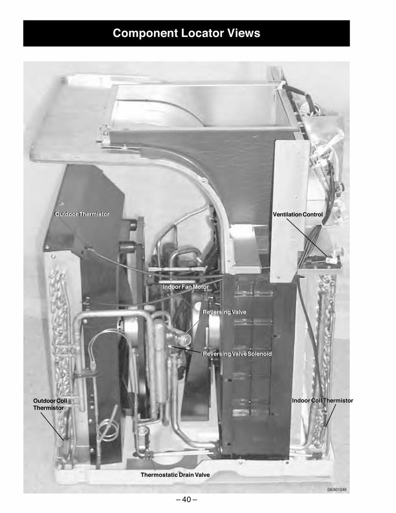
Component Locator Views
Ventilation Control
Outdoor CoilThermistor
Outdoor Thermistor
Thermostatic Drain Valve
Reversing Valve SolenoidReversing Valve Solenoid
Outdoor Thermistor
Indoor Coil ThermistorIndoor Coil Thermistor
Indoor Fan MotorIndoor Fan Motor
Reversing ValveReversing Valve

– 41 –
Outdoor Coil
Indoor Coil
Compressor
Relay andOverload CoverRelay andOverload Cover
AccumulatorAccumulator
Compressor
Outdoor FanMotor
Power Cord Connector
Resistance HeaterConnector

– 42 –
Compressor Capacitor
Main Board
Indoor FanCapacitor
Sub Board
Driver Board
Outdoor FanCapacitor
Power CordConnector
Fuse
Transformer

– 43 –
Parts List

– 44 –

– 45 –

– 46 –
– 47 –
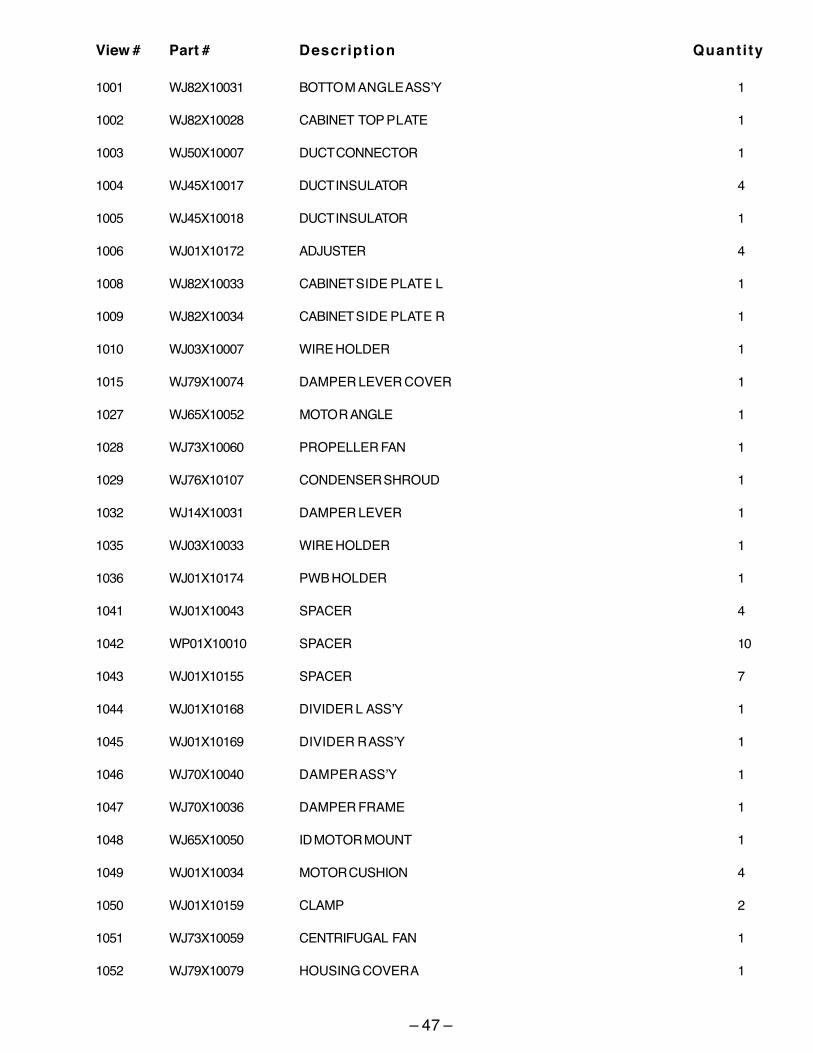
View # Part # Descript ion Quantity
1001 WJ82X10031 BOTTOM ANGLE ASS’Y 1
1002 WJ82X10028 CABINET TOP PLATE 1
1003 WJ50X10007 DUCT CONNECTOR 1
1004 WJ45X10017 DUCT INSULATOR 4
1005 WJ45X10018 DUCT INSULATOR 1
1006 WJ01X10172 ADJUSTER 4
1008 WJ82X10033 CABINET SIDE PLATE L 1
1009 WJ82X10034 CABINET SIDE PLATE R 1
1010 WJ03X10007 WIRE HOLDER 1
1015 WJ79X10074 DAMPER LEVER COVER 1
1027 WJ65X10052 MOTOR ANGLE 1
1028 WJ73X10060 PROPELLER FAN 1
1029 WJ76X10107 CONDENSER SHROUD 1
1032 WJ14X10031 DAMPER LEVER 1
1035 WJ03X10033 WIRE HOLDER 1
1036 WJ01X10174 PWB HOLDER 1
1041 WJ01X10043 SPACER 4
1042 WP01X10010 SPACER 10
1043 WJ01X10155 SPACER 7
1044 WJ01X10168 DIVIDER L ASS’Y 1
1045 WJ01X10169 DIVIDER R ASS’Y 1
1046 WJ70X10040 DAMPER ASS’Y 1
1047 WJ70X10036 DAMPER FRAME 1
1048 WJ65X10050 ID MOTOR MOUNT 1
1049 WJ01X10034 MOTOR CUSHION 4
1050 WJ01X10159 CLAMP 2
1051 WJ73X10059 CENTRIFUGAL FAN 1
1052 WJ79X10079 HOUSING COVER A 1

– 48 –
1053 WJ79X10075 HOUSING COVER B 1
1054 WJ45X10024 INSULATOR 1
1057 WJ01X10170 MOTOR RUBBER 1
1058 WJ76X10108 FAN HOUSING 1
1059 WJ76X10109 FAN HOUSING B 1
1060 WJ76X10110 FAN HOUSING C 1
1061 WJ89X10044 BASE PAN ASS’Y 1
1062 WJ02X10001 PROTECTOR SPRING 1
1063 WJ79X10013 TERMINAL COVER 1
1064 WJ01X10003 GASKET WASHER 1
1065 WJ43X10003 TERMINAL GASKET 1
1066 WJ01X10046 COMPRESSOR CUSHION 3
1067 WJ01X10171 CORNER CAP 2
1068 WJ71X10268 FRONT PANEL 1
1069 WJ05X10029 FILTER GUIDE L 1
1070 WJ05X10030 FILTER GUIDE R 1
1071 WJ65X10051 BRACE 1
1073 WP01X10009 CORD HOLDER L 2
1075 WJ79X10076 DRAIN COVER 1
1082 WJ45X10025 EVAPORATOR INSULATOR 1
1083 WJ40X10014 BULKHEAD INSULATOR 1
1084 WJ40X10015 BULKHEAD INSULATOR 1
1085 WJ45X10026 CONDENSER INSULATOR 1
1089 WJ79X10017 COMPRESSOR COVER 1
1090 WJ70X10037 DRAIN TRAY 1
1091 WJ58X10017 DRAIN VALVE 1
1092 WJ37X10029 DAMPER WIRE 1
1094 WJ11X10008 PLATE ASS’Y 1
1095 WJ11X10007 TOP PLATE SEAL 2 1

– 49 –
1096 WJ60X10002 TOP PLATE SEAL 1 1
1098 WJ03X10032 PROTECTOR HOLDER 1
1099 WJ90X10043 CABINET BACK ASS’Y 1
1100 WJ82X10035 FRONT PANEL ASS’Y 1
1101 WJ79X10078 HOUSING COVER 1
1102 WJ60X10005 BASE PAN SEAL 2
1103 WJ60X10008 FAN HOUSING SEAL A 1
1104 WJ60X10007 FAN HOUSING SEAL B 1
1105 WJ60X10006 FAN HOUSING SEAL C 1
1106 WJ60X10010 DUCT SEAL R 1
1107 WJ60X10009 DUCT SEAL L 1
2001 WJ73X10061 FAN MOTOR 1
2002 WJ70X10038 HEATER K 1
2003 WP28X10005 PROTECTOR 1
2004 WP28X10007 PROTECTOR 1
2005 WJ37X10030 HEATER CONNECTOR 1
2006 WJ36X10010 HEATER WIRE 1
2007 WJ26X10070 MAIN BOARD ASS’Y 1
2008 WJ26X10071 DRIVE BOARD ASS’Y 1
2009 WP23X10003 FUSE 1
2010 WP27X10002 VARISTOR 1
2011 WJ26X10072 SUB BOARD ASS’Y 1
2012 WJ37X10026 LEAD WIRE 1
2013 WJ36X10011 COMP. WIRING 1
2014 WJ36X10012 CONNECTOR K 1
2015 WJ20X0748 RUNNING CAPACITOR 1
2016 WP20X10005 FAN MOTOR CAPACITOR 1
2017 WJ20X10070 FAN MOTOR CAPACITOR 1
2018 WP27X10023 TRANSFORMER 1
2019 WJ73X10062 FAN MOTOR 1

– 50 –
2020 WJ37X10027 LEAD WIRE 1
2021 WJ27X10001 LEAD WIRE 1
2022 WP23X10005 PROTECTOR, COMPRESSOR 1
2023 WJ28X10027 THERMISTOR ASS’Y 1
2024 WJ26X10039 FAN SWITCH 1
2025 WJ37X10028 LEAD WIRE 1
3000 WJ53X0128 CAP. TUBE CUT TO 11.5" 1
3001 WJ31X10011 COIL 1
3002 WJ58X10020 REVERSE VALVE 1
3003 WJ88X10078 CONDENSER ASS’Y 1
3004 WJ87X10085 EVAPORATOR ASS’Y 1
3005 WJ98X10006 COMPRESSOR 1
3006 WJ46X10003 RECEIVER 1
4001 WJ01X10164 ADJUSTABLE BOLT 4
4002 WJ01X10165 ADJUSTABLE NUT 4
4003 WJ01X10031 STUD BOLT 3
4004 WJ01X10037 SPECIAL SCREW 11
4005 WJ01X10041 SPECIAL NUT 1
4006 WJ01X10056 SPECIAL SCREW 1
4007 WJ01X10166 SPECIAL SCREW 4
4009 WJ01X10010 SPECIAL NUT 1
4010 WJ01X10175 SPECIAL SCREW 1
4011 WJ01X10176 SPECIAL SCREW 6
4012 WJ01X10177 SPECIAL SCREW 2
4013 WJ01X10178 SPECIAL SCREW 2
9999 31-60807 MINI-MANUAL 1
9999 49-7419 USE & CARE MANUAL 1

– 51 –
Indoor/Outdoor CoilsThe exhaust coils on the Zoneline should bechecked regularly. If they are clogged with dirt orsoot, they may be professionally steam cleaned, aservice available through your GE service center.You will need to remove the unit from the case toinspect the coils because the dirt buildup occurson the exhaust side.
Base PanIn some installations, dirt or other debris may beblown into the unit from the outside and settle inthe base pan (the bottom of the unit).
In some areas of the United States, a “jell-like”substance may be present in the base pan.
Check it periodically and clean, if necessary.
Air FiltersNote: To maintain optimum performance, changethe filter at least every 30 days.
The most important thing you can do to maintainthe Zoneline is to change the filter at least every30 days. Dirty filters reduce cooling, heating, andair flow.
Changing the filter will: Decrease cost ofoperation, save energy, prevent clogged heatexchanger coils, and reduce the risk of prematurecomponent failure.
Caution: Do not operate the Zoneline without thefilter in place. If a filter becomes torn or damaged,it should be replaced immediately.
Operating without the filter in place or with adamaged filter will allow dirt and dust to reach theindoor coil and reduce the cooling, heating, airflow,and efficiency of the unit.
Replacement filters should be purchased fromyour local retailer where air conditioner andfurnace accessories are sold.
Filter size required is 20” x 20” x 1”.
Warning: Turn the Zoneline off and disconnect the power supply before cleaning.
Care and Cleaning
Coils
Have the coils cleaned regularly.
Unit mounted filter
Remove filter
Access panelmounted filter
Door mounted filter
Filter
Filter
To removeand replacethe filter:

– 52 –
Warranty
For The Period Of: GE Will Replace:
One Year Any part of the Zoneline which fails due to a defect in materials or workmanship. During this From the date of the full one-year warranty, GE will also provide, free of charge, all labor and on-site service to original purchase replace the defective part.
Five Years Any part of the sealed refrigerating system (the compressor, condenser, evaporator and all From the date of the connecting tubing) which fails due to a defect in materials or workmanship. During this original purchase full five-year sealed refrigerating system warranty, GE will also provide, free of charge, all labor
and on-site service to replace the defective part.
Five Years For the second through the fifth year from the date of original purchase, GE will replace From the date of the certain parts that fail due to a defect in materials or workmanship. Parts covered are fan original purchase motors, switches, thermostats, heater, heater protectors, compressor overload, solenoids,
circuit boards, auxiliary controls, thermistors, frost controls, ICR pump, capacitors, varistors and indoor blower bearing. During this limited four-year parts warranty, you will be responsible for any labor or on-site service costs.
! Service trips to your site to teach you how to use theproduct.
! Improper installation.
! If you have an installation problem, or if the airconditioner is of improper cooling or heating capacityfor the intended use, contact your dealer or installer.You are responsible for providing adequate electricalconnecting facilities.
! In commercial locations, labor necessary to move theunit to a location where it is accessible for service by anindividual technician.
! Failure or damage resulting from corrosion due toinstallation in an environment containing corrosivechemicals.
! Replacement of fuses or resetting of circuit breakers.
! Filters.
! Failure of the product resulting from modifications tothe product or due to unreasonable use includingfailure to provide reasonable and necessarymaintenance.
! Failure or damage resulting from corrosion due toinstallation in a coastal environment, except for modelstreated with special factory-applied anti-corrosionprotection as designated in the model number.
! Damage to product caused by improper power supplyvoltage, accident, fire, floods or acts of God.
! Incidental or consequential damage caused by possibledefects with this air conditioner.
What GE Will Not Cover:
This warranty is extended to the original purchaser and any succeeding owner for products purchased for usewithin the USA and Canada. In Alaska, the warranty excludes the cost of shipping or service calls to your site.Some states or provinces do not allow the exclusion or limitation of incidental or consequential damages. Thiswarranty gives you specific legal rights, and you may also have other rights which vary from state to state orprovince to province. To know what your legal rights are, consult your local, state or provincial consumeraffairs office or your state’s Attorney General.
Warrantor: General Electric Company. Louisville, KY 40225
All warranty service provided by our Factory Service Centers, or an authorized Customer Care® technician. To schedule service,on-line, 24 hours a day, visit us at GEAppliances.com, or call800.GE.CARES (800.432.2737). For service in Canada, call1.800.361.3400.
Staple your receipt here. Proof of the original purchase
date is needed to obtain serviceunder the warranty.

– 53 –
Notes