technical rope rescue - montgomery county, maryland...square knot or any of the figure 8 family of...
TRANSCRIPT
MCFRS Driver Certification Program Aerial Apparatus – Module 8 Page 1
TECHNICAL ROPE RESCUE Introduction Rope rescue is a highly specialized field of technical rescue. It can involve very complex rigging systems and extreme heights. Or, a rope rescue can be extremely simple, such as a simple overland carry of a stokes basket to a waiting ambulance. The term rope rescue is a broad term that can be applied to many different rescue scenarios. Rope rescue can be defined as “rescue based in whole or part on ropes and/or other related system components”. This means that a rescue does not necessarily have to involve ropes to be termed a rope rescue. There are many tools involved within the discipline of rope rescue that can be used independently to carry out a rescue. Hence the term rope rescue. This manual is designed to introduce the rescue squad driver to the basic philosophies and techniques of rope rescue. It is by no means a comprehensive rope rescue manual, and should not be regarded as one. It is geared toward someone with a basic knowledge of ropes and rigging equipment. A good pre-requisite for use of this manual would be a Firefighter I class, or basic rescue class such as Practical Rescue. This manual is not a substitute for hands-on practical training. Rather, it is designed to accompany and support a hands-on, practical training program. All practical training evolutions should be supervised by a qualified rope rescue instructor. The philosophies and techniques presented in this manual are practiced by rope rescue experts throughout the United States and Canada. They represent safe, field proven, techniques that have been tested both in the field and in a rope rescue testing facility. Like other fire service techniques, things change throughout the years. New research is an ongoing process, and rope rescue personnel across the nation are constantly seeking out new and better equipment and techniques. You should constantly strive to update your training and knowledge base to assure that you are using the safest and most efficient techniques available.
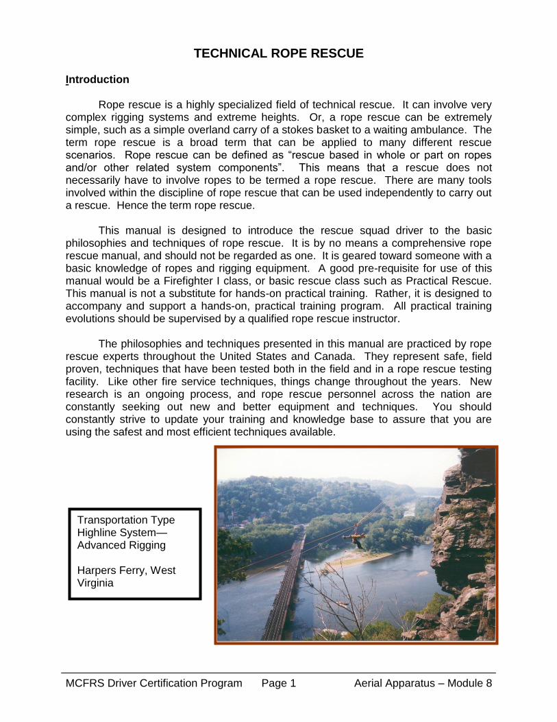
Transportation Type Highline System—Advanced Rigging Harpers Ferry, West Virginia

MCFRS Driver Certification Program Aerial Apparatus – Module 8 Page 2
Technical Rope Rescue Equipment There is a vast array of equipment available for use during technical rescue incidents. Most of the basic equipment is very versatile, and can be used for many different purposes. Some equipment, however, is task specific and only suitable for a certain operation. It is important to note that most technical rescues can be carried out using simple, basic equipment. Through regular practice, you can learn to improvise with your equipment and maximize its usefulness. Use caution when purchasing equipment, as many vendors will try to sell you specialized gadgetry that is expensive, only good for one purpose, and probably something you don’t need. Rescue Rope Rescue rope is a very important tool and is without a doubt very versatile. Through the use of various knots, auxiliary equipment, and an open mind, much can be accomplished with a rescue rope. Rope can be used to construct raising and lowering systems, highline systems, mechanical advantage, travel restrict systems, and much, much more. It is important to have a thorough understanding of what you can and can’t do with a rope, because every piece of equipment has its limitations. This should begin with an understanding of the construction of modern rescue rope. Most rescue ropes in use today are constructed of synthetic fibers such as nylon, polyester, and kevlar. A large majority of rescue professionals are using nylon because of its superior strength, tolerance of impact or shock loads, and resistance to abrasion and heat. It also performs well when wet, with a minimal loss of strength (approximately 10%) which is only present while the rope is wet. Nylon rescue ropes are usually of kernmantle construction—kern meaning core, and mantle meaning sheath. The sheath protects the core from abrasion, UV rays, dirt, and anything the rope comes in contact with. The sheath is generally braided, and covers one of two types of nylon cores. Low stretch rope, the most common type used in rescue, has core strands that run parallel to each other. High stretch rope, most commonly used by climbers, has multiple twisted core strands. Both types contain a majority of their strength in the core, usually about 75%-90%. NFPA 1983, the Standard for Fire Service Life Safety Rope and System Components, has established recommended standards for rescue rope, as well as other technical rescue equipment. According to that standard, a one-person load is considered 300 lbs., and a two-person load is considered 600 lbs. They recommend a 15:1 safety factor be used in all systems, which means that you should multiply the weight of a given load by 15 to determine the strength of the rope to be used. Therefore, a rope used for one-person loads should have a breaking strength of at least 4500 lbs. (3/8” rope), and conversely, 9000 lbs. (1/2” rope) for two persons. This assumes that only one rope is being used to conduct a rescue or training evolution. As will be discussed in the Belay Systems section, many rescue authorities recommend the use of a two-rope system. Each rope in the system is engineered for a 10:1 safety factor, therefore yielding a total safety factor of 20:1.

MCFRS Driver Certification Program Aerial Apparatus – Module 8 Page 3
Care and maintenance of rescue rope is actually quite simple. The best care of any piece of rescue equipment is prevention of situations that require repairs or maintenance. The biggest enemy of nylon rescue rope is UV rays, with abrasion scoring a close second. Proper storage in a rope bag out of direct sunlight will eliminate the UV ray problem. Padding any sharp edge that the rope comes in contact with can prevent abrasion, prolong the life of the rope, and possible prevent a catastrophic failure. Proper care will help a rescue rope to last several years. However, even with proper care, ropes should be carefully inspected after each use. A log should be maintained with the date and type of use, any shock or impact loading, any damage, etc. It should also include the date of purchase, manufacturer, size, length, lot number, color, etc. Each end of the rope should be marked with the length and other information as required. It is recommended that rescue ropes and training ropes be separate ropes, labeled as such. Carabiners/Screw Links Carabiners and screw links also constitute a critical component of any rescue system. They are the metal connectors that link the several parts of a rope rescue system together. Although they are quite similar, carabiners and screw links have two major differences. First, carabiners have a self-closing, or spring-loaded gate that allows them to close automatically. Screw links have a screw gate that must be closed manually. Second, carabiners are designed to be loaded on the spine side only. The spine is the long axis of the carabiner, or the side opposite the gate opening. Loading carabiners on any side other than the spine can cause failure of the carabiner at significantly less than the rated strength. The following pictures illustrate the different types of carabiner loading. Again, note that the only acceptable method is spine loading.
Spine Loading Cross Loading Diagonal Loading
Tri Loading Gate Loading-Gate Up Gate Loading-2” Web

MCFRS Driver Certification Program Aerial Apparatus – Module 8 Page 4
Delta Link (Tri-link) Oval Screw Link The proper loading of carabiners is referred to as carabiner etiquette. There are many things that can cause a carabiner to be loaded improperly. Some of the things that happen frequently are attaching a carabiner to an object that is too large, and orienting the carabiner incorrectly. The largest object that should be inserted into a carabiner is about 1” in diameter. That means that 2” webbing should not be used unless you are using screw links or large rigging hardware such as shackles. When loading carabiners during operations, always orient them down and down, or down and away. This means that the gate opening should face towards the ground, with the locking collar screwing down. There are two reasons for this. First, the carabiner is heavier than webbing or rope. Gravity will pull the carabiner down and cause the webbing or rope to slide towards the top, or spine of the carabiner. Second, if the locking collar must screw down to lock, gravity prevents it from unscrewing due to vibration or gravity. When designing a rope rescue system, keep in mind which direction a carabiner will face once the system is in operation (as opposed to which way it faces during setup). Carabiners should also be oriented so that the gate is facing away from any object that may come in contact with it. Most carabiners are made of either steel or aluminum. Steel carabiners are usually much stronger than aluminum. For this reason, steel carabiners should be used for “system” applications, such as belay systems, hauling systems, lowering systems, or anywhere two-person loads will be encountered. Aluminum carabiners should be reserved for “personal” applications, such as anywhere a single person is attaching to a rope (rappelling, ascending, etc.). NFPA 1983 categorizes carabiners as either “general use” (9000 lbs.), or “personal use” (6000 lbs). These two categories can be linked to steel, and aluminum, respectively, since few aluminum carabiners have a breaking strength greater than 6000 lbs. Webbing Webbing is a very versatile tool used for rope rescue. It is a flat material made of nylon. The most common size used in rope rescue is 1” wide, although it is manufactured in a 2” width also. It is constructed either of tubular, (hollow) weave, or flat (solid) weave. 1” tubular webbing has a breaking strength of about 4000 lbs., and 1” flat about 6000 lbs. The 1” tubular type is the most common type used for rope rescue applications.

MCFRS Driver Certification Program Aerial Apparatus – Module 8 Page 5
Webbing can be used for a multitude of things, from constructing anchor systems, to makeshift harnesses, to patient packaging and lashing. Due to its narrow thickness, it will fit into many small areas that a rope will not. Also, for this reason, it does not lose significant strength when bent around small diameter objects such as carabiners. However, unlike rope, webbing does not have a core and sheath construction to protect it. Great care must be taken when placing it around sharp objects. Taking the time to pad sharp corners and objects will not only increase of the life span of the webbing, it may very well prevent a catastrophic failure (and increase your life span as well). When tying webbing into different configurations, the overhand family of knots should be used. This provides for the creation of a flat knot, which has greater holding power in webbing, and will provide a knot that can be untied after loading. Do not use a square knot or any of the figure 8 family of knots when tying webbing. When used in webbing, square knots will not hold, and figure 8 knots will become so tight that they will be impossible to untie. The most common knots used in webbing are the overhand knot (for creating fixed loops), and the overhand bend (for tying the ends together).
Simple Overhand
Overhand on a Bight

MCFRS Driver Certification Program Aerial Apparatus – Module 8 Page 6
Overhand Bend Step 1
Overhand Bend Step 2
Overhand Bend Step 3
Pulleys Pulleys are a multi-functional tool used in rope rescue. Their primary function is to change the direction of a rope with a minimum of friction, but they can also be used to create mechanical advantage and as a traveling device in highlines. Selection of pulleys is very important, as they are not all created equal. Pulleys are constructed in one of two basic styles: the plastic or bronze bushing, and the sealed ball bearing. Ball bearing pulleys run much more freely than do bushing pulleys, and are therefore more efficient. Pulley efficiency is very important when it comes to the construction of mechanical advantage systems. Some pulleys can reduce efficiency as much as 30-40%. Equally as important is the size of the sheave, or wheel. The greater the size, the greater the efficiency. In addition, a pulley sheave must be at least four times the diameter of the rope used in order to maintain 100% of the rope's strength. Most rescue pulleys come in sizes from 2-5". Use caution when purchasing pulleys, as some manufacturers sell pulleys based on the size of the side plate and not the actual sheave.
Pulleys can be purchased in single, double, and triple sheave designs. This allows a single pulley to accommodate multiple ropes. This can be useful when constructing simple (block and tackle type) mechanical advantage systems, highlines, and other complex rigging systems. Care should be taken not to stack multiple single sheave pulleys into a single carabiner, as this can load the gate side of the carabiner, reducing its strength considerably. In addition, it can cause the pulleys to be situated at an angle to each other, or bind, causing increased friction and reduced efficiency.
Complex Webbing Anchor System

MCFRS Driver Certification Program Aerial Apparatus – Module 8 Page 7
2” Single Sheave Pulleys
Prusik Minding Pulley Double Sheave Pulley
Camming Pulley
2” Single Sheave Pulleys
Some pulleys are designed to "mind" a prusik, or allow the rope to be pulled through the pulley with a prusik attached to one side. This is a very useful feature when constructing mechanical advantage systems, belay systems, and knot passing systems. Beware, however, that in some cases, the prusik can become jammed inside the pulley and restrict the passage of the rope. Other pulleys have a built in cam, such as those used in ascenders, to grip the rope. This device is also useful; however, these metal cams can severely damage or even cut the rope under shock or impact loads. Use extreme caution when using these devices with live loads. Another important fact to consider about pulleys is their ability to multiply the load placed on their anchor. Anytime a change of direction is placed in a rope, and the angle between the ropes exceeds 120 degrees, the load on the pulley and its anchor will be greater than the load on the rope itself. If the angle between the ropes is 0 degrees, the load on the pulley is twice the load on the rope.
Descent Control Devices There are two main types of descent control devices used in rescue: the figure 8 and the rappel rack. Each has distinct advantages and disadvantages that must be considered. In general, however, the rappel rack is considered the device of choice by most rescue teams. Both devices may be attached to a harness and used to descend, or rappel, and can also be attached to an anchor and used to lower other rescuers.

MCFRS Driver Certification Program Aerial Apparatus – Module 8 Page 8
The figure 8 was designed for short rappels, generally 100' or less. It is generally used for single person loads only, however it can be rigged for two person loads. It is quick and easy to use, lightweight, and inexpensive. Some models have "ears", which assist when locking off the device for hands free operation. Problems with figure 8's include the inability to vary the friction once the device is loaded, poor heat dissipation, a twisting of the rope that occurs while in use, and difficulty locking and unlocking the device. In addition, the device must be unhooked from the users harness before rigging, and then reattached. Deaths have occurred when users have forgotten to reattach the device to the harness after rigging it. The rappel rack is a much more user-friendly device with significant advantages over the figure 8, especially when dealing with rescue sized loads. The biggest advantage of the rappel rack is the ability to vary the friction while the device is loaded. This is very important when "picking off" a victim while on descent. In addition, the rack has better heat dissipation, doesn't twist the rope, and is easy to lock and unlock. Unlike the figure 8, the rack remains attached to the harness while it is rigged, reducing the occurrence of failing to reattach it. Deaf Figure “8” Rescue Figure “8” w/Ears Figure “8” Rigged Rappel Rack Rack Rigged Rope Grab Devices A rope grab device is one that is used to grip or grab the rope for pulling, ascending, attaching other equipment, etc. Prusiks and mechanical ascenders are the two most popular rope grab devices. You should note, however, that there are some “grave” differences between the two.

MCFRS Driver Certification Program Aerial Apparatus – Module 8 Page 9
Prusiks Prusik cords are fixed loops of accessory cord, tied together with a double overhand bend. Accessory cord is simply a small diameter of kernmantle life safety rope (3-9mm). Prusiks are very useful devices for gripping the rope, such as for ascending, mechanical advantage systems, and belay systems. Material used for the construction of prusiks should be about 2/3rds the diameter of the host rope they are placed on (8mm for 1/2" rescue rope). Soft, supple accessory cord is preferred over stiff cord, as it provides better holding power. Prusiks may be placed on the rope in a two-wrap or three-wrap configuration. The two-wrap prusik is used for "personal", or single person loads. An example of this would be the ascent of a fixed rope. Three-wrap prusiks are used for "system", or rescue loads, which are usually defined as two or more persons. Examples of this are mechanical advantage systems, belay systems, etc. Prusiks, unlike mechanical ascenders, will hold great amounts of weight. In addition, they are designed to slip before failure occurs. This is especially important during shock or impact loading.
Prusik Wrapping—Step 1 Prusik Wrapping—Step 2 Prusik Wrapping—Step 3
8mm Prusik
2-wrap Prusik 3-wrap Prusik
Bridge

MCFRS Driver Certification Program Aerial Apparatus – Module 8 Page 10
Mechanical Ascenders Ascenders are mechanical devices designed for single person ascents of fixed ropes. They work very well for this purpose, especially the handled ascenders. They are not designed for rescue loads, and therefore should not be used in rescue systems. In addition, they can and will severely damage or cut a rope if overloaded. This can occur during slow, static loading, and/or shock or impact loading. It is worth emphasizing that ascenders are used for ascending, and THAT'S ALL.
Miscellaneous Miscellaneous equipment is equipment that does not necessarily fit into one of the other categories of rope rescue equipment. There numerous pieces of equipment that fit into this category, of which some are very useful and some are not. The scope of this manual does not cover every piece of such equipment, as some of which is only used for advance level rigging. The rigging plate, however, is a very useful basic piece of equipment. A rigging plate is a flat metal plate, with multiple holes drilled into it, for attaching multiple carabiners to. Its use's are infinite, but some of its main functions are to separate pulleys in a mechanical advantage system, and to construct "back tied" or "focused" anchor systems.
Hard Shell Style Ascender
Handled Ascender
Rigging Plate

MCFRS Driver Certification Program Aerial Apparatus – Module 8 Page 11
Knotcraft Knotcraft is the combination of knots, bends, and hitches used in rope rescue. However, sometimes the term “knot” is used generically in place of bend or hitch. It is important that all members of a rescue team or crew be familiar with and use the correct terminology of knotcraft. This can prevent a costly mistake, and provide for more efficient and expedient operations. It is also important to note that all knotcraft will reduce the strength of a rescue rope and/or webbing by approximately 10-40%. In order to allow for a minimum static system safety factor (SSSF) of at least 10:1, it should be assumed that all knots, bends, and hitches will reduce the strength of a rope by a conservative 50%. All knots, bends, and hitches should be dressed, set, and inspected. Dressing a knot means to “clean it up” so that there are no twists, the rope flows smoothly through the many turns and bights, and the tension will be on the correct strand. Setting a knot is the process of placing tension on the strands before the knot is put into use. This assures that all slack is removed, and makes the knot easier to inspect. All knots should be inspected prior to a load being placed on them. Inspecting a knot correctly requires someone to physically touch the knot and inspect each segment. There are many knots, bends, and hitches outlined in this chapter. They are listed to give you several examples for each category of knotcraft. As a rescue squad driver, you will not be required to be able to tie all of them. A list is provided in the objectives at the beginning of the chapter which outlines the knots, bends, and hitches you will be required to proficient in. Keep in mind, however, that the more you know about knotcraft, and the more knots, bends, and hitches you can tie, the better you will be in the rope rescue environment. Knots
A knot is used to form a loop or point of attachment in the middle or end of a rope or piece of webbing (some exceptions do exist to this definition, such as the simple overhand and simple figure 8, which are also called stopper knots, and can be used as the “root” knot to construct other knots, bends, and hitches.) Some examples of knots are as follows: Pictured below are some of the more frequently used knots:
Simple Overhand—
Start Middle Finish
MCFRS Driver Certification Program Aerial Apparatus – Module 8 Page 12
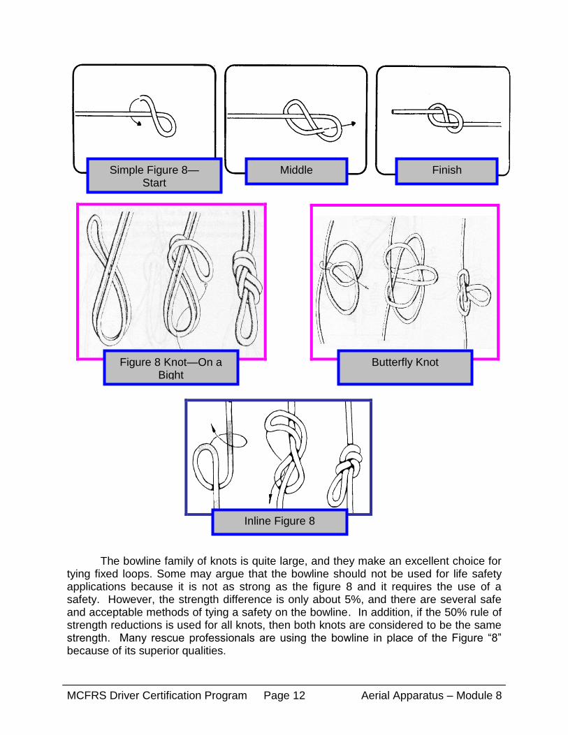
The bowline family of knots is quite large, and they make an excellent choice for tying fixed loops. Some may argue that the bowline should not be used for life safety applications because it is not as strong as the figure 8 and it requires the use of a safety. However, the strength difference is only about 5%, and there are several safe and acceptable methods of tying a safety on the bowline. In addition, if the 50% rule of strength reductions is used for all knots, then both knots are considered to be the same strength. Many rescue professionals are using the bowline in place of the Figure “8” because of its superior qualities.
Simple Figure 8— Start
Middle Finish
Figure 8 Knot—On a Bight Start
Butterfly Knot
Inline Figure 8
MCFRS Driver Certification Program Aerial Apparatus – Module 8 Page 13
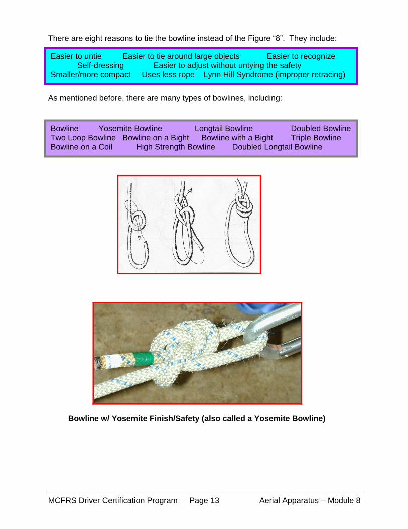
There are eight reasons to tie the bowline instead of the Figure “8”. They include:
As mentioned before, there are many types of bowlines, including:
Bowline w/ Yosemite Finish/Safety (also called a Yosemite Bowline)
Easier to untie Easier to tie around large objects Easier to recognize Self-dressing Easier to adjust without untying the safety Smaller/more compact Uses less rope Lynn Hill Syndrome (improper retracing)
Bowline Yosemite Bowline Longtail Bowline Doubled Bowline Two Loop Bowline Bowline on a Bight Bowline with a Bight Triple Bowline Bowline on a Coil High Strength Bowline Doubled Longtail Bowline

MCFRS Driver Certification Program Aerial Apparatus – Module 8 Page 14
Bowline w/ Double Overhand Safety
Longtail Bowline Doubled Longtail Bowline
Bowline on a Bight

MCFRS Driver Certification Program Aerial Apparatus – Module 8 Page 15
Bends
A bend is used to join the ends of two ropes or pieces of webbing. Some examples of bends are as follows:
Double Overhand
Double Overhand Bend
Sheet (becket) Double Sheet Figure 8 (Flemish) Overhand (ring) Double Overhand (fisherman’s)
Bowline w/out a Bight

MCFRS Driver Certification Program Aerial Apparatus – Module 8 Page 16
Sheet Bend (Becket Bend) Double Sheet Bend
Overhand (ring) Bend Hitches
A hitch is used to attach a rope or piece of webbing to an object. If the object is removed, the hitch will fall apart, and therefore the object must remain in place. Some
Half Hitch Clove Hitch
Half Clove Prusik Timber Munter Chimney Bachman Load Releasing Girth Basket Mariners Slip Half Kleinheist (Italian) Rapid Release Prusik

MCFRS Driver Certification Program Aerial Apparatus – Module 8 Page 17
Clove Hitch
Munter Hitch Timber Hitch
3-Wrap Prusik—Start 3-Wrap Prusik—Middle 3-Wrap Prusik—End
2-Wrap Prusik 3-Wrap Prusik “Bridge”

MCFRS Driver Certification Program Aerial Apparatus – Module 8 Page 18
Anchors/Anchor Systems
The anchor is the backbone of most rescue systems. Without a good anchor, we
cannot operate safely, and therefore can't conduct a rescue or training evolution. There are many types of anchors and anchor systems, which can all be broken down into two broad categories—single-point and multi-point. No matter which type of anchor is used, the ultimate goal is to create a "bombproof" anchor. The term bombproof simply means that the anchor will withstand any force that could possibly be placed upon it, either intentionally or unintentionally. Anchors that are not considered bombproof are called marginal. Marginal anchors are usually considered capable of holding part of a load, but not all. For this reason, marginal anchors must be tied together into an “anchor system”, generally a multi-point anchor system. Single-Point Anchors
Single-point anchors are preferred and should be used when there is one anchor present that is considered bombproof. It may be bombproof to hold one part of the system, such as the main line, or it may be adequate to hold the total rescue package. Some examples of bombproof single point anchors would be large trees, concrete and structural steel columns, very large boulders, and fire apparatus. Once the appropriate anchor is selected, it must be rigged with the necessary equipment so it can be utilized in the system.
For anchoring fixed lines, it is usually easiest just to tie the rope to the anchor
with a Yosemite bowline. For anchoring other objects, such as pulleys and fixed braking systems, an anchor constructed of webbing works best. One of the best and strongest webbing anchors is called the “wrap 3, pull 2”. It is constructed in the following sequence:
Rapid Release Prusik Hitch
Load Releasing Hitch

MCFRS Driver Certification Program Aerial Apparatus – Module 8 Page 19
By placing the bend against the anchor, and facing it in the direction of pull, the bend will be isolated so that it will not see much, if any, tension. Therefore, the strength of the webbing will not be reduced by the overhand bend. This means that the anchor has the full strength of all the webbing.
Wrap Three/Pull Two Anchor
Wrap Three/Pull Two Anchor
1.) Utilizing 1” webbing, wrap it around the anchor three times. 2.) Tie the ends together with an overhand bend. 3.) Place the strand of webbing with the bend in it against the load so that it faces the
direction of pull. 4.) Nest the remaining two strands together to form the point of attachment and attach a
carabiner. 5.) Make sure that there are no twists in the webbing, and that all sharp edges are
padded. In addition, make sure that the angle of the webbing strands at the carabiner does not exceed 90°.

MCFRS Driver Certification Program Aerial Apparatus – Module 8 Page 20
Multi-Point Anchors
Multi-point anchors are used when there is concern that a single anchor will not hold the intended load. A multi-point anchor is basically several, marginal single-point anchors tied together to make one bombproof anchor. Some examples would be small trees, small rocks and boulders, wedge-type eyebolts set in concrete, picket systems, etc. Multi-point anchors should only be used when there is not a single suitable bombproof anchor. Like single-point anchors, multi-point anchors can be constructed of webbing, and they can also be constructed of rope or accessory cord. The steps to construct a multi-point anchor are as follows:
This type of anchor is called a load-distributing anchor, and is considered the
best and safest method of multi-point anchor construction. (Note: it is a good idea to place an object—carabiner, pen, stick, etc.—inside the overhand knot to prevent it from becoming too tight to untie.) It is extremely important that the angle between the individual anchors not exceed 120 °.
The anchor below is the same as the anchor at left, except the anchor at left uses individual wrap 3/pull 2’s on each marginal anchor, and the anchor below does not.
1.) Run the webbing or cord around each anchor. If the individual anchors are large, or spread out over a large area, it is a good idea to tie a wrap-3, pull-2 around each one before starting the multi-point.
2.) Tie the ends of the webbing or cord together with the appropriate bend. 3.) Reach between each two anchors and pull the strands forward, focusing them
toward the anticipated direction of pull. 4.) Nest the strands together and tie the end of the webbing or cord into an overhand
knot.
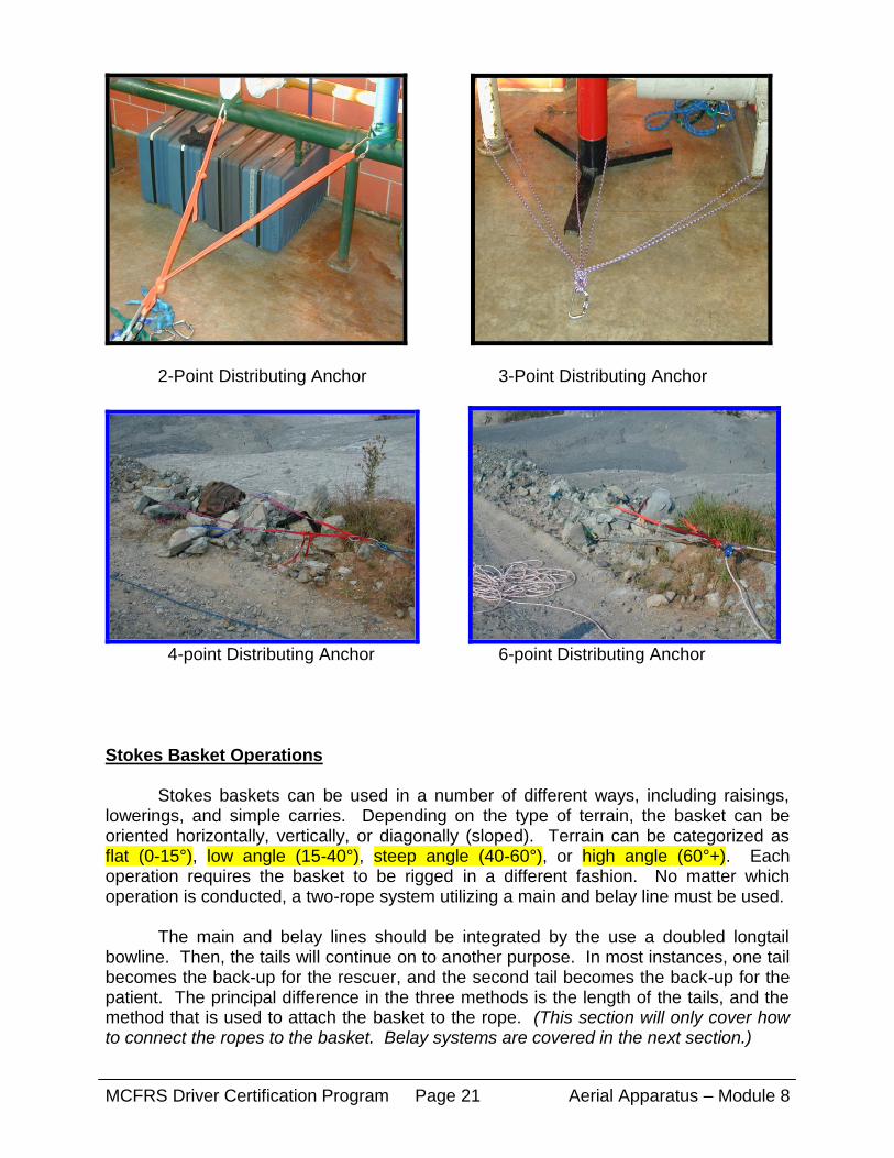
2-point Distributing Anchor
MCFRS Driver Certification Program Aerial Apparatus – Module 8 Page 21
2-Point Distributing Anchor 3-Point Distributing Anchor
4-point Distributing Anchor 6-point Distributing Anchor Stokes Basket Operations Stokes baskets can be used in a number of different ways, including raisings, lowerings, and simple carries. Depending on the type of terrain, the basket can be oriented horizontally, vertically, or diagonally (sloped). Terrain can be categorized as flat (0-15°), low angle (15-40°), steep angle (40-60°), or high angle (60°+). Each operation requires the basket to be rigged in a different fashion. No matter which operation is conducted, a two-rope system utilizing a main and belay line must be used.
The main and belay lines should be integrated by the use a doubled longtail bowline. Then, the tails will continue on to another purpose. In most instances, one tail becomes the back-up for the rescuer, and the second tail becomes the back-up for the patient. The principal difference in the three methods is the length of the tails, and the method that is used to attach the basket to the rope. (This section will only cover how to connect the ropes to the basket. Belay systems are covered in the next section.)

MCFRS Driver Certification Program Aerial Apparatus – Module 8 Page 22
Horizontal Raise/Lower The horizontal raise or lower is probably the most commonly used method for high angle terrain (vertical or near vertical environments). The basket is oriented parallel to the ground, or the horizon. This method facilitates several advantages over the vertical method. First, it places the patient in a horizontal, or supine position. This is much more comfortable for the patient, because it relies more on gravity than the lashing system to hold the patient in the basket. For this same reason, it is also safer for the patient. Second, it allows for greater control of the basket. An attendant can be attached to the basket to maneuver it around obstacles and to provide patient care. The Yosemite Rig stokes basket bridle is the tool of choice to attach the basket to the system for a horizontal raise or lower. It is a 4-leg, adjustable bridle made of rope and accessory cord. Each leg is individually adjustable, rigged for quick release if the patient’s condition requires it, and has some built-in mechanical advantage to assist in shortening the leg while under load. The Yosemite Rig should be attached to the basket with four carabiners. The gates of the carabiners should be oriented down, and toward the inside of the basket. Since the legs of the Yosemite Rig will form a “Y” when attached, a tri-link should be used instead of a carabiner to attach the rig to the rope system. The attendant is attached to the tri-link with a Purcell Prusik, regular prusik, or daisy chain. An etrier can also be attached to allow the attendant to climb up if he becomes too low on the basket. As mentioned above, a doubled longtail bowline is used as the “yoke” knot, or to attach the Yosemite Rig to the rigging system. For operations where the basket will be oriented horizontally, the tails of this knot should be 6-8’ in length. If a single attendant is used, one tail attaches to the patient, and one tail attaches to the attendant. If two attendants are used, one tail will attach to each attendant. For this scenario, the patient can be piggybacked onto one of the tails using a prusik.
Yosemite Rig Stokes Bridle Stokes Basket Rigged Horizontal
with Yosemite

MCFRS Driver Certification Program Aerial Apparatus – Module 8 Page 23
Stokes Basket Horizontal Doubled Longtail Bowline With Yosemite and Etrier Vertical Raise/Lower A vertically oriented basket is required when the basket must be passed through a narrow opening or area, such as a confined space. This operation is not conducted often with a stokes basket, because there are other patient packaging devices better suited to this operation (Sked, LSP Half-back). The Yosemite Rig is not needed for this operation. A piece of 1” tubular webbing is used to create a bridle for the basket (see illustrations). All other aspects of the raising or lowering system are the same. The tails of the yoke knot for this operation may be of different lengths. The patient’s tail can be approximately eight feet long, and the attendants will need to be longer, approximately 10-12’ long.
Metal Stokes Tie-in for Plastic Basket Tie-in for Vertical or for Vertical or Slope Evac Slope Evac

MCFRS Driver Certification Program Aerial Apparatus – Module 8 Page 24
Diagonal/Slope Raise/Lower A diagonal, or sloped basket is most often used for flat and low angle terrain (a slope or embankment type of evolution), and sometimes for steep angle. This is the type of evolution that will be used most often here in Montgomery County and the surrounding areas. A slope evacuation requires a few changes from the basic horizontal or vertical raise or lower. For those types of evolutions, the basket is free hanging from the rope system. In a slope evacuation, the basket will need to be carried by litter attendants, or dragged on the ground. In snow or icy conditions, allowing the basket to slide on the ground may be acceptable. However, in rugged terrain such as grassy or rocky hillsides, the basket will need to be carried. Generally, a system with three or four litter attendants is used. Steeper embankments require less attendants, because most of the weight is held by the rope. Gradual slopes require more attendants, because they will bear the weight. The attendants are tied into the basket using prusiks or pre-rigged litter tie-ins, also made of accessory cord. The pre-rigged style of litter tie-ins are preferred because they are adjustable. Of course, the attendants’ second points of attachment are the tails of the doubled longtail bowline yoke knot. The patient can be piggybacked onto one of the tails for a second point of attachment. For this operation, the tails should be 10-12’ long.
3-Attendant Operation 4-Attendant Operation Example of Edge Protection Anytime you are conducting any of the above evolutions, you should observe the general safety principals of rope rescue. These include, but are not limited to:
—Never get closer than 10’ to an exposed edge without a travel restrict or positioning line —Always have two points of contact to the ground or a rope system —Always use the “three sets of eyes” rule (for system safety checks) —Always pad or protect webbing and rope from sharp edges

MCFRS Driver Certification Program Aerial Apparatus – Module 8 Page 25
Belay Systems A belay system is a safety, or back-up system used in rope rescue. It is designed to stop or catch a falling load (rescuer, patient, etc.) in the event of a main line failure. This may sound like a simple and easy task, but it is in fact very difficult to do. Loads in motion on a rope are very difficult to stop. In addition, when a load in motion is suddenly stopped, a significant force is developed within the system used to stop the load. This force is called a “shock load” or “impact load”. Shock loads can be as much as ten times the weight of the static load. For this reason, the belay system should be the strongest part of the rope rescue system. It should be utterly “bombproof”. From this information, it should become evident that the belay system is the last line of defense in a rope rescue system. If all else fails, the belay system must be capable of withstanding any force that may come upon it. Because the belay system is so important, several characteristics must be built into it to account for all the variables we may encounter. Below is a list of belay system characteristics, along with an explanation of why each is necessary. Belay System Characteristics -Must be able to stop a load in motion or hold a load at rest -Must survive an activation enough to allow further rescue -Must minimize the shock load or Maximum Arrest Force (MAF) -Must minimize the stopping distance of the load -Must work in any environment -Must activate automatically (must pass the whistle test) -Must pass the critical point test Must be able to stop a load in motion or hold a load at rest No one knows when a failure will occur. It may occur while the load is at rest, or while the load is in motion (being raised or lowered). Some belay systems hold static loads well, but can’t stop a load that is in motion. A good belay system must be able to catch and hold the load whether it is at rest or in motion. Must survive an activation enough to allow further rescue When a belay system activates and successfully catches a falling load, the operation is not finished. There is still a patient and/or rescuer hanging somewhere from the belay line. The evolution must still be completed. In most cases, all or part of the main line system must be replaced. Once the main line system has been repaired, the load must be transferred from the belay line back to the main line and the operation may continue. If the belay system components were distorted or destroyed as a result of catching the load, this transfer would not be possible. Therefore, we say that the system must survive to allow further rescue or continued operations.
MCFRS Driver Certification Program Aerial Apparatus – Module 8 Page 26
Must minimize the shock load or Maximum Arrest Force (MAF) Shock load occurs when a load in motion comes to an abrupt stop. The heavier the load, and the greater the distance an object falls, the greater the shock load. This shock load is transferred to all the components of the system, including rope, hardware, anchor, patient and/or rescuers, etc. The shock load can be much greater than the weight of the static load, as much as 10 times greater or more. The greatest force that is delivered to the system during the fall arrest is also called the Maximum Arrest Force (MAF). In order to minimize the MAF, a system that provides some energy absorption (shock absorption) must be used. In other words, a system that brings the load to a gradual stop as opposed to an abrupt stop. Must minimize the stopping distance of the load As noted above, the greater the distance an object falls, the greater the shock load. Therefore, we must minimize the distance an object falls before it comes to a complete stop. In addition, we must stop the load before it strikes another object, such as a rock, part of a building, etc. This helps reduce the MAF, and therefore helps reduce the potential for serious injury. Must work in any environment The belay system must work no matter what the external environment or weather. That means that if the rope gets wet, icy, muddy, dusty, etc., the belay system must still do its job. The same applies to warm and cold temperatures, high and low humidity, etc. The belay must be capable of stopping the load in any conditions. Must activate automatically (pass the whistle test) The belay system must activate automatically, and require no action from the belayer for it to work. In other words, if the belayer were to let go of the system completely, the belay must still work. This concept is also called the whistle test, or hold-up test. In this test, if someone blows a whistle, everyone involved with the evolution lets go of his or her rope or equipment. If, when everyone lets go, the system fails to keep the load from falling, the belay fails the whistle test. If, however, the system holds the load, it passes the whistle test. There are several reasons this characteristic is important. First, it is not uncommon for rescuers to fail to pay close attention to their assigned task. Some belay techniques require the belayer to perform a certain action to activate the belay system. If the belayer is not paying attention at the time this action is needed, it is likely that the belay will not work. Second, it is entirely possible that something could happen to the belayer that would prevent him from doing his job properly. Examples would be someone distracting him, a medical condition such as a heart attack, being stung by a bee, or anything else that would prevent constant attention to detail and an immediate activation of the belay. If a belay system does not meet this requirement, it should not be used.

MCFRS Driver Certification Program Aerial Apparatus – Module 8 Page 27
Must pass the critical point test The critical point test is equally as important as the whistle test. The critical point test is designed to eliminate the weak link in a system. It follows the premise that everyone in a rope system must have two points of contact. The critical point test must be applied to each and every component of your system. While examining each component, ask yourself, “What happens if this particular piece of equipment fails?” If the answer to your question is that a catastrophic failure occurs, then your system doesn’t pass this test. But, if every component has some type of back-up, and the failure of any one component won’t cause the patient or rescuer to fall, then the system passes the test. The only exception to this rule is the harness that the patient or rescuer is wearing. It is not feasible or safe to wear two harnesses at the same time. This is where the “three sets of eyes” rule can be used to eliminate the possibility of failure due to human error. Conclusion Several tests were conducted during the years of 1982 through 1989 for the purposes of evaluating belay devices and techniques. Criteria for the tests was established by the British Columbia Council on Technical Rescue (BCCTR). These criteria were accepted by all those involved with the testing. The criteria are as follows:
All the tests yielded the same results: that only one belay system would meet the
criteria. All the other devices or systems failed at least one of the test criteria. The only belay system that passed the testing was the Tandem Prusik Belay with Load Releasing Hitch (TPB w/ LRH). This is the only belay system that should be used in rope rescue systems. In addition, this belay system has been the only one to date that has ever passed the test with one exception. At the time of this writing, a new belay device has just been introduced to the rope rescue community that has passed all the tests and is suitable for use in rope rescue systems. It is called the 540 Rescue Belay, and was developed by Rigging for Rescue, a technical rope rescue school in British Columbia, Canada. (Since this device is so new, there is no information available on it at this time. It is suggested that users of this manual look into this device.)
BCCTR Belay Competence Drop Test Criteria Test Mass 200Kg. (440 lbs.) Rope Length 3 meters (roughly 10 feet) Drop Distance 1 meter (roughly 3 feet) Stopping distance 1 meter (roughly 3 feet) Maximum Arrest Force (MAF) 15 Kilonewtons (3,372 lbs.)

MCFRS Driver Certification Program Aerial Apparatus – Module 8 Page 28
Tandem Prusik Belay System
The tandem prusik belay system consists of the following:
Tandem Prusik Belay 1 ½” Low stretch kernmantle lifeline 2 8mm triple-wrapped Prusiks (53” & 65” before tying into loops) 1 Steel carabiner (minimum of 9000 breaking strength) 1 Steel tri-link (10mm or larger) 1 Prusik minding pulley 1 Load releasing hitch (made of about 30’ of 9mm accessory cord)
Above and Left: Tandem Prusik Belay with Load Releasing Hitch
Below: Load Releasing Hitch

MCFRS Driver Certification Program Aerial Apparatus – Module 8 Page 29
Before constructing the belay system, you must select a suitable anchor. This anchor must be capable of withstanding a significant shock load. In most cases, it is advisable to utilize a different anchor for the main and belay lines. There are, of course, some situations where one anchor is suitable for both (ex. structural concrete or steel columns, fire apparatus, etc.) The anchor should be set up with a wrap 3, pull 2 high strength anchor. Multi-point anchors should only be used in a belay system as a last resort.
The load releasing hitch is used for two purposes. First, to absorb dynamic energy or shock load, in the belay system. It reduces the force seen by all components in the system. Second, should the belay system activate, it is used to release the load on the prusiks and transfer the load back to the main line. The belay system will usually activate for one of two reasons. First, if a failure occurs in the main line and the belay system catches the load. Second, in a lowering operation, if the belayer can’t keep up with the lowering speed of the main line, the prusiks may engage accidentally. In either case, the belayer must have a means to unlock the prusiks and resume the operations. The LRH is placed between the anchor and the belay prusiks. It is advisable to use a 10mm tri-link on the munter hitch side of the LRH because of the width of the munter hitch. (See picture on page 44 for how to construct LRH.)
The tandem prusik belay is constructed by placing each of the two prusiks on the
rope with three wraps. Make sure each prusik is wrapped in the same direction around the rope. When affixed to the rope, they should be about 4” apart. They should be snug on the rope; a good test of this is to pull rope through the prusiks and listen for the friction between the rope and the prusiks. If you can hear the friction, then the prusiks are tight enough. Connect the prusiks to the carabiner on the LRH. Place the long prusik in first, then the short prusik, and the prusik minding pulley last. As with all rope rescue systems, have someone perform a safety check to make sure that everything is correct.
For raising system operations, simply pull the belay rope through the prusik
minding pulley as the load is raised. Keep all slack out of the system. Make sure to pull the rope through the pulley at a very narrow angle, 0° if possible (see the diagram on page 44 for proper angle). For lowering systems, you must physically pull the rope through the prusiks as the load is lowered. To do this, slide both prusiks together and grasp them with the hand closest to the anchor. Use the hand closest to the load to pull the rope through the prusiks as the load is lowered. Again, you must keep all slack out of the rope. You can use a “Z” turn to manage slack. It is made by placing the hand that is pulling the rope on top of the rope and turning it 180°, creating a “Z” in the rope. As the “Z” is pulled out of your hand by the load being lowered, reach back and pull another one. Continue this procedure throughout the entire operation.
If a failure occurs during an operation, all you need to do is release your hands from the prusiks and the rope. You can also “throw” the prusiks toward the load. Whatever you do, don’t hold onto the prusiks. You could cause them not to grab, and prevent the belay from activating and catching the fall. You could also injure your hands. You must be wearing gloves when operating the belay, or dealing with any moving rope.

MCFRS Driver Certification Program Aerial Apparatus – Module 8 Page 30
Proper hand positioning for the Tandem Prusik Belay
Although this belay is the only one that passed the tests, it is not foolproof. You
must obtain competent instruction to construct and use it. You should obtain this instruction before attempting to use it for live loads. In addition, it requires frequent practice to be proficient in its operation. Directionals It is very important that the belay line not be placed in any directional changes within the system. There are two reasons for this. First, as mentioned earlier, placing a change of direction in a system can result in a load being placed on the directional pulley and anchor that is greater (as much as twice) than the load on the end of the rope or belay system. Since loads on the belay system can be severe (sometimes 3,000-5,000 lbs.), the load on the directional may be enough to cause failure of a system component. Second, if the belay line is incorporated into a directional change, and the directional anchor fails, there will be significant slack in the belay rope. This will cause an increase in the fall distance, and therefore a greater shock load to the system. In addition, the rescue package may strike an object before the belay rope becomes taught. Therefore, it should be common practice to run the belay line directly from the belay system to the rescue package. (This author generally recommends the practice of “never say never”, as there may be situations where there is no other choice but to include the belay in a change of direction. A good example of this is when using an aerial device as a high directional to conduct a stokes basket evolution.)
Main Line (rappel line)
Belay Line
Hand pulling belay rope and “Z” turns
Hand holding prusiks in place

MCFRS Driver Certification Program Aerial Apparatus – Module 8 Page 31
Edge Protection It is essential that some type of protection or padding be placed on any surface the belay comes in contact with that has the potential to cut or damage it. This protection can be anything from a commercial rope pad, to cardboard, old carpet pieces, a sweatshirt, turnout gear, etc. It should be noted, however, that an edge roller or similar device should not be used. These devices are designed to reduce friction and allow a rope to slide across them easily. The belay line does not require a reduction in friction like a hauling system. The belay line, on the other hand, is better suited to objects that cause some additional friction. This friction will help slow or stop the belay line during a fall, therefore absorbing energy. Any energy absorbed by edge padding, the ground, etc., is not transferred to the anchor or rescuers. Therefore, make every effort to use edge protection that is energy absorbing. Self Belay A self-belay is a belay that a rescuer can use for rappels or descents. It does not require a second person to operate the belay. For this reason, it is a good technique to use when you are alone. It is a questionable technique by some organizations. However, if it is done correctly, it does work. This belay technique requires considerable discipline and practice with its use. The same principles apply to this belay as do to the tandem prusik belay. A separate anchor and rope must be used. The belay line is anchored to a tandem prusik belay system. This gives the system the ability to absorb shock. The person utilizing the belay then attaches a single 8mm prusik to the belay rope and his harness. The prusik can be triple wrapped, but double works best. As the person rappels, he tends the prusik using two fingers on top of the wraps (like holding a cigar). DO NOT grab the prusik with a full fist or hand. Activation of this belay requires the person using it to let go of the prusik if the main line fails. By using the two-finger method, you will not be able to grab the prusik; your fingers will slide off quickly if the main line fails. If, however, you grasp the prusik with a full fisted grip, it will slide along the rope and it will not grab. It will not stop a fall in this fashion. AGAIN, you must be disciplined enough to let go and not grab the prusik. (Note: When using this belay alone, you must be able to rescue yourself if your prusik grabs.)
Self-Belay technique—note fingers on prusik are too tight—they should cradle the rope like a cigar

MCFRS Driver Certification Program Aerial Apparatus – Module 8 Page 32
Pulley Systems/Mechanical Advantage A pulley system is defined as an assemblage of rope and pulleys used to increase the force to the level required for the lifting or tightening to be undertaken. In rope rescue, we use pulley systems to create mechanical advantage, or as stated above, to “increase force”. Mechanical advantage is defined as a force created through mechanical means including, but not limited to, a system of levers, gearing, or ropes and pulleys, usually creating an output force greater than the input force and expressed in terms of a ratio of output force to input force. Pulley systems and mechanical advantage are essential elements of rope rescue because we often deal with very heavy loads. It is not uncommon for rescue loads to approach 600 lbs. Since the average pulling ability of a single person is approximately 100 lbs., it would require a minimum of six rescuers to lift a load of this size. More often than not, we don’t have the luxury of having this many people available for this task. However, through the use of mechanical advantage and pulley systems, we can maximize our lifting ability with a minimum of rescuers.
As mentioned above, by creating mechanical advantage systems with rope, we can decrease the level of force required to move a given load. We express the mechanical advantage in a system as a ratio of output force to input force (output/input, ie. 2:1, 3:1, 4:1). For example, if a load weighs 300 lbs., and it requires 100 lbs. of force to move it, then the mechanical advantage would be 3:1. In order to accomplish this, we must spread the load out over multiple strands of rope. By spreading the load in this manner, we are able to put forth less effort; however, there is a trade off. When we create rope mechanical advantage systems, it requires us to apply the effort over a greater distance. In fact, we must multiply the distance the load must be moved by the mechanical advantage factor to determine how much rope we must pull. For example, if we are required to move a load 100 feet, and we are using a 3:1 mechanical advantage system, we must pull a total of 300 feet of rope through the system. With this in mind, let us look at some basic rules of mechanical advantage.
Example: A load weighing 300 lbs. must be moved a distance of 100 feet. The mechanical advantage system is a 3:1. In order to accomplish this, we must apply 100 lbs. of effort over a distance of 300 feet of rope.
300 lbs. (load) / 3 (mechanical advantage) = 100 lbs. effort
100 feet (distance to move load) X 3 (mechanical advantage) = 300 feet of rope
Calculating Required Effort and Distance
1. To determine the effort needed to move a load, divide the weight of the load by the mechanical advantage.
2. To determine the amount of rope that must be pulled, multiply the distance a
load must be moved by the mechanical advantage.
FORMULA: Work = Effort X Distance

MCFRS Driver Certification Program Aerial Apparatus – Module 8 Page 33
The terms mechanical advantage and pulley system are often used interchangeably. This is because in order to create mechanical advantage with rope, you must use pulleys. There are two different types of pulleys in a pulley system: those that are stationary, or fixed to an anchor, and those that are traveling, or moving throughout the system. Stationary pulleys do not create any mechanical advantage in the system. They only change the direction of the rope. They are therefore called change of directions (CD’s), or 1:1’s. On the other hand, pulleys that travel within the system create mechanical advantage. In simple and compound systems, each traveling pulley contributes a 2:1 mechanical advantage to the overall system.
Pulley System Parts & Terminology There are numerous parts to each pulley system, and terms that apply to each. These terms help define the pulley system, both in schematics and in practical application. In order to understand the mechanics of a given pulley system, and how it is constructed, you must understand the parts and their function.
100 100
100
50 50
200 Stationary Pulley
on Anchor Traveling Pulley
Pulleys can double the load on their anchor
Direction Load Moves
Change of Direction (1:1) Mechanical Advantage (2:1)

MCFRS Driver Certification Program Aerial Apparatus – Module 8 Page 34
Pulley System Configurations
Pulley systems can be set up in one of two configurations: integral and ganged.
Integral Pulley System—Where the working rope and the pulley system are one and the same; most often used when the working rope is long enough to extend from the patient to the anchor, with enough left over to construct the pulley system.
Ganged Pulley System—A pulley system that is attached to a rope for doing work;
useful when the working rope is not long enough to extend from the patient to the anchor; also useful when multiple changeovers are required (raise to lower, lower to raise, etc.)
Ratchet Prusik—a prusik used to hold the load in place while the pulley system is at rest, or being reset; most often attached to a prusik minding pulley on an anchor.
Haul Prusik—a prusik used to combine elements of pulley systems, such as attaching
a pulley to the middle of a rope (attaching one simple pulley system to another).
Gang Prusik—a prusik used to attach a pulley system to a separate host rope
(sometimes incorrectly referred to as “piggybacked”) Self-minding Ratchet—a ratchet prusik that is capable of performing its job without the
assistance of someone to attend it; this is accomplished via the use of a prusik minding pulley in an odd pulley system.
Manned Ratchet—a ratchet prusik that must be attended at all times by an attendant;
required for most even pulley systems and all ganged systems. Reset—the act of “resetting” a pulley system that has reached chock-a-block; usually
involves moving the haul prusik(s) toward the load as far as possible. Chock-a-block—a condition that results from a pulley system being pulled to its limit;
generally occurs when a stationary pulley comes in contact with a traveling pulley, but can occur when opposing traveling pulleys meet; the end result is that no more rope may be pulled through the system.
Change of Direction (CD)—an extra pulley attached to an anchor, and placed at one
or more points in a pulley system for the purpose of changing the direction of rope travel; this pulley does not contribute to the mechanical advantage of a pulley system.

MCFRS Driver Certification Program Aerial Apparatus – Module 8 Page 35
There are three types of pulley systems: simple, compound, and complex. This manual will cover simple and compound systems. Complex systems are beyond the scope of this manual. It is important to be able to identify and be familiar with the different types of pulley systems because each has different applications, and a different set of rules. Simple Pulley Systems As you might have guessed, a simple pulley system is the most basic and the easiest to construct. It can be constructed with a minimum of equipment and personnel. You must have a good understanding of simple pulley systems before attempting to understand and construct compound systems.
Both of the pulley systems in the picture on page 49 are simple pulley systems. Even though the system on the left is only a change or direction (1:1), and does not create mechanical advantage, it is still a pulley system. Another good example of a simple pulley system is a block-and-tackle system. There are a number of rules that apply to simple pulley systems. Memorizing these rules will allow you to understand and construct simple pulley systems much easier.
Simple Pulley System—where the rope is tied to either the load or the anchor and is run alternatingly through pulleys on the load or the anchor and the loose end finds itself in the grasp of the pullers.
Rules for Simple Pulley Systems 1) If the pulley closest to the pullers is on the anchor, the pulley is only a change of direction (CD). 2) If the rope used in the pulley system is tied to the anchor, the mechanical advantage will be even (ie. 2:1, 4:1, 6:1, etc.) 3) If the rope used in the pulley system is tied to the load, the mechanical advantage will be odd (ie. 1:1, 3:1, etc.) 4) To determine the mechanical advantage of a simple pulley system, count the ropes that actually support the load. (Do not count the rope between any change of direction and the pullers). 5) If the mechanical advantage is even, the pulley system must be ganged onto the main line for a raising or lifting operation. 6) If the pulley system is ganged (as in rule #5), a manned ratchet will be needed for resets. 7) If the mechanical advantage is odd, then the pulley system can be integrated as part of the main line (integral) and can utilize a self-minding ratchet.

MCFRS Driver Certification Program Aerial Apparatus – Module 8 Page 36
Simple Pulley Systems
Key for Pulley System Schematics S—Simple A—Anchor PMP—Prusik Minding Pulley C—Compound b—Bombproof P—Prusik G—Ganged m—Marginal r—Ratchet
s—System h—Haul g—Gang SMR—Self-Minding Ratchet MR—Manned Ratchet CD—Change of Direction

MCFRS Driver Certification Program Aerial Apparatus – Module 8 Page 37
Compound Pulley Systems Once you understand and can build simple pulley systems easily, it is time to move on to compound pulley systems. Without this thorough understanding of simple systems, it will be difficult to understand the concepts of compound systems. Compound systems build and expand upon the basic concepts of simple systems. Like simple systems, compound systems have their own set of rules.
Compound systems are the most efficient type of pulley systems. That is because there are fewer pulleys required to construct a given compound system than a similar simple system. For example, it takes three pulleys to construct a 4:1 simple system, where it only takes only two to construct a 4:1 compound system. The bigger the pulley system, the more exaggerated this is. For example, an 8:1 simple system requires seven pulleys, and a compound 8:1 system requires only three. So how does this help us? First, fewer pulleys mean less money in equipment, less equipment to carry to the rescue site, and less time to construct the system. It also means less rope is required to construct the system. Second, since all pulleys add friction to a system, the more pulleys we use, the more friction we add to the system. In the next section you will learn how friction in pulleys affect the overall efficiency of a pulley system. The definition of a compound system states that it is “a simple system pulling on the end of another simple system. This does not necessarily mean the end of a rope. The end of a pulley system can be any point past the last pulley in the system (the last pulley is the one closest to the pullers). Many times a prusik is used to connect one pulley system to another. A single, 8mm, triple wrapped prusik is the appropriate choice for this
Compound Pulley System—a simple system pulling on the end of another simple system. (Note: there can be more than two in a sequence.) Piggybacked—a simple system pulling on the end of an identical simple system (ie. 2:1 x 2:1, 3:1 x 3:1, etc.)

MCFRS Driver Certification Program Aerial Apparatus – Module 8 Page 38
Compound Pulley Systems
Rules for Compound Pulley Systems 1) To determine the mechanical advantage of a compound pulley system, multiply the
mechanical advantage of all the simple system components. 2) If an even component exists anywhere in a compound system, the final mechanical
advantage will be even. 3) If an even component of a compound system is closest to the load (in a raising
operation), the pulley system will need to be ganged onto the lifting rope (main line), 4) If an odd component in a compound system is closest to the load, a self-minding
ratchet may be used. 5) For the least amount of resets in a compound system, put the component with the
least mechanical advantage closest to the load. 6) Using staggered anchor points in a compound system will increase the efficiency by
decreasing the number of resets required. 7) Change of directions may exist between or at either end of any component in a
compound system. If a change of direction is interior of a compound system (between components), it is known as a simple system component in itself (ie. a 1:1).
MCFRS Driver Certification Program Aerial Apparatus – Module 8 Page 39
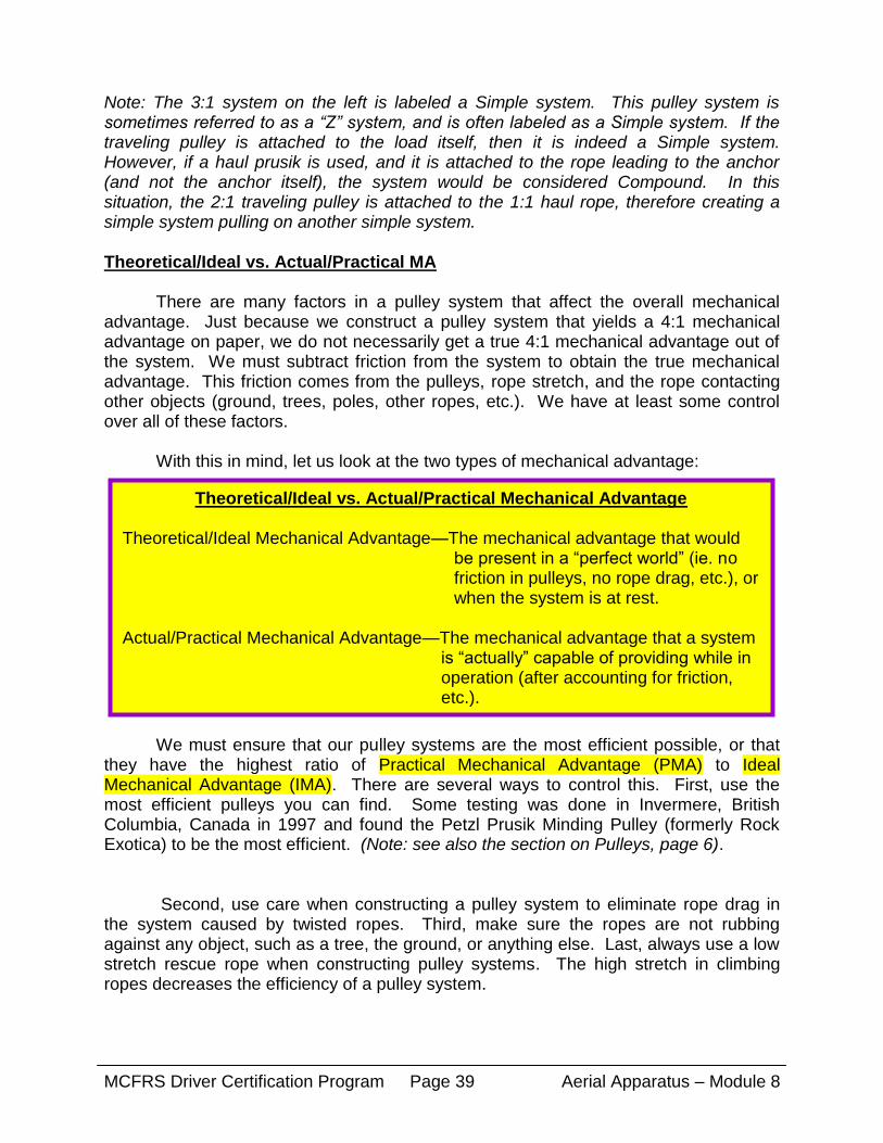
Theoretical/Ideal vs. Actual/Practical Mechanical Advantage
Theoretical/Ideal Mechanical Advantage—The mechanical advantage that would be present in a “perfect world” (ie. no friction in pulleys, no rope drag, etc.), or when the system is at rest.
Actual/Practical Mechanical Advantage—The mechanical advantage that a system
is “actually” capable of providing while in operation (after accounting for friction, etc.).
Note: The 3:1 system on the left is labeled a Simple system. This pulley system is sometimes referred to as a “Z” system, and is often labeled as a Simple system. If the traveling pulley is attached to the load itself, then it is indeed a Simple system. However, if a haul prusik is used, and it is attached to the rope leading to the anchor (and not the anchor itself), the system would be considered Compound. In this situation, the 2:1 traveling pulley is attached to the 1:1 haul rope, therefore creating a simple system pulling on another simple system. Theoretical/Ideal vs. Actual/Practical MA There are many factors in a pulley system that affect the overall mechanical advantage. Just because we construct a pulley system that yields a 4:1 mechanical advantage on paper, we do not necessarily get a true 4:1 mechanical advantage out of the system. We must subtract friction from the system to obtain the true mechanical advantage. This friction comes from the pulleys, rope stretch, and the rope contacting other objects (ground, trees, poles, other ropes, etc.). We have at least some control over all of these factors.
With this in mind, let us look at the two types of mechanical advantage:
We must ensure that our pulley systems are the most efficient possible, or that they have the highest ratio of Practical Mechanical Advantage (PMA) to Ideal Mechanical Advantage (IMA). There are several ways to control this. First, use the most efficient pulleys you can find. Some testing was done in Invermere, British Columbia, Canada in 1997 and found the Petzl Prusik Minding Pulley (formerly Rock Exotica) to be the most efficient. (Note: see also the section on Pulleys, page 6).
Second, use care when constructing a pulley system to eliminate rope drag in the system caused by twisted ropes. Third, make sure the ropes are not rubbing against any object, such as a tree, the ground, or anything else. Last, always use a low stretch rescue rope when constructing pulley systems. The high stretch in climbing ropes decreases the efficiency of a pulley system.

MCFRS Driver Certification Program Aerial Apparatus – Module 8 Page 40
When deciding which pulley system you need to construct to conduct a given operation, keep in mind the Actual Mechanical Advantage the system will provide. Multiplying the mechanical advantage of the system by the efficiency rating of the pulleys will give you a rough estimate. For example, a 3:1 system made with 70% efficient pulleys will yield a PMA of 2.1:1. There are more precise formulas than can be used for classroom exercises, but this will get you close. Personal Skills In order to conduct safe and efficient rope rescue evolutions, all personnel must be proficient with a number of basic, personal skills. These include tying knots, constructing anchors, setting up pulley systems, ascending and descending fixed ropes, self-rescue, etc. This section will cover the basic skills of ascending, descending, self-rescue, and the man-on-man pick off. It is important to note that these skills are best learned in practical training evolutions. One should not attempt to complete these skills without proper instruction from a qualified rope rescue instructor. Ascending Ascending is the process of climbing, or ascending a fixed rope. It is a very simple skill, but a very important one. If you are attached to a rope, either by a descent device or a fixed knot, you must have the ability to travel up the rope if the situation dictates. It requires more physical ability than intellectual knowledge or skill. It can be done with a minimum amount of equipment. Ascending can be done with any type of rope grab device, such as an ascender or prusiks. This section will focus on the use of prusiks to ascend. Most fire departments do not carry mechanical ascenders. In addition, if you can ascend using prusiks, you can ascend with mechanical ascenders even easier.
The minimum equipment required to ascend with prusiks is listed below. This list is the bare minimum (although it is possible to ascend without the use of a foot prusik). Additional equipment can make ascending much easier. It is also worth mentioning that you should always carry extra equipment on your harness in case of an equipment failure, or if you drop or lose something.
Ascenders, either hard shell (Rescucender) or handled can be used in place of prusiks. You will need to attach a loop to the ascender, either webbing or accessory cord. A daisy chain works well for the chest ascender, and an etrier works well for the foot ascender. If using a daisy chain, the bottom side of the daisy chain can be attached to the foot ascender to give a second point of attachment to the rope. Of course, as with any vertical rope operation, you should have a second, independent belay line in place while ascending.
Minimum Equipment Required for Ascending 1—Harness (class 2 or 3) 1—6-8mm Chest Prusik (approximately 4’ 6” - 5’ 6” length before tying) 1—6-8mm Foot Prusik (approximately 8-10 ft. length before tying) 1—Locking “D” Carabiner X—Proper PPE (minimum helmet and gloves)

MCFRS Driver Certification Program Aerial Apparatus – Module 8 Page 41
Remember to orient the carabiner in the “down and down” position. Vibration in the rope may cause the gate to open if it is in the up position. In addition, while ascending, keep a close watch on the carabiner. This carabiner often becomes side loaded or diagonally loaded during the ascending process. Also, remember to use the appropriate PPE during ascending evolutions. This would include gloves and a helmet. Note: If using a mechanical ascender, the process is the same. Descending Descending, also called rappelling, is the process of lowering yourself down a rope through the use of a friction device. Although most often required in high angle environments, it may be necessary to rappel down steep angle terrain as well. Rappelling, like ascending, is a fundamental skill that must be mastered by anyone working in a rope rescue evolution. There are two main friction devices that are used for rappelling: the figure “8” and the rappel rack. There are many other friction devices available, but these are probably the most popular (see equipment section, page 7, for further info). This section details the process of using a figure “8” and a rappel rack for rappelling.
“Sit-Stand” method of Ascending with Prusiks 1) Don the harness and have two other rescuers inspect it and do a safety check. 2) Attach the chest prusik to the rope with a double wrap. 3) Attach the chest prusik to the harness “D” ring using a locking carabiner. 4) Slide the chest prusik as high as you can on the rope. 5) Attach the foot prusik to the rope below the chest prusik using a double wrap. 6) Place one foot inside the foot prusik loop. 7) Slide the foot prusik as high as you can raise your foot. 8) Stand up on the leg that your foot prusik is in. 9) Slide the chest prusik as high as you can and sit down in your harness. 10) Continue to repeat steps 7 – 9 until reaching the desired height.

MCFRS Driver Certification Program Aerial Apparatus – Module 8 Page 42
Listed below is the minimum equipment required to rappel in a high angle environment. This list is the bare minimum. As noted in the ascending section, you should always carry additional equipment in case you drop or lose something, or in case a piece of equipment fails. For rappelling, it is a good idea to carry ascending equipment in the event you have to climb back up the rope. Also, remember to have a second, independent rope belay at all times.
Minimum Equipment Required to Rappel with a Figure “8” or Rappel Rack 1—Harness (class 2 or 3) 1—Rappel Device (figure “8” or rappel rack) 1—Locking “D” Carabiner X—Proper PPE (minimum helmet and gloves)
Rappelling with a Figure “8” 1) Don the harness and have two other rescuers inspect it and do a safety check. 2) Pull a bight of rope through the large hole in the figure “8”, making sure that the
strand of rope leading to the ground is on the side of your dominant hand. 3) Pull the bight around the small end of the figure “8”. 4) Attach the locking carabiner to the small hole in the figure “8” (for “8”s with three
holes, it should be the hole on the small end of the “8”, not the middle hole). 5) Attach the carabiner and the figure “8” to the “D” ring on the harness, again
making sure that the rope leading to the ground is on the side of your dominant hand.
6) Pull all slack out of the anchor side of the rope. 7) Grab the rope with your dominant hand, thumb up, and place that hand tightly
against the side of the buttocks. (Some people like to lightly rest their other hand on the rope above the “8”.)
8) While maintaining a tight grip on the rope, slowly place your weight onto the
figure “8” and rope. 9) Use the tension on the rope and the tightness of your grip to allow rope to slowly
slide through your hand. This will control your speed of descent. This is called your brake hand.
10) To stop your descent, grip the rope tightly and pull tension downward.

MCFRS Driver Certification Program Aerial Apparatus – Module 8 Page 43
Your descent should be slow and controlled. Faster rappels generate more heat,
which can damage the friction device and the rope. It can also cause burns to your hands, even if you are wearing gloves. When stopping, bring yourself to a stop slowly. Sudden stops can cause shock load to all of your system components, and could cause a failure. When rappelling down walls and other flat surfaces, keep a side stance for good balance. Your feet should be flat against the wall, with legs parallel to the ground. (Note: in the picture below, the rappeller’s feet are not flat against the wall.)
Rigging for Figure “8” with Ears Proper Brake Hand Positioning
11) To “lock-off” the figure “8” for hands free operation (ie. to attend to a patient),
first stop your descent. While maintaining a tight grip and tension on the rope, pull the rope straight up and over the top of the figure “8”, so that the rope in your brake hand rests in between the figure “8” and the rope coming from the anchor. If you are using a figure “8” with ears, pull the rope under the ear and repeat this procedure a second time to secure your lock-off.
12) To “unlock” the “8”, reverse this procedure. (Note: it is sometimes difficult for
people with little upper body strength to unlock a figure “8”. Use both hands if necessary.)

MCFRS Driver Certification Program Aerial Apparatus – Module 8 Page 44
Lock-off Procedure—Step 1 Step 2 Step 3
Proper Rappelling Stance—Make sure feet are spread apart.
Rappelling with a Rappel Rack 1) Don the harness and have two other rescuers inspect it and do a safety check. 2) Attach the rappel rack to the harness “D” ring with a locking carabiner. The
short leg of the rack should face away from you (Depending on the style of your rack and harness, this may not be possible. If not, the short leg should face toward your brake hand.)
3) Place the rope coming from the anchor on top of the top bar of the rack. Most
racks have a large (1”) top bar with a “training groove” cut into it. DO NOT place the rope between the frame of the rack and the top bar.
4) Pull all slack out of the anchor side of the rope with your brake hand, pulling the
rope away from you so that the rack is pulled away from your harness. 5) Snap the next bar into place on the rack frame. Pass the rope over top of the
bar. (Note: the second bar on most racks has a straight slot in it as opposed to an angled slot. This bar will fall out of the rack frame if the rope is passed over the wrong side of it.)

MCFRS Driver Certification Program Aerial Apparatus – Module 8 Page 45
6) Repeat step 5 until all the rope is weaved through all the bars. 7) Grab the rope with your dominant hand, thumb up, and place that hand tightly
against the side of the buttocks. (Some people like to lightly rest their other hand on the rope above the rack. However, with a rack, you can also place your hand behind the bars of the rack for additional speed control.)
8) While maintaining a tight grip on the rope, slowly place your weight onto the rack
and rope. 9) Release one bar at a time until you attain the correct number required for your
weight and desired speed. For most people, this is four or five bars. Never use less than four bars.
10) Use the tension on the rope and the tightness of your grip to allow rope to slowly
slide through your hand. This will control your speed of descent. This is called your brake hand. You can place your other hand behind the bars of the rack. By sliding the bars together, you will slow your descent, and by spreading them apart you will speed up your descent.
11) To stop your descent, grip the rope tightly and pull tension downward. You can
also slide the bars together with the other hand. 12) To “lock-off” the rack for hands free operation (ie. to attend to a patient), first stop
your descent. Make sure that the rope is weaved through all the bars. While maintaining a tight grip and tension on the rope, pull the rope under the last bar and straight up and over the top of the rack frame, so that the rope in your brake hand rests in between the rack frame and the rope coming from the anchor. Bring the rope back down and under the last bar again, and repeat the procedure. Secure the lock-off with a half hitch around the short leg of the rack.
13) To “unlock” the rack, reverse this procedure.

MCFRS Driver Certification Program Aerial Apparatus – Module 8 Page 46
Sequence for Rigging the Rappel Rack
Rack Rigging Complete
INCORRECT Rack Rigging

MCFRS Driver Certification Program Aerial Apparatus – Module 8 Page 47
Locking Off with a Rack
As with the figure “8”, your descent should be slow and controlled. The rack will provide a much more controlled descent than the figure “8”. (See the last paragraph on page 58 for more info.) Rappelling with a Rack—using four bars Changeovers/Self-Rescue

MCFRS Driver Certification Program Aerial Apparatus – Module 8 Page 48
A changeover is the process of switching from ascent to descent, or vice versa. Mastery of these two skills is essential to operating on rope. By using these simple skills, you can perform a self-rescue, and get yourself out of trouble while suspended from a rope. These situations can include passing over a knot in the rope, switching from one rope to another, removing clothing caught in a descent device, etc. The equipment required to complete a changeover or self-rescue is much the same as that required for ascending and rappelling. The minimum required equipment is listed below. As with ascending and descending, additional equipment can make changeovers easier. This equipment may include daisy chains, etriers, Purcell prusiks, etc.
The above procedure can easily be modified to pass a knot or obstruction in a
rope while rappelling. Instead of removing the rappel device from the rope and harness in step 6, simply re-attach it below the knot or obstruction. Once the rappel device is re-attached and all slack is removed, lock it off. Attach the long leg prusik to the rope just above the rappel device. Stand up in this prusik loop, and loosen the chest prusik. Remove both prusiks and continue your descent.
Minimum Equipment Required for a Changeover 1—Harness (class 2 or 3) 1—Rappel Device (figure “8” or rappel rack) 2—Locking “D” Carabiners 1—6-8mm Chest Prusik (approximately 4’ 6” - 5’ 6” length before tying) 1—6-8mm Foot Prusik (approximately 8-10 ft. length before tying X—Proper PPE (minimum helmet and gloves)
Procedure for Performing a Changeover—Descent to Ascent 1) While rappelling, stop and lock off your rappel device. 2) Attach your short chest prusik to the rope with a double wrap. 3) Attach the prusik to your harness “D” ring using a locking carabiner. 4) Remove all slack from the prusik. 5) Unlock your rappel device and feed rope through it until your weight is on the prusik. 6) Remove the rappel device from the rope and your harness. 7) Attach the rappel device to a gear loop on your harness, or somewhere out of the way. 8) Attach your long leg prusik to the rope and ascend (per instructions on page 56).

MCFRS Driver Certification Program Aerial Apparatus – Module 8 Page 49
Man-on-Man Pick-Off The “man-on-man” pick-off, as it is commonly known, is a simple technique used to rescue a victim suspended on a rope, scaffold, ledge, or other position on the side of a building, etc. In most cases, use of this technique assumes that there is no possibility of spinal injury, and no need for a backboard, stokes basket, or other patient immobilization device. In many cases, the victim may not even be injured—just stranded, as in the case of a stuck window washer. In others, the victim may have a minor injury such as a fractured hand, or possibly a medical condition such as a diabetic reaction or heart attack. In any case, the victim can be easily rescued using a simple class two or three harness. There are many variables involved with this evolution, such as: is the patient able to assist with his rescue; is the patient already wearing a harness; is the patient secure in his position, or is he hanging on “gecko” style; etc. All of these things are important aspects to consider, however, they do not affect the basic concept of this type of rescue. With a few minor changes, this evolution can be adapted to accommodate a wide variety of situations. This evolution can be performed by as little as two rescuers—one rescuer on rappel, and one managing the belay system. Although not as safe, a lone rescuer can accomplish it by himself with the use of a self-belay. It can also be performed by a team of rescuers using a lowering and/or raising system. The equipment requirements are minimal, and most of which can be found on a rescue squad or truck company.
Procedure for Performing a Changeover—Ascent to Descent 1) Ascend the rope to the desired point (using procedure on page 56). 2) Slide the long leg prusik up the rope until it touches the chest prusik. 3) Place the rappel device on the rope, remove all slack, and lock it off. 4) Stand up in the leg loop prusik. 5) Loosen the chest prusik from the rope. 6) Sit down into your harness. Your weight should now be on the rappel device. If
not, repeat steps four and five until your chest prusik is loose enough for your weight to be on your rappel device.
7) With your weight on the rappel device, you can now remove your leg and chest
prusiks. (Note: if desired, you can leave your chest prusik in place as a “pseudo” self-belay.)
8) Rappel

MCFRS Driver Certification Program Aerial Apparatus – Module 8 Page 50
Equipment Requirements for Man-on-Man Pick-Off—Lowering Mode
1—Harness for Rescuer (class 2 or 3) 2—½” Lifelines (1—main line, 1—belay line) X—Material for Anchor Construction (webbing, rope, etc.) 1—Complete Tandem Prusik Belay System (see page 44) 1—Descent Control Device (Rappel Rack preferred) 3—Locking “D” Carabiners (minimum, not counting belay system, but additional may be helpful) 2—8mm Prusiks (long belay prusiks or similar) Note: if performing operation in raising mode, replace descent control device with
appropriate raising system equipment (pulleys, prusiks, additional carabiners, etc.)
Procedure for Performing a Man-on-Man Pick-Off—Lowering Mode 1) Construct Main Line and Belay Line Anchors. 2) Have rescuer don a harness and have two others perform a safety check of the rescuer. 3) Tie a figure “8” stopper knot in the end of the main line. Attach both prusiks to the
main line above the stopper knot. Attach the top prusik to the rescuer. The bottom prusik will be for attaching to the victim.
4) Tie the belay line to the rescuer using a longtail bowline. Leave about 3-4 feet of
tail. This will be the victims belay attachment. 5) Attach the belay line to the belay system. Attach the main line to the rappel rack
and lock-off. 6) Using “three sets of eyes”, conduct a System Safety Check of both the Main Line
and Belay Line Systems. 7) Lower the rescuer to the victim. Get close enough that the rescuer can reach the
victims harness, or that he can apply a harness if the victim doesn’t have one. Good communication between the lowering team and the rescuer is essential. Do not lower too far.
8) Clip the second (lower) prusik into the victims harness “D” ring with a locking
carabiner.

MCFRS Driver Certification Program Aerial Apparatus – Module 8 Page 51
Rescuer being lowered to victim Rescuer arriving at victim
Rescuer tying victim in to Rescuer and victim
Main and Belay Lines Lowered Together
Procedure for Performing a Man-on-Man Pick-Off—Lowering Mode 9) Tie the tail of the belay line into the victims harness with a Yosemite Bowline. 10) Disconnect any rope or positioning system the victim is tied to. 11) The rescuer should position the victim so that the victim’s armpits are about even
with the rescuer’s thighs. The rescuer and victim should be facing each other. 12) Continue to lower the rescuer and the victim to the ground.
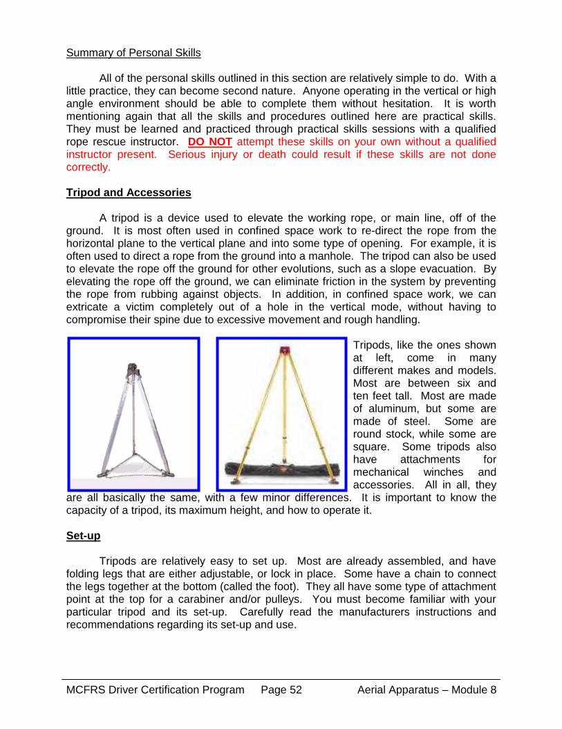
MCFRS Driver Certification Program Aerial Apparatus – Module 8 Page 52
Summary of Personal Skills All of the personal skills outlined in this section are relatively simple to do. With a little practice, they can become second nature. Anyone operating in the vertical or high angle environment should be able to complete them without hesitation. It is worth mentioning again that all the skills and procedures outlined here are practical skills. They must be learned and practiced through practical skills sessions with a qualified rope rescue instructor. DO NOT attempt these skills on your own without a qualified instructor present. Serious injury or death could result if these skills are not done correctly. Tripod and Accessories A tripod is a device used to elevate the working rope, or main line, off of the ground. It is most often used in confined space work to re-direct the rope from the horizontal plane to the vertical plane and into some type of opening. For example, it is often used to direct a rope from the ground into a manhole. The tripod can also be used to elevate the rope off the ground for other evolutions, such as a slope evacuation. By elevating the rope off the ground, we can eliminate friction in the system by preventing the rope from rubbing against objects. In addition, in confined space work, we can extricate a victim completely out of a hole in the vertical mode, without having to compromise their spine due to excessive movement and rough handling.
Tripods, like the ones shown at left, come in many different makes and models. Most are between six and ten feet tall. Most are made of aluminum, but some are made of steel. Some are round stock, while some are square. Some tripods also have attachments for mechanical winches and accessories. All in all, they
are all basically the same, with a few minor differences. It is important to know the capacity of a tripod, its maximum height, and how to operate it. Set-up Tripods are relatively easy to set up. Most are already assembled, and have folding legs that are either adjustable, or lock in place. Some have a chain to connect the legs together at the bottom (called the foot). They all have some type of attachment point at the top for a carabiner and/or pulleys. You must become familiar with your particular tripod and its set-up. Carefully read the manufacturers instructions and recommendations regarding its set-up and use.

MCFRS Driver Certification Program Aerial Apparatus – Module 8 Page 53
Some basic guidelines for setting up a tripod are as follows:
Use of Mechanical Winch As mentioned above, many tripods are set up to accommodate a mechanical winch. This winch is generally attached to one of the legs of the tripod, and takes the place of a mechanical advantage pulley system. Some winches accept standard rescue rope, while some use a cable that is pre-attached. Most winches also have the capability to lower a load. One of the downsides to these winches is the fact that they are very expensive (many over $1,000, some over $2,500). They are also very heavy, bulky, and cumbersome. On the upside, however, they are quick to set up and don’t require lots of other equipment. With some winches, one person can easily lift and control loads up to 600 lbs. Since all winches are constructed differently and operate differently, you should carefully read and understand the manufactures instructions and recommendations before using one. Become thoroughly familiar with your winch before using it in an emergency situation. This should be done in practice sessions and training scenarios.
Capstan Style Winch Cable Winch Electric Capstan Style Winch
1) In most cases, spread the legs as wide as possible for greater stability. The legs on most tripods have a limit as to how far they will spread.
2) Make sure the feet of the tripod are secure and will not kick out. Some tripods
have multiple position feet, for use on different types of terrain. Some feet even have holes for pickets and attachment points for tie-offs.
3) In most cases, set the height of the tripod as high as it will go. You may have to
attach your carabiners and pulleys before raising the tripod. 4) When working over a hole, center the tripod over the hole. When using for a
slope evacuation or other evolution, make sure the direction of force (force vector) is within the legs of the tripod.

MCFRS Driver Certification Program Aerial Apparatus – Module 8 Page 54
No matter which style of winch you use, you must always use a second, independent rope belay. As with other rope rescue systems, the tandem prusik belay is the belay of choice. This belay should be attached to a secondary anchor, and should not be incorporated into the tripod. It should run from the belay anchor, over the edge of the hole, and directly to the patient and/or rescuer. Make sure you pad the edge of the hole where the belay line enters. If necessary, multiple belay lines may be used. Use of Mechanical Advantage If you do not have a mechanical winch with your tripod, you can use any style of mechanical advantage system to pull the rescuer and/or victim out of the hole. For confined space evolutions, many people like to use a simple block-and-tackle system suspended from the tripod. This works well if the distance between the tripod and the bottom of the hole is not too great. In addition, if you are using the tripod for a high directional in a slope evacuation or other evolution, you will have to use a mechanical advantage system. For this type of evolution, you will only be using the tripod as a high directional, and the mechanical advantage system will be between the main anchor and the tripod. The biggest consideration when using a mechanical advantage system outside of the tripod legs is the force vector. In simple terms, this force vector—also called a resultant-- is created when the rope forms an angle, such as the angle formed at the change of direction pulley at the top of a tripod. You can determine the direction of this resultant vector by bisecting the angle formed by the ropes leading into and out of the change of direction pulley. In addition, the pulley will point in the direction of force when the rope is tensioned. This resultant vector must be focused within the legs of the tripod. If it is not, the tripod can easily tip over. An easy way of accomplishing this is to use a leading block at the base of the tripod, such as on one of the feet.
Resultant vector—bisects angle formed by ropes at directional pulley—resultant directed within legs of tripod
Belay line—not incorporated in tripod