technical report netapp hci disaster recovery and …vmware srm 8.1 is supported in netapp element®...
TRANSCRIPT
Technical Report
NetApp HCI Disaster Recovery and Replication With VMware Site Recovery Manager
James Bradshaw, NetApp
September 2019 | TR-4795
Abstract
This document provides a conceptual understanding of disaster recovery and replication with
VMware vCenter Site Recovery Manager (SRM) 8.1 on NetApp® HCI.
2 NetApp HCI Disaster Recovery and Replication with VMware Site Recovery Manager
© 2019 NetApp, Inc. All rights reserved.
TABLE OF CONTENTS
1 Solution Overview ................................................................................................................................ 4
1.1 Target Audience ..............................................................................................................................................5
1.2 Primary Use Cases .........................................................................................................................................5
1.3 Technology Requirements ..............................................................................................................................6
2 Private Cloud Infrastructure with NetApp HCI ................................................................................... 8
2.1 NetApp HCI Overview .....................................................................................................................................8
2.2 NetApp HCI Use Cases ..................................................................................................................................8
2.3 NetApp HCI Key Features...............................................................................................................................9
2.4 NetApp HCI Design Principles: Predictability, Flexibility, Simplicity ................................................................9
2.1 Compute and Storage Nodes........................................................................................................................ 10
2.2 Element Software .......................................................................................................................................... 11
2.3 Streamline Operations .................................................................................................................................. 12
2.4 NetApp Deployment Engine .......................................................................................................................... 12
2.5 NetApp HCI Plug-In for VMware vCenter ...................................................................................................... 13
2.6 NetApp Active IQ .......................................................................................................................................... 13
2.7 Data Fabric ................................................................................................................................................... 13
3 Disaster Recovery and Replication with VMware SRM .................................................................. 13
3.1 Traditional Disaster Recovery Scenario ........................................................................................................ 14
3.2 Topology Considerations .............................................................................................................................. 14
3.3 Putting the Pieces Together .......................................................................................................................... 16
3.4 NetApp SolidFire SRA-Enabled Protection Workflows .................................................................................. 18
3.5 Limits ............................................................................................................................................................ 19
3.6 Best Practices ............................................................................................................................................... 19
4 Conclusion .......................................................................................................................................... 19
Where to Find Additional Information .................................................................................................... 20
NetApp ................................................................................................................................................................. 20
VMware SRM ....................................................................................................................................................... 20
Version History ......................................................................................................................................... 20
LIST OF TABLES
Table 1) Primary use cases. ...........................................................................................................................................5
Table 2) Minimum recommended hardware. ..................................................................................................................6
Table 3) Software requirements. ....................................................................................................................................6
Table 4) Solution compatibility matrix. ............................................................................................................................7

3 NetApp HCI Disaster Recovery and Replication with VMware Site Recovery Manager
© 2019 NetApp, Inc. All rights reserved.
Table 5) SRA array compatibility matrix. ........................................................................................................................7
LIST OF FIGURES
Figure 1) Solution reference architecture. ......................................................................................................................4
Figure 2) NetApp HCI key features. ...............................................................................................................................9
Figure 3) NetApp HCI minimum configuration. ............................................................................................................. 10
Figure 4) NetApp HCI compute node specifications. .................................................................................................... 10
Figure 5) NetApp HCI storage node specifications. ...................................................................................................... 11
Figure 6) NetApp HCI compute, storage, and graphics/AI nodes. ................................................................................ 11
Figure 7) NetApp Element software fundamentals. ...................................................................................................... 11
Figure 8) NetApp NDE welcome screen. ...................................................................................................................... 12
Figure 9) Active-passive protection. ............................................................................................................................. 15
Figure 10) Active-active protection. .............................................................................................................................. 15
Figure 11) Bidirectional protection. ............................................................................................................................... 16
Figure 12) Recovery steps. .......................................................................................................................................... 19

4 NetApp HCI Disaster Recovery and Replication with VMware Site Recovery Manager
© 2019 NetApp, Inc. All rights reserved.
1 Solution Overview
VMware Site Recovery Manager (SRM) provides business continuity, disaster recovery, site migration,
and nondisruptive testing capabilities for VMware virtual environments running on NetApp® HCI. VMware
SRM automates the migration, recovery, testing, protection, and failback of virtual machines (VMs).
VMware SRM can use VMware vSphere Replication to cover various replication scenarios in NetApp HCI
environments.
The VMware SRM application is installed on a supported version of Microsoft Windows Server on both
the protected and recovery vCenter Server sites. There must be at least one vSphere host running ESXi
6.0 U3 at each site.
This document provides a conceptual explanation of what is required in a true disaster recovery scenario.
This scenario typically requires more than just failing over the virtual infrastructure and the storage
environment. To architect a disaster recovery solution, keep the following factors in mind:
• Recovery time objective (RTO). The RTO is how quickly a business can recover from a disaster, or, more specifically, how long it takes to execute the recovery process to make business services available again.
• Recovery point objective (RPO). The RPO is how old the recovered data is after it has been made available, relative to the time that the disaster occurred. Depending on environmental factors, RPO can range from 30 seconds to 24 hours.
• Scalability and adaptability. This factor includes the ability to grow storage resources incrementally as demand increases.
An ideal solution has both a low RPO (measured in minutes) and a low RTO (measured in minutes to
hours). One factor that is often overlooked in a disaster recovery solution is the ability to test the disaster
recovery solution efficiently. In physical environments, disaster recovery testing might take many hours or
even days, and replication between sites must be stopped during the tests.
Figure 1 shows a typical VMware SRM architecture with NetApp HCI.
Figure 1) Solution reference architecture.
Benefits of NetApp HCI and VMware SRM include:
• Reliable disaster recovery performance with NetApp Element software
• Simple, policy-based management
• Reduced TCO
Applications used in the solution include:
• VMware SRM
• NetApp SolidFire® Storage Replication Adapter (SRA)
5 NetApp HCI Disaster Recovery and Replication with VMware Site Recovery Manager
© 2019 NetApp, Inc. All rights reserved.
• vSphere Replication
The combination of NetApp HCI and VMware Site Recovery Manager provides an enterprise-ready
solution that ensures business continuity for many use cases. This document provides a high-level
overview of disaster recovery. It describes a VMware virtualized environment on NetApp HCI that uses
VMware SRM for array-based replication with NetApp SolidFire SRA, and that can use vSphere
Replication as an additional option for protection.
By default, NetApp HCI powered by Element software provides the NetApp Deployment Engine (NDE) for
automated deployment of your virtual environment. It also provides integrated data services such as high
availability, replication, data assurance, quality of service (QoS), data efficiencies, NetApp Snapshot™
copies, and clones all at the array level. These features ensure guaranteed performance and flexibility for
your cloud implementation of choice.
VMware SRM helps you plan, test, and run the recovery of VMs between protected and recovery vCenter Server sites. SRM is a business continuity and disaster recovery solution for minimizing data loss and system downtime.
1.1 Target Audience
The target audience for this solution includes engineering, management, and executives who have
knowledge of VMware Site Recovery Manager and vSphere Replication and want to integrate disaster
recovery and planned migration capabilities into their NetApp HCI–based VMware environment. This
document is aimed at:
• Those with small and midrange VMware environments
• Enterprise IT cloud administrators
• Solution providers
This document does not provide detailed deployment instructions.
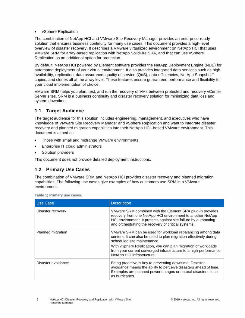
1.2 Primary Use Cases
The combination of VMware SRM and NetApp HCI provides disaster recovery and planned migration
capabilities. The following use cases give examples of how customers use SRM in a VMware
environment.
Table 1) Primary use cases.
Use Case Description
Disaster recovery VMware SRM combined with the Element SRA plug-in provides recovery from one NetApp HCI environment to another NetApp HCI environment. It protects against site failure by automating and orchestrating the recovery of critical systems.
Planned migration VMware SRM can be used for workload rebalancing among data centers. It can also be used to plan migration effectively during scheduled site maintenance.
With vSphere Replication, you can plan migration of workloads from your current converged infrastructure to a high-performance NetApp HCI infrastructure.
Disaster avoidance Being proactive is key to preventing downtime. Disaster avoidance means the ability to perceive disasters ahead of time. Examples are planned power outages or natural disasters such as hurricanes.
6 NetApp HCI Disaster Recovery and Replication with VMware Site Recovery Manager
© 2019 NetApp, Inc. All rights reserved.
Use Case Description
Upgrade and patch testing VMware SRM can be used to conduct VM and application upgrades and patch testing. In this scenario, you copy the production environment to a test environment with isolated networking. This approach is great for dry runs before maintenance operations on production components.
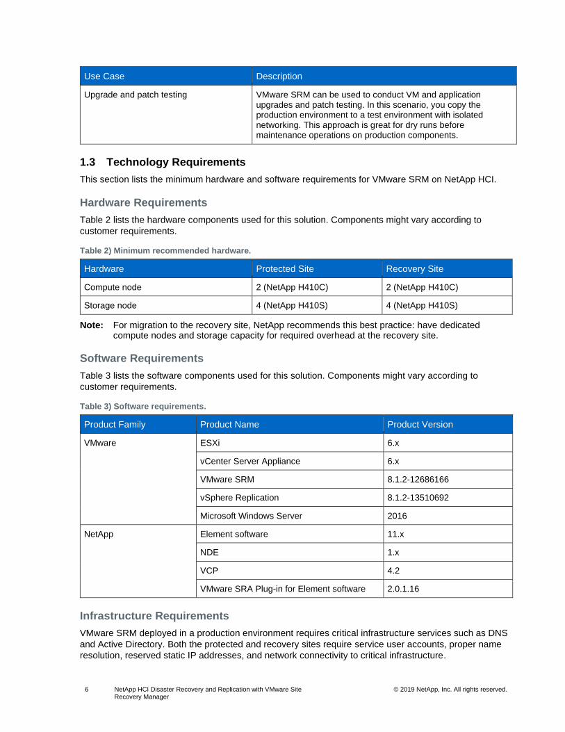
1.3 Technology Requirements
This section lists the minimum hardware and software requirements for VMware SRM on NetApp HCI.
Hardware Requirements
Table 2 lists the hardware components used for this solution. Components might vary according to
customer requirements.
Table 2) Minimum recommended hardware.
Hardware Protected Site Recovery Site
Compute node 2 (NetApp H410C) 2 (NetApp H410C)
Storage node 4 (NetApp H410S) 4 (NetApp H410S)
Note: For migration to the recovery site, NetApp recommends this best practice: have dedicated compute nodes and storage capacity for required overhead at the recovery site.
Software Requirements
Table 3 lists the software components used for this solution. Components might vary according to
customer requirements.
Table 3) Software requirements.
Product Family Product Name Product Version
VMware ESXi 6.x
vCenter Server Appliance 6.x
VMware SRM 8.1.2-12686166
vSphere Replication 8.1.2-13510692
Microsoft Windows Server 2016
NetApp Element software 11.x
NDE 1.x
VCP 4.2
VMware SRA Plug-in for Element software 2.0.1.16
Infrastructure Requirements
VMware SRM deployed in a production environment requires critical infrastructure services such as DNS
and Active Directory. Both the protected and recovery sites require service user accounts, proper name
resolution, reserved static IP addresses, and network connectivity to critical infrastructure.

7 NetApp HCI Disaster Recovery and Replication with VMware Site Recovery Manager
© 2019 NetApp, Inc. All rights reserved.
Licensing
• For Element software, no additional license is required for integrated data services such as NetApp SnapMirror® software, cluster pairing, and replication.
• NetApp SolidFire capacity licensing is available.
For more information, see NetApp SolidFire Capacity Licensing.
• VMware ESXi and vCenter require separate license keys.
SRM requires a license key on any protected and recovery sites where VMs are protected.
For more information, see Site Recovery Manager Licensing.
• Additional vSphere Replication licensing is not required, because it is an included feature with vSphere Standard, Enterprise, and Enterprise Plus.
Compatibility Matrix
VMware SRM 8.1 is supported in NetApp Element® software version 11. For more information about
compatibility with SRM, SRA, and vSphere Replication with NetApp HCI, see Table 4 and Table 5.
For more information about compatibility, review the following documents:
• Compatibility Matrices for VMware Site Recovery Manager 8.1
• VMware Compatibility Guide for SRA for Element software
• Compatibility Matrices for vSphere Replication 8.1.x
Table 4) Solution compatibility matrix.
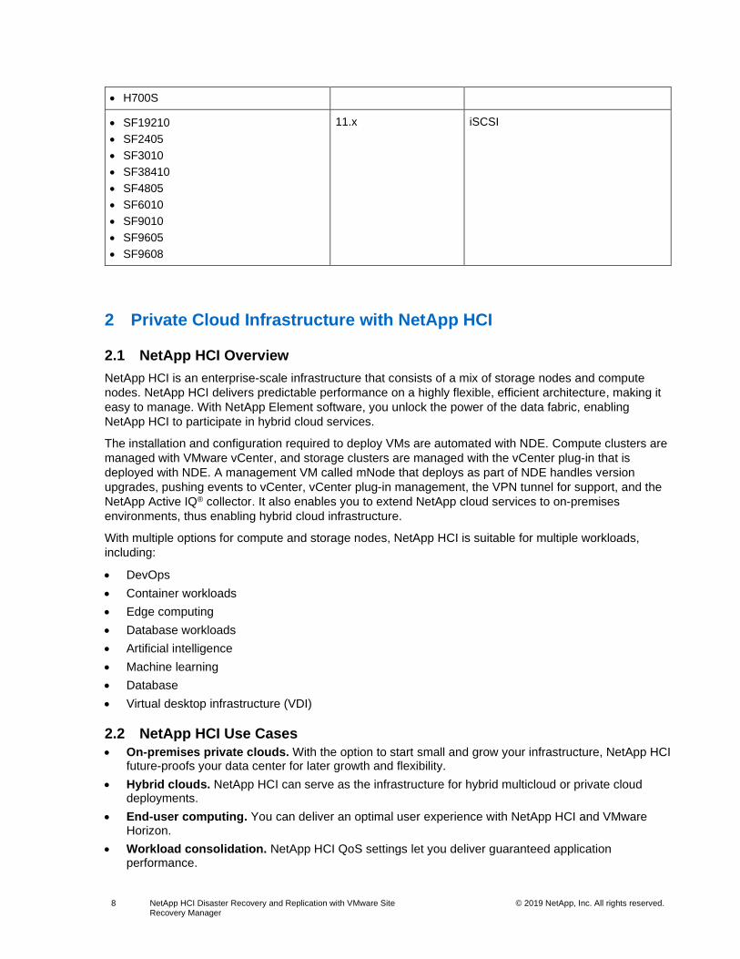
Table 5) SRA array compatibility matrix.
Component Software Version Features
ESXi • ESXi Server 6.0U3
• ESXi Server 6.5
• ESXi Server 6.5U1
• ESXi Server 6.7
–
vCenter • vCenter Server 6.0U3
• vCenter Server 6.5
• vCenter Server 6.5U1
• vCenter Server 6.7
–
SRM 8.1 • Standard storage
• Dynamic Access Restriction (DAR)
vSphere Replication 8.1 –
SolidFire SRA 2.0.1.16 –
Element software 11.x –
Supported NetApp HCI Nodes Firmware Version Protocol
• H300S
• H410S
• H500S
• H610S
11.x iSCSI
8 NetApp HCI Disaster Recovery and Replication with VMware Site Recovery Manager
© 2019 NetApp, Inc. All rights reserved.
2 Private Cloud Infrastructure with NetApp HCI
2.1 NetApp HCI Overview
NetApp HCI is an enterprise-scale infrastructure that consists of a mix of storage nodes and compute
nodes. NetApp HCI delivers predictable performance on a highly flexible, efficient architecture, making it
easy to manage. With NetApp Element software, you unlock the power of the data fabric, enabling
NetApp HCI to participate in hybrid cloud services.
The installation and configuration required to deploy VMs are automated with NDE. Compute clusters are
managed with VMware vCenter, and storage clusters are managed with the vCenter plug-in that is
deployed with NDE. A management VM called mNode that deploys as part of NDE handles version
upgrades, pushing events to vCenter, vCenter plug-in management, the VPN tunnel for support, and the
NetApp Active IQ® collector. It also enables you to extend NetApp cloud services to on-premises
environments, thus enabling hybrid cloud infrastructure.
With multiple options for compute and storage nodes, NetApp HCI is suitable for multiple workloads,
including:
• DevOps
• Container workloads
• Edge computing
• Database workloads
• Artificial intelligence
• Machine learning
• Database
• Virtual desktop infrastructure (VDI)
2.2 NetApp HCI Use Cases
• On-premises private clouds. With the option to start small and grow your infrastructure, NetApp HCI future-proofs your data center for later growth and flexibility.
• Hybrid clouds. NetApp HCI can serve as the infrastructure for hybrid multicloud or private cloud deployments.
• End-user computing. You can deliver an optimal user experience with NetApp HCI and VMware Horizon.
• Workload consolidation. NetApp HCI QoS settings let you deliver guaranteed application performance.
• H700S
• SF19210
• SF2405
• SF3010
• SF38410
• SF4805
• SF6010
• SF9010
• SF9605
• SF9608
11.x iSCSI

9 NetApp HCI Disaster Recovery and Replication with VMware Site Recovery Manager
© 2019 NetApp, Inc. All rights reserved.
2.3 NetApp HCI Key Features
NetApp HCI provides enterprise reliability and availability. Some of the important features of NetApp HCI
include:
• Guaranteed performance
− Allocate storage performance independent of capacity
− Manage performance in real time without affecting other volumes
− Guarantee performance to every volume with fine-grain QoS settings
• Global efficiency
− Inline and post-compression
− Automatic distribution of data (no hot spots) with always-on deduplication
− Global thin provisioning
• Data assurance
− NetApp HCI Helix RAID-less data protection
− Real-time replication (synchronous and asynchronous)
− Integrated backup and recovery (cloud)
− Data and performance availability regardless of system condition or application activity
− Data safeguarded with 256-bit encryption
Figure 2) NetApp HCI key features.
2.4 NetApp HCI Design Principles: Predictability, Flexibility, Simplicity
NetApp HCI gives you flexible and straightforward control over your enterprise-class workloads. It is
designed to provide predictable performance, linear scalability, and a simple deployment and
management experience.
• Predictable
− Prevent noisy neighbors and satisfy performance SLAs with industry-leading performance QoS.
− Combine Storage Policy Based Management (SPBM) to automate and manage QoS.
• Flexible
− Confidently scale compute and storage nodes independently with zero share architecture.
− Prevent inefficient overprovisioning and reduce TCO.
− Mix small, medium, and large compute and storage configurations.

10 NetApp HCI Disaster Recovery and Replication with VMware Site Recovery Manager
© 2019 NetApp, Inc. All rights reserved.
• Simple
− With NDE, eliminate manual deployment and risk of user errors.
− Manage NetApp HCI with the Element Plug-in for vCenter.
2.1 Compute and Storage Nodes
NetApp HCI offers multiple form factors for various compute and storage needs. A minimum starting
configuration includes two chassis with two compute and four storage nodes. More nodes are needed for
GPU-driven workloads such as VMware Horizon or machine learning. Compute nodes used for database
workloads are also available with this architecture.
Figure 3) NetApp HCI minimum configuration.
Compute Nodes
NetApp H300E, H500E, and H700E nodes are based on Intel Xeon E5 v4 (Broadwell) processors.
NetApp HCI H410C and H610C nodes are based on Intel Scalable (Skylake) processors. The NetApp
HCI H610C node contains two NVIDIA Tesla M10 cards. NetApp HCI compute nodes can scale up to 64
per cluster.
Figure 4) NetApp HCI compute node specifications.
NetApp strongly recommends reading the NetApp HCI datasheet for more information about NetApp HCI
compute and storage offerings. For details about how NetApp HCI works, see the NetApp HCI Theory of
Operations white paper.
Storage Nodes
Storage nodes are available on either half-width or full-width rack units. Half-width rack units are
populating two rack unit chassis, which can contain either storage or compute nodes. At least four

11 NetApp HCI Disaster Recovery and Replication with VMware Site Recovery Manager
© 2019 NetApp, Inc. All rights reserved.
storage nodes are required and can be expanded to up to 40 nodes. A storage cluster can be shared
across multiple compute clusters offering asynchronous, synchronous, and Snapshot replication methods
for integrated data service. Storage nodes contain a cache controller to improve the write performance. A
single node provides either 50K or 100K IOPS at 4K block size.
NetApp HCI storage nodes run Element software, which provides a QoS feature that supports minimum,
maximum, and burst limits. The storage cluster allows a mix of storage nodes; the only caveat is that one
storage node size can’t exceed 1/3 of total capacity.
Figure 5) NetApp HCI storage node specifications.
Figure 6) NetApp HCI compute, storage, and graphics/AI nodes.
2.2 Element Software
Element software is designed for data centers that require rapid, modular growth or contraction for
diverse workloads. Because of its flexible handling of permanent and transient workloads with various
throughput and capacity requirements, Element software is the storage infrastructure of choice for service
providers.
Element provides modular, scalable performance with each storage node, delivering guaranteed capacity
and throughput to the environment. Each Element storage node added to a NetApp HCI environment
provides a set amount of IOPS and capacity, allowing predictable, planned growth.
Figure 7) NetApp Element software fundamentals.
Because each node provides a set throughput (IOPS) to the storage environment, QoS for each workload
can be guaranteed. Element helps you ensure minimum SLAs because the total throughput of the cluster
is a known, quantifiable amount.
For more information, see the Element software product page.

12 NetApp HCI Disaster Recovery and Replication with VMware Site Recovery Manager
© 2019 NetApp, Inc. All rights reserved.
Element software is 100% programmable and delivers unmatched agility and guaranteed application
performance. With the ability to mix nodes within a cluster, you can build a private cloud architecture to
meet your business needs at any scale.
2.3 Streamline Operations
A common goal of IT organizations is to automate all routine tasks and eliminate the risk of user errors
associated with manual operations. Automation allows you to focus valuable resources on higher
priorities that drive business efficiencies. NDE streamlines Day 0 installation, reducing it from hours to
minutes. Centralized management through the vCenter plug-in gives you full control over your
infrastructure with an intuitive UI. A robust suite of APIs allows you to seamlessly integrate higher-level
management, orchestration, backup, and disaster recovery tools.
For more information, see TR-7261: NetApp HCI Theory of Operations.
2.4 NetApp Deployment Engine
NDE enables the quick deployment of NetApp HCI, including the NetApp Element cluster and the
VMware virtualized infrastructure. NDE simplifies Day 0 deployment by reducing the number of manual
steps from over 400 to less than 30. Because NDE is intuitive and reuses data such as usernames and
passwords, you do not have to reenter information or set credentials at varying levels of complexity.
Likewise, NDE takes care of assigning IP addresses, allowing you to set a scheme and pool for all
resources before actual configuration. Also, preinstallation checklists enable successful deployments
because the system automatically checks for user errors, eliminating manual checks.
Figure 8) NetApp NDE welcome screen.
As part of the deployment process, an administrator can optionally deploy VMware vCenter Server and
choose simple or advanced networking options. NDE also makes it easy to configure the 1Gb and
10/25GbE network for compute and storage by using predefined defaults. For many users, this basic
network setup is the most convenient option. However, there is also an advanced network setting tab that

13 NetApp HCI Disaster Recovery and Replication with VMware Site Recovery Manager
© 2019 NetApp, Inc. All rights reserved.
allows you to enter individual IP addresses, subnets, and host names to conform to existing infrastructure
standards.
For more information about deploying NetApp HCI with NDE, see the NetApp HCI Deployment Guide 1.6.
2.5 NetApp HCI Plug-In for VMware vCenter
The NetApp HCI plug-in for VMware vCenter is a VMware vCenter Server plug-in that integrates the
management of NetApp HCI storage arrays from within a VMware vSphere Web Client. The vSphere
Web Client is a single management interface that you can use to manage the VMware infrastructure and
all your day-to-day storage needs:
• Manage NetApp HCI in vCenter.
• Discover and manage multiple NetApp HCI clusters.
• Create, extend, clone, share, and delete vSphere datastores.
• Create, edit, and delete NetApp HCI accounts.
• Create edit, clone, and delete NetApp HCI volumes, and add them to or remove them from access groups.
• Create, edit, and delete NetApp HCI access groups.
2.6 NetApp Active IQ
NetApp Active IQ is a web-based tool that provides predictive analytics along with proactive support to
help optimize operations across your cloud infrastructure. The Active IQ tool makes monitoring capacity,
performance, and cluster health easy and accessible from anywhere. You can set up notifications about
specified events, thresholds, or metrics on a cluster so that you can address them when they arise.
2.7 Data Fabric
With NetApp technology, you can build a data fabric that lets you manage and migrate data seamlessly
across Element and NetApp ONTAP® systems on the premises, near the premises, and in the cloud.
NetApp HCI is data fabric ready, so you gain data portability, visibility, and protection of all your data
across public, private, or hybrid clouds. With NetApp HCI, you can unleash the full potential of your data
across multiple cloud environments.
For more information about the data fabric, see What Is Hybrid Multicloud Experience?
3 Disaster Recovery and Replication with VMware SRM
IT operations for critical business deployments require data protection and product environment
replication for development, testing, analytics, and operations. The VMware SRM and NetApp SolidFire
SRA solution enables array-based replication that supports SRM functions such as failover, failback, and
failover testing. This solution gives SRM the ability to communicate directly to the storage array.
SRM can use either array-based replication or vSphere Replication for transferring data between sites.
• Array-based replication. Array-based replication consists of peered storage arrays at the protected and recovery sites. SRM can communicate directly with NetApp Element storage arrays, increasing the ability for virtual environments to replicate from array to array. SRM servers can monitor and control array functions related to migrations, failovers, reprotections, failback, and test scenarios. SRA must be installed on the VM hosting the SRM application. The NetApp SolidFire SRA package is available through the VMware and NetApp download sites.
• vSphere Replication. vSphere Replication, an optional feature, can be added to SRM or run as a standalone application. It is an alternative to array-based replication that provides replication at the vSphere datastore level.

14 NetApp HCI Disaster Recovery and Replication with VMware Site Recovery Manager
© 2019 NetApp, Inc. All rights reserved.
3.1 Traditional Disaster Recovery Scenario
In a traditional failover of business operations after a disaster, recovery requires several steps that are
manual, lengthy, and complex. Often, custom scripts are written to simplify some of these processes.
However, these processes can affect the real RTO that any disaster recovery solution can deliver, and
most scripts cannot adapt and update as an environment grows or changes.
Consider the following outline of a traditional disaster recovery scenario in a virtual environment. Each of
these steps might involve several individual tasks.
1. A disaster recovery solution was previously implemented, and replication has been performed.
2. A disaster occurs that requires failover to the disaster recovery site. This event might be a lengthy power outage that is too long for the business to withstand without failing over. Or it might be a more severe disaster, causing the loss of data or equipment at the primary site.
3. The disaster recovery team takes the necessary steps to confirm the disaster and decides to fail over business operations to the disaster recovery site.
4. If data replication is successful and the results are verified, then the team must perform the following tasks:
a. Present the replicated storage to the VMware ESXi hosts at the disaster recovery site.
b. Attach the ESXi hosts to the storage.
c. Add the VMs to the inventory of the ESXi hosts.
d. If the disaster recovery site is on a network segment that is different from the primary site, each VM might need to be reconfigured for the new network.
e. Verify that the environment is launched properly, with systems and services made available in the correct order.
5. After the disaster recovery environment is ready, the business can continue operating at its current capacity.
6. At some point, the primary site becomes available again or the lost equipment is replaced.
7. Changes that were made to the data while the disaster recovery site was supporting the business must be replicated to the primary site. Replication must be reversed to accomplish this step.
8. The processes described in step 4 must now be performed again, this time within a controlled outage window to fail the environment back to the primary site. Depending on how soon the disaster recovery team was able to engage after the disaster, this failback process might take nearly as long as the failover process.
9. After the primary environment has been recovered, the team must establish replication in the original direction from the primary site to the disaster recovery site.
10. Repeat the tests to verify that the environment is ready for a future disaster.
As previously mentioned, a disaster recovery process can be prone to human error. The risks are
amplified when the process is performed again to recover back to the primary site. And because a
disaster recovery solution is an important insurance policy for any business, you must test the disaster
recovery plan periodically to verify its reliability. Because of physical environment limitations and the
difficulty of testing, most environments can test the disaster recovery plan only a few times a year at most.
Some cannot test it at all.
3.2 Topology Considerations
Because of VMware SRM’s integration with the vSphere client, managing single and multiple topologies
is easy. You can choose from several supported failover scenarios according to your requirements and
objectives.
Note: This technical report covers only protected and recovery topologies.

15 NetApp HCI Disaster Recovery and Replication with VMware Site Recovery Manager
© 2019 NetApp, Inc. All rights reserved.
Active-Passive
Dedicated hardware is required for the active-passive topology. The production site uses resources while
the recovery site remains idle until it is needed for recovery, as shown in Figure 9.
Pro: This approach ensures that resources have required overhead if a recover action must occur.
Con: You pay for a site, servers, and storage that aren’t used much of the time.
Figure 9) Active-passive protection.
Active-Active
In an active-active topology, low-priority workloads such as test and development workloads run at the
recovery site but are powered off during recovery actions, as shown in Figure 10.
Pro: This approach allows maximum utilization of recovery hardware.
Con: Low-priority workloads must be relocated if a recovery action occurs.
Figure 10) Active-active protection.
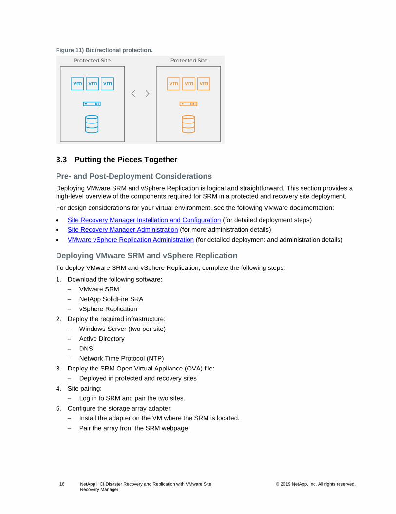
Bidirectional
In this topology, SRM supports paired sites that protect VMs at the protected site and recovery site, as
shown in Figure 11. The bidirectional topology can be implemented with both array-based replication and
vSphere Replication.
Pro: VMs are protected at both sites. This approach fully uses resources and enables flexibility if a
triggered event occurs.
Con: This approach requires a more robust recovery plan if a disaster occurs at both sites.
16 NetApp HCI Disaster Recovery and Replication with VMware Site Recovery Manager
© 2019 NetApp, Inc. All rights reserved.
Figure 11) Bidirectional protection.
3.3 Putting the Pieces Together
Pre- and Post-Deployment Considerations
Deploying VMware SRM and vSphere Replication is logical and straightforward. This section provides a
high-level overview of the components required for SRM in a protected and recovery site deployment.
For design considerations for your virtual environment, see the following VMware documentation:
• Site Recovery Manager Installation and Configuration (for detailed deployment steps)
• Site Recovery Manager Administration (for more administration details)
• VMware vSphere Replication Administration (for detailed deployment and administration details)
Deploying VMware SRM and vSphere Replication
To deploy VMware SRM and vSphere Replication, complete the following steps:
1. Download the following software:
− VMware SRM
− NetApp SolidFire SRA
− vSphere Replication
2. Deploy the required infrastructure:
− Windows Server (two per site)
− Active Directory
− DNS
− Network Time Protocol (NTP)
3. Deploy the SRM Open Virtual Appliance (OVA) file:
− Deployed in protected and recovery sites
4. Site pairing:
− Log in to SRM and pair the two sites.
5. Configure the storage array adapter:
− Install the adapter on the VM where the SRM is located.
− Pair the array from the SRM webpage.

17 NetApp HCI Disaster Recovery and Replication with VMware Site Recovery Manager
© 2019 NetApp, Inc. All rights reserved.
6. Map the objects to be protected, such as host, clusters, VM folders, and networks:
− Network mappings
− Resource mappings
− Folder mappings
7. After you select the VM and datastore to be protected, a placeholder VM and datastore are created and registered with VMware vCenter. The placeholder reserves resources until a recovery plan is specified.
Note: Placeholder VMs are not used when you use storage-based policy protection groups.
8. Configure the desired protection method: array-based, vSphere, or SPBM replication.
9. Configure the settings for the recovery plan (such as failover, planned migration, testing, and reprotection). View the recovery plan as the automation playbook, which controls all the steps in the recovery process:

18 NetApp HCI Disaster Recovery and Replication with VMware Site Recovery Manager
© 2019 NetApp, Inc. All rights reserved.
− Priority groups
− Dependencies
− Shutdown and startup actions
− Pre– and post–power-on steps
− IP customization
3.4 NetApp SolidFire SRA-Enabled Protection Workflows
The following workflow options are available from the Recovery Plan page in SRM:
• Test. The test workflow is a simulation failover of an entire configuration of VMs from protected sites to the recovery sites in a nondisruptive environment. You can use this workflow to confirm that the configuration has been set up correctly for the protected VMs.
Note: When you start the test workflow, a simulated failover is executed. SRM makes sure that protected VMs at the protected site are not subject to any interruption during a test workflow execution. SolidFire SRA enables that workflow by translating SRM actions into SolidFire commands.
• Clean up. Clean up the temporary writable NetApp Snapshot copies (clones) created by the test operation on a recovery site during a simulated failover. The Clean Up link is active only when a test workflow is performed.
• Recovery. Recover VMs to the recovery site from the protected site. SolidFire SRA supports the following recovery types:
− Planned migration. This recovery type includes planned decommissioning of VMs at the protected site and commissioning of VMs at the recovery site. Both protected and recovery sites must be up and running.
− Disaster recovery. This recovery type restores the VMs on the recovery site when the protected site goes down.
• Reprotect. Reprotect after failover from a protected site to a recovery site to restore VMs with datastores to the original protected site. The link is active only after a recovery workflow is performed.
• Cancel. Cancel the current workflow.

19 NetApp HCI Disaster Recovery and Replication with VMware Site Recovery Manager
© 2019 NetApp, Inc. All rights reserved.
Figure 12) Recovery steps.
3.5 Limits
SRM supports protection for up to 5,000 VMs and can simultaneously run up to 10 recovery plans
containing up to 2,000 VMs. Up to 500 VMs can be included in a single protection group, and SRM
supports up to 500 protection groups.
For more information about limits with VMware SRM, see Operational Limits of Site Recovery Manager.
3.6 Best Practices
VMware SRM provides advanced capabilities for disaster recovery management, nondisruptive testing,
and automated failover. The following recommendations are best practices for running VMware SRM:
• Group VMs under fewer protection groups to enable faster test and real recoveries. Make sure those VMs have no constraints that prevent them from being grouped under similar protection groups.
• Enable VMware vSphere Distributed Resource Scheduler (DRS) at the recovery site. This practice allows optimal performance and recovery time because VMware DRS load-balances the recovered VMs across the hosts.
• If VMware DRS is not enabled, manually distribute placeholder VMs evenly across recovery hosts. This practice will help in distributing the load across hosts for all recovery VM operations, which will in turn improve performance and recovery time.
• Chart out the dependencies between, and priorities for, VMs to be recovered so that only a certain number of required VMs can be assigned as high priority. This prioritization does affect test and real recovery time. Similarly, suspending VMs on the recovery site will also affect recovery time.
• It is strongly recommended that you install VMware Tools in all protected VMs to accurately acquire their heartbeats and network change notifications.
For a full list of best practices, see Prerequisites and Best Practices for Site Recovery Manager Server
Installation.
4 Conclusion
The combination of VMware SRM and NetApp HCI brings simplicity to operating and protecting highly
virtualized, multitenant environments, while delivering powerful and cutting-edge capabilities. NetApp HCI
arrays offer the performance that you need when recovering your applications. You can be confident that
the data that you backed up is protected and will be available when you need it.

20 NetApp HCI Disaster Recovery and Replication with VMware Site Recovery Manager
© 2019 NetApp, Inc. All rights reserved.
Where to Find Additional Information
To learn more about the information that is described in this document, review the following documents
and websites:
NetApp
• NetApp HCI Theory of Operations https://www.netapp.com/us/media/wp-7261.pdf
• VMware End-User Computing with NetApp HCI and NVIDIA GPUs https://www.netapp.com/us/media/nva-1129-design.pdf
• NetApp HCI for End-User Computing with VMware and NVIDIA GPUs https://www.netapp.com/us/media/nva-1129-deploy.pdf
• NetApp SolidFire Storage Replication Adapter
https://mysupport.netapp.com/products/p/elementsra.html
• NetApp SolidFire Storage Replication Adapter User Guide
https://mysupport.netapp.com/documentation/productlibrary/index.html?productID=62530
VMware SRM
• VMware SRM Installation and Configuration
https://docs.vmware.com/en/Site-Recovery-Manager/8.1/srm-install-config-8-1.pdf
• Site Recovery Manager Administration
https://docs.vmware.com/en/Site-Recovery-Manager/8.1/srm-admin-8-1.pdf
• Storage Replication Adapters for VMware SRM
https://my.vmware.com/group/vmware/details?downloadGroup=SRM_SRA81&productId=741
• VMware vSphere Replication Documentation
https://docs.vmware.com/en/vSphere-Replication/index.html
• Compatibility Matrices
https://docs.vmware.com/en/Site-Recovery-Manager/8.1/rn/srm-compat-matrix-8-1.html
• VMware Compatibility Guide
https://www.vmware.com/resources/compatibility/search.php?deviceCategory=sra
Version History
Version Date Document Version History
Version 1.0 September 2019 Initial release.

21 NetApp HCI Disaster Recovery and Replication with VMware Site Recovery Manager
© 2019 NetApp, Inc. All rights reserved.
Refer to the Interoperability Matrix Tool (IMT) on the NetApp Support site to validate that the exact product and feature versions described in this document are supported for your specific environment. The NetApp IMT defines the product components and versions that can be used to construct configurations that are supported by NetApp. Specific results depend on each customer’s installation in accordance with published specifications.
Copyright Information
Copyright © 2019 NetApp, Inc. All Rights Reserved. Printed in the U.S. No part of this document covered by copyright may be reproduced in any form or by any means—graphic, electronic, or mechanical, including photocopying, recording, taping, or storage in an electronic retrieval system—without prior written permission of the copyright owner.
Software derived from copyrighted NetApp material is subject to the following license and disclaimer:
THIS SOFTWARE IS PROVIDED BY NETAPP “AS IS” AND WITHOUT ANY EXPRESS OR IMPLIED WARRANTIES, INCLUDING, BUT NOT LIMITED TO, THE IMPLIED WARRANTIES OF MERCHANTABILITY AND FITNESS FOR A PARTICULAR PURPOSE, WHICH ARE HEREBY DISCLAIMED. IN NO EVENT SHALL NETAPP BE LIABLE FOR ANY DIRECT, INDIRECT, INCIDENTAL, SPECIAL, EXEMPLARY, OR CONSEQUENTIAL DAMAGES (INCLUDING, BUT NOT LIMITED TO, PROCUREMENT OF SUBSTITUTE GOODS OR SERVICES; LOSS OF USE, DATA, OR PROFITS; OR BUSINESS INTERRUPTION) HOWEVER CAUSED AND ON ANY THEORY OF LIABILITY, WHETHER IN CONTRACT, STRICT LIABILITY, OR TORT (INCLUDING NEGLIGENCE OR OTHERWISE) ARISING IN ANY WAY OUT OF THE USE OF THIS SOFTWARE, EVEN IF ADVISED OF THE POSSIBILITY OF SUCH DAMAGE.
NetApp reserves the right to change any products described herein at any time, and without notice. NetApp assumes no responsibility or liability arising from the use of products described herein, except as expressly agreed to in writing by NetApp. The use or purchase of this product does not convey a license under any patent rights, trademark rights, or any other intellectual property rights of NetApp.
The product described in this manual may be protected by one or more U.S. patents, foreign patents, or pending applications.
Data contained herein pertains to a commercial item (as defined in FAR 2.101) and is proprietary to NetApp, Inc. The U.S. Government has a non-exclusive, non-transferrable, non-sublicensable, worldwide, limited irrevocable license to use the Data only in connection with and in support of the U.S. Government contract under which the Data was delivered. Except as provided herein, the Data may not be used, disclosed, reproduced, modified, performed, or displayed without the prior written approval of NetApp, Inc. United States Government license rights for the Department of Defense are limited to those rights identified in DFARS clause 252.227-7015(b).
Trademark Information
NETAPP, the NETAPP logo, and the marks listed at http://www.netapp.com/TM are trademarks of NetApp, Inc. Other company and product names may be trademarks of their respective owners.
TR-4795-0919