technical report (final) - smart grid · technical report (final) smart grid demonstration program...
TRANSCRIPT

Technical Report
(Final) Smart Grid Demonstration Program
Contract ID: DE-OE0000232
Sub-Area: 2.5 Demonstration of Promising Energy Storage Technologies
Project Type: Flywheel Energy Storage Demonstration
Revision: V1.0
Company Name: Amber Kinetics, Inc.
December 30, 2015

2
ACKNOWLEDGMENT:
Amber Kinetics would like to acknowledge the people and agencies that made this development possible. At the U.S. Department of Energy, we would like to acknowledge Dr. Imre Gyuk and Ronald Staubly, whose support and guidance have been invaluable to our project. Along with Dr. Gyuk and Mr. Staubly, there have been many individuals who have helped and guided us along the way, and while we cannot mention them all by name, we are deeply grateful for their support and efforts in seeing this project succeed.
This material is based upon work supported by the Department of Energy under Award Number(s) DE-‐OE0000232.
DISCLAIMER:
This report was prepared as an account of work sponsored by an agency of the United States Government. Neither the United States Government nor any agency thereof, nor any of their employees, makes any warranty, express or implied, or assumes any legal liability or responsibility for the accuracy, completeness, or usefulness of any information, apparatus, product, or process disclosed, or represents that its use would not infringe privately owned rights. Reference herein to any specific commercial product, process, or service by trade name, trademark, manufacturer, or otherwise does not necessarily constitute or imply its endorsement, recommendation, or favoring by the United States Government or any agency thereof. The views and opinions of authors expressed herein do not necessarily state or reflect those of the United States Government or any agency thereof.
Amber Kinetics, Inc. Final Technical Report
Page 3
TABLE OF CONTENTS
1. Overview of the Energy Storage Project 4
2. Description of Energy Storage Technologies & Systems 5
3. Description of the Analysis Methodologies 8
3.1 Analysis Objectives 8
3.2 Methodologies for Determining Technical Performance 8
4. Technology Performance Results 9
4.1 Overview 9
4.2 Test Protocol for Prototype Operation 9
4.3 Resonant Modes 9
4.4 Self-‐Discharge 10
4.5 Motor-‐Generator Efficiency 11
4.6 System Efficiency 12
4.7 Ancillary Power Consumption 12
5. Grid Impacts and Benefits 13
6. Major Findings and Conclusions 14
7. Future Plans 15
Appendix A: List of Acronyms 15
Appendix C: Storage System Technical Performance Parameters

Amber Kinetics, Inc. Final Technical Report
Page 4
1. Overview of the Energy Storage Project Flywheel energy storage technology has traditionally focused on storage durations ranging from seconds to minutes. This has primarily been due to two long-‐standing technical challenges:
(1) the traditionally high $/kWh rotor cost, and
(2) the potentially high self-‐discharge rate of flywheel systems due to multiple sources of electrical and mechanical loss while operating.
In the late 1990s and early 2000s, several well-‐funded and competent flywheel start-‐ups worked on commercializing carbon-‐fiber based rotor designs; however, the projected cost reduction of carbon-‐fiber material did not materialize in a manner which made carbon-‐fiber based flywheels a cost-‐effective solution for storage durations above a few minutes. Flywheels subsequently found a comfortable niche in backup uninterruptible power supply (UPS) applications where the dominant requirement was high power and low energy.
Several years later, other companies advanced flywheel technology by commercializing a flywheel with 15-‐minute energy storage duration. However, this target application, frequency regulation, was focused on “power” and not intended for four-‐hour “energy” durations; thus, design decisions involving flywheel architecture and material selection were perhaps not focused primarily on the lowest possible $/kWh cost and lowest possible self-‐discharge rate.
Amber Kinetics saw a path for developing a four-‐hour duration steel flywheel capable of meeting the two important criteria set forth: low $/kWh cost and low self-‐discharge rate.
In this program, Amber Kinetics designed, built, and tested a sub-‐scale 5 kWh engineering prototype flywheel system. Applying lessons learned from the engineering prototype, Amber Kinetics then designed, built and tested full-‐size, commercial-‐scale 25 kWh flywheel systems. The systems underwent basic functional qualification testing before being installed, sequentially, at the company’s outdoor test site in Alameda, CA for full-‐speed field-‐testing.
The primary considerations in testing the prototype units were to demonstrate the functionality of the system, verify the frequencies of resonant modes, and quantify spinning losses and motor/generator efficiency.
Amber Kinetics, Inc. Final Technical Report
Page 5
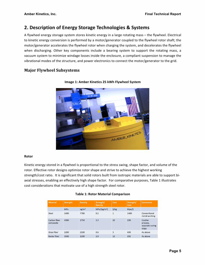
2. Description of Energy Storage Technologies & Systems A flywheel energy storage system stores kinetic energy in a large rotating mass – the flywheel. Electrical to kinetic energy conversion is performed by a motor/generator coupled to the flywheel rotor shaft; the motor/generator accelerates the flywheel rotor when charging the system, and decelerates the flywheel when discharging. Other key components include a bearing system to support the rotating mass, a vacuum system to minimize windage losses inside the enclosure, a compliant suspension to manage the vibrational modes of the structure, and power electronics to connect the motor/generator to the grid.
Major Flywheel Subsystems
Image 1: Amber Kinetics 25 kWh Flywheel System
Rotor
Kinetic energy stored in a flywheel is proportional to the stress swing, shape factor, and volume of the rotor. Effective rotor designs optimize rotor shape and strive to achieve the highest working strength/cost ratio. It is significant that solid rotors built from isotropic materials are able to support bi-‐axial stresses, enabling an effectively high shape factor. For comparative purposes, Table 1 illustrates cost considerations that motivate use of a high strength steel rotor.
Table 1: Rotor Material Comparison

Amber Kinetics, Inc. Final Technical Report
Page 6
Table 1 shows that when measured on a strength per unit cost ratio (MPa/$), traditional steel offers a significant and practical cost advantage compared to composite materials.
The flywheel described in this report is made from approximately 5000 lbs of solid steel. At its top speed, it stores nearly 29 kWh of kinetic energy. However, because the minimum operating speed is limited by system resonances, and mechanical-‐to-‐electrical conversion inefficiencies, the extractable energy in the rotor from a full discharge, delivered to the line, is just above 25 kWh.
The design reported on here constitutes a pivot away from a Generation-‐1 design based on pre-‐tensioned high-‐strength steel wire wound on a steel hub. High-‐strength steel wire, like high-‐strength solid steel, would similarly report a high strength-‐to-‐cost ratio. It is thus, at the surface, a good strategic possibility for low-‐cost stationary energy storage applications. In fact, high-‐strength steel wire can exhibit strength up to the 3 GPa range, still without any costly alloying elements. However, as a fiber, it is suitable for only sustaining uniaxial stress, and must be configured in a thin-‐rim rotor geometry. In a thin-‐rim rotor geometry, predominant stress is the uniaxial hoop stress.
Shape factor for an energy storage rotor refers to the utility of the rotor shape, and indicates efficacy of a given shape in exploiting the available tensile strength. Shape factors for solid geometries that rely on materials with isotropic strength characteristics vary over the range of approximately 0.5 to 1.0, with practical geometries falling in the 0.55 to 0.75 interval. In contrast, the shape factor for an infinitesimally thin rim is 0.5, and practical hoop geometries have shape factors strictly lower than 0.5, typically in the range of 0.3. Thus, the hoop type rotor designs are disadvantaged in comparison to solid designs, with the performance ratio perhaps made up by the higher fiber strength.
Further comparative considerations are the volumetric energy density and manufacturing processes. The hoop type designs have low volumetric energy density since the hoop rotor does not fill in the central core section. Thus, these designs see a substantial cost penalty in consideration of the required housing volume and other balance of system (BOS) costs. Further, the manufacturing process for hoop wound designs requires substantial tooling and time for proper wrapping of the fiber.
Amber Kinetics, Inc. Final Technical Report
Page 7
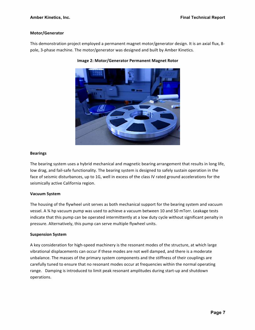
Motor/Generator
This demonstration project employed a permanent magnet motor/generator design. It is an axial flux, 8-‐pole, 3-‐phase machine. The motor/generator was designed and built by Amber Kinetics.
Image 2: Motor/Generator Permanent Magnet Rotor
Bearings
The bearing system uses a hybrid mechanical and magnetic bearing arrangement that results in long life, low drag, and fail-‐safe functionality. The bearing system is designed to safely sustain operation in the face of seismic disturbances, up to 1G, well in excess of the class IV rated ground accelerations for the seismically active California region.
Vacuum System
The housing of the flywheel unit serves as both mechanical support for the bearing system and vacuum vessel. A ¾ hp vacuum pump was used to achieve a vacuum between 10 and 50 mTorr. Leakage tests indicate that this pump can be operated intermittently at a low duty cycle without significant penalty in pressure. Alternatively, this pump can serve multiple flywheel units.
Suspension System
A key consideration for high-‐speed machinery is the resonant modes of the structure, at which large vibrational displacements can occur if these modes are not well damped, and there is a moderate unbalance. The masses of the primary system components and the stiffness of their couplings are carefully tuned to ensure that no resonant modes occur at frequencies within the normal operating range. Damping is introduced to limit peak resonant amplitudes during start-‐up and shutdown operations.
Amber Kinetics, Inc. Final Technical Report
Page 8
Power Electronics
Although power electronics were not a central focus of this project, a simple system to couple the variable speed AC motor/generator with the 60 Hz line can be constructed from a pair of AC-‐DC inverters coupled at the DC side. A typical utility scale installation would aggregate the output of multiple motor/generator inverters at the DC bus for connection with a single large central inverter. Below we consider round-‐trip efficiency at this DC bus, as the upstream equipment (central inverter, transformer) is common to many storage technologies.
3. Description of the Analysis Methodologies
3.1 Analysis Objectives The analysis carried out was experimental, with data collected on two Amber Kinetics Gen-‐2 flywheel units. The analysis aimed to verify a series of design parameters. These included
• Basic functionality, eg. accelerating the flywheel to its intended rated speed • Assessment of resonant modes • Measurement of vibration amplitudes at resonance, and throughout the working speed range • Measurement of spinning (self-‐discharge) losses over speed • Measurement of combined inverter and motor/generator drive efficiency
3.2 Methodologies for Determining Technical Performance Flywheel Data Acquisition & System Instrumentation
The Amber Kinetics Gen-‐2 system is equipped with accelerometers and numerous thermistors, allowing measurement of lateral and axial vibration, and of temperatures of many of the subsystems. Subsystems with temperature measurement instrumentation included bearings, motor/generator windings, and the power electronic drive. The measurement system was rounded out with a high resolution Tektronix digital sampling oscilloscope used to measure and record electrical input/output waveforms.
Temperature data was observed with a thermocouple mounted on the housing near each of the bearing cups, with a thermocouple mounted within the motor/generator stator, and with a thermistor mounted on the main power electronics mechanical chassis. This temperature data was observed initially on 15 minute intervals, and recorded manually. There was never any discernable temperature rise observed at the bearing cups during operation, and so these observations were discontinued. Based on the geometry and mass of the flywheel housing, no discernable temperature rise was expected at the bearing cups. Continuous operation at full power resulted in expected temperature rises in the motor/generator stator of about 20 C, and on the main power electronics chassis of 15 C.
Accelerometer waveforms were sampled and displayed with the high-‐resolution digital oscilloscope, to record short sample waveforms. Longer-‐term accelerometer data was observed and recorded manually, with samples taken on 1 minute intervals, over the many hour durations of the experimental runs.

Amber Kinetics, Inc. Final Technical Report
Page 9
Speed data used to correlate with the vibration data, was extracted from the motor/generator voltage waveforms, with the Amber Kinetics sensorless motion control system.
Input/output power was measured at the system dc bus, with a pair of precision digital multimeters, and recorded at 15 minute intervals. Input/output power is a regulated quantity and thus did not vary unless in response to a system command.
4. Technology Performance Results 4.1 Overview
This section discusses key test results from Amber Kinetics’ prototype commercial-‐scale flywheel system testing, which was tested through the speed range to 8500 rpm.
4.2 Test Protocol for Prototype Operation The Amber Kinetics test site is set in an undeveloped plot of land in Alameda, CA, formerly comprising a part of the Alameda Naval Station. The Gen 2 systems were operated and tested in an underground vault, with substantial grade-‐level re-‐inforcement, to protect all personnel in case of a worst-‐case mishap. Each test system was instrumented as previously described in Section 3. At the time of testing, the test site did not yet have utility power. All power was provided by a 3-‐phase 10 kW gas-‐powered generator. This generator powered test equipment, ancillaries, as well the main experiment. Resistive elements were used to dump power during flywheel discharge runs. A mechanical vacuum pump sustained housing vacuum levels in the range of 10-‐50 mtorr during the tests. 4.3 Resonant Modes
The flywheel housing was instrumented with a dual-‐axis accelerometer. The axes were aligned to capture lateral accelerations (which are normal to the rotor axis) and “rocking” accelerations (which appear in the axial direction when measured at a radial distance from the axis). Resonances matched the design values, within tolerance margins, with the main resonance occurring at approximately 2500 rpm -‐ substantially below the active speed range. Resonances are also well damped, showing peak amplitude values of less than 0.2 G in each axis.
The balance of the rotor can also be inferred from the acceleration data. All tested rotors exhibited excellent balance. Residual unbalance resulted in housing vibration amplitude of 0.01 G, or 0.1 m/s2, across the active speed range. As such, acoustic emission and vibration were not perceptible.
Amber Kinetics, Inc. Final Technical Report
Page 10
4.4 Self-‐Discharge
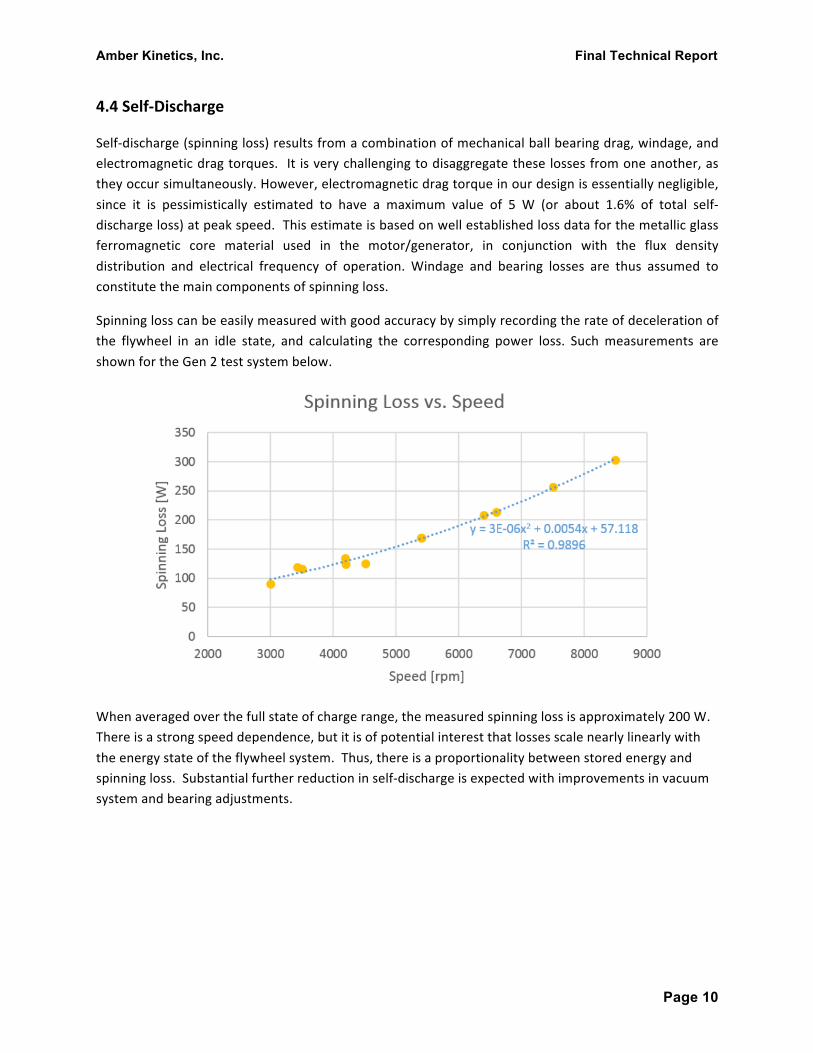
Self-‐discharge (spinning loss) results from a combination of mechanical ball bearing drag, windage, and electromagnetic drag torques. It is very challenging to disaggregate these losses from one another, as they occur simultaneously. However, electromagnetic drag torque in our design is essentially negligible, since it is pessimistically estimated to have a maximum value of 5 W (or about 1.6% of total self-‐discharge loss) at peak speed. This estimate is based on well established loss data for the metallic glass ferromagnetic core material used in the motor/generator, in conjunction with the flux density distribution and electrical frequency of operation. Windage and bearing losses are thus assumed to constitute the main components of spinning loss.
Spinning loss can be easily measured with good accuracy by simply recording the rate of deceleration of the flywheel in an idle state, and calculating the corresponding power loss. Such measurements are shown for the Gen 2 test system below.
When averaged over the full state of charge range, the measured spinning loss is approximately 200 W. There is a strong speed dependence, but it is of potential interest that losses scale nearly linearly with the energy state of the flywheel system. Thus, there is a proportionality between stored energy and spinning loss. Substantial further reduction in self-‐discharge is expected with improvements in vacuum system and bearing adjustments.
Amber Kinetics, Inc. Final Technical Report
Page 11
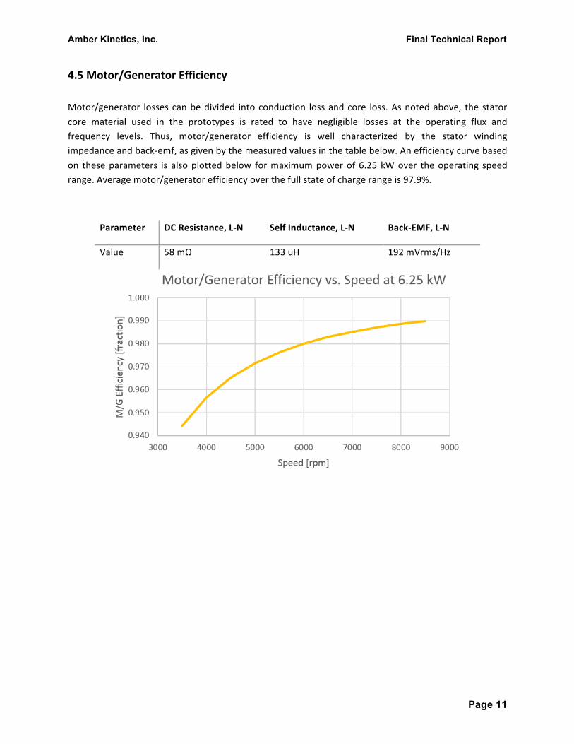
4.5 Motor/Generator Efficiency Motor/generator losses can be divided into conduction loss and core loss. As noted above, the stator core material used in the prototypes is rated to have negligible losses at the operating flux and frequency levels. Thus, motor/generator efficiency is well characterized by the stator winding impedance and back-‐emf, as given by the measured values in the table below. An efficiency curve based on these parameters is also plotted below for maximum power of 6.25 kW over the operating speed range. Average motor/generator efficiency over the full state of charge range is 97.9%.
Parameter DC Resistance, L-‐N Self Inductance, L-‐N Back-‐EMF, L-‐N
Value 58 mΩ 133 uH 192 mVrms/Hz

Amber Kinetics, Inc. Final Technical Report
Page 12
4.6 System Efficiency In order to estimate system efficiency we consider the contribution of a representative AC-‐DC inverter. The modeled topology is a standard 6-‐switch IGBT inverter with reactive filter elements, operated in voltage-‐source PWM mode. The figure below shows calculated losses for this model. Average inverter efficiency over the state of charge range is 97.6%.
Taking the motor/generator losses and inverter losses described above, we can estimate the average round trip efficiency at the DC bus to be 91.3%.
4.7 Ancillary Power Consumption Ancillary power loads are comprised of the control electronics and the vacuum pump. The power consumption of the vacuum pump represents a measured value of 240 W scaled by a duty factor of 10%. The total aggregate ancillary power consumption is thus approximately 65 watts. We expect ancillary power consumption to be reduced further as we proceed toward commercialization.
Amber Kinetics, Inc. Final Technical Report
Page 13
5. Grid Impacts and Benefits This section describes the projected impacts and benefits of the flywheel energy storage technology on the electric grid. For an example 1 MW | 4 MWh flywheel energy storage installation based in Northern California, with operational results extrapolated from Amber’s initial field demonstrations of the Gen-‐2 flywheel technology, we expect the following impacts & benefits to accrue:
Project Size: 1 MW | 4 MWh
Greenhouse Gas Emissions:
Based on our assumption that 1 MW of energy storage would enable an additional 5 MW of renewable generation (with 25% annual capacity factor assumed), storage would enable an additional 10,950 MWh of energy delivered annually from renewables. The calculated greenhouse gas emissions saved would be 3,098 metric tons saved per year (0.283 metric tons / MWh from fossil generation).
Additionally, because the flywheel energy storage system is designed to provide multiple grid services: ancillary services, load ramping & peak shaving, our expectation is that the flywheel system will be dispatched on average 8000 hours per year, or at a 91.3% capacity factor.
Thus, by employing flywheel energy storage instead of traditional fossil generation, assuming the same (0.283 metric tons of CO2 / MWh from fossil generation), employing flywheel energy storage would save an additional 2264 metric tons of CO2 per year.
Compared to an energy storage system that is designed primarily for peak shaving, where annual capacity factors may be 5% or 438 hours per year, the CO2 savings in that case would only be 124 metric tons per year. Thus, we see that the most impactful energy storage solution is one that can be utilized at high capacity factors over decades, enabling higher renewable penetration while also supplanting fossil generation for providing ancillary and ramping services.
Water Savings:
While it is difficult to estimate the water use of newer generations of fossil fuel power plants, Amber’s flywheel technology employs NO water – the entire system is passively cooled and thus provides a net water savings.

Amber Kinetics, Inc. Final Technical Report
Page 14
6. Major Findings and Conclusions This report discusses the objectives and demonstration results of Amber Kinetics’ low-‐cost flywheel energy storage demonstration project. The scope of this report covers the project’s initial goals, Amber’s enabling technology approach, subsequent research and development efforts, major findings from the project, including conclusions and recommendations for future flywheel energy storage development and commercialization.
In this program, Amber Kinetics successfully demonstrated a prototype multi-‐hour, commercial-‐scale flywheel energy storage system. Field demonstrations confirmed that the 25 kWh flywheel system met major design specifications, and we have converged on an effective set of operational and cost targets for a four-‐hour flywheel system. This system meets utility customer requirements, and is both practical and feasible for cost-‐effective manufacturing. We have also developed a commercialization plan to bring to market a commercially viable four-‐hour flywheel energy storage system. The product is now at the stage of final development and testing.
Commercialization Potential
Flywheels have a unique set of technical features that are attractive for grid-‐scale storage applications:
-‐‑ The potential for very low system costs (measured on a $/kWh basis)
-‐‑ High round trip efficiency, in excess of 90% when measured at an intermediate dc bus
-‐‑ 30-‐year calendar life
-‐‑ 30,000 full depth of discharge cycles
-‐‑ Minimal self-‐discharge losses
-‐‑ No capacity degradation
-‐‑ No water or active cooling required
Based on the technology demonstrated in this program, we believe that flywheels will be an important energy storage technology for several grid-‐scale storage applications, primarily where high utilization rates are demanded.
Recommendations
We recommend further collaboration between public and private entities to support and fund flywheel energy storage research, development, and demonstration programs. Future programs designed to demonstrate utility-‐grade, multi-‐hour flywheel systems at MW-‐scale would be beneficial in showcasing the potential for flywheels to emerge as a viable alternative to chemical batteries for multi-‐hour storage applications.
Amber Kinetics, Inc. Final Technical Report
Page 15
7. Future Plans Based on the transformational work completed under this DOE program, Amber is moving forward with commercialization of cost-‐effective, innovative, multi-‐hour flywheels. The cooperative research agreement with the DOE has now led to the creation of over 20 full-‐time jobs and the technology demonstrated in this program, and subsequent manufacturing and supply chain work that we have performed, indicate that high performance steel flywheels based on the technology demonstrated in this program have the potential to reach system-‐level manufacturing cost targets approaching $150 / kWh.
We have also identified new R&D opportunities to lower costs by an additional 25-‐35%. These paths would require additional R&D on the flywheel rotor and bearing systems to systematically de-‐risk new performance and scaling elements that fall outside of the scope of this current program.
Next steps include establishing long-‐term field testing capabilities at our R&D demonstration site in Alameda, CA. Amber has also developed commercial manufacturing plans to produce high-‐quality flywheel systems at scale, along with a long-‐term product roadmap to continuously reduce flywheel system costs with each subsequent generation of product release.
Value propositions for stationary energy storage vary widely, and depend on inputs such as current electricity prices, geographic location, and reliability of grid infrastructure. In California, market and regulatory forces have created opportunities for utility-‐scale energy storage projects that pencil out to be cost-‐effective for the utility and their rate-‐payers when energy storage system costs are below $250 / kWh. At this price point, energy storage becomes more cost effective compared to traditional fossil fueled peaking power plants.
In other markets, such as island nations and microgrids, the requirement for energy security, reliability, and sustainability makes multi-‐hour flywheel storage systems attractive as a replacement to traditional grid power.
Once again, we would like to thank the DOE for their guidance and support throughout this cooperative research agreement. This R&D and demonstration program has served as an ideal springboard for launching a newly demonstrated technology into commercialization.

Amber Kinetics, Inc. Final Technical Report
Page 16
Appendix A: List of Acronyms
AC – alternating current
DC – direct current
G – gravity
hp -‐ horsepower
IGBT – insulated-‐gate bipolar transistor
kg -‐ kilogram
kW -‐ kilowatt
kWh – kilowatt hour
lb -‐ pound
m – meter
ms -‐ millisecond
MPa – megapascal
mTorr – millitorr
MW -‐ megawatt
PIER – Public Interest Energy Research
rpm – revolutions per minute