technical report exp14at rev f · 2016-01-19 · technical report exp14at rev f title: e31 test...
TRANSCRIPT

Radiant Technologies, Inc.
2835B Pan American Freeway NE
Albuquerque, NM 87107
Tel: 505-842-8007
Fax: 505-842-0366
e-mail: [email protected]
www.ferrodevices.com
1
Technical Report
EXP14AT
Rev F
Title: e31 Test Fixture for Reference Piezoelectric Cantilevers
Date: May 21, 2015
Author: Joe Evans
Summary: A second version of Radiant’s e31 test fixture was recently completed. The modifications from
the first prototype allow more room for inserting and removing the sample cantilever. The slot
holding the cantilever is longer, giving it a firmer base. The foot has been re-designed to clamp
the cantilever more evenly and precisely at the edge of the shoe. A micrometer mechanism has
been added to the fixture to accurately set the vertical position of non-contact displacement
sensors above the cantilever tip. Since the cantilever under test can now be re-loaded and
clamped into exactly the same physical position and the displacement sensor probe can be re-
positioned to exactly the same vertical position above the cantilever tip each time, measurements
between loads are almost indistinguishable. Small decays in the butterfly loops of a new
cantilever as a function of the first few cycles can now be resolved from the test results. I made
measurements of Radiant’s 1µm-thick 4/20/80 PNZT. The new fixture yields a slightly higher e31
coefficient than with the initial version of the fixture, -13C/m2. I attribute this change to the
improvement of the micropositioner that holds the MTI photonic sensor wand and a change in the
way the foot clamps the cantilever. Radiant MOD 52/48 PZT 0.5µm-thick yielded an e31
coefficient of -19.3C/m2 at 7 volts.
The 2nd
prototype was demonstrated at the International Workshop on Acoustic Transduction
Materials and Devices (IWATMD 2015) at Penn State University last week. The display
continued into the International Conference on Electroceramics (ICE 2015) that followed the
IWATMD at the same location. I had the complete fixture along with sample cantilevers and an
MTI photonic displacement sensor so during lulls in the meetings I was able to program Vision to
run tests hours long and gather data I thought interesting. I also received recommendations from
attendees about the fixture and its applications.
The sections below will describe the test fixture, the e31 test procedure, the sample geometry
necessary to operate in the test fixture, and the results of the tests.

Radiant Technologies, Inc. 2
e31 Test Fixture
The e31 test fixture will allow Radiant’s tester customers to determine the e31 coefficient for their
films. The fixture configuration is below. The tester drives the cantilever capacitor with a
hysteresis measurement while capturing the displacement of the cantilever tip with a
displacement sensor. The results can be inserted into a derivation of the Stoney formula to
calculate e31.
The cantilever must fit a certain geometry to work inside the prototype. Bob Howard modeled
this geometry after my original “bender” design created back in 2001.
Fig. 1: e31 fixture aligned with test cantilever
The dimensions of the original test cantilevers from 2001 are below.
Fig. 2: Dimensions of the original test cantilever
75mm
5mm
20mm
4mm to 10mm
TE BE PZT
Drive
Return
Earth
Ground

Radiant Technologies, Inc. 3
The goal of the original procedure for fabricating cantilevers was to 1) make the cantilevers large
enough to handle by hand and 2) minimize the amount of photolithography required in their
construction. The procedure for the original cantilevers is listed below.
1. Coat a silicon wafer with global platinum bottom electrode.
2. Deposit the ferroelectric film globally.
3. Fabricate patterned platinum top electrodes.
4. Etch a single large square through the ferroelectric across the wafer to expose BE.
5. Dice the cantilevers with a saw. They will be 5mm wide and 75mm long.
6. The TE forms a long stripe 3mm wide by 5mm long over the global bottom electrode.
The fabrication process for these extremely simple structures requires only one precision mask,
the TE mask. Since it is over global bottom electrode, the TE mask needs no alignment mark to
the BE. The second masking for the PZT etch is not a precision alignment and does not need
alignment marks. The PZT etch exposes the BE platinum for contact and has a significant
amount of tolerance for misalignment. This masking step so simple it can be accomplished by a
placing a strip of metal or tape on the wafer by eye to act as a shadow mask during
photolithographic exposure.
The cantilevers as fabricated on-wafer are diagrammed below. The cantilevers are disarticulated
by dicing. The dicing paths are shown as red dotted lines. Black and Gray lines are the top
electrode platinum pattern on each wafer. The cantilevers are large to allow physical handling
when placing them into and removing them from the e31 fixture.

Radiant Technologies, Inc. 4
Fig. 3: Dicing pattern for disarticulating cantilevers directly from a 100mm wafer
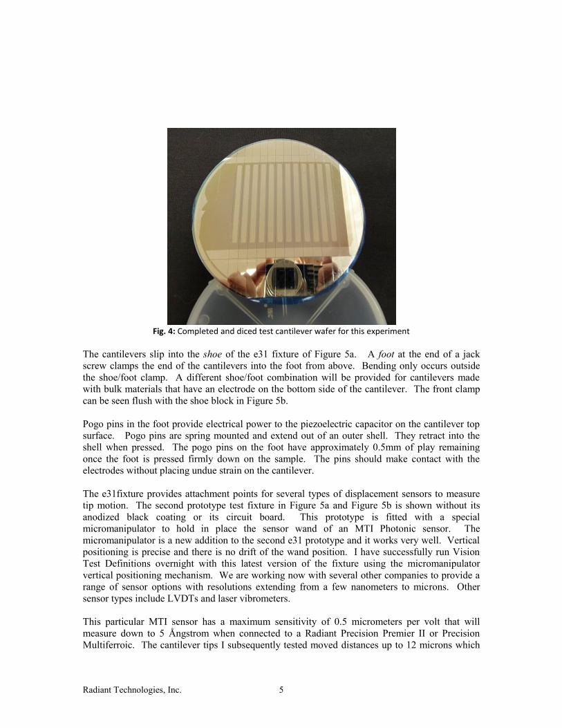
One such wafer recently completed by Naomi Montross in Radiant’s fabrication facility is
photographed in Figure 4. The cantilevers are still mounted on the dicing tape, forming the
outline of the 4-inch silicon wafer. The saw lines in the wafer are visible as is the reflection of
the camera in the exposed bottom electrode.
5mm
Dicing Line
15mm
5mm
5mm
Etched PZT
Radiant Technologies, Inc. 5
Fig. 4: Completed and diced test cantilever wafer for this experiment
The cantilevers slip into the shoe of the e31 fixture of Figure 5a. A foot at the end of a jack
screw clamps the end of the cantilevers into the foot from above. Bending only occurs outside
the shoe/foot clamp. A different shoe/foot combination will be provided for cantilevers made
with bulk materials that have an electrode on the bottom side of the cantilever. The front clamp
can be seen flush with the shoe block in Figure 5b.
Pogo pins in the foot provide electrical power to the piezoelectric capacitor on the cantilever top
surface. Pogo pins are spring mounted and extend out of an outer shell. They retract into the
shell when pressed. The pogo pins on the foot have approximately 0.5mm of play remaining
once the foot is pressed firmly down on the sample. The pins should make contact with the
electrodes without placing undue strain on the cantilever.
The e31fixture provides attachment points for several types of displacement sensors to measure
tip motion. The second prototype test fixture in Figure 5a and Figure 5b is shown without its
anodized black coating or its circuit board. This prototype is fitted with a special
micromanipulator to hold in place the sensor wand of an MTI Photonic sensor. The
micromanipulator is a new addition to the second e31 prototype and it works very well. Vertical
positioning is precise and there is no drift of the wand position. I have successfully run Vision
Test Definitions overnight with this latest version of the fixture using the micromanipulator
vertical positioning mechanism. We are working now with several other companies to provide a
range of sensor options with resolutions extending from a few nanometers to microns. Other
sensor types include LVDTs and laser vibrometers.
This particular MTI sensor has a maximum sensitivity of 0.5 micrometers per volt that will
measure down to 5 Ångstrom when connected to a Radiant Precision Premier II or Precision
Multiferroic. The cantilever tips I subsequently tested moved distances up to 12 microns which

Radiant Technologies, Inc. 6
were too far to use the higher resolution setting of this particular instrument. I switched to the
lower resolution setting of 5 micrometers per volt. In cases where the cantilever consists
completely of bulk ferroelectric or piezoelectric material, the cantilever tip may move more than
20 or 30 microns so even lower resolution instruments may be used.
Fig. 5a: Second generation e31 test fixture with cantilever and MTI Displacement Sensor

Radiant Technologies, Inc. 7
Fig. 5b: Close-up of the sample mounting foot, a cantilever,
and the sensor vertical adjustment mechanism.
Cantilever Design and Fabrication
The original design of the cantilevers will work for Radiant but not for most of our customers.
The reason is that the capacitor area of the original design is 1.5 cm2. This area is far too large
for most of our customers to yield functional capacitors that are not shorted. In our original 2002
experiment, only a few of these simple cantilevers yielded because of the large area. Given the
improvements in our process flow since that time, the most recent lot of cantilevers exhibited
very high yield. Nevertheless, the design of the cantilevers provided to our customers must allow
for small capacitor areas so customers with young programs can achieve functional devices. To
accomplish this, we will not use a global BE layer but instead provide a BE pattern arranged so
that the TE pad that electrically contacts the e31 boot is over a hole in the BE. With this
geometry, the only TE over BE will be outside the cantilever holder clamp. There will be no
parasitic capacitance in this design. All capacitance will contribute to actuator motion.

Radiant Technologies, Inc. 8
Fig. 6a: Proposed capacitor structure for the commercial e31 fixture. The blue rectangles are both top electrode platinum.
These geometries will require a more complex mask layout. At least three and possible five
layers will be involved in fabrication so alignment marks and a photolithographic printer will be
required. For those customers with the appropriate resources, we will simply provide them with
the GDSII files so they can create their own masks. For those without the sophisticated processes
necessary to recreate these patterns on wafer, we can provide the bottom electrode wafers for
them to deposit their films. If the customers cannot do top electrodes, Radiant can receive the
wafers back and deposit/pattern top electrodes on those wafers. Radiant can then pattern the
wafers with photoresist for the piezoelectric film etch. The wafers must be sent back to the
customers for the ferroelectric etch so Radiant does not have to deal with modifications to its
waste stream for any toxic materials in customer films. Radiant can dice the final wafers and
send them back to the customers for testing. Of course, there may be other combinations of
services that Radiant supplies in between these two extremes. The fabrication services that
Radiant will provide coupled with the improved electrode geometries should make it possible for
even the smallest university material science program to make, test, and publish results from their
piezoelectric films.
One aspect of the dicing is that the length and width of the cantilever dimensions shown in the
diagrams represent dimensions before dicing. The width of the trench in the shoe of the fixture
will hold a cantilever very slightly more than 5mm wide (5.1mm). Therefore, dicing exactly on
5mm lines between the cantilevers will 1) ensure that the cantilevers fit snugly in the foot of e31
fixture and 2) ensure that the cantilevers can be replaced in the exact same position each time to
ensure reproducibility in the results. Measurement reproducibility is the bane of piezoelectric
measurement. It is the reason Radiant took so long to develop such a fixture. We had to find
fixture/sample geometry that would minimize variances between re-loadings. This new fixture
can be shipped to the other side of the world and be correct on the first measurement made out of
the shipping container.
An exciting characteristic of the design of this fixture is that a variety of top electrode geometries
can be used. The active capacitor area of the top electrode in the new mask geometry will occur
only where TE crosses over BE. This arrangement will allow us to make parallel-plate capacitor
actuators with a wide range of areas. The bottom electrode can be eliminated altogether to allow
75mm
5mm
25.4mm
4mm to 10mm Bending Moment (42mm)
Sensor Sample Point
Etched
Electrical Contact Points
Clamp

Radiant Technologies, Inc. 9
the testing of actuators with interdigitated electrodes. For parallel-plate actuator capacitors, the
“hole” in the bottom electrode platinum prevents the formation of parasitic capacitance that does
not contribute to actuator motion. For the capacitor shown in Figure 6a, all charges measured
during a hysteresis/butterfly loop will be generated in the active actuator area. Direct comparison
of charge to displacement will be possible allowing calculation of the g piezoelectric coefficient.
Figure 6b below shows a capacitor constructed with interdigitated electrodes and another with a
long but super narrow top electrode.
Fig. 6b: Other possible cantilever configurations.
In Figure 6, the active area of the piezoelectric capacitor is the blue portion of the top electrode
that overlays bottom electrode. It is much shorter and narrower than the cantilever itself. It has a
smaller capacitor area than if the top electrode covered the entire cantilever and thus it has a
much higher chance of yielding functionality, especially with thin films. This will make possible
the piezoelectric characterization of very thin piezoelectric or ferroelectric films which cannot
support large capacitor areas. The bending motion for smaller capacitors may be tiny but this
small motion will be amplified by the long length of the silicon cantilever beyond the end of the
actuator capacitor. This amplified motion will be visible to laser vibrometers which have
resolutions down to 20pm or less. On the other hand, as already described, some cantilevers with
large-area actuator capacitors will move as much as 12 to 20 microns, allowing the use of low
cost low resolution displacement sensors. A major attribute of the e31 fixture will be its ability to
test a variety of actuator geometries at a variety motion scales.
Area = 1mm2
Area = 100µm2

Radiant Technologies, Inc. 10
In summary:
1. The e31 fixture will accept cantilevers with a variety of actuator designs.
2. The 75 millimeter length of the cantilever amplifies the piezoelectric response of thin
films to the point that even films only a few hundred Ångstroms thick will still be
measurable.
3. Customers with sophisticated tools and processes will be able to design and test their own
cantilever and actuator architectures.
4. Other customers will be able to acquire from Radiant the standard mask layout (Figure 6)
for a standardized cantilever architecture, acquire their own masks, and fabricate their
own devices.
5. For those customers with less sophisticated processing capabilities, Radiant will fabricate
and sell prepared bottom electrode wafers.
6. Some researchers that can fabricate films but have no photolithography or metal
deposition capabilities, Radiant will perform the process steps they cannot.
Radiant Technologies, Inc. 11
Test Procedures There are two test procedures to be executed with Radiant’s e31 fixture. The first is an indirect
measurement where the tester executes a hysteresis measurement on the capacitor of the test
cantilever while simultaneously capturing the displacement of the cantilever tip using any one of
several types of displacement sensors. The cantilever motion and voltage will be inserted into a
formula to derive the e31 coefficient. The basis for the calculation will be the Stoney formula.
The year 2009 marked the 100th anniversary for the derivation of this formula by George Gerald
Stoney describing the bending motion of a cantilever caused by a thin film on its surface. Stoney
developed this equation to describe the effects of changes of temperature where the two materials
have different coefficients of thermal expansion. More recently, several researchers have
published treatments of the Stoney formula for use in deriving e31 from piezoelectric actuations as
opposed to temperature changes. For calculations in this document, I will use two different
published treatments to determine the e31 of a Radiant test cantilever and compare the results.
As a matter of historical perspective, George Gerald Stoney was the son of
George Johnstone Stoney. George Johnstone Stoney was a physicist who in the
1870’s was the first to propose a fundamental unit for electrical charge. He
named it the electron in 1891. The electron particle was found by J. J. Thompson
of the Cavendish Laboratory in 1897. I visited the site of the Cavendish
Laboratory during one of my visits to England. Alas, it is now but a sign on a
university office building. To continue, the senior Stoney in 1881 proposed a
unification of physics built around electric charge and mass to calculate the
fundamental scales. Nine years after Stoney named the electron, Max Planck in
1900 proposed the quantization of energy of which the electron is but one form.
Einstein’s astounding revelations came five years later in 1905. Modern physics
began with Einstein and Planck. Planck’s approach with his constant is now
considered the proper method for unifying physics at all scales versus Stoney’s
proposal but it is interesting to find that none of these famous scientists operated
in a vacuum. Was Planck influenced by Stoney’s prior work on unification or did
both build from someone else’s work? No matter. Radiant’s e31 fixture has four
degrees of separation from Einstein, three from Planck, and two from the
discovery of the electron!
The second type of test that can be executed with the e31 fixture is the direct d31 measurement.
This is accomplished by forcing the cantilever tip to move while recording the charge generated
by the piezoelectric capacitor as it is stressed. For this purpose, the center crossbar of the test
fixture is configured to hold a linear piezoelectric actuator to move the cantilever tip.
The tester will capture the charge generated by the capacitor when the cantilever is displaced
when the linear motor is commanded to move a certain distance. The displacement sensor will
measure how far the tip displaces to eliminate the effect of backlash in the motor. The charge
measurement and the displacement along with the geometry of the cantilever can be used to
derive d31 for the piezoelectric film. I have not yet researched methods for this mathematical
derivation. That will be a future development project for the test fixture.

Radiant Technologies, Inc. 12
Fig. 7: The 2
nd prototype after black anodization with the piezoelectric linear displacement motor
mounted under the cantilever tip.
The printed circuit board mounted on the pedestal connects the sample to the tester using coaxial
cables. The bottom socket is for a banana plug so the fixture can be grounded to the tester earth
ground.

Radiant Technologies, Inc. 13
Experimental Results
I connected the e31 fixture to a Precision LC II and inserted an MTI displacement probe into its
collar. I inserted two types of test cantilevers (Figure 4) into the fixture. One consisted of 1µm-
thick 4/20/80 niobium-doped PZT. The other consisted of 0.5µm 52/48 PZT with the same
1.5cm2 electrode configuration. I used the low resolution channel of the MTI2032RX with a
resolution of -10.3 µm/volt for the scale factor.
Three 2-second hysteresis loops with their associated butterfly loops for the 1µm PNZT are in
Figure 8. Reproducibility is excellent.
Fig. 8: Sequential butterfly loops without re-loading for 1µm PNZT
Six 1-second monopolar actuator motions of the PNZT taken from the same test definition
execution by Vision are in Figure 9.
-30
-20
-10
0
10
20
30
-20 -15 -10 -5 0 5 10 15 20
4/20/80 Bipolar and M onopolar Uniformity[ EXP14AT e31 Fixture ]
Po
lari
za
tio
n (
µC
/cm
2)
& M
icro
ns
V o l tage
advPx1 20V 2s B ipolar: Polarizat ion (µC/cm2): 2 advPx1 20V 2s B ipolar: Polarizat ion (µC/cm2): 4 advPx1 20V 2s B ipolar: Polarizat ion (µC/cm2): 6
advPx1 20V 2s B ipolar: Polarizat ion (µC/cm2): 2 advPx1 20V 2s B ipolar: Polarizat ion (µC/cm2): 4 advPx1 20V 2s B ipolar: Polarizat ion (µC/cm2): 6
Radiant Technologies, Inc. 14
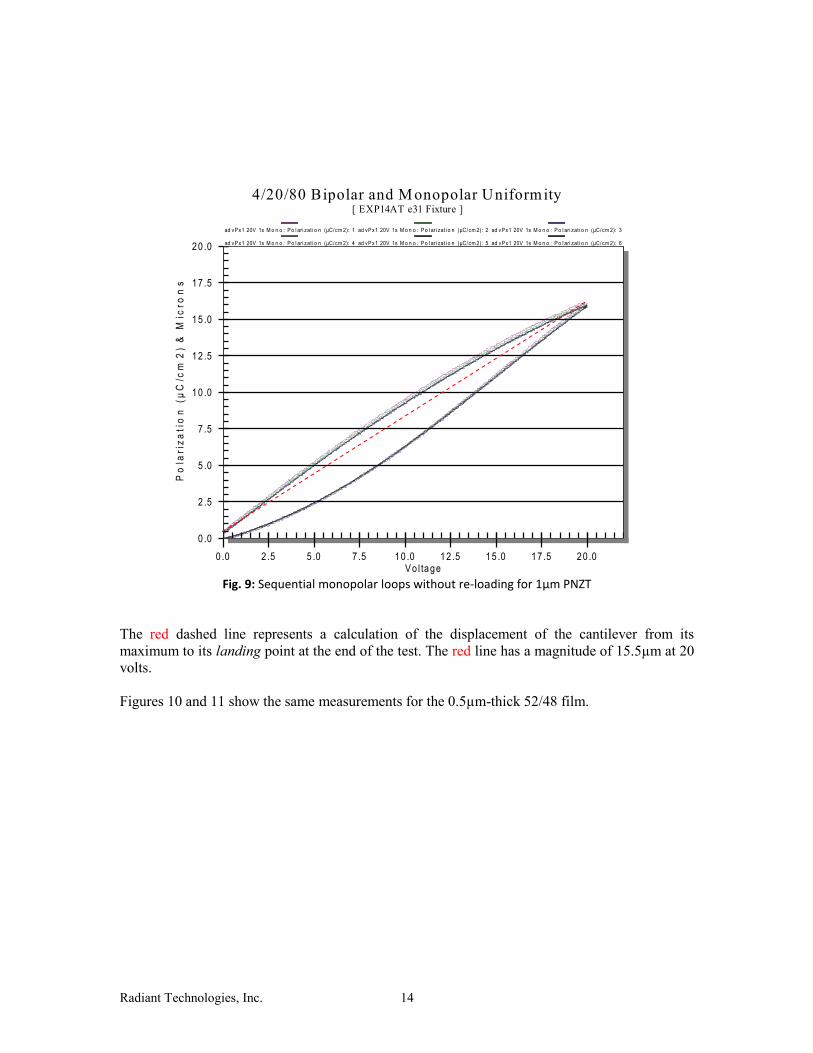
Fig. 9: Sequential monopolar loops without re-loading for 1µm PNZT
The red dashed line represents a calculation of the displacement of the cantilever from its
maximum to its landing point at the end of the test. The red line has a magnitude of 15.5µm at 20
volts.
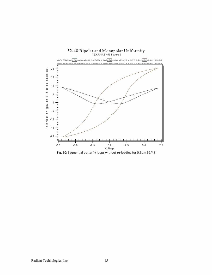
Figures 10 and 11 show the same measurements for the 0.5µm-thick 52/48 film.
0 .0
2 .5
5 .0
7 .5
10 .0
12 .5
15 .0
17 .5
20 .0
0 .0 2 .5 5 .0 7 .5 10 .0 12 .5 15 .0 17 .5 20 .0
4/20/80 Bipolar and M onopolar Uniformity[ EXP14AT e31 Fixture ]
Po
lari
za
tio
n (
µC
/cm
2)
& M
icro
ns
V o l tage
ad vPx1 20V 1s M o n o : P o l ari zat i o n (µC/cm 2): 1 ad vPx1 20V 1s M o n o : P o l ari zat i o n (µC/cm 2): 2 ad vPx1 20V 1s M o n o : P o l ari zat i o n (µC/cm 2): 3
ad vPx1 20V 1s M o n o : P o l ari zat i o n (µC/cm 2): 4 ad vPx1 20V 1s M o n o : P o l ari zat i o n (µC/cm 2): 5 ad vPx1 20V 1s M o n o : P o l ari zat i o n (µC/cm 2): 6
Radiant Technologies, Inc. 15
Fig. 10: Sequential butterfly loops without re-loading for 0.5µm 52/48
-20
-15
-10
-5
0
5
10
15
20
-7 .5 -5 .0 -2 .5 0 .0 2 .5 5 .0 7 .5
52-48 Bipolar and M onopolar Uniformity[ EXP14AT e31 Fixture ]
Po
lari
za
tio
n (
µC
/cm
2)
& D
isp
lac
em
en
t
V o l tage
ad vPx1 7V 2s B i p o l ar: P o l ari zat i o n (µC/cm 2): 2 ad vPx1 7V 2s B i p o l ar: P o l ari zat i o n (µC/cm 2): 4 ad vPx1 7V 2s B i p o l ar: P o l ari zat i o n (µC/cm 2): 6
ad vPx1 7V 2s B i p o l ar: P o l ari zat i o n (µC/cm 2): 2 ad vPx1 7V 2s B i p o l ar: P o l ari zat i o n (µC/cm 2): 4 ad vPx1 7V 2s B i p o l ar: P o l ari zat i o n (µC/cm 2): 6
Radiant Technologies, Inc. 16
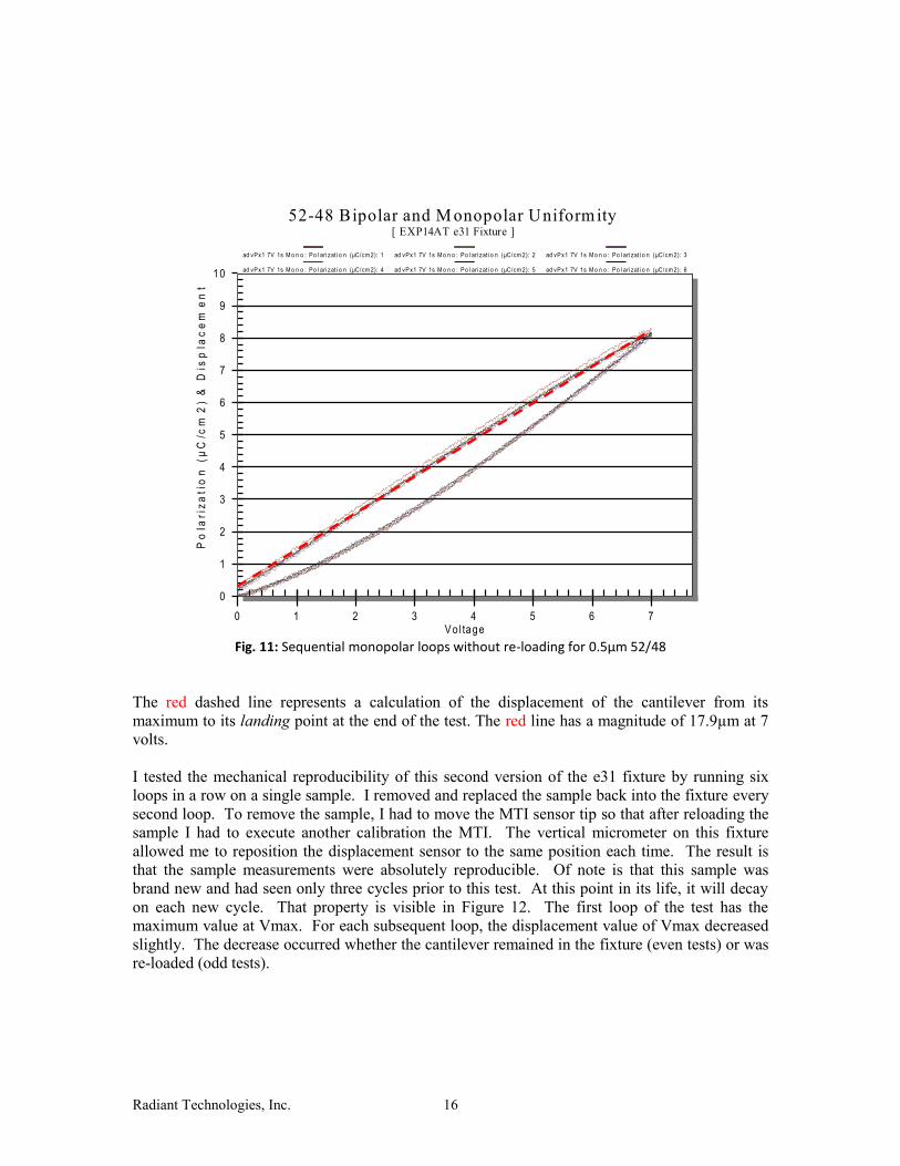
Fig. 11: Sequential monopolar loops without re-loading for 0.5µm 52/48
The red dashed line represents a calculation of the displacement of the cantilever from its
maximum to its landing point at the end of the test. The red line has a magnitude of 17.9µm at 7
volts.
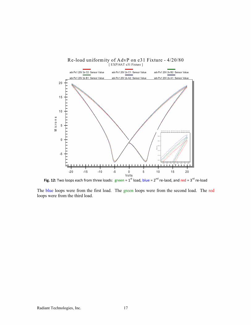
I tested the mechanical reproducibility of this second version of the e31 fixture by running six
loops in a row on a single sample. I removed and replaced the sample back into the fixture every
second loop. To remove the sample, I had to move the MTI sensor tip so that after reloading the
sample I had to execute another calibration the MTI. The vertical micrometer on this fixture
allowed me to reposition the displacement sensor to the same position each time. The result is
that the sample measurements were absolutely reproducible. Of note is that this sample was
brand new and had seen only three cycles prior to this test. At this point in its life, it will decay
on each new cycle. That property is visible in Figure 12. The first loop of the test has the
maximum value at Vmax. For each subsequent loop, the displacement value of Vmax decreased
slightly. The decrease occurred whether the cantilever remained in the fixture (even tests) or was
re-loaded (odd tests).
0
1
2
3
4
5
6
7
8
9
10
0 1 2 3 4 5 6 7
52-48 Bipolar and M onopolar Uniformity[ EXP14AT e31 Fixture ]
Po
lari
za
tio
n (
µC
/cm
2)
& D
isp
lac
em
en
t
V o l tage
ad vPx1 7V 1s M o n o : Po l ari zat i o n (µC/cm 2): 1 ad vPx1 7V 1s M o n o : Po l ari zat i o n (µC/cm 2): 2 ad vPx1 7V 1s M o n o : Po l ari zat i o n (µC/cm 2): 3
ad vPx1 7V 1s M o n o : Po l ari zat i o n (µC/cm 2): 4 ad vPx1 7V 1s M o n o : Po l ari zat i o n (µC/cm 2): 5 ad vPx1 7V 1s M o n o : Po l ari zat i o n (µC/cm 2): 6
Radiant Technologies, Inc. 17
Fig. 12: Two loops each from three loads: green = 1
st load, blue = 2
nd re-laod, and red = 3
rd re-load
The blue loops were from the first load. The green loops were from the second load. The red
loops were from the third load.
-5
0
5
10
15
20
-20 -15 -10 -5 0 5 10 15 20
Re-load uniformity of AdvP on e31 Fixture - 4/20/80[ EXP14AT e31 Fixture ]
Mic
ron
s
V o l ts
adv Px1 20V 2s C2: Sensor Value adv Px1 20V 2s C1: Sensor Value adv Px1 20V 2s B2: Sensor Value
adv Px1 20V 2s B1: Sensor Value adv Px1 20V 2s A2: Sensor Value adv Px1 20V 2s A1: Sensor Value
16.5
17.0
17.5
18.0
18.5
19.0
16.5 17.0 17.5 18.0 18.5 19.0 19.5 20.0
Mic
ron
s
Vol ts
advPx1 20V 2s C2: Sensor Value advPx1 20V 2s C1: Sensor Value advPx1 20V 2s B2: Sensor Value
advPx1 20V 2s B1: Sensor Value advPx1 20V 2s A2: Sensor Value advPx1 20V 2s A1: Sensor Value

Radiant Technologies, Inc. 18
Calculating e31
To convert the tip displacement to an e31 value, I turned to two published equations: one by
Mazzalai at EPFL and the other by Kanno at the University of Kobe.
The e31 equation according to Mazzalai, Balma, Chidambaram, Jin, and Muralt (EPFL)
[International Symposium on Applications of Ferroelectrics - ISAF, Prague, Czech Republic;
07/2013] is
Y = Young’s modulus of the silicon (substrate) in Gigapascals ( silicon = 169GPa)
= Poisson’s ratio for the silicon (substrate) [silicon = 0.064]
tSi = Thickness of the silicon substrate in centimeters (usually 550µm for Radiant
wafers)
tp = Thickness of the piezoelectric film in centimeters (not shown)
V = Volts applied to piezoelectric capacitor
cf = Ratio of capacitor width to cantilever width (0.6 for Radiant cantilevers)
x1 = Distance from clamp point to the end of the piezoelectric capacitor in meters.
x2 = Distance from clamp point to the displacement sensor.
(x2) = Vertical displacement of the cantilever at x2 in meters.
To find the assumed-to-be-uniform stress (in N/m2 = Pa) in the volume of an actuator below the
top electrode, multiply the e31 value by the applied electric field [V/ tp in meters].
For the reference cantilever in the e31 fixture,
x1 = 3.96cm
x2 = 4.24cm
Note: all dimensions entered into the equation should be in meters and the result will be in units
of C/m2.

Radiant Technologies, Inc. 19
Plugging in the fixed geometry values, the equation reduces to
Mazzalai Test Volts Tip Displacement e31
1µm 4/20/80 PNZT 20 15.5µm -13.13 C/m2
0.5µm 52/48 PZT 7 7.9µm -19.32 C/m2
Below I calculate e31 using the equation published by Kanno, Kotera, and Wasa of Kyoto
University. [Sensors and Actuators A 107 (2003) 68–74]
Since s11S
is the compliance of silicon which is the inverse of the Young’s modulus, the equation
can be re-written as
HS = Thickness of the silicon substrate
L = Length of the cantilever
V = Volts applied to the capacitor
= Tip displacement
Yielding the simple equation:
Kanno’s predictions are below.

Radiant Technologies, Inc. 20
Kanno Test Volts Tip Displacement e31
1µm 4/20/80 PNZT 20 15.5µm -7.35 C/m2
0.5µm 52/48 PZT 7 7.9µm -10.7 C/m2
The calculated e31 values for Mallazai and Kanno are very different by almost a factor of 2. Note
that there is a difference in the stress generated by the thin film between these two equations. The
Mazzalai equation assumes that the piezoelectric capacitor stops short of the displacement sample
point (the difference between x1 and x2) while the Kanno equation assumes that the capacitor
extends the entire length of the L. Kanno also assumes that the capacitor is the same width as the
cantilever. Below I will adjust the Kanno equation for these differences in geometry and compare
results.
Analysis Compare the two equations:
Mazzalai
Kanno
The Mazzalai equation has two extra terms than does the Kanno equation:
(1- )cf
which corrects the e31 value if the capacitor is not as wide as the silicon cantilever and
x1(2x2 – x1)
which corrects e31 if the capacitor does not extend all the way to the test point. The second term
reduces to
x12
if the capacitor extends all the way to the displacement sensor which is the identical term to
Kanno’s
L2.
The Mazzalai cf term increases e31 if the piezoelectric capacitor is not as wide as the cantilever
itself. This makes sense. Consider if the capacitor were only 1 micron wide while the cantilever
Radiant Technologies, Inc. 21
is 5 mm wide (as it is for our test sample). That 1µm-wide capacitor could not bend the
cantilever up nearly as far as does our 3mm-wide capacitor.
The only term in Mazzalai not in the Kanno equation is ¸which is the Poisson ratio for silicon.
The Poisson ratio is the ratio of how the width of the material reduces if its thickness increases
due to an applied force. This value should be in the equation so Mazzalai is probably more
precise. However, the value Mazzalai gave for silicon is only 0.064 which means that Mazzalai
corrects e31 by a value of only 7%. Putting all of factors together yields a correction factor of
0.56406. Applying these geometric corrections to Kanno yields the following comparison:
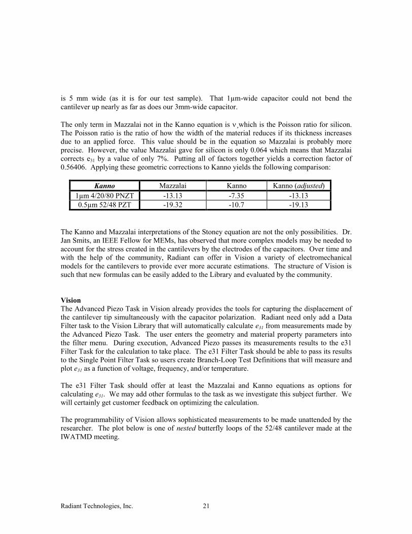
Kanno Mazzalai Kanno Kanno (adjusted)
1µm 4/20/80 PNZT -13.13 -7.35 -13.13
0.5µm 52/48 PZT -19.32 -10.7 -19.13
The Kanno and Mazzalai interpretations of the Stoney equation are not the only possibilities. Dr.
Jan Smits, an IEEE Fellow for MEMs, has observed that more complex models may be needed to
account for the stress created in the cantilevers by the electrodes of the capacitors. Over time and
with the help of the community, Radiant can offer in Vision a variety of electromechanical
models for the cantilevers to provide ever more accurate estimations. The structure of Vision is
such that new formulas can be easily added to the Library and evaluated by the community.
Vision The Advanced Piezo Task in Vision already provides the tools for capturing the displacement of
the cantilever tip simultaneously with the capacitor polarization. Radiant need only add a Data
Filter task to the Vision Library that will automatically calculate e31 from measurements made by
the Advanced Piezo Task. The user enters the geometry and material property parameters into
the filter menu. During execution, Advanced Piezo passes its measurements results to the e31
Filter Task for the calculation to take place. The e31 Filter Task should be able to pass its results
to the Single Point Filter Task so users create Branch-Loop Test Definitions that will measure and
plot e31 as a function of voltage, frequency, and/or temperature.
The e31 Filter Task should offer at least the Mazzalai and Kanno equations as options for
calculating e31. We may add other formulas to the task as we investigate this subject further. We
will certainly get customer feedback on optimizing the calculation.
The programmability of Vision allows sophisticated measurements to be made unattended by the
researcher. The plot below is one of nested butterfly loops of the 52/48 cantilever made at the
IWATMD meeting.

Radiant Technologies, Inc. 22
Fig. 13: Nested butterfly loops for the 52/48 cantilever measured with 10 second periods.
The cantilever is well behaved.
Other Tests Radiant has been developing PAINT and DLTS tasks for Vision. In these impulse-type tests, a
pulse is applied to the sample, the voltage returns to zero, and the tester listens for echoes from
the sample. When applied to a cantilever in the e31 fixture, the cantilever rings at its resonant
frequency.
-1
0
1
2
3
4
5
6
7
8
9
10
-7 .5 -5 .0 -2 .5 0 .0 2 .5 5 .0 7 .5
Displacement vs Volts0.5 um 52/48 PZT on 75mmx5mm Cantilever
Mic
ron
s
P e r iod (m s )
adv P 8V 75m s : S ens or V al: 1 adv P 8V 75m s : S ens or V al: 2 adv P 8V 75m s : S ens or V al: 3 adv P 8V 75m s : S ens or V al: 4 adv P 8V 75m s : S ens or V al: 5 adv P 8V 75m s : S ens or V al: 6 adv P 8V 75m s : S ens or V al: 7
adv P 8V 75m s : S ens or V al: 8 adv P 8V 75m s : S ens or V al: 9 adv P 8V 75m s : S ens or V al: 10 adv P 8V 75m s : S ens or V al: 11 adv P 8V 75m s : S ens or V al: 12 adv P 8V 75m s : S ens or V al: 13 adv P 8V 75m s : S ens or V al: 14

Radiant Technologies, Inc. 23
Fig. 14: Non-switching pulse and ringing of the 52/48 cantilever.
Like the nested butterfly loops of Figure 13, the impulse response of the cantilever can be
measured versus voltage.
0.0
2.5
5.0
7.5
0
2
0
2
4
0 10 20 30 40 50 60 70
Im p u lse R e sp o n se fo r 4 m s 4 V P u lse[ 0.5um 52/48 Cantilever ]
Po
lari
za
tio
n (
µC
/cm
2)
Mic
ron
sD
riv
e V
olt
s
Pr oc. Hys t Pr oc. Dis p Dr ive Voltage

Radiant Technologies, Inc. 24
Fig. 15: Non-switching pulse and ringing of the 52/48 cantilever.
Dynamic models of cantilever motion will be more complex than derivatives of the Stoney
equation which is a static model. Nevertheless, dynamic measurements of the
cantilever/piezoelectric capacitor combination may yield more information about the films and
the effects of the electrodes and passivation layers on the performance of the actuators.
Conclusion The second version of the e31 fixture is acceptable for distribution to customers. The GDSII files
for that mask set are still to be created but should be available by the be. Radiant should prepare
inventory of pre-fabricated BE wafers for the cantilevers for inventory. The possibility of using
wafers thinner than the 500µm-thick standard prime wafers should be explored.
Experimental results with two different compositions produce e31 results that indicate that the
Kanno and Mazzalai equations are equivalent to within 6% of each other when geometry is taken
into account . Both formulas can be placed as options in a Vision filter task to estimate e31 from
the measurement results made by Vision’s Advanced Piezo Task. More formulas may be added
as we get feedback from researchers.
-2
-1
0
1
2
3
4
5
10 15 20 25 30 35 40 45
Cantilever Displacement after 4ms 4.9V Pulse0.5 um 52/48 PZT on 75mmx5mm Cantilever
Mic
ron
s
P e r iod (m s )
U P 8V 75m s : 1 U P 8V 75m s : 3 U P 8V 75m s : 5 U P 8V 75m s : 7 U P 8V 75m s : 9
U P 8V 75m s : 12 U P 8V 75m s : 14 U P 8V 75m s : 16 U P 8V 75m s : 18 U P 8V 75m s : 20