technical protocol
TRANSCRIPT
EURAMET.L-K3.2009 Angle Comparison Using an Autocollimator
Page 1
Key Comparison
EURAMET.L-K3.2009
Angle Comparison
Using an Autocollimator
(Project # 1074)
Technical Protocol October 2014
European Association of National Metrology Institutes (EURAMET)
comparison in accordance with the guidelines of the
Consultative Committee for Length (CCL)
Pilot laboratory:
Physikalisch-Technische Bundesanstalt (PTB)
Time schedule:
12/2009 - 05/2015
Authors / Organisers:
Ralf D. Geckeler & Andreas Just
Physikalisch-Technische Bundesanstalt (PTB)
Bundesallee 100
D-38116 Braunschweig
Germany

EURAMET.L-K3.2009 Angle Comparison Using an Autocollimator
Page 2
Contents
1. Introduction...................................................................................... 3
2. The standard ................................................................................... 3
2.1 General requirements ........................................................... 3
2.2 Description of the standard ................................................... 4
2.3 Mounting ............................................................................... 4
2.4 Handling ................................................................................ 4
3. Organisation .................................................................................... 5
3.1 Requirements for participation .............................................. 5
3.2 Participants ........................................................................... 6
3.3 Time schedule ....................................................................... 8
3.4 Transportation ....................................................................... 9
3.5 Unpacking, handling, packing ............................................. 10
3.6 Financial aspects, insurance .............................................. 11
4. Measuring instructions .................................................................. 11
4.1 Plane mirror………………………………………………………..12
4.2 Distance autocollimator – reflector………………………….…..13
4.3 Autocollimator aperture………………………………………......13
4.4 Measurement ranges / steps………………………………….…13
4.5 Adjustment procedures…………………………………...…..….14
4.6 Autocollimator settings…………………………………….……..15
4.7 Measurement results……………………………………….…….15 5. Standard measurement uncertainty .............................................. 17
6. Documentation and reporting ........................................................ 19
7. Comparison / analysis of results ................................................... 19
8. References .................................................................................... 23
Appendices
Receipt confirmation ........................................................................... A1
Documentation of measuring conditions…………………………… ..A2 Transport packaging .......................................................................... A3
EURAMET.L-K3.2009 Angle Comparison Using an Autocollimator
Page 3
1. Introduction As described in the Mutual Recognition Arrangement (MRA)1, the metrological equivalence of national measurement standards will be determined by a set of comparisons chosen and organised by the Consultative Committees of the Comité International des Poids et Mesures (CIPM) working closely with the Regional Metrology Organisations (RMO).
At the 13th meeting of the Working Group for Dimensional Metrology (WGDM), 24-25th September 2008, INRIM, Torino, Italy, and at the European Association of National Metrology Institutes (EURAMET) Technical Committee of Length (TC-L) Meeting, 6-7th October 2008, MIKES, Espoo, Finland, the Physikalisch-Technische Bundesanstalt (PTB) first proposed a comparison on the calibration of autocollimators. The initial proposal has been refined over the course of subsequent WGDM and EURAMET TC-L meetings and a total of 28 National Metrology Institutes (NMI) have agreed to join this key comparison as participants with the PTB acting as the pilot laboratory.
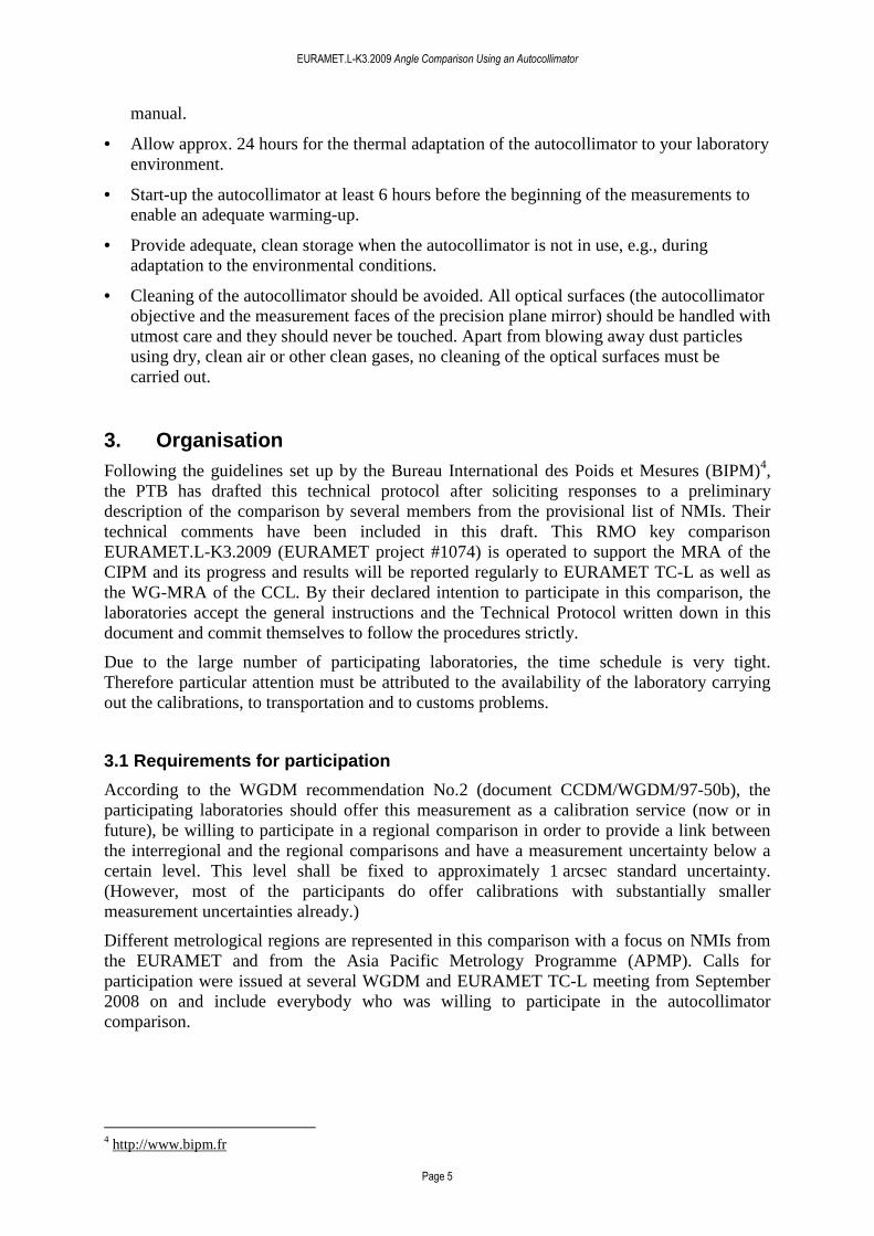
Autocollimators are optical devices for the precise and contactless measurement of angles of reflecting surfaces. They are well suited for a broad range of applications in metrology and industrial manufacturing, e.g., angle adjustment, measurement of straightness, parallelism and rectangularity of machine tools, etc. In recent years, electronic autocollimators have also proved to be capable of providing highly accurate angle metrology for the form measurement of challenging (due to their size / topography range / gradients) optical surfaces. The importance of measurand traceability (via calibration) for this broad range of autocollimator applications supports the motivation for this comparison of the calibration capabilities of NMIs.
Figure 1. Elcomat 3000 autocollimator by Möller-Wedel Optical GmbH (MWO), Wedel, Germany (Figure courtesy MWO).
2. The standard 2.1 General requirements
The standard for this comparison, see Section 2.2, has been chosen for the following reasons:
1. The comprehensive experience at the PTB in its calibration and the characterization of the parameters influencing the standard’s angle response, see Refs. [1-4].
2. Its stability as demonstrated by repeated calibrations of individual instruments over several years at the PTB.
1 The MRA was signed at the 21st General Conference of Weights and Measures on the 14th October 1999 in Paris; see information on the BIPM website (http://www.bipm.fr).

EURAMET.L-K3.2009 Angle Comparison Using an Autocollimator
Page 4
3. Its widespread use for precision angle metrology in research and industry.
4. Its commercial availability so that each participating laboratory may obtain, if desired, a standard of the same type.
2.2 Description of the standard
For this comparison, an electronic autocollimator type Elcomat 3000 by Möller-Wedel Optical GmbH (MWO), Wedel, Germany, see Figure 1, has been kindly made available by the manufacturer2.
As all participants will be provided with a detailed technical manual of the autocollimator, only its basic properties are summarised here shortly:
• Two axis electronic autocollimator (the comparison will be performed on the horizontal x-axis only)
• Measuring range: 2000 x 2000 arcsec (up to 2.5 m distance to the reflector)
• Highest resolution: 0.001 arcsec
• Focal length: 300 mm
• Diameter of the illuminated (effective) aperture: 32 mm (tube diameter: 65 mm)
• Dimensions: 420 x 95 x 135 mm
• Weight: 3.8 kg
• Serial number S.N. 900
2.3 Mounting
An adjustable holder for the autocollimator with a double-sided clam fixture (type D65, MWO no. 223 0243) will be provided by the PTB (kindly made available by MWO). It allows the rotation of the autocollimator in its mount (around the autocollimator’s optical axis) by 90° for the flexible measurement of the x-axis in a vertical orientation. As the autocollimator’s angle deviations are stable with respect to rotations of its body, NMIs can calibrate the x-axis of the device in a horizontal or vertical orientation, depending on the requirements set by their equipment, and can avoid the use of additional optics for the rotation of the beam deflection plane.
2.4 Handling
• Familiarize yourself with the functioning and handling of the autocollimator by means of the manual supplied with it and the information given in the Technical Protocol. The manual was also sent to all participants as an electronic file.
• Before the autocollimator can be switched on, all connecting cables (autocollimator – Control Unit; Control Unit – PC) need to be plugged in.
• Check the operability of the autocollimator.
• Remove the external data logger from the autocollimator tube, see its accompanying
2 http://www.moeller-wedel-optical.com/El-Autocolimators/E_Elcomat3000.htm 3 http://www.moeller-wedel-optical.com/Products/E_acc_mech.htm
EURAMET.L-K3.2009 Angle Comparison Using an Autocollimator
Page 5
manual.
• Allow approx. 24 hours for the thermal adaptation of the autocollimator to your laboratory environment.
• Start-up the autocollimator at least 6 hours before the beginning of the measurements to enable an adequate warming-up.
• Provide adequate, clean storage when the autocollimator is not in use, e.g., during adaptation to the environmental conditions.
• Cleaning of the autocollimator should be avoided. All optical surfaces (the autocollimator objective and the measurement faces of the precision plane mirror) should be handled with utmost care and they should never be touched. Apart from blowing away dust particles using dry, clean air or other clean gases, no cleaning of the optical surfaces must be carried out.
3. Organisation Following the guidelines set up by the Bureau International des Poids et Mesures (BIPM)4, the PTB has drafted this technical protocol after soliciting responses to a preliminary description of the comparison by several members from the provisional list of NMIs. Their technical comments have been included in this draft. This RMO key comparison EURAMET.L-K3.2009 (EURAMET project #1074) is operated to support the MRA of the CIPM and its progress and results will be reported regularly to EURAMET TC-L as well as the WG-MRA of the CCL. By their declared intention to participate in this comparison, the laboratories accept the general instructions and the Technical Protocol written down in this document and commit themselves to follow the procedures strictly.
Due to the large number of participating laboratories, the time schedule is very tight. Therefore particular attention must be attributed to the availability of the laboratory carrying out the calibrations, to transportation and to customs problems.
3.1 Requirements for participation
According to the WGDM recommendation No.2 (document CCDM/WGDM/97-50b), the participating laboratories should offer this measurement as a calibration service (now or in future), be willing to participate in a regional comparison in order to provide a link between the interregional and the regional comparisons and have a measurement uncertainty below a certain level. This level shall be fixed to approximately 1 arcsec standard uncertainty. (However, most of the participants do offer calibrations with substantially smaller measurement uncertainties already.)
Different metrological regions are represented in this comparison with a focus on NMIs from the EURAMET and from the Asia Pacific Metrology Programme (APMP). Calls for participation were issued at several WGDM and EURAMET TC-L meeting from September 2008 on and include everybody who was willing to participate in the autocollimator comparison.
4 http://www.bipm.fr
EURAMET.L-K3.2009 Angle Comparison Using an Autocollimator
Page 6
3.2 Participants
The following Table 1 provides the provisional list (as of 2014/10/10) of the participants.
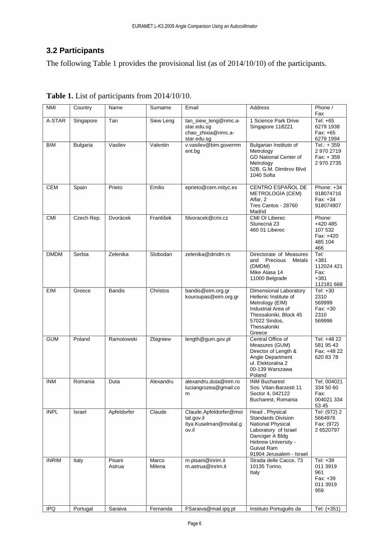
Table 1. List of participants from 2014/10/10.
NMI Country Name Surname Email Address Phone / Fax
A-STAR Singapore Tan Siew Leng [email protected] [email protected]
1 Science Park Drive Singapore 118221
Tel: +65 6279 1938 Fax: +65 6279 1994
BIM Bulgaria Vasilev Valentin [email protected]
Bulgarian Institute of Metrology GD National Center of Metrology 52B, G.M. Dimitrov Blvd 1040 Sofia
Tel.: + 359 2 970 2719 Fax: + 359 2 970 2735
CEM Spain Prieto Emilio [email protected] CENTRO ESPAÑOL DE METROLOGÍA (CEM) Alfar, 2 Tres Cantos - 28760 Madrid
Phone: +34 918074716 Fax: +34 918074807
CMI Czech Rep. Dvorácek František [email protected] CMI OI Liberec Slunecná 23 460 01 Liberec
Phone: +420 485 107 532 Fax: +420 485 104 466
DMDM Serbia Zelenika Slobodan [email protected] Directorate of Measures and Precious Metals (DMDM) Mike Alasa 14 11000 Belgrade
Tel: +381 112024 421 Fax: +381 112181 668
EIM Greece Bandis Christos [email protected] [email protected]
Dimensional Laboratory Hellenic Institute of Metrology (EIM) Industrial Area of Thessaloniki, Block 45 57022 Sindos, Thessaloniki Greece
Tel: +30 2310 569999 Fax: +30 2310 569996
GUM Poland Ramotowski Zbigniew [email protected] Central Office of Measures (GUM) Director of Length & Angle Department ul. Elektoralna 2 00-139 Warszawa Poland
Tel: +48 22 581 95 43 Fax: +48 22 620 83 78
INM Romania Duta Alexandru [email protected] [email protected]
INM Bucharest Sos. Vitan-Barzesti 11 Sector 4, 042122 Bucharest, Romania
Tel: 004021 334 50 60 Fax: 004021 334 53 45
INPL Israel Apfeldorfer Claude [email protected] [email protected]
Head , Physical Standards Division National Physical Laboratory of Israel Danciger A Bldg Hebrew University - Guivat Ram 91904 Jerusalem - Israel
Tel: (972) 2 5664976 Fax: (972) 2 6520797
INRIM Italy Pisani Astrua
Marco Milena
[email protected] [email protected]
Strada delle Cacce, 73 10135 Torino, Italy
Tel: +39 011 3919 961 Fax: +39 011 3919 959
IPQ Portugal Saraiva Fernanda [email protected] Instituto Português da Tel: (+351)
EURAMET.L-K3.2009 Angle Comparison Using an Autocollimator
Page 7
Gentil Sílvia [email protected] Qualidade Área de Comprimento, Tempo e Fotometria Rua António Gião, 2, 2829-513 CAPARICA
21 2948160 or (+351) 21 2948156 Fax: (+351) 21 2948188
KIM-LIPI
Indonesia Nurul Alfiyati [email protected] [email protected] [email protected]
Puslit KIM-LIPI Komplek Puspiptek Serpong Tangerang 15314, Indonesia
Tel: +62 21 7560562 ext 3078 Fax: +62 21 7560568
LNE France Vailleau Georges-Pierre
[email protected] Head of Dimensional Metrology Department Mechanical Metrology Division DMSI Laboratoire national de métrologie et d'essais 1, Rue Gaston Boissier 75724 Paris Cedex 15
Tel: (33) 1 40 43 37 77
METAS Switzerland Thalmann Ruedi [email protected] [email protected]
Federal Office of Metrology METAS Lindenweg 50 CH-3003 Bern-Wabern
Phone: +41 31 32 33 385 Fax: +41 31 32 33 210
MIKES Finland Lassila Hemming
Antti Björn
[email protected] [email protected]
Group manager, Length Centre for Metrology and Accreditation (MIKES) P.O. box 9 (Tekniikantie 1) FIN-02151 Espoo, Finland
Tel: +358 10 6054 413 GSM: +358 40 7678584 Fax: +358 10 6054 499
MKEH Hungary Banreti Edit [email protected] Metrology Division, Department of Mechanical Measurements Nemetvolgyi ut 37-39 Budapest 1124 HUNGARY
Phone: +361 4585 997 Fax: +361 4585 927
NIM China Gao Sitian [email protected] National Institute of Metrology Length Division No 18 Bei San Huan Dong Lu Beijing, 100013 China
Phone: +86 10 6452 4903 Fax: +86 10 6421 8703
NMIA Australia Cox Peter [email protected]
National Measurement Institute 1/153 Bertie Street Port Melbourne VIC 3207
Phone: +61 3 9644 4906 Fax: +61 3 9644 4900
NMIJ Japan Watanabe Fujimoto
Tsukasa Hiroyuki
[email protected] [email protected]
National Metrology Inst. of Japan (NMIJ), Dimensional Standards Section AIST Tsukuba Central 3 1-1-1 Umezono, Tsukuba, Ibaraki 305-8563 Japan
Tel. +81 29 861 40 41 or 42 91 Fax: +81 29 861 4042
NIMT Thailand Anusorn Tonmueanwai
[email protected] Department of Dimensional Metrology National Institute of Metrology Thailand 3/5 Moo 3, Klong 5, Klong Luang, Pathumthani 12120 Thailand
Phone: +662 5775100 Fax: +662 5775088
NPL United Kingdom
Lewis Flack
Andrew David
[email protected] [email protected]
Room F5-A4 Engineering Measurement Division, NPL
Phone: +44 (0) 208 943 6074 Fax: +44 (0) 208 614 0533
EURAMET.L-K3.2009 Angle Comparison Using an Autocollimator
Page 8
NPLI India Chaudhary K.P. [email protected]
LENGTH & DIMENSION STANDARDS National Physical Laboratory, Dr. K.S. Krishnan Road, New Delhi - 110012, India
Tel: 0091-11-25732865 Fax: 0091-11-25726938
PTB Germany Geckeler Just
Ralf D. Andreas
[email protected] [email protected]
Physikalisch-Technische Bundesanstalt 5.23 Angle Metrology Bundesallee 100 D - 38116 Braunschweig Germany
Phone: +49 531 592 5220 Fax: +49 531 592 69 5220
SMD Belgium Pirée Hugo [email protected] [email protected]
FOD Economie, K.M.O., Middenstand & Energie Wetenschappelijke Metrologie Koning Albert II laan 16 1000 Brussel Belgium
Phone: + 32 2 277 76 10 Fax: + 32 2 277 54 05
SMU Slovak Republic
Mokros Jiří [email protected] Slovenský Metrologický ústav Karloveská 63 842 55 Bratislava
Tel.: +421 260294 253
UME Turkey Yandayan Tanfer [email protected] [email protected] [email protected] [email protected]
TUBITAK-UME, Anibal Cad. Gebze Yerleşkesi, PK54 - 41470 Gebze-Kocaeli Turkey
Phone: +90 (0) 262 679 5000 (ext. 5300) Fax: +90 (0) 262 679 5001
VNIIM Russia Chekirda Konstantin [email protected] St. Petersburg, 190005 Moskovsky pr., 19
Tel: +7 812 323-96-80 Fax: +7 812 323- 96-63
VSL Netherland Bergmans Rob [email protected] no information provided Tel: +31 15 2691500 Fax: +31 15 2691641

EURAMET.L-K3.2009 Angle Comparison Using an Autocollimator
Page 9
3.3 Time schedule
The comparison will be carried out in a mixed form, circulation and star-type. After the standards were circulated in a region, they are sent back to the pilot laboratory for recalibration (stability / quality inspection) before circulation within the next region.
Each laboratory has four weeks for calibration, including transportation (during the break of the year, additional time is scheduled). With its confirmation to participate, each laboratory has also confirmed that it is capable to perform the measurements in the limited time allocated to it. Efforts should be made to ensure that the standards arrive in the country of the next participant according to the time schedule. In case of any problems which will affect the time schedule (e.g., technical problems, customs clearance takes too much time, etc.), the laboratory has to contact the pilot laboratory immediately to coordinate the next steps.
The comparison is split into four separate loops, see Table 2 for details:
1. PTB (pilot laboratory)
2. Loop 1: NMIs with an expanded measurement uncertainty U < 0.1 arcsec (k = 2)
3. PTB
4. Loop 2: NMIs with an expanded measurement uncertainty U ≥ 0.1 arcsec (k = 2)
5. PTB
6. Loop 3: APMP Asian-Pacific NMIs (part 1)
7. PTB
8. Loop 4: APMP Asian-Pacific NMIs (part 2) and new European participants
9. PTB
The separate loop for APMP participants was chosen to provide an optimal arrangement for the shipping of the autocollimator in the Asian-pacific region.

EURAMET.L-K3.2009 Angle Comparison Using an Autocollimator
Page 10
Table 2. Preliminary time schedule of comparison from 2014/10/10
Loop 1: Measurement uncertainty U (k=2) < 0.1 arcsec (with exceptions) Germany PTB (pilot) 12 / 2009 United Kingdom NPL 01 / 2010 Netherlands VSL 02 / 2010 Finland MIKES 03 / 2010 Switzerland METAS 04 / 2010 Germany PTB (pilot) 05 / 2010 Italy INRIM 06 / 2010 Turkey UME 07 / 2010 Romania INM 08 / 2010 France LNE 09 / 2010 Germany PTB (pilot) 11 / 2010 Loop 2: Measurement uncertainty U (k=2) ≥ 0.1 arcsec
Germany PTB (pilot) 04 / 2011 Hungary MKEH 05 / 2011 Israel INPL 07 / 2011 Czech Republic CMI 09 / 2011 Poland GUM 11 / 2011 Slovak Republic SMU 12 / 2011 Germany PTB (pilot) 02 / 2012 Spain CEM 03 / 2012 Greece EIM 04 / 2012 Belgium SMD 05 / 2012 Netherlands VSL 07 / 2012 Portugal IPQ 09 / 2012 Italy INRIM 11 / 2012 Germany PTB (pilot) 12 / 2012 Loop 3: APMP Asian-pacific participants (part 1)
Germany PTB (pilot) 12 / 2012 Japan NMIJ 02 / 2013 Australia NMIA 04 / 2013 China NIM 08 / 2013 India NPLI 10 / 2013 Germany PTB (pilot) 02 / 2014 Loop 4: APMP Asian-pacific participants (part 2) an d new European participants Germany PTB (pilot) 02 / 2014 Singapore A-STAR 05 / 2014 Thailand NIMT 07 / 2014 Serbia DMDM 09 / 2014 Germany PTB (pilot) 10 / 2014 Indonesia KIM-LIPI 11 / 2014 Russia VNIIM 12 / 2014 Germany PTB (pilot) 02 / 2015 Bulgaria BIM 03 / 2015 Slovak Republic SMU 04 / 2015 Germany PTB (pilot) 05 / 2015
EURAMET.L-K3.2009 Angle Comparison Using an Autocollimator
Page 11
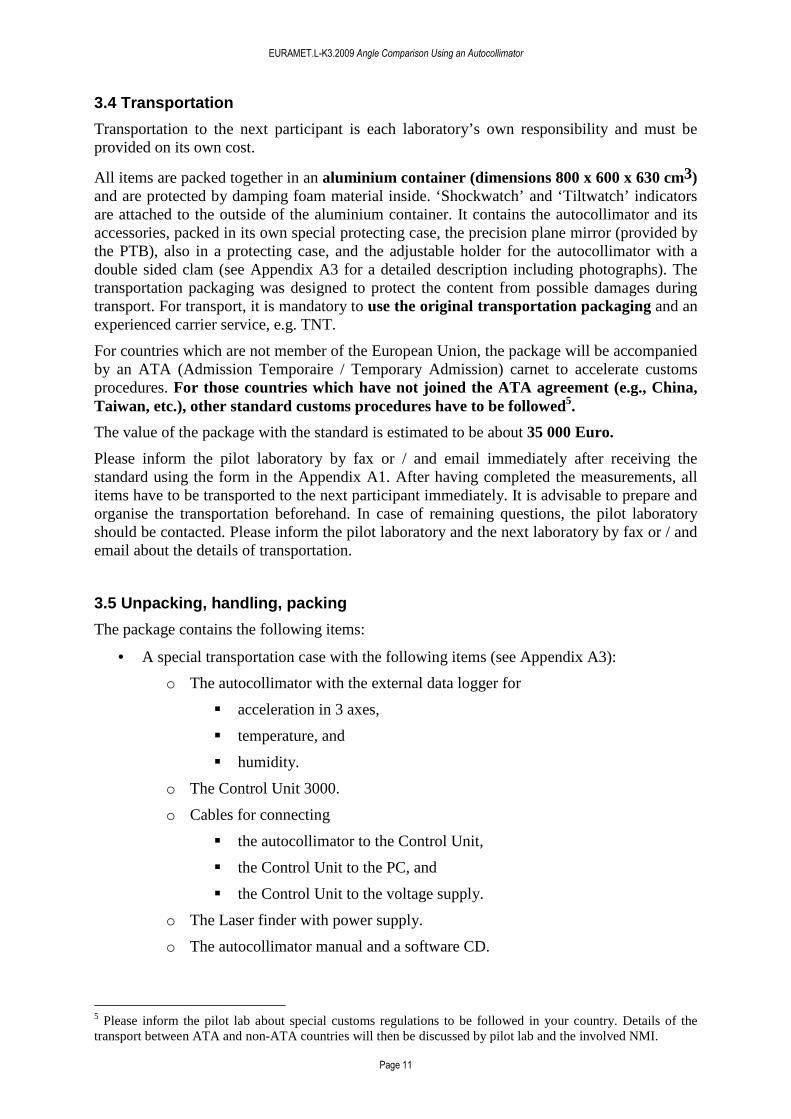
3.4 Transportation
Transportation to the next participant is each laboratory’s own responsibility and must be provided on its own cost.
All items are packed together in an aluminium container (dimensions 800 x 600 x 630 cm3) and are protected by damping foam material inside. ‘Shockwatch’ and ‘Tiltwatch’ indicators are attached to the outside of the aluminium container. It contains the autocollimator and its accessories, packed in its own special protecting case, the precision plane mirror (provided by the PTB), also in a protecting case, and the adjustable holder for the autocollimator with a double sided clam (see Appendix A3 for a detailed description including photographs). The transportation packaging was designed to protect the content from possible damages during transport. For transport, it is mandatory to use the original transportation packaging and an experienced carrier service, e.g. TNT.
For countries which are not member of the European Union, the package will be accompanied by an ATA (Admission Temporaire / Temporary Admission) carnet to accelerate customs procedures. For those countries which have not joined the ATA agreement (e.g., China, Taiwan, etc.), other standard customs procedures have to be followed5.
The value of the package with the standard is estimated to be about 35 000 Euro.
Please inform the pilot laboratory by fax or / and email immediately after receiving the standard using the form in the Appendix A1. After having completed the measurements, all items have to be transported to the next participant immediately. It is advisable to prepare and organise the transportation beforehand. In case of remaining questions, the pilot laboratory should be contacted. Please inform the pilot laboratory and the next laboratory by fax or / and email about the details of transportation.
3.5 Unpacking, handling, packing
The package contains the following items:
• A special transportation case with the following items (see Appendix A3):
o The autocollimator with the external data logger for
� acceleration in 3 axes,
� temperature, and
� humidity.
o The Control Unit 3000.
o Cables for connecting
� the autocollimator to the Control Unit,
� the Control Unit to the PC, and
� the Control Unit to the voltage supply.
o The Laser finder with power supply.
o The autocollimator manual and a software CD.
5 Please inform the pilot lab about special customs regulations to be followed in your country. Details of the transport between ATA and non-ATA countries will then be discussed by pilot lab and the involved NMI.
EURAMET.L-K3.2009 Angle Comparison Using an Autocollimator
Page 12
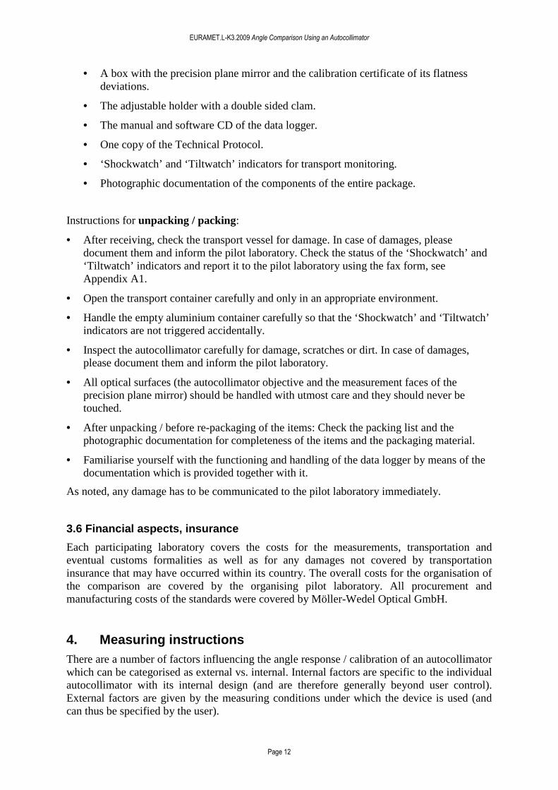
• A box with the precision plane mirror and the calibration certificate of its flatness deviations.
• The adjustable holder with a double sided clam.
• The manual and software CD of the data logger.
• One copy of the Technical Protocol.
• ‘Shockwatch’ and ‘Tiltwatch’ indicators for transport monitoring.
• Photographic documentation of the components of the entire package.
Instructions for unpacking / packing:
• After receiving, check the transport vessel for damage. In case of damages, please document them and inform the pilot laboratory. Check the status of the ‘Shockwatch’ and ‘Tiltwatch’ indicators and report it to the pilot laboratory using the fax form, see Appendix A1.
• Open the transport container carefully and only in an appropriate environment.
• Handle the empty aluminium container carefully so that the ‘Shockwatch’ and ‘Tiltwatch’ indicators are not triggered accidentally.
• Inspect the autocollimator carefully for damage, scratches or dirt. In case of damages, please document them and inform the pilot laboratory.
• All optical surfaces (the autocollimator objective and the measurement faces of the precision plane mirror) should be handled with utmost care and they should never be touched.
• After unpacking / before re-packaging of the items: Check the packing list and the photographic documentation for completeness of the items and the packaging material.
• Familiarise yourself with the functioning and handling of the data logger by means of the documentation which is provided together with it.
As noted, any damage has to be communicated to the pilot laboratory immediately.
3.6 Financial aspects, insurance
Each participating laboratory covers the costs for the measurements, transportation and eventual customs formalities as well as for any damages not covered by transportation insurance that may have occurred within its country. The overall costs for the organisation of the comparison are covered by the organising pilot laboratory. All procurement and manufacturing costs of the standards were covered by Möller-Wedel Optical GmbH.
4. Measuring instructions There are a number of factors influencing the angle response / calibration of an autocollimator which can be categorised as external vs. internal. Internal factors are specific to the individual autocollimator with its internal design (and are therefore generally beyond user control). External factors are given by the measuring conditions under which the device is used (and can thus be specified by the user).
EURAMET.L-K3.2009 Angle Comparison Using an Autocollimator
Page 13
Based on our comprehensive experience in autocollimator calibration at the PTB, the later group of factors includes the following parameters (see [2-4] for details):
• Reflectivity of the mirror
• Curvature of the mirror
• Distance (optical path length) between the autocollimator and the mirror
• If an aperture stop is used:
o Diameter and shape of the aperture stop
o Position of the aperture stop along the autocollimator’s optical axis
o Lateral position of the aperture stop perpendicular to the optical axis
According to our experience in autocollimator calibration, significant differences in the calibration may occur in case of changes in one or several parameters.
With the measuring instructions presented in this section, we attempt to achieve a balance between allowing NMIs to calibrate the reference autocollimator under measurement conditions which are typical for routine calibrations at their facilities, and ensuring optimal comparability of the calibration results achieved at different NMIs. On the one hand, the calibration results should provide realistic information on the calibration capabilities and limits at each NMI, on the other hand, systematic errors due to changes in the measuring conditions must be avoided, as they may not be accounted for by the stated measurement uncertainties.
In case of deviations of the measuring conditions from the stated specifications, e.g., due to constraints of the calibration set-up at the NMI, a detailed documentation of the changed condition(s) is necessary.
4.1 Plane mirror
Each participating NMI is allowed to use its own plane mirror which is normally used for calibrations for customers. To avoid systematic errors due to the mirror’s curvature and reflectivity, we specify the following parameters:
• Reflectivity: Use of a mirror with a metallic coating (usually aluminium) to obtain a reflectivity approaching 100%.
• Size of the reflecting area: 50 mm in diameter in order to provide an unobstructed reflection over the effective, illuminated autocollimator aperture (32 mm in diameter).
• Flatness deviation of the measurement face: λ/8 (peak-to-valley) for a region at least 32 mm in diameter.
As deviations from the stated measuring conditions may alter the autocollimator’s angle response significantly [2-4], we consider the realization of these parameters as essential. If available, please provide optional documentation on your mirror (flatness deviations, reflectivity).
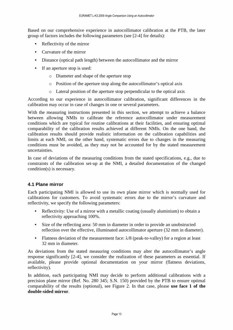
In addition, each participating NMI may decide to perform additional calibrations with a precision plane mirror (Ref. No. 280 345; S.N. 150) provided by the PTB to ensure optimal comparability of the results (optional), see Figure 2. In that case, please use face 1 of the double-sided mirror.

EURAMET.L-K3.2009 Angle Comparison Using an Autocollimator
Page 14
Figure 2. Precision plane mirror provided by the PTB (its use is optional). Please use face 1 of the double-sided mirror.
We have investigated the influence of flatness deviations of the reflecting mirror on the angle response of autocollimators. In the case of two mirrors with different flatness deviations of 4 nm and 20 nm (root-mean-square), systematic changes in the angle response of a few 0.01 arcsec were found [2].
4.2 Distance autocollimator - reflector
In the case of different distances between the autocollimator and the reflecting mirror, the beam returning to the autocollimator follows different paths through its optics. In conjunction with aberrations of the optical components and errors in their alignment (and that of the CCD detector), angle deviations are introduced which are varying as a function of the distance to the mirror [3].
Each participating NMI is allowed to choose the distance between the autocollimator and the reflecting face of the plane mirror according to their usual specifications for calibrations. Please provide information on the distance from the front end of the autocollimator’s tube (which contains the objective) to the reflecting surface in your measurement documentation.
However, if possible with your calibration set-up, we strongly recommend a distance of 300 mm (equal to the focal length of the autocollimator) as, in this case, error influences are minimised, see [5-6]. Additionally, we have demonstrated significant changes in the angle response of autocollimators in the case of a variable distance to the reflecting mirror [3].
4.3 Autocollimator aperture
To avoid vignetting effects [4], the entire illuminated (effective) autocollimator aperture (32 mm in diameter) will be used in this comparison. No additional aperture stop is required. See also 4.1.
4.4 Measurement ranges / steps
The measurement deviations of autocollimators cover a wide range of angular scales, extending from a few arcseconds (connected to the pixels of the autocollimator’s CCD

EURAMET.L-K3.2009 Angle Comparison Using an Autocollimator
Page 15
detector) to the full measurement range (due to aberrations in the autocollimator’s optical elements and detector misalignment).
Therefore, to appropriately sample the angle deviations on both short and long angular scales, we recommend two different measurement ranges for the comparison:
• Measurement range 1: ± 1000 arcsec in steps of 10 arcsec
• Measurement range 2: ± 10 arcsec in steps of 0.1 arcsec
For the comparison, calibrations are to be performed on the x-axis of the autocollimator.
If possible, measurements should be performed at the specified values as indicated by the autocollimator, i.e., the angular positioning of the calibration system is guided by the autocollimator (optional). The starting position should be set to zero to better than 0.1 arcsec.
Qualification #1: If calibrations are not possible over the entire angle range, participants are allowed to calibrate over a limited range.
Qualification #2: If calibrations can not be performed at all specified measurement points (e.g., due to manual operation of the equipment), participants are allowed to calibrate at a selected subset of points. In this case, we suggest choosing a step width which is a multiple of the recommended step width.
Qualification #3: There is a small subset of participants which is not able to perform the calibrations according to the given recommendations even when taking the qualifications into consideration, e.g., due to a fixed step width which is predetermined by their calibration equipment. In this case, calibrations can be performed as specified by the equipment. The pilot laboratory, PTB, will provide a comprehensive calibration of the autocollimator with high angular resolution and will make an effort to accommodate the measurements by means of a flexible data analysis.
4.5 Adjustment procedures
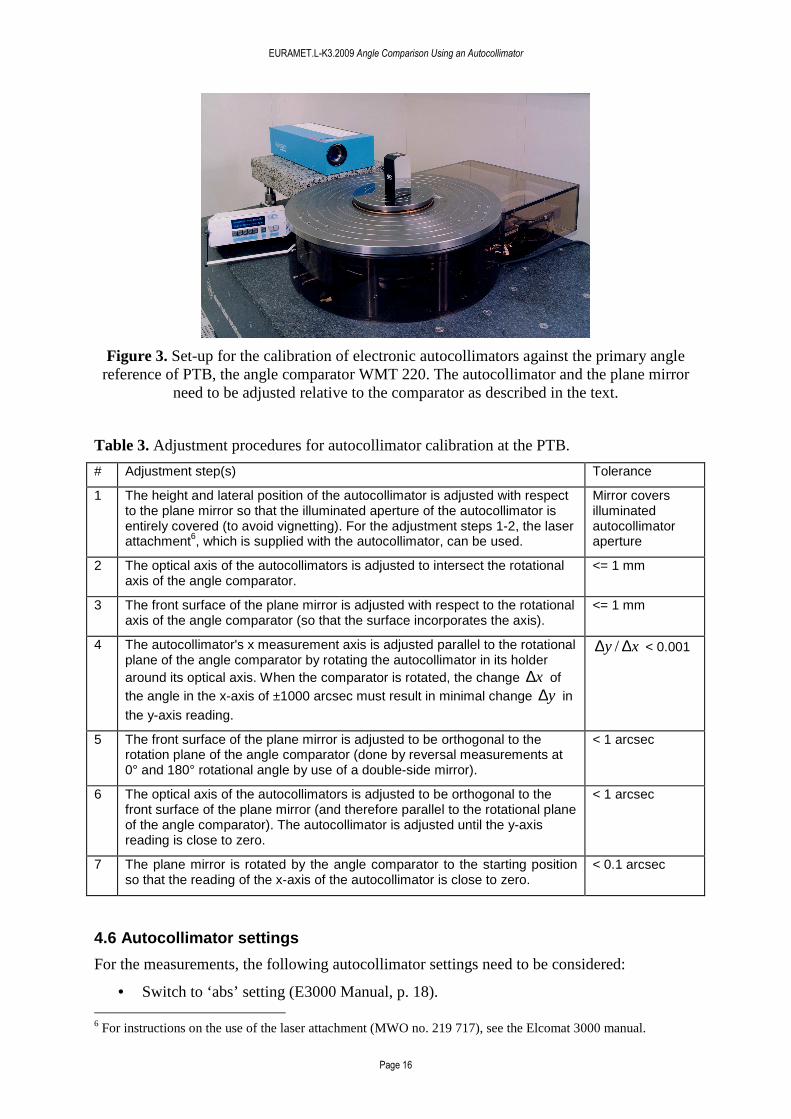
Each participating NMI may follow its own adjustment procedures for autocollimator calibration as specified in their manuals. In Figure 3, the measurement set-up for the calibration of electronic autocollimators against the primary angle reference of the PTB, the angle comparator WMT 220 ([7], manufactured by Dr. Johannes Heidenhain GmbH, Traunreut, Germany) is presented. The optical axis and the measuring axes of the autocollimator, as well as the plane mirror, need to be adjusted with respect to the comparator’s rotational axis and the associated rotation plane. As an example and a guideline, in Table 3, we provide a description of our own adjustment procedures at the PTB.
EURAMET.L-K3.2009 Angle Comparison Using an Autocollimator
Page 16
Figure 3. Set-up for the calibration of electronic autocollimators against the primary angle reference of PTB, the angle comparator WMT 220. The autocollimator and the plane mirror
need to be adjusted relative to the comparator as described in the text.
Table 3. Adjustment procedures for autocollimator calibration at the PTB.
# Adjustment step(s) Tolerance
1 The height and lateral position of the autocollimator is adjusted with respect to the plane mirror so that the illuminated aperture of the autocollimator is entirely covered (to avoid vignetting). For the adjustment steps 1-2, the laser attachment6, which is supplied with the autocollimator, can be used.
Mirror covers illuminated autocollimator aperture
2 The optical axis of the autocollimators is adjusted to intersect the rotational axis of the angle comparator.
<= 1 mm
3 The front surface of the plane mirror is adjusted with respect to the rotational axis of the angle comparator (so that the surface incorporates the axis).
<= 1 mm
4 The autocollimator's x measurement axis is adjusted parallel to the rotational plane of the angle comparator by rotating the autocollimator in its holder around its optical axis. When the comparator is rotated, the change x∆ of the angle in the x-axis of ±1000 arcsec must result in minimal change y∆ in
the y-axis reading.
xy ∆∆ / < 0.001
5 The front surface of the plane mirror is adjusted to be orthogonal to the rotation plane of the angle comparator (done by reversal measurements at 0° and 180° rotational angle by use of a double-side mirror).
< 1 arcsec
6 The optical axis of the autocollimators is adjusted to be orthogonal to the front surface of the plane mirror (and therefore parallel to the rotational plane of the angle comparator). The autocollimator is adjusted until the y-axis reading is close to zero.
< 1 arcsec
7 The plane mirror is rotated by the angle comparator to the starting position so that the reading of the x-axis of the autocollimator is close to zero.
< 0.1 arcsec
4.6 Autocollimator settings
For the measurements, the following autocollimator settings need to be considered:
• Switch to ‘abs’ setting (E3000 Manual, p. 18). 6 For instructions on the use of the laser attachment (MWO no. 219 717), see the Elcomat 3000 manual.

EURAMET.L-K3.2009 Angle Comparison Using an Autocollimator
Page 17
• Set unit to ‘arcsec’ (E3000 Manual, p. 14).
• Resolution (E3000 Manual, p. 16): This setting affects the resolution of the display only; it does not affect the values which are provided by the computer interfaces.
• Protocol for the RS-232 computer interface (E3000 Manual, p. 17 and p. 19): We strongly recommend to use the ‘text protocol ’ , especially for participants with low measurement uncertainties, because the data transfer is more reliable and its resolution is higher (0.001 arcsec in comparison to 0.01 arcsec for the ‘compatible’ format). Please do not use the USB computer interface as we have not tested its reliability for this comparison.
4.7 Measurement results
In general, the result of the calibration is the deviation δ of the angle measured by the autocollimator from the angle provided by the reference system according to (to fix the sign convention)
REFAC ααδ −= , (1)
with
δ : the angle deviation of the autocollimator,
ACα : the angle measured by the autocollimator, and
REFα : the angle measured by the reference system.
For all stated values involving angles, the unit ‘arcsecond’ should be used. Please report any smoothing / filtering of the data values (which should be avoided at all costs).
For the final calibration value δ , multiple measurements may be obtained and processed, e.g., (1) multiple measurements both with the autocollimator and the reference system may be performed or (2) the entire calibration run may be repeated several times. As an illustration, we describe the data acquisition during autocollimator calibration at the PTB.
For a specific calibration and at a specific angle setting, 100AC =n and 25REF =n angle
readings ACα and REFα , respectively, are obtained with the autocollimator and the reference
system in a time-shared sequence. Average values and standard deviations are calculated for further analysis, including the average autocollimator angle measurement ACα and the
average autocollimator deviation REFAC ααδ −= . The procedure is repeated until the
autocollimator deviations have been obtained for all desired angle settings within the measurement range. This data set defines an individual calibration.
Typically, 623r =×=n independent individual calibrations are performed at three different relative angular positions between the autocollimator and the primary standard, including a reversal of the standard’s direction of rotation at each relative position to eliminate linear drifts from the average. These rn individual repeat calibrations are then averaged to obtain the final calibration result. Analysis of the repeatability of the individual calibrations yields an estimate of the Type A uncertainty component for the calibration’s uncertainty budget, see Section 5.
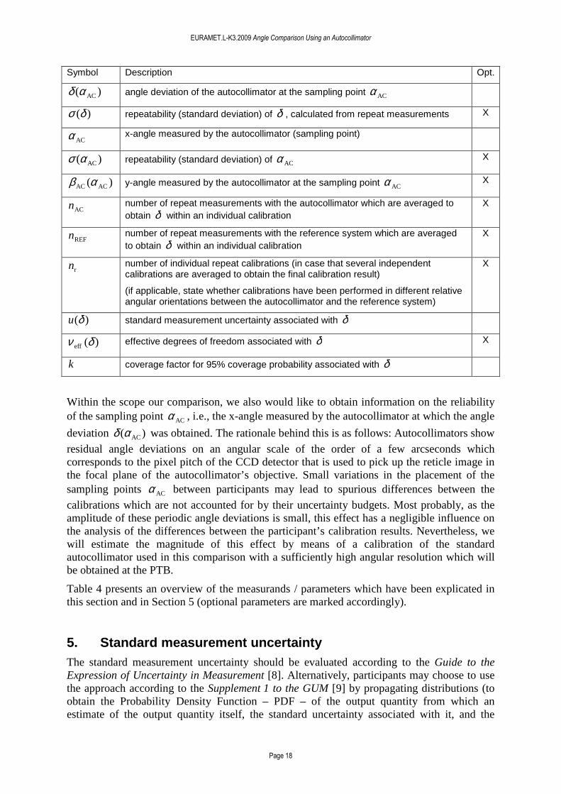
Table 4. Overview of measurands / parameters from Sections 4 and 5 (optional parameters are marked).
EURAMET.L-K3.2009 Angle Comparison Using an Autocollimator
Page 18
Symbol Description Opt.
)( ACαδ angle deviation of the autocollimator at the sampling point ACα
)(δσ repeatability (standard deviation) of δ , calculated from repeat measurements X
ACα x-angle measured by the autocollimator (sampling point)
)( ACασ repeatability (standard deviation) of ACα X
)( ACAC αβ y-angle measured by the autocollimator at the sampling point ACα X
ACn number of repeat measurements with the autocollimator which are averaged to obtain δ within an individual calibration
X
REFn number of repeat measurements with the reference system which are averaged to obtain δ within an individual calibration
X
rn number of individual repeat calibrations (in case that several independent calibrations are averaged to obtain the final calibration result)
(if applicable, state whether calibrations have been performed in different relative angular orientations between the autocollimator and the reference system)
X
)(δu standard measurement uncertainty associated with δ
)(eff δν effective degrees of freedom associated with δ X
k coverage factor for 95% coverage probability associated with δ
Within the scope our comparison, we also would like to obtain information on the reliability of the sampling point ACα , i.e., the x-angle measured by the autocollimator at which the angle
deviation )( ACαδ was obtained. The rationale behind this is as follows: Autocollimators show
residual angle deviations on an angular scale of the order of a few arcseconds which corresponds to the pixel pitch of the CCD detector that is used to pick up the reticle image in the focal plane of the autocollimator’s objective. Small variations in the placement of the sampling points ACα between participants may lead to spurious differences between the
calibrations which are not accounted for by their uncertainty budgets. Most probably, as the amplitude of these periodic angle deviations is small, this effect has a negligible influence on the analysis of the differences between the participant’s calibration results. Nevertheless, we will estimate the magnitude of this effect by means of a calibration of the standard autocollimator used in this comparison with a sufficiently high angular resolution which will be obtained at the PTB.
Table 4 presents an overview of the measurands / parameters which have been explicated in this section and in Section 5 (optional parameters are marked accordingly).
5. Standard measurement uncertainty The standard measurement uncertainty should be evaluated according to the Guide to the Expression of Uncertainty in Measurement [8]. Alternatively, participants may choose to use the approach according to the Supplement 1 to the GUM [9] by propagating distributions (to obtain the Probability Density Function – PDF – of the output quantity from which an estimate of the output quantity itself, the standard uncertainty associated with it, and the
EURAMET.L-K3.2009 Angle Comparison Using an Autocollimator
Page 19
coverage interval for a given coverage probability can be derived)7. In this section, the standard approach is outlined.
For each measured deviation δ , its associated standard uncertainty )(δu needs to be provided. For the derivation of the expanded uncertainty, provide the coverage factor k for a 95% coverage probability and, if appropriate7, its effective degrees of freedom )(eff δν . Note
that the standard uncertainty – not the expanded uncertainty – is the basic statement on the uncertainty of a measurement.
For deriving the uncertainty budget, the deviation REFAC ααδ −= of the autocollimator
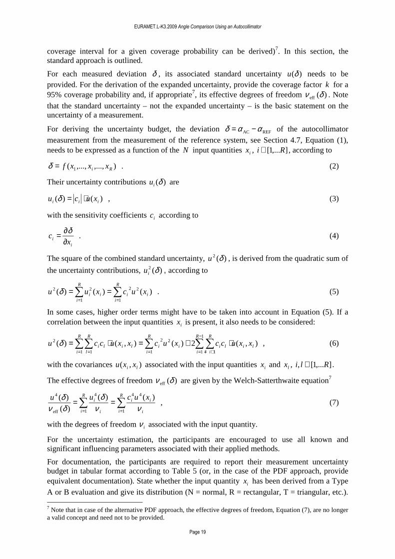
measurement from the measurement of the reference system, see Section 4.7, Equation (1), needs to be expressed as a function of the N input quantities ix , ],...1[ Ri ∈ , according to
),...,,...,( 1 Ri xxxf=δ . (2)
Their uncertainty contributions )(δiu are
)()( iii xucu ⋅=δ , (3)
with the sensitivity coefficients ic according to
ii x
c∂∂= δ
. (4)
The square of the combined standard uncertainty, )(2 δu , is derived from the quadratic sum of
the uncertainty contributions, )(2 δiu , according to
∑∑==
==R
iii
R
iii xucxuu
1
22
1
22 )()()(δ . (5)
In some cases, higher order terms might have to be taken into account in Equation (5). If a correlation between the input quantities ix is present, it also needs to be considered:
∑∑∑∑∑−
= +=== =
⋅+=⋅=1
1 11
22
1 1
2 ),(2)(),()(R
i
R
illili
R
iii
R
i
R
llili xxuccxucxxuccu δ , (6)
with the covariances ),( li xxu associated with the input quantities ix and lx , ],...1[, Rli ∈ .
The effective degrees of freedom )(eff δν are given by the Welch-Satterthwaite equation7
∑∑==
==R
i i
iiR
i i
i xucuu
1
44
1
4
eff
4 )()(
)(
)(
ννδ
δνδ
, (7)
with the degrees of freedom iν associated with the input quantity.
For the uncertainty estimation, the participants are encouraged to use all known and significant influencing parameters associated with their applied methods.
For documentation, the participants are required to report their measurement uncertainty budget in tabular format according to Table 5 (or, in the case of the PDF approach, provide equivalent documentation). State whether the input quantity ix has been derived from a Type
A or B evaluation and give its distribution (N = normal, R = rectangular, T = triangular, etc.). 7 Note that in case of the alternative PDF approach, the effective degrees of freedom, Equation (7), are no longer a valid concept and need not to be provided.

EURAMET.L-K3.2009 Angle Comparison Using an Autocollimator
Page 20
State the degree of freedom iν , the sensitivity coefficient ic , and the uncertainty contribution
)(δiu associated with each ix . Some indicated standard uncertainties, might be based on a
separate calculation, e.g., Monte Carlo simulations, which can be added to the report.
Table 5. Example scheme for the uncertainty budget.
Description of input quantity
ix
Symbol for ix
Type
A or B
Distri-bution
Std. meas. uncertainty
)( ixu of
input quantity
(arcsec)
Degrees of freedom
iν
Sensitivity coeff.
ii x
c∂∂= δ
Std.-meas. uncertainty contribution
)(δiu
(arcsec)
Angle deviations of the primary standard
WMTα∆
B R 0.0006 arcsec ∞ 1 0.0006 arcsec
... … ... ... ... ... ...
Combined standard measurement uncertainty )(δu
Coverage factor k for a coverage probability of 95%
Effective degrees of freedom )(eff δν 7
EURAMET.L-K3.2009 Angle Comparison Using an Autocollimator
Page 21
6. Documentation and reporting Descriptions of the (1) calibration device, (2) the measurement results, and (3) a detailed evaluation of the measurement uncertainty have to be reported (see Sections 5, 6, and Appendix A2). Electronic templates of the report forms in the Appendix of this document are sent by e-mail to all participating laboratories (MS Word documents and PDF files). For further analysis, it is necessary to complete the report forms by computer and to send them back electronically to the pilot laboratory (and the coordinator). In any case, the printed and signed report must also be sent in paper form by mail. In case of any differences, the paper forms are considered to be the valid versions. The reports shall be sent to the pilot laboratory no later than six weeks after completing the measurements.
The measurement data (see Section 4.7) need to be reported as American Standard Code of Information Interchange (ASCII) files (FILENAME.DAT). The FILENAME should include the acronym of the NMI and should identify the measurement range, e.g., PTB_1000.DAT. The file should contain seven columns; one single header row, and R data rows (R : number of measurement steps in the defined measurement range). The file should include a header row (one single row) with the column names as given in Table 6. For documentation, please also send a printed and signed version of the data file.
Table 6. Information on the data rows of the ASCII file.
Column name for file header
ACx sdACx ACDev sdACDev uACDev k ACy
Data value (explanation: see Sections 4.7 and 5)
ACα )( ACασ )( ACαδ )(δσ )(δu k ACβ
Optional X X X
Note 1: In the case of entries which are not changing, please nevertheless provide a column containing R identical numbers. This facilitates the analysis of the results and avoids errors in the attribution of parameters.
Note 2: In the case of optional values, if you decide not to include them, please provide a column containing R identical zeros – do not omit the row(s).
Note 3: For all stated values, the unit ‘arcsecond’ should be used.
7. Comparison / analysis of results After completion of the circulation, the pilot laboratory will prepare a first draft report and send it to the participants for comment. Subsequently, the procedure outlined in the BIPM Guidelines for CIPM Key Comparisons [10] will be followed. According to the MRA, a comparison should provide information on the degree of equivalence of the measurements of all participants. To discuss the degree of equivalence, normally, Key Comparison Reference Values (KCRV) are generated from the participants’ results. Note that there is a small subset of participants which is not able to perform the calibrations according to the recommendations on the measurement ranges and steps given in Section 4.4. This poses a problem for the determination of the KCRV. In these cases, the comprehensive calibration of the autocollimator with high angular resolution provided by the PTB will be used to take this into account by means of a more flexible data analysis (which has not yet been finalised).
The main objective of the comparison is to provide reliable information on the degree of equivalence of the different angle realizations between the participating institutes. To
EURAMET.L-K3.2009 Angle Comparison Using an Autocollimator
Page 22
accomplish this, the measurement results of the participants, which are given as deviations δ of the angles measured by the autocollimator from the angles provided by the reference system have to be analyzed further. The pilot laboratory proposes the following procedure for analysing the comparison results, closely following the recommendations in [11]8:
(1) Input data
Input data are the values delivered by the participants according to Sections 4.7 and 5, specifically:
• The deviations jpjpjp REF,AC, ααδ −= of the angles jpAC,α measured by the
autocollimator from the angles jpREF,α provided by the reference system, with the
index ],...,1[ Nj ∈ of the angle position and the participant’s index ],...,1[ Mp ∈ .
• The combined standard uncertainties )( jpu δ associated with the deviations jpδ .
(2) KCRV
It is assumed that (I) the standard (i.e., the autocollimator) is stable, (II) that each participant’s measurement of the standard is realized independently of the other participants’ measurements, and (III) that a Gaussian distribution (with a mean equal to the participant’s measurement and a standard deviation equal to the associated standard uncertainty) can be assigned to the measurand of which the participant’s measurement is an estimate. The later will also be checked, for details, see item (3) in this section.
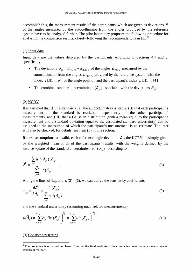
If these assumptions are valid, each reference angle deviation jδ~ , the KCRV, is simply given
by the weighted mean of all of the participants’ results, with the weights defined by the inverse square of the standard uncertainties, )(2
jpu δ− , according to
)(
)(~
1
2
1
2
jp
M
p
jpjp
M
pj
u
u
δ
δδδ
∑
∑
=
−
=
− ⋅= . (8)
Along the lines of Equations (3) - (6), we can derive the sensitivity coefficients
)(
)(~
1
2
2
jp
M
p
jp
jp
jjp
u
uc
δ
δδδ
∑=
−
−
=∂∂
= (9)
and the standard uncertainty (assuming uncorrelated measurements)
21
1
22
1
1
22 )()()~
(
−
=
−
=
=
⋅= ∑∑ jp
M
p
M
pjpjpj uucu δδδ . (10)
(3) Consistency testing
8 The procedure is only outlined here. Note that the final analysis of the comparison may include more advanced statistical methods.
EURAMET.L-K3.2009 Angle Comparison Using an Autocollimator
Page 23
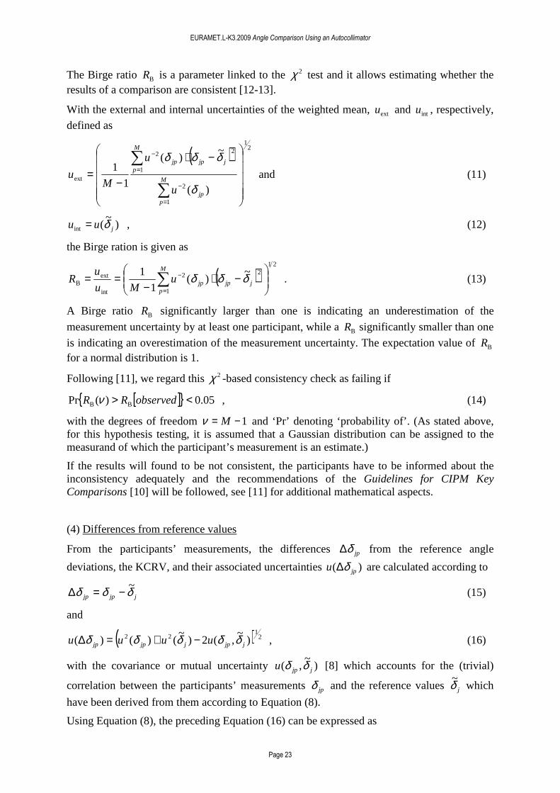
The Birge ratio BR is a parameter linked to the 2χ test and it allows estimating whether the results of a comparison are consistent [12-13].
With the external and internal uncertainties of the weighted mean, extu and intu , respectively,
defined as
( ) 21
1
2
2
1
2
ext
)(
~)(
1
1
−⋅
−=
∑
∑
=
−
=
−
jp
M
p
jjpjp
M
p
u
u
Mu
δ
δδδ and (11)
)~
(int juu δ= , (12)
the Birge ration is given as
( )21
2
1
2
int
extB
~)(
1
1
−⋅
−== ∑
=
−jjpjp
M
p
uMu
uR δδδ . (13)
A Birge ratio BR significantly larger than one is indicating an underestimation of the
measurement uncertainty by at least one participant, while a BR significantly smaller than one
is indicating an overestimation of the measurement uncertainty. The expectation value of BR for a normal distribution is 1.
Following [11], we regard this 2χ -based consistency check as failing if
[ ]{ } 05.0)(Pr BB <> observedRR ν , (14)
with the degrees of freedom 1−= Mν and ‘Pr’ denoting ‘probability of’. (As stated above, for this hypothesis testing, it is assumed that a Gaussian distribution can be assigned to the measurand of which the participant’s measurement is an estimate.)
If the results will found to be not consistent, the participants have to be informed about the inconsistency adequately and the recommendations of the Guidelines for CIPM Key Comparisons [10] will be followed, see [11] for additional mathematical aspects.
(4) Differences from reference values
From the participants’ measurements, the differences jpδ∆ from the reference angle
deviations, the KCRV, and their associated uncertainties )( jpu δ∆ are calculated according to
jjpjp δδδ ~−=∆ (15)
and
( ) 21
22 )~
,(2)~
()()( jjpjjpjp uuuu δδδδδ −+=∆ , (16)
with the covariance or mutual uncertainty )~
,( jjpu δδ [8] which accounts for the (trivial)
correlation between the participants’ measurements jpδ and the reference values jδ~ which
have been derived from them according to Equation (8).
Using Equation (8), the preceding Equation (16) can be expressed as
EURAMET.L-K3.2009 Angle Comparison Using an Autocollimator
Page 24
( ) 21
22 )~
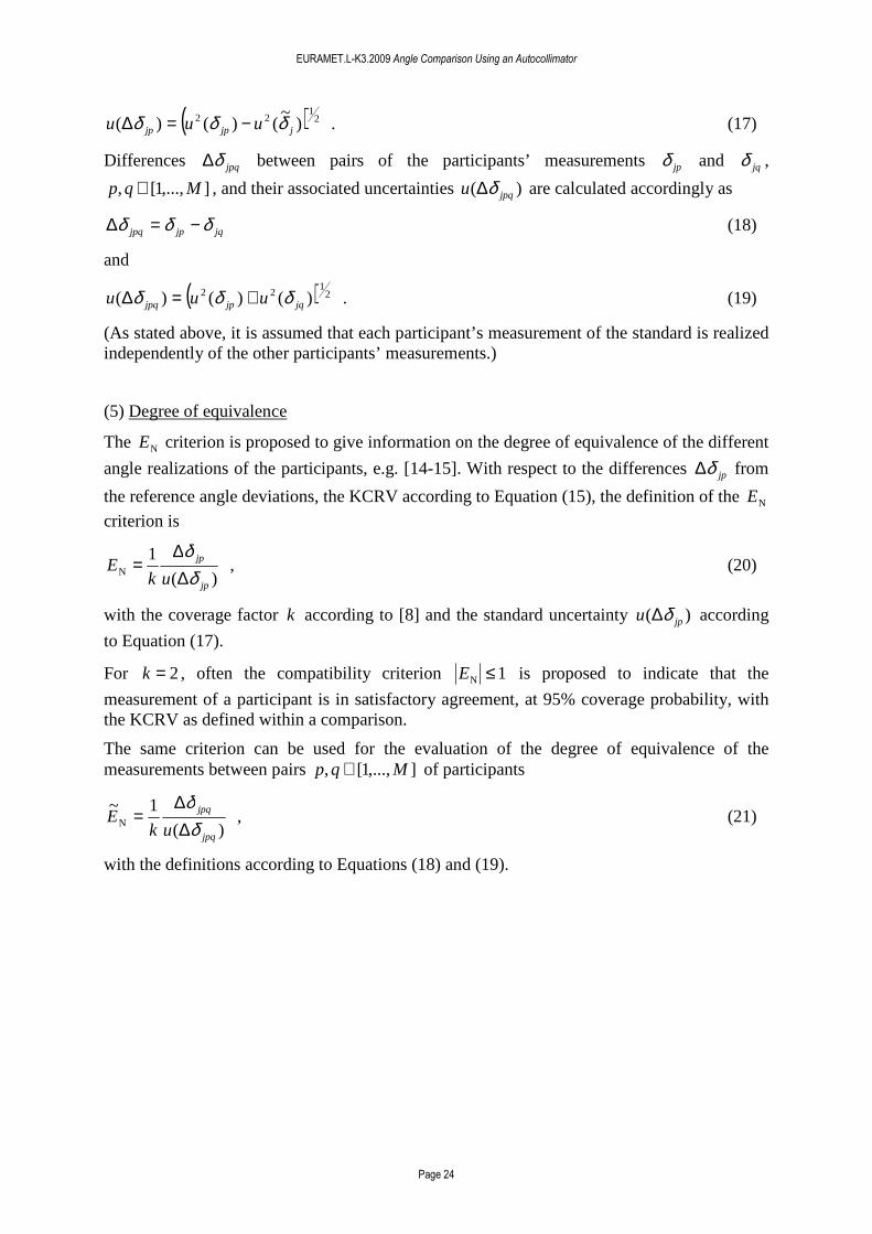
()()( jjpjp uuu δδδ −=∆ . (17)
Differences jpqδ∆ between pairs of the participants’ measurements jpδ and jqδ ,
],...,1[, Mqp ∈ , and their associated uncertainties )( jpqu δ∆ are calculated accordingly as
jqjpjpq δδδ −=∆ (18)
and
( ) 21
22 )()()( jqjpjpq uuu δδδ +=∆ . (19)
(As stated above, it is assumed that each participant’s measurement of the standard is realized independently of the other participants’ measurements.)
(5) Degree of equivalence
The NE criterion is proposed to give information on the degree of equivalence of the different
angle realizations of the participants, e.g. [14-15]. With respect to the differences jpδ∆ from
the reference angle deviations, the KCRV according to Equation (15), the definition of the NE criterion is
)(
1N
jp
jp
ukE
δδ
∆∆
= , (20)
with the coverage factor k according to [8] and the standard uncertainty )( jpu δ∆ according
to Equation (17).
For 2=k , often the compatibility criterion 1N ≤E is proposed to indicate that the
measurement of a participant is in satisfactory agreement, at 95% coverage probability, with the KCRV as defined within a comparison.
The same criterion can be used for the evaluation of the degree of equivalence of the measurements between pairs ],...,1[, Mqp ∈ of participants
)(
1~N
jpq
jpq
ukE
δδ
∆∆
= , (21)
with the definitions according to Equations (18) and (19).
EURAMET.L-K3.2009 Angle Comparison Using an Autocollimator
Page 25
8. References
[1] A. Just, M. Krause, R. Probst, and R. Wittekopf, ‘Calibration of high-resolution electronic autocollimators against an angle comparator’, Metrologia 40 (2003) 288-294
[2] R.D. Geckeler, A. Just, M. Krause, V.V. Yashchuk, ‘Autocollimators for deflectometry: Current status and future progress’, Nuclear Instruments and Methods in Physics Research, Section A (2009), in press (doi:10.1016/j.nima.2009.11.021)
[3] R.D. Geckeler and A. Just, ‘Distance dependent influences on angle metrology with autocollimators in deflectometry’, Proc. SPIE 7077 (2008) 70770B 1-12
[4] R.D. Geckeler and A. Just, ‘Optimized use and calibration of autocollimators in deflectometry’, Proc. SPIE 6704 (2007) 670407 1-12
[5] G. Fütterer, ‘Simulation of the detectors response of an autocollimator’, Proc. SPIE 6617 (2007) 661703 1-8
[6] G. Fütterer, ‘Enhancement of high resolution electronic autocollimators by application of phase grating technology’, Proc. SPIE 5856 (2005) 950-959
[7] R. Probst, R. Wittekopf, M. Krause, H. Dangschat, and A. Ernst, ‘The new PTB angle comparator’, Meas. Sci. Technol. 9 (1998) 1059-1066
[8] ISO/IEC Guide 98-3:2008 ‘Guide to the Expression of Uncertainty in Measurement’ (ISO: 2008) (for the 1995 version with minor corrections, see JCGM 100:2008 http://www.bipm.org/en/publications/guides/gum.html)
[9] JCGM 101:2008 “Evaluation of measurement data - Supplement 1 to the ‘Guide to the expression of uncertainty in measurement’ - Propagation of distributions using a Monte Carlo method”, Joint Committee for Guides in Metrology (JCGM: 2008) http://www.bipm.org/en/publications/guides/gum.html
[10] Guidelines for CIPM key comparisons (CIPM: 1999) http://www.bipm.org/en/cipm-mra/guidelines_kcs/
[11] M.G. Cox ‘The evaluation of key comparison data’ Metrologia 39 (2002) 589-595
[12] R.T. Birge, ‘The calculation of errors by the method of least squares’, Phys. Rev. 40 (1932) 207-227
[13] R. Kacker, R. Datla and A. Parr, ‘Combined result and associated uncertainty from interlaboratory evaluations based on the ISO Guide’, Metrologia 39 (2002) 279-293
[14] W. Wöger, ‘Remarks on the En-criterion used in measurement comparisons’, PTB-Mitteilungen 109 (1) (1999) 24-27
[15] K. Beissner, ‘On a measure of consistency in comparison measurements’, Metrologia 39 (2002), 59-63

EURAMET.L-K3a.2009 Angle Comparison Using an Autocollimator Appendix A1
Telefax Telefax Telefax Telefax Telefax
To: PTB
5.21 Length and Angle Graduations Bundesallee 100 D-38116 Braunschweig Germany Fax: ++49 531 592 69 5221 Email: [email protected] (send copy to [email protected])
From: (participating NMI)
We confirm having received the standard of the EURAMET.L-K3.2009 Angle Comparison Using an Autocollimator:..............................................................(date).
After visual inspection:
No damage has been noticed.
Damage(s) must be reported. Please specify details of the damage (use additional page for description), if possible add image of the damage.
Shockwatch sensor (attached to aluminium transportation container, Appendix A3) was activated.
Tiltwatch sensor (also attached to container) was activated.
Date Signature
...................... ................................................

EURAMET.L-K3a.2009 Angle Comparison Using an Autocollimator Appendix A2
Documentation of measuring conditions 1. General information on the measuring conditions 1.1 Mounting
• Horizontal orientation of the AC x-axis o • Vertical orientation of the AC x-axis o • Use of additional optics for beam rotation o
(If yes, please provide a short description) 1.2 Plane mirror
• Use of the plane mirror provided by the PTB o • Use of the plane mirror owned by the NMI o
o Reflectivity % o Size mm x mm o Flatness deviation (rms or pv, if know) nm
1.3 Distance between autocollimator and reflector
• Distance mm 1.4 Temperature of the measurement room
• Temperature °C 1.5 Autocollimator settings 1.5.1 Automated measurements
� Use of the RS232 interface ‘text’ protocol o � Use of the RS232 interface ’compatible ’protocol o � Use of the USB interface o
1.5.2 Manual measurements � Resolution setting arcsec
1.6 Details to the measurement procedure
� Static measurement o � Dynamic measurement o � Number of repeat measurements =rn � Repeat measurements in different relative angular
orientations between the autocollimator and the reference system o yes
o no • Number or repeat measurements of the autocollimator
in each measuring position =ACn
• Number or repeat measurements of the reference in each measuring position =REFn
Date NMI Signature
...................... ...................... ................................................

EURAMET.L-K3a.2009 Angle Comparison Using an Autocollimator Appendix A3
Transport packaging Photograph A3-1 shows the outer aluminium container (dimensions 800x600x630 cm3) together with the special protecting case for the autocollimator and its accessories (1), the protecting case for the precision plane mirror (2), the adjustable holder for the autocollimator with a double-sided clam packed in protective bubble wrap (3), and customized and numbered damping foam material. On the inside of the top cover of the aluminium container, photographs are attached (4) which show the steps of the packaging in detail.
Photograph A3-1 Photograph A3-2 shows the special protecting case of the autocollimator and its accessories.
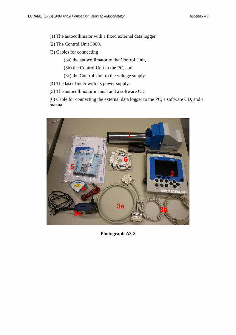
Photograph A3-2 Photograph A3-3 shows content of the protecting case in detail:
3 2
4
1
EURAMET.L-K3a.2009 Angle Comparison Using an Autocollimator Appendix A3
(1) The autocollimator with a fixed external data logger
(2) The Control Unit 3000.
(3) Cables for connecting
(3a) the autocollimator to the Control Unit,
(3b) the Control Unit to the PC, and
(3c) the Control Unit to the voltage supply.
(4) The laser finder with its power supply.
(5) The autocollimator manual and a software CD.
(6) Cable for connecting the external data logger to the PC, a software CD, and a manual.
Photograph A3-3
6 5
4
3c
2
3b
1
3a