technical paper bucknell university - auvsi suas · bucknell university team dronewerks 3 1...
TRANSCRIPT
Technical Paper Bucknell University
______________________________________________________________________________
Nick Urban, Dan Farrell Faculty Advisor – Martin Ligare
Department of Physics & Astronomy Moore Avenue, Bucknell University Lewisburg, P.A. 17837, U.S.A.
May 2011 Student AUVSI Competition
____________________________________________________________________________________ ABSTRACT This paper provides an overview of the design of Bucknell University’s UAS, constructed to meet the requirements of the 2011 AUVSI student UAS competition. The team’s system utilizes a twin boom airframe controlled by an ArduPilot Mega autopilot. This autopilot guides the aircraft through a series of designated waypoints while the aircraft searches for targets within its field of view. Two cameras are used to search for targets, a Sony CCD video cam-era, and a Canon PowerShot ELPH 100 HS. Video is streamed to the ground from the CCD camera over a 1280MHz link, where it is displayed on the team’s ground station. The aircraft may be controlled by either a 2.4GHz spread spectrum radio link, or a 900MHz telemetry link. The ability to control the aircraft with one system does not rely on the success of the other system. Additional safety precautions have been taken to ensure the aircraft does not put it-self, team members, or the surrounding area in danger. This includes a designated failsafe processor, as well as multiple isolated branches of control. This paper describes the system iteratively, beginning with the systems design philosophy, followed by an individual systems break-down, and concluding with a mission plan and testing results which show that the mis-sion can be completed successfully.
Bucknell University Team DroneWerks
2
CONTENTS
1 INTRODUCTION…………………………………………………………………………………….3 1.1 Team………………………………………………………………………………………….3 1.2 Mission Requirements and Goals…………………………………………………………3 1.3 System Overview……………………………………………………………………………3 2 SYSTEMS ENGINEERING AND OVERVIEW……………………………………………………..4 2.1 Airframe………………………………………………………………………………………4 2.1.1 Introduction………………………………………………………………………………4 2.1.2 Design Methodology……………………………………………………………………4 2.1.3 Engineering Decisions………………………………………………………………….5 2.2 Autopilot………………………………...……………………………………………………6 2.2.1 ArduPilot Mega Autopilot………………………………………………………………6 2.2.2 Ground Station…………………………………………………………………………..7 2.2.3 Hardware in Loop Simulation………………………………………………………….9 3 PAYLOADS DESIGN AND OVERVIEW………………………………………………………….10 3.1 Overview……………………………………………………………………………………10 3.2 Live Camera………………………………………………………………………………..10 3.3 Static Camera……………………………………………………………………………...11 3.4 Payload Communications………………………………………………………………...11 4 TESTING, PERFORMANCE AND SAFETY………………………………....………………......12 4.1 Individual Systems Tests..........................................................................................12 4.1.1 Autopilot Testing..................................................................................................12 4.1.2 Imagery Testing...................................................................................................12 4.1.3 Airframe Testing...................................................................................................13 4.1.4 Communications Testing.....................................................................................13 4.2 Full Systems Tests....................................................................................................13 5 MISSION PLAN....................................................................................................................14 5.1 Takeoff......................................................................................................................14 5.2 Target Area................................................................................................................14 5.3 In-flight Retasking.....................................................................................................14 5.4 Landing.....................................................................................................................14 5.5 Target Processing.....................................................................................................15 6 SPECIFICATIONS................................................................................................................15 6.1 Radio Performance...................................................................................................15 6.2 Flight Performance....................................................................................................15 6.3 Airframe Specifications.............................................................................................15 6.4 Payload Specifications..............................................................................................16 6.5 Control Specifications...............................................................................................16 6.6 Autopilot Specifications............................................................................................16 6.7 Ground Station Specifications..................................................................................16 7 REFERENCES......................................................................................................................17
Bucknell University Team DroneWerks
3
1 INTRODUCTION
1.1 Team
Bucknell University’s AUVSI student UAS competition team is comprised of a small inter-disciplinary group of students. The team is advised by Martin Ligare, a professor in and chair of the Physics & Astronomy department. Team members include Nick Urban, a computer scientist, and Dan Farrell, a Physicist.
The small size of the DroneWerks team led to the adaption of a modular iterative approach to systems design. Each subsystem was developed and tested individually, lending a robust-ness to the final product.
1.2 Mission Requirements and Goals
The 2011 AUVSI student UAS competition simulates a real world scenario in which a UAV may be deployed. In this simulated mission, the UAV must support a company of US Marines conducting a patrol by providing them with intelligence, surveillance and reconnaissance (ISR). To provide these resources, the UAV must be able to autonomously navigate through a set of waypoints while remaining within assigned airspace. The UAV will identify and detect an unknown number ground targets, along with details on each target’s specific attributes. To simulate the dynamic nature of modern military operations, the search area will be changed during the mission and the UAV must locate an additional target of an unknown shape.
Team DroneWerks aimed not only to design a UAS which met these goals of autonomy and optical payload capabilities, but also a system which is safe, reliable, and easily confi-gured for a wide variety of missions. To meet these goals, the team selected a well-rounded airframe on which to build this system. The UAS constructed for this year’s competition dis-plays a great amount of both compartmentalization and redundancy, such that a failure of any one system does not affect the operation of any other system. Multiple modules provide re-dundancy for several system capabilities. The UAV carries two optical devices so intelligence may still be provided should one fail. UAV control may be enacted through one of two sub-systems operating on separate frequencies, adding an additional safety margin should one system cease operating.
1.3 System Overview
Being largely self-funded, the team sought to design a system with the best balance of cost-effectiveness and performance. DroneWerks’s UAS, the Flying Bison, is made up of three primary subsystems: airframe, control, and payload. The airframe consists of the aircraft structure built this year specifically to meet the mission requirements and includes the basic supporting hardware, such as propulsion and control surfaces.
The control systems include the autopilot, data telemetry link, and radio control. The auto-pilot is responsible for all active systems during flight in autonomous mode. It communicates with the ground station through a 900MHz telemetry link, and instructions may be sent to the autopilot via a command line interface. Direct radio control utilizes a spread spectrum 2.4GHz link to control the aircraft when in manual mode.
Bucknell University Team DroneWerks
4
Payload systems consist of a CCD camera, video link, and digital camera. Live video from the CCD camera is transmitted to the ground station over a 1280MHz link. The digital camera operates in a continuous shooting mode through firmware modifications and stores images on an onboard memory device.
Each subsystem draws current from its own power source such that no system is depen-dent on the operation of another subsystem.
2 SYSTEMS ENGINEERING AND OVERVIEW
2.1 Airframe
2.1.1 Introduction
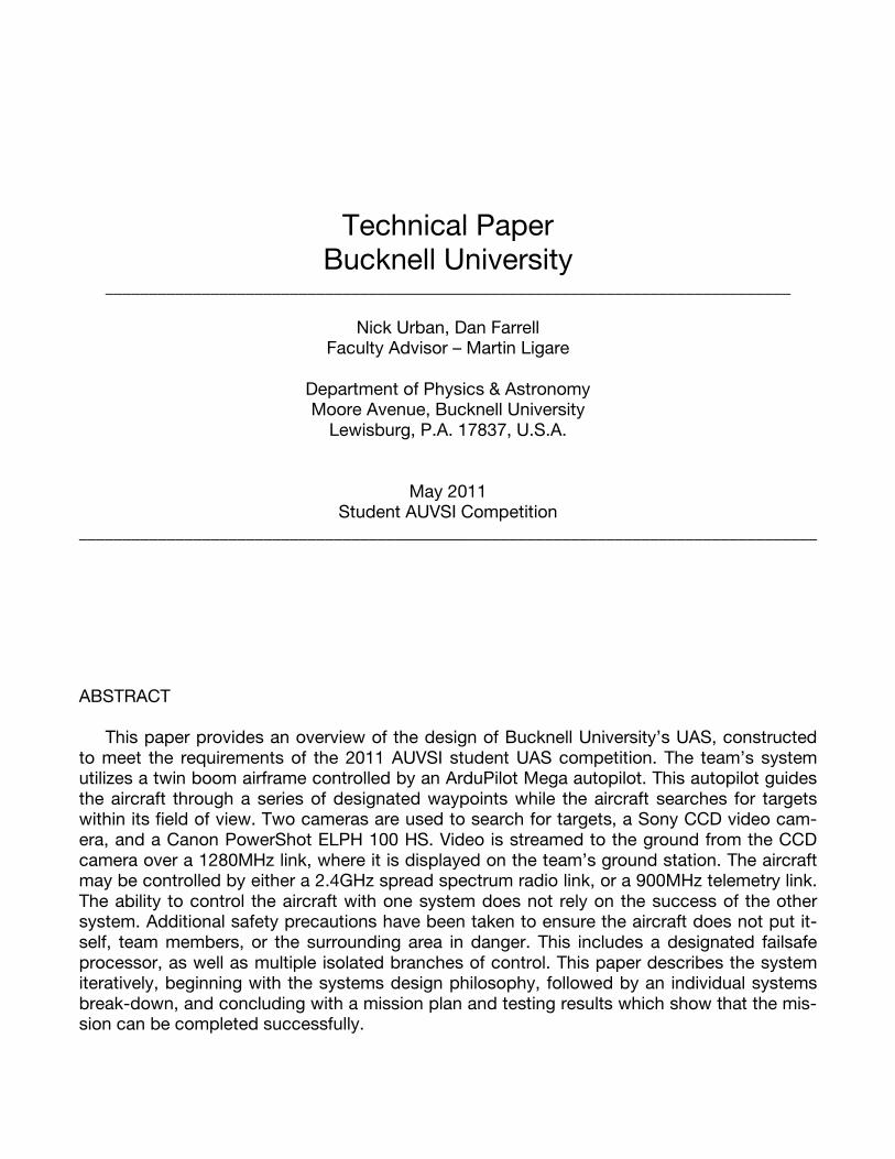
Figure 1: The Flying Bison airframe, shown in hatch access and pre-flight configurations
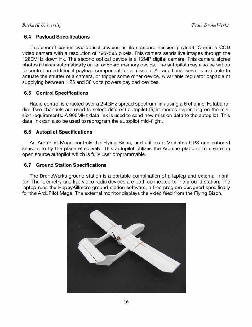
The DroneWerks Flying Bison is a pusher twin boom aircraft with a mid-placed wing. It has a single landing gear setup similar to a glider with tail and nose skids. This allows the Flying Bison to land on a large variety of terrain while also saving weight and increasing aerodynam-ic efficiency. Propulsion is provided by a 1000Kv brushless motor turning a 10x7 propeller. The Flying Bison has a wingspan of 1800mm and a length of 1155mm with an empty weight of 1200g. A large cargo hold of 80x80x400mm is easily accessed through a magnetic hatch, as shown in Figure 1. When loaded for the AUVSI student UAS competition, the Flying Bison has an AUW of 2700g.
2.1.2 Design Methodology
When mapping key performance characteristics during the drafting stage of airframe de-velopment, the team reached the conclusion the airframe should act as a vessel for the payl-oad rather than requiring modification to perform properly as a UAV. It was deemed neces-sary the airframe have reduced vibration, a large payload bay, a large lifting capacity, stable flight, little electromagnetic noise, and portability. The chosen design must also be affordable to construct and maintain, meaning it must be resilient to wear and crash damage.
Bucknell University Team DroneWerks
5
2.1.3 Engineering Decisions
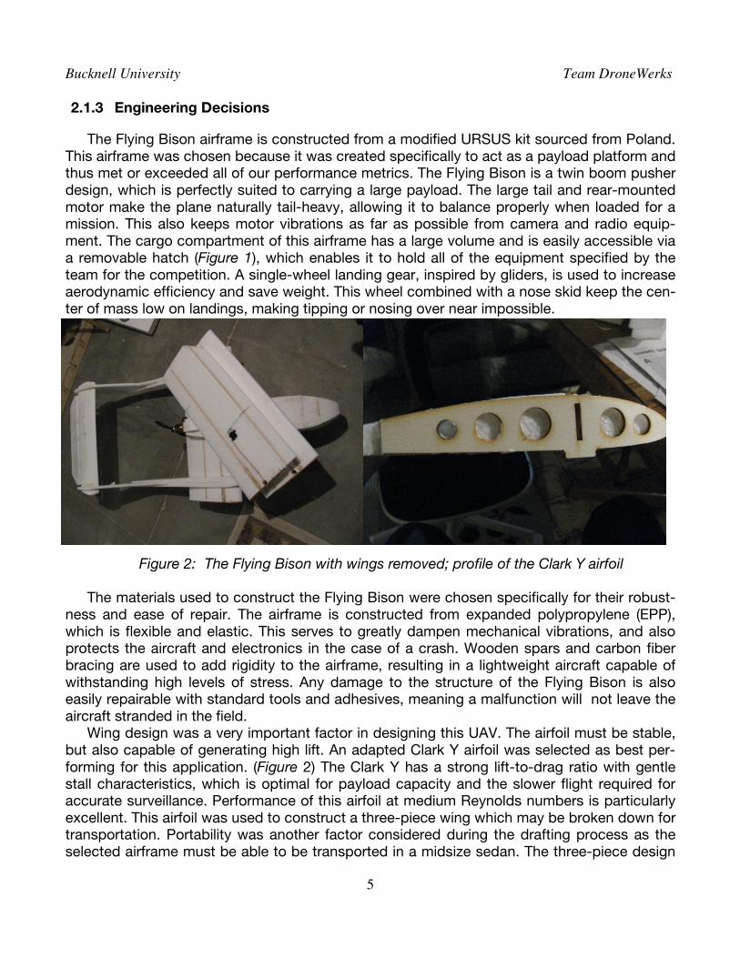
The Flying Bison airframe is constructed from a modified URSUS kit sourced from Poland. This airframe was chosen because it was created specifically to act as a payload platform and thus met or exceeded all of our performance metrics. The Flying Bison is a twin boom pusher design, which is perfectly suited to carrying a large payload. The large tail and rear-mounted motor make the plane naturally tail-heavy, allowing it to balance properly when loaded for a mission. This also keeps motor vibrations as far as possible from camera and radio equip-ment. The cargo compartment of this airframe has a large volume and is easily accessible via a removable hatch (Figure 1), which enables it to hold all of the equipment specified by the team for the competition. A single-wheel landing gear, inspired by gliders, is used to increase aerodynamic efficiency and save weight. This wheel combined with a nose skid keep the cen-ter of mass low on landings, making tipping or nosing over near impossible.
Figure 2: The Flying Bison with wings removed; profile of the Clark Y airfoil The materials used to construct the Flying Bison were chosen specifically for their robust-
ness and ease of repair. The airframe is constructed from expanded polypropylene (EPP), which is flexible and elastic. This serves to greatly dampen mechanical vibrations, and also protects the aircraft and electronics in the case of a crash. Wooden spars and carbon fiber bracing are used to add rigidity to the airframe, resulting in a lightweight aircraft capable of withstanding high levels of stress. Any damage to the structure of the Flying Bison is also easily repairable with standard tools and adhesives, meaning a malfunction will not leave the aircraft stranded in the field.
Wing design was a very important factor in designing this UAV. The airfoil must be stable, but also capable of generating high lift. An adapted Clark Y airfoil was selected as best per-
forming for this application. (Figure 2) The Clark Y has a strong lift-to-drag ratio with gentle stall characteristics, which is optimal for payload capacity and the slower flight required for accurate surveillance. Performance of this airfoil at medium Reynolds numbers is particularly excellent. This airfoil was used to construct a three-piece wing which may be broken down for transportation. Portability was another factor considered during the drafting process as the selected airframe must be able to be transported in a midsize sedan. The three-piece design
Bucknell University Team DroneWerks
6
also cleverly enhances the stability of the Flying Bison. The outer sections are angled up-wards, creating a self-righting dihedral without the need for special construction.
Electric power was found to be superior to combustion engines for the team’s chosen de-sign methodology. A single power source was found to be the most efficient and reduced any possible redundancies. One 4S 25C 5000mAh lithium polymer (lipo) battery is used to power the motor, radio, and payload equipment. A variable voltage regulator provides current to de-vices which do not run on the system’s native 14.8V.
Propulsion is provided by a 1000kV brushless motor which turns a 10x7 propeller. A pro-peller of a large diameter was chosen to maximize efficiency and endurance. The motor is re-gulated by a programmable 60A speed controller. This controller also adds an extra measure of safety when handling the aircraft before takeoff. The team has programmed this controller to prevent motor operation when the transmitter is powered up without the throttle stick in its lowest position. This prevents the aircraft from inadvertently taking off or rotating the propeller before all team members are at a safe distance.
2.2 Autopilot
Being one of the most crucial systems for completing this mission, the team specified several requirements for an autopilot which cannot be compromised. First, the autopilot must be able to be programmed and customized. To maximize mission performance, the team de-cided the autopilot must be tuned for the airframe in which it is installed. User programmabili-ty would also lend a robustness to autonomous control, allowing the team to program its own autonomous takeoff and landing routines.
Telemetry was also decided to be an absolute requirement. The ability to reprogram a mission in-flight was deemed important both as a safety precaution, as well as for increased modularity and ISR performance. Telemetry data is also necessary for ground station opera-tion, and must provide the competition mandated position and UAV status information.
The last vital requirement for the chosen autopilot is cost effectiveness. To save on oper-ating costs and stay within the confines of the team budget, the autopilot must be reasonably affordable and not represent an overly large fraction of the aircraft budget.
These requirements culled the list of commercially available autopilots to just a select few for the team to investigate further. Two possible paths presented themselves at this point. The team could develop and construct an autopilot in-house, or an open source system could be adapted to meet the team’s requirements. After an analysis of these options, it was found developing an autopilot required more resources and personnel than Team DroneWerks had available. Thus, an open source system was concluded to be the optimal solution.
2.2.1 ArduPilot Mega Autopilot
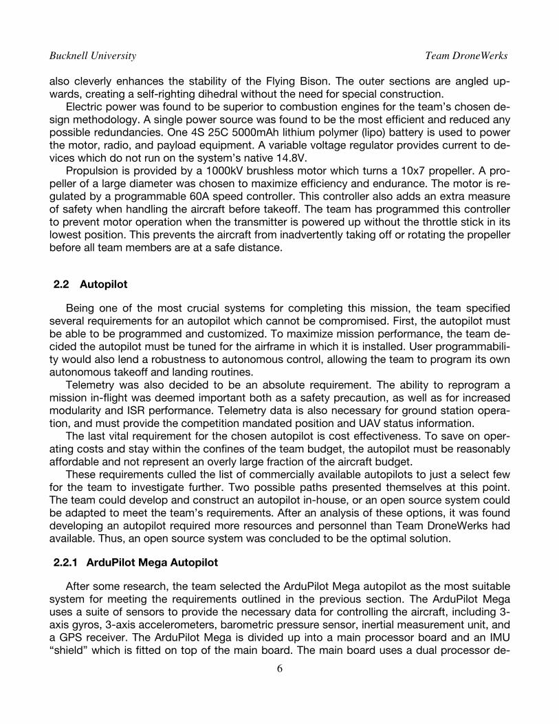
After some research, the team selected the ArduPilot Mega autopilot as the most suitable system for meeting the requirements outlined in the previous section. The ArduPilot Mega uses a suite of sensors to provide the necessary data for controlling the aircraft, including 3-axis gyros, 3-axis accelerometers, barometric pressure sensor, inertial measurement unit, and a GPS receiver. The ArduPilot Mega is divided up into a main processor board and an IMU “shield” which is fitted on top of the main board. The main board uses a dual processor de-
Bucknell University Team DroneWerks
7
sign to generate 32 MIPS of onboard power. Memory includes 128k flash program memory, 8k SRAM, and 4k EEPROM. This amount of memory is enough for the ArduPilot Mega to store over one thousand 3D waypoints, in addition to user-programmed routines. The IMU shield carries the sensor array, data logger, and interface ports for auxiliary devices and pro-gramming.
The ArduPilot Mega also has several important safety features to ensure the Flying Bison operates correctly. A built-in hardware failsafe uses a separate circuit to transfer control be-tween the autopilot and the RC system. This failsafe also has the ability to reboot the main processor mid-flight. This system is responsible for executing the team’s radio loss routine. Its isolation and separation from software ensures at least one method of controlling the air-craft is maintained should a failure occur.
This autopilot system acts as the central node of the Flying Bison’s wiring harness, allow-ing all aspects of the aircraft’s performance to be monitored and controlled during a mission. Combined with programmability of the integrated Atmega processor, the ArduPilot Mega is capable of taking off, landing, and navigating autonomously.
Figure 3: The ArduPilot Mega autopilot main board(red) and IMU shield(blue) [1]
2.2.2 Ground Station
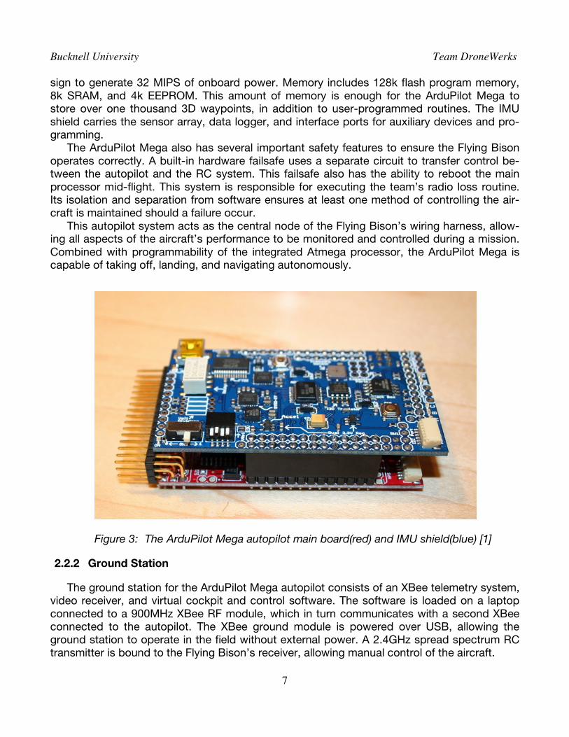
The ground station for the ArduPilot Mega autopilot consists of an XBee telemetry system, video receiver, and virtual cockpit and control software. The software is loaded on a laptop connected to a 900MHz XBee RF module, which in turn communicates with a second XBee connected to the autopilot. The XBee ground module is powered over USB, allowing the ground station to operate in the field without external power. A 2.4GHz spread spectrum RC transmitter is bound to the Flying Bison’s receiver, allowing manual control of the aircraft.
Bucknell University Team DroneWerks
8
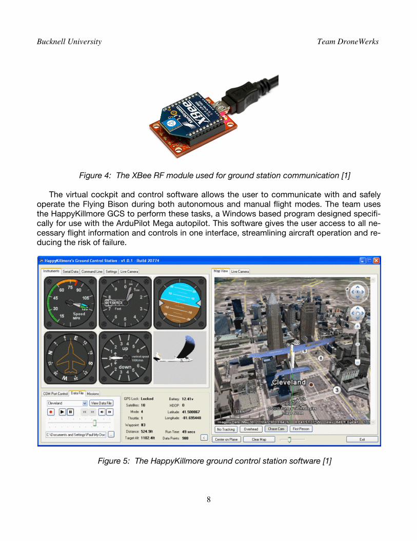
Figure 4: The XBee RF module used for ground station communication [1] The virtual cockpit and control software allows the user to communicate with and safely
operate the Flying Bison during both autonomous and manual flight modes. The team uses the HappyKillmore GCS to perform these tasks, a Windows based program designed specifi-cally for use with the ArduPilot Mega autopilot. This software gives the user access to all ne-cessary flight information and controls in one interface, streamlining aircraft operation and re-ducing the risk of failure.
Figure 5: The HappyKillmore ground control station software [1]
Bucknell University Team DroneWerks
9
A command line interface is used to update waypoints and aircraft settings mid-flight. All aspects of the autopilot can be reprogrammed through this interface. This allows the user to make manual mission updates, including altering waypoint parameters and landing routines, while the aircraft is operating autonomously. Trim and control loop adjustments may also be made as necessary to adjust to dynamic flight conditions.
A full graphical user interface presents all aircraft data to the system operator. A range of flight instruments display aircraft speed, heading, altitude, and other information. Battery ca-pacity, waypoint data, and related systems information is shown in a control window. Serial data output is also available to monitor during the flight. A moving overhead map display shows the UAV’s position geographically, along with the flight path and mission waypoints.
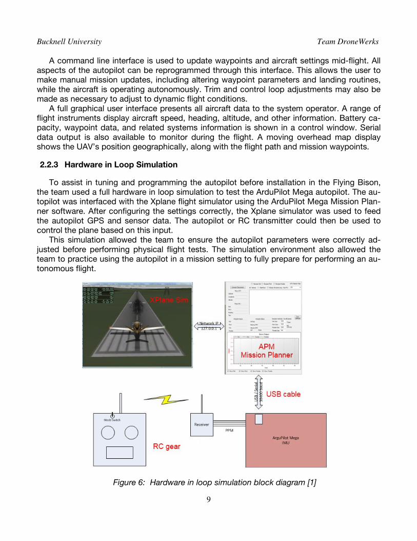
2.2.3 Hardware in Loop Simulation
To assist in tuning and programming the autopilot before installation in the Flying Bison, the team used a full hardware in loop simulation to test the ArduPilot Mega autopilot. The au-topilot was interfaced with the Xplane flight simulator using the ArduPilot Mega Mission Plan-ner software. After configuring the settings correctly, the Xplane simulator was used to feed the autopilot GPS and sensor data. The autopilot or RC transmitter could then be used to control the plane based on this input.
This simulation allowed the team to ensure the autopilot parameters were correctly ad-justed before performing physical flight tests. The simulation environment also allowed the team to practice using the autopilot in a mission setting to fully prepare for performing an au-tonomous flight.
Figure 6: Hardware in loop simulation block diagram [1]
Bucknell University Team DroneWerks
10
3 PAYLOADS DESIGN AND OVERVIEW
3.1 Overview
One of the primary competition mission objectives is to locate targets and identify their unique attributes. Optical characteristics include background color, alphanumeric color, al-phanumeric identification, and target orientation. The aircraft payload must be able to identify and obtain imagery of these features. After reviewing the mission specifications and outlining payload requirements, the team came to the conclusion a dual camera system was the most efficient payload for the Flying Bison. The team wanted the ability to receive live imagery from the UAV during the flight. This would grant the aircraft actionable intelligence capability, and also fulfill a bonus mission re-quirement. To ensure accurate target detection, the team also demanded the optical payload have the highest resolution and image quality possible. These goals are met by two separate modular imagery systems.
3.2 Live Camera
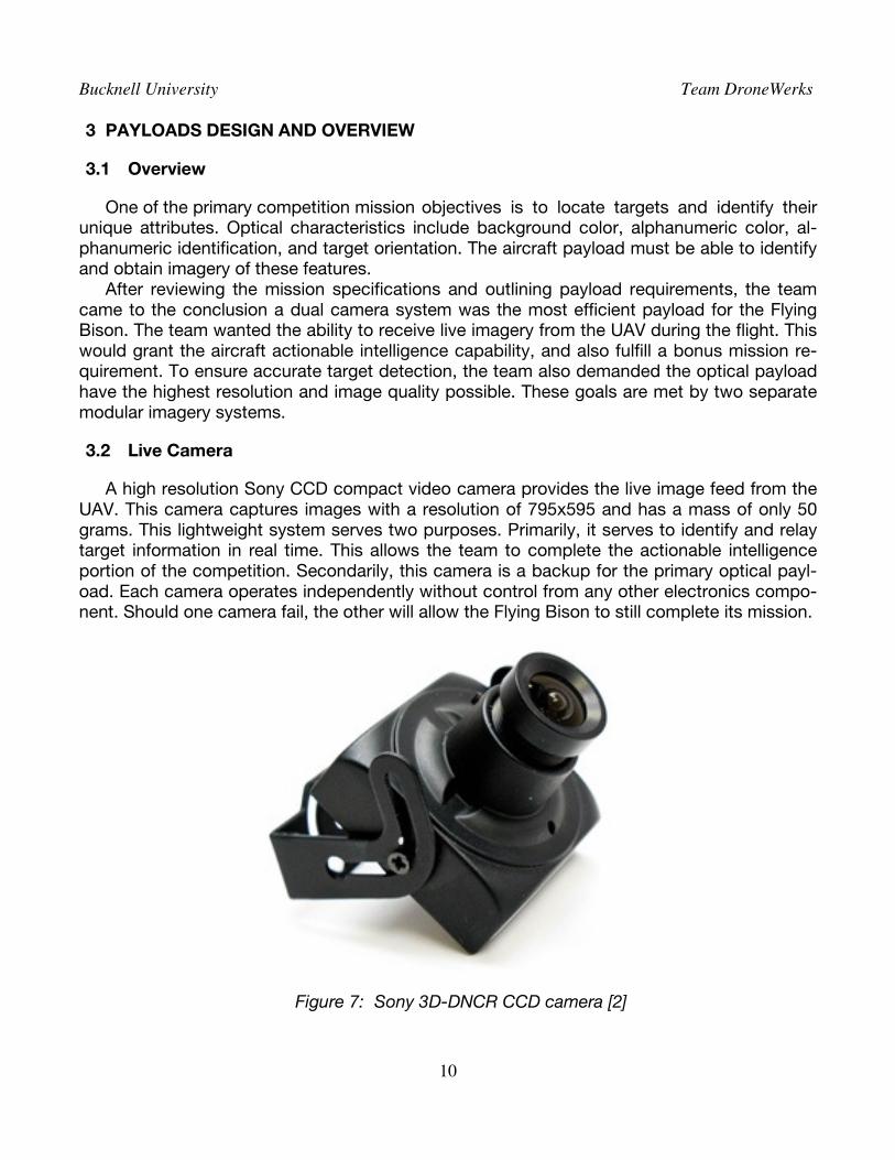
A high resolution Sony CCD compact video camera provides the live image feed from the UAV. This camera captures images with a resolution of 795x595 and has a mass of only 50 grams. This lightweight system serves two purposes. Primarily, it serves to identify and relay target information in real time. This allows the team to complete the actionable intelligence portion of the competition. Secondarily, this camera is a backup for the primary optical payl-oad. Each camera operates independently without control from any other electronics compo-nent. Should one camera fail, the other will allow the Flying Bison to still complete its mission.
Figure 7: Sony 3D-DNCR CCD camera [2]
Bucknell University Team DroneWerks
11
3.3 Static Camera
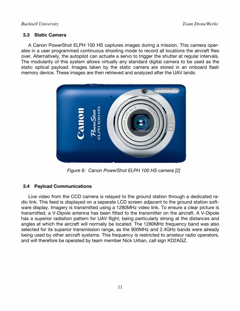
A Canon PowerShot ELPH 100 HS captures images during a mission. This camera oper-ates in a user programmed continuous shooting mode to record all locations the aircraft flies over. Alternatively, the autopilot can actuate a servo to trigger the shutter at regular intervals. The modularity of this system allows virtually any standard digital camera to be used as the static optical payload. Images taken by the static camera are stored in an onboard flash memory device. These images are then retrieved and analyzed after the UAV lands.
Figure 8: Canon PowerShot ELPH 100 HS camera [2]
3.4 Payload Communications
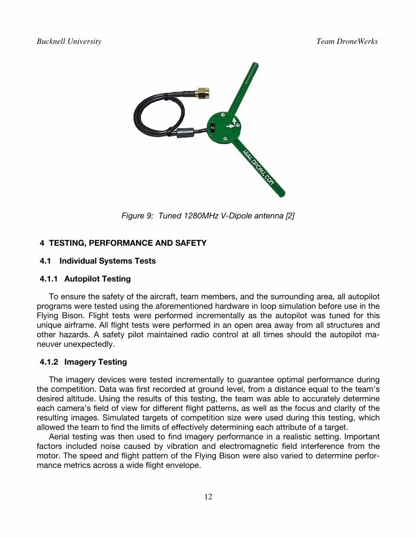
Live video from the CCD camera is relayed to the ground station through a dedicated ra-dio link. This feed is displayed on a separate LCD screen adjacent to the ground station soft-ware display. Imagery is transmitted using a 1280MHz video link. To ensure a clear picture is transmitted, a V-Dipole antenna has been fitted to the transmitter on the aircraft. A V-Dipole has a superior radiation pattern for UAV flight, being particularly strong at the distances and angles at which the aircraft will normally be located. The 1280MHz frequency band was also selected for its superior transmission range, as the 900MHz and 2.4GHz bands were already being used by other aircraft systems. This frequency is restricted to amateur radio operators, and will therefore be operated by team member Nick Urban, call sign KD2AGZ.
Bucknell University Team DroneWerks
12
Figure 9: Tuned 1280MHz V-Dipole antenna [2]
4 TESTING, PERFORMANCE AND SAFETY
4.1 Individual Systems Tests
4.1.1 Autopilot Testing
To ensure the safety of the aircraft, team members, and the surrounding area, all autopilot programs were tested using the aforementioned hardware in loop simulation before use in the Flying Bison. Flight tests were performed incrementally as the autopilot was tuned for this unique airframe. All flight tests were performed in an open area away from all structures and other hazards. A safety pilot maintained radio control at all times should the autopilot ma-neuver unexpectedly.
4.1.2 Imagery Testing
The imagery devices were tested incrementally to guarantee optimal performance during the competition. Data was first recorded at ground level, from a distance equal to the team’s desired altitude. Using the results of this testing, the team was able to accurately determine each camera’s field of view for different flight patterns, as well as the focus and clarity of the resulting images. Simulated targets of competition size were used during this testing, which allowed the team to find the limits of effectively determining each attribute of a target.
Aerial testing was then used to find imagery performance in a realistic setting. Important factors included noise caused by vibration and electromagnetic field interference from the motor. The speed and flight pattern of the Flying Bison were also varied to determine perfor-mance metrics across a wide flight envelope.
Bucknell University Team DroneWerks
13
4.1.3 Airframe Testing
The team constructed only one airframe for this year’s competition, and was therefore un-able to perform more extreme structural and flight tests. Testing for the Flying Bison began with flight trials under manual control. At this time autopilot hardware, payload devices, and other supplemental electronics were not installed. The aircraft was flown only with the core radio control components, power plant, and servos. This level of testing was used to ensure the aircraft was stable and operating correctly before adding other devices which would complicate the control structure. Manual flight was also required to correctly trim and adjust the airframe for maximum performance.
Airframe testing continued into iterative augmented autonomous flight. The ArduPilot Mega has several flight modes outside of programmed autonomous missions. These modes include return to launch, stabilize, and fly by wire. Return to launch directs the aircraft to the location it took off from, above which it will then circle. Stabilize will level the aircraft when the sticks are let go. Fly by wire will hold the roll and pitch specified by the control sticks. Switch-ing between modes and observing aircraft performance is necessary to adjust certain para-meters in the autopilot control software.
Few changes were found to be necessary for the Flying Bison to fly within the appropriate performance metrics. The elevator hinges were switched to pinned nylon hinges from EPP hinges to reduce strain on the elevator servo. Some parts of the fuselage were sanded or trimmed to increase aerodynamic efficiency. Additional bracing was added to support the cargo bay.
4.1.4 Communications Testing
Each radio system was first tested individually to determine maximum effective range and antenna radiation pattern. Simulated sensor input was provided to each transmitter, and the resulting feed at the receiver was monitored. Testing was performed while maintaining line of sight, as well as in an environment with obstacles to radio waves.
Testing was continued to operating all devices simultaneously and in close quarters. This test was performed to look for possible interference caused by or to other radio systems. Lastly, communications equipment was tested after being installed as a part of the completed UAS. This examined the effect of airframe vibrations, transmission barriers, and antenna loca-tion.
4.2 Full Systems Tests
Following the completion of all subsystem tests, full systems tests were performed to en-sure all components could perform correctly together in the airframe. Full systems tests were performed locally in Lewisburg, PA. Farm fields were used for their large space and clear line of sight, after permission was granted by the land owner.
These trials tested all aspects and features of the Flying Bison UAV. Full simulated auto-nomous missions were performed, and the resulting flight path and airframe performance were monitored. To reach a state of full competition readiness, the team plans on completing simulated competition missions to not only prepare the UAS, but also train team members.
Bucknell University Team DroneWerks
14
5 MISSION PLAN
To maximize the performance of DroneWerks and the Flying Bison, the team has formu-lated a strategy based on the abilities of its personnel and equipment. The UAS has also been designed to perform certain mission and bonus tasks, and as such the team will aim to utilize these features as much as possible. The mission plan intends first to ensure the safety of the team, aircraft, and surrounding area. This plan is also designed to earn the maximum amount of points using the available equipment with consistent and repeatable results.
5.1 Takeoff
The mission plan begins by launching the plane autonomously. Due to the single wheel undercarriage, the aircraft must be hand launched. The automatic takeoff routine will then guide the plane on a steady climb until the appropriate altitude is reached. During this time, the safety pilot will stand by ready to disengage automatic takeoff and finish the climbout manually should the aircraft act in an unsafe manner.
5.2 Target Area
The Flying Bison will enter the target area through the designated safe corridor. From here until the end of the mission, the aircraft will be operating autonomously. The team will rely on the static camera system to capture all targets. Upon entering the target area, the aircraft will enter a preprogrammed search pattern. The live camera feed will be used as a spotter to en-sure all targets are being captured. If necessary, the search pattern can be adjusted mid-flight to obtain imagery of missed target. At this point the team ground station operator will be observing the flight data sent over the telemetry link. This includes the location of the aircraft relative to the search zone bounda-ries. A spotter will monitor the live feed for a clear target. The attributes and image of this tar-get will be turned in as actionable intelligence.
5.3 In-flight Retasking
Upon the completion of the predefined search area, the team will then send a new search area to the autopilot. This area will be investigated for “pop-up” targets. The live camera will again be used as a spotter. If the team determines from the live feed that all pop-up targets have been adequately captured, or if the time the team has allotted for the flight portion of the mission runs out, the search will be ended and the aircraft returned to base.
5.4 Landing
The aircraft will be instructed to execute a landing protocol upon the completion of the target search. At this time the safety pilot will again be attentive and prepared to step in should the aircraft approach the landing area in an unsafe manner. Otherwise, the aircraft will perform a gentle landing maneuver, touching down first on the single wheel and then the tail skids. After coming to a safe stop, the autonomous mode will be disengaged and the engine cut.
Bucknell University Team DroneWerks
15
5.5 Target Processing
The onboard memory module will be retrieved from the static optical payload system. The ground station will then be used to analyze the imagery and determine the attributes of each photographed target. This information will then be entered into a target data sheet and stored to a USB flash drive, as per the competition rules.
6 SPECIFICATIONS
During the development of the DroneWerks UAS, many initial design and performance pa-rameters were changed or augmented. The final specifications represent the current capabili-ties of the Flying Bison aircraft. The team aimed to create a system which could complete the competition mission efficiently and effectively. This system was also designed to be flexible, as the Flying Bison will be performing GIS mapping research missions for the duration of the summer following the competition.
6.1 Radio Performance
The Flying Bison operates on three frequency bands. Maximum operating range is 2 miles under radio control.
900MHz : Autopilot Telemetry 1280MHz : Imagery Receipt 2.4GHz : Aircraft Control
6.2 Flight Performance
The current limiting factor for time aloft is the flight battery. The aircraft carries one 5000mAh 4S 25C Lithium Polymer battery pack. This grants the aircraft a maximum flight du-ration of 50 minutes. A current sensor is used to monitor live power consumption. Flight time may be increased with an additional battery pack should this prove necessary for a mission. Additional propellers with differing diameter and pitch may also increase flight performance depending on the desired aircraft abilities.
6.3 Airframe Specifications
The Flying Bison is constructed from crash-resistant EPP foam, with wood and carbon fi-ber reinforcing spars.
Wingspan : 1800mm Length : 1155mm Wing Area : 43.2dm2
MEW : 1200g AUW : 2700g
Bucknell University Team DroneWerks
16
6.4 Payload Specifications
This aircraft carries two optical devices as its standard mission payload. One is a CCD video camera with a resolution of 795x595 pixels. This camera sends live images through the 1280MHz downlink. The second optical device is a 12MP digital camera. This camera stores photos it takes automatically on an onboard memory device. The autopilot may also be set up to control an additional payload component for a mission. An additional servo is available to actuate the shutter of a camera, or trigger some other device. A variable regulator capable of supplying between 1.25 and 30 volts powers payload devices.
6.5 Control Specifications
Radio control is enacted over a 2.4GHz spread spectrum link using a 6 channel Futaba ra-dio. Two channels are used to select different autopilot flight modes depending on the mis-sion requirements. A 900MHz data link is used to send new mission data to the autopilot. This data link can also be used to reprogram the autopilot mid-flight.
6.6 Autopilot Specifications
An ArduPilot Mega controls the Flying Bison, and utilizes a Mediatek GPS and onboard sensors to fly the plane effectively. This autopilot utilizes the Arduino platform to create an open source autopilot which is fully user programmable.
6.7 Ground Station Specifications
The DroneWerks ground station is a portable combination of a laptop and external moni-tor. The telemetry and live video radio devices are both connected to the ground station. The laptop runs the HappyKillmore ground station software, a free program designed specifically for the ArduPilot Mega. The external monitor displays the video feed from the Flying Bison.
Bucknell University Team DroneWerks
17
7 REFERENCES
[1] http://code.google.com/p/ardupilot-mega/
[2] http://diydrones.com/