technical memorandum tm-navfac-exwc-ev-1601 green …
TRANSCRIPT
Distribution Statement A: Approved for Public Release; Distribution is unlimited.
TECHNICAL MEMORANDUM TM-NAVFAC-EXWC-EV-1601
GREEN AND SUSTAINABLE REMEDIATION BEST
MANAGEMENT PRACTICES
By
SEPTEMBER 2016
Deepti Nair, Battelle Samuel Moore, Battelle

This page intentionally blank.
iii
REPORT DOCUMENTATION PAGE FORM APPROVED OMB NO. 0704-0188
Public reporting burden for this collection of information is estimated to average 1 hour per response, including the time for reviewing instructions, searching existing data sources, gathering and maintaining the data needed, and completing and reviewing this collection of information. Send comments regarding this burden estimate or any other aspect of this collection of information, including suggestions for reducing this burden to Department of Defense, Washington Headquarters Services, Directorate for Information Operations and Reports (0704-1. REPORT DATE (DD-MM-YYYY) 2. REPORT TYPE 3. DATES COVERED (From – To)
09-07-2016 Technical Memorandum September 2016 -
4. TITLE AND SUBTITLE 5a. CONTRACT NUMBER
GREEN AND SUSTAINABLE REMEDIATION BEST MANAGEMENT PRACTICES
N62583-11-D-0515
5b. GRANT NUMBER
n/a 5c. PROGRAM ELEMENT NUMBER
n/a 6. AUTHOR(S) 5d. PROJECT NUMBER
Deepti Nair, Battelle Samuel Moore, Battelle
n/a
5e. TASK NUMBER
Task Order 86 5f. WORK UNIT NUMBER
n/a 7. PERFORMING ORGANIZATION NAME(S) AND ADDRESS(ES) 8. PERFORMING ORGANIZATION REPORT NUMBER
Battelle505 King AvenueColumbus OH 43201
9. SPONSORING / MONITORING AGENCY NAME(S) AND ADDRESS(ES) 10. SPONSOR / MONITOR’S ACRONYM(S)
NAVFAX EXWC 1000 23rd Ave. Port Hueneme, CA, 93043
NAVFAC EXWC
11. SPONSOR / MONITOR’S REPORT NUMBER(S)
TM-NAVFAC-EXWC-EV-1601
12. DISTRIBUTION / AVAILABILITY STATEMENT
Distribution Statement A: Approved for public release; distribution is unlimited.
13. SUPPLEMENTARY NOTES
14. ABSTRACT
Green and sustainable remediation (GSR) emphasizes and promotes the consideration of sustainability throughout the entire remedial process: site characterization, remedy selection, remedial design and construction, remedial action operations, and long-term monitoring. An important aspect of applying GSR is the use of best management practices (BMPs). The purpose of this technical memorandum is to succinctly summarize GSR BMPs for commonly used remediation technologies in order to further promote their adoption. The technologies covered include air sparging, biosparging, soil vapor extraction (SVE), enhanced reductive dechlorination (ERD), in situ chemical oxidation (ISCO), thermal treatment, groundwater extraction and treatment (GWET), and excavation.
15. SUBJECT TERMS
16. SECURITY CLASSIFICATION OF: 17. LIMITATIONOF ABSTRACT
18. NUMBER OF
19a. NAME OF RESPONSIBLE PERSON
Amy Hawkins a. REPORT b. ABSTRACT c. THIS PAGE
U 22U U U19b. TELEPHONE NUMBER (include area code)
(805) 982-4890Standard Form 298 (Rev. 8-98) Prescribed by ANSI Std. Z39.18
U

iv
This page intentionally blank.
v
TABLE OF CONTENTS
1.0 INTRODUCTION ............................................................................................................... 1
2.0 GSR AND BMP RESOURCES .......................................................................................... 2 2.1 POLICY FOR OPTIMIZING REMEDIAL AND REMOVAL ACTIONS AT ALL
DON ENVIRONMENTAL RESTORATION PROGRAM SITES ................................ 2 2.2 DON GUIDANCE ON GSR ............................................................................................ 2 2.3 DESIGN CONSIDERATIONS FOR ERD AND ISCO .................................................. 2 2.4 EPA GREEN REMEDIATION BMP FACT SHEETS ................................................... 2 2.5 ARMY GREEN AND SUSTAINABLE REMEDIATION BMP ................................... 3 2.6 ASTM STANDARD GUIDE FOR GREENER CLEANUPS ......................................... 3 2.7 ASTM GUIDE FOR INTEGRATING SUSTAINABLE OBJECTIVES INTO
CLEANUP ....................................................................................................................... 3
3.0 BEST MANAGEMENT PRACTICES ............................................................................... 4
4.0 CASE STUDIES .................................................................................................................. 9 4.1 SITES 3, 4A, AND 5, NAS PATUXENT RIVER........................................................... 9 4.2 SITE LF05, JOINT BASE PEARL HARBOR-HICKAM, HAWAII ........................... 12
5.0 REFERENCES .................................................................................................................. 14
LIST OF FIGURES
Figure 1. NAS Patuxent River Site 5 NTRCA for Debris Removal .............................................. 9 Figure 2. Pilot-Scale Bioreactor Solar Panel at Site LF05 JBPHH, HI ....................................... 13
LIST OF TABLES
Table 1. Summary of BMPs for Remedial Technologies .............................................................................. 5 Table 2. NAS Patuxent River GSR BMP Cost Savings .............................................................. 11 Table 3. NAS Patuxent River GSR BMP Footprint Reductions ................................................. 11 Table 4. Bioreactor GSR BMP Footprint Reductions ................................................................. 12
vi
ACRONYMS AND ABBREVIATIONS
BIP blown-in-place BMP best management practice
CERCLA Comprehensive Environmental Response, Compensation, and Liability Act COC chemical of concern
DD Decision Document DERP Defense Environmental Restoration Program DMF diesel multistage filter DOC diesel oxidation catalyst DoD Department of Defense DON Department of the Navy DPF diesel particulate filter DPT direct push technology
EO Executive Order EPA U.S. Environmental Protection Agency ER Environmental Restoration ERD enhanced reductive dechlorination ERH electrical resistive heating
FY fiscal year
GHG greenhouse gas GSR green and sustainable remediation GWET groundwater extraction and treatment
ISCO in situ chemical oxidation
JBPHH Joint Base Pearl Harbor-Hickam
LIF Laser Induced Fluorescence LUC land use control
MBGC Mamala Bay Golf Course MDAS material documented as safe MEC munitions and explosives of concern
NAS Naval Air Station NTCRA Non-time critical removal action
OSWER Office of Solid Waste and Emergency Response
vii
RACG remedial action cleanup goal RCRA Resource Conservation and Recovery Act ROD Record of Decision RPM Remedial Project Manager
SCR selective catalytic reduction SEE steam enhanced extraction SVE soil vapor extraction
TCE trichloroethene TCH thermal conductive heating TCRA time critical removal action
VC vinyl chloride
1
1.0 INTRODUCTION
Green and sustainable remediation (GSR) emphasizes and promotes the consideration of sustainability throughout the entire remedial process: site characterization, remedy selection, remedial design and construction, remedial action operations, and long-term monitoring. An important aspect of applying GSR is the use of best management practices (BMPs). The purpose of this technical memorandum is to succinctly summarize GSR BMPs for commonly used remediation technologies in order to further promote their adoption. The technologies covered include air sparging, biosparging, soil vapor extraction (SVE), enhanced reductive dechlorination (ERD), in situ chemical oxidation (ISCO), thermal treatment, groundwater extraction and treatment (GWET), and excavation.
Executive Order (EO) 13693 (Federal Facilities Environmental Stewardship & Compliance Assistance Center, 2015) has replaced two older EOs (13423 and 13514) as the primary driver for GSR practices. The new EO requires each Federal agency to establish its own greenhouse gas (GHG) emission reduction goals through fiscal year (FY) 2025. The new EO also requires planning for Federal sustainability in the next decade by the use of clean energy sources, reduction in total energy use, increase in hybrid vehicles, and reduction in water intensity. Many of the principles outlined in EO 13693 can be applied to improve the cost-effectiveness and sustainability of Environmental Restoration (ER) projects led by the Federal government.
The Defense Environmental Restoration Program (DERP), as documented in the DERP Manual, provides guidance for conducting environmental remediation such that it meets the requirements of the Comprehensive Environmental Response, Compensation, and Liability Act (CERCLA); the Resource Conservation and Recovery Act (RCRA); and other Federal, state, and local requirements (Department of Defense [DoD], 2012). The 2012 DERP Manual also instructs DoD components to consider and implement GSR opportunities when feasible and ensure the use of GSR remediation practices where practicable based on economic and social benefits (DoD, 2012a). In addition, the Department of the Navy (DON) has produced policy and guidance for conducting GSR, including Policy for Optimizing Remedial and Removal Actions at all DON Environmental Restoration Program Sites (DON, 2012) and the Department of the Navy Guidance on Green and Sustainable Remediation (NAVFAC, 2012), which requires GSR to be considered throughout the entire remediation process.
Recently, ASTM issued new guidance for evaluating and implementing activities to reduce the environmental footprint of a cleanup project. The ASTM Standard Guide for Greener Cleanups (E2893-13e) is of growing importance in the ER community (ASTM, 2015). Both the new EO and new ASTM standard are drivers in continuing the promotion of sustainability and the minimization of the environmental footprint through reduced demands on natural resources and decreased emissions to the environment.
2
2.0 GSR AND BMP RESOURCES
Several resources are available for Remedial Project Managers (RPMs) to consult to develop site-specific BMPs for implementing GSR practices. This technical memorandum provides an additional tool for GSR implementation, through tables of BMPs applicable to common remedial technologies. This section documents current Navy policies and guidance in applying GSR. Additionally, it provides an introduction to remedial design documents produced by the Navy, as well as the BMP fact sheets produced by the U.S. Environmental Protection Agency (EPA) for various remedial technologies, which serve as references for the BMPs outlined here. Lastly, it provides a brief overview of the intent of the ASTM Standard Guide for Greener Cleanups and the ASTM Guide for Integrating Sustainable Objectives into Cleanup (i.e., documentation of environmental, community, and economic factors), which serve as external industry-accepted resources for the development of GSR BMPs.
2.1 POLICY FOR OPTIMIZING REMEDIAL AND REMOVAL ACTIONS AT ALL DON ENVIRONMENTAL RESTORATION PROGRAM SITES
This policy requires that opportunities to improve performance and to evaluate GSR practices shall be considered and implemented throughout all phases of remediation regardless of the regulatory framework under which cleanup may occur (DON, 2012). It outlines how optimization and GSR considerations must be considered during site characterization, remedy evaluation and selection, design and construction, operation, and long-term management; tracking and reporting of optimization and GSR application; and documenting and reporting response complete and site closeout.
2.2 DON GUIDANCE ON GSR
This guidance document provides an overview of GSR concepts as they pertain to the Navy’s ER Program (NAVFAC, 2012). It describes GSR metrics; metric calculation methods and tools; GSR considerations during site characterization, remedy selection, remedial design and construction, and remedial action operation and long-term monitoring; and general footprint reduction methods. The document can be used as a good resource to obtain an overall familiarity with GSR concepts appropriate to each phase of remediation.
2.3 DESIGN CONSIDERATIONS FOR ERD AND ISCO
ERD and ISCO are among the most commonly used in situ remedial technologies. Two Navy guidance documents were produced to provide a framework for design submittals for remedial systems using ERD and ISCO technologies, respectively. These documents summarize technology-specific GSR BMPs, tips for appropriate quality assurance and quality control measures, and listings of available standards and references.
2.4 EPA GREEN REMEDIATION BMP FACT SHEETS
EPA has produced fact sheets for GSR BMPs by technology for excavation and surface restoration, pump and treat technologies, bioremediation, SVE and air sparging, and implementing in situ thermal technologies (in addition to an overview fact sheet). These fact sheets provide an overview of each technology and considerations for their design, construction,
3
operation, and monitoring. The EPA’s GSR BMP factsheets can be linked to from: https://clu-in.org/greenremediation/.
2.5 ARMY GREEN AND SUSTAINABLE REMEDIATION BMP
The Army conducted a study that followed the process of considering, incorporating, documenting, and evaluating the benefits of GSR practices on Army sites. The BMPs identified were produced in an Excel format to provide for efficient documentation of their evaluation and implementation. The report can be viewed for more detailed information (Army, 2012).
2.6 ASTM STANDARD GUIDE FOR GREENER CLEANUPS
The ASTM Standard Guide for Greener Cleanups (E2893-13e) was developed to encourage property owners, regulatory agencies, responsible parties, developers and communities to voluntarily use greener practices for contaminated site cleanup. It is intended to complement regulatory and voluntary cleanup programs and accommodate each phase of a cleanup. Several EPA representatives were involved in the development of the standard. The EPA's Office of Solid Waste and Emergency Response (OSWER), EPA’s regional offices and state agencies developed a framework outlining the desired outcomes of a potential standard for greener cleanups that reflected EPA's Principles for Greener Cleanups (2009).
The ASTM Standard Guide for Greener Cleanups includes the following:
A protocol to identify, prioritize, select, implement and report on the use of GSR BMPs to reduce the environmental footprint of cleanup activities;
More than 160 greener cleanup BMPs linked to the core elements of greener cleanup technologies;
Guidelines to quantify the environmental footprint of cleanup activities; and
A reporting structure to promote public dissemination of information relating to the decision-making process across the five core elements.
2.7 ASTM GUIDE FOR INTEGRATING SUSTAINABLE OBJECTIVES INTO CLEANUP
The ASTM Guide for Integrating Sustainable Objectives into Cleanup (E2876-13) integrates social and economic aspects along with the environmental objectives. It encourages the use of sustainable aspects (environmental, economic, and social) within cleanup projects in incremental steps. The guide provides a framework that helps the user identify and incorporate sustainable BMPs into site cleanup (both assessment and remediation), and enables the measurement of BMPs during the cleanup process.
4
3.0 BEST MANAGEMENT PRACTICES
Table 1 provides a summary table of GSR BMPs that can be used as a template to incorporate into remedy selection, remedial designs and operating remedies for six commonly applied remedial technologies. Table 1 is organized in columns for each given remedial technology (across the top) including: air sparging, biosparging, SVE, ERD, ISCO, thermal treatment, GWET, and excavation. The rows in the table are divided into the following categories that cover key sustainability considerations and project elements as noted below.
equipment use and buildings, material minimization, waste minimization, energy minimization, project planning, monitoring program, site restoration, renewable energy, alternate fuel, transportation and emission control, and water conservation.
BMPs are then listed and described for each category defined above and indexed to the applicable remedial technologies. Relevant BMPs are marked with a “star” symbol denoting that the given BMP is applicable to the given technology. BMPs can be selected and adapted from this table as appropriate to the site-specific conditions and remedial technology selected.
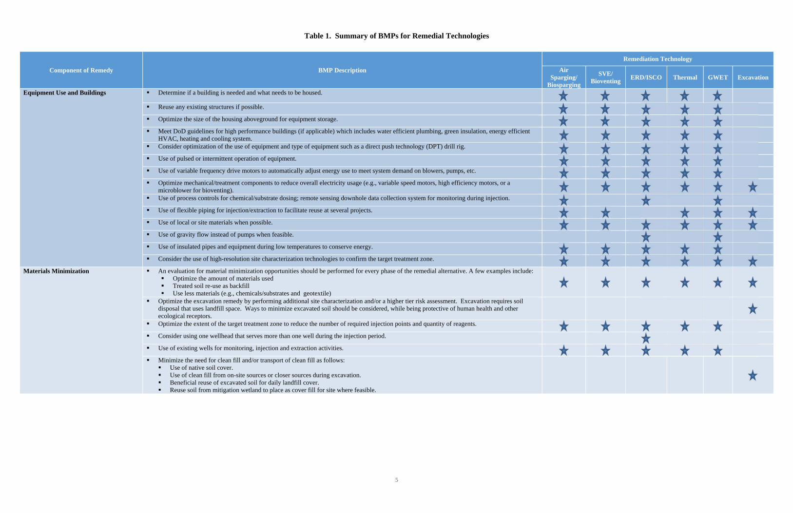
Table 1. Summary of BMPs for Remedial Technologies
5
Component of Remedy BMP Description
Remediation Technology
Air Sparging/
Biosparging
SVE/ Bioventing
ERD/ISCO Thermal GWET Excavation
Equipment Use and Buildings Determine if a building is needed and what needs to be housed.
Reuse any existing structures if possible.
Optimize the size of the housing aboveground for equipment storage.
Meet DoD guidelines for high performance buildings (if applicable) which includes water efficient plumbing, green insulation, energy efficient HVAC, heating and cooling system.
Consider optimization of the use of equipment and type of equipment such as a direct push technology (DPT) drill rig.
Use of pulsed or intermittent operation of equipment.
Use of variable frequency drive motors to automatically adjust energy use to meet system demand on blowers, pumps, etc.
Optimize mechanical/treatment components to reduce overall electricity usage (e.g., variable speed motors, high efficiency motors, or a microblower for bioventing).
Use of process controls for chemical/substrate dosing; remote sensing downhole data collection system for monitoring during injection.
Use of flexible piping for injection/extraction to facilitate reuse at several projects.
Use of local or site materials when possible.
Use of gravity flow instead of pumps when feasible.
Use of insulated pipes and equipment during low temperatures to conserve energy.
Consider the use of high-resolution site characterization technologies to confirm the target treatment zone.
Materials Minimization An evaluation for material minimization opportunities should be performed for every phase of the remedial alternative. A few examples include: Optimize the amount of materials used Treated soil re-use as backfill Use less materials (e.g., chemicals/substrates and geotextile)
Optimize the excavation remedy by performing additional site characterization and/or a higher tier risk assessment. Excavation requires soil disposal that uses landfill space. Ways to minimize excavated soil should be considered, while being protective of human health and other ecological receptors.
Optimize the extent of the target treatment zone to reduce the number of required injection points and quantity of reagents.
Consider using one wellhead that serves more than one well during the injection period.
Use of existing wells for monitoring, injection and extraction activities.
Minimize the need for clean fill and/or transport of clean fill as follows: Use of native soil cover. Use of clean fill from on-site sources or closer sources during excavation. Beneficial reuse of excavated soil for daily landfill cover. Reuse soil from mitigation wetland to place as cover fill for site where feasible.

Table 1. Summary of BMPs for Remedial Technologies
6
Component of Remedy BMP Description
Remediation Technology
Air Sparging/
Biosparging
SVE/ Bioventing
ERD/ISCO Thermal GWET Excavation
Materials Minimization (continued) Consider chemicals that minimize GHG emissions and have a lower impact– alternatives to ISCO reagent and bioremediation amendment.
Use of material substitution should be considered to reduce GHG emissions (e.g., cement, steel, or fill). Steel is a large contributor to resource consumption, energy use, and GHG emissions. Use less refined material when possible.
Use of a more environmentally-friendly material for geotextile that is comprised of recycled material.
Use of recycled steel rods for thermal treatment.
Use of vendors whose substrate is produced with green practices: consider use of oxidants that have a lower environmental footprint.
Use of regenerated granulated activated carbon in carbon drums.
Use of biodegradable products for decontamination.
Use of dedicated sampling equipment, recycle materials when possible.
Use of pilot-scale tests to determine the engineering parameters to help optimize the full-scale treatment.
Use of off peak hours for operating remediation system requiring electricity.
Consider the use of horizontal wells for injection/extraction when feasible due to reduced surficial footprint
Use of pulsed injection versus continuous injection to optimize power consumption.
Consider the use of minimum piping from the injection/extraction well field to the treatment system.
Waste Minimization Perform an evaluation for waste minimization opportunities for every phase of the remedial alternative. A few examples include: Recycling concrete, scrap metal wastes and other materials rather than disposing Reuse treated soil and perform separation and recycling Use of bulk shipping/containers for chemicals to return to vendor when done Use of reusable cartridge or bag filters
Use of DPT drilling or sonic technology when feasible to reduce the soil cutting waste; use of biodegradable fluids for the drill rigs.
Segregate the drilling waste to reduce the drilling waste disposed offsite. If possible, reuse the soil onsite.
Use of electronic documents.
Use of technologies to minimize waste disposal off site and consider on-site treatment.
Consider reinjection of treated water when feasible.
Energy Minimization Use of permanent injection wells instead of temporary injection wells when there are multiple injections.
Use of automatic data logger, telemetry to avoid multiple trips to the site.
Consider the use of centrifugal blowers or sound attenuation to reduce noise levels.
Use of collocated electrodes and recovery wells in the borehole to minimize the number of wells.
Use of comprehensive soil sampling to identify the baseline electrical resistivity and treatment area.
Evaluate and compare the estimated footprints when selecting the heating technology- thermal conductive heating (TCH), steam enhanced extraction (SEE) or electrical resistive heating (ERH).
Use of a phased approach that sequentially heats large sites, to reduce energy and equipment use.
Project Planning Assess remedial action operations and the results of treatment continually as part of periodic optimization reviews; refine and update conceptual site model.
Reduce the footprint of target treatment zones and the frequency and/or duration of treatment as warranted by monitoring results.
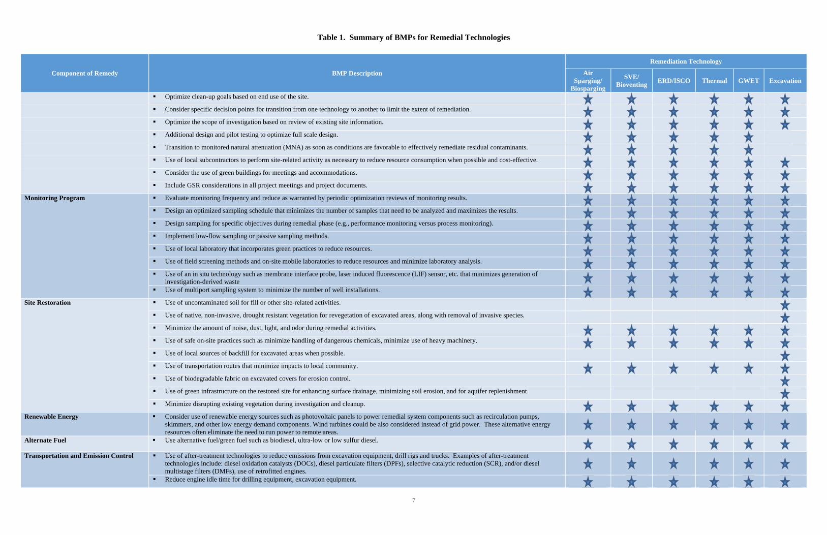
Table 1. Summary of BMPs for Remedial Technologies
7
Component of Remedy BMP Description
Remediation Technology
Air Sparging/
Biosparging
SVE/ Bioventing
ERD/ISCO Thermal GWET Excavation
Optimize clean-up goals based on end use of the site.
Consider specific decision points for transition from one technology to another to limit the extent of remediation.
Optimize the scope of investigation based on review of existing site information.
Additional design and pilot testing to optimize full scale design.
Transition to monitored natural attenuation (MNA) as soon as conditions are favorable to effectively remediate residual contaminants.
Use of local subcontractors to perform site-related activity as necessary to reduce resource consumption when possible and cost-effective.
Consider the use of green buildings for meetings and accommodations.
Include GSR considerations in all project meetings and project documents.
Monitoring Program Evaluate monitoring frequency and reduce as warranted by periodic optimization reviews of monitoring results.
Design an optimized sampling schedule that minimizes the number of samples that need to be analyzed and maximizes the results.
Design sampling for specific objectives during remedial phase (e.g., performance monitoring versus process monitoring).
Implement low-flow sampling or passive sampling methods.
Use of local laboratory that incorporates green practices to reduce resources.
Use of field screening methods and on-site mobile laboratories to reduce resources and minimize laboratory analysis.
Use of an in situ technology such as membrane interface probe, laser induced fluorescence (LIF) sensor, etc. that minimizes generation of investigation-derived waste
Use of multiport sampling system to minimize the number of well installations.
Site Restoration Use of uncontaminated soil for fill or other site-related activities.
Use of native, non-invasive, drought resistant vegetation for revegetation of excavated areas, along with removal of invasive species.
Minimize the amount of noise, dust, light, and odor during remedial activities.
Use of safe on-site practices such as minimize handling of dangerous chemicals, minimize use of heavy machinery.
Use of local sources of backfill for excavated areas when possible.
Use of transportation routes that minimize impacts to local community.
Use of biodegradable fabric on excavated covers for erosion control.
Use of green infrastructure on the restored site for enhancing surface drainage, minimizing soil erosion, and for aquifer replenishment.
Minimize disrupting existing vegetation during investigation and cleanup.
Renewable Energy Consider use of renewable energy sources such as photovoltaic panels to power remedial system components such as recirculation pumps, skimmers, and other low energy demand components. Wind turbines could be also considered instead of grid power. These alternative energy resources often eliminate the need to run power to remote areas.
Alternate Fuel Use alternative fuel/green fuel such as biodiesel, ultra-low or low sulfur diesel.
Transportation and Emission Control Use of after-treatment technologies to reduce emissions from excavation equipment, drill rigs and trucks. Examples of after-treatment technologies include: diesel oxidation catalysts (DOCs), diesel particulate filters (DPFs), selective catalytic reduction (SCR), and/or diesel multistage filters (DMFs), use of retrofitted engines.
Reduce engine idle time for drilling equipment, excavation equipment.
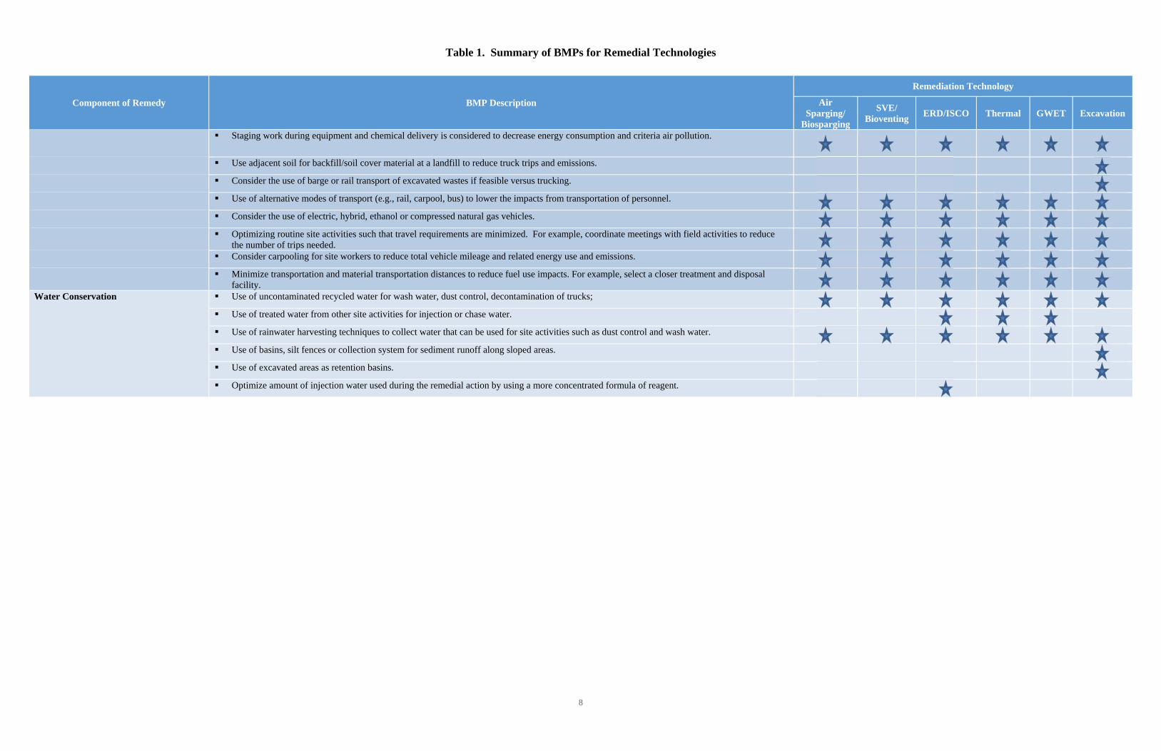
Table 1. Summary of BMPs for Remedial Technologies
8
Component of Remedy BMP Description
Remediation Technology
Air Sparging/
Biosparging
SVE/ Bioventing
ERD/ISCO Thermal GWET Excavation
Staging work during equipment and chemical delivery is considered to decrease energy consumption and criteria air pollution.
Use adjacent soil for backfill/soil cover material at a landfill to reduce truck trips and emissions.
Consider the use of barge or rail transport of excavated wastes if feasible versus trucking.
Use of alternative modes of transport (e.g., rail, carpool, bus) to lower the impacts from transportation of personnel.
Consider the use of electric, hybrid, ethanol or compressed natural gas vehicles.
Optimizing routine site activities such that travel requirements are minimized. For example, coordinate meetings with field activities to reduce the number of trips needed.
Consider carpooling for site workers to reduce total vehicle mileage and related energy use and emissions.
Minimize transportation and material transportation distances to reduce fuel use impacts. For example, select a closer treatment and disposal facility.
Water Conservation Use of uncontaminated recycled water for wash water, dust control, decontamination of trucks;
Use of treated water from other site activities for injection or chase water.
Use of rainwater harvesting techniques to collect water that can be used for site activities such as dust control and wash water.
Use of basins, silt fences or collection system for sediment runoff along sloped areas.
Use of excavated areas as retention basins.
Optimize amount of injection water used during the remedial action by using a more concentrated formula of reagent.
9
4.0 CASE STUDIES
Several GSR BMP strategies have been successfully implemented at Navy ER sites. Navy RPMs have used GSR BMPs such as photovoltaic energy to power free product recovery, bioventing units and groundwater recirculation systems, and passive groundwater samplers to minimize investigation-derived waste. Additionally, the use of on-site landfarming for treating soil that is above action levels has been implemented to save transportation and landfill space. Two case studies were identified that demonstrate the implementation of GSR BMPs: 1) Sites 3, 4a, and 5, Naval Air Station (NAS) Patuxent River and 2) Site Landfill 05 (LF05), at Joint Base Pearl Harbor-Hickam (JBPHH), Hawaii. This section summarizes the remedial activities conducted at each site, the relevant BMPs applied, and their overall benefits.
4.1 SITES 3, 4A, AND 5, NAS PATUXENT RIVER
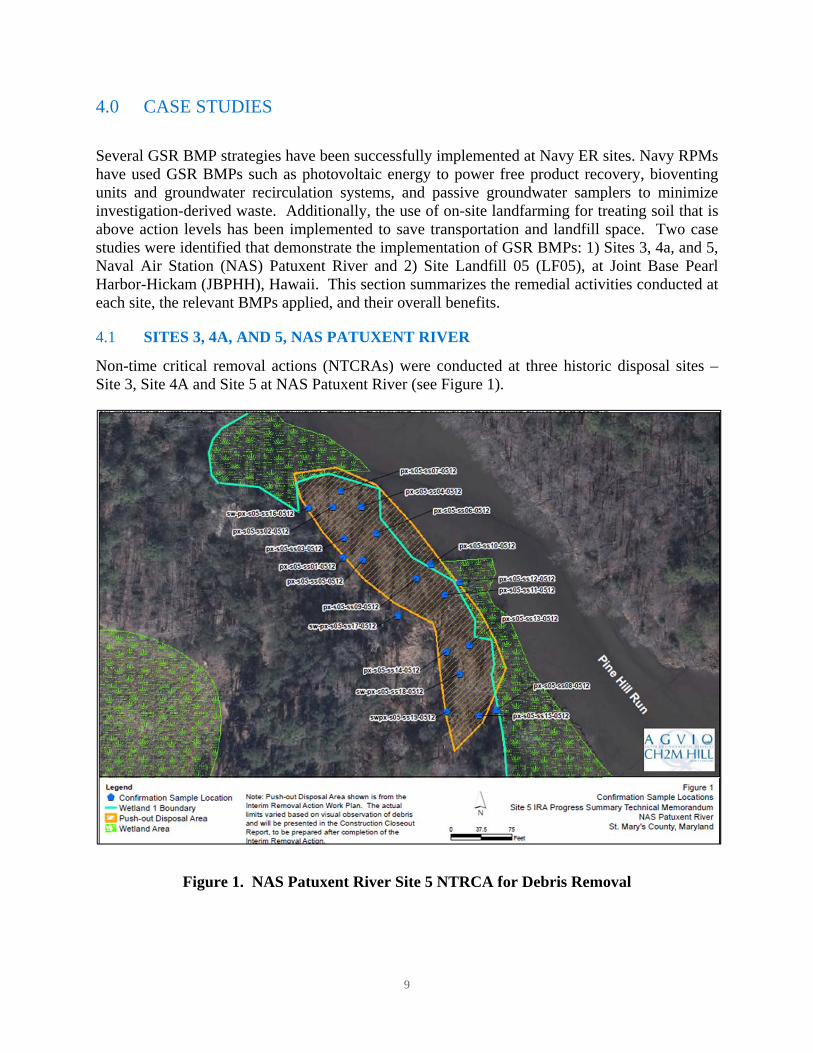
Non-time critical removal actions (NTCRAs) were conducted at three historic disposal sites – Site 3, Site 4A and Site 5 at NAS Patuxent River (see Figure 1).
Figure 1. NAS Patuxent River Site 5 NTRCA for Debris Removal
10
Site 3 The NTCRA at the Disposal Site near Goose Creek (Site 3) at the NAS Patuxent River consisted of the removal of landfill waste and debris along the edge of a wetland in direct communication with the Chesapeake Bay. It also included restoration activities focusing on enhancing the wildlife habitat along Goose Creek. Approximately 3,400 trees and shrubs along with 3,200 native wetland plants were planted. Invasive species were sprayed with an EPA-approved pesticide to halt their expansion into the newly created habitat. The removal employed a mechanical screener to separate soil from debris.
Site 4A The NTCRA at the Hermanville Disposal Site (Site 4A) at the NAS Patuxent River consisted of the removal of landfill waste and debris, asbestos, and munitions and explosives of concern (MEC) from areas adjacent to Holton Pond and on-site reuse of soil as backfill. The NTCRA employed a mechanical screener to separate soil from debris which allowed for the disposal of asbestos and MEC material, reuse of clean soil, and the recycling of scrap metal and concrete. Asbestos was sent to an approved off-site landfill, while MEC was either blown-in-place (BIP) or classified as material documented as safe (MDAS) and demilitarized through smelting at an off-site facility. Site 5 The NTCRA at the Site 5, NAS Patuxent River consisted of excavation of waste and soil, stabilization of soil, and off-site disposal of waste and soil from the Push-out Disposal Area and restoration of the site in accordance with the interim removal action work plan. Although the site has not yet been restored, the work completed to-date has achieved the interim removal action objective. The following GSR BMPs were applied at Sites 3, 4a, and 5:
Site 3:
Recycling 8,900 tons of concrete and 21 tons of metal conserved resources and saved landfill space;
Reusing on-site soil saved from importing 156,000 cubic yards of clean soil as fill;
Using super silt fencing and other erosion and sediment control measures reduced any impacts to adjacent Goose Creek;
Planting seven different native species of upland trees and four native species of wetland plants after removal of the landfill to create riparian forest buffers and expand wetlands along the shoreline; and
Spraying invasive species with an EPA-approved pesticide to halt their expansion into the newly created habitat.
Site 4a:
Reusing on-site soil as backfill reduced landfill space for 6,700 tons of soil. In addition, reduced landfill space for 809 tons of waste by employing a mechanical screener to separate

11
soil from debris. This allowed for the disposal of asbestos and MEC material, reuse of clean soil, and the recycling of scrap metal and concrete. Asbestos was sent to an approved off-site landfill while MEC was either BIP or classified as MDAS and demilitarized through smelting at an offsite facility.
Recycling 94 tons of scrap metal and 630 tons of concrete saved landfill space.
Using super silt fencing and asbestos air monitoring reduced any impacts to adjacent Holton Pond.
Planting 50 hardwood trees of four different native species to create riparian forest buffers along the Holton Pond and enhancing the wildlife habitat.
Site 5:
Using 9,600 tons of on-site soil for grading purposes (versus importing it) prevented the need for transporting and consuming clean soil.
Recycling scrap metal and 38.66 tons of concrete saved landfill space and reduced disposal costs.
For some of the BMPs, it was possible to estimate the cost savings from their implementation as summarized below. The total cost savings for implementing these BMPs exceeds $1 million as summarized in Table 2.
Table 2. NAS Patuxent River GSR BMP Cost Savings
Approximate Cost Benefit from BMPs
Site 3 Site 4A Site 5
Recycling steel $3,500 $22,500 $15,000 Recycling concrete $270,000 $22,500 $1,400 Use of on-site soils $208,500 $210,000 $300,000 Subtotal $482,000 $255,000 $316,400 Grand Total $1,053,400
In addition to cost savings, these BMPs resulted in a reduction in the environmental footprint and reduced accident risk as summarized in Table 3.
Table 3. NAS Patuxent River GSR BMP Footprint Reductions
Footprint Reduction Benefit from BMPs Site 3 Site 4A Site 5 Greenhouse gas emissions saved (metric tons) 561 101 124 Total energy saved (megawatt hour) 10,720 472 485 Reduction in nitrogen oxides emissions (metric tons) 2 0.08 0.08 Reduction in sulfur oxides emissions (metric tons) 1.7 0.03 0.013 Reduction in particulate emissions (metric tons) 4.6 0.15 0.023 Reduction in accident risk injury 0.03 0.03 0.04
12
4.2 SITE LF05, JOINT BASE PEARL HARBOR-HICKAM, HAWAII
The Former Tri-Services Landfill (Site LF05) is located at the Mamala Bay Golf Course (MBGC) in the southeast portion of JBPHH, Hawaii. The Tri-Services Landfill operated from the late 1940s to 1965 as a municipal landfill. The results of the remedial investigation, decision documents (DDs), and risk assessment calculations led to the identification of the chemicals of concern (COCs) and the selection of the remedial action cleanup goals (RACGs). The COCs are trichloroethene (TCE) and vinyl chloride (VC) in groundwater. A time critical removal action (TCRA) was performed in 2002 and 2003 to remove buried bottles containing chlorinated solvents from the solvent bottle area at Site LF05. After the TCRA, the U.S. Navy concluded that installation of a full-scale in situ bioreactor would reduce the overall time required to reach RACGs to 20 years, and reduce the overall life-cycle costs of implementing the Record of Decision (ROD) requirements. The selected remedy for Site LF05 consisted of a full-scale bioreactor, landfill cover improvement; blast grit excavation and consolidation within an on-site cell; and implementation and enforcement of land use controls (LUCs). The following GSR BMPs were applied during the design and implementation of the bioreactor:
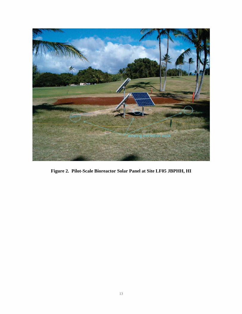
Incorporated renewable energy (solar) into design of the bioreactor to eliminate the need for a power line to be installed at the remote site location reducing both capital cost and operating cost of groundwater recirculation system (see Figure 2);
Reused approximately 80 cubic yards of backfill and no soil required off-site disposal; and
Used native soil available on site to create anaerobic reducing conditions, including mulch from onsite brush trimmings, iron bearing sand (to precipitate sulfides), and coralline sand (to buffer organic acids).
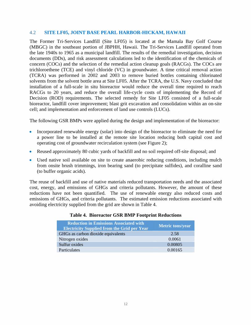
The reuse of backfill and use of native materials reduced transportation needs and the associated cost, energy, and emissions of GHGs and criteria pollutants. However, the amount of these reductions have not been quantified. The use of renewable energy also reduced costs and emissions of GHGs, and criteria pollutants. The estimated emission reductions associated with avoiding electricity supplied from the grid are shown in Table 4.
Table 4. Bioreactor GSR BMP Footprint Reductions
Reduction in Emissions Associated with Electricity Supplied from the Grid per Year
Metric tons/year
GHGs as carbon dioxide equivalents 2.58 Nitrogen oxides 0.0061 Sulfur oxides 0.00805 Particulates 0.00165
13
Figure 2. Pilot-Scale Bioreactor Solar Panel at Site LF05 JBPHH, HI
14
5.0 REFERENCES
Army. 2012. “Evaluation of consideration and incorporation of green and sustainable remediation (GSR) practices in Army environmental remediation.” August. http://www.fedcenter.gov/Documents/index.cfm?id=22322&pge_prg_id=27392
ASTM International. 2013. “ASTM E2893-13 Standard Guide for Greener Cleanups,” November. http://www.astm.org/Standards/E2893.htm
ASTM International. 2013. “ASTM E2876-13 Standard Guide for Integrating Sustainable Objectives into Cleanup”, June. https://www.astm.org/Standards/E2876.htm
ASTM International. 2015. “ASTM E2893-13e Standard Guide for Greener Cleanups”, May. https://www.astm.org/Standards/E2893.htm
Department of Defense (DoD). 2012. “Department of Defense Manual, Defense Environmental Restoration Program (DERP) Management,” Publication Number 4715.20. March. http://www.dtic.mil/whs/directives/corres/pdf/471520m.pdf
Department of Navy (DON). 2012. “Policy for Optimizing Remedial and Removal Actions at all DON Environmental Restoration Program Sites.” http://www.navfac.navy.mil/content/dam/navfac/Specialty%20Centers/Engineering%20and%20Expeditionary%20Warfare%20Center/Environmental/Restoration/er_pdfs/gpr/don-ev-pol-opt-actions-20120402.pdf
Environmental Protection Agency (EPA). Green Remediation Best Management Practices (by remedial technology). http://www.clu-in.org/greenremediation/.
Environmental Protection Agency (EPA). 2009 EPA's Principles for Greener Cleanups. August 27. http://www.epa.gov/greenercleanups/epa-principles-greener-cleanups
Environmental Protection Agency (EPA). 2013. “Encouraging Greener Cleanup Practices through Use of ASTM International’s Standard Guide for Greener Cleanups”, December. http://www.epa.gov/oswer/greenercleanups/pdfs/oswer-aa-gc-memo_december-2013.pdf
Federal Facilities Environmental Stewardship & Compliance Assistance Center. 2015. Executive Order 13693: Planning for Federal Sustainability in the Next Decade. March 19. https://www.fedcenter.gov/Bookmarks/index.cfm?id=27492
Naval Facilities Engineering Command (NAVFAC). 2012. “Department of the Navy Guidance on Green and Sustainable Remediation,” April. http://www.navfac.navy.mil/content/dam/navfac/Specialty%20Centers/Engineering%20and%20Expeditionary%20Warfare%20Center/Environmental/Restoration/er_pdfs/gpr/navfacesc-ev-ug-2093-env-gsr-20120405r1.pdf
Naval Facilities Engineering Command (NAVFAC). 2014. “A Review of Green and Sustainable Practices at NAVFAC Environmental Restoration Sites,” June.
15
http://www.navfac.navy.mil/content/dam/navfac/Specialty%20Centers/Engineering%20and%20Expeditionary%20Warfare%20Center/Environmental/Restoration/er_pdfs/g/navfacexwc-ev-tm-1439-gsr-ersites-201406.pdf
Naval Facilities Engineering Command (NAVFAC). 2015. “Design Considerations for Enhanced Reductive Dechlorination,” March. http://www.navfac.navy.mil/content/dam/navfac/Specialty%20Centers/Engineering%20and%20Expeditionary%20Warfare%20Center/Environmental/Restoration/er_pdfs/d/navfacexwc-ev-tm-1501-erd-design-201503f.pdf
Naval Facilities Engineering Command (NAVFAC). 2015. “Design Considerations for In Situ Chemical Oxidation,” March. http://www.navfac.navy.mil/content/dam/navfac/Specialty%20Centers/Engineering%20and%20Expeditionary%20Warfare%20Center/Environmental/Restoration/er_pdfs/d/navfacexwc-ev-tm-1502-isco-design-201503f.pdf