technical manual tnc 426 b, tnc 430 · for the heidenhain contouring controls. ... list of the plc...
TRANSCRIPT
April 1999 208 896 21 · 7 · 4/99 · S · Printed in Germany · Subject to change without notice(208 896 EC)
Technical ManualTNC 426 CB/PB
TNC 430
NC-Software 280 470-12280 471-12
280 472-12280 473-12
280 474-12280 475-12
280 476-01280 477-01
November 97 Foreword TNC 426B, TNC 430
Foreword
This Technical Manual is intended for manufacturers and distributors of machine tools. It contains allthe necessary information for the assembly, electrical installation, start-up, and PLC programmingfor the HEIDENHAIN contouring controls.
When hardware or software is improved in these HEIDENHAIN contouring controls you willreceive a free delivery of updated information. Please arrange and insert this updated information inyour manual without delay. This will ensure that your manual always remains at the current revisionlevel.
You can use extracts from this manual for your machine documentation. An enlargement ofthe manual’s format (17 cm x 24 cm) by a factor of 1.225 will produce pages in A4 format.
No documentation can be perfect. Like all living things it must grow and change. Amongother things, it lives from your impulses and suggestions for improvement. Please help us by lettingus know your ideas.
DR. JOHANNES HEIDENHAIN GmbHDepartment E/PDr.-Johannes-Heidenhain-Str. 5D-83301 TraunreutGermany
Contents Technical Manual TNC 426 B, TNC 430
Update Informations No. 12 - 7, older InformationsUpdate information for your TNC.
IntroductionTechnical data and general information on software and ID numbers.
Mounting and Electrical InstallationMounting restrictions, power supply, pin layouts of the units and cables.
Machine IntegrationDetailed description of machine functions with the respective machine parameters, markers, words andPLC modules.
PLC ProgrammingGeneral information on the PLC, TRACE functions, complete set of PLC commands.
Data interfacesDetailed description of the data interfaces.
Original Equipment Manufacturer’s (OEM) CyclesImportant on the OEM cycles.
AppendixList of the PLC error messages, tables, dimensions, block diagrams, cable overviews.
Machine ParametersMachine parameter input and output, complete list of the machine parameters.
List of Markers and WordsComplete list of the markers and words.
List of ModulesComplete list of the PLC modules. 11
10
9
8
7
6
5
4
3
1
2
November 97 Contents TNC 426 B, TNC 430 2
1 Update Informations No. 12 - 7, older informations 1–1
2 Introduction 2–1
2.1 Integrated Current Control 2–12.2 Brief Description 2–22.3 Software 2–7
2.3.1 NC Software 2–72.3.2 Software Option 2–72.3.3 PLC Software 2–82.3.4 Software Exchange 2–82.3.5 Data Backup 2–9
2.4 Hardware 2–92.4.1 ID Numbers 2–10
2.5 Release Dates 2–132.5.1 NC Software Versions 280 470 and 280 471 2–132.5.2 NC software versions 280 472 and 280 473 2–15
3 Mounting and Electrical Installation 3–1
3.1 Electrical Noise Immunity 3–13.2 Heat Generation and Cooling 3–23.3 Humidity 3–33.4 Mechanical Vibration 3–33.5 Mounting Position 3–33.6 Degree of Protection 3–63.7 Connection Overview 3–8
3.7.1 LE 426 CB 3–83.7.2 LE 426 PB (Spindle with up to 9000 rpm) 3–93.7.3 LE 426 PB (Spindle with up to 15 000 rpm) 3–103.7.4 LE 430 CA 3–113.7.5 LE 430 PA 3–12
3.8 Power Supply 3–153.8.1 NC Power Supply 3–153.8.2 Buffer Battery Backup 3–163.8.3 PLC Power Supply 3–173.8.4 Power Supply for the Visual Display Units 3–19
3.9 Measuring Systems 3–203.9.1 Encoders for Position 3–203.9.2 Encoders for Speed (TNC 426 PB and TNC 430 PA Only) 3–233.9.3 Adapter for Encoder Signals 3–24
3.10 Motor Power Stage Connection 3–253.11 Analog Inputs 3–293.12 Analog Outputs 3–32
November 97 Contents TNC 426 B, TNC 430 3
3.13 Touch Probes 3–353.13.1 Triggering Touch Probe for Workpiece Measurement 3–353.13.2 Touch Trigger Probe for Tool Measurement 3–373.13.3 Measuring Touch Probe (Option) 3–38
3.14 Data Interface 3–413.14.1 RS-232-C/V.24 Data Interface 3–413.14.2 RS-422/V.11 Data Interface 3–423.14.3 Ethernet Interface (Option) 3–43
3.15 Handwheel Input 3–453.15.1 Connector Assignment on the LE 3–453.15.2 HR 410 Portable Handwheel 3–463.15.3 Panel-Mounted Handwheel HR 130 3–483.15.4 Handwheel Adapter HRA 110 3–49
3.16 Input: Spindle Reference Signal 3–533.17 Input: Drive Motor Enabling (Only TNC 426 PB, TNC 430 PA) 3–533.18 Switching Inputs 24 Vdc (PLC) 3–543.19 Switching Outputs 24 Vdc (PLC) 3–573.20 Connection of the PLC Expansion 3–603.21 Machine Operating Panel 3–653.22 TNC Keyboard 3–673.23 Visual Display Unit 3–693.24 Mounting the Optional PCBs 3–75
4 Machine Integration 4–1
4.1 Machine Axes 4–14.1.1 Encoders 4–24.1.2 Axis Designation 4–44.1.3 Assignment of Axes 4–54.1.4 Reading axis information 4–74.1.5 Traverse Ranges 4–84.1.6 Lubrication Pulse 4–10
4.2 PLC Axes 4–114.3 Axis Error Compensation 4–14
4.3.1 Backlash Compensation 4–144.3.2 Linear Axis-Error Compensation 4–154.3.3 Nonlinear Axis Error Compensation 4–164.3.4 Temperature Compensation 4–204.3.5 Compensation for Reversal Errors in Circular Motion 4–214.3.6 Compensation of Static Friction 4–244.3.7 Compensation of Sliding Friction 4–25
4.4 PLC Positioning Commands 4–26
November 97 Contents TNC 426 B, TNC 430 4
4.5 Tilting Axes 4–294.5.1 “Tilt Working Plane” Feature 4–294.5.2 Automatic Compensation of Offset for Tilting Axes 4–374.5.3 Cylinder Surface 4–38
4.6 Synchronized Axes 4–394.6.1 Synchronization Control 4–394.6.2 Conventions 4–40
4.7 Reference Marks 4–414.7.1 Traversing the Reference Marks 4–42
4.8 The Control Loop 4–514.8.1 Interpolator 4–534.8.2 Position Controllers 4–564.8.3 Motor Speed Controller (Only TNC 426 PB, TNC 430 PA) 4–674.8.4 Current Controller (Only TNC 426 PB, 430 PA) 4–73
4.9 Offset Adjustment 4–754.9.1 Offset Adjustment by Code Number 4–754.9.2 Automatic Cyclic Offset Adjustment 4–754.9.3 Offset Adjustment with Integral Factor 4–76
4.10 Contour Behavior 4–764.10.1 Radial Acceleration 4–764.10.2 Contour Speed in Corners 4–77
4.11 Monitoring Functions 4–794.11.1 Position Monitoring 4–804.11.2 Nominal Speed Monitoring 4–814.11.3 Movement Monitoring 4–814.11.4 Standstill Monitoring 4–824.11.5 Positioning Window 4–824.11.6 NC Supply Voltage Monitoring 4–844.11.7 Temperature Monitoring 4–844.11.8 I²t Monitoring (Digital Axes Only) 4–854.11.9 Monitoring: Power Stage, DC-Link Voltage (Digital Axes Only) 4–874.11.10 Instantaneous Utilization of the Servo Drives (Digital Axes Only) 4–874.11.11 EMERGENCY STOP Monitoring 4–89
4.12 Spindle 4–944.12.1 Position Encoder of the Spindle 4–944.12.2 Analog and Digital Spindle Control 4–964.12.3 Coded Output of Spindle Speed 4–1024.12.4 Oriented Spindle Stop 4–1044.12.5 Tapping with Floating Tap Holder and Nominal Speed Output 4–1084.12.6 Tapping with Floating Tap Holder and Coded Spindle-Speed Output 4–1114.12.7 Rigid Tapping 4–1124.12.8 Speed Controller (Only TNC 426 PB, TNC 430 PA) 4–1144.12.9 Current Controller (Only TNC 426 PB, TNC 430 PA) 4–1144.12.10 Wye Connection / Delta Connection (Only with Spindle DSP) 4–115
November 97 Contents TNC 426 B, TNC 430 5
4.13 Display and Operation 4–1174.13.1 Machine Datum 4–1174.13.2 Color Adjustment 4–1194.13.3 Graphic Display 4–1224.13.4 Status Display 4–1244.13.5 PLC Display 4–1334.13.6 Small PLC Window 4–1334.13.7 Large PLC Window 4–1374.13.8 PLC Soft Keys 4–1504.13.9 Help 4–1524.13.10 Superimpose PLC Window 4–1544.13.11 M Functions 4–1564.13.12 Error Messages 4–1594.13.13 Cycles 4–1634.13.14 Returning to the Contour 4–1674.13.15 Files 4–1714.13.16 Datum Tables (.D) 4–1724.13.17 Pallet Management 4–1734.13.18 Freely Defined Tables 4–1774.13.19 PLC Files 4–1844.13.20 User Parameters 4–1874.13.21 Code Numbers 4–1884.13.22 Programming Station 4–1884.13.23 Conversational Language 4–1894.13.24 Memory Test 4–1904.13.25 Arc End-Point Tolerance 4–1904.13.26 Radius Compensation R+, R- 4–1904.13.27 Power Interrupted Message 4–1914.13.28 Operating Times 4–191
4.14 Keystroke Simulation 4–1964.14.1 TNC Keyboard 4–1964.14.2 Machine Operating Panel 4–201
4.15 Touch Probe 4–2044.15.1 Standard Probing Cycles 4–2044.15.2 Logging Probe Measurements 4–2084.15.3 Digitizing with the Triggering Touch Probe 4–2124.15.4 Digitizing with the Measuring Touch Probe 4–2194.15.5 Tool Measurement 4–224
4.16 Electronic Handwheel 4–2324.16.1 HR 130 Panel-Mounted Handwheel 4–2344.16.2 HR 410 Portable Handwheel 4–2354.16.3 HR 150 Panel-Mounted Handwheels with HRA 110 Adapter 4–236
November 97 Contents TNC 426 B, TNC 430 6
4.17 PLC Inputs/Outputs 4–2384.17.1 24-Vdc Switching Inputs/Outputs 4–2384.17.2 Analog Inputs 4–2404.17.3 Analog Outputs 4–241
4.18 Incremental Jog Positioning 4–2424.19 Hirth Coupling 4–2434.20 Datum Shift 4–2444.21 Tool Changer 4–246
4.21.1 Tool Table, Pocket Table 4–2464.21.2 Automatic Calculation of Cutting Data 4–2544.21.3 Automatic Tool Recognition 4–2574.21.4 Controlling the Tool Changer 4–2674.21.5 PLC Programming Example 4–284
4.22 Special Functions for Laser Cutting Machines 4–2974.22.1 Analog Voltage Output 4–2974.22.2 Graphic Simulation Without TOOL CALL 4–2994.22.3 Program Stop with M Functions and TOOL CALL S 4–300
4.23 Integrated Oscilloscope 4–3024.24 Commissioning 4–307
4.24.1 Preparation 4–3074.24.2 Digital Axis 4–3074.24.3 Analog Axes 4–3284.24.4 Digital Spindle for TNC 426 without Spindle DSP 4–3334.24.5 Digital Spindle for TNC 430 / TNC 426 with Spindle DSP 4–3374.24.6 Analog Spindle 4–339
5 PLC Programming 5–1
5.1 PLC Functions 5–15.1.1 Select PLC Operation 5–15.1.2 PLC Main Menu 5–25.1.3 File Management 5–45.1.4 TRACE Functions 5–55.1.5 Logic Diagram 5–65.1.6 TABLE Function 5–75.1.7 COMPILE Function 5–8
5.2 Operands 5–95.2.1 Operand Directory 5–95.2.2 Operand Addressing 5–105.2.3 Data Transfer 5–11
5.2.4 Data Transfer NC → PLC 5–11
5.2.5 Data Transfer PLC → NC 5–175.2.6 Timer 5–255.2.7 Counters 5–275.2.8 Fast PLC Inputs 5–29
November 97 Contents TNC 426 B, TNC 430 7
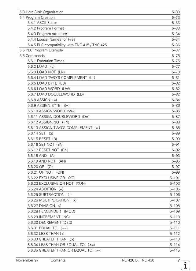
5.3 Hard-Disk Organization 5–305.4 Program Creation 5–33
5.4.1 ASCII Editor 5–335.4.2 Program Format 5–335.4.3 Program structure 5–345.4.4 Logical Names for Files 5–345.4.5 PLC compatibility with TNC 415 / TNC 425 5–36
5.5 PLC Program Example 5–375.6 Commands 5–75
5.6.1 Execution Times 5–755.6.2 LOAD (L) L 5–775.6.3 LOAD NOT (LN) LN 5–795.6.4 LOAD TWO'S-COMPLEMENT (L–) 5–815.6.5 LOAD BYTE (LB) LB 5–825.6.6 LOAD WORD (LW) LW 5–825.6.7 LOAD DOUBLEWORD (LD) LD 5–825.6.8 ASSIGN (=) 5–845.6.9 ASSIGN BYTE (B=) 5–865.6.10 ASSIGN WORD (W=) W= 5–865.6.11 ASSIGN DOUBLEWORD (D=) 5–875.6.12 ASSIGN NOT (=N) 5–885.6.13 ASSIGN TWO'S COMPLEMENT (=-) 5–885.6.14 SET (S) 5–895.6.15 RESET (R) 5–905.6.16 SET NOT (SN) 5–915.6.17 RESET NOT (RN) RN 5–925.6.18 AND (A) 5–935.6.19 AND NOT (AN) AN 5–955.6.20 OR (O) O 5–975.6.21 OR NOT (ON) 5–995.6.22 EXCLUSIVE OR (XO) 5–1015.6.23 EXCLUSIVE OR NOT (XON) XON 5–1035.6.24 ADDITION (+) 5–1055.6.25 SUBTRACTION (–) 5–1065.6.26 MULTIPLICATION (x) 5–1075.6.27 DIVISION (/) 5–1085.6.28 REMAINDER (MOD) 5–1095.6.29 INCREMENT (INC) 5–1105.6.30 DECREMENT (DEC) 5–1105.6.31 EQUAL TO (==) 5–1115.6.32 LESS THAN (<) 5–1125.6.33 GREATER THAN (>) 5–1135.6.34 LESS THAN OR EQUAL TO (<=) 5–1145.6.35 GREATER THAN OR EQUAL TO (>=) 5–115
November 97 Contents TNC 426 B, TNC 430 8
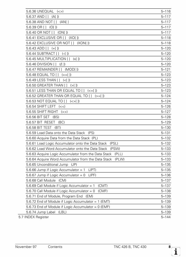
5.6.36 UNEQUAL (<>) 5–1165.6.37 AND [ ] (A[ ]) 5–1175.6.38 AND NOT [ ] (AN[ ] 5–1175.6.39 OR [ ] (O[ ]) 5–1175.6.40 OR NOT [ ] (ON[ ]) 5–1175.6.41 EXCLUSIVE OR [ ] (XO[ ]) 5–1185.6.42 EXCLUSIVE OR NOT [ ] (XON[ ]) 5–1185.6.43 ADD [ ] (+[ ]) 5–1205.6.44 SUBTRACT [ ] (–[ ]) 5–1205.6.45 MULTIPLICATION [ ] (x[ ]) 5–1205.6.46 DIVISION [ ] (/[ ]) 5–1205.6.47 REMAINDER [ ] (MOD[ ]) 5–1215.6.48 EQUAL TO [ ] (==[ ]) 5–1235.6.49 LESS THAN [ ] (<[ ]) 5–1235.6.50 GREATER THAN [ ] (>[ ]) 5–1235.6.51 LESS THAN OR EQUAL TO [ ] (<=[ ]) 5–1235.6.52 GREATER THAN OR EQUAL TO [ ] (>=[ ]) 5–1245.6.53 NOT EQUAL TO [ ] (<>[ ]) 5–1245.6.54 SHIFT LEFT (<<) 5–1265.6.55 SHIFT RIGHT (>>) 5–1275.6.56 BIT SET (BS) 5–1285.6.57 BIT RESET (BC) 5–1295.6.58 BIT TEST (BT) 5–1305.6.59 Load Data onto the Data Stack (PS) 5–1315.6.60 Acquire Data from the Data Stack (PL) 5–1325.6.61 Load Logic Accumulator onto the Data Stack (PSL) 5–1325.6.62 Load Word Accumulator onto the Data Stack (PSW) 5–1335.6.63 Acquire Logic Accumulator from the Data Stack (PLL) 5–1335.6.64 Acquire Word Accumulator from the Data Stack (PLW) 5–1335.6.65 Unconditional Jump (JP) 5–1355.6.66 Jump if Logic Accumulator = 1 (JPT) 5–1355.6.67 Jump if Logic Accumulator = 0 (JPF) 5–1365.6.68 Call Module (CM) 5–1375.6.69 Call Module if Logic Accumulator = 1 (CMT) 5–1375.6.70 Call Module if Logic Accumulator = 0 (CMF) 5–1385.6.71 End of Module, Program End (EM) 5–1395.6.72 End of Module if Logic Accumulator = 1 (EMT) 5–1395.6.73 End of Module if Logic Accumulator = 0 (EMF) 5–1395.6.74 Jump Label (LBL) 5–139
5.7 INDEX Register 5–144
November 97 Contents TNC 426 B, TNC 430 9
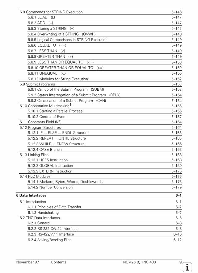
5.8 Commands for STRING Execution 5–1465.8.1 LOAD (L) 5–1475.8.2 ADD (+) 5–1475.8.3 Storing a STRING (=) 5–1475.8.4 Overwriting of a STRING (OVWR) 5–1485.8.5 Logical Comparisons in STRING Execution 5–1495.8.6 EQUAL TO (==) 5–1495.8.7 LESS THAN (<) 5–1495.8.8 GREATER THAN (>) 5–1495.8.9 LESS THAN OR EQUAL TO (<=) 5–1505.8.10 GREATER THAN OR EQUAL TO (>=) 5–1505.8.11 UNEQUAL (<>) 5–1505.8.12 Modules for String Execution 5–152
5.9 Submit Programs 5–1535.9.1 Call up of the Submit Program (SUBM) 5–1535.9.2 Status Interrogation of a Submit Program (RPLY) 5–1545.9.3 Cancellation of a Submit Program (CAN) 5–154
5.10 Cooperative Multitasking1) 5–1565.10.1 Starting a Parallel Process 5–1565.10.2 Control of Events 5–157
5.11 Constants Field (KF) 5–1645.12 Program Structures 5–164
5.12.1 IF ... ELSE ... ENDI Structure 5–1655.12.2 REPEAT ... UNTIL Structure 5–1655.12.3 WHILE ... ENDW Structure 5–1665.12.4 CASE Branch 5–166
5.13 Linking Files 5–1685.13.1 USES Instruction 5–1685.13.2 GLOBAL Instruction 5–1695.13.3 EXTERN Instruction 5–170
5.14 PLC Modules 5–1765.14.1 Markers, Bytes, Words, Doublewords 5–1765.14.2 Number Conversion 5–179
6 Data Interfaces 6–1
6.1 Introduction 6–16.1.1 Principles of Data Transfer 6–26.1.2 Handshaking 6–7
6.2 TNC Data Interfaces 6–86.2.1 General 6–86.2.2 RS-232-C/V.24 Interface 6–86.2.3 RS-422/V.11 Interface 6–106.2.4 Saving/Reading Files 6–12
November 97 Contents TNC 426 B, TNC 430 10
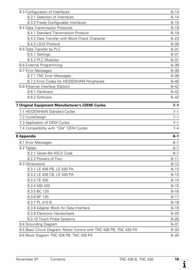
6.3 Configuration of Interfaces 6–146.3.1 Selection of Interfaces 6–146.3.2 Freely Configurable Interfaces 6–15
6.4 Data Transmission Protocols 6–196.4.1 Standard Transmission Protocol 6–196.4.2 Data Transfer with Block Check Character 6–236.4.3 LSV2 Protocol 6–30
6.5 Data Transfer by PLC 6–316.5.1 Settings 6–316.5.2 PLC Modules 6–31
6.6 External Programming 6–386.7 Error Messages 6–39
6.7.1 TNC Error Messages 6–396.7.2 Error Codes for HEIDENHAIN Peripherals 6–40
6.8 Ethernet Interface (Option) 6–426.8.1 Hardware 6–426.8.2 Software 6–42
7 Original Equipment Manufacturer's (OEM) Cycles 7–1
7.1 HEIDENHAIN Standard Cycles 7–17.2 CycleDesign 7–17.3 Application of OEM Cycles 7–17.4 Compatibility with “Old” OEM Cycles 7–4
8 Appendix 8–1
8.1 Error Messages 8–18.2 Tables 8–7
8.2.1 Seven-Bit ASCII Code 8–78.2.2 Powers of Two 8–11
8.3 Dimensions 8–128.3.1 LE 426 PB, LE 430 PA 8–128.3.2 LE 426 CB, LE 430 PA 8–138.3.3 TE 420 8–148.3.4 MB 420 8–158.3.5 BC 120 8–168.3.6 BF 120 8–178.3.7 PL 410 B 8–188.3.8 Adapter Block for Data Interface 8–198.3.9 Electronic Handwheels 8–208.3.10 Touch Probe Systems 8–26
8.4 Grounding Diagram 8–318.5 Basic Circuit Diagram: Motor Control with TNC 426 PB, TNC 430 PA 8–338.6 Block Diagram TNC 426 PB, TNC 430 PA 8–35
October 98 Contents TNC 426 B, TNC 430 11
8.7 Cable Overview 8–378.7.1 TNC 426 8–37
8.7.2 TNC 430 8–39
9 Machine Parameters 9–1
9.1 What is a Machine Parameter? 9–1
9.2 Input and Output of Machine Parameters 9–29.2.1 Input Format 9–2
9.2.2 Activating the Machine Parameter Settings 9–3
9.2.3 Changing the Input Values 9–39.3 List of Machine Parameters 9–7
9.3.1 Encoders and Machine 9–7
9.3.2 Positioning 9–14
9.3.3 Operation with Velocity Feedforward 9–17
9.3.4 Operation with Servo Lag 9–18
9.3.5 Integral Speed and Current Control (Digital Axes Only) 9–19
9.3.6 Spindle 9–24
9.3.7 Integral PLC 9–27
9.3.8 Configuration of Data Interfaces 9–29
9.3.9 3-D Touch Probe 9–30
9.3.10 Digitizing with TS (Available Only with Digitizing Option) 9–32
9.3.11 Digitizing with Measuring Touch Probe (Available Only with Digitizing Option) 9–33
9.3.12 Tool Measurement with TT 9–34
9.3.13 Tapping 9–38
9.3.14 Display and Operation 9–39
9.3.15 Colors 9–45
9.3.16 Machining and Program Run 9–48
9.3.17 Hardware 9–54
9.3.18 Second Spindle 9–58
10 List of Markers and Words 10–1
10.1 List of Markers 10–1
10.2 List of Words 10–7
11 List of Modules 11–1
12 Subject Index 12–1
December 97 Update Information No. 6 TNC 426 B, TNC 430 1–1
1 Update Information No. 6
The following NC software has been released:
NC Software Date of release
280 472 05 11/97 Export-Version: 280 473 05
Improvements:• On the TNC 426 PB without spindle DSP (from hardware version xxx xxx 4x) the maximum
spindle speed was increased from 9000 rpm to 12 000 rpm.• On the TNC 426 PB with spindle DSP and the TNC 430 PA (from hardware version xxx xxx 4x)
the maximum spindle speed was increased from 15 000 rpm to 24 000 rpm.• Module 9135 has been introduced:
The infrared touch probe TS 630 can be switched on by the PLC. If the touch probe does notreport readiness while M4056 is set, the feed rate enable is reset (previously: NC stop).Call:CM 9135
M4203= 0: no error during module execution1: error during module execution
• MP3210.x extended:Input range (S analog voltage or motor revolutions) increased to 100.000
• D364 (nominal speed) and D368 (actual speed) have been added, since speeds greater than32767 rpm cannot be represented in the words W320 (nominal speed) and W322 (actual speed).
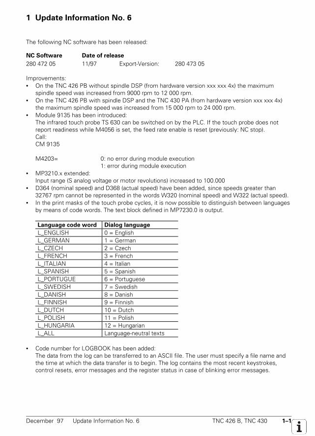
• In the print masks of the touch probe cycles, it is now possible to distinguish between languagesby means of code words. The text block defined in MP7230.0 is output.
Language code word Dialog language
L_ENGLISH 0 = English L_GERMAN 1 = German L_CZECH 2 = Czech L_FRENCH 3 = French L_ITALIAN 4 = Italian L_SPANISH 5 = Spanish L_PORTUGUE 6 = Portuguese L_SWEDISH 7 = Swedish L_DANISH 8 = Danish L_FINNISH 9 = Finnish L_DUTCH 10 = Dutch L_POLISH 11 = Polish L_HUNGARIA 12 = Hungarian L_ALL Language-neutral texts
• Code number for LOGBOOK has been added:
The data from the log can be transferred to an ASCII file. The user must specify a file name andthe time at which the data transfer is to begin. The log contains the most recent keystrokes,control resets, error messages and the register status in case of blinking error messages.
1–2 TNC 426 B, TNC 430 Update Information No. 6 December 97
• MP7471 has been added:Maximum speed of linear axes for compensating movements caused by the positioning ofangular axes with M128.
• New machine parameters for new touch probe cycle (CALIBRATE TS):MP6180.0-2, MP6181.0-2 and MP6182.0-2: Approximate position of the ring gauge center (X, Yand Z in REF coordinates for three traverse ranges)Input: –99 999.9999 to +99 999.9999 [mm]MP6185: Distance below the upper edge of the ring gauge to be probed during calibration.Input: 0.001 to 99 999.9999 [mm]
• FN18:SYSREAD has been expanded:It is now possible to determine whether a datum table is selected in the current operating mode.ID505NR10 = no datum table selected1 = datum table selected
• FN18: SYSREAD has been expanded:It is now possible to determine whether the addressed MP exists.ID1010NRxxxx MP numberIDXxxxx MP index0 = MP does not exist1 = MP exists
NC software Date of release
280 472 06 12/97 Export version: 280 473 06 Improvements:• New touch probe cycles. These cycles are defined like the fixed cycles via the TOUCH PROBE
key and soft keys. All touch probe system functions are now described in a separate manual:User's Manual touch probe cycles – German 329203 10
– English 329203 20• Three new markers for workpiece measurement:
Set ResetM4065: All dimensions of the workpiece are OK NC PLCM4066: Workpiece needs rework NC PLCM4067: Workpiece must be scrapped NC PLC
• Timers T96 to T143 have been added:The new timers can be started only through Module 9006. The timer is set immediately aftermodule call and reset after expiration of the run time.
• FN17:SYSWRITE has been expanded:The touch probe monitoring can be switched on and off.ID990NR2 = numerical valueNumerical value = 0 touch probe monitoring offNumerical value ≠ 1 touch probe monitoring on
• FN17:SYSWRITE has been expanded:The touch probe data of the manual probing cycles are transferred to the tool table.ID990NR3 = Qxxx or any numerical value
December 97 Update Information No. 6 TNC 426 B, TNC 430 1–3
• FN17:SYSWRITE has been expanded:A point in the working plane (i.e., the plane perpendicular to the tool axis) of the workpiececoordinate system can be transformed into the corresponding plane of the machine coordinatesystem and vice versa, whereby the corresponding plane of the machine coordinate system isthe plane whose normal vector has the designation of the tool axis.ID990NR4IDX 1 = Qxxx (Transformation of workpiece coordinate system to machine coordinate system)
2 = Qxxx (Transformation of machine coordinate system to workpiece coordinate system)Qxxx Number of the first of four consecutive Q parameters
1. Q parameter: Coordinate of the 1st axis of the point to be transformed2. Q parameter: Coordinate of the 2nd axis of the point to be transformed3. Q parameter: Coordinate of the 1st axis of the transformed point4. Q parameter: Coordinate of the 2nd axis of the transformed point
November 97 Update Information No. 5 TNC 426 B, TNC 430 1–1
1 Update Information No. 5
1.1 NC Software
HEIDENHAIN has released a new NC software:NC software Release
280 472 04 10/97 Export version: 280 473 04Improvements:• Code words LSV2TIME0 to LSV2TIME2 are new• Module 9038 was expanded by transfer value –1• DR2 can now be defined in the TOOL CALL block• Spindle DSP limits max. torque to 2.5 • rated torque
1.2 Hardware
The maximum input frequency of the position encoder inputs X1 to X5 was reduced to 50 kHz for 1VPP signals. You will find the new ID numbers on page 3-10. Changeover date will be end ofDecember 1997. We will still provide the old logic units with unchanged input frequency under theold ID numbers upon special request.
1.3 Documentation
Various changes were made to the Technical Manual. The list on the next 3 pages gives an insightinto what changes were made, and where the information can be found.
November 97 Update Information No. 4 TNC 426 B, TNC 430 1–1
1 Update Information No. 4
With Update Information No. 3 you received completely new pages for your TNC 426 B / TNC 430Technical Manual. Since then the following changes have been made to the software.
1.1 NC Software 280 472
NC Software Release
280 472 01 6/97 Export version: 280 473 01
NC Software Release
280 472 02 7/97 Export version: 280 473 02
• MP6500 expanded:Bit 9 reservedBit 10 probing routine (Bit 8 = 1)0 = The starting point is pre-positioned in all three principle axes.1 = The starting point is pre-positioned only in the tool axis and in the axis of the probingdirection (MP6505).Bit 11 Checking the tool and adjusting the tool table0 = After "tool checking" the tool table is adjusted.1 = After "tool checking" the tool table is not adjusted.
• MP7500 expanded:Bit 3 Setting the datum in a tilted coordinate system0 = Datum setting is possible in tilted coordinate system.1 = During datum setting the current positions of the tilting axes are not offset.
NC Software Release
280 472 03 8/97 Export version: 280 473 03
• MP7680 expanded:Bit 10 see item 1.1.2 "Optimization of Tool-Radius-Compensated Outside Corners."
• The software also runs on the old hardware of the LE 426 CB/PB and LE 430 CA/PA, howeverwith less feature content.
1.1.1 Nominal Position Value Filter
For optimum adjustment of the velocity and acceleration the nominal position values are filtered.This results in smoother (jerk-limited) traverse. The TNC calculates the filter parameters weightingand width (order) using the permissible axis-specific jerk and the tolerance. The filter is effective inall operating modes. For rigid tapping (Cycle 17) the nominal position value filter is automaticallyswitched off.
With MP1095 you can select whether the TNC uses a single or double filter. The single filter causesa linear change in acceleration and therefore a step in the jerk.
With Cycle 32 the user can overwrite the tolerance defined in MP1096 for contour transitions. Cycle32 was renamed to "fast contour milling" because the nominal position value filter is effective notonly for 3-D contours.
1–2 TNC 426 B, TNC 430 Update Information No. 4 November 97
MP1095 Nominal position value filterInput: 0 = single filter
1 = double filterSuggested input value = 0
MP1096 ToleranceInput: 0 = no nominal position value filter
0.001 to 3.000 [mm] = permissible tolerance at contour transitions
MP1097 Axis specific jerk for single filters (MP1096 = 0)Input: 1 to 1 000 [m/s³]MP1097.0-8 Axis 1 to axis 9
MP1098 Axis specific jerk for double filters (MP1096 = 1)Input: 1 to 1 000 [m/s³]
Suggested input value = 2 • MP1097.xMP1098.0-8 Axis 1 to axis 9
MP1099 Minimum filtering orderInput: 0 to 20MP1099.0 Minimum filtering order for single filters (MP1096 = 0)
Suggested input value = 5MP1099.1 Minimum filtering order for double filters (MP1096 = 1)
Suggested input value = 3
Commissioning
Determine minimum filtering order. Suggested input values: MP1099.0 = 5, MP1099.1 = 3 Switch off the nominal position value filter (MP1096 = 0). Determine MP1090.x, MP1092, MP1510.x as described on page 4-318/4-319. Enter the
optimum jerk values for each axis MP1097.x. In MP1098.x enter twice the value from MP1097.x. Define the tolerance in MP1096 (e.g. 0.02 mm)
1.1.2 Optimization of Tool-Radius-Compensated Outside Corners
With MP7680, bit 10 you set whether a circular arc or a spline should be inserted for the tool centerpath at tool-radius-compensated outside corners. Inserting a spline has the advantage of limiting thejerk at the corners and, when the nominal position value filter (MP1096 > 0) is active, of milling thecorners more precisely.
MP7680 Machines parameters with multiple functionInput: %xxxxxxxxxxxBit10 Tool-radius-compensated outside corners
0 = Insert a circular arc1 = Insert a spline curve
Suggested input value = %1xxxxxxxxxx
November 97 Update Information No. 4 TNC 426 B, TNC 430 1–3
1.1.3 New Backlash Compensation
A new type of backlash compensation is effective beginning with NC software 280 470 08 and280 472 01. Unlike the backlash compensation possible with MP710, you can compensate thebacklash in the entire controlled system with MP750 and MP752. This means that you can now alsocompensate play between the motion of the motor and the table with position measurement vialinear encoders. This feature also compensates the reversal spikes resulting from circular traverse,and the machine parameters MP711 to MP716 are therefore no longer needed.
In MP750 you enter the backlash in mm. In MP752 you enter the time within which thecompensated distance should be traversed.
Example:MP750 = 0.03 mm, MP752 = 15 msFor every reversal in axis direction, for 15 ms a nominal speed command signal is outputcorresponding to a feed rate of 120 mm/min (0.03 mm / 15 ms = 0.002 m/s = 120 mm/min).
MP750 BacklashInput: –1.0000 to +1.0000 [mm]MP750.0-8 Axis 1 to axis 9
MP752 Compensation time for value from MP750.xInput: 0 to 1000 [ms]MP750.0-8 Axis 1 to axis 9
Commissioning
Enter the following test program:LBL 1L X100 R0 F10L X0CALL LBL 1 REP 100/100
With the internal oscilloscope, record ACTL.SPEED and V (ACT RPM) At the reversal point the actual feed rate lags behind the actual RPM with the time delay t. Input values: MP750 = t • ∆ACTL.SPEED
MP752 = approx. 20 ms (optimum value determined empirically with this test)
1.1.4 Other Changes in the Technical Manual • MP7460 (constant contouring speed at corners) has been replaced by MP1096 (tolerance), pages
4-77, 9-45.• MP1091 (Jerk limiting for 3-D milling with Cycle 32) will not be introduced, pages 4-62, 4-78,
9-13.• Module 9037 (read general axis information) was renamed to Module 9038, pages 4-7,
11-1.
1–4 TNC 426 B, TNC 430 Update Information No. 4 November 97
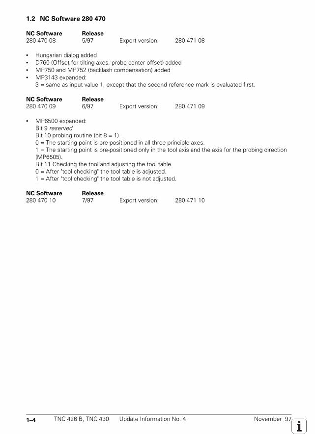
1.2 NC Software 280 470
NC Software Release
280 470 08 5/97 Export version: 280 471 08
• Hungarian dialog added• D760 (Offset for tilting axes, probe center offset) added• MP750 and MP752 (backlash compensation) added• MP3143 expanded:
3 = same as input value 1, except that the second reference mark is evaluated first.
NC Software Release
280 470 09 6/97 Export version: 280 471 09
• MP6500 expanded:Bit 9 reservedBit 10 probing routine (bit 8 = 1)0 = The starting point is pre-positioned in all three principle axes.1 = The starting point is pre-positioned only in the tool axis and the axis for the probing direction(MP6505).Bit 11 Checking the tool and adjusting the tool table0 = After "tool checking" the tool table is adjusted.1 = After "tool checking" the tool table is not adjusted.
NC Software Release
280 470 10 7/97 Export version: 280 471 10
November 97 Update Information No. 3 TNC 426 B, TNC 430 1–1
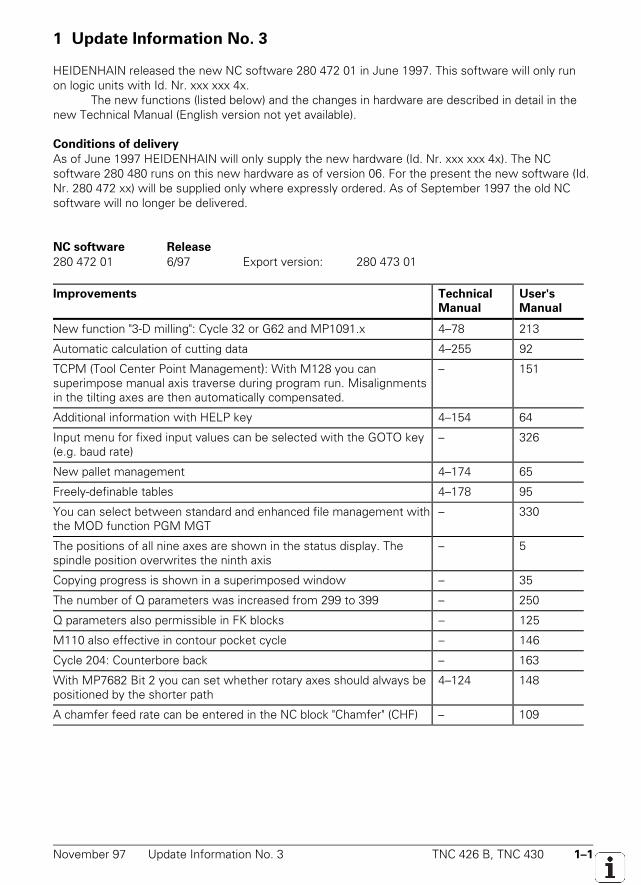
1 Update Information No. 3
HEIDENHAIN released the new NC software 280 472 01 in June 1997. This software will only runon logic units with Id. Nr. xxx xxx 4x.
The new functions (listed below) and the changes in hardware are described in detail in thenew Technical Manual (English version not yet available).
Conditions of delivery
As of June 1997 HEIDENHAIN will only supply the new hardware (Id. Nr. xxx xxx 4x). The NCsoftware 280 480 runs on this new hardware as of version 06. For the present the new software (Id.Nr. 280 472 xx) will be supplied only where expressly ordered. As of September 1997 the old NCsoftware will no longer be delivered.
NC software Release
280 472 01 6/97 Export version: 280 473 01
Improvements Technical
Manual
User's
Manual
New function "3-D milling": Cycle 32 or G62 and MP1091.x 4–78 213
Automatic calculation of cutting data 4–255 92
TCPM (Tool Center Point Management): With M128 you cansuperimpose manual axis traverse during program run. Misalignmentsin the tilting axes are then automatically compensated.
– 151
Additional information with HELP key 4–154 64
Input menu for fixed input values can be selected with the GOTO key(e.g. baud rate)
– 326
New pallet management 4–174 65
Freely-definable tables 4–178 95
You can select between standard and enhanced file management withthe MOD function PGM MGT
– 330
The positions of all nine axes are shown in the status display. Thespindle position overwrites the ninth axis
– 5
Copying progress is shown in a superimposed window – 35
The number of Q parameters was increased from 299 to 399 – 250
Q parameters also permissible in FK blocks – 125
M110 also effective in contour pocket cycle – 146
Cycle 204: Counterbore back – 163
With MP7682 Bit 2 you can set whether rotary axes should always bepositioned by the shorter path
4–124 148
A chamfer feed rate can be entered in the NC block "Chamfer" (CHF) – 109
1–2 TNC 426 B, TNC 430 Update Information No. 3 November 97
Improvements Technical
Manual
User's
Manual
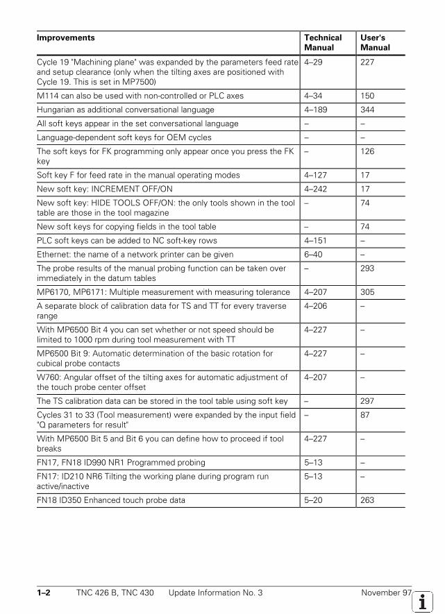
Cycle 19 "Machining plane" was expanded by the parameters feed rateand setup clearance (only when the tilting axes are positioned withCycle 19. This is set in MP7500)
4–29 227
M114 can also be used with non-controlled or PLC axes 4–34 150
Hungarian as additional conversational language 4–189 344
All soft keys appear in the set conversational language – –
Language-dependent soft keys for OEM cycles – –
The soft keys for FK programming only appear once you press the FKkey
– 126
Soft key F for feed rate in the manual operating modes 4–127 17
New soft key: INCREMENT OFF/ON 4–242 17
New soft key: HIDE TOOLS OFF/ON: the only tools shown in the tooltable are those in the tool magazine
– 74
New soft keys for copying fields in the tool table – 74
PLC soft keys can be added to NC soft-key rows 4–151 –
Ethernet: the name of a network printer can be given 6–40 –
The probe results of the manual probing function can be taken overimmediately in the datum tables
– 293
MP6170, MP6171: Multiple measurement with measuring tolerance 4–207 305
A separate block of calibration data for TS and TT for every traverserange
4–206 –
With MP6500 Bit 4 you can set whether or not speed should belimited to 1000 rpm during tool measurement with TT
4–227 –
MP6500 Bit 9: Automatic determination of the basic rotation forcubical probe contacts
4–227 –
W760: Angular offset of the tilting axes for automatic adjustment ofthe touch probe center offset
4–207 –
The TS calibration data can be stored in the tool table using soft key – 297
Cycles 31 to 33 (Tool measurement) were expanded by the input field"Q parameters for result"
– 87
With MP6500 Bit 5 and Bit 6 you can define how to proceed if toolbreaks
4–227 –
FN17, FN18 ID990 NR1 Programmed probing 5–13 –
FN17: ID210 NR6 Tilting the working plane during program runactive/inactive
5–13 –
FN18 ID350 Enhanced touch probe data 5–20 263
November 97 Update Information No. 3 TNC 426 B, TNC 430 1–3
Improvements Technical
Manual
User's
Manual
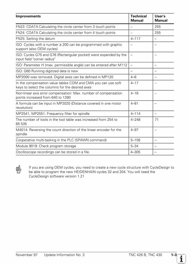
FN23: CDATA Calculating the circle center from 3 touch points – 255
FN24: CDATA Calculating the circle center from 4 touch points – 255
FN25: Setting the datum 4–117 –
ISO: Cycles with a number ≥ 200 can be programmed with graphicsupport (also OEM cycles)
– –
ISO: Cycles G75 and G76 (Rectangular pocket) were expanded by theinput field "corner radius"
– –
ISO: Parameter H (max. permissible angle) can be entered after M112 – –
ISO: G60 Running digitized data is new – –
MP2000 was removed. Digital axes can be defined in MP120 4–6 –
In the compensation value tables COM and CMA you can use softkeys to select the columns for the desired axes
4–17 –
Non-linear axis error compensation: Max. number of compensationpoints increased from 640 to 1280
4–16 –
A formula can be input in MP2020 (Distance covered in one motorrevolution)
4–81 –
MP2541, MP2551: Frequency filter for spindle 4–114 –
The number of tools in the tool table was increased from 254 to65 535
4–248 71
M4014: Reversing the count direction of the linear encoder for thespindle
4–97 –
Cooperative multi-tasking in the PLC (SPAWN command) 5–156 –
Module 9019: Check program storage 5–34 –
Oscilloscope recordings can be stored in a file. 4–305 –
If you are using OEM cycles, you need to create a new cycle structure with CycleDesign tobe able to program the new HEIDENHAIN cycles 32 and 204. You will need theCycleDesign software version 1.21
1–4 TNC 426 B, TNC 430 Update Information No. 3 November 97
New hardware
Since February 1997 HEIDENHAIN has been delivering a new hardware for the LE 426 B andLE 430.The advantages of the new hardware:• 3-row VGA connector for BC 120. With the new connecting cable Id. Nr. 312 878 .. there is no
longer need for an adapter connector• Internal working memory doubled (4 MB)• More memory space available on larger hard disk (1.5 GB)• LE 426 PB and LE 430 PA: Three current controllers. Maximum speed = value from Siemens
data sheetThe NC software 280 470 runs on this new hardware as of version 06.The full benefit of its new range of features can only be seen however if the new hardware is usedtogether with the new NC software 280 472 as of version 01.
LE 426 PB with digital spindle to 15 000 rpm
As an option the LE 426 PB is supplied for digital spindles with up to 15 000 rpm. See pages 2–10and 3–10 in the new Technical Manual.
November 97 Integrated Current Control TNC 426 B, TNC 430 2–1
2 Introduction
2.1 Integrated Current Control
HEIDENHAIN contouring controls are designed for integration in milling, drilling and boring machinesas well as machining centers.
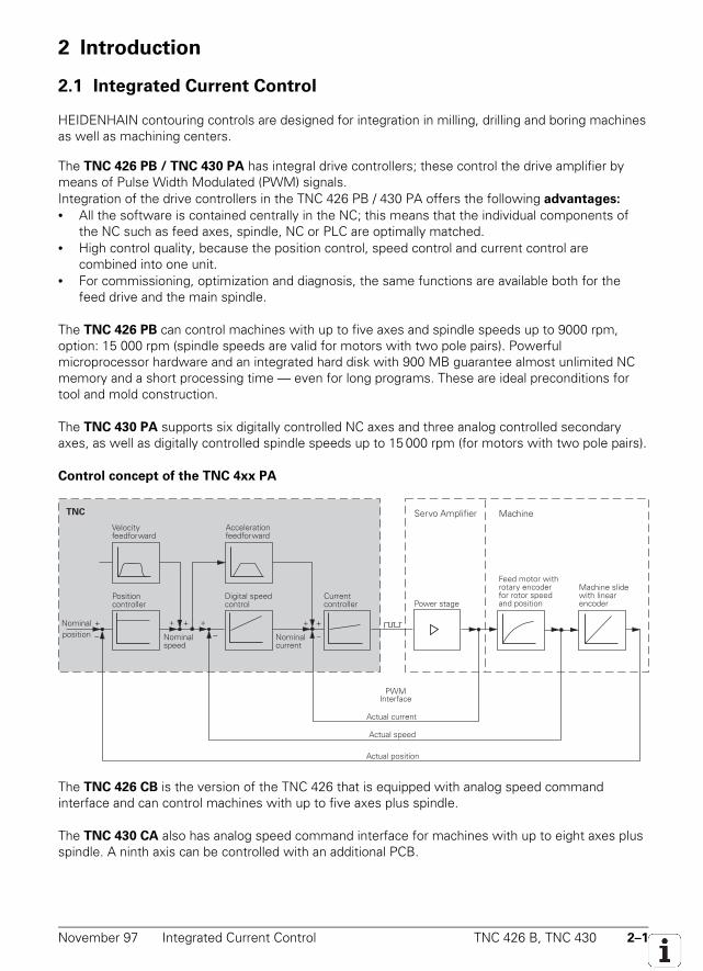
The TNC 426 PB / TNC 430 PA has integral drive controllers; these control the drive amplifier bymeans of Pulse Width Modulated (PWM) signals.Integration of the drive controllers in the TNC 426 PB / 430 PA offers the following advantages:
• All the software is contained centrally in the NC; this means that the individual components ofthe NC such as feed axes, spindle, NC or PLC are optimally matched.
• High control quality, because the position control, speed control and current control arecombined into one unit.
• For commissioning, optimization and diagnosis, the same functions are available both for thefeed drive and the main spindle.
The TNC 426 PB can control machines with up to five axes and spindle speeds up to 9000 rpm,option: 15 000 rpm (spindle speeds are valid for motors with two pole pairs). Powerfulmicroprocessor hardware and an integrated hard disk with 900 MB guarantee almost unlimited NCmemory and a short processing time — even for long programs. These are ideal preconditions fortool and mold construction.
The TNC 430 PA supports six digitally controlled NC axes and three analog controlled secondaryaxes, as well as digitally controlled spindle speeds up to 15 000 rpm (for motors with two pole pairs).
Control concept of the TNC 4xx PA
The TNC 426 CB is the version of the TNC 426 that is equipped with analog speed commandinterface and can control machines with up to five axes plus spindle.
The TNC 430 CA also has analog speed command interface for machines with up to eight axes plusspindle. A ninth axis can be controlled with an additional PCB.
2–2 TNC 426 B, TNC 430 Brief Description November 97
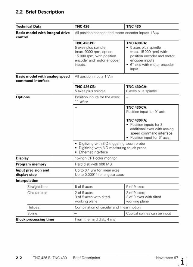
2.2 Brief Description
Technical Data TNC 426 TNC 430
Basic model with integral drive
control
All position encoder and motor encoder inputs 1 VPP
TNC 426PB:
5 axes plus spindle(max. 9000 rpm, option:15 000 rpm) with positionencoder and motor encoderinputs.
TNC 430 PA:
• 5 axes plus spindle(max. 15000 rpm) with position encoder and motor encoder inputs
• 6th axis with motor encoder input
Basic model with analog speed
command interface
All position inputs 1 VPP
TNC 426CB:
5 axes plus spindleTNC 430CA:
8 axes plus spindle
Options Position inputs for the axes:11 µAPP
–
– TNC 430CA:
Position input for 9th axis
TNC 430PA:
• Position inputs for 3 additional axes with analog speed command interface
• Position input for 6th axis
• Digitizing with 3-D triggering touch probe• Digitizing with 3-D measuring touch probe• Ethernet interface
Display 15-inch CRT color monitor
Program memory Hard disk with 900 MB
Input precision and
display step
Up to 0.1 µm for linear axesUp to 0.0001° for angular axes
Interpolation
Straight lines 5 of 5 axes 5 of 9 axes
Circular arcs 2 of 5 axes;3 of 5 axes with tiltedworking plane
2 of 9 axes;3 of 9 axes with tiltedworking plane
Helices Combination of circular and linear motion
Spline – Cubical splines can be input
Block processing time From the hard disk: 4 ms
November 97 Brief Description TNC 426 B, TNC 430 2–3
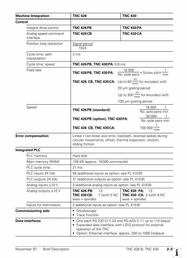
Machine Integration TNC 426 TNC 430
Control
Integral drive control TNC 426PB TNC 430PA
Analog speed commandinterface
TNC 426CB TNC 430CA
Position loop resolution Signal period1024
Cycle time: pathinterpolation
3 ms
Cycle time: speed TNC 426PB, TNC 430PA: 0.6 ms
Feed rateTNC 426PB, TNC 430PA:
18 000No. pole pairs • Screw pitch
1min
TNC 426 CB, TNC 430CA: Up to 60 m
min for encoders with
20 µm grating period
Up to 300 m
min for encoders with
100 µm grating period
SpeedTNC 426PB (standard):
18 000No. pole pairs
1min
TNC 426PB (option), TNC 430PA:30 000
No. pole pairs 1
min
TNC 426 CB, TNC 430CA: 100 000 1
min
Error compensation Linear / non-linear axis error, backlash, reversal spikes duringcircular movements, offset, thermal expansion, stiction,sliding friction
Integrated PLC
PLC memory Hard disk
Main memory (RAM) 128 KB (approx. 16000 commands)
PLC cycle time 21 ms
PLC inputs 24 Vdc 56 (additional inputs as option: see PL 410B)
PLC outputs 24 Vdc 31 (additional outputs as option: see PL 410B)
Analog inputs ±10 V 3 (additional analog inputs as option: see PL 410B)
Analog outputs ±10 V TNC 426 PB: 13TNC 430CB: 7 (with 5 NCaxes + spindle)
TNC 430 PA: 13TNC 430 CA: 3 (with 9 NCaxes + spindle)
Inputs for thermistors 3 (additional inputs as option: see PL 410B)
Commissioning aids • Oscilloscope• Trace function
Data interfaces • One each RS-232-C/ V.24 and RS-422/ V.11 up to 115 kbaud• Expanded data interface with LSV2 protocol for external
operation of the TNC• Option: Ethernet interface, approx. 200 to 1000 kilobaud
2–4 TNC 426 B, TNC 430 Brief Description November 97
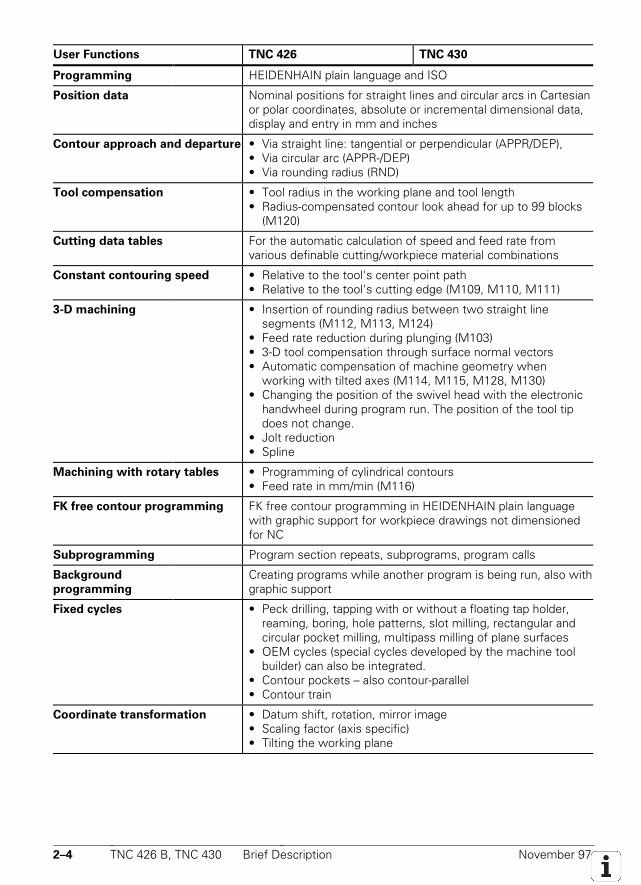
User Functions TNC 426 TNC 430
Programming HEIDENHAIN plain language and ISO
Position data Nominal positions for straight lines and circular arcs in Cartesianor polar coordinates, absolute or incremental dimensional data,display and entry in mm and inches
Contour approach and departure • Via straight line: tangential or perpendicular (APPR/DEP),• Via circular arc (APPR-/DEP)• Via rounding radius (RND)
Tool compensation • Tool radius in the working plane and tool length• Radius-compensated contour look ahead for up to 99 blocks
(M120)
Cutting data tables For the automatic calculation of speed and feed rate fromvarious definable cutting/workpiece material combinations
Constant contouring speed • Relative to the tool's center point path• Relative to the tool's cutting edge (M109, M110, M111)
3-D machining • Insertion of rounding radius between two straight line segments (M112, M113, M124)
• Feed rate reduction during plunging (M103)• 3-D tool compensation through surface normal vectors• Automatic compensation of machine geometry when
working with tilted axes (M114, M115, M128, M130)• Changing the position of the swivel head with the electronic
handwheel during program run. The position of the tool tip does not change.
• Jolt reduction• Spline
Machining with rotary tables • Programming of cylindrical contours• Feed rate in mm/min (M116)
FK free contour programming FK free contour programming in HEIDENHAIN plain languagewith graphic support for workpiece drawings not dimensionedfor NC
Subprogramming Program section repeats, subprograms, program calls
Background
programming
Creating programs while another program is being run, also withgraphic support
Fixed cycles • Peck drilling, tapping with or without a floating tap holder, reaming, boring, hole patterns, slot milling, rectangular and circular pocket milling, multipass milling of plane surfaces
• OEM cycles (special cycles developed by the machine tool builder) can also be integrated.
• Contour pockets – also contour-parallel• Contour train
Coordinate transformation • Datum shift, rotation, mirror image• Scaling factor (axis specific)• Tilting the working plane
November 97 Brief Description TNC 426 B, TNC 430 2–5
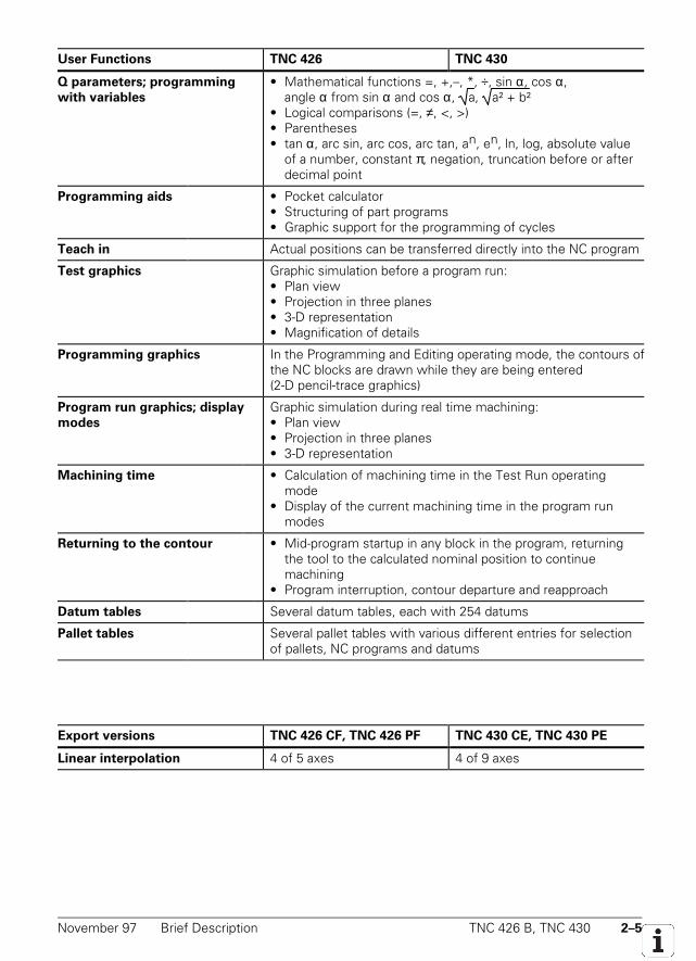
User Functions TNC 426 TNC 430
Q parameters; programming
with variables
• Mathematical functions =, +,–, *, ÷, sin α, cos α,angle α from sin α and cos α, a, a² + b²
• Logical comparisons (=, ≠, <, >)• Parentheses• tan α, arc sin, arc cos, arc tan, an, en, ln, log, absolute value
of a number, constant π, negation, truncation before or after decimal point
Programming aids • Pocket calculator• Structuring of part programs• Graphic support for the programming of cycles
Teach in Actual positions can be transferred directly into the NC program
Test graphics Graphic simulation before a program run:• Plan view• Projection in three planes• 3-D representation• Magnification of details
Programming graphics In the Programming and Editing operating mode, the contours ofthe NC blocks are drawn while they are being entered(2-D pencil-trace graphics)
Program run graphics; display
modes
Graphic simulation during real time machining:• Plan view• Projection in three planes• 3-D representation
Machining time • Calculation of machining time in the Test Run operating mode
• Display of the current machining time in the program run modes
Returning to the contour • Mid-program startup in any block in the program, returning the tool to the calculated nominal position to continue machining
• Program interruption, contour departure and reapproach
Datum tables Several datum tables, each with 254 datums
Pallet tables Several pallet tables with various different entries for selectionof pallets, NC programs and datums
Export versions TNC 426 CF, TNC 426 PF TNC 430 CE, TNC 430 PE
Linear interpolation 4 of 5 axes 4 of 9 axes
2–6 TNC 426 B, TNC 430 Brief Description November 97
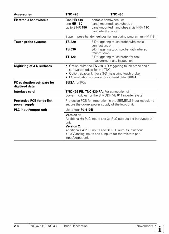
Accessories TNC 426 TNC 430
Electronic handwheels One HR 410 portable handwheel, orone HR 130 panel-mounted handwheel, orup to 3 HR 150 panel-mounted handwheels via HRA 110
handwheel adapter
Superimpose handwheel positioning during program run (M118)
Touch probe systems TS 220 3-D triggering touch probe with cable connection, or
TS 630 3-D triggering touch probe with infrared transmission
TT 120 3-D triggering touch probe for tool measurement and inspection
Digitizing of 3-D surfaces • Option: with the TS 220 3-D triggering touch probe and a software module for the TNC
• Option: adapter kit for a 3-D measuring touch probe.• PC evaluation software for digitized data: SUSA
PC evaluation software for
digitized data
SUSA for PCs
Interface card TNC 426 PB, TNC 430 PA: For connection ofpower modules for the SIMODRIVE 611 inverter system
Protective PCB for dc-link
power supply
Protective PCB for integration in the SIEMENS input module tosecure the dc-link power supply of the logic unit.
PLC input/output unit Up to four PL 410B
Version 1:
Additional 64 PLC inputs and 31 PLC outputs per input/outputunitVersion 2:
Additional 64 PLC inputs and 31 PLC outputs, plus four± 10 V analog inputs and 4 inputs for thermistors perinput/output unit
November 97 Software TNC 426 B, TNC 430 2–7
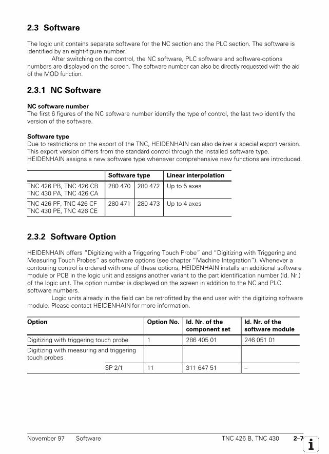
2.3 Software
The logic unit contains separate software for the NC section and the PLC section. The software isidentified by an eight-figure number.
After switching on the control, the NC software, PLC software and software-optionsnumbers are displayed on the screen. The software number can also be directly requested with the aidof the MOD function.
2.3.1 NC Software
NC software number
The first 6 figures of the NC software number identify the type of control, the last two identify theversion of the software.
Software type
Due to restrictions on the export of the TNC, HEIDENHAIN can also deliver a special export version.This export version differs from the standard control through the installed software type.HEIDENHAIN assigns a new software type whenever comprehensive new functions are introduced.
Software type Linear interpolation
TNC 426 PB, TNC 426 CBTNC 430 PA, TNC 426 CA
280 470 280 472 Up to 5 axes
TNC 426 PF, TNC 426 CFTNC 430 PE, TNC 426 CE
280 471 280 473 Up to 4 axes
2.3.2 Software Option
HEIDENHAIN offers “Digitizing with a Triggering Touch Probe” and “Digitizing with Triggering andMeasuring Touch Probes” as software options (see chapter “Machine Integration”). Whenever acontouring control is ordered with one of these options, HEIDENHAIN installs an additional softwaremodule or PCB in the logic unit and assigns another variant to the part identification number (Id. Nr.)of the logic unit. The option number is displayed on the screen in addition to the NC and PLCsoftware numbers.
Logic units already in the field can be retrofitted by the end user with the digitizing softwaremodule. Please contact HEIDENHAIN for more information.
Option Option No. Id. Nr. of the
component set
Id. Nr. of the
software module
Digitizing with triggering touch probe 1 286 405 01 246 051 01
Digitizing with measuring and triggeringtouch probes
SP 2/1 11 311 647 51 –
2–8 TNC 426 B, TNC 430 Software November 97
2.3.3 PLC Software
The PLC software is stored on the hard disk of the TNC. HEIDENHAIN has developed a PLCcommissioning program for the TNC. The source code is available from HEIDENHAIN. This programcan be easily adapted to suit your machine with the PLC programming software PLCdesign.
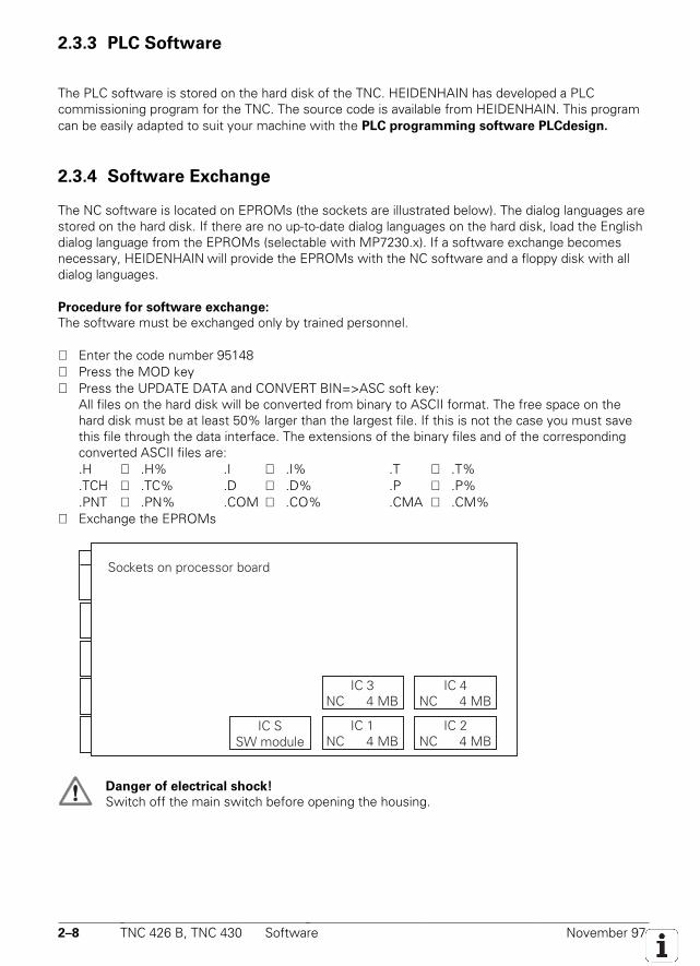
2.3.4 Software Exchange
The NC software is located on EPROMs (the sockets are illustrated below). The dialog languages arestored on the hard disk. If there are no up-to-date dialog languages on the hard disk, load the Englishdialog language from the EPROMs (selectable with MP7230.x). If a software exchange becomesnecessary, HEIDENHAIN will provide the EPROMs with the NC software and a floppy disk with alldialog languages.
Procedure for software exchange:
The software must be exchanged only by trained personnel.
⇒ Enter the code number 95148⇒ Press the MOD key⇒ Press the UPDATE DATA and CONVERT BIN=>ASC soft key:
All files on the hard disk will be converted from binary to ASCII format. The free space on thehard disk must be at least 50% larger than the largest file. If this is not the case you must savethis file through the data interface. The extensions of the binary files and of the correspondingconverted ASCII files are:.H ⇔ .H% .I ⇔ .I% .T ⇔ .T%.TCH ⇔ .TC% .D ⇔ .D% .P ⇔ .P%.PNT ⇔ .PN% .COM ⇔ .CO% .CMA ⇔ .CM%
⇒ Exchange the EPROMs
IC 3NC 4 MB
IC 4NC 4 MB
IC 2NC 4 MB
IC 1NC 4 MB
Sockets on processor board
IC SSW module
Danger of electrical shock!
Switch off the main switch before opening the housing.
November 97 Hardware TNC 426 B, TNC 430 2–9
⇒ Edit or erase the machine parameters. You will find information on the machine parameters inthe MPDOC.A file on the supplied floppy disk.
⇒ Press the END key to exit the machine parameter editor. The error message LANGUAGE LOADERROR appears.
⇒ On the PC, enter the SETUP command to load the NC dialogs, HEIDENHAIN cycles etc. from theprovided floppy disk. The floppy disk also contains a detailed description in the README.TXT file.
⇒ Press the UPDATE DATA and CONVERT ASC=>BIN soft key:All files on the hard disk are converted from ASCII into binary format.
⇒ Reload the files that you have backed up through the data interface.⇒ Switch the TNC off and on to activate the new NC dialogs.
2.3.5 Data Backup
HEIDENHAIN provides a free program, TNCBACK.EXE, for backing up files in the TNC 426. Werecommend to the manufacturer whenever he supplies a machine tool to also provide a floppy diskcontaining a copy of all machine-specific data, backed up with TNCBACK.EXE. The floppy diskmust also contain a copy of TNCBACK.EXE.
Before exchanging his control unit, the customer can save the data from the TNC,especially the TNC:\ partition with its directories containing the part programs (see the user'sinstructions on the floppy disk).
2.4 Hardware
The eight-digit ID number of the logic unit consists of the 6-digit basic ID number followed by the 2-digit version number. The basic ID number designates significant hardware differences (e.g. type oflogic unit encoder inputs). The version number identifies the following differences:
version xy:x = Identifier for a hardware changey = 3 = Export version with “Digitizing with Triggering Touch Probe” option
4 = Standard version with “Digitizing with Triggering Touch Probe” option7 = Standard version with “Digitizing with Measuring and Triggering Touch Probes” option8 = Export version without option9 = Standard version without option
2–10 TNC 426 B, TNC 430 Hardware November 97
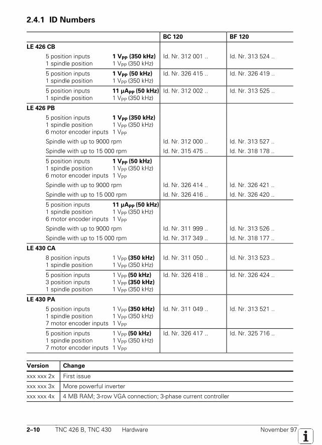
2.4.1 ID Numbers
BC 120 BF 120
LE 426 CB
5 position inputs 1 VPP (350 kHz)
1 spindle position 1 VPP (350 kHz)Id. Nr. 312 001 .. Id. Nr. 313 524 ..
5 position inputs 1 VPP (50 kHz)
1 spindle position 1 VPP (350 kHz)Id. Nr. 326 415 .. Id. Nr. 326 419 ..
5 position inputs 11 µAPP (50 kHz)
1 spindle position 1 VPP (350 kHz)Id. Nr. 312 002 .. Id. Nr. 313 525 ..
LE 426 PB
5 position inputs 1 VPP (350 kHz)
1 spindle position 1 VPP (350 kHz)6 motor encoder inputs 1 VPP
Spindle with up to 9000 rpm Id. Nr. 312 000 .. Id. Nr. 313 527 ..
Spindle with up to 15 000 rpm Id. Nr. 315 475 .. Id. Nr. 318 178 ..
5 position inputs 1 VPP (50 kHz)
1 spindle position 1 VPP (350 kHz)6 motor encoder inputs 1 VPP
Spindle with up to 9000 rpm Id. Nr. 326 414 .. Id. Nr. 326 421 ..
Spindle with up to 15 000 rpm Id. Nr. 326 416 .. Id. Nr. 326 420 ..
5 position inputs 11 µAPP (50 kHz)
1 spindle position 1 VPP (350 kHz)6 motor encoder inputs 1 VPP
Spindle with up to 9000 rpm Id. Nr. 311 999 .. Id. Nr. 313 526 ..
Spindle with up to 15 000 rpm Id. Nr. 317 349 .. Id. Nr. 318 177 ..
LE 430 CA
8 position inputs 1 VPP (350 kHz)
1 spindle position 1 VPP (350 kHz)Id. Nr. 311 050 .. Id. Nr. 313 523 ..
5 position inputs 1 VPP (50 kHz)
3 position inputs 1 VPP (350 kHz)
1 spindle position 1 VPP (350 kHz)
Id. Nr. 326 418 .. Id. Nr. 326 424 ..
LE 430 PA
5 position inputs 1 VPP (350 kHz)
1 spindle position 1 VPP (350 kHz)7 motor encoder inputs 1 VPP
Id. Nr. 311 049 .. Id. Nr. 313 521 ..
5 position inputs 1 VPP (50 kHz)
1 spindle position 1 VPP (350 kHz)7 motor encoder inputs 1 VPP
Id. Nr. 326 417 .. Id. Nr. 325 716 ..
Version Change
xxx xxx 2x First issue
xxx xxx 3x More powerful inverter
xxx xxx 4x 4 MB RAM; 3-row VGA connection; 3-phase current controller
November 97 Hardware TNC 426 B, TNC 430 2–11
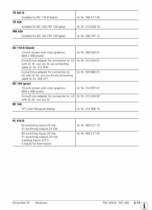
TE 401 B
Suitable for BC 110 B (black) Id. Nr. 250 517 05
TE 420
Suitable for BC 120 / BF 120 (gray) Id. Nr. 313 038 10
MB 420
Suitable for BC 120 / BF 120 (gray) Id. Nr. 293 757 12
BC 110 B (black)
14-inch screen with color graphics(640 x 490 pixels)
Id. Nr. 260 520 01
2-row/3-row adapter for connection to LEwith Id. Nr. xxx xxx 4x via connectingcable Id. Nr. 312 878 ..
Id. Nr. 313 434 01
2-row/3-row adapter for connection toLE with Id. Nr. xxx xxx 4x via connectingcable Id. Nr. 250 477 ..
Id. Nr. 324 862 01
BC 120 (gray)
15-inch screen with color graphics(640 x 490 pixels)
Id. Nr. 313 037 01
3-row/2-row adapter for connection to LEwith Id. Nr. xxx xxx 3x
Id. Nr. 313 434 02
BF 120
TFT color flat-panel display Id. Nr. 313 506 10
PL 410 B
64 switching inputs 24 Vdc31 switching outputs 24 Vdc
Id. Nr. 263 217 12
64 switching inputs 24 Vdc31 switching outputs 24 Vdc4 analog inputs ±10 V4 inputs for thermistors
Id. Nr. 263 217 02
2–12 TNC 426 B, TNC 430 Hardware November 97
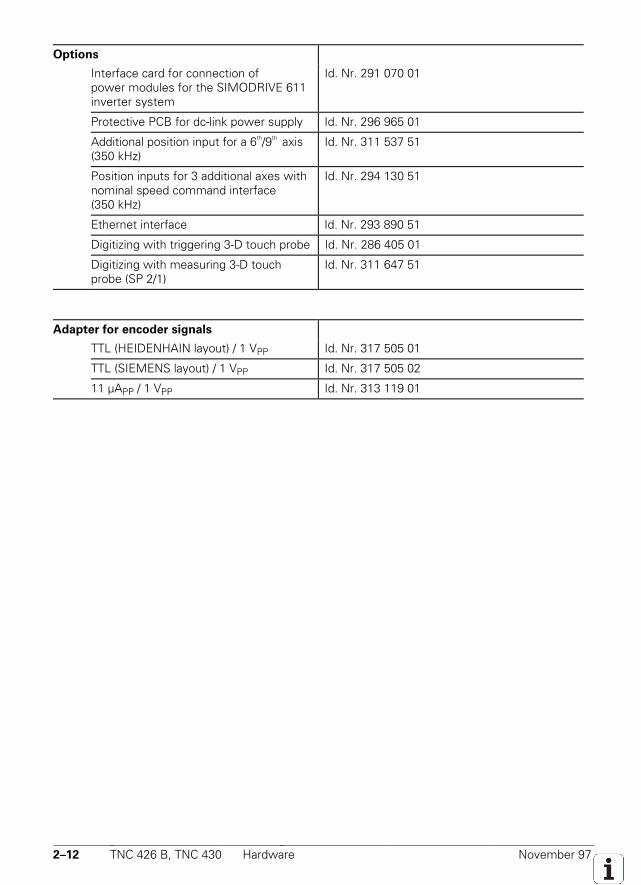
Options
Interface card for connection ofpower modules for the SIMODRIVE 611inverter system
Id. Nr. 291 070 01
Protective PCB for dc-link power supply Id. Nr. 296 965 01
Additional position input for a 6th/9th axis(350 kHz)
Id. Nr. 311 537 51
Position inputs for 3 additional axes withnominal speed command interface(350 kHz)
Id. Nr. 294 130 51
Ethernet interface Id. Nr. 293 890 51
Digitizing with triggering 3-D touch probe Id. Nr. 286 405 01
Digitizing with measuring 3-D touchprobe (SP 2/1)
Id. Nr. 311 647 51
Adapter for encoder signals
TTL (HEIDENHAIN layout) / 1 VPP Id. Nr. 317 505 01
TTL (SIEMENS layout) / 1 VPP Id. Nr. 317 505 02
11 µAPP / 1 VPP Id. Nr. 313 119 01
November 97 Release Dates TNC 426 B, TNC 430 2–13
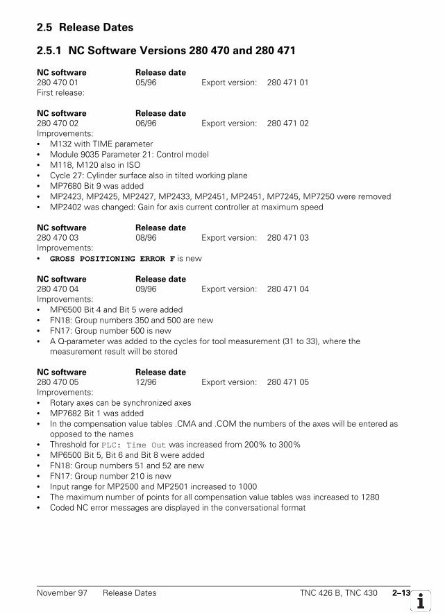
2.5 Release Dates
2.5.1 NC Software Versions 280 470 and 280 471
NC software Release date
280 470 01 05/96 Export version: 280 471 01First release:
NC software Release date
280 470 02 06/96 Export version: 280 471 02Improvements:• M132 with TIME parameter• Module 9035 Parameter 21: Control model• M118, M120 also in ISO• Cycle 27: Cylinder surface also in tilted working plane• MP7680 Bit 9 was added• MP2423, MP2425, MP2427, MP2433, MP2451, MP2451, MP7245, MP7250 were removed• MP2402 was changed: Gain for axis current controller at maximum speed
NC software Release date
280 470 03 08/96 Export version: 280 471 03Improvements:• GROSS POSITIONING ERROR F is new
NC software Release date
280 470 04 09/96 Export version: 280 471 04Improvements:• MP6500 Bit 4 and Bit 5 were added• FN18: Group numbers 350 and 500 are new• FN17: Group number 500 is new• A Q-parameter was added to the cycles for tool measurement (31 to 33), where the
measurement result will be stored
NC software Release date
280 470 05 12/96 Export version: 280 471 05Improvements:• Rotary axes can be synchronized axes• MP7682 Bit 1 was added• In the compensation value tables .CMA and .COM the numbers of the axes will be entered as
opposed to the names• Threshold for PLC: Time Out was increased from 200% to 300%• MP6500 Bit 5, Bit 6 and Bit 8 were added• FN18: Group numbers 51 and 52 are new• FN17: Group number 210 is new• Input range for MP2500 and MP2501 increased to 1000• The maximum number of points for all compensation value tables was increased to 1280• Coded NC error messages are displayed in the conversational format
2–14 TNC 426 B, TNC 430 Release Dates November 97
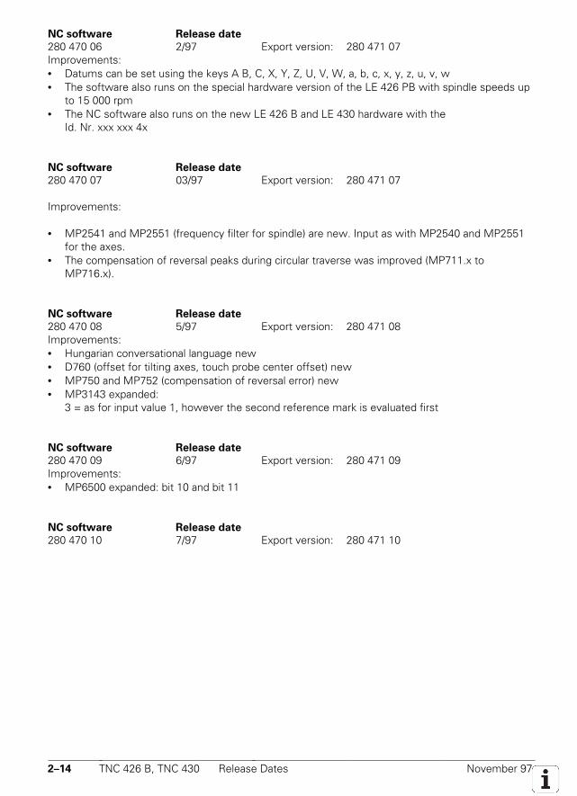
NC software Release date
280 470 06 2/97 Export version: 280 471 07Improvements:• Datums can be set using the keys A B, C, X, Y, Z, U, V, W, a, b, c, x, y, z, u, v, w• The software also runs on the special hardware version of the LE 426 PB with spindle speeds up
to 15 000 rpm• The NC software also runs on the new LE 426 B and LE 430 hardware with the
Id. Nr. xxx xxx 4x
NC software Release date
280 470 07 03/97 Export version: 280 471 07
Improvements:
• MP2541 and MP2551 (frequency filter for spindle) are new. Input as with MP2540 and MP2551for the axes.
• The compensation of reversal peaks during circular traverse was improved (MP711.x toMP716.x).
NC software Release date
280 470 08 5/97 Export version: 280 471 08Improvements:• Hungarian conversational language new• D760 (offset for tilting axes, touch probe center offset) new• MP750 and MP752 (compensation of reversal error) new• MP3143 expanded:
3 = as for input value 1, however the second reference mark is evaluated first
NC software Release date
280 470 09 6/97 Export version: 280 471 09Improvements:• MP6500 expanded: bit 10 and bit 11
NC software Release date
280 470 10 7/97 Export version: 280 471 10
November 97 Release Dates TNC 426 B, TNC 430 2–15
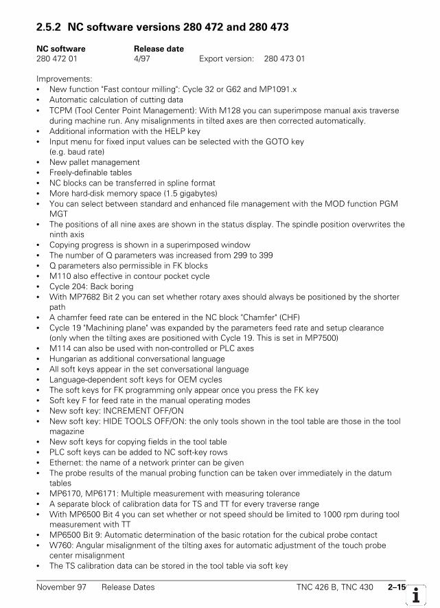
2.5.2 NC software versions 280 472 and 280 473
NC software Release date
280 472 01 4/97 Export version: 280 473 01
Improvements:• New function "Fast contour milling": Cycle 32 or G62 and MP1091.x• Automatic calculation of cutting data• TCPM (Tool Center Point Management): With M128 you can superimpose manual axis traverse
during machine run. Any misalignments in tilted axes are then corrected automatically.• Additional information with the HELP key• Input menu for fixed input values can be selected with the GOTO key
(e.g. baud rate)• New pallet management• Freely-definable tables• NC blocks can be transferred in spline format• More hard-disk memory space (1.5 gigabytes)• You can select between standard and enhanced file management with the MOD function PGM
MGT• The positions of all nine axes are shown in the status display. The spindle position overwrites the
ninth axis• Copying progress is shown in a superimposed window• The number of Q parameters was increased from 299 to 399• Q parameters also permissible in FK blocks• M110 also effective in contour pocket cycle• Cycle 204: Back boring• With MP7682 Bit 2 you can set whether rotary axes should always be positioned by the shorter
path• A chamfer feed rate can be entered in the NC block "Chamfer" (CHF)• Cycle 19 "Machining plane" was expanded by the parameters feed rate and setup clearance
(only when the tilting axes are positioned with Cycle 19. This is set in MP7500)• M114 can also be used with non-controlled or PLC axes• Hungarian as additional conversational language• All soft keys appear in the set conversational language• Language-dependent soft keys for OEM cycles• The soft keys for FK programming only appear once you press the FK key• Soft key F for feed rate in the manual operating modes• New soft key: INCREMENT OFF/ON• New soft key: HIDE TOOLS OFF/ON: the only tools shown in the tool table are those in the tool
magazine• New soft keys for copying fields in the tool table• PLC soft keys can be added to NC soft-key rows• Ethernet: the name of a network printer can be given• The probe results of the manual probing function can be taken over immediately in the datum
tables• MP6170, MP6171: Multiple measurement with measuring tolerance• A separate block of calibration data for TS and TT for every traverse range• With MP6500 Bit 4 you can set whether or not speed should be limited to 1000 rpm during tool
measurement with TT• MP6500 Bit 9: Automatic determination of the basic rotation for the cubical probe contact• W760: Angular misalignment of the tilting axes for automatic adjustment of the touch probe
center misalignment• The TS calibration data can be stored in the tool table via soft key
2–16 TNC 426 B, TNC 430 Release Dates November 97
• Cycles 31 to 33 (Tool measurement) were expanded by the input field "Q parameters for result"• With MP6500 Bit 5 and Bit 6 you can define how to proceed if tool breaks• FN17, FN18 ID990 NR1 Programmed probing• FN17: ID210 NR6 Tilting the working plane during program run active/inactive• FN17: ID50 Overwrite tool table• FN17: ID210 Overwrite basic rotation• FN18 ID350 Enhanced touch probe data• FN23: CDATA Calculating the circle center from 3 touch points• FN24: CDATA Calculating the circle center from 4 touch points• FN25: Setting the datum• ISO: Cycles with a number ≥ 200 can be programmed with graphic support (also OEM cycles)• ISO: Cycles G75 and G76 (Rectangular pocket) were expanded by the input field "corner radius"• ISO: Parameter H (max. permissible angle) can be entered after M112• ISO: G60 Running digitized data is new• MP2000 was removed. Digital axes can be defined in MP120• In the compensation value tables COM and CMA you can use soft keys to select the columns for
the desired axes• Non-linear axis error compensation: Max. number of compensation points increased from 640 to
1280• A formula can be input in MP2020 (Distance covered in one motor revolution)• MP2541, MP2551: Frequency filter for spindle• The number of tools in the tool table was increased from 254 to 37 767• M4019: Reversing the count direction of the linear encoder on the spindle• Cooperative multi-tasking in the PLC (SPAWN command)• Automatic tool recognition (BIS)• String operand S#Axx new• Module 9019: Checking program storage• Module 9035: Expansion of parameters 3, 1000, 1001• Module 9038: Reading axis information• Module 9096: Deleting a line in the tool table• Module 9112: Sending ASCII characters via RS-232• Module 9113: Receiving ASCII characters via RS-232• Module 9151: Selecting traverse range and axis designation• Module 9200/9201: Expanded (PLC soft keys can be added to NC soft-key rows)• Module 9215: Superimposing PLC window• Module 9270: Reading from OEM.SYS• Module 9271: Writing to OEM.SYS• Automatic offset compensation of the encoder signals• The oscilloscope recordings can be stored in a file.• MP7365.5: Selected oscilloscope channel (input $00000FF)
November 97 Release Dates TNC 426 B, TNC 430 2–17
NC software Release date
280 472 02 7/97 Export version: 280 473 02Improvements:• Cycle 32 changed to "Tolerance"• M134 new• System file TNC.SYS new• MP6500 expanded: Bit 10 Probing routine, Bit 11 Checking tool and changing the tool table• MP7500 expanded: Bit 3 Setting the datum in a tilted coordinate system• Editor for creating the format of freely-definable tables• FN18: ID200 and ID270 new• FN17: ID350 new• M4161 new• PLC commands BTX, BCX, and BSX new
NC software Release date
280 472 03 8/97 Export version: 280 473 03Improvements:• Spline blocks also in tilted working plane• MP7680, bit 10 new (spline at compensated outside corners)• This software also runs on the old LE 426 CB/PB and LE 430 CA/PA hardware, however with
reduced function range• Cycle 19: Dialog box "Setup clearance" new
NC software Release date
280 472 04 10/97 Export version: 280 473 04Improvements:• Code words LSV2TIME0 to LSV2TIME2 new• Module 9038 expanded by transfer parameter –1• DR2 can now be defined in TOOL CALL block• Spindle DSP limits maximum torque to 2.5 • rated torque

2–18 TNC 426 B, TNC 430 Release Dates November 97

November 97 Electrical Noise Immunity TNC 426 B, TNC 430 3–1
3 Mounting and Electrical Installation
3.1 Electrical Noise Immunity
Location for use
This device corresponds to Class A according to EN 55022 and is intended primarily for operation inindustrially zoned areas.
Remember that the vulnerability of electronic equipment to noise increases with faster signalprocessing and higher sensitivity. Protect your equipment by observing the following rules andrecommendations.
Noise voltages are mainly produced and transmitted by capacitive and inductive coupling. Electricalnoise can be picked up by the inputs and outputs to the equipment, and the cabling.
Likely sources of interference are:• Strong magnetic fields from transformers and electric motors• Relays, contactors and solenoid valves• High-frequency equipment, pulse equipment and stray magnetic fields from switch-mode power
supplies• Mains leads and leads to the above equipment
Electrical interference can be avoided by:• A minimum distance between the logic unit (and its leads) and interfering equipment > 20 cm.• A minimum distance between the logic unit (and its leads) and cables carrying interference
signals > 10 cm. (Where signal cables and cables that carry interference signals are laid togetherin metallic ducting, adequate decoupling can be achieved by using a grounded separation shield.)
• Shielding according to IEC 742 EN 50 178.• Potential compensating lines dia. ≥ 6 mm² (see Grounding Diagram).• Use of original HEIDENHAIN cables, connectors and couplings.
3–2 TNC 426 B, TNC 430 Heat Generation and Cooling November 97
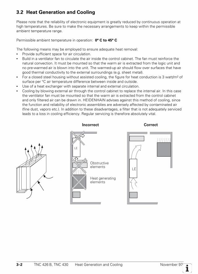
3.2 Heat Generation and Cooling
Please note that the reliability of electronic equipment is greatly reduced by continuous operation athigh temperatures. Be sure to make the necessary arrangements to keep within the permissibleambient temperature range.
Permissible ambient temperature in operation: 0° C to 45° C
The following means may be employed to ensure adequate heat removal:• Provide sufficient space for air circulation.• Build in a ventilator fan to circulate the air inside the control cabinet. The fan must reinforce the
natural convection. It must be mounted so that the warm air is extracted from the logic unit andno pre-warmed air is blown into the unit. The warmed-up air should flow over surfaces that havegood thermal conductivity to the external surroundings (e.g. sheet metal).
• For a closed steel housing without assisted cooling, the figure for heat conduction is 3 watt/m² ofsurface per °C air temperature difference between inside and outside.
• Use of a heat exchanger with separate internal and external circulation.• Cooling by blowing external air through the control cabinet to replace the internal air. In this case
the ventilator fan must be mounted so that the warm air is extracted from the control cabinetand only filtered air can be drawn in. HEIDENHAIN advises against this method of cooling, sincethe function and reliability of electronic assemblies are adversely affected by contaminated air(fine dust, vapors etc.). In addition to these disadvantages, a filter that is not adequately servicedleads to a loss in cooling efficiency. Regular servicing is therefore absolutely vital.
Obstructiveelements
Heat generatingelements
Incorrect
LE
LE
Correct
November 97 Humidity TNC 426 B, TNC 430 3–3
3.3 Humidity
Permissible humidity: < 75% in continuous operation,< 95% for not more than 30 days p.a. (randomly distributed).
In tropical areas it is recommended that the TNC not be switched off, so that condensation isavoided on the circuit boards. The heat generation prevents condensation and has no furtherdisadvantages.
3.4 Mechanical Vibration
Permissible vibration: < 0.5 g
3.5 Mounting Position
Note the following fundamental points on mounting:
• mechanical accessibility,• permissible environmental conditions,• electrical noise immunity,• the electrical regulations that are in force in your country.
3–4 TNC 426 B, TNC 430 Mounting Position November 97
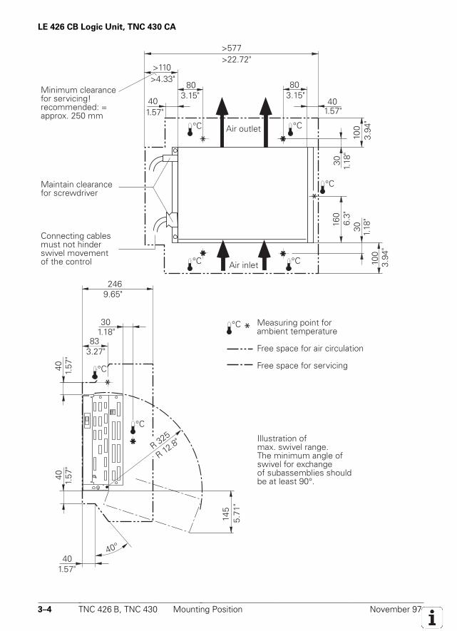
LE 426 CB Logic Unit, TNC 430 CA
B
* **
** **
**
°C °C
°C °C
4040
40°
145
40
30
83
246
°C
>577
>110
80 80
4040
30
100
160
30
100
°C
*
°C
°C
*
*
R 325
Air inlet
Measuring point for ambient temperature
Free space for air circulation
Free space for servicing
Illustration of max. swivel range.The minimum angle ofswivel for exchangeof subassemblies shouldbe at least 90°.
Minimum clearancefor servicing!recommended: =approx. 250 mm
Maintain clearancefor screwdriver
Connecting cablesmust not hinderswivel movementof the control
Air outlet
>22.72"
3.15"3.15"
>4.33"
1.57" 1.57"
3.94
"
1.18
"
1.18
"
3.94
"
6.3"
9.65"
1.18"
3.27"
1.57
"1.
57"
1.57"
5.71
"
R 12.8"
November 97 Mounting Position TNC 426 B, TNC 430 3–5
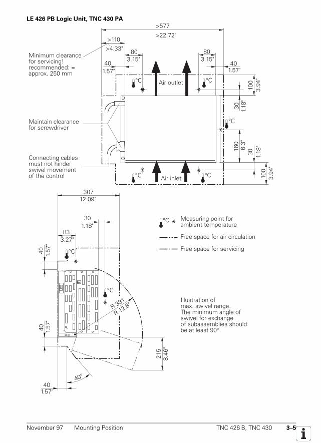
LE 426 PB Logic Unit, TNC 430 PA
*
4040
40°
215
40
30
83
307
°C *
°C
°C
B
R 331
*
** *
* *°C °C
°C °C
>577
>110
80 80
4040
30
100
160
30
100
°C
*
Air inlet
Measuring point for ambient temperature
Free space for air circulation
Free space for servicing
Illustration of max. swivel range.The minimum angle ofswivel for exchangeof subassemblies shouldbe at least 90°.
Minimum clearancefor servicing!recommended: =approx. 250 mm
Maintain clearancefor screwdriver
Connecting cablesmust not hinderswivel movementof the control
Air outlet
>22.72"
3.15"3.15"
>4.33"
1.57" 1.57"
3.94
"
1.18
"
1.18
"
3.94
"
6.3"
12.09"
1.18"
3.27"
1.57
"1.
57"
1.57"
8.46
"
R 12.8"
3–6 TNC 426 B, TNC 430 Degree of Protection November 97
Visual Display Unit
BC 120
When mounting the BC 120, remember that this unit is very sensitive to magnetic or electro-magnetic pick-up. The picture can be disturbed by strong magnetic fields. For this reason, keep aminimum distance of 0.5 m between the VDU housing and the source of any disturbance (e.g.permanent magnets, motors, transformers etc.).
Free space for air circulation, see dimension drawing in Appendix
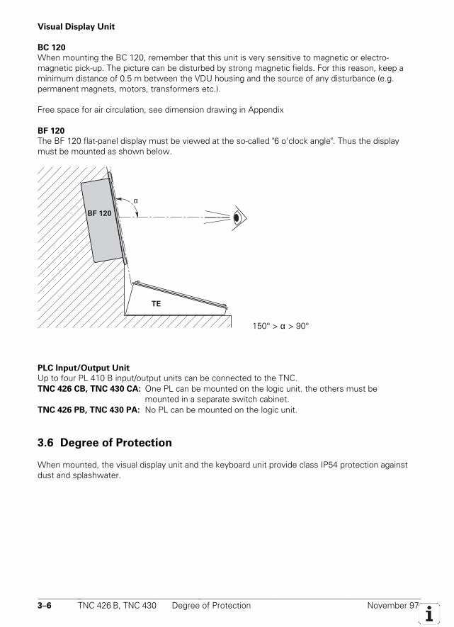
BF 120
The BF 120 flat-panel display must be viewed at the so-called "6 o'clock angle". Thus the displaymust be mounted as shown below.
BF 120
TE
α
150° > α > 90°
PLC Input/Output Unit
Up to four PL 410 B input/output units can be connected to the TNC.TNC 426 CB, TNC 430 CA: One PL can be mounted on the logic unit. the others must be
mounted in a separate switch cabinet.TNC 426 PB, TNC 430 PA: No PL can be mounted on the logic unit.
3.6 Degree of Protection
When mounted, the visual display unit and the keyboard unit provide class IP54 protection againstdust and splashwater.
3–8 TNC 426 B, TNC 430 Connection Overview November 97
3.7 Connection Overview
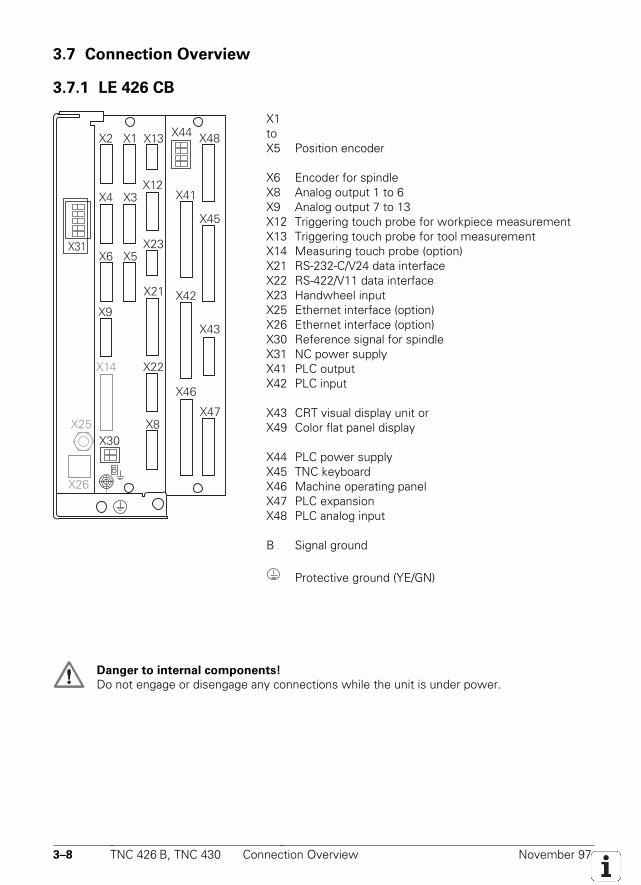
3.7.1 LE 426 CB
X48
X31
X2
X6
X4
X1
X5
X3
X13
X12
X23
X8
X22X14
X21
X45
X41
X43
X42
X47
X46
B
X9
X44
X30X25
X26
X1toX5 Position encoder
X6 Encoder for spindleX8 Analog output 1 to 6X9 Analog output 7 to 13X12 Triggering touch probe for workpiece measurementX13 Triggering touch probe for tool measurementX14 Measuring touch probe (option)X21 RS-232-C/V24 data interfaceX22 RS-422/V11 data interfaceX23 Handwheel inputX25 Ethernet interface (option)X26 Ethernet interface (option)X30 Reference signal for spindleX31 NC power supplyX41 PLC outputX42 PLC input
X43 CRT visual display unit orX49 Color flat panel display
X44 PLC power supplyX45 TNC keyboardX46 Machine operating panelX47 PLC expansionX48 PLC analog input
B Signal ground
Protective ground (YE/GN)
Danger to internal components!
Do not engage or disengage any connections while the unit is under power.
November 97 Connection Overview TNC 426 B, TNC 430 3–9
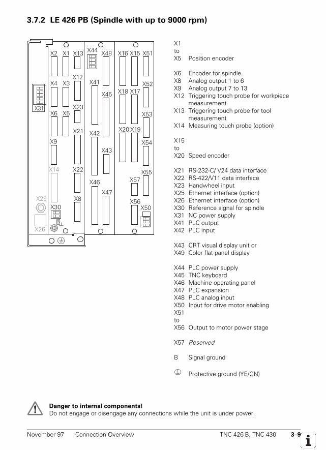
3.7.2 LE 426 PB (Spindle with up to 9000 rpm)
X48
X31
X2
X6
X4
X1
X5
X3
X13
X12
X23
X8
X22X14
X21
X45
X41
X43
X42
X47
X46
X51X16 X15
X52X18 X17
X53
X54
X55X57
X20
B
X9
X44
X30X25
X26
X19
X56X50
X1toX5 Position encoder
X6 Encoder for spindleX8 Analog output 1 to 6X9 Analog output 7 to 13X12 Triggering touch probe for workpiece
measurementX13 Triggering touch probe for tool
measurementX14 Measuring touch probe (option)
X15toX20 Speed encoder
X21 RS-232-C/ V24 data interfaceX22 RS-422/V11 data interfaceX23 Handwheel inputX25 Ethernet interface (option)X26 Ethernet interface (option)X30 Reference signal for spindleX31 NC power supplyX41 PLC outputX42 PLC input
X43 CRT visual display unit orX49 Color flat panel display
X44 PLC power supplyX45 TNC keyboardX46 Machine operating panelX47 PLC expansionX48 PLC analog inputX50 Input for drive motor enablingX51toX56 Output to motor power stage
X57 Reserved
B Signal ground
Protective ground (YE/GN)
Danger to internal components!
Do not engage or disengage any connections while the unit is under power.
3–10 TNC 426 B, TNC 430 Connection Overview November 97
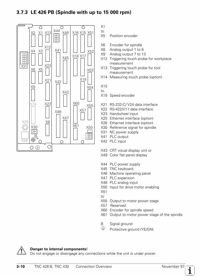
3.7.3 LE 426 PB (Spindle with up to 15 000 rpm)
X48
X31
X2
X6
X4
X1
X5
X3
X13
X12
X23
X8
X22X14
X21
X45
X41
X43
X42
X47
X46
X51X16 X15
X52X18 X17
X53
X54
X55X57
B
X9
X44
X30X25
X26
X19
X50X61
X60
X1toX5 Position encoder
X6 Encoder for spindleX8 Analog output 1 to 6X9 Analog output 7 to 13X12 Triggering touch probe for workpiece
measurementX13 Triggering touch probe for tool
measurementX14 Measuring touch probe (option)
X15toX19 Speed encoder
X21 RS-232-C/ V24 data interfaceX22 RS-422/V11 data interfaceX23 Handwheel inputX25 Ethernet interface (option)X26 Ethernet interface (option)X30 Reference signal for spindleX31 NC power supplyX41 PLC outputX42 PLC input
X43 CRT visual display unit orX49 Color flat panel display
X44 PLC power supplyX45 TNC keyboardX46 Machine operating panelX47 PLC expansionX48 PLC analog inputX50 Input for drive motor enablingX51toX55 Output to motor power stageX57 ReservedX60 Encoder for spindle speedX61 Output to motor power stage of the spindle
B Signal groundProtective ground (YE/GN)
Danger to internal components!
Do not engage or disengage any connections while the unit is under power.
November 97 Connection Overview TNC 426 B, TNC 430 3–11
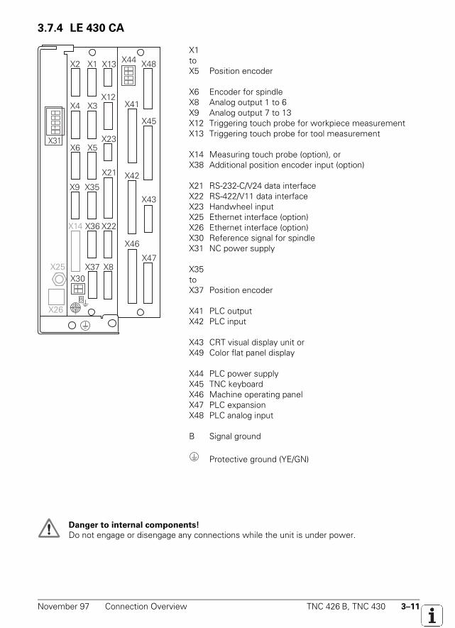
3.7.4 LE 430 CA
X48
X31
X2
X6
X4
X1
X5
X3
X13
X12
X23
X8
X22
X35
X14
X21
X45
X41
X43
X42
X47
X46
B
X9
X36
X37
X44
X30X25
X26
X1toX5 Position encoder
X6 Encoder for spindleX8 Analog output 1 to 6X9 Analog output 7 to 13X12 Triggering touch probe for workpiece measurementX13 Triggering touch probe for tool measurement
X14 Measuring touch probe (option), orX38 Additional position encoder input (option)
X21 RS-232-C/V24 data interfaceX22 RS-422/V11 data interfaceX23 Handwheel inputX25 Ethernet interface (option)X26 Ethernet interface (option)X30 Reference signal for spindleX31 NC power supply
X35toX37 Position encoder
X41 PLC outputX42 PLC input
X43 CRT visual display unit orX49 Color flat panel display
X44 PLC power supplyX45 TNC keyboardX46 Machine operating panelX47 PLC expansionX48 PLC analog input
B Signal ground
Protective ground (YE/GN)
Danger to internal components!
Do not engage or disengage any connections while the unit is under power.
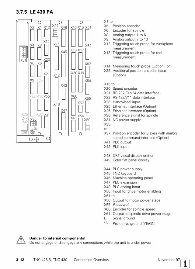
3–12 TNC 426 B, TNC 430 Connection Overview November 97
3.7.5 LE 430 PA
X48
X31
X2
X6
X4
X1
X5
X3
X13
X12
X23
X8
X22
X35
X14
X21
X45
X41
X43
X42
X47
X46
X51X16 X15
X52X18 X17
X53
X54
X55
X61
X57
X20
X60
B
X9
X36
X37
X44
X30X25
X26
X19
X56X50
X1 toX5 Position encoderX6 Encoder for spindleX8 Analog output 1 to 6X9 Analog output 7 to 13X12 Triggering touch probe for workpiece
measurementX13 Triggering touch probe for tool
measurement
X14 Measuring touch probe (Option), orX38 Additional position encoder input
(Option)
X15 toX20 Speed encoderX21 RS-232-C/ V24 data interfaceX22 RS-422/V11 data interfaceX23 Handwheel inputX25 Ethernet interface (Option)X26 Ethernet interface (Option)X30 Reference signal for spindleX31 NC power supplyX35toX37 Position encoder for 3 axes with analog
speed command interface (Option)X41 PLC outputX42 PLC input
X43 CRT visual display unit orX49 Color flat panel display
X44 PLC power supplyX45 TNC keyboardX46 Machine operating panelX47 PLC expansionX48 PLC analog inputX50 Input for drive motor enablingX51 toX56 Output to motor power stageX57 ReservedX60 Encoder for spindle speedX61 Output to spindle drive power stageB Signal ground
Protective ground (YE/GN)
Danger to internal components!
Do not engage or disengage any connections while the unit is under power.
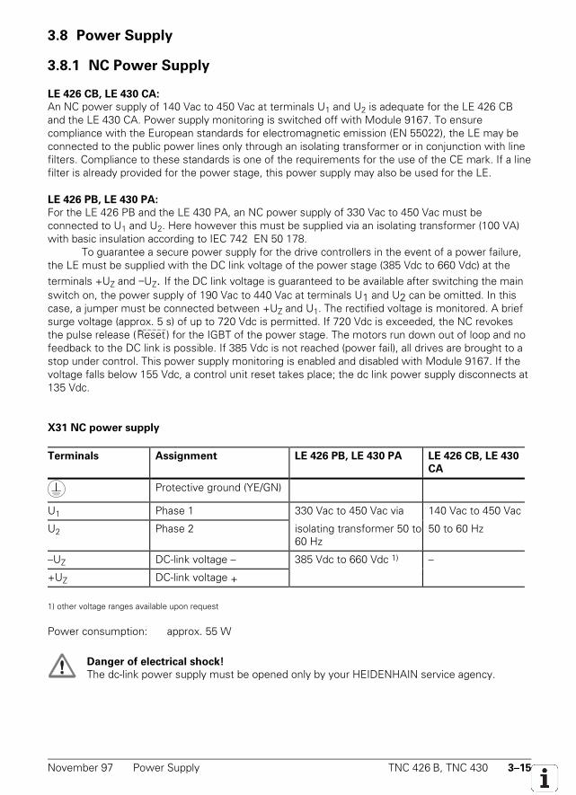
November 97 Power Supply TNC 426 B, TNC 430 3–15
3.8 Power Supply
3.8.1 NC Power Supply
LE 426 CB, LE 430 CA:
An NC power supply of 140 Vac to 450 Vac at terminals U1 and U2 is adequate for the LE 426 CBand the LE 430 CA. Power supply monitoring is switched off with Module 9167. To ensurecompliance with the European standards for electromagnetic emission (EN 55022), the LE may beconnected to the public power lines only through an isolating transformer or in conjunction with linefilters. Compliance to these standards is one of the requirements for the use of the CE mark. If a linefilter is already provided for the power stage, this power supply may also be used for the LE.
LE 426 PB, LE 430 PA:
For the LE 426 PB and the LE 430 PA, an NC power supply of 330 Vac to 450 Vac must beconnected to U1 and U2. Here however this must be supplied via an isolating transformer (100 VA)with basic insulation according to IEC 742 EN 50 178.
To guarantee a secure power supply for the drive controllers in the event of a power failure,the LE must be supplied with the DC link voltage of the power stage (385 Vdc to 660 Vdc) at theterminals +UZ and −UZ. If the DC link voltage is guaranteed to be available after switching the mainswitch on, the power supply of 190 Vac to 440 Vac at terminals U1 and U2 can be omitted. In thiscase, a jumper must be connected between +UZ and U1. The rectified voltage is monitored. A briefsurge voltage (approx. 5 s) of up to 720 Vdc is permitted. If 720 Vdc is exceeded, the NC revokesthe pulse release (Reset
——————
) for the IGBT of the power stage. The motors run down out of loop and nofeedback to the DC link is possible. If 385 Vdc is not reached (power fail), all drives are brought to astop under control. This power supply monitoring is enabled and disabled with Module 9167. If thevoltage falls below 155 Vdc, a control unit reset takes place; the dc link power supply disconnects at135 Vdc.
X31 NC power supply
Terminals Assignment LE 426 PB, LE 430 PA LE 426 CB, LE 430
CA
Protective ground (YE/GN)
U1 Phase 1 330 Vac to 450 Vac via 140 Vac to 450 Vac
U2 Phase 2 isolating transformer 50 to60 Hz
50 to 60 Hz
–UZ DC-link voltage – 385 Vdc to 660 Vdc 1) –
+UZ DC-link voltage +
1) other voltage ranges available upon request
Power consumption: approx. 55 W
Danger of electrical shock!
The dc-link power supply must be opened only by your HEIDENHAIN service agency.
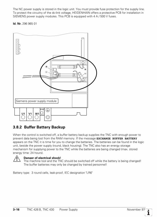
3–16 TNC 426 B, TNC 430 Power Supply November 97
The NC power supply is stored in the logic unit. You must provide fuse protection for the supply line.To protect the circuitry of the dc-link voltage, HEIDENHAIN offers a protective PCB for installation inSIEMENS power supply modules. This PCB is equipped with 4 A / 500 V fuses.
Id. Nr. 296 965 01
U1 V1 W1
X131
–
++
–
3.8.2 Buffer Battery Backup
When the control is switched off, a buffer battery backup supplies the TNC with enough power toprevent data being lost from the RAM memory. If the message EXCHANGE BUFFER BATTERYappears on the TNC it is time for you to change the batteries. The batteries can be found in the logicunit, beside the power supply (round, black housing). The TNC also has an energy storagemechanism for supplying power to the TNC while the batteries are being changed (max. storedenergy time: 24 hours).
Danger of electrical shock!The machine tool and the TNC should be switched off while the battery is being changed!The buffer batteries may only be changed by trained personnel!
Battery type: 3 round cells, leak-proof, IEC designation "LR6"
Siemens power supply module
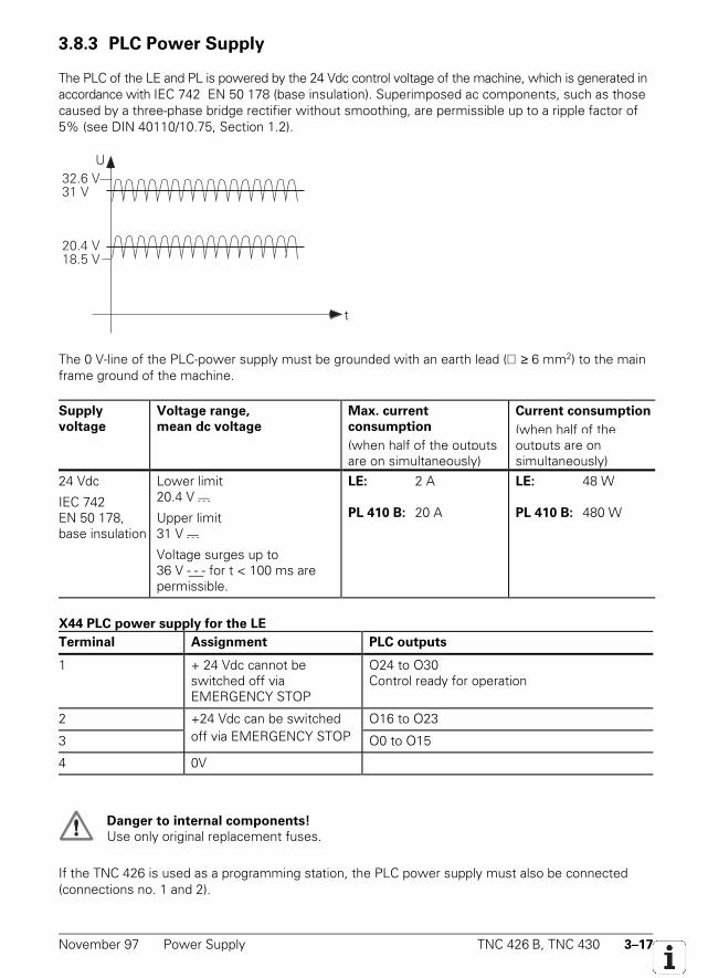
November 97 Power Supply TNC 426 B, TNC 430 3–17
3.8.3 PLC Power Supply
The PLC of the LE and PL is powered by the 24 Vdc control voltage of the machine, which is generated inaccordance with IEC 742 EN 50 178 (base insulation). Superimposed ac components, such as thosecaused by a three-phase bridge rectifier without smoothing, are permissible up to a ripple factor of5% (see DIN 40110/10.75, Section 1.2).
32.6 V31 V
20.4 V18.5 V
U
t
The 0 V-line of the PLC-power supply must be grounded with an earth lead (∅ ≥ 6 mm2) to the mainframe ground of the machine.
Supply
voltage
Voltage range,
mean dc voltage
Max. current
consumption
(when half of the outputsare on simultaneously)
Current consumption
(when half of theoutputs are onsimultaneously)
24 Vdc
IEC 742EN 50 178,base insulation
Lower limit20.4 V - - -
Upper limit31 V - - -
Voltage surges up to36 V - - - for t < 100 ms arepermissible.
LE: 2 A
PL 410 B: 20 A
LE: 48 W
PL 410 B: 480 W
X44 PLC power supply for the LE
Terminal Assignment PLC outputs
1 + 24 Vdc cannot beswitched off viaEMERGENCY STOP
O24 to O30Control ready for operation
2 +24 Vdc can be switched O16 to O23
3 off via EMERGENCY STOP O0 to O15
4 0V
Danger to internal components!
Use only original replacement fuses.
If the TNC 426 is used as a programming station, the PLC power supply must also be connected(connections no. 1 and 2).
3–18 TNC 426 B, TNC 430 Power Supply November 97
Power supply for the PL 410 B
Terminal Assignment 1st PL 2nd PL 3rd PL 4th PL
X9 0 V
X10 +24 Vdc power for logic unit and for control-is-ready signal
X11 +24 Vdc power supply foroutputs
O32 to O39 O64 to O71 O95 to O102 O127 toO134
X12 +24 Vdc power supply foroutputs
O40 to O47 O72 to O79 O130 toO110
O135 toO142
X13 +24 Vdc power supply foroutputs
O48 to O55 O80 to O87 O111 toO118
O143 toO150
X14 +24 Vdc power supply foroutputs
O56 to O62 O88 to O94 O114 toO125
O151 toO157
The PL 410 B input/output unit for the PLC is available as an option. It provides additional analoginputs and inputs for Pt 100 thermistors. The power supply for these analog inputs and thermistorsmust comply with IEC 742 EN 50 178, 5.88, “low-voltage electrical separation.”
X23 Power supply of analog inputs on the PL 410 B
Terminal Assignment
1 + 24 Vdc (IEC 742 EN 50 178, 5.88, low-voltage electrical separation)
2 0 V
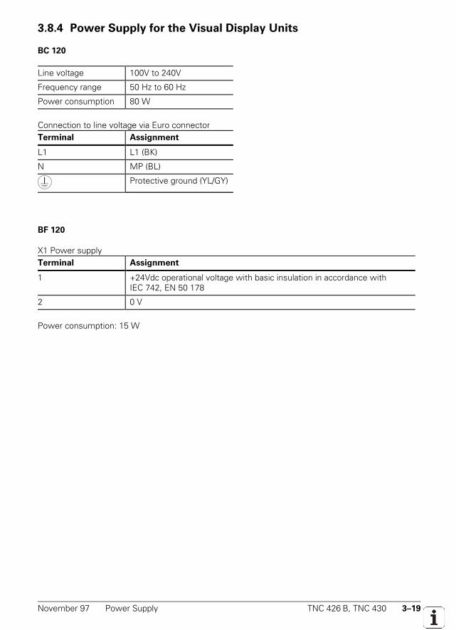
November 97 Power Supply TNC 426 B, TNC 430 3–19
3.8.4 Power Supply for the Visual Display Units
BC 120
Line voltage 100V to 240V
Frequency range 50 Hz to 60 Hz
Power consumption 80 W
Connection to line voltage via Euro connectorTerminal Assignment
L1 L1 (BK)
N MP (BL)
Protective ground (YL/GY)
BF 120
X1 Power supplyTerminal Assignment
1 +24Vdc operational voltage with basic insulation in accordance withIEC 742, EN 50 178
2 0 V
Power consumption: 15 W
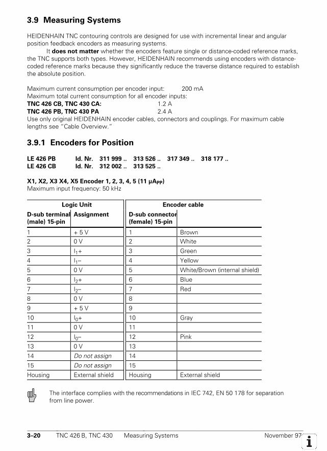
3–20 TNC 426 B, TNC 430 Measuring Systems November 97
3.9 Measuring Systems
HEIDENHAIN TNC contouring controls are designed for use with incremental linear and angularposition feedback encoders as measuring systems.
It does not matter whether the encoders feature single or distance-coded reference marks,the TNC supports both types. However, HEIDENHAIN recommends using encoders with distance-coded reference marks because they significantly reduce the traverse distance required to establishthe absolute position.
Maximum current consumption per encoder input: 200 mAMaximum total current consumption for all encoder inputs:TNC 426 CB, TNC 430 CA: 1.2 ATNC 426 PB, TNC 430 PA 2.4 AUse only original HEIDENHAIN encoder cables, connectors and couplings. For maximum cablelengths see “Cable Overview.”
3.9.1 Encoders for Position
LE 426 PB Id. Nr. 311 999 .. 313 526 .. 317 349 .. 318 177 ..
LE 426 CB Id. Nr. 312 002 .. 313 525 ..
X1, X2, X3 X4, X5 Encoder 1, 2, 3, 4, 5 (11 µAPP)
Maximum input frequency: 50 kHz
Logic Unit Encoder cable
D-sub terminal
(male) 15-pin
Assignment D-sub connector
(female) 15-pin
1 + 5 V 1 Brown2 0 V 2 White
3 I1+ 3 Green
4 I1– 4 Yellow
5 0 V 5 White/Brown (internal shield)
6 I2+ 6 Blue
7 I2– 7 Red
8 0 V 8
9 + 5 V 9
10 I0+ 10 Gray
11 0 V 11
12 I0– 12 Pink
13 0 V 13
14 Do not assign 14
15 Do not assign 15
Housing External shield Housing External shield
The interface complies with the recommendations in IEC 742, EN 50 178 for separationfrom line power.
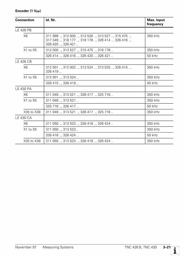
November 97 Measuring Systems TNC 426 B, TNC 430 3–21
Encoder (1 VPP)
Connection Id. Nr. Max. input
frequency
LE 426 PB
X6 311 999 .., 312 000 .., 313 526 .., 313 527 .., 315 475 ..,317 349 .., 318 177 .., 318 178 .., 326 414 .., 326 416 ..,326 420 .., 326 421 ..
350 kHz
X1 to X5 312 000 .., 313 527 .., 315 475 .., 318 178 .. 350 kHz
326 414 .., 326 416 .., 326 420 .., 326 421 .. 50 kHz
LE 426 CB
X6 312 001 .., 312 002 .., 313 524 .., 313 525 .., 326 415 ..,326 419 ..
350 kHz
X1 to X5 312 001 .., 313 524 .. 350 kHz
326 415 .., 326 419 .. 50 kHz
LE 430 PA
X6 311 049 .., 313 521 .., 326 417 .., 325 716 .. 350 kHz
X1 to X5 311 049 .., 313 521 .. 350 kHz
325 716 .., 326 417 .. 50 kHz
X35 to X38 311 049 .., 313 521 .., 326 417 .., 325 716 .. 350 kHz
LE 430 CA
X6 311 050 .., 313 523 .., 326 418 .., 326 424 .. 350 kHz
X1 to X5 311 050 .., 313 523 .. 350 kHz
326 418 .., 326 424 .. 50 kHz
X35 to X38 311 050 .., 313 523 .., 326 418 .., 326 424 .. 350 kHz
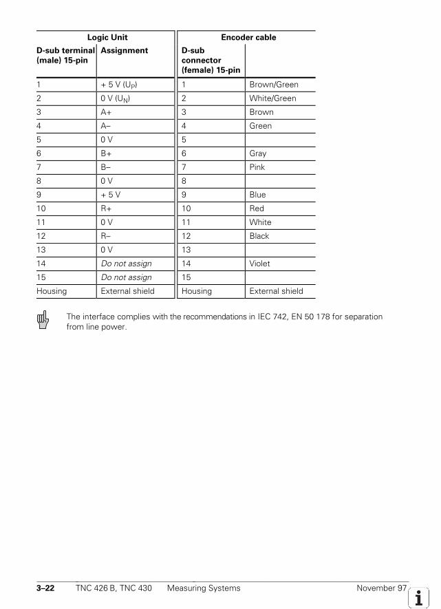
3–22 TNC 426 B, TNC 430 Measuring Systems November 97
Logic Unit Encoder cable
D-sub terminal
(male) 15-pin
Assignment D-sub
connector
(female) 15-pin
1 + 5 V (UP) 1 Brown/Green
2 0 V (UN) 2 White/Green
3 A+ 3 Brown
4 A– 4 Green
5 0 V 5
6 B+ 6 Gray
7 B– 7 Pink
8 0 V 8
9 + 5 V 9 Blue
10 R+ 10 Red
11 0 V 11 White
12 R– 12 Black
13 0 V 13
14 Do not assign 14 Violet
15 Do not assign 15
Housing External shield Housing External shield
The interface complies with the recommendations in IEC 742, EN 50 178 for separationfrom line power.
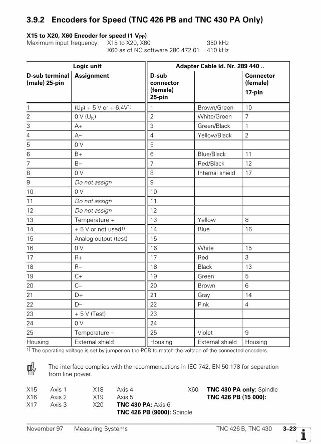
November 97 Measuring Systems TNC 426 B, TNC 430 3–23
3.9.2 Encoders for Speed (TNC 426 PB and TNC 430 PA Only)
X15 to X20, X60 Encoder for speed (1 VPP)
Maximum input frequency: X15 to X20, X60 350 kHzX60 as of NC software 280 472 01 410 kHz
Logic unit Adapter Cable Id. Nr. 289 440 ..
D-sub terminal
(male) 25-pin
Assignment D-sub
connector
(female)
25-pin
Connector
(female)
17-pin
1 (UP) + 5 V or + 6.4V1) 1 Brown/Green 102 0 V (UN) 2 White/Green 7
3 A+ 3 Green/Black 1
4 A– 4 Yellow/Black 2
5 0 V 5
6 B+ 6 Blue/Black 11
7 B– 7 Red/Black 12
8 0 V 8 Internal shield 17
9 Do not assign 9
10 0 V 10
11 Do not assign 11
12 Do not assign 12
13 Temperature + 13 Yellow 8
14 + 5 V or not used1) 14 Blue 16
15 Analog output (test) 15
16 0 V 16 White 15
17 R+ 17 Red 3
18 R– 18 Black 13
19 C+ 19 Green 5
20 C– 20 Brown 6
21 D+ 21 Gray 14
22 D– 22 Pink 4
23 + 5 V (Test) 23
24 0 V 24
25 Temperature – 25 Violet 9
Housing External shield Housing External shield Housing1) The operating voltage is set by jumper on the PCB to match the voltage of the connected encoders.
The interface complies with the recommendations in IEC 742, EN 50 178 for separationfrom line power.
X15 Axis 1 X18 Axis 4 X60 TNC 430 PA only: SpindleX16 Axis 2 X19 Axis 5 TNC 426 PB (15 000):
X17 Axis 3 X20 TNC 430 PA: Axis 6TNC 426 PB (9000): Spindle
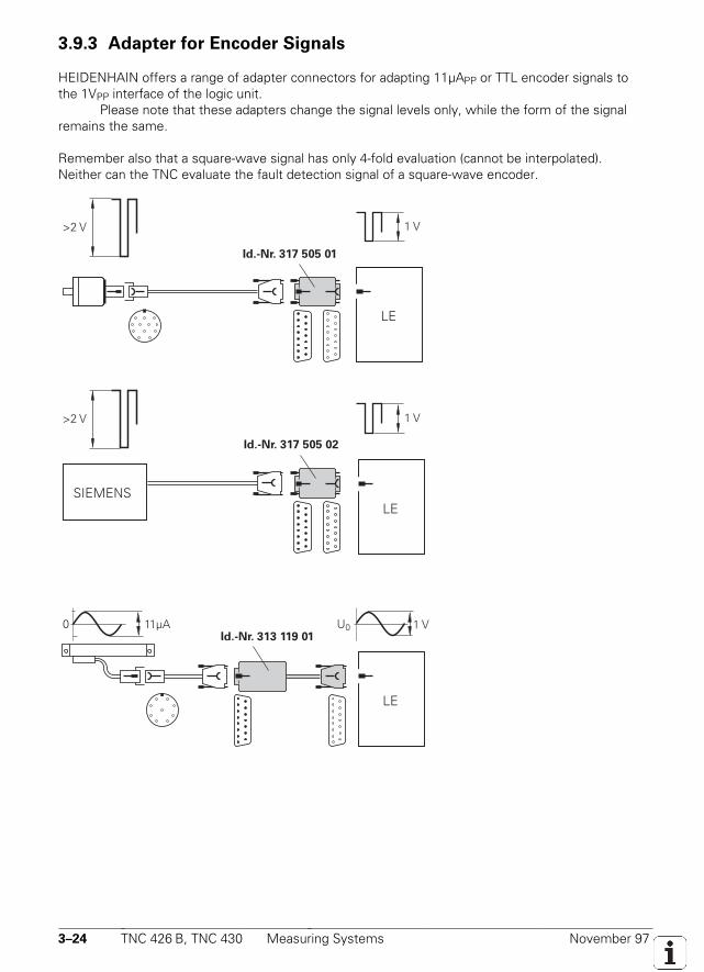
3–24 TNC 426 B, TNC 430 Measuring Systems November 97
3.9.3 Adapter for Encoder Signals
HEIDENHAIN offers a range of adapter connectors for adapting 11µAPP or TTL encoder signals tothe 1VPP interface of the logic unit.
Please note that these adapters change the signal levels only, while the form of the signalremains the same.
Remember also that a square-wave signal has only 4-fold evaluation (cannot be interpolated).Neither can the TNC evaluate the fault detection signal of a square-wave encoder.
1 V
LE
1 V>2 V
>2 V
Id.-Nr. 313 119 01
SIEMENS
U0 1 V11µA0
Id.-Nr. 317 505 02
Id.-Nr. 317 505 01
LE
LE
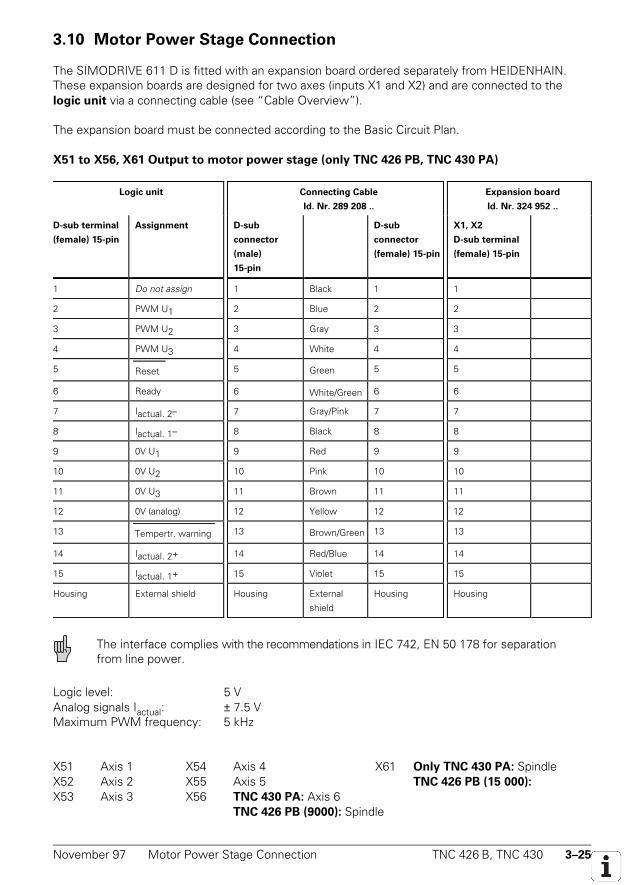
November 97 Motor Power Stage Connection TNC 426 B, TNC 430 3–25
3.10 Motor Power Stage Connection
The SIMODRIVE 611 D is fitted with an expansion board ordered separately from HEIDENHAIN.These expansion boards are designed for two axes (inputs X1 and X2) and are connected to thelogic unit via a connecting cable (see “Cable Overview”).
The expansion board must be connected according to the Basic Circuit Plan.
X51 to X56, X61 Output to motor power stage (only TNC 426 PB, TNC 430 PA)
Logic unit Connecting Cable
Id. Nr. 289 208 ..
Expansion board
Id. Nr. 324 952 ..
D-sub terminal
(female) 15-pin
Assignment D-sub
connector
(male)
15-pin
D-sub
connector
(female) 15-pin
X1, X2
D-sub terminal
(female) 15-pin
1 Do not assign 1 Black 1 1
2 PWM U1 2 Blue 2 2
3 PWM U2 3 Gray 3 3
4 PWM U3 4 White 4 4
5 Reset 5 Green 5 5
6 Ready 6 White/Green 6 6
7 Iactual. 2– 7 Gray/Pink 7 7
8 Iactual. 1– 8 Black 8 8
9 0V U1 9 Red 9 9
10 0V U2 10 Pink 10 10
11 0V U3 11 Brown 11 11
12 0V (analog) 12 Yellow 12 12
13 Tempertr. warning 13 Brown/Green 13 13
14 Iactual. 2+ 14 Red/Blue 14 14
15 Iactual. 1+ 15 Violet 15 15
Housing External shield Housing External
shield
Housing Housing
The interface complies with the recommendations in IEC 742, EN 50 178 for separationfrom line power.
Logic level: 5 VAnalog signals Iactual: ± 7.5 VMaximum PWM frequency: 5 kHz
X51 Axis 1 X54 Axis 4 X61 Only TNC 430 PA: SpindleX52 Axis 2 X55 Axis 5 TNC 426 PB (15 000):
X53 Axis 3 X56 TNC 430 PA: Axis 6TNC 426 PB (9000): Spindle
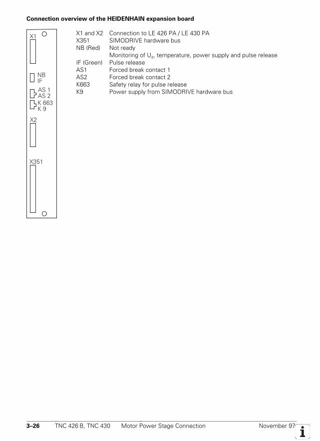
3–26 TNC 426 B, TNC 430 Motor Power Stage Connection November 97
Connection overview of the HEIDENHAIN expansion board
X2
X351
X1
NBIFAS 1AS 2K 663K 9
X1 and X2 Connection to LE 426 PA / LE 430 PAX351 SIMODRIVE hardware busNB (Red) Not ready
Monitoring of Uz, temperature, power supply and pulse releaseIF (Green) Pulse releaseAS1 Forced break contact 1AS2 Forced break contact 2K663 Safety relay for pulse releaseK9 Power supply from SIMODRIVE hardware bus

November 97 Motor Power Stage Connection TNC 426 B, TNC 430 3–27

3–28 TNC 426 B, TNC 430 Motor Power Stage Connection November 97
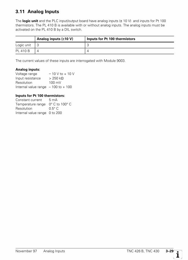
November 97 Analog Inputs TNC 426 B, TNC 430 3–29
3.11 Analog Inputs
The logic unit and the PLC input/output board have analog inputs (± 10 V) and inputs for Pt 100thermistors. The PL 410 B is available with or without analog inputs. The analog inputs must beactivated on the PL 410 B by a DIL switch.
Analog inputs (±10 V) Inputs for Pt 100 thermistors
Logic unit 3 3
PL 410 B 4 4
The current values of these inputs are interrogated with Module 9003.
Analog inputs:
Voltage range − 10 V to + 10 VInput resistance > 250 kΩResolution 100 mVInternal value range – 100 to + 100
Inputs for Pt 100 thermistors:
Constant current 5 mATemperature range 0° C to 100° CResolution 0.5° CInternal value range 0 to 200
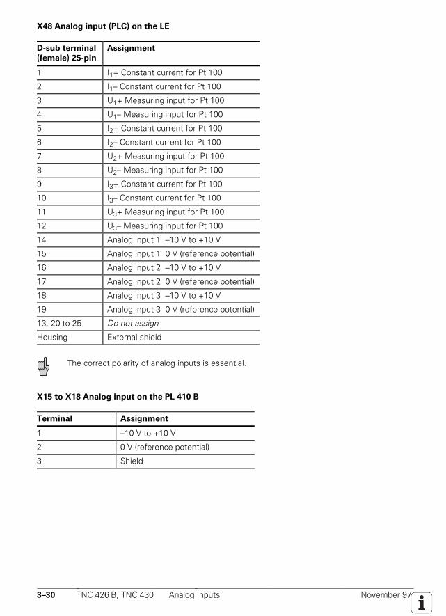
3–30 TNC 426 B, TNC 430 Analog Inputs November 97
X48 Analog input (PLC) on the LE
D-sub terminal
(female) 25-pin
Assignment
1 I1+ Constant current for Pt 100
2 I1– Constant current for Pt 100
3 U1+ Measuring input for Pt 100
4 U1– Measuring input for Pt 100
5 I2+ Constant current for Pt 100
6 I2– Constant current for Pt 100
7 U2+ Measuring input for Pt 100
8 U2– Measuring input for Pt 100
9 I3+ Constant current for Pt 100
10 I3– Constant current for Pt 100
11 U3+ Measuring input for Pt 100
12 U3– Measuring input for Pt 100
14 Analog input 1 –10 V to +10 V
15 Analog input 1 0 V (reference potential)
16 Analog input 2 –10 V to +10 V
17 Analog input 2 0 V (reference potential)
18 Analog input 3 –10 V to +10 V
19 Analog input 3 0 V (reference potential)
13, 20 to 25 Do not assign
Housing External shield
The correct polarity of analog inputs is essential.
X15 to X18 Analog input on the PL 410 B
Terminal Assignment
1 –10 V to +10 V
2 0 V (reference potential)
3 Shield
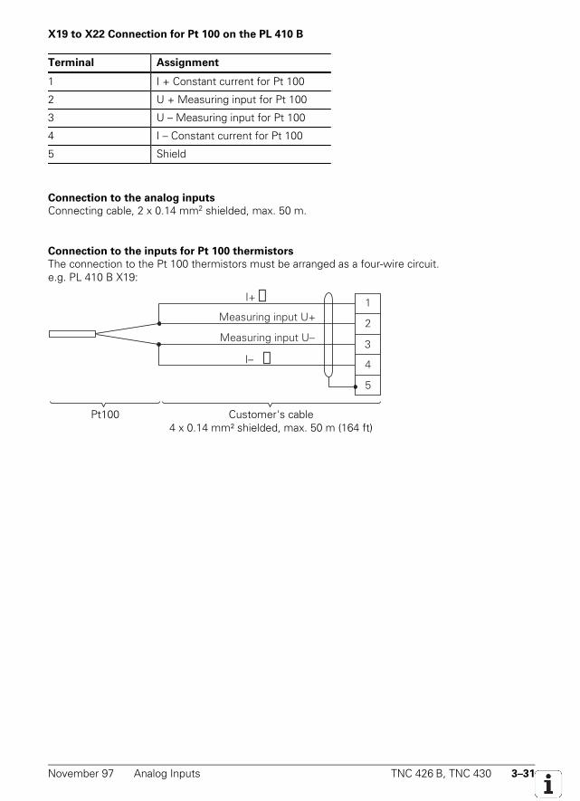
November 97 Analog Inputs TNC 426 B, TNC 430 3–31
X19 to X22 Connection for Pt 100 on the PL 410 B
Terminal Assignment
1 I + Constant current for Pt 100
2 U + Measuring input for Pt 100
3 U – Measuring input for Pt 100
4 I – Constant current for Pt 100
5 Shield
Connection to the analog inputs
Connecting cable, 2 x 0.14 mm2 shielded, max. 50 m.
Connection to the inputs for Pt 100 thermistors
The connection to the Pt 100 thermistors must be arranged as a four-wire circuit.e.g. PL 410 B X19:
1
2
4
5
Measuring input U+
Measuring input U–
→I+
→I–3
Pt100 Customer's cable4 x 0.14 mm² shielded, max. 50 m (164 ft)

3–32 TNC 426 B, TNC 430 Analog Outputs November 97
3.12 Analog Outputs
Maximum loading of the analog outputs: 2 mAMaximum capacitance: 2 nF
There are 13 analog outputs available:• Connection X8: analog output 1 to 6• Connection X9: analog output 7 to 13
PLC analog outputs
The PLC analog outputs can be switched via Module 9130.
Nominal value output:
• For analog axes and analog spindle, use MP120.x and MP121 to assign the corresponding analogoutputs on connection X8 or X9 to the nominal speed outputs.
• The connecting cables to the nominal value outputs must not have more than one intermediateterminal.
• If it is necessary to branch to physically separate servo inputs, the connection must be made in agrounded terminal box. Suitable terminal boxes is available from HEIDENHAIN (Id. Nr. 251 24901).
• The chassis of the terminal box must be electrically connected with the frame of the machine.• The 0 V connection of the nominal-value-difference inputs must be connected with signal
ground. Required cross section ≥ Ø 6 mm².• Use only original HEIDENHAIN cables and connecting elements.
The following wiring plan is suggested for shielding the terminal box:
SERVO
1 2 3 4 5 6 7 8 9 10 11 12 13 14 15 16
LE
•
•
X Y Z SIV V
Insulated against housing.
Leads are provided with end sleeves.
Cable shielding is led onto 14 mm²insulated strands via crimp eyelets.
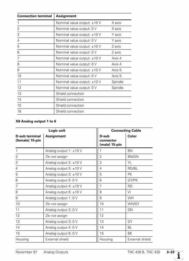
November 97 Analog Outputs TNC 426 B, TNC 430 3–33
Connection terminal Assignment
1 Nominal value output: ±10 V X axis
2 Nominal value output: 0 V X axis
3 Nominal value output: ±10 V Y axis
4 Nominal value output: 0 V Y axis
5 Nominal value output: ±10 V Z axis
6 Nominal value output: 0 V Z axis
7 Nominal value output: ±10 V Axis 4
8 Nominal value output: 0 V Axis 4
9 Nominal value output: ±10 V Axis 5
10 Nominal value output: 0 V Axis 5
11 Nominal value output: ±10 V Spindle
12 Nominal value output: 0 V Spindle
13 Shield connection
14 Shield connection
15 Shield connection
16 Shield connection
X8 Analog output 1 to 6
Logic unit Connecting Cable
D-sub terminal
(female) 15-pin
Assignment D-sub
connector
(male) 15-pin
Color
1 Analog output 1: ±10 V 1 BN
2 Do not assign 2 BN/GN
3 Analog output 2: ±10 V 3 YL
4 Analog output 5: ±10 V 4 RD/BL
5 Analog output 3: ±10 V 5 PK
6 Analog output 5: 0 V 6 GY/PK
7 Analog output 4: ±10 V 7 RD
8 Analog output 6: ±10 V 8 VI
9 Analog output 1: 0 V 9 WH
10 Do not assign 10 WH/GY
11 Analog output 2: 0 V 11 GN
12 Do not assign 12
13 Analog output 3: 0 V 13 GY
14 Analog output 4: 0 V 14 BL
15 Analog output 6: 0 V 15 BK
Housing External shield Housing External shield
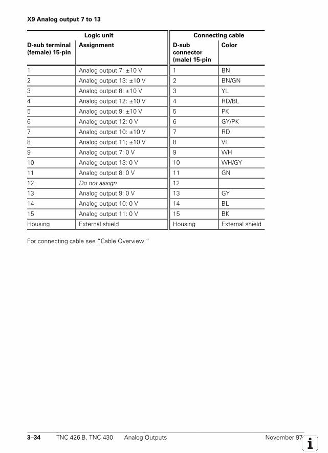
3–34 TNC 426 B, TNC 430 Analog Outputs November 97
X9 Analog output 7 to 13
Logic unit Connecting cable
D-sub terminal
(female) 15-pin
Assignment D-sub
connector
(male) 15-pin
Color
1 Analog output 7: ±10 V 1 BN
2 Analog output 13: ±10 V 2 BN/GN
3 Analog output 8: ±10 V 3 YL
4 Analog output 12: ±10 V 4 RD/BL
5 Analog output 9: ±10 V 5 PK
6 Analog output 12: 0 V 6 GY/PK
7 Analog output 10: ±10 V 7 RD
8 Analog output 11; ±10 V 8 VI
9 Analog output 7: 0 V 9 WH
10 Analog output 13: 0 V 10 WH/GY
11 Analog output 8: 0 V 11 GN
12 Do not assign 12
13 Analog output 9: 0 V 13 GY
14 Analog output 10: 0 V 14 BL
15 Analog output 11: 0 V 15 BK
Housing External shield Housing External shield
For connecting cable see “Cable Overview.”
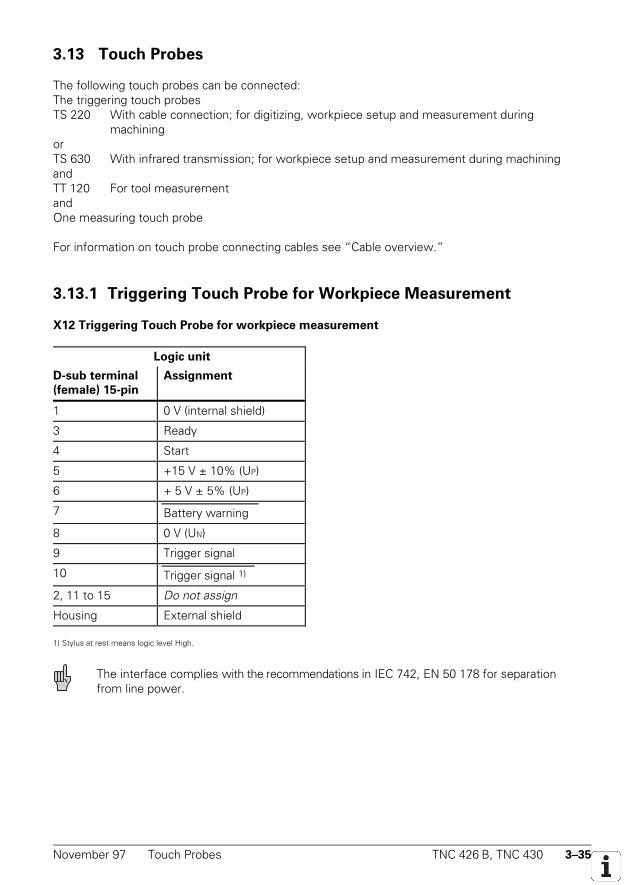
November 97 Touch Probes TNC 426 B, TNC 430 3–35
3.13 Touch Probes
The following touch probes can be connected:The triggering touch probesTS 220 With cable connection; for digitizing, workpiece setup and measurement during
machiningorTS 630 With infrared transmission; for workpiece setup and measurement during machiningandTT 120 For tool measurementandOne measuring touch probe
For information on touch probe connecting cables see “Cable overview.”
3.13.1 Triggering Touch Probe for Workpiece Measurement
X12 Triggering Touch Probe for workpiece measurement
Logic unit
D-sub terminal
(female) 15-pin
Assignment
1 0 V (internal shield)
3 Ready
4 Start
5 +15 V ± 10% (UP)
6 + 5 V ± 5% (UP)
7 Battery warning
8 0 V (UN)
9 Trigger signal
10 Trigger signal 1)
2, 11 to 15 Do not assign
Housing External shield
1) Stylus at rest means logic level High.
The interface complies with the recommendations in IEC 742, EN 50 178 for separationfrom line power.
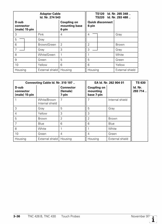
3–36 TNC 426 B, TNC 430 Touch Probes November 97
Adapter Cable
Id. Nr. 274 543
TS120 Id. Nr. 265 348 ..
TS220 Id. Nr. 293 488 ..
D-sub
connector
(male) 15-pin
Coupling on
mounting base
6-pin
Quick disconnect
6-pin
3 Pink 4 4 Gray
5 Gray
6 Brown/Green 2 2 Brown
7 Gray 3 3 Gray
8 White/Green 1 1 White
9 Green 5 5 Green
10 Yellow 6 6 Yellow
Housing External shield Housing Housing External shield
Connecting Cable Id. Nr. 310 197 .. EA Id. Nr. 262 904 01 TS 630
D-sub
connector
(male) 15-pin
Connector
(female)
7-pin
Coupling on
mounting
base 7-pin
Id. Nr.
293 714 ..
1 White/BrownInternal shield
7 7 Internal shield
3 Gray 5 5 Gray
4 Yellow 3 3
5 Brown 2 2 Brown
7 Blue 6 6 Blue
8 White 1 1 White
10 Green 4 4 Green
Housing External shield Housing Housing External shield
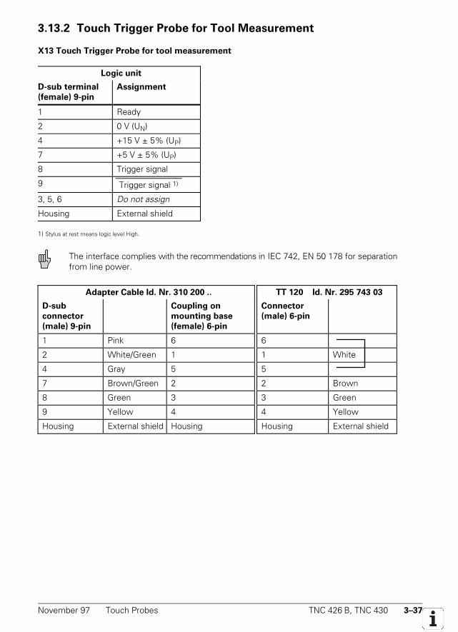
November 97 Touch Probes TNC 426 B, TNC 430 3–37
3.13.2 Touch Trigger Probe for Tool Measurement
X13 Touch Trigger Probe for tool measurement
Logic unit
D-sub terminal
(female) 9-pin
Assignment
1 Ready
2 0 V (UN)
4 +15 V ± 5% (UP)
7 +5 V ± 5% (UP)
8 Trigger signal
9 Trigger signal 1)
3, 5, 6 Do not assign
Housing External shield
1) Stylus at rest means logic level High.
The interface complies with the recommendations in IEC 742, EN 50 178 for separationfrom line power.
Adapter Cable Id. Nr. 310 200 .. TT 120 Id. Nr. 295 743 03
D-sub
connector
(male) 9-pin
Coupling on
mounting base
(female) 6-pin
Connector
(male) 6-pin
1 Pink 6 6
2 White/Green 1 1 White
4 Gray 5 5
7 Brown/Green 2 2 Brown
8 Green 3 3 Green
9 Yellow 4 4 Yellow
Housing External shield Housing Housing External shield
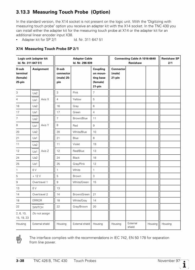
3–38 TNC 426 B, TNC 430 Touch Probes November 97
3.13.3 Measuring Touch Probe (Option)
In the standard version, the X14 socket is not present on the logic unit. With the "Digitizing withmeasuring touch probe" option you receive an adapter kit with the X14 socket. In the TNC 430 youcan install either the adapter kit for the measuring touch probe at X14 or the adapter kit for anadditional linear encoder input X38.• Adapter kit for SP 2/1 Id. Nr. 311 647 51
X14 Measuring Touch Probe SP 2/1
Logic unit (adapter kit
Id. Nr. 311 647 51)
Adapter Cable
Id. Nr. 296 839
Connecting Cable A-1016-6640
Renishaw
Renishaw SP
2/1
D-sub
terminal
(female)
25-pin
Assignment D-sub
connector
(male) 25-
pin
Coupling
on moun-
ting base
(female)
21-pin
Connector
(male)
21-pin
3 Ua2 3 Pink 7
4 Ua1 Axis X 4 Yellow 5
16 Ua2 16 Gray 6
17 Ua1 17 Green 4
7 Ua2 7 Brown/Blue 11
8 Ua1 Axis Y 8 Red 9
20 Ua2 20 White/Blue 10
21 Ua1 21 Blue 8
11 Ua2 11 Violet 19
12 Ua1 Axis Z 12 Red/Blue 13
24 Ua2 24 Black 18
25 Ua1 25 Gray/Pink 12
1 0 V 1 White 1
5 + 12 V 5 Brown 3
9 Overtravel 1 9 White/Green 15
13 0 V 13
14 Overtravel 2 14 Brown/Green 21
18 ERROR 18 White/Gray 14
22 SWITCH 22 Gray/Brown 20
2, 6, 10,
15, 19, 23
Do not assign
Housing External shield Housing External shield Housing Housing Externalshield
Housing Housing
The interface complies with the recommendations in IEC 742, EN 50 178 for separationfrom line power.

November 97 Touch Probes TNC 426 B, TNC 430 3–39

3–40 TNC 426 B, TNC 430 Touch Probes November 97
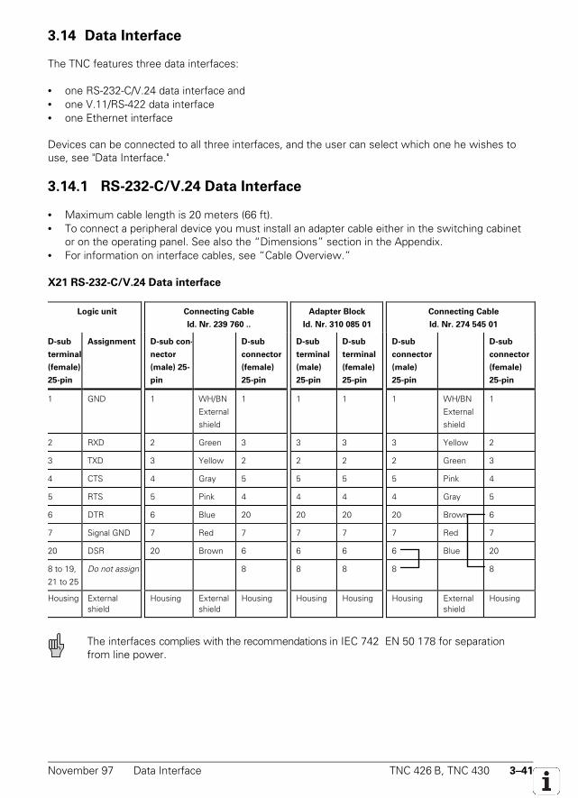
November 97 Data Interface TNC 426 B, TNC 430 3–41
3.14 Data Interface
The TNC features three data interfaces:
• one RS-232-C/V.24 data interface and• one V.11/RS-422 data interface• one Ethernet interface
Devices can be connected to all three interfaces, and the user can select which one he wishes touse, see "Data Interface."
3.14.1 RS-232-C/V.24 Data Interface
• Maximum cable length is 20 meters (66 ft).• To connect a peripheral device you must install an adapter cable either in the switching cabinet
or on the operating panel. See also the “Dimensions” section in the Appendix.• For information on interface cables, see “Cable Overview.”
X21 RS-232-C/V.24 Data interface
Logic unit Connecting Cable
Id. Nr. 239 760 ..
Adapter Block
Id. Nr. 310 085 01
Connecting Cable
Id. Nr. 274 545 01
D-sub
terminal
(female)
25-pin
Assignment D-sub con-
nector
(male) 25-
pin
D-sub
connector
(female)
25-pin
D-sub
terminal
(male)
25-pin
D-sub
terminal
(female)
25-pin
D-sub
connector
(male)
25-pin
D-sub
connector
(female)
25-pin
1 GND 1 WH/BN
External
shield
1 1 1 1 WH/BN
External
shield
1
2 RXD 2 Green 3 3 3 3 Yellow 2
3 TXD 3 Yellow 2 2 2 2 Green 3
4 CTS 4 Gray 5 5 5 5 Pink 4
5 RTS 5 Pink 4 4 4 4 Gray 5
6 DTR 6 Blue 20 20 20 20 Brown 6
7 Signal GND 7 Red 7 7 7 7 Red 7
20 DSR 20 Brown 6 6 6 6 Blue 20
8 to 19,
21 to 25
Do not assign 8 8 8 8 8
Housing Externalshield
Housing Externalshield
Housing Housing Housing Housing Externalshield
Housing
The interfaces complies with the recommendations in IEC 742 EN 50 178 for separationfrom line power.
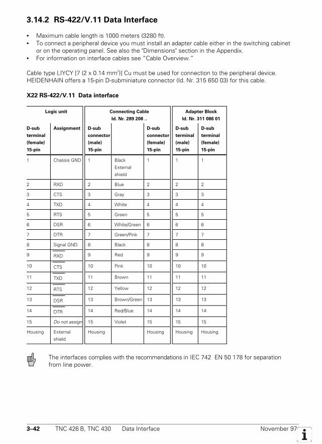
3–42 TNC 426 B, TNC 430 Data Interface November 97
3.14.2 RS-422/V.11 Data Interface
• Maximum cable length is 1000 meters (3280 ft).• To connect a peripheral device you must install an adapter cable either in the switching cabinet
or on the operating panel. See also the "Dimensions" section in the Appendix.• For information on interface cables see “Cable Overview.”
Cable type LIYCY [7 (2 x 0.14 mm2)] Cu must be used for connection to the peripheral device.HEIDENHAIN offers a 15-pin D-subminiature connector (Id. Nr. 315 650 03) for this cable.
X22 RS-422/V.11 Data interface
Logic unit Connecting Cable
Id. Nr. 289 208 ..
Adapter Block
Id. Nr. 311 086 01
D-sub
terminal
(female)
15-pin
Assignment D-sub
connector
(male)
15-pin
D-sub
connector
(female)
15-pin
D-sub
terminal
(male)
15-pin
D-sub
terminal
(female)
15-pin
1 Chassis GND 1 Black
External
shield
1 1 1
2 RXD 2 Blue 2 2 2
3 CTS 3 Gray 3 3 3
4 TXD 4 White 4 4 4
5 RTS 5 Green 5 5 5
6 DSR 6 White/Green 6 6 6
7 DTR 7 Green/Pink 7 7 7
8 Signal GND 8 Black 8 8 8
9 RXD 9 Red 9 9 9
10 CTS 10 Pink 10 10 10
11 TXD 11 Brown 11 11 11
12 RTS 12 Yellow 12 12 12
13 DSR 13 Brown/Green 13 13 13
14 DTR 14 Red/Blue 14 14 14
15 Do not assign 15 Violet 15 15 15
Housing External
shield
Housing Housing Housing Housing
The interfaces complies with the recommendations in IEC 742 EN 50 178 for separationfrom line power.
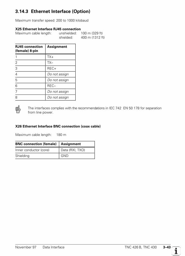
November 97 Data Interface TNC 426 B, TNC 430 3–43
3.14.3 Ethernet Interface (Option)
Maximum transfer speed: 200 to 1000 kilobaud
X25 Ethernet Interface RJ45 connection
Maximum cable length: unshielded: 100 m (329 ft)shielded: 400 m (1312 ft)
RJ45 connection
(female) 8-pin
Assignment
1 TX+
2 TX–
3 REC+
4 Do not assign
5 Do not assign
6 REC–
7 Do not assign
8 Do not assign
The interfaces complies with the recommendations in IEC 742 EN 50 178 for separationfrom line power.
X26 Ethernet Interface BNC connection (coax cable)
Maximum cable length: 180 m
BNC connection (female) Assignment
Inner conductor (core) Data (RXI, TXO)
Shielding GND

3–44 TNC 426 B, TNC 430 Data Interface November 97
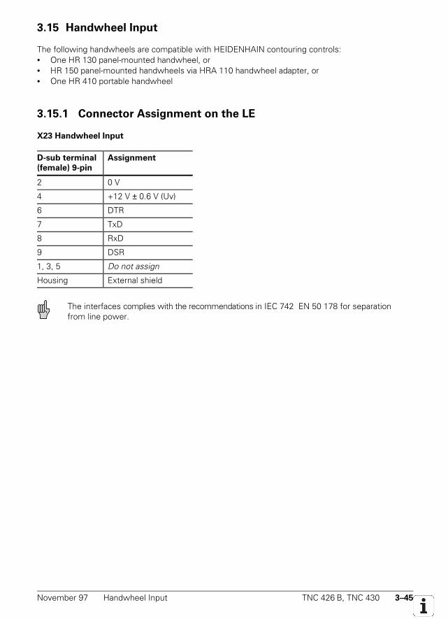
November 97 Handwheel Input TNC 426 B, TNC 430 3–45
3.15 Handwheel Input
The following handwheels are compatible with HEIDENHAIN contouring controls:• One HR 130 panel-mounted handwheel, or• HR 150 panel-mounted handwheels via HRA 110 handwheel adapter, or• One HR 410 portable handwheel
3.15.1 Connector Assignment on the LE
X23 Handwheel Input
D-sub terminal
(female) 9-pin
Assignment
2 0 V
4 +12 V ± 0.6 V (Uv)
6 DTR
7 TxD
8 RxD
9 DSR
1, 3, 5 Do not assign
Housing External shield
The interfaces complies with the recommendations in IEC 742 EN 50 178 for separationfrom line power.
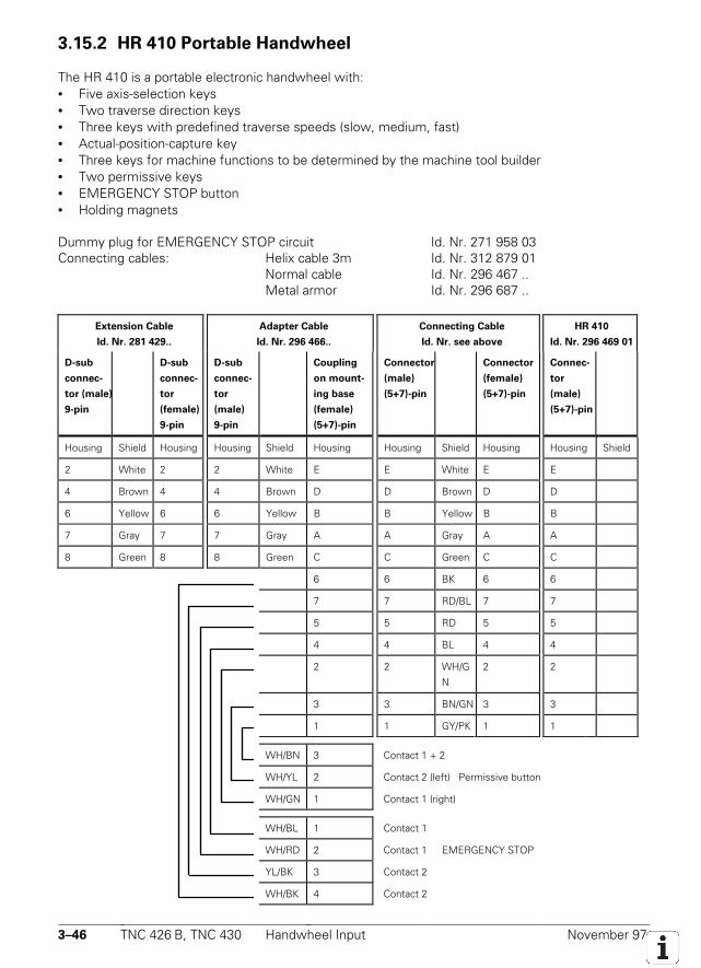
3–46 TNC 426 B, TNC 430 Handwheel Input November 97
3.15.2 HR 410 Portable Handwheel
The HR 410 is a portable electronic handwheel with:• Five axis-selection keys• Two traverse direction keys• Three keys with predefined traverse speeds (slow, medium, fast)• Actual-position-capture key• Three keys for machine functions to be determined by the machine tool builder• Two permissive keys• EMERGENCY STOP button• Holding magnets
Dummy plug for EMERGENCY STOP circuit Id. Nr. 271 958 03Connecting cables: Helix cable 3m Id. Nr. 312 879 01
Normal cable Id. Nr. 296 467 ..Metal armor Id. Nr. 296 687 ..
Extension Cable
Id. Nr. 281 429..
Adapter Cable
Id. Nr. 296 466..
Connecting Cable
Id. Nr. see above
HR 410
Id. Nr. 296 469 01
D-sub
connec-
tor (male)
9-pin
D-sub
connec-
tor
(female)
9-pin
D-sub
connec-
tor
(male)
9-pin
Coupling
on mount-
ing base
(female)
(5+7)-pin
Connector
(male)
(5+7)-pin
Connector
(female)
(5+7)-pin
Connec-
tor
(male)
(5+7)-pin
Housing Shield Housing Housing Shield Housing Housing Shield Housing Housing Shield
2 White 2 2 White E E White E E
4 Brown 4 4 Brown D D Brown D D
6 Yellow 6 6 Yellow B B Yellow B B
7 Gray 7 7 Gray A A Gray A A
8 Green 8 8 Green C C Green C C
6 6 BK 6 6
7 7 RD/BL 7 7
5 5 RD 5 5
4 4 BL 4 4
2 2 WH/G
N
2 2
3 3 BN/GN 3 3
1 1 GY/PK 1 1
WH/BN 3 Contact 1 + 2
WH/YL 2 Contact 2 (left) Permissive button
WH/GN 1 Contact 1 (right)
WH/BL 1 Contact 1
WH/RD 2 Contact 1 EMERGENCY STOP
YL/BK 3 Contact 2
WH/BK 4 Contact 2
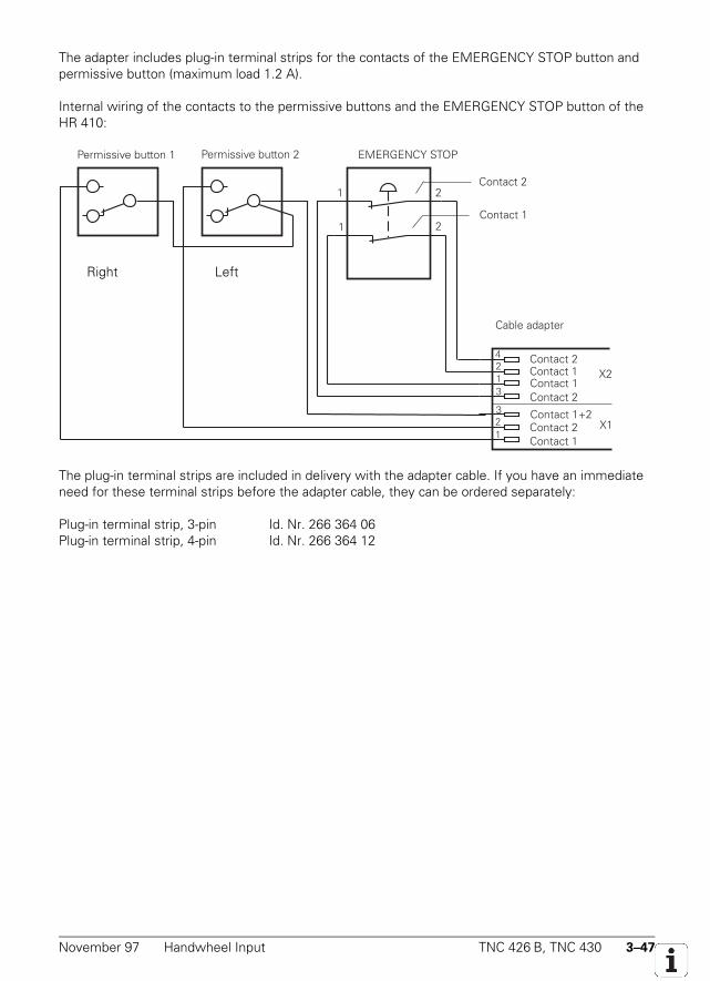
November 97 Handwheel Input TNC 426 B, TNC 430 3–47
The adapter includes plug-in terminal strips for the contacts of the EMERGENCY STOP button andpermissive button (maximum load 1.2 A).
Internal wiring of the contacts to the permissive buttons and the EMERGENCY STOP button of theHR 410:
1
1
2
2
EMERGENCY STOP
Contact 2
Contact 1
Permissive button 1
Contact 1Contact 1Contact 2
Contact 2
Contact 2Contact 1
Contact 1+2
X2
X1
4213
123
Cable adapter
Permissive button 2
The plug-in terminal strips are included in delivery with the adapter cable. If you have an immediateneed for these terminal strips before the adapter cable, they can be ordered separately:
Plug-in terminal strip, 3-pin Id. Nr. 266 364 06Plug-in terminal strip, 4-pin Id. Nr. 266 364 12
Right Left
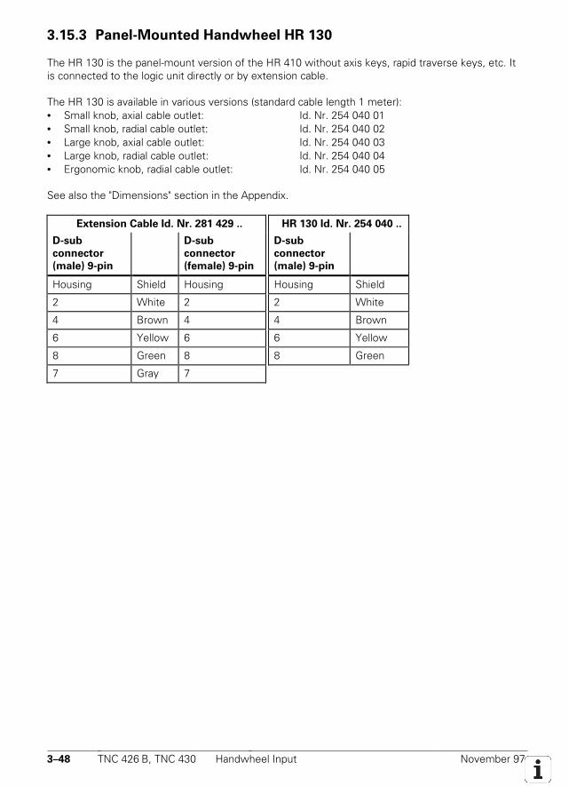
3–48 TNC 426 B, TNC 430 Handwheel Input November 97
3.15.3 Panel-Mounted Handwheel HR 130
The HR 130 is the panel-mount version of the HR 410 without axis keys, rapid traverse keys, etc. Itis connected to the logic unit directly or by extension cable.
The HR 130 is available in various versions (standard cable length 1 meter):• Small knob, axial cable outlet: Id. Nr. 254 040 01• Small knob, radial cable outlet: Id. Nr. 254 040 02• Large knob, axial cable outlet: Id. Nr. 254 040 03• Large knob, radial cable outlet: Id. Nr. 254 040 04• Ergonomic knob, radial cable outlet: Id. Nr. 254 040 05
See also the "Dimensions" section in the Appendix.
Extension Cable Id. Nr. 281 429 .. HR 130 Id. Nr. 254 040 ..
D-sub
connector
(male) 9-pin
D-sub
connector
(female) 9-pin
D-sub
connector
(male) 9-pin
Housing Shield Housing Housing Shield
2 White 2 2 White
4 Brown 4 4 Brown
6 Yellow 6 6 Yellow
8 Green 8 8 Green
7 Gray 7
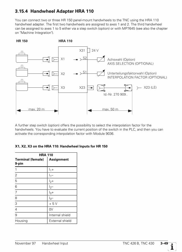
November 97 Handwheel Input TNC 426 B, TNC 430 3–49
3.15.4 Handwheel Adapter HRA 110
You can connect two or three HR 150 panel-mount handwheels to the TNC using the HRA 110handwheel adapter. The first two handwheels are assigned to axes 1 and 2. The third handwheelcan be assigned to axes 1 to 5 either via a step switch (option) or with MP7645 (see also the chapteron "Machine Integration").
HRA 110
X3
X2
X1
X23 (LE)X23
S1
X31 24 V
Achswahl (Option)AXIS SELECTION (OPTIONAL)
Unterteilungsfaktorwahl (Option)INTERPOLATION FACTOR (OPTIONAL)
max. 50 m
Id.-Nr. 270 909..
HR 150
S2
max. 20 m
A further step switch (option) offers the possibility to select the interpolation factor for thehandwheels. You have to evaluate the current position of the switch in the PLC, and then you canactivate the corresponding interpolation factor with Module 9036.
X1, X2, X3 on the HRA 110: Handwheel Inputs for HR 150
HRA 110
Terminal (female)
9-pin
Assignment
1 I1+
2 I1–
5 I2+
6 I2–
7 I0+
8 I0–
3 + 5 V
4 0V
9 Internal shield
Housing External shield
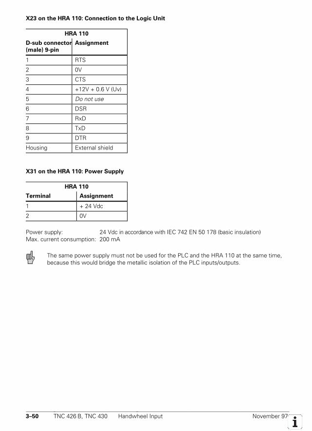
3–50 TNC 426 B, TNC 430 Handwheel Input November 97
X23 on the HRA 110: Connection to the Logic Unit
HRA 110
D-sub connector
(male) 9-pin
Assignment
1 RTS
2 0V
3 CTS
4 +12V + 0.6 V (Uv)
5 Do not use
6 DSR
7 RxD
8 TxD
9 DTR
Housing External shield
X31 on the HRA 110: Power Supply
HRA 110
Terminal Assignment
1 + 24 Vdc
2 0V
Power supply: 24 Vdc in accordance with IEC 742 EN 50 178 (basic insulation)Max. current consumption: 200 mA
The same power supply must not be used for the PLC and the HRA 110 at the same time,because this would bridge the metallic isolation of the PLC inputs/outputs.

November 97 Handwheel Input TNC 426 B, TNC 430 3–51

3–52 TNC 426 B, TNC 430 Handwheel Input November 97
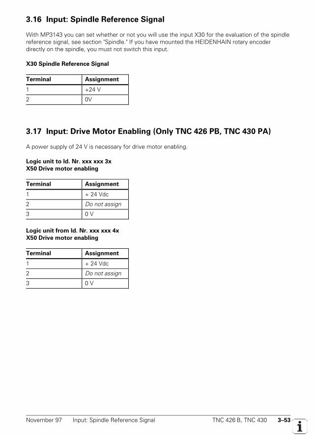
November 97 Input: Spindle Reference Signal TNC 426 B, TNC 430 3–53
3.16 Input: Spindle Reference Signal
With MP3143 you can set whether or not you will use the input X30 for the evaluation of the spindlereference signal, see section "Spindle." If you have mounted the HEIDENHAIN rotary encoderdirectly on the spindle, you must not switch this input.
X30 Spindle Reference Signal
Terminal Assignment
1 +24 V
2 0V
3.17 Input: Drive Motor Enabling (Only TNC 426 PB, TNC 430 PA)
A power supply of 24 V is necessary for drive motor enabling.
Logic unit to Id. Nr. xxx xxx 3x
X50 Drive motor enabling
Terminal Assignment
1 + 24 Vdc
2 Do not assign
3 0 V
Logic unit from Id. Nr. xxx xxx 4x
X50 Drive motor enabling
Terminal Assignment
1 + 24 Vdc
2 Do not assign
3 0 V
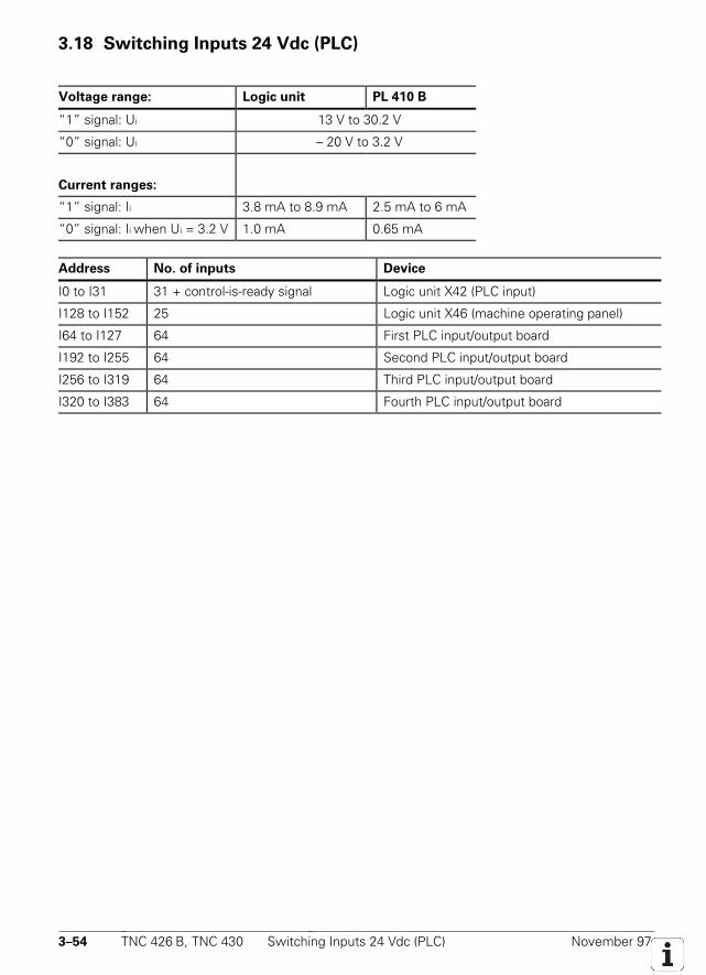
3–54 TNC 426 B, TNC 430 Switching Inputs 24 Vdc (PLC) November 97
3.18 Switching Inputs 24 Vdc (PLC)
Voltage range: Logic unit PL 410 B
“1” signal: Ui 13 V to 30.2 V
“0” signal: Ui – 20 V to 3.2 V
Current ranges:
“1” signal: Ii 3.8 mA to 8.9 mA 2.5 mA to 6 mA
“0” signal: Ii when Ui = 3.2 V 1.0 mA 0.65 mA
Address No. of inputs Device
I0 to I31 31 + control-is-ready signal Logic unit X42 (PLC input)
I128 to I152 25 Logic unit X46 (machine operating panel)
I64 to I127 64 First PLC input/output board
I192 to I255 64 Second PLC input/output board
I256 to I319 64 Third PLC input/output board
I320 to I383 64 Fourth PLC input/output board
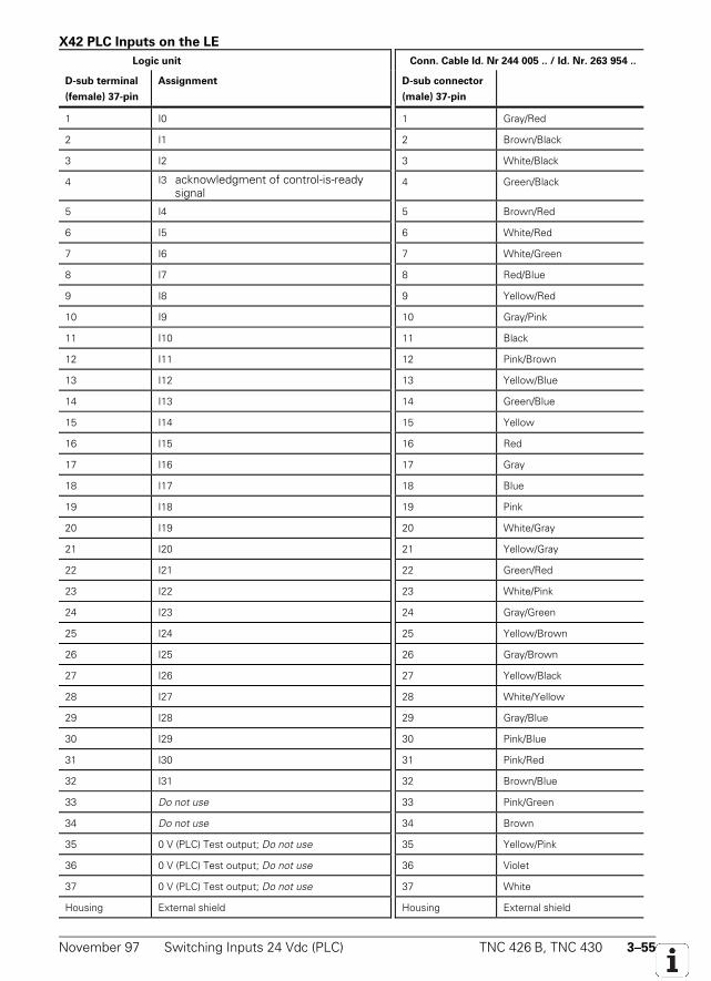
November 97 Switching Inputs 24 Vdc (PLC) TNC 426 B, TNC 430 3–55
X42 PLC Inputs on the LE
Logic unit Conn. Cable Id. Nr 244 005 .. / Id. Nr. 263 954 ..
D-sub terminal
(female) 37-pin
Assignment D-sub connector
(male) 37-pin
1 I0 1 Gray/Red
2 I1 2 Brown/Black
3 I2 3 White/Black
4 I3 acknowledgment of control-is-readysignal
4 Green/Black
5 I4 5 Brown/Red
6 I5 6 White/Red
7 I6 7 White/Green
8 I7 8 Red/Blue
9 I8 9 Yellow/Red
10 I9 10 Gray/Pink
11 I10 11 Black
12 I11 12 Pink/Brown
13 I12 13 Yellow/Blue
14 I13 14 Green/Blue
15 I14 15 Yellow
16 I15 16 Red
17 I16 17 Gray
18 I17 18 Blue
19 I18 19 Pink
20 I19 20 White/Gray
21 I20 21 Yellow/Gray
22 I21 22 Green/Red
23 I22 23 White/Pink
24 I23 24 Gray/Green
25 I24 25 Yellow/Brown
26 I25 26 Gray/Brown
27 I26 27 Yellow/Black
28 I27 28 White/Yellow
29 I28 29 Gray/Blue
30 I29 30 Pink/Blue
31 I30 31 Pink/Red
32 I31 32 Brown/Blue
33 Do not use 33 Pink/Green
34 Do not use 34 Brown
35 0 V (PLC) Test output; Do not use 35 Yellow/Pink
36 0 V (PLC) Test output; Do not use 36 Violet
37 0 V (PLC) Test output; Do not use 37 White
Housing External shield Housing External shield
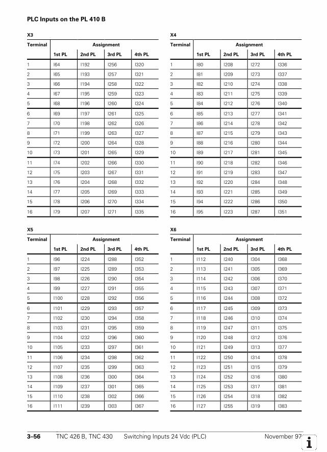
3–56 TNC 426 B, TNC 430 Switching Inputs 24 Vdc (PLC) November 97
PLC Inputs on the PL 410 B
X3 X4
Terminal Assignment Terminal Assignment
1st PL 2nd PL 3rd PL 4th PL 1st PL 2nd PL 3rd PL 4th PL
1 I64 I192 I256 I320 1 I80 I208 I272 I336
2 I65 I193 I257 I321 2 I81 I209 I273 I337
3 I66 I194 I258 I322 3 I82 I210 I274 I338
4 I67 I195 I259 I323 4 I83 I211 I275 I339
5 I68 I196 I260 I324 5 I84 I212 I276 I340
6 I69 I197 I261 I325 6 I85 I213 I277 I341
7 I70 I198 I262 I326 7 I86 I214 I278 I342
8 I71 I199 I263 I327 8 I87 I215 I279 I343
9 I72 I200 I264 I328 9 I88 I216 I280 I344
10 I73 I201 I265 I329 10 I89 I217 I281 I345
11 I74 I202 I266 I330 11 I90 I218 I282 I346
12 I75 I203 I267 I331 12 I91 I219 I283 I347
13 I76 I204 I268 I332 13 I92 I220 I284 I348
14 I77 I205 I269 I333 14 I93 I221 I285 I349
15 I78 I206 I270 I334 15 I94 I222 I286 I350
16 I79 I207 I271 I335 16 I95 I223 I287 I351
X5 X6
Terminal Assignment Terminal Assignment
1st PL 2nd PL 3rd PL 4th PL 1st PL 2nd PL 3rd PL 4th PL
1 I96 I224 I288 I352 1 I112 I240 I304 I368
2 I97 I225 I289 I353 2 I113 I241 I305 I369
3 I98 I226 I290 I354 3 I114 I242 I306 I370
4 I99 I227 I291 I355 4 I115 I243 I307 I371
5 I100 I228 I292 I356 5 I116 I244 I308 I372
6 I101 I229 I293 I357 6 I117 I245 I309 I373
7 I102 I230 I294 I358 7 I118 I246 I310 I374
8 I103 I231 I295 I359 8 I119 I247 I311 I375
9 I104 I232 I296 I360 9 I120 I248 I312 I376
10 I105 I233 I297 I361 10 I121 I249 I313 I377
11 I106 I234 I298 I362 11 I122 I250 I314 I378
12 I107 I235 I299 I363 12 I123 I251 I315 I379
13 I108 I236 I300 I364 13 I124 I252 I316 I380
14 I109 I237 I301 I365 14 I125 I253 I317 I381
15 I110 I238 I302 I366 15 I126 I254 I318 I382
16 I111 I239 I303 I367 16 I127 I255 I319 I383
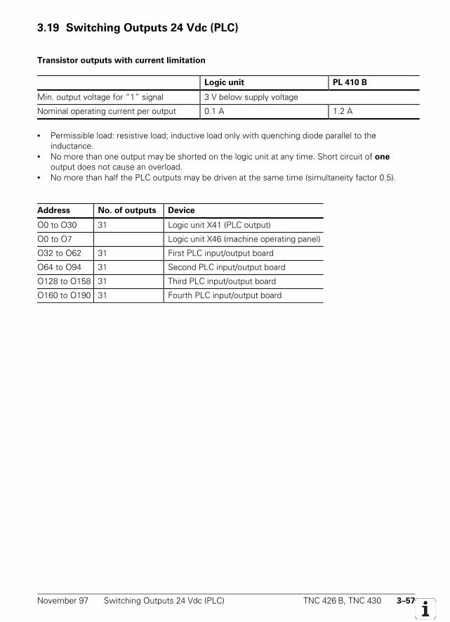
November 97 Switching Outputs 24 Vdc (PLC) TNC 426 B, TNC 430 3–57
3.19 Switching Outputs 24 Vdc (PLC)
Transistor outputs with current limitation
Logic unit PL 410 B
Min. output voltage for “1” signal 3 V below supply voltage
Nominal operating current per output 0.1 A 1.2 A
• Permissible load: resistive load; inductive load only with quenching diode parallel to theinductance.
• No more than one output may be shorted on the logic unit at any time. Short circuit of one
output does not cause an overload.• No more than half the PLC outputs may be driven at the same time (simultaneity factor 0.5).
Address No. of outputs Device
O0 to O30 31 Logic unit X41 (PLC output)
O0 to O7 Logic unit X46 (machine operating panel)
O32 to O62 31 First PLC input/output board
O64 to O94 31 Second PLC input/output board
O128 to O158 31 Third PLC input/output board
O160 to O190 31 Fourth PLC input/output board
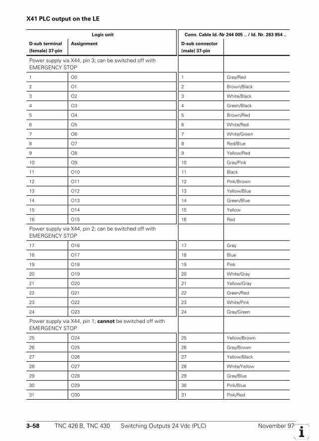
3–58 TNC 426 B, TNC 430 Switching Outputs 24 Vdc (PLC) November 97
X41 PLC output on the LE
Logic unit Conn. Cable Id.-Nr 244 005 .. / Id. Nr. 263 954 ..
D-sub terminal
(female) 37-pin
Assignment D-sub connector
(male) 37-pin
Power supply via X44, pin 3; can be switched off withEMERGENCY STOP
1 O0 1 Gray/Red
2 O1 2 Brown/Black
3 O2 3 White/Black
4 O3 4 Green/Black
5 O4 5 Brown/Red
6 O5 6 White/Red
7 O6 7 White/Green
8 O7 8 Red/Blue
9 O8 9 Yellow/Red
10 O9 10 Gray/Pink
11 O10 11 Black
12 O11 12 Pink/Brown
13 O12 13 Yellow/Blue
14 O13 14 Green/Blue
15 O14 15 Yellow
16 O15 16 Red
Power supply via X44, pin 2; can be switched off withEMERGENCY STOP
17 O16 17 Gray
18 O17 18 Blue
19 O18 19 Pink
20 O19 20 White/Gray
21 O20 21 Yellow/Gray
22 O21 22 Green/Red
23 O22 23 White/Pink
24 O23 24 Gray/Green
Power supply via X44, pin 1; cannot be switched off withEMERGENCY STOP
25 O24 25 Yellow/Brown
26 O25 26 Gray/Brown
27 O26 27 Yellow/Black
28 O27 28 White/Yellow
29 O28 29 Gray/Blue
30 O29 30 Pink/Blue
31 O30 31 Pink/Red
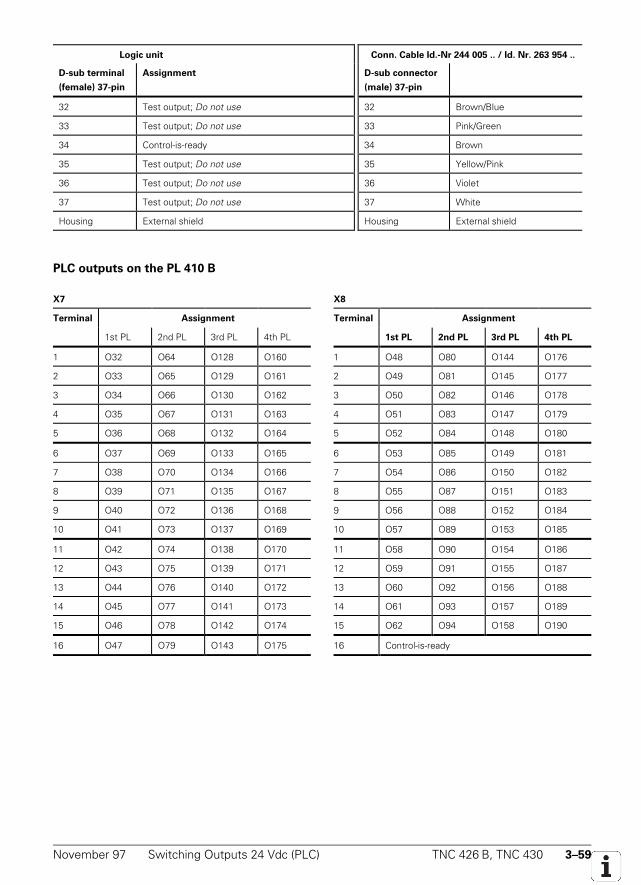
November 97 Switching Outputs 24 Vdc (PLC) TNC 426 B, TNC 430 3–59
Logic unit Conn. Cable Id.-Nr 244 005 .. / Id. Nr. 263 954 ..
D-sub terminal
(female) 37-pin
Assignment D-sub connector
(male) 37-pin
32 Test output; Do not use 32 Brown/Blue
33 Test output; Do not use 33 Pink/Green
34 Control-is-ready 34 Brown
35 Test output; Do not use 35 Yellow/Pink
36 Test output; Do not use 36 Violet
37 Test output; Do not use 37 White
Housing External shield Housing External shield
PLC outputs on the PL 410 B
X7 X8
Terminal Assignment Terminal Assignment
1st PL 2nd PL 3rd PL 4th PL 1st PL 2nd PL 3rd PL 4th PL
1 O32 O64 O128 O160 1 O48 O80 O144 O176
2 O33 O65 O129 O161 2 O49 O81 O145 O177
3 O34 O66 O130 O162 3 O50 O82 O146 O178
4 O35 O67 O131 O163 4 O51 O83 O147 O179
5 O36 O68 O132 O164 5 O52 O84 O148 O180
6 O37 O69 O133 O165 6 O53 O85 O149 O181
7 O38 O70 O134 O166 7 O54 O86 O150 O182
8 O39 O71 O135 O167 8 O55 O87 O151 O183
9 O40 O72 O136 O168 9 O56 O88 O152 O184
10 O41 O73 O137 O169 10 O57 O89 O153 O185
11 O42 O74 O138 O170 11 O58 O90 O154 O186
12 O43 O75 O139 O171 12 O59 O91 O155 O187
13 O44 O76 O140 O172 13 O60 O92 O156 O188
14 O45 O77 O141 O173 14 O61 O93 O157 O189
15 O46 O78 O142 O174 15 O62 O94 O158 O190
16 O47 O79 O143 O175 16 Control-is-ready
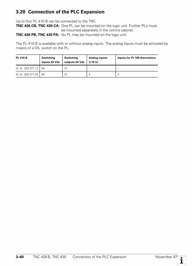
3–60 TNC 426 B, TNC 430 Connection of the PLC Expansion November 97
3.20 Connection of the PLC Expansion
Up to four PL 410 B can be connected to the TNC.TNC 426 CB, TNC 430 CA: One PL can be mounted on the logic unit. Further PLs must
be mounted separately in the control cabinet.TNC 426 PB, TNC 430 PA: No PL may be mounted on the logic unit.
The PL 410 B is available with or without analog inputs. The analog inputs must be activated bymeans of a DIL switch on the PL.
PL 410 B Switching
inputs 24 Vdc
Switching
outputs 24 Vdc
Analog inputs
(±10 V)
Inputs for Pt 100 thermistors
Id. Nr. 263 371 12 64 31 – –
Id. Nr. 263 371 02 64 31 4 4
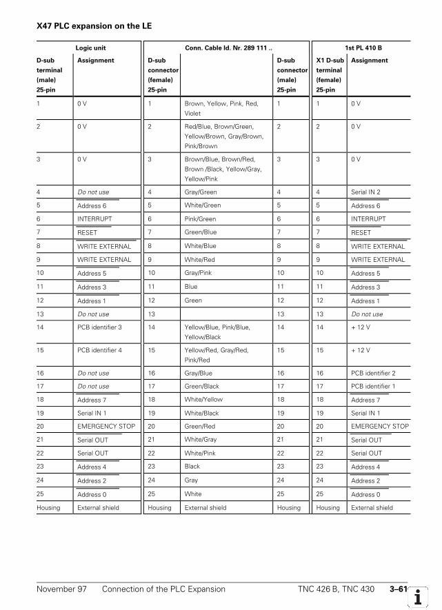
November 97 Connection of the PLC Expansion TNC 426 B, TNC 430 3–61
X47 PLC expansion on the LE
Logic unit Conn. Cable Id. Nr. 289 111 .. 1st PL 410 B
D-sub
terminal
(male)
25-pin
Assignment D-sub
connector
(female)
25-pin
D-sub
connector
(male)
25-pin
X1 D-sub
terminal
(female)
25-pin
Assignment
1 0 V 1 Brown, Yellow, Pink, Red,
Violet
1 1 0 V
2 0 V 2 Red/Blue, Brown/Green,
Yellow/Brown, Gray/Brown,
Pink/Brown
2 2 0 V
3 0 V 3 Brown/Blue, Brown/Red,
Brown /Black, Yellow/Gray,
Yellow/Pink
3 3 0 V
4 Do not use 4 Gray/Green 4 4 Serial IN 2
5 Address 6 5 White/Green 5 5 Address 6
6 INTERRUPT 6 Pink/Green 6 6 INTERRUPT
7 RESET 7 Green/Blue 7 7 RESET
8 WRITE EXTERNAL 8 White/Blue 8 8 WRITE EXTERNAL
9 WRITE EXTERNAL 9 White/Red 9 9 WRITE EXTERNAL
10 Address 5 10 Gray/Pink 10 10 Address 5
11 Address 3 11 Blue 11 11 Address 3
12 Address 1 12 Green 12 12 Address 1
13 Do not use 13 13 13 Do not use
14 PCB identifier 3 14 Yellow/Blue, Pink/Blue,
Yellow/Black
14 14 + 12 V
15 PCB identifier 4 15 Yellow/Red, Gray/Red,
Pink/Red
15 15 + 12 V
16 Do not use 16 Gray/Blue 16 16 PCB identifier 2
17 Do not use 17 Green/Black 17 17 PCB identifier 1
18 Address 7 18 White/Yellow 18 18 Address 7
19 Serial IN 1 19 White/Black 19 19 Serial IN 1
20 EMERGENCY STOP 20 Green/Red 20 20 EMERGENCY STOP
21 Serial OUT 21 White/Gray 21 21 Serial OUT
22 Serial OUT 22 White/Pink 22 22 Serial OUT
23 Address 4 23 Black 23 23 Address 4
24 Address 2 24 Gray 24 24 Address 2
25 Address 0 25 White 25 25 Address 0
Housing External shield Housing External shield Housing Housing External shield
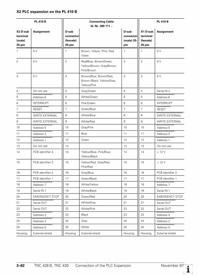
3–62 TNC 426 B, TNC 430 Connection of the PLC Expansion November 97
X2 PLC expansion on the PL 410 B
PL 410 B Connecting Cable
Id. Nr. 289 111 ..
PL 410 B
X2 D-sub
terminal
(male)
25-pin
Assignment D-sub
connector
(female)
25-pin
D-sub
connector
(male) 25-
pin
X1 D-sub
terminal
(female)
25-pin
Assignment
1 0 V 1 Brown, Yellow, Pink, Red,
Violet
1 1 0 V
2 0 V 2 Red/Blue, Brown/Green,
Yellow/Brown, Gray/Brown,
Pink/Brown
2 2 0 V
3 0 V 3 Brown/Blue, Brown/Red,
Brown /Black, Yellow/Gray,
Yellow/Pink
3 3 0 V
4 Do not use 4 Gray/Green 4 4 Serial IN 2
5 Address 6 5 White/Green 5 5 Address 6
6 INTERRUPT 6 Pink/Green 6 6 INTERRUPT
7 RESET 7 Green/Blue 7 7 RESET
8 WRITE EXTERNAL 8 White/Blue 8 8 WRITE EXTERNAL
9 WRITE EXTERNAL 9 White/Red 9 9 WRITE EXTERNAL
10 Address 5 10 Gray/Pink 10 10 Address 5
11 Address 3 11 Blue 11 11 Address 3
12 Address 1 12 Green 12 12 Address 1
13 Do not use 13 13 13 Do not use
14 PCB identifier 4 14 Yellow/Blue, Pink/Blue,
Yellow/Black
14 14 + 12 V
15 PCB identifier 3 15 Yellow/Red, Gray/Red,
Pink/Red
15 15 + 12 V
16 PCB identifier 2 16 Gray/Blue 16 16 PCB identifier 2
17 PCB identifier 1 17 Green/Black 17 17 PCB identifier 1
18 Address 7 18 White/Yellow 18 18 Address 7
19 Serial IN 1 19 White/Black 19 19 Serial IN 1
20 EMERGENCY STOP 20 Green/Red 20 20 EMERGENCY STOP
21 Serial OUT 21 White/Gray 21 21 Serial OUT
22 Serial OUT 22 White/Pink 22 22 Serial OUT
23 Address 4 23 Black 23 23 Address 4
24 Address 2 24 Gray 24 24 Address 2
25 Address 0 25 White 25 25 Address 0
Housing External shield Housing External shield Housing Housing External shield

November 97 Connection of the PLC Expansion TNC 426 B, TNC 430 3–63

3–64 TNC 426 B, TNC 430 Connection of the PLC Expansion November 97
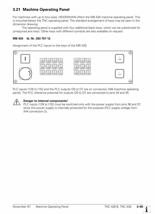
November 97 Machine Operating Panel TNC 426 B, TNC 430 3–65
3.21 Machine Operating Panel
For machines with up to four axes, HEIDENHAIN offers the MB 420 machine operating panel. Thisis mounted below the TNC operating panel. The standard arrangement of keys may be seen in thedimension drawing.
The operating panel is supplied with four additional black keys, which can be substituted forunrequired axis keys. Other keys with different symbols are also available on request.
MB 420 Id. Nr. 293 757 12
Assignment of the PLC inputs to the keys of the MB 420:
I136
I135
I134
I137
I128
I148
I133
I149
I129
I130
I131
I132
I138
I143
I145
I139
I150
I140
I141
I142
I146
I147
I144
PLC inputs I128 to I152 and the PLC outputs O0 to O7 are on connection X46 (machine operatingpanel). The PLC reference potential for outputs O0 to O7 are connected to pins 34 and 35.
Danger to internal components!
PLC inputs I128 to I152 must be switched only with the power supply from pins 36 and 37,since this power supply is internally protected for this purpose (PLC supply voltage fromX44 connection 2).
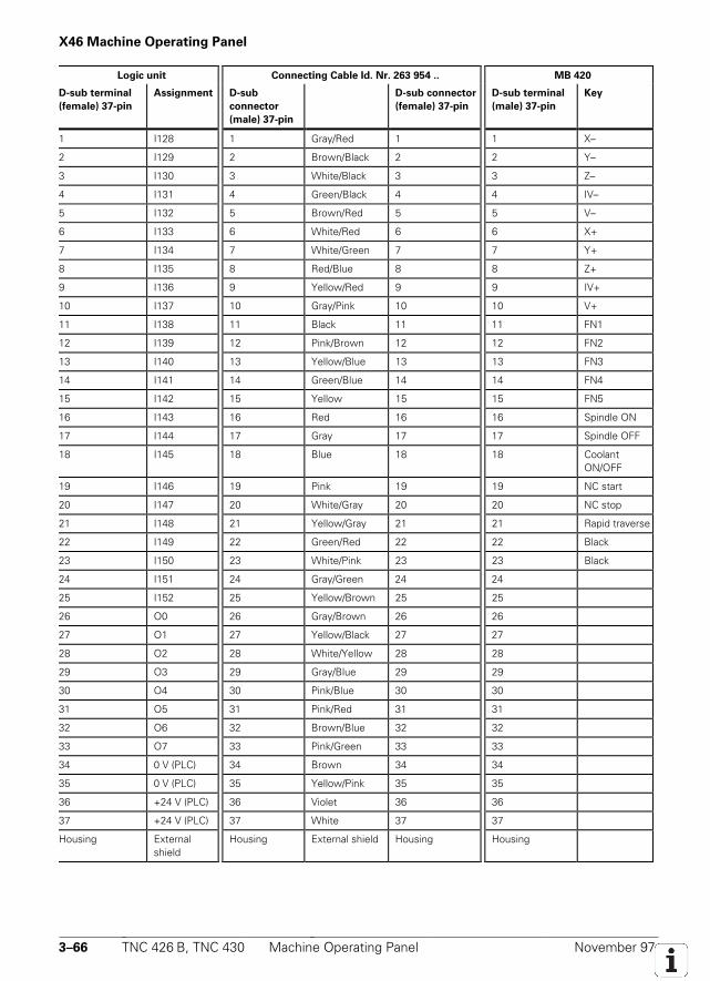
3–66 TNC 426 B, TNC 430 Machine Operating Panel November 97
X46 Machine Operating Panel
Logic unit Connecting Cable Id. Nr. 263 954 .. MB 420
D-sub terminal
(female) 37-pin
Assignment D-sub
connector
(male) 37-pin
D-sub connector
(female) 37-pin
D-sub terminal
(male) 37-pin
Key
1 I128 1 Gray/Red 1 1 X–
2 I129 2 Brown/Black 2 2 Y–
3 I130 3 White/Black 3 3 Z–
4 I131 4 Green/Black 4 4 IV–
5 I132 5 Brown/Red 5 5 V–
6 I133 6 White/Red 6 6 X+
7 I134 7 White/Green 7 7 Y+
8 I135 8 Red/Blue 8 8 Z+
9 I136 9 Yellow/Red 9 9 IV+
10 I137 10 Gray/Pink 10 10 V+
11 I138 11 Black 11 11 FN1
12 I139 12 Pink/Brown 12 12 FN2
13 I140 13 Yellow/Blue 13 13 FN3
14 I141 14 Green/Blue 14 14 FN4
15 I142 15 Yellow 15 15 FN5
16 I143 16 Red 16 16 Spindle ON
17 I144 17 Gray 17 17 Spindle OFF
18 I145 18 Blue 18 18 CoolantON/OFF
19 I146 19 Pink 19 19 NC start
20 I147 20 White/Gray 20 20 NC stop
21 I148 21 Yellow/Gray 21 21 Rapid traverse
22 I149 22 Green/Red 22 22 Black
23 I150 23 White/Pink 23 23 Black
24 I151 24 Gray/Green 24 24
25 I152 25 Yellow/Brown 25 25
26 O0 26 Gray/Brown 26 26
27 O1 27 Yellow/Black 27 27
28 O2 28 White/Yellow 28 28
29 O3 29 Gray/Blue 29 29
30 O4 30 Pink/Blue 30 30
31 O5 31 Pink/Red 31 31
32 O6 32 Brown/Blue 32 32
33 O7 33 Pink/Green 33 33
34 0 V (PLC) 34 Brown 34 34
35 0 V (PLC) 35 Yellow/Pink 35 35
36 +24 V (PLC) 36 Violet 36 36
37 +24 V (PLC) 37 White 37 37
Housing Externalshield
Housing External shield Housing Housing
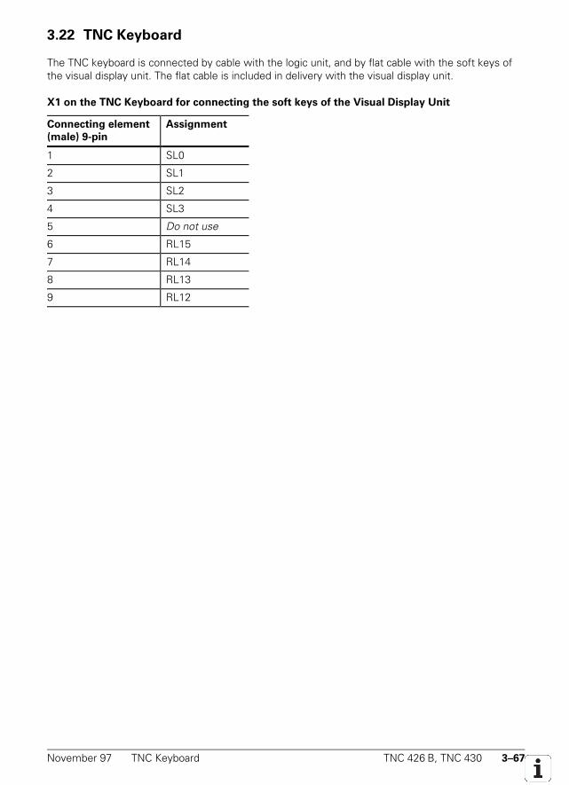
November 97 TNC Keyboard TNC 426 B, TNC 430 3–67
3.22 TNC Keyboard
The TNC keyboard is connected by cable with the logic unit, and by flat cable with the soft keys ofthe visual display unit. The flat cable is included in delivery with the visual display unit.
X1 on the TNC Keyboard for connecting the soft keys of the Visual Display Unit
Connecting element
(male) 9-pin
Assignment
1 SL0
2 SL1
3 SL2
4 SL3
5 Do not use
6 RL15
7 RL14
8 RL13
9 RL12
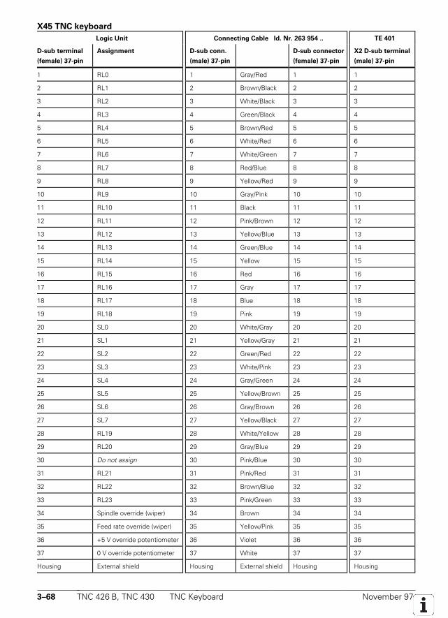
3–68 TNC 426 B, TNC 430 TNC Keyboard November 97
X45 TNC keyboard
Logic Unit Connecting Cable Id. Nr. 263 954 .. TE 401
D-sub terminal
(female) 37-pin
Assignment D-sub conn.
(male) 37-pin
D-sub connector
(female) 37-pin
X2 D-sub terminal
(male) 37-pin
1 RL0 1 Gray/Red 1 1
2 RL1 2 Brown/Black 2 2
3 RL2 3 White/Black 3 3
4 RL3 4 Green/Black 4 4
5 RL4 5 Brown/Red 5 5
6 RL5 6 White/Red 6 6
7 RL6 7 White/Green 7 7
8 RL7 8 Red/Blue 8 8
9 RL8 9 Yellow/Red 9 9
10 RL9 10 Gray/Pink 10 10
11 RL10 11 Black 11 11
12 RL11 12 Pink/Brown 12 12
13 RL12 13 Yellow/Blue 13 13
14 RL13 14 Green/Blue 14 14
15 RL14 15 Yellow 15 15
16 RL15 16 Red 16 16
17 RL16 17 Gray 17 17
18 RL17 18 Blue 18 18
19 RL18 19 Pink 19 19
20 SL0 20 White/Gray 20 20
21 SL1 21 Yellow/Gray 21 21
22 SL2 22 Green/Red 22 22
23 SL3 23 White/Pink 23 23
24 SL4 24 Gray/Green 24 24
25 SL5 25 Yellow/Brown 25 25
26 SL6 26 Gray/Brown 26 26
27 SL7 27 Yellow/Black 27 27
28 RL19 28 White/Yellow 28 28
29 RL20 29 Gray/Blue 29 29
30 Do not assign 30 Pink/Blue 30 30
31 RL21 31 Pink/Red 31 31
32 RL22 32 Brown/Blue 32 32
33 RL23 33 Pink/Green 33 33
34 Spindle override (wiper) 34 Brown 34 34
35 Feed rate override (wiper) 35 Yellow/Pink 35 35
36 +5 V override potentiometer 36 Violet 36 36
37 0 V override potentiometer 37 White 37 37
Housing External shield Housing External shield Housing Housing
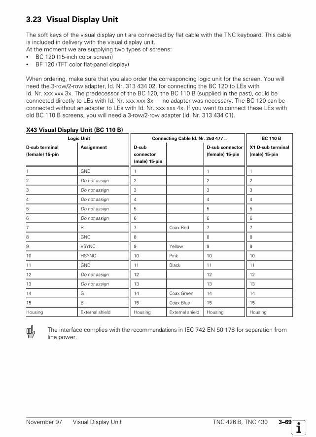
November 97 Visual Display Unit TNC 426 B, TNC 430 3–69
3.23 Visual Display Unit
The soft keys of the visual display unit are connected by flat cable with the TNC keyboard. This cableis included in delivery with the visual display unit.At the moment we are supplying two types of screens:• BC 120 (15-inch color screen)• BF 120 (TFT color flat-panel display)
When ordering, make sure that you also order the corresponding logic unit for the screen. You willneed the 3-row/2-row adapter, Id. Nr. 313 434 02, for connecting the BC 120 to LEs withId. Nr. xxx xxx 3x. The predecessor of the BC 120, the BC 110 B (supplied in the past), could beconnected directly to LEs with Id. Nr. xxx xxx 3x — no adapter was necessary. The BC 120 can beconnected without an adapter to LEs with Id. Nr. xxx xxx 4x. If you want to connect these LEs withold BC 110 B screens, you will need a 3-row/2-row adapter (Id. Nr. 313 434 01).
X43 Visual Display Unit (BC 110 B)
Logic Unit Connecting Cable Id. Nr. 250 477 .. BC 110 B
D-sub terminal
(female) 15-pin
Assignment D-sub
connector
(male) 15-pin
D-sub connector
(female) 15-pin
X1 D-sub terminal
(male) 15-pin
1 GND 1 1 1
2 Do not assign 2 2 2
3 Do not assign 3 3 3
4 Do not assign 4 4 4
5 Do not assign 5 5 5
6 Do not assign 6 6 6
7 R 7 Coax Red 7 7
8 GNC 8 8 8
9 VSYNC 9 Yellow 9 9
10 HSYNC 10 Pink 10 10
11 GND 11 Black 11 11
12 Do not assign 12 12 12
13 Do not assign 13 13 13
14 G 14 Coax Green 14 14
15 B 15 Coax Blue 15 15
Housing External shield Housing External shield Housing Housing
The interface complies with the recommendations in IEC 742 EN 50 178 for separation fromline power.
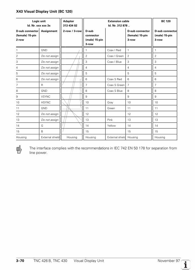
3–70 TNC 426 B, TNC 430 Visual Display Unit November 97
X43 Visual Display Unit (BC 120)
Logic unit
Id. Nr. xxx xxx 3x
Adapter
313 434 02
Extension cable
Id. Nr. 312 878 ..
BC 120
D-sub connector
(female) 15-pin
2-row
Assignment 2-row / 3-row D-sub
connector
(male) 15-pin
3-row
D-sub connector
(female) 15-pin
3-row
D-sub connector
(male) 15-pin
3-row
1 GND 1 Coax I Red 1 1
2 Do not assign 2 Coax I Green 2 2
3 Do not assign 3 Coax I Blue 3 3
4 Do not assign 4 4 4
5 Do not assign 5 5 5
6 Do not assign 6 Coax S Red 6 6
7 R 7 Coax S Green 7 7
8 GND 8 Coax S Blue 8 8
9 VSYNC 9 9 9
10 HSYNC 10 Gray 10 10
11 GND 11 Green 11 11
12 Do not assign 12 12 12
13 Do not assign 13 Pink 13 13
14 G 14 Yellow 14 14
15 B 15 15 15
Housing External shield Housing Housing External shield Housing Housing
The interface complies with the recommendations in IEC 742 EN 50 178 for separation fromline power.
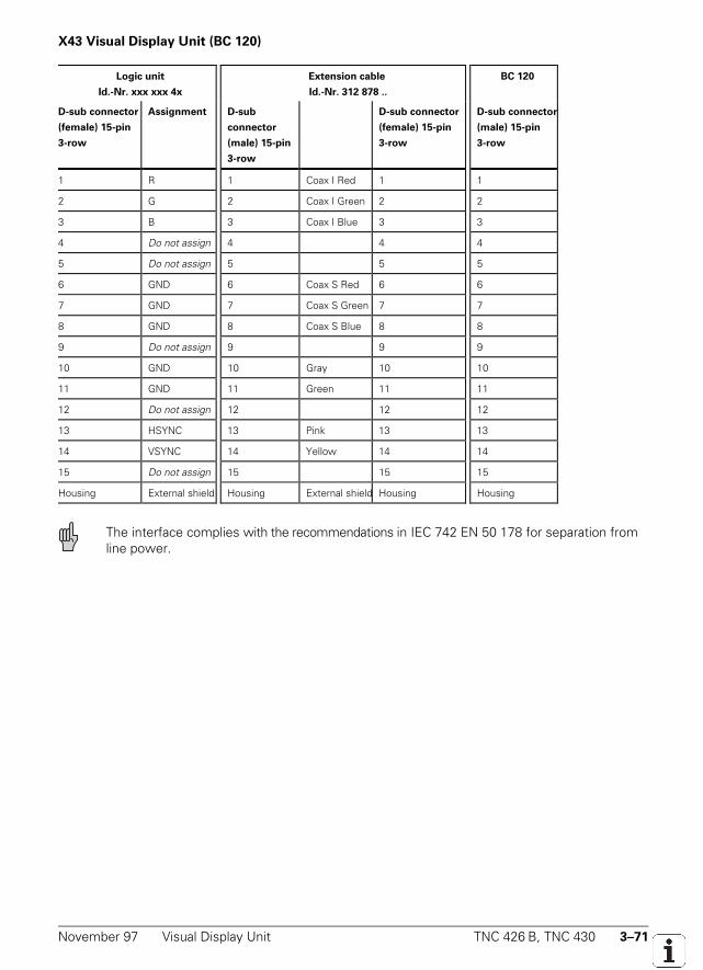
November 97 Visual Display Unit TNC 426 B, TNC 430 3–71
X43 Visual Display Unit (BC 120)
Logic unit
Id.-Nr. xxx xxx 4x
Extension cable
Id.-Nr. 312 878 ..
BC 120
D-sub connector
(female) 15-pin
3-row
Assignment D-sub
connector
(male) 15-pin
3-row
D-sub connector
(female) 15-pin
3-row
D-sub connector
(male) 15-pin
3-row
1 R 1 Coax I Red 1 1
2 G 2 Coax I Green 2 2
3 B 3 Coax I Blue 3 3
4 Do not assign 4 4 4
5 Do not assign 5 5 5
6 GND 6 Coax S Red 6 6
7 GND 7 Coax S Green 7 7
8 GND 8 Coax S Blue 8 8
9 Do not assign 9 9 9
10 GND 10 Gray 10 10
11 GND 11 Green 11 11
12 Do not assign 12 12 12
13 HSYNC 13 Pink 13 13
14 VSYNC 14 Yellow 14 14
15 Do not assign 15 15 15
Housing External shield Housing External shield Housing Housing
The interface complies with the recommendations in IEC 742 EN 50 178 for separation fromline power.
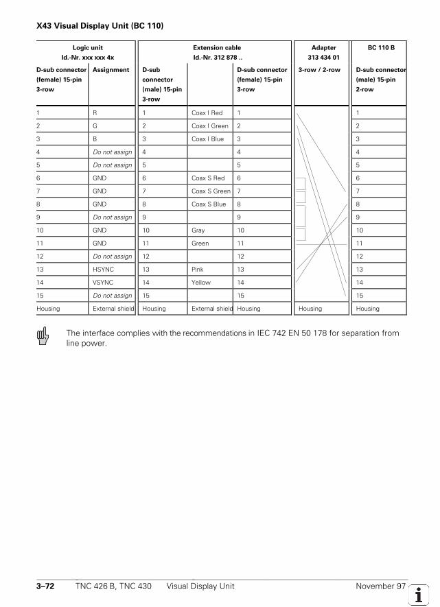
3–72 TNC 426 B, TNC 430 Visual Display Unit November 97
X43 Visual Display Unit (BC 110)
Logic unit
Id.-Nr. xxx xxx 4x
Extension cable
Id.-Nr. 312 878 ..
Adapter
313 434 01
BC 110 B
D-sub connector
(female) 15-pin
3-row
Assignment D-sub
connector
(male) 15-pin
3-row
D-sub connector
(female) 15-pin
3-row
3-row / 2-row D-sub connector
(male) 15-pin
2-row
1 R 1 Coax I Red 1 1
2 G 2 Coax I Green 2 2
3 B 3 Coax I Blue 3 3
4 Do not assign 4 4 4
5 Do not assign 5 5 5
6 GND 6 Coax S Red 6 6
7 GND 7 Coax S Green 7 7
8 GND 8 Coax S Blue 8 8
9 Do not assign 9 9 9
10 GND 10 Gray 10 10
11 GND 11 Green 11 11
12 Do not assign 12 12 12
13 HSYNC 13 Pink 13 13
14 VSYNC 14 Yellow 14 14
15 Do not assign 15 15 15
Housing External shield Housing External shield Housing Housing Housing
The interface complies with the recommendations in IEC 742 EN 50 178 for separation fromline power.
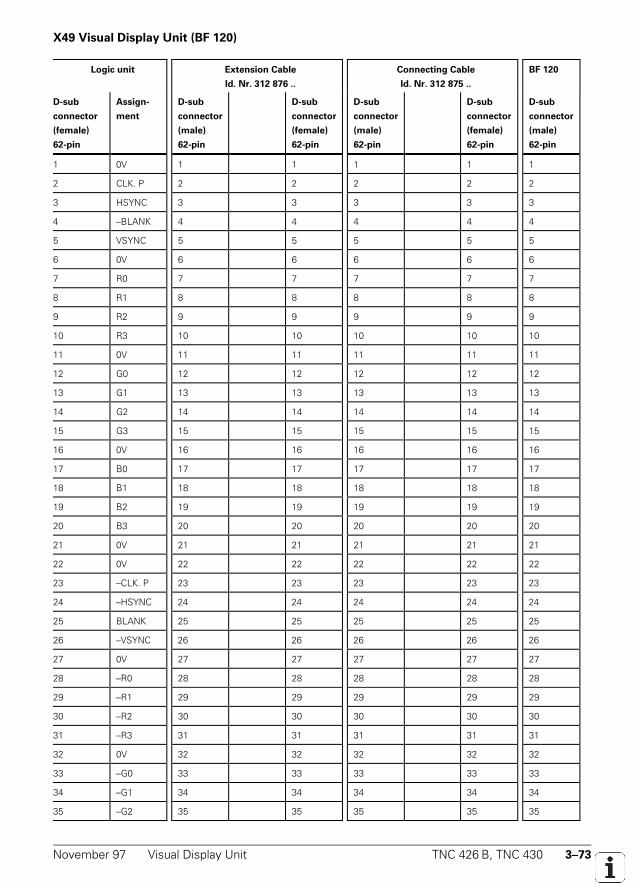
November 97 Visual Display Unit TNC 426 B, TNC 430 3–73
X49 Visual Display Unit (BF 120)
Logic unit Extension Cable
Id. Nr. 312 876 ..
Connecting Cable
Id. Nr. 312 875 ..
BF 120
D-sub
connector
(female)
62-pin
Assign-
ment
D-sub
connector
(male)
62-pin
D-sub
connector
(female)
62-pin
D-sub
connector
(male)
62-pin
D-sub
connector
(female)
62-pin
D-sub
connector
(male)
62-pin
1 0V 1 1 1 1 1
2 CLK. P 2 2 2 2 2
3 HSYNC 3 3 3 3 3
4 –BLANK 4 4 4 4 4
5 VSYNC 5 5 5 5 5
6 0V 6 6 6 6 6
7 R0 7 7 7 7 7
8 R1 8 8 8 8 8
9 R2 9 9 9 9 9
10 R3 10 10 10 10 10
11 0V 11 11 11 11 11
12 G0 12 12 12 12 12
13 G1 13 13 13 13 13
14 G2 14 14 14 14 14
15 G3 15 15 15 15 15
16 0V 16 16 16 16 16
17 B0 17 17 17 17 17
18 B1 18 18 18 18 18
19 B2 19 19 19 19 19
20 B3 20 20 20 20 20
21 0V 21 21 21 21 21
22 0V 22 22 22 22 22
23 –CLK. P 23 23 23 23 23
24 –HSYNC 24 24 24 24 24
25 BLANK 25 25 25 25 25
26 –VSYNC 26 26 26 26 26
27 0V 27 27 27 27 27
28 –R0 28 28 28 28 28
29 –R1 29 29 29 29 29
30 –R2 30 30 30 30 30
31 –R3 31 31 31 31 31
32 0V 32 32 32 32 32
33 –G0 33 33 33 33 33
34 –G1 34 34 34 34 34
35 –G2 35 35 35 35 35
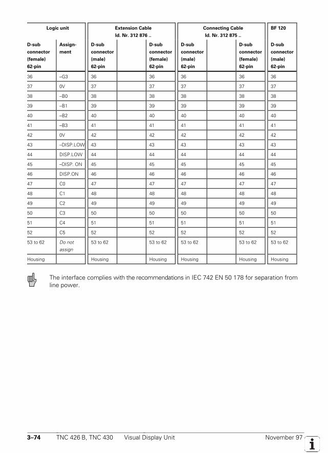
3–74 TNC 426 B, TNC 430 Visual Display Unit November 97
Logic unit Extension Cable
Id. Nr. 312 876 ..
Connecting Cable
Id. Nr. 312 875 ..
BF 120
D-sub
connector
(female)
62-pin
Assign-
ment
D-sub
connector
(male)
62-pin
D-sub
connector
(female)
62-pin
D-sub
connector
(male)
62-pin
D-sub
connector
(female)
62-pin
D-sub
connector
(male)
62-pin
36 –G3 36 36 36 36 36
37 0V 37 37 37 37 37
38 –B0 38 38 38 38 38
39 –B1 39 39 39 39 39
40 –B2 40 40 40 40 40
41 –B3 41 41 41 41 41
42 0V 42 42 42 42 42
43 –DISP.LOW 43 43 43 43 43
44 DISP.LOW 44 44 44 44 44
45 –DISP. ON 45 45 45 45 45
46 DISP.ON 46 46 46 46 46
47 C0 47 47 47 47 47
48 C1 48 48 48 48 48
49 C2 49 49 49 49 49
50 C3 50 50 50 50 50
51 C4 51 51 51 51 51
52 C5 52 52 52 52 52
53 to 62 Do notassign
53 to 62 53 to 62 53 to 62 53 to 62 53 to 62
Housing Housing Housing Housing Housing Housing
The interface complies with the recommendations in IEC 742 EN 50 178 for separation fromline power.
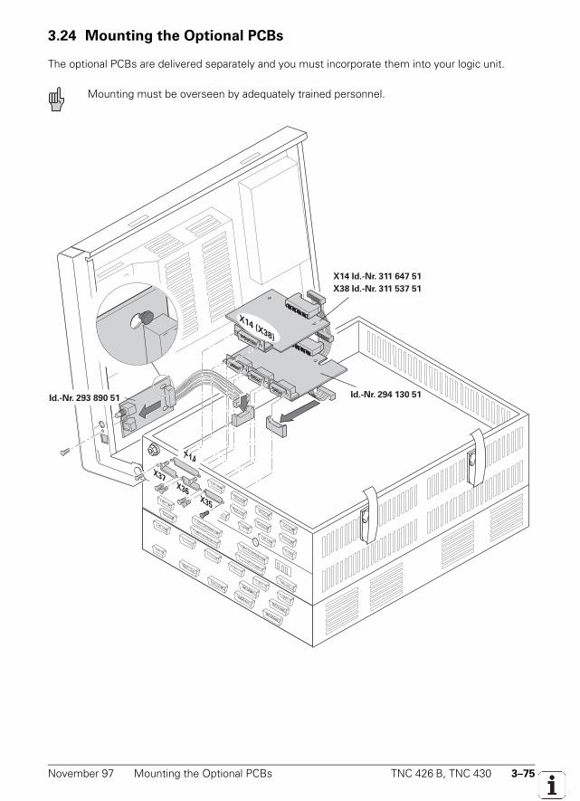
November 97 Mounting the Optional PCBs TNC 426 B, TNC 430 3–75
3.24 Mounting the Optional PCBs
The optional PCBs are delivered separately and you must incorporate them into your logic unit.
Mounting must be overseen by adequately trained personnel.
X37X36
X35
X14 Id.-Nr. 311 647 51
Id.-Nr. 293 890 51 Id.-Nr. 294 130 51
X38 Id.-Nr. 311 537 51
X14 (X38)
X14
November 97 Machine Axes TNC 426 B, TNC 430 4–1
4 Machine Integration
4.1 Machine Axes
The number of machine axes that can be controlled depends on the hardware (see "Specifications").With machine parameter MP10 you can define which axes on the machine are to be put intooperation. If necessary you can use this parameter to deselect all functions for the axes (control,display, reference mark traversing, etc.).
MP10 Active axesInput: %xxxxxxxxx
Bit 0 to 8 0 = not activeAxis 1 to 9 1 = active
Screen display
With MP7291.x you can select the line on which the axis is to be displayed on the screen. You mustset the axes to be displayed in MP100.x (capital letters for NC axes and small letters for PLC axes).You can define a new arrangement for each traverse range. The spindle is always displayed on thelast line.
MP7291.0-3 Display on screenInput: SXYZABCUVWxyzabcuvw- (capital letters for NC axes, small letters for PLC axes,
hyphen for non-displayed axes)Character 1 to 9 (1= right)Line 1 to 9Character 10 = spindle S (display always in line 9)
MP7291.0 Traverse range 1MP7291.1 Traverse range 2MP7291.2 Traverse range 3
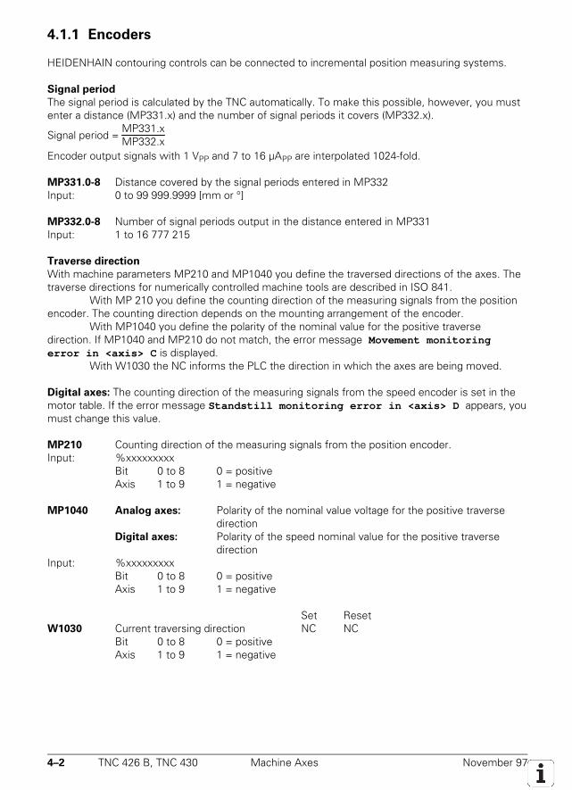
4–2 TNC 426 B, TNC 430 Machine Axes November 97
4.1.1 Encoders
HEIDENHAIN contouring controls can be connected to incremental position measuring systems.
Signal period
The signal period is calculated by the TNC automatically. To make this possible, however, you mustenter a distance (MP331.x) and the number of signal periods it covers (MP332.x).
Signal period = MP331.xMP332.x
Encoder output signals with 1 VPP and 7 to 16 µAPP are interpolated 1024-fold.
MP331.0-8 Distance covered by the signal periods entered in MP332Input: 0 to 99 999.9999 [mm or °]
MP332.0-8 Number of signal periods output in the distance entered in MP331Input: 1 to 16 777 215
Traverse direction
With machine parameters MP210 and MP1040 you define the traversed directions of the axes. Thetraverse directions for numerically controlled machine tools are described in ISO 841.
With MP 210 you define the counting direction of the measuring signals from the positionencoder. The counting direction depends on the mounting arrangement of the encoder.
With MP1040 you define the polarity of the nominal value for the positive traversedirection. If MP1040 and MP210 do not match, the error message Movement monitoringerror in <axis> C is displayed.
With W1030 the NC informs the PLC the direction in which the axes are being moved.
Digital axes: The counting direction of the measuring signals from the speed encoder is set in themotor table. If the error message Standstill monitoring error in <axis> D appears, youmust change this value.
MP210 Counting direction of the measuring signals from the position encoder.Input: %xxxxxxxxx
Bit 0 to 8 0 = positiveAxis 1 to 9 1 = negative
MP1040 Analog axes: Polarity of the nominal value voltage for the positive traversedirection
Digital axes: Polarity of the speed nominal value for the positive traversedirection
Input: %xxxxxxxxxBit 0 to 8 0 = positiveAxis 1 to 9 1 = negative
Set ResetW1030 Current traversing direction NC NC
Bit 0 to 8 0 = positiveAxis 1 to 9 1 = negative
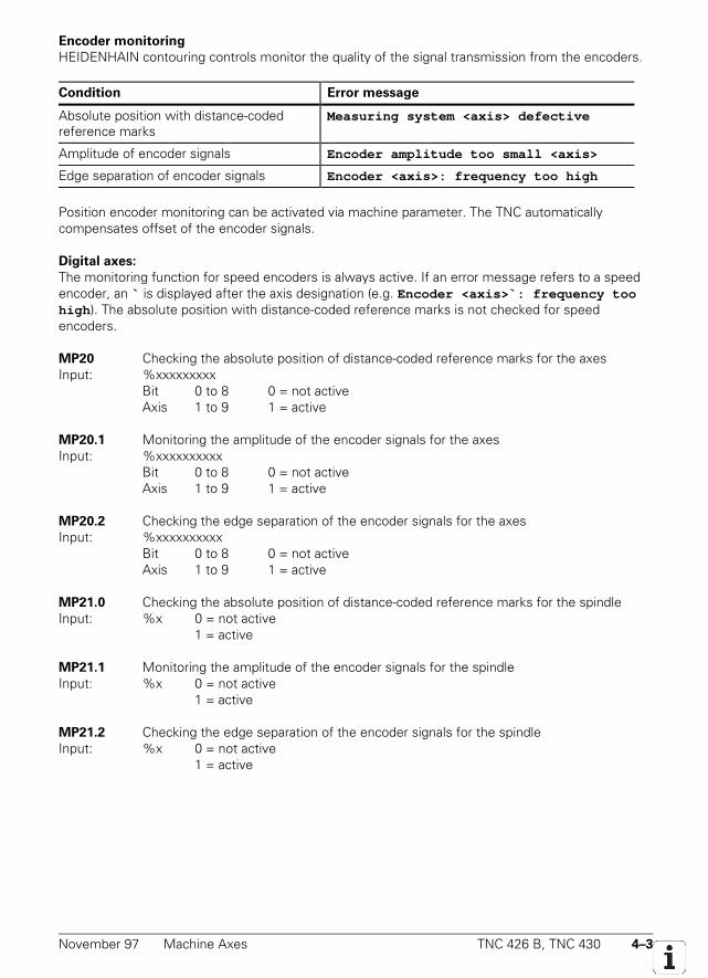
November 97 Machine Axes TNC 426 B, TNC 430 4–3
Encoder monitoring
HEIDENHAIN contouring controls monitor the quality of the signal transmission from the encoders.
Condition Error message
Absolute position with distance-codedreference marks
Measuring system <axis> defective
Amplitude of encoder signals Encoder amplitude too small <axis>
Edge separation of encoder signals Encoder <axis>: frequency too high
Position encoder monitoring can be activated via machine parameter. The TNC automaticallycompensates offset of the encoder signals.
Digital axes:
The monitoring function for speed encoders is always active. If an error message refers to a speedencoder, an ` is displayed after the axis designation (e.g. Encoder <axis>`: frequency toohigh ). The absolute position with distance-coded reference marks is not checked for speedencoders.
MP20 Checking the absolute position of distance-coded reference marks for the axesInput: %xxxxxxxxx
Bit 0 to 8 0 = not activeAxis 1 to 9 1 = active
MP20.1 Monitoring the amplitude of the encoder signals for the axesInput: %xxxxxxxxxx
Bit 0 to 8 0 = not activeAxis 1 to 9 1 = active
MP20.2 Checking the edge separation of the encoder signals for the axesInput: %xxxxxxxxxx
Bit 0 to 8 0 = not activeAxis 1 to 9 1 = active
MP21.0 Checking the absolute position of distance-coded reference marks for the spindleInput: %x 0 = not active
1 = active
MP21.1 Monitoring the amplitude of the encoder signals for the spindleInput: %x 0 = not active
1 = active
MP21.2 Checking the edge separation of the encoder signals for the spindleInput: %x 0 = not active
1 = active
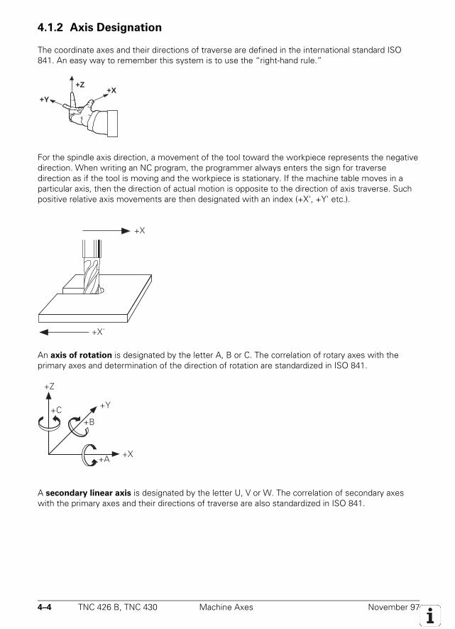
4–4 TNC 426 B, TNC 430 Machine Axes November 97
4.1.2 Axis Designation
The coordinate axes and their directions of traverse are defined in the international standard ISO841. An easy way to remember this system is to use the “right-hand rule.”
+X+Y
+Z
For the spindle axis direction, a movement of the tool toward the workpiece represents the negativedirection. When writing an NC program, the programmer always enters the sign for traversedirection as if the tool is moving and the workpiece is stationary. If the machine table moves in aparticular axis, then the direction of actual motion is opposite to the direction of axis traverse. Suchpositive relative axis movements are then designated with an index (+X', +Y' etc.).
+X
+X´
An axis of rotation is designated by the letter A, B or C. The correlation of rotary axes with theprimary axes and determination of the direction of rotation are standardized in ISO 841.
+Z
+Y
+X+A
+B+C
A secondary linear axis is designated by the letter U, V or W. The correlation of secondary axeswith the primary axes and their directions of traverse are also standardized in ISO 841.
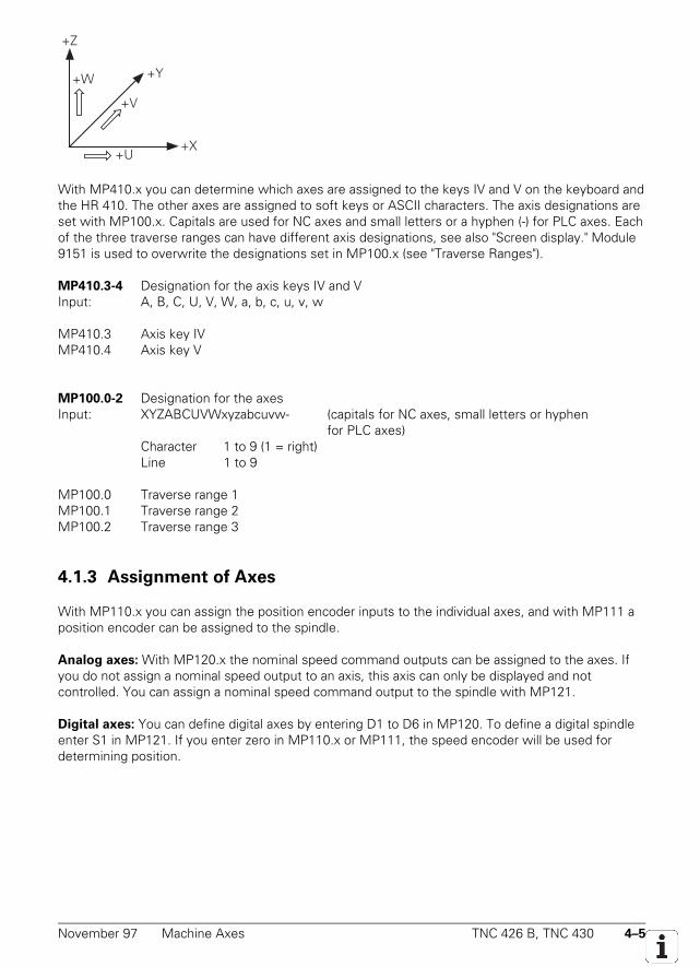
November 97 Machine Axes TNC 426 B, TNC 430 4–5
+Y
+X+U
+V
+W
+Z
With MP410.x you can determine which axes are assigned to the keys IV and V on the keyboard andthe HR 410. The other axes are assigned to soft keys or ASCII characters. The axis designations areset with MP100.x. Capitals are used for NC axes and small letters or a hyphen (-) for PLC axes. Eachof the three traverse ranges can have different axis designations, see also "Screen display." Module9151 is used to overwrite the designations set in MP100.x (see "Traverse Ranges").
MP410.3-4 Designation for the axis keys IV and VInput: A, B, C, U, V, W, a, b, c, u, v, w
MP410.3 Axis key IVMP410.4 Axis key V
MP100.0-2 Designation for the axesInput: XYZABCUVWxyzabcuvw- (capitals for NC axes, small letters or hyphen
for PLC axes)Character 1 to 9 (1 = right)Line 1 to 9
MP100.0 Traverse range 1MP100.1 Traverse range 2MP100.2 Traverse range 3
4.1.3 Assignment of Axes
With MP110.x you can assign the position encoder inputs to the individual axes, and with MP111 aposition encoder can be assigned to the spindle.
Analog axes: With MP120.x the nominal speed command outputs can be assigned to the axes. Ifyou do not assign a nominal speed output to an axis, this axis can only be displayed and notcontrolled. You can assign a nominal speed command output to the spindle with MP121.
Digital axes: You can define digital axes by entering D1 to D6 in MP120. To define a digital spindleenter S1 in MP121. If you enter zero in MP110.x or MP111, the speed encoder will be used fordetermining position.
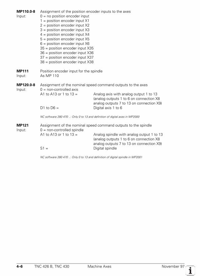
4–6 TNC 426 B, TNC 430 Machine Axes November 97
MP110.0-8 Assignment of the position encoder inputs to the axesInput: 0 = no position encoder input
1 = position encoder input X12 = position encoder input X23 = position encoder input X34 = position encoder input X45 = position encoder input X56 = position encoder input X635 = position encoder input X3536 = position encoder input X3637 = position encoder input X3738 = position encoder input X38
MP111 Position encoder input for the spindleInput: As MP 110
MP120.0-8 Assignment of the nominal speed command outputs to the axesInput: 0 = non-controlled axis
A1 to A13 or 1 to 13 = Analog axis with analog output 1 to 13(analog outputs 1 to 6 on connection X8analog outputs 7 to 13 on connection X9)
D1 to D6 = Digital axis 1 to 6
NC software 280 470 ..: Only 0 to 13 and definition of digital axes in MP2000
MP121 Assignment of the nominal speed command outputs to the spindleInput: 0 = non-controlled spindle
A1 to A13 or 1 to 13 = Analog spindle with analog output 1 to 13(analog outputs 1 to 6 on connection X8analog outputs 7 to 13 on connection X9)
S1 = Digital spindle
NC software 280 470 ..: Only 0 to 13 and definition of digital spindle in MP2001
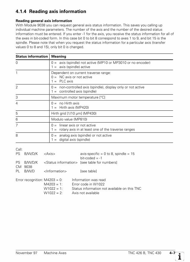
November 97 Machine Axes TNC 426 B, TNC 430 4–7
4.1.4 Reading axis information
Reading general axis information
With Module 9038 you can request general axis status information. This saves you calling upindividual machine parameters. The number of the axis and the number of the desired statusinformation must be entered. If you enter -1 for the axis, you receive the status information for all ofthe axes in bit-coded form. In this case bit 0 to bit 8 correspond to axes 1 to 9, and bit 15 is thespindle. Please note that when you request the status information for a particular axis (transfervalues 0 to 8 and 15), only bit 0 is changed.
Status information Meaning
0 0 = axis (spindle) not active (MP10 or MP3010 or no encoder)1 = axis (spindle) active
1 Dependent on current traverse range:0 = NC axis or not active1 = PLC axis
2 0 = non-controlled axis (spindle), display only or not active1 = controlled axis (spindle)
3 Maximum motor temperature [°C]
4 0 = no Hirth axis1 = Hirth axis (MP420)
5 Hirth grid [1/10 µm] (MP430)
6 Modulo value (MP810)
7 0 = linear axis or not active1 = rotary axis in at least one of the traverse ranges
8 0 = analog axis (spindle) or not active1 = digital axis (spindle)
Call:PS B/W/D/K <Axis> axis-specific = 0 to 8, spindle = 15
bit-coded = -1PS B/W/D/K <Status information> [see table for numbers]CM 9038PL B/W/D <Information> [see table]
Error recognition: M4203 = 0: Information was readM4203 = 1: Error code in W1022W1022 = 1: Status information not available on this TNCW1022 = 2: Axis not available
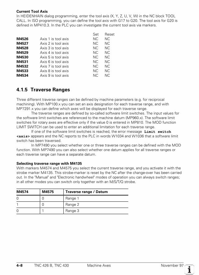
4–8 TNC 426 B, TNC 430 Machine Axes November 97
Current Tool Axis
In HEIDENHAIN dialog programming, enter the tool axis (X, Y, Z, U, V, W) in the NC block TOOLCALL. In ISO programming, you can define the tool axis with G17 to G20. The tool axis for G20 isdefined in MP410.3. In the PLC you can investigate the current tool axis via markers.
Set ResetM4526 Axis 1 is tool axis NC NCM4527 Axis 2 is tool axis NC NCM4528 Axis 3 is tool axis NC NCM4529 Axis 4 is tool axis NC NCM4530 Axis 5 is tool axis NC NCM4531 Axis 6 is tool axis NC NCM4532 Axis 7 is tool axis NC NCM4533 Axis 8 is tool axis NC NCM4534 Axis 9 is tool axis NC NC
4.1.5 Traverse Ranges
Three different traverse ranges can be defined by machine parameters (e.g. for reciprocalmachining). With MP100.x you can set an axis designation for each traverse range, and withMP7291.x you can define which axes will be displayed for each traverse range.
The traverse ranges are defined by so-called software limit switches. The input values forthe software limit switches are referenced to the machine datum (MP960.x). The software limitswitches for rotary axes are effective only if the value 0 is entered in MP810. The MOD functionLIMIT SWITCH can be used to enter an additional limitation for each traverse range.
If one of the software limit switches is reached, the error message Limit switch<axis> appears and the NC reports to the PLC in words W1034 and W1036 that a software limitswitch has been traversed.
In MP7490 you select whether one or three traverse ranges can be defined with the MODfunction. With MP7490 you can also select whether one datum applies for all traverse ranges oreach traverse range can have a separate datum.
Selecting traverse range with M4135
With markers M4574 and M4575 you select the current traverse range, and you activate it with thestrobe marker M4135. This strobe-marker is reset by the NC after the change-over has been carriedout. In the "Manual" and "Electronic handwheel" modes of operation you can always switch ranges;in all other modes you can switch only together with an M/S/T/Q strobe.
M4574 M4575 Traverse range / Datum
0 0 Range 1
1 0 Range 2
0 1 Range 3
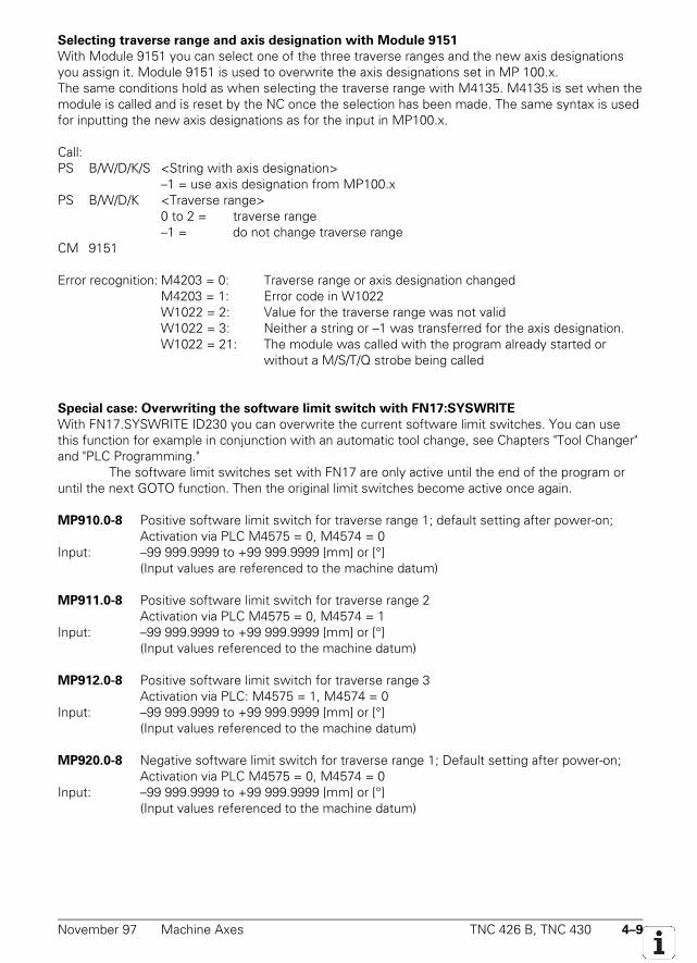
November 97 Machine Axes TNC 426 B, TNC 430 4–9
Selecting traverse range and axis designation with Module 9151
With Module 9151 you can select one of the three traverse ranges and the new axis designationsyou assign it. Module 9151 is used to overwrite the axis designations set in MP 100.x.The same conditions hold as when selecting the traverse range with M4135. M4135 is set when themodule is called and is reset by the NC once the selection has been made. The same syntax is usedfor inputting the new axis designations as for the input in MP100.x.
Call:PS B/W/D/K/S <String with axis designation>
–1 = use axis designation from MP100.xPS B/W/D/K <Traverse range>
0 to 2 = traverse range–1 = do not change traverse range
CM 9151
Error recognition: M4203 = 0: Traverse range or axis designation changedM4203 = 1: Error code in W1022W1022 = 2: Value for the traverse range was not validW1022 = 3: Neither a string or –1 was transferred for the axis designation.W1022 = 21: The module was called with the program already started or
without a M/S/T/Q strobe being called
Special case: Overwriting the software limit switch with FN17:SYSWRITE
With FN17.SYSWRITE ID230 you can overwrite the current software limit switches. You can usethis function for example in conjunction with an automatic tool change, see Chapters "Tool Changer"and "PLC Programming."
The software limit switches set with FN17 are only active until the end of the program oruntil the next GOTO function. Then the original limit switches become active once again.
MP910.0-8 Positive software limit switch for traverse range 1; default setting after power-on;Activation via PLC M4575 = 0, M4574 = 0
Input: –99 999.9999 to +99 999.9999 [mm] or [°](Input values are referenced to the machine datum)
MP911.0-8 Positive software limit switch for traverse range 2Activation via PLC M4575 = 0, M4574 = 1
Input: –99 999.9999 to +99 999.9999 [mm] or [°](Input values referenced to the machine datum)
MP912.0-8 Positive software limit switch for traverse range 3Activation via PLC: M4575 = 1, M4574 = 0
Input: –99 999.9999 to +99 999.9999 [mm] or [°](Input values referenced to the machine datum)
MP920.0-8 Negative software limit switch for traverse range 1; Default setting after power-on;Activation via PLC M4575 = 0, M4574 = 0
Input: –99 999.9999 to +99 999.9999 [mm] or [°](Input values referenced to the machine datum)
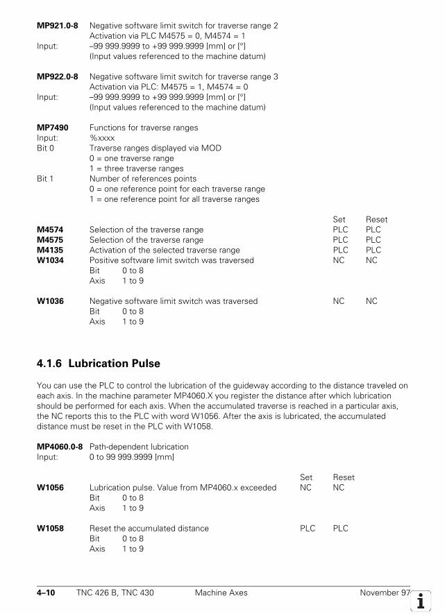
4–10 TNC 426 B, TNC 430 Machine Axes November 97
MP921.0-8 Negative software limit switch for traverse range 2Activation via PLC M4575 = 0, M4574 = 1
Input: –99 999.9999 to +99 999.9999 [mm] or [°](Input values referenced to the machine datum)
MP922.0-8 Negative software limit switch for traverse range 3Activation via PLC: M4575 = 1, M4574 = 0
Input: –99 999.9999 to +99 999.9999 [mm] or [°](Input values referenced to the machine datum)
MP7490 Functions for traverse rangesInput: %xxxxBit 0 Traverse ranges displayed via MOD
0 = one traverse range1 = three traverse ranges
Bit 1 Number of references points0 = one reference point for each traverse range1 = one reference point for all traverse ranges
Set ResetM4574 Selection of the traverse range PLC PLCM4575 Selection of the traverse range PLC PLCM4135 Activation of the selected traverse range PLC PLCW1034 Positive software limit switch was traversed NC NC
Bit 0 to 8Axis 1 to 9
W1036 Negative software limit switch was traversed NC NCBit 0 to 8Axis 1 to 9
4.1.6 Lubrication Pulse
You can use the PLC to control the lubrication of the guideway according to the distance traveled oneach axis. In the machine parameter MP4060.X you register the distance after which lubricationshould be performed for each axis. When the accumulated traverse is reached in a particular axis,the NC reports this to the PLC with word W1056. After the axis is lubricated, the accumulateddistance must be reset in the PLC with W1058.
MP4060.0-8 Path-dependent lubricationInput: 0 to 99 999.9999 [mm]
Set ResetW1056 Lubrication pulse. Value from MP4060.x exceeded NC NC
Bit 0 to 8Axis 1 to 9
W1058 Reset the accumulated distance PLC PLCBit 0 to 8Axis 1 to 9
November 97 PLC Axes TNC 426 B, TNC 430 4–11
4.2 PLC Axes
The controlled axes can also be assigned to the PLC individually. With MP100.x you can definewhich axes are to be controlled by the NC and which ones will be controlled by the PLC:• Axis designation in capitals = NC axis• Axis designation in small letters or hyphen = PLC axis• A hyphen is used when the PLC axis is not to be displayed.
PLC axes are always controlled in servo lag mode. All other axis-specific machine parameters havethe same function as for NC axes. You can start several PLC axes simultaneously. However, theseaxes are not interpolated with each other.
In MP810.x you can enter a modulo value for the counting mode of rotary axes (see thesection "Display and Operation"). If you have entered a modulo value in MP810.x, the PLC axis willalways be moved by the shortest path to the target position, even if this means crossing the zeropoint. You program the positioning of PLC axes in the PLC program using the following modules:
• Module 9120: Start PLC axis• Module 9121: Stop PLC axis• Module 9122: Status of PLC axis• Module 9123: Traverse the reference marks for PLC axis• Module 9124: Feed rate override for PLC axis
MP100.0-2 Designation of the axesInput: XYZABCUVWxyzabcuvw- (capital letters for NC axes, small letters or hyphen for
PLC axes)Byte 0 to 8Axis 1 to 9
MP100.0 Traverse range 1MP100.1 Traverse range 2MP100.2 Traverse range 3
Start PLC axis (Module 9120)
With Module 9120 you start the positioning of a PLC axis, transferring the following parameters:• The axis to be positioned• Target position• Feed rate• Absolute or incremental positionThe axis is positioned fully independently of any other processes in the control. There is no pathinterpolation with other axes.
Constraints:• You must activate the axis using MP10 and identify it as a PLC axis using MP100.x.• The system does not check for limit switch overshoot.• The axis must be stationary. You must abort any positioning movement beforehand with
Module 9121.• There is no feed-rate override. You can influence the feed rate with Module 9124.• If the reference marks were not yet traversed, the positioning movement starts from the counter
value as it existed upon switch-on.
4–12 TNC 426 B, TNC 430 PLC Axes November 97
Call:PS B/W/D/K <Axis> [0 to 8]PS B/W/D/K <Target position> [0.0001mm]PS B/W/D/K <Feed rate> [mm/min]PS B/W/D/K <Mode>
Bit 0: Type of target position data=0: Absolute, referenced to the machine datum=1: Incremental
CM 9120PL B/W/D <Error code> 0: No error. Positioning is started
1: Axis does not exist2: Axis is not defined as a PLC axis3: The axis is already being positioned4: Absolute position is outside of the modulo range
Stop the PLC axis (Module 9121)
With Module 9121 you can abort anywhere a PLC axis positioning command that has alreadystarted.
Call:PS B/W/D/K <Axis> [0 to 8]CM 9121PL B/W/D <Error code> 0: Positioning command is aborted
1: Axis does not exist2: Axis is not defined as a PLC axis3: Axis was already stationary
Status of PLC axis (Module 9122)
With Module 9122 you can interrogate the status of the PLC positioning axis movement. Changes instatus due to commands to the controller of the PLC axes (Modules 9120, 9121, 9123) are notrecognized until the next PLC scan.
Call:PS B/W/D/K <Axis> [0 to 8]CM 9122PL B/W/D <Status> Bit 0: Type
=0: NC axis=1: PLC axis
Bit 1: Reference mark=0: Reference mark has not yet been traversed=1: Reference mark has been traversed
Bit 2: Positioning=0: Not active=1: Active
Bit 3: Direction of traverse=0: Positive=1: Negative
Bit 4: Positioning error=0: No error=1: Positioning error
November 97 PLC Axes TNC 426 B, TNC 430 4–13
Traverse the reference marks for PLC axes (Module 9123)
You can use the same procedures to traverse the reference marks for PLC axes as for NC axes (seesection "Reference Marks"). If you cannot use any of the known procedures, simply use this moduleto program your own procedure for traversing the reference marks. The module starts positioning aPLC axis in a defined direction and continues until a reference mark is found. Due to the decelerationpath, the axis will stop at a position a small distance off the reference mark.
Call:PS B/W/D/K <Axis> [0 to 8]PS B/W/D/K <Feed rate> [mm/min]PS B/W/D/K <Mode>
Bit 0: Traverse direction=0: positive=1: negative
CM 9123PL B/W/D <Error code> 0: No error. Positioning has started
1: Axis does not exist2: Axis is not defined as a PLC axis3: Axis is already being positioned
Feed rate override for PLC axis (Module 9124)
With Module 9124 you can set the feed rate override for a PLC axis. The override value can liebetween 0% and 100.00% (resolution 0.01%) and must be transmitted as an natural number(0 .. 10 000). The last transmitted override value is accounted for at the beginning of movement.After a reset or interruption of the PLC program the override value of all PLC axes is set to 100.00%.The feed rate override can also be changed while a PLC axis is being positioned.
Call:PS B/W/D/K <Axis> [0 to 8]PS B/W/D/K <Override> (Format 0.01%)CM 9124PL B/W/D <Error code> 0: No error: feed rate override was set.
1: Axis does not exist2: Axis is not defined as a PLC axis3: Override value is incorrect
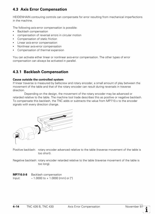
4–14 TNC 426 B, TNC 430 Axis Error Compensation November 97
4.3 Axis Error Compensation
HEIDENHAIN contouring controls can compensate for error resulting from mechanical imperfectionsin the machine.
The following axis-error compensation is possible:• Backlash compensation• compensation of reversal errors in circular motion• Compensation of static friction• Linear axis-error compensation• Nonlinear axis-error compensation• Compensation of thermal expansion
You can activate either linear or nonlinear axis-error compensation. The other types of errorcompensation can always be activated in parallel.
4.3.1 Backlash Compensation
Cause outside the controlled system
If linear traverse is measured by ballscrew and rotary encoder, a small amount of play between themovement of the table and that of the rotary encoder can result during reversals in traversedirection.
Depending on the design, the movement of the rotary encoder may be advanced orretarded relative to the table. The machine tool trade describes this as positive or negative backlash.To compensate this backlash, the TNC adds or subtracts the value from MP710.x to the encodersignals with every direction change.
Positive backlash: rotary encoder advanced relative to the table (traverse movement of the table istoo short).
Negative backlash: rotary encoder retarded relative to the table (traverse movement of the table istoo long).
MP710.0-8 Backlash compensationInput: – 1.0000 to + 1.0000 [mm] or [°]
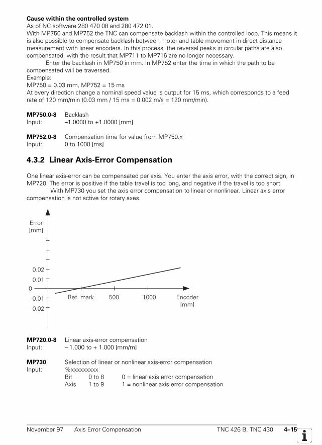
November 97 Axis Error Compensation TNC 426 B, TNC 430 4–15
Cause within the controlled system
As of NC software 280 470 08 and 280 472 01.With MP750 and MP752 the TNC can compensate backlash within the controlled loop. This means itis also possible to compensate backlash between motor and table movement in direct distancemeasurement with linear encoders. In this process, the reversal peaks in circular paths are alsocompensated, with the result that MP711 to MP716 are no longer necessary.
Enter the backlash in MP750 in mm. In MP752 enter the time in which the path to becompensated will be traversed.Example:MP750 = 0.03 mm, MP752 = 15 msAt every direction change a nominal speed value is output for 15 ms, which corresponds to a feedrate of 120 mm/min (0.03 mm / 15 ms = 0.002 m/s = 120 mm/min).
MP750.0-8 BacklashInput: –1.0000 to +1.0000 [mm]
MP752.0-8 Compensation time for value from MP750.xInput: 0 to 1000 [ms]
4.3.2 Linear Axis-Error Compensation
One linear axis-error can be compensated per axis. You enter the axis error, with the correct sign, inMP720. The error is positive if the table travel is too long, and negative if the travel is too short.
With MP730 you set the axis error compensation to linear or nonlinear. Linear axis errorcompensation is not active for rotary axes.
Ref. mark 500 1000 Encoder [mm]
0.02
0.01
-0.01
-0.02
0
Error[mm]
MP720.0-8 Linear axis-error compensationInput: – 1.000 to + 1.000 [mm/m]
MP730 Selection of linear or nonlinear axis-error compensationInput: %xxxxxxxxx
Bit 0 to 8 0 = linear axis error compensationAxis 1 to 9 1 = nonlinear axis error compensation
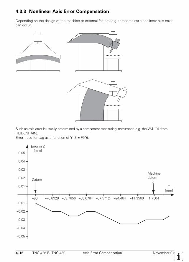
4–16 TNC 426 B, TNC 430 Axis Error Compensation November 97
4.3.3 Nonlinear Axis Error Compensation
Depending on the design of the machine or external factors (e.g. temperature) a nonlinear axis-errorcan occur.
Such an axis-error is usually determined by a comparator measuring instrument (e.g. the VM 101 fromHEIDENHAIN).Error trace for sag as a function of Y (Z = F(Y)):
–76.8928 –50.6784
Error in Z[mm]
Y[mm]
0.01
–90 –63.7856
MachinedatumDatum
00.02
0.03
0.04
0.05
–0.04
–0.03
–0.02
–0.01
–0.05
–37.5712 –11.3568–24.464 1.7504
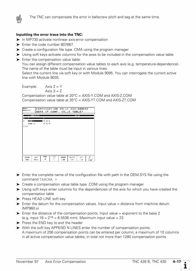
November 97 Axis Error Compensation TNC 426 B, TNC 430 4–17
The TNC can compensate the error in ballscrew pitch and sag at the same time.
Inputting the error trace into the TNC:
In MP730 activate nonlinear axis-error compensation Enter the code number 807667. Create a configuration file type .CMA using the program manager Using soft keys activate columns for the axes to be included in the compensation value table Enter the compensation value table:
You can assign different compensation value tables to each axis (e.g. temperature-dependence).The name of the table must be input in various lines.Select the current line via soft key or with Module 9095. You can interrogate the current activeline with Module 9035.
Example: Axis 2 = YAxis 3 = Z
Compensation value table at 20°C = AXIS-Y.COM and AXIS-Z.COMCompensation value table at 35°C = AXIS-YT.COM and AXIS-ZT.COM
Enter the complete name of the configuration file with path in the OEM.SYS file using thecommand TABCMA =
Create a compensation value table type .COM using the program manager Using soft keys enter columns for the dependencies of the axis for which you have created the
compensation table Press HEAD LINE soft key Enter the datum for the compensation values. Input value = distance from machine datum
(MP960.x) Enter the distance of the compensation points. Input value = exponent to the base 2
(e.g. input 16 = 216 = 6.5536 mm). Maximum input value = 23 Press the END key to exit the header With the soft key APPEND N LINES enter the number of compensation points.
A maximum of 256 compensation points can be entered per column; a maximum of 10 columnsin all active compensation value tables; in total not more than 1280 compensation points
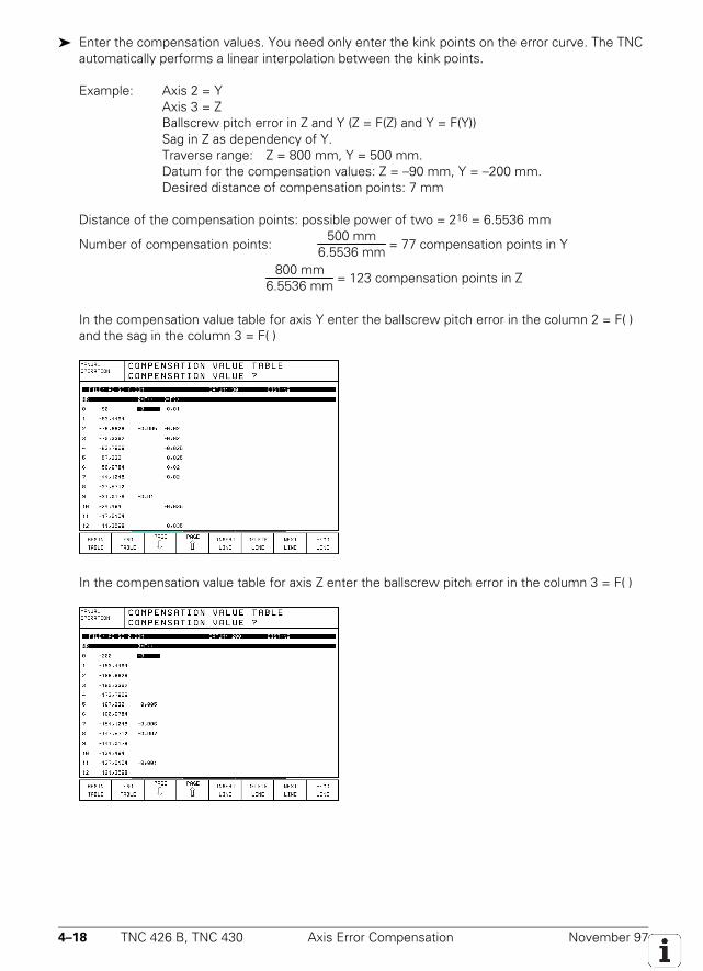
4–18 TNC 426 B, TNC 430 Axis Error Compensation November 97
Enter the compensation values. You need only enter the kink points on the error curve. The TNCautomatically performs a linear interpolation between the kink points.
Example: Axis 2 = YAxis 3 = ZBallscrew pitch error in Z and Y (Z = F(Z) and Y = F(Y))Sag in Z as dependency of Y.Traverse range: Z = 800 mm, Y = 500 mm.Datum for the compensation values: Z = –90 mm, Y = –200 mm.Desired distance of compensation points: 7 mm
Distance of the compensation points: possible power of two = 216 = 6.5536 mm
Number of compensation points:500 mm
6.5536 mm = 77 compensation points in Y
800 mm6.5536 mm = 123 compensation points in Z
In the compensation value table for axis Y enter the ballscrew pitch error in the column 2 = F( )and the sag in the column 3 = F( )
In the compensation value table for axis Z enter the ballscrew pitch error in the column 3 = F( )
November 97 Axis Error Compensation TNC 426 B, TNC 430 4–19
Input and output of the compensation value tables via the data interface
In the PLC Programming mode you can upload and download the .CMA and .COM files via the datainterface. The .CMA file is assigned the extension .S and the .COM file the extension .V.
A rotary axis is a special case
With an axis of rotation, the system only recognizes corrections of entries from 0° to 360° (withreference to the machine datum). The datum for nonlinear compensation must be located in therange +0° to +360°. If you want to compensate a full circle, the datum must be identical with themachine datum.
MP730 Selection of linear or nonlinear axis error compensationInput: %xxxxxxxxx
Bit 0 to 8 0 = linear axis error compensationAxis 1 to 9 1 = nonlinear axis error compensation
Call only in the submit job:PS B/W/D/K <Active line>CM 9095 PL B/W/D <Error code>
0: No error1: Entered line does not exist2: Compensation value table (.COM) does not exist3: Compensation value table (.COM) >256 entries4: Total permissible number of compensation points exceeded5: Too many compensation value tables (.COM)6: .CMA file does not exist7: Call did not come from a submit job8: Call during running program without strobe10: .CMA file is protected
Call:PS B/W/D/K <19>CM 9035 PL B/W/D <Active line number>
≥0: Active line number–1: No .CMA file active
4–20 TNC 426 B, TNC 430 Axis Error Compensation November 97
4.3.4 Temperature Compensation
Exact measurements of machine thermal behavior (center of expansion in the axes, amount ofexpansion as a function of temperature) are necessary to compensate the effects of thermalexpansion.
The temperature measured through the Pt 100 thermistors is filed in PLC words (see section“Analog Inputs”). The thermal expansion is largely proportional to the temperature value: you candirectly determine the amount of expansion by multiplying the temperature value by a certain factor.The value to be compensated can be given with Module 9231. As soon a you transfer a value withModule 9231, the “lag tracking” becomes active. “Lag tracking” means that the actual machineposition changes by a certain value per PLC cycle until it has been completely compensated. Thisdoes not change the value in the actual position display. The increment of change per PLC cyclemust be defined in MP4070.
You don't have to use Module 9231 for axes 1 to 5. In this case the value to be compensated can beentered directly into W576 to W584.
MP4070 Compensation per PLC cycle for lag-tracking error compensationInput: 0.0001 to 0.005 [mm]
Set ResetW576 to W584 Lag-tracking error compensation PLC PLC
(compensation speed from MP4070)Input: +32 767 to –32 768 [1/10 µm]
W576 to W584Axis 1 to Axis 5
Call:PS B/W/D/K <Axis> [0 to 8]PS B/W/D/K <Compensation value> [1/10 000 mm] Range: –30 000 to +30 000CM 9231
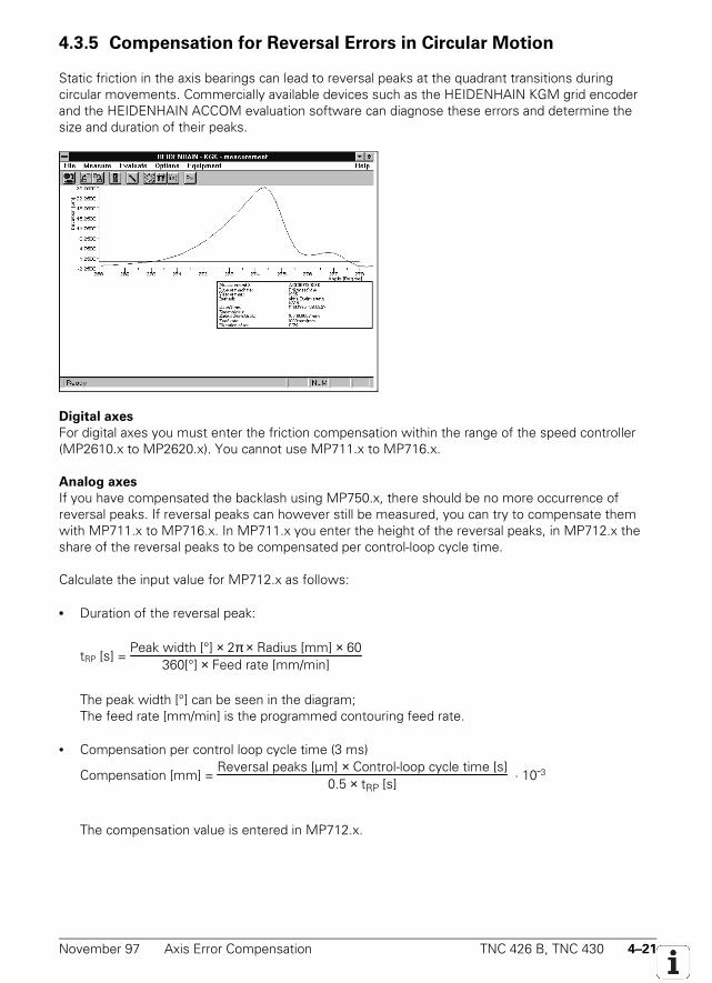
November 97 Axis Error Compensation TNC 426 B, TNC 430 4–21
4.3.5 Compensation for Reversal Errors in Circular Motion
Static friction in the axis bearings can lead to reversal peaks at the quadrant transitions duringcircular movements. Commercially available devices such as the HEIDENHAIN KGM grid encoderand the HEIDENHAIN ACCOM evaluation software can diagnose these errors and determine thesize and duration of their peaks.
Digital axes
For digital axes you must enter the friction compensation within the range of the speed controller(MP2610.x to MP2620.x). You cannot use MP711.x to MP716.x.
Analog axes
If you have compensated the backlash using MP750.x, there should be no more occurrence ofreversal peaks. If reversal peaks can however still be measured, you can try to compensate themwith MP711.x to MP716.x. In MP711.x you enter the height of the reversal peaks, in MP712.x theshare of the reversal peaks to be compensated per control-loop cycle time.
Calculate the input value for MP712.x as follows:
• Duration of the reversal peak:
tRP [s] = Peak width [°] × 2π × Radius [mm] × 60
360[°] × Feed rate [mm/min]
The peak width [°] can be seen in the diagram;The feed rate [mm/min] is the programmed contouring feed rate.
• Compensation per control loop cycle time (3 ms)
Compensation [mm] = Reversal peaks [µm] × Control-loop cycle time [s]
0.5 × tRP [s] · 10-3
The compensation value is entered in MP712.x.
4–22 TNC 426 B, TNC 430 Axis Error Compensation November 97
If the calculated values have no effect, this indicates that the machine dynamics are too weak. Withthe M function M105 you can switch to a second set of Kv factors (see section “Control loop” in thischapter). This activates a second set of machine parameters for compensating the reversal peaks:MP715.x (like MP711.x) and MP716.x (like MP712.x). By selecting a higher Kv factor you canselectively increase the contouring accuracy. The M function M106 reactivates the original set of Kv
factors. You must enable the M functions M105/M106 with MP7440, Bit 3.
MP711.0-8 Analog axes: Height of the reversal peaks during circular traverseInput: – 1.0000 to + 1.0000 [mm]
Digital axes: No meaning (see MP2610.x to MP2620.x)Input: 0
MP712.0-8 Analog axes: Compensation value per control-loop cycle timeInput: 0.000000 to 99.999999 [mm]
Digital axes: No meaning (see MP2610.x to MP2620.x)Input: 0
MP715.0-8 Analog axes: Height of the reversal peaks during circular traverse with M105Input: – 1.0000 to + 1.0000 [mm]
Digital axes: No meaning (see MP2610.x to MP2620.x)Input: 0
MP716.0-8 Analog axes: Compensation value per control-loop cycle time with M105Input: 0.000000 to 99.999999 [mm]
Digital axes: No meaning (see MP2610.x to MP2620.x)Input: 0
MP7440 Output of M functionsInput: %xxxxxBit 3 Switching kv factors with M105/M106
0 = function not effective1 = function effective

November 97 Axis Error Compensation TNC 426 B, TNC 430 4–23
4–24 TNC 426 B, TNC 430 Axis Error Compensation November 97
4.3.6 Compensation of Static Friction
The compensation of static friction (stiction) is effective only during operation with velocityfeedforward control. If you wish the stiction compensation to be effective also in the manualoperating modes you must activate the velocity feedforward control with MP1391.x for each axis formanual operation.
Guideways with a relatively high level of stiction can cause servo lag at low feed-rates,even when using velocity feedforward. You can detect a servo lag by using, for example, the TNC'sintegral oscilloscope; and the TNC can also compensate the error. Enter an axis-specific factor tocompensate the stiction in machine parameter MP1511 (recommended value: 5000 to 10 000). Ahigher nominal speed value based on this factor is then output while traversing.
Fadd = ∆st
a
C × kv × MP1511 Fadd = additional feed rate [
mmin]
∆sa = lag difference after one control loop cycle [mm]tC = control loop cycle time [µs]
kv = position loop gain [m/minmm ]
MP1511.x = factor for stiction compensation [µs]
This increase in nominal value is limited by MP1512. If you set this limit too high, the machine willoscillate at standstill (recommended value: < 50).
MP1512.x = ∆salimit 256
GP∗ MP1512.x =limit to the amount of stiction compensation
[counting steps]∆ salimit = limit value ∆sa [µm]
GP = grating period of the encoder
Compensation may only be active at low feed rates because the increased nominal value wouldcause oscillation at high speed. The feed-rate limit for stiction compensation is defined in MP1513.x.
MP1511.0-8 Factor for stiction compensationInput: 0 to 16 777 215
MP1512.0-8 Limit to amount of stiction compensationInput: 0 to 16 777 215 [counting steps]
MP1513.0-8 Feed rate limit for stiction compensation
Input: 0 to 300 000 [mmmin]
MP1391 Velocity feedforward control for Manual and Handwheel operating modesInput: %xxxxx
Bit 0 to 8 0 = operation with lagAxis 1 to 9 1 = operation with velocity feedforward
November 97 Axis Error Compensation TNC 426 B, TNC 430 4–25
With digital axes only: Limiting the integral factor
In machines with a lot of stiction, a high integral-action component can result if there is a positiondeviation at standstill. This can lead to a jump in position when the axis "takes off." In such cases theintegral-action component of the speed controller can be limited with MP2512.x.
MP2512.0-5 Limiting the integral-action component of the speed controllerInput: 0.000 to 30.000 [s]
Realistic values: 0.1 to 2.0
4.3.7 Compensation of Sliding Friction
Only for digital axes
Sliding friction is compensated within the range of the motor speed controller. With the oscilloscopeintegrated in the TNC you can find the nominal current value (I NOML) at very low speed (approx. 10rpm). This current is entered in MP2610.x.
At every change in direction this value is fed forward to the speed controller in order tocompensate friction at low speeds (speed-independent friction compensation). You also measurethe nominal current value (I NOML) at the rated speed (MP2210). This current is entered inMP2620.x. Depending on the nominal speed value, a corresponding current is fed forward to thespeed controller (speed-dependent friction compensation).
When the traverse direction is reversed at high feed rates overcompensation may occur. Inthe circular interpolation test such overcompensation appears in the form of reversal peaks that jutinward. With MP2612.x you can enter a delay in compensation to prevent overcompensation.
MP2610.0-5 Digital axes: Friction compensation at low motor speedInput: 0 to 30.0000 [A]
0 = no sliding frictionAnalog axes: Non-functional
Input: 0
MP2612.0-5 Digital axes: Delay of friction compensationInput: 0.0000 to 1.0000 [s]
Typical value: 0.015 sAnalog axes: Non-functional
Input: 0
MP2620.0-5 Digital axes: Friction compensation at rated motor speedInput: 0 to 30.0000 [A]
0 = no sliding frictionAnalog axes: Non-functional
Input: 0
4–26 TNC 426 B, TNC 430 PLC Positioning Commands November 97
4.4 PLC Positioning Commands
The TNC lets you position its axes through the PLC. For a description of how the PLC positions thespindle, see section "Spindle" in this chapter.
When to position through the PLC
• In the Manual and Handwheel operating modes, positioning is possible only when the axes arenot already being positioned.
• In all other operating modes, positioning is possible only in conjunction with an M/S/T/Q strobe orif no program has been started.
If one axis is being positioned by the NC, you can move another axis only if you have defined it as aPLC axis (a separate chapter on this).
How to program a PLC positioning command
• With Modules 9221 and 9222• To ensure compatibility (for axis 1 to axis 5), with M4120 to M4124, D528 to D544 and W560 to
W568
PLC Positioning with Modules 9221 and 9222
With Module 9221 you can position a NC axis by transferring the following parameters:• Axis to be positioned• Target position• Feed rate• Absolute or incremental position• Software limit switch status (active or not active)
A simultaneous PLC positioning movement of several axes is interpolated. If you start an additionalaxis while already positioning another, the first movement is aborted, and then all the programmedaxes (e.g. X, Y and Z) are positioned together.
There is no tool compensation. The tool path compensation must be ended before a PLCpositioning command. PLC positioning is not shown in the test graphics.
After the module call the corresponding markers M4120 to M4128 are set. You can abortthe PLC positioning command by resetting this marker. If you wish to change a parameter (e.g. feedrate) of a positioning command in progress, you must first abort it with M4120 to M4128, changethe parameter, and call Module 9221 again.
The NC aborts the PLC positioning command when:• An NC STOP occurs in the Manual or Handwheel mode of operation.• An NC STOP and internal stop occur in the automatic modes of operation.• An EMERGENCY STOP occurs.• An error message occurs that results in a STOP.
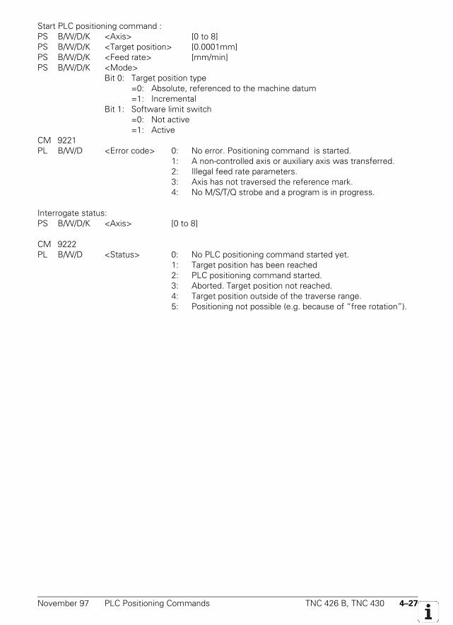
November 97 PLC Positioning Commands TNC 426 B, TNC 430 4–27
Start PLC positioning command :PS B/W/D/K <Axis> [0 to 8]PS B/W/D/K <Target position> [0.0001mm]PS B/W/D/K <Feed rate> [mm/min]PS B/W/D/K <Mode>
Bit 0: Target position type=0: Absolute, referenced to the machine datum=1: Incremental
Bit 1: Software limit switch=0: Not active=1: Active
CM 9221PL B/W/D <Error code> 0: No error. Positioning command is started.
1: A non-controlled axis or auxiliary axis was transferred.2: Illegal feed rate parameters.3: Axis has not traversed the reference mark.4: No M/S/T/Q strobe and a program is in progress.
Interrogate status:PS B/W/D/K <Axis> [0 to 8]
CM 9222PL B/W/D <Status> 0: No PLC positioning command started yet.
1: Target position has been reached2: PLC positioning command started.3: Aborted. Target position not reached.4: Target position outside of the traverse range.5: Positioning not possible (e.g. because of “free rotation”).
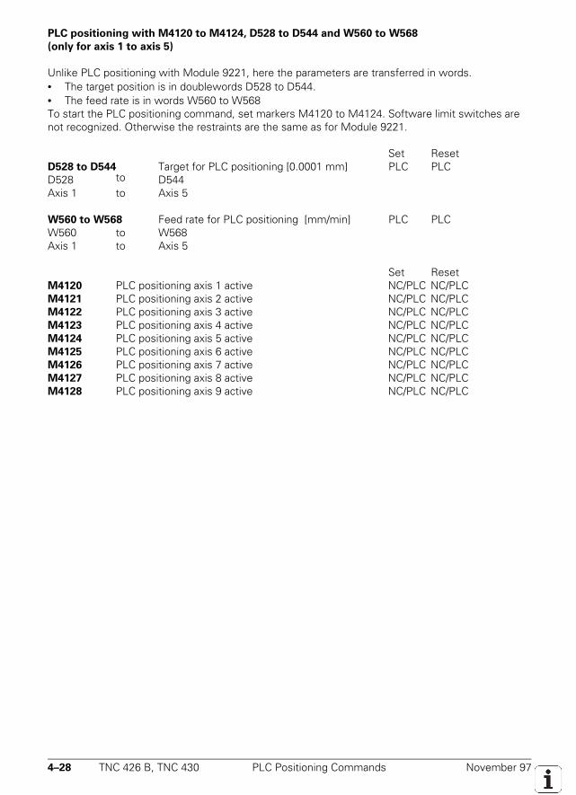
4–28 TNC 426 B, TNC 430 PLC Positioning Commands November 97
PLC positioning with M4120 to M4124, D528 to D544 and W560 to W568
(only for axis 1 to axis 5)
Unlike PLC positioning with Module 9221, here the parameters are transferred in words.• The target position is in doublewords D528 to D544.• The feed rate is in words W560 to W568To start the PLC positioning command, set markers M4120 to M4124. Software limit switches arenot recognized. Otherwise the restraints are the same as for Module 9221.
Set ResetD528 to D544 Target for PLC positioning [0.0001 mm] PLC PLCD528 to D544Axis 1 to Axis 5
W560 to W568 Feed rate for PLC positioning [mm/min] PLC PLCW560 to W568Axis 1 to Axis 5
Set ResetM4120 PLC positioning axis 1 active NC/PLC NC/PLCM4121 PLC positioning axis 2 active NC/PLC NC/PLCM4122 PLC positioning axis 3 active NC/PLC NC/PLCM4123 PLC positioning axis 4 active NC/PLC NC/PLCM4124 PLC positioning axis 5 active NC/PLC NC/PLCM4125 PLC positioning axis 6 active NC/PLC NC/PLCM4126 PLC positioning axis 7 active NC/PLC NC/PLCM4127 PLC positioning axis 8 active NC/PLC NC/PLCM4128 PLC positioning axis 9 active NC/PLC NC/PLC
November 97 Tilting Axes TNC 426 B, TNC 430 4–29
4.5 Tilting Axes
Swiveling milling heads and tilting tables are often used on milling machines to machine workpiecesfrom several sides. You can create such part programs either with a CAD system or right at the TNCby using its Tilt Working Plane function.
4.5.1 “Tilt Working Plane” Feature
You can position tilting axes either manually or under NC control.
In Cycle 19, Tilt Working Plane, you define the position of the working plane (e.g. A-45, B-45). WithMP7500 bit 1 you define whether the entered value should correspond to the position of theindividual tilting axes or the position of the working plane. The position of the working plane can beentered only for certain tilting-axis combinations. If you enter the position of the working plane, theTNC offsets the positions of the tilting axes. The resulting coordinates are stored in the followingQ parameters:Q120 = coordinate of the A axisQ121 = coordinate of the B axisQ122 = coordinate of the C axis
After activation of Cycle 19, the TNC undertakes a coordinate transformation. The other axes remainparallel to the tool axis, and the X-Y plane is perpendicular to the directional vector of the tool axis.With MP7500, bit 2, you define whether the tilting axes should be positioned when Cycle 19 iscalled. If you select automatic positioning in bit 2, you may enter a feed rate and a setup clearance inCycle 19. With Cycle 19 the TNC then moves automatically to setup clearance and interpolates themain axes and the tilting axes so that the tool tip is once again at the same position in the tiltedcoordinate system.
The values displayed in the status window refer to the tilted coordinate system. In this wayyou can transform the working plane to any desired position, then enter the part program in the X-Yplane as usual. The NC automatically interpolates the affected axis during program run. You can useall the path functions, cycles, and datum setting and probing functions in the transformed workingplane. For controlled axes the current coordinates of the tilting axes are accounted for during datumsetting. The reference in this case is the machine datum. Therefore in the 0° position the set datumfor the tilting axes must coincide with the coordinates referenced to the machine datum. Amisalignment can be compensated with MP960.x. In MP7682 bit 1 you can set whether the nominalor the actual values should be used for calculating the preset during "datum setting". For non-controlled axes you must enter the current positions of the tilting axes using the 3D ROT soft key.
Workpieces on rotary tables are often aligned with the turning of the table. After thisalignment the set datum no longer coincides with the machine zero position. If MP7500 bit 3 is set,the TNC assumes that the workpiece is aligned at "datum setting" and the Cycle Tilt Working Planeuses the new position after the table has been rotated as datum.
When combining coordinate transformation cycles you must consider the sequence ofactivation and deactivation. The tool radius offset in the working plane and the tool length offsetparallel to the tool axis are active. With the 3D ROT soft key you can activate the tilted workingplane separately for the Manual and Program Run modes.
You must enter the mechanical offset between the tilting axes in the machine parameters.The tilting head must be in its home position (all tilting axes in the 0° position) when the shifts areentered. For tilting heads the initial position is the tool datum of the machine (usually the spindlehead). Enter the shift or rotation to the tilting axis closest to the machine, then do the same for thenext axis, and continue this in sequence until you reach the end of the tilting-axis chain. If a rotationhas been entered, this must be removed in an additional transformation.
4–30 TNC 426 B, TNC 430 Tilting Axes November 97
For a tilting table, you do not begin the description of the machine geometry at the tooldatum, but rather at the center of rotation of the first tilting axis (seen from the workpiece). First,enter the center of rotation in absolute coordinates, referenced to the machine datum. Then enter, insequence, the shifts and rotations until you reach the end of the tilting-axis chain. For machiningwith the tilting tables the coordinate system remains parallel to the machine coordinate system.
With MP7500 you enable the Tilt Working Plane function. The description of machinegeometry in MP7510 to 7530 is also used for other functions (e.g. Cylinder Surface).
• If Cycle 19 “Tilt Working Plane” is active it is not possible to position with M91 or M92.• The “Basic Rotation” function can be performed only when the tilting axes are at their 0°
positions.• PLC positioning commands are always executed paraxially to the machine coordinate
system. Cycle 19 therefore has no influence on PLC positioning commands.• The datum shift via PLC also works together with the Tilt Working Plane function• Entering the angle for the angle in space (MP7500 Bit 1 = 1) is possible only for the
following combination of tilting axes:- Double swivel head 45°: axis sequence A fixed/ B or C variable / A fixed/ B or C variable- Rectangular double swivel head: axis sequence A or B variable / C variable- Tilt and turn table: axis sequence C variable / A or B variable- Swivel head and rotary table: axis sequence A or B variable / C variable- Rotary table 45°: axis sequence C variable / A fixed / B variable / A fixedAs of NC software 280 472 01:- Double swivel head 90°: axis sequence A variable / B variable
• The axis designation for tilting axes is limited to A, B, C. Each designation can only occuronce.
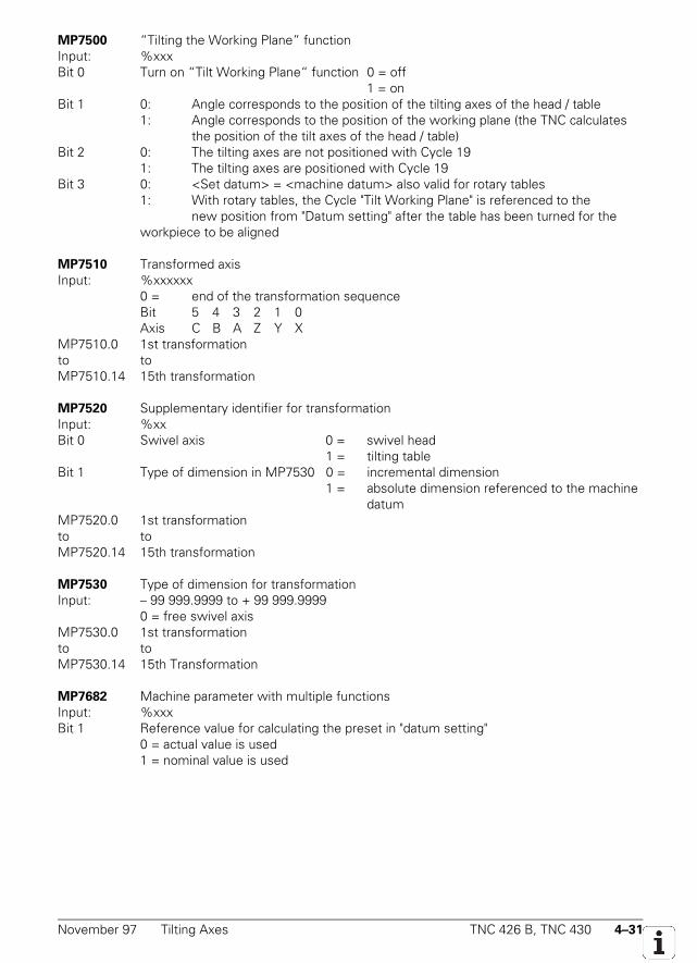
November 97 Tilting Axes TNC 426 B, TNC 430 4–31
MP7500 “Tilting the Working Plane” functionInput: %xxxBit 0 Turn on “Tilt Working Plane“ function 0 = off
1 = onBit 1 0: Angle corresponds to the position of the tilting axes of the head / table
1: Angle corresponds to the position of the working plane (the TNC calculatesthe position of the tilt axes of the head / table)
Bit 2 0: The tilting axes are not positioned with Cycle 191: The tilting axes are positioned with Cycle 19
Bit 3 0: <Set datum> = <machine datum> also valid for rotary tables1: With rotary tables, the Cycle "Tilt Working Plane" is referenced to the
new position from "Datum setting" after the table has been turned for the workpiece to be aligned
MP7510 Transformed axisInput: %xxxxxx
0 = end of the transformation sequenceBit 5 4 3 2 1 0Axis C B A Z Y X
MP7510.0 1st transformationto toMP7510.14 15th transformation
MP7520 Supplementary identifier for transformationInput: %xxBit 0 Swivel axis 0 = swivel head
1 = tilting tableBit 1 Type of dimension in MP7530 0 = incremental dimension
1 = absolute dimension referenced to the machinedatum
MP7520.0 1st transformationto toMP7520.14 15th transformation
MP7530 Type of dimension for transformationInput: – 99 999.9999 to + 99 999.9999
0 = free swivel axisMP7530.0 1st transformationto toMP7530.14 15th Transformation
MP7682 Machine parameter with multiple functionsInput: %xxxBit 1 Reference value for calculating the preset in "datum setting"
0 = actual value is used1 = nominal value is used
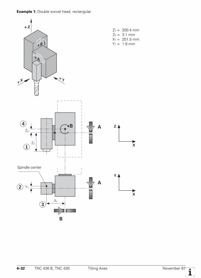
4–32 TNC 426 B, TNC 430 Tilting Axes November 97
Example 1: Double swivel head, rectangular
+ Z
+ Y X +
+ A
+ B
Z1 = 200.4 mmZ2 = 3.1 mmX1 = 201.5 mmY1 = 1.9 mm
4A
Z2
Z1
Y1
X1
A
B
Spindle centre
1
2
3
Z
X
Y
X
B
Spindle center
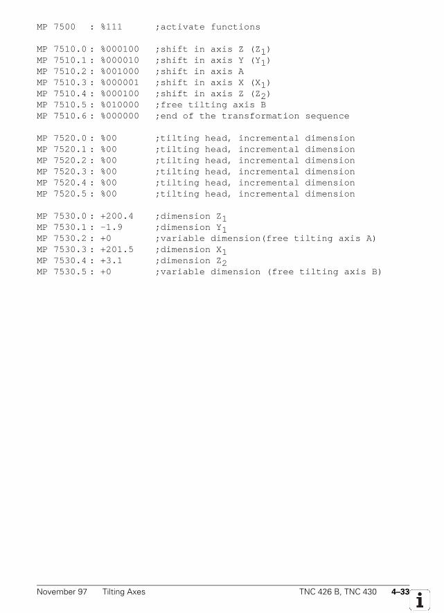
November 97 Tilting Axes TNC 426 B, TNC 430 4–33
MP 7500 : %111 ;activate functions
MP 7510.0 : %000100 ;shift in axis Z (Z 1)MP 7510.1 : %000010 ;shift in axis Y (Y 1)MP 7510.2 : %001000 ;shift in axis AMP 7510.3 : %000001 ;shift in axis X (X 1)MP 7510.4 : %000100 ;shift in axis Z (Z 2)MP 7510.5 : %010000 ;free tilting axis BMP 7510.6 : %000000 ;end of the transformation sequence
MP 7520.0 : %00 ;tilting head, incremental dimensionMP 7520.1 : %00 ;tilting head, incremental dimensionMP 7520.2 : %00 ;tilting head, incremental dimensionMP 7520.3 : %00 ;tilting head, incremental dimensionMP 7520.4 : %00 ;tilting head, incremental dimensionMP 7520.5 : %00 ;tilting head, incremental dimension
MP 7530.0 : +200.4 ;dimension Z 1MP 7530.1 : -1.9 ;dimension Y 1MP 7530.2 : +0 ;variable dimension(free tilting axis A)MP 7530.3 : +201.5 ;dimension X 1MP 7530.4 : +3.1 ;dimension Z 2MP 7530.5 : +0 ;variable dimension (free tilting axis B)
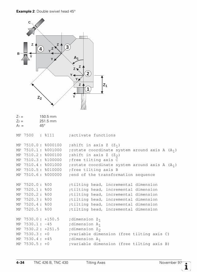
4–34 TNC 426 B, TNC 430 Tilting Axes November 97
Example 2: Double swivel head 45°
Y
Z
Y
Z
Y
Z
Y
Z
Y
Z
Y
Z
Z1
Z2
A1
2
1
34B
C
Z1 = 150.5 mmZ2 = 251.5 mmA1 = 45°
MP 7500 : %111 ;activate functions
MP 7510.0 : %000100 ;shift in axis Z (Z 1)MP 7510.1 : %001000 ;rotate coordinate system around axis A (A 1)MP 7510.2 : %000100 ;shift in axis Z (Z 2)MP 7510.3 : %100000 ;free tilting axis CMP 7510.4 : %001000 ;rotate coordinate system around axis A (A 1)MP 7510.5 : %010000 ;free tilting axis BMP 7510.6 : %000000 ;end of the transformation sequence
MP 7520.0 : %00 ;tilting head, incremental dimensionMP 7520.1 : %00 ;tilting head, incremental dimensionMP 7520.2 : %00 ;tilting head, incremental dimensionMP 7520.3 : %00 ;tilting head, incremental dimensionMP 7520.4 : %00 ;tilting head, incremental dimensionMP 7520.5 : %00 ;tilting head, incremental dimension
MP 7530.0 : +150.5 ;dimension Z 1MP 7530.1 : -45 ;dimension A 1MP 7530.2 : +251.5 ;dimension Z 2MP 7530.3 : +0 ;variable dimension (free tilting axis C)MP 7530.4 : +45 ;dimension A 1MP 7530.5 : +0 ;variable dimension (free tilting axis B)
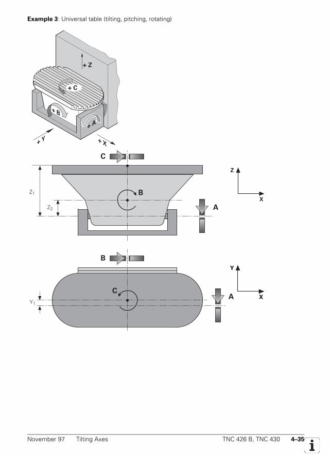
November 97 Tilting Axes TNC 426 B, TNC 430 4–35
Example 3: Universal table (tilting, pitching, rotating)
A +
+ B
+ Z
+ C
+ X Y +
Z2 A
Z
X
C
Z1
AY1
Y
X
Y
X
B
C
B
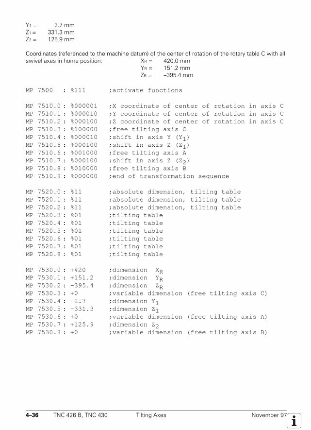
4–36 TNC 426 B, TNC 430 Tilting Axes November 97
Y1 = 2.7 mmZ1 = 331.3 mmZ2 = 125.9 mm
Coordinates (referenced to the machine datum) of the center of rotation of the rotary table C with allswivel axes in home position: XR = 420.0 mm
YR = 151.2 mmZR = –395.4 mm
MP 7500 : %111 ;activate functions
MP 7510.0 : %000001 ;X coordinate of center of rotation in axis CMP 7510.1 : %000010 ;Y coordinate of center of rotation in axis CMP 7510.2 : %000100 ;Z coordinate of center of rotation in axis CMP 7510.3 : %100000 ;free tilting axis CMP 7510.4 : %000010 ;shift in axis Y (Y 1)MP 7510.5 : %000100 ;shift in axis Z (Z 1)MP 7510.6 : %001000 ;free tilting axis AMP 7510.7 : %000100 ;shift in axis Z (Z 2)MP 7510.8 : %010000 ;free tilting axis BMP 7510.9 : %000000 ;end of transformation sequence
MP 7520.0 : %11 ;absolute dimension, tilting tableMP 7520.1 : %11 ;absolute dimension, tilting tableMP 7520.2 : %11 ;absolute dimension, tilting tableMP 7520.3 : %01 ;tilting tableMP 7520.4 : %01 ;tilting tableMP 7520.5 : %01 ;tilting tableMP 7520.6 : %01 ;tilting tableMP 7520.7 : %01 ;tilting tableMP 7520.8 : %01 ;tilting table
MP 7530.0 : +420 ;dimension X RMP 7530.1 : +151.2 ;dimension Y RMP 7530.2 : –395.4 ;dimension Z RMP 7530.3 : +0 ;variable dimension (free tilting axis C)MP 7530.4 : -2.7 ;dimension Y 1MP 7530.5 : -331.3 ;dimension Z 1MP 7530.6 : +0 ;variable dimension (free tilting axis A)MP 7530.7 : +125.9 ;dimension Z 2MP 7530.8 : +0 ;variable dimension (free tilting axis B)
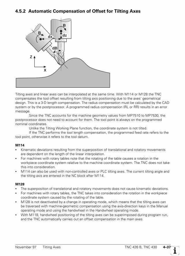
November 97 Tilting Axes TNC 426 B, TNC 430 4–37
4.5.2 Automatic Compensation of Offset for Tilting Axes
B
dz
Z
X
Bdx
dB
Tilting axes and linear axes can be interpolated at the same time. With M114 or M128 the TNCcompensates the tool offset resulting from tilting axis positioning due to the axes' geometricaldesign. This is a 3-D length compensation. The radius compensation must be calculated by the CADsystem or by the postprocessor. A programmed radius compensation (RL or RR) results in an errormessage.
Since the TNC accounts for the machine geometry values from MP7510 to MP7530, thepostprocessor does not need to account for them. The tool point is always on the programmednominal coordinates.
Unlike the Tilting Working Plane function, the coordinate system is not tilted.If the TNC performs the tool length compensation, the programmed feed rate refers to the
tool point, otherwise it refers to the tool datum.
M114
• Kinematic deviations resulting from the superposition of translational and rotatory movementsare dependent on the length of the linear interpolation.
• For machines with rotary tables note that the rotating of the table causes a rotation in theworkpiece coordinate system relative to the machine coordinate system. The TNC does not takethis into consideration.
• M114 can also be used with non-controlled axes or PLC tilting axes. The current tilting angle andthe tilting axis are entered in the NC block after M114.
M128
• The superposition of translational and rotatory movements does not cause kinematic deviations.• For machines with rotary tables, the TNC takes into consideration the rotation in the workpiece
coordinate system caused by the rotating of the table.• M128 is not deactivated by a change in operating mode, which means that the tilting axes can
be traversed with machine-geometric compensation using the axis-direction keys in the Manualoperating mode and using the handwheel in the Handwheel operating mode.
• With M118, handwheel positioning of the tilting axes can be superimposed during program run,and the TNC automatically carries out an offset compensation in the main axes.

4–38 TNC 426 B, TNC 430 Tilting Axes November 97
4.5.3 Cylinder Surface
Cycle 27 "cylinder surface" enables you to machine a cylindrical surface by entering the surfacecurvature separately and programming the contour in two axes as if it were on a plane surface (seethe TNC User's Manual). For Cycle 27 to function properly, the center of rotation must have beendefined in MP7510 to MP7530 (see example 3).
If you wish to use a PLC datum shift together with the Cylinder Surface cycle, ensure thatthe same datum position is used for the description of the machine geometry in MP7510 to MP7530as for the datum shift (home position of the swivel head).
November 97 Synchronized Axes TNC 426 B, TNC 430 4–39
4.6 Synchronized Axes
With the HEIDENHAIN TNC, you can couple two controlled axes in such a way that they can only bemoved simultaneously. This facility is required, for example, for gantry axes and tandem tables, andcan be activated both for operation with servo lag and in the feedforward control mode.
In the following description the main axis and tracking axis are referred to as master andslave, respectively.
You activate the Synchronize function by defining in MP850 the master axis that thespecified slave axis must track.
Example: Axis 4 is the slave of axis 1MP850.0 0MP850.1 0MP850.2 0MP850.3 1MP850.4 0MP850.5 0MP850.6 0MP850.7 0MP850.8 0
Of the nine controlled axes, two pairs can be synchronized.
MP850.0-8 Synchronized axesInput: 0 = main axis
1 = axis tracked to axis 12 = axis tracked to axis 23 = axis tracked to axis 34 = axis tracked to axis 45 = axis tracked to axis 56 = axis tracked to axis 67 = axis tracked to axis 78 = axis tracked to axis 89 = axis tracked to axis 9
4.6.1 Synchronization Control
The TNC monitors the synchronization of the master and slave axes. If the positions of the masterand slave axes differ by a distance greater than that entered in MP855.x, the error messageExcessive servo lag in <axis> # A appears indicating the slave axis. The positionaldifference is shown in the LAG display for the slave axis. Synchronization monitoring is entered inMP855.x of the slave axis. Machine parameter MP860.x defines the datum for synchronizationcontrol.
MP860.x = 0: Datum at position upon switch-on
When the machine is switched on it is assumed that the master and slave axes are synchronizedwith one another. Their position upon switch-on is taken as the synchronization reference. In thismode, passing over the reference mark is necessary only for the master axis, and only if the definedreferences are to be reproduced. Synchrony monitoring begins immediately upon switch-on.
4–40 TNC 426 B, TNC 430 Synchronized Axes November 97
MP860.x = 1: Datum at reference marks (machine datum)
Both axes are positioned to the same reference value when they have passed over their respectivereference marks. The default setting can be modified with MP960.x (machine datum).
In this mode, any offset between the two axes is compensated in the slave axis at thespeed from MP1330.x after both reference marks are traversed, and synchronization does notactivate until compensation is completed. The manner in which the reference marks are traversed(MP1350.x) must be set the same for both axes. The master axis must be defined before the slaveaxis in the sequence for approaching the reference marks (MP1340.x).
Where rotary encoders are used for linear measurement (MP1350.x = 2), only one limitswitch should be used for both axes because the marker "Reference end position for the slave axis"is only for evaluation of the reference mark, and not for evaluation of the traverse direction, whencontrolling the sequence. The direction of traverse is defined by the value of the reference endposition marker for the master axis.
Traversing the reference mark is completed when one reference mark has been evaluatedfor both axes.
MP855.0-8 Synchronization monitoringInput: 0 to 100.0000 [mm]
0 = Monitoring not active
MP860.0-8 Datum for synchronization controlInput: 0 = datum at position upon switch-on
1 = datum at reference marks (machine datum)
4.6.2 Conventions
• The slave axis cannot be moved independently.• The nominal value displayed for the slave axis indicates the nominal value of the master axis.• The PLC program must ensure that the master axis does not move until the slave axis is ready
(locking, feed-rate enable, etc.).• The bits for direction of traverse (W1030) and axis in motion (W1028) are not set for the slave
axis.• An axis cannot be master and slave at the same time.• You must enter axis error compensation (both linear and nonlinear) separately for both axes.• The values for rapid traverse, acceleration, software limit switches, feed-rate for passing over
reference marks, and manual feed-rate are confirmed from the input values of the master axis.• In lag mode, the kv factor for master and slave axis should be the same.• Both axes must be under either analog or digital control.• Up to NC software 280 470 04: master and slave must be linear axes.
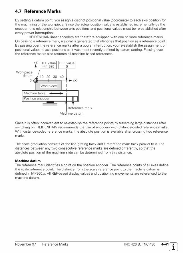
November 97 Reference Marks TNC 426 B, TNC 430 4–41
4.7 Reference Marks
By setting a datum point, you assign a distinct positional value (coordinate) to each axis position forthe machining of the workpiece. Since the actual-position value is established incrementally by theencoder, this relationship between axis positions and positional values must be re-established afterevery power interruption.
HEIDENHAIN linear encoders are therefore equipped with one or more reference marks.On passing a reference mark, a signal is generated that identifies that position as a reference point.By passing over the reference marks after a power interruption, you re-establish the assignment ofpositional values to axis positions as it was most recently defined by datum setting. Passing overthe reference marks also restores all machine-based references.
Position encoder
Machine table
REF value0
10 20 30 40
Machine datum
+Z
+X0
Workpiecedatum
Workpiece
Reference mark
REF value–44.985
Since it is often inconvenient to re-establish the reference points by traversing large distances afterswitching on, HEIDENHAIN recommends the use of encoders with distance-coded reference marks.With distance-coded reference marks, the absolute position is available after crossing two referencemarks.Scale with distance-coded reference marksThe scale graduation consists of the line grating track and a reference mark track parallel to it. Thedistances between any two consecutive reference marks are defined differently, so that theabsolute position of the machine slide can be determined from this distance.
Machine datum
The reference mark identifies a point on the position encoder. The reference points of all axes definethe scale reference point. The distance from the scale reference point to the machine datum isdefined in MP960.x. All REF-based display values and positioning movements are referenced to themachine datum.
4–42 TNC 426 B, TNC 430 Reference Marks November 97
4.7.1 Traversing the Reference Marks
The reference marks for the axes must be passed after the control is switched on. This can beachieved by• pressing the external START key. The axis sequence is determined by machine parameter
MP1340.X (automatic traversing of the reference marks),• pressing the external axis direction keys. The sequence is determined by the operator.
Only after passing over the reference mark• can the software limits be activated,• can the most recently set datum point be reproduced,• is PLC positioning and positioning with the miscellaneous functions M91 and M92 possible,• is the counter value set to zero for non-controlled axes.
For distance-coded measuring systems the machine datum (MP960.x) is referenced to the scalereference point. In linear encoders the scale reference point is the first reference mark after the startof the measuring length; in angle encoders the scale reference point is marked.
The direction of traverse and the velocity on passing the reference marks is defined by machineparameters (MP1320.x, MP1330.x). The functional sequence for passing the reference marks can befixed specifically for the axes by machine parameters (MP1350.x).
The operating condition "PASS OVER REFERENCE MARKS" is sent to the PLC by the NC(W272). If the operating mode is changed before all reference marks have been passed, the PASSOVER REFERENCE soft key will appear. The markers M2136 to M2140 inform the PLC of the axesfor which the reference marks have not yet been crossed.
In order to avoid exceeding the traverse range when passing over the reference marks, a trip dog(reference end-position) is necessary in each axis. This trip dog must be fixed at the end of thetraverse range by the manufacturer of the machine. The signals from the trip dogs are connected toavailable PLC inputs. In the PLC program these PLC inputs are combined with W1054 (Referenceend-position).
Repeated Traversing of the Reference Marks (Module 9220)
With this module you move an axis or controlled spindle over the reference mark. You can alsoreevaluate the reference mark for a particular axis.
NC axis:• The module can be called only in the operating modes “Traverse Reference Points,” “Manual
Operation,” and “Electronic Handwheel.”• The functional sequence (MP1350.x) and the velocity for leaving the reference end position
(MP1331.x) is always defined by the machine parameter values.• The velocity and traversing direction for traversing the reference mark is either taken from
MP1330.x and MP1320.x or entered in the module. Only in specific exceptional cases should thetraversing direction be defined in the module. This is because the module does not regard thereference end positions and therefore the traverse limits may be exceeded.
November 97 Reference Marks TNC 426 B, TNC 430 4–43
• If an axis already has its reference but is started for referencing again, the corresponding bit isset in W1032 and the reference mark is reevaluated. The same constraints apply here as whentraversing the reference mark for the first time.
• An axis cannot be started for referencing until all other axes are in position.
Controlled spindle:• The speed for approaching the reference mark is entered in the module.• The spindle must be started from standstill for reference mark traverse.• If a spindle is started for referencing, the marker M4018 is set.
Call:PS B/W/D/K <Axis / Spindle>
0 to 8 for axis 1 to 9; 15 for spindlePS B/W/D/K <Feed rate / Speed>
0: Feed rate from MP1330.x>0: Feed rate in mm/min or speed in 1/1000 rpm
PS B/W/D/K <Direction of traverse>–1: Negative direction0: Direction from MP1320.x1: Positive direction
CM 9220PL B/W/D <Error code>
0: No error: Ref positioning is commanded1: Axis or spindle does not exist2: Illegal values for feed rate / direction were transferred3: Wrong operating mode (only NC axes)4: Ref positioning not possible because previous reference run was not yet
started5: Axis is already being positioned or spindle in motion6: Another axis is being positioned (only NC axes)
MP960.0-8 Machine datumInput: –99 999.9999 to +99 999,9999 [mm] or [°]
Values referenced to the scale reference point
MP1320 Direction for traversing the reference marksInput: %xxxxx
Bit 0 to 8 0 = positiveAxis 1 to 9 1 = negative
MP1330.0-8 Velocity when traversing the reference marksInput: 80 to 300 000 [mm/min]
MP1331.0-8 Velocity when leaving the reference end position (only for rotary encoders MP1350=2)Input: 80 to 500 [mm/min]
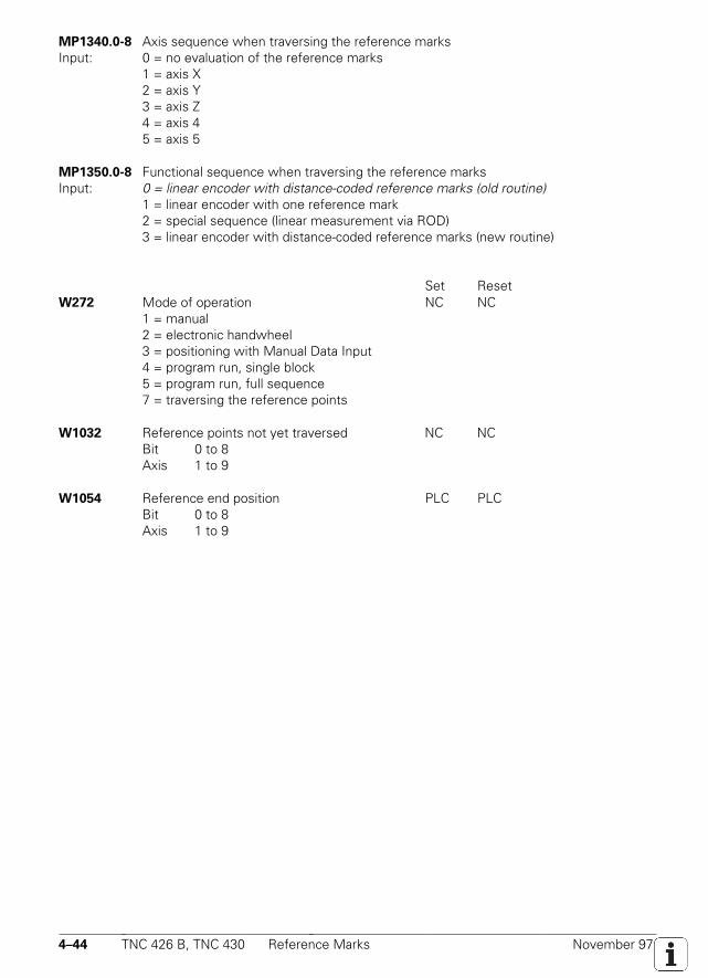
4–44 TNC 426 B, TNC 430 Reference Marks November 97
MP1340.0-8 Axis sequence when traversing the reference marksInput: 0 = no evaluation of the reference marks
1 = axis X2 = axis Y3 = axis Z4 = axis 45 = axis 5
MP1350.0-8 Functional sequence when traversing the reference marksInput: 0 = linear encoder with distance-coded reference marks (old routine)
1 = linear encoder with one reference mark2 = special sequence (linear measurement via ROD)3 = linear encoder with distance-coded reference marks (new routine)
Set ResetW272 Mode of operation NC NC
1 = manual2 = electronic handwheel3 = positioning with Manual Data Input4 = program run, single block5 = program run, full sequence7 = traversing the reference points
W1032 Reference points not yet traversed NC NCBit 0 to 8Axis 1 to 9
W1054 Reference end position PLC PLCBit 0 to 8Axis 1 to 9
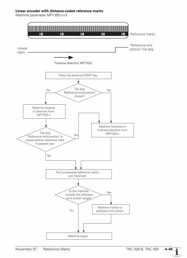
November 97 Reference Marks TNC 426 B, TNC 430 4–45
Linear encoder with distance-coded reference marks
Machine parameter MP1350.x=3
Reference marks
closedopen
"Reference end postion" trip dog
Traverse dirction MP1320
Press the external START key
Trip dog"Reference end position"
closed?
Machine traversein direction from
MP1320.x
Machine traverses in inverted direction from
MP1320.x
Two successive reference marks are traversed
Is the machineoutside the softwarelimit switch range?
Machine moves tosoftware limit switch
Machine stops
No Yes
Yes
No
Yes
No
Trip dog"Reference end position" is
closed before reference mark is passed over
Traverse direction MP1320
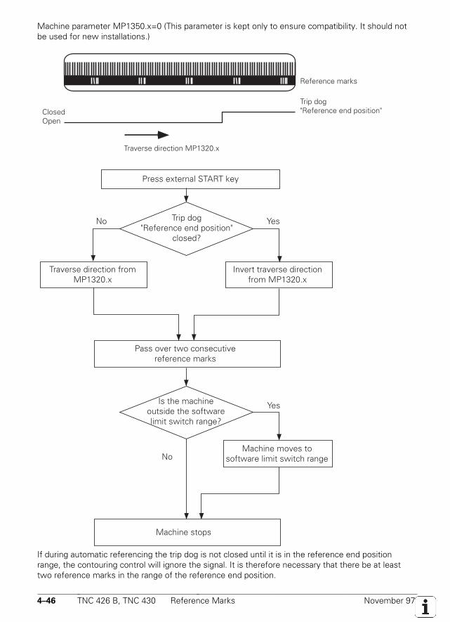
4–46 TNC 426 B, TNC 430 Reference Marks November 97
Machine parameter MP1350.x=0 (This parameter is kept only to ensure compatibility. It should notbe used for new installations.)
Reference marks
ClosedOpen
Trip dog"Reference end position"
Traverse direction MP1320.x
Press external START key
Trip dog"Reference end position"
closed?
Traverse direction fromMP1320.x
Invert traverse directionfrom MP1320.x
Pass over two consecutivereference marks
Machine moves to software limit switch range
Machine stops
No Yes
Yes
No
Is the machine outside the software limit switch range?
If during automatic referencing the trip dog is not closed until it is in the reference end positionrange, the contouring control will ignore the signal. It is therefore necessary that there be at leasttwo reference marks in the range of the reference end position.
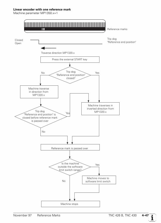
November 97 Reference Marks TNC 426 B, TNC 430 4–47
Linear encoder with one reference mark
Machine parameter MP1350.x=1
Reference marks
ClosedOpen
Trip dog"Reference end position"
Traverse direction MP1320.x
Press the external START key
Trip dog"Reference end position"
closed?
Machine traversein direction from
MP1320.x
Machine traverses in inverted direction from
MP1320.x
Reference mark is passed over
Is the machineoutside the softwarelimit switch range?
Machine moves tosoftware limit switch
Machine stops
No Yes
Yes
No
Yes
No
Trip dog"Reference end position" is
closed before reference mark is passed over
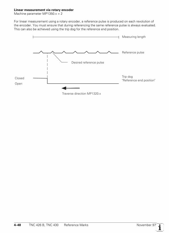
4–48 TNC 426 B, TNC 430 Reference Marks November 97
Linear measurement via rotary encoder
Machine parameter MP1350.x = 2
For linear measurement using a rotary encoder, a reference pulse is produced on each revolution ofthe encoder. You must ensure that during referencing the same reference pulse is always evaluated.This can also be achieved using the trip dog for the reference end position.
Reference pulse
Closed
Open
Trip dog"Reference end position"
Traverse direction MP1320.x
Measuring length
Desired reference pulse
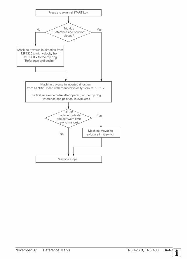
November 97 Reference Marks TNC 426 B, TNC 430 4–49
Press the external START key
Trip dog"Reference end position"
closed?
Machine traverse in direction fromMP1320.x with velocity from
MP1330.x to the trip dog"Reference end positon"
Is the machine outsidethe software limit
switch range?
Machine moves tosoftware limit switch
Machine stops
No Yes
Yes
No
Machine traverse in inverted directionfrom MP1320.x and with reduced velocity from MP1331.x
The first reference pulse after opening of the trip dog"Reference end position" is evaluated

4–50 TNC 426 B, TNC 430 Reference Marks November 97
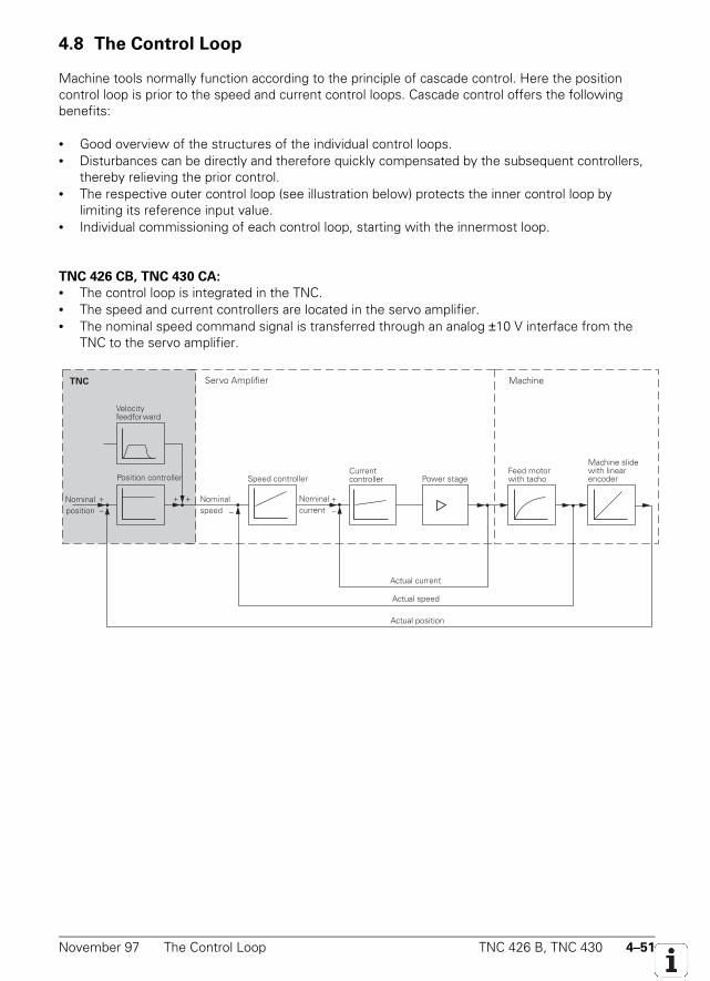
November 97 The Control Loop TNC 426 B, TNC 430 4–51
4.8 The Control Loop
Machine tools normally function according to the principle of cascade control. Here the positioncontrol loop is prior to the speed and current control loops. Cascade control offers the followingbenefits:
• Good overview of the structures of the individual control loops.• Disturbances can be directly and therefore quickly compensated by the subsequent controllers,
thereby relieving the prior control.• The respective outer control loop (see illustration below) protects the inner control loop by
limiting its reference input value.• Individual commissioning of each control loop, starting with the innermost loop.
TNC 426 CB, TNC 430 CA:
• The control loop is integrated in the TNC.• The speed and current controllers are located in the servo amplifier.• The nominal speed command signal is transferred through an analog ±10 V interface from the
TNC to the servo amplifier.
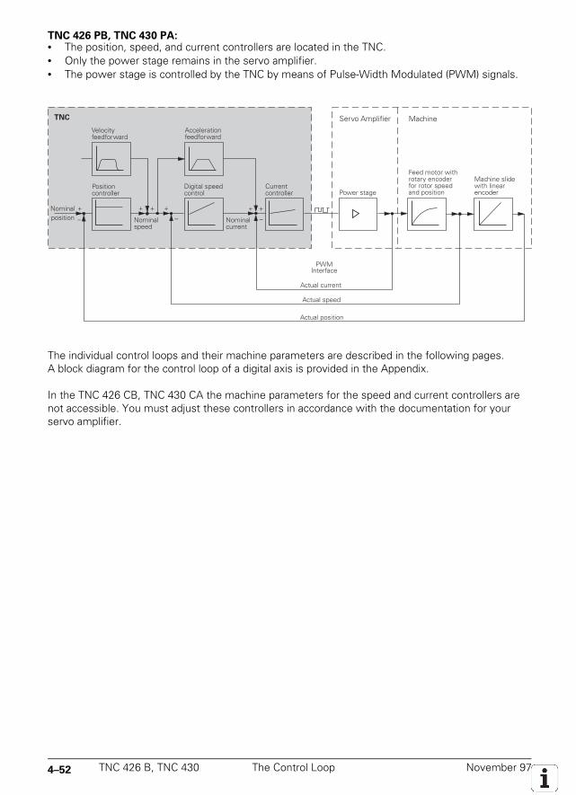
4–52 TNC 426 B, TNC 430 The Control Loop November 97
TNC 426 PB, TNC 430 PA:• The position, speed, and current controllers are located in the TNC.• Only the power stage remains in the servo amplifier.• The power stage is controlled by the TNC by means of Pulse-Width Modulated (PWM) signals.
The individual control loops and their machine parameters are described in the following pages.A block diagram for the control loop of a digital axis is provided in the Appendix.
In the TNC 426 CB, TNC 430 CA the machine parameters for the speed and current controllers arenot accessible. You must adjust these controllers in accordance with the documentation for yourservo amplifier.
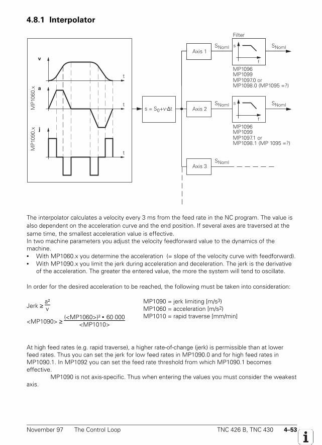
November 97 The Control Loop TNC 426 B, TNC 430 4–53
4.8.1 Interpolator
v
t
t
t
s
f
s
f
s = S0+v·∆tMP
1060
.x a
MP
1090
.x
s
f
MP1096MP1099
MP1096MP1099
Filter
MP1097.0 or MP1098.0 (MP1095 =?)
SNomlAxis 1
MP1097.1 or MP1098.1 (MP 1095 =?)
j
SNoml
SNoml
SNoml
SNoml
Axis 2
Axis 3
The interpolator calculates a velocity every 3 ms from the feed rate in the NC program. The value isalso dependent on the acceleration curve and the end position. If several axes are traversed at thesame time, the smallest acceleration value is effective.In two machine parameters you adjust the velocity feedforward value to the dynamics of themachine.• With MP1060.x you determine the acceleration (= slope of the velocity curve with feedforward).• With MP1090.x you limit the jerk during acceleration and deceleration. The jerk is the derivative
of the acceleration. The greater the entered value, the more the system will tend to oscillate.
In order for the desired acceleration to be reached, the following must be taken into consideration:
Jerk ≥ a²v
<MP1090> ≥ (<MP1060>)² • 60 000
<MP1010>
MP1090 = jerk limiting [m/s3)MP1060 = acceleration [m/s2)MP1010 = rapid traverse [mm/min]
At high feed rates (e.g. rapid traverse), a higher rate-of-change (jerk) is permissible than at lowerfeed rates. Thus you can set the jerk for low feed rates in MP1090.0 and for high feed rates inMP1090.1. In MP1092 you can set the feed rate threshold from which MP1090.1 becomeseffective.
MP1090 is not axis-specific. Thus when entering the values you must consider the weakestaxis.
4–54 TNC 426 B, TNC 430 The Control Loop November 97
Every 3 ms a nominal position value is derived from the calculated velocity. For linear interpolation,the following formula applies
s = so + v • ∆t s = nominal position valueso = previous nominal position valuev = calculated velocity∆t = cycle time (3 ms)
The nominal position value is resolved into the individual axis components, depending on which axeshave been programmed.
Nominal position value filter
For optimal adjusting of speed and acceleration, the nominal position values are filtered. This resultsin smoother (jerk-limited) traverse. The TNC calculates the filter parameters weighting and width(order) from the permissible axis-specific jerk value (MP1097.x or MP1098.x) and the tolerance(MP1096).
Set the minimum filtering order in MP1099. You can use Cycle 32 "Tolerance" to overwritethe tolerance value at contour transitions defined in MP1096. With MP1095 you can select whetherthe TNC uses a single or double filter. The single filter results in a linear change in acceleration andtherefore a step in the jerk. The double filter gives a curved-form change in acceleration and jerk.
The filter is effective in all operating modes. For rigid tapping (Cycle 17) the nominalposition value filter is automatically switched off..
MP1060.0-8 AccelerationInput: 0.001 to 5.0 [m/s2]
MP1090 Jerk limitingInput: 1 to 1000 [m/s3]MP1090.0 Jerk limiting with machining feed rateMP1090.1 Jerk limiting as of feed rate in MP1092
MP1092 Threshold as of which MP1090.1 effectiveInput: 10 to 300 000 [mm/min]
MP1095 Nominal position value filterInput: 0 = single filter
1 = double filterSuggested input value = 0
MP1096 ToleranceInput: 0 = no nominal position value filter
0.001 to 3.000 [mm] = permissible tolerance at contour transitions
MP1097.0-8 Axis-specific jerk for single filter (MP1096 = 0)Input: 1 to 1 000 [m/s³]
MP1098.0-8 Axis-specific jerk for double filter (MP1096 = 1)Input: 1 to 1 000 [m/s³]
Suggested input value = 2 • MP1097.x

November 97 The Control Loop TNC 426 B, TNC 430 4–55
MP1099 Minimum filtering orderInput: 0 to 20MP1099.0 Minimum filtering order for single filter (MP1095 = 0)
Suggested input value = 5MP1099.1 Minimum filtering order for double filter (MP1095 = 1)
Suggested input value = 3
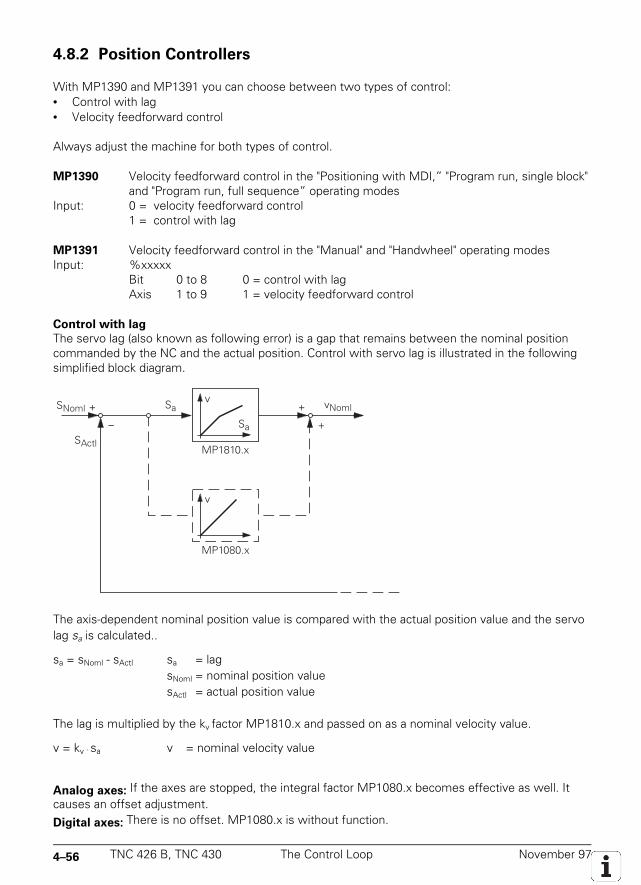
4–56 TNC 426 B, TNC 430 The Control Loop November 97
4.8.2 Position Controllers
With MP1390 and MP1391 you can choose between two types of control:• Control with lag• Velocity feedforward control
Always adjust the machine for both types of control.
MP1390 Velocity feedforward control in the "Positioning with MDI,” "Program run, single block"and "Program run, full sequence” operating modes
Input: 0 = velocity feedforward control1 = control with lag
MP1391 Velocity feedforward control in the "Manual" and "Handwheel" operating modesInput: %xxxxx
Bit 0 to 8 0 = control with lagAxis 1 to 9 1 = velocity feedforward control
Control with lag
The servo lag (also known as following error) is a gap that remains between the nominal positioncommanded by the NC and the actual position. Control with servo lag is illustrated in the followingsimplified block diagram.
vNomlSNoml
SActl
The axis-dependent nominal position value is compared with the actual position value and the servolag sa is calculated..
sa = sNoml - sActl sa = lagsNoml = nominal position valuesActl = actual position value
The lag is multiplied by the kv factor MP1810.x and passed on as a nominal velocity value.
v = kv · sa v = nominal velocity value
Analog axes: If the axes are stopped, the integral factor MP1080.x becomes effective as well. Itcauses an offset adjustment.
Digital axes: There is no offset. MP1080.x is without function.
November 97 The Control Loop TNC 426 B, TNC 430 4–57
The kv factor (position loop gain) determines the amplification of the control loop. The optimal kv
factor must be determined by trial and error. If you choose a very high kv factor, the servo lag is verysmall. However, this can lead to oscillations when moving into a new position. If the kv factor is toosmall, the new position will be reached too slowly. For axes that are interpolated with each other thekv factor must be equal to prevent contour deviations.
With MP1815.x you define a second set of kv factors that the operator can activate with the Mfunction M105. This allows the operator to selectively choose higher contour accuracy at criticalcontours. M105 also influences the compensation of reversal peaks during circular movement.M106 returns the control to the original set of kv factors.You must enable the M functions M105/M106 with MP7440, bit 3.
The following formula shows the relationship among kv factor, feed rate and servo lag:
kv = ve
sa kv = position loop gain [
m/minmm ]
ve = rapid traverse [m
min]
sa = servo lag [mm]or
sa = ve
kv
MP1810.0-8 kv factor for control with servo lag
Input: 0.100 to 20.000 [m/minmm ]
MP1815.0-8 kv factor for control with servo lag effective after M105
Input: 0.100 to 20.000 [m/minmm ]
MP7440 Output of M functionsInput: %xxxxxBit 3 Switching of kv factors with M105/M106
0 = function active1 = function not active
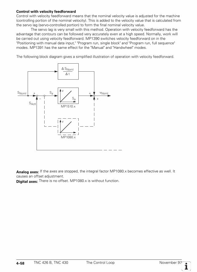
4–58 TNC 426 B, TNC 430 The Control Loop November 97
Control with velocity feedforward
Control with velocity feedforward means that the nominal velocity value is adjusted for the machine(controlling portion of the nominal velocity). This is added to the velocity value that is calculated fromthe servo lag (servo-controlled portion) to form the final nominal velocity value.
The servo lag is very small with this method. Operation with velocity feedforward has theadvantage that contours can be followed very accurately even at a high speed. Normally, work willbe carried out using velocity feedforward. MP1390 switches velocity feedforward on in the"Positioning with manual data input," "Program run, single block" and "Program run, full sequence"modes. MP1391 has the same effect for the "Manual" and "Handwheel" modes.
The following block diagram gives a simplified illustration of operation with velocity feedforward.
vSa+
– Sa
+
+
v
∆ t
MP1510.x
MP1080.x
vNoml
∆ SNoml
SNoml
SActl
Analog axes: If the axes are stopped, the integral factor MP1080.x becomes effective as well. Itcauses an offset adjustment.Digital axes: There is no offset. MP1080.x is without function.
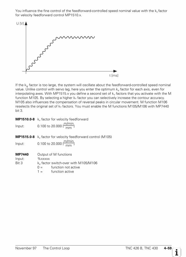
November 97 The Control Loop TNC 426 B, TNC 430 4–59
You influence the fine control of the feedforward-controlled speed nominal value with the kv factorfor velocity feedforward control MP1510.x.
U [V]
t [ms]
If the kv factor is too large, the system will oscillate about the feedforward-controlled speed nominalvalue. Unlike control with servo lag, here you enter the optimum kv factor for each axis, even forinterpolating axes. With MP1515.x you define a second set of kv factors that you activate with the Mfunction M105. By selecting a higher kv factor you can selectively increase the contour accuracy.M105 also influences the compensation of reversal peaks in circular movement. M function M106reselects the original set of kv factors. You must enable the M functions M105/M106 with MP7440bit 3.
MP1510.0-8 kv factor for velocity feedforward
Input: 0.100 to 20.000 [m/minmm ]
MP1515.0-8 kv factor for velocity feedforward control (M105)
Input: 0.100 to 20.000 [m/minmm ]
MP7440 Output of M functionsInput: %xxxxxBit 3 kv factor switch-over with M105/M106
0 = function not active1 = function active
4–60 TNC 426 B, TNC 430 The Control Loop November 97
Rapid traverseIn MP1010.x you define the rapid traverse for each axis of the machine. Through the PLC you canreduce this value for special cases by entering the desired reduced value in D596. If the value inD596 is greater than MP1010.x, the value in MP1010.x will remain in effect. After the control isswitched on, or after an interruption in the PLC scan, the doubleword D596 is preset with the value300 000, so that MP1010.x goes into effect.
In MP1020.x you enter the special feed rate for the manual operating mode. In general it issignificantly lower than the rapid traverse. The programmed feed rate and the current contouringfeed rate are shown in D360 and D388 in mm/min. The maximum possible feed rate alwaysdepends on the encoder being used. For digital axes it also depends on the number of pole pairs inthe drive and on the pitch of the ballscrew.
vmax [mm/min]= P [µm] • fi [kHz] • 60 vmax = maximum traversing speedP = signal period of the encoderfi = encoder input frequency
Digital axes:
vmax [mm/min] = 18 000
number of pole pairs [1/min] • screw pitch [mm]
Analog axes: You must adjust the rapid traverse (maximum traversing speed) with the desiredanalog voltage (for example 9 V) at the servo amplifier. Enter the desired analog voltage for rapidtraverse in MP1050.x.
MP1010.0-8 Rapid traverseInput: 10 to 300 000 [mm/min]
MP1020.0-8 Manual feed rateInput: 10 to 300 000 [mm/min]
MP1050.0-8 Analog axes: Analog voltage for rapid traverseInput: 1.000 to 9.000 [V]digital axes: Non-functionalInput: 1
Set ResetD596 Max. feed rate from PLC [mm/min] NC/PLC PLCD360 Programmed feed rate [mm/min] NC NCD388 Current contouring feed rate [mm/min] NC NC
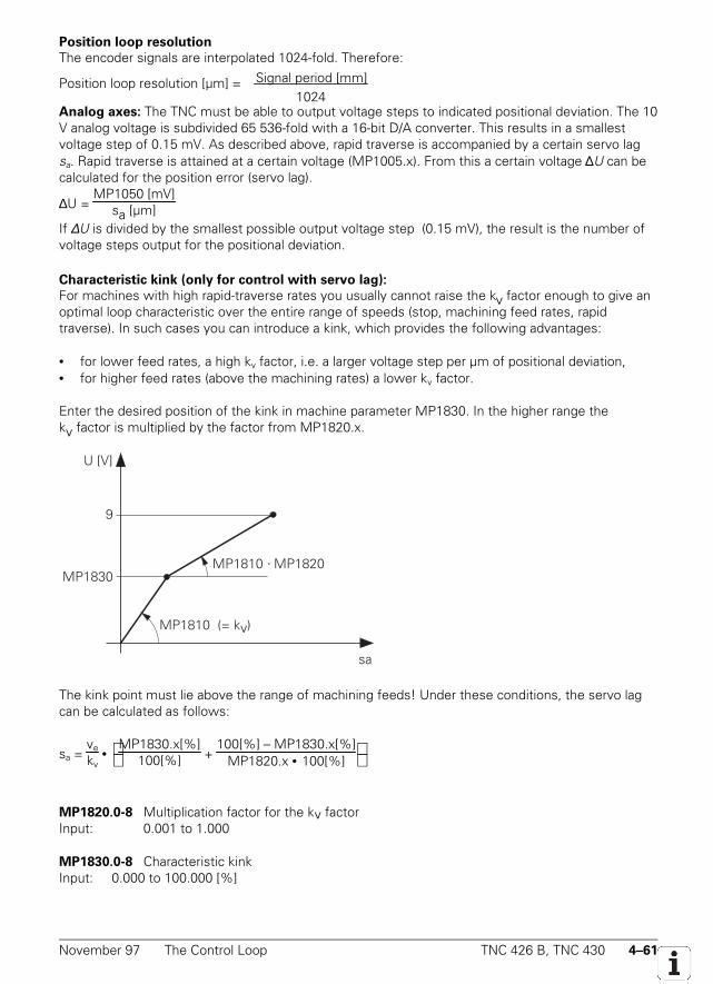
November 97 The Control Loop TNC 426 B, TNC 430 4–61
Position loop resolution
The encoder signals are interpolated 1024-fold. Therefore:
Position loop resolution [µm] = Signal period [mm]
1024
Analog axes: The TNC must be able to output voltage steps to indicated positional deviation. The 10V analog voltage is subdivided 65 536-fold with a 16-bit D/A converter. This results in a smallestvoltage step of 0.15 mV. As described above, rapid traverse is accompanied by a certain servo lagsa. Rapid traverse is attained at a certain voltage (MP1005.x). From this a certain voltage ∆U can becalculated for the position error (servo lag).
∆U = MP1050 [mV]
sa [µm]If ∆U is divided by the smallest possible output voltage step (0.15 mV), the result is the number ofvoltage steps output for the positional deviation.
Characteristic kink (only for control with servo lag):
For machines with high rapid-traverse rates you usually cannot raise the kv factor enough to give anoptimal loop characteristic over the entire range of speeds (stop, machining feed rates, rapidtraverse). In such cases you can introduce a kink, which provides the following advantages:
• for lower feed rates, a high kv factor, i.e. a larger voltage step per µm of positional deviation,• for higher feed rates (above the machining rates) a lower kv factor.
Enter the desired position of the kink in machine parameter MP1830. In the higher range thekv factor is multiplied by the factor from MP1820.x.
MP1810 · MP1820
9
U [V]
sa
MP1810 (= kv)
MP1830
The kink point must lie above the range of machining feeds! Under these conditions, the servo lagcan be calculated as follows:
sa = ve
kv •
MP1830.x[%]100[%] +
100[%] – MP1830.x[%]MP1820.x • 100[%]
MP1820.0-8 Multiplication factor for the kv factorInput: 0.001 to 1.000
MP1830.0-8 Characteristic kinkInput: 0.000 to 100.000 [%]
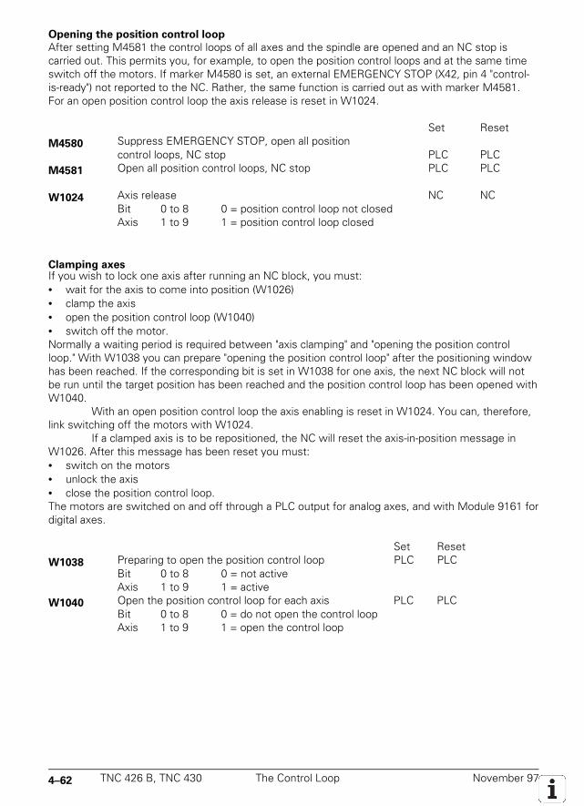
4–62 TNC 426 B, TNC 430 The Control Loop November 97
Opening the position control loop
After setting M4581 the control loops of all axes and the spindle are opened and an NC stop iscarried out. This permits you, for example, to open the position control loops and at the same timeswitch off the motors. If marker M4580 is set, an external EMERGENCY STOP (X42, pin 4 "control-is-ready") not reported to the NC. Rather, the same function is carried out as with marker M4581.For an open position control loop the axis release is reset in W1024.
Set ResetM4580 Suppress EMERGENCY STOP, open all position
control loops, NC stop PLC PLCM4581 Open all position control loops, NC stop PLC PLC
W1024 Axis release NC NCBit 0 to 8 0 = position control loop not closedAxis 1 to 9 1 = position control loop closed
Clamping axesIf you wish to lock one axis after running an NC block, you must:• wait for the axis to come into position (W1026)• clamp the axis• open the position control loop (W1040)• switch off the motor.Normally a waiting period is required between "axis clamping" and "opening the position controlloop." With W1038 you can prepare "opening the position control loop" after the positioning windowhas been reached. If the corresponding bit is set in W1038 for one axis, the next NC block will notbe run until the target position has been reached and the position control loop has been opened withW1040.
With an open position control loop the axis enabling is reset in W1024. You can, therefore,link switching off the motors with W1024.
If a clamped axis is to be repositioned, the NC will reset the axis-in-position message inW1026. After this message has been reset you must:• switch on the motors• unlock the axis• close the position control loop.The motors are switched on and off through a PLC output for analog axes, and with Module 9161 fordigital axes.
Set ResetW1038 Preparing to open the position control loop PLC PLC
Bit 0 to 8 0 = not activeAxis 1 to 9 1 = active
W1040 Open the position control loop for each axis PLC PLCBit 0 to 8 0 = do not open the control loopAxis 1 to 9 1 = open the control loop
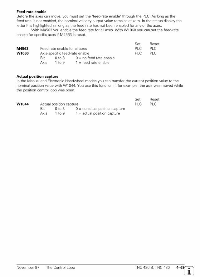
November 97 The Control Loop TNC 426 B, TNC 430 4–63
Feed-rate enable
Before the axes can move, you must set the "feed-rate enable" through the PLC. As long as thefeed-rate is not enabled, the nominal velocity output value remains at zero. In the status display theletter F is highlighted as long as the feed rate has not been enabled for any of the axes.
With M4563 you enable the feed rate for all axes. With W1060 you can set the feed-rateenable for specific axes if M4563 is reset.
Set ResetM4563 Feed rate enable for all axes PLC PLCW1060 Axis-specific feed-rate enable PLC PLC
Bit 0 to 8 0 = no feed rate enableAxis 1 to 9 1 = feed rate enable
Actual position capture
In the Manual and Electronic Handwheel modes you can transfer the current position value to thenominal position value with W1044. You use this function if, for example, the axis was moved whilethe position control loop was open.
Set ResetW1044 Actual position capture PLC PLC
Bit 0 to 8 0 = no actual position captureAxis 1 to 9 1 = actual position capture

4–64 TNC 426 B, TNC 430 The Control Loop November 97

November 97 The Control Loop TNC 426 B, TNC 430 4–65

4–66 TNC 426 B, TNC 430 The Control Loop November 97
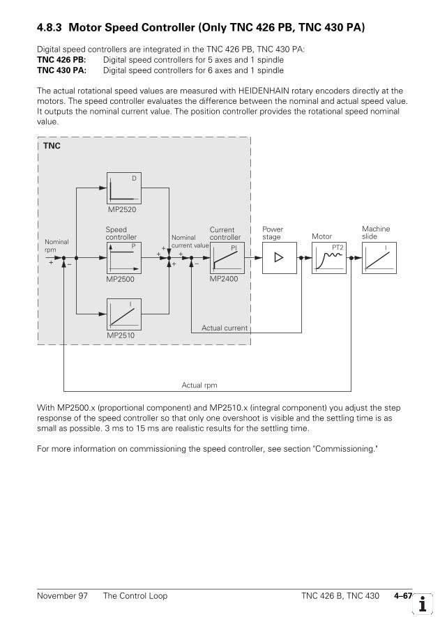
November 97 The Control Loop TNC 426 B, TNC 430 4–67
4.8.3 Motor Speed Controller (Only TNC 426 PB, TNC 430 PA)
Digital speed controllers are integrated in the TNC 426 PB, TNC 430 PA:TNC 426 PB: Digital speed controllers for 5 axes and 1 spindleTNC 430 PA: Digital speed controllers for 6 axes and 1 spindle
The actual rotational speed values are measured with HEIDENHAIN rotary encoders directly at themotors. The speed controller evaluates the difference between the nominal and actual speed value.It outputs the nominal current value. The position controller provides the rotational speed nominalvalue.
TNC
–+
MP2520
++
PI
MP2400
+–
I
MP2500
P
I
MP2510
PT2+
D
Speed controller
Nominal rpm
Current controllerNominal
current value
Actual current
Powerstage Motor
Actual rpm
Machineslide
With MP2500.x (proportional component) and MP2510.x (integral component) you adjust the stepresponse of the speed controller so that only one overshoot is visible and the settling time is assmall as possible. 3 ms to 15 ms are realistic results for the settling time.
For more information on commissioning the speed controller, see section "Commissioning."
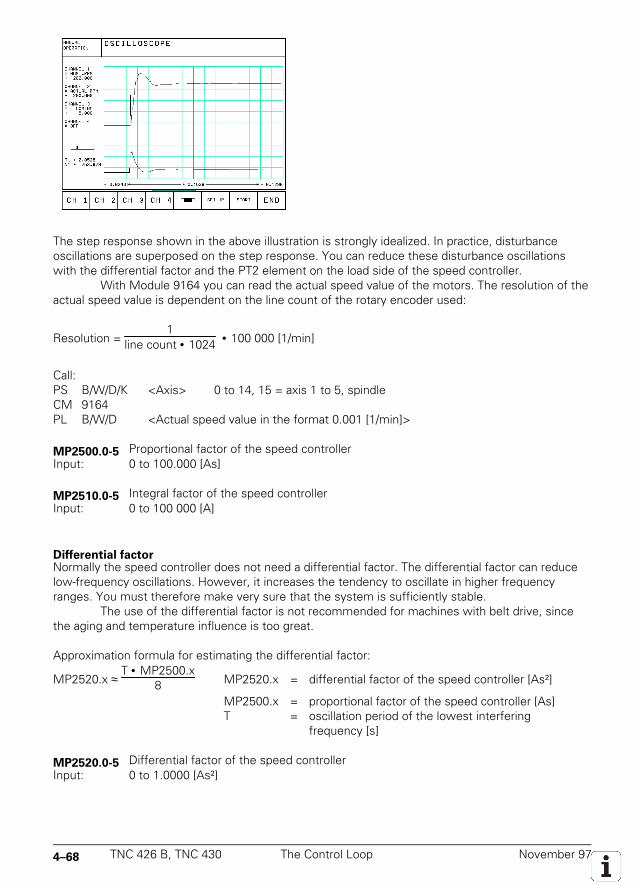
4–68 TNC 426 B, TNC 430 The Control Loop November 97
The step response shown in the above illustration is strongly idealized. In practice, disturbanceoscillations are superposed on the step response. You can reduce these disturbance oscillationswith the differential factor and the PT2 element on the load side of the speed controller.
With Module 9164 you can read the actual speed value of the motors. The resolution of theactual speed value is dependent on the line count of the rotary encoder used:
Resolution = 1
line count • 1024 • 100 000 [1/min]
Call:PS B/W/D/K <Axis> 0 to 14, 15 = axis 1 to 5, spindleCM 9164PL B/W/D <Actual speed value in the format 0.001 [1/min]>
MP2500.0-5 Proportional factor of the speed controllerInput: 0 to 100.000 [As]
MP2510.0-5 Integral factor of the speed controllerInput: 0 to 100 000 [A]
Differential factorNormally the speed controller does not need a differential factor. The differential factor can reducelow-frequency oscillations. However, it increases the tendency to oscillate in higher frequencyranges. You must therefore make very sure that the system is sufficiently stable.
The use of the differential factor is not recommended for machines with belt drive, sincethe aging and temperature influence is too great.
Approximation formula for estimating the differential factor:
MP2520.x ≈ T • MP2500.x
8 MP2520.x = differential factor of the speed controller [As²]
MP2500.x = proportional factor of the speed controller [As]T = oscillation period of the lowest interfering
frequency [s]
MP2520.0-5 Differential factor of the speed controllerInput: 0 to 1.0000 [As²]
November 97 The Control Loop TNC 426 B, TNC 430 4–69
PT2 element of the speed controller
If the controlled system is insufficiently dampened (e.g. direct coupling of the motors or rollerbearings) it will not be possible to attain a sufficiently short settling time when adjusting the stepresponse of the speed controller. The step response will oscillate even at a low proportional factor.
With MP2530.x you can dampen these high-frequency disturbance oscillations. The value inMP2530.x should not be unnecessarily high since otherwise the kv factor of the position controller isrestricted. Realistic values for MP2530.x are 0.0003 to 0.0020.
MP2530.0-5 PT2 element of the speed controller (second-order time-delay element)Input: 0 to 1.0000 [s]
Frequency filter
On critical axes oscillations can arise in a frequency range that can neither be compensated with thedifferential factor or the PT2 element. In this case the frequency filter can be of help. You candetermine the basic frequency of the disturbance oscillation with the oscilloscope of the TNC, andenter this in MP2550.x. You then increase MP2540.x enough to minimize the disturbance oscillation.You should not increase the dampening to an unnecessarily high level, as this limits the dynamicperformance of the control loop. Realistic input values would be three to nine dB.
MP2540.0-5 Frequency filter dampingInput: 0.0 to 18.0 [dB]
MP2550.0-5 Frequency filter for mean frequencyInput: 0.0 to 999.9 [Hz]
Acceleration feedforward
Acceleration feedforward is active only in velocity feedforward control (MP1390 = 0). Every changein velocity results in brief spikes in the servo lag. With acceleration feedforward, which functionsparallel to the speed controller, you can minimize these spikes.
Before you adjust the acceleration feedforward, you must have adjusted the frictioncompensation with machine parameters MP2610.x to MP2620.x.
The input value for MP2600.x for acceleration feedforward is then calculated from theintegral-action component of the nominal current value I (INT RPM). For this purpose, I (INT RPM) isrecorded with the TNC's integral oscilloscope during a positioning movement. For better illustration,the actual speed value V (ACT RPM) and the nominal current value (I NOMINAL) are also recorded.
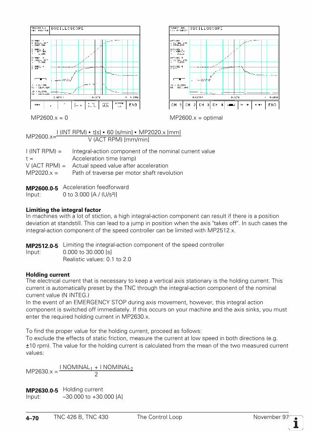
4–70 TNC 426 B, TNC 430 The Control Loop November 97
MP2600.x = 0 MP2600.x = optimal
MP2600.x=I (INT RPM) • t[s] • 60 [s/min] • MP2020.x [mm]
V (ACT RPM) [mm/min]
I (INT RPM) = Integral-action component of the nominal current valuet = Acceleration time (ramp)V (ACT RPM) = Actual speed value after accelerationMP2020.x = Path of traverse per motor shaft revolution
MP2600.0-5 Acceleration feedforwardInput: 0 to 3.000 [A / (U/s²)]
Limiting the integral factorIn machines with a lot of stiction, a high integral-action component can result if there is a positiondeviation at standstill. This can lead to a jump in position when the axis "takes off". In such cases theintegral-action component of the speed controller can be limited with MP2512.x.
MP2512.0-5 Limiting the integral-action component of the speed controllerInput: 0.000 to 30.000 [s]
Realistic values: 0.1 to 2.0
Holding currentThe electrical current that is necessary to keep a vertical axis stationary is the holding current. Thiscurrent is automatically preset by the TNC through the integral-action component of the nominalcurrent value (N INTEG.)In the event of an EMERGENCY STOP during axis movement, however, this integral actioncomponent is switched off immediately. If this occurs on your machine and the axis sinks, you mustenter the required holding current in MP2630.x.
To find the proper value for the holding current, proceed as follows:To exclude the effects of static friction, measure the current at low speed in both directions (e.g.±10 rpm). The value for the holding current is calculated from the mean of the two measured currentvalues:
MP2630.x = I NOMINAL1 + I NOMINAL2
2
MP2630.0-5 Holding currentInput: –30.000 to +30.000 [A]
November 97 The Control Loop TNC 426 B, TNC 430 4–71
Enabling the drive control loop (Module 9161)
With Module 9161 you must switch on the integrated drive controller (speed and current controller).You can use, for example, the "axis enabling" word W1024 as criteria for enabling the drive controlloop. Also for enabling the drive control loop, terminal 1 on connection X50 must be supplied by 24Vdc. The drive control loop cannot be switched on if there is no ready signal or if there is no voltagesupply to connection X50. You can switch the drive controller on and off for the specific axes withmodule 9161. All of the drive controllers are automatically switched off if you remove the voltagesupply to connection X50, terminal 1. They are only then switched on again when the voltage supplyis reconnected and the PLC module 9161 activated. In order that the removal of voltage to X50 berecognized in the PLC, the drive control loop enabling signal must also be connected to a PLC input(see the Basic Circuit Diagram in the Appendix). Another contact assembly should be used for this,so that contact problems can be identified.
If you switch off the controller motor, the axis is decelerated and after coming to a halt thespeed and current control loops are opened. Then the power stage is switched off by the Reset
——————
signal. With Module 9162 you can inquire whether the drive control loop was really switched on.
Call only from sequential program:PS W/D/K <enabled axes>
Bit: 15 0 0 = do not enable the motor controllerAxis: Sxxxxxx987654321 1 = enable the motor controller
CM 9161

4–72 TNC 426 B, TNC 430 The Control Loop November 97
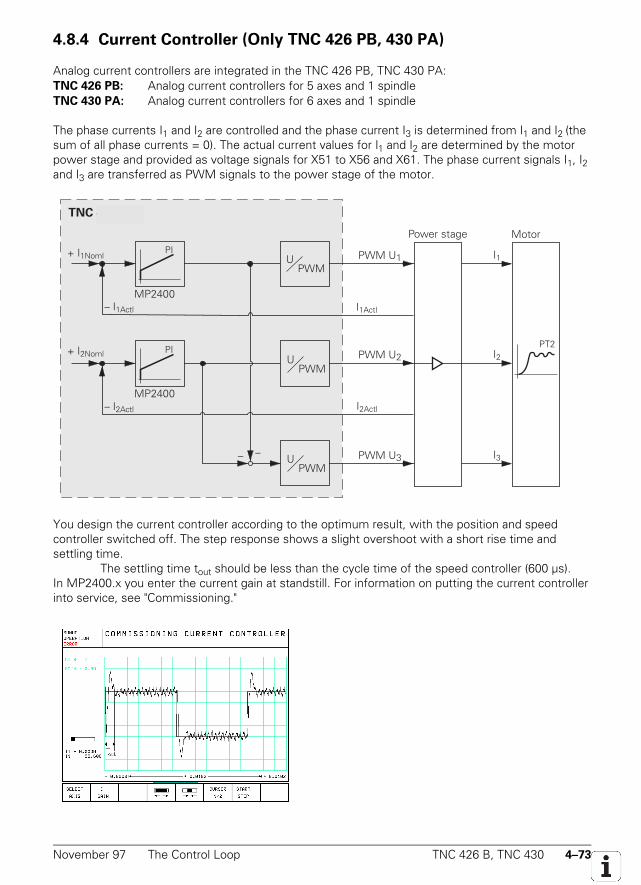
November 97 The Control Loop TNC 426 B, TNC 430 4–73
4.8.4 Current Controller (Only TNC 426 PB, 430 PA)
Analog current controllers are integrated in the TNC 426 PB, TNC 430 PA:TNC 426 PB: Analog current controllers for 5 axes and 1 spindleTNC 430 PA: Analog current controllers for 6 axes and 1 spindle
The phase currents I1 and I2 are controlled and the phase current I3 is determined from I1 and I2 (thesum of all phase currents = 0). The actual current values for I1 and I2 are determined by the motorpower stage and provided as voltage signals for X51 to X56 and X61. The phase current signals I1, I2and I3 are transferred as PWM signals to the power stage of the motor.
TNC 426 PA
PI
MP2400
PI
MP2400
– –
PWM U1
PWM U2
PWM U3
Motor
PT2
I1
I2
I3
UPWM
UPWM
UPWM
+ I1Noml
Power stage
– I2Actl
+ I2Noml
I1Actl
I2Actl
– I1Actl
You design the current controller according to the optimum result, with the position and speedcontroller switched off. The step response shows a slight overshoot with a short rise time andsettling time.
The settling time tout should be less than the cycle time of the speed controller (600 µs).In MP2400.x you enter the current gain at standstill. For information on putting the current controllerinto service, see "Commissioning."
4–74 TNC 426 B, TNC 430 The Control Loop November 97
It can happen with certain asynchronous motors that the motor will not run as smoothly at highspeeds. If this is the case enter a higher current gain in MP2402.x than in MP2400.x. At maximumspeed the current gain in MP2402.x will be reached. It is interpolated linearly between standstill andmaximum speed. If you enter the value zero in MP2402.x, the current gain from MP2400.x will beeffective over the entire speed range.
MP2400.0-5 Gain for current controller at standstillInput: 0.00 to 9 999.99 [V/A]
0 = controller disable
MP2402.0-5 Gain for current controller at maximum speedInput: 0.00 to 9 999.99 [V/A]
0 = value from MP2400.x
November 97 Offset Adjustment TNC 426 B, TNC 430 4–75
4.9 Offset Adjustment
Digital axes:
If an offset exists at the output of the current controller, this is automatically compensated.
Analog axes:
If an offset exists at the output of the position controller, there are several possible methods ofcompensating it. The maximum permissible offset-voltage in the control is 100 mV. If this voltage isreached or exceeded, then the error message Excessive offset in <axis> will appear.
The automatic cyclical offset-adjustment and the adjustment via integral factor must not be activesimultaneously!
4.9.1 Offset Adjustment by Code Number
With the code number 75 368 you activate an offset adjustment. After entering the code numberthe control shows the offset values for the axes X, Y, Z, 4, 5 in the dialog line. The values indicatethe voltage in 0.15 mV units. Thus a display of 10 means 10 x 0.15 mV = 1.5 mV. The displayedoffset value consists of the offset values from the motor controller and in the NC control.
On pressing the ENT key or the CONTINUE soft key the offset values are automaticallycompensated. The control puts out an appropriate compensating voltage. To switch off theautomatic offset adjustment, enter the code number and press the NO ENT key or the QUIT softkey. If you have entered the code number but do not want any changes, press the END soft key.
The offset values are stored in the control and are non-volatile. If the control is exchanged,the code number must be entered to reactivate the offset adjustment.
4.9.2 Automatic Cyclic Offset Adjustment
With MP1220 you program a time interval after which an offset adjustment will be performedcyclically. An automatic adjustment will be carried out if the programmed time has elapsed and thefollowing conditions are fulfilled:
• All axes are stopped• The spindle is not switched on• The axes are not clamped
For each adjustment cycle there will be a 1 mV correction if the offset voltage is larger than 1 mV. Ifthe offset voltage is smaller than 1 mV, then compensation steps of 0.15 mV will be used.
MP1220 Analog axes: Automatic cyclic offset adjustmentInput: 0 to 65 536 [s]
0 = no automatic adjustment
Digital axes: Non-functionalInput: 0
4–76 TNC 426 B, TNC 430 Contour Behavior November 97
4.9.3 Offset Adjustment with Integral Factor
With the integral factor MP1080.x you carry out an automatic offset adjustment. It is only effectivein the stop condition (see block diagram of control loop). Depending on the size of the factor theoffset voltage will be reduced quickly or slowly. Even a small amount of play in the drives can lead toinstability in the control loop. In this case an integral factor of zero is entered.
MP1080.0-8 Analog axes: Integral factorInput: 0 to 65 535
Digital axes: Non-functionalInput: 0
4.10 Contour Behavior
4.10.1 Radial Acceleration
In addition to the normal acceleration of the axes in MP1060.x you also define the radial accelerationin MP1070. MP1070 limits the feed rate at circular movements according to the following formula:
v = r [m] • MP1070 [m/s2] v= feed rate for circular movements [m/s]r= radius [m] (path of the tool center)
It is recommended that a value should be entered which is between the half of and the same as thatin MP1060 (Acceleration). If the programmed feed is lower than that above, then the programmedfeed will be used. MP1070 is effective for operation with lag and with velocity feedforward.
MP1070 Radial accelerationInput: 0.001 to 5.000 [m/s2]
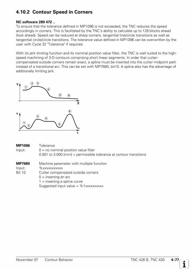
November 97 Contour Behavior TNC 426 B, TNC 430 4–77
4.10.2 Contour Speed in Corners
NC software 280 472 ..
To ensure that the tolerance defined in MP1096 is not exceeded, the TNC reduces the speedaccordingly in corners. This is facilitated by the TNC's ability to calculate up to 128 blocks ahead(look ahead). Speed can be reduced at sharp corners, tangential line/circle transitions as well astangential circle/circle transitions. The tolerance value defined in MP1096 can be overwritten by theuser with Cycle 32 "Tolerance" if required.
With its jerk limiting function and its nominal position value filter, the TNC is well suited to the high-speed machining of 3-D contours comprising short linear segments. In order that cutter-compensated outside corners remain exact, a spline must be inserted into the cutter midpoint pathinstead of a transitional arc. This can be set with MP7680, bit10. A spline also has the advantage ofadditionally limiting jerk.
MP1096 ToleranceInput: 0 = no nominal position value filter
0.001 to 3.000 [mm] = permissible tolerance at contour transitions
MP7680 Machine parameter with multiple functionInput: %xxxxxxxxxxxBit 10 Cutter compensated outside corners
0 = inserting an arc1 = inserting a spline curveSuggested input value = %1xxxxxxxxxx
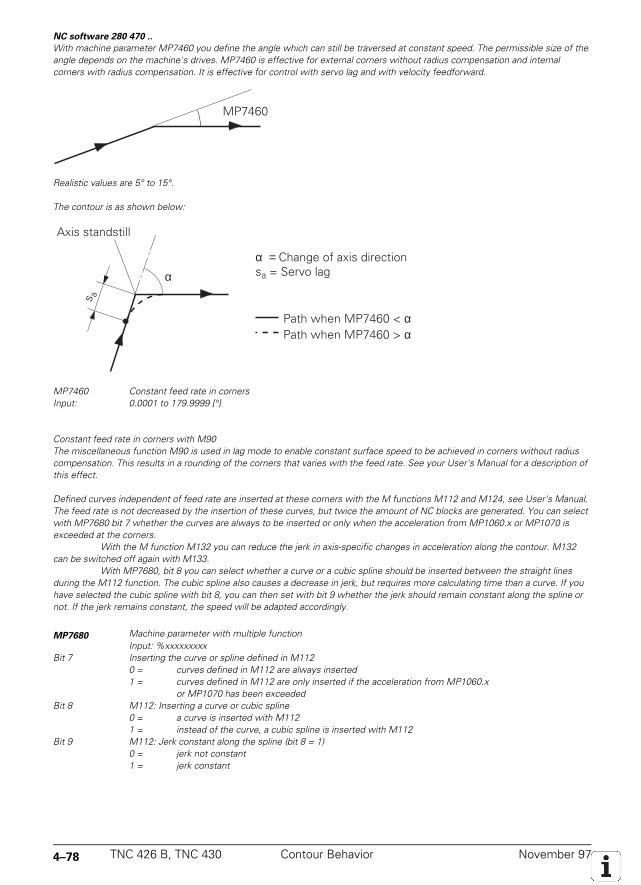
4–78 TNC 426 B, TNC 430 Contour Behavior November 97
NC software 280 470 ..
With machine parameter MP7460 you define the angle which can still be traversed at constant speed. The permissible size of theangle depends on the machine's drives. MP7460 is effective for external corners without radius compensation and internalcorners with radius compensation. It is effective for control with servo lag and with velocity feedforward.
MP7460
Realistic values are 5° to 15°.
The contour is as shown below:
αα = Change of axis directionsa = Servo lag
Axis standstill
Path when MP7460 < αPath when MP7460 > α
s a
MP7460 Constant feed rate in cornersInput: 0.0001 to 179.9999 [°]
Constant feed rate in corners with M90The miscellaneous function M90 is used in lag mode to enable constant surface speed to be achieved in corners without radiuscompensation. This results in a rounding of the corners that varies with the feed rate. See your User's Manual for a description ofthis effect.
Defined curves independent of feed rate are inserted at these corners with the M functions M112 and M124, see User's Manual.The feed rate is not decreased by the insertion of these curves, but twice the amount of NC blocks are generated. You can selectwith MP7680 bit 7 whether the curves are always to be inserted or only when the acceleration from MP1060.x or MP1070 isexceeded at the corners.
With the M function M132 you can reduce the jerk in axis-specific changes in acceleration along the contour. M132can be switched off again with M133.
With MP7680, bit 8 you can select whether a curve or a cubic spline should be inserted between the straight linesduring the M112 function. The cubic spline also causes a decrease in jerk, but requires more calculating time than a curve. If youhave selected the cubic spline with bit 8, you can then set with bit 9 whether the jerk should remain constant along the spline ornot. If the jerk remains constant, the speed will be adapted accordingly.
MP7680 Machine parameter with multiple functionInput: %xxxxxxxxx
Bit 7 Inserting the curve or spline defined in M1120 = curves defined in M112 are always inserted1 = curves defined in M112 are only inserted if the acceleration from MP1060.x
or MP1070 has been exceededBit 8 M112: Inserting a curve or cubic spline
0 = a curve is inserted with M1121 = instead of the curve, a cubic spline is inserted with M112
Bit 9 M112: Jerk constant along the spline (bit 8 = 1)0 = jerk not constant1 = jerk constant
November 97 Monitoring Functions TNC 426 B, TNC 430 4–79
4.11 Monitoring Functions
The NC monitors the axis positions and the dynamic behavior of the machine. If the fixed values areexceeded, it displays an error message and stops the machine. You can switch off the followingtypes of monitoring for the individual axes with W1042:• Position monitoring• Standstill monitoring• Movement monitoring• Nominal speed monitoring
Set ResetW1042 Deactivate monitoring functions PLC PLC
Bit 0 to 8 0 = monitoring functions activeAxis 1 to 9 1 = monitoring functions inactive
Under certain circumstances the reaction time of the PLC for switching off the monitoring function(21 ms) may be too slow. In such cases you must use a fast PLC input. Fast PLC inputs areinterrogated in the control loop cycle time of 3 ms. In MP4130.0 you enter the number of the PLCinput that should be polled more quickly. In MP4131.0 you define the criterion for activating theinput. In W522, bit 0 you must enable the function for switching off the monitoring functions withthe fast PLC input that was defined in MP4130.0. Once you have accomplished this, as soon as theinput is set the monitoring functions are switched off. Also, the axes are automatically stopped, thedrives switched off, and an automatic nominal and actual value transfer is carried out. This automaticnominal and actual value transfer is only carried out if the servo lag is greater than MP1030(positioning window). The monitoring functions are not activated again until the fast PLC input isreset or the function is disabled with W522, bit 0.
It is not possible to operate the machine safely with the monitoring functions switched off,since the TNC does not recognize noncontrolled movements of the axes.
MP4130.0 Number of the fast PLC input for switching off the monitoring functionsInput: 0 to 255 [No. of the PLC input]
MP4131.0 Criterion for activating a fast PLC input for switching off the monitoring functionsInput: 0 = activation at low level
1 = activation at high level
Set ResetW522 Enabling the fast PLC inputs PLC PLCBit 0 Fast PLC input defined in MP4130.0 for switching off
the monitoring functions
4–80 TNC 426 B, TNC 430 Monitoring Functions November 97
4.11.1 Position Monitoring
The position of the axes is monitored by TNC as long as the control loop is active. You define tworanges in machine parameters for position monitoring. If the first limit is exceeded the errormessage Excessive servo lag in <axis> appears and the machine stops. You can erasethis error with the CE key. If the second limit is exceeded the blinking error message Excessiveservo lag in <axis> appears and the control-is-ready output is reset. You cannot erase thismessage. To correct the error you must switch off the control.
Since the input values depend on the highest possible servo lag for the position monitorthere are different input ranges for control with servo lag and control with velocity feedforward. Youmust adjust the input values to the dynamics of the machine.
If blocked axes cause the erasable error message Excessive servo lag in <axis> , anominal speed value may freeze, since the machine axes can no longer be moved. In MP1150 youdefine the time after which the nominal speed value is erased. After this time an automatic actualand nominal value transfer is carried out. If the error message is erased with the CE key before thistime elapses, an automatic actual and nominal value transfer is carried out and the nominal speedvalue is erased.
MP1710.0-8 Position monitoring for control with servo lag (erasable)Input: 0.0000 to 300.0000 [mm]
Recommended: 1.2 • servo lag
MP1720.0-8 Position monitoring for control with servo lag (EMERGENCY STOP)Input: 0.0000 to 300.0000 [mm]
Recommended: 1.4 • servo lag
MP1410.0-8 Position monitoring for velocity feedforward control (erasable)Input: 0.0010 to 30.0000 [mm]
Recommended: 0.5 mm
MP1420.0-8 Position monitoring for operation with velocity feedforward control (EMERGENCYSTOP)Input: 0.0010 to 30.0000 [mm]
Recommended: 2 mm
MP1150 Delay time for erasing the nominal velocity value after an erasable error messageExcessive servo lag in <axis>
Input: 0 to 65.535 [s]Recommended: 0
November 97 Monitoring Functions TNC 426 B, TNC 430 4–81
4.11.2 Nominal Speed Monitoring
For the axes, monitoring the nominal speed is only possible in operation with velocity feedforwardcontrol. For the spindle, nominal speed monitoring is possible in operation with servo lag insofar asthe position control loop is closed (orientation). If the nominal speed value calculated by the positioncontroller is greater than the maximum possible value, the flashing error message Nominal speedvalue too high <axis> is displayed and the output "control is ready for operation" is reset.Analog axes: Maximum nominal speed value = 10 VAnalog spindle: Maximum nominal speed value = 20 VDigital axes and spindle: Maximum nominal speed value = maximum motor speed value
4.11.3 Movement Monitoring
Movement monitoring is possible both in velocity feedforward control and in control with servo lag.During movement monitoring, the actual path traveled is compared with a nominal path calculatedby the NC at short intervals (several servo cycles). If during this period the actual path traveleddiffers from the calculated path, the flashing error message Movement monitoring error in<axis> A appears.
Analog axes: An existing offset at a standstill may cause a potential at the analog output withoutany resulting positioning movement. In MP1140.x you must therefore enter a threshold from whichthe movement monitoring should go into effect.
Digital axes: Since there is no offset, always enter the minimum value in MP1140.x. On digitalaxes, the calculated position from the pulses of the position encoder (MP331.x, MP332.x) iscompared with that calculated from shaft speed encoder. If this difference is greater than the inputvalue from MP2800.x, the error message Movement monitoring error in <axis> Bappears.
If you enter the maximum values in MP1140.x and MP2800.x, you effectively deactivatemovement monitoring. It is not possible to operate the machine safely without movementmonitoring.
MP1140.0-8 Threshold from which movement monitoring is effectiveInput: Analog axes: 0.030 to 10.000 [V]
Digital axes: 0.030 to 10.000 [1000/min]
MP2020.0-5 Path for a motor revolutionInput: Digital axes: 0 to 100.000 [mm] (or as formula, for input format
see Chapter 9 Machine Parameters)Analog axes: No function
MP2800.0-5 Movement monitoring for position and rotational speedInput: Digital axes: 0 to 99 999.9999 [mm]
0 = no monitoringAnalog axes: No function
4–82 TNC 426 B, TNC 430 Monitoring Functions November 97
4.11.4 Standstill Monitoring
The standstill monitoring operates both with velocity feedforward control and with servo lag. Themonitoring begins when the axes have reached the positioning window. As soon as positiondeviation is greater than the value stored in MP1110, the flashing error message Standstillmonitoring error in <axis> is displayed. The message also appears if, on running in to aposition, an overshoot occurs that is larger than the value in MP1110.x, or if the axis moves in theopposite direction on beginning a positioning movement.
MP1110.0-8 Standstill monitoringInput: 0.0010 to 30.0000 [mm]
4.11.5 Positioning Window
The positioning window defines the limits within which the control considers that a position hasbeen reached. After reaching the position the control starts the execution of the next block. Youdefine the size of the positioning window in machine parameter MP1030.x.
MP1030.0-8 Positioning windowsInput: 0.0001 to 2.0000 [mm]
Axes in positionIf the axes have reached the positioning window after a movement, the corresponding bits are set inW1026. This also applies for the condition after the control voltage has been switched on. As soonas you start a positioning movement, the NC resets the bits. This also applies for traversing thereference marks. In the "Electronic handwheel" mode, the axis-in-position bit is reset for the activehandwheel axis. On contours that can be machined with constant surface speed, W1026 is not set.
Set ResetW1026 Axes in position NC NC
Bit 0 to 8 0 = axis not in positioning windowAxis 1 to 9 1 = axis in positioning window
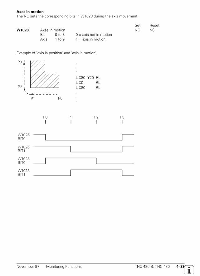
November 97 Monitoring Functions TNC 426 B, TNC 430 4–83
Axes in motion
The NC sets the corresponding bits in W1028 during the axis movement.
Set ResetW1028 Axes in motion NC NC
Bit 0 to 8 0 = axis not in motionAxis 1 to 9 1 = axis in motion
Example of "axis in position" and "axis in motion":
P1
P3
P2
P0
.
.
.
L X80 Y20 RLL X0 RLL X80 RL...
P0
W1026BIT0
P3P1 P2
W1026BIT1
W1028BIT0
W1028BIT1
4–84 TNC 426 B, TNC 430 Monitoring Functions November 97
4.11.6 NC Supply Voltage Monitoring
The NC supply voltage must lie within the defined range (see chapter "Mounting and ElectricalInstallation"). Monitoring NC operating voltage is however only worthwhile with digital axes. A briefvoltage surge (approx. 5 s) of up to 720 Vdc is permitted. If the voltage exceeds 720 Vdc, the NCrevokes the pulse release ( Reset
———————) for the IGBTs (insulated gate bipolar transistors) of the power
stage. The motors come to stop out of loop and no feedback to the dc link is possible.If the supply voltage falls below 385 Vdc (power fail) all drives will come to a controlled
stop. The PLC outputs are switched off and the control displays the error message Power fail . Ifthe voltage falls below 155 Vdc, the control is reset. At 135 Vdc the dc-link power supply is switchedoff.
You can switch the monitoring for supply voltage greater than 385 Vdc on and off withModule 9167. After the control is switched on this type of monitoring is off during the first PLC scanand is then automatically switched on if you have not called module 9167.
Call:PS B/W/D/K <Error code>
0: Switch the monitoring for supply voltage >385 Vdc off1: Switch it on
CM 9167PL B/W/D <Error code>
0: Command was executed–1: Transferred parameter is invalid
4.11.7 Temperature Monitoring
Internal temperature of the logic unitThe internal temperature of the logic unit is constantly monitored. At approx. 70° C the flashing errormessage TNC operating temp. exceeded .
Motor temperature (digital axes only)To measure the motor temperature, a KTY 84 thermistor must be connected to X15 to X20 and X60at pins 13 and 25. The temperature value is sampled at least once every second. The maximumpermissible motor temperature is taken from the motor table. If the entered temperature isexceeded, the flashing error message Motor temperature too high <Axis> appears and thedrives are automatically switched off.
With Module 9165 you can interrogate the current motor temperature and, if desired, takeappropriate measures before the maximum motor temperature has been exceeded.
Call:PS B/W/D/K <Axis> 0 to 5, 15 = axis 1 to 6, spindleCM 9165PL B/W/D <Temperature> Range: 0 to 255 °C
November 97 Monitoring Functions TNC 426 B, TNC 430 4–85
Temperature of heat sink for the power stage (digital axes only)
Pin 13 of X51 to X56 and X61 provides the Temperature warning ——————————————————————
signal. If this signal is reset, itmeans that the permissible temperature of the heat sink for the power stage was exceeded. Themanufacturer of the power stage determines when this signal is reset.
Normally the drives are brought to a stop immediately after a temperature warning in orderto prevent the power stage from being destroyed. The power stage manufacturer can give you moredetailed information. This signal is not evaluated in the NC. Therefore you must interrogate thetemperature warning in the PLC with Module 9160 and provide for the appropriate reactions.
4.11.8 I²t Monitoring (Digital Axes Only)
The instantaneous motor current is limited to the smaller value of the power-stage peak current andof the motor peak current. Once the model of power stage and motor have been set in the TNC, itknows these values.
An I²t monitoring is also carried out. For I²t monitoring, the squares of the actual currentvalues are integrated. The duration of integration is 10 s for feed motors and 150 s for spindlemotors. The lower value of the power-stage rated current and the "reference value for I²t monitoringof the motor" (MP2302.x, MP2303.x) is used as the I²t limit value. If you enter zero, the I²tmonitoring for the motor is switched off. The input value is a factor of the motor rated current (1 =motor rated current).
The I²t warning occurs if the integral calculated from the mean current exceeds the I²t limit,and is canceled when if the integral falls back below the I²t limit. An I²t limitation occurs if the meancurrent value calculated from the integral exceeds the I²t limit value by a factor of 1.1, and iscanceled again when it falls back below 1.1 times the I²t limit value.
There is no I²t limitation on the spindle drive.
MP2302.0-5 Reference value for I²t monitoring of the feed motorsInput: 0 to 1000.000 [• motor rated current]
0 = I²t monitoring for motor switched off1 = rated current of motor as reference value
MP2303 Reference value for I²t monitoring of the spindle motorInput: 0 to 1000.000 [• motor rated current]
0 = I²t monitoring for spindle switched off1 = rated current of motor as reference value
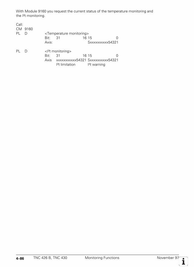
4–86 TNC 426 B, TNC 430 Monitoring Functions November 97
With Module 9160 you request the current status of the temperature monitoring andthe I²t monitoring.
Call:CM 9160PL D <Temperature monitoring>
Bit: 31 16 15 0Axis: Sxxxxxxxxxx54321
PL D <I²t monitoring>Bit: 31 16 15 0Axis xxxxxxxxxxx54321 Sxxxxxxxxxx54321
I²t limitation I²t warning
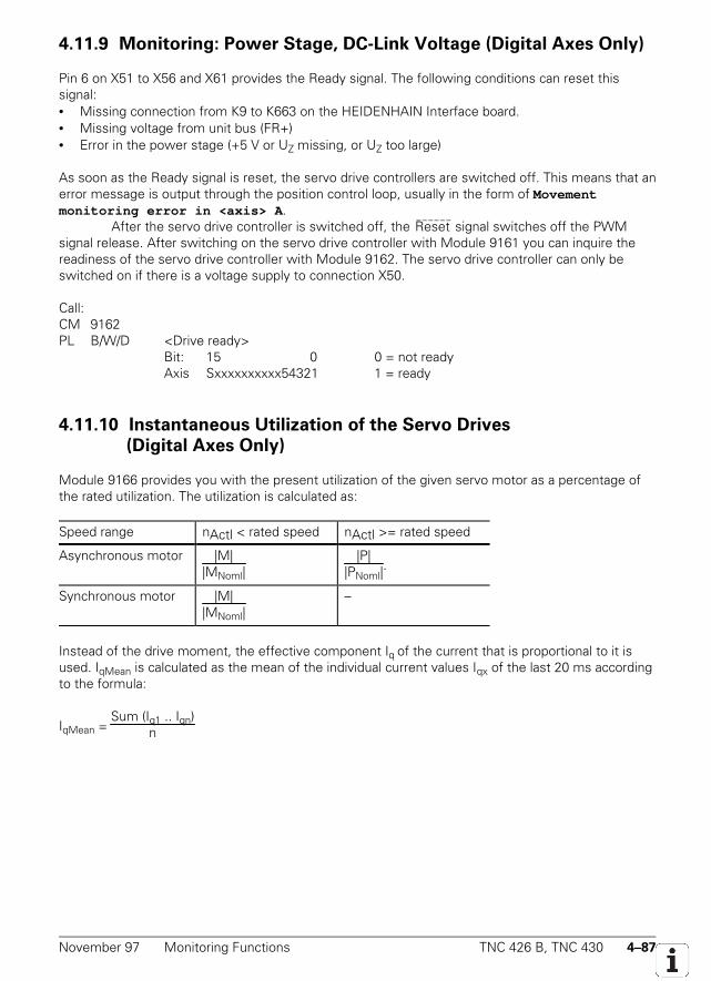
November 97 Monitoring Functions TNC 426 B, TNC 430 4–87
4.11.9 Monitoring: Power Stage, DC-Link Voltage (Digital Axes Only)
Pin 6 on X51 to X56 and X61 provides the Ready signal. The following conditions can reset thissignal:• Missing connection from K9 to K663 on the HEIDENHAIN Interface board.• Missing voltage from unit bus (FR+)• Error in the power stage (+5 V or UZ missing, or UZ too large)
As soon as the Ready signal is reset, the servo drive controllers are switched off. This means that anerror message is output through the position control loop, usually in the form of Movementmonitoring error in <axis> A .
After the servo drive controller is switched off, the Reset ——————
signal switches off the PWMsignal release. After switching on the servo drive controller with Module 9161 you can inquire thereadiness of the servo drive controller with Module 9162. The servo drive controller can only beswitched on if there is a voltage supply to connection X50.
Call:CM 9162PL B/W/D <Drive ready>
Bit: 15 0 0 = not readyAxis Sxxxxxxxxxx54321 1 = ready
4.11.10 Instantaneous Utilization of the Servo Drives
(Digital Axes Only)
Module 9166 provides you with the present utilization of the given servo motor as a percentage ofthe rated utilization. The utilization is calculated as:
Speed range nActl < rated speed nActl >= rated speed
Asynchronous motor |M||MNoml|
|P||PNoml|
.
Synchronous motor |M||MNoml|
–
Instead of the drive moment, the effective component Iq of the current that is proportional to it isused. IqMean is calculated as the mean of the individual current values Iqx of the last 20 ms accordingto the formula:
IqMean = Sum (Iq1 .. Iqn)
n
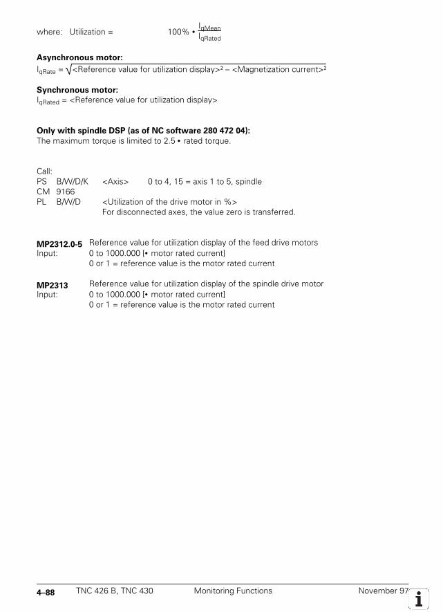
4–88 TNC 426 B, TNC 430 Monitoring Functions November 97
where: Utilization = 100% • IqMeanIqRated
Asynchronous motor:
IqRate = <Reference value for utilization display>² – <Magnetization current>²
Synchronous motor:
IqRated = <Reference value for utilization display>
Only with spindle DSP (as of NC software 280 472 04):
The maximum torque is limited to 2.5 • rated torque.
Call:PS B/W/D/K <Axis> 0 to 4, 15 = axis 1 to 5, spindleCM 9166PL B/W/D <Utilization of the drive motor in %>
For disconnected axes, the value zero is transferred.
MP2312.0-5 Reference value for utilization display of the feed drive motorsInput: 0 to 1000.000 [• motor rated current]
0 or 1 = reference value is the motor rated current
MP2313 Reference value for utilization display of the spindle drive motorInput: 0 to 1000.000 [• motor rated current]
0 or 1 = reference value is the motor rated current
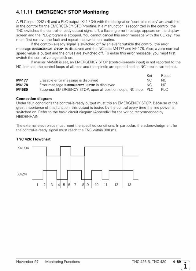
November 97 Monitoring Functions TNC 426 B, TNC 430 4–89
4.11.11 EMERGENCY STOP Monitoring
A PLC-input (X42 / 4) and a PLC-output (X41 / 34) with the designation "control is ready" are availablein the control for the EMERGENCY STOP-routine. If a malfunction is recognized in the control, theTNC switches the control-is-ready output signal off, a flashing error message appears on the displayscreen and the PLC-program is stopped. You cannot cancel this error message with the CE key. Youmust first remove the fault and repeat the switch-on routine.
If the control-is-ready signal is switched off by an event outside the control, the errormessage EMERGENCY STOP is displayed and the NC sets M4177 and M4178. Also, a zero nominalspeed value is output and the drives are switched off. To erase this error message, you must firstswitch the control voltage back on.
If marker M4580 is set, an EMERGENCY STOP (control-is-ready input) is not reported to theNC. Instead, the control loops of all axes and the spindle are opened and an NC stop is carried out.
Set ResetM4177 Erasable error message is displayed NC NCM4178 Error message EMERGENCY STOP is displayed NC NCM4580 Suppress EMERGENCY STOP, open all position loops, NC stop PLC PLC
Connection diagram
Under fault conditions the control-is-ready output must trip an EMERGENCY STOP. Because of thegreat importance of this function, this output is tested by the control every time the line power isswitched on. Refer to the basic circuit diagram (Appendix) for the wiring recommended byHEIDENHAIN.
The external electronics must meet the specified conditions. In particular, the acknowledgment forthe control-is-ready signal must reach the TNC within 380 ms.
TNC 426: Flowchart
X41/34
X42/4
1 2 3 4 5 6 7 8
9 10 11 12 13
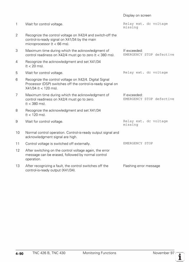
4–90 TNC 426 B, TNC 430 Monitoring Functions November 97
Display on screen
1 Wait for control voltage. Relay ext. dc voltagemissing
2 Recognize the control voltage on X42/4 and switch-off thecontrol-is-ready signal on X41/34 by the mainmicroprocessor (t < 66 ms).
3 Maximum time during which the acknowledgment ofcontrol readiness on X42/4 must go to zero (t < 380 ms).
If exceeded:EMERGENCY STOP defective
4 Recognize the acknowledgment and set X41/34(t < 20 ms).
5 Wait for control voltage. Relay ext. dc voltage
6 Recognize the control voltage on X42/4. Digital SignalProcessor (DSP) switches off the control-is-ready signal onX41/34 (t < 120 ms).
7 Maximum time during which the acknowledgment ofcontrol readiness on X42/4 must go to zero.(t < 380 ms).
If exceeded:EMERGENCY STOP defective
8 Recognize the acknowledgment and set X41/34(t < 120 ms).
9 Wait for control voltage. Relay ext. dc voltagemissing
10 Normal control operation. Control-is-ready output signal andacknowledgment signal are high.
11 Control voltage is switched off externally. EMERGENCY STOP
12 After switching on the control voltage again, the errormessage can be erased, followed by normal controloperation.
13 After recognizing a fault, the control switches off thecontrol-is-ready output (X41/34).
Flashing error message
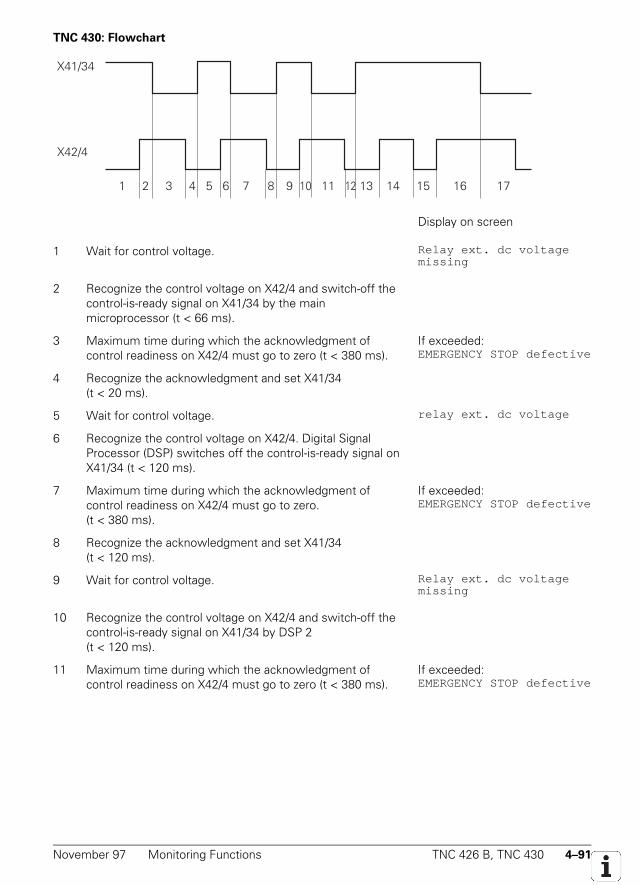
November 97 Monitoring Functions TNC 426 B, TNC 430 4–91
TNC 430: Flowchart
X41/34
X42/4
1 2 3 4 5 6 7 8 9 10 11 12 13 14 15 16 17
Display on screen
1 Wait for control voltage. Relay ext. dc voltagemissing
2 Recognize the control voltage on X42/4 and switch-off thecontrol-is-ready signal on X41/34 by the mainmicroprocessor (t < 66 ms).
3 Maximum time during which the acknowledgment ofcontrol readiness on X42/4 must go to zero (t < 380 ms).
If exceeded:EMERGENCY STOP defective
4 Recognize the acknowledgment and set X41/34(t < 20 ms).
5 Wait for control voltage. relay ext. dc voltage
6 Recognize the control voltage on X42/4. Digital SignalProcessor (DSP) switches off the control-is-ready signal onX41/34 (t < 120 ms).
7 Maximum time during which the acknowledgment ofcontrol readiness on X42/4 must go to zero.(t < 380 ms).
If exceeded:EMERGENCY STOP defective
8 Recognize the acknowledgment and set X41/34(t < 120 ms).
9 Wait for control voltage. Relay ext. dc voltagemissing
10 Recognize the control voltage on X42/4 and switch-off thecontrol-is-ready signal on X41/34 by DSP 2(t < 120 ms).
11 Maximum time during which the acknowledgment ofcontrol readiness on X42/4 must go to zero (t < 380 ms).
If exceeded:EMERGENCY STOP defective
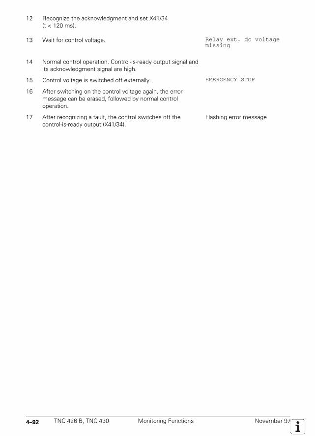
4–92 TNC 426 B, TNC 430 Monitoring Functions November 97
12 Recognize the acknowledgment and set X41/34(t < 120 ms).
13 Wait for control voltage. Relay ext. dc voltagemissing
14 Normal control operation. Control-is-ready output signal andits acknowledgment signal are high.
15 Control voltage is switched off externally. EMERGENCY STOP
16 After switching on the control voltage again, the errormessage can be erased, followed by normal controloperation.
17 After recognizing a fault, the control switches off thecontrol-is-ready output (X41/34).
Flashing error message

November 97 Monitoring Functions TNC 426 B, TNC 430 4–93
4–94 TNC 426 B, TNC 430 Spindle November 97
4.12 Spindle
You control the spindle through the PLC. You can output the programmed rotational speed as:
• Code via PLC outputs• Analog nominal speed value for an analog spindle• Digital nominal speed value for digital spindle
The analog or digital spindle can also be operated with closed position control loop. In this case, youneed a separate position encoder for the spindle. In machine parameter MP3010 you define howyou wish to operate the spindle.
MP3010 Output of rotational speed, gear rangeInput: 0 = no output of spindle speed
1 = speed code only if the spindle speed changes2 = speed code for every TOOL CALL3 = analog output of spindle speed, G code only if the gear stage changes4 = analog output of spindle speed, G code for every TOOL CALL5 = analog output of spindle speed, no G code6 = same as input value 3 but with controlled spindle for orientation7 = same as input value 4 but with controlled spindle for orientation8 = same as input value 5 but with controlled spindle for orientation
4.12.1 Position Encoder of the Spindle
The analog or digital spindle can also be operated with closed-loop position controller. In this caseyou need a separate position encoder for the spindle. The input for this position encoder can bedefined in MP111. If you wish to use the speed encoder on a digital spindle as a position encoder,MP110 must be 0. Enter the line count of the rotary encoder in MP3142. Signals with levels of 1 VPPare subdivided by 1024.
In MP3143 you enter the mounting configuration of the spindle position encoder . Toensure adequate accuracy, the position encoder should be mounted directly on the spindle. If themachine design prevents this, you must enter in MP3450.x and MP3451.x the encoder-to-spindletransmission ratio for each gear range. In this case, the encoder outputs several reference pulsesper revolution of the spindle. The reference mark evaluation is then carried out with Module 9020(see Reference Marks).
If MP3143 = 2, the reference pulse release for the spindle position encoder is set with X30pin 1. In this way you can be sure that the same reference signal is always evaluated. If MP3143 =1, then X30 pin 1 is evaluated as a reference signal. In this case the reference mark of the positionencoder is not evaluated. Due to the low accuracy of such a solution, this setting is not to berecommended. Input value 3 has the same effect as input value 1, however in this case the TNCwaits to evaluate the second reference pulse.
November 97 Spindle TNC 426 B, TNC 430 4–95
MP3142 Line count of the position encoder on the spindleInput: 100 to 9 999 [lines]
MP3143 Mounting configuration of spindle position encoderInput: 0 = position encoder directly on the spindle
1 = position encoder via transmission (transmission ratios in MP3450.x andMP3451.x). X30 pin 1 = reference pulse
2 = position encoder via transmission (transmission ratios in MP3450.x andMP3451.x). X30 pin 1 = reference pulse release
3 = as input value 1, however the TNC waits for the second reference pulse
MP3450.0-7 Number of revolutions of the spindle position encoderInput: 0 to 255
0 = no transmission
MP3451.0-7 Number of revolutions of the spindleInput: 0 to 255
0 = no transmission
Module 9042: Reading the spindle coordinates
With Module 9042 you can read the spindle coordinates. The coordinate values for actual value,nominal value, actual value in the reference system, servo lag, and spindle distance-to-go are storedin five consecutive doublewords beginning from the given target address. The values for actualvalue, nominal value, and reference value are standardized at 0° to +360.000°. The values for servolag and distance-to-go are displayed between –2879.912° and +2879.912°. The display is in 1/1000degree format.
If MP3010 <6 (no controlled spindle), all coordinates are read as zero. During controlledoperation (M03/M04 active or M05 and opened position control loop) the nominal value correspondsto the actual value; servo lag and distance-to-go are zero.
Call:PS B/W/D/K <Target address Dxxxx>CM 9042
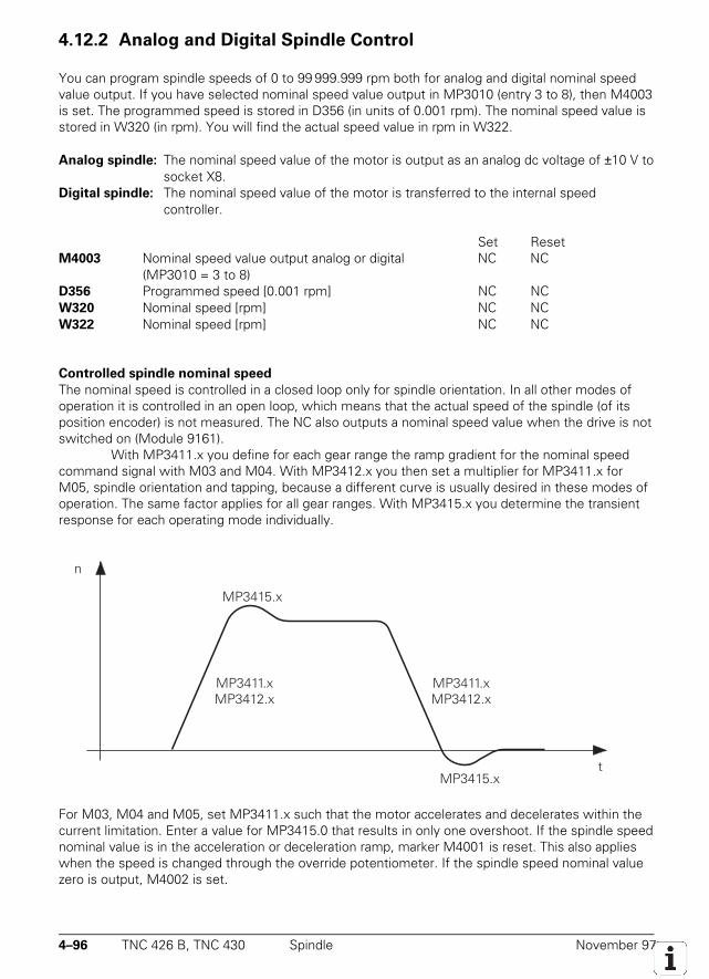
4–96 TNC 426 B, TNC 430 Spindle November 97
4.12.2 Analog and Digital Spindle Control
You can program spindle speeds of 0 to 99 999.999 rpm both for analog and digital nominal speedvalue output. If you have selected nominal speed value output in MP3010 (entry 3 to 8), then M4003is set. The programmed speed is stored in D356 (in units of 0.001 rpm). The nominal speed value isstored in W320 (in rpm). You will find the actual speed value in rpm in W322.
Analog spindle: The nominal speed value of the motor is output as an analog dc voltage of ±10 V tosocket X8.
Digital spindle: The nominal speed value of the motor is transferred to the internal speedcontroller.
Set ResetM4003 Nominal speed value output analog or digital NC NC
(MP3010 = 3 to 8)D356 Programmed speed [0.001 rpm] NC NCW320 Nominal speed [rpm] NC NCW322 Nominal speed [rpm] NC NC
Controlled spindle nominal speed
The nominal speed is controlled in a closed loop only for spindle orientation. In all other modes ofoperation it is controlled in an open loop, which means that the actual speed of the spindle (of itsposition encoder) is not measured. The NC also outputs a nominal speed value when the drive is notswitched on (Module 9161).
With MP3411.x you define for each gear range the ramp gradient for the nominal speedcommand signal with M03 and M04. With MP3412.x you then set a multiplier for MP3411.x forM05, spindle orientation and tapping, because a different curve is usually desired in these modes ofoperation. The same factor applies for all gear ranges. With MP3415.x you determine the transientresponse for each operating mode individually.
n
t
MP3411.xMP3412.x
MP3415.x
MP3415.x
MP3411.xMP3412.x
For M03, M04 and M05, set MP3411.x such that the motor accelerates and decelerates within thecurrent limitation. Enter a value for MP3415.0 that results in only one overshoot. If the spindle speednominal value is in the acceleration or deceleration ramp, marker M4001 is reset. This also applieswhen the speed is changed through the override potentiometer. If the spindle speed nominal valuezero is output, M4002 is set.
November 97 Spindle TNC 426 B, TNC 430 4–97
MP3411.x Ramp gradient of the spindle with M03 and M04Input: analog axes: 0 to 1.999 [V/ms]
digital axes: 0 to 1.999 [(1000/min)/ms]
MP3412.0 Multiplier for MP3411.x for M05Input: 0.000 to 1.999
MP3415.0 Transient response of the spindle with M03, M04 and M05Input: 0 to 1000 [ms]
Set ResetM4001 Spindle speed nominal value not in the ramp NC NCM4002 Spindle speed nominal value = 0 NC NC
Direction of spindle rotation
With MP3130 you define the polarity of the nominal speed command signal. In MP3140 you enterthe counting direction of the position encoder output signals. The nominal speed value is output assoon as you set M4005 for M03 or M4006 for M04. With M4007 for M05 the nominal speed valuezero is output (spindle stop).
With M4005 to M4007 you also control the display of the miscellaneous function in thestatus window (see section "Display and Operation"). If more than one of these markers is set at thesame time, the error message PLC: M4005, M4006, M4007 incorrect appears. With M4014you can reverse the direction of spindle rotation, i.e. the polarity of the nominal speed value isinverted (e.g. to set the transmission ratio for differing horizontal and vertical spindles). M4019inverts the count direction of the position encoder on the spindle.
MP3130 Polarity of the nominal speed command signal for the spindleInput: 0 = M03 positive; M04 negative
1 = M03 negative; M04 positive2 = M03 and M04 positive3 = M03 and M04 negative
MP3140 Counting direction of spindle position encoder signalsInput: 0 = positive counting direction with M03
1 = negative counting direction with M03Set Reset
M4005 Status display and nominal speed value output for M03 PLC PLCM4006 Status display and nominal speed value output for M04 PLC PLCM4007 Status display M05 and spindle stop PLC PLCM4014 Reverse the direction of spindle rotation PLC PLCM4019 Invert the count direction of the spindle position encoder PLC PLC
Disable speed output for spindle
With M4008 you disable the speed output for the spindle. At the same time, M03, M04 or M05 isshown inverted. The nominal speed value is zero.
Set ResetM4008 Disable speed output for spindle PLC PLC
4–98 TNC 426 B, TNC 430 Spindle November 97
Gear ranges
You can define up to eight gear ranges. In MP3510.x you enter for each gear range the rated speedfor S-override at 100%. If you do not need all gear ranges, enter a zero in the remaining machineparameters. In MP3210.x you enter for each gear range the S-analog voltage or the motorrevolutions at rated speed. With MP3240.1 you define the minimum nominal speed value for themotor. With MP3120 you define whether the programmed speed zero is permitted. If an illegalspeed is programmed, M4004 is set and the error message WRONG RPM appears.
MP3510.0-7 Rated speed for gear rangesInput: 0 to 99 999.999 [rpm]
MP3210.0-7 Analog spindle: Nominal value voltage at rated speedInput: 0 to 9.999 [V]Digital spindle: Motor revolutions at rated speedInput: 0 to 100.000 (1000/min)
MP3240.1 Analog spindle: Minimum nominal value voltageInput: 0 to 9.999 [V]Digital spindle: Minimum motor speedInput: 0 to 9.999 [1000/min]
MP3120 Permissibility of zero speed valueInput: 0:S = 0 permitted
1:S = 0 not permittedSet Reset
M4004 Illegal speed was programmed NC NC
November 97 Spindle TNC 426 B, TNC 430 4–99
Gear changing
You control gear changing through the PLC. In accordance with the programmed speed the NC setsthe current gear range in W256. The gear range is calculated using MP3510.x. With MP3010 youmust select the output of the gear range. When the gear range is changed the NC set theG-strobe (M4070). The NC program is not continued until you send the "gear change completed"acknowledgment with M4090. As soon as you set M4090 the G-strobe (M4070) is reset by the NC.
In the PLC program you can change the programmed speed and the gear range calculatedby the NC. This may be necessary, for example, with horizontal-/vertical spindles with two separatetransmissions. The NC stores the programmed speed in doublewords D356 and D756. Enter thespeed that you desire in D756 and the desired gear range in W256. With M4134 you activate yourentries in D756 and W256. After the NC has reset M4134 you shift the gears and then acknowledgewith M4090 "gear change completed." Please note that the speed that you choose falls within thelimits of the gear range that you have chosen.
A changing nominal speed value can be output to shift gears. To do this you mustalternately set and reset markers M4009 and M4010. It is best to do this by interrogating the timersin the PLC program. This function also works if you have used M4008 to disable the speed outputfor the spindle. In MP3240.2 you define the nominal speed value to be output with M4009 / M4010to the spindle motor.
Set ResetW256 Gear code NC/PLC NC/PLCD356 Programmed speed [0.001 rpm] NC NCD756 Programmed speed NC/PLC NC/PLC
or speed of the PLC [0.001 rpm]M4070 Strobe signal for gear code NC NCM4090 Acknowledgment "gear change completed" PLC PLCM4134 Activation of a gear range and speed through the PLC PLC NCM4009 Spindle rotation left (for gear shifting) PLC PLCM4010 Spindle rotation right (for gear shifting) PLC PLC
MP3240.2 Analog spindle: Jog voltage for gear shifting (M4009/M4010)Input: 0 to 9.999 [V]Digital spindle: Motor speed for gear shifting (M4009/M4010)Input: 0 to 9.999 [1000/min]
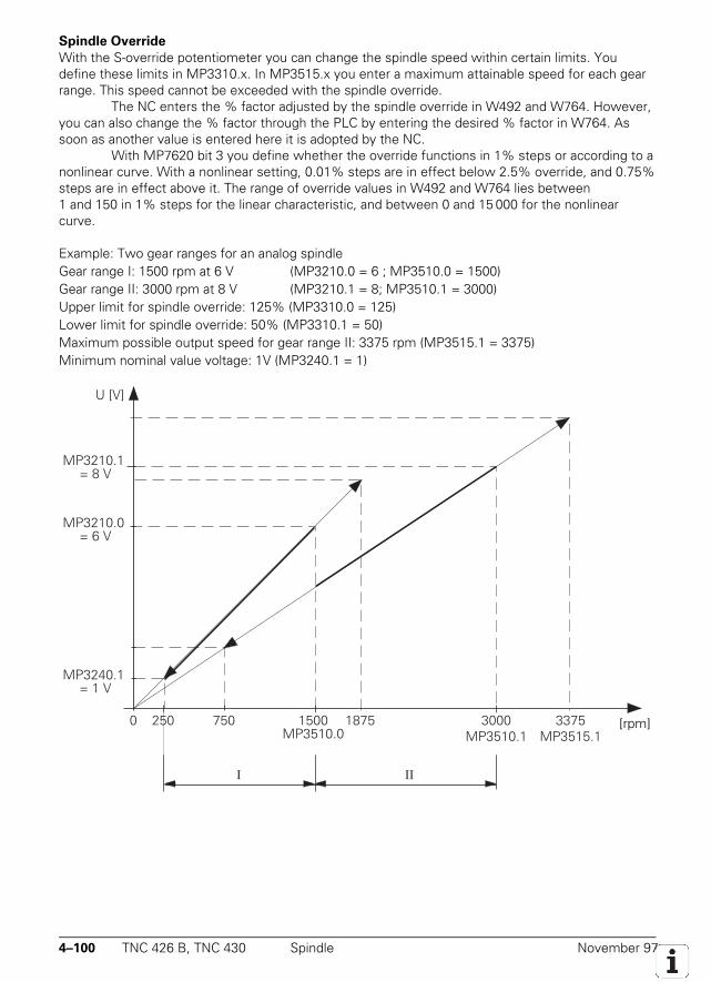
4–100 TNC 426 B, TNC 430 Spindle November 97
Spindle Override
With the S-override potentiometer you can change the spindle speed within certain limits. Youdefine these limits in MP3310.x. In MP3515.x you enter a maximum attainable speed for each gearrange. This speed cannot be exceeded with the spindle override.
The NC enters the % factor adjusted by the spindle override in W492 and W764. However,you can also change the % factor through the PLC by entering the desired % factor in W764. Assoon as another value is entered here it is adopted by the NC.
With MP7620 bit 3 you define whether the override functions in 1% steps or according to anonlinear curve. With a nonlinear setting, 0.01% steps are in effect below 2.5% override, and 0.75%steps are in effect above it. The range of override values in W492 and W764 lies between1 and 150 in 1% steps for the linear characteristic, and between 0 and 15 000 for the nonlinearcurve.
Example: Two gear ranges for an analog spindleGear range I: 1500 rpm at 6 V (MP3210.0 = 6 ; MP3510.0 = 1500)Gear range II: 3000 rpm at 8 V (MP3210.1 = 8; MP3510.1 = 3000)Upper limit for spindle override: 125% (MP3310.0 = 125)Lower limit for spindle override: 50% (MP3310.1 = 50)Maximum possible output speed for gear range II: 3375 rpm (MP3515.1 = 3375)Minimum nominal value voltage: 1V (MP3240.1 = 1)
U [V]
[U/min]
MP3210.1 = 8 V
MP3210.0 = 6 V
MP3240.1 = 1 V
3375MP3515.1
18757500 250 3000MP3510.1
1500MP3510.0
I II
[rpm]
November 97 Spindle TNC 426 B, TNC 430 4–101
MP3310.0-1 Limits for spindle overrideInput: 0 to 150 [%]
MP3310.0 Upper limitMP3310.1 Lower limit
MP3515.0-7 Maximum spindle speedInput: 0 to 99 999.999 [rpm]
MP7620 Feed-rate override and spindle overrideInput: %xxxxBit 3 Feed-rate override and spindle override in 1% steps or according to a nonlinear curve
0 = 1% steps1 = nonlinear curve
Set ResetW492 % factor for spindle override (NC → PLC) NC NCW764 % factor for spindle override (PLC → NC) NC/PLC NC/PLC
4–102 TNC 426 B, TNC 430 Spindle November 97
4.12.3 Coded Output of Spindle Speed
If in MP3010 you have selected spindle-speed code output (input value 1 or 2), an S code is enteredin W258. You must send this speed code through the PLC outputs to the spindle drive.
If the speed code changes, the NC sets the S strobe marker (M4071). The NC programdoes not continue until you acknowledge the S code with M4091. As soon as you set M4091, theNC resets the S strobe (M4071). The NC may round off the programmed spindle speed to the nextstandard value. Spindle speeds of 0 to 9000 are possible.
The NC indicates the programmed spindle speed in the S code in accordance with ISO6983 (see S code table). With MP3020 you define the permissible speed range and the speed step.The S code for the minimum speed is stored in W1008.
Example: Minimum speed = 1 rpm (S-Code 20); Maximum speed = 1000 rpm (S code 80);Speed step = 2:
MP3020 = 20802W1008 = 20
MP3020 Speed range for S code outputInput: 0 to 99 999
Format: xxyyz xx = S code for minimum speedyy = S code for maximum speedz = speed step
Set ResetW258 S code NC NCM4071 Strobe signal S code NC NCM4091 Acknowledgment S code PLC PLCW1008 S code for minimum rpm NC NC
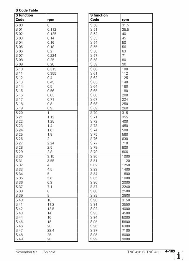
November 97 Spindle TNC 426 B, TNC 430 4–103
S Code Table
S function
Code rpm
S function
Code rpm
S 00 0 S 50 31.5S 01 0.112 S 51 35.5S 02 0.125 S 52 40S 03 0.14 S 53 45S 04 0.16 S 54 50S 05 0.18 S 55 56S 06 0.2 S 56 63S 07 0.224 S 57 71S 08 0.25 S 58 80S 09 0.28 S 59 90S 10 0.315 S 60 100S 11 0.355 S 61 112S 12 0.4 S 62 125S 13 0.45 S 63 140S 14 0.5 S 64 160S 15 0.56 S 65 180S 16 0.63 S 66 200S 17 0.71 S 67 224S 18 0.8 S 68 250S 19 0.9 S 69 280S 20 1 S 70 315S 21 1.12 S 71 355S 22 1.25 S 72 400S 23 1.4 S 73 450S 24 1.6 S 74 500S 25 1.8 S 75 560S 26 2 S 76 630S 27 2.24 S 77 710S 28 2.5 S 78 800S 29 2.8 S 79 900S 30 3.15 S 80 1000S 31 3.55 S 81 1120S 32 4 S 82 1250S 33 4.5 S 83 1400S 34 5 S 84 1600S 35 5.6 S 85 1800S 36 6.3 S 86 2000S 37 7.1 S 87 2240S 38 8 S 88 2500S 39 9 S 89 2800S 40 10 S 90 3150S 41 11.2 S 91 3550S 42 12.5 S 92 4000S 43 14 S 93 4500S 44 16 S 94 5000S 45 18 S 95 5600S 46 20 S 96 6300S 47 22.4 S 97 7100S 48 25 S 98 8000S 49 28 S 99 9000
4–104 TNC 426 B, TNC 430 Spindle November 97
4.12.4 Oriented Spindle Stop
To carry out an oriented spindle stop, the axis S must be kept in the position control loop. You musttherefore mount a position encoder for the spindle. In MP3010 (input values 6 to 8) you definewhether the control works with spindle orientation. For special NC functions (probe cycles, rigidtapping) the spindle is oriented directly from the NC. In such cases the NC sets M4017, and youneed only reset M4012 in the PLC. In most cases, an oriented spindle stop is requested through anM function (e.g. M19) or a cycle. Then you must activate it in the PLC.
Spindle orientation functions asynchronously to the NC positioning movements. Thereforeyou must not acknowledge the orientation until the spindle is in position (M4000). The spindleorientation will not be started by the NC until the drive is switched on (Module 9161).
You have three possible methods of orienting the spindle in the PLC:• With Module 9171• With marker M4130• With a proximity switch and marker M4011
Process of spindle orientation with marker M4130 or Module 9171
The spindle speed is reduced under control along the ramp from MP3412.1 to the speed for spindleorientation (MP3520.1). Once this speed has been reached the position control loop is closed andthe spindle is servo-controlled along the ramp from MP3412.1 to the nominal position. As long asthe servo-controlled spindle is moving, M4017 is set.
To adjust the gear ranges, enter a kv factor for each of the axes in MP3440.x. WithMP3415.1 you define the transient response of the spindle for spindle orientation. With MP3420 youdefine the positioning window. If the spindle is inside the positioning window after the orientedstop, M4000 is set.
If you do not want the spindle to remain in the position control loop after it has reached thenominal position, then you must set marker M4012. The spindle is not free until this marker is set. IfM4012 is always set, the control loop is opened immediately after every oriented spindle stop,provided that the positioning window has been reached. With MP3430 you can easily compensateany misalignment of the rotary encoder resulting from imprecise mounting. The offset between thenominal and actual position of the reference mark entered here is then accounted for during spindleorientation.
When the spindle is first switched on, the NC immediately evaluates the reference mark(even if the position control loop is not closed). M4018 is set until the reference mark is evaluated.For special applications you can evaluate the reference mark again by setting M4015. The NC resetsM4015 when the reference mark has been evaluated.
With MP7291 you activate a display of the spindle position. The spindle position isdisplayed only if neither M03 nor M04 is active. It is displayed as a value below 360°.
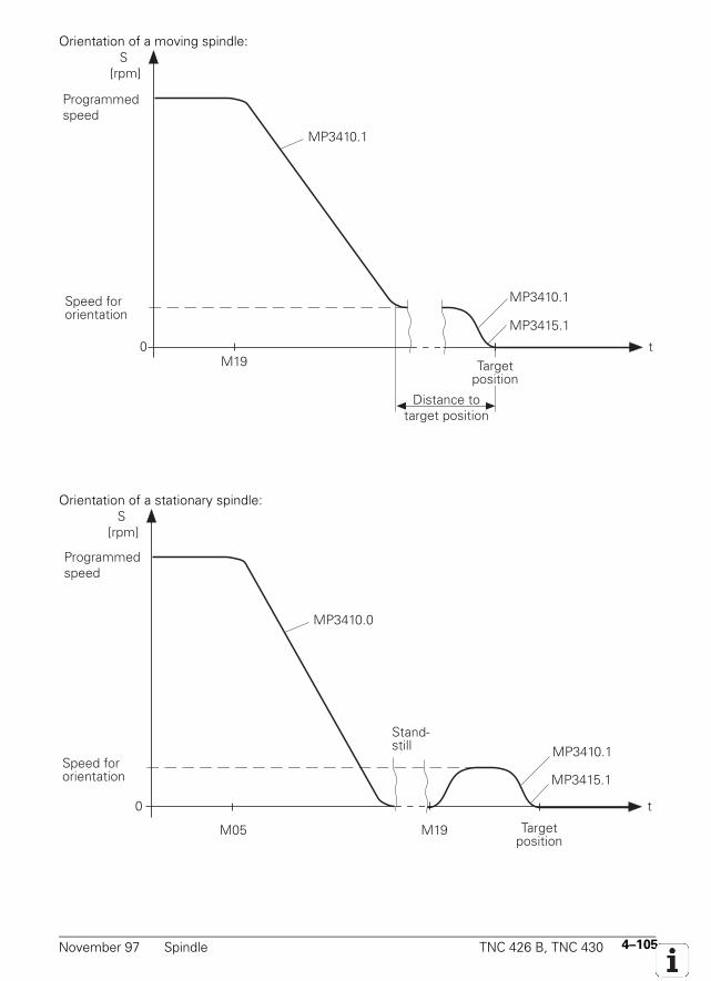
November 97 Spindle TNC 426 B, TNC 430 4–105
Orientation of a moving spindle:
t M19
MP3410.1
MP3410.1
0
MP3415.1
S [rpm]
Programmedspeed
Speed fororientation
Targetposition
Distance totarget position
Orientation of a stationary spindle:
t
M05 M19
0
MP3410.0
MP3410.1
MP3415.1
S [rpm]
Stand-still
Programmedspeed
Speed fororientation
Targetposition
4–106 TNC 426 B, TNC 430 Spindle November 97
MP3412.1 Multiplier for MP3411.x with oriented stopInput: 0 to 1.999
MP3415.1 Transient response of the spindle for oriented stopInput: 0 to 1000 [ms]
MP3420 Positioning window for the spindleInput: 0 to 360.0000 [°]
MP3430 Deviation of the reference mark from the desired position (spindle preset)Input: 0 to 360 [°]
MP3440.0-7 kv factor for spindle orientation
Input: 0.1 to 10 1000°/min
°
MP3520.1 Spindle speed for oriented stopInput: 0 to 99 999.999 [rpm]
Set ResetM4000 Spindle in position NC NCM4012 Open the spindle control loop PLC PLCM4015 Reevaluation of the spindle reference mark PLC NCM4017 Servo-controlled spindle in motion NC NCM4018 Reference mark for spindle not yet traversed NC NC
Spindle orientation with module 9171
Module 9171 starts a spindle orientation for which you enter the speed, nominal position, anddirection of rotation. M4130 is set as long as spindle is being positioned. The module functions onlyin the cyclic PLC program. If you call the module while the spindle is rotating, the transferreddirection is disregarded and the spindle is oriented in the direction of rotation.
If you enter the values 2 to 4 as direction of rotation, the spindle is oriented to the angle lastdefined through CYCL DEF 13. The transferred angle is added to the value from CYCL DEF 13.
Call only from sequential PLC program:PS B/W/D/K <Angle> [1/10 000 °]
or additional preset with value from CYCL DEF 13PS B/W/D/K <Speed> [1/1 000 rpm]
0 = MP3520.1 is usedPS B/W/D/K <Direction of rotation>
–1: Negative direction (M04)0: Direction of the shortest path1: Positive direction (M03)2: Same as –1 but with angle from CYCL DEF 133: Same as 0 but with angle from CYCL DEF 134: Same as +1 but with angle from CYCL DEF 13
CM 9171
November 97 Spindle TNC 426 B, TNC 430 4–107
Spindle orientation with M4130
With M4130 you can start an oriented spindle stop. The nominal position is taken over from D592and the speed from MP3520.1. The nominal position is referenced to the reference point. Thenominal position can be transferred to the PLC with, for example, MP4210.x.The nominal position can also be taken from taken from the Oriented Spindle Stop cycle (CYCL DEF13). Then you must set the MSB of D592 = 1 and the other bits to 0. When Cycle 13 is run, M4016is set.
If a stationary spindle is oriented, it takes the shortest path to the nominal position if thedistance from the actual starting position to the nominal position is not greater than the positioningwindow (MP3420). If the distance is greater than the positioning window it will be positionedaccording to M4013 with M03 or M04.
Set ResetD592 Nominal position for spindle orientation PLC PLCM4013 Direction for spindle orientation from a stop PLC PLC
0 = M03 ; 1 = M04M4016 Cycle 13 is being run NC NCM4130 Activation of the spindle orientation, NC,PLC NC
or spindle orientation has been started with 9171
Spindle orientation through proximity switch with M4011
The spindle can also be oriented by means of a proximity switch. To do this you must set M4011.After you have set M4011 the spindle is moved in the direction of rotation from M4013 at the speedfrom MP3520.0. As soon as you reset M4011 the spindle is stopped. The current position value isdisplayed in the status window.
MP3520.0 Spindle speed activated by marker M4011Input: 0 to 99 999.999 [rpm]
Set ResetM4011 Activate spindle speed from MP3520.0
and direction of rotation from M4013 PLC PLC
Offset adjustment (only analog spindles)
After the spindle has been brought to an oriented stop, any remaining offset is automaticallyadjusted. In order to give the spindle enough time to settle to a stop the offset adjustment isdelayed until the spindle has been in position for at least two seconds. After this time is over theoffset in compensated by 0.152 mV cyclically in intervals of one second.
4–108 TNC 426 B, TNC 430 Spindle November 97
4.12.5 Tapping with Floating Tap Holder and Nominal Speed Output
During tapping with floating tap holder the spindle position control loop is open. During the tappingcycle M4030 is set. After the spindle is switched on with M03 and acknowledged with M4092 thenominal speed must be attained before feed motion begins. After switch-on the spindle follows theramp from MP3411.x; after switch-off it follows the ramp from MP3412.2. With MP3415.2 you candefine the transient response of the spindle.
You must acknowledge the M functions immediately. An NC stop cannot be carried outuntil a preceding M function has been acknowledged. If the feed rate ramp is flatter than the spindleramp, the spindle follows the feed rate ramp. With MP7120.2 you can delay switch-off.
Example:From speed s = 1000 [rpm] = 1.8 [V] and MP3410.2 = 0.05 [V/ms] follows:
1.8 [V] 0.05 [V/ms] = 36 ms
The spindle is decelerated 36 ms before reaching the total hole depth. If the spindle deceleration isdelayed by the slow-down time (MP7120.2), then it is possible only to delay up to 30 ms beforereaching the total hole depth. Any greater delay will be ignored.
With MP7120.0 you can delay the restarting of the spindle with M04. The ramp follows MP3412.2again. You can delay the restarting of the feed by programming a longer dwell time in the cycle. Thedwell times enable you to make an optimal adjustment of the floating tap holder.
The switch-off of the spindle is again performed by the NC with M05. The switch-off rampfollows MP3412.0. After this, the spindle is switched on again with M03.
The feed-rate override can only be effective within limits when tapping, otherwise thefloating tap holder may be damaged. You enter the limits in MP7110.x.
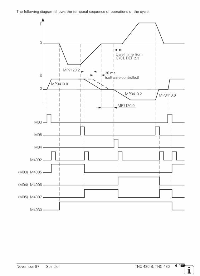
November 97 Spindle TNC 426 B, TNC 430 4–109
The following diagram shows the temporal sequence of operations of the cycle.
F
0
S
0
M03
M05
M04
M4092
(M03) M4005
(M04) M4006
(M05) M4007
M4030
MP3410.0
MP7120.0
MP3410.2 MP3410.0
MP7120.2
Dwell time fromCYCL DEF 2.3
30 ms(software-controlled)
4–110 TNC 426 B, TNC 430 Spindle November 97
MP3412.2 Multiplier for MP3411.x with tappingInput: 0 to 1.999
MP3415.2 Transient response of the spindle for tappingInput: 0 to 1 000 [ms]
MP7110.0 Minimum for feed-rate override during tappingInput: 0 to 150 [%]
MP7110.1 Maximum for feed-rate override during tappingInput: 0 to 150 [%]
MP7120.0 Dwell time for reversal of spindle rotation directionInput: 0 to 65.535 [s]
MP7120.2 Spindle slow-down time after reaching the total hole depthInput: 0 to 65.535 [s]
Set ResetM4030 Cycle 2 or Cycle 17 active NC NC
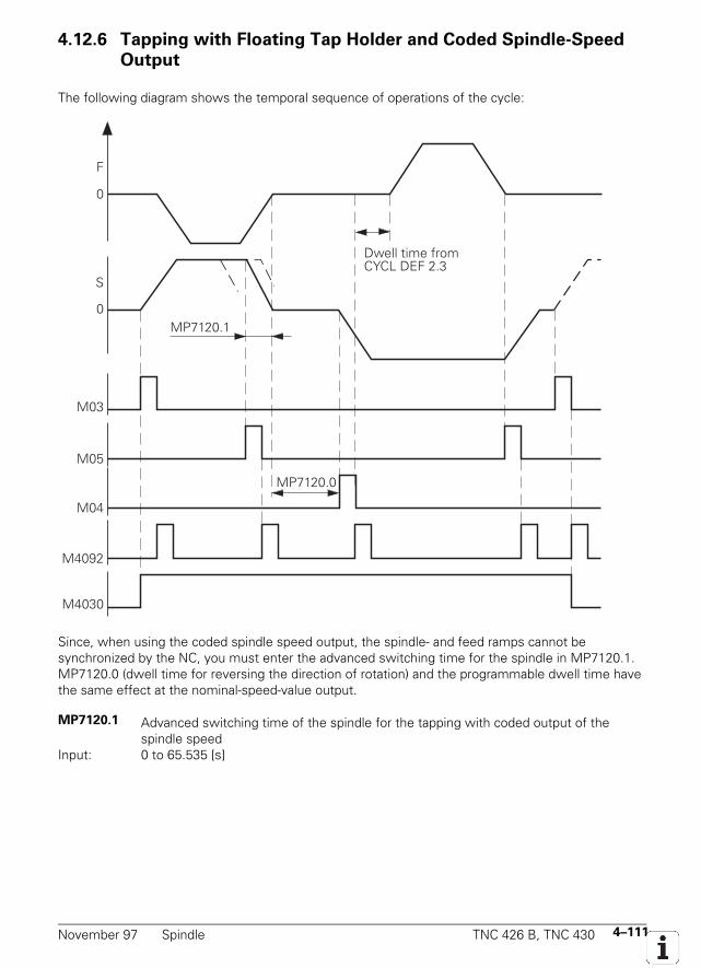
November 97 Spindle TNC 426 B, TNC 430 4–111
4.12.6 Tapping with Floating Tap Holder and Coded Spindle-Speed
Output
The following diagram shows the temporal sequence of operations of the cycle:
0
F
0
S
M03
M05
M04
M4092
M4030
MP7120.0
MP7120.1
Dwell time fromCYCL DEF 2.3
Since, when using the coded spindle speed output, the spindle- and feed ramps cannot besynchronized by the NC, you must enter the advanced switching time for the spindle in MP7120.1.MP7120.0 (dwell time for reversing the direction of rotation) and the programmable dwell time havethe same effect at the nominal-speed-value output.
MP7120.1 Advanced switching time of the spindle for the tapping with coded output of thespindle speed
Input: 0 to 65.535 [s]
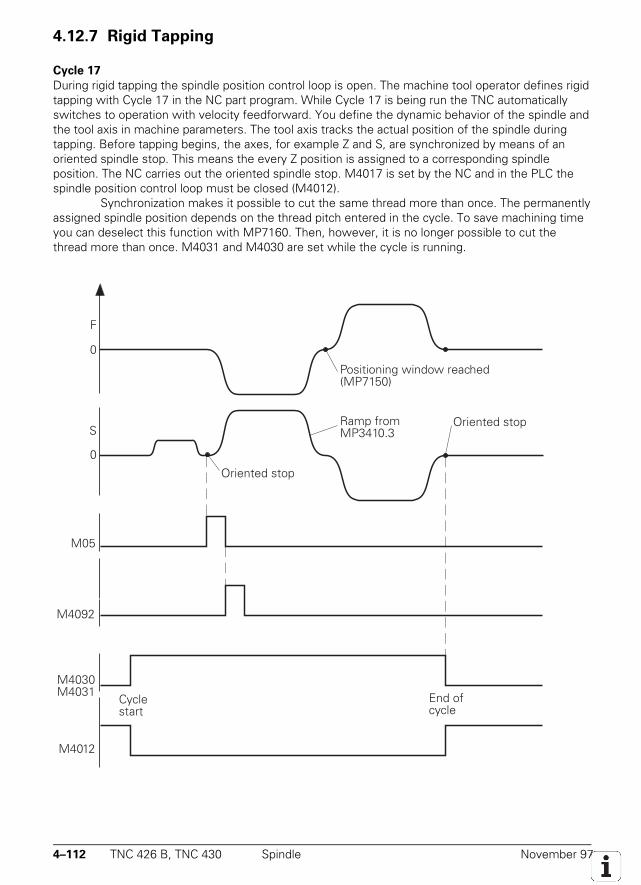
4–112 TNC 426 B, TNC 430 Spindle November 97
4.12.7 Rigid Tapping
Cycle 17
During rigid tapping the spindle position control loop is open. The machine tool operator defines rigidtapping with Cycle 17 in the NC part program. While Cycle 17 is being run the TNC automaticallyswitches to operation with velocity feedforward. You define the dynamic behavior of the spindle andthe tool axis in machine parameters. The tool axis tracks the actual position of the spindle duringtapping. Before tapping begins, the axes, for example Z and S, are synchronized by means of anoriented spindle stop. This means the every Z position is assigned to a corresponding spindleposition. The NC carries out the oriented spindle stop. M4017 is set by the NC and in the PLC thespindle position control loop must be closed (M4012).
Synchronization makes it possible to cut the same thread more than once. The permanentlyassigned spindle position depends on the thread pitch entered in the cycle. To save machining timeyou can deselect this function with MP7160. Then, however, it is no longer possible to cut thethread more than once. M4031 and M4030 are set while the cycle is running.
0
F
0
S
M05
M4092
M4030M4031
M4012
Positioning window reached(MP7150)
Ramp fromMP3410.3
Oriented stop
Cyclestart
End ofcycle
Oriented stop
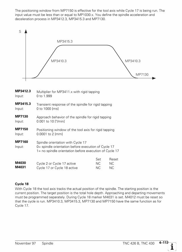
November 97 Spindle TNC 426 B, TNC 430 4–113
The positioning window from MP7150 is effective for the tool axis while Cycle 17 is being run. Theinput value must be less than or equal to MP1030.x. You define the spindle acceleration anddeceleration process in MP3412.3, MP3415.3 and MP7130.
S
MP3410.3
MP3415.3
MP3410.3
MP7130
MP3412.3 Multiplier for MP3411.x with rigid tappingInput: 0 to 1.999
MP3415.3 Transient response of the spindle for rigid tappingInput: 0 to 1000 [ms]
MP7130 Approach behavior of the spindle for rigid tappingInput: 0.001 to 10 [°/min]
MP7150 Positioning window of the tool axis for rigid tappingInput: 0.0001 to 2 [mm]
MP7160 Spindle orientation with Cycle 17Input: 0= spindle orientation before execution of Cycle 17
1= no spindle orientation before execution of Cycle 17
Set ResetM4030 Cycle 2 or Cycle 17 active NC NCM4031 Cycle 17 or Cycle 18 active NC NC
Cycle 18
With Cycle 18 the tool axis tracks the actual position of the spindle. The starting position is thecurrent position. The target position is the total hole depth. Approaching and departing movementsmust be programmed separately. During Cycle 18 marker M4031 is set. M4012 must be reset sothat the cycle is run. MP3410.3, MP3415.3, MP7130 and MP7150 have the same function as forCycle 17.
4–114 TNC 426 B, TNC 430 Spindle November 97
4.12.8 Speed Controller (Only TNC 426 PB, TNC 430 PA)
A digital speed controller for the spindle is integrated in the TNC 426 PB and TNC 430 PA. WithMP2501.x you set the proportional factor and with MP2511.x the integral factor for the speedcontroller of the spindle.
With Module 9164 you can read the actual speed of the motor (see section "Control Loop").As with the axes, you can also define a differential factor, a PT2 element and a frequency filter forthe spindle speed controller (see sections "Control Loop" and "Commissioning").
MP2501.0-1 Proportional factor of the speed controller of the spindleInput: 0 to 1000.000 [As]
MP2511.0-1 Integral factor of the speed controller of the spindleInput: 0 to 100 000 [A]
MP2521.0-1 Differential factor of the speed controller of the spindleInput: 0 to 1.0000 [As²]
MP2531.0-1 PT2 element of the speed controller of the spindleInput: 0 to 1.0000 [s]
MP2541 Damping for frequency filter (spindle)Input: 0.0 to 18.0 [dB]
MP2551 Nominal frequency for frequency filter (spindle)Input: 0.0 to 999.9 [Hz]
4.12.9 Current Controller (Only TNC 426 PB, TNC 430 PA)
Depending on the hardware, the TNC may have different types of current controller. Wedifferentiate between logic units with or without spindle DSP:TNC 426 PB max. spindle speed 9 000 rpm without spindle DSPTNC 426 PB max. spindle speed 15 000 rpm with spindle DSPTNC 430 PA max. spindle speed 15 000 rpm with spindle DSP
Current controller without spindle DSP
With MP2401 you define the current gain for the spindle when stationary. Some asynchronousmotors tend to run unsteadily at high speeds. To correct this, enter a higher gain in MP2403 than inMP2401. MP2403 defines the current gain reached at maximum speed. The gain is interpolatedlinearly between standstill and maximum speed. If you enter the value zero in MP2403, the currentgain from MP2401 will be in effect for the entire speed range.
MP2401 Gain for current controllers of the spindle at standstillInput: 0.00 to 9 999.99 [V/A]
0 = disable the controller
MP2403 Gain for current controllers of the spindle at maximum rotational speedInput: 0.00 to 9 999.99 [V/A]
0 = value from MP2401
November 97 Spindle TNC 426 B, TNC 430 4–115
Current controller with spindle DSP
With MP2421 you define the proportional factor, with MP2431 the integral factor for the currentcontroller of the spindle (see section "Commissioning").
MP2421.0-1 Proportional factor for the current controller of the spindleInput: 0.00 to 9 999.99 [V/A]
MP2431.0-1 Integral factor for the current controller of the spindleInput: 0.00 to 9 999.99 [V/As]
4.12.10 Wye Connection / Delta Connection (Only with Spindle DSP)
You can run the spindle motor either in a wye (Y) or delta (∆) connection. A delta connection enablesyou to run the motor at higher speeds than the wye connection, but at low speeds the motordevelops less power than with the wye connection. For this reason, you will switch between a wyeand delta connection depending on the desired speed. The technical data of the motor are storedinternally both for a wye and a delta connection. Also, there are two sets of machine parametersavailable for the current and speed controllers: index 0 is for wye connection and index 1 for deltaconnection.
With Module 9163 you activate the change between a wye and delta connection. As soonas Module 9163 is called, the NC disables the spindle drive and activates the motor data andmachine parameters of the selected circuit (wye or delta). You can check this with Module 9162.After an external relay has changed the motor circuit, you enable the spindle with Module 9161.
Call:PS B/W/D/K <Axis> 15 = spindlePS B/W/D/K <Type of connection> 0 = wye connection
1 = delta connectionCM 9163

4–116 TNC 426 B, TNC 430 Spindle November 97
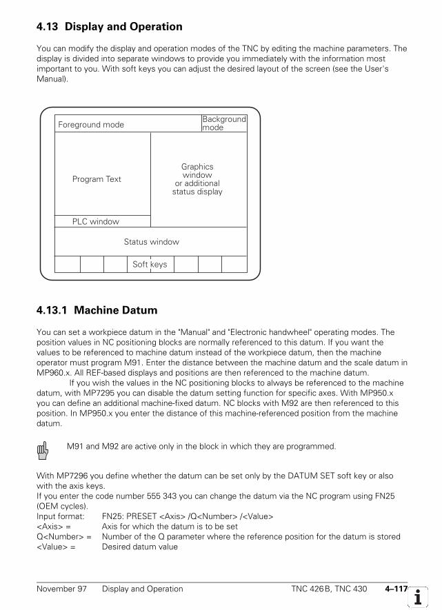
November 97 Display and Operation TNC 426B, TNC 430 4–117
4.13 Display and Operation
You can modify the display and operation modes of the TNC by editing the machine parameters. Thedisplay is divided into separate windows to provide you immediately with the information mostimportant to you. With soft keys you can adjust the desired layout of the screen (see the User'sManual).
Foreground modeBackgroundmode
Program TextGraphics window
or additionalstatus display
PLC window
Status window
Soft keys
4.13.1 Machine Datum
You can set a workpiece datum in the "Manual" and "Electronic handwheel" operating modes. Theposition values in NC positioning blocks are normally referenced to this datum. If you want thevalues to be referenced to machine datum instead of the workpiece datum, then the machineoperator must program M91. Enter the distance between the machine datum and the scale datum inMP960.x. All REF-based displays and positions are then referenced to the machine datum.
If you wish the values in the NC positioning blocks to always be referenced to the machinedatum, with MP7295 you can disable the datum setting function for specific axes. With MP950.xyou can define an additional machine-fixed datum. NC blocks with M92 are then referenced to thisposition. In MP950.x you enter the distance of this machine-referenced position from the machinedatum.
M91 and M92 are active only in the block in which they are programmed.
With MP7296 you define whether the datum can be set only by the DATUM SET soft key or alsowith the axis keys.If you enter the code number 555 343 you can change the datum via the NC program using FN25(OEM cycles).Input format: FN25: PRESET <Axis> /Q<Number> /<Value><Axis> = Axis for which the datum is to be setQ<Number> = Number of the Q parameter where the reference position for the datum is stored<Value> = Desired datum value
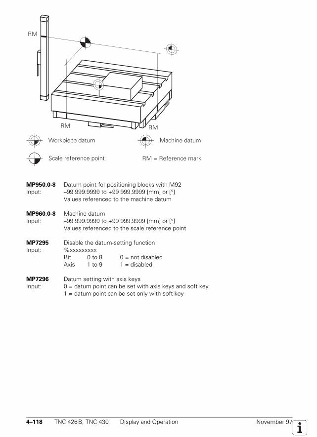
4–118 TNC 426B, TNC 430 Display and Operation November 97
RM RM
RM
Workpiece datum
Scale reference point RM = Reference mark
Machine datum
MP950.0-8 Datum point for positioning blocks with M92Input: –99 999.9999 to +99 999.9999 [mm] or [°]
Values referenced to the machine datum
MP960.0-8 Machine datumInput: –99 999.9999 to +99 999.9999 [mm] or [°]
Values referenced to the scale reference point
MP7295 Disable the datum-setting functionInput: %xxxxxxxxx
Bit 0 to 8 0 = not disabledAxis 1 to 9 1 = disabled
MP7296 Datum setting with axis keysInput: 0 = datum point can be set with axis keys and soft key
1 = datum point can be set only with soft key
November 97 Display and Operation TNC 426B, TNC 430 4–119
4.13.2 Color Adjustment
The colors in the display can be configured by machine parameter. You may wish, for example, tochange the colors to suit your company's corporate image or the design of the machine.
You cannot alter the following color settings by machine parameter:• HEIDENHAIN company logo after switching on the machine (standard color)• Blinking error messages (red)• Error message for invalid machine parameters (red)• Plan view in the graphics display (blue)• Cursor (always inverse)
You mix the desired color by combining the basic colors red, green and blue. You can enter each ofthese elementary colors in 64 different intensity levels. The input values for color adjustment arebyte-oriented. We recommend hexadecimal input.
Color Red Green Blue
Adjustment Coarse Fine Coarse Fine Coarse Fine
HEX ranges 0 to 3 0 to F 0 to 3 0 to F 0 to 3 0 to F
Input for yellow:$0.... 3 9 3 9 0 0
Since it is possible to make mistakes when setting the colors (red error messages on redbackground, for example) HEIDENHAIN supplies the controls with a standard color adjustment. Thisis the setting used by HEIDENHAIN. It is used by the control system when you edit the MP list.
The standard color adjustment is shown in the following list.
MP7350 Window frame $030200C
MP7351 Error messages $03F3F0F
MP7352 "Machine" operating mode displayMP7352.0 Background $0000000MP7352.1 Text for operating mode $0342008MP7352.2 Dialog $03F3828
MP7353 "Programming" operating mode displayMP7353.0 Background $0000000MP7353.1 Text for operating mode $0342008MP7353.2 Dialog $03F3828
MP7354 "Machine" program-text displayMP7354.0 Background $0080400MP7354.1 General program text $038240CMP7354.2 Current block $038341CMP7354.3 Background not current window $00C0800
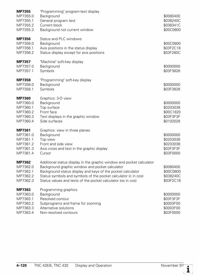
4–120 TNC 426B, TNC 430 Display and Operation November 97
MP7355 "Programming" program-text displayMP7355.0 Background $0080400MP7355.1 General program text $038240CMP7355.2 Current block $038341CMP7355.3 Background not current window $00C0800
MP7356 Status and PLC windowsMP7356.0 Background $00C0800MP7356.1 Axis positions in the status display $03F2C18MP7356.2 Status display except for axis positions $03F280C
MP7357 "Machine" soft-key displayMP7357.0 Background $0000000MP7357.1 Symbols $03F3828
MP7358 "Programming" soft-key displayMP7358.0 Background $0000000MP7358.1 Symbols $03F3828
MP7360 Graphics: 3-D viewMP7360.0 Background $0000000MP7360.1 Top surface $0203038MP7360.2 Front face $00C1820MP7360.3 Text displays in the graphic window $03F3F3FMP7360.4 Side surfaces $0102028
MP7361 Graphics: view in three planesMP7361.0 Background $0000000MP7361.1 Top view $0203038MP7361.2 Front and side view $0203038MP7361.3 Axis cross and text in the graphic display $03F3F3FMP7361.4 Cursor $03F0000
MP7362 Additional status display in the graphic window and pocket calculatorMP7362.0 Background graphic window and pocket calculator $0080400MP7362.1 Background status display and keys of the pocket calculator $00C0800MP7362.2 Status symbols and symbols of the pocket calculator (c in cos) $038240CMP7362.3 Status values and texts of the pocket calculator (os in cos) $03F2C18
MP7363 Programming graphicsMP7363.0 Background $0000000MP7363.1 Resolved contour $03F3F3FMP7363.2 Subprograms and frame for zooming $0003F00MP7363.3 Alternative solutions $0003F00MP7363.4 Non-resolved contours $03F0000
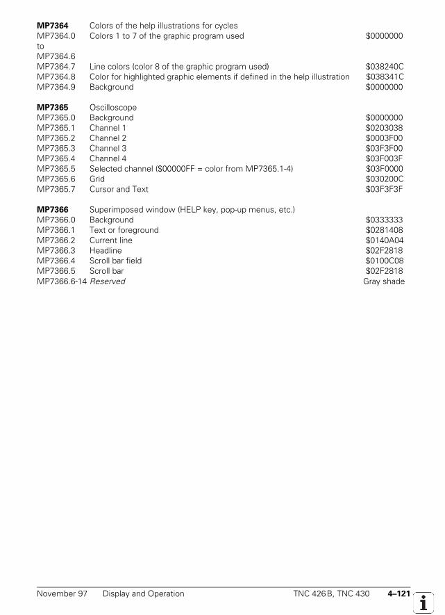
November 97 Display and Operation TNC 426B, TNC 430 4–121
MP7364 Colors of the help illustrations for cyclesMP7364.0 Colors 1 to 7 of the graphic program used $0000000toMP7364.6MP7364.7 Line colors (color 8 of the graphic program used) $038240CMP7364.8 Color for highlighted graphic elements if defined in the help illustration $038341CMP7364.9 Background $0000000
MP7365 OscilloscopeMP7365.0 Background $0000000MP7365.1 Channel 1 $0203038MP7365.2 Channel 2 $0003F00MP7365.3 Channel 3 $03F3F00MP7365.4 Channel 4 $03F003FMP7365.5 Selected channel ($00000FF = color from MP7365.1-4) $03F0000MP7365.6 Grid $030200CMP7365.7 Cursor and Text $03F3F3F
MP7366 Superimposed window (HELP key, pop-up menus, etc.)MP7366.0 Background $0333333MP7366.1 Text or foreground $0281408MP7366.2 Current line $0140A04MP7366.3 Headline $02F2818MP7366.4 Scroll bar field $0100C08MP7366.5 Scroll bar $02F2818MP7366.6-14 Reserved Gray shade
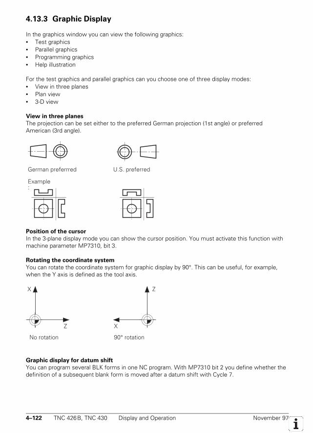
4–122 TNC 426B, TNC 430 Display and Operation November 97
4.13.3 Graphic Display
In the graphics window you can view the following graphics:• Test graphics• Parallel graphics• Programming graphics• Help illustration
For the test graphics and parallel graphics can you choose one of three display modes:• View in three planes• Plan view• 3-D view
View in three planes
The projection can be set either to the preferred German projection (1st angle) or preferredAmerican (3rd angle).
German preferrred U.S. preferred
Example:
Position of the cursor
In the 3-plane display mode you can show the cursor position. You must activate this function withmachine parameter MP7310, bit 3.
Rotating the coordinate system
You can rotate the coordinate system for graphic display by 90°. This can be useful, for example,when the Y axis is defined as the tool axis.
X
Z
No rotation 90° rotation
Z
X
Graphic display for datum shift
You can program several BLK forms in one NC program. With MP7310 bit 2 you define whether thedefinition of a subsequent blank form is moved after a datum shift with Cycle 7.

November 97 Display and Operation TNC 426B, TNC 430 4–123
MP7310 Graphic display modeInput: %xxxxBit 0 Display mode in three planes 0 = projection preferred in Germany
1 = projection preferred in AmericaBit 1 Rotating the coordinate system
in the working plane by +90 °0 = no rotation1 = coordinate system rotated by +90 °
Bit 2 BLK form after a datum shift 0 = BLK form is not shifted1 = BLK form is shifted
Bit 3 Display of cursor position duringview in three planes
0 = no display of cursor position1 = cursor position is displayed
4–124 TNC 426B, TNC 430 Display and Operation November 97
4.13.4 Status Display
The status of the control (axis positions, tools, feed, M-functions, etc.) is displayed on the control screen inthe status window. A soft key can be used to activate an additional status-display in the graphicswindow instead of the graphics.
Position display
With MP7290.x you select the display step for the individual axes. The position loop resolution is notaffected by this machine parameter. With MP7285 you define whether the tool length should becalculated into the position display (i.e. tool length offset). If it is, the displayed position value thenrefers to the tool point.
MP7285 Offset of tool length in the position display in the tool axisInput: 0 = tool length is not offset
1 = tool length is offset
MP7290.0-8 Position display stepInput: 0 = 0.1 mm or 0.1 °
1 = 0.05 mm or 0.05 °2 = 0.01 mm or 0.01 °3 = 0.005 mm or 0.005 °4 = 0.001 mm or 0.001 °5 = 0.0005 mm or 0.0005 °6 = 0.0001 mm or 0.0001 °
Positions display for rotary axes and PLC auxiliary axes
With MP810 you define the position display for rotary axes and PLC auxiliary axes. You set themodulo value for the counting mode (i.e. the value after which the axis display returns to zero). Atthe same time you define whether the software limit switches of the traverse range limits should bein effect.
With MP7682 bit 2 you can set whether rotary axes with modulo display should always bepositioned by the shorter path or without crossing over zero. If bit 2 is set, you don't need toprogram M126.
MP810.0-8 Display mode for rotary axes and PLC auxiliary axesInput: 0.0000 to 99 999.9999[°]
0 = display ±99 999.9999; software limit switch active≠ 0 = modulo value for display; software limit switch inactive
MP7682 Machine parameter with multiple functionInput: %xxxBit 2 Traverse path of rotary axes with modulo display
0 = positioning without crossing over zero1 = shorter path positioning
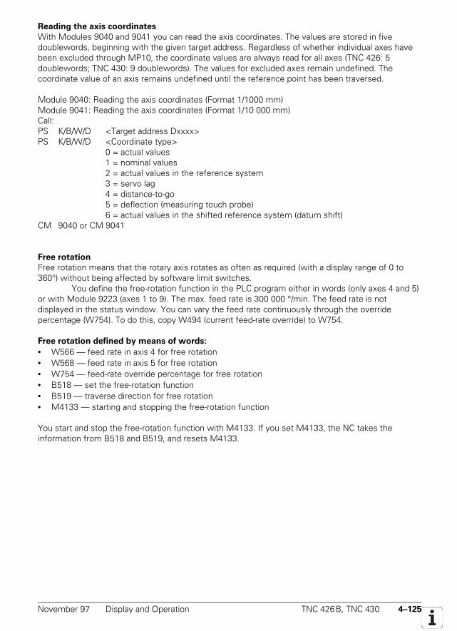
November 97 Display and Operation TNC 426B, TNC 430 4–125
Reading the axis coordinates
With Modules 9040 and 9041 you can read the axis coordinates. The values are stored in fivedoublewords, beginning with the given target address. Regardless of whether individual axes havebeen excluded through MP10, the coordinate values are always read for all axes (TNC 426: 5doublewords; TNC 430: 9 doublewords). The values for excluded axes remain undefined. Thecoordinate value of an axis remains undefined until the reference point has been traversed.
Module 9040: Reading the axis coordinates (Format 1/1000 mm)Module 9041: Reading the axis coordinates (Format 1/10 000 mm)Call:PS K/B/W/D <Target address Dxxxx>PS K/B/W/D <Coordinate type>
0 = actual values1 = nominal values2 = actual values in the reference system3 = servo lag4 = distance-to-go5 = deflection (measuring touch probe)6 = actual values in the shifted reference system (datum shift)
CM 9040 or CM 9041
Free rotation
Free rotation means that the rotary axis rotates as often as required (with a display range of 0 to360°) without being affected by software limit switches.
You define the free-rotation function in the PLC program either in words (only axes 4 and 5)or with Module 9223 (axes 1 to 9). The max. feed rate is 300 000 °/min. The feed rate is notdisplayed in the status window. You can vary the feed rate continuously through the overridepercentage (W754). To do this, copy W494 (current feed-rate override) to W754.
Free rotation defined by means of words:
• W566 — feed rate in axis 4 for free rotation• W568 — feed rate in axis 5 for free rotation• W754 — feed-rate override percentage for free rotation• B518 — set the free-rotation function• B519 — traverse direction for free rotation• M4133 — starting and stopping the free-rotation function
You start and stop the free-rotation function with M4133. If you set M4133, the NC takes theinformation from B518 and B519, and resets M4133.
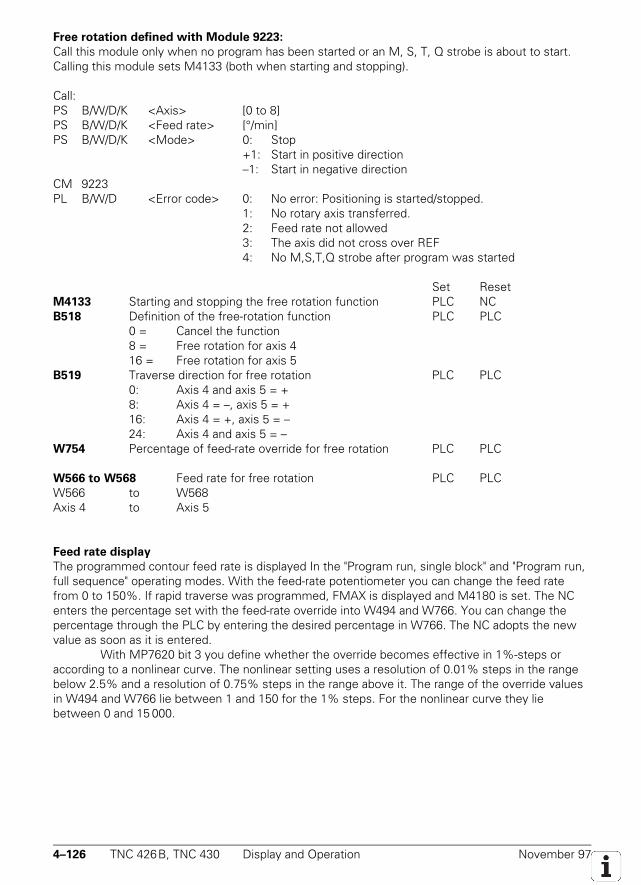
4–126 TNC 426B, TNC 430 Display and Operation November 97
Free rotation defined with Module 9223:
Call this module only when no program has been started or an M, S, T, Q strobe is about to start.Calling this module sets M4133 (both when starting and stopping).
Call:PS B/W/D/K <Axis> [0 to 8]PS B/W/D/K <Feed rate> [°/min]PS B/W/D/K <Mode> 0: Stop
+1: Start in positive direction–1: Start in negative direction
CM 9223PL B/W/D <Error code> 0: No error: Positioning is started/stopped.
1: No rotary axis transferred.2: Feed rate not allowed3: The axis did not cross over REF4: No M,S,T,Q strobe after program was started
Set ResetM4133 Starting and stopping the free rotation function PLC NCB518 Definition of the free-rotation function PLC PLC
0 = Cancel the function8 = Free rotation for axis 416 = Free rotation for axis 5
B519 Traverse direction for free rotation PLC PLC0: Axis 4 and axis 5 = +8: Axis 4 = –, axis 5 = +16: Axis 4 = +, axis 5 = –24: Axis 4 and axis 5 = –
W754 Percentage of feed-rate override for free rotation PLC PLC
W566 to W568 Feed rate for free rotation PLC PLCW566 to W568Axis 4 to Axis 5
Feed rate display
The programmed contour feed rate is displayed In the "Program run, single block" and "Program run,full sequence" operating modes. With the feed-rate potentiometer you can change the feed ratefrom 0 to 150%. If rapid traverse was programmed, FMAX is displayed and M4180 is set. The NCenters the percentage set with the feed-rate override into W494 and W766. You can change thepercentage through the PLC by entering the desired percentage in W766. The NC adopts the newvalue as soon as it is entered.
With MP7620 bit 3 you define whether the override becomes effective in 1%-steps oraccording to a nonlinear curve. The nonlinear setting uses a resolution of 0.01% steps in the rangebelow 2.5% and a resolution of 0.75% steps in the range above it. The range of the override valuesin W494 and W766 lie between 1 and 150 for the 1% steps. For the nonlinear curve they liebetween 0 and 15 000.
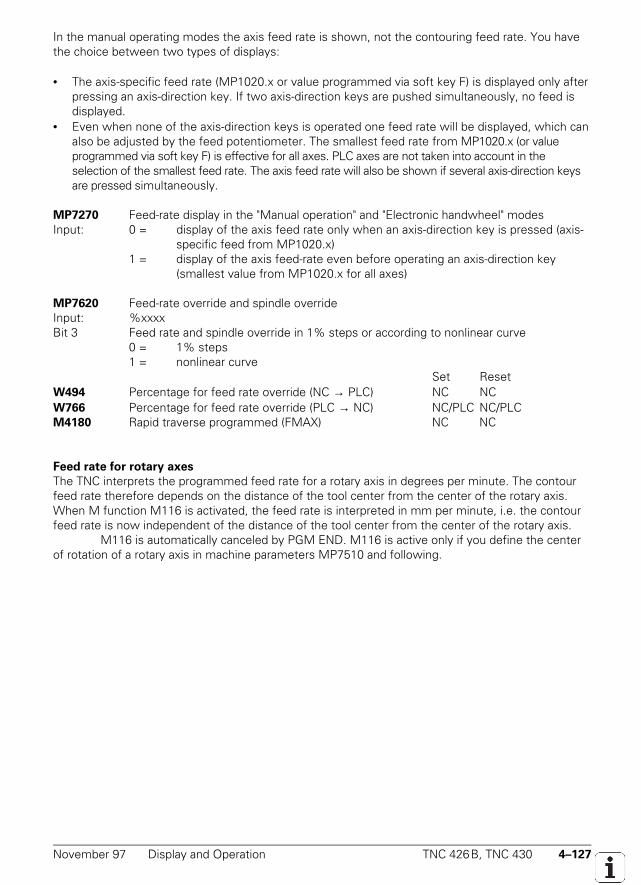
November 97 Display and Operation TNC 426B, TNC 430 4–127
In the manual operating modes the axis feed rate is shown, not the contouring feed rate. You havethe choice between two types of displays:
• The axis-specific feed rate (MP1020.x or value programmed via soft key F) is displayed only afterpressing an axis-direction key. If two axis-direction keys are pushed simultaneously, no feed isdisplayed.
• Even when none of the axis-direction keys is operated one feed rate will be displayed, which canalso be adjusted by the feed potentiometer. The smallest feed rate from MP1020.x (or valueprogrammed via soft key F) is effective for all axes. PLC axes are not taken into account in theselection of the smallest feed rate. The axis feed rate will also be shown if several axis-direction keysare pressed simultaneously.
MP7270 Feed-rate display in the "Manual operation" and "Electronic handwheel" modesInput: 0 = display of the axis feed rate only when an axis-direction key is pressed (axis-
specific feed from MP1020.x)1 = display of the axis feed-rate even before operating an axis-direction key
(smallest value from MP1020.x for all axes)
MP7620 Feed-rate override and spindle overrideInput: %xxxxBit 3 Feed rate and spindle override in 1% steps or according to nonlinear curve
0 = 1% steps1 = nonlinear curve
Set ResetW494 Percentage for feed rate override (NC → PLC) NC NCW766 Percentage for feed rate override (PLC → NC) NC/PLC NC/PLCM4180 Rapid traverse programmed (FMAX) NC NC
Feed rate for rotary axes
The TNC interprets the programmed feed rate for a rotary axis in degrees per minute. The contourfeed rate therefore depends on the distance of the tool center from the center of the rotary axis.When M function M116 is activated, the feed rate is interpreted in mm per minute, i.e. the contourfeed rate is now independent of the distance of the tool center from the center of the rotary axis.
M116 is automatically canceled by PGM END. M116 is active only if you define the centerof rotation of a rotary axis in machine parameters MP7510 and following.
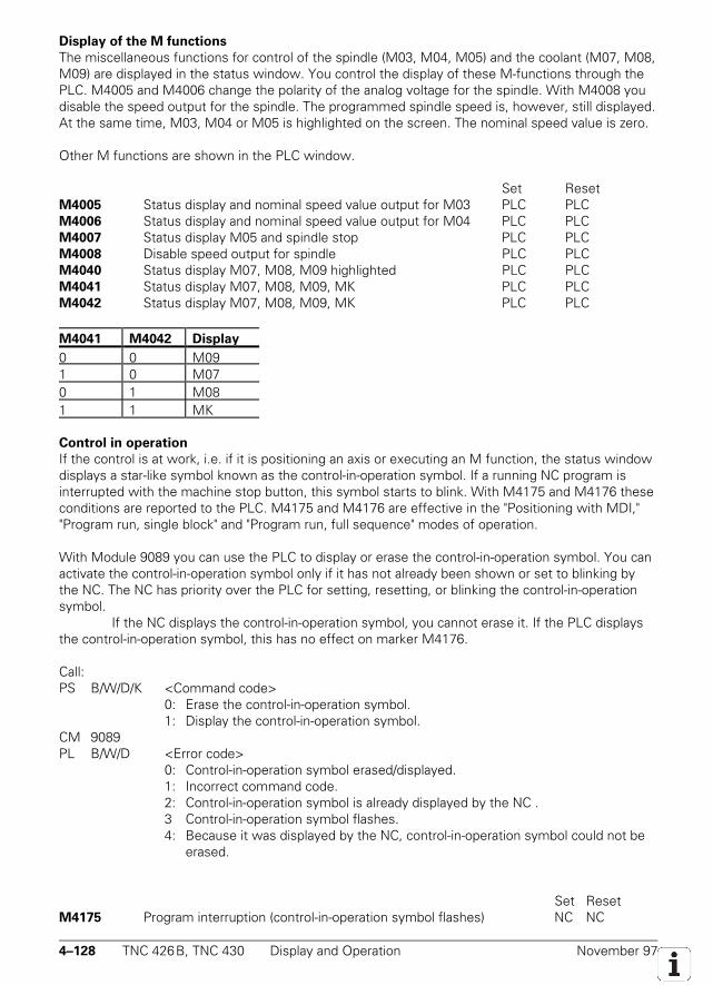
4–128 TNC 426B, TNC 430 Display and Operation November 97
Display of the M functions
The miscellaneous functions for control of the spindle (M03, M04, M05) and the coolant (M07, M08,M09) are displayed in the status window. You control the display of these M-functions through thePLC. M4005 and M4006 change the polarity of the analog voltage for the spindle. With M4008 youdisable the speed output for the spindle. The programmed spindle speed is, however, still displayed.At the same time, M03, M04 or M05 is highlighted on the screen. The nominal speed value is zero.
Other M functions are shown in the PLC window.
Set ResetM4005 Status display and nominal speed value output for M03 PLC PLCM4006 Status display and nominal speed value output for M04 PLC PLCM4007 Status display M05 and spindle stop PLC PLCM4008 Disable speed output for spindle PLC PLCM4040 Status display M07, M08, M09 highlighted PLC PLCM4041 Status display M07, M08, M09, MK PLC PLCM4042 Status display M07, M08, M09, MK PLC PLC
M4041 M4042 Display
0 0 M091 0 M070 1 M081 1 MK
Control in operation
If the control is at work, i.e. if it is positioning an axis or executing an M function, the status windowdisplays a star-like symbol known as the control-in-operation symbol. If a running NC program isinterrupted with the machine stop button, this symbol starts to blink. With M4175 and M4176 theseconditions are reported to the PLC. M4175 and M4176 are effective in the "Positioning with MDI,""Program run, single block" and "Program run, full sequence" modes of operation.
With Module 9089 you can use the PLC to display or erase the control-in-operation symbol. You canactivate the control-in-operation symbol only if it has not already been shown or set to blinking bythe NC. The NC has priority over the PLC for setting, resetting, or blinking the control-in-operationsymbol.
If the NC displays the control-in-operation symbol, you cannot erase it. If the PLC displaysthe control-in-operation symbol, this has no effect on marker M4176.
Call:PS B/W/D/K <Command code>
0: Erase the control-in-operation symbol.1: Display the control-in-operation symbol.
CM 9089PL B/W/D <Error code>
0: Control-in-operation symbol erased/displayed.1: Incorrect command code.2: Control-in-operation symbol is already displayed by the NC .3 Control-in-operation symbol flashes.4: Because it was displayed by the NC, control-in-operation symbol could not be
erased.
Set ResetM4175 Program interruption (control-in-operation symbol flashes) NC NC
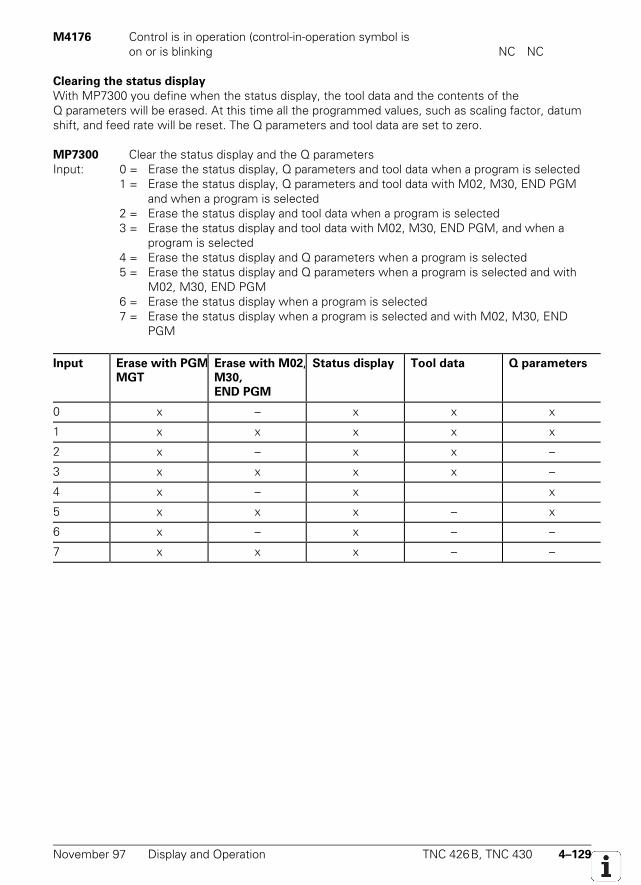
November 97 Display and Operation TNC 426B, TNC 430 4–129
M4176 Control is in operation (control-in-operation symbol ison or is blinking NC NC
Clearing the status display
With MP7300 you define when the status display, the tool data and the contents of theQ parameters will be erased. At this time all the programmed values, such as scaling factor, datumshift, and feed rate will be reset. The Q parameters and tool data are set to zero.
MP7300 Clear the status display and the Q parametersInput: 0 = Erase the status display, Q parameters and tool data when a program is selected
1 = Erase the status display, Q parameters and tool data with M02, M30, END PGMand when a program is selected
2 = Erase the status display and tool data when a program is selected3 = Erase the status display and tool data with M02, M30, END PGM, and when a
program is selected4 = Erase the status display and Q parameters when a program is selected5 = Erase the status display and Q parameters when a program is selected and with
M02, M30, END PGM6 = Erase the status display when a program is selected7 = Erase the status display when a program is selected and with M02, M30, END
PGM
Input Erase with PGM
MGT
Erase with M02,
M30,
END PGM
Status display Tool data Q parameters
0 x – x x x
1 x x x x x
2 x – x x –
3 x x x x –
4 x – x x
5 x x x – x
6 x – x – –
7 x x x – –
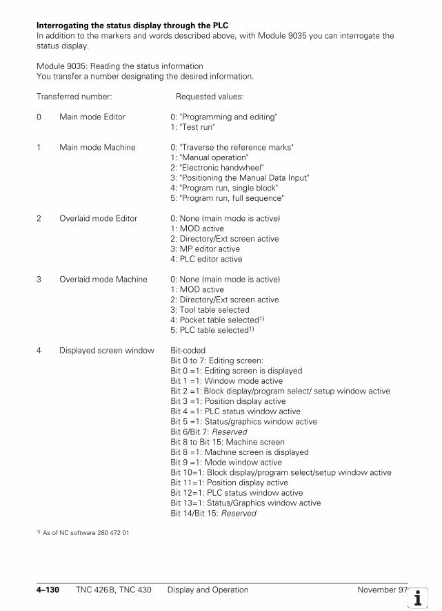
4–130 TNC 426B, TNC 430 Display and Operation November 97
Interrogating the status display through the PLC
In addition to the markers and words described above, with Module 9035 you can interrogate thestatus display.
Module 9035: Reading the status informationYou transfer a number designating the desired information.
Transferred number: Requested values:
0 Main mode Editor 0: "Programming and editing"1: "Test run"
1 Main mode Machine 0: "Traverse the reference marks"1: "Manual operation"2: "Electronic handwheel"3: "Positioning the Manual Data Input"4: "Program run, single block"5: "Program run, full sequence"
2 Overlaid mode Editor 0: None (main mode is active)1: MOD active2: Directory/Ext screen active3: MP editor active4: PLC editor active
3 Overlaid mode Machine 0: None (main mode is active)1: MOD active2: Directory/Ext screen active3: Tool table selected4: Pocket table selected1)
5: PLC table selected1)
4 Displayed screen window Bit-codedBit 0 to 7: Editing screen:Bit 0 =1: Editing screen is displayedBit 1 =1: Window mode activeBit 2 =1: Block display/program select/ setup window activeBit 3 =1: Position display activeBit 4 =1: PLC status window activeBit 5 =1: Status/graphics window activeBit 6/Bit 7: ReservedBit 8 to Bit 15: Machine screenBit 8 =1: Machine screen is displayedBit 9 =1: Mode window activeBit 10=1: Block display/program select/setup window activeBit 11=1: Position display activeBit 12=1: PLC status window activeBit 13=1: Status/Graphics window activeBit 14/Bit 15: Reserved
1) As of NC software 280 472 01
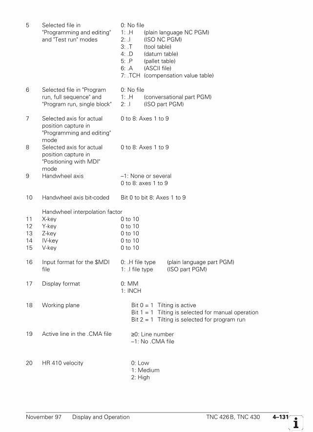
November 97 Display and Operation TNC 426B, TNC 430 4–131
5 Selected file in"Programming and editing"and "Test run" modes
0: No file1: .H (plain language NC PGM)2: .I (ISO NC PGM)3: .T (tool table)4: .D (datum table)5: .P (pallet table)6: .A (ASCII file)7: .TCH (compensation value table)
6 Selected file in "Programrun, full sequence" and"Program run, single block"
0: No file1: .H (conversational part PGM)2: .I (ISO part PGM)
7 Selected axis for actualposition capture in"Programming and editing"mode
0 to 8: Axes 1 to 9
8 Selected axis for actualposition capture in"Positioning with MDI"mode
0 to 8: Axes 1 to 9
9 Handwheel axis –1: None or several0 to 8: axes 1 to 9
10 Handwheel axis bit-coded Bit 0 to bit 8: Axes 1 to 9
Handwheel interpolation factor11 X-key 0 to 1012 Y-key 0 to 1013 Z-key 0 to 1014 IV-key 0 to 1015 V-key 0 to 10
16 Input format for the $MDIfile
0: .H file type (plain language part PGM)1: .I file type (ISO part PGM)
17 Display format 0: MM1: INCH
18 Working plane Bit 0 = 1 Tilting is activeBit 1 = 1 Tilting is selected for manual operationBit 2 = 1 Tilting is selected for program run
19 Active line in the .CMA file ≥0: Line number–1: No .CMA file
20 HR 410 velocity 0: Low1: Medium2: High
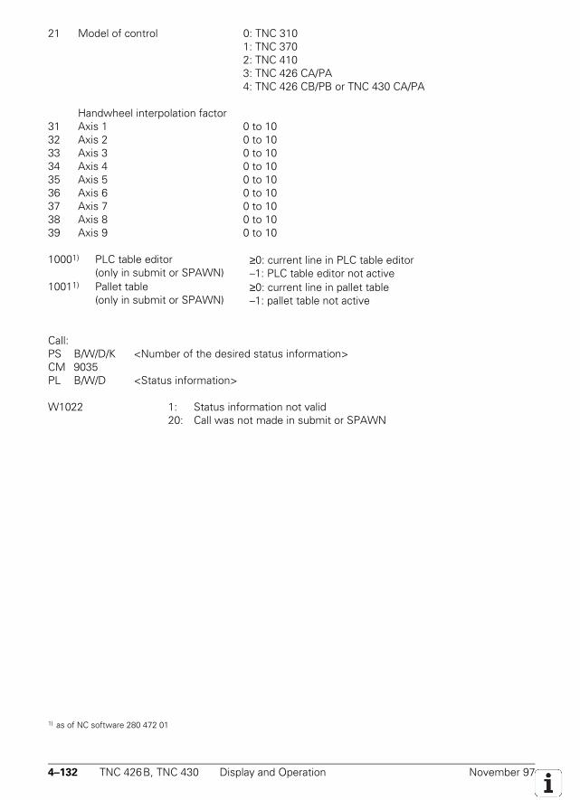
4–132 TNC 426B, TNC 430 Display and Operation November 97
21 Model of control 0: TNC 3101: TNC 3702: TNC 4103: TNC 426 CA/PA4: TNC 426 CB/PB or TNC 430 CA/PA
Handwheel interpolation factor31 Axis 1 0 to 1032 Axis 2 0 to 1033 Axis 3 0 to 1034 Axis 4 0 to 1035 Axis 5 0 to 1036 Axis 6 0 to 1037 Axis 7 0 to 1038 Axis 8 0 to 1039 Axis 9 0 to 10
10001) PLC table editor(only in submit or SPAWN)
≥0: current line in PLC table editor–1: PLC table editor not active
10011) Pallet table(only in submit or SPAWN)
≥0: current line in pallet table–1: pallet table not active
Call:PS B/W/D/K <Number of the desired status information>CM 9035PL B/W/D <Status information>
W1022 1: Status information not valid20: Call was not made in submit or SPAWN
1) as of NC software 280 472 01
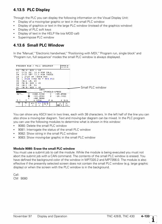
November 97 Display and Operation TNC 426B, TNC 430 4–133
4.13.5 PLC Display
Through the PLC you can display the following information on the Visual Display Unit:• Display of a moving-bar graphic or text in the small PLC window• Display of graphics or text in the large PLC window (instead of the graphics window)• Display of PLC soft keys• Display of text in the HELP file (via MOD call)• Superimpose PLC window
4.13.6 Small PLC Window
In the "Manual," "Electronic handwheel," "Positioning with MDI," "Program run, single block" and"Program run, full sequence" modes the small PLC window is always displayed.
You can show any ASCII text in two lines, each with 38 characters. In the left half of the line you canalso show a moving-bar diagram. Text and moving-bar diagram can be mixed. In the PLC programyou can use the following modules to determine what is shown in this window:• 9080: Delete the small PLC window• 9081: Interrogate the status of the small PLC window• 9082: Show string in the small PLC window• 9083: Show moving-bar graphic in the small PLC window
Module 9080: Erase the small PLC window
You must use a submit job to call the module. While the module is being executed you must notabort the submit job with a CAN command. The contents of the small PLC window is erased. Youhave defined the background color of the window in MP7320.2 and MP7356.0. The module is alsoeffective if the presently selected screen does not contain the small PLC window (e.g. large graphicdisplay) or when the screen with the PLC window is in the background.
Call:CM 9080
Small PLC window
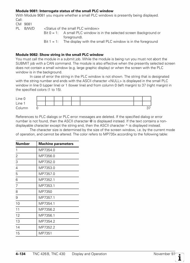
4–134 TNC 426B, TNC 430 Display and Operation November 97
Module 9081: Interrogate status of the small PLC window
With Module 9081 you inquire whether a small PLC windows is presently being displayed.Call:CM 9081PL B/W/D <Status of the small PLC window>
Bit 0 = 1: A small PLC window is in the selected screen (background orforeground).
Bit 1 = 1: The display with the small PLC window is in the foreground
Module 9082: Show string in the small PLC window
You must call the module in a submit job. While the module is being run you must not abort theSUBMIT job with a CAN command. The module is also effective when the presently selected screendoes not contain a small window (e.g. large graphic display) or when the screen with the PLCwindow is in the background.
In case of error the string in the PLC window is not shown. The string that is designatedwith the string number and ends with the ASCII character <NULL> is displayed in the small PLCwindow in line 0 (upper line) or 1 (lower line) and from column 0 (left margin) to 37 (right margin) inthe specified colors (1 to 15).
Line 0Line 1Column 0 37
References to PLC dialogs or PLC error messages are deleted. If the specified dialog or errornumber is not found, then the ASCII character @ is displayed instead. If the text contains a non-displayable character except the string end, then the ASCII character ^ is displayed instead.
The character size is determined by the size of the screen window, i.e. by the current modeof operation, and cannot be altered. The color refers to MP735x according to the following table:
Number Machine parameters
1 MP7354.0
2 MP7356.0
3 MP7352.0
4 MP7353.0
5 MP7357.0
6 MP7352.1
7 MP7353.1
8 MP7350
9 MP7357.1
10 MP7354.1
11 MP7356.2
12 MP7356.1
13 MP7354.2
14 MP7352.2
15 MP7351
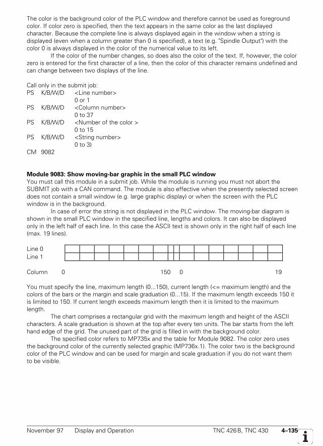
November 97 Display and Operation TNC 426B, TNC 430 4–135
The color is the background color of the PLC window and therefore cannot be used as foregroundcolor. If color zero is specified, then the text appears in the same color as the last displayedcharacter. Because the complete line is always displayed again in the window when a string isdisplayed (even when a column greater than 0 is specified), a text (e.g. "Spindle Output") with thecolor 0 is always displayed in the color of the numerical value to its left.
If the color of the number changes, so does also the color of the text. If, however, the colorzero is entered for the first character of a line, then the color of this character remains undefined andcan change between two displays of the line.
Call only in the submit job:PS K/B/W/D <Line number>
0 or 1PS K/B/W/D <Column number>
0 to 37PS K/B/W/D <Number of the color >
0 to 15PS K/B/W/D <String number>
0 to 3)CM 9082
Module 9083: Show moving-bar graphic in the small PLC window
You must call this module in a submit job. While the module is running you must not abort theSUBMIT job with a CAN command. The module is also effective when the presently selected screendoes not contain a small window (e.g. large graphic display) or when the screen with the PLCwindow is in the background.
In case of error the string is not displayed in the PLC window. The moving-bar diagram isshown in the small PLC window in the specified line, lengths and colors. It can also be displayedonly in the left half of each line. In this case the ASCII text is shown only in the right half of each line(max. 19 lines).
Line 0Line 1
Column 0 150 0 19
You must specify the line, maximum length (0...150), current length (<= maximum length) and thecolors of the bars or the margin and scale graduation (0...15). If the maximum length exceeds 150 itis limited to 150. If current length exceeds maximum length then it is limited to the maximumlength.
The chart comprises a rectangular grid with the maximum length and height of the ASCIIcharacters. A scale graduation is shown at the top after every ten units. The bar starts from the lefthand edge of the grid. The unused part of the grid is filled in with the background color.
The specified color refers to MP735x and the table for Module 9082. The color zero usesthe background color of the currently selected graphic (MP736x.1). The color two is the backgroundcolor of the PLC window and can be used for margin and scale graduation if you do not want themto be visible.
4–136 TNC 426B, TNC 430 Display and Operation November 97
Call only in the submit job:PS K/B/W/D <Line number>
0 or 1PS K/B/W/D <Color of bar >
0 to 15PS K/B/W/D <Color of margin and scale graduation >
0 to 15PS K/B/W/D <Current length of bar>
0 to 150PS K/B/W/D <Maximum length of bar>
0 to 150CM 9083
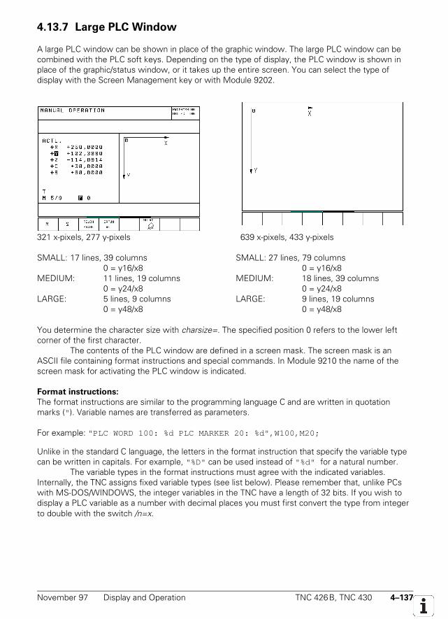
November 97 Display and Operation TNC 426B, TNC 430 4–137
4.13.7 Large PLC Window
A large PLC window can be shown in place of the graphic window. The large PLC window can becombined with the PLC soft keys. Depending on the type of display, the PLC window is shown inplace of the graphic/status window, or it takes up the entire screen. You can select the type ofdisplay with the Screen Management key or with Module 9202.
321 x-pixels, 277 y-pixels 639 x-pixels, 433 y-pixels
SMALL: 17 lines, 39 columns SMALL: 27 lines, 79 columns0 = y16/x8 0 = y16/x8
MEDIUM: 11 lines, 19 columns MEDIUM: 18 lines, 39 columns0 = y24/x8 0 = y24/x8
LARGE: 5 lines, 9 columns LARGE: 9 lines, 19 columns0 = y48/x8 0 = y48/x8
You determine the character size with charsize=. The specified position 0 refers to the lower leftcorner of the first character.
The contents of the PLC window are defined in a screen mask. The screen mask is anASCII file containing format instructions and special commands. In Module 9210 the name of thescreen mask for activating the PLC window is indicated.
Format instructions:
The format instructions are similar to the programming language C and are written in quotationmarks (" ). Variable names are transferred as parameters.
For example: "PLC WORD 100: %d PLC MARKER 20: %d",W100,M20;
Unlike in the standard C language, the letters in the format instruction that specify the variable typecan be written in capitals. For example, "%D" can be used instead of "%d" for a natural number.
The variable types in the format instructions must agree with the indicated variables.Internally, the TNC assigns fixed variable types (see list below). Please remember that, unlike PCswith MS-DOS/WINDOWS, the integer variables in the TNC have a length of 32 bits. If you wish todisplay a PLC variable as a number with decimal places you must first convert the type from integerto double with the switch /n=x.
4–138 TNC 426B, TNC 430 Display and Operation November 97
Special characters:
"\n" (Newline) moves the cursor to the left edge and downward by the distance set or preset inLINEDIST .
"\f" (Form feed) has the same effect as "\n" but also inserts a page break when the cursormoves past this special character (otherwise the window is scrolled).
Variable names:
B0 to B4095 PLC bytes integerW0 to W4094 PLC words integerD0 to D4092 PLC doublewords integerM0 to M4999 PLC marker integer 0/1I0 to I383 PLC inputs integer 0/1O0 to O191 PLC outputs integer 0/1T0 to T96 PLC timer integer 0/1C0 to C143 PLC counter integer 0/1S0 to S3 PLC strings char[128]S#D0 to S#D999 PLC dialogs char*S#E0 to S#E999 PLC error texts char*TIME[0] to TIME[15 ] System time as in Module 9055 char*AXISCHAR[0] to AXISCHAR[4] Letter for NC axis charMP to .. Machine parameters, format: "MP910.1"
Input value: Decimal places doubleHex or binary integerText char*
Time:HOUR int Number of hours from the real-time clockMIN int Number of minutes from the real-time clockSEC int Number of seconds from the real-time clockDAY int Day from the real-time clockMONTH int Month as number from the real-time clockSTR_MONTH string Month as string abbreviation from the real-time clockYEAR2 int Two-digit year two digits from the real-time clockYEAR4 int Four digit year from the real-time clock
Settings for the tool touch probe:TT.RAD double Calibrated radius TTTT.CENTER[3 ] double Calibrated center TTTT.PNT1[3 ] double Calibrated touch point 0 TTTT.PNT2[3] double Calibrated touch point 1 TTTT.PNT3[3 ] double Calibrated touch point 2 TTTT.PNT4[3] double Calibrated touch point 3 TT
Settings for RS-232:RS232.FEBAUD string Baud rate FE on RS-232RS232.EXT1BAUD string Baud rate EXT 1 on RS-232RS232.EXT2BAUD string Baud rate EXT 2 on RS-232RS232.LSV2BAUD string Baud rate LSV2 on RS-232RS232.MODE string RS-232 mode
November 97 Display and Operation TNC 426B, TNC 430 4–139
Settings for RS422:RS422.FEBAUD string Baud rate FE on RS422RS422.EXT1BAUD string Baud rate EXT 1 on RS422RS422.EXT2BAUD string Baud rate EXT 2 on RS422RS422.LSV2BAUD string Baud rate LSV2 on RS422RS422.MODE string RS422 mode
Settings for simulation:SIMU.ENAPRESET string Preset enableSIMU.ENALIMIT string Limit switch enableSIMU.LIMITPL[5] double Positive Limit switchesSIMU.LIMITMI[5] double Negative limit switchesSIMU.PRESET[5] double Preset values
Settings for machine:MACHINE.LIMIT1PL[5] double Positive limit-switch set 1MACHINE.LIMIT1MI[5] double Negative limit-switch set 1MACHINE.LIMIT2PL[5] double Positive limit-switch set 2MACHINE.LIMIT2MI[5] double Negative limit-switch set 2MACHINE.LIMIT3PL[5] double Positive limit-switch set 3MACHINE.LIMIT3MI[5] double Negative limit-switch set 3MACHINE.PRESET1[5] double Preset values 1MACHINE.PRESET2[5] double Preset values 2MACHINE.PRESET3[5] double Preset values 3MACHINE.POSINC doubleMACHINE.DRVOFFSET[5] doubleMACHINE.HANDW_FACTOR[5] double Handwheel interpolation factor
Settings for transformation of the machine reference system:MATRANS.PRESX1_ABC[3] doubleMATRANS.PRESY1_ABC[3] doubleMATRANS.PRESZ1_ABC[3] doubleMATRANS.PRESAXIS1 stringMATRANS.PRESX2_ABC[3] doubleMATRANS.PRESY2_ABC[3] doubleMATRANS.PRESZ2_ABC[3] doubleMATRANS.PRESAXIS2C[3] doubleMATRANS.PRESZ3_ABC[3] doubleMATRANS.PRESAXIS3 stringMATRANS.TRLPRES1[6] doubleMATRANS.TRLPRES2[6] doubleMATRANS.TRLPRES3[6] doubleMATRANS.MANUAL stringMATRANS.PGMRUN stringMATRANS.ANGLE[3] double
Settings for display:DISPLAY.AXIS1 stringDISPLAY.AXIS2 stringDISPLAY.SCREEN intDISPLAY.FORMAT string MM/INCH switchover
4–140 TNC 426B, TNC 430 Display and Operation November 97
Settings for oscilloscope:OSC.AXIS stringOSC.TIMEBASE stringOSC.MODE stringOSC.TRGCHAN stringOSC.TRGTHRES doubleOSC.SLOPE stringOSC.PRETRIG stringOSC.FEED double
Miscellaneous:MISC.MDI stringMISC.OUTPRECISION stringMISC.TEACHINAXIS int
Switches for variables:
/n=x for B/W/D; reformats the integer into a floating comma number with x decimal points. Thisswitch is always needed, for example, when a position (in the format 0.1 µm) must be shownin millimeters.
/mi for B/W/D; reformats the number as an inch expression when the inch conversion is active./e for B/W/D/M/S; editable field: The original content of the variable is shown and can be
changed. You must define the field length in the format string./i for B/W/D/M/S; Entry field: A value can be entered in the field, which is empty at first. You
must define the field length in the format string./c for B/W/D/M/S/TIME; The field content is cyclically updated. The field length should be
defined in the format string, since otherwise the following text could be overwritten if thefield length changes due to a change in the numerical value.
Special commands:
/*<comment>*/ You can enter any comment between the two stars.MMINCH variables that contain a position value (or /mi switch) are converted and displayed in
inches, provided that this was selected under Mode. The default setting is "noconversion."
POS=xpix,ypixWrite the next text or graphic at the designated position (xpix = distance in pixels fromthe upper edge of the current page, ypix = distance in pixels from the left edge of thewindow). The default setting is to begin writing at the upper edge and then line by line.
IPOS=xpix,ypixWrite the next text or graphic shifted by the indicated number of pixels from the currentposition (xpix = distance in pixels from the current x position, ypix = distance in pixelsfrom the current y position).
CPOS=column, lineWrite the next text or graphic at the designated position (line = line on the currentpage, column = column from the left edge of the window). The width of a column iscalculated from the current character set; the height of a line is preset and can bechanged with LINEDIST .
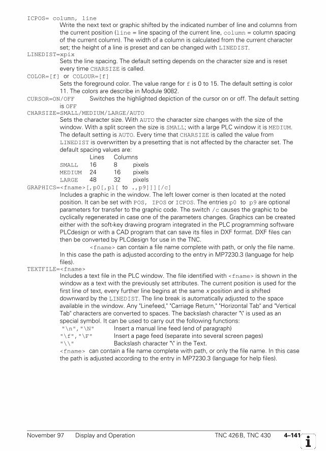
November 97 Display and Operation TNC 426B, TNC 430 4–141
ICPOS= column, lineWrite the next text or graphic shifted by the indicated number of line and columns fromthe current position (line = line spacing of the current line, column = column spacingof the current column). The width of a column is calculated from the current characterset; the height of a line is preset and can be changed with LINEDIST .
LINEDIST=xpixSets the line spacing. The default setting depends on the character size and is resetevery time CHARSIZE is called.
COLOR=[f] or COLOUR=[f]Sets the foreground color. The value range for f is 0 to 15. The default setting is color11. The colors are describe in Module 9082.
CURSOR=ON/OFF Switches the highlighted depiction of the cursor on or off. The default settingis OFF
CHARSIZE=SMALL/MEDIUM/LARGE/AUTOSets the character size. With AUTO the character size changes with the size of thewindow. With a split screen the size is SMALL; with a large PLC window it is MEDIUM.The default setting is AUTO. Every time that CHARSIZE is called the value fromLINEDIST is overwritten by a presetting that is not affected by the character set. Thedefault spacing values are:
Lines ColumnsSMALL 16 8 pixelsMEDIUM 24 16 pixelsLARGE 48 32 pixels
GRAPHICS=<fname>[,p0[,p1[ to .,p9]]][/c]Includes a graphic in the window. The left lower corner is then located at the notedposition. It can be set with POS, IPOS or ICPOS. The entries p0 to p9 are optionalparameters for transfer to the graphic code. The switch /c causes the graphic to becyclically regenerated in case one of the parameters changes. Graphics can be createdeither with the soft-key drawing program integrated in the PLC programming softwarePLCdesign or with a CAD program that can save its files in DXF format. DXF files canthen be converted by PLCdesign for use in the TNC.
<fname> can contain a file name complete with path, or only the file name.In this case the path is adjusted according to the entry in MP7230.3 (language for helpfiles).
TEXTFILE=<fname>Includes a text file in the PLC window. The file identified with <fname> is shown in thewindow as a text with the previously set attributes. The current position is used for thefirst line of text, every further line begins at the same x position and is shifteddownward by the LINEDIST . The line break is automatically adjusted to the spaceavailable in the window. Any "Linefeed," "Carriage Return," "Horizontal Tab" and "VerticalTab" characters are converted to spaces. The backslash character "\" is used as anspecial symbol. It can be used to carry out the following functions: "\n","\N" Insert a manual line feed (end of paragraph)"\f","\F" Insert a page feed (separate into several screen pages)"\\" Backslash character "\" in the Text.<fname> can contain a file name complete with path, or only the file name. In this casethe path is adjusted according to the entry in MP7230.3 (language for help files).
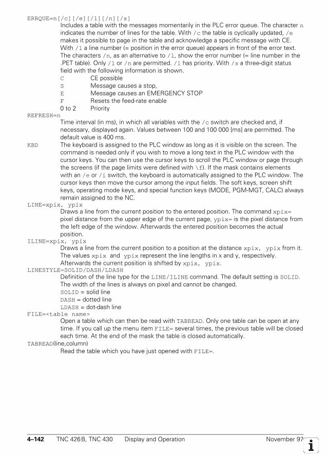
4–142 TNC 426B, TNC 430 Display and Operation November 97
ERRQUE=n[/c][/e][/l][/n][/s]Includes a table with the messages momentarily in the PLC error queue. The character nindicates the number of lines for the table. With /c the table is cyclically updated, /emakes it possible to page in the table and acknowledge a specific message with CE.With /l a line number (= position in the error queue) appears in front of the error text.The characters /n , as an alternative to /l , show the error number (= line number in the.PET table). Only /l or /n are permitted. /l has priority. With /s a three-digit statusfield with the following information is shown.C CE possibleS Message causes a stop,E Message causes an EMERGENCY STOPF Resets the feed-rate enable0 to 2 Priority
REFRESH=nTime interval (in ms), in which all variables with the /c switch are checked and, ifnecessary, displayed again. Values between 100 and 100 000 [ms] are permitted. Thedefault value is 400 ms.
KBD The keyboard is assigned to the PLC window as long as it is visible on the screen. Thecommand is needed only if you wish to move a long text in the PLC window with thecursor keys. You can then use the cursor keys to scroll the PLC window or page throughthe screens (if the page limits were defined with \f ). If the mask contains elementswith an /e or /i switch, the keyboard is automatically assigned to the PLC window. Thecursor keys then move the cursor among the input fields. The soft keys, screen shiftkeys, operating mode keys, and special function keys (MODE, PGM-MGT, CALC) alwaysremain assigned to the NC.
LINE=xpix, ypixDraws a line from the current position to the entered position. The command xpix=pixel distance from the upper edge of the current page, ypix= is the pixel distance fromthe left edge of the window. Afterwards the entered position becomes the actualposition.
ILINE=xpix, ypixDraws a line from the current position to a position at the distance xpix, ypix from it.The values xpix and ypix represent the line lengths in x and y, respectively.Afterwards the current position is shifted by xpix, ypix .
LINESTYLE=SOLID/DASH/LDASHDefinition of the line type for the LINE/ILINE command. The default setting is SOLID.The width of the lines is always on pixel and cannot be changed.SOLID = solid lineDASH = dotted lineLDASH = dot-dash line
FILE=<table name>Open a table which can then be read with TABREAD. Only one table can be open at anytime. If you call up the menu item FILE= several times, the previous table will be closedeach time. At the end of the mask the table is closed automatically.
TABREAD(line,column)Read the table which you have just opened with FILE= .
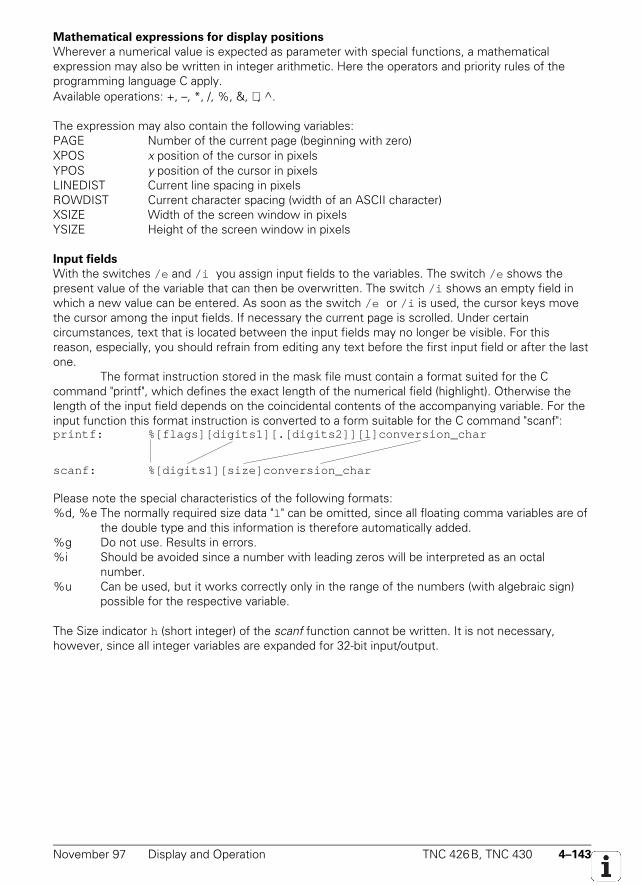
November 97 Display and Operation TNC 426B, TNC 430 4–143
Mathematical expressions for display positions
Wherever a numerical value is expected as parameter with special functions, a mathematicalexpression may also be written in integer arithmetic. Here the operators and priority rules of theprogramming language C apply.Available operations: +, –, *, /, %, &, , ^.
The expression may also contain the following variables:PAGE Number of the current page (beginning with zero)XPOS x position of the cursor in pixelsYPOS y position of the cursor in pixelsLINEDIST Current line spacing in pixelsROWDIST Current character spacing (width of an ASCII character)XSIZE Width of the screen window in pixelsYSIZE Height of the screen window in pixels
Input fields
With the switches /e and /i you assign input fields to the variables. The switch /e shows thepresent value of the variable that can then be overwritten. The switch /i shows an empty field inwhich a new value can be entered. As soon as the switch /e or /i is used, the cursor keys movethe cursor among the input fields. If necessary the current page is scrolled. Under certaincircumstances, text that is located between the input fields may no longer be visible. For thisreason, especially, you should refrain from editing any text before the first input field or after the lastone.
The format instruction stored in the mask file must contain a format suited for the Ccommand "printf", which defines the exact length of the numerical field (highlight). Otherwise thelength of the input field depends on the coincidental contents of the accompanying variable. For theinput function this format instruction is converted to a form suitable for the C command "scanf":printf: %[flags][digits1][.[digits2]][l]conversion_char
scanf: %[digits1][size]conversion_char
Please note the special characteristics of the following formats:%d, %e The normally required size data "l " can be omitted, since all floating comma variables are of
the double type and this information is therefore automatically added.%g Do not use. Results in errors.%i Should be avoided since a number with leading zeros will be interpreted as an octal
number.%u Can be used, but it works correctly only in the range of the numbers (with algebraic sign)
possible for the respective variable.
The Size indicator h (short integer) of the scanf function cannot be written. It is not necessary,however, since all integer variables are expanded for 32-bit input/output.
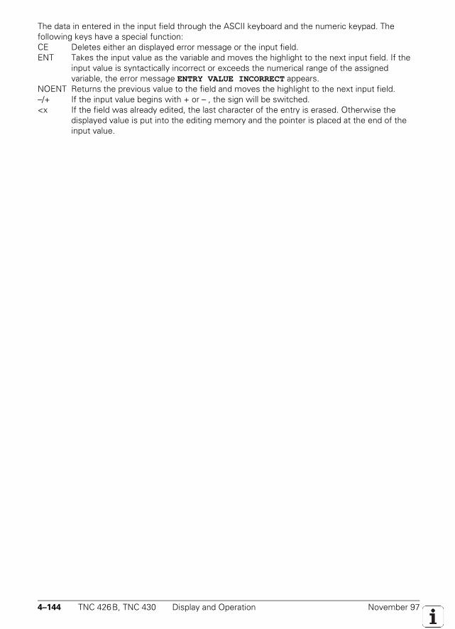
4–144 TNC 426B, TNC 430 Display and Operation November 97
The data in entered in the input field through the ASCII keyboard and the numeric keypad. Thefollowing keys have a special function:CE Deletes either an displayed error message or the input field.ENT Takes the input value as the variable and moves the highlight to the next input field. If the
input value is syntactically incorrect or exceeds the numerical range of the assignedvariable, the error message ENTRY VALUE INCORRECT appears.
NOENT Returns the previous value to the field and moves the highlight to the next input field.–/+ If the input value begins with + or – , the sign will be switched.<x If the field was already edited, the last character of the entry is erased. Otherwise the
displayed value is put into the editing memory and the pointer is placed at the end of theinput value.
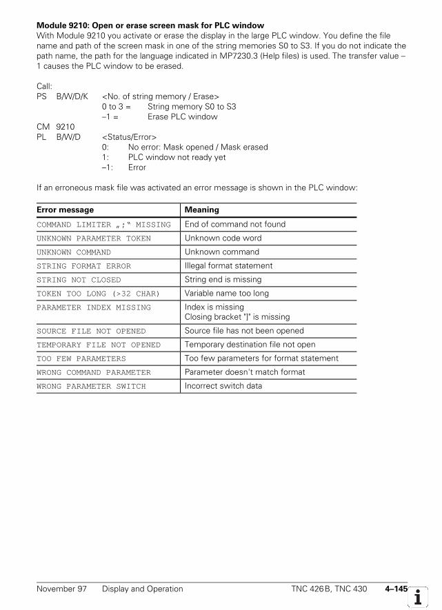
November 97 Display and Operation TNC 426B, TNC 430 4–145
Module 9210: Open or erase screen mask for PLC window
With Module 9210 you activate or erase the display in the large PLC window. You define the filename and path of the screen mask in one of the string memories S0 to S3. If you do not indicate thepath name, the path for the language indicated in MP7230.3 (Help files) is used. The transfer value –1 causes the PLC window to be erased.
Call:PS B/W/D/K <No. of string memory / Erase>
0 to 3 = String memory S0 to S3–1 = Erase PLC window
CM 9210PL B/W/D <Status/Error>
0: No error: Mask opened / Mask erased1: PLC window not ready yet–1: Error
If an erroneous mask file was activated an error message is shown in the PLC window:
Error message Meaning
COMMAND LIMITER „;“ MISSING End of command not found
UNKNOWN PARAMETER TOKEN Unknown code word
UNKNOWN COMMAND Unknown command
STRING FORMAT ERROR Illegal format statement
STRING NOT CLOSED String end is missing
TOKEN TOO LONG (>32 CHAR) Variable name too long
PARAMETER INDEX MISSING Index is missingClosing bracket "]" is missing
SOURCE FILE NOT OPENED Source file has not been opened
TEMPORARY FILE NOT OPENED Temporary destination file not open
TOO FEW PARAMETERS Too few parameters for format statement
WRONG COMMAND PARAMETER Parameter doesn't match format
WRONG PARAMETER SWITCH Incorrect switch data
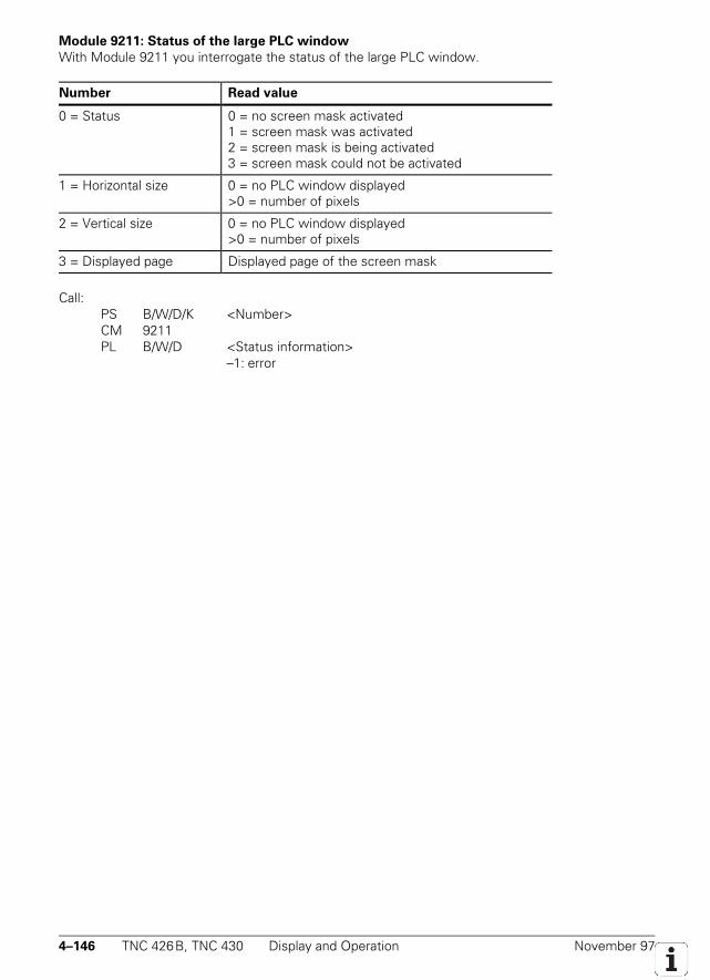
4–146 TNC 426B, TNC 430 Display and Operation November 97
Module 9211: Status of the large PLC window
With Module 9211 you interrogate the status of the large PLC window.
Number Read value
0 = Status 0 = no screen mask activated1 = screen mask was activated2 = screen mask is being activated3 = screen mask could not be activated
1 = Horizontal size 0 = no PLC window displayed>0 = number of pixels
2 = Vertical size 0 = no PLC window displayed>0 = number of pixels
3 = Displayed page Displayed page of the screen mask
Call:PS B/W/D/K <Number>CM 9211PL B/W/D <Status information>
–1: error

November 97 Display and Operation TNC 426B, TNC 430 4–147

4–148 TNC 426B, TNC 430 Display and Operation November 97

November 97 Display and Operation TNC 426B, TNC 430 4–149
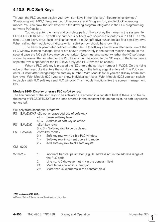
4–150 TNC 426B, TNC 430 Display and Operation November 97
4.13.8 PLC Soft Keys
Through the PLC you can display your own soft keys in the "Manual," "Electronic handwheel,""Positioning with MDI," "Program run, full sequence" and "Program run, single block" operatingmodes. You can draw the soft keys with the drawing program integrated in the PLC programmingsoftware PLCdesign.
You must enter the name and complete path of the soft-key file names in the system filePLC:\ PLCSOFTK.SYS. The soft-key number is defined with sequence of entries in PLCSOFTK.SYS(line 0 = soft key 0 etc.). Each level can contain up to 32 soft keys, which equals four soft-key rows.When calling the module you indicate which soft-key row should be shown first.
The transfer parameter defines whether the PLC soft keys are shown after selection of thePLC window (screen manager key) or are shown immediately in the current machine mode. In thesecond case the NC soft keys may be overwritten (you must also select whether the NC soft keysshould be overwritten or whether the PLC keys should be added to the NC keys. In the latter case aseparate row is opened for the PLC keys. Only one PLC row can be added).
When a PLC soft key is pressed the NC enters the soft-key number in W302. On the risingedge of the keystroke it enters the soft-key number; on the falling edge it enters –1. The PLC canenter –1 itself after recognizing the soft-key number. With Module 9200 you can display entire soft-key rows. With Module 9201 you can show individual soft keys. With Module 9202 you can switchto display with PLC soft keys and PLC window. This module functions like the screen managementkey.
Module 9200: Display or erase PLC soft-key row
The line number of the soft keys to be activated are entered in a constant field. If there is no file bythe name of PLCSOFTK.SYS or the lines entered in the constant field do not exist, no soft-key row isgenerated.
Call only from sequential program:PS B/W/D/K/KF <Select or erase address of soft key>
–1 = Erase soft-key levelKF = Address of soft-key selection
PS B/W/D/K <Soft-key row>0 to 3 = Soft-key row to be displayed
PS B/W/D/K <Soft-key mode>0 = Soft-key row with visible PLC window1 = Soft-key row in current operating mode2 = Add soft-key row to NC soft keys1)
CM 9200
W1022 = 1: Incorrect transfer parameter (e.g. KF address not in the address range ofthe PLC code
2: Line no. < 0 (however not –1) in the constant field24: Module was called in submit job25: More than 32 elements in the constant field
1)NC software 280 470 ..
NC and PLC soft keys cannot be displayed together
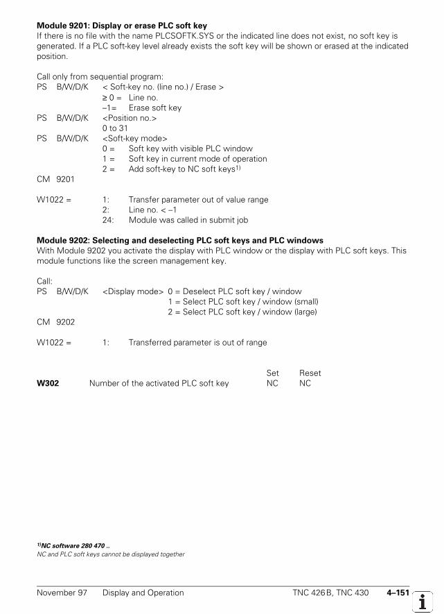
November 97 Display and Operation TNC 426B, TNC 430 4–151
Module 9201: Display or erase PLC soft key
If there is no file with the name PLCSOFTK.SYS or the indicated line does not exist, no soft key isgenerated. If a PLC soft-key level already exists the soft key will be shown or erased at the indicatedposition.
Call only from sequential program:PS B/W/D/K < Soft-key no. (line no.) / Erase >
≥ 0 = Line no.–1= Erase soft key
PS B/W/D/K <Position no.>0 to 31
PS B/W/D/K <Soft-key mode>0 = Soft key with visible PLC window1 = Soft key in current mode of operation2 = Add soft-key to NC soft keys1)
CM 9201
W1022 = 1: Transfer parameter out of value range2: Line no. < –124: Module was called in submit job
Module 9202: Selecting and deselecting PLC soft keys and PLC windows
With Module 9202 you activate the display with PLC window or the display with PLC soft keys. Thismodule functions like the screen management key.
Call:PS B/W/D/K <Display mode> 0 = Deselect PLC soft key / window
1 = Select PLC soft key / window (small)2 = Select PLC soft key / window (large)
CM 9202
W1022 = 1: Transferred parameter is out of range
Set ResetW302 Number of the activated PLC soft key NC NC
1)NC software 280 470 ..
NC and PLC soft keys cannot be displayed together
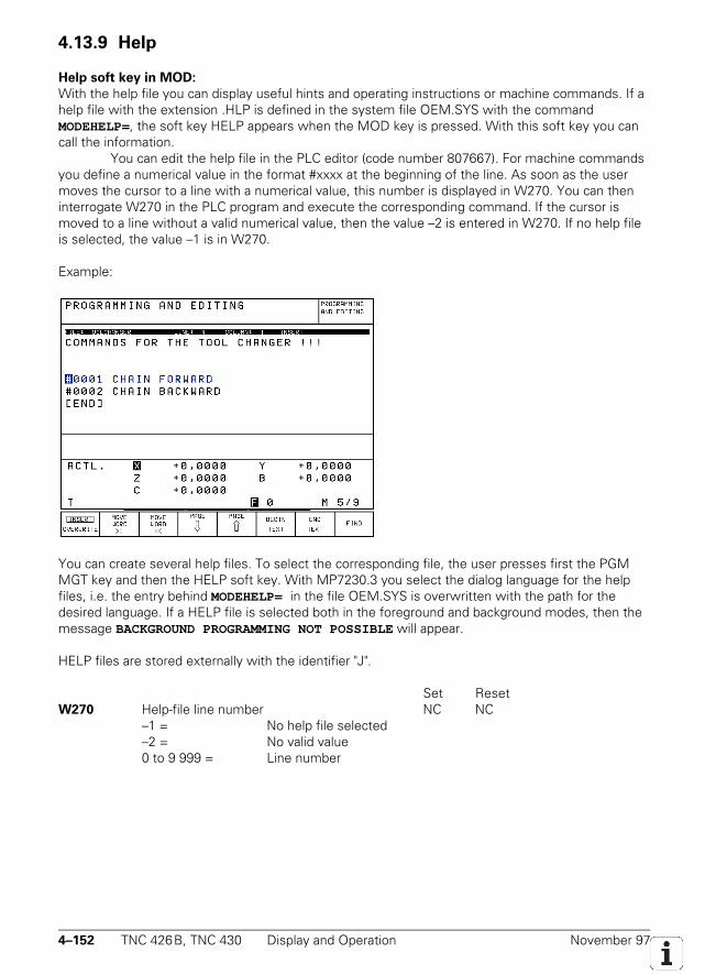
4–152 TNC 426B, TNC 430 Display and Operation November 97
4.13.9 Help
Help soft key in MOD:
With the help file you can display useful hints and operating instructions or machine commands. If ahelp file with the extension .HLP is defined in the system file OEM.SYS with the commandMODEHELP=, the soft key HELP appears when the MOD key is pressed. With this soft key you cancall the information.
You can edit the help file in the PLC editor (code number 807667). For machine commandsyou define a numerical value in the format #xxxx at the beginning of the line. As soon as the usermoves the cursor to a line with a numerical value, this number is displayed in W270. You can theninterrogate W270 in the PLC program and execute the corresponding command. If the cursor ismoved to a line without a valid numerical value, then the value –2 is entered in W270. If no help fileis selected, the value –1 is in W270.
Example:
You can create several help files. To select the corresponding file, the user presses first the PGMMGT key and then the HELP soft key. With MP7230.3 you select the dialog language for the helpfiles, i.e. the entry behind MODEHELP= in the file OEM.SYS is overwritten with the path for thedesired language. If a HELP file is selected both in the foreground and background modes, then themessage BACKGROUND PROGRAMMING NOT POSSIBLE will appear.
HELP files are stored externally with the identifier "J".
Set ResetW270 Help-file line number NC NC
–1 = No help file selected–2 = No valid value0 to 9 999 = Line number
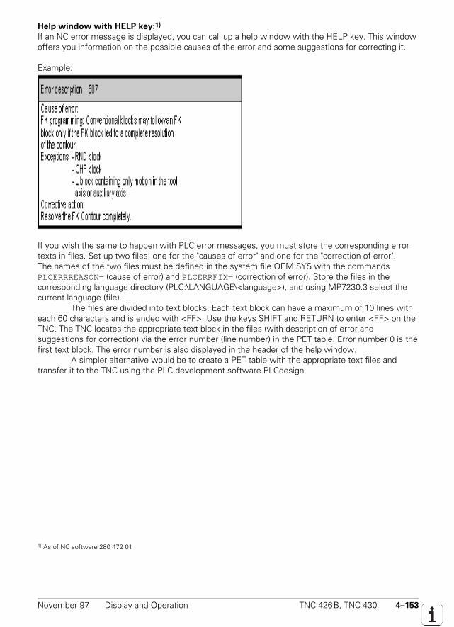
November 97 Display and Operation TNC 426B, TNC 430 4–153
Help window with HELP key:1)
If an NC error message is displayed, you can call up a help window with the HELP key. This windowoffers you information on the possible causes of the error and some suggestions for correcting it.
Example:
If you wish the same to happen with PLC error messages, you must store the corresponding errortexts in files. Set up two files: one for the "causes of error" and one for the "correction of error".The names of the two files must be defined in the system file OEM.SYS with the commandsPLCERRREASON= (cause of error) and PLCERRFIX= (correction of error). Store the files in thecorresponding language directory (PLC:\LANGUAGE\<language>), and using MP7230.3 select thecurrent language (file).
The files are divided into text blocks. Each text block can have a maximum of 10 lines witheach 60 characters and is ended with <FF>. Use the keys SHIFT and RETURN to enter <FF> on theTNC. The TNC locates the appropriate text block in the files (with description of error andsuggestions for correction) via the error number (line number) in the PET table. Error number 0 is thefirst text block. The error number is also displayed in the header of the help window.
A simpler alternative would be to create a PET table with the appropriate text files andtransfer it to the TNC using the PLC development software PLCdesign.
1) As of NC software 280 472 01
4–154 TNC 426B, TNC 430 Display and Operation November 97
4.13.10 Superimpose PLC Window
As of NC software 280 472 01:
With Module 9215 you can activate a pop-up window where the user can choose settings from alist. This PLC window is only displayed in the operating modes "Manual", "Positioning with MDI","Program run, single block" and "Program run, full sequence". You can make your selections usingthe cursor keys and ENTER or using key combinations. The module sends the line number of theselected menu item (line 1 = number 0).
The selection list you require is defined and transferred to the module as a file. Individualentries in the files are separated with <LF>. If you send a file name without indicating the path, theTNC will search for the file in the language-specific directory PLC:\LANGUAGE\<language>. Thecurrent language (file) can be selected using MP7230.3.
Other pop-up windows (e.g. HELP window) are placed in the background when the PLCwindow is called, and become active again once it is closed. Likewise the PLC window can bemoved to the background by calling another pop-up window.
As the module only returns when the window is closed, it must be called in a SPAWNprocess. If it were called in a submit job, the following submit jobs would only be executed whenthe window is closed again.Module 9215 uses the following events:$01 000 000 Window design$00 010 000 Closing the pop-up windowThe event for window design is generated internally and may not be set externally. When the eventfor closing the pop-up window is transferred, the module is ended without any keyboard input.
Call only in SPAWN process:PS B/W/D/K/S <String with window heading>PS B/W/D/K/S <String with file name of the list> [with directory or just file name]PS B/W/D/K <Starting position> [line that is highlighted]PS B/W/D/K <Mode>
Bit0/Bit1: Size of characters00: Automatic01: Small characters10: Medium-size characters01: Large characters
Bit2: Frame0: With frame1: Without frame
Bit3: List name0: Display name1: Do not display name
Bit4: Key combinations0: No key combinations1: Key combinations (0 to 9 and A to Z) before menu items
Bit5: Vertical/horizontal0: Arrange vertically1: Arrange horizontally (bit 4 = 0)
November 97 Display and Operation TNC 426B, TNC 430 4–155
CM 9215PL B/W/D <Selected line>
0 to n: Line number from list–1: No selection (END, NOENT)–2: Error see W1022
W1022 = 2: Incorrect mode transferred3: No valid string for file name or heading6: Window cannot be shown (internal error,
e.g. problem with memory capacity or operating system)20: Module was not called from a SPAWN process28: Another PLC pop-up window is already open36: The file containing the list could not be opened.
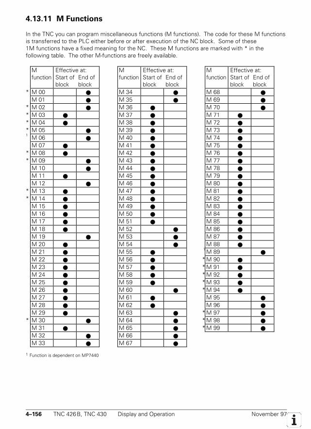
4–156 TNC 426B, TNC 430 Display and Operation November 97
4.13.11 M Functions
In the TNC you can program miscellaneous functions (M functions). The code for these M functionsis transferred to the PLC either before or after execution of the NC block. Some of these1M functions have a fixed meaning for the NC. These M functions are marked with * in thefollowing table. The other M-functions are freely available.
M Effective at: M Effective at: M Effective at:function Start of
blockEnd ofblock
function Start ofblock
End ofblock
function Start ofblock
End ofblock
* M 00 M 34 M 68 M 01 M 35 M 69
* M 02 M 36 M 70 * M 03 M 37 M 71 * M 04 M 38 M 72 * M 05 M 39 M 73 1 M 06 M 40 M 74
M 07 M 41 M 75 * M 08 M 42 M 76 * M 09 M 43 M 77
M 10 M 44 M 78 M 11 M 45 M 79 M 12 M 46 M 80
* M 13 M 47 M 81 * M 14 M 48 M 82
M 15 M 49 M 83 M 16 M 50 M 84 M 17 M 51 M 85 M 18 M 52 M 86 M 19 M 53 M 87 M 20 M 54 M 88 M 21 M 55
1 M 89 M 22 M 56 * M 90 M 23 M 57 * M 91 M 24 M 58 * M 92 M 25 M 59 * M 93 M 26 M 60 * M 94 M 27 M 61 M 95 M 28 M 62 M 96 M 29 M 63 * M 97
* M 30 M 64 * M 98 M 31 M 65 * M 99 M 32 M 66 M 33 M 67
1 Function is dependent on MP7440
November 97 Display and Operation TNC 426B, TNC 430 4–157
If an M function does not have a fixed meaning for the NC, you must evaluate it in the PLC. Whenan M function is transferred to the PLC, its code is stored in W260 and the strobe marker M4072 isset.
The next NC block will not be run until you have acknowledged the execution of the Mfunction by setting M4092. As soon as you set M4092, the NC resets M4072. The M functions M00to M99 can also be transferred decoded to the markers M1900 to M1999. You must activate thisfunction in M4571. All M functions over M99 are not transferred to the PLC. However, they have afixed meaning for the activation of functions (see User's Manual).
Set ResetW260 Code for M function NC NCM4072 Strobe signal for M function NC NCM4092 Acknowledgment of M function PLC PLCM4571 Activation of decoded M-code transfer PLC PLC
in M1900 to M1999M1900 to M1999 Decoded M function if M4571 is set NC NC
Program stop on M functions
In the "Program Run, Full Sequence" and "Program Run, Single Block" operating modes the next NCblock is not run until you have acknowledged the execution of the M function by setting M4092. Youcan deselect this program stop function for special machines by using MP7440 bit 2 (see chapter"Special Functions for Laser Cutting Machines").
Program stop on M06
According to ISO 6983, the M function M06 commands a tool change. With machine parameterMP7440, bit 0 you can select whether the program should stop when M06 is transferred to the PLC.If you have configured the control to stop the program on M06, then you must restart the programafter the tool change. This can also be carried out by the PLC.
Modal cycle call M89
You can use the M function M89 for a modal cycle call.The possibilities for calling a cycle are:• With the NC block CYCL CALL• With the miscellaneous function M99. M99 is only effective for a single block and must
be reprogrammed for each execution.• With the miscellaneous function M89 (depending on the MP7440 bit 1). M89 as a cycle call is
modally effective, i.e. for every following positioning block there will be a call of the machiningcycle last programmed. M89 is canceled by M99 or a CYCL CALL-block.
If M89 is not defined as a modal cycle call, then M89 will be transferred to the PLC as a normal Mfunction at the beginning of the block.
4–158 TNC 426B, TNC 430 Display and Operation November 97
Reduced feed rate of tool axis with M103
With M103 F... you can reduce the contour feed rate for movements of the tool axis in the negativedirection. The feed-rate component of the tool axis is limited to a value that the TNC computes fromthe last programmed feed rate.Fmax = Fprog * F%
Fmax = Maximum feed rate in negative direction of tool axisFprog = Last programmed feed rateF% = Programmed factor after M103 in %M103 F... is canceled by entering M103 without a factor.You can enable M103 F... with MP7440 bit 4.
MP7440 Output of M functionsInput: %xxxxxBit 0 Program stop with M06
0 = program stop with M061 = no program stop with M06
Bit 1 Modal cycle call M890 = normal code transfer of M89 at beginning of block1 = modal cycle call M89 at end of block
Bit 2 Program stop with M functions0 = program stop until acknowledgment of M function1 = no program stop (do not wait for acknowledgment)
Bit 3 Select kv factors with M105/M1060 = Function not effective1 = Function effective
Bit 4 Reduced feed rate in the tool axis with M1030 = Function not effective1 = Function effective
November 97 Display and Operation TNC 426B, TNC 430 4–159
4.13.12 Error Messages
Under certain conditions error messages from the NC or the PLC will be displayed on the screenunder the display for the operating mode. In the event of a blinking error message the machine mustbe switched off and the fault corrected. If a non-blinking error message is displayed on the screen,marker M4177 will be set.
You define the PLC error messages in the .PET table. A PLC error message is called eitherwith Module 9085 or through activation of a marker (M4800 to M4899). If you use the markers,however, you must first assign them to the error messages in the .PET table. With Module 9086 youcan erase the PLC error message; with Module 9087 you can interrogate the current status of theerror message.
With the command PLCERRTAB= you must enter the name of the .PET table in theOEM.SYS file. With COMPILE xxxxx.PET the entry is made automatically in OEM.SYS. If severalPLC error messages are activated at the same time, you can read them in sequence by pressing theCE key. With the special command ERRQUE= you can display the list of active error messages in thelarge PLC window.
In the individual columns you can assign special attributes to the PLC error messages. The PLC errormessage table (.PET) consists of the following columns:
NRLine number in the table. The PLC error message is addressed in the modules by assigning the linenumber.
ERRORError text. There are three possibilities for defining the error text:• Directly entering the error text (max. 32 characters)• Line number of the PLC error text file (#<line no.>) defined in OEM.SYS with PLCERROR =.• Number of the string memory where the error text is located (#S<string no.>)You can call up additional information on the error messages by pressing the HELP key (see section"Help".)
MARKERThe PLC error message can be activated without a module call by setting the marker defined here.Only markers in the range of M4800 to M4899 may be entered. The marker is also set if the errormessage was activated through Module 9085. The entry value 0 means no error marker.
RESET0 = No NC reset upon activation of the error message. Non-blinking error message.1 = NC reset upon activation of the error message. Blinking error message.
NC STOP0 = No NC stop when error message is activated.1 = NC stop when error message is activated.
F STOP0 = Feed-rate enable.1 = Feed-rate enable is reset when error message is activated.
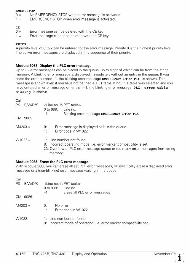
4–160 TNC 426B, TNC 430 Display and Operation November 97
EMER.STOP0 = No EMERGENCY STOP when error message is activated.1 = EMERGENCY STOP when error message is activated.
CE0 = Error message can be deleted with the CE key.1 = Error message cannot be deleted with the CE key.
PRIORA priority level of 0 to 2 can be entered for the error message. Priority 0 is the highest priority level.The active error messages are displayed in the sequence of their priority.
Module 9085: Display the PLC error message
Up to 32 error messages can be placed in the queue, up to eight of which can be from the stringmemory. A blinking error message is displayed immediately without an entry in the queue. If youenter the error number –1, the blinking error message EMERGENCY STOP PLC is shown. Thismessage is shown even if you have not defined a .PET table. If no .PET table was selected and youhave entered an error message other than –1, the blinking error message PLC: error tablemissing is shown.
Call:PS B/W/D/K <Line no. in PET table>
0 to 999: Line no.–1: Blinking error message EMERGENCY STOP PLC
CM 9085
M4203 = 0: Error message is displayed or is in the queue1: Error code in W1022
W1022 = 1: Line number not found8: Incorrect operating mode, i.e. error marker compatibility is set23: Overflow of PLC error-message queue or too many error messages from string
memory
Module 9086: Erase the PLC error message
With Module 9086 you can erase all set PLC error messages, or specifically erase a displayed errormessage or a (non-blinking) error message waiting in the queue.
Call:PS B/W/D/K <Line no. in PET table>
0 to 999: Line no.–1: Erase all PLC error messages
CM 9086
M4203 = 0: No error1: Error code in W1022
W1022: 1: Line number not found8: Incorrect mode of operation, i.e. error marker compatibility set
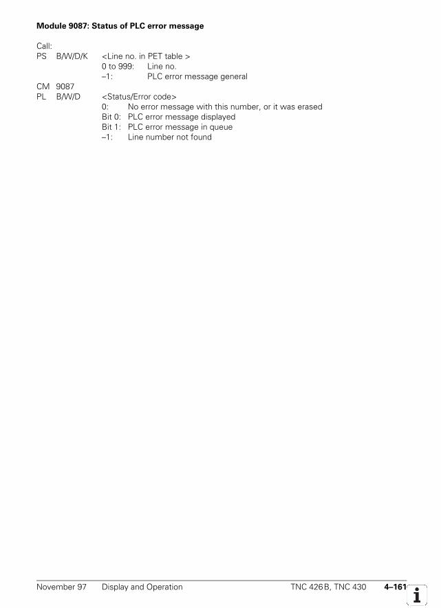
November 97 Display and Operation TNC 426B, TNC 430 4–161
Module 9087: Status of PLC error message
Call:PS B/W/D/K <Line no. in PET table >
0 to 999: Line no.–1: PLC error message general
CM 9087PL B/W/D <Status/Error code>
0: No error message with this number, or it was erasedBit 0: PLC error message displayedBit 1: PLC error message in queue
–1: Line number not found

4–162 TNC 426B, TNC 430 Display and Operation November 97
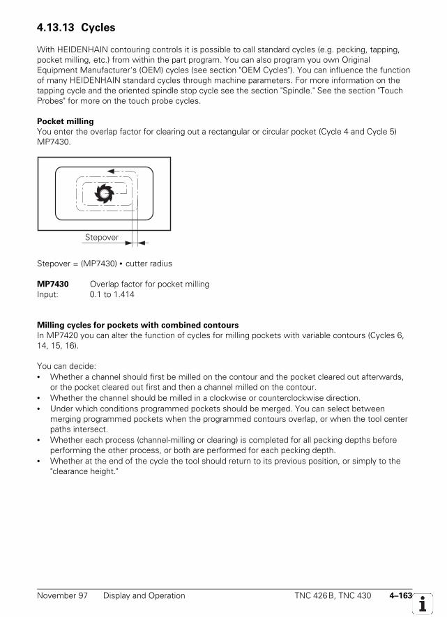
November 97 Display and Operation TNC 426B, TNC 430 4–163
4.13.13 Cycles
With HEIDENHAIN contouring controls it is possible to call standard cycles (e.g. pecking, tapping,pocket milling, etc.) from within the part program. You can also program you own OriginalEquipment Manufacturer's (OEM) cycles (see section "OEM Cycles"). You can influence the functionof many HEIDENHAIN standard cycles through machine parameters. For more information on thetapping cycle and the oriented spindle stop cycle see the section "Spindle." See the section "TouchProbes" for more on the touch probe cycles.
Pocket milling
You enter the overlap factor for clearing out a rectangular or circular pocket (Cycle 4 and Cycle 5)MP7430.
Stepover
Stepover = (MP7430) • cutter radius
MP7430 Overlap factor for pocket millingInput: 0.1 to 1.414
Milling cycles for pockets with combined contours
In MP7420 you can alter the function of cycles for milling pockets with variable contours (Cycles 6,14, 15, 16).
You can decide:• Whether a channel should first be milled on the contour and the pocket cleared out afterwards,
or the pocket cleared out first and then a channel milled on the contour.• Whether the channel should be milled in a clockwise or counterclockwise direction.• Under which conditions programmed pockets should be merged. You can select between
merging programmed pockets when the programmed contours overlap, or when the tool centerpaths intersect.
• Whether each process (channel-milling or clearing) is completed for all pecking depths beforeperforming the other process, or both are performed for each pecking depth.
• Whether at the end of the cycle the tool should return to its previous position, or simply to the"clearance height."
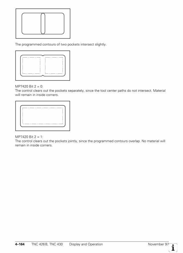
4–164 TNC 426B, TNC 430 Display and Operation November 97
The programmed contours of two pockets intersect slightly.
MP7420 Bit 2 = 0:The control clears out the pockets separately, since the tool center paths do not intersect. Materialwill remain in inside corners.
MP7420 Bit 2 = 1:The control clears out the pockets jointly, since the programmed contours overlap. No material willremain in inside corners.
November 97 Display and Operation TNC 426B, TNC 430 4–165
MP7420 Cycles for milling pockets with combined contoursInput: %xxxx
Bit 0 Traverse direction for channels0 = pockets counterclockwise, islands clockwise1 = pockets clockwise, islands counterclockwise
Bit 1 Sequence for clearing and channel-milling0 = first mill the channel, the clear the pocket1 = first clear the pocket, then mill the channel
Bit 2 Merging of listed contours0 = contours are combined only if the tool center paths intersect1 = contours are combined if the programmed contours intersect
Bit 3 Clearing and pocket-milling to pocket depth or for each pecking depth0 = each process uninterrupted to pocket depth1 = both processes for each pecking depth before proceeding to the next depth.
Bit 4 Position after machining the cycle0 = tool moves to the same position as before the cycle was called1 = tool moves only to the "clearance height"
Scaling factor
In MP7410 you indicate whether Cycle 11 "scaling factor" should be effective only in the workingplane or also in the tool axis.
MP7410 Scaling factor cycle in two or three axesInput: 0 = Scaling factor cycle effective in all three primary axes
1 = Scaling factor cycle effective only in the working plane
Cylindrical surface
With Cycle 27 "cylinder surface" it is possible to machine a contour on a cylindrical surface (see theUser's Manual). For this cycle to be effective you must first define the center of rotation of a rotaryaxes in MP7510 and following (see section "Tilting Axes").

4–166 TNC 426B, TNC 430 Display and Operation November 97
November 97 Display and Operation TNC 426B, TNC 430 4–167
4.13.14 Returning to the Contour
With this HEIDENHAIN contouring control it is possible to resume an interrupted program, or tomake a block scan up to a predetermined block number (see User's Manual).
These functions must be enabled by machine parameters and the PLC program mustbe adapted accordingly.
Markers inform the PLC about individual conditions during mid-program startup (also called blockscan). Depending on these markers, you can enable certain functions in the PLC program (e.g.operating the axis-direction keys in MANUAL OPERATION).
M4156 is set if the MANUAL OPERATION soft key is set. M4157 is set if the return tocontour function is activated with the RESTORE POSITION soft key. M4158 is set if the RESTOREPOS. AT N soft key is pressed M4158 is reset if the RESTORE POSITION or INTERNAL STOP softkey is pressed.
During a block scan, PLC positioning commands are included in the calculation only if theyare also executed. The TOOL CALL block normally releases PLC commands to move the tool to thetool-change position. If you want these positioning commands to be calculated in the block scan youmust enter in MP951.x the absolute tool-change position referenced to the machine datum andactivate the calculation for the specific axes with MP7450.
With flexible tool pocket coding in the central tool file (see section "Tool Changer"), achange in the position numbers in the tool memory must be prevented during block scan. This isensured by setting M4542.
With MP7680 you define whether the block scan should be interrupted through aprogrammed STOP or M06, and whether the programmed dwell time should be considered duringthe block scan. You define the feed rate for returning to the contour in MP7451.x.
The tool data cannot be correctly offset in the block scan if you change them in thePLC or update them with M4538.
MP951.0-8 Simulated tool change position for TOOL CALL during block scanInput: −99 999.9999 to +99 999.9999 [mm] or [°]
MP7450 Calculate the tool change position from MP951 in block scanInput: %xxxxx
Bit 0 to 8 0 = do not calculateAxis 1 to 9 1 = calculate
MP7451.0-4 Feed rate for returning to the contourInput: 10 to 300 000 [mm/min]
4–168 TNC 426B, TNC 430 Display and Operation November 97
MP7680 Machine parameter with multiple functionInput: %x xxx xxxBit1 Return to the contour
0 = not active1 = active
Bit2 Block scan0 = not active1 = active
Bit3 Interruption of block scan with STOP or M060 = interruption1= no interruption
Bit4 Inclusion of programmed dwell time during block scan0 = include dwell time1 = do not include dwell time
Bit 5 Start of calculation for block scan0 = start from block with cursor1 = start from beginning of program
Set ResetM4156 MANUAL OPERATION soft key was pressed NC NCM4157 Returning-to-contour function (RESTORE POSITION) active NC NCM4158 Block scan is active NC, PLC NC, PLCM4542 Do not update the pocket number in the pocket table PLC PLC
M/S/T/Q transfer during block scan
With MP7681 you define whether the M/S/T/Q signals should be collected during the block scan inorder to output them after it is ended. If MP7681 ≠ 0, after a block scan the dialog Restoremachine status: is displayed with the M/S/T/Q signals to be output. With the external start keyyou then output the displayed signals. M4161 remains set for the duration of output.
You define the M functions that you wish to be output after a block scan in the system filesPLC:\MGROUPS.SYS and PLC:\MSPLIT.SYS. The M/S/T/Q signals are normally output in thefollowing sequence (for exceptions see the instruction ORDER.PRIO):1. M function that was defined with MFIRST2. M/S/T/Q signals in the sequence in which they were entered in the NC program.3. M function that was defined with MLAST
November 97 Display and Operation TNC 426B, TNC 430 4–169
Instructions in MGROUPS.SYS:
GROUP=With this instruction you divide the M functions into groups. After a block scan, the last programmedM function in a group is transferred to the PLC.Example: GROUP=M3,M4,M5
SPECIAL=With SPECIAL = you define all M functions that should be sent to the PLC after a block scan and arenot defined in a group.Example: SPECIAL=M19,M22,M25
MFIRST=MLAST=With MFIRST= and MLAST= you define the M functions to be sent to the PLC at the start and end,respectively, of an output sequence after a block scan. In this way you can recognize from the PLCprogram that a sequence of M/S/T/Q strobes is being transferred that was collected during a blockscan. You can omit these instructions if you do not need this information.Example: MFIRST=M80
MLAST=M81
REMAIN=OUTPUTIf you enter this instruction, all M functions that are not defined in MGROUPS.SYS are transferred tothe PLC during a block scan. If you do not enter this instruction such M functions are ignored. Withthe following functions you must use REMAIN=OUTPUT:• Datum shift with M4132• PLC positioning except with TOOL CALL• Traverse range switchover with M4135 if MP7490=1
ORDER=PRIOIf you enter this instruction, the M functions will be transferred in the sequence in which they areentered in the file MGROUPS.SYS. If you do not enter this instruction, the M functions aretransferred after a block scan in the sequence in which they were programmed. HEIDENHAINrecommends that you not use this instruction.
TOOLGROUP, TDEFGROUP, SPINDLEGROUP, FN19GROUPWith these instructions, in conjunction with ORDER=PRIO, the sequence of output of the S/T/Qstrobes after a block scan is defined in the file MGROUPS.SYS. HEIDENHAIN recommends that younot use these instructions.
NCMACRO=TCDuring a TOOL CALL you can also call an NC program instead of the T strobe (see chapter "ToolChanger"). With the instruction NCMACRO=TC you define that this tool-change program is not runduring the block scan, but rather is started at the end of the block scan instead of the T strobe.
Instructions in MSPLIT.SYS:
M functions that are effective in several groups are divided in the file MSPLIT.SYS into functioncomponents.Example: M13=M3,M8
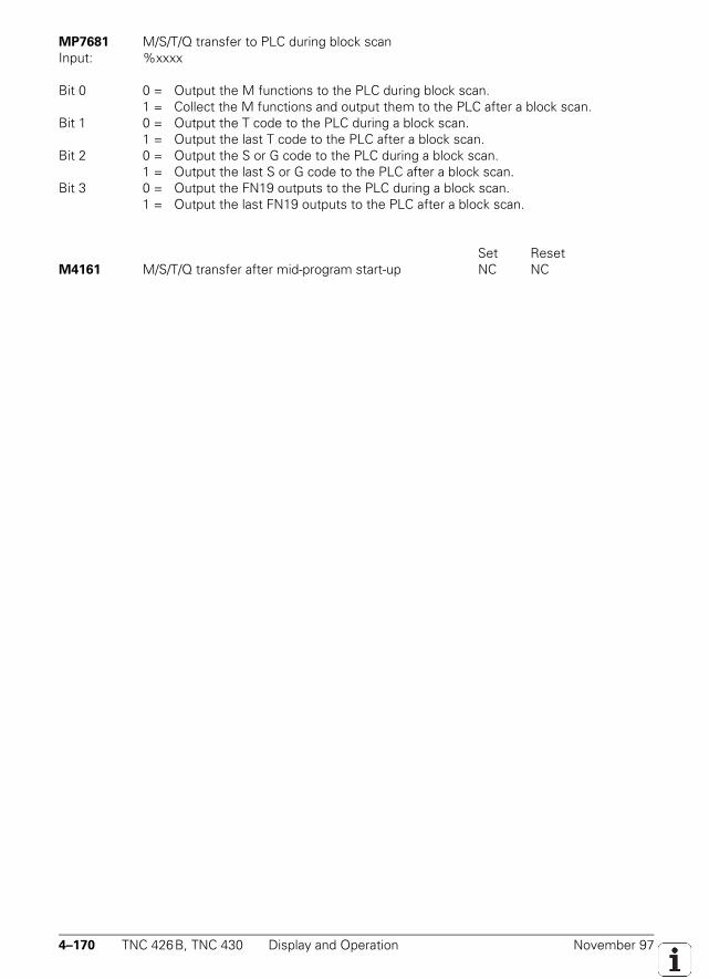
4–170 TNC 426B, TNC 430 Display and Operation November 97
MP7681 M/S/T/Q transfer to PLC during block scanInput: %xxxx
Bit 0 0 = Output the M functions to the PLC during block scan.1 = Collect the M functions and output them to the PLC after a block scan.
Bit 1 0 = Output the T code to the PLC during a block scan.1 = Output the last T code to the PLC after a block scan.
Bit 2 0 = Output the S or G code to the PLC during a block scan.1 = Output the last S or G code to the PLC after a block scan.
Bit 3 0 = Output the FN19 outputs to the PLC during a block scan.1 = Output the last FN19 outputs to the PLC after a block scan.
Set ResetM4161 M/S/T/Q transfer after mid-program start-up NC NC
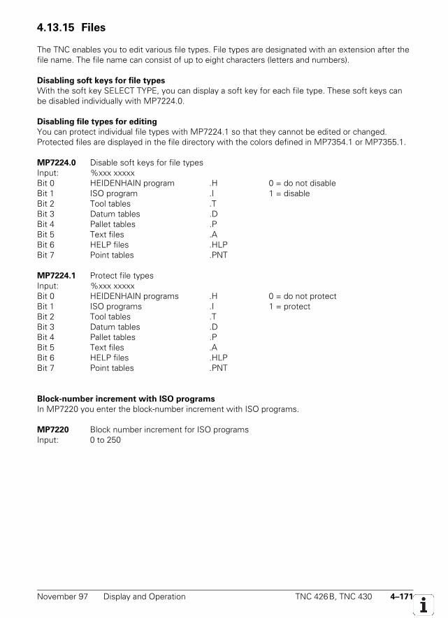
November 97 Display and Operation TNC 426B, TNC 430 4–171
4.13.15 Files
The TNC enables you to edit various file types. File types are designated with an extension after thefile name. The file name can consist of up to eight characters (letters and numbers).
Disabling soft keys for file types
With the soft key SELECT TYPE, you can display a soft key for each file type. These soft keys canbe disabled individually with MP7224.0.
Disabling file types for editing
You can protect individual file types with MP7224.1 so that they cannot be edited or changed.Protected files are displayed in the file directory with the colors defined in MP7354.1 or MP7355.1.
MP7224.0 Disable soft keys for file typesInput: %xxx xxxxxBit 0 HEIDENHAIN program .H 0 = do not disableBit 1 ISO program .I 1 = disableBit 2 Tool tables .TBit 3 Datum tables .DBit 4 Pallet tables .PBit 5 Text files .ABit 6 HELP files .HLPBit 7 Point tables .PNT
MP7224.1 Protect file typesInput: %xxx xxxxxBit 0 HEIDENHAIN programs .H 0 = do not protectBit 1 ISO programs .I 1 = protectBit 2 Tool tables .TBit 3 Datum tables .DBit 4 Pallet tables .PBit 5 Text files .ABit 6 HELP files .HLPBit 7 Point tables .PNT
Block-number increment with ISO programs
In MP7220 you enter the block-number increment with ISO programs.
MP7220 Block number increment for ISO programsInput: 0 to 250
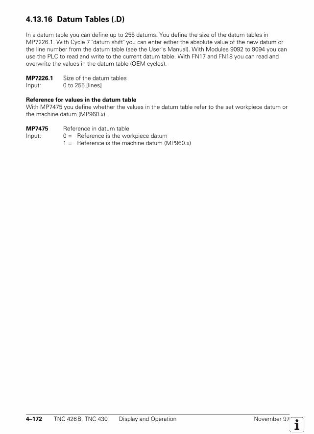
4–172 TNC 426B, TNC 430 Display and Operation November 97
4.13.16 Datum Tables (.D)
In a datum table you can define up to 255 datums. You define the size of the datum tables inMP7226.1. With Cycle 7 "datum shift" you can enter either the absolute value of the new datum orthe line number from the datum table (see the User's Manual). With Modules 9092 to 9094 you canuse the PLC to read and write to the current datum table. With FN17 and FN18 you can read andoverwrite the values in the datum table (OEM cycles).
MP7226.1 Size of the datum tablesInput: 0 to 255 [lines]
Reference for values in the datum table
With MP7475 you define whether the values in the datum table refer to the set workpiece datum orthe machine datum (MP960.x).
MP7475 Reference in datum tableInput: 0 = Reference is the workpiece datum
1 = Reference is the machine datum (MP960.x)
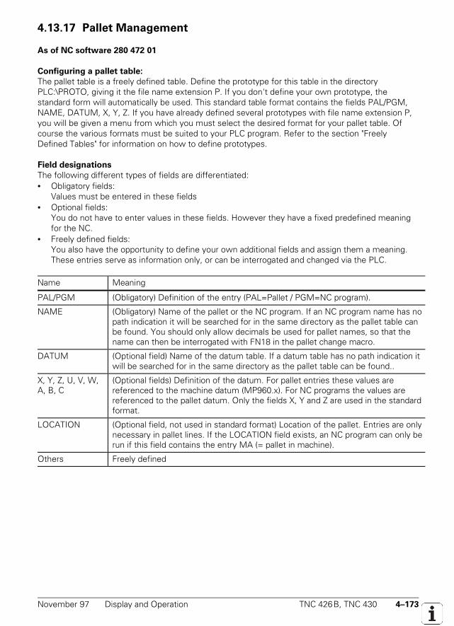
November 97 Display and Operation TNC 426B, TNC 430 4–173
4.13.17 Pallet Management
As of NC software 280 472 01
Configuring a pallet table:
The pallet table is a freely defined table. Define the prototype for this table in the directoryPLC:\PROTO, giving it the file name extension P. If you don't define your own prototype, thestandard form will automatically be used. This standard table format contains the fields PAL/PGM,NAME, DATUM, X, Y, Z. If you have already defined several prototypes with file name extension P,you will be given a menu from which you must select the desired format for your pallet table. Ofcourse the various formats must be suited to your PLC program. Refer to the section "FreelyDefined Tables" for information on how to define prototypes.
Field designations
The following different types of fields are differentiated:• Obligatory fields:
Values must be entered in these fields• Optional fields:
You do not have to enter values in these fields. However they have a fixed predefined meaningfor the NC.
• Freely defined fields:You also have the opportunity to define your own additional fields and assign them a meaning.These entries serve as information only, or can be interrogated and changed via the PLC.
Name Meaning
PAL/PGM (Obligatory) Definition of the entry (PAL=Pallet / PGM=NC program).
NAME (Obligatory) Name of the pallet or the NC program. If an NC program name has nopath indication it will be searched for in the same directory as the pallet table canbe found. You should only allow decimals be used for pallet names, so that thename can then be interrogated with FN18 in the pallet change macro.
DATUM (Optional field) Name of the datum table. If a datum table has no path indication itwill be searched for in the same directory as the pallet table can be found..
X, Y, Z, U, V, W,A, B, C
(Optional fields) Definition of the datum. For pallet entries these values arereferenced to the machine datum (MP960.x). For NC programs the values arereferenced to the pallet datum. Only the fields X, Y and Z are used in the standardformat.
LOCATION (Optional field, not used in standard format) Location of the pallet. Entries are onlynecessary in pallet lines. If the LOCATION field exists, an NC program can only berun if this field contains the entry MA (= pallet in machine).
Others Freely defined
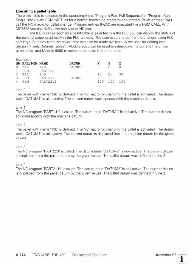
4–174 TNC 426B, TNC 430 Display and Operation November 97
Executing a pallet table
The pallet table is selected in the operating mode "Program Run, Full Sequence" or "Program Run,Single Block" with PGM MGT (as for a normal machining program) and started. Pallet entries (PAL)call the NC macro for pallet change. Program entries (PGM) are executed like a PGM CALL. WithMP7683 you can define the behavior at NC start.
M4160 is set as soon as a pallet table is selected. Via the PLC you can display the status ofthe pallet changer graphically in the PLC window. The user is able to control the changer using PLCsoft keys. Sections from the pallet table can also be made available to the user for editing (seeSection "Freely Defined Tables"). Module 9035 can be used to interrogate the current line of thepallet table, and Module 9090 to select a particular line in the table.
Example:NR PAL/PGM NAME DATUM X Y Z0 PAL 120 DATUM1 0 0 01 PGM PART1.H2 PAL 130 10 20 303 PGM PART21.H DATUM2 5 3 14 PGM PART22.I 100 100 100
Line 0:The pallet with name "120" is defined. The NC macro for changing the pallet is activated. The datumtable "DATUM1" is also active. The current datum corresponds with the machine datum.
Line 1:The NC program "PART1.H" is called. The datum table "DATUM1" is still active. The current datumstill corresponds with the machine datum.
Line 2:The pallet with name "130" is defined. The NC macro for changing the pallet is activated. The datumtable "DATUM1" is still active. The current datum is displaced from the machine datum by the givenvalues.
Line 3:The NC program "PART22.I" is called. The datum table "DATUM2" is now active. The current datumis displaced from the pallet datum by the given values. The pallet datum was defined in Line 2.
Line 4:The NC program "PART21.H" is called. The datum table "DATUM2" is still active. The current datumis displaced from the pallet datum by the given values. The pallet datum was defined in Line 2.
November 97 Display and Operation TNC 426B, TNC 430 4–175
Set ResetM4160 Pallet table selected NC NC
MP7683 Executing pallet tablesInput: %xxxBit 0 Operating mode "Program Run/Single Block"
0: One line of the NC program is run at every start. The pallet change macro is completely executed
1: A complete NC program is run at every startBit 1 Operating mode "Program Run/Full Sequence"
0: A complete NC program is run at every start1: All of the NC programs up to the next pallet are run at every start
Bit 2 Operating mode "Program Run/Full Sequence"0: As defined in Bit 11: All of the NC programs and pallets to the end of the table are run
Module 9090: Selecting a line in the pallet table
With Module 9090 you can set the cursor on a particular line of the pallet table you selected in theProgram Run operating mode. If the TNC is currently running in another mode, e.g. Manual, the linewill only be selected once the Full Sequence mode is once again active. If the pallet table hasalready been started, no selection is possible.
Call in submit job only:PS B/W/D/K <Line number in pallet table>CM 9090PL B/W/D <Error code> 0: No error. Line was selected
1: Call was not from a submit job2: Program was already started before call3: Pallet table not selected in "Program run, full sequence"4: Line does not exist
NC macro for pallet change
Using the entry PALETT = in the NCMACRO.SYS file, you can define the complete path indicationfor the NC macro that is called when a pallet entry (PAL) is executed. In this NC macro you caninterrogate the current line and the name of the pallet using FN18.
End of program run
When the program reaches its end in the "Program run, single block" or "Program run, full sequence"modes, the NC sets M4170. The marker is not reset until the next program start. The information inthis marker can be useful, for example, when you are working with a pallet changer.
Set ResetM4170 END-PGM, M02 or M30 was executed NC NC
4–176 TNC 426B, TNC 430 Display and Operation November 97
NC software: 280470..:
In the pallet tables you can assign NC programs and datum tables to specific workpieces. Each table can contain up to 255assignments. You can define the size of the pallet table in MP7226.0.
With Module 9090 you select the desired assignment by entering the line number. The next NC START then runs theselected program with the assigned datum table. Module 9090 must be called in a submit job and the desired pallet table musthave the status M. The pallet table will be in the M status if you select it with PGM MGT in the "Program run, full sequence"mode.
If no datum table is entered in the pallet table, the previous file is retained. Files that you have locked in MP7224.0 willbe ignored in the pallet table. If you have locked HEIDENHAIN programs or ISO programs and you select a line with such aprogram, the error message NC PROGRAM NOT FOUND will appear.
Call only in the submit job:PS B/W/D/K <Line number in pallet table>CM 9090PL B/W/D <Error condition>
0: Files were selected1: Call was not from a submit job2: Call during running program3: Keyboard evaluator not in the default state4: Pallet table not found5: Line does not exist in pallet table6: Incorrect type for NC program, or point is missing7: NC program not found8: Ambiguous NC program name9: Datum table not found12: Incorrect file name extension
MP7226.0 Size of the pallet tablesInput: 0 to 255 [lines]
November 97 Display and Operation TNC 426B, TNC 430 4–177
4.13.18 Freely Defined Tables
As of NC software 280 472 01
You can define tables to suit your own specific applications. The names and numbers of your fieldsare defined in prototypes. If you wish to edit these entries, they can be interrogated and changed viaspecial modules. Freely defined tables always have the file name extension TAB (except pallettables and cutting data tables).
Creating the prototype
• Set up a table with the file extension TAB in the PLC:\PROTO directory.• If you have defined several prototypes with the extension TAB, you will have to choose your
desired format from a proposed menu when you are creating your table. Press the soft key NEWFORMAT to define your new prototype. If you wish to edit an existing prototype, you can do sousing the soft key EDIT FORMAT, after the prototype has been selected.
• You can display the structure commands for the individual columns by pressing the followingsoft keys.NAME: Title of the column. This can have a max. of 8 characters and cannot be longer thanWIDTH. Spaces are not permitted.TYPE: N = numerical input / C = alphanumeric inputWIDTH: Width of the column. For TYPE = N this includes algebraic sign, decimal point anddecimal places.DEC: Number of decimal places. For TYPE = C this has no meaning.ENGLISH to HUNGARIA: Language-dependent dialogs that are displayed in the dialog line whenthe column is being edited. A max. of 32 characters are permitted per language. A dialog doesnot have to be entered for every language.
• Enter your desired structure commands. If you wish to add further columns it is easiest to usethe INSERT LINE soft key.
• Press END to exit the structure definition display. The table you have just created is displayed.
Data transfer
When a freely defined table (file extensions TAB, P or CDT) is being transferred via data interface,the defined structure format is stored between the lines #STRUCTBEGIN and #STRUCTEND in theexternal storage device. The contents of the table follow the line #STRUCTEND.
Reading and changing table fields in the PLC
You can read and overwrite individual fields of your table using special modules in the PLC. You canalso make various sections available to the user for editing in the different operating modes.
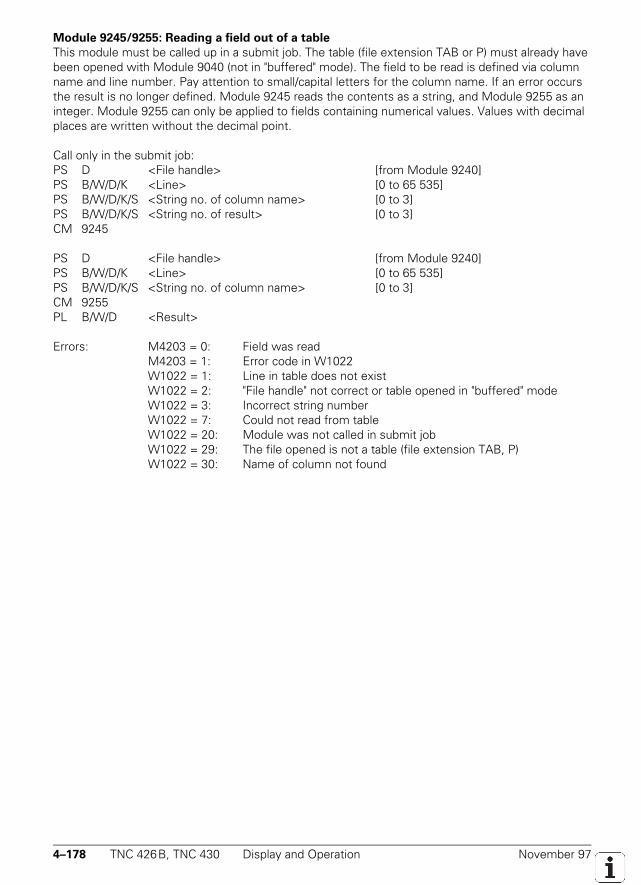
4–178 TNC 426B, TNC 430 Display and Operation November 97
Module 9245/9255: Reading a field out of a table
This module must be called up in a submit job. The table (file extension TAB or P) must already havebeen opened with Module 9040 (not in "buffered" mode). The field to be read is defined via columnname and line number. Pay attention to small/capital letters for the column name. If an error occursthe result is no longer defined. Module 9245 reads the contents as a string, and Module 9255 as aninteger. Module 9255 can only be applied to fields containing numerical values. Values with decimalplaces are written without the decimal point.
Call only in the submit job:PS D <File handle> [from Module 9240]PS B/W/D/K <Line> [0 to 65 535]PS B/W/D/K/S <String no. of column name> [0 to 3]PS B/W/D/K/S <String no. of result> [0 to 3]CM 9245
PS D <File handle> [from Module 9240]PS B/W/D/K <Line> [0 to 65 535]PS B/W/D/K/S <String no. of column name> [0 to 3]CM 9255PL B/W/D <Result>
Errors: M4203 = 0: Field was readM4203 = 1: Error code in W1022W1022 = 1: Line in table does not existW1022 = 2: "File handle" not correct or table opened in "buffered" modeW1022 = 3: Incorrect string numberW1022 = 7: Could not read from tableW1022 = 20: Module was not called in submit jobW1022 = 29: The file opened is not a table (file extension TAB, P)W1022 = 30: Name of column not found
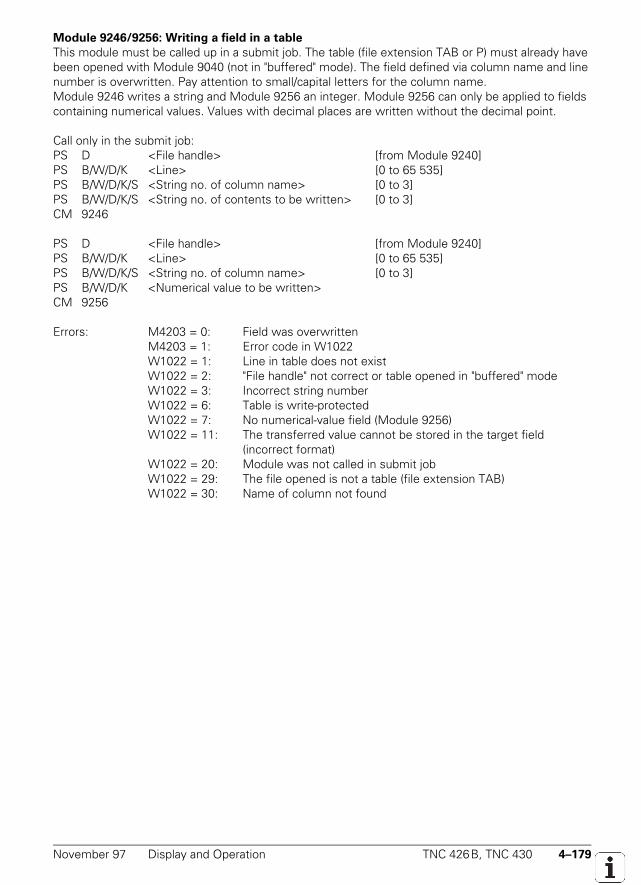
November 97 Display and Operation TNC 426B, TNC 430 4–179
Module 9246/9256: Writing a field in a table
This module must be called up in a submit job. The table (file extension TAB or P) must already havebeen opened with Module 9040 (not in "buffered" mode). The field defined via column name and linenumber is overwritten. Pay attention to small/capital letters for the column name.Module 9246 writes a string and Module 9256 an integer. Module 9256 can only be applied to fieldscontaining numerical values. Values with decimal places are written without the decimal point.
Call only in the submit job:PS D <File handle> [from Module 9240]PS B/W/D/K <Line> [0 to 65 535]PS B/W/D/K/S <String no. of column name> [0 to 3]PS B/W/D/K/S <String no. of contents to be written> [0 to 3]CM 9246
PS D <File handle> [from Module 9240]PS B/W/D/K <Line> [0 to 65 535]PS B/W/D/K/S <String no. of column name> [0 to 3]PS B/W/D/K <Numerical value to be written>CM 9256
Errors: M4203 = 0: Field was overwrittenM4203 = 1: Error code in W1022W1022 = 1: Line in table does not existW1022 = 2: "File handle" not correct or table opened in "buffered" modeW1022 = 3: Incorrect string numberW1022 = 6: Table is write-protectedW1022 = 7: No numerical-value field (Module 9256)W1022 = 11: The transferred value cannot be stored in the target field
(incorrect format)W1022 = 20: Module was not called in submit jobW1022 = 29: The file opened is not a table (file extension TAB)W1022 = 30: Name of column not found
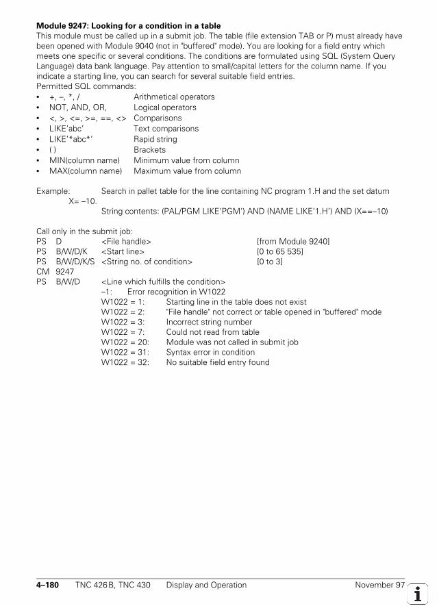
4–180 TNC 426B, TNC 430 Display and Operation November 97
Module 9247: Looking for a condition in a table
This module must be called up in a submit job. The table (file extension TAB or P) must already havebeen opened with Module 9040 (not in "buffered" mode). You are looking for a field entry whichmeets one specific or several conditions. The conditions are formulated using SQL (System QueryLanguage) data bank language. Pay attention to small/capital letters for the column name. If youindicate a starting line, you can search for several suitable field entries.Permitted SQL commands:• +, –, *, / Arithmetical operators• NOT, AND, OR, Logical operators• <, >, <=, >=, ==, <> Comparisons• LIKE’abc’ Text comparisons• LIKE’*abc*’ Rapid string• ( ) Brackets• MIN(column name) Minimum value from column• MAX(column name) Maximum value from column
Example: Search in pallet table for the line containing NC program 1.H and the set datum X= –10.
String contents: (PAL/PGM LIKE’PGM’) AND (NAME LIKE’1.H’) AND (X==–10)
Call only in the submit job:PS D <File handle> [from Module 9240]PS B/W/D/K <Start line> [0 to 65 535]PS B/W/D/K/S <String no. of condition> [0 to 3]CM 9247PS B/W/D <Line which fulfills the condition>
–1: Error recognition in W1022W1022 = 1: Starting line in the table does not existW1022 = 2: "File handle" not correct or table opened in "buffered" modeW1022 = 3: Incorrect string numberW1022 = 7: Could not read from tableW1022 = 20: Module was not called in submit jobW1022 = 31: Syntax error in conditionW1022 = 32: No suitable field entry found
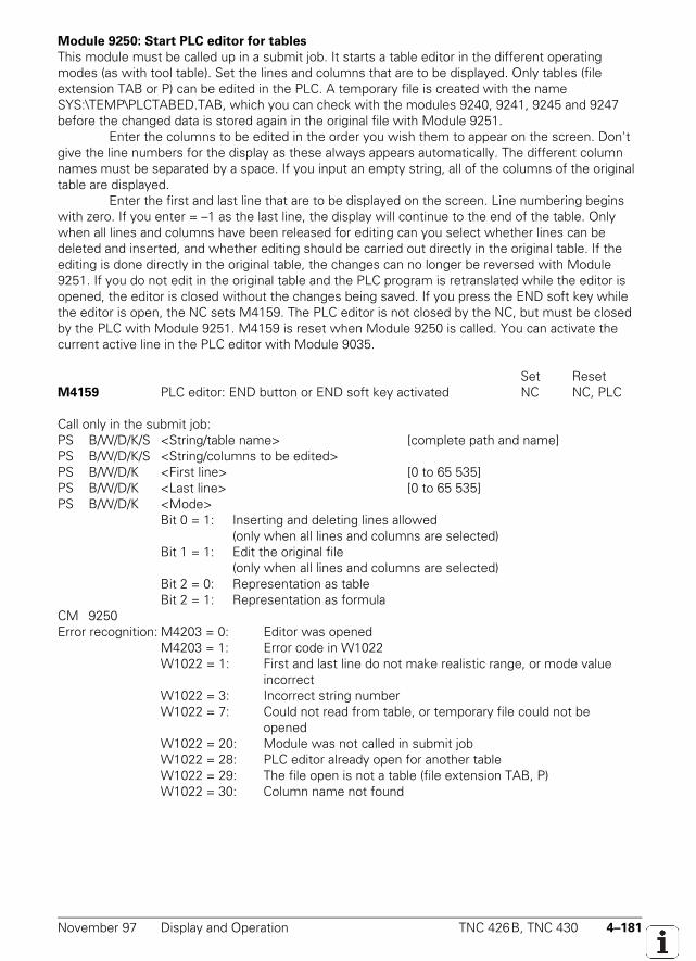
November 97 Display and Operation TNC 426B, TNC 430 4–181
Module 9250: Start PLC editor for tables
This module must be called up in a submit job. It starts a table editor in the different operatingmodes (as with tool table). Set the lines and columns that are to be displayed. Only tables (fileextension TAB or P) can be edited in the PLC. A temporary file is created with the nameSYS:\TEMP\PLCTABED.TAB, which you can check with the modules 9240, 9241, 9245 and 9247before the changed data is stored again in the original file with Module 9251.
Enter the columns to be edited in the order you wish them to appear on the screen. Don'tgive the line numbers for the display as these always appears automatically. The different columnnames must be separated by a space. If you input an empty string, all of the columns of the originaltable are displayed.
Enter the first and last line that are to be displayed on the screen. Line numbering beginswith zero. If you enter = –1 as the last line, the display will continue to the end of the table. Onlywhen all lines and columns have been released for editing can you select whether lines can bedeleted and inserted, and whether editing should be carried out directly in the original table. If theediting is done directly in the original table, the changes can no longer be reversed with Module9251. If you do not edit in the original table and the PLC program is retranslated while the editor isopened, the editor is closed without the changes being saved. If you press the END soft key whilethe editor is open, the NC sets M4159. The PLC editor is not closed by the NC, but must be closedby the PLC with Module 9251. M4159 is reset when Module 9250 is called. You can activate thecurrent active line in the PLC editor with Module 9035.
Set ResetM4159 PLC editor: END button or END soft key activated NC NC, PLC
Call only in the submit job:PS B/W/D/K/S <String/table name> [complete path and name]PS B/W/D/K/S <String/columns to be edited>PS B/W/D/K <First line> [0 to 65 535]PS B/W/D/K <Last line> [0 to 65 535]PS B/W/D/K <Mode>
Bit 0 = 1: Inserting and deleting lines allowed(only when all lines and columns are selected)
Bit 1 = 1: Edit the original file(only when all lines and columns are selected)
Bit 2 = 0: Representation as tableBit 2 = 1: Representation as formula
CM 9250Error recognition: M4203 = 0: Editor was opened
M4203 = 1: Error code in W1022W1022 = 1: First and last line do not make realistic range, or mode value
incorrectW1022 = 3: Incorrect string numberW1022 = 7: Could not read from table, or temporary file could not be
openedW1022 = 20: Module was not called in submit jobW1022 = 28: PLC editor already open for another tableW1022 = 29: The file open is not a table (file extension TAB, P)W1022 = 30: Column name not found
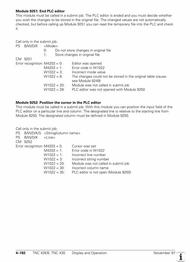
4–182 TNC 426B, TNC 430 Display and Operation November 97
Module 9251: End PLC editor
This module must be called in a submit job. The PLC editor is ended and you must decide whetheryou wish the changes to be stored in the original file. The changed values are not automaticallychecked, but before calling up Module 9251 you can read the temporary file into the PLC and checkit.
Call only in the submit job:PS B/W/D/K <Mode>
0: Do not store changes in original file1: Store changes in original file
CM 9251Error recognition: M4203 = 0: Editor was opened
M4203 = 1: Error code in W1022W1022 = 3: Incorrect mode valueW1022 = 6: The changes could not be stored in the original table (cause:
see Module 9249)W1022 = 20: Module was not called in submit jobW1022 = 28: PLC editor was not opened with Module 9250
Module 9252: Position the cursor in the PLC editor
This module must be called in a submit job. With this module you can position the input field of thePLC editor on a particular line and column. The designated line is relative to the starting line fromModule 9250. The designated column must be defined in Module 9250.
Call only in the submit job:PS B/W/D/K/S <String/column name>PS B/W/D/K <Line>CM 9252Error recognition: M4203 = 0: Cursor was set
M4203 = 1: Error code in W1022W1022 = 1: Incorrect line numberW1022 = 3: Incorrect string numberW1022 = 20: Module was not called in submit jobW1022 = 30: Incorrect column nameW1022 = 35: PLC editor is not open (Module 9250)

November 97 Display and Operation TNC 426B, TNC 430 4–183
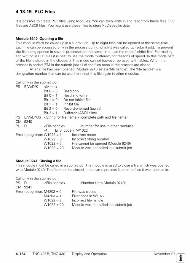
4–184 TNC 426B, TNC 430 Display and Operation November 97
4.13.19 PLC Files
It is possible to create PLC files using Modules. You can then write in and read from these files. PLCfiles are ASCII files. You might use these files to store PLC-specific data.
Module 9240: Opening a file
This module must be called up in a submit job. Up to eight files can be opened at the same time.Each file can be accessed only in the process during which it was called up (submit job). To preventthe file being opened in several processes at the same time, use the mode "inhibit file". For readingand writing in PLC files it is best to use the mode "buffered", for reasons of speed. In this mode partof the file is stored in the clipboard. This mode cannot however be used with tables. When theprocess is ended (EM in the submit job) all of the files open in the process are closed.
After a file has been opened, Module 9240 sets a "file handle". The "file handle" is adesignation number that can be used to select this file again in other modules.
Call only in the submit job:PS B/W/D/K <Mode>
Bit 0 = 0: Read onlyBit 0 = 1: Read and writeBit 1 = 0: Do not inhibit fileBit 1 = 1: Inhibit fileBit 2 = 0: Record-oriented (tables)Bit 2 = 1: Buffered (ASCII files)
PS B/W/D/K/S <String for file name> [complete path and file name]CM 9240PL D <File handle> [number for use in other modules]
–1: Error code in W1022Error recognition: W1022 = 1: Incorrect mode
W1022 = 3: Incorrect string numberW1022 = 7: File cannot be opened (Module 9249)W1022 = 20: Module was not called in a submit job
Module 9241: Closing a file
This module must be called in a submit job. The module is used to close a file which was openedwith Module 9240. The file must be closed in the same process (submit job) as it was opened in.
Call only in the submit job:PS D <File handle> [Number from Module 9240]CM 9241Error recognition: M4203 = 0: File was closed
M4203 = 1: Error code in W1022W1022 = 2: Incorrect file handleW1022 = 20: Module was not called in a submit job
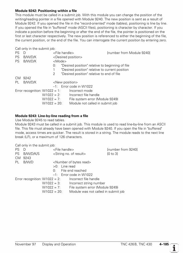
November 97 Display and Operation TNC 426B, TNC 430 4–185
Module 9242: Positioning within a file
This module must be called in a submit job. With this module you can change the position of thewriting/reading pointer in a file opened with Module 9240. The new position is sent as a result ofModule 9242. If you opened the file in the "record-oriented" mode (tables), positioning is line by line.If you opened the file in "buffered" mode (ASCII files), positioning is character by character. If youindicate a position before the beginning or after the end of the file, the pointer is positioned on thefirst or last character respectively. The new position is referenced to either the beginning of the file,the current position, or the end of the file. You can interrogate the current position by entering zero.
Call only in the submit job:PS D <File handle> [number from Module 9240]PS B/W/D/K <Desired position>PS B/W/D/K <Mode>
0: "Desired position" relative to beginning of file1 "Desired position" relative to current position2 "Desired position" relative to end of file
CM 9242PL B/W/D/K <New position>
–1: Error code in W1022Error recognition: W1022 = 1: Incorrect mode
W1022 = 2: Incorrect file handleW1022 = 7: File system error (Module 9249)W1022 = 20: Module not called in submit job
Module 9243: Line-by-line reading from a file
Use Module 9245 to read tables.Module 9243 must be called in a submit job. This module is used to read line-by-line from an ASCIIfile. This file must already have been opened with Module 9240. If you open the file in "buffered"mode, access times are quicker. The result is stored in a string. The module reads to the next linebreak (LF), or a maximum of 126 characters.
Call only in the submit job:PS D <File handle> [number from 9240]PS B/W/D/K/S <String no. of result> [0 to 3]CM 9243PL B/W/D <Number of bytes read>
>0: Line read0: File end reached–1: Error code in W1022
Error recognition: W1022 = 2: Incorrect file handleW1022 = 3: Incorrect string numberW1022 = 7: File system error (Module 9249)W1022 = 20: Module was not called in submit job
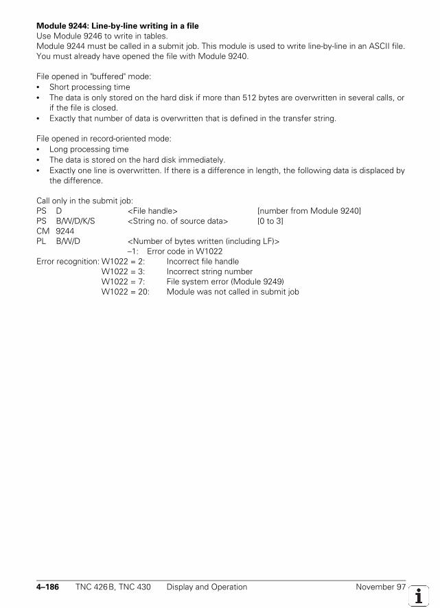
4–186 TNC 426B, TNC 430 Display and Operation November 97
Module 9244: Line-by-line writing in a file
Use Module 9246 to write in tables.Module 9244 must be called in a submit job. This module is used to write line-by-line in an ASCII file.You must already have opened the file with Module 9240.
File opened in "buffered" mode:• Short processing time• The data is only stored on the hard disk if more than 512 bytes are overwritten in several calls, or
if the file is closed.• Exactly that number of data is overwritten that is defined in the transfer string.
File opened in record-oriented mode:• Long processing time• The data is stored on the hard disk immediately.• Exactly one line is overwritten. If there is a difference in length, the following data is displaced by
the difference.
Call only in the submit job:PS D <File handle> [number from Module 9240]PS B/W/D/K/S <String no. of source data> [0 to 3]CM 9244PL B/W/D <Number of bytes written (including LF)>
–1: Error code in W1022Error recognition: W1022 = 2: Incorrect file handle
W1022 = 3: Incorrect string numberW1022 = 7: File system error (Module 9249)W1022 = 20: Module was not called in submit job
November 97 Display and Operation TNC 426B, TNC 430 4–187
4.13.20 User Parameters
You can provide the machine tool operator with easy access to up to 16 machine parameters. Hecan then call them through the MOD function by simply pressing the USER PARAMETER soft key.In MP7330.x you define which parameters are to be user parameters. If, for example, you wish todefine MP7230.1 as the first user parameter, you must enter 7230.01 in MP7330.0.
When the user selects a user parameter, a dialog appears on the screen. In MP7340.x youdefine that dialog by assigning a line number 0 to 4095 from the PLC dialog file. You must haveidentified the name of the PLC dialog file with the command PLCDIALOG= in the system fileOEM.SYS.
MP7330.0-15 Definition of user parametersInput: 0 to 9999.00 (no. of the desired machine parameter)
MP7340.0-15 Dialogs for user parametersInput: 0 to 4095 (line number in the PLC dialog file)
4–188 TNC 426B, TNC 430 Display and Operation November 97
4.13.21 Code Numbers
You can enter predefined code numbers in the MOD functions in order to activate certain functions.The following code numbers have a fixed meaning:
Code number Function
95 148 Machine parameter list
807 667 PLC modes
75 368 Automatic offset adjustment
123 Machine parameters accessible to the user
531 210 Erase M0 to M999 and B0 to B127
688 379 Oscilloscope
555 343 FN17: Overwrite system data, FN25: Overwrite datum
NET123 Ethernet settings (option)
The entered code number is registered in doubleword D276. You can evaluate this code and defineyour own functions for code numbers, or disable the code numbers with fixed meanings.
Set ResetD276 Code number last entered via MOD NC NC
4.13.22 Programming Station
With MP7210 you can set the control for use as a programming station without a machine. In aprogramming station only the "Programming and editing" and "Test run" operating modes function.You can also select whether the PLC should be active.
MP7210 Programming stationInput: 0 = controlling and programming
1 = programming station "PLC active"2 = programming station "PLC not active"

November 97 Display and Operation TNC 426B, TNC 430 4–189
4.13.23 Conversational Language
The TNC is delivered with all eleven NC dialog human languages. With MP7230.0 you select thelanguage in which the operator will work. If the selected language is not located on the hard disk,the error message LANGUAGE LOAD ERROR appears. You can then still work in the basic languageEnglish.
You can also save the dialogs that you write in several languages and select the desiredlanguage with MP7230.1-3. For this purpose your dialogs must be stored in permanently assignedlanguage directories in the PLC partition. These directories are:
PLC:\LANGUAGE\ CZECH\DANISH\DUTCH\ENGLISH\FINNISH\FRENCH\GERMAN\ITALIAN\POLISH\PORTUGUE\SPANISH\SWEDISH\HUNGARIAN\
This makes it possible for you to store PLC dialog files, PLC error files, and help files with theidentical file names in the different languages.
In the system file OEM.SYS you enter only the file names after the commandsPLCDIALOG= and PLCERROR=. The NC looks for the files in the paths given in MP7230.1 andMP7230.2, respectively. The entry MODEHELP= is overwritten with the selected path wheneverMP7230.3 is changed (see above).
MP7230 Changing the dialog languageInput: 0 = English
1 = German2 = Czech 3 = French 4 = Italian 5 = Spanish 6 = Portuguese 7 = Swedish 8 = Danish 9 = Finnish 10 = Dutch 11 = Polish12 = Hungarian
MP7230.0 NC dialog languageMP7230.1 PLC dialog language (user parameters), soft keys for OEM cyclesMP7230.2 PLC Error messagesMP7230.3 Help files
4–190 TNC 426B, TNC 430 Display and Operation November 97
Decimal sign
With MP7280 you define whether to use a comma or point as decimal sign.
MP7280 Decimal signInput: 0 = decimal comma
1 = decimal point
4.13.24 Memory Test
With MP7690 you select the data storage media to be tested during switch-on. The messageMEMORY TEST indicates that the test is in progress.
MP7690 MEMORY TEST during power-onInput: %xxxBit 0 Test the RAM 0 = MEMORY TEST during power-onBit 1 Test the EPROM 1 = no MEMORY TEST during power-onBit 2 Test the hard disk
4.13.25 Arc End-Point Tolerance
The TNC uses the entered NC data to calculate the deviation of the arc radius between thebeginning and end of the arc. If the tolerance defined in MP7431 is exceeded, the error messageCIRCLE END POS. INCORRECT will appear.
MP7431 Arc end-point toleranceInput: 0.0001 to 0.016 [mm]
4.13.26 Radius Compensation R+, R-
A path to be traversed can be increased or decreased by the tool radius by entering "R+" or "R-". Theinput dialog is not initiated with the "L" key but directly with the orange axis direction key. Forreasons of compatibility this function has been retained for point-to-point and straight cut controls.
Example: X + 20 R+ Conversational programmingG07 X + 20 G49 ISO programming
Paraxially compensated positioning blocks (R+/R-) and radius-compensated positioning blocks(RR/RL) must not be entered one after another. To avoid erroneous entries, MP7246 can be used todisable the input of paraxial positioning blocks.
MP7246 Disable paraxial positioning blocksInput: 0 = enable paraxial positioning blocks
1 = disable paraxial positioning blocks
November 97 Display and Operation TNC 426B, TNC 430 4–191
4.13.27 Power Interrupted Message
When the control voltage is disconnected the TNC issues the message POWER INTERRUPTED.The PLC will not become active until you acknowledge the message by pressing the CE key.With MP7212 you can suppress this message if it is not needed, for example for unattendedoperation.
MP7212 Power interrupted messageInput: 0 = Power interrupted message must be acknowledged with the CE key
1 = Power interrupted message does not appear
4.13.28 Operating Times
The TNC can measure up to eleven operating times and store them in a file in the SYS partition:
TNCTIME Control onMACHINETIME Machine onPROGTIME Program runPLCTIME0 to PLCTIME7 Freely defined times of the PLC
The operating times are displayed in the MOD function "machine time." With MP7237 you identifywhich times you can reset with the code number 857282 and which PLC times you wish to display.You define the dialogs which shall be displayed for the individual PLC operating times in MP7238.x.
The time is measured in seconds. During measurement the time information is updatedevery minute so that if the control is switched off no more that one minute will be lost. The NCmeasures the time for TNCTIME, MACHINETIME and PROGTIME. You start measuring theoperating times for PLCTIME0 to PLCTIME7 with Module 9190, and stop it with Module 9191.Except for TNCTIME, all operating times are saved during a hard-disk backup with the programTNCBACK (see section "Software Exchange").
You can evaluate and change the operating times with the following modules:• Module 9190: Start operating times• Module 9191: Stop operating times• Module 9192: Read operating times• Module 9193: Set operating times• Module 9194: Alarm when operating times exceeded
MP7237.0-1 Display and reset the operating timesInput: %xxxxxxxx
MP7237.0 Display PLC operating timesBit 0 to 7 0 = do not displayPLC operating times 1 to 8 1 = display
MP7237.1 Reset the PLC operating times code number 857282Bit 0 to 7 0 = do not resetPLC operating time 1 to 8 1 = reset
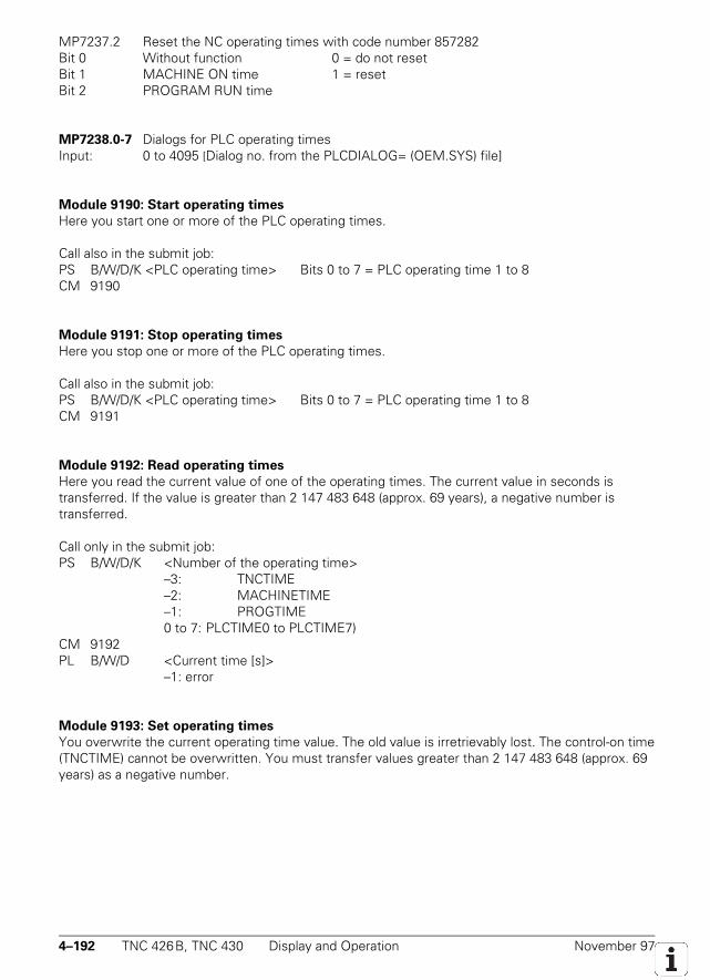
4–192 TNC 426B, TNC 430 Display and Operation November 97
MP7237.2 Reset the NC operating times with code number 857282Bit 0 Without function 0 = do not resetBit 1 MACHINE ON time 1 = resetBit 2 PROGRAM RUN time
MP7238.0-7 Dialogs for PLC operating timesInput: 0 to 4095 [Dialog no. from the PLCDIALOG= (OEM.SYS) file]
Module 9190: Start operating times
Here you start one or more of the PLC operating times.
Call also in the submit job:PS B/W/D/K <PLC operating time> Bits 0 to 7 = PLC operating time 1 to 8CM 9190
Module 9191: Stop operating times
Here you stop one or more of the PLC operating times.
Call also in the submit job:PS B/W/D/K <PLC operating time> Bits 0 to 7 = PLC operating time 1 to 8CM 9191
Module 9192: Read operating times
Here you read the current value of one of the operating times. The current value in seconds istransferred. If the value is greater than 2 147 483 648 (approx. 69 years), a negative number istransferred.
Call only in the submit job:PS B/W/D/K <Number of the operating time>
–3: TNCTIME–2: MACHINETIME–1: PROGTIME0 to 7: PLCTIME0 to PLCTIME7)
CM 9192PL B/W/D <Current time [s]>
–1: error
Module 9193: Set operating times
You overwrite the current operating time value. The old value is irretrievably lost. The control-on time(TNCTIME) cannot be overwritten. You must transfer values greater than 2 147 483 648 (approx. 69years) as a negative number.
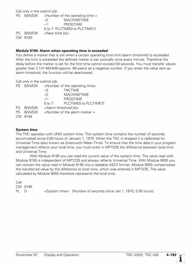
November 97 Display and Operation TNC 426B, TNC 430 4–193
Call only in the submit job:PS B/W/D/K <Number of the operating time >
–2: MACHINETIME–1: PROGTIME0 to 7: PLCTIME0 to PLCTIME7)
PS B/W/D/K <New time [s]>CM 9193
Module 9194: Alarm when operating time is exceeded
You define a marker that is set when a certain operating time limit (alarm threshold) is exceeded.After the limit is exceeded the defined marker is set cyclically once every minute. Therefore thedelay before the marker is set for the first time cannot exceed 59 seconds. You must transfer valuesgreater than 2 147 483 648 (approx. 69 years) as a negative number. If you enter the value zero asalarm threshold, the function will be deactivated.
Call only in the submit job:PS B/W/D/K <Number of the operating time>
–3: TNCTIME–2: MACHINETIME–1: PROGTIME0 to 7: PLCTIME0 to PLCTIME7)
PS B/W/D/K <Alarm threshold [s]>PS B/W/D/K <Number of the alarm marker >CM 9194
System time
The TNC operates with UNIX system time. This system time contains the number of secondsaccumulated since 0:00 hours of January 1, 1970. When the TNC is shipped it is calibrated forUniversal Time (also known as Greenwich Mean Time). To ensure that the time data in your programmanagement reflects your local time, you must enter in MP7235 the difference between local timeand Universal Time.
With Module 9195 you can read the current value of the system time. The value read withModule 9195 is independent of MP7235 and always reflects Universal Time. With Module 9055 youcan convert the value read in Module 9195 into a readable ASCII format. Module 9055 compensatesthe transferred value by the difference to local time, which was entered in MP7235. The valuecalculated by Module 9055 therefore represents the local time.
Call:CM 9195PL D <System time> [Number of seconds since Jan.1, 1970, 0.00 hours]
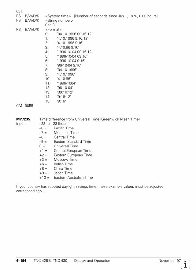
4–194 TNC 426B, TNC 430 Display and Operation November 97
Call:PS B/W/D/K <System time> [Number of seconds since Jan.1, 1970, 0.00 hours]PS B/W/D/K <String number>
0 to 3PS B/W/D/K <Format>
0: "04.10.1996 09:16:12"1: "4.10.1996 9:16:12"2: "4.10.1996 9:16"3: "4.10.96 9:16"4: "1996-10-04 09:16:12"5: "1996-10-04 09:16"6: "1996-10-04 9:16"7: "96-10-04 9:16"
8: "04.10.1996"9: "4.10.1996"10: "4.10.96"
11: "1996-1004"12: "96-10-04"
13: "09:16:12"14: "9:16:12"
15: "9:16"CM 9055
MP7235 Time difference from Universal Time (Greenwich Mean Time)Input: –23 to +23 [hours]
–8 = Pacific Time–7 = Mountain Time–6 = Central Time–5 = Eastern Standard Time0 = Universal Time+1 = Central European Time+2 = Eastern European Time+3 = Moscow Time+6 = Indian Time+8 = China Time+9 = Japan Time+10 = Eastern Australian Time
If your country has adopted daylight savings time, these example values must be adjustedcorrespondingly.

November 97 Display and Operation TNC 426B, TNC 430 4–195
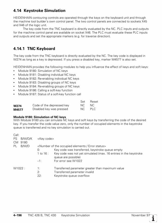
4–196 TNC 426 B, TNC 430 Keystroke Simulation November 97
4.14 Keystroke Simulation
HEIDENHAIN contouring controls are operated through the keys on the keyboard unit and throughthe machine tool builder's own control panel. The two control panels are connected to sockets X45and X46 of the logic unit.
The key code from the TNC keyboard is directly evaluated by the NC. PLC inputs and outputsfor the machine control panel are available on socket X46. The PLC must evaluate these PLC inputsand outputs and set the appropriate markers (e.g. for traverse direction).
4.14.1 TNC Keyboard
The key code from the TNC keyboard is directly evaluated by the NC. The key code is displayed inW274 as long as a key is depressed. If you press a disabled key, marker M4577 is also set.
HEIDENHAIN provides the following modules to help you influence the effect of keys and soft keys:• Module 9180: Simulation of NC keys• Module 9181: Disabling individual NC keys• Module 9182: Re-enabling individual NC keys• Module 9183: Disabling groups of NC keys• Module 9184: Re-enabling groups of NC keys• Module 9186: Calling a soft-key function• Module 9187: Status of a soft-key function call
Set ResetW274 Code of the depressed key NC NCM4577 Disabled key was pressed NC PLC
Module 9180: Simulation of NC keysWith Module 9180 you can simulate NC keys and soft keys by transferring the code of the desiredkey. If you transfer the code value zero, only the number of occupied elements in the keystrokequeue is transferred and no key simulation is carried out.
Call:PS B/W/D/K <Key code>CM 9180PL B/W/D <Number of the occupied elements / Error status>
0: Key code was transferred, keystroke queue empty1 to 16 : Key code was not yet simulated (max. 16 entries in the keystroke
queue are possible)–1: For error see W1022
W1022 : 1: Transferred parameter greater than maximum value2: Transferred parameter invalid22: Keystroke queue overflow
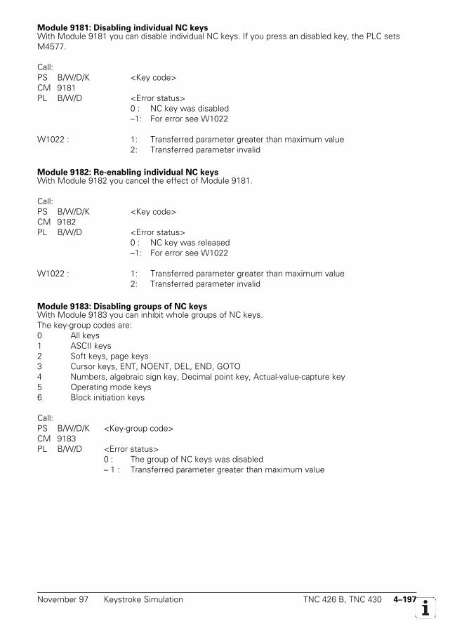
November 97 Keystroke Simulation TNC 426 B, TNC 430 4–197
Module 9181: Disabling individual NC keysWith Module 9181 you can disable individual NC keys. If you press an disabled key, the PLC setsM4577.
Call:PS B/W/D/K <Key code>CM 9181PL B/W/D <Error status>
0 : NC key was disabled–1: For error see W1022
W1022 : 1: Transferred parameter greater than maximum value2: Transferred parameter invalid
Module 9182: Re-enabling individual NC keysWith Module 9182 you cancel the effect of Module 9181.
Call:PS B/W/D/K <Key code>CM 9182PL B/W/D <Error status>
0 : NC key was released–1: For error see W1022
W1022 : 1: Transferred parameter greater than maximum value2: Transferred parameter invalid
Module 9183: Disabling groups of NC keysWith Module 9183 you can inhibit whole groups of NC keys.The key-group codes are:0 All keys1 ASCII keys2 Soft keys, page keys3 Cursor keys, ENT, NOENT, DEL, END, GOTO4 Numbers, algebraic sign key, Decimal point key, Actual-value-capture key5 Operating mode keys6 Block initiation keys
Call:PS B/W/D/K <Key-group code>CM 9183PL B/W/D <Error status>
0 : The group of NC keys was disabled– 1 : Transferred parameter greater than maximum value
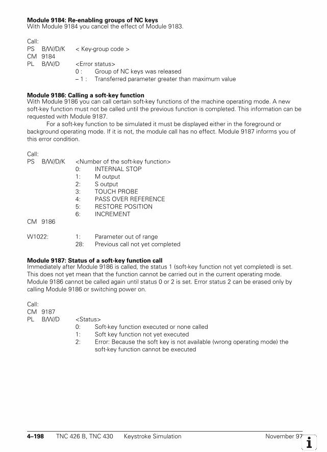
4–198 TNC 426 B, TNC 430 Keystroke Simulation November 97
Module 9184: Re-enabling groups of NC keysWith Module 9184 you cancel the effect of Module 9183.
Call:PS B/W/D/K < Key-group code >CM 9184PL B/W/D <Error status>
0 : Group of NC keys was released– 1 : Transferred parameter greater than maximum value
Module 9186: Calling a soft-key functionWith Module 9186 you can call certain soft-key functions of the machine operating mode. A newsoft-key function must not be called until the previous function is completed. This information can berequested with Module 9187.
For a soft-key function to be simulated it must be displayed either in the foreground orbackground operating mode. If it is not, the module call has no effect. Module 9187 informs you ofthis error condition.
Call:PS B/W/D/K <Number of the soft-key function>
0: INTERNAL STOP 1: M output 2: S output
3: TOUCH PROBE 4: PASS OVER REFERENCE 5: RESTORE POSITION
6: INCREMENTCM 9186
W1022: 1: Parameter out of range28: Previous call not yet completed
Module 9187: Status of a soft-key function callImmediately after Module 9186 is called, the status 1 (soft-key function not yet completed) is set.This does not yet mean that the function cannot be carried out in the current operating mode.Module 9186 cannot be called again until status 0 or 2 is set. Error status 2 can be erased only bycalling Module 9186 or switching power on.
Call:CM 9187PL B/W/D <Status>
0: Soft-key function executed or none called1: Soft key function not yet executed2: Error: Because the soft key is not available (wrong operating mode) the
soft-key function cannot be executed
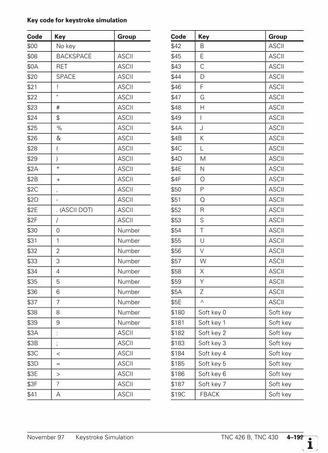
November 97 Keystroke Simulation TNC 426 B, TNC 430 4–199
Key code for keystroke simulation
Code Key Group Code Key Group
$00 No key $42 B ASCII
$08 BACKSPACE ASCII $45 E ASCII
$0A RET ASCII $43 C ASCII
$20 SPACE ASCII $44 D ASCII
$21 ! ASCII $46 F ASCII
$22 " ASCII $47 G ASCII
$23 # ASCII $48 H ASCII
$24 $ ASCII $49 I ASCII
$25 % ASCII $4A J ASCII
$26 & ASCII $4B K ASCII
$28 ( ASCII $4C L ASCII
$29 ) ASCII $4D M ASCII
$2A * ASCII $4E N ASCII
$2B + ASCII $4F O ASCII
$2C , ASCII $50 P ASCII
$2D - ASCII $51 Q ASCII
$2E . (ASCII DOT) ASCII $52 R ASCII
$2F / ASCII $53 S ASCII
$30 0 Number $54 T ASCII
$31 1 Number $55 U ASCII
$32 2 Number $56 V ASCII
$33 3 Number $57 W ASCII
$34 4 Number $58 X ASCII
$35 5 Number $59 Y ASCII
$36 6 Number $5A Z ASCII
$37 7 Number $5E ^ ASCII
$38 8 Number $180 Soft key 0 Soft key
$39 9 Number $181 Soft key 1 Soft key
$3A : ASCII $182 Soft key 2 Soft key
$3B ; ASCII $183 Soft key 3 Soft key
$3C < ASCII $184 Soft key 4 Soft key
$3D = ASCII $185 Soft key 5 Soft key
$3E > ASCII $186 Soft key 6 Soft key
$3F ? ASCII $187 Soft key 7 Soft key
$41 A ASCII $19C FBACK Soft key
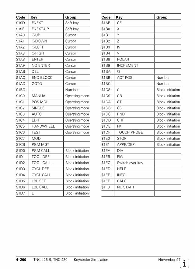
4–200 TNC 426 B, TNC 430 Keystroke Simulation November 97
Code Key Group Code Key Group
$19D FNEXT Soft key $1AE CE
$19E FNEXT-UP Soft key $1B0 X
$1A0 C-UP Cursor $1B1 Y
$1A1 C-DOWN Cursor $1B2 Z
$1A2 C-LEFT Cursor $1B3 IV
$1A3 C-RIGHT Cursor $1B4 V
$1A8 ENTER Cursor $1B8 POLAR
$1A9 NO ENTER Cursor $1B9 INCREMENT
$1AB DEL Cursor $1BA Q
$1AC END BLOCK Cursor $1BB ACT POS Number
$1AD GOTO Cursor $1BC – Number
$1BD . Number $1D8 C Block initiation
$1C0 MANUAL Operating mode $1D9 CR Block initiation
$1C1 POS MDI Operating mode $1DA CT Block initiation
$1C2 SINGLE Operating mode $1DB CC Block initiation
$1C3 AUTO Operating mode $1DC RND Block initiation
$1C4 EDIT Operating mode $1DD CHF Block initiation
$1C5 HANDWHEEL Operating mode $1DE FK Block initiation
$1C6 TEST Operating mode $1DF TOUCH PROBE Block initiation
$1C7 MOD $1E0 STOP Block initiation
$1CB PGM MGT $1E1 APPR/DEP Block initiation
$1D0 PGM CALL Block initiation $1EA DIA
$1D1 TOOL DEF Block initiation $1EB FIG
$1D2 TOOL CALL Block initiation $1EC Switch-over key
$1D3 CYCL DEF Block initiation $1ED HELP
$1D4 CYCL CALL Block initiation $1EE INFO
$1D5 LBL SET Block initiation $1EF CALC
$1D6 LBL CALL Block initiation $1F0 NC START
$1D7 L Block initiation
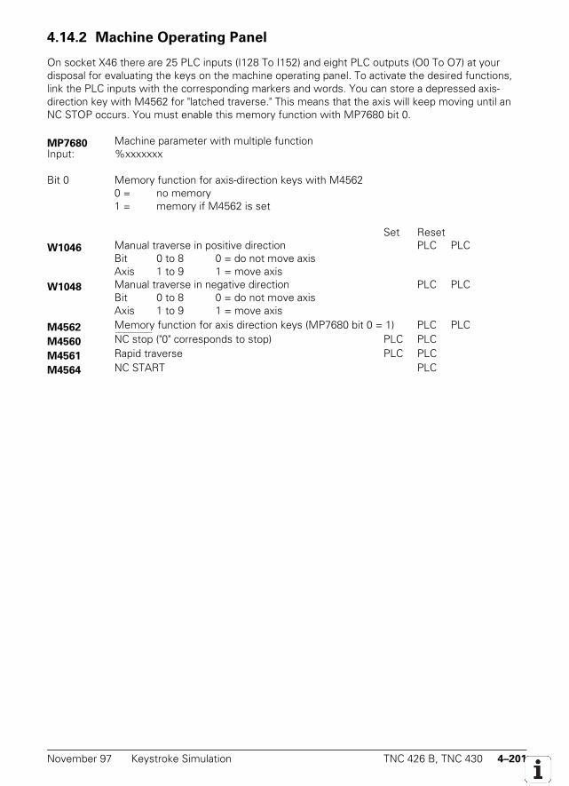
November 97 Keystroke Simulation TNC 426 B, TNC 430 4–201
4.14.2 Machine Operating Panel
On socket X46 there are 25 PLC inputs (I128 To I152) and eight PLC outputs (O0 To O7) at yourdisposal for evaluating the keys on the machine operating panel. To activate the desired functions,link the PLC inputs with the corresponding markers and words. You can store a depressed axis-direction key with M4562 for "latched traverse." This means that the axis will keep moving until anNC STOP occurs. You must enable this memory function with MP7680 bit 0.
MP7680 Machine parameter with multiple functionInput: %xxxxxxx
Bit 0 Memory function for axis-direction keys with M45620 = no memory1 = memory if M4562 is set
Set ResetW1046 Manual traverse in positive direction PLC PLC
Bit 0 to 8 0 = do not move axisAxis 1 to 9 1 = move axis
W1048 Manual traverse in negative direction PLC PLCBit 0 to 8 0 = do not move axisAxis 1 to 9 1 = move axis
M4562 Memory function for axis direction keys (MP7680 bit 0 = 1) PLC PLC
M4560 NC stop_______________
("0" corresponds to stop) PLC PLC
M4561 Rapid traverse PLC PLC
M4564 NC START PLC

4–202 TNC 426 B, TNC 430 Keystroke Simulation November 97

November 97 Keystroke Simulation TNC 426 B, TNC 430 4–203
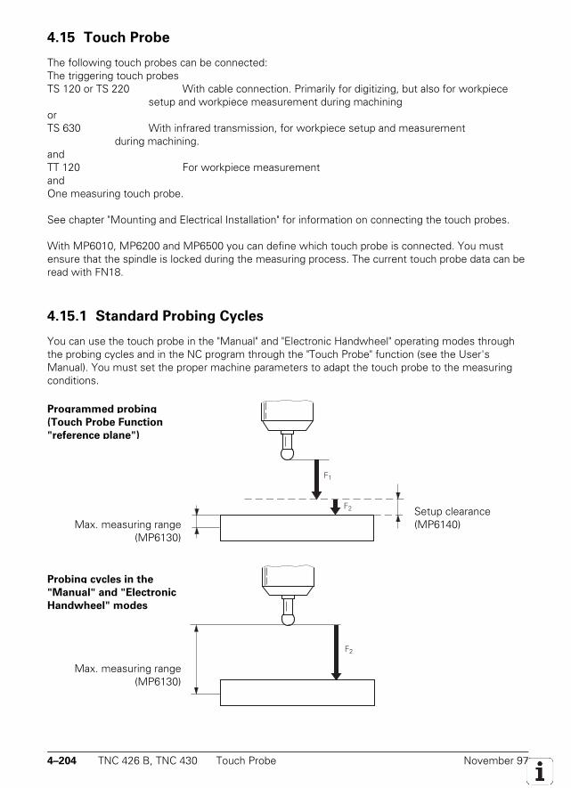
4–204 TNC 426 B, TNC 430 Touch Probe November 97
4.15 Touch Probe
The following touch probes can be connected:The triggering touch probesTS 120 or TS 220 With cable connection. Primarily for digitizing, but also for workpiece
setup and workpiece measurement during machiningorTS 630 With infrared transmission, for workpiece setup and measurement
during machining.andTT 120 For workpiece measurementandOne measuring touch probe.
See chapter "Mounting and Electrical Installation" for information on connecting the touch probes.
With MP6010, MP6200 and MP6500 you can define which touch probe is connected. You mustensure that the spindle is locked during the measuring process. The current touch probe data can beread with FN18.
4.15.1 Standard Probing Cycles
You can use the touch probe in the "Manual" and "Electronic Handwheel" operating modes throughthe probing cycles and in the NC program through the "Touch Probe" function (see the User'sManual). You must set the proper machine parameters to adapt the touch probe to the measuringconditions.
Programmed probing
(Touch Probe Function
"reference plane")
Max. measuring range(MP6130)
Probing cycles in the
"Manual" and "Electronic
Handwheel" modes
Max. measuring range(MP6130)
F1
F2
F2
Setup clearance(MP6140)
November 97 Touch Probe TNC 426 B, TNC 430 4–205
F1 = rapid traverse during programmed probing: MP6150 for triggering touch probe MP6200 = 0MP6361 for measuring touch probe MP6200 = 1
F2 = probing feed rate: MP6120 for triggering touch probe MP6200 = 0MP6360 for measuring touch probe MP6200 = 1
If the maximum measuring range (MP6130) is exceeded, the error message TOUCH POINTINACCESSIBLE appears. For the probing cycles in the "Manual" and "Electronic Handwheel" modes,MP6140, MP6150 and MP6361 have no function.
M4055 is set by the NC before the probing process is started. The NC then waits until youreset M4055 before it performs the probe function. This allows you, for example, to clean themeasured object with compressed air before probing. The probing function is controlled entirelyfrom the NC.
M4050 to M4054 inform you of certain conditions and allows you to process this informationif desired. If you set M4056, the NC stops the machine in all operating modes as soon as the stylusis deflected. Also, the maximum feed rate is limited to the value in MP6150 or MP6361. If M4056 isnot set, the control recognizes stylus deflection only if the probing function has been started.HEIDENHAIN therefore recommends setting M4056 as soon as the touch probe is in the spindle.
With MP7411 you select whether the tool data (length, radius, axis) used in a touch probeblock are taken from the last TOOL CALL block or from the calibrated data of the probe system.When MP7411 = 1 is set, you can use soft keys to have the effective length and the effective radiustaken over by the tool table. Enter the tool number in the menu for touch probe calibration.
The TNC can store the calibration data for up to three touch probes at the same time. Thecurrent data can be activated using M4574/M4575. For three sets of calibration data to be stored atthe same time, bit 2 must be set in MP7490.
Programmed probing (TOUCH PROBE function "reference plane")The touch probe behavior can be set with FN17:SYSWRITE ID990 NR1. With input value = 0 thesetup clearance form MP6140 and the effective radius are used. With input value > 0 the effectiveradius and setup clearance are assumed to be zero. This function might be used for themeasurement of small holes.
Center misalignmentYou can find the center offset of the probe system while calibrating. This center offset is thenautomatically compensated in all probing operations (see User's Manual). With MP6160 you definewhether spindle orientation for a rotation by 180° will be performed directly by the NC or through thePLC. If the NC orients the spindle directly, you need only reset M4012 (see the section "SpindleOrientation"). The PLC orients the spindle, you must enter the number of the M function in MP6160.The respective position is then transferred as in the "spindle orientation" cycle.
For the triggering touch probe, the rotation is activated by pressing a soft key. For themeasuring touch probe, the rotation is automatically activated during measurement. You candeselect this with MP6321. During every spindle orientation the Marker M4017 is set.
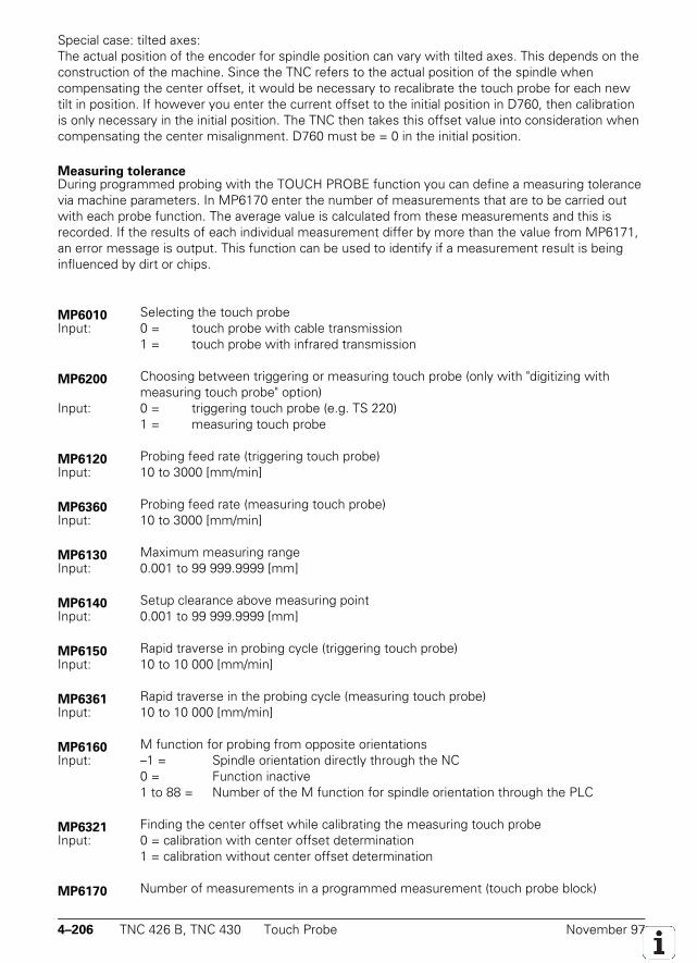
4–206 TNC 426 B, TNC 430 Touch Probe November 97
Special case: tilted axes:The actual position of the encoder for spindle position can vary with tilted axes. This depends on theconstruction of the machine. Since the TNC refers to the actual position of the spindle whencompensating the center offset, it would be necessary to recalibrate the touch probe for each newtilt in position. If however you enter the current offset to the initial position in D760, then calibrationis only necessary in the initial position. The TNC then takes this offset value into consideration whencompensating the center misalignment. D760 must be = 0 in the initial position.
Measuring toleranceDuring programmed probing with the TOUCH PROBE function you can define a measuring tolerancevia machine parameters. In MP6170 enter the number of measurements that are to be carried outwith each probe function. The average value is calculated from these measurements and this isrecorded. If the results of each individual measurement differ by more than the value from MP6171,an error message is output. This function can be used to identify if a measurement result is beinginfluenced by dirt or chips.
MP6010 Selecting the touch probeInput: 0 = touch probe with cable transmission
1 = touch probe with infrared transmission
MP6200 Choosing between triggering or measuring touch probe (only with "digitizing withmeasuring touch probe" option)
Input: 0 = triggering touch probe (e.g. TS 220)1 = measuring touch probe
MP6120 Probing feed rate (triggering touch probe)Input: 10 to 3000 [mm/min]
MP6360 Probing feed rate (measuring touch probe)Input: 10 to 3000 [mm/min]
MP6130 Maximum measuring rangeInput: 0.001 to 99 999.9999 [mm]
MP6140 Setup clearance above measuring pointInput: 0.001 to 99 999.9999 [mm]
MP6150 Rapid traverse in probing cycle (triggering touch probe)Input: 10 to 10 000 [mm/min]
MP6361 Rapid traverse in the probing cycle (measuring touch probe)Input: 10 to 10 000 [mm/min]
MP6160 M function for probing from opposite orientationsInput: –1 = Spindle orientation directly through the NC
0 = Function inactive1 to 88 = Number of the M function for spindle orientation through the PLC
MP6321 Finding the center offset while calibrating the measuring touch probeInput: 0 = calibration with center offset determination
1 = calibration without center offset determination
MP6170 Number of measurements in a programmed measurement (touch probe block)
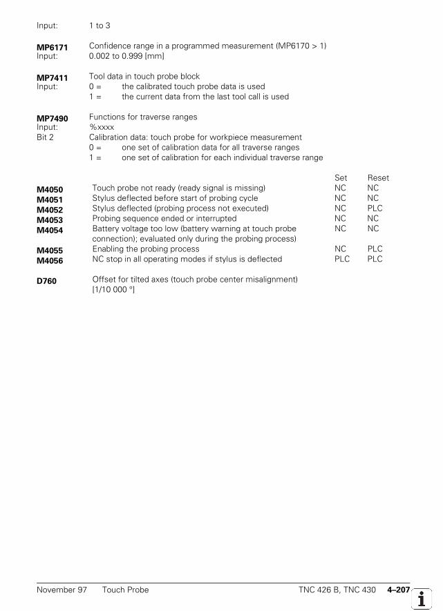
November 97 Touch Probe TNC 426 B, TNC 430 4–207
Input: 1 to 3
MP6171 Confidence range in a programmed measurement (MP6170 > 1)Input: 0.002 to 0.999 [mm]
MP7411 Tool data in touch probe blockInput: 0 = the calibrated touch probe data is used
1 = the current data from the last tool call is used
MP7490 Functions for traverse rangesInput: %xxxxBit 2 Calibration data: touch probe for workpiece measurement
0 = one set of calibration data for all traverse ranges1 = one set of calibration for each individual traverse range
Set ResetM4050 Touch probe not ready (ready signal is missing) NC NCM4051 Stylus deflected before start of probing cycle NC NCM4052 Stylus deflected (probing process not executed) NC PLCM4053 Probing sequence ended or interrupted NC NCM4054 Battery voltage too low (battery warning at touch probe
connection); evaluated only during the probing process)NC NC
M4055 Enabling the probing process NC PLCM4056 NC stop in all operating modes if stylus is deflected PLC PLC
D760 Offset for tilted axes (touch probe center misalignment)[1/10 000 °]
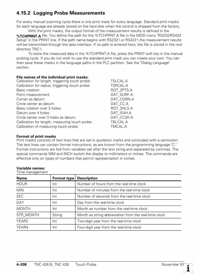
4–208 TNC 426 B, TNC 430 Touch Probe November 97
4.15.2 Logging Probe Measurements
For every manual scanning cycle there is one print mask for every language. Standard print masksfor each language are already stored on the hard disk when the control is shipped from the factory.
With the print masks, the output format of the measurement results is defined in the%TCHPRNT.A file. You define the path for the %TCHPRNT.A file in the MOD menu "RS232/RS422Setup" in the PRINT line. If the path name begins with RS232:\ or RS422:\ the measurement resultswill be transmitted through the data interface. If no path is entered here, the file is stored in the rootdirectory TNC:\.
To store the measured data in the %TCHPRNT.A file, press the PRINT soft key in the manualprobing cycle. If you do not wish to use the standard print mask you can create your own. You canthen save these masks in the language paths in the PLC partition. See the "Dialog Language"section.
File names of the individual print masks:Calibration for length, triggering touch probe: TSLCAL.ACalibration for radius, triggering touch probe: TSRCAL.ABasic rotation: ROT_2PTS.APoint measurement: DAT_SURF.ACorner as datum: DAT_CORN.ACircle center as datum: DAT_CC.ABasic rotation over 2 holes: ROT_2HLS.ADatum over 4 holes: DAT_IS4H.ACircle center over 3 holes as datum: DAT_CC3H.ACalibration for length, measuring touch probe: TBLCAL.ACalibration of measuring touch probe: TMCAL.A
Format of print masksPrint masks consists of text lines that are set in quotation marks and concluded with a semicolon.The text lines can contain format instructions, as are known from the programming language "C."Format instructions are fed from variables set after the text string and separated by commas. Thespecial commands MM and INCH switch the display to millimeters or inches. The commands areeffective only on types of numbers that permit representation in inches.
Variable names:Time management
Name Format type Description
HOUR Int Number of hours from the real-time clock
MIN Int Number of minutes from the real-time clock
SEC Int Number of seconds from the real-time clock
DAY Int Day from the real-time clock
MONTH Int Month as number from the real-time clock
STR_MONTH String Month as string abbreviation from the real-time clock
YEAR2 Int Two-digit year from the real-time clock
YEAR4 Int Four-digit year from the real-time clock
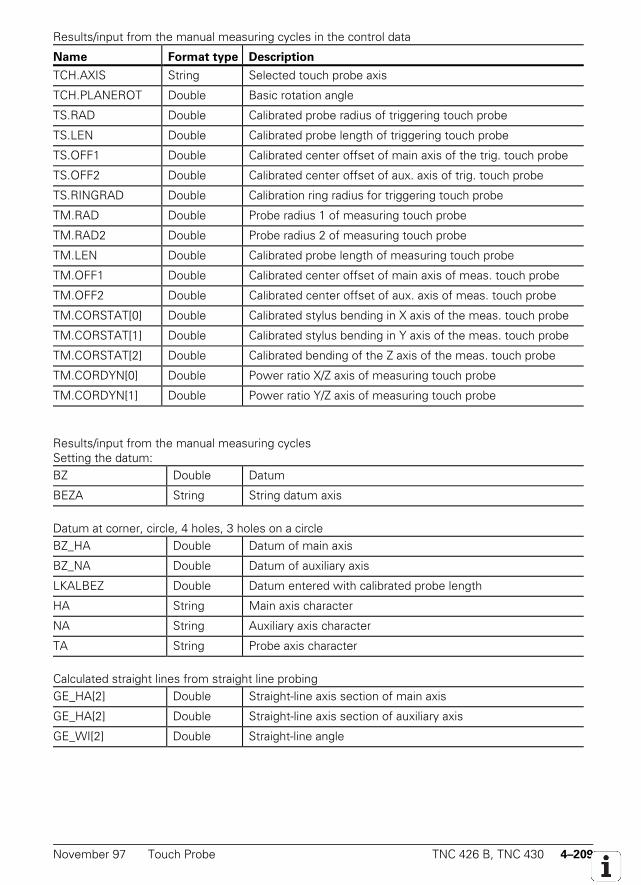
November 97 Touch Probe TNC 426 B, TNC 430 4–209
Results/input from the manual measuring cycles in the control data
Name Format type Description
TCH.AXIS String Selected touch probe axis
TCH.PLANEROT Double Basic rotation angle
TS.RAD Double Calibrated probe radius of triggering touch probe
TS.LEN Double Calibrated probe length of triggering touch probe
TS.OFF1 Double Calibrated center offset of main axis of the trig. touch probe
TS.OFF2 Double Calibrated center offset of aux. axis of trig. touch probe
TS.RINGRAD Double Calibration ring radius for triggering touch probe
TM.RAD Double Probe radius 1 of measuring touch probe
TM.RAD2 Double Probe radius 2 of measuring touch probe
TM.LEN Double Calibrated probe length of measuring touch probe
TM.OFF1 Double Calibrated center offset of main axis of meas. touch probe
TM.OFF2 Double Calibrated center offset of aux. axis of meas. touch probe
TM.CORSTAT[0] Double Calibrated stylus bending in X axis of the meas. touch probe
TM.CORSTAT[1] Double Calibrated stylus bending in Y axis of the meas. touch probe
TM.CORSTAT[2] Double Calibrated bending of the Z axis of the meas. touch probe
TM.CORDYN[0] Double Power ratio X/Z axis of measuring touch probe
TM.CORDYN[1] Double Power ratio Y/Z axis of measuring touch probe
Results/input from the manual measuring cyclesSetting the datum:BZ Double Datum
BEZA String String datum axis
Datum at corner, circle, 4 holes, 3 holes on a circleBZ_HA Double Datum of main axis
BZ_NA Double Datum of auxiliary axis
LKALBEZ Double Datum entered with calibrated probe length
HA String Main axis character
NA String Auxiliary axis character
TA String Probe axis character
Calculated straight lines from straight line probingGE_HA[2] Double Straight-line axis section of main axis
GE_HA[2] Double Straight-line axis section of auxiliary axis
GE_WI[2] Double Straight-line angle
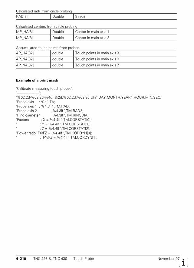
4–210 TNC 426 B, TNC 430 Touch Probe November 97
Calculated radii from circle probingRAD[8] Double 8 radii
Calculated centers from circle probingMP_HA[8] Double Center in main axis 1
MP_NA[8] Double Center in main axis 2
Accumulated touch points from probesAP_HA[32] double Touch points in main axis X
AP_NA[32] double Touch points in main axis Y
AP_NA[32] double Touch points in main axis Z
Example of a print mask
"Calibrate measuring touch probe:";"----------------------";"%02.2d-%02.2d-%4d, %2d:%02.2d:%02.2d Uhr",DAY,MONTH,YEAR4,HOUR,MIN,SEC;"Probe axis : %s“,TA;"Probe axis 1 : %4.3lf“,TM.RAD;"Probe axis 2 : %4.3lf“,TM.RAD2;"Ring diameter : %4.3lf“,TM.RINGDIA;"Factors : X = %4.4lf“,TM.CORSTAT[0];" : Y = %4.4lf“,TM.CORSTAT[1];" : Z = %4.4lf“,TM.CORSTAT[2];"Power ratio: FX/FZ = %4.4lf“,TM.CORDYN[0];" : FY/FZ = %4.4lf“,TM.CORDYN[1];

November 97 Touch Probe TNC 426 B, TNC 430 4–211
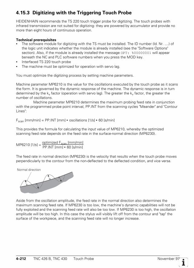
4–212 TNC 426 B, TNC 430 Touch Probe November 97
4.15.3 Digitizing with the Triggering Touch Probe
HEIDENHAIN recommends the TS 220 touch trigger probe for digitizing. The touch probes withinfrared transmission are not suited for digitizing: they are powered by accumulator and provide nomore than eight hours of continuous operation.
Technical prerequisites• The software module for digitizing with the TS must be installed. The ID number (Id. Nr. ....) of
the logic unit indicates whether the module is already installed (see the "Software Options"section). Also, if the module is already installed the message OPT: %00000001 will appearbeneath the NC and PLC software numbers when you press the MOD key.
• Interfaced TS 220 touch probe• The machine must be optimized for operation with servo lag.
You must optimize the digitizing process by setting machine parameters.
Machine parameter MP6210 is the value for the oscillations executed by the touch probe as it scansthe form. It is governed by the dynamic response of the machine. The dynamic response is in turndetermined by the kv factor (operation with servo lag). The greater the kv factor, the greater thenumber of oscillations.
Machine parameter MP6210 determines the maximum probing feed rate in conjunctionwith the programmed probe point interval, PP.INT from the scanning cycles "Meander" and "ContourLines":
Fscan [mm/min] = PP.INT [mm] • oscillations [1/s] • 60 [s/min]
This provides the formula for calculating the input value of MP6210, whereby the optimizedscanning feed rate depends on the feed rate in the surface-normal direction (MP6230).
MP6210 [1/s] = optimized Fscan [mm/min]PP.INT [mm] • 60 [s/min]
The feed rate in normal direction (MP6230) is the velocity that results when the touch probe movesperpendicularly to the contour from the non-deflected to the deflected condition, and vice versa.
Normal direction
Aside from the oscillation amplitude, the feed rate in the normal direction also determines themaximum scanning feed rate. If MP6230 is too low, the machine's dynamic capabilities will not befully exploited and the scanning feed rate will also be too low. If MP6230 is too high, the oscillationamplitude will be too high. In this case the stylus will visibly lift off from the contour and "tap" thesurface of the workpiece, and the scanning feed rate will no longer increase.
November 97 Touch Probe TNC 426 B, TNC 430 4–213
You define the maximum stylus deflection in machine parameter MP6240. The value in MP6240will depend on the length of the stylus used. MP6240 defines the maximum travel by which thestylus retracts on inside corners. If the touch probe is not clear of the surface after the stylus backsout by the travel defined in MP6240, the touch probe axis (e.g. Z) is retracted in the positivedirection. Digitizing continues as soon as the touch probe is clear.
If your input value is too small, the touch probe may get caught up in an endless repetitive attemptto come free of an inside corner.
Machine parameter MP6260 defines whether an M90 is appended to each NC block in the outputdigitized data (see also "Contouring Behavior").
Machine parameter MP6270 defines the output format of the digitized data, i.e. the number ofdecimal places to which the coordinates are output
MP6210 Number of oscillations in normal direction per secondInput: 0 to 65.535 [1/s]
MP6230 Feed rate in normal directionInput: 0 to 1000 [mm/min]
MP6240 Maximum stylus deflectionInput: 0 to 10.000 [mm]
MP6260 Output of M90 for NC blocks with digitized dataInput: 0 = no output of M90
1 = output of M90 in each NC block
MP6270 Rounding decimal placesInput: 0 = output in 0.001-mm steps (1 µm)
1 = output in 0.01-mm steps (10 µm)2 = output in 0.0001-mm steps (0.1 µm)
Scanning cyclesBecause it has direct access to the position control loop of the TNC controller, the touch probe canrecord measured values very rapidly (3 to 5 values per second). With a programmed probe pointinterval of 1 mm, this produces a scanning feed rate of 180 to 300 mm/min. Three scanning cyclesare used for digitizing: "Range," "Meander" and "Contour Lines."
The "Range" cycle defines the cuboid scanning range and the file where the digitized data arestored. You can save the digitized data in the program memory of the control or on a PC.
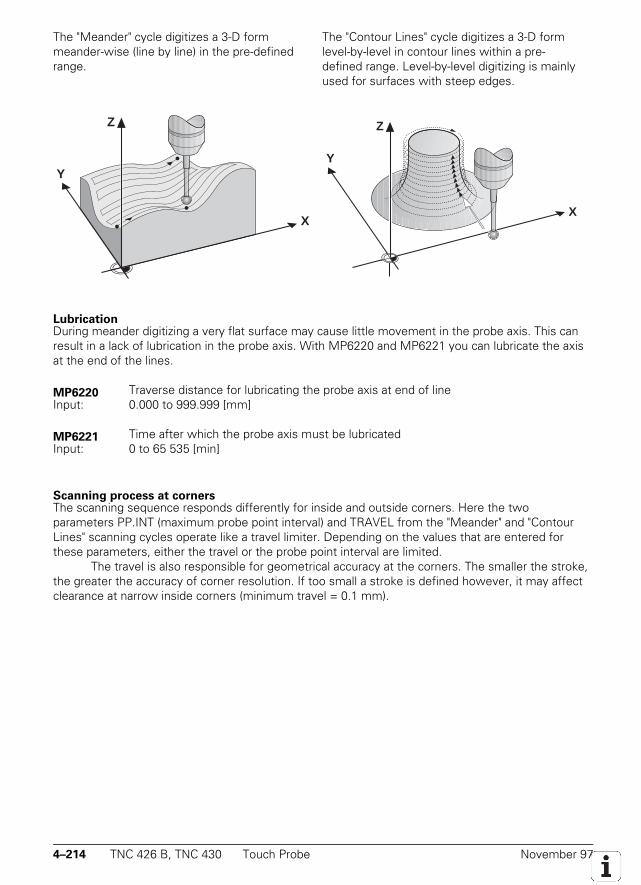
4–214 TNC 426 B, TNC 430 Touch Probe November 97
The "Meander" cycle digitizes a 3-D formmeander-wise (line by line) in the pre-definedrange.
Y
X
Z
The "Contour Lines" cycle digitizes a 3-D formlevel-by-level in contour lines within a pre-defined range. Level-by-level digitizing is mainlyused for surfaces with steep edges.
Y
X
Z
LubricationDuring meander digitizing a very flat surface may cause little movement in the probe axis. This canresult in a lack of lubrication in the probe axis. With MP6220 and MP6221 you can lubricate the axisat the end of the lines.
MP6220 Traverse distance for lubricating the probe axis at end of lineInput: 0.000 to 999.999 [mm]
MP6221 Time after which the probe axis must be lubricatedInput: 0 to 65 535 [min]
Scanning process at cornersThe scanning sequence responds differently for inside and outside corners. Here the twoparameters PP.INT (maximum probe point interval) and TRAVEL from the "Meander" and "ContourLines" scanning cycles operate like a travel limiter. Depending on the values that are entered forthese parameters, either the travel or the probe point interval are limited.
The travel is also responsible for geometrical accuracy at the corners. The smaller the stroke,the greater the accuracy of corner resolution. If too small a stroke is defined however, it may affectclearance at narrow inside corners (minimum travel = 0.1 mm).
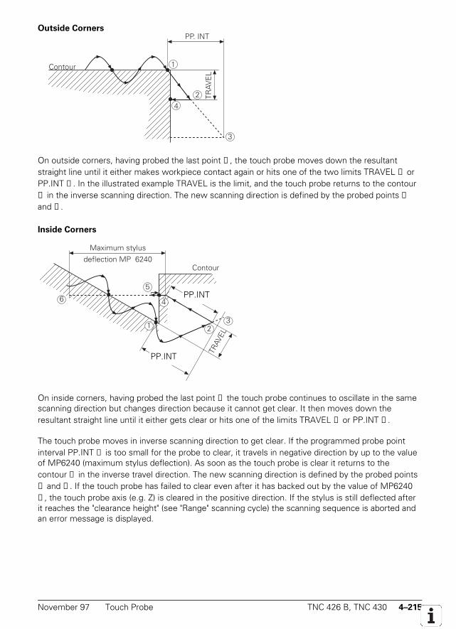
November 97 Touch Probe TNC 426 B, TNC 430 4–215
Outside CornersPP. INT
TRAV
EL
1
4
3
2
Contour
On outside corners, having probed the last point ①, the touch probe moves down the resultantstraight line until it either makes workpiece contact again or hits one of the two limits TRAVEL ② orPP.INT ③. In the illustrated example TRAVEL is the limit, and the touch probe returns to the contour④ in the inverse scanning direction. The new scanning direction is defined by the probed points ①and ④.
Inside Corners
Contour
P.IN
TRAV
EL
3
P.IN
1
4
2
Maximum stylusdeflection MP 6240
5
6
On inside corners, having probed the last point ① the touch probe continues to oscillate in the samescanning direction but changes direction because it cannot get clear. It then moves down theresultant straight line until it either gets clear or hits one of the limits TRAVEL ② or PP.INT ③.
The touch probe moves in inverse scanning direction to get clear. If the programmed probe pointinterval PP.INT ④ is too small for the probe to clear, it travels in negative direction by up to the valueof MP6240 (maximum stylus deflection). As soon as the touch probe is clear it returns to thecontour ⑤ in the inverse travel direction. The new scanning direction is defined by the probed points① and ⑤. If the touch probe has failed to clear even after it has backed out by the value of MP6240⑥, the touch probe axis (e.g. Z) is cleared in the positive direction. If the stylus is still deflected afterit reaches the "clearance height" (see "Range" scanning cycle) the scanning sequence is aborted andan error message is displayed.
PP.INT
PP.INT
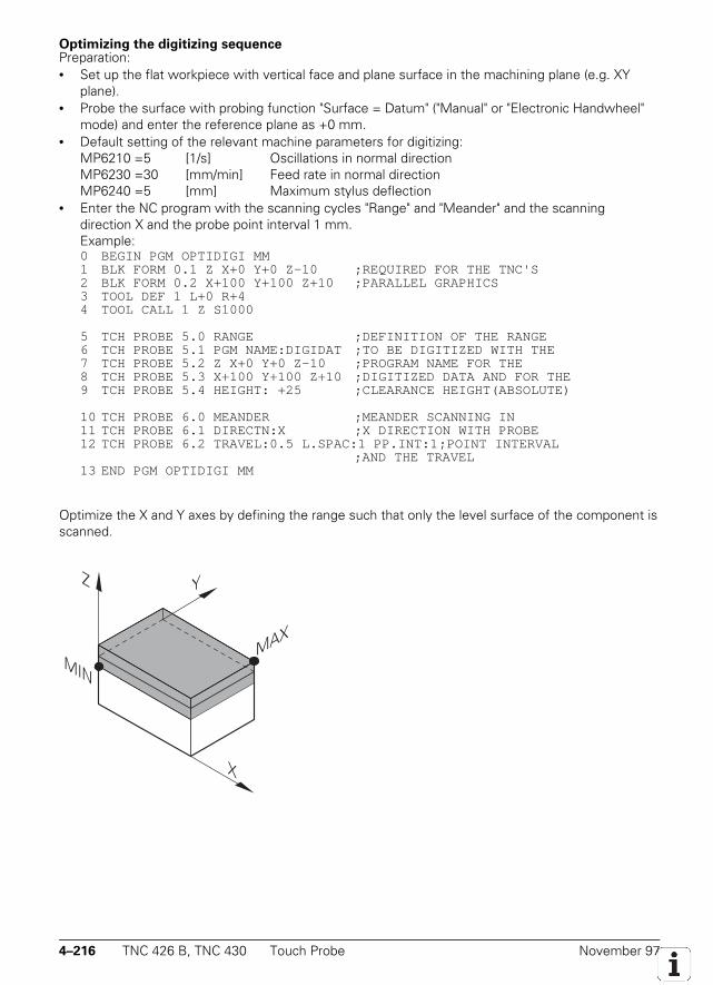
4–216 TNC 426 B, TNC 430 Touch Probe November 97
Optimizing the digitizing sequencePreparation:• Set up the flat workpiece with vertical face and plane surface in the machining plane (e.g. XY
plane).• Probe the surface with probing function "Surface = Datum" ("Manual" or "Electronic Handwheel"
mode) and enter the reference plane as +0 mm.• Default setting of the relevant machine parameters for digitizing:
MP6210 =5 [1/s] Oscillations in normal directionMP6230 =30 [mm/min] Feed rate in normal directionMP6240 =5 [mm] Maximum stylus deflection
• Enter the NC program with the scanning cycles "Range" and "Meander" and the scanningdirection X and the probe point interval 1 mm.Example:0 BEGIN PGM OPTIDIGI MM1 BLK FORM 0.1 Z X+0 Y+0 Z–10 ;REQUIRED FOR THE TNC'S2 BLK FORM 0.2 X+100 Y+100 Z+10 ;PARALLEL GRAPHICS3 TOOL DEF 1 L+0 R+44 TOOL CALL 1 Z S1000
5 TCH PROBE 5.0 RANGE ;DEFINITION OF THE RANGE6 TCH PROBE 5.1 PGM NAME:DIGIDAT ;TO BE DIGITIZED WITH THE7 TCH PROBE 5.2 Z X+0 Y+0 Z–10 ;PROGRAM NAME FOR THE8 TCH PROBE 5.3 X+100 Y+100 Z+10 ;DIGITIZED DATA AND FOR THE9 TCH PROBE 5.4 HEIGHT: +25 ;CLEARANCE HEIGHT(ABSOLUTE)
10 TCH PROBE 6.0 MEANDER ;MEANDER SCANNING IN11 TCH PROBE 6.1 DIRECTN:X ;X DIRECTION WITH PROBE12 TCH PROBE 6.2 TRAVEL:0.5 L.SPAC:1 PP.INT:1;POINT INTERVAL
;AND THE TRAVEL13 END PGM OPTIDIGI MM
Optimize the X and Y axes by defining the range such that only the level surface of the component isscanned.
MINMAX
Z Y
X

November 97 Touch Probe TNC 426 B, TNC 430 4–217
Optimize the Z axis by defining the range such that mainly the vertical face is scanned.
MAX
MIN
Z
X
Y
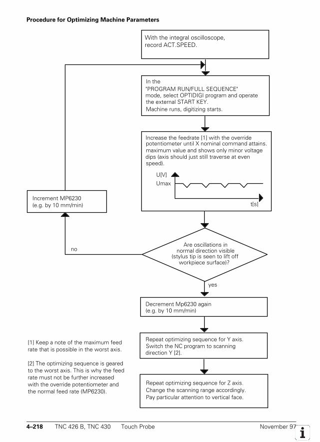
4–218 TNC 426 B, TNC 430 Touch Probe November 97
Procedure for Optimizing Machine Parameters
Connect a storage oscilloscope to the nominalcommand input of the servo amplifier for theX axis.
In the"PROGRAM RUN/FULL SEQUENCE"mode, select OPTIDIGI program and operatethe external START KEY.Machine runs, digitizing starts.
U[V]
Increase the feedrate [1] with the overridepotentiometer until X nominal command attains.maximum value and shows only minor voltagedips (axis should just still traverse at evenspeed).
Umax
t[s]
Decrement Mp6230 again(e.g. by 10 mm/min)
Repeat optimizing sequence for Y axis.Switch the NC program to scanningdirection Y [2].
Repeat optimizing sequence for Z axis.Change the scanning range accordingly.Pay particular attention to vertical face.
Increment MP6230(e.g. by 10 mm/min)
yes
noAre oscillations in
normal direction visible(stylus tip is seen to lift off
workpiece surface)?
[1] Keep a note of the maximumfeedrate that is possible in theworst axis.
[2] The optimizing sequence isgeared to the worst axis. This iswhy the feedrate must not be furtherincreased with the override potentiometer and normal feedrate.
With the integral oscilloscope,record ACT.SPEED.
[1] Keep a note of the maximum feedrate that is possible in the worst axis.
[2] The optimizing sequence is gearedto the worst axis. This is why the feedrate must not be further increasedwith the override potentiometer andthe normal feed rate (MP6230).
November 97 Touch Probe TNC 426 B, TNC 430 4–219
Calculation of Possible Oscillations in Normal Direction
MP6210 [1/s] = optimierter Fscan [mm/min]PP.INT [mm] • 60 [s/min]
When the calculated machine parameter MP 6210 is entered the feed override potentiometer istrimmed to the "attained feed rate."
4.15.4 Digitizing with the Measuring Touch Probe
The measuring touch probe permits high digitizing speeds up to 3 m/min (118 ipm). The stylusdeflection is measured in every direction directly by integral measuring systems and evaluated in theTNC.
Technical prerequisites• Interfaced measuring touch probe• Adapter kit for digitizing with the measuring touch probe
The machine must be prepared for the use of the measuring touch probe. You must mechanicallyclamp the ballscrew and must ensure that the spindle drive cannot be started while the probe is inuse.
The adapter kit for digitizing with the measuring touch probe also enables digitizing with the TStouch trigger probe.
Interfacing the measuring touch probeWith MP6200 you define whether to use the measuring or the triggering touch probe.
DANGER OF BREAKAGEIf you wish to use both the triggering and the measuring touch probe, you must make quitesure that the type of touch probe in use is entered in MP6200.
The counting direction of the measuring system signals must match the counting direction of themeasuring systems for the machine tool axes (MP210). In the "Positioning with MDI" mode you canposition the machine by pressing the PNT soft key. The machine must move in the direction inwhich the stylus was deflected. If this is not the case, you must change the counting direction inMP6320.
With MP6322 you assign the touch probe axes (the measuring systems in the probe) to themachine axes. For machines with swivel heads you must enter the respective mounting position ofthe touch probe in MP6322. If the touch probe is in a horizontal position, the undefined deflectionresulting from the stylus's own weight makes it impossible to find the center of the stylus tip. It istherefore not possible to use the measuring touch probe in a horizontal attitude to locate aworkpiece. In a horizontal attitude the measuring touch probe can be used only for digitizing.
DANGER OF BREAKAGEThe mounting position of the touch probe must be entered correctly in MP6322, otherwisethe calculation of the maximum deflection from MP6330 may be incorrect.
4–220 TNC 426 B, TNC 430 Touch Probe November 97
If the stylus is deflected by a distance greater than the value defined in MP 6330, the blinking errormessage Stylus deflection exceeds max. appears.
With MP 6310 you define the mean constant deflection depth during digitizing. On standardparts an entry value of 1 mm has proven to be useful. On parts with sharp changes in directions(steep edges) that are scanned at high speed you must increase the deflection depth. The probingfor can also be adjusted with the deflection depth.
After the "Meander" or "Contour line" cycle has been started, the probe moves at the feedrate defined in MP6361 to the clearance height, and then in the working plain to the point above thestarting point. It then moves at the feed rate defined in MP6350 to the MIN point. If no touch pointis reached, the probe moves to the first touch point in the direction defined in the cycle at the feedrate given in MP6350.
MP6360 (probing feed rate) and MP6361 (rapid traverse in the probe cycle) are effective inthe standard touch cycles. With MP6362 you can automatically reduce the probing feed rate if theball tip moves too far from the path.
During contour-line scanning the probe sometimes ends the contour line at a point locatednear but not exactly at the starting point. MP6390 defines a target window within which the probe isconsidered to have returned to the starting point. The target window is a square. The entry value ishalf the length of one side of the square.
MP6200 Selection of triggering or measuring touch probe (only with the digitizing-with-measuring-probe option)
Input: 0 = triggering touch probe (e.g. TS 220)1 = measuring touch probe (e.g. TM 110)
MP6310 Stylus deflection depth (measuring touch probe)Input: 0.1000 to 2.0000 [mm]
MP6320 Counting direction of the measuring system signals (measuring touch probe)Input: %xxx
Bit 0 to 2 0 = positiveAxis X to Z 1 = negative
MP6321 Measuring the center offset while calibrating the measuring touch probeInput: 0 = Calibrate and measure center offset
1 = Calibrate without measuring center offset
MP6322.0-2 Assignment of touch probe axes to the machine axesInput: 0 = Touch probe axis X
1 = Touch probe axis Y2 = Touch probe axis Z
MP6330 Maximum stylus deflection (measuring touch probe)Input: 0.1 to 4.000 [mm]
MP6350 Feed rate for positioning to the MIN point and contour approach (measuring touchprobe)
Input: 10 to 3000 [mm/min]
MP6360 Probing feed rate (measuring touch probe)Input: 10 to 3000 [mm/min]

November 97 Touch Probe TNC 426 B, TNC 430 4–221
MP6361 Rapid traverse in scanning cycle (measuring touch probe)Input: 10 to 10 000 [mm/min]
MP6362 Feed rate reduction if stylus of the measuring touch probe is deflected away from itspath
Input: 0 = Feed rate reduction not active1 = Feed rate reduction active
MP6370 Radial acceleration for digitizing with the measuring touch probeInput: 0.001 to 3.000 [m/s²]
Recommended input value: 0.1
MP6390 Target window for contour-line end pointInput: 0.1000 to 4.0000 [mm]

4–222 TNC 426 B, TNC 430 Touch Probe November 97

November 97 Touch Probe TNC 426 B, TNC 430 4–223
4–224 TNC 426 B, TNC 430 Touch Probe November 97
4.15.5 Tool Measurement
With the HEIDENHAIN tool touch probe TT 120 you can measure and inspect tools. HEIDENHAINprovides standard cycles for measuring and inspecting tool automatically with the TT 120 (seeUser's Manual).
Technical Prerequisites:• TT 120• Central tool file TOOL.T must be active (via machine parameter)
The TNC can store the calibration data for up to three different touch probes. The current data canbe activated using M4574/M4575. For three sets of calibration data to be stored at the same time,bit 3 must be set in MP7490.
Standard measuring cyclesWith MP6500 bit 0 you enable the cycles for tool measurement. Of course you should do this onlyafter the TT 120 has been mounted and interfaced.
Calibrating tool radius and tool lengthWith MP6500 bit 1 and bit 2 you define whether tool radius and tool length measurement arepermitted, and whether the individual tool teeth are to be measured.
Oriented spindle stopWith MP6500 bit 3 you define whether the single-tooth measurement should be performed with orwithout an oriented spindle stop. Single-tooth measurement is not possible without spindleorientation, and under certain circumstances a tool radius measurement is also incorrect. WithMP6560 you define whether the spindle should be oriented directly by the NC or through the PLC. Ifthe spindle is oriented directly by the NC, you need only reset M4012 (see "Spindle Orientation." Ifthe spindle is oriented by the PLC, you must enter the number of the M function in MP6560. Therespective positions are then transferred as in the "spindle orientation" cycle. M4017 is set duringevery spindle orientation.
Probing directionYou define the probing direction for tool radius measurement in MP6505.x.
Offset of probe contact to the toolIn MP6530.x you enter the distance from the tool bottom to the top of the probe contact during toolradius measurement. In the tool table you enter an additional tool-specific offset in the L-OFFS field.
Safety zoneIn MP6540 you define a safety zone around the contact of the TT 120. After a cycle for toolmeasurement starts, the tool automatically moves at the feed rate defined in MP6550 from the"clearance height" defined in the cycle to the limit of the safety zone.
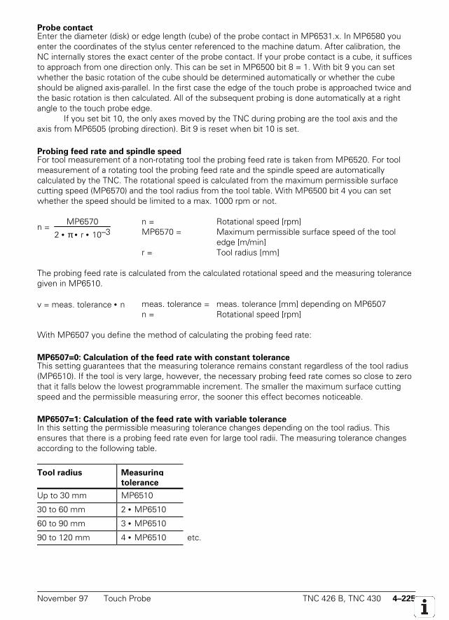
November 97 Touch Probe TNC 426 B, TNC 430 4–225
Probe contactEnter the diameter (disk) or edge length (cube) of the probe contact in MP6531.x. In MP6580 youenter the coordinates of the stylus center referenced to the machine datum. After calibration, theNC internally stores the exact center of the probe contact. If your probe contact is a cube, it sufficesto approach from one direction only. This can be set in MP6500 bit 8 = 1. With bit 9 you can setwhether the basic rotation of the cube should be determined automatically or whether the cubeshould be aligned axis-parallel. In the first case the edge of the touch probe is approached twice andthe basic rotation is then calculated. All of the subsequent probing is done automatically at a rightangle to the touch probe edge.
If you set bit 10, the only axes moved by the TNC during probing are the tool axis and theaxis from MP6505 (probing direction). Bit 9 is reset when bit 10 is set.
Probing feed rate and spindle speedFor tool measurement of a non-rotating tool the probing feed rate is taken from MP6520. For toolmeasurement of a rotating tool the probing feed rate and the spindle speed are automaticallycalculated by the TNC. The rotational speed is calculated from the maximum permissible surfacecutting speed (MP6570) and the tool radius from the tool table. With MP6500 bit 4 you can setwhether the speed should be limited to a max. 1000 rpm or not.
n = MP6570
2 • π • r • 10–3n = Rotational speed [rpm]MP6570 = Maximum permissible surface speed of the tool
edge [m/min]r = Tool radius [mm]
The probing feed rate is calculated from the calculated rotational speed and the measuring tolerancegiven in MP6510.
v = meas. tolerance • n meas. tolerance = meas. tolerance [mm] depending on MP6507n = Rotational speed [rpm]
With MP6507 you define the method of calculating the probing feed rate:
MP6507=0: Calculation of the feed rate with constant toleranceThis setting guarantees that the measuring tolerance remains constant regardless of the tool radius(MP6510). If the tool is very large, however, the necessary probing feed rate comes so close to zerothat it falls below the lowest programmable increment. The smaller the maximum surface cuttingspeed and the permissible measuring error, the sooner this effect becomes noticeable.
MP6507=1: Calculation of the feed rate with variable toleranceIn this setting the permissible measuring tolerance changes depending on the tool radius. Thisensures that there is a probing feed rate even for large tool radii. The measuring tolerance changesaccording to the following table.
Tool radius Measuring
tolerance
Up to 30 mm MP6510
30 to 60 mm 2 • MP6510
60 to 90 mm 3 • MP6510
90 to 120 mm 4 • MP6510 etc.
4–226 TNC 426 B, TNC 430 Touch Probe November 97
MP6507=2: Constant probing feed rateThe probing feed rate remains constant regardless of the tool. The absolute measuring error growslinearly with increasing tool radius.
Meas. tolerance = r
5 [mm] • MP6510r = Tool radius [mm]MP6510 = Max. permissible measuring error [mm]
v = meas. tolerance • nv = MP6570 • MP6510 10 • π • 10–3
v = Probing feed rate [m/min]MP6570 = Maximum permissible surface speed at the
cutting edge [m/min]
Tool breakageWith MP6500 bit 5 and bit 6, you can set whether or not the NC program should be stopped if thebreakage tolerance is exceeded. Marker M4063 is always set if the breakage tolerance is exceeded.If bit 11 is set, the result of "Check tool" is not entered in the tool table.
Markers in the PLCMarker M4060 is set when a tool measuring cycle is started. Marker M4061 indicates whether acycle for tool measurement or tool inspection was activated. If inspection shows that one of theentered tolerances is exceeded, the tool is disabled and Marker M2392 or M2393 is set.
Markers M4050, M4051, M4052, M4053, M4055 and M4056 function as in the standardprobing cycles. The cycles for tool measurement must therefore also be released by the PLC withMarker M4055. If the spindle is oriented directly by the NC (MP6560 = –1), you must reset markerM4012.
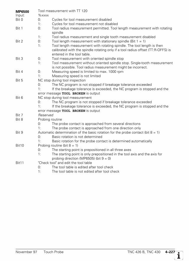
November 97 Touch Probe TNC 426 B, TNC 430 4–227
MP6500 Tool measurement with TT 120Input: %xxxxBit 0 0: Cycles for tool measurement disabled
1: Cycles for tool measurement not disabledBit 1 0: Tool radius measurement permitted. Tool length measurement with rotating
spindle1: Tool radius measurement and single tooth measurement disabled
Bit 2 0: Tool length measurement with stationary spindle (Bit 1 = 1)1: Tool length measurement with rotating spindle. The tool length is then
calibrated with the spindle rotating only if a tool radius offset (TT:R-OFFS) isentered in the tool table.
Bit 3 0: Tool measurement with oriented spindle stop1: Tool measurement without oriented spindle stop. Single-tooth measurement
is not possible. Tool radius measurement might be incorrect.Bit 4 0: Measuring speed is limited to max. 1000 rpm
1: Measuring speed is not limitedBit 5 NC stop during tool inspection
0: The NC program is not stopped if breakage tolerance exceeded1: If the breakage tolerance is exceeded, the NC program is stopped and the error message TOOL BROKEN is output
Bit 6 NC stop during tool measurement0: The NC program is not stopped if breakage tolerance exceeded1: If the breakage tolerance is exceeded, the NC program is stopped and the error message TOOL BROKEN is output
Bit 7 ReservedBit 8 Probing routine
0: The probe contact is approached from several directions1: The probe contact is approached from one direction only
Bit 9 Automatic determination of the basic rotation for the probe contact (bit 8 = 1)0: Basic rotation is not determined1: Basic rotation for the probe contact is determined automatically
Bit10 Probing routine (bit 8 = 1)0: The starting point is prepositioned in all three axes1: The starting point is only prepositioned in the tool axis and the axis for
probing direction (MP6505) (bit 9 = 0)Bit11 "Check tool" and edit the tool table
0: The tool table is edited after tool check1: The tool table is not edited after tool check
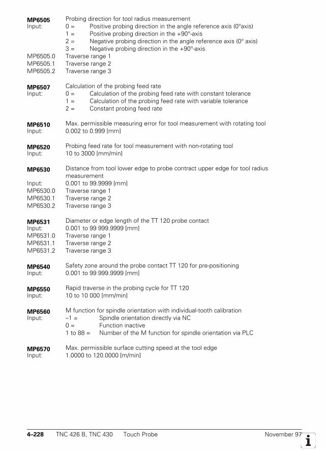
4–228 TNC 426 B, TNC 430 Touch Probe November 97
MP6505 Probing direction for tool radius measurementInput: 0 = Positive probing direction in the angle reference axis (0°axis)
1 = Positive probing direction in the +90°-axis2 = Negative probing direction in the angle reference axis (0° axis)3 = Negative probing direction in the +90°-axis
MP6505.0 Traverse range 1MP6505.1 Traverse range 2MP6505.2 Traverse range 3
MP6507 Calculation of the probing feed rateInput: 0 = Calculation of the probing feed rate with constant tolerance
1 = Calculation of the probing feed rate with variable tolerance2 = Constant probing feed rate
MP6510 Max. permissible measuring error for tool measurement with rotating toolInput: 0.002 to 0.999 [mm]
MP6520 Probing feed rate for tool measurement with non-rotating toolInput: 10 to 3000 [mm/min]
MP6530 Distance from tool lower edge to probe contract upper edge for tool radiusmeasurement
Input: 0.001 to 99.9999 [mm]MP6530.0 Traverse range 1MP6530.1 Traverse range 2MP6530.2 Traverse range 3
MP6531 Diameter or edge length of the TT 120 probe contactInput: 0.001 to 99 999.9999 [mm]MP6531.0 Traverse range 1MP6531.1 Traverse range 2MP6531.2 Traverse range 3
MP6540 Safety zone around the probe contact TT 120 for pre-positioningInput: 0.001 to 99 999.9999 [mm]
MP6550 Rapid traverse in the probing cycle for TT 120Input: 10 to 10 000 [mm/min]
MP6560 M function for spindle orientation with individual-tooth calibrationInput: –1 = Spindle orientation directly via NC
0 = Function inactive1 to 88 = Number of the M function for spindle orientation via PLC
MP6570 Max. permissible surface cutting speed at the tool edgeInput: 1.0000 to 120.0000 [m/min]
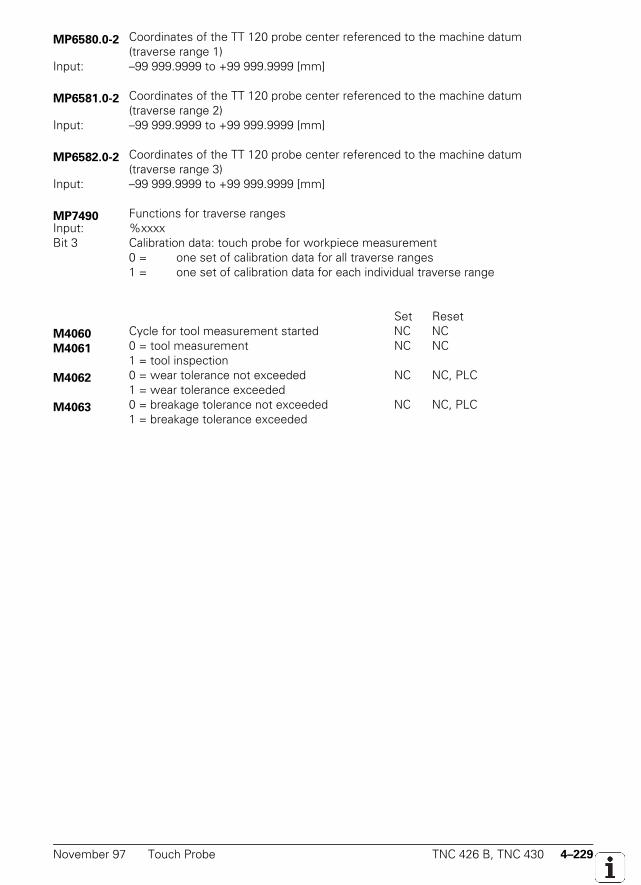
November 97 Touch Probe TNC 426 B, TNC 430 4–229
MP6580.0-2 Coordinates of the TT 120 probe center referenced to the machine datum(traverse range 1)
Input: –99 999.9999 to +99 999.9999 [mm]
MP6581.0-2 Coordinates of the TT 120 probe center referenced to the machine datum(traverse range 2)
Input: –99 999.9999 to +99 999.9999 [mm]
MP6582.0-2 Coordinates of the TT 120 probe center referenced to the machine datum(traverse range 3)
Input: –99 999.9999 to +99 999.9999 [mm]
MP7490 Functions for traverse rangesInput: %xxxxBit 3 Calibration data: touch probe for workpiece measurement
0 = one set of calibration data for all traverse ranges1 = one set of calibration data for each individual traverse range
Set ResetM4060 Cycle for tool measurement started NC NCM4061 0 = tool measurement NC NC
1 = tool inspectionM4062 0 = wear tolerance not exceeded NC NC, PLC
1 = wear tolerance exceededM4063 0 = breakage tolerance not exceeded NC NC, PLC
1 = breakage tolerance exceeded

4–230 TNC 426 B, TNC 430 Touch Probe November 97

November 97 Touch Probe TNC 426 B, TNC 430 4–231
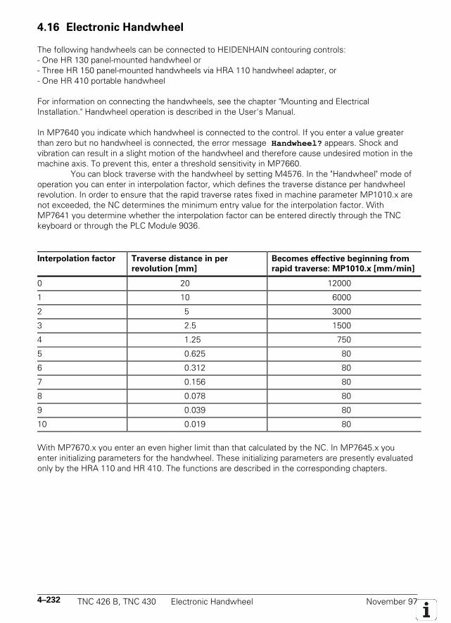
4–232 TNC 426 B, TNC 430 Electronic Handwheel November 97
4.16 Electronic Handwheel
The following handwheels can be connected to HEIDENHAIN contouring controls:- One HR 130 panel-mounted handwheel or- Three HR 150 panel-mounted handwheels via HRA 110 handwheel adapter, or- One HR 410 portable handwheel
For information on connecting the handwheels, see the chapter "Mounting and ElectricalInstallation." Handwheel operation is described in the User's Manual.
In MP7640 you indicate which handwheel is connected to the control. If you enter a value greaterthan zero but no handwheel is connected, the error message Handwheel? appears. Shock andvibration can result in a slight motion of the handwheel and therefore cause undesired motion in themachine axis. To prevent this, enter a threshold sensitivity in MP7660.
You can block traverse with the handwheel by setting M4576. In the "Handwheel" mode ofoperation you can enter in interpolation factor, which defines the traverse distance per handwheelrevolution. In order to ensure that the rapid traverse rates fixed in machine parameter MP1010.x arenot exceeded, the NC determines the minimum entry value for the interpolation factor. WithMP7641 you determine whether the interpolation factor can be entered directly through the TNCkeyboard or through the PLC Module 9036.
Interpolation factor Traverse distance in per
revolution [mm]
Becomes effective beginning from
rapid traverse: MP1010.x [mm/min]
0 20 12000
1 10 6000
2 5 3000
3 2.5 1500
4 1.25 750
5 0.625 80
6 0.312 80
7 0.156 80
8 0.078 80
9 0.039 80
10 0.019 80
With MP7670.x you enter an even higher limit than that calculated by the NC. In MP7645.x youenter initializing parameters for the handwheel. These initializing parameters are presently evaluatedonly by the HRA 110 and HR 410. The functions are described in the corresponding chapters.
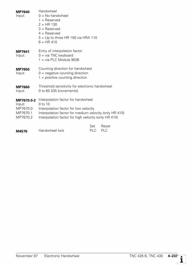
November 97 Electronic Handwheel TNC 426 B, TNC 430 4–233
MP7640 HandwheelInput: 0 = No handwheel
1 = Reserved2 = HR 1303 = Reserved4 = Reserved5 = Up to three HR 150 via HRA 1106 = HR 410
MP7641 Entry of interpolation factorInput: 0 = via TNC keyboard
1 = via PLC Module 9036
MP7650 Counting direction for handwheelInput: 0 = negative counting direction
1 = positive counting direction
MP7660 Threshold sensitivity for electronic handwheelInput: 0 to 65 535 [increments]
MP7670.0-2 Interpolation factor for handwheelInput: 0 to 10MP7670.0 Interpolation factor for low velocityMP7670.1 Interpolation factor for medium velocity (only HR 410)MP7670.2 Interpolation factor for high velocity (only HR 410)
Set ResetM4576 Handwheel lock PLC PLC
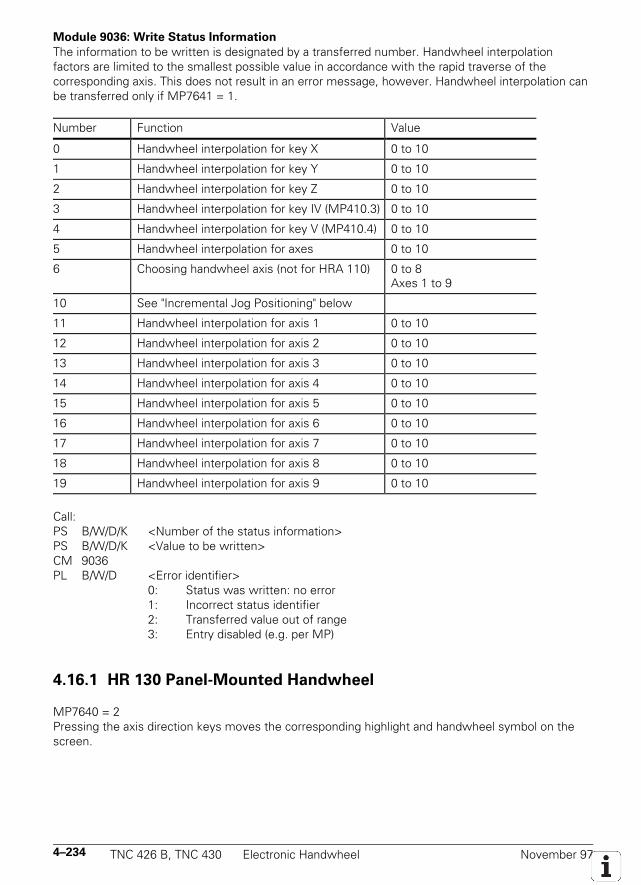
4–234 TNC 426 B, TNC 430 Electronic Handwheel November 97
Module 9036: Write Status Information
The information to be written is designated by a transferred number. Handwheel interpolationfactors are limited to the smallest possible value in accordance with the rapid traverse of thecorresponding axis. This does not result in an error message, however. Handwheel interpolation canbe transferred only if MP7641 = 1.
Number Function Value
0 Handwheel interpolation for key X 0 to 10
1 Handwheel interpolation for key Y 0 to 10
2 Handwheel interpolation for key Z 0 to 10
3 Handwheel interpolation for key IV (MP410.3) 0 to 10
4 Handwheel interpolation for key V (MP410.4) 0 to 10
5 Handwheel interpolation for axes 0 to 10
6 Choosing handwheel axis (not for HRA 110) 0 to 8Axes 1 to 9
10 See "Incremental Jog Positioning" below
11 Handwheel interpolation for axis 1 0 to 10
12 Handwheel interpolation for axis 2 0 to 10
13 Handwheel interpolation for axis 3 0 to 10
14 Handwheel interpolation for axis 4 0 to 10
15 Handwheel interpolation for axis 5 0 to 10
16 Handwheel interpolation for axis 6 0 to 10
17 Handwheel interpolation for axis 7 0 to 10
18 Handwheel interpolation for axis 8 0 to 10
19 Handwheel interpolation for axis 9 0 to 10
Call:PS B/W/D/K <Number of the status information>PS B/W/D/K <Value to be written>CM 9036PL B/W/D <Error identifier>
0: Status was written: no error1: Incorrect status identifier2: Transferred value out of range3: Entry disabled (e.g. per MP)
4.16.1 HR 130 Panel-Mounted Handwheel
MP7640 = 2Pressing the axis direction keys moves the corresponding highlight and handwheel symbol on thescreen.
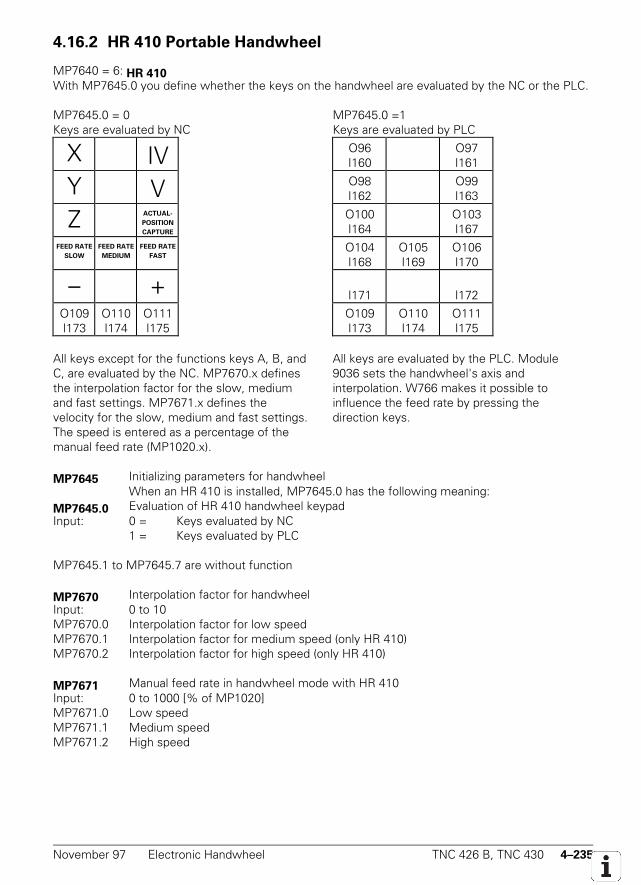
November 97 Electronic Handwheel TNC 426 B, TNC 430 4–235
4.16.2 HR 410 Portable Handwheel
MP7640 = 6: HR 410With MP7645.0 you define whether the keys on the handwheel are evaluated by the NC or the PLC.
MP7645.0 = 0Keys are evaluated by NC
MP7645.0 =1Keys are evaluated by PLC
X IV O96I160
O97I161
Y V O98I162
O99I163
Z ACTUAL-
POSITION
CAPTURE
O100I164
O103I167
FEED RATE
SLOW
FEED RATE
MEDIUM
FEED RATE
FASTO104I168
O105I169
O106I170
– + I171 I172
O109I173
O110I174
O111I175
O109I173
O110I174
O111I175
All keys except for the functions keys A, B, andC, are evaluated by the NC. MP7670.x definesthe interpolation factor for the slow, mediumand fast settings. MP7671.x defines thevelocity for the slow, medium and fast settings.The speed is entered as a percentage of themanual feed rate (MP1020.x).
All keys are evaluated by the PLC. Module9036 sets the handwheel's axis andinterpolation. W766 makes it possible toinfluence the feed rate by pressing thedirection keys.
MP7645 Initializing parameters for handwheelWhen an HR 410 is installed, MP7645.0 has the following meaning:
MP7645.0 Evaluation of HR 410 handwheel keypadInput: 0 = Keys evaluated by NC
1 = Keys evaluated by PLC
MP7645.1 to MP7645.7 are without function
MP7670 Interpolation factor for handwheelInput: 0 to 10MP7670.0 Interpolation factor for low speedMP7670.1 Interpolation factor for medium speed (only HR 410)MP7670.2 Interpolation factor for high speed (only HR 410)
MP7671 Manual feed rate in handwheel mode with HR 410Input: 0 to 1000 [% of MP1020]MP7671.0 Low speedMP7671.1 Medium speedMP7671.2 High speed
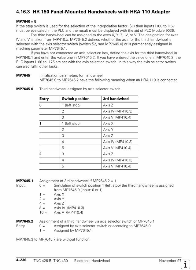
4–236 TNC 426 B, TNC 430 Electronic Handwheel November 97
4.16.3 HR 150 Panel-Mounted Handwheels with HRA 110 Adapter
MP7640 = 5
If the step switch is used for the selection of the interpolation factor (S1) then inputs I160 to I167must be evaluated in the PLC and the result must be displayed with the aid of PLC Module 9036.
The third handwheel can be assigned to the axes X, Y, Z, IV, or V. The designation for axesIV and V is taken from MP410.x. MP7645.2 defines whether the axis for the third handwheel isselected with the axis selector switch (switch S2, see MP7645.0) or is permanently assigned inmachine parameter MP7645.1.
If you have not connected an axis selection key, define the axis for the third handwheel inMP7645.1 and enter the value one in MP7645.2. If you have entered the value one in MP7645.2, thePLC inputs I168 to I175 are set with the axis selection switch. In this way the axis selector switchcan also fulfill other tasks.
MP7645 Initialization parameters for handwheelMP7645.0 to MP7645.2 have the following meaning when an HRA 110 is connected:
MP7645.0 Third handwheel assigned by axis selector switch
Entry Switch position 3rd handwheel
0 1 (left stop) Axis Z
2 Axis IV (MP410.3)
3 Axis V (MP410.4)
1 1 (left stop) Axis X
2 Axis Y
3 Axis Z
4 Axis IV (MP410.3)
5 Axis V (MP410.4)
2 3 Axis Z
4 Axis IV (MP410.3)
5 Axis V (MP410.4)
MP7645.1 Assignment of 3rd handwheel if MP7645.2 = 1Input: 0 = Simulation of switch position 1 (left stop) the third handwheel is assigned
from MP7645.0 (Input: 0 or 1)1 = Axis X2 = Axis Y4 = Axis Z8 = Axis IV (MP410.3)16 = Axis V (MP410.4)
MP7645.2 Assignment of a third handwheel via axis selector switch or MP7645.1Entry 0 = Assigned by axis selector switch or according to MP7645.0
1 = Assigned by MP7645.1
MP7645.3 to MP7645.7 are without function.
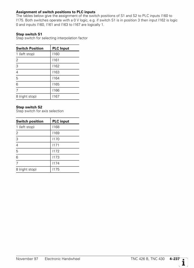
November 97 Electronic Handwheel TNC 426 B, TNC 430 4–237
Assignment of switch positions to PLC inputsThe tables below give the assignment of the switch positions of S1 and S2 to PLC inputs I160 toI175. Both switches operate with a 0 V logic, e.g. if switch S1 is in position 3 then input I162 is logic0 and inputs I160, I161 and I163 to I167 are logically 1.
Step switch S1Step switch for selecting interpolation factor
Switch Position PLC Input
1 (left stop) I160
2 I161
3 I162
4 I163
5 I164
6 I165
7 I166
8 (right stop) I167
Step switch S2Step switch for axis selection
Switch position PLC input
1 (left stop) I168
2 I169
3 I170
4 I171
5 I172
6 I173
7 I174
8 (right stop) I175
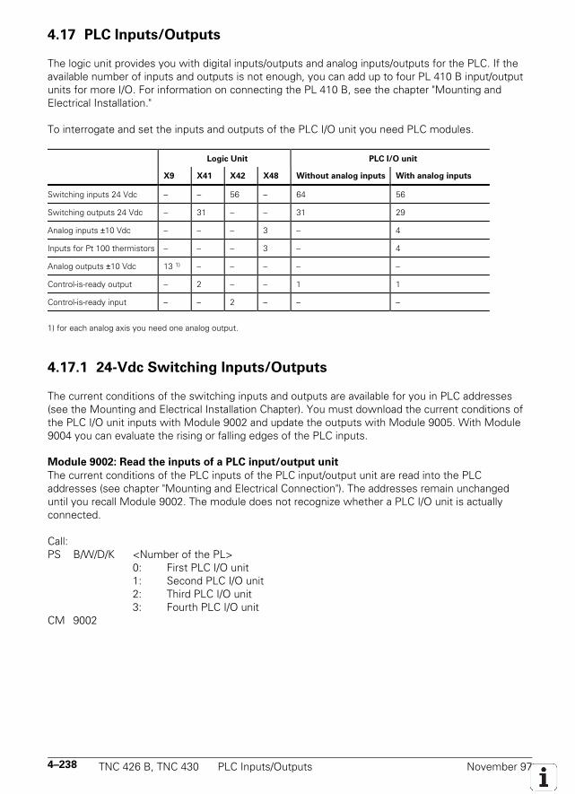
4–238 TNC 426 B, TNC 430 PLC Inputs/Outputs November 97
4.17 PLC Inputs/Outputs
The logic unit provides you with digital inputs/outputs and analog inputs/outputs for the PLC. If theavailable number of inputs and outputs is not enough, you can add up to four PL 410 B input/outputunits for more I/O. For information on connecting the PL 410 B, see the chapter "Mounting andElectrical Installation."
To interrogate and set the inputs and outputs of the PLC I/O unit you need PLC modules.
Logic Unit PLC I/O unit
X9 X41 X42 X48 Without analog inputs With analog inputs
Switching inputs 24 Vdc – – 56 – 64 56
Switching outputs 24 Vdc – 31 – – 31 29
Analog inputs ±10 Vdc – – – 3 – 4
Inputs for Pt 100 thermistors – – – 3 – 4
Analog outputs ±10 Vdc 13 1) – – – – –
Control-is-ready output – 2 – – 1 1
Control-is-ready input – – 2 – – –
1) for each analog axis you need one analog output.
4.17.1 24-Vdc Switching Inputs/Outputs
The current conditions of the switching inputs and outputs are available for you in PLC addresses(see the Mounting and Electrical Installation Chapter). You must download the current conditions ofthe PLC I/O unit inputs with Module 9002 and update the outputs with Module 9005. With Module9004 you can evaluate the rising or falling edges of the PLC inputs.
Module 9002: Read the inputs of a PLC input/output unit
The current conditions of the PLC inputs of the PLC input/output unit are read into the PLCaddresses (see chapter "Mounting and Electrical Connection"). The addresses remain unchangeduntil you recall Module 9002. The module does not recognize whether a PLC I/O unit is actuallyconnected.
Call:PS B/W/D/K <Number of the PL>
0: First PLC I/O unit1: Second PLC I/O unit2: Third PLC I/O unit3: Fourth PLC I/O unit
CM 9002
November 97 PLC Inputs/Outputs TNC 426 B, TNC 430 4–239
Module 9005: Update the outputs of a PLC I/O unitThe outputs of the PLC I/O unit are overwritten with the values from the PLC addresses (seechapter "Mounting and Electrical Connection"). The outputs are set or reset immediately at the timeof module processing. The module does not recognize whether a PLC I/O unit is actually connected.You must not call Module 9005 as long as the Module 9003 is active through a Submit command.
Call:PS B/W/D/K <Number of the PL>
0: First PLC I/O unit1: Second PLC I/O unit2: Third PLC I/O unit3: Fourth PLC I/O unit
CM 9005
Module 9004: Read the edges of PLC inputsWith Module 9004 you set the edge markers or bits corresponding to the rising or falling edges ofPLC markers in the specified byte range. Changes in the inputs are only recognized if a changeoccurs also in the PLC addresses (see Module 9002). Make sure that the given edge markers oredge bytes are in an unassigned area. The edge bytes are written beginning from the leastsignificant bit. Unused bits are erased.
Call:PS B/W/D/K <Number of the first PLC input>PS B/W/D/K <Number of the first edge marker or edge byte>PS B/W/D/K <Number of PLC inputs>PS B/W/D/K <Edge evaluation>
0: Rising edge, entry in edge marker1: Falling edge, entry in edge marker2: Rising edge, entry in edge byte3: Falling edge, entry in edge byte
CM 9004
4–240 TNC 426 B, TNC 430 PLC Inputs/Outputs November 97
4.17.2 Analog Inputs
At socket X48, the logic unit provides you with ±10 Vdc analog inputs and analog inputs forconnecting Pt 100 thermistors (see the chapter "Mounting and Electrical Connection"). The PLCinput/output unit is available in a version with additional analog inputs (see the chapter "Mountingand Electrical Connection"). You must read the current conditions of the analog inputs with Module9003.
Module 9003: Read the analog input
This module reads the current value of the given analog input. It does not recognize whether thegiven input is also present. You must not call Module 9003 as long as the Module 9005 is activethrough a Submit command.
PS B/W/D/K <Number of the analog input>0 to 7: Analog inputs X15 to X22 on the first PLC I/O unit8 to 15: Analog inputs X15 to X22 on the second PLC I/O unit16 to 23: Analog inputs X15 to X22 on the third PLC I/O unit24 to 31: Analog inputs X15 to X22 on the fourth PLC I/O unit64 to 66: ±10V input on socket X4867 to 69: Pt100 input on socket X48
CM 9003PL W/D <Analog value>
Numbers 0 to 31: Natural number with the unit 0.1 V or 0.5°Numbers 64 to 69: Natural number with the unit 0.01 V or 0.1°

November 97 PLC Inputs/Outputs TNC 426 B, TNC 430 4–241
4.17.3 Analog Outputs
With Module 9130 you apply an analog voltage to an analog output. You can control the analogoutputs 1 to 13 at sockets X8 and X9 (see chapter "Mounting and Electrical Connection"). Pleasenote that for each analog axis or an analog spindle you need one analog output, and that theseoutputs are then not available for the PLC.
The voltage is applied with a slight delay after the end of the PLC run. The module can becalled only once for each output per PLC run. The voltage must be transferred in 1 mV format.Voltage greater than 10 V or less than –10 V are limited to their respective maximum values.
Module 9130: Output of an analog voltageCall:PS B/W/D/K <Number the analog output>
1 to 6: Analog output 1 to 6 (X8)7 to 13: Analog output 7 to 13 (X9)
PS B/W/D/K <Analog voltage in millivolts>CM 9130
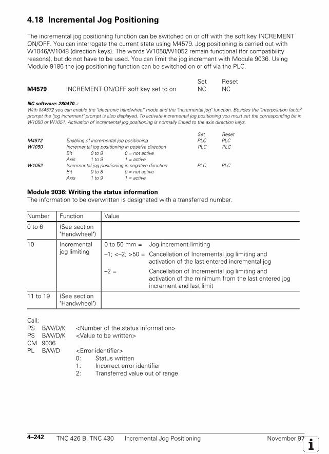
4–242 TNC 426 B, TNC 430 Incremental Jog Positioning November 97
4.18 Incremental Jog Positioning
The incremental jog positioning function can be switched on or off with the soft key INCREMENTON/OFF. You can interrogate the current state using M4579. Jog positioning is carried out withW1046/W1048 (direction keys). The words W1050/W1052 remain functional (for compatibilityreasons), but do not have to be used. You can limit the jog increment with Module 9036. UsingModule 9186 the jog positioning function can be switched on or off via the PLC.
Set ResetM4579 INCREMENT ON/OFF soft key set to on NC NC
NC software: 280470..:
With M4572 you can enable the "electronic handwheel" mode and the "incremental jog" function. Besides the "interpolation factor"prompt the "jog increment" prompt is also displayed. To activate incremental jog positioning you must set the corresponding bit inW1050 or W1051. Activation of incremental jog positioning is normally linked to the axis direction keys.
Set ResetM4572 Enabling of incremental jog positioning PLC PLCW1050 Incremental jog positioning in positive direction PLC PLC
Bit 0 to 8 0 = not activeAxis 1 to 9 1 = active
W1052 Incremental jog positioning in negative direction PLC PLCBit 0 to 8 0 = not activeAxis 1 to 9 1 = active
Module 9036: Writing the status information
The information to be overwritten is designated with a transferred number.
Number Function Value
0 to 6 (See section"Handwheel")
10 Incrementaljog limiting
0 to 50 mm = Jog increment limiting
–1; <–2; >50 = Cancellation of Incremental jog limiting andactivation of the last entered incremental jog
–2 = Cancellation of Incremental jog limiting andactivation of the minimum from the last entered jogincrement and last limit
11 to 19 (See section"Handwheel")
Call:PS B/W/D/K <Number of the status information>PS B/W/D/K <Value to be written>CM 9036PL B/W/D <Error identifier>
0: Status written1: Incorrect error identifier2: Transferred value out of range
November 97 Hirth Coupling TNC 426 B, TNC 430 4–243
4.19 Hirth Coupling
A frequently applied method of locking rotary axes and swivel heads is the so-called Hirth coupling,in which finely splined plates engage to form a rigid connection. You must implement the exactpositioning of the Hirth coupling in the PLC program. The NC merely rounds the datum point off tothe corresponding grid measure from MP430.
"Manual" positioningAs soon as an axis direction key is pressed, the NC resets the corresponding bit in W1026 (axis inposition). From it you derive the unclamping of the PLC in the Hirth axis. As soon as the axis-in-position bit is set, you check the nominal position with the Hirth grid and derive from that a PLCpositioning to the next grid point.
"Electronic handwheel" positioningFor the current handwheel axis the corresponding bit in W1026 (axis in position) is reset. As long asthe axis-in-position bit remains reset, the Hirth axis remains unclamped and the Hirth axis can bemove with the handwheel. As soon as you set another handwheel axis, the axis-in-position bit is setfor the previous axis. You check the actual position with the Hirth grid and derive from it a PLCpositioning to the next grid point.
Controlled positioningThe positions of the Hirth axis must be programmed in the grid. You must check the positions in thePLC during the program run. As soon as the "axis-in-position" bit is reset, check the target positionwith the Hirth grid. If the target position is not in the Hirth grid, you put out a PLC error message.
MP420.0-8 Hirth couplingInput: 0 = no Hirth coupling
1= Hirth coupling
MP430.0-8 Prescribed increment for Hirth couplingInput: 0.0000 to 30.0000 [°]
4–244 TNC 426 B, TNC 430 Datum Shift November 97
4.20 Datum Shift
With the datum shift function you can offset the defined datum point. The same starting positionmust be used for the datum shift as for the description of the machine geometry via MP7510 andfollowing (see "Tilting Axes"). The datum shift function can only be activated during an M/S/T/Qstrobe.
Datum shift with D528 to D544
In D528 to D544 you enter for each axis the distance by which the datum is to be shifted. For axes 6to 9 you must use Module 9230.
With M4132 you activate the datum shift. After the datum is shifted, the NC resets M4132.The offset is calculated into the position display: the display now shows the position valuesaccording to the shifted coordinate system.
Example:Actual position display for X axis without offset = 50Offset value in D528 = +20M4132 is set, i.e. the offset is activeNew actual-value display X= +70
A description of the machine geometry via machine parameters MP7510 and following(see "Tilting axes") must have the same reference position as any datum shift.
Set ResetD528 Datum shift for axis 1 PLC PLCD532 Datum shift for axis 2 PLC PLCD536 Datum shift for axis 3 PLC PLCD540 Datum shift for axis 4 PLC PLCD544 Datum shift for axis 5 PLC PLCM4132 Activate datum shift from D528 to D544 PLC NC
or Module 9230 is called
Datum shift with Module 9230
With Module 9230 you transfer the axis and distance by which the datum is to be shifted. WhenModule 9230 is called M4132 is set and the NC resets the datum shift M4132 after execution.
Call:PS B/W/D/K <Axis> [0 to 8]PS B/W/D/K <Shift> [0.0001 mm]CM 9230

November 97 Datum Shift TNC 426 B, TNC 430 4–245
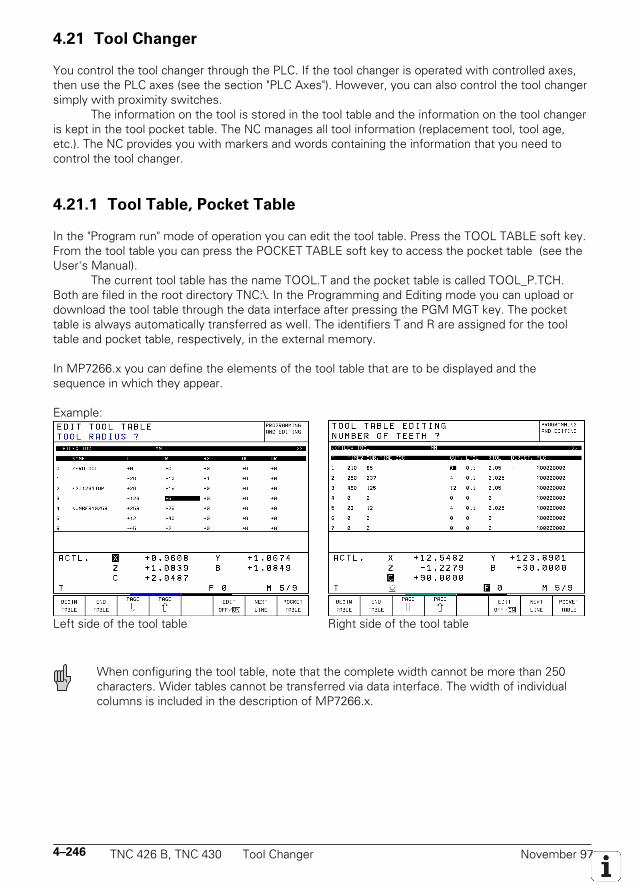
4–246 TNC 426 B, TNC 430 Tool Changer November 97
4.21 Tool Changer
You control the tool changer through the PLC. If the tool changer is operated with controlled axes,then use the PLC axes (see the section "PLC Axes"). However, you can also control the tool changersimply with proximity switches.
The information on the tool is stored in the tool table and the information on the tool changeris kept in the tool pocket table. The NC manages all tool information (replacement tool, tool age,etc.). The NC provides you with markers and words containing the information that you need tocontrol the tool changer.
4.21.1 Tool Table, Pocket Table
In the "Program run" mode of operation you can edit the tool table. Press the TOOL TABLE soft key.From the tool table you can press the POCKET TABLE soft key to access the pocket table (see theUser's Manual).
The current tool table has the name TOOL.T and the pocket table is called TOOL_P.TCH.Both are filed in the root directory TNC:\. In the Programming and Editing mode you can upload ordownload the tool table through the data interface after pressing the PGM MGT key. The pockettable is always automatically transferred as well. The identifiers T and R are assigned for the tooltable and pocket table, respectively, in the external memory.
In MP7266.x you can define the elements of the tool table that are to be displayed and thesequence in which they appear.
Example:
Left side of the tool table Right side of the tool table
When configuring the tool table, note that the complete width cannot be more than 250characters. Wider tables cannot be transferred via data interface. The width of individualcolumns is included in the description of MP7266.x.
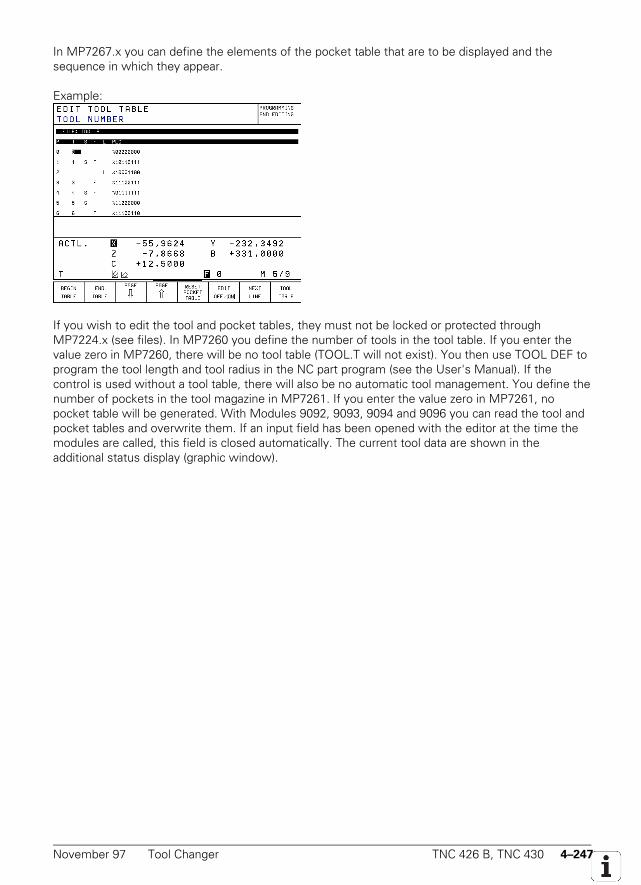
November 97 Tool Changer TNC 426 B, TNC 430 4–247
In MP7267.x you can define the elements of the pocket table that are to be displayed and thesequence in which they appear.
Example:
If you wish to edit the tool and pocket tables, they must not be locked or protected throughMP7224.x (see files). In MP7260 you define the number of tools in the tool table. If you enter thevalue zero in MP7260, there will be no tool table (TOOL.T will not exist). You then use TOOL DEF toprogram the tool length and tool radius in the NC part program (see the User's Manual). If thecontrol is used without a tool table, there will also be no automatic tool management. You define thenumber of pockets in the tool magazine in MP7261. If you enter the value zero in MP7261, nopocket table will be generated. With Modules 9092, 9093, 9094 and 9096 you can read the tool andpocket tables and overwrite them. If an input field has been opened with the editor at the time themodules are called, this field is closed automatically. The current tool data are shown in theadditional status display (graphic window).
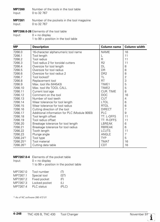
4–248 TNC 426 B, TNC 430 Tool Changer November 97
MP7260 Number of the tools in the tool tableInput: 0 to 32 767
MP7261 Number of the pockets in the tool magazineInput: 0 to 32 767
MP7266.0-26 Elements of the tool tableInput: 0 = no display
1 to 99 = position in the tool table
MP Description Column name Column width
7266.07266.17266.27266.37266.47266.57266.67266.77266.87266.97266.107266.117266.127266.137266.147266.157266.167266.177266.187266.197266.207266.217266.227266.237266.241)
7266.251)
7266.261)
16-character alphanumeric tool nameTool lengthTool radiusTool radius 2 for toroidal cuttersOversize for tool lengthOversize for tool radiusOversize for tool radius 2Tool locked?Replacement toolMax. tool life (M4543)Max. tool life TOOL CALLCurrent tool ageComment on the toolNumber of tool teethWear tolerance for tool lengthWear tolerance for tool radiusCutting direction of the toolAdditional information for PLC (Module 9093)Tool length offsetTool radius offsetBreakage tolerance for tool lengthBreakage tolerance for tool radiusTooth lengthPlunge angleTool typeTool materialCutting data table
NAMELRR2DLDRDR2TLRTTIME1TIME2CUR. TIMEDOCCUTLTOLRTOLDIRECTPLCTT: L-OFFSTT: R-OFFSLBREAKRBREAKLCUTSANGLETYPTMATCDT
1611111188823558164667911116611751616
MP7267.0-4 Elements of the pocket tableInput: 0 = no display
1 to 99 = position in the pocket table
MP7267.0 Tool number (T)MP7267.1 Special tool (ST)MP7267.2 Fixed pocket (F)MP7267.3 Locked pocket (L)MP7267.4 PLC status (PLC)
1) As of NC software 280 472 01
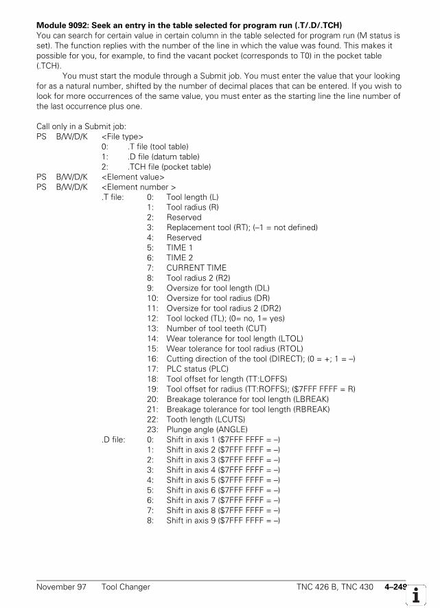
November 97 Tool Changer TNC 426 B, TNC 430 4–249
Module 9092: Seek an entry in the table selected for program run (.T/.D/.TCH)
You can search for certain value in certain column in the table selected for program run (M status isset). The function replies with the number of the line in which the value was found. This makes itpossible for you, for example, to find the vacant pocket (corresponds to T0) in the pocket table(.TCH).
You must start the module through a Submit job. You must enter the value that your lookingfor as a natural number, shifted by the number of decimal places that can be entered. If you wish tolook for more occurrences of the same value, you must enter as the starting line the line number ofthe last occurrence plus one.
Call only in a Submit job:PS B/W/D/K <File type>
0: .T file (tool table)1: .D file (datum table)2: .TCH file (pocket table)
PS B/W/D/K <Element value>PS B/W/D/K <Element number >
.T file: 0: Tool length (L)1: Tool radius (R)2: Reserved3: Replacement tool (RT); (–1 = not defined)4: Reserved5: TIME 16: TIME 27: CURRENT TIME8: Tool radius 2 (R2)9: Oversize for tool length (DL)10: Oversize for tool radius (DR)11: Oversize for tool radius 2 (DR2)12: Tool locked (TL); (0= no, 1= yes)13: Number of tool teeth (CUT)14: Wear tolerance for tool length (LTOL)15: Wear tolerance for tool radius (RTOL)16: Cutting direction of the tool (DIRECT); (0 = +; 1 = –)17: PLC status (PLC)18: Tool offset for length (TT:LOFFS)19: Tool offset for radius (TT:ROFFS); ($7FFF FFFF = R)20: Breakage tolerance for tool length (LBREAK)21: Breakage tolerance for tool length (RBREAK)22: Tooth length (LCUTS)23: Plunge angle (ANGLE)
.D file: 0: Shift in axis 1 ($7FFF FFFF = –)1: Shift in axis 2 ($7FFF FFFF = –)2: Shift in axis 3 ($7FFF FFFF = –)3: Shift in axis 4 ($7FFF FFFF = –)4: Shift in axis 5 ($7FFF FFFF = –)5: Shift in axis 6 ($7FFF FFFF = –)6: Shift in axis 7 ($7FFF FFFF = –)7: Shift in axis 8 ($7FFF FFFF = –)8: Shift in axis 9 ($7FFF FFFF = –)
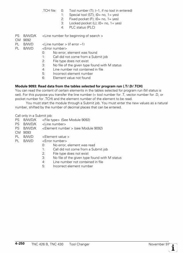
4–250 TNC 426 B, TNC 430 Tool Changer November 97
.TCH file: 0: Tool number (T); (–1, if no tool in entered)1: Special tool (ST); (0= no, 1= yes)2: Fixed pocket (F); (0= no, 1= yes)3: Locked pocket (L); (0= no, 1= yes)4: PLC status (PLC)
PS B/W/D/K <Line number for beginning of search >CM 9092PL B/W/D <Line number > (if error –1)PL B/W/D <Error number>
0: No error, element was found1: Call did not come from a Submit job2: File type does not exist3: No file of the given type found with M status4: Line number not contained in file5: Incorrect element number6: Element value not found
Module 9093: Read data from the tables selected for program run (.T/.D/.TCH)
You can read the content of certain elements in the tables selected for program run (M status isset). For this purpose you transfer the line number (= tool number for .T, vector number for .D, orpocket number for .TCH) and the element number of the element to be read.
You must start the module through a Submit job. You must enter the new values as a naturalnumber, shifted by the number of decimal places that can be entered.
Call only in a Submit job:PS B/W/D/K <File type> (See Module 9092)PS B/W/D/K <Line number>PS B/W/D/K <Element number > (see Module 9092)CM 9093PL B/W/D <Element value >PL B/W/D <Error number>
0: No error, element was read1: Call did not come from a Submit job2: File type does not exist3: No file of the given type found with M status4: Line number not contained in file5: Incorrect element number
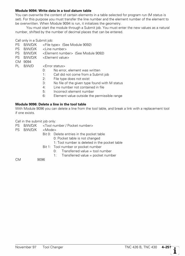
November 97 Tool Changer TNC 426 B, TNC 430 4–251
Module 9094: Write data in a tool datum table
You can overwrite the content of certain elements in a table selected for program run (M status isset). For this purpose you must transfer the line number and the element number of the element tobe overwritten. When Module 9094 is run, it initializes the geometry.
You must start the module through a Submit job. You must enter the new values as a naturalnumber, shifted by the number of decimal places that can be entered.
Call only in a Submit job:PS B/W/D/K <File type> (See Module 9092)PS B/W/D/K <Line number>PS B/W/D/K <Element number> (See Module 9092)PS B/W/D/K <Element value>CM 9094PL B/W/D <Error status>
0: No error, element was written1: Call did not come from a Submit job2: File type does not exist3: No file of the given type found with M status4: Line number not contained in file5: Incorrect element number6: Element value outside the permissible range
Module 9096: Delete a line in the tool table
With Module 9096 you can delete a line from the tool table, and break a link with a replacement toolif one exists.
Call in the submit job only:PS B/W/D/K <Tool number / Pocket number>PS B/W/D/K <Mode>
Bit 0: Delete entries in the pocket table0: Pocket table is not changed1: Tool number is deleted in the pocket table
Bit 1: Tool number or pocket number0: Transferred value = tool number1: Transferred value = pocket number
CM 9096
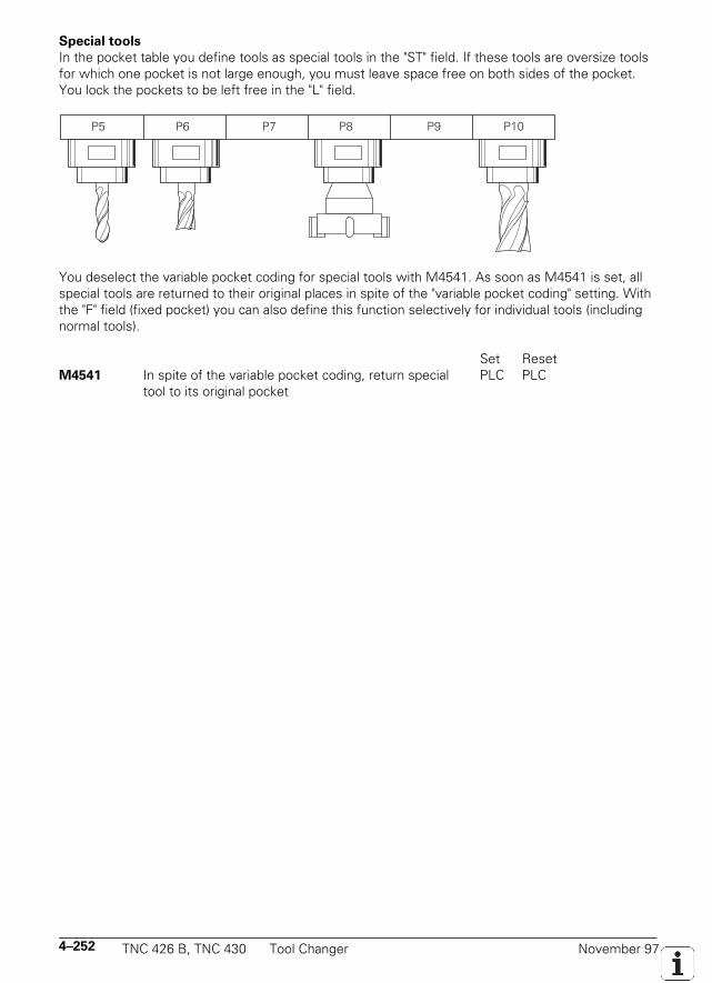
4–252 TNC 426 B, TNC 430 Tool Changer November 97
Special tools
In the pocket table you define tools as special tools in the "ST" field. If these tools are oversize toolsfor which one pocket is not large enough, you must leave space free on both sides of the pocket.You lock the pockets to be left free in the "L" field.
P7 P8 P9P6P5 P10
You deselect the variable pocket coding for special tools with M4541. As soon as M4541 is set, allspecial tools are returned to their original places in spite of the "variable pocket coding" setting. Withthe "F" field (fixed pocket) you can also define this function selectively for individual tools (includingnormal tools).
Set ResetM4541 In spite of the variable pocket coding, return special PLC PLC
tool to its original pocket
November 97 Tool Changer TNC 426 B, TNC 430 4–253
Tool life, replacement tool
In the tool table you can enter for each tool two tool life values (TIME1 and TIME2) and onereplacement tool (RT). If the current tool age (CUR.TIME) for a TOOL CALL is greater than TIME2,the pocket number or tool number (MP7480) of the replacement tool is automatically downloaded. IfTIME2 is greater than zero and no replacement tool is defined, the error message Max. tool ageexpired will appear in the event of a TOOL CALL after this time elapses. If the current tool agebecomes greater than TIME1, the NC sets marker M4543. You decide in the PLC what shouldhappen when M4543 is set (e.g. display a PLC error message).
With the M function M101 you activate the automatic insertion of the replacement tool afterexpiration of the tool life (TIME1 of TIME2). M101 is deactivated with M102. The replacement tool isnot changed exactly upon expiration of the tool life; it can vary by a few NC blocks depending on thedegree of utilization of the processor. A T-strobe M4073 is sent to the PLC and the marker M4525 isset. For automatic tool changing in standard NC programs (NC blocks with RR, RL or R0), thereplacement tool must have the same radius defined as for the original tool.
No radius compensation is entered in NC blocks with surface-normal vectors. For each tool a deltavalue is entered for radius (DR) and length (DL). These delta values are offset by the TNC in NCprograms with surface-normal vectors. If the radius of the replacement tool is different from theradius of the original tool, you must enter the difference in the DR field in the tool table. The deltavalue must always be negative. Entering a positive delta value will provoke the error message TOOLRADIUS TOO LARGE. You can suppress this error message with the M function M107. You cancancel M107 with M108. With MP7680 you define for NC blocks with surface-normal vectorswhether calculation of the tool length includes the oversize for the tool radius (DR2).
The current tool age between tool calls is counted only in the "Program run, full sequence" and"Program run, single block" modes. Spindle operation time and machine traversing time play no rolein the current tool age. The tool time counter is not stopped until the program is terminated with an"internal stop," M02, M30, or END PGM. The tool time counter does not run in the "Manualoperation," "Electronic Handwheel," or "Positioning with Manual Data Input" modes. The operator canreset the current tool age by entering zero.
Set ResetM4543 Tool life expired (TIME1 in the tool table) NC NC, PLC
MP7680 Machine parameters with multiple functionInput: %xxxxxxx
Bit 6 Tool length for blocks with surface-normal vectors0 = Without DR2 from the tool table1 = With DR2 from the tool table
4–254 TNC 426 B, TNC 430 Tool Changer November 97
4.21.2 Automatic Calculation of Cutting Data
As of NC software 280 472 01
The optimal speed and its corresponding feed rate can be calculated from the values entered incutting data tables for workpiece and tool material. Depending on the type of tool (for milling ordrilling), the values for cutting speed, feed rate per tooth or feed rate per revolution may be includedin these tables.
S = vc • 1 000
d • π
S = spindle speed [rpm]vc = cutting speed [m/min]d = tool diameter [mm]
Mill: F = fz • z • S F = feed rate [mm/min]fz = feed rate per tooth [mm]z = number of teeth
Drill: F = fu • S fu = feed rate per revolution [mm]
Tool table
In the tool table enter the name of the cutting data table that is to be used for that tool (under thecolumn CDT). Define the tool type under TYP (DRILL/TAP/MILL). You also need to indicate theradius of the tool (R), the tool material (TMAT) and, in the case of milling machines, the number ofteeth (CUT).
The three tool types are defined in the file PLC.\TTYP.TAB. If you edit this file, you must enterthe new name and path in the system file OEM.SYS using the command TTYP =.
Cutting data table
Your tool manufacturer will provide you with the necessary tool-specific cutting data.Cutting data tables have the file extension CDT. Each line of the cutting data table contains
the cutting data for a particular combination of workpiece and tool material. With milling machinesyou can enter up to four different cutting speeds with the corresponding feed rates per tooth. In thecutting data tables of the tool manufacturers these data are given for various infeeds and for climband up-cut milling. With drilling machines only enter one cutting speed and its corresponding feedrate.
There is a standard design for cutting data tables stored in the TNC root directory (TNC:\). Youcan set up as many tables as you wish. If you want to change the standard format, you must storethis under another path. Otherwise your changes will be overwritten with the standard HEIDENHAINsettings at the next software update. Using the command PCDT =, enter the path where you havestored your cutting data tables in the system file TNC.SYS.
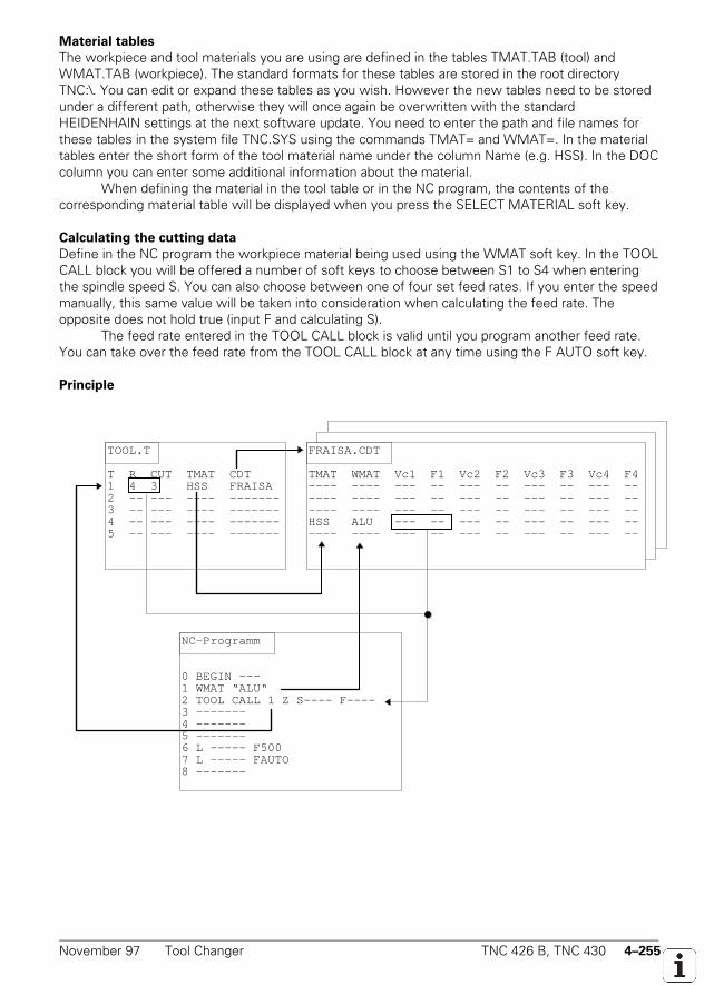
November 97 Tool Changer TNC 426 B, TNC 430 4–255
Material tables
The workpiece and tool materials you are using are defined in the tables TMAT.TAB (tool) andWMAT.TAB (workpiece). The standard formats for these tables are stored in the root directoryTNC:\. You can edit or expand these tables as you wish. However the new tables need to be storedunder a different path, otherwise they will once again be overwritten with the standardHEIDENHAIN settings at the next software update. You need to enter the path and file names forthese tables in the system file TNC.SYS using the commands TMAT= and WMAT=. In the materialtables enter the short form of the tool material name under the column Name (e.g. HSS). In the DOCcolumn you can enter some additional information about the material.
When defining the material in the tool table or in the NC program, the contents of thecorresponding material table will be displayed when you press the SELECT MATERIAL soft key.
Calculating the cutting data
Define in the NC program the workpiece material being used using the WMAT soft key. In the TOOLCALL block you will be offered a number of soft keys to choose between S1 to S4 when enteringthe spindle speed S. You can also choose between one of four set feed rates. If you enter the speedmanually, this same value will be taken into consideration when calculating the feed rate. Theopposite does not hold true (input F and calculating S).
The feed rate entered in the TOOL CALL block is valid until you program another feed rate.You can take over the feed rate from the TOOL CALL block at any time using the F AUTO soft key.
Principle
TOOL.T
T R CUT TMAT CDT1 4 3 HSS FRAISA2 -- --- ---- -------3 -- --- ---- -------4 -- --- ---- -------5 -- --- ---- -------
FRAISA.CDT
TMAT WMAT Vc1 F1 Vc2 F2 Vc3 F3 Vc4 F4---- ---- --- -- --- -- --- -- --- ------ ---- --- -- --- -- --- -- --- ------ ---- --- -- --- -- --- -- --- --HSS ALU --- -- --- -- --- -- --- ------ ---- --- -- --- -- --- -- --- --
NC-Programm
0 BEGIN ---1 WMAT “ALU“2 TOOL CALL 1 Z S---- F----3 -------4 -------5 -------6 L ----- F5007 L ----- FAUTO8 -------

4–256 TNC 426 B, TNC 430 Tool Changer November 97
November 97 Tool Changer TNC 426 B, TNC 430 4–257
4.21.3 Automatic Tool Recognition
Automatic tool identification is possible with the Balluff tool identification system (BIS).Please contact HEIDENHAIN for more information.

4–258 TNC 426 B, TNC 430 Tool Changer November 97

November 97 Tool Changer TNC 426 B, TNC 430 4–259

4–260 TNC 426 B, TNC 430 Tool Changer November 97

November 97 Tool Changer TNC 426 B, TNC 430 4–261

4–262 TNC 426 B, TNC 430 Tool Changer November 97

November 97 Tool Changer TNC 426 B, TNC 430 4–263

4–264 TNC 426 B, TNC 430 Tool Changer November 97

November 97 Tool Changer TNC 426 B, TNC 430 4–265

4–266 TNC 426 B, TNC 430 Tool Changer November 97
November 97 Tool Changer TNC 426 B, TNC 430 4–267
4.21.4 Controlling the Tool Changer
You must program the control of a tool changer, i.e., the positioning of the changing arm andcarousel and the complete tool-change sequence, in the PLC. The NC handles tool management, i.e.tool life, tool pocket assignment and evaluation of the TOOL DEF and TOOL CALL blocks. The NCand PLC communicate by means of markers and words.
When a TOOL CALL BLOCK is executed the tool geometry of the defined tool is taken fromthe tool table. With M4538 you activate the tool geometry of the tool defined in W264. M4538 canbe activated only together with an M/S/T/Q strobe or when the axis is stationary (control-in-operationsymbol "∗" off). With this marker you can ensure, for example, that the current tool geometry isactive even when the tool changing process is interrupted.
With the TOOL DEF block you can pre-position the tool changer. After a tool has beenchanged, the next tool is programmed with TOOL DEF. The PLC evaluates the tool and pocketnumber and pre-positions the tool changer to the follow-up tool.
Calling an NC program with TOOL CALL
With the NC block TOOL CALL you can also call an NC program of your own definition. The toolgeometry is then not taken over with this TOOL CALL and you must program a TOOL CALL atanother location for updating the tool data.
Define the name of the calling NC program in the file PLC:\NCMACRO.SYS as follows:TC = <Path name>\<File name>
With such a program you can, for example, very easily program a positioning motion to the tool-change position. It is best to file the program in the PLC partition to protect it against being changedby the end user. Since the tool data, as mentioned above, are not active in the activated program,you must interrogate them in with FN18 (see the chapter "PLC Programming"). With these data youcan program a TOOL CALL at an appropriate location in the called program so that the tool databecome active and a T-strobe is transferred to the PLC.
With FN18 you can also overwrite the software limit switch for tool-change positioning. If youuse FN18 to also call the programmed position after the TOOL CALL, you can program a continuousmovement from the tool magazine to the connecting position (M112).
With FN20: WAIT FOR you can suspend execution of the NC program until the enteredcondition is fulfilled. Comparisons of a PLC variable with a constant are permitted (see "PLCProgramming" chapter). To ensure that during a block scan the tool-change program is not run untilthe end you must enter the instruction NCMACRO=TC in the MGROUPS.SYS file. See"Reapproaching the Contour." If no NC program is specified in the file NCMACRO.SYS, the TOOLCALL is executed as before.
4–268 TNC 426 B, TNC 430 Tool Changer November 97
Example:0 BEGIN PGM TCALL MM1 M112 T4 ; INSERT AN ARC IN ORDER TO POSITION CONTINUOUSLY2 FN 18: SYSREAD Q1 = ID60 NR1 IDX0 ; TOOL NUMBER3 FN 18: SYSREAD Q2 = ID60 NR2 IDX0 ; TOOL AXIS4 FN 18: SYSREAD Q3 = ID60 NR3 IDX0 ; ROTATIONAL SPEED5 FN 18: SYSREAD Q4 = ID60 NR4 IDX0 ; OVERSIZE FOR TOOL LENGTH DL6 FN 18: SYSREAD Q5 = ID60 NR5 IDX0 ; OVERSIZE FOR TOOL RADIUS DR7 FN 19: PLC=+Q1 / +0 ; INFO FOR PLC FOR PRE-POSITIONING THE MAGAZINE8 LBL 5 ; CHECK WHETHER THE TOOL IS ALREADY IN THE SPINDLE9 FN 18: SYSREAD Q18 = ID2000 NR60 IDX230110 FN 9: IF +Q18 EQU +0 GOTO LBL 5 ; BYTE2301=0: WAIT FOR PLC11 FN 11: IF +Q18 GT +1 GOTO LBL 3 ; BYTE2301=2: TOOL ALREADY IN SPINDLE12 FN 18: SYSREAD Q10 = ID1000 NR4210 IDX0 ; TOOL-CHANGE POSITION AXIS X13 FN 18: SYSREAD Q11 = ID1000 NR4210 IDX2 ; TOOL-CHANGE POSITION 1 AXIS Y14 FN 18: SYSREAD Q12 = ID1000 NR4210 IDX5 ; TOOL-CHANGE POSITION AXIS Z15 FN 18: SYSREAD Q15 = ID1000 NR4210 IDX3 ; TOOL-CHANGE END POSITION AXIS Y16 L X+Q10 Y+Q11 Z+Q12 R0 F MAX M91 ; MOVE TO TOOL-CHANGE POSITION17 LBL 4 ; BYTE2300=1: SPINDLE AND MAGAZINE IN POSITION ?18 FN 18: SYSREAD Q18 = ID2000 NR60 IDX230019 FN 10: IF +Q18 NE +1 GOTO LBL 420 L Y+Q15 R0 F MAX M91 ; TOOL IN TOOL CHANGER21 L Y+Q11 M71 ; CLAMP THE TOOL AND RETURN TO TOOL-CHANGE POSITION22 LBL 322 TOOL CALL Q1 Z SQ3 DL+Q4 DR+Q5 ; TOOL CALL WITH T-STROBE23 M113 ; M112 SWITCH OFF24 END PGM TCALL MM
Variable and fixed pocket coding
You can operate the system with either variable or fixed tool pocket coding. Machine parameterMP7480.x defines whether the tool number or the pocket number is transferred to the PLC. Forvariable pocket coding the pocket number must be transferred to the PLC (MP7480.x = 3 or 4). Withfixed pocket coding it is advisable to work with the tool number (MP7480.x = 1 or 2).
When executing TOOL CALL and TOOL DEF blocks, depending on the setting of MP7480.x,the NC transfers either only the tool number of the programmed tool to the word W264, or thepocket number and the tool number to words W262 and W264, respectively. The NC sets thestrobe marker M4073 (TOOL CALL) or M4074 (TOOL DEF). The NC does not reset these strobemarkers until you set marker M4093 (TOOL CALL) or M4094 (TOOL DEF) after processing the toolor pocket number. The machining program is resumed when you acknowledge the strobe markers.
If tool number zero is processed, the NC sets marker M4521 and this is not reset until thereis a TOOL CALL for another tool.
MP7480.0 Output of tool or pocket number with TOOL CALL blockInput: 0 = No output
1 = Tool number output only when tool number changes2 = Tool number output with every TOOL CALL block3 = Output of pocket number and tool number only when tool number changes4 = Output of pocket number and tool number with every TOOL CALL block5 = Output of pocket number and tool number only when tool number changes.
Pocket table does not change.6 = Output of pocket number (W262) and tool number (W264) with every TOOL
CALL block. Pocket table does not change.
November 97 Tool Changer TNC 426 B, TNC 430 4–269
MP7480.1 Output of tool or pocket number with TOOL DEF blockInput: 0 = No output
1 = Tool number output only when tool number changes2 = Tool number output with every TOOL DEF block3 = Output of pocket number and tool number only when tool number changes4 = Output of pocket number and tool number with every TOOL DEF block
Set ResetW262 Pocket number NC NCW264 Tool number NC NCM4073 Strobe signal T code (P code) with TOOL CALL NC NCM4074 Strobe signal T code (P code) with TOOL DEF NC NCM4093 Acknowledgment of T code (P code) with TOOL CALL PLC PLCM4094 Acknowledgment of T code (P code) with TOOL DEF PLC PLCM4521 Tool no. zero programmed NC NCM4538 Geometry of the tool from W264 PLC NC
Output of tool number (fixed pocket coding)
Evaluating the tool number is adequate for fixed tool pocket coding. With MP7480.x you definewhether the tool number should be transferred to the PLC with every TOOL CALL (TOOL DEF)block or only when the tool number changes (input values for MP7480.x = 2 or 1). With this settingthe tool number is transferred to the word W262 when a TOOL CALL or TOOL DEF block isexecuted. W264 is not used. By entering 5 or 6 in MP7480.0 you can transfer the pocket number toW262 without changing the assignment of tool and pocket numbers in the pocket.
Output of pocket number (variable pocket coding)
With variable pocket coding (MP7480 = 3 or 4), the pocket number of the called tool is transferred tothe PLC and the assignment of tool and pocket number is changed in the pocket table. In addition tothe pocket number, the NC also transfers the current tool number in W264. Variable pocketmanagement (the assignment of tool number to pocket number in the tool table) is handled by theNC. If you set M4542 the assignment of tool and pocket numbers in the pocket table is notchanged, even though variable pocket coding is selected. You set this marker, for example, during amid-program startup.
You define the number of tools with a pocket number in machine parameter MP7261. Theinput value for MP7261 matches the number of pockets in the tool magazine. This means that youcan define more tools in the tool table than there is room for in the tool magazine [(MP7260) >(MP7261)]. If a tool number is programmed and no pocket is defined for it, pocket number –1(W262) is transferred on TOOL CALL, and marker M4523 is set.
Only the tool number and the pocket number are transferred when TOOL DEF isprogrammed. A TOOL DEF for a manual tool has no relevance in the PLC. You can define a fixedpocket in the field "F" of the pocket table. Tools for which a fixed pocket is defined are returned tothe same pocket despite variable coding.
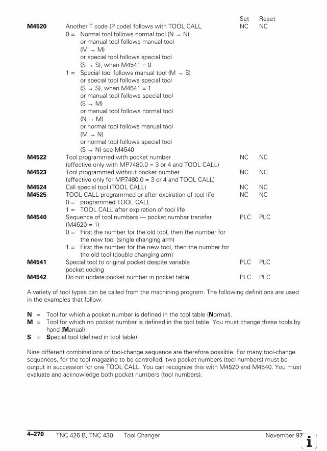
4–270 TNC 426 B, TNC 430 Tool Changer November 97
Set ResetM4520 Another T code (P code) follows with TOOL CALL NC NC
0 = Normal tool follows normal tool (N → N)or manual tool follows manual tool(M → M)or special tool follows special tool(S → S), when M4541 = 0
1 = Special tool follows manual tool (M → S)or special tool follows special tool(S → S), when M4541 = 1or manual tool follows special tool(S → M)or manual tool follows normal tool(N → M)or normal tool follows manual tool(M → N)or normal tool follows special tool(S → N) see M4540
M4522 Tool programmed with pocket number NC NC(effective only with MP7480.0 = 3 or 4 and TOOL CALL)
M4523 Tool programmed without pocket number NC NC(effective only for MP7480.0 = 3 or 4 and TOOL CALL)
M4524 Call special tool (TOOL CALL) NC NCM4525 TOOL CALL programmed or after expiration of tool life NC NC
0 = programmed TOOL CALL1 = TOOL CALL after expiration of tool life
M4540 Sequence of tool numbers — pocket number transfer PLC PLC(M4520 = 1)0 = First the number for the old tool, then the number for
the new tool (single changing arm)1 = First the number for the new tool, then the number for
the old tool (double changing arm)M4541 Special tool to original pocket despite variable PLC PLC
pocket codingM4542 Do not update pocket number in pocket table PLC PLC
A variety of tool types can be called from the machining program. The following definitions are usedin the examples that follow:
N = Tool for which a pocket number is defined in the tool table (Normal).M = Tool for which no pocket number is defined in the tool table. You must change these tools by
hand (Manual).S = Special tool (defined in tool table).
Nine different combinations of tool-change sequence are therefore possible. For many tool-changesequences, for the tool magazine to be controlled, two pocket numbers (tool numbers) must beoutput in succession for one TOOL CALL. You can recognize this with M4520 and M4540. You mustevaluate and acknowledge both pocket numbers (tool numbers).
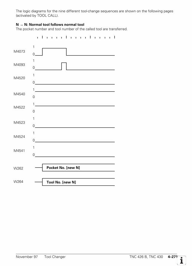
November 97 Tool Changer TNC 426 B, TNC 430 4–271
The logic diagrams for the nine different tool-change sequences are shown on the following pages(activated by TOOL CALL).
N → N: Normal tool follows normal tool
The pocket number and tool number of the called tool are transferred.
1
0M2046
1
0M2483
1
0M2093
1
0M2600
1
0M2401
1
0M2402
1
0M2403
1
0M2601
Pocket No. [new N]W262
Tool No. [new N]W264
M4073
M4093
M4520
M4540
M4522
M4523
M4524
M4541
W262
W264
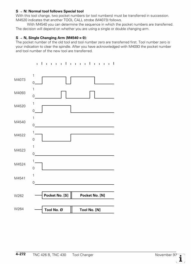
4–272 TNC 426 B, TNC 430 Tool Changer November 97
S → N: Normal tool follows Special tool
With this tool change, two pocket numbers (or tool numbers) must be transferred in succession.M4520 indicates that another TOOL CALL strobe (M4073) follows.
With M4540 you can determine the sequence in which the pocket numbers are transferred.The decision will depend on whether you are using a single or double changing arm.
S → N, Single Changing Arm (M4540 = 0):
The pocket number of the old tool and tool number zero are transferred first. Tool number zero isyour indication to clear the spindle. After you have acknowledged with M4093 the pocket numberand tool number of the new tool are transferred.
1
0M2046
1
0M2483
1
0M2093
1
0M2600
1
0M2401
1
0M2402
1
0M2403
1
0M2601
Pocket No. [S] Pocket No. [N]W262
Tool No. Ø Tool No. [N]W264
M4073
M4093
M4520
M4540
M4522
M4523
M4524
M4541
W262
W264
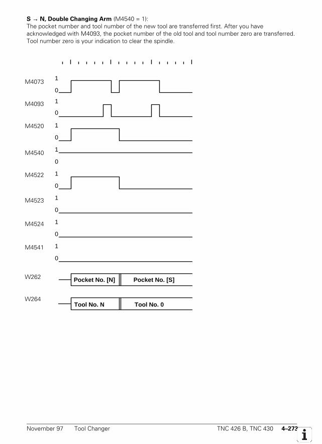
November 97 Tool Changer TNC 426 B, TNC 430 4–273
S → N, Double Changing Arm (M4540 = 1):The pocket number and tool number of the new tool are transferred first. After you haveacknowledged with M4093, the pocket number of the old tool and tool number zero are transferred.Tool number zero is your indication to clear the spindle.
1
0M2046
1
0M2483
1
0M2093
1
0M2600
1
0M2401
1
0M2402
1
0M2403
1
0M2601
Pocket No. [N] Pocket No. [S]W262
Tool No. N Tool No. 0W264
M4073
M4093
M4520
M4540
M4522
M4523
M4524
M4541
W262
W264
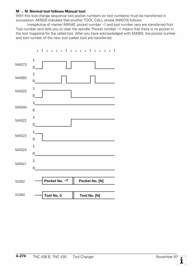
4–274 TNC 426 B, TNC 430 Tool Changer November 97
M → N: Normal tool follows Manual tool
With this tool-change sequence two pocket numbers (or tool numbers) must be transferred insuccession. M4520 indicates that another TOOL CALL strobe (M4073) follows.
Irrespective of marker M4540, pocket number –1 and tool number zero are transferred first.Tool number zero tells you to clear the spindle. Pocket number –1 means that there is no pocket inthe tool magazine for the called tool. After you have acknowledged with M4093, the pocket numberand tool number of the new tool (called tool) are transferred.
1
0M2046
1
0M2483
1
0M2093
1
0M2600
1
0M2401
1
0M2402
1
0M2403
1
0M2601
Pocket No. 255 Pocket No. [N]W262
Tool No. 0 Tool No. [N]W264
M4073
M4093
M4520
M4540
M4522
M4523
M4524
M4541
W262
W264
–1
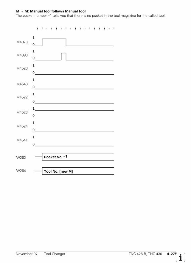
November 97 Tool Changer TNC 426 B, TNC 430 4–275
M → M: Manual tool follows Manual tool
The pocket number –1 tells you that there is no pocket in the tool magazine for the called tool.
1
0M2046
1
0M2483
1
0M2093
1
0M2600
1
0M2401
1
0M2402
1
0M2403
1
0M2601
Pocket No. 255W262
Tool No. [new M]W264
M4073
M4093
M4520
M4540
M4522
M4523
M4524
M4541
W262
W264
–1
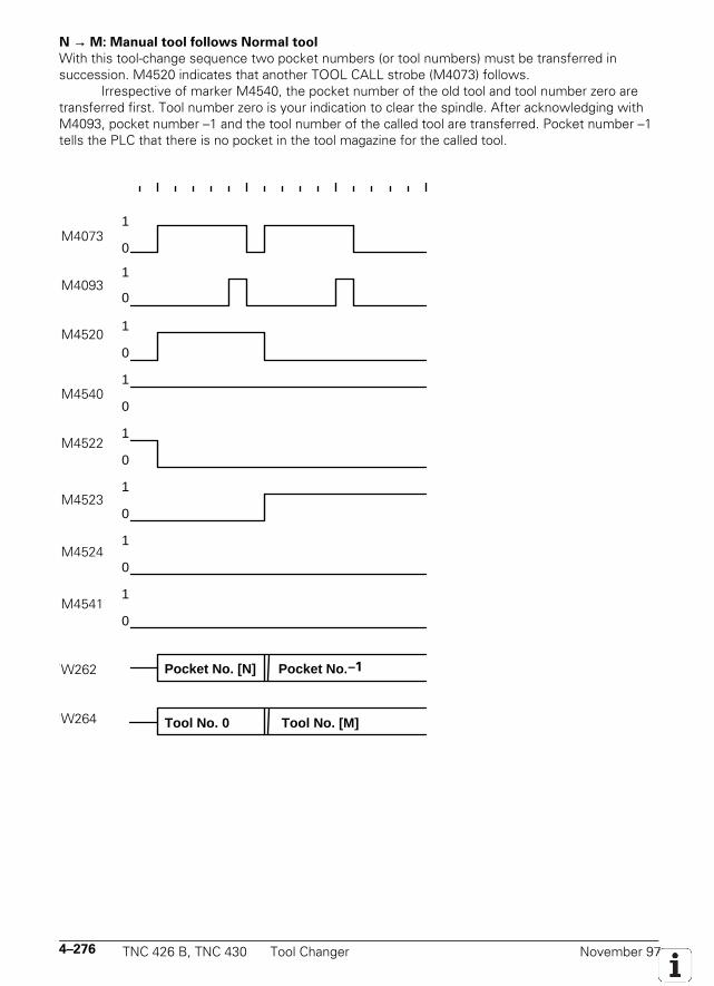
4–276 TNC 426 B, TNC 430 Tool Changer November 97
N → M: Manual tool follows Normal tool
With this tool-change sequence two pocket numbers (or tool numbers) must be transferred insuccession. M4520 indicates that another TOOL CALL strobe (M4073) follows.
Irrespective of marker M4540, the pocket number of the old tool and tool number zero aretransferred first. Tool number zero is your indication to clear the spindle. After acknowledging withM4093, pocket number –1 and the tool number of the called tool are transferred. Pocket number –1tells the PLC that there is no pocket in the tool magazine for the called tool.
1
0M2046
1
0M2483
1
0M2093
1
0M2600
1
0M2401
1
0M2402
1
0M2403
1
0M2601
Pocket No. [N] Pocket No. 255W262
Tool No. 0 Tool No. [M]W264
M4073
M4093
M4520
M4540
M4522
M4523
M4524
M4541
W262
W264
–1
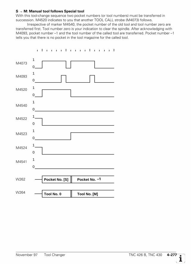
November 97 Tool Changer TNC 426 B, TNC 430 4–277
S → M: Manual tool follows Special tool
With this tool-change sequence two pocket numbers (or tool numbers) must be transferred insuccession. M4520 indicates to you that another TOOL CALL strobe (M4073) follows.
Irrespective of marker M4540, the pocket number of the old tool and tool number zero aretransferred first. Tool number zero is your indication to clear the spindle. After acknowledging withM4093, pocket number –1 and the tool number of the called tool are transferred. Pocket number –1tells you that there is no pocket in the tool magazine for the called tool.
1
0M2046
1
0M2483
1
0M2093
1
0M2600
1
0M2401
1
0M2402
1
0M2403
1
0M2601
Pocket No. [S] Pocket No. 255W262
Tool No. 0 Tool No. [M]W264
M4073
M4093
M4520
M4540
M4522
M4523
M4524
M4541
W262
W264
–1
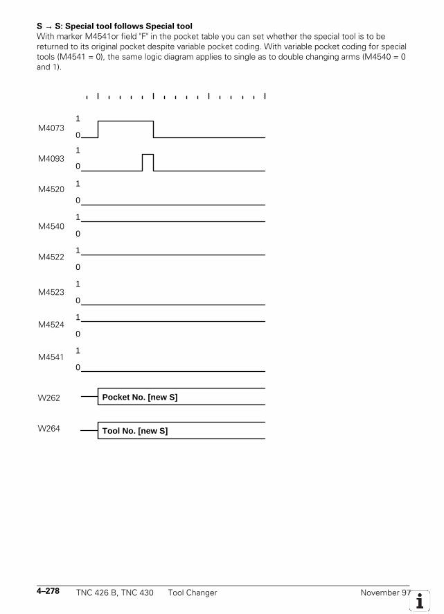
4–278 TNC 426 B, TNC 430 Tool Changer November 97
S → S: Special tool follows Special tool
With marker M4541or field "F" in the pocket table you can set whether the special tool is to bereturned to its original pocket despite variable pocket coding. With variable pocket coding for specialtools (M4541 = 0), the same logic diagram applies to single as to double changing arms (M4540 = 0and 1).
1
0M2046
1
0M2483
1
0M2093
1
0M2600
1
0M2401
1
0M2402
1
0M2403
1
0M2601
Pocket No. [new S]W262
Tool No. [new S]W264
M4073
M4093
M4520
M4540
M4522
M4523
M4524
M4541
W262
W264
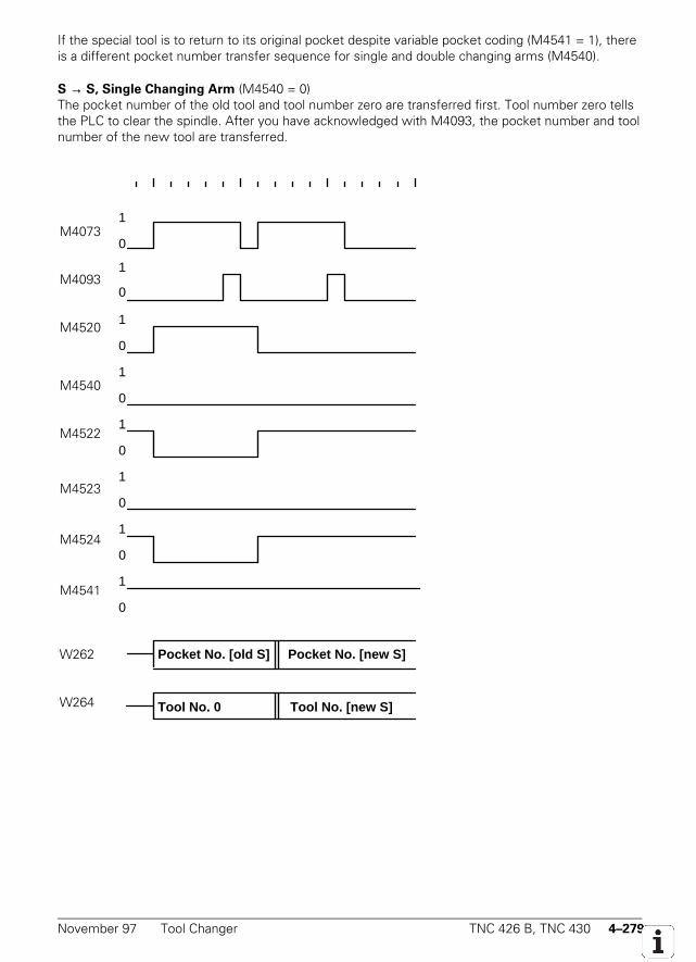
November 97 Tool Changer TNC 426 B, TNC 430 4–279
If the special tool is to return to its original pocket despite variable pocket coding (M4541 = 1), thereis a different pocket number transfer sequence for single and double changing arms (M4540).
S → S, Single Changing Arm (M4540 = 0)The pocket number of the old tool and tool number zero are transferred first. Tool number zero tellsthe PLC to clear the spindle. After you have acknowledged with M4093, the pocket number and toolnumber of the new tool are transferred.
1
0M2046
1
0M2483
1
0M2093
1
0M2600
1
0M2401
1
0M2402
1
0M2403
1
0M2601
Pocket No. [old S] Pocket No. [new S]W262
Tool No. 0 Tool No. [new S]W264
M4073
M4093
M4520
M4540
M4522
M4523
M4524
M4541
W262
W264
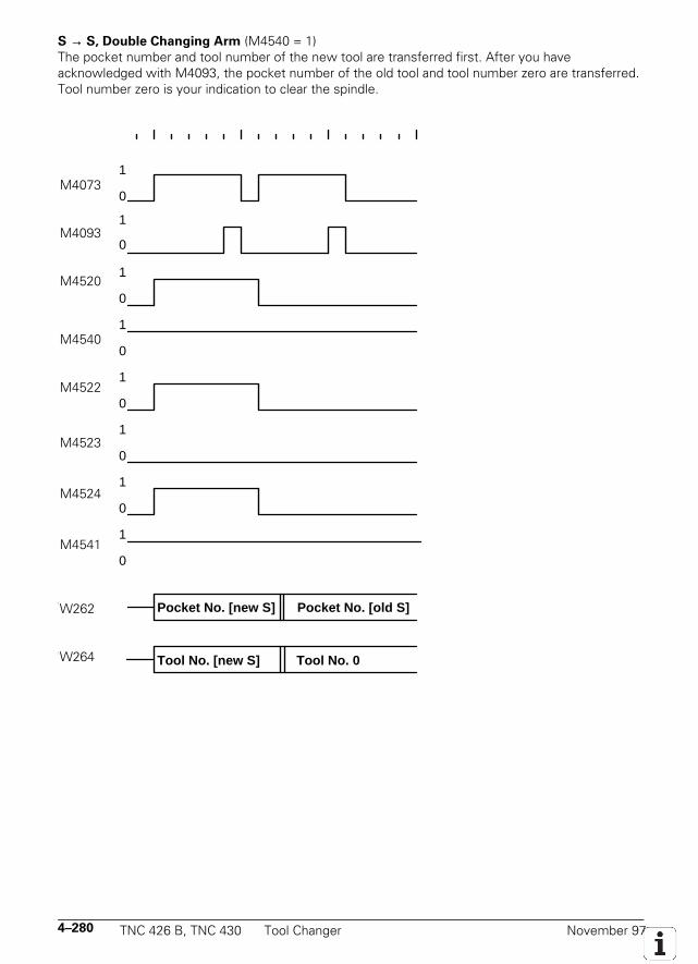
4–280 TNC 426 B, TNC 430 Tool Changer November 97
S → S, Double Changing Arm (M4540 = 1)The pocket number and tool number of the new tool are transferred first. After you haveacknowledged with M4093, the pocket number of the old tool and tool number zero are transferred.Tool number zero is your indication to clear the spindle.
1
0M2046
1
0M2483
1
0M2093
1
0M2600
1
0M2401
1
0M2402
1
0M2403
1
0M2601
Pocket No. [new S] Pocket No. [old S]W262
Tool No. [new S] Tool No. 0W264
M4073
M4093
M4520
M4540
M4522
M4523
M4524
M4541
W262
W264
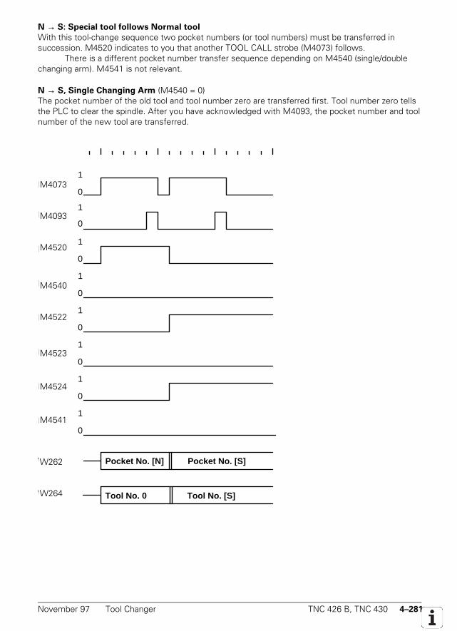
November 97 Tool Changer TNC 426 B, TNC 430 4–281
N → S: Special tool follows Normal tool
With this tool-change sequence two pocket numbers (or tool numbers) must be transferred insuccession. M4520 indicates to you that another TOOL CALL strobe (M4073) follows.
There is a different pocket number transfer sequence depending on M4540 (single/doublechanging arm). M4541 is not relevant.
N → S, Single Changing Arm (M4540 = 0)The pocket number of the old tool and tool number zero are transferred first. Tool number zero tellsthe PLC to clear the spindle. After you have acknowledged with M4093, the pocket number and toolnumber of the new tool are transferred.
1
0M2046
1
0M2483
1
0M2093
1
0M2600
1
0M2401
1
0M2402
1
0M2403
1
0M2601
Pocket No. [N] Pocket No. [S]W262
Tool No. 0 Tool No. [S]W264
M4073
M4093
M4520
M4540
M4522
M4523
M4524
M4541
W262
W264
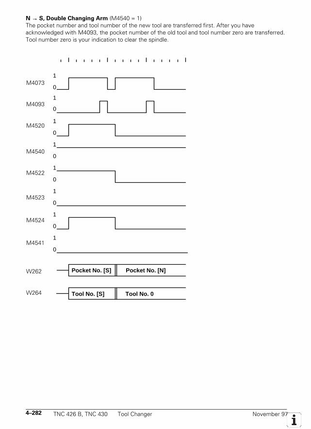
4–282 TNC 426 B, TNC 430 Tool Changer November 97
N → S, Double Changing Arm (M4540 = 1)The pocket number and tool number of the new tool are transferred first. After you haveacknowledged with M4093, the pocket number of the old tool and tool number zero are transferred.Tool number zero is your indication to clear the spindle.
1
0M2046
1
0M2483
1
0M2093
1
0M2600
1
0M2401
1
0M2402
1
0M2403
1
0M2601
Pocket No. [S] Pocket No. [N]W262
Tool No. [S] Tool No. 0W264
M4073
M4093
M4520
M4540
M4522
M4523
M4524
M4541
W262
W264
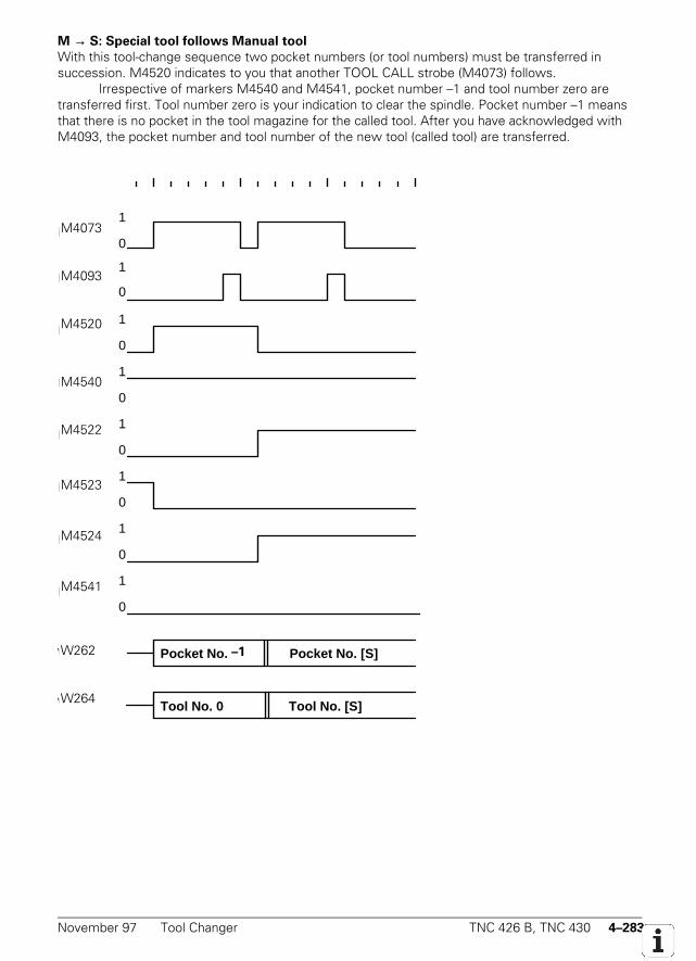
November 97 Tool Changer TNC 426 B, TNC 430 4–283
M → S: Special tool follows Manual tool
With this tool-change sequence two pocket numbers (or tool numbers) must be transferred insuccession. M4520 indicates to you that another TOOL CALL strobe (M4073) follows.
Irrespective of markers M4540 and M4541, pocket number –1 and tool number zero aretransferred first. Tool number zero is your indication to clear the spindle. Pocket number –1 meansthat there is no pocket in the tool magazine for the called tool. After you have acknowledged withM4093, the pocket number and tool number of the new tool (called tool) are transferred.
1
0M2046
1
0M2483
1
0M2093
1
0M2600
1
0M2401
1
0M2402
1
0M2403
1
0M2601
Pocket No. 255 Pocket No. [S]W262
Tool No. 0 Tool No. [S]W264
M4073
M4093
M4520
M4540
M4522
M4523
M4524
M4541
W262
W264
–1
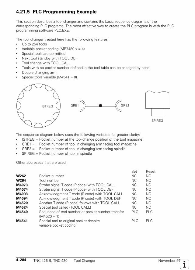
4–284 TNC 426 B, TNC 430 Tool Changer November 97
4.21.5 PLC Programming Example
This section describes a tool changer and contains the basic sequence diagrams of thecorresponding PLC programs. The most effective way to create the PLC program is with the PLCprogramming software PLC.EXE.
The tool changer treated here has the following features:• Up to 254 tools• Variable pocket coding (MP7480.x = 4)• Special tools are permitted• Next tool standby with TOOL DEF• Tool change with TOOL CALL• Tools with no pocket number defined in the tool table can be changed by hand.• Double changing arm• Special tools variable (M4541 = 0)
SPIREG
GRE1 GRE2ISTREG
The sequence diagram below uses the following variables for greater clarity:• ISTREG = Pocket number at the tool-change position of the tool magazine• GRE1 = Pocket number of tool in changing arm facing tool magazine• GRE2 = Pocket number of tool in changing arm facing spindle• SPIREG = Pocket number of tool in spindle
Other addresses that are used:
Set ResetW262 Pocket number NC NCW264 Tool number NC NCM4073 Strobe signal T code (P code) with TOOL CALL NC NCM4074 Strobe signal T code (P code) with TOOL DEF NC NCM4093 Acknowledgment T code (P code) with TOOL CALL NC NCM4094 Acknowledgment T code (P code) with TOOL DEF NC NCM4520 Another T code (P code) follows with TOOL CALL NC NCM4524 Special tool called (TOOL CALL) NC NCM4540 Sequence of tool number or pocket number transfer PLC PLC
(M4520 = 1)M4541 Special tool to original pocket despite PLC PLC
variable pocket coding
November 97 Tool Changer TNC 426 B, TNC 430 4–285
Machines parameter that are used:MP7260 = 90 Number of tools in tool tableMP7261 = 12 Number of pockets in tool magazineMP7480.0 = 4 Output of pocket number and tool number with every TOOL CALL blockMP7480.1 = 4 Output of pocket number and tool number with every TOOL DEF block
The sequence diagram for this tool changer is subdivided into modules.List of modules (subroutines):• TOOL DEF Search tool and load in GRE1• TOOL CALL Automatic tool-change• STANDBY Search tool and load in GRE1• STANDBY BACK Return tool from GRE1 to magazine• MANUAL TOOL IN Manual tool follows Normal or Special tool• MANUAL TOOL OUT Normal or Special tool follows Manual tool• MANUAL OUT/IN Manual tool follows Manual tool• INSERT Take old tool out and put new tool in• COMPUTE SHORTEST PATH• COMPARE P-CODE WITH ISTREG• COMPARE GRE1 WITH ISTREG
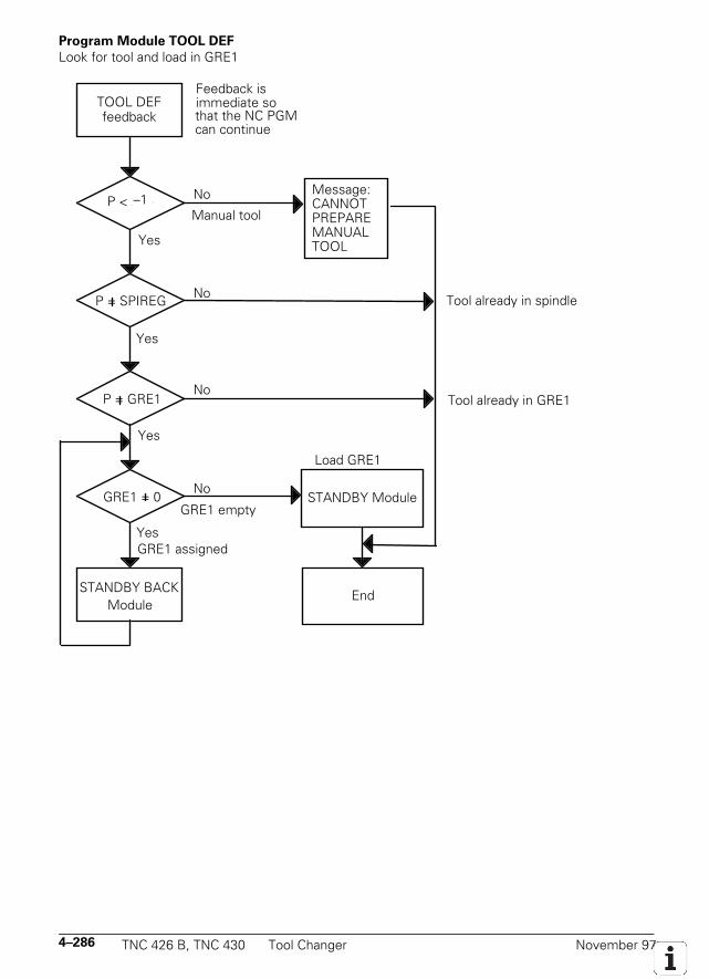
4–286 TNC 426 B, TNC 430 Tool Changer November 97
Program Module TOOL DEF
Look for tool and load in GRE1
TOOL DEFfeedback
P < 255
P = SPIREG
P = GRE1
GRE1 = 0
STANDBY BACK Module
No
No
No
Yes
No
Yes
Yes
Yes
Manual tool
Tool already in spindle
Tool already in GRE1
GRE1 empty
GRE1 assigned
STANDBY Module
End
Message: CANNOT PREPARE MANUAL
Feedback is immediate sothat the NC PGM can continue
Load GRE1
TOOL
–1
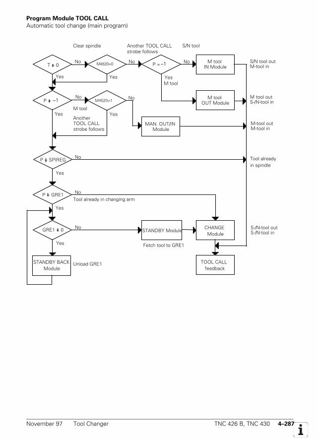
November 97 Tool Changer TNC 426 B, TNC 430 4–287
Program Module TOOL CALL
Automatic tool change (main program)
M tool IN ModuleT = 0
P = SPIREG
P = GRE1
GRE1 = 0
STANDBY BACKModule
No
No
NoNo
Yes
Yes
S/N tool out M-tool in
P = 255
M2093 = 0 P = 255
Another TOOL CALL strobe follows
Clear spindle S/N tool
No No
M tool
M2093 = 1M tool
OUT ModuleM tool outS-/N-tool in
Yes
MAN. OUT/IN Module
M-tool outM-tool in
Another TOOL CALL
Yes
strobe follows
No
Yes
Yes
NoTool already in changing arm
Unload GRE1
Fetch tool to GRE1
STANDBY ModuleCHANGE
Module
TOOL CALL feedback
S-/N-tool outS-/N-tool in
Tool already
Yes YesM tool
in spindle
M4520=0
M4520=1
–1
–1
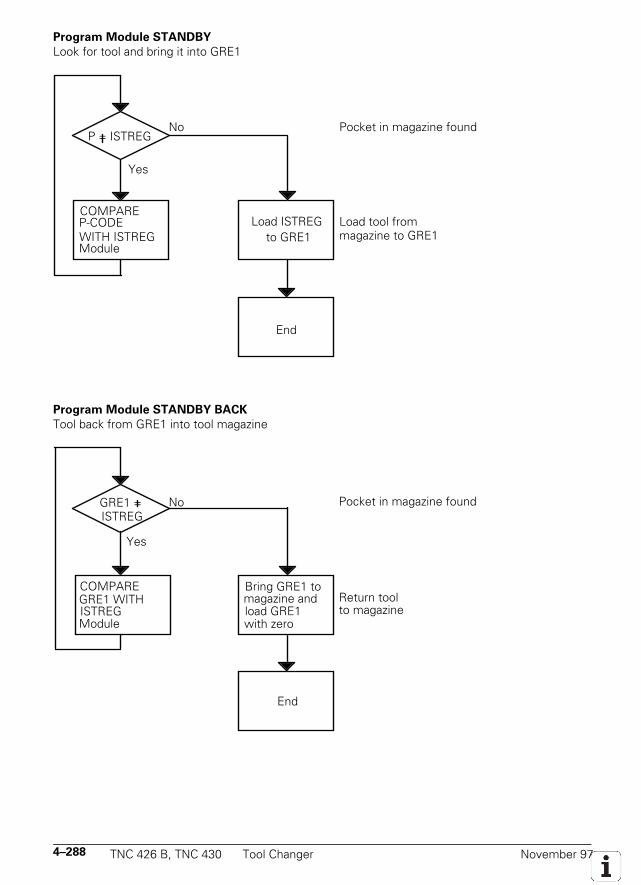
4–288 TNC 426 B, TNC 430 Tool Changer November 97
Program Module STANDBY
Look for tool and bring it into GRE1
P = ISTREG
Yes
COMPARE P-CODEWITH ISTREGModule
Pocket in magazine foundNo
Load ISTREG to GRE1
End
Load tool from magazine to GRE1
Program Module STANDBY BACK
Tool back from GRE1 into tool magazine
Yes
COMPARE GRE1 WITH ISTREG Module
Pocket in magazine foundNo
End
Return tool to magazine
Bring GRE1 to magazine and
with zeroload GRE1
ISTREGGRE1 =
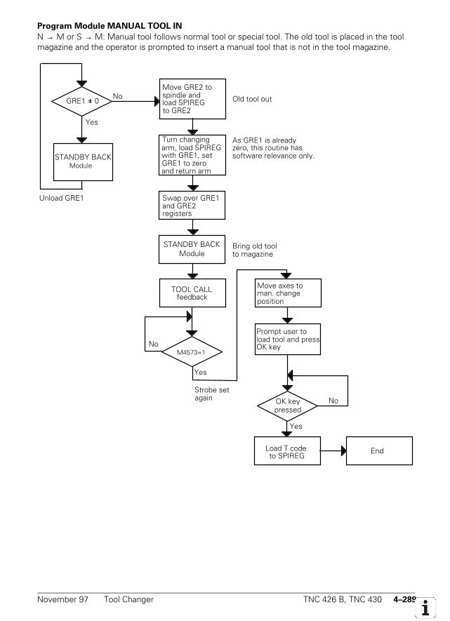
November 97 Tool Changer TNC 426 B, TNC 430 4–289
Program Module MANUAL TOOL IN
N → M or S → M: Manual tool follows normal tool or special tool. The old tool is placed in the toolmagazine and the operator is prompted to insert a manual tool that is not in the tool magazine.
Yes
No
STANDBY BACK
Old tool out
Turn changing arm, load SPIREG
GRE1 to zero with GRE1, set
and return arm
Move GRE2 to spindle and
to GRE2load SPIREG
Swap over GRE1 and GRE2 registers
M2046 = 1 No
As GRE1 is already
software relevance only.zero, this routine has
Bring old tool to magazine
STANDBY BACK Module
TOOL CALL feedback
Move axes to man. change
Load T code to SPIREG
End
Prompt user to load tool and press OK key
Yes
Yes
pressedNoOK key
position
againStrobe set
Unload GRE1
GRE1 = 0
Module
M4573=1
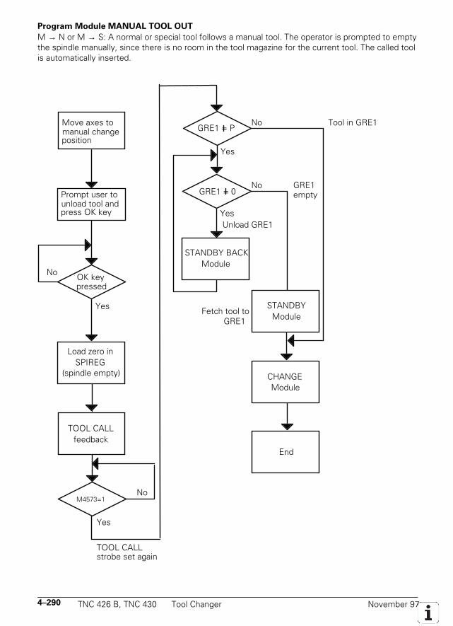
4–290 TNC 426 B, TNC 430 Tool Changer November 97
Program Module MANUAL TOOL OUT
M → N or M → S: A normal or special tool follows a manual tool. The operator is prompted to emptythe spindle manually, since there is no room in the tool magazine for the current tool. The called toolis automatically inserted.
OK key
Yes
Prompt user to unload tool and press OK key
Load zero inSPIREG
Move axes to manual change position
pressed
TOOL CALLfeedback
M2046 = 1
(spindle empty)
No
Yes
TOOL CALLstrobe set again
GRE1 = P
STANDBY BACKModule
Yes
Yes
STANDBYModule
CHANGEModule
End
No Tool in GRE1
No
Unload GRE1
Fetch tool to GRE1
No
emptyGRE1 = 0GRE1
M4573=1
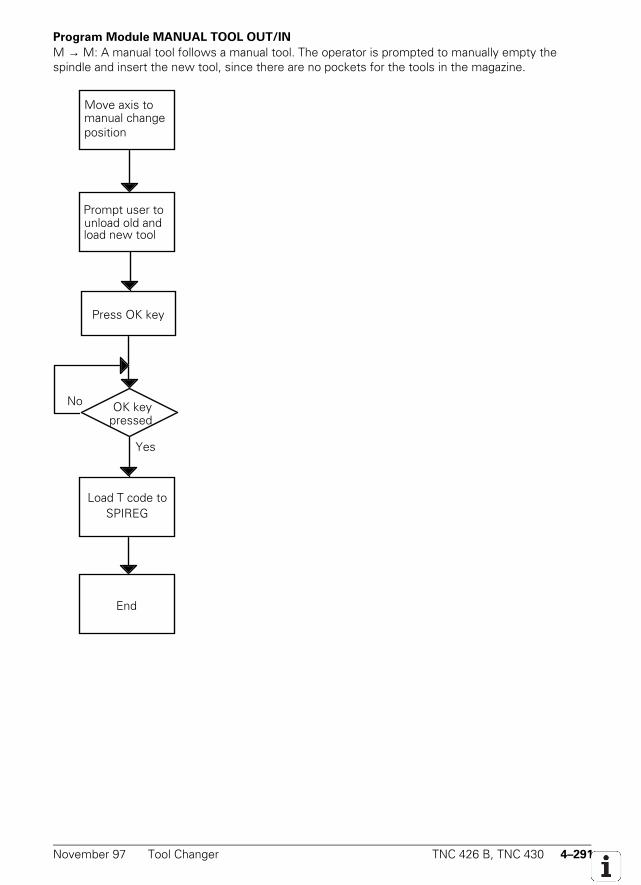
November 97 Tool Changer TNC 426 B, TNC 430 4–291
Program Module MANUAL TOOL OUT/IN
M → M: A manual tool follows a manual tool. The operator is prompted to manually empty thespindle and insert the new tool, since there are no pockets for the tools in the magazine.
OK key
Yes
Move axis to manual changeposition
Prompt user to unload old andload new tool
Press OK key
Load T code toSPIREG
End
pressed
No
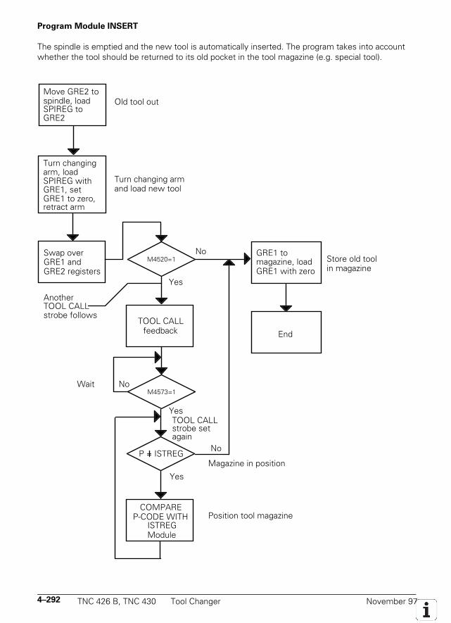
4–292 TNC 426 B, TNC 430 Tool Changer November 97
Program Module INSERT
The spindle is emptied and the new tool is automatically inserted. The program takes into accountwhether the tool should be returned to its old pocket in the tool magazine (e.g. special tool).
M2093 = 1
Move GRE2 to spindle, load SPIREG to GRE2
Turn changing arm, load SPIREG with
No
GRE1, set GRE1 to zero,retract arm
Swap over GRE1 and GRE2 registers
TOOL CALLfeedback
M2046 = 1
P = ISTREG
COMPAREP-CODE WITH
Yes
ISTREGModule
Yes
Position tool magazine
Yes
No
TOOL CALL strobe set
Another TOOL CALLstrobe follows
End
GRE1 to magazine, load GRE1 with zero
Store old tool in magazine
Noagain
Magazine in position
Old tool out
Turn changing arm and load new tool
WaitM4573=1
M4520=1
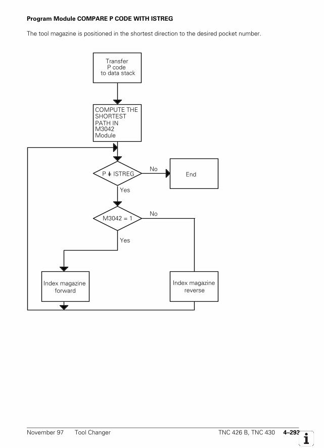
November 97 Tool Changer TNC 426 B, TNC 430 4–293
Program Module COMPARE P CODE WITH ISTREG
The tool magazine is positioned in the shortest direction to the desired pocket number.
P = ISTREG
Transfer
to data stack
COMPUTE THE SHORTEST PATH IN M3042 Module
EndNo
M3042 = 1
Yes
No
Yes
Index magazine forward
Index magazine reverse
P code
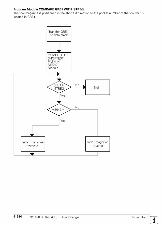
4–294 TNC 426 B, TNC 430 Tool Changer November 97
Program Module COMPARE GRE1 WITH ISTREG
The tool magazine is positioned in the shortest direction to the pocket number of the tool that islocated in GRE1.
Transfer GRE1 to data stack
COMPUTE THE SHORTEST PATH IN M3042 Module
EndNo
M3042 = 1
Yes
No
Yes
Index magazineforward
Index magazinereverse
ISTREG GRE1 =
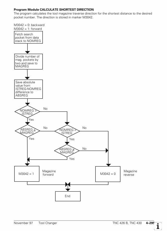
November 97 Tool Changer TNC 426 B, TNC 430 4–295
Program Module CALCULATE SHORTEST DIRECTION
The program calculates the tool magazine traverse direction for the shortest distance to the desiredpocket number. The direction is stored in marker M3042.
M3042 = 0: backwardM3042 = 1: forward
NOMREG >
Save absolutevalue from ISTREG-NOMREG difference to ABSREG
No
Yes
No
Yes
Magazine forward
Magazine reverse
ISTREG
Divide number of mag. pockets by two and save to MAGREG
Fetch search pocket from data stack to NOMREG
ABSREG > MAGREG
End
ABSREG < MAGREG
NOMREG < ISTREG
No
Yes
No
M3042 = 1 M3042 = 0
Yes

4–296 TNC 426 B, TNC 430 Tool Changer November 97
November 97 Special Functions for Laser Cutting Machines TNC 426B, TNC 430 4–297
4.22 Special Functions for Laser Cutting Machines
You can activate special functions to interface the TNC to laser cutting machines and water jetmachines.
4.22.1 Analog Voltage Output
If you do not need the analog output (X8, pin 8) for the spindle, you can define with MP3011 anotherfunction for this analog output. The input values in MP3011 show an effect only if the value in MP3010is less than 3.
MP3011 Function of analog output S, if MP3010 < 3Input: 0 = No special function
1 = Voltage proportional to current contour feed rate (depending on MP3012)2 = Voltage as defined by Module 91303 = Voltage is defined via M function (M200 to M204)
Voltage proportional to the feed rate (MP3011 = 1)
A voltage proportional to the current contour feed rate is output. In MP3012 you enter the feed rateachieved when 10 V is output.
MP3012 Feed rate for output of an analog voltage of 10 V (MP3011 = 1)Input: 0 to 300 000 [mm/min ]
Voltage from the PLC (MP3011 = 2)
The voltage that you have defined with Module 9130 is issued.
Definition of the voltage via M functions (MP3011 = 3)
The analog voltage output can be defined in the positioning block with the miscellaneous functionsM200 to M204. These M functions are available only if you have entered the value 3 in MP3011. TheM functions are executed synchronously to the positioning blocks and are effective at the beginning ofthe block.
Direct output of the programmed voltage: M200 V...
The TNC outputs the value programmed behind M200 V... as a voltage.Input: 0 to 9.999 [V]Duration: M201 V... is effective unit a new voltage is output through M200 to M204.
Voltage varies with distance: M201 V...
The TNC outputs the voltage as a function of the traversed distance. The TNC increases or decreasesthe voltage linearly from the active voltage to the value programmed behind M201 V...Input: 0 to 9.999 [V]Duration: M201 V... is effective until a new voltage is output through M200 to M204.
4–298 TNC 426B, TNC 430 Special Functions for Laser Cutting Machines November 97
Voltage varies with the velocity: M202 FNR.
The TNC outputs the voltage as a function of the velocity. With machine parameters MP3013.x andMP3014.x you can define up to three characteristic curves in a table. In the table certain analogvoltages are assigned to certain feed rates. M202 FNR. selects the characteristic curve in which theTNC finds the voltage to be output.
Input: 1 to 3Duration: M202 FNR. is effective until a new voltage is output through M200 to M204.
You can enter in the table up to four kink points per characteristic curve. The output values areinterpolated linearly between the kink points. The first kink point must have the value zero. The entryvalues of the following kink points must increase in sequence. The TNC recognizes the beginning of anew characteristic curve from the entry value zero.
Example:
Velocity Voltage Characteristic
MP3013.0 0 MP3014.0 0 1
MP3013.1 25 MP3014.1 0 1
MP3013.2 500 MP3014.2 4.5 1
MP3013.3 1000 MP3014.3 9.999 1
MP3013.4 0 MP3014.4 0 2
MP3013.5 10 000 MP3014.5 9.999 2
MP3013.6 0 MP3014.6 9 3
MP3013.7 50 MP3014.7 0.5 3
MP3013.8 300 MP3014.8 1.5 3
MP3013.9 5000 MP3014.9 9.999 3
MP3013.10 0 MP3014.10 0 Not used
MP3013.11 0 MP3014.11 0 Not used
MP3013.0-11 Characteristic kink points (velocity) for analog voltage output with M202Input: 10 to 300 000 [mm/min]
MP3014.0-11 Characteristic kink points (voltage) for analog voltage output with M202Input: 0.000 to 9.999 [V]
Voltage varies with the time (time-voltage ramp): M203 V... TIME...
The TNC outputs the voltage as a function of the time. It increases or decreases the voltage linearly inthe time programmed behind TIME from the current voltage to the voltage value programmed behindV...Input: Voltage V: 0 to 9.999 [V]
TIME: 0 to 1.999 [sec]Duration: M203 V... TIME... is effective until a new voltage is output through M200 to M204.
November 97 Special Functions for Laser Cutting Machines TNC 426B, TNC 430 4–299
Voltage for a specific time (time pulse): M204 V... TIME...
The TNC outputs the voltage programmed behind V... as a pulse. The duration of the pulse is enteredwith TIME....Entry: Voltage V: 0 to 9.999 [V]
TIME: 0 to 1.999 [sec]Duration: M204 V... TIME... is effective until a new voltage is output through M200 to M204.
4.22.2 Graphic Simulation Without TOOL CALL
Graphic simulation is also available on machines that operate without tool definition (e.g. water jet andlaser cutters). You define the tool radius for graphic simulation in machine parameter MP7315. WithMP7316 you define the depth of penetration of the simulated tool. You mark the program sections tobe displayed with M functions that you define in machine parameters MP7317.x.
MP7315 Tool radius for graphic simulation without TOOL CALLInput: 0.0000 to 99 999.9999 [mm]
MP7316 Penetration depth of the toolInput: 0.0000 to 99 999.9999 [mm]
MP7317.0 M function at start of graphic displayInput: 0 to 88
MP7317.1 M function to interrupt graphic displayInput: 0 to 88
4–300 TNC 426B, TNC 430 Special Functions for Laser Cutting Machines November 97
4.22.3 Program Stop with M Functions and TOOL CALL S
When an M function is output in the "Program run, full sequence" and "Program run, single block"modes, the program run is normally interrupted until you report with M4092 that the M function wasexecuted. The same applies for a TOOL CALL with which only a spindle speed is programmed(TOOL CALL S).
This can be a disadvantage in certain applications, such as with laser cutting machines. Forsuch applications it is more desirable not to wait for the acknowledgment, but rather to run theprogram continuously. You can therefore select with machine parameter MP7440 bit 2 and MP3030whether program run should be interrupted in these cases. There must be no PLC positioning, datumshift, spindle orientation or changes in limit-switch range during M function output.
This function must not be used on milling machines or boring machines.
MP3030 Axis stops with TOOL CALL S...Input: 0 = Axis stops with TOOL CALL S...
1 = Axis does not stop with TOOL CALL S...
MP7440 Output of M functionsInput: %xxxxxBit 2 Program stops for M functions
0 = Program stops until M function is acknowledged1 = Program run continues (does not wait for acknowledgment)

November 97 Special Functions for Laser Cutting Machines TNC 426B, TNC 430 4–301
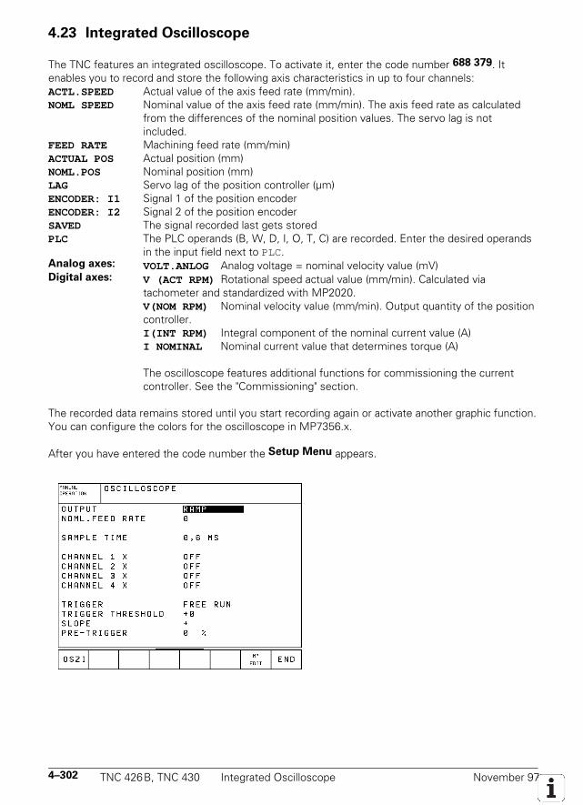
4–302 TNC 426B, TNC 430 Integrated Oscilloscope November 97
4.23 Integrated Oscilloscope
The TNC features an integrated oscilloscope. To activate it, enter the code number 688 379. Itenables you to record and store the following axis characteristics in up to four channels:ACTL.SPEED Actual value of the axis feed rate (mm/min).NOML SPEED Nominal value of the axis feed rate (mm/min). The axis feed rate as calculated
from the differences of the nominal position values. The servo lag is notincluded.
FEED RATE Machining feed rate (mm/min)ACTUAL POS Actual position (mm)NOML.POS Nominal position (mm)LAG Servo lag of the position controller (µm)ENCODER: I1 Signal 1 of the position encoderENCODER: I2 Signal 2 of the position encoderSAVED The signal recorded last gets storedPLC The PLC operands (B, W, D, I, O, T, C) are recorded. Enter the desired operands
in the input field next to PLC.Analog axes: VOLT.ANLOG Analog voltage = nominal velocity value (mV)Digital axes: V (ACT RPM) Rotational speed actual value (mm/min). Calculated via
tachometer and standardized with MP2020.V(NOM RPM) Nominal velocity value (mm/min). Output quantity of the positioncontroller.I(INT RPM) Integral component of the nominal current value (A)I NOMINAL Nominal current value that determines torque (A)
The oscilloscope features additional functions for commissioning the currentcontroller. See the "Commissioning" section.
The recorded data remains stored until you start recording again or activate another graphic function.You can configure the colors for the oscilloscope in MP7356.x.
After you have entered the code number the Setup Menu appears.
November 97 Integrated Oscilloscope TNC 426B, TNC 430 4–303
Use the cursor keys to select the desired position and set the parameters.
OUTPUTHere you can define whether the nominal velocity value is output as a step or as a ramp. For outputas a ramp, the programmed feed rate and the kv factors and acceleration rates set in the machineparameters go into effect.
If you have selected step output, a step will be output as nominal velocity value when youpress the axis direction buttons in the "Manual" operating mode. The position control loop is openwhile the step is being output. You define the height of the step in the NOML. FEED RATE inputfield.
NOML. FEED RATEHere you enter the height of the step for the nominal velocity value (in mm/min). This entry has nosignificance for the output of a ramp.
SAMPLE TIMEYou can set the time interval for recording the signals to between 0.6 and 6 ms. 4096 samples arestored. The signals are therefore stored for a time duration of 2.4576 s to 24.576 seconds.
CHANNEL 1 to CHANNEL 4Here you assign to each of the four channels the signal and axis that you wish to record. The inputpossibilities are described above.
TRIGGERHere you define the type of recording. You have the following possibilities:• FREE RUN The recording is started and stopped manually via soft keys. When you
press the STOP key, the last 4096 events are recorded.• SINGLE SHOT When you press the START key, the next 4096 events are recorded.• CHANNEL 1 to 4 Recording begins when the triggering threshold of the selected channel is
exceeded.
TRIGGER THRESHOLDHere you enter the trigger threshold in the following dimensions:• Velocity [mm/min]• Position [mm]• Rotational speed [mm/min]• Servo lag [µm]• Analog voltage [mV]• Current [A]
SLOPEHere you set whether the rising (positive) or falling (negative) edge should be triggered.
PRE-TRIGGERThe stored recording starts before the trigger time point by the value defined here.
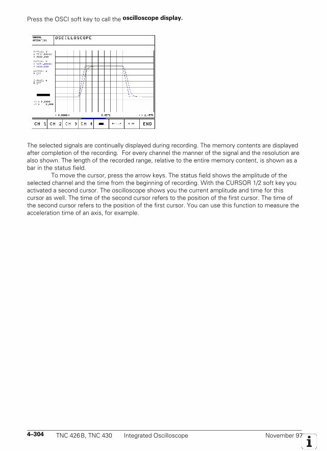
4–304 TNC 426B, TNC 430 Integrated Oscilloscope November 97
Press the OSCI soft key to call the oscilloscope display.
The selected signals are continually displayed during recording. The memory contents are displayedafter completion of the recording. For every channel the manner of the signal and the resolution arealso shown. The length of the recorded range, relative to the entire memory content, is shown as abar in the status field.
To move the cursor, press the arrow keys. The status field shows the amplitude of theselected channel and the time from the beginning of recording. With the CURSOR 1/2 soft key youactivated a second cursor. The oscilloscope shows you the current amplitude and time for thiscursor as well. The time of the second cursor refers to the position of the first cursor. The time ofthe second cursor refers to the position of the first cursor. You can use this function to measure theacceleration time of an axis, for example.
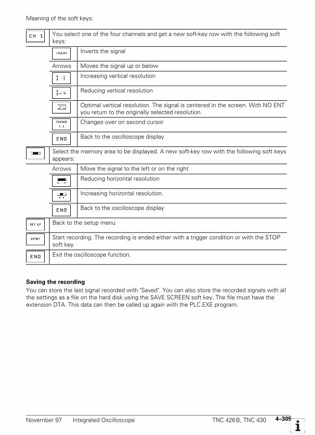
November 97 Integrated Oscilloscope TNC 426B, TNC 430 4–305
Meaning of the soft keys:
You select one of the four channels and get a new soft-key row with the following softkeys:
Inverts the signal
Arrows Moves the signal up or below
Increasing vertical resolution
Reducing vertical resolution
Optimal vertical resolution. The signal is centered in the screen. With NO ENTyou return to the originally selected resolution.
Changes over on second cursor
Back to the oscilloscope display
Select the memory area to be displayed. A new soft-key row with the following soft keysappears:
Arrows Move the signal to the left or on the right
Reducing horizontal resolution
Increasing horizontal resolution.
Back to the oscilloscope display
Back to the setup menu
Start recording. The recording is ended either with a trigger condition or with the STOPsoft key.
Exit the oscilloscope function.
Saving the recording
You can store the last signal recorded with "Saved". You can also store the recorded signals with allthe settings as a file on the hard disk using the SAVE SCREEN soft key. The file must have theextension DTA. This data can then be called up again with the PLC.EXE program.

4–306 TNC 426B, TNC 430 Integrated Oscilloscope November 97
November 97 Commissioning TNC 426B, TNC 430 4–307
4.24 Commissioning
4.24.1 Preparation
• Check the wiring against the grounding diagram and the safety concept (see "Basic CircuitDiagram")
• Check the "control-is-ready" function (see "EMERGENCY STOP Monitoring").• Check the EMERGENCY STOP circuit by pressing the EMERGENCY STOP keys and the
EMERGENCY STOP limit switch.• The current machine parameter file must be selected. Most of the input values can be clearly
determined from the present documentation. Enter preliminary values for those machineparameters that are determined during commissioning.
• The PLC program for integration to the machine must be written prior to commissioning. Ensurethat in the system file OEM.SYS the instruction PLCMAIN= refers to the current PLC program. Towrite the PLC program, use the PLC programming software PLCdesign.
4.24.2 Digital Axis
With MP120 you define digital and analog axes. The current controller, speed controller and positioncontroller must be interfaced in sequence. You can complete all interfacing procedures directly atthe TNC. You can record the signals that you need from the TNC's integrated oscilloscope.
NC software: 280470..:
Digital and analog axes are defined in MP2000.x.MP2000.0-5 Type of driveInput: 0 = output of nominal speed command signal (analog axis)
1 = output of current pulses (digital axis)MP2001 Type of drive for spindleInput: 0 = output of nominal speed command signal (analog spindle)
1 = output of current pulses (digital spindle)
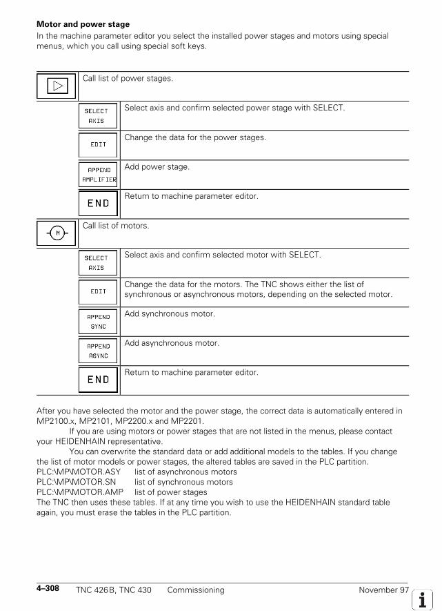
4–308 TNC 426B, TNC 430 Commissioning November 97
Motor and power stage
In the machine parameter editor you select the installed power stages and motors using specialmenus, which you call using special soft keys.
Call list of power stages.
Select axis and confirm selected power stage with SELECT.
Change the data for the power stages.
Add power stage.
Return to machine parameter editor.
Call list of motors.
Select axis and confirm selected motor with SELECT.
Change the data for the motors. The TNC shows either the list ofsynchronous or asynchronous motors, depending on the selected motor.
Add synchronous motor.
Add asynchronous motor.
Return to machine parameter editor.
After you have selected the motor and the power stage, the correct data is automatically entered inMP2100.x, MP2101, MP2200.x and MP2201.
If you are using motors or power stages that are not listed in the menus, please contactyour HEIDENHAIN representative.
You can overwrite the standard data or add additional models to the tables. If you changethe list of motor models or power stages, the altered tables are saved in the PLC partition.PLC:\MP\MOTOR.ASY list of asynchronous motorsPLC:\MP\MOTOR.SN list of synchronous motorsPLC:\MP\MOTOR.AMP list of power stagesThe TNC then uses these tables. If at any time you wish to use the HEIDENHAIN standard tableagain, you must erase the tables in the PLC partition.
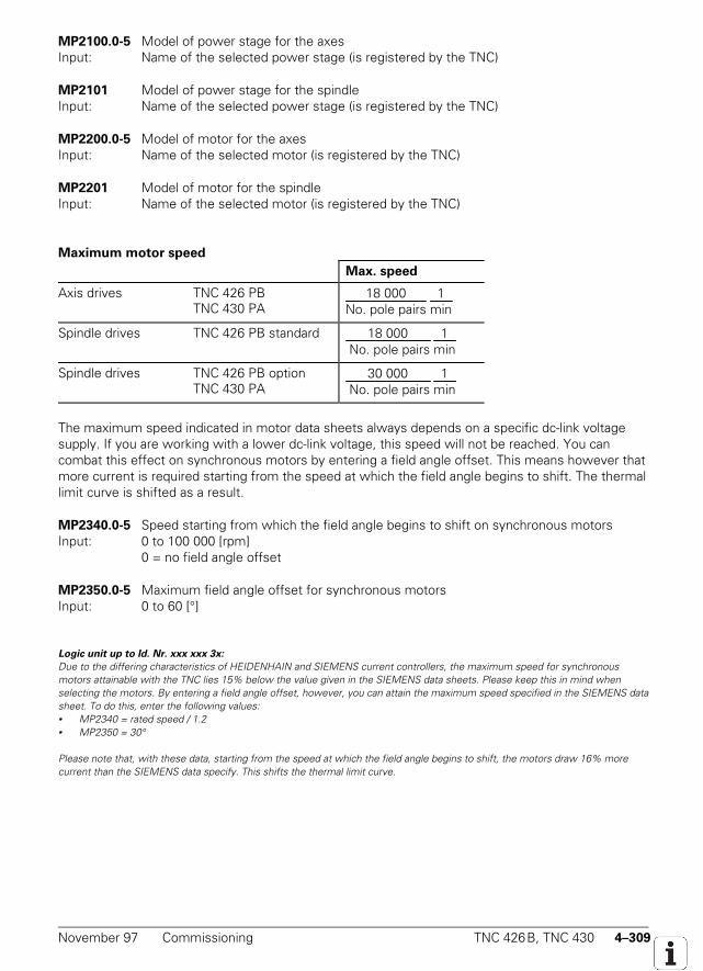
November 97 Commissioning TNC 426B, TNC 430 4–309
MP2100.0-5 Model of power stage for the axesInput: Name of the selected power stage (is registered by the TNC)
MP2101 Model of power stage for the spindleInput: Name of the selected power stage (is registered by the TNC)
MP2200.0-5 Model of motor for the axesInput: Name of the selected motor (is registered by the TNC)
MP2201 Model of motor for the spindleInput: Name of the selected motor (is registered by the TNC)
Maximum motor speed
Max. speed
Axis drives TNC 426 PBTNC 430 PA
18 000No. pole pairs
1min
Spindle drives TNC 426 PB standard 18 000 No. pole pairs
1min
Spindle drives TNC 426 PB optionTNC 430 PA
30 000 No. pole pairs
1min
The maximum speed indicated in motor data sheets always depends on a specific dc-link voltagesupply. If you are working with a lower dc-link voltage, this speed will not be reached. You cancombat this effect on synchronous motors by entering a field angle offset. This means however thatmore current is required starting from the speed at which the field angle begins to shift. The thermallimit curve is shifted as a result.
MP2340.0-5 Speed starting from which the field angle begins to shift on synchronous motorsInput: 0 to 100 000 [rpm]
0 = no field angle offset
MP2350.0-5 Maximum field angle offset for synchronous motorsInput: 0 to 60 [°]
Logic unit up to Id. Nr. xxx xxx 3x:
Due to the differing characteristics of HEIDENHAIN and SIEMENS current controllers, the maximum speed for synchronousmotors attainable with the TNC lies 15% below the value given in the SIEMENS data sheets. Please keep this in mind whenselecting the motors. By entering a field angle offset, however, you can attain the maximum speed specified in the SIEMENS datasheet. To do this, enter the following values:• MP2340 = rated speed / 1.2• MP2350 = 30°
Please note that, with these data, starting from the speed at which the field angle begins to shift, the motors draw 16% morecurrent than the SIEMENS data specify. This shifts the thermal limit curve.
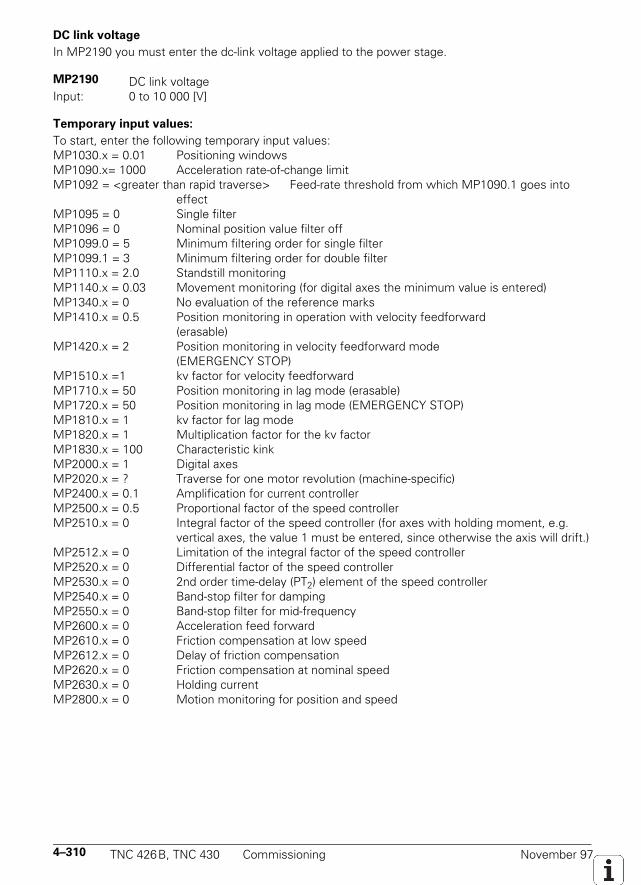
4–310 TNC 426B, TNC 430 Commissioning November 97
DC link voltage
In MP2190 you must enter the dc-link voltage applied to the power stage.
MP2190 DC link voltageInput: 0 to 10 000 [V]
Temporary input values:
To start, enter the following temporary input values:MP1030.x = 0.01 Positioning windowsMP1090.x= 1000 Acceleration rate-of-change limitMP1092 = <greater than rapid traverse> Feed-rate threshold from which MP1090.1 goes into
effectMP1095 = 0 Single filterMP1096 = 0 Nominal position value filter offMP1099.0 = 5 Minimum filtering order for single filterMP1099.1 = 3 Minimum filtering order for double filterMP1110.x = 2.0 Standstill monitoringMP1140.x = 0.03 Movement monitoring (for digital axes the minimum value is entered)MP1340.x = 0 No evaluation of the reference marksMP1410.x = 0.5 Position monitoring in operation with velocity feedforward
(erasable)MP1420.x = 2 Position monitoring in velocity feedforward mode
(EMERGENCY STOP)MP1510.x =1 kv factor for velocity feedforwardMP1710.x = 50 Position monitoring in lag mode (erasable)MP1720.x = 50 Position monitoring in lag mode (EMERGENCY STOP)MP1810.x = 1 kv factor for lag modeMP1820.x = 1 Multiplication factor for the kv factorMP1830.x = 100 Characteristic kinkMP2000.x = 1 Digital axesMP2020.x = ? Traverse for one motor revolution (machine-specific)MP2400.x = 0.1 Amplification for current controllerMP2500.x = 0.5 Proportional factor of the speed controllerMP2510.x = 0 Integral factor of the speed controller (for axes with holding moment, e.g.
vertical axes, the value 1 must be entered, since otherwise the axis will drift.)MP2512.x = 0 Limitation of the integral factor of the speed controllerMP2520.x = 0 Differential factor of the speed controllerMP2530.x = 0 2nd order time-delay (PT2) element of the speed controllerMP2540.x = 0 Band-stop filter for dampingMP2550.x = 0 Band-stop filter for mid-frequencyMP2600.x = 0 Acceleration feed forwardMP2610.x = 0 Friction compensation at low speedMP2612.x = 0 Delay of friction compensationMP2620.x = 0 Friction compensation at nominal speedMP2630.x = 0 Holding currentMP2800.x = 0 Motion monitoring for position and speed
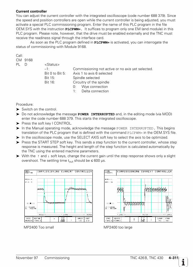
November 97 Commissioning TNC 426B, TNC 430 4–311
Current controller
You can adjust the current controller with the integrated oscilloscope (code number 688 379). Sincethe speed and position controllers are open while the current controller is being adjusted, you mustactivate a special PLC commissioning program. Enter the name of this PLC program in the fileOEM.SYS with the instruction PLCPWM=. It suffices to program only one EM (end module) in thisPLC program. Please note, however, that the drive must be enabled externally and the TNC mustreceive the readiness signal through the interface card.
As soon as the PLC program defined in PLCPWM= is activated, you can interrogate thestatus of commissioning with Module 9168.
Call:CM 9168PL D <Status>
–1: Commissioning not active or no axis yet selected.Bit 0 to Bit 5: Axis 1 to axis 6 selectedBit 15: Spindle selectedBit 16: Circuitry of the spindle
0: Wye connection1: Delta connection
Procedure: Switch on the control. Do not acknowledge the message POWER INTERRUPTED and, in the editing mode (via MOD)
enter the code number 688 379. This starts the integrated oscilloscope. Press the soft key I CONTROL. In the Manual operating mode, acknowledge the message POWER INTERRUPTED. This begins
translation of the PLC program that is defined with the command PLCPWM= in the OEM.SYS file. In the oscilloscope mode, use the SELECT AXIS soft key to select the axis to be optimized. Press the START STEP soft key. This sends a step function to the current controller, whose step
response is measured. The height and length of the step function is calculated automatically bythe TNC using the entered machine parameters.
With the ↑ and ↓ soft keys, change the current gain until the step response shows only a slightovershoot. The settling time tout should be ≤ 600 µs.
MP2400 Too small MP2400 too large
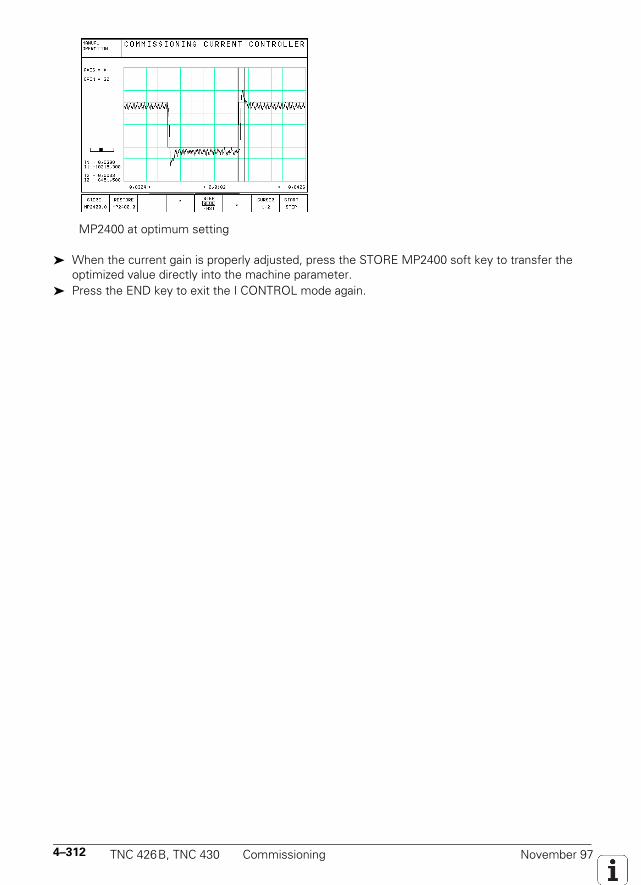
4–312 TNC 426B, TNC 430 Commissioning November 97
MP2400 at optimum setting
When the current gain is properly adjusted, press the STORE MP2400 soft key to transfer theoptimized value directly into the machine parameter.
Press the END key to exit the I CONTROL mode again.
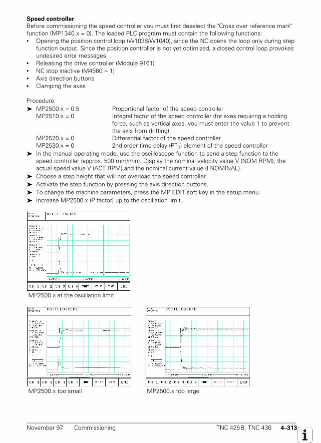
November 97 Commissioning TNC 426B, TNC 430 4–313
Speed controller
Before commissioning the speed controller you must first deselect the "Cross over reference mark"function (MP1340.x = 0). The loaded PLC program must contain the following functions:• Opening the position control loop (W1038/W1040), since the NC opens the loop only during step
function output. Since the position controller is not yet optimized, a closed control loop provokesundesired error messages.
• Releasing the drive controller (Module 9161)• NC stop inactive (M4560 = 1)• Axis direction buttons• Clamping the axes
Procedure: MP2500.x = 0.5 Proportional factor of the speed controller
MP2510.x = 0 Integral factor of the speed controller (for axes requiring a holding force, such as vertical axes, you must enter the value 1 to prevent
the axis from drifting)MP2520.x = 0 Differential factor of the speed controllerMP2530.x = 0 2nd order time-delay (PT2) element of the speed controller
In the manual operating mode, use the oscilloscope function to send a step function to thespeed controller (approx. 500 mm/min). Display the nominal velocity value V (NOM RPM), theactual speed value V (ACT RPM) and the nominal current value (I NOMINAL).
Choose a step height that will not overload the speed controller. Activate the step function by pressing the axis direction buttons. To change the machine parameters, press the MP EDIT soft key in the setup menu. Increase MP2500.x (P factor) up to the oscillation limit.
MP2500.x at the oscillation limit
MP2500.x too small MP2500.x too large
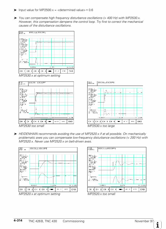
4–314 TNC 426B, TNC 430 Commissioning November 97
Input value for MP2500.x = <determined value> • 0.6
You can compensate high frequency disturbance oscillations (> 400 Hz) with MP2530.x.However, this compensation dampens the control loop. Try first to correct the mechanicalcauses of the disturbance oscillations.
MP2530.x at optimum setting
MP2530 too small MP2530.x too large
HEIDENHAIN recommends avoiding the use of MP2520.x if at all possible. On mechanicallyproblematic axes you can compensate low-frequency disturbance oscillations (< 200 Hz) withMP2520.x. Never use MP2520.x on belt-driven axes.
MP2520.x at optimum setting MP2520.x too small
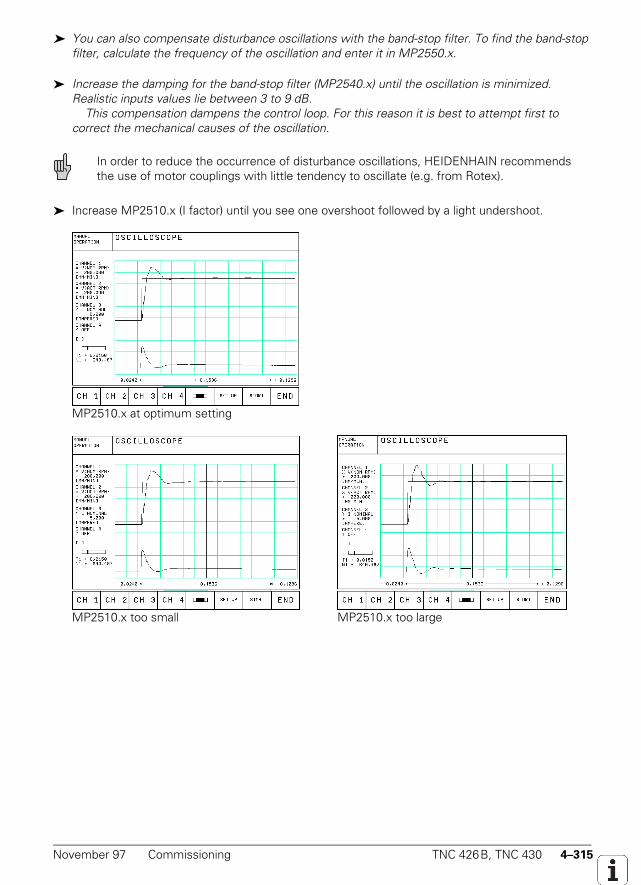
November 97 Commissioning TNC 426B, TNC 430 4–315
You can also compensate disturbance oscillations with the band-stop filter. To find the band-stopfilter, calculate the frequency of the oscillation and enter it in MP2550.x.
Increase the damping for the band-stop filter (MP2540.x) until the oscillation is minimized.Realistic inputs values lie between 3 to 9 dB. This compensation dampens the control loop. For this reason it is best to attempt first tocorrect the mechanical causes of the oscillation.
In order to reduce the occurrence of disturbance oscillations, HEIDENHAIN recommendsthe use of motor couplings with little tendency to oscillate (e.g. from Rotex).
Increase MP2510.x (I factor) until you see one overshoot followed by a light undershoot.
MP2510.x at optimum setting
MP2510.x too small MP2510.x too large
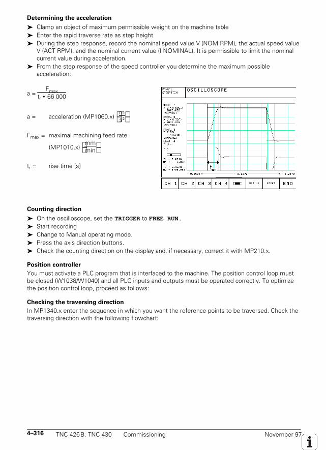
4–316 TNC 426B, TNC 430 Commissioning November 97
Determining the acceleration
Clamp an object of maximum permissible weight on the machine table Enter the rapid traverse rate as step height During the step response, record the nominal speed value V (NOM RPM), the actual speed value
V (ACT RPM), and the nominal current value (I NOMINAL). It is permissible to limit the nominalcurrent value during acceleration.
From the step response of the speed controller you determine the maximum possibleacceleration:
a = Fmax
tr • 66 000
a = acceleration (MP1060.x) ms²
Fmax = maximal machining feed rate
(MP1010.x) mmmin
tr = rise time [s]
Counting direction
On the oscilloscope, set the TRIGGER to FREE RUN.
Start recording Change to Manual operating mode. Press the axis direction buttons. Check the counting direction on the display and, if necessary, correct it with MP210.x.
Position controller
You must activate a PLC program that is interfaced to the machine. The position control loop mustbe closed (W1038/W1040) and all PLC inputs and outputs must be operated correctly. To optimizethe position control loop, proceed as follows:
Checking the traversing direction
In MP1340.x enter the sequence in which you want the reference points to be traversed. Check thetraversing direction with the following flowchart:
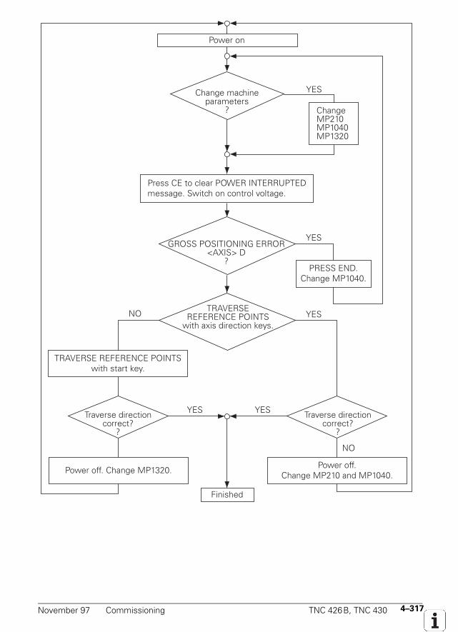
November 97 Commissioning TNC 426B, TNC 430 4–317
NO
YESChange machine parameters
?
GROSS POSITIONING ERROR <AXIS> D
?
ChangeMP210MP1040MP1320
PRESS END. Change MP1040.
Power on
YES
TRAVERSE REFERENCE POINTS
with axis direction keys.
Press CE to clear POWER INTERRUPTED message. Switch on control voltage.
Power off. Change MP1320.
Traverse direction correct?
?
TRAVERSE REFERENCE POINTS with start key.
Finished
YES
Power off.Change MP210 and MP1040.
YES
NO
YES
Traverse direction correct?
?
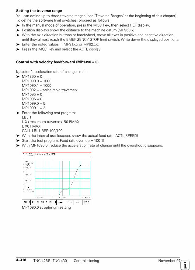
4–318 TNC 426B, TNC 430 Commissioning November 97
Setting the traverse range
You can define up to three traverse ranges (see "Traverse Ranges" at the beginning of this chapter).To define the software limit switches, proceed as follows: In the manual mode of operation, press the MOD key, then select REF display. Position displays show the distance to the machine datum (MP960.x). With the axis direction buttons or handwheel, move all axes in positive and negative direction
until they almost reach the EMERGENCY STOP limit switch. Write down the displayed positions. Enter the noted values in MP91x.x or MP92x.x. Press the MOD key and select the ACTL display.
Control with velocity feedforward (MP1390 = 0)
kv factor / acceleration rate-of-change limit: MP1390 = 0
MP1090.0 = 1000MP1090.1 = 1000MP1092 = <twice rapid traverse>MP1095 = 0MP1096 = 0MP1099.0 = 5MP1099.1 = 3
Enter the following test program:LBL 1L X<maximum traverse> R0 FMAXL X0 FMAXCALL LBL1 REP 100/100
With the internal oscilloscope, show the actual feed rate (ACTL.SPEED) Start the test program. Feed rate override = 100 % With MP1090.0, reduce the acceleration rate of change until the overshoot disappears.
MP1090.0 at optimum setting
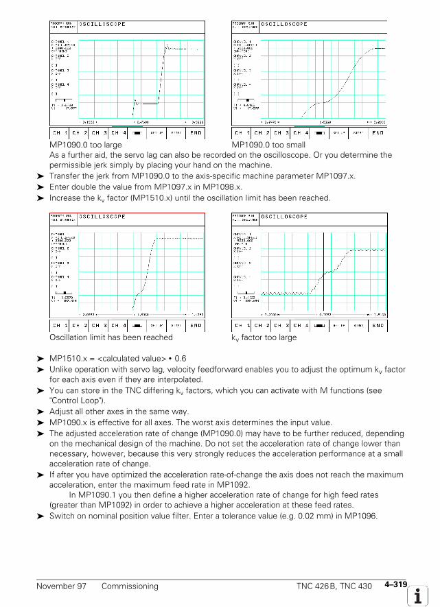
November 97 Commissioning TNC 426B, TNC 430 4–319
MP1090.0 too large MP1090.0 too smallAs a further aid, the servo lag can also be recorded on the oscilloscope. Or you determine thepermissible jerk simply by placing your hand on the machine.
Transfer the jerk from MP1090.0 to the axis-specific machine parameter MP1097.x. Enter double the value from MP1097.x in MP1098.x. Increase the kv factor (MP1510.x) until the oscillation limit has been reached.
Oscillation limit has been reached kv factor too large
MP1510.x = <calculated value> • 0.6 Unlike operation with servo lag, velocity feedforward enables you to adjust the optimum kv factor
for each axis even if they are interpolated. You can store in the TNC differing kv factors, which you can activate with M functions (see
"Control Loop"). Adjust all other axes in the same way. MP1090.x is effective for all axes. The worst axis determines the input value. The adjusted acceleration rate of change (MP1090.0) may have to be further reduced, depending
on the mechanical design of the machine. Do not set the acceleration rate of change lower thannecessary, however, because this very strongly reduces the acceleration performance at a smallacceleration rate of change.
If after you have optimized the acceleration rate-of-change the axis does not reach the maximumacceleration, enter the maximum feed rate in MP1092.
In MP1090.1 you then define a higher acceleration rate of change for high feed rates(greater than MP1092) in order to achieve a higher acceleration at these feed rates.
Switch on nominal position value filter. Enter a tolerance value (e.g. 0.02 mm) in MP1096.
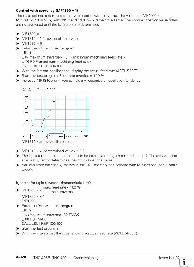
4–320 TNC 426B, TNC 430 Commissioning November 97
Control with servo lag (MP1390 = 1)
The max. defined jerk is also effective in control with servo lag. The values for MP1090.x,MP1097.x, MP1098.x, MP1095.x and MP1099.x remain the same. The nominal position value filtersare not activated until the kv factors are determined.
MP1390 = 1 MP1810 ≈ 1 (provisional input value) MP1096 = 0 Enter the following test program:
LBL 1L X<maximum traverse> R0 F<maximum machining feed rate>L X0 R0 F<maximum machining feed rate>CALL LBL1 REP 100/100
With the internal oscilloscope, display the actual feed rate (ACTL.SPEED) Start the test program. Feed rate override = 100 % Increase MP1810.x until you can clearly recognize an oscillation tendency.
MP1810.x at the oscillation limit
MP1810.x = <determined value> • 0.6 The kv factors for axes that that are to be interpolated together must be equal. The axis with the
smallest kv factor determines the input value for all axes. You can store differing kv factors in the TNC memory and activate with M functions (see "Control
Loop").
kv factor for rapid traverse (characteristic kink):
MP1830.x = max. feed rate • 100 %
rapid traverse
MP1820.x = 1MP1390 = 1
Enter the following test program:LBL 2L X<maximum traverse> R0 FMAXL X0 R0 FMAXCALL LBL1 REP 100/100
Start the test program. With the integral oscilloscope, show the actual feed rate (ACTL.SPEED).
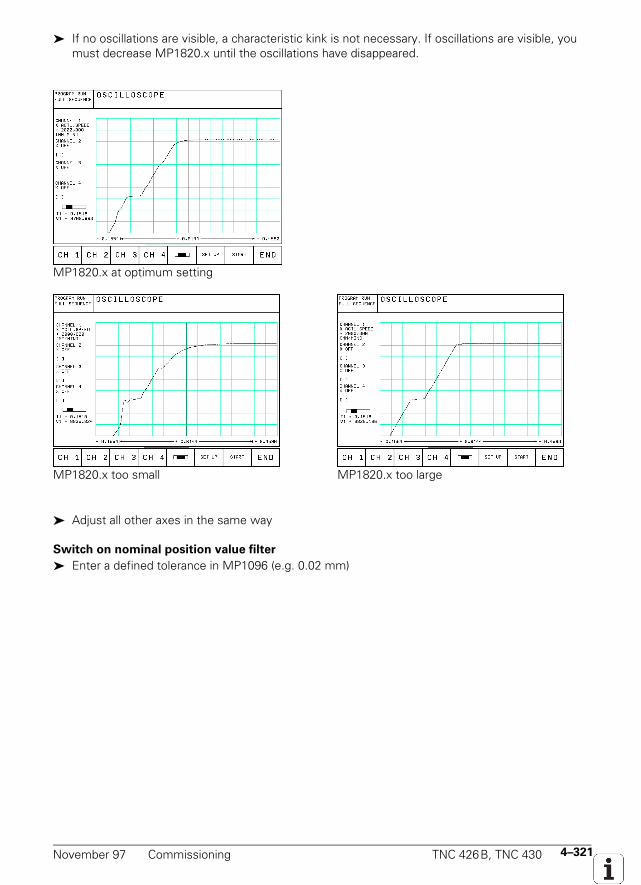
November 97 Commissioning TNC 426B, TNC 430 4–321
If no oscillations are visible, a characteristic kink is not necessary. If oscillations are visible, youmust decrease MP1820.x until the oscillations have disappeared.
MP1820.x at optimum setting
MP1820.x too small MP1820.x too large
Adjust all other axes in the same way
Switch on nominal position value filter
Enter a defined tolerance in MP1096 (e.g. 0.02 mm)
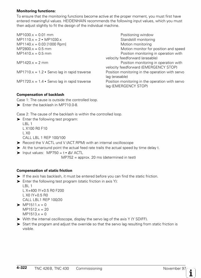
4–322 TNC 426B, TNC 430 Commissioning November 97
Monitoring functions:
To ensure that the monitoring functions become active at the proper moment, you must first haveentered meaningful values. HEIDENHAIN recommends the following input values, which you mustthen adjust slightly to fit the design of the individual machine.
MP1030.x = 0.01 mm Positioning windowMP1110.x = 2 • MP1030.x Standstill monitoringMP1140.x = 0.03 [1000 Rpm] Motion monitoringMP2800.x = 0.5 mm Motion monitor for position and speedMP1410.x = 0.5 mm Position monitoring in operation with
velocity feedforward (erasable)MP1420.x = 2 mm Position monitoring in operation with
velocity feedforward (EMERGENCY STOP)MP1710.x = 1.2 • Servo lag in rapid traverse Position monitoring in the operation with servo
lag (erasable)MP1720.x = 1.4 • Servo lag in rapid traverse Position monitoring in the operation with servo
lag (EMERGENCY STOP)
Compensation of backlash
Case 1: The cause is outside the controlled loop. Enter the backlash in MP710.0-8.
Case 2: The cause of the backlash is within the controlled loop. Enter the following test program:
LBL 1L X100 R0 F10L X0CALL LBL 1 REP 100/100
Record the V ACTL und V (ACT.RPM) with an internal oscilloscope At the turnaround point the actual feed rate trails the actual speed by time delay t. Input values: MP750 = t • ∆V ACTL
MP752 = approx. 20 ms (determined in test)
Compensation of static friction
If the axis has backlash, it must be entered before you can find the static friction. Enter the following test program (static friction in axis Y):
LBL 1L X+400 IY+0.5 R0 F200L X0 IY+0.5 R0CALL LBL1 REP 100/20
MP1511.x = 0MP1512.x = 20MP1513.x = 0
With the internal oscilloscope, display the servo lag of the axis Y (Y SDIFF). Start the program and adjust the override so that the servo lag resulting from static friction is
visible.
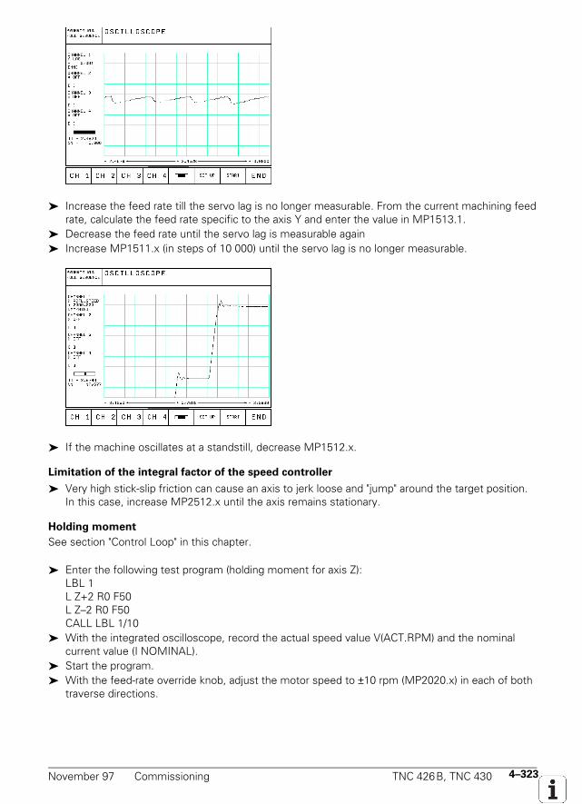
November 97 Commissioning TNC 426B, TNC 430 4–323
Increase the feed rate till the servo lag is no longer measurable. From the current machining feedrate, calculate the feed rate specific to the axis Y and enter the value in MP1513.1.
Decrease the feed rate until the servo lag is measurable again Increase MP1511.x (in steps of 10 000) until the servo lag is no longer measurable.
If the machine oscillates at a standstill, decrease MP1512.x.
Limitation of the integral factor of the speed controller
Very high stick-slip friction can cause an axis to jerk loose and "jump" around the target position.In this case, increase MP2512.x until the axis remains stationary.
Holding moment
See section "Control Loop" in this chapter.
Enter the following test program (holding moment for axis Z):LBL 1L Z+2 R0 F50L Z–2 R0 F50CALL LBL 1/10
With the integrated oscilloscope, record the actual speed value V(ACT.RPM) and the nominalcurrent value (I NOMINAL).
Start the program. With the feed-rate override knob, adjust the motor speed to ±10 rpm (MP2020.x) in each of both
traverse directions.
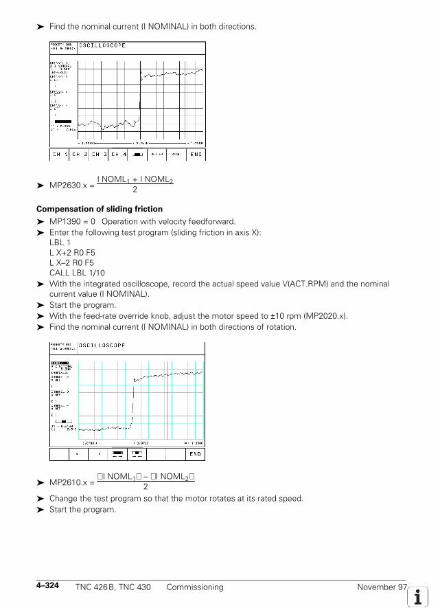
4–324 TNC 426B, TNC 430 Commissioning November 97
Find the nominal current (I NOMINAL) in both directions.
MP2630.x = I NOML1 + I NOML2
2
Compensation of sliding friction
MP1390 = 0 Operation with velocity feedforward. Enter the following test program (sliding friction in axis X):
LBL 1L X+2 R0 F5L X–2 R0 F5CALL LBL 1/10
With the integrated oscilloscope, record the actual speed value V(ACT.RPM) and the nominalcurrent value (I NOMINAL).
Start the program. With the feed-rate override knob, adjust the motor speed to ±10 rpm (MP2020.x). Find the nominal current (I NOMINAL) in both directions of rotation.
MP2610.x = I NOML1 – I NOML2
2
Change the test program so that the motor rotates at its rated speed. Start the program.
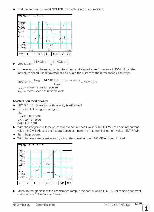
November 97 Commissioning TNC 426B, TNC 430 4–325
Find the nominal current (I NOMINAL) in both directions of rotation.
MP2620.x = I NOML1 + I NOML2
2
In the event that the motor cannot be driven at the rated speed, measure I NOMINAL at themaximum speed (rapid traverse) and calculate the current at the rated speed as follows:
MP2620.x = (Inmax – MP2610.x) • <rated speed>
nmax + MP2610.x
Inmax = current at rapid traversenmax = motor speed at rapid traverse
Acceleration feedforward
MP1390 = 0 Operation with velocity feedforward. Enter the following test program:
LBL 1L X+100 R0 F5000L X–100 R0 F5000CALL LBL 1/10
With the integral oscilloscope, record the actual speed value V (ACT RPM), the nominal currentvalue (I NOMINAL) and the integral-action component of the nominal current value I (INT RPM).
Start the program. With the feed-rate override knob, adjust the speed so that I NOMINAL is not limited.
Measure the gradient of the acceleration ramp in the part in which I (INT RPM) remains constant,and calculate MP2600.x as follows:
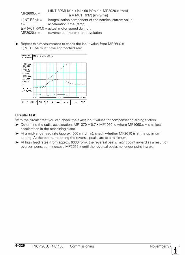
4–326 TNC 426B, TNC 430 Commissioning November 97
MP2600.x =I (INT RPM) [A] • t [s] • 60 [s/min] • MP2020.x [mm]
∆ V (ACT RPM) [mm/min]
I (INT RPM) = integral-action component of the nominal current valuet = acceleration time (ramp)∆ V (ACT RPM) = actual motor speed during tMP2020.x = traverse per motor shaft revolution
Repeat this measurement to check the input value from MP2600.x.I (INT RPM) must have approached zero.
Circular test
With the circular test you can check the exact input values for compensating sliding friction. Determine the radial acceleration: MP1070 = 0.7 • MP1060.x, where MP1060.x = smallest
acceleration in the machining plane At a mid-range feed rate (approx. 500 mm/min), check whether MP2610 is at the optimum
setting. At the optimum setting the reversal peaks are at a minimum. At high feed rates (from approx. 6000 rpm), the reversal peaks might point inward as a result of
overcompensation. Increase MP2612.x until the reversal peaks no longer point inward.

November 97 Commissioning TNC 426B, TNC 430 4–327
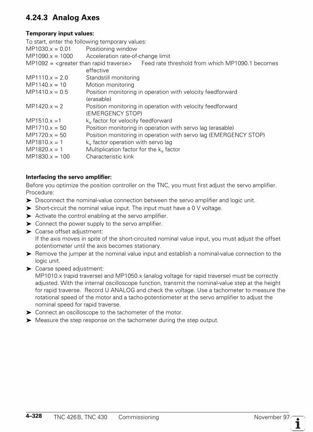
4–328 TNC 426B, TNC 430 Commissioning November 97
4.24.3 Analog Axes
Temporary input values:
To start, enter the following temporary values:MP1030.x = 0.01 Positioning windowMP1090.x = 1000 Acceleration rate-of-change limitMP1092 = <greater than rapid traverse> Feed rate threshold from which MP1090.1 becomes
effectiveMP1110.x = 2.0 Standstill monitoringMP1140.x = 10 Motion monitoringMP1410.x = 0.5 Position monitoring in operation with velocity feedforward
(erasable)MP1420.x = 2 Position monitoring in operation with velocity feedforward
(EMERGENCY STOP)MP1510.x =1 kv factor for velocity feedforwardMP1710.x = 50 Position monitoring in operation with servo lag (erasable)MP1720.x = 50 Position monitoring in operation with servo lag (EMERGENCY STOP)MP1810.x = 1 kv factor operation with servo lagMP1820.x = 1 Multiplication factor for the kv factorMP1830.x = 100 Characteristic kink
Interfacing the servo amplifier:
Before you optimize the position controller on the TNC, you must first adjust the servo amplifier.Procedure: Disconnect the nominal-value connection between the servo amplifier and logic unit. Short-circuit the nominal value input. The input must have a 0 V voltage. Activate the control enabling at the servo amplifier. Connect the power supply to the servo amplifier. Coarse offset adjustment:
If the axis moves in spite of the short-circuited nominal value input, you must adjust the offsetpotentiometer until the axis becomes stationary.
Remove the jumper at the nominal value input and establish a nominal-value connection to thelogic unit.
Coarse speed adjustment:MP1010.x (rapid traverse) and MP1050.x (analog voltage for rapid traverse) must be correctlyadjusted. With the internal oscilloscope function, transmit the nominal-value step at the heightfor rapid traverse. Record U ANALOG and check the voltage. Use a tachometer to measure therotational speed of the motor and a tacho-potentiometer at the servo amplifier to adjust thenominal speed for rapid traverse.
Connect an oscilloscope to the tachometer of the motor. Measure the step response on the tachometer during the step output.
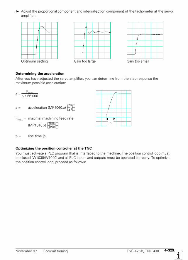
November 97 Commissioning TNC 426B, TNC 430 4–329
Adjust the proportional component and integral-action component of the tachometer at the servoamplifier:
Optimum setting Gain too large Gain too small
Determining the acceleration
After you have adjusted the servo amplifier, you can determine from the step response themaximum possible acceleration:
a = Fmax
tr • 66 000
a = acceleration (MP1060.x) ms²
Fmax = maximal machining feed rate
(MP1010.x) mmmin
tr = rise time [s]
tr
Optimizing the position controller at the TNC
You must activate a PLC program that is interfaced to the machine. The position control loop mustbe closed (W1038/W1040) and all PLC inputs and outputs must be operated correctly. To optimizethe position control loop, proceed as follows:
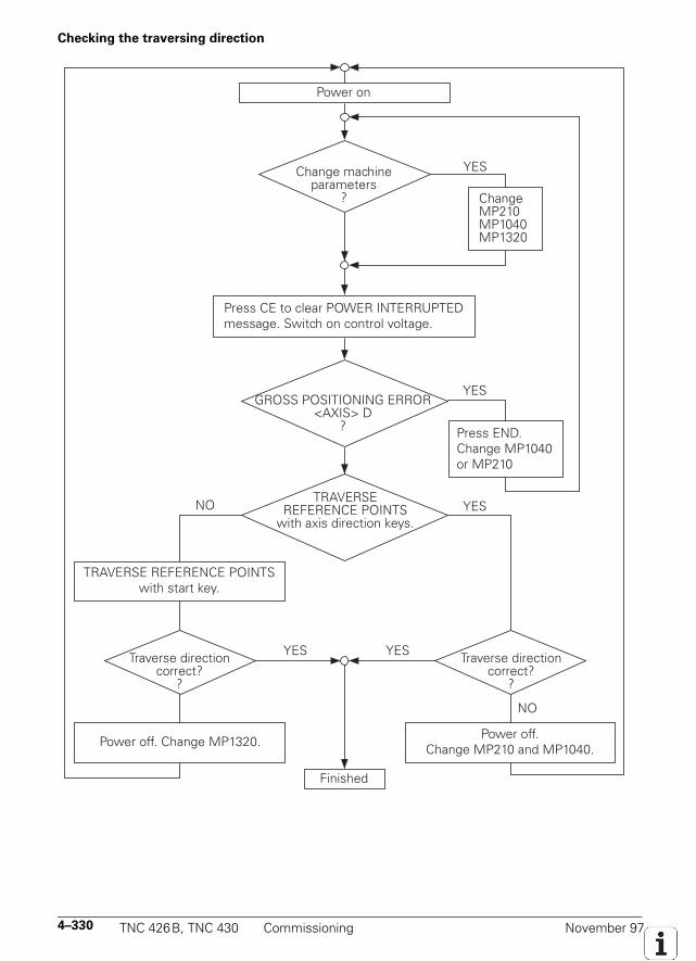
4–330 TNC 426B, TNC 430 Commissioning November 97
Checking the traversing direction
Press END.Change MP1040or MP210
NO
YESChange machine parameters
?
GROSS POSITIONING ERROR <AXIS> D
?
ChangeMP210MP1040MP1320
Power on
YES
TRAVERSE REFERENCE POINTS
with axis direction keys.
Press CE to clear POWER INTERRUPTED message. Switch on control voltage.
Power off. Change MP1320.
Traverse direction correct?
?
TRAVERSE REFERENCE POINTS with start key.
Finished
YES
Power off.Change MP210 and MP1040.
YES
NO
YES
Traverse direction correct?
?
November 97 Commissioning TNC 426B, TNC 430 4–331
Setting the traverse range
Same procedure as for digital axes.
Control with servo lag (MP1390 = 1)
Same procedure as for digital axes.
Control with velocity feedforward (MP1390 = 0)
Same procedure as for digital axes.
Offset adjustment
You can carry out the fine adjustment of the offset at the TNC. See the "Position Control Loop"chapter above.
Monitoring functions:
To ensure that the monitoring functions become active at the proper moment, you must first haveentered meaningful values. HEIDENHAIN recommends the following input values. You must thenadjust these input values slightly to fit the design of the individual machine.
MP1030.x = 0.01 mm Positioning windowMP1110.x = 2 • MP1030.x Standstill monitoringMP1140.x = 0.5 V Motion monitoringMP1410.x = 0.5 mm Position monitoring in operation with
velocity feedforward control (erasable)MP1420.x = 2 mm Position monitoring in operation with
velocity feedforward control (EMERGENCYSTOP)
MP1710.x = 1.2 • servo lag in rapid traverse Position monitoring in the operation with servolag (erasable)
MP1720.x = 1.4 • servo lag in rapid traverse Position monitoring in the operation with servolag (EMERGENCY STOP)
Compensation of static friction
Same procedure as with digital axes.

4–332 TNC 426B, TNC 430 Commissioning November 97
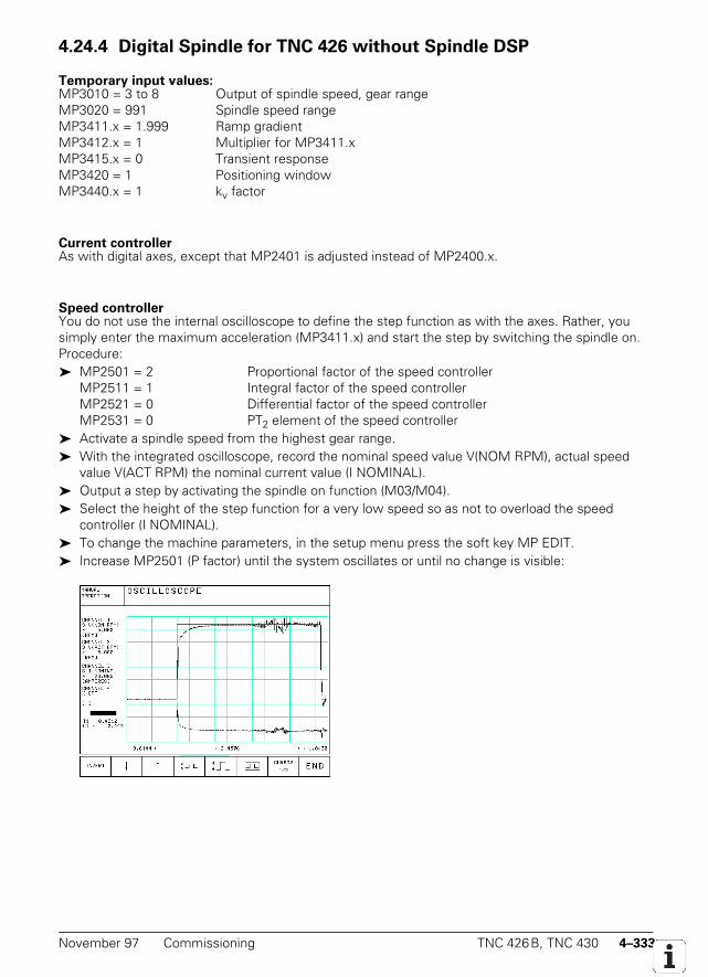
November 97 Commissioning TNC 426B, TNC 430 4–333
4.24.4 Digital Spindle for TNC 426 without Spindle DSP
Temporary input values:MP3010 = 3 to 8 Output of spindle speed, gear rangeMP3020 = 991 Spindle speed rangeMP3411.x = 1.999 Ramp gradientMP3412.x = 1 Multiplier for MP3411.xMP3415.x = 0 Transient responseMP3420 = 1 Positioning windowMP3440.x = 1 kv factor
Current controllerAs with digital axes, except that MP2401 is adjusted instead of MP2400.x.
Speed controllerYou do not use the internal oscilloscope to define the step function as with the axes. Rather, yousimply enter the maximum acceleration (MP3411.x) and start the step by switching the spindle on.Procedure: MP2501 = 2 Proportional factor of the speed controller
MP2511 = 1 Integral factor of the speed controllerMP2521 = 0 Differential factor of the speed controllerMP2531 = 0 PT2 element of the speed controller
Activate a spindle speed from the highest gear range. With the integrated oscilloscope, record the nominal speed value V(NOM RPM), actual speed
value V(ACT RPM) the nominal current value (I NOMINAL). Output a step by activating the spindle on function (M03/M04). Select the height of the step function for a very low speed so as not to overload the speed
controller (I NOMINAL). To change the machine parameters, in the setup menu press the soft key MP EDIT. Increase MP2501 (P factor) until the system oscillates or until no change is visible:
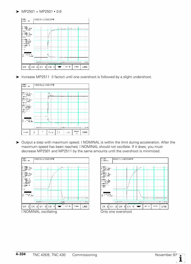
4–334 TNC 426B, TNC 430 Commissioning November 97
MP2501 = MP2501 • 0.6
Increase MP2511 (I factor) until one overshoot is followed by a slight undershoot.
Output a step with maximum speed. I NOMINAL is within the limit during acceleration. After themaximum speed has been reached, I NOMINAL should not oscillate. If it does, you mustdecrease MP2501 and MP2511 by the same amounts until the overshoot is minimized.
I NOMINAL oscillating Only one overshoot
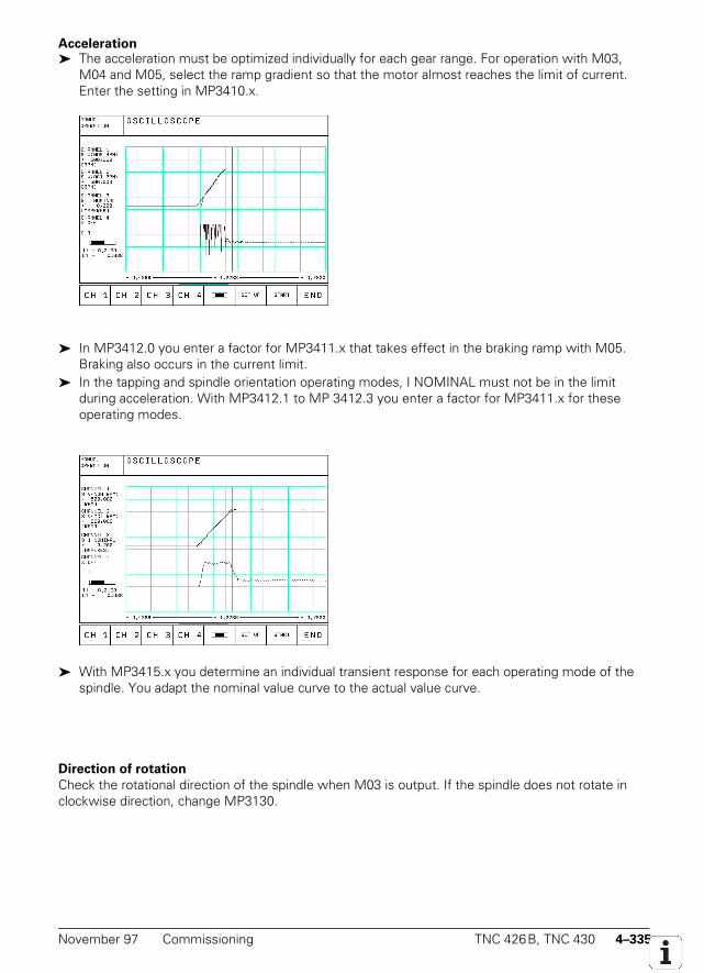
November 97 Commissioning TNC 426B, TNC 430 4–335
Acceleration The acceleration must be optimized individually for each gear range. For operation with M03,
M04 and M05, select the ramp gradient so that the motor almost reaches the limit of current.Enter the setting in MP3410.x.
In MP3412.0 you enter a factor for MP3411.x that takes effect in the braking ramp with M05.Braking also occurs in the current limit.
In the tapping and spindle orientation operating modes, I NOMINAL must not be in the limitduring acceleration. With MP3412.1 to MP 3412.3 you enter a factor for MP3411.x for theseoperating modes.
With MP3415.x you determine an individual transient response for each operating mode of thespindle. You adapt the nominal value curve to the actual value curve.
Direction of rotation
Check the rotational direction of the spindle when M03 is output. If the spindle does not rotate inclockwise direction, change MP3130.
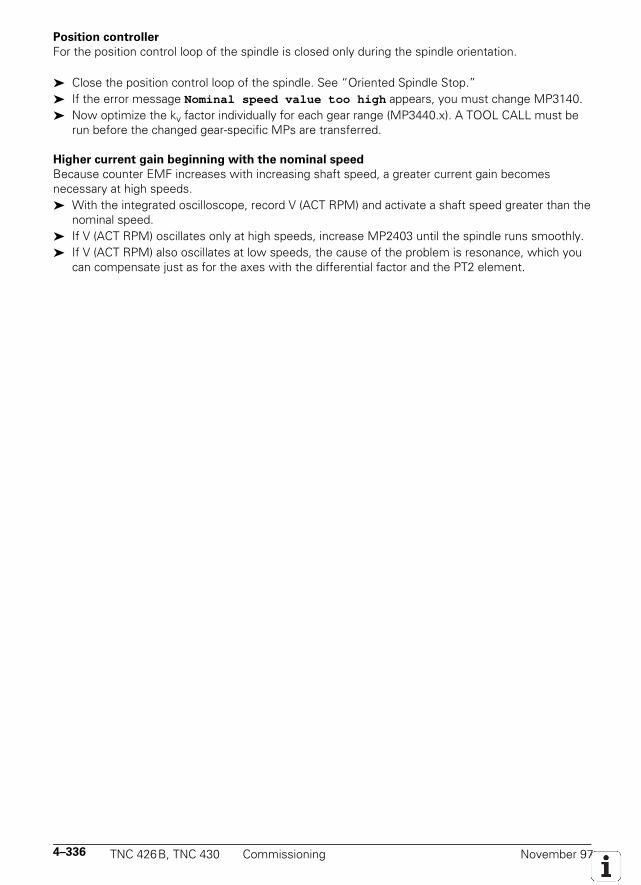
4–336 TNC 426B, TNC 430 Commissioning November 97
Position controller
For the position control loop of the spindle is closed only during the spindle orientation.
Close the position control loop of the spindle. See “Oriented Spindle Stop.” If the error message Nominal speed value too high appears, you must change MP3140. Now optimize the kv factor individually for each gear range (MP3440.x). A TOOL CALL must be
run before the changed gear-specific MPs are transferred.
Higher current gain beginning with the nominal speed
Because counter EMF increases with increasing shaft speed, a greater current gain becomesnecessary at high speeds. With the integrated oscilloscope, record V (ACT RPM) and activate a shaft speed greater than the
nominal speed. If V (ACT RPM) oscillates only at high speeds, increase MP2403 until the spindle runs smoothly. If V (ACT RPM) also oscillates at low speeds, the cause of the problem is resonance, which you
can compensate just as for the axes with the differential factor and the PT2 element.
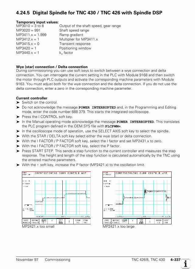
November 97 Commissioning TNC 426B, TNC 430 4–337
4.24.5 Digital Spindle for TNC 430 / TNC 426 with Spindle DSP
Temporary input values:MP3010 = 3 to 8 Output of the shaft speed, gear rangeMP3020 = 991 Shaft speed rangeMP3411.x = 1.999 Ramp gradientMP3412.x = 1 Multiplier for MP3411.xMP3415.x = 0 Transient responseMP3420 = 1 Positioning windowMP3440.x = 1 kv factor
Wye (star) connection / Delta connectionDuring commissioning you can use soft keys to switch between a wye connection and deltaconnection. You can interrogate the current setting in the PLC with Module 9168 and then switchthe motor through PLC outputs and activate the corresponding machine parameters with Module9163. You must adjust both for the wye connection and the delta connection. If you do not use thedelta connection, enter a zero in the corresponding machine parameter.
Current controller Switch on the control. Do not acknowledge the message POWER INTERRUPTED and, in the Programming and Editing
mode, enter the code number 688 379. This starts the integrated oscilloscope. Press the I CONTROL soft key. In the Manual operating mode acknowledge the message POWER INTERRUPTED. This translates
the PLC program defined in the OEM.SYS file with PLCPWM=. In the oscilloscope mode of operation, use the SELECT AXIS soft key to select the spindle. With the STAR / DELTA soft key select either the wye (star) or delta connection. With the I FACTOR / P FACTOR soft key, select the I factor and set MP2431.x to zero. With the I FACTOR / P FACTOR soft key, select the P factor. Press START STEP. This sends a step function to the current controller and measures the step
response. The height and length of the step function is calculated automatically by the TNC usingthe entered machine parameters.
With the ↑ soft key, increase the P factor (MP2421.x) to the oscillation limit.
MP2421.x too small MP2421.x too large
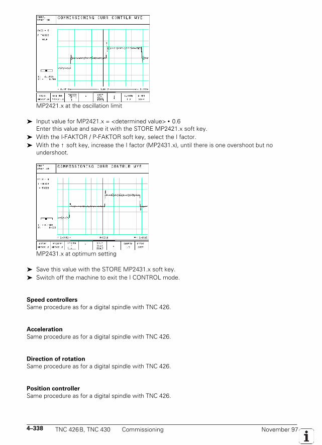
4–338 TNC 426B, TNC 430 Commissioning November 97
MP2421.x at the oscillation limit
Input value for MP2421.x = <determined value> • 0.6Enter this value and save it with the STORE MP2421.x soft key.
With the I-FAKTOR / P-FAKTOR soft key, select the I factor. With the ↑ soft key, increase the I factor (MP2431.x), until there is one overshoot but no
undershoot.
MP2431.x at optimum setting
Save this value with the STORE MP2431.x soft key. Switch off the machine to exit the I CONTROL mode.
Speed controllers
Same procedure as for a digital spindle with TNC 426.
Acceleration
Same procedure as for a digital spindle with TNC 426.
Direction of rotation
Same procedure as for a digital spindle with TNC 426.
Position controller
Same procedure as for a digital spindle with TNC 426.

November 97 Commissioning TNC 426B, TNC 430 4–339
4.24.6 Analog Spindle
Adjusting servo amplifiers:
Same procedure as for analog axes.
Acceleration
Procedure is same as for a digital spindle. You measure the signals directly at the servo amplifierwith an external oscilloscope.
Direction of rotation:
Same procedure as for a digital spindle.
Position controller:
Same procedure as for a digital spindle.

4–340 TNC 426B, TNC 430 Commissioning November 97
November 97 PLC Functions TNC 426B, TNC 430 5–1
5 PLC Programming
5.1 PLC Functions
The integrated PLC in the TNC contains its own Text Editor for creating the list of statements for thePLC program. Commands and comments are entered via the ASCII keyboard on the TNC. It's easier,however, to create your PLC programs with the PLC compiler software PLCdesign. For informationon PLCdesign, contact HEIDENHAIN.
You can use the functions TRACE and TABLE, as well as a syntax check on entering the PLCcommands and a logical test with the COMPILE function to make it easier to find faults in the PLCprogram.
For the compiled PLC program you have 256 KB (approx. 32 000 blocks) available in the sequentialprogram. A new PLC run begins every 21 ms (PLC cycle time). This means that every 21 ms theinputs are read and outputs are set. A PLC run must not take more than 7 ms.
5.1.1 Select PLC Operation
PLC operation covers all functions for creating and testing the PLC programs, for creating the PLCerror messages and the dialogue texts for OEM cycles, the Help files and compensation lists fornon-linear axis error compensation.
To select PLC operation: Select the NC "Programming and Editing" mode of operation. Press the MOD key Enter the code number 807 667, or press the soft key PLC EDIT. PLC operation is now active (Main menu) You can exit PLC operation by pressing the END key or the END soft key.
1) NC software 280 470 xx: 128 KB (approx. 16 000 blocks)
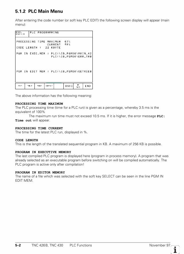
5–2 TNC 426B, TNC 430 PLC Functions November 97
5.1.2 PLC Main Menu
After entering the code number (or soft key PLC EDIT) the following screen display will appear (mainmenu):
The above information has the following meaning:
PROCESSING TIME MAXIMUMThe PLC processing time (time for a PLC run) is given as a percentage, whereby 3.5 ms is theequivalent of 100%
The maximum run time must not exceed 10.5 ms. If it is higher, the error message PLC:Time out will appear.
PROCESSING TIME CURRENTThe time for the latest PLC run, displayed in %.
CODE LENGTHThis is the length of the translated sequential program in KB. A maximum of 256 KB is possible.
PROGRAM IN EXECUTIVE MEMORYThe last compiled PLC program is displayed here (program in process memory). A program that wasalready selected as an executable program before switching on will be compiled automatically. ThePLC program is active only after compilation!
PROGRAM IN EDITOR MEMORYThe name of a file which was selected with the soft key SELECT can be seen in the line PGM INEDIT MEM.
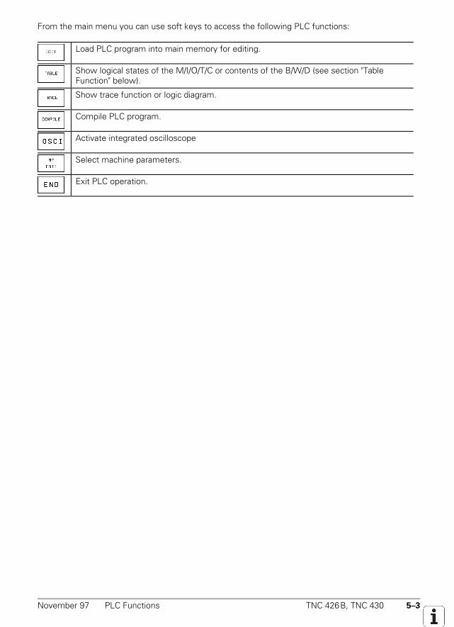
November 97 PLC Functions TNC 426B, TNC 430 5–3
From the main menu you can use soft keys to access the following PLC functions:
Load PLC program into main memory for editing.
Show logical states of the M/I/O/T/C or contents of the B/W/D (see section "TableFunction" below).
Show trace function or logic diagram.
Compile PLC program.
Activate integrated oscilloscope
Select machine parameters.
Exit PLC operation.
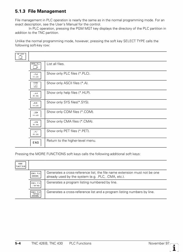
5–4 TNC 426B, TNC 430 PLC Functions November 97
5.1.3 File Management
File management in PLC operation is nearly the same as in the normal programming mode. For anexact description, see the User's Manual for the control.
In PLC operation, pressing the PGM MGT key displays the directory of the PLC partition inaddition to the TNC partition.
Unlike the normal programming mode, however, pressing the soft key SELECT TYPE calls thefollowing soft-key row:
List all files.
Show only PLC files (*.PLC).
Show only ASCII files (*.A).
Show only help files (*.HLP).
Show only SYS files(*.SYS).
Show only COM files (*.COM).
Show only CMA files (*.CMA).
Show only PET files (*.PET).
Return to the higher-level menu.
Pressing the MORE FUNCTIONS soft keys calls the following additional soft keys:
Generates a cross-reference list; the file name extension must not be onealready used by the system (e.g. .PLC, .CMA, etc.).
Generates a program listing numbered by line.
Generates a cross-reference list and a program listing numbers by line.
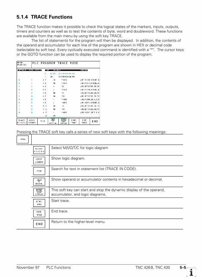
November 97 PLC Functions TNC 426B, TNC 430 5–5
5.1.4 TRACE Functions
The TRACE function makes it possible to check the logical states of the markers, inputs, outputs,timers and counters as well as to test the contents of byte, word and doubleword. These functionsare available from the main menu by using the soft key TRACE.
The list of statements for the program will then be displayed. In addition, the contents ofthe operand and accumulator for each line of the program are shown in HEX or decimal code(selectable by soft key). Every cyclically executed command is identified with a "*". The cursor keysor the GOTO function can be used to display the required portion of the program.
Pressing the TRACE soft key calls a series of new soft keys with the following meanings:
Select M/I/O/T/C for logic diagram
Show logic diagram.
Search for text in statement list (TRACE IN CODE).
Show operand or accumulator contents in hexadecimal or decimal.
This soft key can start and stop the dynamic display of the operand,accumulator, and logic diagrams.
Start trace.
End trace.
Return to the higher-level menu.
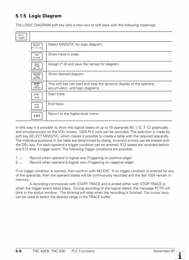
5–6 TNC 426B, TNC 430 PLC Functions November 97
5.1.5 Logic Diagram
The LOGIC DIAGRAM soft key calls a new row of soft keys with the following meanings:
Select M/I/O/T/C for logic diagram.
Show trace in code.
Assign (*.A) and save file names for diagram.
Show desired diagram.
This soft key can start and stop the dynamic display of the operand,accumulator, and logic diagrams.
Start trace.
End trace.
Return to the higher-level menu.
In this way it is possible to show the logical states of up to 16 operands (M, I, O, T, C) graphicallyand simultaneously on the VDU screen. 1024 PLC runs can be recorded. The selection is made bysoft key SELECT M/I/O/T/C, which makes it possible to create a table with the required operands.The individual positions in the table are determined by dialog. Incorrect entries can be erased withthe DEL key. For each operand a trigger condition can be entered. 512 states are recorded beforeand 512 after a trigger event. The following trigger conditions are possible:
1 → Record when operand is logical one (Triggering on positive edge)0 → Record when operand is logical zero (Triggering on negative edge)
If no trigger condition is wanted, then confirm with NO ENT. If no trigger condition is entered for anyof the operands, then the operand states will be continuously recorded and the last 1024 remain inmemory.
A recording commences with START TRACE and is ended either with STOP TRACE orwhen the trigger event takes place. During recording of the logical states, the message PCTR willblink in the status window. The blinking will stop when the recording is finished. The cursor keyscan be used to select the desired range in the TRACE buffer.

November 97 PLC Functions TNC 426B, TNC 430 5–7
Example for logic diagram:
5.1.6 TABLE Function
The table of markers, inputs, outputs, timers, counters, bytes, words, and doublewords can bedynamically displayed on the VDU screen by using the soft key TABLE from within the main menu.The cursor keys or the GOTO key are used to select the positions within the table. Return to themain menu by pressing the END key.
The following soft keys are available for selecting, setting and resetting the markers, inputs, outputs,timers and counters:
Set M/I/O/T/C.
Reset M/I/O/T/C.
Show list of markers.
Show list of inputs.
Show list of outputs.
Show list of counters.
Show list of timers.
Return to the higher-level menu.
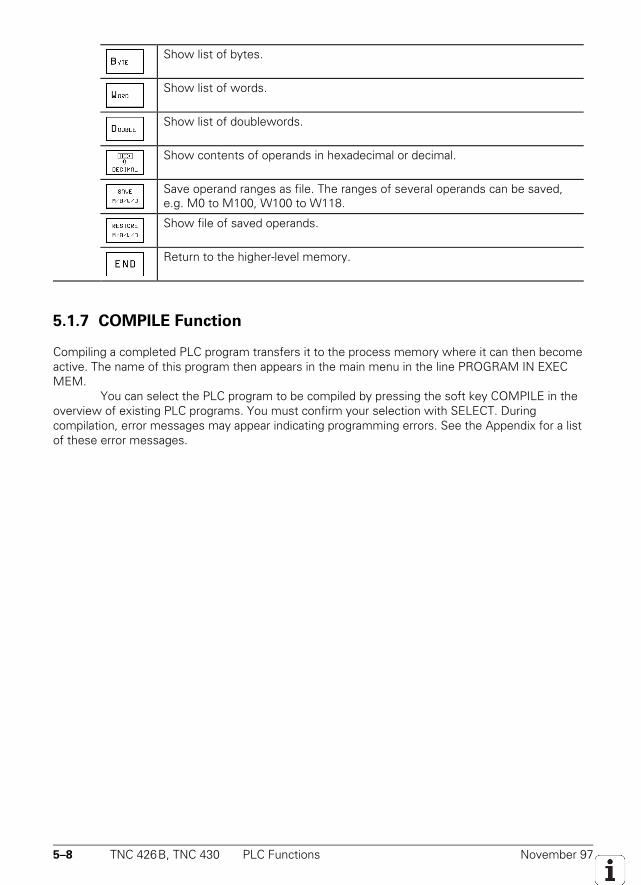
5–8 TNC 426B, TNC 430 PLC Functions November 97
Show list of bytes.
Show list of words.
Show list of doublewords.
Show contents of operands in hexadecimal or decimal.
Save operand ranges as file. The ranges of several operands can be saved,e.g. M0 to M100, W100 to W118.
Show file of saved operands.
Return to the higher-level memory.
5.1.7 COMPILE Function
Compiling a completed PLC program transfers it to the process memory where it can then becomeactive. The name of this program then appears in the main menu in the line PROGRAM IN EXECMEM.
You can select the PLC program to be compiled by pressing the soft key COMPILE in theoverview of existing PLC programs. You must confirm your selection with SELECT. Duringcompilation, error messages may appear indicating programming errors. See the Appendix for a listof these error messages.
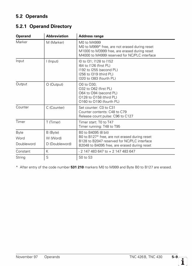
November 97 Operands TNC 426B, TNC 430 5–9
5.2 Operands
5.2.1 Operand Directory
Operand Abbreviation Address range
Marker M (Marker) M0 to M4999M0 to M999* free, are not erased during resetM1000 to M3999 free, are erased during resetM4000 to M4999 reserved for NC/PLC interface
Input I (Input) I0 to I31; I128 to I152I64 to I126 (first PL)I192 to I255 (second PL)I256 to I319 (third PL)I320 to I383 (fourth PL)
Output O (Output) O0 to O30;O32 to O62 (first PL)O64 to O94 (second PL)O128 to O158 (third PL)O160 to O190 (fourth PL)
Counter C (Counter) Set counter: C0 to C31Counter contents: C48 to C79Release count pulse: C96 to C127
Timer T (Timer) Timer start: T0 to T47Timer running: T48 to T95
Byte
Word
Doubleword
B (Byte)
W (Word)
D (Doubleword)
B0 to B4095 (8 bit)B0 to B127* free, are not erased during resetB128 to B2047 reserved for NC/PLC interfaceB2048 to B4095 free, are erased during reset
Constant K - 2 147 483 647 to + 2 147 483 647
String S S0 to S3
* After entry of the code number 531 210 markers M0 to M999 and Byte B0 to B127 are erased.
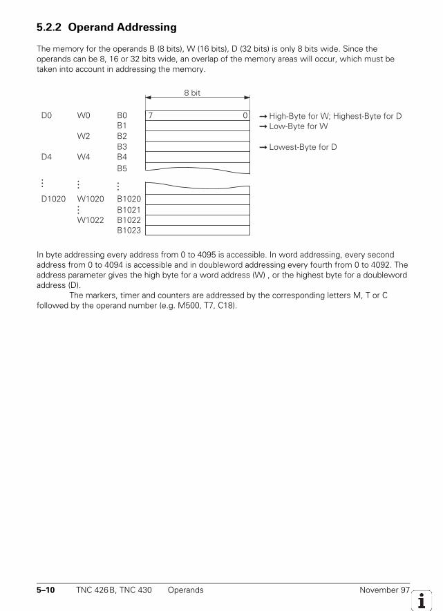
5–10 TNC 426B, TNC 430 Operands November 97
5.2.2 Operand Addressing
The memory for the operands B (8 bits), W (16 bits), D (32 bits) is only 8 bits wide. Since theoperands can be 8, 16 or 32 bits wide, an overlap of the memory areas will occur, which must betaken into account in addressing the memory.
8 bit
07B0
B1023B1022B1021B1020D1020 W1020
B1B2B3B4B5
W0D0
W2
W4D4
W1022
...
......
...
High-Byte for W; Highest-Byte for D
Lowest-Byte for D
Low-Byte for W
In byte addressing every address from 0 to 4095 is accessible. In word addressing, every secondaddress from 0 to 4094 is accessible and in doubleword addressing every fourth from 0 to 4092. Theaddress parameter gives the high byte for a word address (W) , or the highest byte for a doublewordaddress (D).
The markers, timer and counters are addressed by the corresponding letters M, T or Cfollowed by the operand number (e.g. M500, T7, C18).
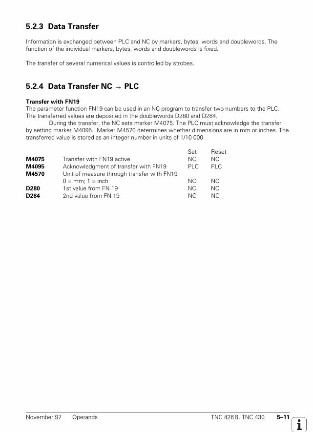
November 97 Operands TNC 426B, TNC 430 5–11
5.2.3 Data Transfer
Information is exchanged between PLC and NC by markers, bytes, words and doublewords. Thefunction of the individual markers, bytes, words and doublewords is fixed.
The transfer of several numerical values is controlled by strobes.
5.2.4 Data Transfer NC → PLC
Transfer with FN19
The parameter function FN19 can be used in an NC program to transfer two numbers to the PLC.The transferred values are deposited in the doublewords D280 and D284.
During the transfer, the NC sets marker M4075. The PLC must acknowledge the transferby setting marker M4095. Marker M4570 determines whether dimensions are in mm or inches. Thetransferred value is stored as an integer number in units of 1/10 000.
Set ResetM4075 Transfer with FN19 active NC NCM4095 Acknowledgment of transfer with FN19 PLC PLCM4570 Unit of measure through transfer with FN19
0 = mm; 1 = inch NC NCD280 1st value from FN 19 NC NCD284 2nd value from FN 19 NC NC
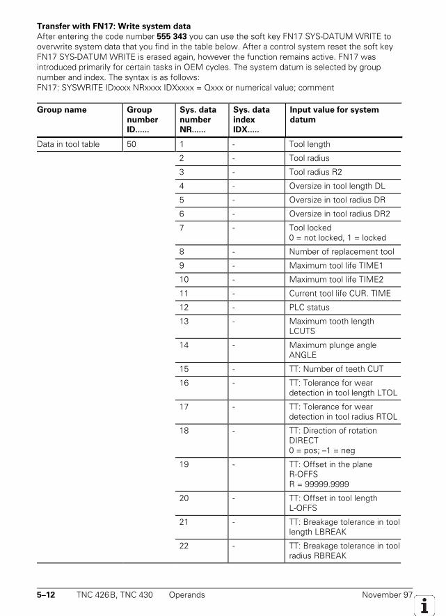
5–12 TNC 426B, TNC 430 Operands November 97
Transfer with FN17: Write system data
After entering the code number 555 343 you can use the soft key FN17 SYS-DATUM WRITE tooverwrite system data that you find in the table below. After a control system reset the soft keyFN17 SYS-DATUM WRITE is erased again, however the function remains active. FN17 wasintroduced primarily for certain tasks in OEM cycles. The system datum is selected by groupnumber and index. The syntax is as follows:FN17: SYSWRITE IDxxxx NRxxxx IDXxxxx = Qxxx or numerical value; comment
Group name Group
number
ID......
Sys. data
number
NR......
Sys. data
index
IDX.....
Input value for system
datum
Data in tool table 50 1 - Tool length
2 - Tool radius
3 - Tool radius R2
4 - Oversize in tool length DL
5 - Oversize in tool radius DR
6 - Oversize in tool radius DR2
7 - Tool locked0 = not locked, 1 = locked
8 - Number of replacement tool
9 - Maximum tool life TIME1
10 - Maximum tool life TIME2
11 - Current tool life CUR. TIME
12 - PLC status
13 - Maximum tooth lengthLCUTS
14 - Maximum plunge angleANGLE
15 - TT: Number of teeth CUT
16 - TT: Tolerance for weardetection in tool length LTOL
17 - TT: Tolerance for weardetection in tool radius RTOL
18 - TT: Direction of rotationDIRECT0 = pos; –1 = neg
19 - TT: Offset in the planeR-OFFSR = 99999.9999
20 - TT: Offset in tool lengthL-OFFS
21 - TT: Breakage tolerance in toollength LBREAK
22 - TT: Breakage tolerance in toolradius RBREAK
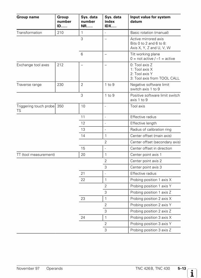
November 97 Operands TNC 426B, TNC 430 5–13
Group name Group
number
ID......
Sys. data
number
NR......
Sys. data
index
IDX.....
Input value for system
datum
Transformation 210 1 - Basic rotation (manual)
3 – Active mirrored axisBits 0 to 2 and 6 to 8:Axis X, Y, Z and U, V, W
6 – Tilt working plane0 = not active / –1 = active
Exchange tool axes 212 – – 0: Tool axis Z1: Tool axis X2: Tool axis Y3: Tool axis from TOOL CALL
Traverse range 230 2 1 to 9 Negative software limitswitch axis 1 to 9
3 1 to 9 Positive software limit switchaxis 1 to 9
Triggering touch probeTS
350 10 - Tool axis
11 - Effective radius
12 - Effective length
13 - Radius of calibration ring
14 1 Center offset (main axis)
2 Center offset (secondary axis)
15 - Center offset in direction
TT (tool measurement) 20 1 Center point axis 1
2 Center point axis 2
3 Center point axis 3
21 - Effective radius
22 1 Probing position 1 axis X
2 Probing position 1 axis Y
3 Probing position 1 axis Z
23 1 Probing position 2 axis X
2 Probing position 2 axis Y
3 Probing position 2 axis Z
24 1 Probing position 3 axis X
2 Probing position 3 axis Y
3 Probing position 3 axis Z
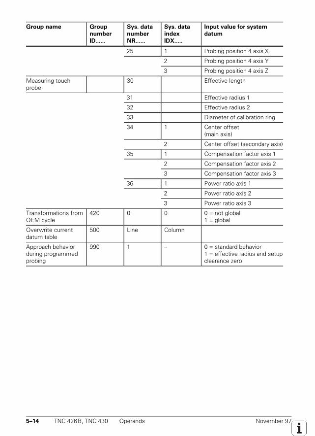
5–14 TNC 426B, TNC 430 Operands November 97
Group name Group
number
ID......
Sys. data
number
NR......
Sys. data
index
IDX.....
Input value for system
datum
25 1 Probing position 4 axis X
2 Probing position 4 axis Y
3 Probing position 4 axis Z
Measuring touchprobe
30 Effective length
31 Effective radius 1
32 Effective radius 2
33 Diameter of calibration ring
34 1 Center offset(main axis)
2 Center offset (secondary axis)
35 1 Compensation factor axis 1
2 Compensation factor axis 2
3 Compensation factor axis 3
36 1 Power ratio axis 1
2 Power ratio axis 2
3 Power ratio axis 3
Transformations fromOEM cycle
420 0 0 0 = not global1 = global
Overwrite currentdatum table
500 Line Column
Approach behaviorduring programmedprobing
990 1 – 0 = standard behavior1 = effective radius and setupclearance zero
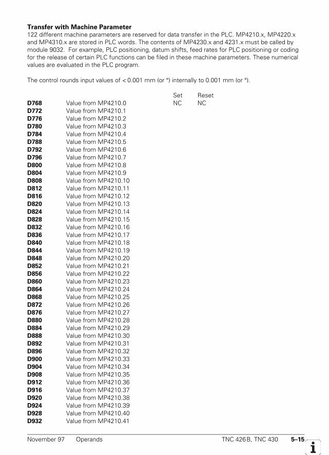
November 97 Operands TNC 426B, TNC 430 5–15
Transfer with Machine Parameter122 different machine parameters are reserved for data transfer in the PLC. MP4210.x, MP4220.xand MP4310.x are stored in PLC words. The contents of MP4230.x and 4231.x must be called bymodule 9032. For example, PLC positioning, datum shifts, feed rates for PLC positioning or codingfor the release of certain PLC functions can be filed in these machine parameters. These numericalvalues are evaluated in the PLC program.
The control rounds input values of < 0.001 mm (or °) internally to 0.001 mm (or °).
Set ResetD768 Value from MP4210.0 NC NCD772 Value from MP4210.1D776 Value from MP4210.2D780 Value from MP4210.3D784 Value from MP4210.4D788 Value from MP4210.5D792 Value from MP4210.6D796 Value from MP4210.7D800 Value from MP4210.8D804 Value from MP4210.9D808 Value from MP4210.10D812 Value from MP4210.11D816 Value from MP4210.12D820 Value from MP4210.13D824 Value from MP4210.14D828 Value from MP4210.15D832 Value from MP4210.16D836 Value from MP4210.17D840 Value from MP4210.18D844 Value from MP4210.19D848 Value from MP4210.20D852 Value from MP4210.21D856 Value from MP4210.22D860 Value from MP4210.23D864 Value from MP4210.24D868 Value from MP4210.25D872 Value from MP4210.26D876 Value from MP4210.27D880 Value from MP4210.28D884 Value from MP4210.29D888 Value from MP4210.30D892 Value from MP4210.31D896 Value from MP4210.32D900 Value from MP4210.33D904 Value from MP4210.34D908 Value from MP4210.35D912 Value from MP4210.36D916 Value from MP4210.37D920 Value from MP4210.38D924 Value from MP4210.39D928 Value from MP4210.40D932 Value from MP4210.41
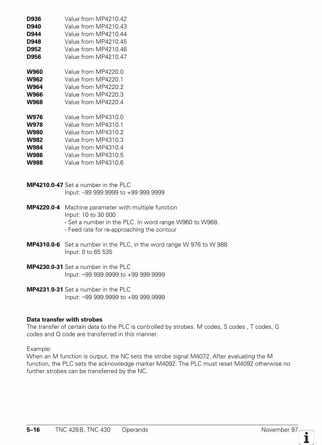
5–16 TNC 426B, TNC 430 Operands November 97
D936 Value from MP4210.42D940 Value from MP4210.43D944 Value from MP4210.44D948 Value from MP4210.45D952 Value from MP4210.46D956 Value from MP4210.47
W960 Value from MP4220.0W962 Value from MP4220.1W964 Value from MP4220.2W966 Value from MP4220.3W968 Value from MP4220.4
W976 Value from MP4310.0W978 Value from MP4310.1W980 Value from MP4310.2W982 Value from MP4310.3W984 Value from MP4310.4W986 Value from MP4310.5W988 Value from MP4310.6
MP4210.0-47 Set a number in the PLC Input: –99 999.9999 to +99 999.9999
MP4220.0-4 Machine parameter with multiple functionInput: 10 to 30 000- Set a number in the PLC. In word range W960 to W968.- Feed rate for re-approaching the contour
MP4310.0-6 Set a number in the PLC, in the word range W 976 to W 988Input: 0 to 65 535
MP4230.0-31 Set a number in the PLCInput: −99 999.9999 to +99 999.9999
MP4231.0-31 Set a number in the PLCInput: −99 999.9999 to +99 999.9999
Data transfer with strobes
The transfer of certain data to the PLC is controlled by strobes. M codes, S codes , T codes, Gcodes and Q code are transferred in this manner.
Example:When an M function is output, the NC sets the strobe signal M4072. After evaluating the Mfunction, the PLC sets the acknowledge marker M4092. The PLC must reset M4092 otherwise nofurther strobes can be transferred by the NC.
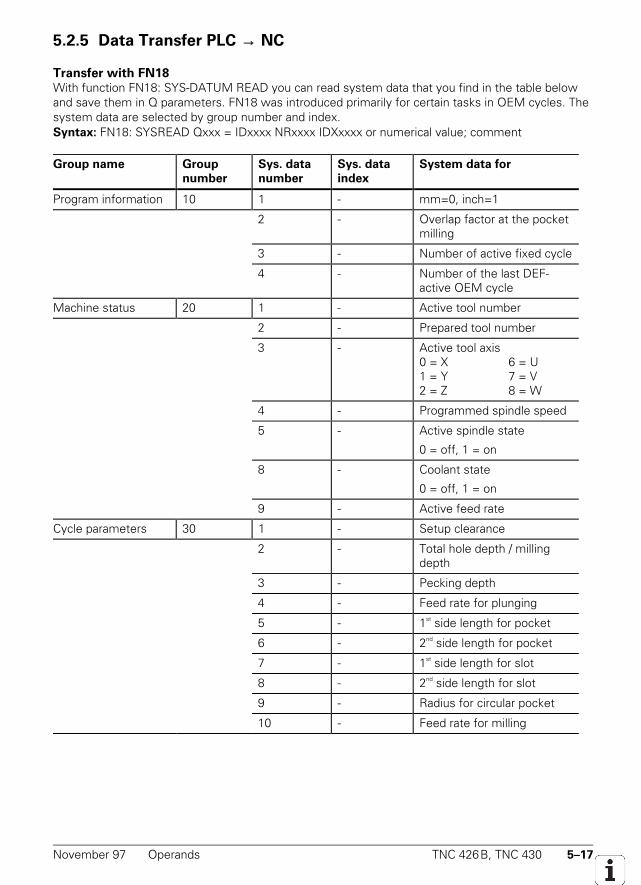
November 97 Operands TNC 426B, TNC 430 5–17
5.2.5 Data Transfer PLC → NC
Transfer with FN18With function FN18: SYS-DATUM READ you can read system data that you find in the table belowand save them in Q parameters. FN18 was introduced primarily for certain tasks in OEM cycles. Thesystem data are selected by group number and index.Syntax: FN18: SYSREAD Qxxx = IDxxxx NRxxxx IDXxxxx or numerical value; comment
Group name Group
number
Sys. data
number
Sys. data
index
System data for
Program information 10 1 - mm=0, inch=1
2 - Overlap factor at the pocketmilling
3 - Number of active fixed cycle
4 - Number of the last DEF-active OEM cycle
Machine status 20 1 - Active tool number
2 - Prepared tool number
3 - Active tool axis0 = X 6 = U1 = Y 7 = V2 = Z 8 = W
4 - Programmed spindle speed
5 - Active spindle state
0 = off, 1 = on
8 - Coolant state
0 = off, 1 = on
9 - Active feed rate
Cycle parameters 30 1 - Setup clearance
2 - Total hole depth / millingdepth
3 - Pecking depth
4 - Feed rate for plunging
5 - 1st side length for pocket
6 - 2nd side length for pocket
7 - 1st side length for slot
8 - 2nd side length for slot
9 - Radius for circular pocket
10 - Feed rate for milling
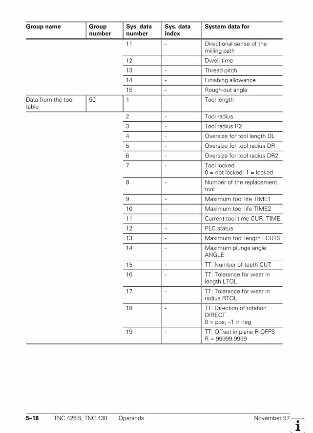
5–18 TNC 426B, TNC 430 Operands November 97
Group name Group
number
Sys. data
number
Sys. data
index
System data for
11 - Directional sense of themilling path
12 - Dwell time
13 - Thread pitch
14 - Finishing allowance
15 - Rough-out angle
Data from the tooltable
50 1 - Tool length
2 - Tool radius
3 - Tool radius R2
4 - Oversize for tool length DL
5 - Oversize for tool radius DR
6 - Oversize for tool radius DR2
7 - Tool locked0 = not locked; 1 = locked
8 - Number of the replacementtool
9 - Maximum tool life TIME1
10 - Maximum tool life TIME2
11 - Current tool time CUR. TIME
12 - PLC status
13 - Maximum tool length LCUTS
14 - Maximum plunge angleANGLE
15 - TT: Number of teeth CUT
16 - TT: Tolerance for wear inlength LTOL
17 - TT: Tolerance for wear inradius RTOL
18 - TT: Direction of rotationDIRECT0 = pos; –1 = neg
19 - TT: Offset in plane R-OFFSR = 99999.9999
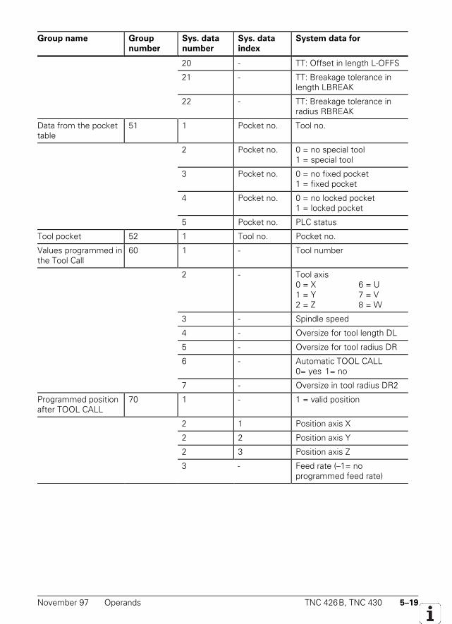
November 97 Operands TNC 426B, TNC 430 5–19
Group name Group
number
Sys. data
number
Sys. data
index
System data for
20 - TT: Offset in length L-OFFS
21 - TT: Breakage tolerance inlength LBREAK
22 - TT: Breakage tolerance inradius RBREAK
Data from the pockettable
51 1 Pocket no. Tool no.
2 Pocket no. 0 = no special tool1 = special tool
3 Pocket no. 0 = no fixed pocket1 = fixed pocket
4 Pocket no. 0 = no locked pocket1 = locked pocket
5 Pocket no. PLC status
Tool pocket 52 1 Tool no. Pocket no.
Values programmed inthe Tool Call
60 1 - Tool number
2 - Tool axis0 = X 6 = U1 = Y 7 = V2 = Z 8 = W
3 - Spindle speed
4 - Oversize for tool length DL
5 - Oversize for tool radius DR
6 - Automatic TOOL CALL0= yes 1= no
7 - Oversize in tool radius DR2
Programmed positionafter TOOL CALL
70 1 - 1 = valid position
2 1 Position axis X
2 2 Position axis Y
2 3 Position axis Z
3 - Feed rate (–1= noprogrammed feed rate)
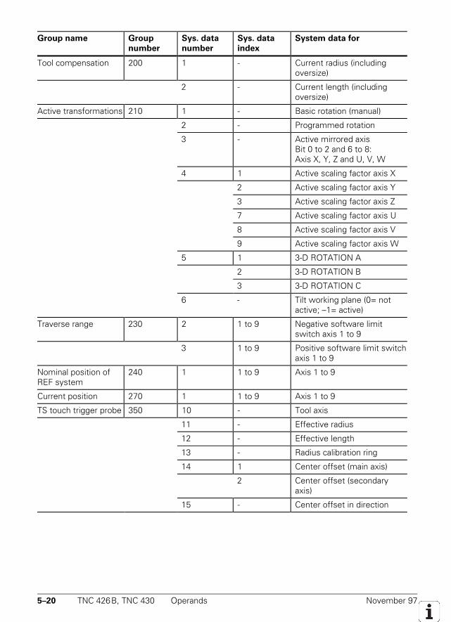
5–20 TNC 426B, TNC 430 Operands November 97
Group name Group
number
Sys. data
number
Sys. data
index
System data for
Tool compensation 200 1 - Current radius (includingoversize)
2 - Current length (includingoversize)
Active transformations 210 1 - Basic rotation (manual)
2 - Programmed rotation
3 - Active mirrored axisBit 0 to 2 and 6 to 8:Axis X, Y, Z and U, V, W
4 1 Active scaling factor axis X
2 Active scaling factor axis Y
3 Active scaling factor axis Z
7 Active scaling factor axis U
8 Active scaling factor axis V
9 Active scaling factor axis W
5 1 3-D ROTATION A
2 3-D ROTATION B
3 3-D ROTATION C
6 - Tilt working plane (0= notactive; –1= active)
Traverse range 230 2 1 to 9 Negative software limitswitch axis 1 to 9
3 1 to 9 Positive software limit switchaxis 1 to 9
Nominal position ofREF system
240 1 1 to 9 Axis 1 to 9
Current position 270 1 1 to 9 Axis 1 to 9
TS touch trigger probe 350 10 - Tool axis
11 - Effective radius
12 - Effective length
13 - Radius calibration ring
14 1 Center offset (main axis)
2 Center offset (secondaryaxis)
15 - Center offset in direction
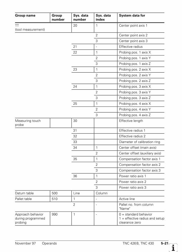
November 97 Operands TNC 426B, TNC 430 5–21
Group name Group
number
Sys. data
number
Sys. data
index
System data for
TT(tool measurement)
20 1 Center point axis 1
2 Center point axis 2
3 Center point axis 3
21 - Effective radius
22 1 Probing pos. 1 axis X
2 Probing pos. 1 axis Y
3 Probing pos. 1 axis Z
23 1 Probing pos. 2 axis X
2 Probing pos. 2 axis Y
3 Probing pos. 2 axis Z
24 1 Probing pos. 3 axis X
2 Probing pos. 3 axis Y
3 Probing pos. 3 axis Z
25 1 Probing pos. 4 axis X
2 Probing pos. 4 axis Y
3 Probing pos. 4 axis Z
Measuring touchprobe
30 Effective length
31 Effective radius 1
32 Effective radius 2
33 Diameter of calibration ring
34 1 Center offset (main axis)
2 Center offset (auxiliary axis)
35 1 Compensation factor axis 1
2 Compensation factor axis 2
3 Compensation factor axis 3
36 1 Power ratio axis 1
2 Power ratio axis 2
3 Power ratio axis 3
Datum table 500 Line Column
Pallet table 510 1 - Active line
2 - Pallet no. from column"Name"
Approach behaviorduring programmedprobing
990 1 - 0 = standard behavior1 = effective radius and setupclearance zero
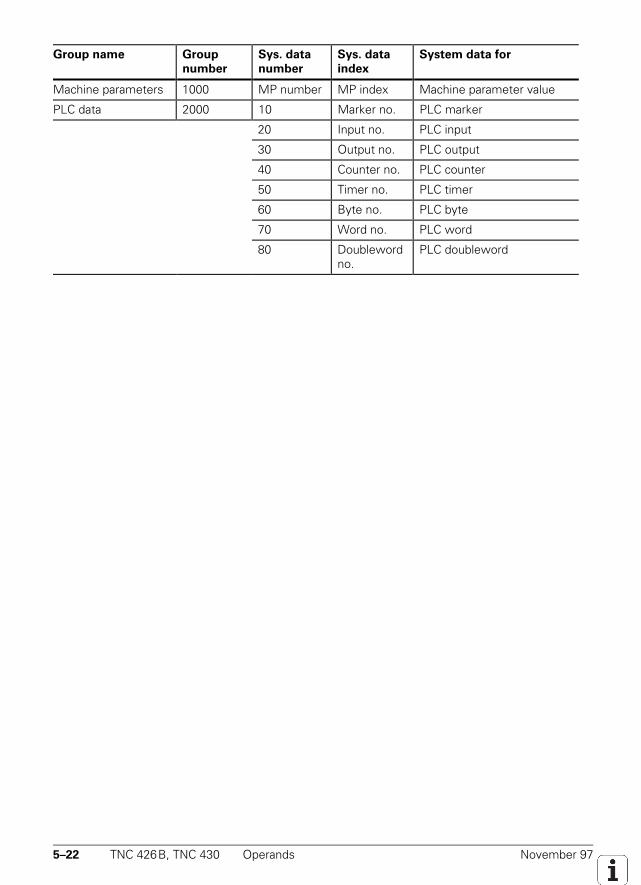
5–22 TNC 426B, TNC 430 Operands November 97
Group name Group
number
Sys. data
number
Sys. data
index
System data for
Machine parameters 1000 MP number MP index Machine parameter value
PLC data 2000 10 Marker no. PLC marker
20 Input no. PLC input
30 Output no. PLC output
40 Counter no. PLC counter
50 Timer no. PLC timer
60 Byte no. PLC byte
70 Word no. PLC word
80 Doublewordno.
PLC doubleword

November 97 Operands TNC 426B, TNC 430 5–23
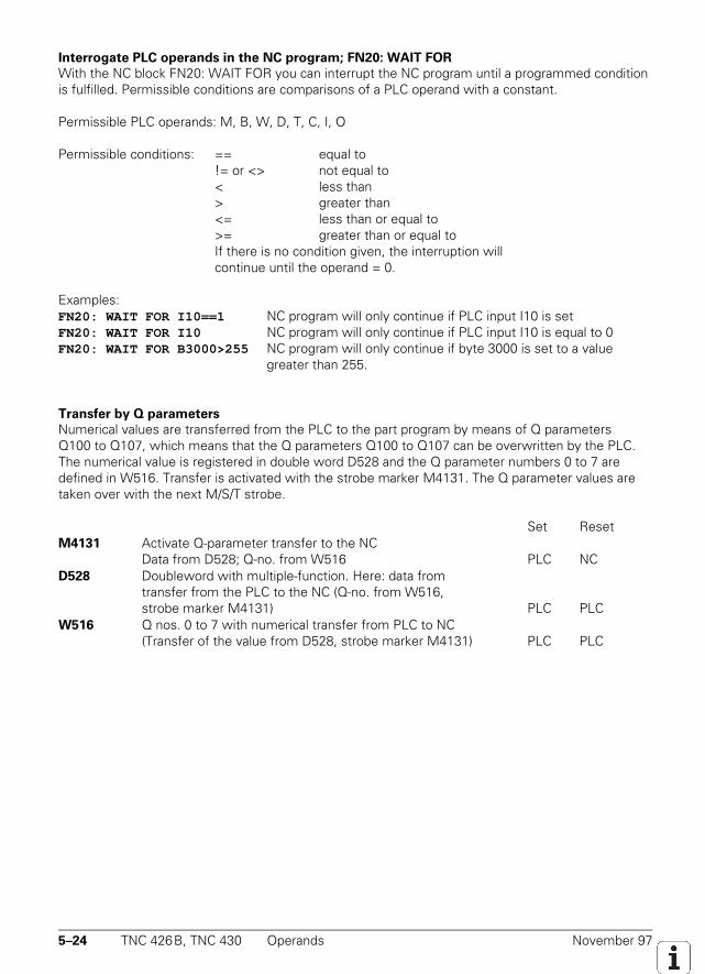
5–24 TNC 426B, TNC 430 Operands November 97
Interrogate PLC operands in the NC program; FN20: WAIT FOR
With the NC block FN20: WAIT FOR you can interrupt the NC program until a programmed conditionis fulfilled. Permissible conditions are comparisons of a PLC operand with a constant.
Permissible PLC operands: M, B, W, D, T, C, I, O
Permissible conditions: == equal to!= or <> not equal to< less than> greater than<= less than or equal to>= greater than or equal toIf there is no condition given, the interruption willcontinue until the operand = 0.
Examples:FN20: WAIT FOR I10==1 NC program will only continue if PLC input I10 is setFN20: WAIT FOR I10 NC program will only continue if PLC input I10 is equal to 0FN20: WAIT FOR B3000>255 NC program will only continue if byte 3000 is set to a value
greater than 255.
Transfer by Q parameters
Numerical values are transferred from the PLC to the part program by means of Q parametersQ100 to Q107, which means that the Q parameters Q100 to Q107 can be overwritten by the PLC.The numerical value is registered in double word D528 and the Q parameter numbers 0 to 7 aredefined in W516. Transfer is activated with the strobe marker M4131. The Q parameter values aretaken over with the next M/S/T strobe.
Set ResetM4131 Activate Q-parameter transfer to the NC
Data from D528; Q-no. from W516 PLC NCD528 Doubleword with multiple-function. Here: data from
transfer from the PLC to the NC (Q-no. from W516,strobe marker M4131) PLC PLC
W516 Q nos. 0 to 7 with numerical transfer from PLC to NC(Transfer of the value from D528, strobe marker M4131) PLC PLC
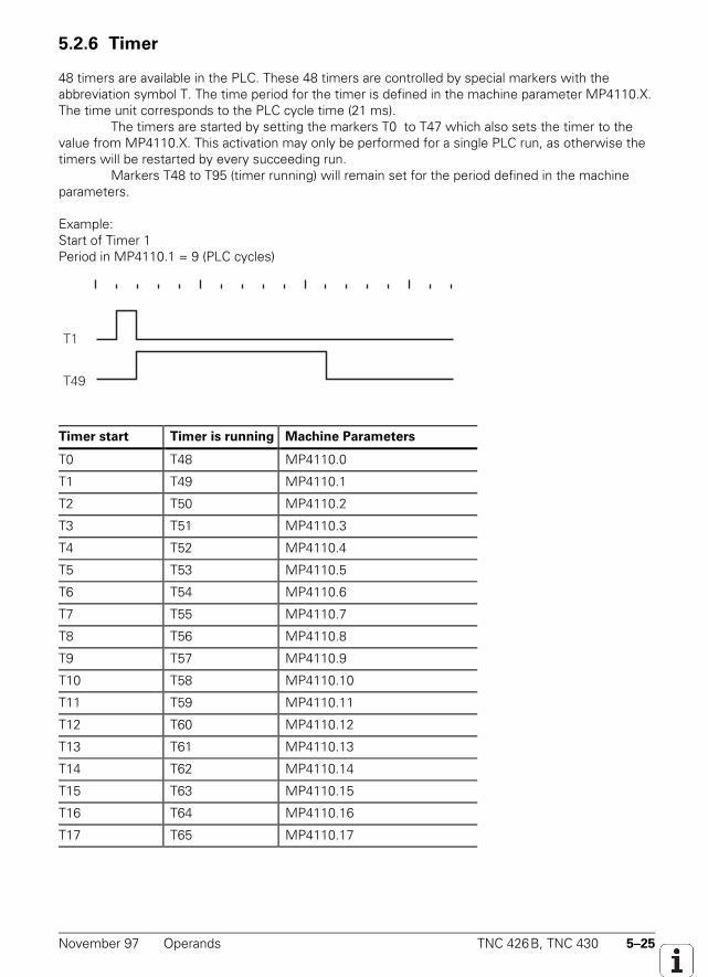
November 97 Operands TNC 426B, TNC 430 5–25
5.2.6 Timer
48 timers are available in the PLC. These 48 timers are controlled by special markers with theabbreviation symbol T. The time period for the timer is defined in the machine parameter MP4110.X.The time unit corresponds to the PLC cycle time (21 ms).
The timers are started by setting the markers T0 to T47 which also sets the timer to thevalue from MP4110.X. This activation may only be performed for a single PLC run, as otherwise thetimers will be restarted by every succeeding run.
Markers T48 to T95 (timer running) will remain set for the period defined in the machineparameters.
Example:Start of Timer 1Period in MP4110.1 = 9 (PLC cycles)
T1
T49
Timer start Timer is running Machine Parameters
T0 T48 MP4110.0
T1 T49 MP4110.1
T2 T50 MP4110.2
T3 T51 MP4110.3
T4 T52 MP4110.4
T5 T53 MP4110.5
T6 T54 MP4110.6
T7 T55 MP4110.7
T8 T56 MP4110.8
T9 T57 MP4110.9
T10 T58 MP4110.10
T11 T59 MP4110.11
T12 T60 MP4110.12
T13 T61 MP4110.13
T14 T62 MP4110.14
T15 T63 MP4110.15
T16 T64 MP4110.16
T17 T65 MP4110.17
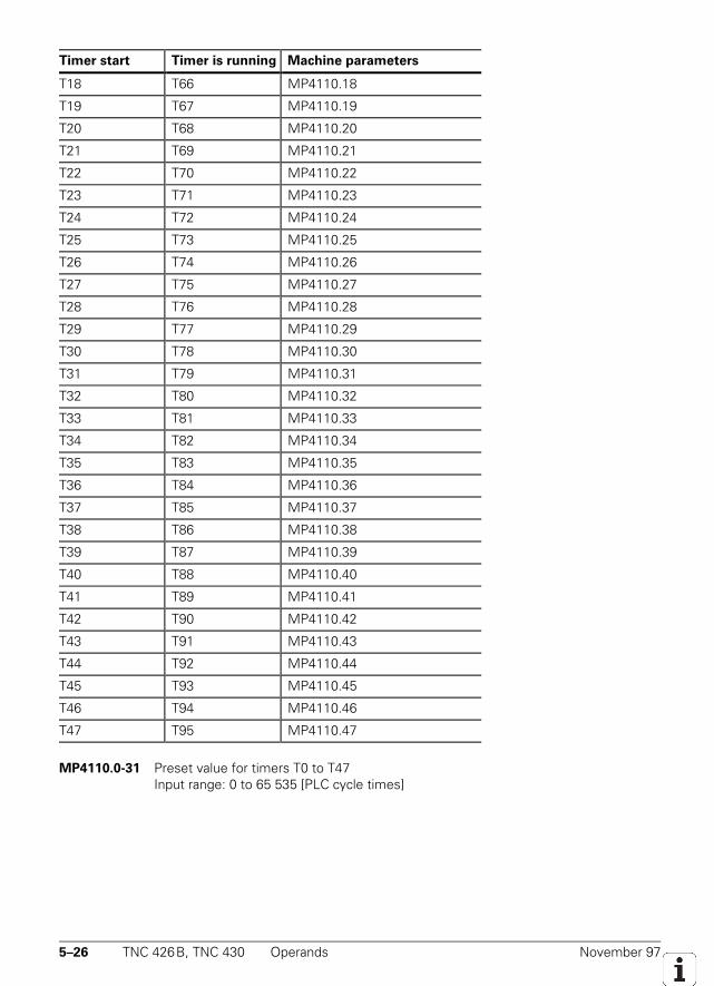
5–26 TNC 426B, TNC 430 Operands November 97
Timer start Timer is running Machine parameters
T18 T66 MP4110.18
T19 T67 MP4110.19
T20 T68 MP4110.20
T21 T69 MP4110.21
T22 T70 MP4110.22
T23 T71 MP4110.23
T24 T72 MP4110.24
T25 T73 MP4110.25
T26 T74 MP4110.26
T27 T75 MP4110.27
T28 T76 MP4110.28
T29 T77 MP4110.29
T30 T78 MP4110.30
T31 T79 MP4110.31
T32 T80 MP4110.32
T33 T81 MP4110.33
T34 T82 MP4110.34
T35 T83 MP4110.35
T36 T84 MP4110.36
T37 T85 MP4110.37
T38 T86 MP4110.38
T39 T87 MP4110.39
T40 T88 MP4110.40
T41 T89 MP4110.41
T42 T90 MP4110.42
T43 T91 MP4110.43
T44 T92 MP4110.44
T45 T93 MP4110.45
T46 T94 MP4110.46
T47 T95 MP4110.47
MP4110.0-31 Preset value for timers T0 to T47Input range: 0 to 65 535 [PLC cycle times]
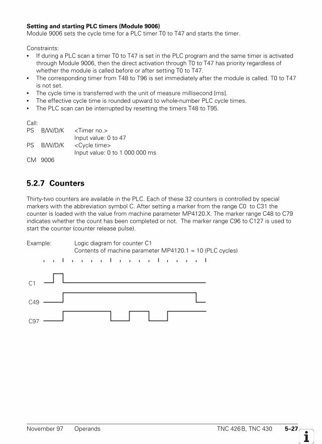
November 97 Operands TNC 426B, TNC 430 5–27
Setting and starting PLC timers (Module 9006)
Module 9006 sets the cycle time for a PLC timer T0 to T47 and starts the timer.
Constraints:• If during a PLC scan a timer T0 to T47 is set in the PLC program and the same timer is activated
through Module 9006, then the direct activation through T0 to T47 has priority regardless ofwhether the module is called before or after setting T0 to T47.
• The corresponding timer from T48 to T96 is set immediately after the module is called. T0 to T47is not set.
• The cycle time is transferred with the unit of measure millisecond [ms].• The effective cycle time is rounded upward to whole-number PLC cycle times.• The PLC scan can be interrupted by resetting the timers T48 to T95.
Call:PS B/W/D/K <Timer no.>
Input value: 0 to 47PS B/W/D/K <Cycle time>
Input value: 0 to 1 000 000 msCM 9006
5.2.7 Counters
Thirty-two counters are available in the PLC. Each of these 32 counters is controlled by specialmarkers with the abbreviation symbol C. After setting a marker from the range C0 to C31 thecounter is loaded with the value from machine parameter MP4120.X. The marker range C48 to C79indicates whether the count has been completed or not. The marker range C96 to C127 is used tostart the counter (counter release pulse).
Example: Logic diagram for counter C1Contents of machine parameter MP4120.1 = 10 (PLC cycles)
C1
C49
C97
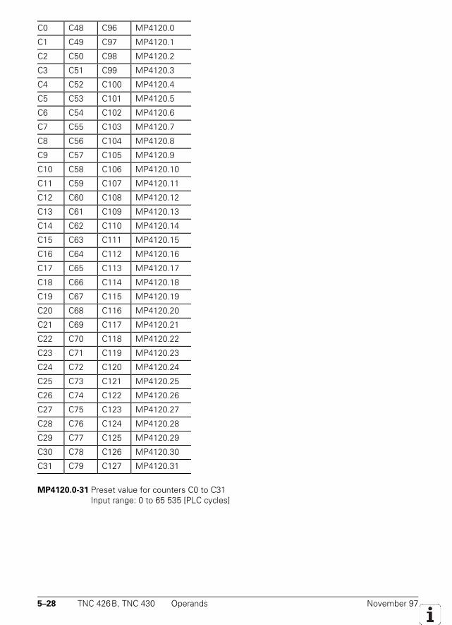
5–28 TNC 426B, TNC 430 Operands November 97
C0 C48 C96 MP4120.0
C1 C49 C97 MP4120.1
C2 C50 C98 MP4120.2
C3 C51 C99 MP4120.3
C4 C52 C100 MP4120.4
C5 C53 C101 MP4120.5
C6 C54 C102 MP4120.6
C7 C55 C103 MP4120.7
C8 C56 C104 MP4120.8
C9 C57 C105 MP4120.9
C10 C58 C106 MP4120.10
C11 C59 C107 MP4120.11
C12 C60 C108 MP4120.12
C13 C61 C109 MP4120.13
C14 C62 C110 MP4120.14
C15 C63 C111 MP4120.15
C16 C64 C112 MP4120.16
C17 C65 C113 MP4120.17
C18 C66 C114 MP4120.18
C19 C67 C115 MP4120.19
C20 C68 C116 MP4120.20
C21 C69 C117 MP4120.21
C22 C70 C118 MP4120.22
C23 C71 C119 MP4120.23
C24 C72 C120 MP4120.24
C25 C73 C121 MP4120.25
C26 C74 C122 MP4120.26
C27 C75 C123 MP4120.27
C28 C76 C124 MP4120.28
C29 C77 C125 MP4120.29
C30 C78 C126 MP4120.30
C31 C79 C127 MP4120.31
MP4120.0-31 Preset value for counters C0 to C31Input range: 0 to 65 535 [PLC cycles]
November 97 Operands TNC 426B, TNC 430 5–29
5.2.8 Fast PLC Inputs
With MP4130 you can define PLC inputs that are not interrogated in the PLC cycle (21 ms), butrather in the control loop cycle (3 ms). The markers M4590 to M4593 show the current state of thefast PLC inputs. The function of the fast PLC inputs must be activated in the PLC program withW522 bit 2 to bit 5. In order to ensure that a signal change be recognized, the duration of the signalat the fast PLC input must be at least 4 ms.
MP4130 Numerical designation of fast PLC inputsInput: 0 to 255 [No. of the PLC input]
MP4130.2 Fast PLC input sets M4590MP4130.3 Fast PLC input sets M4591MP4130.4 Fast PLC input sets M4592MP4130.5 Fast PLC input sets M4593
MP4131.2-5 Condition for activating the fast PLC inputsInput: 0 = activation at low level
1 = activation at high level
Set ResetW522 Activate the fast PLC inputs PLC PLCBit 2 Fast PLC input defined in MP4130.2Bit 3 Fast PLC input defined in MP4130.3Bit 4 Fast PLC input defined in MP4130.4Bit 5 Fast PLC input defined in MP4130.5
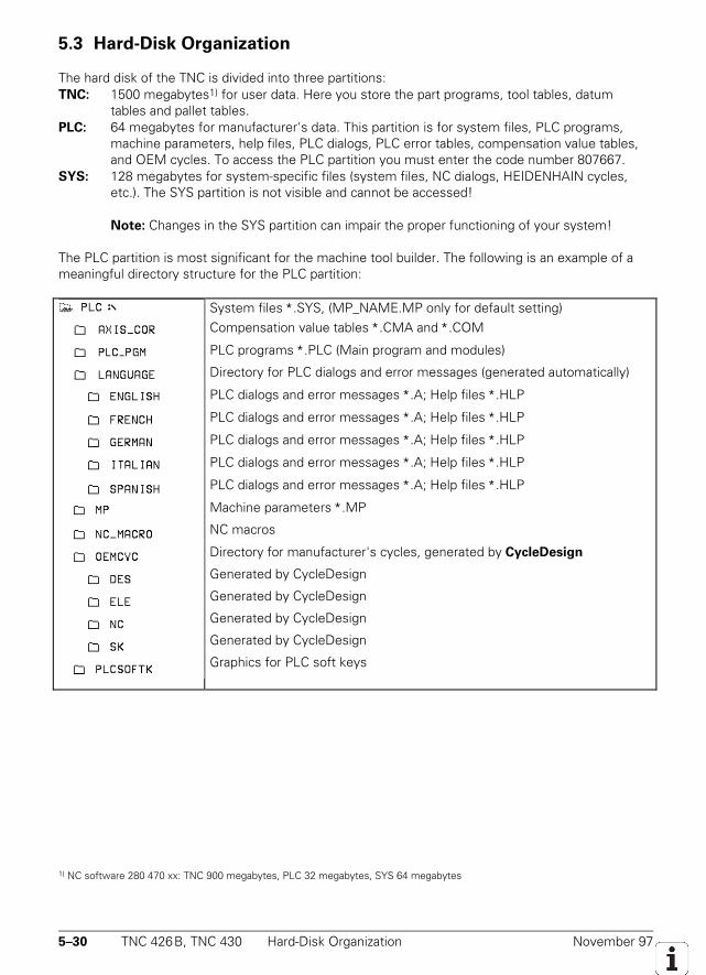
5–30 TNC 426B, TNC 430 Hard-Disk Organization November 97
5.3 Hard-Disk Organization
The hard disk of the TNC is divided into three partitions:TNC: 1500 megabytes1) for user data. Here you store the part programs, tool tables, datum
tables and pallet tables.PLC: 64 megabytes for manufacturer's data. This partition is for system files, PLC programs,
machine parameters, help files, PLC dialogs, PLC error tables, compensation value tables,and OEM cycles. To access the PLC partition you must enter the code number 807667.
SYS: 128 megabytes for system-specific files (system files, NC dialogs, HEIDENHAIN cycles,etc.). The SYS partition is not visible and cannot be accessed!
Note: Changes in the SYS partition can impair the proper functioning of your system!
The PLC partition is most significant for the machine tool builder. The following is an example of ameaningful directory structure for the PLC partition:
System files ∗.SYS, (MP_NAME.MP only for default setting)Compensation value tables ∗.CMA and ∗.COM
PLC programs ∗.PLC (Main program and modules)
Directory for PLC dialogs and error messages (generated automatically)
PLC dialogs and error messages ∗.A; Help files ∗.HLP
PLC dialogs and error messages ∗.A; Help files ∗.HLP
PLC dialogs and error messages ∗.A; Help files ∗.HLP
PLC dialogs and error messages ∗.A; Help files ∗.HLP
PLC dialogs and error messages ∗.A; Help files ∗.HLP
Machine parameters ∗.MP
NC macros
Directory for manufacturer's cycles, generated by CycleDesign
Generated by CycleDesign
Generated by CycleDesign
Generated by CycleDesign
Generated by CycleDesign
Graphics for PLC soft keys
1) NC software 280 470 xx: TNC 900 megabytes, PLC 32 megabytes, SYS 64 megabytes
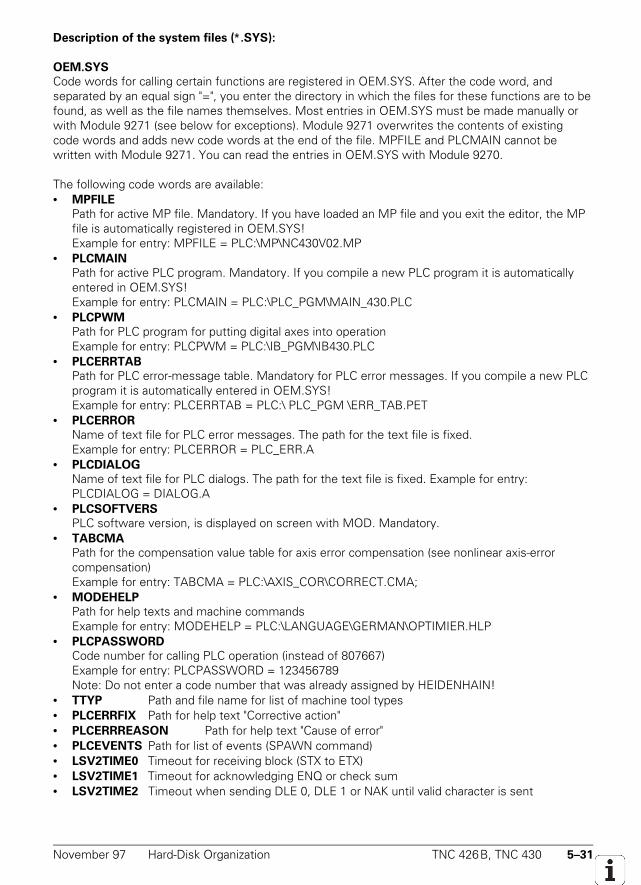
November 97 Hard-Disk Organization TNC 426B, TNC 430 5–31
Description of the system files (∗.SYS):
OEM.SYS
Code words for calling certain functions are registered in OEM.SYS. After the code word, andseparated by an equal sign "=", you enter the directory in which the files for these functions are to befound, as well as the file names themselves. Most entries in OEM.SYS must be made manually orwith Module 9271 (see below for exceptions). Module 9271 overwrites the contents of existingcode words and adds new code words at the end of the file. MPFILE and PLCMAIN cannot bewritten with Module 9271. You can read the entries in OEM.SYS with Module 9270.
The following code words are available:• MPFILE
Path for active MP file. Mandatory. If you have loaded an MP file and you exit the editor, the MPfile is automatically registered in OEM.SYS!Example for entry: MPFILE = PLC:\MP\NC430V02.MP
• PLCMAIN
Path for active PLC program. Mandatory. If you compile a new PLC program it is automaticallyentered in OEM.SYS!Example for entry: PLCMAIN = PLC:\PLC_PGM\MAIN_430.PLC
• PLCPWM
Path for PLC program for putting digital axes into operationExample for entry: PLCPWM = PLC:\IB_PGM\IB430.PLC
• PLCERRTAB
Path for PLC error-message table. Mandatory for PLC error messages. If you compile a new PLCprogram it is automatically entered in OEM.SYS!Example for entry: PLCERRTAB = PLC:\ PLC_PGM \ERR_TAB.PET
• PLCERROR
Name of text file for PLC error messages. The path for the text file is fixed.Example for entry: PLCERROR = PLC_ERR.A
• PLCDIALOG
Name of text file for PLC dialogs. The path for the text file is fixed. Example for entry:PLCDIALOG = DIALOG.A
• PLCSOFTVERS
PLC software version, is displayed on screen with MOD. Mandatory.• TABCMA
Path for the compensation value table for axis error compensation (see nonlinear axis-errorcompensation)Example for entry: TABCMA = PLC:\AXIS_COR\CORRECT.CMA;
• MODEHELP
Path for help texts and machine commandsExample for entry: MODEHELP = PLC:\LANGUAGE\GERMAN\OPTIMIER.HLP
• PLCPASSWORD
Code number for calling PLC operation (instead of 807667)Example for entry: PLCPASSWORD = 123456789Note: Do not enter a code number that was already assigned by HEIDENHAIN!
• TTYP Path and file name for list of machine tool types• PLCERRFIX Path for help text "Corrective action"• PLCERRREASON Path for help text "Cause of error"• PLCEVENTS Path for list of events (SPAWN command)• LSV2TIME0 Timeout for receiving block (STX to ETX)• LSV2TIME1 Timeout for acknowledging ENQ or check sum• LSV2TIME2 Timeout when sending DLE 0, DLE 1 or NAK until valid character is sent
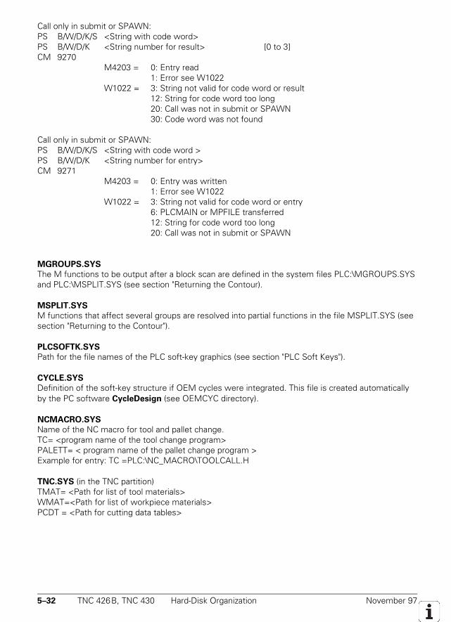
5–32 TNC 426B, TNC 430 Hard-Disk Organization November 97
Call only in submit or SPAWN:PS B/W/D/K/S <String with code word>PS B/W/D/K <String number for result> [0 to 3]CM 9270
M4203 = 0: Entry read1: Error see W1022
W1022 = 3: String not valid for code word or result12: String for code word too long20: Call was not in submit or SPAWN30: Code word was not found
Call only in submit or SPAWN:PS B/W/D/K/S <String with code word >PS B/W/D/K <String number for entry>CM 9271
M4203 = 0: Entry was written1: Error see W1022
W1022 = 3: String not valid for code word or entry6: PLCMAIN or MPFILE transferred12: String for code word too long20: Call was not in submit or SPAWN
MGROUPS.SYS
The M functions to be output after a block scan are defined in the system files PLC:\MGROUPS.SYSand PLC:\MSPLIT.SYS (see section "Returning the Contour).
MSPLIT.SYS
M functions that affect several groups are resolved into partial functions in the file MSPLIT.SYS (seesection "Returning to the Contour").
PLCSOFTK.SYS
Path for the file names of the PLC soft-key graphics (see section "PLC Soft Keys").
CYCLE.SYS
Definition of the soft-key structure if OEM cycles were integrated. This file is created automaticallyby the PC software CycleDesign (see OEMCYC directory).
NCMACRO.SYS
Name of the NC macro for tool and pallet change.TC= <program name of the tool change program>PALETT= < program name of the pallet change program >Example for entry: TC =PLC:\NC_MACRO\TOOLCALL.H
TNC.SYS (in the TNC partition)TMAT= <Path for list of tool materials>WMAT=<Path for list of workpiece materials>PCDT = <Path for cutting data tables>
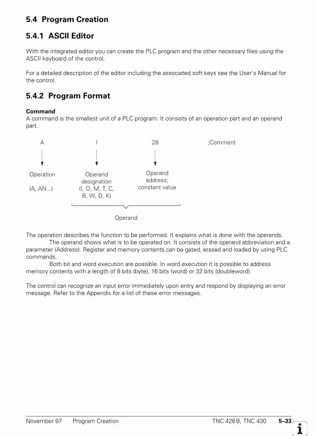
November 97 Program Creation TNC 426B, TNC 430 5–33
5.4 Program Creation
5.4.1 ASCII Editor
With the integrated editor you can create the PLC program and the other necessary files using theASCII keyboard of the control.
For a detailed description of the editor including the associated soft keys see the User's Manual forthe control.
5.4.2 Program Format
Command
A command is the smallest unit of a PLC program. It consists of an operation part and an operandpart.
A I 28 ;Comment
Operation
(A, AN...)
Operanddesignation
(I, O, M, T, C,B, W, D, K)
Operandaddress;
constant value
Operand
The operation describes the function to be performed. It explains what is done with the operands.The operand shows what is to be operated on. It consists of the operand abbreviation and a
parameter (Address). Register and memory contents can be gated, erased and loaded by using PLCcommands.
Both bit and word execution are possible. In word execution it is possible to addressmemory contents with a length of 8 bits (byte), 16 bits (word) or 32 bits (doubleword).
The control can recognize an input error immediately upon entry and respond by displaying an errormessage. Refer to the Appendix for a list of these error messages.
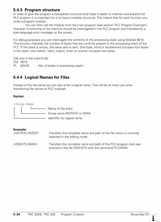
5–34 TNC 426B, TNC 430 Program Creation November 97
5.4.3 Program structureIn order to give the program a transparent structure and make it easier to maintain and expand thePLC program it is important for it to have a modular structure. This means that for each function youwrite a program module.
You can then call the module from the main program (see section "PLC Program Example").Improper functioning of the machine should be interrogated in the PLC program and indicated by aplain-language error message on the screen.
For debug purposes you can interrogate the contents of the processing stack using Module 9019.This function indicates the number of bytes that are currently present in the processing stack of thePLC. If the stack is empty, the value zero is sent. One byte, word or doubleword occupies four bytesin the stack, one marker, input, output, timer or counter occupies two bytes.
Call only in the submit job:CM 9019PL B/W/D <No. of bytes in processing stack>
5.4.4 Logical Names for Files
Instead of the file name you can also enter a logical name. This will be of most use whentransferring file names to PLC modules
Syntax:
Example:
>NCPATH.NCEDIT Transfers the complete name and path of the file which is currently selected in the editing mode.
>OEM.PLCMAIN Transfers the complete name and path of the PLC program that was entered in the file OEM.SYS with the command PLCMAIN.
>Group.Name
Name of the entry
Group name (NCPATH or OEM)
Identifier for logical name
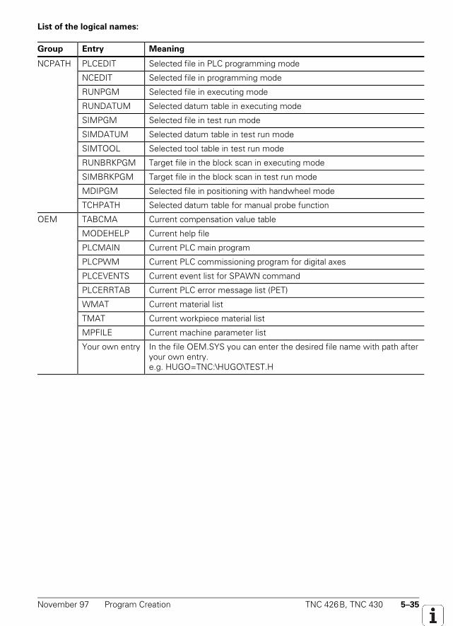
November 97 Program Creation TNC 426B, TNC 430 5–35
List of the logical names:
Group Entry Meaning
NCPATH PLCEDIT Selected file in PLC programming mode
NCEDIT Selected file in programming mode
RUNPGM Selected file in executing mode
RUNDATUM Selected datum table in executing mode
SIMPGM Selected file in test run mode
SIMDATUM Selected datum table in test run mode
SIMTOOL Selected tool table in test run mode
RUNBRKPGM Target file in the block scan in executing mode
SIMBRKPGM Target file in the block scan in test run mode
MDIPGM Selected file in positioning with handwheel mode
TCHPATH Selected datum table for manual probe function
OEM TABCMA Current compensation value table
MODEHELP Current help file
PLCMAIN Current PLC main program
PLCPWM Current PLC commissioning program for digital axes
PLCEVENTS Current event list for SPAWN command
PLCERRTAB Current PLC error message list (PET)
WMAT Current material list
TMAT Current workpiece material list
MPFILE Current machine parameter list
Your own entry In the file OEM.SYS you can enter the desired file name with path afteryour own entry.e.g. HUGO=TNC:\HUGO\TEST.H

5–36 TNC 426B, TNC 430 Program Creation November 97
5.4.5 PLC compatibility with TNC 415 / TNC 425With machine parameter MP4020 you can establish compatibility with the TNC 415 by makingavailable the marker range and word range of the TNC 415.
MP4020 PLC compatibility with TNC 415 / TNC 425Input: %xxxxx
Bit 0= Convert "axis" words (W1024 and following) into markersBit 1= Convert "new" markers (4000 and following) into "old" markers (2000 and following)Bit 2= Convert configuration bits from MP4310 into markers (M2192 to M2239 and M3200
to M3263)Bit 3= Errors markers are availableBit 4= Nonvolatile markers in range M1000 to M1999
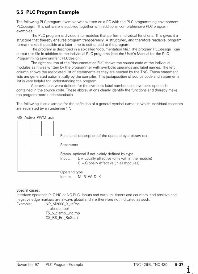
November 97 PLC Program Example TNC 426B, TNC 430 5–37
5.5 PLC Program Example
The following PLC program example was written on a PC with the PLC programming environmentPLCdesign. This software is supplied together with additional comprehensive PLC programexamples.
The PLC program is divided into modules that perform individual functions. This gives it astructure that thereby ensures program transparency. A structured, and therefore readable, programformat makes it possible at a later time to edit or add to the program.
The program is described in a so-called "documentation file." The program PLCdesign canoutput this file in addition to the individual PLC programs (see the User's Manual for the PLCProgramming Environment PLCdesign).
The right column of the "documentation file" shows the source code of the individualmodules as it was written by the programmer with symbolic operands and label names. The leftcolumn shows the associated list of statements as they are needed by the TNC. These statementlists are generated automatically by the compiler. This juxtaposition of source code and statementslist is very helpful for understanding the program.
Abbreviations were defined for the symbolic label numbers and symbolic operandscontained in the source code. These abbreviations clearly identify the functions and thereby makethe program more understandable.
The following is an example for the definition of a general symbol name, in which individual conceptsare separated by an underline "_":
MG_Active_PWM_axis
Functional description of the operand by arbitrary text
Separators
Status, optional if not plainly defined by typeInput: L = Locally effective (only within the module)
G = Globally effective (in all modules)
Operand typeInputs: M, B, W, D, K
Special cases:Interface operands PLC-NC or NC-PLC, inputs and outputs, timers and counters, and positive andnegative edge markers are always global and are therefore not indicated as such.Example: NP_M2008_X_InPos
I_release_toolTS_5_clamp_unclmpCS_RS_Err_ReStart
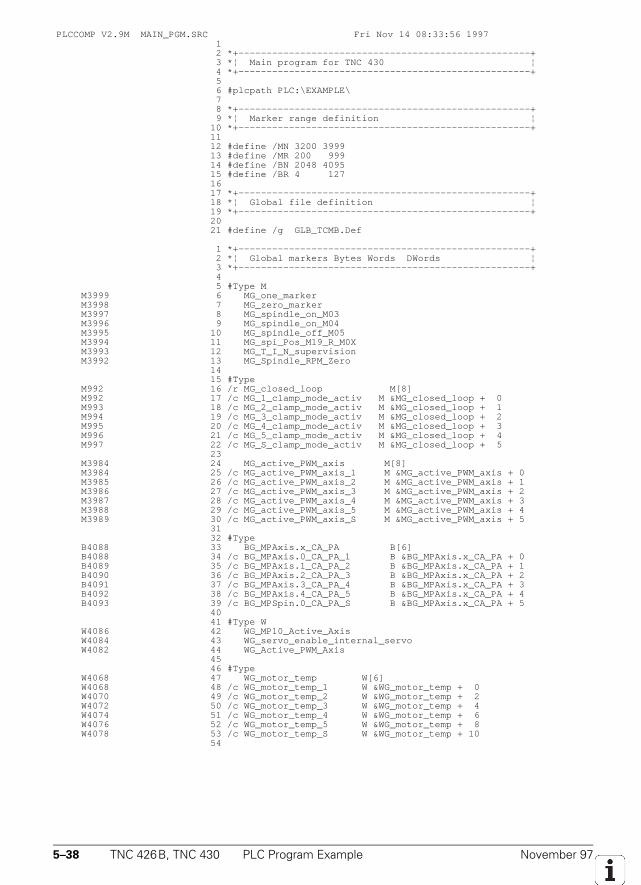
5–38 TNC 426B, TNC 430 PLC Program Example November 97
PLCCOMP V2.9M MAIN_PGM.SRC Fri Nov 14 08:33:56 1997 1 2 *+----------------------------------------------------+ 3 *¦ Main program for TNC 430 ¦ 4 *+----------------------------------------------------+ 5 6 #plcpath PLC:\EXAMPLE\ 7 8 *+----------------------------------------------------+ 9 *¦ Marker range definition ¦ 10 *+----------------------------------------------------+ 11 12 #define /MN 3200 3999 13 #define /MR 200 999 14 #define /BN 2048 4095 15 #define /BR 4 127 16 17 *+----------------------------------------------------+ 18 *¦ Global file definition ¦ 19 *+----------------------------------------------------+ 20 21 #define /g GLB_TCMB.Def
1 *+----------------------------------------------------+ 2 *¦ Global markers Bytes Words DWords ¦ 3 *+----------------------------------------------------+ 4 5 #Type M M3999 6 MG_one_marker M3998 7 MG_zero_marker M3997 8 MG_spindle_on_M03 M3996 9 MG_spindle_on_M04 M3995 10 MG_spindle_off_M05 M3994 11 MG_spi_Pos_M19_R_M0X M3993 12 MG_T_I_N_supervision M3992 13 MG_Spindle_RPM_Zero 14 15 #Type M992 16 /r MG_closed_loop M[8] M992 17 /c MG_1_clamp_mode_activ M &MG_closed_loop + 0 M993 18 /c MG_2_clamp_mode_activ M &MG_closed_loop + 1 M994 19 /c MG_3_clamp_mode_activ M &MG_closed_loop + 2 M995 20 /c MG_4_clamp_mode_activ M &MG_closed_loop + 3 M996 21 /c MG_5_clamp_mode_activ M &MG_closed_loop + 4 M997 22 /c MG_S_clamp_mode_activ M &MG_closed_loop + 5 23 M3984 24 MG_active_PWM_axis M[8] M3984 25 /c MG_active_PWM_axis_1 M &MG_active_PWM_axis + 0 M3985 26 /c MG_active_PWM_axis_2 M &MG_active_PWM_axis + 1 M3986 27 /c MG_active_PWM_axis_3 M &MG_active_PWM_axis + 2 M3987 28 /c MG_active_PWM_axis_4 M &MG_active_PWM_axis + 3 M3988 29 /c MG_active_PWM_axis_5 M &MG_active_PWM_axis + 4 M3989 30 /c MG_active_PWM_axis_S M &MG_active_PWM_axis + 5 31 32 #Type B4088 33 BG_MPAxis.x_CA_PA B[6] B4088 34 /c BG_MPAxis.0_CA_PA_1 B &BG_MPAxis.x_CA_PA + 0 B4089 35 /c BG_MPAxis.1_CA_PA_2 B &BG_MPAxis.x_CA_PA + 1 B4090 36 /c BG_MPAxis.2_CA_PA_3 B &BG_MPAxis.x_CA_PA + 2 B4091 37 /c BG_MPAxis.3_CA_PA_4 B &BG_MPAxis.x_CA_PA + 3 B4092 38 /c BG_MPAxis.4_CA_PA_5 B &BG_MPAxis.x_CA_PA + 4 B4093 39 /c BG_MPSpin.0_CA_PA_S B &BG_MPAxis.x_CA_PA + 5 40 41 #Type W W4086 42 WG_MP10_Active_Axis W4084 43 WG_servo_enable_internal_servo W4082 44 WG_Active_PWM_Axis 45 46 #Type W4068 47 WG_motor_temp W[6] W4068 48 /c WG_motor_temp_1 W &WG_motor_temp + 0 W4070 49 /c WG_motor_temp_2 W &WG_motor_temp + 2 W4072 50 /c WG_motor_temp_3 W &WG_motor_temp + 4 W4074 51 /c WG_motor_temp_4 W &WG_motor_temp + 6 W4076 52 /c WG_motor_temp_5 W &WG_motor_temp + 8 W4078 53 /c WG_motor_temp_S W &WG_motor_temp + 10 54
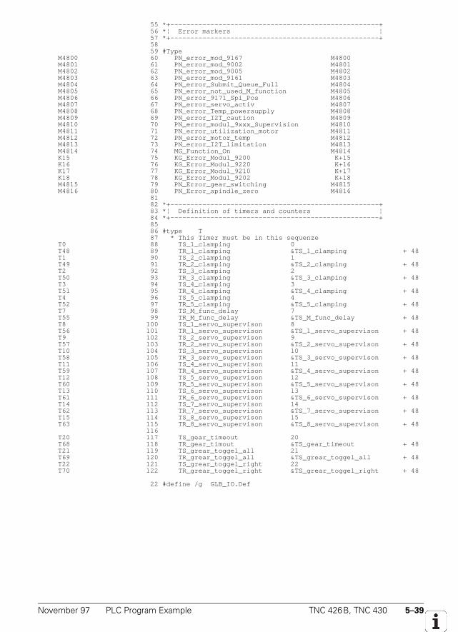
November 97 PLC Program Example TNC 426B, TNC 430 5–39
55 *+----------------------------------------------------+ 56 *¦ Error markers ¦ 57 *+----------------------------------------------------+ 58 59 #Type M4800 60 PN_error_mod_9167 M4800 M4801 61 PN_error_mod_9002 M4801 M4802 62 PN_error_mod_9005 M4802 M4803 63 PN_error_mod_9161 M4803 M4804 64 PN_error_Submit_Queue_Full M4804 M4805 65 PN_error_not_used_M_function M4805 M4806 66 PN_error_9171_Spi_Pos M4806 M4807 67 PN_error_servo_activ M4807 M4808 68 PN_error_Temp_powersupply M4808 M4809 69 PN_error_I2T_caution M4809 M4810 70 PN_error_modul_9xxx_Supervision M4810 M4811 71 PN_error_utilization_motor M4811 M4812 72 PN_error_motor_temp M4812 M4813 73 PN_error_I2T_limitation M4813 M4814 74 MG_Function_On M4814 K15 75 KG_Error_Modul_9200 K+15 K16 76 KG_Error_Modul_9220 K+16 K17 77 KG_Error_Modul_9210 K+17 K18 78 KG_Error_Modul_9202 K+18 M4815 79 PN_Error_gear_switching M4815 M4816 80 PN_Error_spindle_zero M4816 81 82 *+----------------------------------------------------+ 83 *¦ Definition of timers and counters ¦ 84 *+----------------------------------------------------+ 85 86 #type T 87 * This Timer must be in this sequenze T0 88 TS_1_clamping 0 T48 89 TR_1_clamping &TS_1_clamping + 48 T1 90 TS_2_clamping 1 T49 91 TR_2_clamping &TS_2_clamping + 48 T2 92 TS_3_clamping 2 T50 93 TR_3_clamping &TS_3_clamping + 48 T3 94 TS_4_clamping 3 T51 95 TR_4_clamping &TS_4_clamping + 48 T4 96 TS_5_clamping 4 T52 97 TR_5_clamping &TS_5_clamping + 48 T7 98 TS_M_func_delay 7 T55 99 TR_M_func_delay &TS_M_func_delay + 48 T8 100 TS_1_servo_supervison 8 T56 101 TR_1_servo_supervison &TS_1_servo_supervison + 48 T9 102 TS_2_servo_supervison 9 T57 103 TR_2_servo_supervison &TS_2_servo_supervison + 48 T10 104 TS_3_servo_supervison 10 T58 105 TR_3_servo_supervison &TS_3_servo_supervison + 48 T11 106 TS_4_servo_supervison 11 T59 107 TR_4_servo_supervison &TS_4_servo_supervison + 48 T12 108 TS_5_servo_supervison 12 T60 109 TR_5_servo_supervison &TS_5_servo_supervison + 48 T13 110 TS_6_servo_supervison 13 T61 111 TR_6_servo_supervison &TS_6_servo_supervison + 48 T14 112 TS_7_servo_supervison 14 T62 113 TR_7_servo_supervison &TS_7_servo_supervison + 48 T15 114 TS_8_servo_supervison 15 T63 115 TR_8_servo_supervison &TS_8_servo_supervison + 48 116 T20 117 TS_gear_timeout 20 T68 118 TR_gear_timout &TS_gear_timeout + 48 T21 119 TS_grear_toggel_all 21 T69 120 TR_grear_toggel_all &TS_grear_toggel_all + 48 T22 121 TS_grear_toggel_right 22 T70 122 TR_grear_toggel_right &TS_grear_toggel_right + 48
22 #define /g GLB_IO.Def
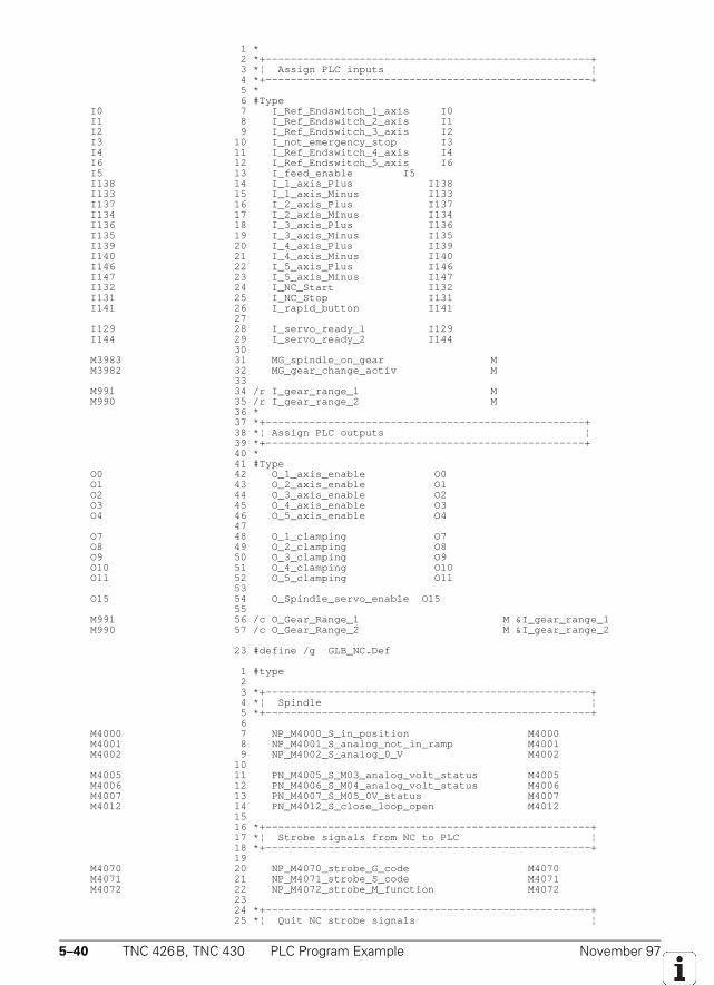
5–40 TNC 426B, TNC 430 PLC Program Example November 97
1 * 2 *+----------------------------------------------------+ 3 *¦ Assign PLC inputs ¦ 4 *+----------------------------------------------------+ 5 * 6 #Type I0 7 I_Ref_Endswitch_1_axis I0 I1 8 I_Ref_Endswitch_2_axis I1 I2 9 I_Ref_Endswitch_3_axis I2 I3 10 I_not_emergency_stop I3 I4 11 I_Ref_Endswitch_4_axis I4 I6 12 I_Ref_Endswitch_5_axis I6 I5 13 I_feed_enable I5 I138 14 I_1_axis_Plus I138 I133 15 I_1_axis_Minus I133 I137 16 I_2_axis_Plus I137 I134 17 I_2_axis_Minus I134 I136 18 I_3_axis_Plus I136 I135 19 I_3_axis_Minus I135 I139 20 I_4_axis_Plus I139 I140 21 I_4_axis_Minus I140 I146 22 I_5_axis_Plus I146 I147 23 I_5_axis_Minus I147 I132 24 I_NC_Start I132 I131 25 I_NC_Stop I131 I141 26 I_rapid_button I141 27 I129 28 I_servo_ready_1 I129 I144 29 I_servo_ready_2 I144 30 M3983 31 MG_spindle_on_gear M M3982 32 MG_gear_change_activ M 33 M991 34 /r I_gear_range_1 M M990 35 /r I_gear_range_2 M 36 * 37 *+---------------------------------------------------+ 38 *¦ Assign PLC outputs ¦ 39 *+---------------------------------------------------+ 40 * 41 #Type O0 42 O_1_axis_enable O0 O1 43 O_2_axis_enable O1 O2 44 O_3_axis_enable O2 O3 45 O_4_axis_enable O3 O4 46 O_5_axis_enable O4 47 O7 48 O_1_clamping O7 O8 49 O_2_clamping O8 O9 50 O_3_clamping O9 O10 51 O_4_clamping O10 O11 52 O_5_clamping O11 53 O15 54 O_Spindle_servo_enable O15 55 M991 56 /c O_Gear_Range_1 M &I_gear_range_1 M990 57 /c O_Gear_Range_2 M &I_gear_range_2
23 #define /g GLB_NC.Def
1 #type 2 3 *+----------------------------------------------------+ 4 *¦ Spindle ¦ 5 *+----------------------------------------------------+ 6 M4000 7 NP_M4000_S_in_position M4000 M4001 8 NP_M4001_S_analog_not_in_ramp M4001 M4002 9 NP_M4002_S_analog_0_V M4002 10 M4005 11 PN_M4005_S_M03_analog_volt_status M4005 M4006 12 PN_M4006_S_M04_analog_volt_status M4006 M4007 13 PN_M4007_S_M05_0V_status M4007 M4012 14 PN_M4012_S_close_loop_open M4012 15 16 *+----------------------------------------------------+ 17 *¦ Strobe signals from NC to PLC ¦ 18 *+----------------------------------------------------+ 19 M4070 20 NP_M4070_strobe_G_code M4070 M4071 21 NP_M4071_strobe_S_code M4071 M4072 22 NP_M4072_strobe_M_function M4072 23 24 *+----------------------------------------------------+ 25 *¦ Quit NC strobe signals ¦
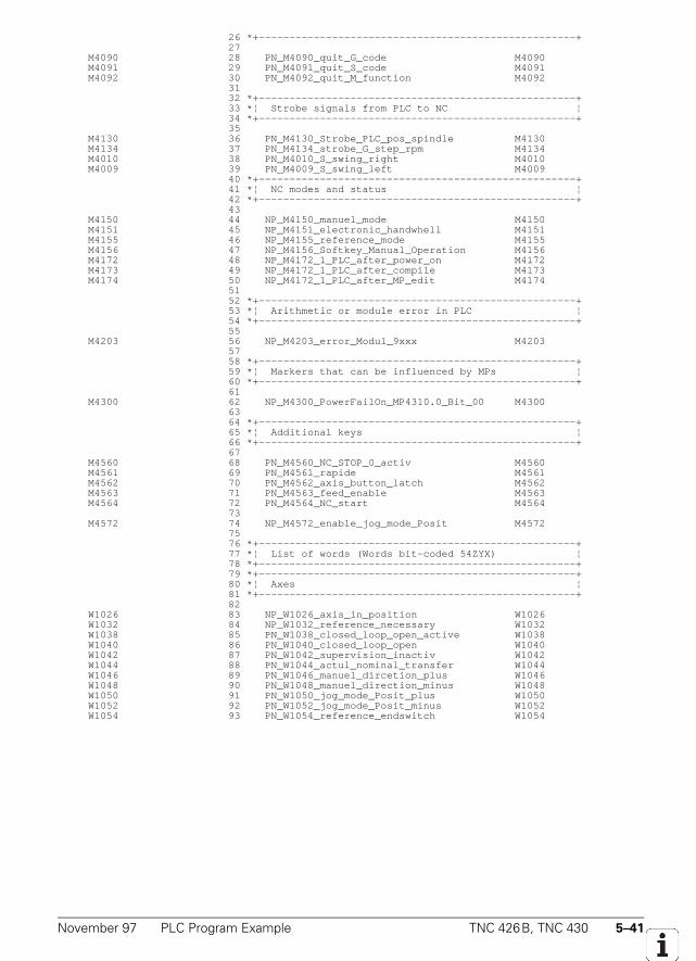
November 97 PLC Program Example TNC 426B, TNC 430 5–41
26 *+----------------------------------------------------+ 27 M4090 28 PN_M4090_quit_G_code M4090 M4091 29 PN_M4091_quit_S_code M4091 M4092 30 PN_M4092_quit_M_function M4092 31 32 *+----------------------------------------------------+ 33 *¦ Strobe signals from PLC to NC ¦ 34 *+----------------------------------------------------+ 35 M4130 36 PN_M4130_Strobe_PLC_pos_spindle M4130 M4134 37 PN_M4134_strobe_G_step_rpm M4134 M4010 38 PN_M4010_S_swing_right M4010 M4009 39 PN_M4009_S_swing_left M4009 40 *+----------------------------------------------------+ 41 *¦ NC modes and status ¦ 42 *+----------------------------------------------------+ 43 M4150 44 NP_M4150_manuel_mode M4150 M4151 45 NP_M4151_electronic_handwhell M4151 M4155 46 NP_M4155_reference_mode M4155 M4156 47 NP_M4156_Softkey_Manual_Operation M4156 M4172 48 NP_M4172_1_PLC_after_power_on M4172 M4173 49 NP_M4172_1_PLC_after_compile M4173 M4174 50 NP_M4172_1_PLC_after_MP_edit M4174 51 52 *+----------------------------------------------------+ 53 *¦ Arithmetic or module error in PLC ¦ 54 *+----------------------------------------------------+ 55 M4203 56 NP_M4203_error_Modul_9xxx M4203 57 58 *+----------------------------------------------------+ 59 *¦ Markers that can be influenced by MPs ¦ 60 *+----------------------------------------------------+ 61 M4300 62 NP_M4300_PowerFailOn_MP4310.0_Bit_00 M4300 63 64 *+----------------------------------------------------+ 65 *¦ Additional keys ¦ 66 *+----------------------------------------------------+ 67 M4560 68 PN_M4560_NC_STOP_0_activ M4560 M4561 69 PN_M4561_rapide M4561 M4562 70 PN_M4562_axis_button_latch M4562 M4563 71 PN_M4563_feed_enable M4563 M4564 72 PN_M4564_NC_start M4564 73 M4572 74 NP_M4572_enable_jog_mode_Posit M4572 75 76 *+----------------------------------------------------+ 77 *¦ List of words (Words bit-coded 54ZYX) ¦ 78 *+----------------------------------------------------+ 79 *+----------------------------------------------------+ 80 *¦ Axes ¦ 81 *+----------------------------------------------------+ 82 W1026 83 NP_W1026_axis_in_position W1026 W1032 84 NP_W1032_reference_necessary W1032 W1038 85 PN_W1038_closed_loop_open_active W1038 W1040 86 PN_W1040_closed_loop_open W1040 W1042 87 PN_W1042_supervision_inactiv W1042 W1044 88 PN_W1044_actul_nominal_transfer W1044 W1046 89 PN_W1046_manuel_dircetion_plus W1046 W1048 90 PN_W1048_manuel_direction_minus W1048 W1050 91 PN_W1050_jog_mode_Posit_plus W1050 W1052 92 PN_W1052_jog_mode_Posit_minus W1052 W1054 93 PN_W1054_reference_endswitch W1054
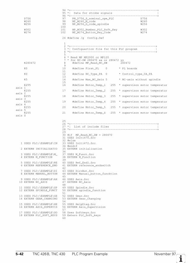
5–42 TNC 426B, TNC 430 PLC Program Example November 97
94 *+----------------------------------------------------+ 95 *¦ Data for strobe signals ¦ 96 *+----------------------------------------------------+ D756 97 PN_D756_S_nominal_rpm_PLC D756 W260 98 NP_W260_M_code W260 W256 99 NP_W256_G_code_spindle W256 100 W302 101 NP_W302_Number_PLC_Soft_Key W302 W274 102 NP_W274_Button_Key_Code W274
24 #define /g Config.Def
1 2 *+---------------------------------------------------+ 3 *¦ Configuartion file for this PLC program ¦ 4 *+---------------------------------------------------+ 5 6 * Read MP MP2000 or MP120 7 * for NC-SW 280470 xx or 280472 yy K280472 8 #define MP_Read_NC_SW 280472 9 K0 10 #define First_PL 0 * PL boards 11 K0 12 #define NC_Type_PA 0 * Control_type_CA_PA 13 K5 14 #define Max_NC_Axis 5 * NC-axis without spindle 15 K255 16 #define Motor_Temp_1 255 * supervison motor temperaturaxis 1 K255 17 #define Motor_Temp_2 255 * supervison motor temperaturaxis 2 K255 18 #define Motor_Temp_3 255 * supervison motor temperaturaxis 3 K255 19 #define Motor_Temp_4 255 * supervison motor temperaturaxis 4 K255 20 #define Motor_Temp_5 255 * supervison motor temperaturaxis 5 K255 21 #define Motor_Temp_S 255 * supervison motor temperaturaxis S
25 26 *+----------------------------------------------------+ 27 *¦ List of include files ¦ 28 *+----------------------------------------------------+ 29 30 #if MP_Read_NC_SW = 280470 31 USES Initi470.Src 32 #else 1 USES PLC:\EXAMPLE\IN 33 USES Initi472.Src 34 #endif 2 EXTERN INITIALIZATIO 35 EXTERN initialization 36 3 USES PLC:\EXAMPLE\M_ 37 USES M_Funct.Src 4 EXTERN M_FUNCTION 38 EXTERN M_Function 39 5 USES PLC:\EXAMPLE\RE 40 USES Ref_Endl.Src 6 EXTERN REFERENCE_END 41 EXTERN reference_endswitch 42 7 USES PLC:\EXAMPLE\DI 43 USES DircBut.Src 8 EXTERN MANUEL_BUTTON 44 EXTERN Manuel_button_funcktion 45 9 USES PLC:\EXAMPLE\AX 46 USES Axis.Src 10 EXTERN NC_AXIS 47 EXTERN NC_Axis 48 11 USES PLC:\EXAMPLE\SP 49 USES Spindle.Src 12 EXTERN SPINDLE_FUNCT 50 EXTERN spindle_function 51 13 USES PLC:\EXAMPLE\GE 52 USES Gear.Src 14 EXTERN GEAR_CHANGING 53 EXTERN Gear_Changing 54 15 USES PLC:\EXAMPLE\HE 55 USES HelpDiag.Src 16 EXTERN AXIS_SUPERVIS 56 EXTERN Axis_Supervision 57 17 USES PLC:\EXAMPLE\SO 58 Uses Softkeys.Src 18 EXTERN PLC_SOFT_KEYS 59 Extern PLC_Soft_keys 60
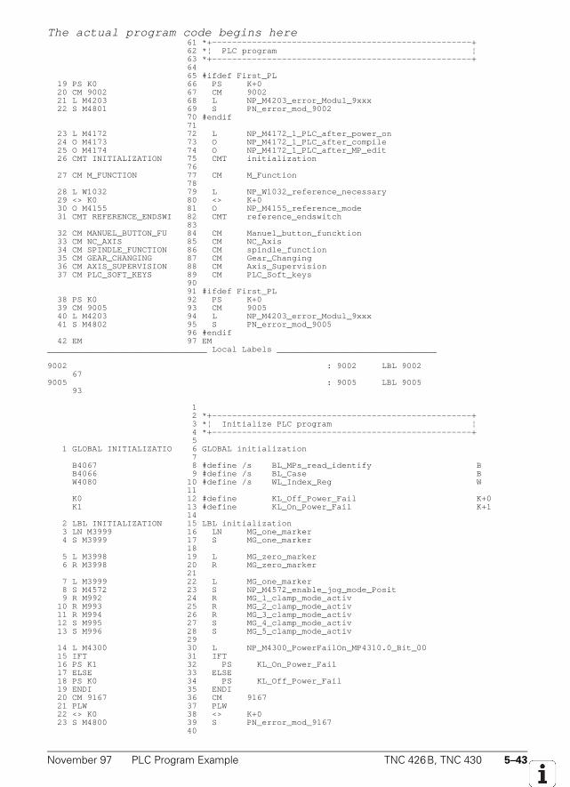
November 97 PLC Program Example TNC 426B, TNC 430 5–43
The actual program code begins here 61 *+----------------------------------------------------+ 62 *¦ PLC program ¦ 63 *+----------------------------------------------------+ 64 65 #ifdef First_PL 19 PS K0 66 PS K+0 20 CM 9002 67 CM 9002 21 L M4203 68 L NP_M4203_error_Modul_9xxx 22 S M4801 69 S PN_error_mod_9002 70 #endif 71 23 L M4172 72 L NP_M4172_1_PLC_after_power_on 24 O M4173 73 O NP_M4172_1_PLC_after_compile 25 O M4174 74 O NP_M4172_1_PLC_after_MP_edit 26 CMT INITIALIZATION 75 CMT initialization 76 27 CM M_FUNCTION 77 CM M_Function 78 28 L W1032 79 L NP_W1032_reference_necessary 29 <> K0 80 <> K+0 30 O M4155 81 O NP_M4155_reference_mode 31 CMT REFERENCE_ENDSWI 82 CMT reference_endswitch 83 32 CM MANUEL_BUTTON_FU 84 CM Manuel_button_funcktion 33 CM NC_AXIS 85 CM NC_Axis 34 CM SPINDLE_FUNCTION 86 CM spindle_function 35 CM GEAR_CHANGING 87 CM Gear_Changing 36 CM AXIS_SUPERVISION 88 CM Axis_Supervision 37 CM PLC_SOFT_KEYS 89 CM PLC_Soft_keys 90 91 #ifdef First_PL 38 PS K0 92 PS K+0 39 CM 9005 93 CM 9005 40 L M4203 94 L NP_M4203_error_Modul_9xxx 41 S M4802 95 S PN_error_mod_9005 96 #endif 42 EM 97 EM________________________________ Local Labels ________________________________
9002 : 9002 LBL 9002 679005 : 9005 LBL 9005 93
1 2 *+----------------------------------------------------+ 3 *¦ Initialize PLC program ¦ 4 *+----------------------------------------------------+ 5 1 GLOBAL INITIALIZATIO 6 GLOBAL initialization 7 B4067 8 #define /s BL_MPs_read_identify B B4066 9 #define /s BL_Case B W4080 10 #define /s WL_Index_Reg W 11 K0 12 #define KL_Off_Power_Fail K+0 K1 13 #define KL_On_Power_Fail K+1 14 2 LBL INITIALIZATION 15 LBL initialization 3 LN M3999 16 LN MG_one_marker 4 S M3999 17 S MG_one_marker 18 5 L M3998 19 L MG_zero_marker 6 R M3998 20 R MG_zero_marker 21 7 L M3999 22 L MG_one_marker 8 S M4572 23 S NP_M4572_enable_jog_mode_Posit 9 R M992 24 R MG_1_clamp_mode_activ 10 R M993 25 R MG_2_clamp_mode_activ 11 R M994 26 R MG_3_clamp_mode_activ 12 S M995 27 S MG_4_clamp_mode_activ 13 S M996 28 S MG_5_clamp_mode_activ 29 14 L M4300 30 L NP_M4300_PowerFailOn_MP4310.0_Bit_00 15 IFT 31 IFT 16 PS K1 32 PS KL_On_Power_Fail 17 ELSE 33 ELSE 18 PS K0 34 PS KL_Off_Power_Fail 19 ENDI 35 ENDI 20 CM 9167 36 CM 9167 21 PLW 37 PLW 22 <> K0 38 <> K+0 23 S M4800 39 S PN_error_mod_9167 40
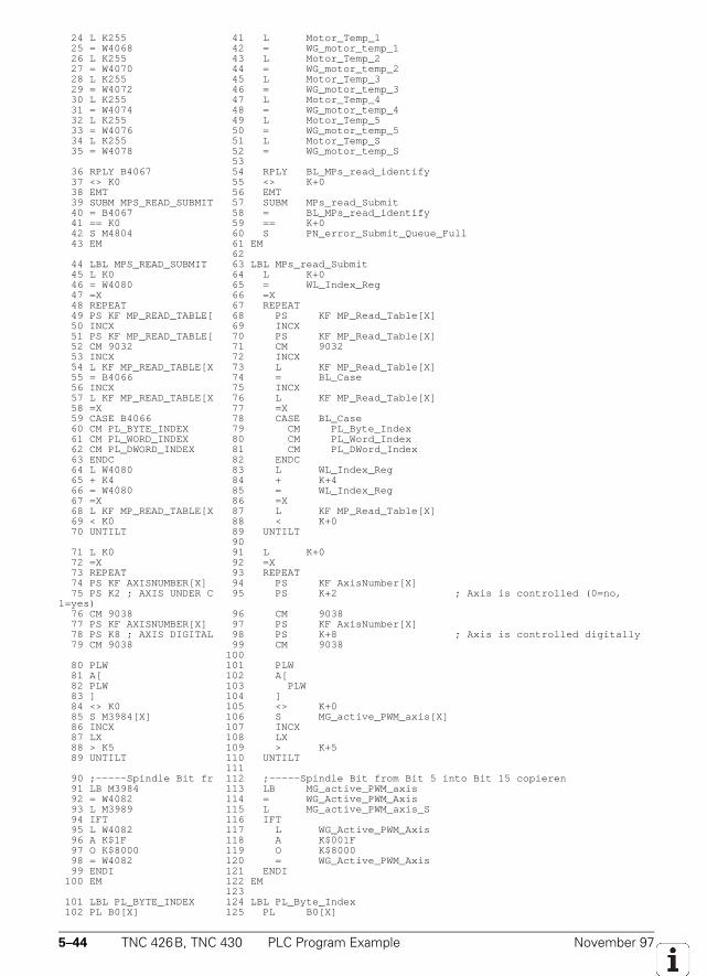
5–44 TNC 426B, TNC 430 PLC Program Example November 97
24 L K255 41 L Motor_Temp_1 25 = W4068 42 = WG_motor_temp_1 26 L K255 43 L Motor_Temp_2 27 = W4070 44 = WG_motor_temp_2 28 L K255 45 L Motor_Temp_3 29 = W4072 46 = WG_motor_temp_3 30 L K255 47 L Motor_Temp_4 31 = W4074 48 = WG_motor_temp_4 32 L K255 49 L Motor_Temp_5 33 = W4076 50 = WG_motor_temp_5 34 L K255 51 L Motor_Temp_S 35 = W4078 52 = WG_motor_temp_S 53 36 RPLY B4067 54 RPLY BL_MPs_read_identify 37 <> K0 55 <> K+0 38 EMT 56 EMT 39 SUBM MPS_READ_SUBMIT 57 SUBM MPs_read_Submit 40 = B4067 58 = BL_MPs_read_identify 41 == K0 59 == K+0 42 S M4804 60 S PN_error_Submit_Queue_Full 43 EM 61 EM 62 44 LBL MPS_READ_SUBMIT 63 LBL MPs_read_Submit 45 L K0 64 L K+0 46 = W4080 65 = WL_Index_Reg 47 =X 66 =X 48 REPEAT 67 REPEAT 49 PS KF MP_READ_TABLE[ 68 PS KF MP_Read_Table[X] 50 INCX 69 INCX 51 PS KF MP_READ_TABLE[ 70 PS KF MP_Read_Table[X] 52 CM 9032 71 CM 9032 53 INCX 72 INCX 54 L KF MP_READ_TABLE[X 73 L KF MP_Read_Table[X] 55 = B4066 74 = BL_Case 56 INCX 75 INCX 57 L KF MP_READ_TABLE[X 76 L KF MP_Read_Table[X] 58 =X 77 =X 59 CASE B4066 78 CASE BL_Case 60 CM PL_BYTE_INDEX 79 CM PL_Byte_Index 61 CM PL_WORD_INDEX 80 CM PL_Word_Index 62 CM PL_DWORD_INDEX 81 CM PL_DWord_Index 63 ENDC 82 ENDC 64 L W4080 83 L WL_Index_Reg 65 + K4 84 + K+4 66 = W4080 85 = WL_Index_Reg 67 =X 86 =X 68 L KF MP_READ_TABLE[X 87 L KF MP_Read_Table[X] 69 < K0 88 < K+0 70 UNTILT 89 UNTILT 90 71 L K0 91 L K+0 72 =X 92 =X 73 REPEAT 93 REPEAT 74 PS KF AXISNUMBER[X] 94 PS KF AxisNumber[X] 75 PS K2 ; AXIS UNDER C 95 PS K+2 ; Axis is controlled (0=no,1=yes) 76 CM 9038 96 CM 9038 77 PS KF AXISNUMBER[X] 97 PS KF AxisNumber[X] 78 PS K8 ; AXIS DIGITAL 98 PS K+8 ; Axis is controlled digitally 79 CM 9038 99 CM 9038 100 80 PLW 101 PLW 81 A[ 102 A[ 82 PLW 103 PLW 83 ] 104 ] 84 <> K0 105 <> K+0 85 S M3984[X] 106 S MG_active_PWM_axis[X] 86 INCX 107 INCX 87 LX 108 LX 88 > K5 109 > K+5 89 UNTILT 110 UNTILT 111 90 ;-----Spindle Bit fr 112 ;-----Spindle Bit from Bit 5 into Bit 15 copieren 91 LB M3984 113 LB MG_active_PWM_axis 92 = W4082 114 = WG_Active_PWM_Axis 93 L M3989 115 L MG_active_PWM_axis_S 94 IFT 116 IFT 95 L W4082 117 L WG_Active_PWM_Axis 96 A K$1F 118 A K$001F 97 O K$8000 119 O K$8000 98 = W4082 120 = WG_Active_PWM_Axis 99 ENDI 121 ENDI 100 EM 122 EM 123 101 LBL PL_BYTE_INDEX 124 LBL PL_Byte_Index 102 PL B0[X] 125 PL B0[X]
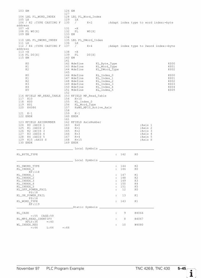
November 97 PLC Program Example TNC 426B, TNC 430 5–45
103 EM 126 EM 127 104 LBL PL_WORD_INDEX 128 LBL PL_Word_Index 105 LX 129 LX 106 / K2 ;TYPE CASTING F 130 / K+2 ;Adapt index type to word index:=byteaddress 107 =X 131 =X 108 PL W0[X] 132 PL W0[X] 109 EM 133 EM 134 110 LBL PL_DWORD_INDEX 135 LBL PL_DWord_Index 111 LX 136 LX 112 / K4 ;TYPE CASTING F 137 / K+4 ;Adapt index type to Dword index:=byteaddress 113 =X 138 =X 114 PL D0[X] 139 PL D0[X] 115 EM 140 EM 141 K0 142 #define KL_Byte_Type K$00 K1 143 #define KL_Word_Type K$01 K2 144 #define KL_DWord_Type K$02 145 K0 146 #define KL_Index_0 K$00 K1 147 #define KL_Index_1 K$01 K2 148 #define KL_Index_2 K$02 K3 149 #define KL_Index_3 K$03 K4 150 #define KL_Index_4 K$04 K5 151 #define KL_Index_5 K$05 152 116 KFIELD MP_READ_TABLE 153 KFIELD MP_Read_Table 117 K10 154 K+10 118 K$0 155 KL_Index_0 119 K$1 156 KL_Word_Type 120 K4086 157 K&WG_MP10_Active_Axis 158 121 K-1 159 K-1 122 ENDK 160 ENDK 161 123 KFIELD AXISNUMBER 162 KFIELD AxisNumber 124 K0 ;AXIS 1 163 K+0 ;Axis 1 125 K1 ;AXIS 2 164 K+1 ;Axis 2 126 K2 ;ACIS 3 165 K+2 ;Acis 3 127 K3 ;AXIS 4 166 K+3 ;Axis 4 128 K4 ;AXIS 5 167 K+4 ;Axis 5 129 K15 ;AXIS S 168 K+15 ;Axis S 130 ENDK 169 ENDK
________________________________ Local Symbols _______________________________
KL_BYTE_TYPE : 142 K0
________________________________ Local Symbols _______________________________
KL_DWORD_TYPE : 144 K2KL_INDEX_0 : 146 K0 KF:118KL_INDEX_1 : 147 K1KL_INDEX_2 : 148 K2KL_INDEX_3 : 149 K3KL_INDEX_4 : 150 K4KL_INDEX_5 : 151 K5KL_OFF_POWER_FAIL : 12 K0 PS:18KL_ON_POWER_FAIL : 13 K1 PS:16KL_WORD_TYPE : 143 K1 KF:119________________________________Static Symbols _______________________________
BL_CASE : 9 B4066 =:55 CASE:59BL_MPS_READ_IDENTIFY : 8 B4067 RPLY:36 =:40WL_INDEX_REG : 10 W4080 =:46 L:64 =:66
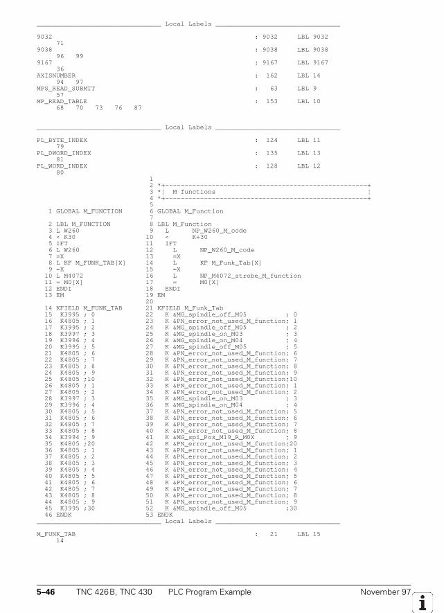
5–46 TNC 426B, TNC 430 PLC Program Example November 97
________________________________ Local Labels ________________________________
9032 : 9032 LBL 9032 719038 : 9038 LBL 9038 96 999167 : 9167 LBL 9167 36AXISNUMBER : 162 LBL 14 94 97MPS_READ_SUBMIT : 63 LBL 9 57MP_READ_TABLE : 153 LBL 10 68 70 73 76 87
________________________________ Local Labels ________________________________
PL_BYTE_INDEX : 124 LBL 11 79PL_DWORD_INDEX : 135 LBL 13 81PL_WORD_INDEX : 128 LBL 12 80 1 2 *+----------------------------------------------------+ 3 *¦ M functions ¦ 4 *+----------------------------------------------------+ 5 1 GLOBAL M_FUNCTION 6 GLOBAL M_Function 7 2 LBL M_FUNCTION 8 LBL M_Function 3 L W260 9 L NP_W260_M_code 4 < K30 10 < K+30 5 IFT 11 IFT 6 L W260 12 L NP_W260_M_code 7 =X 13 =X 8 L KF M_FUNK_TAB[X] 14 L KF M_Funk_Tab[X] 9 =X 15 =X 10 L M4072 16 L NP_M4072_strobe_M_function 11 = M0[X] 17 = M0[X] 12 ENDI 18 ENDI 13 EM 19 EM 20 14 KFIELD M_FUNK_TAB 21 KFIELD M_Funk_Tab 15 K3995 ; 0 22 K &MG_spindle_off_M05 ; 0 16 K4805 ; 1 23 K &PN_error_not_used_M_function; 1 17 K3995 ; 2 24 K &MG_spindle_off_M05 ; 2 18 K3997 ; 3 25 K &MG_spindle_on_M03 ; 3 19 K3996 ; 4 26 K &MG_spindle_on_M04 ; 4 20 K3995 ; 5 27 K &MG_spindle_off_M05 ; 5 21 K4805 ; 6 28 K &PN_error_not_used_M_function; 6 22 K4805 ; 7 29 K &PN_error_not_used_M_function; 7 23 K4805 ; 8 30 K &PN_error_not_used_M_function; 8 24 K4805 ; 9 31 K &PN_error_not_used_M_function; 9 25 K4805 ;10 32 K &PN_error_not_used_M_function;10 26 K4805 ; 1 33 K &PN_error_not_used_M_function; 1 27 K4805 ; 2 34 K &PN_error_not_used_M_function; 2 28 K3997 ; 3 35 K &MG_spindle_on_M03 ; 3 29 K3996 ; 4 36 K &MG_spindle_on_M04 ; 4 30 K4805 ; 5 37 K &PN_error_not_used_M_function; 5 31 K4805 ; 6 38 K &PN_error_not_used_M_function; 6 32 K4805 ; 7 39 K &PN_error_not_used_M_function; 7 33 K4805 ; 8 40 K &PN_error_not_used_M_function; 8 34 K3994 ; 9 41 K &MG_spi_Pos_M19_R_M0X ; 9 35 K4805 ;20 42 K &PN_error_not_used_M_function;20 36 K4805 ; 1 43 K &PN_error_not_used_M_function; 1 37 K4805 ; 2 44 K &PN_error_not_used_M_function; 2 38 K4805 ; 3 45 K &PN_error_not_used_M_function; 3 39 K4805 ; 4 46 K &PN_error_not_used_M_function; 4 40 K4805 ; 5 47 K &PN_error_not_used_M_function; 5 41 K4805 ; 6 48 K &PN_error_not_used_M_function; 6 42 K4805 ; 7 49 K &PN_error_not_used_M_function; 7 43 K4805 ; 8 50 K &PN_error_not_used_M_function; 8 44 K4805 ; 9 51 K &PN_error_not_used_M_function; 9 45 K3995 ;30 52 K &MG_spindle_off_M05 ;30 46 ENDK 53 ENDK________________________________ Local Labels ________________________________
M_FUNK_TAB : 21 LBL 15 14
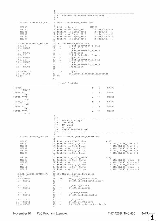
November 97 PLC Program Example TNC 426B, TNC 430 5–47
1 2 *+----------------------------------------------------+ 3 *¦ Control reference end switches ¦ 4 *+----------------------------------------------------+ 5 1 GLOBAL REFERENCE_END 6 GLOBAL reference_endswitch 7 M3200 8 #define Inputs M[16] M3200 9 #define /c Input_Bit0 M &Inputs + 0 M3201 10 #define /c Input_Bit1 M &Inputs + 1 M3202 11 #define /c Input_Bit2 M &Inputs + 2 M3203 12 #define /c Input_Bit3 M &Inputs + 3 M3204 13 #define /c Input_Bit4 M &Inputs + 4 14 2 LBL REFERENCE_ENDSWI 15 LBL reference_endswitch 3 L I0 16 L I_Ref_Endswitch_1_axis 4 = M3200 17 = Input_Bit0 5 L I1 18 L I_Ref_Endswitch_2_axis 6 = M3201 19 = Input_Bit1 7 L I2 20 L I_Ref_Endswitch_3_axis 8 = M3202 21 = Input_Bit2 9 L I4 22 L I_Ref_Endswitch_4_axis 10 = M3203 23 = Input_Bit3 11 L I6 24 L I_Ref_Endswitch_5_axis 12 = M3204 25 = Input_Bit4 26 13 LB M3200 27 LB Inputs 14 = W1054 28 = PN_W1054_reference_endswitch 15 EM 29 EM 30
________________________________ Local Symbols _______________________________
INPUTS : 8 M3200 LB:13INPUT_BIT0 : 9 M3200 =:4INPUT_BIT1 : 10 M3201 =:6INPUT_BIT2 : 11 M3202 =:8INPUT_BIT3 : 12 M3203 =:10INPUT_BIT4 : 13 M3204 =:12 1 2 *+----------------------------------------------------+ 3 *¦ Direction keys ¦ 4 *¦ Jog mode ¦ 5 *¦ NC start ¦ 6 *¦ NC stop ¦ 7 *¦ Rapid traverse key ¦ 8 *+----------------------------------------------------+ 9 1 GLOBAL MANUEL_BUTTON 10 GLOBAL Manuel_button_funcktion 11 M3200 12 #define ML_XYZ45_Plus M[8] M3200 13 #define /c ML_1_Plus M &ML_XYZ45_Plus + 0 M3201 14 #define /c ML_2_Plus M &ML_XYZ45_Plus + 1 M3202 15 #define /c ML_3_Plus M &ML_XYZ45_Plus + 2 M3203 16 #define /c ML_4_Plus M &ML_XYZ45_Plus + 3 M3204 17 #define /c ML_5_Plus M &ML_XYZ45_Plus + 4 18 M3208 19 #define ML_XYZ45_Minus M[8] M3208 20 #define /c ML_1_Minus M &ML_XYZ45_Minus + 0 M3209 21 #define /c ML_2_Minus M &ML_XYZ45_Minus + 1 M3210 22 #define /c ML_3_Minus M &ML_XYZ45_Minus + 2 M3211 23 #define /c ML_4_Minus M &ML_XYZ45_Minus + 3 M3212 24 #define /c ML_5_Minus M &ML_XYZ45_Minus + 4 25 2 LBL MANUEL_BUTTON_FU 26 LBL Manuel_button_funcktion 3 L I131 27 L I_NC_Stop 4 AN M3993 28 AN MG_T_I_N_supervision 5 = M4560 29 = PN_M4560_NC_STOP_0_activ 30 6 L I141 31 L I_rapid_button 7 = M4561 32 = PN_M4561_rapide 33 8 L I5 34 L I_feed_enable 9 = M4563 35 = PN_M4563_feed_enable 36 10 L I132 37 L I_NC_Start 11 = M4564 38 = PN_M4564_NC_start 12 = M4562 39 = PN_M4562_axis_button_latch 40
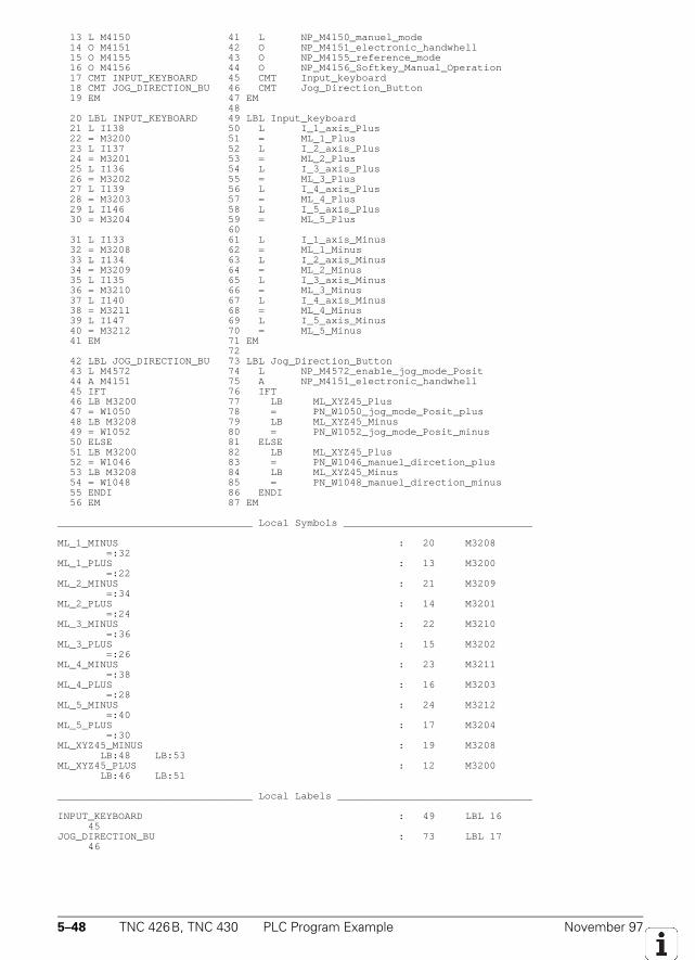
5–48 TNC 426B, TNC 430 PLC Program Example November 97
13 L M4150 41 L NP_M4150_manuel_mode 14 O M4151 42 O NP_M4151_electronic_handwhell 15 O M4155 43 O NP_M4155_reference_mode 16 O M4156 44 O NP_M4156_Softkey_Manual_Operation 17 CMT INPUT_KEYBOARD 45 CMT Input_keyboard 18 CMT JOG_DIRECTION_BU 46 CMT Jog_Direction_Button 19 EM 47 EM 48 20 LBL INPUT_KEYBOARD 49 LBL Input_keyboard 21 L I138 50 L I_1_axis_Plus 22 = M3200 51 = ML_1_Plus 23 L I137 52 L I_2_axis_Plus 24 = M3201 53 = ML_2_Plus 25 L I136 54 L I_3_axis_Plus 26 = M3202 55 = ML_3_Plus 27 L I139 56 L I_4_axis_Plus 28 = M3203 57 = ML_4_Plus 29 L I146 58 L I_5_axis_Plus 30 = M3204 59 = ML_5_Plus 60 31 L I133 61 L I_1_axis_Minus 32 = M3208 62 = ML_1_Minus 33 L I134 63 L I_2_axis_Minus 34 = M3209 64 = ML_2_Minus 35 L I135 65 L I_3_axis_Minus 36 = M3210 66 = ML_3_Minus 37 L I140 67 L I_4_axis_Minus 38 = M3211 68 = ML_4_Minus 39 L I147 69 L I_5_axis_Minus 40 = M3212 70 = ML_5_Minus 41 EM 71 EM 72 42 LBL JOG_DIRECTION_BU 73 LBL Jog_Direction_Button 43 L M4572 74 L NP_M4572_enable_jog_mode_Posit 44 A M4151 75 A NP_M4151_electronic_handwhell 45 IFT 76 IFT 46 LB M3200 77 LB ML_XYZ45_Plus 47 = W1050 78 = PN_W1050_jog_mode_Posit_plus 48 LB M3208 79 LB ML_XYZ45_Minus 49 = W1052 80 = PN_W1052_jog_mode_Posit_minus 50 ELSE 81 ELSE 51 LB M3200 82 LB ML_XYZ45_Plus 52 = W1046 83 = PN_W1046_manuel_dircetion_plus 53 LB M3208 84 LB ML_XYZ45_Minus 54 = W1048 85 = PN_W1048_manuel_direction_minus 55 ENDI 86 ENDI 56 EM 87 EM
________________________________ Local Symbols _______________________________
ML_1_MINUS : 20 M3208 =:32ML_1_PLUS : 13 M3200 =:22ML_2_MINUS : 21 M3209 =:34ML_2_PLUS : 14 M3201 =:24ML_3_MINUS : 22 M3210 =:36ML_3_PLUS : 15 M3202 =:26ML_4_MINUS : 23 M3211 =:38ML_4_PLUS : 16 M3203 =:28ML_5_MINUS : 24 M3212 =:40ML_5_PLUS : 17 M3204 =:30ML_XYZ45_MINUS : 19 M3208 LB:48 LB:53ML_XYZ45_PLUS : 12 M3200 LB:46 LB:51
________________________________ Local Labels ________________________________
INPUT_KEYBOARD : 49 LBL 16 45JOG_DIRECTION_BU : 73 LBL 17 46
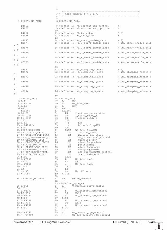
November 97 PLC Program Example TNC 426B, TNC 430 5–49
1 2 * +---------------------------------------------------+ 3 * ¦ Axis control 5,4,Z,Y,X, ¦ 4 * +---------------------------------------------------+ 5 1 GLOBAL NC_AXIS 6 GLOBAL NC_Axis 7 W4062 8 #define /s WL_current_rpm_control W W4060 9 #define /s WL_old_current_rpm_control W 10 B4052 11 #define /s BL_Axis_Step B[5] W2048 12 #define WL_Axis_Mask W 13 M3977 14 #define /s ML_servo_enable_axis M[5] M3977 15 #define /c ML_1_servo_enable_axis M &ML_servo_enable_axis+ 0 M3978 16 #define /c ML_2_servo_enable_axis M &ML_servo_enable_axis+ 1 M3979 17 #define /c ML_3_servo_enable_axis M &ML_servo_enable_axis+ 2 M3980 18 #define /c ML_4_servo_enable_axis M &ML_servo_enable_axis+ 3 M3981 19 #define /c ML_5_servo_enable_axis M &ML_servo_enable_axis+ 4 20 M3972 21 #define /s ML_clamping_Achsen M[5] M3972 22 #define /c ML_clamping_1_axis M &ML_clamping_Achsen +0 M3973 23 #define /c ML_clamping_2_axis M &ML_clamping_Achsen +1 M3974 24 #define /c ML_clamping_3_axis M &ML_clamping_Achsen +2 M3975 25 #define /c ML_clamping_4_axis M &ML_clamping_Achsen +3 M3976 26 #define /c ML_clamping_5_axis M &ML_clamping_Achsen +4 27 2 LBL NC_AXIS 28 LBL NC_Axis 3 L K1 29 L K+1 4 = W2048 30 = WL_Axis_Mask 5 L K0 31 L K+0 6 =X 32 =X 7 REPEAT 33 REPEAT 8 LN I3 34 LN I_not_emergency_stop 9 ON I129 35 ON I_servo_ready_1 10 ON I144 36 ON I_servo_ready_2 11 IFT 37 IFT 12 L K0 38 L K+0 13 = B4052[X] 39 = BL_Axis_Step[X] 14 ENDI 40 ENDI 15 CASE B4052[X] 41 CASE BL_Axis_Step[X] 16 CM INITIAL_AXIS 42 CM Initial_Axis 17 CM WAITING_POS_STAR 43 CM Waiting_Pos_Start 18 CM ON_CURRENTRPML_C 44 CM On_currentRPMl_control 19 CM CLAMPING_OPEN 45 CM Clamping_open 20 CM CLOSE_LOOP_CLOSE 46 CM close_loop_close 21 CM POSITIONING 47 CM positioning 22 CM CLOSE_LOOP_OPEN 48 CM close_loop_open 23 CM CLAMPING_CLOSE 49 CM clamping_close 24 CM OFF_CURRENTRPML_ 50 CM off_currentRPMl_control 25 CM STEP_CHAIN_END 51 CM Step_chain_end 26 ENDC 52 ENDC 27 L W2048 53 L WL_Axis_Mask 28 << K1 54 << K+1 29 = W2048 55 = WL_Axis_Mask 30 INCX 56 INCX 31 LX 57 LX 32 >= K5 58 >= Max_NC_Axis 33 UNTILT 59 UNTILT 60 34 CM WRITE_OUTPUTS 61 CM Write_Outputs 62 63 #ifdef NC_Type_PA 35 L O15 64 L O_Spindle_servo_enable 36 IFT 65 IFT 37 L W4062 66 L WL_current_rpm_control 38 BS K15 67 BS K+15 39 = W4062 68 = WL_current_rpm_control 40 ELSE 69 ELSE 41 L W4062 70 L WL_current_rpm_control 42 BC K15 71 BC K+15 43 = W4062 72 = WL_current_rpm_control 44 ENDI 73 ENDI 74 45 L W4062 75 L WL_current_rpm_control 46 <> W4060 76 <> WL_old_current_rpm_control
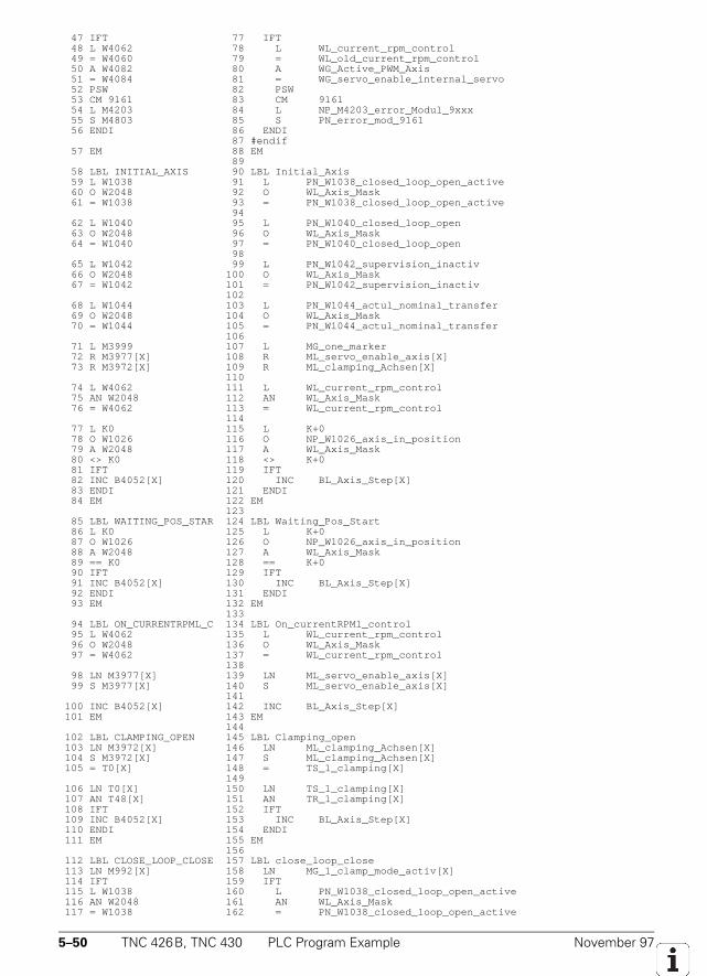
5–50 TNC 426B, TNC 430 PLC Program Example November 97
47 IFT 77 IFT 48 L W4062 78 L WL_current_rpm_control 49 = W4060 79 = WL_old_current_rpm_control 50 A W4082 80 A WG_Active_PWM_Axis 51 = W4084 81 = WG_servo_enable_internal_servo 52 PSW 82 PSW 53 CM 9161 83 CM 9161 54 L M4203 84 L NP_M4203_error_Modul_9xxx 55 S M4803 85 S PN_error_mod_9161 56 ENDI 86 ENDI 87 #endif 57 EM 88 EM 89 58 LBL INITIAL_AXIS 90 LBL Initial_Axis 59 L W1038 91 L PN_W1038_closed_loop_open_active 60 O W2048 92 O WL_Axis_Mask 61 = W1038 93 = PN_W1038_closed_loop_open_active 94 62 L W1040 95 L PN_W1040_closed_loop_open 63 O W2048 96 O WL_Axis_Mask 64 = W1040 97 = PN_W1040_closed_loop_open 98 65 L W1042 99 L PN_W1042_supervision_inactiv 66 O W2048 100 O WL_Axis_Mask 67 = W1042 101 = PN_W1042_supervision_inactiv 102 68 L W1044 103 L PN_W1044_actul_nominal_transfer 69 O W2048 104 O WL_Axis_Mask 70 = W1044 105 = PN_W1044_actul_nominal_transfer 106 71 L M3999 107 L MG_one_marker 72 R M3977[X] 108 R ML_servo_enable_axis[X] 73 R M3972[X] 109 R ML_clamping_Achsen[X] 110 74 L W4062 111 L WL_current_rpm_control 75 AN W2048 112 AN WL_Axis_Mask 76 = W4062 113 = WL_current_rpm_control 114 77 L K0 115 L K+0 78 O W1026 116 O NP_W1026_axis_in_position 79 A W2048 117 A WL_Axis_Mask 80 <> K0 118 <> K+0 81 IFT 119 IFT 82 INC B4052[X] 120 INC BL_Axis_Step[X] 83 ENDI 121 ENDI 84 EM 122 EM 123 85 LBL WAITING_POS_STAR 124 LBL Waiting_Pos_Start 86 L K0 125 L K+0 87 O W1026 126 O NP_W1026_axis_in_position 88 A W2048 127 A WL_Axis_Mask 89 == K0 128 == K+0 90 IFT 129 IFT 91 INC B4052[X] 130 INC BL_Axis_Step[X] 92 ENDI 131 ENDI 93 EM 132 EM 133 94 LBL ON_CURRENTRPML_C 134 LBL On_currentRPMl_control 95 L W4062 135 L WL_current_rpm_control 96 O W2048 136 O WL_Axis_Mask 97 = W4062 137 = WL_current_rpm_control 138 98 LN M3977[X] 139 LN ML_servo_enable_axis[X] 99 S M3977[X] 140 S ML_servo_enable_axis[X] 141 100 INC B4052[X] 142 INC BL_Axis_Step[X] 101 EM 143 EM 144 102 LBL CLAMPING_OPEN 145 LBL Clamping_open 103 LN M3972[X] 146 LN ML_clamping_Achsen[X] 104 S M3972[X] 147 S ML_clamping_Achsen[X] 105 = T0[X] 148 = TS_1_clamping[X] 149 106 LN T0[X] 150 LN TS_1_clamping[X] 107 AN T48[X] 151 AN TR_1_clamping[X] 108 IFT 152 IFT 109 INC B4052[X] 153 INC BL_Axis_Step[X] 110 ENDI 154 ENDI 111 EM 155 EM 156 112 LBL CLOSE_LOOP_CLOSE 157 LBL close_loop_close 113 LN M992[X] 158 LN MG_1_clamp_mode_activ[X] 114 IFT 159 IFT 115 L W1038 160 L PN_W1038_closed_loop_open_active 116 AN W2048 161 AN WL_Axis_Mask 117 = W1038 162 = PN_W1038_closed_loop_open_active
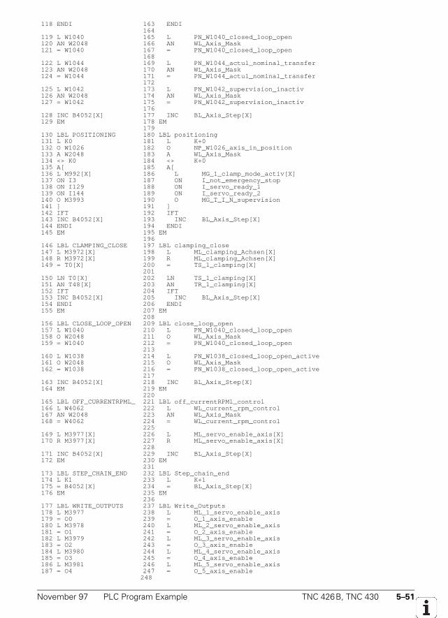
November 97 PLC Program Example TNC 426B, TNC 430 5–51
118 ENDI 163 ENDI 164 119 L W1040 165 L PN_W1040_closed_loop_open 120 AN W2048 166 AN WL_Axis_Mask 121 = W1040 167 = PN_W1040_closed_loop_open 168 122 L W1044 169 L PN_W1044_actul_nominal_transfer 123 AN W2048 170 AN WL_Axis_Mask 124 = W1044 171 = PN_W1044_actul_nominal_transfer 172 125 L W1042 173 L PN_W1042_supervision_inactiv 126 AN W2048 174 AN WL_Axis_Mask 127 = W1042 175 = PN_W1042_supervision_inactiv 176 128 INC B4052[X] 177 INC BL_Axis_Step[X] 129 EM 178 EM 179 130 LBL POSITIONING 180 LBL positioning 131 L K0 181 L K+0 132 O W1026 182 O NP_W1026_axis_in_position 133 A W2048 183 A WL_Axis_Mask 134 <> K0 184 <> K+0 135 A[ 185 A[ 136 L M992[X] 186 L MG_1_clamp_mode_activ[X] 137 ON I3 187 ON I_not_emergency_stop 138 ON I129 188 ON I_servo_ready_1 139 ON I144 189 ON I_servo_ready_2 140 O M3993 190 O MG_T_I_N_supervision 141 ] 191 ] 142 IFT 192 IFT 143 INC B4052[X] 193 INC BL_Axis_Step[X] 144 ENDI 194 ENDI 145 EM 195 EM 196 146 LBL CLAMPING_CLOSE 197 LBL clamping_close 147 L M3972[X] 198 L ML_clamping_Achsen[X] 148 R M3972[X] 199 R ML_clamping_Achsen[X] 149 = T0[X] 200 = TS_1_clamping[X] 201 150 LN T0[X] 202 LN TS_1_clamping[X] 151 AN T48[X] 203 AN TR_1_clamping[X] 152 IFT 204 IFT 153 INC B4052[X] 205 INC BL_Axis_Step[X] 154 ENDI 206 ENDI 155 EM 207 EM 208 156 LBL CLOSE_LOOP_OPEN 209 LBL close_loop_open 157 L W1040 210 L PN_W1040_closed_loop_open 158 O W2048 211 O WL_Axis_Mask 159 = W1040 212 = PN_W1040_closed_loop_open 213 160 L W1038 214 L PN_W1038_closed_loop_open_active 161 O W2048 215 O WL_Axis_Mask 162 = W1038 216 = PN_W1038_closed_loop_open_active 217 163 INC B4052[X] 218 INC BL_Axis_Step[X] 164 EM 219 EM 220 165 LBL OFF_CURRENTRPML_ 221 LBL off_currentRPMl_control 166 L W4062 222 L WL_current_rpm_control 167 AN W2048 223 AN WL_Axis_Mask 168 = W4062 224 = WL_current_rpm_control 225 169 L M3977[X] 226 L ML_servo_enable_axis[X] 170 R M3977[X] 227 R ML_servo_enable_axis[X] 228 171 INC B4052[X] 229 INC BL_Axis_Step[X] 172 EM 230 EM 231 173 LBL STEP_CHAIN_END 232 LBL Step_chain_end 174 L K1 233 L K+1 175 = B4052[X] 234 = BL_Axis_Step[X] 176 EM 235 EM 236 177 LBL WRITE_OUTPUTS 237 LBL Write_Outputs 178 L M3977 238 L ML_1_servo_enable_axis 179 = O0 239 = O_1_axis_enable 180 L M3978 240 L ML_2_servo_enable_axis 181 = O1 241 = O_2_axis_enable 182 L M3979 242 L ML_3_servo_enable_axis 183 = O2 243 = O_3_axis_enable 184 L M3980 244 L ML_4_servo_enable_axis 185 = O3 245 = O_4_axis_enable 186 L M3981 246 L ML_5_servo_enable_axis 187 = O4 247 = O_5_axis_enable 248
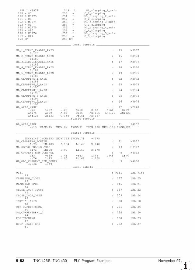
5–52 TNC 426B, TNC 430 PLC Program Example November 97
188 L M3972 249 L ML_clamping_1_axis 189 = O7 250 = O_1_clamping 190 L M3973 251 L ML_clamping_2_axis 191 = O8 252 = O_2_clamping 192 L M3974 253 L ML_clamping_3_axis 193 = O9 254 = O_3_clamping 194 L M3975 255 L ML_clamping_4_axis 195 = O10 256 = O_4_clamping 196 L M3976 257 L ML_clamping_5_axis 197 = O11 258 = O_5_clamping 198 EM 259 EM
________________________________ Local Symbols _______________________________
ML_1_SERVO_ENABLE_AXIS : 15 M3977 L:178ML_2_SERVO_ENABLE_AXIS : 16 M3978 L:180ML_3_SERVO_ENABLE_AXIS : 17 M3979 L:182ML_4_SERVO_ENABLE_AXIS : 18 M3980 L:184ML_5_SERVO_ENABLE_AXIS : 19 M3981 L:186ML_CLAMPING_1_AXIS : 22 M3972 L:188ML_CLAMPING_2_AXIS : 23 M3973 L:190ML_CLAMPING_3_AXIS : 24 M3974 L:192ML_CLAMPING_4_AXIS : 25 M3975 L:194ML_CLAMPING_5_AXIS : 26 M3976 L:196WL_AXIS_MASK : 12 W2048 =:4 L:27 =:29 O:60 O:63 O:66 O:69 AN:75 A:79 A:88 O:96 AN:116 AN:120 AN:123 AN:126 A:133 O:158 O:161 AN:167________________________________Static Symbols _______________________________
BL_AXIS_STEP : 11 B4052 =:13 CASE:15 INCW:82 INCW:91 INCW:100 INCW:109 INCW:128
________________________________Static Symbols _______________________________
INCW:143 INCW:153 INCW:163 INCW:171 =:175ML_CLAMPING_ACHSEN : 21 M3972 R:73 LN:103 S:104 L:147 R:148ML_SERVO_ENABLE_AXIS : 14 M3977 R:72 LN:98 S:99 L:169 R:170WL_CURRENT_RPM_CONTROL : 8 W4062 L:37 =:39 L:41 =:43 L:45 L:48 L:74 =:76 L:95 =:97 L:166 =:168WL_OLD_CURRENT_RPM_CONTR : 9 W4060 <>:46 =:49________________________________ Local Labels ________________________________
9161 : 9161 LBL 9161 83CLAMPING_CLOSE : 197 LBL 25 49CLAMPING_OPEN : 145 LBL 21 45CLOSE_LOOP_CLOSE : 157 LBL 22 46CLOSE_LOOP_OPEN : 209 LBL 24 48INITIAL_AXIS : 90 LBL 18 42OFF_CURRENTRPML_ : 221 LBL 26 50ON_CURRENTRPML_C : 134 LBL 20 44POSITIONING : 180 LBL 23 47STEP_CHAIN_END : 232 LBL 27 51
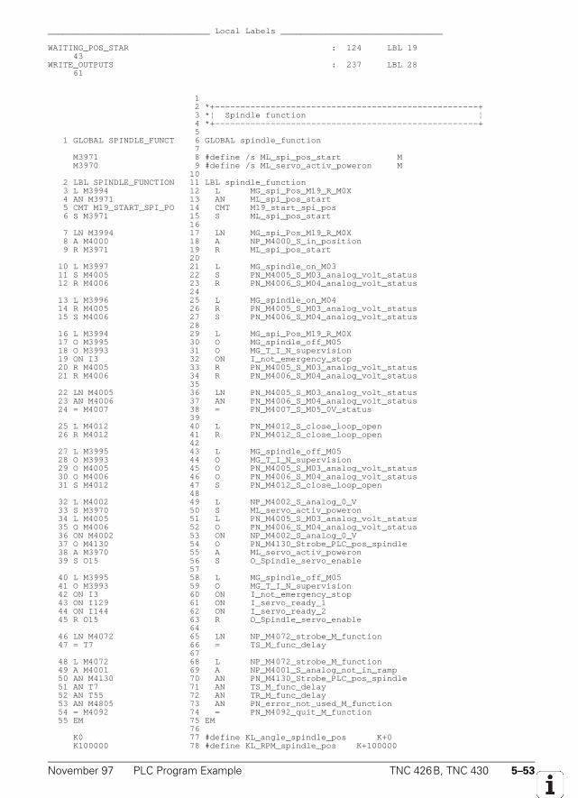
November 97 PLC Program Example TNC 426B, TNC 430 5–53
________________________________ Local Labels ________________________________
WAITING_POS_STAR : 124 LBL 19 43WRITE_OUTPUTS : 237 LBL 28 61
1 2 *+----------------------------------------------------+ 3 *¦ Spindle function ¦ 4 *+----------------------------------------------------+ 5 1 GLOBAL SPINDLE_FUNCT 6 GLOBAL spindle_function 7 M3971 8 #define /s ML_spi_pos_start M M3970 9 #define /s ML_servo_activ_poweron M 10 2 LBL SPINDLE_FUNCTION 11 LBL spindle_function 3 L M3994 12 L MG_spi_Pos_M19_R_M0X 4 AN M3971 13 AN ML_spi_pos_start 5 CMT M19_START_SPI_PO 14 CMT M19_start_spi_pos 6 S M3971 15 S ML_spi_pos_start 16 7 LN M3994 17 LN MG_spi_Pos_M19_R_M0X 8 A M4000 18 A NP_M4000_S_in_position 9 R M3971 19 R ML_spi_pos_start 20 10 L M3997 21 L MG_spindle_on_M03 11 S M4005 22 S PN_M4005_S_M03_analog_volt_status 12 R M4006 23 R PN_M4006_S_M04_analog_volt_status 24 13 L M3996 25 L MG_spindle_on_M04 14 R M4005 26 R PN_M4005_S_M03_analog_volt_status 15 S M4006 27 S PN_M4006_S_M04_analog_volt_status 28 16 L M3994 29 L MG_spi_Pos_M19_R_M0X 17 O M3995 30 O MG_spindle_off_M05 18 O M3993 31 O MG_T_I_N_supervision 19 ON I3 32 ON I_not_emergency_stop 20 R M4005 33 R PN_M4005_S_M03_analog_volt_status 21 R M4006 34 R PN_M4006_S_M04_analog_volt_status 35 22 LN M4005 36 LN PN_M4005_S_M03_analog_volt_status 23 AN M4006 37 AN PN_M4006_S_M04_analog_volt_status 24 = M4007 38 = PN_M4007_S_M05_0V_status 39 25 L M4012 40 L PN_M4012_S_close_loop_open 26 R M4012 41 R PN_M4012_S_close_loop_open 42 27 L M3995 43 L MG_spindle_off_M05 28 O M3993 44 O MG_T_I_N_supervision 29 O M4005 45 O PN_M4005_S_M03_analog_volt_status 30 O M4006 46 O PN_M4006_S_M04_analog_volt_status 31 S M4012 47 S PN_M4012_S_close_loop_open 48 32 L M4002 49 L NP_M4002_S_analog_0_V 33 S M3970 50 S ML_servo_activ_poweron 34 L M4005 51 L PN_M4005_S_M03_analog_volt_status 35 O M4006 52 O PN_M4006_S_M04_analog_volt_status 36 ON M4002 53 ON NP_M4002_S_analog_0_V 37 O M4130 54 O PN_M4130_Strobe_PLC_pos_spindle 38 A M3970 55 A ML_servo_activ_poweron 39 S O15 56 S O_Spindle_servo_enable 57 40 L M3995 58 L MG_spindle_off_M05 41 O M3993 59 O MG_T_I_N_supervision 42 ON I3 60 ON I_not_emergency_stop 43 ON I129 61 ON I_servo_ready_1 44 ON I144 62 ON I_servo_ready_2 45 R O15 63 R O_Spindle_servo_enable 64 46 LN M4072 65 LN NP_M4072_strobe_M_function 47 = T7 66 = TS_M_func_delay 67 48 L M4072 68 L NP_M4072_strobe_M_function 49 A M4001 69 A NP_M4001_S_analog_not_in_ramp 50 AN M4130 70 AN PN_M4130_Strobe_PLC_pos_spindle 51 AN T7 71 AN TS_M_func_delay 52 AN T55 72 AN TR_M_func_delay 53 AN M4805 73 AN PN_error_not_used_M_function 54 = M4092 74 = PN_M4092_quit_M_function 55 EM 75 EM 76 K0 77 #define KL_angle_spindle_pos K+0 K100000 78 #define KL_RPM_spindle_pos K+100000
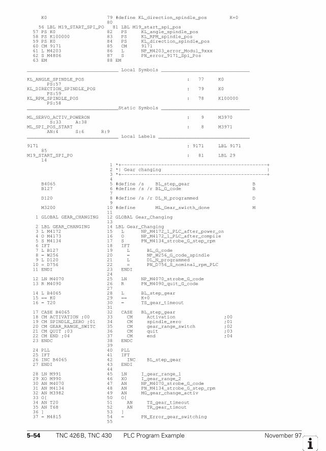
5–54 TNC 426B, TNC 430 PLC Program Example November 97
K0 79 #define KL_direction_spindle_pos K+0 80 56 LBL M19_START_SPI_PO 81 LBL M19_start_spi_pos 57 PS K0 82 PS KL_angle_spindle_pos 58 PS K100000 83 PS KL_RPM_spindle_pos 59 PS K0 84 PS KL_direction_spindle_pos 60 CM 9171 85 CM 9171 61 L M4203 86 L NP_M4203_error_Modul_9xxx 62 S M4806 87 S PN_error_9171_Spi_Pos 63 EM 88 EM
________________________________ Local Symbols _______________________________
KL_ANGLE_SPINDLE_POS : 77 K0 PS:57KL_DIRECTION_SPINDLE_POS : 79 K0 PS:59KL_RPM_SPINDLE_POS : 78 K100000 PS:58________________________________Static Symbols _______________________________
ML_SERVO_ACTIV_POWERON : 9 M3970 S:33 A:38ML_SPI_POS_START : 8 M3971 AN:4 S:6 R:9________________________________ Local Labels ________________________________
9171 : 9171 LBL 9171 85M19_START_SPI_PO : 81 LBL 29 14 1 *+---------------------------------------------------+ 2 *| Gear changing | 3 *+---------------------------------------------------+ 4 B4065 5 #define /s BL_step_gear B B127 6 #define /s /r BL_G_code B 7 D120 8 #define /s /r DL_N_programmed D 9 M3200 10 #define ML_Gear_swicth_done M 11 1 GLOBAL GEAR_CHANGING 12 GLOBAL Gear_Changing 13 2 LBL GEAR_CHANGING 14 LBL Gear_Changing 3 L M4172 15 L NP_M4172_1_PLC_after_power_on 4 O M4173 16 O NP_M4172_1_PLC_after_compile 5 S M4134 17 S PN_M4134_strobe_G_step_rpm 6 IFT 18 IFT 7 L B127 19 L BL_G_code 8 = W256 20 = NP_W256_G_code_spindle 9 L D120 21 L DL_N_programmed 10 = D756 22 = PN_D756_S_nominal_rpm_PLC 11 ENDI 23 ENDI 24 12 LN M4070 25 LN NP_M4070_strobe_G_code 13 R M4090 26 R PN_M4090_quit_G_code 27 14 L B4065 28 L BL_step_gear 15 == K0 29 == K+0 16 = T20 30 = TS_gear_timeout 31 17 CASE B4065 32 CASE BL_step_gear 18 CM ACTIVATION ;00 33 CM Activation ;00 19 CM SPINDLE_ZERO ;01 34 CM spindle_zero ;01 20 CM GEAR_RANGE_SWITC 35 CM gear_range_switch ;02 21 CM QUIT ;03 36 CM quit ;03 22 CM END ;04 37 CM end ;04 23 ENDC 38 ENDC 39 24 PLL 40 PLL 25 IFT 41 IFT 26 INC B4065 42 INC BL_step_gear 27 ENDI 43 ENDI 44 28 LN M991 45 LN I_gear_range_1 29 XO M990 46 XO I_gear_range_2 30 AN M4070 47 AN NP_M4070_strobe_G_code 31 AN M4134 48 AN PN_M4134_strobe_G_step_rpm 32 AN M3982 49 AN MG_gear_change_activ 33 O[ 50 O[ 34 AN T20 51 AN TS_gear_timeout 35 AN T68 52 AN TR_gear_timout 36 ] 53 ] 37 = M4815 54 = PN_Error_gear_switching 55
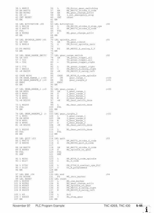
November 97 PLC Program Example TNC 426B, TNC 430 5–55
38 L M4815 56 L PN_Error_gear_switching 39 AN M4070 57 AN NP_M4070_strobe_G_code 40 AN M3982 58 AN MG_gear_change_activ 41 ON I3 59 ON I_not_emergency_stop 42 CMT RESET 60 CMT reset 43 EM 61 EM 62 44 LBL ACTIVATION ;00 63 LBL Activation ;00 45 L M4134 64 L PN_M4134_strobe_G_step_rpm 46 O M4070 65 O NP_M4070_strobe_G_code 47 PSL 66 PSL 48 S M3982 67 S MG_gear_change_activ 49 EM 68 EM 69 50 LBL SPINDLE_ZERO ;01 70 LBL spindle_zero ;01 51 LN T68 71 LN TR_gear_timout 52 S M4816 72 S PN_Error_spindle_zero 73 53 PS M4002 74 PS NP_M4002_S_analog_0_V 54 EM 75 EM 76 55 LBL GEAR_RANGE_SWITC 77 LBL gear_range_switch ;02 56 LN T69 78 LN TR_grear_toggel_all 57 = T21 79 = TS_grear_toggel_all 58 = T22 80 = TS_grear_toggel_right 81 59 L T70 82 L TR_grear_toggel_right 60 = M4010 83 = PN_M4010_S_swing_right 61 =N M4009 84 =N PN_M4009_S_swing_left 85 62 CASE W256 86 CASE NP_W256_G_code_spindle 63 CM GEAR_RANGE_1 ;+00 87 CM gear_range_1 ;+00 64 CM GEAR_RANGFE_2 ;+0 88 CM gear_rangfe_2 ;+01 65 ENDC 89 ENDC 66 EM 90 EM 91 67 LBL GEAR_RANGE_1 ;+0 92 LBL gear_range_1 ;+00 68 LN M991 93 LN I_gear_range_1 69 O M990 94 O I_gear_range_2 70 S M991 95 S O_Gear_Range_1 71 R M990 96 R O_Gear_Range_2 72 =N M3200 97 =N ML_Gear_swicth_done 98 73 L M3200 99 L ML_Gear_swicth_done 74 PSL 100 PSL 75 EM 101 EM 102 76 LBL GEAR_RANGFE_2 ;+ 103 LBL gear_rangfe_2 ;+01 77 L M991 104 L I_gear_range_1 78 ON M990 105 ON I_gear_range_2 79 R M991 106 R O_Gear_Range_1 80 S M990 107 S O_Gear_Range_2 81 =N M3200 108 =N ML_Gear_swicth_done 109 82 L M3200 110 L ML_Gear_swicth_done 83 PSL 111 PSL 84 EM 112 EM 113 85 LBL QUIT ;03 114 LBL quit ;03 86 L M4070 115 L NP_M4070_strobe_G_code 87 S M4090 116 S PN_M4090_quit_G_code 117 88 LN M4070 118 LN NP_M4070_strobe_G_code 89 S M3983 119 S MG_spindle_on_gear 90 PSL 120 PSL 91 EMF 121 EMF 122 92 L W256 123 L NP_W256_G_code_spindle 93 = B127 124 = BL_G_code 125 94 L D756 126 L PN_D756_S_nominal_rpm_PLC 95 = D120 127 = DL_N_programmed 96 EM 128 EM 129 97 LBL END ;04 130 LBL end ;04 98 PS M3998 131 PS MG_zero_marker 99 LBL RESET 132 LBL reset 100 L M3999 133 L MG_one_marker 101 R M3982 134 R MG_gear_change_activ 102 R M3983 135 R MG_spindle_on_gear 103 R M4010 136 R PN_M4010_S_swing_right 104 R M4009 137 R PN_M4009_S_swing_left 138 105 L K0 139 L K+0 106 = B4065 140 = BL_step_gear 107 EM 141 EM
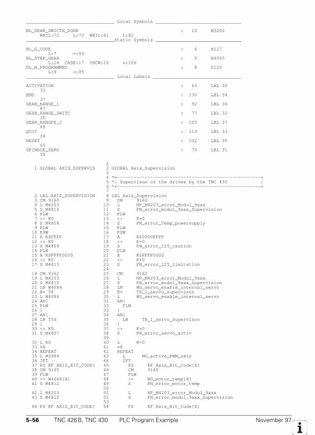
5–56 TNC 426B, TNC 430 PLC Program Example November 97
________________________________ Local Symbols _______________________________
ML_GEAR_SWICTH_DONE : 10 M3200 WHIL:72 L:73 WHIL:81 L:82________________________________Static Symbols _______________________________
BL_G_CODE : 6 B127 L:7 =:93BL_STEP_GEAR : 5 B4065 L:14 CASE:17 INCW:26 =:106DL_N_PROGRAMMED : 8 D120 L:9 =:95________________________________ Local Labels ________________________________
ACTIVATION : 63 LBL 30 33END : 130 LBL 34 37GEAR_RANGE_1 : 92 LBL 36 87GEAR_RANGE_SWITC : 77 LBL 32 35GEAR_RANGFE_2 : 103 LBL 37 88QUIT : 114 LBL 33 36RESET : 132 LBL 35 60SPINDLE_ZERO : 70 LBL 31 34
1 1 GLOBAL AXIS_SUPERVIS 2 GLOBAL Axis_Supervision 3 4 *+----------------------------------------------------+ 5 *¦ Supervison of the drives by the TNC 430 ¦ 6 *+----------------------------------------------------+ 7 2 LBL AXIS_SUPERVISION 8 LBL Axis_Supervision 3 CM 9160 9 CM 9160 4 L M4203 10 L NP_M4203_error_Modul_9xxx 5 S M4810 11 S PN_error_modul_9xxx_Supervision 6 PLW 12 PLW 7 <> K0 13 <> K+0 8 S M4808 14 S PN_error_Temp_powersupply 9 PLW 15 PLW 10 PSW 16 PSW 11 A K$FFFF 17 A K$0000FFFF 12 <> K0 18 <> K+0 13 S M4809 19 S PN_error_I2T_caution 14 PLW 20 PLW 15 A K$FFFF0000 21 A K$FFFF0000 16 <> K0 22 <> K+0 17 S M4813 23 S PN_error_I2T_limitation 24 18 CM 9162 25 CM 9162 19 L M4203 26 L NP_M4203_error_Modul_9xxx 20 S M4810 27 S PN_error_modul_9xxx_Supervision 21 LN W4084 28 LN WG_servo_enable_internal_servo 22 B= T8 29 B= TS_1_servo_supervison 23 L W4084 30 L WG_servo_enable_internal_servo 24 AN[ 31 AN[ 25 PLW 32 PLW 26 ] 33 ] 27 AN[ 34 AN[ 28 LB T56 35 LB TR_1_servo_supervison 29 ] 36 ] 30 <> K0 37 <> K+0 31 S M4807 38 S PN_error_servo_activ 39 32 L K0 40 L K+0 33 =X 41 =X 34 REPEAT 42 REPEAT 35 L M3984 43 L MG_active_PWM_axis 36 IFT 44 IFT 37 PS KF AXIS_BIT_CODE[ 45 PS KF Axis_Bit_Code[X] 38 CM 9165 46 CM 9165 39 PLW 47 PLW 40 >= W4068[X] 48 >= WG_motor_temp[X] 41 S M4812 49 S PN_error_motor_temp 50 42 L M4203 51 L NP_M4203_error_Modul_9xxx 43 S M4810 52 S PN_error_modul_9xxx_Supervision 53 44 PS KF AXIS_BIT_CODE[ 54 PS KF Axis_Bit_Code[X]
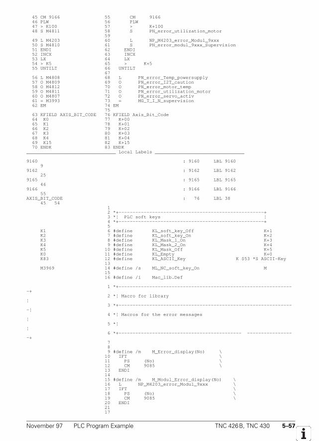
November 97 PLC Program Example TNC 426B, TNC 430 5–57
45 CM 9166 55 CM 9166 46 PLW 56 PLW 47 > K100 57 > K+100 48 S M4811 58 S PN_error_utilization_motor 59 49 L M4203 60 L NP_M4203_error_Modul_9xxx 50 S M4810 61 S PN_error_modul_9xxx_Supervision 51 ENDI 62 ENDI 52 INCX 63 INCX 53 LX 64 LX 54 > K5 65 > K+5 55 UNTILT 66 UNTILT 67 56 L M4808 68 L PN_error_Temp_powersupply 57 O M4809 69 O PN_error_I2T_caution 58 O M4812 70 O PN_error_motor_temp 59 O M4811 71 O PN_error_utilization_motor 60 O M4807 72 O PN_error_servo_activ 61 = M3993 73 = MG_T_I_N_supervision 62 EM 74 EM 75 63 KFIELD AXIS_BIT_CODE 76 KFIELD Axis_Bit_Code 64 K0 77 K+00 65 K1 78 K+01 66 K2 79 K+02 67 K3 80 K+03 68 K4 81 K+04 69 K15 82 K+15 70 ENDK 83 ENDK________________________________ Local Labels ________________________________
9160 : 9160 LBL 9160 99162 : 9162 LBL 9162 259165 : 9165 LBL 9165 469166 : 9166 LBL 9166 55AXIS_BIT_CODE : 76 LBL 38 45 54 1 2 *+----------------------------------------------------+ 3 *¦ PLC soft keys ¦ 4 *+----------------------------------------------------+ 5 K1 6 #define KL_soft_key_Off K+1 K2 7 #define KL_soft_key_On K+2 K3 8 #define KL_Mask_1_On K+3 K4 9 #define KL_Mask_2_On K+4 K5 10 #define KL_Mask_Off K+5 K0 11 #define KL_Empty K+0 K83 12 #define KL_ASCII_Key K $53 *S ASCII-Key 13 M3969 14 #define /s ML_NC_soft_key_On M 15 16 #define /i Mac_lib.Def
1 *+---------------------------------------------------------------+ 2 *¦ Macro for library¦ 3 *+---------------------------------------------------------------¦ 4 *¦ Macros for the error messages¦ 5 *¦¦ 6 *+-------------------------------------------- -----------------+ 7 8 9 #define /m M_Error_display(No) \ 10 IFT \ 11 PS (No) \ 12 CM 9085 \ 13 ENDI 14 15 #define /m M_Modul_Error_display(No) \ 16 L NP_M4203_error_Modul_9xxx \ 17 IFT \ 18 PS (No) \ 19 CM 9085 \ 20 ENDI 21 17
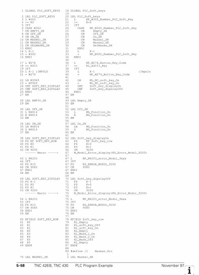
5–58 TNC 426B, TNC 430 PLC Program Example November 97
1 GLOBAL PLC_SOFT_KEYS 18 GLOBAL PLC_Soft_keys 19 2 LBL PLC_SOFT_KEYS 20 LBL PLC_Soft_keys 3 L W302 21 L NP_W302_Number_PLC_Soft_Key 4 >= K0 22 >= K+0 5 IFT 23 IFT 6 CASE W302 24 CASE NP_W302_Number_PLC_Soft_Key 7 CM EMPTY_SK 25 CM Empty_SK 8 CM OFF_SK 26 CM Off_SK 9 CM ON_SK 27 CM On_SK 10 CM MASKE1_SK 28 CM Maske1_SK 11 CM MASKE2_SK 29 CM Maske2_SK 12 CM DELMASKE_SK 30 CM DelMaske_SK 13 ENDC 31 ENDC 14 L K-1 32 L K-1 15 = W302 33 = NP_W302_Number_PLC_Soft_Key 16 ENDI 34 ENDI 35 17 L W274 36 L NP_W274_Button_Key_Code 18 == K$53 37 == KL_ASCII_Key 19 IFT 38 IFT 20 L K-1 ;IMPULS 39 L K-1 ;Impuls 21 = W274 40 = NP_W274_Button_Key_Code 41 22 LN M3969 42 LN ML_NC_soft_key_On 23 = M3969 43 = ML_NC_soft_key_On 24 CMT SOFT_KEY_DISPLAY 44 CMT Soft_key_displayOn 25 CMF SOFT_KEY_DIPSLAY 45 CMF Soft_key_dipslayOff 26 ENDI 46 ENDI 27 EM 47 EM 48 28 LBL EMPTY_SK 49 LBL Empty_SK 29 EM 50 EM 51 30 LBL OFF_SK 52 LBL Off_SK 31 L M4814 53 L MG_Function_On 32 R M4814 54 R MG_Function_On 33 EM 55 EM 56 34 LBL ON_SK 57 LBL On_SK 35 LN M4814 58 LN MG_Function_On 36 S M4814 59 S MG_Function_On 37 EM 60 EM 61 38 LBL SOFT_KEY_DISPLAY 62 LBL Soft_key_displayOn 39 PS KF SOFT_KEY_ROW 63 PS KF Soft_key_row 40 PS K0 64 PS K+0 41 PS K1 65 PS K+1 42 CM 9200 66 CM 9200 ------ Macro -----> 67 M_Modul_Error_display(KG_Error_Modul_9200) 67 43 L M4203 67 L NP_M4203_error_Modul_9xxx 44 IFT 67 IFT 45 PS K15 67 PS KG_ERROR_MODUL_9200 46 CM 9085 67 CM 9085 47 ENDI 67 ENDI 48 EM 68 EM 69 49 LBL SOFT_KEY_DIPSLAY 70 LBL Soft_key_dipslayOff 50 PS K-1 71 PS K-1 51 PS K0 72 PS K+0 52 PS K1 73 PS K+1 53 CM 9200 74 CM 9200 ------ Macro -----> 75 M_Modul_Error_display(KG_Error_Modul_9200) 75 54 L M4203 75 L NP_M4203_error_Modul_9xxx 55 IFT 75 IFT 56 PS K15 75 PS KG_ERROR_MODUL_9200 57 CM 9085 75 CM 9085 58 ENDI 75 ENDI 59 EM 76 EM 77 60 KFIELD SOFT_KEY_ROW 78 KFIELD Soft_key_row 61 K0 79 KL_Empty 62 K1 80 KL_soft_key_Off 63 K2 81 KL_soft_key_On 64 K0 82 KL_Empty 65 K3 83 KL_Mask_1_On 66 K4 84 KL_Mask_2_On 67 K5 85 KL_Mask_Off 68 K0 86 KL_Empty 69 ENDK 87 ENDK 88 89 #define /i Masken.Src 1 70 LBL MASKE1_SK 2 LBL Maske1_SK
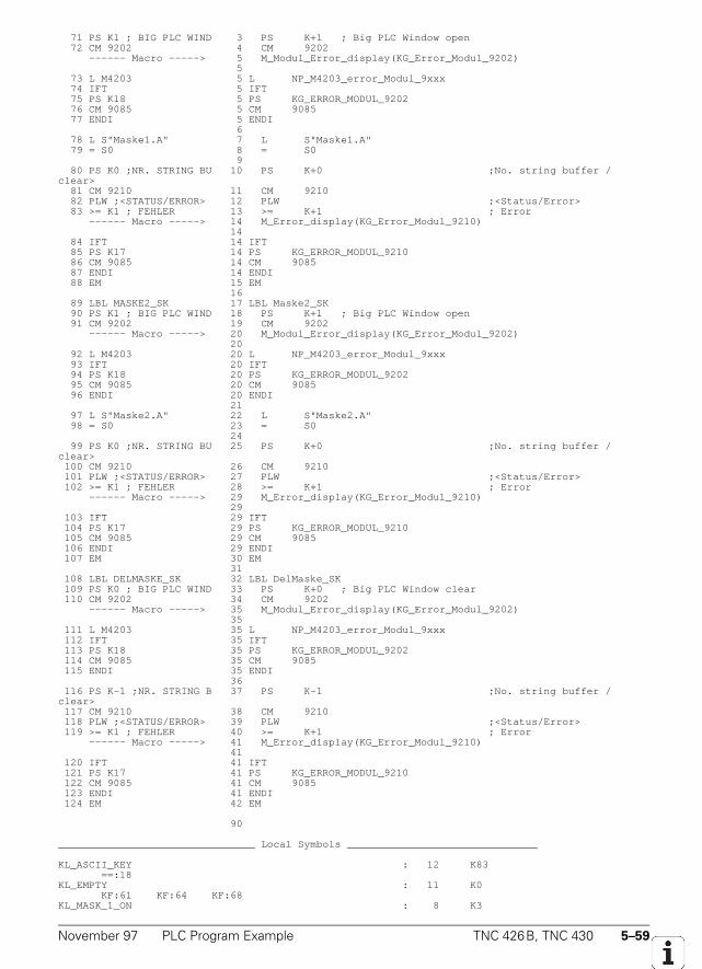
November 97 PLC Program Example TNC 426B, TNC 430 5–59
71 PS K1 ; BIG PLC WIND 3 PS K+1 ; Big PLC Window open 72 CM 9202 4 CM 9202 ------ Macro -----> 5 M_Modul_Error_display(KG_Error_Modul_9202) 5 73 L M4203 5 L NP_M4203_error_Modul_9xxx 74 IFT 5 IFT 75 PS K18 5 PS KG_ERROR_MODUL_9202 76 CM 9085 5 CM 9085 77 ENDI 5 ENDI 6 78 L S"Maske1.A" 7 L S"Maske1.A" 79 = S0 8 = S0 9 80 PS K0 ;NR. STRING BU 10 PS K+0 ;No. string buffer /clear> 81 CM 9210 11 CM 9210 82 PLW ;<STATUS/ERROR> 12 PLW ;<Status/Error> 83 >= K1 ; FEHLER 13 >= K+1 ; Error ------ Macro -----> 14 M_Error_display(KG_Error_Modul_9210) 14 84 IFT 14 IFT 85 PS K17 14 PS KG_ERROR_MODUL_9210 86 CM 9085 14 CM 9085 87 ENDI 14 ENDI 88 EM 15 EM 16 89 LBL MASKE2_SK 17 LBL Maske2_SK 90 PS K1 ; BIG PLC WIND 18 PS K+1 ; Big PLC Window open 91 CM 9202 19 CM 9202 ------ Macro -----> 20 M_Modul_Error_display(KG_Error_Modul_9202) 20 92 L M4203 20 L NP_M4203_error_Modul_9xxx 93 IFT 20 IFT 94 PS K18 20 PS KG_ERROR_MODUL_9202 95 CM 9085 20 CM 9085 96 ENDI 20 ENDI 21 97 L S"Maske2.A" 22 L S"Maske2.A" 98 = S0 23 = S0 24 99 PS K0 ;NR. STRING BU 25 PS K+0 ;No. string buffer /clear> 100 CM 9210 26 CM 9210 101 PLW ;<STATUS/ERROR> 27 PLW ;<Status/Error> 102 >= K1 ; FEHLER 28 >= K+1 ; Error ------ Macro -----> 29 M_Error_display(KG_Error_Modul_9210) 29 103 IFT 29 IFT 104 PS K17 29 PS KG_ERROR_MODUL_9210 105 CM 9085 29 CM 9085 106 ENDI 29 ENDI 107 EM 30 EM 31 108 LBL DELMASKE_SK 32 LBL DelMaske_SK 109 PS K0 ; BIG PLC WIND 33 PS K+0 ; Big PLC Window clear 110 CM 9202 34 CM 9202 ------ Macro -----> 35 M_Modul_Error_display(KG_Error_Modul_9202) 35 111 L M4203 35 L NP_M4203_error_Modul_9xxx 112 IFT 35 IFT 113 PS K18 35 PS KG_ERROR_MODUL_9202 114 CM 9085 35 CM 9085 115 ENDI 35 ENDI 36 116 PS K-1 ;NR. STRING B 37 PS K-1 ;No. string buffer /clear> 117 CM 9210 38 CM 9210 118 PLW ;<STATUS/ERROR> 39 PLW ;<Status/Error> 119 >= K1 ; FEHLER 40 >= K+1 ; Error ------ Macro -----> 41 M_Error_display(KG_Error_Modul_9210) 41 120 IFT 41 IFT 121 PS K17 41 PS KG_ERROR_MODUL_9210 122 CM 9085 41 CM 9085 123 ENDI 41 ENDI 124 EM 42 EM
90
________________________________ Local Symbols _______________________________
KL_ASCII_KEY : 12 K83 ==:18KL_EMPTY : 11 K0 KF:61 KF:64 KF:68KL_MASK_1_ON : 8 K3
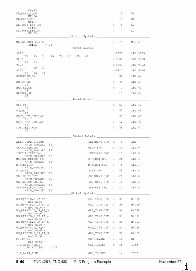
5–60 TNC 426B, TNC 430 PLC Program Example November 97
KF:65KL_MASK_2_ON : 9 K4 KF:66KL_MASK_OFF : 10 K5 KF:67KL_SOFT_KEY_OFF : 6 K1 KF:62KL_SOFT_KEY_ON : 7 K2 KF:63________________________________Static Symbols _______________________________
ML_NC_SOFT_KEY_ON : 14 M3969 LN:22 =:23________________________________ Local Labels ________________________________
9085 : 9085 LBL 9085 67 75 5 14 20 29 35 419200 : 9200 LBL 9200 66 749202 : 9202 LBL 9202 4 19 349210 : 9210 LBL 9210 11 26 38DELMASKE_SK : 32 LBL 44 30EMPTY_SK : 49 LBL 39 25MASKE1_SK : 2 LBL 42 28MASKE2_SK : 17 LBL 43 29________________________________ Local Labels ________________________________
OFF_SK : 52 LBL 40 26ON_SK : 57 LBL 41 27SOFT_KEY_DIPSLAY : 70 LBL 46 45SOFT_KEY_DISPLAY : 62 LBL 45 44SOFT_KEY_ROW : 78 LBL 47 63
________________________________ Global Labels _______________________________
AXIS_SUPERVISION HELPDIAG.SRC : 8 LBL 7 MAIN_PGM.SRC 88GEAR_CHANGING GEAR.SRC : 14 LBL 6 MAIN_PGM.SRC 87INITIALIZATION INITI472.SRC : 15 LBL 0 MAIN_PGM.SRC 75MANUEL_BUTTON_FU DIRCBUT.SRC : 26 LBL 3 MAIN_PGM.SRC 84M_FUNCTION M_FUNCT.SRC : 8 LBL 1 MAIN_PGM.SRC 77NC_AXIS AXIS.SRC : 28 LBL 4 MAIN_PGM.SRC 85PLC_SOFT_KEYS SOFTKEYS.SRC : 20 LBL 8 MAIN_PGM.SRC 89REFERENCE_ENDSWI REF_ENDL.SRC : 15 LBL 2 MAIN_PGM.SRC 82SPINDLE_FUNCTION SPINDLE.SRC : 11 LBL 5 MAIN_PGM.SRC 86________________________________Global Symbols _______________________________
BG_MPAXIS.0_CA_PA_1 GLB_TCMB.DEF : 34 B4088 - not used -BG_MPAXIS.1_CA_PA_2 GLB_TCMB.DEF : 35 B4089 - not used -BG_MPAXIS.2_CA_PA_3 GLB_TCMB.DEF : 36 B4090 - not used -BG_MPAXIS.3_CA_PA_4 GLB_TCMB.DEF : 37 B4091 - not used -BG_MPAXIS.4_CA_PA_5 GLB_TCMB.DEF : 38 B4092 - not used -BG_MPAXIS.X_CA_PA GLB_TCMB.DEF : 33 B4088 - not used -BG_MPSPIN.0_CA_PA_S GLB_TCMB.DEF : 39 B4093 - not used -FIRST_PL CONFIG.DEF : 10 K0 - not used -I_1_AXIS_MINUS GLB_IO.DEF : 15 I133 DIRCBUT.SRC L:31
I_1_AXIS_PLUS GLB_IO.DEF : 14 I138
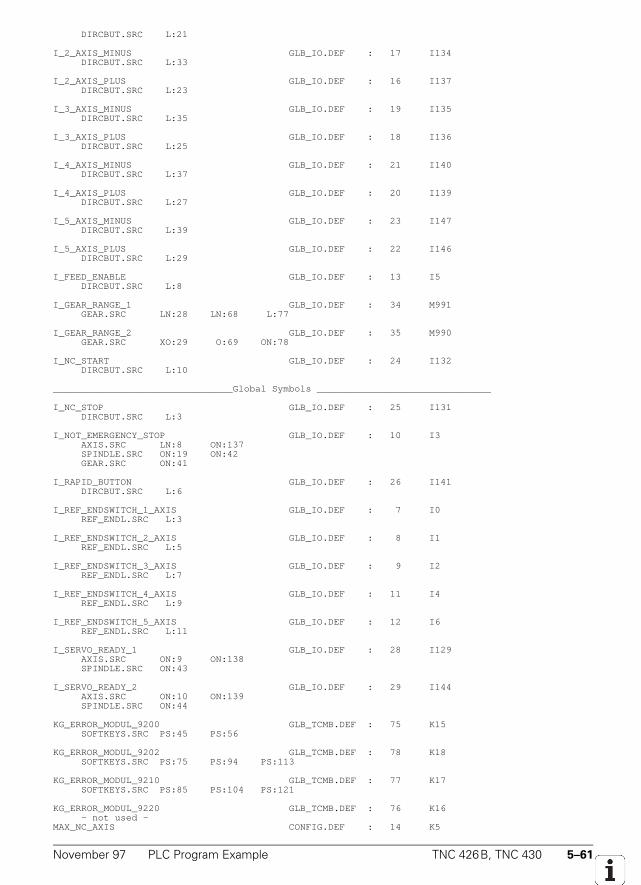
November 97 PLC Program Example TNC 426B, TNC 430 5–61
DIRCBUT.SRC L:21
I_2_AXIS_MINUS GLB_IO.DEF : 17 I134 DIRCBUT.SRC L:33
I_2_AXIS_PLUS GLB_IO.DEF : 16 I137 DIRCBUT.SRC L:23
I_3_AXIS_MINUS GLB_IO.DEF : 19 I135 DIRCBUT.SRC L:35
I_3_AXIS_PLUS GLB_IO.DEF : 18 I136 DIRCBUT.SRC L:25
I_4_AXIS_MINUS GLB_IO.DEF : 21 I140 DIRCBUT.SRC L:37
I_4_AXIS_PLUS GLB_IO.DEF : 20 I139 DIRCBUT.SRC L:27
I_5_AXIS_MINUS GLB_IO.DEF : 23 I147 DIRCBUT.SRC L:39
I_5_AXIS_PLUS GLB_IO.DEF : 22 I146 DIRCBUT.SRC L:29
I_FEED_ENABLE GLB_IO.DEF : 13 I5 DIRCBUT.SRC L:8
I_GEAR_RANGE_1 GLB_IO.DEF : 34 M991 GEAR.SRC LN:28 LN:68 L:77
I_GEAR_RANGE_2 GLB_IO.DEF : 35 M990 GEAR.SRC XO:29 O:69 ON:78
I_NC_START GLB_IO.DEF : 24 I132 DIRCBUT.SRC L:10
________________________________Global Symbols _______________________________
I_NC_STOP GLB_IO.DEF : 25 I131 DIRCBUT.SRC L:3
I_NOT_EMERGENCY_STOP GLB_IO.DEF : 10 I3 AXIS.SRC LN:8 ON:137 SPINDLE.SRC ON:19 ON:42 GEAR.SRC ON:41
I_RAPID_BUTTON GLB_IO.DEF : 26 I141 DIRCBUT.SRC L:6
I_REF_ENDSWITCH_1_AXIS GLB_IO.DEF : 7 I0 REF_ENDL.SRC L:3
I_REF_ENDSWITCH_2_AXIS GLB_IO.DEF : 8 I1 REF_ENDL.SRC L:5
I_REF_ENDSWITCH_3_AXIS GLB_IO.DEF : 9 I2 REF_ENDL.SRC L:7
I_REF_ENDSWITCH_4_AXIS GLB_IO.DEF : 11 I4 REF_ENDL.SRC L:9
I_REF_ENDSWITCH_5_AXIS GLB_IO.DEF : 12 I6 REF_ENDL.SRC L:11
I_SERVO_READY_1 GLB_IO.DEF : 28 I129 AXIS.SRC ON:9 ON:138 SPINDLE.SRC ON:43
I_SERVO_READY_2 GLB_IO.DEF : 29 I144 AXIS.SRC ON:10 ON:139 SPINDLE.SRC ON:44
KG_ERROR_MODUL_9200 GLB_TCMB.DEF : 75 K15 SOFTKEYS.SRC PS:45 PS:56
KG_ERROR_MODUL_9202 GLB_TCMB.DEF : 78 K18 SOFTKEYS.SRC PS:75 PS:94 PS:113
KG_ERROR_MODUL_9210 GLB_TCMB.DEF : 77 K17 SOFTKEYS.SRC PS:85 PS:104 PS:121
KG_ERROR_MODUL_9220 GLB_TCMB.DEF : 76 K16 - not used -MAX_NC_AXIS CONFIG.DEF : 14 K5
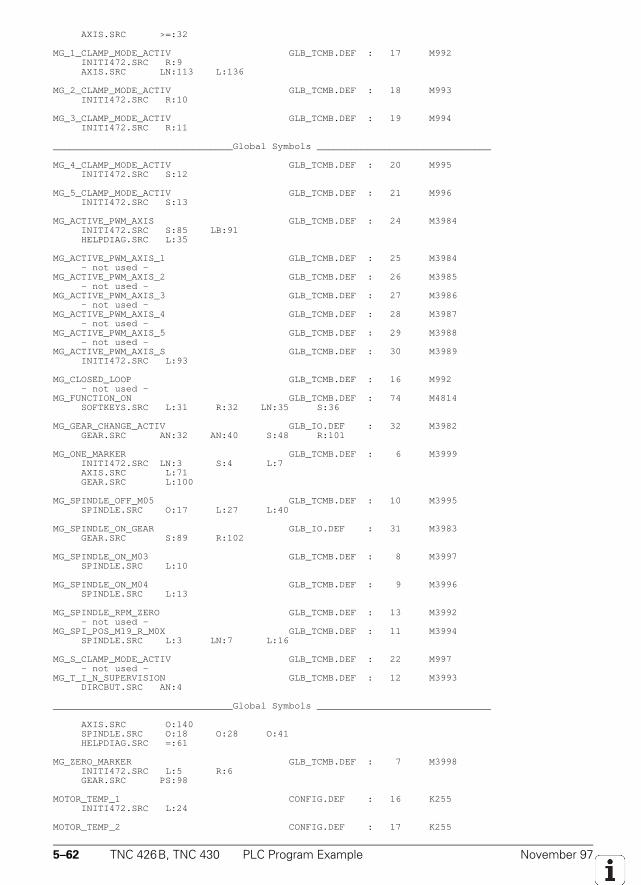
5–62 TNC 426B, TNC 430 PLC Program Example November 97
AXIS.SRC >=:32
MG_1_CLAMP_MODE_ACTIV GLB_TCMB.DEF : 17 M992 INITI472.SRC R:9 AXIS.SRC LN:113 L:136
MG_2_CLAMP_MODE_ACTIV GLB_TCMB.DEF : 18 M993 INITI472.SRC R:10
MG_3_CLAMP_MODE_ACTIV GLB_TCMB.DEF : 19 M994 INITI472.SRC R:11
________________________________Global Symbols _______________________________
MG_4_CLAMP_MODE_ACTIV GLB_TCMB.DEF : 20 M995 INITI472.SRC S:12
MG_5_CLAMP_MODE_ACTIV GLB_TCMB.DEF : 21 M996 INITI472.SRC S:13
MG_ACTIVE_PWM_AXIS GLB_TCMB.DEF : 24 M3984 INITI472.SRC S:85 LB:91 HELPDIAG.SRC L:35
MG_ACTIVE_PWM_AXIS_1 GLB_TCMB.DEF : 25 M3984 - not used -MG_ACTIVE_PWM_AXIS_2 GLB_TCMB.DEF : 26 M3985 - not used -MG_ACTIVE_PWM_AXIS_3 GLB_TCMB.DEF : 27 M3986 - not used -MG_ACTIVE_PWM_AXIS_4 GLB_TCMB.DEF : 28 M3987 - not used -MG_ACTIVE_PWM_AXIS_5 GLB_TCMB.DEF : 29 M3988 - not used -MG_ACTIVE_PWM_AXIS_S GLB_TCMB.DEF : 30 M3989 INITI472.SRC L:93
MG_CLOSED_LOOP GLB_TCMB.DEF : 16 M992 - not used -MG_FUNCTION_ON GLB_TCMB.DEF : 74 M4814 SOFTKEYS.SRC L:31 R:32 LN:35 S:36
MG_GEAR_CHANGE_ACTIV GLB_IO.DEF : 32 M3982 GEAR.SRC AN:32 AN:40 S:48 R:101
MG_ONE_MARKER GLB_TCMB.DEF : 6 M3999 INITI472.SRC LN:3 S:4 L:7 AXIS.SRC L:71 GEAR.SRC L:100
MG_SPINDLE_OFF_M05 GLB_TCMB.DEF : 10 M3995 SPINDLE.SRC O:17 L:27 L:40
MG_SPINDLE_ON_GEAR GLB_IO.DEF : 31 M3983 GEAR.SRC S:89 R:102
MG_SPINDLE_ON_M03 GLB_TCMB.DEF : 8 M3997 SPINDLE.SRC L:10
MG_SPINDLE_ON_M04 GLB_TCMB.DEF : 9 M3996 SPINDLE.SRC L:13
MG_SPINDLE_RPM_ZERO GLB_TCMB.DEF : 13 M3992 - not used -MG_SPI_POS_M19_R_M0X GLB_TCMB.DEF : 11 M3994 SPINDLE.SRC L:3 LN:7 L:16
MG_S_CLAMP_MODE_ACTIV GLB_TCMB.DEF : 22 M997 - not used -MG_T_I_N_SUPERVISION GLB_TCMB.DEF : 12 M3993 DIRCBUT.SRC AN:4
________________________________Global Symbols _______________________________
AXIS.SRC O:140 SPINDLE.SRC O:18 O:28 O:41 HELPDIAG.SRC =:61
MG_ZERO_MARKER GLB_TCMB.DEF : 7 M3998 INITI472.SRC L:5 R:6 GEAR.SRC PS:98
MOTOR_TEMP_1 CONFIG.DEF : 16 K255 INITI472.SRC L:24
MOTOR_TEMP_2 CONFIG.DEF : 17 K255
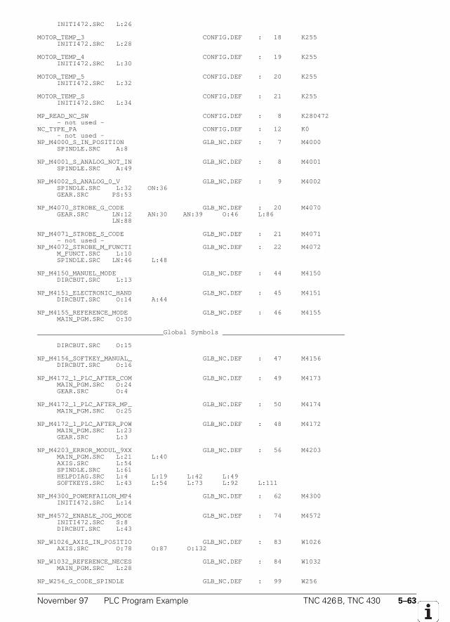
November 97 PLC Program Example TNC 426B, TNC 430 5–63
INITI472.SRC L:26
MOTOR_TEMP_3 CONFIG.DEF : 18 K255 INITI472.SRC L:28
MOTOR_TEMP_4 CONFIG.DEF : 19 K255 INITI472.SRC L:30
MOTOR_TEMP_5 CONFIG.DEF : 20 K255 INITI472.SRC L:32
MOTOR_TEMP_S CONFIG.DEF : 21 K255 INITI472.SRC L:34
MP_READ_NC_SW CONFIG.DEF : 8 K280472 - not used -NC_TYPE_PA CONFIG.DEF : 12 K0 - not used -NP_M4000_S_IN_POSITION GLB_NC.DEF : 7 M4000 SPINDLE.SRC A:8
NP_M4001_S_ANALOG_NOT_IN GLB_NC.DEF : 8 M4001 SPINDLE.SRC A:49
NP_M4002_S_ANALOG_0_V GLB_NC.DEF : 9 M4002 SPINDLE.SRC L:32 ON:36 GEAR.SRC PS:53
NP_M4070_STROBE_G_CODE GLB_NC.DEF : 20 M4070 GEAR.SRC LN:12 AN:30 AN:39 O:46 L:86 LN:88
NP_M4071_STROBE_S_CODE GLB_NC.DEF : 21 M4071 - not used -NP_M4072_STROBE_M_FUNCTI GLB_NC.DEF : 22 M4072 M_FUNCT.SRC L:10 SPINDLE.SRC LN:46 L:48
NP_M4150_MANUEL_MODE GLB_NC.DEF : 44 M4150 DIRCBUT.SRC L:13
NP_M4151_ELECTRONIC_HAND GLB_NC.DEF : 45 M4151 DIRCBUT.SRC O:14 A:44
NP_M4155_REFERENCE_MODE GLB_NC.DEF : 46 M4155 MAIN_PGM.SRC O:30
________________________________Global Symbols _______________________________
DIRCBUT.SRC O:15
NP_M4156_SOFTKEY_MANUAL_ GLB_NC.DEF : 47 M4156 DIRCBUT.SRC O:16
NP_M4172_1_PLC_AFTER_COM GLB_NC.DEF : 49 M4173 MAIN_PGM.SRC O:24 GEAR.SRC O:4
NP_M4172_1_PLC_AFTER_MP_ GLB_NC.DEF : 50 M4174 MAIN_PGM.SRC O:25
NP_M4172_1_PLC_AFTER_POW GLB_NC.DEF : 48 M4172 MAIN_PGM.SRC L:23 GEAR.SRC L:3
NP_M4203_ERROR_MODUL_9XX GLB_NC.DEF : 56 M4203 MAIN_PGM.SRC L:21 L:40 AXIS.SRC L:54 SPINDLE.SRC L:61 HELPDIAG.SRC L:4 L:19 L:42 L:49 SOFTKEYS.SRC L:43 L:54 L:73 L:92 L:111
NP_M4300_POWERFAILON_MP4 GLB_NC.DEF : 62 M4300 INITI472.SRC L:14
NP_M4572_ENABLE_JOG_MODE GLB_NC.DEF : 74 M4572 INITI472.SRC S:8 DIRCBUT.SRC L:43
NP_W1026_AXIS_IN_POSITIO GLB_NC.DEF : 83 W1026 AXIS.SRC O:78 O:87 O:132
NP_W1032_REFERENCE_NECES GLB_NC.DEF : 84 W1032 MAIN_PGM.SRC L:28
NP_W256_G_CODE_SPINDLE GLB_NC.DEF : 99 W256
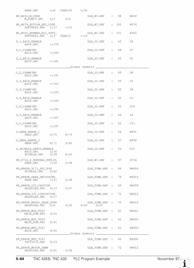
5–64 TNC 426B, TNC 430 PLC Program Example November 97
GEAR.SRC =:8 CASE:62 L:92
NP_W260_M_CODE GLB_NC.DEF : 98 W260 M_FUNCT.SRC L:3 L:6
NP_W274_BUTTON_KEY_CODE GLB_NC.DEF : 102 W274 SOFTKEYS.SRC L:17 =:21
NP_W302_NUMBER_PLC_SOFT_ GLB_NC.DEF : 101 W302 SOFTKEYS.SRC L:3 CASE:6 =:15
O_1_AXIS_ENABLE GLB_IO.DEF : 42 O0 AXIS.SRC =:179
O_1_CLAMPING GLB_IO.DEF : 48 O7 AXIS.SRC =:189
O_2_AXIS_ENABLE GLB_IO.DEF : 43 O1 AXIS.SRC =:181
________________________________Global Symbols _______________________________
O_2_CLAMPING GLB_IO.DEF : 49 O8 AXIS.SRC =:191
O_3_AXIS_ENABLE GLB_IO.DEF : 44 O2 AXIS.SRC =:183
O_3_CLAMPING GLB_IO.DEF : 50 O9 AXIS.SRC =:193
O_4_AXIS_ENABLE GLB_IO.DEF : 45 O3 AXIS.SRC =:185
O_4_CLAMPING GLB_IO.DEF : 51 O10 AXIS.SRC =:195
O_5_AXIS_ENABLE GLB_IO.DEF : 46 O4 AXIS.SRC =:187
O_5_CLAMPING GLB_IO.DEF : 52 O11 AXIS.SRC =:197
O_GEAR_RANGE_1 GLB_IO.DEF : 56 M991 GEAR.SRC S:70 R:79
O_GEAR_RANGE_2 GLB_IO.DEF : 57 M990 GEAR.SRC R:71 S:80
O_SPINDLE_SERVO_ENABLE GLB_IO.DEF : 54 O15 AXIS.SRC L:35 SPINDLE.SRC S:39 R:45
PN_D756_S_NOMINAL_RPM_PL GLB_NC.DEF : 97 D756 GEAR.SRC =:10 L:94
PN_ERROR_9171_SPI_POS GLB_TCMB.DEF : 66 M4806 SPINDLE.SRC S:62
PN_ERROR_GEAR_SWITCHING GLB_TCMB.DEF : 79 M4815 GEAR.SRC =:37 L:38
PN_ERROR_I2T_CAUTION GLB_TCMB.DEF : 69 M4809 HELPDIAG.SRC S:13 O:57
PN_ERROR_I2T_LIMITATION GLB_TCMB.DEF : 73 M4813 HELPDIAG.SRC S:17
PN_ERROR_MODUL_9XXX_SUPE GLB_TCMB.DEF : 70 M4810 HELPDIAG.SRC S:5 S:20 S:43 S:50
PN_ERROR_MOD_9002 GLB_TCMB.DEF : 61 M4801 MAIN_PGM.SRC S:22
PN_ERROR_MOD_9005 GLB_TCMB.DEF : 62 M4802 MAIN_PGM.SRC S:41
PN_ERROR_MOD_9161 GLB_TCMB.DEF : 63 M4803 AXIS.SRC S:55________________________________Global Symbols _______________________________
PN_ERROR_MOD_9167 GLB_TCMB.DEF : 60 M4800 INITI472.SRC S:23
PN_ERROR_MOTOR_TEMP GLB_TCMB.DEF : 72 M4812 HELPDIAG.SRC S:41 O:58
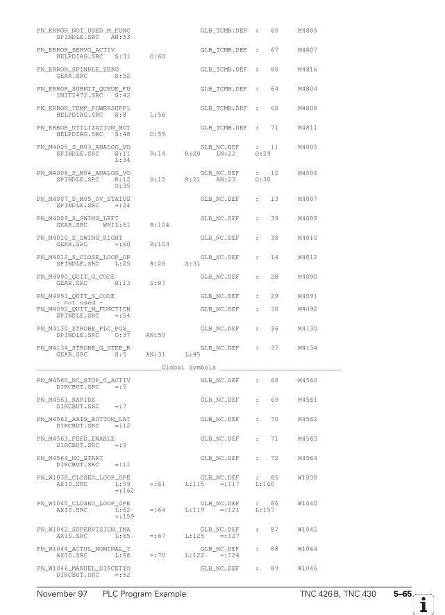
November 97 PLC Program Example TNC 426B, TNC 430 5–65
PN_ERROR_NOT_USED_M_FUNC GLB_TCMB.DEF : 65 M4805 SPINDLE.SRC AN:53
PN_ERROR_SERVO_ACTIV GLB_TCMB.DEF : 67 M4807 HELPDIAG.SRC S:31 O:60
PN_ERROR_SPINDLE_ZERO GLB_TCMB.DEF : 80 M4816 GEAR.SRC S:52
PN_ERROR_SUBMIT_QUEUE_FU GLB_TCMB.DEF : 64 M4804 INITI472.SRC S:42
PN_ERROR_TEMP_POWERSUPPL GLB_TCMB.DEF : 68 M4808 HELPDIAG.SRC S:8 L:56
PN_ERROR_UTILIZATION_MOT GLB_TCMB.DEF : 71 M4811 HELPDIAG.SRC S:48 O:59
PN_M4005_S_M03_ANALOG_VO GLB_NC.DEF : 11 M4005 SPINDLE.SRC S:11 R:14 R:20 LN:22 O:29 L:34
PN_M4006_S_M04_ANALOG_VO GLB_NC.DEF : 12 M4006 SPINDLE.SRC R:12 S:15 R:21 AN:23 O:30 O:35
PN_M4007_S_M05_0V_STATUS GLB_NC.DEF : 13 M4007 SPINDLE.SRC =:24
PN_M4009_S_SWING_LEFT GLB_NC.DEF : 39 M4009 GEAR.SRC WHIL:61 R:104
PN_M4010_S_SWING_RIGHT GLB_NC.DEF : 38 M4010 GEAR.SRC =:60 R:103
PN_M4012_S_CLOSE_LOOP_OP GLB_NC.DEF : 14 M4012 SPINDLE.SRC L:25 R:26 S:31
PN_M4090_QUIT_G_CODE GLB_NC.DEF : 28 M4090 GEAR.SRC R:13 S:87
PN_M4091_QUIT_S_CODE GLB_NC.DEF : 29 M4091 - not used -PN_M4092_QUIT_M_FUNCTION GLB_NC.DEF : 30 M4092 SPINDLE.SRC =:54
PN_M4130_STROBE_PLC_POS_ GLB_NC.DEF : 36 M4130 SPINDLE.SRC O:37 AN:50
PN_M4134_STROBE_G_STEP_R GLB_NC.DEF : 37 M4134 GEAR.SRC S:5 AN:31 L:45
________________________________Global Symbols _______________________________
PN_M4560_NC_STOP_0_ACTIV GLB_NC.DEF : 68 M4560 DIRCBUT.SRC =:5
PN_M4561_RAPIDE GLB_NC.DEF : 69 M4561 DIRCBUT.SRC =:7
PN_M4562_AXIS_BUTTON_LAT GLB_NC.DEF : 70 M4562 DIRCBUT.SRC =:12
PN_M4563_FEED_ENABLE GLB_NC.DEF : 71 M4563 DIRCBUT.SRC =:9
PN_M4564_NC_START GLB_NC.DEF : 72 M4564 DIRCBUT.SRC =:11
PN_W1038_CLOSED_LOOP_OPE GLB_NC.DEF : 85 W1038 AXIS.SRC L:59 =:61 L:115 =:117 L:160 =:162
PN_W1040_CLOSED_LOOP_OPE GLB_NC.DEF : 86 W1040 AXIS.SRC L:62 =:64 L:119 =:121 L:157 =:159
PN_W1042_SUPERVISION_INA GLB_NC.DEF : 87 W1042 AXIS.SRC L:65 =:67 L:125 =:127
PN_W1044_ACTUL_NOMINAL_T GLB_NC.DEF : 88 W1044 AXIS.SRC L:68 =:70 L:122 =:124
PN_W1046_MANUEL_DIRCETIO GLB_NC.DEF : 89 W1046 DIRCBUT.SRC =:52
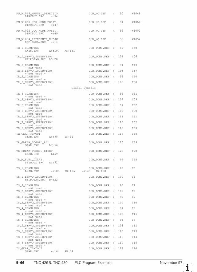
5–66 TNC 426B, TNC 430 PLC Program Example November 97
PN_W1048_MANUEL_DIRECTIO GLB_NC.DEF : 90 W1048 DIRCBUT.SRC =:54
PN_W1050_JOG_MODE_POSIT_ GLB_NC.DEF : 91 W1050 DIRCBUT.SRC =:47
PN_W1052_JOG_MODE_POSIT_ GLB_NC.DEF : 92 W1052 DIRCBUT.SRC =:49
PN_W1054_REFERENCE_ENDSW GLB_NC.DEF : 93 W1054 REF_ENDL.SRC =:14
TR_1_CLAMPING GLB_TCMB.DEF : 89 T48 AXIS.SRC AN:107 AN:151
TR_1_SERVO_SUPERVISON GLB_TCMB.DEF : 101 T56 HELPDIAG.SRC LB:28
TR_2_CLAMPING GLB_TCMB.DEF : 91 T49 - not used -TR_2_SERVO_SUPERVISON GLB_TCMB.DEF : 103 T57 - not used -TR_3_CLAMPING GLB_TCMB.DEF : 93 T50 - not used -TR_3_SERVO_SUPERVISON GLB_TCMB.DEF : 105 T58 - not used -________________________________Global Symbols _______________________________
TR_4_CLAMPING GLB_TCMB.DEF : 95 T51 - not used -TR_4_SERVO_SUPERVISON GLB_TCMB.DEF : 107 T59 - not used -TR_5_CLAMPING GLB_TCMB.DEF : 97 T52 - not used -TR_5_SERVO_SUPERVISON GLB_TCMB.DEF : 109 T60 - not used -TR_6_SERVO_SUPERVISON GLB_TCMB.DEF : 111 T61 - not used -TR_7_SERVO_SUPERVISON GLB_TCMB.DEF : 113 T62 - not used -TR_8_SERVO_SUPERVISON GLB_TCMB.DEF : 115 T63 - not used -TR_GEAR_TIMOUT GLB_TCMB.DEF : 118 T68 GEAR.SRC AN:35 LN:51
TR_GREAR_TOGGEL_ALL GLB_TCMB.DEF : 120 T69 GEAR.SRC LN:56
TR_GREAR_TOGGEL_RIGHT GLB_TCMB.DEF : 122 T70 GEAR.SRC L:59
TR_M_FUNC_DELAY GLB_TCMB.DEF : 99 T55 SPINDLE.SRC AN:52
TS_1_CLAMPING GLB_TCMB.DEF : 88 T0 AXIS.SRC =:105 LN:106 =:149 LN:150
TS_1_SERVO_SUPERVISON GLB_TCMB.DEF : 100 T8 HELPDIAG.SRC B=:22
TS_2_CLAMPING GLB_TCMB.DEF : 90 T1 - not used -TS_2_SERVO_SUPERVISON GLB_TCMB.DEF : 102 T9 - not used -TS_3_CLAMPING GLB_TCMB.DEF : 92 T2 - not used -TS_3_SERVO_SUPERVISON GLB_TCMB.DEF : 104 T10 - not used -TS_4_CLAMPING GLB_TCMB.DEF : 94 T3 - not used -TS_4_SERVO_SUPERVISON GLB_TCMB.DEF : 106 T11 - not used -TS_5_CLAMPING GLB_TCMB.DEF : 96 T4 - not used -TS_5_SERVO_SUPERVISON GLB_TCMB.DEF : 108 T12 - not used -TS_6_SERVO_SUPERVISON GLB_TCMB.DEF : 110 T13 - not used -TS_7_SERVO_SUPERVISON GLB_TCMB.DEF : 112 T14 - not used -TS_8_SERVO_SUPERVISON GLB_TCMB.DEF : 114 T15 - not used -TS_GEAR_TIMEOUT GLB_TCMB.DEF : 117 T20 GEAR.SRC =:16 AN:34
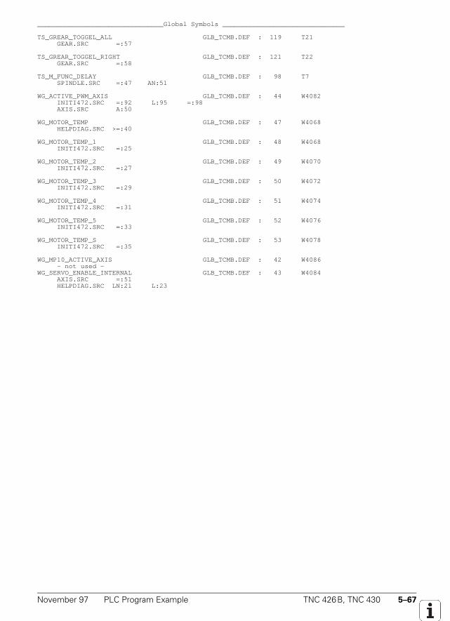
November 97 PLC Program Example TNC 426B, TNC 430 5–67
________________________________Global Symbols _______________________________
TS_GREAR_TOGGEL_ALL GLB_TCMB.DEF : 119 T21 GEAR.SRC =:57
TS_GREAR_TOGGEL_RIGHT GLB_TCMB.DEF : 121 T22 GEAR.SRC =:58
TS_M_FUNC_DELAY GLB_TCMB.DEF : 98 T7 SPINDLE.SRC =:47 AN:51
WG_ACTIVE_PWM_AXIS GLB_TCMB.DEF : 44 W4082 INITI472.SRC =:92 L:95 =:98 AXIS.SRC A:50
WG_MOTOR_TEMP GLB_TCMB.DEF : 47 W4068 HELPDIAG.SRC >=:40
WG_MOTOR_TEMP_1 GLB_TCMB.DEF : 48 W4068 INITI472.SRC =:25
WG_MOTOR_TEMP_2 GLB_TCMB.DEF : 49 W4070 INITI472.SRC =:27
WG_MOTOR_TEMP_3 GLB_TCMB.DEF : 50 W4072 INITI472.SRC =:29
WG_MOTOR_TEMP_4 GLB_TCMB.DEF : 51 W4074 INITI472.SRC =:31
WG_MOTOR_TEMP_5 GLB_TCMB.DEF : 52 W4076 INITI472.SRC =:33
WG_MOTOR_TEMP_S GLB_TCMB.DEF : 53 W4078 INITI472.SRC =:35
WG_MP10_ACTIVE_AXIS GLB_TCMB.DEF : 42 W4086 - not used -WG_SERVO_ENABLE_INTERNAL GLB_TCMB.DEF : 43 W4084 AXIS.SRC =:51 HELPDIAG.SRC LN:21 L:23
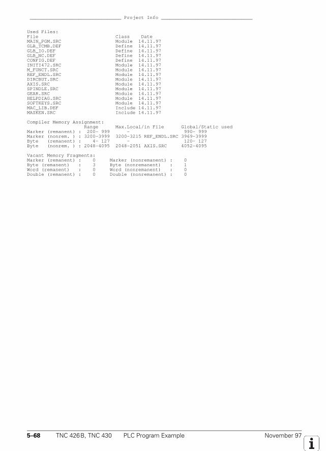
5–68 TNC 426B, TNC 430 PLC Program Example November 97
________________________________ Project Info ________________________________
Used Files:File Class DateMAIN_PGM.SRC Module 14.11.97GLB_TCMB.DEF Define 14.11.97GLB_IO.DEF Define 14.11.97GLB_NC.DEF Define 14.11.97CONFIG.DEF Define 14.11.97INITI472.SRC Module 14.11.97M_FUNCT.SRC Module 14.11.97REF_ENDL.SRC Module 14.11.97DIRCBUT.SRC Module 14.11.97AXIS.SRC Module 14.11.97SPINDLE.SRC Module 14.11.97GEAR.SRC Module 14.11.97HELPDIAG.SRC Module 14.11.97SOFTKEYS.SRC Module 14.11.97MAC_LIB.DEF Include 14.11.97MASKEN.SRC Include 14.11.97
Compiler Memory Assignment: Range Max.Local/in File Global/Static usedMarker (remanent) : 200- 999 - 990- 999Marker (nonrem. ) : 3200-3999 3200-3215 REF_ENDL.SRC 3969-3999Byte (remanent) : 4- 127 - 120- 127Byte (nonrem. ) : 2048-4095 2048-2051 AXIS.SRC 4052-4095
Vacant Memory Fragments:Marker (remanent) : 0 Marker (nonremanent) : 0Byte (remanent) : 3 Byte (nonremanent) : 1Word (remanent) : 0 Word (nonremanent) : 0Double (remanent) : 0 Double (nonremanent) : 0

November 97 PLC Program Example TNC 426B, TNC 430 5–69

5–70 TNC 426B, TNC 430 PLC Program Example November 97

November 97 PLC Program Example TNC 426B, TNC 430 5–71

5–72 TNC 426B, TNC 430 PLC Program Example November 97

November 97 PLC Program Example TNC 426B, TNC 430 5–73

5–74 TNC 426B, TNC 430 PLC Program Example November 97
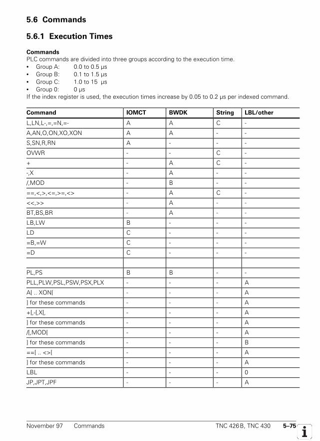
November 97 Commands TNC 426B, TNC 430 5–75
5.6 Commands
5.6.1 Execution Times
Commands
PLC commands are divided into three groups according to the execution time.• Group A: 0.0 to 0.5 µs• Group B: 0.1 to 1.5 µs• Group C: 1.0 to 15 µs• Group 0: 0 µsIf the index register is used, the execution times increase by 0.05 to 0.2 µs per indexed command.
Command IOMCT BWDK String LBL/other
L,LN,L-,=,=N,=- A A C -
A,AN,O,ON,XO,XON A A - -
S,SN,R,RN A - - -
OVWR - - C -
+ - A C -
-,X - A - -
/,MOD - B - -
==,<,>,<=,>=,<> - A C -
<<,>> - A - -
BT,BS,BR - A - -
LB,LW B - - -
LD C - - -
=B,=W C - - -
=D C - - -
PL,PS B B - -
PLL,PLW,PSL,PSW,PSX,PLX - - - A
A[ .. XON[ - - - A
] for these commands - - - A
+[,-[,X[, - - - A
] for these commands - - - A
/[,MOD[ - - - A
] for these commands - - - B
==[ .. <>[ - - - A
] for these commands - - - A
LBL - - - 0
JP,JPT,JPF - - - A
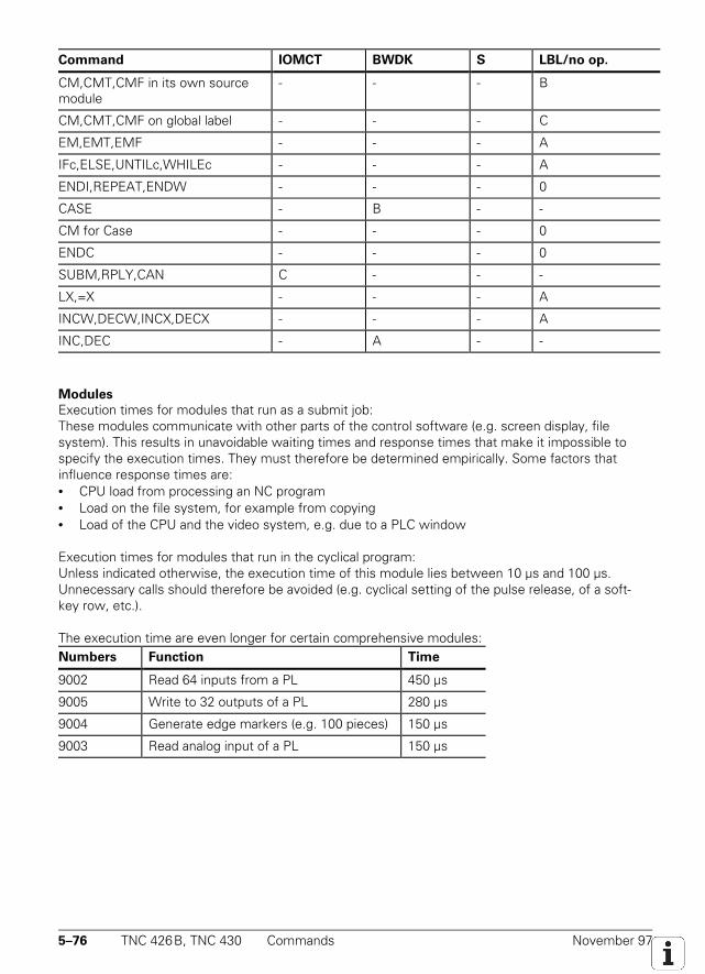
5–76 TNC 426B, TNC 430 Commands November 97
Command IOMCT BWDK S LBL/no op.
CM,CMT,CMF in its own sourcemodule
- - - B
CM,CMT,CMF on global label - - - C
EM,EMT,EMF - - - A
IFc,ELSE,UNTILc,WHILEc - - - A
ENDI,REPEAT,ENDW - - - 0
CASE - B - -
CM for Case - - - 0
ENDC - - - 0
SUBM,RPLY,CAN C - - -
LX,=X - - - A
INCW,DECW,INCX,DECX - - - A
INC,DEC - A - -
Modules
Execution times for modules that run as a submit job:These modules communicate with other parts of the control software (e.g. screen display, filesystem). This results in unavoidable waiting times and response times that make it impossible tospecify the execution times. They must therefore be determined empirically. Some factors thatinfluence response times are:• CPU load from processing an NC program• Load on the file system, for example from copying• Load of the CPU and the video system, e.g. due to a PLC window
Execution times for modules that run in the cyclical program:Unless indicated otherwise, the execution time of this module lies between 10 µs and 100 µs.Unnecessary calls should therefore be avoided (e.g. cyclical setting of the pulse release, of a soft-key row, etc.).
The execution time are even longer for certain comprehensive modules:Numbers Function Time
9002 Read 64 inputs from a PL 450 µs
9005 Write to 32 outputs of a PL 280 µs
9004 Generate edge markers (e.g. 100 pieces) 150 µs
9003 Read analog input of a PL 150 µs
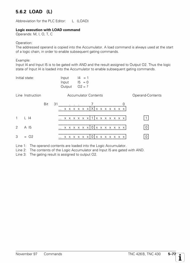
November 97 Commands TNC 426B, TNC 430 5–77
5.6.2 LOAD (L) L
Abbreviation for the PLC Editor: L (LOAD)
Logic execution with LOAD command
Operands: M, I, O, T, C
Operation:The addressed operand is copied into the Accumulator. A load command is always used at the startof a logic chain, in order to enable subsequent gating commands.
Example:Input I4 and Input I5 is to be gated with AND and the result assigned to Output O2. Thus the logicstate of Input I4 is loaded into the Accumulator to enable subsequent gating commands.
Initial state: Input I4 = 1Input I5 = 0Output O2 = ?
Line Instruction Accumulator Contents Operand-Contents
Bit 31 . . . 7 0... x x x x x x X x x x x x x x
1 L I4 ... x x x x x x 1 x x x x x x x 1
2 A I5 ... x x x x x x 0 x x x x x x x 0
3 = O2 ... x x x x x x 0 x x x x x x x 0
Line 1: The operand contents are loaded into the Logic Accumulator.Line 2: The contents of the Logic Accumulator and Input I5 are gated with AND.Line 3: The gating result is assigned to output O2.
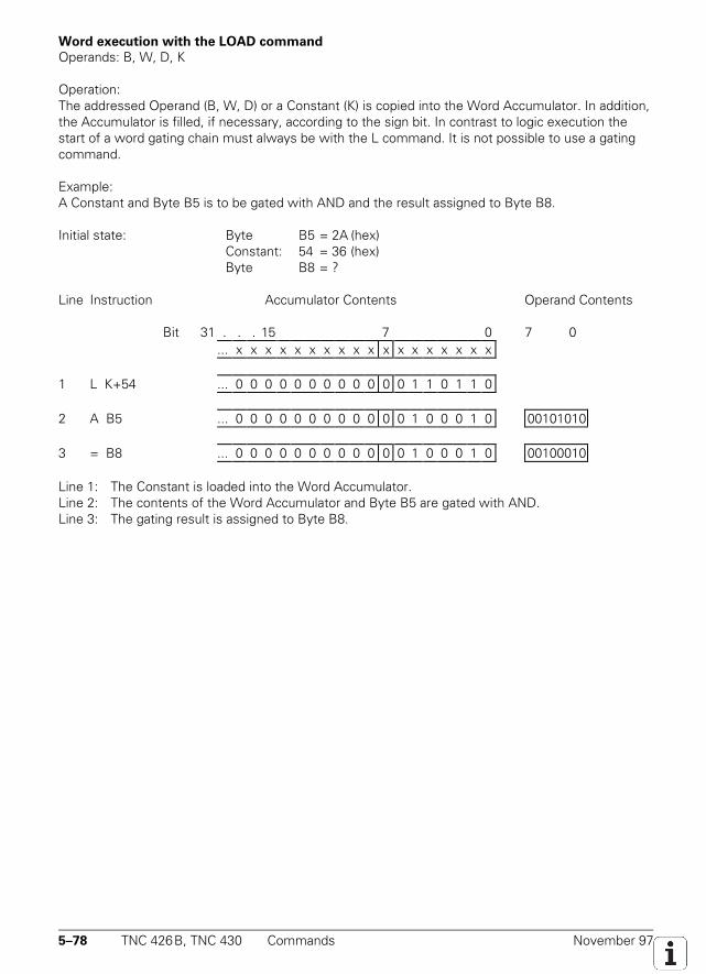
5–78 TNC 426B, TNC 430 Commands November 97
Word execution with the LOAD command
Operands: B, W, D, K
Operation:The addressed Operand (B, W, D) or a Constant (K) is copied into the Word Accumulator. In addition,the Accumulator is filled, if necessary, according to the sign bit. In contrast to logic execution thestart of a word gating chain must always be with the L command. It is not possible to use a gatingcommand.
Example:A Constant and Byte B5 is to be gated with AND and the result assigned to Byte B8.
Initial state: Byte B5 = 2A (hex)Constant: 54 = 36 (hex)Byte B8 = ?
Line Instruction Accumulator Contents Operand Contents
Bit 31 . . . 15 7 0 7 0... x x x x x x x x x x x x x x x x x x
1 L K+54 ... 0 0 0 0 0 0 0 0 0 0 0 0 1 1 0 1 1 0
2 A B5 ... 0 0 0 0 0 0 0 0 0 0 0 0 1 0 0 0 1 0 00101010
3 = B8 ... 0 0 0 0 0 0 0 0 0 0 0 0 1 0 0 0 1 0 00100010
Line 1: The Constant is loaded into the Word Accumulator.Line 2: The contents of the Word Accumulator and Byte B5 are gated with AND.Line 3: The gating result is assigned to Byte B8.
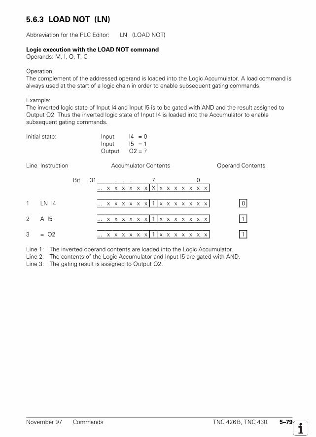
November 97 Commands TNC 426B, TNC 430 5–79
5.6.3 LOAD NOT (LN) LN
Abbreviation for the PLC Editor: LN (LOAD NOT)
Logic execution with the LOAD NOT command
Operands: M, I, O, T, C
Operation:The complement of the addressed operand is loaded into the Logic Accumulator. A load command isalways used at the start of a logic chain in order to enable subsequent gating commands.
Example:The inverted logic state of Input I4 and Input I5 is to be gated with AND and the result assigned toOutput O2. Thus the inverted logic state of Input I4 is loaded into the Accumulator to enablesubsequent gating commands.
Initial state: Input I4 = 0Input I5 = 1Output O2 = ?
Line Instruction Accumulator Contents Operand Contents
Bit 31 . . . 7 0... x x x x x x X x x x x x x x
1 LN I4 ... x x x x x x 1 x x x x x x x 0
2 A I5 ... x x x x x x 1 x x x x x x x 1
3 = O2 ... x x x x x x 1 x x x x x x x 1
Line 1: The inverted operand contents are loaded into the Logic Accumulator.Line 2: The contents of the Logic Accumulator and Input I5 are gated with AND.Line 3: The gating result is assigned to Output O2.
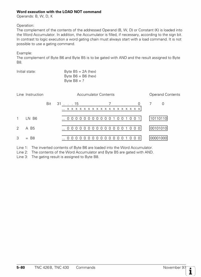
5–80 TNC 426B, TNC 430 Commands November 97
Word execution with the LOAD NOT command
Operands: B, W, D, K
Operation:The complement of the contents of the addressed Operand (B, W, D) or Constant (K) is loaded intothe Word Accumulator. In addition, the Accumulator is filled, if necessary, according to the sign bit.In contrast to logic execution a word gating chain must always start with a load command. It is notpossible to use a gating command.
Example:The complement of Byte B6 and Byte B5 is to be gated with AND and the result assigned to ByteB8.
Initial state: Byte B5 = 2A (hex)Byte B6 = B6 (hex)Byte B8 = ?
Line Instruction Accumulator Contents Operand Contents
Bit 31 . . . 15 7 0 7 0... x x x x x x x x x x x x x x x x x x
1 LN B6 ... 0 0 0 0 0 0 0 0 0 0 0 1 0 0 1 0 0 1 10110110
2 A B5 ... 0 0 0 0 0 0 0 0 0 0 0 0 0 0 1 0 0 0 00101010
3 = B8 ... 0 0 0 0 0 0 0 0 0 0 0 0 0 0 1 0 0 0 00001000
Line 1: The inverted contents of Byte B6 are loaded into the Word Accumulator.Line 2: The contents of the Word Accumulator and Byte B5 are gated with AND.Line 3: The gating result is assigned to Byte B8.
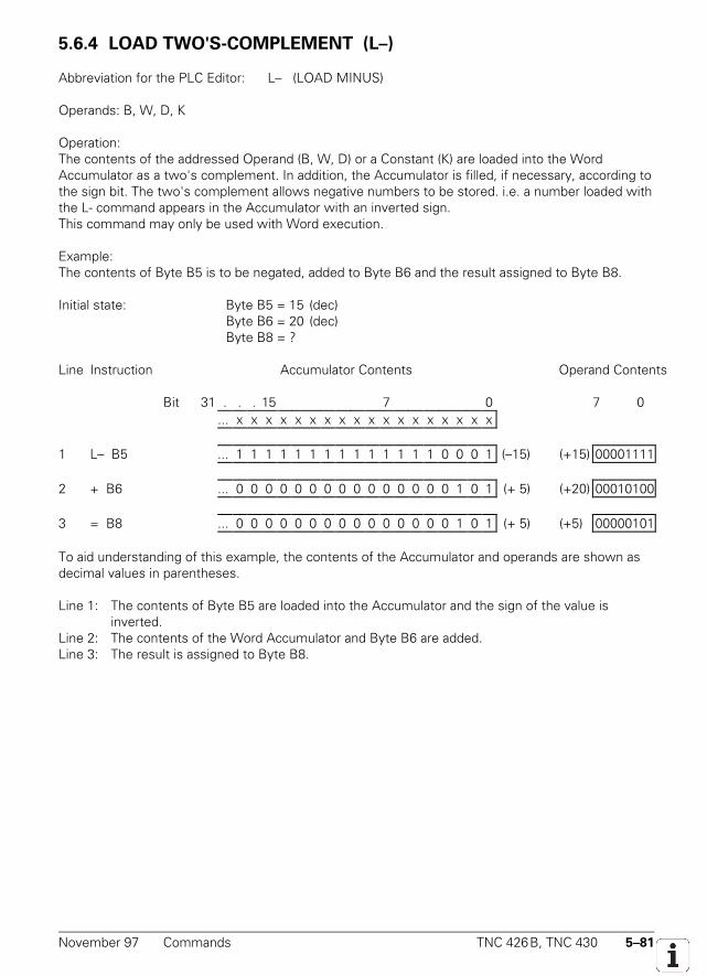
November 97 Commands TNC 426B, TNC 430 5–81
5.6.4 LOAD TWO'S-COMPLEMENT (L–)
Abbreviation for the PLC Editor: L– (LOAD MINUS)
Operands: B, W, D, K
Operation:The contents of the addressed Operand (B, W, D) or a Constant (K) are loaded into the WordAccumulator as a two's complement. In addition, the Accumulator is filled, if necessary, according tothe sign bit. The two's complement allows negative numbers to be stored. i.e. a number loaded withthe L- command appears in the Accumulator with an inverted sign.This command may only be used with Word execution.
Example:The contents of Byte B5 is to be negated, added to Byte B6 and the result assigned to Byte B8.
Initial state: Byte B5 = 15 (dec)Byte B6 = 20 (dec)Byte B8 = ?
Line Instruction Accumulator Contents Operand Contents
Bit 31 . . . 15 7 0 7 0... x x x x x x x x x x x x x x x x x x
1 L– B5 ... 1 1 1 1 1 1 1 1 1 1 1 1 1 1 0 0 0 1 (–15) (+15) 00001111
2 + B6 ... 0 0 0 0 0 0 0 0 0 0 0 0 0 0 0 1 0 1 (+ 5) (+20) 00010100
3 = B8 ... 0 0 0 0 0 0 0 0 0 0 0 0 0 0 0 1 0 1 (+ 5) (+5) 00000101
To aid understanding of this example, the contents of the Accumulator and operands are shown asdecimal values in parentheses.
Line 1: The contents of Byte B5 are loaded into the Accumulator and the sign of the value is inverted.
Line 2: The contents of the Word Accumulator and Byte B6 are added.Line 3: The result is assigned to Byte B8.
5–82 TNC 426B, TNC 430 Commands November 97
5.6.5 LOAD BYTE (LB) LB
Abbreviation for the PLC Editor: LB (LOAD BYTE)
Operands: M, I, O, T, C
Operation:With the command LB, 8 Markers, Inputs, Outputs, Timers or Counters with ascending numberingare loaded into the Word Accumulator. Each operand occupies 1 bit in the Accumulator. Thedesignated operand address occupies the LSB in the Accumulator, the designated address + 1 theLSB + 1 and so on. In this way, the last affected operand occupies the MSB! If necessary, theAccumulator is filled according to the sign bit.
5.6.6 LOAD WORD (LW) LW
Abbreviation for the PLC Editor: LW (LOAD WORD)
Operands: M, I, O, T, C
Operation:With the command LW, 16 Markers, Inputs, Outputs, Timers or Counters with ascending numberingare loaded into the Word Accumulator. Each operand occupies 1 bit in the Accumulator. Thedesignated operand address occupies the LSB in the Accumulator, the designated address + 1 theLSB + 1 and so on. In this way, the last affected operand occupies the MSB! If necessary, theAccumulator is filled according to the sign bit.
5.6.7 LOAD DOUBLEWORD (LD) LD
Abbreviation for the PLC Editor: LD (LOAD DOUBLE WORD)
Operands: M, I, O, T, C
Operation:With the command LD, 32 Markers, Inputs, Outputs, Timers or Counters with ascending numberingare loaded into the Word Accumulator. Each operand occupies 1 bit in the Accumulator. Thedesignated operand address occupies the LSB in the Accumulator, the designated address + 1 theLSB + 1 and so on. In this way, the last affected operand occupies the MSB! If necessary, theAccumulator is filled according to the sign bit.
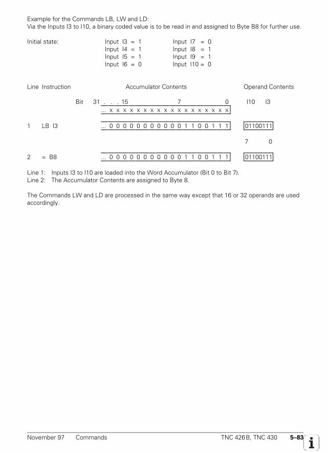
November 97 Commands TNC 426B, TNC 430 5–83
Example for the Commands LB, LW and LD:Via the Inputs I3 to I10, a binary coded value is to be read in and assigned to Byte B8 for further use.
Initial state: Input I3 = 1 Input I7 = 0Input I4 = 1 Input I8 = 1Input I5 = 1 Input I9 = 1Input I6 = 0 Input I10 = 0
Line Instruction Accumulator Contents Operand Contents
Bit 31 . . . 15 7 0 I10 I3... x x x x x x x x x x x x x x x x x x
1 LB I3 ... 0 0 0 0 0 0 0 0 0 0 0 1 1 0 0 1 1 1 01100111
7 0
2 = B8 ... 0 0 0 0 0 0 0 0 0 0 0 1 1 0 0 1 1 1 01100111
Line 1: Inputs I3 to I10 are loaded into the Word Accumulator (Bit 0 to Bit 7).Line 2: The Accumulator Contents are assigned to Byte 8.
The Commands LW and LD are processed in the same way except that 16 or 32 operands are usedaccordingly.
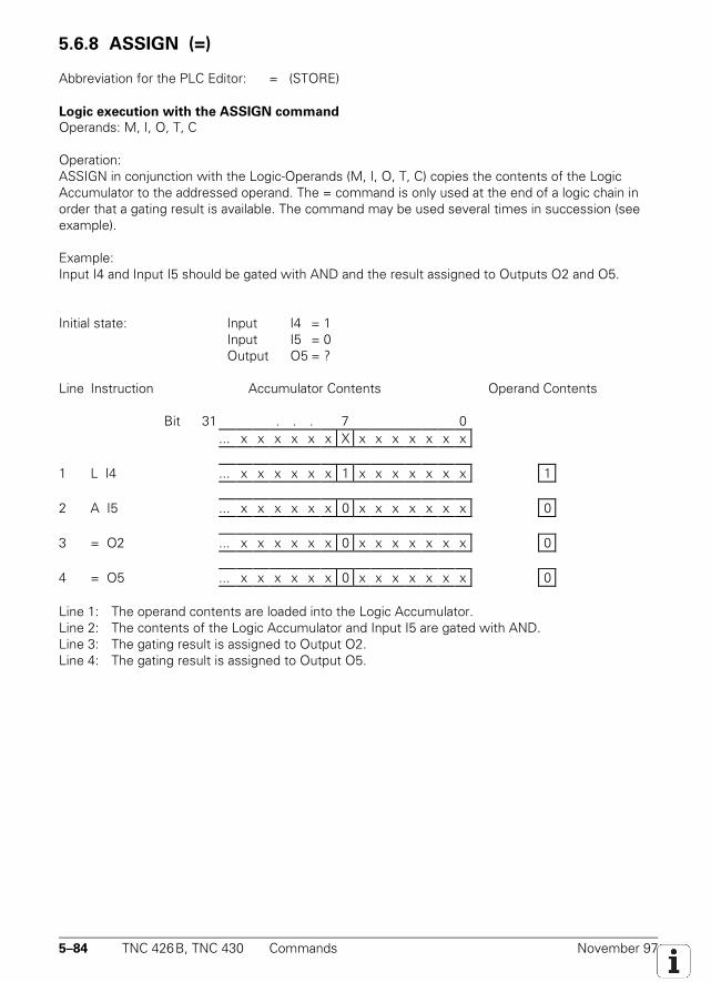
5–84 TNC 426B, TNC 430 Commands November 97
5.6.8 ASSIGN (=)
Abbreviation for the PLC Editor: = (STORE)
Logic execution with the ASSIGN command
Operands: M, I, O, T, C
Operation:ASSIGN in conjunction with the Logic-Operands (M, I, O, T, C) copies the contents of the LogicAccumulator to the addressed operand. The = command is only used at the end of a logic chain inorder that a gating result is available. The command may be used several times in succession (seeexample).
Example:Input I4 and Input I5 should be gated with AND and the result assigned to Outputs O2 and O5.
Initial state: Input I4 = 1Input I5 = 0Output O5 = ?
Line Instruction Accumulator Contents Operand Contents
Bit 31 . . . 7 0... x x x x x x X x x x x x x x
1 L I4 ... x x x x x x 1 x x x x x x x 1
2 A I5 ... x x x x x x 0 x x x x x x x 0
3 = O2 ... x x x x x x 0 x x x x x x x 0
4 = O5 ... x x x x x x 0 x x x x x x x 0
Line 1: The operand contents are loaded into the Logic Accumulator.Line 2: The contents of the Logic Accumulator and Input I5 are gated with AND.Line 3: The gating result is assigned to Output O2.Line 4: The gating result is assigned to Output O5.
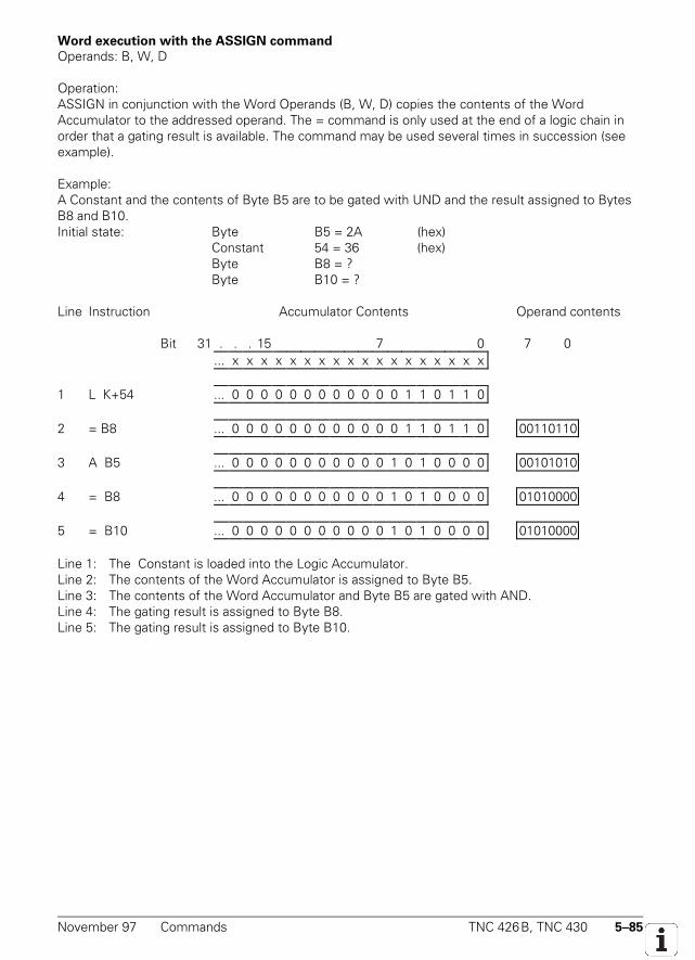
November 97 Commands TNC 426B, TNC 430 5–85
Word execution with the ASSIGN command
Operands: B, W, D
Operation:ASSIGN in conjunction with the Word Operands (B, W, D) copies the contents of the WordAccumulator to the addressed operand. The = command is only used at the end of a logic chain inorder that a gating result is available. The command may be used several times in succession (seeexample).
Example:A Constant and the contents of Byte B5 are to be gated with UND and the result assigned to BytesB8 and B10.Initial state: Byte B5 = 2A (hex)
Constant 54 = 36 (hex)Byte B8 = ?Byte B10 = ?
Line Instruction Accumulator Contents Operand contents
Bit 31 . . . 15 7 0 7 0... x x x x x x x x x x x x x x x x x x
1 L K+54 ... 0 0 0 0 0 0 0 0 0 0 0 0 1 1 0 1 1 0
2 = B8 ... 0 0 0 0 0 0 0 0 0 0 0 0 1 1 0 1 1 0 00110110
3 A B5 ... 0 0 0 0 0 0 0 0 0 0 0 1 0 1 0 0 0 0 00101010
4 = B8 ... 0 0 0 0 0 0 0 0 0 0 0 1 0 1 0 0 0 0 01010000
5 = B10 ... 0 0 0 0 0 0 0 0 0 0 0 1 0 1 0 0 0 0 01010000
Line 1: The Constant is loaded into the Logic Accumulator.Line 2: The contents of the Word Accumulator is assigned to Byte B5.Line 3: The contents of the Word Accumulator and Byte B5 are gated with AND.Line 4: The gating result is assigned to Byte B8.Line 5: The gating result is assigned to Byte B10.
5–86 TNC 426B, TNC 430 Commands November 97
5.6.9 ASSIGN BYTE (B=)
Abbreviation for the PLC Editor: B= (STORE BYTE)
Operands: M, I, O, T, C
Operation:With the command B=, 8 bits are copied from the Word Accumulator to Markers, Inputs, Outputs,Timers or Counters with ascending numbering. Each bit corresponds to 1 operand. The LSB in theAccumulator is copied to the designated operand address, the LSB + 1 to the designated address +1 and so on. The last affected operand is occupied by the MSB.
5.6.10 ASSIGN WORD (W=) W=
Abbreviation for the PLC Editor: W= (STORE WORD)
Operands: M, I, O, T, C
Operation:With the command W=, 16 bits are copied from the Word Accumulator to Markers, Inputs,Outputs, Timers or Counters with ascending numbering. Each bit corresponds to 1 operand. TheLSB in the Accumulator is copied to the designated operand address, the LSB + 1 to the designatedaddress + 1 and so on. The last affected operand is occupied by the MSB.
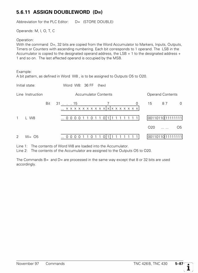
November 97 Commands TNC 426B, TNC 430 5–87
5.6.11 ASSIGN DOUBLEWORD (D=)
Abbreviation for the PLC Editor: D= (STORE DOUBLE)
Operands: M, I, O, T, C
Operation:With the command D=, 32 bits are copied from the Word Accumulator to Markers, Inputs, Outputs,Timers or Counters with ascending numbering. Each bit corresponds to 1 operand. The LSB in theAccumulator is copied to the designated operand address, the LSB + 1 to the designated address +1 and so on. The last affected operand is occupied by the MSB.
Example:A bit pattern, as defined in Word W8 , is to be assigned to Outputs O5 to O20.
Initial state: Word W8: 36 FF (hex)
Line Instruction Accumulator Contents Operand Contents
Bit 31 . . . 15 7 0 15 8 7 0... x x x x x x x x x x x x x x x x x x
1 L W8 ... 0 0 0 0 1 1 0 1 1 0 1 1 1 1 1 1 1 1 00110110 11111111
O20 ... ... O5
2 W= O5 ... 0 0 0 0 1 1 0 1 1 0 1 1 1 1 1 1 1 1 00110110 11111111
Line 1: The contents of Word W8 are loaded into the Accumulator.Line 2: The contents of the Accumulator are assigned to the Outputs O5 to O20.
The Commands B= and D= are processed in the same way except that 8 or 32 bits are usedaccordingly.
5–88 TNC 426B, TNC 430 Commands November 97
5.6.12 ASSIGN NOT (=N)
Abbreviation for the PLC Editor: =N (STORE NOT)
Logic processing
Operands: M,I,O,T,C
Operation:An ASSIGN NOT in conjunction with a logic operand (M,I,O,T,C) copies the one's complement of thecontents of the logic accumulator to the addressed operand.For example see ASSIGN command (=).
Word processing
Operands: B,W;D
Operation:An ASSIGN NOT in conjunction with a word operand (B,W,D) copies the one's complement of thecontents of the word accumulator to the addressed operand. For an example, see ASSIGNcommand (=)
5.6.13 ASSIGN TWO'S COMPLEMENT (=-)
Abbreviation for the PLC Editor: = - (STORE MINUS)Operands: B, W, D
Operation:An ASSIGN TWO'S COMPLEMENT copies the two's complement of the contents of the wordaccumulator to the addressed operand. For example see ASSIGN command (=).
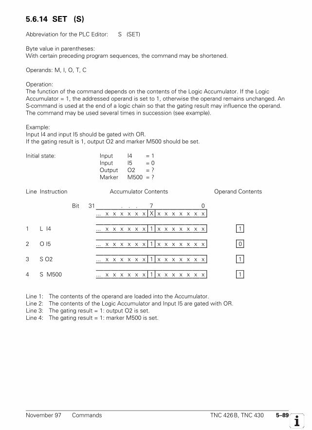
November 97 Commands TNC 426B, TNC 430 5–89
5.6.14 SET (S)
Abbreviation for the PLC Editor: S (SET)
Byte value in parentheses:With certain preceding program sequences, the command may be shortened.
Operands: M, I, O, T, C
Operation:The function of the command depends on the contents of the Logic Accumulator. If the LogicAccumulator = 1, the addressed operand is set to 1, otherwise the operand remains unchanged. AnS-command is used at the end of a logic chain so that the gating result may influence the operand.The command may be used several times in succession (see example).
Example:Input I4 and input I5 should be gated with OR.If the gating result is 1, output O2 and marker M500 should be set.
Initial state: Input I4 = 1Input I5 = 0Output O2 = ?Marker M500 = ?
Line Instruction Accumulator Contents Operand Contents
Bit 31 . . . 7 0... x x x x x x X x x x x x x x
1 L I4 ... x x x x x x 1 x x x x x x x 1
2 O I5 ... x x x x x x 1 x x x x x x x 0
3 S O2 ... x x x x x x 1 x x x x x x x 1
4 S M500 ... x x x x x x 1 x x x x x x x 1
Line 1: The contents of the operand are loaded into the Accumulator.Line 2: The contents of the Logic Accumulator and Input I5 are gated with OR.Line 3: The gating result = 1: output O2 is set.Line 4: The gating result = 1: marker M500 is set.
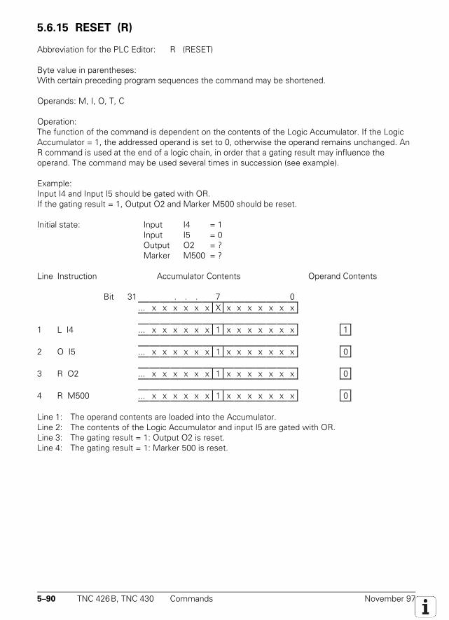
5–90 TNC 426B, TNC 430 Commands November 97
5.6.15 RESET (R)
Abbreviation for the PLC Editor: R (RESET)
Byte value in parentheses:With certain preceding program sequences the command may be shortened.
Operands: M, I, O, T, C
Operation:The function of the command is dependent on the contents of the Logic Accumulator. If the LogicAccumulator = 1, the addressed operand is set to 0, otherwise the operand remains unchanged. AnR command is used at the end of a logic chain, in order that a gating result may influence theoperand. The command may be used several times in succession (see example).
Example:Input I4 and Input I5 should be gated with OR.If the gating result = 1, Output O2 and Marker M500 should be reset.
Initial state: Input I4 = 1Input I5 = 0Output O2 = ?Marker M500 = ?
Line Instruction Accumulator Contents Operand Contents
Bit 31 . . . 7 0... x x x x x x X x x x x x x x
1 L I4 ... x x x x x x 1 x x x x x x x 1
2 O I5 ... x x x x x x 1 x x x x x x x 0
3 R O2 ... x x x x x x 1 x x x x x x x 0
4 R M500 ... x x x x x x 1 x x x x x x x 0
Line 1: The operand contents are loaded into the Accumulator.Line 2: The contents of the Logic Accumulator and input I5 are gated with OR.Line 3: The gating result = 1: Output O2 is reset.Line 4: The gating result = 1: Marker 500 is reset.
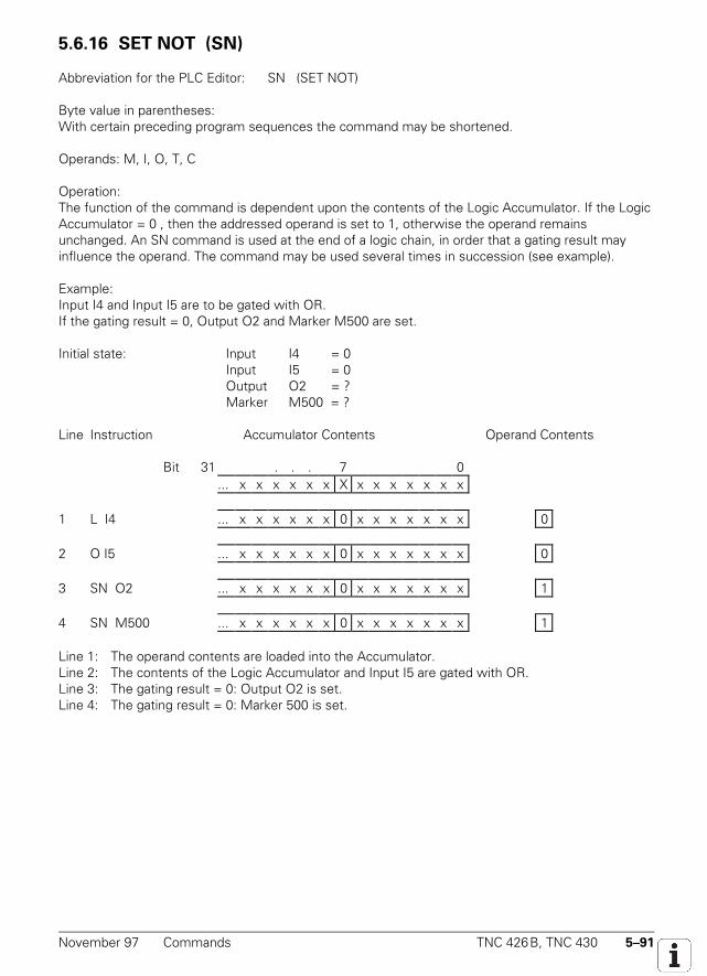
November 97 Commands TNC 426B, TNC 430 5–91
5.6.16 SET NOT (SN)
Abbreviation for the PLC Editor: SN (SET NOT)
Byte value in parentheses:With certain preceding program sequences the command may be shortened.
Operands: M, I, O, T, C
Operation:The function of the command is dependent upon the contents of the Logic Accumulator. If the LogicAccumulator = 0 , then the addressed operand is set to 1, otherwise the operand remainsunchanged. An SN command is used at the end of a logic chain, in order that a gating result mayinfluence the operand. The command may be used several times in succession (see example).
Example:Input I4 and Input I5 are to be gated with OR.If the gating result = 0, Output O2 and Marker M500 are set.
Initial state: Input I4 = 0Input I5 = 0Output O2 = ?Marker M500 = ?
Line Instruction Accumulator Contents Operand Contents
Bit 31 . . . 7 0... x x x x x x X x x x x x x x
1 L I4 ... x x x x x x 0 x x x x x x x 0
2 O I5 ... x x x x x x 0 x x x x x x x 0
3 SN O2 ... x x x x x x 0 x x x x x x x 1
4 SN M500 ... x x x x x x 0 x x x x x x x 1
Line 1: The operand contents are loaded into the Accumulator.Line 2: The contents of the Logic Accumulator and Input I5 are gated with OR.Line 3: The gating result = 0: Output O2 is set.Line 4: The gating result = 0: Marker 500 is set.
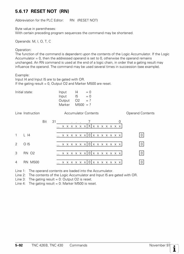
5–92 TNC 426B, TNC 430 Commands November 97
5.6.17 RESET NOT (RN)RN
Abbreviation for the PLC Editor: RN (RESET NOT)
Byte value in parentheses:With certain preceding program sequences the command may be shortened.
Operands: M, I, O, T, C
Operation:The function of the command is dependent upon the contents of the Logic Accumulator. If the LogicAccumulator = 0, then the addressed operand is set to 0, otherwise the operand remainsunchanged. An RN command is used at the end of a logic chain, in order that a gating result mayinfluence the operand. The command may be used several times in succession (see example).
Example:Input I4 and Input I5 are to be gated with OR.If the gating result = 0, Output O2 and Marker M500 are reset.
Initial state: Input I4 = 0Input I5 = 0Output O2 = ?Marker M500 = ?
Line Instruction Accumulator Contents Operand Contents
Bit 31 . . . 7 0... x x x x x x X x x x x x x x
1 L I4 ... x x x x x x 0 x x x x x x x 0
2 O I5 ... x x x x x x 0 x x x x x x x 0
3 RN O2 ... x x x x x x 0 x x x x x x x 0
4 RN M500 ... x x x x x x 0 x x x x x x x 0
Line 1: The operand contents are loaded into the Accumulator.Line 2: The contents of the Logic Accumulator and Input I5 are gated with OR.Line 3: The gating result = 0: Output O2 is reset.Line 4: The gating result = 0: Marker M500 is reset.
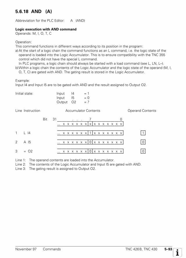
November 97 Commands TNC 426B, TNC 430 5–93
5.6.18 AND (A)
Abbreviation for the PLC Editor: A (AND)
Logic execution with AND command
Operands: M, I, O, T, C
Operation:This command functions in different ways according to its position in the program:a) At the start of a logic chain the command functions as an L command, i.e. the logic state of the
operand is loaded into the Logic Accumulator. This is to ensure compatibility with the TNC 355control which did not have the special L command.In PLC programs, a logic chain should always be started with a load command (see L, LN, L–).
b)Within a logic chain the contents of the Logic Accumulator and the logic state of the operand (M, I,O, T, C) are gated with AND. The gating result is stored in the Logic Accumulator.
Example:Input I4 and Input I5 are to be gated with AND and the result assigned to Output O2.
Initial state: Input I4 = 1Input I5 = 0Output O2 = ?
Line Instruction Accumulator Contents Operand Contents
Bit 31 . . . 7 0... x x x x x x x x x x x x x x
1 L I4 ... x x x x x x 1 x x x x x x x 1
2 A I5 ... x x x x x x 0 x x x x x x x 0
3 = O2 ... x x x x x x 0 x x x x x x x 0
Line 1: The operand contents are loaded into the Accumulator.Line 2: The contents of the Logic Accumulator and Input I5 are gated with AND.Line 3: The gating result is assigned to Output O2.
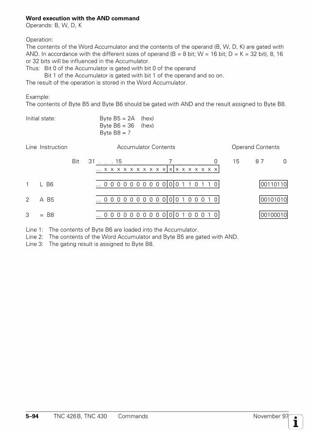
5–94 TNC 426B, TNC 430 Commands November 97
Word execution with the AND command
Operands: B, W, D, K
Operation:The contents of the Word Accumulator and the contents of the operand (B, W, D, K) are gated withAND. In accordance with the different sizes of operand (B = 8 bit; W = 16 bit; D = K = 32 bit), 8, 16or 32 bits will be influenced in the Accumulator.Thus: Bit 0 of the Accumulator is gated with bit 0 of the operand
Bit 1 of the Accumulator is gated with bit 1 of the operand and so on.The result of the operation is stored in the Word Accumulator.
Example:The contents of Byte B5 and Byte B6 should be gated with AND and the result assigned to Byte B8.
Initial state: Byte B5 = 2A (hex)Byte B6 = 36 (hex)Byte B8 = ?
Line Instruction Accumulator Contents Operand Contents
Bit 31 . . . 15 7 0 15 8 7 0... x x x x x x x x x x x x x x x x x x
1 L B6 ... 0 0 0 0 0 0 0 0 0 0 0 0 1 1 0 1 1 0 00110110
2 A B5 ... 0 0 0 0 0 0 0 0 0 0 0 0 1 0 0 0 1 0 00101010
3 = B8 ... 0 0 0 0 0 0 0 0 0 0 0 0 1 0 0 0 1 0 00100010
Line 1: The contents of Byte B6 are loaded into the Accumulator.Line 2: The contents of the Word Accumulator and Byte B5 are gated with AND.Line 3: The gating result is assigned to Byte B8.
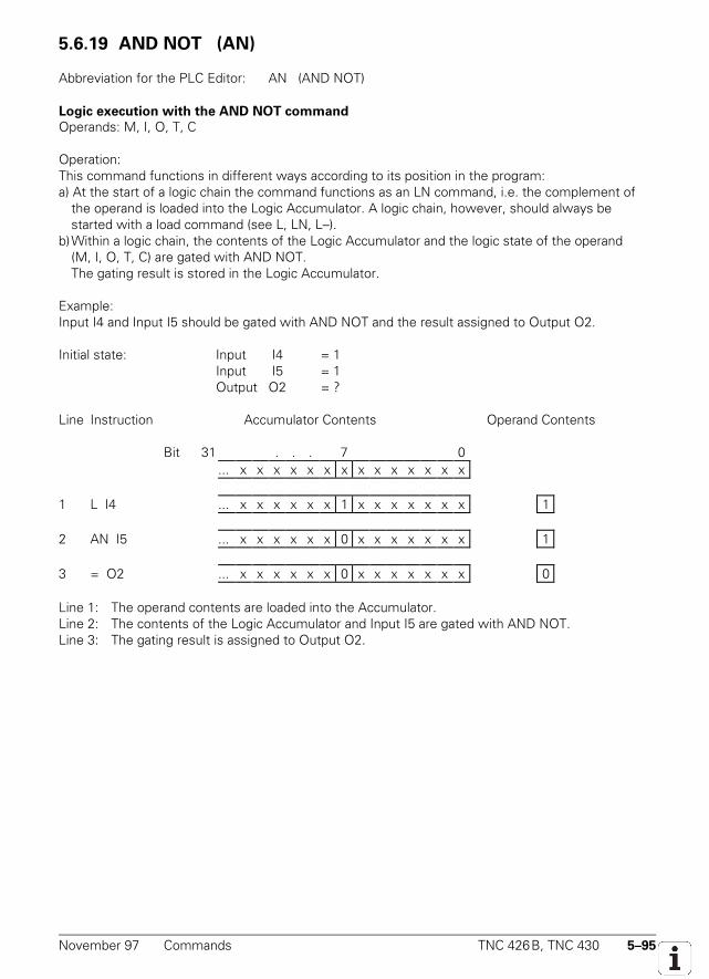
November 97 Commands TNC 426B, TNC 430 5–95
5.6.19 AND NOT (AN) AN
Abbreviation for the PLC Editor: AN (AND NOT)
Logic execution with the AND NOT command
Operands: M, I, O, T, C
Operation:This command functions in different ways according to its position in the program:a) At the start of a logic chain the command functions as an LN command, i.e. the complement of
the operand is loaded into the Logic Accumulator. A logic chain, however, should always bestarted with a load command (see L, LN, L–).
b)Within a logic chain, the contents of the Logic Accumulator and the logic state of the operand(M, I, O, T, C) are gated with AND NOT.The gating result is stored in the Logic Accumulator.
Example:Input I4 and Input I5 should be gated with AND NOT and the result assigned to Output O2.
Initial state: Input I4 = 1Input I5 = 1Output O2 = ?
Line Instruction Accumulator Contents Operand Contents
Bit 31 . . . 7 0... x x x x x x x x x x x x x x
1 L I4 ... x x x x x x 1 x x x x x x x 1
2 AN I5 ... x x x x x x 0 x x x x x x x 1
3 = O2 ... x x x x x x 0 x x x x x x x 0
Line 1: The operand contents are loaded into the Accumulator.Line 2: The contents of the Logic Accumulator and Input I5 are gated with AND NOT.Line 3: The gating result is assigned to Output O2.
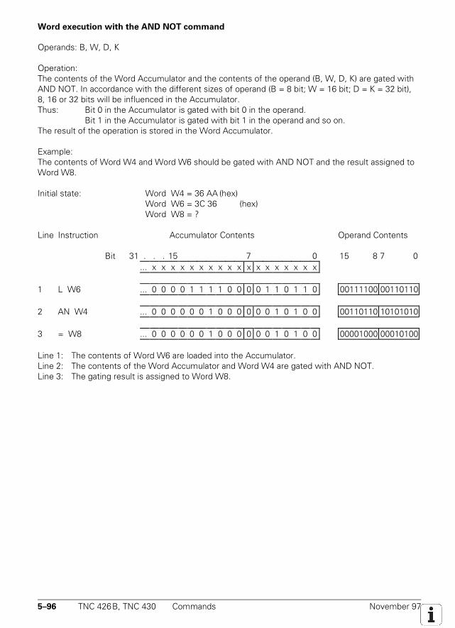
5–96 TNC 426B, TNC 430 Commands November 97
Word execution with the AND NOT command
Operands: B, W, D, K
Operation:The contents of the Word Accumulator and the contents of the operand (B, W, D, K) are gated withAND NOT. In accordance with the different sizes of operand (B = 8 bit; W = 16 bit; D = K = 32 bit),8, 16 or 32 bits will be influenced in the Accumulator.Thus: Bit 0 in the Accumulator is gated with bit 0 in the operand.
Bit 1 in the Accumulator is gated with bit 1 in the operand and so on.The result of the operation is stored in the Word Accumulator.
Example:The contents of Word W4 and Word W6 should be gated with AND NOT and the result assigned toWord W8.
Initial state: Word W4 = 36 AA (hex)Word W6 = 3C 36 (hex)Word W8 = ?
Line Instruction Accumulator Contents Operand Contents
Bit 31 . . . 15 7 0 15 8 7 0... x x x x x x x x x x x x x x x x x x
1 L W6 ... 0 0 0 0 1 1 1 1 0 0 0 0 1 1 0 1 1 0 00111100 00110110
2 AN W4 ... 0 0 0 0 0 0 1 0 0 0 0 0 0 1 0 1 0 0 00110110 10101010
3 = W8 ... 0 0 0 0 0 0 1 0 0 0 0 0 0 1 0 1 0 0 00001000 00010100
Line 1: The contents of Word W6 are loaded into the Accumulator.Line 2: The contents of the Word Accumulator and Word W4 are gated with AND NOT.Line 3: The gating result is assigned to Word W8.
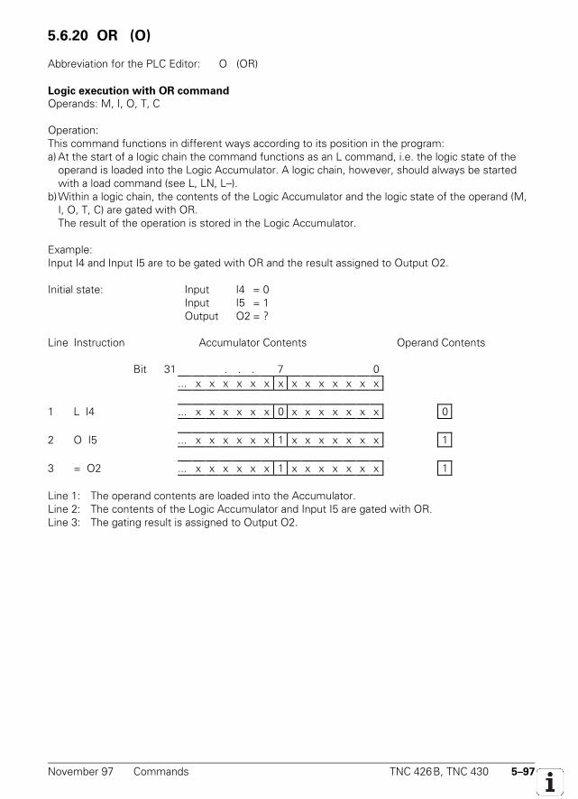
November 97 Commands TNC 426B, TNC 430 5–97
5.6.20 OR (O) O
Abbreviation for the PLC Editor: O (OR)
Logic execution with OR command
Operands: M, I, O, T, C
Operation:This command functions in different ways according to its position in the program:a) At the start of a logic chain the command functions as an L command, i.e. the logic state of the
operand is loaded into the Logic Accumulator. A logic chain, however, should always be startedwith a load command (see L, LN, L–).
b)Within a logic chain, the contents of the Logic Accumulator and the logic state of the operand (M,I, O, T, C) are gated with OR.The result of the operation is stored in the Logic Accumulator.
Example:Input I4 and Input I5 are to be gated with OR and the result assigned to Output O2.
Initial state: Input I4 = 0Input I5 = 1Output O2 = ?
Line Instruction Accumulator Contents Operand Contents
Bit 31 . . . 7 0... x x x x x x x x x x x x x x
1 L I4 ... x x x x x x 0 x x x x x x x 0
2 O I5 ... x x x x x x 1 x x x x x x x 1
3 = O2 ... x x x x x x 1 x x x x x x x 1
Line 1: The operand contents are loaded into the Accumulator.Line 2: The contents of the Logic Accumulator and Input I5 are gated with OR.Line 3: The gating result is assigned to Output O2.
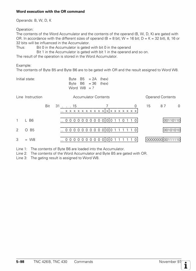
5–98 TNC 426B, TNC 430 Commands November 97
Word execution with the OR command
Operands: B, W, D, K
Operation:The contents of the Word Accumulator and the contents of the operand (B, W, D, K) are gated withOR. In accordance with the different sizes of operand (B = 8 bit; W = 16 bit; D = K = 32 bit), 8, 16 or32 bits will be influenced in the Accumulator.Thus: Bit 0 in the Accumulator is gated with bit 0 in the operand
Bit 1 in the Accumulator is gated with bit 1 in the operand and so on.The result of the operation is stored in the Word Accumulator.
Example:The contents of Byte B5 and Byte B6 are to be gated with OR and the result assigned to Word W8.
Initial state: Byte B5 = 2A (hex) Byte B6 = 36 (hex) Word W8 = ?
Line Instruction Accumulator Contents Operand Contents
Bit 31 . . . 15 7 0 15 8 7 0... x x x x x x x x x x x x x x x x x x
1 L B6 ... 0 0 0 0 0 0 0 0 0 0 0 0 1 1 0 1 1 0 00110110
2 O B5 ... 0 0 0 0 0 0 0 0 0 0 0 0 1 1 1 1 1 0 00101010
3 = W8 ... 0 0 0 0 0 0 0 0 0 0 0 0 1 1 1 1 1 0 00000000 00111110
Line 1: The contents of Byte B6 are loaded into the Accumulator.Line 2: The contents of the Word Accumulator and Byte B5 are gated with OR.Line 3: The gating result is assigned to Word W8.
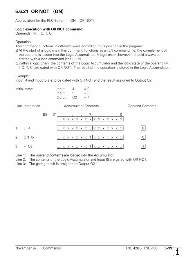
November 97 Commands TNC 426B, TNC 430 5–99
5.6.21 OR NOT (ON)
Abbreviation for the PLC Editor: ON (OR NOT)
Logic execution with OR NOT command
Operands: M, I, O, T, C
Operation:This command functions in different ways according to its position in the program:a) At the start of a logic chain this command functions as an LN command, i.e. the complement of
the operand is loaded into the Logic Accumulator. A logic chain, however, should always bestarted with a load command (see L, LN, L–).
b)Within a logic chain, the contents of the Logic Accumulator and the logic state of the operand (M,I, O, T, C) are gated with OR NOT. The result of the operation is stored in the Logic Accumulator.
Example:Input I4 and Input I5 are to be gated with OR NOT and the result assigned to Output O2.
Initial state: Input I4 = 0Input I5 = 0Output O2 = ?
Line Instruction Accumulator Contents Operand Contents
Bit 31 . . . 7 0... x x x x x x x x x x x x x x
1 L I4 ... x x x x x x 0 x x x x x x x 0
2 ON I5 ... x x x x x x 1 x x x x x x x 0
3 = O2 ... x x x x x x 1 x x x x x x x 1
Line 1: The operand contents are loaded into the Accumulator.Line 2: The contents of the Logic Accumulator and Input I5 are gated with OR NOT.Line 3: The gating result is assigned to Output O2.

5–100 TNC 426B, TNC 430 Commands November 97
Word execution with the OR NOT command
Operands: B, W, D, K
Operation:The contents of the Word Accumulator and the contents of the operand (B, W, D, K) are gated withOR NOT. In accordance with the different sizes of operand (B = 8 bit; W = 16 bit; D = K = 32 bit), 8,16 or 32 bits will be influenced in the Accumulator.Thus: Bit 0 in the Accumulator is gated with bit 0 in the operand
Bit 1 in the Accumulator is gated with bit 1 in the operand and so on.The result of the operation is stored in the Word Accumulator.
Example:The contents of Word W4 and Word W6 are to be gated with OR NOT and the result assigned toWord W8.
Initial state: Word W4 = 36 AA (hex)Word W6 = 3C 36 (hex)Word W8 = ?
Line Instruction Accumulator Contents Operand Contents
Bit 31 . . . 15 7 0 15 8 7 0... x x x x x x x x x x x x x x x x x x
1 L W6 ... 0 0 0 0 1 1 1 1 0 0 0 0 1 1 0 1 1 0 00111100 00110110
2 ON W4 ... 1 1 1 1 1 1 1 1 0 1 0 1 1 1 0 1 1 1 00110110 10101010
3 = W8 ... 1 1 1 1 1 1 1 1 0 1 0 1 1 1 0 1 1 1 11111101 01110111
Line 1: The contents of Word W6 are loaded into the Accumulator.Line 2: The contents of the Word Accumulator and Word W4 are gated with OR NOT.Line 3: The gating result is assigned to Word W8.
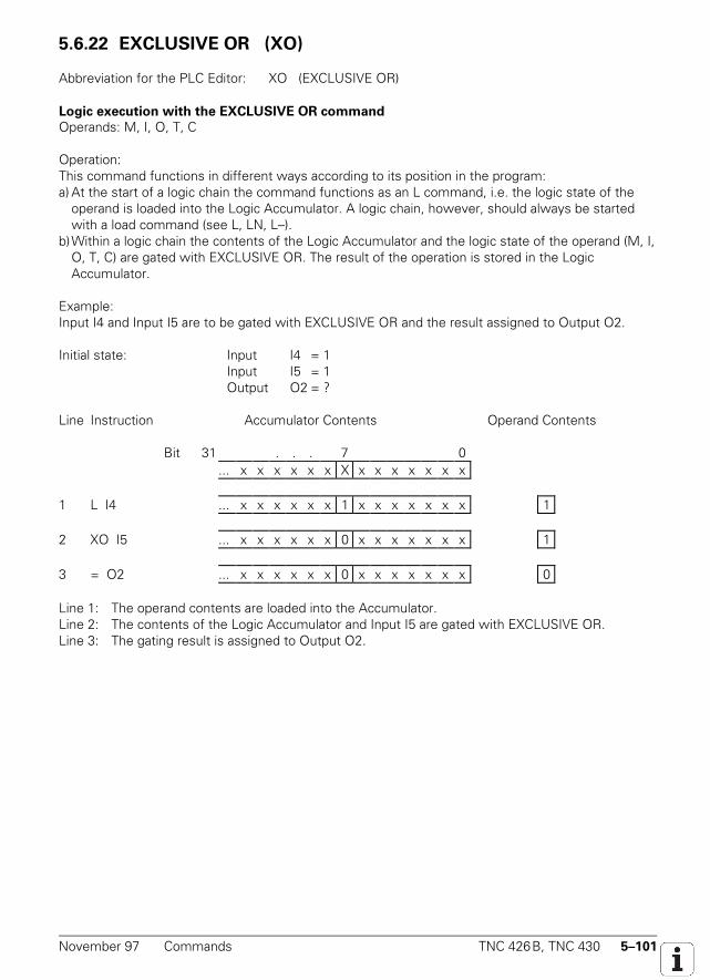
November 97 Commands TNC 426B, TNC 430 5–101
5.6.22 EXCLUSIVE OR (XO)
Abbreviation for the PLC Editor: XO (EXCLUSIVE OR)
Logic execution with the EXCLUSIVE OR command
Operands: M, I, O, T, C
Operation:This command functions in different ways according to its position in the program:a) At the start of a logic chain the command functions as an L command, i.e. the logic state of the
operand is loaded into the Logic Accumulator. A logic chain, however, should always be startedwith a load command (see L, LN, L–).
b)Within a logic chain the contents of the Logic Accumulator and the logic state of the operand (M, I,O, T, C) are gated with EXCLUSIVE OR. The result of the operation is stored in the LogicAccumulator.
Example:Input I4 and Input I5 are to be gated with EXCLUSIVE OR and the result assigned to Output O2.
Initial state: Input I4 = 1Input I5 = 1Output O2 = ?
Line Instruction Accumulator Contents Operand Contents
Bit 31 . . . 7 0... x x x x x x X x x x x x x x
1 L I4 ... x x x x x x 1 x x x x x x x 1
2 XO I5 ... x x x x x x 0 x x x x x x x 1
3 = O2 ... x x x x x x 0 x x x x x x x 0
Line 1: The operand contents are loaded into the Accumulator.Line 2: The contents of the Logic Accumulator and Input I5 are gated with EXCLUSIVE OR.Line 3: The gating result is assigned to Output O2.
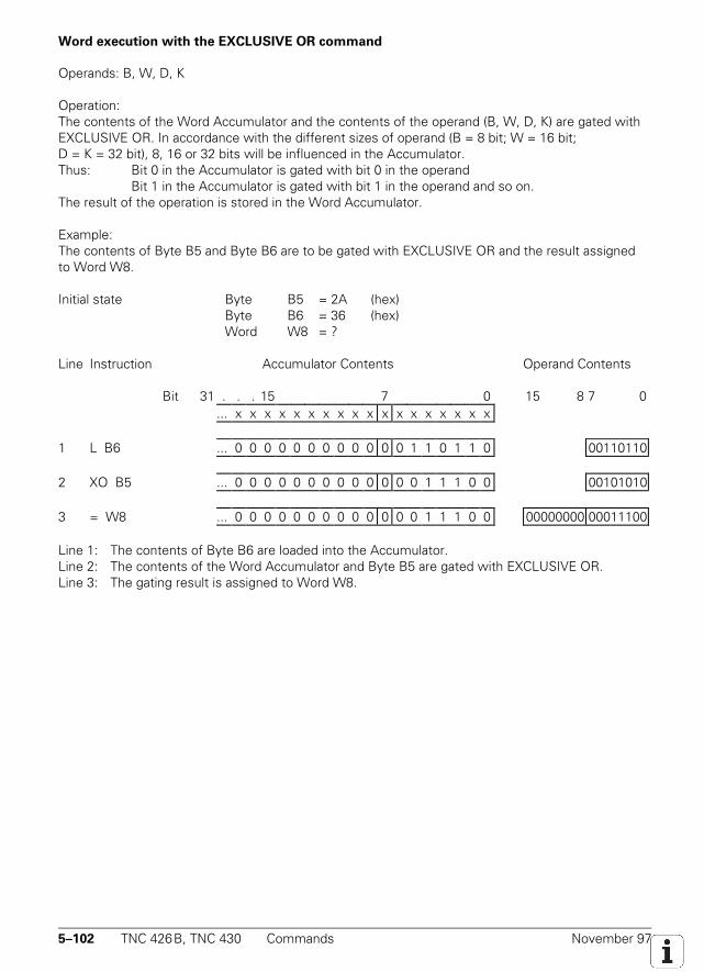
5–102 TNC 426B, TNC 430 Commands November 97
Word execution with the EXCLUSIVE OR command
Operands: B, W, D, K
Operation:The contents of the Word Accumulator and the contents of the operand (B, W, D, K) are gated withEXCLUSIVE OR. In accordance with the different sizes of operand (B = 8 bit; W = 16 bit;D = K = 32 bit), 8, 16 or 32 bits will be influenced in the Accumulator.Thus: Bit 0 in the Accumulator is gated with bit 0 in the operand
Bit 1 in the Accumulator is gated with bit 1 in the operand and so on.The result of the operation is stored in the Word Accumulator.
Example:The contents of Byte B5 and Byte B6 are to be gated with EXCLUSIVE OR and the result assignedto Word W8.
Initial state Byte B5 = 2A (hex)Byte B6 = 36 (hex)Word W8 = ?
Line Instruction Accumulator Contents Operand Contents
Bit 31 . . . 15 7 0 15 8 7 0... x x x x x x x x x x x x x x x x x x
1 L B6 ... 0 0 0 0 0 0 0 0 0 0 0 0 1 1 0 1 1 0 00110110
2 XO B5 ... 0 0 0 0 0 0 0 0 0 0 0 0 0 1 1 1 0 0 00101010
3 = W8 ... 0 0 0 0 0 0 0 0 0 0 0 0 0 1 1 1 0 0 00000000 00011100
Line 1: The contents of Byte B6 are loaded into the Accumulator.Line 2: The contents of the Word Accumulator and Byte B5 are gated with EXCLUSIVE OR.Line 3: The gating result is assigned to Word W8.
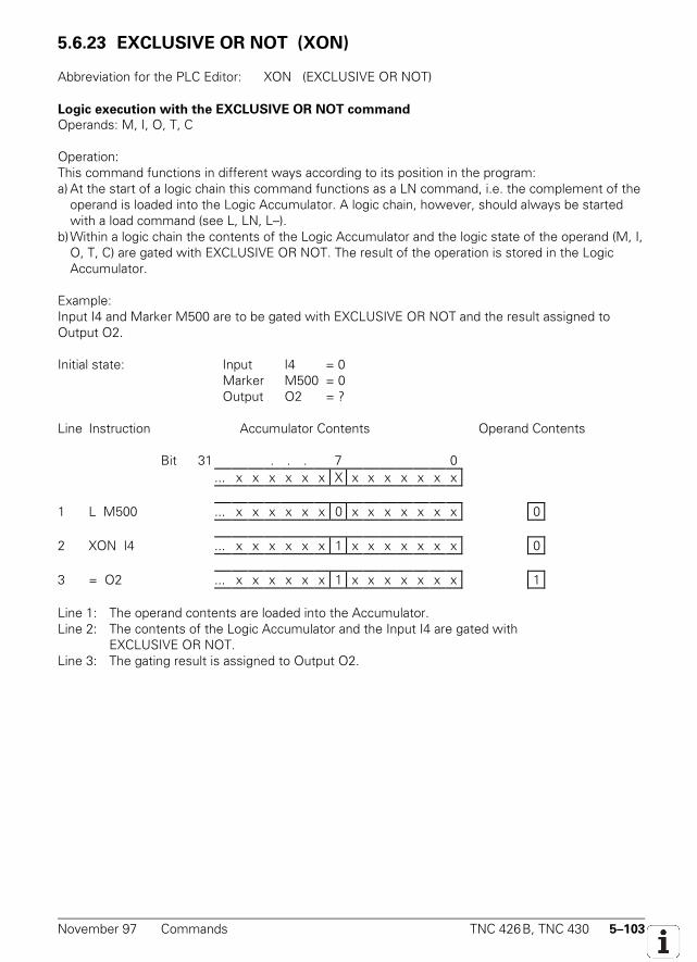
November 97 Commands TNC 426B, TNC 430 5–103
5.6.23 EXCLUSIVE OR NOT (XON) XON
Abbreviation for the PLC Editor: XON (EXCLUSIVE OR NOT)
Logic execution with the EXCLUSIVE OR NOT command
Operands: M, I, O, T, C
Operation:This command functions in different ways according to its position in the program:a) At the start of a logic chain this command functions as a LN command, i.e. the complement of the
operand is loaded into the Logic Accumulator. A logic chain, however, should always be startedwith a load command (see L, LN, L–).
b)Within a logic chain the contents of the Logic Accumulator and the logic state of the operand (M, I,O, T, C) are gated with EXCLUSIVE OR NOT. The result of the operation is stored in the LogicAccumulator.
Example:Input I4 and Marker M500 are to be gated with EXCLUSIVE OR NOT and the result assigned toOutput O2.
Initial state: Input I4 = 0Marker M500 = 0Output O2 = ?
Line Instruction Accumulator Contents Operand Contents
Bit 31 . . . 7 0... x x x x x x X x x x x x x x
1 L M500 ... x x x x x x 0 x x x x x x x 0
2 XON I4 ... x x x x x x 1 x x x x x x x 0
3 = O2 ... x x x x x x 1 x x x x x x x 1
Line 1: The operand contents are loaded into the Accumulator.Line 2: The contents of the Logic Accumulator and the Input I4 are gated with
EXCLUSIVE OR NOT.Line 3: The gating result is assigned to Output O2.
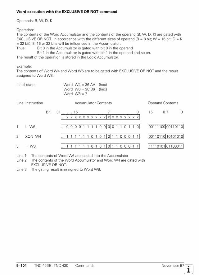
5–104 TNC 426B, TNC 430 Commands November 97
Word execution with the EXCLUSIVE OR NOT command
Operands: B, W, D, K
Operation:The contents of the Word Accumulator and the contents of the operand (B, W, D, K) are gated withEXCLUSIVE OR NOT. In accordance with the different sizes of operand (B = 8 bit; W = 16 bit; D = K= 32 bit), 8, 16 or 32 bits will be influenced in the Accumulator.Thus: Bit 0 in the Accumulator is gated with bit 0 in the operand
Bit 1 in the Accumulator is gated with bit 1 in the operand and so on.The result of the operation is stored in the Logic Accumulator.
Example:The contents of Word W4 and Word W6 are to be gated with EXCLUSIVE OR NOT and the resultassigned to Word W8.
Initial state: Word W4 = 36 AA (hex)Word W6 = 3C 36 (hex)Word W8 = ?
Line Instruction Accumulator Contents Operand Contents
Bit 31 . . . 15 7 0 15 8 7 0... x x x x x x x x x x x x x x x x x x
1 L W6 ... 0 0 0 0 1 1 1 1 0 0 0 0 1 1 0 1 1 0 00111100 00110110
2 XON W4 ... 1 1 1 1 1 1 0 1 0 1 0 1 1 0 0 0 1 1 00110110 10101010
3 = W8 ... 1 1 1 1 1 1 0 1 0 1 0 1 1 0 0 0 1 1 11110101 01100011
Line 1: The contents of Word W6 are loaded into the Accumulator.Line 2: The contents of the Word Accumulator and Word W4 are gated with
EXCLUSIVE OR NOT.Line 3: The gating result is assigned to Word W8.
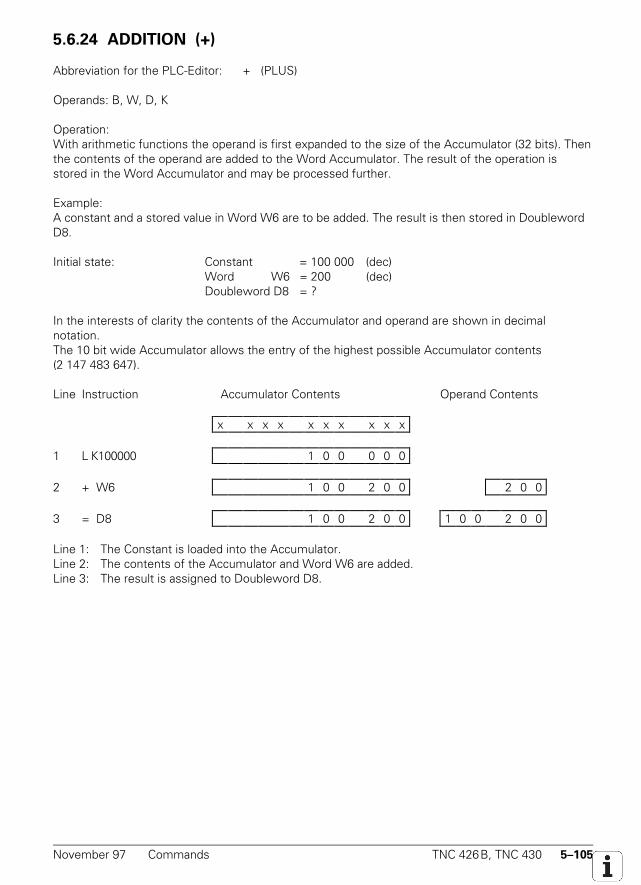
November 97 Commands TNC 426B, TNC 430 5–105
5.6.24 ADDITION (+)
Abbreviation for the PLC-Editor: + (PLUS)
Operands: B, W, D, K
Operation:With arithmetic functions the operand is first expanded to the size of the Accumulator (32 bits). Thenthe contents of the operand are added to the Word Accumulator. The result of the operation isstored in the Word Accumulator and may be processed further.
Example:A constant and a stored value in Word W6 are to be added. The result is then stored in DoublewordD8.
Initial state: Constant = 100 000 (dec)Word W6 = 200 (dec)Doubleword D8 = ?
In the interests of clarity the contents of the Accumulator and operand are shown in decimalnotation.The 10 bit wide Accumulator allows the entry of the highest possible Accumulator contents(2 147 483 647).
Line Instruction Accumulator Contents Operand Contents
x x x x x x x x x x
1 L K100000 1 0 0 0 0 0
2 + W6 1 0 0 2 0 0 2 0 0
3 = D8 1 0 0 2 0 0 1 0 0 2 0 0
Line 1: The Constant is loaded into the Accumulator.Line 2: The contents of the Accumulator and Word W6 are added.Line 3: The result is assigned to Doubleword D8.
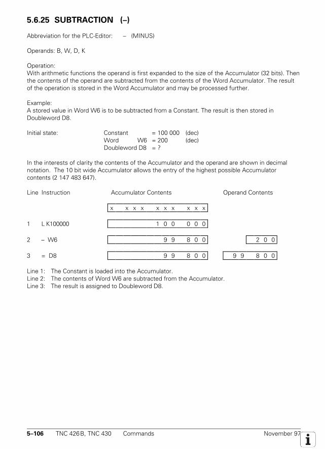
5–106 TNC 426B, TNC 430 Commands November 97
5.6.25 SUBTRACTION (–)
Abbreviation for the PLC-Editor: – (MINUS)
Operands: B, W, D, K
Operation:With arithmetic functions the operand is first expanded to the size of the Accumulator (32 bits). Thenthe contents of the operand are subtracted from the contents of the Word Accumulator. The resultof the operation is stored in the Word Accumulator and may be processed further.
Example:A stored value in Word W6 is to be subtracted from a Constant. The result is then stored inDoubleword D8.
Initial state: Constant = 100 000 (dec)Word W6 = 200 (dec)Doubleword D8 = ?
In the interests of clarity the contents of the Accumulator and the operand are shown in decimalnotation. The 10 bit wide Accumulator allows the entry of the highest possible Accumulatorcontents (2 147 483 647).
Line Instruction Accumulator Contents Operand Contents
x x x x x x x x x x
1 L K100000 1 0 0 0 0 0
2 – W6 9 9 8 0 0 2 0 0
3 = D8 9 9 8 0 0 9 9 8 0 0
Line 1: The Constant is loaded into the Accumulator.Line 2: The contents of Word W6 are subtracted from the Accumulator.Line 3: The result is assigned to Doubleword D8.
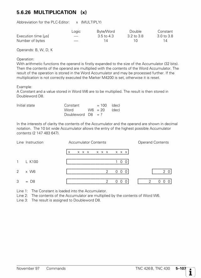
November 97 Commands TNC 426B, TNC 430 5–107
5.6.26 MULTIPLICATION (x)
Abbreviation for the PLC-Editor: x (MULTIPLY)
Logic Byte/Word Double ConstantExecution time [µs] ---- 3.5 to 4.3 3.2 to 3.8 3.0 to 3.8Number of bytes ---- 14 10 14
Operands: B, W, D, K
Operation:With arithmetic functions the operand is firstly expanded to the size of the Accumulator (32 bits).Then the contents of the operand are multiplied with the contents of the Word Accumulator. Theresult of the operation is stored in the Word Accumulator and may be processed further. If themultiplication is not correctly executed the Marker M4200 is set, otherwise it is reset.
Example:A Constant and a value stored in Word W6 are to be multiplied. The result is then stored inDoubleword D8.
Initial state Constant = 100 (dec)Word W6 = 20 (dec)Doubleword D8 = ?
In the interests of clarity the contents of the Accumulator and the operand are shown in decimalnotation. The 10 bit wide Accumulator allows the entry of the highest possible Accumulatorcontents (2 147 483 647).
Line Instruction Accumulator Contents Operand Contents
x x x x x x x x x x
1 L K100 1 0 0
2 x W6 2 0 0 0 2 0
3 = D8 2 0 0 0 2 0 0 0
Line 1: The Constant is loaded into the Accumulator.Line 2: The contents of the Accumulator are multiplied by the contents of Word W6.Line 3: The result is assigned to Doubleword D8.
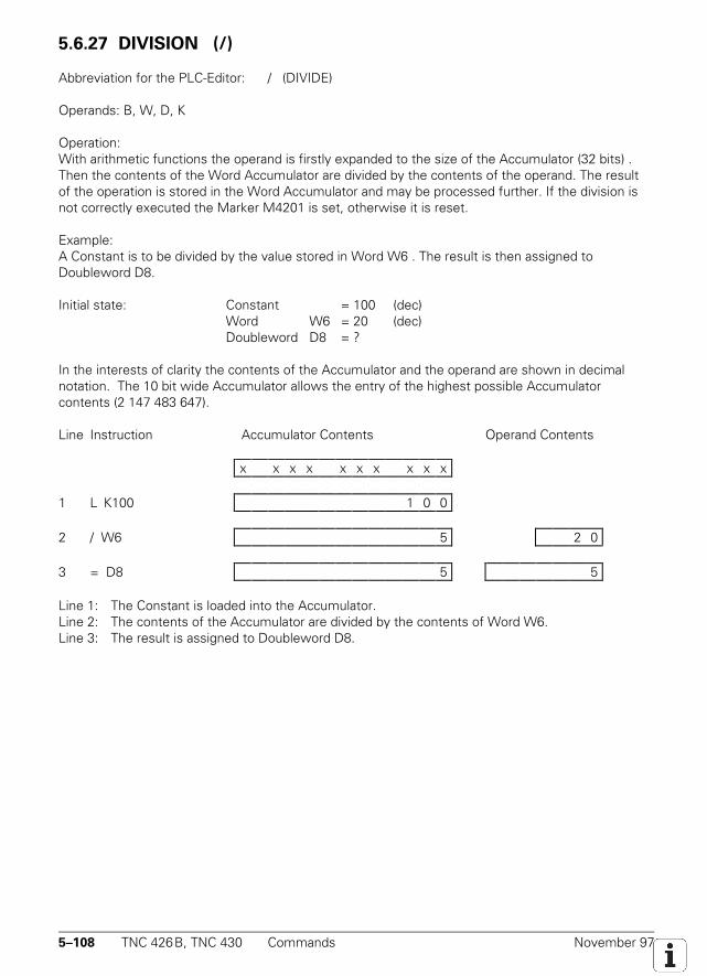
5–108 TNC 426B, TNC 430 Commands November 97
5.6.27 DIVISION (/)
Abbreviation for the PLC-Editor: / (DIVIDE)
Operands: B, W, D, K
Operation:With arithmetic functions the operand is firstly expanded to the size of the Accumulator (32 bits) .Then the contents of the Word Accumulator are divided by the contents of the operand. The resultof the operation is stored in the Word Accumulator and may be processed further. If the division isnot correctly executed the Marker M4201 is set, otherwise it is reset.
Example:A Constant is to be divided by the value stored in Word W6 . The result is then assigned toDoubleword D8.
Initial state: Constant = 100 (dec)Word W6 = 20 (dec)Doubleword D8 = ?
In the interests of clarity the contents of the Accumulator and the operand are shown in decimalnotation. The 10 bit wide Accumulator allows the entry of the highest possible Accumulatorcontents (2 147 483 647).
Line Instruction Accumulator Contents Operand Contents
x x x x x x x x x x
1 L K100 1 0 0
2 / W6 5 2 0
3 = D8 5 5
Line 1: The Constant is loaded into the Accumulator.Line 2: The contents of the Accumulator are divided by the contents of Word W6.Line 3: The result is assigned to Doubleword D8.
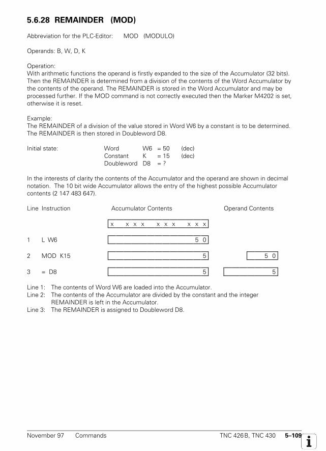
November 97 Commands TNC 426B, TNC 430 5–109
5.6.28 REMAINDER (MOD)
Abbreviation for the PLC-Editor: MOD (MODULO)
Operands: B, W, D, K
Operation:With arithmetic functions the operand is firstly expanded to the size of the Accumulator (32 bits).Then the REMAINDER is determined from a division of the contents of the Word Accumulator bythe contents of the operand. The REMAINDER is stored in the Word Accumulator and may beprocessed further. If the MOD command is not correctly executed then the Marker M4202 is set,otherwise it is reset.
Example:The REMAINDER of a division of the value stored in Word W6 by a constant is to be determined.The REMAINDER is then stored in Doubleword D8.
Initial state: Word W6 = 50 (dec)Constant K = 15 (dec)Doubleword D8 = ?
In the interests of clarity the contents of the Accumulator and the operand are shown in decimalnotation. The 10 bit wide Accumulator allows the entry of the highest possible Accumulatorcontents (2 147 483 647).
Line Instruction Accumulator Contents Operand Contents
x x x x x x x x x x
1 L W6 5 0
2 MOD K15 5 5 0
3 = D8 5 5
Line 1: The contents of Word W6 are loaded into the Accumulator.Line 2: The contents of the Accumulator are divided by the constant and the integer
REMAINDER is left in the Accumulator.Line 3: The REMAINDER is assigned to Doubleword D8.
5–110 TNC 426B, TNC 430 Commands November 97
5.6.29 INCREMENT (INC)
INCREMENT Operand
Abbreviation for the PLC Editor: INCOperands: B, W, D
Operation:The contents of the addressed operand increases by one.
INCREMENT Word Accumulator
Abbreviation for the PLC Editor: INC W
Operation:The contents of the word accumulator increases by one.
INCREMENT Index Register
Abbreviation for the PLC Editor: INC X
Operation:The contents of the index register increases by one.
5.6.30 DECREMENT (DEC)
DECREMENT Operand
Abbreviation for the PLC Editor: DECOperands: B, W, D
Operation:The contents of the addressed operand decreases by one.
DECREMENT Word Accumulator
Abbreviation for the PLC Editor: DEC W
Operation:The contents of the word accumulator decreases by one.
DECREMENT Index Register
Abbreviation for the PLC Editor: DEC X
Operation:The contents of the index register decreases by one.
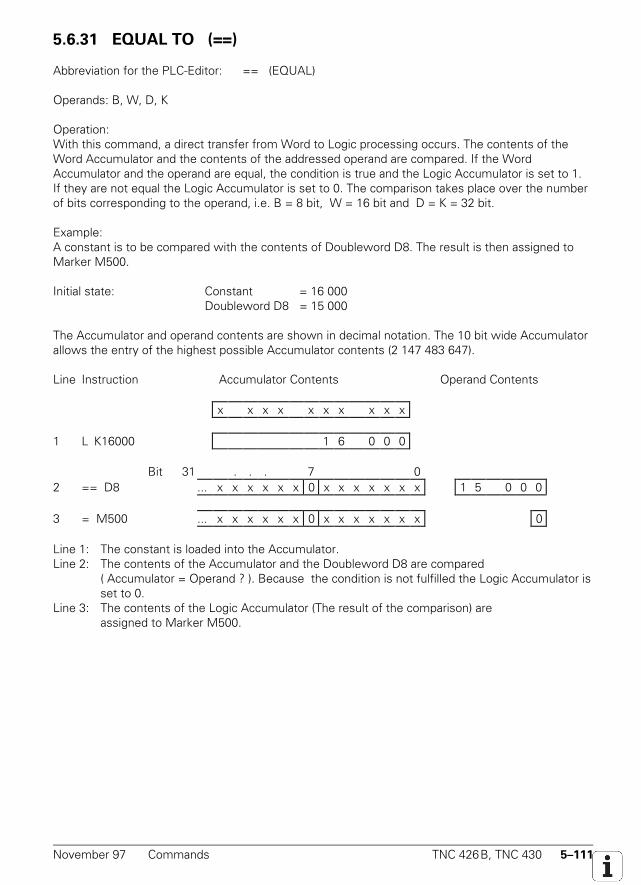
November 97 Commands TNC 426B, TNC 430 5–111
5.6.31 EQUAL TO (==)
Abbreviation for the PLC-Editor: == (EQUAL)
Operands: B, W, D, K
Operation:With this command, a direct transfer from Word to Logic processing occurs. The contents of theWord Accumulator and the contents of the addressed operand are compared. If the WordAccumulator and the operand are equal, the condition is true and the Logic Accumulator is set to 1.If they are not equal the Logic Accumulator is set to 0. The comparison takes place over the numberof bits corresponding to the operand, i.e. B = 8 bit, W = 16 bit and D = K = 32 bit.
Example:A constant is to be compared with the contents of Doubleword D8. The result is then assigned toMarker M500.
Initial state: Constant = 16 000Doubleword D8 = 15 000
The Accumulator and operand contents are shown in decimal notation. The 10 bit wide Accumulatorallows the entry of the highest possible Accumulator contents (2 147 483 647).
Line Instruction Accumulator Contents Operand Contents
x x x x x x x x x x
1 L K16000 1 6 0 0 0
Bit 31 . . . 7 02 == D8 ... x x x x x x 0 x x x x x x x 1 5 0 0 0
3 = M500 ... x x x x x x 0 x x x x x x x 0
Line 1: The constant is loaded into the Accumulator.Line 2: The contents of the Accumulator and the Doubleword D8 are compared
( Accumulator = Operand ? ). Because the condition is not fulfilled the Logic Accumulator isset to 0.
Line 3: The contents of the Logic Accumulator (The result of the comparison) areassigned to Marker M500.
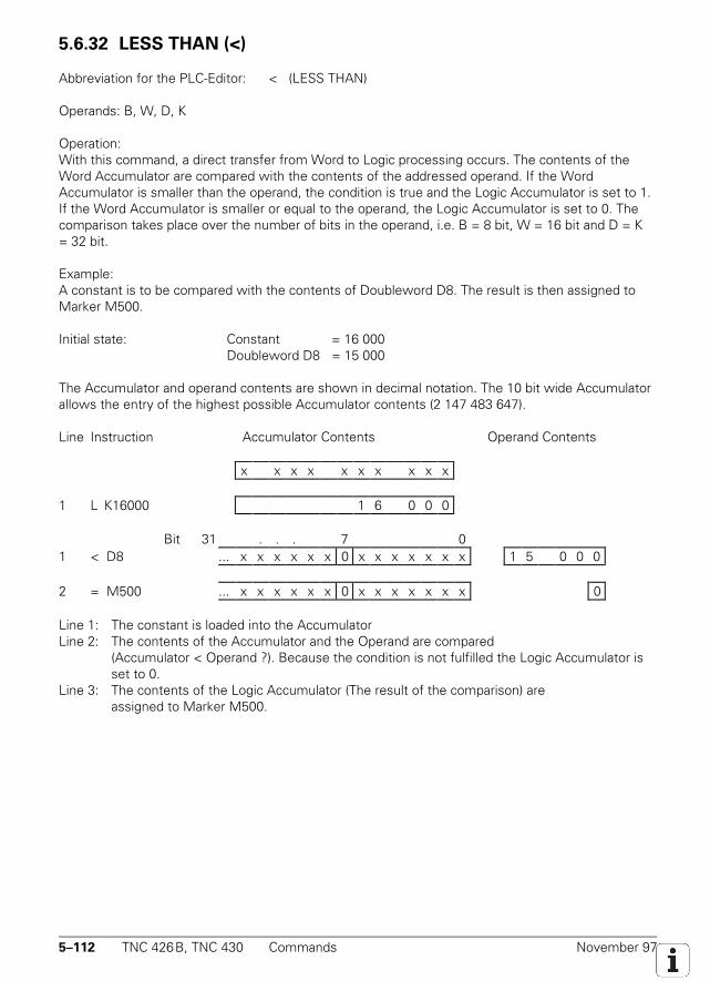
5–112 TNC 426B, TNC 430 Commands November 97
5.6.32 LESS THAN (<)
Abbreviation for the PLC-Editor: < (LESS THAN)
Operands: B, W, D, K
Operation:With this command, a direct transfer from Word to Logic processing occurs. The contents of theWord Accumulator are compared with the contents of the addressed operand. If the WordAccumulator is smaller than the operand, the condition is true and the Logic Accumulator is set to 1.If the Word Accumulator is smaller or equal to the operand, the Logic Accumulator is set to 0. Thecomparison takes place over the number of bits in the operand, i.e. B = 8 bit, W = 16 bit and D = K= 32 bit.
Example:A constant is to be compared with the contents of Doubleword D8. The result is then assigned toMarker M500.
Initial state: Constant = 16 000Doubleword D8 = 15 000
The Accumulator and operand contents are shown in decimal notation. The 10 bit wide Accumulatorallows the entry of the highest possible Accumulator contents (2 147 483 647).
Line Instruction Accumulator Contents Operand Contents
x x x x x x x x x x
1 L K16000 1 6 0 0 0
Bit 31 . . . 7 01 < D8 ... x x x x x x 0 x x x x x x x 1 5 0 0 0
2 = M500 ... x x x x x x 0 x x x x x x x 0
Line 1: The constant is loaded into the AccumulatorLine 2: The contents of the Accumulator and the Operand are compared
(Accumulator < Operand ?). Because the condition is not fulfilled the Logic Accumulator isset to 0.
Line 3: The contents of the Logic Accumulator (The result of the comparison) areassigned to Marker M500.
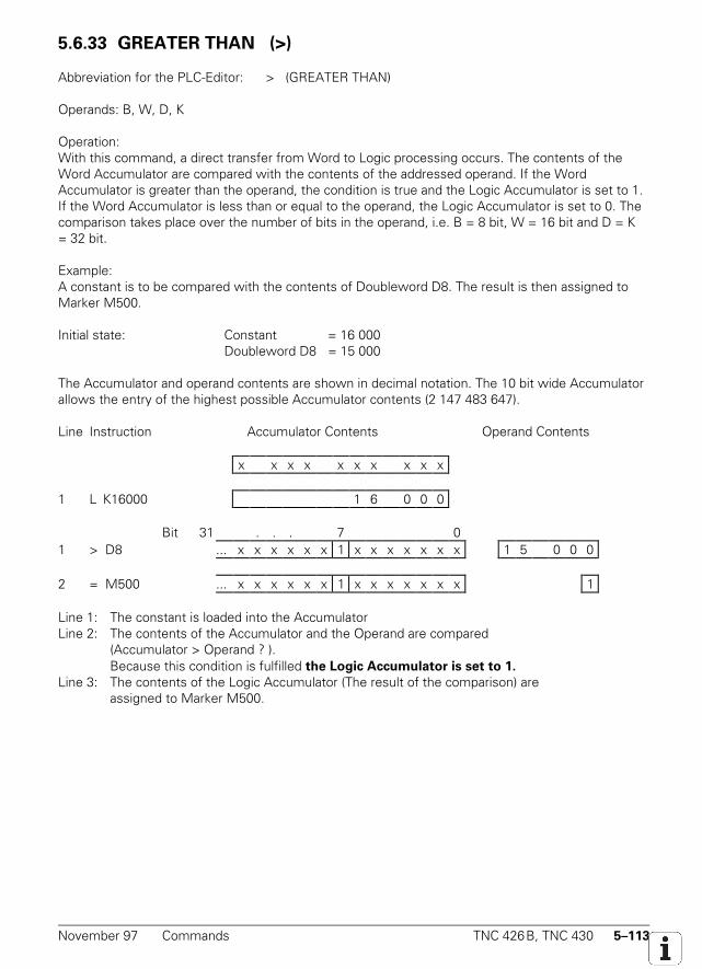
November 97 Commands TNC 426B, TNC 430 5–113
5.6.33 GREATER THAN (>)
Abbreviation for the PLC-Editor: > (GREATER THAN)
Operands: B, W, D, K
Operation:With this command, a direct transfer from Word to Logic processing occurs. The contents of theWord Accumulator are compared with the contents of the addressed operand. If the WordAccumulator is greater than the operand, the condition is true and the Logic Accumulator is set to 1.If the Word Accumulator is less than or equal to the operand, the Logic Accumulator is set to 0. Thecomparison takes place over the number of bits in the operand, i.e. B = 8 bit, W = 16 bit and D = K= 32 bit.
Example:A constant is to be compared with the contents of Doubleword D8. The result is then assigned toMarker M500.
Initial state: Constant = 16 000Doubleword D8 = 15 000
The Accumulator and operand contents are shown in decimal notation. The 10 bit wide Accumulatorallows the entry of the highest possible Accumulator contents (2 147 483 647).
Line Instruction Accumulator Contents Operand Contents
x x x x x x x x x x
1 L K16000 1 6 0 0 0
Bit 31 . . . 7 01 > D8 ... x x x x x x 1 x x x x x x x 1 5 0 0 0
2 = M500 ... x x x x x x 1 x x x x x x x 1
Line 1: The constant is loaded into the AccumulatorLine 2: The contents of the Accumulator and the Operand are compared
(Accumulator > Operand ? ).Because this condition is fulfilled the Logic Accumulator is set to 1.
Line 3: The contents of the Logic Accumulator (The result of the comparison) areassigned to Marker M500.
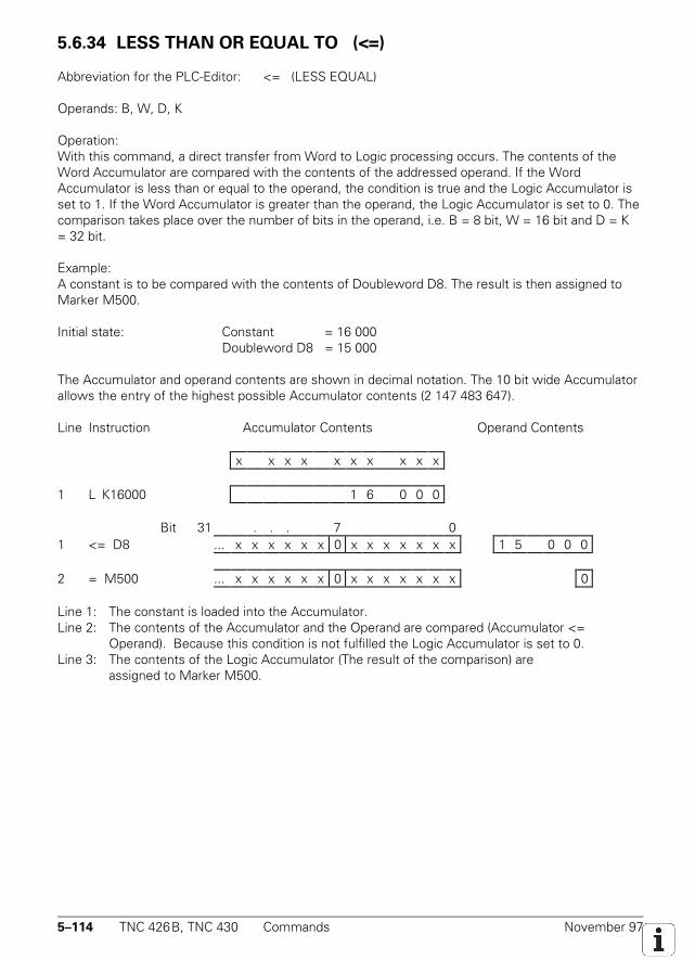
5–114 TNC 426B, TNC 430 Commands November 97
5.6.34 LESS THAN OR EQUAL TO (<=)
Abbreviation for the PLC-Editor: <= (LESS EQUAL)
Operands: B, W, D, K
Operation:With this command, a direct transfer from Word to Logic processing occurs. The contents of theWord Accumulator are compared with the contents of the addressed operand. If the WordAccumulator is less than or equal to the operand, the condition is true and the Logic Accumulator isset to 1. If the Word Accumulator is greater than the operand, the Logic Accumulator is set to 0. Thecomparison takes place over the number of bits in the operand, i.e. B = 8 bit, W = 16 bit and D = K= 32 bit.
Example:A constant is to be compared with the contents of Doubleword D8. The result is then assigned toMarker M500.
Initial state: Constant = 16 000Doubleword D8 = 15 000
The Accumulator and operand contents are shown in decimal notation. The 10 bit wide Accumulatorallows the entry of the highest possible Accumulator contents (2 147 483 647).
Line Instruction Accumulator Contents Operand Contents
x x x x x x x x x x
1 L K16000 1 6 0 0 0
Bit 31 . . . 7 01 <= D8 ... x x x x x x 0 x x x x x x x 1 5 0 0 0
2 = M500 ... x x x x x x 0 x x x x x x x 0
Line 1: The constant is loaded into the Accumulator.Line 2: The contents of the Accumulator and the Operand are compared (Accumulator <=
Operand). Because this condition is not fulfilled the Logic Accumulator is set to 0.Line 3: The contents of the Logic Accumulator (The result of the comparison) are
assigned to Marker M500.
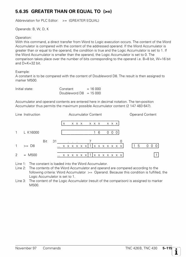
November 97 Commands TNC 426B, TNC 430 5–115
5.6.35 GREATER THAN OR EQUAL TO (>=)
Abbreviation for PLC Editor: >= (GREATER EQUAL)
Operands: B, W, D, K
Operation:With this command, a direct transfer from Word to Logic execution occurs. The content of the WordAccumulator is compared with the content of the addressed operand. If the Word Accumulator isgreater than or equal to the operand, the condition is true and the Logic Accumulator is set to 1. Ifthe Word Accumulator is smaller than the operand, the Logic Accumulator is set to 0. Thecomparison takes place over the number of bits corresponding to the operand i.e. B=8 bit, W=16 bitand D=K=32 bit.
Example:A constant is to be compared with the content of Doubleword D8. The result is then assigned tomarker M500.
Initial state: Constant = 16 000Doubleword D8 = 15 000
Accumulator and operand contents are entered here in decimal notation. The ten-positionAccumulator thus permits the maximum possible Accumulator content (2 147 483 647).
Line Instruction Accumulator Content Operand Content
x x x x x x x x x x
1 L K16000 1 6 0 0 0
Bit 31 . . . 7 01 >= D8 ... x x x x x x 1 x x x x x x x 1 5 0 0 0
2 = M500 ... x x x x x x 1 x x x x x x x 1
Line 1: The constant is loaded into the Word Accumulator.Line 2: The contents of the Word Accumulator and operand are compared according to the
following criteria: Word Accumulator >= Operand. Because this condition is fulfilled, theLogic Accumulator is set to 1.
Line 3: The content of the Logic Accumulator (result of the comparison) is assigned to markerM500.
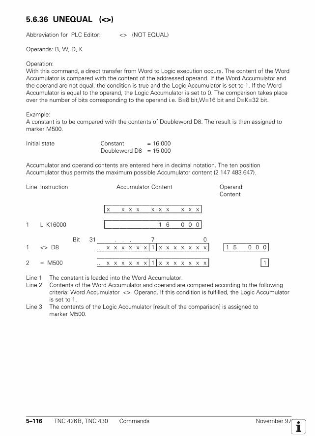
5–116 TNC 426B, TNC 430 Commands November 97
5.6.36 UNEQUAL (<>)
Abbreviation for PLC Editor: <> (NOT EQUAL)
Operands: B, W, D, K
Operation:With this command, a direct transfer from Word to Logic execution occurs. The content of the WordAccumulator is compared with the content of the addressed operand. If the Word Accumulator andthe operand are not equal, the condition is true and the Logic Accumulator is set to 1. If the WordAccumulator is equal to the operand, the Logic Accumulator is set to 0. The comparison takes placeover the number of bits corresponding to the operand i.e. B=8 bit,W=16 bit and D=K=32 bit.
Example:A constant is to be compared with the contents of Doubleword D8. The result is then assigned tomarker M500.
Initial state Constant = 16 000Doubleword D8 = 15 000
Accumulator and operand contents are entered here in decimal notation. The ten positionAccumulator thus permits the maximum possible Accumulator content (2 147 483 647).
Line Instruction Accumulator Content Operand Content
x x x x x x x x x x
1 L K16000 1 6 0 0 0
Bit 31 . . . 7 01 <> D8 ... x x x x x x 1 x x x x x x x 1 5 0 0 0
2 = M500 ... x x x x x x 1 x x x x x x x 1
Line 1: The constant is loaded into the Word Accumulator.Line 2: Contents of the Word Accumulator and operand are compared according to the following
criteria: Word Accumulator <> Operand. If this condition is fulfilled, the Logic Accumulatoris set to 1.
Line 3: The contents of the Logic Accumulator [result of the comparison] is assigned tomarker M500.
November 97 Commands TNC 426B, TNC 430 5–117
5.6.37 AND [ ] (A[ ])
Abbreviation for PLC Editor: A[ ] (AND [ ])
Operands: none
5.6.38 AND NOT [ ] (AN[ ]
Abbreviation for PLC Editor: AN[ ] (AND NOT [ ])
Operands: none
5.6.39 OR [ ] (O[ ])
Abbreviation for PLC Editor: O[ ] (OR [ ])
Operands: none
5.6.40 OR NOT [ ] (ON[ ])
Abbreviation for PLC Editor: ON[ ] (OR NOT [ ])
Operands: none

5–118 TNC 426B, TNC 430 Commands November 97
5.6.41 EXCLUSIVE OR [ ] (XO[ ])
Abbreviation for PLC Editor: XO[ ] (EXCL: OR [ ])
Operands: none
5.6.42 EXCLUSIVE OR NOT [ ] (XON[ ])
Abbreviation for PLC Editor: XON[ ] (EXCL: OR NOT [ ])
Operands: none
Function of Parentheses with Logic Commands:The execution sequence in a ladder may be altered by the use of parentheses. The "open-parentheses" command loads the contents of the Accumulator onto the Program Stack. If the LogicAccumulator is addressed in the previous command, prior to a "parentheses-open" instruction, thecontent of the Logic Accumulator is loaded into the Program Stack. By addressing the WordAccumulator, the content of the Word Accumulator will be distributed.
The "close-parentheses" instruction initiates the gating of the buffered value from the Program Stackwith the Logic Accumulator and/or the Word Accumulator, depending on which Accumulator wasaddressed prior to the "parentheses-open" instruction. The result is then available in thecorresponding Accumulator. The maximum nesting level is 16 pairs of parentheses.
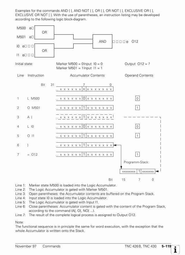
November 97 Commands TNC 426B, TNC 430 5–119
Examples for the commands AND [ ], AND NOT [ ], OR [ ], OR NOT [ ], EXCLUSIVE OR [ ],EXCLUSIVE OR NOT [ ]. With the use of parentheses, an instruction listing may be developedaccording to the following logic block-diagram.
M500 οOR
M501 οAND ο O12
I0 οOR
I1 ο
Initial state: Marker M500 = 0Input I0 = 0 Output O12 = ?Marker M501 = 1Input I1 = 1
Line Instruction Accumulator Contents Operand Contentsp
Bit 31 7 0... x x x x x x x x x x x x x x
Programm-Stack:
1 L M500
2 O M501
3 A [
4 L I0
5 O I1
6 ]
7 = O12
xxxxxxxx 1 xxxxxxx
Bit 7 015
... x x x x x x 0 x x x x x x x
... x x x x x x 1 x x x x x x x
... x x x x x x 1 x x x x x x x
... x x x x x x 0 x x x x x x x
... x x x x x x 1 x x x x x x x
... x x x x x x 1 x x x x x x x
... x x x x x x 1 x x x x x x x
0
1
0
1
1
Line 1: Marker state M500 is loaded into the Logic Accumulator.Line 2: The Logic Accumulator is gated with Marker M501.Line 3: Open parentheses: the Accumulator contents are buffered on the Program Stack.Line 4: Input state I0 is loaded into the Logic Accumulator.Line 5: The Logic Accumulator is gated with Input I1.Line 6: Close parentheses: Accumulator content is gated with the content of the Program Stack,
according to the command (A[, O[, NO[ ...).Line 7: The result of the complete logical process is assigned to Output O12.
Note:The functional sequence is in principle the same for word execution, with the exception that thewhole Accumulator is written onto the Stack.
5–120 TNC 426B, TNC 430 Commands November 97
5.6.43 ADD [ ] (+[ ])
Abbreviation for PLC Editor: + [ ] (PLUS [ ])
Operands: none
5.6.44 SUBTRACT [ ] (–[ ])
Abbreviation for PLC Editor: – [ ] (MINUS [ ])
Operands: none
5.6.45 MULTIPLICATION [ ] (x[ ])
Abbreviation for PLC Editor: x [ ] (MULTIPLY [ ])
Operands: none
Marker M4200 is set if an error occurs.
5.6.46 DIVISION [ ] (/[ ])
Abbreviation for PLC Editor: / [ ] (DIVIDE [ ])
Operands: none
Marker M4201 is set if an error occurs.
November 97 Commands TNC 426B, TNC 430 5–121
5.6.47 REMAINDER [ ] (MOD[ ])
Abbreviation for PLC Editor: MOD [ ] (MODULO [ ])
Operands: none
Function of Parentheses with Arithmetic Commands:With arithmetic commands, only word execution comes into question. The execution sequence in aladder may be altered by the use of parentheses. The "open-parentheses" command loads thecontent of the Word Accumulator onto the Program Stack. Then the Accumulator is available for thecalculation of intermediate results. The "close-parentheses" instruction initiates the gating of thebuffered value from the Program Stack with the content of the Word Accumulator. The result isagain loaded into the Accumulator. The maximum nesting level is 16 pairs of parentheses.
Marker M4201 is set if an error occurs.
Example for the commands ADD [ ], SUBTRACT [ ], MULTIPLY [ ], DIVIDE [ ], DIVISIONREMAINDER [ ]The following example demonstrates how parentheses influence the result of the operation.
Initial state: Constant = 1000 (decimal)DoublewordD12 = 15000 (decimal)DoublewordD36 = 100 (decimal)DoublewordD100 = ?
The specification of Accumulator and operand contents is given in decimal notation. The ten-placeAccumulator thus permits the maximum possible Accumulator content of (2 147 483 647).
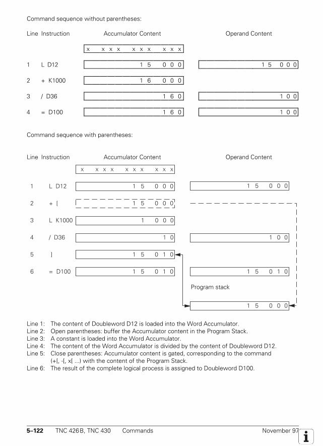
5–122 TNC 426B, TNC 430 Commands November 97
Command sequence without parentheses:
Line Instruction Accumulator Content Operand Content
x x x x x x x x x x
1 L D12 1 5 0 0 0 1 5 0 0 0
2 + K1000 1 6 0 0 0
3 / D36 1 6 0 1 0 0
4 = D100 1 6 0 1 0 0
Command sequence with parentheses:
Line Instruction Accumulator Content Operand ContentZeile AWL Akku-Inhalt Operanden-Inhalt
1 L D12
x x x x x x x x x x
1 5 0 0 0 1 5 0 0 0
1 5 0 0 0
1 0 0 0
1 0
1 5 0 1 0
Programmstack:
1 5 0 0 0
2 + [
3 L K1000
4 / D36
5 ]
6 = D100 1 5 0 1 0 1 5 0 1 0
1 0 0
Line 1: The content of Doubleword D12 is loaded into the Word Accumulator.Line 2: Open parentheses: buffer the Accumulator content in the Program Stack.Line 3: A constant is loaded into the Word Accumulator.Line 4: The content of the Word Accumulator is divided by the content of Doubleword D12.Line 5: Close parentheses: Accumulator content is gated, corresponding to the command
(+[, -[, x[ ...) with the content of the Program Stack.Line 6: The result of the complete logical process is assigned to Doubleword D100.
Program stack
November 97 Commands TNC 426B, TNC 430 5–123
5.6.48 EQUAL TO [ ] (==[ ])
Abbreviation for PLC Editor: == [ ] (EQUAL [ ])
Operands: none
5.6.49 LESS THAN [ ] (<[ ])
Abbreviation for PLC Editor: < [ ] (LESS THAN [ ])
Operands: none
5.6.50 GREATER THAN [ ] (>[ ])
Abbreviation for PLC Editor: > [ ] (GREATER THAN [ ])
Operands: none
5.6.51 LESS THAN OR EQUAL TO [ ] (<=[ ])
Abbreviation for PLC Editor: <= [ ] (LESS EQUAL [ ])
Operands: none
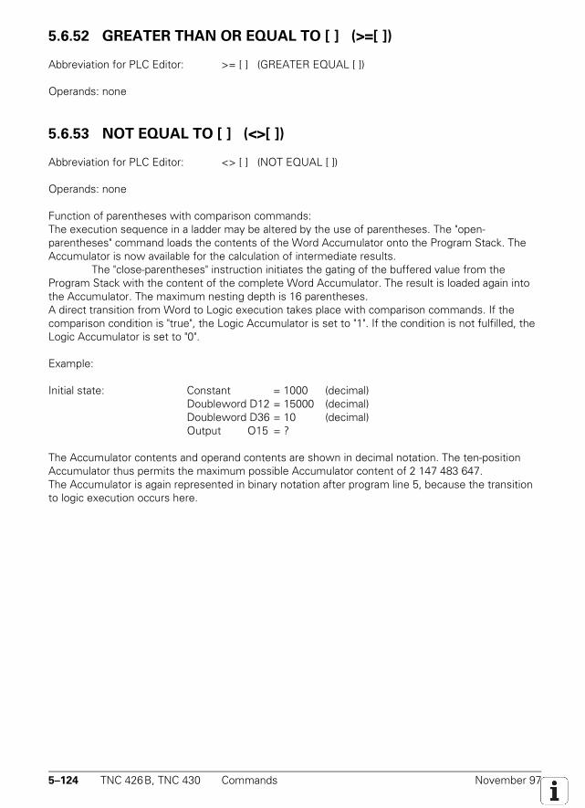
5–124 TNC 426B, TNC 430 Commands November 97
5.6.52 GREATER THAN OR EQUAL TO [ ] (>=[ ])
Abbreviation for PLC Editor: >= [ ] (GREATER EQUAL [ ])
Operands: none
5.6.53 NOT EQUAL TO [ ] (<>[ ])
Abbreviation for PLC Editor: <> [ ] (NOT EQUAL [ ])
Operands: none
Function of parentheses with comparison commands:The execution sequence in a ladder may be altered by the use of parentheses. The "open-parentheses" command loads the contents of the Word Accumulator onto the Program Stack. TheAccumulator is now available for the calculation of intermediate results.
The "close-parentheses" instruction initiates the gating of the buffered value from theProgram Stack with the content of the complete Word Accumulator. The result is loaded again intothe Accumulator. The maximum nesting depth is 16 parentheses.A direct transition from Word to Logic execution takes place with comparison commands. If thecomparison condition is "true", the Logic Accumulator is set to "1". If the condition is not fulfilled, theLogic Accumulator is set to "0".
Example:
Initial state: Constant = 1000 (decimal)Doubleword D12 = 15000 (decimal)Doubleword D36 = 10 (decimal)Output O15 = ?
The Accumulator contents and operand contents are shown in decimal notation. The ten-positionAccumulator thus permits the maximum possible Accumulator content of 2 147 483 647.The Accumulator is again represented in binary notation after program line 5, because the transitionto logic execution occurs here.
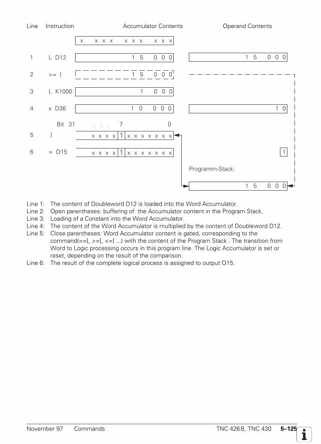
November 97 Commands TNC 426B, TNC 430 5–125
Line Instruction Accumulator Contents Operand Contentsp
1 L D12
x x x x x x x x x x
1 5 0 0 0
1 5 0 0 0
1 0 0 0
Programm-Stack:
1 5 0 0 0
2 >= [
3 L K1000
4 x D36
5 ]
6 = O15 1
1 0 1 0 0 0 0
1 5 0 0 0
Bit 31 . . . 7 0
x x x x 1 x x x x x x x
x x x x 1 x x x x x x x
Line 1: The content of Doubleword D12 is loaded into the Word Accumulator.Line 2: Open parentheses: buffering of the Accumulator content in the Program Stack.Line 3: Loading of a Constant into the Word Accumulator.Line 4: The content of the Word Accumulator is multiplied by the content of Doubleword D12.Line 5: Close parentheses: Word Accumulator content is gated, corresponding to the
command(==[, >=[, <=[ ...) with the content of the Program Stack . The transition fromWord to Logic processing occurs in this program line. The Logic Accumulator is set orreset, depending on the result of the comparison.
Line 6: The result of the complete logical process is assigned to output O15.
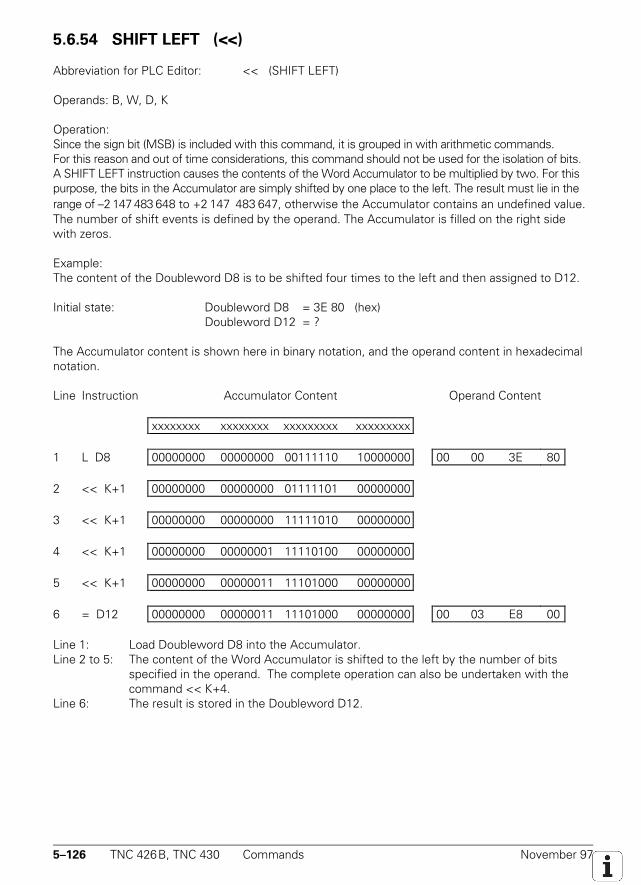
5–126 TNC 426B, TNC 430 Commands November 97
5.6.54 SHIFT LEFT (<<)
Abbreviation for PLC Editor: << (SHIFT LEFT)
Operands: B, W, D, K
Operation:Since the sign bit (MSB) is included with this command, it is grouped in with arithmetic commands.For this reason and out of time considerations, this command should not be used for the isolation of bits.A SHIFT LEFT instruction causes the contents of the Word Accumulator to be multiplied by two. For thispurpose, the bits in the Accumulator are simply shifted by one place to the left. The result must lie in therange of –2 147 483 648 to +2 147 483 647, otherwise the Accumulator contains an undefined value.The number of shift events is defined by the operand. The Accumulator is filled on the right sidewith zeros.
Example:The content of the Doubleword D8 is to be shifted four times to the left and then assigned to D12.
Initial state: Doubleword D8 = 3E 80 (hex)Doubleword D12 = ?
The Accumulator content is shown here in binary notation, and the operand content in hexadecimalnotation.
Line Instruction Accumulator Content Operand Content
xxxxxxxx xxxxxxxx xxxxxxxxx xxxxxxxxx
1 L D8 00000000 00000000 00111110 10000000 00 00 3E 80
2 << K+1 00000000 00000000 01111101 00000000
3 << K+1 00000000 00000000 11111010 00000000
4 << K+1 00000000 00000001 11110100 00000000
5 << K+1 00000000 00000011 11101000 00000000
6 = D12 00000000 00000011 11101000 00000000 00 03 E8 00
Line 1: Load Doubleword D8 into the Accumulator.Line 2 to 5: The content of the Word Accumulator is shifted to the left by the number of bits
specified in the operand. The complete operation can also be undertaken with thecommand << K+4.
Line 6: The result is stored in the Doubleword D12.
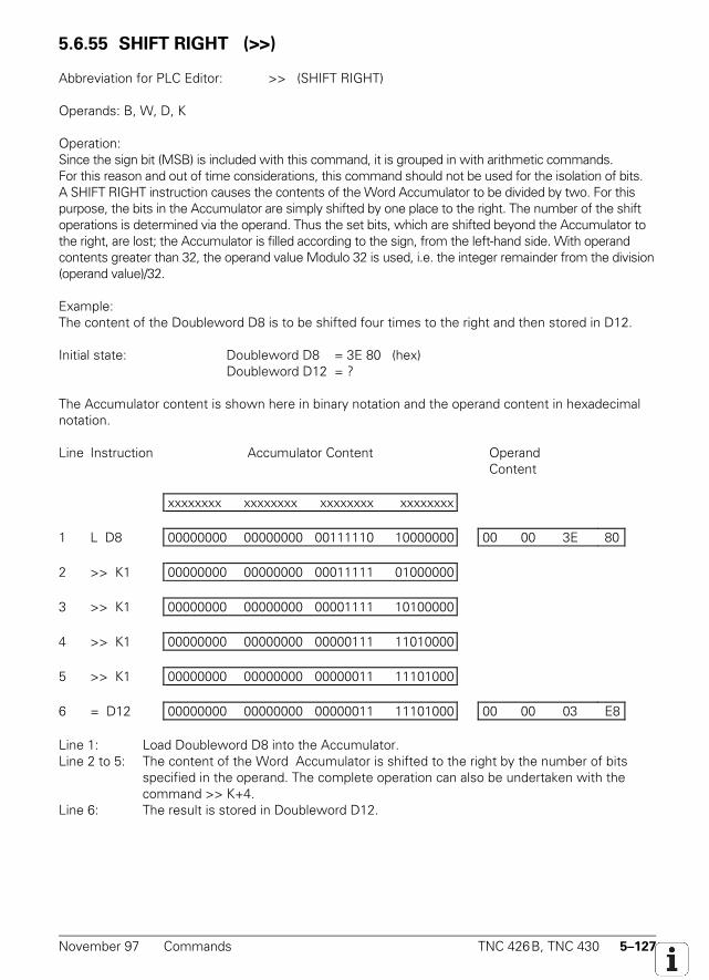
November 97 Commands TNC 426B, TNC 430 5–127
5.6.55 SHIFT RIGHT (>>)
Abbreviation for PLC Editor: >> (SHIFT RIGHT)
Operands: B, W, D, K
Operation:Since the sign bit (MSB) is included with this command, it is grouped in with arithmetic commands.For this reason and out of time considerations, this command should not be used for the isolation of bits.A SHIFT RIGHT instruction causes the contents of the Word Accumulator to be divided by two. For thispurpose, the bits in the Accumulator are simply shifted by one place to the right. The number of the shiftoperations is determined via the operand. Thus the set bits, which are shifted beyond the Accumulator tothe right, are lost; the Accumulator is filled according to the sign, from the left-hand side. With operandcontents greater than 32, the operand value Modulo 32 is used, i.e. the integer remainder from the division(operand value)/32.
Example:The content of the Doubleword D8 is to be shifted four times to the right and then stored in D12.
Initial state: Doubleword D8 = 3E 80 (hex)Doubleword D12 = ?
The Accumulator content is shown here in binary notation and the operand content in hexadecimalnotation.
Line Instruction Accumulator Content Operand Content
xxxxxxxx xxxxxxxx xxxxxxxx xxxxxxxx
1 L D8 00000000 00000000 00111110 10000000 00 00 3E 80
2 >> K1 00000000 00000000 00011111 01000000
3 >> K1 00000000 00000000 00001111 10100000
4 >> K1 00000000 00000000 00000111 11010000
5 >> K1 00000000 00000000 00000011 11101000
6 = D12 00000000 00000000 00000011 11101000 00 00 03 E8
Line 1: Load Doubleword D8 into the Accumulator.Line 2 to 5: The content of the Word Accumulator is shifted to the right by the number of bits
specified in the operand. The complete operation can also be undertaken with thecommand >> K+4.
Line 6: The result is stored in Doubleword D12.
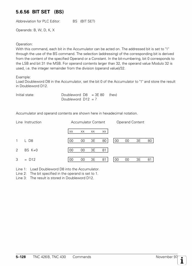
5–128 TNC 426B, TNC 430 Commands November 97
5.6.56 BIT SET (BS)
Abbreviation for PLC Editor: BS (BIT SET)
Operands: B, W, D, K, X
Operation:With this command, each bit in the Accumulator can be acted on. The addressed bit is set to "1"through the use of the BS command. The selection (addressing) of the corresponding bit is derivedfrom the content of the specified Operand or a Constant. In the bit-numbering, bit 0 corresponds tothe LSB and bit 31 the MSB. For operand contents larger than 32, the operand value Modulo 32 isused, i.e. the integer remainder from the division (operand value)/32.
Example:Load Doubleword D8 in the Accumulator, set the bit 0 of the Accumulator to "1" and store the resultin Doubleword D12.
Initial state: Doubleword D8 = 3E 80 (hex)Doubleword D12 = ?
Accumulator and operand contents are shown here in hexadecimal notation.
Line Instruction Accumulator Content Operand Content
xx xx xx xx
1 L D8 00 00 3E 80 00 00 3E 80
2 BS K+0 00 00 3E 81
3 = D12 00 00 3E 81 00 00 3E 81
Line 1: Load Doubleword D8 into the Accumulator.Line 2: The bit specified in the operand is set to 1.Line 3: The result is stored in Doubleword D12.
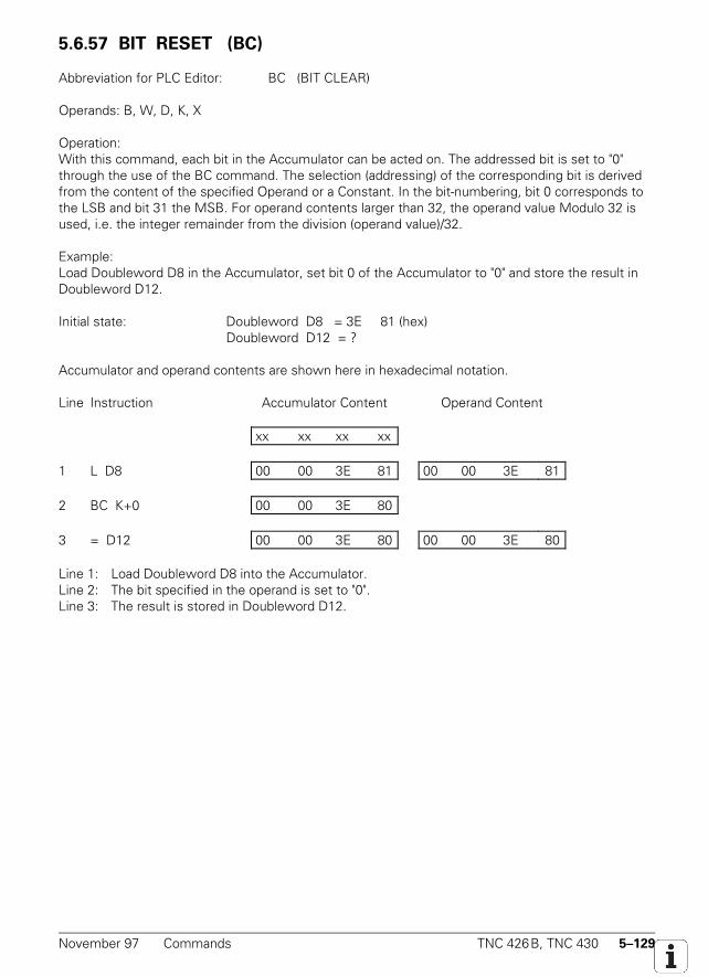
November 97 Commands TNC 426B, TNC 430 5–129
5.6.57 BIT RESET (BC)
Abbreviation for PLC Editor: BC (BIT CLEAR)
Operands: B, W, D, K, X
Operation:With this command, each bit in the Accumulator can be acted on. The addressed bit is set to "0"through the use of the BC command. The selection (addressing) of the corresponding bit is derivedfrom the content of the specified Operand or a Constant. In the bit-numbering, bit 0 corresponds tothe LSB and bit 31 the MSB. For operand contents larger than 32, the operand value Modulo 32 isused, i.e. the integer remainder from the division (operand value)/32.
Example:Load Doubleword D8 in the Accumulator, set bit 0 of the Accumulator to "0" and store the result inDoubleword D12.
Initial state: Doubleword D8 = 3E 81 (hex)Doubleword D12 = ?
Accumulator and operand contents are shown here in hexadecimal notation.
Line Instruction Accumulator Content Operand Content
xx xx xx xx
1 L D8 00 00 3E 81 00 00 3E 81
2 BC K+0 00 00 3E 80
3 = D12 00 00 3E 80 00 00 3E 80
Line 1: Load Doubleword D8 into the Accumulator.Line 2: The bit specified in the operand is set to "0".Line 3: The result is stored in Doubleword D12.
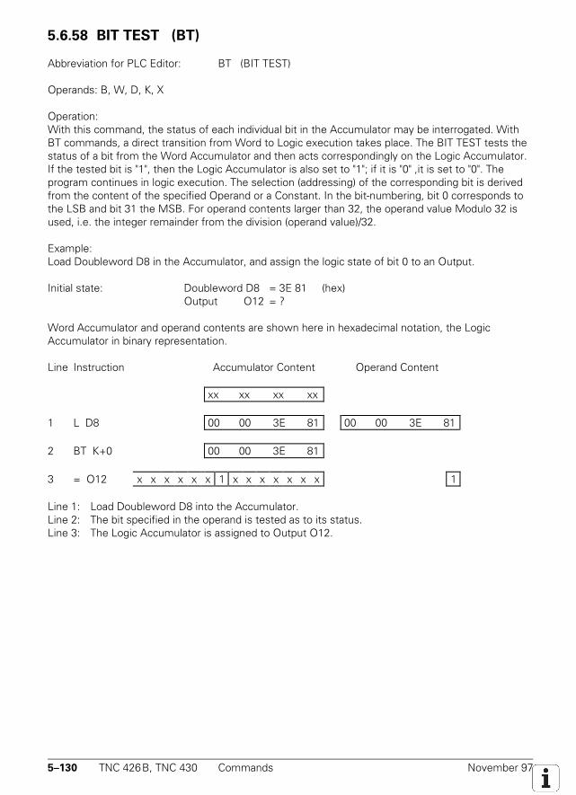
5–130 TNC 426B, TNC 430 Commands November 97
5.6.58 BIT TEST (BT)
Abbreviation for PLC Editor: BT (BIT TEST)
Operands: B, W, D, K, X
Operation:With this command, the status of each individual bit in the Accumulator may be interrogated. WithBT commands, a direct transition from Word to Logic execution takes place. The BIT TEST tests thestatus of a bit from the Word Accumulator and then acts correspondingly on the Logic Accumulator.If the tested bit is "1", then the Logic Accumulator is also set to "1"; if it is "0" ,it is set to "0". Theprogram continues in logic execution. The selection (addressing) of the corresponding bit is derivedfrom the content of the specified Operand or a Constant. In the bit-numbering, bit 0 corresponds tothe LSB and bit 31 the MSB. For operand contents larger than 32, the operand value Modulo 32 isused, i.e. the integer remainder from the division (operand value)/32.
Example:Load Doubleword D8 in the Accumulator, and assign the logic state of bit 0 to an Output.
Initial state: Doubleword D8 = 3E 81 (hex)Output O12 = ?
Word Accumulator and operand contents are shown here in hexadecimal notation, the LogicAccumulator in binary representation.
Line Instruction Accumulator Content Operand Content
xx xx xx xx
1 L D8 00 00 3E 81 00 00 3E 81
2 BT K+0 00 00 3E 81
3 = O12 x x x x x x 1 x x x x x x x 1
Line 1: Load Doubleword D8 into the Accumulator.Line 2: The bit specified in the operand is tested as to its status.Line 3: The Logic Accumulator is assigned to Output O12.
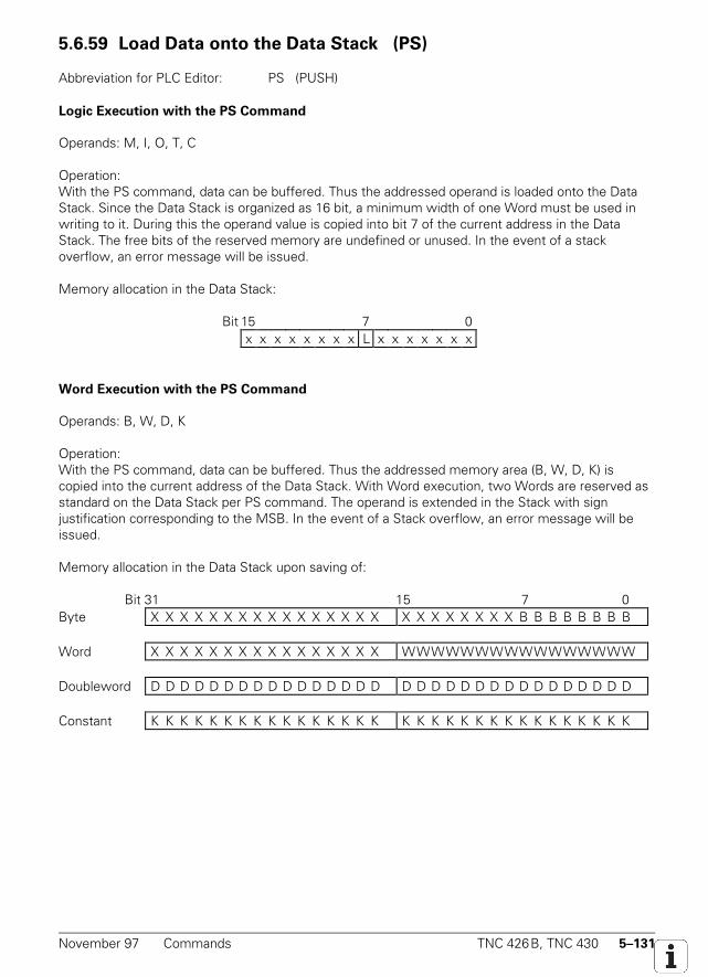
November 97 Commands TNC 426B, TNC 430 5–131
5.6.59 Load Data onto the Data Stack (PS)
Abbreviation for PLC Editor: PS (PUSH)
Logic Execution with the PS Command
Operands: M, I, O, T, C
Operation:With the PS command, data can be buffered. Thus the addressed operand is loaded onto the DataStack. Since the Data Stack is organized as 16 bit, a minimum width of one Word must be used inwriting to it. During this the operand value is copied into bit 7 of the current address in the DataStack. The free bits of the reserved memory are undefined or unused. In the event of a stackoverflow, an error message will be issued.
Memory allocation in the Data Stack:
Bit 15 7 0x x x x x x x x L x x x x x x x
Word Execution with the PS Command
Operands: B, W, D, K
Operation:With the PS command, data can be buffered. Thus the addressed memory area (B, W, D, K) iscopied into the current address of the Data Stack. With Word execution, two Words are reserved asstandard on the Data Stack per PS command. The operand is extended in the Stack with signjustification corresponding to the MSB. In the event of a Stack overflow, an error message will beissued.
Memory allocation in the Data Stack upon saving of:
Bit 31 15 7 0Byte X X X X X X X X X X X X X X X X X X X X X X X X B B B B B B B B
Word X X X X X X X X X X X X X X X X WWWWWWWWWWWWWWWW
Doubleword D D D D D D D D D D D D D D D D D D D D D D D D D D D D D D D D
Constant K K K K K K K K K K K K K K K K K K K K K K K K K K K K K K K K
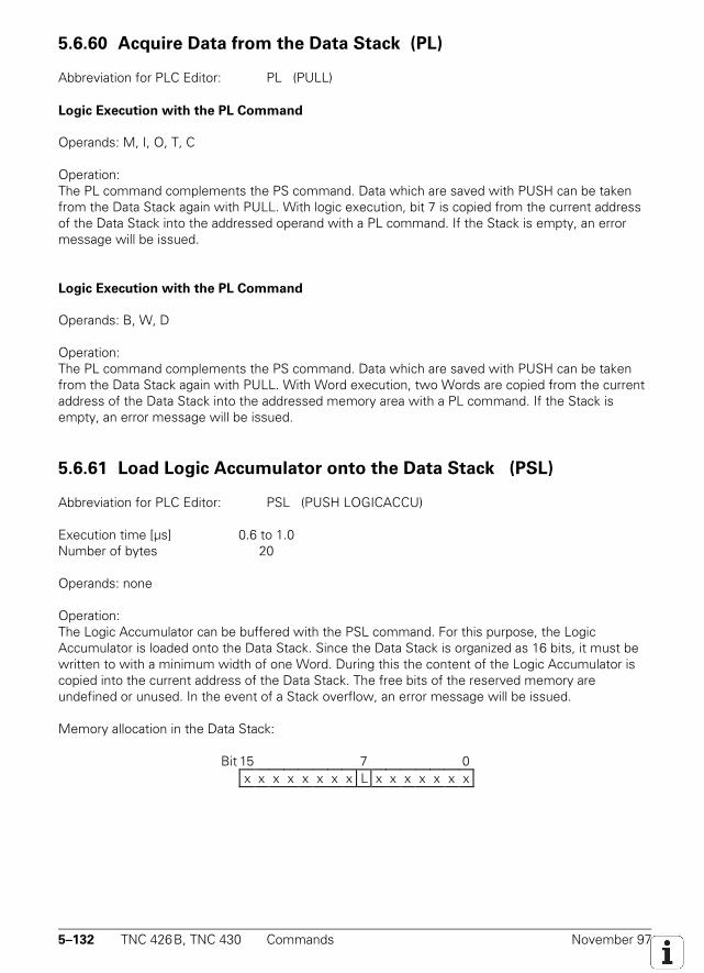
5–132 TNC 426B, TNC 430 Commands November 97
5.6.60 Acquire Data from the Data Stack (PL)
Abbreviation for PLC Editor: PL (PULL)
Logic Execution with the PL Command
Operands: M, I, O, T, C
Operation:The PL command complements the PS command. Data which are saved with PUSH can be takenfrom the Data Stack again with PULL. With logic execution, bit 7 is copied from the current addressof the Data Stack into the addressed operand with a PL command. If the Stack is empty, an errormessage will be issued.
Logic Execution with the PL Command
Operands: B, W, D
Operation:The PL command complements the PS command. Data which are saved with PUSH can be takenfrom the Data Stack again with PULL. With Word execution, two Words are copied from the currentaddress of the Data Stack into the addressed memory area with a PL command. If the Stack isempty, an error message will be issued.
5.6.61 Load Logic Accumulator onto the Data Stack (PSL)
Abbreviation for PLC Editor: PSL (PUSH LOGICACCU)
Execution time [µs] 0.6 to 1.0Number of bytes 20
Operands: none
Operation:The Logic Accumulator can be buffered with the PSL command. For this purpose, the LogicAccumulator is loaded onto the Data Stack. Since the Data Stack is organized as 16 bits, it must bewritten to with a minimum width of one Word. During this the content of the Logic Accumulator iscopied into the current address of the Data Stack. The free bits of the reserved memory areundefined or unused. In the event of a Stack overflow, an error message will be issued.
Memory allocation in the Data Stack:
Bit 15 7 0x x x x x x x x L x x x x x x x
November 97 Commands TNC 426B, TNC 430 5–133
5.6.62 Load Word Accumulator onto the Data Stack (PSW)
Abbreviation for PLC Editor: PSW (PUSH WORDACCU)
Operands: none
Operation:The content of the Word Accumulator can be buffered with the PSW command. For this purpose,the Word Accumulator is copied into the Data Stack. The content of the Word Accumulator (32 bit)reserves two Words on the Data Stack. In the event of a stack overflow, an error message will beissued.
5.6.63 Acquire Logic Accumulator from the Data Stack (PLL)
Abbreviation for PLC Editor: PLL (PULL LOGICACCU)
Operands: none
Operation:The PLL command complements the PSL command. With a PLL instruction, bit 7 from the currentaddress of the Data Stack is copied into the Logic Accumulator. If the stack is empty, an errormessage will be issued.
5.6.64 Acquire Word Accumulator from the Data Stack (PLW)
Abbreviation for PLC Editor: PLW (PULL WORDACCU)
Operands: none
Operation:The PLW command complements the PSW command. With a PLW instruction, two Words arecopied from the Data Stack into the Word Accumulator. If the stack is empty, an error message willbe issued.
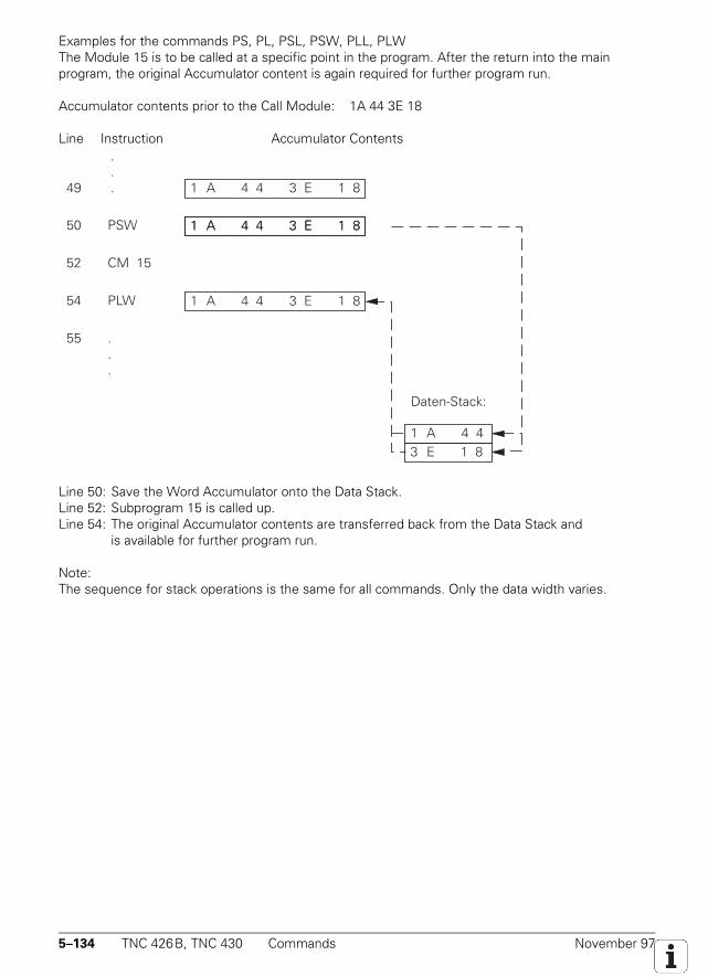
5–134 TNC 426B, TNC 430 Commands November 97
Examples for the commands PS, PL, PSL, PSW, PLL, PLWThe Module 15 is to be called at a specific point in the program. After the return into the mainprogram, the original Accumulator content is again required for further program run.
Accumulator contents prior to the Call Module: 1A 44 3E 18
Line Instruction Accumulator ContentsZeile AWL Akku-Inhalt
50 PSW
1 A 4 4 3 E 1 8 49
1 A 4 4 3 E 1 8
52 CM 15
54 PLW
55 ...
1 A 4 4 3 E 1 8
1 A 4 4 3 E 1 8
.
.
.
1 A 4 4 3 E 1 8
Daten-Stack:
Line 50: Save the Word Accumulator onto the Data Stack.Line 52: Subprogram 15 is called up.Line 54: The original Accumulator contents are transferred back from the Data Stack and
is available for further program run.
Note:The sequence for stack operations is the same for all commands. Only the data width varies.
November 97 Commands TNC 426B, TNC 430 5–135
5.6.65 Unconditional Jump (JP)
Abbreviation for PLC Editor: JP (JUMP)
Operands: jump address (LBL)
Operation:A JP command instructs the processor to continue the program at the specified jump address(Label). This command interrupts a logic sequence.
5.6.66 Jump if Logic Accumulator = 1 (JPT)
Abbreviation for PLC Editor: JPT (JUMP IF TRUE)
Operands: jump address (LBL)
Operation:A JPT command is a conditional jump command. If the Logic Accumulator is "1", the program iscontinued from the specified jump address (Label). If the Logic Accumulator is "0" the jump is notprocessed. This command interrupts a logic sequence.
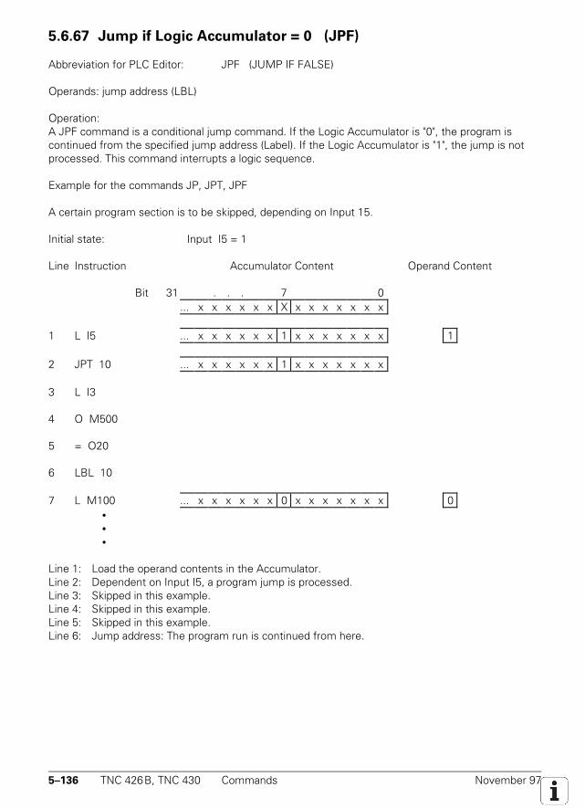
5–136 TNC 426B, TNC 430 Commands November 97
5.6.67 Jump if Logic Accumulator = 0 (JPF)
Abbreviation for PLC Editor: JPF (JUMP IF FALSE)
Operands: jump address (LBL)
Operation:A JPF command is a conditional jump command. If the Logic Accumulator is "0", the program iscontinued from the specified jump address (Label). If the Logic Accumulator is "1", the jump is notprocessed. This command interrupts a logic sequence.
Example for the commands JP, JPT, JPF
A certain program section is to be skipped, depending on Input 15.
Initial state: Input I5 = 1
Line Instruction Accumulator Content Operand Content
Bit 31 . . . 7 0... x x x x x x X x x x x x x x
1 L I5 ... x x x x x x 1 x x x x x x x 1
2 JPT 10 ... x x x x x x 1 x x x x x x x
3 L I3
4 O M500
5 = O20
6 LBL 10
7 L M100 ... x x x x x x 0 x x x x x x x 0•••
Line 1: Load the operand contents in the Accumulator.Line 2: Dependent on Input I5, a program jump is processed.Line 3: Skipped in this example.Line 4: Skipped in this example.Line 5: Skipped in this example.Line 6: Jump address: The program run is continued from here.
November 97 Commands TNC 426B, TNC 430 5–137
5.6.68 Call Module (CM)
Abbreviation for PLC Editor: CM (CALL MODULE)
Operands: jump address (LBL)
Operation:A Call Module instructs the processor to leave the main program and process the Moduledesignated by the jump address (LBL). Modules are independent subprograms and are terminatedby the command EM. They can also be called at multiple points in the main program. This commandinterrupts a logic sequence.
5.6.69 Call Module if Logic Accumulator = 1 (CMT)
Abbreviation for PLC Editor: CMT (CALL MODULE IF TRUE)
Operands: jump address (LBL)
Operation:A CMT command is a conditional Call Module. If the Logic Accumulator is "1", the Module with thespecified jump address (Label) is processed. If the Logic Accumulator is "0", the main programcontinues without a Call Module. This command interrupts a logic sequence.
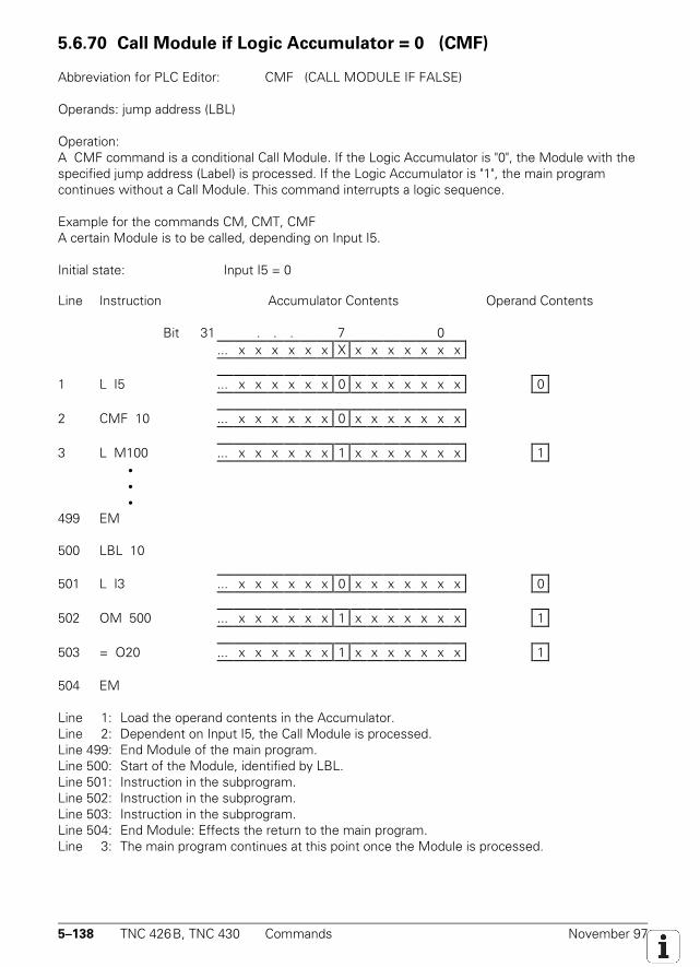
5–138 TNC 426B, TNC 430 Commands November 97
5.6.70 Call Module if Logic Accumulator = 0 (CMF)
Abbreviation for PLC Editor: CMF (CALL MODULE IF FALSE)
Operands: jump address (LBL)
Operation:A CMF command is a conditional Call Module. If the Logic Accumulator is "0", the Module with thespecified jump address (Label) is processed. If the Logic Accumulator is "1", the main programcontinues without a Call Module. This command interrupts a logic sequence.
Example for the commands CM, CMT, CMFA certain Module is to be called, depending on Input I5.
Initial state: Input I5 = 0
Line Instruction Accumulator Contents Operand Contents
Bit 31 . . . 7 0... x x x x x x X x x x x x x x
1 L I5 ... x x x x x x 0 x x x x x x x 0
2 CMF 10 ... x x x x x x 0 x x x x x x x
3 L M100 ... x x x x x x 1 x x x x x x x 1•••
499 EM
500 LBL 10
501 L I3 ... x x x x x x 0 x x x x x x x 0
502 OM 500 ... x x x x x x 1 x x x x x x x 1
503 = O20 ... x x x x x x 1 x x x x x x x 1
504 EM
Line 1: Load the operand contents in the Accumulator.Line 2: Dependent on Input I5, the Call Module is processed.Line 499: End Module of the main program.Line 500: Start of the Module, identified by LBL.Line 501: Instruction in the subprogram.Line 502: Instruction in the subprogram.Line 503: Instruction in the subprogram.Line 504: End Module: Effects the return to the main program.Line 3: The main program continues at this point once the Module is processed.
November 97 Commands TNC 426B, TNC 430 5–139
5.6.71 End of Module, Program End (EM)
Abbreviation for PLC Editor: EM (END OF MODULE)
Operands: none
Operation:Every program and/or every subprogram (Module) is terminated with an EM command. An EMcommand in a Module initiates the return jump to the Call Module (CM, CMT, CMF). The program iscontinued with the instruction following the Call Module. The command EM is handled as programend criterion; thus subsequent program instructions can be reached using a jump address.
5.6.72 End of Module if Logic Accumulator = 1 (EMT)
Abbreviation for the PLC Editor: EMT (END OF MODULE IF TRUE)
Operation:An EMT command only initiates a return jump to the Call Module (CM, CMT, CMF) when the LogicAccumulator is "1".
5.6.73 End of Module if Logic Accumulator = 0 (EMF)
Abbreviation for the PLC Editor: EMF (END OF MODULE IF FALSE)
Operation:An EMF command only initiates a return jump to the Call Module (CM, CMT, CMF) when the LogicAccumulator is "0".
5.6.74 Jump Label (LBL)
Abbreviation for PLC Editor: LBL (LABEL)
Operands: ASCII name (up to 32 characters long)
Operation:The jump label defines a program position as an entry point for the CM and JP commands. Jumplabels may be allocated addresses in the range 0 to 511. Up to 1000 jump labels per file can bedefined.
The ASCII name of the jump label may be up to 32 characters long, but only the first 16 charactersare used to distinguish jump labels. For importing global jump labels, see EXTERN instruction.

5–140 TNC 426B, TNC 430 Commands November 97

November 97 Commands TNC 426B, TNC 430 5–141

5–142 TNC 426B, TNC 430 Commands November 97

November 97 Commands TNC 426B, TNC 430 5–143
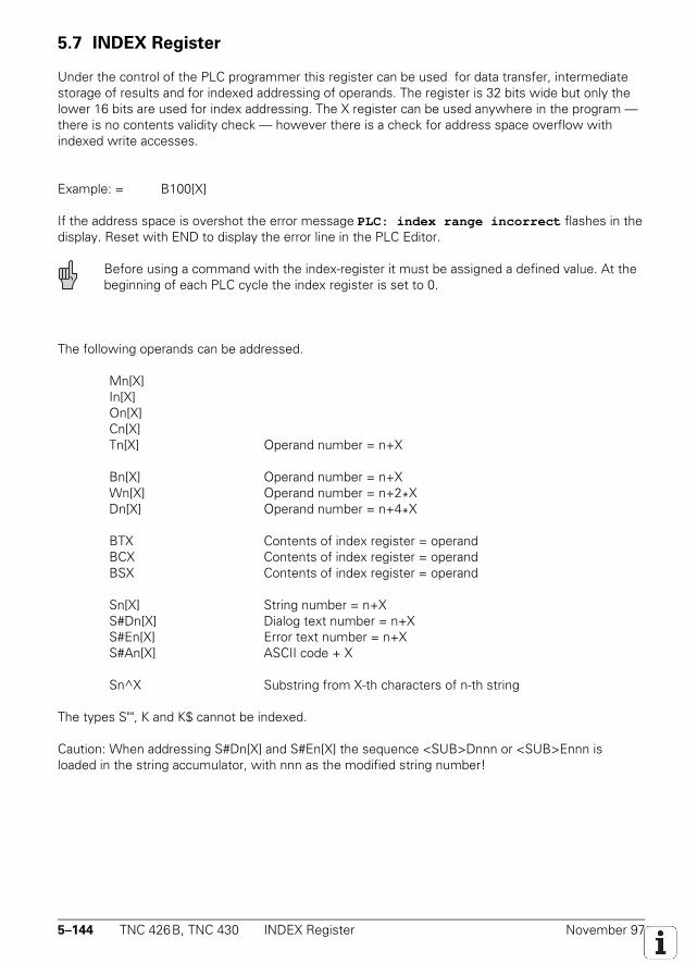
5–144 TNC 426B, TNC 430 INDEX Register November 97
5.7 INDEX Register
Under the control of the PLC programmer this register can be used for data transfer, intermediatestorage of results and for indexed addressing of operands. The register is 32 bits wide but only thelower 16 bits are used for index addressing. The X register can be used anywhere in the program —there is no contents validity check — however there is a check for address space overflow withindexed write accesses.
Example: = B100[X]
If the address space is overshot the error message PLC: index range incorrect flashes in thedisplay. Reset with END to display the error line in the PLC Editor.
Before using a command with the index-register it must be assigned a defined value. At thebeginning of each PLC cycle the index register is set to 0.
The following operands can be addressed.
Mn[X]In[X]On[X]Cn[X]Tn[X] Operand number = n+X
Bn[X] Operand number = n+XWn[X] Operand number = n+2*XDn[X] Operand number = n+4*X
BTX Contents of index register = operandBCX Contents of index register = operandBSX Contents of index register = operand
Sn[X] String number = n+XS#Dn[X] Dialog text number = n+XS#En[X] Error text number = n+XS#An[X] ASCII code + X
Sn^X Substring from X-th characters of n-th string
The types S"", K and K$ cannot be indexed.
Caution: When addressing S#Dn[X] and S#En[X] the sequence <SUB>Dnnn or <SUB>Ennn isloaded in the string accumulator, with nnn as the modified string number!

November 97 INDEX Register TNC 426B, TNC 430 5–145
Commands for operating the Index Register:
The following commands have been introduced to permit data interchange between the WordAccumulator and the Index Register or between the Stack and Index Register:
LX (Load Index to Accu) Index Register --> Word Accumulator=X (Store Accu to Index) Word Accumulator --> Index RegisterPSX (Push Index Register) Index Register --> StackPLX (Pull Index Register) Stack --> Index RegisterINCX (Increment Index Register)DECX (Decrement Index Register)
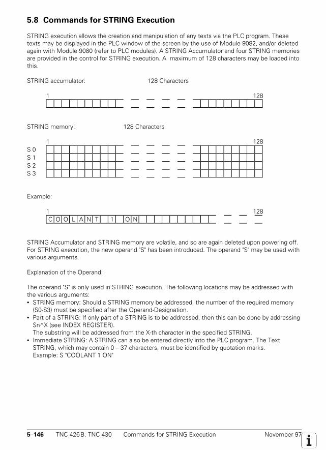
5–146 TNC 426B, TNC 430 Commands for STRING Execution November 97
5.8 Commands for STRING Execution
STRING execution allows the creation and manipulation of any texts via the PLC program. Thesetexts may be displayed in the PLC window of the screen by the use of Module 9082, and/or deletedagain with Module 9080 (refer to PLC modules). A STRING Accumulator and four STRING memoriesare provided in the control for STRING execution. A maximum of 128 characters may be loaded intothis.
STRING accumulator: 128 Characters
1 128
STRING memory: 128 Characters
1 128S 0S 1S 2S 3
Example:
1 128C O O L A N T 1 O N
STRING Accumulator and STRING memory are volatile, and so are again deleted upon powering off.For STRING execution, the new operand "S" has been introduced. The operand "S" may be used withvarious arguments.
Explanation of the Operand:
The operand "S" is only used in STRING execution. The following locations may be addressed withthe various arguments:• STRING memory: Should a STRING memory be addressed, the number of the required memory
(S0-S3) must be specified after the Operand-Designation.• Part of a STRING: If only part of a STRING is to be addressed, then this can be done by addressing
Sn^X (see INDEX REGISTER).The substring will be addressed from the X-th character in the specified STRING.
• Immediate STRING: A STRING can also be entered directly into the PLC program. The TextSTRING, which may contain 0 – 37 characters, must be identified by quotation marks.Example: S "COOLANT 1 ON"
November 97 Commands for STRING Execution TNC 426B, TNC 430 5–147
• Text from the PLC-Error Message files and/or from the PLC-dialog files: Text from the activeerror message or dialog files may be read by the input of the line number.PLC ERROR: S#Exx xx: Line number from the PLC error message file (0 to 999)PLC DIALOG: S#Dxx xx: Line number from the PLC dialog file (0 to 4095)The character sequence #Exx or #Dxx is entered in the Argument <arg> for the STRING-Command. A 5 Byte long character train <SUB> E0xx or <SUB> D0xx is loaded into theAccumulator ( <SUB> = ASCII <SUB> ). Instead of this character train, the line xx of the activeerror message or dialog file is read for display on the screen.
• ASCII character entered in string. The ASCII character is defined by its code S#Axxx.
5.8.1 LOAD (L)
Abbreviation for PLC Editor: L (LOAD)
Operands: S <arg>
Operation:The STRING Accumulator is loaded with this L command. The selection of the STRINGS to beloaded, proceeds using the Argument <arg> after the operand designation.Refer also to operand explanation.
5.8.2 ADD (+)
Abbreviation for PLC Editor: +
Operands: S <arg>
Operation:With this command another STRING is added to the STRING in the STRING Accumulator. Theselection of the STRINGS, which should be added, proceeds using the Argument <arg> after theoperand designation. Refer also to operand explanation. The resultant STRING must not be longerthan 128 characters.
5.8.3 Storing a STRING (=)
Abbreviation for PLC Editor: =
Operands: S <arg>
Operation:With the = command a STRING from the STRING Accumulator is stored in a STRING memory. Theselection of the memory, into which the STRING should be copied, proceeds using the Argument<arg> after the operand designation. Whereby only the Arguments 0 – 3, which address a STRINGmemory (S0 – S3) are valid here. Refer also to operand explanation.
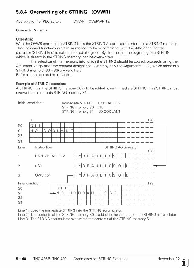
5–148 TNC 426B, TNC 430 Commands for STRING Execution November 97
5.8.4 Overwriting of a STRING (OVWR)
Abbreviation for PLC Editor: OVWR (OVERWRITE)
Operands: S <arg>
Operation:With the OVWR command a STRING from the STRING Accumulator is stored in a STRING memory.This command functions in a similar manner to the = command, with the difference that thecharacter "STRING-End" is not transferred alongside. By this means, the beginning of a STRINGwhich is already in the STRING memory, can be overwritten.
The selection of the memory, into which the STRING should be copied, proceeds using theArgument <arg> after the operand designation. Whereby only the Arguments 0 – 3, which address aSTRING memory (S0 – S3) are valid here.Refer also to operand explanation.
Example of STRING execution:A STRING from the STRING memory S0 is to be added to an Immediate STRING. This STRING mustoverwrite the contents STRING memory S1.
OVWR S1
2 + S0
3
1 L S "HYDRAULICS"
1
S0S1
Line Instruction STRING Accumulator
O I L
H Y D R A U L I C S
128
1 128
S2
S3
Initial condition: Immediate STRING: HYDRAULICSSTRING memory S0: OILSTRING memory S1: NO COOLANT
Final condition:
Line 1: Load the immediate STRING into the STRING accumulator.Line 2: The contents of the STRING memory S0 is added to the contents of the STRING accumulator.Line 3: The STRING accumulator overwrites the contents of the STRING memory S1.
128
N O C O O L A N T
S0S1S2S3
H Y D R A U L I C S O I L
H Y D R A U L I C S O I L
O I L N O H Y D R A U L I C S O I L
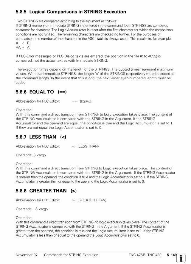
November 97 Commands for STRING Execution TNC 426B, TNC 430 5–149
5.8.5 Logical Comparisons in STRING Execution
Two STRINGS are compared according to the argument as follows:If STRING memory or Immediate STRING are entered in the command, both STRINGS are comparedcharacter for character. The Logic Accumulator is reset after the first character for which the comparisonconditions are not fulfilled. The remaining characters are checked no further. For the purposes ofcomparison, the number of the character in the ASCII table is always used. This results in, for example:A < BAA > A
If PLC-Error messages or PLC-Dialog texts are entered, the position in the file (0 to 4095) iscompared, not the actual text as with Immediate STRING.
The execution times depend on the length of the STRINGS. The quoted times represent maximumvalues. With the Immediate STRINGS, the length "n" of the STRINGS respectively must be added tothe command length. In the event that this is odd, the next larger even-numbered length must beadded.
5.8.6 EQUAL TO (==)
Abbreviation for PLC Editor: == (EQUAL)
Operation:With this command a direct transition from STRING- to logic execution takes place. The content ofthe STRING Accumulator is compared with the STRING in the Argument. If the STRINGAccumulator and the operand are equal, the condition is true and the Logic Accumulator is set to 1.If they are not equal the Logic Accumulator is set to 0.
5.8.7 LESS THAN (<)
Abbreviation for PLC Editor: < (LESS THAN)
Operands: S <arg>
Operation:With this command a direct transition from STRING to Logic execution takes place. The content ofthe STRING Accumulator is compared with the STRING in the Argument. If the STRING Accumulatoris smaller than the operand, the condition is true and the Logic Accumulator is set to 1. If the STRINGAccumulator is greater than or equal to the operand the Logic Accumulator is set to 0.
5.8.8 GREATER THAN (>)
Abbreviation for PLC Editor: > (GREATER THAN)
Operands: S <arg>
Operation:With this command a direct transition from STRING- to logic execution takes place. The content of theSTRING Accumulator is compared with the STRING in the Argument. If the STRING Accumulator isgreater than the operand, the condition is true and the Logic Accumulator is set to 1. If the STRINGAccumulator is less than or equal to the operand the Logic Accumulator is set to 0.
5–150 TNC 426B, TNC 430 Commands for STRING Execution November 97
5.8.9 LESS THAN OR EQUAL TO (<=)
Abbreviation for PLC Editor: <= (LESS EQUAL)
Operands: S <arg>
Operation:With this command a direct transition from STRING- to logic execution takes place. The content of theSTRING Accumulator is compared with the STRING in the Argument. If the STRING Accumulator is lessthan or equal to the operand, the condition is true and the Logic Accumulator is set to 1. If the STRINGAccumulator is greater than the operand the Logic Accumulator is set to.
5.8.10 GREATER THAN OR EQUAL TO (>=)
Abbreviation for PLC Editor: >= (GREATER EQUAL)
Operands: S <arg>
Operation:With this command a direct transition from STRING- to logic execution takes place. The content of theSTRING Accumulator is compared with the STRING in the Argument. If the STRING Accumulator isgreater than or equal to the operand, the condition is true and the Logic Accumulator is set to 1. If theSTRING Accumulator is less than the operand the Logic Accumulator is set to 0.
5.8.11 UNEQUAL (<>)
Abbreviation for PLC Editor: <> (NOT EQUAL)
Operands: S <arg>
Operation:With this command a direct transition from STRING- to logic execution takes place. The content ofthe STRING Accumulator is compared with the STRING in the Argument. If the STRINGAccumulator is not equal to the operand, the condition is true and the Logic Accumulator is set to 1.If the STRING Accumulator is equal to the operand the Logic Accumulator is set to 0.
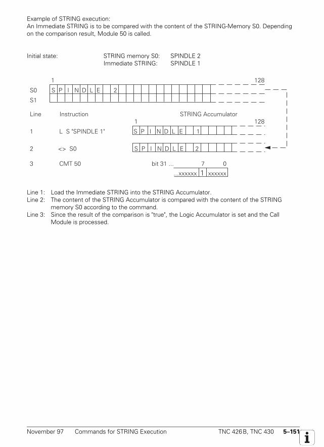
November 97 Commands for STRING Execution TNC 426B, TNC 430 5–151
Example of STRING execution:An Immediate STRING is to be compared with the content of the STRING-Memory S0. Dependingon the comparison result, Module 50 is called.
Initial state: STRING memory S0: SPINDLE 2Immediate STRING: SPINDLE 1
...xxxxxx 1 xxxxxx
7 0bit 31 ...CMT 50
2 <> S0
3
1 L S "SPINDLE 1"
1
S P I N D L E 2 S0
S1
Line Instruction STRING Accumulator
128
1 128
S P I N D L E 1
S P I N D L E 2
Line 1: Load the Immediate STRING into the STRING Accumulator.Line 2: The content of the STRING Accumulator is compared with the content of the STRING
memory S0 according to the command.Line 3: Since the result of the comparison is "true", the Logic Accumulator is set and the Call
Module is processed.
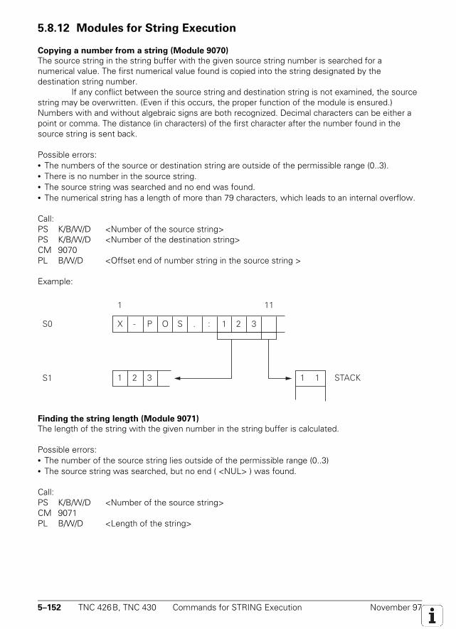
5–152 TNC 426B, TNC 430 Commands for STRING Execution November 97
5.8.12 Modules for String Execution
Copying a number from a string (Module 9070)
The source string in the string buffer with the given source string number is searched for anumerical value. The first numerical value found is copied into the string designated by thedestination string number.
If any conflict between the source string and destination string is not examined, the sourcestring may be overwritten. (Even if this occurs, the proper function of the module is ensured.)Numbers with and without algebraic signs are both recognized. Decimal characters can be either apoint or comma. The distance (in characters) of the first character after the number found in thesource string is sent back.
Possible errors:• The numbers of the source or destination string are outside of the permissible range (0..3).• There is no number in the source string.• The source string was searched and no end was found.• The numerical string has a length of more than 79 characters, which leads to an internal overflow.
Call:PS K/B/W/D <Number of the source string>PS K/B/W/D <Number of the destination string>CM 9070PL B/W/D <Offset end of number string in the source string >
Example:
S1
XS0 - P O S . : 1 2
111Beispiel:
1 2 3 1 1 STACK
3
Finding the string length (Module 9071)
The length of the string with the given number in the string buffer is calculated.
Possible errors:• The number of the source string lies outside of the permissible range (0..3)• The source string was searched, but no end ( <NUL> ) was found.
Call:PS K/B/W/D <Number of the source string>CM 9071PL B/W/D <Length of the string>
November 97 Submit Programs TNC 426B, TNC 430 5–153
5.9 Submit Programs
Submit programs are subprograms which the PLC submits to the NC for processing. This allowstasks to be performed which are very processor-intensive, require program loops, or must wait forexternal results. It is assumed, however, that these programs are not bound by a particular timeframe. Depending on processor loading, each Submit program is allocated a certain computingpower, but always at least 5% of the total power. Submit programs are started from the PLCprogram and can access all the same data memories (M/B/W/D) as can the main program. This canlead to problems in certain circumstances. Such problems can be avoided if the data processed bythe PLC program are clearly separated from the data processed by the Submit program.
Up to eight Submit programs can be entered in a queue (Submit Queue). Each receives an"Identifier," a number between 1 and 255 assigned by the NC, which is transferred into the WordAccumulator. With this Identifier and the REPLY function, you can inquire whether or not theprogram is in the queue, is being processed, or is already complete. The Submit programs areexecuted in the order of their placement in the queue. Should an error occur during the execution ofthe Submit programs, the following Markers are set:
M4200 Overflow during MultiplicationM4201 Division by 0M4202 MODULO incorrectly executedM4203 Error status for PLC moduleM4204 Reserved for errors that the PLC programmer would like to intercept
These markers are listed separately in the submit job. This means that the same markers can beedited as those in the PLC run program without changing the original markers.
Exact times cannot be given for the commands for the management of the Submit queue. Theexecution times denote maximum values.
5.9.1 Call up of the Submit Program (SUBM)
Abbreviation for PLC Editor: SUBM (SUBMIT)
Operands: jump address (LBL)
Operation:The SUBM command allots an "Identifier" (1 to 255) to the subprogram, designated by the jumpaddress (LBL). Simultaneously, the allocated number is written to the Word Accumulator. If thereare already programs transferred into the Submit queue, the addressed program will not beprocessed until the program immediately prior to it is finished. A submission to the queue may onlytake place from a PLC program, a SUBM command in a Submit program is not possible.
If no location is free in the queue, or if the SUBM command is programmed in a Submit program(nesting), a "0" will be returned to the Word Accumulator.
5–154 TNC 426B, TNC 430 Submit Programs November 97
5.9.2 Status Interrogation of a Submit Program (RPLY)
Abbreviation for PLC Editor: RPLY (REPLY)
Operands: B, W
Operation:With the RPLY command the Status of the Submit program is interrogated with the specifiedIdentifier. This Identifier must already be stored in a Byte or Word prior to the calling up of theSubmit program. With the RPLY command and the memory address specified above, whichcontains the Identifier, one of the following messages about the status is transferred to the WordAccumulator:
Word Accumulator 0: Program complete/not in the queueWord Accumulator 1: Program runningWord Accumulator 2: Program in the queue
5.9.3 Cancellation of a Submit Program (CAN)
Abbreviation for PLC Editor: CAN (CANCEL)
Operands: B, W
Operation:With the CAN command the Submit-Program with the specified Identifier is canceled duringexecution or removed from the queue. This Identifier must already be stored in a Byte or Word priorto the calling up of the Submit-Program. After the cancellation of the Program, the next Submitprogram in the queue will immediately be processed.
The following PLC modules cannot be canceled with CANCEL at any desired point:– PLC module for access to the screen (908X).– PLC module for reading NC files (909X).In these cases, the RPLY command must be used to check whether or not the CAN command maybe used.
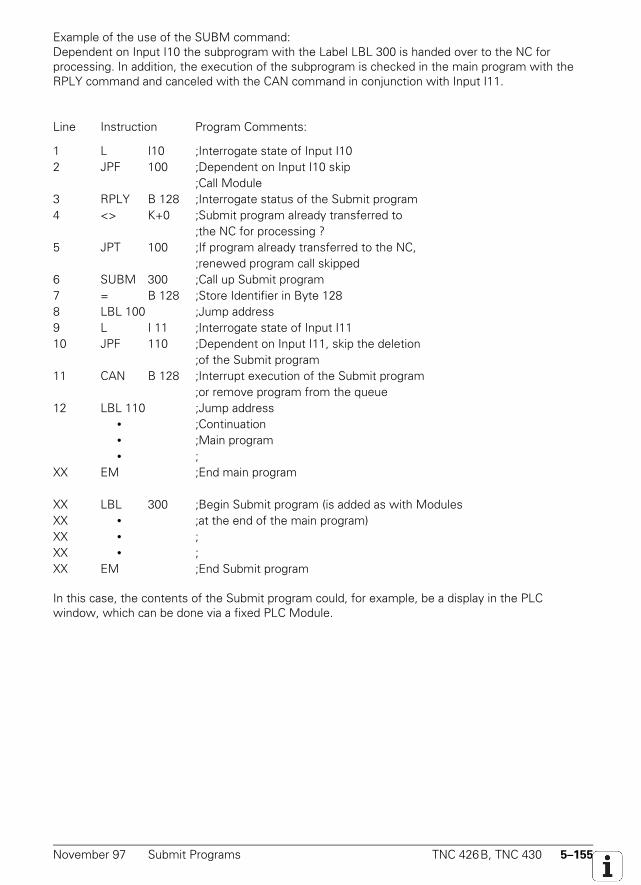
November 97 Submit Programs TNC 426B, TNC 430 5–155
Example of the use of the SUBM command:Dependent on Input I10 the subprogram with the Label LBL 300 is handed over to the NC forprocessing. In addition, the execution of the subprogram is checked in the main program with theRPLY command and canceled with the CAN command in conjunction with Input I11.
Line Instruction Program Comments:
1 L I10 ;Interrogate state of Input I102 JPF 100 ;Dependent on Input I10 skip
;Call Module3 RPLY B 128 ;Interrogate status of the Submit program4 <> K+0 ;Submit program already transferred to
;the NC for processing ?5 JPT 100 ;If program already transferred to the NC,
;renewed program call skipped6 SUBM 300 ;Call up Submit program7 = B 128 ;Store Identifier in Byte 1288 LBL 100 ;Jump address9 L I 11 ;Interrogate state of Input I1110 JPF 110 ;Dependent on Input I11, skip the deletion
;of the Submit program11 CAN B 128 ;Interrupt execution of the Submit program
;or remove program from the queue12 LBL 110 ;Jump address
• ;Continuation • ;Main program • ;
XX EM ;End main program
XX LBL 300 ;Begin Submit program (is added as with ModulesXX • ;at the end of the main program)XX • ;XX • ;XX EM ;End Submit program
In this case, the contents of the Submit program could, for example, be a display in the PLCwindow, which can be done via a fixed PLC Module.
5–156 TNC 426B, TNC 430 Cooperative Multitasking1) November 97
5.10 Cooperative Multitasking1)
It is possible to run several parallel processes in the PLC using the cooperative multitasking function.In comparison to real multitasking, information exchange and task change only occur at certainprogrammed instances in cooperative multitasking.
Cooperative multitasking comprises a maximum of 8 parallel PLC processes and the submitqueue. This means that the commands for task change and event control (Module 926x) can also beused in a program started with SUBM. A task change is also inserted between the individual jobs inthe submit queue, so that if parallel processes exist, they will be executed by the end of that job atthe latest.
The cyclic PLC main program does not take part in cooperative multitasking, but interrupts asubmit job and the parallel processes at whatever point they are at.
5.10.1 Starting a Parallel Process
A parallel process is started with the command:SPAWN <jump label>= D<number>The identifier is sent back in the given doubleword (see submit job). If no process can be started, thevalue –1 is sent.
The SPAWN command can only be called from a submit job or from another SPAWNprocess. A maximum of 8 parallel processes can be started at the same time. If such a process isended with EM, it is taken from the memory and this memory area is once again available.
1) As of NC software 280 472 01
November 97 Cooperative Multitasking1) TNC 426B, TNC 430 5–157
5.10.2 Control of Events
The parallel processes can make events available to one another. This offers the advantage that notime is lost by the individual processes constantly interrogating the operating status.
One particular feature of the events control is the timeout. This timeout allows the processto "sleep" for a certain time, which is particularly useful for the repetition of program sections in aslow time-slot pattern (e.g. display functions, monitoring functions).
List of events
In the file OEM.SYS enter the complete name for the ASCII file containing your list of events usingthe command PLCEVENTS=.The entries in the events file must have the following syntax:<job name> ; <condition> ; <event> [;comment ]
<job name> This name is identical with the jump label in the SPAWN command. Only the first16 characters are taken into consideration.
<condition> Logical expression in accordance with C language convention, identical with thesyntax used in function FN20:Operand:M/I/O/T/C/B/W/D with a permissible number for this typeCondition: == equal to
!= or <> not equal to< less than> greater than<= less than or equal to>= greater than or equal to
If you do not enter any condition, the condition = 0 will be tested .
<event mask> Hexadecimal coded mask of events that are triggered if the condition is met.The limits defined in Module 9260 are valid for bits 16 to 31.
Example:Entry in OEM.SYS:
PLCEVENTS=PLC:\EXAMPLE.PEVContents of file PLC:\EXAMPLE.PEV:
JOB_1;I5==1;$0010 ; Event $0010 to process JOB_1, if I5==1JOB_1;B20==5;$0004 ; Event $0004 to process JOB_1, if B20==5AUXJOB;W6<10;$0100 ; Event $0100 to process AUXJOB, if W6<10
An event is triggered if a particular condition is met after one run of the cyclic PLC program, and ifthis condition was not met after the previous run of the cyclic PLC program (edge formation). Thenumber of events that can be triggered at the same time is limited to 15.
When a PLC process is generated (with the SPAWN command), the events file is searchedfor entries for this process. All of the entries found are transferred to a list which is executed aftereach run of the cyclic PLC program. If a PLC process ends itself, or if is ended through a recompilingof the PLC program, the entries are deleted from the list and are once again available.
5–158 TNC 426B, TNC 430 Cooperative Multitasking1) November 97
The entries in the events file are not monitored, which means that syntactically incorrect entries orincorrect job names do not lead to an error message being output. If an events file which actuallydoes not exist is entered in OEM.SYS, a flashing error message is triggered with the first SPAWNcommand. An error message is also triggered if more events need to be monitored than the runtime list contains (currently contains 15 entries).
Process monitor
The PROCESS MONITOR soft key is available in the PLC programming operating mode. This softkey opens a screen showing all of the parallel processes as well as the process for the submitqueue. The current status (ready to run, running, waiting for event) of each process is shown in onesecond intervals. You can also see how many context changes were carried out by each process inthe previous second, and how much CPU time it used. The distribution of the CPU time is shown ina bar chart.
Module 9260: Receiving and waiting for events
This module must be called in a submit or a SPAWN job. The module makes it possible for aSPAWN process or a SUBMIT job to interrogate or wait for the arrival of one or several events. Atthe same time the module triggers a contact change.
After the module call, the markers 4200 to 4202 and 4204 have undefined changes.If the value zero is transferred for the events mask, all of the events are sent back without thembeing canceled. In a call with Wait, all of the events requested are sent back and are also canceled.In a call without Wait, only those events that have fulfilled the condition are sent back and canceled.In the case where the events are OR-gated, only the set events are sent and canceled. If you wishto specify which events should be canceled, you need to call without Wait and with OR-gating.The event bits 16 to 31 are reserved for the operating system:Bit16: BREAK Aborts a function. May be set and read. Access to interfaces and network is
interrupted if this event is sent in wait conditions!Bit17: Reserved, do not use.Bit18: Reserved, do not use.Bit19: QUIT Acknowledgment for a request. May only be used in immediate with a request.Bit20 to Bit31: Reserved, do not use.
Call in the SPAWN or submit job only:PS B/W/D/K <Wait> 0 = do not wait
–1 = waitPS B/W/D/K <AND/OR> 0 = OR-gated, otherwise AND-gatedPS B/W/D/K <Event mask> 0 = existing events are to be read onlyCM 9260PL B/W/D <Events> read eventsError recognition: M4203 = 0: Events were read
M4203 = 1: Error code in W1022W1022 = 2: Incorrect transfer value for parameter <Wait>W1022 = 20: Module was not called in the submit job.
November 97 Cooperative Multitasking1) TNC 426B, TNC 430 5–159
Module 9261: Sending events
With this module you can send events to a SPAWN or submit job. These events are theninterrogated with Module 9260.
This module can be called up in the cyclical program section, in submit jobs and in the SPAWNprocesses. The identifier indicates the destination address. This identifier is then sent back with theSPAWN command. The submit queue is addressed with the identifier $80000000 (and not with theidentifier sent back with the SUBM command!).
The events that are sent to the submit queue are always assigned to the job that is runningat the time of arrival. If they are not read by this job, they are kept for the next job.If the receiver process is also to start immediately, Module 9262 must be called immediately afterModule 9261 so that a context change will be triggered.The event bits 16 to 31 are reserved for the operating system (see Module 9260).
Call:PS D/K <Identifier> Identifier from SPAWN command of the receiver
K$80000000 = submit queuePS B/W/D/K <Events> Events bit-codedCM 9261Error recognition: M4203 = 0: Events were sent
M4203 = 1: Error code in W1022W1022 = 2: Incorrect identifier
Module 9262: Context change between SPAWN processes
This module may only be called in a SPAWN or submit job. The module carries out a context changein another PLC process or in the submit queue if such a process exists which is not waiting for anevent or a timeout.After the module call, the markers 4200 to 4202 and 4204 have undefined changes.
Call in the SPAWN or submit job only:CM 9262Error recognition: M4203 = 0: Context change was executed
M4203 = 1: Error code in W1022W1022 = 30: Module was not called in the submit job.
5–160 TNC 426B, TNC 430 Cooperative Multitasking1) November 97
Module 9263: Interrupt SPAWN process for a defined period of time
This module may only be called in a SPAWN or submit job. The module interrupts the calling processfor at least the time indicated in the module. If other processes or the submit queue are ready torun, a context change is carried out to one of these processes.After the module call, the markers 4200 to 4202 and 4204 have undefined changes.The timeout is interpreted as an unsigned number, i.e. negative numbers result in extremely longtimeouts.
Call only in the SPAWN or submit job:PS B/W/D/K <Waiting time in ms>CM 9263Error recognition: M4203 = 0: Timeout
M4203 = 1: Error code in W1022W1022 = 30: Module was not called in the submit job.

November 97 Cooperative Multitasking1) TNC 426B, TNC 430 5–161

5–162 TNC 426B, TNC 430 Cooperative Multitasking1) November 97

November 97 Cooperative Multitasking1) TNC 426B, TNC 430 5–163
5–164 TNC 426B, TNC 430 Constants Field (KF) November 97
5.11 Constants Field (KF)
The Constants Field data type can be used to access one of several constants defined in tabularform, depending on the value of the Index Register X.
Addressing is with KF <Name>[X], where <Name> is a jump label that identifies thebeginning of the Constants Field.
Constants Fields start with the label KFIELD <Name> followed by a random (not zero)number of constants followed by the end label ENDK. Constants Fields may only be created whenthe program has been previously terminated with an EM or JP instruction.The name of the Constants Fields conforms to the rules for jump labels.
Types of addressing:
L KF <Name> [X]: (X ≥ 0): The value of the constant defined by X from the Constants Field<Name>is transferred.
L KF <Name> [X]: (X = –1): The length of the Constants Field <Name> is transferred.L KF <Name>: The absolute address of the Constants Field <Name> is transferred. This is
only worthwhile in conjunction with modules (e.g. module 9200). This type of addressing can also be used within a Constants Field.
Example:L KF VALUESFIELD ;ACCESS TO VALUESFIELD WITH
VALUESFIELD[X];X=[0 TO 3]
= W0 ONE OF THE CONSTANTS ISSTORED
EMKFIELD VALUESFIELD
K+10 CONSTANT TO BE LOADED IF X=0K+1K$ABCK-100000 CONSTANT TO BE LOADED IF X=3ENDK
Access to Constants Fields is checked in the same way as write access to indexed operands. This iswhy X may only assume positive values from 0 to <Length of Constants Field -1>.
5.12 Program Structures
A program is split up into program sequences so as to make it clearer. To do this the programmeruses jump labels (LBL) and conditional and unconditional jumps.
When structured instructions are used, the jump labels and jump commands are created bythe Compiler. Remember that internal jump labels are generated to implement these structuredcommands, so the total number of available jump labels will be reduced accordingly. Structuredinstructions can be nested to up to 16 levels but there must be no "interleaving".
Right: IFT Wrong: IFT... ...WHILEF WHILEF... ...ENDW END... ...ENDI ENDW
November 97 Program Structures TNC 426B, TNC 430 5–165
Instructions IFT, IFF, WHILET, WHILEF, ENDW, UNTILT and UNTILF require a valid gating result inthe Logic Accumulator. They terminate the gating chain. Instructions ELSE, ENDI and REPEATrequire all gating chains to be terminated first.
5.12.1 IF ... ELSE ... ENDI Structure
The IF ... ELSE ... ENDI structure permits the alternative processing of two program branchesdepending on the value in the Logic Accumulator. The ELSE branch can be omitted. The followingcommands are available:
• IFT (If Logic Accu True) Following code only if Logic Accumulator=1• IFF (If Logic Accu False) Following code only if Logic Accumulator=0• ELSE (else) Following code only if IF not fulfilled• ENDI (End of IF-Structure) End of IF Structure
Example:
L I0IFT ;If Logic Accu=1
.... ;Program code for I0 = 1ELSE ; can be omitted
.... ;Program code for I0 = 0 can be omittedENDI ;end of conditional processing
5.12.2 REPEAT ... UNTIL Structure
The REPEAT ... UNTIL structure repeats a program sequence until a condition is fulfilled.Under no circumstances may this structure wait for an external event in the cyclical PLC
program to happen!
The following commands are available:
• REPEAT (Repeat) Repeat program sequence from here• UNTILT (Until True) Repeat sequence until Logic Accumulator=1• UNTILF (Until False) Repeat sequence until Logic Accumulator=0
A REPEAT ... UNTIL loop is always run at least once!
Example:= M100 ;end of previous chain
REPEAT ;repeat following code..... ;code to be executedLX ;load Index Register>= K100 ;check Index Register
UNTILT ;repeat until X>=100
5–166 TNC 426B, TNC 430 Program Structures November 97
5.12.3 WHILE ... ENDW Structure
The WHILE ... ENDW structure repeats a program sequence if a condition is fulfilled.Under no circumstances must this structure wait for an external event in the cyclical PLC program tohappen!
The following commands are available:
• WHILET (While True) Execute sequence if Logic Accumulator=1• WHILEF (While False) Execute sequence if Logic Accumulator=0• ENDW (End While) End of program sequence, go back to beginning
A WHILE ... ENDW loop is only run when the WHILE condition is fulfilled at the beginning. Theexecution condition must be repeated before the ENDW instruction. The condition can also berepeated differently than before the WHILE instruction!
Example:.....L M100 ;create condition for 1st WHILE scan
WHILET ;execute following code if Logic Accumulator = 1..... ;code to be executedL M101 ;create condition for repeat processingA M102 ;next condition
ENDW ;return to WHILE scan
Two internal jump labels are generated for the WHILE ... ENDW structure.
5.12.4 CASE Branch
Indexed Module Call (CASE)
Abbreviation for PLC Editor: CASE (CASE OF)
Byte WordExecution time [µs] 3.3 to 3.8 3.3 to 3.8Number of bytes 46 44
4 bytes must be added to the length for each entry in the jump table (CM).
Operands: B, W
Operation:The CASE command is used to select a defined subprogram from a list of module calls (CM). TheseCM commands come directly after the CASE command and are numbered internally in ascendingorder from 0 to 127 maximum. The content of the operand (B, W) addresses the desired module.
November 97 Program Structures TNC 426B, TNC 430 5–167
End of Indexed Module Call (ENDC)
Abbreviation for PLC Editor: ENDC (ENDCASE)
Byte WordExecution time [µs] 0 0Number of bytes 0 0
Operands: none
Operation:The ENDC command is used together with the CASE command. It must come directly after the listof CM commands.
Structure of a CASE instruction:
Internal addressing (0 to 127 max.)1 CASE B 1502 CM 100 <------- (0)3 CM 200 <------- (1)4 CM 201 <------- (2)5 CM 202 <------- (3)6 CM 203 <------- (4)7 CM 204 <------- (5)8 CM 300 <------- (6)9 ENDC
Line 1: Command + Operand; the internal address of the required module must be filed in the operand
Line 2: Call Module if operand content 0Line 3: Call Module if operand content 1Line 4: Call Module if operand content 2Line 5: Call Module if operand content 3Line 6: Call Module if operand content 4Line 7: Call Module if operand content 5Line 8: Call Module if operand content 6Line 9: End of CASE instruction
5–168 TNC 426B, TNC 430 Linking Files November 97
5.13 Linking Files
The source code of the PLC program can be stored in several different files that are managed withthe USES, GLOBAL and EXTERN commands. These must be written at the beginning of theprogram, i.e. before any PLC instruction (see "PLC Program Example").
The USES command links another file to the program. The GLOBAL command supplies a jump labelfrom its own file as an entry that can be used by all other files. The EXTERN command supplies ajump label defined in another file where it is declared as GLOBAL for use in its own file.
Splitting the source code up into a number of files helps improve clarity and overview by swappingout individual function groups.
The number of possible jump labels is 1000 for each file.
In all, up to 60 files can be linked to form a program. Each file can generate up to 64 KB of code. Thetotal potential length of the code is limited to 128 KB.
Where several files exist, the main program must have the status flag "M" in the directory. In theRAM this is done by selecting the PLC program function "COMPILE" once, in the EPROM it is doneby specifying the /M option after the main program in the Linker file for binary output.
5.13.1 USES Instruction
The USES instruction links other files to the main program. Files linked with USES can also link otherfiles with the USES instruction. It is also acceptable for one file to be linked by several other fileswith USES, and code for that file is only generated once.
The USES instruction requires a file name as its argument.
The USES instruction only links the file, the program code for the file is not executed, i.e. USEScannot be compared to a CM instruction. The linked files must therefore contain individual moduleswhich can then be called with CM instructions.
November 97 Linking Files TNC 426B, TNC 430 5–169
Example:
USES PLCMOD1 ;USES EPRUPG ;USES RAMPLC ;
Example of file linking:
PLCMAIN.PLC;main programUSES SPINDEL.PLCUSES TCHANGE.PLC;code
TCHANGE.PLC SPINDEL.PLC;tool change ;spindle controlUSES PLCUPG.PLC USES PLCUPG.PLC;code ;code
PLCUPG.PLC;general subprograms;Code
5.13.2 GLOBAL Instruction
Up to 1000 local jump labels can be defined in each of the files linked with USES. Modules definedin one file must be defined globally before they can be called from another file.
This is done with the GLOBAL instruction at the beginning of the file. Jump labels can onlybe defined globally when they are defined as LBL later on in the program (and not as KFIELD!).
Syntax:
GLOBAL jump label ;declaration of "jump label" beyond the file boundary
GLOBAL definitions must not be written in the main program. A single jump label cannot bedeclared globally by more than one module, however a name that has been declared globally by fileA can be used again locally in file B.
In all, 1000 jump labels can be defined globally by all modules.
5–170 TNC 426B, TNC 430 Linking Files November 97
5.13.3 EXTERN Instruction
For a jump label to be able to access in one file modules which other files have declared asGLOBAL, it must be declared as EXTERN. The EXTERN instruction must be written at the beginningof the file.
The commands CM, CMT and CMF can then jump to this label in the program code.
The instructions JP, JPT, JPF, access to a Constants Field and linking with CM to a CASE Branch arenot possible with external jump labels.
The name of the jump label cannot be assigned again in this file for a local jump label. Every externaljump label reduces the number of available local jump labels.
Syntax:EXTERN Jump label ;the "Jump Label" Module can now be called from another file
with the CM instruction.

November 97 Linking Files TNC 426B, TNC 430 5–171

5–172 TNC 426B, TNC 430 Linking Files November 97

November 97 Linking Files TNC 426B, TNC 430 5–173

5–174 TNC 426B, TNC 430 Linking Files November 97

November 97 Linking Files TNC 426B, TNC 430 5–175
5–176 TNC 426B, TNC 430 PLC Modules November 97
5.14 PLC Modules
A number of PLC modules are available for PLC functions that are very difficult, or even impossible,to perform only with PLC commands.
You will find a description of these modules in the corresponding function descripions. There is a listof all available modules in the chapter entitled "List of PLC Modules."
Improper execution of a module sets Marker 4203. This marker can then be used to evaluate anerror message.
5.14.1 Markers, Bytes, Words, Doublewords
Copy in Marker or Word Range (Module 9000/9001)
Modules 9000 (Marker) and 9001 (Byte/Word/Double) copy a block with a certain number of markersor bytes beginning from the start address to the specified target address.For module 9001 the length should always be defined in bytes.
Constraints:Copying is sequential, starting with the first memory cell. This means that the function is notguaranteed when the source and destination blocks overlap and the source block begins at a loweraddress than the destination block. In this case the overlapping part of the source block isoverwritten before copying takes place.
Possible errors:• A block of the defined length cannot be read from the defined address in the marker or word RAM
(address is too high or block is too long).• A block of the defined length cannot be written to the defined address in the marker or word RAM
(address is too high or block is too long).
Call:PS B/W/D/K <Number 1st marker source block>PS B/W/D/K <Number 1st marker destination block>PS B/W/D/K <Length of block in markers>CM 9000 Transfer in marker range
PS B/W/D/K <Number 1st marker source block>PS B/W/D/K <Number 1st marker destination block>PS B/W/D/K <Length of block in bytes>CM 9001 Transfer in word range
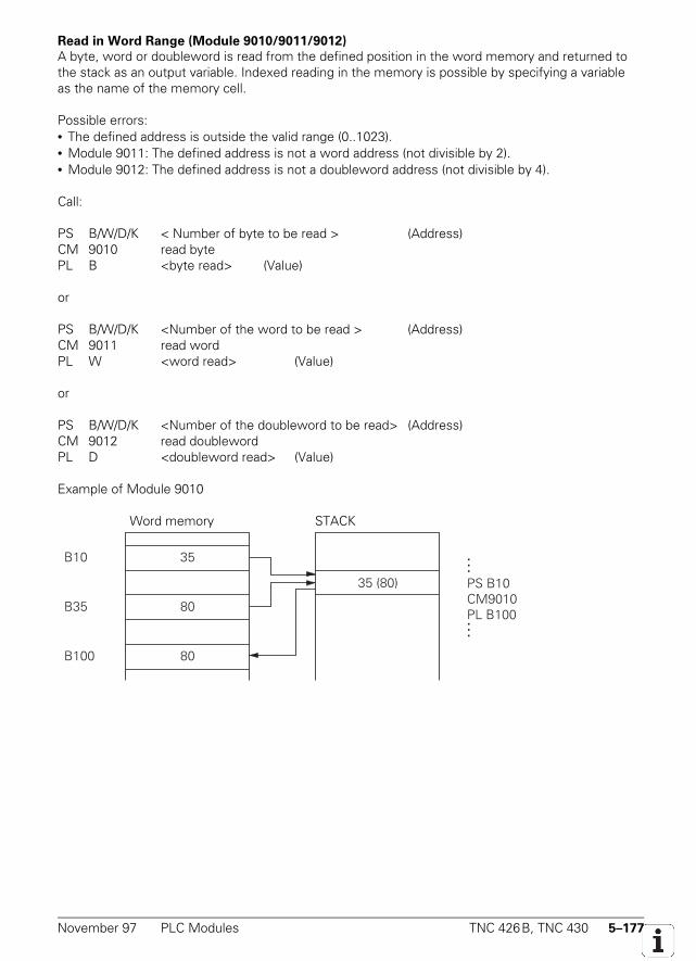
November 97 PLC Modules TNC 426B, TNC 430 5–177
Read in Word Range (Module 9010/9011/9012)
A byte, word or doubleword is read from the defined position in the word memory and returned tothe stack as an output variable. Indexed reading in the memory is possible by specifying a variableas the name of the memory cell.
Possible errors:• The defined address is outside the valid range (0..1023).• Module 9011: The defined address is not a word address (not divisible by 2).• Module 9012: The defined address is not a doubleword address (not divisible by 4).
Call:
PS B/W/D/K < Number of byte to be read > (Address)CM 9010 read bytePL B <byte read> (Value)
or
PS B/W/D/K <Number of the word to be read > (Address)CM 9011 read wordPL W <word read> (Value)
or
PS B/W/D/K <Number of the doubleword to be read> (Address)CM 9012 read doublewordPL D <doubleword read> (Value)
Example of Module 9010
Word memory STACK
35 (80)
35
80
80
B10
B35
B100
...
PS B10CM9010PL B100...
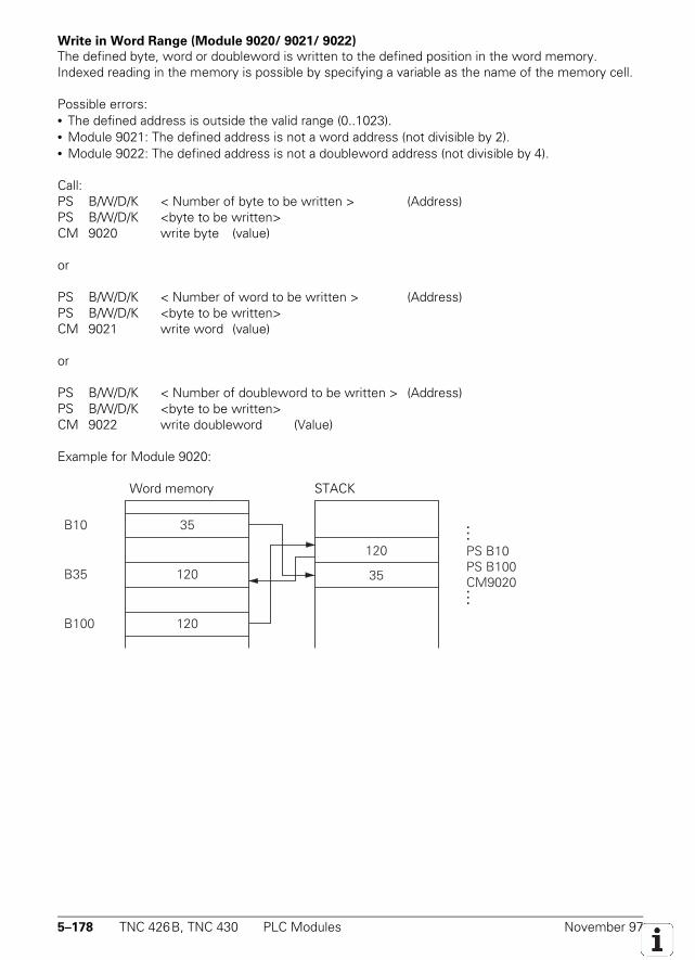
5–178 TNC 426B, TNC 430 PLC Modules November 97
Write in Word Range (Module 9020/ 9021/ 9022)
The defined byte, word or doubleword is written to the defined position in the word memory.Indexed reading in the memory is possible by specifying a variable as the name of the memory cell.
Possible errors:• The defined address is outside the valid range (0..1023).• Module 9021: The defined address is not a word address (not divisible by 2).• Module 9022: The defined address is not a doubleword address (not divisible by 4).
Call:PS B/W/D/K < Number of byte to be written > (Address)PS B/W/D/K <byte to be written>CM 9020 write byte (value)
or
PS B/W/D/K < Number of word to be written > (Address)PS B/W/D/K <byte to be written>CM 9021 write word (value)
or
PS B/W/D/K < Number of doubleword to be written > (Address)PS B/W/D/K <byte to be written>CM 9022 write doubleword (Value)
Example for Module 9020:
Word memory STACKSTACKWortspeicher
120
35
120
120
B10
B35
B100
...
PS B10PS B100CM9020...
35
November 97 PLC Modules TNC 426B, TNC 430 5–179
5.14.2 Number Conversion
Conversion of Binary Number to ASCII (Module 9050)
Converts a binary numerical value consisting of mantissa and exponent to the base 10 to an ASCII-coded decimal number.
The number specified as mantissa and exponent is converted to a decimal number and stored at thespecified address as a string. The exponent relates to the lowest-value place in the number. Anegative number is detected when the mantissa corresponds to a negative number in the notationas a two's complement. A sign is only set in front of negative numbers. Trailing zeroes after thedecimal point or leading zeroes before the decimal point are not converted, the string is written left-justified starting from the specified target address in the string buffer.
Constraints:The decimal sign is defined by machine parameter MP7280 as a decimal comma (MP7280 = 0) or adecimal point (MP7280 = 1).
Possible errors:• The number of the target string is outside the permitted range (0..3).• The conversion would result in more than 10 places after the decimal point.• The conversion would result in more than 10 places before the decimal point.
Call:
PS K/B/W/D <Mantissa of numerical value to be converted>PS K/B/W/D <Exponent to base 10 of the value>PS K/B/W/D <Number of target string>CM 9050
5–180 TNC 426B, TNC 430 PLC Modules November 97
Conversion of Binary Number to ASCII (Module 9051)
Converts a binary numerical value to an ASCII-coded decimal number in the format specified.The specified number is converted to a decimal number and stored as a string in the
specified address. The number is interpreted as a two's complement. When interpreted without asign the absolute amount of the number is converted without a sign being put before the string.With the algebraically signed notation, the sign ("+" or "-") is placed before the string in any event.
With the inch notation the numerical value is divided by 25.4 before being converted. If thenumber has more decimal places than the total of specified places before and after the decimalpoint, then the highest-value decimal places are omitted. With right-justified notation leading zeroesbefore the decimal point are replaced by blanks, with left-justified notation they are suppressed.Trailing zeroes after the decimal point are always converted.
Constraints:The decimal sign is defined by machine parameter MP7280 as a decimal comma (MP7280 = 0) or adecimal point (MP7280 = 1).
Possible errors:• The number of the target string is outside the permitted range (0..3).• There are more than 16 decimal places in all (before and after decimal point)• No places before the decimal point are specified
Call:PS K/B/W/D <Numerical value to >PS K/B/W/D <display mode (bit coded)>
Bit #3: Display with signBit #2: Display converted to INCHBit #1/#0: Format00: Sign and number left-justified1: Sign left-justified, number right-justified10: Sign and number right-justified11: Not permitted
PS K/B/W/D <Number of places after the decimal point>PS K/B/W/D <Number of places before the decimal point>PS K/B/W/D <Target address in string buffer>CM 9051
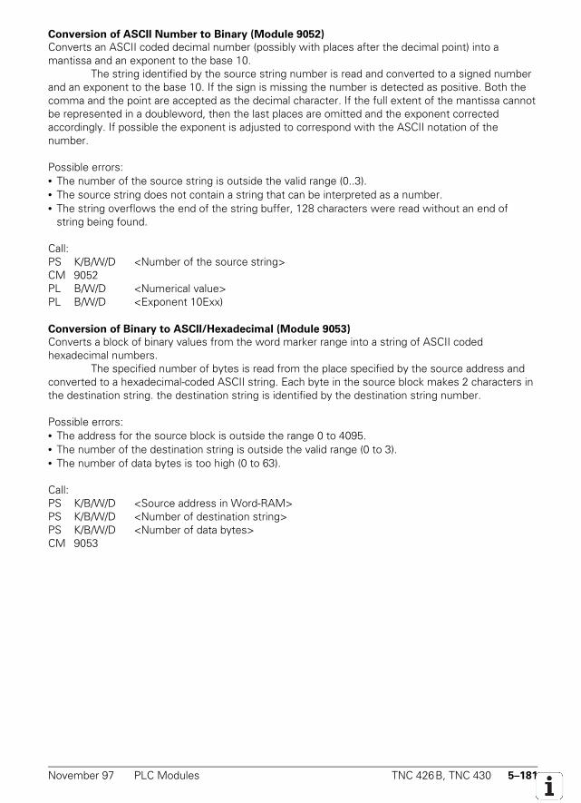
November 97 PLC Modules TNC 426B, TNC 430 5–181
Conversion of ASCII Number to Binary (Module 9052)
Converts an ASCII coded decimal number (possibly with places after the decimal point) into amantissa and an exponent to the base 10.
The string identified by the source string number is read and converted to a signed numberand an exponent to the base 10. If the sign is missing the number is detected as positive. Both thecomma and the point are accepted as the decimal character. If the full extent of the mantissa cannotbe represented in a doubleword, then the last places are omitted and the exponent correctedaccordingly. If possible the exponent is adjusted to correspond with the ASCII notation of thenumber.
Possible errors:• The number of the source string is outside the valid range (0..3).• The source string does not contain a string that can be interpreted as a number.• The string overflows the end of the string buffer, 128 characters were read without an end of
string being found.
Call:PS K/B/W/D <Number of the source string>CM 9052PL B/W/D <Numerical value>PL B/W/D <Exponent 10Exx)
Conversion of Binary to ASCII/Hexadecimal (Module 9053)
Converts a block of binary values from the word marker range into a string of ASCII codedhexadecimal numbers.
The specified number of bytes is read from the place specified by the source address andconverted to a hexadecimal-coded ASCII string. Each byte in the source block makes 2 characters inthe destination string. the destination string is identified by the destination string number.
Possible errors:• The address for the source block is outside the range 0 to 4095.• The number of the destination string is outside the valid range (0 to 3).• The number of data bytes is too high (0 to 63).
Call:PS K/B/W/D <Source address in Word-RAM>PS K/B/W/D <Number of destination string>PS K/B/W/D <Number of data bytes>CM 9053
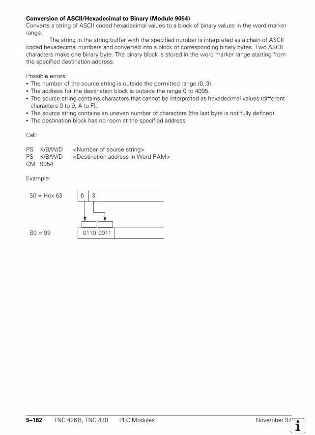
5–182 TNC 426B, TNC 430 PLC Modules November 97
Conversion of ASCII/Hexadecimal to Binary (Module 9054)
Converts a string of ASCII coded hexadecimal values to a block of binary values in the word markerrange.
The string in the string buffer with the specified number is interpreted as a chain of ASCIIcoded hexadecimal numbers and converted into a block of corresponding binary bytes. Two ASCIIcharacters make one binary byte. The binary block is stored in the word marker range starting fromthe specified destination address.
Possible errors:• The number of the source string is outside the permitted range (0..3).• The address for the destination block is outside the range 0 to 4095.• The source string contains characters that cannot be interpreted as hexadecimal values (different
characters 0 to 9, A to F).• The source string contains an uneven number of characters (the last byte is not fully defined).• The destination block has no room at the specified address
Call:
PS K/B/W/D <Number of source string>PS K/B/W/D <Destination address in Word-RAM>CM 9054
Example:
0110 0011B0 = 99
6S0 = Hex 63 3
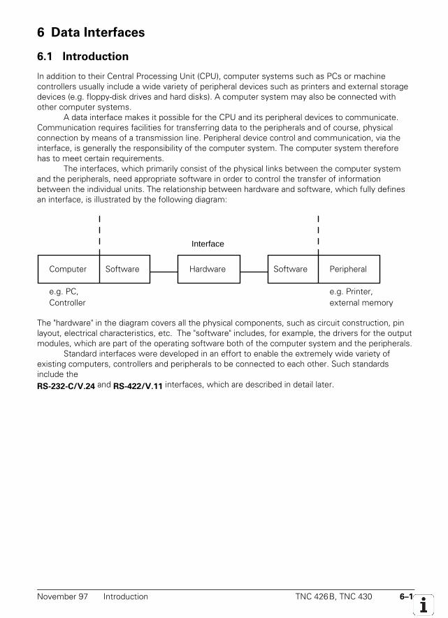
November 97 Introduction TNC 426B, TNC 430 6–1
6 Data Interfaces
6.1 Introduction
In addition to their Central Processing Unit (CPU), computer systems such as PCs or machinecontrollers usually include a wide variety of peripheral devices such as printers and external storagedevices (e.g. floppy-disk drives and hard disks). A computer system may also be connected withother computer systems.
A data interface makes it possible for the CPU and its peripheral devices to communicate.Communication requires facilities for transferring data to the peripherals and of course, physicalconnection by means of a transmission line. Peripheral device control and communication, via theinterface, is generally the responsibility of the computer system. The computer system thereforehas to meet certain requirements.
The interfaces, which primarily consist of the physical links between the computer systemand the peripherals, need appropriate software in order to control the transfer of informationbetween the individual units. The relationship between hardware and software, which fully definesan interface, is illustrated by the following diagram:
Computer Software Hardware Software Peripheral
e.g. PC,Controller
e.g. Printer,external memory
Interface
The "hardware" in the diagram covers all the physical components, such as circuit construction, pinlayout, electrical characteristics, etc. The "software" includes, for example, the drivers for the outputmodules, which are part of the operating software both of the computer system and the peripherals.
Standard interfaces were developed in an effort to enable the extremely wide variety ofexisting computers, controllers and peripherals to be connected to each other. Such standardsinclude theRS-232-C/V.24 and RS-422/V.11 interfaces, which are described in detail later.
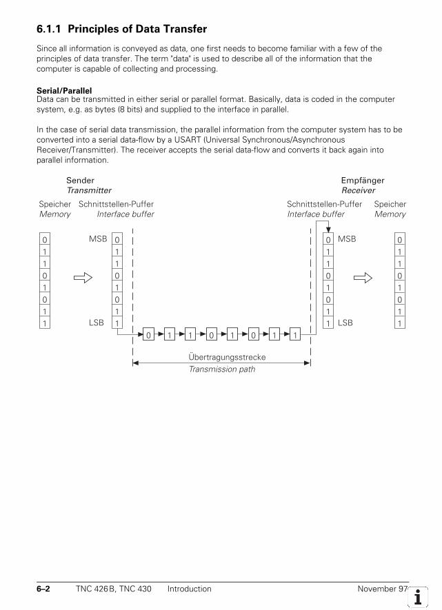
6–2 TNC 426B, TNC 430 Introduction November 97
6.1.1 Principles of Data Transfer
Since all information is conveyed as data, one first needs to become familiar with a few of theprinciples of data transfer. The term "data" is used to describe all of the information that thecomputer is capable of collecting and processing.
Serial/ParallelData can be transmitted in either serial or parallel format. Basically, data is coded in the computersystem, e.g. as bytes (8 bits) and supplied to the interface in parallel.
In the case of serial data transmission, the parallel information from the computer system has to beconverted into a serial data-flow by a USART (Universal Synchronous/AsynchronousReceiver/Transmitter). The receiver accepts the serial data-flow and converts it back again intoparallel information.
0 1 1 0 1 0 1 1
SenderTransmitter
SpeicherMemory
ÜbertragungsstreckeTransmission path
EmpfängerReceiver
Schnittstellen-PufferInterface buffer
MSB
LSB
01101011
01101011
MSB
LSB
01101011
01101011
SpeicherMemory
Schnittstellen-PufferInterface buffer
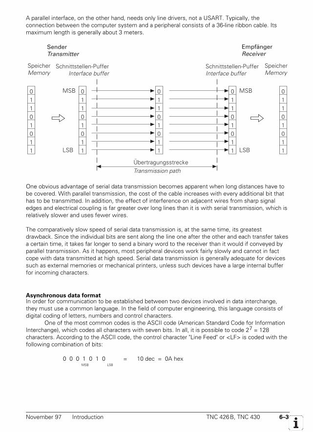
November 97 Introduction TNC 426B, TNC 430 6–3
A parallel interface, on the other hand, needs only line drivers, not a USART. Typically, theconnection between the computer system and a peripheral consists of a 36-line ribbon cable. Itsmaximum length is generally about 3 meters.
SenderTransmitter
SpeicherMemory
MSB
LSB
ÜbertragungsstreckeTransmission path
EmpfängerReceiver
Schnittstellen-PufferInterface buffer
01101011
01101011
01101011
MSB
LSB
01101011
01101011
SpeicherMemory
Schnittstellen-PufferInterface buffer
One obvious advantage of serial data transmission becomes apparent when long distances have tobe covered. With parallel transmission, the cost of the cable increases with every additional bit thathas to be transmitted. In addition, the effect of interference on adjacent wires from sharp signaledges and electrical coupling is far greater over long lines than it is with serial transmission, which isrelatively slower and uses fewer wires.
The comparatively slow speed of serial data transmission is, at the same time, its greatestdrawback. Since the individual bits are sent along the line one after the other and each transfer takesa certain time, it takes far longer to send a binary word to the receiver than it would if conveyed byparallel transmission. As it happens, most peripheral devices work fairly slowly and cannot in factcope with data transmitted at high speed. Serial data transmission is generally adequate for devicessuch as external memories or mechanical printers, unless such devices have a large internal bufferfor incoming characters.
Asynchronous data formatIn order for communication to be established between two devices involved in data interchange,they must use a common language. In the field of computer engineering, this language consists ofdigital coding of letters, numbers and control characters.
One of the most common codes is the ASCII code (American Standard Code for InformationInterchange), which codes all characters with seven bits. In all, it is possible to code 27 = 128characters. According to the ASCII code, the control character "Line Feed" or <LF> is coded with thefollowing combination of bits:
0 0 0 1 0 1 0 = 10 dec = 0A hexMSB LSB
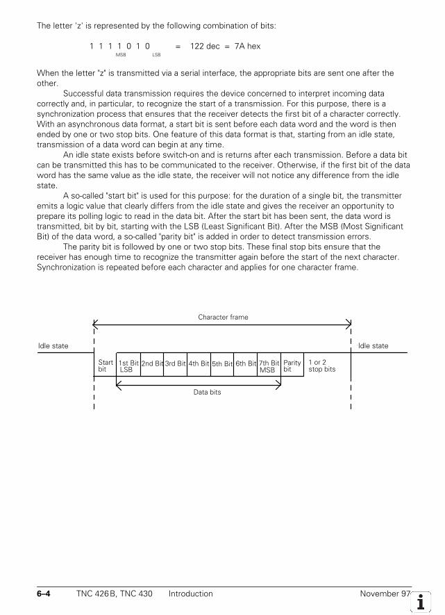
6–4 TNC 426B, TNC 430 Introduction November 97
The letter 'z' is represented by the following combination of bits:
1 1 1 1 0 1 0 = 122 dec = 7A hexMSB LSB
When the letter "z" is transmitted via a serial interface, the appropriate bits are sent one after theother.
Successful data transmission requires the device concerned to interpret incoming datacorrectly and, in particular, to recognize the start of a transmission. For this purpose, there is asynchronization process that ensures that the receiver detects the first bit of a character correctly.With an asynchronous data format, a start bit is sent before each data word and the word is thenended by one or two stop bits. One feature of this data format is that, starting from an idle state,transmission of a data word can begin at any time.
An idle state exists before switch-on and is returns after each transmission. Before a data bitcan be transmitted this has to be communicated to the receiver. Otherwise, if the first bit of the dataword has the same value as the idle state, the receiver will not notice any difference from the idlestate.
A so-called "start bit" is used for this purpose: for the duration of a single bit, the transmitteremits a logic value that clearly differs from the idle state and gives the receiver an opportunity toprepare its polling logic to read in the data bit. After the start bit has been sent, the data word istransmitted, bit by bit, starting with the LSB (Least Significant Bit). After the MSB (Most SignificantBit) of the data word, a so-called "parity bit" is added in order to detect transmission errors.
The parity bit is followed by one or two stop bits. These final stop bits ensure that thereceiver has enough time to recognize the transmitter again before the start of the next character.Synchronization is repeated before each character and applies for one character frame.
1st Bit 2nd Bit 3rd Bit 4th Bit 5th Bit 7th Bit6th BitStart Paritybit LSB MSB bit
1 or 2stop bits
Character frame
Data bits
Quiescent stateQuiescent stateIdle state Idle state
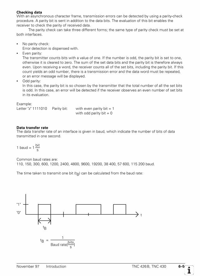
November 97 Introduction TNC 426B, TNC 430 6–5
Checking dataWith an asynchronous character frame, transmission errors can be detected by using a parity-checkprocedure. A parity bit is sent in addition to the data bits. The evaluation of this bit enables thereceiver to check the parity of received data.
The parity check can take three different forms; the same type of parity check must be set atboth interfaces.
• No parity check:Error detection is dispensed with.
• Even parity:The transmitter counts bits with a value of one. If the number is odd, the parity bit is set to one,otherwise it is cleared to zero. The sum of the set data bits and the parity bit is therefore alwayseven. Upon receiving a word, the receiver counts all of the set bits, including the parity bit. If thiscount yields an odd number, there is a transmission error and the data word must be repeated,or an error message will be displayed.
• Odd parity:In this case, the parity bit is so chosen by the transmitter that the total number of all the set bitsis odd. In this case, an error will be detected if the receiver observes an even number of set bitsin its evaluation.
Example:Letter "z" 1111010 Parity bit: with even parity bit = 1
with odd parity bit = 0
Data transfer rateThe data transfer rate of an interface is given in baud, which indicate the number of bits of datatransmitted in one second.
1 baud = 1 bits
Common baud rates are:110, 150, 300, 600, 1200, 2400, 4800, 9600, 19200, 38 400, 57 600, 115 200 baud.
The time taken to transmit one bit (tB) can be calculated from the baud rate:
tB
t
"1"
"0"
tB = 1
Baud rate[bitss ]
6–6 TNC 426B, TNC 430 Introduction November 97
For example, a baud rate of 19 200 baud will have a bit duration of tB = 52.083 µs. The number ofcharacters transmitted can be calculated from the baud rate and the transmission format:
Characters per second = Baud rate[
bitss ]
Number of bits per character
For example: with a transmission format of one start bit, seven data bits, two stop bits and a datatransfer rate of exactly 300 baud:
300 baud10 bits = 30 characters per second will be transmitted.
November 97 Introduction TNC 426B, TNC 430 6–7
6.1.2 Handshaking
A "handshake" procedure is often used in connection with interfaces. This means that two devicesare, as it were, working "hand in hand" in order to control data transfer. A distinction is drawnbetween "software" and "hardware" handshaking. Either hardware or software handshaking can bechosen for communication between two devices.
Hardware handshakingWith this procedure, data transfer is controlled by electrical signals. Important information, such asClear To Send (CTS), Request To Send (RTS), "Start transmission" and "Stop transmission" is signaledby the hardware.
For example, when a computer character is to be transmitted, the CTS signal line is checkedto see whether it is active (ON). If it is, the character is transmitted. Otherwise the computer willdelay transmission until the CTS line is switched to active.
Hardware handshaking requires as a minimum the two data lines TXD and RXD, the RTScontrol line, the CTS signal line, and a ground connection.
Software HandshakingWith software handshake, control of data transfer is achieved by appropriate control characterstransmitted via the data line. One such handshake is the XON/XOFF method, which is in widespreaduse with the RS-232-C/V.24 interface. The meaning XON is assigned to a control character DC1 andthe meaning XOFF to control character DC3. Before transmitting a character, the computer checkswhether the receiving unit is transmitting the XOFF character. If it is, it delays transmission until itreceives the character XON, indicating that the connected unit is ready to receive further characters.
Besides the ground line and the data lines TXD and RXD, no other lines are needed forsoftware handshaking.
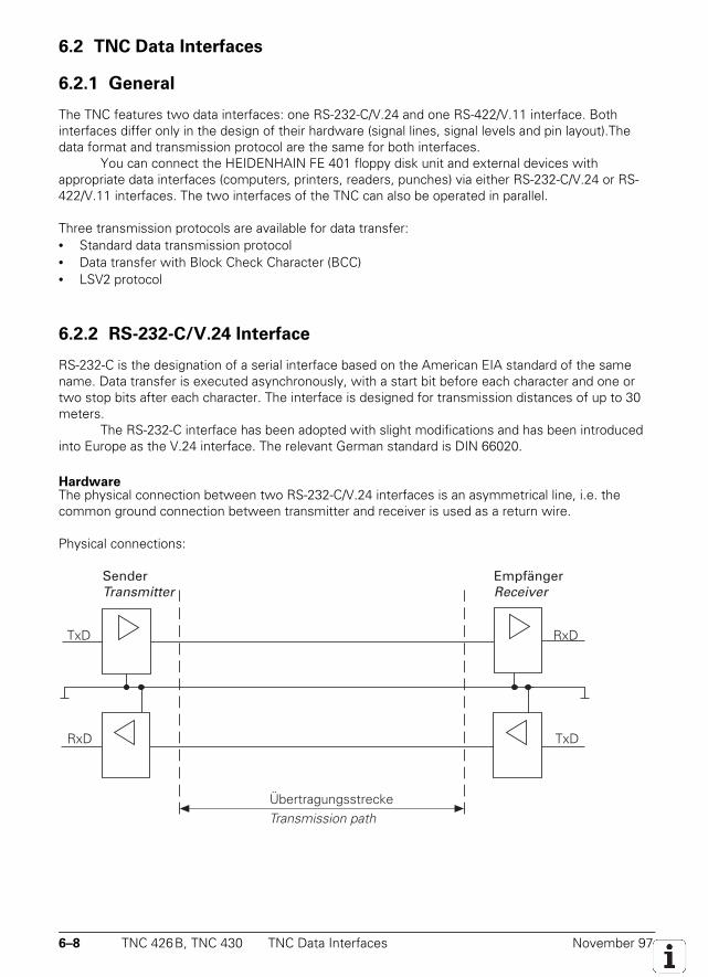
6–8 TNC 426B, TNC 430 TNC Data Interfaces November 97
6.2 TNC Data Interfaces
6.2.1 General
The TNC features two data interfaces: one RS-232-C/V.24 and one RS-422/V.11 interface. Bothinterfaces differ only in the design of their hardware (signal lines, signal levels and pin layout).Thedata format and transmission protocol are the same for both interfaces.
You can connect the HEIDENHAIN FE 401 floppy disk unit and external devices withappropriate data interfaces (computers, printers, readers, punches) via either RS-232-C/V.24 or RS-422/V.11 interfaces. The two interfaces of the TNC can also be operated in parallel.
Three transmission protocols are available for data transfer:• Standard data transmission protocol• Data transfer with Block Check Character (BCC)• LSV2 protocol
6.2.2 RS-232-C/V.24 Interface
RS-232-C is the designation of a serial interface based on the American EIA standard of the samename. Data transfer is executed asynchronously, with a start bit before each character and one ortwo stop bits after each character. The interface is designed for transmission distances of up to 30meters.
The RS-232-C interface has been adopted with slight modifications and has been introducedinto Europe as the V.24 interface. The relevant German standard is DIN 66020.
HardwareThe physical connection between two RS-232-C/V.24 interfaces is an asymmetrical line, i.e. thecommon ground connection between transmitter and receiver is used as a return wire.
Physical connections:
SenderTransmitter
ÜbertragungsstreckeTransmission path
EmpfängerReceiver
RxDTxD
RxD TxD
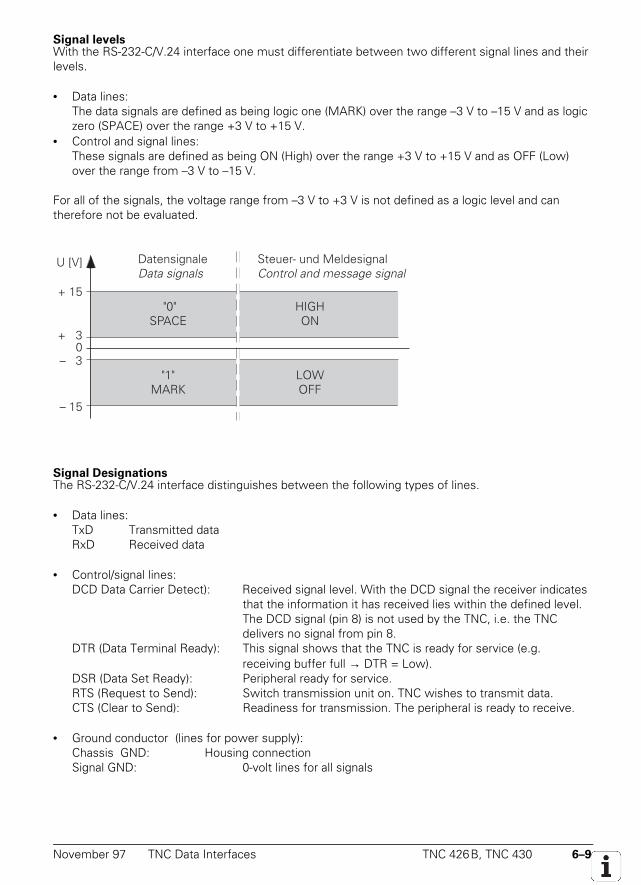
November 97 TNC Data Interfaces TNC 426B, TNC 430 6–9
Signal levelsWith the RS-232-C/V.24 interface one must differentiate between two different signal lines and theirlevels.
• Data lines:The data signals are defined as being logic one (MARK) over the range –3 V to –15 V and as logiczero (SPACE) over the range +3 V to +15 V.
• Control and signal lines:These signals are defined as being ON (High) over the range +3 V to +15 V and as OFF (Low)over the range from –3 V to –15 V.
For all of the signals, the voltage range from –3 V to +3 V is not defined as a logic level and cantherefore not be evaluated.
– 13
U [V]
+ 15
– 15
+ 13
DatensignaleData signals
Steuer- und MeldesignalControl and message signal
"0"SPACE
HIGH ON
"1"MARK
LOW OFF
0
Signal DesignationsThe RS-232-C/V.24 interface distinguishes between the following types of lines.
• Data lines:TxD Transmitted dataRxD Received data
• Control/signal lines:DCD Data Carrier Detect): Received signal level. With the DCD signal the receiver indicates
that the information it has received lies within the defined level.The DCD signal (pin 8) is not used by the TNC, i.e. the TNCdelivers no signal from pin 8.
DTR (Data Terminal Ready): This signal shows that the TNC is ready for service (e.g.receiving buffer full → DTR = Low).
DSR (Data Set Ready): Peripheral ready for service.RTS (Request to Send): Switch transmission unit on. TNC wishes to transmit data.CTS (Clear to Send): Readiness for transmission. The peripheral is ready to receive.
• Ground conductor (lines for power supply):Chassis GND: Housing connectionSignal GND: 0-volt lines for all signals
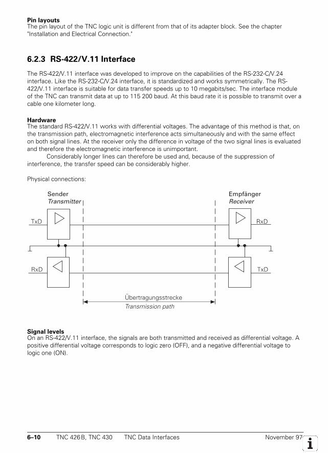
6–10 TNC 426B, TNC 430 TNC Data Interfaces November 97
Pin layoutsThe pin layout of the TNC logic unit is different from that of its adapter block. See the chapter"Installation and Electrical Connection."
6.2.3 RS-422/V.11 Interface
The RS-422/V.11 interface was developed to improve on the capabilities of the RS-232-C/V.24interface. Like the RS-232-C/V.24 interface, it is standardized and works symmetrically. The RS-422/V.11 interface is suitable for data transfer speeds up to 10 megabits/sec. The interface moduleof the TNC can transmit data at up to 115 200 baud. At this baud rate it is possible to transmit over acable one kilometer long.
HardwareThe standard RS-422/V.11 works with differential voltages. The advantage of this method is that, onthe transmission path, electromagnetic interference acts simultaneously and with the same effecton both signal lines. At the receiver only the difference in voltage of the two signal lines is evaluatedand therefore the electromagnetic interference is unimportant.
Considerably longer lines can therefore be used and, because of the suppression ofinterference, the transfer speed can be considerably higher.
Physical connections:
SenderTransmitter
ÜbertragungsstreckeTransmission path
EmpfängerReceiver
RxDTxD
RxD TxD
Signal levelsOn an RS-422/V.11 interface, the signals are both transmitted and received as differential voltage. Apositive differential voltage corresponds to logic zero (OFF), and a negative differential voltage tologic one (ON).
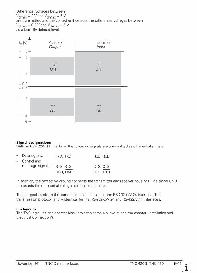
November 97 TNC Data Interfaces TNC 426B, TNC 430 6–11
Differential voltages betweenVdmin = 2 V and Vdmax = 5 Vare transmitted and the control unit detects the differential voltages betweenVdmin = 0.2 V and Vdmax = 6 Vas a logically defined level.
– 0.2
Ud [V] AusgangOutput
EingangInput
"0"OFF
"1"ON
+ 0.2
– 0.2
– 0.5
– 0.6
+ 0.2
+ 0.5
+ 0.6
"1"ON
"0"OFF
Signal designationsWith an RS-422/V.11 interface, the following signals are transmitted as differential signals:
• Data signals: TxD, TxD RxD, RxD• Control and
message signals: RTS, RTSDSR, DSR
CTS, CTSDTR, DTR
In addition, the protective ground connects the transmitter and receiver housings. The signal GNDrepresents the differential voltage reference conductor.
These signals perform the same functions as those on the RS-232-C/V.24 interface. Thetransmission protocol is fully identical for the RS-232-C/V.24 and RS-422/V.11 interfaces.
Pin layoutsThe TNC logic unit and adapter block have the same pin layout (see the chapter "Installation andElectrical Connection").
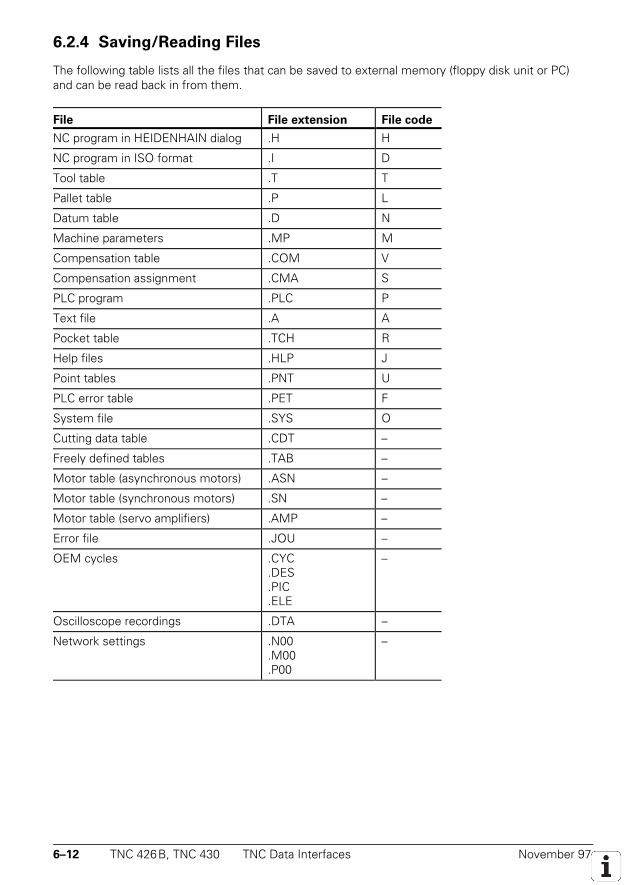
6–12 TNC 426B, TNC 430 TNC Data Interfaces November 97
6.2.4 Saving/Reading Files
The following table lists all the files that can be saved to external memory (floppy disk unit or PC)and can be read back in from them.
File File extension File code
NC program in HEIDENHAIN dialog .H H
NC program in ISO format .I D
Tool table .T T
Pallet table .P L
Datum table .D N
Machine parameters .MP M
Compensation table .COM V
Compensation assignment .CMA S
PLC program .PLC P
Text file .A A
Pocket table .TCH R
Help files .HLP J
Point tables .PNT U
PLC error table .PET F
System file .SYS O
Cutting data table .CDT –
Freely defined tables .TAB –
Motor table (asynchronous motors) .ASN –
Motor table (synchronous motors) .SN –
Motor table (servo amplifiers) .AMP –
Error file .JOU –
OEM cycles .CYC.DES.PIC.ELE
–
Oscilloscope recordings .DTA –
Network settings .N00.M00.P00
–
November 97 TNC Data Interfaces TNC 426B, TNC 430 6–13
After you have entered the appropriate code numbers for the PLC, the machine parameters, and thecorrection table, you can write to or read from these files via the data interfaces. You can also outputthe current values of Q parameters, PLC error messages and dialogs via the two interfaces (NCprogram: FN 15: PRINT). During transmission with a Block Check Character (BCC) each deviceoutputs and again receives the appropriate file code.
If the file is stored in an external computer using HEIDENHAIN's TNC.EXE data transfer software, anew file extension is generated. This extension consists of the file code and the letters NC.
Example:If a pallet table is stored, it is given the file extension *.LNC.
For data transmission with the HEIDENHAIN software TNC Remote, the file code has nosignificance. The files are saved on the PC with the same extension as on the TNC.
Files that have no code (–) can only be transmitted with LSV2 protocol (TNC Remote).
Output to external devicesAny external device, e.g. computers, printers, readers and punches, can be addressed through eitherof the two interfaces. For this purpose, the TNC has three freely configurable interface modes(EXT1/EXT2/EXT3) that, within certain limits, permit any setting of the data format of the requireddata transmission protocol.
The setting selected at external devices must of course match the TNC. On printers, this isdone by setting the DIP switches or adjusting the transmission parameters. If data transfer to acomputer is desired, appropriate data transfer software must be installed. To help in this,HEIDENHAIN offers the data transfer software TNC.EXE, which permits transfer between TNC anda PC using a fixed transmission protocol.
Communication between TNCsFor certain applications, it is necessary for TNCs to be able to exchange data or to communicatewith each other. This is made possible both by RS-232-C/V.24 and RS-422/V.11 interfaces.
The simplest form of data exchange is the transfer of files (e.g. NC programs) from one TNCto another. To do this, set both TNCs to LSV2 protocol. The control from which you start the datatransmission is the master.
The PLC provides you with access to the data interfaces (EXT3).
6–14 TNC 426B, TNC 430 Configuration of Interfaces November 97
6.3 Configuration of Interfaces
6.3.1 Selection of Interfaces
Either data interface can be inhibited with MP 5000. If neither of the interfaces is inhibited, you canuse the RS-232-C RS 422 SETUP soft key to select the following settings:
Operating mode External device
FE1 HEIDENHAIN Floppy Disk Unit:
• FE 401B
• FE 401 from Program no. 230 626 03
FE2 • HEIDENHAIN FE 401 Floppy Disk Unit up to program no. 230 626 02
• PC with HEIDENHAIN TNC.EXE data transfer software
LSV2 PC with HEIDENHAIN software TNC Remote
EXT1 and EXT2 Non-HEIDENHAIN device such as a printer, punch or PC with other datatransfer software
MP5000 Disable data interfacesInput: 0 = no interface disabled
1 = RS-232-C/V.24 interface disabled2 = RS-422/V.11 interface disabled
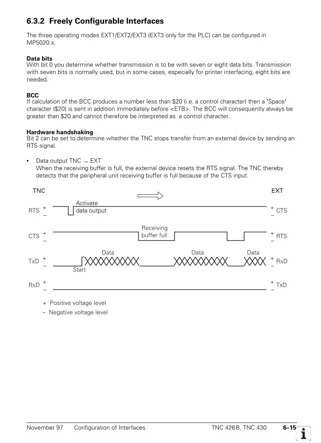
November 97 Configuration of Interfaces TNC 426B, TNC 430 6–15
6.3.2 Freely Configurable Interfaces
The three operating modes EXT1/EXT2/EXT3 (EXT3 only for the PLC) can be configured inMP5020.x.
Data bitsWith bit 0 you determine whether transmission is to be with seven or eight data bits. Transmissionwith seven bits is normally used, but in some cases, especially for printer interfacing, eight bits areneeded.
BCCIf calculation of the BCC produces a number less than $20 (i.e. a control character) then a "Space"character ($20) is sent in addition immediately before <ETB>. The BCC will consequently always begreater than $20 and cannot therefore be interpreted as a control character.
Hardware handshakingBit 2 can be set to determine whether the TNC stops transfer from an external device by sending anRTS signal.
• Data output TNC → EXTWhen the receiving buffer is full, the external device resets the RTS signal. The TNC therebydetects that the peripheral unit receiving buffer is full because of the CTS input.
TNC EXT
–RTS +
–CTS +
–TxD +
–RxD +
–CTS +
–RTS +
–RxD+
–TxD+
Receivingbuffer full
DataData Data
Start
+ Positive voltage level
– Negative voltage level
Activatedata output
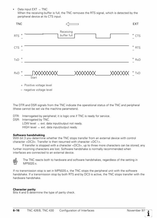
6–16 TNC 426B, TNC 430 Configuration of Interfaces November 97
• Data input EXT → TNCWhen the receiving buffer is full, the TNC removes the RTS signal, which is detected by theperipheral device at its CTS input.
TNC EXT
+ Positive voltage level
– negative voltage level
–CTS +
–RTS +
–RTS +
–CTS +
Receivingbuffer full
–RxD +
–TxD+
Start
–TxD +
–RxD+
The DTR and DSR signals from the TNC indicate the operational status of the TNC and peripheral(these cannot be set via the machine parameters).
DTR: Interrogated by peripheral; it is logic one if TNC is ready for service.DSR: Interrogated by TNC.
LOW level → ext. data input/output not ready.HIGH level → ext. data input/output ready.
Software handshakingWith bit 3 you determine whether the TNC stops transfer from an external device with controlcharacter <DC3>. Transfer is then resumed with character <DC1>.
If transfer is stopped with a character <DC3>, up to three more characters can be stored; anyfurther incoming characters are lost. Software handshake is normally recommended wheninterfaces are connected to an external device.
The TNC reacts both to hardware and software handshakes, regardless of the setting inMP5020.x.
If no transmission stop is set in MP5020.x, the TNC stops the peripheral unit with the softwarehandshake. If a transmission stop by both RTS and by DC3 is active, the TNC stops transfer with thehardware handshake.
Character parityBits 4 and 5 determine the type of parity check.
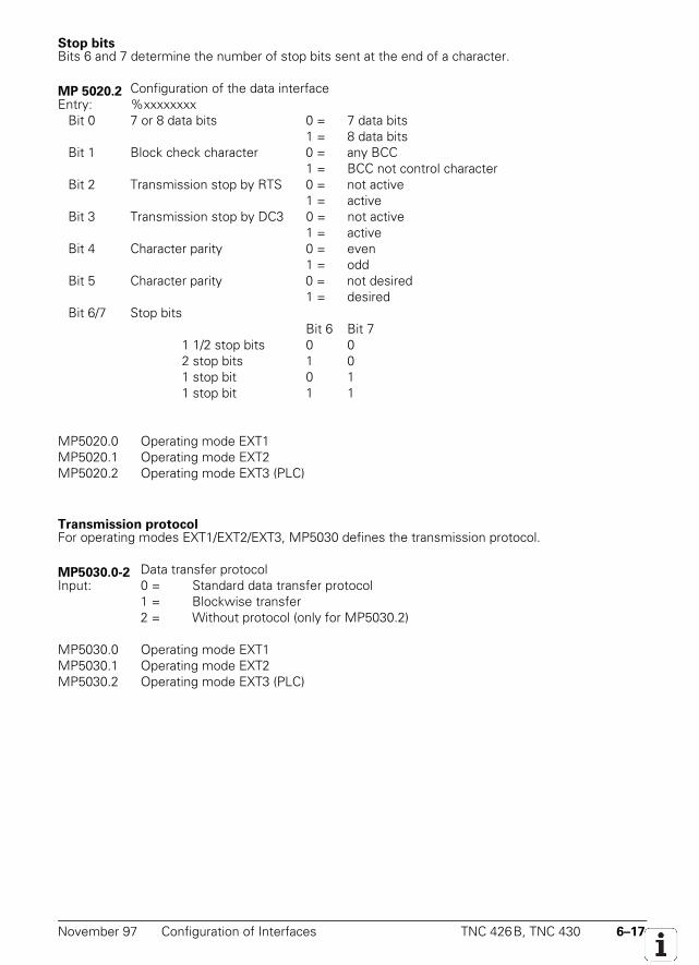
November 97 Configuration of Interfaces TNC 426B, TNC 430 6–17
Stop bitsBits 6 and 7 determine the number of stop bits sent at the end of a character.
MP 5020.2 Configuration of the data interfaceEntry: %xxxxxxxx
Bit 0 7 or 8 data bits 0 = 7 data bits1 = 8 data bits
Bit 1 Block check character 0 = any BCC1 = BCC not control character
Bit 2 Transmission stop by RTS 0 = not active1 = active
Bit 3 Transmission stop by DC3 0 = not active1 = active
Bit 4 Character parity 0 = even1 = odd
Bit 5 Character parity 0 = not desired1 = desired
Bit 6/7 Stop bitsBit 6 Bit 7
1 1/2 stop bits 0 02 stop bits 1 01 stop bit 0 11 stop bit 1 1
MP5020.0 Operating mode EXT1MP5020.1 Operating mode EXT2MP5020.2 Operating mode EXT3 (PLC)
Transmission protocolFor operating modes EXT1/EXT2/EXT3, MP5030 defines the transmission protocol.
MP5030.0-2 Data transfer protocolInput: 0 = Standard data transfer protocol
1 = Blockwise transfer2 = Without protocol (only for MP5030.2)
MP5030.0 Operating mode EXT1MP5030.1 Operating mode EXT2MP5030.2 Operating mode EXT3 (PLC)
6–18 TNC 426B, TNC 430 Configuration of Interfaces November 97
Example: NEC P7PLUS printer with EXT1The following setting is selected at the printer itself (see the operating manual of the printerconcerned):• Serial interface• Data bits• Even character parity• XON/XOFF protocol (software handshake)• 9600 baud
The following settings (EXT1) are made at the TNC:
MP5000 = 0 No interface inhibitedMP5020.0 = %10101001 8 data bits
Any BCC characterTransfer stop by RTS not activeTransfer stop by DC3 activeCharacter parity evenCharacter parity required1 stop bit
MP5030.0 = 0 Standard data transfer
In the "RS-232/RS-422 Setup" of the TNC, you must assign the EXT1 operating mode to theRS-232 interface and set the baud rate to 9600.
November 97 Data Transmission Protocols TNC 426B, TNC 430 6–19
6.4 Data Transmission Protocols
The TNC enables your data and files to be transferred using different protocols.
The transmission protocols can be selected as follows:
– FE1, FE2 Transmission with Block Check Character and with fixed control characters(7 data bits, 1 start bit, 1 stop bit)
– EXT1, EXT2, EXT3 Freely configurable operating modes: using machine parameters you canselect data format, transmission protocol and control characters.
− LSV2 Two-way transfer for TNC diagnostics and remote operation conforms toDIN 66019. This protocol always runs in the background of the TNC and canbe started from a PC or from the TNC.
The following applies to data transmission protocols (except LSV2):• If an incoming file is already stored in the TNC, the TNC will ask you whether you really wish to
overwrite this file. You can continue the transmission by pressing a soft key.• If you attempt to erase write-protected files, the TNC displays an error message. You can
remove the write protection and continue transmission by pressing a soft key.• If a file has been read out and the data transfer menu has been terminated with the END key,
the TNC outputs the characters <ETX> and <EOT>.If a transmission is terminated with the END key, the error message Program incomplete isissued.
6.4.1 Standard Transmission Protocol
General informationYou can set this protocol as standard in operating modes EXT1/EXT2/EXT3. In the following, thecontrol characters that are sent and received with this protocol are listed for the varioustransmission alternatives. When outputting a file, the <NUL> character is sent exactly 50 times atthe start of the file. When reading in, however, the control unit ignores this character. It is thereforeinsignificant how often the peripheral unit sends the <NUL> character before the file.
If you wish to signal an error to the TNC, you must send the following sequence ofinstructions:
<ESC> <1> <Error number>
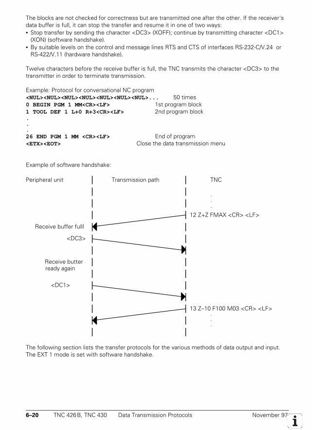
6–20 TNC 426B, TNC 430 Data Transmission Protocols November 97
The blocks are not checked for correctness but are transmitted one after the other. If the receiver'sdata buffer is full, it can stop the transfer and resume it in one of two ways:• Stop transfer by sending the character <DC3> (XOFF); continue by transmitting character <DC1>
(XON) (software handshake).• By suitable levels on the control and message lines RTS and CTS of interfaces RS-232-C/V.24 or
RS-422/V.11 (hardware handshake).
Twelve characters before the receive buffer is full, the TNC transmits the character <DC3> to thetransmitter in order to terminate transmission.
Example: Protocol for conversational NC program<NUL><NUL><NUL><NUL><NUL><NUL><NUL>... 50 times0 BEGIN PGM 1 MM<CR><LF> 1st program block1 TOOL DEF 1 L+0 R+3<CR><LF> 2nd program block...26 END PGM 1 MM <CR><LF> End of program<ETX><EOT> Close the data transmission menu
Example of software handshake:
Peripheral unit Transmission path
Receive buffer fulll
<DC3>
Receive butterready again
<DC1>
12 Z+Z FMAX <CR> <LF>
13 Z–10 F100 M03 <CR> <LF>
TNC
.
.
.
.
.
.
The following section lists the transfer protocols for the various methods of data output and input.The EXT 1 mode is set with software handshake.
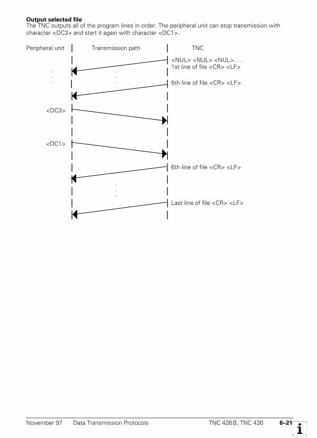
November 97 Data Transmission Protocols TNC 426B, TNC 430 6–21
Output selected fileThe TNC outputs all of the program lines in order. The peripheral unit can stop transmission withcharacter <DC3> and start it again with character <DC1>.
Peripheral unit Transmission path
<DC1>
<DC3>
<NUL> <NUL> <NUL>. . .1st line of file <CR> <LF>
TNC
.
.
.
.
.
.
Last line of file <CR> <LF>
.
.
.
6th line of file <CR> <LF>
5th line of file <CR> <LF>
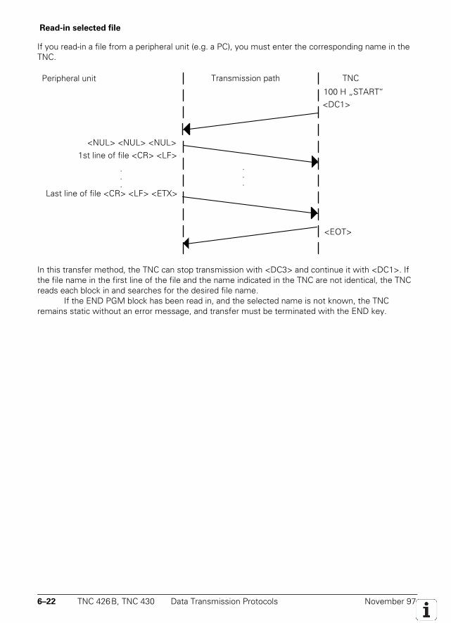
6–22 TNC 426B, TNC 430 Data Transmission Protocols November 97
Read-in selected file
If you read-in a file from a peripheral unit (e.g. a PC), you must enter the corresponding name in theTNC.
Peripheral unit Transmission path
<EOT>
<DC1>
<NUL> <NUL> <NUL>1st line of file <CR> <LF>
TNC
.
.
.
Last line of file <CR> <LF> <ETX>
.
.
.
100 H „START“
In this transfer method, the TNC can stop transmission with <DC3> and continue it with <DC1>. Ifthe file name in the first line of the file and the name indicated in the TNC are not identical, the TNCreads each block in and searches for the desired file name.
If the END PGM block has been read in, and the selected name is not known, the TNCremains static without an error message, and transfer must be terminated with the END key.
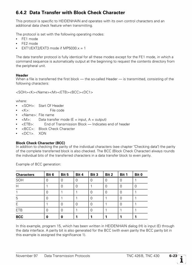
November 97 Data Transmission Protocols TNC 426B, TNC 430 6–23
6.4.2 Data Transfer with Block Check Character
This protocol is specific to HEIDENHAIN and operates with its own control characters and anadditional data check feature when transmitting.
The protocol is set with the following operating modes:• FE1 mode• FE2 mode• EXT1/EXT2/EXT3 mode if MP5030.x = 1
The data transfer protocol is fully identical for all these modes except for the FE1 mode, in which acommand sequence is automatically output at the beginning to request the contents directory fromthe peripheral unit.
HeaderWhen a file is transferred the first block — the so-called Header — is transmitted, consisting of thefollowing characters:
<SOH><K><Name><M><ETB><BCC><DC1>
where:• <SOH>: Start Of Header• <K>: File code• <Name>: File name• <M>: Data transfer mode (E = input, A = output)• <ETB>: End of Transmission Block — Indicates end of header• <BCC>: Block Check Character• <DC1>. XON
Block Check Character (BCC)In addition to checking the parity of the individual characters (see chapter "Checking data") the parityof the complete transferred block is also checked. The BCC (Block Check Character) always roundsthe individual bits of the transferred characters in a data transfer block to even parity.
Example of BCC generation:
Characters Bit 6 Bit 5 Bit 4 Bit 3 Bit 2 Bit 1 Bit 0
SOH 0 0 0 0 0 0 1
H 1 0 0 1 0 0 0
1 0 1 1 0 0 0 1
5 0 1 1 0 1 0 1
E 1 0 0 0 1 0 1
ETB 0 0 1 0 1 1 1
BCC 0 0 1 1 1 1 1
In this example, program 15, which has been written in HEIDENHAIN dialog (H) is input (E) throughthe data interface. A parity bit is also generated for the BCC (with even parity the BCC parity bit inthis example is assigned the significance 1).
6–24 TNC 426B, TNC 430 Data Transmission Protocols November 97
At the end of every block the receiver checks that it has transferred correctly. To do this the receivercomputes a BCC from the received block and compares it with the received BCC. If the receivedBCC and the computed BCC are identical, the receiver transmits the <ACK> character (= positiveacknowledgment) to indicate that the data block has been transmitted without error.
If the two BCCs are not identical, then the receiver transmits the <NAK> character (=negative acknowledgment) to indicate that the data block was not transmitted correctly and must bere-transmitted. This process is repeated 15 times, then the error message Transferred dataincorrect E is output and the transmission is aborted.
If the header is acknowledged with <ACK>, the first file block can be transmitted: The beginning ofa file block is always identified by the control character <STX>. The other control characters in thisblock are identical with the control characters in the header.
If the block is acknowledged by <ACK> then the next program block is transmitted; with<NAK>, the same block has to be re-transmitted, etc.
Once the last program block has transferred successfully (acknowledged by <ACK>) thetransmission is terminated by the characters <ETX> (end of text) and <EOT> (end of transmission).
HandshakingThe character <DC1> (XON) follows the BCC. It is required by many devices to explicitly request ananswer and to provoke the transmission once again.
You can suppress transmission of the <DC1> character in the EXT1, EXT2 and EXT3 modesby setting MP5020.x bit 3 = 0. The <DC1> character is not required for reading-in a file in the formatwith BCC.
A software handshake is very easy to arrange when transmitting with BCC. The receiver transmitsat first neither a positive acknowledgment (<ACK>) nor a negative one (<NAK>), and the transmitterwaits to receive one of these characters. When the receiving device's receiving buffer is ready, ittransmits an <ACK> and its partner resumes transmission.
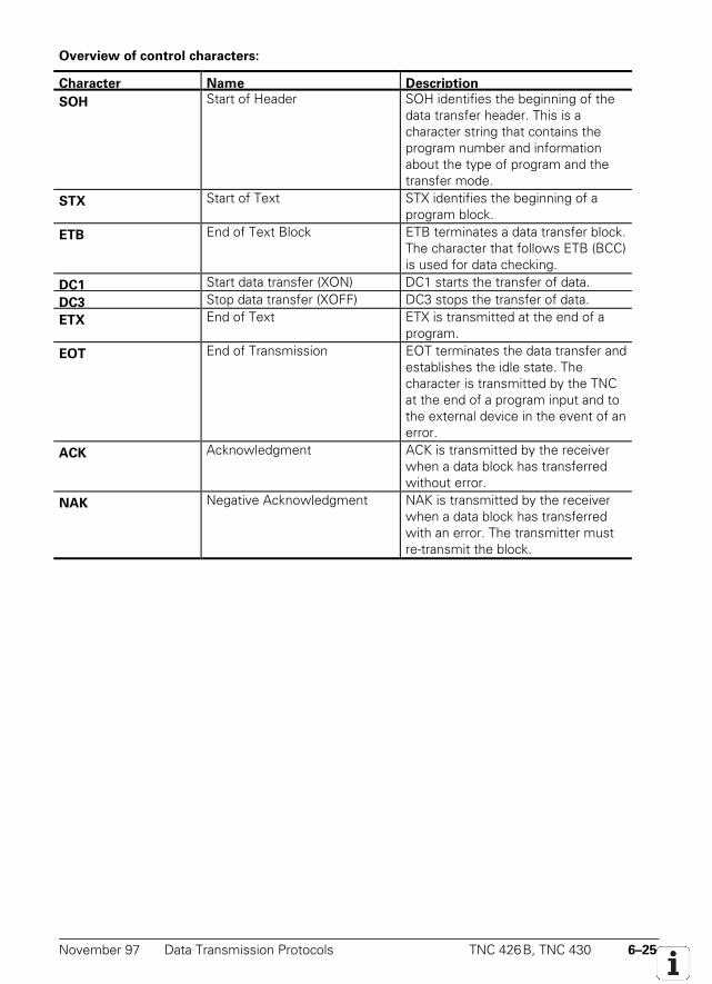
November 97 Data Transmission Protocols TNC 426B, TNC 430 6–25
Overview of control characters:
Character Name Description
SOH Start of Header SOH identifies the beginning of thedata transfer header. This is acharacter string that contains theprogram number and informationabout the type of program and thetransfer mode.
STX Start of Text STX identifies the beginning of aprogram block.
ETB End of Text Block ETB terminates a data transfer block.The character that follows ETB (BCC)is used for data checking.
DC1 Start data transfer (XON) DC1 starts the transfer of data.
DC3 Stop data transfer (XOFF) DC3 stops the transfer of data.
ETX End of Text ETX is transmitted at the end of aprogram.
EOT End of Transmission EOT terminates the data transfer andestablishes the idle state. Thecharacter is transmitted by the TNCat the end of a program input and tothe external device in the event of anerror.
ACK Acknowledgment ACK is transmitted by the receiverwhen a data block has transferredwithout error.
NAK Negative Acknowledgment NAK is transmitted by the receiverwhen a data block has transferredwith an error. The transmitter mustre-transmit the block.
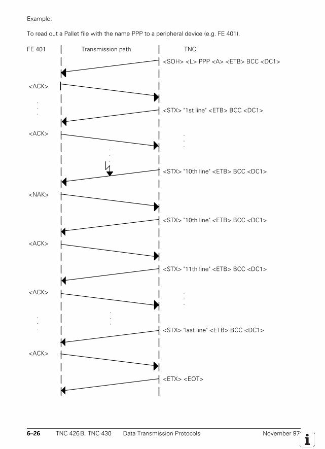
6–26 TNC 426B, TNC 430 Data Transmission Protocols November 97
Example:
To read out a Pallet file with the name PPP to a peripheral device (e.g. FE 401).
FE 401 Transmission path
<ACK>
<ACK>
<SOH> <L> PPP <A> <ETB> BCC <DC1>
<STX> "1st line" <ETB> BCC <DC1>
TNC
.
.
.
.
.
.
.
.
.
.
.
.
<STX> "last line" <ETB> BCC <DC1>
<STX> "10th line" <ETB> BCC <DC1>
<STX> "11th line" <ETB> BCC <DC1>
<ETX> <EOT>
<NAK>
<ACK>
<ACK>
<ACK>
.
.
.
.
.
.
<STX> "10th line" <ETB> BCC <DC1>
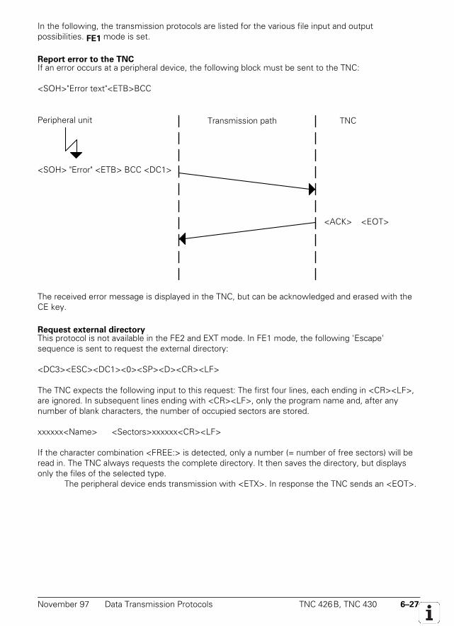
November 97 Data Transmission Protocols TNC 426B, TNC 430 6–27
In the following, the transmission protocols are listed for the various file input and outputpossibilities. FE1 mode is set.
Report error to the TNCIf an error occurs at a peripheral device, the following block must be sent to the TNC:
<SOH>"Error text"<ETB>BCC
Peripheral unit
<SOH> "Error" <ETB> BCC <DC1>
Transmission path
<EOT><ACK>
TNC
The received error message is displayed in the TNC, but can be acknowledged and erased with theCE key.
Request external directoryThis protocol is not available in the FE2 and EXT mode. In FE1 mode, the following 'Escape'sequence is sent to request the external directory:
<DC3><ESC><DC1><0><SP><D><CR><LF>
The TNC expects the following input to this request: The first four lines, each ending in <CR><LF>,are ignored. In subsequent lines ending with <CR><LF>, only the program name and, after anynumber of blank characters, the number of occupied sectors are stored.
xxxxxx<Name> <Sectors>xxxxxx<CR><LF>
If the character combination <FREE:> is detected, only a number (= number of free sectors) will beread in. The TNC always requests the complete directory. It then saves the directory, but displaysonly the files of the selected type.
The peripheral device ends transmission with <ETX>. In response the TNC sends an <EOT>.
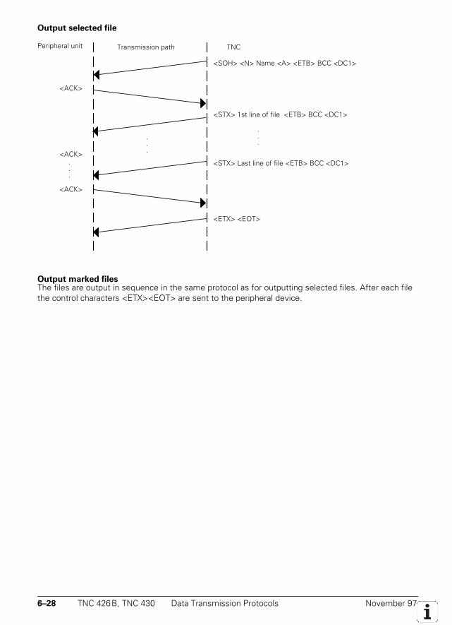
6–28 TNC 426B, TNC 430 Data Transmission Protocols November 97
Output selected file
Peripheral unit
<ACK>
<ACK>
.
.
.
<ACK>
Transmission path TNC
<STX> 1st line of file <ETB> BCC <DC1>
<ETX> <EOT>
<STX> Last line of file <ETB> BCC <DC1>
.
.
.
<SOH> <N> Name <A> <ETB> BCC <DC1>
.
.
.
Output marked filesThe files are output in sequence in the same protocol as for outputting selected files. After each filethe control characters <ETX><EOT> are sent to the peripheral device.
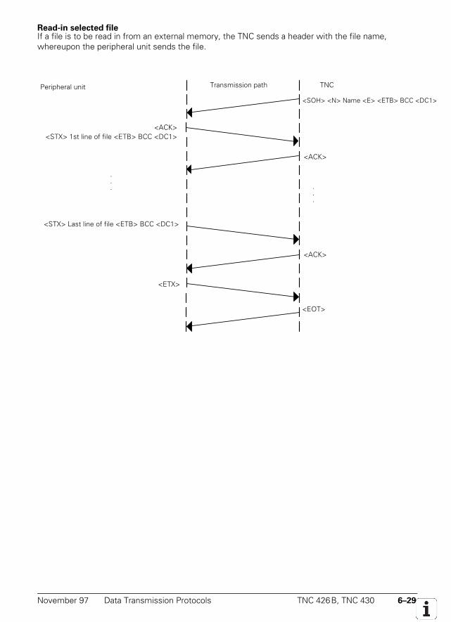
November 97 Data Transmission Protocols TNC 426B, TNC 430 6–29
Read-in selected fileIf a file is to be read in from an external memory, the TNC sends a header with the file name,whereupon the peripheral unit sends the file.
Peripheral unit
<ACK>
.
.
.
<ETX>
<SOH> <N> Name <E> <ETB> BCC <DC1>
Transmission path TNC
<ACK>
<EOT>
<ACK>
.
.
.
<STX> 1st line of file <ETB> BCC <DC1>
<STX> Last line of file <ETB> BCC <DC1>
6–30 TNC 426B, TNC 430 Data Transmission Protocols November 97
6.4.3 LSV2 Protocol
The LSV2 protocol is a data transfer protocol for the two-way transfer of commands and dataaccording to DIN 66019. The commands and data are transferred in so-called telegrams, i.e. the datais split up into blocks (telegrams) and transmitted.
The following functions are possible:• Data transfer• File management (delete, copy and rename files)• Write screen to a file (screen dump)• Remote operation of the control functions, i.e. the TNC screen appears on the computer monitor
and all TNC functions can be executed from the computer.• Real DNC operation, i.e. starting and stopping the machine from the computer.• Diagnosis of TNC error messages and keystrokes for service purposes (the last 1000 events are
stored in the TNC).• Changing, creating and deleting paths
HEIDENHAIN offer two LSV2 software packages:• TNC Remote:
Software for TNC remote control. Can be run on an AT compatible PC with MS-DOS. All theabove functions are available with this software.
• LSV2 TOOL BOX:Software tools in C programming language for creating the transfer telegrams (library, executablefiles for telegrams, source codes, INCLUDE files for LSV2, MAKE files).
TimeoutsIf you choose not to use the standard times for timeouts, you must define your own times in thesystem file OEM.SYS.LSV2TIME0 = Timeout for receiving block STX to ETX (standard 3 s)LSV2TIME1 = Timeout for acknowledging ENQ or check sum (standard 3 s)LSV2TIME2 = Timeout when sending DLE 0, DLE 1 or NAK until a valid character is sent
(standard 1 s)Input range: 0.001 to 3.600 [s]If the code words are not defined or if the value range is exceeded, the standard values are used.
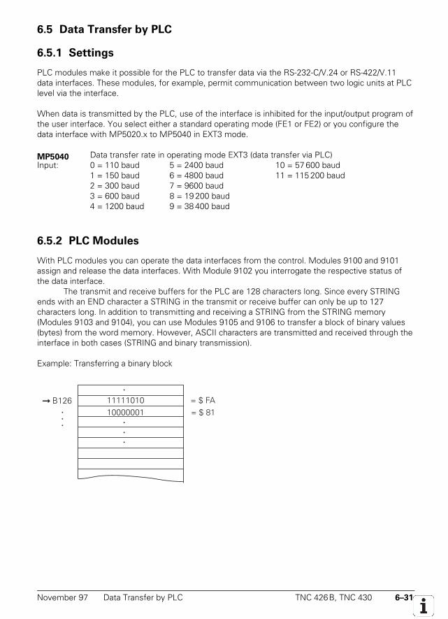
November 97 Data Transfer by PLC TNC 426B, TNC 430 6–31
6.5 Data Transfer by PLC
6.5.1 Settings
PLC modules make it possible for the PLC to transfer data via the RS-232-C/V.24 or RS-422/V.11data interfaces. These modules, for example, permit communication between two logic units at PLClevel via the interface.
When data is transmitted by the PLC, use of the interface is inhibited for the input/output program ofthe user interface. You select either a standard operating mode (FE1 or FE2) or you configure thedata interface with MP5020.x to MP5040 in EXT3 mode.
MP5040 Data transfer rate in operating mode EXT3 (data transfer via PLC)Input: 0 = 110 baud 5 = 2400 baud 10 = 57 600 baud
1 = 150 baud 6 = 4800 baud 11 = 115 200 baud2 = 300 baud 7 = 9600 baud3 = 600 baud 8 = 19 200 baud4 = 1200 baud 9 = 38 400 baud
6.5.2 PLC Modules
With PLC modules you can operate the data interfaces from the control. Modules 9100 and 9101assign and release the data interfaces. With Module 9102 you interrogate the respective status ofthe data interface.
The transmit and receive buffers for the PLC are 128 characters long. Since every STRINGends with an END character a STRING in the transmit or receive buffer can only be up to 127characters long. In addition to transmitting and receiving a STRING from the STRING memory(Modules 9103 and 9104), you can use Modules 9105 and 9106 to transfer a block of binary values(bytes) from the word memory. However, ASCII characters are transmitted and received through theinterface in both cases (STRING and binary transmission).
Example: Transferring a binary block
11111010 B126 ...
10000001= $ FA= $ 81
.
.
.
.
6–32 TNC 426B, TNC 430 Data Transfer by PLC November 97
When transferring binary data from the word memory from address B126 the ASCII characters<F><A><8><1> etc. are transmitted consecutively through the interface. Since each byte containstwo ASCII characters when transferring binary data, the transmit and receive buffers hold 63 bytes.When transferring binary data you can use Module 9107 to read each byte (two ASCII characters)from the receive buffer without erasing the buffer.
Assign data interface (Module 9100)Module 9100 configures the transfer parameters. It also initializes the interface, thereby erasing anyerrors that may have occurred. The interface is switched to receive mode. Once assigned to thePLC, the interface is disabled for use by the output program of the user interface. The assignment ofan interface to the PLC is canceled when the PLC program is recompiled.
Call only in submit job:PS B/W/D/K <Interface> 0: RS232
1: RS422PS B/W/D/K <Transmission parameters>
0: from MP50x0.21: from MOD function
CM 9100Error recognition: M4203 = 0: Interface was assigned
M4203 = 1: Error code in W1022W1022 = 1: Incorrect interface or incorrect transfer parameterW1022 = 13: No connectionW1022 = 14: Interface already assigned or input/output not readyW1022 = 17: Incorrect baud rateW1022 = 20: Call was not from submit
Release data interface (Module 9101)Module 9101 cancels the assignment of a serial interface to the PLC. The receive mode of theinterface is canceled.
Call only in submit job:PS B/W/D/K <Interface> 0: RS232
1: RS422CM 9101Error recognition: M4203 = 0: Interface was released
M4203 = 1: Error code in W1022W1022 = 1: Incorrect interfaceW1022 = 14: Interface not assignedW1022 = 20: Call was not from submit
Status of data interface (Module 9102)Module 9102 reads all the relevant status information about one of the two serial interfaces in bit-coded form.
The information "interface ready" is updated only when the interface is assigned to either thePLC or the NC. If the interface is not assigned, the module reads the status that was valid before thelast interface release (whether by PLC or NC).
November 97 Data Transfer by PLC TNC 426B, TNC 430 6–33
Call:PS B/W/D/K <Interface> 0: RS232
1: RS422CM 9102PL B/W/D <Interface status >
–1: Incorrect module callBit 0: Interface is assignedBit 1: Interface is assigned to PLCBit 2: Interface is ready (see above)Bit 3: Send buffer is emptyBit 4: Error during transmissionBit 5: Receive buffer is fullBit 6: Error in receptionBit 7: ETX was received (not ready to receive)Bit 8: Internal buffer from Module 9113 still contains characters
Error recognition: M4203 = 0: Status readM4203 = 1: Error code in W1022W1022 = 1: Incorrect interface
Send string through data interface (Module 9103)You must have already assigned the interface to the PLC and initialized it with MP 9100.Module 9103 transmits a string from one of the four string memories through one of the two serialinterfaces. References to the PLC error file and PLC dialog file are deleted (see "PLC ErrorMessages").
Call only in submit job:PS B/W/D/K <Interface> 0: RS232
1: RS422PS K/B/W/D <Number of source string in the string buffer (0 to 3)>CM 9103Error recognition: M4203 = 0: String was sent
M4203 = 1: Error code in W1022W1022 = 1: Incorrect interface or incorrect stringW1022 = 12: String too longW1022 = 13: Interface not readyW1022 = 14: Interface not assignedW1022 = 15: Send buffer not emptyW1022 = 20: Call was not from submit
Receive string through data interface (Module 9104)Module 9104 reads a string from the receive buffer of a serial interface in one of the four stringbuffers and resets the receive buffer. You must have previously assigned the interface to the PLCand initialized it with MP 9100.
Call only in submit job:PS B/W/D/K <Interface> 0: RS232
1: RS422PS K/B/W/D <Number of destination string in the string buffer (0 to 3)>CM 9104
6–34 TNC 426B, TNC 430 Data Transfer by PLC November 97
Error recognition: M4203 = 0: String was receivedM4203 = 1: Error code in W1022W1022 = 1: Incorrect interface or incorrect stringW1022 = 12: String too longW1022 = 14: Interface not assignedW1022 = 16: Receiving buffer emptyW1022 = 18: Transfer error or input/output not readyW1022 = 20: Call was not from submit
Send binary data through data interface (Module 9105)Module 9105 transmits a block of binary values from the word memory of the PLC to one of the twoserial interfaces. The transfer is in the form of ASCII-coded hexadecimal values, so every byte in thesource block makes two ASCII characters at the serial interface. You must have previously assignedthe interface to the PLC and initialized it with MP 9100.
Call only in submit job:PS B/W/D/K <Interface> 0: RS232
1: RS422PS K/B/W/D <Number of the first byte in the binary block (0 to 1023)>PS K/B/W/D <Length of the binary block (0..63)>CM 9105Error recognition: M4203 = 0: Data was sent
M4203 = 1: Error code in W1022W1022 = 1: Incorrect interface or incorrect byte number or block too longW1022 = 4: Block outside value rangeW1022 = 13: Interface not ready or no connectionW1022 = 14: Interface not assignedW1022 = 15: Send buffer not emptyW1022 = 20: Call was not from submit
Receive binary data through data interface (Module 9106)Module 9106 reads a block of binary values from one of the two serial interfaces to the wordmemory of the PLC. The transfer is in the form of ASCII-coded hexadecimal values, so every twoASCII characters from the serial interface make one byte in the binary block. The length of the readbinary block is returned as the initial variable. You must have previously assigned the interface to thePLC and initialized it with MP 9100.
Call only in submit job:PS B/W/D/K <Interface> 0: RS232
1: RS422PS K/B/W/D <Number of first byte in binary block (0 to 1023)>CM 9106PL B/W/D <Length of binary block in bytes> –1: Incorrect module callError recognition: M4203 = 0: Data was received
M4203 = 1: Error code in W1022W1022 = 1: Incorrect interface or incorrect offsetW1022 = 4: Block outside value rangeW1022 = 11: Odd number of characters or illegal characterW1022 = 12: String too longW1022 = 14 Interface not assignedW1022 = 16: Receiving buffer emptyW1022 = 18: Transfer error or input/output not readyW1022 = 20: Call was not from submit
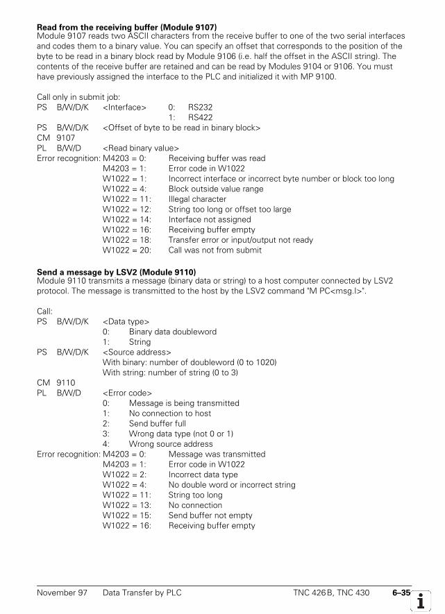
November 97 Data Transfer by PLC TNC 426B, TNC 430 6–35
Read from the receiving buffer (Module 9107)Module 9107 reads two ASCII characters from the receive buffer to one of the two serial interfacesand codes them to a binary value. You can specify an offset that corresponds to the position of thebyte to be read in a binary block read by Module 9106 (i.e. half the offset in the ASCII string). Thecontents of the receive buffer are retained and can be read by Modules 9104 or 9106. You musthave previously assigned the interface to the PLC and initialized it with MP 9100.
Call only in submit job:PS B/W/D/K <Interface> 0: RS232
1: RS422PS B/W/D/K <Offset of byte to be read in binary block>CM 9107PL B/W/D <Read binary value>Error recognition: M4203 = 0: Receiving buffer was read
M4203 = 1: Error code in W1022W1022 = 1: Incorrect interface or incorrect byte number or block too longW1022 = 4: Block outside value rangeW1022 = 11: Illegal characterW1022 = 12: String too long or offset too largeW1022 = 14: Interface not assignedW1022 = 16: Receiving buffer emptyW1022 = 18: Transfer error or input/output not readyW1022 = 20: Call was not from submit
Send a message by LSV2 (Module 9110)Module 9110 transmits a message (binary data or string) to a host computer connected by LSV2protocol. The message is transmitted to the host by the LSV2 command "M PC<msg.I>".
Call:PS B/W/D/K <Data type>
0: Binary data doubleword1: String
PS B/W/D/K <Source address>With binary: number of doubleword (0 to 1020)With string: number of string (0 to 3)
CM 9110PL B/W/D <Error code>
0: Message is being transmitted1: No connection to host2: Send buffer full3: Wrong data type (not 0 or 1)4: Wrong source address
Error recognition: M4203 = 0: Message was transmittedM4203 = 1: Error code in W1022W1022 = 2: Incorrect data typeW1022 = 4: No double word or incorrect stringW1022 = 11: String too longW1022 = 13: No connectionW1022 = 15: Send buffer not emptyW1022 = 16: Receiving buffer empty
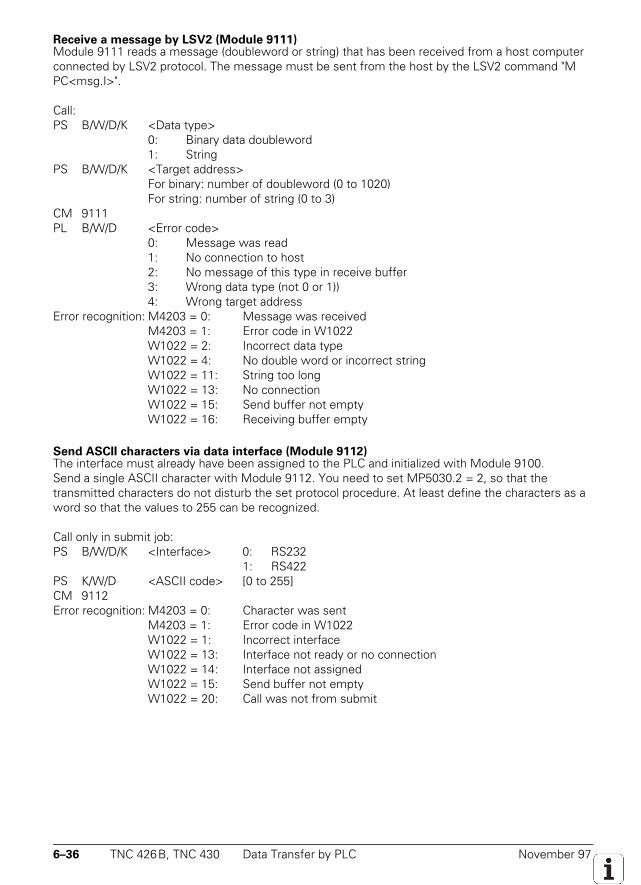
6–36 TNC 426B, TNC 430 Data Transfer by PLC November 97
Receive a message by LSV2 (Module 9111)Module 9111 reads a message (doubleword or string) that has been received from a host computerconnected by LSV2 protocol. The message must be sent from the host by the LSV2 command "MPC<msg.I>".
Call:PS B/W/D/K <Data type>
0: Binary data doubleword1: String
PS B/W/D/K <Target address>For binary: number of doubleword (0 to 1020)For string: number of string (0 to 3)
CM 9111PL B/W/D <Error code>
0: Message was read1: No connection to host2: No message of this type in receive buffer3: Wrong data type (not 0 or 1))4: Wrong target address
Error recognition: M4203 = 0: Message was receivedM4203 = 1: Error code in W1022W1022 = 2: Incorrect data typeW1022 = 4: No double word or incorrect stringW1022 = 11: String too longW1022 = 13: No connectionW1022 = 15: Send buffer not emptyW1022 = 16: Receiving buffer empty
Send ASCII characters via data interface (Module 9112)The interface must already have been assigned to the PLC and initialized with Module 9100.Send a single ASCII character with Module 9112. You need to set MP5030.2 = 2, so that thetransmitted characters do not disturb the set protocol procedure. At least define the characters as aword so that the values to 255 can be recognized.
Call only in submit job:PS B/W/D/K <Interface> 0: RS232
1: RS422PS K/W/D <ASCII code> [0 to 255]CM 9112Error recognition: M4203 = 0: Character was sent
M4203 = 1: Error code in W1022W1022 = 1: Incorrect interfaceW1022 = 13: Interface not ready or no connectionW1022 = 14: Interface not assignedW1022 = 15: Send buffer not emptyW1022 = 20: Call was not from submit
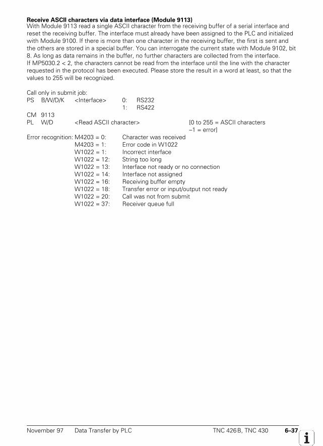
November 97 Data Transfer by PLC TNC 426B, TNC 430 6–37
Receive ASCII characters via data interface (Module 9113)With Module 9113 read a single ASCII character from the receiving buffer of a serial interface andreset the receiving buffer. The interface must already have been assigned to the PLC and initializedwith Module 9100. If there is more than one character in the receiving buffer, the first is sent andthe others are stored in a special buffer. You can interrogate the current state with Module 9102, bit8. As long as data remains in the buffer, no further characters are collected from the interface.If MP5030.2 < 2, the characters cannot be read from the interface until the line with the characterrequested in the protocol has been executed. Please store the result in a word at least, so that thevalues to 255 will be recognized.
Call only in submit job:PS B/W/D/K <Interface> 0: RS232
1: RS422CM 9113PL W/D <Read ASCII character> [0 to 255 = ASCII characters
–1 = error]Error recognition: M4203 = 0: Character was received
M4203 = 1: Error code in W1022W1022 = 1: Incorrect interfaceW1022 = 12: String too longW1022 = 13: Interface not ready or no connectionW1022 = 14: Interface not assignedW1022 = 16: Receiving buffer emptyW1022 = 18: Transfer error or input/output not readyW1022 = 20: Call was not from submitW1022 = 37: Receiver queue full
6–38 TNC 426B, TNC 430 External Programming November 97
6.6 External Programming
Remember the following when programming externally for subsequent transmission:• At the program beginning and after every program block <CR><LF> or <LF> must be
programmed.• After the End of Program block <CR> <LF> and also <ETX> must be programmed.• For NC programs, the spaces can be omitted between the individual words.• When reading-in DIN blocks, the asterisk character (*) is not required at the end of the block.• Comments are separated from the NC block with a semicolon (;).• Comments located before the program are not saved.• Block numbers need not be programmed. They are generated by the TNC (only for
conversational programming).
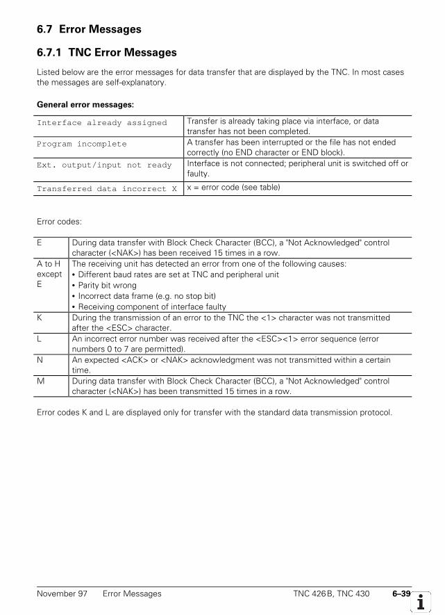
November 97 Error Messages TNC 426B, TNC 430 6–39
6.7 Error Messages
6.7.1 TNC Error Messages
Listed below are the error messages for data transfer that are displayed by the TNC. In most casesthe messages are self-explanatory.
General error messages:
Interface already assigned Transfer is already taking place via interface, or datatransfer has not been completed.
Program incomplete A transfer has been interrupted or the file has not endedcorrectly (no END character or END block).
Ext. output/input not ready Interface is not connected; peripheral unit is switched off orfaulty.
Transferred data incorrect X x = error code (see table)
Error codes:
E During data transfer with Block Check Character (BCC), a "Not Acknowledged" controlcharacter (<NAK>) has been received 15 times in a row.
A to HexceptE
The receiving unit has detected an error from one of the following causes:• Different baud rates are set at TNC and peripheral unit• Parity bit wrong• Incorrect data frame (e.g. no stop bit)• Receiving component of interface faulty
K During the transmission of an error to the TNC the <1> character was not transmittedafter the <ESC> character.
L An incorrect error number was received after the <ESC><1> error sequence (errornumbers 0 to 7 are permitted).
N An expected <ACK> or <NAK> acknowledgment was not transmitted within a certaintime.
M During data transfer with Block Check Character (BCC), a "Not Acknowledged" controlcharacter (<NAK>) has been transmitted 15 times in a row.
Error codes K and L are displayed only for transfer with the standard data transmission protocol.
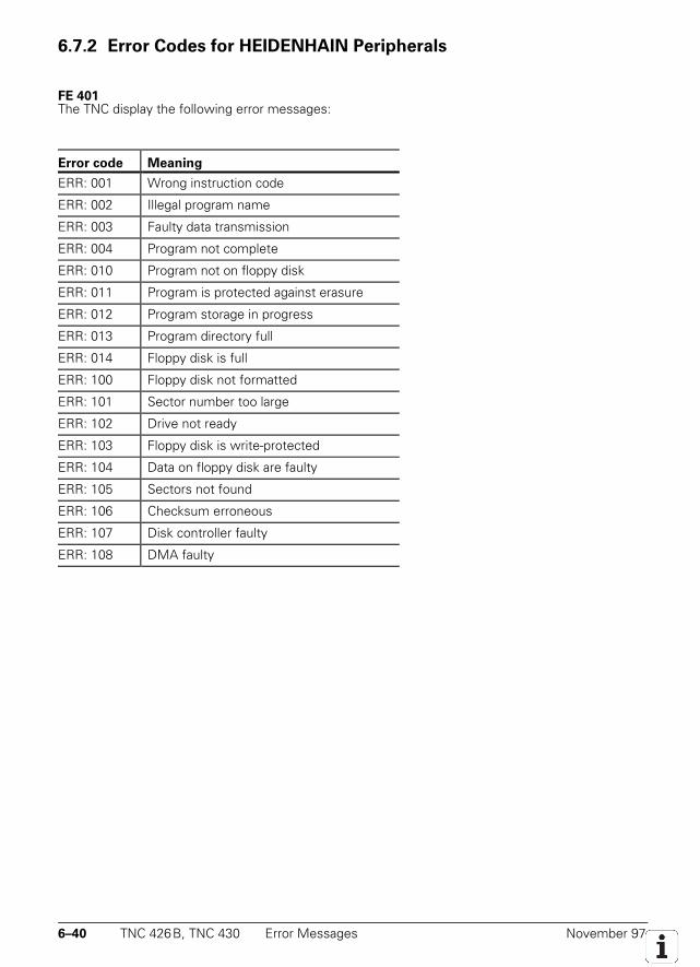
6–40 TNC 426B, TNC 430 Error Messages November 97
6.7.2 Error Codes for HEIDENHAIN Peripherals
FE 401The TNC display the following error messages:
Error code Meaning
ERR: 001 Wrong instruction code
ERR: 002 Illegal program name
ERR: 003 Faulty data transmission
ERR: 004 Program not complete
ERR: 010 Program not on floppy disk
ERR: 011 Program is protected against erasure
ERR: 012 Program storage in progress
ERR: 013 Program directory full
ERR: 014 Floppy disk is full
ERR: 100 Floppy disk not formatted
ERR: 101 Sector number too large
ERR: 102 Drive not ready
ERR: 103 Floppy disk is write-protected
ERR: 104 Data on floppy disk are faulty
ERR: 105 Sectors not found
ERR: 106 Checksum erroneous
ERR: 107 Disk controller faulty
ERR: 108 DMA faulty
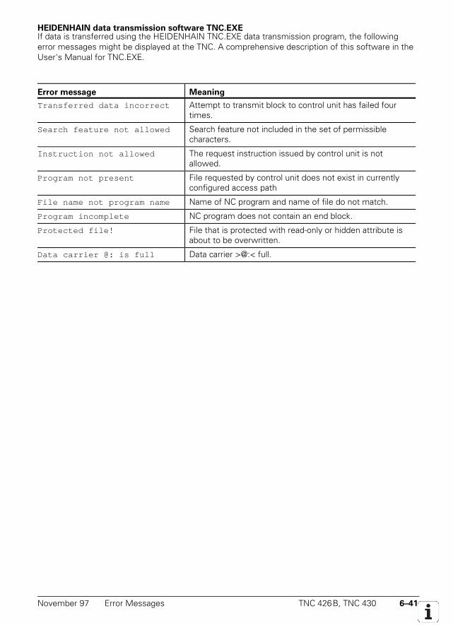
November 97 Error Messages TNC 426B, TNC 430 6–41
HEIDENHAIN data transmission software TNC.EXEIf data is transferred using the HEIDENHAIN TNC.EXE data transmission program, the followingerror messages might be displayed at the TNC. A comprehensive description of this software in theUser's Manual for TNC.EXE.
Error message Meaning
Transferred data incorrect Attempt to transmit block to control unit has failed fourtimes.
Search feature not allowed Search feature not included in the set of permissiblecharacters.
Instruction not allowed The request instruction issued by control unit is notallowed.
Program not present File requested by control unit does not exist in currentlyconfigured access path
File name not program name Name of NC program and name of file do not match.
Program incomplete NC program does not contain an end block.
Protected file! File that is protected with read-only or hidden attribute isabout to be overwritten.
Data carrier @: is full Data carrier >@:< full.
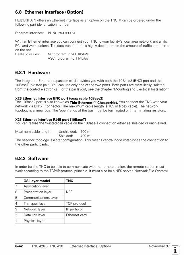
6–42 TNC 426B, TNC 430 Ethernet Interface (Option) November 97
6.8 Ethernet Interface (Option)
HEIDENHAIN offers an Ethernet interface as an option on the TNC. It can be ordered under thefollowing part identification number.
Ethernet interface: Id. Nr. 293 890 51
With an Ethernet interface you can connect your TNC to your facility's local area network and all itsPCs and workstations. The data transfer rate is highly dependent on the amount of traffic at the timeon the net.Realistic values: NC program to 200 Kbits/s,
ASCII program to 1 Mbit/s
6.8.1 Hardware
The integrated Ethernet expansion card provides you with both the 10Base2 (BNC) port and the10BaseT (twisted pair). You can use only one of the two ports. Both ports are metallically isolatedfrom the control electronics. For the pin layout, see the chapter "Mounting and Electrical Installation."
X26 Ethernet interface BNC port (coax cable 10Base2)The 10Base2 port is also known as Thin-Ethernet or CheaperNet. You connect the TNC with yournetwork via BNC-T connector. The maximum cable length is 185 m (coax cable). The networktopology is a linear bus. The "open" ends of the bus must be terminated with terminating resistors.
X25 Ethernet interface RJ45 port (10BaseT)You can realize the twisted-pair cable on the 10Base-T connection either as shielded or unshielded.
Maximum cable length: Unshielded: 100 mShielded: 400 m
The network topology is a star configuration. This means central node establishes the connection tothe other participants.
6.8.2 Software
In order for the TNC to be able to communicate with the remote station, the remote station mustwork according to the TCP/IP protocol principle. It must also be a NFS server (Network File System).
OSI layer model TNC
7 Application layer
6 Presentation layer NFS
5 Communications layer
4 Transport layer TCP protocol
3 Network layer IP protocol
2 Data link layer Ethernet card
1 Physical layer
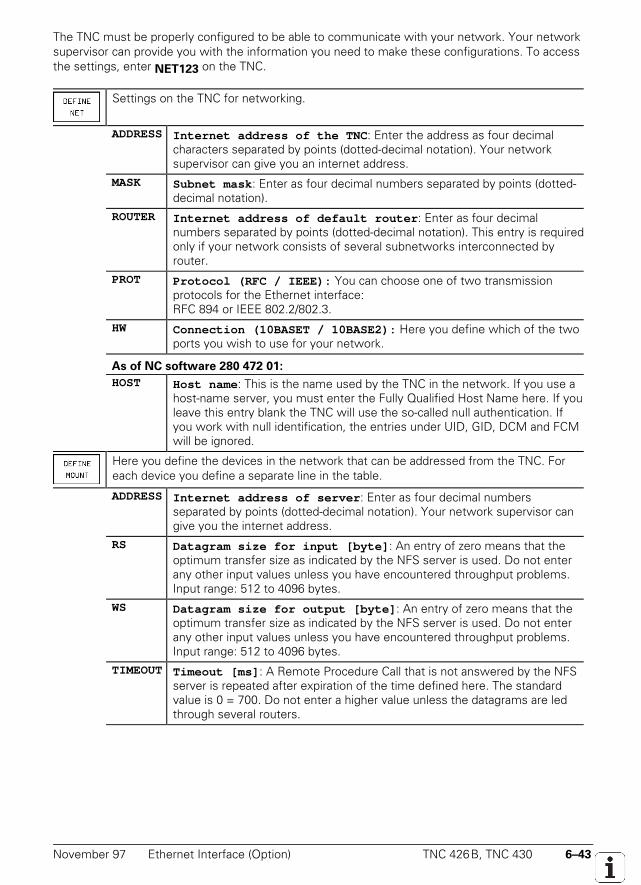
November 97 Ethernet Interface (Option) TNC 426B, TNC 430 6–43
The TNC must be properly configured to be able to communicate with your network. Your networksupervisor can provide you with the information you need to make these configurations. To accessthe settings, enter NET123 on the TNC.
Settings on the TNC for networking.
ADDRESS Internet address of the TNC : Enter the address as four decimalcharacters separated by points (dotted-decimal notation). Your networksupervisor can give you an internet address.
MASK Subnet mask : Enter as four decimal numbers separated by points (dotted-decimal notation).
ROUTER Internet address of default router : Enter as four decimalnumbers separated by points (dotted-decimal notation). This entry is requiredonly if your network consists of several subnetworks interconnected byrouter.
PROT Protocol (RFC / IEEE): You can choose one of two transmissionprotocols for the Ethernet interface:RFC 894 or IEEE 802.2/802.3.
HW Connection (10BASET / 10BASE2): Here you define which of the twoports you wish to use for your network.
As of NC software 280 472 01:
HOST Host name : This is the name used by the TNC in the network. If you use ahost-name server, you must enter the Fully Qualified Host Name here. If youleave this entry blank the TNC will use the so-called null authentication. Ifyou work with null identification, the entries under UID, GID, DCM and FCMwill be ignored.
Here you define the devices in the network that can be addressed from the TNC. Foreach device you define a separate line in the table.
ADDRESS Internet address of server : Enter as four decimal numbersseparated by points (dotted-decimal notation). Your network supervisor cangive you the internet address.
RS Datagram size for input [byte] : An entry of zero means that theoptimum transfer size as indicated by the NFS server is used. Do not enterany other input values unless you have encountered throughput problems.Input range: 512 to 4096 bytes.
WS Datagram size for output [byte] : An entry of zero means that theoptimum transfer size as indicated by the NFS server is used. Do not enterany other input values unless you have encountered throughput problems.Input range: 512 to 4096 bytes.
TIMEOUT Timeout [ms] : A Remote Procedure Call that is not answered by the NFSserver is repeated after expiration of the time defined here. The standardvalue is 0 = 700. Do not enter a higher value unless the datagrams are ledthrough several routers.
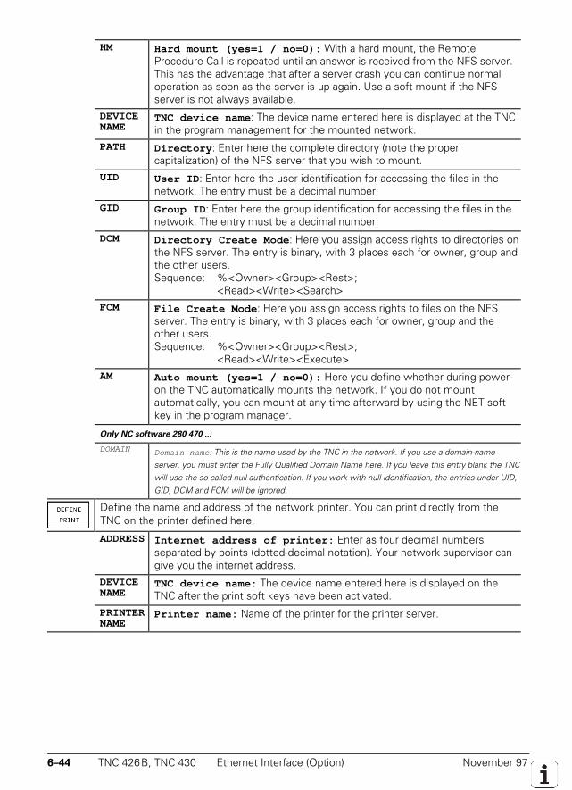
6–44 TNC 426B, TNC 430 Ethernet Interface (Option) November 97
HM Hard mount (yes=1 / no=0): With a hard mount, the RemoteProcedure Call is repeated until an answer is received from the NFS server.This has the advantage that after a server crash you can continue normaloperation as soon as the server is up again. Use a soft mount if the NFSserver is not always available.
DEVICENAME
TNC device name : The device name entered here is displayed at the TNCin the program management for the mounted network.
PATH Directory : Enter here the complete directory (note the propercapitalization) of the NFS server that you wish to mount.
UID User ID : Enter here the user identification for accessing the files in thenetwork. The entry must be a decimal number.
GID Group ID : Enter here the group identification for accessing the files in thenetwork. The entry must be a decimal number.
DCM Directory Create Mode : Here you assign access rights to directories onthe NFS server. The entry is binary, with 3 places each for owner, group andthe other users.Sequence: %<Owner><Group><Rest>;
<Read><Write><Search>
FCM File Create Mode : Here you assign access rights to files on the NFSserver. The entry is binary, with 3 places each for owner, group and theother users.Sequence: %<Owner><Group><Rest>;
<Read><Write><Execute>
AM Auto mount (yes=1 / no=0): Here you define whether during power-on the TNC automatically mounts the network. If you do not mountautomatically, you can mount at any time afterward by using the NET softkey in the program manager.
Only NC software 280 470 ..:
DOMAIN Domain name : This is the name used by the TNC in the network. If you use a domain-nameserver, you must enter the Fully Qualified Domain Name here. If you leave this entry blank the TNCwill use the so-called null authentication. If you work with null identification, the entries under UID,GID, DCM and FCM will be ignored.
Define the name and address of the network printer. You can print directly from theTNC on the printer defined here.
ADDRESS Internet address of printer: Enter as four decimal numbersseparated by points (dotted-decimal notation). Your network supervisor cangive you the internet address.
DEVICENAME
TNC device name: The device name entered here is displayed on theTNC after the print soft keys have been activated.
PRINTERNAME
Printer name: Name of the printer for the printer server.
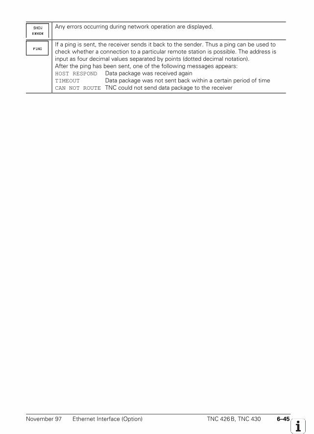
November 97 Ethernet Interface (Option) TNC 426B, TNC 430 6–45
Any errors occurring during network operation are displayed.
If a ping is sent, the receiver sends it back to the sender. Thus a ping can be used tocheck whether a connection to a particular remote station is possible. The address isinput as four decimal values separated by points (dotted decimal notation).After the ping has been sent, one of the following messages appears:HOST RESPOND Data package was received againTIMEOUT Data package was not sent back within a certain period of timeCAN NOT ROUTE TNC could not send data package to the receiver

6–46 TNC 426B, TNC 430 Ethernet Interface (Option) November 97
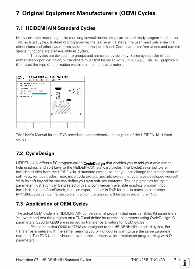
November 97 HEIDENHAIN Standard Cycles TNC 426B, TNC 430 7–1
7 Original Equipment Manufacturer's (OEM) Cycles
7.1 HEIDENHAIN Standard Cycles
Many common machining tasks requiring several routine steps are stored ready-programmed in theTNC as fixed cycles. Instead of programming the task in all its steps, the user need only enter thedimensions and other parameters specific to the job at hand. Coordinate transformations and severalspecial functions are also available as cycles.
The cycles are divided into groups and are called by soft key. Some cycles take effectimmediately upon definition, while others must first be called with CYCL CALL. The TNC graphicallyillustrates the type of information required in the input parameters.
The User's Manual for the TNC provides a comprehensive description of the HEIDENHAIN fixedcycles.
7.2 CycleDesign
HEIDENHAIN offers a PC program called CycleDesign that enables you to add your own cycles,help graphics, and soft keys to the HEIDENHAIN standard cycles. The CycleDesign softwareincludes all files from the HEIDENHAIN standard cycles, so that you can change the arrangement ofsoft keys, remove cycles, reorganize cycle groups, and add cycles that you have developed yourself.With its soft-key editor you can define you own soft-key contents. The help graphics for inputparameter illustration can be created with any commercially available graphics program (notincluded), such as AutoSketch, that can export its files in DXF format. In machine parameterMP7364.x you can define the colors in which the graphic will be displayed on the TNC.
7.3 Application of OEM Cycles
The actual OEM cycle is a HEIDENHAIN conversational program that uses variables (Q parameters).You write and test the program on a TNC and define its transfer parameters using CycleDesign. Qparameters Q200 to Q299 are reserved as transfer parameters for OEM cycles.
Please note that Q200 to Q248 are assigned to the HEIDENHAIN standard cycles. Fortransfer parameters with the same meaning you will of course want to use the same parameternumbers. The TNC User's Manual provides comprehensive information on programming with Qparameters.
7–2 TNC 426B, TNC 430 Application of OEM Cycles November 97
Functions that are not permitted in OEM cycles
• M functions M02, M30, M06 with program stop• Programmed STOP call• Program calls with PGM CALL• Definition of Cycle 14 "Contour Geometry"
Cycle 14 must be defined in the main program.
Q parameters with special meanings
Q parameters Q100 to Q 199 are reserved for special functions on the TNC. Many of these Qparameters have a special meaning such as tool radius, tool axis, etc. For a description of theseparameters refer to the TNC User's Manual.
Global and local Q parameters
The content of the global Q parameters can be changed both in the calling NC program as well as inthe OEM cycle being called. However, the content of the global Q parameter is not changed duringtransfer to and from the program being called.
Local Q parameters keep there contents only in the current program. When an OEM cycleis called, all contents of the local Q parameters are buffer stored and the same value is reassignedafter they return from the OEM cycle. Any change in a local Q parameter in an OEM cycle istherefore effective only in the OEM cycle.
Q parameter Effect
Q0 to Q59 LocalQ60 to Q99 Depends on MP7251
Q200 to Q299 Global
Because they are always local and can be changed within the program, Q parameters Q0 to Q59 areused in HEIDENHAIN standard cycles for mathematical operations. We recommend this for yourOEM cycles as well.
MP7251 Definition of global Q parameters Q60 to Q99Input: 0 = Q60 to Q99 local
1 to 40 = Q(100 – <Input value>) to Q99 global
FN functions with special meanings
With the following FN functions you can solve various tasks such as outputting error messagestransferring data from the NC to the PLC:• FN14 Output of error messages and dialogs on the screen.• FN15 Output of error messages, dialogs and Q parameters to a file or through a data interface• FN17 Overwrite system data: see "PLC programming"• FN18 Read system data• FN19 Assignment of two numerical values or Q parameters values from the OEM cycle to the
PLC: see "PLC Programming."• FN20 Wait for condition to become valid• FN25 Overwrite datum
Nesting of OEM cycles
When nesting OEM cycles, you must distinguish between DEF-active and CALL-active OEM cycles.DEF-active cycles are effective immediately after definition. CALL-active cycles must first beactivated with a separate CYCL CALL block. You can call DEF-active cycles from other OEM cycles,but not CALL-active cycles.
November 97 Application of OEM Cycles TNC 426B, TNC 430 7–3
Loading the OEM-specific cycle structure
On you PC, use CycleDesign to link the OEM cycles that you have developed with your soft keysand help graphics.
Use CycleDesign to transfer these new cycle structures to the TNC. The TNC opens the system file PLC:\CYCLE.SYS . This system file contains the definition of the
directories and files of the OEM cycles, soft keys and help graphics. You can also store OEMcycles on the hard disk of the TNC in coded form to protect them from unauthorized alteration. Ifthe TNC cannot find PLC:\CYCLE.SYS it uses the standard HEIDENHAIN cycle structures.
Remember to use TNCBACK.EXE to make a backup copy of the PLC partition on a floppy disk,and to ship it together with your machine tool.
Example: HEIDENHAIN Standard Cycle 201 REAMING
The new HEIDENHAIN Standard Cycles (beginning from Cycle 200) are written like OEM cycles.
0 BEGIN PGM 201 MM P1 FN 17: SYSWRITE ID212 = +3 Automatic compensation of the tool axis2 FN 9: IF +Q110 EQU +0 GOTO LBL 1993 FN 9: IF +Q110 EQU +1 GOTO LBL 199 Inquiry whether spindle on with M3 or M44 FN 14: ERROR = 1000 Error message, spindle5 LBL 1996 FN 10: IF +Q109 NE -1 GOTO LBL 198 Inquiry whether tool is active7 FN 14: ERROR = 1001 Error message tool axis is missing8 LBL 1989 FN 12: IF +Q201 LT +0 GOTO LBL 197 Inquiry, whether the machining direction is
negative10 FN 0: Q30 = -1 If not, the set constant to negative11 FN 9: IF +0 EQU +0 GOTO LBL 19412 LBL 19713 FN 0: Q30 = +1 Otherwise set constant to positive14 LBL 19415 FN 9: IF +Q97 EQU +1 GOTO LBL 193 Inquiry whether signs already were negated16 CALL LBL 417 LBL 19318 FN 1: Q19 = +Q203 + +Q200 Calculate Z end position19 FN 9: IF +Q204 EQU +0 GOTO LBL 2 Inquiry whether to enter a 2nd safety clearance20 FN 1: Q19 = +Q203 + +Q204 If so, set a new Z position21 LBL 222 FN 1: Q20 = +Q203 + +Q200 Calculate Z pre-position23 FN 1: Q24 = +Q203 + +Q201 Calculate total hole depth24 FN 0: Q25 = +Q208 Transfer the feed rate for retraction25 FN 10: IF +Q208 NE +0 GOTO LBL 4 Inquiry whether to enter feed rate for retraction26 FN 0: Q25 = +Q206 No: feed rate for retraction = feed rate for reaming27 LBL 4 Negate sign-critical parameters28 FN 9: IF +Q97 EQU +1 GOTO LBL 192 If the sign was already reversed in the DEF cycle,29 FN 3: Q200 = +Q200 * +Q30 skip negation30 FN 3: Q204 = +Q204 * +Q3031 LBL 032 LBL 19233 L Z+Q20 R0 F MAX Move to pre-position in Z34 L Z+Q24 R0 FQ206 Move to total hole depth35 CYCL DEF 9.0 VERWEILZEIT36 CYCL DEF 9.1 V.ZEIT Q211 If desired, dwell at bottom37 L Z+Q20 R0 FQ25 Retraction to setup clearance38 L Z+Q19 R0 F MAX If desired, retract to 2nd setup clearance39 END PGM 201 MM P
7–4 TNC 426B, TNC 430 Compatibility with “Old” OEM Cycles November 97
7.4 Compatibility with “Old” OEM Cycles
Before the TNC 426 was introduced, OEM cycles were created directly at the TNC and then storedin the PLC EPROM. Such OEM cycles, which have the program numbers 99999968 to 99999999,are of limited use on the TNC 426, TNC 430.
In order to be able to run old NC programs in which these OEM cycles are called, you mustuse CycleDesign to save the old OEM cycles on the TNC's hard disk. CycleDesign provides aseparate routine for this purpose. Such OEM cycles can be run on the TNC, but they cannot bedefined. To enable your old OEM cycles to be defined on the TNC you must use CycleDesign torewrite them in the new format.
November 97 Error Messages TNC 426B, TNC 430 8–1
8 Appendix
8.1 Error Messages
As of NC software 280 470 05 / 280 472 01
All NC error messages are displayed in dialog. With NC software 280 472 .. you can use the Helpkey to call up additional information on the error message shown.
Old/New error messages
In this new Technical Manual only the new dialog error messages are to be found throughout thetext and in the Index at the end. These dialog error messages will be displayed only as of NCsoftware version 280 470 05 and 280 472 01. If you are using one of the older controls, thefollowing list may assist you by providing a cross reference between the old and the new errormessages.
Old error message (coded) New error message (dialog)
Gross positioning error <axis> A Excessive servo lag in <axis>
Gross positioning error <axis> B Nominal speed value too high <axis>
Gross positioning error <axis> C Movement monitoring error in <axis> A
Gross positioning error <axis> D Standstill monitoring error in <axis>
Gross positioning error <axis> E Excessive offset in <axis>
Gross positioning error <axis> F Movement monitoring error in <axis> B
Gross positioning error <axis> G Analog output already assigned <axis>
Encoder <axis> defective A Encoder amplitude too small <axis>
Encoder <axis> defective B Encoder <axis>: frequency too high
Encoder <axis> defective C Encoder <axis> defective
Encoder <axis>' defective A Encoder <axis>': amplitude too small
Positioning error Excessive servo lag in <axis>
Error in PLC program 1Q PLC: M4005, M4006, M4007 incorrect
Error in PLC program 1R PLC: more than one strobe active
Error in PLC program 1S PLC: module 9008 not called
Error in PLC program 00 PLC: invalid command
Error in PLC program 02 PLC: invalid operand type
Error in PLC program 03 PLC: operand not found
Error in PLC program 04 PLC: operand incorrect
Error in PLC program 05 PLC: error in text after command
Error in PLC program 06 PLC: line too long
Error in PLC program 07 PLC: label not defined
Error in PLC program 08 PLC: end of block not found
Error in PLC program 09 PLC: program too long
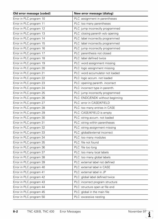
8–2 TNC 426B, TNC 430 Error Messages November 97
Old error message (coded) New error message (dialog)
Error in PLC program 10 PLC: assignment in parentheses
Error in PLC program 11 PLC: too many parentheses
Error in PLC program 12 PLC: jump incorrectly programmed
Error in PLC program 13 PLC: closing parenth w/o opening
Error in PLC program 14 PLC: label incorrectly programmed
Error in PLC program 15 PLC: label incorrectly programmed
Error in PLC program 16 PLC: jump incorrectly programmed
Error in PLC program 17 PLC: parenthesis not closed
Error in PLC program 18 PLC: label defined twice
Error in PLC program 19 PLC: word assignment missing
Error in PLC program 20 PLC: logic assignment missing
Error in PLC program 21 PLC: word accumulator not loaded
Error in PLC program 22 PLC: logic accum. not loaded
Error in PLC program 23 PLC: opening parenth. incorrect
Error in PLC program 24 PLC: incorrect type in parenth.
Error in PLC program 25 PLC: jump incorrectly programmed
Error in PLC program 26 PLC: ENDC/ENDK without beginning
Error in PLC program 27 PLC: error in CASE/KFIELD
Error in PLC program 28 PLC: too many entries in CASE
Error in PLC program 29 PLC: CASE/KFIELD is empty
Error in PLC program 30 PLC: string accum. not loaded
Error in PLC program 31 PLC: string within parentheses
Error in PLC program 32 PLC: string assignment missing
Error in PLC program 33 PLC: global/external incorrect
Error in PLC program 34 PLC: too many modules
Error in PLC program 35 PLC: file not found
Error in PLC program 36 PLC: file too long
Error in PLC program 37 PLC: too many local labels
Error in PLC program 38 PLC: too many global labels
Error in PLC program 39 PLC: external label not defined
Error in PLC program 40 PLC: external label in CASE
Error in PLC program 41 PLC: external label in JP
Error in PLC program 42 PLC: global label defined twice
Error in PLC program 43 PLC: incorrect program structure
Error in PLC program 44 PLC: structure open at file end
Error in PLC program 45 PLC: global in the main file
Error in PLC program 50 PLC: excessive nesting
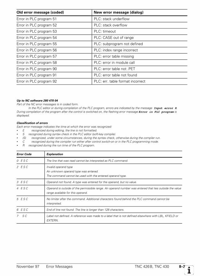
November 97 Error Messages TNC 426B, TNC 430 8–3
Old error message (coded) New error message (dialog)
Error in PLC program 51 PLC: stack underflow
Error in PLC program 52 PLC: stack overflow
Error in PLC program 53 PLC: timeout
Error in PLC program 54 PLC: CASE out of range
Error in PLC program 55 PLC: subprogram not defined
Error in PLC program 56 PLC: index range incorrect
Error in PLC program 57 PLC: error table missing
Error in PLC program 58 PLC: error in module call
Error in PLC program 90 PLC: error table not .PET
Error in PLC program 91 PLC: error table not found
Error in PLC program 92 PLC: err. table format incorrect
Up to NC software 280 470 04
Part of the NC error messages is in coded form.In the PLC editor or during compilation of the PLC program, errors are indicated by the message Input error X .
During compilation of the program after the control is switched on, the flashing error message Error in PLC program isdisplayed.
Classification of errors
Each error message indicates the time at which the error was recognized:• E recognized during editing, the line is not formatted.• S recognized during syntax check in the PLC editor (soft-key compile).• (S) recognized, under some circumstances, during the syntax check, otherwise during the compiler run.• C recognized during the compiler run either after control switch-on or in the PLC programming mode.• R recognized during the run time of the PLC program.
Error Code Explanation
0 E S C The line that was read cannot be interpreted as PLC command.
2 E S C Invalid operand typeAn unknown operand type was entered.The command cannot be used with the entered operand type.
3 E S C Operand not found. A type was entered for the operand, but no value.
4 E S C Operand is outside of the permissible range. An operand number was entered that lies outside the valuerange available for this operand.
5 E S C No limiter after the command. Additional characters found behind the PLC command cannot beinterpreted.
6 E S C End of line not found. The line is longer than 128 characters.
7 S C Label not defined. A reference was made to a label that is not defined elsewhere with LBL, KFIELD orEXTERN.
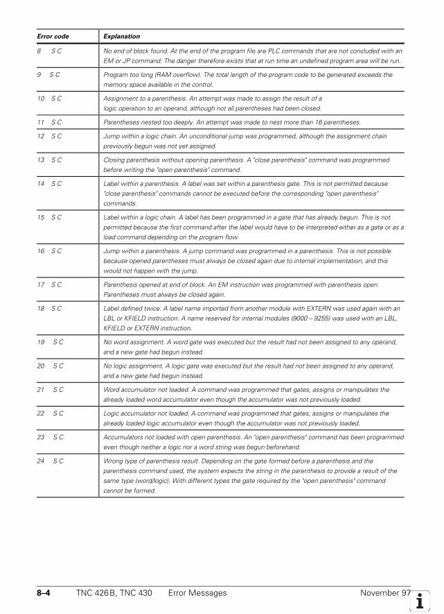
8–4 TNC 426B, TNC 430 Error Messages November 97
Error code Explanation
8 S C No end of block found. At the end of the program file are PLC commands that are not concluded with anEM or JP command. The danger therefore exists that at run time an undefined program area will be run.
9 S C Program too long (RAM overflow). The total length of the program code to be generated exceeds thememory space available in the control.
10 S C Assignment to a parenthesis. An attempt was made to assign the result of alogic operation to an operand, although not all parentheses had been closed.
11 S C Parentheses nested too deeply. An attempt was made to nest more than 16 parentheses.
12 S C Jump within a logic chain. An unconditional jump was programmed, although the assignment chainpreviously begun was not yet assigned.
13 S C Closing parenthesis without opening parenthesis. A "close parenthesis" command was programmedbefore writing the "open parenthesis" command.
14 S C Label within a parenthesis. A label was set within a parenthesis gate. This is not permitted because"close parenthesis" commands cannot be executed before the corresponding "open parenthesis"commands.
15 S C Label within a logic chain. A label has been programmed in a gate that has already begun. This is notpermitted because the first command after the label would have to be interpreted either as a gate or as aload command depending on the program flow.
16 S C Jump within a parenthesis. A jump command was programmed in a parenthesis. This is not possiblebecause opened parentheses must always be closed again due to internal implementation, and thiswould not happen with the jump.
17 S C Parenthesis opened at end of block. An EM instruction was programmed with parenthesis open.Parentheses must always be closed again.
18 S C Label defined twice. A label name imported from another module with EXTERN was used again with anLBL or KFIELD instruction. A name reserved for internal modules (9000 – 9255) was used with an LBL,KFIELD or EXTERN instruction.
19 S C No word assignment. A word gate was executed but the result had not been assigned to any operand,and a new gate had begun instead.
20 S C No logic assignment. A logic gate was executed but the result had not been assigned to any operand,and a new gate had begun instead.
21 S C Word accumulator not loaded. A command was programmed that gates, assigns or manipulates thealready loaded word accumulator even though the accumulator was not previously loaded.
22 S C Logic accumulator not loaded. A command was programmed that gates, assigns or manipulates thealready loaded logic accumulator even though the accumulator was not previously loaded.
23 S C Accumulators not loaded with open parenthesis. An "open parenthesis" command has been programmedeven though neither a logic nor a word string was begun beforehand.
24 S C Wrong type of parenthesis result. Depending on the gate formed before a parenthesis and theparenthesis command used, the system expects the string in the parenthesis to provide a result of thesame type (word/logic). With different types the gate required by the "open parenthesis" commandcannot be formed.
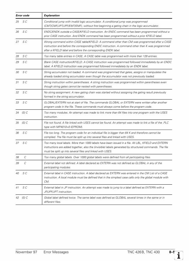
November 97 Error Messages TNC 426B, TNC 430 8–5
Error code Explanation
25 S C Conditional jump with invalid logic accumulator. A conditional jump was programmed(CMT/CMF/JPT/JPF/EMT/EMF), without first beginning a gating chain in the logic accumulator.
26 S C ENDC/ENDK outside a CASE/KFIELD instruction. An ENDC command has been programmed without aprior CASE instruction. And ENDK command has been programmed without a prior KFIELD label.
27 S C Wrong command within CASE table/KFIELD. A command other than CM was programmed after a CASEinstruction and before the corresponding ENDC instruction. A command other than K was programmedafter a KFIELD label and before the corresponding ENDK label.
28 S C Too many table entries in CASE. A CASE table was programmed with more than 128 entries.
29 S C Blank CASE instruction/KFIELD. A CASE instruction was programmed followed immediately by an ENDClabel. A KFIELD instruction was programmed followed immediately by an ENDK label.
30 S C String accumulator not loaded. A command was programmed that gates, assigns or manipulates thealready loaded string accumulator even though the accumulator was not previously loaded.
31 S C String instruction within parentheses. A string instruction was programmed within parentheses eventhough string gates cannot be nested with parentheses.
32 S C No string assignment. A new gating chain was started without assigning the gating result previouslyformed in the string accumulator.
33 S C GLOBAL/EXTERN not at start of file. The commands GLOBAL or EXTERN were written after anotherprogram code in the file. These commands must always come before the program code.
34 (S) C Too many modules. An attempt was made to link more than 64 files into one program with the USESinstruction.
35 (S) C File not found. A file linked with USES cannot be found. An attempt was made to link a file of the .PLCtype with MP4010=0 (EPROM).
36 S C File too long. The program code for an individual file is bigger than 64 K and therefore cannot becompiled. The file must be split up into several files and linked with USES.
37 S C Too many local labels. More than 1000 labels have been issued in a file. All LBL, KFIELD and EXTERNinstructions are added together, also the (invisible) labels generated by structured commands. The filemust be split up into several files and linked with USES.
38 C Too many global labels. Over 1000 global labels were defined from all participating files.
39 C External label not defined. A label declared as EXTERN was not defined as GLOBAL in any of theparticipating modules.
40 S C External label in CASE instruction. A label declared as EXTERN was entered in the CM List of a CASEinstruction. A local module must be defined that in the simplest case calls only the global module withCM.
41 S C External label in JP instruction. An attempt was made to jump to a label defined as EXTERN with aJP/JPF/JPT instruction.
42 (S) C Global label defined twice. The same label was defined as GLOBAL several times in the same or indifferent files.
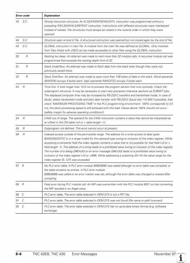
8–6 TNC 426B, TNC 430 Error Messages November 97
Error code Explanation
43 S C Wrong instruction structure. An ELSE/ENDI/ENDW/UNTIL instruction was programmed without apreceding IF/ELSE/WHILE/REPEAT instruction. Instructions with different structures were interleavedinstead of nested. The structures must always be closed in the reverse order in which they wereopened!
44 S C Structure open at end of file. A structured instruction was opened but not closed again by the end of file.
45 S C GLOBAL instruction in main file. A module from the main file was defined as GLOBAL. Only modulesfrom files linked with USES can be made accessible to other files using the GLOBAL instruction.
50 R Nesting too deep. An attempt was made to nest more than 32 module calls. A recursive module call wasprogrammed that exceeds the nesting depth limit of 32.
51 R Stack Underflow. An attempt was made to fetch data from the stack even though they were notpreviously saved there.
52 R Stack Overflow. An attempt was made to save more than 128 bytes of data to the stack. Word operands(B/W/D/K) occupy 4 bytes each, logic operands (M/I/O/T/C) occupy 2 bytes each.
53 R Time Out. It took longer than 10.5 ms to process the program section that runs cyclically. Check thesubprogram structure. It may be necessary to start very processor-intensive sections as SUBMIT jobs.The displayed computer time may be increased by RS-232-C transfers and handwheel mode. In case ofdoubt, select handwheel mode and start data transfer with RS-232-C (baud rate 115 000 if possible), thencheck "MAXIMUM PROCESSING TIME" in the PLC programming environment. 100% corresponds to 3.5ms, the block processing speed is still achieved with this load. Values above 150% should not occur(safety margin for adverse operating conditions!).
54 R CASE out of range. The operand for the CASE instruction contains a value that cannot be interpreted asan offset in the CM table (<0 or > table length –1).
55 R Subprogram not defined. This error cannot occur at present.
56 R Indexed access outside of the permissible range. The address for a write access to data typesB/W/D/M/I/O/T/C is in a range invalid for this operand type owing to inclusion of the index register. Whileaccessing a constants field the index register contains a value that is not possible for that field (<0 or >field length -1). The address of a string leads to a prohibited value owing to inclusion of the index register.The number of a dialog (S#Dn[X]) or an error message (S#En[X]) leads to a prohibited value owing toinclusion of the index register (<0 or >999). While addressing a substring (Sn^X) the value range for theindex register (0..127) was exceeded.
57 R No PLC error table. A PLC error module 9085/9086 was called although no error table was compiled, orthe table contains no entries. A PLC error module9085/9086 was called or an error marker was set, although the error table was changed or erased aftercompiling.
58 R Fatal error during PLC module call. An MP was overwritten with the PLC module 9031 so that convertingthe MP resulted in an illegal value.
90 C PLC error table. The error table selected in OEM.SYS is not a PET file.
91 C PLC error table. The error table selected in OEM.SYS was not found (file name or path incorrect).
92 C PLC error table. The error table selected in OEM.SYS has no up-to-date binary format (e.g. softwareexchange).
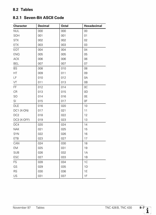
November 97 Tables TNC 426B, TNC 430 8–7
8.2 Tables
8.2.1 Seven-Bit ASCII Code
Character Decimal Octal Hexadecimal
NUL 000 000 00
SOH 001 001 01
STX 002 002 02
ETX 003 003 03
EOT 004 004 04
ENQ 005 005 05
ACK 006 006 06
BEL 007 007 07
BS 008 010 08
HT 009 011 09
LF 010 012 0A
VT 011 013 0B
FF 012 014 0C
CR 013 015 0D
SO 014 016 0E
SI 015 017 0F
DLE 016 020 10
DC1 (X-ON) 017 021 11
DC2 018 022 12
DC3 (X-OFF) 019 023 13
DC4 020 024 14
NAK 021 025 15
SYN 022 026 16
ETB 023 027 17
CAN 024 030 18
EM 025 031 19
SUB 026 032 1A
ESC 027 033 1B
FS 028 034 1C
GS 029 035 1D
RS 030 036 1E
US 031 037 1F
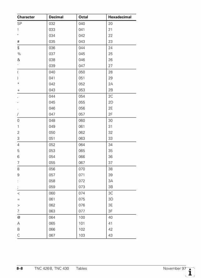
8–8 TNC 426B, TNC 430 Tables November 97
Character Decimal Octal Hexadecimal
SP 032 040 20
! 033 041 21
" 034 042 22
# 035 043 23
$ 036 044 24
% 037 045 25
& 038 046 26
´ 039 047 27
( 040 050 28
) 041 051 29
* 042 052 2A
+ 043 053 2B
, 044 054 2C
- 045 055 2D
. 046 056 2E
/ 047 057 2F
0 048 060 30
1 049 061 31
2 050 062 32
3 051 063 33
4 052 064 34
5 053 065 35
6 054 066 36
7 055 067 37
8 056 070 38
9 057 071 39
: 058 072 3A
; 059 073 3B
< 060 074 3C
= 061 075 3D
> 062 076 3E
? 063 077 3F
@ 064 100 40
A 065 101 41
B 066 102 42
C 067 103 43
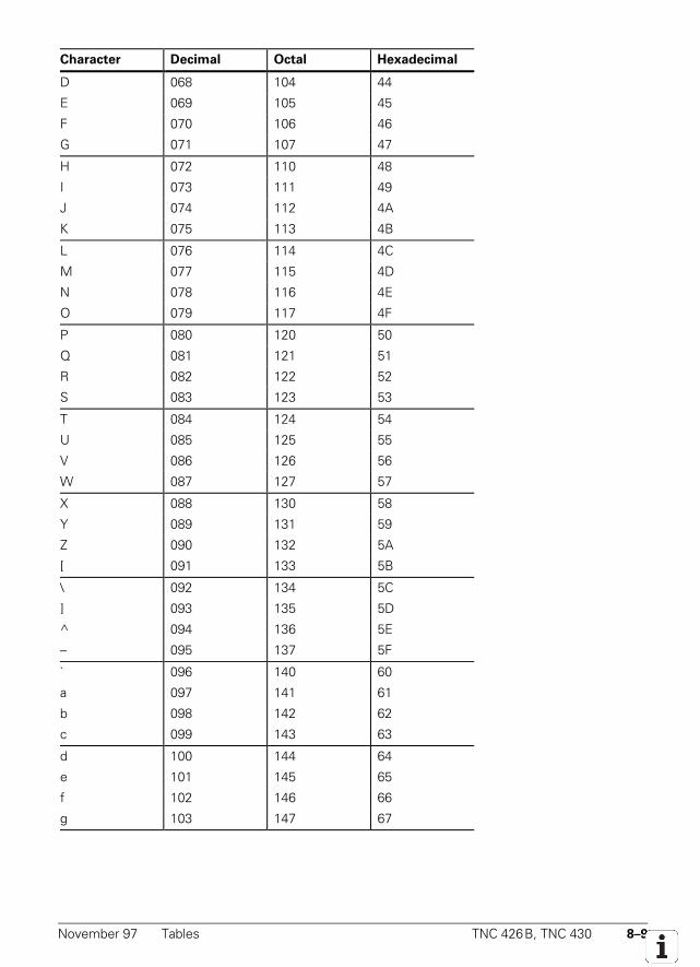
November 97 Tables TNC 426B, TNC 430 8–9
Character Decimal Octal Hexadecimal
D 068 104 44
E 069 105 45
F 070 106 46
G 071 107 47
H 072 110 48
I 073 111 49
J 074 112 4A
K 075 113 4B
L 076 114 4C
M 077 115 4D
N 078 116 4E
O 079 117 4F
P 080 120 50
Q 081 121 51
R 082 122 52
S 083 123 53
T 084 124 54
U 085 125 55
V 086 126 56
W 087 127 57
X 088 130 58
Y 089 131 59
Z 090 132 5A
[ 091 133 5B
\ 092 134 5C
] 093 135 5D
^ 094 136 5E
– 095 137 5F
` 096 140 60
a 097 141 61
b 098 142 62
c 099 143 63
d 100 144 64
e 101 145 65
f 102 146 66
g 103 147 67
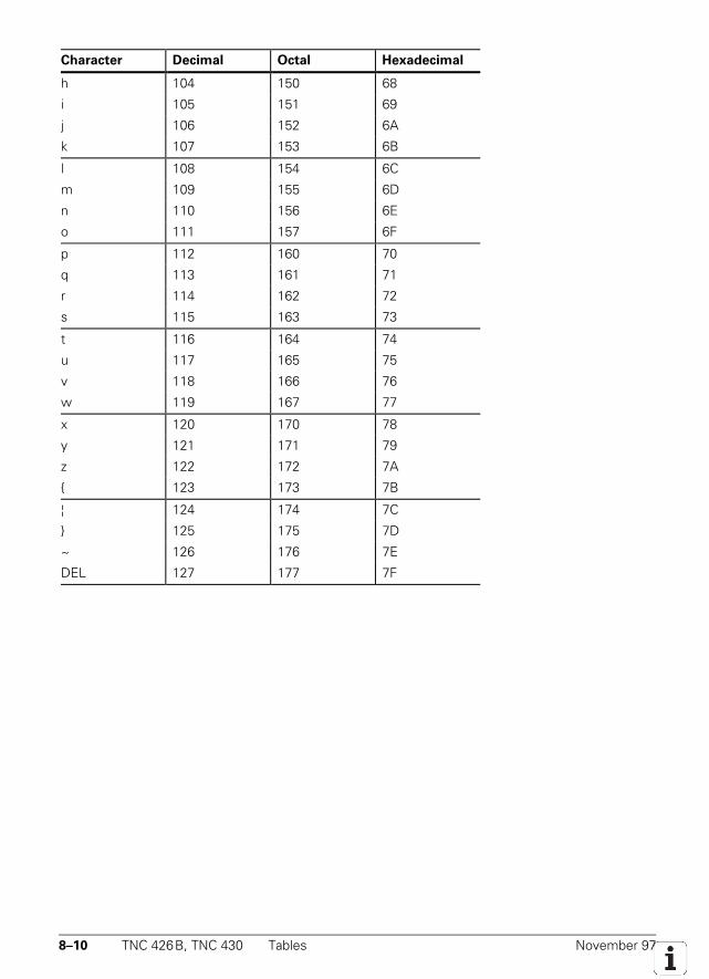
8–10 TNC 426B, TNC 430 Tables November 97
Character Decimal Octal Hexadecimal
h 104 150 68
i 105 151 69
j 106 152 6A
k 107 153 6B
l 108 154 6C
m 109 155 6D
n 110 156 6E
o 111 157 6F
p 112 160 70
q 113 161 71
r 114 162 72
s 115 163 73
t 116 164 74
u 117 165 75
v 118 166 76
w 119 167 77
x 120 170 78
y 121 171 79
z 122 172 7A
123 173 7B
¦ 124 174 7C
125 175 7D
~ 126 176 7E
DEL 127 177 7F
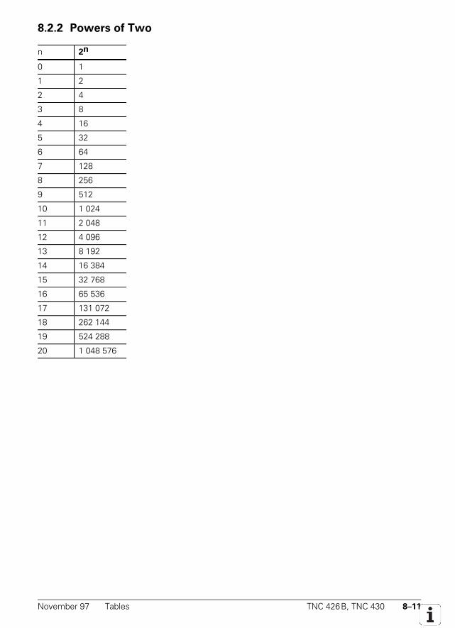
November 97 Tables TNC 426B, TNC 430 8–11
8.2.2 Powers of Two
n 2n
0 1
1 2
2 4
3 8
4 16
5 32
6 64
7 128
8 256
9 512
10 1 024
11 2 048
12 4 096
13 8 192
14 16 384
15 32 768
16 65 536
17 131 072
18 262 144
19 524 288
20 1 048 576
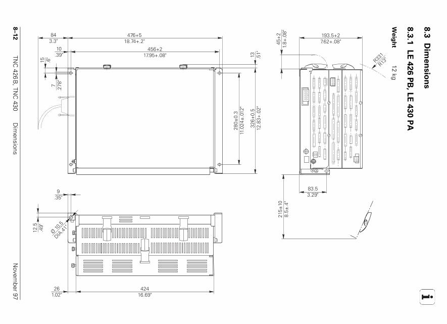
8–12
TNC
426B
, TNC
430D
imensions
Novem
ber 97
8.3
D
ime
nsio
ns
8.3
.1
LE
42
6 P
B, L
E 4
30
PA
Weig
ht
12 kg10
.39"
843.3"
15 .6"
7.2
78"
476+518.74+.2"
456+217.95+.08" 13 .5
1"
280±
0.3
11.0
24±
.012
"
326+
0.5
12.8
3+.0
2"
9.35"
12.5
.49"
Ø 10,5
DIA.41
"
261.02"
42416.69"
45+
21.
8+.0
8" 193.5+27.62+.08"
R331
R13"
83.53.29"
215±
108.
5±.4
"
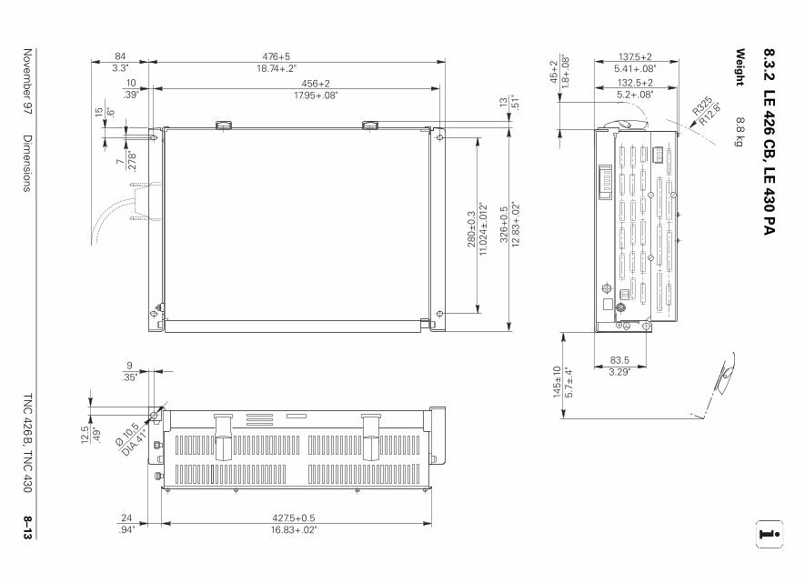
N
ovember 97
Dim
ensionsTN
C 426
B, TN
C 430
8–13
8.3
.2
LE
426 C
B, L
E 4
30 P
A
Weig
ht
8.8 kg
10.39"
843.3"
15 .6"
7.2
78"
476+518.74+.2"
456+217.95+.08"
13 .51"
280±
0.3
11.0
24±
.012
"
326+
0.5
12.8
3+.0
2"
9.35"
12.5
.49"
Ø 10,5
DIA.41
"
24.94"
427.5+0.516.83+.02"
45+
21.
8+.0
8" 137.5+25.41+.08"
R325
R12.8"
83.53.29"
145±
105.
7±.4
"
132.5+25.2+.08"
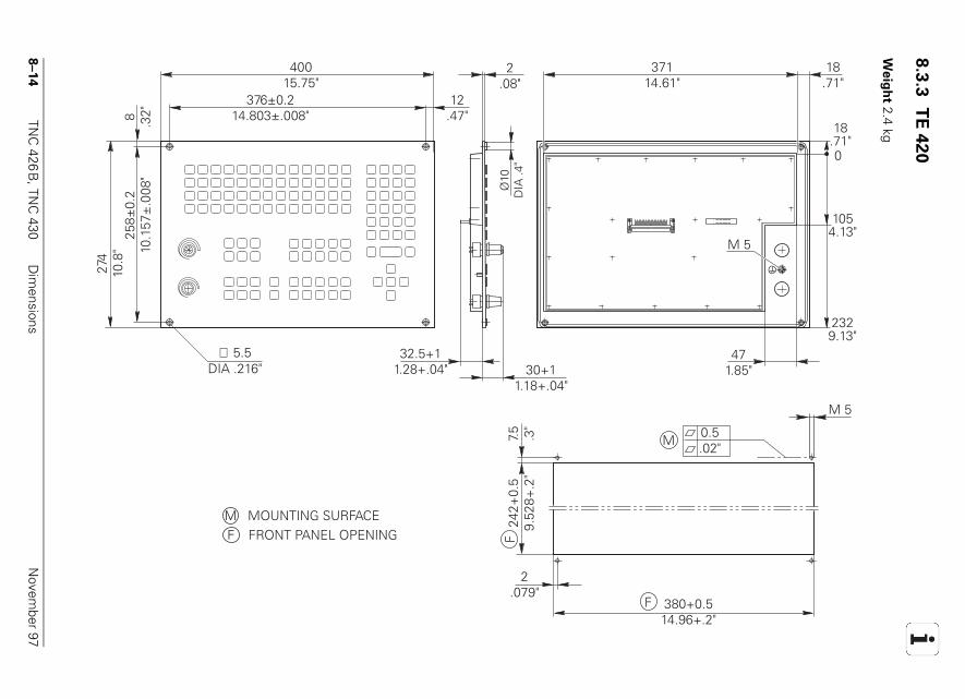
8–14
TNC
426B
, TNC
430D
imensions
Novem
ber 97
8.3
.3
TE
42
0
Weig
ht 2.4 kg
40015.75"
258±
0.2
10.1
57±
.008
"
274
10.8
"376±0.2
14.803±.008"12
.47"
37114.61"
2329.13"
18.71"
2.08"
32.5+11.28+.04" 30+1
1.18+.04"
380+0.514.96+.2"
242+
0.5
9.52
8+.2
"7.
5 .3"
M 5
0.5.02"
M 5
2.079"
0
M
8 .32"
18.71"
1054.13"
471.85"
F
F
∅ 5.5DIA .216"
M
F
Ø10
DIA
.4"
F FRONT PANEL OPENINGM MOUNTING SURFACE
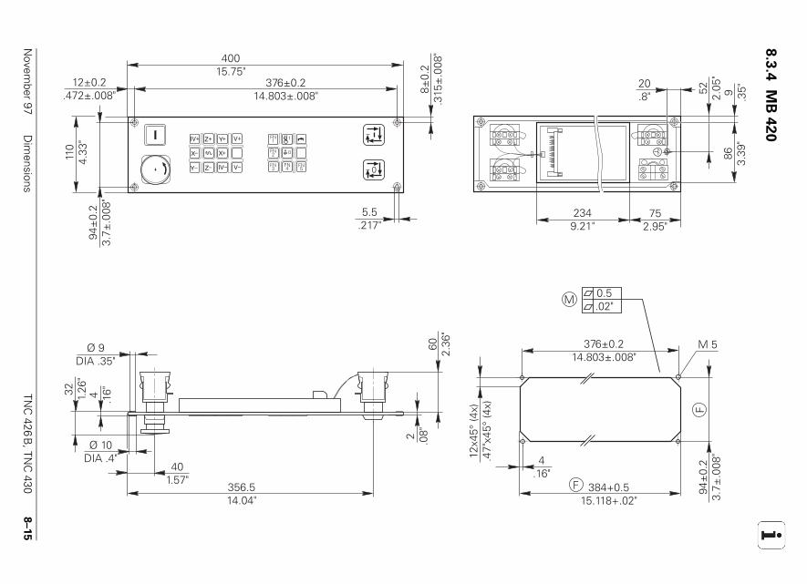
N
ovember 97
Dim
ensionsTN
C 426
B, TN
C 430
8–15
8.3
.4
MB
420
0FN3
FN1
FN2
1
FN4
FN5
0
Z+
Z–
IV+
IV–
X+X–
Y+
Y– V–
V+
5.5.217"
94±
0.2
3.7±
.008
"
110
4.33
"
40015.75"
376±0.214.803±.008"
12±0.2.472±.008" 8±
0.2
.315
±.0
08"
86 3.39
"9 .35"52 2.05
"
2349.21"
752.95"
20.8"
356.514.04"
401.57"
Ø 10DIA .4"
60 2.36
"
32 1.26
"
Ø 9DIA .35"
4 .16"
384+0.515.118+.02"
376±0.214.803±.008"
94±
0.2
3.7±
.008
"
M 5
0.5.02"
2 .08"
4.16"
12x4
5° (4
x).4
7"x4
5° (4
x)
M
F
F
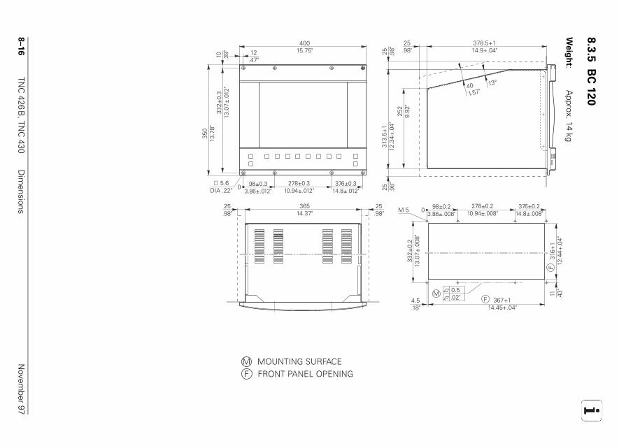
8–16
TNC
426B
, TNC
430D
imensions
Novem
ber 97
8.3
.5
BC
120
Weig
ht:
Approx. 14 kg
12.47"
010 .39"
40015.75"
332±
0.3
13.0
7±.0
12"
350
13.7
8"
∅ 5.6DIA .22"
F31
6+1
12.4
4+.0
4"
98±0.23.86±.008"
278±0.210.94±.008"
376±0.214.8±.008"
367+114.45+.04"
F4.5.18"
M 5
11 .43"
332±
0.2
13.0
7±.0
08"
98±0.33.86±.012"
278±0.310.94±.012"
376±0.314.8±.012"
0
378.5+114.9+.04"
25.98"
313.
5+1
12.3
4+.0
4"25
29.
92"
25 .98"
25 .98"
36514.37"
25.98"
25.98"
401.57"
13°
0.5.02"
M
F FRONT PANEL OPENINGM MOUNTING SURFACE
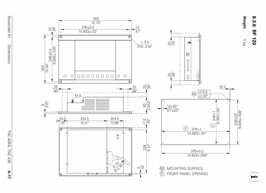
N
ovember 97
Dim
ensionsTN
C 426
B, TN
C 430
8–17
8.3
.6
BF 1
20
Weig
ht:
3 kg
12.47"
238
9.37
"
M 5
0
10 .39"
40015.75"
376±0.514.803±.02"
246±
0.4
9.68
5±.0
16"
264
10.3
9"∅ 5.5
DIA .216"
20 .79"
25 .98"
376+114.803+.04"
248+
19.
763+
.04"
M 50.5.02"
M
F
F
376+0.214.803+.008"
246±
029.
685±
.008
"
45.51.8"
264.510.41"
354.513.96"
5 .18"
11.5
.45"
R 70R 2.
76"
25.98"
25.98"
12x45°.47"x45°
25 .98"
903.
543"
8.3
15"
F FRONT PANEL OPENINGM MOUNTING SURFACE
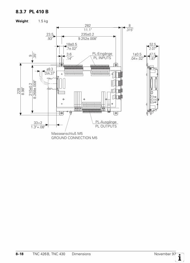
8–18 TNC 426B, TNC 430 Dimensions November 97
8.3.7 PL 410 B
Weight: 1.5 kg
47.51.87"
23.5.93"
18±0.5.7±.02"
3.6.14"
Masseanschluß M5GROUND CONNECTION M5
235±0.29.252±.008"
28211.1"
1±0.5.04+.02"
52.52.07"
33+21.3"+.08"
9 .35"
228
8.98
"
210±
0.2
8.26
8±.0
08"
ø9.3DIA.37"
PL-EingängePL INPUTS
PL-AusgängePL OUTPUTS
8.315"
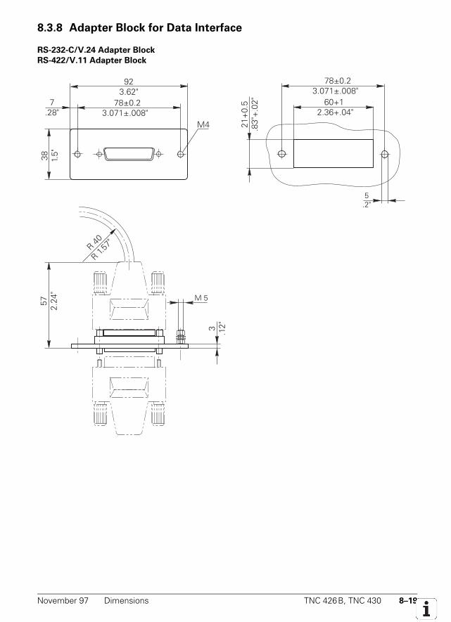
November 97 Dimensions TNC 426B, TNC 430 8–19
8.3.8 Adapter Block for Data Interface
RS-232-C/V.24 Adapter Block
RS-422/V.11 Adapter Block
78±0.23.071±.008" 60+12.36+.04"
5.2"
21+
0.5
.83"
+.0
2" 78±0.23.071±.008"
7.28"
M4
38 1.5"
923.62"
57 2.24
"
M 5
3 .12"
R 40
R 1.57
"
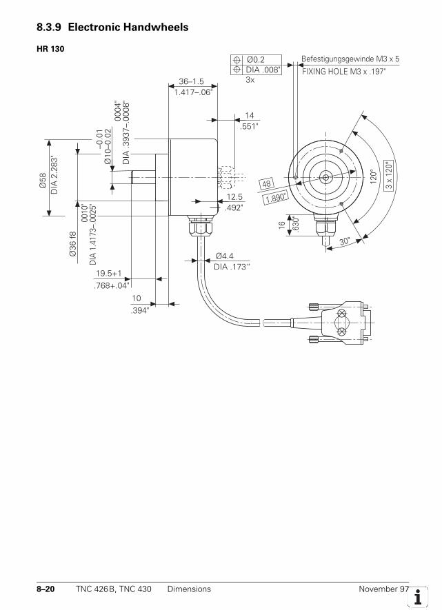
8–20 TNC 426B, TNC 430 Dimensions November 97
8.3.9 Electronic Handwheels
HR 130
DIA
.393
7–.0
004"
DIA
.393
7–.0
008"
Ø10
–0.0
1Ø
10–0
.02
Ø36
f8
DIA
1.4
173–
.001
0"D
IA 1
.417
3–.0
025"
DIA
2.2
83"
Ø58
1.417–.06"36–1.5
.551"14
.492"12.5
DIA .173“Ø4.4
120°
3 x
120°
30°
48
1.890"
16 .630
"
FIXING HOLE M3 x .197"
Befestigungsgewinde M3 x 5Ø0.2DIA .008"3x
19.5+1.768+.04"
10.394"
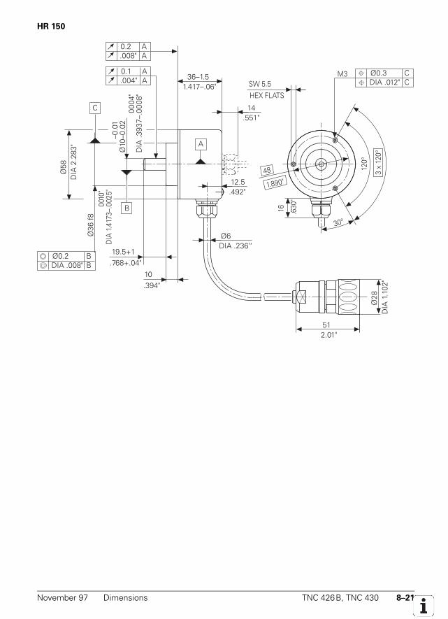
November 97 Dimensions TNC 426B, TNC 430 8–21
HR 150
DIA
.393
7–.0
004"
DIA
.393
7–.0
008"
Ø10
–0.0
1Ø
10–0
.02
Ø36
f8
DIA
1.4
173–
.001
0"D
IA 1
.417
3–.0
025"
DIA
2.2
83"
Ø58
1.417–.06"36–1.5
.551"14
.492"12.5
DIA .236“Ø6
120°
3 x
120°
30°
48
1.890"
16 .630
"
HEX FLATS
SW 5.5
19.5+1.768+.04"
10.394"
2.01"51
C
B
A
0.2.008"
AA
0.1.004"
AA
M3
Ø0.2DIA .008"
BB
Ø0.3DIA .012"
CC
DIA
1.1
02"
Ø28
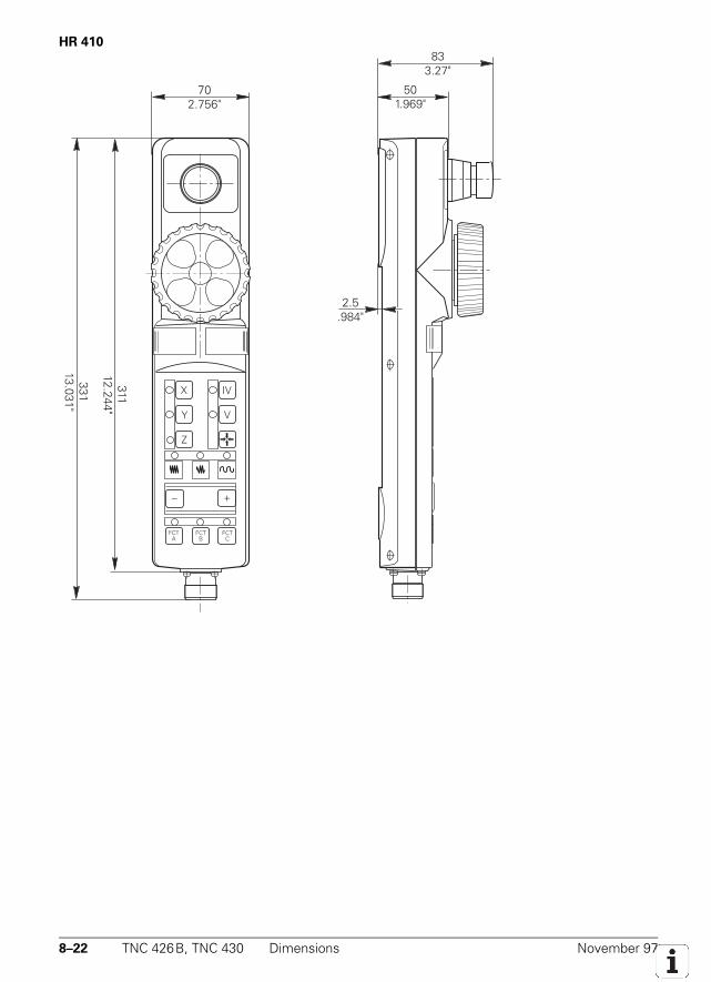
8–22 TNC 426B, TNC 430 Dimensions November 97
HR 410
–
Z
Y
X
+
V
IV
FCTC
FCTB
FCTA
33113.031"
702.756"
31112.244"
833.27"
501.969"
2.5.984"
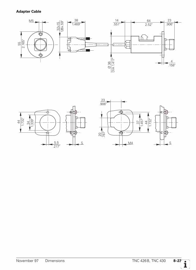
November 97 Dimensions TNC 426B, TNC 430 8–23
Adapter Cable
14.551"
23.906"
Ø 3
6D
IA 1
.417
"
4.158"
32x1
51.2
6x.5
9" 381.469"
M555
2.16
5"44
1.73
2"
341.
339"
5.5.217"
S M4
20 .787
"23
.906"
371.
457"
441.
732"
S
64 2.52"
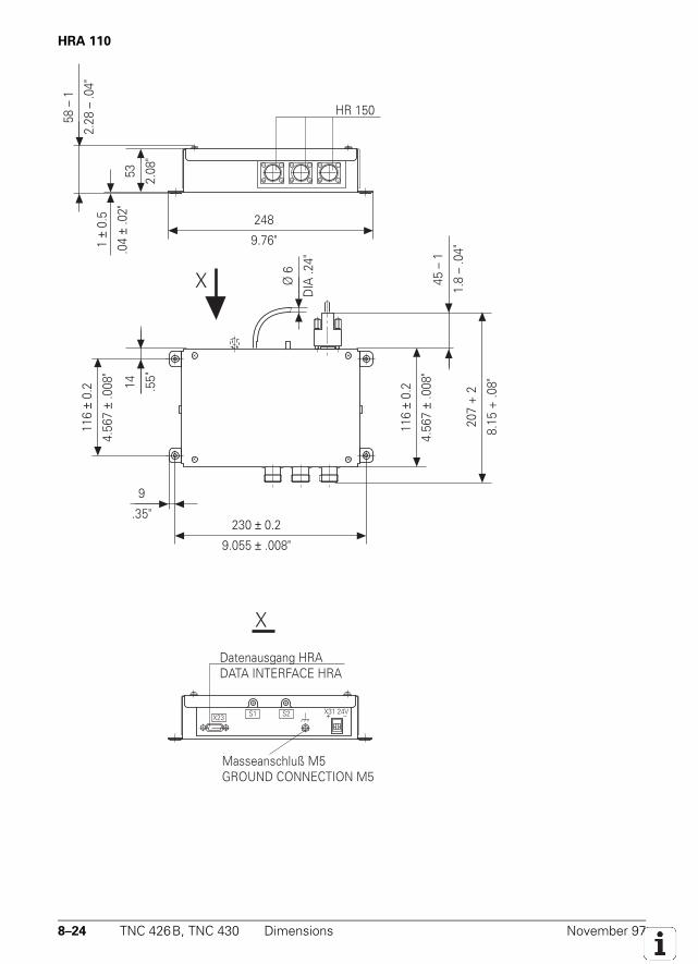
8–24 TNC 426B, TNC 430 Dimensions November 97
HRA 110
116
± 0.
2
4.56
7 ±
.008
"
14 .55"
230 ± 0.2
9.055 ± .008"
9
.35"
116
± 0.
2
4.56
7 ±
.008
"
207
+ 2
8.15
+ .0
8"
45 –
1
1.8
– .0
4"
Ø 6
DIA
.24"
58 –
1
2.28
– .0
4"
53 2.08
"
1 ±
0.5
.04
± .0
2"
248
9.76"
HR 150
X
Masseanschluß M5GROUND CONNECTION M5
Datenausgang HRADATA INTERFACE HRA
X31 24V+ –X23 S1 S2
X
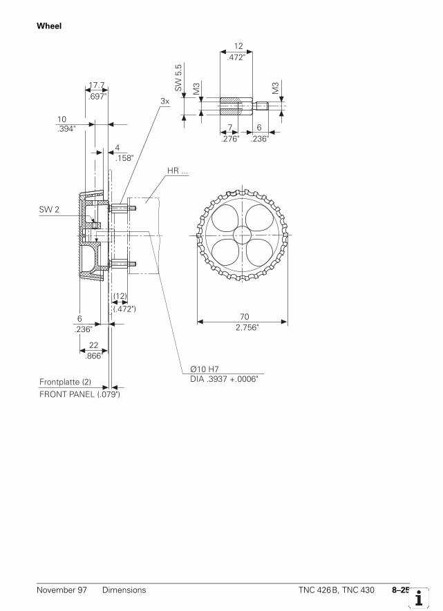
November 97 Dimensions TNC 426B, TNC 430 8–25
Wheel
7
M3
6.236".276"
M3
12.472"
SW
5.5
HR ...
Ø10 H7
(12)
(.472")
Frontplatte (2)FRONT PANEL (.079")
702.756"
4.158"
10.394"
SW 2
17.7.697"
22.866"
.236"6
DIA .3937 +.0006"
3x
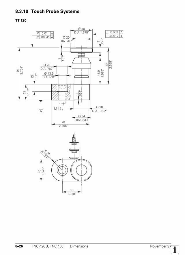
8–26 TNC 426B, TNC 430 Dimensions November 97
8.3.10 Touch Probe Systems
TT 120
Ø 28DIA 1.102"
Ø 34DIA1.339"
702.756"
1.0
39"
13 .512
"
281.
102"
943.
701"
A
Ø 20DIA .787"
Ø 40DIA 1.575"
4.1
57"
7.2
75"
48.9
1.92
5"66
2.59
8"
Ø 13.5DIA .531"
401.
575"
351.378"
R 20R .787"
Ø 20DIA .787"
0.003 .00012"
AA
0.01 .0004"
////
AA
M 12
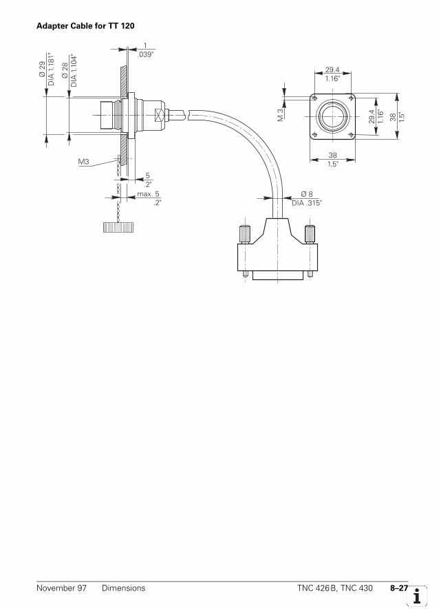
November 97 Dimensions TNC 426B, TNC 430 8–27
Adapter Cable for TT 120
M3
Ø 2
8D
IA 1
.104
"
1.039"
5.2"
max. 5 .2"
Ø 2
9D
IA 1
.181
"
Ø 8DIA .315"
381.5"
38 1.5"
29.41.16"
29.4
1.16
"
M 3
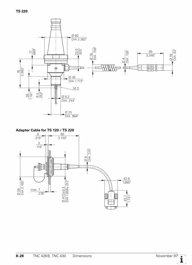
8–28 TNC 426B, TNC 430 Dimensions November 97
TS 220
Ø 60DIA 2.362"
Ø 45DIA 1.772"
Ø 25DIA .984"
M 3
6.4
.252
"
301.
181"
762.
992"
23.5
.925
"
17 .669
"
Ø 6.2DIA .244"
Ø 4
DIA
.158
"
Ø 1
6D
IA .6
3"853.346"
Ø 1
8D
IA .7
09"
Ø 2
8D
IA 1
.10"51
2.008"
Adapter Cable for TS 120 / TS 220
Ø 4
7.2±
0.3
DIA
1.8
58±
.012
"
803.150"
8.315"
3.118"
Ø 5
5D
IA 2
.165
"
max. 7 .276"
Ø 8
DIA
.315
"
43.7
1.72
1"
42.81.685"
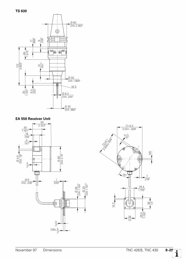
November 97 Dimensions TNC 426B, TNC 430 8–29
TS 630
Ø 60DIA 2.362"
Ø 50DIA 1.969"
6.4
.252
"
301.
181"
122
4.80
3"
6.2
36"
17 .669
"
401.
575"
14 .551
"
Ø 25DIA .984"
M 3
Ø 6.2DIA .244"
EA 550 Receiver Unit
Ø 6DIA .236"
4.157"
18.709"
301.181"
592.323"
Ø 8
0D
IA 3
.15"
5.2"
72±0
.12.
835±
.004
"
4.1
57"
77–0.23.031–.008"
M5
7.276"
35°
Ø 4
.5D
IA .1
8"
5.2"
max. 5 .2"
Ø 2
9D
IA 1
.181
"
Ø 2
8D
IA 1
.104
"
1.039"
381.5"
38 1.5"
29.41.155"
29.4
1.15
5"
M 3

8–30 TNC 426B, TNC 430 Dimensions November 97
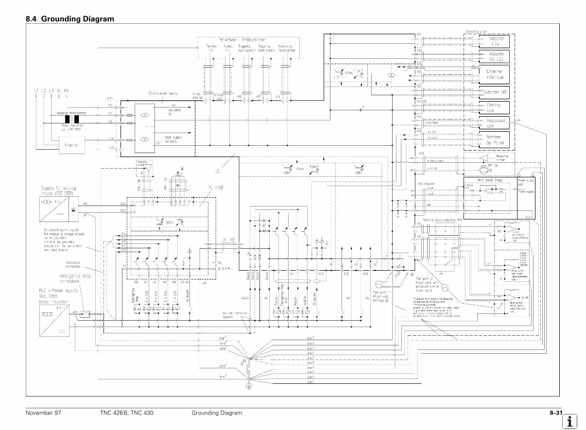
November 97 TNC 426B, TNC 430 Grounding Diagram 8–31
8.4 Grounding Diagram
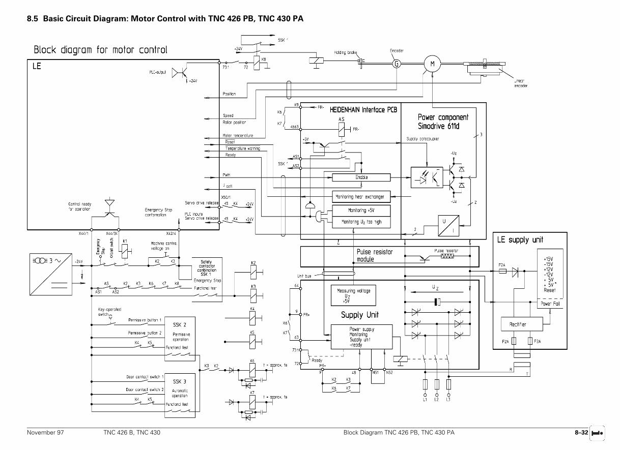
November 97 TNC 426 B, TNC 430 Block Diagram TNC 426 PB, TNC 430 PA 8–32
8.5 Basic Circuit Diagram: Motor Control with TNC 426 PB, TNC 430 PA
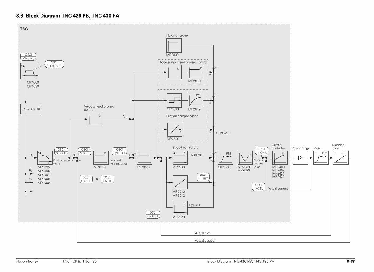
November 97 TNC 426 B, TNC 430 Block Diagram TNC 426 PB, TNC 430 PA 8–33
8.6 Block Diagram TNC 426 PB, TNC 430 PA
TNC
MP2610 MP2612
MP2620
––
+sx
sy
sz
MP1060MP1090
t
v
MP2520
MP2530
+
+ PI
MP2400MP2402MP2421MP2431
+–
MP1510
I
n
PT1
n
P
MP2500
P
I
MP2510MP2512
PT2 PT2
MP2540MP2550
D
I (N PROP)
OSCII (N INT)
Motor
I (N DIFF)
ssx
OSCIS SOLL
D
MP2600
P
t
OSCIS DIFF
OSCIV (N SOLL)
s = s0 + v . ∆t
D Vx
MP1095MP1096MP1097MP1098MP1099
MP2020
+ + ++
+
+
+
+
+
+
MP2630
Velocity feedforward control
Friction compensation
Speed controllers
Position nominal value
Current controller
Nominal current value
Actual current
Power stage
Actual position
Actual rpm
Machine slide
OSCIV NOML
Nominal velocity value
OSCII NOML
OSCII ACTL
OSCIV(N ACTL)
OSCIS ACTL
OSCIV ACTL
OSCIFEED RATE
Acceleration feedforward control
Holding torque
I (FDFWD)
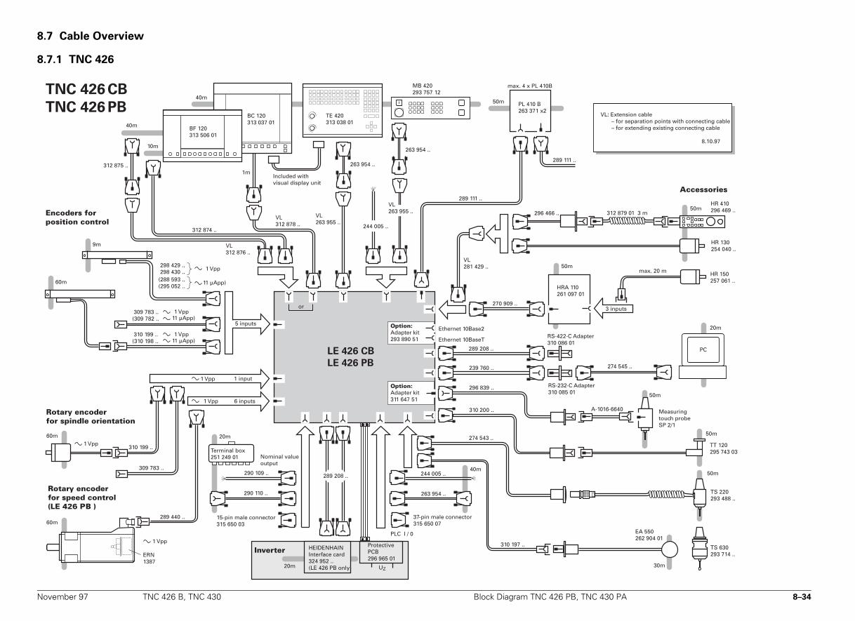
November 97 TNC 426 B, TNC 430 Block Diagram TNC 426 PB, TNC 430 PA 8–34
8.7 Cable Overview
8.7.1 TNC 426
9m
40m
50m
50m
50m
263 954 ..
40m244 005 ..
290 110 ..
309 783 ..(309 782 ..
60m
VL263 955 ..
HR 150257 061 ..
max. 20 m
HR 130254 040 ..
HR 410296 469 ..
HRA 110261 097 01
270 909 ..
VL281 429 ..
296 466 ..
20m
290 109 ..
TNC 426 CB
TNC 426 PB
20m
263 954 ..
TT 120295 743 03
310 197 ..
30m
TS 630293 714 ..
EA 550 262 904 01
274 543 ..
310 200 ..
50m
TS 220293 488 ..
289 208 ..
263 954 ..
244 005 ..
10m
40m
BC 120313 037 01
60m
310 199 ..
60m
289 440 ..
309 783 ..
ERN1387
TE 420313 038 01
289 111 ..
239 760 ..
289 208 ..
20m
PCLE 426 CB
LE 426 PB
UZ
274 545 ..
298 429 ..298 430 ..
310 199 ..(310 198 ..
(288 593 ..(295 052 ..
A-1016-6640
296 839 ..50m
VL263 955 ..
BF 120313 506 01
VL312 878 ..
VL312 876 ..
312 874 ..
312 875 ..
50m PL 410 B263 371 x2
289 111 ..
1m
312 879 01 3 m
MB 420 293 757 12
1 Vpp
6 inputs
5 inputs
1 Vpp
15-pin male connector 315 650 03
HEIDENHAINInterface card324 952 ..(LE 426 PB only)
Rotary encoderfor spindle orientation
Encoders forposition control
Nominal value output
PLC I / 0
37-pin male connector315 650 07
RS-232-C Adapter310 085 01
Accessories
VL: Extension cable – for separation points with connecting cable – for extending existing connecting cable
8.10.97
RS-422-C Adapter310 086 01
Rotary encoderfor speed control(LE 426 PB )
Measuringtouch probeSP 2/1
Terminal box251 249 01
1 Vpp
Option:Adapter kit293 890 51
3 inputs1 Vpp
1 Vpp
1 Vpp
11 µApp)
11 µApp)
11 µApp)
1 input
or
Option:Adapter kit311 647 51
InverterProtectivePCB296 965 01
1 Vpp
Included withvisual display unit
max. 4 x PL 410B
Ethernet 10Base2
Ethernet 10BaseT
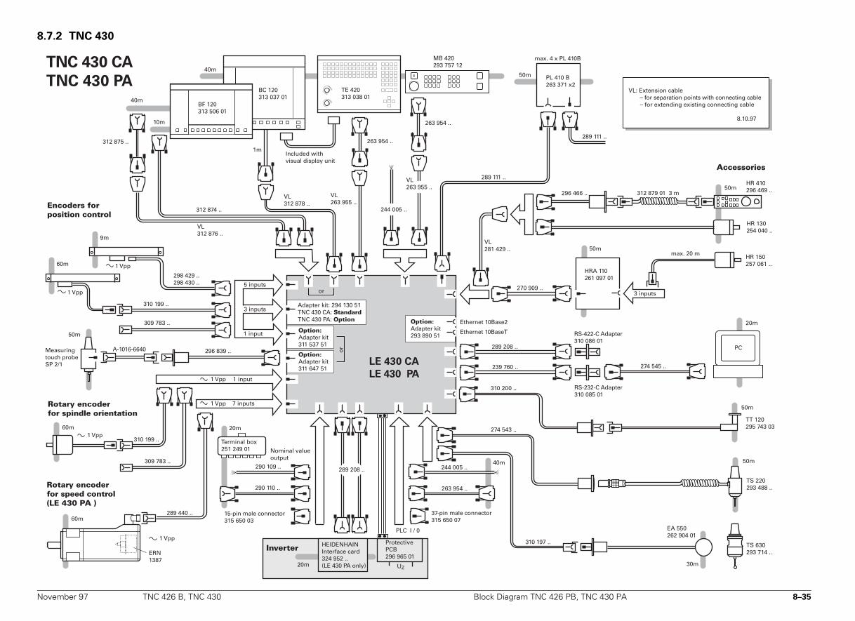
November 97 TNC 426 B, TNC 430 Block Diagram TNC 426 PB, TNC 430 PA 8–35
8.7.2 TNC 430
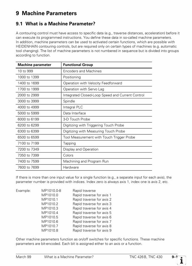
March 99 What is a Machine Parameter? TNC 426B, TNC 430 9–1
9 Machine Parameters
9.1 What is a Machine Parameter?
A contouring control must have access to specific data (e.g., traverse distances, acceleration) before itcan execute its programmed instructions. You define these data in so-called machine parameters.In addition, machine parameters can be used to activated certain functions, which are possible withHEIDENHAIN contouring controls, but are required only on certain types of machines (e.g. automatictool changing). The list of machine parameters is not numbered in sequence but is divided into groupsaccording to function.
Machine parameter Functional Group
10 to 999 Encoders and Machines
1000 to 1399 Positioning
1400 to 1699 Operation with Velocity Feedforward
1700 to 1999 Operation with Servo Lag
2000 to 2999 Integrated Closed-Loop Speed and Current Control
3000 to 3999 Spindle
4000 to 4999 Integral PLC
5000 to 5999 Data Interface
6000 to 6199 3-D Touch Probe
6200 to 6299 Digitizing with Triggering Touch Probe
6300 to 6399 Digitizing with Measuring Touch Probe
6500 to 6599 Tool Measurement with Touch Trigger Probe
7100 to 7199 Tapping
7200 to 7349 Display and Operation
7350 to 7399 Colors
7400 to 7599 Machining and Program Run
7600 to 7699 Hardware
If there is more than one input value for a single function (e.g., a separate input for each axis), theparameter number is provided with indices. Index zero is always axis 1, index one is axis 2, etc.
Example: MP1010.0-8 Rapid traverseMP1010.0 Rapid traverse for axis 1MP1010.1 Rapid traverse for axis 2MP1010.2 Rapid traverse for axis 3MP1010.3 Rapid traverse for axis 4MP1010.4 Rapid traverse for axis 5MP1010.5 Rapid traverse for axis 6MP1010.6 Rapid traverse for axis 7MP1010.7 Rapid traverse for axis 8MP1010.8 Rapid traverse for axis 9
Other machine parameters function as on/off switches for specific functions. These machineparameters are bit-encoded. Each bit is assigned either to an axis or a function.
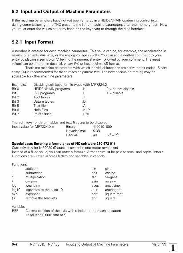
9–2 TNC 426B, TNC 430 Input and Output of Machine Parameters March 99
9.2 Input and Output of Machine Parameters
If the machine parameters have not yet been entered in a HEIDENHAIN contouring control (e.g.,during commissioning), the TNC presents the list of machine parameters after the memory test. Nowyou must enter the values either by hand on the keyboard or through the data interface.
9.2.1 Input Format
A number is entered for each machine parameter. This value can be, for example, the acceleration inmm/s2 of an individual axis, or the analog voltage in volts. You can add a written comment to yourentry by placing a semicolon ";" behind the numerical entry, followed by your comment. The inputvalues can be entered in decimal, binary (%) or hexadecimal ($) format.
There are machine parameters with which individual functions are activated bit-coded. Binaryentry (%) is recommended for these machine parameters. The hexadecimal format ($) may beadvisable for other machine parameters.
Example: Disabling soft keys for file types with MP7224.0.Bit 0 HEIDENHAIN programs .H 0 = do not disableBit 1 ISO programs .I 1 = disableBit 2 Tool tables .TBit 3 Datum tables .DBit 5 Text files .ABit 6 Help files .HLPBit 7 Point tables .PNT
The soft keys for datum tables and text files are to be disabled.Input value for MP7224.0 = Binary %00101000
Hexadecimal $ 38Decimal 40 (23 + 25)
Special case: Entering a formula (as of NC software 280 472 01)
Currently only for MP2020 (Distance covered in one motor revolution)Instead of a fixed value, you can enter a formula. Attention must be paid to small and capital letters.Functions are written in small letters and variables in capitals.
Functions:+ addition– subtraction* multiplication/ divisionlog logarithmlog10 logarithm to the base 10exp exponent( ) remove the brackets
sin sinecos cosinetan tangentasin arcsineacos arccosineatan arctangentsqrt square rootsqr square
Variable:REF Current position of the axis with relation to the machine datum
(resolution 0.0001mm or °)
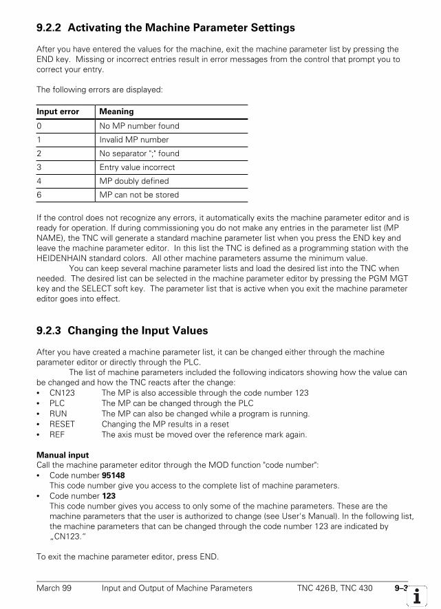
March 99 Input and Output of Machine Parameters TNC 426B, TNC 430 9–3
9.2.2 Activating the Machine Parameter Settings
After you have entered the values for the machine, exit the machine parameter list by pressing theEND key. Missing or incorrect entries result in error messages from the control that prompt you tocorrect your entry.
The following errors are displayed:
Input error Meaning
0 No MP number found
1 Invalid MP number
2 No separator ";" found
3 Entry value incorrect
4 MP doubly defined
6 MP can not be stored
If the control does not recognize any errors, it automatically exits the machine parameter editor and isready for operation. If during commissioning you do not make any entries in the parameter list (MPNAME), the TNC will generate a standard machine parameter list when you press the END key andleave the machine parameter editor. In this list the TNC is defined as a programming station with theHEIDENHAIN standard colors. All other machine parameters assume the minimum value.
You can keep several machine parameter lists and load the desired list into the TNC whenneeded. The desired list can be selected in the machine parameter editor by pressing the PGM MGTkey and the SELECT soft key. The parameter list that is active when you exit the machine parametereditor goes into effect.
9.2.3 Changing the Input Values
After you have created a machine parameter list, it can be changed either through the machineparameter editor or directly through the PLC.
The list of machine parameters included the following indicators showing how the value canbe changed and how the TNC reacts after the change:• CN123 The MP is also accessible through the code number 123• PLC The MP can be changed through the PLC• RUN The MP can also be changed while a program is running.• RESET Changing the MP results in a reset• REF The axis must be moved over the reference mark again.
Manual input
Call the machine parameter editor through the MOD function "code number":• Code number 95148
This code number give you access to the complete list of machine parameters.• Code number 123
This code number gives you access to only some of the machine parameters. These are themachine parameters that the user is authorized to change (see User's Manual). In the following list,the machine parameters that can be changed through the code number 123 are indicated by„CN123.“
To exit the machine parameter editor, press END.
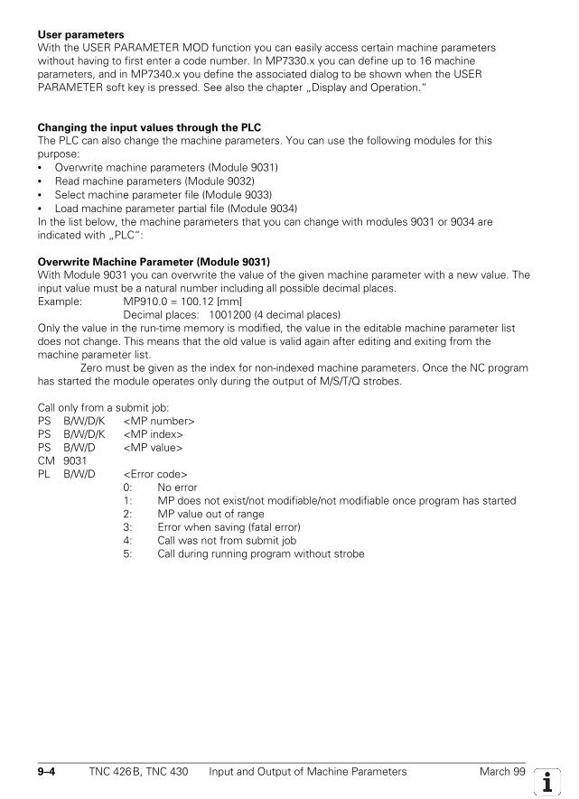
9–4 TNC 426B, TNC 430 Input and Output of Machine Parameters March 99
User parameters
With the USER PARAMETER MOD function you can easily access certain machine parameterswithout having to first enter a code number. In MP7330.x you can define up to 16 machineparameters, and in MP7340.x you define the associated dialog to be shown when the USERPARAMETER soft key is pressed. See also the chapter „Display and Operation.“
Changing the input values through the PLC
The PLC can also change the machine parameters. You can use the following modules for thispurpose:• Overwrite machine parameters (Module 9031)• Read machine parameters (Module 9032)• Select machine parameter file (Module 9033)• Load machine parameter partial file (Module 9034)In the list below, the machine parameters that you can change with modules 9031 or 9034 areindicated with „PLC“:
Overwrite Machine Parameter (Module 9031)
With Module 9031 you can overwrite the value of the given machine parameter with a new value. Theinput value must be a natural number including all possible decimal places.Example: MP910.0 = 100.12 [mm]
Decimal places: 1001200 (4 decimal places)Only the value in the run-time memory is modified, the value in the editable machine parameter listdoes not change. This means that the old value is valid again after editing and exiting from themachine parameter list.
Zero must be given as the index for non-indexed machine parameters. Once the NC programhas started the module operates only during the output of M/S/T/Q strobes.
Call only from a submit job:PS B/W/D/K <MP number>PS B/W/D/K <MP index>PS B/W/D <MP value>CM 9031PL B/W/D <Error code>
0: No error1: MP does not exist/not modifiable/not modifiable once program has started2: MP value out of range3: Error when saving (fatal error)4: Call was not from submit job5: Call during running program without strobe
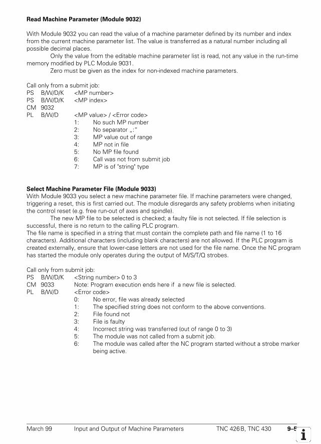
March 99 Input and Output of Machine Parameters TNC 426B, TNC 430 9–5
Read Machine Parameter (Module 9032)
With Module 9032 you can read the value of a machine parameter defined by its number and indexfrom the current machine parameter list. The value is transferred as a natural number including allpossible decimal places.
Only the value from the editable machine parameter list is read, not any value in the run-timememory modified by PLC Module 9031.
Zero must be given as the index for non-indexed machine parameters.
Call only from a submit job:PS B/W/D/K <MP number>PS B/W/D/K <MP index>CM 9032PL B/W/D <MP value> / <Error code>
1: No such MP number2: No separator „:“3: MP value out of range4: MP not in file5: No MP file found6: Call was not from submit job7: MP is of "string" type
Select Machine Parameter File (Module 9033)
With Module 9033 you select a new machine parameter file. If machine parameters were changed,triggering a reset, this is first carried out. The module disregards any safety problems when initiatingthe control reset (e.g. free run-out of axes and spindle).
The new MP file to be selected is checked; a faulty file is not selected. If file selection issuccessful, there is no return to the calling PLC program.The file name is specified in a string that must contain the complete path and file name (1 to 16characters). Additional characters (including blank characters) are not allowed. If the PLC program iscreated externally, ensure that lower-case letters are not used for the file name. Once the NC programhas started the module only operates during the output of M/S/T/Q strobes.
Call only from submit job:PS B/W/D/K <String number> 0 to 3CM 9033 Note: Program execution ends here if a new file is selected.PL B/W/D <Error code>
0: No error, file was already selected1: The specified string does not conform to the above conventions.2: File found not3: File is faulty4: Incorrect string was transferred (out of range 0 to 3)5: The module was not called from a submit job.6: The module was called after the NC program started without a strobe marker
being active.
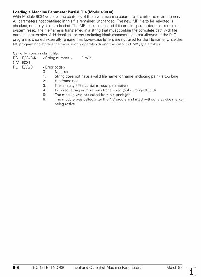
9–6 TNC 426B, TNC 430 Input and Output of Machine Parameters March 99
Loading a Machine Parameter Partial File (Module 9034)
With Module 9034 you load the contents of the given machine parameter file into the main memory.All parameters not contained in this file remained unchanged. The new MP file to be selected ischecked; no faulty files are loaded. The MP file is not loaded if it contains parameters that require asystem reset. The file name is transferred in a string that must contain the complete path with filename and extension. Additional characters (including blank characters) are not allowed. If the PLCprogram is created externally, ensure that lower-case letters are not used for the file name. Once theNC program has started the module only operates during the output of M/S/T/Q strobes.
Call only from a submit file:PS B/W/D/K <String number > 0 to 3CM 9034PL B/W/D <Error code>
0: No error1: String does not have a valid file name, or name (including path) is too long2: File found not3: File is faulty / File contains reset parameters4: Incorrect string number was transferred (out of range 0 to 3)5: The module was not called from a submit job.6: The module was called after the NC program started without a strobe marker
being active.
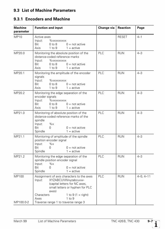
March 99 List of Machine Parameters TNC 426B, TNC 430 9–7
9.3 List of Machine Parameters
9.3.1 Encoders and Machine
Machine
parameter
Function and input Change via Reaction Page
MP10 Active axesInput: %xxxxxxxxxBit 0 to 8 0 = not activeAxis 1 to 9 1 = active
RESET 4–1
MP20.0 Monitoring the absolute position of thedistance-coded reference marksInput: %xxxxxxxxxBit 0 to 8 0 = not activeAxis 1 to 9 1 = active
PLC RUN 4–3
MP20.1 Monitoring the amplitude of the encodersignalsInput: %xxxxxxxxxBit 0 to 8 0 = not activeAxis 1 to 9 1 = active
PLC RUN 4–3
MP20.2 Monitoring the edge separation of theencoder signalsInput: %xxxxxxxxxBit 0 to 8 0 = not activeAxis 1 to 9 1 = active
PLC RUN 4–3
MP21.0 Monitoring of absolute position of thedistance-coded reference marks of thespindleInput: %xBit 0 0 = not activeSpindle 1 = active
PLC RUN 4–3
MP21.1 Monitoring of amplitude of the spindleposition encoder signalInput: %xBit 0 0 = not activeSpindle 1 = active
PLC RUN 4–3
MP21.2 Monitoring the edge separation of thespindle position encoder signalInput: %xBit 0 0 = not activeSpindle 1 = active
PLC RUN 4–3
MP100
MP100.0-2
Assignment of axis characters to the axesInput: XYZABCUVWxyzabcuvw-
(capital letters for NC axes,small letters or hyphen for PLC axes)
Characters 1 to 9 (1 = right)Axes 1 to 9Traverse range 1 to traverse range 3
PLC RUN 4–5; 4–11
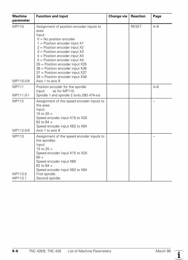
9–8 TNC 426B, TNC 430 List of Machine Parameters March 99
Machine
parameter
Function and input Change via Reaction Page
MP110
MP110.0-8
Assignment of position encoder inputs toaxesInput: 0 = No position encoder 1 = Position encoder input X1 2 = Position encoder input X2 3 = Position encoder input X3 4 = Position encoder input X4 5 = Position encoder input X535 = Position encoder input X3536 = Position encoder input X3637 = Position encoder input X3738 = Position encoder input X38Axis 1 to axis 9
RESET 4–6
MP111
MP111.0-1
Position encoder for the spindleInput: as for MP110Spindle 1 and spindle 2 (only 280 474-xx)
4–6
MP112
MP112.0-8
Assignment of the speed encoder inputs tothe axesInput:15 to 20 =Speed encoder input X15 to X2062 to 64 =Speed encoder input X62 to X64Axis 1 to axis 9
–
MP113
MP113.0MP113.1
Assignment of the speed encoder inputs tothe spindlesInput:15 to 20 =Speed encoder input X15 to X2060 =Speed encoder input X6062 to 64 =Speed encoder input X62 to X64First spindleSecond spindle
–
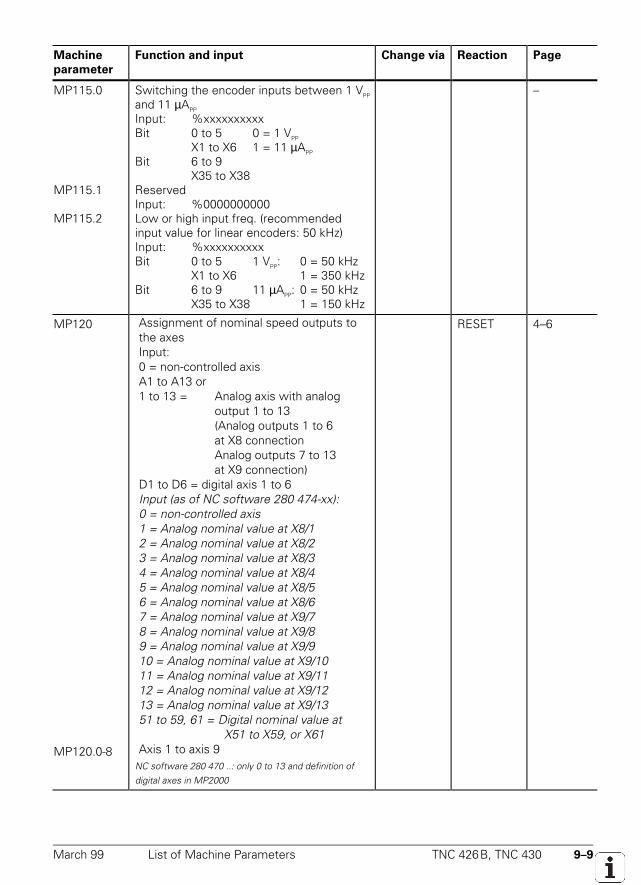
March 99 List of Machine Parameters TNC 426B, TNC 430 9–9
Machine
parameter
Function and input Change via Reaction Page
MP115.0
MP115.1
MP115.2
Switching the encoder inputs between 1 VPP
and 11 µAPP
Input: %xxxxxxxxxxBit 0 to 5 0 = 1 VPP
X1 to X6 1 = 11 µAPP
Bit 6 to 9X35 to X38
ReservedInput: %0000000000Low or high input freq. (recommendedinput value for linear encoders: 50 kHz)Input: %xxxxxxxxxxBit 0 to 5 1 VPP: 0 = 50 kHz
X1 to X6 1 = 350 kHzBit 6 to 9 11 µAPP: 0 = 50 kHz
X35 to X38 1 = 150 kHz
–
MP120
MP120.0-8
Assignment of nominal speed outputs tothe axesInput:0 = non-controlled axisA1 to A13 or1 to 13 = Analog axis with analog
output 1 to 13(Analog outputs 1 to 6at X8 connectionAnalog outputs 7 to 13at X9 connection)
D1 to D6 = digital axis 1 to 6Input (as of NC software 280 474-xx):0 = non-controlled axis1 = Analog nominal value at X8/12 = Analog nominal value at X8/23 = Analog nominal value at X8/34 = Analog nominal value at X8/45 = Analog nominal value at X8/56 = Analog nominal value at X8/67 = Analog nominal value at X9/78 = Analog nominal value at X9/89 = Analog nominal value at X9/910 = Analog nominal value at X9/1011 = Analog nominal value at X9/1112 = Analog nominal value at X9/1213 = Analog nominal value at X9/1351 to 59, 61 = Digital nominal value at
X51 to X59, or X61Axis 1 to axis 9
NC software 280 470 ..: only 0 to 13 and definition ofdigital axes in MP2000
RESET 4–6
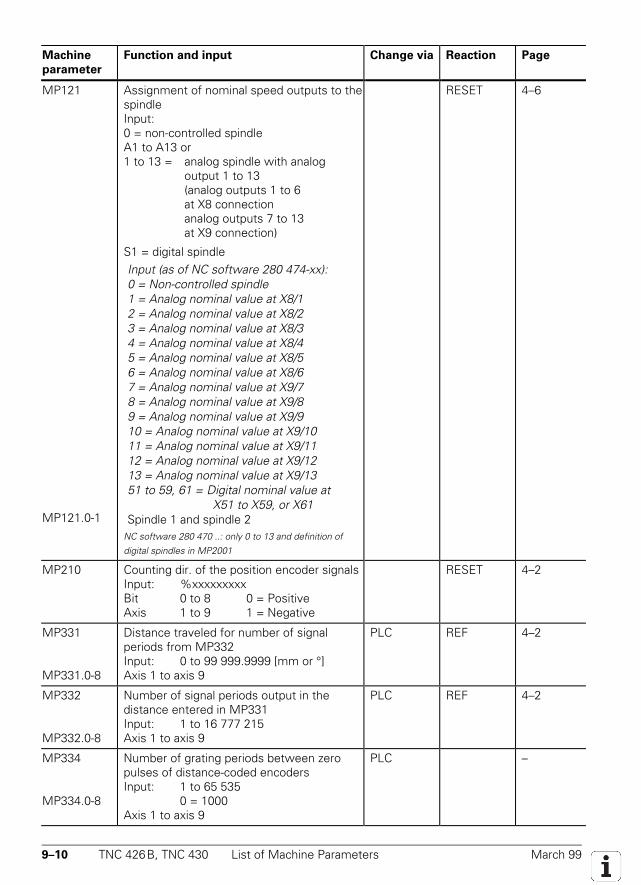
9–10 TNC 426B, TNC 430 List of Machine Parameters March 99
Machine
parameter
Function and input Change via Reaction Page
MP121
MP121.0-1
Assignment of nominal speed outputs to thespindleInput: 0 = non-controlled spindleA1 to A13 or1 to 13 = analog spindle with analog
output 1 to 13(analog outputs 1 to 6at X8 connectionanalog outputs 7 to 13at X9 connection)
S1 = digital spindleInput (as of NC software 280 474-xx):0 = Non-controlled spindle1 = Analog nominal value at X8/12 = Analog nominal value at X8/23 = Analog nominal value at X8/34 = Analog nominal value at X8/45 = Analog nominal value at X8/56 = Analog nominal value at X8/67 = Analog nominal value at X9/78 = Analog nominal value at X9/89 = Analog nominal value at X9/910 = Analog nominal value at X9/1011 = Analog nominal value at X9/1112 = Analog nominal value at X9/1213 = Analog nominal value at X9/1351 to 59, 61 = Digital nominal value at
X51 to X59, or X61Spindle 1 and spindle 2
NC software 280 470 ..: only 0 to 13 and definition ofdigital spindles in MP2001
RESET 4–6
MP210 Counting dir. of the position encoder signalsInput: %xxxxxxxxxBit 0 to 8 0 = PositiveAxis 1 to 9 1 = Negative
RESET 4–2
MP331
MP331.0-8
Distance traveled for number of signalperiods from MP332Input: 0 to 99 999.9999 [mm or °]Axis 1 to axis 9
PLC REF 4–2
MP332
MP332.0-8
Number of signal periods output in thedistance entered in MP331Input: 1 to 16 777 215Axis 1 to axis 9
PLC REF 4–2
MP334
MP334.0-8
Number of grating periods between zeropulses of distance-coded encodersInput: 1 to 65 535
0 = 1000Axis 1 to axis 9
PLC –
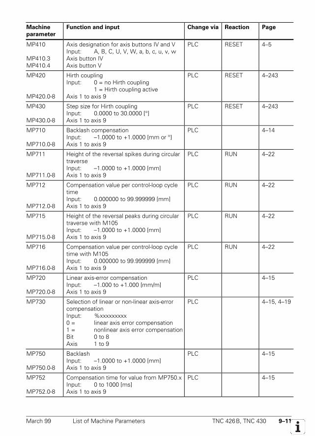
March 99 List of Machine Parameters TNC 426B, TNC 430 9–11
Machine
parameter
Function and input Change via Reaction Page
MP410
MP410.3MP410.4
Axis designation for axis buttons IV and VInput: A, B, C, U, V, W, a, b, c, u, v, wAxis button IVAxis button V
PLC RESET 4–5
MP420
MP420.0-8
Hirth couplingInput: 0 = no Hirth coupling
1 = Hirth coupling activeAxis 1 to axis 9
PLC RESET 4–243
MP430
MP430.0-8
Step size for Hirth couplingInput: 0.0000 to 30.0000 [°]Axis 1 to axis 9
PLC RESET 4–243
MP710
MP710.0-8
Backlash compensationInput: –1.0000 to +1.0000 [mm or °]Axis 1 to axis 9
PLC 4–14
MP711
MP711.0-8
Height of the reversal spikes during circulartraverseInput: –1.0000 to +1.0000 [mm]Axis 1 to axis 9
PLC RUN 4–22
MP712
MP712.0-8
Compensation value per control-loop cycletimeInput: 0.000000 to 99.999999 [mm]Axis 1 to axis 9
PLC RUN 4–22
MP715
MP715.0-8
Height of the reversal peaks during circulartraverse with M105Input: –1.0000 to +1.0000 [mm]Axis 1 to axis 9
PLC RUN 4–22
MP716
MP716.0-8
Compensation value per control-loop cycletime with M105Input: 0.000000 to 99.999999 [mm]Axis 1 to axis 9
PLC RUN 4–22
MP720
MP720.0-8
Linear axis-error compensationInput: –1.000 to +1.000 [mm/m]Axis 1 to axis 9
PLC 4–15
MP730 Selection of linear or non-linear axis-errorcompensationInput: %xxxxxxxxx0 = linear axis error compensation1 = nonlinear axis error compensationBit 0 to 8Axis 1 to 9
PLC 4–15, 4–19
MP750
MP750.0-8
BacklashInput: –1.0000 to +1.0000 [mm]Axis 1 to axis 9
PLC 4–15
MP752
MP752.0-8
Compensation time for value from MP750.xInput: 0 to 1000 [ms]Axis 1 to axis 9
PLC 4–15
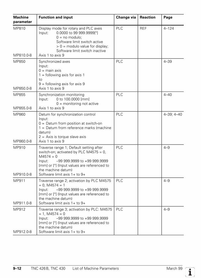
9–12 TNC 426B, TNC 430 List of Machine Parameters March 99
Machine
parameter
Function and input Change via Reaction Page
MP810
MP810.0-8
Display mode for rotary and PLC axesInput: 0.0000 to 99 999.9999[°]
0 = no modulo;Software limit switch active> 0 = modulo value for display; Software limit switch inactive
Axis 1 to axis 9
PLC REF 4–124
MP850
MP850.0-8
Synchronized axesInput:0 = main axis1 = following axis for axis 1to9 = following axis for axis 9Axis 1 to axis 9
PLC 4–39
MP855
MP855.0-8
Synchronization monitoringInput: 0 to 100.0000 [mm]
0 = monitoring not activeAxis 1 to axis 9
PLC 4–40
MP860
MP860.0-8
Datum for synchronization controlInput:0 = Datum from position at switch-on1 = Datum from reference marks (machinedatum)2 = Axis is torque slave axisAxis 1 to axis 9
PLC 4–39; 4–40
MP910
MP910.0-8
Traverse range 1; Default setting afterswitch-on; activated by PLC M4575 = 0,M4574 = 0Input: –99 999.9999 to +99 999.9999[mm] or [°] (Input values are referenced tothe machine datum)Software limit axis 1+ to 9+
PLC 4–9
MP911
MP911.0-8
Traverse range 2; activation by PLC M4575= 0, M4574 = 1Input: –99 999.9999 to +99 999.9999[mm] or [°] (Input values are referenced tothe machine datum)Software limit axis 1+ to 9+
PLC 4–9
MP912
MP912.0-8
Traverse range 3; activation by PLC: M4575= 1, M4574 = 0Input: –99 999.9999 to +99 999.9999[mm] or [°] (Input values are referenced tothe machine datum)Software limit axis 1+ to 9+
PLC 4–9
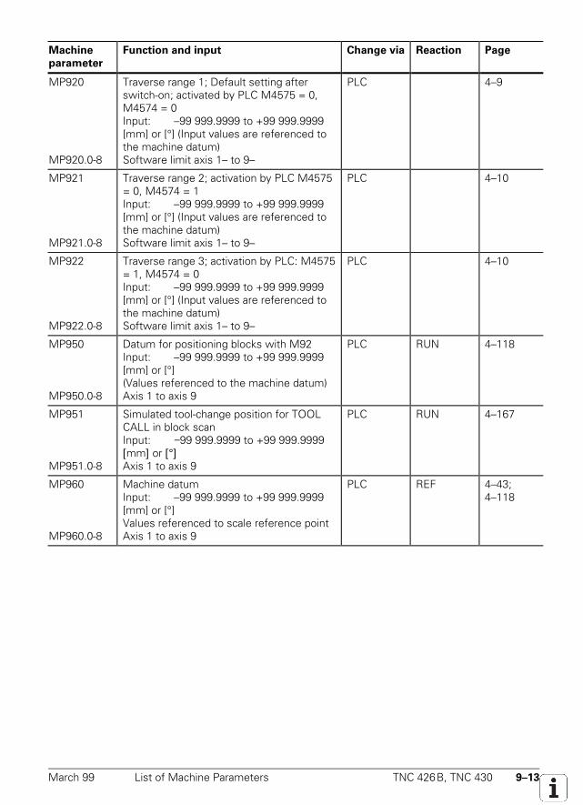
March 99 List of Machine Parameters TNC 426B, TNC 430 9–13
Machine
parameter
Function and input Change via Reaction Page
MP920
MP920.0-8
Traverse range 1; Default setting afterswitch-on; activated by PLC M4575 = 0,M4574 = 0Input: –99 999.9999 to +99 999.9999[mm] or [°] (Input values are referenced tothe machine datum)Software limit axis 1– to 9–
PLC 4–9
MP921
MP921.0-8
Traverse range 2; activation by PLC M4575= 0, M4574 = 1Input: –99 999.9999 to +99 999.9999[mm] or [°] (Input values are referenced tothe machine datum)Software limit axis 1– to 9–
PLC 4–10
MP922
MP922.0-8
Traverse range 3; activation by PLC: M4575= 1, M4574 = 0Input: –99 999.9999 to +99 999.9999[mm] or [°] (Input values are referenced tothe machine datum)Software limit axis 1– to 9–
PLC 4–10
MP950
MP950.0-8
Datum for positioning blocks with M92Input: –99 999.9999 to +99 999.9999[mm] or [°](Values referenced to the machine datum)Axis 1 to axis 9
PLC RUN 4–118
MP951
MP951.0-8
Simulated tool-change position for TOOLCALL in block scanInput: −99 999.9999 to +99 999.9999[mm] or [°]Axis 1 to axis 9
PLC RUN 4–167
MP960
MP960.0-8
Machine datumInput: –99 999.9999 to +99 999.9999[mm] or [°]Values referenced to scale reference pointAxis 1 to axis 9
PLC REF 4–43;4–118
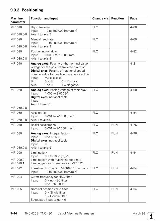
9–14 TNC 426B, TNC 430 List of Machine Parameters March 99
9.3.2 Positioning
Machine
parameter
Function and input Change via Reaction Page
MP1010
MP1010.0-8
Rapid traverseInput: 10 to 300 000 [mm/min]Axis 1 to axis 9
PLC 4–60
MP1020
MP1020.0-8
Manual feed rateInput: 10 to 300 000 [mm/min]Axis 1 to axis 9
PLC 4–60
MP1030
MP1030.0-8
Positioning windowInput: 0.0001 to 2.0000 [mm]Axis 1 to axis 9
PLC 4–82
MP1040 Analog axes: Polarity of the nominal valuevoltage for the positive traverse directionDigital axes: Polarity of rotational speednominal value for positive traverse directionInput: %xxxxxxxxxBit 0 to 8 0 = PositiveAxis 1 to 9 1 = Negative
4–2
MP1050
MP1050.0-8
Analog axes: Analog voltage at rapid trav.Input: 1.000 to 9.000 [V]Digital axes: not applicableInput: 1Axis 1 to axis 9
PLC 4–60
MP1060
MP1060.0-8
AccelerationInput: 0.001 to 20.000 [m/s2]Axis 1 to axis 9
PLC 4–54
MP1070 Radial accelerationInput: 0.001 to 20.000 [m/s2]
PLC RUN 4–76
MP1080
MP1080.0-8
Analog axes: Integral factorInput: 0 to 65 535Digital axes: not applicableInput: 0Axis 1 to axis 9
PLC RUN 4–76
MP1090
MP1090.0MP1090.1
Limiting jerkInput: 0.1 to 1000 [m/s³]Limiting jerk with machining feed rateLimiting jerk as of feed rate in MP1092
PLC RUN 4–54
MP1092 Threshold from which MP1090.1 functionsInput: 10 to 300 000 [mm/min]
PLC RUN 4–54
MP1094 Cutoff frequency for HSC filterInput: 0 = no HSC filter
0 to 166.0 [Hz]
–
MP1095 Nominal position value filterInput: 0 = Single filter
1 = Double filterSuggested input value = 0
PLC RUN 4–54
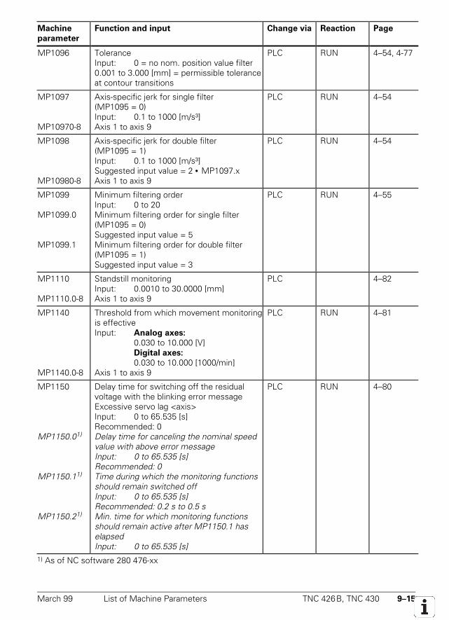
March 99 List of Machine Parameters TNC 426B, TNC 430 9–15
Machine
parameter
Function and input Change via Reaction Page
MP1096 ToleranceInput: 0 = no nom. position value filter0.001 to 3.000 [mm] = permissible toleranceat contour transitions
PLC RUN 4–54, 4-77
MP1097
MP10970-8
Axis-specific jerk for single filter(MP1095 = 0)Input: 0.1 to 1000 [m/s³]Axis 1 to axis 9
PLC RUN 4–54
MP1098
MP10980-8
Axis-specific jerk for double filter(MP1095 = 1)Input: 0.1 to 1000 [m/s³]Suggested input value = 2 • MP1097.xAxis 1 to axis 9
PLC RUN 4–54
MP1099
MP1099.0
MP1099.1
Minimum filtering orderInput: 0 to 20Minimum filtering order for single filter(MP1095 = 0)Suggested input value = 5Minimum filtering order for double filter(MP1095 = 1)Suggested input value = 3
PLC RUN 4–55
MP1110
MP1110.0-8
Standstill monitoringInput: 0.0010 to 30.0000 [mm]Axis 1 to axis 9
PLC 4–82
MP1140
MP1140.0-8
Threshold from which movement monitoringis effectiveInput: Analog axes:
0.030 to 10.000 [V]Digital axes:
0.030 to 10.000 [1000/min]Axis 1 to axis 9
PLC RUN 4–81
MP1150
MP1150.01)
MP1150.11)
MP1150.21)
Delay time for switching off the residualvoltage with the blinking error messageExcessive servo lag <axis>Input: 0 to 65.535 [s]Recommended: 0Delay time for canceling the nominal speedvalue with above error messageInput: 0 to 65.535 [s]Recommended: 0Time during which the monitoring functionsshould remain switched offInput: 0 to 65.535 [s]Recommended: 0.2 s to 0.5 sMin. time for which monitoring functionsshould remain active after MP1150.1 haselapsedInput: 0 to 65.535 [s]
PLC RUN 4–80
1) As of NC software 280 476-xx
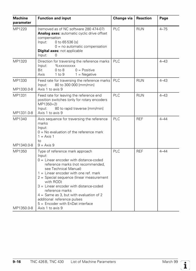
9–16 TNC 426B, TNC 430 List of Machine Parameters March 99
Machine
parameter
Function and input Change via Reaction Page
MP1220 (removed as of NC software 280 474-07)Analog axes: automatic cyclic drive offsetcompensationInput: 0 to 65 536 [s]
0 = no automatic compensationDigital axes: not applicableInput: 0
PLC RUN 4–75
MP1320 Direction for traversing the reference marksInput: %xxxxxxxxxBit 0 to 8 0 = PositiveAxis 1 to 9 1 = Negative
PLC 4–43
MP1330
MP1330.0-8
Feed rate for traversing the reference marksInput: 80 to 300 000 [mm/min]Axis 1 to axis 9
PLC RUN 4–43
MP1331
MP1331.0-8
Feed rate for leaving the reference endposition switches (only for rotary encodersMP1350=2)Input: 80 to rapid traverse [mm/min]Axis 1 to axis 9
PLC RUN 4–43
MP1340
MP1340.0-8
Axis sequence for traversing the referencemarksInput:0 = No evaluation of the reference mark1 = Axis 1to9 = Axis 9
PLC REF 4–44
MP1350
MP1350.0-8
Type of reference mark approachInput:0 = Linear encoder with distance-coded
reference marks (not recommended,see Technical Manual)
1 = Linear encoder with one ref. mark2 = Special sequence (linear measurement
with ROD)3 = Linear encoder with distance-coded
reference marks4 = Same as 3, but with evaluation of 2additional reference pulses5 = Encoder with EnDat interfaceAxis 1 to axis 9
PLC REF 4–44
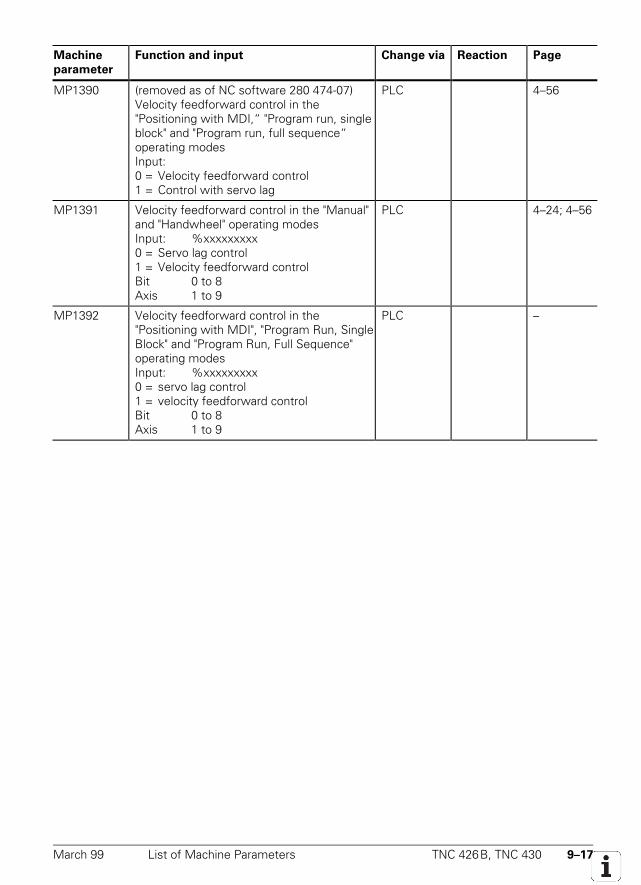
March 99 List of Machine Parameters TNC 426B, TNC 430 9–17
Machine
parameter
Function and input Change via Reaction Page
MP1390 (removed as of NC software 280 474-07)Velocity feedforward control in the"Positioning with MDI,“ "Program run, singleblock" and "Program run, full sequence“operating modesInput:0 = Velocity feedforward control1 = Control with servo lag
PLC 4–56
MP1391 Velocity feedforward control in the "Manual"and "Handwheel" operating modesInput: %xxxxxxxxx0 = Servo lag control1 = Velocity feedforward controlBit 0 to 8Axis 1 to 9
PLC 4–24; 4–56
MP1392 Velocity feedforward control in the"Positioning with MDI", "Program Run, SingleBlock" and "Program Run, Full Sequence"operating modesInput: %xxxxxxxxx0 = servo lag control1 = velocity feedforward controlBit 0 to 8Axis 1 to 9
PLC –
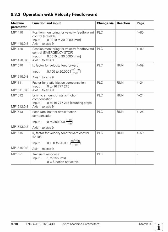
9–18 TNC 426B, TNC 430 List of Machine Parameters March 99
9.3.3 Operation with Velocity Feedforward
Machine
parameter
Function and input Change via Reaction Page
MP1410
MP1410.0-8
Position monitoring for velocity feedforwardcontrol (erasable)Input: 0.0010 to 30.0000 [mm]Axis 1 to axis 9
PLC 4–80
MP1420
MP1420.0-8
Position monitoring for velocity feedforwardcontrol (EMERGENCY STOP)Input: 0.0010 to 30.0000 [mm]Axis 1 to axis 9
PLC 4–80
MP1510
MP1510.0-8
kv factor for velocity feedforward
Input: 0.100 to 20.000 [m/minmm ]
Axis 1 to axis 9
PLC RUN 4–59
MP1511
MP1511.0-8
Factor for static friction compensationInput: 0 to 16 777 215Axis 1 to axis 9
PLC RUN 4–24
MP1512
MP1512.0-8
Limit to amount of static frictioncompensationInput: 0 to 16 777 215 [counting steps]Axis 1 to axis 9
PLC RUN 4–24
MP1513
MP1513.0-8
Feed-rate limit for static frictioncompensation
Input: 0 to 300 000 [mmmin]
Axis 1 to axis 9
PLC RUN 4–24
MP1515
MP1515.0-8
kv factor for velocity feedforward control(M105)
Input: 0.100 to 20.000 [m/minmm ]
Axis 1 to axis 9
PLC RUN 4–59
MP1521 Transient responseInput: 1 to 255 [ms]
0 = function not active
PLC –

March 99 List of Machine Parameters TNC 426B, TNC 430 9–19
9.3.4 Operation with Servo Lag
Machine
parameter
Function and input Change via Reaction Page
MP1710
MP1710.0-8
Position monitoring for control with servolag (erasable)Input: 0.0000 to 300.0000 [mm]Recommended: 1.2 • servo lagAxis 1 to axis 9
PLC 4–80
MP1720
MP1720.0-8
Position monitoring for control with servolag (EMERGENCY STOP)Input: 0.0000 to 300.0000 [mm]Axis 1 to axis 9
PLC 4–80
MP1810
MP1810.0-8
kv factor for control with servo lag
Input: 0.100 to 20.000 [m/minmm ]
Axis 1 to axis 9
PLC 4–57
MP1815
MP1815.0-8
kv factor for control with servo lag effectiveafter M105
Input: 0.100 to 20.000 [m/minmm ]
Axis 1 to axis 9
PLC 4–57
MP1820
MP1820.0-8
Multiplier for the kv factorInput: 0.001 to 1.000Axis 1 to axis 9
PLC 4–61
MP1830
MP1830.0-8
Kink point in characteristic curveInput: 0.000 to 100.000 [%]Axis 1 to axis 9
PLC 4–61
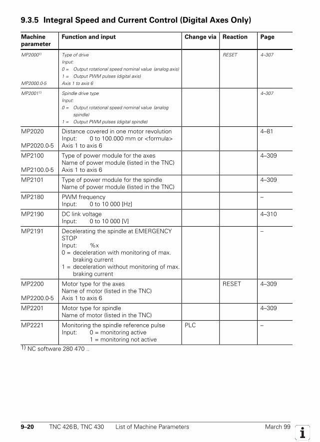
9–20 TNC 426B, TNC 430 List of Machine Parameters March 99
9.3.5 Integral Speed and Current Control (Digital Axes Only)
Machine
parameter
Function and input Change via Reaction Page
MP20001)
MP2000.0-5
Type of driveInput:0 = Output rotational speed nominal value (analog axis)1 = Output PWM pulses (digital axis)Axis 1 to axis 6
RESET 4–307
MP20011) Spindle drive typeInput:0 = Output rotational speed nominal value (analog
spindle)1 = Output PWM pulses (digital spindle)
4–307
MP2020
MP2020.0-5
Distance covered in one motor revolutionInput: 0 to 100.000 mm or <formula>Axis 1 to axis 6
4–81
MP2100
MP2100.0-5
Type of power module for the axesName of power module (listed in the TNC)Axis 1 to axis 6
4–309
MP2101 Type of power module for the spindleName of power module (listed in the TNC)
4–309
MP2180 PWM frequencyInput: 0 to 10 000 [Hz]
–
MP2190 DC link voltageInput: 0 to 10 000 [V]
4–310
MP2191 Decelerating the spindle at EMERGENCYSTOPInput: %x0 = deceleration with monitoring of max.
braking current1 = deceleration without monitoring of max.
braking current
–
MP2200
MP2200.0-5
Motor type for the axesName of motor (listed in the TNC)Axis 1 to axis 6
RESET 4–309
MP2201 Motor type for spindleName of motor (listed in the TNC)
4–309
MP2221 Monitoring the spindle reference pulseInput: 0 = monitoring active
1 = monitoring not active
PLC –
1) NC software 280 470 ..
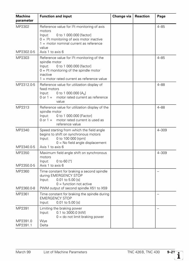
March 99 List of Machine Parameters TNC 426B, TNC 430 9–21
Machine
parameter
Function and input Change via Reaction Page
MP2302
MP2302.0-5
Reference value for I2t monitoring of axismotorsInput: 0 to 1 000.000 [factor]0 = I²t monitoring of axis motor inactive1 = motor nominal current as referencevalueAxis 1 to axis 6
4–85
MP2303 Reference value for I2t monitoring of thespindle motorInput: 0 to 1 000.000 [factor]0 = I²t monitoring of the spindle motorinactive1 = motor rated current as reference value
4–85
MP2312.0-5 Reference value for utilization display offeed motorsInput: 0 to 1 000.000 [As]0 or 1 = motor rated current as reference
value
4–88
MP2313 Reference value for utilization display of thespindle motorInput: 0 to 1 000.000 [Factor]0 or 1 = motor rated current is used as
reference value
4–88
MP2340
MP2340.0-5
Speed starting from which the field anglebegins to shift on synchronous motorsInput: 0 to 100 000 [rpm]
0 = No field angle displacementAxis 1 to axis 6
4–309
MP2350
MP2350.0-5
Maximum field angle shift on synchronousmotorsInput: 0 to 60 [°]Axis 1 to axis 6
4–309
MP2360
MP2360.0-8
Time constant for braking a second spindleduring EMERGENCY STOPInput: 0.01 to 5.00 [s]
0 = function not activePWM output of second spindle X51 to X59
–
MP2361 Time constant for braking the spindle duringEMERGENCY STOPInput: 0.01 to 5.00 [s]
–
MP2391
MP2391.0MP2391.1
Limiting the braking powerInput: 0.1 to 3000.0 [kW]
0 = do not limit braking powerWyeDelta
–
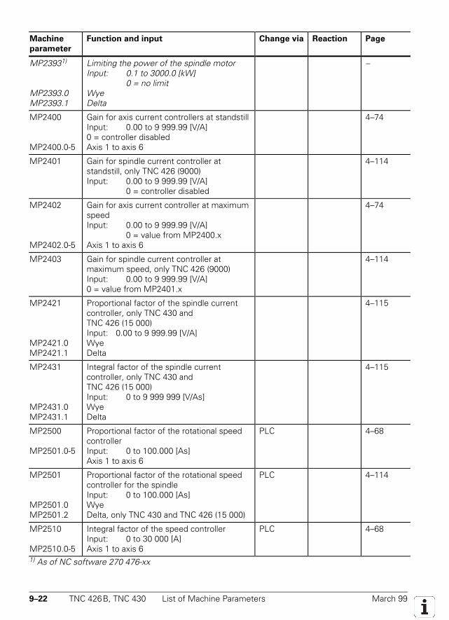
9–22 TNC 426B, TNC 430 List of Machine Parameters March 99
Machine
parameter
Function and input Change via Reaction Page
MP23931)
MP2393.0MP2393.1
Limiting the power of the spindle motorInput: 0.1 to 3000.0 [kW]
0 = no limitWyeDelta
–
MP2400
MP2400.0-5
Gain for axis current controllers at standstillInput: 0.00 to 9 999.99 [V/A]0 = controller disabledAxis 1 to axis 6
4–74
MP2401 Gain for spindle current controller atstandstill, only TNC 426 (9000)Input: 0.00 to 9 999.99 [V/A]
0 = controller disabled
4–114
MP2402
MP2402.0-5
Gain for axis current controller at maximumspeedInput: 0.00 to 9 999.99 [V/A]
0 = value from MP2400.xAxis 1 to axis 6
4–74
MP2403 Gain for spindle current controller atmaximum speed, only TNC 426 (9000)Input: 0.00 to 9 999.99 [V/A]0 = value from MP2401.x
4–114
MP2421
MP2421.0MP2421.1
Proportional factor of the spindle currentcontroller, only TNC 430 andTNC 426 (15 000)Input: 0.00 to 9 999.99 [V/A]WyeDelta
4–115
MP2431
MP2431.0MP2431.1
Integral factor of the spindle currentcontroller, only TNC 430 andTNC 426 (15 000)Input: 0 to 9 999 999 [V/As]WyeDelta
4–115
MP2500
MP2501.0-5
Proportional factor of the rotational speedcontrollerInput: 0 to 100.000 [As]Axis 1 to axis 6
PLC 4–68
MP2501
MP2501.0MP2501.2
Proportional factor of the rotational speedcontroller for the spindleInput: 0 to 100.000 [As]WyeDelta, only TNC 430 and TNC 426 (15 000)
PLC 4–114
MP2510
MP2510.0-5
Integral factor of the speed controllerInput: 0 to 30 000 [A]Axis 1 to axis 6
PLC 4–68
1) As of NC software 270 476-xx
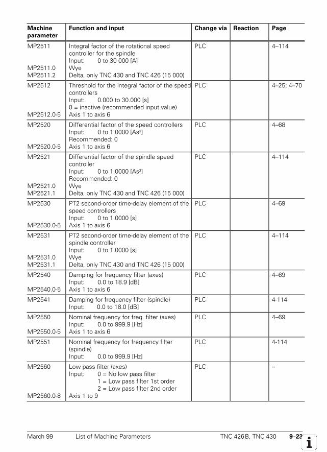
March 99 List of Machine Parameters TNC 426B, TNC 430 9–23
Machine
parameter
Function and input Change via Reaction Page
MP2511
MP2511.0MP2511.2
Integral factor of the rotational speedcontroller for the spindleInput: 0 to 30 000 [A]WyeDelta, only TNC 430 and TNC 426 (15 000)
PLC 4–114
MP2512
MP2512.0-5
Threshold for the integral factor of the speedcontrollersInput: 0.000 to 30.000 [s]0 = inactive (recommended input value)Axis 1 to axis 6
PLC 4–25; 4–70
MP2520
MP2520.0-5
Differential factor of the speed controllersInput: 0 to 1.0000 [As²]Recommended: 0Axis 1 to axis 6
PLC 4–68
MP2521
MP2521.0MP2521.1
Differential factor of the spindle speedcontrollerInput: 0 to 1.0000 [As²]Recommended: 0WyeDelta, only TNC 430 and TNC 426 (15 000)
PLC 4–114
MP2530
MP2530.0-5
PT2 second-order time-delay element of thespeed controllersInput: 0 to 1.0000 [s]Axis 1 to axis 6
PLC 4–69
MP2531
MP2531.0MP2531.1
PT2 second-order time-delay element of thespindle controllerInput: 0 to 1.0000 [s]WyeDelta, only TNC 430 and TNC 426 (15 000)
PLC 4–114
MP2540
MP2540.0-5
Damping for frequency filter (axes)Input: 0.0 to 18.9 [dB]Axis 1 to axis 6
PLC 4–69
MP2541 Damping for frequency filter (spindle)Input: 0.0 to 18.0 [dB]
PLC 4-114
MP2550
MP2550.0-5
Nominal frequency for freq. filter (axes)Input: 0.0 to 999.9 [Hz]Axis 1 to axis 6
PLC 4–69
MP2551 Nominal frequency for frequency filter(spindle)Input: 0.0 to 999.9 [Hz]
PLC 4-114
MP2560
MP2560.0-8
Low pass filter (axes)Input: 0 = No low pass filter
1 = Low pass filter 1st order2 = Low pass filter 2nd order
Axis 1 to 9
PLC –
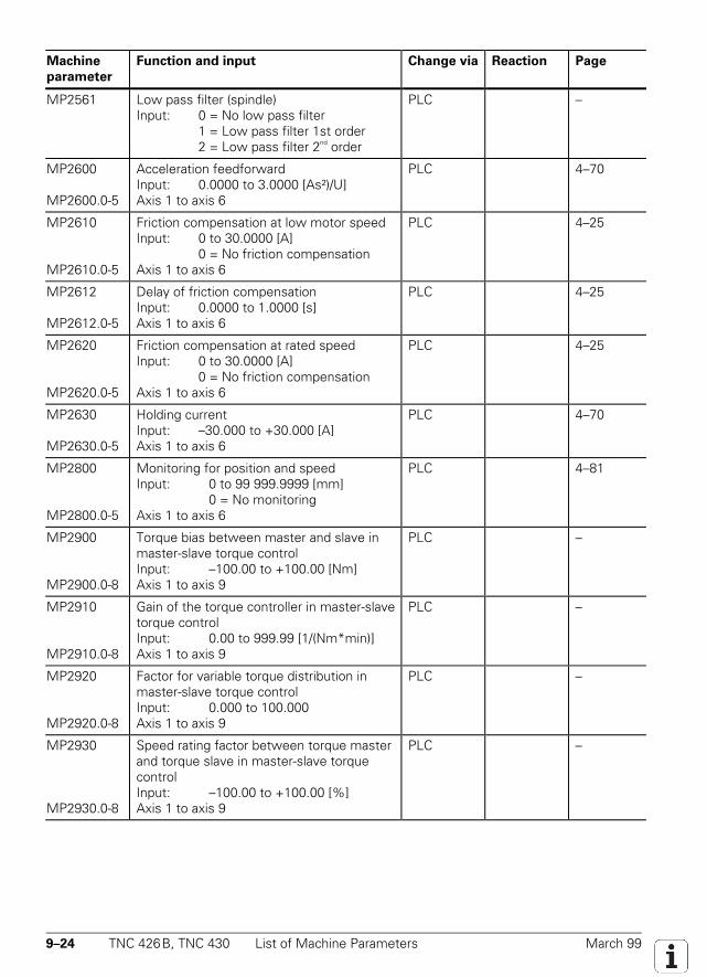
9–24 TNC 426B, TNC 430 List of Machine Parameters March 99
Machine
parameter
Function and input Change via Reaction Page
MP2561 Low pass filter (spindle)Input: 0 = No low pass filter
1 = Low pass filter 1st order2 = Low pass filter 2nd order
PLC –
MP2600
MP2600.0-5
Acceleration feedforwardInput: 0.0000 to 3.0000 [As²)/U]Axis 1 to axis 6
PLC 4–70
MP2610
MP2610.0-5
Friction compensation at low motor speedInput: 0 to 30.0000 [A]
0 = No friction compensationAxis 1 to axis 6
PLC 4–25
MP2612
MP2612.0-5
Delay of friction compensationInput: 0.0000 to 1.0000 [s]Axis 1 to axis 6
PLC 4–25
MP2620
MP2620.0-5
Friction compensation at rated speedInput: 0 to 30.0000 [A]
0 = No friction compensationAxis 1 to axis 6
PLC 4–25
MP2630
MP2630.0-5
Holding currentInput: –30.000 to +30.000 [A]Axis 1 to axis 6
PLC 4–70
MP2800
MP2800.0-5
Monitoring for position and speedInput: 0 to 99 999.9999 [mm]
0 = No monitoringAxis 1 to axis 6
PLC 4–81
MP2900
MP2900.0-8
Torque bias between master and slave inmaster-slave torque controlInput: –100.00 to +100.00 [Nm]Axis 1 to axis 9
PLC –
MP2910
MP2910.0-8
Gain of the torque controller in master-slavetorque controlInput: 0.00 to 999.99 [1/(Nm*min)]Axis 1 to axis 9
PLC –
MP2920
MP2920.0-8
Factor for variable torque distribution inmaster-slave torque controlInput: 0.000 to 100.000Axis 1 to axis 9
PLC –
MP2930
MP2930.0-8
Speed rating factor between torque masterand torque slave in master-slave torquecontrolInput: –100.00 to +100.00 [%]Axis 1 to axis 9
PLC –
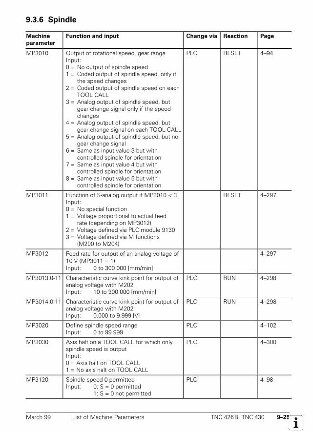
March 99 List of Machine Parameters TNC 426B, TNC 430 9–25
9.3.6 Spindle
Machine
parameter
Function and input Change via Reaction Page
MP3010 Output of rotational speed, gear rangeInput:0 = No output of spindle speed1 = Coded output of spindle speed, only if
the speed changes2 = Coded output of spindle speed on each
TOOL CALL3 = Analog output of spindle speed, but
gear change signal only if the speed changes
4 = Analog output of spindle speed, but gear change signal on each TOOL CALL
5 = Analog output of spindle speed, but no gear change signal
6 = Same as input value 3 but with controlled spindle for orientation
7 = Same as input value 4 but with controlled spindle for orientation
8 = Same as input value 5 but with controlled spindle for orientation
PLC RESET 4–94
MP3011 Function of S-analog output if MP3010 < 3Input:0 = No special function1 = Voltage proportional to actual feed
rate (depending on MP3012)2 = Voltage defined via PLC module 91303 = Voltage defined via M functions
(M200 to M204)
RESET 4–297
MP3012 Feed rate for output of an analog voltage of10 V (MP3011 = 1)Input: 0 to 300 000 [mm/min]
4–297
MP3013.0-11 Characteristic curve kink point for output ofanalog voltage with M202Input: 10 to 300 000 [mm/min]
PLC RUN 4–298
MP3014.0-11 Characteristic curve kink point for output ofanalog voltage with M202Input: 0.000 to 9.999 [V]
PLC RUN 4–298
MP3020 Define spindle speed rangeInput: 0 to 99 999
PLC 4–102
MP3030 Axis halt on a TOOL CALL for which onlyspindle speed is outputInput:0 = Axis halt on TOOL CALL1 = No axis halt on TOOL CALL
PLC 4–300
MP3120 Spindle speed 0 permittedInput: 0: S = 0 permitted
1: S = 0 not permitted
PLC 4–98
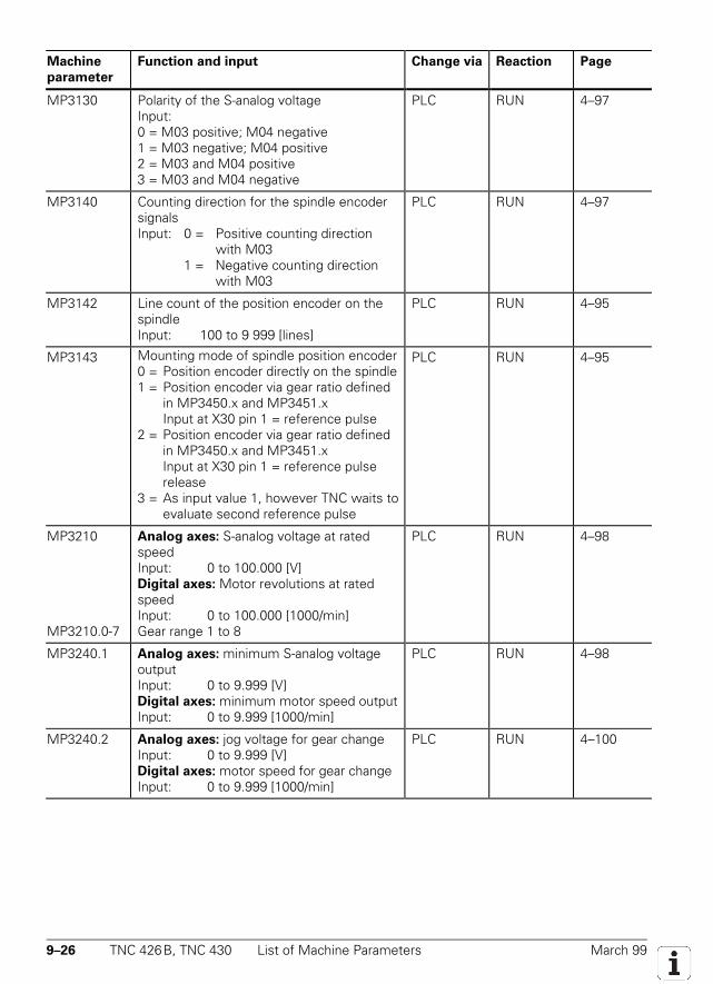
9–26 TNC 426B, TNC 430 List of Machine Parameters March 99
Machine
parameter
Function and input Change via Reaction Page
MP3130 Polarity of the S-analog voltageInput:0 = M03 positive; M04 negative1 = M03 negative; M04 positive2 = M03 and M04 positive3 = M03 and M04 negative
PLC RUN 4–97
MP3140 Counting direction for the spindle encodersignalsInput: 0 = Positive counting direction
with M031 = Negative counting direction
with M03
PLC RUN 4–97
MP3142 Line count of the position encoder on thespindleInput: 100 to 9 999 [lines]
PLC RUN 4–95
MP3143 Mounting mode of spindle position encoder0 = Position encoder directly on the spindle1 = Position encoder via gear ratio defined
in MP3450.x and MP3451.xInput at X30 pin 1 = reference pulse
2 = Position encoder via gear ratio definedin MP3450.x and MP3451.xInput at X30 pin 1 = reference pulserelease
3 = As input value 1, however TNC waits toevaluate second reference pulse
PLC RUN 4–95
MP3210
MP3210.0-7
Analog axes: S-analog voltage at ratedspeedInput: 0 to 100.000 [V]Digital axes: Motor revolutions at ratedspeedInput: 0 to 100.000 [1000/min]Gear range 1 to 8
PLC RUN 4–98
MP3240.1 Analog axes: minimum S-analog voltageoutputInput: 0 to 9.999 [V]Digital axes: minimum motor speed outputInput: 0 to 9.999 [1000/min]
PLC RUN 4–98
MP3240.2 Analog axes: jog voltage for gear changeInput: 0 to 9.999 [V]Digital axes: motor speed for gear changeInput: 0 to 9.999 [1000/min]
PLC RUN 4–100
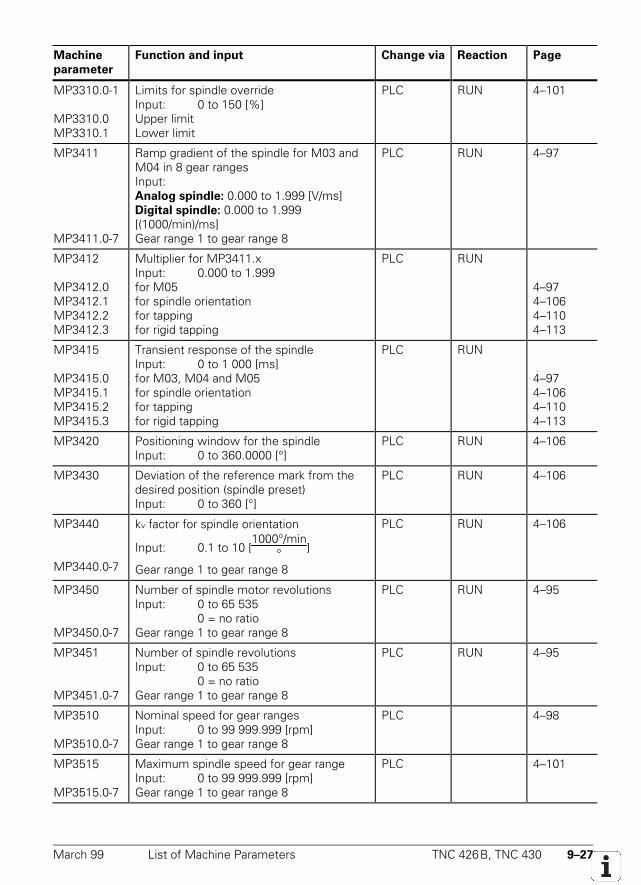
March 99 List of Machine Parameters TNC 426B, TNC 430 9–27
Machine
parameter
Function and input Change via Reaction Page
MP3310.0-1
MP3310.0MP3310.1
Limits for spindle overrideInput: 0 to 150 [%]Upper limitLower limit
PLC RUN 4–101
MP3411
MP3411.0-7
Ramp gradient of the spindle for M03 andM04 in 8 gear rangesInput:Analog spindle: 0.000 to 1.999 [V/ms]Digital spindle: 0.000 to 1.999[(1000/min)/ms]Gear range 1 to gear range 8
PLC RUN 4–97
MP3412
MP3412.0MP3412.1MP3412.2MP3412.3
Multiplier for MP3411.xInput: 0.000 to 1.999for M05for spindle orientationfor tappingfor rigid tapping
PLC RUN
4–974–1064–1104–113
MP3415
MP3415.0MP3415.1MP3415.2MP3415.3
Transient response of the spindleInput: 0 to 1 000 [ms]for M03, M04 and M05for spindle orientationfor tappingfor rigid tapping
PLC RUN
4–974–1064–1104–113
MP3420 Positioning window for the spindleInput: 0 to 360.0000 [°]
PLC RUN 4–106
MP3430 Deviation of the reference mark from thedesired position (spindle preset)Input: 0 to 360 [°]
PLC RUN 4–106
MP3440
MP3440.0-7
kv factor for spindle orientation
Input: 0.1 to 10 [1000°/min
° ]
Gear range 1 to gear range 8
PLC RUN 4–106
MP3450
MP3450.0-7
Number of spindle motor revolutionsInput: 0 to 65 535
0 = no ratioGear range 1 to gear range 8
PLC RUN 4–95
MP3451
MP3451.0-7
Number of spindle revolutionsInput: 0 to 65 535
0 = no ratioGear range 1 to gear range 8
PLC RUN 4–95
MP3510
MP3510.0-7
Nominal speed for gear rangesInput: 0 to 99 999.999 [rpm]Gear range 1 to gear range 8
PLC 4–98
MP3515
MP3515.0-7
Maximum spindle speed for gear rangeInput: 0 to 99 999.999 [rpm]Gear range 1 to gear range 8
PLC 4–101
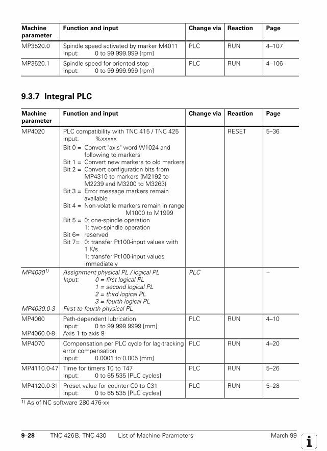
9–28 TNC 426B, TNC 430 List of Machine Parameters March 99
Machine
parameter
Function and input Change via Reaction Page
MP3520.0 Spindle speed activated by marker M4011Input: 0 to 99 999.999 [rpm]
PLC RUN 4–107
MP3520.1 Spindle speed for oriented stopInput: 0 to 99 999.999 [rpm]
PLC RUN 4–106
9.3.7 Integral PLC
Machine
parameter
Function and input Change via Reaction Page
MP4020 PLC compatibility with TNC 415 / TNC 425Input: %xxxxxBit 0 = Convert "axis" word W1024 and
following to markersBit 1 = Convert new markers to old markersBit 2 = Convert configuration bits from
MP4310 to markers (M2192 toM2239 and M3200 to M3263)
Bit 3 = Error message markers remainavailable
Bit 4 = Non-volatile markers remain in rangeM1000 to M1999
Bit 5 = 0: one-spindle operation1: two-spindle operation
Bit 6= reservedBit 7= 0: transfer Pt100-input values with
1 K/s.1: transfer Pt100-input valuesimmediately
RESET 5–36
MP40301)
MP4030.0-3
Assignment physical PL / logical PLInput: 0 = first logical PL
1 = second logical PL2 = third logical PL3 = fourth logical PL
First to fourth physical PL
PLC –
MP4060
MP4060.0-8
Path-dependent lubricationInput: 0 to 99 999.9999 [mm]Axis 1 to axis 9
PLC RUN 4–10
MP4070 Compensation per PLC cycle for lag-trackingerror compensationInput: 0.0001 to 0.005 [mm]
PLC RUN 4–20
MP4110.0-47 Time for timers T0 to T47Input: 0 to 65 535 [PLC cycles]
PLC RUN 5–26
MP4120.0-31 Preset value for counter C0 to C31Input: 0 to 65 535 [PLC cycles]
PLC RUN 5–28
1) As of NC software 280 476-xx
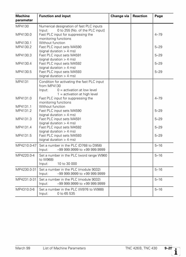
March 99 List of Machine Parameters TNC 426B, TNC 430 9–29
Machine
parameter
Function and input Change via Reaction Page
MP4130
MP4130.0
MP4130.1MP4130.2
MP4130.3
MP4130.4
MP4130.5
Numerical designation of fast PLC inputsInput: 0 to 255 [No. of the PLC input]Fast PLC input for suppressing themonitoring functionsWithout functionFast PLC input sets M4590(signal duration > 4 ms)Fast PLC input sets M4591(signal duration > 4 ms)Fast PLC input sets M4592(signal duration > 4 ms)Fast PLC input sets M4593(signal duration > 4 ms)
4–79
5–29
5–29
5–29
5–29
MP4131
MP4131.0
MP4131.1MP4131.2
MP4131.3
MP4131.4
MP4131.5
Condition for activating the fast PLC inputfrom MP4130Input: 0 = activation at low level
1 = activation at high levelFast PLC input for suppressing themonitoring functionsWithout functionFast PLC input sets M4590(signal duration > 4 ms)Fast PLC input sets M4591(signal duration > 4 ms)Fast PLC input sets M4592(signal duration > 4 ms)Fast PLC input sets M4593(signal duration > 4 ms)
4–79
5–29
5–29
5–29
5–29
MP4210.0-47 Set a number in the PLC (D768 to D956)Input: –99 999.9999 to +99 999.9999
5–16
MP4220.0-4 Set a number in the PLC (word range W960to W968)Input: 10 to 30 000
5–16
MP4230.0-31 Set a number in the PLC (module 9032)Input: –99 999.9999 to +99 999.9999
5–16
MP4231.0-31 Set a number in the PLC (module 9032)Input: –99 999.9999 to +99 999.9999
5–16
MP4310.0-6 Set a number in the PLC (W976 to W988)Input: 0 to 65 535
5–16
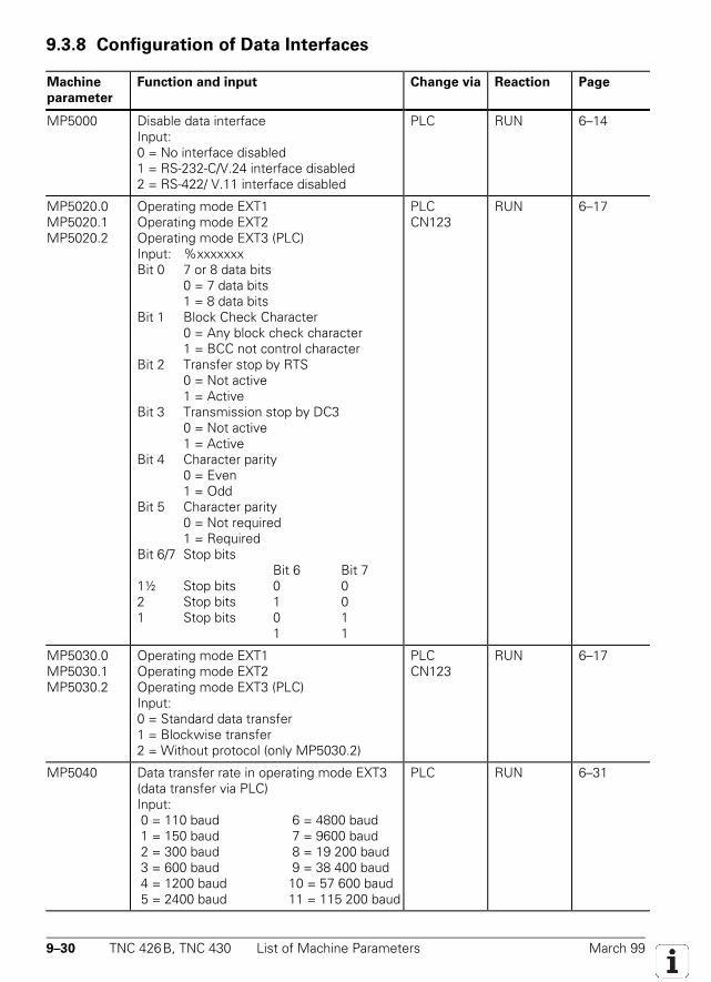
9–30 TNC 426B, TNC 430 List of Machine Parameters March 99
9.3.8 Configuration of Data Interfaces
Machine
parameter
Function and input Change via Reaction Page
MP5000 Disable data interfaceInput:0 = No interface disabled1 = RS-232-C/V.24 interface disabled2 = RS-422/ V.11 interface disabled
PLC RUN 6–14
MP5020.0MP5020.1MP5020.2
Operating mode EXT1Operating mode EXT2Operating mode EXT3 (PLC)Input: %xxxxxxxBit 0 7 or 8 data bits
0 = 7 data bits1 = 8 data bits
Bit 1 Block Check Character0 = Any block check character1 = BCC not control character
Bit 2 Transfer stop by RTS0 = Not active1 = Active
Bit 3 Transmission stop by DC30 = Not active1 = Active
Bit 4 Character parity0 = Even1 = Odd
Bit 5 Character parity0 = Not required1 = Required
Bit 6/7 Stop bitsBit 6 Bit 7
1½ Stop bits 0 02 Stop bits 1 01 Stop bits 0 1
1 1
PLCCN123
RUN 6–17
MP5030.0MP5030.1MP5030.2
Operating mode EXT1Operating mode EXT2Operating mode EXT3 (PLC)Input:0 = Standard data transfer1 = Blockwise transfer2 = Without protocol (only MP5030.2)
PLCCN123
RUN 6–17
MP5040 Data transfer rate in operating mode EXT3(data transfer via PLC)Input: 0 = 110 baud 6 = 4800 baud 1 = 150 baud 7 = 9600 baud 2 = 300 baud 8 = 19 200 baud 3 = 600 baud 9 = 38 400 baud 4 = 1200 baud 10 = 57 600 baud 5 = 2400 baud 11 = 115 200 baud
PLC RUN 6–31
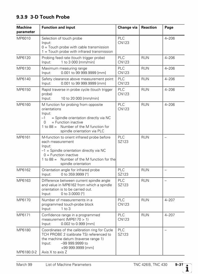
March 99 List of Machine Parameters TNC 426B, TNC 430 9–31
9.3.9 3-D Touch Probe
Machine
parameter
Function and input Change via Reaction Page
MP6010 Selection of touch probeInput:0 = Touch probe with cable transmission1 = Touch probe with infrared transmission
PLCCN123
4–206
MP6120 Probing feed rate (touch trigger probe)Input: 1 to 3 000 [mm/min]
PLCCN123
RUN 4–206
MP6130 Maximum measuring rangeInput: 0.001 to 99 999.9999 [mm]
PLCCN123
RUN 4–206
MP6140 Safety clearance above measurement pointInput: 0.001 to 99 999.9999 [mm]
PLCCN123
RUN 4–206
MP6150 Rapid traverse in probe cycle (touch triggerprobe)Input: 10 to 20 000 [mm/min]
PLCCN123
RUN 4–206
MP6160 M function for probing from oppositeorientationsInput:–1 = Spindle orientation directly via NC 0 = Function inactive1 to 88 = Number of the M function for
spindle orientation via PLC
PLCCN123
RUN 4–206
MP6161 M-function to orient infrared probe beforeeach measurementInput:–1 = Spindle orientation directly via NC 0 = Function inactive1 to 88 = Number of the M function for the
spindle orientation
PLCSZ123
RUN –
MP6162 Orientation angle for infrared probeInput: 0 to 359.9999 [°]
PLCSZ123
RUN –
MP6163 Difference between current spindle angleand value in MP6162 from which a spindleorientation is to be carried out.Input: 0 to 3.0000 [°]
PLCSZ123
RUN –
MP6170 Number of measurements in aprogrammed touch-probe blockInput: 1 to 3
PLCCN123
RUN 4–207
MP6171 Confidence range in a programmedmeasurement (MP6170 > 1)Input: 0.002 to 0.999 [mm]
PLCCN123
RUN 4–207
MP6180
MP6180.0-2
Coordinates of the calibration ring for CycleTCH PROBE 2 (calibrate TS) referenced tothe machine datum (traverse range 1)Input: –99 999.9999 to
+99 999.9999 [mm]Axis X to axis Z
PLCSZ123
–
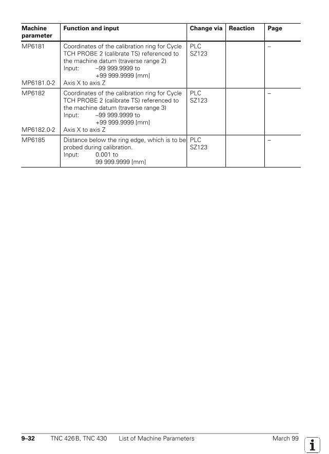
9–32 TNC 426B, TNC 430 List of Machine Parameters March 99
Machine
parameter
Function and input Change via Reaction Page
MP6181
MP6181.0-2
Coordinates of the calibration ring for CycleTCH PROBE 2 (calibrate TS) referenced tothe machine datum (traverse range 2)Input: –99 999.9999 to
+99 999.9999 [mm]Axis X to axis Z
PLCSZ123
–
MP6182
MP6182.0-2
Coordinates of the calibration ring for CycleTCH PROBE 2 (calibrate TS) referenced tothe machine datum (traverse range 3)Input: –99 999.9999 to
+99 999.9999 [mm]Axis X to axis Z
PLCSZ123
–
MP6185 Distance below the ring edge, which is to beprobed during calibration.Input: 0.001 to
99 999.9999 [mm]
PLCSZ123
–
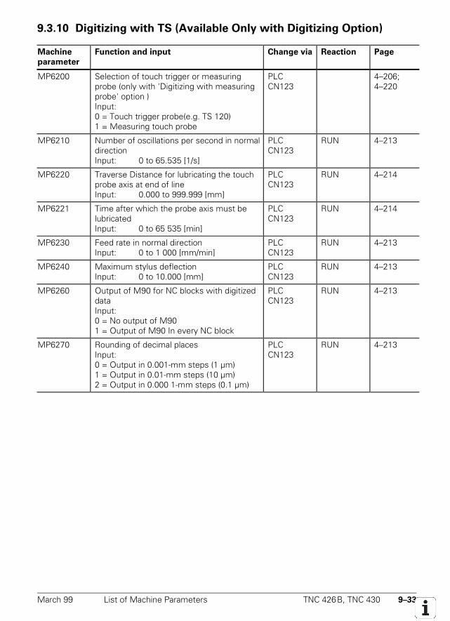
March 99 List of Machine Parameters TNC 426B, TNC 430 9–33
9.3.10 Digitizing with TS (Available Only with Digitizing Option)
Machine
parameter
Function and input Change via Reaction Page
MP6200 Selection of touch trigger or measuringprobe (only with 'Digitizing with measuringprobe' option )Input:0 = Touch trigger probe(e.g. TS 120)1 = Measuring touch probe
PLCCN123
4–206;4–220
MP6210 Number of oscillations per second in normaldirectionInput: 0 to 65.535 [1/s]
PLCCN123
RUN 4–213
MP6220 Traverse Distance for lubricating the touchprobe axis at end of lineInput: 0.000 to 999.999 [mm]
PLCCN123
RUN 4–214
MP6221 Time after which the probe axis must belubricatedInput: 0 to 65 535 [min]
PLCCN123
RUN 4–214
MP6230 Feed rate in normal directionInput: 0 to 1 000 [mm/min]
PLCCN123
RUN 4–213
MP6240 Maximum stylus deflectionInput: 0 to 10.000 [mm]
PLCCN123
RUN 4–213
MP6260 Output of M90 for NC blocks with digitizeddataInput:0 = No output of M901 = Output of M90 In every NC block
PLCCN123
RUN 4–213
MP6270 Rounding of decimal placesInput:0 = Output in 0.001-mm steps (1 µm)1 = Output in 0.01-mm steps (10 µm)2 = Output in 0.000 1-mm steps (0.1 µm)
PLCCN123
RUN 4–213
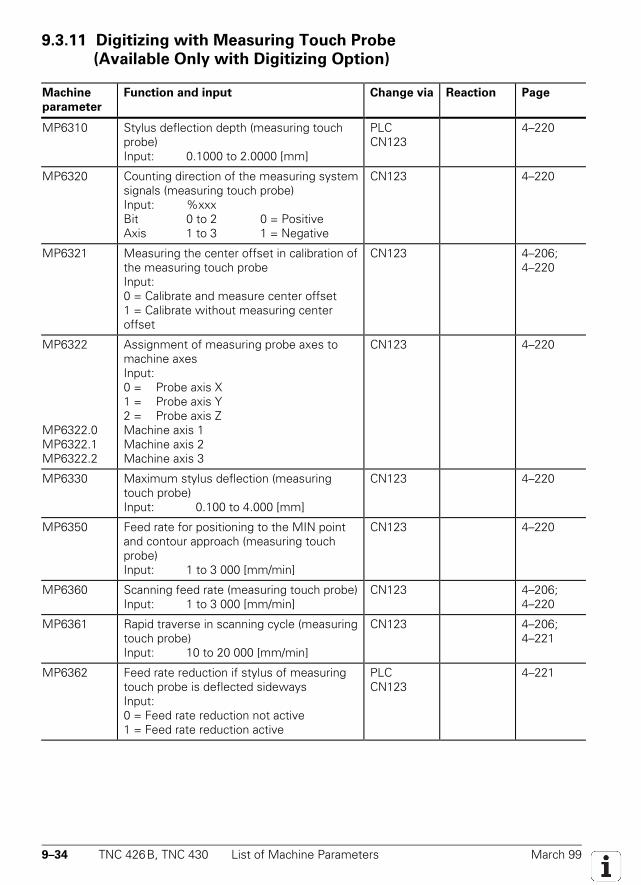
9–34 TNC 426B, TNC 430 List of Machine Parameters March 99
9.3.11 Digitizing with Measuring Touch Probe
(Available Only with Digitizing Option)
Machine
parameter
Function and input Change via Reaction Page
MP6310 Stylus deflection depth (measuring touchprobe)Input: 0.1000 to 2.0000 [mm]
PLCCN123
4–220
MP6320 Counting direction of the measuring systemsignals (measuring touch probe)Input: %xxxBit 0 to 2 0 = PositiveAxis 1 to 3 1 = Negative
CN123 4–220
MP6321 Measuring the center offset in calibration ofthe measuring touch probeInput:0 = Calibrate and measure center offset1 = Calibrate without measuring centeroffset
CN123 4–206;4–220
MP6322
MP6322.0MP6322.1MP6322.2
Assignment of measuring probe axes tomachine axesInput:0 = Probe axis X1 = Probe axis Y2 = Probe axis ZMachine axis 1Machine axis 2Machine axis 3
CN123 4–220
MP6330 Maximum stylus deflection (measuringtouch probe)Input: 0.100 to 4.000 [mm]
CN123 4–220
MP6350 Feed rate for positioning to the MIN pointand contour approach (measuring touchprobe)Input: 1 to 3 000 [mm/min]
CN123 4–220
MP6360 Scanning feed rate (measuring touch probe)Input: 1 to 3 000 [mm/min]
CN123 4–206;4–220
MP6361 Rapid traverse in scanning cycle (measuringtouch probe)Input: 10 to 20 000 [mm/min]
CN123 4–206;4–221
MP6362 Feed rate reduction if stylus of measuringtouch probe is deflected sidewaysInput:0 = Feed rate reduction not active1 = Feed rate reduction active
PLCCN123
4–221
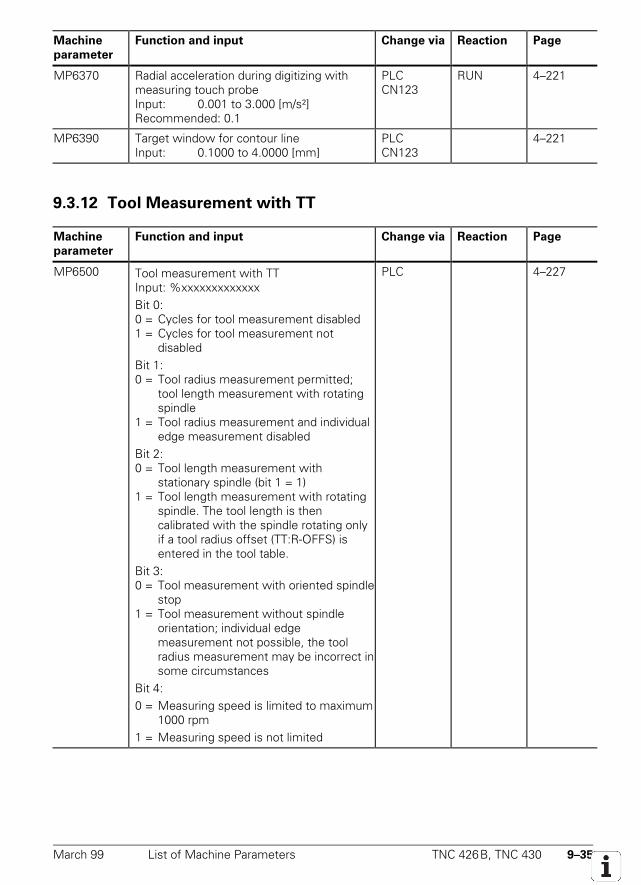
March 99 List of Machine Parameters TNC 426B, TNC 430 9–35
Machine
parameter
Function and input Change via Reaction Page
MP6370 Radial acceleration during digitizing withmeasuring touch probeInput: 0.001 to 3.000 [m/s²]Recommended: 0.1
PLCCN123
RUN 4–221
MP6390 Target window for contour lineInput: 0.1000 to 4.0000 [mm]
PLCCN123
4–221
9.3.12 Tool Measurement with TT
Machine
parameter
Function and input Change via Reaction Page
MP6500 Tool measurement with TTInput: %xxxxxxxxxxxxxBit 0:0 = Cycles for tool measurement disabled1 = Cycles for tool measurement not
disabledBit 1:0 = Tool radius measurement permitted;
tool length measurement with rotating spindle
1 = Tool radius measurement and individual edge measurement disabled
Bit 2:0 = Tool length measurement with
stationary spindle (bit 1 = 1)1 = Tool length measurement with rotating
spindle. The tool length is thencalibrated with the spindle rotating onlyif a tool radius offset (TT:R-OFFS) isentered in the tool table.
Bit 3:0 = Tool measurement with oriented spindle
stop1 = Tool measurement without spindle
orientation; individual edgemeasurement not possible, the toolradius measurement may be incorrect insome circumstances
Bit 4:0 = Measuring speed is limited to maximum
1000 rpm1 = Measuring speed is not limited
PLC 4–227
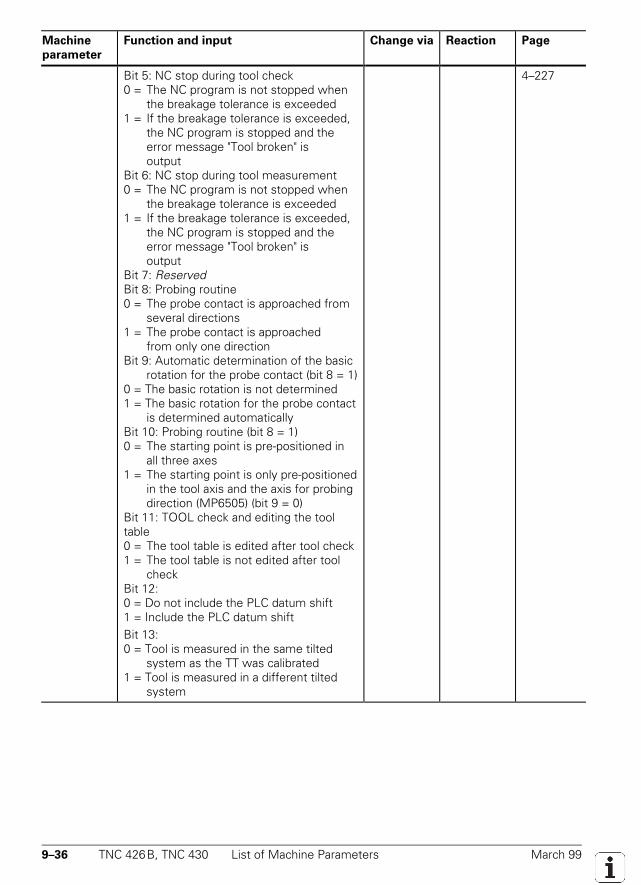
9–36 TNC 426B, TNC 430 List of Machine Parameters March 99
Machine
parameter
Function and input Change via Reaction Page
Bit 5: NC stop during tool check0 = The NC program is not stopped when
the breakage tolerance is exceeded1 = If the breakage tolerance is exceeded,
the NC program is stopped and the error message "Tool broken" is output
Bit 6: NC stop during tool measurement0 = The NC program is not stopped when
the breakage tolerance is exceeded1 = If the breakage tolerance is exceeded,
the NC program is stopped and the error message "Tool broken" is output
Bit 7: ReservedBit 8: Probing routine0 = The probe contact is approached from
several directions1 = The probe contact is approached
from only one directionBit 9: Automatic determination of the basic
rotation for the probe contact (bit 8 = 1)0 = The basic rotation is not determined1 = The basic rotation for the probe contact
is determined automaticallyBit 10: Probing routine (bit 8 = 1)0 = The starting point is pre-positioned in
all three axes1 = The starting point is only pre-positioned
in the tool axis and the axis for probingdirection (MP6505) (bit 9 = 0)
Bit 11: TOOL check and editing the tooltable0 = The tool table is edited after tool check1 = The tool table is not edited after tool
checkBit 12:0 = Do not include the PLC datum shift1 = Include the PLC datum shiftBit 13:0 = Tool is measured in the same tilted
system as the TT was calibrated1 = Tool is measured in a different tilted
system
4–227
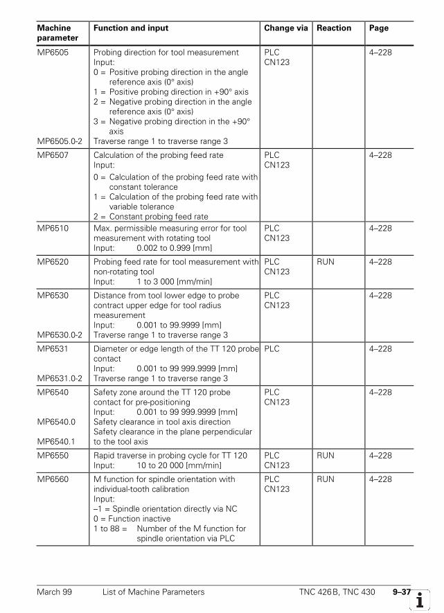
March 99 List of Machine Parameters TNC 426B, TNC 430 9–37
Machine
parameter
Function and input Change via Reaction Page
MP6505
MP6505.0-2
Probing direction for tool measurementInput:0 = Positive probing direction in the angle
reference axis (0° axis)1 = Positive probing direction in +90° axis2 = Negative probing direction in the angle
reference axis (0° axis)3 = Negative probing direction in the +90°
axisTraverse range 1 to traverse range 3
PLCCN123
4–228
MP6507 Calculation of the probing feed rateInput:0 = Calculation of the probing feed rate with
constant tolerance1 = Calculation of the probing feed rate with
variable tolerance2 = Constant probing feed rate
PLCCN123
4–228
MP6510 Max. permissible measuring error for toolmeasurement with rotating toolInput: 0.002 to 0.999 [mm]
PLCCN123
4–228
MP6520 Probing feed rate for tool measurement withnon-rotating toolInput: 1 to 3 000 [mm/min]
PLCCN123
RUN 4–228
MP6530
MP6530.0-2
Distance from tool lower edge to probecontract upper edge for tool radiusmeasurementInput: 0.001 to 99.9999 [mm]Traverse range 1 to traverse range 3
PLCCN123
4–228
MP6531
MP6531.0-2
Diameter or edge length of the TT 120 probecontactInput: 0.001 to 99 999.9999 [mm]Traverse range 1 to traverse range 3
PLC 4–228
MP6540
MP6540.0
MP6540.1
Safety zone around the TT 120 probecontact for pre-positioningInput: 0.001 to 99 999.9999 [mm]Safety clearance in tool axis directionSafety clearance in the plane perpendicularto the tool axis
PLCCN123
4–228
MP6550 Rapid traverse in probing cycle for TT 120Input: 10 to 20 000 [mm/min]
PLCCN123
RUN 4–228
MP6560 M function for spindle orientation withindividual-tooth calibrationInput:–1 = Spindle orientation directly via NC0 = Function inactive1 to 88 = Number of the M function for
spindle orientation via PLC
PLCCN123
RUN 4–228
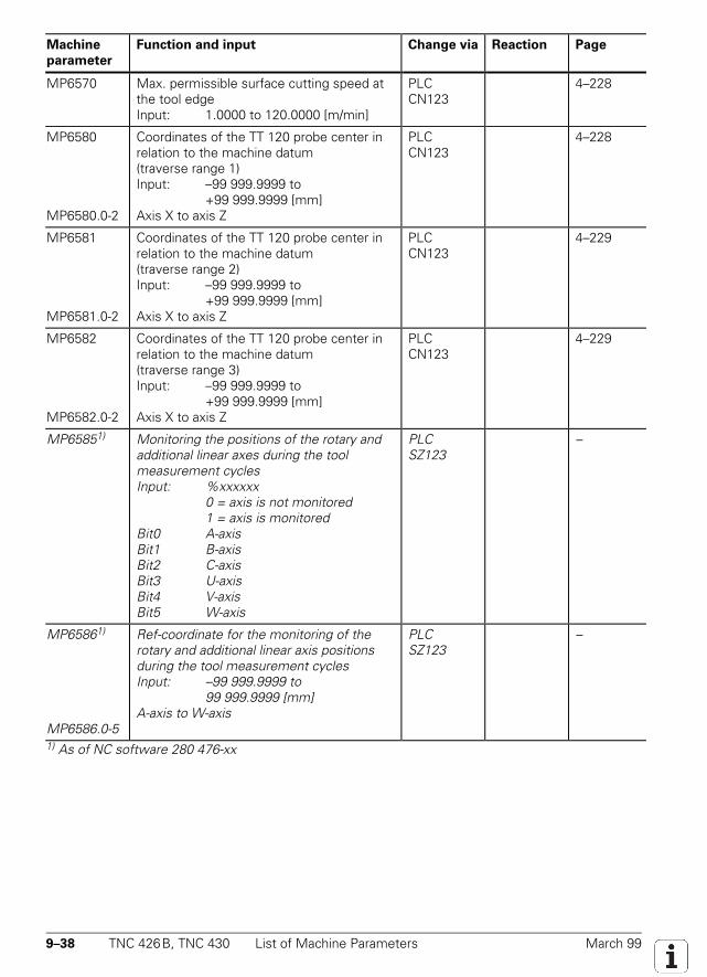
9–38 TNC 426B, TNC 430 List of Machine Parameters March 99
Machine
parameter
Function and input Change via Reaction Page
MP6570 Max. permissible surface cutting speed atthe tool edgeInput: 1.0000 to 120.0000 [m/min]
PLCCN123
4–228
MP6580
MP6580.0-2
Coordinates of the TT 120 probe center inrelation to the machine datum(traverse range 1)Input: –99 999.9999 to
+99 999.9999 [mm]Axis X to axis Z
PLCCN123
4–228
MP6581
MP6581.0-2
Coordinates of the TT 120 probe center inrelation to the machine datum(traverse range 2)Input: –99 999.9999 to
+99 999.9999 [mm]Axis X to axis Z
PLCCN123
4–229
MP6582
MP6582.0-2
Coordinates of the TT 120 probe center inrelation to the machine datum(traverse range 3)Input: –99 999.9999 to
+99 999.9999 [mm]Axis X to axis Z
PLCCN123
4–229
MP65851) Monitoring the positions of the rotary andadditional linear axes during the toolmeasurement cyclesInput: %xxxxxx
0 = axis is not monitored1 = axis is monitored
Bit0 A-axisBit1 B-axisBit2 C-axisBit3 U-axisBit4 V-axisBit5 W-axis
PLCSZ123
–
MP65861)
MP6586.0-5
Ref-coordinate for the monitoring of therotary and additional linear axis positionsduring the tool measurement cyclesInput: –99 999.9999 to
99 999.9999 [mm]A-axis to W-axis
PLCSZ123
–
1) As of NC software 280 476-xx
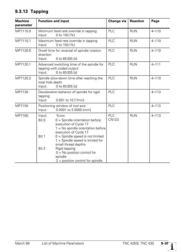
March 99 List of Machine Parameters TNC 426B, TNC 430 9–39
9.3.13 Tapping
Machine
parameter
Function and input Change via Reaction Page
MP7110.0 Minimum feed rate override in tappingInput: 0 to 150 [%]
PLC RUN 4–110
MP7110.1 Maximum feed rate override in tappingInput: 0 to 150 [%]
PLC RUN 4–110
MP7120.0 Dwell time for reversal of spindle rotationdirectionInput: 0 to 65.535 [s]
PLC RUN 4–110
MP7120.1 Advanced switching time of the spindle fortapping with coded outputInput: 0 to 65.535 [s]
PLC RUN 4–111
MP7120.2 Spindle slow-down time after reaching thetotal hole depthInput: 0 to 65.535 [s]
PLC RUN 4–110
MP7130 Deceleration behavior of spindle for rigidtappingInput: 0.001 to 10 [°/min]
PLC 4–113
MP7150 Positioning window of tool axisInput: 0.0001 to 2.0000 [mm]
PLC 4–113
MP7160 Input: %xxxBit 0 0 = Spindle orientation before
execution of Cycle 171 = No spindle orientation beforeexecution of Cycle 17
Bit 1 0 = Spindle speed is not limited1 = Spindle speed is limited forsmall thread depths
Bit 2 Rigid tapping0 = No position control forspindle2 = position control for spindle
PLCCN123
RUN 4–113
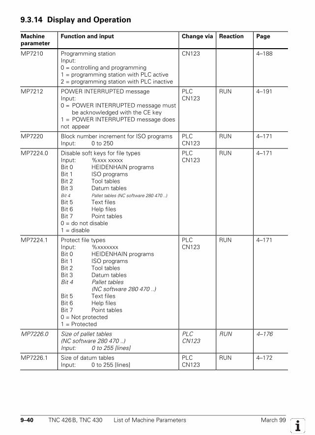
9–40 TNC 426B, TNC 430 List of Machine Parameters March 99
9.3.14 Display and Operation
Machine
parameter
Function and input Change via Reaction Page
MP7210 Programming stationInput:0 = controlling and programming1 = programming station with PLC active2 = programming station with PLC inactive
CN123 4–188
MP7212 POWER INTERRUPTED messageInput:0 = POWER INTERRUPTED message must
be acknowledged with the CE key1 = POWER INTERRUPTED message doesnot appear
PLCCN123
RUN 4–191
MP7220 Block number increment for ISO programsInput: 0 to 250
PLCCN123
RUN 4–171
MP7224.0 Disable soft keys for file typesInput: %xxx xxxxxBit 0 HEIDENHAIN programsBit 1 ISO programsBit 2 Tool tablesBit 3 Datum tablesBit 4 Pallet tables (NC software 280 470 ..)Bit 5 Text filesBit 6 Help filesBit 7 Point tables0 = do not disable1 = disable
PLCCN123
RUN 4–171
MP7224.1 Protect file typesInput: %xxxxxxxBit 0 HEIDENHAIN programsBit 1 ISO programsBit 2 Tool tablesBit 3 Datum tablesBit 4 Pallet tables
(NC software 280 470 ..)Bit 5 Text filesBit 6 Help filesBit 7 Point tables0 = Not protected1 = Protected
PLCCN123
RUN 4–171
MP7226.0 Size of pallet tables(NC software 280 470 ..)Input: 0 to 255 [lines]
PLCCN123
RUN 4–176
MP7226.1 Size of datum tablesInput: 0 to 255 [lines]
PLCCN123
RUN 4–172
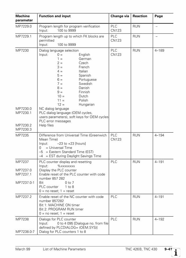
March 99 List of Machine Parameters TNC 426B, TNC 430 9–41
Machine
parameter
Function and input Change via Reaction Page
MP7229.0 Program length for program verificationInput: 100 to 9999
PLCCN123
RUN –
MP7229.1 Program length up to which FK blocks arepermittedInput: 100 to 9999
PLCCN123
RUN –
MP7230
MP7230.0MP7230.1
MP7230.2MP7230.3
Dialog language selectionInput: 0 = English
1 = German2 = Czech3 = French4 = Italian5 = Spanish6 = Portuguese7 = Swedish8 = Danish9 = Finnish10 = Dutch11 = Polish12 = Hungarian
NC dialog languagePLC dialog language (OEM cycles,users parameters), soft keys for OEM cyclesPLC error messagesHelp files
PLCCN123
RUN 4–189
MP7235 Difference from Universal Time (GreenwichMean Time)Input: –23 to +23 [hours]0 = Universal Time–5 = Eastern Standard Time (EST)–4 = EST during Daylight Savings Time
PLCCN123
RUN 4–194
MP7237
MP7237.0MP7237.1
MP7237.0-1
PLC counter display and resettingInput: %xxxxxxxxDisplay the PLC counterEnable reset of the PLC counter with codenumber 857 282Bit 0 to 7PLC counter 1 to 80 = no reset; 1 = reset
PLC RUN 4–191
MP7237.2 Enable reset of the NC counter with codenumber 857282Bit 1: MACHINE ON timerBit 2: PROGRAM RUN timer0 = no reset; 1 = reset
PLC RUN 4–191
MP7238
MP7238.0-7
Dialogs for PLC counterInput: 0 to 4 095 [Dialogue no. from filedefined by PLCDIALOG= (OEM.SYS)]Dialog for PLC counters 1 to 8
PLC RUN 4–192
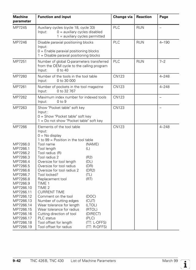
9–42 TNC 426B, TNC 430 List of Machine Parameters March 99
Machine
parameter
Function and input Change via Reaction Page
MP7245 Auxiliary cycles (cycle 18, cycle 33)Input: 0 = auxiliary cycles disabled
1 = auxiliary cycles permitted
PLC RUN –
MP7246 Disable paraxial positioning blocksInput:0 = Enable paraxial positioning blocks1 = Disable paraxial positioning blocks
PLC RUN 4–190
MP7251 Number of global Q-parameters transferredfrom the OEM cycle to the calling programInput: 0 to 40
PLC RUN 7–2
MP7260 Number of the tools in the tool tableInput: 0 to 30 000
CN123 4–248
MP7261 Number of pockets in the tool magazineInput: 0 to 32 767
CN123 4–248
MP7262 Maximum index number for indexed toolsInput: 0 to 9
CN123 –
MP7263 Show "Pocket table" soft keyInput::0 = Show "Pocket table" soft key1 = Do not show "Pocket table" soft key
CN123 –
MP7266
MP7266.0MP7266.1MP7266.2MP7266.3MP7266.4MP7266.5MP7266.6MP7266.7MP7266.8MP7266.9MP7266.10MP7266.11MP7266.12MP7266.13MP7266.14MP7266.15MP7266.16MP7266.17MP7266.18MP7266.19
Elements of the tool tableInput:0 = No display1 to 99 = Position in the tool tableTool name (NAME)Tool length (L)Tool radius (R)Tool radius 2 (R2)Oversize for tool length (DL)Oversize for tool radius (DR)Oversize for tool radius 2 (DR2)Tool locked? (TL)Replacement tool (RT)TIME 1TIME 2CURRENT TIMEComment on the tool (DOC)Number of cutting edges (CUT)Wear tolerance for length (LTOL)Wear tolerance for radius (RTOL)Cutting direction of tool (DIRECT)PLC status (PLC)Tool offset for length (TT: L-OFFS)Tool offset for radius (TT: R-OFFS)
CN123 4–248
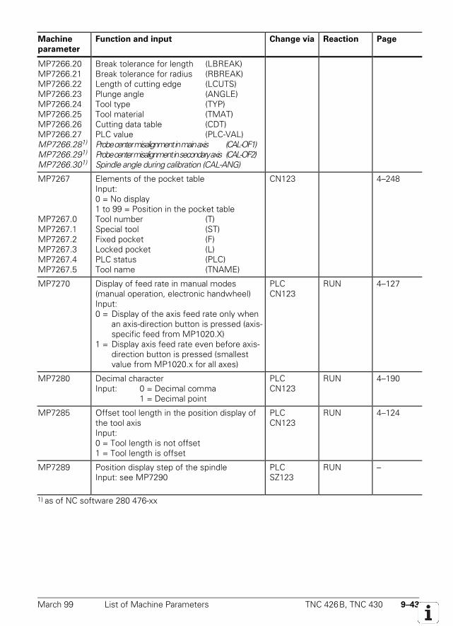
March 99 List of Machine Parameters TNC 426B, TNC 430 9–43
Machine
parameter
Function and input Change via Reaction Page
MP7266.20MP7266.21MP7266.22MP7266.23MP7266.24MP7266.25MP7266.26MP7266.27MP7266.281)
MP7266.291)
MP7266.301)
Break tolerance for length (LBREAK)Break tolerance for radius (RBREAK)Length of cutting edge (LCUTS)Plunge angle (ANGLE)Tool type (TYP)Tool material (TMAT)Cutting data table (CDT)PLC value (PLC-VAL)Probe center misalignment in main axis (CAL-OF1)Probe center misalignment in secondary axis (CAL-OF2)Spindle angle during calibration (CAL-ANG)
MP7267
MP7267.0MP7267.1MP7267.2MP7267.3MP7267.4MP7267.5
Elements of the pocket tableInput:0 = No display1 to 99 = Position in the pocket tableTool number (T)Special tool (ST)Fixed pocket (F)Locked pocket (L)PLC status (PLC)Tool name (TNAME)
CN123 4–248
MP7270 Display of feed rate in manual modes(manual operation, electronic handwheel)Input:0 = Display of the axis feed rate only when
an axis-direction button is pressed (axis-specific feed from MP1020.X)
1 = Display axis feed rate even before axis-direction button is pressed (smallestvalue from MP1020.x for all axes)
PLCCN123
RUN 4–127
MP7280 Decimal characterInput: 0 = Decimal comma
1 = Decimal point
PLCCN123
RUN 4–190
MP7285 Offset tool length in the position display ofthe tool axisInput:0 = Tool length is not offset1 = Tool length is offset
PLCCN123
RUN 4–124
MP7289 Position display step of the spindleInput: see MP7290
PLCSZ123
RUN –
1) as of NC software 280 476-xx
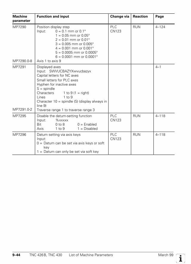
9–44 TNC 426B, TNC 430 List of Machine Parameters March 99
Machine
parameter
Function and input Change via Reaction Page
MP7290
MP7290.0-8
Position display stepInput: 0 = 0.1 mm or 0.1°
1 = 0.05 mm or 0.05°2 = 0.01 mm or 0.01°3 = 0.005 mm or 0.005°4 = 0.001 mm or 0.001°5 = 0.0005 mm or 0.0005°6 = 0.0001 mm or 0.0001°
Axis 1 to axis 9
PLCCN123
RUN 4–124
MP7291
MP7291.0-2
Displayed axesInput: SWVUCBAZYXwvucbazyxCapital letters for NC axesSmall letters for PLC axesHyphen for inactive axesS = spindleCharacters 1 to 9 (1 = right)Lines 1 to 9Character 10 = spindle (S) (display always inline 9)Traverse range 1 to traverse range 3
4–1
MP7295 Disable the datum-setting functionInput: %xxxxxBit 0 to 8 0 = EnabledAxis 1 to 9 1 = Disabled
PLCCN123
RUN 4–118
MP7296 Datum setting via axis keysInput:0 = Datum can be set via axis keys or soft
key1 = Datum can only be set via soft key
PLCCN123
RUN 4–118
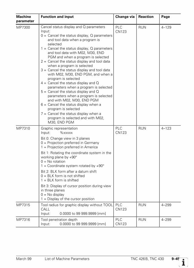
March 99 List of Machine Parameters TNC 426B, TNC 430 9–45
Machine
parameter
Function and input Change via Reaction Page
MP7300 Cancel status display and Q parametersInput:0 = Cancel the status display, Q parameters
and tool data when a program isselected
1 = Cancel the status display, Q parametersand tool data with M02, M30, ENDPGM and when a program is selected
2 = Cancel the status display and tool datawhen a program is selected
3 = Cancel the status display and tool datawith M02, M30, END PGM, and when aprogram is selected
4 = Cancel the status display and Qparameters when a program is selected
5 = Cancel the status display and Qparameters when a program is selectedand with M02, M30, END PGM
6 = Cancel the status display when aprogram is selected
7 = Cancel the status display when aprogram is selected and with M02,M30, END PGM
PLCCN123
RUN 4–129
MP7310 Graphic representationInput: %xxxxx
Bit 0: Change view in 3 planes0 = Projection preferred in Germany1 = Projection preferred in America
Bit 1: Rotating the coordinate system in theworking plane by +90°0 = No rotation1 = Coordinate system rotated by +90°
Bit 2: BLK form after a datum shift0 = BLK form is not shifted1 = BLK form is shifted
Bit 3: Display of cursor position during viewin three planes0 = No display1 = Display of the cursor position
PLCCN123
RUN 4–123
MP7315 Tool radius for graphic display without TOOLCALLInput: 0.0000 to 99 999.9999 [mm]
PLCCN123
RUN 4–299
MP7316 Tool penetration depthInput: 0.0000 to 99 999.9999 [mm]
PLCCN123
RUN 4–299
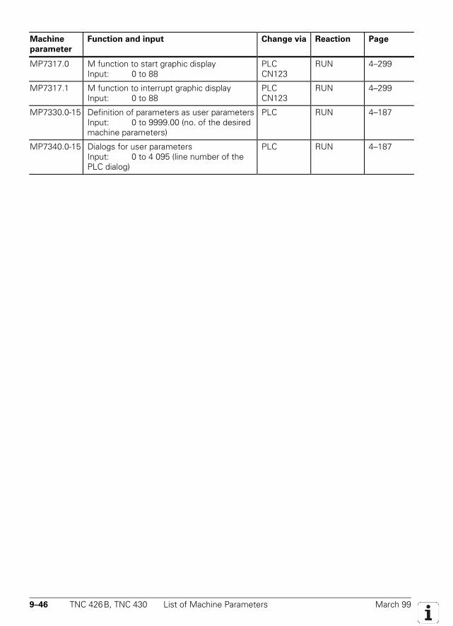
9–46 TNC 426B, TNC 430 List of Machine Parameters March 99
Machine
parameter
Function and input Change via Reaction Page
MP7317.0 M function to start graphic displayInput: 0 to 88
PLCCN123
RUN 4–299
MP7317.1 M function to interrupt graphic displayInput: 0 to 88
PLCCN123
RUN 4–299
MP7330.0-15 Definition of parameters as user parametersInput: 0 to 9999.00 (no. of the desiredmachine parameters)
PLC RUN 4–187
MP7340.0-15 Dialogs for user parametersInput: 0 to 4 095 (line number of thePLC dialog)
PLC RUN 4–187
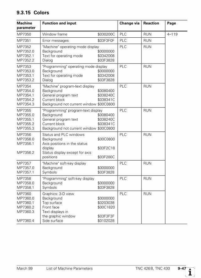
March 99 List of Machine Parameters TNC 426B, TNC 430 9–47
9.3.15 Colors
Machine
parameter
Function and input Change via Reaction Page
MP7350 Window frame $030200C PLC RUN 4–119
MP7351 Error messages $03F3F0F PLC RUN
MP7352MP7352.0MP7352.1MP7352.2
"Machine" operating mode displayBackground $0000000Text for operating mode $0342008Dialog $03F3828
PLC RUN
MP7353MP7353.0MP7353.1MP7353.2
"Programming" operating mode displayBackground $0000000Text for operating mode $0342008Dialog $03F3828
PLC RUN
MP7354MP7354.0MP7354.1MP7354.2MP7354.3
"Machine" program-text displayBackground $0080400General program text $038240CCurrent block $038341CBackground not current window $00C0800
PLC RUN
MP7355MP7355.0MP7355.1MP7355.2MP7355.3
"Programming" program-text displayBackground $0080400General program text $038240CCurrent block $038341CBackground not current window $00C0800
PLC RUN
MP7356MP7356.0MP7356.1
MP7356.2
Status and PLC windowsBackground $00C0800Axis positions in the statusdisplay $03F2C18Status display except for axispositions $03F280C
PLC RUN
MP7357MP7357.0MP7357.1
"Machine" soft-key displayBackground $0000000Symbols $03F3828
PLC RUN
MP7358MP7358.0MP7358.1
"Programming" soft-key displayBackground $0000000Symbols $03F3828
PLC RUN
MP7360MP7360.0MP7360.1MP7360.2MP7360.3
MP7360.4
Graphics: 3-D viewBackground $0000000Top surface $0203038Front face $00C1820Text displays inthe graphic window $03F3F3FSide surface $0102028
PLC RUN
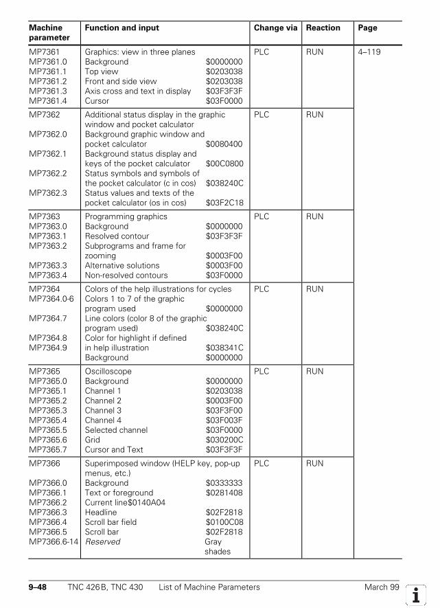
9–48 TNC 426B, TNC 430 List of Machine Parameters March 99
Machine
parameter
Function and input Change via Reaction Page
MP7361MP7361.0MP7361.1MP7361.2MP7361.3MP7361.4
Graphics: view in three planesBackground $0000000Top view $0203038Front and side view $0203038Axis cross and text in display $03F3F3FCursor $03F0000
PLC RUN 4–119
MP7362
MP7362.0
MP7362.1
MP7362.2
MP7362.3
Additional status display in the graphicwindow and pocket calculatorBackground graphic window andpocket calculator $0080400Background status display andkeys of the pocket calculator $00C0800Status symbols and symbols ofthe pocket calculator (c in cos) $038240CStatus values and texts of thepocket calculator (os in cos) $03F2C18
PLC RUN
MP7363MP7363.0MP7363.1MP7363.2
MP7363.3MP7363.4
Programming graphicsBackground $0000000Resolved contour $03F3F3FSubprograms and frame forzooming $0003F00Alternative solutions $0003F00Non-resolved contours $03F0000
PLC RUN
MP7364MP7364.0-6
MP7364.7
MP7364.8MP7364.9
Colors of the help illustrations for cyclesColors 1 to 7 of the graphicprogram used $0000000Line colors (color 8 of the graphicprogram used) $038240CColor for highlight if definedin help illustration $038341CBackground $0000000
PLC RUN
MP7365MP7365.0MP7365.1MP7365.2MP7365.3MP7365.4MP7365.5MP7365.6MP7365.7
OscilloscopeBackground $0000000Channel 1 $0203038Channel 2 $0003F00Channel 3 $03F3F00Channel 4 $03F003FSelected channel $03F0000Grid $030200CCursor and Text $03F3F3F
PLC RUN
MP7366
MP7366.0MP7366.1MP7366.2MP7366.3MP7366.4MP7366.5MP7366.6-14
Superimposed window (HELP key, pop-upmenus, etc.)Background $0333333Text or foreground $0281408Current line$0140A04Headline $02F2818Scroll bar field $0100C08Scroll bar $02F2818Reserved Gray
shades
PLC RUN
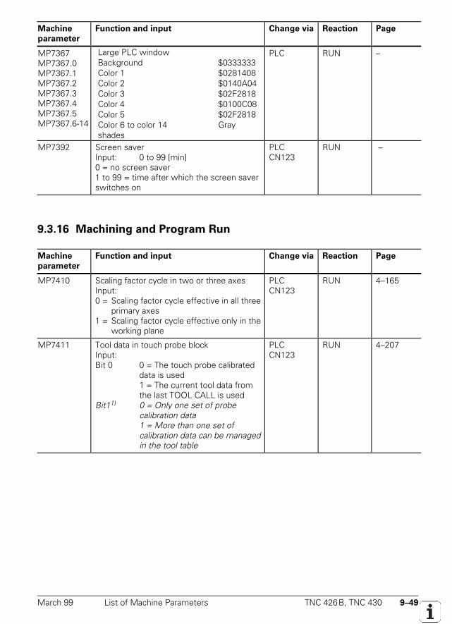
March 99 List of Machine Parameters TNC 426B, TNC 430 9–49
Machine
parameter
Function and input Change via Reaction Page
MP7367MP7367.0MP7367.1MP7367.2MP7367.3MP7367.4MP7367.5MP7367.6-14
Large PLC windowBackground $0333333Color 1 $0281408Color 2 $0140A04Color 3 $02F2818Color 4 $0100C08Color 5 $02F2818Color 6 to color 14 Grayshades
PLC RUN –
MP7392 Screen saverInput: 0 to 99 [min]0 = no screen saver1 to 99 = time after which the screen saverswitches on
PLCCN123
RUN –
9.3.16 Machining and Program Run
Machine
parameter
Function and input Change via Reaction Page
MP7410 Scaling factor cycle in two or three axesInput:0 = Scaling factor cycle effective in all three
primary axes1 = Scaling factor cycle effective only in the
working plane
PLCCN123
RUN 4–165
MP7411 Tool data in touch probe blockInput:Bit 0 0 = The touch probe calibrated
data is used1 = The current tool data from the last TOOL CALL is used
Bit11) 0 = Only one set of probe calibration data1 = More than one set of calibration data can be managed in the tool table
PLCCN123
RUN 4–207
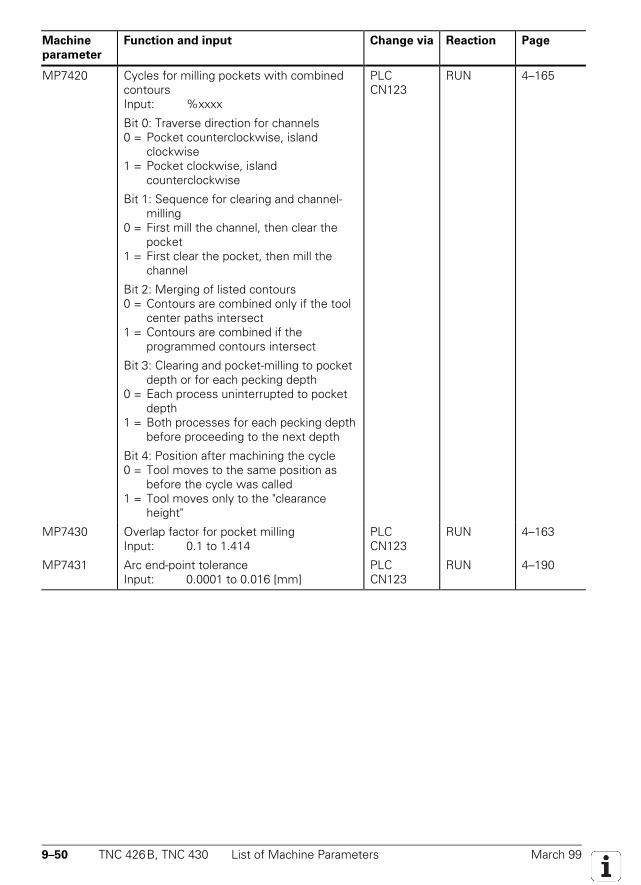
9–50 TNC 426B, TNC 430 List of Machine Parameters March 99
Machine
parameter
Function and input Change via Reaction Page
MP7420 Cycles for milling pockets with combinedcontoursInput: %xxxx
Bit 0: Traverse direction for channels0 = Pocket counterclockwise, island
clockwise1 = Pocket clockwise, island
counterclockwise
Bit 1: Sequence for clearing and channel-milling
0 = First mill the channel, then clear the pocket
1 = First clear the pocket, then mill the channel
Bit 2: Merging of listed contours0 = Contours are combined only if the tool
center paths intersect1 = Contours are combined if the
programmed contours intersect
Bit 3: Clearing and pocket-milling to pocket depth or for each pecking depth
0 = Each process uninterrupted to pocket depth
1 = Both processes for each pecking depth before proceeding to the next depth
Bit 4: Position after machining the cycle0 = Tool moves to the same position as
before the cycle was called1 = Tool moves only to the "clearance
height"
PLCCN123
RUN 4–165
MP7430 Overlap factor for pocket millingInput: 0.1 to 1.414
PLCCN123
RUN 4–163
MP7431 Arc end-point toleranceInput: 0.0001 to 0.016 [mm]
PLCCN123
RUN 4–190
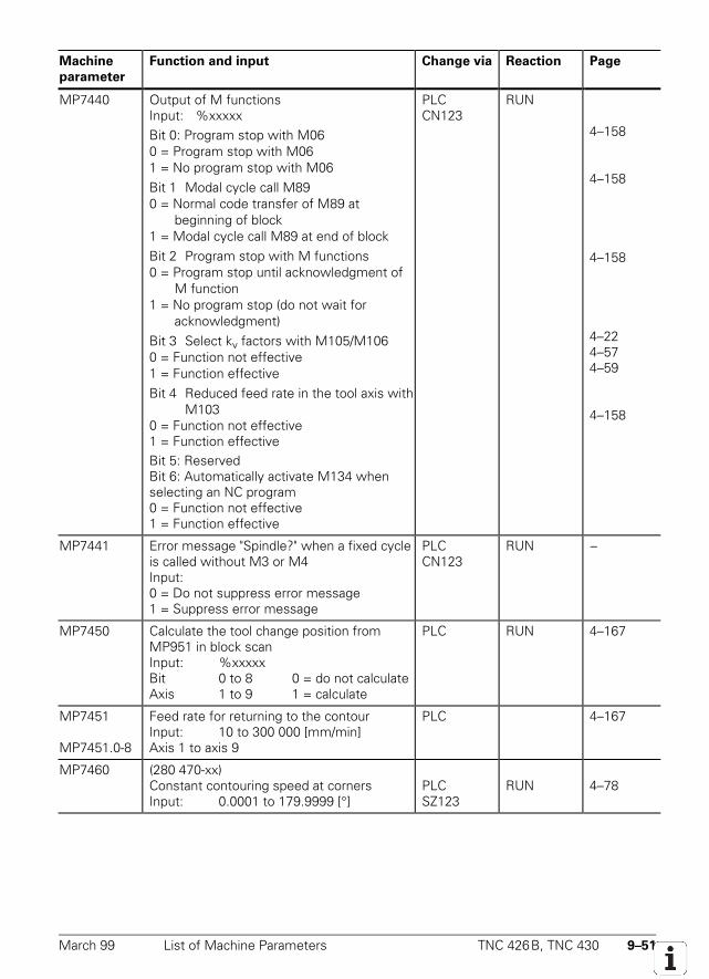
March 99 List of Machine Parameters TNC 426B, TNC 430 9–51
Machine
parameter
Function and input Change via Reaction Page
MP7440 Output of M functionsInput: %xxxxxBit 0: Program stop with M060 = Program stop with M061 = No program stop with M06Bit 1 Modal cycle call M890 = Normal code transfer of M89 at
beginning of block1 = Modal cycle call M89 at end of blockBit 2 Program stop with M functions0 = Program stop until acknowledgment of
M function1 = No program stop (do not wait for
acknowledgment)Bit 3 Select kv factors with M105/M1060 = Function not effective1 = Function effectiveBit 4 Reduced feed rate in the tool axis with
M1030 = Function not effective1 = Function effectiveBit 5: ReservedBit 6: Automatically activate M134 whenselecting an NC program0 = Function not effective1 = Function effective
PLCCN123
RUN
4–158
4–158
4–158
4–224–574–59
4–158
MP7441 Error message "Spindle?" when a fixed cycleis called without M3 or M4Input:0 = Do not suppress error message1 = Suppress error message
PLCCN123
RUN –
MP7450 Calculate the tool change position fromMP951 in block scanInput: %xxxxxBit 0 to 8 0 = do not calculateAxis 1 to 9 1 = calculate
PLC RUN 4–167
MP7451
MP7451.0-8
Feed rate for returning to the contourInput: 10 to 300 000 [mm/min]Axis 1 to axis 9
PLC 4–167
MP7460 (280 470-xx)Constant contouring speed at cornersInput: 0.0001 to 179.9999 [°]
PLCSZ123
RUN 4–78
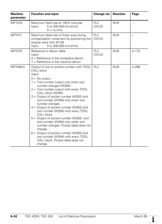
9–52 TNC 426B, TNC 430 List of Machine Parameters March 99
Machine
parameter
Function and input Change via Reaction Page
MP7470 Maximum feed rate at 100% overrideInput: 0 to 300 000 [mm/min]
0 = no limit
PLCCN123
RUN –
MP7471 Maximum feed rate of linear axes duringcompensation movement by positioning theangular axes with M128Input: 0 to 300 000 [mm/min]
PLCCN123
RUN –
MP7475 Reference in datum tableInput:0 = Reference is the workpiece datum1 = Reference is the machine datum
PLCCN123
RUN 4–172
MP7480.0 Output of tool or pocket number with TOOLCALL blockInput:0 = No output1 = Tool number output only when tool
number changes (W264)2 = Tool number output with every TOOL
CALL block (W264)3 = Output of pocket number (W262) and
tool number (W264) only when toolnumber changes
4 = Output of pocket number (W262) andtool number (W264) with every TOOLCALL block
5 = Output of pocket number (W262) andtool number (W264) only when toolnumber changes. Pocket table does notchange.
6 = Output of pocket number (W262) andtool number (W264) with every TOOLCALL block. Pocket table does notchange.
PLC RUN 4–268
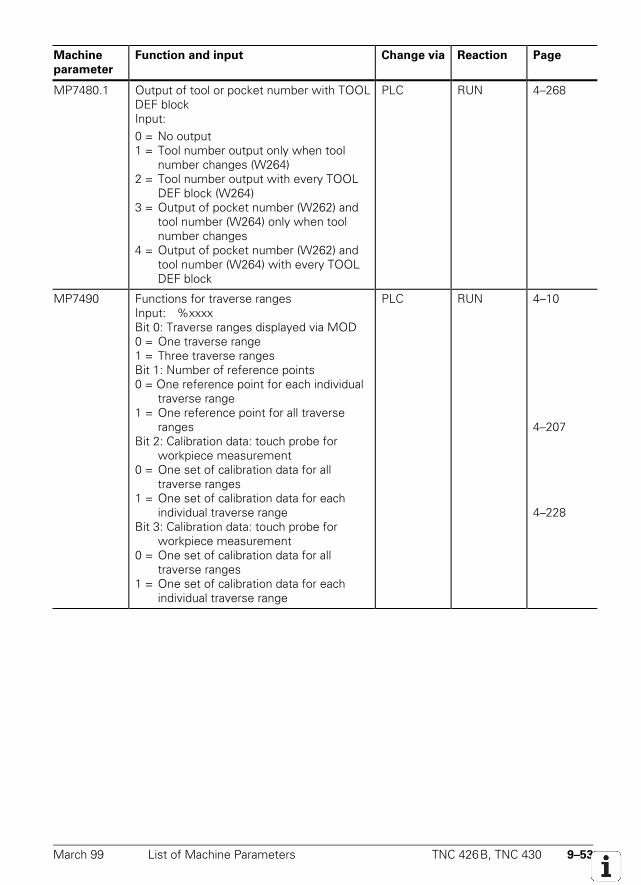
March 99 List of Machine Parameters TNC 426B, TNC 430 9–53
Machine
parameter
Function and input Change via Reaction Page
MP7480.1 Output of tool or pocket number with TOOLDEF blockInput:0 = No output1 = Tool number output only when tool
number changes (W264)2 = Tool number output with every TOOL
DEF block (W264)3 = Output of pocket number (W262) and
tool number (W264) only when toolnumber changes
4 = Output of pocket number (W262) andtool number (W264) with every TOOLDEF block
PLC RUN 4–268
MP7490 Functions for traverse rangesInput: %xxxxBit 0: Traverse ranges displayed via MOD0 = One traverse range1 = Three traverse rangesBit 1: Number of reference points0 = One reference point for each individual
traverse range1 = One reference point for all traverse
rangesBit 2: Calibration data: touch probe for
workpiece measurement0 = One set of calibration data for all
traverse ranges1 = One set of calibration data for each
individual traverse rangeBit 3: Calibration data: touch probe for
workpiece measurement0 = One set of calibration data for all
traverse ranges1 = One set of calibration data for each
individual traverse range
PLC RUN 4–10
4–207
4–228
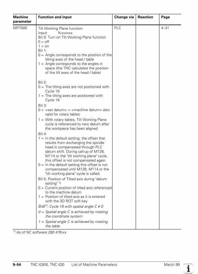
9–54 TNC 426B, TNC 430 List of Machine Parameters March 99
Machine
parameter
Function and input Change via Reaction Page
MP7500 Tilt Working Plane functionInput: %xxxxxxBit 0: Turn on Tilt Working Plane function0 = off1 = onBit 1:0 = Angle corresponds to the position of the
tilting axes of the head / table1 = Angle corresponds to the angles in
space (the TNC calculates the positionof the tilt axes of the head / table)
PLC 4–31
Bit 2:0 = The tilting axes are not positioned with
Cycle 191 = The tilting axes are positioned with
Cycle 19Bit 3:0 = <set datum> = <machine datum> also
valid for rotary tables1 = With rotary tables, Tilt Working Plane
cycle is referenced to new datum afterthe workpiece has been aligned
Bit 4:1 = In the default setting, the offset that
results from exchanging the spindlehead is compensated through PLCdatum shift. During call-up of M128,M114 or the "tilt working plane" cycle,this offset is not compensated again.
0 = In the default setting this offset is notcompensated until M128, M114 or the"tilt working plane" cycle is called.
Bit 5: Position of Tilted axis during "datumsetting" 1)
0 = Current position of tilted axis referencedto the machine datum
1 = Position of tilted axis as it is enteredwith the 3D ROT soft key
Bit61): Cycle 19 with spatial angle C ≠ 00 = Spatial angle C is achieved by rotating
the coordinate system1 = Spatial angle C is achieved by rotating
the table1) As of NC software 280 476-xx
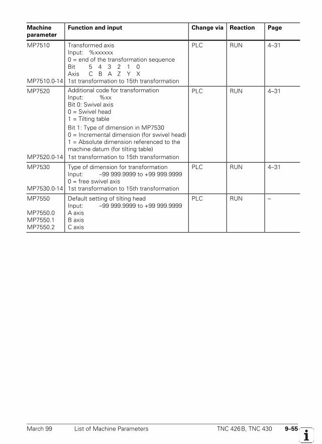
March 99 List of Machine Parameters TNC 426B, TNC 430 9–55
Machine
parameter
Function and input Change via Reaction Page
MP7510
MP7510.0-14
Transformed axisInput: %xxxxxx0 = end of the transformation sequenceBit 5 4 3 2 1 0Axis C B A Z Y X1st transformation to 15th transformation
PLC RUN 4–31
MP7520
MP7520.0-14
Additional code for transformationInput: %xxBit 0: Swivel axis0 = Swivel head1 = Tilting tableBit 1: Type of dimension in MP75300 = Incremental dimension (for swivel head)1 = Absolute dimension referenced to themachine datum (for tilting table)1st transformation to 15th transformation
PLC RUN 4–31
MP7530
MP7530.0-14
Type of dimension for transformationInput: –99 999.9999 to +99 999.99990 = free swivel axis1st transformation to 15th transformation
PLC RUN 4–31
MP7550
MP7550.0MP7550.1MP7550.2
Default setting of tilting headInput: –99 999.9999 to +99 999.9999A axisB axisC axis
PLC RUN –
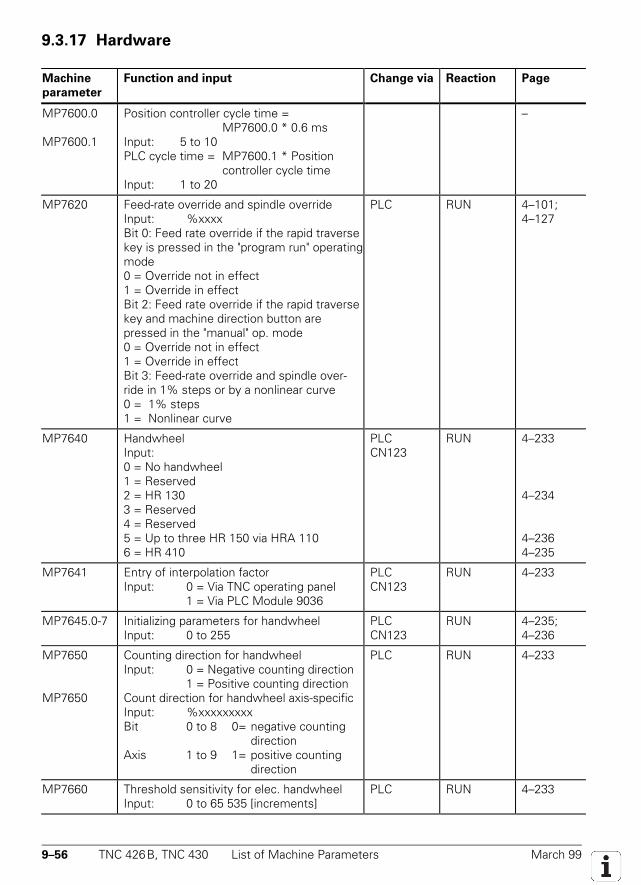
9–56 TNC 426B, TNC 430 List of Machine Parameters March 99
9.3.17 Hardware
Machine
parameter
Function and input Change via Reaction Page
MP7600.0
MP7600.1
Position controller cycle time =MP7600.0 * 0.6 ms
Input: 5 to 10PLC cycle time = MP7600.1 * Position
controller cycle timeInput: 1 to 20
–
MP7620 Feed-rate override and spindle overrideInput: %xxxxBit 0: Feed rate override if the rapid traversekey is pressed in the "program run" operatingmode0 = Override not in effect1 = Override in effectBit 2: Feed rate override if the rapid traversekey and machine direction button arepressed in the "manual" op. mode0 = Override not in effect1 = Override in effectBit 3: Feed-rate override and spindle over-ride in 1% steps or by a nonlinear curve0 = 1% steps1 = Nonlinear curve
PLC RUN 4–101;4–127
MP7640 HandwheelInput:0 = No handwheel1 = Reserved2 = HR 1303 = Reserved4 = Reserved5 = Up to three HR 150 via HRA 1106 = HR 410
PLCCN123
RUN 4–233
4–234
4–2364–235
MP7641 Entry of interpolation factorInput: 0 = Via TNC operating panel
1 = Via PLC Module 9036
PLCCN123
RUN 4–233
MP7645.0-7 Initializing parameters for handwheelInput: 0 to 255
PLCCN123
RUN 4–235;4–236
MP7650
MP7650
Counting direction for handwheelInput: 0 = Negative counting direction
1 = Positive counting directionCount direction for handwheel axis-specificInput: %xxxxxxxxxBit 0 to 8 0= negative counting
directionAxis 1 to 9 1= positive counting
direction
PLC RUN 4–233
MP7660 Threshold sensitivity for elec. handwheelInput: 0 to 65 535 [increments]
PLC RUN 4–233
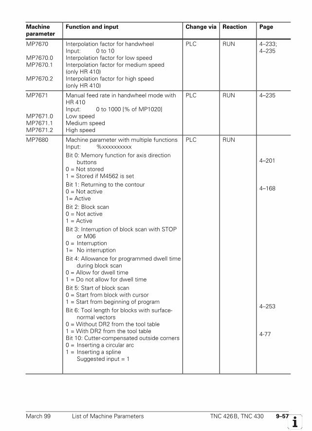
March 99 List of Machine Parameters TNC 426B, TNC 430 9–57
Machine
parameter
Function and input Change via Reaction Page
MP7670
MP7670.0MP7670.1
MP7670.2
Interpolation factor for handwheelInput: 0 to 10Interpolation factor for low speedInterpolation factor for medium speed(only HR 410)Interpolation factor for high speed(only HR 410)
PLC RUN 4–233;4–235
MP7671
MP7671.0MP7671.1MP7671.2
Manual feed rate in handwheel mode withHR 410Input: 0 to 1000 [% of MP1020]Low speedMedium speedHigh speed
PLC RUN 4–235
MP7680 Machine parameter with multiple functionsInput: %xxxxxxxxxxBit 0: Memory function for axis direction
buttons0 = Not stored1 = Stored if M4562 is setBit 1: Returning to the contour0 = Not active1= ActiveBit 2: Block scan0 = Not active1 = ActiveBit 3: Interruption of block scan with STOP
or M060 = Interruption1= No interruptionBit 4: Allowance for programmed dwell time
during block scan0 = Allow for dwell time1 = Do not allow for dwell timeBit 5: Start of block scan0 = Start from block with cursor1 = Start from beginning of programBit 6: Tool length for blocks with surface-
normal vectors0 = Without DR2 from the tool table1 = With DR2 from the tool tableBit 10: Cutter-compensated outside corners0 = Inserting a circular arc1 = Inserting a spline
Suggested input = 1
PLC RUN
4–201
4–168
4–253
4-77
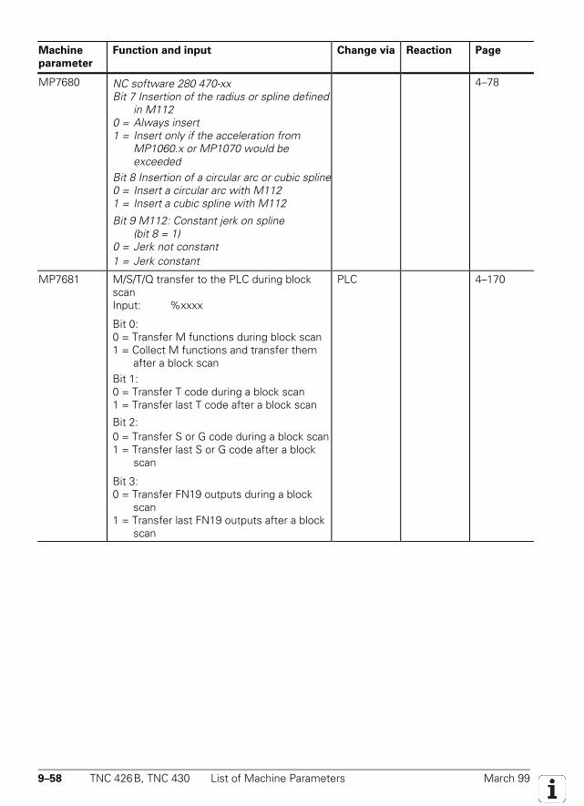
9–58 TNC 426B, TNC 430 List of Machine Parameters March 99
Machine
parameter
Function and input Change via Reaction Page
MP7680 NC software 280 470-xxBit 7 Insertion of the radius or spline defined
in M1120 = Always insert1 = Insert only if the acceleration from
MP1060.x or MP1070 would beexceeded
Bit 8 Insertion of a circular arc or cubic spline0 = Insert a circular arc with M1121 = Insert a cubic spline with M112
Bit 9 M112: Constant jerk on spline(bit 8 = 1)
0 = Jerk not constant1 = Jerk constant
4–78
MP7681 M/S/T/Q transfer to the PLC during blockscanInput: %xxxx
Bit 0:0 = Transfer M functions during block scan1 = Collect M functions and transfer them
after a block scanBit 1:0 = Transfer T code during a block scan1 = Transfer last T code after a block scan
Bit 2:0 = Transfer S or G code during a block scan1 = Transfer last S or G code after a block
scan
Bit 3:0 = Transfer FN19 outputs during a block
scan1 = Transfer last FN19 outputs after a block
scan
PLC 4–170
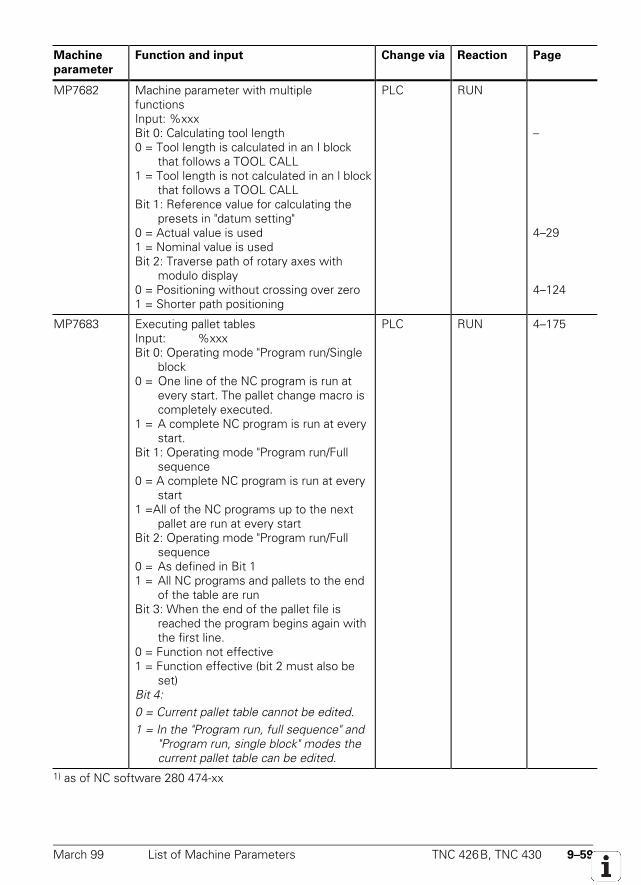
March 99 List of Machine Parameters TNC 426B, TNC 430 9–59
Machine
parameter
Function and input Change via Reaction Page
MP7682 Machine parameter with multiplefunctionsInput: %xxxBit 0: Calculating tool length0 = Tool length is calculated in an I block
that follows a TOOL CALL1 = Tool length is not calculated in an l block
that follows a TOOL CALLBit 1: Reference value for calculating the
presets in "datum setting"0 = Actual value is used1 = Nominal value is usedBit 2: Traverse path of rotary axes with
modulo display0 = Positioning without crossing over zero1 = Shorter path positioning
PLC RUN
–
4–29
4–124
MP7683 Executing pallet tablesInput: %xxxBit 0: Operating mode "Program run/Single
block0 = One line of the NC program is run at
every start. The pallet change macro is completely executed.
1 = A complete NC program is run at every start.
Bit 1: Operating mode "Program run/Full sequence
0 = A complete NC program is run at every start
1 =All of the NC programs up to the next pallet are run at every start
Bit 2: Operating mode "Program run/Full sequence
0 = As defined in Bit 11 = All NC programs and pallets to the end
of the table are runBit 3: When the end of the pallet file is
reached the program begins again withthe first line.
0 = Function not effective1 = Function effective (bit 2 must also be
set)Bit 4:0 = Current pallet table cannot be edited.1 = In the "Program run, full sequence" and
"Program run, single block" modes thecurrent pallet table can be edited.
PLC RUN 4–175
1) as of NC software 280 474-xx
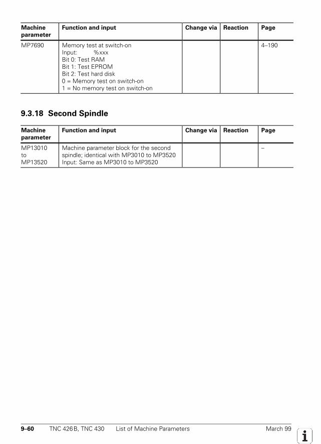
9–60 TNC 426B, TNC 430 List of Machine Parameters March 99
Machine
parameter
Function and input Change via Reaction Page
MP7690 Memory test at switch-onInput: %xxxBit 0: Test RAMBit 1: Test EPROMBit 2: Test hard disk0 = Memory test on switch-on1 = No memory test on switch-on
4–190
9.3.18 Second Spindle
Machine
parameter
Function and input Change via Reaction Page
MP13010toMP13520
Machine parameter block for the secondspindle; identical with MP3010 to MP3520Input: Same as MP3010 to MP3520
–
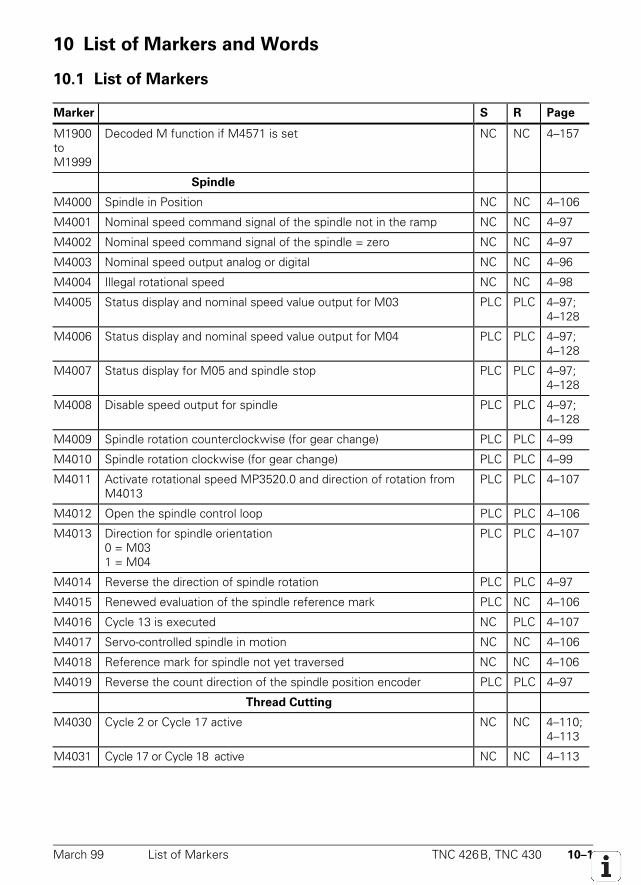
March 99 List of Markers TNC 426B, TNC 430 10–1
10 List of Markers and Words
10.1 List of Markers
Marker S R Page
M1900toM1999
Decoded M function if M4571 is set NC NC 4–157
Spindle
M4000 Spindle in Position NC NC 4–106
M4001 Nominal speed command signal of the spindle not in the ramp NC NC 4–97
M4002 Nominal speed command signal of the spindle = zero NC NC 4–97
M4003 Nominal speed output analog or digital NC NC 4–96
M4004 Illegal rotational speed NC NC 4–98
M4005 Status display and nominal speed value output for M03 PLC PLC 4–97;4–128
M4006 Status display and nominal speed value output for M04 PLC PLC 4–97;4–128
M4007 Status display for M05 and spindle stop PLC PLC 4–97;4–128
M4008 Disable speed output for spindle PLC PLC 4–97;4–128
M4009 Spindle rotation counterclockwise (for gear change) PLC PLC 4–99
M4010 Spindle rotation clockwise (for gear change) PLC PLC 4–99
M4011 Activate rotational speed MP3520.0 and direction of rotation fromM4013
PLC PLC 4–107
M4012 Open the spindle control loop PLC PLC 4–106
M4013 Direction for spindle orientation0 = M031 = M04
PLC PLC 4–107
M4014 Reverse the direction of spindle rotation PLC PLC 4–97
M4015 Renewed evaluation of the spindle reference mark PLC NC 4–106
M4016 Cycle 13 is executed NC PLC 4–107
M4017 Servo-controlled spindle in motion NC NC 4–106
M4018 Reference mark for spindle not yet traversed NC NC 4–106
M4019 Reverse the count direction of the spindle position encoder PLC PLC 4–97
Thread Cutting
M4030 Cycle 2 or Cycle 17 active NC NC 4–110;4–113
M4031 Cycle 17 or Cycle 18 active NC NC 4–113
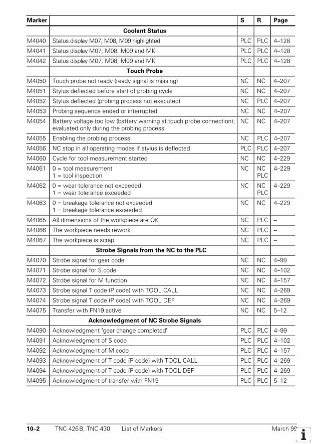
10–2 TNC 426B, TNC 430 List of Markers March 99
Marker S R Page
Coolant Status
M4040 Status display M07, M08, M09 highlighted PLC PLC 4–128
M4041 Status display M07, M08, M09 and MK PLC PLC 4–128
M4042 Status display M07, M08, M09 and MK PLC PLC 4–128
Touch Probe
M4050 Touch probe not ready (ready signal is missing) NC NC 4–207
M4051 Stylus deflected before start of probing cycle NC NC 4–207
M4052 Stylus deflected (probing process not executed) NC PLC 4–207
M4053 Probing sequence ended or interrupted NC NC 4–207
M4054 Battery voltage too low (battery warning at touch probe connection);evaluated only during the probing process
NC NC 4–207
M4055 Enabling the probing process NC PLC 4–207
M4056 NC stop in all operating modes if stylus is deflected PLC PLC 4–207
M4060 Cycle for tool measurement started NC NC 4–229
M4061 0 = tool measurement1 = tool inspection
NC NCPLC
4–229
M4062 0 = wear tolerance not exceeded1 = wear tolerance exceeded
NC NCPLC
4–229
M4063 0 = breakage tolerance not exceeded1 = breakage tolerance exceeded
NC NC 4–229
M4065 All dimensions of the workpiece are OK NC PLC –
M4066 The workpiece needs rework NC PLC –
M4067 The workpiece is scrap NC PLC –
Strobe Signals from the NC to the PLC
M4070 Strobe signal for gear code NC NC 4–99
M4071 Strobe signal for S code NC NC 4–102
M4072 Strobe signal for M function NC NC 4–157
M4073 Strobe signal T code (P code) with TOOL CALL NC NC 4–269
M4074 Strobe signal T code (P code) with TOOL DEF NC NC 4–269
M4075 Transfer with FN19 active NC NC 5–12
Acknowledgment of NC Strobe Signals
M4090 Acknowledgment "gear change completed" PLC PLC 4–99
M4091 Acknowledgment of S code PLC PLC 4–102
M4092 Acknowledgment of M code PLC PLC 4–157
M4093 Acknowledgment of T code (P code) with TOOL CALL PLC PLC 4–269
M4094 Acknowledgment of T code (P code) with TOOL DEF PLC PLC 4–269
M4095 Acknowledgment of transfer with FN19 PLC PLC 5–12
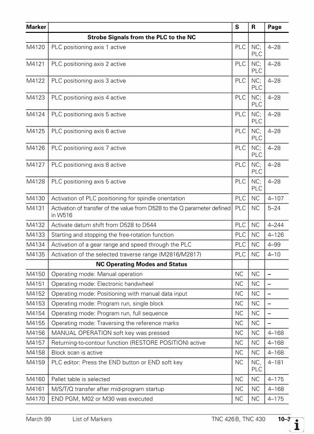
March 99 List of Markers TNC 426B, TNC 430 10–3
Marker S R Page
Strobe Signals from the PLC to the NC
M4120 PLC positioning axis 1 active PLC NC;PLC
4–28
M4121 PLC positioning axis 2 active PLC NC;PLC
4–28
M4122 PLC positioning axis 3 active PLC NC;PLC
4–28
M4123 PLC positioning axis 4 active PLC NC;PLC
4–28
M4124 PLC positioning axis 5 active PLC NC;PLC
4–28
M4125 PLC positioning axis 6 active PLC NC;PLC
4–28
M4126 PLC positioning axis 7 active PLC NC;PLC
4–28
M4127 PLC positioning axis 8 active PLC NC;PLC
4–28
M4128 PLC positioning axis 5 active PLC NC;PLC
4–28
M4130 Activation of PLC positioning for spindle orientation PLC NC 4–107
M4131 Activation of transfer of the value from D528 to the Q parameter definedin W516
PLC NC 5–24
M4132 Activate datum shift from D528 to D544 PLC NC 4–244
M4133 Starting and stopping the free-rotation function PLC NC 4–126
M4134 Activation of a gear range and speed through the PLC PLC NC 4–99
M4135 Activation of the selected traverse range (M2816/M2817) PLC NC 4–10
NC Operating Modes and Status
M4150 Operating mode: Manual operation NC NC –
M4151 Operating mode: Electronic handwheel NC NC –
M4152 Operating mode: Positioning with manual data input NC NC –
M4153 Operating mode: Program run, single block NC NC –
M4154 Operating mode: Program run, full sequence NC NC –
M4155 Operating mode: Traversing the reference marks NC NC –
M4156 MANUAL OPERATION soft key was pressed NC NC 4–168
M4157 Returning-to-contour function (RESTORE POSITION) active NC NC 4–168
M4158 Block scan is active NC NC 4–168
M4159 PLC editor: Press the END button or END soft key NC NC,PLC
4–181
M4160 Pallet table is selected NC NC 4–175
M4161 M/S/T/Q transfer after mid-program startup NC NC 4–168
M4170 END PGM, M02 or M30 was executed NC NC 4–175
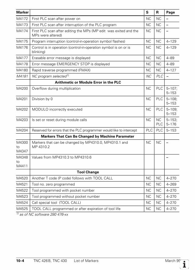
10–4 TNC 426B, TNC 430 List of Markers March 99
Marker S R Page
M4172 First PLC scan after power on NC NC –
M4173 First PLC scan after interruption of the PLC program NC NC –
M4174 First PLC scan after editing the MPs (MP edit was exited and theMPs were altered)
NC NC –
M4175 Program interruption (control-in-operation symbol flashes) NC NC 4–129
M4176 Control is in operation (control-in-operation symbol is on or isblinking)
NC NC 4–129
M4177 Erasable error message is displayed NC NC 4–89
M4178 Error message EMERGENCY STOP is displayed NC NC 4–89
M4180 Rapid traverse programmed (FMAX) NC NC 4–127
M4181 NC program selected1) NC PLC –
Arithmetic or Module Error in the PLC
M4200 Overflow during multiplication NC PLC 5–107;5–153
M4201 Division by 0 NC PLC 5–108;5–153
M4202 MODULO incorrectly executed NC PLC 5–109;5–153
M4203 Is set or reset during module calls NC NCPLC
5–153;5–176
M4204 Reserved for errors that the PLC programmer would like to intercept PLC PLC 5–153
Markers That Can Be Changed by Machine Parameter
M4300toM4347
Markers that can be changed by MP4310.0, MP4310.1 andMP 4310.2
NC NC –
M4348toM4411
Values from MP4310.3 to MP4310.6 –
Tool Change
M4520 Another T code (P code) follows with TOOL CALL NC NC 4–270
M4521 Tool no. zero programmed NC NC 4–269
M4522 Tool programmed with pocket number NC NC 4–270
M4523 Tool programmed without pocket number NC NC 4–270
M4524 Call special tool (TOOL CALL) NC NC 4–270
M4525 TOOL CALL programmed or after expiration of tool life NC NC 4–2701) as of NC software 280 476-xx
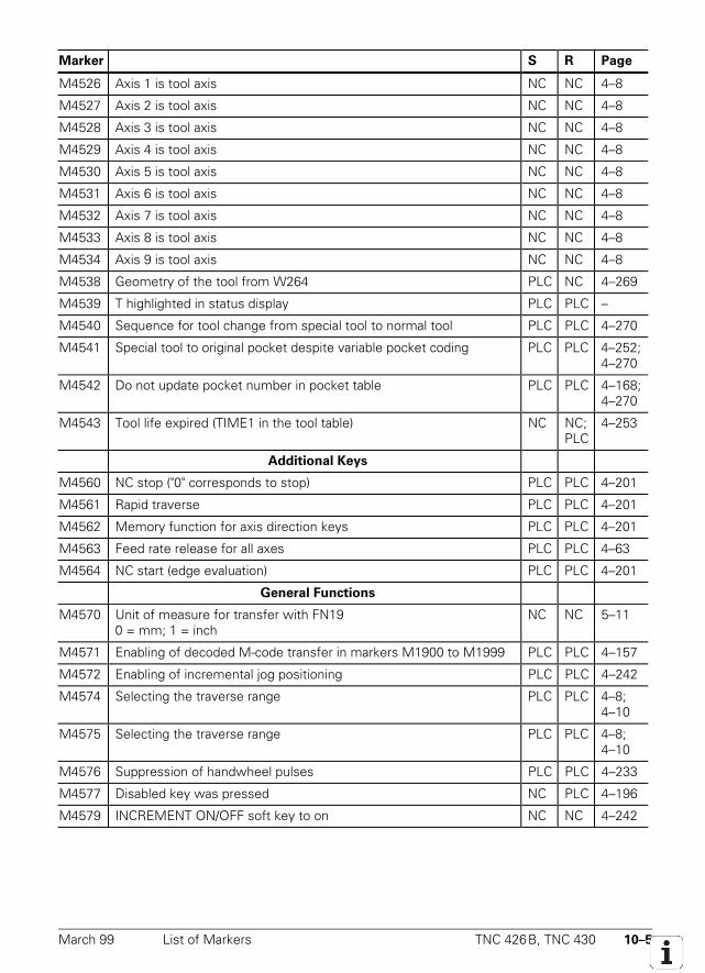
March 99 List of Markers TNC 426B, TNC 430 10–5
Marker S R Page
M4526 Axis 1 is tool axis NC NC 4–8
M4527 Axis 2 is tool axis NC NC 4–8
M4528 Axis 3 is tool axis NC NC 4–8
M4529 Axis 4 is tool axis NC NC 4–8
M4530 Axis 5 is tool axis NC NC 4–8
M4531 Axis 6 is tool axis NC NC 4–8
M4532 Axis 7 is tool axis NC NC 4–8
M4533 Axis 8 is tool axis NC NC 4–8
M4534 Axis 9 is tool axis NC NC 4–8
M4538 Geometry of the tool from W264 PLC NC 4–269
M4539 T highlighted in status display PLC PLC –
M4540 Sequence for tool change from special tool to normal tool PLC PLC 4–270
M4541 Special tool to original pocket despite variable pocket coding PLC PLC 4–252;4–270
M4542 Do not update pocket number in pocket table PLC PLC 4–168;4–270
M4543 Tool life expired (TIME1 in the tool table) NC NC;PLC
4–253
Additional Keys
M4560 NC stop ("0" corresponds to stop) PLC PLC 4–201
M4561 Rapid traverse PLC PLC 4–201
M4562 Memory function for axis direction keys PLC PLC 4–201
M4563 Feed rate release for all axes PLC PLC 4–63
M4564 NC start (edge evaluation) PLC PLC 4–201
General Functions
M4570 Unit of measure for transfer with FN190 = mm; 1 = inch
NC NC 5–11
M4571 Enabling of decoded M-code transfer in markers M1900 to M1999 PLC PLC 4–157
M4572 Enabling of incremental jog positioning PLC PLC 4–242
M4574 Selecting the traverse range PLC PLC 4–8;4–10
M4575 Selecting the traverse range PLC PLC 4–8;4–10
M4576 Suppression of handwheel pulses PLC PLC 4–233
M4577 Disabled key was pressed NC PLC 4–196
M4579 INCREMENT ON/OFF soft key to on NC NC 4–242
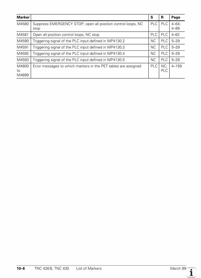
10–6 TNC 426B, TNC 430 List of Markers March 99
Marker S R Page
M4580 Suppress EMERGENCY STOP, open all position control loops, NCstop
PLC PLC 4–64;4–89
M4581 Open all position control loops, NC stop PLC PLC 4–62
M4590 Triggering signal of the PLC input defined in MP4130.2 NC PLC 5–29
M4591 Triggering signal of the PLC input defined in MP4130.3 NC PLC 5–29
M4592 Triggering signal of the PLC input defined in MP4130.4 NC PLC 5–29
M4593 Triggering signal of the PLC input defined in MP4130.5 NC PLC 5–29
M4800toM4899
Error messages to which markers in the PET tables are assigned PLC NC;PLC
4–159
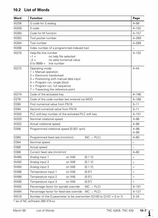
March 99 List of Words TNC 426B, TNC 430 10–7
10.2 List of Words
Word Function Page
W256 G code for S analog 4–99
W258 S code 4–102
W260 Code for M function 4–157
W262 Tool pocket number 4–269
W264 Tool number 4–269
W266 Index number of a programmed indexed tool –
W270 Help-file line number–1 = no help file selected–2 = no valid numerical value0 to 9999 = line number
4–152
W272 Operating mode1 = Manual operation2 = Electronic handwheel3 = Positioning with manual data input4 = Program run, single block5 = Program run, full sequence7 = Traversing the reference point
4–44
W274 Code of the activated key 4–196
D276 Code of the code number last entered via MOD 4–188
D280 First numerical value from FN19 5–11
D284 Second numerical value from FN19 5–11
W302 PLC soft-key number of the activated PLC soft key 4–151
W320 Nominal rotational speed 4–96
W322 Actual rotational speed 4–96
D356 Programmed rotational speed [0.001 rpm] 4–96,4–99
D360 Programmed feed rate [mm/min] (NC → PLC) 4–60
D364 Nominal speed –
D368 Actual speed –
D388 Current feed rate [mm/min] 4–60
W480 Analog input 1 on X48 [0.1 V] –
W482 Analog input 2 on X48 [0.1 V] –
W484 Analog input 3 on X48 [0.1 V] –
W486 Temperature input 1 on X48 [0.5°] –
W488 Temperature input 2 on X48 [0.5°] –
W490 Temperature input 3 on X48 [0.5°] –
W492 Percentage factor for spindle override (NC → PLC) 4–101
W494 Percentage factor for feed-rate override (NC → PLC) 4–127
W516 Number of the Q parameter to be overwritten (Q100 to Q107 = 0 to 7) 5–241) as of NC software 280 474-xx
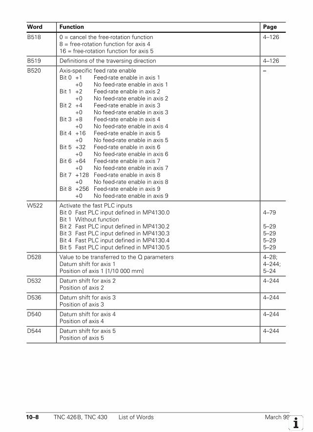
10–8 TNC 426B, TNC 430 List of Words March 99
Word Function Page
B518 0 = cancel the free-rotation function8 = free-rotation function for axis 416 = free-rotation function for axis 5
4–126
B519 Definitions of the traversing direction 4–126
B520 Axis-specific feed rate enableBit 0 +1 Feed-rate enable in axis 1
+0 No feed-rate enable in axis 1Bit 1 +2 Feed-rate enable in axis 2
+0 No feed-rate enable in axis 2Bit 2 +4 Feed-rate enable in axis 3
+0 No feed-rate enable in axis 3Bit 3 +8 Feed-rate enable in axis 4
+0 No feed-rate enable in axis 4Bit 4 +16 Feed-rate enable in axis 5
+0 No feed-rate enable in axis 5Bit 5 +32 Feed-rate enable in axis 6
+0 No feed-rate enable in axis 6Bit 6 +64 Feed-rate enable in axis 7
+0 No feed-rate enable in axis 7Bit 7 +128 Feed-rate enable in axis 8
+0 No feed-rate enable in axis 8Bit 8 +256 Feed-rate enable in axis 9
+0 No feed-rate enable in axis 9
–
W522 Activate the fast PLC inputsBit 0 Fast PLC input defined in MP4130.0Bit 1 Without functionBit 2 Fast PLC input defined in MP4130.2Bit 3 Fast PLC input defined in MP4130.3Bit 4 Fast PLC input defined in MP4130.4Bit 5 Fast PLC input defined in MP4130.5
4–79
5–295–295–295–29
D528 Value to be transferred to the Q parametersDatum shift for axis 1Position of axis 1 [1/10 000 mm]
4–28;4–244;5–24
D532 Datum shift for axis 2Position of axis 2
4–244
D536 Datum shift for axis 3Position of axis 3
4–244
D540 Datum shift for axis 4Position of axis 4
4–244
D544 Datum shift for axis 5Position of axis 5
4–244
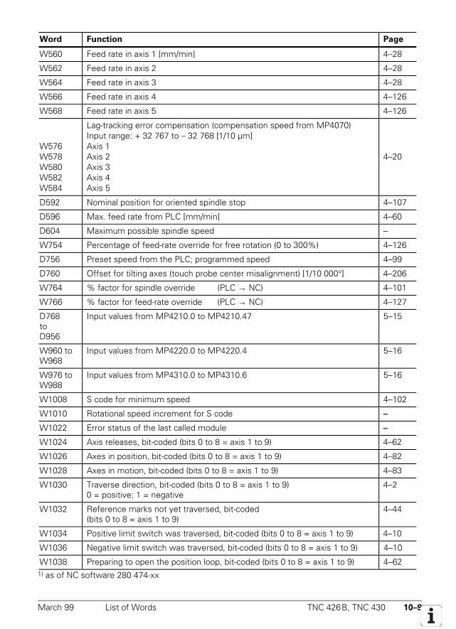
March 99 List of Words TNC 426B, TNC 430 10–9
Word Function Page
W560 Feed rate in axis 1 [mm/min] 4–28
W562 Feed rate in axis 2 4–28
W564 Feed rate in axis 3 4–28
W566 Feed rate in axis 4 4–126
W568 Feed rate in axis 5 4–126
W576W578W580W582W584
Lag-tracking error compensation (compensation speed from MP4070)Input range: + 32 767 to – 32 768 [1/10 µm]Axis 1Axis 2Axis 3Axis 4Axis 5
4–20
D592 Nominal position for oriented spindle stop 4–107
D596 Max. feed rate from PLC [mm/min] 4–60
D604 Maximum possible spindle speed –
W754 Percentage of feed-rate override for free rotation (0 to 300%) 4–126
D756 Preset speed from the PLC; programmed speed 4–99
D760 Offset for tilting axes (touch probe center misalignment) [1/10 000°] 4–206
W764 % factor for spindle override (PLC → NC) 4–101
W766 % factor for feed-rate override (PLC → NC) 4–127
D768toD956
Input values from MP4210.0 to MP4210.47 5–15
W960 toW968
Input values from MP4220.0 to MP4220.4 5–16
W976 toW988
Input values from MP4310.0 to MP4310.6 5–16
W1008 S code for minimum speed 4–102
W1010 Rotational speed increment for S code –
W1022 Error status of the last called module –
W1024 Axis releases, bit-coded (bits 0 to 8 = axis 1 to 9) 4–62
W1026 Axes in position, bit-coded (bits 0 to 8 = axis 1 to 9) 4–82
W1028 Axes in motion, bit-coded (bits 0 to 8 = axis 1 to 9) 4–83
W1030 Traverse direction, bit-coded (bits 0 to 8 = axis 1 to 9)0 = positive; 1 = negative
4–2
W1032 Reference marks not yet traversed, bit-coded(bits 0 to 8 = axis 1 to 9)
4–44
W1034 Positive limit switch was traversed, bit-coded (bits 0 to 8 = axis 1 to 9) 4–10
W1036 Negative limit switch was traversed, bit-coded (bits 0 to 8 = axis 1 to 9) 4–10
W1038 Preparing to open the position loop, bit-coded (bits 0 to 8 = axis 1 to 9) 4–621) as of NC software 280 474-xx
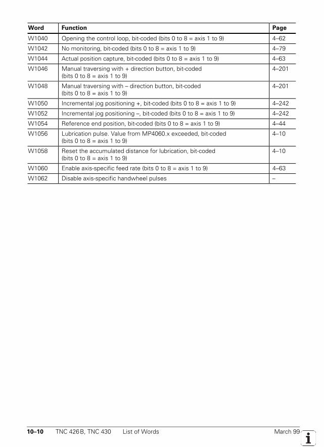
10–10 TNC 426B, TNC 430 List of Words March 99
Word Function Page
W1040 Opening the control loop, bit-coded (bits 0 to 8 = axis 1 to 9) 4–62
W1042 No monitoring, bit-coded (bits 0 to 8 = axis 1 to 9) 4–79
W1044 Actual position capture, bit-coded (bits 0 to 8 = axis 1 to 9) 4–63
W1046 Manual traversing with + direction button, bit-coded(bits 0 to 8 = axis 1 to 9)
4–201
W1048 Manual traversing with – direction button, bit-coded(bits 0 to 8 = axis 1 to 9)
4–201
W1050 Incremental jog positioning +, bit-coded (bits 0 to 8 = axis 1 to 9) 4–242
W1052 Incremental jog positioning –, bit-coded (bits 0 to 8 = axis 1 to 9) 4–242
W1054 Reference end position, bit-coded (bits 0 to 8 = axis 1 to 9) 4–44
W1056 Lubrication pulse. Value from MP4060.x exceeded, bit-coded(bits 0 to 8 = axis 1 to 9)
4–10
W1058 Reset the accumulated distance for lubrication, bit-coded(bits 0 to 8 = axis 1 to 9)
4–10
W1060 Enable axis-specific feed rate (bits 0 to 8 = axis 1 to 9) 4–63
W1062 Disable axis-specific handwheel pulses –
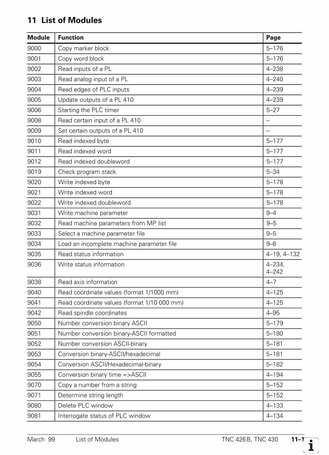
March 99 List of Modules TNC 426B, TNC 430 11–1
11 List of Modules
Module Function Page
9000 Copy marker block 5–176
9001 Copy word block 5–176
9002 Read inputs of a PL 4–238
9003 Read analog input of a PL 4–240
9004 Read edges of PLC inputs 4–239
9005 Update outputs of a PL 410 4–239
9006 Starting the PLC timer 5–27
9008 Read certain input of a PL 410 –
9009 Set certain outputs of a PL 410 –
9010 Read indexed byte 5–177
9011 Read indexed word 5–177
9012 Read indexed doubleword 5–177
9019 Check program stack 5–34
9020 Write indexed byte 5–178
9021 Write indexed word 5–178
9022 Write indexed doubleword 5–178
9031 Write machine parameter 9–4
9032 Read machine parameters from MP list 9–5
9033 Select a machine parameter file 9–5
9034 Load an incomplete machine parameter file 9–6
9035 Read status information 4–19, 4–132
9036 Write status information 4–234,4–242
9038 Read axis information 4–7
9040 Read coordinate values (format 1/1000 mm) 4–125
9041 Read coordinate values (format 1/10 000 mm) 4–125
9042 Read spindle coordinates 4–95
9050 Number conversion binary ASCII 5–179
9051 Number conversion binary-ASCII formatted 5–180
9052 Number conversion ASCII-binary 5–181
9053 Conversion binary-ASCII/hexadecimal 5–181
9054 Conversion ASCII/Hexadecimal-binary 5–182
9055 Conversion binary time =>ASCII 4–194
9070 Copy a number from a string 5–152
9071 Determine string length 5–152
9080 Delete PLC window 4–133
9081 Interrogate status of PLC window 4–134
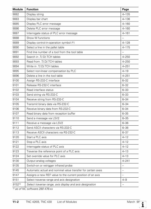
11–2 TNC 426B, TNC 430 List of Modules March 99
Module Function Page
9082 Display string 4–135
9083 Display bar chart 4–136
9085 Display PLC error message 4–160
9086 Delete PLC error message 4–160
9087 Interrogate status of PLC error message 4–161
9088 Show M functions –
9089 Display control-in-operation symbol (∗) 4–128
9090 Select a line in the pallet table 4–175
9091 Find line number of a tool from the tool table –
9092 Search in .T/.D/.TCH tables 4–250
9093 Read from .T/.D/.TCH tables 4–250
9094 Write in .T/.D/.TCH tables 4–251
9095 Select non-linear compensation by PLC 4–19
9096 Delete a line in the tool table 4–251
9100 Assign RS-232-C interface 6–32
9101 Release RS-232-C interface 6–32
9102 Read interface status 6–33
9103 Send string via RS-232-C 6–33
9104 Receive string from RS-232-C 6–34
9105 Transmit binary data via RS-232-C 6–34
9106 Receive binary data from RS-232-C 6–34
9107 Read binary data from reception buffer 6–35
9110 Send a message via LSV2 6–35
9111 Receive a message via LSV2 6–36
9112 Send ASCII characters via RS-232-C 6–36
9113 Receive ASCII characters via RS-232-C 6–37
9120 Start a PLC axis 4–12
9121 Stop a PLC axis 4–12
9122 Interrogate status of PLC axis 4–12
9123 Traverse the reference point of a PLC axis 4–13
9124 Set override value for PLC axis 4–13
9130 Output analog voltages 4–241
9135 Switch-on or retrigger infrared probe –
9145 Automatic actual and nominal value transfer for certain axes –
9147 Assigns a new REF value to the current position of an axis –
9151 Select traverse range and axis designation 4–9
91521) Select traverse range, axis display and axis designation –1) as of NC software 280 476-xx
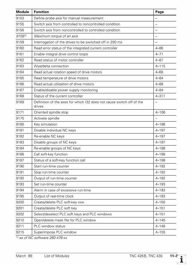
March 99 List of Modules TNC 426B, TNC 430 11–3
Module Function Page
9153 Define probe axis for manual measurement –
9155 Switch axis from controlled to noncontrolled condition –
9156 Switch axis from noncontrolled to controlled condition –
91581) Maximum torque of an axis –
9159 Interrogation of the drives to be switched off in 200 ms –
9160 Read error status of the integrated current controller 4–86
9161 Enable integral drive control loops 4–71
9162 Read status of motor controller 4–87
9163 Wye/delta connection 4–115
9164 Read actual rotation speed of drive motors 4–68
9165 Read temperature of drive motors 4–84
9166 Read actual utilization of drive motors 4–88
9167 Enable/disable power supply monitoring 4–84
9168 Status of the current controller 4–311
9169 Definition of the axes for which I32 does not cause switch off of thedrives
–
9171 Oriented spindle stop 4–106
9175 Activate spindle –
9180 Key simulation 4–196
9181 Disable individual NC keys 4–197
9182 Re-enable NC keys 4–197
9183 Disable groups of NC keys 4–197
9184 Re-enable groups of NC keys 4–198
9186 Call soft-key function 4–198
9187 Status of a soft-key function call 4–198
9190 Start run-time counter 4–192
9191 Stop run-time counter 4–192
9192 Output of run-time counter 4–192
9193 Set run-time counter 4–193
9194 Alarm in case of excessive run-time 4–193
9195 Output of real-time clock 4–193
9200 Create/delete PLC soft-key row 4–150
9201 Create/delete PLC soft key 4–151
9202 Select/deselect PLC soft keys and PLC windows 4–151
9210 Open/delete mask file for PLC window 4–145
9211 PLC window status 4–146
9215 Superimpose PLC window 4–1551) as of NC software 280 476-xx
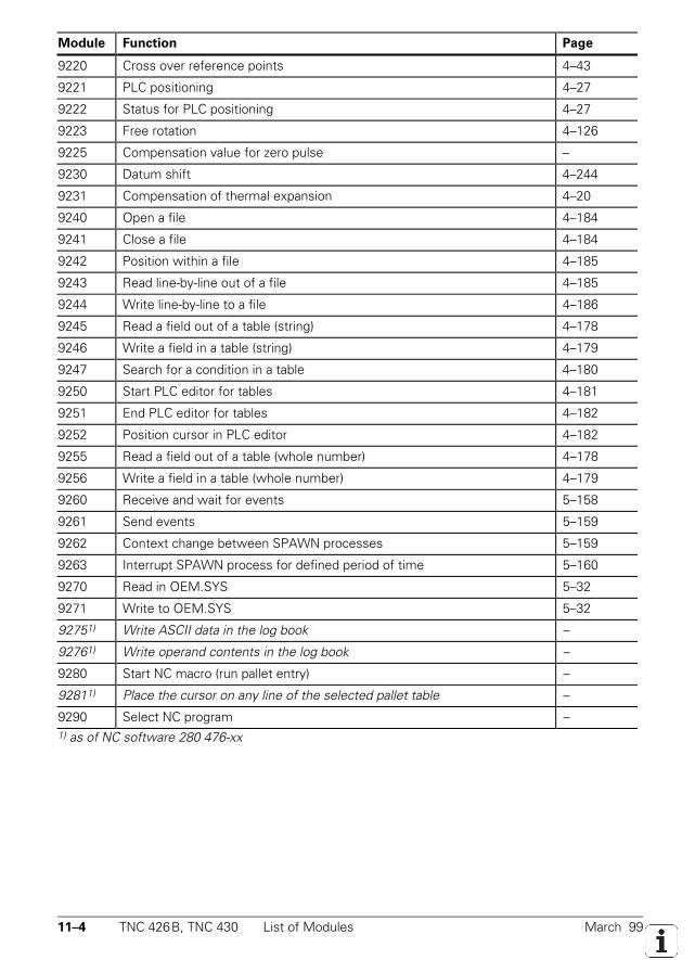
11–4 TNC 426B, TNC 430 List of Modules March 99
Module Function Page
9220 Cross over reference points 4–43
9221 PLC positioning 4–27
9222 Status for PLC positioning 4–27
9223 Free rotation 4–126
9225 Compensation value for zero pulse –
9230 Datum shift 4–244
9231 Compensation of thermal expansion 4–20
9240 Open a file 4–184
9241 Close a file 4–184
9242 Position within a file 4–185
9243 Read line-by-line out of a file 4–185
9244 Write line-by-line to a file 4–186
9245 Read a field out of a table (string) 4–178
9246 Write a field in a table (string) 4–179
9247 Search for a condition in a table 4–180
9250 Start PLC editor for tables 4–181
9251 End PLC editor for tables 4–182
9252 Position cursor in PLC editor 4–182
9255 Read a field out of a table (whole number) 4–178
9256 Write a field in a table (whole number) 4–179
9260 Receive and wait for events 5–158
9261 Send events 5–159
9262 Context change between SPAWN processes 5–159
9263 Interrupt SPAWN process for defined period of time 5–160
9270 Read in OEM.SYS 5–32
9271 Write to OEM.SYS 5–32
92751) Write ASCII data in the log book –
92761) Write operand contents in the log book –
9280 Start NC macro (run pallet entry) –
92811) Place the cursor on any line of the selected pallet table –
9290 Select NC program –1) as of NC software 280 476-xx
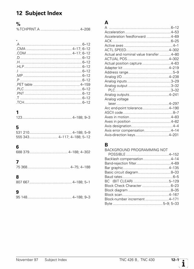
November 97 Subject Index TNC 426 B, TNC 430 12–1
12 Subject Index
%%TCHPRNT.A ....................................... 4–208
.
.A ............................................................. 6–12
.CMA ............................................. 4–17; 6–12
.COM............................................. 4–17; 6–12
.D ............................................................. 6–12
.H ............................................................. 6–12
.HLP......................................................... 6–12
.I ............................................................. 6–12
.MP.......................................................... 6–12
.P ............................................................. 6–12
.PET table .............................................. 4–159
.PLC......................................................... 6–12
.PNT......................................................... 6–12
.T ............................................................. 6–12
.TCH......................................................... 6–12
1123................................................. 4–188; 9–3
5531 210.......................................... 4–188; 5–9555 343............................ 4–117; 4–188; 5–12
6688 379...................................... 4–188; 4–302
775 368.......................................... 4–75; 4–188
8807 667.......................................... 4–188; 5–1
995 148............................................ 4–188; 9–3
AA .............................................................6–12Acceleration .............................................4–53Acceleration feedforward ........................4–69ACK..........................................................6–25Active axes ................................................4–1ACTL.SPEED..........................................4–302Actual and nominal value transfer ...........4–80ACTUAL POS.........................................4–302Actual position capture ............................4–63Adapter kit .............................................4–219Address range............................................5–9Analog I/O ..............................................4–238Analog inputs ...........................................3–29Analog output ..........................................3–32
PLC.......................................................3–32Analog outputs.......................................4–241Analog voltage
laser....................................................4–297Arc end-point tolerance..........................4–190ASCII code .................................................8–7Axes in motion.........................................4–83Axes in position .......................................4–82Axis designation.........................................4–4Axis error compensation..........................4–14Axis-direction keys.................................4–201
BBACKGROUND PROGRAMMING NOT
POSSIBLE ..........................................4–152Backlash compensation...........................4–14Band-rejection filter..................................4–69Bar graphic.............................................4–135Basic circuit diagram................................8–33Baud rates..................................................6–5BC (BIT CLEAR) ...................................5–129Block Check Character ............................6–23Block diagram ..........................................8–35Block scan..............................................4–167Block-number increment .......................4–171Byte ................................................. 5–9; 5–33
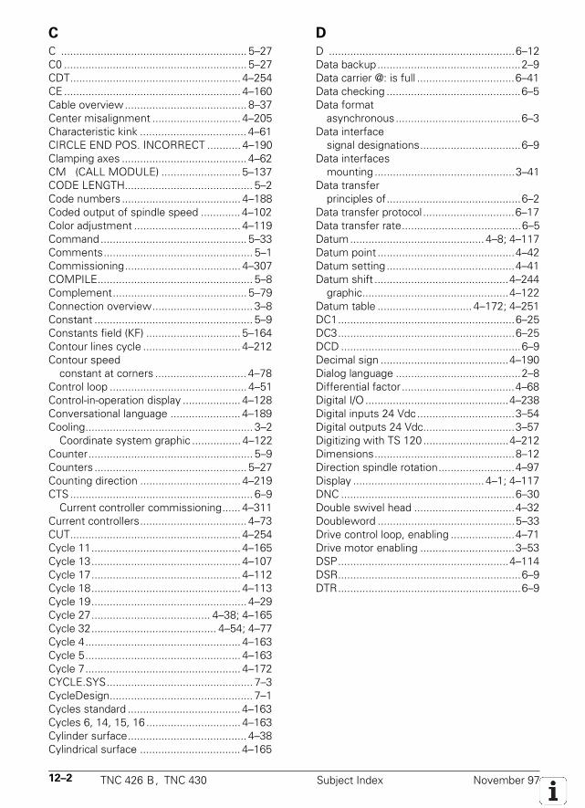
12–2 TNC 426 B, TNC 430 Subject Index November 97
C
C ............................................................. 5–27C0 ............................................................ 5–27CDT........................................................ 4–254CE.......................................................... 4–160Cable overview........................................ 8–37Center misalignment ............................. 4–205Characteristic kink ................................... 4–61CIRCLE END POS. INCORRECT ........... 4–190Clamping axes ......................................... 4–62CM (CALL MODULE) .......................... 5–137CODE LENGTH.......................................... 5–2Code numbers ....................................... 4–188Coded output of spindle speed ............. 4–102Color adjustment ................................... 4–119Command................................................ 5–33Comments................................................. 5–1Commissioning...................................... 4–307COMPILE................................................... 5–8Complement............................................ 5–79Connection overview................................. 3–8Constant .................................................... 5–9Constants field (KF) ............................... 5–164Contour lines cycle ................................ 4–212Contour speed
constant at corners .............................. 4–78Control loop ............................................. 4–51Control-in-operation display ................... 4–128Conversational language ....................... 4–189Cooling....................................................... 3–2
Coordinate system graphic ................ 4–122Counter...................................................... 5–9Counters .................................................. 5–27Counting direction ................................. 4–219CTS............................................................ 6–9
Current controller commissioning...... 4–311Current controllers................................... 4–73CUT........................................................ 4–254Cycle 11................................................. 4–165Cycle 13................................................. 4–107Cycle 17................................................. 4–112Cycle 18................................................. 4–113Cycle 19................................................... 4–29Cycle 27....................................... 4–38; 4–165Cycle 32......................................... 4–54; 4–77Cycle 4................................................... 4–163Cycle 5................................................... 4–163Cycle 7................................................... 4–172CYCLE.SYS................................................ 7–3CycleDesign............................................... 7–1Cycles standard ..................................... 4–163Cycles 6, 14, 15, 16 ............................... 4–163Cylinder surface....................................... 4–38Cylindrical surface ................................. 4–165
D
D .............................................................6–12Data backup...............................................2–9Data carrier @: is full ................................6–41Data checking ............................................6–5Data format
asynchronous.........................................6–3Data interface
signal designations.................................6–9Data interfaces
mounting ..............................................3–41Data transfer
principles of............................................6–2Data transfer protocol ..............................6–17Data transfer rate.......................................6–5Datum............................................ 4–8; 4–117Datum point .............................................4–42Datum setting ..........................................4–41Datum shift ............................................4–244
graphic................................................4–122Datum table ............................... 4–172; 4–251DC1..........................................................6–25DC3..........................................................6–25DCD ...........................................................6–9Decimal sign ..........................................4–190Dialog language .........................................2–8Differential factor .....................................4–68Digital I/O ...............................................4–238Digital inputs 24 Vdc................................3–54Digital outputs 24 Vdc..............................3–57Digitizing with TS 120 ............................4–212Dimensions..............................................8–12Direction spindle rotation.........................4–97Display ........................................... 4–1; 4–117DNC .........................................................6–30Double swivel head .................................4–32Doubleword .............................................5–33Drive control loop, enabling .....................4–71Drive motor enabling ...............................3–53DSP........................................................4–114DSR............................................................6–9DTR............................................................6–9
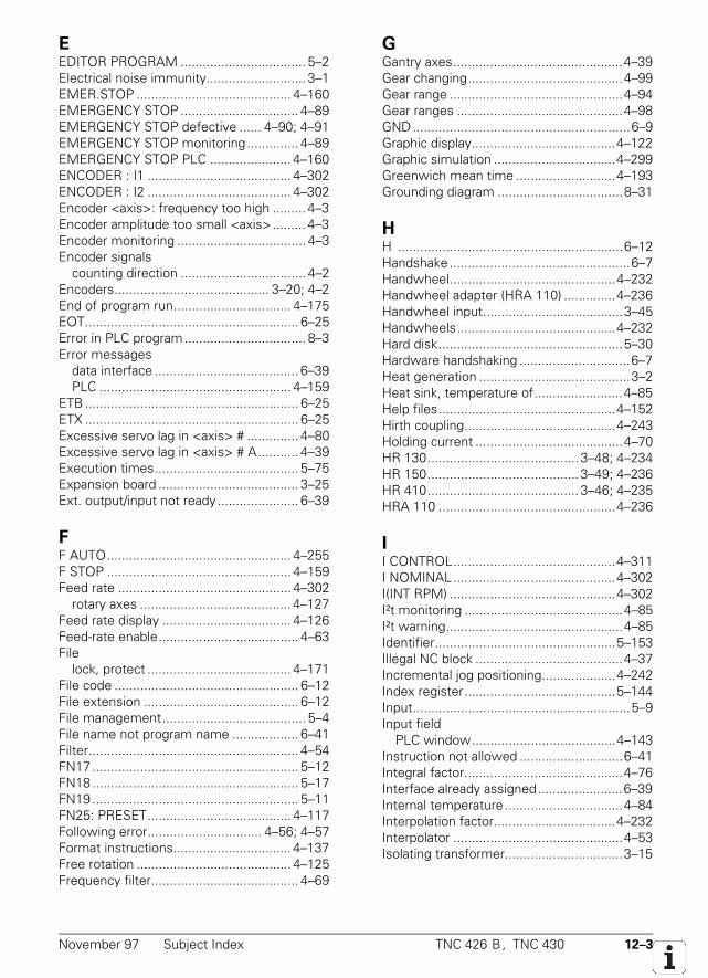
November 97 Subject Index TNC 426 B, TNC 430 12–3
EEDITOR PROGRAM .................................. 5–2Electrical noise immunity........................... 3–1EMER.STOP .......................................... 4–160EMERGENCY STOP ................................ 4–89EMERGENCY STOP defective ...... 4–90; 4–91EMERGENCY STOP monitoring.............. 4–89EMERGENCY STOP PLC ...................... 4–160ENCODER : I1 ....................................... 4–302ENCODER : I2 ....................................... 4–302Encoder <axis>: frequency too high ......... 4–3Encoder amplitude too small <axis>......... 4–3Encoder monitoring ................................... 4–3Encoder signals
counting direction .................................. 4–2Encoders.......................................... 3–20; 4–2End of program run................................ 4–175EOT.......................................................... 6–25Error in PLC program................................. 8–3Error messages
data interface ....................................... 6–39PLC .................................................... 4–159
ETB.......................................................... 6–25ETX .......................................................... 6–25Excessive servo lag in <axis> # .............. 4–80Excessive servo lag in <axis> # A........... 4–39Execution times....................................... 5–75Expansion board ...................................... 3–25Ext. output/input not ready...................... 6–39
FF AUTO.................................................. 4–255F STOP .................................................. 4–159Feed rate ............................................... 4–302
rotary axes ......................................... 4–127Feed rate display ................................... 4–126Feed-rate enable...................................... 4–63File
lock, protect ....................................... 4–171File code .................................................. 6–12File extension .......................................... 6–12File management....................................... 5–4File name not program name .................. 6–41Filter......................................................... 4–54FN17 ........................................................ 5–12FN18 ........................................................ 5–17FN19 ........................................................ 5–11FN25: PRESET....................................... 4–117Following error............................... 4–56; 4–57Format instructions................................ 4–137Free rotation .......................................... 4–125Frequency filter........................................ 4–69
GGantry axes..............................................4–39Gear changing..........................................4–99Gear range ...............................................4–94Gear ranges .............................................4–98GND...........................................................6–9Graphic display.......................................4–122Graphic simulation .................................4–299Greenwich mean time ...........................4–193Grounding diagram ..................................8–31
HH .............................................................6–12Handshake.................................................6–7Handwheel.............................................4–232Handwheel adapter (HRA 110) ..............4–236Handwheel input......................................3–45Handwheels...........................................4–232Hard disk..................................................5–30Hardware handshaking ..............................6–7Heat generation .........................................3–2Heat sink, temperature of........................4–85Help files................................................4–152Hirth coupling.........................................4–243Holding current ........................................4–70HR 130......................................... 3–48; 4–234HR 150......................................... 3–49; 4–236HR 410......................................... 3–46; 4–235HRA 110 ................................................4–236
II CONTROL............................................4–311I NOMINAL............................................4–302I(INT RPM) .............................................4–302I²t monitoring ...........................................4–85I²t warning................................................4–85Identifier.................................................5–153Illegal NC block ........................................4–37Incremental jog positioning....................4–242Index register.........................................5–144Input...........................................................5–9Input field
PLC window.......................................4–143Instruction not allowed ............................6–41Integral factor...........................................4–76Interface already assigned.......................6–39Internal temperature ................................4–84Interpolation factor.................................4–232Interpolator ..............................................4–53Isolating transformer................................3–15
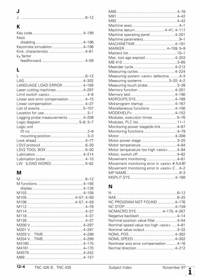
12–4 TNC 426 B, TNC 430 Subject Index November 97
J
J ............................................................. 6–12
K
Key code................................................ 4–199Keys
disabling ............................................. 4–196Keystroke simulation ............................. 4–196Kink, characteristic .................................. 4–61kv factor
feedforward ......................................... 4–59
L
L ............................................................. 6–12LAG........................................................ 4–302LANGUAGE LOAD ERROR ................... 4–189Laser cutting machines ......................... 4–297Limit switch <axis>................................... 4–8Linear axis error compensation ............... 4–15Linear compensation ............................... 4–37List of events......................................... 5–157Location for use......................................... 3–1Logging probe measurements .............. 4–208Logic diagram .................................... 5–6; 5–7Logic unit
ID no. ..................................................... 2–9mounting position .................................. 3–3
Look ahead .............................................. 4–77LSV2 protocol .......................................... 6–30LSV2 TOOL BOX ..................................... 6–30Lubrication ............................................. 4–214Lubrication pulse ..................................... 4–10LW (LOAD WORD)................................ 5–82
M
M ............................................................. 6–12M functions ........................................... 4–156
display ................................................ 4–128M103 ..................................................... 4–158M105 ............................................. 4–57; 4–59M106 ............................................. 4–57; 4–59M112 ....................................................... 4–78M114 ....................................................... 4–37M118 ....................................................... 4–37M128 ....................................................... 4–37M200 V... ............................................... 4–297M201 V... ............................................... 4–297M203 V... TIME... .................................. 4–298M204 V... TIME... .................................. 4–299M4160 ................................................... 4–175M4161 ................................................... 4–170M4579 ................................................... 4–242M89 ....................................................... 4–157
M90 .........................................................4–78M91 .........................................................4–42M92 .........................................................4–42Machine axes.............................................4–1Machine datum............................ 4–41; 4–117Machine operating panel .......................4–201Machine parameters..................................9–1MACHINETIME......................................4–191MARKER........................................ 4–159; 5–9Markers list ..............................................10–1Max. tool age expired ............................4–253MB 410 ....................................................3–65Meander cycle .......................................4–212Measuring cycles...................................4–224Measuring system <axis> defective .........4–3Measuring systems ......................... 3–20; 4–2Measuring touch probe............................3–38Memory function ...................................4–201Memory test ..........................................4–190MGROUPS.SYS.....................................4–168Mid-program startup..............................4–167Miscellaneous functions........................4–156MODEHELP= ........................................4–152Modules, execution times .......................5–76Modules, PLC list.....................................11–1Monitoring power stage/dc-link ...............4–87Monitoring functions................................4–79Motor .....................................................4–308Motor power stage..................................3–25Motor temperature ..................................4–84Motor temperature too high <axis> ........4–84Motor, switch off .....................................4–62Movement monitoring .............................4–81Movement monitoring error in <axis> # A.4–87Movement monitoring error in <axis> C ...4–2MP NAME..................................................9–3MSPLIT.SYS ..........................................4–168
N
N .............................................................6–12NAK..........................................................6–25NC PROGRAM NOT FOUND ................4–176NC STOP................................................4–159NCMACRO.SYS......................... 4–175; 4–267Negative backlash....................................4–14Nominal position value filter ....................4–54Nominal speed value too high <axis> .....4–81Nominal value output...............................3–32NOML.POS............................................4–302NOML.SPEED........................................4–302Nonlinear axis error compensation ..........4–16Normal direction ....................................4–212
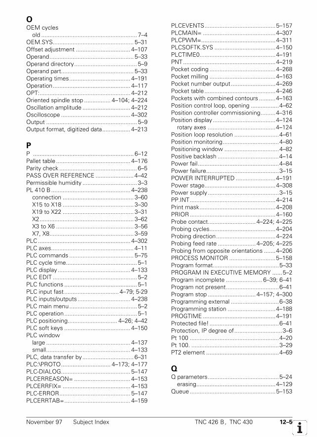
November 97 Subject Index TNC 426 B, TNC 430 12–5
OOEM cycles
old .......................................................... 7–4OEM.SYS................................................. 5–31Offset adjustment ................................. 4–107Operand................................................... 5–33Operand directory...................................... 5–9Operand part............................................ 5–33Operating times..................................... 4–191Operation............................................... 4–117OPT:....................................................... 4–212Oriented spindle stop ................ 4–104; 4–224Oscillation amplitude ............................. 4–212Oscilloscope .......................................... 4–302Output ....................................................... 5–9Output format, digitized data................. 4–213
PP ............................................................. 6–12Pallet table ............................................. 4–176Parity check ............................................... 6–5PASS OVER REFERENCE ....................... 4–42Permissible humidity ................................. 3–3PL 410 B ................................................ 4–238
connection ........................................... 3–60X15 to X18 ........................................... 3–30X19 to X22 ........................................... 3–31X2......................................................... 3–62X3 to X6 ............................................... 3–56X7, X8................................................... 3–59
PLC........................................................ 4–302PLC axes.................................................. 4–11PLC commands ....................................... 5–75PLC cycle time........................................... 5–1PLC display ............................................ 4–133PLC EDIT ................................................... 5–2PLC functions ............................................ 5–1PLC input fast ................................. 4–79; 5-29PLC inputs/outputs ................................ 4–238PLC main menu......................................... 5–2PLC operation ............................................ 5–1PLC positioning.............................. 4–26; 4–42PLC soft keys ........................................ 4–150PLC window
large ................................................... 4–137small................................................... 4–133
PLC, data transfer by............................... 6–31PLC:\PROTO.............................. 4–173; 4–177PLC-DIALOG.......................................... 5–147PLCERREASON= .................................. 4–153PLCERRFIX= ......................................... 4–153PLC-ERROR........................................... 5–147PLCERRTAB=........................................ 4–159
PLCEVENTS...........................................5–157PLCMAIN= ............................................4–307PLCPWM=.............................................4–311PLCSOFTK.SYS .....................................4–150PLCTIME0..............................................4–191PNT........................................................4–219Pocket coding ........................................4–268Pocket milling ........................................4–163Pocket number output ...........................4–269Pocket table ...........................................4–246Pockets with combined contours ..........4–163Position control loop, opening .................4–62Position controller commissioning.........4–316Position display ......................................4–124
rotary axes .........................................4–124Position loop resolution ...........................4–61Position monitoring..................................4–80Positioning window .................................4–82Positive backlash .....................................4–14Power fail.................................................4–84Power failure............................................3–15POWER INTERRUPTED ........................4–191Power stage...........................................4–308Power supply ...........................................3–15PP.INT....................................................4–214Print mask..............................................4–208PRIOR....................................................4–160Probe contact............................. 4–224; 4–225Probing cycles........................................4–204Probing direction....................................4–224Probing feed rate ....................... 4–205; 4–225Probing from opposite orientations .......4–206PROCESS MONITOR ............................5–158Program format........................................5–33PROGRAM IN EXECUTIVE MEMORY ......5–2Program incomplete ...................... 6–39; 6–41Program not present................................6–41Program stop ............................. 4–157; 4–300Programming external .............................6–38Programming station .............................4–188PROGTIME ............................................4–191Protected file! ..........................................6–41Protection, IP degree of.............................3–6Pt 100 ......................................................4–20Pt 100. .....................................................3–29PT2 element ............................................4–69
QQ parameters...........................................5–24
erasing................................................4–129Queue ....................................................5–153
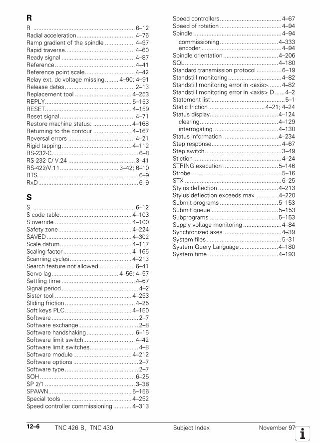
12–6 TNC 426 B, TNC 430 Subject Index November 97
R
R ............................................................. 6–12Radial acceleration................................... 4–76Ramp gradient of the spindle .................. 4–97Rapid traverse.......................................... 4–60Ready signal ............................................ 4–87Reference ................................................ 4–41Reference point scale.............................. 4–42Relay ext. dc voltage missing........ 4–90; 4–91Release dates.......................................... 2–13Replacement tool .................................. 4–253REPLY.................................................... 5–153RESET.................................................... 4–159Reset signal ............................................. 4–71Restore machine status: ....................... 4–168Returning to the contour ....................... 4–167Reversal errors ........................................ 4–21Rigid tapping.......................................... 4–112RS-232-C.................................................... 6–8RS-232-C/ V.24 ........................................ 3–41RS-422/V.11................................... 3–42; 6–10RTS ............................................................ 6–9RxD............................................................ 6–9
S
S ............................................................. 6–12S code table........................................... 4–103S override .............................................. 4–100Safety zone............................................ 4–224SAVED................................................... 4–302Scale datum........................................... 4–117Scaling factor ......................................... 4–165Scanning cycles..................................... 4–213Search feature not allowed...................... 6–41Servo lag........................................ 4–56; 4–57Settling time ............................................ 4–67Signal period .............................................. 4–2Sister tool .............................................. 4–253Sliding friction .......................................... 4–25Soft keys PLC........................................ 4–150Software .................................................... 2–7Software exchange.................................... 2–8Software handshaking............................. 6–16Software limit switch............................... 4–42Software limit switches............................. 4–8Software module ................................... 4–212Software options ....................................... 2–7Software type............................................ 2–7SOH......................................................... 6–25SP 2/1 ...................................................... 3–38SPAWN.................................................. 5–156Special tools .......................................... 4–252Speed controller commissioning ........... 4–313
Speed controllers.....................................4–67Speed of rotation .....................................4–94Spindle .....................................................4–94
commissioning ...................................4–333encoder ................................................4–94
Spindle orientation .................................4–206SQL........................................................4–180Standard transmission protocol ...............6–19Standstill monitoring ................................4–82Standstill monitoring error in <axis>........4–82Standstill monitoring error in <axis> D......4–2Statement list ............................................5–1Static friction.................................. 4–21; 4–24Status display.........................................4–124
clearing...............................................4–129interrogating .......................................4–130
Status information .................................4–234Step response..........................................4–67Step switch..............................................3–49Stiction.....................................................4–24STRING execution .................................5–146Strobe ......................................................5–16STX ..........................................................6–25Stylus deflection ....................................4–213Stylus deflection exceeds max..............4–220Submit programs ...................................5–153Submit queue ........................................5–153Subprograms .........................................5–153Supply voltage monitoring .......................4–84Synchronized axes...................................4–39System files .............................................5–31System Query Language .......................4–180System time ..........................................4–193
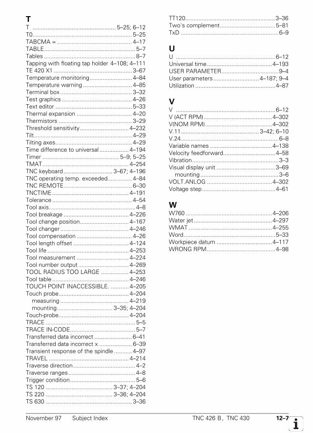
November 97 Subject Index TNC 426 B, TNC 430 12–7
TT ................................................... 5–25; 6–12T0............................................................. 5–25TABCMA = .............................................. 4–17TABLE........................................................ 5–7Tables ........................................................ 8–7Tapping with floating tap holder 4–108; 4–111TE 420 X1 ................................................ 3–67Temperature monitoring.......................... 4–84Temperature warning .............................. 4–85Terminal box ............................................ 3–32Test graphics ........................................... 4–26Text editor ............................................... 5–33Thermal expansion .................................. 4–20Thermistors ............................................. 3–29Threshold sensitivity.............................. 4–232Tilt............................................................ 4–29Tilting axes............................................... 4–29Time difference to universal .................. 4–194Timer ............................................... 5–9; 5–25TMAT..................................................... 4–254TNC keyboard.............................. 3–67; 4–196TNC operating temp. exceeded............... 4–84TNC REMOTE.......................................... 6–30TNCTIME............................................... 4–191Tolerance ................................................. 4–54Tool axis..................................................... 4–8Tool breakage ........................................ 4–226Tool change position.............................. 4–167Tool changer .......................................... 4–246Tool compensation .................................. 4–26Tool length offset .................................. 4–124Tool life .................................................. 4–253Tool measurement ................................ 4–224Tool number output ............................... 4–269TOOL RADIUS TOO LARGE ................. 4–253Tool table ............................................... 4–246TOUCH POINT INACCESSIBLE. ........... 4–205Touch probe........................................... 4–204
measuring .......................................... 4–219mounting.................................. 3–35; 4–204
Touch-probe........................................... 4–204TRACE ....................................................... 5–5TRACE IN-CODE........................................ 5–7Transferred data incorrect ....................... 6–41Transferred data incorrect x .................... 6–39Transient response of the spindle ........... 4–97TRAVEL ................................................. 4–214Traverse direction...................................... 4–2Traverse ranges......................................... 4–8Trigger condition........................................ 5–6TS 120 ......................................... 3–37; 4–204TS 220 ......................................... 3–36; 4–204TS 630 ..................................................... 3–36
TT120.......................................................3–36Two's complement..................................5–81TxD ............................................................6–9
UU .............................................................6–12Universal time........................................4–193USER PARAMETER...................................9–4User parameters............................ 4–187; 9–4Utilization .................................................4–87
VV .............................................................6–12V (ACT RPM)..........................................4–302V(NOM RPM).........................................4–302V.11................................................ 3–42; 6–10V.24............................................................6–8Variable names ......................................4–138Velocity feedforward................................4–58Vibration.....................................................3–3Visual display unit ....................................3–69
mounting ................................................3–6VOLT.ANLOG ........................................4–302Voltage step.............................................4–61
WW760 .....................................................4–206Water jet ................................................4–297WMAT ...................................................4–255Word ........................................................5–33Workpiece datum ..................................4–117WRONG RPM..........................................4–98
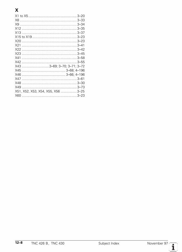
12–8 TNC 426 B, TNC 430 Subject Index November 97
X
X1 to X5 ................................................... 3–20X8 ............................................................ 3–33X9 ............................................................ 3–34X12 .......................................................... 3–35X13 .......................................................... 3–37X15 to X19 ............................................... 3–23X20 .......................................................... 3–23X21 .......................................................... 3–41X22 .......................................................... 3–42X23 .......................................................... 3–45X41 .......................................................... 3–58X42 .......................................................... 3–55X43 .............................3–69; 3–70; 3–71; 3–72X45 .............................................. 3–68; 4–196X46 .............................................. 3–66; 4–196X47 .......................................................... 3–61X48 .......................................................... 3–30X49 .......................................................... 3–73X51, X52, X53, X54, X55, X56 ................. 3–25X60 .......................................................... 3–23
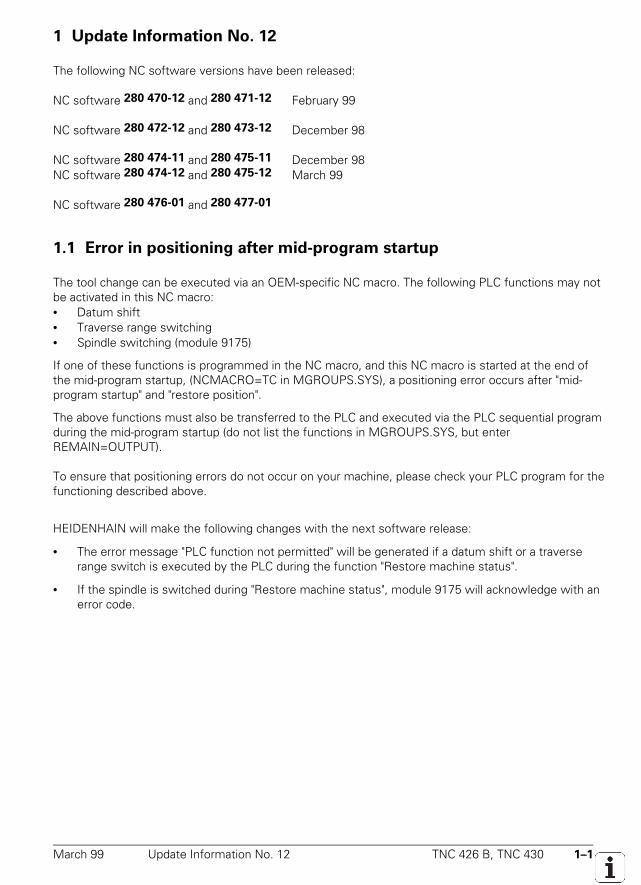
March 99 Update Information No. 12 TNC 426 B, TNC 430 1–1
1 Update Information No. 12
The following NC software versions have been released:
NC software 280 470-12 and 280 471-12 February 99
NC software 280 472-12 and 280 473-12 December 98
NC software 280 474-11 and 280 475-11 December 98NC software 280 474-12 and 280 475-12 March 99
NC software 280 476-01 and 280 477-01
1.1 Error in positioning after mid-program startup
The tool change can be executed via an OEM-specific NC macro. The following PLC functions may notbe activated in this NC macro:• Datum shift• Traverse range switching• Spindle switching (module 9175)
If one of these functions is programmed in the NC macro, and this NC macro is started at the end ofthe mid-program startup, (NCMACRO=TC in MGROUPS.SYS), a positioning error occurs after "mid-program startup" and "restore position".
The above functions must also be transferred to the PLC and executed via the PLC sequential programduring the mid-program startup (do not list the functions in MGROUPS.SYS, but enterREMAIN=OUTPUT).
To ensure that positioning errors do not occur on your machine, please check your PLC program for thefunctioning described above.
HEIDENHAIN will make the following changes with the next software release:
• The error message "PLC function not permitted" will be generated if a datum shift or a traverserange switch is executed by the PLC during the function "Restore machine status".
• If the spindle is switched during "Restore machine status", module 9175 will acknowledge with anerror code.
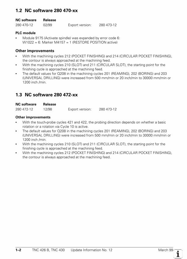
1–2 TNC 426 B, TNC 430 Update Information No. 12 March 99
1.2 NC software 280 470-xx
NC software Release
280 470-12 02/99 Export version: 280 473-12
PLC module
• Module 9175 (Activate spindle) was expanded by error code 6:W1022 = 6: Marker M4157 = 1 (RESTORE POSITION active)
Other improvements
• With the machining cycles 212 (POCKET FINISHING) and 214 (CIRCULAR POCKET FINISHING),the contour is always approached at the machining feed.
• With the machining cycles 210 (SLOT) and 211 (CIRCULAR SLOT), the starting point for thefinishing cycle is approached at the machining feed.
• The default values for Q208 in the machining cycles 201 (REAMING), 202 (BORING) and 203(UNIVERSAL DRILLING) were increased from 500 mm/min or 20 inch/min to 30000 mm/min or1200 inch /min.
1.3 NC software 280 472-xx
NC software Release
280 472-12 12/98 Export version: 280 473-12
Other improvements
• With the touch-probe cycles 421 and 422, the probing direction depends on whether a basicrotation or a rotation via Cycle 10 is active.
• The default values for Q208 in the machining cycles 201 (REAMING), 202 (BORING) and 203(UNIVERSAL DRILLING) were increased from 500 mm/min or 20 inch/min to 30000 mm/min or1200 inch /min.
• With the machining cycles 210 (SLOT) and 211 (CIRCULAR SLOT), the starting point for thefinishing cycle is approached at the machining feed.
• With the machining cycles 212 (POCKET FINISHING) and 214 (CIRCULAR POCKET FINISHING),the contour is always approached at the machining feed.
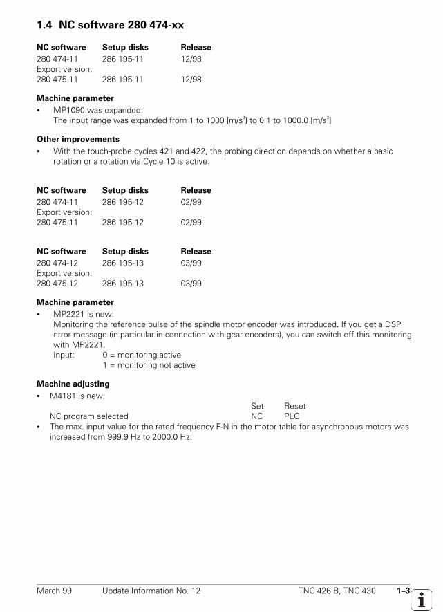
March 99 Update Information No. 12 TNC 426 B, TNC 430 1–3
1.4 NC software 280 474-xx
NC software Setup disks Release
280 474-11 286 195-11 12/98Export version:280 475-11 286 195-11 12/98
Machine parameter
• MP1090 was expanded:The input range was expanded from 1 to 1000 [m/s3] to 0.1 to 1000.0 [m/s3]
Other improvements
• With the touch-probe cycles 421 and 422, the probing direction depends on whether a basicrotation or a rotation via Cycle 10 is active.
NC software Setup disks Release
280 474-11 286 195-12 02/99Export version:280 475-11 286 195-12 02/99
NC software Setup disks Release
280 474-12 286 195-13 03/99Export version:280 475-12 286 195-13 03/99
Machine parameter
• MP2221 is new:Monitoring the reference pulse of the spindle motor encoder was introduced. If you get a DSPerror message (in particular in connection with gear encoders), you can switch off this monitoringwith MP2221.Input: 0 = monitoring active
1 = monitoring not active
Machine adjusting
• M4181 is new:Set Reset
NC program selected NC PLC• The max. input value for the rated frequency F-N in the motor table for asynchronous motors was
increased from 999.9 Hz to 2000.0 Hz.
1–4 TNC 426 B, TNC 430 Update Information No. 12 March 99
PLC modules
• Module 9175 (Activate spindle) was expanded by error code 6:W1022 = 6: Marker M4157 = 1 (RESTORE POSITION active)
• Module 9281 is new:With module 9281, the cursor can be placed on a particular line in the pallet table selected in oneof the operating modes Single Block or Full Sequence. Programmed parameters such as datumshift or datum set can be executed immediately.
Call:PS B/W/D/K <line number in the pallet table>PS B/W/D/K <mode>
0 = datum shift / do not execute datum set1 = datum shift / execute datum set
CM 9281PL B/W/D <Error code>
0: Cursor was placed in the line1: Module was not called in a SPAWN or submit job2: Module was called when NC program already started3: No pallet table selected as main program4: Line does not exist5: Error during datum set, or error in datum or pallet table
Error code: M4203 = 0: Cursor was placed in the lineM4203 = 1: Error according to error code
Other improvements
• The new error number 1068 (datum table?) was introduced for the function FN14: ERROR.• The maximum input value for Q239 in cycle 207 (RIGID TAPPING NEW) and for the pitch in cycles
17 (RIGID TAPPING) and 18 (THREAD CUTTING) was increased to 99.9999 mm.
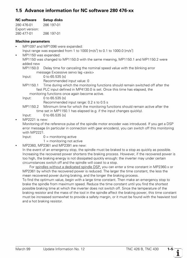
March 99 Update Information No. 12 TNC 426 B, TNC 430 1–5
1.5 Advance information for NC software 280 476-xx
NC software Setup disks
280 476-01 286 197-01Export version:280 477-01 286 197-01
Machine parameters
• MP1097 and MP1098 were expanded:Input range was expanded from 1 to 1000 [m/s3] to 0.1 to 1000.0 [m/s3]
• MP1150 was expanded:MP1150 was changed to MP1150.0 with the same meaning, MP1150.1 and MP1150.2 wereadded newMP1150.0 Delay time for canceling the nominal speed value with the blinking error
message Excessive servo lag <axis>Input: 0 to 65.535 [s]
Recommended input value: 0MP1150.1 Time during which the monitoring functions should remain switched off after the
fast PLC input defined in MP4130.0 is set. Once this time has elapsed, the monitoring functions once again become active.
Input: 0 to 65.535 [s]Recommended input range: 0.2 s to 0.5 s
MP1150.2 Minimum time for which the monitoring functions should remain active after the time set in MP1150.1 has elapsed (e.g. if the input changes quickly).
Input: 0 to 65.535 [s]• MP2221 is new:
Monitoring of the reference pulse of the spindle motor encoder was introduced. If you get a DSPerror message (in particular in connection with gear encoders), you can switch off this monitoringwith MP2221.Input: 0 = monitoring active
1 = monitoring not active• MP2360, MP2361 and MP2391 are new:
In the event of an emergency stop, the spindle must be braked to a stop as quickly as possible.Increasing the recovered power shortens the braking process. However, if the recovered power istoo high, the braking energy is not dissipated quickly enough: the inverter may under certaincircumstances switch off and the spindle will coast to a stop.
For spindles without a dedicated spindle DSP, you can enter a time constant in MP2360.x orMP2361 by which the recovered power is reduced. The larger the time constant, the less themean recovered power during braking, and the longer the braking process.To find the optimum value, begin with a large time constant. Then make an emergency stop tobrake the spindle from maximum speed. Reduce the time constant until you find the shortestpossible braking time at which the inverter does not switch off. Since the temperature of thebraking resistor and the mass of the tool in the spindle affect the braking power, this time constantmust be increased somewhat to provide a safety margin, or it must be found with the heaviest tooland a hot braking resistor.
1–6 TNC 426 B, TNC 430 Update Information No. 12 March 99
MP2360.x Time constant for braking a second digital spindle during EMERGENCY STOP
Effective MP2360.x PWM output of the second spindle
MP2360.0toMP2360.8
X51toX59
MP2361 Time constant for braking the spindle during EMERGENCY STOPInput: 0.01 to 5.00 [s]
0 = function not active (braking is only dependent on MP2191)
For spindles with dedicated spindle DSP the braking power can be limited in MP2391.
Input value 1000R
U9,0x.2391MP
2minZ
⋅⋅=
UZmin = minimum dc-link voltage [V]R = braking resistance [Ω]MP2391.0 Wye connectionMP2391.1 Delta connectionInput: 0.1 to 3000.0 [kW]
0 = braking power is not limited(preferable for inverters with dc-link power recovery)
• MP2393 is new:To achieve a "wide range" performance from a spindle motor, the power of the motor must belimited. With MP2393 the power for spindles with their own spindle DSP can be limited for wyeand delta connection.MP2393.0 Wye connectionMP2393.1 Delta connectionInput: 0.1 to 3000.0 [kW]
0 = no power limit• MP4030 is new:
A max. 4 PL 4xx B PLC I/O units can be connected to the LE 426 and LE 430. The first PL isconnected to the LE and the other PLs to the first PL. The number of the physical PL correspondsto the number of the logical PL. With MP4030.x the logical number of a PL can be assigned to adifferent physical PL.MP4030.0 to MP4030.3 First to fourth physical PLInput: 0 = first logical PL
1 = second logical PL2 = third logical PL3 = fourth logical PL
March 99 Update Information No. 12 TNC 426 B, TNC 430 1–7
• MP6585 and MP6586 are new:Before the start of a tool measurement cycle, MP6585 checks the position of the rotary andadditional linear axes. MP6586.x indicates the reference coordinate at which the axis must bepositioned for the measurement to take place.If monitoring is active for an axis and if the current reference coordinate does not correspond withthe reference coordinate in MP6586, an error message is output.
MP6585 Monitoring the positions of the rotary and additional linear axes during the tool measurement cyclesBit0 A-axis 0 = axis is not monitoredBit1 B-axis 1 = axis is monitoredBit2 C-axisBit3 U-axisBit4 V-axisBit5 W-axis
MP6586 Ref-coordinate for the monitoring of the rotary and additional linear axis positions during the tool measurement cycles
Input: –99 999.9999 to + 99 999.9999 [mm]MP6586.0 A-axisMP6586.1 B-axisMP6586.2 C-axisMP6586.3 U-axisMP6586.4 V-axisMP6586.5 W-axis
• MP7245 is new:With MP7245 the auxiliary cycles 18 (THREAD CUTTING) and cycle 33 (TAPER THREAD BORING)can be disabled.Input: 0 = auxiliary cycles are inhibited
1 = auxiliary cycles are permitted• MP7266 was expanded:
MP7266.28 Probe center misalignment main axis (CAL-OF1)MP7266.29 Probe center misalignment secondary axis (CAL-OF2)MP7266.30 Spindle angle during calibration (CAL-ANG)See also section on Machine integration
• MP7411 was expanded:Bit1 = 0: Only one set of probe calibration data
= 1: More than one set of probe calibration data in the tool tableSee also section on Machine integration
• MP7500 was expanded:Bit6 Cycle 19 (Tilt working plane) with spatial angle C ≠ 0 (for A = 0 and
B = 0) on machines with C rotary table and tool axis Z= 0: Spatial angle C is achieved by rotating the coordinate system.= 1: Spatial angle C is achieved by rotating the table (and storing the angle in Q122).
• MP7530 was expanded:In MP7530.x (dimensions for transformation) a formula can be entered for temperaturecompensation for swivel heads and tilting tables with M128 and for "Tilt working plane". Theformulas may not have more than 31 characters and must contain PLC words as variables.As soon as M128 or the "Tilt working plane" function are activated in the Automatic modes, thedimensions of the swivel head or tilting table are recalculated.
1–8 TNC 426 B, TNC 430 Update Information No. 12 March 99
Machine integration
• HSC filter was expanded:With the HSC filter up until now, only the jerk at corners that was entered in MP1098.x waslimited. Now an additional permissible jerk for curve changes (e.g. tangential transitions of a linearmovement in a circular path) can be entered in MP1097.x. Recommended input value: MP1097.x =MP1098.x
• If the fast PLC input defined in MP4130.0 is set, the drive is no longer switched off automatically(see also machine parameter MP1150.x).
• The position indications in the Tilt working plane function (MP7500 Bit1 = 1) have been expandedby the following tilting axis combinations:Universal swivel head: Axis sequence A fixed / B –90° / A variable / B +90° / A fixed / C
variable (tool axis Z)Universal swivel head: Axis sequence B fixed / A variable / B fixed / C variable
(tool axis X)• M4181 is new:
Set ResetNC program selected NC PLC
• The max. input value for the rated frequency F-N in the table for asynchronous motors wasincreased from 999.9 Hz to 2000.0 Hz
• Several sets of probe calibration data (only trigger probe) can be managed in the tool table. Thisfunction must be activated with MP7411 bit1. The tool table was expanded by the columns CAL-OF1 (probe center misalignment in main axis), CAL-OF2 (probe center misalignment in secondaryaxis) and CAL-ANG (spindle angle during calibration). These columns are not visible as default, canhowever be made visible with MP7266.28, MP7266.29 and MP7266.30. During manualmeasurement, the current probe calibration data can be viewed and changed in the calibrationmenu.
• In the Manual operating modes, the highest axis feed for all axes is stored in D388 (currentmachining feed rate).
PLC programming
• FN17: SYSWRITE was expanded:The software limit switches can be overwritten.ID230NR4IDX xxx = yyy
xxx = number of axes whose limit switches are to be overwrittenyyy = number of the first of several successive Q parameters
1. Q parameter: negative limit switch of the 1st axis2. Q parameter: positive limit switch of the 1st axis3. Q parameter: negative limit switch of the 2nd axis4. Q parameter: positive limit switch of the 2nd axis5. Q parameter: negative limit switch of the 3rd axisetc.
March 99 Update Information No. 12 TNC 426 B, TNC 430 1–9
• FN18: SYSREAD was expanded:The number of axes that are programmed in the selected datum table is indicated in the return Qparameter.ID990NR3ID xxx
xxx = number of the first of 9 successive Q parameters for the axes X, Y, Z, A, B, C, U, V, WQ xxx = +1.0: axis existsQ xxx = –1.0: axis does not exist
PLC modules
• Module 9122 was expanded:With bit 6 of the status word, you can interrogate whether the PLC axis has reached the targetposition (0 = target position not yet reached, 1 = target position reached)
• Module 9151 was expanded:The axis designations defined with Module 9151 remain unchanged, even if other machineparameters are edited.
• Module 9152 is new:With module 9152 you can select a freely-definable axis display or designation and one of thethree traverse ranges. The same conditions apply as for traverse range selection with M4135.When the module is called, M4135 is set and it is reset after the change has been made. Wheninputting the string for axis designation and display, you can use the same syntax as for input inMP100.x or MP7291.MP100.x or MP7291 cannot be activated again until the string for axis display or axis assignmenthas been transferred to Module 9151 or 9152 –1, a traverse range has been activated with M4135,MP100.x or MP7291 have been edited or a control reset has been carried out.
Call:PS B/W/D/K/S <string with axis display>
–1 = use axis display from MP7291PS B/W/D/K/S <string with axis assignment>
–1 = use axis assignment from MP100.xPS B/W/D/K <traverse range>
0 to 2 = traverse range–1 = do not change traverse range
CM 9152Error code: M4203 = 0: traverse range, axis designation or display has been
switchedM4203 = 1: Error code in W1022W1022 = 2: Value not valid for the traverse range, or string for the
display configuration too longW1022 = 3: Neither a string nor –1 was transferred for the axis
assignment or displayW1021 = 21: The module was called when the program was already
started, or without a M/S/T/T2/Q strobe
1–10 TNC 426 B, TNC 430 Update Information No. 12 March 99
• Module 9158 is new:Module 9158 can limit the max. torque for an axis. After the drive is switched off, the originaltorque is restored again.
Call:PS B/W/D/K/S <axis number>PS B/W/D/K/S <torque in 1/1000 Nm>
–1 = torque from motor dataCM 9158Error code: M4203 = 0: Torque indicator active
M4203 = 1: Error code in W1022W1022 = 1: Transfer torque value 0W1022 = 2: Invalid axis numberW1022 = 24: Module was called in a SPAWN or submit job
• Module 9169 is new:With Module 9169 you can define axes that are not switched off by the input I32 (X42/33, driveenable, acknowledgment for control-is-ready signal) . This module works only in conjunction withthe TNC 426 M / TNC 430 M controls.
Call:PS B/W/D/K <bit-coded axes>CM 9169Error code: M4203 = 0:no errors possible
• Module 9175 (Activate spindle) was expanded by error code 6:W1022 = 6: Marker M4157 = 1 (APPROACH POSITION active)
• Module 9275 is new:With module 9275, ASCII data can be written to the log book. Each entry can be given anidentification for future processing.Module 9275 should not be used in the general PLC program, but rather only for debug purposes,because the processing time may be negatively influenced, unnecessary space used on the harddisk and the log book used for purposes not intended for its function (namely recording keys anderror messages).
Call:PS B/W/D/K/S <log book entry>
–1 = no entryPS B/W/D/K/S <log book identification>
–1 = no entryPS B/W/D/K <priority>
0 = information1 = warning2 = error
CM 9275Error code: M4203 = 0: Entry was written in book
M4203 = 1: Error code in W1022W1022 = 1: Invalid priorityW1022 = 2: Invalid string or invalid immediate stringW1022 = 12: No string end identifierW1022 = 20: Module was not called in SPAWN or submit job
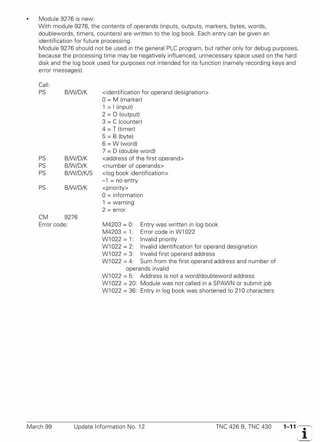
March 99 Update Information No. 12 TNC 426 B, TNC 430 1–11
• Module 9276 is new:With module 9276, the contents of operands (inputs, outputs, markers, bytes, words,doublewords, timers, counters) are written to the log book. Each entry can be given anidentification for future processing.Module 9276 should not be used in the general PLC program, but rather only for debug purposes,because the processing time may be negatively influenced, unnecessary space used on the harddisk and the log book used for purposes not intended for its function (namely recording keys anderror messages).
Call:PS B/W/D/K <identification for operand designation>
0 = M (marker)1 = I (input)2 = O (output)3 = C (counter)4 = T (timer)5 = B (byte)6 = W (word)7 = D (double word)
PS B/W/D/K <address of the first operand>PS B/W/D/K <number of operands>PS B/W/D/K/S <log book identification>
–1 = no entryPS B/W/D/K <priority>
0 = information1 = warning2 = error
CM 9276Error code: M4203 = 0: Entry was written in log book
M4203 = 1: Error code in W1022W1022 = 1: Invalid priorityW1022 = 2: Invalid identification for operand designationW1022 = 3: Invalid first operand addressW1022 = 4: Sum from the first operand address and number of
operands invalidW1022 = 5: Address is not a word/doubleword addressW1022 = 20: Module was not called in a SPAWN or submit jobW1022 = 36: Entry in log book was shortened to 210 characters
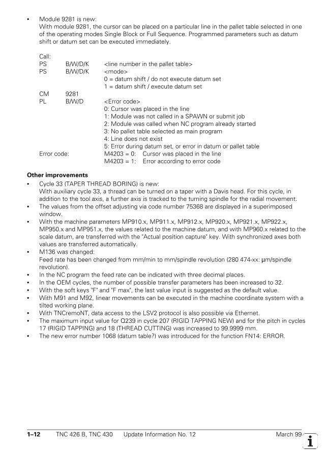
1–12 TNC 426 B, TNC 430 Update Information No. 12 March 99
• Module 9281 is new:With module 9281, the cursor can be placed on a particular line in the pallet table selected in oneof the operating modes Single Block or Full Sequence. Programmed parameters such as datumshift or datum set can be executed immediately.
Call:PS B/W/D/K <line number in the pallet table>PS B/W/D/K <mode>
0 = datum shift / do not execute datum set1 = datum shift / execute datum set
CM 9281PL B/W/D <Error code>
0: Cursor was placed in the line1: Module was not called in a SPAWN or submit job2: Module was called when NC program already started3: No pallet table selected as main program4: Line does not exist5: Error during datum set, or error in datum or pallet table
Error code: M4203 = 0: Cursor was placed in the lineM4203 = 1: Error according to error code
Other improvements
• Cycle 33 (TAPER THREAD BORING) is new:With auxiliary cycle 33, a thread can be turned on a taper with a Davis head. For this cycle, inaddition to the tool axis, a further axis is tracked to the turning spindle for the radial movement.
• The values from the offset adjusting via code number 75368 are displayed in a superimposedwindow.
• With the machine parameters MP910.x, MP911.x, MP912.x, MP920.x, MP921.x, MP922.x,MP950.x and MP951.x, the values related to the machine datum, and with MP960.x related to thescale datum, are transferred with the "Actual position capture" key. With synchronized axes bothvalues are transferred automatically.
• M136 was changed:Feed rate has been changed from mm/min to mm/spindle revolution (280 474-xx: µm/spindlerevolution).
• In the NC program the feed rate can be indicated with three decimal places.• In the OEM cycles, the number of possible transfer parameters has been increased to 32.• With the soft keys "F" and "F max", the last value input is suggested as the default value.• With M91 and M92, linear movements can be executed in the machine coordinate system with a
tilted working plane.• With TNCremoNT, data access to the LSV2 protocol is also possible via Ethernet.• The maximum input value for Q239 in cycle 207 (RIGID TAPPING NEW) and for the pitch in cycles
17 (RIGID TAPPING) and 18 (THREAD CUTTING) was increased to 99.9999 mm.• The new error number 1068 (datum table?) was introduced for the function FN14: ERROR.
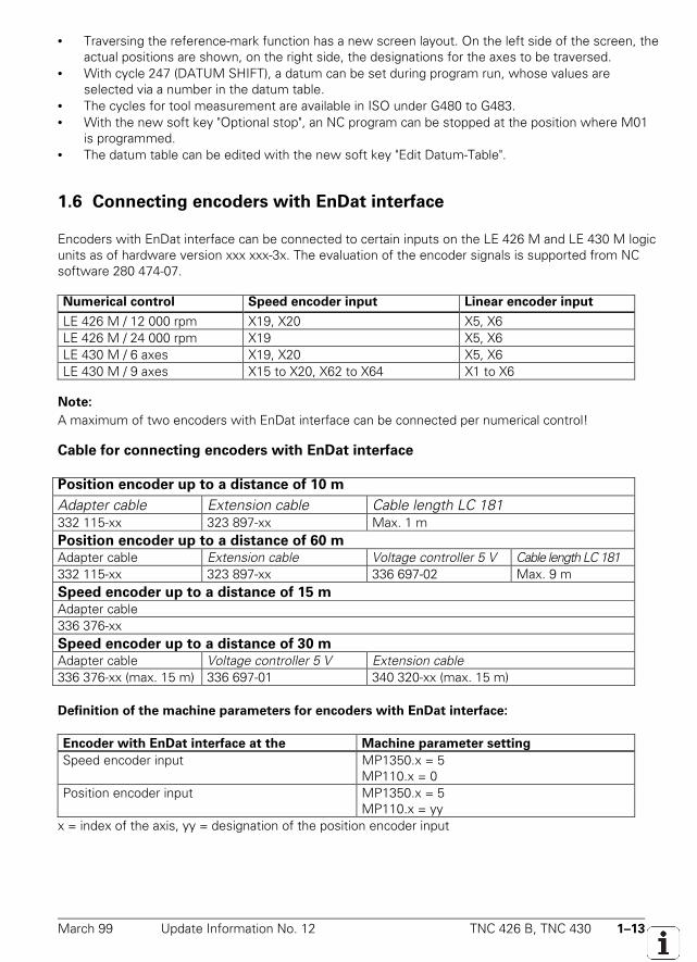
March 99 Update Information No. 12 TNC 426 B, TNC 430 1–13
• Traversing the reference-mark function has a new screen layout. On the left side of the screen, theactual positions are shown, on the right side, the designations for the axes to be traversed.
• With cycle 247 (DATUM SHIFT), a datum can be set during program run, whose values areselected via a number in the datum table.
• The cycles for tool measurement are available in ISO under G480 to G483.• With the new soft key "Optional stop", an NC program can be stopped at the position where M01
is programmed.• The datum table can be edited with the new soft key "Edit Datum-Table".
1.6 Connecting encoders with EnDat interface
Encoders with EnDat interface can be connected to certain inputs on the LE 426 M and LE 430 M logicunits as of hardware version xxx xxx-3x. The evaluation of the encoder signals is supported from NCsoftware 280 474-07.
Numerical control Speed encoder input Linear encoder input
LE 426 M / 12 000 rpm X19, X20 X5, X6LE 426 M / 24 000 rpm X19 X5, X6LE 430 M / 6 axes X19, X20 X5, X6LE 430 M / 9 axes X15 to X20, X62 to X64 X1 to X6
Note:
A maximum of two encoders with EnDat interface can be connected per numerical control!
Cable for connecting encoders with EnDat interface
Position encoder up to a distance of 10 m
Adapter cable Extension cable Cable length LC 181332 115-xx 323 897-xx Max. 1 mPosition encoder up to a distance of 60 m
Adapter cable Extension cable Voltage controller 5 V Cable length LC 181332 115-xx 323 897-xx 336 697-02 Max. 9 mSpeed encoder up to a distance of 15 m
Adapter cable336 376-xxSpeed encoder up to a distance of 30 m
Adapter cable Voltage controller 5 V Extension cable336 376-xx (max. 15 m) 336 697-01 340 320-xx (max. 15 m)
Definition of the machine parameters for encoders with EnDat interface:
Encoder with EnDat interface at the Machine parameter setting
Speed encoder input MP1350.x = 5MP110.x = 0
Position encoder input MP1350.x = 5MP110.x = yy
x = index of the axis, yy = designation of the position encoder input
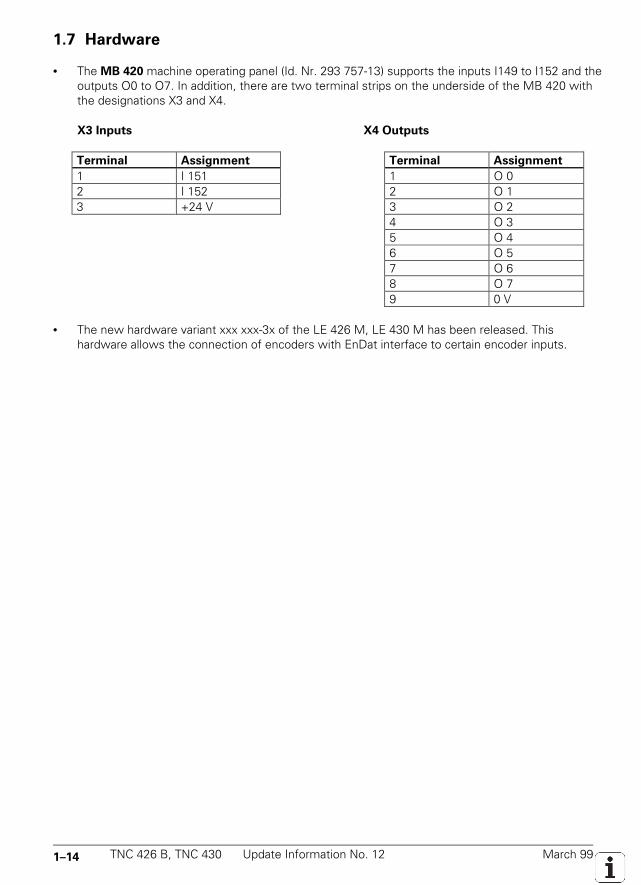
1–14 TNC 426 B, TNC 430 Update Information No. 12 March 99
1.7 Hardware
• The MB 420 machine operating panel (Id. Nr. 293 757-13) supports the inputs I149 to I152 and theoutputs O0 to O7. In addition, there are two terminal strips on the underside of the MB 420 withthe designations X3 and X4.
X3 Inputs X4 Outputs
Terminal Assignment Terminal Assignment
1 I 151 1 O 02 I 152 2 O 13 +24 V 3 O 2
4 O 35 O 46 O 57 O 68 O 79 0 V
• The new hardware variant xxx xxx-3x of the LE 426 M, LE 430 M has been released. Thishardware allows the connection of encoders with EnDat interface to certain encoder inputs.
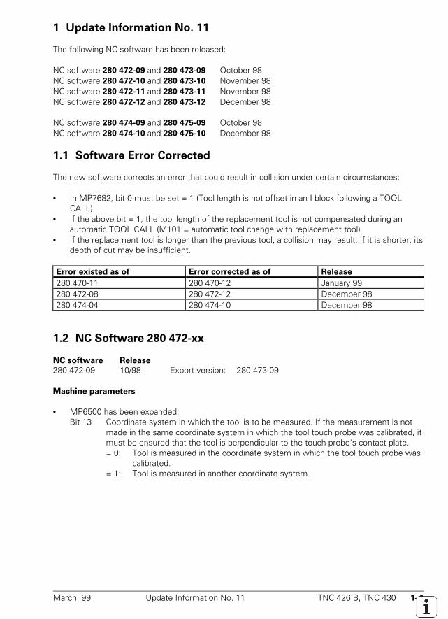
March 99 Update Information No. 11 TNC 426 B, TNC 430 1–1
1 Update Information No. 11
The following NC software has been released:
NC software 280 472-09 and 280 473-09 October 98NC software 280 472-10 and 280 473-10 November 98NC software 280 472-11 and 280 473-11 November 98NC software 280 472-12 and 280 473-12 December 98
NC software 280 474-09 and 280 475-09 October 98NC software 280 474-10 and 280 475-10 December 98
1.1 Software Error Corrected
The new software corrects an error that could result in collision under certain circumstances:
• In MP7682, bit 0 must be set = 1 (Tool length is not offset in an I block following a TOOLCALL).
• If the above bit = 1, the tool length of the replacement tool is not compensated during anautomatic TOOL CALL (M101 = automatic tool change with replacement tool).
• If the replacement tool is longer than the previous tool, a collision may result. If it is shorter, itsdepth of cut may be insufficient.
Error existed as of Error corrected as of Release
280 470-11 280 470-12 January 99280 472-08 280 472-12 December 98280 474-04 280 474-10 December 98
1.2 NC Software 280 472-xx
NC software Release
280 472-09 10/98 Export version: 280 473-09
Machine parameters
• MP6500 has been expanded:Bit 13 Coordinate system in which the tool is to be measured. If the measurement is not
made in the same coordinate system in which the tool touch probe was calibrated, itmust be ensured that the tool is perpendicular to the touch probe's contact plate.= 0: Tool is measured in the coordinate system in which the tool touch probe was
calibrated.= 1: Tool is measured in another coordinate system.
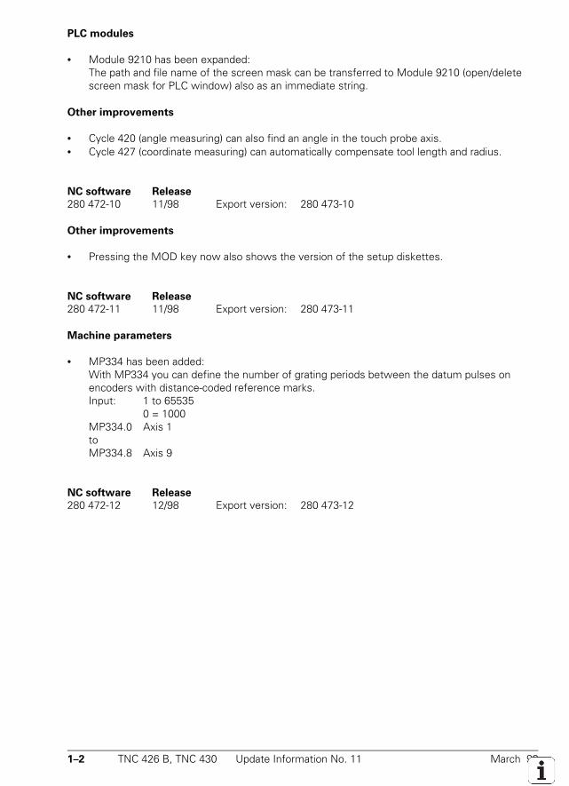
1–2 TNC 426 B, TNC 430 Update Information No. 11 March 99
PLC modules
• Module 9210 has been expanded:The path and file name of the screen mask can be transferred to Module 9210 (open/deletescreen mask for PLC window) also as an immediate string.
Other improvements
• Cycle 420 (angle measuring) can also find an angle in the touch probe axis.• Cycle 427 (coordinate measuring) can automatically compensate tool length and radius.
NC software Release
280 472-10 11/98 Export version: 280 473-10
Other improvements
• Pressing the MOD key now also shows the version of the setup diskettes.
NC software Release
280 472-11 11/98 Export version: 280 473-11
Machine parameters
• MP334 has been added:With MP334 you can define the number of grating periods between the datum pulses onencoders with distance-coded reference marks.Input: 1 to 65535
0 = 1000MP334.0 Axis 1toMP334.8 Axis 9
NC software Release
280 472-12 12/98 Export version: 280 473-12
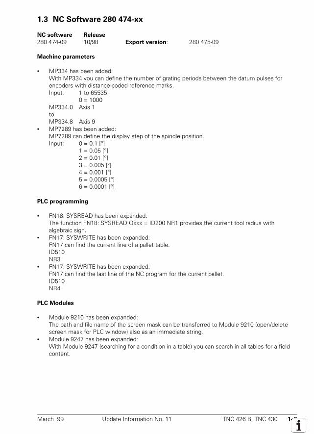
March 99 Update Information No. 11 TNC 426 B, TNC 430 1–3
1.3 NC Software 280 474-xx
NC software Release
280 474-09 10/98 Export version: 280 475-09
Machine parameters
• MP334 has been added:With MP334 you can define the number of grating periods between the datum pulses forencoders with distance-coded reference marks.Input: 1 to 65535
0 = 1000MP334.0 Axis 1toMP334.8 Axis 9
• MP7289 has been added:MP7289 can define the display step of the spindle position.Input: 0 = 0.1 [°]
1 = 0.05 [°]2 = 0.01 [°]3 = 0.005 [°]4 = 0.001 [°]5 = 0.0005 [°]6 = 0.0001 [°]
PLC programming
• FN18: SYSREAD has been expanded:The function FN18: SYSREAD Qxxx = ID200 NR1 provides the current tool radius withalgebraic sign.
• FN17: SYSWRITE has been expanded:FN17 can find the current line of a pallet table.ID510NR3
• FN17: SYSWRITE has been expanded:FN17 can find the last line of the NC program for the current pallet.ID510NR4
PLC Modules
• Module 9210 has been expanded:The path and file name of the screen mask can be transferred to Module 9210 (open/deletescreen mask for PLC window) also as an immediate string.
• Module 9247 has been expanded:With Module 9247 (searching for a condition in a table) you can search in all tables for a fieldcontent.
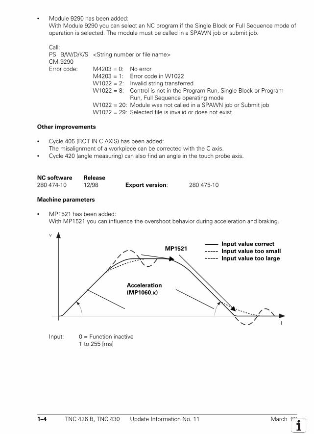
1–4 TNC 426 B, TNC 430 Update Information No. 11 March 99
• Module 9290 has been added:With Module 9290 you can select an NC program if the Single Block or Full Sequence mode ofoperation is selected. The module must be called in a SPAWN job or submit job.
Call:PS B/W/D/K/S <String number or file name>CM 9290Error code: M4203 = 0: No error
M4203 = 1: Error code in W1022W1022 = 2: Invalid string transferredW1022 = 8: Control is not in the Program Run, Single Block or Program
Run, Full Sequence operating modeW1022 = 20: Module was not called in a SPAWN job or Submit jobW1022 = 29: Selected file is invalid or does not exist
Other improvements
• Cycle 405 (ROT IN C AXIS) has been added:The misalignment of a workpiece can be corrected with the C axis.
• Cycle 420 (angle measuring) can also find an angle in the touch probe axis.
NC software Release
280 474-10 12/98 Export version: 280 475-10
Machine parameters
• MP1521 has been added:With MP1521 you can influence the overshoot behavior during acceleration and braking.
Input: 0 = Function inactive1 to 255 [ms]
Acceleration
(MP1060.x)
Input value correct
Input value too small
Input value too large
MP1521
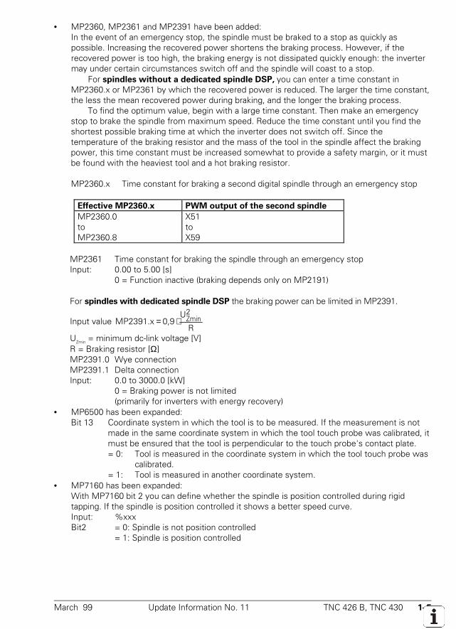
March 99 Update Information No. 11 TNC 426 B, TNC 430 1–5
• MP2360, MP2361 and MP2391 have been added:In the event of an emergency stop, the spindle must be braked to a stop as quickly aspossible. Increasing the recovered power shortens the braking process. However, if therecovered power is too high, the braking energy is not dissipated quickly enough: the invertermay under certain circumstances switch off and the spindle will coast to a stop.
For spindles without a dedicated spindle DSP, you can enter a time constant inMP2360.x or MP2361 by which the recovered power is reduced. The larger the time constant,the less the mean recovered power during braking, and the longer the braking process.
To find the optimum value, begin with a large time constant. Then make an emergencystop to brake the spindle from maximum speed. Reduce the time constant until you find theshortest possible braking time at which the inverter does not switch off. Since thetemperature of the braking resistor and the mass of the tool in the spindle affect the brakingpower, this time constant must be increased somewhat to provide a safety margin, or it mustbe found with the heaviest tool and a hot braking resistor.
MP2360.x Time constant for braking a second digital spindle through an emergency stop
Effective MP2360.x PWM output of the second spindle
MP2360.0toMP2360.8
X51toX59
MP2361 Time constant for braking the spindle through an emergency stopInput: 0.00 to 5.00 [s]
0 = Function inactive (braking depends only on MP2191)
For spindles with dedicated spindle DSP the braking power can be limited in MP2391.
Input value R
U0,9MP2391.x
2Zmin⋅=
UZmin = minimum dc-link voltage [V]R = Braking resistor [Ω]MP2391.0 Wye connectionMP2391.1 Delta connectionInput: 0.0 to 3000.0 [kW]
0 = Braking power is not limited(primarily for inverters with energy recovery)
• MP6500 has been expanded:Bit 13 Coordinate system in which the tool is to be measured. If the measurement is not
made in the same coordinate system in which the tool touch probe was calibrated, itmust be ensured that the tool is perpendicular to the touch probe's contact plate.= 0: Tool is measured in the coordinate system in which the tool touch probe was
calibrated.= 1: Tool is measured in another coordinate system.
• MP7160 has been expanded:With MP7160 bit 2 you can define whether the spindle is position controlled during rigidtapping. If the spindle is position controlled it shows a better speed curve.Input: %xxxBit2 = 0: Spindle is not position controlled
= 1: Spindle is position controlled
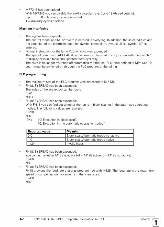
1–6 TNC 426 B, TNC 430 Update Information No. 11 March 99
• MP7245 has been added:With MP7245 you can disable the auxiliary cycles, e.g. Cycle 18 (thread cutting).Input: 0 = Auxiliary cycles permitted1 = Auxiliary cycles disabled
Machine Interfacing
• The log has been expanded:The control model and NC software is entered in every log. In addition, the selected files andthe condition of the control-in-operation symbol (symbol on, symbol blinks, symbol off) isentered.
• Format instruction for the large PLC window was expanded:The special command TABREAD (line, column) can be used in conjunction with the switch /cto display cells in a table and updated them cyclically.
• The drive is no longer switched off automatically if the fast PLC input defined in MP4130.0 isset. It must be switched on through the PLC program or the wiring.
PLC programming
• The maximum size of the PLC program was increased to 512 KB.• FN18: SYSREAD has been expanded:
The index of the active tool can be found.ID20NR11
• FN18: SYSREAD has been expanded:With FN18 you can find out whether the run is in block scan or in the automatic operatingmodes. The following values are reported:ID990NR2IDXx 10: Execution in block scan?
16: Execution in the automatic operating modes?
Reported value Meaning
0.0 Block scan/Automatic mode not active1.0 Block scan/Automatic mode active–1.0 Invalid index
• FN18: SYSREAD has been expanded:You can ask whether M128 is active (–1 = M128 active, 0 = M128 not active).ID280NR1
• FN18: SYSREAD has been expanded:FN18 provides the feed rate that was programmed with M128. The feed rate is the maximumspeed of compensation movements in the linear axes.ID280NR2
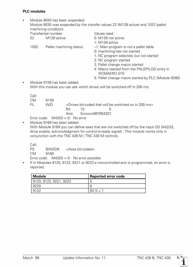
March 99 Update Information No. 11 TNC 426 B, TNC 430 1–7
PLC modules
• Module 9035 has been expanded:Module 9035 was expanded by the transfer values 22 (M128 active) and 1022 (palletmachining condition).Transferred number: Values read:22 M128 active 0: M128 not active
1: M128 active1002 Pallet machining status –1: Main program is not a pallet table
0: machining has not started1: NC program selected, but not started2: NC program started3: Pallet change macro started4: Macro started from the PALEPILOG entry in
NCMAKRO.SYS5: Pallet change macro started by PLC (Module 9280)
• Module 9159 has been added:With this module you can ask which drives will be switched off in 200 ms.
Call:CM 9159PL W/D <Drives bit-coded that will be switched on in 200 ms>
Bit 15 0Axis Sxxxxxx987654321
Error code: M4203 = 0: No error• Module 9169 has been added:
With Module 9169 you can define axes that are not switched off by the input I32 (X42/33,drive enable, acknowledgment for control-is-ready signal) . This module works only inconjunction with the TNC 426 M / TNC 430 M controls.
Call:PS B/W/D/K <Axes bit-coded>CM 9169Error code: M4203 = 0: No error possible
• If in Modules 9120, 9123, 9221 or 9223 a noncontrolled axis is programmed, an error isreported.
Module Reported error code
9120, 9123, 9221, 9223 59220 89122 Bit 5 = 1
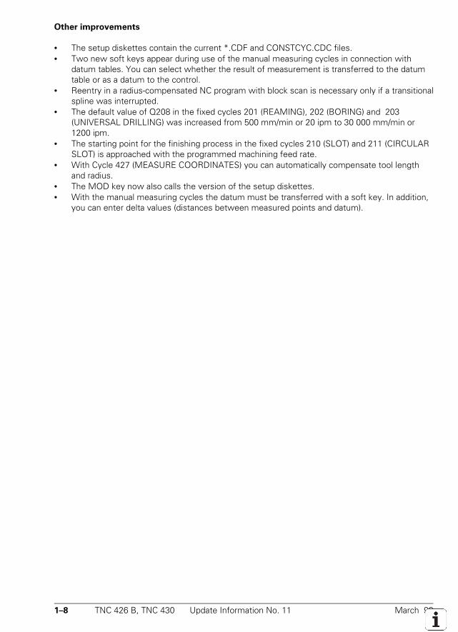
1–8 TNC 426 B, TNC 430 Update Information No. 11 March 99
Other improvements
• The setup diskettes contain the current *.CDF and CONSTCYC.CDC files.• Two new soft keys appear during use of the manual measuring cycles in connection with
datum tables. You can select whether the result of measurement is transferred to the datumtable or as a datum to the control.
• Reentry in a radius-compensated NC program with block scan is necessary only if a transitionalspline was interrupted.
• The default value of Q208 in the fixed cycles 201 (REAMING), 202 (BORING) and 203(UNIVERSAL DRILLING) was increased from 500 mm/min or 20 ipm to 30 000 mm/min or1200 ipm.
• The starting point for the finishing process in the fixed cycles 210 (SLOT) and 211 (CIRCULARSLOT) is approached with the programmed machining feed rate.
• With Cycle 427 (MEASURE COORDINATES) you can automatically compensate tool lengthand radius.
• The MOD key now also calls the version of the setup diskettes.• With the manual measuring cycles the datum must be transferred with a soft key. In addition,
you can enter delta values (distances between measured points and datum).
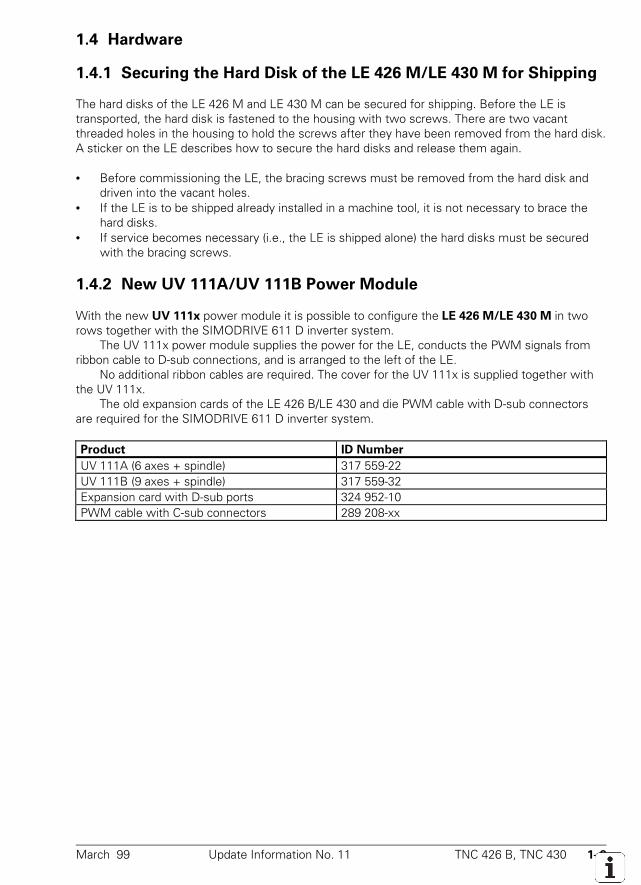
March 99 Update Information No. 11 TNC 426 B, TNC 430 1–9
1.4 Hardware
1.4.1 Securing the Hard Disk of the LE 426 M/LE 430 M for Shipping
The hard disks of the LE 426 M and LE 430 M can be secured for shipping. Before the LE istransported, the hard disk is fastened to the housing with two screws. There are two vacantthreaded holes in the housing to hold the screws after they have been removed from the hard disk.A sticker on the LE describes how to secure the hard disks and release them again.
• Before commissioning the LE, the bracing screws must be removed from the hard disk anddriven into the vacant holes.
• If the LE is to be shipped already installed in a machine tool, it is not necessary to brace thehard disks.
• If service becomes necessary (i.e., the LE is shipped alone) the hard disks must be securedwith the bracing screws.
1.4.2 New UV 111A/UV 111B Power Module
With the new UV 111x power module it is possible to configure the LE 426 M/LE 430 M in tworows together with the SIMODRIVE 611 D inverter system.
The UV 111x power module supplies the power for the LE, conducts the PWM signals fromribbon cable to D-sub connections, and is arranged to the left of the LE.
No additional ribbon cables are required. The cover for the UV 111x is supplied together withthe UV 111x.
The old expansion cards of the LE 426 B/LE 430 and die PWM cable with D-sub connectorsare required for the SIMODRIVE 611 D inverter system.
Product ID Number
UV 111A (6 axes + spindle) 317 559-22UV 111B (9 axes + spindle) 317 559-32Expansion card with D-sub ports 324 952-10PWM cable with C-sub connectors 289 208-xx
October 98 Update Information No. 10 TNC 426 B, TNC 430 1–1
1 Update Information No. 10
1.1 NC software 280 472-08
NC software Release
280 472-08 07/98 Export version: 280 473-08
Machine parameters
• MP2510 and MP2511 expanded:Maximum input value reduced to 30 000 [A]
• MP2191 new:Deceleration of the spindle during Emergency StopThe spindle must be decelerated as quickly as possible during Emergency Stop. If the brakingenergy cannot be led away quickly enough, the dc-link voltage will rise significantly. In the worstcase, the inverter will switch off and the spindle will then turn freely. With MP2191 you can setwhether you wish the max. braking current to be monitored and reduced if necessary.Monitoring increases the duration of the braking function somewhat.Input: %xBit 0 = 0: Braking with monitoring of the max. braking current
(preferably for inverters with braking resistance)= 1: Braking without monitoring of the max. braking current
(preferably for inverters with energy recovery)• MP6161, MP6162 and MP6163 new:
MP6161 defines an M function for orienting the infrared sensor before each measurement. Theorientation angle is set in MP6162. Spindle orientation is then carried out when the differencebetween the current spindle angle and the orientation angle from MP6162 is smaller than thetolerance value in MP6163.MP6161 M-function to orient infrared sensor before each measurementInput: –1 = Spindle orientation direct via NC
0 = Function inactive1 to 88 = Number of the M-function for spindle orientation
MP6162 Orientation angle for infrared sensorInput: 0 to 359.9999 [°]
MP6163 Difference between current spindle angle and angle in MP6162 from which a spindle orientation is to be carried out.
Input: 0 to 3.0000 [°]
PLC programming
• The number of strings was increased from 4 to 8 (now: S0 to S7).• FN17: SYSWRITE expanded:
Data of certain tools can be overwritten in the tool table.ID50NRxx System datumIDXxxxx Tool number (0 or NO ENT = current tool)
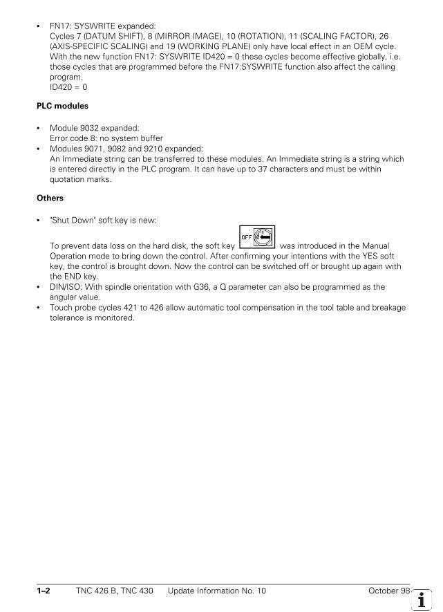
1–2 TNC 426 B, TNC 430 Update Information No. 10 October 98
• FN17: SYSWRITE expanded:Cycles 7 (DATUM SHIFT), 8 (MIRROR IMAGE), 10 (ROTATION), 11 (SCALING FACTOR), 26(AXIS-SPECIFIC SCALING) and 19 (WORKING PLANE) only have local effect in an OEM cycle.With the new function FN17: SYSWRITE ID420 = 0 these cycles become effective globally, i.e.those cycles that are programmed before the FN17:SYSWRITE function also affect the callingprogram.ID420 = 0
PLC modules
• Module 9032 expanded:Error code 8: no system buffer
• Modules 9071, 9082 and 9210 expanded:An Immediate string can be transferred to these modules. An Immediate string is a string whichis entered directly in the PLC program. It can have up to 37 characters and must be withinquotation marks.
Others
• "Shut Down" soft key is new:
To prevent data loss on the hard disk, the soft key was introduced in the ManualOperation mode to bring down the control. After confirming your intentions with the YES softkey, the control is brought down. Now the control can be switched off or brought up again withthe END key.
• DIN/ISO: With spindle orientation with G36, a Q parameter can also be programmed as theangular value.
• Touch probe cycles 421 to 426 allow automatic tool compensation in the tool table and breakagetolerance is monitored.
October 98 Update Information No. 10 TNC 426 B, TNC 430 1–3
1.2 NC software 280 474-xx
NC software Release
280 474-06 07/98 Export version: 280 475-06
NC software Release
280 474-07 08/98 Export version: 280 475-07
Machine parameters
• MP1094 new:For controls with their own spindle DSP, an HSC filter can be activated instead of the single ordouble filter. A cutoff frequency must be entered in MP1094. The cutoff frequency should beapprox. 20% to 30% below the resonance frequency of the machine. The axis-specific jerk fromMP1098 is valid. MP1095, MP1097 and MP1099 have no effect. With input value 0, the oldfilters are active.Input: 0 = No HSC filter active
0 to 166.0 [Hz] Cutoff frequency for an HSC filter• MP1220 was removed as it had no function.• MP1390 was removed and MP1392 was added instead.• MP1392 is new:
With MP1390 operation with servo lag or velocity feedforward control could only be selected forall axes. With MP1392 operation with servo lag or feedforward can be set on an axis-specificbasis. M90 (operation with servo lag: constant speed at corners) is only effective if operationwith servo lag is selected for all axes.Input: %xxxxxxxxxBit 0 to 8 0 = Operation with servo lagAxis 1 to 9 1 = Operation with velocity feedforward control
• MP2560 and MP2561 new:With machine parameters MP2560.x and MP2561 a 1st or 2nd order low pass filter can beactivated for the axes and the spindle. This filter is suitable for dampening disruptive high-frequency vibrations (> 600 Hz). If you have problems with such vibrations, first try this filter.Use the first order filter for vibrations of < approx. 700 Hz and the second order filter forvibrations of > approx. 700 Hz. If these filters do not give satisfactory results, then try using thePT2 time-delay element (MP2530).MP2560.0 to MP2560.8 low pass filter for the axes 1 to 9MP2561 low pass filter for the spindleInput: 0 = No low pass filter
1 = low pass filter 1st order2 = low pass filter 2nd order
• MP6161, MP6162 and MP6163 new:see improvements of NC software 280 472-08
• MP7267 expanded:MP7267.5 Tool name (TNAME)
• See also the section "Machine Integration."
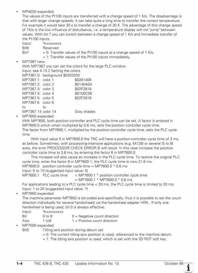
1–4 TNC 426 B, TNC 430 Update Information No. 10 October 98
• MP4020 expanded:The values of the Pt100 inputs are transferred with a change speed of 1 K/s. The disadvantage isthat with larger change speeds, it can take quite a long time to transfer the correct temperature.For example it would take 30 s to transfer a change of 30 K. The advantage of this change speedof 1K/s is the low influence of disturbance, i.e. a temperature display will not "jump" betweenvalues. With bit 7 you can switch between a change speed of 1 K/s and immediate transfer ofthe Pt100 inputs.Input: %xxxxxxxxBit6 ReservedBit7 = 0: Transfer values of the Pt100 inputs at a change speed of 1 K/s.
= 1: Transfer values of the Pt100 inputs immediately.• MP7367 new:
With MP7367 you can set the colors for the large PLC window.Input: see 4.13.2 Setting the colorsMP7367.0: background $0333333MP7367.1: color 1 $0281408MP7367.2: color 2 $0140A04MP7367.3: color 3 $02F2818MP7367.4: color 4 $0100C08MP7367.5: color 5 $02F2818MP7367.6 color 6to toMP7367.14 color 14 Gray shades
• MP7600 expanded:With MP7600, both position-controller and PLC cycle time can be set. A factor is entered inMP7600.0 which when multiplied by 0.6 ms, sets the position controller cycle time.The factor from MP7600.1, multiplied by the position-controller cycle time, sets the PLC cycletime.
With input value 5 in MP7600.0 the TNC will have a position-controller cycle time of 3 ms,as before. Sometimes, with processing-intensive applications (e.g. M128) or several (5 to 9)axes, the error PROCESSOR CHECK ERROR B will result. In this case increase the positioncontroller cycle time to 3.6 ms, by entering the factor 6 in MP7600.0.
This increase will also cause an increase in the PLC cycle time. To restore the original PLCcycle time, enter the factor 6 in MP7600.1; the PLC cycle time is now 21.6 ms.MP7600.0 position controller cycle time = MP7600.0 * 0.6 msInput: 5 to 10 (suggested input value: 5)MP7600.1 PLC cycle time = MP7600.1 * position controller cycle time
= MP7600.1 * MP7600.0 * 0.6 msFor applications leading to a PLC cycle time < 20 ms, the PLC cycle time is limited to 20 ms.Input: 1 to 20 (suggested input value: 7)
• MP7650 expanded:The machine parameter MP7650 is bit-coded axis-specifically; thus it is possible to set the countdirection individually for several handwheels via the handwheel adapter HRA . If only onehandwheel is being used, bit 0 is always effective.Input: %xxxxxxxxxBit 0 to 8 0 = Negative count directionAxis 1 to9 1 = Positive count direction
• MP7500 expanded:Bit5 Tilting axis position during datum set
= 0: The current tilting axis position is used, referenced to the machine datum.= 1: The tilting axis position is used, which is set with the 3D ROT soft key.
October 98 Update Information No. 10 TNC 426 B, TNC 430 1–5
Machine integration
• The gear range from W256 (G code with S-analog) is output with spindle speed = 0.• The pocket table was expanded by the column TNAME. The tool name from the tool table is
entered in this column and therefore cannot be edited. With indexed tools, the name of the toolis entered with the index 0.
• The column LOCK can be added to a pallet table. Lines containing any entry in this column willnot be processed. If several programs or pallets are being run, the TNC will move to the nextunlocked line. Likewise unlocked lines in a locked pallet will be skipped.
PLC programming
• FN17: SYSWRITE ID420 = 0 new:see improvements for NC software 280 472-08
• FN17: SYSWRITE expanded:With the new touch probe cycle 3 it is possible to switch between inputs X12 and X13. If thevalue 1.0 is assigned (= input X13), marker M4060 is set. If 0.0 is assigned (= input X12), markerM4060 is reset (if it had been set).ID990NR6 = <input>
0.0 = input X121.0 = input X13
• FN26: TABOPEN, FN 27: TABWRITE and FN28: TABREAD new:These FN functions open numeric cells for freely definable tables which can then be written to orread from. Only one table can be open at any one time. A new TABOPEN closes an open tableand opens a new one.FN26: TABOPEN <path> path of the table to be opened (*.TAB)FN27: TABWRITE <line number> / <"column name"> = Qxxx
The content of the Q parameter (Q0 to Q399) is written to the cell which isdefined by the line number and the column name. Up to 8 column names canbe defined, divided by commas. Only the first Q parameter needs to beindicated. The following Q parameters are assigned accordingly.
FN28: TABREAD Qxxx = <line number> / <"column name">The content of the cell, defined by the line number and the column name, isstored in the Q parameter (Q0 to Q399). Up to 8 column names can beindicated, divided by commas. Only the first Q parameter needs to beindicated. The following Q parameters are assigned accordingly.
1–6 TNC 426 B, TNC 430 Update Information No. 10 October 98
• Formatting options expanded for the large PLC window:Each line can now contain more than one input field. Selection is made via the cursor keys.The switches for variables have been expanded:
With the switches /e and /i, you can indicate an identifier (/e = n, /i = n). It is then possibleto use this identifier to determine, using the expanded module 9211, in which field the cursor islocated.
With the new switch /s = n a field is generated in which no input can be made. You can usethe identifier however to determine whether the cursor is located in this field.
• New code words for OEM.SYS:MPPASSWORD Code word for calling the machine parameter editor (instead of 95148). If a
code word is entered under MPPASSWORD, the machine parameters can nolonger be edited with the standard code word 95148.
MPLOCKFILE The path of a machine parameter subfile can be entered. If differences existwith the current machine parameter file (e.g. after read in), a window issuperimposed with the message to change the MP to the values suggested inthe subfile.
• New code word for NCMAKRO.SYS:PALEPILOG An NC macro (with complete path) can be defined. This macro will be called at
the end of every NC program which was started from the pallet table.
Markers and words
• W1062 new:W1062 inhibits handwheel pulses on an axis-specific basis if several handwheels are being usedvia the HRA 110 handwheel adapter. If marker M4576 (Suppression of handwheel pulses) is set,then all axes are inhibited. When marker M4576 is reset, W1062 is valid. If only one handwheelis being used, it can be inhibited with W1062.
PLC modules
• Module 9153 new:With module 9153 you can define a new probe axis (axis 0, 1 or 2) for manual measurement. Anew probe axis can only be defined if bit 2 from MP7490 is set. The module must be called in aSPAWN or Submit job
Call:PS B/W/D/K <axis number 0...2>CM 9153Error code: M4203 = 0: No error
M4203 = 1: Error code in W1022W1022 = 2: Invalid axis numberW1022 = 20: Module was not called in the SPAWN or submit job.
October 98 Update Information No. 10 TNC 426 B, TNC 430 1–7
• Module 9211 expanded:Identifiers can be assigned to the fields of the large PLC window. The new transfer value 4indicates the identifier of the field in which the cursor may be found, see also PLC programming.
Call:PS B/W/D/K <number of the status information>
0 = Status1 = Horizontal length2 = Vertical length3 = Displayed page4 = Identifier
CM 9211PL B/W/D <status information>
–1 = errorError code: M4203 = 0: No error
M4203 = 1: Error code in W1022W1022 = 1: Invalid number of the status information
• Module 9280 new:Module 9280 starts the NC macro which is called when running a pallet entry (PAL). The NCmacro must be defined in the file PLC:\NCMAKRO.SYS under the entry PALETT.
The NC macro can only be activated if the control is in the Full Sequence or Single Blockmode and only if a pallet table is selected and no NC macro or NC program is being run at thattime. The NC macro can read the transferred values with the function FN18: SYSREAD Qxxx =ID510 NR1 or NR2.
Call:PS B/W/D/K <pallet number>PS B/W/D/K <line number>CM 9280Error code: M4203 = 0: No error
M4203 = 1: Error code in W1022W1022 = 7: The file entered under PALETT in NCMAKRO.SYS does not exist.W1022 = 8: The control is not in Full Sequence or Single Block mode.W1022 = 20: Module was not called in SPAWN or Submit job.W1022 = 28: An NC program or an NC macro is already being run.W1022 = 29: No pallet table is selected.W1022 = 30: There is no entry PALETT in NCMAKRO.SYS.W1022 = 36: NCMAKRO.SYS does not exist.
1–8 TNC 426 B, TNC 430 Update Information No. 10 October 98
Other improvements
• A customer-specific company logo can be displayed while the control is starting. To convert apicture of this logo to a format that can be read by the TNC (16-color bitmap format, pixel widthdivisible by 8), you need the conversion tool Bmp2Logo 1.0. This tool includes two files. The*.SYS file must be copied to the main directory PLC:\ as LOGO.SYS and the *.VEC file must becopied to the directory PLC:\LOGO as LOGO.VEC.
• Soft key "Shut down" new:See improvements for NC software 280 472-08
• The cycle structure can be composed of up to 9 cycle trees. This function is only supported withCycleDesign as of version 2.2.
• M117 new:M117 can deactivate module M116 (feed rate in mm/min for angular axes).M116 is also automatically deactivated when a tool change macro or a manufacturing cycle isbeing executed.
• M136 and M137 new:M136 switches the programming of the contouring feed rate from mm/min toµm/spindle/revolution. The position of the spindle override is taken into consideration. M137switches back to mm/min.
• M138 new:Initially all of the tilting axes defined in MP7510 are affected by the functions M114, M128 and"Tilt the working plane." With M138 you can define axes which are affected by these functions,but not by M116 (feed rate in mm/min for angular axes). M138 with no axis indication cancelsthe previous selection made.
• The new touch probe cycle 3 allows probing without retraction. The cycle can be effective atinput X12 or input X13. You can switch between the two inputs with FN17: SYSWRITE ID990NR6 = <input>.
• The block number for the mid-program startup or the block number up to which the test run is tobe carried out, is superimposed in a window.
NC software Release
280 474-08 09/98 Export version: 280 475-08
Other improvements
• ISO: New soft key for ordering block numbers with a constant increment.
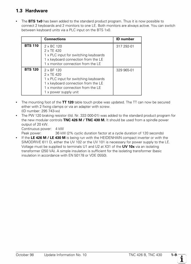
October 98 Update Information No. 10 TNC 426 B, TNC 430 1–9
1.3 Hardware
• The BTS 1x0 has been added to the standard product program. Thus it is now possible toconnect 2 keyboards and 2 monitors to one LE. Both monitors are always active. You can switchbetween keyboard units via a PLC input on the BTS 1x0.
Connections ID number
BTS 110 2 x BC 1202 x TE 4201 x PLC input for switching keyboards1 x keyboard connection from the LE1 x monitor connection from the LE
317 292-01
BTS 120 2 x BF 1202 x TE 4201 x PLC input for switching keyboards1 x keyboard connection from the LE1 x monitor connection from the LE1 x power supply unit
329 965-01
• The mounting foot of the TT 120 table touch probe was updated. The TT can now be securedeither with 2 fixing clamps or via an adapter with screw.(ID number: 295 743-xx)
• The PW 120 braking resistor ((Id. Nr. 333 000-01) was added to the standard product program forthe new modular controls TNC 426 M / TNC 430 M. It should be used from a spindle poweroutput of 20 kW.Continuous power: 4 kWPeak power: 36 kW (2% cyclic duration factor at a cycle duration of 120 seconds)
• If the LE 426 M / LE 430 M is being run with the HEIDENHAIN compact inverter or with theSIMODRIVE 611 D, either the UV 102 or the UV 101 is necessary for power supply to the LE.Voltage must be supplied to terminals U1 and U2 at X31 of the UV 10x via an isolatingtransformer (250 VA). A simple insulation is sufficient for the isolating transformer (basicinsulation in accordance with EN 50178 or VDE 0550).
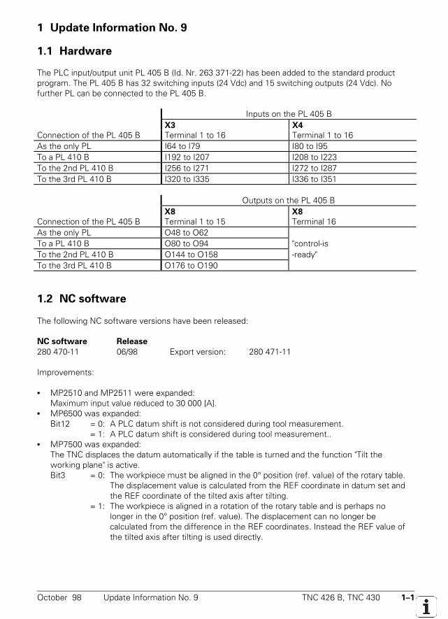
October 98 Update Information No. 9 TNC 426 B, TNC 430 1–1
1 Update Information No. 9
1.1 Hardware
The PLC input/output unit PL 405 B (Id. Nr. 263 371-22) has been added to the standard productprogram. The PL 405 B has 32 switching inputs (24 Vdc) and 15 switching outputs (24 Vdc). Nofurther PL can be connected to the PL 405 B.
Inputs on the PL 405 BX3 X4
Connection of the PL 405 B Terminal 1 to 16 Terminal 1 to 16As the only PL I64 to I79 I80 to I95To a PL 410 B I192 to I207 I208 to I223To the 2nd PL 410 B I256 to I271 I272 to I287To the 3rd PL 410 B I320 to I335 I336 to I351
Outputs on the PL 405 BX8 X8
Connection of the PL 405 B Terminal 1 to 15 Terminal 16As the only PL O48 to O62To a PL 410 B O80 to O94 "control-isTo the 2nd PL 410 B O144 to O158 -ready"To the 3rd PL 410 B O176 to O190
1.2 NC software
The following NC software versions have been released:
NC software Release280 470-11 06/98 Export version: 280 471-11
Improvements:
• MP2510 and MP2511 were expanded:Maximum input value reduced to 30 000 [A].
• MP6500 was expanded:Bit12 = 0: A PLC datum shift is not considered during tool measurement.
= 1: A PLC datum shift is considered during tool measurement..• MP7500 was expanded:
The TNC displaces the datum automatically if the table is turned and the function "Tilt theworking plane" is active.Bit3 = 0: The workpiece must be aligned in the 0° position (ref. value) of the rotary table.
The displacement value is calculated from the REF coordinate in datum set andthe REF coordinate of the tilted axis after tilting.
= 1: The workpiece is aligned in a rotation of the rotary table and is perhaps no longer in the 0° position (ref. value). The displacement can no longer becalculated from the difference in the REF coordinates. Instead the REF value of
the tilted axis after tilting is used directly.
1–2 TNC 426 B, TNC 430 Update Information No. 9 October 98
NC software Release280 474-04 05/98 Export version: 280 475-04
Improvements:
• MP860 was expanded:With input value 2, an axis is defined as a torque-slave axis.
• MP2900 is new:Torque bias between master and slave in master/slave torque control. The torque bias must beentered at the torque-slave axis.Input: –100.00 to +100.00 [Nm]MP2900.0 Axis 1toMP2900.8 Axis 9
• MP2910 is new:Gain (proportional gain) of the torque controller in master/slave torque control. The gain must beentered at the torque-slave axis.Input: 0.00 to 999.99 [1/(min*Nm)]MP2910.0 Axis 1toMP2910.8 Axis 9
• MP2920 is new:Factor for variable torque distribution in master/slave torque control. The factor must be input atthe torque-slave axis. If identical motors are used for both torque-master and torque-slave axes,the value 1 must be input.Input: 0.000 to 100.000MP2920.0 Axis 1toMP2920.8 Axis 9
• MP2930 is new:Speed compensation ratio between torque-master and torque-slave axes in master/slave torquecontrol. The speed compensation ratio must be entered at the torque-slave axis.Input: –100.00 to +100.00 [%]MP2930.0 Axis 1toMP2930.8 Axis 9
• MP7160 was expanded:Limiting the spindle speed in rigid tappingBit 1 = 0: Spindle speed is not limited.
= 1: With small thread depths, the spindle speed is limited so that the spindle will turn at a constant speed for approx. 1/3 of the time.
• MP7263 is new:Display/do not display "Pocket Table" soft key.Input: %xBit 0 = 0: Display "Pocket Table" soft key
= 1: Do not display "Pocket Table" soft key
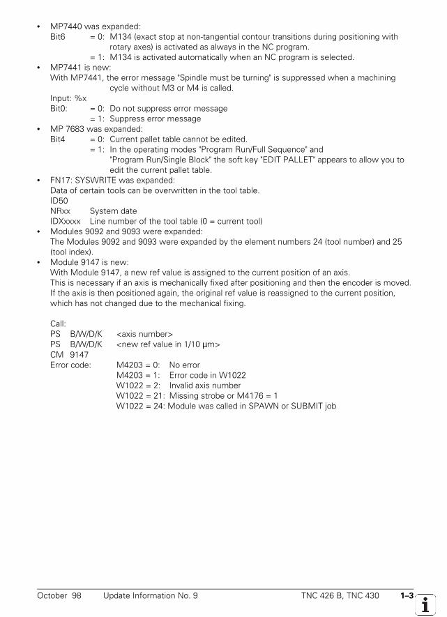
October 98 Update Information No. 9 TNC 426 B, TNC 430 1–3
• MP7440 was expanded:Bit6 = 0: M134 (exact stop at non-tangential contour transitions during positioning with
rotary axes) is activated as always in the NC program.= 1: M134 is activated automatically when an NC program is selected.
• MP7441 is new:With MP7441, the error message "Spindle must be turning" is suppressed when a machining
cycle without M3 or M4 is called.Input: %xBit0: = 0: Do not suppress error message
= 1: Suppress error message• MP 7683 was expanded:
Bit4 = 0: Current pallet table cannot be edited.= 1: In the operating modes "Program Run/Full Sequence" and
"Program Run/Single Block" the soft key "EDIT PALLET" appears to allow you to edit the current pallet table.
• FN17: SYSWRITE was expanded:Data of certain tools can be overwritten in the tool table.ID50NRxx System dateIDXxxxx Line number of the tool table (0 = current tool)
• Modules 9092 and 9093 were expanded:The Modules 9092 and 9093 were expanded by the element numbers 24 (tool number) and 25(tool index).
• Module 9147 is new:With Module 9147, a new ref value is assigned to the current position of an axis.This is necessary if an axis is mechanically fixed after positioning and then the encoder is moved.If the axis is then positioned again, the original ref value is reassigned to the current position,which has not changed due to the mechanical fixing.
Call:PS B/W/D/K <axis number>PS B/W/D/K <new ref value in 1/10 µm>CM 9147Error code: M4203 = 0: No error
M4203 = 1: Error code in W1022W1022 = 2: Invalid axis numberW1022 = 21: Missing strobe or M4176 = 1W1022 = 24: Module was called in SPAWN or SUBMIT job
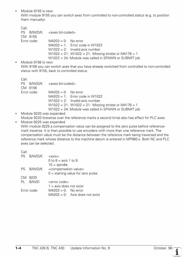
1–4 TNC 426 B, TNC 430 Update Information No. 9 October 98
• Module 9155 is new:With module 9155 you can switch axes from controlled to non-controlled status (e.g. to positionthem manually).
Call:PS B/W/D/K <axes bit-coded>CM 9155Error code: M4203 = 0: No error
M4203 = 1: Error code in W1022W1022 = 2: Invalid axis numberW1022 = 21: W1022 = 21: Missing strobe or M4176 = 1W1022 = 24: Module was called in SPAWN or SUBMIT job
• Module 9156 is new:With 9156 you can switch axes that you have already switched from controlled to non-controlledstatus with 9155, back to controlled status.
Call:PS B/W/D/K <axes bit-coded>CM 9156Error code: M4203 = 0: No error
M4203 = 1: Error code in W1022W1022 = 2: Invalid axis numberW1022 = 21: W1022 = 21: Missing strobe or M4176 = 1W1022 = 24: Module was called in SPAWN or SUBMIT job
• Module 9220 was expanded:Module 9220 (traverse over the reference marks a second time) also has effect for PLC axes.
• Module 9225 was expanded:With module 9225 a compensation value can be assigned to the zero pulse before reference-mark traverse. It is then possible to use encoders with more than one reference mark. Thecompensation value must be the distance between the reference mark being traversed and thereference mark whose distance to the machine datum is entered in MP960.x. Both NC and PLCaxes can be selected.
Call:PS B/W/D/K <axis>
0 to 8 = axis 1 to 915 = spindle
PS B/W/D/K <compensation value>0 = starting value for zero pulse
CM 9225PL B/W/D <error code>
1 = axis does not existError code: M4203 = 0: No error
M4203 = 0: Axis does not exist
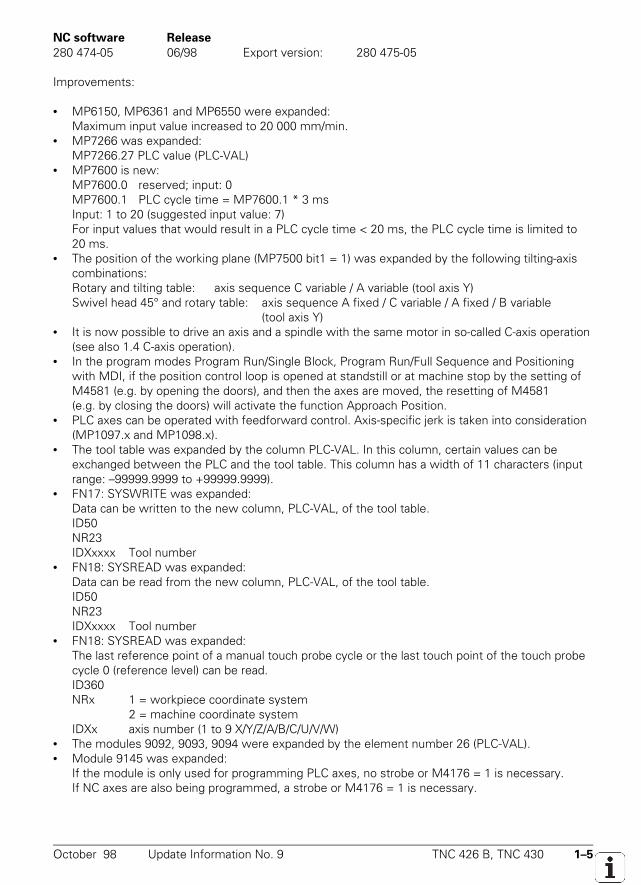
October 98 Update Information No. 9 TNC 426 B, TNC 430 1–5
NC software Release280 474-05 06/98 Export version: 280 475-05
Improvements:
• MP6150, MP6361 and MP6550 were expanded:Maximum input value increased to 20 000 mm/min.
• MP7266 was expanded:MP7266.27 PLC value (PLC-VAL)
• MP7600 is new:MP7600.0 reserved; input: 0MP7600.1 PLC cycle time = MP7600.1 * 3 msInput: 1 to 20 (suggested input value: 7)For input values that would result in a PLC cycle time < 20 ms, the PLC cycle time is limited to20 ms.
• The position of the working plane (MP7500 bit1 = 1) was expanded by the following tilting-axiscombinations:Rotary and tilting table: axis sequence C variable / A variable (tool axis Y)Swivel head 45° and rotary table: axis sequence A fixed / C variable / A fixed / B variable
(tool axis Y)• It is now possible to drive an axis and a spindle with the same motor in so-called C-axis operation
(see also 1.4 C-axis operation).• In the program modes Program Run/Single Block, Program Run/Full Sequence and Positioning
with MDI, if the position control loop is opened at standstill or at machine stop by the setting ofM4581 (e.g. by opening the doors), and then the axes are moved, the resetting of M4581(e.g. by closing the doors) will activate the function Approach Position.
• PLC axes can be operated with feedforward control. Axis-specific jerk is taken into consideration(MP1097.x and MP1098.x).
• The tool table was expanded by the column PLC-VAL. In this column, certain values can beexchanged between the PLC and the tool table. This column has a width of 11 characters (inputrange: –99999.9999 to +99999.9999).
• FN17: SYSWRITE was expanded:Data can be written to the new column, PLC-VAL, of the tool table.ID50NR23IDXxxxx Tool number
• FN18: SYSREAD was expanded:Data can be read from the new column, PLC-VAL, of the tool table.ID50NR23IDXxxxx Tool number
• FN18: SYSREAD was expanded:The last reference point of a manual touch probe cycle or the last touch point of the touch probecycle 0 (reference level) can be read.ID360NRx 1 = workpiece coordinate system
2 = machine coordinate systemIDXx axis number (1 to 9 X/Y/Z/A/B/C/U/V/W)
• The modules 9092, 9093, 9094 were expanded by the element number 26 (PLC-VAL).• Module 9145 was expanded:
If the module is only used for programming PLC axes, no strobe or M4176 = 1 is necessary.If NC axes are also being programmed, a strobe or M4176 = 1 is necessary.
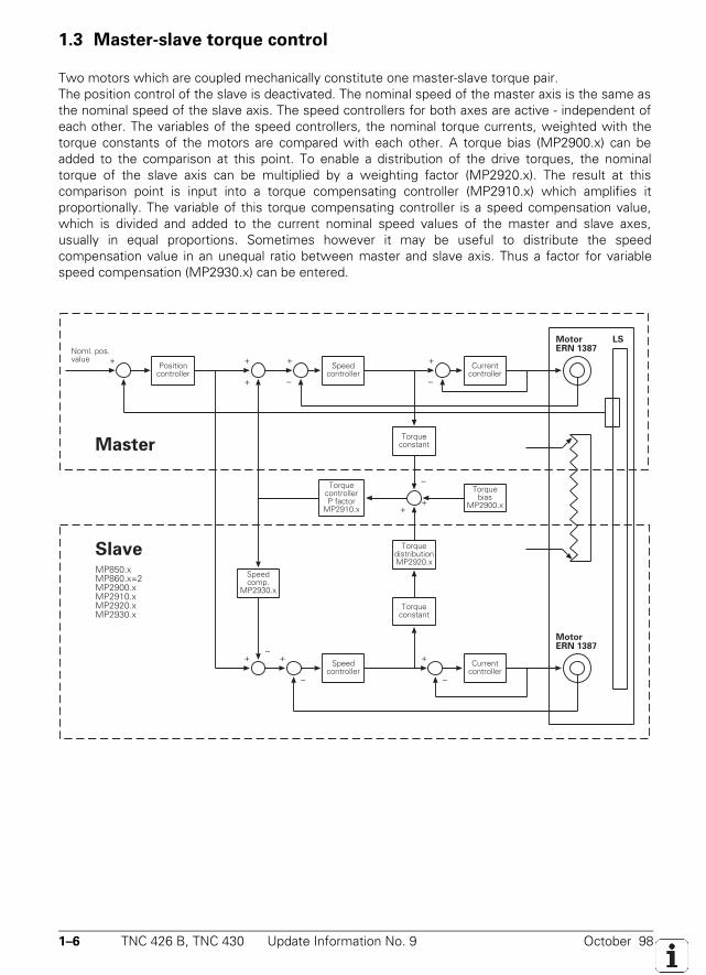
1–6 TNC 426 B, TNC 430 Update Information No. 9 October 98
1.3 Master-slave torque control
Two motors which are coupled mechanically constitute one master-slave torque pair.The position control of the slave is deactivated. The nominal speed of the master axis is the same asthe nominal speed of the slave axis. The speed controllers for both axes are active - independent ofeach other. The variables of the speed controllers, the nominal torque currents, weighted with thetorque constants of the motors are compared with each other. A torque bias (MP2900.x) can beadded to the comparison at this point. To enable a distribution of the drive torques, the nominaltorque of the slave axis can be multiplied by a weighting factor (MP2920.x). The result at thiscomparison point is input into a torque compensating controller (MP2910.x) which amplifies itproportionally. The variable of this torque compensating controller is a speed compensation value,which is divided and added to the current nominal speed values of the master and slave axes,usually in equal proportions. Sometimes however it may be useful to distribute the speedcompensation value in an unequal ratio between master and slave axis. Thus a factor for variablespeed compensation (MP2930.x) can be entered.
October 98 Update Information No. 9 TNC 426 B, TNC 430 1–7
1.4 C-axis operation
With NC software 280 474-05, it is possible to move an axis and a spindle with the same servodrive. This is called C-axis operation as the spindle motor of the tool axis Z is often used also to drivea rotary axis. The rotary axis corresponding to the tool axis Z is the C axis. It is however possible todrive any other axis with the spindle drive. The spindle and the axis can each have their own positionencoder. As the speed encoder is built into the motor, both spindle and axis will have the samespeed encoder.Enter the encoder inputs in the corresponding machine parameters, e.g.:MP110.3: 4 (X4: position encoder for the C-axis)MP111.0: 6 (X6: position encoder for the spindle)MP112.3: 0 (speed encoder for the C axis: the speed encoder for the spindle is used
from MP113.0)MP113.0: 60 (X60: speed encoder for the spindle)
The spindle and the axis can only be operated digitally. It is not important whether the digital spindlehas its own spindle DSP or not.As the same drive is used for the axis and the spindle, the same output is entered in the machineparameter for nominal speed value outputs, e.g.:MP120.3: 61 (X61: PWM output for the C-axis)MP121.0: 61 (X61: PWM output for the spindle)
Commissioning of the current and speed controller only takes place for the spindle; the value zero isentered in the machine parameter for the current and speed controller of the axis (MP2xxx.x).Commissioning of the position encoders is separate for the spindle and for the axis.
Use bit 15 (spindle) from module 9161 to enable the integrated drive controller (current and speedcontroller) for the axis and the spindle.
If the position controller for the axis is closed (corresponding bit set in W1024), the output of aspindle speed has no effect. For a spindle speed to be output, the position controller for the axisneeds to be open (corresponding bit not set in W1024). An axis can be switched from controlled tononcontrolled status with module 9155. With module 9156 controlled status is regained and anautomatic actual and nominal position capture is carried out.
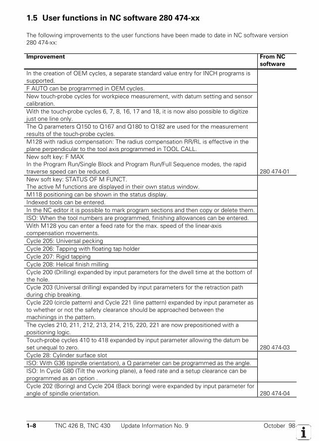
1–8 TNC 426 B, TNC 430 Update Information No. 9 October 98
1.5 User functions in NC software 280 474-xx
The following improvements to the user functions have been made to date in NC software version280 474-xx:
Improvement From NC
software
In the creation of OEM cycles, a separate standard value entry for INCH programs issupported.F AUTO can be programmed in OEM cycles.New touch-probe cycles for workpiece measurement, with datum setting and sensorcalibration.With the touch-probe cycles 6, 7, 8, 16, 17 and 18, it is now also possible to digitizejust one line only.The Q parameters Q150 to Q167 and Q180 to Q182 are used for the measurementresults of the touch-probe cycles.M128 with radius compensation: The radius compensation RR/RL is effective in theplane perpendicular to the tool axis programmed in TOOL CALL.New soft key: F MAXIn the Program Run/Single Block and Program Run/Full Sequence modes, the rapidtraverse speed can be reduced. 280 474-01New soft key: STATUS OF M FUNCT.The active M functions are displayed in their own status window.M118 positioning can be shown in the status display.Indexed tools can be entered.In the NC editor it is possible to mark program sections and then copy or delete them.ISO: When the tool numbers are programmed, finishing allowances can be entered.With M128 you can enter a feed rate for the max. speed of the linear-axiscompensation movements.Cycle 205: Universal peckingCycle 206: Tapping with floating tap holderCycle 207: Rigid tappingCycle 208: Helical finish millingCycle 200 (Drilling) expanded by input parameters for the dwell time at the bottom ofthe hole.Cycle 203 (Universal drilling) expanded by input parameters for the retraction pathduring chip breaking.Cycle 220 (circle pattern) and Cycle 221 (line pattern) expanded by input parameter asto whether or not the safety clearance should be approached between themachinings in the pattern.The cycles 210, 211, 212, 213, 214, 215, 220, 221 are now prepositioned with apositioning logic.Touch-probe cycles 410 to 418 expanded by input parameter allowing the datum beset unequal to zero. 280 474-03Cycle 28: Cylinder surface slotISO: With G36 (spindle orientation), a Q parameter can be programmed as the angle.ISO: In Cycle G80 (Tilt the working plane), a feed rate and a setup clearance can beprogrammed as an option .Cycle 202 (Boring) and Cycle 204 (Back boring) were expanded by input parameter forangle of spindle orientation. 280 474-04
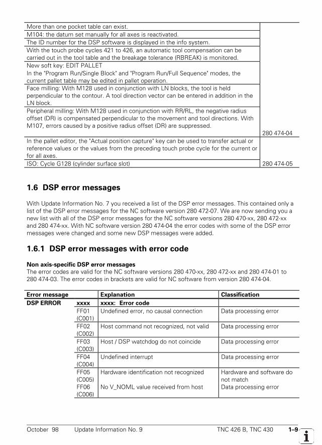
October 98 Update Information No. 9 TNC 426 B, TNC 430 1–9
More than one pocket table can exist.M104: the datum set manually for all axes is reactivated.The ID number for the DSP software is displayed in the info system.With the touch probe cycles 421 to 426, an automatic tool compensation can becarried out in the tool table and the breakage tolerance (RBREAK) is monitored.New soft key: EDIT PALLETIn the "Program Run/Single Block" and "Program Run/Full Sequence" modes, thecurrent pallet table may be edited in pallet operation.Face milling: With M128 used in conjunction with LN blocks, the tool is heldperpendicular to the contour. A tool direction vector can be entered in addition in theLN block.Peripheral milling: With M128 used in conjunction with RR/RL, the negative radiusoffset (DR) is compensated perpendicular to the movement and tool directions. WithM107, errors caused by a positive radius offset (DR) are suppressed.
280 474-04In the pallet editor, the "Actual position capture" key can be used to transfer actual orreference values or the values from the preceding touch probe cycle for the current orfor all axes.ISO: Cycle G128 (cylinder surface slot) 280 474-05
1.6 DSP error messages
With Update Information No. 7 you received a list of the DSP error messages. This contained only alist of the DSP error messages for the NC software version 280 472-07. We are now sending you anew list with all of the DSP error messages for the NC software versions 280 470-xx, 280 472-xxand 280 474-xx. With NC software version 280 474-04 the error codes with some of the DSP errormessages were changed and some new DSP messages were added.
1.6.1 DSP error messages with error code
Non axis-specific DSP error messagesThe error codes are valid for the NC software versions 280 470-xx, 280 472-xx and 280 474-01 to280 474-03. The error codes in brackets are valid for NC software from version 280 474-04.
Error message Explanation ClassificationDSP ERROR xxxx xxxx: Error code
FF01(C001)
Undefined error, no causal connection Data processing error
FF02(C002)
Host command not recognized, not valid Data processing error
FF03(C003)
Host / DSP watchdog do not coincide Data processing error
FF04(C004)
Undefined interrupt Data processing error
FF05(C005)
Hardware identification not recognized Hardware and software donot match
FF06(C006)
No V_NOML value received from host Data processing error
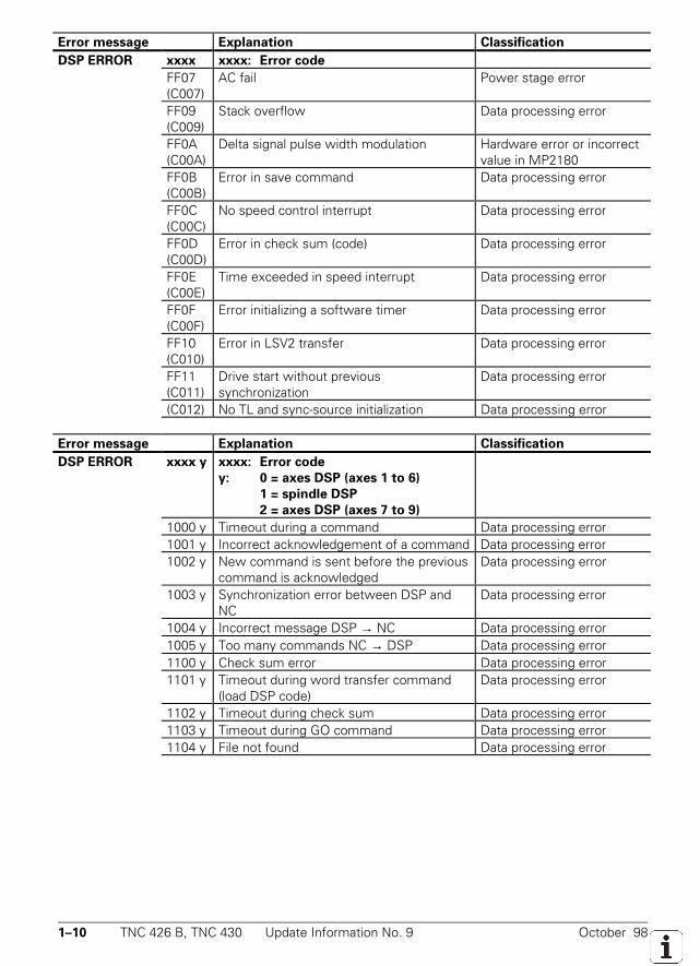
1–10 TNC 426 B, TNC 430 Update Information No. 9 October 98
Error message Explanation ClassificationDSP ERROR xxxx xxxx: Error code
FF07(C007)
AC fail Power stage error
FF09(C009)
Stack overflow Data processing error
FF0A(C00A)
Delta signal pulse width modulation Hardware error or incorrectvalue in MP2180
FF0B(C00B)
Error in save command Data processing error
FF0C(C00C)
No speed control interrupt Data processing error
FF0D(C00D)
Error in check sum (code) Data processing error
FF0E(C00E)
Time exceeded in speed interrupt Data processing error
FF0F(C00F)
Error initializing a software timer Data processing error
FF10(C010)
Error in LSV2 transfer Data processing error
FF11(C011)
Drive start without previoussynchronization
Data processing error
(C012) No TL and sync-source initialization Data processing error
Error message Explanation ClassificationDSP ERROR xxxx y xxxx: Error code
y: 0 = axes DSP (axes 1 to 6)1 = spindle DSP2 = axes DSP (axes 7 to 9)
1000 y Timeout during a command Data processing error1001 y Incorrect acknowledgement of a command Data processing error1002 y New command is sent before the previous
command is acknowledgedData processing error
1003 y Synchronization error between DSP andNC
Data processing error
1004 y Incorrect message DSP → NC Data processing error1005 y Too many commands NC → DSP Data processing error1100 y Check sum error Data processing error1101 y Timeout during word transfer command
(load DSP code)Data processing error
1102 y Timeout during check sum Data processing error1103 y Timeout during GO command Data processing error1104 y File not found Data processing error
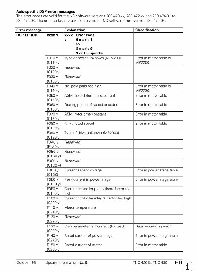
October 98 Update Information No. 9 TNC 426 B, TNC 430 1–11
Axis-specific DSP error messagesThe error codes are valid for the NC software versions 280 470-xx, 280 472-xx and 280 474-01 to280 474-03. The error codes in brackets are valid for NC software from version 280 474-04.
Error message Explanation ClassificationDSP ERROR xxxx y xxxx: Error code
y: 0 = axis 1to8 = axis 99 or F = spindle
F010 y(C110 y)
Type of motor unknown (MP2200) Error in motor table orMP2200
F020 y(C120 y)
Reserved
F030 y(C130 y)
Reserved
F040 y(C140 y)
No. pole pairs too high Error in motor table orMP2230
F050 y(C150 y)
ASM: field-determining current Error in motor table
F060 y(C160 y)
Grating period of speed encoder Error in motor table
F070 y(C170 y)
ASM: rotor time constant Error in motor table
F080 y(C180 y)
Kink / rated speed Error in motor table
F090 y(C190 y)
Type of drive unknown (MP2000)
F0A0 y(F1A0 y)
Reserved
F0B0 y(C1B0 y)
Reserved
F0C0 y(C1C0 y)
Reserved
F0D0 y(C1D0)
Current sensor voltage Error in power stage table
F0E0 y(C1E0 y)
Peak current in power stage Error in power stage table
F0F0 y(C1F0 y)
Current controller proportional factor toohigh
F100 y(C200 y)
Current controller integral factor too high
F110 y(C210 y)
Motor temperature
F120 y(C220 y)
Reserved
F130 y(C230 y)
Osci parameter is incorrect (for test) Data processing error
F140 y(C240 y)
Rated current of power stage Error in power stage table
F150 y(C250 y)
Rated current of motor Error in motor table
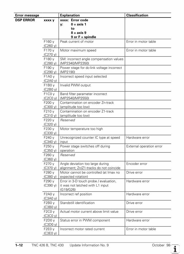
1–12 TNC 426 B, TNC 430 Update Information No. 9 October 98
Error message Explanation ClassificationDSP ERROR xxxx y xxxx: Error code
y: 0 = axis 1to8 = axis 99 or F = spindle
F160 y(C260 y)
Peak current of motor Error in motor table
F170 y(C270 y)
Motor maximum speed Error in motor table
F180 y(C280 y)
SM: incorrect angle compensation values(MP2340/MP2350)
F190 y(C290 y)
Power stage for dc-link voltage incorrect(MP2190)
F1A0 y(C2A0 y)
Incorrect speed input selected
F1B0 y(C2B0 y)
Invalid PWM output
F1C0 y(C2C0 y)
Band filter parameter incorrect(MP2540/MP2550)
F200 y(C300 y)
Contamination on encoder Zn-track(amplitude too low)
F210 y(C310 y)
Contamination on encoder Z1-track(amplitude too low)
F220 y(C320 y)
Reserved
F230 y(C330 y)
Motor temperature too high
F240 y(C340 y)
Unrecognized counter IC type at speedinput
Hardware error
F250 y(C350 y)
Power stage switches off duringoperation
External operation error
F260 y(C360 y)
Reserved
F270 y(C370 y)
Angle deviation too large duringalignment; Zn/Z1-tracks do not coincide
Encoder error
F280 y(C380 y)
Motor cannot be controlled (at Imax noexpected rotation)
Drive error
F290 y(C390 y)
Error in 3-D touch probe / evaluation,it was not latched with L1 input(G19/G26)
Hardware error
F2A0 y(C3A0 y)
Incorrect ref position Hardware error
F2B0 y(C3B0 y)
Standstill identification Drive error
F2C0 y(C3C0 y)
Actual motor current above limit value Drive error
F2D0 y(C3D0 y)
Status error in PWM component Hardware error
F2E0 y(C3E0 y)
Incorrect motor rated current Error in motor table
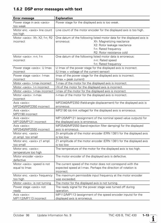
October 98 Update Information No. 9 TNC 426 B, TNC 430 1–13
1.6.2 DSP error messages with text
Error message ExplanationPower stage in axis <axis>too weak
Power stage for the displayed axis is too weak.
Motor enc. <axis> line counttoo high
Line count of the motor encoder for the displayed axis is too high.
Motor <axis>: Xh; X2; f-n; R2incorrect
One datum of the following listed motor data for the displayed axis iserroneous: Xh: Magnetizing reactance
X2: Rotor leakage reactancef-n: Rated frequencyR2: Rotor resistance cold
Motor <axis>: n-n; f-nincorrect
One datum of the following listed motor data is erroneous:n-n: Rated speedf-n: Rated frequency
Power stage <axis>: U Imaxincorrect
U Imax of the power stage for the displayed axis is incorrect.(U Imax = voltage of the current sensor)
Power stage <axis>: I-maxincorrect
Imax of the power stage for the displayed axis is incorrect.(Imax = peak current)
Motor <axis>: t-max incorrect T-max of the motor for the displayed axis is incorrect.Motor <axis>: I-n incorrect I-N of the motor for the displayed axis is incorrect.Motor <axis>: I-max incorrect I-max of the motor for the displayed axis is incorrect.Motor <axis>: n-maxincorrect
n-max of the motor for the displayed axis is incorrect.
Axis <axis>:MP2340/MP2350 incorrect
MP2340/MP2350 (field-angle displacement) for the displayed axis iserroneous.
Axis <axis>:MP2190 incorrect
MP2190 (dc-link voltage) for the displayed axis is erroneous.
Axis <axis>:MP120/MP121 incorrect
MP120/MP121 (assignment of the nominal speed value outputs) forthe displayed axis is erroneous.
Axis <axis>:MP2540/MP2550 incorrect
MP2540/MP2550 (band-rejection filter damping) for the displayedaxis is erroneous.
Motor enc. <axis>zn ampl. too small
Zn amplitude of the motor encoder (ERN 1381) for the displayed axisis too low
Motor enc. <axis> z1 ampl.too small
Z1 amplitude of the motor encoder (ERN 1381) for the displayed axisis too low
Motor enc. <axis>:temperature too high
The temperature of the motor for the displayed axis is too high.
Motor encoder <axis>defective
The motor encoder of the displayed axis is defective.
Motor <axis>: speed is notequal to Imax
The current speed of the motor does not correspond with theexpected speed at I-max. Perhaps the direction of rotation isincorrect.
Motor enc. <axis> frequencytoo high
The maximum permissible input frequency at the motor encoderwas exceeded.
Motor <axis>: is not turning The motor for the displayed axis is not turning.Power stage <axis> notready
The ready signal for the power stage was turned off duringoperation.
Axis <axis>:MP112/MP113 incorrect
MP112/MP113 (assignment of the speed encoder inputs) for thedisplayed axis is erroneous.
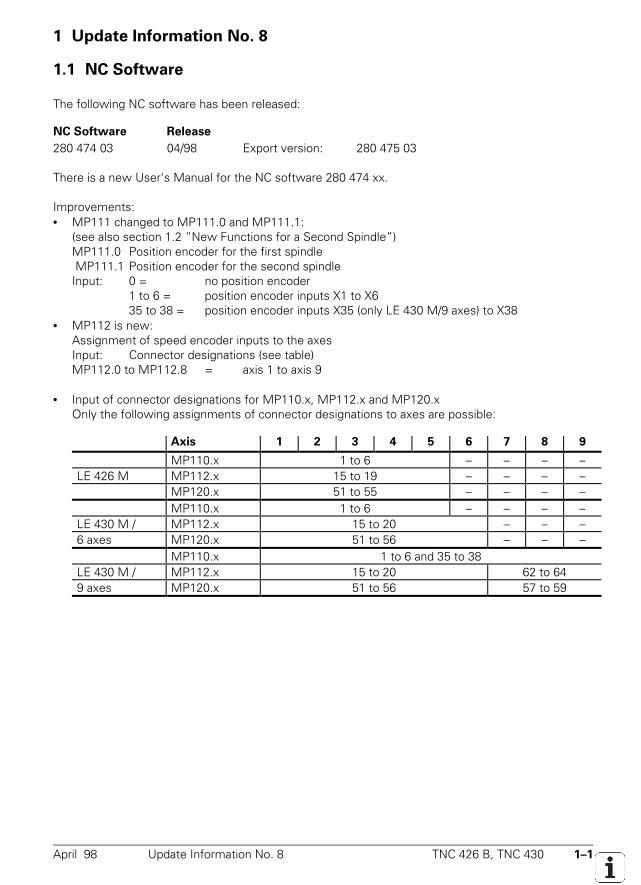
April 98 Update Information No. 8 TNC 426 B, TNC 430 1–1
1 Update Information No. 8
1.1 NC Software
The following NC software has been released:
NC Software Release
280 474 03 04/98 Export version: 280 475 03
There is a new User's Manual for the NC software 280 474 xx.
Improvements:• MP111 changed to MP111.0 and MP111.1:
(see also section 1.2 ”New Functions for a Second Spindle”)MP111.0 Position encoder for the first spindle MP111.1 Position encoder for the second spindleInput: 0 = no position encoder
1 to 6 = position encoder inputs X1 to X635 to 38 = position encoder inputs X35 (only LE 430 M/9 axes) to X38
• MP112 is new:Assignment of speed encoder inputs to the axesInput: Connector designations (see table)MP112.0 to MP112.8 = axis 1 to axis 9
• Input of connector designations for MP110.x, MP112.x and MP120.xOnly the following assignments of connector designations to axes are possible:
Axis 1 2 3 4 5 6 7 8 9
MP110.x 1 to 6 – – – – LE 426 M MP112.x 15 to 19 – – – – MP120.x 51 to 55 – – – – MP110.x 1 to 6 – – – – LE 430 M / MP112.x 15 to 20 – – – 6 axes MP120.x 51 to 56 – – – MP110.x 1 to 6 and 35 to 38 LE 430 M / MP112.x 15 to 20 62 to 64 9 axes MP120.x 51 to 56 57 to 59
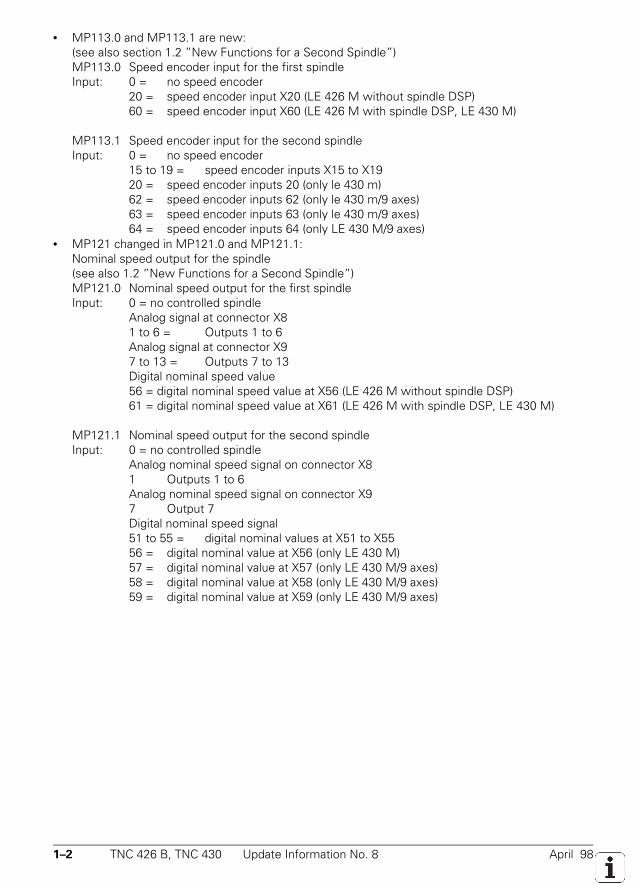
1–2 TNC 426 B, TNC 430 Update Information No. 8 April 98
• MP113.0 and MP113.1 are new:(see also section 1.2 ”New Functions for a Second Spindle”)MP113.0 Speed encoder input for the first spindleInput: 0 = no speed encoder
20 = speed encoder input X20 (LE 426 M without spindle DSP)60 = speed encoder input X60 (LE 426 M with spindle DSP, LE 430 M)
MP113.1 Speed encoder input for the second spindleInput: 0 = no speed encoder
15 to 19 = speed encoder inputs X15 to X1920 = speed encoder inputs 20 (only le 430 m)62 = speed encoder inputs 62 (only le 430 m/9 axes)63 = speed encoder inputs 63 (only le 430 m/9 axes)64 = speed encoder inputs 64 (only LE 430 M/9 axes)
• MP121 changed in MP121.0 and MP121.1:Nominal speed output for the spindle(see also 1.2 ”New Functions for a Second Spindle”)MP121.0 Nominal speed output for the first spindleInput: 0 = no controlled spindle
Analog signal at connector X81 to 6 = Outputs 1 to 6Analog signal at connector X97 to 13 = Outputs 7 to 13Digital nominal speed value56 = digital nominal speed value at X56 (LE 426 M without spindle DSP)61 = digital nominal speed value at X61 (LE 426 M with spindle DSP, LE 430 M)
MP121.1 Nominal speed output for the second spindleInput: 0 = no controlled spindle
Analog nominal speed signal on connector X81 Outputs 1 to 6Analog nominal speed signal on connector X97 Output 7Digital nominal speed signal51 to 55 = digital nominal values at X51 to X5556 = digital nominal value at X56 (only LE 430 M)57 = digital nominal value at X57 (only LE 430 M/9 axes)58 = digital nominal value at X58 (only LE 430 M/9 axes)59 = digital nominal value at X59 (only LE 430 M/9 axes)
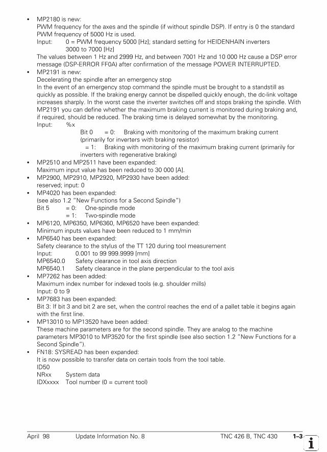
April 98 Update Information No. 8 TNC 426 B, TNC 430 1–3
• MP2180 is new:PWM frequency for the axes and the spindle (if without spindle DSP). If entry is 0 the standardPWM frequency of 5000 Hz is used.Input: 0 = PWM frequency 5000 [Hz]; standard setting for HEIDENHAIN inverters
3000 to 7000 [Hz]The values between 1 Hz and 2999 Hz, and between 7001 Hz and 10 000 Hz cause a DSP errormessage (DSP-ERROR FF0A) after confirmation of the message POWER INTERRUPTED.
• MP2191 is new:Decelerating the spindle after an emergency stopIn the event of an emergency stop command the spindle must be brought to a standstill asquickly as possible. If the braking energy cannot be dispelled quickly enough, the dc-link voltageincreases sharply. In the worst case the inverter switches off and stops braking the spindle. WithMP2191 you can define whether the maximum braking current is monitored during braking and,if required, should be reduced. The braking time is delayed somewhat by the monitoring.Input: %x Bit 0 = 0: Braking with monitoring of the maximum braking current
(primarily for inverters with braking resistor) = 1: Braking with monitoring of the maximum braking current (primarily for
inverters with regenerative braking)• MP2510 and MP2511 have been expanded:
Maximum input value has been reduced to 30 000 [A].• MP2900, MP2910, MP2920, MP2930 have been added:
reserved; input: 0• MP4020 has been expanded:
(see also 1.2 ”New Functions for a Second Spindle”)Bit 5 = 0: One-spindle mode
= 1: Two-spindle mode• MP6120, MP6350, MP6360, MP6520 have been expanded:
Minimum inputs values have been reduced to 1 mm/min• MP6540 has been expanded:
Safety clearance to the stylus of the TT 120 during tool measurementInput: 0.001 to 99 999.9999 [mm]MP6540.0 Safety clearance in tool axis directionMP6540.1 Safety clearance in the plane perpendicular to the tool axis
• MP7262 has been added:Maximum index number for indexed tools (e.g. shoulder mills)Input: 0 to 9
• MP7683 has been expanded:Bit 3: If bit 3 and bit 2 are set, when the control reaches the end of a pallet table it begins againwith the first line.
• MP13010 to MP13520 have been added:These machine parameters are for the second spindle. They are analog to the machineparameters MP3010 to MP3520 for the first spindle (see also section 1.2 ”New Functions for aSecond Spindle”).
• FN18: SYSREAD has been expanded:It is now possible to transfer data on certain tools from the tool table.ID50NRxx System dataIDXxxxx Tool number (0 = current tool)
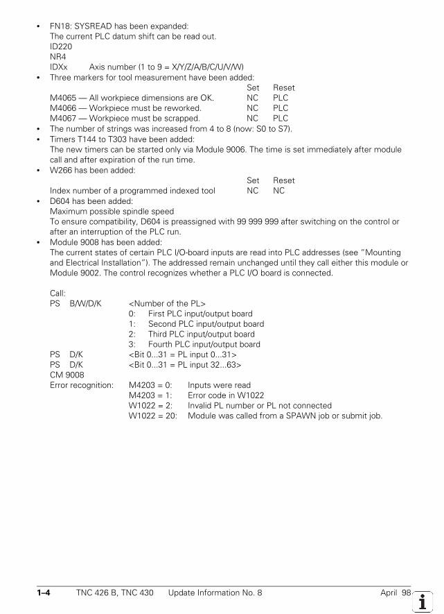
1–4 TNC 426 B, TNC 430 Update Information No. 8 April 98
• FN18: SYSREAD has been expanded:The current PLC datum shift can be read out.ID220NR4IDXx Axis number (1 to 9 = X/Y/Z/A/B/C/U/V/W)
• Three markers for tool measurement have been added:Set Reset
M4065 — All workpiece dimensions are OK. NC PLCM4066 — Workpiece must be reworked. NC PLCM4067 — Workpiece must be scrapped. NC PLC
• The number of strings was increased from 4 to 8 (now: S0 to S7).• Timers T144 to T303 have been added:
The new timers can be started only via Module 9006. The time is set immediately after modulecall and after expiration of the run time.
• W266 has been added:Set Reset
Index number of a programmed indexed tool NC NC• D604 has been added:
Maximum possible spindle speedTo ensure compatibility, D604 is preassigned with 99 999 999 after switching on the control orafter an interruption of the PLC run.
• Module 9008 has been added:The current states of certain PLC I/O-board inputs are read into PLC addresses (see ”Mountingand Electrical Installation”). The addressed remain unchanged until they call either this module orModule 9002. The control recognizes whether a PLC I/O board is connected.
Call: PS B/W/D/K <Number of the PL>
0: First PLC input/output board1: Second PLC input/output board2: Third PLC input/output board3: Fourth PLC input/output board
PS D/K <Bit 0...31 = PL input 0...31>PS D/K <Bit 0...31 = PL input 32...63>CM 9008Error recognition: M4203 = 0: Inputs were read
M4203 = 1: Error code in W1022W1022 = 2: Invalid PL number or PL not connectedW1022 = 20: Module was called from a SPAWN job or submit job.
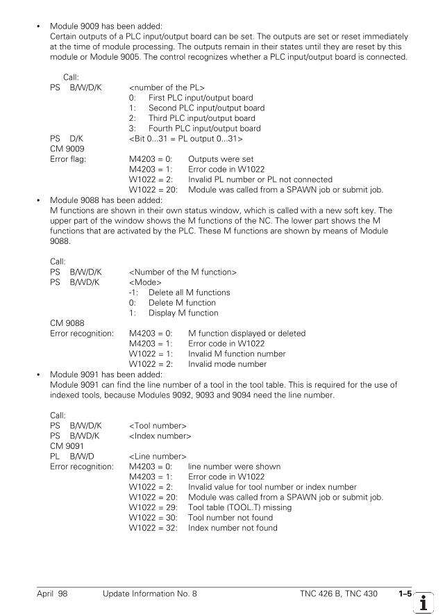
April 98 Update Information No. 8 TNC 426 B, TNC 430 1–5
• Module 9009 has been added:Certain outputs of a PLC input/output board can be set. The outputs are set or reset immediatelyat the time of module processing. The outputs remain in their states until they are reset by thismodule or Module 9005. The control recognizes whether a PLC input/output board is connected.
Call: PS B/W/D/K <number of the PL>
0: First PLC input/output board1: Second PLC input/output board2: Third PLC input/output board3: Fourth PLC input/output board
PS D/K <Bit 0...31 = PL output 0...31>CM 9009Error flag: M4203 = 0: Outputs were set
M4203 = 1: Error code in W1022W1022 = 2: Invalid PL number or PL not connectedW1022 = 20: Module was called from a SPAWN job or submit job.
• Module 9088 has been added:M functions are shown in their own status window, which is called with a new soft key. Theupper part of the window shows the M functions of the NC. The lower part shows the Mfunctions that are activated by the PLC. These M functions are shown by means of Module9088.
Call: PS B/W/D/K <Number of the M function>
PS B/WD/K <Mode>-1: Delete all M functions0: Delete M function1: Display M function
CM 9088Error recognition: M4203 = 0: M function displayed or deleted
M4203 = 1: Error code in W1022W1022 = 1: Invalid M function numberW1022 = 2: Invalid mode number
• Module 9091 has been added:Module 9091 can find the line number of a tool in the tool table. This is required for the use ofindexed tools, because Modules 9092, 9093 and 9094 need the line number.
Call:
PS B/W/D/K <Tool number>PS B/WD/K <Index number>CM 9091PL B/W/D <Line number>Error recognition: M4203 = 0: line number were shown
M4203 = 1: Error code in W1022W1022 = 2: Invalid value for tool number or index numberW1022 = 20: Module was called from a SPAWN job or submit job.W1022 = 29: Tool table (TOOL.T) missing
W1022 = 30: Tool number not foundW1022 = 32: Index number not found
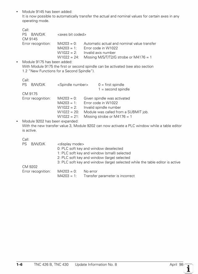
1–6 TNC 426 B, TNC 430 Update Information No. 8 April 98
• Module 9145 has been added:It is now possible to automatically transfer the actual and nominal values for certain axes in anyoperating mode.
Call:
PS B/W/D/K <axes bit coded>CM 9145Error recognition: M4203 = 0: Automatic actual and nominal value transfer
M4203 = 1: Error code in W1022W1022 = 2: Invalid axis numberW1022 = 24: Missing M/S/T/T2/G strobe or M4176 = 1
• Module 9175 has been added:With Module 9175 the first or second spindle can be activated (see also section1.2 ”New Functions for a Second Spindle”).
Call: PS B/W/D/K <Spindle number> 0 = first spindle
1 = second spindleCM 9175Error recognition: M4203 = 0: Given spindle was activated
M4203 = 1: Error code in W1022W1022 = 2: Invalid spindle numberW1022 = 20: Module was called from a SUBMIT job.W1022 = 21: Missing strobe or M4176 = 1
• Module 9202 has been expanded:With the new transfer value 3, Module 9202 can now activate a PLC window while a table editoris active.
Call:PS B/W/D/K <display mode>
0: PLC soft key and window deselected1: PLC soft key and window (small) selected2: PLC soft key and window (large) selected3: PLC soft key and window (large) selected while the table editor is active
CM 9202Error recognition: M4203 = 0: No error
M4203 = 1: Transfer parameter is incorrect
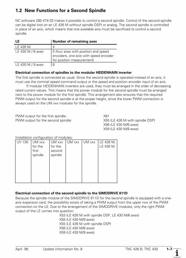
April 98 Update Information No. 8 TNC 426 B, TNC 430 1–7
1.2 New Functions for a Second Spindle
NC software 280 474 03 makes it possible to control a second spindle. Control of the second spindlecan be digital (not on an LE 426 M without spindle DSP) or analog. The second spindle is controlledin place of an axis, which means that one available axis must be sacrificed to control a secondspindle.
LE Number of remaining axes
LE 426 M 4LE 430 M / 6 axes 5 (four axes with position and speed
encoders, one axis with speed encoderfor position measurement)
LE 430 M / 9 axes 8
Electrical connection of spindles to the modular HEIDENHAIN inverter
The first spindle is connected as usual. Since the second spindle is operated instead of an axis, itmust use the nominal speed command output or the speed and position encoder input of an axis.
If modular HEIDENHAIN inverters are used, they must be arranged in the order of decreasingrated current values. This means that the power module for the second spindle must be arrangednext to the power module for the first spindle. This arrangement also ensures that the requiredPWM output for the second spindle is at the proper height, since the lower PWM connection isalways used on the UM xxx modules for the spindle.
PWM output for the first spindle: X61PWM output for the second spindle: X55 (LE 426 M with spindle DSP)
X56 (LE 430 M/6 axes)X59 (LE 430 M/9 axes)
Installation configuration of modules:UV 130 UM xxx
for thefirstspindle
UM xxxfor thesecondspindle
UM xxx UM xxx LE 426 M,LE 430 M
Electrical connection of the second spindle to the SIMODRIVE 611D
Because the spindle module of the SIMODRIVE 611D for the second spindle is equipped with a one-axis expansion card, the possibility exists of taking a PWM output from the upper row of the PWMconnection on the LE. Due to the arrangement of the SIMODRIVE modules, only the right PWMoutput of the LE comes into question:
X53 (LE 426 M with spindle DSP, LE 430 M/6 axes)X55 (LE 430 M/9 axes)X55 (LE 426 M with spindle DSP)X56 (LE 430 M/6 axes)X59 (LE 430 M/9 axes)
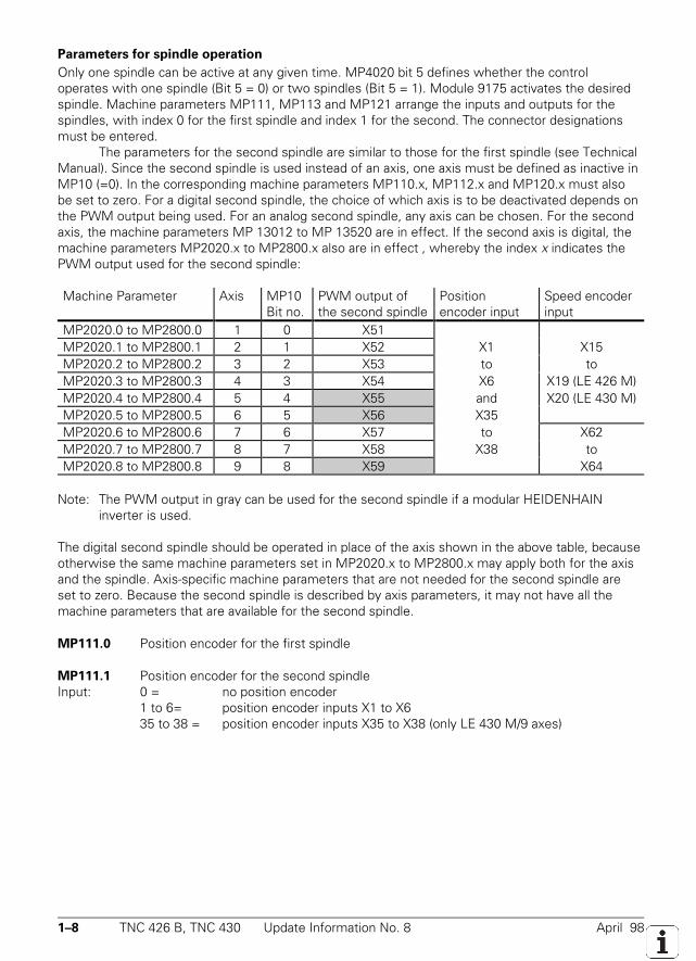
1–8 TNC 426 B, TNC 430 Update Information No. 8 April 98
Parameters for spindle operation
Only one spindle can be active at any given time. MP4020 bit 5 defines whether the controloperates with one spindle (Bit 5 = 0) or two spindles (Bit 5 = 1). Module 9175 activates the desiredspindle. Machine parameters MP111, MP113 and MP121 arrange the inputs and outputs for thespindles, with index 0 for the first spindle and index 1 for the second. The connector designationsmust be entered.
The parameters for the second spindle are similar to those for the first spindle (see TechnicalManual). Since the second spindle is used instead of an axis, one axis must be defined as inactive inMP10 (=0). In the corresponding machine parameters MP110.x, MP112.x and MP120.x must alsobe set to zero. For a digital second spindle, the choice of which axis is to be deactivated depends onthe PWM output being used. For an analog second spindle, any axis can be chosen. For the secondaxis, the machine parameters MP 13012 to MP 13520 are in effect. If the second axis is digital, themachine parameters MP2020.x to MP2800.x also are in effect , whereby the index x indicates thePWM output used for the second spindle:
Machine Parameter Axis MP10Bit no.
PWM output ofthe second spindle
Positionencoder input
Speed encoderinput
MP2020.0 to MP2800.0 1 0 X51MP2020.1 to MP2800.1 2 1 X52 X1 X15MP2020.2 to MP2800.2 3 2 X53 to toMP2020.3 to MP2800.3 4 3 X54 X6 X19 (LE 426 M)MP2020.4 to MP2800.4 5 4 X55 and X20 (LE 430 M)MP2020.5 to MP2800.5 6 5 X56 X35MP2020.6 to MP2800.6 7 6 X57 to X62MP2020.7 to MP2800.7 8 7 X58 X38 toMP2020.8 to MP2800.8 9 8 X59 X64
Note: The PWM output in gray can be used for the second spindle if a modular HEIDENHAINinverter is used.
The digital second spindle should be operated in place of the axis shown in the above table, becauseotherwise the same machine parameters set in MP2020.x to MP2800.x may apply both for the axisand the spindle. Axis-specific machine parameters that are not needed for the second spindle areset to zero. Because the second spindle is described by axis parameters, it may not have all themachine parameters that are available for the second spindle.
MP111.0 Position encoder for the first spindle
MP111.1 Position encoder for the second spindleInput: 0 = no position encoder
1 to 6= position encoder inputs X1 to X635 to 38 = position encoder inputs X35 to X38 (only LE 430 M/9 axes)
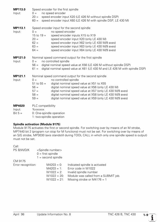
April 98 Update Information No. 8 TNC 426 B, TNC 430 1–9
MP113.0 Speed encoder for the first spindleInput: 0 = no speed encoder
20 = speed encoder input X20 (LE 426 M without spindle DSP)60 = speed encoder input X60 (LE 426 M with spindle DSP, LE 430 M)
MP113.1 Speed encoder input for the second spindleInput: 0 = no speed encoder
15 to 19 = speed encoder inputs X15 to X1920 = speed encoder input X20 (only LE 430 M)62 = speed encoder input X62 (only LE 430 M/9 axes)63 = speed encoder input X63 (only LE 430 M/9 axes)64 = speed encoder input X64 (only LE 430 M/9 axes)
MP121.0 Nominal speed command output for the first spindleInput: 0 = no controlled spindle
56 = digital nominal speed value at X56 (LE 426 M without spindle DSP)61 = digital nominal speed value at X61 (LE 430 M and LE 426 M with spindle DSP)
MP121.1 Nominal speed command output for the second spindleInput: 0 = no controlled spindle
51 to 55 = digital nominal speed value at X51 to X5556 = digital nominal speed value at X56 (only LE 430 M)57 = digital nominal speed value at X57 (only LE 430 M/9 axes)58 = digital nominal speed value at X58 (only LE 430 M/9 axes)59 = digital nominal speed value at X59 (only LE 430 M/9 axes)
MP4020 PLC compatibilityInput: %xxxxxxBit 5 = 0: One-spindle operation
1: two-spindle operation
Spindle activation (Module 9175)
Module 9175 activates the first or second spindle. For switching over by means of an M strobe,MP7440 bit 2 (program run stop for M functions) must not be set. For switching over by means ofan S/G strobe, MP3030 (axis standstill during TOOL CALL in which only one spindle speed is output)must not be set.
Call:PS B/W/D/K <Spindle number>
0 = first spindle1 = second spindle
CM 9175Error recognition: M4203 = 0: Indicated spindle is activated
M4203 = 1: Error code in W1022W1022 = 2: Invalid spindle numberW1022 = 20: Module was called from a SUBMIT job.W1022 = 21: Missing strobe or M4176 = 1
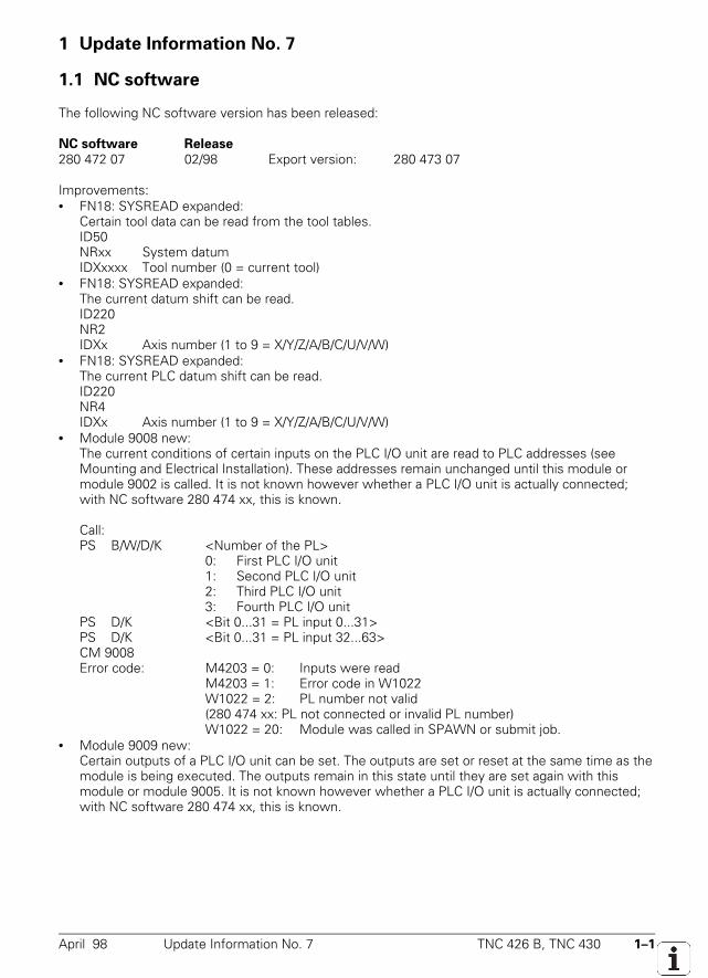
April 98 Update Information No. 7 TNC 426 B, TNC 430 1–1
1 Update Information No. 7
1.1 NC software
The following NC software version has been released:
NC software Release280 472 07 02/98 Export version: 280 473 07
Improvements:• FN18: SYSREAD expanded:
Certain tool data can be read from the tool tables.ID50NRxx System datumIDXxxxx Tool number (0 = current tool)
• FN18: SYSREAD expanded:The current datum shift can be read.ID220NR2IDXx Axis number (1 to 9 = X/Y/Z/A/B/C/U/V/W)
• FN18: SYSREAD expanded:The current PLC datum shift can be read.ID220NR4IDXx Axis number (1 to 9 = X/Y/Z/A/B/C/U/V/W)
• Module 9008 new:The current conditions of certain inputs on the PLC I/O unit are read to PLC addresses (seeMounting and Electrical Installation). These addresses remain unchanged until this module ormodule 9002 is called. It is not known however whether a PLC I/O unit is actually connected;with NC software 280 474 xx, this is known.
Call:PS B/W/D/K <Number of the PL>
0: First PLC I/O unit1: Second PLC I/O unit2: Third PLC I/O unit3: Fourth PLC I/O unit
PS D/K <Bit 0...31 = PL input 0...31>PS D/K <Bit 0...31 = PL input 32...63>CM 9008Error code: M4203 = 0: Inputs were read
M4203 = 1: Error code in W1022W1022 = 2: PL number not valid(280 474 xx: PL not connected or invalid PL number)W1022 = 20: Module was called in SPAWN or submit job.
• Module 9009 new:Certain outputs of a PLC I/O unit can be set. The outputs are set or reset at the same time as themodule is being executed. The outputs remain in this state until they are set again with thismodule or module 9005. It is not known however whether a PLC I/O unit is actually connected;with NC software 280 474 xx, this is known.
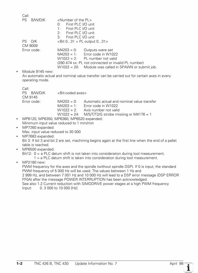
1–2 TNC 426 B, TNC 430 Update Information No. 7 April 98
Call:PS B/W/D/K <Number of the PL>
0: First PLC I/O unit1: First PLC I/O unit2: First PLC I/O unit3: First PLC I/O unit
PS D/K <Bit 0...31 = PL output 0...31>CM 9009Error code: M4203 = 0: Outputs were set
M4203 = 1: Error code in W1022W1022 = 2: PL number not valid(280 474 xx: PL not connected or invalid PL number)W1022 = 20: Module was called in SPAWN or submit job.
• Module 9145 new:An automatic actual and nominal value transfer can be carried out for certain axes in everyoperating mode.
Call:PS B/W/D/K <Bit-coded axes>CM 9145Error code: M4203 = 0: Automatic actual and nominal value transfer
M4203 = 1: Error code in W1022W1022 = 2: Axis number not validW1022 = 24: M/S/T/T2/G strobe missing or M4176 = 1
• MP6120, MP6350, MP6360, MP6520 expanded:Minimum input value reduced to 1 mm/min
• MP7260 expanded:Max. input value reduced to 30 000
• MP7683 expanded:Bit 3: If bit 3 and bit 2 are set, machining begins again at the first line when the end of a pallettable is reached.
• MP6500 expanded:Bit12: 0 = a PLC datum shift is not taken into consideration during tool measurement.
1 = a PLC datum shift is taken into consideration during tool measurement.• MP2180 new:
PWM frequency for the axes and the spindle (without spindle DSP). If 0 is input, the standardPWM frequency of 5 000 Hz will be used. The values between 1 Hz and2 999 Hz, and between 7 001 Hz and 10 000 Hz will lead to a DSP error message (DSP ERRORFF0A) after the message POWER INTERRUPTION has been acknowledged.See also 1.2 Current reduction with SIMODRIVE power stages at a high PWM frequencyInput: 0. 3 000 to 10 000 [Hz]
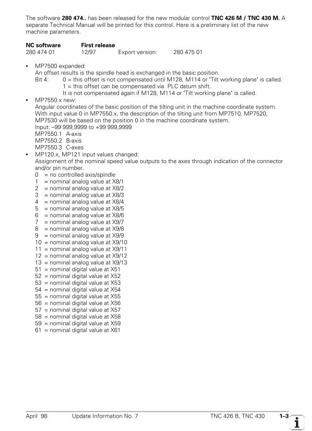
April 98 Update Information No. 7 TNC 426 B, TNC 430 1–3
The software 280 474.. has been released for the new modular control TNC 426 M / TNC 430 M. Aseparate Technical Manual will be printed for this control. Here is a preliminary list of the newmachine parameters.
NC software First release280 474 01 12/97 Export version: 280 475 01
• MP7500 expanded:An offset results is the spindle head is exchanged in the basic position.Bit 4: 0 = this offset is not compensated until M128, M114 or "Tilt working plane" is called.
1 = this offset can be compensated via PLC datum shift.It is not compensated again if M128, M114 or "Tilt working plane" is called.
• MP7550.x new:Angular coordinates of the basic position of the tilting unit in the machine coordinate system.With input value 0 in MP7550.x, the description of the tilting unit from MP7510, MP7520,MP7530 will be based on the position 0 in the machine coordinate system.Input: –99 999,9999 to +99 999,9999MP7550.1 A-axisMP7550.2 B-axisMP7550.3 C-axes
• MP120.x, MP121 input values changed:Assignment of the nominal speed value outputs to the axes through indication of the connectorand/or pin number.0 = no controlled axis/spindle1 = nominal analog value at X8/12 = nominal analog value at X8/23 = nominal analog value at X8/34 = nominal analog value at X8/45 = nominal analog value at X8/56 = nominal analog value at X8/67 = nominal analog value at X9/78 = nominal analog value at X9/89 = nominal analog value at X9/910 = nominal analog value at X9/1011 = nominal analog value at X9/1112 = nominal analog value at X9/1213 = nominal analog value at X9/1351 = nominal digital value at X5152 = nominal digital value at X5253 = nominal digital value at X5354 = nominal digital value at X5455 = nominal digital value at X5556 = nominal digital value at X5657 = nominal digital value at X5758 = nominal digital value at X5859 = nominal digital value at X5961 = nominal digital value at X61
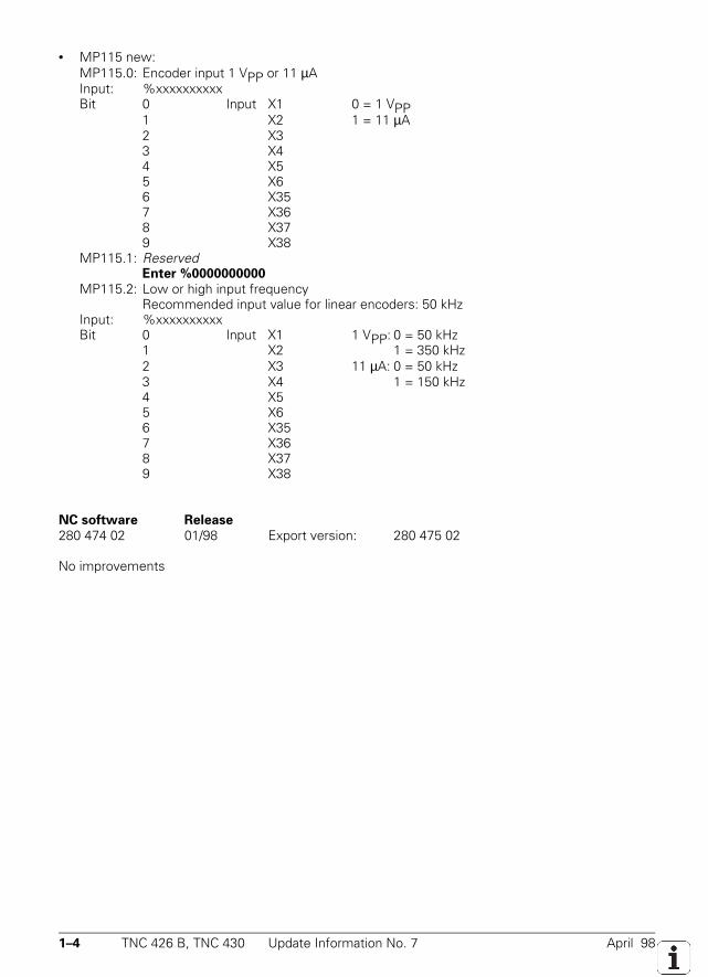
1–4 TNC 426 B, TNC 430 Update Information No. 7 April 98
• MP115 new:MP115.0: Encoder input 1 VPP or 11 µAInput: %xxxxxxxxxxBit 0 Input X1 0 = 1 VPP
1 X2 1 = 11 µA2 X33 X44 X55 X66 X357 X368 X379 X38
MP115.1: ReservedEnter %0000000000
MP115.2: Low or high input frequencyRecommended input value for linear encoders: 50 kHz
Input: %xxxxxxxxxxBit 0 Input X1 1 VPP: 0 = 50 kHz
1 X2 1 = 350 kHz2 X3 11 µA: 0 = 50 kHz3 X4 1 = 150 kHz4 X55 X66 X357 X368 X379 X38
NC software Release280 474 02 01/98 Export version: 280 475 02
No improvements
April 98 Update Information No. 7 TNC 426 B, TNC 430 1–5
1.2 Current reduction in SIMODRIVE power stages at high PWM frequency
The HEIDENHAIN controls TNC 426 PB / TNC 430 work with a PWM frequency of 5kHz.
SIEMENS power stages are usually operated at a PWM frequency of 3.2kHz (spindle) and 4kHz(axes). The rated currents IN are defined for these frequencies.If these power stages are operated at a higher PWM frequency (5kHz), the modules can, in certaincases, overheat (in particular 6SN1123-1AA00-0CA0 and 6SN1123-1AB00-0CA0 as axis modules). Inmachines where the modules are not used to their full capacity, there is no danger of overheating.
There are two ways of preventing this undesired heating:– Reducing the PWM frequency– Reducing the factor for I2t monitoring or reducing the rated current IN of the power stages
For spindles with their own DSP, the only possibility is to reduce the factor for I2t monitoring or to reduce the rated current.
Reducing the PWM frequencyUsing the new machine parameter MP2180, it is possible to set the PWM frequency for the axesand the spindle together.The MP2180 has no effect on a spindle with its own DSP.Input: 0 and 3 000 to 7 000 [Hz]
0 = PWM frequency 5000 [Hz]3000 [Hz] to 7000 [Hz] PWM frequency for SIMODRIVE power stagesThe values between 1 Hz and 2 999 Hz, and between 7 001 Hz and10 000 Hz will lead to a DSP error message (DSP ERROR FF0A) after the
message POWER INTERRUPTION has been acknowledged.Note:Reduction of the PWM frequency has no effect on the max. speed, but does require the axes andthe spindle to be recommissioned!HEIDENHAIN recommends setting a suitable PWM frequency for axis modules (usually 4kHz, seeSiemens documentation) when commissioning new machines. If the spindle module continues toshow signs of excess heating despite the reduction in the PWM frequency from 5 kHz to 4 kHz,then you need to reduce the reference value for I2t monitoring (MP2302.x, MP2303) or the ratedcurrent instead.
1–6 TNC 426 B, TNC 430 Update Information No. 7 April 98
Reducing the reference value for I2t monitoring or reducing the rated currentThe reduction of the rated current of the power stages as well as the reference value for I2tmonitoring can be calculated using two values (X1, X2), which can be taken from the SIEMENSdocumentation.
X1 = current reduction factor in % at 8 kHz PWM frequency;X2 = PWM frequency in kHz as of which the current reduction becomes valid;fPWM = with PWM frequency in kHz as set in MP2180;
The percentage reduction of the rated current can be calculated using the following formula:
XR [%] = 100 – ( (100 – X1) * (8kHz – fPWM)
8 kHz – X2 + X1)
From this we get the following reference value for I2t monitoring:
XB = 1– XR[%] 100 ;
Note:The reduction of the rated current of the power stage can cause a reduction in the rated torque andthe rated power of the motor, if the rated current of the power stage and the rated current of themotor had been set the same.
Examples for LT module 50A:
Axis LT module 50A, PWM frequency 5kHz, X1=40%, X2=4kHz
XR [%] = 100 – ( (100 – 40) * (8kHz – 5kHz)
8 kHz – 4kHz + 40) = 15% XB=0.85
Spindle LT module 50A, PWM frequency 5kHz, X1=40%, X2=3.2kHz
XR [%] = 100 – ( (100 – 40) * (8kHz – 5kHz)
8 kHz – 3.2kHz + 40) = 22.5% XB=0.78
Axis LT module 50A, PWM frequency 4kHz, X1=40%, X2=4kHz
XR [%] = 100 – ( (100 – 40) * (8kHz – 4kHz)
8 kHz – 4kHz + 40) = 0% XB=1.00
Spindle LT module 50A, PWM frequency 4kHz, X1=40%, X2=3.2kHz
XR [%] = 100 – ( (100 – 40) * (8kHz – 4kHz)
8 kHz – 3.2kHz + 40) = 10% XB=0.90
If you wish you can reduce the rated currents IN of your power stages in the power stage tablemotor.amp, using the calculated reduction values, or lower the reference value for I2t monitoring.The edited motor.amp table will automatically be stored in the PLC partition.
April 98 Update Information No. 7 TNC 426 B, TNC 430 1–7
1.3 DSP error messages
DSP error messages with error code
Error message Explanation ClassificationDSP ERROR XXXX
1000 0 Timeout during a command Data processing error1001 0 Incorrect acknowledgement of a command Data processing error1002 0 Command is sent before preceding
command is acknowledgedData processing error
1003 0 Synchronization error between DSP andNC
Data processing error
1004 0 Incorrect message DSP − NC Data processing error1005 0 Too many commands NC − DSP Data processing error1100 0 Error determining check sum Data processing error1101 0 Timeout during Word transfer command
(load DSP code)Data processing error
1102 0 Timeout during check sum Data processing errorF010 Motor type unknown (MP2200) Error in motor table or in
MP2200F020 ReservedF030 ReservedF040 No. pole pairs too high Error in motor table or in
MP2230F090 Drive type unknown (MP2000)F0A0 ReservedF0B0 ReservedF0C0 ReservedF0F0 Current controller proportional factor too
highF100 Current controller integral factor too highF110 Motor temperatureF120 ReservedF130 Osci parameter is incorrect (for test) Data processing errorF140 Rated current power stage Error in power stage tableF220 ReservedF240 Unknown counter-IC type at speed input Hardware errorF260 ReservedF290 Error 3-D touch probe/evaluation,
there was no latch with L1 input(G19/G26)
Hardware error
F2C0 Actual motor current above limit value Drive errorFF01 Undefined error, no casual connection Data processing errorFF02 Host command not recognized, not valid Data processing errorFF03 Host-/DSP watchdogs do not agree Data processing error
1–8 TNC 426 B, TNC 430 Update Information No. 7 April 98
Error message Explanation ClassificationDSP ERROR XXXX
FF04 Undefined interrupt Data processing errorFF05 Hardware not recognized Hardware and software do
not matchFF06 No V_NOML value received from the host Data processing errorFF07 AC-fail Power stage errorFF08 Emergency stop failFF09 Stack overflow Data processing errorFF0A Pulse width modulation delta signal Hardware error or incorrect
value in MP2180FF0B Error in store request Data processing errorFF0C No speed control interrupt Data processing errorFF0D Error in sum check (code) Data processing errorFF0E Time exceeded in the speed interrupt Data processing errorFF0F Error initializing a software timer Data processing errorFF10 Error in LSV2 transfer Data processing error
DSP error messages with text
Error message ExplanationPower stage in axis <axis>too weak
Power stage is too weak for the axis displayed
<Axis> motor enc. line counttoo high
Line count of motor encoder is too high for the axis displayed
Motor <axis>: Xh; X2; f-n; R2incorrect
One of the datums in the following motor data for the axis displayedis incorrect: Xh: Magnetizing reactance
X2: Rotor leakage reactancef-n: Rated frequencyR2: Rotor resistance
Motor <axis>: n-n; f-nincorrect
One of the datums in the following motor data is incorrect:n-n: Rated speedf-n: Rated frequency
Power stage <axis>: U-Imaxincorrect
U-Imax of the power stage for the displayed axis is erroneous(U-Imax = voltage of the current sensor)
Power stage <axis>: I-maxincorrect
Imax of the power stage for the displayed axis is erroneous(Imax = peak current)
Motor <axis>: t-maxincorrect
T-max of the motor for the displayed axis is erroneous
Motor <axis>: I-n incorrect I-N of the motor for the displayed axis is erroneousMotor <axis>: I-max incorrect I-max of the motor for the displayed axis is erroneousMotor <axis>: n-maxincorrect
n-max of the motor for the displayed axis is erroneous
Axis <axis>:MP2340/MP2350 incorrect
MP2340/MP2350 (field angle displacement for the displayed axis)incorrect
Axis <axis>: MP2190incorrect
MP2190 (dc-link voltage) for displayed axis incorrect
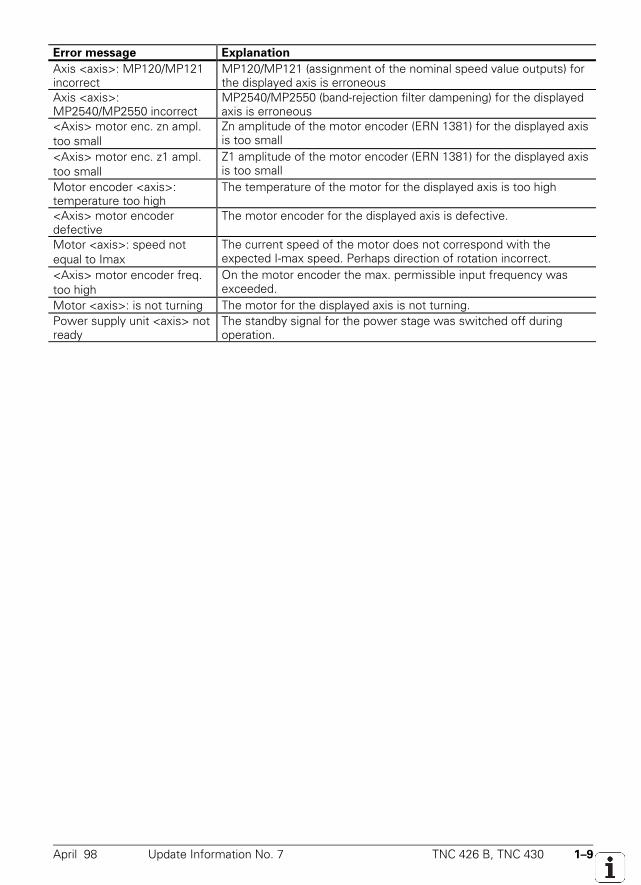
April 98 Update Information No. 7 TNC 426 B, TNC 430 1–9
Error message ExplanationAxis <axis>: MP120/MP121incorrect
MP120/MP121 (assignment of the nominal speed value outputs) forthe displayed axis is erroneous
Axis <axis>:MP2540/MP2550 incorrect
MP2540/MP2550 (band-rejection filter dampening) for the displayedaxis is erroneous
<Axis> motor enc. zn ampl.too small
Zn amplitude of the motor encoder (ERN 1381) for the displayed axisis too small
<Axis> motor enc. z1 ampl.too small
Z1 amplitude of the motor encoder (ERN 1381) for the displayed axisis too small
Motor encoder <axis>:temperature too high
The temperature of the motor for the displayed axis is too high
<Axis> motor encoderdefective
The motor encoder for the displayed axis is defective.
Motor <axis>: speed notequal to Imax
The current speed of the motor does not correspond with theexpected I-max speed. Perhaps direction of rotation incorrect.
<Axis> motor encoder freq.too high
On the motor encoder the max. permissible input frequency wasexceeded.
Motor <axis>: is not turning The motor for the displayed axis is not turning.Power supply unit <axis> notready
The standby signal for the power stage was switched off duringoperation.