technical manual operator’s manual for...
TRANSCRIPT

ARMY TM 9-2320-272-10AIR FORCE TO 36A12-1C-441
TECHNICAL MANUALOPERATOR’S MANUAL
FORTRUCK, 5-TON, 6X6, M939,
M939A1, AND M939A2SERIES TRUCKS (DIESEL)
TRUCK, CARGO: 5-TON, 6X6 DROPSIDE, M923(2320-1-050-2084) (EIC: BRY); M923A1 (2320-01-206-4087) (EIC:BSS); M923A2 (2320-01-230-0307) (EIC: BS7);M925 (2320-01-047-8769) (EIC: BRT); M925A1(2320-01-206-4088) (EIC:BST); M925A2 (2320-01-230-0308) (EIC: BS8);TRUCK, CARGO: 5-TON, 6X6 XLWB, M927(2320-01047-8771) (EIC: BRV); M927A1 (2320-01-206-4089), (EIC: BSW); M927A2 (2320-01-230-0309) (EIC: BS9); M928 (2320-01-047-8770) (EIC:BRU); M928A1 (2320-01-206-4090) (EIC: BSX);M928A2 (2320-01-230-0310) (EIC: BTM);TRUCK, DUMP: 5-TON, 6X6, M929 (2320-0147-8756)(EIC: BTH); M929A1 (2320-01-206-4079) (EIC:BSY);M929A2 (2320-01-230-0305) (EIC: BTN); M930(2320-01-047-8755) (EIC: BTG); M930A1 (2320-01-206-4080), (EIC: BSZ); M930A2 (2320-01-230-0306) (EIC: BTO);TRUCK, TRACTOR: 5-TON, 6X6, M931 (2320-01-047-8753)(EIC: BTE); M931A1 (2320-01-206-4077) (EIC:BS2);M931A2 (2320-01-230-0302) (EIC: BTP); M932(2320-01-047-8752) (EIC: BTD); M932A1 (2320-01-205-2684) (EIC: BS5); M932A2 (2320-01-230-0303) (EIC: BTQ);TRUCK, VAN, EXPANSIBLE: 5-TON, 6X6, M934(2320-01-047-8750) (EIC: BTB); M934A1 (2320-01-205-2682) (EIC: BS4); M934A2 (2320-01-230-0300) (EIC: BTR);TRUCK, MEDIUM WRECKER: 5-TON, 6X6, M936(2320-01-047-8754) (EIC: BTF); M936A1 (2320-01-206-4078) (EIC:BS6); M936A2 (2320-01-230-0304) (EIC: BTT).
TABLE OF CONTENTS ii
HOW TO USE THIS MANUAL iii
INTRODUCTION 1-1
OPERATING INSTRUCTIONS 2-1
PREVENTIVE MAINTENANCE CHECKS ANDSERVICES (PMCS) 2-28
MAINTENANCE INSTRUCTIONS 3-1
TROUBLESHOOTING PROCEDURES 3-2
REFERENCES A-1
COMPONENTS OF END ITEM(COEI) AND BASIC ISSUEITEMS (BII) LISTS B-1
ADDITIONAL AUTHORIZAIONLISTS (AAL) C-1
EXPENDABLE/DURABLE SUPPLIESAND MATERIALS UST D-1
STOWAGE AND SIGN GUIDE E-1
DISTRIBUTION STATEMENT A Approved for public release; distribution is unlimited.
HEADQUARTERS, DEPARTMENT OF THE ARMYAND THE AIR FORCE AUGUST 15, 1996
Downloaded from http://www.everyspec.com on 2012-10-29T18:40:10.

TECHNICALMANUALNo. 9-2320-272-10
TM 9-2320-272-10TO 36A12-1C-441
C1DEPARTMENTS OF THE ARMY
AND THE AIR FORCEWASHINGTON, D.C. 22 Feb 1999
OPERATOR’S MANUALFOR
TRUCK, 5-TON, 6X6, M939,M939A1 AND M939A2 SERIES (DIESEL)
TRUCK, CARGO: 5-TON, 6X6, DROPSIDE,M923 (2320-01-050-2084), M923A1 (2320-01-206-4087), M923A2 (2320-01-230-0307).M925 (2320-01-047-8769). M925A1 (2320-01-206-4088), M925A2 (2320-01-230-0308);
TRUCK, CARGO: 5-TON. 6X6,M924 (2320-01-047-8773), M924A1 (2320-01-205-2692),M926 (2320-01-047-8772), M926A1 (2320-01-205-2693);
TRUCK, CARGO: 5-TON, 6X6, XLWB,M927 (2320-01-047-8771), M927A1 (2320-01-206-4089). M927A2 (2320-01-230-0309),M928 (2320-01-047-8770), M928A1 (2320-01-206-4090), M928A2 (2320-01-230-0310);
TRUCK, DUMP: 5-TON, 6X6,M929 (2320-01-047-8756), M929A1 (2320-01-206-4079), M929A2 (2320-01-230-0305),M930 (2320-01-047-8755), M930A1 (2320-01-206-4080). M930-A2 (2320-01-230-0306);
TRUCK, TRACTOR: 5-TON, 8X6,M931 (2320-01-047-8753), M931A1 (2320-01-206-4077), M931A2 (2320-01-230-0302),M932 (2320-01-047-8752), M932A1 (2320-01-205-2684), M932A2 (2320-01-230-0303);
TRUCK, VAN, EXPANSIBLE: 5-TON, 6X6,M934 (2320-01-047-8750), M934A1 (2320-01-205-2682), M934A2 (2320-01-230-0300);M935 (2320-01-047-8751, M935A1 (2320-01-205-2683), M935A2 (2320-01-230-0301);
TRUCK, MEDIUM WRECKER: 5-TON, 6X6,M936 (2320-01-047-8754), M936A1 (2320-01-206-4078). M936A2 (2320-01-230-0304)
This change is issued in conjunction with Safety of Use Message (SUOM). TACOM Control No. 98-07. It emphasizessafe driving procedures to be followed by M939 vehicle operators.
TM 9-2320-272-10. August 1996, is changed as follows:Remove old pages 1-23, 1-24 and 2-105, 2-106 and insert provided pages with same numbering.
DISTRIBUTION STATEMENT A. Approved for public release; distribution is unlimited
Downloaded from http://www.everyspec.com on 2012-10-29T18:40:10.

By Order of the Secretary of the Army:
DENNIS J. REIMERGeneral, United States Army
Chief of Staff
Administrative Assistant to theSecretary of the Army
05676
By Order of the Secretary of the Air Force:
RONALD R. FOGLEMANGeneral, United States Air Force
Chief of Staff
Official:
HENRY VICCELLIO, JR.General, United States Air Force
Commander, Air Force Materiel Command
DISTRIBUTION:
To be distributed in accordance with the initial distribution number (IDN)380385, requirements for TM 9-2320-272-10.
Downloaded from http://www.everyspec.com on 2012-10-29T18:40:10.
TM 9-2320-272-10
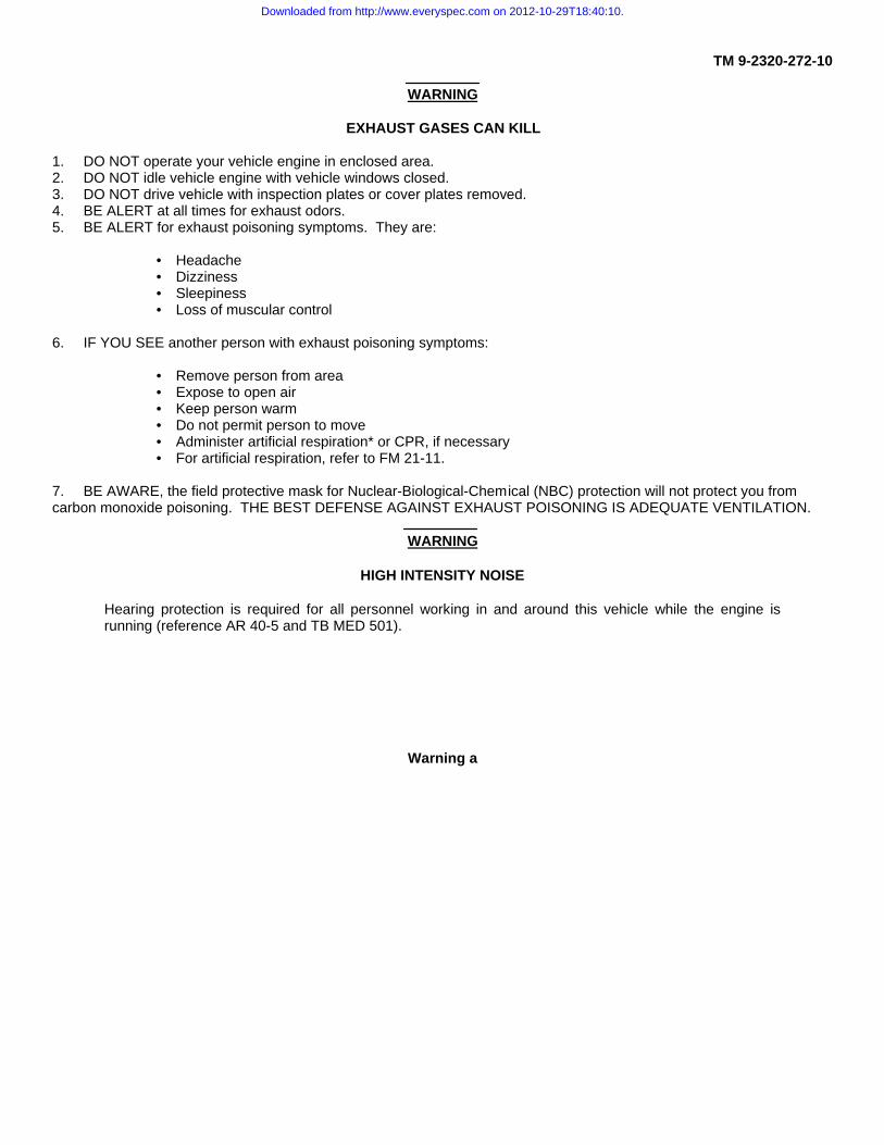
WARNING
EXHAUST GASES CAN KILL
1. DO NOT operate your vehicle engine in enclosed area.2. DO NOT idle vehicle engine with vehicle windows closed.3. DO NOT drive vehicle with inspection plates or cover plates removed.4. BE ALERT at all times for exhaust odors.5. BE ALERT for exhaust poisoning symptoms. They are:
• Headache• Dizziness• Sleepiness• Loss of muscular control
6. IF YOU SEE another person with exhaust poisoning symptoms:
• Remove person from area• Expose to open air• Keep person warm• Do not permit person to move• Administer artificial respiration* or CPR, if necessary• For artificial respiration, refer to FM 21-11.
7. BE AWARE, the field protective mask for Nuclear-Biological-Chemical (NBC) protection will not protect you fromcarbon monoxide poisoning. THE BEST DEFENSE AGAINST EXHAUST POISONING IS ADEQUATE VENTILATION.
WARNING
HIGH INTENSITY NOISE
Hearing protection is required for all personnel working in and around this vehicle while the engine isrunning (reference AR 40-5 and TB MED 501).
Warning a
Downloaded from http://www.everyspec.com on 2012-10-29T18:40:10.
TM 9-2320-272-10
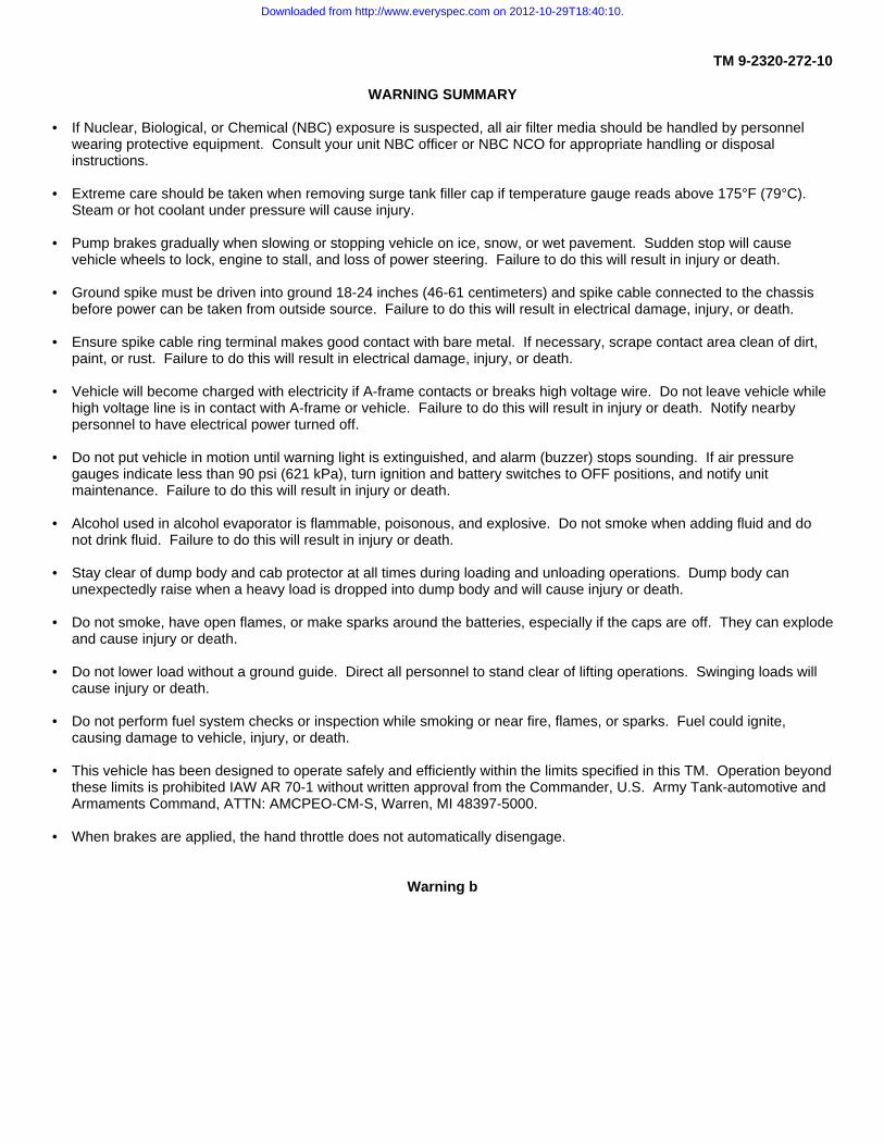
WARNING SUMMARY
• If Nuclear, Biological, or Chemical (NBC) exposure is suspected, all air filter media should be handled by personnelwearing protective equipment. Consult your unit NBC officer or NBC NCO for appropriate handling or disposalinstructions.
• Extreme care should be taken when removing surge tank filler cap if temperature gauge reads above 175°F (79°C).Steam or hot coolant under pressure will cause injury.
• Pump brakes gradually when slowing or stopping vehicle on ice, snow, or wet pavement. Sudden stop will causevehicle wheels to lock, engine to stall, and loss of power steering. Failure to do this will result in injury or death.
• Ground spike must be driven into ground 18-24 inches (46-61 centimeters) and spike cable connected to the chassisbefore power can be taken from outside source. Failure to do this will result in electrical damage, injury, or death.
• Ensure spike cable ring terminal makes good contact with bare metal. If necessary, scrape contact area clean of dirt,paint, or rust. Failure to do this will result in electrical damage, injury, or death.
• Vehicle will become charged with electricity if A-frame contacts or breaks high voltage wire. Do not leave vehicle whilehigh voltage line is in contact with A-frame or vehicle. Failure to do this will result in injury or death. Notify nearbypersonnel to have electrical power turned off.
• Do not put vehicle in motion until warning light is extinguished, and alarm (buzzer) stops sounding. If air pressuregauges indicate less than 90 psi (621 kPa), turn ignition and battery switches to OFF positions, and notify unitmaintenance. Failure to do this will result in injury or death.
• Alcohol used in alcohol evaporator is flammable, poisonous, and explosive. Do not smoke when adding fluid and donot drink fluid. Failure to do this will result in injury or death.
• Stay clear of dump body and cab protector at all times during loading and unloading operations. Dump body canunexpectedly raise when a heavy load is dropped into dump body and will cause injury or death.
• Do not smoke, have open flames, or make sparks around the batteries, especially if the caps are off. They can explodeand cause injury or death.
• Do not lower load without a ground guide. Direct all personnel to stand clear of lifting operations. Swinging loads willcause injury or death.
• Do not perform fuel system checks or inspection while smoking or near fire, flames, or sparks. Fuel could ignite,causing damage to vehicle, injury, or death.
• This vehicle has been designed to operate safely and efficiently within the limits specified in this TM. Operation beyondthese limits is prohibited IAW AR 70-1 without written approval from the Commander, U.S. Army Tank-automotive andArmaments Command, ATTN: AMCPEO-CM-S, Warren, MI 48397-5000.
• When brakes are applied, the hand throttle does not automatically disengage.
Warning b
Downloaded from http://www.everyspec.com on 2012-10-29T18:40:10.

ARMY TM 9-2320-272-10AIR FORCE TO 36A12-1C-441
TECHNICAL MANUALNO. 9-2320-272-10 HEADQUARTERS,
DEPARTMENT OF THE ARMYTECHNICAL ORDER ANDTHEAIRFORCENO. 36A12-1C441 Washington DC, 15August 1996
OPERATOR’S MANUALFOR
TRUCK, 5-TON, 6X6, M939, M939A1, ANDM939A2 SERIES TRUCKS (DIESEL)
TRUCK MODEL EIC NSN (WO/WINCH) NSN (W/WINCH)
Cargo, Dropside M923 BRY 2320-01-050-2084Cargo, Dropside M923A1 BSS 2320-01-206-4087Cargo, Dropside M923A2 BS7 2320-01-230-0307Cargo, Dropside M925 BRT 2320-01-047-8769Cargo, Dropside M925A1 BST 2320-01-206-4088Cargo, Dropside M925A2 BS8 2320-01-230-0308Cargo M927 BRV 2320-01-047-8771Cargo M927A1 BSW 2320-01-206-4089Cargo M927A2 BS9 2320-01-230-0309Cargo M928 BRU 2320-01-047-8770Cargo M928A1 BSX 2320-01-206-4090Cargo M928A2 BTM 2320-01-230-0310Dump M929 BTH 2320-01-047-8756Dump M929A1 BSY 2320-01-206-4079Dump M929A2 BTN 2320-01-230-0305Dump M930 BTG 2320-01-047-8755Dump M930A1 BSZ 2320-01-206-4080Dump M930A2 BTO 2320-01-230-0306Tractor M931 BTE 2320-01-047-8753Tractor M931A1 BS2 2320-01-206-4077Tractor M931A2 BTP 2320-01-230-0302Tractor M932 BTD 2320-01-047-8752Tractor M932A1 BS5 2320-01-205-2684Tractor M932A2 BTQ 2320-01-230-0303Van, Expansible M934 BTB 2320-01-047-8750Van, Expansible M934A1 BS4 2320-01-205-2682Van, Expansible M934A2 BTR 2320-01-230-0300Medium Wrecker M936 BTF 2320-01-047-8754Medium Wrecker M936A1 BS6 2320-01-206-4078Medium Wrecker M936A2 BTT 2320-01-230-0304
i
Downloaded from http://www.everyspec.com on 2012-10-29T18:40:10.

TM 9-2320-272-10
REPORTING OF ERRORS AND RECOMMENDING IMPROVEMENTSYou can help improve this manual. If you find any mistakes or if you know of a way to improve the procedures, please letus know. Mail your letter, DA Form 2028 (Recommended Changes to Publications and Blank Forms), or DA Form 2028-2located in back of this manual direct to: Commander. U.S. Army Tank-automotive and Armaments Command, ATTN:AMSTA-IM-OPIT, Warren, Michigan 48397-5000. A reply will be furnished to you.
DISRTRRUTION STATEMFENT A - Approved for public release; distribution is unlimited.
PageHOW TO USE THIS MANUAL ..............................................................................................................iii
CHAPTER 1. INTRODUCTION ..................................................................................................................................................................................................................................................................................1-1
Section I. General Information ......................................................................................................................1-1II. Equipment Description and Data ..................................................................................................1-8III. Principles of Operation ................................................................................................................1-27
CHAPTER 2. OPERATING INSTRUCTIONS .....................................................................................................2-1
Section I. Description and Use of Operator’s Controls and Indicators ..........................................................2-1
II. PREVENTIVE MAINTENANCE CHECKS.....................................................................................2-28AND SERVICES (PMCS)
III. Operation Under Usual Conditions ..............................................................................................2-100IV. Operation Under Unusual Conditions ............................................................................................2-201V. Operation of Special Purpose kits ................................................................................................2-217
CHAPTER 3. MAINTENANCE INSTRUCTIONS.................................................................................................3-1
Section I. Lubrication Instructions .................................................................................................................3-1
II. TROUBLESHOOTING PROCEDURES ........................................................................................3-2
III. Maintenance Procedures ..............................................................................................................3-23
APPENDIX A. REFERENCES ..............................................................................................................................A-1
APPENDIX B. COMPONENTS OF END ITEM (COEI) AND................................................................................B-1BASIC ISSUE ITEMS (BII) LISTS
APPENDIX C. ADDITIONAL AUTHORIZATION LIST (AAL) ................................................................................C-1
APPENDIX D. EXPENDABLE/DURABLE SUPPLIESAND MATERIALS LIST .................................................................................................................D-1
APPENDIX E. STOWAGE AND SIGN GUIDE ...................................................................................................E-1ii
Downloaded from http://www.everyspec.com on 2012-10-29T18:40:10.

TM 9-2320-272-10
HOW TO USE THIS MANUAL
1. The information contained in this manual can be accessed in several ways.a. If you know what area you are looking for, us the front cover index. Find the appropriate box and match it to the
blackened pages on the side of the book, or use the page number listed in the box.b. If you are looking for a specific paragraph, refer to the index at the back of the manual.
2. This manual consists of:a. Chapter 1, Introduction - provides information for completing forms and records, gives a familiarization of
equipment, and a functional and physical description of major equipment.b. Chapter 2, Operating Instructions - provides information needed to use or operate the vehicle.c. Chapter 3, Maintenance Instructions - provides information covering lubrication, troubleshooting, and corrective
maintenance.3. Types of notations
a. Warnings are posted immediately prior to text covering any area that would present a situation that may result ininjury or death. Compliance is mandatory.
b. Cautions will be found on the same page and preceding the text covering any area that would present a situationthat may result in damage to equipment.
c. Notes will precede text covering an area with the intent to alter normal proce-dures for unique situations orequipment, or point out areas of special concern.
4. Appendices have been provided to:a. Basic Issue Items (BII) list - specify the minimum essential items to place and maintain the M939, M939A1, and
M939A2 (M939/A/A2) series vehicles in operation, and are maintain with the vehicle.b. Additional Authorization List (AAL) - specify items not shipped with vehicles, but are authorized for support of the
M939A1/A2 series vehicles.c. Expendable/Durable Supplies and Materials List - specify expendable/durable supplies and materials you will need
to operate and maintain M939/A1/A2 series vehicles.
iii (iv blank)
Downloaded from http://www.everyspec.com on 2012-10-29T18:40:10.

TM 9-2320-272-10
CHAPTER 1INTRODUCTION
Section I General Information (page 1-1)Section II Equipment Description and Data (page 1-8)Section III Principles of Operation (page 1-27)
Section I. GENERAL INFORMATION
M923A2 AND M925A2
M927A2 AND M928A21-1
Downloaded from http://www.everyspec.com on 2012-10-29T18:40:10.

TM 9-2320-272-10
M929A2 AND M930A2
M931A2 AND M932A21-2
Downloaded from http://www.everyspec.com on 2012-10-29T18:40:10.

TM 9-2320-272-10
M934A2
M936A2
1-3
Downloaded from http://www.everyspec.com on 2012-10-29T18:40:10.

TM 9-2320-272-101-1. SCOPE
a. This operator’s manual contains instructions for operating and servicing the following M939/A1/A2 series vehicles:(1) M923/A1/A2, Cargo Truck, WO/W (Dropside)(2) M925/A1/A2, Cargo Truck, W/W (Dropside)(3) M927/A1/A2, Cargo Truck, WO/W (XLWB)(4) M928/A1/A2, Cargo Truck, W/W (XLWB)(5) M929/A1/A2, Dump Truck, WO/W(6) M930/A/A2, Dump Truck, W/W(7) M931/A1/A2, Tractor Truck, WO/W(8) M932/A1/A2, Tractor Truck, W/W(9) M934/A1/A2, Expansible Van, WO/W(10) M936/A1/A2, Medium Wrecker, W/W
b. Vehicles’ purpose.(1) The M923/A1/A2, M925/A1/A2, M927/AYA2, and M928/A1/A2 series cargo trucks provide transportation of
personnel or equipment over a variety of terrain and climate conditions.(2) The M929/A1/A2 and M930/A1/A2 series dump trucks are used to transport various materials over a variety
of terrains. Each vehicle can be equipped with troop seat, and tarpaulin and bow kits for troop transport operations.(3) The M931/A/A2 and M932/A1A2 series tractor trucks are equipped with a fifth wheel used to haul a
semitrailer over a variety of terrain.(4) The M934/A1/A2 series expansible vans are designed to transport electronic base stations over a variety of
terrain.(5) The M936/A1/A2 series wreckers are designed for recovery of disabled or mired vehicles, and perform crane
operation.c. The material presented here provides operators with information and procedures needed to provide the safest and
most efficient operation and servicing of these vehicles. This information includes:(1) Vehicle limitations.(2) The function of controls.(3) Operation instructions for vehicle.(4) Cautions and warnings to operators regarding safety to personnel and equipment.(5) Operator maintenance checks and services.(6) Troubleshooting procedures to be followed by operator if the vehicle malfunctions.(7) Operator forms and records.
1-4
Downloaded from http://www.everyspec.com on 2012-10-29T18:40:10.

TM 9-2320-272-10
1-2. MAINTENANCE FORMS
a. Vehicle Maintenance Forms and Records. Department of the Army forms and procedures used for equipmentmaintenance will be those prescribed by DA Pam 738-750 as contained in the maintenance management update.
b. Hand Receipt Manual This manual has a companion document with a TM number followed by -HR (which standsfor Hand Receipt). The TM 9-2320-272-10-HR consists of preprinted hand receipts (DA Form 2062) that list end itemrelated equipment (i.e., COEI, BII, and AAL) you must account for. As an aid to property accountability, additional -HRmanuals may be requisitioned from the following source in accordance with procedures in chapter 3, AR 310-2:
The U.S. Army Adjutant General Publications Center2800 Eastern Blvd.Baltimore, MD 21220
1-3. CORROSION PREVENTION AND CONTROL (CPC)
Corrosion Preventive and Control (CPC) of Army materiel is a continuing concern. It is important that any corrosionproblems with this item be reported so that the problems can be corrected and improvements can be made to preventproblems in the future items.
While corrosion is typically associated with rusting of metals, it can also include deterioration of other materials, suchas rubber and plastic. Unusual cracking, softening, swelling, or breaking of these materials may be a corrosion problem.
If a corrosion problem is identified, it can be reported using Standard Form 368, Product Quality Deficiency Report.Use of key words such as “corrosion ”rust”, “deterioration”, or a cracking” will ensure that the information is identified as aCPC problem. The form should be submitted to the address specified in DA Pam 738-750.
1-4. DESTRUCTION OF ARMY MATERIEL TO PREVENT ENEMY USE
Procedures for destruction of Army materiel to prevent enemy use can be found in TM 750-244-6.
1-5. REPORTING EQUIPMENT IMPROVEMENT RECOMMENDATIONS (EIR’S)
If the design of your vehicle needs improvement, let us know. If your vehicle is in proper operating condition andthere are problems with vehicle or equipment performance, send us an EIR. You, the user, are the only one who can tellus what you don’t like about your equipment. It is not necessary to show a new design or a better way to perform aprocedure. Just let us know why you don’t like the design or performance. Put it on an SF 368 (Quality DeficiencyReport). Mail it to us at:Commander, U.S. Army Tank-automotive and Armaments Command, ATTN:AMSTA-IM-MMAA, Warren, Michigan 48397-5000. Well send you a reply.
1-5
Downloaded from http://www.everyspec.com on 2012-10-29T18:40:10.

TM 9-2320-272-101-6. WARRANTY INFORMATION
The Cummins engine (model NHC 250) used in M939/A1 series vehicles and Allison transmission (model MT-654 CR)used in all models are warranted in accordance with TB 9 2300-29515/1. The Cummins engine (model 6CTA8.3) used inthe M939A2 series vehicles is warranted in accordance with TB 9-2300-358-24. The warranty starts on the date, found inBlock 23, DA Form 2408-9, in the logbook. Report all defects in material or workmanship to your supervisor, who will takeappropriate action through your unit maintenance shop.
1-7. NOMENCLATURE CROSS-REFERENCE LIST
The following is an alphabetical list of commonly used military terms that appear in this manual. This list is cross-referenced to commonly understood terms used in everyday speech that mean the same thing.
Engine Coolant .................................................................................................................................................antifreeze/waterExhaust Stack ................................................................................................................................................................tailpipeFailsafe Unit.......................................................................................................................................................warning buzzerFording ..................................................................................................................................................crossing through waterGrade............................................................................................................................................................... steepness of hillHydraulics............................................................................................................................................operated by oil pressureInclement Weather ..........................................................................................................bad weather (rain, snow, high winds)Indicators ........................................................................................................................................gauges, warning lights, etc.Mired........................................................................................................................................................ stuck in mud or snowOperation............................................................................................................................................................................ taskOperator ........................................................................................................................................................................... driverSlaving.................................................................................................................................................................. jump startingSplash Shields........................................................................................................................................................... mud flapsTransport ....................................................................................................................................................................... to carryTurning Radius ....................................................................................................................distance needed to make a U-turnUsual Conditions ............................................................................................................................. good roads, good weather
1-8. LIST OF ABBREVIATIONS
All abbreviations that appear in this manual are listed below.
AAL................................................................................................................................................Additional Authorization ListAC................................................................................................................................................................Alternating CurrentBII ..................................................................................................................................................................Basic Issue ItemsB.O. ..............................................................................................................................................................................blackoutBRT .................................................................................................................................................................................. brightCC ....................................................................................................................................................................... cross-country°C....................................................................................................................................................................... degree Celsiuscm............................................................................................................................................................................. centimeterContd ..........................................................................................................................................................................continuedCPC.............................................................................................................................................Corrosion Prevention ControlCTIS .............................................................................................................................................Central Tire Inflation Systemcu f .............................................................................................................................................................................cubic feetCW ..................................................................................................................................chain (and) wire rope (lubricating oil)DA..............................................................................................................................................................Department of ArmyDC .......................................................................................................................................................................Direct CurrentDFA ...............................................................................................................................................................diesel fuel (arctic)
1-6
Downloaded from http://www.everyspec.com on 2012-10-29T18:40:10.

TM 9-2320-272-10
1-8. LIST OF ABBREVIATIONS (Contd)
drvy.................................................................................................................................................................................... driveEIR........................................................................................................................ Equipment Improvement Recommendationemer ........................................................................................................................................................................ emergency°F..................................................................................................................................................................degree Fahrenheitft..................................................................................................................................................................................... feetfootg.........................................................................................................................................................................................gramGAA........................................................................................................................................grease, automotive, and artillerygal.....................................................................................................................................................................................gallonGO................................................................................................................................................................................. gear oilGOS..............................................................................................................................................................gear oil (sub-zero)Hwy............................................................................................................................................................................... highwayin..........................................................................................................................................................................................inchkg................................................................................................................................................................................. kilogramkm............................................................................................................................................................................... kilometerkm/h............................................................................................................................................................ kilometers per hourkPa ............................................................................................................................................................................ kilopascalI............................................................................................................................................................................................ literlb...................................................................................................................................................................................... poundlb-ft............................................................................................................................................................................pound-feet1ig....................................................................................................................................................................................... longLO.................................................................................................................................................................. Lubrication Orderm ......................................................................................................................................................................................meterMAC............................................................................................................................................ Maintenance Allocation Chartmi........................................................................................................................................................................................ milempg ..................................................................................................................................................................miles per gallonmph .................................................................................................................................................................... miles per hourN.m......................................................................................................................................................................Newton meterNBC........................................................................................................................................ Nuclear, Biological, or ChemicalNSN......................................................................................................................................................National Stock NumberOE/HDO ............................................................................................................................................. oil, engine/heavy duty oilOEA...............................................................................................................................................................oil, engine (arctic)oz..................................................................................................................................................................................... ouncepara ...........................................................................................................................................................................paragraphpg....................................................................................................................................................................................... pagePMCS ...............................................................................................................Preventive Maintenance Checks and Servicespr ......................................................................................................................................................................................... pairpsi ........................................................................................................................................................ pounds per square inchpt.......................................................................................................................................................................................... pintPTO ..................................................................................................................................................................... power takeoffqt........................................................................................................................................................................................quartrpm ............................................................................................................................................. revolutions (turns) per minuteTM .................................................................................................................................................................. technical manualw/hlg .........................................................................................................................................................with hydraulic liftgatew/o ..................................................................................................................................................................................withoutwo/w .....................................................................................................................................................................without winchw..........................................................................................................................................................................................withw/w ............................................................................................................................................................................with winchxlwb ......................................................................................................................................................... extra long wheelbaseyd........................................................................................................................................................................................ yard
1-7
Downloaded from http://www.everyspec.com on 2012-10-29T18:40:10.

TM 9-2320-272-10
1-9. GLOSSARY
The following list shows definitions of military terms that appear in this manual. Other terms in this manual are defined inthe paragraph where they first appear.
Angle of Approach - Angle between front tires and front bumperAngle of Departure - Angle between rear tires and rear bumperFording - Crossing through waterGrade - Steepness of terrainHydraulic - Operated by oil pressureOperator - Driver of vehicleTarpaulin - Canvas coverSlaving - Jump starting6X6 - Each vehicle has six axle ends and all six are capable of drivingTorque - Measurable force or power required to do workTorqued - Requirement for a specified force to be applied to ensure proper seatingor seal
Section II. EQUIPMENT DESCRIPTION AND DATA
1-10. EQUIPMENT DESCRIPTION INDEX
PARA. TITLE PAGENO. NO.
1-11. Equipment Characteristics, Capabilities, and Features 1-91-12. Location and Description of Major Components 1-101-13. Differences Between Models 1-141-14. Equipment Data 1-16
1-8
Downloaded from http://www.everyspec.com on 2012-10-29T18:40:10.

TM 9-2320-272-101-11. EQUIPMENT CHARACTERISTICS, CAPABILITIES, AND FEATURES
a. The 5-ton, 6x6, M939, M939A1, and M939A2 series vehicles are designed for use on all types of roads, highways,and cross-country terrain. These vehicles also operate in extreme temperatures such as arctic weather conditions.
b. The M939 series vehicles are an improved version of the M809 series. The improvements make M939 seriesvehicles more reliable and easier to operate. The major improvements are:
WARNINGThis vehicle has been designed to operate safely and efficiently within the limits specified in this TM.Operation beyond these limits is prohibited IAW AR 70-1 without written approval from the Commander,U.S. Army Tank-automotive and Armaments Command, ATTN: AMCPEO-CM-S, Warren, MI 48397-5000.
(1) Automatic Transmission(2) Improved Power Steering System(3) Complete Airbrake System(4) Improved Cooling System(5) Improved Electrical System(6) Three-Crew Member Cab(7) Tilt Hood(8) Hydraulically Powered Front Winch
c. The M939 series vehicles use 11:00 x R20 tires and have rear tandem duals, while the M939A1 and M939A2series vehicles use 14:00 x R20 super sized tires and rear tandem singles. The mounted tires and spare on each vehicleare non-directional in design and use.
d. The M939 and M939A1 series vehicles employ the Cummings (NHC 250) 250 horsepowered engine, while theM939A2 series vehicles use a smaller, turbocharged Cummings (6CTA8.3) 240 horsepowered engine. The M939A2series vehicles additionally have the Central Tires Inflation System (CTIS) which allows for greater tactical mobility.
e. All M939/A1/A2 series vehicles utilize the same automatic transmission, are equipped with a spare tire mount atthe rear of the cab, have removable canvas cab tops, and are supplied with pintle hooks and air connections used fortowing.
f. The 5-ton load limit rating of M939/A1/A2 series vehicles does not mean these vehicles are limited to 5-tonpayloads. A vehicle rating only indicates the maximum amount of cargo weight the vehicle axles and frame can withstandwhen operating under the worst cross-country conditions.
1-9
Downloaded from http://www.everyspec.com on 2012-10-29T18:40:10.
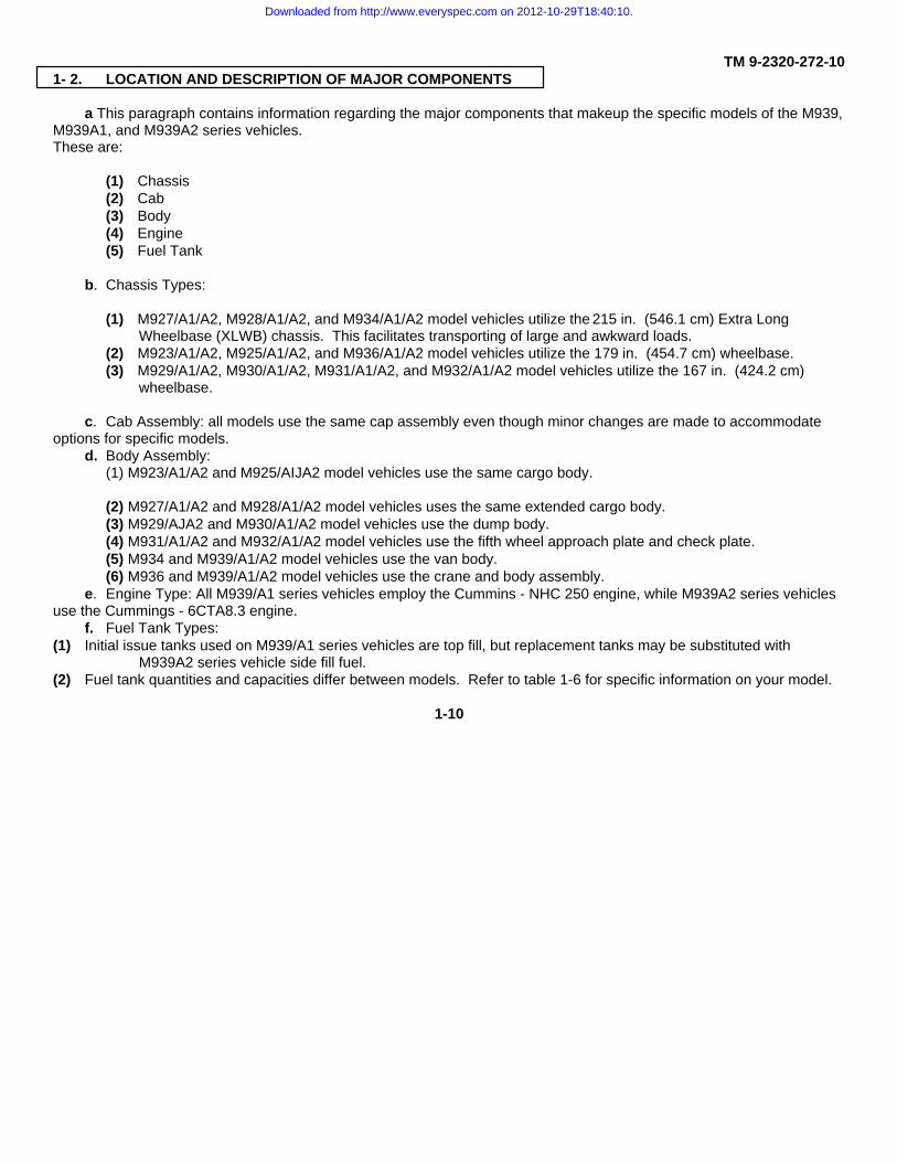
TM 9-2320-272-101- 2. LOCATION AND DESCRIPTION OF MAJOR COMPONENTS
a This paragraph contains information regarding the major components that makeup the specific models of the M939,M939A1, and M939A2 series vehicles.These are:
(1) Chassis(2) Cab(3) Body(4) Engine(5) Fuel Tank
b. Chassis Types:
(1) M927/A1/A2, M928/A1/A2, and M934/A1/A2 model vehicles utilize the 215 in. (546.1 cm) Extra LongWheelbase (XLWB) chassis. This facilitates transporting of large and awkward loads.
(2) M923/A1/A2, M925/A1/A2, and M936/A1/A2 model vehicles utilize the 179 in. (454.7 cm) wheelbase.(3) M929/A1/A2, M930/A1/A2, M931/A1/A2, and M932/A1/A2 model vehicles utilize the 167 in. (424.2 cm)
wheelbase.
c. Cab Assembly: all models use the same cap assembly even though minor changes are made to accommodateoptions for specific models.
d. Body Assembly:(1) M923/A1/A2 and M925/AIJA2 model vehicles use the same cargo body.
(2) M927/A1/A2 and M928/A1/A2 model vehicles uses the same extended cargo body.(3) M929/AJA2 and M930/A1/A2 model vehicles use the dump body.(4) M931/A1/A2 and M932/A1/A2 model vehicles use the fifth wheel approach plate and check plate.(5) M934 and M939/A1/A2 model vehicles use the van body.(6) M936 and M939/A1/A2 model vehicles use the crane and body assembly.
e. Engine Type: All M939/A1 series vehicles employ the Cummins - NHC 250 engine, while M939A2 series vehiclesuse the Cummings - 6CTA8.3 engine.
f. Fuel Tank Types:(1) Initial issue tanks used on M939/A1 series vehicles are top fill, but replacement tanks may be substituted with
M939A2 series vehicle side fill fuel.(2) Fuel tank quantities and capacities differ between models. Refer to table 1-6 for specific information on your model.
1-10
Downloaded from http://www.everyspec.com on 2012-10-29T18:40:10.

TM 9-2320-272-101-12. LOCATION AND DESCRIPTION OF MAJOR COMPONENTS (Contd)
215 IN. (546.1 CM) EXTRA LONG WHEELBASE (XLWB) CHASSIS
(A) FRONT WINCH - Used on M925/A1/A2, M928/A1/A2, M930/A1/A2, M932/A1/A2, and M936/A1A2 model vehicles torecover mired vehicles and in conjunction with A-frame kit for lifting operations.
(B) TILT HOOD - Tilts forward and can be locked open to gain access to engine components.
(C) HOOD LATCHES - Hold hood down when closed.
(D) CANVAS CAB ROOF - Can be folded down to reduce overall height and facilitate use of machine gun mount kit.
(E) WINCH FRAME EXTENSION - Used on winch models to extend frame for mounting of winch.
(F) EXPANSIBLE VAN BODY - Is designed with hardware and electrical attachments to facilitate electronic equipmentoperation or maintenance.
(G) SPARE TIRE DAVIT - Used on M934A1/A2 series vehicles for lifting and lowering spare tire. M934 models use alifting eye located above spare tire.
(H) EXT’ENDED LONG CARGO BODY - Is a fixed side bed designed to carry large awkward loads which will not fit instandard beds.
1-11
Downloaded from http://www.everyspec.com on 2012-10-29T18:40:10.

TM 9-2320-272-101-12. LOCATION AND DESCRIPTION OF MAJOR COMPONENTS (Contd)
179 IN. (454.7 CM) WHEELBASE CHASSIS
(A) REAR VIEW MIRROR - Provides wide angle rear view of both right and left side, and rear sides of vehicle.
(B) REAR BOGIE - Consists of two axles on M939/A1/A2 series vehicles. M939 series vehicles utilize 11:00R20 tires(four per axle), and M939A1/A2 series vehicles utilize 14:00R20 tires (two per axle).
(C) FOLDDOWN WINDSHIELD - Allows for reduction in overall height of vehicle.
(D) HOOD TILTING HANDLE AND LATCH - Used to pull on top front of hood to tilt and latch it in a secure position.
(E) CRANE AND BODY ASSEMBLY - Used on M936/A/A2 model vehicles. Used for recovering disabled and miredvehicles, and lifting operations.
(F) DROPSIDE CARGO BODY - Provides unobstructed access to side for loading with fork lift (M923A1/A2 andM925/A1/A2 model vehicles).
1-12
Downloaded from http://www.everyspec.com on 2012-10-29T18:40:10.

TM 9-2320-272-101-12. LOCATION AND DESCRIPTION OF MAJOR COMPONENTS (Contd)
167 IN. (424.2 CM) WHEELBASE CHASSIS
(G) FIFTH WHEEL APPROACH PLATE AND DECK PLATE - Used on M93VA/A2 and M932/A1/A2 model vehicles.Provides mechanical connection between semitractor and semitrailer.
(H) SPARE TIRE AND MOUNTING BRACKET - Provides storage location for spare tire.
(I) SPARE TIRE DAVIT - Used for lifting and lowering tire. Use on M923/A1/A2, M925/A1/A2, M927/A1/A2,M928/A1/A2, M931/A1/A2, and M932/A1/A2 model vehicles.
(J) FUEL TANK - Second tank for vehicles equipped with dual tank capacity.
(K) DUMP BODY - Used on M929/A1/A2 and M930/A1/A2 model vehicles for carrying various loads over differentterrains.
(L) SPARE TIRE LIFTING EYE - Used for lifting and lowering spare tire on M929/A/A2 and M930/A1/A2 model vehicles.
(M) FUEL TANK - Used on all vehicles for storage of fuel.
1-13
Downloaded from http://www.everyspec.com on 2012-10-29T18:40:10.

TM 9-2320-272-10
1-13. DIFFERENCE BETWEEN MODELS
Table 1-1. Differences Between Models.
1-14
Downloaded from http://www.everyspec.com on 2012-10-29T18:40:10.

TM 9-2320-272-10
1-13. DIFFERENCE BETWEEN MODELS (Contd)
Table 1-1. Differences Between Models (Contd).
1-15
Downloaded from http://www.everyspec.com on 2012-10-29T18:40:10.

TM 9-2320-272-10
1-14. EQUIPMENT DATA
a. General. This paragraph organizes vehicle specifications, special equip-ment, and model differences in table formfor easy reference by operators.
b. Specifications.
(1) Winch and Crane Data. See table 1-2.
(2) Vehicle Dimensions. See table 1-3.
(3) Weights. See table 1-4.
(4) Chassis Dimensions. See table 1-5.
(5) Capacities for Normal Operating Conditions. See table 1-6.
(6) General Service Data. See table 1-7.
(7) Engine and Cooling System Data. See table 1-8.
(8) Automatic Transmission Data. See table 1-9.
(9) Tire Inflation Data. See table 1-10.
(10) Shipping Dimensions. See table 1-11.
Table 1-2. Winch and Crane Data.
1-16
Downloaded from http://www.everyspec.com on 2012-10-29T18:40:10.

TM 9-2320-272-10Table 1-3. Vehicle Dimensions
1-17
Downloaded from http://www.everyspec.com on 2012-10-29T18:40:10.

TM 9-2320-272-10Table 1-4. Weights.
1-18
Downloaded from http://www.everyspec.com on 2012-10-29T18:40:10.

TM 9-2320-272-10Table 1-5. Chassis Dimensions.
1-19
Downloaded from http://www.everyspec.com on 2012-10-29T18:40:10.

TM 9-2320-272-10
WARNING
Accidental or intentional introduction of liquid contaminants into the environment is in violation of state,federal, and military regulations. Refer to Lubrication Order (para. 31) for information concerning storage,use, and disposal of these liquids. Failure to do so may result in injury or death.
Table 1-6. Capacities for Normal Operating Conditions.
1-20
Downloaded from http://www.everyspec.com on 2012-10-29T18:40:10.
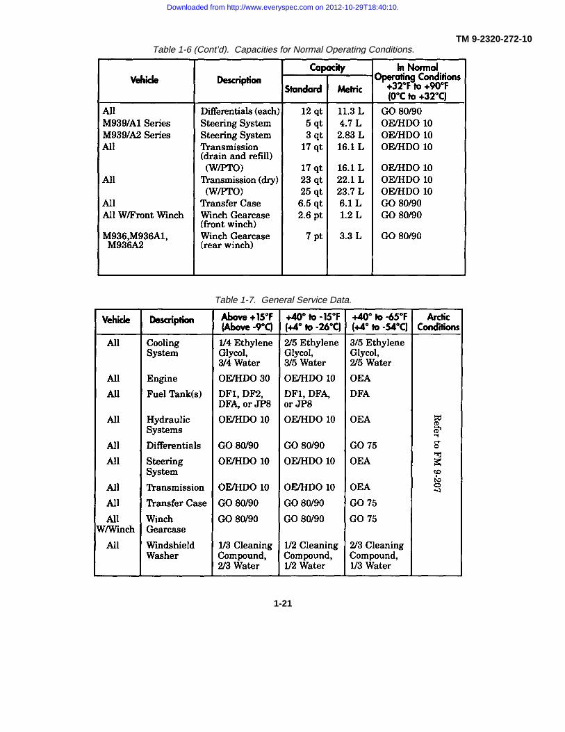
TM 9-2320-272-10Table 1-6 (Cont’d). Capacities for Normal Operating Conditions.
Table 1-7. General Service Data.
1-21
Downloaded from http://www.everyspec.com on 2012-10-29T18:40:10.

TM 9-2320-272-10Table 1-8. Engine and Cooling System Data.
1-22
Downloaded from http://www.everyspec.com on 2012-10-29T18:40:10.

TM 9-2320-272-10
Table 1-9. Automatic Transmission Data.
TRANSMISSION (MT654)
Oil Type . . . . . . . . . . . . . . . . . . . . . . . . . . . . . . . . . . . . . . . . . . . . . . OE/HDO-10Oil Capacity:
WO/PTO (drain and refill) . . . . . . . . . . . . . . . . . . . . . . 4.25 gal. (16.1 L)W/PTO (drain and refill) . . . . . . . . . . . . . . . . . . . . . . . . 4.25 gal. (16.1 L)WO/PTO (dry) . . . . . . . . . . . . . . . . . . . . . . . . . . . . . . . . 5.75 gal. (21.8 L)W/PTO (dry) . . . . . . . . . . . . . . . . . . . . . . . . . . . . . . . . . . 6.25 gal. (23.7 L)
Oil Temperature:Maximum . . . . . . . . . . . . . . . . . . . . . . . . . . . . . . . . . . . . . . . . . . 300°F(149°C)Normal Operating Temperature . . . . . . . . . . . . . . . . . . 120°-220°F (49°-104°C)
Power Takeoff . . . . . . . . . . . . . . . . . . . . . . . . . . . . . . . . . . . . . . Converter driven
TRANSMISSION DRIVING RANGE SELECTION
RangeSelection
Condition
R (reverse)
N (neutral)1-5 (drive)
1-4 (fourth)
1-3 (third)
1-2 (second)
1 (first)
Easy grades clear of trafficwith ground guide
Maximum Operating SpeedsW/Transfer Case
M939 M939A1 andSeries M939A2 Series
In High In Low In High In Low
5 mph 5 mph(8 km/h) (8 km/h)
Good roads, grades, trafficconditionsModerate grades, trafficrestricted speed limitsModerate grades, heavy traffic,restricted speed limitsSteep grades, heavy trafiic,rough terrainStarting heavy loads, extremegrades, rough terrain
- -
50 mph 22 mph(80 km/h) (35 km/h)43 mph 17 mph
(69 km/h) (27 km/h)33 mph 13 mph
(53 km/h) (21 km/h)25 mph 10 mph
(40 km/h) (16 km/h)12 mph 5 mph
(19 km/h) (8 km/h)
- -
50 mph 26 mph(80 km/h) (42 km/h)50 mph 20 mph
(80 km/h) (32 km/h)38 mph 16 mph
(61 km/h) (26 km/h)29 mph 12 mph
(47 km/h) (19 km/h)15 mph 6 mph
(24 km/h) (10 km/h)
Table 1-9A. Maximum Safe Operating Speeds Table.
Maximum Side Operating Speeds:
Highway and Secondary Roads
Cross Country Roads
Sand and Snow
Icy Conditions
40 Miles per Hour
35 Miles per Hour
25 Miles per Hour
12 Miles per Hour
Change 1 1-23
Downloaded from http://www.everyspec.com on 2012-10-29T18:40:10.

TM 9-2320-272-10
Table 1-10. Tire Inflation Data.
1-24
Downloaded from http://www.everyspec.com on 2012-10-29T18:40:10.

TM 9-2320-272-10
Table 1-10. Tire Inflation Data (Contd).
M923 M925 M297 M928 M929 M930 M931 M932 M934 M936
M939A 1/A2 SERIES(14:00 X R20)
HIGHWAY
FRONT AND REARStandard (psi) 60 60 60 60 60 60 60 60 60 80Metric (kPa) 414 414 414 414 414 414 414 414 414 551
CROSS COUNTRY
FRONT AND REARStandard (psi) 35 35 35 35 35 35 35 35 35 35Metric (kPa) 241 241 241 241 241 241 241 241 241 241
MUD, SAND, AND SNOW
FRONT AND REARStandard (psi) 25 25 25 25 25 25 25 25 25 25Metric (kPa) 172 172 172 172 172 172 172 172 172 172
EMERGENCY
FRONT AND REARStandard (psi) 12 12 12 12 12 12 12 12 12 12Metric (kPa) 83 83 83 83 83 83 83 83 83 83
ALL MODELS:
SPARE
inflate to maximum - - - - - - - - - -highway pressure
1-25
Downloaded from http://www.everyspec.com on 2012-10-29T18:40:10.

TM 9-2320-272-10
Table 1-11. Shipping Dimensions.
Vehicle Shippingin
Heightcm
Shippinglb
Weightkg
Shippingcu. ft.
Cubagecu. m.
ShippingTons
TonnageMetric Ton
M923 91.2 231.6 21,600 9,806 1,581.0 447.4 10.8 9.8M923A1 93.9 238.5 22,175 10,067 1,644.0 465.3 11.1 10.1M923A2 93.9 238.5 20,930 9,502 1,644.0 465.3 10.5 9.5M925 91.2 231.6 22,360 10,151 1,692.0 478.8 11.2 10.1M925A1 93.9 238.5 23,275 10,567 1,758.0 497.5 11.6 10.6M925A2 93.9 238.5 22,030 10,002 1,758.0 497.5 11.0 10.0M927 91.0 231.1 27,749 12,598 1,970.0 557.5 13.9 12.6M927A1 93.5 237.5 25,035 11,366 2,032.0 575.1 12.5 11.4M927A2 93.5 237.5 23,790 10,801 2,032.0 575.1 11.9 10.8M928 91.0 231.1 27,811 12,626 2,078.0 588.1 13.9 12.6M928A1 93.5 237.5 26,135 11,865 2,151.0 608.7 13.1 11.9M928A2 93.5 237.5 24,890 11,300 2,151.0 608.7 12.4 11.3M929 90.3 229.4 25,888 11,753 1,391.0 393.7 12.9 11.7M929A1 93.5 237.5 25,065 11,380 1,441.0 407.8 12.5 11.4M929A2 93.5 237.5 23,820 10,814 1,441.0 407.8 11.9 10.8M930 90.3 229.4 26,624 12,087 1,501.0 424.8 13.3 12.1M930A1 93.5 237.5 26,165 11,879 1,552.0 439.2 13.1 11.9M930A2 93.5 237.5 24,920 11,314 1,552.0 439.2 12.5 11.3M931 91.4 232.2 22,089 10,028 1,364.0 386.0 11.0 10.0M931A1 94.1 239.0 21,140 9,598 1,403.0 397.0 10.6 9.6M931A2 94.1 239.0 19,895 9,032 1,403.0 397.0 9.9 9.0M932 91.4 232.2 22,841 10,370 1,475.0 417.4 11.4 10.4M932A1 94.1 239.0 22,242 10,098 1,517.0 429.3 11.1 10.1M932A2 94.1 239.0 20,995 9,532 1,517.0 429.3 10.5 9.5M934 138.0 350.5 29,946 13,595 2,838.0 803.2 15.0 13.6M934A1 142.3 361.4 29,280 13,293 2,925.0 827.8 14.6 13.3M934A2 142.3 361.4 28,035 12,728 2,925.0 827.8 14.0 12.7M936 114.7 291.3 39,334 17,858 2,174.0 615.2 19.7 17.8M936A1 108.5 275.6 38,155 17,322 2,203.0 623.4 19.1 17.3M936A2 108.5 275.6 36,910 16,757 2,203.0 623.4 18.5 16.7
1-26
Downloaded from http://www.everyspec.com on 2012-10-29T18:40:10.

TM 9-2320-272-10
Section III. PRINCIPLES OF OPERATION
1-15. GENERAL
This section explains how components of the 5-ton M939/A1/A2 series vehicles work together. A functionaldescription of these components and their related parts will be covered in the following paragraphs. To find the operationof a specific system or component, see the principles of operation reference index below.
1-16. PRINCIPLES OF OPERATION REFERENCE INDEX
PARA. TITLE PAGENO. NO.
1-17 Control System Operation 1-271-18 Power System Operation 1-361-19 Electrical Systems Operation 1-471-20 Compressed Air and Brake System Operation 1-571-21 Hydraulic System Operation 1-73
1-17. CONTROL SYSTEM OPERATION
The control system includes those controls and their related parts that are essential to the operation of the vehicle.These controls are common to all vehicles with the exception of the transmission and transfer case power takeoff controls.All originate from the cab. Each of these controls and their related parts will be described as part of the following systems:
a. Starting and Ether Starting System Operation (page 1-28).b. Accelerator Controls System Operation (page 1-30).c. Parking Brake System Operation (page 1-31).d. Steering System Operation (page 1-32).e. Transmission Control System Operation (page 1-33).f. Transfer Case Control System Operation (page 1-34).
1-27
Downloaded from http://www.everyspec.com on 2012-10-29T18:40:10.

TM 9-2320-272-10
1-17. CONTROL SYSTEM OPERATION (Contd)
a. Starting and Ether Starting System Operation.
The starting system is identical on all models covered in this manual. It will start the engine in all types of weatherand has built-in protection that prevents starting components from reengaging once the engine has been started. Majorcomponents of the starting and ether starting system are:
A HAND THROTTLE CONTROL - Used to set engine speed without applying pressure to the accelerator(rotated to lock).
B BATTERY SWITCH - Activates all electrical circuits except arctic heaters.
C IGNITION SWITCH - Has OFF, RUN, and START positions. Switch automatically returns from START toRUN when hand pressure is released.
D TACHOMETER - Used to indicate speed of engine.
E VOLTMETER - Indicates charging condition of the battery.
F EMERGENCY ENGINE STOP - Used to shut down engine during emergencies (M934/A1 series vehiclesmust be reset by unit maintenance).
G ETHER START SWITCH - Injects ether into engine for cold weather starting.
1-28
Downloaded from http://www.everyspec.com on 2012-10-29T18:40:10.

TM 9-2320-272-10
1-17. CONTROL SYSTEM OPERATION (Contd)
H PROTECTIVE CONTROL BOX - Prevents reengagement of starter motor once engine is running.
I BATTERIES - Provide 24-volt electrical current for energizing electrical circuits.
J STARTER SOLENOID - Relays 24-volt battery power to energize starter motor.
K STARTER MOTOR - When energized, it converts electrical energy to mechanical power as it engages theflywheel to crank engine.
L ETHER START CYLINDER - Stores ether used for cold weather starting.
1-29
Downloaded from http://www.everyspec.com on 2012-10-29T18:40:10.

TM 9-2320-272-10
1-17. CONTROL SYSTEM OPERATION (Contd)
b. Accelerator Controls System Operation.The accelerator controls system permits the operator to control vehicle speed and engine power. It is identical on
all models covered in this manual. Major components of the accelerator control system are:
A HAND THROTTLE CONTROL - Sets engine speed at desired rpm without maintaining pressure onaccelerator pedal.
B EMERGENCY ENGINE STOP CONTROL - Is pulled out to cut off fuel to engine. It is used only in anemergency.
C ACCELERATOR PEDAL - Controls engine speed.
D MODULATOR - With transmission selector lever in drive, modulator controls transmission upshifting anddownshifting as engine rpm changes.
E CABLE - Connects modulator to fuel pump.
F ACCELERATOR LINKAGE - Links accelerator pedal and throttle control to fuel pump.
1-30
Downloaded from http://www.everyspec.com on 2012-10-29T18:40:10.
TM 9-2320-272-10
1-17. CONTROL SYSTEM OPERATION (Contd)
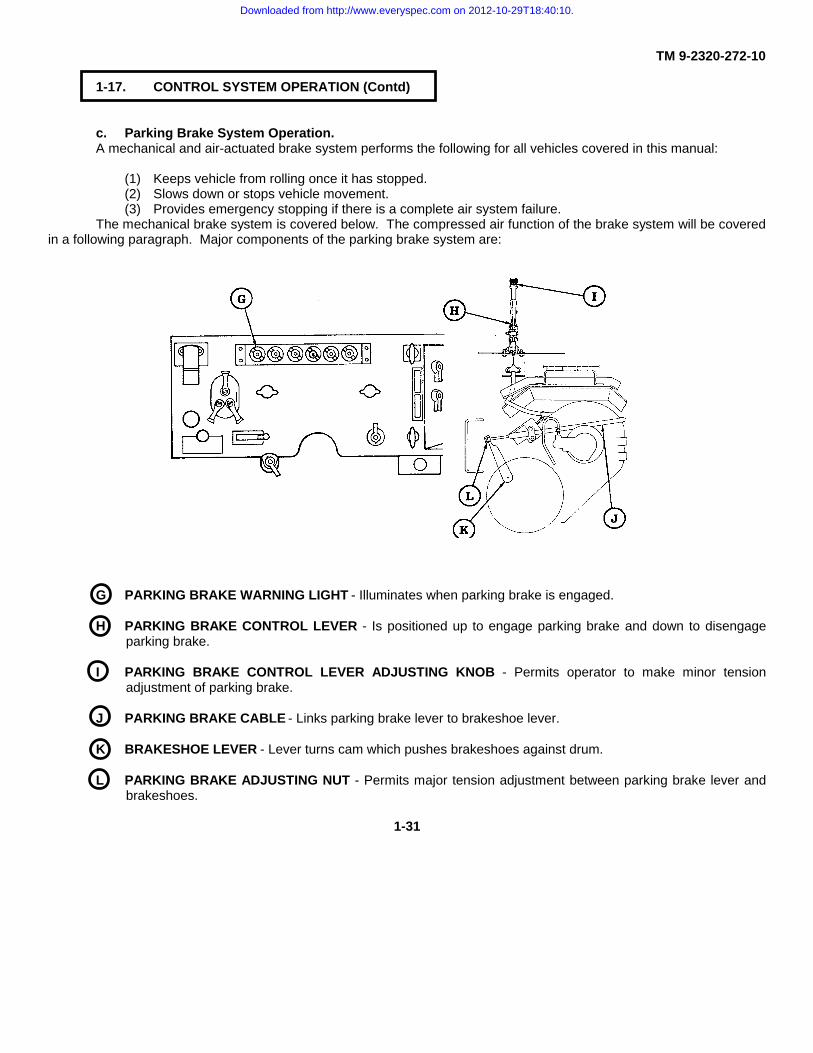
c. Parking Brake System Operation.A mechanical and air-actuated brake system performs the following for all vehicles covered in this manual:
(1) Keeps vehicle from rolling once it has stopped.(2) Slows down or stops vehicle movement.(3) Provides emergency stopping if there is a complete air system failure.
The mechanical brake system is covered below. The compressed air function of the brake system will be coveredin a following paragraph. Major components of the parking brake system are:
G PARKING BRAKE WARNING LIGHT - Illuminates when parking brake is engaged.
H PARKING BRAKE CONTROL LEVER - Is positioned up to engage parking brake and down to disengageparking brake.
I PARKING BRAKE CONTROL LEVER ADJUSTING KNOB - Permits operator to make minor tensionadjustment of parking brake.
J PARKING BRAKE CABLE - Links parking brake lever to brakeshoe lever.
K BRAKESHOE LEVER - Lever turns cam which pushes brakeshoes against drum.
L PARKING BRAKE ADJUSTING NUT - Permits major tension adjustment between parking brake lever andbrakeshoes.
1-31
Downloaded from http://www.everyspec.com on 2012-10-29T18:40:10.

TM 9-2320-272-10
1-17. CONTROL SYSTEM OPERATION (Contd)
d. Steering System Operation.The steering system is identical for all models covered in this manual. It is a hydraulically assisted system that
provides ease of turning and control for the operator. Major components of the steering system are:
A OIL RESERVOIR AND STEERING PUMP - Combined in one unit, the reservoir serves as an oil fill point andthe pump creates pressure.
B ACCESSORY DRIVE BELTS - Transmits mechanical power from accessory drive pulley to steering pumppulley to drive the steering pump.
C STEERING WHEEL - Serves ’as manual steering control for the operator.
D STEERING COLUMN UNIVERSAL JOINT - Connects, at an angle, the steering wheel column and inputshaft of power steering gear.
E POWER STEERING ASSIST CYLINDER - Receives hydraulic pressure from the steering gear to assist inturning the front wheels.
F STEERING KNUCKLE - Serves as the pivot point and link for the front wheels from the tie rod assembly.
G TIE ROD ASSEMBLY - Connects steering knuckles so both wheels will turn at the same time.
H STEERING ARM - Connects drag link to steering knuckle.
I DRAG LINK - Transmits movement from steering arm to pitman arm.
J PITMAN ARM - Transfers torque from power steering gear to drag link.
K STEERING GEAR - Converts hydraulic pressure from steering pump to mechanical power at pitman arm.
1-32
Downloaded from http://www.everyspec.com on 2012-10-29T18:40:10.

TM 9-2320-272-10
1-17. CONTROL SYSTEM OPERATION (Contd)
e. Transmission Control System Operation.The transmission control system permits shifting of transmission, prevents starting of engine with transmission in
gear, and prevents shifting of transfer case unless transmission is in neutral. This system also permits engagement of theTransmission Power Takeoff (PTO) to provide hydraulic power for auxiliary equipment on M925/A1/A2, M928/A1/A2,M929/A1/A2, M930/A1/A2, M932/A1/A2 and M936/A1/A2 vehicles. Major components of the transmission control systemare:
L TRANSMISSION SELECTOR LEVER - Is used to select vehicle driving gear range.
M POWER TAKEOFF CONTROL LEVER - Engages transmission power takeoff to provide power for auxiliaryequipment.
N TRANSMISSION CONTROL SWITCH - Actuates transmission lock-up solenoid valve when transmissionselector lever is placed in neutral and transfer case shift lever lock-out switch is pressed.
O TRANSMISSION NEUTRAL START SWITCH - The neutral start switch, wired to the starter switch, preventsthe engine from being started with transmission in gear.
P TRANSMISSION 5TH-GEAR LOCKUP SOLENOID VALVE - Activated by transmission control switch andtransfer case switch, the 5th-gear lockup solenoid valve directs main oil pressure of transmission to thetransmission governor system. This puts the transmission in 5th-gear, creating less drag on the transfercase synchronizer which permits smoother shifting from one transfer case drive range to another. Refer toparagraph 1-17f, Transfer Case Control System Operation, for further details.
Q TRANSMISSION POWER TAKEOFF (PTO) - Driven by the transmission, the PTO drives the hydraulic pumpwhich provides hydraulic pressure to power the front winch on M925/A1/A2, M928/A1/A2, M930/A1/A2,M932/A1/A2, and M936/A1/A2 vehicles, and to power the dump body on M929/AVA2 and M930/A1/A2vehicles. The PTO is mounted on the right front side of the transmission.
1-33
Downloaded from http://www.everyspec.com on 2012-10-29T18:40:10.

TM 9-2320-272-10
1-17. CONTROL SYSTEM OPERATION (Contd)
f. Transfer Case Control System Operation.The transfer case control system converts four-wheel driving power into six-wheel driving power, provides smooth
shifting of transfer case into high or low driving ranges while vehicle is in motion, prevents transfer case from being shiftedwith transmission in gear, and provides hydraulic power for auxiliary equipment through a Power Takeoff (PTO).
(1) Six-wheel drive is achieved two different ways depending on the drive range (high or low) desired. In lowrange, the transfer case shift linkage automatically moves a cam-actuated valve which dumps air intothe front drive cylinder. This forces a piston against the transfer case clutch to engage front-wheeldrive. In high range, front-wheel drive is engaged in the same manner except that the front-wheel drivevalve is manually actuated by the front-wheel drive lock-in switch on the instrument panel.
(2) In order to shift the transfer case from one driving range to another, an interlock system working inconjunction with the 5th-gear lock up solenoid is used. This system prevents the transfer case formbeing shifted unless the transmission is in neutral.
(3) With the automatic transmission, several actions must occur in order to shift the transfer case from onedriving range to another. Because of the interlock system, the transmission must be placed in neutral.The transfer case shift lever switch must also be depressed.
(4) The transfer case control system, through the use of a PTO driven by the transfer case, also provideshydraulic power to operate the crane and rear winch on the M936/A1/A2 wreckers.
(5) Major components of this system are:
1-34
Downloaded from http://www.everyspec.com on 2012-10-29T18:40:10.

TM 9-2320-272-10
1-17. CONTROL SYSTEM OPERATION (Contd)
A TRANSFER CASE SHIFT LEVER SWITCH - When depressed with transmission in neutral, signals interlocksolenoid valve to exhaust air pressure from interlock air cylinder and actuates lock-up solenoid.
B TRANSFER CASE SHIFT LEVER - Is pushed down to high for light load operations, and up to low for heavyload operations. Six-wheel drive is achieved automatically when transfer case shift lever is placed in low.
C TRANSFER CASE POWER TAKEOFF CONTROL LEVER - Manual control for engaging power takeoff.
D TRANSFER CASE POWER TAKEOFF - Mounted and mechanically driven at rear of transfer case, the PTOdrives a pump to supply hydraulic pressure to power the rear winch and crane on the M936/A1/A2 wreckers.
E FRONT-WHEEL DRIVE LOCK-IN SWITCH - Manual control for activating front-wheel drive valve to providefront-wheel drive with transfer case in high drive range.
F INTERLOCK AIR CYLINDER - Under air pressure, a piston in the interlock air cylinder forces a shaft againstone of three grooves in transfer case shift lever. This prevents transfer case from being shifted withtransmission in gear.
G INTERLOCK SOLENOID VALVE - Releases air from interlock air cylinder when transmission is in neutraland transfer case shift lever switch is depressed. This permits the transfer case high/low shift shaft to move.
H FRONT-WHEEL DRIVE AIR CYLINDER - When under pressure, it moves transfer case clutch forward toengage front-wheel drive.
I FRONT-WHEEL DRIVE VALVE - When tripped by transfer case shift shaft, the front wheel drive valve routesair to front-wheel drive air cylinder.
1-35
Downloaded from http://www.everyspec.com on 2012-10-29T18:40:10.

TM 9-2320-272-10
1-18. POWER SYSTEM OPERATION
The power system includes those components’ that give all vehicles covered in this manual the power to move.Each of these components will be described as part of the following subsystems:
a. Air Intake System Operation (page 1-36).b. Fuel System (Dual Tank) Operation (page 1-38).c. Fuel System (Single Tank) Operation (page 1-40).d. Exhaust System Operation (page 1-41).e. Cooling System Operation (page 1-42).f. Engine Oil System Operation (page 1-44).g. Powertrain System Operation (page 1-46).a. Air Intake System Operation.
The air intake system channels and cleans air going to the combustion chamber where it mixes with fuel from theinjectors to provide power for the engine. This system is identical on all models, except where indicated. Majorcomponents of the air intake system are:
1-36
Downloaded from http://www.everyspec.com on 2012-10-29T18:40:10.

TM 9-2320-272-10
1-18. POWER SYSTEM OPERATION (Contd)
A RAIN CAP - Prevents rain and large objects from entering air intake system.
B AIR INTAKE EXTENSION TUBE - Routes air to air intake system. Can be removed for shipping.
C STACK-TO-AIR INTAKE EXTENSION TUBE - Routes air to air cleaner and is high enough to keep intakeopening above fording level.
D STACK-TO-AIR CLEANER ELBOW - Flexible connection between air stack and air cleaner.
E AIR CLEANER - Filters dirt and dust from air.
F HUMP HOSE - Flexible connection between air cleaner and air cleaner outlet tube.
G AIR CLEANER OUTLET TUBE - Routes air from air cleaner to intake manifold.
H INTAKE MANIFOLD - Distributes air to combustion chambers in each cylinder head (M939/A1 series only).
I AIR CLEANER INDICATOR - Shows red when engine air filter needs servicing.
J TURBOCHARGER - Mounts on exhaust manifold and uses spent exhaust gases to dive impeller andpressurize air entering aftercooler (M939A2 series only).
K AFTERCOOLER - Distributes compressed air from turbocharger to combustion chambers while cooling airintake out of the turbocharger (M939A2 series only).
1-37
Downloaded from http://www.everyspec.com on 2012-10-29T18:40:10.

TM 9-2320-272-10
1-18. POWER SYSTEM OPERATION (Contd)
b. Fuel System (Dual Tank) Operation.
(1) The fuel system stores, cleans, and supplies fuel to the fuel injectors where it is mixed with air to initiateengine combustion.
(2) The fuel system is not identical for all models. Vehicles covered in this manual have either one or twotanks. These tanks can also differ in capacity. See table 1-6, Capacities for Normal OperatingConditions, for these differences.
(3) A typical two-tank fuel system is described below. A single tank is described later in paragraph 1-18c.Both systems include fuel supply, return, and vent lines to provide fuel flow and release the fumesthroughout the system. Major components of fuel system (dual tank) are:
A RIGHT TANK (FRONT) VENT LINE - Vents vapors from fuel tank to vent hole in air intake stack.
B RIGHT TANK FILLER CAP - Covers fuel filler opening on right fuel tank.
1-38
Downloaded from http://www.everyspec.com on 2012-10-29T18:40:10.

TM 9-2320-272-10
1-18. POWER SYSTEM OPERATION (Contd)
C RIGHT FUEL TANK - Stores fuel for vehicle use.
D RIGHT TANK FUEL RETURN LINE - Returns unused fuel back to fuel tank.
E RIGHT TANK (REAR) VENT LINE - Vents vapors from fuel tank to vent hole in air intake stack.
F RIGHT TANK FUEL SUPPLY LINE - Directs fuel from tank to fuel filter.
G RIGHT TANK FUEL LEVEL SENDING UNIT - Electrical signal registers fuel level in right tank at gauge oninstrument panel.
H LEFT TANK FUEL LEVEL SENDING UNIT - Electrical signal registers fuel level in left tank at gauge oninstrument panel.
I LEFT TANK FUEL SUPPLY LINE - Directs fuel from tank to fuel filter.
J LEFT FUEL TANK - Stores fuel for vehicle use.
K LEFT TANK (REAR) VENT LINE - Vents vapors from fuel tank to vent hole in air intake stack.
L LEFT TANK FILLER CAP - Covers fuel filler opening on left fuel tank.
M LEFT TANK FUEL RETURN LINE - Returns unused fuel back to fuel tank.
N LEFT TANK (FRONT) VENT LINE - Vents vapors from fuel tank to vent hole in air intake stack.
O FUEL SELECTOR VALVE - Manual control valve that opens fuel flow to engine from left or right fuel tank.
P FUEL FILTER/WATER SEPARATOR - Filters water and dirt from fuel.
Q FUEL FILTER-TO-PUMP SUPPLY LINE - Directs fuel from fuel filter to fuel pump.
R FUEL RETURN LINE - Returns unused fuel back to fuel tanks.
S FUEL PUMP - Draws fuel from tank(s) and pumps it through supply line to fuel injectors.
T FUEL SUPPLY LINE - Directs fuel from fuel pump to fuel injectors.
U FUEL PRIMER PUMP - Purges air from fuel system.
1-39
Downloaded from http://www.everyspec.com on 2012-10-29T18:40:10.

TM 9-2320-272-10
1-18. POWER SYSTEM OPERATION (Contd)
c. Fuel System (Single Tank) Operation.Major components of the fuel system (single tank) are:
A TANK (REAR) VENT LINE - Vents vapors from fuel tank to vent hole in air intake stack.
B TANK FILLER CAP - Covers fuel fill opening.
C FUEL TANK - Stores fuel for vehicle use.
D FUEL TANK LEVEL SENDING UNIT - Electrical signal registers fuel level in tank at gauge on instrumentpanel.
E TANK (FRONT) VENT LINE - Vents vapors from fuel tank to vent hole in air intake stack.
F FUEL FILTER/WATER SEPARATOR - Filters water and dirt from fuel.
G FUEL RETURN LINE - Returns unused fuel back to fuel tank.
H FUEL PUMP - Draws fuel from tank and pumps it through supply line to fuel injectors.
I FUEL SUPPLY LINE - Directs fuel from fuel pump to fuel injectors.
J FUEL PRIMER PUMP - Purges air from fuel system.
1-40
Downloaded from http://www.everyspec.com on 2012-10-29T18:40:10.
TM 9-2320-272-10
1-18. POWER SYSTEM OPERATION (Contd)
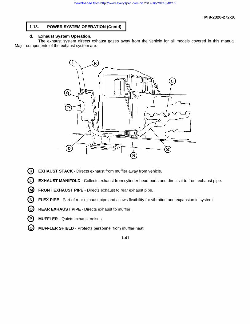
d. Exhaust System Operation.The exhaust system directs exhaust gases away from the vehicle for all models covered in this manual.
Major components of the exhaust system are:
K EXHAUST STACK - Directs exhaust from muffler away from vehicle.
L EXHAUST MANIFOLD - Collects exhaust from cylinder head ports and directs it to front exhaust pipe.
M FRONT EXHAUST PIPE - Directs exhaust to rear exhaust pipe.
N FLEX PIPE - Part of rear exhaust pipe and allows flexibility for vibration and expansion in system.
O REAR EXHAUST PIPE - Directs exhaust to muffler.
P MUFFLER - Quiets exhaust noises.
Q MUFFLER SHIELD - Protects personnel from muffler heat.
1-41
Downloaded from http://www.everyspec.com on 2012-10-29T18:40:10.

TM 9-2320-272-10
1-18. POWER SYSTEM OPERATION (Contd)
e. Cooling System Operation.This system provides cooling of the engine and transmission. It differs slightly between the M939/A1 series
and M939A2 series vehicles because different engines are used. Major components of the cooling system are:
1-42
Downloaded from http://www.everyspec.com on 2012-10-29T18:40:10.

TM 9-2320-272-10
1-18. POWER SYSTEM OPERATION (Contd)
A SURGE TANK - Filling point for cooling system. On M939A2 vehicles, a float sensor monitors water leveland illuminates a light on instrument panel.
B COOLANT PRESSURE CAP - Designed to depressurize cooling system and to access cooling system forfilling.
C WATER MANIFOLD - Collects coolant from cylinder heads and directs it to the thermostat housing (M939/A1series only).
D SURGE TANK-TO-WATER MANIFOLD VENT - Vents air trapped in water manifold (M939/A1 series only).
E SURGE TANK-TO-RADIATOR VENT - Vents air in cooling system.
F THERMOSTAT - Shuts off coolant flow to radiator until temperature reaches 175°F (79°C) on M939/A1series vehicles, and 181°F (83°C) on M939A2 series vehicles. Coolant is then directed to the radiatorthrough the radiator inlet hose.
G RADIATOR INLET HOSE - Directs coolant from water manifold to radiator after thermostat has opened.
H BYPASS TUBE - Directs coolant back to transmission oil cooler where it is then recirculated through theengine block until the thermostat opens.
I RADIATOR SHROUD - Concentrates air flow through the radiator.
J RADIATOR - Directs coolant through a series of fins or baffles so outside air can remove excessive heatfrom coolant.
K FAN CLUTCH - Regulates use of fan to control engine temperature fan to belt driven pulley when conditionsrequire additional cooling.
L WATER PUMP - Provides force to move coolant through engine.
M FAN - Provides force to pull air through radiator.
N RADIATOR DRAINVALVE - Permits coolant to be drained from radiator.
O TRANSMISSION OIL COOLER HOSE - Directs coolant to transmission oil cooler.
P ENGINE OIL COOLER - Reduces heat of engine oil (M939/A1 series only).
Q TRANSMISSION OIL COOLER - Reduces heat of transmission oil.
R ENGINE OIL COOLER TO HEATER HOSE - Directs coolant to personnel water heater when shutoff valve isopen (M939/A1 series only).
S PERSONNEL WATER HEATER - Provides heat for cab and personnel.
1-43
Downloaded from http://www.everyspec.com on 2012-10-29T18:40:10.

TM 9-2320-272-10
1-18. POWER SYSTEM OPERATION (Contd)
f. Engine Oil System Operation.The engine oil system provides lubricating oil for internal moving parts. Major components of the engine oil
system are:
1-44
Downloaded from http://www.everyspec.com on 2012-10-29T18:40:10.

TM 9-2320-272-10
1-18. POWER SYSTEM OPERATION (Contd)
A OIL DIPSTICK - Indicates engine oil level.
B CRANKCASE BREATHER - Vents hot engine oil fumes from engine and allows fresh air to enter.
C ENGINE OIL COOLER - Removes heat from engine oil as coolant circulates through internal tubes of oilcooler.
D OIL FILTER - Filters out foreign particals suspended in oil.
E OIL FILLER CAP - Located on rocker lever cover, cap covers engine oil fill opening.
F OIL PRESSURE TRANSMITTER - Sends an electrical signal that indicates engine oil pressure to gauge oninstrument panel.
G OIL PAN DRAINPLUG - Plugs engine oil drain opening.
H OIL PAN - Reservoir for engine oil.
I OIL SUPPLY LINE - Carries oil from oil pan to the oil pump.
J OIL BYPASS RETURN LINE - Returns oil from oil pump to the oil pan.
K OIL PUMP - Provides mechanical pressurization of oil to circulate it through the oil system.
1-45
Downloaded from http://www.everyspec.com on 2012-10-29T18:40:10.

TM 9-2320-272-10
1-18. POWER SYSTEM OPERATION (Contd)
g. Powertrain System Operation.The powertrain system is the same on all models in this manual except the extra-long wheelbase models
which have an additional propeller shaft and center bearing. This system transmits engine power to the axles to put thevehicle in motion. Major components of the powertrain system are:
A ENGINE - Provides power needed for powertrain component operation.
B TRANSMISSION - Adapts engine power to meet different driving conditions.
C CENTER BEARING - Provides support for propeller shaft to decrease vibration and wear on universal joints(M927/A1/A2, M928/A1/A2, and M934/A1/A2 series only).
D TRANSFER CASE - Distributes power evenly to front and rear axles.
E UNIVERSAL JOINTS - Connections between two propeller shafts that permit one to drive the other eventhough they may be at different angles.
F DIFFERENTIALS - Distribute power to left and right axle shafts.
G AXLES - Transmit power from differentials to rotate wheels.
H PROPELLER SHAFTS - Serve as driving shafts that connect the transmission to the transfer case and thetransfer case to the differentials.
1-46
Downloaded from http://www.everyspec.com on 2012-10-29T18:40:10.
TM 9-2320-272-10
1-19. ELECTRICAL SYSTEMS OPERATION
Nearly every component of the models covered in this manual is affected by the electrical system. Thesecomponents and their electrical connections are described as part of the following electrical subsystems:
a. Battery System Operation (page 1-48).b. Starting System Operation (page 1-49).c. Ether Starting System Operation (page 1-50).d. Generating System Operation (page 1-51).e. Directional Signal System Operation (page 1-52).f. Heating System Operation (page 1-53).g. Indicator, Gauge, and Warning System Operation (page 1-54).h. Trailer and Semitrailer Connection System Operation (page 1-56).
Electrical Terms and Definitions.
The following electrical terms and definitions will be frequently referred to throughout this section and shouldbe understood before proceeding:
Alternating Current (AC signal) - Current in a circuit that flows, in one direction first, then in the other direction.
Circuit - A complete path for electric current flow between components.
Circuit Breaker - An automatic switch that interrupts current flow in a circuit when the current limit is exceeded.
Direct Current (DC signal) - Current in a circuit that flows in one direction.
Female Connector - One-half of a connector which fits over the other half.
Ground - A common return to complete a path for current flow in a circuit.
Harness - A group of wires connected between devices that are bundled and routed together to prevent damage andmake repair and replacement easier.
Male Connector - One-half of a connector which fits the other half.
Polarity - The direction current flows in a circuit (usually positive to negative).
Relay - An electromagnetic device that operates like an automatic switch to control the flow of current in the same ordifferent circuit.
Reverse Polarity - The condition that exists when circuit polarity is connected opposite of that which was intended.
Sending Unit - A device that produces an electrical signal and sends this signal to the device which will make use of it.
Sensor - An electrical sensor takes a physical condition (temperature, oil presence or absence) and converts this into anelectrical signal.
Splice - A permanent physical connection of two or more wires.
Terminal - Fastener at end of wire used to connect the wire to an electrically-powered device.
1-47
Downloaded from http://www.everyspec.com on 2012-10-29T18:40:10.
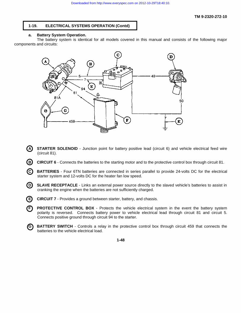
TM 9-2320-272-10
1-19. ELECTRICAL SYSTEMS OPERATION (Contd)
a. Battery System Operation.The battery system is identical for all models covered in this manual and consists of the following major
components and circuits:
A STARTER SOLENOID - Junction point for battery positive lead (circuit 6) and vehicle electrical feed wire(circuit 81).
B CIRCUIT 6 - Connects the batteries to the starting motor and to the protective control box through circuit 81.
C BATTERIES - Four 6TN batteries are connected in series parallel to provide 24-volts DC for the electricalstarter system and 12-volts DC for the heater fan low speed.
D SLAVE RECEPTACLE - Links an external power source directly to the slaved vehicle’s batteries to assist incranking the engine when the batteries are not sufficiently charged.
E CIRCUIT 7 - Provides a ground between starter, battery, and chassis.
F PROTECTIVE CONTROL BOX - Protects the vehicle electrical system in the event the battery systempolarity is reversed. Connects battery power to vehicle electrical lead through circuit 81 and circuit 5.Connects positive ground through circuit 94 to the starter.
G BATTERY SWITCH - Controls a relay in the protective control box through circuit 459 that connects thebatteries to the vehicle electrical load.
1-48
Downloaded from http://www.everyspec.com on 2012-10-29T18:40:10.

TM 9-2320-272-10
1-19. ELECTRICAL SYSTEMS OPERATION (Contd)
b. Starting System Operation.The starting system is identical for all models covered in this manual and consists of the following major
components and circuitry:
H BATTERY SWITCH - Completes circuit 459, closing a relay in the protective control box to supply power tothe ignition switch through circuits 5 and 5B.
I PROTECTIVE CONTROL BOX - Locks out starter circuit, which prevents starter from reengaging whileengine is running.
J IGNITION SWITCH - Provides battery power to the fuel solenoid through circuit 54 and the neutral startsafety switch through circuit 498.
K NEUTRAL START SAFETY SWITCH - Prevents starter from energizing when vehicle is not in neutral, bydeenergizing circuit 499 and a relay in the protective control box, which disconnects power from circuit 74and the starter solenoid.
L STARTER SOLENOID - A magnetic relay that is powered by circuit 74 to transmit 24-volt battery power to thestarter motor through circuit 6.
M STARTER MOTOR - Cranks the engine for starting. Supplied with 24-volt battery power through circuit 6.
1-49
Downloaded from http://www.everyspec.com on 2012-10-29T18:40:10.

TM 9-2320-272-10
1-19. ELECTRICAL SYSTEMS OPERATION (Contd)
c. Ether Starting System Operation.The ether starting system is identical for all models covered in this manual and consists of the following major
components and circuitry:
A BATTERY SWITCH - Provides 24-volt battery power to the protective control box through circuits 459, 81A,and 81.
B PROTECTIVE CONTROL BOX - Energizes the ether feed switch through circuits 5, 5A, 27, 5C, and 570.
C ETHER FEED SWITCH - Controls 24-volt power to the ether pressure switch through circuit 570.
D ETHER PRESSURE SWITCH - Connects the ether feed switch to the ether tank valve through circuit 570.
E ETHER TANK VALVE - Is activated through circuit 570 when the ether pressure switch is closed and theether feed switch is pressed.
1-50
Downloaded from http://www.everyspec.com on 2012-10-29T18:40:10.

TM 9-2320-272-10
1-19. ELECTRICAL SYSTEMS OPERATION (Contd)
d. Generating System Operation.The generating system is identical for all vehicles covered in this manual and consists of the following major
components and circuitry:
F VOLTMETER - Indicates electrical system voltage. It is connected to the electrical system through circuit 27.
G ALTERNATOR - Rated at 26-30 volts, 60 amperes, the alternator assists and recharges the batteries duringoperation. A 100 ampere model is available as a kit.
H CIRCUIT 3 - Provides a ground circuit to the alternator.
I CIRCUIT 566 - Controls a relay in the protective control box that prevents the starter from reactivating whilethe engine is running.
J CIRCUIT 568 - Senses system voltage and excites the alternator field.
K PROTECTIVE CONTROL BOX - Connects circuit 5 to 81 to power the electrical system and charge thebatteries.
L CIRCUIT 5 - Conducts alternator output to charge the batteries and maintain vehicle voltage.
M BATTERY SWITCH - Closes the relay in the protective control box that connects battery circuits.
1-51
Downloaded from http://www.everyspec.com on 2012-10-29T18:40:10.
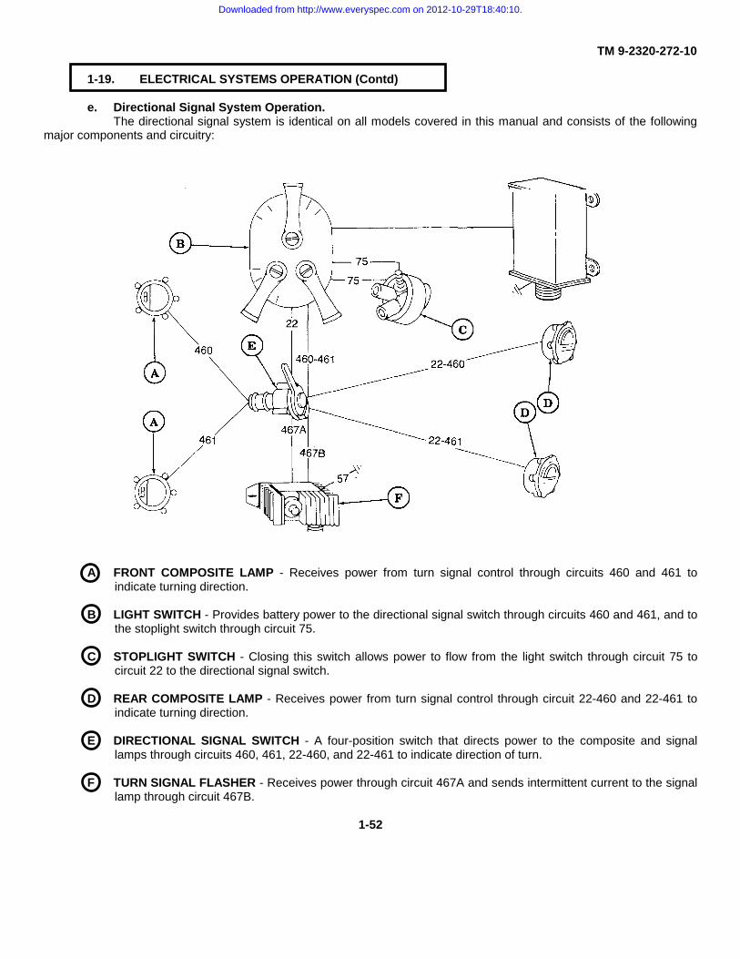
TM 9-2320-272-10
1-19. ELECTRICAL SYSTEMS OPERATION (Contd)
e. Directional Signal System Operation.The directional signal system is identical on all models covered in this manual and consists of the following
major components and circuitry:
A FRONT COMPOSITE LAMP - Receives power from turn signal control through circuits 460 and 461 toindicate turning direction.
B LIGHT SWITCH - Provides battery power to the directional signal switch through circuits 460 and 461, and tothe stoplight switch through circuit 75.
C STOPLIGHT SWITCH - Closing this switch allows power to flow from the light switch through circuit 75 tocircuit 22 to the directional signal switch.
D REAR COMPOSITE LAMP - Receives power from turn signal control through circuit 22-460 and 22-461 toindicate turning direction.
E DIRECTIONAL SIGNAL SWITCH - A four-position switch that directs power to the composite and signallamps through circuits 460, 461, 22-460, and 22-461 to indicate direction of turn.
F TURN SIGNAL FLASHER - Receives power through circuit 467A and sends intermittent current to the signallamp through circuit 467B.
1-52
Downloaded from http://www.everyspec.com on 2012-10-29T18:40:10.

TM 9-2320-272-10
1-19. ELECTRICAL SYSTEMS OPERATION (Contd)
f. Heating System Operation.The electrical portion of the heating system is identical for all models covered in the manual and consists of
the following major components and circuitry:
G PROTECTIVE CONTROL BOX - Provides 24-volt power to circuit breaker through circuits 5 and 5a and tothe heater switch through circuits 27 and 5c.
H CIRCUIT BREAKER - Provides overload protection for 24-volt circuits 5, 5a, 27, and 5c leading to the heaterswitch.
I BATTERY SWITCH - Provides 12-volt battery power from circuit 569 through 569A to the heater.
J CIRCUIT BREAKER - Provides overload protection for 12-volt circuit 569A leading to heater switch.
K HEATER SWITCH - Controls low and high blower motor speed and has two sources of power; 12-volt poweris supplied through circuit 569A from the battery switch and is used to provide low speed; 24-volt power issupplied through circuit 5C from the protective control box and is used to provide high speed.
L HEATER BLOWER MOTOR - A direct current motor controlled by the heater switch through circuit 400.
1-53
Downloaded from http://www.everyspec.com on 2012-10-29T18:40:10.

TM 9-2320-272-10
1-19. ELECTRICAL SYSTEMS OPERATION (Contd)
g. Indicator, Gauge, and Warning System Operation.The indicator, gauge, and warning system is comprised of several subsystems:
1-54
Downloaded from http://www.everyspec.com on 2012-10-29T18:40:10.

TM 9-2320-272-10
1-19. ELECTRICAL SYSTEMS OPERATION (Contd)
A VOLTMETER - Indicates system voltage and is connected to the batteries through circuit 27 and to chassisground through instrument panel.
B ENGINE COOLANT TEMPERATURE INDICATOR - Indicates engine coolant temperature and receives batterypower through circuit 27. Circuit 33 completes the circuit to ground through a coolant temperature sensor thatreacts to changes in engine coolant temperature by increasing or decreasing the resistance in the ground circuit.
C ENGINE OIL PRESSURE INDICATOR - Indicates engine oil pressure and receives battery power through circuit27. Circuit 36 completes the circuit to ground through the oil pressure transmitter located on the engine block.
D FUEL INDICATOR - Indicates fuel level. Receives battery power through circuit 27. Circuit 28 or 29, dependingupon which position the fuel selector switch is in, completes the circuit to ground through the fuel level sensor.
E TRANSMISSION OIL TEMPERATURE INDICATOR - Indicates transmission oil temperature and receives batterypower through circuit 27. Circuit 324 completes the circuit to ground through a temperature sensor located in thetransmission.
F FRONT-WHEEL DRIVE ENGAGEMENT LIGHT - Informs the operator that the front-wheel drive is engaged. Thesystem consists of a normally open pressure switch, which is powered through circuit 27A and an indicator lamppowered through circuit 27A.
G HORN SYSTEM - The horn system consists of an air-operated horn that is controlled by an electric solenoid. Thesolenoid is powered through circuit 26 and controlled by the horn switch through circuit 25.
H SPRING BRAKE WARNING SYSTEM - Warns the operator that the spring brakes are applied. The systemconsists of normally open pressure switch powered through circuit 37 and an indicator lamp which is poweredthrough circuit 37.
I FAILSAFE WARNING - SYSTEM Intended to give the operator an audible as well as visual signal of a malfunctionin one of the primary systems. Power for the system is supplied from the ignition switch through circuit 564. Thefailsafe module causes an indicator lamp to illuminate and an alarm to sound when the air pressure falls below 60psi (414 kPa) or when the parking brake is set.
1-55
Downloaded from http://www.everyspec.com on 2012-10-29T18:40:10.
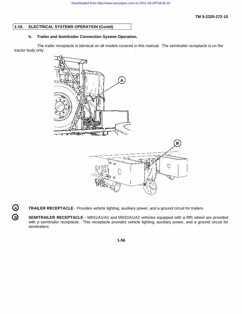
TM 9-2320-272-10
1-19. ELECTRICAL SYSTEMS OPERATION (Contd)
h. Trailer and Semitrailer Connection System Operation.
The trailer receptacle is identical on all models covered in this manual. The semitrailer receptacle is on thetractor body only.
A TRAILER RECEPTACLE - Provides vehicle lighting, auxiliary power, and a ground circuit for trailers.
B SEMITRAILER RECEPTACLE - M931/A1/A2 and M932/A1/A2 vehicles equipped with a fifth wheel are providedwith a semitrailer receptacle. This receptacle provides vehicle lighting, auxiliary power, and a ground circuit forsemitrailers.
1-56
Downloaded from http://www.everyspec.com on 2012-10-29T18:40:10.

TM 9-2320-272-10
1-20. COMPRESSED AIR AND BRAKE SYSTEM OPERATION I
The compressed air and brake system takes filtered air, compresses it, and supplies it to various components thatenable the operator to slow down or stop the vehicle. This system also supplies compressed air to air-actuatedaccessories throughout the vehicle. These components and accessories will be described as part of the followingsystems:
a. Medium Wrecker Automatic Brake Lock System Operation (page 1-57).
b. Air Pressure Supply System Operation (page 1-58).
c. Secondary Service Airbrake System Operation (page 1-62).
d. Spring Airbrake System Operation (page 1-64).
e. Primary Service Airbrake System Operation (page 1-65).
f. Auxiliary Air-Powered System Operation (page 1-68).
g. Air Venting System Operation (page 1-70).
h. Central Tire Inflation System (CTIS) (M939A2 series vehicles) (page 1-72).
a. Medium Wrecker Automatic Brake Lock System Operation.
The M936/A1/A2 Medium Wrecker Automatic Brake Lock System locks the service airbrakes when thetransfer case power takeoff lever is engaged. Major components of the automatic brake lock system are:
A TRANSFER CASE POWER TAKEOFF LEVER - Opens the brake lock control valve through mechanical linkagewhen engaged.
B BRAKE LOCK CONTROL - Allows air pressure to flow from secondary air reservoir to pressure regulator andactivate variable speed governor.
C PRESSURE REGULATOR - Reduces and regulates system air pressure to 70 psi (483 kPa) for automatic brakelock application.
D TREADLE VALVE - Connects pressure regulator and service airbrakes.
1-57
Downloaded from http://www.everyspec.com on 2012-10-29T18:40:10.
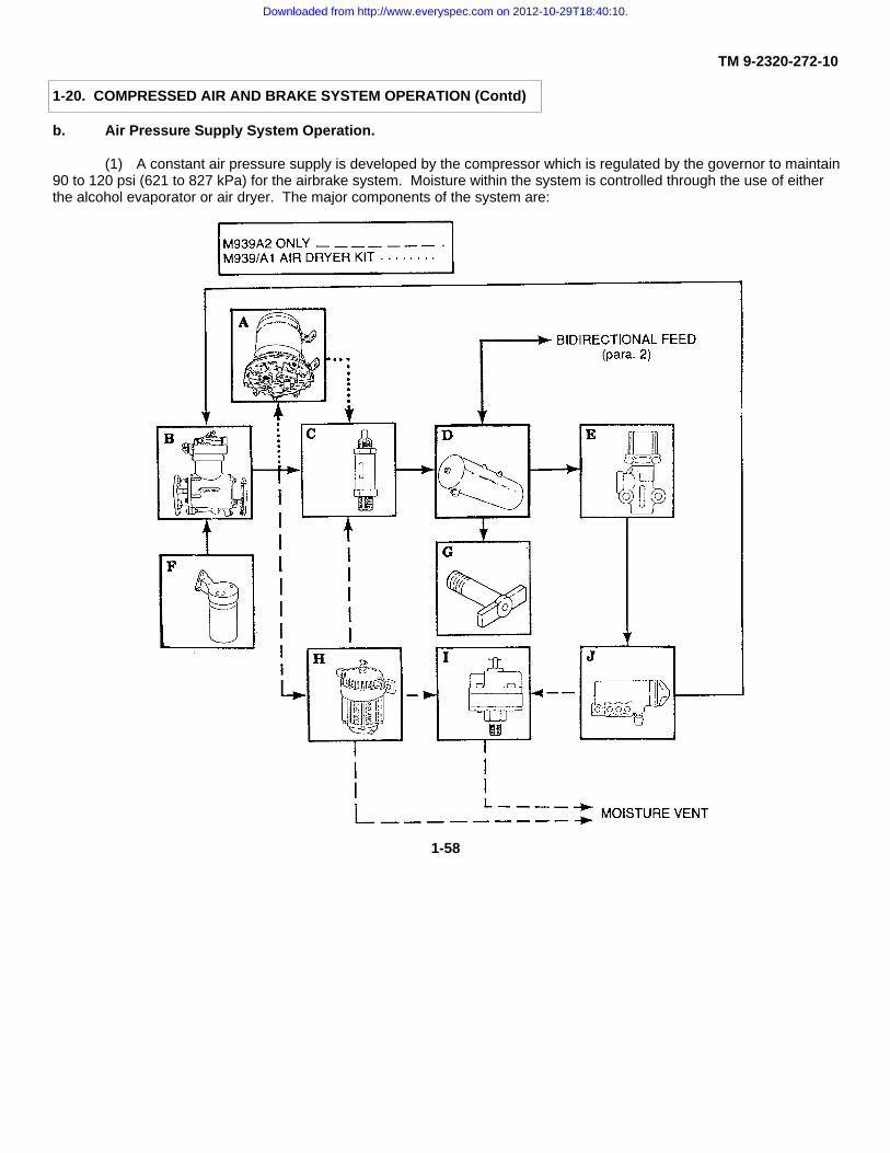
TM 9-2320-272-10
1-20. COMPRESSED AIR AND BRAKE SYSTEM OPERATION (Contd)
b. Air Pressure Supply System Operation.
(1) A constant air pressure supply is developed by the compressor which is regulated by the governor to maintain90 to 120 psi (621 to 827 kPa) for the airbrake system. Moisture within the system is controlled through the use of eitherthe alcohol evaporator or air dryer. The major components of the system are:
1-58
Downloaded from http://www.everyspec.com on 2012-10-29T18:40:10.

TM 9-2320-272-10
1-20. COMPRESSED AIR AND BRAKE SYSTEM OPERATION (Contd)
A AIR DRYER - Installed in supply line to wet tank and removes moisture from inlet air to wet tank (M939/A1 airdryer kit installed only).
B AIR COMPRESSOR - Draws in air from the intake manifold and forces it into the brake system and wet tankreservoir.
C SAFETY VALVE - Located at the inlet side of the wet reservoir, it prevents pressure build-up by releasing airpressure exceeding 150 psi (1034 kPa) when the governor fails to regulate air supplied by the compressor.
D WET TANK RESERVOIR - Performs two functions:• Traps water in air reservoir to protect other air systems from freezing or corroding.• Stores reserve air supply enabling operator to make normal stops when engine stalls or compressor fails.
E PRESSURE PROTECTION VALVE - Performs two functions:• Allows air pressure to build to 60-65 psi (414-448 kPa) before supplying air to auxiliary air-powered
equipment.• Closes off auxiliary air system from other systems if an accessory fails and prevents loss of air from
secondary reservoir.
F ALCOHOL EVAPORATOR (M939/A1 series) - Helps protect air lines from freezing.
G WET TANK RESERVOIR DRAINVALVE - Provides a drain for moisture and air from reservoir.
H AIR DRYER - Removes moisture from inlet air to wet tank (M939A2 only).
I EXPELLO VALVE - Augments air dryer condensation blowdown by venting moisture when compressor cycles.
J GOVERNOR - Trips valve inside compressor to regulate flow of air to the system. When pressure builds to 120-127 psi (827-876 kPa), the governor will close valve.
1-59
Downloaded from http://www.everyspec.com on 2012-10-29T18:40:10.

TM 9-2320-272-10
1-20. COMPRESSED AIR AND BRAKE SYSTEM OPERATION (Contd)
(2) The constant air pressure supply is distributed to the primary service airbrake system (para e.) and secondaryairbrake system (para c.) through a shutoff and check valve. Air pressure can either be fed from or supplied to anothervehicle through the emergency couplings.
1-60
Downloaded from http://www.everyspec.com on 2012-10-29T18:40:10.

TM 9-2320-272-10
1-20. COMPRESSED AIR AND BRAKE SYSTEM OPERATION (Contd)
A FRONT EMERGENCY COUPLING - When vehicle is being towed, coupling receives compressed air from towingvehicle’s brake system to charge its own brake system.
B PRIMARY AIR RESERVOIR - Stores sufficient air pressure to allow operator to make normal brake applications,should system pressure fail or engine stall.
C PRIMARY FEED CUTOFF - Manually-operated valve used to isolate pressure leaks in primary air system fromdraining wet tank (para. 3-12).
D PRIMARY AIR RESERVOIR CHECKVALVE - Presents backflow of air from primary tank if wet system developsa leak.
E SECONDARY FEED CUTOFF - Manually-operated valve used to isolate pressure leaks in secondary air systemfrom draining wet tank (para. 3-12).
F SECONDARY AIR RESERVOIR CHECKVALVE - Prevents backflow of air from secondary tank if wet systemdevelops a leak.
G REAR EMERGENCY COUPLING - When towing another vehicle, coupling allows pressurized air from wet tank tocharge towed vehicle’s wet tank.
H SECONDARY AIR RESERVOIR - Stores enough air pressure in case constant pressure system fails or enginestalls. The operator can make normal brake application before running out of air.
I PRESSURE PROTECTION VALVE - Performs two functions:• Allows air pressure to build to 60-65 psi (414-448 kPa) before supplying air to auxiliary air-powered
equipment.• Closes off auxiliary air system from other systems if an accessory fails and prevents loss of air from
secondary reservoir.
1-61
Downloaded from http://www.everyspec.com on 2012-10-29T18:40:10.
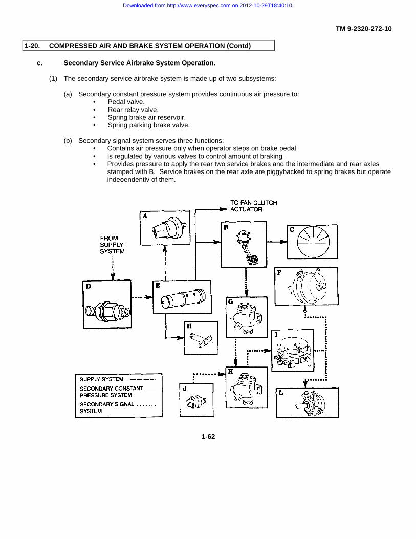
TM 9-2320-272-10
1-20. COMPRESSED AIR AND BRAKE SYSTEM OPERATION (Contd)
c. Secondary Service Airbrake System Operation.
(1) The secondary service airbrake system is made up of two subsystems:
(a) Secondary constant pressure system provides continuous air pressure to:• Pedal valve.• Rear relay valve.• Spring brake air reservoir.• Spring parking brake valve.
(b) Secondary signal system serves three functions:• Contains air pressure only when operator steps on brake pedal.• Is regulated by various valves to control amount of braking.• Provides pressure to apply the rear two service brakes and the intermediate and rear axles
stamped with B. Service brakes on the rear axle are piggybacked to spring brakes but operateindeoendentlv of them.
1-62
Downloaded from http://www.everyspec.com on 2012-10-29T18:40:10.

TM 9-2320-272-10
1-20. COMPRESSED AIR AND BRAKE SYSTEM OPERATION (Contd)
(2) The secondary constant pressure system is made up of the following components:
A LOW AIR PRESSURE SWITCH - Activates warning buzzer and warning lights when air pressure goes below 60psi (414 kPa).
B PEDAL VALVE - Allows air pressure from secondary constant pressure system to flow into secondary signalsystem when operator depresses brake pedal.
C SECONDARY AIR PRESSURE GAUGE - Indicates amount of air pressure in secondary system.
D ONE-WAY CHECK VALVE - Allows air pressure to flow into secondary reservoir but prevents it from coming out ifconstant pressure system fails or engine stalls.
E SECONDARY AIR RESERVOIR - Stores enough air pressure so the operator can make five normal brakeapplications before running out of air if constant pressure fails or engine stalls.
F INTERMEDIATE REAR BRAKE CHAMBERS - Converts air pressure to mechanical force which appliesintermediate rear service brake.
G DOUBLECHECK VALVE #1 - Serves two functions:• Allows system to receive signal pressure from either pedal valve or, when towed, from brake system of
towing vehicle.• Serves as a tee between front and rear primary signal lines.
H SECONDARY AIR RESERVOIR DRAINVALVE - Provides a drain for moisture and air from secondary airreservoir.
I FRONT RELAY VALVE - Boosts signal air to rear brake chambers; regulates air pressure to rear brake chambersso operator has control over amount of braking; and releases air pressure to rear brake chambers directly to ventwhen brake pedal is released.
J STOPLIGHT SWITCH - As the brake pedal is depressed, switch receives an air pressure signal at electricalcontacts which close to activate circuits to taillights.
K DOUBLECHECK VALVE #2 - Allows either primary or secondary signal air pressure to activate stoplight switchwhile keeping the two systems separate.
L REAR-REAR BRAKE CHAMBERS - Converts air pressure to mechanical force which applies rear-rear brakes.
1-63
Downloaded from http://www.everyspec.com on 2012-10-29T18:40:10.

TM 9-2320-272-10
1-20. COMPRESSED AIR AND BRAKE SYSTEM OPERATION (Contd)
d. Spring Airbrake System Operation.
The spring airbrake system applies rear brakes when vehicle parking brake is applied or in event of a majorbrake failure. The spring brake is located on one of the two service brake chambers at each rear wheel. Majorcomponents of the spring airbrake system are:
A SPRING BRAKE WARNING LIGHT SWITCH - Activates warning light when spring brakes are engaged.
B SPRING BRAKE RELEASE CONTROL VALVE - Pushed in to release spring brakes independently of mechanicalparking brake. Control is also used to release spring brakes in order to test and adjust mechanical brake.
C DOUBLECHECK VALVE #4 - Allows spring brake air pressure to come from either release control valve or springparking brake valve directly to doublecheck valve #3.
1-64
Downloaded from http://www.everyspec.com on 2012-10-29T18:40:10.

TM 9-2320-272-10
1-20. COMPRESSED AIR AND BRAKE SYSTEM OPERATION (Contd)
A INTERMEDIATE FRONT SPRING BRAKE CHAMBER - Contains a large spring which applies rear brakes whenspring brake air pressure is released.
B ONE-WAY CHECK VALVE - Allows air pressure to flow into spring brake reservoir but prevents it from coming outif constant pressure system or primary system fails.
C SPRING BRAKE AIR RESERVOIR - Stores enough air pressure to release spring brakes for emergencyoperation in event of primary or secondary air system failure.
D QUICK-RELEASE VALVE - Releases spring brake air pressure directly to vent if parking brake has been set orbrake system fails.
E SPRING BRAKE VALVE - Automatically sets spring brakes when parking brake is set. Valve can be releasedindependently of parking brake when spring brake control valve is pushed in.
F SPRING BRAKE RESERVOIR DRAINVALVE - Provides a drain for moisture and air from spring brake reservoir.
G DOUBLECHECK VALVE #3 - Allows spring brake air pressure to come from either release control valve or springparking brake valve directly to doublecheck valve #4.
H REAR-REAR SPRING BRAKE CHAMBER - Contains a large spring which applies rear brakes when spring brakeair pressure is released.
e. Primary Service Airbrake System Operation.
(1) The primary service airbrake system is made up of two subsystems: (a) Primary constant pressuresystem provides continuous air pressure to:
• Pedal valve.• Rear relay valve.• Spring brake air reservoir.• Spring parking brake valve.
(b) Primary signal system serves three functions:• Contains pressure only when operator steps on brake pedal.• Is regulated by various valves to give operator control over amount of braking.• Provides pressure to apply front service brakes and the front two service brakes on the intermediate
and rear axles stamped with an A Service brakes on the intermediate axle are piggybacked tospring brakes but operate independently of them.
1-65
Downloaded from http://www.everyspec.com on 2012-10-29T18:40:10.

TM 9-2320-272-10
1-20. COMPRESSED AIR AND BRAKE SYSTEM OPERATION (Contd)
(2) The primary constant pressure system is made up of the following components:
A PRIMARY AIR PRESSURE GAUGE - Indicates amount of air pressure in primary system.
B LIMITING VALVE - Serves three functions:• Regulates signal air pressure going to front brake chambers so rear brakes are applied first.• Regulates signal air pressure to front brake chambers so operator has control over amount of braking.• Releases air pressure in front brake chambers directly to vent in the valve when brake pedal is released.
C RONT BRAKE CHAMBERS - Converts air pressure to mechanical force which applies front service brakes.
D PRIMARY RESERVOIR LOW AIR PRESSURE SWITCH - Activates warning buzzer and warning light when airpressure goes below 60 psi (414 kPa).
1-66
Downloaded from http://www.everyspec.com on 2012-10-29T18:40:10.

TM 9-2320-272-10
1-20. COMPRESSED AIR AND BRAKE SYSTEM OPERATION (Contd)
E PEDAL INTO VALVE - Allows air pressure from primary constant pressure system to flow into primary signalsystem when operator depresses brake pedal.
F DOUBLECHECK VALVE #1 - Serves two functions:• Allows system to receive signal pressure from either pedal valve or, when towed, from brake system oftowing vehicle.• Serves as a tee between front and rear primary signal lines.
G FRONT SERVICE COUPLING - When vehicle is being towed, coupling is connected to towing vehicle so that thebrake systems of the two vehicles work together.
H ONE-WAY CHECK VALVE - Allows air pressure to flow into primary reservoir but prevents it from coming out ifconstant pressure system fails or engine stalls.
I PRIMARY AIR RESERVOIR - Stores enough air pressure so the operator can make five normal brakeapplications before running out of air if constant pressure fails or engine stalls.
J DOUBLECHECK VALVE #2 - Allows either primary or secondary signal air pressure to activate stoplight switchwhile keeping the two systems separate.
K STOPLIGHT SWITCH - As the brake pedal is depressed, switch receives an air pressure signal which closeselectric contacts turning on stoplight.
L REAR SERVICE COUPLING When towing another vehicle, coupling is connected to towed vehicle so that thebrake system of the two vehicles work together.
M INTERMEDIATE FRONT BRAKE CHAMBERS Converts air pressure to mechanical force which appliesintermediate rear service brake.
N PRIMARY RESERVOIR DRAINVALVE - Provides a drain for moisture and air from primary air reservoir.
O REAR RELAY VALVE - Serves three functions:• Boosts signal air pressure to rear brake chambers. Air signal from brake pedal opens valve to route constantair pressure to rear brake chambers.• Regulates signal air pressure from brake pedal to rear brake chambers so operator has control over amountof braking. Regulates amount of constant air pressure going to brake chambers as the operator depresses thebrake pedal.• Releases air pressure in rear brake chamber directly to vent system when brake pedal is released.
P REAR FRONT BRAKE CHAMBERS - Converts air pressure to mechanical force which applies rear servicebrakes.
1-67
Downloaded from http://www.everyspec.com on 2012-10-29T18:40:10.

TM 9-2320-272-10
1-20. COMPRESSED AIR AND BRAKE SYSTEM OPERATION (Contd)
f. Auxiliary Air-Powered System Operation.
The auxiliary air-powered system consists of air-actuated vehicle accessories. All of these accessoriesreceive air pressure through the accessory manifold and off the pressure protection valve with the exception of the horns.Components of the auxiliary air-powered system are:
1-68
Downloaded from http://www.everyspec.com on 2012-10-29T18:40:10.

TM 9-2320-272-10
1-20. COMPRESSED AIR AND BRAKE SYSTEM OPERATION (Contd)
A WINDSHIELD WIPER CONTROL SWITCH - Opens air pressure valve in wiper motor to operate wipers.
B WINDSHIELD WIPER MOTOR - Air-actuated motor powers windshield wipers.
C WINDSHIELD WASHER CONTROL - Spring-loaded valve that allows air pressure to force washer fluid fromwasher reservoir to windshield.
D WINDSHIELD WASHER RESERVOIR - Container for windshield washer fluid.
E ACCESSORY MANIFOLD - Receives air pressure from the pressure protection valve and distributes it to thevarious accessories.
F FRONT-WHEEL DRIVE LOCK-IN SWITCH - Air-actuated switch that engages front-wheel drive when transfercase is in HIGH.
G WINDSHIELD WASHER NOZZLES - Direct washer fluid on windshield.
H GOVERNOR - Serves as a tee between accessory manifold and horn relay valve. It also signals the aircompressor to stop compressing air for the supply system when operating pressure has been reached.
I TRANSFER CASE AIR SHIFT CYLINDER - Engages front-wheel drive when it receives air pressure from lock-inswitch or engagement control valve.
J FRONT AXLE ENGAGEMENT CONTROL VALVE - Operates off cam on transfer case shift linkage so front-wheel drive engages automatically when transfer case is put into LOW.
K HORN RELAY VALVE - Electrical signal from horn button on steering wheel opens valve in horn relay, allowing airpressure to sound horns.
L HORNS - Receive air pressure from horn relay valve to sound off.
1-69
Downloaded from http://www.everyspec.com on 2012-10-29T18:40:10.

TM 9-2320-272-10
1-20. COMPRESSED AIR AND BRAKE SYSTEM OPERATION (Contd)
g. Air Venting System Operation.
The air venting system vents air from brake system and power train, and fuel vapors from fuel system into airintake stack where it is released into the atmosphere. The components of the air venting system are:
1-70
Downloaded from http://www.everyspec.com on 2012-10-29T18:40:10.

TM 9-2320-272-10
1-20. COMPRESSED AIR AND BRAKE SYSTEM OPERATION (Contd)
A SPRING BRAKE RELEASE CONTROL VALVE - This valve functions as an override when a failure in the airsupply system (causing spring brakes to engage) occurs. When valve is manually pushed in, emergency air issupplied to the spring brake chambers. This releases the spring brakes, allowing vehicle movement.
B PEDAL VALVE - Vents primary or secondary signal air pressure when pedal is released.
C FRONT BRAKE CHAMBER VENT - Vents air pressure inside chambers when pedal valve is released.
D LIMITING VALVE - Vents signal air pressure going to front brake chambers so rear brakes apply first.
E STEP BOX QUICK-RELEASE VALVE - Vents air pressure from spring brake chambers when parking brake valvehas been actuated.
F REAR BRAKE CHAMBERS - Vents ports on chambers to prevent air pressure build-up.
G RELAY VALVES - Vents air pressure in rear brake chambers directly to intake tube when brake pedal is released.Vents signal air pressure through upper port in valve.
H AIR INTAKE STACK - Venting point for the vent system.
I TRANSMISSION VENT - Vents internal air pressure build-up due to internal heat.
J SPRING PARKING BRAKE VALVE - Vents air pressure from air and doublecheck valves #3 and #4.
K TRANSFER CASE VENT - Vents internal air pressure build-up due to internal heat.
L FUEL TANK VENTS - Vent fuel vapors to prevent partial vacuum from stopping fuel flow.
1-71
Downloaded from http://www.everyspec.com on 2012-10-29T18:40:10.

TM 9-2320-272-10
1-20. COMPRESSED AIR AND BRAKE SYSTEM OPERATION (Contd)
h. Central Tire Inflation System (CTIS).
The CTIS is common to all M939A2 series vehicles. This system maintains tire air pressure depending onwhich road type is selected. If this setting is changed, tires will automatically inflate or deflate to the new setting.
A PNEUMATIC CONTROLLER - Directs air pressure according to ECU commands.
B ELECTRONIC CONTROL UNIT (ECU) - Contains CTIS selector panel so that operator can change tire inflationduring vehicle operation.
C AIR PRESSURE SWITCH - Protects air brake system for a minimum supply of 85 psi (586 kPa) of air.
D AIR DRYER AND FILTER - Separates moisture from compressed air system and filters impurities fromcompressed air before they enter CTIS.
E EXHAUST VALVES - Exhausts air from tires during deflation.
F WHEEL VALVES - Isolates air pressure in the tires during normal operation and for tire removal.
G SPEED SIGNAL GENERATOR - Signals ECU to automatically inflate CTIS when vehicle speed exceeds the topspeed setting for the selected mode by 10 mph (16 km/h).
1-72
Downloaded from http://www.everyspec.com on 2012-10-29T18:40:10.

TM 9-2320-272-10
1-21. HYDRAULIC SYSTEM OPERATION
Oil pressure (hydraulics) is used to provide operating power for the auxiliary equipment on the vehicles covered inthis manual. The components that provide hydraulic power are discussed in the following order:
a. Front Winch Hydraulic System Operation (page 1-73).
b. Rear Winch Hydraulic System Operation (page 1-74).
c. Dump Body Hydraulic System Operation (page 1-76).
d. Medium Wrecker Crane Hydraulic System Operation (page 1-78).
a. Front Winch Hydraulic System Operation.
A front winch is installed on M925/A1/A2, M928/A1/A2, M930/A1/A2, M932/A1/A2, and M936/A1/A2 seriesvehicles. The front winch hydraulic system converts mechanical power at the winch drive motor. The basic operatingprinciples are the same for each model. Major components of this system are:
A TRANSMISSION POWER TAKEOFF (PTO) CONTROL - A manually operated control lever located inside thecab that permits engagement or disengagement of the transmission Power Takeoff (PTO).
B WINCH CONTROL LEVER - An operator control that determines the hydraulic oil pressure flow from the controlvalve to the winch motor. The flow of this oil determines the direction the winch drum will turn.
C TRANSMISSION POWER TAKEOFF (PTO) - Uses driving power of the transmission to provide mechanicaldriving power for the hydraulic pump.
D POWER TAKEOFF (PTO) DRIVE SHAFT - Transmits mechanical power from the PTO to the hydraulic pump.
E HYDRAULIC PUMP - Driven by the PTO drive shaft, it draws oil from the oil reservoir through hydraulic hoses,then pressurizes and directs this oil to the control valve.
1-73
Downloaded from http://www.everyspec.com on 2012-10-29T18:40:10.

TM 9-2320-272-10
1-21. HYDRAULIC SYSTEM OPERATION (Contd)
A CLUTCH LEVER - Manual control that engages the winch drum gear to the drive gear of the winch motor.
B OIL FILTER - Filters used or bypassed oil from the control valve before it returns to the hydraulic oil reservoir.
C HYDRAULIC OIL RESERVOIR - Storage tank for hydraulic oil.
D CONTROL VALVE - Four-port valve accepts pressurized oil from the hydraulic pump and directs this oil to thewinch motor. It also directs oil returning from the winch back to the oil reservoir. The flow of this oil from the valvedetermines the directional drive of the winch motor.
E WINCH MOTOR - Converts hydraulic power into mechanical power as hydraulic oil is forced through the winchmotor.
b. Rear Winch Hydraulic System Operation.
A rear winch is installed only on the M936/A1/A2 medium wrecker. It is primarily to rescue vehicles that havebecome deeply mired. The rear winch hydraulic system converts mechanical power of the engine into fluid power throughuse of the hydraulic pump and back into mechanical power at the winch drive motor. The major components of the rearwinch hydraulic system are: 1-74
1-74
Downloaded from http://www.everyspec.com on 2012-10-29T18:40:10.

TM 9-2320-272-10
1-21. HYDRAULIC SYSTEM OPERATION (Contd)
F TRANSFER CASE POWER TAKEOFF (PTO) CONTROL - A manually operated control lever located inside thecab that permits engagement or disengagement of the Power Takeoff (PTO).
G TRANSFER CASE POWER TAKEOFF (PTO) - Uses driving power of the transfer case to provide mechanicaldriving power for the hydraulic pump.
H POWER TAKEOFF (PTO) DRIVE SHAFT - Transmits mechanical driving power from PTO to the hydraulic pump.
I HYDRAULIC PUMP - Draws oil from hydraulic oil reservoir and directs it to the rear winch control valve and winchdrive motor.
J OIL FILTER - Filters used or bypassed oil from the control valve before it returns to the hydraulic oil reservoir.
K HYDRAULIC OIL RESERVOIR - Storage tank for hydraulic oil.
L TORQUE CONTROL LEVER - Controls the operating gear ratio of the winch drive motor. Lever is pulled outwardto HIGH for heavy loads or pushed inward to LOW for light loads.
M WINCH DIRECTIONAL CONTROL LEVER - Manually-operated lever that controls the WIND and UNWINDdirection of the rear winch drum. Lever does this by opening and closing the directional control valve to the winch motor,and reversing the direction of pressurized hydraulic fluid. Lever is pushed inward to wind and pulled outward to unwindwinch cable.
N DIRECTIONAL CONTROL VALVE - Receives pressurized hydraulic oil from the hydraulic pump and directs it tothe winch motor. The flow of the hydraulic oil to and from this control valve provides forward or reverse driving power tothe winch motor. Valve also returns used oil back to the hydraulic oil reservoir from the winch.
O TORQUE CONTROL VALVE - Hydraulically controls the hydraulic oil pressure to engage rear winch drum clutchin HIGH or LOW gear range.
P WINCH MOTOR - Converts hydraulic power back into mechanical power needed to turn the rear winch drum.
Q CONTROL LINKAGE - Connects transfer case power takeoff control to transfer case power takeoff.
1-75
Downloaded from http://www.everyspec.com on 2012-10-29T18:40:10.

TM 9-2320-272-10
1-21. HYDRAULIC SYSTEM OPERATION (Contd)
c. Dump Body Hydraulic System Operation.
The dump body is installed on M929/A1/A2 and M930/A1/A2 vehicles. These models are used to transport anddeposit cargo. The dump body hydraulic system converts mechanical power from the engine into fluid power through useof the hydraulic pump. The pump draws fluid from the oil reservoir and then forces it into the control valve. This hydraulicpressure raises and lowers the dump body. Major components of the dump body hydraulic system are:
1-76
Downloaded from http://www.everyspec.com on 2012-10-29T18:40:10.

TM 9-2320-272-10
1-21. HYDRAULIC SYSTEM OPERATION (Contd)
A TRANSMISSION POWER TAKEOFF (PTO) CONTROL - A manually operated control lever located inside thevehicle cab that permits engagement or disengagement of the transmission Power Takeoff (PTO).
B TRANSMISSION POWER TAKEOFF (PTO) - Uses driving power of the transmission to provide mechanicaldriving power for the hydraulic pump.
C POWER TAKEOFF (PTO) DRIVE SHAFT - Transmits mechanical driving power from the PTO to the hydraulicpump.
D HYDRAULIC PUMP - Driven by the PTO drive shaft, it draws oil from the oil reservoir through hydraulic hoses,then pressurizes and directs it to the control valve.
E HYDRAULIC OIL RESERVOIR - Storage tank for hydraulic oil.
F DUMP BODY SAFETY LATCH - Hydraulically-operated in conjunction with the dump body control lever, thesafety latch locks the dump body in the lowered position and releases it when the control lever is pulled back to theraised position.
G DUMP BODY CYLINDER ASSEMBLY - Consists of two piston-type hydraulic cylinder hoists. Assembly raisesand lowers dump body with hydraulic oil, forcing the cylinder upward or downward.
H OIL FILTER - Filters used or bypassed oil from the control valve before it returns to the hydraulic oil reservoir.
I CONTROL VALVE - Four-port valve accepts pressurized oil from the hydraulic pump and directs oil pressure flowfrom control valve to the hydraulic cylinders. It also directs oil returning from the hydraulic cylinders back to thehydraulic oil reservoir.
J DUMP BODY CONTROL LEVER - An operator control that determines the hydraulic oil pressure flow from controlvalve to the hydraulic cylinders. The route this oil takes will determine whether the dump will raise or lower.
K CONTROL LINKAGE Connects dump body control lever inside cab to the control valve.
1-77
Downloaded from http://www.everyspec.com on 2012-10-29T18:40:10.
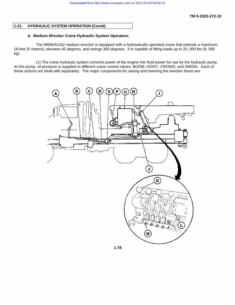
TM 9-2320-272-10
1-21. HYDRAULIC SYSTEM OPERATION (Contd)
d. Medium Wrecker Crane Hydraulic System Operation.
The M936/A1/A2 medium wrecker is equipped with a hydraulically-operated crane that extends a maximum18 feet (5 meters), elevates 45 degrees, and swings 360 degrees. It is capable of lifting loads up to 20, 000 lbs (9, 090kg).
(1) The crane hydraulic system converts power of the engine into fluid power for use by the hydraulic pump.At this pump, oil pressure is supplied to different crane control valves: BOOM, HOIST, CROWD, and SWING. Each ofthese actions are dealt with separately. The major components for raising and lowering the wrecker boom are:
1-78
Downloaded from http://www.everyspec.com on 2012-10-29T18:40:10.

TM 9-2320-272-10
1-21. HYDRAULIC SYSTEM OPERATION (Contd)
A TRANSFER CASE POWER TAKEOFF (PTO) CONTROL - A manually operated control lever located inside thecab that engages and disengages the transfer case power takeoff.
B TRANSFER CASE POWER TAKEOFF (PTO) LINKAGE - Connects transfer case power takeoff control totransfer case Power Takeoff (PTO).
C TRANSFER CASE POWER TAKEOFF (PTO) - Receives driving power from vehicle’s engine through the transfercase to provide mechanical driving power for the hydraulic pump.
D POWER TAKEOFF (PTO) DRIVE SHAFT - Transmits mechanical driving power from the power takeoff to thehydraulic pump.
E HYDRAULIC PUMP - Draws oil from hydraulic oil reservoir and directs it to valves inside the crane controlconsole.
F OIL FILTER - Filters used or bypassed oil from the control valve before it returns to the hydraulic oil reservoir.
G HYDRAULIC OIL RESERVOIR - Storage tank for hydraulic oil.
H SWIVEL VALVE - Permits oil to channel through pivot post while crane is swinging and eliminates twisting of thehydraulic lines connecting reservoir to the stationary pump.
I BOOM LIFT CYLINDER - A hydraulically-driven piston that extends upward when boom control lever is pulledback to UP position, raising the boom. A check valve located near hydraulic oil inlet hose prevents piston fromlowering when control lever is in neutral. Oil returns through boom control valve back to hydraulic oil reservoirallowing piston to lower when control lever is pushed forward to DOWN position.
J BOOM HYDRAULIC LINES - Carry the hydraulic oil to and from boom lift cylinder. Oil pumped through thebottom lines pushes the lift cylinder piston upward. Oil pumped through the top lines pushes the lift cylinder pistondownward. When this downward action occurs, the oil that originally pushes the cylinder upwards is returned tothe hydraulic oil reservoir.
K BOOM CONTROL LEVER - Manual control attached to the control valve that determines hydraulic oil flow forraising and lowering action of the boom. Lever is pulled back to raise the boom and pushed forward to lowerboom.
L CRANE CONTROL CONSOLE - Houses BOOM, HOIST, CROWD, and SWING levers and their control valves.
M BOOM CONTROL VALVE - Located directly below boom control lever. Valve directs hydraulic oil from thehydraulic pump to the boom lift cylinder for lifting, or out of the lift cylinder and back to the hydraulic oil reservoirfor lowering.
1-79
Downloaded from http://www.everyspec.com on 2012-10-29T18:40:10.

TM 9-2320-272-10
1-21. HYDRAULIC SYSTEM OPERATION (Contd)
A SHEAVES - Grooved wheels that guide hoist cable through boom.
B HOIST MOTOR ASSEMBLY - Converts hydraulic power back into mechanical power needed to turn the hoistdrum.
C UPPER ROLLER ASSEMBLY - Prevents cable from contacting inner boom during winding/unwinding.
D CRANE HOIST CABLE DRUM - Is turned by the worm gear in hoist motor assembly. Drum unwinds cable whenturning toward front of vehicle. Drum winds cable when turning toward rear of vehicle.
E HOIST CONTROL LEVER - Manual control attached to the control valve that determines hydraulic oil flow for theraising and lowering action of the crane hoist cable and hook. Lever is pulled back to raise cable and hook andpushed forward to lower cable and hook.
F HOIST CONTROL VALVE - Two-way hydraulic valve located under the hoist control lever directs fluid from thehydraulic pump to the hoist motor assembly and back through the valve to the hydraulic oil reservoir.
1-80
Downloaded from http://www.everyspec.com on 2012-10-29T18:40:10.

TM 9-2320-272-10
1-21. HYDRAULIC SYSTEM OPERATION (Contd)
(3) Major components for extending and retracting the boom for the CROWD action are:
G ROLLERS - Guides inner boom assembly and permits smooth extension and retraction of boom.
H INNER BOOM ASSEMBLY - Extends when crowd control lever is pushed forward and retracts when control leveris pulled back.
I CROWD CYLINDER - A hydraulically-driven piston that extends outward when crowd control lever is pushedforward to EXTEND position. Piston is hydraulically driven back into the cylinder when crowd control lever ispulled back to RETRACT position. This cylinder is contained in the inner boom assembly.
J CROWD CONTROL LEVER - Manual control attached to the control valve that determines oil flow for extendingand retracting the crane boom. Lever is pushed forward to extend the boom and pulled back to retract the boom.
K CROWD CONTROL VALVE - Two-way hydraulic valve located directly below crowd control lever. Valve directshydraulic oil from the hydraulic pump to the crowd cylinder to extend and retract inner boom assembly.
1-81
Downloaded from http://www.everyspec.com on 2012-10-29T18:40:10.

TM 9-2320-272-10
1-21. HYDRAULIC SYSTEM OPERATION (Contd)
(4) The major components for swinging the crane left and right for the SWING action are:
A SWING MOTOR - Converts hydraulic power back into mechanical power needed to turn the crane turntable whenhydraulic fluid is forced through its worm gear. This gear turns a large gear at the base of the turntable to swingthe crane.
B TURNTABLE ASSEMBLY - Driven by the swing motor through a ring gear at the base of the assembly, permitsthe crane to swing 360 degrees.
C SWING CONTROL LEVER - Manual control attached to the control valve that determines hydraulic oil flow forswinging wrecker boom to the left and to the right. Lever is pushed inward for left boom movement, and pulledoutward for right boom movement.
D SWING CONTROL VALVE - TIwo-way hydraulic valve located directly below swing control lever. Valve directshydraulic oil from the hydraulic pump to the swing motor assembly and back through the valve to the hydraulic oilreservoir.
1-82
Downloaded from http://www.everyspec.com on 2012-10-29T18:40:10.

TM 9-2320-272-10
CHAPTER 2 OPERATING INSTRUCTIONS
Section I Description and Use of Operator’s Controls and Indicators (page 2-1)Section II Operator Preventive Maintenance Checks and Services (PMCS) (page 2-28)Section III Operation Under Usual Conditions (page 2-100)Section IV Operation Under Unusual Conditions (page 2-201)Section V Operation of Special Purpose Kits (page 2-217)
Section I. DESCRIPTION AND USE OF OPERATOR’S CONTROLS AND INDICATORS
2-1. KNOW YOUR CONTROLS AND INDICATORS
Before you attempt to operate your equipment, ensure you are familiar with the location and function of all controlsand indicators. The location and function of controls and indicators for the M939, M939A1, and M939A2 series vehiclesare described in this section as follows:
a. Chassis Controls and Indicators: paragraph 2-3.
b. Body Equipment Controls and Indicators: paragraph 2-4.
c. Special Kits Controls and Indicators: paragraph 2-5.
NOTE• Except where specifically noted, the controls and indicators in this section are generally applicable to all
vehicles covered in this manual.
• In this manual, the term left indicates the driver's side of the vehicle. The term right indicates the opposite, orcrew's side of the vehicle.
2-2. PREPARATION FOR USE
When a vehicle is received by the using organization, it is the responsibility of the officer-in-charge to determinewhether it has been properly prepared for service by the supplier. It is the responsibility of the officer-in-charge to ensurethe vehicle is in condition to perform its functions. Unit maintenance will provide any additional service required to bringthe vehicle to operating standards. Before operating the vehicle, the operator must become familiar with the vehiclecontrols and indicators as described in this chapter.
2-1
Downloaded from http://www.everyspec.com on 2012-10-29T18:40:10.

TM 9-2320-272-10
2-3. CHASSIS CONTROLS AND INDICATORS
Key Item and Function
1 AIR CLEANER INDICATOR shows red when engine air filter needs servicing.
2 PARKING BRAKE WARNING LIGHT lights when parking brake is on.
3 LOW AIR PRESSURE WARNING LIGHT illuminates when air brake system pressure drops below 50-60 psi (345-414 kPa).
4 SPRING BRAKE WARNING LIGHT lights when spring brakes are engaged.
5 LOW COOLANT LEVEL LIGHT (M939A2 series vehicles) lights when engine coolant level is low.
6 AXLE LOCK-IN LIGHT lights when front wheel drive lock-in switch is on.
7 HIGH BEAM INDICATOR lights when front headlights are on high beam.
8 HAND THROTTLE CONTROL sets engine speed at desired rpm without maintaining pressure on acceleratorpedal. Throttle control locks in desired position when pulled out. Rotating control handle clockwise orcounterclockwise unlocks it.
9 BATTERY SWITCH activates and deactivates all electrical circuits on or off except arctic heater and lights.
10 IGNITION SWITCH has OFF, RUN, and START positions. Switch automatically returns from START to RUNwhen hand pressure is released.
11 TACHOMETER indicates engine speed in revolutions per minute (rpm) and operating hours in tenths.
12 SPEEDOMETER/ODOMETER indicates vehicle speed and total mileage.
13 ENGINE COOLANT TEMPERATURE GAUGE indicates engine coolant temperature. Normal engine coolantoperating temperature for M939/A1 series vehicles is 1750-195°F (790-91°C) and 190°-200°F (880-93°C) forM939A2 series vehicles.
2-2
Downloaded from http://www.everyspec.com on 2012-10-29T18:40:10.

TM 9-2320-272-10
2-3. CHASSIS CONTROLS AND INDICATORS (Contd)
Key Item and Function
14 PRIMARY AIR PRESSURE GAUGE indicates air pressure in the primary brake system. Normal pressure is 90-130 psi (621-896 kPa).
15 DEFROSTER CONTROL opens vents to direct heated air at the windshield.
16 HEAT VENT CONTROL controls the amount of heat blown into the cab by adjusting the opening of heatventilation doors.
17 FRESH AIR VENT CONTROL pulls out to open ventilation doors, allowing outside air to circulate in the cab.
18 GRAB HANDLE aids crewmembers in entering and exiting vehicle cab. Handle is also a brace for crewmembersduring travel.
19 FLOODLIGHT CONTROL SWITCH (M936/AI/A2 models) turns on floodlights installed on wrecker body for use innight crane operations.
20 ELECTRICAL RECEPTACLE OUTLET (M936/A1/A2 models) provides battery voltage for extension cord troublelight.
21 AUXILIARY OUTLET RECEPTACLE (M936/A1/A2 models) is plugged into electrical receptacle outlet. A troublelight is then plugged into the auxiliary outlet receptacle in order to be powered by vehicle batteries.
22 SPRING BRAKE RELEASE CONTROL is pushed in to release spring brakes independently of the mechanicalparking brake. Control is used to release spring brakes in order to test and adjust mechanical brakes.
23 VOLTMETER indicates charging condition of the batteries.
24 SECONDARY AIR PRESSURE GAUGE indicates air pressure in the secondary brake system. Normal pressureis 90-130 psi (621-896 kPa).
25 TRANSMISSION OIL TEMPERATURE GAUGE indicates temperature of transmission oil. Normal operatingtemperature is 120°-220°F (49°-104°C).
26 ENGINE OIL PRESSURE GAUGE indicates oil pressure when engine is running. Normal operating pressure atidle is 15 psi (103 kPa).
27 FUEL GAUGE indicates fuel level in fuel tank(s).
28 AMBER WARNING LIGHT SWITCH (M936/A1/A2 models) controls operation of amber warning light used duringcrane operations or while towing disabled vehicle.
29 TRAILER AIR SUPPLY VALVE (M931/A1/A2 and M932/A1/A2 models) is pushed in to supply air to the brakesystem of towed trailer or semitrailer.
30 EMERGENCY ENGINE STOP CONTROL is pulled out to cut off fuel to engine. It is used only in an emergency.
31 HEATER BLOWER MOTOR SWITCH activates heater blower.
32 WIPER MOTOR SWITCHES activate and controls speed of wiper.
33 WINDSHIELD WASHER CONTROL sprays cleaning solution on windshield when depressed.2-3
Downloaded from http://www.everyspec.com on 2012-10-29T18:40:10.

TM 9-2320-272-10
2-3. CHASSIS CONTROLS AND INDICATORS (Contd)
Key Item and Function
1 TURN SIGNAL CONTROL LEVER is moved down to operate vehicle left turn signals and up to operate right turnsignals. Lever must be returned to the center position to turn off signal. Turn signal control is equipped withhazard tab button.
2 HORN BUTTON is pressed to operate vehicle horn.
3 SPRING BRAKE OVERRIDE held in during self-recovery of M936/AVA2 model vehicles with rear winch.
4 FUEL LEVEL GAUGE SWITCH (M929/A1/A2, M930/A1/A2, M931/A1/A2, M932/AVA2, and M936/A1/A2 models)permits reading fuel level on the fuel gauge for each fuel tank when turned L (left) or R (right).
5 FRONT WHEEL DRIVE LOCK-IN SWITCH allows operator to engage front wheel drive and is used only whenvehicle transfer case is in high range. In low range, the vehicle’s front wheel drive engages automatically. Vehiclemay be in motion or stopped to engage front wheel drive lock-in switch.
6 LIGHT SWITCH controls operation of vehicle lights.
7 ETHER START SWITCH injects ether into engine for cold weather starting.
8 INSTRUMENT PANEL LIGHTS illuminate instrument panel gauges.
9 TRANSMISSION POWER TAKEOFF CONTROL LEVER (M925/A1/A2, M928/A1/A2, M929/A1/A2, M930/A1/A2,M932/A1A2, and M936/A1/A2 models) engages transmission power takeoff to provide power for auxiliaryequipment.
10 FRONT WINCH CONTROL LEVER (M925/A1/A2, M928/A1/A2, M930/A1/A2, M932/A1/A2, and M936/A1/A2models) is pulled back to wind front winch, and forward to unwind for lowering loads during A-frame operation.
11 AUTOMATIC TRANSMISSION SELECTOR LEVER is used to select vehicle driving gear.
2-4
Downloaded from http://www.everyspec.com on 2012-10-29T18:40:10.

TM 9-2320-272-10
2-3. CHASSIS CONTROLS AND INDICATORS (Contd)
Key Item and Function
12 (a) DUMP BODY CONTROL LEVER (M929/A1A2 and M930/A1/A2 models) is pushed back to raise dump bodyand pulled forward to lower dump body.
(b) TRANSFER CASE POWER TAKEOFF CONTROL LEVER (M936/A1/A2 models) is engaged to providepower to crane and rear winch.
13 SAFETY LATCH secures dump body control in neutral when not in use.
14 MECHANICAL PARKING BRAKE CONTROL LEVER is pulled up to engage parking brakes and down todisengage brakes. Knob on top of handle is turned clockwise to increase parking brake tension andcounterclockwise to decrease parking brake tension. When parking brake lever is applied, it also trips a valve torelease air pressure from spring brakes. This engages spring brakes.
15 TRANSFER CASE SHIFT LEVER is pushed down to high range for light load operations and up to low range forheavy load operations. Six-wheel drive is achieved automatically when transfer case shift lever is placed in lowrange.
16 ACCELERATOR PEDAL controls engine speed.
17 BRAKE PEDAL is depressed to stop vehicle.
18 DIMMER SWITCH is depressed to raise or lower headlight beam.
19 COWL VENTILATOR (one on each side of cab) is opened manually to provide fresh air ventilation.
20 ACCESS DOOR opens to provide access to transmission dipstick and oil fill (M939/A1 series vehicles).
21 TRANSMISSION DIPSTICK is turned counterclockwise to remove and check transmission oil level, (M939/A1series vehicles).
2-5
Downloaded from http://www.everyspec.com on 2012-10-29T18:40:10.

TM 9-2320-272-10
2-3. CHASSIS CONTROLS AND INDICATORS (Contd)
Key Item and Function
1 SELECTOR PANEL (M939A2 series vehicles) contains selectors for the four preset tire pressure modes and arun-flat selector.
2 AMBER WARNING LIGHT (M939A2 series vehicles) flashes as an overspeed warning for cross-country and sandtire pressure modes. It will stay lit when the emergency tire pressure mode is selected.
3 RUN FLAT (M939A2 series vehicles) selector causes the CTIS to check tire pressures every fifteen seconds.
4 ELECTRONIC CONTROL UNIT (ECU) (M9393A2 series vehicles) is the microprocessor in the CTIS. It iscontained in the selector panel housing.
5 EMERGENCY (EMER) (M939A2 series vehicles) tire pressure selector is used for operating the vehicle inextreme terrain conditions where maximum traction is required.
6 SAND (M939A2 series vehicles) tire pressure selector is used for operating the vehicle in sand, snow, and mud.
7 CROSS-COUNTRY (X-C) (M939A2 series vehicles) tire pressure selector is used for operating the vehicle onnon-paved secondary roads and unimproved surfaces.
8 HIGHWAY (HWY) (M939A2 series vehicles) tire pressure selector is the normal operating modes of CTIS. Thehighway mode is automatically set each time the engine is started.
2-6
Downloaded from http://www.everyspec.com on 2012-10-29T18:40:10.

TM 9-2320-272-10
2-3. CHASSIS CONTROLS AND INDICATORS (Contd)
Key Item and Function
9 BACKREST CONTROL adjusts angle of seat backrest.
10 SEAT CUSHION CONTROL adjusts height and angle of seat cushion.
11 SEAT HORIZONTAL CONTROL positions seat forward or backward.
12 FUEL TANK SELECTOR SWITCH (M929/A1/A2, M930/A1/A2, M931/A1/A2, M932/A1/A2, and M936/A1/A2models) is turned L (left) or R (right) to select fuel supply source. Selector is located on the cab floor to the leftside of the operator’s seat. Occasionally switch fuel tanks to prevent the fuel from becoming dirty, moisture filled,and thick.
13 SPRING TENSION CONTROL increases seat spring tension when crank is turned clockwise.
14 SLOTTED BRACKETS at each corner permit front portion of seat to be raised or lowered.
2-7
Downloaded from http://www.everyspec.com on 2012-10-29T18:40:10.

TM 9-2320-272-10
2-3. CHASSIS CONTROLS AND INDICATORS (Contd)
Key Item and Function
1 RETAINING ROD holds crew seat in up position for inspection of batteries.
2 COMPANION AND BATTERY BOX COVER is lifted to provide access to batteries.
3 CLIP holds safety rod when companion seat is down.
4 MAP COMPARTMENT stores maps, manuals, forms, and papers.
5 BATTERY CAPS are removed to check fluid level.
6 BATTERY BOX provides compartment for four 12-volt batteries.
7 LATCHES lock companion seat down for travel.
8 COMPANION SEAT SEATBELTS provide two personnel restraints for crewmembers. (Ensure straps are notcaught inside battery box when cover is closed.)
9 FRONT WINCH CONTROL (W/W models only) is pulled out to engage winch clutch and pushed in to disengagewinch clutch.
10 FRONT WINCH DRUM LOCK KNOB locks drum when winch is not in use.
2-8
Downloaded from http://www.everyspec.com on 2012-10-29T18:40:10.

TM 9-2320-272-10
2-3. CHASSIS CONTROLS AND INDICATORS (Contd)
Key Item and Function
11 HOOD RETAINING BAR is used to raise and lower hood. Bar secures raised hood to bumper while in up position.Bar is secured by hood retaining bar safety pin (15) to storage bracket (13) during travel.
12 HOOD HANDLE is used to assist in raising and lowering hood.
13 HOOD RETAINING BAR STORAGE BRACKET secures retaining bar (11) to hood.
14 BUMPER BRACKET secures hood retaining bar (11) to bumper when hood is in open position.
15 HOOD RETAINING BAR SAFETY PIN is attached to hood retaining bar (11). Pin secures retaining bar (11) tostorage bracket (13) during travel and secures bar (11) to bumper bracket (14) during use.
16 HOOD LATCH (one on each side of vehicle) unhooks to release hood.
2-9
Downloaded from http://www.everyspec.com on 2012-10-29T18:40:10.

TM 9-2320-272-10
2-3. CHASSIS CONTROLS AND INDICATORS (Contd)
M939/A1 SERIES VEHICLES
M939A2 SERIES VEHICLES
2-10
Downloaded from http://www.everyspec.com on 2012-10-29T18:40:10.

TM 9-2320-272-10
2-3. CHASSIS CONTROLS AND INDICATORS (Contd)
Key Item and Function
1 POWER STEERING OIL RESERVOIR DIPSTICK is attached to reservoir fill cap. Dipstick is turnedcounterclockwise and removed to check power steering oil level.
2 COOLANT SURGE TANK CAP is turned counterclockwise and removed to add coolant. (Location common to allvehicles)
3 ENGINE OIL FILLER CAP is turned counterclockwise and removed to add oil.
4 OIL DIPSTICK is to check engine oil level. On M939/A1 series vehicles, turn counterclockwise to remove.
5 SHUTOFF VALVES are turned counterclockwise to circulate heated coolant through vehicle cab heating system.
6 RADIATOR DRAINVALVE is turned counterclockwise to drain coolant from radiator. (Location common to allvehicles)
7 WINDSHIELD WASHER BOTTLE CAP is unsnapped to refill washer reservoir.
8 ETHER STORAGE CYLINDER stores ether used for starting during cold-weather operations.
2-11
Downloaded from http://www.everyspec.com on 2012-10-29T18:40:10.

TM 9-2320-272-10
2-3. CHASSIS CONTROLS AND INDICATORS (Contd)
Key Item and Function
1 PERSONNEL HEATER VENTVALVE, located in engine compartment, is turned counterclockwise to purgepersonnel hot water heater of air.
2 WINDSHIELD WIPER MOTOR, located on each front window, powers windshield wipers.
3 WING NUT, located on each side of window, is tightened to hold window in open position.
4 LATCHING HANDLE secures window in closed position.
5 WARNING ALARM BUZZER is located above left cowl vent. The alarm sounds when airbrake system pressuredrops below 50-60 psi (345-414 kPa) or when parking brake is engaged.
6 FUEL TANK FILLER CAP is turned counterclockwise and removed for fuel servicing.
7 PRIMARY DRAINVALVE, located on right side of vehicle, is turned counterclockwise to drain water from primarybrake system air reservoir.
8 SECONDARY DRAINVALVE, located on right side of vehicle, is turned counterclockwise to drain water fromsecondary brake system air reservoir.
9 WET TANK DRAINVALVE, located on right side of vehicle, is turned counterclockwise to drain water from brakesystem wet tank air reservoir.
10 SPRING BRAKE DRAINVALVE, located on right side of vehicle, is turned counterclockwise to drain water fromspring brake system air reservoir.
11 TOOLBOX LATCH HANDLE is turned up to unlatch and open toolbox.
12 SLAVE RECEPTACLE, located on right rear side of cab, is plug-in point for an external power source required toslave start vehicle when batteries have become discharged.
2-12
Downloaded from http://www.everyspec.com on 2012-10-29T18:40:10.

TM 9-2320-272-10
2-3. CHASSIS CONTROLS AND INDICATORS (Contd)
Key Item and Function
13 SPARE TIRE DAVIT BOOM is extended to allow spare tire to be lifted and guided over side of vehicle. Davitboom is installed on all M939/A1/A2 series vehicles except M929/A1/A2, M930/A1/A2, and M934/A1/A2 modelswhich are equipped with an eyebolt or special divot, and M936/A1/A2 models which use the vehicle boom to liftand lower spare tire.
14 CHAIN FALL lifts and lowers spare tire (all models except M936/A1/A2).
15 WHEEL BRACE holds tire in place once hinged wheel brace (16) is secured.
16 HINGED WHEEL BRACE (all models except M929/A1A2, M930/A1/A2, and M936/AVA2) is removed before sparetire removal.
17 WING LUG secures hinged wheel brace (16) to spare tire.
18 RETAINING PIN secures wing lug (17) to hinged wheel brace (16) for traveling.
19 SPARE TIRE WING LUG (M936/A1/A2 models) secures spare tire to wrecker.
2-13
Downloaded from http://www.everyspec.com on 2012-10-29T18:40:10.

TM 9-2320-272-10
2-3. CHASSIS CONTROLS AND INDICATORS (Contd)
Key Item and Function
1 TRAILER POWER OUTLET RECEPTACLE provides electric power for trailer.
2 TOWING PINTLE HOOK is opened to attach trailer towing bar.
3 TRAILER SERVICE AIR COUPLING is connected by an air coupling hose to the service coupling of a trailer orvehicle to be towed. This connection permits operator to engage brakes of the towed load when pressing brakepedal of the towing vehicle.
4 TRAILER AIR VALVE HANDLES are turned to release compressed air to trailer brake system.
5 EMERGENCY AIR COUPLING is connected by an air coupling hose to the emergency coupling of a trailer orvehicle to be towed. This connection permits towing vehicle to charge the brake system of a trailer or disabledvehicle with air.
2-14
Downloaded from http://www.everyspec.com on 2012-10-29T18:40:10.

TM 9-2320-272-10
2-4. BODY EQUIPMENT CONTROLS AND INDICATORS
Key Item and Function
1 DIRECTIONAL CONTROL LEVER controls rotation of rear winch drum. Control is pulled back to UNWIND andpushed forward to WIND. Center position is neutral.
2 TORQUE CONTROL LEVER is pushed forward to LOW for heavy winch loads and pulled back to HIGH for lightwinch loads. Lever must be engaged in HIGH or LOW before operation of directional control lever (1).
3 CABLE TENSIONER CONTROL VALVE controls tension on winch cable. Lever is positioned up to releasetension and down to apply tension.
4 BOOM CONTROL LEVER raises boom when pulled toward operator and lowers boom when moved away fromoperator.
5 HOIST CONTROL LEVER raises boom hook when pulled toward operator and lowers hook when moved awayfrom operator.
6 CROWD CONTROL LEVER retracts boom when pulled toward operator and extends boom when moved awayfrom operator.
7 SWING CONTROL LEVER swings crane assembly right when pulled toward operator and swings crane assemblyleft when moved away from operator.
2-15
Downloaded from http://www.everyspec.com on 2012-10-29T18:40:10.

TM 9-2320-272-10
2-4. BODY EQUIPMENT CONTROLS AND INDICATORS (Contd)
Key Item and Function
1 SHIPPER BRACE RETAINING BRACKET holds shipper braces (3) when not in use.
2 FLOODLIGHTS are used for night crane operations and have individual on/off switches.
3 SHIPPER BRACE ASSEMBLIES support shipper and boom.
4 FRAME TUBE provides storage space for outriggers (5) when not in use.
5 OUTRIGGERS provide stabilization during crane operation.
6 HANDLES adjust length of outriggers (5).
7 BOOM JACKS provide stabilization as required for heavy lifting.
8 BOOM JACK BASE PLATES provide platforms for boom jacks (7) when in use.
9 TIE BAR provides stability for boom jacks (7) and is secured to boom with retainer pins.
2-16
Downloaded from http://www.everyspec.com on 2012-10-29T18:40:10.

TM 9-2320-272-10
2-4. BODY EQUIPMENT CONTROLS AND INDICATORS (Contd)
Key Item and Function
10 FIELD CHOCKS anchor vehicle during winch operations.
11 DIPSTICK on top of reservoir measures oil level in hydraulic oil reservoir.
12 FILTER INDICATOR on front of reservoir indicates whether crane oil filter is CLEAN or NEEDS CLEANING. Filterelement must be changed whenever indicator is on NEED CLEANING.
2-17
Downloaded from http://www.everyspec.com on 2012-10-29T18:40:10.

TM 9-2320-272-10
2-4. BODY EQUIPMENT CONTROLS AND INDICATORS (Contd)
Key Item and Function
1 HYDRAULIC OIL RESERVOIR CAP is turned counterclockwise and removed to provide access to hydraulic oildipstick (2).
2 DIPSTICK, located inside hydraulic oil fill tube, indicates hydraulic oil level.
3 TAILGATE CONTROL LEVER unlocks tailgate latches (9) when pulled forward and locks tailgate when pushedback.
4 RETAINING PINS secure tailgate upper hinge pins during standard dump operations. Pins are removed forrocker-type dump operations.
5 UPPER HINGE BRACKETS holds upper hinge pins with retaining pins (4).
6 TAILGATE WINGS swing to rear for rocker-type dump operations.
7 TAILGATE WING BRACKETS used during rocker-type dump operations.
8 WING HARNESS HOOKS secure tailgate wings to dump body. Retaining pins (4) are removed for rocker-typedump operations.
2-18
Downloaded from http://www.everyspec.com on 2012-10-29T18:40:10.

TM 9-2320-272-10
2-4. BODY EQUIPMENT CONTROLS AND INDICATORS (Contd)
9 TAILGATE LATCHES unlock when tailgate control lever (3) is pulled forward. Latches lock tailgate when controllever (3) is pushed back.
10 DUMP BODY SUPPORT BRACES hold dump body in up position for safety during maintenance or cleaning ofdump body underside.
11 BRACKETS hold dump body support braces (10) when not in use.
12 ELECTRICAL CABLE AND CONNECTOR provides electrical power to semitrailer.
13 EMERGENCY AIRBRAKE HOSE AND COUPLING connect to the emergency airbrake coupling on thesemitrailer. Semitrailer emergency brake system is activated when the service airbrakes fail.
14 SERVICE AIRBRAKE HOSE AND COUPLING connect to the service air coupling on the semitrailer.
15 AIRBRAKE HOSE COUPLING SHUTOFF VALVES are placed in the down (open) position to release compressedair to the semitrailer.
16 LOCKING PLUNGER HANDLE is pulled forward, then out to unlock fifth wheel coupling jaws (17).
17 FIFTH WHEEL COUPLING JAWS lock the semit railer kingpin into the tractor fifth wheel.
2-19
Downloaded from http://www.everyspec.com on 2012-10-29T18:40:10.

TM 9-2320-272-10
2-4. BODY EQUIPMENT CONTROLS AND INDICATORS (Contd)
Key Item and Function
1 BOW AND TARPAULIN STORAGE LOCATION provides fasteners and supports for storage of bow and tarpaulinkit (para. 2-42).
2 BOW AND TARPAULIN KIT provides a covering for the bed (5) and its contents to protect them from the weather(para. 2-42).
3 WELD SIDES provide greater stability to large shifting loads and less flexing of bed. (M927/A1/A2 andM928/Al/A2 models).
4 SIDE RACKS provides extension to sides of bed and troopseats (para. 2-23).
5 CARGO BED provides platform for moving troops and various types of cargo.
6 DROPSIDES are hinged sides which can be lowered to provide side loading of cargo and secured in uprightposition with quick locking handles (para. 2-23). (M923/Al/A2 and M925/A1/A2 models).
7 TOOL COMPARTMENT provides storage location for Basic Issue Items (BII) and Additional Authorized List (AAL)equipment.
8 HYDRAULIC OIL RESERVOIR CAP is turned counterclockwise and removed to provide access to hydraulic oildipstick (9). (M925/A1/A2 and M928/Al/A2 models).
9 DIPSTICK, located inside hydraulic oil fill tube, indicates hydraulic oil level. (M925/A1/A2 and M928/A1/A2models).
2-20
Downloaded from http://www.everyspec.com on 2012-10-29T18:40:10.

TM 9-2320-272-10
2-4. BODY EQUIPMENT CONTROLS AND INDICATORS (Contd)
Key Item and Function
10 HINGED ROOF PANEL is supported by swivel hooks (21) and toggle clamps (22).
11 END PANEL is hinged to van side (20) and secured to corner post (13) by sliding bolt (19).
12 BALANCE MECHANISM evenly controls lowering and raising of hinged floor (17) and roof panel (10).
13 CORNER POST provides brace for expanded van sides (20).
14 HEATERS in front of van provide heat.
15 BONNET DOOR CONTROL HANDLE is pushed forward to open bonnet door before operating air conditioner.Handle is pulled back to close bonnet door after air conditioner has been shut off.
16 HEAT REGISTERS are in use when van heaters (14) are operating. Registers must be closed when van heaters(14) are not in use.
17 FLOOR is hinged for up and down movement.
18 LATCH on van corner post (13) holds sliding bolt (19) in correct position.
19 SLIDING BOLT aligns end panel (11) with van corner post (13).
20 EXPANDED VAN SIDE is secured to hinged roof panel (10) by swivel hooks (21) and toggle clamps (22).
21 SWIVEL HOOKS are swung sideways to support hinged roof panel (10) when van sides (20) are expanded.
22 TOGGLE CLAMP locks with swivel hook (21) to secure hinged roof panel (10) to van side (20).
2-21
Downloaded from http://www.everyspec.com on 2012-10-29T18:40:10.
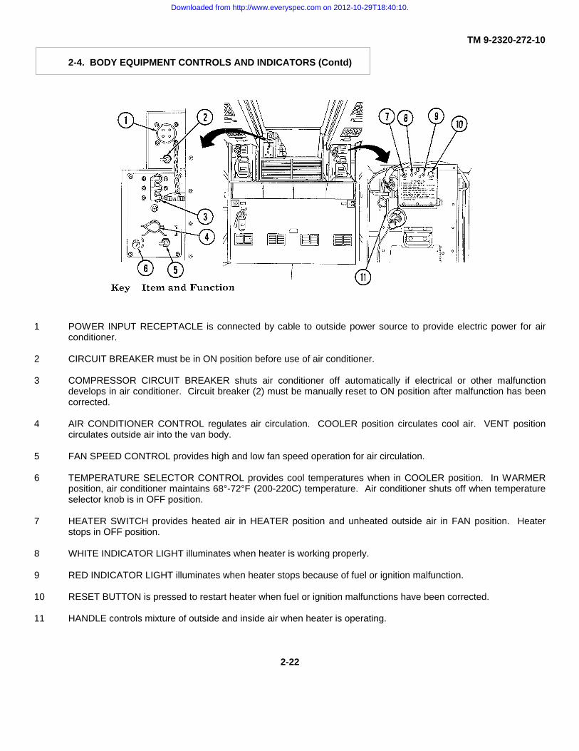
TM 9-2320-272-10
2-4. BODY EQUIPMENT CONTROLS AND INDICATORS (Contd)
1 POWER INPUT RECEPTACLE is connected by cable to outside power source to provide electric power for airconditioner.
2 CIRCUIT BREAKER must be in ON position before use of air conditioner.
3 COMPRESSOR CIRCUIT BREAKER shuts air conditioner off automatically if electrical or other malfunctiondevelops in air conditioner. Circuit breaker (2) must be manually reset to ON position after malfunction has beencorrected.
4 AIR CONDITIONER CONTROL regulates air circulation. COOLER position circulates cool air. VENT positioncirculates outside air into the van body.
5 FAN SPEED CONTROL provides high and low fan speed operation for air circulation.
6 TEMPERATURE SELECTOR CONTROL provides cool temperatures when in COOLER position. In WARMERposition, air conditioner maintains 68°-72°F (200-220C) temperature. Air conditioner shuts off when temperatureselector knob is in OFF position.
7 HEATER SWITCH provides heated air in HEATER position and unheated outside air in FAN position. Heaterstops in OFF position.
8 WHITE INDICATOR LIGHT illuminates when heater is working properly.
9 RED INDICATOR LIGHT illuminates when heater stops because of fuel or ignition malfunction.
10 RESET BUTTON is pressed to restart heater when fuel or ignition malfunctions have been corrected.
11 HANDLE controls mixture of outside and inside air when heater is operating.
2-22
Downloaded from http://www.everyspec.com on 2012-10-29T18:40:10.

TM 9-2320-272-10
2-4. BODY EQUIPMENT CONTROLS AND INDICATORS (Contd)
Key Item and Function
12 AIR CONDITIONER VENT runs along entire length of ceiling and allows air to circulate.
13 HEATER THERMOSTAT regulates heater temperature.
14 FIRE EXTINGUISHERS are mounted on van front and rear walls.
15 TELEPHONE JACK connects van telephone to outside lines.
16 VAN BODY EXPANDING AND RETRACTING WRENCH is used to expand and retract van body.
17 SIDE PANEL LOCK WRENCH is used to lock outer edges of van roof, corner posts, and end panels when van isexpanded.
18 PLATE contains instructions for operation of van.
19 BLACKOUT MAIN SWITCH is turned on for blackout operations.
20 EMERGENCY LIGHT SWITCH is turned on when normal service lights fail.
21 SIDE DOORS are used by personnel when van is expanded.
NOTE
An instruction plate near the circuit breaker panel lists circuits controlled by each switch.
22 CIRCUIT BREAKER PANEL controls electric power received from outside source.
2-23
Downloaded from http://www.everyspec.com on 2012-10-29T18:40:10.

TM 9-2320-272-10
2-4. BODY EQUIPMENT CONTROLS AND INDICATORS (Contd)
Key Item and Function
1 WINDOW REGULATOR opens window when turned clockwise and closes window when turned counterclockwise.
2 BONNET DOOR allows fresh air to enter air conditioner.
3 ROD opens bonnet door (2) when bonnet door control handle inside van is pushed forward. Rod pulls bonnetdoor (2) closed when control handle is pulled back.
4 SIDE LOCKRODS stabilize expanded van sides when attached to lock handles.
2-24
Downloaded from http://www.everyspec.com on 2012-10-29T18:40:10.
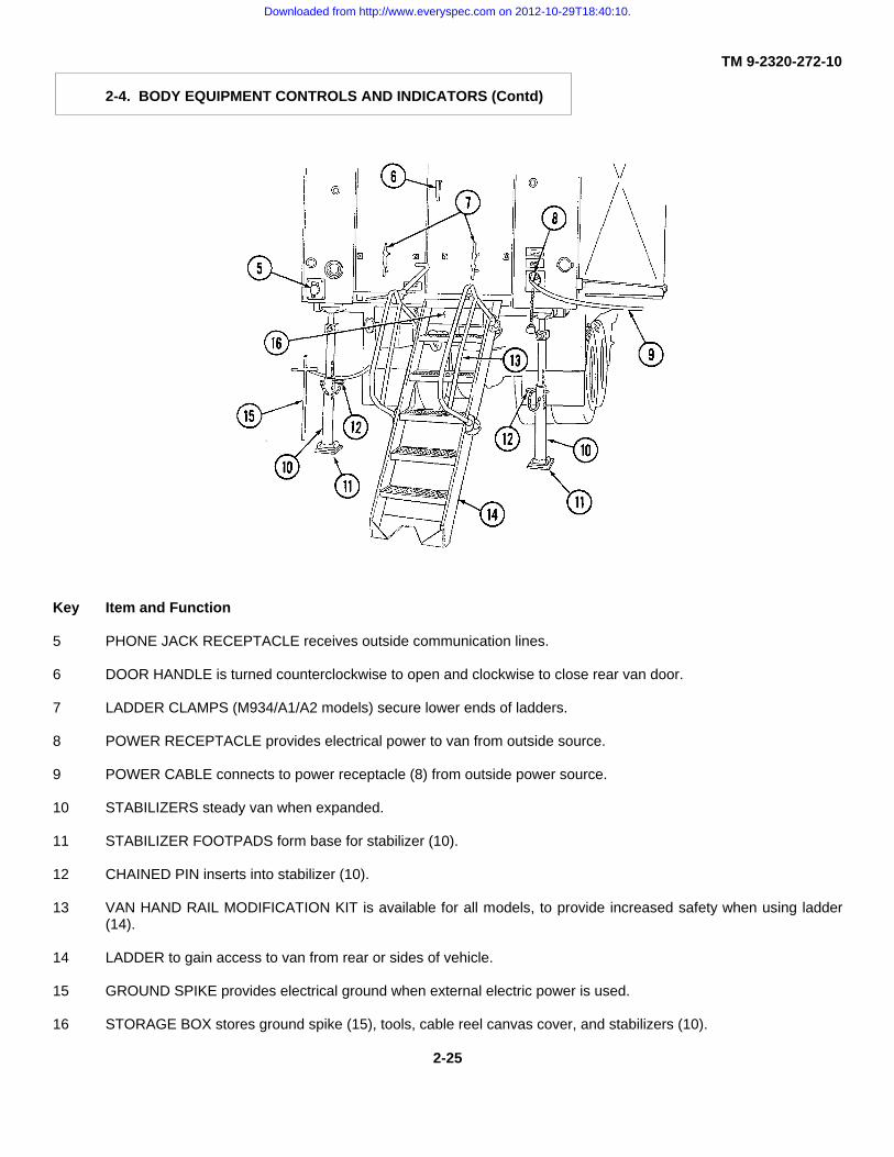
TM 9-2320-272-10
2-4. BODY EQUIPMENT CONTROLS AND INDICATORS (Contd)
Key Item and Function
5 PHONE JACK RECEPTACLE receives outside communication lines.
6 DOOR HANDLE is turned counterclockwise to open and clockwise to close rear van door.
7 LADDER CLAMPS (M934/A1/A2 models) secure lower ends of ladders.
8 POWER RECEPTACLE provides electrical power to van from outside source.
9 POWER CABLE connects to power receptacle (8) from outside power source.
10 STABILIZERS steady van when expanded.
11 STABILIZER FOOTPADS form base for stabilizer (10).
12 CHAINED PIN inserts into stabilizer (10).
13 VAN HAND RAIL MODIFICATION KIT is available for all models, to provide increased safety when using ladder(14).
14 LADDER to gain access to van from rear or sides of vehicle.
15 GROUND SPIKE provides electrical ground when external electric power is used.
16 STORAGE BOX stores ground spike (15), tools, cable reel canvas cover, and stabilizers (10).
2-25
Downloaded from http://www.everyspec.com on 2012-10-29T18:40:10.

TM 9-2320-272-10
2-4. BODY EQUIPMENT CONTROLS AND INDICATORS (Contd)
Key Item and Function
1 LOCK WRENCH is turned counterclockwise to unlock expansible sides, hinged roof, and hinged floor, beforeexpansion or retraction. Wrench is turned clockwise to lock these components after van is expanded or retracted.
2 DOOR LOCK HANDLE is turned up to unlock and down to lock van doors.
3 LADDER MOUNTING BRACKETS secure ladders when ladders are in use.
4 LOCK HANDLES engage side lockrods when van is expanded to secure expanded sides to frame.
5 PIN secures lock handle (4) in closed position.
6 POWER CABLE REEL stores power cable.
7 WINCH (M934A1/A2 models) raises and lowers spare tire on opposite side of vehicle when wire rope is attachedto tire.
2-26
Downloaded from http://www.everyspec.com on 2012-10-29T18:40:10.

TM 9-2320-272-10
2-4. BODY EQUIPMENT CONTROLS AND INDICATORS (Contd)
Key Item and Function
8 LIFTING BRACKETS on rear and front of van body allow lifting van body from chassis.
9 LADDER RACK (M934/A1/A2 models) holds ladders.
10 CLEARANCE AND BLACKOUT LIGHTS are controlled from vehicle cab.
11 VAN BODY EXPANDING AND RETRACTING WRENCH (stowed in bracket on inner part of rear door) fits overratchets (12). Wrench is turned counter- clockwise to expand left van side and clockwise to expand right van side.
12 RATCHET is turned by expanding and retracting wrench (11) to expand and retract van sides.
13 LOCKING PLUNGERS (located below left and right rear doors) are pushed downward to release ratchets (11) andpawls (14) before expanding or retracting sides. Plungers are pulled upward to lock van sides in expanded orretracted position.
14 PAWL attached to locking plunger (13) locks ratchet (12). Pawl releases ratchet when locking plunger (13) ispushed downward.
2-27
Downloaded from http://www.everyspec.com on 2012-10-29T18:40:10.

TM 9-2320-272-10
2-5. SPECIAL KITS CONTROLS AND INDICATORS
Controls and indicators which are added as part of a modification kit have been incorporated into paragraph 2-3and 2-4. Controls and Indicators which are added as part of an optional kit can be found in section V.
Section II. PREVENTIVE MAINTENANCE CHECKS AND SERVICES (PMCS)
2-6. GENERAL
Preventive Maintenance Checks and Services (PMCS) means systematic caring, inspecting, and servicing ofequipment to keep it in good condition and to prevent breakdowns. As the vehicle’s operator, your mission is to:
a. Be sure to perform your PMCS each time you operate the vehicle. Always do your PMCS in the same order,so it gets to be a habit. Once you’ve had some practice, you’ll quickly spot anything wrong.
b. Do your BEFORE checks and service just prior to the start of the mission to identify faults that will preventperformance of the mission. Pay attention to WARNINGS, CAUTIONS, and NOTES.
c. Do your DURING checks and services during the mission to identify faults in equipment performance. Payattention to WARNINGS, CAUTIONS, and NOTES.
d. Do your AFTER checks immediately at the conclusion of the mission. Pay attention to WARNINGS,CAUTIONS, and NOTES.
NOTE
When a check and service procedure is required for both weekly and after intervals, it is not necessary toperform the weekly procedure during the same week in which the before procedure was done.
e. Do your WEEKLY checks once a week to identify faults that must be corrected to sustain equipment at fullymission capable standards until next unit maintenance service.
f. Do your MONTHLY checks for faults that do not need to be checked weekly, but must be checked more oftenthan at next service by unit maintenance.
g. Use DA Form 2404 (Equipment Inspection and Maintenance Worksheet) to record any faults that youdiscover before, during, or after operation, unless you can fix them. You DO NOT need to record faults that you fix.
h. Be prepared to assist unit maintenance when they lubricate the vehicle. Perform any other services whenrequired by unit maintenance.
i. A permanent record of the services, repairs, and modifications made to these vehicles must be recorded.See DA PAM 738-750 for a list of the forms and records required. Refer to chapter 3, for specific maintenanceinstructions.
2-28
Downloaded from http://www.everyspec.com on 2012-10-29T18:40:10.

TM 9-2320-272-10
2-7. PMCS PROCEDURES
a. Your PMCS, table 2-3, lists inspections and care required to keep your vehicle in good operating condition. Itis set up so you can make your BEFORE (B) OPERATION checks as you walk around the vehicle.
b. The Item Number column of table 2-3 lists procedures in consecutive numerical order. The TM Numbercolumn on DA Form 2404, Equipment Inspection and Maintenance Worksheet, refers to these item numbers whenrecording PMCS results.
c. The INTERVAL column of table 2-3 tells you when to do a certain check or service.
d. The PROCEDURE column of table 2-3 tells you how to do required checks and services. Carefully followthese instructions. If you do not have tools, or if the procedure tells you to, notify unit maintenance.
e. The Not Fully Mission Capable If column of table 2-3 tells you why vehicle is not able to perform the describedmission, and what equipment will be reported as not ready or unavailable. Refer to DA PAM 738-750.
f. If the truck does not perform as required, refer to Table 3-1, Troubleshooting Procedures.
g. If anything looks wrong and you can’t fix it, write it on your DA Form 2404. IMMEDIATELY report it to unitmaintenance.
Drycleaning solvent is flammable and will not be used near an open flame. A fire extinguisher will be keptnearby when solvent is used. Use only in well-ventilated places. Failure to do this will result in injury topersonnel and/or damage to equipment.
NOTE
Dirt, grease, oil, and debris may cover up a serious problem. Clean as you check. Use drycleaningsolvent on all metal surfaces. Use soap and water on rubber or plastic material.
h. When you do your PMCS, you will always need a rag-or two. Following are checks that are common to theentire vehicle.
(1) Check all bolts, nuts, and screws. If loose, bent, broken, or missing, either tighten or report condition(s)to unit maintenance.
(2) Look for loose or chipped paint and rust or gaps at welds. If a cracked or broken weld is found, reportcondition(s) to unit maintenance.
(3) Check electrical wires and connectors for cracked or broken insulation. Look for bare wires and loose orbroken connections. Tighten loose connections. Report other problem(s) to unit maintenance.
(4) Check hoses and fluid lines for wear, damage, and leaks. Ensure clamps and fittings are tight. (Referto para. 2-9 for information on leaks.)
(5) Check air lines for damage or leaks. Ensure clamps and fittings are tight. Tighten loose connections. Ifleaks or other problems still exist, report condition to unit maintenance.
2-29
Downloaded from http://www.everyspec.com on 2012-10-29T18:40:10.

TM 9-2320-272-10
2-7. PMCS PROCEDURES (Contd)
i. Correct Assembly or Stowage. Check each component or assembly for proper installation and ensure thatthere are no missing parts.
2-8. CLEANING INSTRUCTION AND PRECAUTIONS
Accidental or intentional introduction of liquid contaminants into the environment is in violation of state,federal, and military regulations. Refer to Lubrication Order (para. 3-1) for information concerning storage,use, and disposal of these liquids. Failure to do so may result in injury or death.
Cleaning is an after-operation service performed by operator/crew to keep the vehicle in a state of readiness. Facilitiesand material available to operators for vehicle cleaning can vary greatly in differing operating conditions. However,vehicles must be kept as clean as available cleaning equipment, materials, and tactical situations permit.
a. General Cleaning Precautions.
(1) All cleaning procedures must be accomplished in well-ventilated areas.
(2) Protective gloves, clothing, and/or respiratory equipment must be worn whenever caustic, toxic, orflammable cleaning solutions are used.
(3) Diesel fuel or gasoline must never be used for cleaning.
(4) A fire extinguisher must be available and ready during all cleaning operations involving solvents.
b. Special Precautions.
(1) Do not allow cleaning compounds to come into contact with rubber, leather, vinyl, or canvas materials.
(2) Do not allow corrosion-removing cleaning compounds to contact painted surfaces.
(3) Do not use air in cleaning truck cab interiors or van body interiors.
(4) Do not steam-clean any part of vehicle that has been rustproofed.
(5) Mildew must be removed with a bristle brush before canvas tarpaulin can be properly cleaned and aired.
(6) The radiator is always cleaned first from behind in order to blow debris, insects, or other obstructions outand away from the radiator core. Low pressure water or air can be used in cleaning radiator core of obstructions.
c. Cleaning Materials. Detailed description of specific cleaning compounds, cleaning solvents, drycleaningsolutions, and corrosion-removing compounds are found in TM 9-247.
2-30
Downloaded from http://www.everyspec.com on 2012-10-29T18:40:10.
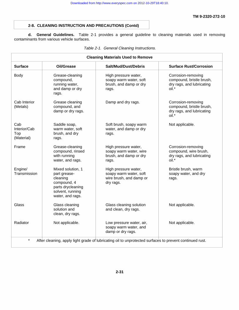
TM 9-2320-272-10
2-8. CLEANING INSTRUCTION AND PRECAUTIONS (Contd)
d. General Guidelines. Table 2-1 provides a general guideline to cleaning materials used in removingcontaminants from various vehicle surfaces.
Table 2-1. General Cleaning Instructions.
Cleaning Materials Used to Remove
Surface Oil/Grease Salt/Mud/Dust/Debris Surface Rust/Corrosion
Body Grease-cleaning High pressure water, Corrosion-removingcompound, soapy warm water, soft compound, bristle brush,running water, brush, and damp or dry dry rags, and lubricatingand damp or dry rags. oil.*rags.
Cab Interior Grease cleaning Damp and dry rags. Corrosion-removing(Metals) compound, and compound, bristle brush,
damp or dry rags. dry rags, and lubricatingoil.*
Cab Saddle soap, Soft brush, soapy warm Not applicable.Interior/Cab warm water, soft water, and damp or dryTop brush, and dry rags.(Material) rags.
Frame Grease-cleaning High pressure water, Corrosion-removingcompound, rinsed soapy warm water, wire compound, wire brush,with running brush, and damp or dry dry rags, and lubricatingwater, and rags. rags. oil.*
Engine/ Mixed solution, 1 High pressure water, Bristle brush, warmTransmission part grease- soapy warm water, soft soapy water, and dry
cleaning wire brush, and damp or rags.compound, 4 dry rags.parts drycleaningsolvent, runningwater, and rags.
Glass Glass cleaning Glass cleaning solution Not applicable.solution and and clean, dry rags.clean, dry rags.
Radiator Not applicable. Low pressure water, air, Not applicable.soapy warm water, anddamp or dry rags.
* After cleaning, apply light grade of lubricating oil to unprotected surfaces to prevent continued rust.
2-31
Downloaded from http://www.everyspec.com on 2012-10-29T18:40:10.

TM 9-2320-272-10
2-8. CLEANING INSTRUCTION AND PRECAUTIONS (Contd)
Table 2-1. General Cleaning Instructions (Contd).
Cleaning Materials Used to Remove
Surface Oil/Grease Salt/Mud/Dust/Debris Surface Rust/Corrosion
Rubber Damp or dry rags. Damp or dry rags. Not applicable.Insulation
Tires Soapy water and High pressure water and Not applicable.bristle brush. bristle brush.
Wire Rope Cleaning Wire brush. Wire brush andcompound and lubricating oil.**wire brush.
Wood Detergent, warm Low pressure water, Not applicable.water, and damp soapy warm water, andor dry rags. damp or dry rags.
** After cleaning, apply grease (MIL-B-18458).
2-9. CLASS LEAKAGE DEFINITIONS
Accidental or intentional introduction of liquid contaminants into the environment is in violation of state,federal, and military regulations. Refer to Lubrication Order (para. 3-1) for information concerning storage,use, and disposal of these liquids. Failure to do so may result in injury or death.
Wetness around seals, gaskets, fittings, or connections indicates leakage. A stain also denotes leakage. If afitting or connector is loose, tighten it. If broken or defective, report it. Use the following as a guide when referring to table2-2, Fluid Leakage Criteria for Tactical Vehicles:
a. Class I. Leakage indicated by wetness or discoloration not great enough to form drops.
b. Class II. Leakage great enough to form drops, but not enough to cause drops to drip from item beingchecked/inspected.
c. Class III. Leakage great enough to form drops that fall from the item being checked/inspected.
2-32
Downloaded from http://www.everyspec.com on 2012-10-29T18:40:10.

TM 9-2320-272-10
2-9. CLASS LEAKAGE DEFINITIONS (Contd)
CAUTION
Operation is allowable with class I or II leakage. You must, of course, consider fluid capacity of theitem/system. WHEN IN DOUBT, NOTIFY UNIT MAINTENANCE. When operating with class I or II leaks,check fluid levels more frequently. Class III leaks must be reported immediately to your supervisor or tounit maintenance.
Table 2-2. Fluid Leakage Criteria for Tactical Vehicles.
DEADUNINGFLUID LEAKAGE CRITERIA FOR TACTICAL VEHICLES LEAKAGE CRITERIA
I II IIIALL MODELSAir Compressor (Oil) aCoolant System (Engine) aDifferentials aDump Hoist Cylinder aEngine Lube Oil System aEngine Surge Tank aFront Winch (M925/A1/A2, M928/A1/A2, M930/A1/A2, a
M932/A1/A2, M936/A1/A2)Fuel Filter/Water Separator aFuel System aFuel Tank aHydraulic Hoist (except M923/A1/A2, M927/A1/A2, a
M931/A1/A2, and M934/A1/A2) aHydraulic Lines and Hoses (except M923/A1/A2,
M927/A1/A2, M931/A1/A2, and M934/A1/A2) aHydraulic Pump (except M923/A1/A2, M927/A1/A2,
M931/A1/A2, and M934/A1/A2) aHydraulic Tank aOil Filter aPersonnel Heater and Hoses aPower Steering Assist Cylinder aPower Steering Pump aPower TrainPTO (except M923/A1/A2, M927/A1/A2, a
M931/A1/A2, and M934/Al/A2)Radiator aTransmission Cooler aTransmission and Transmission Case aWater Pump a
M936/A1/A2 MEDIUM WRECKER aCrane in Operation aRear Winch and Crane aWrecker Crane a
2-33
Downloaded from http://www.everyspec.com on 2012-10-29T18:40:10.

TM 9-2320-272-10
2-10. PMCS TABLE
Walk-around inspections will begin at the front of the vehicle and proceed around the crewmember’s side (rightside), around the rear of the vehicle, and continue up the driver’s side (left side). If inspection items are found in more thanone location, cover the entire vehicle. Reinspection is required after a change in engine run-up condition, and is notcomplete until all areas have been inspected or reinspected.
Table 2-3. Preventive Maintenance Checks and Services for Models M939/A1/A2.
LocationItem Interval Item to CREWMEMBER Not Fully MissionNo. Check/ Procedure Capable If:
Service
WARNING
Always remember theCAUTIONS, WARNINGS, andNOTES before operating thisvehicle and prior to PMCS.
Perform all before, during, after,and weekly checks if:
a. You are the assigned driverbut have not operated the vehiclesince the last weekly inspection.
b. You are operating the vehiclefor the first time.
2-34
Downloaded from http://www.everyspec.com on 2012-10-29T18:40:10.

TM 9-2320-272-10
Table 2-3. Preventive Maintenance Checks and Service for Models M939/A1/A2 (Contd).
(Para 2-9)
(Para 2-9)
2-35
Downloaded from http://www.everyspec.com on 2012-10-29T18:40:10.

TM 9-2320-272-10
Table 2-3. Preventive Maintenance Checks and Services for Models M939 /A1/A2 (Contd).
(Para 2-9)
(Para 2-9)
(Para 3-11)
2-36
Downloaded from http://www.everyspec.com on 2012-10-29T18:40:10.

TM 9-2320-272-10
Table 2-3. Preventive Maintenance Checks and Services for Models M939 /A1 /A2 (Contd).
(Para 3-11)
(Para 3-11)
2-37
Downloaded from http://www.everyspec.com on 2012-10-29T18:40:10.

TM 9-2320-272-10
Table 2-3. Preventive Maintenance Checks and Services for Models M939 /A1/ A2 (Contd).
2-38
Downloaded from http://www.everyspec.com on 2012-10-29T18:40:10.
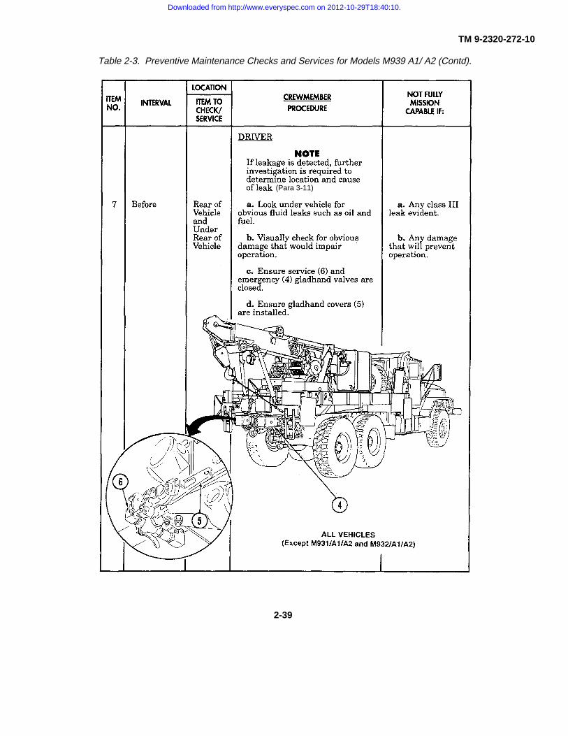
TM 9-2320-272-10
Table 2-3. Preventive Maintenance Checks and Services for Models M939 A1/ A2 (Contd).
(Para 3-11)
2-39
Downloaded from http://www.everyspec.com on 2012-10-29T18:40:10.

TM 9-2320-272-10
Table 2-3. Preventive Maintenance Checks and Services for Models M939/A1/A2 (Contd).
2-40
Downloaded from http://www.everyspec.com on 2012-10-29T18:40:10.
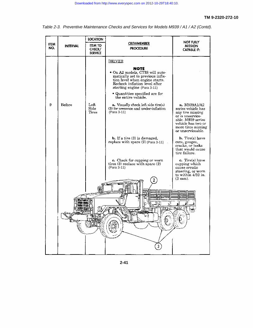
TM 9-2320-272-10
Table 2-3. Preventive Maintenance Checks and Services for Models M939 / A1 / A2 (Contd).
(Para 3-11)
(Para 3-11)
(Para 3-11)
(Para 3-11)
2-41
Downloaded from http://www.everyspec.com on 2012-10-29T18:40:10.

TM 9-2320-272-10
Table 2-3. Preventive Maintenance Checks and Services for Models M939 /A1/A2 (Contd).
2-42
Downloaded from http://www.everyspec.com on 2012-10-29T18:40:10.

TM 9-2320-272-10
Table 2-3. Preventive Maintenance Checks and Services for Models M939 / A1 / A2 (Contd).
(Para 2-9)
2-43
Downloaded from http://www.everyspec.com on 2012-10-29T18:40:10.

TM 9-2320-272-10
Table 2-3. Preventive Maintenance Checks and Services for Models M939 / A1 / A2 (Contd).
(Para 2-12)
(Para 2-12)
2-44
Downloaded from http://www.everyspec.com on 2012-10-29T18:40:10.
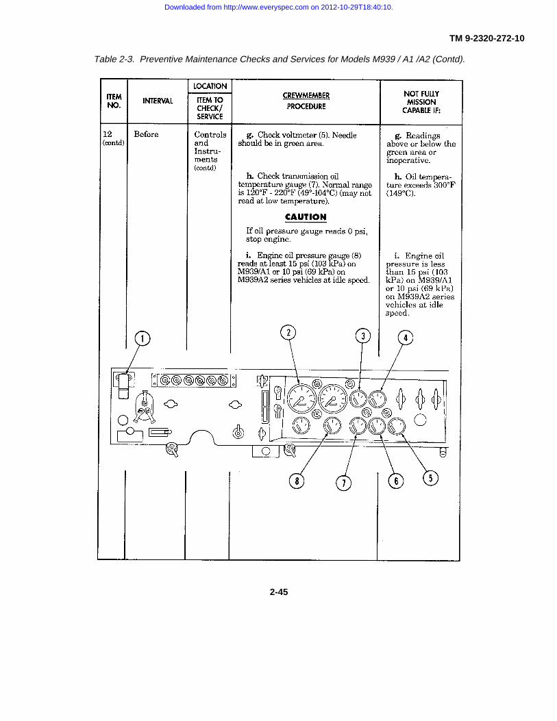
TM 9-2320-272-10
Table 2-3. Preventive Maintenance Checks and Services for Models M939 / A1 /A2 (Contd).
2-45
Downloaded from http://www.everyspec.com on 2012-10-29T18:40:10.

TM 9-2320-272-10
Table 2-3. Preventive Maintenance Checks and Services for Models M939 / A1 / A2 (Contd).
(Para 3-17)
(Para 2-3)
2-46
Downloaded from http://www.everyspec.com on 2012-10-29T18:40:10.

TM 9-2320-272-10
Table 2-3. Preventive Maintenance Checks and Services for Models M939 / A1 / A2 (Contd).
2-47
(Para 3-13
(Para 3-16)
(Para 2-14)
Downloaded from http://www.everyspec.com on 2012-10-29T18:40:10.

TM 9-2320-272-10
Table 2-3. Preventive Maintenance Checks and Services for Models M939 / A1/ IA2 (Contd).
(Para 2-12)
2-48
Downloaded from http://www.everyspec.com on 2012-10-29T18:40:10.

TM 9-2320-272-10
Table 2-3. Preventive Maintenance Checks and Services for Models M939 / A1 / A2 (Contd).
2-49
Downloaded from http://www.everyspec.com on 2012-10-29T18:40:10.

TM 9-2320-272-10
Table 2-3. Preventive Maintenance Checks and Services for Models M939 / A1 / A2 (Contd).
(Para 2-26)
(Para 3-12)
2-50
Downloaded from http://www.everyspec.com on 2012-10-29T18:40:10.

TM 9-2320-272-10
Table 2-3. Preventive Maintenance Checks and Services for Models M939 / A1 / A2 (Contd).
2-51
Downloaded from http://www.everyspec.com on 2012-10-29T18:40:10.

TM 9-2320-272-10
Table 2-3. Preventive Maintenance Checks and Services for Models M939 / A1 / A2 (Contd).
2-52
Downloaded from http://www.everyspec.com on 2012-10-29T18:40:10.

TM 9-2320-272-10
Table 2-3. Preventive Maintenance Checks and Services for Models M939 / A1 / A2 (Contd).
(Para 2-12)
(Para 3-16)
(Para 2-14)
2-53
Downloaded from http://www.everyspec.com on 2012-10-29T18:40:10.

TM 9-2320-272-10
Table 2-3. Preventive Maintenance Checks and Services for Models M939 / A1 / A2 (Contd).
(Para 3-13)
(Para 2-22)
(Para 2-19)
2-54
Downloaded from http://www.everyspec.com on 2012-10-29T18:40:10.

TM 9-2320-272-10
Table 2-3. Preventive Maintenance Checks and Services for Models M939 / A1 / A2 (Contd).
2-55
Downloaded from http://www.everyspec.com on 2012-10-29T18:40:10.

TM 9-2320-272-10
Table 2-3. Preventive Maintenance Checks and Services for Models M939 / A1 / A2 (Contd).
2-56
Downloaded from http://www.everyspec.com on 2012-10-29T18:40:10.

TM 9-2320-272-10
Table 2-3. Preventive Maintenance Checks and Services for Models M939 / A1 / A2 (Contd).
(Para 2-9)
2-57
Downloaded from http://www.everyspec.com on 2012-10-29T18:40:10.

TM 9-2320-272-10
Table 2-3. Preventive Maintenance Checks and Services for Models M939 / A1 / A2 (Contd).
2-58
(Para 3-1)
(Para 3-10)
(Para 3-10)
Downloaded from http://www.everyspec.com on 2012-10-29T18:40:10.

TM 9-2320-272-10
Table 2-3. Preventive Maintenance Checks and Services for Models M939 / A1 / A2 (Contd).
2-59
Downloaded from http://www.everyspec.com on 2012-10-29T18:40:10.
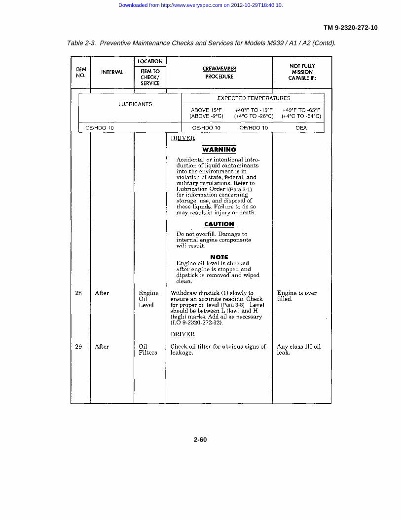
TM 9-2320-272-10
Table 2-3. Preventive Maintenance Checks and Services for Models M939 / A1 / A2 (Contd).
(Para 3-1)
(Para 3-8)
2-60
Downloaded from http://www.everyspec.com on 2012-10-29T18:40:10.

TM 9-2320-272-10
Table 2-3. Preventive Maintenance Checks and Services for Models M939 / A1 / A2 (Contd).
2-61
Downloaded from http://www.everyspec.com on 2012-10-29T18:40:10.

TM 9-2320-272-10
Table 2-3. Preventive Maintenance Checks and Services for Models M939 / A1 / A2 (Contd).
(Para 3-10)
(Para 3-8)
2-62
Downloaded from http://www.everyspec.com on 2012-10-29T18:40:10.

TM 9-2320-272-10
Table 2-3. Preventive Maintenance Checks and Services for Models M939/A1/A2 (Contd).
(Para 2-9)
2-63
Downloaded from http://www.everyspec.com on 2012-10-29T18:40:10.

TM 9-2320-272-10
Table 2-3. Preventive Maintenance Checks and Services for Models M939 /A1/A2 (Contd).
(Para 2-9)
(Para 2-9)
2-64
Downloaded from http://www.everyspec.com on 2012-10-29T18:40:10.

TM 9-2320-272-10
Table 2-3. Preventive Maintenance Checks and Services for Models M939 /A1/A2 (Contd).
(Para 2-9)
(Para 2-9)
2-65
Downloaded from http://www.everyspec.com on 2012-10-29T18:40:10.
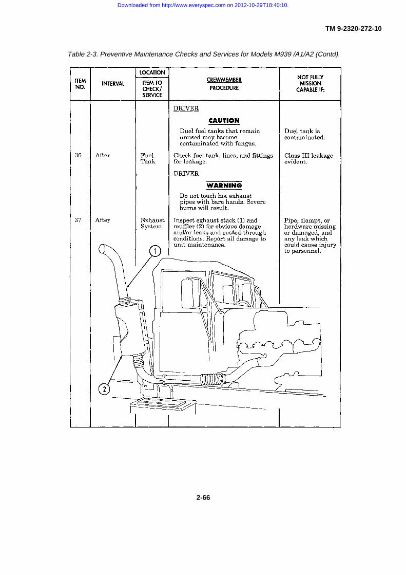
TM 9-2320-272-10
Table 2-3. Preventive Maintenance Checks and Services for Models M939 /A1/A2 (Contd).
2-66
Downloaded from http://www.everyspec.com on 2012-10-29T18:40:10.
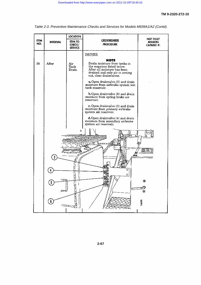
TM 9-2320-272-10
Table 2-3. Preventive Maintenance Checks and Services for Models M939A1/A2 (Contd).
2-67
Downloaded from http://www.everyspec.com on 2012-10-29T18:40:10.

TM 9-2320-272-10
Table 2-3. Preventive Maintenance Checks and Services for Models M939 /A1 A2 (Contd).
(Para 2-9)
2-68
Downloaded from http://www.everyspec.com on 2012-10-29T18:40:10.

TM 9-2320-272-10
Table 2-3. Preventive Maintenance Checks and Services for Models M939/A1/A2 (Contd).
2-69
Downloaded from http://www.everyspec.com on 2012-10-29T18:40:10.

TM 9-2320-272-10
Table 2-3. Preventive Maintenance Checks and Services for Models M939 /A1/A2 (Contd).
2-70
Downloaded from http://www.everyspec.com on 2012-10-29T18:40:10.

TM 9-2320-272-10
Table 2-3. Preventive Maintenance Checks and Services for Models M939/A1/A2 (Contd).
(Para 2-9)
(Para 2-9)
(Para 2-9)
2-71
Downloaded from http://www.everyspec.com on 2012-10-29T18:40:10.

TM 9-2320-272-10
Table 2-3. Preventive Maintenance Checks and Services for Models M939 I/A1/A2 (Contd).
(Para 3-9 and 3-12)
(Para 3-9)
2-72
Downloaded from http://www.everyspec.com on 2012-10-29T18:40:10.

TM 9-2320-272-10
Table 2-3. Preventive Maintenance Checks and Services for Models M939 /A1IA2 (Contd).
2-73
Downloaded from http://www.everyspec.com on 2012-10-29T18:40:10.

TM 9-2320-272-10
Table 2-3. Preventive Maintenance Checks and Services for Models M939 /A1/A2 (Contd).
2-74
Downloaded from http://www.everyspec.com on 2012-10-29T18:40:10.

TM 9-2320-272-10
Table 2-3. Preventive Maintenance Checks and Services for Models M939/A1/A2 (Contd).
2-75
Downloaded from http://www.everyspec.com on 2012-10-29T18:40:10.

TM 9-2320-272-10
Table 2-3. Preventive Maintenance Checks and Services for Models M9391A1/A2 (Contd).
2-76
Downloaded from http://www.everyspec.com on 2012-10-29T18:40:10.

TM 9-2320-272-10
Table 2-3. Preventive Maintenance Checks and Services for Models M939/A1/A2 (Contd).
2-77
Downloaded from http://www.everyspec.com on 2012-10-29T18:40:10.
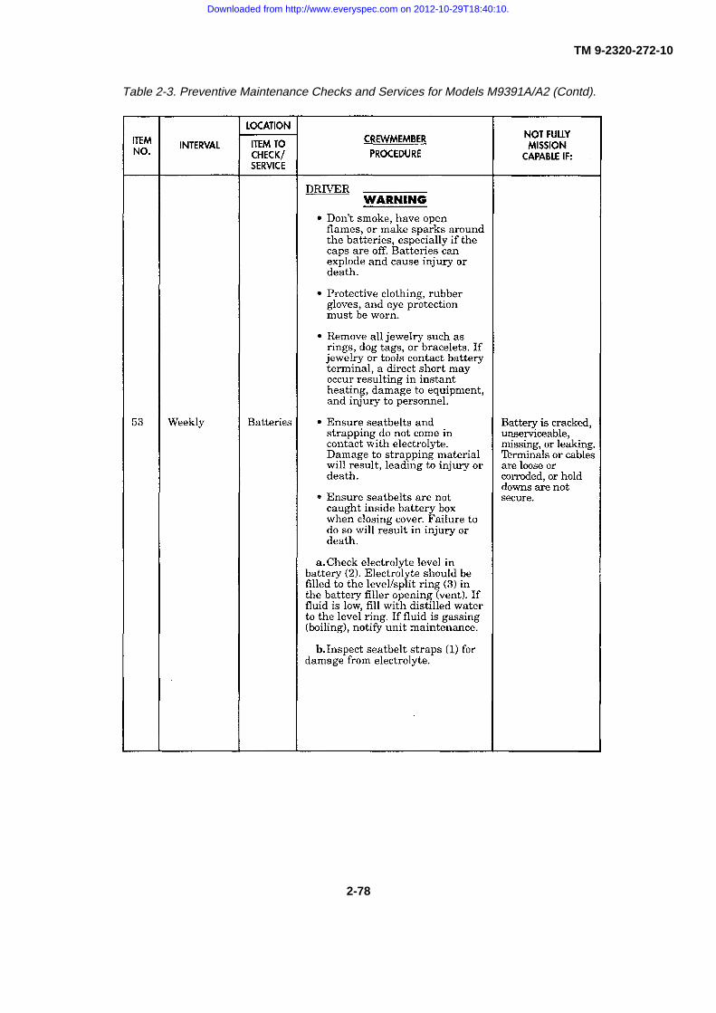
TM 9-2320-272-10
Table 2-3. Preventive Maintenance Checks and Services for Models M9391A/A2 (Contd).
2-78
Downloaded from http://www.everyspec.com on 2012-10-29T18:40:10.
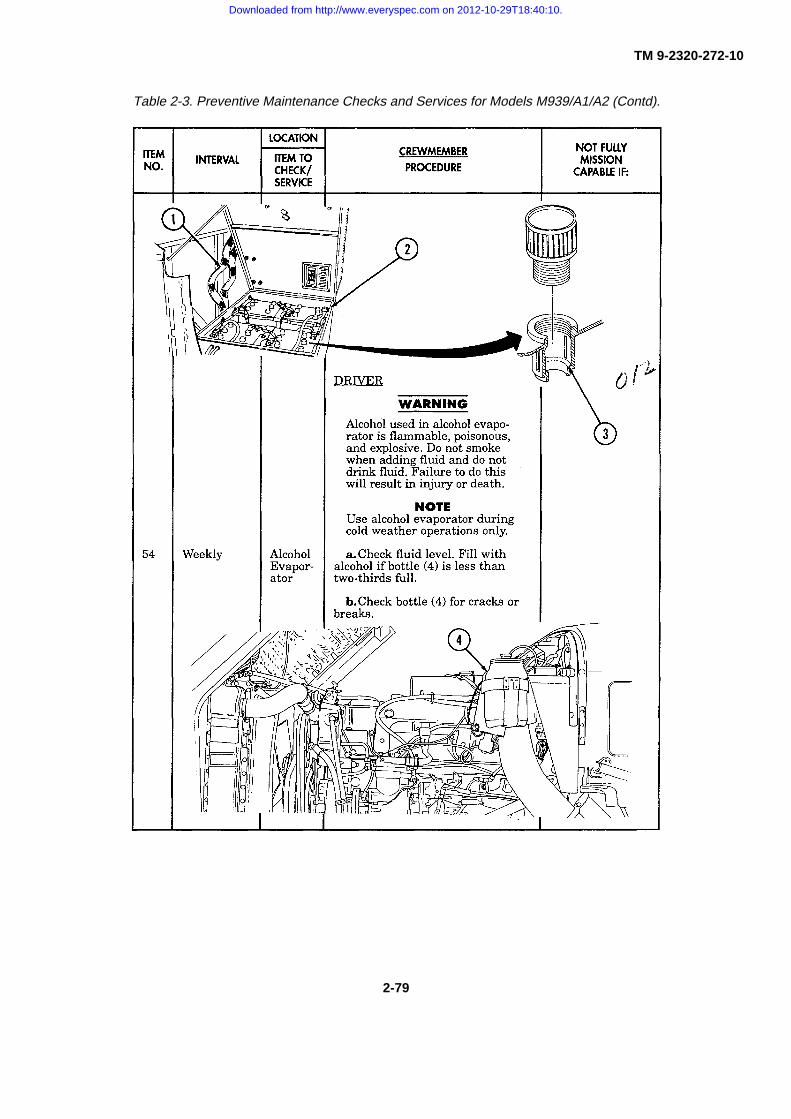
TM 9-2320-272-10
Table 2-3. Preventive Maintenance Checks and Services for Models M939/A1/A2 (Contd).
2-79
Downloaded from http://www.everyspec.com on 2012-10-29T18:40:10.

TM 9-2320-272-10
Table 2-3. Preventive Maintenance Checks and Services for Models M939/A1/A2 (Contd).
2-80
Downloaded from http://www.everyspec.com on 2012-10-29T18:40:10.

TM 9-2320-272-10
Table 2-3. Preventive Maintenance Checks and Services for Models M939 /A1/A2 (Contd).
2-81
Downloaded from http://www.everyspec.com on 2012-10-29T18:40:10.

TM 9-2320-272-10
Table 2-3. Preventive Maintenance Checks and Services for Models M939 /A1/A2 (Contd).
2-82
Downloaded from http://www.everyspec.com on 2012-10-29T18:40:10.

TM 9-2320-272-10
Table 2-3. Preventive Maintenance Checks and Services for Models M939 /A1/A2 (Contd).
(Para 2-11)
2-83
Downloaded from http://www.everyspec.com on 2012-10-29T18:40:10.

TM 9-2320-272-10
Table 2-3. Preventive Maintenance Checks and Services for Models M939/A1/A2 (Contd).
(Para 2-9)
(Para 2-9)
2-84
Downloaded from http://www.everyspec.com on 2012-10-29T18:40:10.

TM 9-2320-272-10
Table 2-3. Preventive Maintenance Checks and Services for Models M939 /A1/A2 (Contd).
2-85
Downloaded from http://www.everyspec.com on 2012-10-29T18:40:10.

TM 9-2320-272-10
Table 2-3. Preventive Maintenance Checks and Services for Models M939 /A1/A2 (Contd).
2-86
Downloaded from http://www.everyspec.com on 2012-10-29T18:40:10.
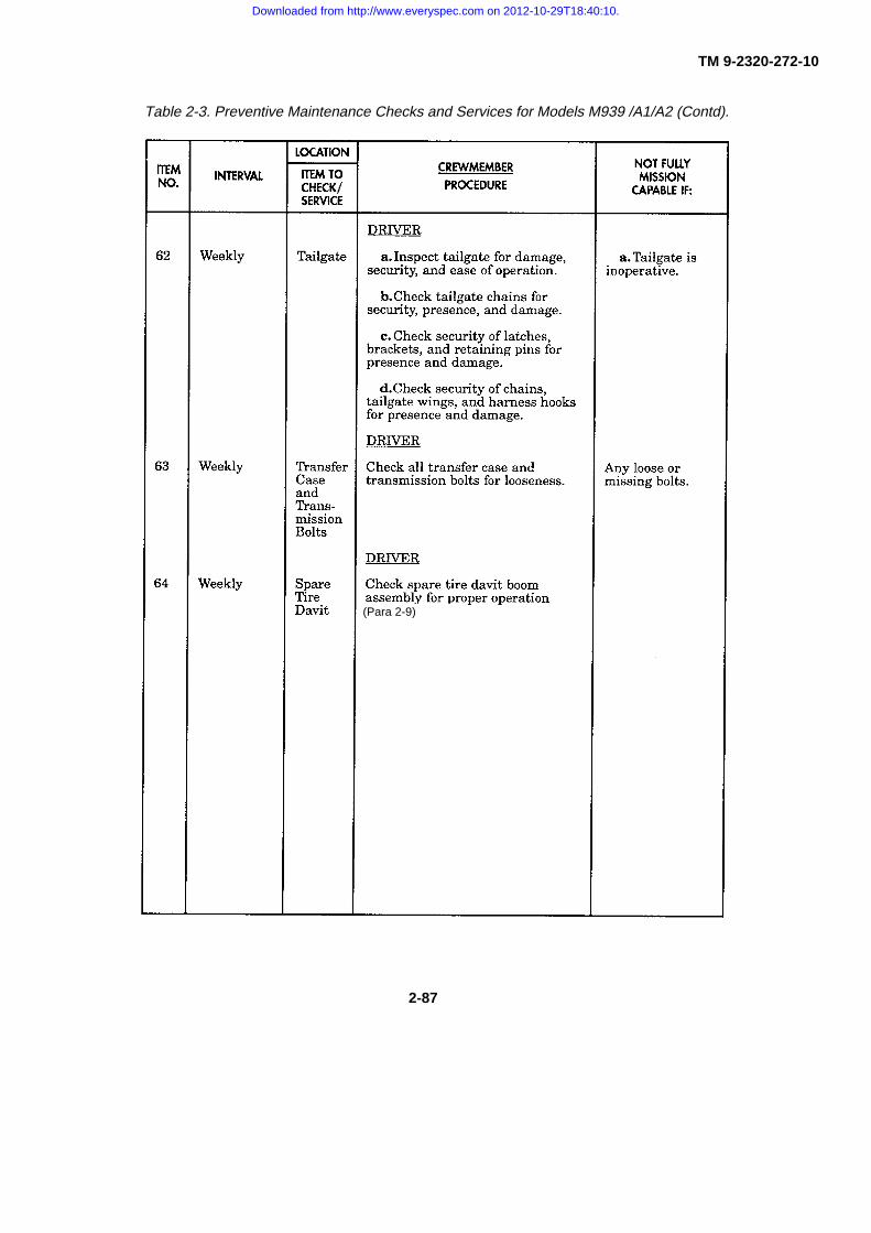
TM 9-2320-272-10
Table 2-3. Preventive Maintenance Checks and Services for Models M939 /A1/A2 (Contd).
(Para 2-9)
2-87
Downloaded from http://www.everyspec.com on 2012-10-29T18:40:10.

TM 9-2320-272-10
Table 2-3. Preventive Maintenance Checks and Services for Models M939 /A1/A2 (Contd).
(Para 2-9)
2-88
Downloaded from http://www.everyspec.com on 2012-10-29T18:40:10.

TM 9-2320-272-10
Table 2-3. Preventive Maintenance Checks and Services for Models M939 /A1/A2 (Contd).
2-89
Downloaded from http://www.everyspec.com on 2012-10-29T18:40:10.

TM 9-2320-272-10
Table 2-3. Preventive Maintenance Checks and Services for Models M939/A1/A2 (Contd).
(Para 2-40)
(Para 2-40)
(Para 2-40)
(Para 2-40)
2-90
Downloaded from http://www.everyspec.com on 2012-10-29T18:40:10.
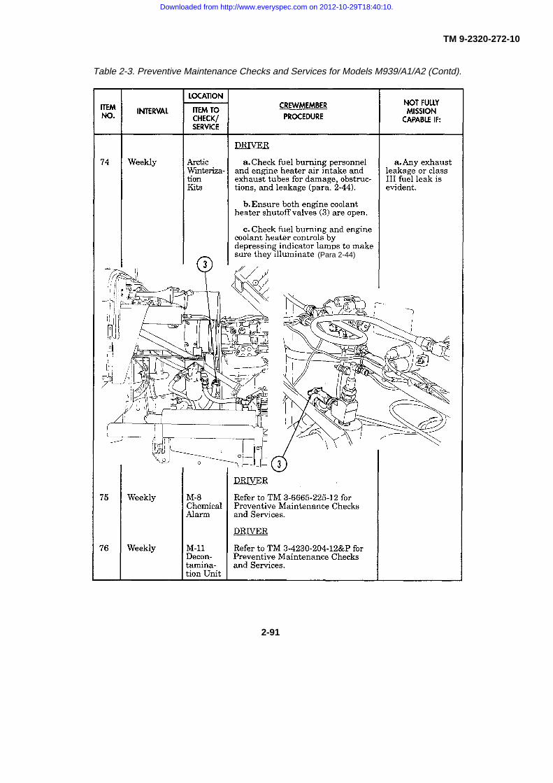
TM 9-2320-272-10
Table 2-3. Preventive Maintenance Checks and Services for Models M939/A1/A2 (Contd).
(Para 2-44)
2-91
Downloaded from http://www.everyspec.com on 2012-10-29T18:40:10.

TM 9-2320-272-10
Table 2-3. Preventive Maintenance Checks and Services for Models M939/A1/A2 (Contd).
(Para 2-40)
2-92
Downloaded from http://www.everyspec.com on 2012-10-29T18:40:10.
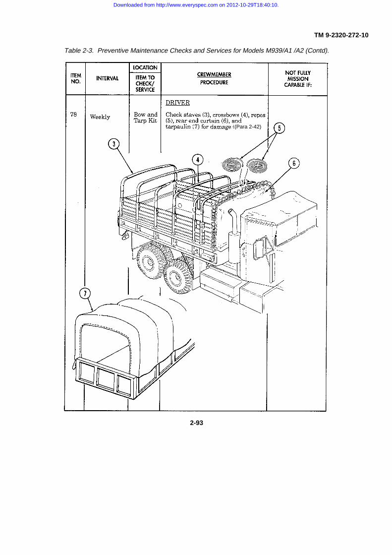
TM 9-2320-272-10
Table 2-3. Preventive Maintenance Checks and Services for Models M939/A1 /A2 (Contd).
(Para 2-42)
2-93
Downloaded from http://www.everyspec.com on 2012-10-29T18:40:10.

TM 9-2320-272-10
Table 2-3. Preventive Maintenance Checks and Services for Models M939 /A1/A2 (Contd).
(Para 2-43)
2-94
Downloaded from http://www.everyspec.com on 2012-10-29T18:40:10.

TM 9-2320-272-10
Table 2-3. Preventive Maintenance Checks and Services for Models M939/A1/A2 (Contd).
2-95
Downloaded from http://www.everyspec.com on 2012-10-29T18:40:10.

TM 9-2320-272-10
Table 2-3. Preventive Maintenance Checks and Services for Models M939/A1/A2 (Contd).
2-96
Downloaded from http://www.everyspec.com on 2012-10-29T18:40:10.

TM 9-2320-272-10
Table 2-3. Preventive Maintenance Checks and Services for Models M939/A1/A2 (Contd).
2-97
Downloaded from http://www.everyspec.com on 2012-10-29T18:40:10.

TM 9-2320-272-10
Table 2-3. Preventive Maintenance Checks and Services for Models M939/A1/A2 (Contd).
2-98
Downloaded from http://www.everyspec.com on 2012-10-29T18:40:10.
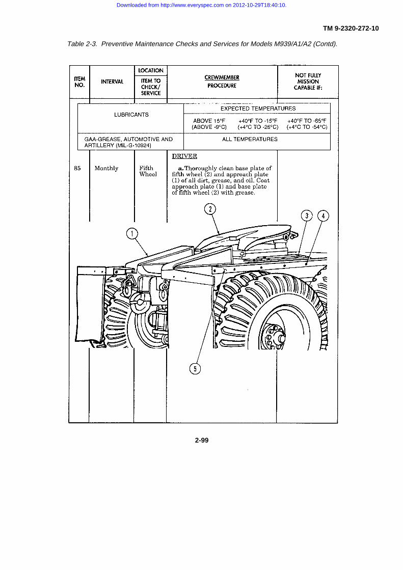
TM 9-2320-272-10
Table 2-3. Preventive Maintenance Checks and Services for Models M939/A1/A2 (Contd).
2-99
Downloaded from http://www.everyspec.com on 2012-10-29T18:40:10.

TM 9-2320-272-10
Section III. OPERATION UNDER USUAL CONDITIONS
2-11. GENERAL
This section provides instructions for vehicle operations under moderate temperature, humidity, and terrainconditions. For vehicle operations under unusual conditions, refer to Section IV of this chapter.
WARNING
This vehicle has been designed to operate safely and efficiently within thelimits specified in this TM. Operation beyond these limits is prohibited IAWAR 70-1 without written approval from the Commander, U.S. Army Tank-automotive and Armaments Command, ATTN: AMCPEO-CM-S, Warren,MI 48397-5000.
NOTE
Before you attempt to operate your vehicle, be sure to perform thepreventive maintenance checks and services shown in table 2-3.
2-12. STARTING THE ENGINE (ABOVE +32°F) (O°C)
a. Ensure parking brakes are applied. Turn knob on the end of parking brake lever (4) to adjust brake cabletension and pull up on parking brake lever (4) to apply brakes.
b. Adjust operator’s seat. Refer to paragraph 2-3.
c. Adjust left and right rearview mirrors. Ensure both mirrors provide a clear rearview.
d. Ensure vehicle front and side windows are clean. If not, clean windows before
e. On vehicles with a front winch, ensuretransmission power takeoff control lever (2) is inDISENGAGE position.
f. On vehicles equipped with transfer casepower takeoff control lever (3), ensure lever (3) islocked in neutral (full forward) position.
g. Place automatic transmission selectorlever (1) in N (neutral).
h. Ensure EMERGENCY ENGINE STOPcontrol (8) is pushed in all the way.
i. Check air cleaner indicator (6). If redappears, indicating air restriction, notify yoursupervisor.
j. Place battery switch (10) in ONposition.
2-100
Downloaded from http://www.everyspec.com on 2012-10-29T18:40:10.

TM 9-2320-272-10
2-12. STARTING THE ENGINE (ABOVE +320F) (O°C) (Contd)
NOTE• Perform steps k. and 1. for M939A1 vehicles.• For M939A2 vehicle, crank engine first, then depress accelerator pedal
all the way down. When engine fires, release pedal to partial travel.
k. Depress accelerator pedal (5).
CAUTION
Do not operate starter continuously for more than 10 seconds at a time, orwith headlights on. Wait 10-15 seconds between periods of starteroperation.
l. Place ignition switch (11) in START position. Release switch (11) after engine starts.
m. Check your instruments:
(1) Air pressure gauges (14) and (15) must read 50-60 psi (345-414 kPa) before warning light (7) goesout and warning buzzer stops. Normal operating pressures for both gauges (14) and (15) is 90-130 psi (621-896 kPa).
(2) Oil pressure gauge (13) should read 15 psi (103 kPa) on M939/A1 series vehicles, 10 psi (69 kPa)on M939A2 series vehicles, or higher.
(3) Voltmeter (16) should read in green area.
(4) Fuel gauge (17) indicates fuel level in fuel tank(s).
n. If necessary, pull out hand throttle control (9) until tachometer (12) indicates an operating range of 700-800 rpm (800-1000 rpm on M939A2 vehicles).
o. Allow engine to warm up approximately five minutes. If engaged, disengage hand throttle control (9) byrotating handle and pushing in to allow engine speed to drop to idle after warmup period.
p. Pull out EMERGENCY ENGINE STOP control (8) if any of the following
2-101
Downloaded from http://www.everyspec.com on 2012-10-29T18:40:10.

TM 9-2320-272-10
2-12. STARTING THE ENGINE (ABOVE +32°F) (O°C) (Contd)
conditions occur:
(1) Noisy engine and/or excessive engine vibration.
(2) Oil pressure does not register, or suddenly drops to less than 15 psi (103 kPa) on M939A1 series; 10psi (69 kPa) on M939A2 series, as indicated by engine oil pressure gauge (6).
(3) Sudden increase in coolant temperature beyond normal operating temperature, 175°-200°F (79°-93°C), as indicated by engine coolant temperature gauge (5).
(4) Engine continues to run after ignition switch (1) and battery switch (3) are turned to OFF positions.
q. After an emergency shutdown, the engine will not restart until unit maintenance resets the fuel shutoffvalve. On M939A2 series vehicles, position EMERGENCY ENGINE STOP control (7) to reset.
r. Turn vehicle light switch (9) to desired position (para. 2-18).
2-13. COLD WEATHER STARTING (BELOW +32°F) (O°C)
a. Perform steps a. through k. in paragraph 2-12.
b. Press ether start switch (8) during cranking. Allow three seconds for ether to discharge into system afterreleasing switch (8).
CAUTION
Do not operate starter continuously for more than 10 seconds at a time orwith headlights on. Wait 10-15 seconds between periods of starteroperation.
NOTEIf engine cranks but will not start, turn battery switch to OFF position. Seetroubleshooting, malfunction 3.
c. Release engine ignition switch (1) after engine starts.
2-102
Downloaded from http://www.everyspec.com on 2012-10-29T18:40:10.

TM 9-2320-272-10
2-13. COLD WEATHER STARTING (BELOW +32°F) (0C) (Contd)
NOTE• If engine needs additional ether to prevent stalling, perform step b. again.
• At temperatures below 0°F (-18°C), M939A2 series vehicles will need to be repeated up to sixtimes before engine will start. The engine start switch on the M939A2 series vehicles must beheld in the START position to inject ether.
d. Check your instruments again (para. 2-12).
e. If necessary, pull out hand throttle control (2) until tachometer (4) indicates an operating range of 700-800rpm (800-1000 rpm on M939A2 vehicles).
f. Allow engine to warm up approximately ten minutes. If engaged, disengage hand throttle control (2) byrotating handle and pushing in to allow engine speed to drop to idle after warmup period.
g. Stop engine immediately by pulling out EMERGENCY ENGINE STOP control (7) if at any time one ormore of the following conditions arise:
(1) Noisy engine and/or excessive engine vibration.
(2) Engine oil pressure does not register, or suddenly drops to less than 15 psi (103 kPa) on M939/A1series vehicles or 10 psi (69 kPa) on M939A2 series vehicles, as indicated by engine oil pressure gauge (6).
(3) Sudden increase in engine coolant temperature as indicated by engine coolant temperature gauge(5). Normal operating temperature is 175°-200°F (79°-93°C).
(4) Engine continues to run after ignition switch (1) and battery switch (3) are turned to OFF positions.
h. After an emergency shutdown, the engine will not restart until unit maintenance resets the fuel shutoffvalve. On M939A2 series vehicles, position EMERGENCY ENGINE STOP control (7) to reset.
2-103
Downloaded from http://www.everyspec.com on 2012-10-29T18:40:10.

TM 9-2320-272-10
2-14. CTIS OPERATION
NOTEIf CTIS is not operational, referto paragraph. 3-16.
a. Hwy Mode. CTIS highway selectionautomatically programmed Hwy (4) when y( start theengine.
b. X-C Mode. When the mission requiresoff-road driving, select X-C (cross-country) bdepressing X-C (3) on the selector panel (1).
c. Sand Mode. When the mission requiresdriving in sand, snow, or mud, select SAND bydepressing SAND (2) on the selector panel (1).
2-15. PLACING VEHICLE IN MOTION
WARNING
Do not put vehicle in motion until warning light goes out and alarm (buzzer)stops sounding. Air pressure gauge should indicate at least 90 psi (621kPa). If warnings continue beyond three minutes, and/or pressure gaugedoes not reach 90 psi (621 kPa), turn ignition switch and battery switch toOFF positions and notify your supervisor. Failure to do this may causeinjury or death.
a. Be sure all auxiliary equipment and tools are stored and locked.
b. Start engine. Refer to paragraph 2-12 for instructions.
c. Set vehicle lights for operating conditions. Refer to paragraph 2-18 for light switch operating instructions.
CAUTION
Do not shift transfer case shift lever from high range to low range, or lowrange to high range, unless transmission selector lever is in N (neutral).
d. With transmission selector lever (2) in N (neutral), select transfer case driving range:
(1) Depress lockout switch (1) and place transfer case shift lever (3) down to HIGH range for normaldriving conditions.
2-104
Downloaded from http://www.everyspec.com on 2012-10-29T18:40:10.

TM 9-2320-272-10
2-15. PLACING VEHICLE IN MOTION (Contd)
(2) Depress lockout switch (1) andplace transfer case shift lever (3) up toLOW range if vehicle is heavily loaded,facing a steep grade, and/or operating off-road.
e. Apply service brake pedal (6).f. Release parking brake lever (4) by
pushing forward to the floor.g. Engage transmission with
transmission shift lever (2).(1) Select 1-5 (drive) if operation
is on good roads and/or is on minimalgrades.
(2) Select 1-4 (fourth) setting ifoperation is over moderately hilly roadgrades and/or is on restricted road speeds.
(3) Select 1-3 (third) setting ifspeed limits are low.
(4) Select 1-2 (second) setting ifoperation is over steep grades and/or is onrough terrain.
(5) Select 1 (first) setting ifoperation is under heavy loads, onextreme grades, and/or is on roughterrain.
h. Release brake pedal (6) and depress accelerator pedal (5). Accelerate at asafe, steady speed.
WARNINGl Do not use hand throttle while driving. The hand throttle will notdisengage when brakes are applied.l Do not drive too fast for road or weather conditions! The maximum safespeed limit for highway is 40 miles per hour. Do not tailgate. Alwaysmaintain a safe following distance. Stopping the M939 family of vehicles canbe adversely affected by poor road/weather conditions, especially if yourtruck is lightly loaded. Drive at a slower speed if conditions call for it. Deathor injury to personnel or damage to equipment may occur if excessivebraking is used under these conditions.
CAUTIONl Do not allow engine speed to exceed 2100 rpm in anytransmission gear ratio.l Do not accelerate at full power when downshifting or upshifting to andfrom forward driving range 1 (first).
Upshift or downshift transmission selector lever (2), as necessary, wheneverdriving conditions change.
2-105 Change 1
Downloaded from http://www.everyspec.com on 2012-10-29T18:40:10.

TM 9-2320-272-10
2-15. PLACING VEHICLE IN MOTION (Contd)
CAUTION
l Do not shift transfer case shiftlever when transmission is ingear. Transmission selectorlever must be in N (neutral)before shifting transfer caseshift lever from high range tolow range, or low range to highrange.
l Never shift transfer case shiftlever from high range to lowrange until vehicle is sloweddown to 22 mph (35 km/h) orless.
j . Shift transfer case shift lever (4) as required by vehicle speed and changes indriving conditions.
(1) To shift transfer case shift lever (4) from high rangeto low range when vehicle is in motion:
(a) Slow vehicle to 22 mph (35 km/h) or less asindicated by speedometer (1).
(b) Shift transmission selector lever (3) to N(neutral) (9).
NOTEIf gears do not mesh smoothly, returntransfer case shift lever to neutral andattempt to re-engage low range.
(c) Press lockout switch (6) with thumb and shifttransfer case shift lever (4) from high range to low range.
(d) Release transfer case shift lever (4) and shifttransmission selector lever (3) into 1-5 (drive) (10) position.
(2) To shift transfer case shift lever (4) from low range to high range whenvehicle is in motion:
(a) Shift transmission selector lever (3) to N (neutral) (9).(b) Press lockout switch (6) and shift transfer case shift lever (4) to high.(c) Release transfer case shift lever (4) and shift transmission selector
lever (3) into 1-5 (drive) (10).k. Apply brake pedal (8) as needed when going down a grade.
2-106 *U.S. GOVERNMENT PRINTING OFFICE:1999-746-025/80170
Downloaded from http://www.everyspec.com on 2012-10-29T18:40:10.

TM 9-2320-272-10
2-15. PLACING VEHICLE IN MOTION (Contd)
l. To drive in reverse:
WARNING
Do not back up without a ground guide. Failure to do this may result indamage to vehicle, injury, or death.
(1) Stop vehicle (para. 2-16).
CAUTION
Do not back up with transfer case shift lever in low range.
(2) Place transmission selector lever (3) in R (reverse) (11).
(3) Have ground guide direct backup operation.
2-16. STOPPING THE VEHICLE AND ENGINE
a. Release accelerator pedal (7).
WARNING
Pump brakes gradually when slowing or stopping vehicle on ice, snow, orwet pavement. Sudden stop will cause vehicle wheels to lock, engine tostall, and loss of power steering. Failure to pump brakes may result ininjury or death.
b. Apply brake pedal (8) to bring vehicle to a gradual stop.
c. Move transmission selector lever (3) to N (neutral) (9).
NOTE
Park on hard surface if possible.
d. Apply parking brake by pulling up on parking brake lever (5).
CAUTION
Do not shut down engine if engine coolant temperature gauge reads above200°F (93°C).
e. Let engine idle for five minutes if engine coolant temperature gauge (2) reads above 195°F (91°C).
2-107
Downloaded from http://www.everyspec.com on 2012-10-29T18:40:10.

TM 9-2320-272-10
2-16. STOPPING THE VEHICLE AND ENGINE (Contd)
f. Turn vehicle light switch (1), ignition switch (3), and battery switch (2) to OFF position.
CAUTIONPull out EMERGENCY ENGINE STOP control if engine continues to runafter ignition and battery switches are in OFF position. Do not attempt torestart M939/A1 series vehicle engine until unit maintenance has reset fuelcutoff valve.
g. Perform AFTER operation checks and services (table 2-3).
2-17. USING SLAVE RECEPTACLE TO START ENGINE
a. Position right sides of both vehicles together.
b. Stop slaving vehicle engine.
c. Pull covers (6) from slave receptacles (7) of disabled vehicle and slaving vehicle. Receptacle (7) islocated below grab handle (5).
CAUTION
Always connect slave cable to disabled vehicle first. Damage to batteriesor cable may result from improperly connecting cables.
d. Connect slaving cable (8) between disabled vehicle and slaving vehicle.
NOTE
Ensure all unused electrical switches in both vehicles are off.
e. Start slaving vehicle engine (para. 2-12).
f. Start disabled vehicle engine.
g. After disabled vehicle engine starts, disconnect slaving cable (8) from both vehicles.
2-108
Downloaded from http://www.everyspec.com on 2012-10-29T18:40:10.

TM 9-2320-272-10
2-17. USING SLAVE RECEPTACLE TO START ENGINE (Contd) I
h. Put covers (6) back over receptacles (7).
i. Clean and stow slaving cable (8). j. If voltmeter (4) is not in green area, notify unit maintenance.
2-18. OPERATION OF VEHICLE SERVICE LIGHTS
a. Service Lights.
Table 2-4. Main Light Switch Logic Table.MAIN LIGHT SWITCH OPERATION
LEVER POSITIONSER STOP BO BODRV PARK TURN OFF MKR DRV SYSTEMS OPERATED
X X X PANEL LIGHTX X SERVICE STOP LIGHTSX BLACKOUT DRIVING LIGHTS
X X BLACKOUT MARKERS ANDTAILLIGHTS
X X SERVICE TURN INDICATOR(LEFT AND RIGHT)
X X STOP LIGHTSX PARKING LIGHTSX SERVICE HEADLIGHTS
X X BLACKOUT STOP LIGHTS
2-109
Downloaded from http://www.everyspec.com on 2012-10-29T18:40:10.

TM 9-2320-272-10
2-18. OPERATION OF VEHICLE SERVICE LIGHTS (Contd)
NOTEUnlock lever must be in UNLOCK position to move main switch to anyposition other than BO MARKER.
(1) To illuminate instrument panel, turn main switch (4) to either STOP LIGHT, SERVICE DRIVE, BOMARKER, or BO DRIVE position.
(2) To brighten or dim instrument panel illumination, move auxiliary switch (6) to either PANEL BRT or DIMposition.
(3) For normal daylight driving, turn main switch (4) to STOP LIGHT position.
(4) For night driving, turn main switch (4) to SERVICE DRIVE position.
(5) In blackout operation:
(a) Turn main switch (4) to BO DRIVE position before driving vehicle.
(b) Turn main switch (4) to BO MARKER position after stopping vehicle.
(6) To illuminate parked vehicle at night, turn main switch (4) to SERVICE DRIVE position and auxiliaryswitch (6) to PARK position.
b. Turn Signal and Hazard Warning Lights Tab Button.
NOTE• Turn signal control lever must be moved to center position after
completing turn. • When the hazard warning light/emergency flashers are in use, they
override the brake light/stop light operation. When driving, exercisecaution and be prepared to use hand signals to indicate a stop.
(1) For right turns, move turn signal control lever (1) upward towards windshield (3). For left turns, movelever (1) downward away from windshield (3).
2-110
Downloaded from http://www.everyspec.com on 2012-10-29T18:40:10.

TM 9-2320-272-10
2-18. OPERATION OF VEHICLE SERVICE LIGHTS (Contd)
(2) For hazard warning lights (blinking lights):
(a) Turn main switch lever (4) to STOP LIGHT position.
(b) Depress hazard tab button (2) and move turn signal control lever (1) up to lock tab button (2) inposition.
(c) To deactivate, move turn signal control lever (1) back to neutral. Hazard tab button (2) willautomatically disengage.
2-19. RAISING AND SECURING CAB HOOD
a. General. All M939/A1/A2 series vehicles are equipped with a tilt-forward hood which provides easyaccess to the engine compartment.
b. Raising and Securing Hood.
(1) Release left and right hood latches (7).
(2) Remove pin (11) from hood bracket (9) and swing bar (12) out.
(3) Pull hood forward by grasping hood handle (8).
WARNING
Ensure pin is placed in end of retaining bar. Failure to do so may damage vehicle, or cause injury or death.
(4) Once hood is raised, secure bar (12) to bumper bracket (10) with pin (11).
c. To lower and secure hood, reverse steps of task b, steps 1 through 4.
2-111
Downloaded from http://www.everyspec.com on 2012-10-29T18:40:10.

TM 9-2320-272-10
2-20. TOWING WITH TOWBAR
WARNING
Personnel must not occupy vehicle in tow. Injury or death may
CAUTION
• Do not use towing as a means to start engine of vehicle with automatic transmission.
• Damage to automatic transmission of disabled M939/A1/A2 series vehicles will result from towingunless transmission, transfer case, and PTO are all in neutral. Refer to disabled vehicleoperator’s manual for towing instructions.
• When towing M939/A1/A2 series vehicles with inoperative compressed air system, spring brakesmust be caged prior to towing. Refer to paragraph 3-13.
• Maximum towing speed shall not exceed 35 mph (56 km/h) on paved highway or 15 mph (24km/h) on off-highway surfaces.
NOTE
When towing M939/A1A2 series vehicles, normal towing proceduresrequire removal of propeller shaft.
(a) Remove two lifting shackles (3) from front bumper (5) of vehicle to be towed and store in safe place.
(b) Install clevis (2) end of towbar (7) on front bumper shackle brackets (4) and secure in place with clevisbolt (6) and safety pin (1).
2-112
Downloaded from http://www.everyspec.com on 2012-10-29T18:40:10.

TM 9-2320-272-10
2-20. TOWING WITH TOWBAR (Contd) I
(c) Install yoke (12) end of towbar (7) to pintle hook (13) of towing vehicle.
(d) Loosely install a utility chain (9) through front springs (8) of disabled vehicle and around frame (11) oftowing vehicle. Make sure utility chain (9) is clear of any light brackets or wiring.
WARNING
If vehicle being towed has inoperative compressed air system, emergencyair and service air lines must not be connected between vehicles. Failureto do this may result in damage to equipment, or cause injury or death.
(e) Connect emergency air line (15) and service air line (17) to half couplings (14) and (16) on each vehicle.
(f) Release parking brake (20) and place transmission selector lever (18), transfer case shift lever (19), andpower takeoff lever (21) in neutral on disabled vehicle.
(g) Turn on hazard warning lights on both towing and disabled vehicles
2-113
Downloaded from http://www.everyspec.com on 2012-10-29T18:40:10.

TM 9-2320-272-10
2-21. RAISING WINDSHIELD AND INSTALLING CAB TOP
NOTE
This operation is best accomplished by the operator and one crew member.
a. Release windshield catches (3) and raise windshield frame (1) to vertical position.
b. Tighten knobs (4) on left and right sides of windshield frame (1).
c. Secure windshield catches (3) to hood (2) mounts.
d. Lower cab windows.
e. Install two pillar posts (5) in rear corners of cab (10).
f. Insert crossbow (8) in roof rail bows (6) and crossbow (7) with stave holes in curved portion of pillar posts(5).
g. Insert roof rails (12) on pillar posts (5) and windshield frame (1) and push roof rail catch (11) intowindshield frame (1) to lock catch (11).
h. Install overhead staves (14) by placing washer end of staves (14) in windshield frame (1) and other end intop crossbow (7).
i. Place tarpaulin top (13) on hood (2) of vehicle, and slide front edge of cab top (13) sideways intowindshield channel (15) from either side of windshield frame (1).
j. Pull tarpaulin top (13) towards rear of cab (10) over windshield frame (1), overhead staves (14), andcrossbows (7) and (8). Place inner flap of cab top (13) between seats (9) and inside of cab (10).
k. Slide right and left edge of tarpaulin top (13) in right and left pillar post channels (20) and pull cab top (13)down to back of cab (10). Make sure inner flap of tarpaulin top (13) slides behind seats (9) evenly.
l. Secure top edge of tarpaulin top (13) to roof rail (12) with turn-button fasteners (16).
2-114
Downloaded from http://www.everyspec.com on 2012-10-29T18:40:10.

TM 9-2320-272-10
2-21. RAISING WINDSHIELD AND INSTALLING CAB TOP (Contd)
m. Remove retaining clip (22) and pin (23) from crossbow (8) and push movable crossbow (8) outward totake up slack of cab top (13). Push pin (23) through crossbow (8) and bracket (21) holes and push retaining clip (22)through hole in pin (23).
n. Thread rope (18) through tarpaulin top (13) holes and around lashing hooks (17).Tie ends of rope (18) to grab handles (19) on each side of cab (10).
o. To remove cab top, reverse steps e. through n.
p. Clean and fold tarpaulin top (13). Do not fold or stow when wet. Refer to paragraph 2-8 for tarpaulincleaning procedures.
q. Store tarpaulin top (13), overhead staves (14), crossbows (7) and (8), and pillar posts (5).
2-115
Downloaded from http://www.everyspec.com on 2012-10-29T18:40:10.

TM 9-2320-272-10
2-22. OPERATION OF FRONT WINCH
NOTE
All winching and recovery operations will be performed IAW FM 20-22.
a. Preparation for Use.(1) Park vehicle directly facing object to be winched, if possible. If vehicle cannot be parked in a direct
line with object to be winched, refer to task e.
(2) Place transmission selector lever (3) in N (neutral).
(3) Apply parking brake (4).
(4) Turn ignition switch (1) and battery switch (2) to OFF position.
CAUTION
• Before opening reservoir, make sure area around reservoir filler cap is clean. Do not allow dirt,dust, or water to enter reservoir. Failure to do this may cause damage to internal components.
• Do not proceed with winch operation if oil level is less than halfway from end of dipstick to FULLmark on wrecker models or in red area of dipstick on all other models. Damage to internalcomponents may result.
(5) Check oil level in hydraulic oil reservoir (5). Refer to paragraph 2-4 for locations of hydraulic oilreservoir.
2-116
Downloaded from http://www.everyspec.com on 2012-10-29T18:40:10.
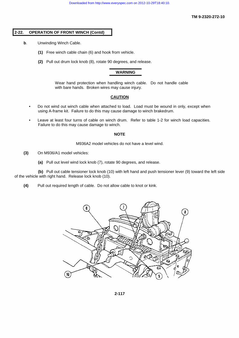
TM 9-2320-272-10
2-22. OPERATION OF FRONT WINCH (Contd)
b. Unwinding Winch Cable.
(1) Free winch cable chain (6) and hook from vehicle.
(2) Pull out drum lock knob (8), rotate 90 degrees, and release.
WARNING
Wear hand protection when handling winch cable. Do not handle cablewith bare hands. Broken wires may cause injury.
CAUTION
• Do not wind out winch cable when attached to load. Load must be wound in only, except whenusing A-frame kit. Failure to do this may cause damage to winch brakedrum.
• Leave at least four turns of cable on winch drum. Refer to table 1-2 for winch load capacities.Failure to do this may cause damage to winch.
NOTE
M936A2 model vehicles do not have a level wind.
(3) On M936/A1 model vehicles:
(a) Pull out level wind lock knob (7), rotate 90 degrees, and release.
(b) Pull out cable tensioner lock knob (10) with left hand and push tensioner lever (9) toward the left sideof the vehicle with right hand. Release lock knob (10).
(4) Pull out required length of cable. Do not allow cable to knot or kink.
2-117
Downloaded from http://www.everyspec.com on 2012-10-29T18:40:10.

TM 9-2320-272-10
2-22. OPERATION OF FRONT WINCH (Contd)
c. Rigging the Load.
(1) Attach utility chain (4) to lifting shackles (5) or pintle hook of load.
(2) If load is very heavy or deeply mired, install a snatch block (3) to increase winch pulling power.
(3) To rig a snatch block (3):(a) Unwind enough cable (7) to reach the load and back to the front winch. Attach cable chain hook (2)
to lifting shackle (1).
(b) Turn snatch block hook (8) to the right. Lift up rear of snatch block (3) and open support link (6).Insert cable (7). Lift up rear of snatch block (3) to lower and lock support link (6) to snatch block hook (8). Returnhook (8) to original position.
(c) Attach utility chain (4) to liftingshackles (5) or pintle hook of load. Attach snatch block(3) to utility chain (4).
NOTE• M936A2 wreckers do not have front
anchors for field chocks.
• M936 wreckers are equipped with fieldchocks for heavy recovery operations.Refer to paragraph 2-24 for field chockinstallation.
(4) Disengage brakes, transmission, and transfercase of vehicle being retrieved.
d. Pulling Load.
NOTEThis operation requires two crew members.
2-118
Downloaded from http://www.everyspec.com on 2012-10-29T18:40:10.

TM 9-2320-272-10
2-22. OPERATION OF FRONT WINCH (Contd) I
(1) Start engine (para. 2-12).
(2) Release hinged latch (10) and pull clutch lever (11) as far back as it will go.
(3) On vehicles with level wind device (9), pull out lock knob (13) and tensioner lever (12) back. Align lockknob (13) with hole in housing and release.
(4) Press lockout switch (18) and shift transfer case shift lever (17) into high range.
WARNING
• Direct all personnel to stand clear of winch cable and vehicle when engaging transmission ortransfer case. Failure to do so may result in injury or death.
• Do not operate winch erratically. Erratic winding will result in a snapped cable, causing injury ordeath.
CAUTION
• If temperature is above 70°F (21°C), stop winding operation for six minutes every 100 ft (30.5 m)of cable winched in, and leave engine and power takeoff engaged. Failure to do so may causedamage to winch.
• Do not operate winch when engine is running over 1800 rpm. Damage to equipment will occur.
2-119
Downloaded from http://www.everyspec.com on 2012-10-29T18:40:10.

TM 9-2320-272-10
2-22. OPERATION OF FRONT WINCH (Contd)
NOTE
Ensure each layer of cable winds evenly, if not equipped with level wind.
(5) With parking brake applied, place transmission selector lever (2) in 1-5 (drive) and pull transmissionpower takeoff control lever (3) back to ENGAGE. Return transmission selector lever (2) to N (neutral).
(6) Pull front winch control lever (14) back to WIND and hold.
(7) Winding speed and pulling capacity of winch is regulated by engine rpm.To increase, depress accelerator pedal (5) or adjust hand throttle control (1).
(8) Release winch control lever (4) to stop winding.
e. Pulling Indirect Loads.
(1) If vehicle (11) cannot be lined up straight with load (6), line vehicle (11) up with a reliable go-betweensuch as a large tree (10).
CAUTION
Do not perform front winch operation if direct pull or use of a go-between object is unavailable.
(2) Unwind enough cable (7) to reach tree (10) and load (6). Refer to task b. for instructions onunwinding cable (7).
(3) Attach snatch block (8) to cable (7) (task c).
(4) Rig chain (9) from tree (10) to the snatch block (8). Attach cable chain to pintle hook or liftingshackles of load (6) (task c).
(5) Wind cable (7) until cable chain reaches snatch block (8) (task d).
2-120
Downloaded from http://www.everyspec.com on 2012-10-29T18:40:10.

TM 9-2320-272-10
2-22. OPERATION OF FRONT WINCH (Contd)
NOTE
If load is on a slope, block. wheels of lead before loosening cable.
(6) Briefly push front winch control lever (4) forward to WINCH. Cable (7) will unwind (loosen) to permitremoval of snatch block (8).
(7) Remove snatch block (8) and utility chain (9).
(8) Continue winding operation.
f. Lifting and Lowering Loads.
(1) A-frame kit is installed and rigged by unit maintenance.
WARNING
• Vehicle will become charged with electricity if A-frame contacts or breaks high-voltage wire. Donot leave vehicle while charged with high-voltage. Notify nearby personnel to have electricalpower turned off. Failure to do this may result in injury or death.
• Do not lower load without a ground guide. Direct all personnel to stand clear of lifting operation.Swinging loads may cause injury or death.
CAUTION
• Do not winch out line loads for distances greater than 10 ft (3 m), as this may result in damage towinch brakedrum.
• Do not attempt to lift loads heavier than 3, 000 lb (1, 362 kg), as this may result in damage to theA-frame kit.
(2) Rig winch to load (task c).
(3) To lift load, follow same winding instructions as in task d.2-121
Downloaded from http://www.everyspec.com on 2012-10-29T18:40:10.

TM 9-2320-272-10
2-22. OPERATION OF FRONT WINCH (Contd) |
(4) To lower load:
(a) Push front winch control lever (2) forward to WINCH.
(b) Observe directions of ground guide.
(c) After load has been lowered, release front winch control lever (2) to NEUTRAL.
(d) Direct ground guide to maintain tension on cable while unrigging load.
g. After Winch Operation.
(1) Direct ground guide to maintain tension on cable.
(2) Pull front winch control lever (2) back to WIND.
(3) Watch ground guide for signal indicating cable chain coupling is approaching drum.
(4) Release winch control lever (2) when signaled by ground guide.
(5) Direct crew member to:
(a) Disengage drum clutch by pushing clutch control lever (4) toward the winch.
CAUTION
Do not force clutch control lever. If lever does not easily disengage,slightly engage winch control lever in WIND until clutch control leverreturns without force.
(b) Swing hinged latch (3) down to lock clutch control lever (4) in disengaged position.
(c) Pull out drum lock knob (5), rotate 90 degrees, and release. If necessary, rotate drum by hand to allowdrum lock plunger to engage.
2-122
Downloaded from http://www.everyspec.com on 2012-10-29T18:40:10.

TM 9-2320-272-10
2-22. OPERATION OF FRONT WINCH (Contd)
(d) On winches with level wind device, manually push level wind (12) completely to the operator’s side oflevel wind (12) frame. Pull out level wind lock knob (13), rotate 90 degrees, and release. If necessary, adjust level wind(12) to assure lock plunger engages.
(6) Push transmission power takeoff control lever (1) forward to DISENGAGE.
h. Preparing Winch for Travel.
(1) On winches without level wind:
(a) Put cable chain (8) under and over right frame extension, then across top of bumper. Attach cable hook(7) to left lifting shackle (6).
(b) Remove right lifting shackle (11) by unsnapping pin lock (9) and removing shackle bolt (10). Place chain(8) through lifting shackle (6) and reinstall shackle (11).
(2) On winches with level wind:
(a) Pull cable chain (16) up through the space between bumper and winch.
(b) Wind cable chain (16) around level wind (12) frame and attach hook (7) to frame.
(c) Pull out cable tensioner lock knob (15) with left hand and push tensioner lever (14) toward left of vehiclewith right hand. Release lock knob (15).
2-123
Downloaded from http://www.everyspec.com on 2012-10-29T18:40:10.

TM 9-2320-272-102-23. OPERATION OF CARGO TRUCKS
a. General. M923/A1/A2 and M925/A1/A2 cargo trucks have 7 x 14 ft (2.1 x 4.3 m) cargo beds. M927/A1/A2and M928/A1/A2 cargo trucks have 7 x 20 ft (2.1 x 6.1 m) beds. All can be equipped with bow and tarp kit.
b. Lowering and Raising Tailgate.
WARNING
On dropside trucks, make sure forward end of dropsides are secured before lowering tailgate. Failure todo this may result in injury or death.
(1) On fixed-side vehicles, remove hooks (2) from retainer slots on both sides of tailgate (1). On dropsidetrucks, turn locking handles (3) on both sides of tailgate (1) counterclockwise to loosen. Grasp ring (4) and turn T-bolt (7)900. Remove locking handles (3).
(2) Lower top of tailgate (1).Do not drop tailgate (1).
(3) Reverse steps 1 and 2 toraise tailgate (1).
c. Lowering and Raising Troop Seats.
(1) To lower troop seats (15), pull troop seat supports (10) forward 45 degrees, release latches (9), and lowerseats (15).
(2) Adjust troop seat supports (10) to contact both side and floor of vehicle.(3) On dropside trucks, install troopseat locking rods (11) in hole (14) near tailgate (1). Locking rod (11) can be
shortened or lengthened. To adjust locking rod (11):
(a) Loosen locknut (12).
(b) Turn end (13) clockwise to shorten; counterclockwise to lengthen.
(c) Tighten locknut (12).
2-124
Downloaded from http://www.everyspec.com on 2012-10-29T18:40:10.

TM 9-2320-272-10
2-23. OPERATION OF CARGO TRUCKS (Contd)
(4) To raise troop seat (15), reverse steps 1 through 3.
d. Removing Front and Side Racks.
(1) Lower tailgate (1). Refer to task b.
(2) If troop seats are lowered, raise troop seats (15) and secure in place with latches (9). Refer to task c.
NOTEThis operation requires two crewmembers.
(3) On dropside trucks:
(a) Remove troop seat locking rods (10) from holes (14) near tailgate (1) and secure to side rack clip (8).
(b) Raise tailgate (1) ( task b).(c) Pull back four troop seat securing
pins (5) from corners of dropsides (6).(d) Remove retaining clip (16) from
anchor pin (17).(e) Lift and remove side rack (19).(f) Repeat steps c and d for opposite
side rack (19).(4) Lift and remove front rack (18).(5) Lift and remove side racks (19).
e. Installing Front and Side Racks.
NOTEWhen installing front rack, be sure front rackretainer clip is inserted in side rack rings.
(1) Reverse steps 1 through 5 of task d.
2-125
Downloaded from http://www.everyspec.com on 2012-10-29T18:40:10.

TM 9-2320-272-10
2-23. OPERATION OF CARGO TRUCKS (Contd)
f. Lowering and Raising Dropsides.
(1) Park vehicle where it can best be loaded or unloaded. Turn ignition switch and battery switch to OFF andapply parking brake.
(2) Turn locking handle (4) counterclockwise to loosen grasp ring (5) and turn T-bolt (7) 90° Remove lockinghandle (4) and repeat operation on opposite end of dropside (2).
WARNING
• Troop seats, side rack braces, bows, side racks, and troop seat securingpins must be secured in stowed position before lowering dropside. Failureto do so may result in injury or death.
• Make sure side panel front locks are secured before lowering tailgate ordropsides will fall. Failure to do so may result in injury or death.
NOTE
This operation requires two crewmembers.
(3) Grasp side rack (3) and carefully lower dropside (2).
(4) To load from both sides:
(a) Lower tailgate (1) (task b).
(b) Remove locking handles (4) securing dropside (2) and lower drop- side (2). Repeat operation for otherside.
(5) To raise dropside (2):
(a) Raise dropside (2) and install T-bolt (7) at forward end. Place T-bolt (7) in slot, turn 90 degrees and holdin position with ring (5). Turn locking handle (4) clockwise to secure.
(b) Raise opposite dropside (2) and secure it in position.
(6) Raise tailgate (1) and install left rear and right rear locking handles (6).
2-126
Downloaded from http://www.everyspec.com on 2012-10-29T18:40:10.

TM 9-2320-272-10
2-24. OPERATION OF MEDIUM WRECKER
a. General. The medium wrecker (M936/A1/A2) has a hydraulic crane and front and rear winches. Thevehicle’s winch and towing capacities are adequate for recovering all wheeled vehicles. The medium wrecker can alsoremove and replace engines, power packs, and gun tubes.
NOTE
• M936A2 vehicles do not have a level wind or front anchors for fieldchocks.
• All winching and recovery operations will be performed IAW FM 20-22.
b. Front Winch Operation.
(1) Refer to paragraph 2-22 for operating instructions.
(2) Install field chocks (4) for heavy recovery operations or operations on slippery terrain. To install chocks(4):
(a) Remove chocks (4) from storage area at left rear of wrecker body.
(b) Insert chocks (4) in left and right brackets(2) below the front bumper (5). Insert pin (1) through bracket(2) and yoke (3) to secure chock (4) in place.
(c) Dig two 12 in. (30 cm) holes at spade end(6) of chocks (7). Insert spade ends (6) in holes.
c. Rear Winch Operation.
WARNING
Do not wind out winch cable when attached to load.Load must be wound in only. Failure to do this mayresult in injury or death.
(1) Position rear of wrecker in direct line with loadto be winched if possible.
2-127
Downloaded from http://www.everyspec.com on 2012-10-29T18:40:10.

TM 9-2320-272-10
2-24 OPERATION OF MEDIUM WRECKER (Contd)
(2) Engage parking brake lever (9) and turn ignition switch (3) and battery switch (2) to OFF.
CAUTION
• Before opening hydraulic oil reservoir, make sure area around reservoir filler cap is clean. Do not allow dirt,dust, or water to enter reservoir. Failure to do so may cause damage to internal components.
• Do not proceed with winch operation if oil level is less than halfway from end of dipstick to full mark. Fill asneeded. Failure to do so may cause damage to internal components.
(3) Check oil level in hydraulic oil reservoir (12). Refer to LO 9-2320-272-12.
2-128
Downloaded from http://www.everyspec.com on 2012-10-29T18:40:10.

TM 9-2320-272-10
2-24. OPERATION OF MEDIUM WRECKER (Contd)
(4) For heavy pulls, install field chocks (15). Perform the following:
(a) Remove field chocks (15) from storage area at left rear of wrecker body.
(b) For direct pulls, install chocks (15) facing the load in left and right rear chock brackets (13) belowbumperettes. Insert pin (16) through bracket (13) and yoke (17) to secure each field chock (15) in place.
(c) For indirect pulls, install field chocks (15) in left side and rear brackets (13) for left side pulls or in rightside and rear brackets (13) for right side pulls.
(d) Dig two 12 in. (30 cm) holes at spade end (14) of chocks (15). Insert chock spade ends (14) in holes.
(5) Start engine (para. 2-12).
(6) Place transfer case shift lever (8)in NEUTRAL.
(7) Unlock safety latch (11) andpush transfer case power takeoff lever (10)back to engage.
(8) Place transmission selectorlever (7) in 1-5 (drive).
NOTE
Vehicles equipped with automaticthrottle kit/MWO will automaticallyincrease engine rpms to the properrange when the PTO is engaged.
(9) Pull out hand throttle control(1) and set engine speed between 1250and 1300 rpm as indicated by tachometer(4).
(10) Turn on floodlight controlswitch (5) if operation is at night and tacticalsituation permits.
(11) Turn on amber warning lightswitch (6), if required, and if tacticalsituation permits
2-129
Downloaded from http://www.everyspec.com on 2012-10-29T18:40:10.

TM 9-2320-272-10
2-24. OPERATION OF MEDIUM WRECKER (Contd)
(12) Release level wind (1) by pulling outlock knob (2), rotating it 90 degrees, and releasing knob(2).
(13) Turn on floodlights (5) for nightoperation if tactical situation permits.
NOTETorque control lever must be in HIGHor LOW before directional control levercan be operated.
(14) Remove travel pin (8) and pull torquecontrol lever (7) outward to HIGH.
WARNING
Wear hand protection when handling winch cable. Do not handlecable with bare hands. Broken wires may result in injury.
NOTE
Cable and snatch block ratings on level surface are 14,500 lb (6, 583 kg) for 3/4 in. (19 mm) cable; 22, 500 lb(10, 215 kg) for single sheave snatch block; 27, 500 lb(12, 485 kg) for double-sheave snatch block.
(15) To unwind winch cable:
(a) Release cable tensionerswitch (9) if engaged.
(b) Remove travel pin (8)and pull directional control lever (6)outward to UNWIND until winch cablehook and chain (3) are loosened frombumperettes (4).
(c) Direct crewmember tofree cable hook and chain (3) from rearbumperettes (4).
(d) With crewmembermaintaining manual tension on cable, pulldirectional control lever (6) outward toUNWIND.
(e) After required length ofcable (14) has been unwound, returndirectional control lever (6) to NEUTRAL.
2-130
Downloaded from http://www.everyspec.com on 2012-10-29T18:40:10.

TM 9-2320-272-10
2-24. OPERATION OF MEDIUM WRECKER (Contd)
(16) To rig the load:
(a) Attach utility chain (10) to liftingshackles (11) or pintle hook of load (12).
NOTE
M939A2 vehicles do not have front anchors.
(b) If load (12) is very heavy ordeeply mired, install snatch block (16) orcombination of snatch blocks (16) to increasewinch pulling power. To rig a snatch block (16):
1. Unwind enough cable (14) to reach the load (12) and back to rearwinch. Rig cable hook and chain (3) to rear bumperettes (4).
2. Turn hook (15) to right. Lift up rear of snatch block (16) and opensupport link (13). Insert cable (14). Lift up rear of snatch block (16) and lower and locksupport link (13) to hook (15). Return hook (15) to original position.
3. Rig hook (15) to load (12).
(17) Release brakes, transmission, andtransfer case of vehicle being retrieved.
WARNING
Direct all personnel to stand clearof winch cable during winchoperation. A snapped winch cablemay result in injury or death.
NOTE
If using the wrecker’s rear winch for self-recovery,release parking brake and set spring brakeoverride.
(18) To pull load:
(a) Position lever (7) to LOW forheavy loads or HIGH for light loads.
(b) Push tensioner switch (9)down to engage tensioner.
2-131
Downloaded from http://www.everyspec.com on 2012-10-29T18:40:10.

TM 9-2320-272-10
2-24. OPERATION OF MEDIUM WRECKER (Contd)
WARNING
Do not operate winch erratically. Erratic winding may result in a snapped cable, causing injury or death.
(c) Push directional control lever (1) intoWIND.
(19) To shift torque control lever (2) from LOWto HIGH or HIGH to LOW:
(a) Pull directional control lever (1) out toNEUTRAL.
(b) Shift torque control lever (2).
(c) Push directional control lever (1) into resume winding.
(20) Place directional control lever (1) inNEUTRAL to stop winding.
(21) Briefly pull directional control lever (1)outward to UNWIND to loosen cable for unrigging.
(22) Remove winch cable chain t 7) and hook (9) from load. Remove snatch blocks if used.
(23) Push directional control lever (1) in to WIND. Release directional control lever (1) to stop winding operationwhen cable chain (7) approaches guide rollers (4).
2-132
Downloaded from http://www.everyspec.com on 2012-10-29T18:40:10.

TM 9-2320-272-10
2-24. OPERATION OF MEDIUM WRECKER (Contd)
(24) To prepare rear winch for travel:(a) Manually push level wind (5) completely to the right. Pull out drum lock knob (6), rotate 90 degrees, and
release. If necessary, adjust level wind (5) to ensure lock plunger engages.(b) Place cable chain (7) and hook (9) up through right bumperette (8) and down through left bumperette
(10).(c) Place cable chain (7) and hook (9) around chain (7) between bumperettes (8) and (10).(d) Push directional control lever. (1) into WIND. Stop when cable is snug and replace travel pin.
(25) Pull cable tensioner switch (3) up to disengage tensioner.(26) Place torque control lever (2) in NEUTRAL and replace travel pin.(27) Turn off floodlights (11) if used.(28) Disengage hand throttle control (13) by rotating handle and pushing in to allow engine speed to drop to idle.(29) Pull transfer case power
takeoff control lever (18) forward todisengage, and lock in position.
(30) Place transmission selectorlever (15) in N (neutral).
(31) Turn off main floodlightswitch (16) and amber warning lightswitch (14), if used.
(32) If field chocks (12) wereused:
(a) Make sure transfercase shift lever (17) is in high range.
(b) Release parking brakelever (19).
(c) Place transmissionselector lever (15) in 1-5 (drive) to movevehicle ahead far enough to free chocks(12).
(d) Stop vehicle, shutdown engine, and engage parking brakelever (19) (para. 2-16).
(e) Remove field chocks(12).
2-133
Downloaded from http://www.everyspec.com on 2012-10-29T18:40:10.
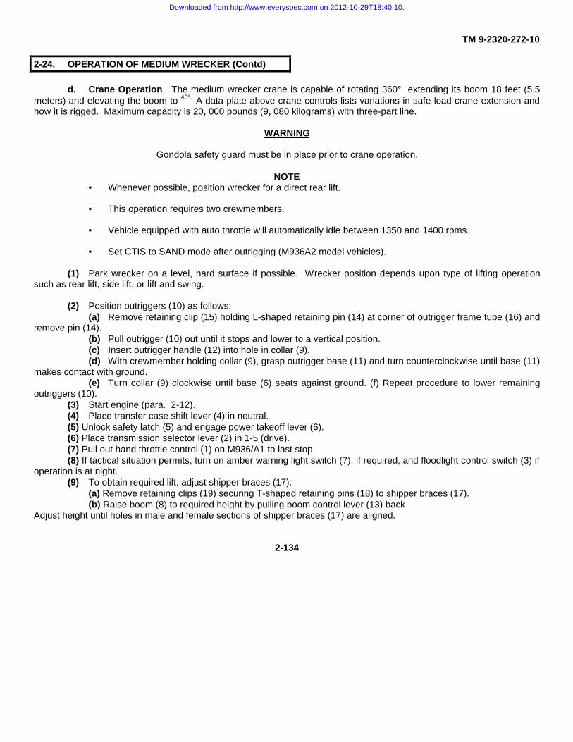
TM 9-2320-272-10
2-24. OPERATION OF MEDIUM WRECKER (Contd)
d. Crane Operation. The medium wrecker crane is capable of rotating 360°, extending its boom 18 feet (5.5meters) and elevating the boom to 45°. A data plate above crane controls lists variations in safe load crane extension andhow it is rigged. Maximum capacity is 20, 000 pounds (9, 080 kilograms) with three-part line.
WARNING
Gondola safety guard must be in place prior to crane operation.
NOTE• Whenever possible, position wrecker for a direct rear lift.
• This operation requires two crewmembers.
• Vehicle equipped with auto throttle will automatically idle between 1350 and 1400 rpms.
• Set CTIS to SAND mode after outrigging (M936A2 model vehicles).
(1) Park wrecker on a level, hard surface if possible. Wrecker position depends upon type of lifting operationsuch as rear lift, side lift, or lift and swing.
(2) Position outriggers (10) as follows:(a) Remove retaining clip (15) holding L-shaped retaining pin (14) at corner of outrigger frame tube (16) and
remove pin (14).(b) Pull outrigger (10) out until it stops and lower to a vertical position.(c) Insert outrigger handle (12) into hole in collar (9).(d) With crewmember holding collar (9), grasp outrigger base (11) and turn counterclockwise until base (11)
makes contact with ground.(e) Turn collar (9) clockwise until base (6) seats against ground. (f) Repeat procedure to lower remaining
outriggers (10).(3) Start engine (para. 2-12).(4) Place transfer case shift lever (4) in neutral.(5) Unlock safety latch (5) and engage power takeoff lever (6).(6) Place transmission selector lever (2) in 1-5 (drive).(7) Pull out hand throttle control (1) on M936/A1 to last stop.(8) If tactical situation permits, turn on amber warning light switch (7), if required, and floodlight control switch (3) if
operation is at night.(9) To obtain required lift, adjust shipper braces (17):
(a) Remove retaining clips (19) securing T-shaped retaining pins (18) to shipper braces (17).(b) Raise boom (8) to required height by pulling boom control lever (13) back
Adjust height until holes in male and female sections of shipper braces (17) are aligned.
2-134
Downloaded from http://www.everyspec.com on 2012-10-29T18:40:10.

TM 9-2320-272-102-24. OPERATION OF MEDIUM WRECKER (Contd)
Do not get underneath the wrecker boom when raised unless properlysecured. Failure to do this may result in injury or death to personnel.
NOTE
If more height is needed than full length of shipper braces allow, use boom jacks. Refer to paragraph d,step 13 for installation of boom jacks.
(c) Reinsert T-shaped retaining pins (18) in lined-up holes and secure with retaining clips (19).
(d) Lower boom (8) to support boom (8) weight on shipper braces (17).
2-135
Downloaded from http://www.everyspec.com on 2012-10-29T18:40:10.

TM 9-2320-272-10
2-24. OPERATION OF MEDIUM WRECKER (Contd)
WARNING
Direct all personnel to stand clear of crane or load during crane operation. A snapped cable, shifting, orswinging load may cause injury or death.
(10) To lift load:
CAUTION
Do not allow crane block to jam boom sheaves in raising operation. Failure to do this will damage boomsheaves.
(a) Lower crane block (3) to load (5) by pushing hoist control lever (7) to DOWN position, and releasing it tostop.
(b) Rig load (5) with utility chains, cable slings, or attach hook (4) directly to lifting devices on the load (5).
(c) Raise load (5) by pulling hoist control lever (7) to UP position, and releasing it to stop.
(11) To lower load:
(a) Lower load (5) by pushing hoist control lever (7) to DOWN position, and releasing it to stop.
(b) Block load (5) to prevent tipping or shifting.
2-136
Downloaded from http://www.everyspec.com on 2012-10-29T18:40:10.

TM 9-2320-272-10
2-24. OPERATION OF MEDIUM WRECKER (Contd)
(12) To lift and swing load:
NOTE
This operation requires use of all outriggers.
(a) Perform steps 1 through 9.
(b) Slightly pull boom control lever (6)back to UP to take boom (1) weight off shipper braces(12).
(c) Remove retaining clips (16) from L-shaped shipper brace retaining pins (14) and removepins (14) from shipper brace brackets (13).
(d) Swing brace (12) upward to braceretaining brackets (10) on each side of shipper (11).Secure braces (12) on brackets (10) with retaining clips(15).
CAUTION
When extending boom, move HOIST andCROWD levers at the same time. Failure todo so may result in boom damage.
(e) Extend boom (1) as necessary bypushing crowd control lever (8) forward to DOWN.Maintain an even distance between crane block (3) andboom sheaves (2).
(f) Elevate boom (1) to desired height bypulling boom control lever (6) back to UP.
(g) Lift load (5). Refer to step 10.
CAUTION
Boom rotates 360°. Make sure area is clear of obstacles, and caution is usedwhen operating boom over cab area. Damage to windshield, exhaust stack,air intake, and cab may result.
(h) Push swing control lever (9) forward to LEFT to swing load (5) left. Pull swing control lever (9) back toRIGHT to swing load (5) right.
(i) Lower load. Refer to step 11.
2-137
Downloaded from http://www.everyspec.com on 2012-10-29T18:40:10.

TM 9-2320-272-10
2-24. OPERATION OF MEDIUM WRECKER (Contd)
(13) For heavy rear lift:
NOTE
This operation requires use of front outriggers.
(a) Perform steps 1 through 9.
(b) Slightly pull boom control lever (2) back to UP to take boom (1) weight off shipper braces (8).
(c) Remove retaining clips (11) form L-shaped shipper brace retaining pins (9) and remove retaining pins (9)from shipper brackets (8).
(d) Swing shipper braces (7) upward to brace retaining brackets (5) on each side of shipper (6). Securebraces (7) on brackets (5) with retaining clips (10).
(e) Push boom control lever (2) forward to DOWN to lower boom (1) to horizontal position.
2-138
CAUTION
When extending boom, moveHOIST and CROWD levers at thesame time. Failure to do this willresult in boom damage.
Downloaded from http://www.everyspec.com on 2012-10-29T18:40:10.

TM 9-2320-272-10
2-24. OPERATION OF MEDIUM WRECKER (Contd)
(f) Extend boom (1) to desired operational length by pushing crowd control lever (4) forward to EXTEND andhoist control lever (3) forward to DOWN. Maintain even distance between crane block (14) and boom sheaves (13).
(g) Remove boom jacks (15) from wrecker bed.
(h) Remove both retaining pins (16) and jack pin (20). Insert jack pin (20) in hole of 12-ft mark (21) on boom (1).
(i) Insert boom jack yoke end (17) on jack pin (20) and secure with retaining pin (16).
(j) Obtain ring-handled pin (11) and extend boom Jacks (15) to required length. Insert ring-handled pin (19)when required length is obtained and secure with retaining clip (18).
(k) Repeat steps i and j on opposite side of boom (1) with second boom jack (15).
WARNING
Direct all personnel to stand clear of crane or load during crane operation. A snapped cable, shifting, orswinging load may result in injury or death.
(1) Pull boom control lever (2) to UP position until boom jacks (15) are off the ground.
(m) Remove boom jack base plates (12) from wrecker bed.
2-139
Downloaded from http://www.everyspec.com on 2012-10-29T18:40:10.

TM 9-2320-272-102-24. OPERATION OF MEDIUM WRECKER (Contd)
(n) Install boom jack (1) in base plate (3) and secure in place with retaining pin (7) and retaining clip (8).(o) Obtain tie bar (2) from wrecker bed and install between boom jacks (1). Secure in place with retaining
pin (5) and retaining clip (6).(p) Push boom control lever (9) to DOWN position, and release it when boom jacks (1) make firm contact
with ground.(q) Perform lifting and lowering operation. Refer to steps 10 and 11. (14) Heavy side lifts are similar to
heavy rear lifts except that front and rear outriggers (4) from the lifting side of the vehicle will be positioned.
e. Towing With Wrecker Crane.
WARNING
• If vehicle being towed has inoperative compressed air system, emergency air and service air lines mustnot be connected between vehicles. Failure to do this may result in damage to equipment, or causeinjury or death.
• If the compressed air system of the vehicle being towed has emergency air and service air lines, theymust not be connected.
CAUTION
• Do not use towing as a means to start engine of vehicle with automatic transmission. Refer to disabledvehicle operator's manual for towing instruction. Failure to so may will result in damage to vehicle.
• Maximum towing speed shall not exceed 35 mph (56 km/h) on paved highway or 15 mph (24 km/h) onoff-highway surfaces.
NOTE• When towing M939/A1/A2 series vehicles with inoperative compressed air system, the spring brakes
must be caged.
2-140
Downloaded from http://www.everyspec.com on 2012-10-29T18:40:10.

TM 9-2320-272-10
2-24. OPERATION OF MEDIUM WRECKER (Contd)
(1) Position rear of wrecker directly in front of disabled vehicle.(2) If tires, transmission, and steering of disabled vehicles are serviceable, proceed to step 4 and install towbar
(10) to front bumper shackle brackets (14).(3) If disabled vehicle has no shackle brackets (14), or if tires, transmission, and/or steering of disabled vehicle
are unserviceable, proceed to step 5d and use lift-tow procedure.(4) To tow a disabled vehicle using front bumper shackle brackets:
(a) Remove lifting shackles (13) from bumper (15) of disabled vehicle.(b) Install clevis (12) end of towbar (10) on front bumper shackle brackets (14) and secure in place with
clevis bolt (16) and safety pin (11).(c) Install yoke (18) end of towbar (10) to wrecker pintle hook (19).
WARNING
Crisscross and connect utility chains between vehicles in the event towbar breaks or becomesdisconnected. Failure to do this will result in injury or death.
(d) Crisscross and connect utilitychains (17) to spring hangers (20) on towedvehicle and secure to towing vehicle.
(e) Connect emergency andservice air line (22) to respective half coupling(21) on each vehicle.
(f) Release parking brake andplace transmission, transfer case, and PTO ofdisabled M939/A1/A2 series vehicles in neutral.
(g) Reverse steps a through fafter completion of towing.
2-141
Downloaded from http://www.everyspec.com on 2012-10-29T18:40:10.

TM 9-2320-272-10
2-24. OPERATION OF MEDIUM WRECKER (Contd)
(5) For lift-tow operations (except M936A2):(a) Attach whiffletree (3) to lifting shackles (4) of disabled vehicle. Whiffletree (3) is attached the same way
as a towbar (12). Refer to step 4c.(b) Lower crane block (2) and insert hook (5) through center hole of whiffletree (3). Refer to crane operation
(para. 2-24d).(c) Remove two retaining pins (11) and towbar adjustment pins (10). Slide out leg extensions (9).(d) Attach two clamps (8) to clevis (13) of leg extensions (9) and secure in place with clevis bolts (14) and
attached safety pins (15).(e) Loosen two tension adjusting nuts (7) on clamps (8).(f) Position clamps (8) against front axle (16) of disabled vehicle and wrap clamp chain (6) around axle and
back up through clamp (8). Lock in place by turning tension adjusting nut (7) until secure.(g) Repeat step f with second clamp (8) in position against axle (16) on opposite side of forward axle.
NOTEIf necessary, adjust length of towbar while performing step h. Yoke end of towbar should extend one footor more beyond front bumper of disabled vehicle.
(h) After both clamps (8) are secured to disabled vehicle, slide leg extensions (9) back into towbar (12) andsecure in place with adjustment pins (10) and retaining pins (11).
(i) Install yoke end of towbar (12) on wrecker pintle hook (16).(j) Disengage brakes and remove propeller shafts between transmission and transfer and place transfer in
high range of disabled M939/A1/A2.(k) Raise crane block (2) and lift front wheels of disabled vehicle off ground until towbar is level (parallel to
ground).(l) To secure from lift-tow operation, reverse steps a through k
2-142
Downloaded from http://www.everyspec.com on 2012-10-29T18:40:10.

TM 9-2320-272-10
2-24. OPERATION OF MEDIUM WRECKER (Contd)
(6) For lift-tow operations (M936A2):(a) Remove two retainer and adjustment pins (18) and (19) from shipper brace adjustment holes (17).
Elevate boom until third hole from bottom of two shipper braces (1) are aligned with pin holes (17). Replace shipper braceadjustment and retainer pins (18) and (19).
(b) Attach whiffletree (3) to reversed lift shackles (4) of disabled vehicle.
CAUTION
Remove line, assembly, and sling from crane hook before lifting boom.
(c) Remove two retaining pins (11) and adjustment pins (10). Slide out leg extensions (9) to third hole(seventh hole on vehicles with winch) from clevis (13) end. Replace adjustment and retaining pins (10) and (11). Attachclevis (13) to each clevis (13) end and secure in place with clevis end retainer pin (14).
(d) Loosen two tension adjusting nuts (7) on clamps (8). Position one clamp (8) against front axle ofdisabled vehicle and wrap clamp chain (6) around axle (16) and back up through clamp (8). Fasten chain (6) to clamp (8).Lock in place by turning tension adjusting nut (7) until secure. Repeat step with second clamp (8) on opposite side.Secure clevis (13) and clevis end retainer pin (14) with clamp (15).
(e) Install other end of towbar (12) to wrecker pintle hook (20), and secure with retaining pin (21). Lowercrane block (2), and insert hook (5) facing away from wrecker through center hole of whiffletree (3).
(f) Install safety chain on towed vehicle, wrap chain three times around towbar, and attach chain to rightrear lift-shackle (4) of wrecker. Connect emergency and service air connectors (23) to half connectors (22) on eachvehicle. Disengage brakes and place transmission, transfer case, and PTO of disabled M939A1/A2 series vehicle inneutral. Fully retract boom, and hoist crane block (2) up until front wheels of disabled vehicle are off ground and towbar islevel (parallel to ground).
2-143
Downloaded from http://www.everyspec.com on 2012-10-29T18:40:10.

TM 9-2320-272-10
2-24. OPERATION OF MEDIUM WRECKER (Contd)
f. Securing Crane After Operation.
(1) Secure outriggers (4), two boom jacks(3), tie bar (6), and boom jack base plates (5).Refer to step d.
NOTE
When retracting boom, pull crowd controllever back to RETRACT and hoist controllever back to UP to prevent block frombecoming tangled.
(2) Fully retract boom (1) into shipper(2) and center boom (1) to rear of wrecker.
(3) Remove retaining clip (11) fromupper retaining brackets (7) and swing shipperbraces (8) to shipper brace brackets (9) onwrecker body. Secure shipper braces (8) inplace with L-shaped retaining pins (10) andretaining clip (12).
(4) Push boom control lever (17) forward to DOWN to allow shipper braces (8) to support boom (1) and weight ofshipper (2).
(5) Install lifting sling (15) onto crane block hook (14). Attach hook ends of sling (15) to brackets (16) onoutrigger (4).
(6) Pull hoist control lever (18) back to UP and remove all slack from lifting sling (15) and boom cable (13).
2-144
Downloaded from http://www.everyspec.com on 2012-10-29T18:40:10.

TM 9-2320-272-10
2-24. OPERATION OF MEDIUM WRECKER (Contd)
(7) Release hand throttle control (19) by rotating handle and pushing in to allow engine speed to drop to idle.(8) Push transfer case power takeoff lever (23) forward to disengage.(9) Place transmission selector lever (20) in N (neutral).(10) Apply parking brake lever (24).(11) Turn off amber warning light (25) and floodlight control switch (21) if used during crane operation.(12) Place transfer case shift lever (22) in desired operating range.
2-145
Downloaded from http://www.everyspec.com on 2012-10-29T18:40:10.

TM 9-2320-272-10
2-25. OPERATION OF DUMP TRUCKS
a. Payload Capacities. M929/A1/A2 and M930/A1/A2 dump trucks can carry 10, 000 lb (4, 540 kg) of materialcross-country. Table 2-5 lists typical material weights.
WARNING
Stay clear of dump body and cab protector at all times during loading and unloading operations. Dumpbody can unexpectedly raise when a heavy load is dropped into dump body and will cause injury or death.
Table 2-5. Typical Material Weights.
Capacity level Capacity Heapingfull 5.0 cu-yd full 7.5 cu-ydMATERIAL WEIGHT (3.8 cu-M) (5.7 cu-M)lb per cu-ft lb per cu-ydlb (approx) lb (approx)(kg per cu-M) (kg) (kg)
Ashes 43 1,161 5, 805 8, 708(1,518.5) (2, 635.5) (3, 953.4)
Cinders 46 1,242 6, 210 9, 315(1,624.4) (2, 819.3) (4, 229.0)
Clay (dry and loose) 77 2,079 10, 395 15, 593(2,719.1) (4, 719.3) (7, 079.2)
Clay (wet) 110 2,970 14, 850 22, 275(3, 884.5)(6, 741.9) (10, 113.0)
Clay and gravel (dry) 100 2,700 13, 500 20, 250(3, 513.3)(6, 129.0) (9, 193.5)
Clay and gravel (wet) 65 1,755 8, 775 13, 163(2,295.4) (3, 983.4) (5, 976.0)
Coal, anthracite 54 1,458 7, 290 10, 935(hard) (1, 906.9) (3, 309.7) (4, 964.5)Coal, bituminous 81 2, 187 10, 935 16, 403(soft) (2, 860.4) (4, 964.5) (7, 447.0)Coke 28 756 3, 780 5, 670
(988.8) (1, 716.1) (2, 587.2)Concrete 138 3, 726 18, 630 27, 945
(4, 873.2)(8, 58.0) (12, 678.2)Concrete mix (wet) 124 3, 348 16, 740 25, 110
(4, 379.1)(7, 600.0) (11, 400.1)Earth (dry and loose) 75 2, 025 10, 125 15, 188
(2, 648.8)(4, 596.8) (6, 895.4)Earth (moist and 95 2, 565 12, 825 19, 238packed) (3, 345.8) (5, 822.6) (8, 734.1)
* Over rated cross-country payload † Over rated cross-country and highway payload
2-146
Downloaded from http://www.everyspec.com on 2012-10-29T18:40:10.

TM 9-2320-272-10
2-25. OPERATION OF DUMP TRUCKS (Contd)
Table 2-5. Typical Material Weights (Contd).
Capacity levelCapacity Heapingfull 5.0 cu-ydfull 7.5 cu-yd
MATERIAL WEIGHT (3.8 cu-M)or (5.7 cu-M)lb per cu-ft lb (per cu-ydlb(approx) 16 (approx
(kg per cu-M) (kg) (kg)Earth and gravel 100 2, 700 *13, 500 20, 250(dry and loose) (3, 531.3) (6, 129.0) (9, 193.5)Garbage (dry) 37 999 4, 995 7, 493
(1, 306.6)(2, 267.7) (3, 401.8)Garbage (wet) 47 1, 269 6, 345 9, 518
(1, 659.7)(2, 880.6) (4, 321.2)Gravel 110 2, 970 14, 850 22, 275
(3, 884.5)(6, 741.9) (10, 112.9)Gravel and sand 95 2, 565 12, 825 19, 238(dry and loose) (3, 354.8) (5, 822.6) (8, 734.1)Gravel and sand (wet) 120 3, 240 16, 200 24, 300
(4, 237.6)(7, 354.8) (11, 032.2)Limestone (crushed) 100 2, 700 13, 500 20, 250
(3, 531.3)(6, 129.0) (9, 193.5)Mud (wet) 120 3, 240 16, 200 24, 300
(4, 237.6)(7, 354.8) (11, 032.2)Rock and stone 95 2, 565 12, 825 19, 238
(3, 354.8)(5, 822.6) (8, 734.1)Salt (fine)50 1, 350 6, 750 10, 125
(1, 765.7)(3, 064.5) (4, 596.8)Sand (dry and loose) 98 2, 646 13, 230 19, 845
(3, 460.7)(6, 006.4) (9, 009.6)Sand (dry and packed) 110 2, 970 14, 850 22, 275
(3, 884.5)(6, 741.9) (10, 112.9)Sand (moist and loose) 120 3, 240 16, 200 24, 300
(4, 237.6)(7, 354.8) (11, 032.2)Slag (crushed)75 2, 025 10, 125 15, 188
(2, 648.5)(4, 596.8) (6, 895.4)Snow (moist and 50 1, 350 6, 750 10, 125packed) (1, 765.7) (3, 064.5) (4, 596.8)Stone (crushed) 100 2, 700 13, 500 20, 250
(3, 531.3)(6, 129.0) (9, 193.5)Stone (loose) 95 2, 565 12, 825 19, 238
(3, 354.8)(5, 822.6) (8, 734.1)
* Over rated cross-country payload † Over rated cross-country and highway payload
2-147
Downloaded from http://www.everyspec.com on 2012-10-29T18:40:10.

TM 9-2320-272-102-25. OPERATION OF DUMP TRUCKS (Contd)
b. Regular Dump Operation.
NOTE
Transfer case shift lever should be in H (high) range.
(1) Start engine (para. 2-12) and position vehicle for dumping. Apply parking brake lever (7), placetransmission selector lever (1) in N (neutral), and transfer case shift lever (3) to HIGH.
(2) Check chains (16) to ensure they will not restrict tailgate (14) opening.(3) Unhook safety chain and unlock tailgate (14) by pulling control lever (8) forward and down.
WARNING
Direct all personnel to stand clear of vehicle when engaging transmission or transfer case. Failure to dothis will cause injury or death.
(4) Apply parking brake (7) and shift transmission selector lever (1) in 1-5 (drive).
2-148
Downloaded from http://www.everyspec.com on 2012-10-29T18:40:10.

TM 9-2320-272-10
2-25. OPERATION OF DUMP TRUCKS (Contd)
(5) Pull transmission power takeoff control lever (2) back to ENGAGE.
(6) Return transmission selector lever (1) to N (neutral).
(7) Depress spring (4) to release safety latch (5) and push dump body control lever (6) back to raise dumpbody.
NOTE• Dump body will stop automatically when fully raised.• Engine rpm should not exceed 1000 rpm during dumping operation.
(8) To lower dump body, pull dump body control lever (6) full forward to lower dump body.
CAUTIONTo prevent dump body from raising during vehicle operation, dump body control lever must remain locked in
N (neutral) position.
(9) Return dump body control lever (6) to N (neutral) when dump body is completely lowered. Secure lever(6) with control lever safety latch (5).
(10) Push power takeoff control lever (2) forward to DISENGAGE.
(11) Push tailgate control lever (8) up and back as far as it will go to lock tailgate (14) in closed position.
c. Rocker-Type Dump Operation.
NOTEThis operation requires two crewmembers. Perform steps 2 through 6 on left side of vehicle first.
(1) Position vehicle for dumping and apply parking brake lever (7). Place transmission selector lever (1) inN (neutral).
(2) Remove chain (16) from upper chain slot (11).
(3) Thread chain (16) through chain bracket (15) at corner of tailgate (14).
(4) Remove bracket pin (13) in upper hinged bracket (12).
(5) Unfasten retaining hook (9) and swing tailgate wing (10) fully to the rear of vehicle.
(6) Insert bracket pin (13) in upper hinged bracket (12).
(7) Repeat steps 2 through 5 for right side of tailgate (14).
(8) Remove bracket pin (13) from upper hinged bracket (12).
(9) Lower tailgate (14) and insert bracket pins (13) from upper hinged brackets (12) on both sides of thevehicle.
2-149
Downloaded from http://www.everyspec.com on 2012-10-29T18:40:10.

TM 9-2320-272-10
2-25. OPERATION OF DUMP TRUCKS (Contd)
(10) Install chains (6) in lower chain slots (7).
(11) Raise and lower dump body as required. Refer to task 6, steps 4 through 10.
(12) After dump operation, remove two bracket pins (2) and raise tailgate (4). Swing two tailgate wings (3) tosides of dump body and reinsert bracket pins (2) into upper hinged brackets (1).
(13) Remove chains (6) from lower chain slots (7).
(14) Secure tailgate wings (3) to retaining hooks (8).
(15) Insert chains (6) in upper chain slots (9).
d. Spreader-Type Dump Operation.
NOTEThis operation requires two crewmembers. Perform steps 2 through 6 on left side first.
(1) Position vehicle for dumping and apply parking brake lever (17). Place transmission selector lever (11)in N (neutral).
(2) Remove chain (6) from upper chain slot (9).(3) Thread chain (6) through chain brace (5) at corner of tailgate (4).(4) Unfasten retaining hook (8) from tailgate wing (3) and swing wing (3) fully to the rear of vehicle.(5) Loop chain (6) under tailgate (4), take up slack, and insert link of chain (6) into lower chain slot (7).(6) Return tailgate wing (3) to side of dump body and secure with retaining hook (8).(7) Repeat steps 2 through 6 for other side of tailgate (4).
2-150
Downloaded from http://www.everyspec.com on 2012-10-29T18:40:10.

TM 9-2320-272-10
2-25. OPERATION OF DUMP TRUCKS (Contd)
(8) Pull tailgate control lever (18) forward and down to unlock tailgate.(9) Raise and lower dump body as required. Refer to task b, steps 4 through 6.(10) Depress spring (14) to release safety latch (15), and pull dump body control lever (16) back to raise dump
body. When dump body lifts 2 or 3 ft (.6 or .9 m), move dump control lever (16) back to neutral position to lock dumpbody.
(11) Shift transfer case shift lever (13) up to low range.(12) Push brake pedal (10) and release parking brake lever (17).(13) Place transmission selector lever (11) in 1 (first).(14) Release brake pedal (10) and accelerate.(15) Raise dump body at intervals by pulling dump body control lever (16) back to raise and then forward to
neutral position as required.
CAUTION
Do not exceed 5 mph (8 km/h) in 1 (first). If more speed is required, refer to caution data plate for correcttransmission gear range.
(16) After vehicle has been unloaded:
(a) Stop vehicle and apply parking brake lever (17).
(b) Place transmission selector lever (11) in N (neutral).
(c) Shift transfer case shift lever (13) into desired position.
(d) Pull dump body control lever (16) forward to lower position.
(e) Return dump body control lever (16) to neutral position and secure lever with safety latch (15).
(f) Push power takeoff control lever (12) forward to DISENGAGE.
(g) Unhook safety chain and push tailgate control lever (18) up and back as far as it will go to lock tailgate(4) in closed position.
2-151
Downloaded from http://www.everyspec.com on 2012-10-29T18:40:10.

TM 9-2320-272-10
2-26. OPERATION OF TRACTOR AND FIFTH WHEEL
a. General. A fifth wheel, or semitrailer coupler, is mounted on the rear of M931/Al/A2 and M932/Al/A2 tractortrucks. When connected to a semitrailer, the fifth wheel pivots up, down, and sideways to allow for changes in roadconditions. The fifth wheel is rated at 37, 500 lb (17, 025 kg) cross-country.
b. Wedge Adjustment.
(1) Position fifth wheel wedges (13) fully below walking beam (10) for highway operations.(2) Position wedges (13) back and away from walking beam (10) for cross- country operations.(3) To position wedges:
(a) Remove screws (14) from center wedges (13).(b) Remove wedge (13) and reverse position.(c) Install screws (14) on center wedges (13) and tighten.
c. Coupling Semitrailer.
WARNING
When backing up, maintain centerline of tractor with centerline of semitrailer and use ground guide.
(1) Back up tractor so fifth wheel coupler jaws (11) are directly in line with semitrailer kingpin (3).(2) Stop tractor in front of semitrailer, place transmission shift lever (8) in N (neutral), and apply parking brake
(9).(3) Turn landing gear crank (4) to adjust semitrailer height to tractor. Semitrailer approach plates (2) should be
slightly lower than tractor fifth wheel (1).(4) Block semitrailer wheels with chocks (5).(5) Pull plunger handle (12) forward, then out, to open fifth wheel coupling jaws (11).(6) Release parking brake (9) and slowly back tractor under semitrailer. Place transmission selector (8) in N
(neutral) and apply parking brake (9).
WARNING
Make sure to connect service hose to service coupling and emergency hose to emergency coupling.Hoses not properly connected will cause brake failure.
(7) Connect tractor air coupling (15) to semitrailer air couplings (16).
2-152
Downloaded from http://www.everyspec.com on 2012-10-29T18:40:10.

TM 9-2320-272-10
2-26. OPERATION OF TRACTOR AND FIFTH WHEEL (Contd)
WARNINGAirbrake hose shutoff valves must be open at all times during normal operation of tractor truck and trailer,and brakes should be functional. Failure to follow these precautions may cause injury or death topersonnel.
(8) Open shutoff valves (7) by placing handles (6) in alignment with valves (7).
2-153
Downloaded from http://www.everyspec.com on 2012-10-29T18:40:10.

TM 9-2320-272-10
2-26. OPERATION OF TRACTOR AND FIFTH WHEEL (Contd)
(9) Press in trailer air supply valve (3) andhold in place for 15 seconds. Release valve (3). Valve(3) should remain in engaged position indicatingsemitrailer airbrake system has proper air pressure. Ifvalve (3) does not remain in engaged position,disconnect couplings (9) and notify your supervisor.
(10) Pull down trailer air brake hand controllever (2) to engage semitrailer brakes.
WARNINGDo not back up without a ground guide. Doing so may result in damage to vehicle, injury, or death.
(11) Release parking brake lever (6), place transmission selector lever (5) in R (reverse), and resumebacking up.
(12) Stop vehicle when coupling jaws (7) close around semitrailer kingpin (8). Visually check to make surejaws (7) have completely closed.
(13) With trailer air brake control handle (2) engaged, place transmission selector lever (5) in 1 (first) andslightly depress accelerator pedal. Tractor will not move forward if fifth wheel is properly connected to semitrailer.
CAUTIONStop vehicle immediately if tractor moves forward and repeat task c, steps 9 through 12.
(14) Place transmission selector lever (5) in N (neutral) and apply parking brake lever (6).
(15) Connect electrical cable (11) to electric receptacle (10) on semitrailer.
2-154
Downloaded from http://www.everyspec.com on 2012-10-29T18:40:10.
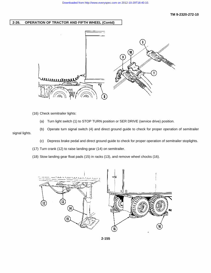
TM 9-2320-272-10
2-26. OPERATION OF TRACTOR AND FIFTH WHEEL (Contd)
(16) Check semitrailer lights:
(a) Turn light switch (1) to STOP TURN position or SER DRIVE (service drive) position.
(b) Operate turn signal switch (4) and direct ground guide to check for proper operation of semitrailersignal lights.
(c) Depress brake pedal and direct ground guide to check for proper operation of semitrailer stoplights.
(17) Turn crank (12) to raise landing gear (14) on semitrailer.
(18) Stow landing gear float pads (15) in racks (13), and remove wheel chocks (16).
2-155
Downloaded from http://www.everyspec.com on 2012-10-29T18:40:10.
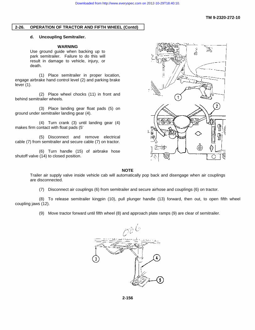
TM 9-2320-272-10
2-26. OPERATION OF TRACTOR AND FIFTH WHEEL (Contd)
d. Uncoupling Semitrailer.
WARNINGUse ground guide when backing up topark semitrailer. Failure to do this willresult in damage to vehicle, injury, ordeath.
(1) Place semitrailer in proper location,engage airbrake hand control level (2) and parking brakelever (1).
(2) Place wheel chocks (11) in front andbehind semitrailer wheels.
(3) Place landing gear float pads (5) onground under semitrailer landing gear (4).
(4) Turn crank (3) until landing gear (4)makes firm contact with float pads (5’
(5) Disconnect and remove electricalcable (7) from semitrailer and secure cable (7) on tractor.
(6) Turn handle (15) of airbrake hoseshutoff valve (14) to closed position.
NOTETrailer air supply valve inside vehicle cab will automatically pop back and disengage when air couplingsare disconnected.
(7) Disconnect air couplings (6) from semitrailer and secure airhose and couplings (6) on tractor.
(8) To release semitrailer kingpin (10), pull plunger handle (13) forward, then out, to open fifth wheelcoupling jaws (12).
(9) Move tractor forward until fifth wheel (8) and approach plate ramps (9) are clear of semitrailer.
2-156
Downloaded from http://www.everyspec.com on 2012-10-29T18:40:10.

TM 9-2320-272-10
2-26. OPERATION OF TRACTOR AND FIFTH WHEEL (Contd)
2-157
Downloaded from http://www.everyspec.com on 2012-10-29T18:40:10.

TM 9-2320-272-10
2-27. OPERATION OF EXPANSIBLE VAN TRUCK
a. General. Expansible van trucks transport communication equipment into the field. Van bodies are 8 ft (2.4m) wide in travel position. In the field, van sides expand to nearly 14 ft (4.3 m).
b. Selecting Operating Site. Whenever possible, position van on level, firm ground.
WARNINGBlock vehicle wheels if operating site is on a grade, no matter how slight. Failure to do this will result ininjury or death.
c. Leveling Van Body.
(1) Remove four adjustable leveling jacks (4) and foot pads (5) from stowage compartment in rear of vanbody.
(2) Attach foot pad (5) to bottom of each jack (4). Assemble and install inner and outer tubes of jack (4) andadjust length to approximate height of brackets (1) (marked H) at each corner of van. Secure jack (4) with chained pin (7).
(3) Insert upper foot (2) of jack (4) into bracket (1). Install jack handle (3) and unscrew jack (4) until footpads (5) are in firm contact with ground. Anchor each jack foot pad (5) with two jack spikes (6). Do not attempt to raiseentire van off of ground with leveling jacks.
(4) Repeat procedure at each corner of van until body is level.
d. Expanding Van Body.
WARNINGOpen van door slowly. Personnel maybe on ladder. Use caution when usingladder.
CAUTIONVehicle must be approximately level forexpansion or retraction of van body.
NOTEThis operation requires twocrewmembers.
(1) Ladder setup:
(a) Release toggle clamp (11)securing right ladder (10).
(b) Lift ladder (10) up to remove.
(c) Install ladder (10) in bracketsbelow rear doors.
(2) Remove chained pin (16) from lock handle (15). Pull handle (15) disengage handle (15) end fromretaining bracket (17). Repeat procedure van corners.
2-158
Downloaded from http://www.everyspec.com on 2012-10-29T18:40:10.

TM 9-2320-272-10
2-27. OPERATION OF EXPANSIBLE VAN TRUCK (Contd)
(6) Turn left ratchet (13) (marked B)counterclockwise with ratchet wrench to expand left sidepanel (8) on left side of vehicle. Turn right ratchet (12)(marked B) to expand right side panel (8) on right side ofvehicle. Crank both sides fully out.
(7) Unfold two end panels (18) on eachside panel (8). Unclip and use side lock rod (19)(marked C) to keep end panel door open and out of theway while roof (21) and floor panels (20) are being raisedand lowered.
(3) Remove side panel lock wrench andratchet wrench from holders inside left rear door.
(4) Using side panel lock wrench, turn fourside locks (9) (marked A) counterclockwise.
(5) Push locking plunger (14) downward torelease left ratchet (13).
2-159
Downloaded from http://www.everyspec.com on 2012-10-29T18:40:10.

TM 9-2320-272-10
2-27. OPERATION OF EXPANSIBLE VAN TRUCK (Contd)
WARNINGHave crewmember support raised floor panel when operator turns hinged roof lock handle. Floor panelmay fall, resulting in injury or death.
NOTEPush open roof and floor panel from inside van only.
(8) Turn hinged roof lock handle (10) (marked D) counterclockwise to unlock roof panel (3) and floor panel(4).
(9) From inside van, push hinged roof (3) and floor panel (4) outward, step out onto floor panel (4) and liftroof panel (3) until swivel hooks (8) (marked E) can be turned at right angles. Support hinged roof (3) on three swivelhooks (8).
(10) Slide end panel bolt (15) (marked F) into corner post guide (14).
(11) Crank both sides (1) in with ratchet wrench (17) until swivel eyes (7) on toggle clamps (9) (marked G) onvan roof (3) can be attached to swivel hooks (8). Left ratchet (16) is turned clockwise to retract left side of van. Rightratchet (18) is turned counterclockwise to retract right side of van.
(12) Pull side panel (2) straight by partially closing toggle clamps (9). While doing this, push up on hingedroof (3) and out on end panel (1) to ensure seal alignment.
(13) Stand on hinged floor panel (4) to relieve any binding.
(14) Adjust left ratchet (16) and right ratchet (18) to ensure a tight seal.
(15) Close three toggle clamps (9) on each side (2), closing the center clamp first.
(16) Remove side swing rod (6) from retaining clip (11). Swing rod (6) down and engage end of swing rod (6)with lock handle assembly (12). Push assembly closed and secure with chained pin (13). Repeat procedure at all four vancorners.
NOTEMake sure sliding end panel bolts are fully extended into corner post guides.
(17) Set up van as applicable:
(a) Mount ladders (5) to rear and/or side doors.
2-160
Downloaded from http://www.everyspec.com on 2012-10-29T18:40:10.
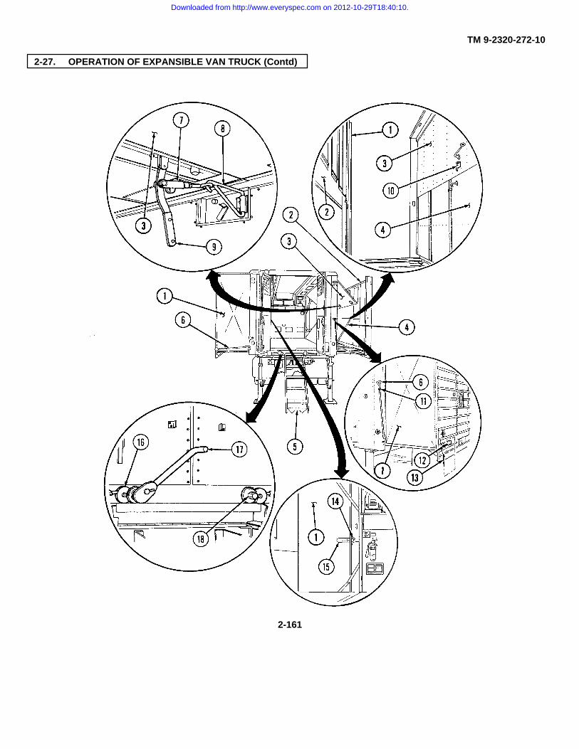
TM 9-2320-272-10
2-27. OPERATION OF EXPANSIBLE VAN TRUCK (Contd)
2-161
Downloaded from http://www.everyspec.com on 2012-10-29T18:40:10.

TM 9-2320-272-10
2-27. OPERATION OF EXPANSIBLE VAN TRUCK (Contd)
(b) Remove ground spike (6) and spike cable(4) from storage location.
WARNING
• Ground spike must be driven into ground 18-24 in. (46-61 cm) and spike cable connectedto the chassis, ensuring that all terminalsmake good contact with bare metal beforeconnecting power from outside source. Ifnecessary, scrape dirt, paint, or rust fromcontact area. Failure to do this will result inelectrical damage, injury, or death.
• Open van door slowly. Personnel may be onladder. Use caution when using ladder.
(c) Remove wingnut (8) and connect ringterminal (3) on spike cable (4) to chassis stud (1) behind left-rearstoplight (2). Connect spike cable terminal clamp (5) to groundspike (6) and slide up to T-handle (7).
(d) Drive ground spike (6) 18-24 in. (46-61 cm)into ground.
(e) Remove canvas cover on cable reel (11).
(f) Remove power cable (10) on cable reel (11)using ratchet wrench.
NOTEIt may be necessary to use electric auxiliary cablering to connect to auxiliary power source.
(g) Connect power cable (10) to appropriateauxiliary power source.
(h) Connect other end of power cable (10) topower receptacle (9).
2-162
Downloaded from http://www.everyspec.com on 2012-10-29T18:40:10.

TM 9-2320-272-10
2-27. OPERATION OF EXPANSIBLE VAN TRUCK (Contd)
e. Operating Van Electrical System.
(1) Inspect ground spike (6), spike cable (4), andchassis stud (1) for loose or damaged components.
(2) Turn to connect switch box (12) to outsidepower source.
(3) Turn on ceiling light switch (switch 14).
(4) Turn on receptacle switches (switches 1, 3, 4,6, 7, 9, 10, 12, 13).
(5) Turn on switch 5 if left heater (13) is to beused. Turn on switch 8 if right heater (15) is to be used. Refer tostep f. for left and right heater operating instructions.
(6) Turn air conditioner switch if air conditioningunit (14) is to be used. Refer to step h. for air conditioneroperating instructions.
(7) Turn on switch 2 if blackout switch (16) is to beused. Refer to step i. for blackout operating instructions.
(8) Turn on emergency light switch (17) if outsidepower source fails.
Downloaded from http://www.everyspec.com on 2012-10-29T18:40:10.

2-163
Downloaded from http://www.everyspec.com on 2012-10-29T18:40:10.

TM 9-2320-272-10
2-27. OPERATION OF EXPANSIBLE VAN TRUCK (Contd)
f. Operating Van Heaters.
WARNINGGround spike must be driven into ground 18-24 in. (46-61cm) and spike cable connected to the chassis before powercan be taken from outside source. Failure to do this willresult in electrical damage, injury, or death.
(1) Turn on main switch in circuit breaker switch box (1).
(2) Turn on left heater switch (switch 5) and/or right heaterswitch (switch 8) in circuit breaker switch box (1).
(3) Set heater thermostat (2) to desired temperature.
2-164
Downloaded from http://www.everyspec.com on 2012-10-29T18:40:10.

TM 9-2320-272-10
2-27. OPERATION OF EXPANSIBLE VAN TRUCK (Contd)
(4) Open heater fuel shutoffvalve
(5) Set heater switch (3) toHEATER (for heated air) or FAN (for unheatedair) as desired. White indicator light (4) shouldcome on when heater is working properly.
(6) Set louver operating handles(4) on each side to control mix of outside airwith recirculated air.
(7) Open heat registers (7)below heaters.
(8) To stop heaters, turn offheater control switch (3).
CAUTIONDo not turn off heater circuitbreaker switches (switches 5and 8) until white indicatorlight goes off. Damage toheater will result.
(9) To secure heater for transit,turn heater fuel shutoff (5) and turn off leftheater switch (switch 5) and right heater switch(switch 8), as required.
2-165
Downloaded from http://www.everyspec.com on 2012-10-29T18:40:10.

TM 9-2320-272-10
2-27. OPERATION OF EXPANSIBLE VAN TRUCK (Contd)
g. Operating Van Air Conditioner.
(1) Push bonnet door control rod (9) forward to open bonnet door (11).
(2) Turn on main circuit breaker switch in circuit breaker switch box (1).
(3) Turn on air conditioner switch in circuit breaker switch box (1).
(4) Turn on power input switch (3) and compressor circuit breaker (4).
(5) Set air conditioner control (5) to COOL for cold air or VENT for ventilation of outside air into van.
(6) Turn compressor switch (6) to HIGH when starting air conditioning unit. Turn switch (6) to LOW afterdesired temperature is obtained.
2-166
Downloaded from http://www.everyspec.com on 2012-10-29T18:40:10.

TM 9-2320-272-10
2-27. OPERATION OF EXPANSIBLE VAN TRUCK (Contd)
(7) Adjust temperature selector (7). Cooler temperatures are obtained when temperature selector (7) isturned counterclockwise.
(8) Open air conditioner vents (8).
(9) To shut off air conditioner:
(a) Turn air conditioner control (5) to VENT.
(b) Turn compressor circuit breaker (4) toOFF.
(c) Turn power input switch (3) to OFF.
(d) Turn off air conditioner switch in circuitbreaker switch box (1).
(e) Pull bonnet door control rod (9) back toclose bonnet door (11).
h. Blackout Operations.
(1) Push up blackout panels (12) on van sides and rear doors to block in all interior light.
(2) Turn on blackout circuit switch (switch 2) in circuit breaker box (1).
(3) Turn on main circuit breaker switch in circuit breaker box (1).
(4) Turn on blackout switch (2). Ceiling lights (10) will cut off automatically when van door is opened.
2-167
Downloaded from http://www.everyspec.com on 2012-10-29T18:40:10.

TM 9-2320-272-10
2-27. OPERATION OF EXPANSIBLE VAN TRUCK (Contd)
NOTELeave switches servicing machines that must operate without interruption during blackout conditions inOFF positions. Lights to operate these machines should be plugged into a separate overhead receptaclewith blackout switch in ON position.
(5) After blackout operation:
(a) Turn all overhead receptacle blackout switches (6) to OFF.
(b) Turn off main blackout switch (2).
(c) Turn off blackout circuit breaker (switch 2) in circuit breaker box (1).
i. Retracting Van Body.
(1) Turn off van machines.
(2) Remove and stow all gear and equipment from expanded van floor.
(3) Close and secure all windows, screws, and side doors.
(4) Turn off all switches (switches 1 through 15, air conditioner, and main switch) in circuit box (1).
2-168
Downloaded from http://www.everyspec.com on 2012-10-29T18:40:10.

TM 9-2320-272-10
2-27. OPERATION OF EXPANSIBLE VAN TRUCK (Contd)
(5) Release and unhook six toggle clamps(3). Do not place swivel hooks (5) in stowed position.
(6) Disconnect field telephone lead-in (7),if used.
(7) Disconnect power cable (8) from vanauxiliary power entrance receptacle and auxiliary powersource.
(8) Disengage side lockrods (9) at all fourcorners from lock handle assemblies (11) and place rods(9) in retaining clips (10).
(9) Make sure locking plunger is unlockedto release right ratchet (13).
(10) Turn right ratchet (13) clockwise withratchet wrench (14) to expand right side panel (12).Crank side panel (12) until fully expanded.
(11) Retract two end sliding bolts (15).
(12) Push up on hinged roof (16) to freeend panels (18). Push out on end panels (17) and holdpanels open with holding rod (18).
(13) Push up on hinged roof (16) and swingswivel hooks (5) into stored position. Lower hinged roof(16).
(14) Engage eye of each toggle clamp (3)with anchor post (4) in stored position and close toggleclamp (3).
(15) From outside van, push floor panel(19) upward and inward with roof panel (16) downwarduntil fully closed.
2-169
Downloaded from http://www.everyspec.com on 2012-10-29T18:40:10.
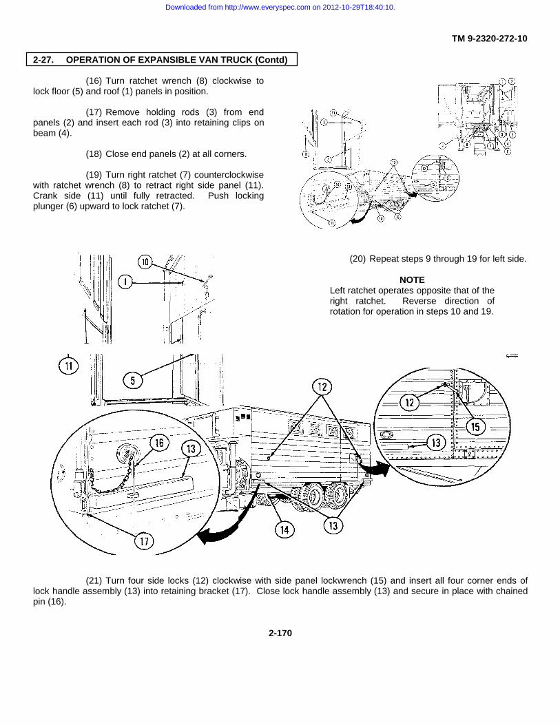
TM 9-2320-272-10
2-27. OPERATION OF EXPANSIBLE VAN TRUCK (Contd)
(16) Turn ratchet wrench (8) clockwise tolock floor (5) and roof (1) panels in position.
(17) Remove holding rods (3) from endpanels (2) and insert each rod (3) into retaining clips onbeam (4).
(18) Close end panels (2) at all corners.
(19) Turn right ratchet (7) counterclockwisewith ratchet wrench (8) to retract right side panel (11).Crank side (11) until fully retracted. Push lockingplunger (6) upward to lock ratchet (7).
(20) Repeat steps 9 through 19 for left side.
NOTELeft ratchet operates opposite that of theright ratchet. Reverse direction ofrotation for operation in steps 10 and 19.
(21) Turn four side locks (12) clockwise with side panel lockwrench (15) and insert all four corner ends oflock handle assembly (13) into retaining bracket (17). Close lock handle assembly (13) and secure in place with chainedpin (16).
2-170
Downloaded from http://www.everyspec.com on 2012-10-29T18:40:10.

TM 9-2320-272-10
2-27. OPERATION OF EXPANSIBLE VAN TRUCK (Contd)
(22) Remove ground spike (9) and store in storagelocation (14).
(23) Remove two jack spikes (22) from footpad (21) andinstall jack handle (19) in leveling jack (20). Rotate jack handle (19)clockwise until footpad (21) clears ground.
(24) Remove leveling jack (20) from van body bracket(18) and detach footpad (21) from jack (20).
(25) Remove leveling jack eyebolt (23) and telescopeleveling jack (20). Reinsert eyebolt (23).
(26) Repeat steps 23 through25 with three remaining van body levelingjacks (20).
(27) Stow two leveling jacks(20), footpads (21), and jack spikes (22) incompartment at rear of van body.
(28) Stow all tools and equipment used invan operation.
(29) Close and secure rear doors.
(30) Install ladders (24) to rear doors (26)and secure for travel with toggle clamps (25).
(31) Start with van end of auxiliary powercable (28) and, using handle (29), wind up power cable(28) on reel (27).
2-171
Downloaded from http://www.everyspec.com on 2012-10-29T18:40:10.

TM 9-2320-272-10
2-28. DECALS AND INSTRUCTION PLATES
a. The location and contents of decals and instruction plates are provided in this paragraph. A complete list andlocation of all decals and instruction plates is in TM 9-2320-272-20P. If any of these plates are worn, broken, painted over,missing, or unreadable, they must be replaced.
b. Below are those decals and plates that are located inside the cab. These decals and plates are common toone or more models covered in this manual.
2-172
Downloaded from http://www.everyspec.com on 2012-10-29T18:40:10.

TM 9-2320-272-10
2-28. DECALS AND INSTRUCTION PLATES (Contd)
2-173
Downloaded from http://www.everyspec.com on 2012-10-29T18:40:10.

TM 9-2320-272-10
2-28. DECALS AND INSTRUCTION PLATES (Contd)
2-174
Downloaded from http://www.everyspec.com on 2012-10-29T18:40:10.

TM 9-2320-272-10
2-28. DECALS AND INSTRUCTION PLATES (Contd)
2-175
Downloaded from http://www.everyspec.com on 2012-10-29T18:40:10.

TM 9-2320-272-10
2-28. DECALS AND INSTRUCTION PLATES (Contd)
c. The plate and decals shown below are located on the air cleaner assembly and are common to allM939/A1/A2 series vehicles.
2-176
Downloaded from http://www.everyspec.com on 2012-10-29T18:40:10.

TM 9-2320-272-10
2-28. DECALS AND INSTRUCTION PLATES (Contd)
d. Below are those plates located on the service and emergency couplings and are common to M939/Al/A2series vehicles.
e. The decal shown below is located on the hydraulic reservoir tank and is common to M925/A1/A2,M928/A1/A2, M929/A1/A2, M930/A1/A2, and M932/A1/A2 models.
2-177
Downloaded from http://www.everyspec.com on 2012-10-29T18:40:10.

TM 9-2320-272-10
2-28. DECALS AND INSTRUCTION PLATES (Contd)
f. The labels shown below are located on the central box harness, and are common to all M939/A1/A2 seriesvehicles.
g. The decals shown below are located on the radiator and are common to all M939/A1/A2 series vehicles.
2-178
Downloaded from http://www.everyspec.com on 2012-10-29T18:40:10.

TM 9-2320-272-10
2-28. DECALS AND INSTRUCTION PLATES (Contd)
h. The decal shown below is located on the surge tank and is common to all M939/A1/A2 series vehicles.
2-179
Downloaded from http://www.everyspec.com on 2012-10-29T18:40:10.

TM 9-2320-272-10
2-28. DECALS AND INSTRUCTION PLATES (Contd)
i. The vehicle decal shown below is common only to the dump (M929, M930), tractor (M931/A1]A2,M932/A1/A2), and wrecker (M936/A1/A2) vehicles.
j. The caution plates shown below are common only to the dropside cargo (M923/A1/A2, M925/A1/A2) modelvehicles.
2-180
Downloaded from http://www.everyspec.com on 2012-10-29T18:40:10.
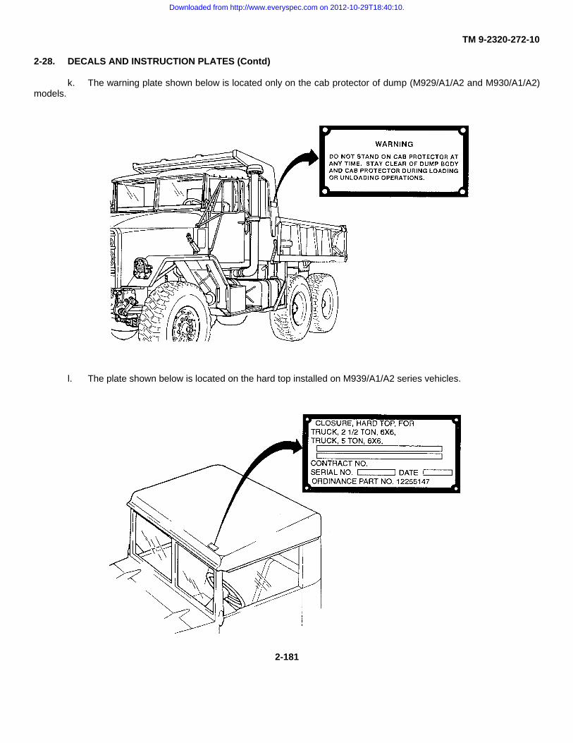
TM 9-2320-272-10
2-28. DECALS AND INSTRUCTION PLATES (Contd)
k. The warning plate shown below is located only on the cab protector of dump (M929/A1/A2 and M930/A1/A2)models.
l. The plate shown below is located on the hard top installed on M939/A1/A2 series vehicles.
2-181
Downloaded from http://www.everyspec.com on 2012-10-29T18:40:10.

TM 9-2320-272-10
2-28. DECALS AND INSTRUCTION PLATES (Contd)
m. The plates shown below are common to all front winch models and wrecker rear winch (M925/A1/A2,M928/A1/A2, M930/A1/A2, M932/A1/A2, and M936/A1/A2) models.
2-182
Downloaded from http://www.everyspec.com on 2012-10-29T18:40:10.

TM 9-2320-272-10
2-28. DECALS AND INSTRUCTION PLATES (Contd)
2-183
Downloaded from http://www.everyspec.com on 2012-10-29T18:40:10.
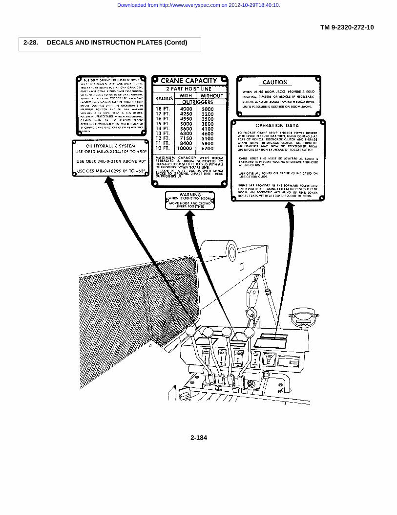
TM 9-2320-272-10
2-28. DECALS AND INSTRUCTION PLATES (Contd)
2-184
Downloaded from http://www.everyspec.com on 2012-10-29T18:40:10.
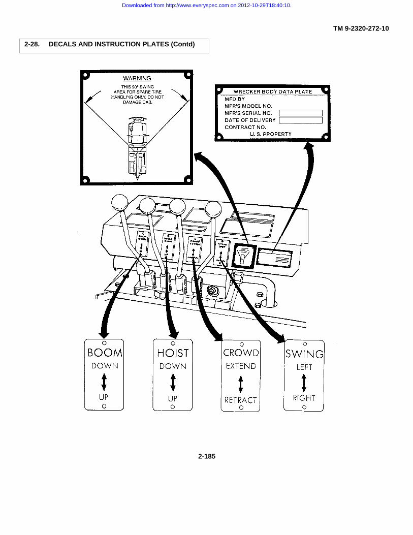
TM 9-2320-272-10
2-28. DECALS AND INSTRUCTION PLATES (Contd)
2-185
Downloaded from http://www.everyspec.com on 2012-10-29T18:40:10.

TM 9-2320-272-10
2-28. DECALS AND INSTRUCTION PLATES (Contd)
2-186
Downloaded from http://www.everyspec.com on 2012-10-29T18:40:10.

TM 9-2320-272-10
2-28. DECALS AND INSTRUCTION PLATES (Contd)
2-187
Downloaded from http://www.everyspec.com on 2012-10-29T18:40:10.

TM 9-2320-272-10
2-28. DECALS AND INSTRUCTION PLATES (Contd)
o. The vehicle plates shown below are common only to the expansible van (M934/A1/A2) model vehicles.
2-188
Downloaded from http://www.everyspec.com on 2012-10-29T18:40:10.
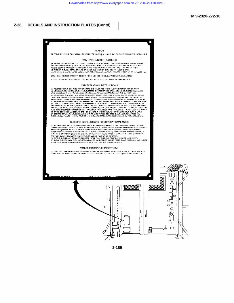
TM 9-2320-272-10
2-28. DECALS AND INSTRUCTION PLATES (Contd)
2-189
Downloaded from http://www.everyspec.com on 2012-10-29T18:40:10.

TM 9-2320-272-10
2-28. DECALS AND INSTRUCTION PLATES (Contd)
2-190
Downloaded from http://www.everyspec.com on 2012-10-29T18:40:10.
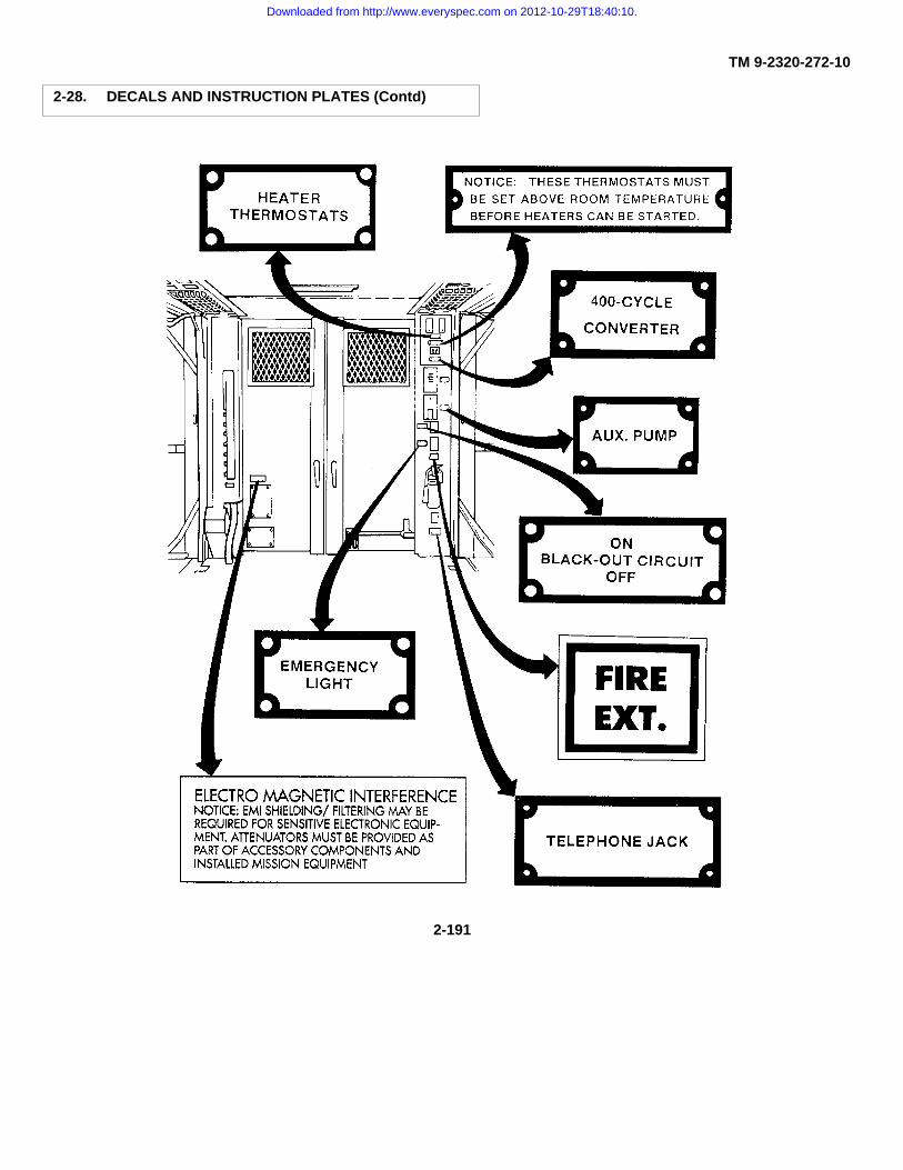
TM 9-2320-272-10
2-28. DECALS AND INSTRUCTION PLATES (Contd)
2-191
Downloaded from http://www.everyspec.com on 2012-10-29T18:40:10.

TM 9-2320-272-10
2-28. DECALS AND INSTRUCTION PLATES (Contd)
2-192
Downloaded from http://www.everyspec.com on 2012-10-29T18:40:10.

TM 9-2320-272-10
2-28. DECALS AND INSTRUCTION PLATES (Contd)
2-193
Downloaded from http://www.everyspec.com on 2012-10-29T18:40:10.
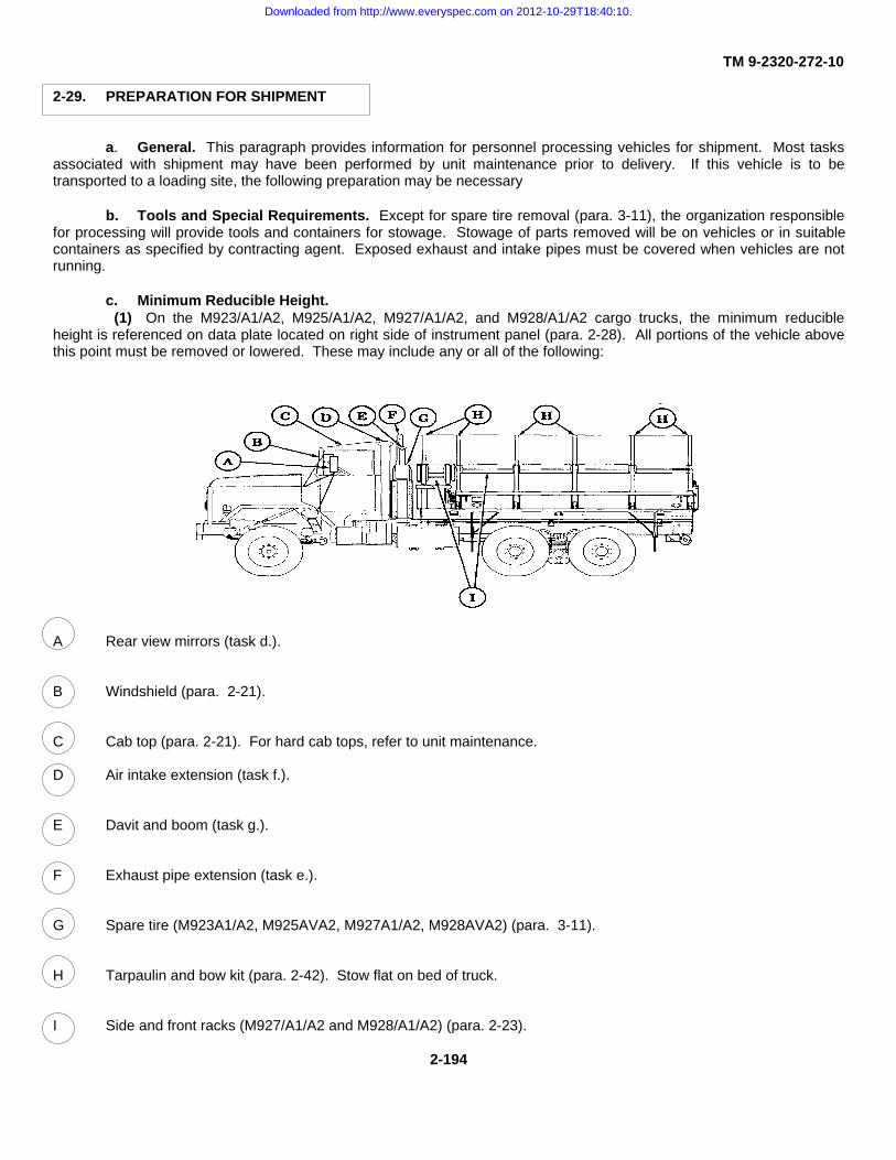
TM 9-2320-272-10
2-29. PREPARATION FOR SHIPMENT
a. General. This paragraph provides information for personnel processing vehicles for shipment. Most tasksassociated with shipment may have been performed by unit maintenance prior to delivery. If this vehicle is to betransported to a loading site, the following preparation may be necessary
b. Tools and Special Requirements. Except for spare tire removal (para. 3-11), the organization responsiblefor processing will provide tools and containers for stowage. Stowage of parts removed will be on vehicles or in suitablecontainers as specified by contracting agent. Exposed exhaust and intake pipes must be covered when vehicles are notrunning.
c. Minimum Reducible Height.(1) On the M923/A1/A2, M925/A1/A2, M927/A1/A2, and M928/A1/A2 cargo trucks, the minimum reducible
height is referenced on data plate located on right side of instrument panel (para. 2-28). All portions of the vehicle abovethis point must be removed or lowered. These may include any or all of the following:
A Rear view mirrors (task d.).
B Windshield (para. 2-21).
C Cab top (para. 2-21). For hard cab tops, refer to unit maintenance.
D Air intake extension (task f.).
E Davit and boom (task g.).
F Exhaust pipe extension (task e.).
G Spare tire (M923A1/A2, M925AVA2, M927A1/A2, M928AVA2) (para. 3-11).
H Tarpaulin and bow kit (para. 2-42). Stow flat on bed of truck.
I Side and front racks (M927/A1/A2 and M928/A1/A2) (para. 2-23).
2-194
Downloaded from http://www.everyspec.com on 2012-10-29T18:40:10.

TM 9-2320-272-10
2-29. PREPARATION FOR SHIPMENT (Contd)
(2) n the M93VAI/A2 and M932/A1/A2 tractors, the minimum reducible height is referenced on data platelocated on the side of the instrument panel (para. 2-28). All portions of the vehicle above this point must be removed orlowered. These may include any or all of the following:
J Air intake extension (task f.).
K Davit and boom (task g.).
L Cab top (para. 2-21). For hard cab tops, refer to unit maintenance.
M Exhaust pipe extension (task e.).
N Rear view mirrors (task d.).
O Windshield (para. 2-21).
P Spare tire (M931A1/A2 and M932A1/A2) (para. 3-11).
2-195
Downloaded from http://www.everyspec.com on 2012-10-29T18:40:10.

TM 9-2320-272-10
2-29. PREPARATION FOR SHIPMENT (Contd)
d. Mirror Removal and Installation.
(1) Removal
(a) On left side of vehicle, remove locknut (11) and washer (10) from screw (8), lower brace (5), andlower door hinge (9).
(b) Remove locknut (13) and washer (14) from screw (18) support braces (16) and (17), and bracket(15).
(c) Remove locknut (12) and washer (7) from screw (2), support braces (1) and (3), and door hinge(6).
(d) Remove screws (2), (8), and (18) from mirror assembly (4), bracket (15), and door hinges (6) and(9). Remove mirror assembly (4).
(e) Install screw (18), washer (14), and locknut (13) on support bracket (15).
(f) Install screw (2), washer (7), and locknut (12) on door hinge (6).
(g) Install screw (8), washer (10), and locknut (11) on door hinge (9).
(h) Repeat steps a through g for right side of vehicle.
(2) Installation
(a) On left side of vehicle, remove screw (2), washer (7), and locknut (12) from door hinge (6).
(b) Remove screw (18), washer (14), and locknut(13) from support bracket (15).
(c) Remove screw (8), washer (10), and locknut (11)from door hinge (9).
(d) Install mirror assembly (4) on top door hinge (6)with screw (2), washer (7), and locknut (12), and on lower door hinge (9)with screw (8), washer (10), and locknut (11).
(e) Install support braces (16) and (17) on bracket(15) with screw (18), washer (14), and locknut (13).
(f) Adjust mirror as necessary to provideunobstructed rear view.
(g) Repeat steps a through f for right side of vehicle.
2-196
Downloaded from http://www.everyspec.com on 2012-10-29T18:40:10.

TM 9-2320-272-10
2-29. PREPARATION FOR SHIPMENT (Contd)
e. Exhaust Pipe Extension Removal and Installation.
Do not touch hot exhaust system components with bare hands. Injury to personnel mayresult.
(1) Removal
(a) Remove locknut (25) and screw (22) from muffler coupling clamp (21).
(b) Remove muffler coupling clamp (21), gasket (24), and muffler extension (20) from muffler (23).
(c) Install screw (22), locknut (25), muffler coupling clamp (21), and gasket (24) on muffler extension(20).
(2) Installation
(a) Remove locknut (25) and screw (22) from muffler coupling clamp (21).
(b) Remove muffler coupling clamp (21) and gasket (24) from muffler extension (20).
(c) Install muffler extension (20) and gasket (24) to muffler (23) with screw (22), muffler couplingclamp (21), and locknut (25).
(d) Rotate muffler exhaust extension (20) so that top points away from cab (19). Tighten screw (22)and locknut (25) to seal muffler extension (20) to muffler (23).
(e) Start engine (para. 2-12) and check for exhaust leaks.
NOTEReport removal and installation to unit maintenance to replace gasket and locknut.
2-197
Downloaded from http://www.everyspec.com on 2012-10-29T18:40:10.

TM 9-2320-272-10
2-29. PREPARATION FOR SHIPMENT (Contd)
CAUTION
Cover exposed intake tube when vehicle is not running. Failure to do so will result indamage to internal components.
f. Air Intake Extension Removal and Installation.
(1) Removal
(a) Remove screw (2) and locknut (3) from clamp (5) on air intake tube (4).
(b) Remove air intake extension (1) from air intake tube (4) and clamp (5).
(c) Install screw (2) and locknut (3) in clamp (5) on air intake tube (4).
(2) Installation
(a) Remove screw (2) and locknut (3) from clamp (5) on air intake tube (4).
(b) Install air intake extension (1) on air intake tube (4) with clamp (5), screw (2), and locknut (3).
(c) Report removal and installation of air intake extension (1) to unit maintenance as soon as possible.
2-198
Downloaded from http://www.everyspec.com on 2012-10-29T18:40:10.

TM 9-2320-272-10
2-29. PREPARATION FOR SHIPMENT (Contd)
g. Davit and Boom Removal andInstallation.
(1) Removal (M939 series vehicles)
(a) Remove lock pin (10) andretaining pin (11) from boom (7).
(b) Remove boom extension (6)from boom (7).
(c) Loosen setscrew (8) in boom (7).
(d) Remove boom (7) from boombase (9).
(2) Installation (M939 series vehicles)
(a) Install boom (7) in boom base(9).
(b) Tighten setscrew (8) in boom (7).
(c) Install boom extension (6) inboom (7).
(d) Install retaining pin (11) in boom(8) and secure with lock pin (10).
M939/A1/A2 SERIES VEHICLES
M939 SERIES VEHICLES
(3) Removal (M939A1/A2 series vehicles)
(a) Remove lock pin (17) andretaining pin (18) from boom extension (12) and boom(13).
(b) Remove boom extension (12)from boom (13).
(c) Remove four locknuts (15),screws (14), and boom (13) from boom base (16).
(4) Installation (M939A1/A2)
(a) Install boom (13) on boom base(16) with four locknuts (15) and screws (14).
(b) Install boom extension (12) inboom (13).
(c) Install retaining pin (18) in boom(13) and boom extension (12), and secure with lock pin(17).
2-199
Downloaded from http://www.everyspec.com on 2012-10-29T18:40:10.

TM 9-2320-272-10
2-29. PREPARATION FOR SHIPMENT (Contd)
h. Minimum Reducible Width.
(1) Shipping width is measured at the widest point on the vehicle excluding mirrors. On the M939, M939A1,and M939A2 series vehicles, it may be necessary to retract mirrors to obtain necessary clearance.
(2) Retracting mirrors.
(a) On left side of vehicle, loosen locknut (3) from screw (4).
(b) Rotate outer brace (2) inward toward door (1) until outer brace (2) no longer extends beyondfender (5).
(c) Tighten locknut (3) on screw (4) to secure outer brace (2) in this position.
(d) Repeat steps a through c for right side of vehicle.
CAUTION
With rear view mirrors retracted, use additional spotters when moving vehicle. Failure todo so may result in damage to equipment.
(3) Extending mirrors.
(a) On left side of vehicle, loosen locknut (3) from screw (4).
(b) Rotate outer brace (2) outward from the door (1) until extends it beyond fender.
(c) Adjust as necessary to obtainunobstructed rear view.
(d) Tighten locknut (3) on screw (4)while holding outer brace (2) in place.
(e) Repeat steps a through d forright side of vehicle.
2-200
Downloaded from http://www.everyspec.com on 2012-10-29T18:40:10.
TM 9-2320-272-10
Section IV. OPERATION UNDER UNUSUAL CONDITIONS
2-30. SPECIAL INSTRUCTIONS
a. General. Special instructions for operating and maintaining vehicles under unusual conditions are included inthis section. Unusual conditions are extreme high or low temperatures, humidity, and/or terrain. Special care in cleaningand lubrication must be taken to keep vehicles operating under unusual conditions.
b. Cleaning. Refer to paragraph 2-8 for cleaning instructions and precautions.
c. Lubrication.
(1) Refer to LO 9-2320-272-12 for proper lubricating instructions.
(2) Service intervals in LO 9-2320-272-12 are for normal operating conditions. Reduce service intervalswhen unusual conditions exist.
d. Driving Instructions.
(1) FM 21-305 contains special driving instructions for operating wheeled vehicles.
(2) FM 9-207 contains instructions on vehicle operation in extreme cold of 0° to -65°F (-18° to -54°C) orbelow. Other documents with information on cold weather vehicle operation are:
(a) FM 31-70 Basic Cold Weather Manual.
(b) FM 31-71 Northern Operations.
(c) FM 90-6 (HTF) Mountain Operations.
e. Reporting Materiel Failure. Report failure of vehicle, body equipment, or kits on DA form SF 368 (QualityDeficiency Report-Equipment Improvement Recommendations) as prescribed by DA Pam 738-750 and as stated inparagraph 1-5 of this manual.
f. Special Purpose Kits. Paragraphs describing special purpose kits for operation under unusual conditionsare:
(1) Fuel burning personnel heater kit (para. 2-44) and engine coolant heater kit (para. 2-45).
(2) Deepwater fording kit (para. 2-40).
(3) Hardtop kit and radiator and hood cover kit (para. 2-43).
2-31. CTIS OPERATION UNDER UNUSUAL CONDITIONS
a. General. This paragraph provides instructions for M939A2 CTIS operation under emergency conditions andoperation with a punctured tire.
NOTEExcept where specifically noted, the controls and indicator in this section are applicable toall M939A2 series vehicles.
2-201
Downloaded from http://www.everyspec.com on 2012-10-29T18:40:10.

TM 9-2320-272-10
2-31. CTIS OPERATION UNDER UNUSUAL CONDITIONS (Contd)
b. The selector panel (1) is part of the Electronic Control Unit (ECU) (4) and contains selectors for the fourpreset tire pressure modes and a run flat selector. Each selector has its own light. A steady selector light shows that thetire pressure selected has been achieved. A flashing selector light means that the system is working to change tirepressures (para. 3-5).
c. HWY Mode. The highway tire pressure selector is the normal operating mode of CTIS. The HWY mode (8)is 60 psi (414 kPa) (80 psi (552kPa) for M936A2 wrecker). If a lower tire pressure mode had been selected the last timethe vehicle was operated, CTIS will automatically begin to inflate to the highway setting.
d. X-C Mode. The cross-country tire pressure selector X/C (7) is used for operating the vehicle on non-pavedsecondary roads and unimproved surfaces. It allows operation up to 35 mph (56 km/h) (25 mph (40 km/h) on M936A2wrecker). When 35 mph (56 km/h) is exceeded for more than one minute, the amber overspeed warning light (2) will flash.If 35 mph (56 km/h) is exceeded for more than two minutes, CTIS will automatically begin to inflate to HWY (8) mode.
e. Sand Mode. When the mission requires maximum traction in sand, snow, or mud select SAND (6) onselector panel (1). It allows operation up to 20 mph (32 km/h) (15 mph (24 km/h) on M936A2 wrecker). When 20 mph (32km/h) is exceeded for more than one minute, the amber overspeed warning light (2) will flash. If 20 mph (32 km/h) isexceeded for more than two minutes, CTIS will automatically begin to inflate to X/C (7) pressure.
2-202
Downloaded from http://www.everyspec.com on 2012-10-29T18:40:10.

TM 9-2320-272-10
2-31. CTIS OPERATION UNDER UNUSUAL CONDITIONS (Contd)
CAUTION
Speed must be limited to 10 mph (16 km/h) in the emergency mode to prevent damage totires.
f. Emer Mode. When the mission requires maximum traction on extremely adverse terrain, select emergencymode by depressing EMER (5) on the selector panel (1). The dash-mounted amber warning light will illuminate.Operation in emergency mode is limited to ten minutes. Then the system automatically inflates to SAND (6); if the missiondemands extended emergency mode use, select EMER (5) as needed.
g. Run Flat Mode. When the mission requires operation with a punctured tire, select run flat mode bydepressing RUN FLAT (3) on the selector panel (1). Run flat mode causes the CTIS to check tire pressure every fifteenseconds. Normally, checks occur every fifteen minutes. Repeated damage detection results in repeated inflationattempts. The punctured tire receives a new air supply each fifteen seconds. Operation in the run flat mode is limited toten minutes unless reselected. If no longer required, press the RUN FLAT (3) selector a second time.
2-32. OPERATING IN EXTREME COLD
a. General. The operator must always be alert to changes in weather. The operator must take care ofassigned vehicle in order to prevent damage to vehicle because of sudden changes in weather. The operator should becautious when starting or driving a vehicle that has not been operated for a long period. Lubricants may thicken and causeparts failure. Tires may freeze to the ground, or may freeze flat on the bottom, if underinflated. The operator should bealert to such possibilities to prevent great damage to the vehicle.
b. Before Operation.
(1) Perform all before operation services listed in table 2-3, Preventive Maintenance Checks and Services(PMCS).
(2) Start engine coolant heater, if equipped, to warm vehicle coolant, engine, and batteries beforeattempting to start engine. Refer to paragraph 2-45 for engine coolant heater operating instructions.
c. Starting Engine.
NOTE
Shut down engine coolant heater before starting vehicle engine.
2-203
Downloaded from http://www.everyspec.com on 2012-10-29T18:40:10.
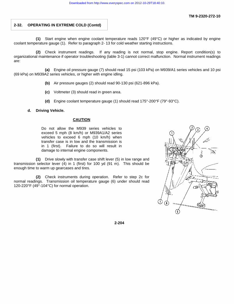
TM 9-2320-272-10
2-32. OPERATING IN EXTREME COLD (Contd)
(1) Start engine when engine coolant temperature reads 120°F (49°C) or higher as indicated by enginecoolant temperature gauge (1). Refer to paragraph 2- 13 for cold weather starting instructions.
(2) Check instrument readings. If any reading is not normal, stop engine. Report condition(s) toorganizational maintenance if operator troubleshooting (table 3-1) cannot correct malfunction. Normal instrument readingsare:
(a) Engine oil pressure gauge (7) should read 15 psi (103 kPa) on M939/A1 series vehicles and 10 psi(69 kPa) on M939A2 series vehicles, or higher with engine idling.
(b) Air pressure gauges (2) should read 90-130 psi (621-896 kPa).
(c) Voltmeter (3) should read in green area.
(d) Engine coolant temperature gauge (1) should read 175°-200°F (79°-93°C).
d. Driving Vehicle.
CAUTION
Do not allow the M939 series vehicles toexceed 5 mph (8 km/h) or M939A1/A2 seriesvehicles to exceed 6 mph (10 km/h) whentransfer case is in low and the transmission isin 1 (first). Failure to do so will result indamage to internal engine components.
(1) Drive slowly with transfer case shift lever (5) in low range andtransmission selector lever (4) in 1 (first) for 100 yd (91 m). This should beenough time to warm up gearcases and tires.
(2) Check instruments during operation. Refer to step 2c fornormal readings. Transmission oil temperature gauge (6) under should read120-220°F (49°-104°C) for normal operation.
2-204
Downloaded from http://www.everyspec.com on 2012-10-29T18:40:10.

TM 9-2320-272-10
2-32. OPERATING IN EXTREME COLD (Contd)
e. Stopping or Parking.
CAUTION
• Operator must take every precaution to prevent snow from blowing into enginecompartment when parked. Snow will melt and later form ice to jam engine controls.
• Do not apply parking brake. Brakeshoes may freeze to drum.
NOTE
• Do not idle engine for more than 15 minutes.
• Park in a sheltered area out of the wind, if possible, or park so that vehicle does notface into the wind. Park vehicle with wood planks, brush, mats, or canvas under thewheels if a long shutdown period in open area is expected.
(1) Place transmission selector lever (4) in N (neutral).
(2) Place chocks (8) in front of or behind vehicle wheels.
(3) Drain water from compressed air reservoirs by turning four drainvalves (9) counterclockwise. Closedrainvalves (9) immediately after purging water.
Alcohol used in alcohol evaporator is flammable, poisonous, and explosive. Do notsmoke when adding fluid and do not drink fluid. Doing so will result in injury or death.
2-205
Downloaded from http://www.everyspec.com on 2012-10-29T18:40:10.

TM 9-2320-272-10
2-32. OPERATING IN EXTREME COLD (Contd)
(4) On M939/A1 series vehicles, check fluid level in alcohol evaporator (1) located on left side of engine.Add alcohol as required.
(5) Start engine coolant heater if required. Refer to paragraph 2-45 for engine coolant heater operatinginstructions.
(6) Perform after-operation services in Preventive Maintenance Checks and Services (PMCS table 2-3).
(7) Drain off any accumulated water in fuel filter/water separator (2). To train water from fuel system:
(a) On M939/A1 series vehicles, open fuel drainvalves (3) and (4) on fuel filter/water separator (2) anddrain water into suitable container. Close drainvalves (3) and (4) when clear fuel is visible.
CAUTION
Do not overtighten plastic valve; damage may result and fuel may leak.
(b) On M939A2 series vehicles, loosen drainvalve (6) on bottom of fuel filter/water separator (5) anddrain water into suitable container. Close drainvalve (6) when clean fuel is visible.
(c) If fuel is not clear before approximately one qt (0.946 L) has drained, notify unit maintenance.
(d) After draining has been completed, prime the fuel system (para. 3-8).
2-206
Downloaded from http://www.everyspec.com on 2012-10-29T18:40:10.

TM 9-2320-272-10
2-33. OPERATING IN SNOW
a. General.
(1) Refer to paragraph 2-13 for cold weather starting instructions.
(2) If vehicle is equipped with arctic winterization kits, refer to paragraphs 2-44 and 2-45 for description andoperating instructions.
(3) Operating on snow or ice requires use of tire chains on forward-rear axle tires. Refer to FM 21-305 forinstallation of tire chains.
CAUTION
Attempting operation with only one driving wheel equipped with tire chain may result in damage to tireand/or power train.
NOTE
Use tire chains on forward-rear-axle-tires. For M939 series vehicles place chains onoutside tires. Remove as soon as mission allows.
(4) If tire chains are not available, deflate tire pressure to 25 psi (172 kPa). Reinflate to normal pressuresafter operating in snow (table 1-10).
b. Driving Vehicle.
(1) Remove chocks (7) from vehicle wheels if used.
(2) Place transmission selector lever (8) in 1-5 (drive) and transfer case shift lever (9) in low range. Slowlyaccelerate without causing wheels to spin or engine to race. Place transfer case shift lever (9) in high range when underway.
2-207
Downloaded from http://www.everyspec.com on 2012-10-29T18:40:10.
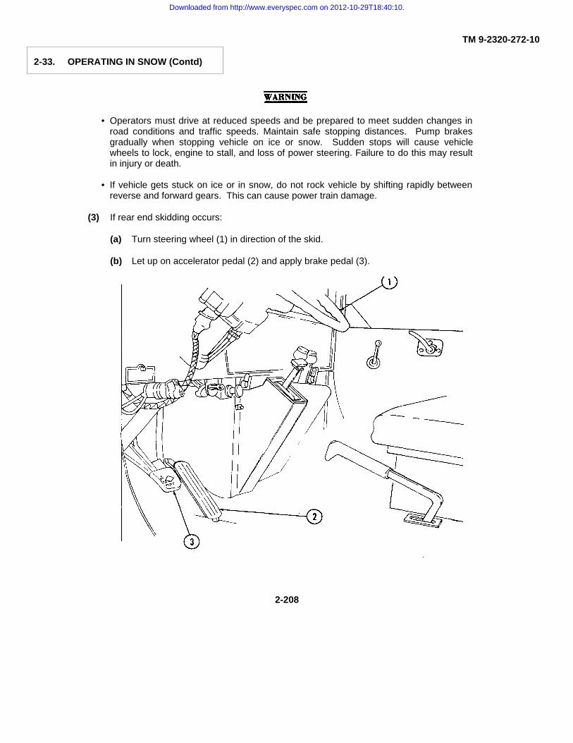
TM 9-2320-272-10
2-33. OPERATING IN SNOW (Contd)
• Operators must drive at reduced speeds and be prepared to meet sudden changes inroad conditions and traffic speeds. Maintain safe stopping distances. Pump brakesgradually when stopping vehicle on ice or snow. Sudden stops will cause vehiclewheels to lock, engine to stall, and loss of power steering. Failure to do this may resultin injury or death.
• If vehicle gets stuck on ice or in snow, do not rock vehicle by shifting rapidly betweenreverse and forward gears. This can cause power train damage.
(3) If rear end skidding occurs:
(a) Turn steering wheel (1) in direction of the skid.
(b) Let up on accelerator pedal (2) and apply brake pedal (3).
2-208
Downloaded from http://www.everyspec.com on 2012-10-29T18:40:10.

TM 9-2320-272-10
2-33. OPERATING IN SNOW (Contd)
c. After Operation.
(1) Remove all ice and snow build-up on vehicle.
(2) Refuel fuel tank(s) (4) as soon as possible.
CAUTION
Drain moisture from tanks in the following sequence. Failure to do so may result inreintroduction of moisture from tanks that have not been purged, resulting in equipmentfailures due to ice forming in air lines.
(3) Purge moisture from air tanks in the following order:
(a) Open wet tank drainvalve (7).
(b) Open primary and secondary drainvalves (5) and (6).
(c) Open spring brake drainvalve (8).
2-209
Downloaded from http://www.everyspec.com on 2012-10-29T18:40:10.
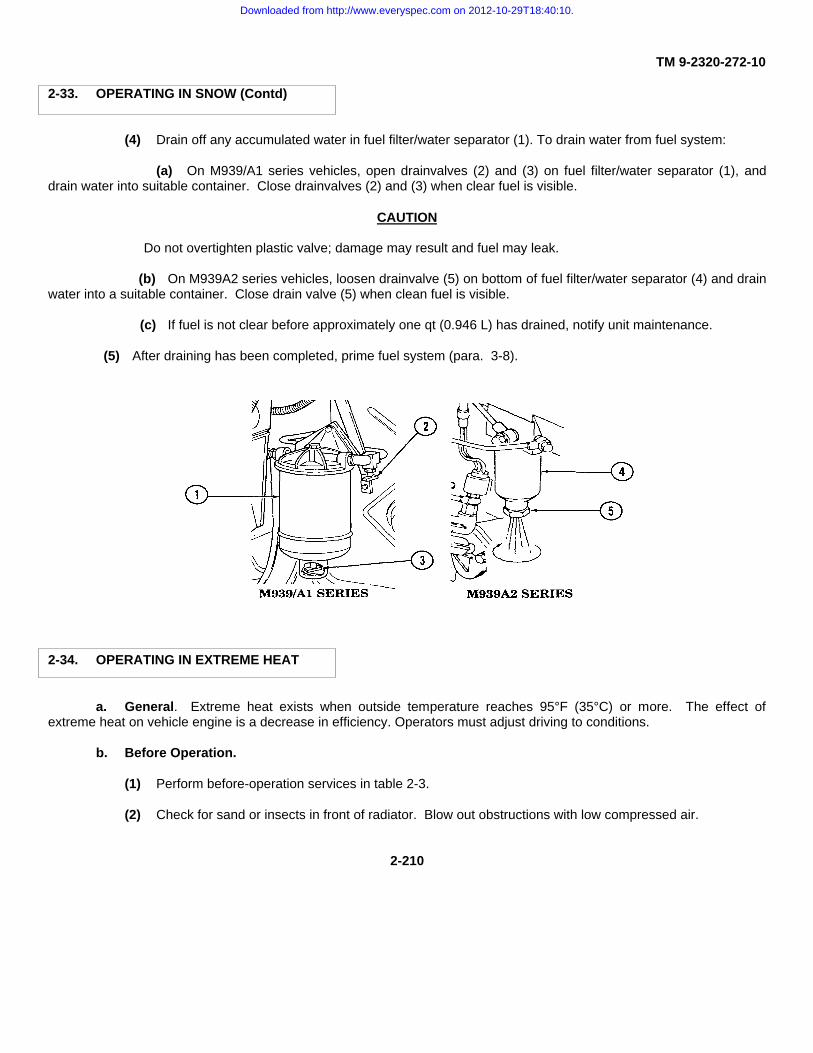
TM 9-2320-272-10
2-33. OPERATING IN SNOW (Contd)
(4) Drain off any accumulated water in fuel filter/water separator (1). To drain water from fuel system:
(a) On M939/A1 series vehicles, open drainvalves (2) and (3) on fuel filter/water separator (1), anddrain water into suitable container. Close drainvalves (2) and (3) when clear fuel is visible.
CAUTION
Do not overtighten plastic valve; damage may result and fuel may leak.
(b) On M939A2 series vehicles, loosen drainvalve (5) on bottom of fuel filter/water separator (4) and drainwater into a suitable container. Close drain valve (5) when clean fuel is visible.
(c) If fuel is not clear before approximately one qt (0.946 L) has drained, notify unit maintenance.
(5) After draining has been completed, prime fuel system (para. 3-8).
2-34. OPERATING IN EXTREME HEAT
a. General. Extreme heat exists when outside temperature reaches 95°F (35°C) or more. The effect ofextreme heat on vehicle engine is a decrease in efficiency. Operators must adjust driving to conditions.
b. Before Operation.
(1) Perform before-operation services in table 2-3.
(2) Check for sand or insects in front of radiator. Blow out obstructions with low compressed air.
2-210
Downloaded from http://www.everyspec.com on 2012-10-29T18:40:10.

TM 9-2320-272-10
2-34. OPERATING IN EXTREME HEAT (Contd)
(3) Check tension adjustment of belts.
(4) Check coolant hoses and lines for cracks, leaks, and security of connections.
(5) Add corrosion inhibitor compound to cooling liquid.
(6) Check for correct tire inflation pressure. Do not reduce pressure if tires are hot from driving.
(7) Reduce lubrication intervals as specified in applicable LOs.
c. Driving Vehicle.
(1) Avoid continuous vehicle operation at high speeds. Avoid long, hard pulls on steep grades with transfercase shift lever (6) in low.
(2) Frequently check air cleaner indicator (7). If indicator shows red, perform emergency air cleanerservicing (para. 3-8).
(3) Frequently check engine coolant temperature gauge (8), engine oil pressure gauge (10), andtransmission oil temperature gauge (9). Engine or transmission is overheating if any of the following conditions exist:
(a) Coolant temperature gauge (8) indicates more than 210°F (99°C).
(b) Oil pressure gauge (10) drops below 15 psi (103 kPa) on M939/A1 series vehicles and 10 psi (69kPa) on M939A2 series vehicles, with engine at idle.
(c) Transmission oil temperature exceeds 300°F (149°C) on oil temperature gauge (9).
(4) If engine overheating occurs:
NOTE
Do not raise vehicle hood.Engine will cool faster atidle with hood closed.
(a) Park vehicle, allowing engine to idle.
2-211
Downloaded from http://www.everyspec.com on 2012-10-29T18:40:10.

TM 9-2320-272-10
2-34. OPERATING IN EXTREME HEAT (Contd)
CAUTION
If engine temperature continues to rise or does not drop after two minutes of idling, shutdown engine and refer to trouble- shooting table 3-1.
(b) Observe coolant temperature gauge (1), engine oil pressure gauge (3), and transmission oiltemperature gauge (2) for signs that engine or transmission is steadily cooling.
(c) Shut off when engine coolant temperature gauge (1) reaches normal operating temperature of175°-200°F (79° -93°C
(d) Perform troubleshooting procedures as listed in table 3-1.
Extreme care should be taken when removing surge tank filler cap if coolant temperaturegauge reads above 175°F (79°C). Steam or hot coolant under pressure will cause injury.
(e) Place a thick cloth over surge tank filler cap (4). Carefully turn cap (4) counterclockwise to firststop to allow pressure to escape.
(f) Remove cap (4) when cooling system pressure is vented and check coolant level. Surge tankshould be filled approximately to bottom of filler neck.
(g) Add engine coolant as required. Install surge tank filler cap (4) after filling and start engine (para.2-12).
(h) Proceed with operation. Report any overheating to unit maintenance upon completion ofoperation.
d. Stopping or Parking.
(1) Park vehicle in a sheltered area, out of sun, if possible.
(2) Check batteries after operation and service, as required.
2-212
Downloaded from http://www.everyspec.com on 2012-10-29T18:40:10.

TM 9-2320-272-10
2-35. OPERATING IN DUSTY OR SANDY AREAS
a. General. Be aware of vehicle overheating when operating in dusty or sandy areas. Air cleaner, cooling system,and lubrication points will require frequent servicing.
NOTE• Do not use tire chains in soft sand.• Use a second vehicle with winch to recover
vehicles stuck or sunk in sand.
b. Driving Vehicle.
(1) When starting in sand or soft ground, place transfer case shift lever (6) in low range and transmissionselector lever (5) in 1-2 (second) or 1-3 (third).
(2) Deflate tires to 25 psi (172 kPa) only when operating off the road in heavy rain. Inflate tires immediately tocorrect pressure when operation changes to paved roads. Refer to table 1-10 for tire inflation data. Refer to paragraph 3-11 for inflating tires using vehicle air system.
(3) On M939A2 series vehicles, select SAND (8) on control panel (7). This will automatically deflate tires unless20 mph (32 km/h) is exceeded (15 mph (24 km/h) on M936A2 wrecker) for more than two minutes. CTIS will thenautomatically inflate to cross-country pressure.
(4) Accelerate slowly so wheels will not spin and dig into sand.
(5) Inflate tires to normal pressures after vehicle has cleared deep sand(table 1-10). On M939A2 series vehicles, press the desired mode select button on thecontrol panel (7).
(6) When moving across a slope, choose the least angle possible. Keepmoving and avoid turning quickly.
(7) Keep throttle steady after reaching desired speed.
(8) Do not rock vehicle out of deep sand.
2-213
Downloaded from http://www.everyspec.com on 2012-10-29T18:40:10.

TM 9-2320-272-10
2-35. OPERATING IN DUSTY OR SANDY AREAS (Contd)
c. Stopping or Parking.
(1) Park vehicle in a sheltered area, out of blowing dust or sand whenever possible. If sheltered area is notavailable, park so vehicle does not face into wind and cover vehicle with tarpaulins. When entire vehicle cannot becovered, protect windows, cab, and engine compartment with tarpaulins to prevent entry of sand or dust.
(2) Use low air pressure to remove all sand from vehicle engine compartment, areas around brakes, drums, andspring seats after daily operation.
(3) Use caution while refueling to prevent dust or sand from entering fuel tank(s). Tighten filler cap securely afterrefueling.
2-36. OPERATING UNDER RAINY OR HUMID CONDITIONS
a. General.
(1) Vehicles inactive for long periods in hot, humid weather can rust rapidly. Fungus may grow in the fuel tank(s),on canvas tarpaulin, seats, and other components. Frequent inspection, cleaning (para. 2-8), and lubrication arenecessary to maintain the readiness of vehicles.
(2) Drain off any accumulated water in fuel filter/water separator (1). To drain water from fuel system:
(a) On M939/A1 series vehicles, open drainvalves (2) and (3) on fuel filter/water separator (1), drain waterinto suitable container, close drainvalves (2) and (3) when clean fuel is visible.
2-214
Downloaded from http://www.everyspec.com on 2012-10-29T18:40:10.

TM 9-2320-272-10
2-36. OPERATING UNDER RAINY OR HUMID CONDITIONS (Contd)
CAUTIONDo not overtighten plastic valve; damage may result and fuel may leak.
(b) On M939A2 series vehicles, loosen drainvalve (5) on bottom of fuel filter/water separator (4), drainwater into suitable container, and close drainvalve (5) when clean fuel is visible.
(c) If fuel is not clear before approximately one qt (0.946 L) has drained, notify unit maintenance.
(d) After draining has been completed, prime the fuel system (para. 3-8).
b. Driving Vehicle.
(1) Do not spin wheels when placing vehicle in motion in heavy rain or muddy conditions. If necessary, placetransfer case shift lever (7) in low range and transmission selector lever (6) in 1-3 (third) to obtain a slow, firm start.
WARNINGPump brakes gradually when slowing or stopping vehicle on wetpavement. Sudden stops will cause vehicle wheels to lock, engine tostall, and loss of power steering. Failure to do this may result in injury ordeath.
(2) Deflate tires to 25 psi (172 kPa) only when operating off-the-road in heavy rain. Inflate tires immediately tocorrect pressure when operation changes to paved roads. Refer to table 1-10 for tire inflation data. Refer to paragraph 3-11 for inflating tires using vehicle air system.
(3) On M939A2 series vehicles, select SAND (9) on control panel (8). This will automatically deflate tires unless20 mph (32 km/h) is exceeded (15 mph (24 km/h) on M936A2 wrecker)) for more than two minutes. CTIS willautomatically inflate to cross-country pressure.
2-215
Downloaded from http://www.everyspec.com on 2012-10-29T18:40:10.

TM 9-2320-272-10
2-37. OPERATING IN DEEP MUD
a. Driving Vehicle.
NOTE• Six-wheel drive is achieved automatically when transfer case shift lever is placed
in low range. In high range, the front-wheel drive lock-in switch must be engagedto achieve six-wheel drive.
• Use a second vehicle with winch to recover vehicles sunk in deep mud. Do notspin wheels. Refer to paragraph 2-22 for front winch operation.
(1) Place transmission selector lever (2) in 1-5 (drive) and transfer case shift lever (3) in low range. Place vehiclein motion slowly without causing wheels to spin or engine to race. Place transfer case shift lever (3) in high range whenvehicle is under way.
(2) If rear end skidding occurs:
(a) Turn steering wheel (1) in direction of skid.
(b) Let up on accelerator pedal (4) and apply brake pedal (5) in a gradual pumping manner.
b. After Operation.
(1) Wash all mud from vehicle as soon as possible.
(2) If vehicle front winch was used, clean and lubricate. Refer to LO 9-2320-272-12.
2-216
Downloaded from http://www.everyspec.com on 2012-10-29T18:40:10.

TM 9-2320-272-10
Section V. OPERATION OF SPECIAL PURPOSE KITS
2-38. GENERAL
This section provides information and instructions for operation of special purpose kits for M939/A1/A2 series vehicles.
Table 2-6. M939/A1/A2 Series Special Purpose Kits.
KITS
A-frame Kit X X X XAirbrake Control Kit X X X X XBow and Tarpaulin Kit X X X X X XChemical Agent Alarm Kit* X X X X X X X X X XDeepwater Fording Kit X X X X X X X X X XFuel Burning Personnel Heater andEngine Coolant Heater Kits X X X X X X X X X XHardtop Kit X X X X X X X X X XMachine Gun Mount Kit* X X X X X X XMud Flap Kit X XRadiator and Hood Cover Kit X X X X X X X X X XRifle Mount Kit* X X X X X X X X X XTroop Seat Kit X X
*Information found in other section of this manual.
2-39. OPERATION OF AUXILIARY EQUIPMENT(SPECIAL PURPOSE KITS)
Operating Instructions. Operating instructions for the following special purpose kits are covered herein.
(1) Deepwater Fording Kit (page 2-218)(2) Troop Seat Kit (page 2-223)(3) Bow and Tarpaulin Kit (page 2-224)(4) Hardtop Kit and Radiator and Hood Cover Kit (page 2-231)(5) Fuel Burning Personnel Heater Kit (page 2-232)(6) Engine Coolant Heater Kit (page 2-234)(7) A-frame Kit (page 2-238)(8) Airbrake Control Kit (page 2-239)(9) Mud Flap Kit (page 2-240)
2-217
Downloaded from http://www.everyspec.com on 2012-10-29T18:40:10.

TM 9-2320-272-10
2-40. DEEPWATER FORDING KIT
a. General. Salt water causes damage to vehicle components. For this reason, do not drive needlessly in or throughsalt water. Vehicle components that are exposed to salt water must be washed with fresh water as soon as possible. Thevehicle will ford water up to 30 in. (76 cm) in depth without a fording kit and 78 in. (198 cm) with kit installed.
b. Operator Preparation for Fording.
(1) Tighten cap(s) (1) on fuel tank(s) (2).
(a) Location of fuel tank (2) on single tank model vehicles:
2-218
Downloaded from http://www.everyspec.com on 2012-10-29T18:40:10.

TM 9-2320-272-10
2-40. DEEPWATER FORDING KIT (Contd)
(b) Location of fuel tanks (2) on dual tank model vehicles:
2-219
Downloaded from http://www.everyspec.com on 2012-10-29T18:40:10.
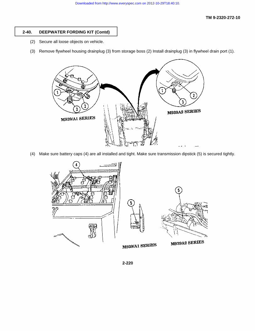
TM 9-2320-272-10
2-40. DEEPWATER FORDING KIT (Contd)
(2) Secure all loose objects on vehicle.
(3) Remove flywheel housing drainplug (3) from storage boss (2) Install drainplug (3) in flywheel drain port (1).
(4) Make sure battery caps (4) are all installed and tight. Make sure transmission dipstick (5) is secured tightly.
2-220
Downloaded from http://www.everyspec.com on 2012-10-29T18:40:10.

TM 9-2320-272-10
2-40. DEEPWATER FORDING KIT (Contd)
c. Fording Operation.
(1) Start engine (para. 2-12). Make sure engine is running properly.
(2) Pull transfer case shift lever (7) up to low range and place transmission selector lever (6) in 1 (first).
WARNINGDo not attempt to cross water deeper than 78 in. (198 cm). Limit vehiclespeed while fording to 3 or 4 mph (5 or 6 km/h). Failure to do this mayresult in damage to vehicle, injury, or death.
(3) Enter water slowly. Pull fording control handle (8) out immediately upon entering water.
(4) Maintain constant vehicle speed while fording, and exit water in area with gentle slope.
(5) Push fording control handle (8) in immediately upon leaving water.
2-221
Downloaded from http://www.everyspec.com on 2012-10-29T18:40:10.

TM 9-2320-272-10
2-40. DEEPWATER FORDING KIT (Contd)
WARNINGDo not rely on service brakes until they dry out. Keep applying brakesuntil uneven braking ceases. Failure to do this may result in injury ordeath.
d. After Fording Operation.
(1) Remove flywheel housing drainplug (3) from drain port (1). Install drainplug (3) in storage boss (2).
(2) All parts of vehicle that were in contact with salt water are to be washed with fresh water as soon as possible.
NOTEVehicles completing a deepwater fording operation must be serviced byunit maintenance as soon as possible. Refer to LO 9-2320-272-12.
2-222
Downloaded from http://www.everyspec.com on 2012-10-29T18:40:10.
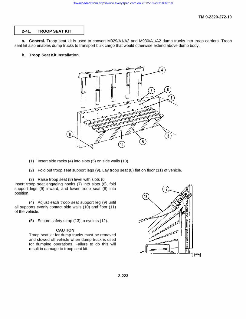
TM 9-2320-272-10
2-41. TROOP SEAT KIT
a. General. Troop seat kit is used to convert M929/A1/A2 and M930/A1/A2 dump trucks into troop carriers. Troopseat kit also enables dump trucks to transport bulk cargo that would otherwise extend above dump body.
b. Troop Seat Kit Installation.
(1) Insert side racks (4) into slots (5) on side walls (10).
(2) Fold out troop seat support legs (9). Lay troop seat (8) flat on floor (11) of vehicle.
(3) Raise troop seat (8) level with slots (6Insert troop seat engaging hooks (7) into slots (6), foldsupport legs (9) inward, and lower troop seat (8) intoposition.
(4) Adjust each troop seat support leg (9) untilall supports evenly contact side walls (10) and floor (11)of the vehicle.
(5) Secure safety strap (13) to eyelets (12).
CAUTIONTroop seat kit for dump trucks must be removedand stowed off vehicle when dump truck is usedfor dumping operations. Failure to do this willresult in damage to troop seat kit.
2-223
Downloaded from http://www.everyspec.com on 2012-10-29T18:40:10.

TM 9-2320-272-10
2-42. BOW AND TARPAULIN KIT
a. General. Kits are available for all M939/A1/A2 cargo and dump trucks, and are installed in a similar fashion. Thefollowing procedures and illustrations are installation and removal of bow and tarpaulin kits for M923/A1/A2 andM925/A1/A2 series vehicles.
b. Bow and Tarpaulin Kit Installation.
(1) Insert staves (1) into side rack sockets (4).
NOTESome overhead cross bows are secured in place with screws andwashers instead of latches.
(2) Insert overhead cross bows (3) into staves (1). Secure each end of overhead cross bows (3) in place withstave latches (2).
(3) Thread two lashing ropes (5) into center eyelets (11) of forward end curtain (7). Place forward end curtain (7)in position and wind ropes (5) alternately around overhead bow (6) and through eyelets (11).
2-224
Downloaded from http://www.everyspec.com on 2012-10-29T18:40:10.
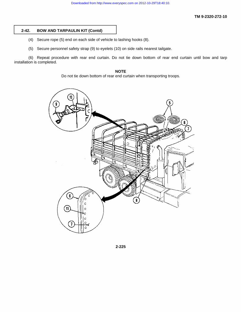
TM 9-2320-272-10
2-42. BOW AND TARPAULIN KIT (Contd)
(4) Secure rope (5) end on each side of vehicle to lashing hooks (8).
(5) Secure personnel safety strap (9) to eyelets (10) on side rails nearest tailgate.
(6) Repeat procedure with rear end curtain. Do not tie down bottom of rear end curtain until bow and tarpinstallation is completed.
NOTEDo not tie down bottom of rear end curtain when transporting troops.
2-225
Downloaded from http://www.everyspec.com on 2012-10-29T18:40:10.

TM 9-2320-272-10
2-42. BOW AND TARPAULIN KIT (Contd)
(7) Place folded tarpaulin (1) across top centerbow with half marked FRONT facing front of vehicle.
(8) Unfold front of tarpaulin (1) over bows (2) allthe way to front of vehicle. Unfold other end of tarpaulin(1) toward rear of vehicle.
(9) Unfold one side of tarpaulin (1), then unfoldother side toward sides of vehicle. Allow loose tarpaulin(1) sides to drape over side of vehicle.
NOTEAll ropes should be snug, but not too tight.
(10) Tie lashing ropes (3) to lashing hooks (4) oneach side of vehicle.
2-226
Downloaded from http://www.everyspec.com on 2012-10-29T18:40:10.

TM 9-2320-272-10
2-42. BOW AND TARPAULIN KIT (Contd)
c. Raising Tarpaulin for Ventilation.
NOTEThis operation requires two crew-members.
(1) Remove rear tarpaulin end curtain (5), ifinstalled.
(2) Untie all tarpaulin lashing ropes (3).
(3) Fold up tarpaulin (1) into three to five foldsuntil straps (6) can be attached to staves (8).
(4) Fasten folded tarpaulin (1) in place usingstraps (6) and buckles (7).
(5) Tie front and rear lashing ropes (3) to endstaves (8).
d. Bow and Tarpaulin Kit Removal.
CAUTIONDo not fold or stow tarpaulin when wet. Todo so will damage tarpaulin.
(1) Remove tarpaulin top (1) from vehicle andlay tarpaulin (1) flat on ground, with buckles (9) facingup.
2-227
Downloaded from http://www.everyspec.com on 2012-10-29T18:40:10.

TM 9-2320-272-10
2-42. BOW AND TARPAULIN KIT (Contd)
(2) Fold eyelet side of tarpaulin (1) to first rowof buckles (2).
(3) Fold tarpaulin (1) over again, and then onemore time.
(4) Fold other side of tarpaulin (1) once, to therow of buckles (2).
(5) Fold tarpaulin (1) again, until the two foldsmeet.
(6) Fold the side of tarpaulin (1) with three foldsover the side with four folds.
(7) Fold tarpaulin (1) end halfway to the firstseam, and then over again, until inner edge of tarpaulin(1) is at middle.
2-228
Downloaded from http://www.everyspec.com on 2012-10-29T18:40:10.

TM 9-2320-272-10
2-42. BOW AND TARPAULIN KIT (Contd)
(8) Repeat folding on opposite end of tarpaulin(1) until both folded ends meet.
(9) Place folded tarpaulin (1) front end up andwith chalk, mark FRONT. Make sure that letters are bigenough to see.
(10) Turn folded tarpaulin (1) over and markREAR.
(11) Remove end curtains (2) and fold them toapproximately the same dimensions as the tarpaulin (1).
(12) Place tarpaulin (1) and end curtains (2) on apallet for storage.
(13) Unlatch and remove overhead cross bows(5) from staves (4).
(14) Remove staves (4) from side rack sockets(3).
2-229
Downloaded from http://www.everyspec.com on 2012-10-29T18:40:10.

TM 9-2320-272-10
2-42. BOW AND TARPAULIN KIT (Contd)
(15) Stow staves (2) in pockets (3) on forward end of vehicle sides. On M923/A1/A2 and M925/A1/A2 modelvehicles, staves are stored in pockets on cargo body directly behind vehicle cab (1).
2-230
(16)Strap overhead cross bows(4) together and stow in storage areaunder cargo body.
Downloaded from http://www.everyspec.com on 2012-10-29T18:40:10.

TM 9-2320-272-10
2-43. HARDTOP KIT AND RADIATOR AND HOOD COVER KIT
a. General. The hardtop kit and the radiator and hood cover kit are installed by direct support maintenance onvehicles operating in -25°F (-32°C) temperatures or below.
b. Operating with Engine Compartment Covers Installed.
(1) Start engine with radiator cover flap (6) closed. Refer to paragraph 2-13 for cold weather starting instructions.
(2) Roll up and secure radiator cover flap (6) in open position when engine temperature rises above 175°F(79°C) as indicated by engine coolant temperature gauge (7) on instrument panel (8).
(3) If engine coolant temperature should exceed 200°F (93°C), completely remove engine compartment cover(5) to avoid overheating.
(4) Open and close cover flap (6) as required during arctic operations to maintain engine coolant temperaturewithin normal operating range of 175°-200°F (790-930C).
2-231
Downloaded from http://www.everyspec.com on 2012-10-29T18:40:10.

TM 9-2320-272-10
2-44. FUEL BURNING PERSONNEL HEATER KIT
a. General. Fuel burning personnel heater provides heat and defrost to vehicle cab when the engine is operating.
b. Fuel Burning Personnel Heater Operation.
(1) Shut off engine coolant heater if operating. Refer to paragraph 2-45 for engine coolant heater shutdowninstructions.
CAUTIONDo not operate the engine coolant heater control box and personnel heater control box at thesame time. Electric fuel pump will not maintain fuel pressure for both heaters at same time.
2-232
(2) Open electric fuel pump shutoffvalve by turning valve lever (9) one-quarterturn counterclockwise. Open two valves (10)for M939A2 series vehicles.
(3) Start engine. Refer to paragraph2-13 for cold weather starting instructions ifnecessary.
(4) Press PRESS-TO-TEST button(7) l h t t l b (5) t
Downloaded from http://www.everyspec.com on 2012-10-29T18:40:10.

TM 9-2320-272-10
2-44. FUEL BURNING PERSONNEL HEATER KIT (Contd)
(5) Set HI-LO switch (6) on personnel heater control box (5) to HI.
NOTEHeater will not operate if switch is released from START position beforeindicator lamp illuminates.
(6) Hold RUN-OFF-START switch (8) on personnel heater control box (5) in START position until indicator lamp(7) illuminates.
(7) Move switch (8) from START to RUN, without hesitating at OFF, as soon as indicator lamp (7) illuminates.
NOTE• If heater fails to start, turn RUN-OFF-START switch to OFF position
and repeat steps 6 and 7. Notify your supervisor if heater fails to startafter two attempts.
• Heater blower motor switch on vehicle instrument panel is not usedfor blower operation. HI-LO switch and RUN-OFF-START switch onpersonnel heater control box are used in place of blower motorswitch.
(8) Adjust hot air flow with heat vent control (3).
CAUTIONHeat cab before defrosting windshield. Glass damage may result fromsudden temperature changes.
(9) Adjust defroster control (2) as required to defrost windshield. All heated air is directed at windshield whendefroster control (2) is pulled all the way out.
(10) To shut down personnel heater:
(a) Turn RUN-OFF-START switch (8) to OFF.
(b) Remain in vehicle cab to make sure indicator lamp (7) goes out and blower motor stops.
(c) Close defroster control (2) and heat vent control (3).
(d) Shut off engine. Refer to paragraph 2-16 for engine shutoff instructions.
(e) Close electric fuel pump shutoff valve by turning valve lever (9) one-quarter turn clockwise. Close twovalves (10) for M939A2 series vehicles.
2-233
Downloaded from http://www.everyspec.com on 2012-10-29T18:40:10.

TM 9-2320-272-10
2-45. ENGINE COOLANT HEATER KIT
a. General. Engine coolant heater is not designed for use while vehicle engine is operating. This heater preheatsengine coolant in preparation for starting at extremely low temperatures or to maintain engine in standby readiness.
b. Engine Coolant Heater Operation.
WARNINGExhaust gases will kill. Do not operate engine coolant heater in closedarea occupied by personnel. Failure to do this will result in injury or death.
CAUTIONCoolant shutoff valves on engine must remain open at all times whenoperating heater. Failure to do this will result in damage to heater.
(1) Open coolant shutoff valves (1) and (2).
(2) Open electric fuel pump shutoff valve located near air cleaner assembly by turning valve lever (3) one-quarterturn counterclockwise. Open two valves (4) for M939A2 series vehicles.
2-234
Downloaded from http://www.everyspec.com on 2012-10-29T18:40:10.

TM 9-2320-272-10
2-45. ENGINE COOLANT HEATER KIT (Contd)
(3) Press PRESS-TO-TEST button (7) on engine coolant heater control box (5) to check operation of circuit.Observe that indicator lamp (7) illuminates.
(4) Set HI-LO switch (6) on engine coolant heater control box (5) to HI or LO.
NOTESelect HI position if engine is cold. Switch will automatically change to LOposition when coolant temperature exceeds 195°F (91°C). Switch willautomatically change to HI position when coolant temperature dropsbelow 120°F (49°C).
(5) Hold RUN-OFF-START switch (8) on engine coolant heater control box (5) in START position until indicatorlamp (7) illuminates.
NOTEHeater will not operate if switch is moved to RUN position before indicatorlamp illuminates.
(6) Move switch (8) to RUN, without hesitating at OFF, as soon as indicator lamp (7) illuminates.
2-235
Downloaded from http://www.everyspec.com on 2012-10-29T18:40:10.

TM 9-2320-272-10
2-45. ENGINE COOLANT HEATER KIT (Contd)
NOTEIf heater fails to start, turn RUN-OFF-START switch to OFF position andrepeat steps 5 and 6. Notify your supervisor if heater fails to start aftertwo attempts.
(7) Check fuel gauge (1). Make sure fuel tank(s) are full if engine coolant heater is to operate for an extendedperiod.
(8) To shut down engine coolant heater:
(a) Turn RUN-OFF-START switch (3) to OFF.
(b) Remain in vehicle cab to make sure indicator lamp (2) goes out and blower motor shuts down(approximately 1-3 minutes).
NOTEOmit step c if engine is to be started immediately.
(c) Close electric fuel pump shutoff valve by turning valve lever (4) one-quarter turn clockwise. Close twolevers (4) on M939A2 series vehicles.
2-236
Downloaded from http://www.everyspec.com on 2012-10-29T18:40:10.

TM 9-2320-272-10
2-45. ENGINE COOLANT HEATER KIT (Contd)
CAUTIONTake care not to accidentally close coolant shutoff valves. During arcticoperations, all coolant shutoff valves must remain open at all times.
(d) Do not close coolant shutoff valves (5) and (6) during any arctic operation.
2-237
Downloaded from http://www.everyspec.com on 2012-10-29T18:40:10.

TM 9-2320-272-10
2-46. A-FRAME KIT
a. General. The A-frame kit is installed on cargo and tractor vehicles equipped with a front winch to provide a meansfor lifting, moving, loading, and unloading material and equipment. A-frame load capacity is 3,000 lb (1,362 kg).
b. Preparation for Use.
WARNINGVehicle will become charged with electricity if A-frame contacts or breakshigh-voltage wire. Do not leave vehicle while high voltage line is incontact with A-frame or vehicle. Notify nearby personnel to have electricalpower turned off. Failure to do this may result in injury or death.
NOTEA-frame kit is installed and rigged by unit maintenance.
(1) Maneuver vehicle into position for operation. Be careful that A-frame does not come into contact with wires,cables, tree limbs, or other overhead obstructions.
(2) Park vehicle and apply parking brake.
c. Operating A-frame. Operate front winch to raise, lower, or hold load. Refer to paragraph 2-22 for front winchoperating instructions.
CAUTION
• Do not attempt to lift more than 3,000 lb (1,362 kg) with A-frame kit.
• Do not allow cable chain (2) to contact snatch block (1).
2-238
Downloaded from http://www.everyspec.com on 2012-10-29T18:40:10.
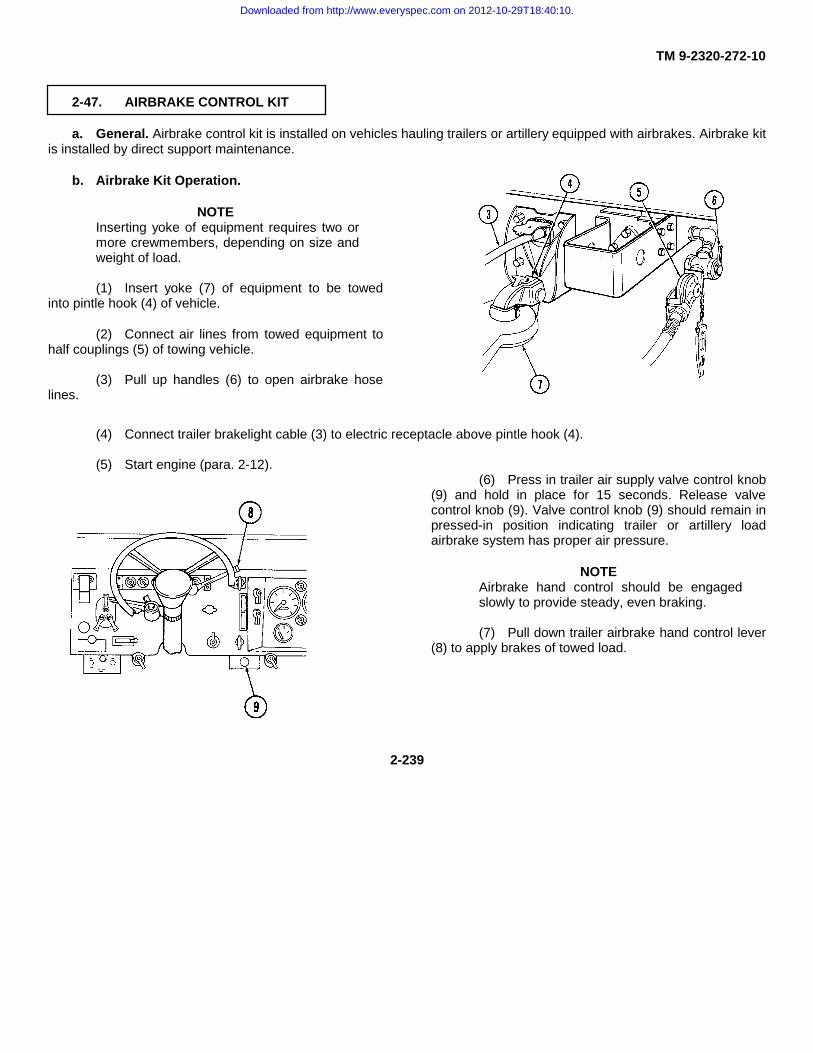
TM 9-2320-272-10
2-47. AIRBRAKE CONTROL KIT
a. General. Airbrake control kit is installed on vehicles hauling trailers or artillery equipped with airbrakes. Airbrake kitis installed by direct support maintenance.
b. Airbrake Kit Operation.
NOTEInserting yoke of equipment requires two ormore crewmembers, depending on size andweight of load.
(1) Insert yoke (7) of equipment to be towedinto pintle hook (4) of vehicle.
(2) Connect air lines from towed equipment tohalf couplings (5) of towing vehicle.
(3) Pull up handles (6) to open airbrake hoselines.
(4) Connect trailer brakelight cable (3) to electric receptacle above pintle hook (4).
(5) Start engine (para. 2-12).(6) Press in trailer air supply valve control knob
(9) and hold in place for 15 seconds. Release valvecontrol knob (9). Valve control knob (9) should remain inpressed-in position indicating trailer or artillery loadairbrake system has proper air pressure.
NOTEAirbrake hand control should be engagedslowly to provide steady, even braking.
(7) Pull down trailer airbrake hand control lever(8) to apply brakes of towed load.
2-239
Downloaded from http://www.everyspec.com on 2012-10-29T18:40:10.

TM 9-2320-272-10
2-48. MUD FLAP KIT
a. General. The mud flap kit is installed on the M931/Al/A2 or M932/A1/A2 tractor vehicles when a trailer is notattached.
CAUTIONMud flaps must be removed prior to coupling to semitrailer. Failure to dothis will result in damage to vehicle.
NOTELeft and right mud flaps are replaced the same. This procedure is for theleft mud flap.
b. Mud Flap Removal.
(1) Remove securing pin (3) from mud flap (1).
(2) Remove mud flap (1) from bracket (4).
(3) Unbuckle and fold back three stowage straps (5) on the backside of the tool box (6).
(4) Position mud flap (1) against tool box (6) and secure with stowage straps (5).
c. Mud Flap Installation.
(1) Unbuckle and fold back three stowage straps (5) on back of the tool box (6).
(2) Remove mud flap (1) from tool box (6) and position into bracket (4) on the frame (2).
(3) Insert securing pin (3) into mud flap (1).
2-240
Downloaded from http://www.everyspec.com on 2012-10-29T18:40:10.
TM 9-2320-272-10
CHAPTER 3MAINTENANCE INSTRUCTIONS
Section I Lubrication Instructions (page 3-1)Section II Troubleshooting Procedures (page 3-2)Section III Maintenance Procedures (page 3-23)
Section I. LUBRICATION INSTRUCTIONS
3-1. LUBRICATION ORDER
Lubrication instructions are contained in lubrication order LO 9-2320-272-12. The lubrication order designates cleaningand lubricating procedures for M939/A1/A2 series vehicles. All lubrication instructions are mandatory. This document isissued with each truck and is carried in vehicle at all times. A damaged or lost lubrication order should be replacedimmediately.
Proper disposal of hazardous waste material is vital to protecting the environment and providing a safe workenvironment. Materials such as batteries, oils, and antifreeze must be disposed of in a safe and efficient manner.
The following references are provided as a means to ensure that proper disposal methods are followed.
• Technical Guide No. 126 from the U.S. Army Environmental Hygiene Agency(USAEHA)
• National Environmental Policy Act of 1969 (NEPA)
• Clean Air Act (CAA)
• Resource Conservation and Recovery Act (RCRA)
• Comprehensive Environmental Response, Compensation, and Liability Act
• Emergency Planning and Community Right to Know Act (EPCRA)
• Toxic Substances Control Act (TSCA)
• Occupational Health and Safety Act (OHSA)
The disposal of Army Petroleum, Oils, and Lubricants (POL) products are affected by some of these regulations. Stateregulations may also be applicable to POL.
If you are unsure of which legislation affects you, contact state or local agencies for regulations regarding properdisposal of Army POL.
3-1
Downloaded from http://www.everyspec.com on 2012-10-29T18:40:10.

TM 9-2320-272-10
Section II. TROUBLESHOOTING PROCEDURES
3-2. SCOPE
The troubleshooting table contains instructions that will help the operator identify and correct simple vehiclemalfunctions during operations. The table also helps the operator identify major mechanical difficulties that must bereferred to unit maintenance.
NOTEOperators should perform the corrective action in the order listed.
3-3. TROUBLESHOOTING PROCEDURES
This manual cannot list all malfunctions that may occur. If a malfunction occurs that is not listed in table 3-1, notify unitmaintenance.
3-4. TROUBLESHOOTING SYMPTOM INDEX
TROUBLESHOOTINGMALFUNCTION MALFUNCTION PROCEDURE
NO. PAGEENGINE1. When starter switch is turned to start, engine fails to crank.................................................................. 3-52. Engine cranks but does not start ........................................................................................................... 3-53. Engine cranks but fails to start at outside temperatures
below +32°F (0°C) ................................................................................................................................. 3-64. Engine starts but misfires, runs rough, or lacks power.......................................................................... 3-65. Engine overheats as indicated by engine coolant
temperature gauge ................................................................................................................................ 3-76. Low engine oil pressure......................................................................................................................... 3-77. Engine failure during operation.............................................................................................................. 3-78. Excessive exhaust smoke after engine reaches normal operating
temperature 175°F to 200°F (79°C to 93°C) ......................................................................................... 3-8HEATING SYSTEM
9. Hot water personnel heater fails to produce heat afterengine reaches normal operating temperature ..................................................................................... 3-8
10. Heater blower motor operates, but heat fails to reach cab, ordefrosters fail to operate........................................................................................................................ 3-8TRANSMISSION
11. Excessive creep in forward or reverse range ........................................................................................ 3-812. Transmission overheating as indicated by transmission oil
temperature gauge ................................................................................................................................ 3-8
3-2
Downloaded from http://www.everyspec.com on 2012-10-29T18:40:10.

TM 9-2320-272-10
3-4. TROUBLESHOOTING SYMPTOM INDEX (Contd)
TROUBLESHOOTINGMALFUNCTION MALFUNCTION PROCEDURE
NO. PAGE
13. Oil thrown from filler tube ...................................................................................................................... 3-914. Slippage in all forward ranges ............................................................................................................... 3-915. Transmission oil leakage....................................................................................................................... 3-9
TRANSFER CASE16. Transfer case lubricant leakage ............................................................................................................ 3-9
AIR AND BRAKE SYSTEMS17. Insufficient air pressure as indicated by low air pressure
warning buzzer or air pressure gauge................................................................................................... 3-918. Service brakes do not operate .............................................................................................................. 3-919. Parking brake does not hold vehicle ..................................................................................................... 3-1020. Parking brake drags or overheats ......................................................................................................... 3-10
WHEELS, TIRES, AND HUBS21. Wheel wobbles or shimmies ................................................................................................................. 3-1022. Excessive or uneven tire wear .............................................................................................................. 3-1023. Vehicle wanders or pulls to one side on level surface or highway ........................................................ 3-10
STEERING24. Hard steering......................................................................................................................................... 3-1025. Oil leaks................................................................................................................................................. 3-11
SPECIAL BODY EQUIPMENT
FRONT WINCH26. Winch drum does not turn or payout cable ........................................................................................... 3-1127. Winch does not wind ............................................................................................................................. 3-11
DUMP BODY HOIST ASSEMBLY28. Hoist does not lift dump body ................................................................................................................ 3-1229. Body raises to full dump but does not power down............................................................................... 3-1230. Hydraulic pump noisy ............................................................................................................................ 3-1231. Tailgate does not open.......................................................................................................................... 3-12
HYDRAULIC CRANE32. Crane not operating or lacks power ...................................................................................................... 3-1333. Crane does not lift ................................................................................................................................. 3-1334. Hydraulic pump noisy ............................................................................................................................ 3-1335. Vehicle rolls while operating crane........................................................................................................ 3-13
REAR WINCH36. Winch not operating or lacks power ...................................................................................................... 3-1437. Vehicle rolls while operating rear winch ................................................................................................ 3-14
EXPANSIBLE VANS38. Light shines through gaps at side panel of van body ............................................................................ 3-14
3-3
Downloaded from http://www.everyspec.com on 2012-10-29T18:40:10.

TM 9-2320-272-10
3-4. TROUBLESHOOTING SYMPTOM INDEX (Contd)
TROUBLESHOOTINGMALFUNCTION MALFUNCTION PROCEDURE
NO. PAGE
39. Ceiling lights and service receptacles fail to energize whendoors are closed under blackout conditions (110 volt system) ............................................................. 3-15
40. Emergency light, blackout light, and ceiling lights fail toilluminate (24 volt system)..................................................................................................................... 3-15
41. Heater will not ignite .............................................................................................................................. 3-1542. Air conditioner compressor fails to start ................................................................................................ 3-16
SPECIAL PURPOSE KITS
RADIATOR AND HOOD COVER KIT43. Engine fails to reach operating temperature ......................................................................................... 3-1644. Engine temperature exceeds 200°F (93°C) .......................................................................................... 3-16
FUEL BURNING PERSONNEL AND ENGINE COOLANT HEATER KITS45. Fuel burning personnel heater fails to start when run-off-start
switch is held in start position................................................................................................................ 3-1746. Engine coolant heater fails to start when run-off-start switch
is held in start position........................................................................................................................... 3-1847. Heater fails to continue burning............................................................................................................. 3-1848. Windshield defrosters not operating...................................................................................................... 3-1949. Engine oil pan shroud not receiving heat (engine coolant
heater only)............................................................................................................................................ 3-1950. Engine coolant system not receiving heat (engine coolant
heater only)............................................................................................................................................ 3-19A-FRAME KIT
51. Winch inoperative.................................................................................................................................. 3-1952. A-frame misaligned ............................................................................................................................... 3-19
AIRBRAKE CONTROL KIT53. Trailer airbrakes do not operate when airbrake control
handle is pulled down............................................................................................................................ 3-20
3-4
Downloaded from http://www.everyspec.com on 2012-10-29T18:40:10.

TM 9-2320-272-10
Table 3-1. Troubleshooting
MALFUNCTIONTEST OR INSPECTION
CORRECTIVE ACTION
NOTE
If malfunction corrective action does not correct malfunction, notify unit maintenance.
ENGINE
1. WHEN STARTER SWITCH IS TURNED TO START, ENGINE FAILS TO CRANK.
Step 1. Check to see if battery switch is off.If off, turn switch on.
Step 2. Check to see if transmission selector lever is in N (neutral).If not, place in N (neutral).
WARNING
Do not smoke, have open flames, or make sparks around battery, especially if cap is off. Battery canexplode and cause injury or death to personnel.
Step 3. Visually check to see if battery cables, terminals, and connections are loose, broken, or corroded.Check battery for proper water level.If loose, tighten.Notify unit maintenance of any damage to batteries, cables, and terminals.
2. ENGINE CRANKS BUT DOES NOT START.
NOTE
• Do not completely fill fuel tank(s) before checking visually for leaks in fuel system.
• Whenever fuel tank(s) are completely drained and then refilled, the fuel system must be primed(para. 3-8).
Step 1. Check to see if fuel gauge indicates empty.If empty, fill fuel tank(s).
Step 2. Check to see if emergency engine stop control on instrument panel is pulled out.Notify unit maintenance to reset fuel cutoff valve (M939/A1 series vehicles only).
3-5
Downloaded from http://www.everyspec.com on 2012-10-29T18:40:10.

TM 9-2320-272-10
Table 3-1. Troubleshooting (Contd).
MALFUNCTIONTEST OR INSPECTION
CORRECTIVE ACTION
Step 3. Check to see if throttle control solenoid is functioning properly (M939A2 series vehicles only).If solenoid is malfunctioning, tie up with a strap or rope and finish mission. Report to unit maintenanceas soon as possible.
3. ENGINE CRANKS BUT FAILS TO START AT OUTSIDE TEMPERATURES BELOW +32°F (0°C).
NOTE
Refer to Cold Weather Starting (para. 2-13).
Step 1. Check to see if fuel gauge indicates empty.If empty, fill fuel tank(s).
Step 2. Check to see if emergency engine stop control on instrument panel is pulled out.Notify unit maintenance to reset fuel cutoff valve (M939/A1 series vehicles only).
Step 3. Check ether starting system.Operate ether starting system.
4. ENGINE STARTS BUT MISFIRES, RUNS ROUGH, OR LACKS POWER.
Step 1. Check to see if emergency engine stop control on instrument panel is pulled out.Notify unit maintenance to reset fuel cutoff valve (M939/A1 series vehicles only).
Step 2. Check for restricted air cleaner.If restricted, clean air cleaner element (para. 3-8).
Step 3. Check fuel supply system for water and impurities.Perform service operation (para. 3-8).
Step 4. Check for air in fuel system.Prime fuel system (para. 3-8).
3-6
Downloaded from http://www.everyspec.com on 2012-10-29T18:40:10.

TM 9-2320-272-10
Table 3-1. Troubleshooting (Contd).MALFUNCTION
TEST OR INSPECTIONCORRECTIVE ACTION
5. ENGINE OVERHEATS AS INDICATED BY ENGINE COOLANT TEMPERATURE GAUGE
WARNING
Extreme care should be taken when removing surge tank filler cap if temperature gauge reads above175°F (79°C). Steam or hot coolant under pressure will cause injury.
Step 1. Check radiator core for obstructions.If clogged, remove debris (refer to table 2-1).
Step 2. Check coolant level in surge tank.If low, add coolant to surge tank until at bottom of fill neck.
Step 3. Check for leakage from radiator, surge tank, hoses, and hose connections.If loose, tighten. If still leaking, notify unit maintenance.
Step 4. Check engine oil level.If low, add oil (refer to LO 9-2320-272-12).
Step 5. Check radiator fan clutch operation.If fan blade is not turning, install override lockup bolts (para. 3-14).
6. LOW ENGINE OIL PRESSURE.
Check engine oil level.If low, add oil (refer to LO 9-2320-272-12).
NOTE
• If oil pressure is still low, notify unit maintenance.
7. ENGINE FAILURE DURING OPERATION.
Step 1. Check to see if emergency stop cable is pulled out.On M939A2 series vehicles, manually reset emergency stop. On M939/A1 series vehicles, notify unitmaintenance.
Step 2. Check to see if throttle control solenoid is malfunctioning (M939/A2 series vehicles).If solenoid is malfunctioning, tie up with strap or rope and finish mission. Report to unit maintenance assoon as possible.
3-7
Downloaded from http://www.everyspec.com on 2012-10-29T18:40:10.

TM 9-2320-272-10
Table 3-1. Troubleshooting (Contd).MALFUNCTION
TEST OR INSPECTIONCORRECTIVE ACTION
8. EXCESSIVE EXHAUST SMOKE AFTER ENGINE REACHES NORMAL OPERATING TEMPERATURE 175°FTO 200°F (79°C TO 93°C).
Check for restricted air cleaner.If restricted, clean air cleaner element (para. 3-8).
HEATING SYSTEM
9. HOT WATER PERSONNEL HEATER FAILS TO PRODUCE HEAT AFTER ENGINE REACHES NORMALOPERATING TEMPERATURE.
Step 1. Check to see if blower motor switch is in OFF position.If in OFF position, put blower motor switch in HI or LOW position.
Step 2. Check to see if coolant shutoff valves are closed (para. 2-44).If closed, open coolant shutoff valves.
Step 3. Check for air in heater.With engine running, open air bleed drainvalve on engine side of heater and allow air to escape (para. 2-44). Close drainvalve.
10. HEATER BLOWER MOTOR OPERATES, BUT HEAT FAILS TO REACH CAB, OR DEFROSTERS FAIL TOOPERATE.
Step 1. Check to see if heat vent control and/or defroster control levers are adjusted properly.If not, adjust heat vent control or defroster control levers to direct heat flow to desired location (para. 2-44).
Step 2. Check to see if heat/defroster vent tubes are connected below instrument panel.
TRANSMISSION
11. EXCESSIVE CREEP IN FORWARD OR REVERSE RANGE.
Check hand throttle position.If partially out, push hand throttle all the way in.
12. TRANSMISSION OVERHEATING AS INDICATED BY TRANSMISSION OIL TEMPERATURE GAUGE.
Check transmission oil level.If low, add oil (para. 3-10).
3-8
Downloaded from http://www.everyspec.com on 2012-10-29T18:40:10.

TM 9-2320-272-10
Table 3-1. Troubleshooting (Contd).MALFUNCTION
TEST OR INSPECTIONCORRECTIVE ACTION
13. OIL THROWN FROM FILLER TUBE.
Step 1. Check transmission oil level (para. 3-10).If overfull, notify unit maintenance.
Step 2. Check for loose transmission oil dipstick.If loose, turn dipstick handle clockwise until tight (para. 3-10).
14. SLIPPAGE IN ALL FORWARD RANGES.
Check transmission oil level.If low, add oil (para. 3-10).
15. TRANSMISSION OIL LEAKAGE.
Check for loose hose and tube connections.If loose, tighten.
TRANSFER CASE
16. TRANSFER CASE LUBRICANT LEAKAGE.
Check for loose drainplugs.If loose, tighten drainplugs.
AIR AND BRAKE SYSTEMS
17. INSUFFICIENT AIR PRESSURE AS INDICATED BY LOW AIR PRESSURE WARNING BUZZER OR AIRPRESSURE GAUGE.
Step 1. Check to see if air reservoir drainvalves are open.If open, close drainvalves securely (para. 3-9).
Step 2. Check all air lines for loose connections.If loose, tighten.
Step 3. Check all air lines for damage.If damage is not repairable, shut off affected system (para. 3-13) and notify unit maintenance.
Step 4. Check towed equipment for air leaks at drainvalves or air lines.If leaking, tighten.
18. SERVICE BRAKES DO NOT OPERATE.
Step 1. Check to see if air reservoir drainvalves are open.If open, close drainvalves securely (para. 3-9).
Step 2. Check all air lines for loose connections.If loose, tighten.
3-9
Downloaded from http://www.everyspec.com on 2012-10-29T18:40:10.

TM 9-2320-272-10
Table 3-1. Troubleshooting (Contd).
MALFUNCTIONTEST OR INSPECTION
CORRECTIVE ACTION
19. PARKING BRAKE DOES NOT HOLD VEHICLE.
Step 1. Check parking brake handle position.If partially applied, pull parking brake handle all the way up.
Step 2. Check handle adjustment.Turn knob on end of lever clockwise to increase braking action (para. 3-17).
20. PARKING BRAKE DRAGS OR OVERHEATS.
Step 1. Check parking brake handle position.If partially applied, push parking brake handle all the way down.
Step 2. Check handle adjustment.Turn knob on end of lever counterclockwise to decrease braking action (para. 3-17).
WHEELS, TIRES, AND HUBS
21. WHEEL WOBBLES OR SHIMMIES.
Step 1. Check for loose wheel stud nuts.If loose, tighten.Notify unit maintenance to retighten to proper torque.
Step 2. Check for cupping or missing rubber on tire.Replace tire (para. 3-11).
22. EXCESSIVE OR UNEVEN TIRE WEAR.
Check air pressure in tires.Inflate or deflate tires to correct air pressure (refer to table 1-10).
23. VEHICLE WANDERS OR PULLS TO ONE SIDE ON LEVEL SURFACE OR HIGHWAY.
Check air pressure in tires.Inflate or deflate tires to correct air pressure (refer to table 1-10).
STEERING
24. HARD STEERING.
Step 1. Check air pressure in tires.Inflate or deflate tires to correct air pressure (refer to table 1-10).
Step 2. Check power steering reservoir oil level.If low, add oil to FULL mark on dipstick (refer to LO 9-2320-272-12).
3-10
Downloaded from http://www.everyspec.com on 2012-10-29T18:40:10.

TM 9-2320-272-10
Table 3-1. Troubleshooting (Contd).
MALFUNCTIONTEST OR INSPECTION
CORRECTIVE ACTION
25. OIL LEAKS.
Check for loose connections.If loose, tighten.
SPECIAL BODY EQUIPMENT:
WARNING
Wear hand protection when handling winch cable. Do not handle cable with bare hands. Broken wireswill cause injury.
FRONT WINCH
26. WINCH DRUM DOES NOT TURN OR PAYOUT CABLE.
Step 1. Check to see if drum lock knob is engaged.If engaged, pull out drum lock knob, rotate 90 degrees, and release (para. 2-22).
Step 2. On M936/A1/A2 model vehicles with level wind device, check to see if level wind lock knob and cabletensioner lock knob and lever are engaged.If engaged, release level wind lock knob and cable tensioner lock knob and lever.
Step 3. Check if cable is binding.If binding, free cable from drum.
27. WINCH DOES NOT WIND.
Step 1. Check to see if power takeoff is engaged.If not, engage power takeoff.
Step 2. Check to see if winch clutch lever is engaged.If not, engage clutch lever.
Step 3. On vehicles with level wind device, check to see if tensioner lever is positioned all the way toward right(crew side) of vehicle.If not, pull tensioner lever all the way toward right side of vehicle.
Step 4. Check level of hydraulic oil in reservoir (para. 2-22).If low, add oil to proper level (refer to LO 9-2320-272-12).
3-11
Downloaded from http://www.everyspec.com on 2012-10-29T18:40:10.

TM 9-2320-272-10
Table 3-1. Troubleshooting (Contd).
MALFUNCTIONTEST OR INSPECTION
CORRECTIVE ACTION
DUMP BODY HOIST ASSEMBLY
28. HOIST DOES NOT LIFT DUMP BODY.
Step 1. Check to see if power takeoff is engaged.If not, engage power takeoff.
Step 2. Check to see if dump body control lever is pushed back to raise position.If not, push lever back to raise position.
Step 3. Check level of hydraulic oil in reservoir (para 2-25).If low, add oil to proper level (refer to LO 9-2320-272-12).
Step 4. Check for hydraulic oil leaks.Tighten loose connections. If leaks continue, notify unit maintenance.
29. BODY RAISES TO FULL DUMP BUT DOES NOT POWER DOWN.
Step 1. Check to see if support braces are in place.If in place, lower.
Step 2. Check to see if dump body control lever is pulled full forward to lower position.If not, pull lever full forward to lower position.
30. HYDRAULIC PUMP NOISY.
Check level of hydraulic oil in reservoir (para. 2-25).If low, add oil to proper level (refer to LO 9-2320-272-12).
31. TAILGATE DOES NOT OPEN.
Step 1. Check to see if tailgate control rod is pulled forward and down to unlock tailgate.If not, pull tailgate control rod forward and down to unlock tailgate.
Step 2. Check to see if tailgate chains are restricting tailgate from opening.If restricting opening of tailgate, reposition tailgate chains.
3-12
Downloaded from http://www.everyspec.com on 2012-10-29T18:40:10.

TM 9-2320-272-10
Table 3-1. Troubleshooting (Contd).
MALFUNCTIONTEST OR INSPECTION
CORRECTIVE ACTION
32. CRANE NOT OPERATING OR LACKS POWER.
Step 1. Check to see if tachometer indicates 1, 275 rpm.If not, pull hand throttle control all the way out.
Step 2. Check to see if transmission selector lever is in 1-5 (drive).If not, place transmission selector lever in 1-5 (drive).
Step 3. Check to see if transfer case power takeoff lever is pushed back to engaged position.If not, push transfer case power takeoff lever back to engaged position.
Step 4. Check level of hydraulic oil in reservoir (para. 2-24).If low, add oil to proper level (refer to LO 9-2320-272-12).
Step 5. Check for hydraulic oil leaks.Tighten loose connections. If leaks continue, notify unit maintenance.
33. CRANE DOES NOT LIFT.
Step 1. Check level of hydraulic oil in reservoir (para. 2-24).If low, add oil to proper level (refer to LO 9-2320-272-12).
Step 2. Check for hydraulic oil leaks.Tighten loose connections. If leaks continue, notify unit maintenance.
34. HYDRAULIC PUMP NOISY.
Check level of hydraulic oil in reservoir (para. 2-24).If low, add oil to proper level (refer to LO 9-2320-272-12).If still noisy, notify unit maintenance.
35. VEHICLE ROLLS WHILE OPERATING CRANE.
Step 1. Check to see if parking brake is applied.If not, apply parking brake.
Step 2. Check to see if chock blocks are in place.If not, place chock blocks at wheels and notify unit maintenance.
3-13
Downloaded from http://www.everyspec.com on 2012-10-29T18:40:10.

TM 9-2320-272-10
Table 3-1. Troubleshooting (Contd).
MALFUNCTIONTEST OR INSPECTION
CORRECTIVE ACTION
36. WINCH NOT OPERATING OR LACKS POWER.
Step 1. Check to see if tachometer indicates 1, 275 rpm.If not, pull hand throttle control all the way out.
Step 2. Check to see if transmission selector lever is in 1-5 (drive).If not, place transmission selector lever in 1-5 (drive).
Step 3. Check to see if transfer case power takeoff shift lever is pushed back to engaged position.If not, push transfer case power takeoff shift lever back to engaged position.
Step 4. Check to see if level wind lock knob is released.If not, release level wind lock knob.
Step 5. Check level of hydraulic oil in reservoir (para. 2-24).If low, add oil to proper level (refer to LO 9-2320-272-12).
Step 6. Check for hydraulic oil leaks.Tighten loose connections. If leaks continue, notify unit maintenance.
37. VEHICLE ROLLS WHILE OPERATING REAR WINCH.
Step 1. Check to see if parking brake is applied.If not, apply parking brake.
Step 2. Check to see if chock blocks are in place.If not, place chock blocks at wheels and notify unit maintenance.
EXPANSIBLE VANS
38. LIGHT SHINES THROUGH GAPS AT SIDE PANEL OF VAN BODY.
Step 1. Check toggle clamps at side panels (para. 2-27).If toggle clamp does not draw top of side panel tight enough, loosen locknut on toggle clamp eyebolt.Turn eyebolt inward to close the gap. Tighten locknut.
Step 2. Check to see if roof is properly seated.If not, loosen toggle clamp, push up on hinged roof, and push out on end panels, then reclose toggleclamps to ensure seal alignment.
Step 3. Check to see if blackout panels are closed properly.If not, slide up blackout panels on van sides and rear doors until they latch in closed position.
3-14
Downloaded from http://www.everyspec.com on 2012-10-29T18:40:10.

TM 9-2320-272-10
Table 3-1. Troubleshooting (Contd).
MALFUNCTIONTEST OR INSPECTION
CORRECTIVE ACTION
39. CEILING LIGHTS AND SERVICE RECEPTACLES FAIL TO ENERGIZE WHEN DOORS ARE CLOSED UNDERBLACKOUT CONDITIONS (110 VOLT SYSTEM).
Step 1. Check to see if blackout circuit switch and/or main circuit breaker switches are turned off (para. 2-27).If off, turn on switches.
Step 2. Check to see if blackout switch is turned off.If off, turn on blackout switch.
Step 3. Check outside power cable for secure connections if electrical power is supplied from outside source.If not, connect power cable securely to power entrance receptacle and power source.
40. EMERGENCY LIGHT, BLACKOUT LIGHT, AND CEILING LIGHTS FAIL TO ILLUMINATE (24 VOLT SYSTEM).
Step 1. Check to see if main circuit breaker and/or light switches are turned off.If not, turn on main circuit breaker or light switches.
Step 2. Check outside power cable for secure connections if electrical power is supplied from outside source.If not, connect power cable securely to power entrance receptacle and power source.
41. HEATER WILL NOT IGNITE.
Step 1. Check to see if main circuit breaker and/or heater switches are turned off (para. 2-27).If off, turn on main circuit breaker or heater switches.
Step 2. Check to see if thermostat is set to desired temperature.If not, set thermostat properly.
Step 3. Check fuel level on fuel gauge.Fill fuel tank(s) as necessary.
3-15
Downloaded from http://www.everyspec.com on 2012-10-29T18:40:10.

TM 9-2320-272-10
Table 3-1. Troubleshooting (Contd).
MALFUNCTIONTEST OR INSPECTION
CORRECTIVE ACTION
42. AIR CONDITIONER COMPRESSOR FAILS TO START.
Step 1. Check to see if bonnet door is closed (para. 2-27).If closed, push bonnet door control rod forward to open bonnet door.
Step 2. If closed, check to see if main circuit breaker and/or air conditioner switches in circuit breaker box areturned off.If off, turn on main circuit breaker or air conditioner switches.
Step 3. Check to see if power input switch and/or compressor circuit breaker are turned off.If off, turn on power input switch or compressor circuit breaker.
Step 4. Check to see if compressor switch is turned to HIGH when starting air conditioner.If not, turn compressor switch to HIGH when starting air conditioner.
SPECIAL PURPOSE KITS:
RADIATOR AND HOOD COVER KIT
43. ENGINE FAILS TO REACH OPERATING TEMPERATURE.
Check to see if radiator cover flap is opened (para. 2-43).If open, roll cover flap down.
44. ENGINE TEMPERATURE EXCEEDS 200°F (93°C).
Step 1. Check to see if radiator cover flap is closed (para. 2-43).If closed, roll up cover flap and secure.
WARNING
Extreme care should be taken when removing surge tank filler cap if temperature gauge reads above175°F (79°C). Steam or hot coolant under pressure will cause injury.
Step 2. Check radiator core for obstructions.If clogged, remove debris (refer to table 2-1).
Step 3. Check coolant level in surge tank.If low, add coolant to surge tank until at bottom of filler neck.
Step 4. Check for leakage from tank, hoses and hose connections.If loose, tighten. If still leaking, notify unit maintenance.
3-16
Downloaded from http://www.everyspec.com on 2012-10-29T18:40:10.
TM 9-2320-272-10
Table 3-1. Troubleshooting (Contd).
MALFUNCTIONTEST OR INSPECTION
CORRECTIVE ACTION
Step 5. Check engine oil level.If low, add oil (refer to LO 9-2320-272-12).
Step 6. Check radiator fan clutch operation.If fan blade is not turning, install override lockup bolts (para. 3-14).
FUEL BURNING PERSONNEL AND ENGINE COOLANT HEATER KITS
45. FUEL BURNING PERSONNEL HEATER FAILS TO START WHEN RUN-OFF-START SWITCH IS HELD INSTART POSITION.
WARNING
Exhaust gases can kill. Do not operate engine coolant heater in closed area occupied by personnel.Such action will result in injury or death.
NOTE
Heater will not operate if RUN-OFF-START switch is moved to RUN position before indicator lampilluminates.
Step 1. Press PRESS-TO-TEST button on heater control box to check operation of circuit.If indicator lamp does not illuminate, notify unit maintenance.
Step 2. Check to see if HI-LO switch on heater control box is set to HI.If not, set HI-LO switch to HI.
Step 3. Check fuel level on fuel gauge.Fill fuel tank(s) if necessary.
Step 4. Check to see if electric fuel pump shutoff valve is closed (para. 2-44).If closed, open fuel pump shutoff valve.
3-17
Downloaded from http://www.everyspec.com on 2012-10-29T18:40:10.

TM 9-2320-272-10
Table 3-1. Troubleshooting (Contd).
MALFUNCTIONTEST OR INSPECTION
CORRECTIVE ACTION
46. ENGINE COOLANT HEATER FAILS TO START WHEN RUN-OFF-START SWITCH IS HELD IN STARTPOSITION.
WARNING
Exhaust gases can kill. Do not operate engine coolant heater in closed area occupied by personnel.Such action will result in injury or death.
CAUTION
Do not operate engine coolant heater and personnel heater at the same time. Damage to equipment mayresult.
NOTE
• Select HI position if engine is cold. Select LOW position if engine is already well heated. Switch willautomatically change to LOW position when coolant temperature exceeds 195°F (91°C). Switch willautomatically change to HI position when coolant temperature drops below 120°F (490C).
• Heater will not operate if RUN-OFF-START switch is moved to RUN position before indicator lampilluminates.
Step 1. Press PRESS-TO-TEST button on heater control box to check operation of circuit.If indicator lamp does not illuminate, notify unit maintenance.
Step 2. Check fuel level on fuel gauge.Fill fuel tank(s) if necessary.
Step 3. Check to see if electric fuel pump shutoff valve located near air cleaner assembly is closed (para. 2-45).If closed, open fuel shutoff valve.
47. HEATER FAILS TO CONTINUE BURNING.
Check fuel level on fuel gauge.Fill fuel tank(s) if necessary.
3-18
Downloaded from http://www.everyspec.com on 2012-10-29T18:40:10.

TM 9-2320-272-10
Table 3-1. Troubleshooting (Contd).
MALFUNCTIONTEST OR INSPECTION
CORRECTIVE ACTION
48. WINDSHIELD DEFROSTERS NOT OPERATING.
Step 1. Check adjustment of defroster control handle.Adjust defroster control handle.
Step 2. Check for restrictions in defroster deflectors.If restricted, clear restriction.
49. ENGINE OIL PAN SHROUD NOT RECEIVING HEAT (ENGINE COOLANT HEATER ONLY).
Step 1. Check to see if coolant heater is operating (para. 2-45).Start heater. If inoperative, notify unit maintenance.
Step 2. Check to see if coolant heater exhaust tube is disconnected from oil pan shroud.If disconnected, reconnect heater exhaust tube.
50. ENGINE COOLANT SYSTEM NOT RECEIVING HEAT (ENGINE COOLANT HEATER ONLY).
Step 1. Check to see if coolant heater is operating (para. 2-45).Start heater. If inoperative, notify unit maintenance.
Step 2. Check to see if one or more coolant shutoff valves are closed at engine.If closed, open coolant shutoff valve(s).
A-FRAME KIT
51. WINCH INOPERATIVE.
Check winch.See malfunctions 26 and 27.
52. A-FRAME MISALIGNED.
Check to see if cable is secured in towing pintle.If not, secure cable in towing pintle and lock pintle in closed position.
3-19
Downloaded from http://www.everyspec.com on 2012-10-29T18:40:10.

TM 9-2320-272-10
Table 3-1. Troubleshooting (Contd).
MALFUNCTIONTEST OR INSPECTION
CORRECTIVE ACTION
AIRBRAKE CONTROL KIT
53. TRAILER AIRBRAKES DO NOT OPERATE WHEN AIRBRAKE CONTROL HANDLE IS PULLED DOWN.
Step 1. Check to see if trailer air supply valve control knob is not in pressed-in position (para. 2-47).If not, press in trailer air supply valve control knob and hold in place for 15 seconds. Release valve. Ifvalve does not stay in, notify unit maintenance.
Step 2. Check to see if trailer air lines are securely connected to air couplings of towing truck.If not, securely connect trailer air lines of air coupling, and open air coupling valves.
3-5. CTIS STATUS INDICATION AND MALFUNCTIONS
a. Central Tire Inflation System (CTIS). CTIS is designed to work automatically in case of tire leakage.Additionally, CTIS will adjust tire pressure when a road surface selection is made, to preset valves. Refer to table 3-2,CTIS Indications, for explanation of indications or malfunction.
b. CTIS Integration with the Airbrake System. The Central Tire Inflation System uses the same aircompressor that supplies air to the vehicle brakes. The vehicle brakes are always given priority over the CTIS. Whenbrake operation causes the air pressure in the brake reservoir to fall below a preset limit, inflation will stop until the aircompressor has refilled the brake reservoir. If the CTIS was deflating the tires, it would continue to do so.
CAUTION
To prevent damage to transmission, refer to paragraph 2-15 for proper transmission shifting procedures.
c. Rapid Inflation. The most rapid tire pressure increase is achieved during vehicle operation. Keep thetransmission downshifted to a lower gear. Keep engine operation at 2, 000 rpm. Engaging the turbocharger suppliesextra air pressure directly to the air compressor.
3-20
Downloaded from http://www.everyspec.com on 2012-10-29T18:40:10.

TM 9-2320-272-10
Table 3-2. CTIS Indications
CTIS STATUS INDICATIONSYSTEM MALFUNCTION
ACTION REQUIRED
1. SINGLE MODE LIGHT: STEADY.
None. Air pressure achieved, wheel valves closed, and system stable.None.
2. SINGLE MODE LIGHT: FLASHING.
None. System working to achieve new air pressure.None.
3. TWO MODE LIGHTS ON: STEADY.
System has shut off with tire pressure between two settings, but vehicle and CTIS are still operational.Monitor and, if indication is repeated frequently, notify supervisor.
4. FOUR MODE LIGHTS FLASHING.
System has shut off due to air leak or possible tire damage and is waiting for operator instruction.
a. Select RUN FLAT, if tire damage is minimal (vehicle is still operational).b. Change tire if tire damage is not minimal (para. 3-11).c. Check for air leaks (para. 3-3).
5. FIVE LIGHTS FLASHING.
NOTE
If CTIS is not operational, disconnect electrical connector from Electronic Control Unit (ECU) andcomplete mission (para. 3-16).
System has shut off due to fault detection of CTIS component or system has major air leak.
a. Check for air leaks (para. 3-3) and reset CTIS (para. 3-16).b. Disable CTIS (para. 3-16) and notify unit maintenance.
6. RUN FLAT SELECTOR FLASHING (WITH A STEADY OR FLASHING MODE LIGHT).
None. RUN FLAT has been selected, and tire pressure is being checked at frequent intervals (every 15 seconds).May be turned off by depressing run flat mode.
3-21
Downloaded from http://www.everyspec.com on 2012-10-29T18:40:10.
TM 9-2320-272-10
Table 3-2. CTIS Indications (Contd).
CTIS STATUS INDICATIONSYSTEM MALFUNCTION
ACTION REQUIRED
7. SYSTEM REPEATEDLY RESUMES CYCLING 30 SECONDS AFTER MODE LIGHT STOPS FLASHING.
Undetermined.Notify unit maintenance.
8. SYSTEM SHUTS OFF DURING INFLATION, SINGLE MODE LIGHT CONTINUES TO FLASH.
Undetermined.Notify unit maintenance.
9. SYSTEM FAILS TO DEFLATE, PARTIALLY DEFLATES, OR TIRE PRESSURES ARE IMBALANCED.
Undetermined.Disable CTIS (para. 3-16) and notify unit maintenance.
10. SELECTOR PANEL LIGHTS WORK, SYSTEM FAILS TO INFLATE OR DEFLATE.
Undetermined.Notify unit maintenance.
11. LOSS OF OVERSPEED WARNING LIGHT AND/OR OVERSPEED PRESSURE CHANGE.
Undetermined.Disable CTIS (para. 3-16), maintain vehicle speed within limits of tire pressure setting (table 1-10), andnotify unit maintenance.
12. SYSTEM IS OVERINFLATING THE TIRES.
Undetermined.Disable CTIS (para. 3-16), readjust tire pressure for road conditions (table 1-10), and notify unitmaintenance.
13. SLOW AIR RECOVERY OR OCCASIONAL LOW AIR WARNING DURING BRAKE OPERATION.
Step 1. Minor leak in air system.Troubleshoot air system (para. 3-3), and notify unit maintenance.
Step 2. Major leak in air system.Disable CTIS (para. 3-16) and notify unit maintenance.
3-22
Downloaded from http://www.everyspec.com on 2012-10-29T18:40:10.

TM 9-2320-272-10
Section III. MAINTENANCE PROCEDURES
3-6. GENERAL
The operator/crew is responsible for daily, weekly, and monthly checks listed in the Preventive MaintenanceChecks and Services, table 2-3. Certain other maintenance services, also the responsibility of the operator/crew, arelisted in this section.
3-7. BREAK-IN OPERATION
a. Road Test.
CAUTION
Do not go faster than the maximum allowable speeds shown on the maximum road speed data plate. Donot drive continuously at maximum allowable speeds. Be alert for signs of equipment failure. Failure todo this may result in equipment damage.
All vehicles received by the using organization must be road-tested to check operation and condition of allreconditioned vehicles, except those previously driven 50 mi (80 km). The operator will check the instrument panel andgauges as often as possible for signs of unsatisfactory performance. Stops will be made at least every 10 mi (16 km) togive the operator a chance to check the vehicle for possible coolant, oil, fuel, or exhaust leakage and any signs that mayshow the engine, transmission, wheel hubs, brake drums, axles, differentials, or transfer case assemblies are overheated.The vehicle must be checked thoroughly for any control that is hard to operate and any instrument not operating properly.Unusual noises and vibration will be noted. All unusual conditions will be reported to unit level maintenance.
b. After Road Test. After the road test, correct any faulty condition that can be done at operator’s maintenancelevel. Notify unit maintenance about any other faulty condition.
3-8. ENGINE SERVICE
a. General. To perform engine service, the hood must be unlatched and secured in the opened position. Aftercompleting engine service, release hood, lower it to fixed position, and latch it (para. 2-19).
3-23
Downloaded from http://www.everyspec.com on 2012-10-29T18:40:10.

TM 9-2320-272-10
3-8. ENGINE SERVICE (Contd)
b. Engine Crankcase Oil Level.
CAUTION
• Never operate engine in M939/A1 series vehicles with oil level below L (low) level mark or above H(high) level mark.
• Never operate engine in M939A2 series vehicles below ADD 2 QTS (low) mark or above FULL (high)mark on dipstick.
(1) Engine oil level dipstick (4) is located on right side of engine below coolant surge tank (1) on M939/A1series vehicles, and behind alternator (2) on M939A2 series vehicles.
(2) On M939/A1 series vehicles, turn dipstick (4) handle counterclockwise to release from dipstick tube (3).
(3) Pull dipstick (4) from dipstick tube (3).
(4) Wipe dipstick (4) clean and return to dipstick tube (3).
(5) Slowly pull dipstick (4) from dipstick tube (3) and read level.
3-24
Downloaded from http://www.everyspec.com on 2012-10-29T18:40:10.

TM 9-2320-272-10
3-8. ENGINE SERVICE (Contd)
NOTE
On M939/A1 series vehicles, 7 qts (6.6 L) of oil are required to raise oil level from L mark to H mark ondipstick. On M939A2 series vehicles, 2 qts (1.9 L) are required to raise oil level from ADD 2 QTS. markto FULL mark. Refer to LO 9-2320-272-12 for oil specifications.
(6) If engine oil level is low, remove engine oil filler cap (5), add engine oil, and replace engine oil filler cap(5). Tighten cap securely wipe away any spilled oil.
(7) After checking or adjusting oil level, wipe dipstick (4) clean and reinstall dipstick (4) in dipstick tube (3).Make sure dipstick (4) is seated securely.
(8) On M939/A1 series vehicles, turn dipstick (4) handle clockwise to tighten in dipstick tube (3).
3-25
Downloaded from http://www.everyspec.com on 2012-10-29T18:40:10.

TM 9-2320-272-10
3-8. ENGINE SERVICE (Contd)
c. Coolant Surge Tank.
WARNING
Extreme care should be taken when removing surge tank filler cap if temperature gauge reads above175°F (79°C). Steam or hot coolant under pressure may cause injury.
(1) Remove coolant surge tank filler cap (1). Visually check coolant level. Surge tank (2) should be filled toapproximately bottom end of filler tube (3) with engine cold, and slightly above with engine at normal operatingtemperature.
NOTE
• Have suitable container ready to catch liquid contaminants.
• If surge tank on M939A2 series vehicles is found to be empty, open drainvalve on aftercooler and fillsurge tank. Close drain- valve when coolant is observed flowing from drain, and continue filling toapproximately bottom end of fill tube.
(2) If coolant level is low, add coolant as necessary.
(3) Run engine until temperature gauge (4) reads 175°-200°F (79°-93°C). Check and refill as necessary.
d. Power Steering Reservoir.
CAUTION
Do not overfill power steering reservoir. Oil will overflow into vent system.
3-26
Downloaded from http://www.everyspec.com on 2012-10-29T18:40:10.

TM 9-2320-272-10
3-8. ENGINE SERVICE (Contd)
NOTE
• Power steering reservoir oil level ischecked with engine stopped.
• With engine cold, use COLD FULLmark on dipstick. If engine is atnormal operating temperature,175°-200°F (79° - 93°C), use HOTFULL mark on dipstick.
(1) The power steering reservoir (7) islocated on left side of engine near the radiator. Removeoil filler cap (6) and wipe off dipstick (5). Reinstall andremove dipstick (5) to check reservoir (7) oil level.
(2) If oil level is low, add oil (refer to LO 9-2320-272-12). Replace oil filler cap (6), tighten securely,and wipe up any oil spilled.
e. Fuel Filter/Water Separator.
(1) Service Operation.
(a) The fuel filter/water separator (9)is located under left-front fender on M939/A1 seriesvehicles, and attached to left side of engine on M939A2series vehicles, and requires daily maintenance.
(b) On M939/A1 series vehicles,open inlet drainvalve (8) located near top of fuelfilter/water separator (9).
(c) On M939A2 series vehicles,open drainvalve (10) at bottom of fuel filter/waterseparator (9) and drain off 1 pt. (0.47 L) of liquid into acontainer.
(d) If larger amounts of water andimpurities are detected, drain until fuel is clear. Notifyunit maintenance.
(e) After service has been completed,close drainvalves (8) or (10), and prime fuel system.
3-27
Downloaded from http://www.everyspec.com on 2012-10-29T18:40:10.
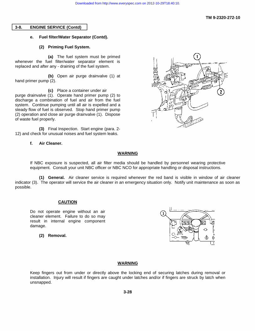
TM 9-2320-272-10
3-8. ENGINE SERVICE (Contd)
e. Fuel filter/Water Separator (Contd).
(2) Priming Fuel System.
(a) The fuel system must be primedwhenever the fuel filter/water separator element isreplaced and after any - draining of the fuel system.
(b) Open air purge drainvalve (1) athand primer pump (2).
(c) Place a container under airpurge drainvalve (1). Operate hand primer pump (2) todischarge a combination of fuel and air from the fuelsystem. Continue pumping until all air is expelled and asteady flow of fuel is observed. Stop hand primer pump(2) operation and close air purge drainvalve (1). Disposeof waste fuel properly.
(3) Final Inspection. Start engine (para. 2-12) and check for unusual noises and fuel system leaks.
f. Air Cleaner.
WARNING
If NBC exposure is suspected, all air filter media should be handled by personnel wearing protectiveequipment. Consult your unit NBC officer or NBC NCO for appropriate handling or disposal instructions.
(1) General. Air cleaner service is required whenever the red band is visible in window of air cleanerindicator (3). The operator will service the air cleaner in an emergency situation only. Notify unit maintenance as soon aspossible.
CAUTION
Do not operate engine without an aircleaner element. Failure to do so mayresult in internal engine componentdamage.
(2) Removal.
WARNING
Keep fingers out from under or directly above the locking end of securing latches during removal orinstallation. Injury will result if fingers are caught under latches and/or if fingers are struck by latch whenunsnapped.
3-28
Downloaded from http://www.everyspec.com on 2012-10-29T18:40:10.

TM 9-2320-272-10
3-8 ENGINE SERVICE (Contd)
(2) Removal (Contd).
(a) Release latch (6) securing rear retaining strap (5) to hanger (11) and spread apart retaining strap(5).
(b) Release five latches (8) securing air cleaner body (7) to air cleaner manifold (4).(c) Remove air cleaner body (7), gasket (9), and element (10).
WARNING
Keep fingers out from under or directly above the locking end of securing latches during removal orinstallation. Injury will result if fingers are caught under latches and/or if fingers are struck by latch whenunsnapped.
(b) Position gasket (9) on air cleaner body (7) and install air cleaner body (7) over element (10) witharrows on end of air cleaner body (7) pointing up.
(c) Secure air cleaner body (7) to manifold (4) with five latches (8).(d) Secure rear retaining strap (5) to hanger (11).
(5) Final Inspection. Start engine (para. 2-12) and press top of air cleaner indicator (3) to release red band.If green band does not appear, report condition to unit maintenance.
(3) Cleaning Element by Tapping
CAUTION
Do not strike ends of element on hard surface.Damage will result
(a) Hold element (10) so open end facesground.
(b) Gently tap completely around element (1)with hand to free trapped dirt.
(4) Installation.
(a) Position air cleaner element (1) in aircleaner manifold (4) with closed end of element (10) facingoutward.
3-29
Downloaded from http://www.everyspec.com on 2012-10-29T18:40:10.

TM 9-2320-272-10
3-9. AIR RESERVOIRS
a. General. Four drainvalves, located on right side of vehicle next to toolbox, are used to drain moisture fromair reservoirs.
b. Service.
(1) Turn drainvalves (1) counterclockwiseto drain moisture from:
(a) Airbrake system wet tankreservoir drainvalve 1.
(b) Spring brake air reservoirdrainvalve 2.
(c) Primary airbrake system airreservoir drainvalve 3.
(d) Secondary airbrake system airreservoir drainvalve 4.
(2) After all moisture has been drained and only air is coming out, turn drainvalves (1) clockwise to close.
c. Final Inspection. Make sure drainvalves (1) are closed tight to prevent air from escaping. If air escapesafter drainvalves are closed tightly, notify unit maintenance immediately.
3-10. TRANSMISSION OIL LEVEL
CAUTION
When checking transmission oil level, do not permit dirt, dust or grit to enter transmission filler tube. Makesure dipstick handle and end of filler tube are clean to prevent internal transmission damage.
a. General. The transmission oil level is checked weekly with engine running at idle, transmission in neutral,and parking brake applied. In M939/A1 series vehicles, transmission dipstick (3) is located under access door (4) in centerof cab floor. In M939A2 series vehicles, transmission dipstick (3) is on right side of engine compartment.
3-30
Downloaded from http://www.everyspec.com on 2012-10-29T18:40:10.

TM 9-2320-272-10
3-10. TRANSMISSION OIL LEVEL (Contd)
b. Check Oil Level.
WARNING
Do not check transmission oil level if transmission oil temperature gauge indicates temperature over220°F (104°C). Stop engine and allow transmission to cool. Hot oil may result in injury to personnel.
(1) Open access door (4) on cab floor in M939/A1 series vehicles or open hood in M939A2 series vehiclesto access dipstick (3). Clean around end of filler tube (5) before removing dipstick (3).
WARNING
Hot turbocharger and exhaust manifold can cause injury to personnel.
(2) Turn dipstick (3) handle counterclockwise and pull out dipstick (3) on M939/A1 series vehicles. OnM939A2 series vehicles, pull dipstick (3) straight out.
(3) Wipe clean and insert dipstick (3) in filler tube (5).
(4) On M939/A1 series vehicles, withdraw dipstick (3) slowly to prevent a false reading. If transmission oiltemperature gauge (8) on instrument panel reads 180°F (82°C) or below, level on dipstick (3) should show between marksdesignated for normal run (2).
(5) On M939A2 series vehicles, slowly pull dipstick (3) out of filler tube (5). Level on dipstick (3) should bebetween ADD mark (7) and FULL mark (6).
CAUTION
Overfilling transmission will result in internal transmission damage.
(6) If transmission oil level is low, add oil through filler tube (5) (LO 9-2320-272-12). Return dipstick (3) tofiller tube (5), tighten dipstick handle (M939/A1 series vehicles), and wipe up any oil spilled.
3-31
Downloaded from http://www.everyspec.com on 2012-10-29T18:40:10.

TM 9-2320-272-10
3-11. WHEELS AND TIRES
a. General. Tires are checked as part of Preventive Maintenance Checks and Services (PMCS) (table 2-3). Iftire becomes flat while operating, stop vehicle immediately, if tactical situation permits. All tires on M939/A1/A2 seriesvehicles are bi-directional and do not require any special mounting.
b. Spare Tire. Models M923/A1/A2, M925/A1/A2, M927/A1/A2, M928/A1/A2, M931/A1/A2, and M932/A1/A2(cargo trucks, tractors) are equipped with expendable spare tire davit boom. The M929/A1/A2, M930/A1/A2 (dumptrucks), and the M934 (expansible van) are equipped with an eyebolt for attaching a chain fall. The M934A1 and M93A2(expansible vans) are equipped with a davit-expendable boom and a built-in hand operated winch, while the M936/A1/A2(wrecker) models use the vehicle boom and chain to lift and lower spare tire.
(1) Removal (M923/A1/A2, M925/A1/A2, M927/A1/A2, M928/A1/A2, M9311A1/A2, and M932/A1/A2).
NOTE
• This operation requires personnel.
• Procedures and illustrations are for M931A2 and M932A2 other
(a) Obtain utility chain (7) and chain fall (6) from tool compartment.(b) Secure utility chain (7) around spare tire (11) and take up slack.
3-32
Downloaded from http://www.everyspec.com on 2012-10-29T18:40:10.

TM 9-2320-272-10
3-11. WHEELS AND TIRES (Contd)
(c) Hook chain fall (6) to davit boom roller (3) and to utility chain (7) securing spare tire (11) and take upslack.
(d) Remove lock pin (14) from davit boom (2), roller (3) and retaining pin (4) from davit boom (2) and davitsupport (5).
(e) Slide out davit boom (2) until holes in davit boom (2) and davit support (5) are aligned. Secure in placewith retaining pin (4) and lock pin (14).
(f) Hook chain fall (6) to ring (13) on utility chain (7). Pull hand chain (12) to take up slack.
(g) Loosen wingnut (15) securing wheel brace (10) to threaded bar (9).
(h) Guide threaded bar (9) from notch in davit boom base (8). Lift wheel brace (10) and threaded bar (9)from davit boom base (8).
WARNING
• Stand clear during hoisting operations. Injury may result if personnel are struck by a swinging sparetire.
• Use caution when operating chain hoist. Injury may result if fingers are caught in chain hoist pulleysheave.
(i) Pull hand chain (12) to slightly raise spare tire (11). Slide spare tire (11) along davit boom (2) until roller(3) hits stop (1).
NOTESpare tire must be turned flat to vehicle body during lowering operation.
(j) Pull hand chain (12) to lower spare tire (11) to ground.
(k) Remove utility chain (7) from spare tire (11) and chain fall (6).
(2) Installation (M923/A1/A2, M925/A1/A2, M927/A1/A2, M928/A1/A2, M931/A1/A2, and M932/A1/A2).
(a) Place utility chain (7) through rim of spare tire (11) and ring (13) on utility chain (7). Center ring (13) attop of spare tire. Take up slack and hook utility chain (7) back onto utility chain (7).
(b) Lower chain fall (6) hook and attach to ring (13).
(c) Raise spare tire (11) until it clears davit boom base (8).
(d) Using roller (3), place spare tire (11) in davit boom base (8).
(e) Lower wheel brace (10), guide threaded bar (9) into notch in davit boom base (8) and tighten wingnut(15) until snug.
(f) Remove utility chain (7) from spare tire (11) and chain fall (6).
(g) Slide davit boom (2) into davit support (5) until holes in davit boom (2) and davit support (5) are aligned.Secure in place with retaining pin (4) and lock pin (14).
(h) Return utility chain (7) and chain fall (6) to tool compartment.3-33
Downloaded from http://www.everyspec.com on 2012-10-29T18:40:10.
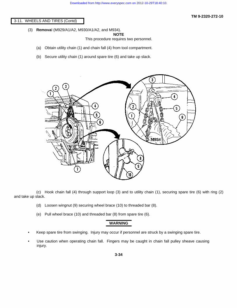
TM 9-2320-272-103-11. WHEELS AND TIRES (Contd)
(3) Removal (M929/A1/A2, M930/A1/A2, and M934).NOTE
This procedure requires two personnel.
(a) Obtain utility chain (1) and chain fall (4) from tool compartment.
(b) Secure utility chain (1) around spare tire (6) and take up slack.
(c) Hook chain fall (4) through support loop (3) and to utility chain (1), securing spare tire (6) with ring (2)and take up slack.
(d) Loosen wingnut (9) securing wheel brace (10) to threaded bar (8).
(e) Pull wheel brace (10) and threaded bar (8) from spare tire (6).
WARNING
• Keep spare tire from swinging. Injury may occur if personnel are struck by a swinging spare tire.
• Use caution when operating chain fall. Fingers may be caught in chain fall pulley sheave causinginjury.
3-34
Downloaded from http://www.everyspec.com on 2012-10-29T18:40:10.

TM 9-2320-272-103-11. WHEELS AND TIRES (Contd)
(f) Pull hand chain (5) to slightly raise spare tire (6) from spare tire carrier base (7). Move spare tire (6) outof bracket area towards back of cab. Pull spare tire (6) towards side of vehicle until sufficient clearance is obtained tolower spare tire (6) to ground.
(g) Pull on hand chain (5) to lower spare tire (6) to ground.
(h) Remove utility chain (1) securing spare tire (6) to chain fall (4).
(4) Installation (M929/A1/A2, M930/A1A2, and M934).
(a) Place utility chain (1) through rim of spare tire (6) and ring (2) on utility chain (1). Center ring (2) at top ofspare tire (6). Take up slack and hook utility chain (1) back onto utility chain (1).
(b) Lower chain fall (4) hook and attach to utility chain ring (2).
(c) Raise spare tire (6) until it clears tire carrier base (7). Place tire on tire carrier base (7).
(d) Lower wheel brace (10), guide threaded bar (8) to notch in spare tire carrier base (10), and tightenwingnut (9) until snug.
(e) Remove utility chain (1) from spare tire (6) and chain fall (4) from support loop (3). Return utility chain(1) and chain fall (4) to tool compartment.
(5) Removal (M934A1/A2).
NOTE• This procedure requires two personnel.
• Cable and hook will be attached to spare tire during normal vehicle operation.
(a) Push and hold button (14) and remove retaining pin (13) and lift brace (11) up. Reinstall pin (13) withbrace (11) in up position.
(b) Turn winch handle (12) counterclockwise to remove tension.
3-35
Downloaded from http://www.everyspec.com on 2012-10-29T18:40:10.

TM 9-2320-272-103-11. WHEELS AND TIRES (Contd)
(c) Loosen wingnut (7) attaching wheel brace (8) to threaded bar (6).
(d) Guide threaded bar (6) from notch in spare tire carrier (4). Lift wheel brace (3) and threaded bar (6)from spare tire carrier (4).
WARNING
Stand clear during hoisting operations. Injury may result if personnel are struck by a swinging spare tire.
(e) Turn handle (9) clockwise to slightly raise spare tire (5). Swing spare tire (5) and davit boom (2) towardside of vehicle until sufficient clearance is obtained to lower spare tire (5) to ground.
NOTESpare tire must be turned flat to vehicle body during lowering operation.
(f) Turn winch handle (9) counterclockwise to lower spare tire (5) to ground.
(g) Remove davit chain (1) from spare tire (5).
3-36
Downloaded from http://www.everyspec.com on 2012-10-29T18:40:10.

TM 9-2320-272-10
3-11. WHEELS AND TIRES (Contd)
(h) Reverse steps (a) through (g) as necessary to install spare tire (5).
(6) Removal (M936/A1/A2).
WARNING
Do not touch hot exhaust system components.Injury to personnel may result.
NOTE• Utility chain hook must be centered on top
of tire to keep tire from lifting.
• This operation requires an assistant toguide spare tire.
(a) Obtain utility chain (11) from tool compartment,install around spare tire (12) with utility chain hook (10) centered
on top of spare tire (12), and take up slack.
(b) Remove wingnut (13) and brace (14) securingspare tire (12).
3-37
Downloaded from http://www.everyspec.com on 2012-10-29T18:40:10.

TM 9-2320-272-103-11. WHEELS AND TIRES (Contd)
(c) Prepare wrecker for boom (1) operation (para. 2-24).
(d) Position boom (1) with boom hook (2) centered over spare tire (5). Attach boom hook (2) to chain ring(3).
(e) Raise spare tire (5) from spare tire support (6).
WARNING
Keep spare tire from swinging. Injury may occur if personnel are struck by swinging spare tire.
(f) Position boom (1) to right side of vehicle until sufficient clearance is obtained to lower spare tire (5) toground, and lower spare tire (5).
(g) Remove chain (4) from spare tire (5) and boom hook (2).
(h) Secure wrecker from boom (1) operation (para. 2-24).
(7) Installation (M936/A1/A2).
(a) Install utility chain (4) around spare tire (5) with utility chain hook (7) centered on top of spare tire (5),and take up slack.
(b) Prepare wrecker for boom (1) operation (para. 2-24).
WARNING
Keep spare tire from swinging. Injury may occur if personnel are struck by swinging spare tire.
NOTEAssistant will guide spare tire to tire support.
(c) Position boom (1) with boom hook (2) centered over spare tire (5). Attach boom hook (2) to chain ring(3).
(d) Raise spare tire (5) and place in spare tire support (6).
(e) Remove chain (4) from spare tire (5) and boom hook (2).
(f) Install brace (9) and wingnut (8) on spare tire (5) and support (6).
(g) Return utility chain (4) to tool compartment.
(h) Secure wrecker from boom (1) operation (para. 2-24).
3-38
Downloaded from http://www.everyspec.com on 2012-10-29T18:40:10.
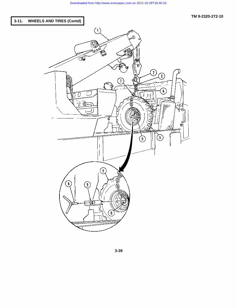
TM 9-2320-272-103-11. WHEELS AND TIRES (Contd)
3-39
Downloaded from http://www.everyspec.com on 2012-10-29T18:40:10.

TM 9-2320-272-103-11. WHEELS AND TIRES (Contd)
c. Tire Replacement.
WARNING
Engage parking brake and chock wheels on both sides to keep vehicle from rolling. Failure to do so mayresult in injury to personnel.
(1) Tire Removal (M939 series vehicles).
(a) Remove hydraulic jack (10), jack handle (12), wheel stud nut wrench (1), and wrench handle (14) fromtool compartment. Remove spare tire from storage location.
NOTEWheel stud nuts on left side have left-hand threads. Those on right side have right-hand threads. Studsand nuts are marked L and R accordingly.
(b) Install wrench handle (14) through wheel stud nut wrench (1) and position wrench (1) on wheel stud nuts(2). Loosen ten wheel stud nuts (2) but do not remove.
(c) Turn jack screw (9) of jack (10) out approximately 3 in. (7.6 cm) by hand.
(d) Turn valve (11) at base of jack (10) by turning clockwise with slotted end of jack handle (12) until closedsecurely.
WARNING
Do not work under vehicle supported by jack only. Jack may slip causing vehicle to fall, which will result ininjury or death.
NOTE• Place a block under jack if used on soft terrain.
• Use jack stands if available.
• Expansible van bodies must be retracted on M934 models before jacking vehicle up.
(e) Position jack (10) under axle housing (8) near tire to be removed. Insert jack handle (12) into jack (10).Move jack handle (12) up and down until tire is off the ground.
NOTEUse special second wheel stud wrench NSN 5120-00-378-4411 to hold inner adapter spacer nuts in placewhen braking outer lug nut.
(f) If rear dual tire is to be replaced, remove ten wheel stud nuts (2) from adapter spacer nuts (4) and outertire (3) from axle hub (13). If rear inner wheel (6) is to be removed, reverse wheel stud nut wrench (1), remove handle(14), and install near large end of wrench (1). Remove ten adapter spacer nuts (4) and inner tire (6).
(g) If front tire is to be replaced, remove ten wheel stud nuts (2) from studs (7) and tire (6) from hub (13).
3-40
Downloaded from http://www.everyspec.com on 2012-10-29T18:40:10.
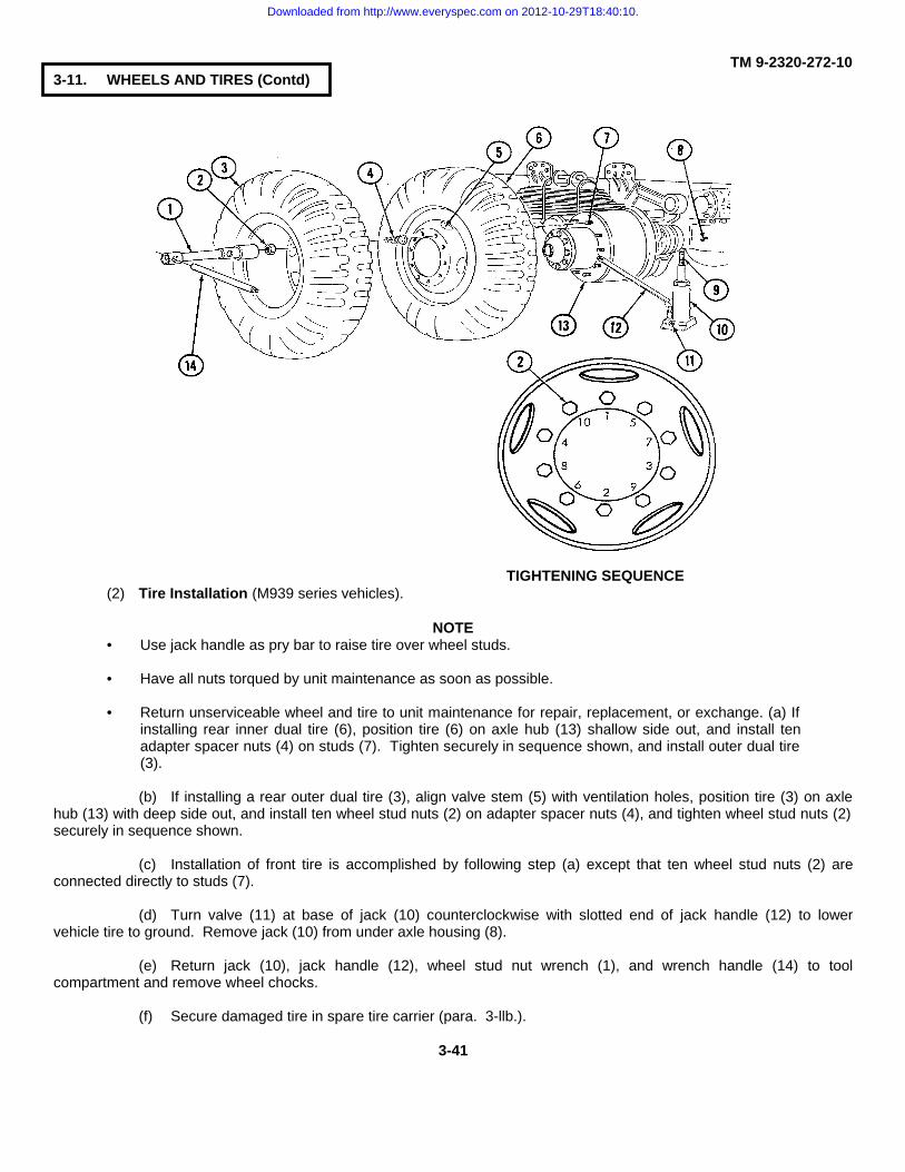
TM 9-2320-272-103-11. WHEELS AND TIRES (Contd)
TIGHTENING SEQUENCE(2) Tire Installation (M939 series vehicles).
NOTE• Use jack handle as pry bar to raise tire over wheel studs.
• Have all nuts torqued by unit maintenance as soon as possible.
• Return unserviceable wheel and tire to unit maintenance for repair, replacement, or exchange. (a) Ifinstalling rear inner dual tire (6), position tire (6) on axle hub (13) shallow side out, and install tenadapter spacer nuts (4) on studs (7). Tighten securely in sequence shown, and install outer dual tire(3).
(b) If installing a rear outer dual tire (3), align valve stem (5) with ventilation holes, position tire (3) on axlehub (13) with deep side out, and install ten wheel stud nuts (2) on adapter spacer nuts (4), and tighten wheel stud nuts (2)securely in sequence shown.
(c) Installation of front tire is accomplished by following step (a) except that ten wheel stud nuts (2) areconnected directly to studs (7).
(d) Turn valve (11) at base of jack (10) counterclockwise with slotted end of jack handle (12) to lowervehicle tire to ground. Remove jack (10) from under axle housing (8).
(e) Return jack (10), jack handle (12), wheel stud nut wrench (1), and wrench handle (14) to toolcompartment and remove wheel chocks.
(f) Secure damaged tire in spare tire carrier (para. 3-llb.).
3-41
Downloaded from http://www.everyspec.com on 2012-10-29T18:40:10.

TM 9-2320-272-103-11. WHEELS AND TIRES (Contd)
(3) Tire Removal (M939A1 series vehicles).
WARNING
Engage parking brake and chock wheels on both sides. Failure to do so may result in injury to personnel.
(a) Remove hydraulic jack (9), jack handle (7), wheel stud nut wrench (2), and wrench handle (1) from toolcompartment. Remove spare tire from storage location.
NOTE• This procedure requires two personnel.
• Wheel stud nuts on left side have left-hand threads. Those on right side have right-hand threads.Studs and nuts are marked L and R accordingly.
(b) Install wrench handle (1) through wheel stud nut wrench (2) and position wheel stud nut wrench (2) onwheel stud nuts (3). Loosen ten wheel stud nuts (3) but do not remove.
(c) Turn jack screw (10) of jack (9) out approximately 3 in. (7.6 cm).
(d) Turn valve (8) at base of jack (9) by turning clockwise with slotted end of jack handle (7) until closedsecurely.
WARNING
Do not work under vehicle supported by jack only. Jack may slip causing vehicle to fall, which will result ininjury or death.
NOTE• Place a block under jack if used on soft terrain.
• Use jack stands if available.
• Expansible van bodies must be retracted on M934A1 model trucks before jacking vehicle up.
(e) Position jack (9) under axle housing (6) near tire (4) or (12) to be removed. Insert handle (7) into jack(9). Move jack handle (7) up and down until tire (4) or (12) is off the ground.
(f) Remove ten wheel stud nuts (3) from studs (11) and tire (4) or (12) from hub (5).
3-42
Downloaded from http://www.everyspec.com on 2012-10-29T18:40:10.

TM 9-2320-272-103-11 WHEELS AND TIRES (Contd)
(4) Tire Installation (M939A1 series vehicles).
NOTE• Use jack handle as pry bar to raise tire over wheel studs.
• Have all nuts torqued by unit maintenance as soon as possible.
• Return unserviceable wheel and tire to unit maintenance for repair, replacement, or exchange.
(a) Position tire (4) or (12) on axle hub (5) over wheel studs (11), front tire (4) is mounted shallow side outand rear tire (12) is mounted deep side out. Tighten wheel stud nuts (3) securely in sequence shown.
(b) Turn valve (8) at base of jack (9) counterclockwise with slotted end of jack handle (7) to lower vehicletire to ground. Remove jack (9) from under axle housing (6).
(c) Return jack (9), jack handle (7), wheel stud nut wrench (2), and wrench handle (1) to tool compartmentand remove wheel chocks.
(d) Secure damaged tire in spare tire carrier (para. 3-llb.).
3-43
Downloaded from http://www.everyspec.com on 2012-10-29T18:40:10.

TM 9-2320-272-103-11. WHEELS AND TIRES (Contd)
(5) Front Tire Removal (M939A2 series vehicles).
(a) Remove CTIS tools from tool compartment.
(b) Remove spare tire from vehicle.
WARNING
• Engage parking brake and chock wheels on both sides to keep vehicle from rolling. Failure to do somay result in injury to personnel.
• Air in system is under pressure. Make sure engine is shut down and air reservoirs are drainedbefore disconnecting CTIS components to prevent serious injury to personnel.
NOTETemporarily store CTIS assembly removed during this operation on spare tire while removing damagedtire to prevent loss of critical parts.
(c) Remove valve core cap (2) and valve core (3) from tank valve (7) to exhaust air pressure from tire (19)and install valve core (3) securely back in tank valve (7). Install valve core cap (2) on valve core (3).
(d) Remove two nuts (26) and washers (25) from rim studs (8) and (12).
(e) Remove two screws (28), washers (27), shield (1), and spacer (24) from hub (14).
(f) Remove nut (5) and two washers (6) from rim stud (10) and wheel valve (4).
(g) Disconnect hose assembly (9) from turret valve (11).
(h) On spare tire (30), remove valve core cap (32) and valve core (31) from turret valve (29).
3-44
Downloaded from http://www.everyspec.com on 2012-10-29T18:40:10.

TM 9-2320-272-103-11. WHEELS AND TIRES (Contd)
CAUTION
Do not damage or lose O-ring whenremoving manifold. Damage or loss ofO-ring will result in loss of CTISpressure and damage to equipment.
(i) Remove screw (23), washer (22), andO-ring (21) from manifold (20).
(j) Remove hose assembly (9), wheelvalve (4), and manifold (20) from manifold tube (13) as acomplete assembly.
(k) Remove hydraulic jack (36), handle(34), wheel stud nut wrench (39), and wrench handle(40) from tool compartment.
WARNING
Do not work under vehicle supported by jack only. Jack may slip causing vehicle to fall, which will result ininjury or death.
NOTE• This procedure requires two personnel.
• Place a block under jack if used on soft terrain.
• Use jack stands if available.
• Expansible van bodies must be retracted on M934A2 models before jacking vehicle up.
• Wheel stud nuts on left side have left-hand threads. Those on right side have right-hand threads.Stud and nuts are marked L and R accordingly.
(i) Install wrench handle (40) through wheel stud nut wrench (39), loosen ten wheel stud nuts (15) andrimnut (17), but do not remove.
(m) Turn jack screw (37) out approximately3 in. (7.6 cm). Position jack (36) under axle housing(33), close valve (35), and jack up vehicle until tire is offthe ground.
(n) Remove ten wheel stud nuts (15) fromwheel studs (38) and remove tire (19).
(o) Remove rimnut (17) and counterweight(16) from rim stud (18). Replace rimnut back on rim stud(18).
(p) Remove rimnut (17) from spare tire(30) and install counterweight (16) on rim stud (18) ofspare tire (30) with rimnut (17).
3-45
Downloaded from http://www.everyspec.com on 2012-10-29T18:40:10.

TM 9-2320-272-103-11. WHEELS AND TIRES (Contd)
(6) Front Tire Installation (M939A2 series vehicles)
NOTEUse jack handle to lift tire over hub and stud.
(a) Install spare tire (4) on hub (5) with shallow side out over hub (5) so that turret valve (22) and manifoldtube (24) are aligned.
(b) Install ten wheel stud nuts (3) on wheel studs (11) and tighten until tire (4) is against face of hub (5)using the wheel stud wrench (2) and wrench handle (1).
(c) Turn valve (8) at the base of the jack (9) counterclockwise with slotted end of jack handle (7) to lower tire(4) to ground, and remove jack (9) from under axle (6) and turn jack screw (10) back into jack (9).
(d) Tighten ten wheel stud nuts (3) securely in sequence shown. Tighten rimnut (26) on counterweight (25)and rim stud (27).
NOTE• Ensure O-ring seal is on manifold tube before installing manifold.
• Ensure valve core has been removed from turret valve when installing hose assembly.
(e) Install hose assembly (20), wheel valve (15), and manifold (29) as a complete assembly. With manifold(29) and O-ring (28) over manifold tube (24), install wheel valve (15) onto rim studs (19) and (21), and hose assembly (20)to turret valve (22).
3-46
Downloaded from http://www.everyspec.com on 2012-10-29T18:40:10.

TM 9-2320-272-103-11 WHEELS AND TIRES (Contd)
(f) Install nut (16) and two washers (17) on rim stud (21).
(g) Install screw (31) and washer (30) in manifold (29) and hub (5).
(h) Install one of two screws (36), washer (35), shield (12), and short end of spacer (32), on manifold (29)and hub (5), and the second of two screws (36), washer (35), shield (12), and long end of spacer (32) on hub (5).
(i) Install two nuts (34) and washers (33) on shield (12) and rim studs (19) and (23).
(j) Tighten valve core (14) in tank valve (18) and install valve cap (13).
(k) Start vehicle and select desired CTIS mission mode.
NOTE• Check replaced tire to ensure tire inflates automatically.
• Report tire change to unit maintenance as soon as possible. Most screws will require torquing tospecific limits and O-ring seal will have to be replaced.
(l) Return jack (9), jack handle (7), wheel stud nut wrench (2), wrench handle (1), and CTIS tools to toolcompartment and remove chocks.
(m) Secure damaged tire in spare tire carrier (para. 3-llb.).
3-47
Downloaded from http://www.everyspec.com on 2012-10-29T18:40:10.

TM 9-2320-272-103-11. WHEELS AND TIRES (Contd)
(7) Rear Tire Removal (M939A2 series vehicles).
(a) Remove CTIS tools from tool compartment.
(b) Remove spare tire from vehicle.
WARNING
• Air in system is under pressure. Make sure engine is shut down and air reservoirs are drainedbefore disconnecting CTIS components to prevent serious injury to personnel.
• Air is under pressure and creates danger to eyes. Shield eyes to prevent serious personal injury.
• Ensure brake is set and vehicle is properly chocked. Failure to do so may result in serious injury topersonnel.
(c) Remove valve core cap (12) and valve core (13) from tank valve (14) to exhaust all air from tire (16).Replace valve core (13) and valve core cap (12).
(d) Remove hose assembly (11) from turret valve (15).
(e) Remove valve cap (18) and valve core (19) from turret valve (20) of spare tire (21) to exhaust air. Installvalve core (19) and valve cap (18) from spare tire (21) in turret valve (15) of damaged tire (16).
(f) Remove two locknuts (8) and washers (7) holding shield (6) on wheel valve (5).
(g) Remove two screws (10), washers (9), and shield (6) from hub cap (17) and wheel valve (5). Replacetwo screws (10) and washers (9) in hub cap (17) and hand-tighten.
(h) Loosen adapter nut (4) until wheel valve (5) can be removed.
(i) Remove wheel valve (5) and hose assembly (11) as a complete assembly from adapter nut (4).
(j) Before removing adapter, clean surface of hub body of dirt and foreign material which could clog CTISair passages. Failure to do so will result in improper inflation or damage to wheel valve.
CAUTION
• Temporarily seal hole in hub body by rapping electrical tape around hub body at least twice, ensuringthat tape completely covers hole. Failure to do so may result in introduction of dirt or foreign materialinto critical CTIS components.
• Temporarily reattach adapter, O-ring, and washer to wheel valve and rap with electrical tape to sealend and hold O-ring and washer in place.
(k) Clean area around adapter.
(l) Reinstall parts and tape together.
(m) Remove adapter nut (4), O-ring (3), and washer (2) from hub body (1). Seal hole in hub body (1) withelectrical tape.
3-48
Downloaded from http://www.everyspec.com on 2012-10-29T18:40:10.

TM 9-2320-272-103-11. WHEELS AND TIRES (Contd)
3-49
Downloaded from http://www.everyspec.com on 2012-10-29T18:40:10.

TM 9-2320-272-103-11. WHEELS AND TIRES (Contd)
(n) Remove hydraulic jack (9), jack handle (7), wheel stud nut wrench (2), and wrench handle (1) from toolcompartment.
WARNING
Do not work under vehicle supported by jack only. Jack may slip causing vehicle to fall. Failure to do sowill result in injury or death.
(o) Install wrench handle (1) through hole in side of small end of wheel stud nut wrench (2) and use wheelstud nut wrench (2) to loosen ten wheel stud nuts (5), but do not remove.
(p) Turn jack screw (10) of jack (9) out approximately 3 in. (7.6 cm).
(q) Turn valve (8) at base of jack (9) by turning clockwise with slotted end of jack handle (7) until closedsecurely.
NOTE• This procedure requires two personnel.
• Place a block under jack if used on softterrain.
• Use jack stands if available.
• Expansible van bodies must beretracted on M934A2 models beforejacking vehicle up.
• Wheel stud nuts on left side have left-hand threads. Those on right side haveright-hand threads. Stud and nuts aremarked L and R accordingly.
(o) Position jack (9) under axle housing (11) near tire (4) that is damaged. Insert jack handle (7) into jack(9), and move jack handle (7) up and down until tire (4) is off the ground.
(p) Remove ten wheel stud nuts (5) from wheel studs (6) and tire (4) from hub (3).
3-50
Downloaded from http://www.everyspec.com on 2012-10-29T18:40:10.

TM 9-2320-272-103-11 WHEELS AND TIRES (Contd)
(8) Rear Tire Installation (M939A2 series vehicles).
NOTE• Use jack handle to lift tire over hub and studs.
• Mount tire on hub and studs with deep side out.
• Ensure hole in hub body is centered between third and fourth stud hole (counterclockwise fromthe turret valve) on the spare.
(a) Install tire (4), deep side out, over hub (3) and wheel studs (6).
(b) Install ten wheel stud nuts (5) on wheel studs (6) and tighten until tire (4) is against the face of the hub(3) using wheel stud wrench (2).
(c) Turn valve (8) at base of jack (9) counterclockwise with slotted end of jack handle (7) to lower tire (4) toground and remove jack (9) from under axle housing (11).
(d) Tighten ten wheel stud nuts (5) securely in sequence shown.
(e) Return jack (9), jack handle (7), wheel stud nut wrench (2), and wrench handle (1) to tool compartmentand remove chocks.
3-51
Downloaded from http://www.everyspec.com on 2012-10-29T18:40:10.

TM 9-2320-272-103-11. WHEELS AND TIRES (Contd)
(f) Remove tape from hub body (1).Remove adapter (4), O-ring (3), and washer (2) fromtemporary storage on the wheel valve (5), and install inhole in hub body (1).
(g) Install hose assembly (11) on turretvalve (16) and hand-tighten.
(h) Install wheel valve (5) on adapter (4).Tighten adapter nut (15) and hose assembly (11).
(i) Install shield (6) on wheel valve (5)with two nuts (8) and washers (7), and on hub cap (18)with two screws (10) and washers (9).
(j) Start vehicle and select desired CTISmission mode.
NOTE• Check replaced tire to ensure
tire inflates automatically.
• Report tire change to unitmaintenance as soon possible.Most screws will requiretorquing to specific limits, andO-ring seal will have to bereplaced.
(k) Return CTIS tools to toolcompartment.
(l) Secure damaged tire in spare tirecarrier.
d. Tire Inflation.
(1) General. Never decrease pressure of warm tires (17) except for operation in snow, sand, or mud (para. 2-33, 2-35, or 2-37). After operations are completed, reinflate tires (17) to recommended pressure (refer to table 1-10).
3-52
Downloaded from http://www.everyspec.com on 2012-10-29T18:40:10.

TM 9-2320-272-103-11. WHEELS AND TIRES (Contd)
NOTEChock wheels if necessary.
(2) Tire Gauging and Inflation.
(a) Remove valve cap (12) from valvestem (14) for access to valve core (13).
(b) Remove tire inflation gauge andhose assembly (19) from tool compartment.
(c Start engine and engage parkingbrake. Make sure air reservoir pressure is higherthan recommended tire pressure by checking primary(20) and secondary (21) air pressure gauges oninstrument panel (22).
(d) Remove emergency air couplingcover (25). Install tire inflation hose assemblycoupling (26) on left front emergency air coupling(23) to inflate front tires, and on right rear emergencyair coupling for rear tires.
(e) Align air valve handle (24) at aircoupling (23) with piping to release compressed airinto tire inflation gauge and hose assembly (19).
3-53
Downloaded from http://www.everyspec.com on 2012-10-29T18:40:10.

TM 9-2320-272-103-11. WHEELS AND TIRES (Contd)
(f) Start at one corner of vehicle to gauge and adjust pressure, as necessary, of all tires (6). Remove tirevalve cap (1), apply tire gauge air chuck (7) on tire valve stem (2) and press down firmly to read tire pressure on gauge dial(5). Press air chuck lever (4) to inflate tire (6) as necessary. Release air chuck lever (4) momentarily to read pressure ongauge dial (5).
NOTEM939A2 series vehicles utilize CTISwhich must be disabled to manuallyinflate front and rear tires
(g) On M939A2 series vehicles, remove valve cap (1) from the valve stem (2) through CTIS cover access(8).
(3) Remove tire gauge air chuck (7) from tire valve stem (2) when tire pressure is adjusted to recommendedinflation pressures in table 1-10. Install tire valve cap (1) and tighten finger-tight.
(4) When tire inflation operation is completed, turn airvalve handle (10) crosswise to piping. Uncouple gauge and hoseassembly (3) from air coupling (9), and install cover (11) on aircoupling (9).
(5) Return tire inflation gauge and hose assembly (3) totool compartment.
NOTERemove wheel chocks if used.
3-54
Downloaded from http://www.everyspec.com on 2012-10-29T18:40:10.

TM 9-2320-272-103-12. AIR SYSTEM SHUTOFF VALVES
General. Primary and secondary air systems are provided with shutoff valves to isolate them from the rest of thevehicle air system. These valves are closed by the operator only in an emergency situation.
(1) The primary system air shutoff valve (1) on the M939/A1 series vehicles is located at the forward end of thewet tank. On the M939A2 series vehicles, it is at the side of the wet tank reservoir. If air leaks in the primary system andthe vehicle must be driven, close air shutoff valve (1). Closing the primary system air shutoff valve (1) will isolate theprimary system and maintain air pressure to brake system components and enable operator to slow down or stop thevehicle.
(2) The secondary system air shutoff valve (2) is located on top of the wet tank reservoir. In the event of an airleak in the secondary system and the vehicle must be driven, close air shutoff valve (2). Closing the secondary systemand air shutoff valve (2) will isolate the secondary system and maintain air pressure to brake system components andenable operator to slow down or stop the vehicle.
3-55
Downloaded from http://www.everyspec.com on 2012-10-29T18:40:10.

TM 9-2320-272-103-13. SPRING BRAKE SERVICE
a. General. Spring brakes on M939/A1/A2 series vehicles lock automatically and stop the vehicle whenever alarge loss of air pressure occurs. Before the vehicle can be towed away for repairs, the spring in each spring brake mustbe manually released. This procedure is performed by operator only in an emergency.
b. Applying Spring Brake. Switches located on the emergency brake and PTO levers reduce the air pressureto the spring brake system, resulting in automatic activation of spring brakes. Testing of these switches can beaccomplished by manually lifting switch and increasing engine speed while in drive.
c. Spring Brake Override. An air-actuation switch on the dash supplies normal air pressure to spring brakespreventing them from engaging.
d. Releasing the Spring (Caging Brakes).
WARNING
Make sure vehicle parking brake is engaged and wheels are chocked before releasing springs in springbrakes. Failure to do so will result in vehicle rolling out of control, which may cause injury or death.
NOTE• Do not lose rubber plugs. After removal, store all four plugs in map compartment inside cab. Be
sure to notify unit maintenance of where they are stored so they may be reinstalled later.
• If inside of brake chamber is clogged with mud, sand, or dirt, do not proceed with spring releaseoperation unless the chamber can be cleared. Notify unit maintenance if chamber cannot becleared.
(1) Remove rubber plug (1) from spring brake chamber (2).
(2) Visually inspect spring brake chamber (2) for mud, sand, or dirt.
WARNING
Do not remove rim clamp bolt or nut. High pressure inside of spring brake chamber may result in injury ordeath if released.
(3) Remove nut (6), washer (5), and release bolt (4) from storage housing (3).
(4) Insert T-end of release bolt (4) all the way into spring brake chamber (2) and turn bolt (4) one-quarter turnclockwise.
NOTEIf release bolt cannot be pulled directly out of spring brake chamber after it has been turned, bolt isproperly seated.
(5) Pull on release bolt (4) to make sure it is firmly holding spring plate within the spring brake chamber (2).
3-56
Downloaded from http://www.everyspec.com on 2012-10-29T18:40:10.

TM 9-2320-272-103-13. SPRING BRAKE SERVICE (Contd)
(6) Install nut (6) and washer (5) on end of release bolt (4). Tighten nut (6) down until it is in contact with springbrake chamber (2).
NOTEMeasurement can be accomplished using the paper ruler in the back of this manual.
CAUTIONMeasurement of release bolt from nut must be at least 3 in. (7.6 cm). If distance is not correct, damageto brakes will result.
(7) Turn nut (6) clockwise until at least 3 in. (7.6 cm) of threads of release bolt (4) extends out of nut (6).
(8) Reverse steps 1 through 7 to remove manual release of spring brake.
3-57
Downloaded from http://www.everyspec.com on 2012-10-29T18:40:10.

TM 9-2320-272-103-14. RADIATOR FAN CLUTCH EMERGENCY SERVICE
a. General. The radiator fan on M939/A1 series vehicles normally activates when the engine coolanttemperature exceeds 185°F (85°C), which is within the normal operating range of 175°-195°F (79°-91°C). It is possible,however, for the thermostat governing fan operation to become damaged. This will result in engine overheating. In anemergency, the operator can bypass the fan thermostat by bolting the fan to the engine's fan clutch assembly. Thisprocedure is performed by the operator only when service by unit maintenance is not available.
b. Symptoms.
(1) Engine coolant temperature exceeds 195°F (91°C) as indicated by engine coolant temperature gauge (3).
(2) Operator has stopped vehicle and allowed engine to idle as described in paragraph 2-16.
(3) Engine coolant temperature gauge (3) indicated engine is not cooling, or engine coolant temperaturecontinues to rise after two-minute idle period.
c. Inspection. With engine continuing to idle, raise hood and inspect fan (4) for operation. If fan is not turning,fan clutch thermostat is damaged. Operator must immediately shut down engine and notify unit maintenance. If service isnot available, perform step d., emergency service.
d. Emergency Service.
WARNING
• Make sure battery switch and ignition switch are OFF. Make sure crewmembers inside vehicle cabare aware of danger in engaging these switches while emergency service is being performed.Failure to do so may result in fan blade suddenly engaging and cause injury or death.
• Do not allow hands to contact engine during emergency service. Burns will result from contact withengine.
(1) Stop engine by shutting off ignition switch (2) and battery switch (1).
3-58
Downloaded from http://www.everyspec.com on 2012-10-29T18:40:10.

TM 9-2320-272-103-14. RADIATOR FAN CLUTCH EMERGENCY SERVICE (Contd)
(2) Raise and secure hood (paragraph 2-19).
(3) Remove two clutch override lockup bolts (6) from storage boss on fan clutch support bracket (5).
NOTEBecause fan clutch assembly is a moving part when engine is running, alignment mark may be located indifferent position from position shown in illustration. Without starting engine, tap engine ignition switch tomove alignment mark to proper position.
(4) Line up alignment mark on side of fan mounting plate (8) with alignment mark on side of fan clutch assembly(7). Fan mounting plate (8) turns freely by hand.
(5) With alignment marks lined up, insert two clutch override lockup bolts (6) into holes of fan mounting plate (8)and hand-tighten.
(6) Tighten override lockup bolts (6) until fully seated to secure fan mounting plate (8) to fan clutch assembly (7).
(7) Close and secure hood (para. 2-19).
(8) Start engine and allow engine to cool at idle speed until engine coolant temperature drops to normaloperating temperature range of 1750-195°F (79°-910C).
(9) Make certain unit maintenance is notified of emergency service performed on vehicle.
3-59
Downloaded from http://www.everyspec.com on 2012-10-29T18:40:10.
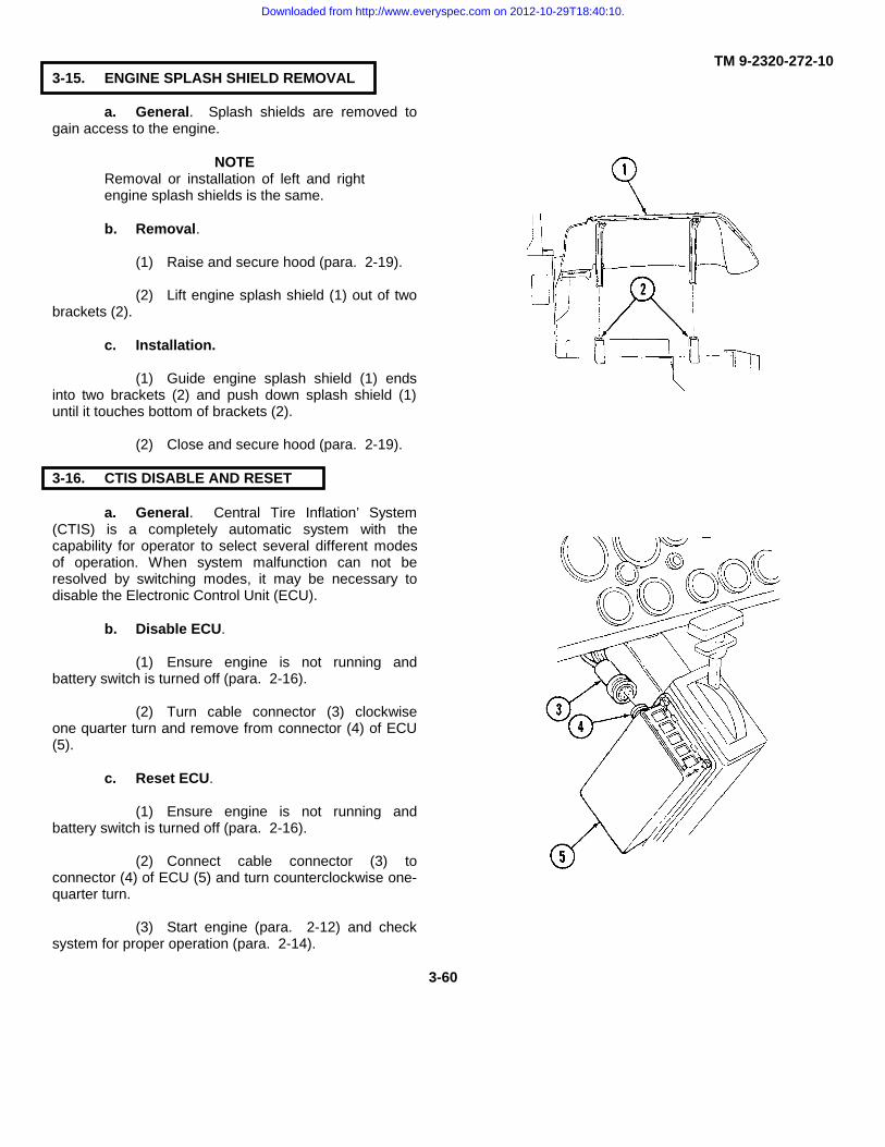
TM 9-2320-272-103-15. ENGINE SPLASH SHIELD REMOVAL
a. General. Splash shields are removed togain access to the engine.
NOTERemoval or installation of left and rightengine splash shields is the same.
b. Removal.
(1) Raise and secure hood (para. 2-19).
(2) Lift engine splash shield (1) out of twobrackets (2).
c. Installation.
(1) Guide engine splash shield (1) endsinto two brackets (2) and push down splash shield (1)until it touches bottom of brackets (2).
(2) Close and secure hood (para. 2-19).
3-16. CTIS DISABLE AND RESET
a. General. Central Tire Inflation’ System(CTIS) is a completely automatic system with thecapability for operator to select several different modesof operation. When system malfunction can not beresolved by switching modes, it may be necessary todisable the Electronic Control Unit (ECU).
b. Disable ECU.
(1) Ensure engine is not running andbattery switch is turned off (para. 2-16).
(2) Turn cable connector (3) clockwiseone quarter turn and remove from connector (4) of ECU(5).
c. Reset ECU.
(1) Ensure engine is not running andbattery switch is turned off (para. 2-16).
(2) Connect cable connector (3) toconnector (4) of ECU (5) and turn counterclockwise one-quarter turn.
(3) Start engine (para. 2-12) and checksystem for proper operation (para. 2-14).
3-60
Downloaded from http://www.everyspec.com on 2012-10-29T18:40:10.

TM 9-2320-272-103-17. EMERGENCY BRAKE SERVICE
a. General. The emergency brake combines the holding strength of the spring brake system (activated by aswitch on emergency brake lever), with brake shoes attached to the output shaft of the transfer case.
b. Operation. The emergency brake can be applied simply by pulling the emergency brake (3) backward andupward at the same time until it is in the full upright position.
c. Testing With Engine Running (para 2-12).
(1) With service brake (5) applied, depress override button (2) on dash.
(2) Set emergency brake. Make sure parking brake warning light (6) illuminates.
(3) Shift transmission selector (1) to 1-5 drive.
(4) With engine at idle speed, release service brakes (5). If vehicle moves, adjust emergency brake (3).
d. Adjusting Emergency Brake.
(1) With emergency brake (3) off (forward and down position), rotate knurled knob (4) clockwise one-quarterturn.
(2) Repeat testing procedure and step (1) until emergency brake holds vehicle at idle. Rotate knurled knob(4) an additional one-quarter turn.
CAUTION
If emergency brake cannot be adjusted, or drags when released, notify unit maintenance. Failure to do somay result in damage to equipment.
3-61 (3-62 blank)
Downloaded from http://www.everyspec.com on 2012-10-29T18:40:10.

TM 9-2320-272-10
APPENDIX AREFERENCES
A-1. PUBLICATION INDEX
The following index should be consulted frequently for latest changes or revisions and for new publications relatingto material covered in this manual:
Consolidated Index of Army Publicationsand Blank Forms ............................................................................................. DA Pam 310-1
A-2. OTHER PUBLICATIONS
a Technical Manuals.Cleaning Materials ................................................................................................... TM 9-247Hand Receipt Manual ..........................................................................TM 9-2320-272-10-HRWarranty Program for Trucks, 5 Ton......................................................... TB 9-2300-358-24Maintenance Manual for Chemical Agent Alarm .......................................TM 3-6665-225-12Maintenance Manual for DecontaminatingApparatus ............................................................................................. TM 3-4230-204-12&PMaintenance Manual for Machine Gun Mounts.........................................TM 9-1005-245-14Procedures and Destruction of Tank-AutomotiveEquipment to Prevent Enemy Use ................................................................... TM 750-244-6Standards and Criteria for Technical Inspection andClassification of Tires (FSC 2610).............................................................TM 9-2610-201-14Load-Testing Vehicles Used to Handle Missiles and Rockets .................................TB 9-352
b Technical Bulletins.Occupational and Environmental Health:Hearing Conservation......................................................................................... TB MED 501Safety Inspection and Testing of Lifting Devices..................................................TB 43-0142Warranty Procedures for Cummins Engine (Model NHC 250)and Allison Transmission (Model MT654CR) inTruck, 5-Ton, 6x6, M939 Series ........................................................... TB 9-2300-295-15/21Security of Tactical Wheeled Vehicles ...................................................... TB 9-2300-422-20Use of Antifreeze Solutions and Cleaning Compoundsin Engine Cooling Systems...................................................................................TB 750-651Tactical Wheeled Vehicles: Repair of Frames .......................................... TB 9-2300-247-40
c Field Manuals.Basic Cold Weather Manual.................................................................................... FM 31-70Driver’s Manual, Wheeled Vehicles....................................................................... FM 21-305First Aid for Soldiers ................................................................................................ FM 21-11Mountain Operations .......................................................................................FM 90-6 (HTF)NBC (Nuclear, Biological, and Chemical Defense) ................................................. FM 21-40Northern Operations ................................................................................................ FM 31-71
A-1
Downloaded from http://www.everyspec.com on 2012-10-29T18:40:10.

TM 9-2320-272-10
APPENDIX A (Contd)
A-2. OTHER PUBLICATIONS (Contd)
Operation and Maintenance of Ordnance Materiel inCold Weather (0° to -65°F)...................................................................................... FM 9-207Vehicle Recovery and Towing ................................................................................. FM 20-22
d General Publications.Army Acquisition Policy ..............................................................................................AR 70-1Driver Selection, Testing, and Licensing ................................................................AR 600-55Identification and Distribution ...................................................................................AR 310-2Lubrication Order, Truck, 5-Ton, 6x6, M939 Series .................................. LO 9-2320-272-12Preventive Medicine ...................................................................................................AR 40-5Prevention of Motor Vehicle Accidents...................................................................AR 385-55The Army Maintenance Management System (TAMMS)............................ DA Pam 738-750
e Forms.Equipment Control Record ........................................................................... DA Form 2408-9Equipment Daily or Monthly Log................................................................... DA Form 2408-1Equipment Inspection and Maintenance Worksheet....................................... DA Form 2404Maintenance Request...................................................................................... DA Form 2407Pre-printed Hand Receipts .............................................................................. DA Form 2062Quality Deficiency Report ............................................................................................ SF 368
A-2
Downloaded from http://www.everyspec.com on 2012-10-29T18:40:10.

TM 9-2320-272-10
APPENDIX BCOMPONENTS OF END ITEM (COEI)AND BASIC ISSUE ITEMS (BII) LISTS
Section I. INTRODUCTION
B-1. SCOPE
This appendix lists integral components and basic issue items for M939, M939A1, and M939A2 series vehicles.The appendix is designed to help you inventory items required for safe and efficient operation.
B-2. GENERAL
a. Section II, Components of the End Item (COEI). These items are installed in the vehicle at time ofmanufacture or rebuild. (None authorized for M939, M939A1, and M939A2 series.)
b. Section III, Basic Issue Items (BII). These are the minimum essential items required to place and maintainM939, M939A1, and M939A2 series vehicles in operation. BII must accompany the vehicle during operation andwhenever it is transferred between accountable officers. The illustrations will assist you in identifying each basic issueitem.
B-3. EXPLANATION OF COLUMNS
The following provides an explanation of columns found in the tabular listings:a. Column (1) - Illustration Number (Illus Number). This column indicates the number of the illustration in
which the item is shown.b. Column (2) - National Stock Number. Indicates the national stock number assigned to the item and will be
used for requisitioning purposes.c. Column (3) - Description.
(1) Left side of column. Indicates the federal item name and, if required, a minimum description to identifyand locate the item. The last line for each item indicates the Commercial and Government Entity Code (CAGEC) (inparentheses) followed by the part number.
B-1
Downloaded from http://www.everyspec.com on 2012-10-29T18:40:10.

TM 9-2320-272-10
B-3. EXPLANATION OF COLUMNS (Contd)
(a). Commercial and Government Entity Code (CAGEC).
CAGEC MANUFACTURER03306 Ampco Metal Div., Ampco04741 White Motor Corp., Ogden Truck Plant18876 Army Missile Command19204 Rock Island Arsenal19207 U.S. Army Tank-automotive and Armaments Command,
AMSTA-TFP21108 G T Price Products Inc.21450 Army Weapons Command, ATTN: AMSWE-REE-S
Ordnance Corps Engineering Standards Rock Island Arsenal24076 Sargeant Industries - Gar Wood Div.24617 General Motors Corp.28047 Hein - Werner Corp.32779 Alert Stamping and Mfg. Co., Inc.50980 Department of the Army, U.S. Army General Materiel and
Petroleum Activity55719 Snap-On Tools Corp.57068 Stanley Works Corp.65814 TRW77348 Rayetter R Plumb Inc.80063 U.S. Army Communications and Electronics Materiel Readiness80244 General Services Administration Federal Supply Services81337 Army Natick Research and Development Center81348 Federal Specifications Promulgated by General Service
Administration81349 Military Specification Promulgated by Standardization Div.
Directorate of Logistic Services DSA81902 Craig Systems Corp.95879 Stewart Warner Alemite Corp.96906 Military Standards
(b). Part Number. Indicates primary number used by manufacturer for control of design and characteristicsof item, through engineering drawings, specifications, standards, and inspection requirements, used to identify an item orrange of items.
(2) Right side of column. If item needed differs for different models of this equipment, the model is shownunder the "Usable On Code" heading in this column.
B-2
Downloaded from http://www.everyspec.com on 2012-10-29T18:40:10.

TM 9-2320-272-10
B-3. EXPLANATION OF COLUMNS (Contd)
USABLE ON CODE VEHICLE USED ONA A11DAW M923A1 wo/w (Dropside)DAX M925A1 w/w (Dropside)DAC M927A1 wo/w (XLWB)DAD M928A1 w/w (XLWB)DAE M929A1 wo/wDAF M930A1 w/wDAG M931A1 wo/wDAH M932A1 w/wDAJ M934A1 wo/wDAL M936A1 w/wV15 M923 wo/w (Dropside)V14 M925 w/w (Dropside)V17 M927 wo/w (XLWB)V16 M928 w/w (XLWB)V20 M929 wo/wV19 M930 w/wV22 M931 wo/wV21 M932 w/wV24 M934 wo/wV18 M936 w/wZAA M923A2 wo/w (Dropside)ZAB M925A2 w/w (Dropside)ZAC M927A2 wo/w (XLWB)ZAD M928A2 w/w (XLWB)ZAE M929A2 wo/wZAF M930A2 w/wZAG M931A2 wo/wZAH M932A2 w/wZAJ M934A2 wo/wZAL M936A2 w/w
d. Column (4) - U/I (Unit of Issue). Indicates how the item is issued for the National Stock Number shown incolumn two.
e. Column (5) - Qty Rqd. Indicates the quantity required.
Section II. COMPONENTS OF END ITEM LIST (COEI)
B-4. GENERAL
These items are installed in the vehicle at the time of manufacture or rebuild. (None authorized for M939,M939A1, and M939A2 series.)
B-3
Downloaded from http://www.everyspec.com on 2012-10-29T18:40:10.
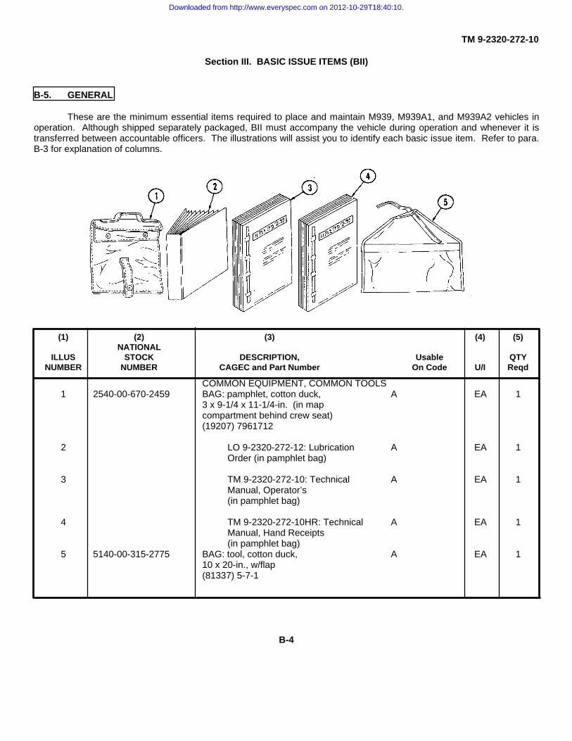
TM 9-2320-272-10
Section III. BASIC ISSUE ITEMS (BII)
B-5. GENERAL
These are the minimum essential items required to place and maintain M939, M939A1, and M939A2 vehicles inoperation. Although shipped separately packaged, BII must accompany the vehicle during operation and whenever it istransferred between accountable officers. The illustrations will assist you to identify each basic issue item. Refer to para.B-3 for explanation of columns.
(1) (2) (3) (4) (5)NATIONAL
ILLUS STOCK DESCRIPTION, Usable QTYNUMBER NUMBER CAGEC and Part Number On Code U/I Reqd
COMMON EQUIPMENT, COMMON TOOLS1 2540-00-670-2459 BAG: pamphlet, cotton duck, A EA 1
3 x 9-1/4 x 11-1/4-in. (in mapcompartment behind crew seat)(19207) 7961712
2 LO 9-2320-272-12: Lubrication A EA 1Order (in pamphlet bag)
3 TM 9-2320-272-10: Technical A EA 1Manual, Operator’s(in pamphlet bag)
4 TM 9-2320-272-10HR: Technical A EA 1Manual, Hand Receipts(in pamphlet bag)
5 5140-00-315-2775 BAG: tool, cotton duck, A EA 110 x 20-in., w/flap(81337) 5-7-1
B-4
Downloaded from http://www.everyspec.com on 2012-10-29T18:40:10.

TM 9-2320-272-10
Section III. BASIC ISSUE ITEMS (Contd)
(1) (2) (3) (4) (5)NATIONAL
ILLUS STOCK DESCRIPTION, Usable QTYNUMBER NUMBER CAGEC and Part Number On Code U/I Reqd
COMMON EQUIPMENT, COMMON TOOLS(Contd)
6 5120-00-223-7397 PLIERS: combination, slip-joint, A EA 1straight nose, w/cutter, 8-in. long,phosphate finish (in toolbag)(19207) 11655775-3
7 5120-00-234-8913 SCREWDRIVER: cross tip, A EA 1Phillips, plastic handle, point no.2, 4-in. blade, 7-11/2-in. overalllength (in toolbag)(19207) 11655777-12
8 5120-00-222-8852 SCREWDRIVER: flat tip, flared A EA 1sides, plastic handle, round blade,1/4-in. wide tip, 4-in. long blade,7-3/4-in. overall length (in toolbag)(19207) 116755777-2
9 5315-00-732-1019 WRENCH: key, oil drainplug, A EA 1straight bar, 1/2-in. square x 2-1/2-in. long (in toolbag)(96906) MS20066-543
10 5120-00-240-5328 WRENCH: open end, adjustable, A EA 1.95-in. jaw opening, 8-in. long (intoolbag) (19207) 116755778-3
11 5120-00-264-3796 WRENCH: open end, adj. 0-in. A EA 1to 1.322-in. jaw opening, 12-in. long,phosphate finish, type I, class A(in toolbag) (19207) 11655778-5
B-5
Downloaded from http://www.everyspec.com on 2012-10-29T18:40:10.

TM 9-2320-272-10
Section III. BASIC ISSUE ITEMS (Contd)(1) (2) (3) (4) (5)
NATIONALILLUS STOCK DESCRIPTION, Usable QTY
NUMBER NUMBER CAGEC and Part Number On Code U/I Reqd
EQUIPMENT FOR CTIS SERVICE1 5120-00-236-7590 HANDLE, SOCKET WRENCH: ZAA,ZAB, EA 1
hinged, 1/2-in. drive end, 14-1/2- ZAC,ZAD,in. to 19-in. O/A Ig (81348) GGG- ZAE,ZAF,W-641; Type III, Class 1 ZAG,ZAH,ZAJ,ZAL
2 5130-00-714-0600 SOCKET, SOCKET WRENCH: ZAA,ZAB, EA 11/2-in. sq. drive, 15/16-in. (81348) ZAC,ZAD,GGG-W-660 Deep Style, Type I, ZAE,ZAF,Class 1, Style A (Use to remove ZAG,ZAH,CTIS wheel valve shield) ZAJ,ZAL
3 5120-00-189-7985 SOCKET, SOCKET WRENCH: ZAA,ZAB, EA 11/2-in. sq. drive, 12 point, 3/4-in., ZAC,ZAD,regular length (81348) GGG- ZAE,ZAF,W-641, Type II, Class 2, Style A ZAG,ZAH,(Use to remove CTIS wheel valve ZAJ,ZALshield and manifold)
4 5120-00-243-7913 SOCKET, SOCKET WRENCH: ZAA,ZAB, EA 11/2-in. sq. drive, 1-1/16-in., deep ZAC,ZAD,style (93389) 7436H, Type I, ZAE,ZAF,Class 1, Style A ZAG,ZAH,ZAJ,ZAL
5 5130-00-203-6448 SOCKET, SOCKET WRENCH: ZAA,ZAB, EA 11/2-in. sq. drive, 1-1/8-in., ZAC,ZAD,impact type (81348) GGG- ZAE,ZAF,W-660 ZAG,ZAH,ZAJ,ZAL
6 5120-00-541-4687 TOOL: valve core removal: ZAA,ZAB, EA 13-1/4-in. Ig. (53477) 2688 ZAC,ZAD,ZAE,ZAF,ZAG,ZAH,ZAJ,ZAL
B-6
Downloaded from http://www.everyspec.com on 2012-10-29T18:40:10.
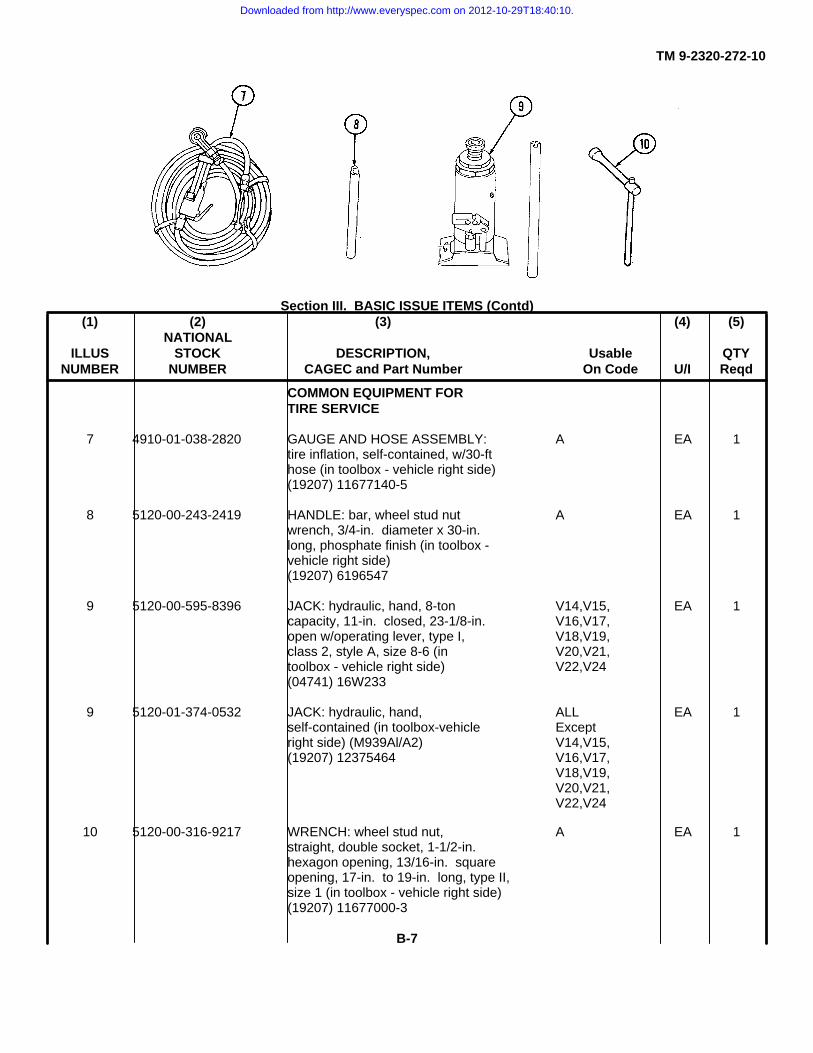
TM 9-2320-272-10
Section III. BASIC ISSUE ITEMS (Contd)(1) (2) (3) (4) (5)
NATIONALILLUS STOCK DESCRIPTION, Usable QTY
NUMBER NUMBER CAGEC and Part Number On Code U/I Reqd
COMMON EQUIPMENT FORTIRE SERVICE
7 4910-01-038-2820 GAUGE AND HOSE ASSEMBLY: A EA 1tire inflation, self-contained, w/30-fthose (in toolbox - vehicle right side)(19207) 11677140-5
8 5120-00-243-2419 HANDLE: bar, wheel stud nut A EA 1wrench, 3/4-in. diameter x 30-in.long, phosphate finish (in toolbox -vehicle right side)(19207) 6196547
9 5120-00-595-8396 JACK: hydraulic, hand, 8-ton V14,V15, EA 1capacity, 11-in. closed, 23-1/8-in. V16,V17,open w/operating lever, type I, V18,V19,class 2, style A, size 8-6 (in V20,V21,toolbox - vehicle right side) V22,V24(04741) 16W233
9 5120-01-374-0532 JACK: hydraulic, hand, ALL EA 1self-contained (in toolbox-vehicle Exceptright side) (M939Al/A2) V14,V15,(19207) 12375464 V16,V17,
V18,V19,V20,V21,V22,V24
10 5120-00-316-9217 WRENCH: wheel stud nut, A EA 1straight, double socket, 1-1/2-in.hexagon opening, 13/16-in. squareopening, 17-in. to 19-in. long, type II,size 1 (in toolbox - vehicle right side)(19207) 11677000-3
B-7
Downloaded from http://www.everyspec.com on 2012-10-29T18:40:10.

TM 9-2320-272-10
Section 11. BASIC ISSUE ITEMS (Contd)(1) (2) (3) (4) (5)
NATIONALILLUS STOCK DESCRIPTION, Usable QTY
NUMBER NUMBER CAGEC and Part Number On Code U/I ReqdSPECIALIZED EQUIPMENT FORTIRE SERVICE
1 5120-00-378-4411 WRENCH: Wheel stud nut, straight, V14,V15double socket, 1-1/2-in. hexagon V16,V17,opening, socket within a socket/with V18,V19,handle. V20,V21,(87641) 151 V22,V24
2 4010-01-114-3728 CHAIN ASSEMBLY: single leg V14,V15, EA 1w/grab hook, w/ring end link, V16,V17,750-lb work load, zinc finish V19,V20,(in toolbox - vehicle right side) V21,V22,(19207) 12256287 V24
2 4010-01-238-0518 CHAIN ASSEMBLY: single leg DAC,DAD, EA 1w/grab hook, w/ring end link, DAE,DAF,1250-lb work load, zinc finish DAG,DAH,(in toolbox - vehicle right side) DAL,DAJ,(19207) 12302917 DAW,DAX,
V18,ZAA,ZAB,ZAC,ZAD,ZAE,ZAF,ZAG,ZAH,ZAJ,ZAL
3 3950-01-238-0504 HOIST ASSEMBLY: chain, A EA 1hand-operated, hook suspension,500-lb rated load (in toolbox -vehicle right side) (19207)12301088
B-8
Downloaded from http://www.everyspec.com on 2012-10-29T18:40:10.
TM 9-2320-272-10
Section III. BASIC ISSUE ITEMS (Contd)
(1) (2) (3) (4) (5)NATIONAL
ILLUS STOCK DESCRIPTION, Usable QTYNUMBER NUMBER CAGEC and Part Number On Code U/I Reqd
EQUIPMENT - MISCELLANEOUS4 5340-00-912-4086 PADLOCK SET. keyed alike, DAC,DAD, ST 1
1-1/2-in. size, w/clevis and chain, DAG,DAH,composed of 2 padlocks, 2 keys DAW,DAX,per set (in toolbox - vehicle right V14,V15,side) (96906) MS21313-160 V16,V17,
V21,V22,ZAA,ZAB,ZAC,ZAD,ZAG,ZAH,
5 5340-00-268-1508 PADLOCK SE7. keyed individ- DAE,DAF, EA 1ually, 1-1/2-in. size, w/clevis and V19,V20,chain, w/2 keys (in toolbox - ZAE,ZAFvehicle right side)(96906) MS35647-3
B-9
Downloaded from http://www.everyspec.com on 2012-10-29T18:40:10.
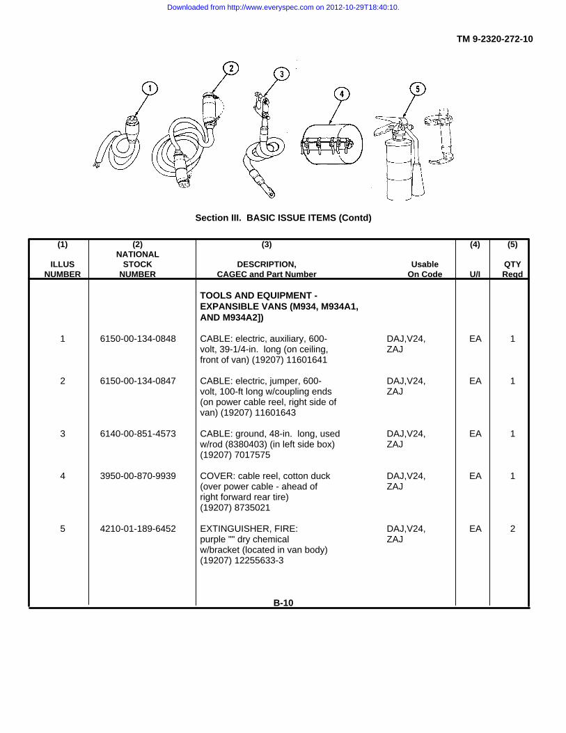
TM 9-2320-272-10
Section III. BASIC ISSUE ITEMS (Contd)
(1) (2) (3) (4) (5)NATIONAL
ILLUS STOCK DESCRIPTION, Usable QTYNUMBER NUMBER CAGEC and Part Number On Code U/I Reqd
TOOLS AND EQUIPMENT -EXPANSIBLE VANS (M934, M934A1,AND M934A2])
1 6150-00-134-0848 CABLE: electric, auxiliary, 600- DAJ,V24, EA 1volt, 39-1/4-in. long (on ceiling, ZAJfront of van) (19207) 11601641
2 6150-00-134-0847 CABLE: electric, jumper, 600- DAJ,V24, EA 1volt, 100-ft long w/coupling ends ZAJ(on power cable reel, right side ofvan) (19207) 11601643
3 6140-00-851-4573 CABLE: ground, 48-in. long, used DAJ,V24, EA 1w/rod (8380403) (in left side box) ZAJ(19207) 7017575
4 3950-00-870-9939 COVER: cable reel, cotton duck DAJ,V24, EA 1(over power cable - ahead of ZAJright forward rear tire)(19207) 8735021
5 4210-01-189-6452 EXTINGUISHER, FIRE: DAJ,V24, EA 2purple "" dry chemical ZAJw/bracket (located in van body)(19207) 12255633-3
B-10
Downloaded from http://www.everyspec.com on 2012-10-29T18:40:10.
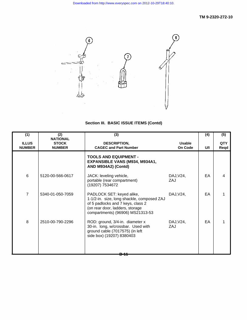
TM 9-2320-272-10
Section III. BASIC ISSUE ITEMS (Contd)
(1) (2) (3) (4) (5)NATIONAL
ILLUS STOCK DESCRIPTION, Usable QTYNUMBER NUMBER CAGEC and Part Number On Code U/I Reqd
TOOLS AND EQUIPMENT -EXPANSIBLE VANS (M934, M934A1,AND M934A2) (Contd)
6 5120-00-566-0617 JACK: leveling vehicle, DAJ,V24, EA 4portable (rear compartment) ZAJ(19207) 7534672
7 5340-01-050-7059 PADLOCK SET: keyed alike, DAJ,V24, EA 11-1/2-in. size, long shackle, composed ZAJof 5 padlocks and 7 keys, class 2(on rear door, ladders, storagecompartments) (96906) MS21313-53
8 2510-00-790-2296 ROD: ground, 3/4-in. diameter x DAJ,V24, EA 130-in. long, w/crossbar. Used with ZAJground cable (7017575) (in leftside box) (19207) 8380403
B-11
Downloaded from http://www.everyspec.com on 2012-10-29T18:40:10.

TM 9-2320-272-10
Section III. BASIC ISSUE ITEMS (Contd)
(1) (2) (3) (4) (5)NATIONAL
ILLUS STOCK DESCRIPTION, Usable QTYNUMBER NUMBER CAGEC and Part Number On Code U/I Reqd
TOOLS AND EQUIPMENT -EXPANSIBLE VANS [M934, M934A1,AND M934A2) (Contd)
1 2590-00-870-9936 SPIKE: stabilizer anchor, welded DAJ,V24, EA 8(in rear exterior compartment) ZAJ(19207) 7534689
2 5120-00-650-7830 WRENCH: ratchet, reversible DAJ,V24, EA 1w/removable socket, 3/4-in. ZAJsquare drive (stowed on interiorof rear door, left-hand side)(19207) 7759181
3 5120-00-650-7829 WRENCH: socket, 90 degree DAJ,V24, EA 1offset, 112-in. square opening ZAJ(stowed on interior of rear door,left-hand side) (19207) 8380406TOOLS AND EQUIPMENT -MEDIUM WRECKER (M936, M936A1,AND M936A2)
4 5110-00-293-2336 AX: single bit, 4-lb head weight, DAL,V18, EA 14-3/4-in. cutting edge, 35-1/2-in. ZALto 36-1/2-in. long, type I, class 1,design A, olive drab finish [incompartment no. 1B (pg B-24)](19207) 6150925
5 4910-00-347-9703 BAR: lifting, whiffletree DAL,V18, EA 1[on right deck (pg B-24)] ZAL(19207) 8690061
6 4910-01-365-9304 BAR: towing, V universal type DAL,V18, EA 1w/bumper axle clamp assembly ZAL[on right deck (pg B-24)](19204) 7551058
B-12
Downloaded from http://www.everyspec.com on 2012-10-29T18:40:10.
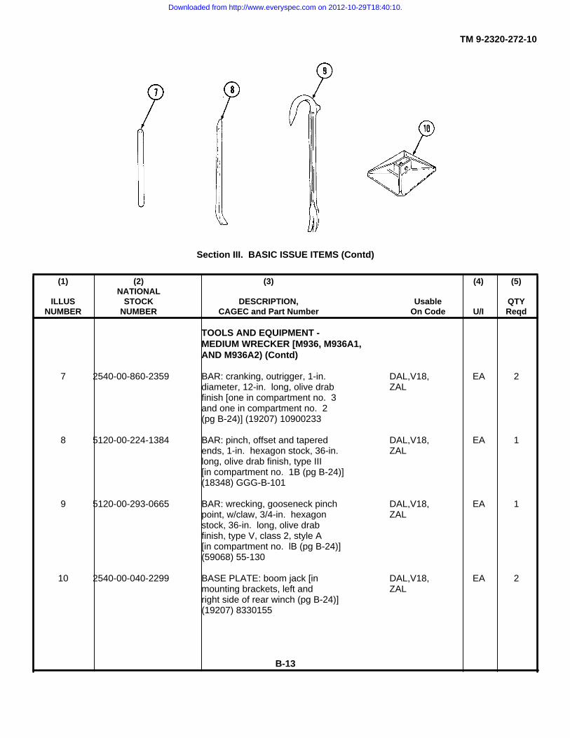
TM 9-2320-272-10
Section III. BASIC ISSUE ITEMS (Contd)
(1) (2) (3) (4) (5)NATIONAL
ILLUS STOCK DESCRIPTION, Usable QTYNUMBER NUMBER CAGEC and Part Number On Code U/I Reqd
TOOLS AND EQUIPMENT -MEDIUM WRECKER [M936, M936A1,AND M936A2) (Contd)
7 2540-00-860-2359 BAR: cranking, outrigger, 1-in. DAL,V18, EA 2diameter, 12-in. long, olive drab ZALfinish [one in compartment no. 3and one in compartment no. 2(pg B-24)] (19207) 10900233
8 5120-00-224-1384 BAR: pinch, offset and tapered DAL,V18, EA 1ends, 1-in. hexagon stock, 36-in. ZALlong, olive drab finish, type III[in compartment no. 1B (pg B-24)](18348) GGG-B-101
9 5120-00-293-0665 BAR: wrecking, gooseneck pinch DAL,V18, EA 1point, w/claw, 3/4-in. hexagon ZALstock, 36-in. long, olive drabfinish, type V, class 2, style A[in compartment no. lB (pg B-24)](59068) 55-130
10 2540-00-040-2299 BASE PLATE: boom jack [in DAL,V18, EA 2mounting brackets, left and ZALright side of rear winch (pg B-24)](19207) 8330155
B-13
Downloaded from http://www.everyspec.com on 2012-10-29T18:40:10.
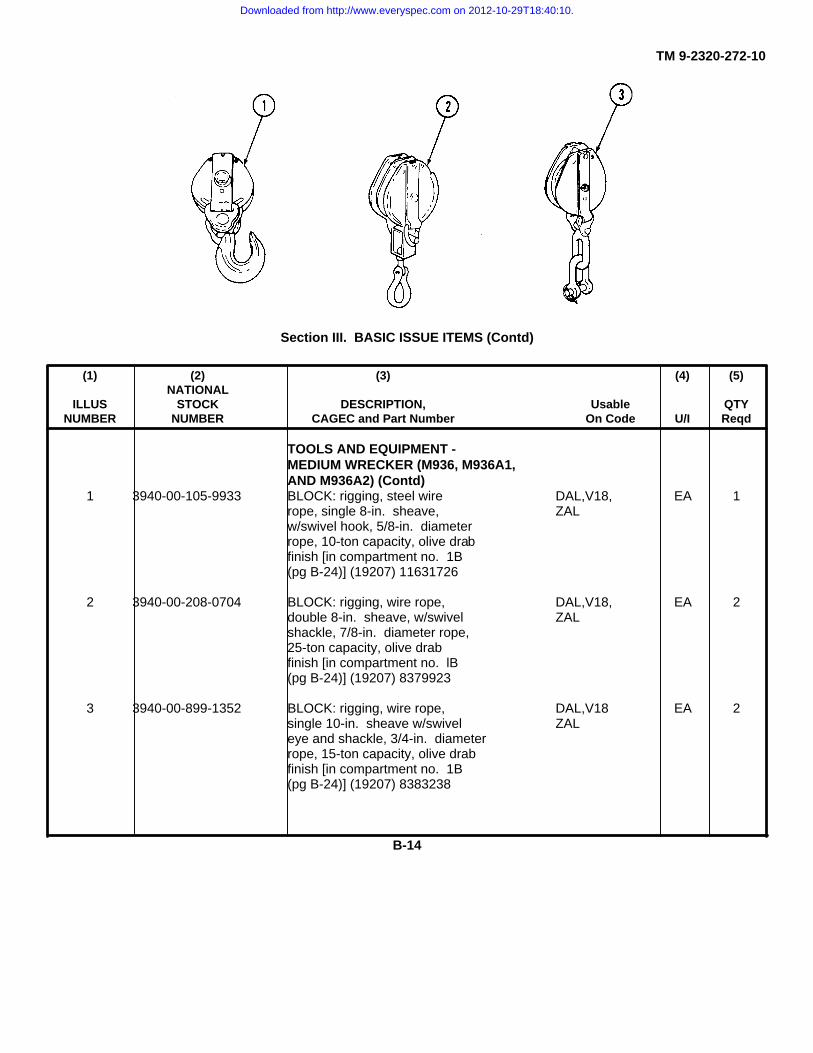
TM 9-2320-272-10
Section III. BASIC ISSUE ITEMS (Contd)
(1) (2) (3) (4) (5)NATIONAL
ILLUS STOCK DESCRIPTION, Usable QTYNUMBER NUMBER CAGEC and Part Number On Code U/I Reqd
TOOLS AND EQUIPMENT -MEDIUM WRECKER (M936, M936A1,AND M936A2) (Contd)
1 3940-00-105-9933 BLOCK: rigging, steel wire DAL,V18, EA 1rope, single 8-in. sheave, ZALw/swivel hook, 5/8-in. diameterrope, 10-ton capacity, olive drabfinish [in compartment no. 1B(pg B-24)] (19207) 11631726
2 3940-00-208-0704 BLOCK: rigging, wire rope, DAL,V18, EA 2double 8-in. sheave, w/swivel ZALshackle, 7/8-in. diameter rope,25-ton capacity, olive drabfinish [in compartment no. lB(pg B-24)] (19207) 8379923
3 3940-00-899-1352 BLOCK: rigging, wire rope, DAL,V18 EA 2single 10-in. sheave w/swivel ZALeye and shackle, 3/4-in. diameterrope, 15-ton capacity, olive drabfinish [in compartment no. 1B(pg B-24)] (19207) 8383238
B-14
Downloaded from http://www.everyspec.com on 2012-10-29T18:40:10.

TM 9-2320-272-10
Section III. BASIC ISSUE ITEMS (Contd)
(1) (2) (3) (4) (5)NATIONAL
ILLUS STOCK DESCRIPTION, Usable QTYNUMBER NUMBER CAGEC and Part Number On Code U/I Reqd
TOOLS AND EQUIPMENT-MEDIUM WRECKER (M936, M936A1,AND M936A2) (Contd)
4 2590-00-148-7961 CABLE KIT: slave, electric, DAL,V18, EA 124 volts, 20-ft long, w/2 coupling ZALends (NATO), w/adapter (NATO-to standard) [in compartmentno. 1A (pg B-24)] (19207) 11682379-1
5 4010-00-473-6166 CHAIN: tow, single leg, 5/8-in. DAL,V18, EA 1link, 16-ft long, w/2 pear-shaped ZALcoupling links, w/l grab hook end[in compartment no. 1B (pg B-24)](19207) 7077063
6 4010-00-443-4845 CHAIN: utility, single leg, DAL,V18, EA 13/8-in. link, 14-1/2-ft long w/2 grab ZALhooks, zinc plate finish [incompartment no. 1B (pg B-24)](19207) 10944642-2
7 4010-01-010-2536 CHAIN: utility, single leg, DAL,V18, EA 13/4-in. link, 12-ft long, w/grab ZALhook, w/pear-shaped coupling link[in compartment no. lB (pg B-24)](19207) 8744250
B-15
Downloaded from http://www.everyspec.com on 2012-10-29T18:40:10.

TM 9-2320-272-10
Section III. BASIC ISSUE ITEMS (Contd)
(1) (2) (3) (4) (5)NATIONAL
ILLUS STOCK DESCRIPTION, Usable QTYNUMBER NUMBER CAGEC and Part Number On Code U/I Reqd
TOOLS AND EQUIPMENT -MEDIUM WRECKER (M936, M936A1,AND M936A2) (Contd)
1 5110-00-236-3272 CHISEL: cold, hand, 3/4-in. DAL,V18, EA 1cutting edge, 6-1/2-in. long, ZALtype TV, class 1 [in compartmentno. 4B (pg B-24)] (96906) MS17070-5
2 5110-00-238-8296 CHISEL: machinist’s, cold, hand, DAL,V18, EA 1long length, 1-in. cutting edge, ZAL24-in. long, olive drab finish,type IV. class 2 [in compartmentno. 1B (pg B-24)] (03306) C6
3 2540-00-315-2306 CHOCK: field [on left deck DAL,V18, EA 2(pg B-24)] (19207) 8330150 ZAL
4 5120-00-224-1390 CROWBAR: pinch-point, 1-1/4-in. DAL,V18, EA 1diameter stock, 59-in. to 62-in. ZALlong, olive drab finish, type II,class 1, size 4 [in compartmentno. 1B (pg B-24)] (18876) 9150189
5 5110-00-188-2524 CUTTER: bolt, rigid head-type, DAL,V18, EA 1clipper cut-type, 9/16-in. diameter, ZALmild steel rod cutting capacity,35-in. to 39-in. long, olive drabfinish [in compartment no. 1A(pg B-24)] (81348) GGG-C-740
B-16
Downloaded from http://www.everyspec.com on 2012-10-29T18:40:10.
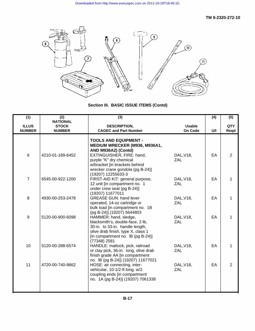
TM 9-2320-272-10
Section III. BASIC ISSUE ITEMS (Contd)
(1) (2) (3) (4) (5)NATIONAL
ILLUS STOCK DESCRIPTION, Usable QTYNUMBER NUMBER CAGEC and Part Number On Code U/I Reqd
TOOLS AND EQUIPMENT -MEDIUM WRECKER (M936, M936A1,AND M936A2) (Contd)
6 4210-01-189-6452 EXTINGUISHER, FIRE: hand, DAL,V18, EA 2purple "K" dry chemical ZALw/bracket [in brackets behindwrecker crane gondola (pg B-24)](19207) 12255633-3
7 6545-00-922-1200 FIRST-AID KIT: general purpose, DAL,V18, EA 112 unit [in compartment no. 1 ZALunder crew seat (pg B-24)](19207) 11677011
8 4930-00-253-2478 GREASE GUN: hand lever DAL,V18, EA 1operated, 14-oz cartridge or ZALbulk load [in compartment no. 1B(pg B-24)] (19207) 5644803
9 5120-00-900-6098 HAMMER: hand, sledge, DAL,V18, EA 1blacksmith’s, double-face, 2-lb, ZAL30-in. to 33-in. handle length,olive drab finish, type X, class 1[in compartment no. lB (pg B-24)](77348) 2581
10 5120-00-288-6574 HANDLE: mattock, pick, railroad DAL,V18, EA 1or clay pick, 36-in. long, olive drab ZALfinish grade AA [in compartmentno. lB (pg B-24)] (19207) 11677021
11 4720-00-740-9662 HOSE: air connecting, inter- DAL,V18, EA 2vehicular, 10-1/2-ft long, w/2 ZALcoupling ends [in compartmentno. 1A (pg B-24)] (19207) 7061338
B-17
Downloaded from http://www.everyspec.com on 2012-10-29T18:40:10.

TM 9-2320-272-10
Section III. BASIC ISSUE ITEMS (Contd)
(1) (2) (3) (4) (5)NATIONAL
ILLUS STOCK DESCRIPTION, Usable QTYNUMBER NUMBER CAGEC and Part Number On Code U/I Reqd
TOOLS AND EQUIPMENT -MEDIUM WRECKER (M936, M936A1,AND M936A2) (Contd)
1 4720-00-899-6721 HOSE: tank drain, hydraulic oil, DAL,V18, EA 11-3/16-in. outside diameter x 5-ft ZALlong, olive drab finish [incompartment no. 1A (pg B-24)](19207) 10900093
2 5120-00-188-1790 JACK: hydraulic, hand, self-cont, DAL,V18, EA 130-ton cap., w/oper lever, OD finish ZAL[in compartment no. 1A (pg B-24)](28047) RHD160
3 6230-00-274-4018 LIGHT: extension, w/single plug DAL,V18, EA 1and plug socket, 24V, 25-ft, w/o lamp ZAL[in compartment no. 4 (pg B-24)](32779) 2000 G2A
4 5120-00-243-2395 MATTOCK: pick-type, 5-lb w/o DAL,V18, EA 1handle, olive drab finish, type II, ZALclass F [in compartment no. 1B(pg B-24)] (19207) 11677022
5 4930-00-266-9182 OILER: hand, push bottom, 8-oz DAL,Vi8, EA 1capacity, 4-in. long spout [on ZALleft deck (pg B-24)] (96906)MS15764-1
6 5340-00-838-5266 PADLOCK SET. low-security, DAL,V18, EA 1keyed alike, regular (open) ZALshackle, class 2 [in positionsecuring compartments nos. 1,IA, lB, 2, 3, and 4 (pg B-24)](96906) MS21313-124
B-18
Downloaded from http://www.everyspec.com on 2012-10-29T18:40:10.

TM 9-2320-272-10
Section III. BASIC ISSUE ITEMS (Contd)
(1) (2) (3) (4) (5)NATIONAL
ILLUS STOCK DESCRIPTION, Usable QTYNUMBER NUMBER CAGEC and Part Number On Code U/I Reqd
TOOLS AND EQUIPMENT -MEDIUM WRECKER (M936, M936A1,AND M936A2) (Contd)
7 4010-00-740-9834 PIN: boom jack, w/lockpin, olive DAL,V18, EA 2drab finish [in compartment no. 3 ZAL(pg B-24)] (19207) 7409834
8 5315-00-854-4431 PIN: inner, boom jack, w/lockpin, DAL,V18, EA 1olive drab finish [in compartment ZALno. 2 (pg B-24)] (19207) 10876413
9 5315-00-316-1008 PIN: tie-bar yoke, w/lockpin, olive DAL,V18, EA 2drab finish [in compartment no. 3 ZAL(pg B-24)] (19207) 8327939
B-19
Downloaded from http://www.everyspec.com on 2012-10-29T18:40:10.

TM 9-2320-272-10
Section III. BASIC ISSUE ITEMS (Contd)
(1) (2) (3) (4) (5)NATIONAL
ILLUS STOCK DESCRIPTION, Usable QTYNUMBER NUMBER CAGEC and Part Number On Code U/I Reqd
TOOLS AND EQUIPMENT -MEDIUM WRECKER (M936, M936A1,AND M936A2) [Contd)
1 2540-00-318-0326 SHACKLE: lifting, round pin, 7/8-in. DAL,V18, EA 2diameter, olive drab finish [in ZALcompartment no. 2 (pg B-24)](19207) 7357967
2 5120-00-293-3336 SHOVEL: hand, round point, DAL,V18, EA 1D-handle, short, size 2, olive drab ZALfinish, type IV, class A, style 1[in compartment no. lB (pg B-24)](19207) 11655784
3 2590-00-040-2297 SLING: wire rope, double leg DAL,V18, EA 1w/ring, w/2 hook ends (ring ends ZALattach to block, two hook endsattach to vehicle rear bumperettes)(19207) 8330151
4 5340-00-543-3034 STRAP: webbing, 1-1/2-in. wide x DAL,V18, EA 124-in. long, w/buckle (securing ZALfield chocks to vehicle deck) [onleft deck (pg B-24)] (19207) 8690516
5 5340-00-753-3744 STRAP: webbing, 1-1/2-in. wide x DAL,V18, EA 136-in. long, w/buckle (securing ZALboom jacks to vehicle deck) [onleft deck (pg B-24)1 (19207) 8690473
B-20
Downloaded from http://www.everyspec.com on 2012-10-29T18:40:10.
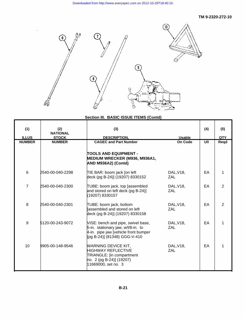
TM 9-2320-272-10
Section III. BASIC ISSUE ITEMS (Contd)
(1) (2) (3) (4) (5)NATIONAL
ILLUS STOCK DESCRIPTION, Usable QTYNUMBER NUMBER CAGEC and Part Number On Code U/I Reqd
TOOLS AND EQUIPMENT -MEDIUM WRECKER (M936, M936A1,AND M936A2) (Contd)
6 2540-00-040-2298 TIE BAR: boom jack [on left DAL,V18, EA 1deck (pg B-24)] (19207) 8330152 ZAL
7 2540-00-040-2300 TUBE: boom jack, top [assembled DAL,V18, EA 2and stored on left deck (pg B-24)] ZAL(19207) 8330157
8 2540-00-040-2301 TUBE: boom jack, bottom DAL,V18, EA 2[assembled and stored on left ZALdeck (pg B-24)] (19207) 8330158
9 5120-00-243-9072 VISE: bench and pipe, swivel base, DAL,V18, EA 15-in. stationary jaw, w/l/8-in. to ZAL4-in. pipe jaw [vehicle front bumper(pg B-24)] (81348) GGG-V-410
10 9905-00-148-9546 WARNING DEVICE KIT, DAL,V18, EA 1HIGHWAY REFLECTIVE ZALTRIANGLE: [in compartmentno. 2 (pg B-24)] (19207)11669000, set no. 3
B-21
Downloaded from http://www.everyspec.com on 2012-10-29T18:40:10.
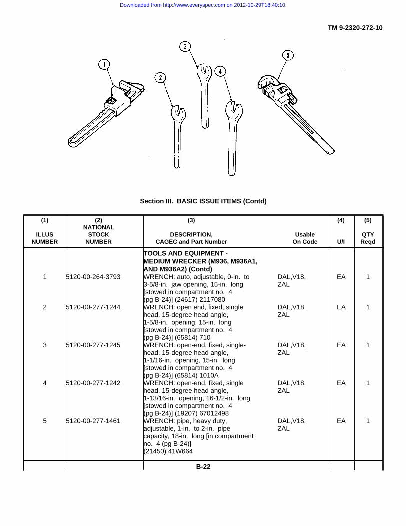
TM 9-2320-272-10
Section III. BASIC ISSUE ITEMS (Contd)
(1) (2) (3) (4) (5)NATIONAL
ILLUS STOCK DESCRIPTION, Usable QTYNUMBER NUMBER CAGEC and Part Number On Code U/I Reqd
TOOLS AND EQUIPMENT -MEDIUM WRECKER (M936, M936A1,AND M936A2) (Contd)
1 5120-00-264-3793 WRENCH: auto, adjustable, 0-in. to DAL,V18, EA 13-5/8-in. jaw opening, 15-in. long ZAL[stowed in compartment no. 4(pg B-24)] (24617) 2117080
2 5120-00-277-1244 WRENCH: open end, fixed, single DAL,V18, EA 1head, 15-degree head angle, ZAL1-5/8-in. opening, 15-in. long[stowed in compartment no. 4(pg B-24)] (65814) 710
3 5120-00-277-1245 WRENCH: open-end, fixed, single- DAL,V18, EA 1head, 15-degree head angle, ZAL1-1/16-in. opening, 15-in. long[stowed in compartment no. 4(pg B-24)] (65814) 1010A
4 5120-00-277-1242 WRENCH: open-end, fixed, single DAL,V18, EA 1head, 15-degree head angle, ZAL1-13/16-in. opening, 16-1/2-in. long[stowed in compartment no. 4(pg B-24)] (19207) 67012498
5 5120-00-277-1461 WRENCH: pipe, heavy duty, DAL,V18, EA 1adjustable, 1-in. to 2-in. pipe ZALcapacity, 18-in. long [in compartmentno. 4 (pg B-24)](21450) 41W664
B-22
Downloaded from http://www.everyspec.com on 2012-10-29T18:40:10.

TM 9-2320-272-10
Section III. BASIC ISSUE ITEMS (Contd)
(1) (2) (3) (4) (5)NATIONAL
ILLUS STOCK DESCRIPTION, Usable QTYNUMBER NUMBER CAGEC and Part Number On Code U/I Reqd
EQUIPMENT - WELDING ANDCUTTING (M936, M936A1,AND M936A2)
6 8120-00-357-7992 CYLINDER: compressed gas, DAL,V18, EA 1oxygen, 250-cu ft capacity ZAL[behind cab, forward left side ofwrecker body (pg B-24)] (81349)RR-C-901/1-15
7 8120-00-268-3360 CYLINDER: compressed gas, DAL,V18, EA 1acetylene, 360-cu ft capacity ZAL[behind cab, forward left side ofwrecker body (pg B-24)] (81348)MILIC-3701-7
8 5180-00-754-0661 TOOL KIT. welder’s [in compart- DAL,V18, EA 1ment no. 1A) (pg B-24)] ZAL(50980) SC5180-90-CL-N39
9 3433-00-357-6311 TORCH OUTFIT: cutting and DAL,V18, EA 1welding [in compartment no. 1B ZAL(pg B-24)] (50980) SC3433-90-CL-N03
B-23
Downloaded from http://www.everyspec.com on 2012-10-29T18:40:10.

TM 9-2320-272-10
B-24
Downloaded from http://www.everyspec.com on 2012-10-29T18:40:10.

TM 9-2320-272-10
APPENDIX CADDITIONAL AUTHORIZATION LIST (AAL)
Section I. INTRODUCTION
C-1. SCOPE
This appendix lists additional items authorized for support of M939, M939A1, and M939A2 series vehicles.
C-2. GENERAL
This list identifies items that do not have to accompany your truck and do not have to be turned in with it.
C-3. EXPLANATION OF LISTING
a. Descriptions, national stock numbers, and part numbers are provided to help you identify and requestadditional items you require to support this equipment. If item required differs for different models, the model is shownunder the "USABLE ON CODE" heading. Codes are the same as in appendix B, Basic Issue Items.
b. Column (1) - National Stock Number. Indicates the national stock number assigned to the item and will beused for requisitioning purposes.
c. Column (2) - Description. Indicates the federal item name and, if required, a minimum description toidentify and locate the item. The last line for each item indicates the Commercial and Government Entity Code (CAGEC)(in parentheses) followed by the part number. If item needed differs for different models of this equipment, the model isshown under the "Usable On Code" heading in this column. Refer to appendix B for cage codes used.
d. Column (3) - U/I (Unit of Issue). Indicates how the item is issued for the national stock number shown incolumn two.
e. Column (4) - Qty Auth. Is the quantity of the item authorized.
C-1
Downloaded from http://www.everyspec.com on 2012-10-29T18:40:10.

TM 9-2320-272-10
Section II. ADDITIONAL AUTHORIZATION LIST
(1) (2) (3) (4)NATIONAL
STOCK DESCRIPTION QTYNUMBER CAGEC & PART NUMBER USABLE ON CODE U/I AUTH
4930-00-204-2550 ADAPTER: grease gun, rigid, thin-stem, DAL,V18, EA 16-in. long, type IV, class 2 (19207) ZAL5349744
5110-00-293-2336 AX: single bit, 4-lb head All EA 1(19207) 6150925 Except
DAL,V18,ZAL
6135-00-120-1020 BATTERY: dry, 1.5 volt, BA 30, DAL,V18, EA 4(80063) BA30U ZAL
3940-00-105-9933 BLOCK: rigging, steel, wire rope, single DAD,DAF, EA 18-in. sheave, w/swivel hook, 5/8-in. DAH,DAL,diameter rope, 10-ton safe work load DAX,V14,(19207) 11631726 V16,V18,
V19,V21,ZAB,ZAD,ZAF,ZAH,ZAL
3940-00-926-3719 BLOCK: tackle, manila rope, DAL,V18, EA 1single 4-1/2-in. sheave, 1-in. ZALdiameter rope, 3-in. ropecircumference, w/loose side hook,w/becket, 5,100-lb capacity, type II,class 1 [in compartment no 1B(pg B-24)] (81348) GGG-B-490
3940-00-926-3710 BLOCK: tackle, manila rope, DAL,V18, EA 1single 4-3/4-in. sheave, 1-in. ZALdiameter rope, 3-in. ropecircumference, w/loose side hook,w/becket, 3,300-lb capacity, type II,class 1 [in compartment no 1B(pg B-24)] (81348) GGG-B-490
2590-00-473-6331 BRACKET: gas/water can DAL,V18, EA 1(19207) 6566675 ZAL
7240-00-222-3088 CAN: gasoline, MIL type, 5 gallon, A EA 1(81902) 14196P1
7240-00-242-6153 CAN: water, MIL type, 5 gallon A EA 1(19207) 11655980
5140-00-860-2354 CASE: crosscut saw, cotton duck, DAL,V18, EA 163-3/4-in. long (closed) (24076) 3005187 ZAL
C-2
Downloaded from http://www.everyspec.com on 2012-10-29T18:40:10.
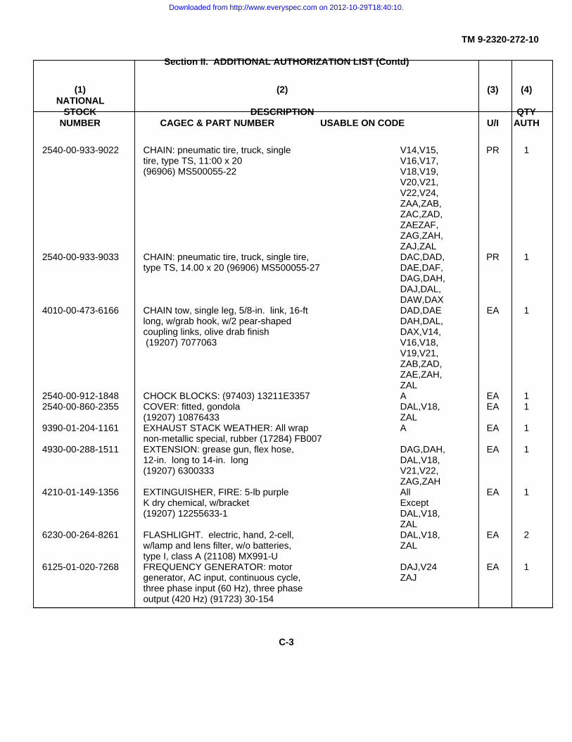
TM 9-2320-272-10
Section II. ADDITIONAL AUTHORIZATION LIST (Contd)
(1) (2) (3) (4)NATIONAL
STOCK DESCRIPTION QTYNUMBER CAGEC & PART NUMBER USABLE ON CODE U/I AUTH
2540-00-933-9022 CHAIN: pneumatic tire, truck, single V14,V15, PR 1tire, type TS, 11:00 x 20 V16,V17,(96906) MS500055-22 V18,V19,
V20,V21,V22,V24,ZAA,ZAB,ZAC,ZAD,ZAEZAF,ZAG,ZAH,ZAJ,ZAL
2540-00-933-9033 CHAIN: pneumatic tire, truck, single tire, DAC,DAD, PR 1type TS, 14.00 x 20 (96906) MS500055-27 DAE,DAF,
DAG,DAH,DAJ,DAL,DAW,DAX
4010-00-473-6166 CHAIN tow, single leg, 5/8-in. link, 16-ft DAD,DAE EA 1long, w/grab hook, w/2 pear-shaped DAH,DAL,coupling links, olive drab finish DAX,V14, (19207) 7077063 V16,V18,
V19,V21,ZAB,ZAD,ZAE,ZAH,ZAL
2540-00-912-1848 CHOCK BLOCKS: (97403) 13211E3357 A EA 12540-00-860-2355 COVER: fitted, gondola DAL,V18, EA 1
(19207) 10876433 ZAL9390-01-204-1161 EXHAUST STACK WEATHER: All wrap A EA 1
non-metallic special, rubber (17284) FB0074930-00-288-1511 EXTENSION: grease gun, flex hose, DAG,DAH, EA 1
12-in. long to 14-in. long DAL,V18,(19207) 6300333 V21,V22,
ZAG,ZAH4210-01-149-1356 EXTINGUISHER, FIRE: 5-lb purple All EA 1
K dry chemical, w/bracket Except(19207) 12255633-1 DAL,V18,
ZAL6230-00-264-8261 FLASHLIGHT. electric, hand, 2-cell, DAL,V18, EA 2
w/lamp and lens filter, w/o batteries, ZALtype I, class A (21108) MX991-U
6125-01-020-7268 FREQUENCY GENERATOR: motor DAJ,V24 EA 1generator, AC input, continuous cycle, ZAJthree phase input (60 Hz), three phaseoutput (420 Hz) (91723) 30-154
C-3
Downloaded from http://www.everyspec.com on 2012-10-29T18:40:10.
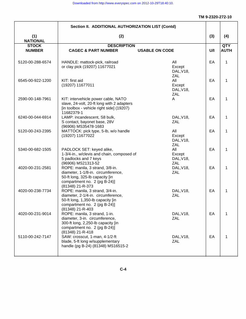
TM 9-2320-272-10
Section II. ADDITIONAL AUTHORIZATION LIST (Contd)
(1) (2) (3) (4)NATIONAL
STOCK DESCRIPTION QTYNUMBER CAGEC & PART NUMBER USABLE ON CODE U/I AUTH
5120-00-288-6574 HANDLE: mattock-pick, railroad All EA 1or clay pick (19207) 11677021 Except
DAL,V18,ZAL
6545-00-922-1200 KIT: first aid All EA 1(19207) 11677011 Except
DAL,V18,ZAL
2590-00-148-7961 KIT: intervehicle power cable, NATO A EA 1slave, 24-volt, 20-ft long with 2 adapters[in toolbox - vehicle right side] (19207)11682379-1
6240-00-044-6914 LAMP: incandescent, S8 bulk, DAL,V18, EA 1S contact, bayonet base, 28V ZAL(96906) MS35478-1683
5120-00-243-2395 MATTOCK: pick type, 5-lb, w/o handle All EA 1(19207) 11677022 Except
DAL,V18,ZAL
5340-00-682-1505 PADLOCK SET: keyed alike, All EA 11-3/4-in., w/clevis and chain, composed of Except5 padlocks and 7 keys DAL,V18,(96906) MS21313-52 ZAL
4020-00-231-2581 ROPE: manila, 3 strand, 3/8-in. DAL,V18, EA 1diameter, 1-1/8-in. circumference, ZAL50-ft long, 325-lb capacity [incompartment no. 2 (pg B-24)](81348) 21-R-373
4020-00-238-7734 ROPE: manila, 3 strand, 3/4-in. DAL,V18, EA 1diameter, 2-1/4-in. circumference, ZAL50-ft long, 1,350-lb capacity [incompartment no. 2 (pg B-24)](81348) 21-R-403
4020-00-231-9014 ROPE: manila, 3 strand, 1-in. DAL,V18, EA 1diameter, 3-in. circumference, ZAL300-ft long, 2,250-lb capacity [incompartment no. 2 (pg B-24)](81348) 21-R-418
5110-00-242-7147 SAW: crosscut, 1-man, 4-1/2-ft DAL,V18, EA 1blade, 5-ft long w/supplementary ZALhandle (pg B-24) (81348) MS16515-2
C-4
Downloaded from http://www.everyspec.com on 2012-10-29T18:40:10.

TM 9-2320-272-10
Section II. ADDITIONAL AUTHORIZATION LIST (Cont’d)
(1) (2) (3) (4)NATIONAL
STOCK DESCRIPTION QTYNUMBER CAGEC & PART NUMBER USABLE ON CODE U/I AUTH
5120-00-293-3336 SHOVEL: hand, round point, All EA 1D handle, short size Except(19207) 11655784 DAL,V18,
ZAL7240-01-129-7474 SPOUT, can gasoline, flex, w/filter cap DAL,V18, EA 1
assembly screen (7420-00-152-6433), ZAL2-1/4-in. outside diameter, 16-in. long(19207) 11677020
5340-00-988-9277 TIEDOWN STRAP: Ratchet with All EA 1integral hooks, 20 ft long (81349) ExceptMIL-T-272 60 TYPECGUIB V18,V19,
V20,V21,V22
6220-01-217-8316 TOW LIGHT BAR (19207) 12375702 DAL,V18 EA 16150-01-180-6035 TOW LIGHT CABLE (19207) 12375703 DAL,V18 EA 19905-00-148-9546 WARNING DEVICE KIT, All KT 1
HIGHWAY REFLECTIVE TRIANGLE: Except(80244) RR-W-1817, set no. 3 DAL,V18,
ZAL2540-00-912-1848 WHEEL CHOCK BLOCK: Aluminum A EA 1
fixed-welded plates, 15 x 12 x 9.375inches (97403) 13211E3357
C-5 (C-6 blank)
Downloaded from http://www.everyspec.com on 2012-10-29T18:40:10.

TM 9-2320-272-10
APPENDIX DEXPENDABLE/DURABLE SUPPLIES AND MATERIALS LIST
Section I. INTRODUCTION
D-1. SCOPE
This appendix lists expendable/durable supplies and materials you will need to operate and maintain M939,M939A1, and M939A2 series vehicles.
D-2. EXPLANATION OF COLUMNS
a. Column (1) - Item Number. This number is assigned to the entry in the listing.
b. Column (2) - Level. This column identifies the lowest level of maintenance that requires the listed item.Codes used in this column are:
C - Operator/CrewO - Unit Maintenance
c. Column (3) - National Stock Number. This is the national stock number assigned an item. Use thisnumber to request or requisition that item.
d. Column (4) - Description, CAGEC, and Part Number. Indicates the federal item name and, if required, adescription to identify the item. The last line for each item indicates the Commercial and Government Entity Code(CAGEC) (in parentheses) followed by the part number. Refer to appendix B for CAGE codes used.
e. Column (5) - Unit of Measure (U/M). Indicates the measure used in performing the actual maintenancefunction. This measure is expressed by an abbreviation (such as ea (each), oz (ounce), gal. (gallon)). If the unit ofmeasure differs from the unit of issue, requisition the lowest unit of issue that will satisfy your requirements.
D-1
Downloaded from http://www.everyspec.com on 2012-10-29T18:40:10.

TM 9-2320-272-10
Section II. EXPENDABLE/DURABLE SUPPLIES AND MATERIALS LIST
(1) (2) (3) (4) (5)
ITEM LEVEL NATIONALNUMBER STOCK DESCRIPTION U/M
NUMBER CAGEC AND PART NUMBER
1 0 6830-00-264-6751 ACETYLENE, TECHNICAL: gas filled cu ftacetylene, 225-cu ft (to be filled/refilledlocally) (81348) BB-A-106ANTIFREEZE: PERMANENTETHYLENE GLYCOL [-60°F (-51°C)]INHIBITED (MIL-A-46153)
2 C 6850-00-181-7929 1-GALLON CONTAINER gal.3 C 6850-00-181-7933 5-GALLON CONTAINER gal.4 C 6850-00-181-7940 55-GALLON DRUM gal.
ANTIFREEZE: PERMANENT TYPE;ARCTIC GRADE [-90°F (-68°C)](MIL-A-11755)
5 C 6850-00-174-1806 55-GALLON DRUM gal.6 O 6850-00-926-2275 CLEANING COMPOUND,WINDSHIELD oz
16-OUNCE BOTTLE, CONCENTRATEDGREASE. AUTOMOTIVE ANDARTILLERY GAA (MIL-G-10924)
7 C 9150-00-065-0029 2-1/4-OUNCE TUBE oz8 C 9150-00-935-1017 14-OUNCE CARTRIDGE oz9 C 9150-00-190-0904 1-3/4-POUND CAN lb10 C 9150-00-190-0905 6-1/2-POUND CAN lb11 C 9150-00-190-0907 35-POUND CAN lb12 C 9150-00-530-7369 120-POUND DRUM lb
INHIBITOR: CORROSION, LIQUIDCOOLING SYSTEM; POWDERFORM (0-I-490)
13 C 6850-00-753-4967 6-OUNCE CAN ozOIL, FUEL, DIESEL DF-2: REGULAR(VV-F-800)
14 C 9140-00-286-5296 55-GALLON DRUM, 16 GAUGE gal.15 C 9140-00-286-5297 55-GALLON DRUM, 18 GAUGE gal.16 C 9140-00-286-5294 BULK gal.
OIL, FUEL, DIESEL, DF-1: WINTER(VV-F-800)
17 C 9140-00-286-5288 55-GALLON DRUM, 16 GAUGE gal.18 C 9140-00-286-5289 55-GALLON DRUM, 18 GAUGE gal.19 C 9140-00-286-5286 BULK gal.
OIL, FUEL, DIESEL DF-A: ARCTIC(VV-F-800)
D-2
Downloaded from http://www.everyspec.com on 2012-10-29T18:40:10.

TM 9-2320-272-10
Section II. EXPENDABLE/DURABLE SUPPLIES AND MATERIALS LIST (Contd)
(1) (2) (3) (4) (5)
ITEM LEVEL NATIONAL DESCRIPTIONNUMBER STOCK U/M
NUMBER CAGEC AND PART NUMBER
20 C 9140-00-286-5284 55-GALLON DRUM, 16 GAUGE gal.21 C 9140-00-286-5285 55-GALLON DRUM, 18 GAUGE gal.22 C 9140-00-286-5283 BULK gal.
OIL, LUBRICATING, ENGINE,ARCTIC (ICE, SUB-ZERO) OEA(SAE OW-20) (MIL-L-46167)
23 C 9150-00-402-4478 1-QUART CAN qt24 C 9150-00-402-2372 5-GALLON CAN gal.25 C 9150-00-491-7197 55-GALLON DRUM, 16 GAUGE gal.
OIL, LUBRICATING, EXPOSEDGEAR, CW (VV-L-751)
26 C 9150-00-234-5197 5-POUND CAN lb27 C 9150-00-261-7891 35-POUND PAIL lb
OIL, LUBRICATING, GEAR, MULTI-PURPOSE, GO 80/90 (MIL-L-2105)
28 C 9150-01-035-5392 1-QUART CAN qt29 C 9150-01-035-5393 5-GALLON DRUM gal.30 C 9150-01-035-5394 55-GALLON DRUM, 16 GAUGE gal.
OIL, LUBRICATING, GEAR MULTI-PURPOSE, GO 75 (MIL-L-2105)
31 C 9150-01-035-5390 1-QUART CAN qt32 C 9150-01-035-5391 5-GALLON DRUM gal.33 C 9150-00-188-9867 55-GALLON DRUM, 16 GAUGE gal.34 C 9150-00-183-7807 BULK gal.
OIL, LUBRICATING, OE/HDO 10W(MIL-L-2104)
35 C 9150-00-177-3988 1-QUART CAN qt36 C 9150-00-186-6668 5-GALLON CAN gal.37 C 9150-00-191-2772 55-GALLON DRUM, 16 GAUGE gal.
OIL, LUBRICATING, OE/HDO 30(MIL-L-2104)
38 C 9150-01-178-4726 1-QUART CAN qt39 C 9150-00-188-9858 5-GALLON DRUM gal.40 C 9150-00-189-6729 55-GALLON DRUM, 16 GAUGE gal.41 C 9150-00-183-7808 BULK gal.
OIL, TURBINE FUEL, AVIATIONGrade JP-8
42 C 9130-01-031-5816 BULK gal.
D-3
Downloaded from http://www.everyspec.com on 2012-10-29T18:40:10.

TM 9-2320-272-10
Section II. EXPENDABLE/DURABLE SUPPLIES AND MATERIALS LIST (Contd)
(1) (2) (3) (4) (5)
ITEM LEVEL NATIONAL DESCRIPTIONNUMBER STOCK U/M
NUMBER CAGEC AND PART NUMBER
43 O 6830-00-292-0129 OXYGEN, TECHNICAL: gas filled cu ftoxygen, 240-cu ft (to be filled/refilledlocally) (81348) BB-0-925SOLVENT, DRYCLEANINGSD-2
44 C 6850-00-664-5685 1-QUART CAN qt45 C 6850-00-281-1985 1-GALLON CAN gal.
METHYL ALCOHOL, METHANOL46 0 6810-00-597-3608 1-GALLON CAN gal.47 0 6810-00-275-6010 5-GALLON CAN gal.
D-4
Downloaded from http://www.everyspec.com on 2012-10-29T18:40:10.

TM 9-2320-272-10
APPENDIX ESTOWAGE AND SIGN GUIDE
E-1. SCOPE
This appendix shows the location for stowage of equipment and material required to be carried on M939/A1/A2series vehicles.
E-2. GENERAL
The stowed equipment locater is designed to help inventory items required for safe and efficient operation.
E-3. STOWAGE LOCATIONS
ALL (A) VEHICLESKEY LOCATION
1 Toolbox, right access step2 Map compartment, inside cab rear wall
E-1
Downloaded from http://www.everyspec.com on 2012-10-29T18:40:10.

TM 9-2320-272-10
E-3. STOWAGE LOCATIONS (Cont’d )
M923 (V15), M923A1 (DAW), M923A2 (ZAA), M925 (V14), M925A1 (DAX), M925A2 (ZAB) M927 (VT7), M927A1 (DAC),M927A2 (ZAC), M928 (V16), M928A1 (DAD), M928A2 (ZAD)
KEY LOCATION
1 Toolbox, vehicle right side frame rail
M934 (V24), M934A1 (DAJ), M934A2 (ZAJ)
KEY LOCATION
2 Tray, rear exterior of van body (under door)3 Clips, attached to interior left van door4 Mount, fire extinguisher, interior left rear5 Mount, fire extinguisher, interior left front
E-2
Downloaded from http://www.everyspec.com on 2012-10-29T18:40:10.

TM 9-2320-272-10
E-3. STOWAGE LOCATIONS (Cont’d )
M936 (V18), M936A1 (DAL, M936A2 (ZAL
KEY LOCATION
6 Utility compartment, inside of cab7 Mounting provision for gas can bracket, forward of spare tire8 Compartment No. 1B, right front of vehicle body9 Spare gas can bracket, exterior rear of hydraulic oil reservoir10 Right rear deck of vehicle body11 Compartment No. 3, right rear of vehicle12 Boom jack base bracket, left and right of rear winch13 Compartment No. 2, left rear of vehicle14 Left rear deck of vehicle body15 Fire extinguisher brackets, exterior rear of gondola cab16 Compartment No. 1A, left front of vehicle body17 Acetylene cylinder, behind left rear of cab18 Oxygen cylinder, behind left rear of cab
E-3 (E-4 blank)
Downloaded from http://www.everyspec.com on 2012-10-29T18:40:10.

TM 9-2320-272-10
INDEXPara. Page
AAccelerator controls system operation ................................................................................................. 1-17b 1-30Additional authorization list (AAL), Appendix C .................................................................................... C-1A-frame kit:
General ......................................................................................................................................... 2-46a 2-238Operating ...................................................................................................................................... 2-46c 2-238Preparation for use ....................................................................................................................... 2-46b 2-238Troubleshooting ............................................................................................................................ 3-4 3-19
Airbrake control kit:General ......................................................................................................................................... 2-47a 2-239Operation ...................................................................................................................................... 2-47b 2-239
Air cleaner:Maintenance ................................................................................................................................. 3-8f 3-28Preventive maintenance ............................................................................................................... 2-10 2-80
Air conditioner operation (M934/A1/A2) ............................................................................................... 2-27g 2-166Air conditioner troubleshooting ............................................................................................................. 3-4 3-16Air induction system:
Air cleaner ..................................................................................................................................... 3-8f 3-28Air intake system operation .......................................................................................................... 1-18a 1-36Preventive maintenance ............................................................................................................... 2-6 2-28
Air intake system preventive maintenance ........................................................................................... 2-10 2-69Air reservoirs:
Final inspection ............................................................................................................................. 3-9c 3-30General ......................................................................................................................................... 3-9a 3-30Preventive maintenance ............................................................................................................... 2-10 2-67Service .......................................................................................................................................... 3-9b 3-30Shutoff valves ............................................................................................................................... 3-12 3-55
Air system shutoff valves ...................................................................................................................... 3-12 3-55Approach angle (table 1-5) ................................................................................................................... 1-14 1-19Arctic winterization kit:
Hardtop kit and radiator and hood cover kit .................................................................................. 2-43 2-231Operating with engine compartment covers installed ................................................................... 2-43b 2-231Operation, engine coolant heater kit ............................................................................................. 2-45b 2-234Operation, fuel-burning personnel heater kit ................................................................................ 2-44b 2-232Operation, slave receptacle .......................................................................................................... 2-17 2-108Preventive maintenance ............................................................................................................... 2-10 2-91Troubleshooting ............................................................................................................................ 3-4 3-16
Automatic transmission data (table 1-9) ............................................................................................... 1-14 1-23Auxiliary equipment (special purpose kits), operation of ...................................................................... 2-39 2-217
BBasic issue items list ............................................................................................................................ B-5 B-4Battery system operation ...................................................................................................................... 1-19a 1-48Blackout operations:
Index 1
Downloaded from http://www.everyspec.com on 2012-10-29T18:40:10.

TM 9-2320-272-10
INDEXPara. Page
B (Contd)Expansible van ..................................................................................................................................... 2-27h 2-167
Operation of vehicle service lights ................................................................................................ 2-18 2-109Preventive maintenance, van blackout switches .......................................................................... 2-10 2-82Troubleshooting ........................................................................................................................... 3-4 3-15
Body equipment controls and indicators: .............................................................................................. 2-4 2-15Cargo body ................................................................................................................................... 2-4d 2-20Dump truck ................................................................................................................................... 2-4b 2-18Expansible van ............................................................................................................................. 2-4e 2-21Medium wrecker ........................................................................................................................... 2-4a 2-15Tractor .......................................................................................................................................... 2-4c 2-19
Bow and tarpaulin kit:General ......................................................................................................................................... 2-42a 2-224Installation ..................................................................................................................................... 2-42b 2-224Raising for ventilation ................................................................................................................... 2-42c 2-227Removal ....................................................................................................................................... 2-42d 2-227
Brake service, spring ............................................................................................................................ 3-13 3-56Brake system:
Emergency brake ......................................................................................................................... 3-17 3-61Preventive maintenance ............................................................................................................... 2-6 2-28Releasing spring brake (emergency) ............................................................................................ 3-13d 3-56
Troubleshooting .................................................................................................................................... 3-4 3-9Break-in operation ................................................................................................................................ 3-7 3-23
CChassis controls and indicators ............................................................................................................ 2-3 2-2Cab top:
Installation ..................................................................................................................................... 2-21 2-114Removal ....................................................................................................................................... 2-21 2-114
Capacities for normal operating condition (table 1-6) ........................................................................... 1-20Cargo trucks (M923/A1/A2, M925/A1/A2, M927/A1/A2,
M928/A1/A2):Bow and tarpaulin kit .................................................................................................................... 2-42 2-224
General ................................................................................................................................. 2-42a 2-224Installation ............................................................................................................................. 2-42b 2-224Raising tarpaulin for ventilation ............................................................................................. 2-42c 2-227Removal ................................................................................................................................ 2-42d 2-227
Central tire inflation system:Central tire inflation system .................................................................................................................. 3-5a 3-20
CTIS disable and reset ................................................................................................................. 3-16 3-60CTIS integration with air brake system ......................................................................................... 3-5b 3-20Disable ECU ................................................................................................................................. 3-16b 3-60General ......................................................................................................................................... 3-16a 3-60Rapid inflation ............................................................................................................................... 3-5c 3-20Reset ECU .................................................................................................................................... 3-16c 3-60Troubleshooting ............................................................................................................................ 3-5 3-21
Chassis dimensions (table 1-5) ............................................................................................................ 1-19
Index 2
Downloaded from http://www.everyspec.com on 2012-10-29T18:40:10.

TM 9-2320-272-10
INDEXPara. Page
C (Contd)Class leakage definitions ...................................................................................................................... 2-9 2-32Cleaning instruction and precautions ................................................................................................... 2-8 2-30Cold weather starting (below +32°F) (0°C) ........................................................................................... 2-13 2-102Components of End Item (COEI) and Basic Issue Items (BII) lists,
Appendix B ................................................................................................................................... B-1Compressed air and brakes system operation ..................................................................................... 1-20 1-57Compressed air system:
Air compressor preventive maintenance ...................................................................................... 2-10 2-63Operation ...................................................................................................................................... 1-20 1-57Operation of airbrake control kit ................................................................................................... 2-47 2-239Shutoff valves ............................................................................................................................... 3-12 3-55
Control system, principles of operation:Accelerator controls system operation ......................................................................................... 1-17b 1-30Parking brake system operation ................................................................................................... 1-17c 1-31Starting and ether starting system operation ................................................................................ 1-17a 1-28Steering system operation ............................................................................................................ 1-17d 1-32Transfer case control system operation ....................................................................................... 1-17f 1-34Transmission control system operation ........................................................................................ 1-17e 1-33
Cooling system:Capacities (table 1-6) ................................................................................................................... 1-14 1-20Cooling system data (table 1-8) .................................................................................................... 1-14 1-22Fan clutch emergency service ...................................................................................................... 3-14 3-58General service data (table 1-7) ................................................................................................... 1-14 1-21Operation of engine coolant heater kit .......................................................................................... 2-45 2-234Operation in extreme cold ............................................................................................................ 2-32 2-203Operation in extreme heat ............................................................................................................ 2-34 2-210Surge tank service ........................................................................................................................ 3-8c 3-26Troubleshooting ............................................................................................................................ 3-4 3-7
Corrosion prevention and control (CPC) .............................................................................................. 1-3 1-5Crane:
Body equipment controls and indicators ....................................................................................... 2-4a 2-15Front winch operation ................................................................................................................... 2-24b 2-127General ......................................................................................................................................... 2-24a 2-127Operation ...................................................................................................................................... 2-24d 2-134Rear winch operation .................................................................................................................... 2-24c 2-127Securing crane after operation ..................................................................................................... 2-24f 2-144
CTIS operation ..................................................................................................................................... 2-14 2-104CTIS operation under unusual conditions ............................................................................................ 2-31 2-201
DDecals and instruction plates ............................................................................................................... 2-28 2-172Deepwater fording kit ........................................................................................................................... 2-40 2-218
After fording operation .................................................................................................................. 2-40d 2-222Fording Operation ......................................................................................................................... 2-40c 2-221General ......................................................................................................................................... 2-40a 2-218Operator preparation for fording ................................................................................................... 2-40b 2-218Preventive maintenance service ................................................................................................... 2-10 2-90
Index 3
Downloaded from http://www.everyspec.com on 2012-10-29T18:40:10.

TM 9-2320-272-10
INDEXPara. Page
D (Contd)
Destruction of Army materiel to prevent enemy use ............................................................................ 1-4 1-5Differences between models (table 1-1) ............................................................................................... 1-13 1-15Dimensions, chassis (table 1-5) ........................................................................................................... 1-14 1-19Dimensions, shipping (table 1-11) ........................................................................................................ 1-14 1-26Dimensions, vehicle (table 1-3) ............................................................................................................ 1-14 1-17Directional signal system operation ...................................................................................................... 1-19e 1-52Drivebelt preventive maintenance ........................................................................................................ 2-10 2-55Driving:
In deep mud .................................................................................................................................. 2-37a 2-216In dusty or sandy areas ................................................................................................................ 2-35b 2-213In extreme cold ............................................................................................................................. 2-32d 2-204In extreme heat ............................................................................................................................. 2-34d 2-211In snow ......................................................................................................................................... 2-33b 2-207
Dropsides:Lowering and raising ..................................................................................................................... 2-23f 2-126Preventive maintenance ............................................................................................................... 2-10 2-85
Dump trucks (M929/A1/A2, M930/A1/A2):Body equipment controls and indicators ....................................................................................... 2-4b 2-18Operation:
Payload capacities ................................................................................................................ 2-25a 2-146Regular dump ....................................................................................................................... 2-25b 2-148Rocker-type dump ................................................................................................................ 2-25c 2-149Spreader-type dump ............................................................................................................. 2-25d 2-150
Troop seat kit installation ...................................................................................................................... 2-41b 2-223E
Electrical system:Battery preventive maintenance ................................................................................................... 2-10 2-78Operating expansible van electrical system ................................................................................. 2-27e 2-163Preventive maintenance (M934/A1/A2) ........................................................................................ 2-10 2-76Principles of operation:
Battery system operation ...................................................................................................... 1-19a 1-48Directional signal system operation ...................................................................................... 1-19e 1-52Ether starting system operation ............................................................................................ 1-19c 1-50Generating system operation ................................................................................................ 1-19d 1-51Heating system operation ..................................................................................................... 1-19f 1-53Indicator, gauge, and warning system operation .................................................................. 1-19g 1-54Starting system operation ..................................................................................................... 1-19b 1-49Trailer and semitrailer connections system operation ......................................................... 1-19h 1-56
Use of ground (M934/A1/A2) ........................................................................................................ 2-27e 2-163Use of slave receptacle ................................................................................................................ 2-17 2-108
Emergency brake:Adjusting emergency brake .......................................................................................................... 3-17d 3-61General ......................................................................................................................................... 3-17a 3-61Operation ...................................................................................................................................... 3-17b 3-61Testing .......................................................................................................................................... 3-17c 3-61
Index 4
Downloaded from http://www.everyspec.com on 2012-10-29T18:40:10.

TM 9-2320-272-10
INDEXPara. Page
E (Contd)
Emergency service (radiator fan clutch) ............................................................................................... 3-14d 3-58Engine and cooling system data (table 1-8) ......................................................................................... 1-14 1-22Engine coolant heater kit:
General ......................................................................................................................................... 2-45a 2-234Operation ...................................................................................................................................... 2-45b 2-234
Troubleshooting .................................................................................................................................... 3-4 3-17Engine oil level (cold check) ................................................................................................................. 2-10 2-60Engine oil system operation ................................................................................................................. 1-18b 1-44Engine service:
Air cleaner ..................................................................................................................................... 3-8f 3-28Coolant surge tank ....................................................................................................................... 3-8c 3-26Crankcase oil level ....................................................................................................................... 3-8b 3-24Fuel filter/water separator ............................................................................................................. 3-8e 3-27General ......................................................................................................................................... . 3-8a 3-23Power steering reservoir ............................................................................................................... 3-8d 3-26Splash shield removal .................................................................................................................. 3-15 3-60
Engine splash shield removal ............................................................................................................... 3-15 3-60Equipment characteristics, capabilities, and features .......................................................................... 1-11 1-9Equipment data .................................................................................................................................... 1-14 1-16Equipment Improvement Recommendations (EIRs), reporting ........................................................... 1-5 1-5Ether starting system operation ............................................................................................................ 1-19c 1-50Exhaust system operation .................................................................................................................... 1-18d 1-41Exhaust system preventive maintenance ............................................................................................. 2-10 2-66Expansible van (M934/A1/A2):
Blackout operations ...................................................................................................................... 2-27h 2-167Body equipment controls and indicators ....................................................................................... 2-4e 2-21Expanding van body ..................................................................................................................... 2-27d 2-158General ......................................................................................................................................... . 2-27a 2-158Leveling van body ......................................................................................................................... 2-27c 2-158Operating air conditioner .............................................................................................................. 2-27g 2-166Operating electrical system .......................................................................................................... 2-27e 2-163Operating heater ........................................................................................................................... 2-27f 2-164Preventive maintenance ............................................................................................................... 2-10 2-76Retracting van body ...................................................................................................................... 2-27i 2-168Selecting operating site ................................................................................................................ 2-27b 2-158
FFan clutch emergency service, radiator ............................................................................................... 3-14 3-59Fire extinguisher:
Location, expansible van (M934/A1/A2) ....................................................................................... E-2Location, medium wrecker (M936/A1/A2) .................................................................................... E-3Preventive maintenance ............................................................................................................... 2-10 2-42
Floodlights (M936/A1/A2):Operation during crane operations ............................................................................................... 2-24d 2-134Operation during rear winch operations ....................................................................................... 2-24c 2-127
Index 5
Downloaded from http://www.everyspec.com on 2012-10-29T18:40:10.

TM 9-2320-272-10
INDEXPara. Page
F (Contd)
Fording, deepwater:After fording .................................................................................................................................. 2-40d 2-222General ......................................................................................................................................... 2-40a 2-218Operation ...................................................................................................................................... 2-40c 2-221Operator preparation .................................................................................................................... 2-40b 2-218
Forms:Hand receipt manual .................................................................................................................... 1-2b 1-5List ............................................................................................................................................... A-2Maintenance ................................................................................................................................. 1-2a 1-5
Front winch, operation of ...................................................................................................................... 2-22 2-216Fuel burning personnel heater:
General ......................................................................................................................................... 2-44a 2-232Operation ...................................................................................................................................... 2-44b 2-232Preventive maintenance ............................................................................................................... 2-10 2-91Troubleshooting ............................................................................................................................ 3-4 3-17
Fuel system:Capacity (table 1-6) ...................................................................................................................... 1-14 1-20Filter service ................................................................................................................................. 3-8e 3-27Operation (dual tanks) .................................................................................................................. 1-18b 1-38Operation (single tank) ................................................................................................................. 1-18c 1-40Operation in extreme cold ............................................................................................................ 2-34e 2-205Operation under rainy or humid conditions ................................................................................... 2-36 2-214Preventive maintenance ............................................................................................................... 2-10 2-64Priming fuel pump ......................................................................................................................... 3-8e 3-27
GGauging tires and inflation .................................................................................................................... 3-11d 3-52General service data (table 1-7) ........................................................................................................... 1-14 1-21Generating system operation ............................................................................................................... 1-19d 1-51Glossary ............................................................................................................................................... 1-9 1-8
HHardtop kit and radiator and hood cover kit:
General ......................................................................................................................................... 2-43a 2-231Operating with engine compartment covers installed ................................................................... 2-43b 2-231
Heater kit, engine coolantGeneral ......................................................................................................................................... 2-45a 2-234Operation ...................................................................................................................................... 2-45b 2-234
Heating system operation ..................................................................................................................... 1-19b 1-53Hood, raising and securing, cab ........................................................................................................... 2-19 2-111How to use this manual ........................................................................................................................ iiiHydraulic system:
Capacities (table 1-6) ................................................................................................................... 1-14 1-20Crane operation ............................................................................................................................ 2-24d 2-134Dump body operation ................................................................................................................... 2-25b 2-148Front winch operation ................................................................................................................... 2-22 2-116
Index 6
Downloaded from http://www.everyspec.com on 2012-10-29T18:40:10.
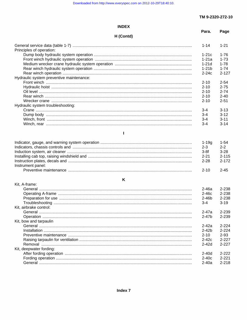
TM 9-2320-272-10
INDEXPara. Page
H (Contd)
General service data (table 1-7) ........................................................................................................... 1-14 1-21Principles of operation:
Dump body hydraulic system operation ........................................................................................ 1-21c 1-76Front winch hydraulic system operation ....................................................................................... 1-21a 1-73Medium wrecker crane hydraulic system operation ..................................................................... 1-21d 1-78Rear winch hydraulic system operation ........................................................................................ 1-21b 1-74Rear winch operation .................................................................................................................... 2-24c 2-127
Hydraulic system preventive maintenance:Front winch ................................................................................................................................... 2-10 2-54Hydraulic hoist .............................................................................................................................. 2-10 2-75Oil level ......................................................................................................................................... 2-10 2-74Rear winch .................................................................................................................................... 2-10 2-40Wrecker crane .............................................................................................................................. 2-10 2-51
Hydraulic system troubleshooting:Crane ............................................................................................................................................ 3-4 3-13Dump body ................................................................................................................................... 3-4 3-12Winch, front .................................................................................................................................. 3-4 3-11Winch, rear ................................................................................................................................... 3-4 3-14
I
Indicator, gauge, and warning system operation .................................................................................. 1-19g 1-54Indicators, chassis controls and ........................................................................................................... 2-3 2-2Induction system, air cleaner ................................................................................................................ 3-8f 3-28Installing cab top, raising windshield and ............................................................................................. 2-21 2-115Instruction plates, decals and ............................................................................................................... 2-28 2-172Instrument panel:
Preventive maintenance ............................................................................................................... 2-10 2-45
KKit, A-frame:
General ......................................................................................................................................... 2-46a 2-238Operating A-frame ........................................................................................................................ 2-46c 2-238Preparation for use ....................................................................................................................... 2-46b 2-238Troubleshooting ............................................................................................................................ 3-4 3-19
Kit, airbrake control:General ......................................................................................................................................... 2-47a 2-239Operation ...................................................................................................................................... 2-47b 2-239
Kit, bow and tarpaulinGeneral ......................................................................................................................................... 2-42a 2-224Installation ..................................................................................................................................... 2-42b 2-224Preventive maintenance ............................................................................................................... 2-10 2-93Raising tarpaulin for ventilation ..................................................................................................... 2-42c 2-227Removal ....................................................................................................................................... 2-42d 2-227
Kit, deepwater fording:After fording operation .................................................................................................................. 2-40d 2-222Fording operation .......................................................................................................................... 2-40c 2-221General ......................................................................................................................................... 2-40a 2-218
Index 7
Downloaded from http://www.everyspec.com on 2012-10-29T18:40:10.

TM 9-2320-272-10
INDEXPara. Page
K (Contd)
Operation preparation for fording ................................................................................................. 2-40b 2-218Preventive maintenance services ................................................................................................. 2-10 2-90
Kit, engine coolant heater:Operating ...................................................................................................................................... 2-45b 2-234Preventive maintenance ............................................................................................................... 2-10 2-91
Kit, fuel burning personnel heater:Operating ...................................................................................................................................... 2-44b 2-232Preventive maintenance ............................................................................................................... 2-10 2-91Troubleshooting ............................................................................................................................ 3-4 3-17
Kit, hardtop and radiator and hood cover:General ......................................................................................................................................... 2-43a 2-231Operation ...................................................................................................................................... 2-43b 2-231Preventive maintenance ............................................................................................................... 2-10 2-94Troubleshooting............................................................................................................................. 3-4 3-16
Kit, M-8 chemical alarm preventive maintenance ................................................................................. 2-10 2-91Kit, M-11 decontamination preventive maintenance ............................................................................ 2-10 2-91Kit, machine gun mount preventive maintenance ................................................................................ 2-10 2-90Kit, mud flap
General ......................................................................................................................................... 2-48a 2-240Installation ..................................................................................................................................... 2-48c 2-240Removal ....................................................................................................................................... 2-48b 2-240
Kit, rifle mount preventive maintenance ............................................................................................... 2-10 2-90Kit, troop seat (M929/A1/A2, M930A1/A2):
General ......................................................................................................................................... 2-41a 2-223Installation ..................................................................................................................................... 2-41b 2-223Preventive maintenance ............................................................................................................... 2-10 2-92
LLeakage, definition by class ................................................................................................................. 2-9 2-32Lighting system:
Blackout operations, expansible van ............................................................................................ 2-27h 2-167Blackout operations, preventive maintenance .............................................................................. 2-10 2-72Operation of vehicle service lights ................................................................................................ 2-18a 2-109Troubleshooting, expansible van .................................................................................................. 3-4 3-14Turn signal and hazard warning lights tab button ......................................................................... 2-18b 2-110
List of abbreviations .............................................................................................................................. 1-8 1-6Location and description of major components: ................................................................................... 1-12 1-10
Body assembly ............................................................................................................................. 1-12d 1-10Cab assembly ............................................................................................................................... 1-12c 1-10Chassis types ............................................................................................................................... 1-2b 1-10Engine types ................................................................................................................................. 1-2e 1-10Fuel tank types ............................................................................................................................. 1-2f 1-10General ......................................................................................................................................... 1-2a 1-10
Lowering windshield ............................................................................................................................. 2-21 2-114Lubrication order ................................................................................................................................... 3-1 3-1
Index 8
Downloaded from http://www.everyspec.com on 2012-10-29T18:40:10.

TM 9-2320-272-10
INDEXPara. Page
M
Maintenance forms ............................................................................................................................... 1-2 1-5Material weights, typical (table 2-5) ...................................................................................................... 2-25 2-146Metric system ....................................................................................................................................... Inside back
coverMud flap kit:
General ......................................................................................................................................... 2-48a 2-240Installation ..................................................................................................................................... 2-48c 2-240Removal ....................................................................................................................................... 2-48b 2-240
NNomenclature cross-reference list ....................................................................................................... 1-7 1-6
OOil level, engine .................................................................................................................................... 2-10 2-60Oil level, transmission .......................................................................................................................... 2-10 2-58Operating A-frame, kit .......................................................................................................................... 2-46c 2-238Operating under rainy or humid conditions:
General ......................................................................................................................................... 2-36a 2-214Driving vehicle .............................................................................................................................. 2-36b 2-215
Operating vehicle:Driving in reverse .......................................................................................................................... 2-15 2-107Parking vehicle ............................................................................................................................. 2-16 2-107Placing vehicle in motion .............................................................................................................. 2-15 2-104Stopping vehicle ........................................................................................................................... 2-16 2-107
Operation:A-frame kit .................................................................................................................................... 2-46 2-238Airbrake control kit ........................................................................................................................ 2-47 2-239Deepwater fording kit .................................................................................................................... 2-40 2-218Dump trucks (M929/A1/A2, M930/A1/A2) .................................................................................... 2-25 2-146Front winch ................................................................................................................................... 2-22 2-116In deep mud .................................................................................................................................. . 2-37 2-216In dusty or sandy areas ................................................................................................................ 2-35 2-213In extreme cold ............................................................................................................................. 2-32 2-203In extreme heat ............................................................................................................................. 2-34 2-210In rainy or humid conditions .......................................................................................................... 2-36 2-214In salt water .................................................................................................................................. 2-40 2-218In snow ......................................................................................................................................... 2-33 2-207Medium wrecker (M936/A1/A2) .................................................................................................... 2-24 2-127Rear winch .................................................................................................................................... 2-24c 2-127Slave receptacle ........................................................................................................................... 2-17 2-108Tractor and fifth wheel (M931/A1/A2, M932/A1/A2) ..................................................................... 2-26 2-152Truck, cargo (M923/A1/A2, M925/A1/A2, M927/A1/A2,
M928/A1/A2) ......................................................................................................................... 2-23 2-124Van (M934/A1/A2) ........................................................................................................................ 2-27 2-158Wrecker crane (M936/A1/A2) ....................................................................................................... 2-24d 2-134
Index 9
Downloaded from http://www.everyspec.com on 2012-10-29T18:40:10.

TM 9-2320-272-10
INDEXPara. Page
O (Contd)
Operation in deep mud:After operation .............................................................................................................................. 2-37b 2-216Driving vehicle .............................................................................................................................. 2-37a 2-216
Operation in dusty or sandy areas:Driving vehicle .............................................................................................................................. 2-35b 2-213General ......................................................................................................................................... 2-35a 2-213Stopping or parking ...................................................................................................................... 2-35c 2-214
Operation in extreme cold:Before operation ........................................................................................................................... 2-32b 2-203Driving vehicle .............................................................................................................................. 2-32d 2-204General ......................................................................................................................................... 2-32a 2-203Starting engine .............................................................................................................................. 72-32c 2-203Stopping or parking ...................................................................................................................... 2-32e 2-205
Operation in extreme heat:Before operation ........................................................................................................................... 2-34b 2-210Driving vehicle .............................................................................................................................. 2-34c 2-211General ......................................................................................................................................... 2-34a 2-210Stopping or parking ...................................................................................................................... 2-34d 2-212
Operation in snow:After operation .............................................................................................................................. 2-33c 2-209Driving vehicle .............................................................................................................................. 2-33b 2-207General ......................................................................................................................................... 2-33a 2-207
Operation of airbrake control kit:General ......................................................................................................................................... 2-47a 2-239Operation ...................................................................................................................................... 2-47b 2-239
Operation of auxiliary equipment (special purpose kits) ....................................................................... 2-39 2-217Operation of cargo trucks (M923/A1/A2, M925/A1/A2,
M927/A1/A2, M928/A1/A2):Bow and tarpaulin kit:
General ................................................................................................................................. 2-42a 2-224Installation ............................................................................................................................. 2-42b 2-224Raising tarpaulin for ventilation ............................................................................................. 2-42c 2-227Removal ................................................................................................................................ 2-42d 2-227
Controls and indicators ................................................................................................................. 2-4d 2-20General ......................................................................................................................................... 2-23a 2-124Installing front and side racks ....................................................................................................... 2-23e 2-125
Lowering and raising dropsides (M923/A1/A2, M925/Al/A2) ................................................................ 2-23f 2-126Lowering and raising tailgate ................................................................................................................ 2-23b 2-124Lowering and raising troop seat ........................................................................................................... 2-23c 2-124Removing front and side racks ............................................................................................................. 2-23d 2-125Operation of crane (M936/A1/A2):
Controls ........................................................................................................................................ 2-4a 2-15General ......................................................................................................................................... 2-24a 2-127Operation ...................................................................................................................................... 2-24d 2-134Securing crane after operation ..................................................................................................... 2-24f 2-144Towing .......................................................................................................................................... 2-24e 2-140
Index 10
Downloaded from http://www.everyspec.com on 2012-10-29T18:40:10.

TM 9-2320-272-10
INDEXPara. Page
O (Contd)
Operation of CTIS ................................................................................................................................ 2-14 2-104Disable and reset .......................................................................................................................... 3-16 3-60Disable ECU ................................................................................................................................. 3-16b 3-60General ......................................................................................................................................... 3-16a 3-60Reset ECU .................................................................................................................................... 3-16c 3-60
Operation of dump trucks (M929/A1/A2, M930/A1/A2):Controls and indicators ................................................................................................................. 2-4b 2-18Payload capacities ........................................................................................................................ 2-25a 2-146Regular dump operation ............................................................................................................... 2-25b 2-148Rocker-type dump operation ........................................................................................................ 2-25c 2-149Spreader-type dump operation ..................................................................................................... 2-25d 2-150
Operation of engine coolant heater:General ......................................................................................................................................... 2-45a 2-234Operation ...................................................................................................................................... 2-45b 2-234
Operation of expansible van (M934/A1/A2):Air conditioner operation ............................................................................................................... 2-27g 2-166Blackout operations ...................................................................................................................... 2-27h 2-167Controls and indicators ................................................................................................................. 2-4e 2-21Electrical system ........................................................................................................................... 2-27e 2-163Expanding van body ..................................................................................................................... 2-27d 2-158General ......................................................................................................................................... 2-27a 2-158Heater operation ........................................................................................................................... 2-27f 2-164Leveling van body ......................................................................................................................... 2-27c 2-158Retracting van body ...................................................................................................................... 2-27i 2-168Selecting operating site ................................................................................................................ 2-27b 2-158
Operation of front winch:After winch operation .................................................................................................................... 2-22g 2-122Lifting and lowering loads ............................................................................................................. 2-22f 2-121Preparation for use ....................................................................................................................... 2-22a 2-116Preparing winch for travel ............................................................................................................. 2-22h 2-123Pulling indirect loads ..................................................................................................................... 2-22e 2-120Pulling load ................................................................................................................................... 2-22d 2-118Rigging the load ............................................................................................................................ 2-22c 2-118Unwinding winch cable ................................................................................................................. 2-22b 2-116
Operation of fuel burning personnel heater:General ......................................................................................................................................... 2-44a 2-232Operation ...................................................................................................................................... 2-44b 2-232
Operation of medium wrecker (M936/A1/A2):Crane operation ............................................................................................................................ 2-24d 2-134Front winch operation ................................................................................................................... 2-24b 2-127General ......................................................................................................................................... 2-24a 2-127Rear winch (M936/A1/A2):
General ................................................................................................................................. 2-24a 2-127Operation .............................................................................................................................. 2-24c 2-127
Rear winch operation .................................................................................................................... 2-24c 2-127Securing crane after operation ..................................................................................................... 2-24f 2-144Towing with wrecker crane ........................................................................................................... 2-24e 2-140
Index 11
Downloaded from http://www.everyspec.com on 2012-10-29T18:40:10.
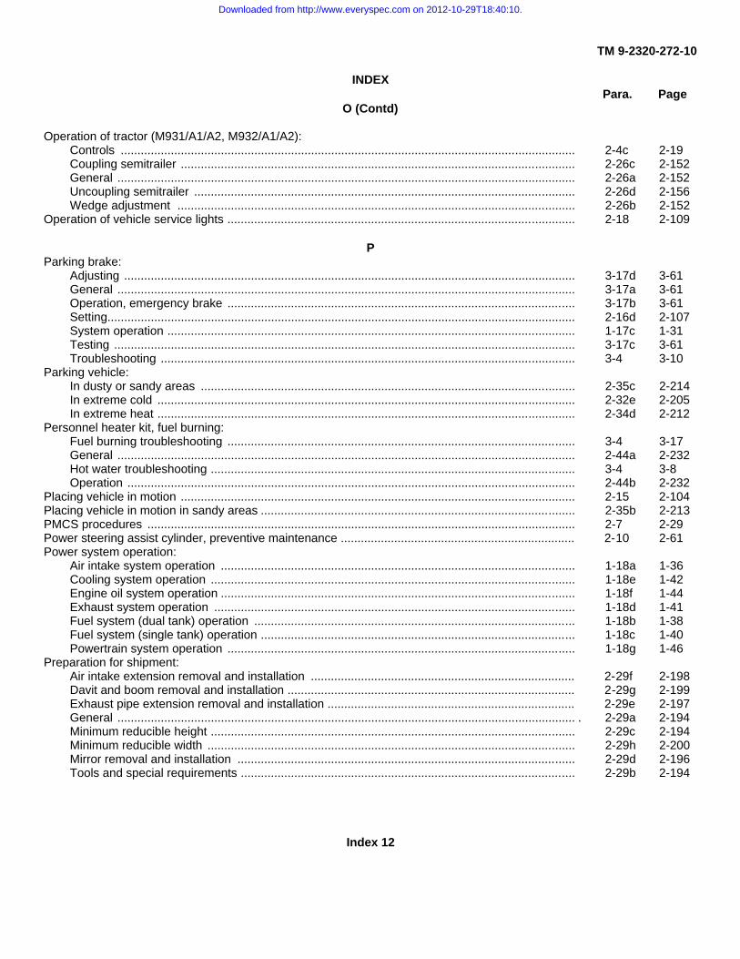
TM 9-2320-272-10
INDEXPara. Page
O (Contd)
Operation of tractor (M931/A1/A2, M932/A1/A2):Controls ........................................................................................................................................ 2-4c 2-19Coupling semitrailer ...................................................................................................................... 2-26c 2-152General ......................................................................................................................................... 2-26a 2-152Uncoupling semitrailer .................................................................................................................. 2-26d 2-156Wedge adjustment ....................................................................................................................... 2-26b 2-152
Operation of vehicle service lights ........................................................................................................ 2-18 2-109
PParking brake:
Adjusting ....................................................................................................................................... 3-17d 3-61General ......................................................................................................................................... 3-17a 3-61Operation, emergency brake ........................................................................................................ 3-17b 3-61Setting............................................................................................................................................ 2-16d 2-107System operation .......................................................................................................................... 1-17c 1-31Testing .......................................................................................................................................... 3-17c 3-61Troubleshooting ............................................................................................................................ 3-4 3-10
Parking vehicle:In dusty or sandy areas ................................................................................................................ 2-35c 2-214In extreme cold ............................................................................................................................. 2-32e 2-205In extreme heat ............................................................................................................................. 2-34d 2-212
Personnel heater kit, fuel burning:Fuel burning troubleshooting ........................................................................................................ 3-4 3-17General ......................................................................................................................................... 2-44a 2-232Hot water troubleshooting ............................................................................................................. 3-4 3-8Operation ...................................................................................................................................... 2-44b 2-232
Placing vehicle in motion ...................................................................................................................... 2-15 2-104Placing vehicle in motion in sandy areas .............................................................................................. 2-35b 2-213PMCS procedures ................................................................................................................................ 2-7 2-29Power steering assist cylinder, preventive maintenance ...................................................................... 2-10 2-61Power system operation:
Air intake system operation .......................................................................................................... 1-18a 1-36Cooling system operation ............................................................................................................. 1-18e 1-42Engine oil system operation .......................................................................................................... 1-18f 1-44Exhaust system operation ............................................................................................................ 1-18d 1-41Fuel system (dual tank) operation ................................................................................................ 1-18b 1-38Fuel system (single tank) operation .............................................................................................. 1-18c 1-40Powertrain system operation ........................................................................................................ 1-18g 1-46
Preparation for shipment:Air intake extension removal and installation ............................................................................... 2-29f 2-198Davit and boom removal and installation ...................................................................................... 2-29g 2-199Exhaust pipe extension removal and installation .......................................................................... 2-29e 2-197General ......................................................................................................................................... . 2-29a 2-194Minimum reducible height ............................................................................................................. 2-29c 2-194Minimum reducible width .............................................................................................................. 2-29h 2-200Mirror removal and installation ..................................................................................................... 2-29d 2-196Tools and special requirements .................................................................................................... 2-29b 2-194
Index 12
Downloaded from http://www.everyspec.com on 2012-10-29T18:40:10.

TM 9-2320-272-10
INDEXPara. Page
P (Contd)
Preparation for starting engine (above +32°F) (0°C) ............................................................................ 2-12 2-100Preparation for use ............................................................................................................................... 2-2 2-1Preparations for fording ........................................................................................................................ 2-40b 2-218Preventive maintenance checks and services ..................................................................................... 2-6 2-28
After .............................................................................................................................................. 2-10 2-54Before ........................................................................................................................................... 2-10 2-35During ........................................................................................................................................... 2-10 2-52Monthly ......................................................................................................................................... 2-10 2-95Weekly .......................................................................................................................................... 2-10 2-78
Priming fuel pump ................................................................................................................................ 3-8e 3-27Principles of operation:
Compressed air and brake system operation ............................................................................... 1-20 1-57Air pressure supply system operation ................................................................................... 1-20b 1-58Air venting system operation ................................................................................................. 1-20g 1-70Auxiliary air-power system operation .................................................................................... 1-20f 1-68Central Tire Inflation System (CTIS) ..................................................................................... 1-20h 1-72Medium wrecker automatic brake lock system operation ..................................................... 1-20a 1-57Primary service airbrake system operation ........................................................................... 1-20e 1-65Secondary service airbrake system operation ...................................................................... 1-20c 1-62Spring airbrake system operation ......................................................................................... 1-20d 1-64
Control system operation .............................................................................................................. 1-17 1-27Accelerator controls system operation .................................................................................. 1-17b 1-30Parking brake system operation ........................................................................................... 1-17c 1-31Starting and ether starting system operation ........................................................................ 1-17a 1-28Steering system operation .................................................................................................... 1-17d 1-32Transfer case control system operation ............................................................................... 1-17f 1-34Transmission control system operation ................................................................................ 1-17e 1-33
Electrical system operation ........................................................................................................... 1-19 1-48Battery system operation ...................................................................................................... 1-19a 1-48Directional signal system operation ...................................................................................... 1-19e 1-52Ether starting system operation ............................................................................................ 1-19c 1-50Generating system operation ................................................................................................ 1-19d 1-51Heating system operation ..................................................................................................... 1-19f 1-53Indicator, gauge, and warning system operation .................................................................. 1-19g 1-54Starting system operation ..................................................................................................... 1-19b 1-49Trailer and semitrailer connection system operation ............................................................. 1-19h 1-56
Hydraulic system operation .......................................................................................................... 1-21 1-73Dump body hydraulic system operation ................................................................................ 1-21c 1-76Front winch hydraulic system operation ................................................................................ 1-21a 1-73Medium wrecker crane hydraulic system operation .............................................................. 1-21d 1-78Rear winch hydraulic system operation ................................................................................ 1-21b 1-74
Power system operation ............................................................................................................... 1-18 1-36Air intake system operation .................................................................................................. 1-18a 1-36Cooling system operation ..................................................................................................... 1-18e 1-42Engine oil system operation .................................................................................................. 1-18f 1-44
Index 13
Downloaded from http://www.everyspec.com on 2012-10-29T18:40:10.
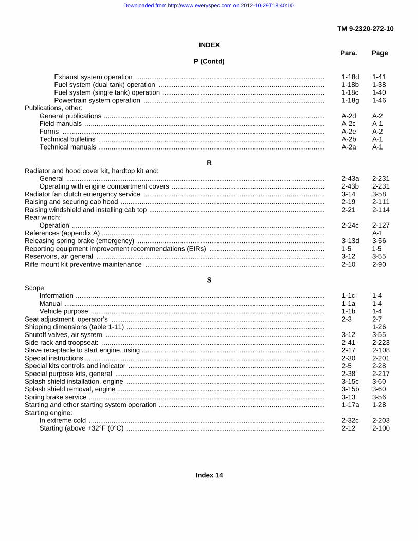
TM 9-2320-272-10
INDEXPara. Page
P (Contd)
Exhaust system operation .................................................................................................... 1-18d 1-41Fuel system (dual tank) operation ........................................................................................ 1-18b 1-38Fuel system (single tank) operation ...................................................................................... 1-18c 1-40Powertrain system operation ................................................................................................ 1-18g 1-46
Publications, other:General publications ..................................................................................................................... A-2d A-2Field manuals ............................................................................................................................... A-2c A-1Forms ........................................................................................................................................... A-2e A-2Technical bulletins ........................................................................................................................ A-2b A-1Technical manuals ........................................................................................................................ A-2a A-1
RRadiator and hood cover kit, hardtop kit and:
General ......................................................................................................................................... 2-43a 2-231Operating with engine compartment covers ................................................................................. 2-43b 2-231
Radiator fan clutch emergency service ................................................................................................ 3-14 3-58Raising and securing cab hood ............................................................................................................ 2-19 2-111Raising windshield and installing cab top ............................................................................................. 2-21 2-114Rear winch:
Operation ...................................................................................................................................... 2-24c 2-127References (appendix A) ...................................................................................................................... A-1Releasing spring brake (emergency) ................................................................................................... 3-13d 3-56Reporting equipment improvement recommendations (EIRs) ............................................................. 1-5 1-5Reservoirs, air general ......................................................................................................................... 3-12 3-55Rifle mount kit preventive maintenance ............................................................................................... 2-10 2-90
SScope:
Information .................................................................................................................................... 1-1c 1-4Manual .......................................................................................................................................... 1-1a 1-4Vehicle purpose ............................................................................................................................ 1-1b 1-4
Seat adjustment, operator’s ................................................................................................................. 2-3 2-7Shipping dimensions (table 1-11) ......................................................................................................... 1-26Shutoff valves, air system .................................................................................................................... 3-12 3-55Side rack and troopseat: ...................................................................................................................... 2-41 2-223Slave receptacle to start engine, using ................................................................................................. 2-17 2-108Special instructions ............................................................................................................................... 2-30 2-201Special kits controls and indicator ........................................................................................................ 2-5 2-28Special purpose kits, general ............................................................................................................... 2-38 2-217Splash shield installation, engine ......................................................................................................... 3-15c 3-60Splash shield removal, engine .............................................................................................................. 3-15b 3-60Spring brake service ............................................................................................................................. 3-13 3-56Starting and ether starting system operation ........................................................................................ 1-17a 1-28Starting engine:
In extreme cold ............................................................................................................................. 2-32c 2-203Starting (above +32°F (0°C) ......................................................................................................... 2-12 2-100
Index 14
Downloaded from http://www.everyspec.com on 2012-10-29T18:40:10.

TM 9-2320-272-10
INDEXPara. Page
S (Contd)
Starting (below +32°F (0°C) .......................................................................................................... 2-13 2-102Using slave receptacle to start engine .......................................................................................... 2-17 2-108
Starting system operation ..................................................................................................................... 1-19b 1-49Steering system:
Operation ...................................................................................................................................... 1-17d 1-32Power steering assist cylinder preventive maintenance ............................................................... 2-10 2-61Power steering pump preventive maintenance ............................................................................ 2-10 2-62Preventive maintenance checks and service, general ................................................................. 2-6 2-28Reservoir ...................................................................................................................................... 3-8d 3-26Reservoir preventive maintenance ............................................................................................... 2-10 2-62Troubleshooting ............................................................................................................................ 3-4 3-10
Stopping the vehicle and the engine .................................................................................................... 2-16 2-107
TTables:
1-1 - Differences Between Models ............................................................................................... 1-13 1-141-2 - Winch and Crane Data ......................................................................................................... 1-14 1-161-3 - Vehicle Dimensions .............................................................................................................. 1-14 1-171-4 - Weights ................................................................................................................................ 1-14 1-181-5 - Chassis Dimensions ............................................................................................................. 1-14 1-191-6 - Capacities for Normal Operating Conditions ........................................................................ 1-14 1-201-7 - General Service Data ........................................................................................................... 1-14 1-211-8 - Engine and Cooling System Data ........................................................................................ 1-14 1-221-9 --Automatic Transmission Data .............................................................................................. 1-14 1-231-10 - Tire Inflation Data ............................................................................................................... 1-14 1-241-11 - Shipping Dimensions ......................................................................................................... 1-14 1-262-1 - General Cleaning Instructions .............................................................................................. 2-8 2-312-2 - Fluid Leakage Criteria for Tactical Vehicles ......................................................................... 2-9 2-332-3 - Preventive Maintenance Checks and Services .................................................................... 2-10 2-342-4 - Main Light Switch Logic Table .............................................................................................. 2-18 2-1092-5 - Typical Material Weights ...................................................................................................... 2-25 2-1462-6 - M939/A1/A2 Series Special Purpose Kits ............................................................................ 2-38 2-2173-1 - Troubleshooting ................................................................................................................... 3-4 3-23-2 - CTIS Indications ................................................................................................................... 3-5 3-21
Tarpaulin, bows, and troopseats:Bow and tarpaulin kit installation .................................................................................................. 2-42b 2-224Removing cab top and lowering windshield .................................................................................. 2-21 2-114Side rack and troop seat installation
(M939/A1/A2, M930/A1/A2) .................................................................................................. 2-41b 2-223Side rack and troop seat (M929/A1/A2, M930/A1/A2) .................................................................. 2-41 2-223Side rack and troop seat (M923/A1/A2, M925/A1/A2,
M927/A1/A2, M928/A1/A2):Installation ............................................................................................................................. 2-23e 2-125Removal ................................................................................................................................ 2-23d 2-125Troop seat, lowering and raising ........................................................................................... 2-23c 2-124
Index 15
Downloaded from http://www.everyspec.com on 2012-10-29T18:40:10.

TM 9-2320-272-10
INDEXPara. Page
T (Contd)Tarpaulin kit, bow and:
General ......................................................................................................................................... 2-42a 2-224Installation ..................................................................................................................................... 2-42b 2-224Raising for ventilation ................................................................................................................... 2-42c 2-227Removal ....................................................................................................................................... 2-42d 2-227
Tire inflation data (table 1-10) .............................................................................................................. 1-14 1-24Tires:
General ......................................................................................................................................... 3-11a 3-32Inflation ......................................................................................................................................... 3-11d 3-52Pressure (table 1-10) .................................................................................................................... 1-14 1-24Preventive maintenance ............................................................................................................... 2-10 2-68Replacement ................................................................................................................................ 3-11c 3-40Spare tire ...................................................................................................................................... 3-11b 3-32
Towing vehicle:With towbar ................................................................................................................................... 2-20 2-112With wrecker crane ....................................................................................................................... 2-24e 2-140
Tractor (M931/A1/A2, M932/A1/A2):Body equipment controls and indicators ....................................................................................... 2-4c 2-19Connecting accessories, preventive maintenance ....................................................................... 2-10 2-38Fifth wheel preventive maintenance:
Before ................................................................................................................................... 2-10 2-37Monthly ................................................................................................................................. 2-10 2-99Operation:Coupling semitrailer .............................................................................................................. 2-26c 2-152General ................................................................................................................................. 2-26a 2-152Uncoupling semitrailer .......................................................................................................... 2-26d 2-156Wedge adjustment ................................................................................................................ 2-26b 2-152
Trailer and semitrailer connection system operation ............................................................................ 1-19h 1-56Transfer case:
Operation ...................................................................................................................................... 1-17f 1-34Troubleshooting ............................................................................................................................ 3-4 3-9
Transmission:Automatic transmission data (table 1-9) ....................................................................................... 1-14 1-23Capacities (table 1-6) ................................................................................................................... 1-14 1-20Data (table 1-9) ............................................................................................................................. 1-14 1-23Oil level ......................................................................................................................................... 3-103-30Operation ...................................................................................................................................... 1-17e 1-33Preventive maintenance, oil level ................................................................................................. 2-10 2-58Transmission driving range selection (table 1-9) .......................................................................... 1-14 1-23Troubleshooting ............................................................................................................................ 3-4 3-8
Troop seat kit:General ......................................................................................................................................... 2-41a 2-223Troop seat kit installation .............................................................................................................. 2-41b 2-223
Troubleshooting .................................................................................................................................... 3-3 3-2
Index 16
Downloaded from http://www.everyspec.com on 2012-10-29T18:40:10.

TM 9-2320-272-10
INDEXPara. Page
T (Contd)Troubleshooting (table 3-1):
A-frame kit .................................................................................................................................... 3-4 3-19Air and brake systems .................................................................................................................. 3-4 3-9Airbrake control kit ........................................................................................................................ 3-4 3-20Dump body hoist assembly ........................................................................................................... 3-4 3-12Engine ........................................................................................................................................... 3-4 3-5Expansible vans ............................................................................................................................ 3-4 3-14Front winch ................................................................................................................................... 3-4 3-11Fuel burning personnel and engine coolant heater kits ............................................................... 3-4 3-17Heating system ............................................................................................................................. 3-4 3-8Hydraulic crane ............................................................................................................................. 3-4 3-13Radiator and hood cover kit .......................................................................................................... 3-4 3-16Rear winch .................................................................................................................................... 3-4 3-14Steering ........................................................................................................................................ 3-4 3-10Transfer case ................................................................................................................................ 3-4 3-9Transmission ................................................................................................................................ 3-4 3-8Wheels, tires, and hubs ................................................................................................................ 3-4 3-10
Troubleshooting, CTIS (table 3-2):Central tire inflation system .......................................................................................................... 3-5a 3-20CTIS integration with air brake system ......................................................................................... 3-5b 3-20Rapid inflation ............................................................................................................................... 3-5c 3-20
Typical material weights (table 2-5) ...................................................................................................... 2-25 2-146
VVan (M934/A1/A2):
Blackout operations ...................................................................................................................... 2-27h 2-167Controls and instruments .............................................................................................................. 2-4e 2-21Expanding body ............................................................................................................................ 2-27d 2-158Leveling body ................................................................................................................................ 2-27c 2-158Operating air conditioner .............................................................................................................. 2-27g 2-166Operating electrical system .......................................................................................................... 2-27e 2-163Operating heater ........................................................................................................................... 2-27f 2-164Retracting body ............................................................................................................................. 2-27i 2-168Selecting operating site ................................................................................................................ 2-27b 2-158Vehicle dimensions (table 1-3) ..................................................................................................... 1-14 1-17
WWarnings .............................................................................................................................................. Warning aWarranty information ............................................................................................................................ 1-6 1-6Wedge adjustment (fifth wheel) ............................................................................................................ 2-26b 2-152Weights (table 1-4) ............................................................................................................................... 1-14 1-18Wheels and tires ................................................................................................................................... 3-11 3-32Winch:
Front operation ............................................................................................................................. 2-24b 2-127Rear:
Operation .............................................................................................................................. 2-24c 2-127Preventive maintenance ....................................................................................................... 2-10 2-40
Index 17
Downloaded from http://www.everyspec.com on 2012-10-29T18:40:10.

TM 9-2320-272-10
INDEXPara. Page
W (Contd)
Winch and crane data (table 1-2) ......................................................................................................... 1-14 1-16Windshield, raising ............................................................................................................................... 2-21 2-114Windshield wipers preventive maintenance ......................................................................................... 2-10 2-35Wrecker, medium (M936/A1/A2):
Body equipment controls and indicators ....................................................................................... 2-4a 2-15General ......................................................................................................................................... 2-24a 2-127Operation of crane ........................................................................................................................ 2-24d 2-134Operation of front winch ............................................................................................................... 2-24b 2-127Operation of rear winch ................................................................................................................ 2-24c 2-127Towing:
With towbar ........................................................................................................................... 2-20 2-112With wrecker crane ............................................................................................................... 2-24e 2-140
� U S GOVERNMENT PRINTING OFFICE 1996-746-014/20250
Index 18
Downloaded from http://www.everyspec.com on 2012-10-29T18:40:10.

Downloaded from http://www.everyspec.com on 2012-10-29T18:40:10.

Downloaded from http://www.everyspec.com on 2012-10-29T18:40:10.
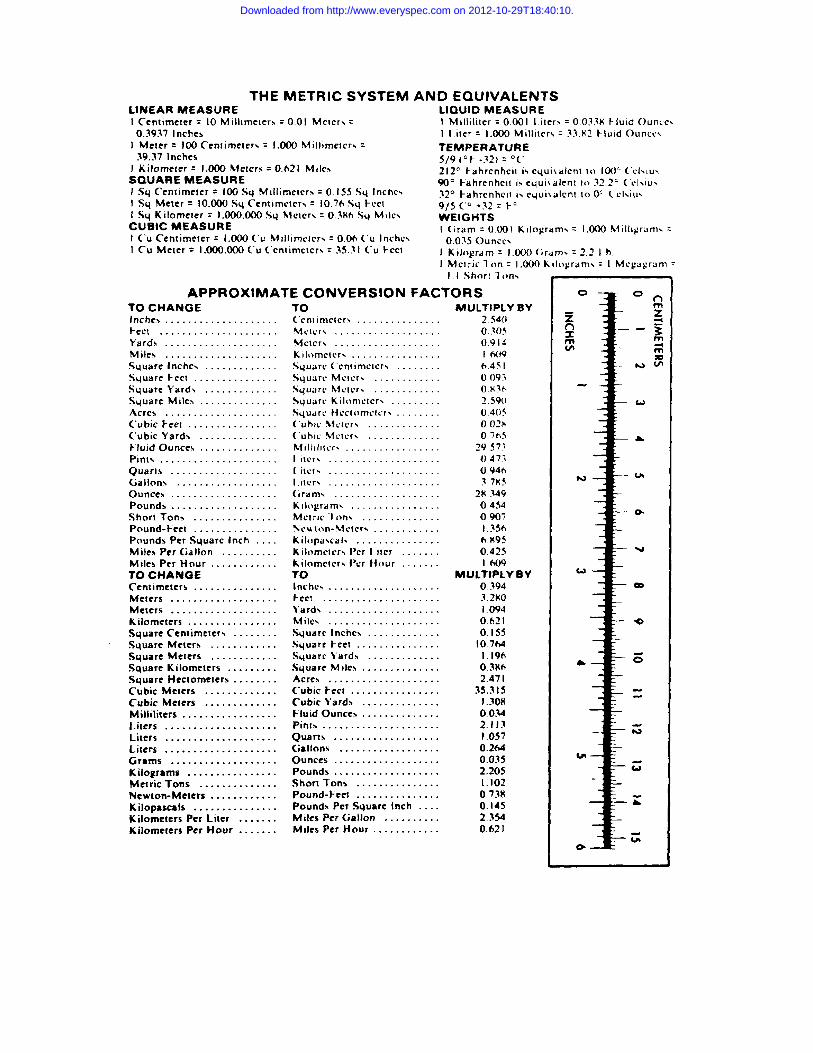
Downloaded from http://www.everyspec.com on 2012-10-29T18:40:10.

051550-001
Downloaded from http://www.everyspec.com on 2012-10-29T18:40:10.