technical manual msi te (top entry) valve - diwmsi.com · revision f march 17, 2017 technical...
TRANSCRIPT

Revision F March 17, 2017
Technical Manual
MSI TE (Top Entry) Valve
MSI – A Division of Dixie Iron Works, Ltd.
300 W. Main St.
Alice, TX 78332
www.diwmsi.com
(800) 242-0059

Revision F 3/20/2017
TABLE OF CONTENTS
SECTION 1 WARNINGS ...................................................................................................................... 1
SECTION 2 GENERAL DESCRIPTION ............................................................................................ 2
2.1 TE VALVE DESCRIPTION .................................................................................................................. 2
2.2 TE VALVE SPECIFICATIONS ............................................................................................................. 2
2.3 SAFETAPTM
GREASE FITTING ........................................................................................................... 3
2.4 GREASEALTM
PLUG ......................................................................................................................... 3
SECTION 3 PARTS ............................................................................................................................... 4
3.1 EXPLODED VIEW 1” & 2” TE VALVES ............................................................................................. 4
3.2 BILL OF MATERIALS 1” TE VALVES ................................................................................................ 5
3.3 BILL OF MATERIALS 2” TE VALVES ................................................................................................ 6
3.4 EXPLODED VIEW 3” TES VALVE ..................................................................................................... 7
3.5 BILL OF MATERIALS 3” TES VALVES .............................................................................................. 8
SECTION 4 ASSEMBLY....................................................................................................................... 9
4.1 TOOLS AND LUBRICANTS NEEDED FOR ASSEMBLY TE VALVE SPECIFIC TOOL ................................. 9
4.2 ASSEMBLY PROCEDURE (PICTORIAL) ............................................................................................ 10
4.3 ASSEMBLY PROCEDURE (TEXT) ..................................................................................................... 20
4.4 DISASSEMBLY PROCEDURE ............................................................................................................ 22
SECTION 5 MAINTENANCE ............................................................................................................ 23
5.1 MAINTENANCE TIPS ....................................................................................................................... 23
5.2 STORAGE ....................................................................................................................................... 23
5.3 SHELF LIFE .................................................................................................................................... 24
5.4 GREASES AND LUBRICATION REQUIREMENTS ................................................................................ 24
SECTION 6 INSPECTION AND REPAIR ........................................................................................ 25
6.1 INSPECTION .................................................................................................................................... 25
6.2 SANDING TIPS ................................................................................................................................ 26
6.3 ASSEMBLY TIPS ............................................................................................................................. 26

Revision E 1 3/20/2017
SECTION 1 WARNINGS
The MSI Top Entry (TE) valve is used in high-pressure and high flow well service applications. High pressure
equipment, if not used and maintained properly, can cause serious injury or death and damage to equipment and
property. Not taking proper precautions and failing to perform routine maintenance and inspections can also
contribute to loss of well control, and such loss could cause serious injury or death and damage to equipment
and property.
ALL OPERATORS AND MAINTENANCE PERSONNEL SHOULD BE THOROUGHLY TRAINED
IN THE SAFE OPERATION, MAINTENANCE, AND INSPECTION OF THIS EQUIPMENT.
Usage Note: The primary function of MSI plug valves is to direct/isolate the flow of pressurized fluids within a
system. Plug valves in general are not to be used to throttle the flow of fluid. In systems where this is required,
appropriate style throttling valves and/or chokes should be used in conjunction with plug valves.

Revision E 2 3/20/2017
SECTION 2 GENERAL DESCRIPTION
2.1 TE Valve Description
The MSI TE Plug Valve is a lubricated, straight pocket, quarter-turn plug valve for rapid full open or close
operation. The valve cavity is straight to ensure low-torque operation and uniform sealing of the components at
the full range of pressures. The MSI TE Plug Valve and replacement parts are engineered to provide low
operating torque and resistance to the toughest abrasive and corrosive conditions.
2.2 TE Valve Specifications
MSI offers more end connection choices than any other plug valve manufacturer in the industry. Connection
types such as Hammer Unions, Line Pipe, API Flanged, Clamp Hub, and our own metal-to-metal WingSeal
(WS20 and WS30) are just a few of the available choices. All sizes of MSI valves can be outfitted with your
choice of end connections or combinations to suit your specific application. Custom end-to-end lengths are also
available on some valves.
Compact design
Lightweight
Top Entry
Longer lasting internals
Ease of repair
Interchangeability
SafeTap™ grease fitting
GreaSeal™ plug for full 360° greasing
Widest range of end connections in the industry
• Hammer union (all sizes of 602, 1002, 1502, 2002, 2202)
• API Flange (all sizes and working pressures)
• WingSeal 20 (2.00”ID) & 30 (3.00”ID) *metal-to-metal
• Threaded Ends (all sizes of Line Pipe, EU, NU, and premium threads)

Revision E 3 3/20/2017
2.3 SafeTapTM
Grease Fitting
SafeTap™ grease fittings are designed to provide maximum safe operation in the field. These fittings are
standard in all TE valves. Key features include:
The unique metal-to-metal seal eliminates wetted
threads and pipe taps. Since the threads do not
perform a sealing function they do not require
Teflon tape or other sealing aids.
The heavier cross section stands up better to
impacts.
Each fitting has a slot machined through the
threads which serves as a pressure relief path in
the event of a leak.
The metal-to-metal seal and the pressure relief
slot of the SafeTap™ grease fitting also allow a
means to safely bleed off any residual internal
pressure.
2.4 GreaSealTM
Plug
The patented GreaSeal™ plug is designed to provide maximum lubrication in the harshest field conditions. Key
features include:
The only plug that allows greasing in the opened
or closed position while in service.
Dual 360° grease channels.
Forces grease into 360° of the seal area when
closed.
Allows for complete distribution of lubricant
immediately prior to opening a valve when
exposure to high temperatures and well fluids may
have compromised the existing grease.
Greasing in the closed position can stop or
significantly slow leaks in valves with worn or
damaged parts.

Revision E 4 3/20/2017
SECTION 3 PARTS
3.1 Exploded View 1” & 2” TE Valves
See the following drawings and bills of materials for replacement parts. 2” TE valve is shown below, but the 1”
TE valve is similar.

Revision E 5 3/20/2017
3.2 Bill of Materials 1” TE Valves
These part numbers are the common part numbers as they apply to Standard and H2S service 1” x 1”
1502 valve. Please contact MSI, for specific part numbers as they apply to particular valve assembly
numbers. I.E. Special service, product specification level (PSL2 or PSL3).
NO. QTY DESCRIPTION H2S STD
1 1 SAFETAP™ GREASE FITTING HC0226 HC0226
2 1 HANDLE LOCKNUT HC0197 HC0197
3 1 HANDLE ADAPTER VC0492 VC0492
4 1 HANDLE GASKET VC0498 VC0498
5 1 BODY CAP VC0525 VC0490
6 1 PARBAK RING, BODY CAP N/A N/A
7 1 O-RING, BODY CAP OC0095 OC0086
8 2 PLUG SEAL RING VC0496 VC0496
9 2 O-RING, PLUG SEAL OC0096 OC0087
10 1 PLUG VC0521P VC0500P
11 2 SIDE SEGMENT VC0502 VC0502
12 1 SEGMENT SET VC0522 VC0501
13 2 O-RING, SEGMENT OC0100 OC0092
14 2 GROOVED PIN VC0513 VC0513
15 2 DRIVE SCREW HC0200 HC0200
16 1 HANDLE SPRING VC0505 VC0505
17 1 ROLL PIN HC0196 HC0196

Revision E 6 3/20/2017
3.3 Bill of Materials 2” TE Valves
These part numbers are the common part numbers as they apply to Standard and H2S service 2” x 2”
1502 valve. Please contact MSI, for specific part numbers as they apply to particular valve assembly
numbers. I.E. Special service, product specification level (PSL2 or PSL3).
NO. QTY DESCRIPTION H2S STD
1 1 SAFETAP™ GREASE FITTING HC0226 HC0226
2 1 HANDLE LOCKNUT HC0198 HC0198
3 1 HANDLE ADAPTER VC0493 VC0493
4 1 HANDLE GASKET VC0499 VC0499
5 1 BODY CAP VC0526 VC0491
6 1 PARBAK RING, BODY CAP OC0098 OC0098
7 1 O-RING, BODY CAP OC0097 OC0088
8 2 PLUG SEAL RING VC0497 VC0497
9 2 O-RING, PLUG SEAL OC0099 OC0090
10 1 PLUG VC0523P VC0507P
11 2 SIDE SEGMENT VC0506 VC0506
12 1 SEGMENT SET VC0524 VC0508
13 2 O-RING, SEGMENT OC0101 OC0091
14 2 GROOVED PIN VC0513 VC0513
15 2 DRIVE SCREW HC0200 HC0200
16 1 HANDLE SPRING VC0511 VC0511
17 1 ROLL PIN HC0196 HC0196
Revision E 7 3/20/2017
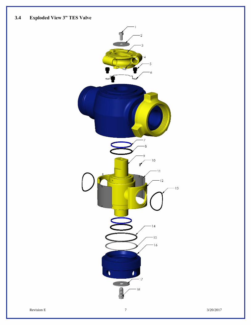
3.4 Exploded View 3” TES Valve

Revision E 8 3/20/2017
3.5 Bill of Materials 3” TES Valves
These part numbers are the common part numbers as they apply to Standard and H2S service 3” x 3”
1502 valve. Please contact MSI, for specific part numbers as they apply to particular valve assembly
numbers. I.E. Special service, product specification level (PSL2 or PSL3).
NO. QTY DESCRIPTION H2S STD
1 1 HEX HD CAP SCREW HC0009 HC0009
2 1 FLAT WASHER HC0260 HC0260
3 1 HANDLE ADAPTER VC0577 VC0577
4 2 SOC SET SCREW HC0259 HC0259
5 3 SOC HD CAP SCREW HC0008 HC0008
6 1 HANDLE SPRING VC0583 VC0583
7 2 PLUG SEAL RING VC0568 VC0568
8 2 O-RING, PLUG SEAL OC0183 OC0115
9 1 PLUG VC0792P VC0565P
10 2 GROOVED PIN VC0513 VC0513
11 2 SIDE SEGMENT VC0794 VC0567
12 2 SEGMENT SET VC0793 VC0566
13 2 O-RING, SEGMENT OC0184 OC0116
14 1 PARBAK RING, BODY CAP OC0120 OC0118
15 1 O-RING, BODY CAP OC0185 OC0117
16 1 BODY CAP VC0795 VC0569
17 1 FLAT WASHER HC0262 HC0262
18 1 SAFETAP™ GREASE FITTING HC0226 HC0226

Revision E 9 3/20/2017
SECTION 4 ASSEMBLY
4.1 Tools and lubricants needed for assembly TE Valve Specific Tool
1) TE Valve Specific Tool
Use only MSI recommended wrenches for working on TE Valves.
MSI Part Number Description
VC0494 1” TE Valve Wrench
VC0495 2” TE Valve Wrench
VC0494 VC0495
2) Lubricants
o Copper based anti-seize lubricant
o Valve grease. See 5.4 Greases and Lubrication Requirements

Revision E 10 3/20/2017
4.2 Assembly Procedure (Pictorial)
NOTE: It is imperative that the workstation being used to assemble the valve be clean and free of
anything that could possibly contaminate the grease such as metal shavings, dirt, rust, old paint, etc. Do
not sand or deburr near the workstation.
NOTE item numbers within ( ) refer to 1” & 2” TE valve drawing, and item numbers within [ ] refer to
the 3” TES valve drawing.
o Check surfaces around the valve bore inside the
valve pocket for sharp edges and pitting that could
cause cutting of the segment o-rings.
o Check the pins (14) [10] in the bottom of the valve
body pocket to make sure they are not bent or
broken.

Revision E 11 3/20/2017
o Lightly lubricate the threads with anti-seize, then
screw the clean body cap (5) [16] all the way into
the valve body to make sure the threads are not
damaged.
o Remove the body cap (5) [16], lubricate the
sealing groove with valve grease and install the
body cap parbak ring (6) [14] on the side of the
groove away from the pressure and the curved face
towards the pressure.
NOTE: 1” valve does not use a parbak ring (6)
o Install the o-ring (7) [15] into the groove so that it
sits on the curved side of the parbak ring (6) [14]
towards the pressure.

Revision E 12 3/20/2017
o Lubricate the valve pocket with valve grease.
o Check the surface finish of the segment set (12)
[12] making sure they do not have any scratches,
dings, nicks, or sharp edges that could affect the
sealing area. See 6.2 Sanding Tips for repair.
o Inspect the segment o-rings (13) [13] for any
possible non-conformity.

Revision E 13 3/20/2017
o Coat the o-rings (13) [13] with valve grease and
install onto the segment set (12) [12].
o Place the set into the valve body, making sure to
engage the dowel pins (14) [10].
o Place the side segments (11) [11] into the valve
body between the segment set (12) [12].

Revision E 14 3/20/2017
o Make sure the tops of all 4 pieces are at the same
height.
o Check the plug (10) [9] outside diameter for
surface defects such as nicks, dings, scratches, etc.
that could possibly affect the sealing area. See 6.2
Sanding Tips for repair.
o Install the upper and lower plug seal rings (8) [7]
and o-rings (9) [8] onto the ends of the plug (10)
[9].

Revision E 15 3/20/2017
o Apply valve grease to both seals.
o Apply a thin film of valve grease to the entire O.D.
of the plug (10) [9].
o Push the assembled plug with seals into the valve
body, making sure it is properly aligned with the
segment set (12) [12] and side segments (11) [11]
until it is seated all the way down. Make sure the
valve is in the open position.
NOTE: Install the plug with straight downward force.
DO NOT APPLY SIDE TO SIDE MOTION as this will
damage segments

Revision E 16 3/20/2017
o Apply anti-seize compound to the threads on the
valve body and body cap (5) [16], along with a
light coat of valve grease on the body cap sealing
surfaces.
o Tighten the body cap (5) [16] until snug.
o Hit valve wrench with hammer a couple times to
make sure it is firmly seated. This is necessary to
fully compress the plug seal o-ring.

Revision E 17 3/20/2017
o Install the handle spring (16) [6] and drive screws
(15) or socket head cap screws [5].
o Add handle gasket (4) to handle adapter (3).
NOTE: 3” TES valve does not use a handle gasket
o Install the handle adapter (3) [3] onto the top of
the plug (10) [9].

Revision E 18 3/20/2017
o Secure the handle adapter (3)[3] with handle
lock-nut (2) for 1” & 2” TE valves or hex-hd cap
screw [1] and flat washer [2] for 3” TES valves.
o Apply anti-seize compound to the threads on the
SafeTap™ grease fitting (1) [18].
NOTE: Do not use Teflon tape on the grease fitting.
\
o Install SafeTap™ grease fitting (1) [18] and torque
to 80 ft-lbs for 1” TE valves & 125 ft-lbs for all
others.
NOTE: 3” TES valve uses a flat washer [17] in
addition to the grease fitting [18]. The fitting also
is threaded into plug on the body cap end. See 3.4
Exploded View 3” TES Valve

Revision E 19 3/20/2017
o Grease valve according to ENG SPEC# 9-2001.
o Remove excess grease from valve bore.
o Ensure that the plug, segment set, and valve bore
are properly aligned.

Revision E 20 3/20/2017
4.3 Assembly Procedure (Text)
NOTE: It is imperative that the workstation being used to assemble the valve be clean and free of
anything that could possibly contaminate the grease such as metal shavings, dirt, rust, old paint, etc. Do
not sand or deburr near the workstation.
1. Check surfaces around the valve bore inside the valve pocket for sharp edges and pitting that could
cause cutting of the segment o-rings.
2. Check the pins (14) [10] in the bottom of the valve body pocket to make sure they are not bent or
broken.
3. Lightly lubricate the threads with anti-seize, the screw the clean body cap (5) [16] all the way into
the valve body to make sure the threads are not damaged.
4. Remove the body cap (5) [16] and install the body cap parbak ring (6) [14] on the side of the
groove away from the pressure and the curved face towards the pressure. NOTE: The 1” valve
does not use a parbak ring (6).
5. Install the o-ring (7) [15] into the groove, so that it sits on the curved side of the parbak o-ring (6)
[14] towards the pressure.
6. Lubricate the valve pocket with valve grease.
7. Check the surface finish of the segment set (12) [12] making sure they do not have any scratches,
dings, nicks, or sharp edges that could affect the sealing area. See 6.2 Sanding Tips for repair.
8. Inspect the segment o-rings (13) [13] for any possible non-conformity.
9. Coat the o-rings (13) [13] with valve grease and install onto the segment set (12) [12].
10. Place the set into the valve body, making sure to engage the dowel pins (14) [10].
11. Place the side segments (11) [11] into the valve body between the segment set (12) [12].
12. Make sure the tops of all 4 pieces are at the same height.
13. Check the plug (10) [9] outside diameter for surface defects such as nicks, dings, scratches, etc. that
could possibly affect the sealing area. See 6.2 Sanding Tips for repair.
14. Install the upper and lower plug seal rings (8) [7] and o-rings (9) [8] onto the ends of the plug (10)
[9].
15. Apply valve grease to both seals.
16. Apply a thin film of valve grease to the entire O.D. of the plug (10) [9].
17. Push the assembled plug with seals into the valve body, making sure it is properly aligned with the
segment set (12) [12] and side segments (11) [11] until it is seated all the way down. Make sure the

Revision E 21 3/20/2017
valve is in the open position. NOTE: Install the plug with straight downward force. DO NOT
APPLY SIDE TO SIDE MOTION, as this will damage segments.
18. Apply anti-seize compound to the threads on the valve body and body cap (5) [16], along with a
light coat of grease on the body cap sealing surfaces.
19. Tighten the body cap (5) [16] until snug.
20. Hit valve wrench with hammer a couple times to make sure it is firmly seated. This is necessary to
fully compress the plug seal o-ring.
21. Install the handle spring (16) [6] and drive pins (15) or socket head cap screws [5]
22. Add handle gasket (4) to handle adapter (3). NOTE: The 3” TES valve does not use a handle
gasket (4).
23. Install the handle adapter (3) [3] to the end of the plug (10) [9].
24. Secure the Secure the handle adapter (3)[3] with handle lock-nut (2) for 1” & 2” TE valves or
hex-hd cap screw [1] and flat washer [2] for 3” TES valves.
25. Apply anti-seize compound to the threads on the SafeTap™ grease fitting (1) [18]. NOTE: DO
NOT USE TEFLON TAPE ON THE GREASE FITTING.
26. Install SafeTap™ grease fitting (1) [18] and torque to 80 ft-lbs for 1” TE valves & 125 ft-lbs for all
others. NOTE: 3” TES valve uses a flat washer [17] in addition to the grease fitting [18]. The
fitting also is threaded into the plug on the body cap end. See 3.4 Exploded View 3” TES Valve.
27. Grease valve according to ENG SPEC# 9-2001.
28. Remove excess grease from valve bore.
29. Ensure that the plug, segment set and valve bore are properly aligned.

Revision E 22 3/20/2017
4.4 Disassembly Procedure
1. The SafeTap™ grease fitting allows for the safe relief of trapped pressure within a valve. Slowly turn
the grease fitting ¼ CCW turn to relieve the pressure. See section 2.3 SafeTapTM
Grease Fitting for
more details on the SafeTap™ grease fitting.
2. Actuate the valve to ensure all pressure has been relieved.
3. Remove the SafeTap™ grease fitting (1) [18] and handle adapter (3) [3]. Note the 3” TES requires
you to remove hex hd cap screw [1] and flat washer [2]. Screw out (turning counter-clockwise) the
body cap (5) [16].
4. Remove the plug (10) [9] along with upper and lower plug seal rings (8) [7] and o-rings (9) [8].
5. Remove the side segments (11) [11].
6. Remove the segment set (12) [12].
7. Remove the segment set o-rings (13) [13], body cap o-rings (7) [15], plug o-rings (9) [8] and plug seal
rings (8) [7].
8. Clean all of the old lubricant and debris from the parts and valve body internal profile.

Revision E 23 3/20/2017
SECTION 5 MAINTENANCE
5.1 Maintenance Tips
Valves should be greased as part of a regular maintenance program. Regular greasing will increase the service
life of the internal valve parts. Routine disassembly and cleaning as part of a maintenance program can prevent
unnecessary damage to the valve body. Dixie Iron Works, Ltd. recommends that valves be greased after every
job or every 5 actuations, whichever one comes first.
Valves should be greased according to the severity of use. Each operating company should establish guidelines
for a greasing and/or disassembly program. These guidelines should be based on the operating conditions.
Special consideration should be given for conditions in which the following would be involved:
Abrasives in the fluid stream
High flow rates
Caustic or Acidic fluid streams
High Temperature
Fluid Streams that would act as solvents such as condensate
High number of valve actuations
Valves in the open position may be lubricated when line pressure is present. If a Greaseal™ plug is being used,
plugs may be lubricated in the open or closed position. In addition, valves should not be disassembled for repair
while part of an operating arrangement such as a manifold. This should not be attempted even though the valve
may be isolated from the fluid stream by other valves.
If the valve is NOT pressurized, MSI recommends greasing the valve to a minimum of 3,000 psi greasing
pressure. If the valve is pressurized, the greasing pressure needs to be greater than the internal pressure of the
valve, but always less than the rated working pressure of the valve. In all cases the maximum greasing pressure
will be the difference between the internal pressure and the rated working pressure of the valve. The greasing
pump must have pressure measuring capability.
5.2 Storage
Disassemble the valve completely. See section 4.4 Disassembly Procedure for detailed instructions on valve
disassembly. Remove old grease and debris from valve pocket with a solvent and inspect for wear or damage
per 6.1 Inspection
Drain after testing. All equipment should be drained and lubricated after testing and prior to storage or
shipment.
All components and assemblies should be cleaned of dirt, rust, and other contaminants.
Rust Prevention: Equipment should have exposed metallic surfaces protected with a rust inhibitor which
will not become fluid and run at a temperature less than 125°F (52°C).
Sealing surface protection: Exposed sealing surfaces should be protected from mechanical damage.

Revision E 24 3/20/2017
5.3 Shelf Life
The following is recommended for maximum equipment shelf life:
# of Months in storage Manufacturers Recommendation
0-3 months Nothing required
3-6 months Re-grease and operate. Operate by rotating the plug. Check to see that rotation is
smooth without grinding, scraping or binding.
6+ months Disassemble, rebuild and retest the valve. Replace all internal seals
5.4 Greases and Lubrication Requirements
Use only MSI recommended greases. Greases intended for gate valves or other applications may result in
failure to achieve a good test and may actually damage the new parts.
MSI Part Number Description Manufacturer
VC0012 #972 General Service (size K) Val-Tex
VC0426 #972 General Service (size 5.5) Val-Tex
VC0669 #972 General Service (size V) Val-Tex
VC0527 #750 Low Temperature (size J) Val-Tex
VC0402 #750 Low Temperature (size K) Val-Tex
VC0357 #700 CO2 / Hi-Temp / Condensate (size J) Val-Tex
GREASE002* 1502-S-7 Low Pressure Testing (7 lb. can) Val-Tex
#80HM Suitable for Acid Service Val-Tex
*Val-Tex 1502 grease is for hand application only and not to be pumped. Therefore, it is to be used only during
the assembly process. Inject body grease prior to testing and after each actuation.
Valve Size Approximate amount of grease
1” valve 1/3 stick
2” valve 1/2 stick
3” valve 1 stick

Revision E 25 3/20/2017
SECTION 6 INSPECTION AND REPAIR
6.1 Inspection
When repairing a MSI plug valve, the following basic guidelines can help you ensure a good hydrostatic test of
the reassembled valve.
Disassemble the valve completely. See section 4.4 Disassembly Procedure for detailed instructions on valve
disassembly. Remove old grease and debris from valve pocket with a solvent and inspect for wear or damage.
Ensure inspection is performed in a clean well illuminated area. Minor damage and imperfections may be
repaired. See section 6.2 Sanding Tips for more information.
The following are areas that should be inspected:
Threads: Inspect the body cap and valve pocket threads. Check for damage such as nicks, dings, or
raised edges especially the lead thread. Carefully sand as needed.
Sealing Surfaces:
o Body cap: o-ring groove and seal bore
o Valve body: pocket walls and plug seal area
o Valve plug: plug seal area and plug outside diameter
o Segment set: o-ring groove and inside and outside diameters.
During the inspection you should check for scratches, dings, pitting or other surface defects. Paying particular
attention to surfaces which may fail to seal against the o-ring or even damage the o-ring during installation.
Also look for evidence of washout.
If the flow bore is washed and eroded larger than when the bore I.D. was new, the plug and segment set can
only be used when the wear conforms to the guidelines detailed below. Since the bore will no longer be a
perfect circle, you must measure the largest gap from one side of the bore to the other. If the bore tapers in
either direction, measure the largest dimension. Compare the measurement to the following maximum
acceptable dimensions:
1” Plugs and Segment sets – 1.090” max
2” Plugs and Segment sets – 2.120” max
3” Plugs and Segment sets – 3.120” max
Plug valves seal on the downstream side or the side opposite the pressure. The o-ring in the segment is
pressured inward, trying to collapse the inside wall toward the bore. Dimensions larger than these guidelines
will produce walls too thin to support the working pressure of the valve and these parts should be scrapped.
Because the bore is larger than when new and because the eroded area tends to be uneven, worn parts create a
larger internal upset in the valve which increases turbulence. This increased turbulence means that the rate of
wear will increase exponentially so special consideration should be given to the application of valves with worn
parts to minimize the possibility of failure during the course of the job. Continued use of parts with eroded flow
bores may reduce the life of the valve body. MSI recommends that valves with working but washed parts
within these guidelines be used in locations of the rig-up that see less abrasive flow.
See the Minimum Wall Thickness Datasheet for wall thickness inspection procedures and allowable erosion
values.

Revision E 26 3/20/2017
6.2 Sanding Tips
When repairing a MSI plug valve, the following basic guidelines can help you ensure a successful
hydrostatic test of the reassembled valve.
Sanding is necessary to repair blemishes from the sealing surfaces of parts
Sanding of scratches, dings, and pitting should always be done with 600 grit sanding cloth that is well
lubricated with water or solvent. When sanding sealing surfaces, it is VERY important to avoid
sanding in one spot continuously; sand evenly across the entire sealing surface. Sand scratches by
moving the sandpaper around the plug, not up and down along the length of the plug. If scratches
cannot be removed utilizing this technique, replace the parts. If raised edges or dings in non-sealing
areas are too large to be sanded effectively, you may use a rotary flapper-type sanding wheel. It is very
important that you do not remove any material other than the actual raised edge. Do not remove any of
the base material or you may permanently damage the valve and render it unsafe for use.
6.3 Assembly Tips
When repairing a MSI plug valve, the following basic guidelines can help you ensure a good hydrostatic
test of the reassembled valve.
If you choose to mix old and new parts, you must make absolutely sure that the old part does not have any
defects. Using 600 grit sanding cloth, wet sand any surface blemishes as described in section 6.2 Sanding Tips
See section 4.2 Assembly Procedures for detailed assembly instructions.

Revision E 27 3/20/2017
.
MSI – A Division of Dixie Iron Works, Ltd.
300 W. Main St.
Alice, TX 78332
www.diwmsi.com
(800) 242-0059
(361) 664-6597