technical manual - lehner-lifttechnik.at
TRANSCRIPT

Technical Manual
Liftboy 5
V e r t i c a l
p l a t f o r m l i f t

Liftboy 5 Installation manual Version 05/2017
2
Overview Introduction ........................................................................................................................... 4
Technical specification ....................................................................................................... 4
Delivery.............................................................................................................................. 4
Safety ................................................................................................................................ 4
Platform controls ................................................................................................................ 6
Upper gate door lock.......................................................................................................... 6
Side view of unfolded platform without safety curtain ......................................................... 7
Side view of folded platform with battery and controller position ........................................ 8
View of platform switch positions ....................................................................................... 9
Switch position – view from below!! ...................................................................................10
Installation ............................................................................................................................11
Controls descpriptions: .........................................................................................................12
Radio controls for landings stations: .................................................................................12
Overload control ...............................................................................................................12
Control description of automatic access ramp ...................................................................13
Control description of manual and automatic door ............................................................13
Manual unblocking of door lock and automatic door opener..............................................14
Emergency opening of the automatic access ramp: ..........................................................15
Switches and connectors on the control unit .....................................................................16
Switch S2 ....................................................................................................................................... 17
Button S1 ....................................................................................................................................... 18
LED signalization on platform´s control unit ......................................................................19
Description of LED signalization of platform´s control unit .................................................19
Emergency drive control unit .............................................................................................21
Menu ....................................................................................................................................22
General info ......................................................................................................................22
Menu activation .................................................................................................................23
Menu structure ..................................................................................................................23
Menu items .......................................................................................................................29
User menu ..................................................................................................................................... 29
Device info ..................................................................................................................................... 30
Language ....................................................................................................................................... 30
Factory number ............................................................................................................................. 30
Errors ............................................................................................................................................. 30
Acknowledge error ........................................................................................................................ 30
Operation time .............................................................................................................................. 30
Factory default .............................................................................................................................. 31

Liftboy 5 Installation manual Version 05/2017
3
Radio controller version ................................................................................................................ 31
Motor configuration ...................................................................................................................... 32
Door lock configuration ................................................................................................................. 33
Overload control............................................................................................................................ 33
Options .......................................................................................................................................... 34
Radio wall mounted controllers .........................................................................................35
Emergency drive ..................................................................................................................36
Error and operating messages on display ............................................................................37
Operation message list – help hints on display .....................................................................44
Schematics ...........................................................................................................................48

Liftboy 5 Installation manual Version 05/2017
4
Introduction
The Liftboy 5 is a vertical platform lift designed for the transportation of wheelchair drivers.
The driving mechanism is a double scissor driven by 2 x 24V actuators and powerered by 2 x
12V batteries which are continuously charged (as long as the main power switch is switched
ON).
The standard version of the Liftboy 5 is delivered with a manual gate for the upper level
including a shear wall and with an automatic access ramp on the platform. The standard
platform size is 900x1400mm.
Technical specification
Loading capacity 300kg
Lifting speed 0,04m/s
Net weight 270 kg
Drive mechanism Double scissor
Motors 2 x 24V actuators
Max power 300VA
Power supply 2 x 12V batteries
Power supply for battery charger 1 x 230V
Folded down height 120mm
Lifting travel 1180mm
Total unfolded lifting height 1300mm
Color standard RAL 7035
Remote controls in landings Radio frequency controlled
Duty cycle 10%, 6min./h
Standard lift size (outside dimension) 1150x1570mm
Delivery
The unit is delivered preassembled in 2 main parts, packed on a wooden pallet:
1. Folded platform (270 kg)
2. Upper door wide shear wall (90kg)
When unpacking the lift, check all parts for potential visible damage during transportation. If
damage is visible, please immediately take pictures and send those later to Lehner Lifttechnik
GmbH for potential warranty claims.
Safety
Read all instructions in this manual before installing or operating the lift.
Do not exceed the maximum payload capacity of 300 kg.
This product is designed only for lifting people and wheelchairs only.
Do not disable any safety equipment or switches supplied with this lift.
Stay away from all drive train components while the lift is operating.

Liftboy 5 Installation manual Version 05/2017
5
Overview platform mechanics and switch position:
In the following various views of the Litboy 5 are presented in order to provide an overview of
the main functions and components.
With door on platform (manual
or automatic)
With automatic access ramp on
platform

Liftboy 5 Installation manual Version 05/2017
6
Platform controls
Upper gate door lock
Display
Stop button
Emergency lowering
Main power switch
Up button
Down button
Keyswitch
Door lock
Emergency door
opening

Liftboy 5 Installation manual Version 05/2017
7
Side view of unfolded platform without safety curtain
Upward
movement
contact bar
Left stabilizing
bracket
Safety contact bar on all
4 sides of the platform
for downward
movement
Right stabilizing
bracket
View without
detachable
floor plate
Lugs for
moving of
platforms

Liftboy 5 Installation manual Version 05/2017
8
Side view of folded platform with battery and controller position
Position of
electrical control
boards
2 x 12 V batteries Ramp actuator

Liftboy 5 Installation manual Version 05/2017
9
View of platform switch positions
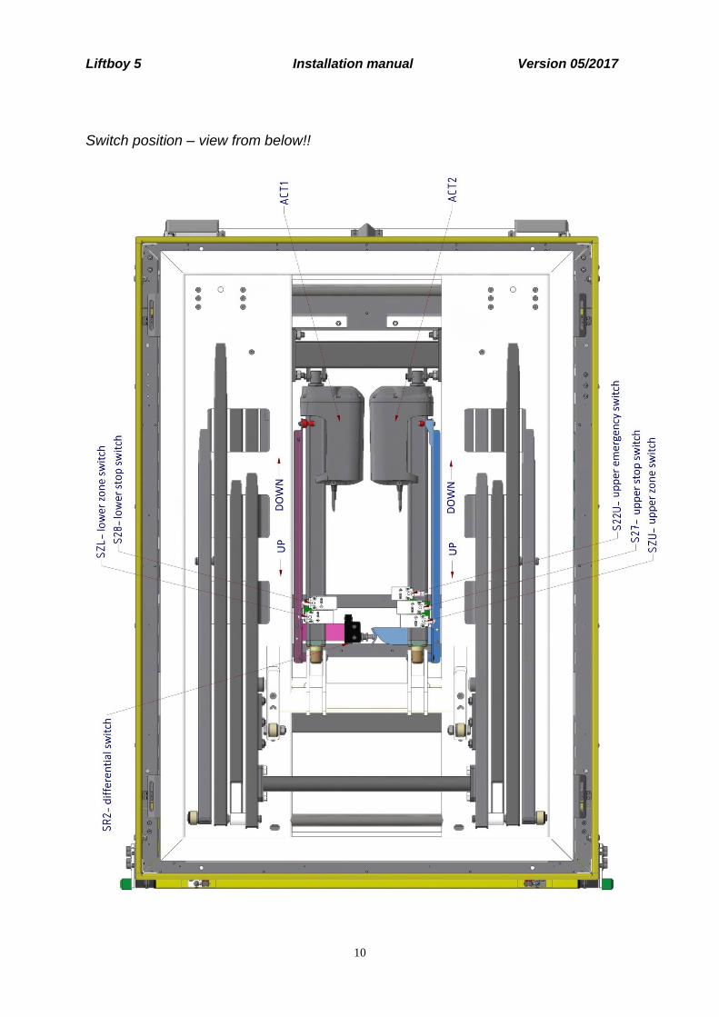
Picture of all the limit switches placed on a platform. Limit switches are placed directly under the floor, right on
motors. Switches for lower stop on a motor M1 which is placed on the left, limit switch of the upper stop on a
motor M2 on the right.
Pic. 24 Display of limit switches (bottom view)
SZL - Lower zone
switch
SZU - Upper zone
switch
S27U - Upper Stop
Switch
S11U - Upper
emergency switch
S28 - Lower stop
switch
Liftboy 5 Installation manual Version 05/2017
10
Switch position – view from below!!

Liftboy 5 Installation manual Version 05/2017
11
Guide blocks to be
removed before using
installation method 1.
Installation
The folded platform has a net weight of 270kg. 4 people will be necessary to move the platform
from the transport box to the installation location. Use belts that go under the whole structure to
lift and move the platform.
There are 2 ways to install the platform on site:
1. Bring the platform in the correct
position while assuring that there is
the necessary space in front of the
platform for entering the upper gate
with the shear wall. When the
platform is in place enter the upper
gate with shear wall from above and
make sure not to damage the guide
blocks on each side of the platform.
When in place fix the upper gate
wall in place and run the platform up
and down. If the run is smooth, then
fix also the platform to the ground.
2. First fix the upper gate with shear wall on the correct position on site. Then take
off the guide blocks on both side of the platform. Move the platform in the correct
position in front of the shear wall in such a way that the guide blocks can be put into the
guide profile and fixed again on the platform sides. Run the platform up and down. If
the run is smooth, then fix also the platform to the ground.
Use belts to connect to the
metal frame (2 connection
points are given on each
side). On each side of
platform 2 people can pull
on the belts to raise and
move the platform.

Liftboy 5 Installation manual Version 05/2017
12
Controls descpriptions:
Radio controls for landings stations:
Drive from external controllers can be set in a menu item “Options – Drive with permanently active buttons“,
the directional drive button must be activeted during the platform´s movement, respectively after the button is
not pressed anymore, platform standardly stops immediately.
Other option is allowed after a function “Activated imp.“ is selected, afterwards control button can be just
activated by a short press and the platform automatically drives all the way to the final stop in the chosen
direction. This function is only possible for the platform in a lift shaft.
Overload control
During motors activity, consumed current is monitored and after the set limit is exceeded, motors are stopped.
If platform´s overload control is active and the overload occurs when the platform leaves the lower stop (shown
on a display as „overload lift“) – the drive up is immediately interrupted and only drive down is allowed. The
platform must drive back to the lower stop, where it is possible to open ramps, respectively open lower door. By
doing so, platform returns to its standard mode and drive up is possible again.
Setting of the max motor current will be done in a menu digitally – setting in a range between 1 – 15 A (factory
default In=13A). Asymmetry of motors is also set in the menu in % of overcurrent threshold.
LED signalization
Key switch
Under the case
2 type AAA batteries
Inactive button
Inactive button
Down button – signal
RF-DOWN
Up button – signal RF-
UP

Liftboy 5 Installation manual Version 05/2017
13
Control description of automatic access ramp
The automatic ramp can be controlled by platform´s controller or the radio controller. Commands from the
platform´s controller has priority over any other controllers.
Opening of the automatic ramp is possible only in the lower stop (signalized by closing of the lower zone switch
of the ramp SZ=1, by activation of lower limit switch S28-2=0 and S28-3=1).
Movement of the ramp is blocked by any switch of a safety curcuit, that means that power supply of relay
KC1/K01 is interrupted.
During the actuator´s movement, current is monitored and after exceeding set limit for more than 0,3 sec, the
actuator´s movement is stopped, overcurrent safety works as an electronic limit switch.
Setting of the max actuator´s current is possible in menu – in between 0,5-6,9 A.
Exceeding of this limit is also shown on display.
Control description of manual and automatic door
Doors can be manual (equipped with electric door lock to secure the door – door has to be opened/closed
manually) or automatic (equipped with electric door lock and automatic door opener, usually NICE WALKY).
Function description of manual door operation:
In case of manual door the menu item „Config.door lck“ value is set to 0 (means 0 impulse for door opener).
Time of opened door lock, during which manual opening of the door after arrival in stop station is possible, can
be set in menu item „Config.door lck - Time open.DL“.
The respective door will also lock when drive button on the platform in opposite down/up direction is pressed.
If the platform is controled by wall mounted/radio controllers, ones has to wait until the timing of unlocking of
the door lock is finished and after that to select drive down/up.
Automatic door opener function description:
The door opens automatically after reaching the stop position. The time for which the door lock stays unlocked
and door stays opened, can be set in a menu item „Config. door lock“ „Time open. DL“. The factory setting is
30 seconds. This is also the minimal value for electric opener Nice WALKY!!
If you make changes, do not set the time less than 30 seconds. It must be 30 seconds or more.
The door will stay unlock for the set time, or until you press drive in down direction on the platfrom controls.
We have two setting versions for automatic opening of the door:
Version 1 – Standard – factory default
Version 2 - With blocking of door
Standard version: After the door opens it stays open for the set time or until you press drive in opposite
direction on the platform controls. From the external controls the platform can only be called/sent after the set
time passed and the platform closed automatically.
Version with blocking of door: This version allows the door to stay open permanently. If can be useful if the
platform is used for loading to goods.
In this version the door can be blocked in open position if you press the up button more then 3 seconds after the
door is fully opened. If you then want to unblock it again you have to press again the up button for more then 3
seconds and it will return to normal mode and close after the set time or when down button is pressed.
To set this version in the menu it is necessary to set the menu item „Config. door lck“ - „Impulse for DO“ on
value 1, the opened door time in parameter „Time open. DL“ on min 30 sec the menu item „Config. door lck“ -
„Version DO“ - „With blocking“.
Liftboy 5 Installation manual Version 05/2017
14
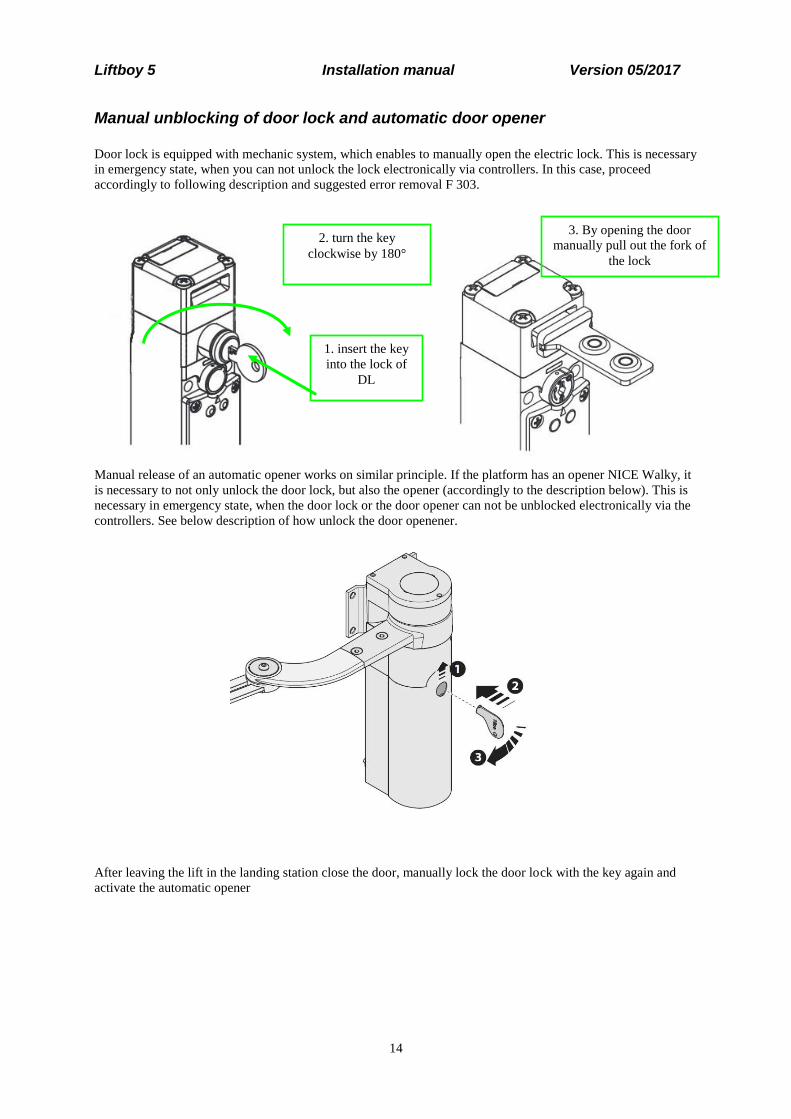
Manual unblocking of door lock and automatic door opener
Door lock is equipped with mechanic system, which enables to manually open the electric lock. This is necessary
in emergency state, when you can not unlock the lock electronically via controllers. In this case, proceed
accordingly to following description and suggested error removal F 303.
Manual release of an automatic opener works on similar principle. If the platform has an opener NICE Walky, it
is necessary to not only unlock the door lock, but also the opener (accordingly to the description below). This is
necessary in emergency state, when the door lock or the door opener can not be unblocked electronically via the
controllers. See below description of how unlock the door openener.
After leaving the lift in the landing station close the door, manually lock the door lock with the key again and
activate the automatic opener
1. insert the key
into the lock of
DL
2. turn the key
clockwise by 180°
3. By opening the door
manually pull out the fork of
the lock

Liftboy 5 Installation manual Version 05/2017
15
Emergency opening of the automatic access ramp:
In a case that electric opening of the ramp does not work, it can be opened manually in the lower stop in order to
release a passenger.
Dismantle 2 screws M8x40 DIN912, secure the loosen ramp and slowly lower it down manually towards the
ground.
Dismantle 2pcs
screws M8x40 for
manual emergency
ramp opening

Liftboy 5 Installation manual Version 05/2017
16
Switches and connectors on the control unit
In this chapter, function and activity of each switch on the main control board will be described.
Connector for the
display
Connector for
radio receiver
Acoustic
warning device HF1
(buzzer)
Button S1 to set
a receiver
Switch S2 for
menu selection Memory unit
EEPROM

Liftboy 5 Installation manual Version 05/2017
17
Switch S2
This switch selects between user/service menu types. For the detailed descripion see chapter 0

Liftboy 5 Installation manual Version 05/2017
18
Menu.
User menu Service menu
PIC. 11 Detailed look at the switch S2 on Liftboy CU
WARNING: After the platform installation and setting all service menu parameters, push the switch S2 to the
positon for user menu!!!.
Button S1
This button serves for pairing/programming the attached RF receiver with the RF transmitters (RF wall-mount
controllers). See overview of main board for button location.

Liftboy 5 Installation manual Version 05/2017
19
LED signalization on platform´s control unit
LD3 input SS active
LD16 input S7X active
LD39 input SZ active
LD4 input S20 active
LD15 input RSV2 active
LD29 input EKU active
LD1 charging active
LD9 input S11C.3 active
LD8 input S11C.2
active
LD300 input S110.3 active
active
LD10 vstup S110.2 active
LD11 input SU active
LD22 input S27.3 active
LD27 input S27.2 active
LD33 input EKD active
LD26 input S28.3 active
LD21 input SR2 active
LD18 input SR1 active
LD17 input S22U active
LD28 input S28.2 active
LD7 input S21L active
LD14 input RSV1 active
LD19 input SDU active
LD12 inpute ODU active
LD2 input S5A active
LD5 input S21 active
LD6 input S20L active
LD23 closed relay KC1
LD37 input SZU active
LD24 closed relay K01
LD13 input ODL active
LD20 input SDL active
LD30 closed relay KLU
LD38 input SZL active
LD25 closed relay KLL
LD32 closed relay RKOUO
LD31 closed relay RKOLO
LD36 closed transistor T4
LD301 closed relay RKOLC
LD302 closed relay RKOUC
LD35 closed relay K1D
LD34 closed relay K1U

Liftboy 5 Installation manual Version 05/2017
20
Description of LED signalization of platform´s control unit
Name Colour Function
LD1 green Lights when battery charging is active
LD2 green Lights when alarm input is activated
LD3 green SS; Lights when the control key is active
LD4 green S20; drive up button is pressed on the platform
LD5 green S21; drive down button is pressed on the platform
LD6 green S20L; drive up button is pressed on one of the wall mounted controllers
LD7 green S21L; drive down button is pressed on one of the wall mounted controllers
LD8 green S11C.2 reseve input for ramp
LD9 green S11C.3; Lights when the ramp is fully closed
LD10 green S110.2 reserve input for ramp
LD11 green SU; Overload control (not used)
LD12 green ODU; Ligths if upper door is open
LD13 green ODL; Lights if lower door is open
LD14 green RSV1; reserve input of control unit
LD15 green RSV2; reserve input of control unit LD16 green S7X; turns of after STOP-button is pressed
LD17 green S22U; turns off when the upper emergency switch is activated
LD18 green SR1; reserve input of an safety circuit
LD19 green SDU; turns off if the upper door is open
LD20 green SDL; turns off if the lower door is open
LD21 green SR2; Turns off if the motor synchronization switch is activated
LD22 green S27.3; Lights if the upper stop limit switch was activated
LD23 green Relay KC1; Lights if the ramp is closing
LD24 green Relay K01; Lights if the ramp is opening
LD25 green Relay KLL; Lights if coil of the upper electronic lock is activated, that means
lock is in the timing regime
LD26 green S28.3 Lights if the lower stop limit switch was activated
LD27 green S27.2; Lights if the platform is outside the upper stop
LD28 green S28.2; Lights if the platform is outside the lower stop
LD29 green EKU; Turns off when the upper safety bottom is activated (pressed)
LD30 green Relay KLU; Lights if coil of the lower electronic lock is activated, that means
lock is in the timing regime
LD31 green Relay RKOLO; Lights if the relay, which sends impulses to the lower automatic
door opener, is activated
LD32 green Relay RKOUO; Lights if the relay, which sends impulses to the upper
automatic door opener, is activated
LD33 green EKD; Turns off when the lower safety bottom is activated (pressed)
LD34 green Relay K1U; Light if the main drive up relays are activated
LD35 green Relay K1D; Light if the main drive down relays are activated
LD36 green T4; Light if the main control transistor T4 is activated
LD37 green SZU; Lights if the upper limit switch is released (platform is in the upper zone)
LD38 green SZL; Lights if the lower limit switch is released (platform is in the lower zone)

Liftboy 5 Installation manual Version 05/2017
21
Name Colour Function
LD39 green SZ; Lights if the lower limit switch is released (platform is in the lower zone)
LD300 green S110.3; Lights if the ramp is fully opened
LD301 green Relay RKOLC; spare relay for an opener
LD302 green Relay RKOUC; spare relay for an opener
Note: If some of the previous switches in the line of the safety circuit (eventually switches in the drive direction)
opens, not only does the appropriate LED turns off, but also LEDs for all the other following inputs, see the
schema in chapter 0 Schematics
Emergency drive control unit
CU of emergency drive is an optional item of platform´s equipement. This unit allows the user to drive to lower
station in a case of main CU failure or other unexpected failure.
If necessary, service person can change the direction of drive from emegency button by switching the conductors
on connectors for connection of main motors M1U/1 for M1D/1 and M2U/1 for M2D/1.
Pic. 13 Emergency drive CU
Connectors for
connection of main motor
M1 M1U/1 and M1D/1
Connectors for
connection of main motor
M2 M2U/1 and M2D/1

Liftboy 5 Installation manual Version 05/2017
22
Menu Following pictures show examples of standard information shown on a display in both USER and SERVICE
modes.
User menu with help hints during the fully opened ramp:
Shown hints on the display for in the lower stop
Example of an user menu when the platform is outside the landing stations:
Shown hints on the display for drive options in both directions
Service menu with info about voltage on the accumulators and current taken by active motors:
Display during the service mode drive
General info
Menu can be used to analyse errors, for the maintenance or the system configuration. Following chapters
illustrate and describe functions individually.
Menu has two scopes:
1. First one is limited (user menu) which is intended for end users and a technical support. Via this user
menu error list can be read and also basic system settings are allowed.
2. Second scope is full view (service menu) which is intended ONLY for technicians and service workers.
Via this service menu advanced parameter, behavior etc. settings can be done.
Liftboy 5 Installation manual Version 05/2017
23
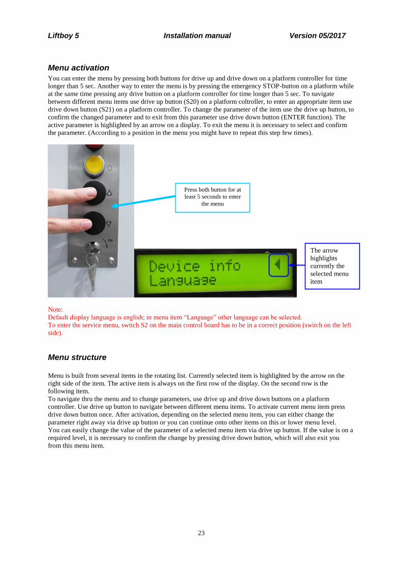
Menu activation
You can enter the menu by pressing both buttons for drive up and drive down on a platform controller for time
longer than 5 sec. Another way to enter the menu is by pressing the emergency STOP-button on a platform while
at the same time pressing any drive button on a platform controller for time longer than 5 sec. To navigate
between different menu items use drive up button (S20) on a platform coltroller, to enter an appropriate item use
drive down button (S21) on a platform controller. To change the parameter of the item use the drive up button, to
confirm the changed parameter and to exit from this parameter use drive down button (ENTER function). The
active parameter is highlighted by an arrow on a display. To exit the menu it is necessary to select and confirm
the parameter. (According to a position in the menu you might have to repeat this step few times).
Note:
Default display language is english; in menu item “Language” other language can be selected.
To enter the service menu, switch S2 on the main control board has to be in a correct position (switch on the left
side).
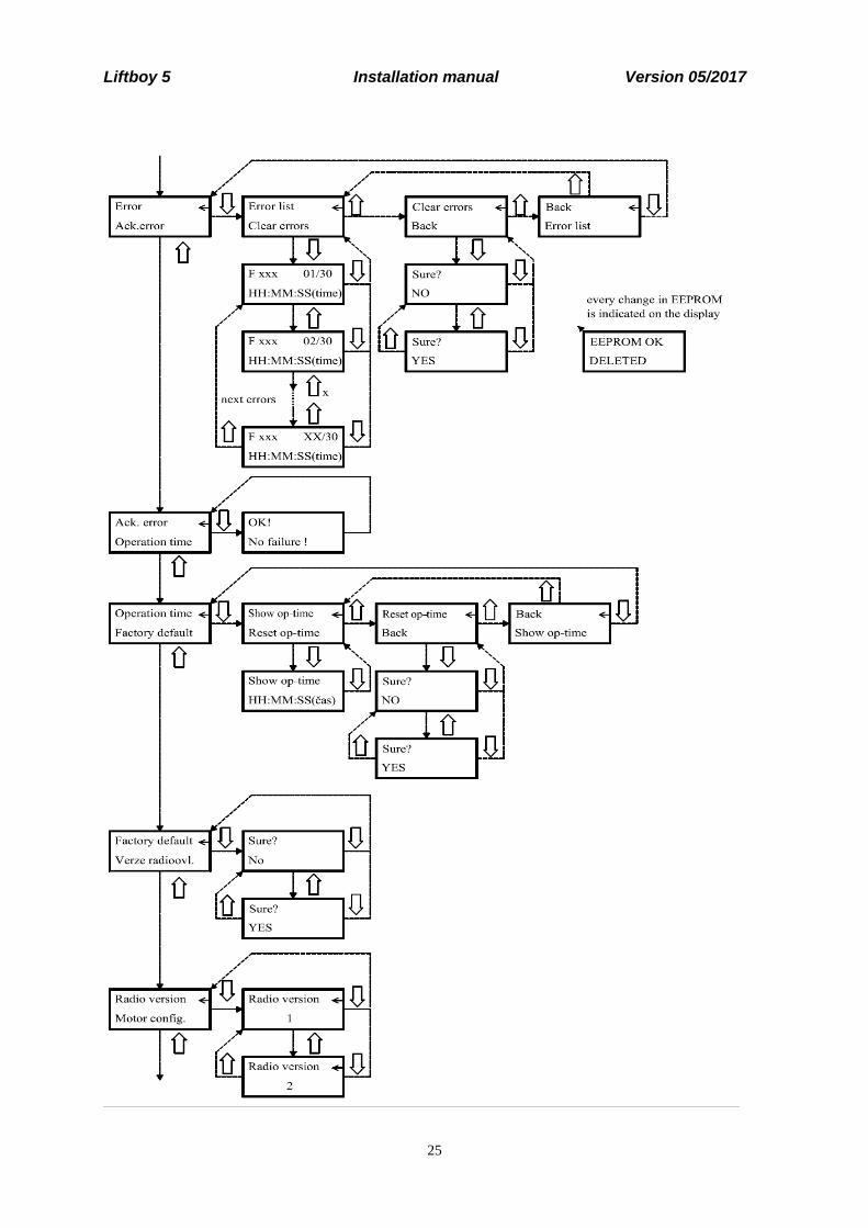
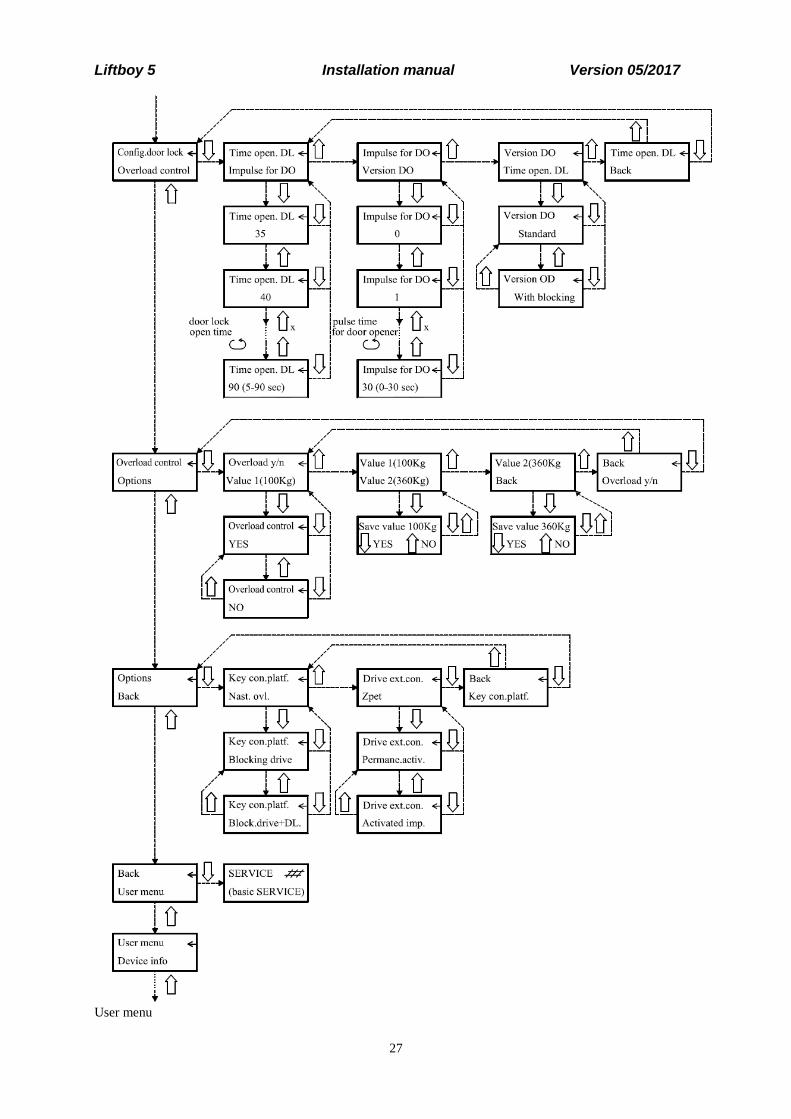
Menu structure
Menu is built from several items in the rotating list. Currently selected item is highlighted by the arrow on the
right side of the item. The active item is always on the first row of the display. On the second row is the
following item.
To navigate thru the menu and to change parameters, use drive up and drive down buttons on a platform
controller. Use drive up button to navigate between different menu items. To activate current menu item press
drive down button once. After activation, depending on the selected menu item, you can either change the
parameter right away via drive up button or you can continue onto other items on this or lower menu level.
You can easily change the value of the parameter of a selected menu item via drive up button. If the value is on a
required level, it is necessary to confirm the change by pressing drive down button, which will also exit you
from this menu item.
The arrow
highlights
currently the
selected menu
item
Press both button for at
least 5 seconds to enter
the menu

Liftboy 5 Installation manual Version 05/2017
24
Service menu
Liftboy 5 Installation manual Version 05/2017
25

Liftboy 5 Installation manual Version 05/2017
26
Liftboy 5 Installation manual Version 05/2017
27
User menu

Liftboy 5 Installation manual Version 05/2017
28

Liftboy 5 Installation manual Version 05/2017
29
Menu items
In the following table there are all main menu items listed. Also it shows if the item is in user menu or in service
menu. This table also shows brief description of options, which are after main menu items.
Menu item User
menu Service
menu Description
User menu X
In this item you can set, if you can enter the menu in user regime
Device info X X
This item shows basic device info – HW and SW version, serial number
Language X X Display language can be set via this item
Factory number
X This item can store custom factory number.
Error X X
Shows list of recorded errors, also allows to delete this list.
Ack. Error X If activated, this item acknowledges found errors.
Operation time
X This item shows operation time and also allows to clear it.
Factory default
X Activation of this item restores all parameters to factory default.
Radio version X Allows radio module version setting.
Motor config. X
Allows to select the number of main motors if the platform has an automatic ramp and set the value of current of all motors
Config. door lock
X Allows to set a time needed to open door lock and a version of an automatic opening
Overload control
X Allows to activate/deactivate overload control, this item can also change basic overload setting
Options X Allows to set platform’s special functions
In the following paragraphs some of menu items will be described. Descriptions are structured as based in main
menu. Factory default settings are underlined in following lists. These settings can be restored by resetting
system to factory default settings.
User menu
Menu item Value Name Description
User menu YES Allows the user to enter the user menu
Blocked Blocks the user from entering the user
menu

Liftboy 5 Installation manual Version 05/2017
30
Device info
First row shows the type of device LIFTBOY, the version of HW and SW of CU.Second row shows factory
number.
Language
Menu item Value Name Description
Language CZE Czech One of these can be selected
ENG English
GER German
ESP Spanish
FRA French
PL Polish
Factory number
A factory or identification number can be set by this menu item (5 digits). Command for the movement up can
change current digit. The currently edited digit is underlined. Command for the movement down can move onto
the next digit.
Errors
Menu item Value Name Description
Error list Fxxx n/30 h:m:s
- Shows list of stored errors, saved in menu. First row shows code number of error Fxxx (see table of errors) and order of error item in the error list (max 30 items). Second row shows current operation time when error appeared.
Clear errors Sure? YES
- By activation and selecting YES all stored errors will be purged from the list.
CAUTION: List of errors can be deleted by the authorized technician only.
Acknowledge error
If the menu item is active, all errors that occured are acknowledged. Which means that an attempt for a deletion
of the wrong code occurs so the normal function of the platform can be restored. Errors which must be
acknowledged are mentioned in the table of errors. Platform´s behavior during errors is described in the table of
errors in chapter Fehler! Verweisquelle konnte nicht gefunden werden.. By acknowledging error item is not
removed from the error list. If you want to do so, you need to clear whole list as was described before.
Operation time
Menu item Value Name Description

Liftboy 5 Installation manual Version 05/2017
31
Show op-time h:m:s - This item shows current operation time in hrs:min:sec format
Reset op-time Sure? YES
- By activation and selecting YES operation time counter is cleared.
CAUTION: Operation time counter can be cleared by the authorized technician only.
Factory default
Activation of this item restores all parameters to factory default. Factory default settings are underlined in lists.
Radio controller version
Menu item Value Name Description
Radio version 1 TX-OMDE-V-01 (Schmidiger)
Allows radio module version setting
2 Reserve for other type of radio controller

Liftboy 5 Installation manual Version 05/2017
32
Motor configuration
Menu item Value Name Description
Number of main motors
Number of main motors 1
1 Allows to set a number of main motors on exactly one motor. This is used on platforms ZP1 and ZP2
Number of main motors 2
2 Allows to set a number of main motors on two motors. This is used on this platform ZP 5
El ramp:
Aut. ramp YES Platform has an automatic ramp
If this parameter is active, platform has an automaticaly tilted ramp. You have to adjust wiring of the lower zone switch on the CU
Aut. ramp NO Platform has a lower door
If this parameter is active, platform has a door in lower station. You have to adjust wiring of the lower zone switch on the CU
Current setting
Main drive 5-15
13
A Sets the current setting of the main motor, if there are two motors, this value applies to each one.
After exceeding this threshold, motor stops and „DRIVE MOTOR CURRENT LIMIT“ error is shown on the display
Differ. M1/M2 10-100%
50
% Determines a possible percentage difference in current taken by each motor. If the taken current on one of the mottors differs from the other by more than the set percentage, motors stop and a „LOAD DIFFERENCE M1/M2“ error is shown on the display
Actuator R 0,5-6,9
2,5
A Sets overcurrent threshold for ramp motor.
After exceeding this level, motor stops and an error message “ CURRENT LIMIT ACT – RAMP“ is shown on the display

Liftboy 5 Installation manual Version 05/2017
33
Door lock configuration
Menu item Value Name Description
Time open. DL 5-90
35
sec. Allows to set the necessary time to open the door. If an automatic door opener WALKY is in use, it is necessary to set this time to min 30 sec.
Impulse for DO 0-30
0 (=manual openingt of the door)
sec. Allows to set impulse length for an automatic door opener.
Factory default 0 is used for manual opening of the door.
If the platform has an automatic door opener WALKY, it is necessary to set this value on 1.
Version DO Standard Allows to set appropriate version of the door opener. For detailed description see chapter 1.1.3
With blocking
Overload control
Menu item Value Name Description
Overload y/n YES
Activation of this menu item and selecting YES activates platform´s overload watch
NO Activation of this menu item and selecting NO deactivates platform´s overload watch
Value 1 (100Kg) Save value 100Kg
YES
NO
By activation of this menu item and selecting YES, we save a corresponding load of 100kg on a CU memory.
This menu item is usually used for factory setting of a platform.
Value 2 (350Kg) Save value 350Kg
YES
NO
By activation of this menu item and selecting YES, we save a corresponding load of 350kg on a CU memory.
This menu item is usually used for factory setting of a platform.
Liftboy 5 Installation manual Version 05/2017
34
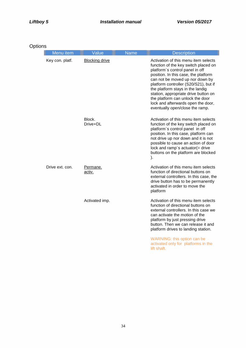
Options
Menu item Value Name Description
Key con. platf. Blocking drive Activation of this menu item selects function of the key switch placed on platform´s control panel in off position. In this case, the platform can not be moved up nor down by platform controller (S20/S21), but if the platform stays in the landig station, appropriate drive button on the platform can unlock the door lock and afterwards open the door, eventually open/close the ramp.
Block. Drive+DL
Activation of this menu item selects function of the key switch placed on platform´s control panel in off position. In this case, platform can not drive up nor down and it is not possible to cause an action of door lock and ramp´s actuator(= drive buttons on the platform are blocked ).
Drive ext. con. Permane. activ.
Activation of this menu item selects function of directional buttons on external controllers. In this case, the drive button has to be permanently activated in order to move the platform
Activated imp. Activation of this menu item selects function of directional buttons on external controllers. In this case we can activate the motion of the platform by just pressing drive button. Then we can release it and platform drives to landing station.
WARNING: this option can be activated only for platforms in the lift shaft.
Liftboy 5 Installation manual Version 05/2017
35
Radio wall mounted controllers
External wall mounted controllers communicate with the platform via radio signal. Standardly there is one in
each station.
Each wall mounted RF controller is supplied by 2 pcs ob batteries type AAA.
Following table describes all used colours and blinking combinations of signalization on
TX-OMDE-V-01 (Schmidiger) controller type :
State LED Description
Blinks in green Connection is established and control messages are passed to CU – normal
condition.
Blinks in orange Connection is lost. Keep button pressed – system will try to find not jammed signal
and reconnect.
Blinks in red Batteries in this controller are low. Replacing is necessary.
Lights in green Radio transmitter was succesfully connected to receiver during the programming
Lights in orange Connection is established but the platform is not moving.
Possible causes:
Safety circuit is opened
Error states e.i. motor overload, switch failure etc.
Error messages are shown on the display.
Lights in red Connection is established but there is no answer from the platform. Platform is
operated either from the platform controller or other remote RF controller..
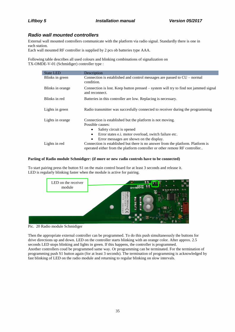
Pariing of Radio module Schmidiger: (if more or new radio controls have to be connected)
To start pairing press the button S1 on the main control board for at least 3 seconds and release it.
LED is regularly blinking faster when the module is active for pairing.
Pic. 20 Radio module Schmidiger
Then the appropriate external controller can be programmed. To do this push simultaneously the buttons for
drive directions up and down. LED on the controller starts blinking with an orange color. After approx. 2.5
seconds LED stops blinking and lights in green. If this happens, the controller is programmed.
Another controllers coud be programmed same way. Or programming can be terminated. For the termination of
programming push S1 button again (for at least 3 seconds). The termination of programming is acknowledged by
fast blinking of LED on the radio module and returning to regular blinking on slow intervals.
LED on the receiver
module

Liftboy 5 Installation manual Version 05/2017
36
1. remove cover of
emergency drive button
2. press emergency
drive button
Connectors for
connection of
main motor M1
Connectors for
connection of
main motor M2
M1U
M1S1
M2D
M2S1
M2U
M1D
M2S1 M1S2
Fuse 5A for
emergency
down drive
Emergency drive The emergency drive is an optional equipment of platform. This unit allows the user to drive to lower stop in a
case of main board failure or other unexpected failures.
Control of platform via emergency drive button S1 is allowed only if platform can not be controlled in any
standard way and it is necessary to extricate the user. Button S1 can not be used for ordinary use of platform!
To use emergency drive it is necessary to firstly remove the cover of button S1 (which is placed above the main
switch) and then press the button S1. After selecting this button the platform starts to move downwards. During
the emergency drive all safety and control systems are out of function.
After reaching lower station it is necessary to release the emergency drive button and manually open the door or
the platform ramp.
In a case of necessity, service worker can change the direction of movement of the platform from emergency
drive by switching the conductors on connectors for connection of main motors M1U/1 for M1D/1 and M2U/1
for M2D/1 on the emergeny drive CU. It will be necessary to change the fuse on connectors K1 and K2 on value
30A.
1. Turn off main switch SK1.
2. Switch connectors of motor M1 from M1U to M1S1, from M1D to M1S2 and motor M2 from M2U to M2S1,
from M2D to M2S2. Power supply of both motors must be changed!
3. Between connectors K1 and K2 insert fuse 5A.
4. Turn on main switch SK1 and platform immediately starts moving downwards.
For drive up (because of service reasons) it is necessary to switch M1S1 for M1S2 and M2S1 for M2S2 (for
motor M1: M1U to M1S2, M1D to M1S1 etc. for M2), use fuse 30A. Power supply of both motors must be
changed!

Liftboy 5 Installation manual Version 05/2017
37
Error and operating messages on display It is necessary to acknowledge (reset) errors F1xx after removal of their cause.
Acknowledging them doesn’t mean automatic deletion. Deletion must be done separately. If the error can not be
acknowledged the reason is that the root cause of this error is still present and was not repaired.
Errors F1xx shown below must be reset in the menu after they have been repaired. Reset can be done even by
turning off via the main switch.
Error ID Shown on display Description How to repair
F101 TRANSISTOR SHORT.
T4
Faulty transistor– there is voltage
on its output although it should
not (faulty control, punctured
transistor and so on)
Try to reset the error message by
switching off (for at least 2 sec)
and then turning on the main
switch. Afterwards, give a
command for movement and if this
error shows up again, it is
necessary to replace the whole CU
F102
TRANSISTOR FAILURE
T4
Transistor failure – did not close
(faulty control, transistor failure
and so on)
Try to reset the error message by
switching off (for at least 2 sec)
and then turning on the main
switch. Afterwards, give a
command for movement and if this
error shows up again, it is
necessary to replace the whole CU
F103 LOAD DIFFERENCE
M1/M2
Exceeding the set difference in
current of main motors M1 and
M2
Try to reset the error message by
switching off (for at least 2 sec)
and then turning on the main
switch, remove uneven load on the
platform, select drive up on any
controller, motors should level it;
manually level different height of
motors, read the current taken by
motors during the drive and check
the setting of difference of main
motors M1 and M2, and then check
setting the difference in current
taken
F104 ACTUATOR FAILURE
M1
Motor M1 is not active (current
on the motor M1= 0A)
Try to reset the error message by
switching off (for at least 2 sec)
and then turning on the main
switch, measure the voltage on
motors terminals, on directional
relays of appropriate motor; check
the cable connection between
motor and CU, replace the CU,
replace the motor
F105 ACTUATOR FAILURE
M2
Motor M2 is not active (current
on the motor M2= 0A)
Try to reset the error message by
switching off (for at least 2 sec)
and then turning on the main
switch, measure the voltage on
motors terminals, on directional
relays of appropriate motor; check
the cable connection between
motor and CU, replace the CU,
replace the motor

Liftboy 5 Installation manual Version 05/2017
38
Error ID Shown on display Description How to repair
F106 EEPROM FAILURE Nonfunctional EEPROM
memory
Try to reset the error message by
switching off (for at least 2 sec)
and then turning on the main
switch. Afterwards, give a
command for movement and if this
error shows up again, it is
necessary to replace the whole CU
Following errors are recorded in EEPROM but they don’t block operation of platform – don’t need
acknowledgement. They’re shown as long as the error is present or/and corresponding control buttons activated.
Error ID Shown display text Description How to repair
F201 EMERGENCY STOP
SI: S7X
STOP button pressed,
emergency input open S7X=0
Deactivate STOP button by
turning it in the direction of
arrows, if the STOP button is not
pressed, Check NC-contact by
STOP button, connecting cable
towards the CU, emergency
input S7X
F202 UP SAF.LIMIT SW
SI: S22U
Active upper safety limit
switch S22U=0
By movement of the platform
with emergency drive in the
direction down release the safety
switch S22U, check the adjusting
of the upper stop, limit switch
S27 and safety limit switch
S22U, stop element on a motor
ACT2 has to firstly press the
limit switch S27 and by doing so
to stop the motion of the
platform; If
the emergency switch is not
activated, check NC-contacts of
the switch S22U, connecting
cables towards CU, emergency
input S22U
F203 RESERVE SAF.C.SW
SI: SR1
Contact of the main safety
circuit is open, emergency
input SR1=0
Check the input bridge
connection on terminals SR1 on
CU
F204 ASYNCHR. ACTUAT.
SI: SR2, M1, M2
asynchronous movement of
main motors, contact SR2= 0
open. (standardly this switch is
not used, emergency input SR2
has to be bridged)
If SR is used: check the even
reaction of main motors, check
the setting of differential switch
SR 2; if the switch is not
activated, check NC-contact of
the switch SR2, connecting
cables towards the CU,
emergency input SR2

Liftboy 5 Installation manual Version 05/2017
39
Error ID Shown display text Description How to repair
F205 FAILURE ZON. SW.
SI: SZU, SZ/SZL
One or both zone switches are
in incorrect position
With no regard towards the
setting in the menu El. ramp -
YES/NO
SZU=1∧ SZL=1
∨ SZU=1∧ SZ=1
In this error state, the drive is
allowed in both directions if the
platform is outside the station,
after it reaches the station it is
prevented from leaving and it is
not allowed to automatically
lower the ramp or to open the
door; check the setting of zone
switches, if the platform is in one
of the stops, the contacts of the
zone switch has to be in closed
position and contacts of the other
one in permanetly opened
position; if the setting of the zone
switches is correct, check NC-
contact of the switches and
connecting cables towards the
CU on inputs SZU, ZL/SZ
F206 UNDEF.STATION SW
SI: S27, S28
One of limit switches is in
incorrect position (for
example, both limit switches
are active at the same time)
(S27-2=0 ∧ S28-2=0)
∨ (S27-3=1 ∧ S28-3=1)
Check the setting of limit
switches, check the mechanical
function of limit switches, check
inner wiring S27/S28, check
cable connection of the switches
with CU, check the wiring in CU
F301 STOP ˅DOWN
SI: EKD, RD
Safety edges hit an obstacle in
the drive direction down, this
message shows up only in
combination with the drive
down command
Ctrl DOWN=1 ∨ Wall ctrl
DOWN=1 ∨ RF- DOWN=1
∧ SENS EDGE DOWN= 0
Remove obstacle that prevents
the platfrom from movement
down, if necessary release the
obstacle by driving up, check the
setting of appropriate limit
switches of lower safety edges;
if the emergency switches are not
active, check the NC-contacts of
switches EKD 1 till 4 and their
serial connection, check
connecting cables on an input
EKD and a bridge-connection on
terminals RD
F302 STOP ˄UP
SI: EKU, S11S
Safety edges hit an obstacle in
the drive direction up, this
message shows up only in
combination with the drive up
command
Ctrl UP=1 ∨ Wall ctrl UP=1 ∨ RF-UP=1
∧ SENS EDGE UP= 0
Remove the obstacle that
prevents the platfrom from
movement up, check the setting
of appropriate limit switches of
upper safety edges;
if the emergency switches are not
active, check the NC-contacts of
switches EKU 1 and 2 and their
serial connection, check the
connecting cables on an input
EKU and a bridge-connection on
terminals S11S

Liftboy 5 Installation manual Version 05/2017
40
Error ID Shown display text Description How to repair
F303 FAILURE UP. LOCK
SI: 0/SDU
While giving command for
drive up in upper station, the
activation of coil and
unlocking of the door lock did
not occur or control contacts of
the lock did not switch -
(ODU=1, SDU=0)
Ctrl UP=1 ∨ Wall ctrl UP=1
∨ RF-UP=1 for more than
1sec.
∧ S27-3=1 ∧ S27-2=0 ∧
SZU=1
∧ (ODU=0 ∨ SDU=1)
Check the wiring and mechanical
function of door lock, check the
connection cables of the door
lock, correct function of the coil
of door lock DLU and
appropriate contacts SDU,ODU
When this error is present on a
platform with automatic door
opener NICE WALKY, the
impulse for door opener is not
coming, the door has to be
opened manually!
F304 FAIL: UP.ZON./SW
PRESS˅ SI:SZU/S27
Upper limit switch S27 is
actuated, but upper zone
switch SZU is open and drive
up is selected (example: after
reaching the upper stop, the
zone switch SZU remains
open)
S27-3=1 ∧ S27-2=0 ∧ SZU=0
∧ Ctrl UP=1 ∨ Wall ctrl UP=1
∨ RF-UP=1
Check the setting of upper stop,
stop element on motor ACT2 has
to firstly release the zone switch
SZU= 1 and then actuate the
limit switch S27-3=1 and S27-2=
0, check the switching
functionality of S27 and SZU,
check contacts of switches S27
and SZU, connecting cables on
inputs S27, SZU in the CU
F305 FAILURE UP. SW.
PRESS˅ SI: S27
Contacts of the upper limit
switch are not in its usual
position
(S27-3=0 ∧ S27-2=0)
∨ (S27-3=1 ∧ S27-2=1)
Displays during drive up
command, that is
Ctrl UP=1 ∨ Wall ctrl UP=1
∨ RF-UP=1
Check the function, setting and
connection of the limit switch
S27, check the contact system in
this switch, check connecting
cable on the input S27
F306 FAIL. LOWER LOCK
SI: 0/SDL
While giving command for
drive down in lower stop, the
activation of coil and
unlocking of the door lock did
not occur, or contacts of the
door lock did not switch
(ODL=1, SDL=0)
Ctrl DOWN=1 ∨ Wall ctrl
DOWN=1 ∨ RF-DOWN=1
for more than 1sec.
∧S28-3=1 ∧ S28-2=0
∧SZL=1
∧ (ODL=0 ∨ SDL=1)
Check the wiring and mechanical
function of door lock, check the
connection cables of the door
lock , correct function of the coil
of door lock DLL and
appropriate contacts SDL,ODL
When this error is present on a
platform with automatic door
opener NICE WALKY, the
impulse for door opener is not
coming, the door has to be
opened manually!
F307 F.LOWER ZON/SP
PRESS˄ SI: SZL/S28
Lower limit switch S28 is
actuated, but lower zone
switch SZL is open and drive
down is selected (example:
after reaching the lower stop,
the zone switch SZ remains
open)
S28-3=1 ∧ S28-2=0 ∧ SZL=0
∧ Ctrl DOWN=1 ∨ Wall ctrl
DOWN=1 ∨ RF- DOWN=1
Check the setting of the lower
stop, stop element on the motor
ACT1 has to firstly release the
zone switch SZL= 1 and then
actuate the limit switch S28-
3=1 and S28-2= 0, check the
switching functionality of S28
and SZL,check the contacts of
switches S28 and SZL,
connecting cables on inputs S28,
Liftboy 5 Installation manual Version 05/2017
41
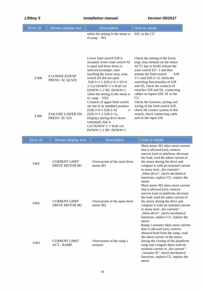
Error ID Shown display text Description How to repair
while the setting in the menu is
el.ramp – NO
SZL in the CU
F308 F.LOWER ZON/SP
PRESS˄ SI: SZ/S28
Lower limit switch S28 is
actuated, lower zone switch SZ
is open and drive down is
selected (example: after
reaching the lower stop, zone
switch SZ did not open
S28-3=1 ∧ S28-2=0 ∧ SZ=0
∧ Ctrl DOWN=1 ∨ Wall ctrl
DOWN=1 ∨ RF- DOWN=1
while the setting in the menu is
el. ramp – YES
Check the setting of the lower
stop, stop element on the motor
ACT1 has to firstly release the
zone switch SZ= 1 and then
actuate the limit switch S28-
3=1 and S28-2= 0, check the
switching functionality of S28
and SZ, check the contacts of
switches S28 and SZ, connecting
cables on inputs S28, SZ in the
CU
F309 FAILURE LOWER SW.
PRESS˄ SI: S28
Contacts of upper limit switch
are not in its standard position
(S28-3=0 ∧ S28-2=0) ∨
(S28-3=1 ∧ S28-2=1),
Displays during drive down
command, that is
Ctrl DOWN=1 ∨ Wall ctrl
DOWN=1 ∨ RF- DOWN=1
Check the function, setting and
wiring of the limit switch S28,
check the contact system in this
switch, check connecting cable
and on the input S28
Error ID Shown display text Description How to repair
F401 CURRENT LIMIT
DRIVE MOTOR M1
Overcurrent of the main drive
motor M1
Main motor M1 takes more current
that is allowed (set), remove
uneven load on platform, decrease
the load, read the taken current of
the motor during the drive and
compare it with set nominal current
in menu item „Set currents“ –
„Main drive“, check mechanical
functions, replace CU, replace the
motor
F402 CURRENT LIMIT
DRIVE MOTOR M2
Overcurrent of the main drive
motor M2
Main motor M2 takes more current
that is allowed (set), remove
uneven load on platform, decrease
the load, read the taken current of
the motor during the drive and
compare it with set nominal current
in menu item „Set currents“ –
„Main drive“, check mechanical
functions, replace CU, replace the
motor
F403 CURRENT LIMIT
ACT - RAMP
Overcurrent of the ramp´s
actuator
Ramp´s actuator takes more current
than is allowed (set), remove
obstacle/load from the ramp, read
the taken current of the motor
during the closing of the plaatform
ramp and compare them with set
nominal current in „Set current“ –
„Actuator R“, check mechanical
functions, replace CU, replace the
motor

Liftboy 5 Installation manual Version 05/2017
42
F412 EMPTY BATTERY
STOP
Voltage on the batteries dropped
under 19,4V, the drive up is
blocked
Reach the lower landing station
and let the batteries to charge
properly; if the batteries can not be
fully charged, it is necessary to
replace them, (note:all the batteries
have to be replaced)
F413 OVERLOAD LIFT
SI: SU, TENS. INPUT
CU evaluated overload of the
platform via start-off current
Movement is allowed only in the
down direction. After overload
detection, it is necessary to drive to
lower stop and reduce the load on
the platform; if it does not exceed
the allowed load, it is necessary to
check mechanical functions and
current taken by motors, or perform
new overload calibration (see chap.
Fehler! Verweisquelle konnte
nicht gefunden werden.)
Following errors are not recorded in the error message list and it is not necessary to reset them in menu. They are
shown only during the command from platform or radio controller.
Shown display text Description How to repair
DOOR OPEN FAULT
OPENER
Message is shown after the third (last)
automatic impulse for door opener and the
door remains open. This means
ODU = 1 v ODL = 1
Impulses are always sent after the time,
that is set in parameter Time open. DL, if
the door is not closed.
Remove obstacles that could obstruct door to
close automatically. Check the wiring of el.
opener and function of relay RKOUO or
relay RKOLO on CU, release opener
WALKY with a key and close the door
manually, check if the fork on the door
correctly falls into door lock, check the
wiring of el. door lock and its connection to
the CU, check if contacts (ODU, SDU) and
(ODL, SDL) switched into a position
allowing the movement (ODU=0 ∧ SDU=1
or ODL=0 SDL=1).
The door has to be closed manually, see chap.
0 Pic.1 Manual unlocking of an automatic
opener NICE walky
UP. DOOR OPEN
CLO.DO/ ˅ DOWN
Manual opening of the door:
Message is shown in upper landing station
if the door is open and any drive down
button is activated. Serves as a warning
that upper door is not closed and to enable
drive down the door has to be closed and
locked (secured?)
Ctrl DOWN=1 ∨ Wall ctrl DOWN=1∨
RF- DOWN=1 ∧
S27-3=1 ∧ S27-2=0 ∧ SZU=1 ∧
ODU=1 ∧ SDU=0
Manually close door, when the door is closed
manually check if the fork on the door fits
correctly into door lock, check the wiring of
el.lock, its connection towards the CU. Check
if contacts ODU and SDU switched into a
position that allows movement
(ODU= 0 ∧ SDU= 1)
Automatic opening of the door (both
versions):
Message is shown in upper landing station
if the door is not fully closed and drive
down button is pressed.
Ctrl DOWN=1 ∨ Wall ctrl DOWN=1∨
RF- DOWN=1 ∧
S27-3=1 ∧ S27-2=0 ∧ SZU=1 ∧
If automatic door is not closing, it is
necessary to wait for automatically generated
impulse, which is sent max 3 times in a row,
always with time delay that was set as „Time
open. DL“, if the door did not close even after
the third (last) automatic impulse, proceed
accordingly to description above, see :
DOOR OPEN FAULT
OPENER

Liftboy 5 Installation manual Version 05/2017
43
Shown display text Description How to repair
ODU=1 ∧ SDU=0
LOWER DOOR OPEN
CLO.DO/ ˄ UP
Manual opening of the door:
Message is shown in lower landing station
if the door is open and any drive up button
is activated. Serves as a warning that lower
door is not closed and to enable drive up
the door has to be closed and locked.
(secured?)
Ctrl UP=1 ∨ Wall ctrl UP=1∨ RF- UP=1 ∧
S28-3=1 ∧ S28-2=0 ∧ SZL=1 ∧
ODL=1 ∧ SDL=0
Manually close door, when the door is closed
manually check if the fork on the door fits
correctly into door lock, check the wiring of
el.lock, its connection towards the CU. Check
if contacts ODL and SDL switched into a
position that allows movement
(ODL= 0 ∧ SDL= 1)
Automatic opening of the door (both
versions):
Message is shown in lower landing station
if the door is not fully closed and drive up
button is pressed.
Ctrl UP=1 ∨ Wall ctrl UP=1∨ RF- UP=1 ∧
S28-3=1 ∧ S28-2=0 ∧ SZL=1 ∧
ODL=1 ∧ SDL=0
If automatic door is not closing, it is
necessary to wait for automatically generated
impulses, which are sent max 3x in a row
with a time delay that was set in Time
open.DL. If the door did not close after the
third impulse, proceed accordingly to
description above, see: DOOR OPEN
FAULT OPENER
UP. ST. LOCK - OPEN
SI: S27, SZU/SDU
Manual opening of the door:
Message is shown in upper landing station
after selecting any drive up button. Serves
as a warning that upper lock is unlocked
and we can open the door. This message
also shows up when the door is already
open, in this case drive up button has no
function.
Ctrl UP=1 ∨ Wall ctrl UP=1∨ RF- UP=1 ∧
S27-3=1 ∧ S27-2=0 ∧ SZU=1 ∧
ODU=1 ∧ SDU=0
If the lock is not unlocked and the door can
not be opened manually, check the wiring of
el.lock, see Error F307
Automatic opening of the door,
version 1 - Standard:
Message is shown in upper landing station
after selecting any drive up button, door
unlocks, automatic opening of the door is
happening.
For version 1 „Standard“: This message
also shows up if the door is open, in this
case drive up button has no function.
Ctrl UP=1 ∨ Wall ctrl UP=1∨ RF- UP=1 ∧
S27-3=1 ∧ S27-2=0 ∧ SZU=1 ∧
ODU=1 ∧ SDU=0
If the lock is not unlocked or if the door is not
opening, check the wiring of el.lock (see
Error F307) and check the circuit of automatic
door opener control (see chapter 0 Control
description of manual and automatic door
Liftboy 5 Installation manual Version 05/2017
44
Shown display text Description How to repair
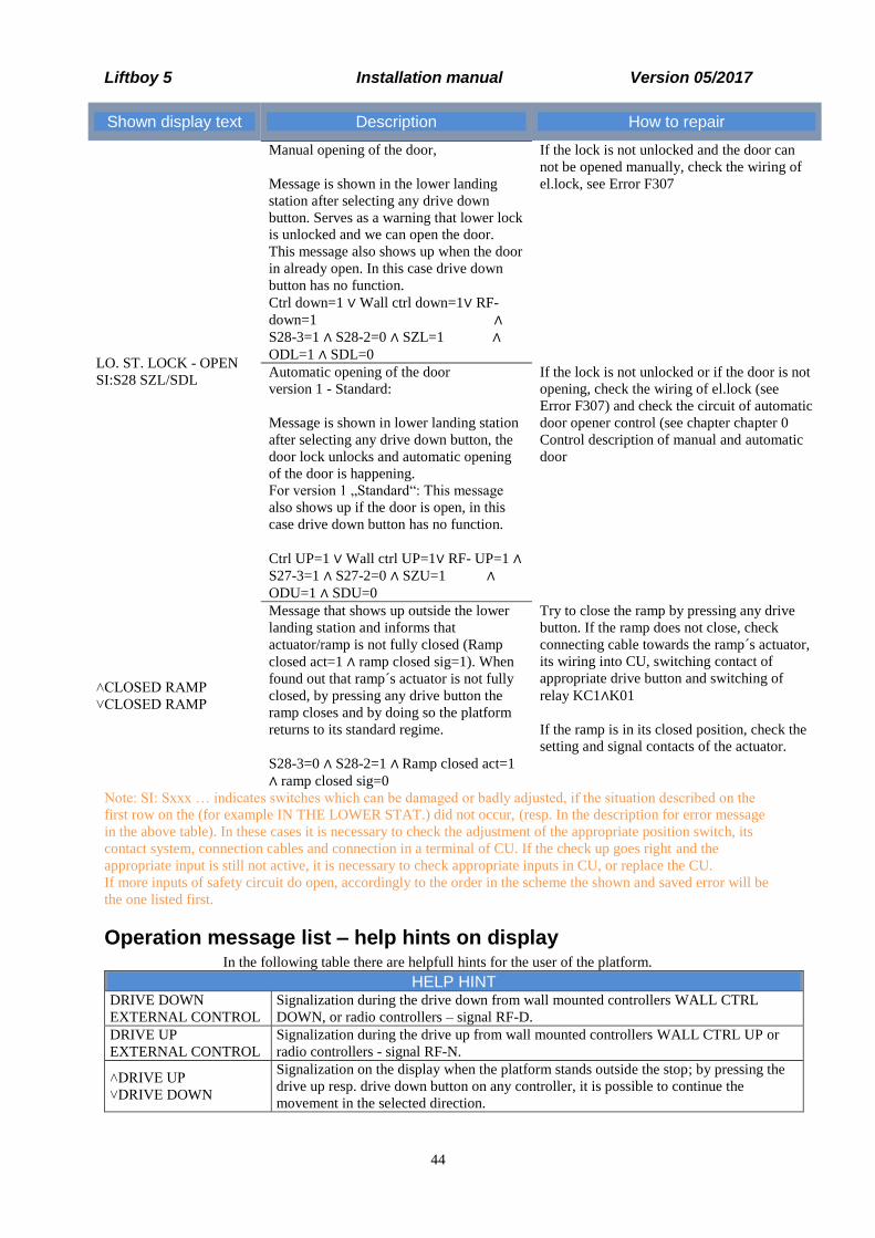
LO. ST. LOCK - OPEN
SI:S28 SZL/SDL
Manual opening of the door,
Message is shown in the lower landing
station after selecting any drive down
button. Serves as a warning that lower lock
is unlocked and we can open the door.
This message also shows up when the door
in already open. In this case drive down
button has no function.
Ctrl down=1 ∨ Wall ctrl down=1∨ RF-
down=1 ∧
S28-3=1 ∧ S28-2=0 ∧ SZL=1 ∧
ODL=1 ∧ SDL=0
If the lock is not unlocked and the door can
not be opened manually, check the wiring of
el.lock, see Error F307
Automatic opening of the door
version 1 - Standard:
Message is shown in lower landing station
after selecting any drive down button, the
door lock unlocks and automatic opening
of the door is happening.
For version 1 „Standard“: This message
also shows up if the door is open, in this
case drive down button has no function.
Ctrl UP=1 ∨ Wall ctrl UP=1∨ RF- UP=1 ∧
S27-3=1 ∧ S27-2=0 ∧ SZU=1 ∧
ODU=1 ∧ SDU=0
If the lock is not unlocked or if the door is not
opening, check the wiring of el.lock (see
Error F307) and check the circuit of automatic
door opener control (see chapter chapter 0
Control description of manual and automatic
door
˄CLOSED RAMP
˅CLOSED RAMP
Message that shows up outside the lower
landing station and informs that
actuator/ramp is not fully closed (Ramp
closed act=1 ∧ ramp closed sig=1). When
found out that ramp´s actuator is not fully
closed, by pressing any drive button the
ramp closes and by doing so the platform
returns to its standard regime.
S28-3=0 ∧ S28-2=1 ∧ Ramp closed act=1
∧ ramp closed sig=0
Try to close the ramp by pressing any drive
button. If the ramp does not close, check
connecting cable towards the ramp´s actuator,
its wiring into CU, switching contact of
appropriate drive button and switching of
relay KC1∧K01
If the ramp is in its closed position, check the
setting and signal contacts of the actuator.
Note: SI: Sxxx … indicates switches which can be damaged or badly adjusted, if the situation described on the
first row on the (for example IN THE LOWER STAT.) did not occur, (resp. In the description for error message
in the above table). In these cases it is necessary to check the adjustment of the appropriate position switch, its
contact system, connection cables and connection in a terminal of CU. If the check up goes right and the
appropriate input is still not active, it is necessary to check appropriate inputs in CU, or replace the CU.
If more inputs of safety circuit do open, accordingly to the order in the scheme the shown and saved error will be
the one listed first.
Operation message list – help hints on display In the following table there are helpfull hints for the user of the platform.
HELP HINT
DRIVE DOWN
EXTERNAL CONTROL
Signalization during the drive down from wall mounted controllers WALL CTRL
DOWN, or radio controllers – signal RF-D.
DRIVE UP
EXTERNAL CONTROL
Signalization during the drive up from wall mounted controllers WALL CTRL UP or
radio controllers - signal RF-N.
˄DRIVE UP
˅DRIVE DOWN
Signalization on the display when the platform stands outside the stop; by pressing the
drive up resp. drive down button on any controller, it is possible to continue the
movement in the selected direction.

Liftboy 5 Installation manual Version 05/2017
45
HELP HINT
LOW BATTERY Signalization when the voltage on batteries drops below 20,4V; decrease in voltage is
also signalized by quick interrupted acoustic signal.
BATERRY IS NOT
CHARGING
There is no signal from the input of charging accumulator, charger is disconnected or
damaged, this state is also signalized by interrupted acoustic signal. In this case it is
necessary to immediately restore the charging of batteries or to switch off the main
switch and make sure that the main switch is accessible afterwards. Otherwise the
batteries would become fully descharged and damaged.
˄UNLOCK DOOR
˅DRIVE DOWN
Message shown in upper landing station when the door is closed and locked (ODU=0 ∧
SDU=1), when KLU=0 and no drive button is activated. Serves as a hint for a
possibility to unlock the door lock or in a case of automatic version to open the door by
pressing the drive up button or by drive down button to leave the upper landing station.
Ctrl up=0 ∧ Ctrl down = 0 ∧ Wall ctrl up=0 ∧ Wall ctrl down=0 ∧ RF- UP=0 ∧ RF
down 0 ∧ S27-3=1 ∧ S27-2=0 ∧ SZU =1 ∧ ODU=0 ∧ SDU=1
˄DRIVE UP
˅UNLOCK DOOR
Message shown in lower landing station when the door is closed and locked (ODL=0 ∧
SDL=1), when KLL=0 and no drive button is activated. Serves as a hint for a possibility
to unlock the door lock or in a case of automatic version to open the door by pressing
the drive down button or by drive up button to leave the lower landing station.
Ctrl up=0 ∧ Ctrl down = 0 ∧ Wall ctrl up=0 ∧ Wall ctrl down=0 ∧ RF- UP=0 ∧ RF
down 0 ∧ S28-3=1 ∧ S28-2=0 ∧ SZL =1 ∧ODL=0 ∧ SDL=1
UP. DOOR OPEN SI:
0/SDU
Message shown in upper landing station when the door is open (ODU=1 ∧ SDU=0),
relay KLU=0 which means that door lock is not active anymore and no drive button is
pressed.
In a case of manual version this serves as a warning that upper door is open.
In a case of automatic version the door should automatically close, be fully opened or
blocked by an obstacle.
If the automatic opener did not start to move with the door, check the functionality
of relay KRKOUO and wiring of el. opener.
Ctrl up=0 ∧ Ctrl down = 0 ∧ Wall ctrl up=0 ∧ Wall ctrl down=0 ∧ RF- UP=0 ∧ RF
down 0 ∧ S27-3=1 ∧ S27-2=0 ∧ SZU =1 ∧ ODU=1 ∧ SDU=0
LOW. DOOR OPEN
SI: 0/SDL
Message shown in lower landing station when the door is open (ODL=1 ∧ SDL=0),
relay KLL=0 which means that door lock is not active anymore and no drive button is
pressed.
In a case of manual version this serves as a warning that lower door is open.
In a case of automatic version the door should automatically close, be fully opened or
blocked by an obstacle..
If the automatic opener did not start to move with the door, check the functionality
of relay KRKOLO and wiring of el. opener.
Ctrl up=0 ∧ Ctrl down = 0 ∧ Wall ctrl up=0 ∧ Wall ctrl down=0 ∧ RF- UP=0 ∧ RF
down 0 ∧ S28-3=1 ∧ S28-2=0 ∧ SZL =1 ∧ODL=1 ∧ SDL=0
UP. ST. LOCK-OPEN
˅DRIVE DOWN
Message shown in upper landing station when the door is closed (or in a case of
automatic version the door is opening) ODU=1 ∧ SDU=0, relay KLU=1 which means
door lock is unlocked and no drive command was given.
In a case of manual version this serves as a warning that upper door is unlocked and we
can open the door.
In a case of automatic version 1 „Standard“ the door should automatically open or be
fully opened. Serves as a hint for a possibility to speed up the closing of the door by
pressing drive down button S21 on the platform.
If the automatic opener did not start to move with the door, check the functionality
of relay KRKOUO and wiring of el. opener.
Ctrl up=0 ∧ Ctrl down = 0 ∧ Wall ctrl up=0 ∧ Wall ctrl down=0 ∧ RF- UP=0 ∧ RF
down 0 ∧ S27-3=1 ∧ S27-2=0 ∧ SZU=1 ∧ ODU=1 ∧ SDU=0
LO. ST. LOCK-OPEN
˄DRIVE UP
Message shown in lower landing station when the door is closed (or in a case of
automatic version the door is opening) ODL=1 ∧ SDL=0, relay KLL=1 which means
door lock is unlocked and no drive command was given.
In a case of manual version this serves as a warning that lower door is unlocked and we
can open the door.

Liftboy 5 Installation manual Version 05/2017
46
HELP HINT
In a case of automatic version 1 „Standard“ the door should automatically open or be
fully opened. Serves as a hint for a possibility to speed up the closing of the door by
pressing drive up button S20 on the platform.
If the automatic opener did not start to move with the door, check the functionality
of relay KRKOLO and wiring of el. opener.
Ctrl up=0 ∧ Ctrl down = 0 ∧ Wall ctrl up=0 ∧ Wall ctrl down=0 ∧ RF- UP=0 ∧ RF
down 0 ∧ S28-3=1 ∧ S28-2=0 ∧ SZL=1 ∧ ODL=1 ∧ SDL=0
LOWER STATION
˄DRIVE UP
Message shown in the lower stop if the ramp is fully open. Serves as a hint for a user to
safely leave the platform or as an option for closing of the ramp by any drive up button.
Ctrl UP=0 ∨ Wall ctrl UP=0∨ RF- UP=0 S28-3=1 ∧ S28-2=0 ∧ SZL=1 Ramp
closed act=1 ∧ ramp closed sig=0 ∧ ramp open= 1
˄ DRIVE UP ˅
OPEN RAMP
Message shown in the lower stop. Serves as a hint for leaving the platform by opening
the ramp via any drive down button or to drive up after selecting any drive up button.
S28-3=1 ∧ S28-2=0 ∧ SZL=1
Ramp closed act=1 ∧ ramp closed sig=1 ∨ 0
Shown until the ramp is fully opened
˄BLOCK. DOOR
˅DRIVE DOWN
Message shows only if the menu item „Version DO“ is set to „With blocking“.
Message shown in upper landing station when the door/lock is unlocked (ODU=1 ∧
SDU=0), relay KLU=1 and no drive command was given. Door should automatically
open or be fully opened.
Serves as a hint for a possibility to speed up the closing of the door by pressing drive
down button S21 on the platform or to keep the door in its fully opened position by
pressing drive up button S20 on the platform for time longer than 3 sec.
For more see the process and message in help ∧ ACTIV. DOOR
Ctrl up=0 ∧ Ctrl down = 0 ∧ Wall ctrl up=0 ∧ Wall ctrl down=0 ∧ RF- UP=0 ∧ RF
down 0 ∧ S27-3=1 ∧ S27-2=0 ∧ SZU=1 ∧ ODU=1 ∧ SDU=0
˄ DRIVE UP
˅ BLOCK. DOOR
Message shows only if the menu item „Version DO“ is set to „With blocking“.
Message shown in lower landing station when the door/lock is unlocked (ODL=1 ∧
SDL=0), relay KLL=1 and no drive command was given. Door should automatically
open or be fully opened.
Serves as a hint for a possibility to speed up the closing of the door by pressing drive up
button S20 on the platform or to keep the door in its fully opened position by pressing
drive down button S21 on the platform for time longer than 3 sec.
For more see the process and message in help ∧ ACTIV. DOOR
Ctrl up=0 ∧ Ctrl down = 0 ∧ Wall ctrl up=0 ∧ Wall ctrl down=0 ∧ RF- UP=0 ∧ RF
down 0 ∧ S28-3=1 ∧ S28-2=0 ∧ SZL=1 ∧ ODL=1 ∧ SDL=0
˄ ACTIVE DOOR
Message shows only if the menu item „Version DO“ is set to „With blocking“.
If any of these three options is fulfilled:
1. After reaching upper landing station, during the opening of the door or if the door is
open, drive up button S20 was activated for time longer than 3 sec and this blocked
upper door in opened position (see description above ˄BLOCK. DOOR)
Unblocking followed by closing of the door is possible after pressing drive up button
S20 on the platform for time longer than 3 sec.
2. By pressing drive down button S21 on the platform the unlocking of the door lock
ended, this sped up the closing of the door.
If during the closing of the door drive up button S20 was activated on the platform for
time longer than 3 sec, the door starts to open again. Then after another press of the
button it starts to close and so on.
3. After the time for opening of the door runs out and automatic command for closing of
the door is given (function of the door opener switched into „Standard version“) and the
door did not close even after third automatically generated impulse, it is possible to try
(if the opener´s CU is alright) to open/close the door by pressing drive up button S20 on
the platform for time longer than 3 sec.

Liftboy 5 Installation manual Version 05/2017
47
HELP HINT
During the time when the opener is in „Standard version“, you also get corresponding
messages on the display, such as UP. DOOR OPEN/SI: 0/SDU.
Generally, this message serves as a hint for a possibility to activate the movement of the
door in any direction and ,if the door is already moving, to change the direction of the
movement.
Note: if we choose the direction for the opening, the door stays in its fully opened
position until next command from button S20 on the platform is given.
Relay KLU=0 (not active)
Ctrl up=0 ∨ Ctrl up=1 ∨ Ctrl down = 0 ∨ Wall ctrl up=0 ∨ Wall ctrl up=1 ∨ Wall ctrl
down=0 ∨ RF- UP=0 ∨ RF- UP=1 ∨ RF down 0 ∧ S27-3=1 ∧ S27-2=0 ∧ SZU=1 ∧
ODU=1 ∧ SDU=0
˅ ACTIVE DOOR
Message shows only if the menu item „Version DO“ is set to „With blocking“.
If any of these three options is fulfilled:
1. After reaching lower landing station, during the opening of the door or if the door is
open, drive down button S21 was activated for time longer than 3 sec and this blocked
lower door in opened position (see description above ˄BLOCK. DOOR)
Unblocking followed by closing of the door is possible after pressing drive down button
S21 on the platform for time longer than 3 sec.
2. By pressing drive up button S20 on the platform the unlocking of the door lock
ended, this sped up the closing of the door.
If during the closing of the door drive down button S21 was activated on the platform
for time longer than 3 sec, the door starts to open again. Then after another press of the
button it starts to close and so on.
3. After the time for opening of the door runs out and automatic command for closing of
the door is given (function of the door opener switched into „Standard version“) and the
door did not close even after third automatically generated impulse, it is possible to try
(if the opener´s CU is alright) to open/close the door by pressing drive down button S21
on the platform for time longer than 3 sec.
During the time when the opener is in „Standard version“, you also get corresponding
messages on the display, such as UP. DOOR OPEN/SI: 0/SDU.
Generally, this message serves as a hint for a possibility to activate the movement of the
door in any direction and ,if the door is already moving, to change the direction of the
movement.
Note: if we choose the direction for the opening, the door stays in its fully opened
position until next command from button S21 on the platform is given.
Relay KLL=0 (not active)
Ctrl up=0 ∨ Ctrl down = 1 ∨ Ctrl down = 0 ∨ Wall ctrl up=0 ∨ Wall ctrl down=1 ∨
Wall ctrl down=0 ∨ RF- UP=0 ∨ RF down 1 ∨ RF down 0 ∧ S27-3=1 ∧ S27-2=0 ∧
SZU=1 ∧ ODU=1 ∧ SDU=0

Liftboy 5 Installation manual Version 05/2017
48
Schematics

Liftboy 5 Installation manual Version 05/2017
49

Liftboy 5 Installation manual Version 05/2017
50
Wiring scheme without emergency drive relay unit
Wiring scheme with emergency drive relay unit
2 3321
M1
+-
-+
M2
HA
1
cab
le L
A3
6 2
x1
,5
cab
le L
A3
6 2
x1
,5
bla
ck
bro
wn
bla
ck
bro
wn
bro
wn
wh
ite
gre
en
LiY
Y 6
x0
,5
LiY
Y 1
0x
0,5
LiY
Y 1
6x
0,5
LiY
Y 3
x0
,5
CY
LY
2x
0,5
CY
LY
2x
0,5
CY
LY
2x
0,5
LiY
Y 3
x0
,5
CY
LY
2x
0,5
brown
green
white
brown
black
brown
black
black
brown
brown
green
white
brown
black
brown
black
brown
black
LiYY 6x0,5
23
0V
AC
/ 2
4 V
DC
24
V-
+2
30
V 5
0H
zL
NP
E
blu
e
white
black
red
blue
pink
gray
yellow
green
brown
purple
Up
per
sen
siti
ve
edge
Lo
wer
sen
siti
ve
edge
Do
or
op
ener
1
LIN
AK
LA
36
LIN
AK
LA
36
CO
NT
RO
L S
TIC
KE
R O
N A
PL
AT
FO
RM
yel
low
gra
y
brown
green
white
yel
low
gra
y
pink
blue
red
bla
ck
purple
12
12
21
21
EK
U.2
cab
le L
A2
3
CY
LY
2x
1,0
XS
3
SK
1
S5A
bro
wn
wh
ite
gra
y
pin
k
yel
low
gre
en
bro
wn
wh
ite
gre
en
yel
low
gra
y
pin
k
bro
wn
red
blu
ew
hit
e
gre
en
pu
rple
yel
low
bla
ck
red
black
brown
black
brown
black
black CYA 2,5 -
black CYA 2,5 +black CYA 2,5 +
black CYA 2,5 +
red
red
red
red
red
green
white
blue
yellow
orange
wh
ite
gre
en
yel
low
blu
e
ora
ng
e
L+
M1
S1
-
M1U
M1D
M1
S2
+
M2U
M2
S1
-
M2D
M2
S2
+
cable LA36 2x1,5
cable LA36 2x1,5
M1 wires 1,5mm
M2 wires 1,5mm
EM
ER
GE
NC
Y D
RIV
E C
ON
TR
OL
UN
IT
S1
JP5
S2
SN
122 1
wir
escl
utc
h
bro
wn
bla
ck
12
12
21
121 12 2
12
21
2 12 1 12
F1
K1
K2
LC
Dco
ntr
ast
M2
SF3M3KOLOKOUO- +SF4SZLDLLSDLODLSZUDLUSDUODUSZ
S2
0L
S20U
S21U
S2
1L
HA
S5A
SS
S20
S21
S7X
CHARGES11CS110SURSV2RSV1
A+
A-
B+
Lo
wer
sto
p s
wit
ch
S28
SZ
U
Up
per
zo
ne
swit
ch
S27
Up
per
sto
p s
wit
ch
S22U
Up
per
em
erg
ency
sw
itch
S22US22U
S22U S22U
S27-1 S27-1
S27-3 S27-3
SZU-2 SZU-2
SZU-1 SZU-1
SR2 SR2
SR2 SR2
SZL/SZ SZL/SZ
SZL/SZ SZL/SZ
S28-2 S28-2
S28-1 S28-1
XS 1
14
22
21
13
PENL
23
0V
50H
z
12
12
12
-+
ram
p d
riv
e o
n p
latf
orm
M3
M3
MA
X
MIN
bro
wn
yel
low
red
gre
en
blu
e
OU
T
IN
LIN
AK
LA
23
(opti
onal
)
2-N
O
3-N
C
CO
MM
Ch
arger
S1
RE
L1
RE
L2
AL
AR
M
KE
Y
SS
S20
S21D
RIV
E D
OW
N
DR
IVE
UP
ST
OP
S7X
-+
yel
low
bla
ck
gre
en
bro
wn
wh
ite
pin
k
gra
y
yel
low
EZ
1
14
1322
21
A2
A1
42
41
32
31
SD
U-R
SD
U
SD
U
OD
U
DL
U
(op
tio
nal
)
DO
OR
LO
CK
1 -
upp
er s
tati
on
secu
rep
eg
Open
DO
OR
C
lose
S28-3S28-3
S27-2S27-2
KO
LC
KO
UC
S22U
SR
1S
R2
S11S
EK
US
27
EK
DR
DS
28
14
22
21
13
21
22
14
13
13 14
22
21 1
3
14
22
21
Dif
fere
nti
al s
wit
ch (
opti
onal
)
SR
2
Lo
wer
zo
ne
swit
ch
SZ
L/S
Z
11
12
14
HF
1
2 4 6531
LC
D1
yel
low
red
gre
en
NO
CO
M
NCM
FI.
1
EK
D.1
EK
D.2
NC
CO
M
NO
EK
D.3
NC
CO
M
NO
EK
D.4
NC
CO
M
NO
NO
CO
M
NCM
FI.
1
EK
U.1
NC
CO
M
NO
MA
IN S
WIT
CH
bla
ck -
bla
ck +
bla
ck 0
,5
21
21
12
21
21
21
12 2 12 12 1 2 1 1212 12 12
bro
wn
12
32
13
1
wh
ite
1 2 3 4y
ello
w
gre
en
bro
wn
set
clo
sest
op
op
en
M /
ME
LS
B.B
.S
TO
PP
.P.
GM
1
gray
yellow
pink
white
green
brown
21
10
11
12
pu
rple
yel
low
Clo
seD
OO
RO
pen
peg
secu
re
DO
OR
LO
CK
2 -
on p
latf
orm
/low
er s
tati
on
(op
tio
nal
)
DL
L
OD
L
SD
LSD
L
SD
L-R
31
32
41 42 A1
A2 21 22
13 14
EZ
2
yel
low
gra
y
pin
k
wh
ite
bro
wn
gre
en
gre
en
wh
ite
bro
wn
pin
k
gra
y
yel
low
gre
en
bro
wn
wh
ite
wh
ite
bro
wn
gre
en
yel
low
gra
y
pin
k
blu
e
red
987654321
XS
21
-48
07
08
-01
-48
07
09
-0
LO
CK
LO
CK
NA
ME
CH
AN
GE
13
12
10
98
711
LIS
T:
1
PO
ČE
T:
1
65
43
21
0
S1E
ME
RG
EN
CY
DR
IVE
blue
blue
brown
brown
bla
ck
bla
ckb
lack
bla
ck
bla
ck
bla
ck
blu
e
M1U
M1D
M1
S2
+
M1
S1
-
M2
S1
-
M2U
M2D
M2
S2
+
red
red
blu
e
M2 wires 1,5mm
M1 wires 1,5mm
M1
Mai
n d
rive
2M
ain
dri
ve
1
blu
eb
lue
bla
ckb
lack
bla
ckb
lack
bla
ckb
lack
M1
U/1
M1
D/1
M2
U/1
M2
D/1
bla
ck C
YA
2,5
-
BA
TT
ER
Y
+- 2x 1
2V
/9A
h -+
bla
ck C
YA
2,5
+
FU1
30A/24V MINI
gra
y
pin
k65 87 9
wh
ite
bro
wn
gre
en
gre
en
bro
wn
wh
ite
LIF
TB
OY
ZP
5
Wir
e co
nn
ecti
on
ele
men
ts Z
P5
ZP
-5 U
niv
ersa
l un
it
red
red
red
red
red
11.1
1.1
6
DA
TE
DA
TE
DR
AF
TE
D
VE
R.
EN
G
NO
RM
.
bro/gree.
bro./green
wh./gree.
white/gree.
red/blue
red/blue
gray/pink
gray/pink
LiY
Y 3
x0
,5
LiY
Y 3
x0
,5
up
per
sta
tion
on
pla
tfo
rm/l
ow
er s
tati
on
bro
wn
wh
ite
gre
en
ON
KE
Y
SS
1L
S2
0L
S2
1L
DR
IVE
DO
WN
DR
IVE
UP
OV
1
WA
LL
MO
UN
TE
D C
ON
TR
OL
LE
RS
up
per
sta
tion
WA
LL
MO
UN
TE
D C
ON
TR
OL
LE
RS
lo
wer
sta
tion
OV
2
DR
IVE
UP
DR
IVE
DO
WN
S21U
S20U
SS
1UK
EY
ON
gre
en
wh
ite
bro
wn
Do
or
op
ener
2
GM
2
P.P
.S
TO
PB
.B.
EL
SM
/ M
op
enst
op
clo
sese
t
+-
yel
low
bro
wn
wh
ite
gre
en
CA
BL
E 3
x1
,5
CY
LY
2x
1,0
black
brown
41
SH
EA
TIN
GP
LA
TF
OR
M
CY
LY
2x
0,5
CY
LY
2x
0,5
LiY
Y 6
x0
,5
LiY
Y 4
x0
,5
XS
3
CY
LY
2x
1,0
cab
le L
A2
3
EK
U.2
12
12
21
21
purple
bla
ck
red
blue
pink
gra
y
yel
low
white
green
brown
gra
y
yel
low
CO
NT
RO
L S
TIC
KE
R O
N A
PL
AT
FO
RM
LIN
AK
LA
36
LIN
AK
LA
36
Door
open
er 1
Low
er s
ensi
tive
edge
Upp
er s
ensi
tive
edge
purple
brown
green
yellow
gray
pink
blue
red
black
white
blu
e
PE
NL23
0V
50
Hz
+-
24
V
23
0V
AC
/ 2
4 V
DC
LiYY 6x0,5
black
brown
black
brown
black
brown
white
green
brown
brown
black
black
brown
black
brown
white
green
brown
CY
LY
2x
0,5
LiY
Y 3
x0
,5
CY
LY
2x
0,5
CY
LY
2x
0,5
CY
LY
2x
0,5
LiY
Y 3
x0
,5
LiY
Y 1
6x
0,5
LiY
Y 1
0x
0,5
LiY
Y 6
x0
,5
gre
en
wh
ite
bro
wn
bro
wn
bla
ck
bro
wn
bla
ck
cab
le L
A3
6 2
x1
,5
cab
le L
A3
6 2
x1
,5
HA
1
M2
+-
-+
M1
1 2 3 321
31
23
21
bro
wn
2 12 12 1 2 11212 12 122 1
12
12
12
21
12
12
bla
ck 0
,5
bla
ck +
bla
ck -
MA
IN S
WIT
CH
NO
CO
M
NC
EK
U.1
MF
I.1
NC
CO
M
NO
NO
CO
M
NC
EK
D.4
NO
CO
M
NC
EK
D.3
NO
CO
M
NC
EK
D.2
EK
D.1
MF
I.1
NC
CO
M
NO
gre
en
red
yel
low
LC
D1
1 3 5642
HF
1
S2
8R
DE
KD
S2
7E
KU
S1
1S
SR
2S
R1
S2
2U
KO
UC
KO
LC
S27-2 S27-2
S28-3 S28-3
Clo
seD
OO
R
Op
en
peg
secu
reD
OO
R L
OC
K 1
- u
pper
sta
tion
(op
tio
nal
)
DL
U
OD
U
SD
USD
U
SD
U-R
31
32
41 42 A1
A2 21 22
13
14
EZ
1
S27-1S27-1
S22US22U
S22U S22U
Upp
er e
mer
gen
cy s
wit
ch
S22U
Upper
sto
p s
wit
ch
S27
Upper
zone
swit
ch
SZ
U
S28
Low
er s
top s
wit
ch
B+
A-
A+
RSV1 RSV2 SU S110 S11C CHARGE
S7
XS
21
S2
0S
SS
5A
HA
S2
1L
S2
1U
S2
0U
S2
0L
SZ ODU SDU DLU SZU ODL SDL DLL SZL SF4 +- KOUO KOLO M3 SF3
LiY
Y 6
x0
,5
CY
LY
2x
0,5
CY
LY
2x
0,5
PL
AT
FO
RM
SH
EA
TIN
G
14
brown
black
CY
LY
2x
1,0
CA
BL
E 3
x1
,5gre
en
wh
ite
bro
wn
yel
low
-+
set
clo
sest
op
op
en
M /
ME
LS
B.B
.S
TO
PP
.P.
GM
2
Door
open
er 2
bro
wn
wh
ite
gre
en
ON
KE
Y
SS
1U
S2
0U
S2
1U
DR
IVE
DO
WN
DR
IVE
UP
OV
2
WA
LL
MO
UN
TE
D C
ON
TR
OL
LE
RS
lo
wer
sta
tion
WA
LL
MO
UN
TE
D C
ON
TR
OL
LE
RS
upper
sta
tion
OV
1
DR
IVE
UP
DR
IVE
DO
WN
S2
1L
S2
0L
SS
1LK
EY
ON
gre
en
wh
ite
bro
wn
on p
latf
orm
/low
er s
tati
on
upper
sta
tion
LiY
Y 3
x0
,5
LiY
Y 3
x0
,5
gray/pink
gray/pink
red/blue
red/blue
white/gree.
wh./gree.
bro./green
bro/gree.
NO
RM
.
VE
R.
EN
G
DR
AF
TE
D
DA
TE
DA
TE
11.1
1.1
6
01
23
45
6
PO
ČE
T:
1
LIS
T:
1
11
14
12
11
SZ
L/S
Z
Low
er z
on
e sw
itch
SR
2
Dif
fere
nti
al s
wit
ch (
op
tion
al)
21 22
1413
21
22
14
1313
14
22
21
13
2122
14
13
2122
14
XS 1
S28-1S28-1
S28-2S28-2
SZL/SZSZL/SZ
SZL/SZSZL/SZ
SR2SR2
SR2SR2
SZU-1SZU-1
SZU-2SZU-2
S27-3S27-3
yel
low
gra
y
pin
k
wh
ite
bro
wn
gre
en
bla
ck
1-4
80
70
9-0
1-4
80
70
8-0
XS
2
1 2 3 4 5 6 7 8 9
red
blu
e
pin
k
gra
y
yel
low
gre
en
bro
wn
wh
ite
wh
ite
bro
wn
gre
en
yel
low
gra
y
pin
k
bro
wn
wh
ite
gre
en
gre
en
bro
wn
wh
ite
pin
k
gra
y
yel
low
EZ
2
14
1322
21
A2
A1
42
41
32
31
SD
L-R
SD
L
SD
L
OD
L
DL
L
(op
tio
nal
)
DO
OR
LO
CK
2 -
on p
latf
orm
/low
er s
tati
on
secu
rep
eg
Op
enD
OO
RC
lose
yel
low
pu
rple
1211
10
12
brown
green
white
pink
yellow
gray
GM
1
P.P
.S
TO
PB
.B.
EL
SM
/ M
op
enst
op
clo
sese
t
bro
wn
gre
en
yel
low
4321w
hit
e
yel
low
+-
S7
X
ST
OP
DR
IVE
UP
DR
IVE
DO
WN
S2
1
S2
0
SS
KE
Y
AL
AR
M
Char
ger
CO
MM
3-N
C
2-N
O
LIN
AK
LA
23 (
opti
onal
)
IN OU
T
blu
e
gre
en
red
yel
low
bro
wn
MIN
MA
X
M3
ram
p d
riv
e on
pla
tform
M3
+ -
21
21
21
23
0V
50
Hz
L N PE
LiY
Y 4
x0
,5
78
91
01
21
3
CH
AN
GE
NA
ME
LO
CK
LO
CK
M1
S1
-
M1
U
M1
D
M1
S2
+
M2
U
M2
S1
-
M2
D
M2
S2
+
blu
eb
lue
bro
wn
bro
wn
red
red
red
red
red
ZP
-5 U
niv
ersa
l un
it
Wir
e co
nnec
tion
ele
men
ts Z
P5
ZP
5
LIF
TB
OY
wh
ite
bro
wn
gre
en
gre
en
bro
wn
wh
ite
97 85 6p
ink
gra
y
30A/24V MINI
FU1
bla
ck C
YA
2,5
+
+ -
2x 1
2V
/9A
h
- +BA
TT
ER
Y
bla
ck C
YA
2,5
-
Mai
n d
rive
1M
ain
dri
ve
2
con
tras
tL
CD
K2
K1
F1
2 112 12
12
21
22 11 2 1
12
21
21
bla
ck
bro
wn
clu
tch
wir
es
12 2 1
NS
S2
JP5
S1
cable LA36 2x1,5
cable LA36 2x1,5
L+
ora
ng
e
blu
e
yel
low
gre
en
wh
ite
orange
yellow
blue
white
green
red
red
red
red
red
black CYA 2,5 +
black CYA 2,5 + black CYA 2,5 +
black CYA 2,5 -
black
brown
black
brown
black
red
bla
ck
yel
low
pu
rple
gre
en
wh
ite
blu
e
red
bro
wn
pin
k
gra
y
yel
low
gre
en
wh
ite
bro
wn
gre
en
yel
low
pin
k
gra
y
wh
ite
bro
wn
S5
A
SK
1