technical manual - laminex nz - benchtops kitchens … · · 2015-05-27square edge...
TRANSCRIPT

another trade essential from
Technical Manual


Technical Manual
Edition 2 - July 2010
The Laminex Group24-26 O’Rorke Road,PO Box 12 270PenroseAuckland 1642New Zealand
Phone: 0800 303 606Fax: 0800 303 707www.thelaminexgroup.co.nz
Strandfl oor Square Edge, Strandfl oor Square Edge logo, Strandfl oor Tongue & Groove, Strandfl oor Tongue & Groove logo, Strandfl oor H3.1 Square Edge, Strandfl oor H3.1 Square Edge Logo, Strandfl oor H3.1 Tongue & Groove, Strandfl oor H3.1 Tongue & Groove logo, IBUILT, Lakepine and Trade Essentials Particleboard are trademarks of Fletcher Building Holdings and used under licence by The Laminex Group, a division of FLETCHER BUILDING PRODUCTS LTD. The Laminex Group and Trade Essentials are trademarks used under licence by The Laminex Group, a division of FLETCHER BUILDING PRODUCTS LTD.
another trade essential from


Page
Section 1 Scope & Interpretation . . . . . . . . . . . . . . . . . . . . . . . . . . . . . . . . . . . . . . . . . 1-1
Section 2 General Product Description . . . . . . . . . . . . . . . . . . . . . . . . . . . . . . . . 2-1
Section 3 Material Properties . . . . . . . . . . . . . . . . . . . . . . . . . . . . . . . . . . . . . . . . . . . . . . . 3-1
Section 4 Durability . . . . . . . . . . . . . . . . . . . . . . . . . . . . . . . . . . . . . . . . . . . . . . . . . . . . . . . . . . . . . . . 4-1
Section 5 Floor Design. . . . . . . . . . . . . . . . . . . . . . . . . . . . . . . . . . . . . . . . . . . . . . . . . . . . . . . . . . . 5-1
Section 6 Specification Clauses . . . . . . . . . . . . . . . . . . . . . . . . . . . . . . . . . . . . . . . . . . . . . 6-1
Section 7 Installation . . . . . . . . . . . . . . . . . . . . . . . . . . . . . . . . . . . . . . . . . . . . . . . . . . . . . . . . . . . . . 7-1
Section 8 Flooring Overlays . . . . . . . . . . . . . . . . . . . . . . . . . . . . . . . . . . . . . . . . . . . . . . . . . . 8-1
Section 9 Finishing. . . . . . . . . . . . . . . . . . . . . . . . . . . . . . . . . . . . . . . . . . . . . . . . . . . . . . . . . . . . . . . . . 9-1
Section 10 Maintenance. . . . . . . . . . . . . . . . . . . . . . . . . . . . . . . . . . . . . . . . . . . . . . . . . . . . . . . . 10-1
Section 11 Health & Safety . . . . . . . . . . . . . . . . . . . . . . . . . . . . . . . . . . . . . . . . . . . . . . . . . . . 11-1
Contents


1
Scope & Interpretation
1.1 Compliance . . . . . . . . . . . . . . . . . . . . . . . . . . . . . . . . . . . . . . . . . . . . . . . . . . . . . . . . . . . . . . . . . . . . . 1-1
1.2 Scope . . . . . . . . . . . . . . . . . . . . . . . . . . . . . . . . . . . . . . . . . . . . . . . . . . . . . . . . . . . . . . . . . . . . . . . . . . . . . . . 1-1
1.3 Interpretation . . . . . . . . . . . . . . . . . . . . . . . . . . . . . . . . . . . . . . . . . . . . . . . . . . . . . . . . . . . . . . . . . 1-1
1.4 Definitions. . . . . . . . . . . . . . . . . . . . . . . . . . . . . . . . . . . . . . . . . . . . . . . . . . . . . . . . . . . . . . . . . . . . . . . 1-1

1-1Scope & Interpretation
1.1 ComplianceStrandfloor has two BRANZ Appraisals - Strandfloor – No. 676 (2010) and Strandfloor H3.1- No. 677 (2010). The Appraisals cover the use of both product options within the scope of the New Zealand Building Code.
The valid Appraisals can be viewed on the BRANZ website – www.branz.co.nz
In the opinion of BRANZ, Strandfloor and Strandfloor H3.1 will meet the following provisions of the New Zealand Building Code:
Clause B1 STRUCTURE: Performance B1.3.1, B1.3.2 and B1.3.4 for loads arising from self-weight, oimposed gravity loads arising from use, earthquake, wind and impact [i.e. B1.3.3 (a), (b), (f), (h), and (j)].
Clause B2 DURABILITY: Performance B2.3.1 (a) not less than 50 years, and B2.3.1 (b) 15 years. o
Clause F2 HAZARDOUS BUILDING MATERIALS: Performance F2.3.1. o
Strandfloor H3.1 meets the criteria specified in NZS 3602 - Clause 110.3.1 and Table 1C.3 - Note 7. NZS 3602 being an Acceptable Solution to meet the requirement of the New Zealand Building Code – Clause B2 Durability.
1.2 ScopeThe Strandfloor information in this manual has been specifically designed in accordance with AS/NZS 1170 to comply with the appropriate design loadings for domestic and commercial buildings.
Strandfloor panels are suitable for timber framed buildings within the scope of NZS 3604, clause 1.1.2 and those uses specifically designed within this manual.
Tables 1.1 and 1.2 together with Figure, 1.1 and 1.2 in NZS 3604 may be used to determine the scope.
1.3 InterpretationInterpretation shall be as detailed in NZS 3604, clause 1.2.
1.4 DefinitionsDefinitions are those given in NZS 3604, clause 1.3.
C1.3.In particular, the words “shall” or “must” identify a mandatory requirement and “should” or “recommend” is advisory. Clauses prefixed by “C” (such as these) are intended as comments.

2
General Product Description
2.1 Strandfloor Material . . . . . . . . . . . . . . . . . . . . . . . . . . . . . . . . . . . . . . . . . . . . . . . . . . . . . . . 2-1
2.2 Identification . . . . . . . . . . . . . . . . . . . . . . . . . . . . . . . . . . . . . . . . . . . . . . . . . . . . . . . . . . . . . . . . . . 2-1
2.3 Uses . . . . . . . . . . . . . . . . . . . . . . . . . . . . . . . . . . . . . . . . . . . . . . . . . . . . . . . . . . . . . . . . . . . . . . . . . . . . . . . . . 2-1
2.4 Strandfloor Types . . . . . . . . . . . . . . . . . . . . . . . . . . . . . . . . . . . . . . . . . . . . . . . . . . . . . . . . . . . .2-2
2.4.1 Strandfloor Square Edge. . . . . . . . . . . . . . . . . . . . . . . . . . . . . . . . . . . . . . .2-2
2.4.2 Strandfloor Tongue & Groove . . . . . . . . . . . . . . . . . . . . . . . . . . . . . .2-2
2.4.3 Strandfloor H3.1 Square Edge . . . . . . . . . . . . . . . . . . . . . . . . . . . . . .2-2
2.4.4 Strandfloor H3.1 Tongue & Groove . . . . . . . . . . . . . . . . . . . . . .2-2
2.5 Flooring Guide . . . . . . . . . . . . . . . . . . . . . . . . . . . . . . . . . . . . . . . . . . . . . . . . . . . . . . . . . . . . . . . .2-3
Figure
2.1 Flooring Guide . . . . . . . . . . . . . . . . . . . . . . . . . . . . . . . . . . . . . . . . . . . . . . . . . . . . . . . . . . . . . . . .2-3

2-1General Product Description
2.1 Strandfloor MaterialHigh-density wood based panels are manufactured for The Laminex Group, primarily for use as flooring, under the trade mark Strandfloor™.
Panels are produced by pressing strands of wood together under heat and pressure.
2.2 IdentificationAll panels are ink marked on the underside with the product identification and a 5 digit manufacturing traceability number. Strandfloor H3.1 panels also have the NZ Timber Preservation Council registration number, the type of treatment and the Hazard Class included.
All panels will have a label on the upper face.
Strandfloor Tongue & Groove has a white polypropylene tongue. Strandfloor H3.1 Tongue & Groove has a green polypropylene tongue.
2.3 UsesStrandfloor can be used:
As pre-laid or post-laid flooring over traditional timber floor joists, engineered timber (“ o I” joists) such as IBUILT™ Structural Flooring Solutions or steel joist supports in single or double layer applications.
As an overlay to concrete floor slabs or wooden floors. o
As floor diaphragms for the transfer of wind and earthquake loads. o
For general stair construction. o
For shelving and packaging. o
As carcass members for cabinetry. o
square edge
tongue&groove
tongue&groove
square edge
2-2General Product Description
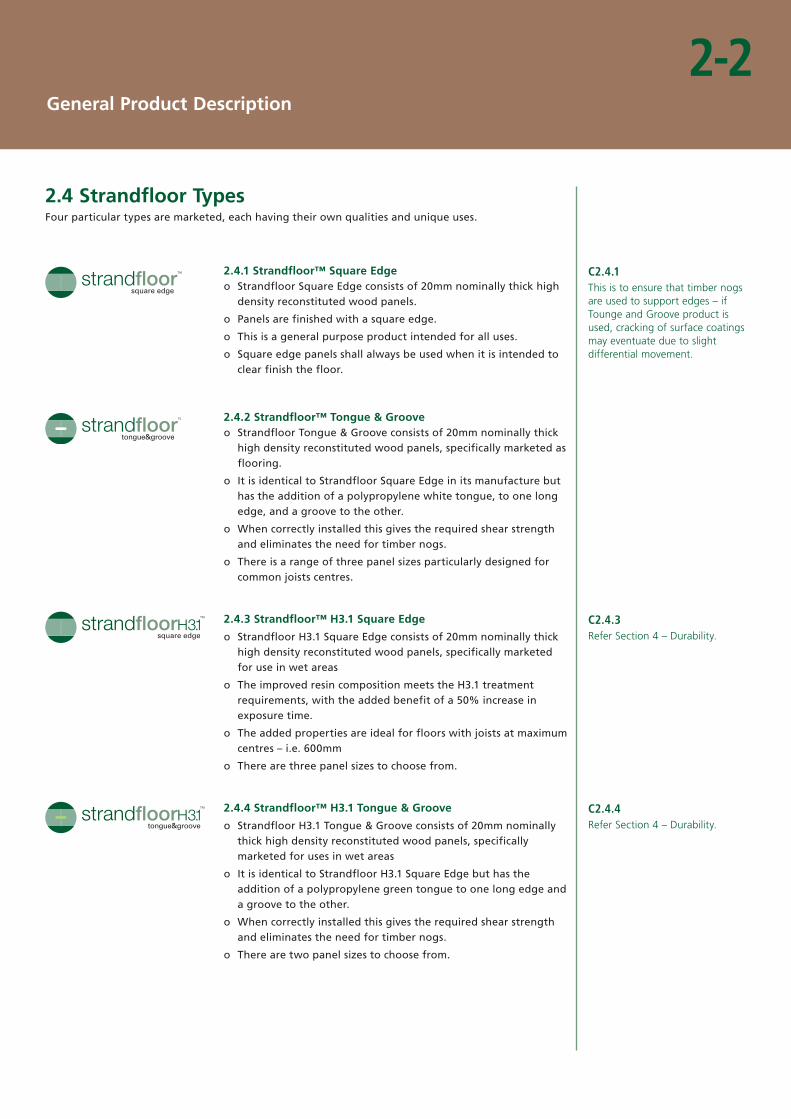
2.4 Strandfloor TypesFour particular types are marketed, each having their own qualities and unique uses.
2.4.1 Strandfloor™ Square EdgeStrandfloor Square Edge consists of 20mm nominally thick high odensity reconstituted wood panels.
Panels are finished with a square edge. o
This is a general purpose product intended for all uses. o
Square edge panels shall always be used when it is intended to oclear finish the floor.
2.4.2 Strandfloor™ Tongue & Groove Strandfloor Tongue & Groove consists of 20mm nominally thick ohigh density reconstituted wood panels, specifically marketed as flooring.
It is identical to Strandfloor Square Edge in its manufacture but ohas the addition of a polypropylene white tongue, to one long edge, and a groove to the other.
When correctly installed this gives the required shear strength oand eliminates the need for timber nogs.
There is a range of three panel sizes particularly designed for ocommon joists centres.
2.4.3 Strandfloor™ H3.1 Square Edge
Strandfloor H3.1 Square Edge consists of 20mm nominally thick ohigh density reconstituted wood panels, specifically marketed for use in wet areas
The improved resin composition meets the H3.1 treatment orequirements, with the added benefit of a 50% increase in exposure time.
The added properties are ideal for floors with joists at maximum ocentres – i.e. 600mm
There are three panel sizes to choose from. o
2.4.4 Strandfloor™ H3.1 Tongue & Groove
Strandfloor H3.1 Tongue & Groove consists of 20mm nominally othick high density reconstituted wood panels, specifically marketed for uses in wet areas
It is identical to Strandfloor H3.1 Square Edge but has the oaddition of a polypropylene green tongue to one long edge and a groove to the other.
When correctly installed this gives the required shear strength oand eliminates the need for timber nogs.
There are two panel sizes to choose from. o
C2.4.1This is to ensure that timber nogs are used to support edges – if Tounge and Groove product is used, cracking of surface coatings may eventuate due to slight differential movement.
C2.4.3Refer Section 4 – Durability.
C2.4.4Refer Section 4 – Durability.
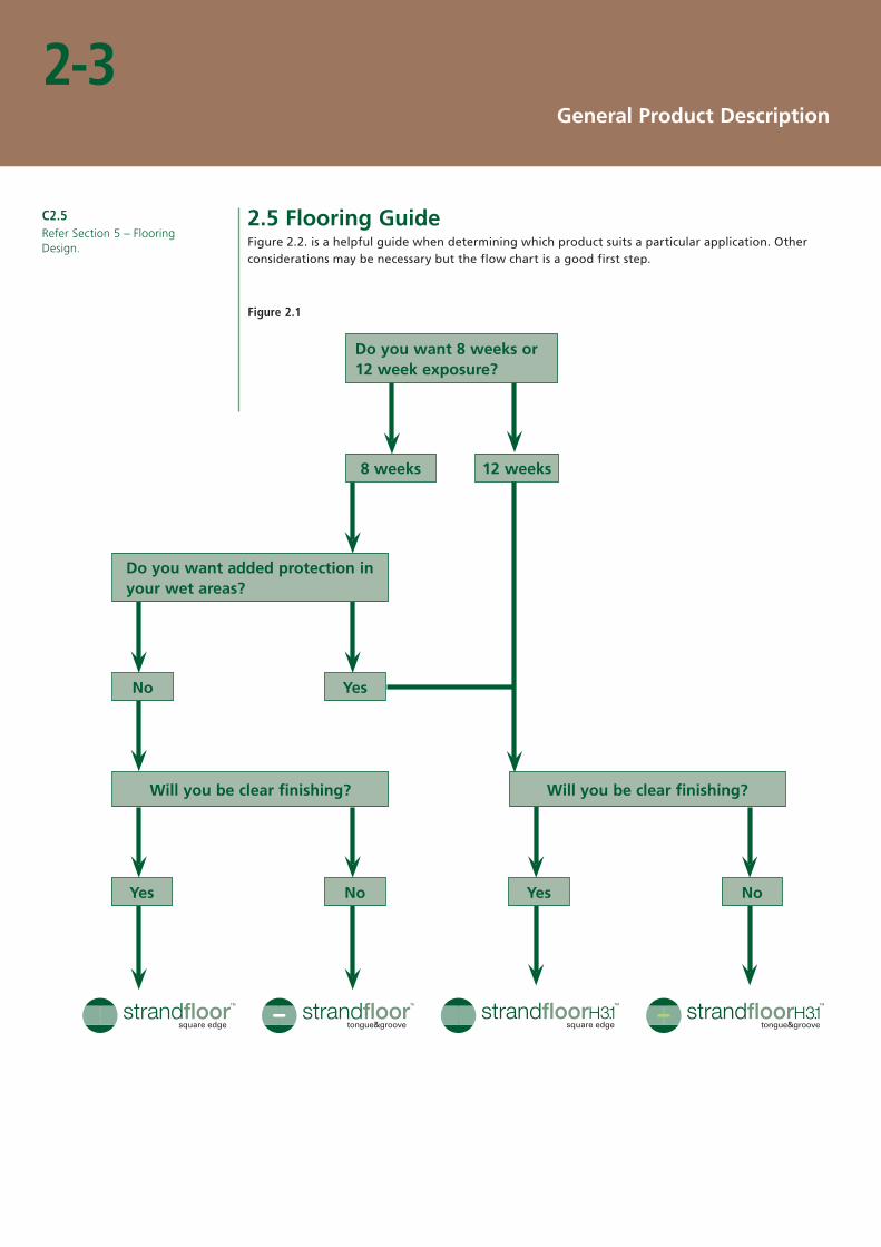
Figure 2.1
Will you be clear finishing?Will you be clear finishing?
Do you want added protection in your wet areas?
YesYes NoNo
YesNo
Do you want 8 weeks or 12 week exposure?
8 weeks 12 weeks
square edge tongue&groovesquare edgetongue&groove
2-3General Product Description
2.5 Flooring GuideFigure 2.2. is a helpful guide when determining which product suits a particular application. Other considerations may be necessary but the flow chart is a good first step.
C2.5Refer Section 5 – Flooring Design.

3
Material Properties
3.1 Description . . . . . . . . . . . . . . . . . . . . . . . . . . . . . . . . . . . . . . . . . . . . . . . . . . . . . . . . . . . . . . . . . . . . . .3-1
3.2 Panel Dimensions. . . . . . . . . . . . . . . . . . . . . . . . . . . . . . . . . . . . . . . . . . . . . . . . . . . . . . . . . . . .3-1
3.3 Tolerances . . . . . . . . . . . . . . . . . . . . . . . . . . . . . . . . . . . . . . . . . . . . . . . . . . . . . . . . . . . . . . . . . . . . . . .3-1
3.4 Physical Properties . . . . . . . . . . . . . . . . . . . . . . . . . . . . . . . . . . . . . . . . . . . . . . . . . . . . . . . . . .3-2
3.5 Formaldehyde . . . . . . . . . . . . . . . . . . . . . . . . . . . . . . . . . . . . . . . . . . . . . . . . . . . . . . . . . . . . . . . . .3-3
Table
3.1 Panel Dimensions. . . . . . . . . . . . . . . . . . . . . . . . . . . . . . . . . . . . . . . . . . . . . . . . . . . . . . . . . . . .3-1
3.2 Panel Tolerances . . . . . . . . . . . . . . . . . . . . . . . . . . . . . . . . . . . . . . . . . . . . . . . . . . . . . . . . . . . .3-1
3.3 Physical Properties (Strandfloor Square Edge and Tongue & Groove) . . . . . . . . . . . . . . . . . . .3-2
3.4 Physical Properties (Strandfloor H3.1 Square Edge and Tongue & Groove) . . . . . . . . . . . .3-2

3-1Material Properties
3.1 DescriptionStrandfloor panels are manufactured from strands of radiata pine which impart a range of colour tones within each panel.
The wood strands are bonded together with a pMDI resin which is applied to each individual wood strand prior to the pressing of the panels. A wax emulsion is added at this stage to impart additional moisture resistance to the strands.
Fungicide and insecticide are applied to each individual strand to provide protection throughout the panel that meets the H3.1 treatment classification.
The long edges of the tongue and groove Strandfloor panels are factory grooved and fitted on one side with a polypropylene tongue
3.2 Panel Dimensions Table 3.1 gives panel dimensions for all products.
Table 3.1
Panel Dimensions
Panel Sizesmm
Weight (kg)per m2
Weight (kg)per panel
Square Edge 3600 x 2400 x 203600 x 1200 x 202400 x 1200 x 20
13.613.613.6
117.558.839.2
Tongue&Groove 3600 x 1200 x 203600 x 800 x 202400 x 1200 x 20
13.613.613.6
58.839.239.2
H3.1 Square Edge 3600 x 2400 x 203600 x 1200 x 202400 x 1200 x 20
13.613.613.6
117.558.839.2
H3.1 Tongue&Groove 3600 x 1200 x 203600 x 800 x 20
13.613.6
58.839.2
3.3 Panel TolerancesTable 3.2 gives panel tolerances for all products (ex factory).
Table 3.2
Panel Tolerances
Length +/- 1.5mm
Width +/- 1.5mm
Thickness +/- 0.2mm
Panel Edge Straightness 1mm/metre maximum deviation from the line
Panel Squareness The difference between the measured diagonals is no greater than 0.5mm/metre

3-2Material Properties
3.4 Physical PropertiesStrandfloor Square Edge, Strandfloor Tongue & Groove, Strandfloor H3.1 Square Edge and Strandfloor H3.1 Tongue & Groove are manufactured to meet or exceed the requirements of AS/NZS 1860.1 :2002 Specifications for Particleboard Flooring. The values in Tables 3.3 and 3.4 indicate the Manufacturers Mean values ex-factory and the minimum/maximum values as determined in AS/NZS 1860.
Table 3.3 Strandfloor Square Edge & Strandfloor Tongue & Groove
Table 3.4 Strandfloor H3.1 Square Edge & Strandfloor H3.1 Tongue & Groove
C3.4aPanels are tested in accordance with AS/NZS 4266:
Property Units Manufacturers Mean AS/NZS
Min/max
Bending Strength (MOR) MPa 25.5 17
Modulus of Elasticity (MOE) MPa 4137 2650
Internal Bond Strength MPa 0.68 0.5
24-hour Thickness Swell % 4.5 14
Property Units Manufacturers Mean AS/NZS
Min/max
Bending Strength (MOR) MPa 26.4 19
Modulus of Elasticity (MOE) MPa 4200 2750
Internal Bond Strength MPa 0.85 0.55
24-hour Thickness Swell % 4.5 8
3-3Material Properties
3.5 Formaldehyde The formaldehyde content of Strandfloor complies with the limits specified in AS/NZS 1859.1:2004 Particleboard Part 1 Specifications, and the World Health Organisation for E0 product.
The extractable formaldehyde content being ≤ 0.5 milligrams per litre of water when tested to AS/NZS 4266.16.
When installed, emission levels can be controlled by room ventilation together with the sealing of the surface or the use of coverings such as foam-backed carpet, carpet with rubber underlay, vinyl or tiles. Sealing or covering of the surface shall be carried out before the building is occupied.
C3.5Refer also Section 9 – Finishing and Section 11 – Health and Safety.

4
Durability
4.1 Producer Statement . . . . . . . . . . . . . . . . . . . . . . . . . . . . . . . . . . . . . . . . . . . . . . . . . . . . . . . .4-1
4.2 BRANZ Appraisal . . . . . . . . . . . . . . . . . . . . . . . . . . . . . . . . . . . . . . . . . . . . . . . . . . . . . . . . . . . .4-1
4.3 Durability Conditions. . . . . . . . . . . . . . . . . . . . . . . . . . . . . . . . . . . . . . . . . . . . . . . . . . . . . .4-2
4.3.1 Handling & Storage . . . . . . . . . . . . . . . . . . . . . . . . . . . . . . . . . . . . . . . . . . . . . . .4-2
4.3.2 Weathering . . . . . . . . . . . . . . . . . . . . . . . . . . . . . . . . . . . . . . . . . . . . . . . . . . . . . . . . . . .4-2
4.3.3 Wet Areas. . . . . . . . . . . . . . . . . . . . . . . . . . . . . . . . . . . . . . . . . . . . . . . . . . . . . . . . . . . . . .4-2
4.3.4 Heat . . . . . . . . . . . . . . . . . . . . . . . . . . . . . . . . . . . . . . . . . . . . . . . . . . . . . . . . . . . . . . . . . . . . . . .4-2
4.3.5 Prohibited Uses . . . . . . . . . . . . . . . . . . . . . . . . . . . . . . . . . . . . . . . . . . . . . . . . . . . . .4-2
Figure
4.1 Storage Method. . . . . . . . . . . . . . . . . . . . . . . . . . . . . . . . . . . . . . . . . . . . . . . . . . . . . . . . . . . . . .4-1

Breather Type Sheeting
Air space
Air space
Figure 4.1
4-1Durability
4.1 Producer Statement When stored, handled, installed and maintained in accordance with this document, Strandfloor panels will meet: The durability performance requirements of NZBC B2.3.1 (a) for 50 years.
The specifications, details and methods described herein shall be strictly observed to avoid building code non-compliance.
The Laminex Group will not be liable to any person if the conditions as to storage, handling, installation and maintenance of Strandfloor panels as outlined within this document are not complied with.
Strandfloor H3.1 Square Edge and Strandfloor H3.1 Tongue & Groove panels have been treated to resist attack by insects such as borer.
4.2 BRANZ AppraisalStrandfloor has two BRANZ Appraisals – Strandfloor – No. 676 (2010) and Strandfloor H3.1 – No 677 (2010). The current versions of these appraisals are published on the BRANZ website – www.branz.co.nz
The BRANZ Appraisals confirm that:
Strandfloor panels will have a life of at least 50 years o

4-2Durability
4.3 Durability ConditionsThe following conditions shall be met; otherwise the durability of Strandfloor will be compromised.
4.3.1 Handling & StoragePanels shall be stored and handled so as to minimise surface and edge damage. o
Wherever possible panels shall be stored inside under cover. Outside storage shall be for short operiods only. Panels shall not be stacked on wet concrete floors.
The panels shall be flat stacked clear of the ground, on evenly placed, full width, level bearers. oBearers shall be of uniform thickness and shall extend across the full width of the stack. (Refer Figure 4.1)
When stored in external situations, panels shall be protected from the weather. A breather-type ocover shall be used, supported clear of the top and sides of the panels using battens to allow air to circulate freely around the pack. (Refer Figure 4.1)
4.3.2 WeatheringStrandfloor Square Edge and Strandfloor Tongue & Groove shall not be exposed to weathering for omore than eight weeks.
Strandfloor H3.1 Square Edge and Strandfloor H3.1 Tongue & Groove shall not be exposed to oweathering for more than 12 weeks.
Panel properties may be affected by moisture saturation and/or exposure to sub-zero otemperatures.
During the exposed period, do not allow water to pond on the surface. Remove water by sweeping oand forming small holes adjacent to plate lines. Do not directly cover panels with sheeting or apply liquid sealers to any surface. Panels should weather in their raw condition to allow release of absorbed moisture.
4.3.3 Wet AreasIn “wet areas” panels shall be protected with a suitable wet area membrane or an integrally owaterproof sheet material. – Section 9: Finishing – 9.3 Wet Areas.
4.3.4 HeatPanels shall be separated from fuel burning appliances, flues and chimneys in accordance with oNZBC Section C – AS/1.
Panels shall not be subjected to temperatures exceeding 50˚C for a prolonged period. o
4.3.5 Prohibited UsesPanels shall not be used in covered exterior situations with no weather protection oe.g. open verandas.
Panels shall not be used as a substrate for roofing or decking membranes. o
Panels shall not be used in spa-pool rooms. o
Once installed and in use, panels shall not be subjected to conditions that will allow the continuing omoisture content to be above 16%.
C4.3.2The “weather exposed” period includes the time that the panels are in an exposed condition when being transported or stored on site without covering. Panels will respond to changes in humidity and moisture content. Some edge peaking expansion and grain raising may result. Loss of stiffness and strength can occur if panels are exposed to sub-zero conditions whilst saturated – i.e. ski lodges.If the exposure period cannot be met, then panels shall be post laid (once the structure is enclosed). Alternatively, sheet covering may be used providing it is indirect and adequate air space is maintained (“tent” effect).
C4.3.3A “wet area” is any area within a building supplied with water from a water supply system, e.g. kitchens, bathrooms, toilets, shower rooms, laundries, changing rooms, ensuites, etc.
C4.3.4Over floor type heating systems may be used with Strandfloor products providing the operating temperature does not exceed 35ºC and the panel moisture content is less than 16%. Under floor systems are not acceptable. The heating system manufacturer must be consulted prior to installation.


5
Floor Design
5.1 Non-Specific Design . . . . . . . . . . . . . . . . . . . . . . . . . . . . . . . . . . . . . . . . . . . . . . . . . . . . . . . .5-1
5.1.1 Joist Selection . . . . . . . . . . . . . . . . . . . . . . . . . . . . . . . . . . . . . . . . . . . . . . . . . . . . . . . .5-1
5.1.2 Domestic Housing . . . . . . . . . . . . . . . . . . . . . . . . . . . . . . . . . . . . . . . . . . . . . . . . .5-1
5.1.3 Commercial & Industrial Use . . . . . . . . . . . . . . . . . . . . . . . . . . . . . . . . .5-2
5.1.4 Structural Diaphragms . . . . . . . . . . . . . . . . . . . . . . . . . . . . . . . . . . . . . . . . . .5-2
5.2 Specific Design . . . . . . . . . . . . . . . . . . . . . . . . . . . . . . . . . . . . . . . . . . . . . . . . . . . . . . . . . . . . . . . .5-3
5.2.1 Uniformly Distributed Actions . . . . . . . . . . . . . . . . . . . . . . . . . . . . . .5-3
5.2.2 Concentrated Actions . . . . . . . . . . . . . . . . . . . . . . . . . . . . . . . . . . . . . . . . . . 5-4
5.3 Sub-Floor Ventilation . . . . . . . . . . . . . . . . . . . . . . . . . . . . . . . . . . . . . . . . . . . . . . . . . . . . 5-4
5.3.1 Opening Requirement . . . . . . . . . . . . . . . . . . . . . . . . . . . . . . . . . . . . . . . . 5-4
5.3.2 Vapour Barriers . . . . . . . . . . . . . . . . . . . . . . . . . . . . . . . . . . . . . . . . . . . . . . . . . . . . 5-5
5.4 Ground Clearance . . . . . . . . . . . . . . . . . . . . . . . . . . . . . . . . . . . . . . . . . . . . . . . . . . . . . . . . . . 5-5
5.5 Fire Ratings . . . . . . . . . . . . . . . . . . . . . . . . . . . . . . . . . . . . . . . . . . . . . . . . . . . . . . . . . . . . . . . . . . . . 5-6
5.6 Insulation . . . . . . . . . . . . . . . . . . . . . . . . . . . . . . . . . . . . . . . . . . . . . . . . . . . . . . . . . . . . . . . . . . . . . . . 5-6
5.7 Supporting Timber . . . . . . . . . . . . . . . . . . . . . . . . . . . . . . . . . . . . . . . . . . . . . . . . . . . . . . . . 5-6
Figure
5.1 Uniformly Distributed Actions (Strandfloor) . . . . . . . . . . . . . . . . . . . . . . . . . . . . . . . . . . . . . . . . . . . . . . . . . . . . . . . . . . . . . . . . . . . . . .5-3
5.2 Concentrated Live Actions(Strandfloor) . . . . . . . . . . . . . . . . . . . . . . . . . . . . . . . . . . . . . . . . . . . . . . . . . . . . . . . . . . . . . . . . . . . . . 5-4
5.3 Ground Clearances . . . . . . . . . . . . . . . . . . . . . . . . . . . . . . . . . . . . . . . . . . . . . . . . . . . . . . . . 5-5

5-1Floor Design
5.1 Non-Specific DesignThe following design information covers the use of Strandfloor when used in buildings detailed by 1.1.2(e) of NZS 3604 which is an acceptable solution of the New Zealand Building Code (not requiring specific design) .
5.1.1 Joist Selection
Ranges of joists are now available, in solid timber, engineered timber (“I” joists) and steel. Each has its particular advantages and preferences.
The use of solid timber or “I” joists, with a moisture content of less than 15%, is strongly recommended and will provide the following benefits:
Post construction shrinkage and distortion will be minimised, limiting fastener noise and nail opopping.
Deflection will be limited as dry timber is stronger and stiffer. o
In all cases joists are lighter and easier to handle – particularly with “ o I” joists.
In some cases it is hard to avoid the use of “wet” timber due to the treatment requirements of NZS 3602. If this is the case care should be taken to select straight and undistorted material or consideration given to post laying of panels.
5.1.2 Domestic Buildings
In domestic housing applications, joist support centres up to 600mm are acceptable for all Strandfloor products, in line with Table 1.2 of NZS 3604.
o If a more rigid floor is required reduce support centres to 450mm.
For large floors, over 15m long, consider post laying or allow for expansion. o
Ensure that adequate ventilation is provided in sub-floor areas. o
When clear finish is required, use only square edge panels. o
Additional panel support will be required for high point loads such as pianos, billiard tables etc. o
C5.1.2aSee Section 7 – 7.4. Large floors.
C5.1.2bThis is to ensure that timber nogs are used to support edges – if Tounge and Groove product is used, cracking of surface coatings may eventuate due to slight differential movement.

5-2Floor Design
5.1.3 All Other Buildings
In all non-domestic building applications (i.e. residential, institutional, educational and other buildings)
Joist spacings shall not exceed 600mm centres. o
The kPa loadings, from Table 1.2 of NZS 3604, shall not be exceeded without specific design. o
Special attention shall be given at the design stage to the effects of concentrated loadings, such as ohigh density foot traffic, storage racks, hand trolley point loads etc.
Where a double layer floor system is used, joists can be spaced up to 600mm support centres for all oproducts.
Adequate cross flow ventilation shall be provided in all subfloor areas. o
Where large areas of Strandfloor are laid e.g. gymnasiums, community halls, institutional type odwellings, farm buildings etc., it is important to ensure that careful consideration is given to the cross flow effect of sub-floor ventilation and allowance is made for panel expansion.
Post laying is always the better option for large floors, particularly where clear finishing. o
5.1.4 Structural Diaphragms
All Strandfloor products can be used for structural diaphragms. Design requirements for diaphragms to resist wind or seismic loads are given in NZS 3604.
Square edge Strandfloor complies if fixed in accordance with this manual. o
Tongue & groove Strandfloor complies if fixed in accordance with this manual and joist centres do onot exceed 450mm.
For floor diaphragms complying with NZS 4229 – Concrete Masonry Buildings Not Requiring Specific Engineering Design – square edge Strandfloor shall be used. Details shall be in accordance with NZS 4229.
C5.1.3Residential, institutional, educational and other buildings as described in NZS 3604: clause 1.1.2 (e), (ii) - (v)
C5.1.4See Section 7 – Installation, for special fixing details.

kPa
kN
5.2 Specific Design, Commercial & Industrial UseThe following information has been specifically designed for Strandfloor products. All calculation is based on the requirements and methods detailed in AS/NZS 1170.
Reference to Table 3.1 of this Standard will give the requirements for particular activities, which can then be aligned with these tables.
This information is by no means exhaustive but covers the common commercial and industrial situations that may occur outside the scope of NZS 3604 and the majority of those within AS/NZS 1170.
All other situations require individual specific design.
5.2.1 Uniformly Distributed Actions (UDL)
Table 5.1 gives safe uniformly distributed actions for Strandfloor.
Table 5.1
Strandfloor
Span up to 600mm
Single Layer 5kPa
Double Layer 10kPa
5.2.2 Concentrated Actions
Table 5.2 gives safe concentrated actions for Strandfloor.
Table 5.2
Strandfloor
Support Centres 400mm 450mm 500mm 550mm 600mm
Single Layer 4kN 3.2kN 3kN 2.1kN 1.8kN
Double Layer 8kN 6.4kN 5kN 4.2kN 3.6kN
C5.2.1Refer Section 7 – Installation, for double layer fixing details.
5-3Floor Design

5.3 Sub-Floor VentilationSubfloor ventilation must be provided to all platform floors suspended above the ground to ensure the ongoing moisture content of the Strandfloor remains at or below 16%.
The following information shall be regarded as the minimum ventilation levels required. Failure to control moisture in the Strandfloor could result in a non-performance which The Laminex Group will not be responsible for.
5.3.1 Opening Requirement
This requirement shall be met by the provision of evenly distributed openings in the foundation wall, at a rate of no less than 3500mm2 for every m2 of floor area. The openings shall be as near as possible to the underside of the plates and bearers and be positioned to allow effective cross flow.
Either one, or a combination of the following methods, may be used to construct ventilation openings:
Continuous gaps, at least 20mm wide between baseboards, around the building perimeter. o
Perimeter wall ventilators with sufficient net open area spaced regularly, commencing 750mm from othe wall corner and at intervals of no greater than 1.8m.
A 50mm gap between the wall plates and a boundary joist at the ends of cantilevered floor joists oand the wall plate and joist, where the bearer is cantilevered.
Other regularly spaced openings that will provide adequate ventilation. o
It is important to ensure that party walls, internal foundations, attached terraces, or any other impediment, do not obstruct the subfloor ventilation airflow, and that:
No point of the ground is more than 7.5m from a ventilation opening, or o
The subfloor ventilation rate is greater than 10 air changes per hour for wet sites, or five air ochanges per hour for dry sites.
C5.3.1All requirements in accordance with NZBC – E2/AS1 and NZS 3604.
5-4Floor Design

Airvent
Strandfloor
550mm min. above ground
Figure 5.3
5.3.2 Vapour Barriers
Where a sub-floor space cannot be adequately ventilated, the ground under a suspended floor shall be covered with a vapour barrier having a vapour flow resistance of no less than 50MN s/g, and a thickness of no less than 0.25mm.
Even with a vapour barrier, ventilation openings shall still be provided, but the net open area may be reduced to no less than 700mm2 for every m2 of floor area and be located to provide air cross flow in the subfloor space.
The vapour barrier shall be installed in a way that ensures:
It covers the total ground area. o
Adjacent sheets are lapped no less than 75mm and laps are intermittently taped. o
The ground is shaped to prevent water accumulation on the vapour barrier. o
Water drains to the exterior. o
It is securely held in place by bricks, large stones or a similar method. o
Where floor area designs still do not meet the above criteria, consideration should be given to the use of mechanical draft ventilation systems that create a subfloor ventilation rate greater than 10 air changes per hour for wet sites, or five air changes per hour for dry sites.
It is essential that all ventilation openings remain unrestricted and that vegetation is not allowed to cause obstructions over the life of the building.
5.4 Ground ClearanceA minimum clearance of 550mm between the surface of the ground beneath the building and the underside of the flooring panels shall be provided in order to give adequate sub-floor air capacity and to provide access for inspection of the sub-floor structure.
The clearance of 550mm may not be reduced, even when vapour barriers are installed. Vapour barriers only allow the reduction in the ventilation requirement not the clearance dimension.
For ground clearance detail, see Figure 5.3
C5.3.2It is strongly recommended that vapour barriers be installed regardless of the situation. Great advantages can be gained in the reduction of sub-floor moisture content for very little cost.
5-5Floor Design

5-6Floor Design
5.5 Fire RatingsStrandfloor can be used as flooring in detached dwellings that have no specific fire resistance rating requirements under the NZBC (Purpose Group SH).
For other types of occupancy, product use depends on the number of stories, the number of full and intermediate floors involved and whether the building is sprinkled etc.
The required fire resistance rating for floors and surface finish in NZBC Acceptable Solution C3/AS1 shall be complied with.
5.6 InsulationWhile Strandfloor panels used to form an on-ground platform floor will contribute toward the building performance index of the building envelope, additional insulation material will be needed to achieve the thermal insulation requirements as detailed in NZBC H1.3.2. For the purposes of calculation the R-value of 20mm Strandfloor panels shall be taken as 0.17 m2K/W
When fitting any insulation it is important to ensure the material that is chosen is installed in accordance with the insulation manufacturers’ instructions. It is also critical to ensure that control of moisture in the sub-floor space is maintained as the efficiency of some insulation materials may be affected by elevated moisture levels.
5.7 Supporting Timber The moisture content of the support system at the time of laying and fixing the flooring panels can affect the performance of the total floor system. As wet framing dries it will shrink. This can reduce the effectiveness of the fixing, allowing movement of panels resulting in floor squeaking and nail-head rise under vinyl flooring.
The use of kiln dried timber or “I” joists is therefore recommended.
Herringbone strutting in lieu of solid blocking will reduce the likelihood of a noisy floor. End nailing of solid blocks often result in squeaking and is hard to rectify once the structure is closed in.
C5.6aHistorically perforated foil draped over the joist has been the preferred under-floor insulation material. Alternative bulk insulation such as polystyrene is now favoured. One advantage gained is that the top of the joist is left free which allows the gluing of the Strandfloor panels to the joists. – Refer Section 7 Installation.
C5.6bRefer 5.3 Subfloor Ventilation


6
Specification Clauses
6.1 General. . . . . . . . . . . . . . . . . . . . . . . . . . . . . . . . . . . . . . . . . . . . . . . . . . . . . . . . . . . . . . . . . . . . . . . . . . . .6-1
6.2 Recommended Clauses . . . . . . . . . . . . . . . . . . . . . . . . . . . . . . . . . . . . . . . . . . . . . . . . . . .6-1
6.2.1 Documents Referred To . . . . . . . . . . . . . . . . . . . . . . . . . . . . . . . . . . . . . . . .6-1
6.2.2 Manufacturers Documents . . . . . . . . . . . . . . . . . . . . . . . . . . . . . . . . . . .6-1
6.2.3 Materials . . . . . . . . . . . . . . . . . . . . . . . . . . . . . . . . . . . . . . . . . . . . . . . . . . . . . . . . . . . . . . .6-1
6.2.4 Components . . . . . . . . . . . . . . . . . . . . . . . . . . . . . . . . . . . . . . . . . . . . . . . . . . . . . . . . . .6-1
6.2.5 On Site Conditions . . . . . . . . . . . . . . . . . . . . . . . . . . . . . . . . . . . . . . . . . . . . . . . .6-1
6.2.6 Application . . . . . . . . . . . . . . . . . . . . . . . . . . . . . . . . . . . . . . . . . . . . . . . . . . . . . . . . . . . .6-2
6.2.7 Installation . . . . . . . . . . . . . . . . . . . . . . . . . . . . . . . . . . . . . . . . . . . . . . . . . . . . . . . . . . . .6-2
6.2.8 Completion . . . . . . . . . . . . . . . . . . . . . . . . . . . . . . . . . . . . . . . . . . . . . . . . . . . . . . . . . . .6-3
6.2.9 Surface Finish . . . . . . . . . . . . . . . . . . . . . . . . . . . . . . . . . . . . . . . . . . . . . . . . . . . . . . . .6-3

6-1Specification Clauses
6.1 GeneralThe clauses listed below are those recommended to be used when specifying Strandfloor products for all building uses as covered by NZS 3604 1.1.2 (e).
It will be necessary to edit those particular sections that apply to the specific project documentation.
6.2 Recommended Clauses6.2.1 Documents Referred To
Documents referred to in this section are:
AS/NZS 1859 Reconstituted wood-based panels - Specifications Part 1: Particleboard. o
AS/NZS 1860 Particleboard flooring,1860.1: Specifications. o
NZS 3604 Timber framed buildings. o
Strandfloor has two BRANZ Appraisals – Strandfloor – No. 676 (2010) and Strandfloor H3.1- No. 677 (2010). – The current versions of these are published on the BRANZ website – www.branz.co.nz.
Documents listed above and cited in the clauses that follow are part of this specification. However, this specification takes precedence in the event of it being at variance with the cited document.
6.2.2 Manufacturers Documents
Confirm current status of documentation held:
By visiting The Laminex Group website – www.thelaminexgroup.co.nz. o
Or call The Laminex Group Customer Services Department – 0800 303 606. o
6.2.3 MaterialsStrandfloor Square Edge o
Strandfloor Tongue & Groove o
Strandfloor H3.1 Square Edge o
Strandfloor H3.1 Tongue & Groove o
6.2.4 ComponentsNAILS – 60mm annular grooved gun nails or annular grooved particleboard nails. o
SCREWS – (for timber joists) – 45mm x 8g Type 17 countersunk head self drilling screws. o
SCREWS – (for steel joists) – 50mm x 12g Tek self drilling screws corrosion resistant. o
ADHESIVE – Elastomeric construction adhesive. o
6.2.5 On-Site Conditions
Take delivery of and accept packets of Strandfloor, dry and undamaged. Reject all damaged material. Store on a level, firm base, well ventilated and completely protected from weather and damage, all as manufacturers requirements.
Avoid distortion and contact with damaging substances. Protect edges and surfaces from damage. Use a sufficient number of people to lift and lay sheets with ease.
Do not commence work until the substrate is plumb and level, in true alignment and to the Strandfloor manufacturer’s requirements.
C6.2.2It is important to ensure that all on-site personnel have access to up to date information. Products are not used in isolation, but as part of a process. Particular details of handling, storage, installation, finishing and protection, can vary from what is considered the norm.
C6.2.3Select the appropriate material by referring to Section 2 – Product Description and Section 5 – Floor Design.
C6.2.4Select the appropriate component by referring to Section 7 – Installation.
C6.2.5All fasteners shall be corrosion resistant. Fastener sizes given in 6.2.4 shall be minimum dimensions.
C6.2.6Refer Section 4 – Durability.

6-2Specification Clauses
6.2.6 ApplicationAdhesive Fastening – Use construction adhesive to joists in conjunction with mechanical fixing. oApply adhesive in a continuous 5mm bead to all floor joists. For tongue & groove panels, apply a 2mm bead of construction adhesive to the top of the tongue prior to insertion into the groove. Remove excess adhesive. Apply adhesive in a continuous 5mm bead to all floor joists and between sheets ends and edges (square edge panels) where they butt together.
Nail Fixing – Nail panel ends (and panel edges for square edge) at 150mm centres 10mm from othe edge. Nail intermediates at maximum 200mm, with all nails slightly skewed except for corner vertical nails. Where tongue and groove material is used, nails shall be 15mm from the edge to avoid tongue damage.
Screw Fixing – Screw panel ends (and panel edges for square edge panels) at 150mm centres 10mm ofrom the edge. Screw intermediate support at maximum 200mm. For tongue & groove panels, locate screws 15mm from the edge to avoid tongue damage. Pre-drill the panel for screw fixing.
6.2.7 Installation
Laying of tongue & groove StrandfloorProgramme work for minimal exposure to weather and lay sheets across the joists in a staggered opattern.
Panels to span at least three joists. o
Lay panels with brand name down. o
Allow 8mm minimum clearance between panel edges and fixed objects including columns and obottom plates.
Provide continuous edge support at building perimeter. o
Provide continuous tongue and groove edge support (nogs) in wet areas or where rigid floor ofinishes (ceramic tiles) are used.
All fixings to finish flush with surface at time of fixing. Tighten fixings; punch nails and tighten oscrews just prior to sanding.
Close butt edges and ends of panels. Do not cramp. o
Do not allow water to remain ponded on the floor surface – remove as soon as possible. o
Do not cover panels with polythene or apply liquid sealers, while exposed to weathering. o
C6.2.6aA Plan-a-floor software program that provides basic quantities and sheet layout options is freely available on The Laminex Group website under the “Knowledge Bank” button.
C6.2.6bIn general terms nailing with adhesive is the recommended method as it allows control throughout the installation process.
C6.2.6cRefer to Section 7 – Installation – for double nailing requirements for diaphragm floors.
C6.2.6dScrew fixing is not acceptable for diaphragm floors.
C6.2.7Select the appropriate clauses regarding installation of Square Edge or Tongue & Groove Strandfloor.

6-3Specification Clauses
Laying of square edge StrandfloorProgramme work for minimal exposure to weather and lay sheets across the joists in a staggered opattern.
Panels to span at least three joists. o
Lay panels with brand name down. o
Allow 8mm minimum clearance between panel edges and fixed objects including columns and obottom plates.
Provide continuous edge support at perimeter and at panel edges with solid blocking minimum oex 100mm x 50mm.
All fixings to finish flush with surface at time of fixing. Tighten fixings; punch nails and tighten oscrews just prior to sanding.
Close butt edges and ends of panels. Do not cramp. o
Do not allow water to remain ponded on the floor surface – remove as soon as possible. o
Do not cover panels with polythene or apply liquid sealers, while exposed to weathering. o
6.2.8 CompletionLeave work to the standard required by following procedures. o
Remove all debris, unused materials and elements from the site. o
6.2.9 Surface FinishCarpet and Wet Area Membrane – Single cut with a drum or belt sander – 60 to 100 grit. o
Sheet Vinyl – Single cut with a drum or belt sander – 60 to 100 grit. Do not fill nail holes. o
Clear Coating – 1st cut with a drum sander – 60 to 80 grit. o2nd cut with a disc sander – 100 grit.3rd cut with disc sander – 120 to 150 grit.
Follow coating manufacturer’s instructions. o
C6.2.9For vinyl finish, filling holes can lead to “show through” of filler.Refer also Section 9 – Finishing. Clear coating is not suitable for wet areas. Clear coating or covering the board with an impervious layer should not be carried out if Strandfloor is above 15% moisture content.
7
Installation
7.1 General. . . . . . . . . . . . . . . . . . . . . . . . . . . . . . . . . . . . . . . . . . . . . . . . . . . . . . . . . . . . . . . . . . . . . . . . . . . . 7-1
7.2 Square Edge Strandfloor . . . . . . . . . . . . . . . . . . . . . . . . . . . . . . . . . . . . . . . . . . . . . . . . 7-1
7.3 Tongue & Groove Strandfloor . . . . . . . . . . . . . . . . . . . . . . . . . . . . . . . . . . . . . . . .7-2
7.4 Large Floors . . . . . . . . . . . . . . . . . . . . . . . . . . . . . . . . . . . . . . . . . . . . . . . . . . . . . . . . . . . . . . . . . . . .7-3
7.5 Fixing . . . . . . . . . . . . . . . . . . . . . . . . . . . . . . . . . . . . . . . . . . . . . . . . . . . . . . . . . . . . . . . . . . . . . . . . . . . . . . .7-3
7.5.1 Adhesive. . . . . . . . . . . . . . . . . . . . . . . . . . . . . . . . . . . . . . . . . . . . . . . . . . . . . . . . . . . . . . . . .7-3
7.5.2 Nails . . . . . . . . . . . . . . . . . . . . . . . . . . . . . . . . . . . . . . . . . . . . . . . . . . . . . . . . . . . . . . . . . . . . . . .7-4
7.5.3 Screws . . . . . . . . . . . . . . . . . . . . . . . . . . . . . . . . . . . . . . . . . . . . . . . . . . . . . . . . . . . . . . . . . . . .7-4
7.6 Diaphragm Floors . . . . . . . . . . . . . . . . . . . . . . . . . . . . . . . . . . . . . . . . . . . . . . . . . . . . . . . . . . .7-5
7.7 Double Layer Installation . . . . . . . . . . . . . . . . . . . . . . . . . . . . . . . . . . . . . . . . . . . . . . .7-5
7.8 Avoiding “Squeaking & Creaking” . . . . . . . . . . . . . . . . . . . . . . . . . . . . . . . .7-6
Figure
7.1 Panels Laid With Joist. . . . . . . . . . . . . . . . . . . . . . . . . . . . . . . . . . . . . . . . . . . . . . . . . . . . . 7-1
7.2 Panels Laid Across Joist . . . . . . . . . . . . . . . . . . . . . . . . . . . . . . . . . . . . . . . . . . . . . . . . . . 7-1
7.3 Panel Layout . . . . . . . . . . . . . . . . . . . . . . . . . . . . . . . . . . . . . . . . . . . . . . . . . . . . . . . . . . . . . . . . . . .7-2
7.4 Expansion Gap . . . . . . . . . . . . . . . . . . . . . . . . . . . . . . . . . . . . . . . . . . . . . . . . . . . . . . . . . . . . . . . .7-3
7.5 Nail Holding . . . . . . . . . . . . . . . . . . . . . . . . . . . . . . . . . . . . . . . . . . . . . . . . . . . . . . . . . . . . . . . . . . . .7-4
7.6 Diaphragm Nailing . . . . . . . . . . . . . . . . . . . . . . . . . . . . . . . . . . . . . . . . . . . . . . . . . . . . . . . . .7-5
Table
7.1 Fixing Quantities . . . . . . . . . . . . . . . . . . . . . . . . . . . . . . . . . . . . . . . . . . . . . . . . . . . . . . . . . . . . .7-2
7.2 Fastener Types . . . . . . . . . . . . . . . . . . . . . . . . . . . . . . . . . . . . . . . . . . . . . . . . . . . . . . . . . . . . . . . .7-3

Staggered layout for400mm + 600mm centres
Nogs
Figure 7.1
Staggered layout for all centresup to maximum 600mm
Nogs
Figure 7.2
7-1Installation
7.1 GeneralThe following information applies to all Strandfloor products.
Continuous support shall be provided at the building perimeter. o
Lay ink marked face to joists – (side with label should face up). o
Panels shall be close butted together without being placed under pressure by mechanical cramping. o
Panels shall be staggered when used as a diaphragm and it is recommended that staggering is used ofor general use.
Each panel shall span at least two floor joist spacings (i.e. supported over three consecutive joists) oexcept where part panels provide the necessary infill at the building edge.
A minimum of 8mm clearance shall be made between edges and any fixed object e.g. bottom oplates, masonry walls, abutting concrete floors, structural columns etc. This is to accommodate linear expansion that may occur during the weather exposure period and eliminate moisture transfer from concrete to Strandfloor.
To stop permanent staining do not leave materials (scaffolding, nails, etc.) on panels during wet oconditions and avoid spills of cement, paint, tea, etc.
If adhesive is being used apply a continuous 5mm bead to the top of the joists (and nogs if used) ojust prior to each sheet being positioned and fixed in place. Also apply a 5mm bead between sheet ends and edges (square edge panels) as installation proceeds.
7.2 Square Edge StrandfloorThe following information applies to square edge Strandfloor panels only.
Support shall be provided to all panel edges and ends by way of joists and nogs/dwangs. o
All supporting timber shall be a minimum of ex 100 x 50. o
For joist spacings of 400mm or 600mm, panels can be laid with, or across the joists. o(Refer Figure 7.1 and 7.2)
For joist spacings of 450mm panels shall be laid across the joists. (Refer Figure 7.2) o
When square edge panels are to be clear finished, ensure panel sizes, types and batches are not mixed.
C7.1Where a part panel is necessary, consideration should be given to the specific location and potential loads. If the area is likely to carry regular foot traffic or heavy concentrated loads, consideration should be given to installing nogs/dwangs at centres matching the joist spacings.
C7.2This will ensure that shading between panels does not occur – five digit number on underside of panel is a batch number.

Joist
Locate secondsheet first
Initial sheet
String line
Use spacer block to set first row straight to line
Tongue edge
End of sheetsupported by joist
8mm
Figure 7.3
7-2Installation
7.3 Tongue & Groove Strandfloor The following information applies to all tongue & goove Strandfloor panels.
Panels shall always be laid across the joists. (Refer Figure 7.2 for panel orientation) o
Lay the first row with the brand name down and the tongue aligned to the perimeter of the floor. o(Refer Figure 7.3)
Ends of sheets should be close butted and ocentred over joists.
Check the grooved edge, for straightness, with oa string line.
Fix panels with only sufficient fastenings to oavoid movement – this will stop any distortion of the grooved edge prior to further installation.
Allow for a stagger of at least one joist space oand position the first sheet of the second row, with the tongue adjacent to the groove of the first row.
If adhesive is to be used, apply a thin bead oalong the top of each tongue, before insertion into the groove.
Lay a blocking piece (an off-cut of minimum oex 150 x 50 timber 1.4m long) across the joists, in the centre of the panel, on the grooved edge.
Stand on the blocking piece and strike with a oheavy hammer to drive the panel tongue into the groove of the first row.
It will assist if a second person can stand on the joint between the two rows. o
Fix, as before and continue the process to complete the second row – the first row can now be ofully fixed.
Subsequent rows are similarly installed to complete the floor. o
Table 7.1 gives an indication of the quantity of fixings required for Strandfloor panels. Extra fixings may be required for diaphragm floors. C/A equals construction adhesive cartridges (375ml). Refer 7.6 Diaphragm Floors.
Table 7.1
C7.3aAt this stage the tongue in the first row is redundant and can be removed for use elsewhere, if required.
C7.3bRefer 7.6 Diaphragm Floors.
Fixing Quantities Tongue & Groove Panels
Panel Size (mm) 3600 x 1200 3600 x 800 2400 x 1200
Joist Centres Nails(number)
C/A(cartridge)
Nails(number)
C/A(cartridge)
Nails(number)
C/A(cartridge)
600mm 53 0.6 37 0.4 39 0.4
450mm 67 0.7 47 0.5 N/A N/A
400mm 74 0.8 52 0.5 53 0.5
Fixing Quantities Square Edge Panels
Panel Size (mm) 3600 x 2400 3600 x 1200 2400 x 1200
Joist Centres Nails(number)
C/A(cartridge)
Nails(number)
C/A(cartridge)
Nails(number)
C/A(cartridge)
600mm 135 1.5 89 1 63 0.7
450mm 157 1.7 99 1.1 N/A N/A
400mm 168 1.9 104 1.2 73 0.8

Strandfloor
40mm expansion gap
Double joist or nogs
Filler strip
Figure 7.4
Table 7.2
7-3Installation
7.4 Large FloorsA large floor is one with a length or width exceeding 15m.
All large floors that are pre-laid (exposed to weather) shall provide for panel expansion.
This can be achieved by:
Leaving out one row of flooring panels oacross the building width at centres not exceeding 15m until the structure is completely closed in.
Providing a 40mm wide expansion gap ounder partition lines or other hidden situations, at no greater than 15m intervals. (Refer Figure 7.4) Insert a filler strip on completion.
All large floors that are post-laid (not exposed to weather) do not require expansion provisions.
It is essential that no exposure of any type occur.
7.5 FixingThe type and position of the fastening chosen is important for long-term performance. Incorrectly fixed panels and high moisture content in timber may lead to squeaking floors which can be difficult to remedy at a later date.
Table 7.2. gives details of acceptable fastener types. All others, including staples, are unacceptable.
Perimeter fixing shall be 10mm from the panel edges except where long edges have tongues. Increase to 15mm to avoid tongue damage.
7.5.1 Adhesive
Adhesive is recommended for use in conjunction with mechanical fastening.
Adhesive should be applied in a continuous 5mm bead to all floor joists & nogs if present, and between sheet ends and edges (square edge panels). A 2mm bead should be applied along the tongue of the tongue & groove panels as they are laid.
C7.4aEnsure that the 8mm clearance is maintained around the perimeter and between fixed objects. Where a double joist is not available, use rows of double nogs.
C7.4bIf floor is to be clear finished ensure all product is from the same batch (check identification numbers on underside of panels).
C7.5.1aThe use of a continuous bead of adhesive will result in the joist and panel ‘acting as one’ which will provide a stiffer platform floor.
C7.5.1bThe application of adhesive between sheets as they are laid will restrict moisture uptake through the panel edges.
Fastener Types
Timber Joists Size (minimum)
Fixing Centres mm(Edges) (Intermediate)
Annular grooved particle board flooring nails
60mm 150 200
Galvanised Jolt head nails 60mm 150 200
Type 17 countersunk self drilling screws(corrosion resistant)
45mm x8 gauge
150 200
Steel JoistsTek self drilling screw (corrosion resistant)
50mm x12 gauge
150 200
AdhesiveElastomatic constructionadhesive
5mm bead to the top of each joist and between sheets at ends and edges. 2mm bead to the top of the tongue.

Nail verticallyat panel corners
Fasten nails at an angle parallel to the panel edge, in alternate directions (Excluding panel corner)
Figure 7.5
7-4Installation
7.5.2 Nails
Hand-driven nails shall initially be driven flush with the surface. Punching of nails must take place after building is closed in – just prior to sanding. This allows for the moisture content of joists to dry during building construction.
Hand-driven nail fastening usually provides a better finish for clear coatings than power-driven nails.
To improve lateral holding, nails shall be slightly angled and be driven parallel to the sheet edge. (Refer Figure 7.5)
When using power-driven nails, set the depth adjuster attachment on the power tool to drive nails flush with the surface of the panel. This will allow hand punching to take place just prior to sanding.
The use of the pre-punching mechanism increases the risk of squeaky floors, as any timber shrinkage that occurs as the supports dry out is not taken up later as is the case when the punching process is carried out at sanding and floor finishing stage.
7.5.3 Screws
For a satisfactory result with screws it is essential to first drill pilot holes. This will avoid fibre being driven ahead of the screw and being deposited on the top of the joist, adding to potential movement and noise.
When using screws, it is important to initially finish flush, to allow retightening just prior to sanding.
C7.5.2Hand nailing will generally give the best result as more control can be exercised. The best possible result will be achieved with the proper use of annular grooved hand driven nails used in conjunction with adhesive.
C7.5.3Care should be taken when retightening screws, as heads are liable to shear, particularly if rusting has occurred.

Single fixing for non-diaphragm(1 nail per grouping)
Panel intermediate fixing200mm maximum nail centres
Panel edge fixing150mm maximum nail centres
1515
1010
Double fixing for diaphragm(2 nails per grouping – as shown)
1515
15
1010
Joist
Figure 7.6
7-5Installation
7.6 Diaphragm FloorsScrew fixing is not acceptable when forming diaphragm floors.
Square edge panels - there are no restrictions or additional fixing requirements when using square edge Standfloor panels to form a diaphragm.
Tongue & groove panels - When using tongue & groove Strandfloor panels to form a diaphragm, joist spacings must not exceed 450mm centres. In addition to the standard nailing, extra nails, as shown in Figure 7.6, are required along the long edge placed 30mm back.
7.7 Double Layer InstallationThe bottom layer of Strandfloor shall be laid as for single layer flooring panels.
The top layer shall be laid in a similar pattern with edges of panels offset in each direction from the bottom layer edges.
All panel ends shall be located centrally over joists or blocking to ensure positive fixing and nail length increased to 75mm.
When installing a double layer flooring system, allow for the installation of the second layer after closing in and when all sub-trade work is completed. This will provide a clean unweathered surface for clear finishing.
Moisture content of the first layer must be at 15% or below before the second layer is installed.

7-6Installation
7.8 Avoiding “Squeaking & Creaking”Since the 1960s when reconstituted wood flooring was introduced, the panels have been laid on “green” floor joists.
The drying out of this timber is a major cause of panel movement that can lead to a noisy floor.
Strandfloor itself does not create noise, but common causes of creaking or squeaking floors are:
Poor alignment of the joists bearing surfaces, creating gaps resulting in uneven stress on fixings. o
Shrinkage as the joists dry out – timber shrinks across the grain, leaving a gap between the ounderside of the sheet and the top of the joist.
Using long span joists which allow the floor to deflect more and creak at the solid blocking fixings. o
Insufficient and loose strutting or blocking of the joists. o
Swelling of the Strandfloor panels exposed to the weather. Swollen edges of the panel may not obear tightly on the joists when they dry. Sanding may level the thickened edge, but this does not rectify the underside. Nails shall therefore be punched and/or screws re-tightened just prior to sanding.
Insufficient fixings holding the panels to the support system. o
Panels not being fully fixed down when laid. o
Foot traffic in the house working the panels down the shank of the nails onto the top of the joists ooften leading to squeaking as the nail shafts work in the Strandfloor panels.
Power fastenings being over-driven into the panel core. o
Hand fixed nailing being punched off at the initial fastening stage with no allowances made for oany subsequent movement as drying of materials occcurs.
Fastenings being positioned too close to the panel edges. o
The following good practice will help to avoid a noisy floor:
When possible, use dry joists. o
For new buildings, reduce the joist span or increase joist depth to reduce deflection (prop green olong span joists at mid span until they are dry).
Consider the use of an engineered floor system (see www.ets-nz.co.nz). o
Level the joist tops before laying the flooring panels. o
Ensure dry solid blocking or herringbone strutting is fitted tightly to stiffen floor in accordance owith NZS 3604.
If using solid blocking fit as late as possible so that joists are drier and shrinkage will be less. o
Herringbone strutting is preferred as it can be tightened from the underside after timber is dry and obefore ceilings are fixed to upper floor joists.
Lay flooring panels with staggered joints. o
Don’t cramp flooring panels tightly together. o
Drive fastenings flush with the top surface of the board at time of laying. o
Leave punching of nails and/or re-tightening of screws as long as possible. o
Use adhesive/nail fixing system where possible and completely nail off at time of laying. o


8
Flooring Overlays
8.1 General. . . . . . . . . . . . . . . . . . . . . . . . . . . . . . . . . . . . . . . . . . . . . . . . . . . . . . . . . . . . . . . . . . . . . . . . . . . .8-1
8.2 Uses . . . . . . . . . . . . . . . . . . . . . . . . . . . . . . . . . . . . . . . . . . . . . . . . . . . . . . . . . . . . . . . . . . . . . . . . . . . . . . . . .8-1
8.3 Pre-Conditioning . . . . . . . . . . . . . . . . . . . . . . . . . . . . . . . . . . . . . . . . . . . . . . . . . . . . . . . . . . . .8-1
8.4 Direct Floor Overlay. . . . . . . . . . . . . . . . . . . . . . . . . . . . . . . . . . . . . . . . . . . . . . . . . . . . . . . .8-1
8.4.1 Timber Substrate . . . . . . . . . . . . . . . . . . . . . . . . . . . . . . . . . . . . . . . . . . . . . . . . . . .8-2
8.4.2 Concrete Substrate . . . . . . . . . . . . . . . . . . . . . . . . . . . . . . . . . . . . . . . . . . . . . . .8-2
8.5 Indirect Floor Overlay . . . . . . . . . . . . . . . . . . . . . . . . . . . . . . . . . . . . . . . . . . . . . . . . . . . . 8-4
Figure
8.1 Direct Floor Overlay. . . . . . . . . . . . . . . . . . . . . . . . . . . . . . . . . . . . . . . . . . . . . . . . . . . . . . . .8-2
8.2 Flooring Hygrometer . . . . . . . . . . . . . . . . . . . . . . . . . . . . . . . . . . . . . . . . . . . . . . . . . . . . . .8-3
8.3 Indirect Floor Overlay (Square Edge) . . . . . . . . . . . . . . . . . . . . . . . . . . . . 8-4
8.4 Indirect Floor Overlay (Tongue & Groove) . . . . . . . . . . . . . . . . . . . 8-5
8-1Flooring Overlays
8.1 GeneralThe Laminex Group manufactures a range of panel products suitable for overlaying existing concrete and wooden floors for commercial and domestic requirements.
There is a panel suitable for most flooring overlay applications, including:
All Strandfloor™ products o
Lakepine® MDF o
Trade Essentials® Strandboard o
Trade Essentials® Hardboard o
This section is specific to Strandfloor, for others refer to individual publications.
All other sections of this manual apply equally to this section.
Overlays are only intended for interior use and should not be exposed to weathering. The fixing of overlays should not be carried out until the structure is closed and the substrate is waterproof and dry.
8.2 UsesOverlays can be used for:
Refurbishing uneven and damaged tongue and groove wooden floors. o
Re-leveling damaged and uneven concrete floors in commercial premises prior to laying carpet, ovinyl, parquet or floor tiles.
Upgrading of school and community halls, gymnasium floors and stages, to meet the requirements ofor dancing, indoor bowling and other sporting activities.
Structural upgrades of wooden flooring in existing commercial buildings. o
As a substrate for solid timber tongue and groove overlays. o
8.3 Pre-conditioningTo ensure equilibrium of product, panels should be conditioned (left separated and standing vertically) in the installation location for at least 48 hours, prior to commencing fixing.
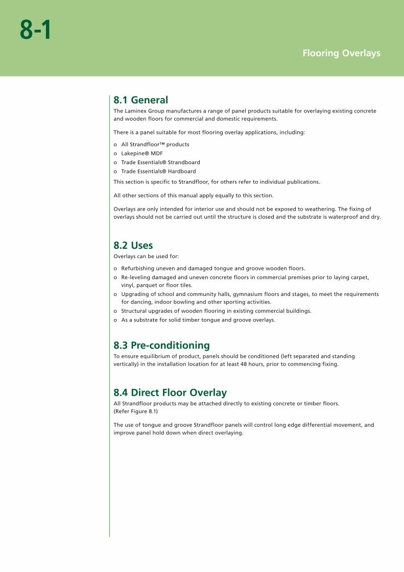
8.4 Direct Floor OverlayAll Strandfloor products may be attached directly to existing concrete or timber floors. (Refer Figure 8.1)
The use of tongue and groove Strandfloor panels will control long edge differential movement, and improve panel hold down when direct overlaying.

SkirtingNew overlay
Adhesive
Existing concrete floor
Damp proof membrane
Figure 8.1
8-2Flooring Overlays
8.4.1 Timber Substrates
For best results when direct overlaying, use a combined nail/full spread adhesive method. This eliminates any tendency for “drumming” in the new floor. A construction adhesive is recommended and should be applied as a full spread, to the manufacturer’s instructions.
Existing tongue and groove wooden floors shall be refixed and repunched as applicable, and then coarse sanded to provide a flat substrate. Ensure that there are no protruding nails prior to machine sanding.
When overlaying a tongue and groove timber floor, or existing particleboard floor, ensure that the joints in the new panels do not occur directly above parallel joins in the base floor.
All clearances, fastening and finishing detail applies equally where described elsewhere in this manual.
8.4.2 Concrete Substrates
For best results when direct overlaying onto concrete, use a full spread adhesive method. This reduces panel movement and “drumming”.
Mechanical fixing of direct overlays on concrete floors should be avoided.
A construction adhesive is recommended and should be applied as a full spread, to the manufacturer’s instructions.
C8.4.1Refer section 7 – Installation, for fixing specifications.
C8.4.2aConcrete waterproofing additives do not guarantee a dry substrate. A membrane is the only safe solution.
C8.4.2bBRANZ Bulletin No. 424 “Site Measurement of Moisture in Timber and Concrete”, describes the whole process and how measurements shall be taken.

Clear, sealed plastic window
P.V.C. box
Box must be sealed to floor
Solid E.P.S.
Opening inbottom of box(broken line)
Dial
Figure 8.2
8-3Flooring Overlays
Localised defects in the existing floor (i.e. exceeding 5mm undulations per 3m in any direction) shall be matrix filled to a leveled surface as applicable, and high spots ground flat.
The prepared floor surface shall be clean, sound and dust free.
New and old concrete floor slabs shall be dry before laying. As a guide for new concrete, allow one-month drying time per 25mm of floor slab thickness.
There are a number of “rule of thumb” methods to determine if concrete is sufficiently dry to install overlays. The only true method is to measure the relative humidity of the concrete surface, using a Flooring Hygrometer. (Refer Figure 8.2)
The reading shall be below 70% before the laying of Strandfloor can be considered.
Substrates shall be free from wax, oil, moisture, grease, dirt and dust or loose material.
Construction joints shall be formed in the overlay to coincide with those in the concrete substrate. Bridging construction joints is not recommended.
Before applying adhesive the floor shall be vacuumed clean and wiped over with a damp mop.
Apply full spread adhesive to the manufacturer’s specifications.
All clearances, fastening and finishing details apply equally where described elsewhere in this manual.
Temporary even pressure (e.g. sandbags) should be laid over the floor area until the adhesive has cured. Pay particular attention to square-edged panel intersections, where it is necessary to eliminate surface differentials.
Prohibit traffic over the new floor until the new adhesive is fully cured as recommended by the adhesive manufacturer.
C8.4.2cThe adhesive shall be full spread. Spot or bead application may lead to “drumming”.

Overlay
Skirting 8mm clearancefrom fixed objects
Existing floor
BattensProvision forcross-flowventilation
X = Joist centre
Figure 8.3
8-4Flooring Overlays
8.5 Indirect Floor OverlayAll Strandfloor products can be used for indirect overlays, up to spans of 600mm.
Flooring panels are fastened to timber battens fixed to the existing concrete or timber surface, dependent on end application (square edge or tongue and groove). (Refer Figures 8.3 and 8.4)
Indirect overlaying of concrete, with tongue and groove product, allows for services to be installed within the cavity and specialist sprung floors can be accommodated. (Refer Figure 8.4)
Increased floor stiffness will be achieved when closer support centres are used.
C8.5aRefer Section 5-Floor Design, for all joist spacings.
C8.5bBRANZ Bulletin No. 424 “Site Measurement of Moisture in Timber and Concrete”, describes the whole process and how measurements shall be taken.

Dampcourse(on existing concrete floor)
Accommodation forservices, pipes, ducting
Raised skirting
8mm clearance from fixed objects and nog back for
cross flowventilation
Figure 8.4
8-5Flooring Overlays
Provision shall be made for cross flow air change within the new floor cavity especially when overlaying concrete substrates. (Refer Figure 8.3)
Where large floor areas are to be installed, effective cross flow ventilation between battens is essential and a surface moisture barrier may be required.
Again new and old concrete floor slabs shall be dry before laying and the use of a hygrometer is essential.
The reading shall be below 70% before the laying of Strandfloor can be considered.
Ensure battening accommodates any excessive sub-floor undulations and ensure “hold downs” are secure.
Sub-floor framing moisture content shall not exceed 18%.

9
Finishing
9.1 General Preparation . . . . . . . . . . . . . . . . . . . . . . . . . . . . . . . . . . . . . . . . . . . . . . . . . . . . . . .9-1
9.2 Dry Areas . . . . . . . . . . . . . . . . . . . . . . . . . . . . . . . . . . . . . . . . . . . . . . . . . . . . . . . . . . . . . . . . . . . . . . . .9-1
9.2.1 Sheet Vinyl. . . . . . . . . . . . . . . . . . . . . . . . . . . . . . . . . . . . . . . . . . . . . . . . . . . . . . . . . . . . .9-1
9.2.2 Carpet . . . . . . . . . . . . . . . . . . . . . . . . . . . . . . . . . . . . . . . . . . . . . . . . . . . . . . . . . . . . . . . . . . . .9-1
9.2.3 Clear Finish . . . . . . . . . . . . . . . . . . . . . . . . . . . . . . . . . . . . . . . . . . . . . . . . . . . . . . . . . . . .9-2
9.2.4 Sport Court Markings . . . . . . . . . . . . . . . . . . . . . . . . . . . . . . . . . . . . . . . . . . .9-2
9.3 Wet Areas . . . . . . . . . . . . . . . . . . . . . . . . . . . . . . . . . . . . . . . . . . . . . . . . . . . . . . . . . . . . . . . . . . . . . . .9-3
9.3.1 Definition. . . . . . . . . . . . . . . . . . . . . . . . . . . . . . . . . . . . . . . . . . . . . . . . . . . . . . . . . . . . . . .9-3
9.3.2 Impervious Surface Finish . . . . . . . . . . . . . . . . . . . . . . . . . . . . . . . . . . . . .9-3
Table
9.1 Floor Sanding . . . . . . . . . . . . . . . . . . . . . . . . . . . . . . . . . . . . . . . . . . . . . . . . . . . . . . . . . . . . . . . . . .9-1

9-1Finishing
9.1 General PreparationStrandfloor flooring panels provide an ideal substrate for most types of floor finishes. All floors will require sanding prior to covering or coating.
No Strandfloor material shall remain in a permanently raw unfinished condition. After the building is completed and before occupation panels shall be finished with floor coverings such as carpet, sheet vinyl, ceramic tiles etc, or a coating system.
Table 9.1
Floor Sanding
Surface Finish Cut Sander Type Paper Grit
Clear Coating First
Second
Third
Drum
Disc
Disc, Sander
60 – 80
100
120 – 150
Other Finishes Single 60 – 100
(Carpet, Vinyl, Wet Area Membranes etc.)
Prior to applying floor finishes nails shall be punched or screws retightened. All panels should be sanded in line with Table 9.1
Excessive sanding of Strandfloor or using too coarse a paper will reduce the thickness of the panel thereby affecting the structural strength of the panel.
9.2 Dry areasThe following applies to areas that are not supplied with water from a water supply system:
9.2.1 Sheet VinylThe moisture content of panels shall be checked prior to laying of vinyl. The maximum moisture ocontent shall not exceed 15% especially at panel edges before any finishing takes place. Covering of Strandfloor with higher moisture content can result in an unsatisfactory visual appearance owing to panel shrinkage as it dries out over a period of time.
Carefully sand the entire floor area as required in Table 9.1. o
Do not fill nail holes as filling can lead to show through. o
Prior to the application of sheet vinyl a floor levelling compound (matrix coating) shall be applied oto the surface of the panels.
Panels shall be sealed prior to the application of adhesives. This will reduce the absorption of oadhesives and extend tack off time.
9.2.2 CarpetCarefully sand the entire floor area as required in Table 9.1. o
C9.1aRefer Section 11 – Health and Safety.
C9.2.1aIf nail holes are filled, subsequent movement of fastenings can cause filler to rise up, resulting in show through.
C9.2.1bThe sheet vinyl manufacturer will specify a suitable sealer.

9-2Finishing
9.2.3 Clear FinishWhen clear coating use only square edge product. o
Hand-driven nailing will usually give a better finish than power-driven nails. o
Panel sizes and batch numbers should not be mixed if an overall uniform appearance is desired. o
Flooring intended for clear finishing shall be kept clean and free from staining, soiling and oabrasion.
When clear finishing large floor areas, e.g., halls and gymnasiums, etc., post laying of the floor is orecommended.
Clear finishing is not suitable in wet areas. o
The moisture content of panels shall be checked prior to coating. The maximum moisture content oshall not exceed 15% especially at panel edges before any finishing takes place. Coating of Strandfloor with higher moisture content can result in an unsatisfactory visual appearance owing to panel shrinkage as it dries out over a period of time.
Clear coatings should provide protection in normal domestic building applications for a limited operiod. The clear coating manufacturer’s application instructions shall be strictly followed and their requirements for periodic recoating shall be adhered to.
The following sequence is required for clear coating.
Ensure floor panels are dry, at or below 15% moisture content. o
Punch nails just prior to sanding. o
Fill nails holes with a compatible filler colour matched to the Strandfloor. o
Carefully sand the entire floor area as required in Table 9.1. o
Remove dust from the entire floor surface and skirtings by broom and vacuum cleaner. o
Apply the first coat of polyurethane in accordance with the manufacturer’s instructions. o
Sand and apply further coats as required by coating manufacturer. o
At all times strictly follow the coating manufacturer’s instructions. o
9.2.4 Sports Court Markings
It is recommended that painted court markings be carried out prior to clear finishing and follow the requirements of the final coating manufacturer.
C9.2.3aThis is to ensure that timber nogs are used to support edges – if Tounge and Groove product is used cracking of surface coatings may eventuate due to slight differential movement.
C9.2.3bThis will ensure that shading between panels does not occur – identification numbers printed on one face of the panels are batch numbers.
C9.2.3cRefer Definition 9.3 – Wet Areas
C9.2.3dBest results are achieved when specialist applicators carry out the work. Should any imperfections appear in panel surfaces during coating, cease work and contact the panel supplier or the coating manufacturer.

9-3Finishing
9.3 Wet AreasThe long-term performance of Strandfloor will be adversely affected if exposed to moisture for prolonged periods. It is therefore essential to prevent moisture penetration into the Strandfloor panels in wet areas.
9.3.1 Definition
A wet area is any area within a building supplied with water from a water supply system, e.g. kitchens, bathrooms, toilets, shower rooms, laundries, changing rooms, en-suites etc.
9.3.2 Impervious Surface FinishIn wet areas, Strandfloor panels shall be covered with a floor covering or finish that is impervious (i.e. does not allow the passage of moisture).
While Acceptable Solution E3/AS1 provides a list of impervious surface finishes that meet the requirements of the NZBC, The Laminex Group believe that the laying of an integrally waterproof sheet material (e.g. Polyvinylchloride) with sealed joins, or the installation of ceramic or stone tiles laid over an appropriate(1) wet area membrane, are the only acceptable methods to ensure the Strandfloor remains dry during its intended life.
An integrally waterproof sheet material (sheet vinyl) shall be installed with heat welded joins. The vinyl shall be coved at the wall/floor intersection, and where a fixture (cabinet/shower/bath etc.) intersects the floor. It shall be continued under any floor fixed toilet pan. Where coving at the intersection of the floor and fixture is considered undesirable, the vinyl shall be installed prior to the installation of the fixture. In these instances the vinyl shall be coved at the wall/floor intersection behind/under all fixtures. Coving of the vinyl shall be in accordance with NZBC Acceptable Solution E3/AS1 Figure 1 (a).
The installation of an appropriate wet area membrane shall be in accordance with the manufacturers’ recommendations. As with the vinyl covering, the membrane shall be returned up the wall at least 75mm. Where appropriate, the membrane shall be returned up the vertical front face of any fixture. If not appropriate, the membrane shall continue under the fixture and return up the wall at the room perimeter.
It is strongly recommended that floor drains be installed wherever possible to control the affect of any accidental flood. Critical areas for the inclusion of a floor drain include: under dish washers, in laundries and where spa baths are installed.
Care must be taken to ensure all pipes and penetrations through the vinyl or wet area membrane are fully sealed to eliminate any seepage through to the Strandfloor.
If floor finishes other than sheet vinyl with heat welded joins, or ceramic or stone tile laid over an appropriate wet area membrane are desired, the specifier must satisfy themselves that water will not penetrate through to the Strandfloor.
Where alternative coverings are laid over an appropriate wet area membrane, compatibility between the two products must be checked.
Maintenance recommendations as prescribed by the vinyl or wet area membrane manufacturers must be adhered too.
The particular clause – 9.2.1. Sheet Vinyl – applies equally to “Wet Areas”.
Please Note: As with other floor coverings the moisture content of the Strandfloor must not exceed 15%, especially at sheet edges, at the time the vinyl or wet area membrane is installed.
Impervious Coatings (polyurethane/paint)
While historically polyurethane coatings have been an acceptable finish for particleboard, The Laminex Group believe these finishes do not provide the necessary medium or long term protection to ensure all requirements of the NZBC are met. Therefore they are not acceptable finishes on Strandfloor or any other material which is fixed directly to the Strandfloor substrate in wet areas.
(1) An appropriate wet area membrane is one that complies with AS/NZS 4858 or which carries a current BRANZ Appraisal (see BRANZ web site www.branz.co.nz for the current list of appraised wet area membranes).

10
Maintenance
10.1 Ongoing Maintenance . . . . . . . . . . . . . . . . . . . . . . . . . . . . . . . . . . . . . . . . . . . . . . . . .10-1
10.1.1 Floor Coverings . . . . . . . . . . . . . . . . . . . . . . . . . . . . . . . . . . . . . . . . . . . . . . . . . .10-1
10.1.2 Sub-Floor Space . . . . . . . . . . . . . . . . . . . . . . . . . . . . . . . . . . . . . . . . . . . . . . . . .10-1
10.2. General Precautions . . . . . . . . . . . . . . . . . . . . . . . . . . . . . . . . . . . . . . . . . . . . . . . . . . . . .10-1
10.3. Accidental Flooding . . . . . . . . . . . . . . . . . . . . . . . . . . . . . . . . . . . . . . . . . . . . . . . . . . . . . .10-1

10-1Maintenance
10.1 Ongoing Maintenance The occupier or owner, throughout the life of the building, shall maintain the following specific areas.
10.1.1 Floor CoveringsFloor coverings in wet areas, shall be maintained to ensure water cannot penetrate through to the oStrandfloor. To ensure long-term performance of the flooring, the surface protection system shall be repaired at any sign of damage.
Other floor coverings and coatings shall be maintained to ensure the Strandfloor surface is oprotected.
Floor wastes shall remain unobstructed and drain to the outside of the building. o
10.1.2 Sub-Floor SpaceThe sub-floor space shall continue to receive ventilation throughout the life of the building. o
Air vents in the foundation enclosure perimeter of the building shall not be obstructed by shrubs oand gardens, etc. or any building extensions including decks. Building extensions shall allow for the continued compliance with sub-floor ventilation requirements.
Vapour barriers required to provide adequate moisture control in the sub-floor areas shall be omaintained in an effective condition.
Clothes drier vents or steam vents shall not be allowed to exit into the sub-floor space. All relief ovalves or overflow pipes shall discharge outside of the building.
10.2 General PrecautionsStrandfloor shall not be re-exposed to weather during renovations or extensions. o
Where heavy floor loads are intended such as iron-framed pianos or billiard tables, etc. professional oengineering advice should be sought to avoid undesired deflection or surface failure.
10.3 Accidental FloodingIn any area where accidental flooding may occur, such as where water holding whiteware oappliances are installed, a floor waste is recommended.
If for any reason flooding should occur, care shall be taken to ensure that the panels can dry out oquickly. Removal of carpets or other loose laid floor coverings may be necessary and the slitting of the under floor foil, to ensure water is not trapped in the drape, may also be required.
It is essential that air be allowed to circulate around the panels and the replacement of floor ocoverings etc. shall not be considered until the Strandfloor is below 16% moisture content.
If required, The Laminex Group will test samples to verify continued fitness for use.

11
Health & Safety
11.1 Working Conditions. . . . . . . . . . . . . . . . . . . . . . . . . . . . . . . . . . . . . . . . . . . . . . . . . . . . . . 11-1
11.2 Formaldehyde . . . . . . . . . . . . . . . . . . . . . . . . . . . . . . . . . . . . . . . . . . . . . . . . . . . . . . . . . . . . . . . 11-1
11.2.1 Control . . . . . . . . . . . . . . . . . . . . . . . . . . . . . . . . . . . . . . . . . . . . . . . . . . . . . . . . . . . . . . . 11-1
11.2.2 Formaldehyde Facts . . . . . . . . . . . . . . . . . . . . . . . . . . . . . . . . . . . . . . . . . . 11-1
11.2.3 Risks . . . . . . . . . . . . . . . . . . . . . . . . . . . . . . . . . . . . . . . . . . . . . . . . . . . . . . . . . . . . . . . . . . . 11-2
11.2.4 Detecting Formaldehyde . . . . . . . . . . . . . . . . . . . . . . . . . . . . . . . . . . 11-2

11-1Health & Safety
11.1 Working ConditionsHealth and Safety precautions shall be taken when working with wood panel products.
Exposure to wood dust and/or formaldehyde may cause irritation to the eyes, respiratory system oand skin, and may cause sensitisation resulting in asthma, and by skin contact resulting in dermatitis.
Wood dust is classified as a known carcinogen. Repeated inhalation of wood dust over many years omay cause nasal cancer. Formaldehyde is classified as a known carcinogen.
Storage areas containing large quantities of Strandfloor shall be adequately ventilated. o
Work areas shall be well ventilated and kept clean. o
Sawing, sanding and machining equipment shall be fitted with dust extractors to ensure that odust levels are kept within standards laid down by Occupational Health and Safety New Zealand, Worksafe Australia or the specific country of use. If not, a dust mask conforming with AS/NZS 1715 and AS/NZS 1716 and eye protection conforming with AS/NZS 1337 shall be worn.
Offcuts, shavings and dust shall be disposed of in a manner that avoids the generation of dust and oin accordance with the requirements of local waste authorities.
In end use applications all product surfaces exposed to occupied space shall be sealed. o
11.2 Formaldehyde 11.2.1 Control
When installed, emission levels can be controlled by room ventilation and covering of the surface. The surface shall be sealed or covered with a coating system or alternatively, with a floor covering such as foam-backed carpet, carpet with rubber underlay, sheet vinyl or ceramic tiles.
Sealing or covering of the surface shall be carried out before the building is occupied.
When it is anticipated that the building may be closed for long periods of time, “trickle” ventilators shall be provided.
11.2.2 Formaldehyde Facts
Formaldehyde is a clear, naturally occurring gas, which is given off by plants, animals and human beings as part of the normal life process.
Formaldehyde is used in a wide range of consumer products and scientific and industrial processes. Formaldehyde is biodegradable, being destroyed by exposure to the atmosphere and by biological processes in soil and water, plants, animals and human beings.
Because some people can react to low levels of formaldehyde exposure, all possible sources of emissions in homes should be checked.

11-2Health & Safety
Among the factors which can lead to a build-up of formaldehyde levels in some homes are:
Unsealed or uncovered reconstituted wood flooring. o
Unpainted or unsealed reconstituted wood products such as door jambs, scotias and skirting oboards, doors and plywood.
Unpainted or unsealed furniture made out of reconstituted wood products like cupboards, chests oof drawers and kitchen and laundry units.
Thermal backed curtaining and upholstery. o
LPG-Fuelled heaters and cookers (unflued). o
Cooking with hot oil. o
Cigarette smoke. o
11.2.3 Risks
Formaldehyde is a natural gas, which will break down when exposed to the atmosphere, but in confined spaces this dissipation is slower.
Formaldehyde is irritating to the nose and throat, eyes and skin. Some people are hypersensitive to formaldehyde and experience allergic reactions resembling asthma. They also experience runny noses and skin reactions.
11.2.4 Detecting Formaldehyde
Air-borne formaldehyde is detectable by smell at about 0.3 – 0.4 parts per million (ppm) and at this level may cause mild eye irritation for some people.
At 0.5 ppm some people notice a mild effect in the throat. At 1.0 ppm and over, watering of the eye begins. At 10.0 ppm, intolerable irritant effects on the nose and throat are felt.
C11.2.4See Section 3 - Material Properties for information about Strandfloor formaldehyde emission levels.

The Laminex Group
24-26 O’Rorke Road, PO Box 12 270, Penrose, Auckland 1642, New Zealand.Phone: 0800 303 606. Fax: 0800 303 707.
www.thelaminexgroup.co.nz
Strandfloor Square Edge, Strandfloor Square Edge logo, Strandfloor Tongue & Groove, Strandfloor Tongue & Groove logo, Strandfloor H3.1 Tongue & Groove, Strandfloor H3.1 Tongue & Groove logo, Strandfloor H3.1 Square Edge, Strandfloor H3.1 Square Edge logo, IBUILT, Lakepine and Trade Essentials Particleboard
are trademarks of Fletcher Building Holdings and used under licence by The Laminex Group, a division of FLETCHER BUILDING PRODUCTS LTD. The Laminex Group and Trade Essentials are trademarks used under licence by The Laminex Group, a division of FLETCHER BUILDING PRODUCTS LTD.