technical manual - home - csr...
TRANSCRIPT
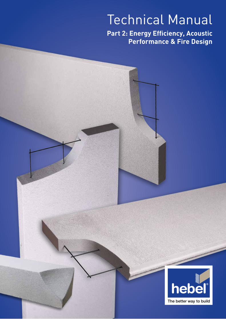
Technical ManualPart 2: Energy Efficiency, Acoustic
Performance & Fire Design
CSR Hebel Technical Manual • January 2006
3
3.1
Energy Efficiency
3.1 Introduction
Energy savings in the operation of buildings are of particular importance as the cost of energy for heating and air conditioning in most cases represent the major cost factor in the operating cost of a building. The energy retention or loss characteristics of a building are directly related to the thermal performance of the building components.
The entrained air in the cellular structure of CSR Hebel AAC gives the product excellent thermal insulation properties, as well as good heat retention characteristics. These characteristics contribute significantly to the energy saving performance of the building, as highlighted in the example at the end of this section.
This section gives an overview of factors that affect thermal performance, reasons to insulate buildings, an introduction to the parameters that determine the thermal resistance of a building element and transferred energy, an overview of the BCA building regulations, and condensation control. This section should be read in conjunction with Appendix B, which provides a more descriptive explanation of the terms and background of thermal modelling.
An example is provided in Appendix B to illustrate the outstanding thermal performance of CSR Hebel AAC wall construction compared to traditional competitors of brickwork and blockwork.
3.2 Thermal Performance
Thermal performance is concerned with the energy retention or loss characteristics of a building system and the consequential reduction of greenhouse gas emissions.
The thermal performance of buildings is affected by a complex relationship between all components of the structure, and the environment. Some elements of this relationship include:
• Windows which occupy a large percentage of the perimeter of the building. Their thermal performance depends very much upon the existence and operation of internal and external shading;
• The materials of which the walls are constructed affect not only steady state heat transfer, but also the transient response of the internal environment to daily external temperature changes. In this respect mass and specific heat are important physical properties;
• Ventilation is variable, depending both upon wind velocity, direction and site exposure, and on the management of windows and doors;
• Internal temperatures which vary throughout the day and from room to room; and
• During the day, solar radiation produces external temperatures which are higher than ambient shade air temperature, and which vary around the building envelop in accordance with orientation and exposure to the sun.
To accurately assess the influence of these various elements computer models have been developed to simulate the thermal performance of the total building system (see Appendix B). A less accurate method will be presented here, which can be used to obtain a feel for the thermal performance of a building component, such as; floors, roofs, walls, etc.
Energy Efficiency
Sec
tio
n 3
3
CSR Hebel Technical Manual • January 2006
3
3.2
Energy Efficiency
3.3 Why Thermally Insulate Buildings?
Thermal insulation for buildings is important for many reasons:
• Provide a very comfortable building environment, even in very hot climates;
• Protection of the structure against climatic influences leading to harmful moisture effects by means of water vapor condensation;
• Considerably less energy consumed by heating and cooling systems, and associated reduction of emissions into the atmosphere;
• Down-scaling the thermal design requirements, and
• Cost reduction for procurement and maintenance of down-scaled heating and cooling equipment.
3.4 Heat Transfer
Heat transfer occurs by heat flowing from a hot region to a cool region. In winter when buildings require internal heating, it is desirable to minimise the heat loss which is flowing outwards through the external building components. Conversely in summer, it is desirable to minimise the thermal transmission which is flowing inwards through the external building components, especially through those that are directly exposed to the sun.
Heat flow is a function of three mechanisms; radiation, conduction and convection. These mechanisms are discussed more thoroughly in Appendix B.
3.5 Thermal Conductivity, λ
The thermal conductivity is a property of the material, which represents the quantity of heat per unit time in watts, that flows through a 1m thick even layer of material with an area of 1m2, across a temperature gradient of 1K (Kelvin) in the direction of the heat flow.
Thermal Conductivity, λ The lower the value,
the better the thermal insulation
3.6 Total Thermal Resistance of a Building Component, RT
The total thermal resistance of a building component (wall system), RT is equal to the sum of a number of individual thermal resistances, which are related to material type, internal and external surface air film, and air spaces. Following is a brief introduction to these thermal resistances, further more descriptive explanations are presented in Appendix B.
Thermal Resistance of a Material, R-Value The thermal resistance of a material is the resistance to heat flow between two surfaces at different temperature. The thermal resistance of a material is expressed as the R-Value and is a function of the material thickness and thermal conductivity. The calculation of the R-Value of a material can be found in Appendix B.
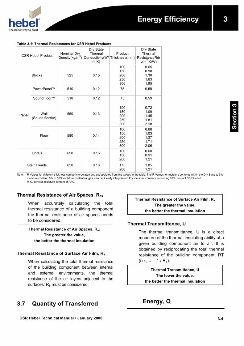
Note. The R-Value of a material can be significantly influenced by the level of moisture in the material. This is illustrated in Table 3.1. for the various AAC products manufactured by CSR Hebel.
Energy Efficiency
Sec
tio
n 3
3
CSR Hebel Technical Manual • January 2006
3
3.3
Energy Efficiency
Thermal Resistance, R-Value The greater the value,
the better the thermal insulation
Energy Efficiency
Sec
tio
n 3
3
CSR Hebel Technical Manual • January 2006
3
3.4
Energy Efficiency
Table 3.1: Thermal Resistances for CSR Hebel Products
CSR Hebel Product Nominal Dry Density(kg/m3)
Dry State Thermal
Conductivity(W/m.K)
Product Thickness(mm)
Dry State Thermal
ResistanceRdry(m2.K/W)
Blocks 525 0.15
100 150 200 250 300
0.65 0.98 1.30 1.63 1.95
Panel
PowerPanel™
510
0.12
75
0.59
SoundFloor™
510
0.12
75
0.59
Wall (Sound Barrier)
550
0.13
100 150 200 250 300
0.72 1.09 1.45 1.81 2.18
Floor
580
0.14
100 150 200 250 300
0.68 1.03 1.37 1.71 2.06
Lintels
650
0.16
100 150 200
0.60 0.91 1.21
Stair Treads
650
0.16
175 200
1.05 1.21
Note: R-Values for different thickness can be interpolated and extrapolated from the values in the table. The R-Values for moisture contents within the Dry State to 5% moisture content, 5% to 10% moisture content ranges, can be linearly interpolated. For moisture contents exceeding 10%, contact CSR Hebel. M.C. denotes moisture content of AAC.
Thermal Resistance of Air Spaces, Ras When accurately calculating the total thermal resistance of a building component the thermal resistance of air spaces needs to be considered.
Thermal Resistance of Air Spaces, Ras The greater the value,
the better the thermal insulation
Thermal Resistance of Surface Air Film, Rs When calculating the total thermal resistance of the building component between internal and external environments, the thermal resistance of the air layers adjacent to the surfaces, RS must be considered.
Thermal Resistance of Surface Air Film, Rs The greater the value,
the better the thermal insulation
Thermal Transmittance, U The thermal transmittance, U is a direct measure of the thermal insulating ability of a given building component air to air. It is obtained by reciprocating the total thermal resistance of the building component, RT (i.e., U = 1 / RT).
Thermal Transmittance, U The lower the value,
the better the thermal insulation
3.7 Quantity of Transferred Energy, Q
Energy Efficiency
Sec
tio
n 3
3
CSR Hebel Technical Manual • January 2006
3
3.5
Energy Efficiency
The quantity of energy, Q (kWh) flowing through the building component can be calculated by multiplying the considered surface area and the heat flow rate of the building component. Energy can be determined from the following expression:
Q = U . A . Δt . T x 10-3
where,
U is the thermal transmittance of the building component (W/(m2.K)).
A is the area of the building component under consideration (m2).
T is the period of time (hours).
Δt is the temperature difference between internal and external environments (K).
Note: a change in temperature of 1˚C is equal to a change in temperature of 1K.
Transferred Energy, Q The lower the value,
the better the thermal insulation
This expression will give an indication of thermal performance, but the actual behaviour is more complex due to the non-uniform temperature behaviour of both internal and external environments, and the subsequent interaction with the building component. To quantify this behaviour computer models have been developed to simulate the thermal movements in a building system, for further information refer to Appendix B.
3.8 Building Regulations
In building regulations and standards, there are Performance Requirements to limit the amount of heat loss or heat gain, or thermal transmission through the external building components and importantly reduce greenhouse gas emissions. The thermal resistance and degree of sealing of a building envelop will assist in controlling and reducing the heating load and/or cooling load of the building.
On the 1st of May, 2004, the Building Code of Australia (BCA) was released with new regulatory Performance Requirements for energy efficiency design of Building Solutions (i.e., walls, floors, etc.) for various classes of buildings. Most states and territories, and other regulatory authorities (councils) have adopted these energy efficiency regulations, or a modified form of the regulations. Note, New South Wales has provided alternate regulations (i.e. BASIX, for information refer to “www.basix.nsw.gov.au”). For the BCA regulations the Performance Requirements and Assessment Methods to be used, and the minimum standard to be achieved varies between states, territories and other regulatory authorities.
To comply with the measures outlined in the BCA or by other appropriate authorities, the Building Solution for a project will satisfy the Performance Requirements presented in the BCA or other regulatory authority. The BCA is structured so that compliance of the Building Solution can be achieved by several methods, these being:
• Complying with Deemed-to-Satisfy Provisions presented in the BCA; or
• Formulating an Alternative Solution; or
Energy Efficiency
Sec
tio
n 3
3
CSR Hebel Technical Manual • January 2006
3
3.6
Energy Efficiency
For a Building Solution that is an Alternative Solution, Assessment Methods are presented in the BCA for compliance assessment. These methods include:
• Documentary evidence; or
• Verifications Methods in the BCA or those accepted by the appropriate authority; or
• Comparison to Deemed-to-Satisfy Provisions; or;
• Expert Judgement.
The advantage of using the performance based path towards compliance is that it is possible to trade things which add amenity but reduce thermal performance for an increase in thermal performance elsewhere in the house. For example, west facing picture windows may take advantage of a wonderful view, but will increase the probability of overheating the house in the afternoon in summer. This could be offset by providing better ventilation or better contact with the cooler ground below the floor.
Prescriptive measures relating to the levels of insulation vary, depending on the authority requiring compliance. They may be described in terms of minimum additional R-Value of insulation required in the wall, ceiling or floor, or minimum total R-Value of the wall, ceiling or floor. Air film resistance may or may not be included in the total R-Value.
Table 3.2 presents typical Building Solutions of CSR Hebel products in wall system and floor system applications, respectively. These tables contain the Total R-Value of the Building Solution and Minimum Additional R-Value Required to achieve compliance. The appropriate consultant (expert) should check that the assumed component R-Values are acceptable, and therefore the Total R-Value is appropriate and approved as satisfying the Deemed-to-Satisfy Provisions of a particular project.
3.9 Condensation Control
Atmospheric water vapour will condense when it, or air containing it, comes into contact with a surface that is at or below the dew point temperature. Condensation of vapour within the building system should be considered by the designer. For an introduction to condensation control and simplified calculations, see Appendix C. The calculations can be used to determine a minimum thickness of the base material to minimise the occurrence of condensation forming.
Importantly, condensation is a complex problem, and can occur under a variety of conditions, not just cold conditions – hence the appropriate designer should check and approve the building solution for the particular conditions of the project.
Energy Efficiency
Sec
tio
n 3
3

CSR Hebel Technical Manual • January 2006
3
3.7
Energy Efficiency
Table 3.2: Thermal Insulation Options from CSR Hebel for Walls (BCA Vol. 2 - Class 1 & Class 10 Buildings - Housing Provisions)
Climate zones 1, 2, 3 and 5 4 and 6 7 8
Minimum required Total R-Value for walls* 1.4 1.7 1.9 2.8
CSR Hebel AAC Masonry Wall Construction R-Values
10mm cement render/coating system CSR Hebel AAC Masonry (5% MC) 20mm non-reflective cavity NIL insulation 10mm plasterboard • 200mm thick Thermoblok
Total R-Value of wall system 1.82
Minimum added R-Value of insulation NIL NIL 0.08 0.98
10mm cement render/coating systemCSR Hebel AAC Masonry (5% MC) 20mm non-reflective cavity NIL insulation 10mm plasterboard • 200mm thick Sonoblok
Total R-Value of wall system 1.40
Minimum added R-Value of insulation NIL 0.30 0.50 1.40
2-3mm skim render/coating system 75mm thick CSR Hebel PowerPanel 25mm anti-glare air space Sarking R1.5 insulation 10mm Gyprock plasterboard CD • 75mm thick PowerPanel
Total R-Value of wall system 2.72
Minimum added R-Value of insulation NIL NIL NIL 0.08
* Queensland has a variation to the Minimum Total R-Value for the climatic zones. At 1st of May 2004, Climatic zones 1, 2, 3 have a Minimum Total R-Value of 1.0 and Climatic zone 5 has a Minimum Total R-Value of 1.4.
The following R-Values were assumed in the calculation of the Total R-Value of the wall systems detailed in Table 3.2:
• External (outside) Surface, Rso = 0.03m2.K/W
• Internal Surface, Rsi = 0.12m2.K/W
• Non-ventilated cavity less than 20mm non-reflective = 0.16m2.K/W
• Non-ventilated cavity less than 100mm non-reflective = 0.17m2.K/W
• Bradford R1.5 Batts = 1.50m2.K/W
• 10mm plasterboard = 0.06m2.K/W
• 110mm brickwork = 0.17m2.K/W
• Sarking = 0.00m2.K/W
The project specific values should be checked by the appropriate project consultant.
Energy Efficiency
Sec
tio
n 3
3
CSR Hebel Technical Manual • January 2006
4
4.1
Acoustic Performance
4.1 Introduction
The area of acoustics is too broad to be covered in-depth, however, this section provides a brief introduction to the concept of acoustics and an explanation of some common terms, a description of field testing procedure, impact sound transfer, chasing requirements, and current building regulations. As of the 1st of May 2004, the new Building Code of Australia (BCA) requirements have been introduced pertaining to sound insulation. An overview of these requirements can be found in Section 4.9.
At the end of the section, there is a table summarising the sound insulation performance of CSR Hebel products based on data derived from testing at a NATA registered laboratory and/or technical opinions by an acoustic consultants.
4.2 Sound
What we hear as sound is actually small pressure fluctuations in the air. For example, when a drum is struck, the surface vibrates backwards and forwards. These oscillations have a direct affect on the air particles very close to the vibrating surface, causing them also to move backwards and forwards. Oscillations of the first air particles are transferred to adjacent air particles and so the sound spreads outwards from the source. A given sound will have two basic characteristics - amplitude and frequency (or pitch) of the sound. The amplitude of the sound is a measure of the magnitude of the oscillation. The frequency of the sound is a measure of how quickly the vibrating surface is moving back and forth.
4.3 Acoustic Materials – Sound Barriers & Sound Absorbers
When it comes to building materials and acoustics, there are two broad categories of materials. There are materials that absorb sound and prevent it reflecting around a room (echo). These materials are sound absorbers and are usually soft to touch (e.g., Glasswool insulation, carpets, curtains, mineral fibres etc.).
The second category of materials are those which reduce transmission of sound through the material from one room to another. These materials are referred to as sound barriers (e.g., Hebel block and panel walls, and floor panels).
There is generally very little overlap between the two categories of materials; that is, a material that is an effective sound barrier is generally also a very poor absorber of sound and tends to reflect sound instead, and vice versa. Both types of materials are necessary for providing a satisfactory acoustic environment in a building. In residential situations, the furnishings provide most of the sound absorption materials. It is up to the builder/designer to provide effective sound barriers to satisfactorily reduce external sounds and also transmission of sound between apartments or other units. However, the careful combination of acoustic barriers and sound absorbent materials can provide a very cost effective and space efficient solution.
Increasing the weight of a sound barrier will reduce the sound transfer through it, but will increase costs associated with the walls and supporting structure. One way to make a more efficient sound barrier is to provide a wall system consisting of two barriers separated by an airspace filled with sound absorbent material. In this way, very high levels of sound reduction can be achieved using wall systems that are relatively lightweight and with a narrow footprint.
Acoustic Performance
Sec
tio
n 4
4
CSR Hebel Technical Manual • January 2006
4
4.2
Acoustic Performance
4.4 STC & Rw Acoustic Rating Systems
The Building Code of Australia (BCA) presents the Performance Requirements for sound insulation ratings. The sound insulation ratings set minimum values to consider for two types of sound: airbourne sound and impact generated sound.
The Performance Requirements for airbourne sound insulation and impact sound insulation rating are dependant upon the form of construction (i.e., walls or floors), Class of Building, and the type of areas being separated. The airborne sound performance requirement is a value that could be the weighted sound reduction index (Rw) or weighted reduction index with spectrum adaptation term (Rw + Ctr). The impact sound performance requirements is a value called the weighted normalised impact sound pressure level with spectrum adaptation term (Ln,w + Ctr).
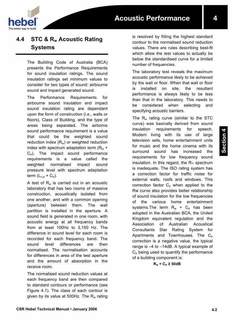
A test of Rw is carried out in an acoustic laboratory that has two rooms of massive construction, acoustically isolated from one another, and with a common opening (aperture) between them. The wall partition is installed in the aperture. A sound field is generated in one room, with acoustic energy at all frequency bands from at least 100Hz to 3,150 Hz. The difference in sound level for each room is recorded for each frequency band. The sound level differences are then normalised. The normalisation accounts for differences in area of the test aperture and the amount of absorption in the receive room.
The normalised sound reduction values at each frequency band are then compared to standard contours or performance (see Figure 4.1). The class of each contour is given by its value at 500Hz. The Rw rating
is resolved by fitting the highest standard contour to the normalised sound reduction values. There are rules describing best-fit which allow the test values to actually be below the standardised curve for a limited number of frequencies.
The laboratory test reveals the maximum acoustic performance likely to be achieved by the wall or floor. When that wall or floor is installed on site, the resultant performance is always likely to be less than that in the laboratory. This needs to be considered when selecting and specifying acoustic barriers.
The Rw rating curve (similar to the STC curve) was basically derived from sound insulation requirements for speech. Modern living with its use of large television sets, home entertainment units for music and the home cinema with its surround sound has increased the requirements for low frequency sound insulation. In this regard, the Rw spectrum is inadequate. The ISO rating system has a correction factor for traffic noise for external walls, roofs and windows. This correction factor Ctr when applied to the Rw curve also provides better relationship of sound insulation for the low frequencies of the various home entertainment systems.The term Rw + Ctr has been adopted in the Australian BCA, the United Kingdom equivalent regulation and the Association of Australian Acoustical Consultants Star Rating System for Apartments and Townhouses. The Ctr correction is a negative value, the typical range is –4 to –14dB. A typical example of Ctr being used to quantify the performance of a building component is:
Rw + Ctr ≥ 50dB
Acoustic Performance
Sec
tio
n 4
4
CSR Hebel Technical Manual • January 2006
4
4.3
Acoustic Performance
Figure 4.1: “Best Fit” of Partition Wall Test Result to Standardised Curves (Rw60 standardised curve is the highest curve fitting the results)
4.5 Field Tests of Partitions and Design Considerations
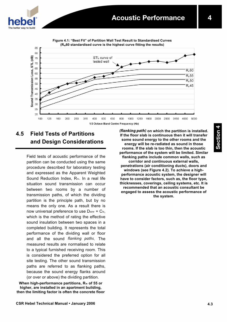
Field tests of acoustic performance of the partition can be conducted using the same procedure described for laboratory testing and expressed as the Apparent Weighted Sound Reduction Index, Rw. In a real life situation sound transmission can occur between two rooms by a number of transmission paths, of which the dividing partition is the principle path, but by no means the only one. As a result there is now universal preference to use Dntw + Ctr, which is the method of rating the effective sound insulation between two spaces in a completed building. It represents the total performance of the dividing wall or floor and all the sound flanking paths. The measured results are normalised to relate to a typical furnished receiving room. This is considered the preferred option for all site testing. The other sound transmission paths are referred to as flanking paths, because the sound energy flanks around (or over or above) the dividing partition.
When high-performance partitions, Rw of 55 or higher, are installed in an apartment building,
then the limiting factor is often the concrete floor
(flanking path) on which the partition is installed. If the floor slab is continuous then it will transfer some sound energy to the other rooms and the
energy will be re-radiated as sound in those rooms. If the slab is too thin, then the acoustic
performance of the system will be limited. Similar flanking paths include common walls, such as
corridor and continuous external walls, penetrations (air conditioning ducts), doors and
windows (see Figure 4.2). To achieve a high-performance acoustic system, the designer will have to consider factors, such as, the floor type, thicknesses, coverings, ceiling systems, etc. It is
recommended that an acoustic consultant be engaged to assess the acoustic performance of
the system.
Acoustic Performance
Sec
tio
n 4
4
CSR Hebel Technical Manual • January 2006
4
4.4
Acoustic Performance
Figure 4.2: Plan of Flanking Paths for Sound Transmission
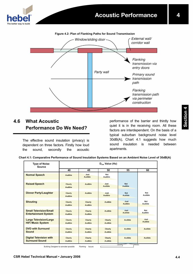
4.6 What Acoustic Performance Do We Need?
The effective sound insulation (privacy) is dependent on three factors. Firstly how loud the sound, secondly the acoustic
performance of the barrier and thirdly how quiet it is in the receiving room. All these factors are interdependent. On the basis of a typical suburban background noise level 30dB(A), Chart 4.1 suggests how much sound insulation is needed between apartments.
Chart 4.1: Comparative Performance of Sound Insulation Systems Based on an Ambient Noise Level of 30dB(A)
Acoustic Performance
Sec
tio
n 4
4
CSR Hebel Technical Manual • January 2006
4
4.5
Acoustic Performance
4.7 Impact Sound Transfer
Impact sound transfer can occur across a wall separating two apartments when a kitchen cupboard, or the like, is attached directly to one side of the wall. Opening and closing the cupboard doors will transfer impact sound energy directly to the wall, which will be re-radiated as sound into the other apartment. Ideally, to minimise this sound transfer, the dividing wall should incorporate a cavity in the middle, with no direct or rigid connections between the two sides of the wall. This can be achieved by constructing a double-leaf Hebel wall, a wall with a separate steel stud wall.
For walls to be impact rated they must be of discontinuous construction. In general, “discontinuous construction” is described as a wall having a minimum of 20mm cavity between 2 separate wall leaves and no mechanical linkage except at the periphery. For detailed description of impact, sound insulation ratings requirements refer to the Sound Insulation sections of the BCA.
The new BCA requirements have quantified the Impact Sound Insulation Ratings for floors by including weighted normalised impact sound pressure level (L’n,w) and spectrum adaptation term (CI). The two terms are added together (L’n,w + CI) to obtain a single rating value of the floor systems. For required performance ratings of floors see section 4.9.
At present there is no agreed method of impact testing of walls amongst the acoustics fraternity, particularly for field testing.”
4.8 Recesses for Services and Chasing in CSR Hebel Walls
CSR Hebel has a set of informative provisions with regards to recesses for services and/or chasing, which are not
detrimental to the already established fire/acoustic levels. The designer should refer to chasing guidance in CSR Hebel building systems literature.
These provisions include:
• Recesses and chasings for all services must comply with BCA 2004, Volumes 1 and 2 requirements.
• Water services should not be chased whatsoever into CSR Hebel blockwork or panels. For locating water services within walls, refer to the BCA volumes 1 and 2. In non-acoustic rated walls such as internal unit walls, chasing may be permissible but check with the BCA for your State or Territory.
• Electrical services may be chased within the wall section for party dividing walls (Rw rated) but check with BCA requirements for your State or Territory. If chasing is allowed, certain guidelines must be enforced:
★ Offset all GPO’s by 600mm to ensure that a full stud cavity or furring channel exists between outlets. All GPO’s on the stud and plasterboard side of the wall system should be acoustic and fire rated.
★ Electrical service chasings should not be installed exactly opposite each other, on either side of the wall, with at least a vertical offset of 300mm enforced.
★ The chase is backfilled after the installation of the services with suitable material, which would adhere to the wall (e.g., Hebel Patch).
★ The depth of the chasings should not exceed 25mm for vertical chases and 15mm for horizontal chases. Maximum width of the chasings shall not be greater then 25mm.
★ Maximum number of chases allowed is 2 chases per 1m length of wall.
The guidelines above provide methods to minimise Rw loss due to chasing in CSR Hebel block or panel walls.
Acoustic Performance
Sec
tio
n 4
4
CSR Hebel Technical Manual • January 2006
4
4.6
Acoustic Performance
4.9 Requirements of the BCA for Dividing Walls and Floors
On the 1st of May, 2004, the Building Code of Australia (BCA) was released with new regulatory Performance Requirements for insulation design of airborne and impact sound generation through Building Solutions (i.e., walls, floors, etc.) for various classes of buildings. The acoustic requirements for party walls have been in place for over 30 years, but in 2004 were significantly upgraded for most of the Australian states and the ACT. In 2005 some of the remaining states adopted the upgrades. This only leaves the state of Queensland and the Northern Territory using the old acoustic regulations.
For the States of New South Wales Victoria South Australia Western Australia Tasmania Australian Capital Territory
The sound insulation rating of a wall in Class 2 or 3 building must :
(i) have an Rw + Ctr (airborne) not less than 50, if it separates sole-occupancy units; and
(ii) have an Rw (airborne) not less than 50, if it separates a sole-occupancy unit from a plant room, lift shaft, stairway, public corridor, public lobby or the like, or parts of a different classification; and
(iii) comply with F5.3(b) if it separates:
(A) a bathroom, sanitary compartment, laundry or kitchen in one sole-occupancy unit from a habitable room (other than a kitchen) in an adjoining unit; or
(B) a sole-occupancy unit from a plant room or lift shaft.
The BCA 2005 allows for on site verification.
This is covered by Section FV5.2. Compliance with FP5.2(a) and FP5.3 to avoid the transmission of airborne sound through walls is verified when it is measured in-situ that:
(a) a wall separating sole-occupancy units has a weighted standardised level difference with spectrum adaptation term (DnT,w + Ctr) not less than 45 when determined under AS/NZS 1276.1 or ISO 717.1; or
(b) a wall separating a sole-occupancy unit from a plant room, lift shaft, stairway, public corridor, public lobby, or the like, or parts of a different classification, has a weighted standardised level difference (DnT,w) not less than 45 when determined under AS/NZS 1276.1 or ISO 717.1.
BCA 2004 also allows for A0.8 Alternative Solutions, together with A0.9 Assessment Methods, providing these are determined in accordance with A0.10.Relevant Performance Requirements. This is covered in A2.2 Evidence of Suitability (a) (iii) (A) and (B).”
To comply with the measures outlined in the BCA or by other appropriate authorities, the Building Solution for a project will satisfy the Performance Requirements presented in the BCA or other authority. The BCA is structured so that compliance of the Building Solution can be achieved by several methods, these being:
• Complying with Deemed-to-Satisfy Provisions presented in the BCA; or
• Formulating an Alternative Solution; or
• A combination of the above.
Acoustic Performance
Sec
tio
n 4
4
CSR Hebel Technical Manual • January 2006
4
4.7
Acoustic Performance
For a building solution that is an Alternative Solution, Assessment Methods are presented in the BCA for compliance assessment. These methods include:
• Documentary evidence; or
• Verifications Methods in the BCA or those accepted by the appropriate authority; or
• Comparison to Deemed-to-Satisfy Provisions; or
• Expert Judgement.
4.10 AAAC Star Rating System
The Association of Australia Acoustical Consultants (AAAC) has developed a star rating system, from 1 to 6 stars, which addresses all aspects of acoustic amenity in apartments. This will create greater awareness of acoustic issues and better informed purchasers of residential apartments. The AAAC Star Rating System is designed to promote better acoustic quality in buildings where as the BCA is a minimum acceptable community standard.
Some aspects of the AAAC system have been adopted by some councils in Sydney.
Experience, to date, has clearly shown that the minimum becomes “The Standard” irrespective of the cost of the apartment. The AAAC Star Rating System intends to correct this situation.
The AAAC System is totally field orientated and relates to the actual performance of the completed apartment. It is a direct measure of what an occupant can anticipate. The measurement of sound insulation will be as DnT,w and it is most likely that the relevant Ctr correction will be applied.
Acoustic Performance
Sec
tio
n 4
4
CSR Hebel Technical Manual • January 2006
4
4.8
Acoustic Performance
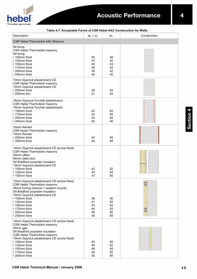
Table 4.1: Acceptable Forms of CSR Hebel AAC Construction for Walls
Description Rw + Ctr Rw Construction
CSR Hebel Thermoblok AAC Masonry
Nil lining CSR Hebel Thermoblok masonry Nil lining • 100mm thick • 125mm thick • 150mm thick • 175mm thick • 200mm thick • 250mm thick
35 37 40 39 39 42
38 40 43 42 42 45
10mm Gyprock plasterboard CD CSR Hebel Thermoblok masonry 10mm Gyprock plasterboard CD • 200mm thick • 250mm thic
39 41
42 44
16mm Gyprock Fyrchek plasterboard CSR Hebel Thermoblok masonry 16mm Gyprock Fyrchek plasterboard • 150mm thick • 175mm thick • 200mm thick • 250mm thick
42 42 43 45
45 45 46 48
10mm Render CSR Hebel Thermoblok masonry 10mm Render • 200mm thick • 250mm thick
42 44
46 48
10mm Gyprock plasterboard CD (screw fixed) CSR Hebel Thermoblok masonry 20mm offset 64mm steel stud S4 Bradford polyester insulation 10mm Gyprock plasterboard CD • 100mm thick • 125mm thick • 150mm thick
42 44 47
52 54 56
10mm Gyprock plasterboard CD (screw fixed) CSR Hebel Thermoblok masonry 28mm furring channel + resilient mounts S4 Bradford polyester insulation 10mm Gyprock plasterboard CD • 100mm thick • 125mm thick • 150mm thick • 175mm thick • 200mm thick • 250mm thick
39 41 43 44 46 49
50 52 54 55 56 59
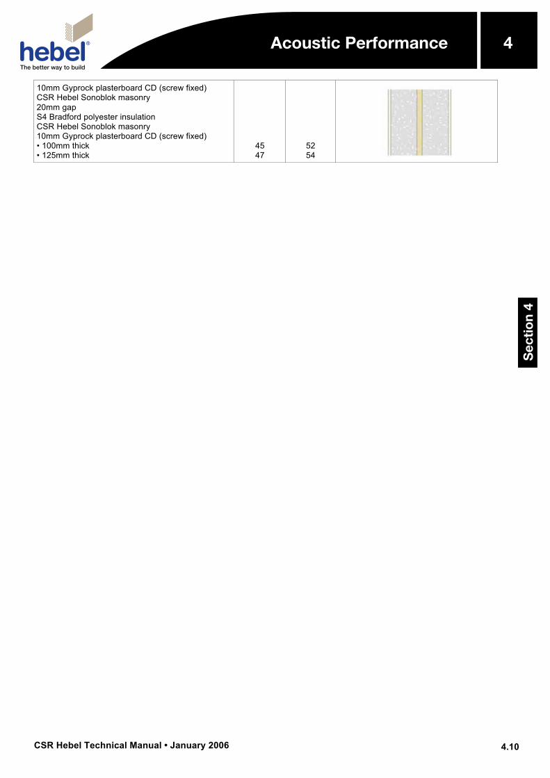
10mm Gyprock plasterboard CD (screw fixed) CSR Hebel Thermoblok masonry 20mm gap S4 Bradford polyester insulation CSR Hebel Thermoblok masonry 10mm Gyprock plasterboard CD (screw fixed) • 100mm thick • 125mm thick • 150mm thick • 175mm thick • 200mm thick
43 45 48 49 50
50 52 54 55 56
Acoustic Performance
Sec
tio
n 4
4
CSR Hebel Technical Manual • January 2006
4
4.9
Acoustic Performance
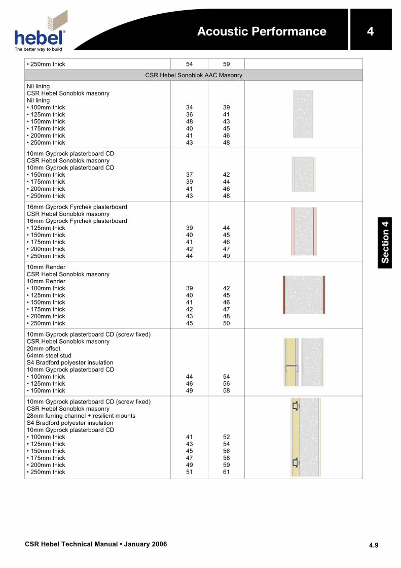
• 250mm thick 54 59
CSR Hebel Sonoblok AAC Masonry
Nil lining CSR Hebel Sonoblok masonry Nil lining • 100mm thick • 125mm thick • 150mm thick • 175mm thick • 200mm thick • 250mm thick
34 36 48 40 41 43
39 41 43 45 46 48
10mm Gyprock plasterboard CD CSR Hebel Sonoblok masonry 10mm Gyprock plasterboard CD • 150mm thick • 175mm thick • 200mm thick • 250mm thick
37 39 41 43
42 44 46 48
16mm Gyprock Fyrchek plasterboard CSR Hebel Sonoblok masonry 16mm Gyprock Fyrchek plasterboard • 125mm thick • 150mm thick • 175mm thick • 200mm thick • 250mm thick
39 40 41 42 44
44 45 46 47 49
10mm Render CSR Hebel Sonoblok masonry 10mm Render • 100mm thick • 125mm thick • 150mm thick • 175mm thick • 200mm thick • 250mm thick
39 40 41 42 43 45
42 45 46 47 48 50
10mm Gyprock plasterboard CD (screw fixed) CSR Hebel Sonoblok masonry 20mm offset 64mm steel stud S4 Bradford polyester insulation 10mm Gyprock plasterboard CD • 100mm thick • 125mm thick • 150mm thick
44 46 49
54 56 58
10mm Gyprock plasterboard CD (screw fixed) CSR Hebel Sonoblok masonry 28mm furring channel + resilient mounts S4 Bradford polyester insulation 10mm Gyprock plasterboard CD • 100mm thick • 125mm thick • 150mm thick • 175mm thick • 200mm thick • 250mm thick
41 43 45 47 49 51
52 54 56 58 59 61
Acoustic Performance
Sec
tio
n 4
4
CSR Hebel Technical Manual • January 2006
4
4.10
Acoustic Performance
10mm Gyprock plasterboard CD (screw fixed) CSR Hebel Sonoblok masonry 20mm gap S4 Bradford polyester insulation CSR Hebel Sonoblok masonry 10mm Gyprock plasterboard CD (screw fixed) • 100mm thick • 125mm thick
45 47
52 54
Acoustic Performance
Sec
tio
n 4
4
CSR Hebel Technical Manual • January 2006
4
4.11
Acoustic Performance
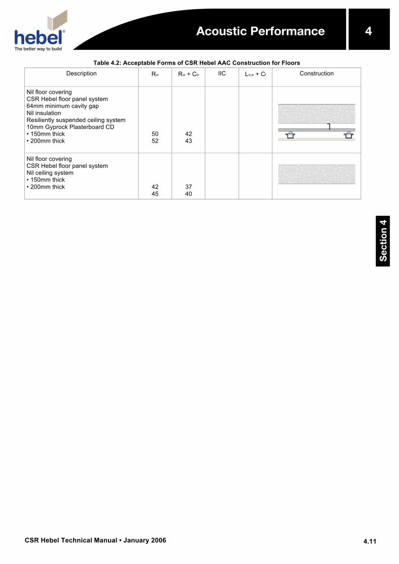
Table 4.2: Acceptable Forms of CSR Hebel AAC Construction for Floors
Description
Rw
Rw + Ctr
IIC
Ln,w + Cl
Construction
Nil floor covering CSR Hebel floor panel system 64mm minimum cavity gap Nil insulation Resiliently suspended ceiling system 10mm Gyprock Plasterboard CD • 150mm thick • 200mm thick
50 52
42 43
Nil floor covering CSR Hebel floor panel system Nil ceiling system • 150mm thick • 200mm thick
42 45
37 40
Acoustic Performance
Sec
tio
n 4
4
CSR Hebel Technical Manual • January 2006
5
5.1
Fire Design
5.1 Overview
Autoclaved Aerated Concrete (AAC) is one of the most effective building materials for providing a barrier to fire. AAC has shown itself to be non-combustible and very stable under fire loading, this results in structural systems that have high fire resistance level (FRL) ratings. The properties that highlight the high level performance of AAC under fire loading are presented in this section.
Basically, CSR Hebel manufactures two types of products:
• Blocks; and
• Panels.
These products have different methods for assessing their performance when subjected to fire loading. While blocks are used to construct various types of walls, panels are used in both walls and additionally in horizontal applications of:
• Floors;
• Ceilings; and
• Roofs.
To address the different methods clearly, this “Fire Design” section covers the fire performance of block and panel products in two separate sections:
• Block Products; and
• Panel Products
Each section presents the background of the methods and design charts to assist the designer with the adequacy of the CSR Hebel products.
5.2 Fire Properties of CSR Hebel AAC
Fire Hazard Indices
CSR Hebel blocks have the following early fire hazard indices, determined in accordance with AS1530.3:1990:
• Ignitability Index : 0
• Spread of Flame Index : 0
• Heat Developed Index : 0
• Smoke Developed Index : 0–1
5.3 Fire Resistance Level (FRL) Ratings
The Building Code of Australia regulations express the fire performance of a wall with the rating system called the ‘Fire Resistance Level’ (FRL). The FRL ratings in the CSR Hebel Technical Manual have been determined by testing in accordance with AS1530.4 – Fire Resistance Tests of Elements of Building Construction - at the CSIRO North Ryde, or opinions issued by the CSIRO based on test results.
The FRL rating consists of three performance criteria, structural adequacy/integrity/insulation. For non-loadbearing walls, there is no requirement to express the ‘structural adequacy’ criteria.
When considering a FRL, the fuel load and fire exposure type (the fire exposure type being either cellulosic or hydrocarbon based) must be determined. AS1530.4 only provides for the fire exposure type to be cellulosic, therefore any FRL levels as determined by testing under AS1530.4 can only be considered applicable to a cellulosic fire.
Fire Design
Sec
tio
n 5
5
CSR Hebel Technical Manual • January 2006
5
5.2
Fire Design
Example: The FRL of a non-loadbearing wall may be expressed as - /120/90. The ‘dash’ indicates no requirement for the ‘structural adequacy’ criterion, followed by ‘integrity’ criterion of 120 minutes, and ‘insulation’ criterion of 90 minutes.
The FRL of a loadbearing wall may be expressed as 180/120/90. Where the 180 is the ‘structural adequacy’ criterion and indicates that the building component is structurally adequate for 180 minutes, followed by the ‘integrity’ criterion of 120 minutes, and the ‘insulation’ criterion of 90 minutes.
5.4 Fire Certificates and Reports
Copies of the test reports for fire testing performed on the CSR Hebel blocks can be obtained by contacting CSR Hebel. Test certificates can be found in Appendix F.
5.5 Additional Design Considerations
Fire-rated block walls should comply with both strength and robustness requirements, and minimum slenderness ratios outlined in AS3700 - Masonry Structures code.
Sec
tio
n 5
5Fire Design
CSR Hebel Technical Manual • January 2006
5
5.3
Fire Design
Block Products 5.6 Design for Fire – Blocks
The capacity of a wall under fire loading depends upon the cross-sectional properties, slenderness of the wall and the lateral support conditions of the edges of the wall, size of openings and magnitude of the applied load.
AAC walls can be designed for fire loading using the requirements outlined in Section 6 of AS3700. The capacity of the wall is expressed in terms of the fire resistance level (FRL), which consists of three terms, these being structural adequacy, integrity and insulation (e.g., 240/240/240). The values of these terms have been determined from the results of tests performed at the CSIRO Fire Testing Laboratory, see Clause 6.2 in AS3700.
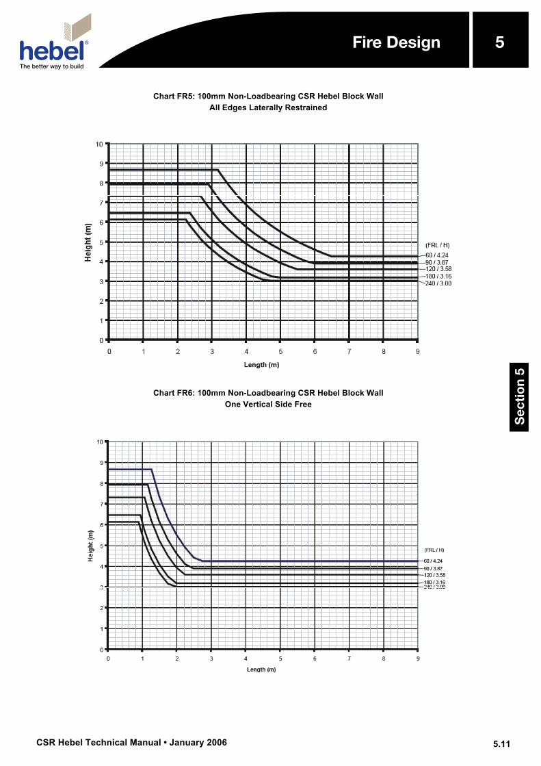
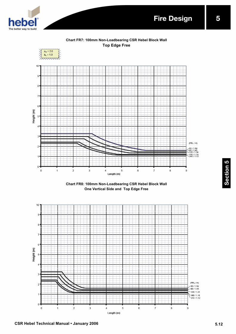
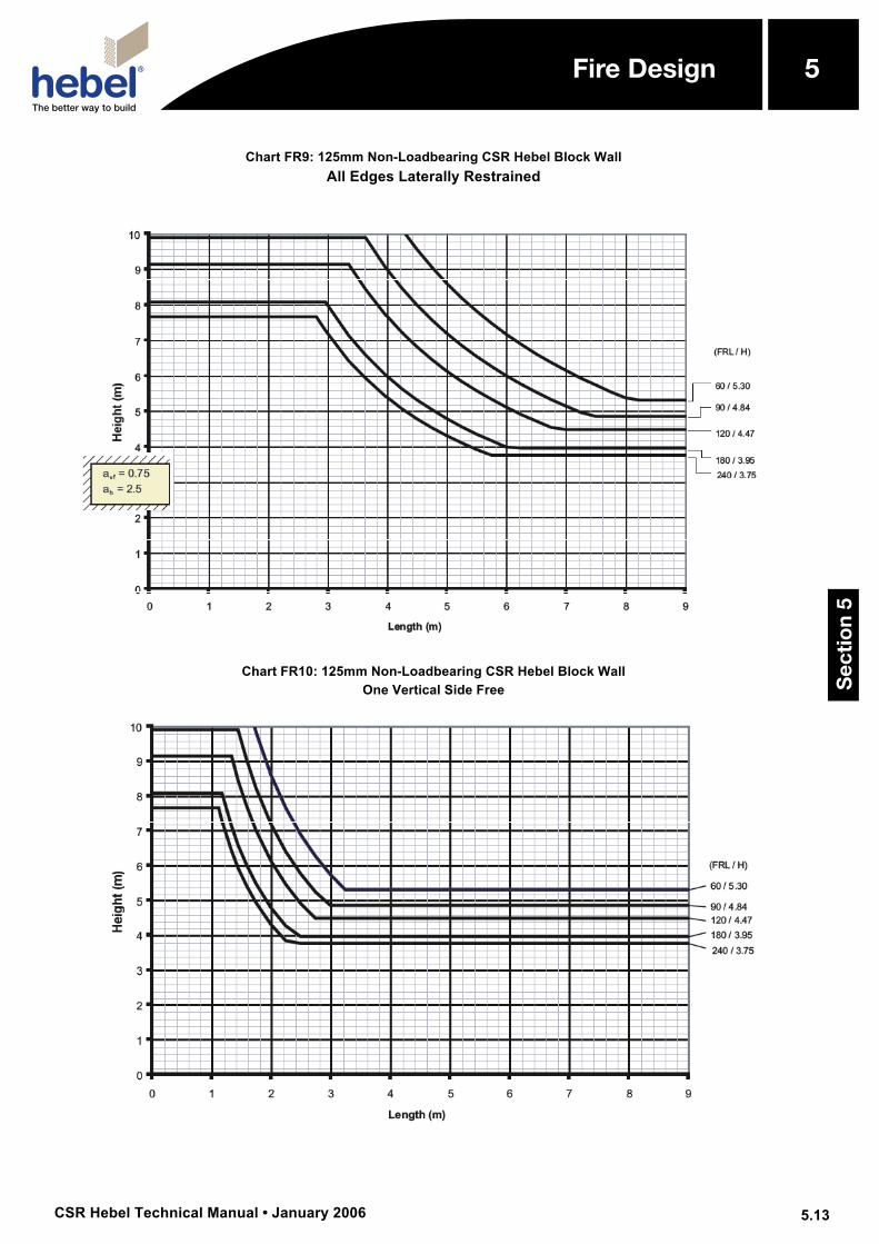
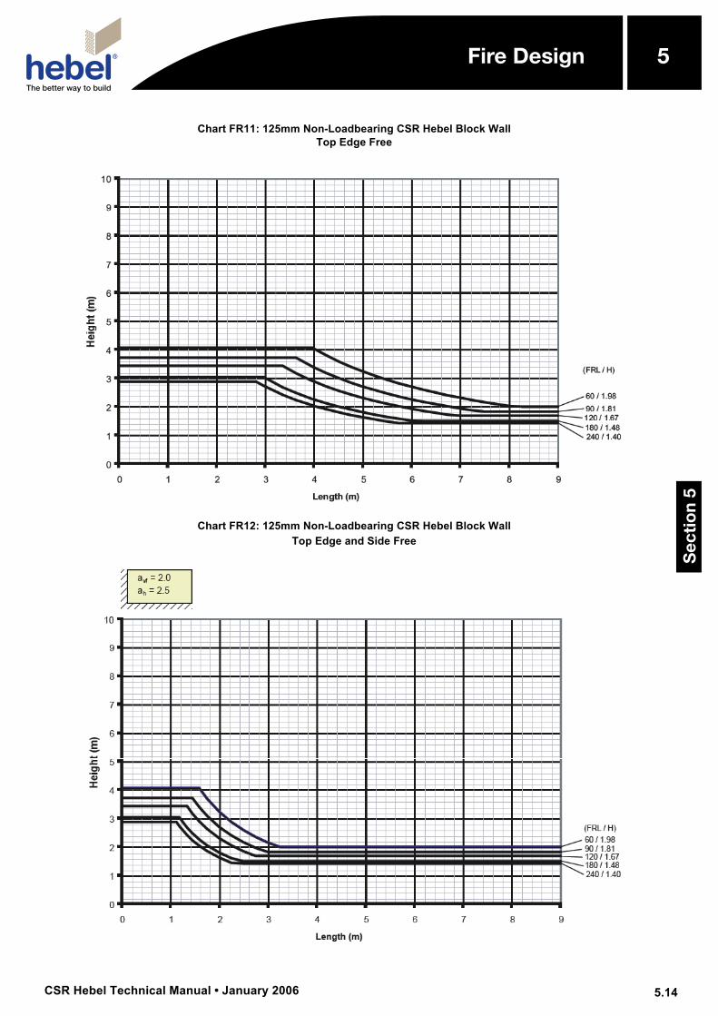
Structural Adequacy Design charts for structural adequacy have been determined in accordance with AS3700 Clause 6.3. Each chart is for a particular wall thickness and loading type (i.e., non-loadbearing, or loadbearing) and presents curves for various structural adequacy FRL values as a function of length and height of wall. The height and length of the wall are the clear dimensions between supports or free edges in all cases. Where the height of an opening is greater than 1/5 of the wall height, then the wall shall be divided into two sub-panels with a free edge at the centre of the opening, see AS3700 Clause 6.3.1 (Refer to Section 5.12 for further information). The structural adequacy FRL of a wall should be equal to or greater than the integrity and insulation FRL requirements for the wall.
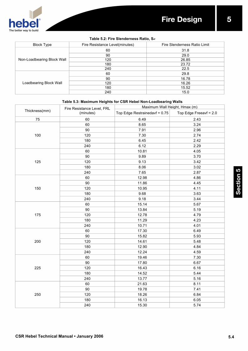
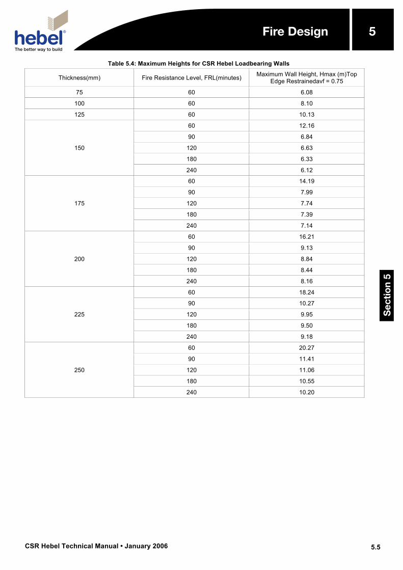
AS3700 caters for the various support conditions by the use of slenderness coefficients avf and ah as shown in Table 5.1. The limiting slenderness ratio for design of fire resistance, Srf for various FRL values (i.e., 60, 90, 120, 180, 240) have been determined in accordance with the AS3700 Clause 6.3.3. These coefficients, slenderness ratios, Srf and the expressions in AS3700 Clause 6.3.2.2 have been used to generate the design charts. Maximum wall heights are shown in Tables 5.3 and 5.4.
Table 5.1: Slenderness Coefficients for Structural
Adequacy (AS3700 Clause 6.3.2.2)
Support Conditions at the Top and Bottom avf
Lateral support along the top edge 0.75
Lateral support at bottom only 2.0
Support Conditions at the Sides ah
Lateral support on both vertical edges 1.0
Lateral support on one vertical edge 2.5
Sec
tio
n 5
5Fire Design
CSR Hebel Technical Manual • January 2006
5
5.4
Fire Design
Table 5.2: Fire Slenderness Ratio, Srf
Block Type Fire Resistance Level(minutes) Fire Slenderness Ratio Limit
Non-Loadbearing Block Wall
60 31.8 90 29.0
120 26.85 180 23.72 240 22.5
Loadbearing Block Wall
60 29.8 90 16.78
120 16.26 180 15.52 240 15.0
Table 5.3: Maximum Heights for CSR Hebel Non-Loadbearing Walls
Thickness(mm) Fire Resistance Level, FRL (minutes)
Maximum Wall Height, Hmax (m) Top Edge Restrainedavf = 0.75 Top Edge Freeavf = 2.0
75 60 6.49 2.43
100
60 8.65 3.24 90 7.91 2.96
120 7.30 2.74 180 6.45 2.42 240 6.12 2.29
125
60 10.81 4.05 90 9.89 3.70
120 9.13 3.42 180 8.06 3.02 240 7.65 2.87
150
60 12.98 4.86 90 11.86 4.45
120 10.95 4.11 180 9.68 3.63 240 9.18 3.44
175
60 15.14 5.67 90 13.84 5.19
120 12.78 4.79 180 11.29 4.23 240 10.71 4.01
200
60 17.30 6.49 90 15.82 5.93
120 14.61 5.48 180 12.90 4.84 240 12.24 4.59
225
60 19.46 7.30 90 17.80 6.67
120 16.43 6.16 180 14.52 5.44 240 13.77 5.16
250
60 21.63 8.11 90 19.78 7.41
120 18.26 6.84 180 16.13 6.05 240 15.30 5.74
Sec
tio
n 5
5Fire Design
CSR Hebel Technical Manual • January 2006
5
5.5
Fire Design
Table 5.4: Maximum Heights for CSR Hebel Loadbearing Walls
Thickness(mm) Fire Resistance Level, FRL(minutes) Maximum Wall Height, Hmax (m)Top Edge Restrainedavf = 0.75
75 60 6.08
100 60 8.10
125 60 10.13
150
60 12.16
90 6.84
120 6.63
180 6.33
240 6.12
175
60 14.19
90 7.99
120 7.74
180 7.39
240 7.14
200
60 16.21
90 9.13
120 8.84
180 8.44
240 8.16
225
60 18.24
90 10.27
120 9.95
180 9.50
240 9.18
250
60 20.27
90 11.41
120 11.06
180 10.55
240 10.20 S
ecti
on
5
5Fire Design
CSR Hebel Technical Manual • January 2006
5
5.6
Fire Design
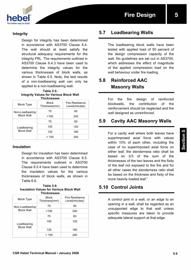
Integrity Design for integrity has been determined in accordance with AS3700 Clause 6.4. The wall should at least satisfy the structural adequacy requirements for the integrity FRL. The requirements outlined in AS3700 Clause 6.4.3 have been used to determine the integrity values for the various thicknesses of block walls, as shown in Table 6.5. Note, the test results of a non-loadbearing wall can only be applied to a non-loadbearing wall.
Table 5.5: Integrity Values for Various Block Wall
Thicknesses
Block Type Block Thickness(mm)
Fire Resistance Level(minutes)
Non-Loadbearing Block Wall
75 60
>100 240
Loadbearing Block Wall
75 60
100 120
125 180
> 150 240
Insulation Design for insulation has been determined in accordance with AS3700 Clause 6.5. The requirements outlined in AS3700 Clause 6.5.4 have been used to determine the insulation values for the various thicknesses of block walls, as shown in Table 6.6.
Table 5.6: Insulation Values for Various Block Wall
Thicknesses
Block Type Block Thickness(mm)
Fire Resistance Level(minutes)
Non-Loadbearing Block Wall
75 60
>100 240
Loadbearing Block Wall
75 60
100
120
125 180
> 150 240
5.7 Loadbearing Walls
The loadbearing block walls have been tested with applied load of 50 percent of the design compression capacity of the wall. No guidelines are set out in AS3700, which addresses the effect of magnitude of the applied compression load on the wall behaviour under fire loading.
5.8 Reinforced AAC Masonry Walls
For the fire design of reinforced blockwalls, the contribution of the reinforcement should be neglected and the wall designed as unreinforced.
5.9 Cavity AAC Masonry Walls
For a cavity wall where both leaves have superimposed axial force with values within 10% of each other, including the case of no superimposed axial force on either leaf, the slenderness ratio shall be based on 2/3 of the sum of the thicknesses of the two leaves and the fixity of the leaf not exposed to the fire and for all other cases the slenderness ratio shall be based on the thickness and fixity of the more heavily loaded leaf.”
5.10 Control Joints
A control joint in a wall, or an edge to an opening in a wall, shall be regarded as an unsupported edge to that wall unless specific measures are taken to provide adequate lateral support at that edge.
Sec
tio
n 5
5Fire Design
CSR Hebel Technical Manual • January 2006
5
5.7
Fire Design
5.11 CSR Hebel Block Walls with Thick Bed Mortar Joints
The charts presented in this publication are not applicable to blockwork constructed with CSR Hebel blocks and conventional 10mm thick mortar joints.
A non-loadbearing fire test has been performed on 100mm thick CSR Hebel blockwork with 10mm thick mortar joints and the test certificate (number 964) can be found in Appendix F. The tested non-loadbearing wall has a fire slenderness ratio (Srf) of 22.5 and a fire resistance level (FRL) rating of 240/240/180.
This test result can be used to determine the fire performance of non-loadbearing walls constructed of CSR Hebel blocks in 10mm thick mortar joints, in accordance with AS3700 requirements.
5.12 Recesses for Services and Chasing for Fire Design
When walls are to be recessed or chased for the provision of services and cabling, these recesses or chases satisfy the requirements presented in AS3700 Clauses 6.6 and 6.7, respectively. All chasing to be approved by Project Engineer.
In addition to these requirements CSR Hebel provides the following information with regards to chasing, which will not be detrimental to the already established levels.
The effect of recesses for services on the fire resistance periods, for structural adequacy, integrity and insulation of a wall shall be ignored, provided that the depth of material removed is not greater than one third of the wall thickness and the total area of recesses is not more than
10,000mm2 total of both faces within any 5m2 of wall area.
Where these limits are exceeded, the wall thickness of the masonry (t) shall be taken as the overall thickness of the wall less the depth of recess.
Chases
The effect of chases on structural adequacy
The effect of chases on the fire-resistance period for structural adequacy shall be dealt with as follows:
(a) For vertically spanning walls:
(i) where the chase is vertical – ignored;
(ii) where the chase is horizontal and of length not greater than four times the wall thickness – ignored; and
(iii) where the chase is horizontal and of length greater than four times the wall thickness – considered, using the slenderness ratio of the wall based on the wall thickness at the bottom of the chase.
(b) For horizontally spanning walls –
(i) where the chase is horizontal – ignored;
(ii) where the chase is vertical and of length not greater than four times the wall thickness – ignored; and
(iii) where the chase is vertical and of length greater than four times the wall thickness – considered, using the slenderness ratio of the wall based on the wall thickness at the bottom of the chase.
(c) For walls spanning vertically and horizontally (panel action)
(i) where the length, L, of chase is not greater than half the height, h, (for a vertical chase) or half the length (for a horizontal chase)—ignored;
(ii) where the length, L, of chase is greater than half the length (for a horizontal chase)—considered, using the slenderness ratio of the wall based on the wall thickness at the bottom of the chase
Sec
tio
n 5
5Fire Design
CSR Hebel Technical Manual • January 2006
5
5.8
Fire Design
(iii) where the length, L, of chase is greater than half the height, h (for a vertical chase)—considered, the chase may be regarded as an unsupported edge and the panel designed as two subpanels using the slenderness ratio of the wall based on the wall thickness.
The effect of chases on integrity and insulation
The effect of chases on the fire-resistance periods for integrity and insulation shall be dealt with as follows:
(i) the effects shall be ignored, where the depth of material removed is not greater than the lesser of one third of the wall thickness or 30mm, the cross-sectional area (normal to the plane of the wall) of the chase is not greater than 1000mm2, and the total face area of the chase is not greater than 100,000mm2 total on both faces of the wall on any 5m2 area; and
(ii) the effects shall be taken into account for other chases by calculating the integrity and insulation based on the thickness of the wall at the base of the chase.
Sec
tio
n 5
5Fire Design
CSR Hebel Technical Manual • January 2006
5
5.9
Fire Design
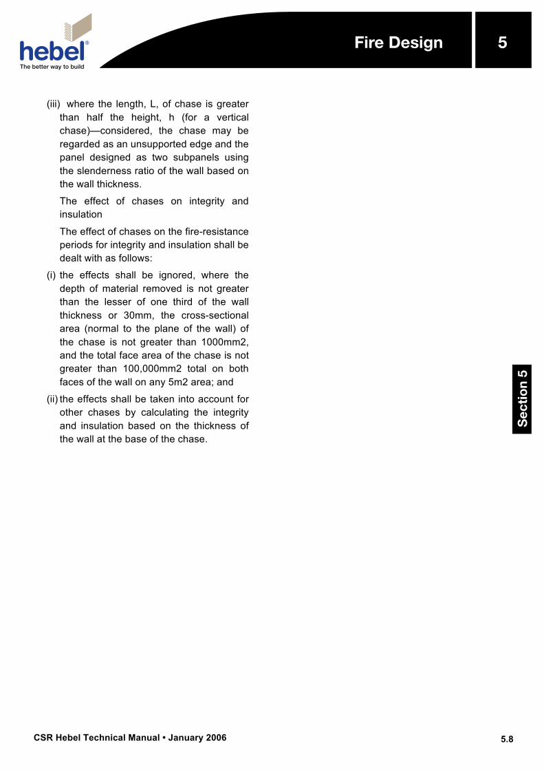
=Chart FR1: 75mm Non-Loadbearing CSR Hebel Block Wall All Edges Laterally Restrained
Chart FR2: 75mm Non-Loadbearing CSR Hebel Block Wall One Vertical Side Free
Sec
tio
n 5
5Fire Design
CSR Hebel Technical Manual • January 2006
5
5.10
Fire Design
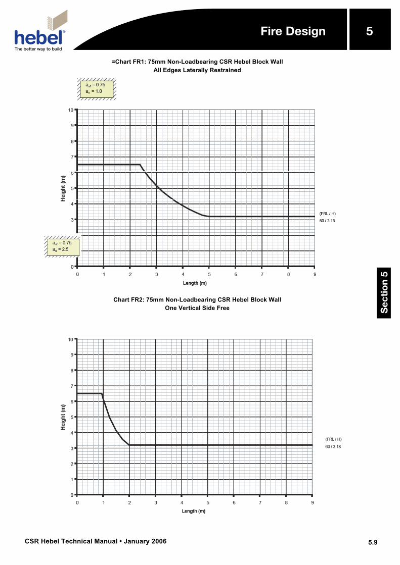
Chart FR3: 75mm Non-Loadbearing CSR Hebel Block Wall Top Edge Free
Chart FR4: 75mm Non-Loadbearing CSR Hebel Block Wall One Vertical Side and Top Edge Free
Sec
tio
n 5
5Fire Design
CSR Hebel Technical Manual • January 2006
5
5.11
Fire Design
Chart FR5: 100mm Non-Loadbearing CSR Hebel Block Wall All Edges Laterally Restrained
Chart FR6: 100mm Non-Loadbearing CSR Hebel Block Wall
One Vertical Side Free
Sec
tio
n 5
5Fire Design
CSR Hebel Technical Manual • January 2006
5
5.12
Fire Design
Chart FR7: 100mm Non-Loadbearing CSR Hebel Block Wall Top Edge Free
Chart FR8: 100mm Non-Loadbearing CSR Hebel Block Wall
One Vertical Side and Top Edge Free
Sec
tio
n 5
5Fire Design
CSR Hebel Technical Manual • January 2006
5
5.13
Fire Design
Chart FR9: 125mm Non-Loadbearing CSR Hebel Block Wall All Edges Laterally Restrained
Chart FR10: 125mm Non-Loadbearing CSR Hebel Block Wall
One Vertical Side Free
Sec
tio
n 5
5Fire Design
CSR Hebel Technical Manual • January 2006
5
5.14
Fire Design
Chart FR11: 125mm Non-Loadbearing CSR Hebel Block Wall Top Edge Free
Chart FR12: 125mm Non-Loadbearing CSR Hebel Block Wall
Top Edge and Side Free
Sec
tio
n 5
5Fire Design
CSR Hebel Technical Manual • January 2006
5
5.15
Fire Design
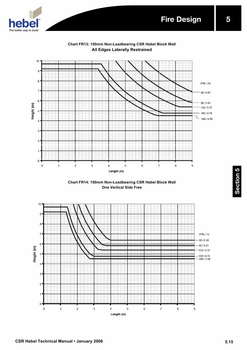
Chart FR13: 150mm Non-Loadbearing CSR Hebel Block Wall All Edges Laterally Restrained
Chart FR14: 150mm Non-Loadbearing CSR Hebel Block Wall
One Vertical Side Free
Sec
tio
n 5
5Fire Design
CSR Hebel Technical Manual • January 2006
5
5.16
Fire Design
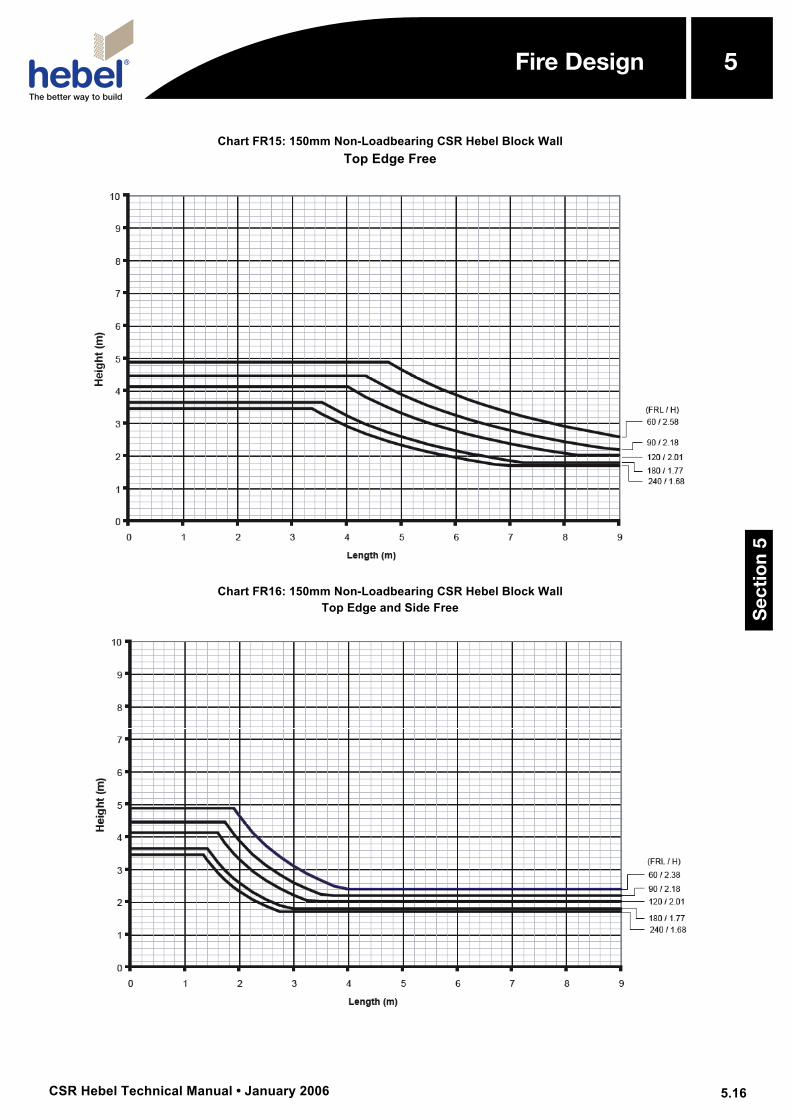
Chart FR15: 150mm Non-Loadbearing CSR Hebel Block Wall Top Edge Free
Chart FR16: 150mm Non-Loadbearing CSR Hebel Block Wall
Top Edge and Side Free
Sec
tio
n 5
5Fire Design
CSR Hebel Technical Manual • January 2006
5
5.17
Fire Design
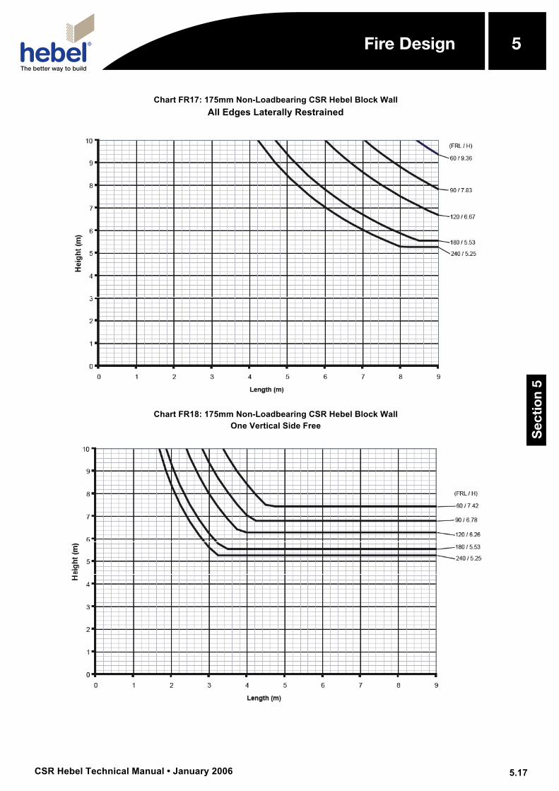
Chart FR17: 175mm Non-Loadbearing CSR Hebel Block Wall All Edges Laterally Restrained
Chart FR18: 175mm Non-Loadbearing CSR Hebel Block Wall
One Vertical Side Free
Sec
tio
n 5
5Fire Design
CSR Hebel Technical Manual • January 2006
5
5.18
Fire Design
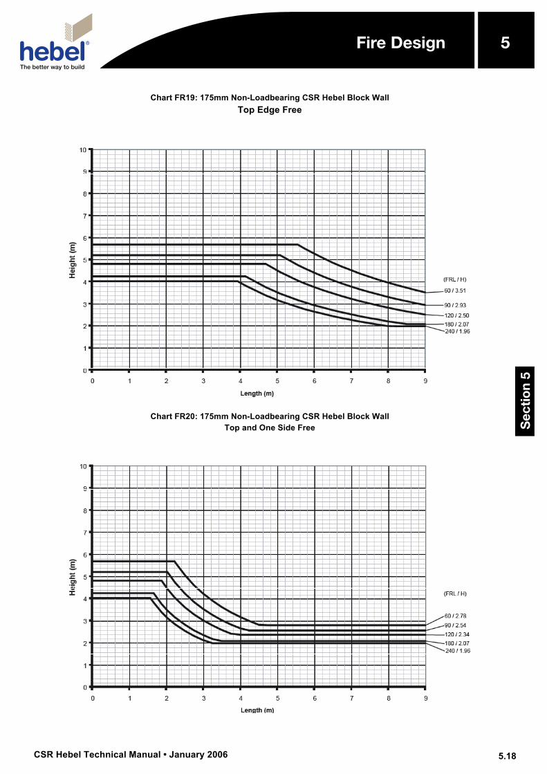
Chart FR19: 175mm Non-Loadbearing CSR Hebel Block Wall Top Edge Free
Chart FR20: 175mm Non-Loadbearing CSR Hebel Block Wall
Top and One Side Free
Sec
tio
n 5
5Fire Design
CSR Hebel Technical Manual • January 2006
5
5.19
Fire Design
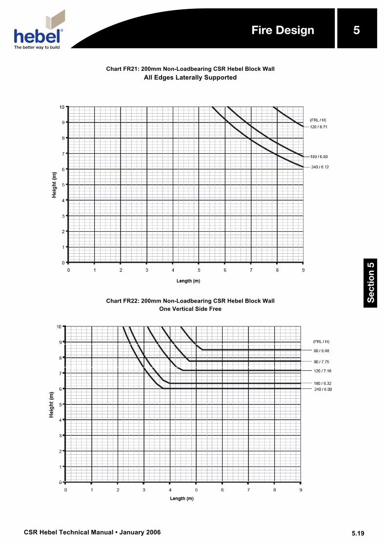
Chart FR21: 200mm Non-Loadbearing CSR Hebel Block Wall All Edges Laterally Supported
Chart FR22: 200mm Non-Loadbearing CSR Hebel Block Wall
One Vertical Side Free
Sec
tio
n 5
5Fire Design
CSR Hebel Technical Manual • January 2006
5
5.20
Fire Design
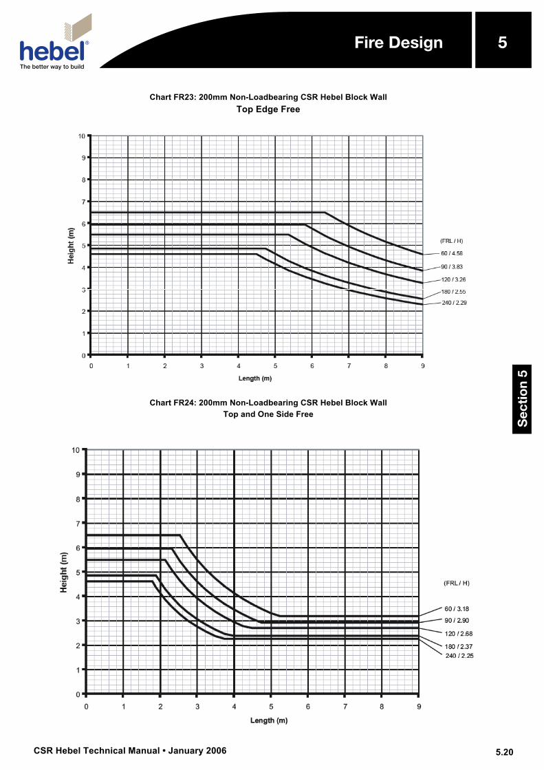
Chart FR23: 200mm Non-Loadbearing CSR Hebel Block Wall Top Edge Free
Chart FR24: 200mm Non-Loadbearing CSR Hebel Block Wall
Top and One Side Free
Sec
tio
n 5
5Fire Design
CSR Hebel Technical Manual • January 2006
5
5.21
Fire Design
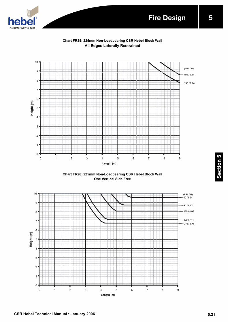
Chart FR25: 225mm Non-Loadbearing CSR Hebel Block Wall All Edges Laterally Restrained
Chart FR26: 225mm Non-Loadbearing CSR Hebel Block Wall
One Vertical Side Free
Sec
tio
n 5
5Fire Design
CSR Hebel Technical Manual • January 2006
5
5.22
Fire Design
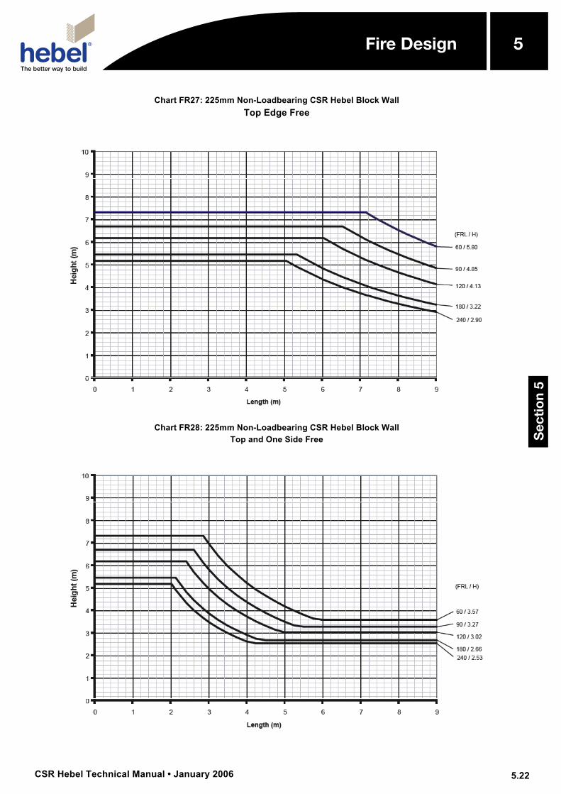
Chart FR27: 225mm Non-Loadbearing CSR Hebel Block Wall Top Edge Free
Chart FR28: 225mm Non-Loadbearing CSR Hebel Block Wall
Top and One Side Free
Sec
tio
n 5
5Fire Design
CSR Hebel Technical Manual • January 2006
5
5.23
Fire Design
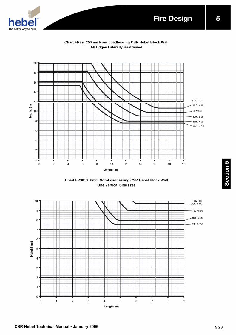
Chart FR29: 250mm Non- Loadbearing CSR Hebel Block Wall All Edges Laterally Restrained
Chart FR30: 250mm Non-Loadbearing CSR Hebel Block Wall
One Vertical Side Free
Sec
tio
n 5
5Fire Design
CSR Hebel Technical Manual • January 2006
5
5.24
Fire Design
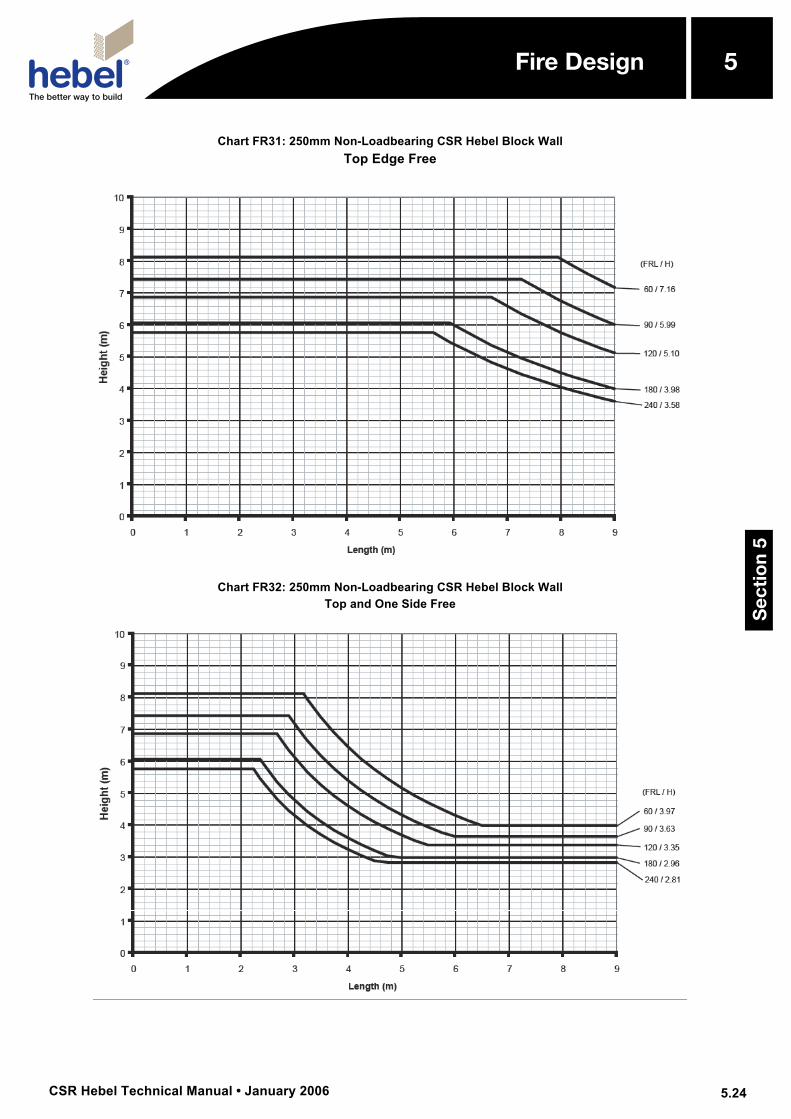
Chart FR31: 250mm Non-Loadbearing CSR Hebel Block Wall Top Edge Free
Chart FR32: 250mm Non-Loadbearing CSR Hebel Block Wall
Top and One Side Free
Sec
tio
n 5
5Fire Design
CSR Hebel Technical Manual • January 2006
5
5.25
Fire Design
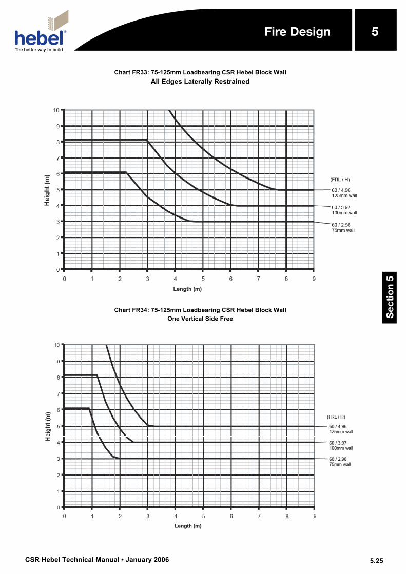
Chart FR33: 75-125mm Loadbearing CSR Hebel Block Wall All Edges Laterally Restrained
Chart FR34: 75-125mm Loadbearing CSR Hebel Block Wall
One Vertical Side Free
Sec
tio
n 5
5Fire Design

CSR Hebel Technical Manual • January 2006
5
5.26
Fire Design
Chart FR35: 150mm Loadbearing CSR Hebel Block Wall All Edges Laterally Restrained
Chart FR36: 150mm Loadbearing CSR Hebel Block Wall
One Vertical Side Free
Sec
tio
n 5
5Fire Design
CSR Hebel Technical Manual • January 2006
5
5.27
Fire Design
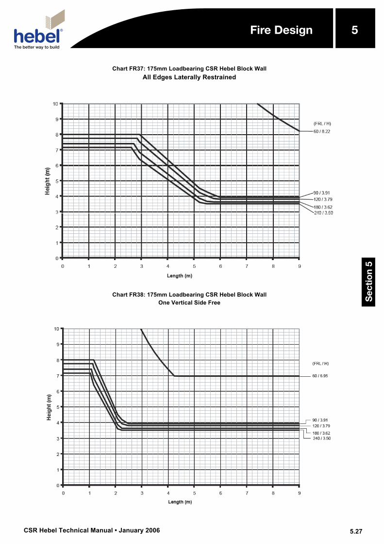
Chart FR37: 175mm Loadbearing CSR Hebel Block Wall All Edges Laterally Restrained
Chart FR38: 175mm Loadbearing CSR Hebel Block Wall
One Vertical Side Free
Sec
tio
n 5
5Fire Design
CSR Hebel Technical Manual • January 2006
5
5.28
Fire Design
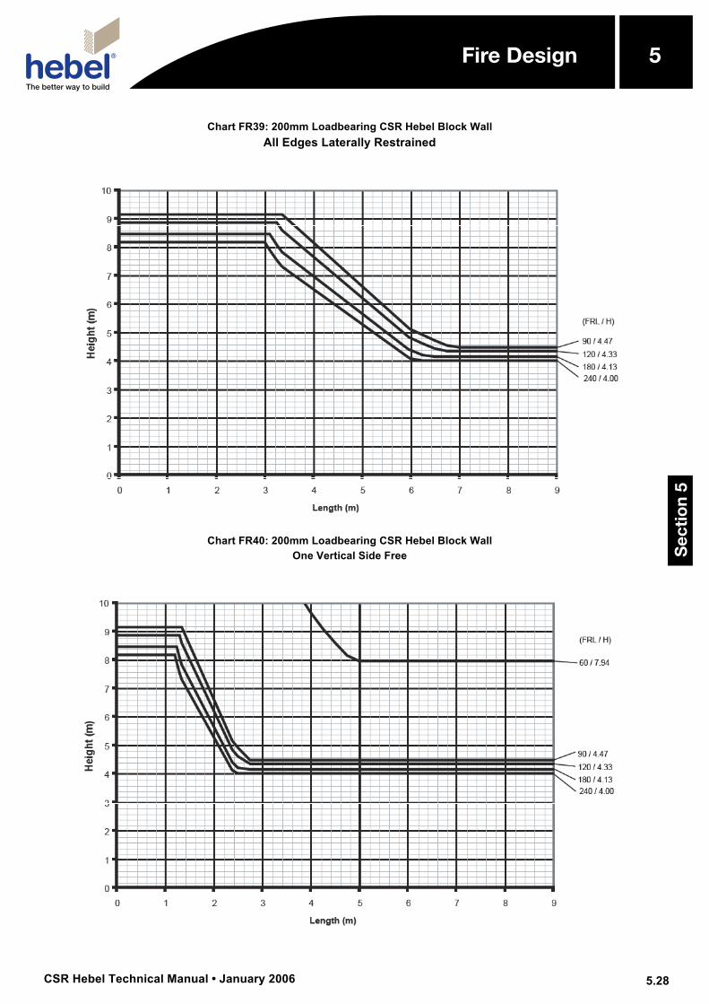
Chart FR39: 200mm Loadbearing CSR Hebel Block Wall All Edges Laterally Restrained
Chart FR40: 200mm Loadbearing CSR Hebel Block Wall
One Vertical Side Free
Sec
tio
n 5
5Fire Design
CSR Hebel Technical Manual • January 2006
5
5.29
Fire Design
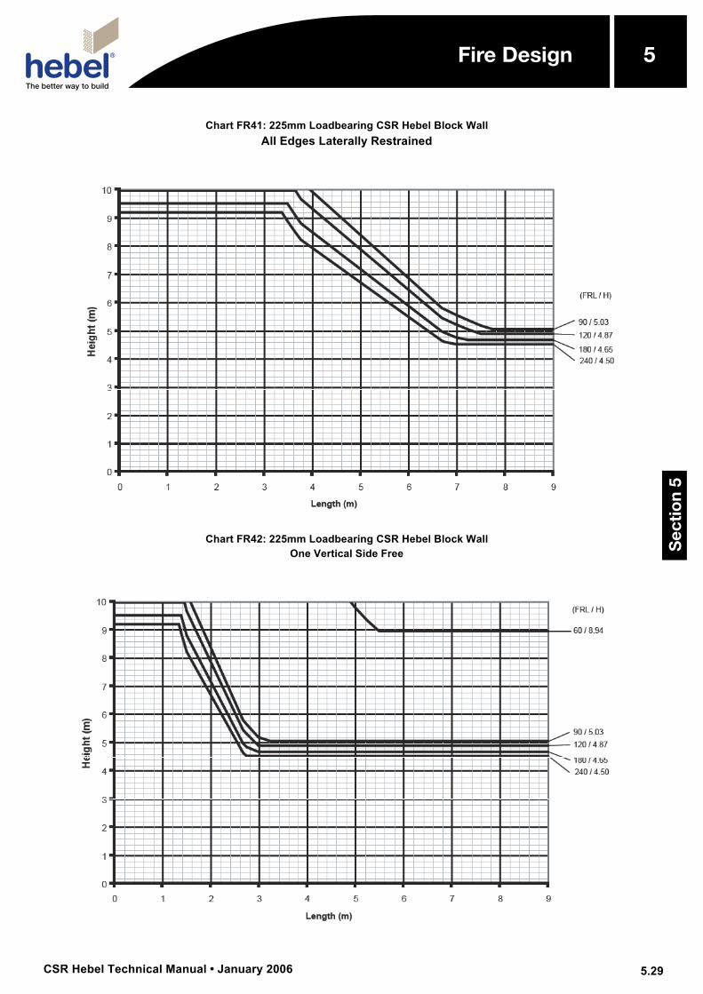
Chart FR41: 225mm Loadbearing CSR Hebel Block Wall All Edges Laterally Restrained
Chart FR42: 225mm Loadbearing CSR Hebel Block Wall
One Vertical Side Free
Sec
tio
n 5
5Fire Design
CSR Hebel Technical Manual • January 2006
5
5.30
Fire Design
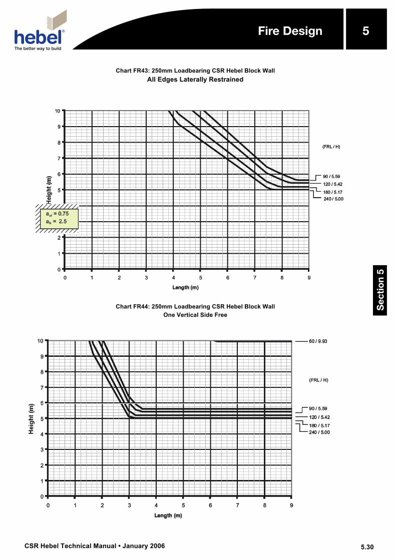
Chart FR43: 250mm Loadbearing CSR Hebel Block Wall All Edges Laterally Restrained
Chart FR44: 250mm Loadbearing CSR Hebel Block Wall
One Vertical Side Free
Sec
tio
n 5
5Fire Design
CSR Hebel Technical Manual • January 2006
5
5.31
Fire Design
Panel Products 5.13 Design for Fire – Panels
Overview The inherent heat insulation quality of autoclaved aerated concrete (AAC) provide structural panels with exceptional fire resistance characteristics.
CSR Hebel manufacture a range of panels to suit a arrange of applications, these being wall, floor, ceiling and roof applications, for both loadbearing and non-loadbearing configurations.
This section will present the fire design methodology background and design detailing requirements to be considered when selecting a CSR Hebel AAC panel. To simplify the presentation of panel design information, the fire performance characteristics of the various panel types have been incorporated in the panel capacity tables presented in Section 7 of this publication.
Determining the Fire Performance Characteristics of the Panel For non-loadbearing wall panels, the fire resistance level (FRL) ratings have been established by the AS1530.4.
For loadbearing wall panels, the knowledge of CSIRO with regards to the performance of AAC panels and block masonry have allowed them to provide opinions on the likely performance of loadbearing panels when subjected to fire loading. These opinions have been issued on a project by project basis, as no global design methods have been determined.
Along with fire loading, other loadings conditions have to be checked. Currently, there are no documented design methods
to assist in checking the performance of the loadbearing panel system. The loadbearing panel wall system can be designed from engineering principles and is the responsibility of an appropriate structural engineer.
For horizontal panels, such as floor, wall, ceiling and roof applications, the fire performance characteristics of these panels are a function of:
• Location of the fire source.
• Span of the panel.
• Magnitude of load applied.
• Thickness of AAC (cover) protecting the reinforcement.
When determining the adequacy of the panel there are two approaches depending on the location of the fire source. For the fire source located above the panel, a depth of AAC is deemed to be structurally ineffective. The structural adequacy of the panel subjected to the fire loadings is checked for a reduced effective panel thickness.
For a fire source located below, the panel will be structurally adequate if the reduced tensile strength of the reinforcement is greater than the strength required to support the applied load. The longer a panel is subjected to a fire and the smaller the cover of AAC the more likely the reinforcement strength will be reduced.
The CSIRO have established a relationship between duration of exposure to fire source and cover of AAC, which provides a reduced maximum stress capacity (strength) of the reinforcement, and a relationship between FRL rating and the depth of AAC to be considered ineffective.
Sec
tio
n 5
5Fire Design
CSR Hebel Technical Manual • January 2006
5
5.32
Fire Design
End Protection of Cut Panels to Maintain FRL
The ends of the panels need to be protected in both cases as the cover to the tensile reinforcement may be as low as 20mm. The recommended method is to glue 100mm blocks to the ends of the panels using Hebel Adhesive. Refer to Appendix F for some test results and certificates.
Connections Some connection systems – typically exposed and not concealed within the panel width - require secondary fire protection systems to maintain their performance when subjected to a fire loading. Connection that require fire protection:
• Tension Tie
• Bolted Connection (cleats and angles)
The conventional right angle bracket connection is located within the width of the wall and the panel provides the fire protection of the bracket.
Edge Profile on the Panel For horizontal panels a T&G profile is not compulsory as the weight of the panels over prevent the joint from opening. Unlike vertical panels where the heat of the fire and subsequent shrinkage of the panels results in a vertical crack occurring at the joint- ideally a T&G profile should be adopted as a the tongue resists the flow of heat through the crack and hence results in a higher FRL rating. Contact CSR Hebel Engineering Services for available information.
5.14 Recesses for Services and Chasing for Fire Design
When walls are to be recessed or chased for the provision of services and cabling, these recesses or chases satisfy the
requirements presented in AS3700 Clauses 6.6 and 6.7, respectively. All chasing to be approved by Project Engineer.
In addition to these requirements CSR Hebel provides the following information with regards to chasing, which will not be detrimental to the already established levels.
Vertically orientated chases • the depth of the chase to be less than 1/3
of the thickness of the wall;
• thickness of the material remaining after forming the chase is not less than 60mm;
• the width of the chase is not greater than 100mm;
• for panels, reinforcement shall not be cut, which will restrict the maximum possible chase depth; and
• the chase is backfilled after the installation of the services with suitable material which would adhere to the wall (e.g. Hebel Patch).
Horizontally orientated chases • the depth of the chase to be less than 1/3
of the thickness of the wall;
• thickness of the material remaining after forming the chase is not less than 60mm;
• the width of the chase is not greater than 100mm;
• the horizontal length of the chase is not greater than 300mm or 3 times the thickness of the wall;
• for panels, reinforcement shall not be cut, which will restrict the maximum possible chase depth; and
• the chase is backfilled after the installation of the services with suitable material which would adhere to the wall (e.g. Hebel Patch).
Sec
tio
n 5
5Fire Design