technical manual for the interflite microprocessor lift control systemileweb.com/2010 website...
TRANSCRIPT

FM40432
INTERNATIONAL LIFT EQUIPMENT LTD. Head Office Factory Units 1&2, Highams Park Ind Estate Wanlip Road Larkshall Road Syston London. E4 7HS Leicester. LE7 1PD Telephone 0208 5279669 Telephone 0116 2690900 Telefax 0208 5310936 Telefax 0116 2690939
TECHNICAL MANUAL FOR THE
INTERFLITE MICROPROCESSOR LIFT CONTROL SYSTEM
DATE : 22/6/2000 ISSUE NO. 7
WE RESERVE THE RIGHT TO ALTER WITHOUT GIVING PRIOR NOTICE TECHNICAL DATA, DIMENSIONS AND WEIGHTS DESCRIBED IN THIS MANUAL.

CONTENTS PAGE 1) Introduction 1 2) Interflite Control Software Features 2 3) Switching onto Test operation for the first time 4 4) Switching onto Normal operation for the first time 5 5) Picture of I / O board ( Full Collective) 6 6) Terminal descriptions for the I / O board 7 7) Picture of I / O board ( Down Collective) 9 8) Picture of I / O board (Non Selective collective & APB) 10 9) Picture of I / O board (Group control with despatcher) 11 10) Picture of Interflite CPU board 12 11) CPU board LED indicator assignments 13 12) CPU Board DIL switch settings 14 13) Diagnostic levels via Logger push buttons 16 14) Fault logger and Diagnostic level 3 17 15) Fault logger Main Events 18 16) Fault logger Micro Processor Events 21 17) Fault logger Expanded Events 22 18) Fault logger Out Of Service Messages 25 19) Logger Push Button assignments 27 20) Picture of Interflite Power Supply Board ( PSU ) 28 21) PSU Board connection assignments 29 22) PSU Board Fuse assignments 30 23) Interflite Services description 31 24) Lift In Service Functions 32 25) Anti - Nuisance Control 33 26) Re - Levelling Services 35 27) Interflite System Types 37 28) Multi car applications & Duplex control 38 29) Triplex Operation 40 30) Fault Finding & Callouts 42 31) µ Processor & Ctrl Switchgear Sequencing/Interfacing 43 32) Common Faults on the lift system 44 33) After Sales Service 45 34) UK Contact points 46 35) Conditions Of Sale 47

1
INTRODUCTION The Interflite Compact Microprocessor system has been designed to suit a wide range of lift installations. The system is divided into three main modules :- The Microprocessor CPU Board, Input / Output Board (I/O Board) and the Power Supply Board. This new modular design has a number of advantages including a much greater noise immunity and attenuation of supply voltage transients and spikes. The power supply has been carefully designed to give high tolerance to supply fluctuations and provide the necessary filtering to meet modern EMC requirements. The I /O Board has been designed for direct connection and all inputs are fully isolated by opto-couplers. LED indication is provided for each relevant input or output. The CPU board has been designed to mount above the I / O board and connects to it via one ribbon connector. The CPU board is fully isolated from the I / O board. This manual explains the three modules of the system with illustrations so that connectors, DIL switches, push buttons, indicators and fuses can be found swiftly and remembered easily for future reference. Also illustrations are given for the different modes of lift operation relating to the I / O board, i.e. (down & full collective etc.) The new main features of the system are highlighted throughout this manual and include the Diagnostic level Fault Logger, Anti-Nuisance, Safety Re-levelling and Yo Yo inhibit for hydraulic lifts, and the communication medium CAN (Central Area Network). CAN is a system technology that provides high speed data communication with excellent data integrity. This means the Interflite in conjunction with the dispatcher unit can cope with large group systems (up to 8 car group) and have the confidence of its speedy response with a very low error count.

2
INTERFLITE CONTROL SOFTWARE FEATURES Indicators:- All inputs and outputs have diagnostic indicators General output system indicators are provided for:- Direction Arrows On Collective Only Hall Lanterns On Full Collective Only Pulsed Arrival Gong On Full Collective Only Lift Overloaded Indicator Position Indicators Car Call Accepted Indicators Landing Call Accepted Indicators Out of service Indicators Standard System Control Features:- Up to 8 Car Group Control Full Collective Down Collective Non-Selective Collective A.P.B Control Standard Service Features:- Fire Control Service / Goods Control 110% Overload 90% Overload / Bypass Emergency Return On request Stuck Car / Landing Push Control Homing Lift In / Out of service indicator Event Logging:- 135 Recognised Events. 50 Recordable Events. 10 Year power off event retention. Events displayed in plain English. Demand Request Control. Confidence Testing. Automatic diagnostics.

3
Door Control:- Manual Doors. Full Auto Doors. Swing Landing Doors / Power Car. Besam Power Swing Door. Park Open Control. On Request Advance Door Opening On Request Door Nudging On Request Full Differential Door Dwell Timings. Adjustable Door Dwell Timers. Door Open Push. Safety Edge Input. Light Ray / Door Close Input. Light Ray Override Timers Limited Landing Door Reopen Anti-Nuisance Control:- Shutdown Facility Limited Reverse Car Call Dumping Limited Forward Car Call Dumping Doors Held Car Call Dumping Stuck Landing Call Detection & Service Stuck Car Call Detection & Service Safety Relevelling Control:- Hydraulic Overtravel Sequencing Hydraulic Homing Hydraulic Relevelling Timer Hydraulic Vane Sequence Check (via software control) Hydraulic Vane Sequence Check (via safety relays) Hydraulic YoYo Inhibit Special Features:- Psion Organiser Facility PC Communications Facility Attendant Control

4
SWITCHING ONTO TEST OPERATION FOR THE FIRST TIME Installation state:- The Motor, Thermistors, Fan and Brake etc. have been connected to the Control Panel. The safety and lock circuit are in a state where the door contacts, emergency stops etc. are making contact providing continuity from terminals OTL to CTS , CTS to CDC and from CDC to LDC. The wiring has been checked and all cables are connected correctly. The fuses are in their correct places and of the correct size and type. The lift is switched to TEST via the Car Top Control or manually by leaving the connection between TS and TRS open circuit. Check there are no obstructions in the lift shaft. Provisionally set the lift and door motor overloads. Check that the car and landing doors are closed fully (if fitted at this stage). The lift can now be switched on Check the incoming three phase sequence is correct (PHTR relay is energised) Check the LED's EMER, LOCK and TEST are illuminated on the bottom I / O board. The lift can now be driven by making the following temporary connections:- To travel UP = TUD to TUP To travel DOWN = TUD to TDN The following checks should be made before continuing with moving the lift :- 1) Check that the Emergency stop buttons, Locks and Safety circuit (if applicable) will stop the lift instantaneously shortly after the lift motor starts to rotate. 2) Run the lift and check that the direction of rotation is correct. 3) Run the lift and check that the brake and ramp voltages are correct 4) Check the door operation (if fitted) by using the car top control buttons to make contact between terminals :- CLOSE = DTC and DTF OPEN = DTC and DTF 5) Check selector stepping and levelling switches are in place and are functional. 6) After Test operation move the lift to the lowest level possible, park with doors closed and switch off the control system. Note :- If you have any problems at this stage please refer to the fault finding section of this manual.

5
SWITCHING ONTO NORMAL OPERATION FOR THE FIRST TIME Installation state:- The lift is complete and is to be operated normally for the first time. The tape head, door operator, Emergency stop buttons, locks, safety circuit, shaft switches, proximity and levelling signals have been checked on TEST control as previously instructed and are operating correctly. The pulsing and levelling signals are in the correct sequence as on the shaft and vane layout drawing. The lift is at the lowest floor level with the reset signal energised. The lift is switched onto NORMAL operation via the car top control, i.e. a connection should be made between terminals TR and TRS, also the lift should not be on any other form of independent service, i.e. Fire or Service control. Ensure no shaft obstructions exist. The lift can now be switched on and the following suggested test procedures can be carried out, using the Interflite logger push buttons (see also p17):- 1) Purging of the Event Logger RAM:- By pressing the TEST button during power initialise the previous events stored in the Event Logger are completely cleared. 2) Testing the pulsing and levelling signals (MSU/MSD & PX) :-This can be achieved by placing calls to each floor in turn in both the UP and DOWN direction ensuring correct selector stepping and stopping sequence. Correct any problems with the vanes before proceeding to the next stage. Once correct , run the lift to the terminal floors in both directions to check vane operation. 3) Testing of Terminal limit and Slowing switches :- Press CPT button to register a top car call and then press TEST under constant pressure to inhibit signals MSU/MSD and PX thus forcing the lift to slow down via the slowing limit and stopping on the terminal limit. Press CPB to register a bottom car call and repeat the above process. Note:- If you have any problems at this stage please refer to the fault finding section of this manual. Note:- The terminal designations are for example only. Actual designations may differ from job to job. Check diagrams.

6
I / O BOARD FULL COLLECTIVE

7
INTERFLITE I / O BOARD
Connection Terminal Function Voltage (Picture Only) Z1 SP1 FUTURE USE " LD2 - LD8 DOWN LANDING CALL INPUTS (2 - 8) 24V DC Z2 L1U - L8U UP LANDING CALL INPUTS (1 - 8) " " Z3 CP1 - CP8 CAR CALL PUSH INPUTS (1 - 8) " " Z4 PX PROXIMITY STEPPING INPUT " " " RSD SELECTOR RESET (BOTTOM) " " " MSD LEVELLING PROXIMITY (DOWN) " " " MSU LEVELLING PROXIMITY (UP) " " " RSU SELECTOR RESET (TOP) " " " RET EMERGENCY RECALL SHUTDOWN INPUT " " " SERV SERVICE / GOODS CONTROL INPUT( SEE P31 ) " " " FIRE FIRE CONTROL INPUT (SEE ALSO P31 ) " " Z5 TEST CAR TOP CONTROL TEST INPUT " " " SE SAFE EDGE INPUT " " " DOP DOOR OPEN PUSH INPUT " " " DRL DOOR LIGHT RAY / DOOR CLOSE PUSH INPUT " " " STR CONTROLLER START FEEDBACK INPUT " " " DO-C DOORS OPENING/CLOSING FEEDBACK INPUT " " " LW90 90 % LOAD WEIGHING INPUT (SEE P31 ) " " " LW110 110 % LOAD WEIGHING INPUT (SEE P31 ) " " Z6 LPF LANDING PUSH FEED OUTPUT " " " LAF LANDING PUSH ACCEPTANCE IND FEED " " Z7 PIF POSITION INDICATOR FEED SUPPLY " " " OVP O VOLTS RETURN PATH FOR POSITION IND'S " CAF CAR CALL ACCEPTANCE INDICATOR FEED " " " OVR OV RETURN FOR 24V DC SIGNALS " " Z8 EMER END OF SAFETY CIRCUIT INPUT 240V AC " LOCK GATE LOCK INPUT 240V AC Z9 NG DOOR NUDGING RELAY OUTPUT PILOT 240V AC " DC DOOR CLOSING RELAY OUTPUT PILOT 240V AC " DO DOOR OPENING RELAY OUTPUT PILOT 240V AC Z10 N NEUTRAL CONNECTION " UP UP TRAVEL RELAY OUTPUT PILOT 240V AC " DN DOWN TRAVEL RELAY OUTPUT PILOT 240V AC

8
Z11 HS2 2ND HIGH SPEED RELAY OUTPUT PILOT 240VAC " LS LOW SPEED RELAY OUTPUT PILOT 240V AC " HS 1ST HIGH SPEED RELAY OUTPUT PILOT 240V AC Z12 PI9 - PI12 POSITION INDICATOR OUTPUTS 9 TO 12 24V DC " OSI OUT OF SERVICE / IN SERVICE INDICATOR " " (SEE ALSO P32 ) " OLI LIFT OVERLOADED INDICATOR " " " IU COMMITTED UP DIRECTION ARROW " " " ID COMMITTED DOWN DIRECTION ARROW " " Z13 PI1 - PI8 POSITION INDICATOR OUTPUTS 1 TO 8 " " Z14 CA1 - CA8 CALL ACCEPTED INDICATOR OUTPUTS 1 TO 8 " " Z15 I1U - I8U UP LAN CALL ACCEPTED IND OUTPUTS 1 - 8 " " Z16 HLR HALL LANTERN RELAY OUTPUT " " " I2D - I8D DN LAN CALL ACCEPTED IND OUTPUTS 2 - 8 " " POWER SUPPLY INPUT PUSH ON CONNECTIONS OVCOMMS O VOLTS SUPPLY FOR COMMUNICATIONS PORT +5VCOMMS +5 VOLTS SUPPLY FOR COMMUNICATIONS PORT OV OV SUPPLY FOR CPU BOARD +5V +5V SUPPLY FOR CPU BOARD OVIO OV SUPPLY FOR I/O BOARD +5VIO +5V SUPPLY FOR I/O BOARD OVR O VOLTS RETURN FOR 24V DC SIGNALS LAF LANDING CALL ACCEPTANCE FEED SUPPLY PIF POSITION INDICATOR FEED SUPPLY OVP O VOLTS RETURN PATH FOR POSITION INDICATORS CAF CAR CALL ACCEPTANCE FEED SUPPLY +24V +24 VOLTS DC SUPPLY FOR AUX INPUTS LPS LPF TERMINAL SUPPLY 500mA. INTERFLITE CONTROL DOOR CONFIGURATION The Interflite Control System is capable of driving the following door operator configurations:- FULLY AUTOMATIC FULLY AUTOMATIC (Selective or Non-Selective Rear Doors) MANUAL GATES SWING LANDING DOOR SWING LANDING DOOR / POWER CAR DOOR BESAM POWER SWING LANDING DOOR Also the System can be configured for Park Open Control.

9
I / O BOARD DOWN COLLECTIVE

10
I / O BOARD NON SELECTIVE

11
I/O BOARD GROUP CONTROL WITH DESPATCHER

12
CPU BOARD PICTURE

13
INTERFLITE CPU BOARD
L.E.D INDICATOR ASSIGNMENTS Indicator Function TX1 RS422 Message transmission in progress RX1 RS422 Message reception in progress TX CAN 1 Message transmission in progress RX CAN 1 Message reception in progress TXC CAN C Message transmission in progress RXC CAN C Message reception in progress CS Common communication successful reception ind LIS Lift in Service Indicator HA Homing Available TCN (R5) This Car Next Indicator HOM Homing Timer Timing LOOP Program Running Indicator PSU Power Supply OK + Watchdog OK CF Common communications failure Notes Referring to the CPU Board Layout Diagram 1) The RS422 Connector is used to provide serial communications to either the despatcher or the Psion Organiser / Printer. 2) Connectors SK4 and SK5 are used for Landing Call and per lift communication. The communication is achieved using a CAN (Central Area Network). The example on the diagram shows the card as belonging to LIFT B of a Triplex 3 Car Group, whereby SK4 connects to LIFT A and SK5 connects to LIFT C.

14
INTERFLITE DIL SWITCH SETTINGS
Lift Number Settings:- Lift Number DIL Switch Simplex Duplex Triplex Group Lift 1 LIFT_2 (1) Off Off Off Off LIFT_3 (2) Off Off Off Off Lift 2 LIFT_2 (1) Off On On Off LIFT_3 (2) Off Off Off Off Lift 3 LIFT_2 (1) Off *** Off Off LIFT_3 (2) Off *** On Off Note:- For group control all the above switches are off and the lift landing
calls are processed by the dispatcher.
Feature Settings:-
DIL Switch Setting Function HOM_EN (3) On Homing Enabled HOM_EN Off Homing Disabled REL_EN (4) On Relevelling Enabled REL_EN Off Relevelling Disabled P-OPEN (5) On Park Doors Open on Normal P_OPEN Off Park Doors Closed on Normal SP1 (6)On Park Doors Closed on PPTT SP1 Off DWEL_1 (7)*** See Door Dwell Section DWEL_2 (8)*** See Door Dwell Section

15
INTERFLITE DIL SWITCH SETTINGS (CONTINUED Varying Door Dwell Times:- DIL Switch Time_1 Time_2 Time_3 Time_4 DWEL_1 (7) Off On Off On DWEL_2 (8) Off Off On On Time_1 Standard Door Dwell Time Time_2 Standard Door Dwell Time Plus 1 Second Time_3 Standard Door Dwell Time Plus 2 Seconds Time_4 Standard Door Dwell Time Plus 3 Seconds Notes:- The Standard Door Dwell times are defined as below (i.e. DWELL_1 & 2Off) 1) In Response to a Car & Landing Call 7 Secs 2) In Response to a Landing Call 5 Secs 3) In Response to a Car Call 3 Secs 4) After a Door Open Push Operation 5 Secs 5) After a Photo Cell Operation 1 Sec 6) After a Safety Edge Operation 1 Sec Varying Double Journey Times:- DIL Switch Time_1 Time_2 Time_3 Time_4 DJT_1 (10) Off On Off On DJT_2 (11) Off Off On On Time_1 Standard Double Journey Time of 20 Seconds Time_2 Extended Double Journey Time of 30 Seconds Time_3 Extended Double Journey Time of 45 Seconds Time_4 Extended Double Journey Time of 60 Seconds Feature Settings (cont..) :- DIL Switch Setting Function HOME_1 (9) On Change Homing Floor to Homing Floor +1 HOME_1 Off Homing Floor as set in Contract Software DSP_EN (12)On Group Dispatch Failure Enable (SeeDespatcher DSP_EN Off Group Dispatch Failure Disable applications) ANU_EN (13) On Anti-Nuisance Enabled ANU_EN Off Anti_Nuisance Disabled PRPTT (14) On Prepare to Test Enable (See Services PRPTT Off Prepare to Test Disable Section)

16
INTERFLITE DIAGNOSTIC LEVELS VIA LOGGER PUSH BUTTONS
The Interflite controller has been developed to obtain diagnostic levels for an Engineer visiting the site. These levels can operate on self test to produce information via the fault logger detailing the lifts' operation (see expanded event next page). To enter the diagnostic levels you must be on Normal service and in the engineer present mode (press Engineer once). To obtain the correct diagnostic level required the Test push must be operated x times to the level you require e.g. 3 times for expanded event, twice for auto car calls etc. Level 1 Cancel diagnostics Level 2 Auto car calls Level 3 Expanded event logging Level 4 Auto car call and expanded event logging Level 5 Clear car and Landing calls (no landing call cancel on group systems) Level 6 Enters auto car calls Level 1 - Cancel diagnostics. Once you are in a diagnostic level you can jump from one level to another simply by pressing the Test button x times to your requirement as previously described. It is not necessary to press the engineer button to leave and then come back in again. Cancel diagnostics ( level 1) is therefore a null level with no specific function. Level 2 - Auto car calls places Terminal floor calls (top+bottom) every 60 seconds. Level 3 - Expanded event logging gives a greater detail of the lifts operation
(see next page). Level 4 - Combination of the previous two levels. Level 5 - Clears all car and landing calls but not landing calls when connected to the dispatcher. Level 6 - Enters each car call up to the top floor then brings the car to the bottom without stopping. The Test push button returns to its' normal function, i.e. inhibiting of levelling / stepping signals and logger ram purge when not on engineer present.

17
INTERFLITE FAULT LOGGER AND DIAGNOSTIC LEVEL 3 The Fault Logger now has an expanded event code to give a much more detailed event description of the lifts' operation. To obtain this mode press ENGINEER button once and TEST button three times. This will prove very useful for site engineers searching for faults as-well as for the commissioning of new lift installations. Each event is recorded and can be viewed at anytime. The recorded faults are in plain English displayed on the 2 * 16 character liquid crystal display together with the position of the lift at the time of the fault, the number of times that the fault has occurred and the age of the record in days. Records are held in battery back up RAM with a 10 year power off retention. Example for a typical lift floor to floor run cycle:- FRONT OPEN FULL FRONT CLOSING FRONT LOCKED FRONT CLOSED STARTING UP HIGH POSITION ADVANCE SLOWDOWN UP LEVELLING UP STOPPED UP FRONT OPENING FRONT OPEN FULL Thus a constant update of the lifts' operation is given to the person viewing the logger display. An example of a new main event is below (not in the diagnostic levels) :- LOCK LOW SPEED P=01 O=04 D=0 This information should be interpreted as :- At position 1 in the lift shaft (P = position) the lock circuit has been interrupted (tipped) four times (O = no of times fault has occurred) today (D = no of days since happened). Since the example incorporates a new main event it can be seen that the fault can easily be detected to the lift tipping the lock at position 1 when approaching the floor on low speed (assuming it is a two speed lift). The site engineer can then run the lift to that floor and establish the cause.

18
EXPLANATION OF THE FAULT LOGGER EVENTS
Main Events EMERGENCY STOP :- is recorded whenever the control safety circuit is interrupted during lift motion, causing a loss of supply to terminal CTS and to the input EMER of the I / O board. LOCK -HIGH SPEED :- is recorded when the lift lock circuit is interrupted during lift motion, causing a loss of supply to terminal LDC and to the input LOCK of the I / O board. The micro processor monitors this condition at the inputs LOCK and HS on the I / O board. LOCK -LOW SPEED :- is recorded when the lift lock circuit is interrupted during lift motion, causing a loss of supply to terminal LDC and to the input LOCK of the I / O board. The micro processor monitors this condition at the inputs LOCK and LS on the I / O board. LOCK -LEV SPEED :- is recorded when the lift lock circuit is interrupted during lift motion, causing a loss of supply to terminal LDC and to the input LOCK of the I / O board. The micro processor monitors this condition at the inputs LOCK and HS2 on the I / O board. LOCK STATIONARY :- is recorded when the lift is stationary. The lift has attempted to close the doors and the lock circuit has not & made contact . The micro processor monitors this condition at the LOCK input and after 4 secs of the LOCK FAILURE :- door close contactor de-energising the doors will re- open and the event is then generated. After three successive door cycles the event Lock Failure will be generated. FAILURE TO START :- The micro processor monitors the start condition via an input feed to the input STR on the I/O board. Many conditions can cause this but generally it is caused by a terminal limit not making contact in the shaft, the run contact of a regulator such as a VVVF drive or the contact of PHTR (phase and thermistor relay). The event will be generated shortly after the lift has attempted to start. MOTION FAILURE :- The micro processor monitors the motion condition via an input feed to the input STR on the I/O board. Many conditions can cause this but generally it is caused by a VVVF drive or the contact of PHTR (phase and

19
thermistor relay). The event will be generated shortly after the loss of the STR signal. STOP NOT LEVEL This event is used mainly when the lift has had a AND STUCK VANES :- signal to stop i.e. MSU &MSD and then come off the vanes due to the lift sliding past floor level. This would be caused by the brake not being set correctly. This event is also useful for finding tapehead and proximity faults regarding pulsing and levelling signals. If signals are intermittent when stopping on the levelling vanes (i.e. MSU & MSD on and then off) then the event is displayed. SHUTDOWN FAILURE :- See Interflite Anti-Nuisance control (p33) SELECTOR RESET :- is recorded when the lift has reset to either the top or bottom of the shaft. This is achieved in the transition from high to low speed by hitting a slowing limit in the relevant direction. The micro processor monitors the reset signals at inputs RSU & RSD on the I/O board. After power initiation the lift resets to the bottom floor via a separate contact in the slowing limit to produce a signal at RSD which is held after the lift has stopped to reset the lift. SLOW / LEVEL FAULT :- is recorded when the lift travelling on low speed has exceeded the time duration of the slow speed timer. JOURNEY TIMER :- is recorded when the lift travelling on high speed has exceeded the time duration set by the DIL switches on the CPU board (DSW 10 & 11 or DJT_1 & 2). When this event has occurred the lift is out of service and will not accept car or landing calls but the lift will still operate on Test. To restore Normal lift operation the power has to be switched on and off. DOOR OPEN TIMER :- is recorded when the door open time determined by the micro processor software has been exceeded whilst the lift doors have been trying to open. DOOR CLOSE TIMER :- is recorded when the door close time determined by the micro processor software has been exceeded whilst the lift doors have been trying to close. DOOR/LOCK FAULT :- is on GAL.H.A. or any doors without a close limit, the micro processor detects a door or lock fault. RELEVEL FAULT :- see relevel section (p35)

20
110 % OVERLOAD :- is recorded when the lift has been overloaded by 110%. The micro processor monitors this condition at the input 110% on the I/O board (see p31 for further details). DESPATCH FAILURE :- see Multi car applications (p38 ) MISSING PROX SWT :- not yet implemented. EXTRA PROX SWT :- not yet implemented. PRIORITY SERVICE :- See emergency return. HYDRAULIC FAULT :- See Relevelling services. (p35) RELEVEL FAULT :- See Relevelling services. (p35) RELEVELLING YOYO :- See Relevelling services. (p35) OPEN PUSH HELD :- is recorded when open push is held for 20 seconds. SAFE EDGE HELD :- is recorded when safe edge is held for 20 seconds. STUCK CAR BUTTON :- See Interflite Anti-Nuisance control. (p34) STUCK HALL PUSH :- See Interflite Anti-Nuisance control. (p34) ENGINEER PRESENT :- is recorded when the Engineer button is pressed on the CPU board. This enables site engineers to distinguish between events caused by them and other faults caused prior to and after their visit. ENGINEER LEAVING :- is recorded when the Engineer button on the CPU board is pressed a second time. This provides an end to the visit to contain all events caused by the engineer whilst on site. SERVICE VISIT :- is recorded when the Engineer button and the Mode button are pressed together on the CPU board. Also clears the maintenance logger on the despatcher. 1000 JOURNEYS :- is recorded when the lift has served 1000 journeys. Entering the engineer present mode or service visit mode resets this counter to zero. 1000 DOOR OPS :- not yet implemented. DEMAND REQUEST :- see lift in service functions. (p32) DEMAND FAILURE :- see lift in service functions. (p32)

21
Processor Events POWER INITIATION :- is recorded shortly after power is supplied to the micro processor board. PROCESSOR REBOOT :- is recorded when the program is restarted without a power initialisation cycle. This can be due to main power supply brown outs (dips). RAM CORRUPTION :- is recorded during program initialisation when previously known stored values are found to be corrupt. This can be due to faulty ram chips or more likely brown outs. RAM MEMORY FAULT :- is recorded during program initialisation when one or more ram memory locations are found to be faulty. PROCESSOR FAULT :- is recorded during program initialisation when one or more of the processors internal registers are found to be faulty. STACK OVERFLOW :- is recorded when an internal ram memory organisation fault is detected. INTERRUPT FAULT :- is recorded when an internal problem has been detected with the micro processors' interrupts. LOGGER RAM PURGE :- is recorded upon power initialisation when the TEST button is pressed on the CPU board. This in effect clears all previous stored events in the event logger memory.

22
Expanded Events (diagnostic level 3) STARTING UP HIGH is recorded when the micro processor receives a start signal STR in the up direction on high speed. STARTING DN HIGH is recorded when the micro processor receives a start signal STR in the down direction on high speed. SLOWDOWN UP is recorded when the lift is forced into slow speed by a slowing limit or when the micro processor produces a transition from high speed to low speed in the up direction. Outputs LSR & UPR are active. SLOWDOWN DN is recorded when the lift is forced into slow speed by a slowing limit or when the micro processor produces a transition from high speed to low speed in the down direction. Outputs LSR & DNR are active. LEVELLING UP is recorded when the lift is travelling up on levelling speed. The outputs LSR & UPR are active. LEVELLING DN is recorded when the lift is travelling down on levelling speed. The outputs LSR & DNR are active. ADVANCE OPEN UP is recorded when the lift is on low speed, travelling up
and the doors are opening prior to it reaching floor level Special requirements via the relevel board is required before this can take place. The micro processor monitors this condition via inputs DOC, MSU or MSD.
ADVANCE OPEN DN is recorded when the lift is on low speed, travelling
down and the doors are opening prior to it reaching floor level . Special requirements via the relevel board is required before this can take place. The micro processor monitors this condition via inputs DOC, MSU or MSD.

23
STOPPED UP is recorded when the lift has stopped after travelling in the up direction. The micro processor monitors this via inputs MSU, MSD & STR. STOPPED DN is recorded when the lift has stopped after travelling in the down direction. The micro processor monitors this via inputs MSU, MSD & STR. FRONT OPENING is recorded when the power doors designated front are (software designates Front in the process of opening and the door open limit is not or Rear according to broken. The micro processor monitors this condition at floor level) the inputs LOCK & DOC. FRONT OPEN FULL is recorded when the power doors designated front are open fully and the door close limit has broken contact. The micro processor monitors this condition at the inputs LOCK & DOC. FRONT CLOSING is recorded when the power doors designated front are in the process of closing, the locks are broken and the door close limit is making contact . The micro processor monitors this condition at the inputs LOCK & DOC. FRONT LOCKED is recorded when the doors designated front are locked, i.e. the locks are made but the door close limit has not been broken. The micro processor monitors this condition at inputs LOCK & DOC. FRONT CLOSED is recorded when the doors designated front are fully closed, the locks are making contact and the door close limit is broken. Hence the doors have stopped driving and input DOC is disabled.

24
REAR OPENING is recorded when the power doors designated rear are (software designates Front in the process of opening and the door open limit is not or Rear according to broken. The micro processor monitors this condition at floor level) the inputs LOCK & DOC. REAR OPEN FULL is recorded when the power doors designated rear are open fully and the door close limit has broken contact. The micro processor monitors this condition at the inputs LOCK & DOC. REAR CLOSING is recorded when the power doors designated rear are in the process of closing, the locks are broken and the door close limit is making contact . The micro processor monitors this condition at the inputs LOCK & DOC. REAR LOCKED is recorded when the doors designated rear are locked, i.e. the locks are made but the door close limit has not been broken. The micro processor monitors this condition at inputs LOCK & DOC. REAR CLOSED is recorded when the doors designated rear are fully closed, the locks are making contact and the door close limit is broken. Hence the doors have stopped driving and input DOC is disabled.

25
Status & Out of Service Messages OUT OF SERVICE INSPECTION CTRL is recorded when the lift is switched onto Test control. The micro processor monitors this condition at the TEST input. OUT OF SERVICE EMERGENCY STOP is recorded whenever the control safety circuit has been interrupted during lift motion for a period of more than 60 secs, causing a loss of supply to terminal CTS and to the input EMER of the I / O board. OUT OF SERVICE FIRE CONTROL is recorded when the lift is switched onto Fire control. The micro processor monitors this condition at the FIRE input. OUT OF SERVICE SERVICE CONTROL is recorded when the lift is switched onto Service control. The micro processor monitors this condition at the SERV input. OUT OF SERVICE PREPARE TO TEST see Interflite services description. (p32) OUT OF SERVICE LOAD WEIGHING is recorded when the lift has been overloaded by 110% for a period of more than 60 secs. The micro processor monitors this condition at the input 110% on the I/O board (see p31 for further details). OUT OF SERVICE DOOR FAULT is recorded following a door fault, i.e. door open / close protection timer. OUT OF SERVICE EMERGENCY RECALL is recorded when the lift is switched to Emergency Recall control. The micro processor monitors this condition at the RET input.

26
OUT OF SERVICE JOURNEY TIMER is recorded when the lift travelling on high speed has exceeded the time duration set by the dil switches on the CPU board (DSW 10 & 11 or DJT_1 & 2). When this event has occurred the lift is out of service and will not accept car or landing calls but the lift will still operate on Test. To restore Normal lift operation the power has to be switched on and off. OUT OF SERVICE RELEVEL FAULT is recorded after a time of 60 secs following a Relevelling fault (see Relevelling services p35 ). OUT OF SERVICE HYDRAULIC FAULT is recorded when the lift overtravels or the motor overload trips.

27
INTERFLITE LOGGER PUSH BUTTON ASSIGNMENTS Push Button Function MODE Shift/Mode Push Button, selects alternative push button set. A bit like a shift key on a computer keyboard. EXIT Exit's you from the current event queue and resets the event display to the last event. NEXT Display's the next event recorded in the event queue ENGINEER Records Engineer present/Leaving Site event, and allows entry to the diagnostic levels. It also clears the journey counter back to zero. ENGINEER+MODE Records Service Visit/Engineer leaving site event, also clears journey counter and clears maintenance counter on dispatcher systems. TEST Inhibits levelling signals MSU/MSD and proximity stepping signal PX from being recognised, this forces slow down via the slowing limits and the lift then stops on the terminal limits. This also push purges the event logger ram when held during power initialise. It is also used to select a level of diagnostics when in the Engineer present mode. CPT When pressed, enters a top floor car call except when on any form of independent service. (i.e. Fire, Service etc.) CPT+MODE When both are pressed, enters all up landing calls into system, except when on any form of independent service or connected to the despatcher. CPB When pressed, enters a bottom floor car call except when on any form of independent service. CPB+MODE When both are pressed enters all Car calls into system, except when on any form of independent service.
28
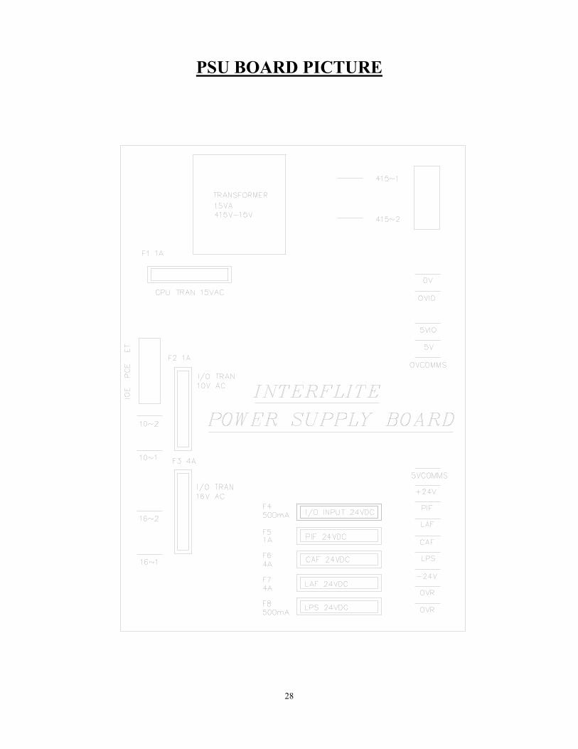
PSU BOARD PICTURE

29
INTERFLITE PSU CONNECTION ASSIGNMENTS Terminal Terminal Type Terminal Function Destination 415-1 7.5mm Terminal L1 Phase 415vac 3 Phase Supply 415-2 7.5mm Terminal L2 Phase 415vac 3 Phase Supply 415-1 Lucar Crimp L1 Phase 415vac PT1 Transformer 415-2 Lucar Crimp L2 Phase 415vac PT1 Transformer 10-1 Lucar Crimp 10v ac for CPU PT1 Transformer 10-2 Lucar Crimp 10v ac for CPU PT1 Transformer 16-1 Lucar Crimp 16v ac for +24vdc PT1 Transformer 16-2 Lucar Crimp 16v ac for +24vdc PT1 Transformer 5VIO Lucar Crimp +5 Volts for I/O IC's 5VIO on I/O Board OVIO Lucar Crimp OV Volts for I/O IC's OVIO on I/O Board 5V Lucar Crimp +5 Volts for CPU 5V on I/O Board OV Lucar Crimp OV Volts for CPU OV on I/O Board OVCOMMS Lucar Crimp +5 Volts for Comms 5VCOMMS on I/O Brd OVCOMMS Lucar Crimp OV Volts for Comms OVCOMMS on I/O Brd LAF Lucar Crimp Landing-Call-Ind-Feed LAF on I/O Board CAF Lucar Crimp Car-Call-Ind-Feed CAF on I/O Board PIF Lucar Crimp Position-Ind-Feed PIF on I/O Board +24V Lucar Crimp +24vdc Input Supply +24v on I/O Board OVP Lucar Crimp OV Return for Pos-Ind OVP on I/O Board OVR Lucar Crimp OV Return for signals OVR on I/O Board OVR Lucar Crimp OV Return for signals OVR on I/O Board LPS Lucar Crimp Land-Push input supply LPS on I/O Board ET 5mm Terminal Dirty Earth CEP on Panel PCE 5mm Terminal Processor Earth CEP on Panel IOE 5mm Terminal I/O Dirty Earth CEP on Panel Note:- ET,PCE and IOE must have their own respective wires run directly back to the central earthing point (CEP) and must not come in close proximity with heavy switching cables or motor field drive units.

30
INTERFLITE PSU BOARD FUSE ASSIGNMENTS Fuse Name Fuse Size Fuse Side Fuse Function Destination F1 1A AC Protects CPU transformer 15vac CPU +5V F2 1A AC Protects I/O Transformer 10vac I/O Board 5VIO F3 4A AC Protects I/O Transformer 16vac General +24v F4 500m/A DC Protects I/O Input Stages 24vdc +24V F5 1A DC Protects Position ind stage 24vdc PIF F6 4A DC Protects Car-Call ind stage 24vddc CAF F7 4A DC Protects Lan-Call ind stage 24vdc LAF F8 500m/A DC Protects Lan-Call input stage 24vdc LPS Notes:- The power supply board is supplied externally by the standard transformer 415V to 16V and 10V at VA ratings 75 and 25VA respectively. The 415V is supplied from the mains via fuses to both the transformer and the PSU board.

31
INTERFLITE SERVICES DESCRIPTION Prepare To Test:- The prepare to test feature is enabled by switching the DIL Switch marked PRPTT to the ON Position. This feature has the effect of preparing the lift for full test control by inhibiting any further landing calls and preventing the lift from homing to the main floor, thus prevents the pickup of further passengers. Any passenger still travelling within the lift will still be able to register car calls to their destination. When the lift becomes idle the doors will park closed and the lift will be marked out of service, the door open push is still active at this point. Service Control:- The Service Control Feature is selected by asserting the SERV input signal found on the bottom I/O board. When selected, the service control feature renders the lift out of service and transfers all landing calls to other members of the group (if any). The control of the lift is then from the car only and it assumed that an attendant would operate the lift in a manual fashion as the car call buttons now become constant pressure buttons. The advantage of such control is for the loading and unloading of goods whereby the attendant has full control of the lift e.g. a porter in a Hotel. Fire Control:- The Fire Control feature is selected by asserting the FIRE input signal found on the bottom I/O board. When selected, the fire control feature renders the lift out of service and transfers all landing calls to the other members of the group (if any). There are many different types of Fire control but generally the lift is interrupted from its' normal direction of travel to its' destination (any car calls being immediately cancelled) and called automatically to a specific floor as a matter of urgency for a fireman. Once the lift has reached this floor, full control of the lift and the doors is assigned to the fireman via constant pressure call buttons and the door open button. Load Weighing 110% Overloaded:- The 110% overload function becomes active when the lift is stationary and the LW110 input found on the bottom I/O board is asserted. The event 110% overload is generated, doors are parked open, the lift is then marked out of service. Load Weighing 90% Overload/Bypass:- The 90% overload function is active when the lift is either moving or stationary and the LW90 input found on the bottom I/O board is asserted. The operation of the lift from then on is that landing calls are bypassed therefore reducing the chance of another person entering the lift and fully overloading it. Instead car calls are dispensed with so that passengers will leave the lift car thus reducing the weight and relieving the 90% overload condition. Once this is achieved landing calls are resumed and the lift is ready to pick up passengers once again as normal.

32
INTERFLITE LIFT IN SERVICE FUNCTIONS Lift In Service / Out of Service Indicator:- ( OSI Output). As standard the Interflite board will drive an "OUT OF SERVICE" indicator, this indicator will only extinguish when the lift is deemed to be in full lift service. When requested the Interflite board will drive a "LIFT_IN_SERVICE" indicator, this indicator will illuminate when the lift is deemed to be in full lift service. Full lift service refers to being on normal operation and not Fire control, Service control, Test control or any other not normal service operation. Note:- The above paragraph describes two ways of implementing the same output to provide a "Lift in Service" or "Lift Out of Service" indicator as requested by the customer. Demand Request Operation:- The demand feature automatically inserts terminal floor car calls (i.e. Top and Bottom) 120 seconds after lift inactivity following a fault condition, e.g. door open/close protection time, lock failure, failure to start etc. This cycle will be repeated every 120 seconds up to a maximum of six attempts or until the lift is back in service. After the sixth attempt, demand request will be inhibited until the Interflite system is returned to normal operation via passenger intervention. Lift Confidence Checking:- When the lift motion and door operation is confirmed correct, the level of system confidence is high. During normal lift operation the motion or door failures are automatically analysed to produce a reduction in the appropriate motion / door confidence levels. If regular failures occur then the confidence level fault ( NO MOTION CONFNC / NO DOOR CONFDNCE ) is recorded to the event logger system in order to trigger investigation by the service personnel. Otherwise an event CONFIDENCE GAIN will be displayed when the level of confidence is high. LISI Indicator:- (LIS Ind on top CPU Board). The LIS Indicator will be extinguished whenever the lift is deemed to be out of service. The LIS Indicator will be permanently illuminated whenever the lift is deemed to be in full lift service and the confidence testing result is high, otherwise the LIS Indicator will flash, indicating that the lift is in service but something is not quite right.

33
INTERFLITE ANTI NUISANCE CONTROL Many New Anti-Nuisance features have been added to the Interflite control system, these new features enhance the operation of the system and help reduce waiting times. The features described below are all disabled during any not_normal service operations, i.e. Fire and Service control. Shutdown Control:- The Interflite Control System will shutdown and transfer any awaiting landing calls to the other members of a group system when the lift is delayed at a floor for 60 sec. This may be due to faulty door operations or the failure to start following any demand to move. The event "SHUTDOWN FAILURE" will be recorded in the event logger and when possible the doors will be parked open showing the out of service indicator, also all car and landing calls will be cancelled. Registration of a car call or landing call (if a simplex) will attempt to restore the lift back into service. The Demand Request feature itself will also attempt to restore full lift operation within two minutes. Reverse Car Call Dumping:- When the lift slows for its' last call in the established direction of travel then reverse car call dumping is established. Reverse car call dumping causes the cancellation of reverse direction car calls if 3 or more car calls exist. This feature can be disabled by setting the ANU_EN Dill switch in the OFF position. Forward Car Call Dumping:- If the lift slows for car calls on three previous journeys without breaking the light ray then the remaining car calls will be cancelled when next slowing. This feature can be disabled by setting the ANU_EN Dill switch in the OFF position Doors Held Car Call Dumping:- The remaining car calls will be cancelled when the door open push has been held constantly for more than 20 seconds. When fitted with a safety edge, the remaining car calls will be cancelled when the safe edge input has been held constantly for more then 20 seconds. Both these features can be disabled by switching the ANU_EN Dill switch in the OFF Position.

34
INTERFLITE ANTI NUISANCE CONTROL CONT...
Stuck Hall Push Detection:- The "STUCK UP-LAN" event and "STUCK DN-LAN" event ( UP and DOWN landing call buttons) will be recorded 10 seconds after the Interflite Board has attempted and failed to cancel the respective hall call. The respective stuck hall call is now ignored but will be eligible for operation after the stuck condition has been removed. However, to provide lift service to the floor with the stuck hall push or pushes, the Interflite Board will reinstate the call (if still stuck), 240 seconds from when originally detected. Stuck Car Push Detection:- The "STUCK CAR CALL" event will be recorded 10 seconds after the Interflite board has attempted and failed to cancel a car call. The stuck car call is now ignored but will be eligible for operation after the stuck condition has been removed. However, to provide lift service to the floor with the stuck car call push, the Interflite board will reinstate the call (if still stuck), 240 seconds from when originally detected.

35
RELEVELLING SERVICES
The Relevelling feature is included as standard within the Interflite control system on all hydraulic lifts and is an optional extra on traction lift systems. The Interflite Control System continuously monitors the Relevelling operation. If a failure occurs with the Relevelling operation then the relevant fault is recorded and recovery action is initialised. Safety features associated with Relevelling can be categorised as follows:- a) Relevelling:- The Relevelling sequence is automatically initiated via the Interflite control system and can perform Relevelling in the up or down direction depending on loss of up or down levelling vanes. To prevent the lift from hydraulic oscillations, the Relevelling sequence will not be initiated or re-initiated until the lift has been idle for 3 seconds. The Interflite Control System continuously monitors the Relevelling operation. If a failure occurs with the Relevelling operation then the relevant fault is recorded and recovery action is initialised. Failures associated with Relevelling can be categorised as follows:- b) Relevelling Time-out Timer:- The Hydraulic time-out timer will time when the drive system fails to move the lift to floor level. This may be caused by failure of the lift hydraulic pump / valve unit or it's associated control circuit. These types of faults will cause the lift to remain in the levelling zone, but not reach floor level within a predictable time limit. This time to reach floor level is set generally to 20 seconds by the Interflite lift programme. If the lift exceeds this time it is removed from normal service, and Relevelling operation is suspended. An attempt to return the lift to the bottom floor is then made, since the down operation could well be achievable i.e. (no pump motor operation is required). On arrival at the bottom floor the lift will remain out of service until the power is switched off. c) Hydraulic Homing The Interflite Control System will automatically home to the lowest floor level 12 minutes after the last lift movement. When the main homing floor is not the lowest floor level, the lift will home to the main homing floor after the standard homing time, usually 5 seconds on duplex / triplex systems and 6 minutes on simplex control systems. However the control system will hydraulic home again to the lowest level after becoming idle for 12 mins.
36
d) Hydraulic Anti-YoYo. During normal Relevelling operation excessive Relevelling cycles can be detected and recovery action taken. Excessive Relevelling cycles can be due to overheating hydraulic oil or faulty proximity switches all of which when left unattended can place the lift in a dangerous condition. The number of Relevelling cycles are monitored over a period of minutes. If the number of Relevelling cycles is deemed excessive by the Interflite programme, then the Relevelling function is suspended and the lift is removed from service. Attempts will be made to return the lift to the bottom floor, where it will remain out of service. e) Relevelling Sequence Check. (software). Failure of the levelling vanes to operate causing the lift to stop by the release of both vanes. This type of operation can be caused by an intermittent malfunction, or by a faulty proximity switch. If the proximity switch operation is unreliable then the Relevelling operation is potentially dangerous. The Interflite Microprocessor monitors the Relevelling, and keeps a record of occurrences when the lift stops out of level following a relevel operation. Each time the lift stops out of level a counter is incremented by sixteen. If the lift makes a successful Relevelling operation to stop at floor level the counter is decremented by 1. If the counter reaches a count of 48 (caused by three consecutive Relevelling errors, or frequent levelling errors), the lift is removed from service, and Relevelling is suspended. Attempts will be made to return the lift to the bottom floor, where it will remain out of service. f) Relevelling Sequence Check via Safety Proven Relays. The Interflite Microprocessor Relevelling monitor programme checks the Relevelling operation in a non-interlocked way that enhances the safety of the system. However, the addition of a Relevelling monitor board is used, to check the levelling vane operation during normal journeys, using relay interlocked methods. The relay control methods cannot achieve the same sophistication as the microprocessor in areas to establish the reliability. The microprocessor system cannot achieve the safety interlocking resulting from the relay monitor. It is the combination of both systems that are used to give the desired safety, reliability monitoring, and recovery procedures required.

37
INTERFLITE SYSTEM TYPES The Interflite Lift Control System can provide the following control types as standard and can be expanded with extension boards to cover the following systems:- Standard Interflite Board Extension Board 2nd Extension Board 8 Floors Full Collective No No 16 Floors Full Collective Yes No 24 Floors Full Collective Yes Yes 12 Floors Down Collective No No 24 Floors Down Collective Yes No 36 Floors Down Collective Yes Yes 12 Floors Non-Sel Collective No No 24 Floors Non-Sel Collective Yes No 36 Floors Non-Sel Collective Yes Yes 12 Floors A.P.B No No 24 Floors A.P.B Yes No 36 Floors Not Implemented 24 Floor Group Control No No 48 Floor Group Control Yes No 64 Floor Group Control Yes Yes

38
INTERFLITE MULTI-CAR APPLICATIONS Control Type Despatcherless Dispatcher Control Duplex System Yes Yes, Use only for special Requirements Triplex System Yes(limit 8 fl) Yes, Use only for special Requirements 4 Car Group No Yes 6 Car Group No Yes 8 Car Group No Yes Dispatcher Failure DSP_EN (DSW 12) :- This is enabled by switching the dil switch to the ON position. When initiated the per lift will provide 'Despatch Failure' mode of operation if communications between the lift and despatcher are lost. During despatch failure a car call pattern is automatically registered at alternate floor levels in order to supply a reduced landing service , since landing calls cannot be registered / allotted by the despatcher. This type of operation may be undesirable overnight or during the weekend periods. Group System For details see despatcher manual.
DUPLEX OPERATION 1) Parking The first car to become idle shall be automatically despatched to the "main floor" to park with its' doors closed. Should another car become idle, which is positionally nearer the "main" floor, then it will home to the "main" floor 2) Free car operation The "free" car shall function generally as a simplex lift except that it will not respond to the following landing demands unless the "home" car is fully loaded, or out of normal service e.g. fire control, service control, etc. a) Main floor landing call. b) A landing call below the "main floor" unless the "free" car is at or below the "main" floor.

39
3) Home car operation The "home" car shall generally be reserved for "main" floor landing demands and will not respond to other landing calls unless one of the following conditions arise:- a) A car call is registered on the "home" car. b) The free car is fully loaded. c) An up or down landing call is registered below the "free" car when it is travelling upwards. d) An up or down landing call is registered above the "free" car when it is travelling downwards. e) When greater than four calls exist. f) When the "free" car is out of normal service. g) A landing call is registered at or below the "main" floor and the "free" car is above the main floor. 4) Collective operation Each car shall answer calls in the following order. When a car is travelling in a set direction it shall answer its own car calls in that direction, and only the landing calls in that direction, provided it is the nearest car to them . A car shall not reverse until the furthest car or landing call (dependant upon position and direction) has been answered. 5) Car failure operation
If a car fails to start when answering a landing call by being held at a landing for more than 40 seconds, the all landing calls are automatically transferred to the other lift. The failed car will the park with its' doors open if the reason for failure is due to the doors having being prevented form closing, and all calls on that lift shall be cancelled. When a new car or landing call is registered the failed car will attempt once more to start. If after forty seconds the car still has not started the landing calls once again shall be transferred to the other lift , all calls are cancelled and the doors will park open if not fully closed. Three attempts shall be made to start the failed car in the described sequence and if it is still inoperative after these the lift shall park with its' doors fully open. The failed car shall now respond only to car calls (it is hoped that a passenger entering the car will clear any door obstructions if feasible). Should a lift be removed from normal service (fire, service control etc.) then the remaining car should function as a simplex. If a lift fails to open its' doors on normal operation (door open protection timer operates) successively three times then the lift shall be removed from service to respond only to car calls.

40
TRIPLEX OPERATION 1) Parking As cars become idle with no calls registered or allocated then they are selected as "free" for parking. If a car is "free", and there is not a lift at the main floor then the car will be automatically despatched to the main floor for parking. When a lift is parked at the main floor then all other free cars will randomly park at their last stop. The first car to arrive at the main floor is elected to operate as the "home" car , and the remaining cars will operate as "free" cars. 2) Free car operation A "free" car will function generally as a simplex lift except that it will not respond to the following landing demands unless the other cars are fully loaded, or out of normal service i.e. fire, service control etc. a) A main floor landing call. b) A landing call below the main floor , unless the "free" car is at or below the main floor . c) A landing call that is nearer to the other "free" car, unless the other car is committed to car calls, or has allocations contrary to its' established committed directional preference. 3) Home car operation The "home" car shall generally be reserved for "main" floor landing demands and will not respond to other landing calls unless one of the following conditions arise: a) A car call is registered on the "home" car. b) The "free" cars become fully loaded. c) An up or down landing call is registered which generates an allocation contrary to the established committed directional preference of both "free" cars . d) When greater than 4 landing calls exist. e) When "free" cars are out of service. f) A landing call is registered at or below the "main" floor and the "free" cars are above the "main" floor. 4) Collective operation Each car shall answer calls in the following order. When a car is travelling in a set direction it shall answer its own car calls in that direction, and only the landing calls in that direction, provided it is the nearest car to them . A car shall not reverse until the furthest car or landing call (dependant upon position and direction) has been answered.

41
5) Car failure operation
If a car fails to start when answering a landing call by being held at a landing for more than 40 seconds, the all landing calls are automatically transferred to the other lifts. The failed car will the park with its' doors open if the reason for failure is due to the doors having being prevented form closing, and all calls on that lift shall be cancelled. When a new car or landing call is registered the failed car will attempt once more to start. If after forty seconds the car still has not started the landing calls once again shall be transferred to the other lifts , all calls are cancelled and the doors will park open if not fully closed. Three attempts shall be made to start the failed car in the described sequence and if it is still inoperative after these the lift shall park with its' doors fully open. The failed car shall now respond only to car calls (it is hoped that a passenger entering the car will clear any door obstructions if feasible). Should a lift be removed from normal service (fire, service control etc.) then the remaining cars should function as a Duplex system. If a lift fails to open its' doors on normal operation (door open protection timer operates) successively three times then the lift shall be removed from service to respond only to car calls.

42
FAULT FINDING AND CALLOUTS If the lift system is not working correctly, the service Engineer must find the fault. The Micro processor and circuitry helps the engineer in fault finding because it remembers each fault in turn, which floor it was at, how many times it has occurred and the day it happened (see also event logger p17 ). No external diagnostic equipment is required for finding and recording faults/events from the fault logger. CHECKING PROCEDURE 1) Check the 3 phase incoming supply to the controller. 3) Check motor overloads/circuit breakers etc. 4) Check the various voltages at the Primary and Secondary of each transformer with respect to their terminals and not earth. 5) Check the voltage going into and out of each fuse on the PSU board (see p30 ) and in the control panel, making sure they match and visually inspect where possible for a blown fuse (Avoid switching off if possible to check fuses as this may clear the problem, but it may return at a later date causing another callout). 6) LED EMER = Safety Circuit should be lit on the I/O Board, if not check live feeds in order to terminals TS, OTL, RWS, OS, SGS and CTS. 7) LED LOCK = Lock Circuit Should be lit on the I/O Board, if not check live feeds in order to terminals CDC and LDC. 8) Check that the following functions are NOT switched on and the LED's are not illuminated:- (see p31 for descriptions of the service features) a) OSI, out of service indicator (see p32 ) b) TEST, illuminated on test. c) LW90, LW110 & OLI, illuminated when the lift is 90% and 110% overloaded. d) RET, illuminated when on Emergency Recall/Shutdown. e) SERV, illuminated when on Service control. f) FIRE, illuminated when on Fire Control. g) SE, DOP and DRL are illuminated when the Safe edge, Door open Button and Door light Ray are activated respectively, which may prevent the doors from closing.
h) The PHTR must be operating correctly with both TC and R LED’s illuminated.
If all circuits appear to be O.K, there is a possibility of a coil burning out on a relay, contactor, the brake, ramp or a valve coil may have burnt out. If further help is required whilst fault finding please make a note of the following before contacting ILE. i) LED's that are illuminated. ii) A full report of the state of the contactors and relays etc. iii) A full report of the lift fault. iv) A full report from the fault logger.

43
MICRO PROCESSOR & CONTROL SWITCHGEAR SEQUENCING / INTERFACING
The micro processor situated on the CPU board is responsible for the co-ordination of all the inputs / outputs of the surrounding control circuitry via the I / O board. It is therefore important to be able to understand the sequence of events surrounding the I / O board in conjunction with the events generated on the fault logger display when fault finding. SEQUENCE Assuming the lift is at floor level with the doors closed and ready to accept a call. 1) A car / landing call is made. 2) The micro processor accepts this and produces a call accepted indicator, then energises the pilot relays UPR or DNR (depending upon direction) and HSR at the same time. These relays are situated on the I / O board. 3) The pilot relays provide a current path to the controller return for the control relays / contactors (UP or DN and HSR). 4) The relay STR (start relay) is energised via the contacts of UP or DN. A contact of STR relay is then used to provide a feedback input to the micro processor at the input STR. 5) The micro processor acknowledges the start signal (STR) and energises the pilot relay LSR on the I / O board. This then provides a current path to the control panel return for the LSR (low speed relay) in the control panel (when req'd).

44
COMMON FAULTS ON THE LIFT SYSTEM A) Lift car out of step with the controller i) When car stops at floor level both MSU and MSD must be illuminated. ii) Proximity input PX must pulse on and off between every floor. iii) Check Tapehead unit/floor selection switches operate correctly. iv) Check car/landing calls are being entered to the correct floors. B) Doors remain open and will not close i) Check safe edge, door open button, photocells are not operated. ii) Check door open limit has operated. iii) Check that the DIL switch 'P_OPEN' (Park Open Doors on Normal) on the CPU board is in the OFF position. iv) Check Terminal limits. v) Note under Fire control, Service control and overload bypass the lift doors remain open and will only close by initiating a car call. C) Doors closed lift will not run i) Check car and landing locks are made LED's EMER and LOCK on the I /O board. ii) Check door limits. iii) Check shaft Terminal limits. D) Lift stops in travel i) Lock tipped. ii) Journey timer operated. iii) Slowing switch incorrectly set. iv) Lift slowed and stopped in mid travel, Tapehead / Proximity switch malfunctioning or set incorrectly.

45
AFTER SALES SERVICE
1) Aim It is the aim of International Lift Equipment to provide an After Sales Service which is to the complete satisfaction of our customers. 2) Spares We will endeavour to despatch within 24 hours of your written or verbal order, received during normal working hours. Despatch and receipt for the spares ordered, will be dependent on the delivery requested, (letter post, parcel post, datapost, red star, overnight or any other you require). 3) Telephone / Telefax Support We are available to offer support over the telephone / Telefax at anytime during office hours, 0830 - 1230 and 1330 - 1700. 4) Commissioning and Assistance on site We are available to assist with the commissioning of the lift on site, or give help and advice regarding the lift on site. Non guarantee visits may be charged, please check if in doubt. 5) Customer Training It is our aim to ensure that all lift engineers are fully conversant with the Interflite lift controllers and we will carry out training courses at Syston-Leicester to suit the level of training required. 6) Systems Standard The Interflite controllers are suitable for all types of lifts and therefore can be adopted as a systems standard. If the PCB's are damaged during installation by mechanical damage, humidity, incorrect connections and/or incorrect voltages being connected, THE GUARANTEE IS VOID.

46
AFTER SALES TECHNICAL SUPPORT
ILE MANUFACTURING LTD
Wanlip Road Syston Leicester ENGLAND E4 7HS Telephone (0116) 2690900 Telefax (0116) 2690939
ILE LONDON SALES OFFICE
Units 1 & 2 Highams Park Industrial Estate Larkshall Road London ENGLAND E4 7HS Telephone (0181) 527 9669 Telefax (0181) 527 0936

47
CONDITIONS OF SALE
(For the sale of all lift equipment) 1) General All quotations are made and orders are accepted subject to the following terms. 2) Validity of quotations All quotations are valid for 30 days from the date of tender. We reserve the right to refuse your acceptance of a quotation. 3) Prices We reserve the right to 'invoice at the time of despatch' if the delivery of the equipment is delayed beyond a reasonable time. 4) Acceptance The placing of an order must be accompanied by sufficient information to enable us to proceed, otherwise we shall be at liberty to amend the price to cover any increases in cost and also amend the delivery date resulting from such delays. Technical information must be supplied (if requested) to enable the manufacture of the system to be carried out. Information received will be used and we accept no responsibility for errors caused by others. 5) Despatch All despatch times are estimates only and we will endeavour to despatch the equipment to suit your requirements whenever possible. We will not be liable for failure to despatch on time. 6) Delivery Prices are quoted 'ex woks' and delivery costs will be charged as an extra. 7) Guarantee All controllers are guaranteed for 12 months from the date of delivery. 8) Faulty Equipment The guarantee covers replacement of the faulty part only and no other liability. 9) Health and Safety at Work The equipment is designed and manufactured in accordance with accepted International and British standards. It is also designed and manufactured to be safe without risk to health (as far as is reasonably practicable) when properly used. It is the obligation of the purchaser to ensure that the equipment is correctly installed, commissioned, operated and maintained by competent persons.
ALSO SEE THE ILE STANDARD CONDITIONS OF SALE