technical manual engineering series for aircraft repair
TRANSCRIPT
TO 1-1A-9NAVAIR 01-1A-9
TECHNICAL MANUAL
ENGINEERING SERIES FOR AIRCRAFT REPAIR
AEROSPACE METALS -GENERAL DATA
AND USAGE FACTORS
DISTRIBUTION STATEMENT A - Approved for public release; distribution is unlimited. PA Case Number 11-03010. Submit recommendedchanges or problems with this Technical Order to 406 SCMS/GUEE, Robins AFB, GA 31098. Questions concerning technical content shall bereferred to AFLCMC/EZPT.
Published Under Authority of the Secretary of the Air Force and by Direction of the Chief of the Naval Air Systems Command.
17 NOVEMBER 2016 CHANGE 8 - 13 DECEMBER 2021
BASIC AND ALL UPDATES HAVE BEEN MERGED TO MAKE THIS A COMPLETE PUBLICATION.

Dates of issue for original and changed pages are:
Original. . . . . . . .0 . . . 17 November 2016Change . . . . . . . . 1 . . . . . . . 30 July 2018Change . . . . . . . . 2 . . . . 13 February 2019Change . . . . . . . . 3. . . . .24 January 2020Change . . . . . . . . 4. . . . .2 February 2021
Change . . . . . . . . 5. . . . . . . .4 May 2021Change . . . . . . . . 6 . . . . . . . 21 May 2021Change . . . . . . . . 7 . . . . . . . 22 July 2021Change . . . . . . . . 8 . . . 13 December 2021
TOTAL NUMBER OF PAGES IN THIS PUBLICATION IS 368, CONSISTING OF THE FOLLOWING:
Page *ChangeNo. No.
Page *ChangeNo. No.
Page *ChangeNo. No.
Title . . . . . . . . . . . . . . . . . . . . . . 8A . . . . . . . . . . . . . . . . . . . . . . . . 8i - iv . . . . . . . . . . . . . . . . . . . . . 3v . . . . . . . . . . . . . . . . . . . . . . . . 8vi Blank . . . . . . . . . . . . . . . . . . . 3vii - xii. . . . . . . . . . . . . . . . . . . .6xiii . . . . . . . . . . . . . . . . . . . . . . . 3xiv - xv . . . . . . . . . . . . . . . . . . . 0xvi Blank. . . . . . . . . . . . . . . . . . .0xvii - xix . . . . . . . . . . . . . . . . . . 3xx Blank . . . . . . . . . . . . . . . . . . . 0xxi . . . . . . . . . . . . . . . . . . . . . . . 0xxii. . . . . . . . . . . . . . . . . . . . . . .3xxiii - xxiv . . . . . . . . . . . . . . . . . 01-1 . . . . . . . . . . . . . . . . . . . . . . . 01-2 Blank . . . . . . . . . . . . . . . . . . 02-1 - 2-8. . . . . . . . . . . . . . . . . . .02-9 . . . . . . . . . . . . . . . . . . . . . . . 32-10 - 2-13 . . . . . . . . . . . . . . . . . 62-14 . . . . . . . . . . . . . . . . . . . . . . 02-15 - 2-29 . . . . . . . . . . . . . . . . . 32-30 Blank. . . . . . . . . . . . . . . . . .32-31 - 2-34 Deleted . . . . . . . . . . . 32-35 - 2-54 . . . . . . . . . . . . . . . . . 02-55 - 2-56 . . . . . . . . . . . . . . . . . 32-57 . . . . . . . . . . . . . . . . . . . . . . 52-58 - 2-66 . . . . . . . . . . . . . . . . . 32-67 - 2-74 . . . . . . . . . . . . . . . . . 02-75 - 2-76 . . . . . . . . . . . . . . . . . 32-76.1 Added . . . . . . . . . . . . . . . . 32-76.2 Blank . . . . . . . . . . . . . . . . 32-77 - 2-88 . . . . . . . . . . . . . . . . . 02-89 - 2-90 . . . . . . . . . . . . . . . . . 82-90.1 Added . . . . . . . . . . . . . . . . 82-90.2 Blank . . . . . . . . . . . . . . . . 82-91 - 2-96 . . . . . . . . . . . . . . . . . 03-1 - 3-7. . . . . . . . . . . . . . . . . . .03-8 . . . . . . . . . . . . . . . . . . . . . . . 73-9 - 3-11. . . . . . . . . . . . . . . . . .03-12 - 3-13 . . . . . . . . . . . . . . . . . 23-14 . . . . . . . . . . . . . . . . . . . . . . 03-15 - 3-22 . . . . . . . . . . . . . . . . . 2
3-22.1 Added . . . . . . . . . . . . . . . . 13-22.2 Blank . . . . . . . . . . . . . . . . 13-23 - 3-37 . . . . . . . . . . . . . . . . . 03-38 . . . . . . . . . . . . . . . . . . . . . . 63-39 . . . . . . . . . . . . . . . . . . . . . . 73-40 - 3-43 . . . . . . . . . . . . . . . . . 63-44 . . . . . . . . . . . . . . . . . . . . . . 03-45 . . . . . . . . . . . . . . . . . . . . . . 63-46 - 3-68 . . . . . . . . . . . . . . . . . 03-69 . . . . . . . . . . . . . . . . . . . . . . 63-70 - 3-73 . . . . . . . . . . . . . . . . . 03-74 Blank. . . . . . . . . . . . . . . . . .04-1 - 4-20. . . . . . . . . . . . . . . . . .04-21 . . . . . . . . . . . . . . . . . . . . . . 24-22 . . . . . . . . . . . . . . . . . . . . . . 05-1 - 5-16. . . . . . . . . . . . . . . . . .06-1 . . . . . . . . . . . . . . . . . . . . . . . 66-2 - 6-10. . . . . . . . . . . . . . . . . .06-11 - 6-12 . . . . . . . . . . . . . . . . . 27-1 - 7-12. . . . . . . . . . . . . . . . . .08-1 - 8-12. . . . . . . . . . . . . . . . . .08-13 Blank. . . . . . . . . . . . . . . . . .08-14 - 8-23 . . . . . . . . . . . . . . . . . 08-24 Blank. . . . . . . . . . . . . . . . . .09-1 - 9-3. . . . . . . . . . . . . . . . . . .09-4 . . . . . . . . . . . . . . . . . . . . . . . 69-5 - 9-9. . . . . . . . . . . . . . . . . . .09-10 . . . . . . . . . . . . . . . . . . . . . . 69-11 - 9-15 . . . . . . . . . . . . . . . . . 09-16 Blank. . . . . . . . . . . . . . . . . .0A-1. . . . . . . . . . . . . . . . . . . . . . .6A-2 - A-53 . . . . . . . . . . . . . . . . . 0A-54 Blank . . . . . . . . . . . . . . . . . 0Glossary 1 - Glossary 3 . . . . . . . . 0Glossary 4 - Glossary 6 . . . . . . . . 2Glossary 6.1 Added. . . . . . . . . . . .2Glossary 6.2 Blank . . . . . . . . . . . . 2Glossary 7 - Glossary 10. . . . . . . .0
TO 1-1A-9NAVAIR 01-1A-9
LIST OF EFFECTIVE PAGESINSERT LATEST CHANGED PAGES. DESTROY SUPERSEDED PAGES.
NOTE The portion of the text affected by the changes is indicated by a vertical line in the outer margins ofthe page. Changes to illustrations are indicated by shaded or screened areas, or by miniaturepointing hands.
* Zero in this column indicates an original page.
A Change 8 USAF

TABLE OF CONTENTSChapter Page
LIST OF ILLUSTRATIONS . . . . . . . . . . . . . . . . . . . . . . . . . . . . . . . . . . . . . . . . . . . . . . . . . . . . . xiii
LIST OF TABLES . . . . . . . . . . . . . . . . . . . . . . . . . . . . . . . . . . . . . . . . . . . . . . . . . . . . . . . . . . . . xiii
INTRODUCTION . . . . . . . . . . . . . . . . . . . . . . . . . . . . . . . . . . . . . . . . . . . . . . . . . . . . . . . . . . . . xvii
SAFETY SUMMARY . . . . . . . . . . . . . . . . . . . . . . . . . . . . . . . . . . . . . . . . . . . . . . . . . . . . . . . . . xxi
1 INTRODUCTION . . . . . . . . . . . . . . . . . . . . . . . . . . . . . . . . . . . . . . . . . . . . . . . . . . . . . . . . . . . 1-1
1.1 INTRODUCTION . . . . . . . . . . . . . . . . . . . . . . . . . . . . . . . . . . . . . . . . . . . . . . . . . . . . 1-11.1.1 General Information . . . . . . . . . . . . . . . . . . . . . . . . . . . . . . . . . . . . . . . . . . . . . . . . . . . 1-11.1.2 Instructions . . . . . . . . . . . . . . . . . . . . . . . . . . . . . . . . . . . . . . . . . . . . . . . . . . . . . . . . . 1-11.2 WELDING . . . . . . . . . . . . . . . . . . . . . . . . . . . . . . . . . . . . . . . . . . . . . . . . . . . . . . . . . 1-1
2 FERROUS (STEEL) ALLOYS . . . . . . . . . . . . . . . . . . . . . . . . . . . . . . . . . . . . . . . . . . . . . . . . . . . 2-1
2.1 CLASSIFICATION. . . . . . . . . . . . . . . . . . . . . . . . . . . . . . . . . . . . . . . . . . . . . . . . . . . . 2-12.1.1 Society of Automotive Engineers (SAE) Numbering System . . . . . . . . . . . . . . . . . . . . . . . . 2-12.1.2 Carbon Steels . . . . . . . . . . . . . . . . . . . . . . . . . . . . . . . . . . . . . . . . . . . . . . . . . . . . . . . 2-22.1.3 Nickel Steels . . . . . . . . . . . . . . . . . . . . . . . . . . . . . . . . . . . . . . . . . . . . . . . . . . . . . . . . 2-22.1.4 Chromium Steels . . . . . . . . . . . . . . . . . . . . . . . . . . . . . . . . . . . . . . . . . . . . . . . . . . . . . 2-22.1.5 Chromium-Nickel Steels . . . . . . . . . . . . . . . . . . . . . . . . . . . . . . . . . . . . . . . . . . . . . . . . 2-22.1.6 Chrome-Vanadium Steels. . . . . . . . . . . . . . . . . . . . . . . . . . . . . . . . . . . . . . . . . . . . . . . . 2-32.1.7 Chrome Molybdenum Steels . . . . . . . . . . . . . . . . . . . . . . . . . . . . . . . . . . . . . . . . . . . . . 2-32.2 PRINCIPLES OF HEAT TREATMENT OF STEELS . . . . . . . . . . . . . . . . . . . . . . . . . . . . 2-32.2.1 Hardening . . . . . . . . . . . . . . . . . . . . . . . . . . . . . . . . . . . . . . . . . . . . . . . . . . . . . . . . . . 2-32.3 QUENCHING PROCEDURE . . . . . . . . . . . . . . . . . . . . . . . . . . . . . . . . . . . . . . . . . . . . 2-42.3.1 Quenching Medium . . . . . . . . . . . . . . . . . . . . . . . . . . . . . . . . . . . . . . . . . . . . . . . . . . . 2-42.3.2 Straightening of Parts Warped in Quenching. . . . . . . . . . . . . . . . . . . . . . . . . . . . . . . . . . . 2-52.3.3 Tempering (Drawing) . . . . . . . . . . . . . . . . . . . . . . . . . . . . . . . . . . . . . . . . . . . . . . . . . . 2-52.3.4 Normalizing . . . . . . . . . . . . . . . . . . . . . . . . . . . . . . . . . . . . . . . . . . . . . . . . . . . . . . . . 2-52.3.5 Case Hardening . . . . . . . . . . . . . . . . . . . . . . . . . . . . . . . . . . . . . . . . . . . . . . . . . . . . . . 2-62.3.5.1 Flame Hardening/Softening . . . . . . . . . . . . . . . . . . . . . . . . . . . . . . . . . . . . . . . . . . . . . . 2-62.3.5.2 Induction Hardening/Heating . . . . . . . . . . . . . . . . . . . . . . . . . . . . . . . . . . . . . . . . . . . . . 2-62.3.6 Carburizing . . . . . . . . . . . . . . . . . . . . . . . . . . . . . . . . . . . . . . . . . . . . . . . . . . . . . . . . . 2-62.3.7 Cyaniding . . . . . . . . . . . . . . . . . . . . . . . . . . . . . . . . . . . . . . . . . . . . . . . . . . . . . . . . . . 2-72.3.8 Nitriding . . . . . . . . . . . . . . . . . . . . . . . . . . . . . . . . . . . . . . . . . . . . . . . . . . . . . . . . . . . 2-72.4 HEAT TREATING EQUIPMENT . . . . . . . . . . . . . . . . . . . . . . . . . . . . . . . . . . . . . . . . . . 2-72.4.1 Furnaces . . . . . . . . . . . . . . . . . . . . . . . . . . . . . . . . . . . . . . . . . . . . . . . . . . . . . . . . . . . 2-82.4.2 Heat Treating Furnaces/Baths . . . . . . . . . . . . . . . . . . . . . . . . . . . . . . . . . . . . . . . . . . . . . 2-82.5 HEAT CONTROL: TEMPERATURE MEASURING EQUIPMENT, FURNACE TEMPERA-
TURE UNIFORMITY SURVEY, AND SYSTEM ACCURACY TESTS . . . . . . . . . . . . . . 2-82.5.1 Controlling, Monitoring, and Recording Equipment . . . . . . . . . . . . . . . . . . . . . . . . . . . . . . 2-82.5.2 Field Test Instruments . . . . . . . . . . . . . . . . . . . . . . . . . . . . . . . . . . . . . . . . . . . . . . . . . . 2-82.5.3 TC. . . . . . . . . . . . . . . . . . . . . . . . . . . . . . . . . . . . . . . . . . . . . . . . . . . . . . . . . . . . . . . 2-82.5.4 Temperature Control and Uniformity Testing . . . . . . . . . . . . . . . . . . . . . . . . . . . . . . . . . . 2-82.5.4.1 SAT . . . . . . . . . . . . . . . . . . . . . . . . . . . . . . . . . . . . . . . . . . . . . . . . . . . . . . . . . . . . . . 2-92.5.4.2 TEMPERATURE UNIFORMITY SURVEY (TUS) . . . . . . . . . . . . . . . . . . . . . . . . . . . . . . 2-102.5.4.3 TUS Procedure . . . . . . . . . . . . . . . . . . . . . . . . . . . . . . . . . . . . . . . . . . . . . . . . . . . . . . 2-112.5.4.4 Temperature Uniformity Pass/Fail Requirements . . . . . . . . . . . . . . . . . . . . . . . . . . . . . . . . 2-112.5.4.5 TUS Data and TUS Reports. . . . . . . . . . . . . . . . . . . . . . . . . . . . . . . . . . . . . . . . . . . . . . 2-112.5.4.6 Failed TUS Procedures . . . . . . . . . . . . . . . . . . . . . . . . . . . . . . . . . . . . . . . . . . . . . . . . . 2-12
TO 1-1A-9NAVAIR 01-1A-9
Change 3 i

Chapter Page
2.6 SALT BATH CONTROL. . . . . . . . . . . . . . . . . . . . . . . . . . . . . . . . . . . . . . . . . . . . . . . . 2-152.6.1 Quenching Tanks and Liquids . . . . . . . . . . . . . . . . . . . . . . . . . . . . . . . . . . . . . . . . . . . . 2-152.7 HEAT TREATING PROCEDURES. . . . . . . . . . . . . . . . . . . . . . . . . . . . . . . . . . . . . . . . . 2-152.7.1 Newly Fabricated Parts . . . . . . . . . . . . . . . . . . . . . . . . . . . . . . . . . . . . . . . . . . . . . . . . . 2-152.7.2 Initial Furnace Temperatures . . . . . . . . . . . . . . . . . . . . . . . . . . . . . . . . . . . . . . . . . . . . . 2-152.7.3 Soaking Periods . . . . . . . . . . . . . . . . . . . . . . . . . . . . . . . . . . . . . . . . . . . . . . . . . . . . . . 2-152.7.4 Hardening . . . . . . . . . . . . . . . . . . . . . . . . . . . . . . . . . . . . . . . . . . . . . . . . . . . . . . . . . . 2-162.7.5 Tempering (Drawing) . . . . . . . . . . . . . . . . . . . . . . . . . . . . . . . . . . . . . . . . . . . . . . . . . . 2-162.7.6 Annealing . . . . . . . . . . . . . . . . . . . . . . . . . . . . . . . . . . . . . . . . . . . . . . . . . . . . . . . . . . 2-162.7.7 Normalizing . . . . . . . . . . . . . . . . . . . . . . . . . . . . . . . . . . . . . . . . . . . . . . . . . . . . . . . . 2-162.7.8 Carburizing . . . . . . . . . . . . . . . . . . . . . . . . . . . . . . . . . . . . . . . . . . . . . . . . . . . . . . . . . 2-162.7.9 Records . . . . . . . . . . . . . . . . . . . . . . . . . . . . . . . . . . . . . . . . . . . . . . . . . . . . . . . . . . . 2-162.8 HARDNESS TESTING. . . . . . . . . . . . . . . . . . . . . . . . . . . . . . . . . . . . . . . . . . . . . . . . . 2-162.8.1 General. . . . . . . . . . . . . . . . . . . . . . . . . . . . . . . . . . . . . . . . . . . . . . . . . . . . . . . . . . . . 2-162.8.2 Tensile Strength . . . . . . . . . . . . . . . . . . . . . . . . . . . . . . . . . . . . . . . . . . . . . . . . . . . . . . 2-162.8.3 Hardness-Tensile Strength Relationship . . . . . . . . . . . . . . . . . . . . . . . . . . . . . . . . . . . . . . 2-172.8.4 Specification Cross Reference . . . . . . . . . . . . . . . . . . . . . . . . . . . . . . . . . . . . . . . . . . . . 2-172.9 GENERAL HEAT TREATING TEMPERATURES, COMPOSITION (CHEMICAL) AND
CHARACTERISTICS OF VARIOUS STEEL AND STEEL ALLOYS . . . . . . . . . . . . . . . 2-262.9.1 1010 Low Carbon . . . . . . . . . . . . . . . . . . . . . . . . . . . . . . . . . . . . . . . . . . . . . . . . . . . . 2-262.9.2 1015 Low Carbon . . . . . . . . . . . . . . . . . . . . . . . . . . . . . . . . . . . . . . . . . . . . . . . . . . . . 2-262.9.3 1020 Low Carbon . . . . . . . . . . . . . . . . . . . . . . . . . . . . . . . . . . . . . . . . . . . . . . . . . . . . 2-262.9.4 1022 Low Carbon . . . . . . . . . . . . . . . . . . . . . . . . . . . . . . . . . . . . . . . . . . . . . . . . . . . . 2-272.9.5 1025 Low Carbon . . . . . . . . . . . . . . . . . . . . . . . . . . . . . . . . . . . . . . . . . . . . . . . . . . . . 2-272.9.6 Corten, Low Carbon, Low Alloy. . . . . . . . . . . . . . . . . . . . . . . . . . . . . . . . . . . . . . . . . . . 2-272.9.7 NAXAC9115 Low Carbon, Low Alloy . . . . . . . . . . . . . . . . . . . . . . . . . . . . . . . . . . . . . . 2-282.9.8 1035 Medium Carbon . . . . . . . . . . . . . . . . . . . . . . . . . . . . . . . . . . . . . . . . . . . . . . . . . . 2-282.9.9 1040 Medium Carbon . . . . . . . . . . . . . . . . . . . . . . . . . . . . . . . . . . . . . . . . . . . . . . . . . . 2-282.9.10 1045 Medium Carbon . . . . . . . . . . . . . . . . . . . . . . . . . . . . . . . . . . . . . . . . . . . . . . . . . . 2-292.9.11 1050 Medium Carbon . . . . . . . . . . . . . . . . . . . . . . . . . . . . . . . . . . . . . . . . . . . . . . . . . . 2-292.9.12 1055 High Carbon . . . . . . . . . . . . . . . . . . . . . . . . . . . . . . . . . . . . . . . . . . . . . . . . . . . . 2-292.9.13 1060 High Carbon . . . . . . . . . . . . . . . . . . . . . . . . . . . . . . . . . . . . . . . . . . . . . . . . . . . . 2-352.9.14 1070 High Carbon . . . . . . . . . . . . . . . . . . . . . . . . . . . . . . . . . . . . . . . . . . . . . . . . . . . . 2-352.9.15 1080 High Carbon . . . . . . . . . . . . . . . . . . . . . . . . . . . . . . . . . . . . . . . . . . . . . . . . . . . . 2-352.9.16 1095 High Carbon . . . . . . . . . . . . . . . . . . . . . . . . . . . . . . . . . . . . . . . . . . . . . . . . . . . . 2-362.9.17 1112 Free Cutting. . . . . . . . . . . . . . . . . . . . . . . . . . . . . . . . . . . . . . . . . . . . . . . . . . . . . 2-362.9.18 1117 Carbon (Free Cutting Steel) . . . . . . . . . . . . . . . . . . . . . . . . . . . . . . . . . . . . . . . . . . 2-362.9.19 1137 Carbon, Free Cutting. . . . . . . . . . . . . . . . . . . . . . . . . . . . . . . . . . . . . . . . . . . . . . . 2-372.9.20 2317 Nickel Alloy . . . . . . . . . . . . . . . . . . . . . . . . . . . . . . . . . . . . . . . . . . . . . . . . . . . . 2-372.9.21 2330 Nickel Alloy . . . . . . . . . . . . . . . . . . . . . . . . . . . . . . . . . . . . . . . . . . . . . . . . . . . . 2-382.9.22 2340 Nickel Alloy . . . . . . . . . . . . . . . . . . . . . . . . . . . . . . . . . . . . . . . . . . . . . . . . . . . . 2-382.9.23 2515 Nickel Alloy . . . . . . . . . . . . . . . . . . . . . . . . . . . . . . . . . . . . . . . . . . . . . . . . . . . . 2-382.9.24 3115 Steel Nickel Chromium Alloy. . . . . . . . . . . . . . . . . . . . . . . . . . . . . . . . . . . . . . . . . 2-392.9.25 3140 Nickel Chrome Alloy . . . . . . . . . . . . . . . . . . . . . . . . . . . . . . . . . . . . . . . . . . . . . . 2-392.9.26 3310 Nickel - Chromium Alloy . . . . . . . . . . . . . . . . . . . . . . . . . . . . . . . . . . . . . . . . . . . 2-402.9.27 4037 Molydenum Alloy. . . . . . . . . . . . . . . . . . . . . . . . . . . . . . . . . . . . . . . . . . . . . . . . . 2-402.9.28 4130 Chromium - Molydenum Alloy. . . . . . . . . . . . . . . . . . . . . . . . . . . . . . . . . . . . . . . . 2-402.9.29 4135 Chromium Molydenum Alloy . . . . . . . . . . . . . . . . . . . . . . . . . . . . . . . . . . . . . . . . . 2-412.9.30 17-22A(V) Structural (Ultra High Strength) Low Alloy . . . . . . . . . . . . . . . . . . . . . . . . . . . 2-412.9.31 4137CO . . . . . . . . . . . . . . . . . . . . . . . . . . . . . . . . . . . . . . . . . . . . . . . . . . . . . . . . . . . 2-412.9.32 4140 Medium Carbon Chromium - Molybdenun (Nitriding Grade) . . . . . . . . . . . . . . . . . . . 2-422.9.33 SAE 4330 V Mod . . . . . . . . . . . . . . . . . . . . . . . . . . . . . . . . . . . . . . . . . . . . . . . . . . . . 2-422.9.34 4150 Chromium-Molybdenun. . . . . . . . . . . . . . . . . . . . . . . . . . . . . . . . . . . . . . . . . . . . . 2-432.9.35 521000 High Carbon, High Chromium Alloy . . . . . . . . . . . . . . . . . . . . . . . . . . . . . . . . . . 2-432.9.36 LADISH D-6-A Low Alloy High Strength . . . . . . . . . . . . . . . . . . . . . . . . . . . . . . . . . . . . 2-43
TO 1-1A-9NAVAIR 01-1A-9
TABLE OF CONTENTS - CONTINUED
ii Change 3
Chapter Page
2.9.37 Nitralloy 135 Mod Steel Ultra High Strength (Nitriding Grade). . . . . . . . . . . . . . . . . . . . . . 2-442.9.38 4337 and 4340 Steel Nickel - Chromium Molybdenum Alloy . . . . . . . . . . . . . . . . . . . . . . . 2-442.9.39 4615 Steel Nickel Molybdenum Alloy . . . . . . . . . . . . . . . . . . . . . . . . . . . . . . . . . . . . . . . 2-452.9.40 4620 Steel Nickel Molybdenum Alloy . . . . . . . . . . . . . . . . . . . . . . . . . . . . . . . . . . . . . . . 2-462.9.41 4640 Steel Nickel Molybdenum . . . . . . . . . . . . . . . . . . . . . . . . . . . . . . . . . . . . . . . . . . . 2-462.9.42 6150 and 6152 Chromium Vanadium Alloy . . . . . . . . . . . . . . . . . . . . . . . . . . . . . . . . . . . 2-472.9.43 8615 Steel-Nickel-Chromium-Molybdenum Alloy . . . . . . . . . . . . . . . . . . . . . . . . . . . . . . . 2-472.9.44 8617 Steel-Nickel-Chromium-Molybdenum Alloy . . . . . . . . . . . . . . . . . . . . . . . . . . . . . . . 2-472.9.45 8620 Nickel-Chromium-Molybdenum-Alloy . . . . . . . . . . . . . . . . . . . . . . . . . . . . . . . . . . . 2-482.9.46 8630 Steel Nickel-Chromium-Molybdenum Alloy . . . . . . . . . . . . . . . . . . . . . . . . . . . . . . . 2-492.9.47 8640 Steel Nickel-Chromium-Molybdenum . . . . . . . . . . . . . . . . . . . . . . . . . . . . . . . . . . . 2-492.9.48 8735 Steel Nickel-Chromium-Molybdenum . . . . . . . . . . . . . . . . . . . . . . . . . . . . . . . . . . . 2-492.9.49 8740 Steel Nickel-Chromium-Molybdenum . . . . . . . . . . . . . . . . . . . . . . . . . . . . . . . . . . . 2-502.9.50 9260, 9261 and 9262 Steel Silicon . . . . . . . . . . . . . . . . . . . . . . . . . . . . . . . . . . . . . . . . . 2-502.9.51 9310 Steel Nickel Chromium-Molybdenum (Electric Furnace Steel). . . . . . . . . . . . . . . . . . . 2-502.9.52 Type 301 Steel Austenitic Stainless . . . . . . . . . . . . . . . . . . . . . . . . . . . . . . . . . . . . . . . . . 2-512.9.53 Type 302 Steel Austenitic Stainless . . . . . . . . . . . . . . . . . . . . . . . . . . . . . . . . . . . . . . . . . 2-522.9.54 Type 303 and Type 303Se, Steel Austenitic Stainless . . . . . . . . . . . . . . . . . . . . . . . . . . . . . 2-522.9.55 Type 304 and Type 304L Steel Austenitic Stainless . . . . . . . . . . . . . . . . . . . . . . . . . . . . . . 2-522.9.56 Type 314 Steel-Austenitic Stainless . . . . . . . . . . . . . . . . . . . . . . . . . . . . . . . . . . . . . . . . . 2-532.9.57 Type 316 and Type 317 Steel Austenitic Stainless . . . . . . . . . . . . . . . . . . . . . . . . . . . . . . . 2-532.9.58 Type 321 Steel Austenitic Stainless . . . . . . . . . . . . . . . . . . . . . . . . . . . . . . . . . . . . . . . . . 2-542.9.59 Types 347 and Type 348 Steel Austenitic Stainless . . . . . . . . . . . . . . . . . . . . . . . . . . . . . . 2-542.9.60 Type 414 Steel Martensitic Stainless . . . . . . . . . . . . . . . . . . . . . . . . . . . . . . . . . . . . . . . . 2-552.9.61 Type 403, Type 410, and Type 416 Steel-Martensitic Stainless . . . . . . . . . . . . . . . . . . . . . . 2-552.9.62 Type 420 Steel Martensitic Stainless . . . . . . . . . . . . . . . . . . . . . . . . . . . . . . . . . . . . . . . . 2-552.9.63 Type 431 Steel Martensitic Stainless . . . . . . . . . . . . . . . . . . . . . . . . . . . . . . . . . . . . . . . . 2-562.9.64 PH13-8Mo Steel, Martensitic Stainless, Precipitation Hardening . . . . . . . . . . . . . . . . . . . . . 2-562.9.65 PH15-5 Steel, Martensitic Stainless, Precipitation Hardening. . . . . . . . . . . . . . . . . . . . . . . . 2-572.9.66 17-4PH Steel, Martensitic Stainless, Precipitation Hardening. . . . . . . . . . . . . . . . . . . . . . . . 2-572.9.67 17-7PH Steel Martensitic Stainless (Precipitation Hardening) . . . . . . . . . . . . . . . . . . . . . . . 2-582.9.68 Type 440A, Type 440B, Type 550C, and Type 440C Steel Martensitic Stainless. . . . . . . . . . . 2-582.9.69 15-7-Molybdenum Steel Martensitic Stainless . . . . . . . . . . . . . . . . . . . . . . . . . . . . . . . . . . 2-592.9.70 PH14-8 Molybdenum . . . . . . . . . . . . . . . . . . . . . . . . . . . . . . . . . . . . . . . . . . . . . . . . . . 2-592.9.71 19-9DL 19-9DX. . . . . . . . . . . . . . . . . . . . . . . . . . . . . . . . . . . . . . . . . . . . . . . . . . . . . . 2-602.9.72 AM-350 Steel - Age Hardening Stainless . . . . . . . . . . . . . . . . . . . . . . . . . . . . . . . . . . . . . 2-602.9.73 AM-355 Steel - Age Hardening Stainless . . . . . . . . . . . . . . . . . . . . . . . . . . . . . . . . . . . . . 2-612.9.74 HNM Steel - Age Hardening Stainless. . . . . . . . . . . . . . . . . . . . . . . . . . . . . . . . . . . . . . . 2-612.9.75 16-15-6 Steel - Iron - Chromium - Nickel - Alloy . . . . . . . . . . . . . . . . . . . . . . . . . . . . . . . 2-612.9.76 V57 Steel - Nickel Chromium Stainless (Austenitic) . . . . . . . . . . . . . . . . . . . . . . . . . . . . . 2-622.9.77 V36 Steel Cobalt Base - Chromium-Nickel-Alloy . . . . . . . . . . . . . . . . . . . . . . . . . . . . . . . 2-622.9.78 W152 Steel Cobalt Chromium Tungsten Corrosion Resistant Alloy . . . . . . . . . . . . . . . . . . . 2-622.9.79 Haynes Alloy No. 151 Cobalt Base Corrosion Resistant Alloy. . . . . . . . . . . . . . . . . . . . . . . 2-632.9.80 GMR-235 Nickel Base Corrosive Resistant Alloy . . . . . . . . . . . . . . . . . . . . . . . . . . . . . . . 2-632.9.81 Hastelloy Alloy R-235 Nickel Base Corrosion Resistant Alloy. . . . . . . . . . . . . . . . . . . . . . . 2-632.9.82 Inconel Alloy 718 Steel Nickel Chromium Stainless Alloy . . . . . . . . . . . . . . . . . . . . . . . . . 2-642.9.83 Udimet 700 Highly Alloyed Nickel Base Corrosion Resistant . . . . . . . . . . . . . . . . . . . . . . . 2-652.9.84 Rene 41 Nickel Base Heat Treatable Stainless Alloy . . . . . . . . . . . . . . . . . . . . . . . . . . . . . 2-652.9.84.1 Composition Range . . . . . . . . . . . . . . . . . . . . . . . . . . . . . . . . . . . . . . . . . . . . . . . . . . . 2-652.9.85 Nicrotung Nickel Base Corrosion Resistant Alloy . . . . . . . . . . . . . . . . . . . . . . . . . . . . . . . 2-652.9.86 Nimonic 105 Nickel-Cobalt-Chromium Corrosion Resistant Alloy . . . . . . . . . . . . . . . . . . . . 2-662.10 MACHINING OF STEELS (GENERAL). . . . . . . . . . . . . . . . . . . . . . . . . . . . . . . . . . . . . 2-662.10.1 Machinability . . . . . . . . . . . . . . . . . . . . . . . . . . . . . . . . . . . . . . . . . . . . . . . . . . . . . . . 2-662.10.2 Cutting Tool Angles . . . . . . . . . . . . . . . . . . . . . . . . . . . . . . . . . . . . . . . . . . . . . . . . . . . 2-672.11 MACHINING CORROSION RESISTING STEEL . . . . . . . . . . . . . . . . . . . . . . . . . . . . . . 2-72
TO 1-1A-9NAVAIR 01-1A-9
TABLE OF CONTENTS - CONTINUED
Change 3 iii

Chapter Page
2.11.1 Machining Comparison of Corrosion Resisting Steel . . . . . . . . . . . . . . . . . . . . . . . . . . . . . 2-722.11.2 Machining of the Corrosion Resisting Steels. . . . . . . . . . . . . . . . . . . . . . . . . . . . . . . . . . . 2-722.11.3 Cutting Tools for Machining Corrosion Resisting Steels . . . . . . . . . . . . . . . . . . . . . . . . . . . 2-732.12 TURNING OF THE CORROSION RESISTING STEELS . . . . . . . . . . . . . . . . . . . . . . . . . 2-742.13 MILLING CORROSION RESISTING STEEL . . . . . . . . . . . . . . . . . . . . . . . . . . . . . . . . . 2-752.13.1 Cutters for Milling . . . . . . . . . . . . . . . . . . . . . . . . . . . . . . . . . . . . . . . . . . . . . . . . . . . . 2-762.13.2 Lubrication for Milling . . . . . . . . . . . . . . . . . . . . . . . . . . . . . . . . . . . . . . . . . . . . . . . . . 2-762.14 DRILLING CORROSION RESISTING STEEL . . . . . . . . . . . . . . . . . . . . . . . . . . . . . . . . 2-762.14.1 Drilling Speeds for Corrosion Resisting Steel . . . . . . . . . . . . . . . . . . . . . . . . . . . . . . . . . . 2-762.14.2 Lubrication for Drilling Stainless . . . . . . . . . . . . . . . . . . . . . . . . . . . . . . . . . . . . . . . . . . 2-762.15 REAMING CORROSION RESISTING STEEL . . . . . . . . . . . . . . . . . . . . . . . . . . . . . . . . 2-772.15.1 Hardening Characteristics of Corrosion Resisting Steel. . . . . . . . . . . . . . . . . . . . . . . . . . . . 2-772.15.2 Reamers for Cutting Stainless Steel. . . . . . . . . . . . . . . . . . . . . . . . . . . . . . . . . . . . . . . . . 2-772.15.3 Speeds for Reaming . . . . . . . . . . . . . . . . . . . . . . . . . . . . . . . . . . . . . . . . . . . . . . . . . . . 2-772.16 TAPPING CORROSION RESISTING STEEL . . . . . . . . . . . . . . . . . . . . . . . . . . . . . . . . . 2-772.16.1 Tapping Quality Corrosion Resisting Steel . . . . . . . . . . . . . . . . . . . . . . . . . . . . . . . . . . . . 2-772.16.2 Tapping Speeds Corrosion Resisting Steel . . . . . . . . . . . . . . . . . . . . . . . . . . . . . . . . . . . . 2-782.16.3 Lubrication for Tapping. . . . . . . . . . . . . . . . . . . . . . . . . . . . . . . . . . . . . . . . . . . . . . . . . 2-782.17 SAWING . . . . . . . . . . . . . . . . . . . . . . . . . . . . . . . . . . . . . . . . . . . . . . . . . . . . . . . . . . 2-792.17.1 Hack Saws (Mechanical Drive) . . . . . . . . . . . . . . . . . . . . . . . . . . . . . . . . . . . . . . . . . . . 2-792.17.2 Band Sawing . . . . . . . . . . . . . . . . . . . . . . . . . . . . . . . . . . . . . . . . . . . . . . . . . . . . . . . . 2-792.18 FABRICATION OF FERROUS ALLOYS . . . . . . . . . . . . . . . . . . . . . . . . . . . . . . . . . . . . 2-792.18.1 Accomplish Designs, Application and Fabrication . . . . . . . . . . . . . . . . . . . . . . . . . . . . . . . 2-792.19 BENDING (SINGLE CURVATURE). . . . . . . . . . . . . . . . . . . . . . . . . . . . . . . . . . . . . . . . 2-802.19.1 Springback Allowance. . . . . . . . . . . . . . . . . . . . . . . . . . . . . . . . . . . . . . . . . . . . . . . . . . 2-802.20 DRAW FORMING. . . . . . . . . . . . . . . . . . . . . . . . . . . . . . . . . . . . . . . . . . . . . . . . . . . . 2-812.20.1 Surface Condition. . . . . . . . . . . . . . . . . . . . . . . . . . . . . . . . . . . . . . . . . . . . . . . . . . . . . 2-812.21 STRETCH FORMING . . . . . . . . . . . . . . . . . . . . . . . . . . . . . . . . . . . . . . . . . . . . . . . . . 2-822.21.1 Trimming of Edges, Removal of Nicks and Scratches . . . . . . . . . . . . . . . . . . . . . . . . . . . . 2-822.21.2 Forming Dies/Blocks for General Production . . . . . . . . . . . . . . . . . . . . . . . . . . . . . . . . . . 2-822.22 DROP HAMMER FORMING . . . . . . . . . . . . . . . . . . . . . . . . . . . . . . . . . . . . . . . . . . . . 2-832.23 SPINNING . . . . . . . . . . . . . . . . . . . . . . . . . . . . . . . . . . . . . . . . . . . . . . . . . . . . . . . . . 2-832.23.1 Form Blocks for Spinning . . . . . . . . . . . . . . . . . . . . . . . . . . . . . . . . . . . . . . . . . . . . . . . 2-832.24 SHEARING AND BLANKING . . . . . . . . . . . . . . . . . . . . . . . . . . . . . . . . . . . . . . . . . . . 2-832.25 BLANKING AND PUNCHING . . . . . . . . . . . . . . . . . . . . . . . . . . . . . . . . . . . . . . . . . . . 2-832.26 GENERAL FABRICATING CHARACTERISTICS . . . . . . . . . . . . . . . . . . . . . . . . . . . . . . 2-832.27 PLAIN CARBON AND ALLOY STEELS . . . . . . . . . . . . . . . . . . . . . . . . . . . . . . . . . . . . 2-832.27.1 Plain Carbon Steel - 1006 through 1015 . . . . . . . . . . . . . . . . . . . . . . . . . . . . . . . . . . . . . 2-832.27.2 Plain Carbon Steels - SAE 1016 through 1030 . . . . . . . . . . . . . . . . . . . . . . . . . . . . . . . . . 2-842.27.3 Plain Carbon Steels - 1030 through 1050 . . . . . . . . . . . . . . . . . . . . . . . . . . . . . . . . . . . . . 2-842.27.4 Alloy Steels - 1055 through 1095 . . . . . . . . . . . . . . . . . . . . . . . . . . . . . . . . . . . . . . . . . . 2-842.27.5 1100 Series Steel . . . . . . . . . . . . . . . . . . . . . . . . . . . . . . . . . . . . . . . . . . . . . . . . . . . . . 2-842.27.6 1300 Series Alloy Steel . . . . . . . . . . . . . . . . . . . . . . . . . . . . . . . . . . . . . . . . . . . . . . . . . 2-842.27.7 2300 Series Nickel Alloy Steels . . . . . . . . . . . . . . . . . . . . . . . . . . . . . . . . . . . . . . . . . . . 2-842.27.8 2500 Series Nickel Steel . . . . . . . . . . . . . . . . . . . . . . . . . . . . . . . . . . . . . . . . . . . . . . . . 2-842.27.9 3100, 3200, and 3300 Series Nickel Chromium Steels . . . . . . . . . . . . . . . . . . . . . . . . . . . . 2-842.27.10 4000 Series Molybdenum Steels . . . . . . . . . . . . . . . . . . . . . . . . . . . . . . . . . . . . . . . . . . . 2-842.27.11 4100 Series Chromium - Molybdenum Steels . . . . . . . . . . . . . . . . . . . . . . . . . . . . . . . . . . 2-842.27.12 4130 Grade Steel . . . . . . . . . . . . . . . . . . . . . . . . . . . . . . . . . . . . . . . . . . . . . . . . . . . . . 2-842.27.13 4140 Series Steel . . . . . . . . . . . . . . . . . . . . . . . . . . . . . . . . . . . . . . . . . . . . . . . . . . . . . 2-842.27.14 4300 Series Nickel-Chromium-Molybdenum Steels . . . . . . . . . . . . . . . . . . . . . . . . . . . . . . 2-842.27.15 8000 Series Molybdemum Steels . . . . . . . . . . . . . . . . . . . . . . . . . . . . . . . . . . . . . . . . . . 2-852.27.16 8600, 8700, 9300, 9700, 9800, and 9900 Series Steels . . . . . . . . . . . . . . . . . . . . . . . . . . . . 2-852.28 CORROSION RESISTANT (STAINLESS) AND HEAT RESISTANT STEELS . . . . . . . . . . . 2-852.28.1 Forming Sheet Stock . . . . . . . . . . . . . . . . . . . . . . . . . . . . . . . . . . . . . . . . . . . . . . . . . . 2-85
TO 1-1A-9NAVAIR 01-1A-9
TABLE OF CONTENTS - CONTINUED
iv Change 3

Chapter Page
2.28.2 Draw Forming . . . . . . . . . . . . . . . . . . . . . . . . . . . . . . . . . . . . . . . . . . . . . . . . . . . . . . . 2-852.28.3 Drop Hammer Forming . . . . . . . . . . . . . . . . . . . . . . . . . . . . . . . . . . . . . . . . . . . . . . . . . 2-852.28.4 Spinning . . . . . . . . . . . . . . . . . . . . . . . . . . . . . . . . . . . . . . . . . . . . . . . . . . . . . . . . . . . 2-852.28.5 Shearing and Blanking . . . . . . . . . . . . . . . . . . . . . . . . . . . . . . . . . . . . . . . . . . . . . . . . . 2-852.28.6 Hot Forming . . . . . . . . . . . . . . . . . . . . . . . . . . . . . . . . . . . . . . . . . . . . . . . . . . . . . . . . 2-852.29 STEEL SURFACE FINISHES . . . . . . . . . . . . . . . . . . . . . . . . . . . . . . . . . . . . . . . . . . . . 2-892.30 DEFINITION OF DISSIMILIAR METALS . . . . . . . . . . . . . . . . . . . . . . . . . . . . . . . . . . . 2-892.31 TYPES OF PLATING. . . . . . . . . . . . . . . . . . . . . . . . . . . . . . . . . . . . . . . . . . . . . . . . . . 2-892.31.1 Cadmium Plating (AMS-QQ-P-416) . . . . . . . . . . . . . . . . . . . . . . . . . . . . . . . . . . . . . . . . 2-892.31.2 Zinc Plating (QQ-Z-325) . . . . . . . . . . . . . . . . . . . . . . . . . . . . . . . . . . . . . . . . . . . . . . . . 2-902.31.3 Nickel Plating (QQ-N-290) . . . . . . . . . . . . . . . . . . . . . . . . . . . . . . . . . . . . . . . . . . . . . . 2-902.31.4 Chromium Plating (QQ-C-320). . . . . . . . . . . . . . . . . . . . . . . . . . . . . . . . . . . . . . . . . . . . 2-90.12.31.5 Tin Plating (QQ-T-425) . . . . . . . . . . . . . . . . . . . . . . . . . . . . . . . . . . . . . . . . . . . . . . . . . 2-912.31.6 Phosphate Coating (MIL-P-16232) . . . . . . . . . . . . . . . . . . . . . . . . . . . . . . . . . . . . . . . . . 2-912.31.7 Silver Plating (QQ-S-635) . . . . . . . . . . . . . . . . . . . . . . . . . . . . . . . . . . . . . . . . . . . . . . . 2-912.31.8 Intended Use . . . . . . . . . . . . . . . . . . . . . . . . . . . . . . . . . . . . . . . . . . . . . . . . . . . . . . . . 2-912.32 SURFACE TREATMENTS FOR CORROSION AND HEAT-RESISTING STEELS AND
ALLOYS . . . . . . . . . . . . . . . . . . . . . . . . . . . . . . . . . . . . . . . . . . . . . . . . . . . . . . . . 2-922.33 PASSIVATION OF STAINLESS STEELS . . . . . . . . . . . . . . . . . . . . . . . . . . . . . . . . . . . . 2-922.33.1 Prior to Accomplishing the Passivation . . . . . . . . . . . . . . . . . . . . . . . . . . . . . . . . . . . . . . 2-922.34 VAPOR DEPOSITED COATING . . . . . . . . . . . . . . . . . . . . . . . . . . . . . . . . . . . . . . . . . . 2-932.35 MECHANICAL-SURFACE FINISH . . . . . . . . . . . . . . . . . . . . . . . . . . . . . . . . . . . . . . . . 2-932.35.1 Designation of Surface Finish . . . . . . . . . . . . . . . . . . . . . . . . . . . . . . . . . . . . . . . . . . . . 2-93
3 ALUMINUM ALLOYS. . . . . . . . . . . . . . . . . . . . . . . . . . . . . . . . . . . . . . . . . . . . . . . . . . . . . . . . 3-1
3.1 CLASSIFICATION. . . . . . . . . . . . . . . . . . . . . . . . . . . . . . . . . . . . . . . . . . . . . . . . . . . . 3-1
TO 1-1A-9NAVAIR 01-1A-9
TABLE OF CONTENTS - CONTINUED
Change 8 v/(vi blank)


Chapter Page
3.2 COMMERCIAL AND MILITARY DESIGNATIONS. . . . . . . . . . . . . . . . . . . . . . . . . . . . . 3-13.3 MECHANICAL PROPERTIES. . . . . . . . . . . . . . . . . . . . . . . . . . . . . . . . . . . . . . . . . . . . 3-23.3.1 Tempers of Aluminum Alloys. . . . . . . . . . . . . . . . . . . . . . . . . . . . . . . . . . . . . . . . . . . . . 3-23.3.2 Physical Properties . . . . . . . . . . . . . . . . . . . . . . . . . . . . . . . . . . . . . . . . . . . . . . . . . . . . 3-43.4 HEAT TREATMENT OF ALUMINUM ALLOYS. . . . . . . . . . . . . . . . . . . . . . . . . . . . . . . 3-22.13.4.1 General. . . . . . . . . . . . . . . . . . . . . . . . . . . . . . . . . . . . . . . . . . . . . . . . . . . . . . . . . . . . 3-22.13.5 NEWLY FABRICATED PARTS . . . . . . . . . . . . . . . . . . . . . . . . . . . . . . . . . . . . . . . . . . . 3-22.13.6 RECORDS . . . . . . . . . . . . . . . . . . . . . . . . . . . . . . . . . . . . . . . . . . . . . . . . . . . . . . . . . 3-22.13.7 SOLUTION HEAT TREATMENT . . . . . . . . . . . . . . . . . . . . . . . . . . . . . . . . . . . . . . . . . 3-233.7.1 Heating Temperature. . . . . . . . . . . . . . . . . . . . . . . . . . . . . . . . . . . . . . . . . . . . . . . . . . . 3-233.7.2 Heating (Soak) Time. . . . . . . . . . . . . . . . . . . . . . . . . . . . . . . . . . . . . . . . . . . . . . . . . . . 3-233.7.3 Interruptions . . . . . . . . . . . . . . . . . . . . . . . . . . . . . . . . . . . . . . . . . . . . . . . . . . . . . . . . 3-233.7.4 Oven/Part Loading . . . . . . . . . . . . . . . . . . . . . . . . . . . . . . . . . . . . . . . . . . . . . . . . . . . . 3-233.7.5 Oven Recovery Time . . . . . . . . . . . . . . . . . . . . . . . . . . . . . . . . . . . . . . . . . . . . . . . . . . 3-243.8 QUENCHING . . . . . . . . . . . . . . . . . . . . . . . . . . . . . . . . . . . . . . . . . . . . . . . . . . . . . . . 3-243.8.1 Quench Equipment . . . . . . . . . . . . . . . . . . . . . . . . . . . . . . . . . . . . . . . . . . . . . . . . . . . . 3-243.8.2 Quench Delay . . . . . . . . . . . . . . . . . . . . . . . . . . . . . . . . . . . . . . . . . . . . . . . . . . . . . . . 3-243.8.3 Quenchant Temperature . . . . . . . . . . . . . . . . . . . . . . . . . . . . . . . . . . . . . . . . . . . . . . . . . 3-243.8.4 Quenchant Temperature Rise . . . . . . . . . . . . . . . . . . . . . . . . . . . . . . . . . . . . . . . . . . . . . 3-243.8.5 Agitation. . . . . . . . . . . . . . . . . . . . . . . . . . . . . . . . . . . . . . . . . . . . . . . . . . . . . . . . . . . 3-253.8.6 Immersion Time. . . . . . . . . . . . . . . . . . . . . . . . . . . . . . . . . . . . . . . . . . . . . . . . . . . . . . 3-253.9 STRAIGHTENING OF PARTS AFTER QUENCHING . . . . . . . . . . . . . . . . . . . . . . . . . . . 3-253.10 REFRIGERATION . . . . . . . . . . . . . . . . . . . . . . . . . . . . . . . . . . . . . . . . . . . . . . . . . . . . 3-253.11 PRECIPITATION HEAT TREATING (Artificial Aging) . . . . . . . . . . . . . . . . . . . . . . . . . . . 3-253.11.1 Artificial Aging . . . . . . . . . . . . . . . . . . . . . . . . . . . . . . . . . . . . . . . . . . . . . . . . . . . . . . 3-253.11.2 Soak Time. . . . . . . . . . . . . . . . . . . . . . . . . . . . . . . . . . . . . . . . . . . . . . . . . . . . . . . . . . 3-263.11.3 Part Loading . . . . . . . . . . . . . . . . . . . . . . . . . . . . . . . . . . . . . . . . . . . . . . . . . . . . . . . . 3-263.11.4 Interruptions . . . . . . . . . . . . . . . . . . . . . . . . . . . . . . . . . . . . . . . . . . . . . . . . . . . . . . . . 3-263.11.5 Annealing . . . . . . . . . . . . . . . . . . . . . . . . . . . . . . . . . . . . . . . . . . . . . . . . . . . . . . . . . . 3-263.11.6 Cold Working . . . . . . . . . . . . . . . . . . . . . . . . . . . . . . . . . . . . . . . . . . . . . . . . . . . . . . . 3-273.11.7 Re-Solution Heat Treatment . . . . . . . . . . . . . . . . . . . . . . . . . . . . . . . . . . . . . . . . . . . . . . 3-273.12 HEAT TREATMENT OF RIVETS . . . . . . . . . . . . . . . . . . . . . . . . . . . . . . . . . . . . . . . . . 3-273.12.1 2117 (AD) Rivets . . . . . . . . . . . . . . . . . . . . . . . . . . . . . . . . . . . . . . . . . . . . . . . . . . . . . 3-273.12.2 2017 or 2017-T4 (D) Rivets. . . . . . . . . . . . . . . . . . . . . . . . . . . . . . . . . . . . . . . . . . . . . . 3-283.12.3 2024-0 or 2024-T4 (DD) Rivets . . . . . . . . . . . . . . . . . . . . . . . . . . . . . . . . . . . . . . . . . . . 3-283.12.4 1100 and 5056 Rivets . . . . . . . . . . . . . . . . . . . . . . . . . . . . . . . . . . . . . . . . . . . . . . . . . . 3-283.12.5 7050 (E) Rivets . . . . . . . . . . . . . . . . . . . . . . . . . . . . . . . . . . . . . . . . . . . . . . . . . . . . . . 3-283.12.6 D/DD Rivets . . . . . . . . . . . . . . . . . . . . . . . . . . . . . . . . . . . . . . . . . . . . . . . . . . . . . . . . 3-283.13 HEAT TREATING EQUIPMENT . . . . . . . . . . . . . . . . . . . . . . . . . . . . . . . . . . . . . . . . . . 3-363.13.1 Air Furnaces/Ovens . . . . . . . . . . . . . . . . . . . . . . . . . . . . . . . . . . . . . . . . . . . . . . . . . . . 3-373.13.2 Salt Bath Furnace. . . . . . . . . . . . . . . . . . . . . . . . . . . . . . . . . . . . . . . . . . . . . . . . . . . . . 3-373.13.3 Field Test Instruments . . . . . . . . . . . . . . . . . . . . . . . . . . . . . . . . . . . . . . . . . . . . . . . . . . 3-383.13.4 Controlling, Monitoring, and Recording Equipment . . . . . . . . . . . . . . . . . . . . . . . . . . . . . . 3-383.13.5 TC. . . . . . . . . . . . . . . . . . . . . . . . . . . . . . . . . . . . . . . . . . . . . . . . . . . . . . . . . . . . . . . 3-383.14 TEMPERATURE CONTROL AND UNIFORMITY TESTING . . . . . . . . . . . . . . . . . . . . . . 3-403.14.1 System Accuracy Test (SAT) . . . . . . . . . . . . . . . . . . . . . . . . . . . . . . . . . . . . . . . . . . . . . 3-403.14.1.5 Modification Offset. . . . . . . . . . . . . . . . . . . . . . . . . . . . . . . . . . . . . . . . . . . . . . . . . . . . 3-413.14.2 TUS. . . . . . . . . . . . . . . . . . . . . . . . . . . . . . . . . . . . . . . . . . . . . . . . . . . . . . . . . . . . . . 3-423.14.2.2 Initial TUS Requirement . . . . . . . . . . . . . . . . . . . . . . . . . . . . . . . . . . . . . . . . . . . . . . . . 3-423.14.2.3 Periodic TUS Requirement . . . . . . . . . . . . . . . . . . . . . . . . . . . . . . . . . . . . . . . . . . . . . . 3-423.14.2.4 Annual TUS Requirement . . . . . . . . . . . . . . . . . . . . . . . . . . . . . . . . . . . . . . . . . . . . . . . 3-433.14.3 TUS Procedure . . . . . . . . . . . . . . . . . . . . . . . . . . . . . . . . . . . . . . . . . . . . . . . . . . . . . . 3-433.14.3.1 Number of Required Thermocouples . . . . . . . . . . . . . . . . . . . . . . . . . . . . . . . . . . . . . . . . 3-433.14.3.2 Location of TUS Sensors. . . . . . . . . . . . . . . . . . . . . . . . . . . . . . . . . . . . . . . . . . . . . . . . 3-433.14.3.3 Qualified Working Zone . . . . . . . . . . . . . . . . . . . . . . . . . . . . . . . . . . . . . . . . . . . . . . . . 3-43
TO 1-1A-9NAVAIR 01-1A-9
TABLE OF CONTENTS - CONTINUED
Change 6 vii

Chapter Page
3.14.3.4 TUS Data Collection . . . . . . . . . . . . . . . . . . . . . . . . . . . . . . . . . . . . . . . . . . . . . . . . . . 3-443.14.4 Temperature Uniformity Pass/Fail Requirements . . . . . . . . . . . . . . . . . . . . . . . . . . . . . . . . 3-443.14.5 TUS Data and TUS Reports. . . . . . . . . . . . . . . . . . . . . . . . . . . . . . . . . . . . . . . . . . . . . . 3-443.14.5.2 TUS Survey Report Requirements. . . . . . . . . . . . . . . . . . . . . . . . . . . . . . . . . . . . . . . . . . 3-453.14.6 Failed TUS Procedures . . . . . . . . . . . . . . . . . . . . . . . . . . . . . . . . . . . . . . . . . . . . . . . . . 3-453.14.6.2 Modification Offset. . . . . . . . . . . . . . . . . . . . . . . . . . . . . . . . . . . . . . . . . . . . . . . . . . . . 3-453.15 FABRICATION . . . . . . . . . . . . . . . . . . . . . . . . . . . . . . . . . . . . . . . . . . . . . . . . . . . . . . 3-473.16 FORMING SHEET METAL . . . . . . . . . . . . . . . . . . . . . . . . . . . . . . . . . . . . . . . . . . . . . 3-473.16.1 General. . . . . . . . . . . . . . . . . . . . . . . . . . . . . . . . . . . . . . . . . . . . . . . . . . . . . . . . . . . . 3-473.16.2 Bending . . . . . . . . . . . . . . . . . . . . . . . . . . . . . . . . . . . . . . . . . . . . . . . . . . . . . . . . . . . 3-473.16.3 Draw Forming . . . . . . . . . . . . . . . . . . . . . . . . . . . . . . . . . . . . . . . . . . . . . . . . . . . . . . . 3-483.16.4 Stretch Forming . . . . . . . . . . . . . . . . . . . . . . . . . . . . . . . . . . . . . . . . . . . . . . . . . . . . . . 3-483.16.5 Hydraulic Press Forming . . . . . . . . . . . . . . . . . . . . . . . . . . . . . . . . . . . . . . . . . . . . . . . . 3-483.16.6 Drop Hammer Forming . . . . . . . . . . . . . . . . . . . . . . . . . . . . . . . . . . . . . . . . . . . . . . . . . 3-483.16.7 Joggling . . . . . . . . . . . . . . . . . . . . . . . . . . . . . . . . . . . . . . . . . . . . . . . . . . . . . . . . . . . 3-493.16.8 Hot-Forming . . . . . . . . . . . . . . . . . . . . . . . . . . . . . . . . . . . . . . . . . . . . . . . . . . . . . . . . 3-493.16.9 Spinning . . . . . . . . . . . . . . . . . . . . . . . . . . . . . . . . . . . . . . . . . . . . . . . . . . . . . . . . . . . 3-493.16.10 Blanking and Shearing . . . . . . . . . . . . . . . . . . . . . . . . . . . . . . . . . . . . . . . . . . . . . . . . . 3-493.16.11 Blanking . . . . . . . . . . . . . . . . . . . . . . . . . . . . . . . . . . . . . . . . . . . . . . . . . . . . . . . . . . . 3-493.16.12 Riveting . . . . . . . . . . . . . . . . . . . . . . . . . . . . . . . . . . . . . . . . . . . . . . . . . . . . . . . . . . . 3-503.16.12.8 Rivet Selection . . . . . . . . . . . . . . . . . . . . . . . . . . . . . . . . . . . . . . . . . . . . . . . . . . . . . . 3-513.16.13 Machining. . . . . . . . . . . . . . . . . . . . . . . . . . . . . . . . . . . . . . . . . . . . . . . . . . . . . . . . . . 3-543.16.14 Cutting Tools for Machining Aluminum. . . . . . . . . . . . . . . . . . . . . . . . . . . . . . . . . . . . . . 3-553.16.15 Turning. . . . . . . . . . . . . . . . . . . . . . . . . . . . . . . . . . . . . . . . . . . . . . . . . . . . . . . . . . . . 3-553.16.16 Milling - Aluminum . . . . . . . . . . . . . . . . . . . . . . . . . . . . . . . . . . . . . . . . . . . . . . . . . . . 3-563.16.17 Shaping and Planing . . . . . . . . . . . . . . . . . . . . . . . . . . . . . . . . . . . . . . . . . . . . . . . . . . . 3-583.16.18 Drilling Aluminum Alloy. . . . . . . . . . . . . . . . . . . . . . . . . . . . . . . . . . . . . . . . . . . . . . . . 3-603.16.19 Tapping . . . . . . . . . . . . . . . . . . . . . . . . . . . . . . . . . . . . . . . . . . . . . . . . . . . . . . . . . . . 3-643.16.20 Filing . . . . . . . . . . . . . . . . . . . . . . . . . . . . . . . . . . . . . . . . . . . . . . . . . . . . . . . . . . . . . 3-643.16.21 Reaming . . . . . . . . . . . . . . . . . . . . . . . . . . . . . . . . . . . . . . . . . . . . . . . . . . . . . . . . . . . 3-653.16.22 Sawing . . . . . . . . . . . . . . . . . . . . . . . . . . . . . . . . . . . . . . . . . . . . . . . . . . . . . . . . . . . . 3-653.16.22.1 Band Saws . . . . . . . . . . . . . . . . . . . . . . . . . . . . . . . . . . . . . . . . . . . . . . . . . . . . . . . . . 3-653.16.22.2 Hack Saws . . . . . . . . . . . . . . . . . . . . . . . . . . . . . . . . . . . . . . . . . . . . . . . . . . . . . . . . . 3-663.16.22.3 Lubricants and Coolants . . . . . . . . . . . . . . . . . . . . . . . . . . . . . . . . . . . . . . . . . . . . . . . . 3-663.16.23 Grinding . . . . . . . . . . . . . . . . . . . . . . . . . . . . . . . . . . . . . . . . . . . . . . . . . . . . . . . . . . . 3-663.16.23.2 Lubricants and Coolants . . . . . . . . . . . . . . . . . . . . . . . . . . . . . . . . . . . . . . . . . . . . . . . . 3-663.16.24 Polishing. . . . . . . . . . . . . . . . . . . . . . . . . . . . . . . . . . . . . . . . . . . . . . . . . . . . . . . . . . . 3-663.16.25 Roughing . . . . . . . . . . . . . . . . . . . . . . . . . . . . . . . . . . . . . . . . . . . . . . . . . . . . . . . . . . 3-663.16.26 Greasing or Oiling . . . . . . . . . . . . . . . . . . . . . . . . . . . . . . . . . . . . . . . . . . . . . . . . . . . . 3-673.16.27 Buffing . . . . . . . . . . . . . . . . . . . . . . . . . . . . . . . . . . . . . . . . . . . . . . . . . . . . . . . . . . . . 3-673.17 HARDNESS TESTING. . . . . . . . . . . . . . . . . . . . . . . . . . . . . . . . . . . . . . . . . . . . . . . . . 3-673.17.1 Brinell Hardness . . . . . . . . . . . . . . . . . . . . . . . . . . . . . . . . . . . . . . . . . . . . . . . . . . . . . 3-673.18 NON-DESTRUCTIVE TESTING/INSPECTION. . . . . . . . . . . . . . . . . . . . . . . . . . . . . . . . 3-673.18.1 Anodizing Process for Inspection of Aluminum Alloy Parts . . . . . . . . . . . . . . . . . . . . . . . . 3-673.18.2 Aluminum Alloy Effects on Scratches on Clad Aluminum Alloy . . . . . . . . . . . . . . . . . . . . . 3-673.18.3 Allowable Defects . . . . . . . . . . . . . . . . . . . . . . . . . . . . . . . . . . . . . . . . . . . . . . . . . . . . 3-683.18.4 Harmful Scratches . . . . . . . . . . . . . . . . . . . . . . . . . . . . . . . . . . . . . . . . . . . . . . . . . . . . 3-683.18.5 Inspection . . . . . . . . . . . . . . . . . . . . . . . . . . . . . . . . . . . . . . . . . . . . . . . . . . . . . . . . . . 3-683.18.6 Test for Depth of Scratches . . . . . . . . . . . . . . . . . . . . . . . . . . . . . . . . . . . . . . . . . . . . . . 3-683.19 DISPOSITION OF SCRATCHED SHEETS/PARTS. . . . . . . . . . . . . . . . . . . . . . . . . . . . . . 3-693.19.1 Air Weapon Parts . . . . . . . . . . . . . . . . . . . . . . . . . . . . . . . . . . . . . . . . . . . . . . . . . . . . . 3-693.20 CLEANING OF ALUMINUM ALLOY SHEET (STOCK) . . . . . . . . . . . . . . . . . . . . . . . . . 3-693.20.1 Dry Cleaning Solvent . . . . . . . . . . . . . . . . . . . . . . . . . . . . . . . . . . . . . . . . . . . . . . . . . . 3-693.20.2 Alkali Cleaning Solution . . . . . . . . . . . . . . . . . . . . . . . . . . . . . . . . . . . . . . . . . . . . . . . . 3-693.20.3 Preparation . . . . . . . . . . . . . . . . . . . . . . . . . . . . . . . . . . . . . . . . . . . . . . . . . . . . . . . . . 3-69
TO 1-1A-9NAVAIR 01-1A-9
TABLE OF CONTENTS - CONTINUED
viii Change 6

Chapter Page
3.20.4 Nitric-Hydrofluoric Acid Cleaning. . . . . . . . . . . . . . . . . . . . . . . . . . . . . . . . . . . . . . . . . . 3-703.20.5 Corrosion Removal. . . . . . . . . . . . . . . . . . . . . . . . . . . . . . . . . . . . . . . . . . . . . . . . . . . . 3-713.20.6 Chromate Conversion Coating . . . . . . . . . . . . . . . . . . . . . . . . . . . . . . . . . . . . . . . . . . . . 3-713.20.7 Packaging, Packing and Storage of Aluminum Alloy Sheets . . . . . . . . . . . . . . . . . . . . . . . . 3-723.20.8 Anodic Coatings for Aluminum . . . . . . . . . . . . . . . . . . . . . . . . . . . . . . . . . . . . . . . . . . . 3-73
4 MAGNESIUM ALLOYS. . . . . . . . . . . . . . . . . . . . . . . . . . . . . . . . . . . . . . . . . . . . . . . . . . . . . . . 4-1
4.1 CLASSIFICATION. . . . . . . . . . . . . . . . . . . . . . . . . . . . . . . . . . . . . . . . . . . . . . . . . . . . 4-14.2 DEFINITIONS . . . . . . . . . . . . . . . . . . . . . . . . . . . . . . . . . . . . . . . . . . . . . . . . . . . . . . 4-14.2.1 Hardness. . . . . . . . . . . . . . . . . . . . . . . . . . . . . . . . . . . . . . . . . . . . . . . . . . . . . . . . . . . 4-14.2.2 Tensile Strength . . . . . . . . . . . . . . . . . . . . . . . . . . . . . . . . . . . . . . . . . . . . . . . . . . . . . . 4-14.2.3 Temper . . . . . . . . . . . . . . . . . . . . . . . . . . . . . . . . . . . . . . . . . . . . . . . . . . . . . . . . . . . . 4-14.2.4 Shear Strength . . . . . . . . . . . . . . . . . . . . . . . . . . . . . . . . . . . . . . . . . . . . . . . . . . . . . . . 4-14.2.5 Elongation. . . . . . . . . . . . . . . . . . . . . . . . . . . . . . . . . . . . . . . . . . . . . . . . . . . . . . . . . . 4-14.2.6 Physical Properties . . . . . . . . . . . . . . . . . . . . . . . . . . . . . . . . . . . . . . . . . . . . . . . . . . . . 4-24.2.7 Chemical Properties . . . . . . . . . . . . . . . . . . . . . . . . . . . . . . . . . . . . . . . . . . . . . . . . . . . 4-24.2.8 Temper Designation System. . . . . . . . . . . . . . . . . . . . . . . . . . . . . . . . . . . . . . . . . . . . . . 4-24.3 SAFETY REQUIREMENTS FOR HANDLING AND FABRICATION OF MAGNESIUM
ALLOYS . . . . . . . . . . . . . . . . . . . . . . . . . . . . . . . . . . . . . . . . . . . . . . . . . . . . . . . . 4-24.3.1 Magnesium-Thorium Alloys (HK31, HM21, HM31, HZ32, ZH42, ZH62) . . . . . . . . . . . . . . . 4-24.3.2 Safety Precautions for All Alloys (Including Fire Hazards) . . . . . . . . . . . . . . . . . . . . . . . . . 4-34.3.3 Heat Treating Safety Practices . . . . . . . . . . . . . . . . . . . . . . . . . . . . . . . . . . . . . . . . . . . . 4-44.3.4 Identification of Alloy . . . . . . . . . . . . . . . . . . . . . . . . . . . . . . . . . . . . . . . . . . . . . . . . . . 4-64.4 HEAT TREATING MAGNESIUM ALLOYS - GENERAL. . . . . . . . . . . . . . . . . . . . . . . . . 4-64.4.1 Precautions During Heating . . . . . . . . . . . . . . . . . . . . . . . . . . . . . . . . . . . . . . . . . . . . . . 4-64.4.2 Heat Treating Equipment . . . . . . . . . . . . . . . . . . . . . . . . . . . . . . . . . . . . . . . . . . . . . . . . 4-64.4.3 Heat Treatment Solution . . . . . . . . . . . . . . . . . . . . . . . . . . . . . . . . . . . . . . . . . . . . . . . . 4-74.4.4 Heat Treating Procedures. . . . . . . . . . . . . . . . . . . . . . . . . . . . . . . . . . . . . . . . . . . . . . . . 4-84.5 ALLOY GENERAL CHARACTERISTIC INFORMATION . . . . . . . . . . . . . . . . . . . . . . . . 4-8
5 TITANIUM AND TITANIUM ALLOYS . . . . . . . . . . . . . . . . . . . . . . . . . . . . . . . . . . . . . . . . . . . . 5-1
5.1 CLASSIFICATION. . . . . . . . . . . . . . . . . . . . . . . . . . . . . . . . . . . . . . . . . . . . . . . . . . . . 5-15.2 GENERAL . . . . . . . . . . . . . . . . . . . . . . . . . . . . . . . . . . . . . . . . . . . . . . . . . . . . . . . . . 5-15.2.1 Military and Commercial Designations . . . . . . . . . . . . . . . . . . . . . . . . . . . . . . . . . . . . . . 5-15.2.2 Physical Properties . . . . . . . . . . . . . . . . . . . . . . . . . . . . . . . . . . . . . . . . . . . . . . . . . . . . 5-15.2.3 Mechanical Properties . . . . . . . . . . . . . . . . . . . . . . . . . . . . . . . . . . . . . . . . . . . . . . . . . . 5-15.2.4 Methods of Identification. . . . . . . . . . . . . . . . . . . . . . . . . . . . . . . . . . . . . . . . . . . . . . . . 5-15.2.5 Hardness Testing . . . . . . . . . . . . . . . . . . . . . . . . . . . . . . . . . . . . . . . . . . . . . . . . . . . . . 5-15.2.6 Tensile Testing. . . . . . . . . . . . . . . . . . . . . . . . . . . . . . . . . . . . . . . . . . . . . . . . . . . . . . . 5-15.2.7 Non-Destructive Testing . . . . . . . . . . . . . . . . . . . . . . . . . . . . . . . . . . . . . . . . . . . . . . . . 5-15.2.8 Fire Damage . . . . . . . . . . . . . . . . . . . . . . . . . . . . . . . . . . . . . . . . . . . . . . . . . . . . . . . . 5-25.3 HEAT TREATMENT - GENERAL . . . . . . . . . . . . . . . . . . . . . . . . . . . . . . . . . . . . . . . . . 5-45.3.1 Furnaces . . . . . . . . . . . . . . . . . . . . . . . . . . . . . . . . . . . . . . . . . . . . . . . . . . . . . . . . . . . 5-55.3.2 Hydrogen Embrittlement . . . . . . . . . . . . . . . . . . . . . . . . . . . . . . . . . . . . . . . . . . . . . . . . 5-55.3.3 Aging and Stress Relieving . . . . . . . . . . . . . . . . . . . . . . . . . . . . . . . . . . . . . . . . . . . . . . 5-65.4 FABRICATION . . . . . . . . . . . . . . . . . . . . . . . . . . . . . . . . . . . . . . . . . . . . . . . . . . . . . . 5-115.4.1 Forming Sheet Metal-General. . . . . . . . . . . . . . . . . . . . . . . . . . . . . . . . . . . . . . . . . . . . . 5-115.4.2 Bending . . . . . . . . . . . . . . . . . . . . . . . . . . . . . . . . . . . . . . . . . . . . . . . . . . . . . . . . . . . 5-115.4.3 Draw Forming . . . . . . . . . . . . . . . . . . . . . . . . . . . . . . . . . . . . . . . . . . . . . . . . . . . . . . . 5-115.4.4 Hydraulic Press Forming . . . . . . . . . . . . . . . . . . . . . . . . . . . . . . . . . . . . . . . . . . . . . . . . 5-115.4.5 Stretch Forming . . . . . . . . . . . . . . . . . . . . . . . . . . . . . . . . . . . . . . . . . . . . . . . . . . . . . . 5-115.4.6 Drop-Hammer Forming . . . . . . . . . . . . . . . . . . . . . . . . . . . . . . . . . . . . . . . . . . . . . . . . . 5-115.4.7 Joggling . . . . . . . . . . . . . . . . . . . . . . . . . . . . . . . . . . . . . . . . . . . . . . . . . . . . . . . . . . . 5-11
TO 1-1A-9NAVAIR 01-1A-9
TABLE OF CONTENTS - CONTINUED
Change 6 ix

Chapter Page
5.4.8 Blanking and Shearing . . . . . . . . . . . . . . . . . . . . . . . . . . . . . . . . . . . . . . . . . . . . . . . . . 5-125.4.9 Soldering . . . . . . . . . . . . . . . . . . . . . . . . . . . . . . . . . . . . . . . . . . . . . . . . . . . . . . . . . . 5-125.4.10 Riveting . . . . . . . . . . . . . . . . . . . . . . . . . . . . . . . . . . . . . . . . . . . . . . . . . . . . . . . . . . . 5-125.5 MACHINING AND GRINDING . . . . . . . . . . . . . . . . . . . . . . . . . . . . . . . . . . . . . . . . . . 5-135.5.1 Machining. . . . . . . . . . . . . . . . . . . . . . . . . . . . . . . . . . . . . . . . . . . . . . . . . . . . . . . . . . 5-135.5.2 Turning. . . . . . . . . . . . . . . . . . . . . . . . . . . . . . . . . . . . . . . . . . . . . . . . . . . . . . . . . . . . 5-135.5.3 Milling . . . . . . . . . . . . . . . . . . . . . . . . . . . . . . . . . . . . . . . . . . . . . . . . . . . . . . . . . . . . 5-135.5.4 Drilling. . . . . . . . . . . . . . . . . . . . . . . . . . . . . . . . . . . . . . . . . . . . . . . . . . . . . . . . . . . . 5-145.5.5 Tapping . . . . . . . . . . . . . . . . . . . . . . . . . . . . . . . . . . . . . . . . . . . . . . . . . . . . . . . . . . . 5-145.5.6 Reaming . . . . . . . . . . . . . . . . . . . . . . . . . . . . . . . . . . . . . . . . . . . . . . . . . . . . . . . . . . . 5-145.5.7 Grinding . . . . . . . . . . . . . . . . . . . . . . . . . . . . . . . . . . . . . . . . . . . . . . . . . . . . . . . . . . . 5-14
6 COPPER AND COPPER BASE ALLOYS . . . . . . . . . . . . . . . . . . . . . . . . . . . . . . . . . . . . . . . . . . . 6-1
6.1 COPPER AND COPPER BASE ALLOYS . . . . . . . . . . . . . . . . . . . . . . . . . . . . . . . . . . . . 6-16.2 COPPER ALLOYING ELEMENTS . . . . . . . . . . . . . . . . . . . . . . . . . . . . . . . . . . . . . . . . 6-16.2.1 Zinc . . . . . . . . . . . . . . . . . . . . . . . . . . . . . . . . . . . . . . . . . . . . . . . . . . . . . . . . . . . . . . 6-16.2.2 Tin. . . . . . . . . . . . . . . . . . . . . . . . . . . . . . . . . . . . . . . . . . . . . . . . . . . . . . . . . . . . . . . 6-16.2.3 Lead. . . . . . . . . . . . . . . . . . . . . . . . . . . . . . . . . . . . . . . . . . . . . . . . . . . . . . . . . . . . . . 6-16.2.4 Aluminum. . . . . . . . . . . . . . . . . . . . . . . . . . . . . . . . . . . . . . . . . . . . . . . . . . . . . . . . . . 6-16.2.5 Iron . . . . . . . . . . . . . . . . . . . . . . . . . . . . . . . . . . . . . . . . . . . . . . . . . . . . . . . . . . . . . . 6-16.2.6 Phosphorous . . . . . . . . . . . . . . . . . . . . . . . . . . . . . . . . . . . . . . . . . . . . . . . . . . . . . . . . 6-16.2.7 Nickel . . . . . . . . . . . . . . . . . . . . . . . . . . . . . . . . . . . . . . . . . . . . . . . . . . . . . . . . . . . . 6-16.2.8 Silicon . . . . . . . . . . . . . . . . . . . . . . . . . . . . . . . . . . . . . . . . . . . . . . . . . . . . . . . . . . . . 6-16.2.9 Beryllium . . . . . . . . . . . . . . . . . . . . . . . . . . . . . . . . . . . . . . . . . . . . . . . . . . . . . . . . . . 6-16.2.10 Manganese . . . . . . . . . . . . . . . . . . . . . . . . . . . . . . . . . . . . . . . . . . . . . . . . . . . . . . . . . 6-16.3 CHEMICAL COMPOSITION . . . . . . . . . . . . . . . . . . . . . . . . . . . . . . . . . . . . . . . . . . . . 6-16.4 HEAT TREATMENT AND NOT WORKING TEMPERATURE OF COPPER ALLOYS. . . . . 6-16.5 STRESS RELIEF OF COPPER ALLOYS . . . . . . . . . . . . . . . . . . . . . . . . . . . . . . . . . . . . 6-26.5.1 Machining Copper and Copper Alloys . . . . . . . . . . . . . . . . . . . . . . . . . . . . . . . . . . . . . . . 6-26.5.2 Wrought-Copper-Beryllium Alloys . . . . . . . . . . . . . . . . . . . . . . . . . . . . . . . . . . . . . . . . . 6-26.6 HEAT TREATING PROCEDURES AND EQUIPMENT REQUIREMENTS . . . . . . . . . . . . . 6-26.6.1 Solution Heat Treatment Copper-Beryllium . . . . . . . . . . . . . . . . . . . . . . . . . . . . . . . . . . . 6-26.6.2 Precipitation or Age Hardening. . . . . . . . . . . . . . . . . . . . . . . . . . . . . . . . . . . . . . . . . . . . 6-2
7 TOOL STEELS . . . . . . . . . . . . . . . . . . . . . . . . . . . . . . . . . . . . . . . . . . . . . . . . . . . . . . . . . . . . . 7-1
7.1 GENERAL . . . . . . . . . . . . . . . . . . . . . . . . . . . . . . . . . . . . . . . . . . . . . . . . . . . . . . . . . 7-17.2 ALLOYING ELEMENTS IN TOOL STEELS . . . . . . . . . . . . . . . . . . . . . . . . . . . . . . . . . 7-17.2.1 Carbon . . . . . . . . . . . . . . . . . . . . . . . . . . . . . . . . . . . . . . . . . . . . . . . . . . . . . . . . . . . . 7-17.2.2 Chromium. . . . . . . . . . . . . . . . . . . . . . . . . . . . . . . . . . . . . . . . . . . . . . . . . . . . . . . . . . 7-17.2.3 Cobalt . . . . . . . . . . . . . . . . . . . . . . . . . . . . . . . . . . . . . . . . . . . . . . . . . . . . . . . . . . . . 7-17.2.4 Manganese . . . . . . . . . . . . . . . . . . . . . . . . . . . . . . . . . . . . . . . . . . . . . . . . . . . . . . . . . 7-17.2.5 Molybdenum . . . . . . . . . . . . . . . . . . . . . . . . . . . . . . . . . . . . . . . . . . . . . . . . . . . . . . . . 7-17.2.6 Nickel . . . . . . . . . . . . . . . . . . . . . . . . . . . . . . . . . . . . . . . . . . . . . . . . . . . . . . . . . . . . 7-17.2.7 Silicon . . . . . . . . . . . . . . . . . . . . . . . . . . . . . . . . . . . . . . . . . . . . . . . . . . . . . . . . . . . . 7-17.2.8 Tungsten . . . . . . . . . . . . . . . . . . . . . . . . . . . . . . . . . . . . . . . . . . . . . . . . . . . . . . . . . . . 7-17.2.9 Vanadium . . . . . . . . . . . . . . . . . . . . . . . . . . . . . . . . . . . . . . . . . . . . . . . . . . . . . . . . . . 7-17.3 SPECIFICATIONS . . . . . . . . . . . . . . . . . . . . . . . . . . . . . . . . . . . . . . . . . . . . . . . . . . . . 7-17.4 CLASS DESIGNATIONS . . . . . . . . . . . . . . . . . . . . . . . . . . . . . . . . . . . . . . . . . . . . . . . 7-67.5 APPLICATIONS OF TOOL STEELS . . . . . . . . . . . . . . . . . . . . . . . . . . . . . . . . . . . . . . . 7-67.6 SELECTION OF MATERIAL FOR A CUTTING TOOL . . . . . . . . . . . . . . . . . . . . . . . . . . 7-67.6.1 High Speed Cutting Tools . . . . . . . . . . . . . . . . . . . . . . . . . . . . . . . . . . . . . . . . . . . . . . . 7-77.6.2 High Speed Drills. . . . . . . . . . . . . . . . . . . . . . . . . . . . . . . . . . . . . . . . . . . . . . . . . . . . . 7-77.6.3 Material for Reamers . . . . . . . . . . . . . . . . . . . . . . . . . . . . . . . . . . . . . . . . . . . . . . . . . . 7-7
TO 1-1A-9NAVAIR 01-1A-9
TABLE OF CONTENTS - CONTINUED
x Change 6
Chapter Page
7.6.4 Material for Taps . . . . . . . . . . . . . . . . . . . . . . . . . . . . . . . . . . . . . . . . . . . . . . . . . . . . . 7-77.6.5 Milling Cutters . . . . . . . . . . . . . . . . . . . . . . . . . . . . . . . . . . . . . . . . . . . . . . . . . . . . . . 7-77.6.6 Punch and Die Material. . . . . . . . . . . . . . . . . . . . . . . . . . . . . . . . . . . . . . . . . . . . . . . . . 7-77.7 HEAT TREAT DATA . . . . . . . . . . . . . . . . . . . . . . . . . . . . . . . . . . . . . . . . . . . . . . . . . . 7-77.8 DISTORTION IN TOOL STEELS . . . . . . . . . . . . . . . . . . . . . . . . . . . . . . . . . . . . . . . . . 7-7
8 TESTING AND INSPECTION HARDNESS TESTING . . . . . . . . . . . . . . . . . . . . . . . . . . . . . . . . . . 8-1
8.1 GENERAL . . . . . . . . . . . . . . . . . . . . . . . . . . . . . . . . . . . . . . . . . . . . . . . . . . . . . . . . . 8-18.2 METHODS OF HARDNESS TESTING . . . . . . . . . . . . . . . . . . . . . . . . . . . . . . . . . . . . . 8-18.2.1 Brinell Hardness Test . . . . . . . . . . . . . . . . . . . . . . . . . . . . . . . . . . . . . . . . . . . . . . . . . . 8-18.2.2 Making The Brinell Test . . . . . . . . . . . . . . . . . . . . . . . . . . . . . . . . . . . . . . . . . . . . . . . . 8-18.3 ROCKWELL HARDNESS TEST . . . . . . . . . . . . . . . . . . . . . . . . . . . . . . . . . . . . . . . . . . 8-28.3.1 Rockwell Machine/Tester. . . . . . . . . . . . . . . . . . . . . . . . . . . . . . . . . . . . . . . . . . . . . . . . 8-28.3.2 Rockwell Test Procedure . . . . . . . . . . . . . . . . . . . . . . . . . . . . . . . . . . . . . . . . . . . . . . . . 8-28.4 VICKERS PYRAMID HARDNESS TEST. . . . . . . . . . . . . . . . . . . . . . . . . . . . . . . . . . . . 8-118.4.1 Vickers Tester . . . . . . . . . . . . . . . . . . . . . . . . . . . . . . . . . . . . . . . . . . . . . . . . . . . . . . . 8-118.4.2 Making The Vickers Test. . . . . . . . . . . . . . . . . . . . . . . . . . . . . . . . . . . . . . . . . . . . . . . . 8-118.5 SHORE SCLEROSCOPE HARDNESS TEST . . . . . . . . . . . . . . . . . . . . . . . . . . . . . . . . . 8-158.5.1 The Scleroscope Tester . . . . . . . . . . . . . . . . . . . . . . . . . . . . . . . . . . . . . . . . . . . . . . . . . 8-158.6 TESTING WITH THE SCLEROSCOPE . . . . . . . . . . . . . . . . . . . . . . . . . . . . . . . . . . . . . 8-168.6.1 Tensile Testing. . . . . . . . . . . . . . . . . . . . . . . . . . . . . . . . . . . . . . . . . . . . . . . . . . . . . . . 8-168.7 DECARBURIZATION MEASUREMENT . . . . . . . . . . . . . . . . . . . . . . . . . . . . . . . . . . . . 8-178.8 HARDNESS METHOD . . . . . . . . . . . . . . . . . . . . . . . . . . . . . . . . . . . . . . . . . . . . . . . . 8-178.8.1 Taper or Step Grind . . . . . . . . . . . . . . . . . . . . . . . . . . . . . . . . . . . . . . . . . . . . . . . . . . . 8-178.8.2 File Method. . . . . . . . . . . . . . . . . . . . . . . . . . . . . . . . . . . . . . . . . . . . . . . . . . . . . . . . . 8-188.9 NONDESTRUCTIVE INSPECTION METHODS . . . . . . . . . . . . . . . . . . . . . . . . . . . . . . . 8-228.9.1 Radiographic Inspection . . . . . . . . . . . . . . . . . . . . . . . . . . . . . . . . . . . . . . . . . . . . . . . . 8-228.9.2 Penetrant Inspection . . . . . . . . . . . . . . . . . . . . . . . . . . . . . . . . . . . . . . . . . . . . . . . . . . . 8-228.9.3 Ultrasonic Inspection . . . . . . . . . . . . . . . . . . . . . . . . . . . . . . . . . . . . . . . . . . . . . . . . . . 8-228.9.4 Magnetic Particle Inspection . . . . . . . . . . . . . . . . . . . . . . . . . . . . . . . . . . . . . . . . . . . . . 8-228.9.5 Eddy Current Inspection . . . . . . . . . . . . . . . . . . . . . . . . . . . . . . . . . . . . . . . . . . . . . . . . 8-228.10 CHEMICAL ANALYSIS. . . . . . . . . . . . . . . . . . . . . . . . . . . . . . . . . . . . . . . . . . . . . . . . 8-228.11 SPECTROCHEMICAL ANALYSIS . . . . . . . . . . . . . . . . . . . . . . . . . . . . . . . . . . . . . . . . 8-22
9 HEAT TREATMENT . . . . . . . . . . . . . . . . . . . . . . . . . . . . . . . . . . . . . . . . . . . . . . . . . . . . . . . . . 9-1
9.1 GENERAL . . . . . . . . . . . . . . . . . . . . . . . . . . . . . . . . . . . . . . . . . . . . . . . . . . . . . . . . . 9-19.1.1 Cold Oven . . . . . . . . . . . . . . . . . . . . . . . . . . . . . . . . . . . . . . . . . . . . . . . . . . . . . . . . . 9-19.2 SPECIAL HEAT TREATMENT INFORMATION . . . . . . . . . . . . . . . . . . . . . . . . . . . . . . . 9-19.2.1 Cadmium Plated Parts. . . . . . . . . . . . . . . . . . . . . . . . . . . . . . . . . . . . . . . . . . . . . . . . . . 9-19.3 TINT TEST FOR DETERMINING COATING REMOVAL FROM NICKEL BASE AND CO-
BALT BASE ALLOYS . . . . . . . . . . . . . . . . . . . . . . . . . . . . . . . . . . . . . . . . . . . . . . . 9-19.4 TITANIUM ALLOY PARTS . . . . . . . . . . . . . . . . . . . . . . . . . . . . . . . . . . . . . . . . . . . . . 9-39.4.1 General. . . . . . . . . . . . . . . . . . . . . . . . . . . . . . . . . . . . . . . . . . . . . . . . . . . . . . . . . . . . 9-39.5 SOLUTION, STABILIZATION, OR PRECIPITATION HEAT TREATMENT . . . . . . . . . . . . 9-39.5.1 General. . . . . . . . . . . . . . . . . . . . . . . . . . . . . . . . . . . . . . . . . . . . . . . . . . . . . . . . . . . . 9-39.5.2 Stabilization Heat Treatment . . . . . . . . . . . . . . . . . . . . . . . . . . . . . . . . . . . . . . . . . . . . . 9-49.5.3 Precipitation Heat Treatment . . . . . . . . . . . . . . . . . . . . . . . . . . . . . . . . . . . . . . . . . . . . . 9-49.5.4 Sequence of Solution, Stabilization, or Precipitation Heat Treatment . . . . . . . . . . . . . . . . . . 9-49.5.5 Air Cool and Air Cool or Faster . . . . . . . . . . . . . . . . . . . . . . . . . . . . . . . . . . . . . . . . . . . 9-49.5.5.1 Air Cool . . . . . . . . . . . . . . . . . . . . . . . . . . . . . . . . . . . . . . . . . . . . . . . . . . . . . . . . . . . 9-49.5.5.2 Air Cool or Faster . . . . . . . . . . . . . . . . . . . . . . . . . . . . . . . . . . . . . . . . . . . . . . . . . . . . 9-49.6 CYCLE NUMBER, TYPE OF HEAT TREATMENT, SPOP NUMBER, AND MAXIMUM
TEMPERATURE . . . . . . . . . . . . . . . . . . . . . . . . . . . . . . . . . . . . . . . . . . . . . . . . . . . 9-4
TO 1-1A-9NAVAIR 01-1A-9
TABLE OF CONTENTS - CONTINUED
Change 6 xi

Chapter Page
9.6.1 Cycle 20 (SPOP 480) . . . . . . . . . . . . . . . . . . . . . . . . . . . . . . . . . . . . . . . . . . . . . . . . . . 9-49.6.2 Cycle 21 (SPOP 481) . . . . . . . . . . . . . . . . . . . . . . . . . . . . . . . . . . . . . . . . . . . . . . . . . . 9-59.6.3 Cycle 12 (SPOP 471) . . . . . . . . . . . . . . . . . . . . . . . . . . . . . . . . . . . . . . . . . . . . . . . . . . 9-59.6.4 Cycle 12A (SPOP 465) . . . . . . . . . . . . . . . . . . . . . . . . . . . . . . . . . . . . . . . . . . . . . . . . . 9-69.6.5 Cycle 15 (SPOP 468) . . . . . . . . . . . . . . . . . . . . . . . . . . . . . . . . . . . . . . . . . . . . . . . . . . 9-69.6.6 Cycle 17 (SPOP 470) . . . . . . . . . . . . . . . . . . . . . . . . . . . . . . . . . . . . . . . . . . . . . . . . . . 9-69.6.7 Cycle 101 (SPOP 761) . . . . . . . . . . . . . . . . . . . . . . . . . . . . . . . . . . . . . . . . . . . . . . . . . 9-79.6.8 Cycle 102 (SPOP 762) . . . . . . . . . . . . . . . . . . . . . . . . . . . . . . . . . . . . . . . . . . . . . . . . . 9-79.6.9 Cycle 103 (SPOP 763) . . . . . . . . . . . . . . . . . . . . . . . . . . . . . . . . . . . . . . . . . . . . . . . . . 9-89.6.10 Cycle 104 (SPOP 764) . . . . . . . . . . . . . . . . . . . . . . . . . . . . . . . . . . . . . . . . . . . . . . . . . 9-89.6.11 Cycle 105 (SPOP 765) . . . . . . . . . . . . . . . . . . . . . . . . . . . . . . . . . . . . . . . . . . . . . . . . . 9-89.6.12 Cycle 106 (SPOP 766) . . . . . . . . . . . . . . . . . . . . . . . . . . . . . . . . . . . . . . . . . . . . . . . . . 9-99.6.13 Cycle 107 (SPOP 767) . . . . . . . . . . . . . . . . . . . . . . . . . . . . . . . . . . . . . . . . . . . . . . . . . 9-99.7 STRESS-RELIEF AFTER WELDING. . . . . . . . . . . . . . . . . . . . . . . . . . . . . . . . . . . . . . . 9-109.7.1 General. . . . . . . . . . . . . . . . . . . . . . . . . . . . . . . . . . . . . . . . . . . . . . . . . . . . . . . . . . . . 9-109.8 CYCLE NUMBER, SPOP NUMBER, AND MAXIMUM TEMPERATURE . . . . . . . . . . . . . 9-109.8.1 Cycle 1 (SPOP 455-1). . . . . . . . . . . . . . . . . . . . . . . . . . . . . . . . . . . . . . . . . . . . . . . . . . 9-109.8.2 Cycle 1A (SPOP 455-2) . . . . . . . . . . . . . . . . . . . . . . . . . . . . . . . . . . . . . . . . . . . . . . . . 9-109.8.3 Cycle 2 (SPOP 456) . . . . . . . . . . . . . . . . . . . . . . . . . . . . . . . . . . . . . . . . . . . . . . . . . . . 9-119.8.4 Cycle 3 (SPOP 457) . . . . . . . . . . . . . . . . . . . . . . . . . . . . . . . . . . . . . . . . . . . . . . . . . . . 9-119.8.5 Cycle 4 (SPOP 458-1). . . . . . . . . . . . . . . . . . . . . . . . . . . . . . . . . . . . . . . . . . . . . . . . . . 9-119.8.6 Cycle 4A (SPOP 458-2) . . . . . . . . . . . . . . . . . . . . . . . . . . . . . . . . . . . . . . . . . . . . . . . . 9-119.8.7 Cycle 5 (SPOP 459-1). . . . . . . . . . . . . . . . . . . . . . . . . . . . . . . . . . . . . . . . . . . . . . . . . . 9-119.8.8 Cycle 5A (SPOP 459-2) . . . . . . . . . . . . . . . . . . . . . . . . . . . . . . . . . . . . . . . . . . . . . . . . 9-119.8.9 Cycle 6 (SPOP 460-1). . . . . . . . . . . . . . . . . . . . . . . . . . . . . . . . . . . . . . . . . . . . . . . . . . 9-129.8.10 Cycle 6A (SPOP 460-2) . . . . . . . . . . . . . . . . . . . . . . . . . . . . . . . . . . . . . . . . . . . . . . . . 9-129.8.11 Cycle 7 (SPOP 461) . . . . . . . . . . . . . . . . . . . . . . . . . . . . . . . . . . . . . . . . . . . . . . . . . . . 9-129.8.12 CYCLE 8 (SPOP 455-3) . . . . . . . . . . . . . . . . . . . . . . . . . . . . . . . . . . . . . . . . . . . . . . . . 9-129.8.13 Cycle 9 (SPOP 459-3). . . . . . . . . . . . . . . . . . . . . . . . . . . . . . . . . . . . . . . . . . . . . . . . . . 9-129.8.14 Cycle 11 (SPOP 464) . . . . . . . . . . . . . . . . . . . . . . . . . . . . . . . . . . . . . . . . . . . . . . . . . . 9-139.8.15 Cycle 13 (SPOP 466) . . . . . . . . . . . . . . . . . . . . . . . . . . . . . . . . . . . . . . . . . . . . . . . . . . 9-139.8.16 Cycle 14 (SPOP 467) . . . . . . . . . . . . . . . . . . . . . . . . . . . . . . . . . . . . . . . . . . . . . . . . . . 9-139.8.17 Cycle 22 (SPOP 482) . . . . . . . . . . . . . . . . . . . . . . . . . . . . . . . . . . . . . . . . . . . . . . . . . . 9-139.9 LOCAL STRESS-RELIEF. . . . . . . . . . . . . . . . . . . . . . . . . . . . . . . . . . . . . . . . . . . . . . . 9-149.9.1 General. . . . . . . . . . . . . . . . . . . . . . . . . . . . . . . . . . . . . . . . . . . . . . . . . . . . . . . . . . . . 9-149.10 DESCRIPTION OF METHODS. . . . . . . . . . . . . . . . . . . . . . . . . . . . . . . . . . . . . . . . . . . 9-159.10.1 Resistance . . . . . . . . . . . . . . . . . . . . . . . . . . . . . . . . . . . . . . . . . . . . . . . . . . . . . . . . . . 9-159.10.2 Induction . . . . . . . . . . . . . . . . . . . . . . . . . . . . . . . . . . . . . . . . . . . . . . . . . . . . . . . . . . 9-159.10.3 Quartz Lamp . . . . . . . . . . . . . . . . . . . . . . . . . . . . . . . . . . . . . . . . . . . . . . . . . . . . . . . . 9-159.10.4 Radiant Gas Burner . . . . . . . . . . . . . . . . . . . . . . . . . . . . . . . . . . . . . . . . . . . . . . . . . . . 9-15
APPENDIX A SUPPLEMENTAL DATA . . . . . . . . . . . . . . . . . . . . . . . . . . . . . . . . . . . . . . . . . . . . A-1
A.1 THE FOLLOWING IS SUPPLEMENTAL DATA FOR THIS MANUAL . . . . . . . . . . . . . . . A-1
GLOSSARY . . . . . . . . . . . . . . . . . . . . . . . . . . . . . . . . . . . . . . . . . . . . . . . . . . . . . . . . . . . . . . . . . Glossary 1
TO 1-1A-9NAVAIR 01-1A-9
TABLE OF CONTENTS - CONTINUED
xii Change 6

LIST OF ILLUSTRATIONS
Number PageTitle
2-1 Number and Distribution of Thermocouples . . . . . . . . . . . . . . . . . . . . . . . . . . . . . . . . . . . . . . . 2-142-2 Stretch Forming . . . . . . . . . . . . . . . . . . . . . . . . . . . . . . . . . . . . . . . . . . . . . . . . . . . . . . . . . . 2-872-3 Surface Roughness . . . . . . . . . . . . . . . . . . . . . . . . . . . . . . . . . . . . . . . . . . . . . . . . . . . . . . . . 2-952-4 Surface Roughness and Lay Symbols. . . . . . . . . . . . . . . . . . . . . . . . . . . . . . . . . . . . . . . . . . . . 2-963-1 Head to Alloy Identification Method . . . . . . . . . . . . . . . . . . . . . . . . . . . . . . . . . . . . . . . . . . . . 3-293-2 Welded Thermocouple Wire . . . . . . . . . . . . . . . . . . . . . . . . . . . . . . . . . . . . . . . . . . . . . . . . . . 3-383-3 Twisted Thermocouple Wire . . . . . . . . . . . . . . . . . . . . . . . . . . . . . . . . . . . . . . . . . . . . . . . . . . 3-393-4 Rivet ID Information. . . . . . . . . . . . . . . . . . . . . . . . . . . . . . . . . . . . . . . . . . . . . . . . . . . . . . . 3-513-5 Drill Designs and Recommended Cutting Angles . . . . . . . . . . . . . . . . . . . . . . . . . . . . . . . . . . . . 3-634-1 Typical Dust Collectors for Magnesium . . . . . . . . . . . . . . . . . . . . . . . . . . . . . . . . . . . . . . . . . . 4-108-1 Brinell Hardness Tester . . . . . . . . . . . . . . . . . . . . . . . . . . . . . . . . . . . . . . . . . . . . . . . . . . . . . 8-98-2 Rockwell Hardness Tester . . . . . . . . . . . . . . . . . . . . . . . . . . . . . . . . . . . . . . . . . . . . . . . . . . . 8-108-3 Attachments for Rockwell Tester. . . . . . . . . . . . . . . . . . . . . . . . . . . . . . . . . . . . . . . . . . . . . . . 8-118-4 Vickers Pyramid Hardness Tester . . . . . . . . . . . . . . . . . . . . . . . . . . . . . . . . . . . . . . . . . . . . . . 8-148-5 Standard Pyramid Diamond Indentor . . . . . . . . . . . . . . . . . . . . . . . . . . . . . . . . . . . . . . . . . . . . 8-158-6 Shore Scleroscope. . . . . . . . . . . . . . . . . . . . . . . . . . . . . . . . . . . . . . . . . . . . . . . . . . . . . . . . . 8-168-7 Test Specimens . . . . . . . . . . . . . . . . . . . . . . . . . . . . . . . . . . . . . . . . . . . . . . . . . . . . . . . . . . 8-19A-1 Bend Set Back Chart. . . . . . . . . . . . . . . . . . . . . . . . . . . . . . . . . . . . . . . . . . . . . . . . . . . . . . . A-50
LIST OF TABLES
Number PageTitle
2-1 Soaking Periods for Hardening Normalizing and Annealing (Plain Carbon Steel) . . . . . . . . . . . . . . 2-152-2 Specification Cross Reference. . . . . . . . . . . . . . . . . . . . . . . . . . . . . . . . . . . . . . . . . . . . . . . . . 2-172-3 Cutting Speeds and Feeds for SAE 1112 Using Standard High Speed Tools. . . . . . . . . . . . . . . . . . 2-672-4 Machinability Rating of Various Metals . . . . . . . . . . . . . . . . . . . . . . . . . . . . . . . . . . . . . . . . . . 2-682-5 Conversion of SFM to RPM (10-110) . . . . . . . . . . . . . . . . . . . . . . . . . . . . . . . . . . . . . . . . . . . 2-702-6 Conversion of SFM to RPM (120-300) . . . . . . . . . . . . . . . . . . . . . . . . . . . . . . . . . . . . . . . . . . 2-712-7 Tool Correction Chart . . . . . . . . . . . . . . . . . . . . . . . . . . . . . . . . . . . . . . . . . . . . . . . . . . . . . . 2-722-8 General Machining Comparison of Corrosion Resisting Steel to Free Machining Screw Stock
B1112. . . . . . . . . . . . . . . . . . . . . . . . . . . . . . . . . . . . . . . . . . . . . . . . . . . . . . . . . . . . . . . 2-732-9 Suggested Cutting Speeds and Feeds . . . . . . . . . . . . . . . . . . . . . . . . . . . . . . . . . . . . . . . . . . . . 2-732-10 Tool Angles - Turning . . . . . . . . . . . . . . . . . . . . . . . . . . . . . . . . . . . . . . . . . . . . . . . . . . . . . . 2-742-11 Suggested Milling Cutting Speeds and Feeds . . . . . . . . . . . . . . . . . . . . . . . . . . . . . . . . . . . . . . 2-752-12 Suggested Tool Angles - Milling . . . . . . . . . . . . . . . . . . . . . . . . . . . . . . . . . . . . . . . . . . . . . . . 2-752-13 Drilling Speeds for Corrosion Resisting Steel . . . . . . . . . . . . . . . . . . . . . . . . . . . . . . . . . . . . . . 2-76.12-14 Tapping Allowances (Hole Size to Screw Size) . . . . . . . . . . . . . . . . . . . . . . . . . . . . . . . . . . . . . 2-782-15 Cold Bend Radii (Inside) Carbon/Low Alloy Steels . . . . . . . . . . . . . . . . . . . . . . . . . . . . . . . . . . 2-882-16 Cold Bend Radii (Inside) Corrosion Resistant Steel Alloys . . . . . . . . . . . . . . . . . . . . . . . . . . . . . 2-882-17 Forging Temperature Ranges For Corrosion Resistant Steel . . . . . . . . . . . . . . . . . . . . . . . . . . . . . 2-882-18 Galvanic Series of Metals and Alloys . . . . . . . . . . . . . . . . . . . . . . . . . . . . . . . . . . . . . . . . . . . 2-943-1 Designations for Alloy Groups . . . . . . . . . . . . . . . . . . . . . . . . . . . . . . . . . . . . . . . . . . . . . . . . 3-13-2 Aluminum Alloy Designation and Conversions to 4 Digit System . . . . . . . . . . . . . . . . . . . . . . . . 3-13-3 Aluminum Alloy Material Specifications . . . . . . . . . . . . . . . . . . . . . . . . . . . . . . . . . . . . . . . . . 3-43-4 Chemical Composition Nominal and General Use Data . . . . . . . . . . . . . . . . . . . . . . . . . . . . . . . 3-113-5 Mechanical Properties, Aluminum - Typical . . . . . . . . . . . . . . . . . . . . . . . . . . . . . . . . . . . . . . . 3-143-6 Physical Properties - Standard Aluminum Alloys . . . . . . . . . . . . . . . . . . . . . . . . . . . . . . . . . . . . 3-173-7 Properties of Common Aluminum Alloys - Minimum. . . . . . . . . . . . . . . . . . . . . . . . . . . . . . . . . 3-213-8 Solution Heat Treating Temperatures for Wrought Aluminum Alloys . . . . . . . . . . . . . . . . . . . . . . 3-293-9 Solution Heat Treat Soaking Times for Wrought Aluminum Alloys. . . . . . . . . . . . . . . . . . . . . . . . 3-30
TO 1-1A-9NAVAIR 01-1A-9
Change 3 xiii

Number PageTitle
3-10 Solution Heat Treating Temperatures and Soak Times for Cast Aluminum Alloys . . . . . . . . . . . . . . 3-303-11 Maximum Quench Delay Times . . . . . . . . . . . . . . . . . . . . . . . . . . . . . . . . . . . . . . . . . . . . . . . 3-313-12 Quenching Temperature for Aluminum Forgings and Castings . . . . . . . . . . . . . . . . . . . . . . . . . . . 3-313-13 Refrigeration Requirements . . . . . . . . . . . . . . . . . . . . . . . . . . . . . . . . . . . . . . . . . . . . . . . . . . 3-323-14 Precipitation Heat Treating (Aging) Process for Wrought Aluminum Alloys . . . . . . . . . . . . . . . . . . 3-323-15 Precipitation Heat Treating (Aging) Process for Cast Aluminum Alloys. . . . . . . . . . . . . . . . . . . . . 3-343-16 Annealing - Wrought Aluminum Alloys . . . . . . . . . . . . . . . . . . . . . . . . . . . . . . . . . . . . . . . . . . 3-363-17 Annealing - Cast Aluminum Alloys . . . . . . . . . . . . . . . . . . . . . . . . . . . . . . . . . . . . . . . . . . . . . 3-363-18 Re-Solution Heat Treatment of Alclad Alloys . . . . . . . . . . . . . . . . . . . . . . . . . . . . . . . . . . . . . . 3-363-19 Temperature Uniformity Allowance for Heat Treat Operations . . . . . . . . . . . . . . . . . . . . . . . . . . . 3-463-20 Expendable Base Metal Thermocouples . . . . . . . . . . . . . . . . . . . . . . . . . . . . . . . . . . . . . . . . . . 3-463-21 Oven/Furnace Instrumentation Type, Sensor Requirements . . . . . . . . . . . . . . . . . . . . . . . . . . . . . 3-463-22 Maximum Accumulative Reheat Times for Hot Forming Heat Treatable Alloys at Different
Temperatures . . . . . . . . . . . . . . . . . . . . . . . . . . . . . . . . . . . . . . . . . . . . . . . . . . . . . . . . . . 3-493-23 General Rivet (Alum) Identification Chart . . . . . . . . . . . . . . . . . . . . . . . . . . . . . . . . . . . . . . . . 3-523-24 General Aluminum Rivet Selection Chart (Rivet Alloy vs Assembly Alloy) . . . . . . . . . . . . . . . . . . 3-543-25 Shear Strength of Protruding and Flush Head Aluminum Alloy Rivets, Inch Pounds . . . . . . . . . . . . 3-563-26 Bearing Properties, Typical, of Aluminum Alloy Plates and Shapes . . . . . . . . . . . . . . . . . . . . . . . 3-573-27 Standard Rivet Hole Sizes with Corresponding Shear and Bearing Areas for Cold Driven Aluminum
Alloy Rivets . . . . . . . . . . . . . . . . . . . . . . . . . . . . . . . . . . . . . . . . . . . . . . . . . . . . . . . . . . 3-593-28 Turning Speeds and Feeds . . . . . . . . . . . . . . . . . . . . . . . . . . . . . . . . . . . . . . . . . . . . . . . . . . . 3-613-29 Tool Angles - Turning . . . . . . . . . . . . . . . . . . . . . . . . . . . . . . . . . . . . . . . . . . . . . . . . . . . . . . 3-613-30 Milling - Speeds and Feeds . . . . . . . . . . . . . . . . . . . . . . . . . . . . . . . . . . . . . . . . . . . . . . . . . . 3-613-31 Tool Angles - Milling . . . . . . . . . . . . . . . . . . . . . . . . . . . . . . . . . . . . . . . . . . . . . . . . . . . . . . 3-623-32 Shaping and Planing-Speeds and Feeds . . . . . . . . . . . . . . . . . . . . . . . . . . . . . . . . . . . . . . . . . . 3-623-33 Shaping Tool Angles . . . . . . . . . . . . . . . . . . . . . . . . . . . . . . . . . . . . . . . . . . . . . . . . . . . . . . . 3-623-34 Thread Constant for Various Standard Thread Forms . . . . . . . . . . . . . . . . . . . . . . . . . . . . . . . . . 3-644-1 Cross-Reference, Alloy Designation to Specifications . . . . . . . . . . . . . . . . . . . . . . . . . . . . . . . . . 4-114-2 Alloy Designation Cross-Reference . . . . . . . . . . . . . . . . . . . . . . . . . . . . . . . . . . . . . . . . . . . . . 4-124-3 Chemical Properties of Magnesium Alloys . . . . . . . . . . . . . . . . . . . . . . . . . . . . . . . . . . . . . . . . 4-144-4 Mechanical Properties Magnesium Extrusions and Forgings at Room Temperature - Typical . . . . . . 4-164-5 Mechanical Properties of Magnesium Alloy Sheet and Plate at Room Temperature - Typical . . . . . . 4-184-6 Mechanical Properties of Magnesium Alloy Castings at Room Temperatures . . . . . . . . . . . . . . . . . 4-204-7 Physical Properties Magnesium Alloy at 68 °F . . . . . . . . . . . . . . . . . . . . . . . . . . . . . . . . . . . . . 4-214-8 Solution Heat Treating Temperatures and Holding Times . . . . . . . . . . . . . . . . . . . . . . . . . . . . . . 4-214-9 Artificial Aging (Precipitation Treatment) . . . . . . . . . . . . . . . . . . . . . . . . . . . . . . . . . . . . . . . . . 4-225-1 Specification Cross Reference Titanium Alloys . . . . . . . . . . . . . . . . . . . . . . . . . . . . . . . . . . . . . 5-25-2 Nominal Mechanical Properties at Room Temperature . . . . . . . . . . . . . . . . . . . . . . . . . . . . . . . . 5-75-3 Heat Treat, Stress Relief and Annealing Temperatures and Times . . . . . . . . . . . . . . . . . . . . . . . . . 5-95-4 Recommended Minimum Constant Current Line Drive (CCLD) Bend Radii . . . . . . . . . . . . . . . . . 5-125-5 Turning Speeds for Titanium Alloys . . . . . . . . . . . . . . . . . . . . . . . . . . . . . . . . . . . . . . . . . . . . 5-145-6 Tool Angles for Alloys . . . . . . . . . . . . . . . . . . . . . . . . . . . . . . . . . . . . . . . . . . . . . . . . . . . . . 5-155-7 Speeds and Feeds for Milling . . . . . . . . . . . . . . . . . . . . . . . . . . . . . . . . . . . . . . . . . . . . . . . . . 5-155-8 Angles for Tool Grinding. . . . . . . . . . . . . . . . . . . . . . . . . . . . . . . . . . . . . . . . . . . . . . . . . . . . 5-156-1 Chemical Composition by Trade Name . . . . . . . . . . . . . . . . . . . . . . . . . . . . . . . . . . . . . . . . . . 6-36-2 Hot Working and Annealing Temperatures for Copper and Wrought Copper Alloys. . . . . . . . . . . . . 6-96-3 Typical Stress-Relief Treatments for Certain Copper Alloys. . . . . . . . . . . . . . . . . . . . . . . . . . . . . 6-106-4 Standard Machinability Rating of Copper Alloys . . . . . . . . . . . . . . . . . . . . . . . . . . . . . . . . . . . . 6-116-5 Typical Engineering Properties . . . . . . . . . . . . . . . . . . . . . . . . . . . . . . . . . . . . . . . . . . . . . . . . 6-116-6 Age Hardening Time-Temperature Conditions and Material Temper Designations . . . . . . . . . . . . . . 6-127-1 Tool Steel Specifications . . . . . . . . . . . . . . . . . . . . . . . . . . . . . . . . . . . . . . . . . . . . . . . . . . . . 7-27-2 Chemical Composition, Tool Steel. . . . . . . . . . . . . . . . . . . . . . . . . . . . . . . . . . . . . . . . . . . . . . 7-47-3 Tool Steel Selection . . . . . . . . . . . . . . . . . . . . . . . . . . . . . . . . . . . . . . . . . . . . . . . . . . . . . . . 7-67-4 Tool Steel Hardening and Tempering Temperatures . . . . . . . . . . . . . . . . . . . . . . . . . . . . . . . . . . 7-67-5 Forging, Normalizing and Annealing Treatments of Tool and Die Steels . . . . . . . . . . . . . . . . . . . . 7-8
TO 1-1A-9NAVAIR 01-1A-9
LIST OF TABLES - CONTINUED
xiv

Number PageTitle
7-6 Thermal Treatment for Hardening and Tempering Tool Steel - General . . . . . . . . . . . . . . . . . . . . . 7-107-7 Comparison of Tool Steel Properties . . . . . . . . . . . . . . . . . . . . . . . . . . . . . . . . . . . . . . . . . . . . 7-128-1 Hardness Conversion Chart for Hardened Steel and Hard Alloys Scale . . . . . . . . . . . . . . . . . . . . . 8-38-2 Hardness Conversion Chart for Unhardened Steel, Steel of Soft Temper, Grey and Malleable Cast
Iron and Most Non-Ferrous Metal 100-3000 Load . . . . . . . . . . . . . . . . . . . . . . . . . . . . . . . . . 8-48-3 Hardness Conversion Chart for Unhardened Steel, Steel of Soft Temper, Grey and Malleable Cast
Iron and Most Non-Ferrous Metal 100-500 Load. . . . . . . . . . . . . . . . . . . . . . . . . . . . . . . . . . 8-68-4 Rockwell Scales, Loads and Prefix Letters . . . . . . . . . . . . . . . . . . . . . . . . . . . . . . . . . . . . . . . . 8-178-5 Approximate Hardness - Tensile Strength Relationship of Carbon and Low Alloy Steels . . . . . . . . . 8-209-1 Typical Heat Treatment Application. . . . . . . . . . . . . . . . . . . . . . . . . . . . . . . . . . . . . . . . . . . . . 9-19-2 Cross-Index for Solution, Stabilization, or Precipitation Heat Treatments. . . . . . . . . . . . . . . . . . . . 9-99-3 Cross-Index for Stress-Relief Heat Treatments. . . . . . . . . . . . . . . . . . . . . . . . . . . . . . . . . . . . . . 9-14A-1 Chemical Symbols . . . . . . . . . . . . . . . . . . . . . . . . . . . . . . . . . . . . . . . . . . . . . . . . . . . . . . . . A-1A-2 Decimal Equivalents . . . . . . . . . . . . . . . . . . . . . . . . . . . . . . . . . . . . . . . . . . . . . . . . . . . . . . . A-2A-3 Engineering Conversion Factors . . . . . . . . . . . . . . . . . . . . . . . . . . . . . . . . . . . . . . . . . . . . . . . A-6A-4 Table of Weights - Aluminum and Aluminum Alloy (Length) . . . . . . . . . . . . . . . . . . . . . . . . . . . A-7A-5 Table of Weights - Aluminum and Aluminum Alloy (Area) . . . . . . . . . . . . . . . . . . . . . . . . . . . . . A-11A-6 Table of Weights - Brass . . . . . . . . . . . . . . . . . . . . . . . . . . . . . . . . . . . . . . . . . . . . . . . . . . . . A-11A-7 Table of Weights - Brass (Area) . . . . . . . . . . . . . . . . . . . . . . . . . . . . . . . . . . . . . . . . . . . . . . . A-16A-8 Table of Weights - Brass Shim Stock. . . . . . . . . . . . . . . . . . . . . . . . . . . . . . . . . . . . . . . . . . . . A-17A-9 Table of Weights - Bronze (Length). . . . . . . . . . . . . . . . . . . . . . . . . . . . . . . . . . . . . . . . . . . . . A-18A-10 Table of Weights - Bronze (Area) . . . . . . . . . . . . . . . . . . . . . . . . . . . . . . . . . . . . . . . . . . . . . . A-18A-11 Table of Weights - Copper . . . . . . . . . . . . . . . . . . . . . . . . . . . . . . . . . . . . . . . . . . . . . . . . . . . A-19A-12 Table Of Weights - Copper (Area). . . . . . . . . . . . . . . . . . . . . . . . . . . . . . . . . . . . . . . . . . . . . . A-23A-13 Table of Weights - Copper Wire . . . . . . . . . . . . . . . . . . . . . . . . . . . . . . . . . . . . . . . . . . . . . . . A-23A-14 Table of Weights - Iron . . . . . . . . . . . . . . . . . . . . . . . . . . . . . . . . . . . . . . . . . . . . . . . . . . . . . A-24A-15 Table of Weights - Iron (Area) . . . . . . . . . . . . . . . . . . . . . . . . . . . . . . . . . . . . . . . . . . . . . . . . A-24A-16 Table of Weights - Lead . . . . . . . . . . . . . . . . . . . . . . . . . . . . . . . . . . . . . . . . . . . . . . . . . . . . A-25A-17 Table of Weights - Magnesium and Magnesium Alloy . . . . . . . . . . . . . . . . . . . . . . . . . . . . . . . . A-25A-18 Table of Weights - Magnesium and Magnesium Alloy (Area) . . . . . . . . . . . . . . . . . . . . . . . . . . . A-26A-19 Table of Weights - Nickel Chromium Iron Alloy (Inconel) . . . . . . . . . . . . . . . . . . . . . . . . . . . . . A-27A-20 Table of Weights - Nickel Chromium Iron Alloy (Inconel) (Area) . . . . . . . . . . . . . . . . . . . . . . . . A-28A-21 Table of Weights - Nickel Copper Alloy. . . . . . . . . . . . . . . . . . . . . . . . . . . . . . . . . . . . . . . . . . A-28A-22 Table of Weights - Nickel Copper Alloy (Area) . . . . . . . . . . . . . . . . . . . . . . . . . . . . . . . . . . . . . A-29A-23 Table of Weights - Steel . . . . . . . . . . . . . . . . . . . . . . . . . . . . . . . . . . . . . . . . . . . . . . . . . . . . A-29A-24 Table of Weights - Steel (Area). . . . . . . . . . . . . . . . . . . . . . . . . . . . . . . . . . . . . . . . . . . . . . . . A-37A-25 Table of Weights - Steel (Length) . . . . . . . . . . . . . . . . . . . . . . . . . . . . . . . . . . . . . . . . . . . . . . A-38A-26 Table of Weights - Zinc . . . . . . . . . . . . . . . . . . . . . . . . . . . . . . . . . . . . . . . . . . . . . . . . . . . . . A-39A-27 Temperature Conversion Chart (-459.4 - 75) . . . . . . . . . . . . . . . . . . . . . . . . . . . . . . . . . . . . . . . A-40A-28 Temperature Conversion Chart (76 - 750). . . . . . . . . . . . . . . . . . . . . . . . . . . . . . . . . . . . . . . . . A-41A-29 Temperature Conversion Chart (751 - 2000) . . . . . . . . . . . . . . . . . . . . . . . . . . . . . . . . . . . . . . . A-42A-30 Temperature Conversion Chart (2001 - 3000) . . . . . . . . . . . . . . . . . . . . . . . . . . . . . . . . . . . . . . A-44A-31 Standard Bend Radii for 90° Cold Forming-Flat Sheet (0.008 - 0.050) . . . . . . . . . . . . . . . . . . . . . A-45A-32 Standard Bend Radii for 90° Cold Forming-Flat Sheet (0.063 - 0.250) . . . . . . . . . . . . . . . . . . . . . A-47A-33 Metal Bending and Bend Radii Bend Allowances Sheet Metal Bend Allowances per Degree of Bend
Aluminum Alloys . . . . . . . . . . . . . . . . . . . . . . . . . . . . . . . . . . . . . . . . . . . . . . . . . . . . . . . A-49A-34 Comparative Table of Standard Gages . . . . . . . . . . . . . . . . . . . . . . . . . . . . . . . . . . . . . . . . . . . A-51A-35 Melting Points Approximate . . . . . . . . . . . . . . . . . . . . . . . . . . . . . . . . . . . . . . . . . . . . . . . . . . A-52
TO 1-1A-9NAVAIR 01-1A-9
LIST OF TABLES - CONTINUED
xv/(xvi blank)


INTRODUCTION
1 PURPOSE.
This is one of a series of technical or engineering technical manuals prepared to assist personnel engaged in the maintenanceand repair of Aerospace Weapon Systems and Supporting Equipment Aerospace Ground Equipment (AGE). Army Person-nel: Wherever the text of this manual refers to other technical orders (TO’s) for supporting information, refer to comparableArmy documents.
2 SCOPE.
This manual consists of the following chapters:
Chapter 1 IntroductionChapter 2 Ferrous (Steel) AlloysChapter 3 Aluminum AlloysChapter 4 Magnesium AlloysChapter 5 Titanium and Titanium AlloysChapter 6 Copper and Copper Base AlloysChapter 7 Tool SteelsChapter 8 Testing and Inspection, Hardness TestingChapter 9 Heat TreatmentAppendix A Supplemental Data
3 ABBREVIATIONS.
All abbreviations used in this manual are shown in the list of abbreviations below. Standard abbreviations are in accordancewith ASME Y14.38, Abbreviations and Acronyms for Use on Drawings and Related Documents.
°C Degree Celsius°F Degree FahrenheitAC Air-CooledACS Annealed Copper StandardAEC Atomic Energy CommissionAF Air ForceAFTO Air Force Technical OrderAGE Aerospace Ground EquipmentAMA Automatic Message AccountingAMS Aeronautical Material SpecificationAWS American Welding SocietyBHN Brinell Hardness NumberBTU British Thermal UnitCCLD Constant Current Line DriveCD Cold DrawnCID Commercial Item DescriptionDLA Defense Logistics AgencyDoD Department of DefenseESDS Electrostatic Discharge SensitiveETIMS Enhanced Technical Information Manage-
ment SystemFPM Foot per minute
TO 1-1A-9NAVAIR 01-1A-9
Change 3 xvii

GSE Ground Support EquipmentH HardnessHCI Hardness Critical ItemsIACS International Annealed Copper StandardKSI Kips per Square InchNCOIC Non Commissioned Officer in ChargeNDI Non-Destructive InspectionNo. NumberNSN National Stock NumberPPE Personal Protective EquipmentPSI Pound-force per square inchPSIG Pound-force per square inch, gaugePWA Printed Wiring AssemblyRAM Random-Access MemoryRMS Root Mean SquareRPM Revolutions Per MinuteS/m Siemens/meterSAE Society of Automotive EngineersSAT System Accuracy TestsSDS Safety Data SheetSFM Surface Feet Per MinuteST Surface TemperatureTC ThermocoupleTO Technical OrderTOMA Technical Order Management AgencyTUS Temperature Uniformity Surveys
4 RELATED PUBLICATIONS.
NOTE
When searching technical order (TO) numbers in the Enhanced Technical Information Management System(ETIMS) catalog, please use the wildcard (*) after typing in the TO number. Many TOs are not available in paperformat, (i.e., digital (WA-1) or Compact Disk (CD-1)). This ensures TOs in all media formats will populate thesearch.
The following publications contain information in support of this technical manual.
List of Related Publications
Number TitleASME Y14.38 Abbreviations and Acronyms for Use on Drawings and Related DocumentsDODI 5330.03_AFI 33-395 Defense Logistics Agency (DLA) Document ServicesTO 00-5-1 Air Force (AF) Technical Order SystemTO 00-25-195 AF Technical Order System Source, Maintenance, and Recoverability Coding of Air
Force Weapons, Systems, and EquipmentsTO 00-25-234 General Shop Practice Requirements for the Repair, Maintenance, and Test of Electri-
cal EquipmentTO 00-25-252 Intermediate And Depot Level Maintenance Instructions - Aeronautical Equipment
WeldingTO 00-85A-23-1 Packaging, Packing, And Storage Of Aluminum Alloy Sheet And PlateTO 1-1-2 Fiberglass Airborne Radomes, Maintenance Repair And Electrical RequirementsTO 1-1-8 Application And Removal Of Organic Coatings, Aerospace And Non-Aerospace
Equipment
TO 1-1A-9NAVAIR 01-1A-9
xviii Change 3
List of Related Publications - Continued
Number TitleTO 1-1A-1 Engineering Handbook Series For Aircraft Repair General Manual For Structural Re-
pair (Atos)TO 1-1A-8 Aircraft And Missile Repair - Structural HardwareTO 1-1A-9 Aerospace Metals - General Data And Usage FactorsTO 33B-1-1 Nondestructive Inspection Methods, Basic Theory (Atos)TO 33B-1-2 Nondestructive Inspection - General Procedures And Process Controls (Atos)TO 42C2-1-7 Metal Treatments - Electrodeposition Of Metals And Metal Surface Treatments To
Meet Air Force Maintenance Requirements
5 RECORD OF APPLICABLE TIME COMPLIANCE TECHNICAL ORDERS (TCTOS).
List of Time Compliance Technical Orders
TCTONumber
TCTOTitle
TCTODate
None
6 HARDNESS CRITICAL ITEMS (HCI).
The HCI symbol ( ) establishes special requirements limiting changes and substitutions and that the specificparts listed must be used to ensure hardness is not degraded.
If included, items with nuclear survivability requirements are marked with the HCI symbol ( ). All changes to, orproposed substitutions of, HCIs must be approved by the acquiring activity.
7 ELECTROSTATIC DISCHARGE SENSITIVE (ESDS) ITEMS.
All ESDS parts shall be handled in accordance with the ESDS device handling procedures in TO 00-25-234.
If included, items containing ESDS parts are marked with the ESDS symbol ( ).
8 IMPROVEMENT REPORTS.
Recommended changes to this manual shall be submitted in accordance with TO 00-5-1.
TO 1-1A-9NAVAIR 01-1A-9
Change 3 xix/(xx blank)

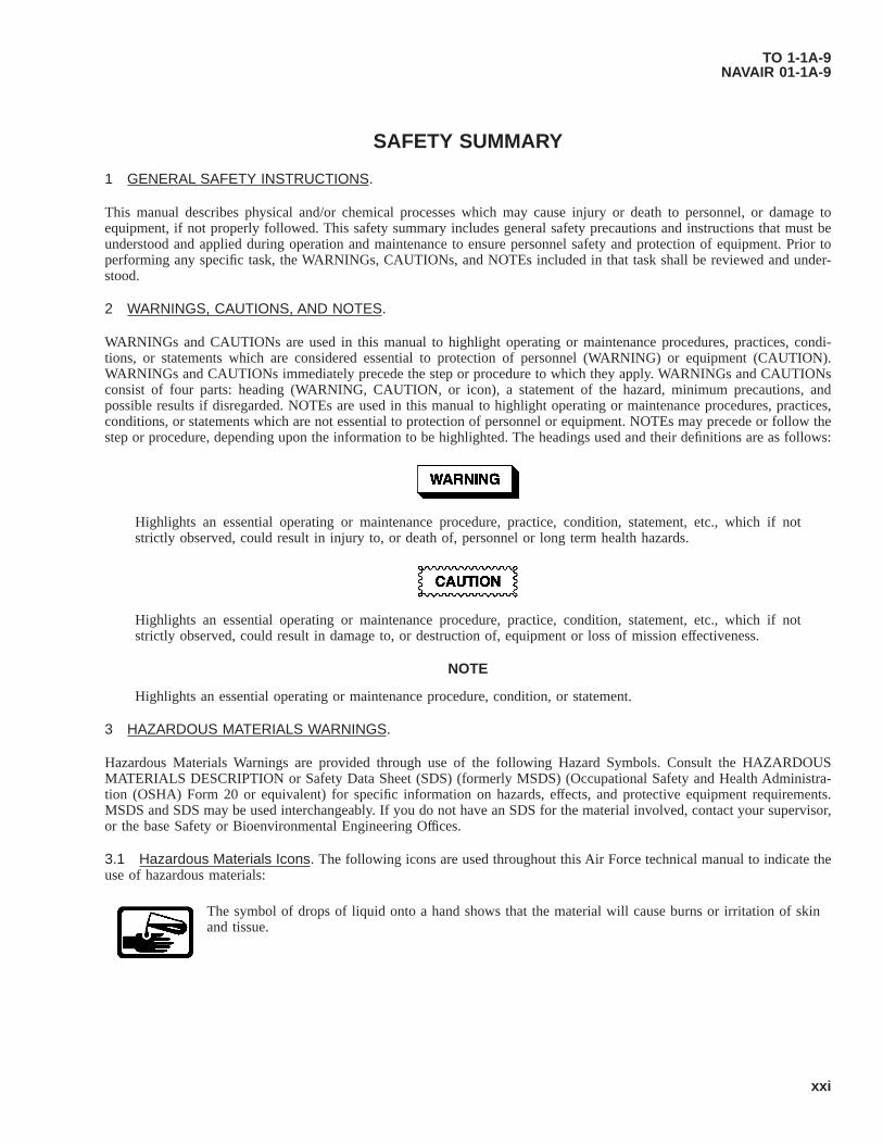
SAFETY SUMMARY
1 GENERAL SAFETY INSTRUCTIONS.
This manual describes physical and/or chemical processes which may cause injury or death to personnel, or damage toequipment, if not properly followed. This safety summary includes general safety precautions and instructions that must beunderstood and applied during operation and maintenance to ensure personnel safety and protection of equipment. Prior toperforming any specific task, the WARNINGs, CAUTIONs, and NOTEs included in that task shall be reviewed and under-stood.
2 WARNINGS, CAUTIONS, AND NOTES.
WARNINGs and CAUTIONs are used in this manual to highlight operating or maintenance procedures, practices, condi-tions, or statements which are considered essential to protection of personnel (WARNING) or equipment (CAUTION).WARNINGs and CAUTIONs immediately precede the step or procedure to which they apply. WARNINGs and CAUTIONsconsist of four parts: heading (WARNING, CAUTION, or icon), a statement of the hazard, minimum precautions, andpossible results if disregarded. NOTEs are used in this manual to highlight operating or maintenance procedures, practices,conditions, or statements which are not essential to protection of personnel or equipment. NOTEs may precede or follow thestep or procedure, depending upon the information to be highlighted. The headings used and their definitions are as follows:
Highlights an essential operating or maintenance procedure, practice, condition, statement, etc., which if notstrictly observed, could result in injury to, or death of, personnel or long term health hazards.
Highlights an essential operating or maintenance procedure, practice, condition, statement, etc., which if notstrictly observed, could result in damage to, or destruction of, equipment or loss of mission effectiveness.
NOTE
Highlights an essential operating or maintenance procedure, condition, or statement.
3 HAZARDOUS MATERIALS WARNINGS.
Hazardous Materials Warnings are provided through use of the following Hazard Symbols. Consult the HAZARDOUSMATERIALS DESCRIPTION or Safety Data Sheet (SDS) (formerly MSDS) (Occupational Safety and Health Administra-tion (OSHA) Form 20 or equivalent) for specific information on hazards, effects, and protective equipment requirements.MSDS and SDS may be used interchangeably. If you do not have an SDS for the material involved, contact your supervisor,or the base Safety or Bioenvironmental Engineering Offices.
3.1 Hazardous Materials Icons. The following icons are used throughout this Air Force technical manual to indicate theuse of hazardous materials:
The symbol of drops of liquid onto a hand shows that the material will cause burns or irritation of skinand tissue.
TO 1-1A-9NAVAIR 01-1A-9
xxi
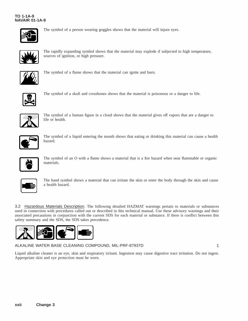
The symbol of a person wearing goggles shows that the material will injure eyes.
The rapidly expanding symbol shows that the material may explode if subjected to high temperature,sources of ignition, or high pressure.
The symbol of a flame shows that the material can ignite and burn.
The symbol of a skull and crossbones shows that the material is poisonous or a danger to life.
The symbol of a human figure in a cloud shows that the material gives off vapors that are a danger tolife or health.
The symbol of a liquid entering the mouth shows that eating or drinking this material can cause a healthhazard.
The symbol of an O with a flame shows a material that is a fire hazard when near flammable or organicmaterials.
The hand symbol shows a material that can irritate the skin or enter the body through the skin and causea health hazard.
3.2 Hazardous Materials Description. The following detailed HAZMAT warnings pertain to materials or substancesused in connection with procedures called out or described in this technical manual. Use these advisory warnings and theirassociated precautions in conjunction with the current SDS for each material or substance. If there is conflict between thissafety summary and the SDS, the SDS takes precedence.
ALKALINE WATER BASE CLEANING COMPOUND, MIL-PRF-87937D 1
Liquid alkaline cleaner is an eye, skin and respiratory irritant. Ingestion may cause digestive tract irritation. Do not ingest.Appropriate skin and eye protection must be worn.
TO 1-1A-9NAVAIR 01-1A-9
xxii Change 3
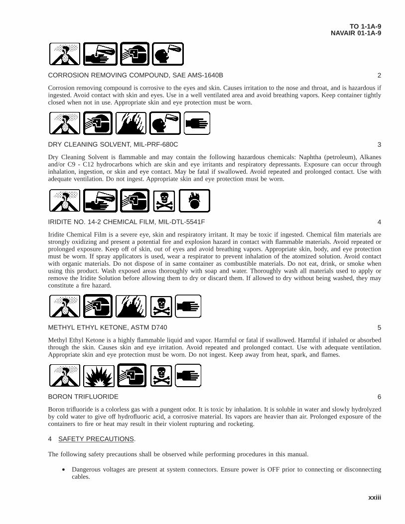
CORROSION REMOVING COMPOUND, SAE AMS-1640B 2
Corrosion removing compound is corrosive to the eyes and skin. Causes irritation to the nose and throat, and is hazardous ifingested. Avoid contact with skin and eyes. Use in a well ventilated area and avoid breathing vapors. Keep container tightlyclosed when not in use. Appropriate skin and eye protection must be worn.
DRY CLEANING SOLVENT, MIL-PRF-680C 3
Dry Cleaning Solvent is flammable and may contain the following hazardous chemicals: Naphtha (petroleum), Alkanesand/or C9 - C12 hydrocarbons which are skin and eye irritants and respiratory depressants. Exposure can occur throughinhalation, ingestion, or skin and eye contact. May be fatal if swallowed. Avoid repeated and prolonged contact. Use withadequate ventilation. Do not ingest. Appropriate skin and eye protection must be worn.
IRIDITE NO. 14-2 CHEMICAL FILM, MIL-DTL-5541F 4
Iridite Chemical Film is a severe eye, skin and respiratory irritant. It may be toxic if ingested. Chemical film materials arestrongly oxidizing and present a potential fire and explosion hazard in contact with flammable materials. Avoid repeated orprolonged exposure. Keep off of skin, out of eyes and avoid breathing vapors. Appropriate skin, body, and eye protectionmust be worn. If spray applicators is used, wear a respirator to prevent inhalation of the atomized solution. Avoid contactwith organic materials. Do not dispose of in same container as combustible materials. Do not eat, drink, or smoke whenusing this product. Wash exposed areas thoroughly with soap and water. Thoroughly wash all materials used to apply orremove the Iridite Solution before allowing them to dry or discard them. If allowed to dry without being washed, they mayconstitute a fire hazard.
METHYL ETHYL KETONE, ASTM D740 5
Methyl Ethyl Ketone is a highly flammable liquid and vapor. Harmful or fatal if swallowed. Harmful if inhaled or absorbedthrough the skin. Causes skin and eye irritation. Avoid repeated and prolonged contact. Use with adequate ventilation.Appropriate skin and eye protection must be worn. Do not ingest. Keep away from heat, spark, and flames.
BORON TRIFLUORIDE 6
Boron trifluoride is a colorless gas with a pungent odor. It is toxic by inhalation. It is soluble in water and slowly hydrolyzedby cold water to give off hydrofluoric acid, a corrosive material. Its vapors are heavier than air. Prolonged exposure of thecontainers to fire or heat may result in their violent rupturing and rocketing.
4 SAFETY PRECAUTIONS.
The following safety precautions shall be observed while performing procedures in this manual.
• Dangerous voltages are present at system connectors. Ensure power is OFF prior to connecting or disconnectingcables.
TO 1-1A-9NAVAIR 01-1A-9
xxiii

• Do not wear metal frame glasses, rings, watches, or other metal jewelry while working on electronic equipment.
• Some cleaning materials specified herein are flammable and/or toxic. Keep away from open flame or other ignitionsources. Provide adequate ventilation and avoid skin/eye exposure.
• Cleaning with compressed air can create airborne particles that may enter eyes or penetrate skin. Pressure shall notexceed 30 pound-force per square inch, gauge (PSIG). Wear goggles. Do not direct compressed air against skin.
TO 1-1A-9NAVAIR 01-1A-9
xxiv

CHAPTER 1INTRODUCTION
1.1 INTRODUCTION.
This is one of a series of technical or engineering technical manuals prepared to assist personnel engaged in the maintenanceand repair of Aerospace Weapon Systems and Supporting Equipment Aerospace Ground Equipment (AGE). Army Person-nel: Wherever the text of this manual refers to other technical orders (TOs) for supporting information, refer to comparableArmy documents.
1.1.1 General Information. This technical manual provides precise data on specific metals to assist in selection, usageand processing for fabrication and repair. It includes such data as specification cross reference; approved designation systemfor alloys and tempers; temperatures and other controls for heat treatments; mechanical and physical properties processinginstructions for basic corrosion prevention; forming characteristics; and other information required for general aerospaceweapon system repair. Procedures for general foundry practice, sand control, gating and risering of both ferrous and non-ferrous castings may be obtained from available commercial handbooks and/or publications. Due to the many types, grades,diversified uses and new developments of metal products, it may not include all data required in some instances and furtherstudy and citation of this data will be required.
1.1.2 Instructions. The information/instruction contained herein are for general use. If a conflict exists between thistechnical manual and the specific technical manual(s) or other approved data for a particular weapon, end item, equipment,etc., the data applicable to the specific item(s) will govern in all cases.
1.1.2.1 The use of “shall”, “will”, “should” and “may” in this technical manual is as follows:
a. Whenever the word “shall” appears, it shall be interpreted to mean that the requirements are binding.
b. The words “will”, “should” and “may”, shall be interpreted as non-mandatory provisions.
c. The word “will” is used to express declaration of purpose.
d. The word “should” is used to express non-mandatory desired or preferred method of accomplishment.
e. The word “may” is used to express an acceptable or suggested means of accomplishment.
1.2 WELDING.
Information on welding aerospace metals is contained in NAVAIR 01-1A-34, TO 00-25-252, TC 9-238.
TO 1-1A-9NAVAIR 01-1A-9
1-1/(1-2 blank)


CHAPTER 2FERROUS (STEEL) ALLOYS
2.1 CLASSIFICATION.
2.1.1 Society of Automotive Engineers (SAE) Numbering System. A numeral index system is used to identify thecompositions of the SAE steels, which makes it possible to use numerals that are partially descriptive of the composition ofmaterial covered by such numbers. The first digit indicates the type to which the steel belongs; for example “1” indicates acarbon steel; “2” a nickel steel; and “3” a nickel chromium steel. In the case of the simple alloy steels, the second digitgenerally indicates the approximate percentage of the predominant alloying element. Usually the last two or three digitsindicate the approximate average carbon content in “points” or hundredths of percent. Thus “2340” indicates a nickel steel ofapproximately 3% nickel (3.25 to 3.75) and 0.40% carbon (0.38 to 0.43). In some instances, in order to avoid confusion, ithas been found necessary to depart from this system of identifying the approximate alloy composition of a steel by varyingthe second and third digits of the number. An instance of such departure is the steel numbers selected for several of thecorrosion and heat resisting alloys.
2.1.1.1 The basic numerals for the various types of SAE steel are:
Type Of Steel Numerals (and Digits)Carbon Steels 1xxx
Plain Carbon 10xxFree Cutting (Screw Stock) 11xx
Magnesium Steels 13xxNickel Chromium Steels 3xxx
1.25% Nickel; 0.65% Chromium 31xxCorrosion and Heat Resisting 303xx
Molybdenum Steels 4xxx0.25 Percent Molybdenum 40xx
Nickel-Chromium-Molybdenum Steels1.80% Nickel; 0.50 and 0.80% Chromium; 0.25% Molybdenum 43xx0.55% Nickel; 0.50 and 0.65% Chromium; 0.20% Molybdenum 86xx0.55% Nickel; 0.50 Chromium 0.25% Molybdenum 87xx3.25% Nickel; 1.20 Chromium 0.12% Molybdenum 93xx
Nickel-Molybdenum Steels1.75% Nickel; 0.25% Molybdenum 46xx3.50% Nickel; 0.25% Molybdenum 48xx
Chromium Steels 5xxxLow Chromium 50xxMedium Chromium 51xxxHigh Chromium 52xxxCorrosion and Heat Resisting 514xx and 515xx
Chromium-Vanadium Steel 6xxx0.80-1.00% Chromium, 0.10-0.15 Vanadium 61xx
Silicon Magnesium Steels 9xxxA Percent Silicon 92xxLow Alloy, High Tensile 950Boron Intensified xxBxxLeaded Steels xxLxx
TO 1-1A-9NAVAIR 01-1A-9
2-1

2.1.2 Carbon Steels. Steel containing carbon in percentages ranging from 0.10 to 0.30% is classed as low carbon steel.The equivalent SAE numbers range from 1010 to 1030. Steels of this grade are used for the manufacture of articles such assafety wire, certain nuts, cable bushing, etc. This steel in sheet form is used for secondary structural parts and clamps and intubular form for moderately stressed structural parts.
2.1.2.1 Steel containing carbon in percentages ranging from 0.30 to 0.50% is classed as medium carbon steel. This steel isespecially adaptable for machining, forging, and where surface hardness is important. Certain rod ends, light forgings, andparts such as Woodruff keys, are made from SAE 1035 steel.
2.1.2.2 Steel containing carbon in percentage ranging from 0.50 to 1.05% is classed as high carbon steel. The addition ofother elements in varying quantities adds to the hardness of this steel. In the fully heat-treated condition it is very hard andwill withstand high shear and wear, but little deformation. It has limited use in aircraft construction. SAE 1095 in sheet formis used for making flat springs and in wire form for making coil springs.
2.1.3 Nickel Steels. The various nickel steels are produced by combining nickel with carbon steel. Some benefits derivedfrom the use of nickel as an alloy in steel are as follows:
1. Lowers the percentage of carbon that is necessary for hardening. The lowering of the carbon content makes thesteel more ductile and less susceptible to uneven stress.
2. Lowers the critical temperature ranges (heating and cooling) and permits the use of lower heating temperaturesfor hardening.
3. Hardening of nickel alloy steels at moderate rates of cooling has the advantage of lowering the temperaturegradients, reducing internal stress/warpage and permits deeper/more uniform hardening.
4. The low heat treating temperatures required, reduces the danger of overheating, excessive grain growth and theconsequent development of brittleness.
5. The characteristics depth hardening from the addition of nickel to steel as an alloy results in good mechanicalproperties after quenching and tempering. At a given strength (except for very thin sections/parts) the nickel steelsprovide greatly improve elastic properties, impact resistance and toughness.
2.1.4 Chromium Steels. Chromium steel is high in hardness, strength, and corrosion resistant properties. SAE 51335steel is particularly adaptable for heat-treated forgings which require greater toughness and strength than may be obtained inplain carbon steel. It may be used for such articles as the balls and rollers of anti-friction bearings.
2.1.5 Chromium-Nickel Steels. Chromium and nickel in various proportions mixed with steel form the chrome-nickelsteels. The general proportion is about two and one-half times as much nickel as chromium. For all ordinary steels in thisgroup the chromium content ranges from 0.45 to 1.25%, while the nickel content ranges from 1-2%. Both nickel andchromium influence the properties of steel; nickel toughens it, while chromium hardens it. Chrome-nickel steel is used formachined and forged parts requiring strength, ductility, toughness and shock resistance. Parts such as crankshafts andconnecting rods are made of SAE 3140 steel.
2.1.5.1 Chrome-nickel steel containing approximately 18% chromium and 8% nickel is known as corrosion resistant steel.It is usually identified as AISI types 301, 302, 303, 304, 304L, 309, 316, 316L, 321, 347, 347F or Selenium, etc., however;the basic 18-8 chrome-nickel steel is Type 302. The other grades/types have been modified by changing or adding alloyingelements to that contained in the basic alloy. The alloys are varied to obtain the required mechanical properties for somespecific purpose such as improving corrosion resistance or forming machining, welding characteristics, etc. The followingare examples of variations:
1. 301-Chromium and Nickel (approximate 0.5 Nickel) is lowered to increase response to cold working.
2. 302-Basic Type 18 Chromium 8 Nickel.
3. 303-Sulfur or Selenium added for improved machining characteristics.
TO 1-1A-9NAVAIR 01-1A-9
2-2
4. 304-Carbon lowered to reduce susceptibility to carbide precipitation. This alloy is still subject to carbide precipi-tation from exposure to temperatures 800-1500 °F range and this shall be considered when it is selected for aspecific application.
5. 304L-Carbon lowered for welding applications.
6. 309-Chromium and Nickel higher for additional corrosion and scale resistance.
7. 316-Molybdenum added to improve corrosion resistance and strength.
8. 316L-Carbon- lowered for welding applications.
9. 321-Titanium added to reduce/avoid carbide precipitation (stabilized grade).
10. 347-Niobium, Tantalum added to reduce/avoid carbide precipitation (stabilized grade).
11. 347F Selenium-Sulfur or Selenium added to improve machinability.
2.1.5.1.1 The chrome-nickel steels are used for a variety of applications on aircraft and missiles. In plate and sheet formit is used for firewalls, surface skin, exhaust stacks, heater ducts, gun wells, ammunition chutes, clamps, heat shields/deflectors, fairing, stiffeners, brackets, shims, etc. In bar and rod it is used to fabricate various fittings, bolts, studs, screws,nuts, couplings, flanges, valve stems/seats, turn-buckles, etc. In wire form it is used for safety wire, cable, rivets, hinge pins,screens/screening and other miscellaneous items.
2.1.6 Chrome-Vanadium Steels. The vanadium content of this steel is approximately 0.18% and the chromium contentapproximately 1.00%. Chrome-vanadium steels when heat-treated have excellent properties such as strength, toughness, andresistance to wear and fatigue. A special grade of this steel in sheet form can be cold-formed into intricate shapes. It can befolded and flattened without signs of breaking or failure. Chrome-vanadium steel with medium high carbon content (SAE6150) is used to make springs. Chrome-vanadium steel with high carbon content (SAE 6195) is used for ball and rollerbearings.
2.1.7 Chrome Molybdenum Steels. Molybdenum in small percentage is used in combination with chromium to formchrome-molybdenum steel; this steel has important applications in aircraft. Molybdenum is a strong alloying element, only0.15-0.25% being used in the chrome-molybdenum steels; the chromium content varies from 0.80-1.10%. Molybdenum isvery similar to tungsten in its effect on steel. In some instances it is used to replace tungsten in cutting tools, however; theheat treat characteristic varies. The addition of up to 1% molybdenum gives steel a higher tensile strength and elastic limitwith only a slight reduction in ductility. They are especially adaptable for welding and for this reason are used principally forwelded structural parts and assemblies. Parts fabricated from 4130, are used extensively in the construction of aircraft,missiles, and miscellaneous Ground Support Equipment (GSE) equipment. The 4130 alloy is used for parts such as enginemounts (reciprocating), nuts, bolts, gear structures, support brackets for accessories, etc.
2.2 PRINCIPLES OF HEAT TREATMENT OF STEELS.
2.2.1 Hardening. At ordinary temperatures, the carbon content of steel exists in the form of particles of iron carbidescattered throughout the iron matrix; the nature of these carbide particles, i.e., their number, size, and distribution, deter-mines the hardness and strength of the steel. At elevated temperatures, the carbon is dissolved in the iron matrix and thecarbide-particles appear only after the steel has cooled through its “critical temperature” (see Paragraph 2.2.1.1). If the rateof cooling is slow, the carbide particles are relatively coarse and few; in this condition the steel is soft. If the cooling is rapid,as be quenching in oil or water, the carbon precipitates as a cloud of very fine carbide particles, which condition is associatedwith high hardness of the steel.
2.2.1.1 At elevated temperatures, the iron matrix exists in a form called “austenite” which is capable of dissolving carbonin solid solution. At ordinary temperatures the iron exists as “ferrite”, in which carbon is relatively insoluble and precipitates;as described in the preceding paragraph, in the form of carbide particles. The temperature at which this change fromaustenite to ferrite begins to occur on cooling is called the “upper critical temperature” of the steel, and varies with thecarbon content; up to approximately 0.85% carbon, the upper critical temperature is lowered with increasing carbon content;from 0.85-1.70% carbon the upper critical temperature is raised with increasing carbon content. Steel that has been heated toits upper critical point will harden completely if rapidly quenched; however, in practice it is necessary to exceed this
TO 1-1A-9NAVAIR 01-1A-9
2-3

temperature by/from approximately 28 to 56 degree Celsius (°C) (50-100 degree Fahrenheit (°F)) to ensure thorough heatingof the inside of the piece. If the upper critical temperature is exceeded too much, an unsatisfactory coarse grain size will bedeveloped in the hardened steel.
2.2.1.2 Successful hardening of steel will largely depend upon the following factors after steel has been selected whichhas harden ability desires:
a. Control over the rate of heating, specifically to prevent cracking of thick and irregular sections.
b. Thorough and uniform heating through sections to the correct hardening temperatures.
c. Control of furnace atmosphere, in the case of certain steel parts, to prevent scaling and decarburization.
d. Correct heat capacity, viscosity, and temperature of quenching medium to harden adequately and to avoid cracks.
e. In addition to the preceding factors, the thickness of the section controls the depth of hardness for a given steelcomposition. Very thick sections may not harden through because of the low rate of cooling at the center.
2.2.1.3 When heating steel, the temperature should be determined by the use of accurate instruments. At times, however,such instruments are not available, and in such cases, the temperature of the steel may be judged approximately by its color.The accuracy with which temperatures may be judged by color depends on the experience of the workman, the light inwhich the work is being done, the character of the scale on the steel, the amount of radiated light within the furnace, and theemissivity or tendency of steel to radiate or emit light.
2.2.1.4 A number of liquids may be used for quenching steel. Both the medium and the form of the bath depend largely onthe nature of the work to be cooled. It is important that a sufficient quantity of the medium be provided to allow the metalto be quenched without causing an appreciable change in the temperature of the bath. This is particularly important wheremany articles are to be quenched in succession.
2.3 QUENCHING PROCEDURE.
NOTE
Aerators may be used in the Quench Tanks to help dissipate the vapor barrier.
The tendency of steel to warp and crack during the quenching process is difficult to overcome, and is due to the fact thatcertain parts of the article cool more rapidly than others. Whenever the rate of cooling is not uniform, internal stresses are setup on the metal which may result in warpage or cracking, depending on the severity of the stresses. Irregularly shaped partsare particularly susceptible to these conditions although parts of uniform section size are often affected in a similar manner.Operations such as forging and machining may set up internal stresses in steel parts and it is therefore advisable to normalizearticles before attempting the hardening process. The following recommendations will greatly reduce the warping tendencyand should be carefully observed:
1. An article should never be thrown into quenching media/bath. By permitting it to lie on the bottom of the bath itis apt to cool faster on the top side than on the bottom side, thus causing it to warp or crack.
2. The article should be slightly agitated in the bath to destroy the coating of vapor which might prevent it fromcooling rapidly. This allows the bath to remove the heat of the article rapidly by conduction and convection.
3. An article should be quenched in such a manner that all parts will be cooled uniformly and with the least possibledistortion. For example, a gear wheel or shaft should be quenched in a vertical position.
4. Irregularly shaped sections should be immersed in such a manner that the parts of the greatest section thicknessenters the bath first.
2.3.1 Quenching Medium. Oil is much slower in action than water, and the tendency of heated steel to warp or crackwhen quenched may be greatly reduced by its use. Unfortunately, parts made from high carbon steel will not developmaximum hardness when quenched in oil unless they are quite thin in cross section. In aircraft, however, it is generally usedand is recommended in all cases where it will produce the desired degree of hardness.
TO 1-1A-9NAVAIR 01-1A-9
2-4

NOTE
Alloy steels should never be quenched in water.
2.3.1.1 In certain cases water is used in the quenching of steel for the hardening process. The water bath should beapproximately 18 °C (65 °F) as extremely cold water is apt to warp or crack the steel and water above this temperature willnot produce the required hardness.
2.3.1.2 A 10% salt brine (sodium chloride) solution is used when higher cooling rates are desired. A 10% salt brinesolution is made by dissolving 0.89 pound of salt per gallon of water.
2.3.1.3 For many articles such as milling cutters and similar tools, a bath of water covered by a film of oil is occasionallyused. When the steel is plunged through this oil film a thin coating will adhere to it, retarding the cooling effect of the waterslightly, thus reducing the tendency to crack due to contraction.
2.3.2 Straightening of Parts Warped in Quenching. Warped parts must be straightened by first heating to below thetempering temperature of the article, and then applying pressure. This pressure should be continued until the piece is cooled.It is desirable to re-temper the part after straightening at the straightening temperature. No attempt should be made tostraighten hardened steel without heating, regardless of the number of times it has been previously heated, as steel in itshardened condition cannot be bent or sprung cold with any degree of safety.
2.3.3 Tempering (Drawing). Steel that has been hardened by rapid cooling from a point slightly above its critical range isoften harder than necessary and generally too brittle for most purposes. In addition, it is under severe internal stress. In orderto relieve the stresses and reduce the brittleness or restore ductility the metal is always “tempered”. Tempering consists inreheating the steel to a temperature below the critical range (usually in the neighborhood of 600-1200 °F). This reheatingcauses a coalescence and enlargement of the fine carbide particles produced by drastic quenching, and thus tends to softenthe steel. The desired strength wanted will determine the tempering temperature. This is accomplished in the same types offurnaces as are used for hardening and annealing. Less refined methods are sometimes used for tempering small tools.
2.3.3.1 As in the case of hardening, tempering temperatures may be approximately determined by color. These colorsappear only on the surface and are due to a thin film of oxide which forms on the metal after the temperature reaches 232 °C(450 °F). In order to see the tempering colors, the surface must be brightened. A buff stick consisting of a piece of wood withemery cloth attached is ordinarily used for this purpose. When tempering by the color method, an open flame of heated ironplate is ordinarily used as the heating medium. Although the color method is convenient, it should not be used unlessadequate facilities for determining temperature are not obtainable. Tempering temperatures can also be determined by theuse of crayons of known melting point. Such crayons are commercially available for a wide range of temperatures under thetrade name of “Tempilstiks”. The above method may be used where exact properties after tempering is not too importantsuch as for blacksmith work. The most desirable method for general aeronautical use, is to determine temperatures byhardness checks, and subsequent adjustments made as necessary to obtain the properties required. For recommended tem-pering temperatures see heat treat data for material/composition involved.
2.3.3.2 Steel is usually subjected to the annealing process for the following purposes:
1. To increase its ductility by reducing hardness and brittleness.
2. To refine the crystalline structure and remove stresses. Steel which has been cold-worked is usually annealed soas to increase its ductility. However, a large amount of cold-drawn wire is used in its cold-worked state when veryhigh yield point and tensile strength are desired and relatively low ductility is permissible, as in spring wire, pianowire, and wires for rope and cable. Heating to low temperatures, as in soldering, will destroy these properties.However, rapid heating will narrow the affected area.
3. To soften the material so that machining, forming, etc., can be performed.
2.3.4 Normalizing. Although involving a slightly different heat treatment, normalizing may be classed as a form ofannealing. This process also removes stresses due to machining, forging, bending, and welding. Normalizing may beaccomplished in furnaces used for annealing. The articles are put in the furnace and heated to a point approximately 150 to225 °F above the critical temperature of the steel. After the parts have been held at this temperature for a sufficient time forthe parts to be heated uniformly throughout, they must be removed from the furnace and cooled in still air. Prolonged
TO 1-1A-9NAVAIR 01-1A-9
2-5

soaking of the metal at high temperatures must be avoided, as this practice will cause the grain structure to enlarge. Thelength of time required for the soaking temperature will depend upon the mass of metal being treated. The optimum soakingtime is roughly one-quarter hour per inch of diameter or thickness.
2.3.5 Case Hardening. In many instances it is desirable to produce a hard, wear-resistant surface or “case” over a strong,tough core. Treatment of this kind is known as “case hardening”. This treatment may be accomplished in several ways, theprincipal ways being carbonizing, cyaniding, and nitriding.
2.3.5.1 Flame Hardening/Softening. Surface hardening/softening by applying intense heat (such as that produced by anOxy-Acetylene flame) can be accomplished on almost any of the medium carbon or alloys steel, i.e. 1040, 1045, 1137, 1140,etc. The parts are surface hardened, by applying a reducing flame (an Oxidizing flame should never be used) at such a rate,that the surface is rapidly heated to the proper quenching temperature for the steel being treated. Following the applicationof the heat, the part is quenched by a spraying of water/oil rapidly. The fast quench hardens the steel to the depth that thehardening temperature has penetrated below the surface. The actual hardness resulting will depend on the rate of coolingfrom the quenching temperature. In hardening by this method the shape and size/mass of the part must be considered. Mostoperations will require special adapted spray nozzles to apply the quenching media, which is usually water. Normally, flamehardening will produce surface hardness higher than can be obtained by routine furnace heating and quenching, becausesurface can be cooled at a faster rate. If a combination of high strength core and surface is required some of the mediumcarbon alloy steels can be heat treated and subsequently surface hardened by the flame method.
NOTE
This method is not adapted for surface hardening of parts for use in critical applications.
2.3.5.1.1 Surface softening is accomplished by heating the surface to just below the temperature by drastic quenching, andthus tends to soften the steel. The desired strength wanted will determine the tempering temperature. This is accomplished inthe same types of furnaces as are used for hardening and annealing. Less refined methods are sometimes used for temperingsmall tools.
2.3.5.2 Induction Hardening/Heating. The induction method of heating can be used to surface harden steels, in a mannersimilar to that used for flame hardening. The exception is that the heat for hardening is produced by placing the part in amagnetic field (electrical) specifically designed for the purpose. Parts hardened (surface) by this method will be limited tocapability and size of loop/coil used to produce the magnetic field.
2.3.5.2.1 In some instances the induction method can be used to deep harden; the extent will depend on exposure/dwelltime, intensity of the magnetic field, and the size of the part to be treated.
2.3.6 Carburizing. At elevated temperatures iron can react with gaseous carbon compounds to form iron carbide. Byheating steel, while in contact with a carbon-aceous substance, carbonic gases given off by this material will penetrate thesteel to an amount proportional to the time and temperature. For example, if mild or soft steel is heated to 732 °C (1,350 °F)in an atmosphere of carbonic gases, it will absorb carbon from the gas until a carbon content of approximately 0.80% hasbeen attained at the surface, this being the saturation point of the steel for the particular temperature. By increasing the heatto 899 °C/(1,650 °F) the same steel will absorb carbon from the gas until a carbon content of approximately 1.1% has beenattained, which is the saturation point for the increased temperature.
2.3.6.1 The carburizing process may be applied to both plain carbon and alloy steels provided they are within the lowcarbon range. Specifically, the carburizing steels are those containing not more than 0.20% carbon. The lower the carboncontent in the steel, the more readily it will absorb, carbon during the carburizing process.
2.3.6.2 The amount of carbon absorbed and the thickness of the case obtained increases with time; however, the carbur-ization progresses more slowly as the carbon content increases during the process. The length of time required to produce thedesired degree of carburization material used and the temperature to which the metal is subjected. It is apparent that, incarburizing, carbon travels slowly from the outside toward the inside center, and therefore, the proportion of carbon absorbedmust decrease from the outside to the inside.
2.3.6.3 Solid, liquid, and gas carburizing methods are employed.
1. The simplest method of carburizing consists of soaking the parts at an elevated temperature while in contact withsolid carbonaceous material such as wood charcoal, bone charcoal and charred leather.
TO 1-1A-9NAVAIR 01-1A-9
2-6

2. Liquid carburizing consists of immersing the parts in a liquid salt bath, heated to the proper temperature. Thecarbon penetrates the steel as in the solid method producing the desired case.
3. Gas carburizing consists of heating the parts in a retort and subjecting them to a carbon-aceous gas such as carbonmonoxide or the common fuel gases. This process is particularly adaptable to certain engine parts.
2.3.6.4 When pack carburizing, the parts are packed with the carburizing material in a vented steel container to preventthe solid carburizing compound from burning and to retain the carbon monoxide and dioxide gases. Nichrome boxes, cappedpipes of mild steel, or welded mild steel boxes may be used. Nichrome boxes are most economical for production becausethey withstand oxidation. Capped pipes of mild steel or welded mild steel boxes are useful only as substitutes. The containershould be so placed as to allow the heat to circulate entirely around it. The furnace must be brought to the carburizingtemperature as quickly as possible and held at this heat from 1 to 16 hours, depending upon the depth of case desired and thesize of the work. After carburizing the container should be removed and allowed to cool in air or the parts removed from thecarburizing compound and quenched in oil or water. The air cooling, although slow, reduces warpage and is advisable inmany cases.
2.3.6.5 Carburized steel parts are rarely used without subsequent heat treatment, which consists of several steps to obtainoptimum hardness in the case, and optimum strength and ductility in the core. Grain size of the core and case is refined.
1. Refining the core is accomplished by reheating the parts to a point just above the critical temperature of the steel.After soaking for a sufficient time to ensure uniform heating, the parts are quenched in oil.
2. The hardening temperature for the high carbon case is well below that of the core. It is, therefore, necessary toheat the parts again to the critical temperature of the case and quench them in oil to produce the requiredhardness. A soaking period of 10 minutes is generally sufficient.
3. A final stress relieving operation is necessary to minimize the hardening stresses produced by the previoustreatment. The stress relieving temperature is generally around 350 °F. This is accomplished by heating, soakinguntil uniformly heated, and cooling in still air. When extreme hardness is desired, the temperature should becarefully held to the lower limit of the range.
2.3.7 Cyaniding. Steel parts may be surface hardened by heating while in contact with a cyanid salt, followed byquenching. Only a thin case is obtained by this method and it is, therefore, seldom used in connection with aircraftconstruction or repair. Cyaniding is, however, a rapid and economical method of case hardening, and may be used in someinstances for relatively unimportant parts. The work to be hardened is immersed in a bath of molten sodium or potassiumcyanide from 30 to 60 minutes. The cyanide bath should be maintained at a temperature to 760-899 °C (1,400-1,650 °F).Immediately after removal from the bath, the parts are quenched in water. The case obtained in this manner is due princi-pally to the formation of carbides and nitrides on the surface of the steel. The use of a closed pot and ventilating hood arerequired for cyaniding, as cyanide vapors are extremely poisonous.
2.3.8 Nitriding. This method of case hardening is advantageous due to the fact that a harder case is obtained than bycarburizing. Many engine parts such as cylinder barrels and gears may be treated in this way. Nitriding is generally appliedto certain special steel alloys, one of the essential constituents of which is aluminum. The process involves the exposing ofthe parts to ammonia gas or other nitrogenous materials for 20 to 100 hours at 950 °F. The container in which the work andammonia gas are brought in contact must be airtight and capable of maintaining good circulation and even temperaturethroughout. The depth of case obtained by nitriding is about 0.015 inch if heated for 50 hours. The nitriding process does notaffect the physical state of the core if the preceding tempering temperature was 950 °F or over. When a part is to be onlypartially treated, tinning of any surface will prevent it from being nitrided. Nitrided surfaces can be reheated to 950 °F without losing any of their hardness, however, if heated above that temperature, the hardness is rapidly lost and cannot beregained by retreatment. Prior to any nitriding treatment, all decarburized metal must be removed to prevent flaking of thenitrided case. When no distortion is permissible in the nitrided part, it is necessary to normalize the steel prior to nitriding toremove all strains resulting from the forging, quenching, or machining.
2.4 HEAT TREATING EQUIPMENT.
Equipment necessary for heat treating consists of a suitable means for bringing the metal to the required temperaturemeasuring and controlling device and quenching medium. Heat may, in some instances, be supplied by means of a forge orwelding torch; however, for the treatment required in aircraft work, a furnace is necessary. Various jigs and fixtures aresometimes needed for controlling quenching and preventing warping.
TO 1-1A-9NAVAIR 01-1A-9
2-7

2.4.1 Furnaces. Heat treating furnaces are of many designs and no one size or type perfectly fills every heat treatingrequirement. The size and quantity of metal to be treated and the various treatments required determine the size and type offurnace most suitable for each individual case. The furnace should be of a suitable type and design for the purpose intendedand should be capable of maintaining within the working zone a temperature varying not more than ±25 °F for the desiredvalue. Certain processes or materials may require tighter temperature control and uniformity, see Paragraph 2.4.2.1.
2.4.2 Heat Treating Furnaces/Baths. The acceptable heating media for heat treating of steels are air, combusted gases,protective atmosphere, inert atmosphere or vacuum furnaces, molten-fused salt baths, and molten-lead baths. The heattreating furnaces/baths are of many designs and no one size or type will perfectly fill every heat treating requirement.Furnaces and baths shall be of suitable design, type and construction for purpose intended. Protective and inert atmospheresshall be utilized and circulated as necessary to protect all surfaces of parts comprising the furnace load.
2.4.2.1 The design and construction of the heating equipment shall be such that the furnace/bath is capable of maintainingwithin the qualified working zone, at any point, a temperature varying not more than ±25 °F from the required heat treatingtemperature, with any charge. After the charge has been brought up to treating/soaking temperature all areas of the workingzone shall be within the permissible temperature range specified for the steel/alloy being heat treated. Certain processes ormaterials may require tighter temperature control and uniformity. See Table 3-19, Paragraph 2.4.2.1, SAE-AMS-H-6875 orspecific engineering data for the material involved.
2.5 HEAT CONTROL: TEMPERATURE MEASURING EQUIPMENT, FURNACE TEMPERATURE UNIFOR-MITY SURVEY, AND SYSTEM ACCURACY TESTS.
NOTE
SAE-AMS-2750, Pyrometry, is the control document for equipment used to heat treat aerospace materials. AMS-2750 covers temperature sensors, instrumentation, system accuracy tests, and temperature uniformity surveys. Fora complete description of pyrometry requirements for heat treating equipment, refer to the latest issue of SAE-AMS-2750. In case of conflict with this manual, the discrepancy will be negotiated with the responsible technical/engineering activity for resolution and updating.
2.5.1 Controlling, Monitoring, and Recording Equipment. Instrumentation type for controlling, monitoring, and record-ing equipment is broken down into five categories. Each category is based on how many controlling, monitoring, andrecording Thermocouple (TCs) are operational in an furnace chamber. The most common instrumentation type is Type D.Furnace controllers, monitoring, and process recording equipment shall be digital and have a calibration accuracy of ±2 °For 0.2% of the reading, whichever is greater. Field test instruments can temporarily be used as monitoring/recording equip-ment to monitor and record heat treatment processes when on-board furnace equipment is inoperable or non-digital, ie; paperchart recorders. See Table 3-22 for furnace instrumentation types.
2.5.2 Field Test Instruments. Field test instruments are used in conjunction with thermocouples to measure the operatingtemperature inside the furnace chamber. They are used to monitor load thermocouples, perform System Accuracy Tests(SAT), and temperature uniformity surveys (TUS). They range from hand held single input units to suitcase style multi-inputunits. Many modern units come with software to log and record data. Field test instruments used to perform SATs andmonitor load thermocouples shall have a minimum of 1 input channel, a calibration accuracy of ±1 °F or ±0.1% of thereading, whichever is greater, and the ability to log/record data. Field test instruments used to perform TUSs shall have aminimum of 9 input channels, a calibration accuracy of ±1 °F or ±0.1% of the reading, whichever is greater, and the abilityto log/record data. National Stock Number (NSN) 6625-01-649-1136 is an example of a multi-point field test unit that logsdata and can be used for multiple heat treatment process test, measuring, and recording applications such as SATs and TUSs.
2.5.3 TC. See Paragraph 3.13.5 through Paragraph 3.13.5.5.2.
2.5.4 Temperature Control and Uniformity Testing. Precise temperature control is essential to produce the exact mate-rial properties and temper requirements necessary for modern aviation manufacturing and maintenance. Periodic surveys andtests of the internal chamber temperatures must be conducted, documented and compared to the set point temperatures of thefurnace/furnace controller to ensure accurate equipment operation. The two methods used to ensure accurate operation ofheat treating equipment are the SAT and the TUS. The SAT is a quick and simple user test to ensure the furnace temperatureremains accurate in between TUSs. The TUS is a more thorough user test to ensure temperature accuracy and uniformity inthe entire furnace chamber as compared to the furnace control sensor and SAT. These two tests work in conjunction witheach other as a checks and balance system to ensure accurate and uniform furnace operation. If one is accurate and the otheris not, that is a sign that your furnace needs troubleshooting or maintenance to correct a deficiency.
TO 1-1A-9NAVAIR 01-1A-9
2-8
2.5.4.1 SAT. A SAT is performed to assess the accuracy of the heat treat furnace’s resident thermocouple and controller.This is done through the use of an independently calibrated field test instrument and thermocouple. By placing the testthermocouple within 3 inches of the resident thermocouple and taking a reading with the field test instrument, the accuracyof the furnace’s controller and resident thermocouple is validated. If the difference between the field test instrument and thefurnace controller is greater than ±5 °F, then that is an indication of required maintenance or adjustment of the furnace,furnace controller, and/or resident thermocouple.
2.5.4.1.1 A SAT shall be performed and documented using a field test instrument that meets the requirements of Paragraph3.13.3 and a TC that meets the requirements of Paragraph 3.13.5.5.2, on each furnace chamber used to perform heat treatingon ferrous alloys, at the following intervals/situations:
a. Initial. Upon initial furnace installation, prior to first operational use.
b. Periodic. System Accuracy Test (SAT) frequency is based on frequency of heat treating operations and furnace instru-mentation type. See Table 3-22 for instrumentation types.
(1) Shops that perform daily heat treating operations, utilizing Type D instrumentation, shall perform SATs on abiweekly basis, not to exceed 14 calendar days. If utilizing Type B or C instrumentation, the SAT interval may beextended to monthly, not to exceed 31 calendar days.
(2) Shops performing weekly to biweekly heat treating operations, every 5 to 14 calendar days, utilizing Type Dinstrumentation, shall perform SATs on a monthly basis, not to exceed 31 calendar days. If utilizing Type B or Cinstrumentation, the SAT interval may be extended to quarterly, not to exceed 91 calendar days.
(3) Shops performing biweekly to monthly heat treating operations, every 15 to 30 calendar days, utilizing Type Dinstrumentation, shall perform SATs on a quarterly basis, not to exceed 91 calendar days. Use of Type B or Cinstrumentation is recommended, but the SAT interval will not be extended.
(4) Shops performing heat treating operations less frequent than every 30 calendar days, regardless of instrumenttype, will perform a SAT prior to use/heat treating operation.
(5) If utilizing Type A instrumentation, refer to AMS2750 for SAT interval.
c. After any maintenance to the furnace, ie; replacement of a sensor/TC, heating element, or controlling, monitoring, orrecording instrument.
d. Recalibration of the controlling, monitoring, or recording instrument, or when parameter/rheostat adjustments havebeen made.
2.5.4.1.2 SAT Procedure. A successful SAT reading must be within ±5 °F of furnace controller set-point.
a. Set furnace controller to desired set point and allow to stabilize.
b. Insert TC into furnace with tip (measuring junction) as close to practical to the controlling, monitoring, or recordingsensor tip. The tip to tip distance shall not exceed 3 inches. Proper Personal Protective Equipment (PPE) must be wornwhen manually inserting SAT TC into furnace.
c. Allow furnace to recover. Some alloys have specific recovery period timelines. Recovery time must not be exceeded,as applicable.
d. Record temperature reading.
e. Document and file report.
2.5.4.1.3 SAT Report Requirements. A paper or digital copy of the completed record shall be retained by the facilityperforming the SAT in accordance with applicable Records Disposition Schedule guidelines. The report will contain, at aminimum:
1. Identification of furnace/sensor (if multi-zone) being tested.
TO 1-1A-9NAVAIR 01-1A-9
Change 3 2-9

2. Date and time of the test.
3. Identification of the test sensor.
4. Test sensor correction factors.
5. Identification of the test instrument.
6. Identification of test instrument correction factors.
7. Set point of furnace during the test.
8. Observed furnace controller instrument reading.
9. Observed test instrument reading.
10. Corrected test instrument reading [will be same as (i) if (d) and (f) are programmed into test unit, if not, (j = i +d + f)].
11. Calculated system accuracy difference (k = h - j).
12. Indication of test pass or fail.
13. Identification of technician performing test.
14. Identification of supervisor performing review.
2.5.4.1.4 If SAT failure occurs, corrective action may include, but is not limited to replacement of the out of tolerancesensor, rheostat adjustment, recalibration of the out of tolerance instrument/controller, etc. After any corrective actions, aSAT must be performed prior to any production heat treatments in accordance with Paragraph 2.5.4.1.2.
2.5.4.1.5 Modification Offset. Manual modification offset of the control instrument to facilitate desired chamber tempera-tures based on most recent SAT results are not permitted.
2.5.4.2 TEMPERATURE UNIFORMITY SURVEY (TUS). A TUS is performed to ensure the furnace chamber’s oper-ating temperature is accurate and uniform, within given tolerance standards, throughout the entire volume or qualified workzone in relation to the furnace set point. This is done through the use of an independently calibrated field test instrument(multi-point data logger) and multiple thermocouples all simultaneously measuring temperature from multiple points in thefurnace chamber over a period of at least 30 minutes.
2.5.4.2.1 A TUS shall be performed and documented using a field test instrument that meets the requirements of Para-graph 3.13.3 and a TC that meets the requirements of Paragraph 3.13.5.5.2, on each furnace chamber used to perform heattreating on ferrous alloys, at the following intervals/situations:
1. Upon initial furnace installation, prior to first operational use. See Paragraph 2.5.4.2.2.
2. Quarterly. See Paragraph 2.5.4.2.3.
3. Annually. See Paragraph 2.5.4.2.4.
4. After any maintenance to the furnace, ie; replacement of a sensor/TC, heating element, controlling, monitoring, orrecording instrument, airflow pattern/velocity, replacement of refractory material.
5. Recalibration of the controlling, monitoring, or recording instrument, or when parameter/rheostat adjustmentshave been made.
6. Work zone volume increase, larger than previously qualified area.
TO 1-1A-9NAVAIR 01-1A-9
2-10 Change 6

7. Work zone location change, outside of previously qualified area.
2.5.4.2.2 Initial TUS Requirement. Initial survey temperatures shall be the minimum and maximum temperatures of thequalified operating temperature range. Additional temperatures shall be added as required to ensure that no two adjacentsurvey temperatures are greater than 600 °F apart. For example, if a furnace operating range is 1200 to 2400 °F, the furnacemust be surveyed at 1200, 1800, and 2400 °F.
2.5.4.2.3 Quarterly TUS Requirement. A quarterly TUS shall be performed, not to exceed 91 calendar days. For singleoperating ranges greater than 600 °F, TUS temperatures shall be selected so that one temperature is within 300 °F of theminimum and another temperature is within 300 °F of the maximum qualified operating range and there is no more than 600°F in between. For example, if a furnace operating range is 1200-2400 °F, then the furnace must be surveyed at 1200 °F-1500 °F and again at 2100 °F -2400 °F and the selected temperatures must not be more than 600 °F apart. Temperatures of1500 °F and 2100 °F would meet this requirement.
1. If utilizing Type D instrumentation, after 4 consecutive passing TUSs, the interval may be extended to semian-nually, not to exceed 181 calendar days.
2. If utilizing Type B or C instrumentation, after 3 consecutive passing TUSs, the interval may be extended tosemiannually, not to exceed 181 calendar days.
3. If utilizing Type A instrumentation, after 2 consecutive passing TUSs, the interval may be extended to annually,not to exceed 365 calendar days.
4. If at any time a TUS fails, the interval resorts back to standard and the count starts again.
2.5.4.2.4 Annual TUS Requirement. In addition to the periodic test requirement, at least once per year, not to exceed365 calendar days, surveys shall also be performed at the minimum and maximum of the qualified operating temperaturerange. For example, if a furnace operating range is 1200-2400 °F, then the furnace must be surveyed at 1200, 1800, and 2400°F.
2.5.4.3 TUS Procedure. See Paragraph 3.14.3 through Paragraph 3.14.3.4.4.
2.5.4.4 Temperature Uniformity Pass/Fail Requirements. A survey shall be considered passing if all the followingrequirements are met.
a. Control or monitoring sensor readings and TUS sensor readings did not exceed applicable positive temperature toler-ance at any time. See Table 3-19 for Temperature Uniformity Allowances.
b. The time required to achieve recovery, stabilization, and maintain set point temperature tolerances did not exceed thetime limit specified in any applicable process specifications.
c. All readings of control/monitor and TUS sensor readings are within the temperature tolerance requirements of Table3-19 for the process being surveyed after the official start of TUS survey time except as allowed in Paragraph3.14.3.4.3.
d. TUS sensor data was logged for each sensor at a frequency not greater than every two minutes.
e. TUS is run for the minimum required time of 30 minutes.
2.5.4.5 TUS Data and TUS Reports. TUS data must be gathered and recorded on a system that creates electronicrecords that cannot be altered without detection.
2.5.4.5.1 The TUS system software and playback utilities shall provide a means of examining and/or compiling the recorddata, but shall not provide any means of altering the source data. The system shall be capable of providing evidence therecord was reviewed, such as by recording an electronic review or a method of printing the record for a physical marking toindicate a review.
TO 1-1A-9NAVAIR 01-1A-9
Change 6 2-11
2.5.4.5.2 TUS Survey Report Requirements. A paper or digital copy of the completed record shall be retained by thefacility performing the TUS in accordance with applicable Air Force Records Disposition Schedule guidelines. The reportwill contain, at a minimum:
a. Furnace identification name or serial number.
b. Survey temperature.
c. Required temperature uniformity.
d. Furnace chamber dimensions or qualified working zone dimensions and location in chamber.
e. TUS sensor and location identification including a detailed diagram, description or photograph of any load or rackused.
f. Time and temperature data from all TUS sensors.
g. TC spool correction factor or correction factors for each TUS sensor at each calibration temperature.
h. Corrected or uncorrected readings of all TUS sensors. Reading shall be identified as corrected or uncorrected.
i. As found and as left TUS offsets (if used in production).
j. Survey start date and time.
k. Survey end date and time.
l. Survey test instrument identification or serial number.
m. Survey test instrument calibration agency.
n. Survey test instrument calibration date.
o. Survey test sensor failures, if any.
p. Indication of test pass or fail.
q. Identification of technician performing survey.
r. Identification of supervisor approving survey.
2.5.4.6 Failed TUS Procedures. If the temperature uniformity is not within the tolerances of Table 3-19, the cause of thedeviation shall be determined, documented, and corrected. The equipment shall not be used for additional processing untilthe deviation has been corrected and the TUS has been performed successfully.
2.5.4.6.1 For furnaces being tested at an extended interval, failure of a TUS shall cause the extended TUS interval torevert back to the standard periodic interval as applicable in Paragraph 2.5.4.2.3.
2.5.4.6.2 Modification Offset. Manual modification offset of the control instrument to facilitate the desired chambertemperature based on the most recent TUS results are permissible, provided it does not exceed ±13 °F. Modification offsetsshall be documented, approved/signed by the section supervisor or NCOIC, and used in production heat treatments, i.e.controller is offset to 1810 °F to obtain accurate uniform internal chamber temperature uniformity of 1800±25 °F, controlleris offset to 2108 °F to obtain accurate internal chamber temperature of 2100±25 °F etc. The signed temperature offset chartshall be posted next to the furnace controller or a similar location where the operator will see it and not overlook it.Temperature offsets greater than ±13 °F shall be troubleshot and corrected by a qualified technician within 90 days.
TO 1-1A-9NAVAIR 01-1A-9
2-12 Change 6

2.5.4.6.2.1 The quenching liquids authorized for use are as follows: Water, Commercial Quenching Oil, and AqueousPolymer Solutions. Quenchant medium shall be between 60 and 160 °F at the beginning of the quenching operation, andshall not exceed 200 °F at any time during the quenching operation, unless specified or approved by the responsibleengineering authority.
TO 1-1A-9NAVAIR 01-1A-9
Change 6 2-13
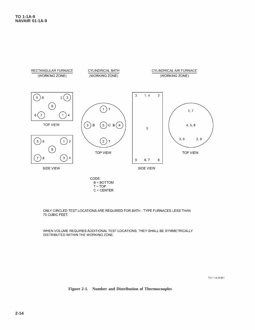
Figure 2-1. Number and Distribution of Thermocouples
TO 1-1A-9NAVAIR 01-1A-9
2-14
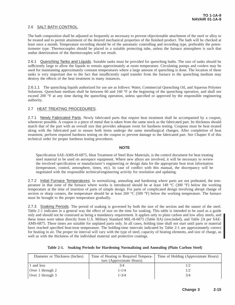
2.6 SALT BATH CONTROL.
The bath composition shall be adjusted as frequently as necessary to prevent objectionable attachment of the steel or alloy tobe treated and to permit attainment of the desired mechanical properties of the finished product. The bath will be checked atleast once a month. Temperature recording should be of the automatic controlling and recording type, preferably the poten-tiometer type. Thermocouples should be placed in a suitable protecting tube, unless the furnace atmosphere is such thatundue deterioration of the thermocouples will not result.
2.6.1 Quenching Tanks and Liquids. Suitable tanks must be provided for quenching baths. The size of tanks should besufficiently large to allow the liquids to remain approximately at room temperature. Circulating pumps and coolers may beused for maintaining approximately constant temperatures where a large amount of quenching is done. The location of thesetanks is very important due to the fact that insufficiently rapid transfer from the furnace to the quenching medium maydestroy the effects of the heat treatment in many instances.
2.6.1.1 The quenching liquids authorized for use are as follows: Water, Commercial Quenching Oil, and Aqueous PolymerSolutions. Quenchant medium shall be between 60 and 160 °F at the beginning of the quenching operation, and shall notexceed 200 °F at any time during the quenching operation, unless specified or approved by the responsible engineeringauthority.
2.7 HEAT TREATING PROCEDURES.
2.7.1 Newly Fabricated Parts. Newly fabricated parts that require heat treatment shall be accompanied by a coupon,whenever possible. A coupon is a piece of metal that is taken from the same stock as the fabricated part. Its thickness shouldmatch that of the part with an overall size that provides adequate room for hardness testing. Coupons must be heat treatedalong with the fabricated part to ensure both items undergo the same metallurgical changes. After completion of heattreatment, perform required hardness testing on the coupon to prevent damage to the fabricated part. See Chapter 8 of thistechnical order for proper hardness testing procedures.
NOTE
Specification SAE-AMS-H-6875, Heat Treatment of Steel Raw Materials, is the control document for heat treatingsteel material to be used on aerospace equipment. Where new alloys are involved, it will be necessary to reviewthe involved specification or manufacturer’s engineering or design data for the appropriate heat treat information(temperature, control, atmosphere, times, etc). In case of conflict with this manual, the discrepancy will benegotiated with the responsible technical/engineering activity for resolution and updating.
2.7.2 Initial Furnace Temperatures. In normalizing, annealing and hardening where parts are not preheated, the tem-perature in that zone of the furnace where works is introduced should be at least 149 °C (300 °F) below the workingtemperature at the time of insertion of parts of simple design. For parts of complicated design involving abrupt change ofsection or sharp corners, the temperature should be at least 260 °C (500 °F) below the working temperature. The furnacemust be brought to the proper temperature gradually.
2.7.3 Soaking Periods. The period of soaking is governed by both the size of the section and the nature of the steel.Table 2-1 indicates in a general way the effect of size on the time for soaking. This table is intended to be used as a guideonly and should not be construed as being a mandatory requirement. It applies only to plain carbon and low alloy steels, andthese times were taken directly from U.S. Military Standard MIL-H-6875 (Table IIA) (rescinded), and Table 2A per SAE-AMS-6875. These times are suitable for unplated parts only. In all cases, holding time shall not start until parts or materialhave reached specified heat-treat temperature. The holding-time intervals indicated by Table 2-1 are approximately correctfor heating in air. The proper tie interval will vary with the type of steel, capacity of heating elements, and size of charge, aswell as with the thickness of the individual material and protective coatings.
Table 2-1. Soaking Periods for Hardening Normalizing and Annealing (Plain Carbon Steel)
Diameter or Thickness (Inches) Time of Heating to Required Tempera-ture (Approximate Hours)
Time of Holding (Approximate Hours)
1 and less 3/4 1/2Over 1 through 2 1-1/4 1/2Over 2 through 3 1-3/4 3/4
TO 1-1A-9NAVAIR 01-1A-9
Change 3 2-15

Table 2-1. Soaking Periods for Hardening Normalizing and Annealing (Plain Carbon Steel) - Continued
Diameter or Thickness (Inches) Time of Heating to Required Tempera-ture (Approximate Hours)
Time of Holding (Approximate Hours)
Over 3 through 4 2-1/4 1Over 4 through 5 2-3/4 1Over 5 through 8 3-1/2 1-1/2
2.7.4 Hardening. Temperatures required for hardening steel are governed by the chemical composition of the steel,previous treatment, handling equipment, size and shape of piece to be treated. Generally, parts of heavy cross section shouldbe hardened from the high side of the given temperature range.
2.7.5 Tempering (Drawing). Tempering consists of heating the hardened steel to the applicable temperature holding atthis temperature for approximately 1 hour per inch of the thickness of the largest section, and cooling in air or quenching inoil at approximately 27-66 °C (80-150 °F). The temperature to be used for tempering of steel depends upon the exactchemical composition, hardness, and grain structure obtained by hardening and the method of tempering. The temperingtemperatures given are only approximate, and the exact temperature should be determined by hardness or tension test forindividual pieces. The final tempering temperatures should not be more than 111 °C (200 °F) below the tempering, tempera-ture given. If the center of the section is more that 1/2 inch from the surface, the tensile strength at the center will in generalbe reduced; therefore, a lower tempering temperature should be used for sections thicker than 1 inch in order to obtain therequired tensile strength.
2.7.6 Annealing. Annealing consists of heating to the applicable temperature, holding at this temperature for approxi-mately the period of time given, and cooling in the furnace to a temperature not higher than 482 °C (900 °F). The steel maythen be removed from the furnace and cooled in still air.
2.7.7 Normalizing. Normalizing consists of heating the steel to the applicable temperature, holding at this temperature forperiod of time, removing from furnace and cooling in still air.
2.7.8 Carburizing. Carburizing consists of heating the steel packed in a carburizing medium, in a closed container, to theapplicable temperature and holding at this temperature for the necessary period of time to obtain the desired depth of case.1020 steel will require 1 to 3 hours at a carburizing temperature of 899 °C (1650 °F) for each 1/64 inch of case depth,required. Parts may be cooled in the box or furnace to a temperature of approximately 482 °C (900 °F) then air cool. Thistreatment leaves the alloy in a relatively soft condition and it is then necessary to condition by heating and quenching, firstfor core refinement, followed by heating and quenching for case hardness. Alloy may be quenched directly from thecarburizing furnace, thus producing a hard case and a core hardness of Rockwell B67. This treatment produces a coarsegrain in some types of steel and may cause excessive distortion. Usually there is less distortion in fine grain steels. The coretreatment outlined above refines the grain as well as hardens.
2.7.9 Records. Air Force personnel shall document heat treatment procedures performed on aircraft and missile weaponsystems and support equipment by utilizing AFTO Form 8, Heat Treatment Procedure Record. On-site Air Force (AF)contractors shall also use the Air Force Technical Order (AFTO) Form 8 unless their contract specifies a different method ofheat treatment documentation. Personnel performing hardness testing shall document results on AFTO Form 8, Blocks21-25. A paper or digital copy of the completed record shall be retained by the facility performing the heat treatment inaccordance with applicable Air Force Records Disposition Schedule guidelines.
2.8 HARDNESS TESTING.
2.8.1 General. Hardness testing is an important factor in the determination of the results of the heat treatment as well asthe condition of the metal before heat treatment and must, therefore, be carefully considered in connection with this work.The methods of hardness testing in general use are: the Brinell, Rockwell, Vickers, and Shore Scleroscope. Each of thesemethods is discussed in Chapter 8.
2.8.2 Tensile Strength. Tempering temperatures listed with the individual steels in Table 2-3 are offered as a guide forobtaining desired tensile and yield strength of the entire cross section. When the physical properties are specified in terms oftensile strength, but tension tests are impractical, hardness tests may be employed using the equivalent hardness valuesspecified in Table 8-5.
TO 1-1A-9NAVAIR 01-1A-9
2-16 Change 3

2.8.3 Hardness-Tensile Strength Relationship. The approximate relationship between the tensile strength and hardnessis indicated in Table 8-5. This table is to be used as a guide. It applied only to the plain carbon and low alloy steels not tocorrosion-resistant, magnet, valve, or tool steels. When a narrow range of hardness is required, the tests to determine therelationship between hardness and strength should be made on the actual part. Hardness values should be within a range oftwo points Rockwell or 20 points Brinell or Vickers. The tensile strength-hardness relationship is quite uniform for partswhich are sufficiently large and rigid to permit obtaining a full depression on a flat surface without deflection of the piece.For cylindrical parts of less than inch in diameter, the Rockwell reading will be lower than indicated in the table for thecorresponding tensile strength. Any process which affects the surface, such as buffing and plating, or the presence ofdecarburized or porous areas and hard spots, will affect the corresponding relation between hardness and tensile strength.Therefore, these surfaces must be adequately removed by grinding before measurements are made.
2.8.3.1 In making hardness measurements on tubular sections, correction factors must be determined and applied to theobserved readings in order to compensate for the roundness and deflection of the tubing under the pressure of the penetrator.This may be impractical because every tube size end wall thickness would have a different factor. As an alternate, thefollowing procedure may be used: Short lengths may be cut from the tube. A mandrel long enough to extend out both endsof the tube and slightly smaller in diameter than the inner diameter of the tube is then passed through the section and theends supported in “V” supports on the hardness tester. Hardness readings may then be taken on the tubing.
2.8.4 Specification Cross Reference. Table 2-2 is a cross reference index listing the steel and alloy types and thecorresponding Federal, Military, and Industry specifications for the different configurations. Where two or more specifica-tions cover the same material, stock material meeting the requirements of a military specification shall be used for allaeronautical structural items.
Table 2-2. Specification Cross Reference
Comp/AlloyDesign Form/Commodity Industry Federal Military
1005 Rod and wire (steel and cast iron weld-ing)
AMS 5030
1008 Steel, sheet and strip, flat, aluminumcoated low carbon
AMS 5036
1010 Bars, Billets, Blooms, Slabs QQ-S-633 DOD-F-24669MIL-S-11310MIL-S-16788
Wire QQ-W-461QQ-W-405
Sheet and Strip AMS 5040 / 5042 /5044 / 5047 QQ-S-698
Tubing, Seamless AMS 5050Rivets AMS 7225Strip (For Small Arms, bullets) MIL-S-13468Tubes, Seamless (Marine Boiler applica-tion)
MIL-T-16286
Electrode, WeldingRod and Wire (Welding Low CarbonSteel) AWS A5.5 MIL-E-
23765/1E /4AMS 5027 / 5028 /6452 / 6456 / 6457 /6458 / 6459 / 6461
1015, 1016,1017, 1018,1019
Bars, Billets, and Tubing (Mechanical) AMS 5060 / 5061 /5069
Wire (Carbon) QQ-W-405 / QQ-W-461
Plate, Sheet, and Strip QQ-S-640Sheet, Strip Bars, and Billets MIL-S-7809
TO 1-1A-9NAVAIR 01-1A-9
Change 3 2-17

Table 2-2. Specification Cross Reference - Continued
Comp/AlloyDesign Form/Commodity Industry Federal Military
Blooms and Slabs DOD-F-246691020 Bars, Billets, Blooms, Slabs DOD-F-24669
Bars ASTM A29 QQ-S-633 MIL-S-11310Wire (Carbon) AMS 5032 QQ-W-461
QQ-W-405Sheet and Strip AMS 5045 / 5046 QQ-S-698Plate (Carbon) QQ-S-635Blooms, Billets, Slabs MIL-S-16788Tubing (Welded) MIL-T-20162Tubing (Seamless, Mechanical andWelded)
QQ-T-830
1022 Bars and Forgings AMS 5070Plates (Up to 1 inch) QQ-S-691Wire (Carbon) QQ-W-405Bars, Billets, Blooms, Slabs DOD-F-24669Sheet and Strip AMS-QQ-S-700Tubing, (Seamless, Mechanical andWelded) QQ-T-830
1025 Bars ASTM A29 QQ-S-633 MIL-S-11310Casting QQ-S-681 MIL-C-24707Tubing, Seamless AMS 5075Tubing, Welded AMS 5077Wire QQ-W-405Sheet and Strip AMS 5046Plate QQ-S-691
Corten Plate, Sheet and Strip (High Strength) MIL-S-125051035 Steel, Carbon (Bars, Forgings, and Tub-
ings)AMS 5080
Wire (Carbon) QQ-W-461QQ-W-405
Plate (Carbon) QQ-S-635Tubing, Seamless AMS 5082Plate (Marine Boiler) QQ-S-691Shapes, Bar and Plate (Structural) QQ-S-741Sheet and Strip QQ-S-640Forging (Naval Ship Board) MIL-S-19434
1040 Bars ASTM A29 QQ-S-633Plate (Carbon) QQ-S-635Castings QQ-S-681Wire (Carbon) QQ-W-405Bars MIL-S-11310Blooms, Billets, Bars and Slabs DOD-F-24669
1045 Tubing, Seamless and Welded QQ-T-830Bars ASTM A29 QQ-S-633Wire (Carbon) QQ-W-461Plate (Carbon) QQ-S-635Sheets and Strip QQ-S-640
1050 Bars ASTM A29 QQ-S-633
TO 1-1A-9NAVAIR 01-1A-9
2-18 Change 3

Table 2-2. Specification Cross Reference - Continued
Comp/AlloyDesign Form/Commodity Industry Federal Military
Plate (Carbon) QQ-S-635Blooms, Billets, and Slabs (For Forg-ings) MIL-S-16788
Bars, Billets, Slabs, Castings AMS 50851055 Forgings (For Projectile Stock) MIL-S-10520
Bars ASTM A29 QQ-S-633Electrodes MIL-E-23765
1060 Bars ASTM A29 QQ-S-633Spring MIL-S-2839Blooms, Billets, Slabs, Forgings MIL-S-16788
DOD-F-24669Sheet and Strip QQ-S-640
1070-1075 Sheet and Strip MIL-S-8143Wire, Spring AMS 5115Tool Steel QQ-T-580Washers SAE 7240 FF-W-84Bar ASTM A29 QQ-S-633Steel, Strip (Spring-Time Fuse) MIL-DTL-11713Strip, Spring AMS 5120 (1074)
1080, 1086,1090
Bars ASTM A29 QQ-S-633
Tool Steel QQ-T-580Blooms, Billets, Slabs, Forgings MIL-S-16788Wire, Carbon Spring AMS 5110
1095 Bars AMS 5132 / 8559 QQ-S-633Wire, Spring AMS-QQ-W-428Sheet, Strip AMS 5121 / 5122 MIL-DTL-11713Blooms, Billets, Slabs, Forgings MIL-S-16788Wire, Carbon SpringSteel Bars, Round, Square, and Flat forSprings
MIL-S-46033
1112 Bars QQ-S-6331117 Steel, Bars, Forgings, and Tubing AMS 5022 QQ-S-6331137 Steel, Bars, Forgings, and Tubing AMS 5024 QQ-S-633
Tubing, Seamless and Welded QQ-T-8302137, 2330, Bars QQ-S-6242340, 2515 Wire (Alloy) QQ-W-4053115, 3140, Blooms, Billets, Slabs, Forgings QQ-S-624 DOD-F-246693310 Wire (Alloy) QQ-W-4054037 Bars ASTM A29 QQ-S-624
Bars and Forging AMS 6300Wire (Alloy) QQ-W-405
4050 Tool Steel QQ-T-5704130 Bars and Forging AMS 6370 / 6758
Sheet, Strip, and Plate AMS 6350 / 6351Blooms, Billets, Slabs, Forgings DOD-F-24669
Tubing, Seamless AMS 6030 / 6361 /6362
Tubing, Mechanical AMS 6371
TO 1-1A-9NAVAIR 01-1A-9
Change 3 2-19

Table 2-2. Specification Cross Reference - Continued
Comp/AlloyDesign Form/Commodity Industry Federal Military
Plate QQ-S-626Sheet and Strip QQ-S-627Wire (Alloy) QQ-W-405
4135 Bars ASTM A29 QQ-S-624Blooms, Billets, Slabs, Forgings DOD-F-24669
Tubing, Seamless AMS 6365 / AMST-6735
Tubing, Mechanical AMS 637217-22A Bars and Forgings AMS 63034137 Bars ASTM A294140 Bars ASTM A29 QQ-S-624
Bars and Forgings AMS 6382 / 6349Tubing, Mechanical AMS 6381Blooms, Billets, Slabs, Forgings DOD-F-24669Wire (Alloy) QQ-W-405
4150 Bars ASTM A29 QQ-S-624Bar (For Small Arms Weapons Barrels) MIL-S-11595Bar (Special Bar for AF Bullet Coresand Shot)
MIL-S-12504
52100 Bars, Forgings, and Tubing AMS 6444 / 6447 /6440
Nitralloy 135 Bars, Forgings, and Tubing AMS 6470Bars and Forgings AMS 6472
4337 Bars and Forgings AMS 6412 / 6475Tubing, Mechanical AMS 6413Wire (Alloy) QQ-W-405
4340 Sheet, Strip, and Plate AMS 6359Bars ASTM A29 QQ-S-624Bars, Forgings, and Tubing AMS 6414 / 6415Blooms, Billets, Slabs, Forgings DOD-F-24669Wire (Alloy) QQ-W-405
4335 (Mod) Bars, Forgings, and Tubing AMS 6428Hy-Tuf Bars, Forgings, and Tubing AMS 64184615 Bars ASTM A29 QQ-S-624
Bars and Forgings AMS 6290Blooms, Billets, Slabs, Forgings DOD-F-24669Wire (Alloy) QQ-W-405
4617 Bars AMS 62924620 Bars ASTM A29 QQ-S-624
Bars and Forgings AMS 6294Wire (Alloy) QQ-W-405
4640 Blooms, Billets, Slabs, Forgings DOD-F-24669Bars ASTM A29 QQ-S-624Bars, Forgings, and Tubing AMS 6312Bars and Forgings AMS 6317Wire (Alloy) QQ-W-405
6150 Bars ASTM A29 / AMS6448
QQ-S-624
Wire (Spring) AMS-QQ-W-428
TO 1-1A-9NAVAIR 01-1A-9
2-20 Change 3

Table 2-2. Specification Cross Reference - Continued
Comp/AlloyDesign Form/Commodity Industry Federal Military
Sheet, Strip and Plate AMS 6445Springs (Highly Stressed) AMS 7301
8615 Bars ASTM A29 QQ-S-624Bars, Forgings, and Tubing AMS 6270Blooms, Billets, Slabs, Forgings DOD-F-24669Wire (Alloy) QQ-W-405Castings AMS 5333
8617 Bars ASTM A29 QQ-S-624Bars, Forgings, and Tubing AMS 6272Sheet and Strip QQ-S-627Wire (Alloy) QQ-W-405
8620 Bars ASTM A29 QQ-S-624Bars, Forgings, and Tubing AMS 6274Plate (Alloy) QQ-S-626Sheet and Strip QQ-S-627Wire (Alloy) QQ-W-405Blooms, Billets, Slabs, Forgings DOD-F-24669
8630 Bars ASTM A29 QQ-S-624Bars, Forgings AMS 6280 MIL-S-6050Tubing, Mechanical AMS 6281Blooms, Billets, Slabs, Forgings DOD-F-24669Plate (Alloy) QQ-S-626Wire (Alloy) QQ-W-405Sheet and Strip QQ-S-627
8640 Bars ASTM A29 QQ-S-624Blooms, Billets, Slabs, Forgings DOD-F-24669Plate (Alloy) QQ-S-626Tubing, Seamless, Mechanical ASTM A519Wire (Alloy) QQ-W-405
8735 Tubing, Mechanical AMS 6282Bars, Forgings AMS 6320Sheet, Strip, and Plate AMS 6357
8740 Bars ASTM A29 QQ-S-624
Bars, Forgings AMS 6322 / 6325 /6327
Sheet, Strip, and Plate AMS 6358Plate (Alloy) QQ-S-626Tubing, Mechanical AMS 6323Wire (Alloy) QQ-W-405
9620 Bars ASTM A29 QQ-S-624Wire (Spring) AMS-QQ-W-428Steel, Strip QQ-S-777 MIL-S-46049
9262 Bars ASTM A29 QQ-S-624Wire (Alloy) AMS-QQ-W-428Sheet and Strip QQ-S-627
9310 Bars ASTM A29 QQ-S-624Bars, Forgings, and Tubing AMS 6260 / 6265Wire (Alloy) QQ-W-405
TO 1-1A-9NAVAIR 01-1A-9
Change 3 2-21
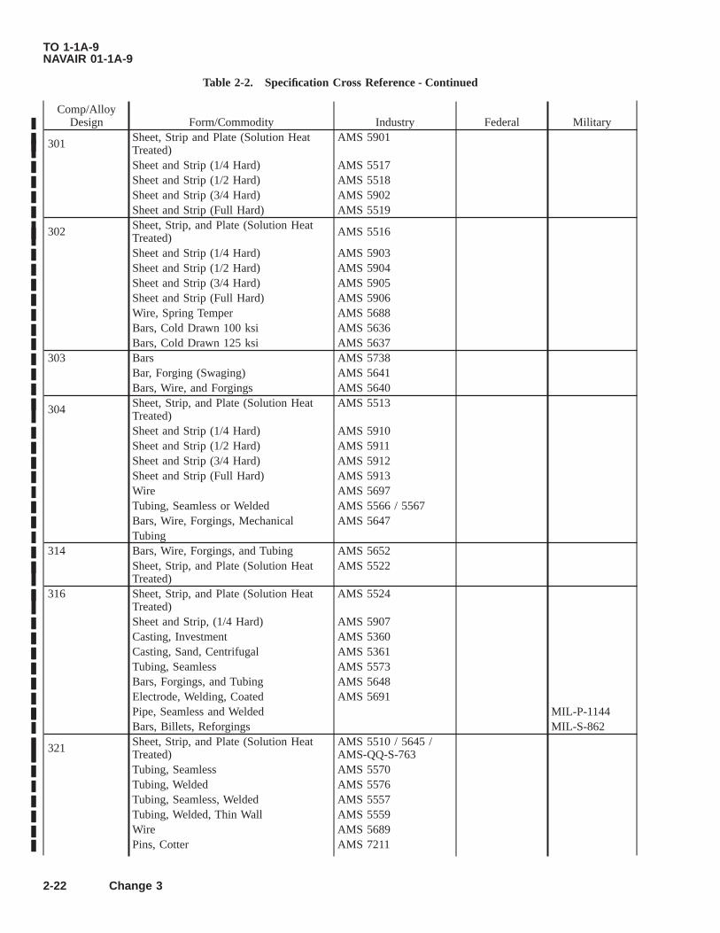
Table 2-2. Specification Cross Reference - Continued
Comp/AlloyDesign Form/Commodity Industry Federal Military
301 Sheet, Strip and Plate (Solution HeatTreated)
AMS 5901
Sheet and Strip (1/4 Hard) AMS 5517Sheet and Strip (1/2 Hard) AMS 5518Sheet and Strip (3/4 Hard) AMS 5902Sheet and Strip (Full Hard) AMS 5519
302 Sheet, Strip, and Plate (Solution HeatTreated) AMS 5516
Sheet and Strip (1/4 Hard) AMS 5903Sheet and Strip (1/2 Hard) AMS 5904Sheet and Strip (3/4 Hard) AMS 5905Sheet and Strip (Full Hard) AMS 5906Wire, Spring Temper AMS 5688Bars, Cold Drawn 100 ksi AMS 5636Bars, Cold Drawn 125 ksi AMS 5637
303 Bars AMS 5738Bar, Forging (Swaging) AMS 5641Bars, Wire, and Forgings AMS 5640
304 Sheet, Strip, and Plate (Solution HeatTreated)
AMS 5513
Sheet and Strip (1/4 Hard) AMS 5910Sheet and Strip (1/2 Hard) AMS 5911Sheet and Strip (3/4 Hard) AMS 5912Sheet and Strip (Full Hard) AMS 5913Wire AMS 5697Tubing, Seamless or Welded AMS 5566 / 5567Bars, Wire, Forgings, Mechanical AMS 5647Tubing
314 Bars, Wire, Forgings, and Tubing AMS 5652Sheet, Strip, and Plate (Solution HeatTreated)
AMS 5522
316 Sheet, Strip, and Plate (Solution HeatTreated)
AMS 5524
Sheet and Strip, (1/4 Hard) AMS 5907Casting, Investment AMS 5360Casting, Sand, Centrifugal AMS 5361Tubing, Seamless AMS 5573Bars, Forgings, and Tubing AMS 5648Electrode, Welding, Coated AMS 5691Pipe, Seamless and Welded MIL-P-1144Bars, Billets, Reforgings MIL-S-862
321 Sheet, Strip, and Plate (Solution HeatTreated)
AMS 5510 / 5645 /AMS-QQ-S-763
Tubing, Seamless AMS 5570Tubing, Welded AMS 5576Tubing, Seamless, Welded AMS 5557Tubing, Welded, Thin Wall AMS 5559Wire AMS 5689Pins, Cotter AMS 7211
TO 1-1A-9NAVAIR 01-1A-9
2-22 Change 3
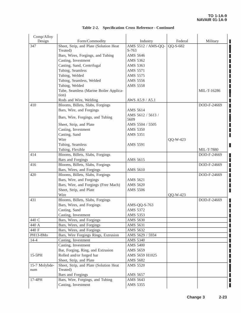
Table 2-2. Specification Cross Reference - Continued
Comp/AlloyDesign Form/Commodity Industry Federal Military
347 Sheet, Strip, and Plate (Solution HeatTreated)
AMS 5512 / AMS-QQ-S-763
QQ-S-682
Bars, Wires, Forgings, and Tubing AMS 5646Casting, Investment AMS 5362Casting, Sand, Centrifugal AMS 5363Tubing, Seamless AMS 5571Tubing, Welded AMS 5575Tubing, Seamless, Welded AMS 5556Tubing, Welded AMS 5558Tube, Seamless (Marine Boiler Applica-tion)
MIL-T-16286
Rods and Wire, Welding AWS A5.9 / A5.1410 Blooms, Billets, Slabs, Forgings DOD-F-24669
Bars, Wire, and Forgings AMS 5614
Bars, Wire, Forgings, and Tubing AMS 5612 / 5613 /5609
Sheet, Strip, and Plate AMS 5504 / 5505Casting, Investment AMS 5350Casting, Sand AMS 5351Wire QQ-W-423Tubing, Seamless AMS 5591Tubing, Flexible MIL-T-7880
414 Blooms, Billets, Slabs, Forgings DOD-F-24669Bars and Forgings AMS 5615
416 Blooms, Billets, Slabs, Forgings DOD-F-24669Bars, Wires, and Forgings AMS 5610
420 Blooms, Billets, Slabs, Forgings DOD-F-24669Bars, Wire, and Forgings AMS 5621Bars, Wire, and Forgings (Free Mach) AMS 5620Sheet, Strip, and Plate AMS 5506Wire QQ-W-423
431 Blooms, Billets, Slabs, Forgings DOD-F-24669Bars, Wires, and Forgings AMS-QQ-S-763Casting, Sand AMS 5372Casting, Investment AMS 5353
440 C Bars, Wires, and Forgings AMS 5630440 A Bars, Wires, and Forgings AMS 5631440 F Bars, Wires, and Forgings AMS 5632PH13-8Mo Bars, Wire Forgings Rings, Extrusion AMS 5629 / 593414-4 Casting, Investment AMS 5340
Casting, Investment AMS 5400Bar, Forging, Ring, and Extrusion AMS 5659
15-5PH Rolled and/or forged bar AMS 5659 H1025Sheet, Strip, and Plate AMS 5682
15-7 Molybde-num
Sheet, Strip, and Plate (Solution HeatTreated)
AMS 5520
Bars and Forgings AMS 565717-4PH Bars, Wire, Forgings, and Tubing AMS 5643
Casting, Investment AMS 5355
TO 1-1A-9NAVAIR 01-1A-9
Change 3 2-23

Table 2-2. Specification Cross Reference - Continued
Comp/AlloyDesign Form/Commodity Industry Federal Military
Casting, Investment 130 ksi AMS 5342Casting, Investment 150 ksi AMS 5343Casting, Investment 180 ksi AMS 5344Electrode, Welding AWS A5.4
17-7PH Sheet, Strip, and Plate (Solution HeatTreated)
AMS 5528
Bars and Forgings AMS 5644Tubing, Welded AMS 5568
19-9DL Bar AMS 5720 / 5721Bar and Forging AMS 5722Casting, Sand (Solution Heat Treated) AMS 5369Sheet, Strip, and Plate AMS 5526 / 5527
19-9DX Bar AMS 5724 / 5729Bar and Forging AMS 5723Sheet, Strip, and Plate AMS 5538 / 5539
19-9 MOD Electrode, Welding, Covered (ArmorApplications)
MIL-E-13080
AM 350 Bars and Forgings AMS 5745 MIL-S-6271Sheet and Strip (High Temperature An-nealed)
AMS 5748
Tubing, Seamless AMS 5554Wire, Welding AMS 5774Electrode, Welding, Coated Wire AMS 5775
AM 355 Bars and Forgings AMS 5743Sheet and Strip (Solution Heat Treated) AMS 5547Plate (Solution Heat Treated) AMS 5549Plate (Equalized and Overtempered) AMS 5594Electrode, Coated Welding AMS 5781
A286 Bars, Wire, Forgings, and Tubing AMS 5734 / 5735 /5736 / 5737
Rivets, Steel (Annealed 1650 °F andpartially precip treated) AMS 7235
Rene 41 Bars and Forging AMS 5712 / 5713Sheet, Strip, and Plate AMS 5545
Greek Ascoloy Castings, Investment AMS 5354(418) Sheet, Strip, and Plate AMS 5508
Bars, Wire, Forgings, Tubing and Rings AMS 5616Inconel 600 Sheet, Strip, and Plate AMS 5540
Bar and Rod ASTM B 166Forging ASTM B 565Tubing, Seamless AMS 5580
Inconel X750 Sheet, Strip and Plate AMS 5542Bars and Forgings AMS 5667Wire, No.1 Temper AMS 5698Wire, Spring Temper AMS 5699
Hastelloy C Castings, Investment AMS 5388Casting, Sand AMS 5389Sheet, Strip, and Plate AMS 5530Bars, Forgings, and Rings AMS 5750
TO 1-1A-9NAVAIR 01-1A-9
2-24 Change 3
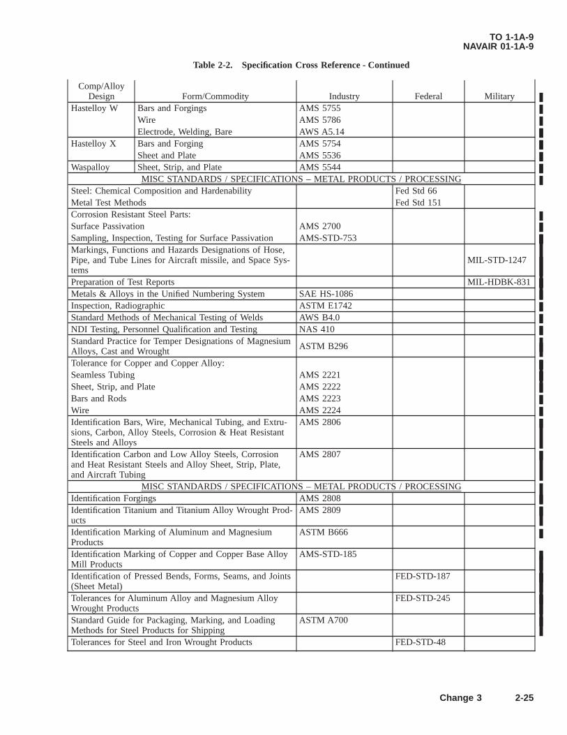
Table 2-2. Specification Cross Reference - Continued
Comp/AlloyDesign Form/Commodity Industry Federal Military
Hastelloy W Bars and Forgings AMS 5755Wire AMS 5786Electrode, Welding, Bare AWS A5.14
Hastelloy X Bars and Forging AMS 5754Sheet and Plate AMS 5536
Waspalloy Sheet, Strip, and Plate AMS 5544MISC STANDARDS / SPECIFICATIONS – METAL PRODUCTS / PROCESSING
Steel: Chemical Composition and Hardenability Fed Std 66Metal Test Methods Fed Std 151Corrosion Resistant Steel Parts:Surface Passivation AMS 2700Sampling, Inspection, Testing for Surface Passivation AMS-STD-753Markings, Functions and Hazards Designations of Hose,Pipe, and Tube Lines for Aircraft missile, and Space Sys-tems
MIL-STD-1247
Preparation of Test Reports MIL-HDBK-831Metals & Alloys in the Unified Numbering System SAE HS-1086Inspection, Radiographic ASTM E1742Standard Methods of Mechanical Testing of Welds AWS B4.0NDI Testing, Personnel Qualification and Testing NAS 410Standard Practice for Temper Designations of MagnesiumAlloys, Cast and Wrought ASTM B296
Tolerance for Copper and Copper Alloy:Seamless Tubing AMS 2221Sheet, Strip, and Plate AMS 2222Bars and Rods AMS 2223Wire AMS 2224Identification Bars, Wire, Mechanical Tubing, and Extru-sions, Carbon, Alloy Steels, Corrosion & Heat ResistantSteels and Alloys
AMS 2806
Identification Carbon and Low Alloy Steels, Corrosionand Heat Resistant Steels and Alloy Sheet, Strip, Plate,and Aircraft Tubing
AMS 2807
MISC STANDARDS / SPECIFICATIONS – METAL PRODUCTS / PROCESSINGIdentification Forgings AMS 2808Identification Titanium and Titanium Alloy Wrought Prod-ucts
AMS 2809
Identification Marking of Aluminum and MagnesiumProducts
ASTM B666
Identification Marking of Copper and Copper Base AlloyMill Products
AMS-STD-185
Identification of Pressed Bends, Forms, Seams, and Joints(Sheet Metal)
FED-STD-187
Tolerances for Aluminum Alloy and Magnesium AlloyWrought Products
FED-STD-245
Standard Guide for Packaging, Marking, and LoadingMethods for Steel Products for Shipping
ASTM A700
Tolerances for Steel and Iron Wrought Products FED-STD-48
TO 1-1A-9NAVAIR 01-1A-9
Change 3 2-25

2.9 GENERAL HEAT TREATING TEMPERATURES, COMPOSITION (CHEMICAL) AND CHARACTERISTICSOF VARIOUS STEEL AND STEEL ALLOYS.
See supplement data for chemical symbols.
2.9.1 1010 Low Carbon. Low Carbon steel of this grade is used for manufacture of such articles as safety wire, certainnuts, cable bushings and threaded rod ends, and other items where cold formability is the primary requisite. Heat treatmentis frequently employed to improve machinability. Welding is easily accomplished by all common welding methods.
Composition RangeCarbon% Magnesium% Phosphorus% Sulfur% Iron%0.08-0.13 0.3-0.6 0-0.04 0-0.5 Balance
Forms. See Specification Table 2-2.Heat TreatmentNormalize: 1650 °F-1750 °F, cool in still air.Anneal: 1650 °FHarden: 1650 °F-1750 °F. Quench in oil (minimum hardness) Water, and Brine (maximum hardness).
2.9.2 1015 Low Carbon. This material is similar in content and characteristics to 1010. Of low tensile value, it should notbe selected where strength is required.
Composition RangeCarbon% Magnesium% Phosphorus% Sulfur% Iron%0.13-18 0.3-0.6 0-0.04 0-0.05 Balance
Forms. See Specification Table 2-2.Heat TreatmentNormalize: 1650-1750 °F, cool in still air.Anneal: 1600-1650 °FHarden: 1650-1700 °F. Quench with water, oil, brine.
2.9.3 1020 Low Carbon. Because of the carbon range this metal has increased strength and hardness but reduced coldformability compared with the lowest carbon group. It finds wide application where carburizing is required. It is suitable forwelding and brazing.
Composition RangeCarbon% Magnesium% Phosphorus% Sulfur% Iron%
8-0.23 0.3-0.6 0-0.04 0-0.05 BalanceForms-Specifications. See Specification Table 2-2.Heat TreatmentNormalize: 1700 °F, air cool.Anneal: 1600 °F, furnace cool.Harden: 1600 °F, quench with water, oil, brine.
CARBO-NITRIDINGTemperature Time Case Depth Hardness Cool Draw
1560 2.5 0.019 62 OQ 3501650 2.5 0.018 59 OQ 350
For 1560 °F, use 35NH3d 25CH4 generator gas*.For 1650 °F, use 38NH3 and 24CH4.*Gas - American Gas Assoc Class 302.
TO 1-1A-9NAVAIR 01-1A-9
2-26 Change 3

2.9.4 1022 Low Carbon. This steel is similar in content and heat treatment requirements to 1020. Typical applications arecase hardened roller chains, bearing races, cam shafts, etc.
Composition RangeCarbon% Magnesium% Silicon% Phosphorus% Sulfur% Iron%0.18-0.23 0.7-0.10 0-0.2 0-0.04 0-0.05 Balance
Forms-Specifications. See Specification Table 2-2.Heat TreatmentNormalize: 1700 °F, air cool.Anneal: 1600 °F, furnace cool.Carburize: 1550-1650 °F, water quench.Tensile: 130,000 PSIYield: 78,000 PSI
2.9.5 1025 Low Carbon. Typical applications are bolts, machinery, electrical equipment, automotive parts, pipe flanges,etc. With this steel no martensite is formed and tempering is not required. This material is not generally considered acarburizing type; however, it is sometimes used in this manner for larger sections, or where greater case hardness is needed.
Composition RangeCarbon% Magnesium% Phosphorus% Sulfur% Iron%0.22-0.28 0.-0.6 0-0.04 0-0.05 Balance
Forms-Specifications. See Specification Table 2-2.Heat TreatmentNormalize: 1600-1700 °F, furnace cool.Hardening: 1575-1650 °F, water quench.Carburize: 1650-1700 °F, water or brine quench.Tempering: 250-400 °F is optionalTensilestrength:
Hot rolled 67,000, cold rolled 80,000.
Yield strength: Hot rolled 45,000, cold rolled 68,000.Temper: 1150 °F for 70,000 PSI.
2.9.6 Corten, Low Carbon, Low Alloy. This steel is not heat treatable, but in the annealed or normalized condition it isstronger than plain carbon steel, is easily formed, welded and machined. In addition, this alloy is 4-6 times more resistant toatmospheric corrosion than plain carbon steel.
Composition RangeCarbon% Chromium% Copper% Magnesium% Nickel%
0-0.12 0.30-1.25 0.25-0.055 0.2-0.5 0-0.65Silicon% Phosphorus% Sulfur% Iron%0.25-0.75 0.07-0.15 0-0.05 Balance
Heat TreatmentNormalize: 1650 °F, air cool.Anneal: 1550 °F, furnace cool.
2.9.6.1 Stress relief 1150 °F, 1 hour per inch of maximum section thickness. This alloy cannot be hardened. Tensilestrength, annealed or normalized 67,000 PSI. Yield strength, annealed or normalized 47,000 PSI. This alloy is readily weldedby the usual gas and arc methods with complete freedom from air hardening. ASTM A233 or E60 electrodes are recom-mended for shielded arc welding. For gas welding, high strength welding rods such as ASTM A251, CA-25, are recom-mended. This steel may be resistance welded to itself or other resistance weldable ferrous alloys, using the same methodsapplied to plain carbon steel.
TO 1-1A-9NAVAIR 01-1A-9
Change 3 2-27
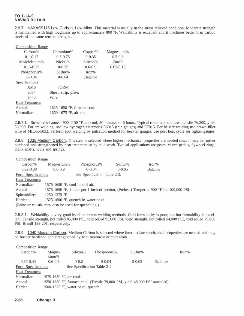
2.9.7 NAXAC9115 Low Carbon, Low Alloy. This material is usually in the stress relieved condition. Moderate strengthis maintained with high toughness up to approximately 800 °F. Weldability is excellent and it machines better than carbonsteels of the same tensile strengths.
Composition RangeCarbon% Chromium% Copper% Magnesium%0.1-0.17 0.5-0.75 0-0.35 0.5-0.8
Molybdenum% Nickel% Silicon% Zinc%0.15-0.25 0-0.25 0.6-0.9 0.05-0.15
Phosphorus% Sulfur% Iron%0-0.04 0-0.04 Balance
SpecificationsAMS FORM6354 Sheet, strip, plate.6440 Wire.
Heat TreatmentAnneal: 1625-1650 °F, furnace cool.Normalize: 1650-1675 °F, air cool.
2.9.7.1 Stress relief anneal 900-1150 °F, air cool, 30 minutes to 6 hours. Typical room temperatures: tensile 76,500, yield53,000. For arc welding, use low hydrogen electrodes E6015 (thin gauges) and E7015. For heliarc welding use drawn fillerwire of MIL-R-5032. Perform spot welding by pulsation method for heavier gauges; use post heat cycle for lighter gauges.
2.9.8 1035 Medium Carbon. This steel is selected where higher mechanical properties are needed since it may be furtherhardened and strengthened by heat treatment or by cold work. Typical applications are gears, clutch pedals, flywheel rings,crank shafts, tools and springs.
Composition RangeCarbon% Magnesium% Phosphorus% Sulfur% Iron%0.32-0.38 0.6-0.9 0-0.04 0-0.05 Balance
Form Specifications See Specification Table 2-2.Heat TreatmentNormalize: 1575-1650 °F, cool in still air.Anneal: 1575-1650 °F, 1 hour per 1 inch of section, (Preheat) Temper at 900 °F for 100,000 PSI.Spheroidize: 1250-1375 °F.Harden: 1525-1600 °F, quench in water or oil.(Brine or caustic may also be used for quenching.)
2.9.8.1 Weldability is very good by all common welding methods. Cold formability is poor, but hot formability is excel-lent. Tensile strength, hot rolled 85,000 PSI, cold rolled 92,000 PSI, yield strength, hot rolled 54,000 PSI, cold rolled 79,000PSI, Brinill 183-201, respectively.
2.9.9 1040 Medium Carbon. Medium Carbon is selected where intermediate mechanical properties are needed and maybe further hardened and strengthened by heat treatment or cold work.
Composition RangeCarbon% Magne-
sium%Silicon% Phosphorus% Sulfur% Iron%
0.37-0.44 0.6-0.9 0-0.2 0-0.04 0-0.05 BalanceForm Specifications See Specification Table 2-2.Heat TreatmentNormalize: 1575-1650 °F, air cool.Anneal: 1550-1650 °F, furnace cool. (Tensile 79,000 PSI, yield 48,000 PSI annealed).Harden: 1500-1575 °F, water or oil quench.
TO 1-1A-9NAVAIR 01-1A-9
2-28 Change 3

Temper: 1100-1150 °F, to obtain tensile 100,000 PSI, yield 80,000 PSI. For tensile 125,000 and yield 85,000 PSItemper at 700 °F. Suitable heat treatment is required to permit machining.
2.9.10 1045 Medium Carbon. Forgings such as connecting rods, steering arms, axles, axle shafts and tractor wheels arefabricated from this steel. Not recommended for welding.
Composition RangeCarbon% Magne-
sium%Phosphorus% Sulfur% Iron%
0.43-0.5 0.6-0.9 0-0.04 0-0.04 BalanceForm Specifications See Specification Table 2-2.Heat TreatmentNormalize: 1575-1675 °F, air cool.Anneal: 1550-1600 °F, furnace cool for maximum softness.Harden: 1475-1550 °F, quench, water or oil.Temper: 1100 °F for tensile 100,000 PSI, yield 65,000 PSI.Temper: 1000 °F for tensile 125,000 PSI, yield 95,000 PSI.
2.9.11 1050 Medium Carbon. This is a medium carbon type steel with high mechanical properties which may be furtherhardened and strengthened by heat treatment or by cold work. Application is similar to 1045. Not recommended for welding.
Composition RangeCarbon% Magne-
sium%Phosphorus% Sulfur% Iron%
0.46-0.55 0.6-0.9 0-0.04 0-0.05 BalanceForm Specifications See Specification Table 2-2.Heat TreatmentNormalize: 1550-1650 °F, air cool.Anneal: 1450-1525 °F, furnace cool (Tensile 90,000 yield 50,000 annealed.)Harden: 1475-1550 °F, oil or water quench.Temper: 1250 °F for 125,000 PSI tensile, 90,000 for yield.Temper: 1025 °F for 125,000 PSI tensile, 90,000 for yield.Temper: 700 °F for 150,000 PSI tensile, 114,000 for yield.
2.9.12 1055 High Carbon. Steels of this Type (1060, 1070, 1080 are in same category) have similar characteristics andare primarily used where higher carbon is needed to improve wear characteristics for cutting edges, as well as for manufac-ture of springs, etc. Not recommended for welding.
Composition RangeCarbon% Magne-
sium%Phosphorus% Sulfur% Iron%
0.50-0.60 0.6-0.9 0-0.04 0-0.05 BalanceForm Specifications See Specification Table 2-2.Heat TreatmentNormalize: 1550-1650 °F, air cool.Anneal: 1550-1575 °F.Harden: 1450-1550 °F, water or oil quench.Temper: 1250 °F for 100,000 PSI tensile, 1050 °F for 125,000 tensile, 600 °F for 150,000 tensile.
TO 1-1A-9NAVAIR 01-1A-9
Change 3 2-29/(2-30 blank)


2.9.13 1060 High Carbon. See 1055 for application and characteristics.
Composition RangeCarbon% Magne-
sium%Phosphorus% Sulfur% Iron%
0.55-0.65 0.6-0.09 0-0.04 0-0.05 BalanceForm Specifications See Specification Table 2-2.Heat TreatmentNormalize: 1525-1625 °F, air cool.Anneal: 1500-1575 °F (Tensile 104,000 PSI, yield 54,000 PSI annealed).Harden: 1450-1550 °F, water or oil quench.Temper: 1125 °F for 130,000 tensile, 80,000 yield.Temper: 1025 °F for 139,000 tensile, 96,000 yield.Temper: 925 °F for 149,000 tensile, 99,000 yield.
2.9.14 1070 High Carbon. See 1055 for application and characteristics. In addition this alloy is used for flat springs andwire form as coil springs.
Composition RangeCarbon% Magne-
sium%Phosphorus% Sulfur% Iron%
0.65-0.75 0.6-0.9 0-0.04 0-0.05 BalanceForm Specifications See Specification Table 2-2.Heat TreatmentNormalize: 1525-1625 °F, air cool, retard cooling rate to prevent hardness.Anneal: 1500-1575 °F, furnace cool.Harden: 1450-1550 °F, water or oil quench (Preheat).Hot Working
Temperature:1550-1650 °F.
Temper: 1250 °F for 100,000 PSI tensile.Temper: 1100 °F for 125,000 PSI tensile.Temper: 1000 °F for 150,000 PSI tensile.
2.9.14.1 The high carbon content of this steel causes difficulties in arc or gas welding processes. Welding by the thermitprocess is satisfactory. Hot formality is very good at 1550-1650 °F.
2.9.15 1080 High Carbon. See 1055 for application and characteristics.
Composition RangeCarbon% Magne-
sium%Phosphorus% Sulfur% Iron%
0.75-0.88 0.6-0.9 0-0.04 0-0.05 BalanceForm Specifications See Specification Table 2-2.Heat TreatmentNormalize: 1550-1650 °F, air cool.Anneal: 1475-1525 °F (Tensile 120,000, yield 66,000 PSI annealed).Harden: 1450-1550 °F, quench oil.Temper: 1200 °F for 129,000 tensile, 87,000 yield.Temper: 1100 °F for 145,000 tensile, 103,000 yield.Temper: 900 °F for 178,000 tensile, 129,000 yield.
2.9.15.1 The high carbon content of this steel causes difficulties in arc or gas welding processes. Welding by the thermitprocess is satisfactory. Hot formality is very good at 1550-1650 °F.
TO 1-1A-9NAVAIR 01-1A-9
2-35

2.9.16 1095 High Carbon. See 1055 for applications. In addition these steels are used for flat spring applications and inwire form as coil springs.
Composition RangeCarbon% Magne-
sium%Phosphorus% Sulfur% Iron%
0.9-1.03 0.3-0.5 0-0.04 0-0.05 BalanceForm Specifications See Specification Table 2-2.Heat Treatment
Oil QuenchNormalize: 1550-1650 °F, air cool.Anneal: 1425-1475 °F (Tensile 98,000 PSI, yield 52,000 PSI annealed) furnace cool. To reduce annealing time,
furnace cool to 900 °F and air cool. Speroidize for maximum softness when required.Harden: 1425-1550 °F, (oil quench.)Temper: 1100 °F for 146,000 PSI tensile, 88,000 yield.Temper: 800 °F for 176,000 PSI tensile, 113,000 yield.Temper: 600 °F for 184,000 PSI tensile, 113,000 yield.
Water QuenchNormalize: 1550-1650 °F, air cool.Anneal: 1425-1475 °F.Harden: 1425-1500 °F, quench with water.Temper: 1100 °F for 143,000 PSI tensile, 96,000 yield.Temper: 800 °F for 200,000 PSI tensile, 138,000 yield.Temper: 600 °F for 213,000 PSI tensile, 150,000 yield.
2.9.17 1112 Free Cutting. This steel is used as the standard for rating the machinability of other steels. It is easy tomachine and resulting surface finish is excellent. It has good brazing characteristics but is difficult to weld except with thelow hydrogen electrode E6015 American Welding Society (AWS). This and similar grades are widely used for parts forbolts, nuts, screws, but not for parts subjected to severe stresses and shock.
Composition RangeCarbon% Magne-
sium%Phosphorus% Sulfur% Iron%
0-0.13 maxi-mum
0.7-0.9 0.07-0.12 0.16-0.23 Balance
Form Specifications See Specification Table 2-2.Heat TreatmentMay be surface hardened by heating in cyanide at 1500-1650 °F, followed by single or double quench and draw. Preheat
and soak at 1500-1650 °F and quench in oil or water; tempering is optional.Tensile strength hot rolled bars 65,000.Tensile strength cold drawn 83,000.
2.9.18 1117 Carbon (Free Cutting Steel). This material is used where a combination of good machinability and uniformresponse to heat treatment is needed. It is suited for fabrication of small parts which are to be cyanided or carbonitrided andmay be oil quenched after case hardening heat treating.
Composition RangeCarbon% Magne-
sium%Phosphorus% Sulfur% Iron%
0.41-0.2 1.0-1.3 0-0.04 0.08-0.13 BalanceForm Specifications See Specification Table 2-2.Heat TreatmentNormalize: 1650 °F, air cool.Anneal: 1575 °F, furnace cool (Tensile 68,000 PSI annealed)
TO 1-1A-9NAVAIR 01-1A-9
2-36
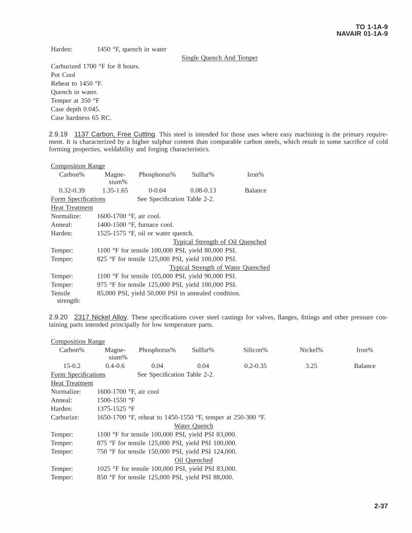
Harden: 1450 °F, quench in waterSingle Quench And Temper
Carburized 1700 °F for 8 hours.Pot CoolReheat to 1450 °F.Quench in water.Temper at 350 °FCase depth 0.045.Case hardness 65 RC.
2.9.19 1137 Carbon, Free Cutting. This steel is intended for those uses where easy machining is the primary require-ment. It is characterized by a higher sulphur content than comparable carbon steels, which result in some sacrifice of coldforming properties, weldability and forging characteristics.
Composition RangeCarbon% Magne-
sium%Phosphorus% Sulfur% Iron%
0.32-0.39 1.35-1.65 0-0.04 0.08-0.13 BalanceForm Specifications See Specification Table 2-2.Heat TreatmentNormalize: 1600-1700 °F, air cool.Anneal: 1400-1500 °F, furnace cool.Harden: 1525-1575 °F, oil or water quench.
Typical Strength of Oil QuenchedTemper: 1100 °F for tensile 100,000 PSI, yield 80,000 PSI.Temper: 825 °F for tensile 125,000 PSI, yield 100,000 PSI.
Typical Strength of Water QuenchedTemper: 1100 °F for tensile 105,000 PSI, yield 90,000 PSI.Temper: 975 °F for tensile 125,000 PSI, yield 100,000 PSI.Tensile
strength:85,000 PSI, yield 50,000 PSI in annealed condition.
2.9.20 2317 Nickel Alloy. These specifications cover steel castings for valves, flanges, fittings and other pressure con-taining parts intended principally for low temperature parts.
Composition RangeCarbon% Magne-
sium%Phosphorus% Sulfur% Silicon% Nickel% Iron%
15-0.2 0.4-0.6 0.04 0.04 0.2-0.35 3.25 BalanceForm Specifications See Specification Table 2-2.Heat TreatmentNormalize: 1600-1700 °F, air coolAnneal: 1500-1550 °FHarden: 1375-1525 °FCarburize: 1650-1700 °F, reheat to 1450-1550 °F, temper at 250-300 °F.
Water QuenchTemper: 1100 °F for tensile 100,000 PSI, yield PSI 83,000.Temper: 875 °F for tensile 125,000 PSI, yield PSI 100,000.Temper: 750 °F for tensile 150,000 PSI, yield PSI 124,000.
Oil QuenchedTemper: 1025 °F for tensile 100,000 PSI, yield PSI 83,000.Temper: 850 °F for tensile 125,000 PSI, yield PSI 88,000.
TO 1-1A-9NAVAIR 01-1A-9
2-37

Tensilestrength:
650 °F for tensile 150,000 PSI, yield PSI 108,000.
This steel may be welded by common welding procedures.
2.9.21 2330 Nickel Alloy. This is a heat treatable steel which develops high strength and toughness in moderate sections.It is used in highly stressed bolts, nuts, studs, turnbuckles, etc.
Composition RangeCarbon% Magne-
sium%Phosphorus% Sulfur% Silicon% Nickel% Iron%
0.28-0.33 0.6-0.8 0-0.04 0-0.04 0.2-0.35 3.25-0.75 BalanceForm Specifications See Specification Table 2-2.Heat TreatmentNormalize: 1600 °F, preheat, cool in air.Anneal: 1425-1600 °F, furnace cool.Harden: 1400-1500 °F. Quench with oil.Temper: 1200-1250 °F for tensile 100,000 PSI, yield 90,000 PSI.Temper: 900 °F for tensile 140,000 PSI.Temper: 700 °F for 178,000 PSI.Water Quench700 °F - 190,000 PSI900 °F - 150,000 PSI1100 °F - 124,000 PSI
2.9.22 2340 Nickel Alloy. This metal is similar to 2330, but has greater strength. It is an oil hardening steel.
Composition RangeCarbon% Magne-
sium%Phosphorus% Sulfur% Silicon% Nickel%
0.38-0.43 0.7-0.9 0-0.04 0-0.04 0.2-0.35 3.25-3.75Form Specifications See Specification Table 2-2.Heat TreatmentNormalize: 1600-1700 °F.Anneal: 1450-1600 °F.Harden: 1400-1550 °F, quench in oil.Temper: 1100 °F for 125,000 PSI tensile, 105,000 PSI yield.Temper: 900 °F for 150,000 PSI tensile, 132,000 PSI yield.Temper: 800 °F for 182,000 PSI tensile, 164,000 PSI yield.
2.9.23 2515 Nickel Alloy. This steel is quite similar to SAE 2512 and 2517, both in composition and response to heattreatment.
Composition RangeCarbon% Magne-
sium%Phosphorus% Sulfur% Silicon% Nickel% Iron%
0.12-0.17 0.4-0.6 0-0.04 0-0.04 0.2-0.35 4.75-5.25 BalanceForm Specifications See Specification Table 2-2.Heat TreatmentNormalize: 1650-1750 °FAnneal: 1500 °FHarden: 1425-1525 °F, oil quench.Temper: 1200 °F for tensile 104,000, yield 80,000 PSI.Temper: 900 °F for tensile 125,000, yield 106,000 PSI.
TO 1-1A-9NAVAIR 01-1A-9
2-38

Temper: 700 °F for tensile 152,000, yield 125,000 PSI.Water QuenchTemper: 1100 °F for 116,000 PSI.Temper: 900 °F for 138,000 PSI.Temper: 700 °F for 165,000 PSI.
2.9.24 3115 Steel Nickel Chromium Alloy.
Composition RangeCarbon% Magne-
sium%Phospho-
rus%Sulfur% Silicon% Nickel% Chromium% Iron%
0.11-0.2 0.37-0.63 0-0.048 0-0.058 0.18-0.37 1.05-1.45 0.52-0.78 BalanceForm Specifications See Specification Table 2-2.Heat TreatmentNormalize: 1625-1725 °FAnneal: 1550-1600 °FHarden: 1425-1525 °F, with oil.Temper: 300 °F for tensile, 125,000 PSI, yield 86,000 PSI.
Core Properties Draw Temperature Tensile Kips per SquareInch (Kips per Square Inch
(KSI))
Yield KSI
3115 300 °F 125 88Box cooled 1425 °F
3120 300 °F 155 1153115 300 °F 125 86
Reheated 1475 °F3120 300 °F 155 1153115 300 °F 125 86
Oil Quenched 1525 °F3120 300 °F 155 110
2.9.25 3140 Nickel Chrome Alloy. This is a medium deep hardening steel capable of developing good strength andtoughness when oil quenched.
Composition RangeCarbon% Magne-
sium%Phosphorus% Sulfur% Silicon% Nickel% Chro-
mium%Iron%
0.37-0.45 0.6-0.95 0-0.04 0-0.04 0.2-0.35 1.0-1.5 0.5-0.8 BalanceForm Specifications See Specification Table 2-2.Heat TreatmentNormalize: 1550-1700 °FAnneal: 1475-1550 °F (Tensile 94,000 PSI, yield 66,000 PSI annealed).Harden: 1475-1550 °F, oil quench.Temper: 1200 °F for tensile 125,000 PSI, yield 105,000 PSI.Temper: 1000 °F for Tensile 14,000 PSI, yield 125,000 PSI.Temper: 800 °F for Tensile 184,000 PSI, yield 178,000 PSI.Temper: 700 °F for Tensile 200,000 PSI.
TO 1-1A-9NAVAIR 01-1A-9
2-39
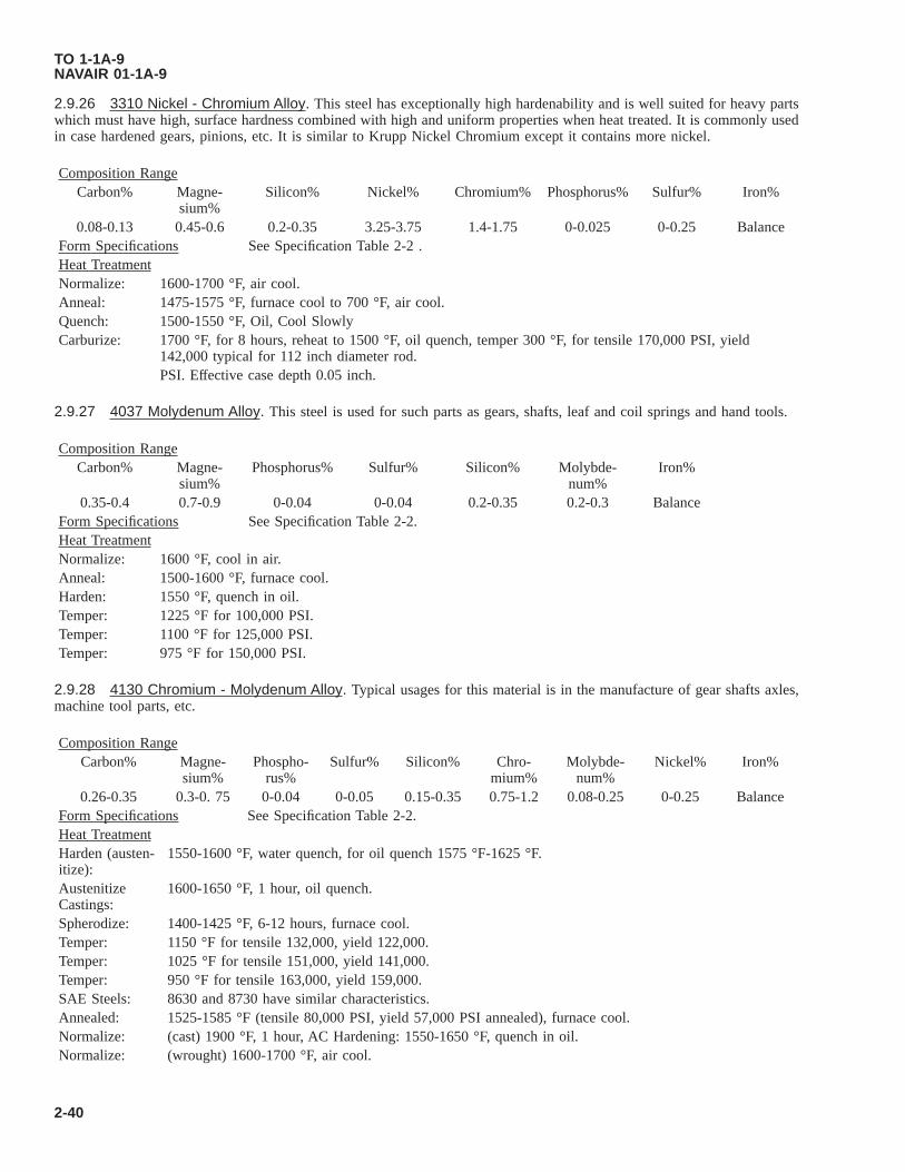
2.9.26 3310 Nickel - Chromium Alloy. This steel has exceptionally high hardenability and is well suited for heavy partswhich must have high, surface hardness combined with high and uniform properties when heat treated. It is commonly usedin case hardened gears, pinions, etc. It is similar to Krupp Nickel Chromium except it contains more nickel.
Composition RangeCarbon% Magne-
sium%Silicon% Nickel% Chromium% Phosphorus% Sulfur% Iron%
0.08-0.13 0.45-0.6 0.2-0.35 3.25-3.75 1.4-1.75 0-0.025 0-0.25 BalanceForm Specifications See Specification Table 2-2 .Heat TreatmentNormalize: 1600-1700 °F, air cool.Anneal: 1475-1575 °F, furnace cool to 700 °F, air cool.Quench: 1500-1550 °F, Oil, Cool SlowlyCarburize: 1700 °F, for 8 hours, reheat to 1500 °F, oil quench, temper 300 °F, for tensile 170,000 PSI, yield
142,000 typical for 112 inch diameter rod.PSI. Effective case depth 0.05 inch.
2.9.27 4037 Molydenum Alloy. This steel is used for such parts as gears, shafts, leaf and coil springs and hand tools.
Composition RangeCarbon% Magne-
sium%Phosphorus% Sulfur% Silicon% Molybde-
num%Iron%
0.35-0.4 0.7-0.9 0-0.04 0-0.04 0.2-0.35 0.2-0.3 BalanceForm Specifications See Specification Table 2-2.Heat TreatmentNormalize: 1600 °F, cool in air.Anneal: 1500-1600 °F, furnace cool.Harden: 1550 °F, quench in oil.Temper: 1225 °F for 100,000 PSI.Temper: 1100 °F for 125,000 PSI.Temper: 975 °F for 150,000 PSI.
2.9.28 4130 Chromium - Molydenum Alloy. Typical usages for this material is in the manufacture of gear shafts axles,machine tool parts, etc.
Composition RangeCarbon% Magne-
sium%Phospho-
rus%Sulfur% Silicon% Chro-
mium%Molybde-
num%Nickel% Iron%
0.26-0.35 0.3-0. 75 0-0.04 0-0.05 0.15-0.35 0.75-1.2 0.08-0.25 0-0.25 BalanceForm Specifications See Specification Table 2-2.Heat TreatmentHarden (austen-itize):
1550-1600 °F, water quench, for oil quench 1575 °F-1625 °F.
AustenitizeCastings:
1600-1650 °F, 1 hour, oil quench.
Spherodize: 1400-1425 °F, 6-12 hours, furnace cool.Temper: 1150 °F for tensile 132,000, yield 122,000.Temper: 1025 °F for tensile 151,000, yield 141,000.Temper: 950 °F for tensile 163,000, yield 159,000.SAE Steels: 8630 and 8730 have similar characteristics.Annealed: 1525-1585 °F (tensile 80,000 PSI, yield 57,000 PSI annealed), furnace cool.Normalize: (cast) 1900 °F, 1 hour, AC Hardening: 1550-1650 °F, quench in oil.Normalize: (wrought) 1600-1700 °F, air cool.
TO 1-1A-9NAVAIR 01-1A-9
2-40

2.9.29 4135 Chromium Molydenum Alloy.
Composition RangeCarbon% Magne-
sium%Silicon% Chro-
mium%Molybde-
num%Phospho-
rus%Sulfur% Iron%
0.32-0.39 0.6-0.95 0.2-0.35 0.8-1.15 0.15-0.25 0-0.04 0-0.04 BalanceHeat TreatmentNormalize: 1600-1700 °F, air cool.Anneal: 1525-1575 °F, furnace cool.Harden: 1550-1625 °F, quench in oil.Temper: 1100 °F for 125,000 tensile PSI.Temper: 1050 °F for 150,000 tensile PSI.Temper: 850 °F for 180,000 tensile PSI.
2.9.30 17-22A(V) Structural (Ultra High Strength) Low Alloy. This is a high strength, heat resistant steel with a 1000hour rupture strength of 1100 °F (30,000 PSI tensile strength). It is used in turbine rotors, and for components of guidedmissiles, in which high temperatures are encountered for short periods.
Composition RangeCarbon% Chro-
mium%Cerium% Magne-
sium%Molybde-
num%Nickel% Silicon% Vanadium% Phospho-
rus%0.25-0.3 1.0-1.5 0-0.5 0.6-0.9 0.4-0.6 0-0.5 0.55-0.75 0.75-0.95 0-0.04Sulfur% Iron%0-0.04 Balance
Form Specifications AMS6303 Bar, forging, forging stock.Heat TreatmentNormalize: 1700-1850 °F, hold for 1 hour per inch of thickness, air cool. Larger sections may be fan cooled in order
to accelerate cooling. All sections should be so placed as to provide access of air to all surfaces.Anneal: 1450 °F, hold at this temperature 1 hour for each inch of section thickness. Cool down 20 °F per hour to
1100 °F, then air cool.Oil Quenching requires prior heating to 1750 °F, for each inch of thickness. Annealed bars, 1 inch diameter have tensile
strength 87,000 yield strength, 67,800. Pancake forgings normalized at 1800 °F + tempering at 1225 °F, 6 hours havetensile strength 142,000, yield strength 126,500, hardness Brinell Hardness Number (BHN) 311-321. This alloy maybe welded by any of the commercial methods in use. A welding rod corresponding to 17-22A(S) is available. Whenpre-heating is required depending upon size of section and type of welding procedure, a temperature of 600 °F is gen-erally used. Post heating or stress relief is recommended.
2.9.31 4137CO. This ultra-high strength steel has yield strength in the 230,000-240,000 PSI range. It forms and weldsreadily. It was developed for use in high performances solid rocket motor cases. Alternate designations are Unimach VC X2, MX-2, and Rocoloy. Machining characteristics are similar to 4140.
Composition RangeCarbon% Chro-
mium%Cobalt% Magne-
sium%Molybde-
num%Silicon% Vanadium% Phospho-
rus%Sulfur%
0.39-0.4 0.95-1.2 0.98-1.23 0.6-0.79 0.22-0.35 0.97-1.19 0.14-0.16 0-0.015 0-0.012Iron%
BalanceSpecifications NoneForms Sheet, strip, plate, bar, forging, wire.Heat TreatmentNormalize: 1750 °F, 30 minutes, air cool.Spheroidize: Anneal: 1420-1460 °F, 2 hours, fast cool to 1235-1265 °F, hold 14 to 24 hours, air cool. Resulting hard-
ness RB95 maximum.
TO 1-1A-9NAVAIR 01-1A-9
2-41

Intermediate stress relieve to restore ductility of formed parts, 1250 °F for 10 minutes, air cool. Stress relieve after weld-ing 1250 °F, 30 minutes minimum.
Austenitize: 1700 °F for sections less than 112 inch 1725 °F for sections larger than 112 inch, 20 minutes minimumto 1 hour maximum per inch thickness, oil or salt quench at 400 °F. Maximum time in salt 12 min-utes.
Double temper 540-560 °F for two consecutive 2 hour periods with intermediate cooling to room temperature. Weldabil-ity characteristics are good using the Tungsten-arc-inert-gas process.
2.9.32 4140 Medium Carbon Chromium - Molybdenun (Nitriding Grade). This steel is widely used where the higherstrength and higher hardenability of 4340 is not required. It can be nitrided.
Composition RangeCarbon% Magne-
sium%Phosphorus% Sulfur% Chromium% Molybde-
num%Silicon% Iron%
0.38-0.43 0.75-1.0 0-0.040 maxi-mum
0-0.040 maxi-mum
0.80-1.1 0.15-0.25 0.2-0.35 Balance
SpecificationsType 4140
AMS Form Military5336 Precision Investment Castings5338 Precision Investment Castings6378 Bars6379 Bars6381 Heavy Wall Tubing6382 Bars, Forgings, Forgings, Stock MIL-S-5626
Heat TreatmentNormalize: 1600-1650 °F (air cool) minimum 1 hour.Anneal: 1550-1600 °F furnace cool.Harden: 1550-1600 °F 30 minutes, oil quench.Spheroidize: 1400-1425 °F furnace cool.Temper: 4 hours to obtain desired strength. See table below.Draw Temperatures1300 °F - 100,000 PSI1175 °F - 120,000 to 140,000 PSI1075 °F - 140,000 to 160,000 PSI950 °F - 160,000 to 180,000 PSI850 °F - 180,000 to 200,000 PSI725 °F - 200,000 to 220,000 PSI
2.9.33 SAE 4330 V Mod. This steel is 4330 improved by the addition of vanadium, and is primarily used heat treated toa tensile strength between 220 and 240 KSI. It is highly shock resistant and has better welding characteristics than highercarbon steels.
Composition RangeCarbon% Magne-
sium%Silicon% Phospho-
rus%Silicon% Chromium% Nickel% Molybde-
num%0.28-0.33 0.75-1.00 0.20-0.35 0.040 0.040 0.75-1.00 1.65-2.00 0.35-0.50
Vanadium% Iron%0.05-0.10 Balance
Heat TreatmentNormalize: 1600-1700 °F, air cool.Temper: Normalized condition for machinability 1250 °F maximum.Full anneal at 1525-1575 °F furnace cool or cool in ash or lime.
TO 1-1A-9NAVAIR 01-1A-9
2-42
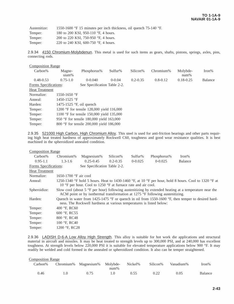
Austenitize: 1550-1600 °F 15 minutes per inch thickness, oil quench 75-140 °F.Temper: 180 to 200 KSI, 950-110 °F, 4 hours.Temper: 200 to 220 KSI, 750-950 °F, 4 hours.Temper: 220 to 240 KSI, 600-750 °F, 4 hours.
2.9.34 4150 Chromium-Molybdenun. This metal is used for such items as gears, shafts, pistons, springs, axles, pins,connecting rods.
Composition RangeCarbon% Magne-
sium%Phosphorus% Sulfur% Silicon% Chromium% Molybde-
num%Iron%
0.48-0.53 0.75-1.0 0-0.040 0-0.04 0.2-0.35 0.8-0.12 0.18-0.25 BalanceForms Specifications: See Specification Table 2-2.Heat TreatmentNormalize: 1550-1650 °FAnneal: 1450-1525 °FHarden: 1475-1525 °F, oil quenchTemper: 1200 °F for tensile 128,000 yield 116,000Temper: 1100 °F for tensile 150,000 yield 135,000Temper: 950 °F for tensile 180,000 yield 163,000Temper: 800 °F for tensile 200,000 yield 186,000
2.9.35 521000 High Carbon, High Chromium Alloy. This steel is used for anti-friction bearings and other parts requir-ing high heat treated hardness of approximately Rockwell C60, toughness and good wear resistance qualities. It is bestmachined in the spheroidized annealed condition.
Composition RangeCarbon% Chromium% Magnesium% Silicon% Sulfur% Phosphorus% Iron%0.95-1.1 1.3-1.6 0.25-0.45 0.2-0.35 0-0.025 0-0.025 Balance
Forms Specifications: See Specification Table 2-2.Heat TreatmentNormalize: 1650-1700 °F air coolAnneal: 1250-1340 °F hold 5 hours. Heat to 1430-1460 °F, at 10 °F per hour, hold 8 hours. Cool to 1320 °F at
10 °F per hour. Cool to 1250 °F at furnace rate and air cool.Spheroidize: Slow cool (about 5 °F per hour) following austenitizing by extended heating at a temperature near the
ACM point or by isothermal transformation at 1275 °F following austenitizing.Harden: Quench in water from 1425-1475 °F or quench in oil from 1550-1600 °F, then temper to desired hard-
ness. The Rockwell hardness at various temperatures is listed below:Temper: 400 °F, RC60Temper: 600 °F, RC55Temper: 800 °F, RC48Temper: 100 °F, RC40Temper: 1200 °F, RC28
2.9.36 LADISH D-6-A Low Alloy High Strength. This alloy is suitable for hot work die applications and structuralmaterial in aircraft and missiles. It may be heat treated to strength levels up to 300,000 PSI, and at 240,000 has excellenttoughness. At strength levels below 220,000 PSI it is suitable for elevated temperature applications below 900 °F. It mayreadily be welded and cold formed in the annealed or spheroidized condition. It also can be temper straightened.
Composition RangeCarbon% Chromium% Magnesium% Molybde-
num%Nickel% Silicon% Vanadium% Iron%
0.46 1.0 0.75 1.0 0.55 0.22 0.05 Balance
TO 1-1A-9NAVAIR 01-1A-9
2-43
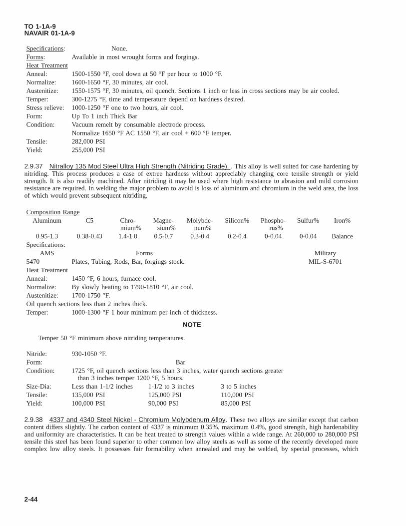
Specifications: None.Forms: Available in most wrought forms and forgings.Heat TreatmentAnneal: 1500-1550 °F, cool down at 50 °F per hour to 1000 °F.Normalize: 1600-1650 °F, 30 minutes, air cool.Austenitize: 1550-1575 °F, 30 minutes, oil quench. Sections 1 inch or less in cross sections may be air cooled.Temper: 300-1275 °F, time and temperature depend on hardness desired.Stress relieve: 1000-1250 °F one to two hours, air cool.Form: Up To 1 inch Thick BarCondition: Vacuum remelt by consumable electrode process.
Normalize 1650 °F AC 1550 °F, air cool + 600 °F temper.Tensile: 282,000 PSIYield: 255,000 PSI
2.9.37 Nitralloy 135 Mod Steel Ultra High Strength (Nitriding Grade). . This alloy is well suited for case hardening bynitriding. This process produces a case of extree hardness without appreciably changing core tensile strength or yieldstrength. It is also readily machined. After nitriding it may be used where high resistance to abrasion and mild corrosionresistance are required. In welding the major problem to avoid is loss of aluminum and chromium in the weld area, the lossof which would prevent subsequent nitriding.
Composition RangeAluminum C5 Chro-
mium%Magne-
sium%Molybde-
num%Silicon% Phospho-
rus%Sulfur% Iron%
0.95-1.3 0.38-0.43 1.4-1.8 0.5-0.7 0.3-0.4 0.2-0.4 0-0.04 0-0.04 BalanceSpecifications:
AMS Forms Military5470 Plates, Tubing, Rods, Bar, forgings stock. MIL-S-6701Heat TreatmentAnneal: 1450 °F, 6 hours, furnace cool.Normalize: By slowly heating to 1790-1810 °F, air cool.Austenitize: 1700-1750 °F.Oil quench sections less than 2 inches thick.Temper: 1000-1300 °F 1 hour minimum per inch of thickness.
NOTE
Temper 50 °F minimum above nitriding temperatures.
Nitride: 930-1050 °F.Form: BarCondition: 1725 °F, oil quench sections less than 3 inches, water quench sections greater
than 3 inches temper 1200 °F, 5 hours.Size-Dia: Less than 1-1/2 inches 1-1/2 to 3 inches 3 to 5 inchesTensile: 135,000 PSI 125,000 PSI 110,000 PSIYield: 100,000 PSI 90,000 PSI 85,000 PSI
2.9.38 4337 and 4340 Steel Nickel - Chromium Molybdenum Alloy. These two alloys are similar except that carboncontent differs slightly. The carbon content of 4337 is minimum 0.35%, maximum 0.4%, good strength, high hardenabilityand uniformity are characteristics. It can be heat treated to strength values within a wide range. At 260,000 to 280,000 PSItensile this steel has been found superior to other common low alloy steels as well as some of the recently developed morecomplex low alloy steels. It possesses fair formability when annealed and may be welded, by special processes, which
TO 1-1A-9NAVAIR 01-1A-9
2-44

require strict control. No welding shall be performed on this alloy heat treated above 200,000 PSI unless specificallyapproved by design engineer. This alloy is easily welded by conventional methods using low hydrogen electrode of similarcomposition.
Composition RangeCarbon% Magne-
sium%Silicon% Phospho-
rus%Sulfur% Chro-
mium%Nickel% Molybde-
num%Iron%
0.38-0.43 0.65-0.85 0.2-0.35 0-0.04 0-0.04 0. 7-0.9 1.54-2.0 0.2-0.3 BalanceForms Specifications: See Specification Table 2-2.
Heat TreatmentNormalize: 1600-1700 °F, 1 hour of maximum thickness, air cool. Temper, normalize condition for improved ma-
chinability 125 °F maximum.Anneal: 1475-1575 °F, furnace cool or cool in ash or lime.Harden: 1475-1550 °F, oil quench.SpheroidizeAnneal:
1425 °F, 2 hours, then furnace cool to 1210 °F, hold 8 hours, furnace cool or air cool.
Stress relief parts after straightening, machining, etc.Temper: 1100 °F for tensile 150,000 yield, 142,000.Temper: 900 °F for tensile 190,000, yield, 176,000.Temper: 725 °F for tensile 220,000, yield, 200,000.Temper: 400-500 °F for tensile 260,000, 2 hours per thickness, 6 hours minimum.Parts heat treated to 260,000-280,000 PSI tensile and subsequently subjected to grinding, machining or straighteningshould be tempered to 350-400 °F, 4 hours minimum. Temperature should not exceed tempering temp or reduce the ten-sile strength below 260,000 PSI. Austenitize 1475-1575 °F, 15 minutes for each inch of thickness. Normalize, welded orbrazed parts before austenitizing. Cool after austenitizing.To heat treat for regular machining, normalize or austenitize, then heat to 1200 °F (maximum 1250 °F) for15-20 hours. Resulting hardness should be 229-248 BHN.Austenitize: 1575-1625 °F, oil quench.Tempering range is limited to 400-600 °F preferably no higher than 550 °F.Temper: 600 °F for 230,000 PSI tensile, 194,000 PSI yield.Temper: 550 °F for 234,000 PSI tensile, 193,000 PSI yield.Temper: 500 °F for 235,000 PSI tensile, 191,000 PSI yield.Temper: 400 °F for 239,000 PSI tensile, 183,000 PSI yield.
2.9.39 4615 Steel Nickel Molybdenum Alloy. This is a high grade carburizing steel for use where reliability anduniformity are required.
Composition RangeCarbon% Magne-
sium%Phospho-
rus%Sulfur% Silicon% Nickel% Molybde-
num%Iron%
0.13-0.18 0.45-0.65 0-0.04 0-0.04 0.2-0.35 1.65-2.0 0.2-0.3 BalanceForms Specifications: See Specification Table 2-2.
Heat TreatmentNormalize: 1675-1725 °FAnneal: 1575-1625 °FHarden: 1425-1550 °F, oil quench.Carburize: 1425-1550 °FWhere case hardening is paramount, reheat to 1425-1475 °F quench in oil. Tempering 250-350 °F is optional. It is gener-ally employed for partial stress relief and improved resistance to cracking from grinding operation.
TO 1-1A-9NAVAIR 01-1A-9
2-45

2.9.40 4620 Steel Nickel Molybdenum Alloy. This is a medium hardenability case steel. Its hardenability characteristicslie between that of plain carbon steel and the high alloy carburized steel. It may be used for average size case hardenedautomotive parts such as gears, piston pins, crackshafts, etc.
Composition RangeCarbon% Magne-
sium%Phospho-
rus%Sulfur% Silicon% Nickel% Molybde-
num%Iron%
0.17-0.24 0.45-0.65 0-0.04 0-0.04 0.2-0.35 1.65-2.0 0.2-3.0 BalanceHeat TreatmentNormalize: 1650-1750 °FAnneal: 1550-1600 °FQuench: (High temperature) 1550 °FQuench: (Low temperature) 1425 °FCarburize: 1650-1700 °F
Recommend practice for maximum case hardness:Direct quench from pot:1. Carburize: at 1700 °F for 8 hours.2. Quench: in agitated oil.3. Temper: at 300 °FCase depth: 0.075Case hardness: RC62Single Quench and Temper:1. Carburize: 1700 °F for 8 hours.2. Pot cool.3. Reheat: 1500 °F.4. Quench: in agitated oil.5. Temper: 300 °F.Case depth: 0.075.Case hardness: RC62Recommended practices for maximum core toughness: Direct quench from pot.1. Carburize: 1700 °F for 8 hours.2. Quench: in agitated oil.3. Temper: 450 °F.Case depth: 0.06Case hardness: RC58Single Quench and Temper:1. Carburize: 1700 °F for 8 hours.2. Pot Cool.3. Reheat: to 1500 °F4. Quench: in agitated oil.5. Temper: 450 °F.Case depth: 0.065Case hardness: RC59
2.9.41 4640 Steel Nickel Molybdenum. This steel has excellent machinability at high hardness levels, and small distor-tion in heat treatment. Its application is primarily gears, spline shafts, hand tools, and machine parts.
Composition RangeCarbon% Magne-
sium%Phospho-
rus%Sulfur% Silicon% Nickel% Molybde-
num%Iron%
0.38-0.43 0.6-0.8 0-0.04 0-0.04 0.2-0.35 1.65-2.0 0.2-0.3 Balance
TO 1-1A-9NAVAIR 01-1A-9
2-46

Forms Specifications: See Specification Table 2-2.Heat TreatmentNormalize: 1600-1750 °FAnneal: 1450-1550 °FHarden: 1450-1550 °F, oil quench, agitated oil.Temper: 1200 °F for 100,000 PSI.Temper: 1100 °F for 120 to 140,000 PSI.Temper: 1000 °F for 140 to 160,000 PSI.Temper: 900 °F for 160 to 180,000 PSI.Temper: 800 °F for 180 to 200,000 PSI.Temper: 700 °F for 200 to 220,000 PSI.
2.9.42 6150 and 6152 Chromium Vanadium Alloy. These two steels are essentially the same, differing only in theamount of Vanadium. Alloy 6152 contains a minimum of 0.1% Vanadium. Typical usages are for flat springs under 1/8 inchthick, cold formed, and 1/8 inch and over hot formed; oil quenched, and drawn at 725-900 °F to 44-48 or 48-52 RC, and forcoil springs over 1/2 inch diameter with same heat treatment. It is also used for valve springs, piston rods, pump parts, splineshafts, etc.
Composition RangeCarbon% Magne-
sium%Phospho-
rus%Sulfur% Silicon% Chro-
mium%Vana-dium%
Iron%
0.48-0.53 0.7-0.9 0-0.04 0-0.04 0.2-0.35 0.8-1.1 0.15 mini-mum
Balance
Forms Specifications: See Specification Table 2-2.Heat TreatmentNormalize: 1625-1750 °F, furnace cool.Anneal: 1500-1600 °F. (Tensile PSI 90,000 yield 58,000 PSI annealed.)Harden: 1550-1600 °F, oil quench.Temper: 1100 °F for tensile PSI 150,000 yield PSI 137,000 PSI.Temper: 800 °F for tensile PSI 210,000 yield PSI 194,000 PSI.Spheroidized annealed to 183-241 BHN = 45%
2.9.43 8615 Steel-Nickel-Chromium-Molybdenum Alloy. This is a triple alloy case-hardening steel with medium hard-enability. It is primarily used for differential pinions, engine pins, gears etc.
Composition RangeCarbon% Magne-
sium%Phospho-
rus%Sulfur% Silicon% Nickel% Chro-
mium%Iron%
0.13-0.18 0.7-0.9 0.04 0-0.04 0.2-0.3 0.4-0.6 0.4-0.6 BalanceForms Specifications: See Specification Table 2-2.
Heat TreatmentPsuedo-Car-
burize:1650-1700 °F, box cool, reheat 1550 °F, oil quench.
Temper: 300 °F for tensile 100,000 PSI yield 72,500 PSI.Normalize: 1650-1725 °F.Anneal: 1575-1650 °F.Harden: 1475-1575 °F.
2.9.44 8617 Steel-Nickel-Chromium-Molybdenum Alloy. This steel is very similar to 8615, but develops somewhatgreater strength.
Composition Range
TO 1-1A-9NAVAIR 01-1A-9
2-47

Carbon% Magne-sium%
Phospho-rus%
Sulfur% Silicon% Nickel% Chro-mium%
Molybde-num%
Iron%
0.15-0.2 0.7-0.9 0-0.04 0-0.04 0.2-0.35 0.4-0.7 0.4-0.6 0.15-0.25 BalanceForms Specifications: See Specification Table 2-2.
Heat TreatmentNormalize: 1650-1725 °FAnneal: 1575-1650 °FHarden: 1474-1575 °FCarburize: 1700 °F for 8 hours, oil quench.Draw at 300 °FTensile: 128,000 PSI yield 94,000 PSI.
2.9.45 8620 Nickel-Chromium-Molybdenum-Alloy. This steel is similar to 8615 and 8617 though stronger. It is used forring gears, transmission gears, cam shafts and for good core properties with high surface hardness after case hardening. It isalso used in the heat treated condition as chain, at about 100,000 PSI yield strength. It is classed as medium hardenable.
Composition RangeCarbon% Magne-
sium%Phospho-
rus%Sulfur% Silicon% Nickel% Chro-
mium%Molybde-
num%Iron%
0.18-0.23 0.7-0.9 0-0.04 0-0.04 0.2-0.35 0.4-0.7 0.4-0.6 0.15-0.25 BalanceForms Specifications: See Specification Table 2-2 .
Heat TreatmentNormalize: 1600-1750 °F.Anneal: 1575-1625 °F.
CARBURIZING:Recommend practice for maximum case hardness:Direct quench from pot:1. Carburize: 1700 °F for 8 hours.2. Quench: in agitated oil.3. Temper: 300 °F.Case depth: 0.075.Case hardness: RC64.Single Quench and Temper:1. Carburize: 1700 °F for 8 hours.2. Pot cooled.3. Reheat: to 1550 °F.4. Quench: in agitated oil.5. Temper: 300 °FCase depth: 0.075Case hardness: RC64Recommended practices for maximum core toughness:Direct quench from pot:1. Carburize: 1700 °F for 8 hours.2. Quench: in agitated oil.3. Temper: 450 °FCase depth: 0.050Case hardness: RC58Single Quench and Temper:1. Carburize: 1700 °F for 8 hours.2. Pot Cool.3. Reheat: to 1500 °F.
TO 1-1A-9NAVAIR 01-1A-9
2-48

4. Quench: in agitated oil.5. Temper: 450 °FCase depth: 0.076.Case hardness: RC61.
2.9.46 8630 Steel Nickel-Chromium-Molybdenum Alloy. This steel has characteristics very similar to 4130. It is usedfor aircraft engine mounts, and other aircraft parts due to good properties when normalized in light sections, and its airhardening after welding.
Composition RangeCarbon% Magne-
sium%Phospho-
rus%Sulfur% Silicon% Nickel% Chro-
mium%Molybde-
num%Iron%
0.28-0.33 0.7-0.9 0-0.04 0-0.04 0.2-0.35 0.4-0.7 0.4-0.6 0.15-0.25 BalanceForms Specifications: See Specification Table 2-2.
Heat TreatmentNormalize: 1550-1650 °F.Anneal: 1500-1550 °F (Tensile 90,000 PSI, tensile 60,000 annealed), furnace cool.Harden: 1500-1575 °F, oil or water quench.,Temper: 1000 °F for 150,000 PSI tensile, 140,000 PSI yield strength.Temper: 700 °F for 200,000 PSI tensile, 180,000 PSI yield strength.
2.9.47 8640 Steel Nickel-Chromium-Molybdenum. Typical uses, propeller shafts, transmission gears, spline shafts,heavy duty bolts, etc. 4140 has higher strength and ductility and slightly better machinability.
Composition RangeCarbon% Magne-
sium%Phospho-
rus%Sulfur% Silicon% Nickel% Chro-
mium%Molybde-
num%Iron%
0.38-0.43 0.75-1.0 0-0.04 0-0.04 0.2-0.35 0.4-0.7 0.4-0.6 0.15-0.25 BalanceForms Specifications: See Specification Table 2-2.
Heat TreatmentNormalize: 1550-1650 °F.Anneal: 1475-1575 °FHarden: 1475-1575 °F, oil quench.Temper: 1100 °F for 145,000 PSI tensile, 130,000 PSI yield.Temper: 800 °F for 200,000 PSI tensile, 184,000 PSI yield.Temper: 700 °F for 220,000 PSI tensile, 205,000 PSI yield.
2.9.48 8735 Steel Nickel-Chromium-Molybdenum. This metal is used for shapes, tubing, aircraft engine studs, knuck-les, etc. It is similar in characteristics to 8630 and 8640.
Composition RangeCarbon% Magne-
sium%Phospho-
rus%Sulfur% Silicon% Nickel% Chro-
mium%Molybde-
num%Iron%
0.33-0.38 0.75-1.0 0-0.04 0-0.04 0.2-0.35 0.4-0.7 0.4-0.6 0.2-0.3 BalanceForms Specifications: See Specification Table 2-2.
Heat TreatmentNormalize: 1575-1625 °F.Anneal: 1525-1525 °F.Harden: 1525-1600 °F Oil quench.Temper: 1200 °F for tensile 119,000 PSI, yield 93,000 PSI.Temper: 1100 °F for tensile 131,000 PSI, yield 107,000 PSI.Temper: 900 °F for tensile 149,000 PSI, yield 127,000 PSI.Temper: 800 °F for tensile 170,000 PSI.
TO 1-1A-9NAVAIR 01-1A-9
2-49

Temper: 775 °F for tensile 200,000 PSI.
2.9.49 8740 Steel Nickel-Chromium-Molybdenum. This steel is similar to 4140. It may be satisfactorily used for axles,tool joints, bits, core drills, reamer bodies, drill collars, piston rods, aircraft engine bolts, shapes, tubing etc.
Composition RangeCarbon% Magne-
sium%Phospho-
rus%Sulfur% Silicon% Nickel% Chro-
mium%Molybde-
num%Iron%
0.38-0.43 0. 75-1.0 0-0.04 0-0.04 0.2-0.35 0.4-0.7 0.4-0.6 0.2-0.3 BalanceForms Specifications: See Specification Table 2-2.
Heat TreatmentNormalize: 1575-1625 °F.Anneal: 1500-1575 °F (Tensile 103,000 PSI, yield 66,000 PSI annealed)Harden: 1500-1575 °F (Quench in agitated oil)Temper: 1100 °F for tensile 160,000 PSI, yield 152,000 PSI.Temper: 900 °F for tensile 190,000 PSI, yield 183,000 PSI.Temper: 800 °F for tensile 210,000 PSI, yield 198,000 PSI.Temper: 725 °F for tensile 220,000.
2.9.50 9260, 9261 and 9262 Steel Silicon. These are similar alloy spring steels, oil hardening type. The quantities ofchromium in each, constitutes the only chemical variations in these alloys. Typical applications are coil and flat springs,axles, chisels, bolts. etc.
Composition Range9260 Carbon% Magne-
sium%Phospho-
rus%Sulfur% Silicon% Chro-
mium%Iron%
0.55-0.65 -0.7-1.0 0-0.04 0-0.04 1.8-2.2 – Balance9261 Carbon% Magne-
sium%Phospho-
rus%Sulfur% Silicon% Chro-
mium%Iron%
0.55-0.65 0.75-1.0 0-0.04 0-0.04 1.8-2.2 0.1-0.25 Balance9262 Carbon% Magne-
sium%Phospho-
rus%Sulfur% Silicon% Chro-
mium%Iron%
0.55-0.65 0.75-1.0 0-0.04 0-0.04 1.8-2.2 0.25-0.4 BalanceForms Specifications: See Specification Table 2-2.
Heat TreatmentNormalize: 1600-1650 °F.Anneal: 1525-1575 °FHarden: 1575-1625 °F quench in agitated oil.Temper: 1100 °F for tensile 165,000 PSI, yield 144,000 PSI.Temper: 900 °F for tensile 214,000 PSI, yield 192,000 PSI.Temper: 600 °F for tensile 325,000 PSI, yield 280,000 PSI.
2.9.51 9310 Steel Nickel Chromium-Molybdenum (Electric Furnace Steel). This is a high hardenability case steel,since it is a high alloy, both the case and core have high hardenability. This type of steel is used particularly for carburizedparts having thick sections such as bearing races, heavy duty gears etc.
Composition RangeCarbon% Magne-
sium%Phospho-
rus%Sulfur% Silicon% Nickel% Chro-
mium%Molybde-
num%Iron%
0.7-0.13 0.4-0.7 0-0.025 0-0.025 0.2-0.35 2.95-3.55 1.0-1.45 0.08-0.15 BalanceForms Specifications: See Specification Table 2-2.
Heat TreatmentNormalize: 1625-1725 °F, air cool.
TO 1-1A-9NAVAIR 01-1A-9
2-50

Anneal: 1475-1575 °F, furnace cool.
Recommend practice for maximum case hardness:Direct quench from pot:1. Carburize: at 1700 °F for 8 hours.2. Quench: in agitated oil.3. Temper: 300 °FCase depth: 0.047 inchCase hardness: RC62Single Quench and Temper:1. Carburize: 1700 °F for 8 hours.2. Pot cool.3. Reheat: to 1450 °F.4. Quench: in agitated oil.5. Temper: 300 °F.Case depth: 0.047 inchCase hardness: RC62.Recommended practices for maximum core toughness:Direct quench from pot:1. Carburize: 1700 °F for 8 hours.2. Quench: in agitated oil.3. Temper: 450 °F.Case depth: 0.039 inch.Case hardness: RC54.Single Quench and Temper:1. Carburize: 1700 °F for 8 hours.2. Pot Cool.3. Reheat: to 1450 °F.4. Quench: in agitated oil.5. Temper: 450 °F.Case depth: 0.047 inch.Case hardness: RC59.
2.9.52 Type 301 Steel Austenitic Stainless. This steel belongs to the sub-family of 18-8 steels, which vary only slightlyin chromium and nickel and contain no other metallic alloying element. This alloy may be strengthened to an exceptionaldegree by cold work. For best results, cold work should be followed by stress relieving at 400-800 °F.
Composition RangeCarbon% Magne-
sium%Silicon% Phospho-
rus%Chromium% Nickel% Sulfur% Copper% Iron%
0.08-0.15 0-2.0 0-1.0 0-0.04 17.0-19.0 6.0-8.0 0-0.03 0-0.05 BalanceForms Specifications: See Specification Table 2-2.
Heat TreatmentAnneal: 1950-2050 °F, 1 hour per inch thickness, water quench.Cool to 800 °F within 3 minutes maximum.To relieve the elastic characteristics and increase the compressive yield strength of cold worked conditions, 400-800 °F,36 to 8 hours maximum respectively. After forming in order to prevent stress cracking, full anneal, or alternately 600 °F,1/2 to 2 hours. This alloy can be hardened only by cold work. Maximum tensile strength, 1/4 hard 125,000, 1/2 hard150,000, full hard 185,000 PSI. Full anneal is mandatory when, exposed to corrosive media, such as hot chlorides, etc.which may lead to stress corrosion cracking.
TO 1-1A-9NAVAIR 01-1A-9
2-51

2.9.53 Type 302 Steel Austenitic Stainless. This alloy is similar to Type 301 in composition and characteristics. It isinferior in strength to 301, however, possesses superior corrosive resistance. It is generally used in the annealed conditions.
Composition RangeCarbon% Magne-
sium%Silicon% Phospho-
rus%Sulfur% Chro-
mium%Nickel% Iron%
0.08-0.25 0-2.0 0-1.0 0-0.045 0-0.03 17.0-19.0 8.0-10.0 BalanceForms Specifications: See Specification Table 2-2.
Heat TreatmentThe heat treatment and resulting strength is similar to that recommended for Type 301, except that the temperature rangefor annealing Type 302 ranges between 1925-2075 °F.
2.9.54 Type 303 and Type 303Se, Steel Austenitic Stainless. These varieties of the 18-8 austenitic stainless familycontain additions of sulphur and selenium for the purpose of improving machining characteristics. However the presence ofthese elements tend to decrease formability and corrosion resistance. Type 303Se is superior to 303 in these respects. Thecast form of 303Se is also known as CF-16F.
Alloy Type 303 (Percent) Type 303Se (Percent)Minimum Maximum Minimum Maximum
Carbon - 0.15 - 0.15Magnesium - 2.0 - 2.0Silicon - 1.0 - 1.0Phosphorus - 0.04 0.12 0.17Sulfur 0.18 0.35 - 0.04Chromium 17.0 19.0 17.0 19.0Nickel 8.0 10.0 8.0 10.0Molybdenum - 0.75 - 0.5Copper - 0.5 - 0.5Selenium - - 0.15 0.35Iron Balance Balance
Heat TreatmentAnneal or so-lution treat:
1900-2050 °F, air cool or quench, depending on section thickness, cool to 800 °F maximum within 3 min-utes.
Bars, forgings: 1900-1950 °F, 1/2 hour per inch of thickness, water quench.Sheet, tubing: 1900-1950 °F, 10 minutes, air cool up to 0.064 thickness, water Quench 0.065 inch and thicker.Castings: 2000-2100 °F, 30 minutes minimum.This alloy may be hardened only by cold work. Welding is not generally recommended. These steels are subject to car-bide precipitation when subjected to temperature over 800 °F.
2.9.55 Type 304 and Type 304L Steel Austenitic Stainless. This steel is produced in two grades, Type 304 with 0.08carbon (maximum) and Type 304L with 0.03% maximum carbon. They have properties similar to Type 302 but the corrosionresistance is slightly higher. These metals are available as castings under the designations CF-8 and CF-3 respectively.Welding may be readily accomplished by all common methods.
Alloy Type 304 (Percent) Type 304L (Percent)Minimum Maximum Minimum Maximum
Carbon - 0.08 - 0.03Magnesium - 2.0 - 2.0Silicon - 1.0 0.5 1.0Phosphorus - 0.04 - 0.04Sulfur - 0.03 - 0.03Chromium 18.0 20.0 18.0 20.0
TO 1-1A-9NAVAIR 01-1A-9
2-52

Alloy Type 304 (Percent) Type 304L (Percent)Minimum Maximum Minimum Maximum
Nickel 8.0 11.0 8.0 11.0Molybdenum - 0.5 - -Copper - 0.5 - -Iron Balance Balance Balance
Heat TreatmentSame as Type 303 and Type 303Se. This alloy can only be hardened by cold work.
2.9.56 Type 314 Steel-Austenitic Stainless. This is a non-heat-treatable stainless steel generally used in the annealedcondition. It possesses high resistance to scaling and carburizing and is used for parts and welded assemblies requiringcorrosion and oxidation resistance to 2000 °F. It is subject to embrittlement after long time exposure to temperature in the1200-1600 °F range.
Composition RangeCarbon% Chromium% Copper% Magne-
sium%Molybde-
num%Nickel% Silicon% Phospho-
rus%Sulfur%
0.12 23.0-25.0 0.50 1.0-2.0 0.50 19.0-22.0 1.7-2.3 0.04 0.03Iron%
BalanceForms Specifications: See Specification Table 2-2.
Heat TreatmentAnneal (solution treat) 1900-2100 °F using rapid air cooling for sheet and light plate and water quench for heavier sec-tions. Stress relief and best corrosion resistance to high temperatures properties is achieved by final annealing at 1900 °Fminimum. To restore ductility after embrittlement has occurred, anneal 1900-1950 °F for 10-60 minutes.This alloy may be hardened only by cold work.
Forms Bar Plate Sheet WireCondition Annealed Annealed Annealed Annealed Hard Drawn
Thickness-Inch 1 Inch Diameter 0.002 to 0.010 0.002 to 0.010Tensile 100,000 100,000 100,000 95,000-130,000 245,000-275,000Yield 50,000 50,000 50,000 35,000-70,000 230,000-260,000Hardness RB 89 89 89
2.9.57 Type 316 and Type 317 Steel Austenitic Stainless. Wrought products are readily formable and weldable.Castings are also weldable, and the metal arc method is most often used. These alloys have better corrosion resistance than30302 or 30304 types.
Composition RangeCarbon% Magne-
sium%Silicon% Phospho-
rus%Sulfur% Chro-
mium%Nickel% Molybde-
num%Copper%
0-0.08 1.25-2.0 0-1.0 0-0.04 0-0.03 16.0-19.0 11.0-14.0 2.0-2.5 0-0.5Iron%
BalanceForms Specifications: See Specification Table 2-2.
Heat TreatmentAnneal wrought products 1850-2150 °F, air cool or quench depending on section size. For sheet alloys, annealing tem-perature 1950 °F, minimum.Castings 1950-2100 °F, water or oil quench or air cool. Low side of temperature range is used for CF 8M, (Cast Alloy)but CF 12M castings should be quenched from above 2000 °F.Stabilize for high temperature service 1625-1675 °F, stress relieve 400-500 °F, 1/2 to 2 hours. This alloy may be hardenedonly by cold work. In annealed condition, tensile 90,000 PSI, yield 45,000 PSI.
TO 1-1A-9NAVAIR 01-1A-9
2-53
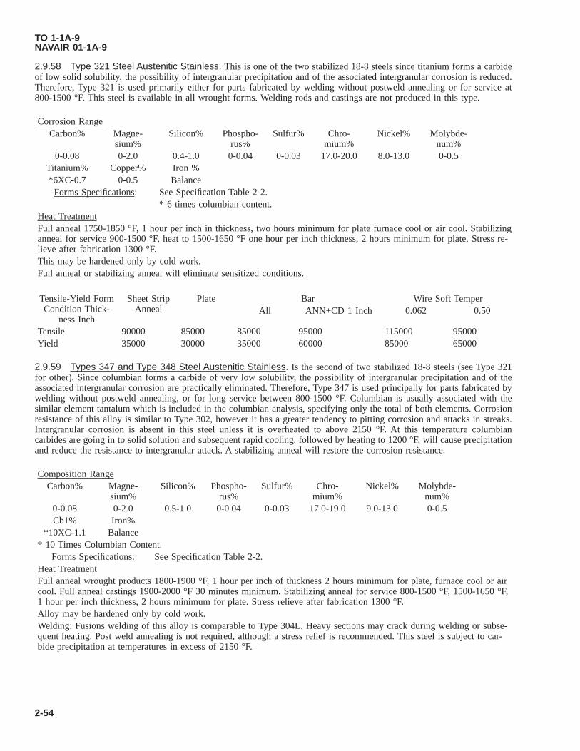
2.9.58 Type 321 Steel Austenitic Stainless. This is one of the two stabilized 18-8 steels since titanium forms a carbideof low solid solubility, the possibility of intergranular precipitation and of the associated intergranular corrosion is reduced.Therefore, Type 321 is used primarily either for parts fabricated by welding without postweld annealing or for service at800-1500 °F. This steel is available in all wrought forms. Welding rods and castings are not produced in this type.
Corrosion RangeCarbon% Magne-
sium%Silicon% Phospho-
rus%Sulfur% Chro-
mium%Nickel% Molybde-
num%0-0.08 0-2.0 0.4-1.0 0-0.04 0-0.03 17.0-20.0 8.0-13.0 0-0.5
Titanium% Copper% Iron %*6XC-0.7 0-0.5 Balance
Forms Specifications: See Specification Table 2-2.* 6 times columbian content.
Heat TreatmentFull anneal 1750-1850 °F, 1 hour per inch in thickness, two hours minimum for plate furnace cool or air cool. Stabilizinganneal for service 900-1500 °F, heat to 1500-1650 °F one hour per inch thickness, 2 hours minimum for plate. Stress re-lieve after fabrication 1300 °F.This may be hardened only by cold work.Full anneal or stabilizing anneal will eliminate sensitized conditions.
Tensile-Yield FormCondition Thick-
ness Inch
Sheet StripAnneal
Plate Bar Wire Soft TemperAll ANN+CD 1 Inch 0.062 0.50
Tensile 90000 85000 85000 95000 115000 95000Yield 35000 30000 35000 60000 85000 65000
2.9.59 Types 347 and Type 348 Steel Austenitic Stainless. Is the second of two stabilized 18-8 steels (see Type 321for other). Since columbian forms a carbide of very low solubility, the possibility of intergranular precipitation and of theassociated intergranular corrosion are practically eliminated. Therefore, Type 347 is used principally for parts fabricated bywelding without postweld annealing, or for long service between 800-1500 °F. Columbian is usually associated with thesimilar element tantalum which is included in the columbian analysis, specifying only the total of both elements. Corrosionresistance of this alloy is similar to Type 302, however it has a greater tendency to pitting corrosion and attacks in streaks.Intergranular corrosion is absent in this steel unless it is overheated to above 2150 °F. At this temperature columbiancarbides are going in to solid solution and subsequent rapid cooling, followed by heating to 1200 °F, will cause precipitationand reduce the resistance to intergranular attack. A stabilizing anneal will restore the corrosion resistance.
Composition RangeCarbon% Magne-
sium%Silicon% Phospho-
rus%Sulfur% Chro-
mium%Nickel% Molybde-
num%0-0.08 0-2.0 0.5-1.0 0-0.04 0-0.03 17.0-19.0 9.0-13.0 0-0.5Cb1% Iron%
*10XC-1.1 Balance* 10 Times Columbian Content.
Forms Specifications: See Specification Table 2-2.Heat TreatmentFull anneal wrought products 1800-1900 °F, 1 hour per inch of thickness 2 hours minimum for plate, furnace cool or aircool. Full anneal castings 1900-2000 °F 30 minutes minimum. Stabilizing anneal for service 800-1500 °F, 1500-1650 °F,1 hour per inch thickness, 2 hours minimum for plate. Stress relieve after fabrication 1300 °F.Alloy may be hardened only by cold work.Welding: Fusions welding of this alloy is comparable to Type 304L. Heavy sections may crack during welding or subse-quent heating. Post weld annealing is not required, although a stress relief is recommended. This steel is subject to car-bide precipitation at temperatures in excess of 2150 °F.
TO 1-1A-9NAVAIR 01-1A-9
2-54

2.9.60 Type 414 Steel Martensitic Stainless. This steel has good resistance to weather and water. It should be passi-vated. Stainless Type 416 has similar mechanical properties, workability and resistance to corrosion, however, corrosionresistance is not as good as the 300 series stainless. It has better machinability but less weldability. Type 420 has highermechanical properties, similar workability and machinability.
Composition RangeCarbon% Magne-
sium%Phospho-
rus%Sulfur% Silicon% Chro-
mium%Nickel% Iron%
0.08-0.15 0-1.0 0-0.04 0-0.03 0-0.10 11.5-13.5 1.25-2.5 BalanceForms Specifications: See Specification Table 2-2.Heat TreatmentAnnealing: 1200-1300 °F.Hardening: 1800-1900 °F, cool rapidly.Tensile: Strength in annealed condition 117,000 yield, 98,000 PSI.Tensile: Strength in annealed cold drawn 130,000 yield, 115,000 PSI.
2.9.61 Type 403, Type 410, and Type 416 Steel-Martensitic Stainless. This is a free machining type of alloy. Bestperformance is obtained if heat treated or cold worked to 180-240 BHN. It is magnetic in the hardened condition and is notnormally used in the annealed condition.
Composition RangeCarbon% Magne-
sium%Phospho-
rus%Sulfur% Silicon% Chro-
mium%Molybde-
num%Silicon% Iron%
0.15 1.25 0.06 0.15 1.0 14.0 0.6 0.6 BalanceForms Specifications: See Specification Table 2-2.Heat TreatmentAnnealing: 1500-1650 °F, furnace cool 50 °F per hour to 1100 °F.Harden: 1700-1850 °F, cool rapidly, oil and quench.Tensile: Yield strength is as follows:1. Annealed Tensile 75,000 PSI, yield 40,000 PSI.2. HeatTreated
Tensile 110,000 PSI, yield 85,000 PSI.
3. Temperedand Drawn
Tensile 100,000 PSI, yield 85,000 PSI. Weldability is poor except by use of low-hydrogen electrodes.
Temper: 400-1300 °F. Avoid 700-1075 °F temper range.Temper: 1300 °F for 100,000 PSI.Temper: 1075 °F for 120,000 PSI.Temper: 575-600 °F for 180,000 PSI.
2.9.62 Type 420 Steel Martensitic Stainless. This is a medium carbon grade of martensitic stainless which in the pasthas been intensively used in the cutlery industry. It has recently proved satisfactory for air weapon application where its highstrength permits heat treatment for tensile strength up to 240,000 PSI. In the fully annealed condition formability of thisalloy almost equals the 1/4 hard austenitic stainless steels. Shearing type operations such as blanking and punching are notrecommended. It machines best in conditions having approximately 225 BHN.
Composition RangeCarbon% Magne-
sium%Silicon% Phospho-
rus%Sulfur% Chro-
mium%Nickel% Molybde-
num%Iron%
0.3-0.4 0-1.0 0-1.0 0-0.04 0-0.03 12.0-14.0 0-0.5 0-0.5 BalanceForms Specifications See Specification Table 2-2.Heat TreatmentFull anneal: 1550-1650 °F one hour per inch of thickness, furnace cool (50 °F per hour) to 1100 °F.Subcriticalanneal:
1300-1350 °F, 3 hours minimum, air cool. Austenitize 1800-1850 °F oil quench, depending on sectionsize. Heavy sections should be preheated at 1250 °F.
TO 1-1A-9NAVAIR 01-1A-9
Change 3 2-55

Temper: 400-1500 °F, 3 hours minimum. Tempering between 600-1000 °F is not generally recommended due toreduced ductility and corrosion resistance.
2.9.63 Type 431 Steel Martensitic Stainless. This alloy is suitable for highly stressed parts in corrosive environment.
Composition Range.Carbon% Magnesium% Silicon% Phosphorus% Sulfur% Chromium% Nickel% Iron%
0.2 1.0 1.0 0.04 0.03 15.0-17.0 1.25-2.5 BalanceForms Specifications. See Specification Table 2-2.Heat Treatment. Type 431 steel must be protected from contamination at furnace temperature by dry
inert atmosphere (organ, helium) or vacuum in the furnace working zones, except thatair or salt bath furnaces may be employed for tempering operations. Parts shall betransferred from furnace working zones to the oil bath within a 30 second intervalprior to quenching. Materials in the solution treated condition (not more than 2% seg-regated ferrite or austenite in the microstructure) may be hardened by the followingtreat treatment.
HT-200 Condition: Austenitize at 1850±25 °F for 30 minutes, quickly transfer from furnace to oil quench-ing bath at not over 100 °F followed by refrigeration at -100±10 °F for 2 hours, tem-pering at 550 ±25 °F for 2 hours, air cool, and final temper at 550±25 °F for 2 hours;or austenitize 1850±25 °F for 30 minutes, marquench into salt bath at 400 °F, air coolto room temperature, refrigerate at -100±10 °F for 2 hours, temper 550±25 °F for 2hours, air cool, temper 550 °F for 2 hours.
HT-125 (125,000 Tensile): Austenitize at 1850±25 °F for 30 minutes, quickly transfer from furnace to oil quenchto bath at not over 100 °F, temper 1200±25 °F for 2 hours, air cool, temper 1200±25°F for 2 hours.
HT-115 (115,000 Tensile and Yield 90,000 PSI):
Avoid tempering or holding within range from 700-1100 °F. Failure to comply could result in damage to, or destruc-tion of, equipment or loss of mission effectiveness.
Heat Cond A material to 1800-1900 °F for 30 minutes, oil quench from furnace, temper at a temperature not lower than1100 °F.
HT-175 (175,000 Tensile and 135,000Yield PSI):
Heat Cond A material to 1850-1950 °F, quench in oil from furnace temper at a temperaturenot higher than 700 °F.
2.9.64 PH13-8Mo Steel, Martensitic Stainless, Precipitation Hardening. This stainless steel possesses high strengthand good corrosion and oxidation resistance up to 800 °F.
Composition Range.Carbon% Magnesium% Silicon% Phosphorus% Sulfur% Chromium% Nickel% Molybde-
num%0.05 0.01 0.01 0.001 0.008 12.25-13.25 7.5-8.5 2.00-2.50
maximum maximum maximum maximum maximumAluminum% Nitrogen%
0.90-1.35 20 ppmForm. Bar, forging, ring, extrusion (Vacuum Induction plus Consumable Electrode Melted)Specifications. AMS 5629, AMS 5934, AMS 5400Heat Treatment. To condition A - 1700±25 °F 30 minutes, air cool or oil quench below 60 °F.
• From condition A to Condition H950 (RH-C 45/49) ±10 °F, 4 hour, air cool.
TO 1-1A-9NAVAIR 01-1A-9
2-56 Change 3

• Condition H1000 (RH-C 43/48) 1000±10 °F, 4 hours, air cool.• Condition H1025 (RH-C 41/46) 1025±10 °F, 4 hours, air cool.• Condition H1050 (RH-C 40/42) 1050±10 °F, 4 hours, air cool.• Condition H1100 (RH-C 34/42) 1100±10 °F, 4 hours, air cool.• Condition H1150M (RH-C 28/36) H1150M is an intermediate soft condition that must be re-solution heat treated
to obtain a different final condition. To obtain H1150M, heat at 1400±10 °F for 2 to 2-1/2 hours, air cool below90 °F then heat at 1150 °F for 4 hours.
2.9.64.1 Normally furnished in condition A (solution-treated). Do not place into service in condition a. Machine, joining,forming typically accomplished in condition a.
2.9.65 PH15-5 Steel, Martensitic Stainless, Precipitation Hardening. This stainless steel possesses high strength andgood corrosion and oxidation resistance up to 600 °F.
Composition Range.Carbon% Magnesium% Silicon% Phosphorus% Sulfur% Chromium% Nickel% Nio-
bium%0.07 1 1 0.030 0.015 14-15.5 3.5-5.5 5xC-0.45
maximum maximum maximum maximumCopper% Molybdenum%2.5-4.5 0.50 maximum
Form. Bar, forging, ring, extrusion, rolled and/or forged bar, sheet, strip, plate, investmentcasting
Specifications. AMS 5659, AMS 5659/H1025, AMS 5682, AMS 5400Heat Treatment. To condition A - 1900±25 °F 30 minutes, air cool or oil quench below 90 °F
• From condition A to Condition H900 (RH-C 40/47) ±10 °F, 1 hour, air cool.• Condition H925 (RH-C 38/45) 925±10 °F, 4 hours, air cool.• Condition H950 (RH-C 37/44) 950±10 °F, 4 hours, air cool.• Condition H1000 (RH-C 36/43) 1000±10 °F, 4 hours, air cool.• Condition H1025 (RH-C 34/42) 1025±10 °F, 4 hours, air cool.• Condition H1050 (RH-C 32/38) 1050±10 °F, 4 hours, air cool.• Condition H1075 (RH-C 31/38) 1075±10 °F, 4 hours, air cool.• Condition H1100 (RH-C 30/37) 1100±10 °F, 4 hours, air cool.• Condition H1150 (RH-C 28/37) 1150±10 °F, 4 hours, air cool.• Condition H1150M (RH-C 24/30) 1150±10 °F, 4 hours, air cool. H1150M is an intermediate soft condition that
must be re-solution heat treated to obtain a different final condition. To obtain H1150M, heat at 1400 °F (760°C) for 2 to 2-1/2 hours, air cool below 90 °F (32 °C) then heat at 1150 °F (621 °C) for 4 hours.
Castings (RH-C 38/47). Castings shall be solution and precipitation heat treated.• Solution Heat Treatment: Heat to 1900±25 °F (1038±14 °C), hold at heat for 60 minutes per inch (25.4 mm) of
maximum cross-section, and cool to below 90 °F (32 °C) at a rate equivalent to an air cool or faster.• Precipitation Heat Treatment: Heat to 935±15 °F (502±8 °C), hold at heat for 4 hours ±0.25, and cool in air.
2.9.65.1 Readily forged and welded. Do not place into service in condition A. Machine, joining, forming typicallyaccomplished in condition A.
2.9.66 17-4PH Steel, Martensitic Stainless, Precipitation Hardening. This stainless steel possesses high strength andgood corrosion and oxidation resistance up to 600 °F.
Composition Range.Carbon% Niobium% Chro-
mium%Copper% Magne-
sium%Nickel% Phospho-
rus%Sulfur%
0.07 maxi-mum
0.15-0.45 15.5-17.5 3.0-5.0 1.0 maxi-mum
3.0-5.0 0.04 maxi-mum
0.03 maxi-mum
Silicon% Iron%
TO 1-1A-9NAVAIR 01-1A-9
Change 5 2-57

1.0 maxi-mum
Balance
Specifications. MIL-S-81506Heat Treatment. To condition A - 1900±25 °F 30 minutes, air cool or oil quench below 90 °F.
• From condition A to Condition H900 (RH-C 40/47) ±10 °F, 1 hour, air cool.• Condition H925 (RH-C 38/45) 925±10 °F, 4 hours, air cool.• Condition H950 (RH-C 37/44) 950±10 °F, 4 hours, air cool.• Condition H975 (RH-C 36/43) 975±10 °F, 4 hours, air cool.• Condition H1000 (RH-C 35/42) 1000±10 °F, 4 hours, air cool.• Condition H1025 (RH-C 35/42) 1025±10 °F, 4 hours, air cool.• Condition H1050 (RH-C 33/40) 1050±10 °F, 4 hours, air cool.• Condition H1075 (RH-C 31/39) 1075±10 °F, 4 hours, air cool.• Condition H1100 (RH-C 32/38) 1100±10 °F, 4 hours, air cool.• Condition H1125 (RH-C 30/37) 1125±10 °F, 4 hours. air cool.• Condition H1150 (RH-C 28/37) 1150±10 °F, 4 hours, air cool.
2.9.67 17-7PH Steel Martensitic Stainless (Precipitation Hardening). This stainless steel possesses good corrosionresistance, may be machined and formed in its annealed condition, and is used up to temperatures of 800 °F.
Composition Range.Carbon% Carbon% Chro-
mium%Magne-sium%
Nickel% Silicon% Phospho-rus%
Sulfur%
0.50-1.0 0.10-0.12 16.0-18.0 1.00 6.0-8.0 1.0-5.0 0.045 0.030Iron
BalanceSpecifications. See MIL-S-25043.Heat Treatment.
• Condition A - Solution anneal 1925-1975 °F, 30 minutes per inch of thickness, air cool. Age condition A tocondition TH1050, 1375-1425 °F, 1-1/2 hour, air cool to 50-60 °F within 1 hour, hold at 50-60 °F 1/2 hour(condition TO) + 1040-1060 °F, 1-1/2 hour. Age condition A to condition RH950, 1735-1765 °F, 10 minutes,refrigerate (condition A 1750 °F) to -90 to -110 °F 8 hours (condition R100), +940-960 °F, 1 hour. Age condi-tion C of cold rolled sheet or cold drawn wire to condition CH900, 890-910 °F for 1 hour.
• Condition A - 130 to 150 KSI ultimate, 55 KSI yield.• Condition T - 125 to 145 KSI ultimate 75 to 100 KSI yield.• Condition RH950 - 200 to 215 KSI ultimate 180 to 190 KSI yield.• Condition RH1050 - 180 to 200 KSI ultimate 150 to 185 KSI yield.• Condition C - 200 to 215 KSI ultimate 175 to 185 KSI yield.• Condition CH900 - 240 to 250 KSI ultimate, 230 to 240 KSI yield.
2.9.68 Type 440A, Type 440B, Type 550C, and Type 440C Steel Martensitic Stainless. These steels are similarexcept for carbon range, therefore they are grouped since heat treatment requirements are the same. These steels are used forcutlery, valves, etc.
Composition Range.440A
Carbon% Magne-sium%
Silicon% Phospho-rus%
Sulfur% Chromium% Molybde-num%
Iron%
0.6-0.75 maxi-mum
1.0 maxi-mum
1.0 maxi-mum
0.04 maxi-mum
0.03 maxi-mum
16.0-18.0 maxi-mum
0.75 maxi-mum
Balance
Forms Specifications. See Specification Table 2-2.Heat Treatment.
TO 1-1A-9NAVAIR 01-1A-9
2-58 Change 3

• Anneal: 1550-1650 °F.• Temper: 300-800 °F.• Harden: 1850-1950 °F, cool rapidly.• 440A: tensile 270,000 PSI, yield 260,000 PSI.• 440B: tensile 280,000 PSI, yield 270,000 PSI.• 440C: tensile 285,000 PSI, yield 275,000 PSI.
2.9.69 15-7-Molybdenum Steel Martensitic Stainless. This alloy is a further development of 17-7PH alloy and due tomolybdenum content it can be heat treated to high strength at room and elevated temperature (up to 1000 °F). The heattreatment is identical to 17-7PH and other properties are identical or similar to 17-7PH.
Composition Range.Carbon% Magne-
sium%Silicon% Phospho-
rus%Sulfur% Chromium% Nickel% Molybde-
num%0.09 1.0 1.0 0.4 0.03 14.0-16.0 6.50-7.75 2.0-3.0
Aluminum% Iron%0.75-1.50 Balance
Forms. Sheet, strip, plate, bars and forgings.Specification. AMS 5520, AMS 5657.Heat Treatment. Condition A. Solution anneal sheet and strip, 1925-1975 °F, 3 minutes per 0.1 inch thickness, air cool.
Bar and forgings solution anneal 1925-1975 °F, 30 minutes per inch thickness, water quench. Age con-dition A to condition TH1050, 1375-1425 °F, 1-1/2 hour (austenite conditioning), air cool to 50-60 °Fwithin 1 hour, hold at 50-60 °F, 1/2 hour (condition T) + 1040-1060 °F, 1-1/2 hour, air cool. Age con-dition A to condition RH 950, 1735-1765 °F, 10 minutes (austenite conditioning), air cool (condition A1750) ±90-110 °F, 8 hours (condition R100) +940-960 °F, 1 hour, air cool. Age condition C, sheet coldrolled or wire cold drawn to condition CH 900, by heating 890-910 °F for 1 hour, air cool. TH andRH conditions are also used with difference final age hardening temperatures, such as TH1150,RH1050, etc.
Typical Properties for Various Conditions.• Condition A - 130 to 150 KSI ultimate, 55-65 KSI yield, hardness 90-100.• Condition T - 125 to 145 KSI ultimate, 75-90 KSI yield, hardness 28-30.• Condition TH1050 - 190 to 210 KSI ultimate, 170-200 KSI yield, hardness RC40-45.• Condition RH950 - 225 to 240 KSI ultimate, 200-225 KSI yield, hardness RC46-48.• Condition R100 - 180 KSI ultimate, 125 KSI yield, hardness RC40.• Condition C - 220 KSI ultimate, 190 yield, hardness RC45.• Condition CH900 - 265 KSI ultimate, 260 yield, hardness RC50.
2.9.70 PH14-8 Molybdenum. This alloy (sheet) is similar to PH15-7 Molybdenum except it has slightly lower tensileand yield strength but considerable higher toughness and superior welding characteristics. In general this alloy is unstableduring exposure to temperatures exceeding 500 °F, which is a common characteristic of precipitation hardening stainlesssteels.
Composition Range.Carbon% Magne-
sium%Silicon% Ph% Sulfur% Chromium% Nickel% Me%
0.02-0-05 1.0 1.0 0.015 1.0 13.50-15.50 7.50-9.50 2.0-3.0Aluminum% Iron%
0.75-1.50 RemForms and Conditions. Available - Sheet and strip. Condition A - annealed C cold worker.Heat Treatment. Anneal to Condition A, 1800-1850 °F, 30 minutes air cool. Age condition A to SRH conditions, 1685-
1715 °F, 1 hour, air cool and within 1 hour cool to -100 °F, 8 hours + age 1 hour, air cool. Aging at940-960 °F or 1040-1060 °F is generally used with the higher temperature giving somewhat lowerstrength but after better toughness. Age cold worked alloy, condition C, 890-910 °F or 1040-1060 °F, 1hour, air cool.
Typical properties for various conditions.Condition A - 150 KSI ultimate, 65 KSI yield, hardness, RB100 max.
TO 1-1A-9NAVAIR 01-1A-9
Change 3 2-59
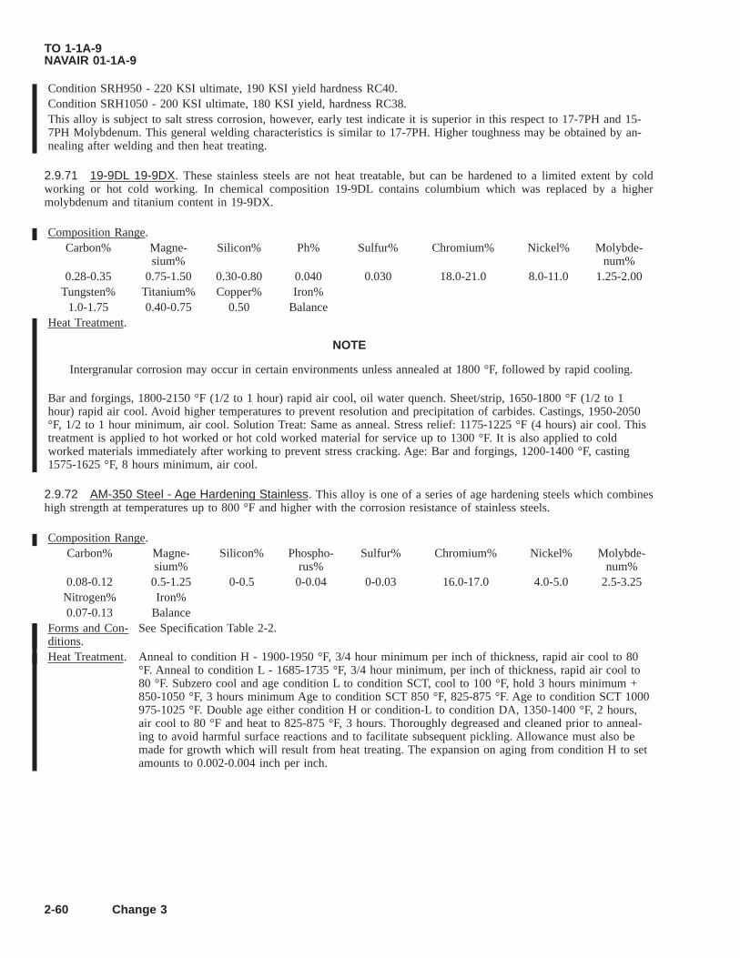
Condition SRH950 - 220 KSI ultimate, 190 KSI yield hardness RC40.Condition SRH1050 - 200 KSI ultimate, 180 KSI yield, hardness RC38.This alloy is subject to salt stress corrosion, however, early test indicate it is superior in this respect to 17-7PH and 15-7PH Molybdenum. This general welding characteristics is similar to 17-7PH. Higher toughness may be obtained by an-nealing after welding and then heat treating.
2.9.71 19-9DL 19-9DX. These stainless steels are not heat treatable, but can be hardened to a limited extent by coldworking or hot cold working. In chemical composition 19-9DL contains columbium which was replaced by a highermolybdenum and titanium content in 19-9DX.
Composition Range.Carbon% Magne-
sium%Silicon% Ph% Sulfur% Chromium% Nickel% Molybde-
num%0.28-0.35 0.75-1.50 0.30-0.80 0.040 0.030 18.0-21.0 8.0-11.0 1.25-2.00
Tungsten% Titanium% Copper% Iron%1.0-1.75 0.40-0.75 0.50 Balance
Heat Treatment.
NOTE
Intergranular corrosion may occur in certain environments unless annealed at 1800 °F, followed by rapid cooling.
Bar and forgings, 1800-2150 °F (1/2 to 1 hour) rapid air cool, oil water quench. Sheet/strip, 1650-1800 °F (1/2 to 1hour) rapid air cool. Avoid higher temperatures to prevent resolution and precipitation of carbides. Castings, 1950-2050°F, 1/2 to 1 hour minimum, air cool. Solution Treat: Same as anneal. Stress relief: 1175-1225 °F (4 hours) air cool. Thistreatment is applied to hot worked or hot cold worked material for service up to 1300 °F. It is also applied to coldworked materials immediately after working to prevent stress cracking. Age: Bar and forgings, 1200-1400 °F, casting1575-1625 °F, 8 hours minimum, air cool.
2.9.72 AM-350 Steel - Age Hardening Stainless. This alloy is one of a series of age hardening steels which combineshigh strength at temperatures up to 800 °F and higher with the corrosion resistance of stainless steels.
Composition Range.Carbon% Magne-
sium%Silicon% Phospho-
rus%Sulfur% Chromium% Nickel% Molybde-
num%0.08-0.12 0.5-1.25 0-0.5 0-0.04 0-0.03 16.0-17.0 4.0-5.0 2.5-3.25Nitrogen% Iron%0.07-0.13 Balance
Forms and Con-ditions.
See Specification Table 2-2.
Heat Treatment. Anneal to condition H - 1900-1950 °F, 3/4 hour minimum per inch of thickness, rapid air cool to 80°F. Anneal to condition L - 1685-1735 °F, 3/4 hour minimum, per inch of thickness, rapid air cool to80 °F. Subzero cool and age condition L to condition SCT, cool to 100 °F, hold 3 hours minimum +850-1050 °F, 3 hours minimum Age to condition SCT 850 °F, 825-875 °F. Age to condition SCT 1000975-1025 °F. Double age either condition H or condition-L to condition DA, 1350-1400 °F, 2 hours,air cool to 80 °F and heat to 825-875 °F, 3 hours. Thoroughly degreased and cleaned prior to anneal-ing to avoid harmful surface reactions and to facilitate subsequent pickling. Allowance must also bemade for growth which will result from heat treating. The expansion on aging from condition H to setamounts to 0.002-0.004 inch per inch.
TO 1-1A-9NAVAIR 01-1A-9
2-60 Change 3

2.9.73 AM-355 Steel - Age Hardening Stainless. This alloy combines high strength at temperatures up to 850 °F withthe corrosive resistance of stainless steel. This alloy differs from AM-350 by a lower chromium and a higher carbon content.It possesses good formability in the high temperature annealed condition. Corrosion resistance of this alloy is slightly lowerthan that of AM-350.
Forms Specifica-tions.
See Specification Table 2-2.
Heat Treatment. Anneal to condition H for maximum formability and stability. Anneal to condition H: Plate and forg-ings at 1925-1975 °F, 1 hour minimum per inch, water quench: sheet and welded tubing, 1850-1900°F, 3/4 hour minimum per inch, rapid air cool. Bar should not be annealed to condition H unless sub-sequently subjected to forgings. Anneal to Condition L: 1685-1735 °F. Sheet and strip, 3/4 hour perinch, air cool; plate 3/4 hour inch, oil or water quench. Condition H plate, if not subsequently se-verely cold formed, should be equalized before annealing to condition L and aging to condition SCT.Bar forgings and tubing, 1 hour minimum per inch thickness, oil or water quench. Equalize and agebar for best machineability, 1350-1400 °F, 3 hours, air cool to 80 °F maximum +1000-1050 °F, 3hours. Resulting should be approximately RC38 Subzero cool and age condition L to condition SCT,cool to -100 °F, hold 3 hour minimum, 850-1050 °F for 3 hours minimum. Age condition SCT 850,825-875 °F. Age to condition SCT 1000, 975-1025 °F. Double age condition L to condition DA,1300-1450 °F 1 to 2 hours, air cool to 80 °F, 825-875 °F, 3 hours minimum. Homogenize sand andshell mold castings, 2000 °F, 2-4 hours, air cool up to 1 inch thick, oil or water quench, section above1 inch.
2.9.74 HNM Steel - Age Hardening Stainless. This is a precipitation hardening austenitic steel, with high rupture andcreep properties in the 1000-1400 °F and not prone to overage at these temperatures. In the solution annealed condition ithas a Brinell hardness of 201 maximum. It has a low magnetic permeability, and is suitable for transformer parts, non-magnetic bolts, aircraft structural, engine components, shafts and gears. This material is very susceptible to work hardening.It is somewhat inferior to regular 18cr-8ni stainless types, however, machining requirements are similar requiring heavypositive feeds and sharp cutting tools. Welding is not recommended, however brazing may be successfully accomplished byuse of orayacetylene torch and furnace methods, using an alloy conforming to specification AMS 4755.
Composition Range.Carbon% Chromium% Magne-
sium%Nickel% Phospho-
rus%Silicon% Sulfur% Iron
0.30 18.5 3.5 9.5 0.25 0.5 0.025 BalanceForms Specifi-cations.
None.
Heat Treatment. Anneal 2000-2150 °F, 30 minutes, water quench. Sections 5/8 inches thick may be air cooled. The op-timum solution treatment for best properties after aging is approximately 2050 °F. Age 1300 °F, 16hours, air cool.
2.9.75 16-15-6 Steel - Iron - Chromium - Nickel - Alloy. This alloy was developed as a replacement for 16-25-6 alloyand contains less nickel. However, the lower nickel content is balanced by additional manganese which allows an increase inthe nitrogen content that can be retained during melting.
Composition Range.Carbon% Chromium% Magne-
sium%Molybde-
num%Nickel% Silicon% Nitrogen% Phospho-
rus%0-0.07 15.0-17.5 6.5-8.5 5.0-7.0 14-0-17.0 0-1.0 0.30-0.40 0-0.03
Sulfur% Iron0.03 Balance
Form. Bar, forging.Specification. None.Heat Treatment. Anneal 1700-2300 °F. Solution treat 2125-2175 °F, air cool, water or oil quench, depending on sec-
tion size. Cold work (about 20% reduction) and age (bar up to 1-1/2 inch) 1200-1300 °F, 2 to 8hours. At a temperature of 1200 °F a tensile of 145,000 and yield of 100,000 PSI is obtained.
TO 1-1A-9NAVAIR 01-1A-9
Change 3 2-61
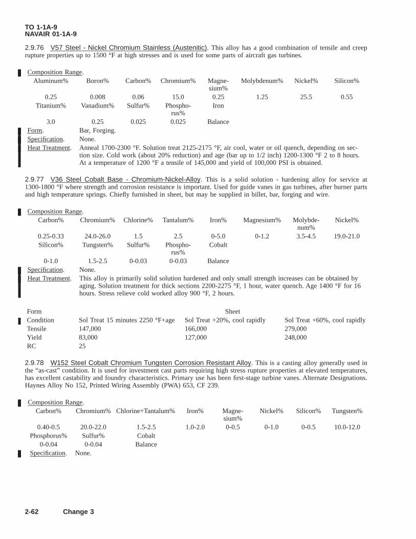
2.9.76 V57 Steel - Nickel Chromium Stainless (Austenitic). This alloy has a good combination of tensile and creeprupture properties up to 1500 °F at high stresses and is used for some parts of aircraft gas turbines.
Composition Range.Aluminum% Boron% Carbon% Chromium% Magne-
sium%Molybdenum% Nickel% Silicon%
0.25 0.008 0.06 15.0 0.25 1.25 25.5 0.55Titanium% Vanadium% Sulfur% Phospho-
rus%Iron
3.0 0.25 0.025 0.025 BalanceForm. Bar, Forging.Specification. None.Heat Treatment. Anneal 1700-2300 °F. Solution treat 2125-2175 °F, air cool, water or oil quench, depending on sec-
tion size. Cold work (about 20% reduction) and age (bar up to 1/2 inch) 1200-1300 °F 2 to 8 hours.At a temperature of 1200 °F a tensile of 145,000 and yield of 100,000 PSI is obtained.
2.9.77 V36 Steel Cobalt Base - Chromium-Nickel-Alloy. This is a solid solution - hardening alloy for service at1300-1800 °F where strength and corrosion resistance is important. Used for guide vanes in gas turbines, after burner partsand high temperature springs. Chiefly furnished in sheet, but may be supplied in billet, bar, forging and wire.
Composition Range.Carbon% Chromium% Chlorine% Tantalum% Iron% Magnesium% Molybde-
num%Nickel%
0.25-0.33 24.0-26.0 1.5 2.5 0-5.0 0-1.2 3.5-4.5 19.0-21.0Silicon% Tungsten% Sulfur% Phospho-
rus%Cobalt
0-1.0 1.5-2.5 0-0.03 0-0.03 BalanceSpecification. None.Heat Treatment. This alloy is primarily solid solution hardened and only small strength increases can be obtained by
aging. Solution treatment for thick sections 2200-2275 °F, 1 hour, water quench. Age 1400 °F for 16hours. Stress relieve cold worked alloy 900 °F, 2 hours.
Form SheetCondition Sol Treat 15 minutes 2250 °F+age Sol Treat +20%, cool rapidly Sol Treat +60%, cool rapidlyTensile 147,000 166,000 279,000Yield 83,000 127,000 248,000RC 25
2.9.78 W152 Steel Cobalt Chromium Tungsten Corrosion Resistant Alloy. This is a casting alloy generally used inthe “as-cast” condition. It is used for investment cast parts requiring high stress rupture properties at elevated temperatures,has excellent castability and foundry characteristics. Primary use has been first-stage turbine vanes. Alternate Designations.Haynes Alloy No 152, Printed Wiring Assembly (PWA) 653, CF 239.
Composition Range.Carbon% Chromium% Chlorine+Tantalum% Iron% Magne-
sium%Nickel% Silicon% Tungsten%
0.40-0.5 20.0-22.0 1.5-2.5 1.0-2.0 0-0.5 0-1.0 0-0.5 10.0-12.0Phosphorus% Sulfur% Cobalt
0-0.04 0-0.04 BalanceSpecification. None.
TO 1-1A-9NAVAIR 01-1A-9
2-62 Change 3

2.9.79 Haynes Alloy No. 151 Cobalt Base Corrosion Resistant Alloy. This alloy may be air melted or air cast. It isused as gas turbine blades and rotors within the heat range 1200-1700 °F.
Composition Range.Boron% Carbon% Chro-
mium%Iron% Magne-
sium%Nickel% Silicon% Titanium%
0.03-0.08 0.4-0.5 19.0-21.0 0-2.0 0-1.0 0-1.0 0-1.0 0.05-0.5Tungsten% Phospho-
rus%Sulfur% Cobalt
12.0-13.5 0-0.03 0-0.03 BalanceSpecification. None.Forms. Available as castings and investment castings.Heat Treat-ment.
This material is generally used in the “as cast” condition. The best creep rupture properties are in the1300-1500 °F range. Solution treat 2170-2200 °F, 1 hour minimum, rapid air cool. This treatment re-duces tensile properties below 1400 °F and lowers creep rupture strength. Aging 1400 °F 4 hours aircool after solution treating, results in higher tensile properties than “as cast” material, but creep ruptureproperties are somewhat lower than the “as cast” alloy.
Hardenability. As-cast hardness at room temperature RC33.
2.9.80 GMR-235 Nickel Base Corrosive Resistant Alloy. GMR-235 and GMR-235D are nickel based alloys precipi-tation hardening, high temperature alloys developed for investment cast gas turbine wheels, buckets and vanes, operatingabove 1400 °F. They are similar to Hastelloy R-235 but contain more aluminum. The composition with maximum aluminumand titanium content is designated GMR-235D.
Composition RangeGMR-235 % GMR-235D
Minimum Maximum Minimum MaximumAluminum 2.5 3.5 3.25 4.0Boron 0.05 0.1 0.05 0.1Carbon 0.1 0.2 0.1 0.2Chromium 14.0 17.0 14.0 17.0Cobalt 0.1 0.2 0 0Iron 8.0 12.0 3.5 5.0Magnesium 0 0.25 0 0.1Molybdenum 4.5 6.0 4.5 6.0Silicon 0 0.60 0 0.3Titanium 1.5 2.5 2.0 3.0Nickel Balance Balance Balance Balance
Specification. None.Forms. This material is available in wrought form only, except that GMR-235 is available in cast form.Heat Treatment. Solution treatment 2050 °F, 1 to 3 hours, air cool (GMR-235) Solution treatment 2100 °F, 2
hours, air cool (GMR-235D). For heavier sections (of both alloys) temperatures should be in-creased to 2150 °F, 2 to 4 hours, air cool. Aging at 1800 °F, 5 hours from the “as cast” condi-tion improves the stress rupture life of the alloy. These alloys precipitation harden rapidly duringair cooling and aging treatments are usually unnecessary. “As-cast” room temperatures hardnessfor both alloys is RC36 maximum. Tensile 115,000 PSI yield 90,000 PSI.
2.9.81 Hastelloy Alloy R-235 Nickel Base Corrosion Resistant Alloy. This is a nickel base aluminum-titanium pre-cipitation hardening alloy. It possesses high strength up to 1800 °F with good resistance to oxidation and over aging in hightemperature service. This alloy is readily fabricated and welded in the solution treated condition.
Composition Range.
TO 1-1A-9NAVAIR 01-1A-9
Change 3 2-63

Aluminum% Boron% Carbon% Chromium% Cobalt% Iron% Magne-sium%
Molybdenum%
1.75-2.25 0-0.009 0-0.16 14.0-17.0 0-2.5 9.0-11.0 0-0.25 4.5-6.5Silicon% Titanium% Phospho-
rus%Sulfur% Nickel%
0-0.6 2.25-2.75 0-0.01 0-0.03 BalanceSpecification.Forms. Sheet, Strip, Plate, Bar and Wire.Heat Treat-ment.
Solution treatment 1950-2000 °F 1/2 hour, water quench. Material treated at higher solution temperature(2200 °F) is subject to strain-age cracking. Final heat treatment after fabrication of sheet and bar dependsupon properties desired. To obtain maximum long time stress-rupture life, solution treat at 2175-2225 °F,15 minutes, water quench. Then heat to 2025-2075 °F, hold at temperature for 30 minutes and cool instill air. To obtain maximum room and high temperature tensile strength or short time rupture strength,solution treat at 1950-2000 °F hold at temperature for 30 minutes and air cool. Then age at 1385-1415 °Fhold at temperature for 16 hours and air cool.
Form SheetCondition Thickness (Inch) Sol Treat 1975 °F Water Quench 0.021 Sol Treat 2200 °F Water Quench 0.70Tensile, Maximum PSI 150,000 150,000Yield, Maximum 95,000 95,000PSI RC-Maximum 27 25
2.9.82 Inconel Alloy 718 Steel Nickel Chromium Stainless Alloy. This is a relatively new alloy and heat treatment andfabrication procedures are still under development. It has good properties up to 1300 °F, slow response to age-hardening andgood ductility from 1200-1400 °F. It is readily welded in either the annealed or aged condition.
Composition Range.
Aluminum% Carbon% Chromium%Chlorine%
Copper% Magnesium%Molybde-
num% Nickel%+Tantalum%0.4-1.0 0-0.1 17.0-21.0 4.5-5.75 0-0.75 0-0.50 2.0-4.0 50.0-55.0
Silicon% Titanium% Sulfur% Iron0-0.5 0.3-1.3 0-0.03 Balance
Specification. None.Forms. Sheet, Strip, Bar, Investment Castings.Heat Treat-ment.
Both single age and double age treatments may be employed, however, the latter is preferred for higheststrength up to 1300 °F. Solution treat rods, bars and forgings 1800-1900 °F. Somewhat higher creeprupture properties are obtained at the higher temperatures. Solution treat sheet at 1725 °F. Single ageanneal alloy at 1325 °F 16 hours, air cool. Double age anneal alloy at 1325 °F 8 hours, furnace cool,20 °F per hour to 1150 °F air cool or 1325 °F 8 hours, furnace cool, 100 °F per hour to 1150 °F, hold 8hours, air cool. Both of these double age treatments appear to give the same results.
Form: Hot Rolled Bar 0.0500 Inch DiameterCondition Anneal + Age
1800 °F 1 hour + 1325 °F8 hour* 8 hour** 16 hour
Thickness - Inch 0.500Tensile PSI 211,000 204,000 193,000Yield PSI 174,000 173,000 154,000*Furnace cool at temperature reduction of 100 °F per hour to 1150 °F hold 8 hours air cool.** Furnace cool at temperature reduction of 20 °F per hour to 1150 °F air cool.
TO 1-1A-9NAVAIR 01-1A-9
2-64 Change 3
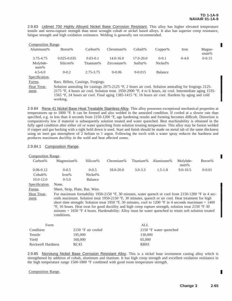
2.9.83 Udimet 700 Highly Alloyed Nickel Base Corrosion Resistant. This alloy has higher elevated temperaturetensile and stress-rupture strength than most wrought cobalt or nickel based alloys. It also has superior creep resistance,fatigue strength and high oxidation resistance. Welding is generally not recommended.
Composition Range.Aluminum% Boron% Carbon% Chromium% Cobalt% Copper% Iron Magne-
sium%3.75-4.75 0.025-0.035 0.03-0.1 14.0-16.0 17.0-20.0 0-0.1 0-4.0 0-0.15Molybde-
num%Silicon% Titanium% Zirconium% Sulfur% Nickel%
4.5-6.0 0-0.2 2.75-3.75 0-0.06 0-0.015 BalanceSpecification.Forms. Bars, Billets, Castings, Forgings.Heat Treat-ment.
Solution annealing for castings 2075-2125 °F, 2 hours air cool. Solution annealing for forgings 2125-2175 °F, 4 hours air cool. Solution treat. 1950-2000 °F, 4 to 6 hours, air cool. Intermediate aging 1535-1565 °F, 24 hours air cool. Final aging 1385-1415 °F, 16 hours air cool. Hardens by aging and coldworking.
2.9.84 Rene 41 Nickel Base Heat Treatable Stainless Alloy. This alloy possesses exceptional mechanical properties attemperatures up to 1800 °F. It can be formed and also welded in the annealed condition. If cooled at a slower rate thanspecified, e.g. in less than 4 seconds from 2150-1200 °F, age hardening results and forming becomes difficult. Distortion iscomparatively low if material is subsequently solution treated and water quenched. Best machinability is obtained in thefully aged condition after either oil or water quenching from solution treating temperature. This alloy may be fusion weldedif copper and gas backing with a tight hold down is used. Start and finish should be made on metal tab of the same thicknessusing an inert gas atmosphere of 2 helium to 1 argon. Following the torch with a water spray reduces the hardness andproduces maximum ductility in the weld and heat affected zones.
2.9.84.1 Composition Range.
Composition Range.Carbon% Magnesium% Silicon% Chromium% Titanium% Aluminum% Molybde-
num%Boron%
0.06-0.12 0-0.5 0-0.5 18.0-20.0 3.0-3.3 1.5-1.8 9.0-10.5 0-0.01Cobalt% Iron% Nickel%10.0-12.0 0-5.0 Balance
Specification. None.Forms. Sheet, Strip, Plate, Bar, Wire.Heat Treat-ment.
For maximum formability 1950-2150 °F, 30 minutes, water quench or cool from 2150-1200 °F in 4 sec-onds maximum. Solution treat 1950-2150 °F, 30 minutes, quench or air cool. Heat treatment for highshort time strength: Solution treat 1950 °F, 30 minutes, cool to 1200 °F in 4 seconds maximum + 1400°F, 16 hours. Heat treat for good ductility and high creep rupture strength, solution treat 2150 °F 30minutes + 1650 °F 4 hours. Hardenability: Alloy must be water quenched to retain soft solution treatedconditions.
Form ALLCondition 2150 °F air cooled 2150 °F water quenchedTensile 195,000 130,000Yield 160,000 65,000Rockwell Hardness RC43 RB93
2.9.85 Nicrotung Nickel Base Corrosion Resistant Alloy. This is a nickel base investment casting alloy which isstrengthened by addition of cobalt, aluminum and titanium. It has high creep strength and excellent oxidation resistance inthe high temperature range 1500-1800 °F combined with good room temperature strength.
Composition Range.
TO 1-1A-9NAVAIR 01-1A-9
Change 3 2-65
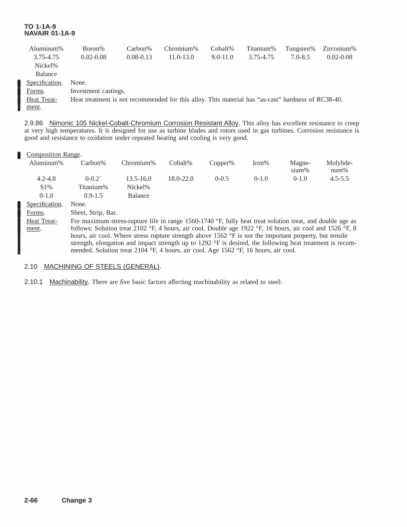
Aluminum% Boron% Carbon% Chromium% Cobalt% Titanium% Tungsten% Zirconium%3.75-4.75 0.02-0.08 0.08-0.13 11.0-13.0 9.0-11.0 3.75-4.75 7.0-8.5 0.02-0.08Nickel%Balance
Specification. None.Forms. Investment castings.Heat Treat-ment.
Heat treatment is not recommended for this alloy. This material has “as-cast” hardness of RC38-40.
2.9.86 Nimonic 105 Nickel-Cobalt-Chromium Corrosion Resistant Alloy. This alloy has excellent resistance to creepat very high temperatures. It is designed for use as turbine blades and rotors used in gas turbines. Corrosion resistance isgood and resistance to oxidation under repeated heating and cooling is very good.
Composition Range.Aluminum% Carbon% Chromium% Cobalt% Copper% Iron% Magne-
sium%Molybde-
num%4.2-4.8 0-0.2´ 13.5-16.0 18.0-22.0 0-0.5 0-1.0 0-1.0 4.5-5.5S1% Titanium% Nickel%0-1.0 0.9-1.5 Balance
Specification. None.Forms. Sheet, Strip, Bar.Heat Treat-ment.
For maximum stress-rupture life in range 1560-1740 °F, fully heat treat solution treat, and double age asfollows: Solution treat 2102 °F, 4 hours, air cool. Double age 1922 °F, 16 hours, air cool and 1526 °F, 8hours, air cool. Where stress rupture strength above 1562 °F is not the important property, but tensilestrength, elongation and impact strength up to 1292 °F is desired, the following heat treatment is recom-mended. Solution treat 2104 °F, 4 hours, air cool. Age 1562 °F, 16 hours, air cool.
2.10 MACHINING OF STEELS (GENERAL).
2.10.1 Machinability. There are five basic factors affecting machinability as related to steel:
TO 1-1A-9NAVAIR 01-1A-9
2-66 Change 3

• The capacity and rigidity of the machine tool.
• Cutting fluids.
• Design composition and hardness of the cutting tool.
• Cutting condition with respect to feeds and speeds.
• The structure of the steel to be machined.
2.10.2 Cutting Tool Angles. The cutting tool angles (back rake, side clearance, front clearance, and side rake) are highlyimportant in the machining of metals. The range of values based on general practice for the machining of steel and steelalloys, are as follows:
• Back rake angle, 8-16 degrees.
• Side rake angle, 12-22 degrees.
• Front clearance angle, 8-13 degrees.
• Side clearance angle, 10-15 degrees.
2.10.2.1 Regardless of the material of which the cutting tool is made, the cutting action is the same. The main differenceis the cutting speed. The carbon-steel tool cuts at low speed. The highspeed tool cuts at twice the speed of carbon-steel, thecast alloys at twice the speed of high-speed steel, and the sintered carbides at twice that of the cast alloys. The cutting speedslisted in Table 2-4 are approximate speeds using high-speed steel tools, and are to be used only as a basis from which properspeeds for a particular part may be calculated. These speeds are based on SAE 1112 steel, which is assigned a machinabilityrating of 100%. In order to obtain an approximate starting speed for different steels, select the type of operation, the width,depth or diameter of cut and obtain the recommended cutting speed for SAE 1112 from Table 2-3 then refer to Table 2-4 forthe percent rating of the metal to be machined, and multiply the Surface Feet Per Minute (SFM) value from Table 2-5 by therating in Table 2-4. The result is the recommended SFM for the cutting operation. For a known diameter and SFM be usedfor an operation, the corresponding Revolution Per Minute (RPM) can be obtained from Table 2-5 and Table 2-6.
2.10.2.2 The term cutting feed is used to express the axial distance the tool moves in each revolution. A course feed isusually used for roughing operations, and a fine feed for finishing operations. In general, the feed remains the same fordifferent cutting tool steels, and only the speed is changed. Approximate cutting feeds are listed in Table 2-3. For toolcorrections when improper machining on an operation is encountered, refer to Table 2-7 for recommended checks.
2.10.2.3 The use of a proper coolant (cutting fluid) often results in an increase of cutting speed for the same tool life, andalso acts as a lubricant giving better cutting action and surface finish. Recommended cutting fluids for steels are lard oil,mineral oils, sulphurized oils, and soluble or emulsifiable oils.
Table 2-3. Cutting Speeds and Feeds for SAE 1112 Using Standard High Speed Tools
Tool Name Size of Hole (Inch) Width or Depth of Cut (Inch) SFM Feed (Inch/Rev)
Form Circular orDovetail
-- Width - 0.500 165 0.0025Width - 1.000 160 0.0020Width - 1.500 160 0.0018Width - 2.000 155 0.0015Width - 2.500 150 0.0012
Twist Drills
0.250 105 0.00450.500 105 0.0050.750 115 0.0061.000 115 0.0071.250 120 0.008
TO 1-1A-9NAVAIR 01-1A-9
2-67

Table 2-3. Cutting Speeds and Feeds for SAE 1112 Using Standard High Speed Tools - Continued
Tool Name Size of Hole (Inch) Width or Depth of Cut (Inch) SFM Feed (Inch/Rev)
Box Tools Blade
Depth - 0.125 165 0.007Depth - 0.250 160 0.0065Depth - 0.375 155 0.0055Depth - 0.500 150 0.0045
Threading andTapping
Over 25 Pitch 30-4015 to 25 Pitch 20-30
Less than 15 Pitch 15-20
Hollow Mills
0.062 150 0.0100.125 140 0.0080.187 135 0.0070.250 130 0.0065
ReamersUnder 1/2 inch 145 0.007Over 1/2 inch 145 0.010
Cut Off
Width - 0.062 165 0.002Width - 0.125 175 0.0025Width - 0.187 180 0.0025Width - 0.250 190 0.003
Table 2-4. Machinability Rating of Various Metals
SAE Designation Rating % Brinell Hardness1010 50 131-1701015 50 131-1701020 65 137-1741022 70 159-1921025 65 116-1261035 65 174-2171040 60 179-2291045 60 179-2291050 50 179-2291055 55 192-1971060 60 183-2011070 45 183-2411080 45 192-2291095 42 197-2481112 100 179-2291117 85 143-1791137 70 187-2292317 55 174-2172330 50 179-2292340 45 187-2412515 30 179-2293115 65 143-1743140 55 187-2293310 40 170-2294037 65 170-2294130 65 187-2294135 64 170-229
TO 1-1A-9NAVAIR 01-1A-9
2-68

Table 2-4. Machinability Rating of Various Metals - Continued
SAE Designation Rating % Brinell Hardness4137 60 187-2294140 66 179-1974150 50 187-2354337 50 187-2414340 45 187-2414615 65 174-2174620 62 152-1794640 55 187-2355210 30 183-2296150 50 1978615 67 170-2178617 63 170-2178620 60 170-2178630 65 179-2298640 60 179-2298735 55 179-2298740 60 179-2299260 45 187-2559262 45 187-2559310 40 207-217
TO 1-1A-9NAVAIR 01-1A-9
2-69
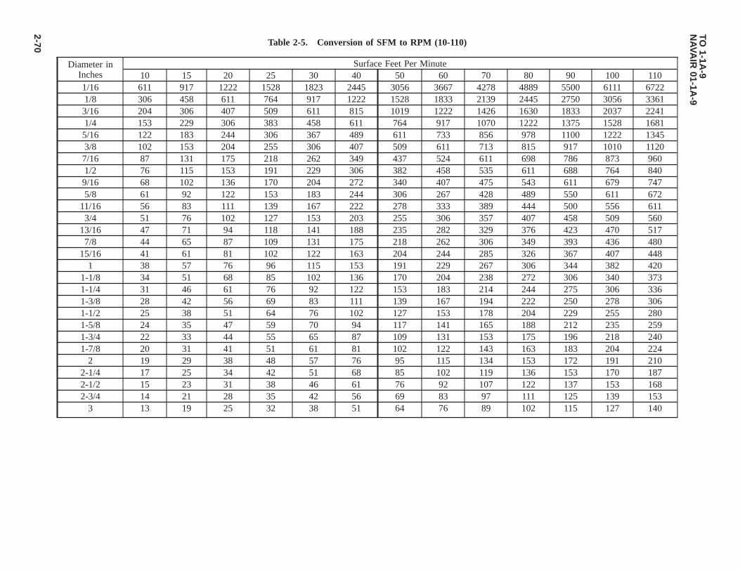
Table 2-5. Conversion of SFM to RPM (10-110)
Diameter inInches
Surface Feet Per Minute10 15 20 25 30 40 50 60 70 80 90 100 110
1/16 611 917 1222 1528 1823 2445 3056 3667 4278 4889 5500 6111 67221/8 306 458 611 764 917 1222 1528 1833 2139 2445 2750 3056 33613/16 204 306 407 509 611 815 1019 1222 1426 1630 1833 2037 22411/4 153 229 306 383 458 611 764 917 1070 1222 1375 1528 16815/16 122 183 244 306 367 489 611 733 856 978 1100 1222 13453/8 102 153 204 255 306 407 509 611 713 815 917 1010 11207/16 87 131 175 218 262 349 437 524 611 698 786 873 9601/2 76 115 153 191 229 306 382 458 535 611 688 764 8409/16 68 102 136 170 204 272 340 407 475 543 611 679 7475/8 61 92 122 153 183 244 306 267 428 489 550 611 672
11/16 56 83 111 139 167 222 278 333 389 444 500 556 6113/4 51 76 102 127 153 203 255 306 357 407 458 509 560
13/16 47 71 94 118 141 188 235 282 329 376 423 470 5177/8 44 65 87 109 131 175 218 262 306 349 393 436 480
15/16 41 61 81 102 122 163 204 244 285 326 367 407 4481 38 57 76 96 115 153 191 229 267 306 344 382 420
1-1/8 34 51 68 85 102 136 170 204 238 272 306 340 3731-1/4 31 46 61 76 92 122 153 183 214 244 275 306 3361-3/8 28 42 56 69 83 111 139 167 194 222 250 278 3061-1/2 25 38 51 64 76 102 127 153 178 204 229 255 2801-5/8 24 35 47 59 70 94 117 141 165 188 212 235 2591-3/4 22 33 44 55 65 87 109 131 153 175 196 218 2401-7/8 20 31 41 51 61 81 102 122 143 163 183 204 224
2 19 29 38 48 57 76 95 115 134 153 172 191 2102-1/4 17 25 34 42 51 68 85 102 119 136 153 170 1872-1/2 15 23 31 38 46 61 76 92 107 122 137 153 1682-3/4 14 21 28 35 42 56 69 83 97 111 125 139 153
3 13 19 25 32 38 51 64 76 89 102 115 127 140
TO1-1A
-9N
AVA
IR01-1A
-9
2-70

Table 2-6. Conversion of SFM to RPM (120-300)
Diameter inInches
Surface Feet Per Minute120 130 140 150 160 170 180 190 200 225 250 270 300
1/16 7334 7945 8556 9167 9778 10390 11000 11612 12223 13751 15279 16807 183341/8 3667 3973 4278 4584 4889 5195 5500 5806 6111 6875 7639 8403 91673/16 2445 2648 2852 3056 3259 3463 3667 3871 4074 4584 5093 5602 61121/4 1833 1986 2139 2292 2445 2597 2750 2903 3056 3438 3820 4202 45845/16 1467 1589 1711 1833 1956 2078 2200 2322 2445 2750 3056 3361 36673/8 1222 1324 1436 1528 1630 1732 1833 1935 2037 2292 2546 2801 30567/16 1048 1135 1222 1310 1397 1484 1572 1659 1746 1964 2183 2401 26191/2 917 993 1070 1146 1222 1299 1375 1451 1528 1719 1910 2101 22929/16 815 883 951 1019 1086 1154 1222 1290 1358 1528 1698 1867 20375/8 733 794 856 917 978 1039 1100 1161 1222 1375 1528 1681 1833
11/16 667 722 778 833 889 945 1000 1056 1111 1250 1389 1528 16673/4 611 662 713 764 815 866 917 968 1019 1146 1273 1401 1528
13/16 564 611 658 705 752 799 846 893 940 1058 1175 1293 14107/8 524 567 611 655 698 742 786 829 873 982 1091 1200 1310
15/16 489 530 570 611 652 693 733 774 815 917 1019 1120 12221 458 497 535 573 611 649 688 726 764 859 955 1050 1146
1-1/8 407 441 475 509 543 577 611 645 679 764 849 934 10191-1/4 367 397 428 458 489 519 550 581 611 688 764 840 9171-3/8 333 361 389 417 444 472 500 528 556 625 694 764 8331-1/2 306 331 357 382 407 433 458 484 509 573 637 700 7641-5/8 282 306 329 353 376 400 423 447 470 529 588 646 7051-3/4 262 284 306 327 349 371 393 415 437 491 546 600 6551-7/8 244 265 285 306 326 346 367 387 407 458 509 560 611
2 229 248 267 287 306 325 344 363 382 430 477 525 5732-1/4 204 221 233 255 272 289 306 323 340 382 424 467 5092-1/2 183 199 214 229 244 260 275 290 306 344 382 420 4582-3/4 167 181 194 208 222 236 250 264 278 313 347 382 417
3 153 166 178 191 204 216 229 242 255 286 318 350 382
TO1-1A
-9N
AVA
IR01-1A
-9
2-71

Table 2-7. Tool Correction Chart
Tool Check:Tool Chatter
1. Tool overhand (reduce to minimum)2. Work Support (eliminate vibration)3. Nose radius (too large a radius may cause chatter)4. Tool clearance (be sure end cutting edge angle is sufficient)5. Feed (increase feed if too light a feed has tendency to rub rather than cut)6. Tool load (vary side cutting edge angle to correct improper load)7. Chip breaker (widen breaker if chips are too tight)
Chipping of Cutting Edge1. Edge sharpness (Hone or chamber slightly)2. Chip Breaker (widen breaker if tight chip causes chipping)3. Speed (Increase)4. Coolant (Heating and cooling of tip may cause chipping)
Rapid Tool Wear1. Feed (Increase)2. Speed (Low and excessive speeds cause tool wear)3. Relief angles (clearance may not be sufficient)4. Nose radius (decrease size)
Unsatisfactory Finish1. Speed (rough finishes can be eliminated by increasing speed)2. Nose radius (too large a nose radius mats finish)
2.11 MACHINING CORROSION RESISTING STEEL.
The corrosion resisting steels, especially the 18-8 grades, are more difficult to machine than the carbon steels and most othermetals. Even though they are more difficult to machine, the same general methods are used with modification/compensationfor the individual characteristics of each type or grade. To improve machining characteristics of some types, their chemicalcontent is modified by adding selenium and sulfur. The modified alloys which are usually designated by a suffix to typenumber such as 430 F or Selenium. Exceptions are Type 416 and Type 303.
2.11.1 Machining Comparison of Corrosion Resisting Steel. For comparison and as a general guide to the machiningcharacteristics of free machining screw stock Grade B1112 as an 100% machinable “norm.” This table is only intended as astarting point and is not intended to replace any information accumulated through experience or other available data.
2.11.2 Machining of the Corrosion Resisting Steels. In machining of the corrosion resisting steels, difficulty will beexperienced from seizing, galling and stringing. To overcome these problems requires control of speeds, cutting tools, andlubricants. The following general practices are recommended for shaping/grinding cutting tools, equipment, etc., for cuttingcorrosion resisting steel:
a. Select tools of proper alloy/type and keep cutting edges sharp, smooth, free of burrs, nicks and scratches.
b. Avoid overheating cutting tool when grinding to prevent surface and stress cracking.
c. Grind tools with generous lip rake and with ample side and front clearance.
d. Speeds are critical in machining stainless; select speed about 50% slower than those used for carbon steels as a startingpoint.
e. In general, use slow speeds and heavy feed to reduce effect of work hardening. Avoid riding of tool on work andintermittent cutting when possible.
TO 1-1A-9NAVAIR 01-1A-9
2-72

f. Apply proper lubricant/coolant to cutting tool to prevent overheating.
g. Support cutting tool rigidly near work to prevent lash and other difficulty from use of heavy cutting feeds.
2.11.3 Cutting Tools for Machining Corrosion Resisting Steels.
NOTE
Some types of tool steel are available in raw stock in accordance with Federal Specifications, see Paragraph 7.2.Prior to attempting local manufacture of cutting tools, facilities/equipment must be available to properly heat treat.In addition, from an economic standpoint, it is usually advisable to obtain most cutting tools pre-finished to size,etc., and heat treated.
Selection of cutting tool is important for machining stainless due to tough machining characteristics. The following is arecommended guide for selection of tools:
a. For general machining and short runs use high speed tool steels such as Tungsten Type T1 (18-41) and Molybdenum-Tungsten Type M3 (6-6-3).
b. For medium runs at approximately 25% higher speed, use Tungsten-Cobalt Type T5 (18-4-2-8) and Tungsten-CobaltType T4.
c. For long production runs at high speed, use Tungsten Carbides. Cutting tool of these alloys can be used at approxi-mately 100% faster speeds than the Tungsten-Cobalt type.
Table 2-8. General Machining Comparison of Corrosion Resisting Steel to Free Machining Screw Stock B1112
Grade/Type Machinability Rating Grade/Type Machinability RatingGroup I 430F 80% Group III 420 45%
416 75% 431 45%420F 70% 440 45%303 65% 442 45%
446 45%347 40-45%
Group II 403 55% Group IV 302 40%410 50% 304 40%430 50% 309 40%440F 50% 316 40%
Table 2-9. Suggested Cutting Speeds and Feeds
Alloy Type/Grade
Feed Inch 1/ Cutting Speed SFM Operation Tool Material
302, 304, 309,310, 314,316
0.020-0.040 20-40 Rough High Speed Steel0.008-0.015 50-80 Finish High Speed Steel0.020-0.040 40-60 Rough Tungsten-Cobalt0.008-0.015 90-110 Finish Tungsten-Cobalt0.010-0.030 150-200 Rough Carbide0.008-0.018 150-300 Finish Carbide
TO 1-1A-9NAVAIR 01-1A-9
2-73

Table 2-9. Suggested Cutting Speeds and Feeds - Continued
Alloy Type/Grade
Feed Inch 1/ Cutting Speed SFM Operation Tool Material
420, 431, 440,442, 446,347, 321
0.015-0.040 20-40 Rough High Speed Steel0.008-0.018 55-90 Finish High Speed Steel0.015-0.040 40-80 Rough Tungsten-Cobalt0.008-0.018 100-130 Finish Tungsten-Cobalt0.015-0.030 165-220 Rough Carbide0.005-0.015 165-330 Finish Carbide
430F, 416 0.015-0.040 30-60 Rough High Speed Steel0.008-0.018 75-120 Finish High Speed Steel0.015-0.040 60-105 Rough Tungsten-Cobalt0.005-0.015 135-180 Finish Tungsten-Cobalt0.010-0.030 225-300 Rough Carbide0.005-0.015 225-450 Finish Carbide
420F 0.015-0.050 25-55 Rough High Speed Steel303 0.005-0.015 65-105 Finish High Speed Steel
0.020-0.050 50-90 Rough Tungsten-Cobalt0.005-0.015 100-155 Finish Tungsten-Cobalt0.010-0.030 175-240 Rough Carbide0.005-0.015 195-350 Finish Carbide
NOTE
1/Feeds cited are based on turning 1 inch stock or larger. Feeds for smaller sizes should be reduced proportionallyto size of material being turned.
2.12 TURNING OF THE CORROSION RESISTING STEELS.
NOTE
In grinding chip breakers, allow for chip to clear work or rough finish will result.
Tools for turning the corrosion steels should be ground with a heavy side rake clearance for maximum cut freedom. Theupper surface of the tool should be finished with a fine wheel or hand stoned to prevent galling. For chip disposal orbreakage a chip grove is usually necessary except with the free machining grades. In addition, the chip breakage is a safetyprecaution to prevent difficulty and hazards in breaking the expelled cutting. Do not allow tools to become dull to preventsurface hardening from rubbing and hard spots which are difficult to remove. The softer condition of stainless is notnecessarily the easiest to cut. It is generally preferable that material be moderately hardened (Brinell 200-240) for bestmachining. Another factor requiring consideration in machining stainless is high co-efficient of thermal expansion which willnecessitate adjusting (slacking off) centers as material heats up. The recommended cutting speeds, tool angles and feeds forturning corrosion resisting steel are cited in Table 2-9 and Table 2-10.
Table 2-10. Tool Angles - Turning
Tool Angles High Speed Tool Steel Cobalt CarbideTop Rake 5-10° 5-10° -5-8°Back Rake (side) 4-10° 8-15° 6-12°Side Clearance 5-8° 6-10° 6-10°End Relief 4-10° 4-10° 4-10°Side Cutting Lead 5-15° 4-12° 3-12°Front Clearance 7-10° 7-10° 5-10°
TO 1-1A-9NAVAIR 01-1A-9
2-74

Table 2-10. Tool Angles - Turning - Continued
Tool Angles High Speed Tool Steel Cobalt Carbide
Table 2-11. Suggested Milling Cutting Speeds and Feeds
Alloy Type/Grade Feed Inch 1/ Speed SFM Tool Material301, 302, 304, 309, 310,314, 316, 321, 347, PH13-8Mo, 15-5PH, 17-4PH, 17-7PH, 420, 431, 440, 442,446
0.002-0.005 35-70 High Speed Steel
0.002-0.007 30-95 High Speed Steel
403-410, 430 0.002-0.008 35-90 High Speed Steel440F 0.002-0.008 35-70 High Speed Steel303 0.002-0.008 50-100 High Speed Steel430F, 416 0.002-0.006 50-130 High Speed Steel420F 0.002-0.006 35-80 High Speed Steel1/ Use heavy feeds for rough cuts and light feeds for finishing.
Table 2-12. Suggested Tool Angles - Milling
Tool Angles Tool MaterialHigh Speed Steel Cemented Carbide/Carbon Alloy
Rake Radial 1/ 10-20° Use lower angleRake Axial 1/ 30-50° Use lower angleClearance 4-8° Approximately sameLand Width 1/64-1/16 inches Approximately same1/ Saws, form relieved cutters, and miscellaneous profile cutters, etc., are sometimes used with rake angle as low as 0degrees.
2.13 MILLING CORROSION RESISTING STEEL.
The same general procedures/equipment are used in working stainless as those used with carbon steel. However more powerand rigid support of tool is required to accomplish cutting due to inherent strength and toughness of the various stainlessalloys. In milling the corrosion resisting steel, difficulty will be experienced from heat build-up. Heat conduction of thechromium-nickel grades is about 50% slower than the carbon steels. This problem can be controlled in most cases byadjusting cutting speeds, tool angles, method of grinding, and use of proper lubricants in adequate quantities. In closetolerance work, controlling of heat build-up is of utmost importance to meet dimensional requirements.
TO 1-1A-9NAVAIR 01-1A-9
Change 3 2-75

2.13.1 Cutters for Milling. High speed tool steel is used for most milling on stainless. The other grades are used undercertain conditions, such as cemented carbides; however, capacity of equipment and cost of tooling for specific uses requiresconsideration.
2.13.1.1 All the standard cutter designs used for cutting carbon steel can be used to cut stainless but preferred design isthose with helical (spiral) teeth. The use of helical cutter minimizes vibration and chatter especially when cutter/cut exceeds1 inch. Chip removal and loading of cutter can be aided when milling slots by staggering teeth to cut successively onalternate sides and half the bottom.
2.13.1.2 Cutter lands should be ground to narrow width (0.020 to 0.025) with clearance (3 degrees - 10 degrees primaryangular) behind cutting lip to reduce frictional heat resulting from rubbing. The exact amounts the land is ground willdepend on diameter of cutter, material hardness, grade, etc. However, in grinding the lands, care should be taken to avoidunnecessary weakening of support for cutting edge. As a further measure against rubbing, a secondary clearance of 6 degrees- 12 degrees starting at the back of the land is recommended. On side cutter, angular clearance of 3 degrees to 10 degrees toavoid frictional heat and rubbing is recommended.
Before starting operation/equipment, carefully check for proper set up, safety, rigid support of work and cutters,running condition of equipment, and flow of coolant/lubrication. Once cutting is started, it should be carried tocompletion to avoid the effects of changes in metal temperature. Naturally the continuous operation will dependon satisfactory operation of equipment and other factors. Failure to comply could result in damage to, or destruc-tion of, equipment or loss of mission effectiveness.
2.13.1.3 The recommended cutting speeds, tools, angles, and feeds for milling are cited in Table 2-11 and Table 2-12. Theinformation in these tables is only provided as a starting point, or as a guide.
2.13.2 Lubrication for Milling. The lubrication of milling cutter is very important to control generation of heat which isconsiderable in cutting all grades of stainless, and to prevent seizing of chips to cutting edges. The cutting oils used shouldbe applied in large quantities directly on the cutter and zone of cut. The sulphurized oils diluted to desired viscosity withparaffin oil are usually satisfactory.
2.14 DRILLING CORROSION RESISTING STEEL.
High speed steel drills are commonly used for drilling stainless. Special types are used for drilling grades (420, 440, etc.)that are abrasive due to high carbon content. Speeds for drilling the high carbon types are usually reduced 25-50% incomparison to the other grades. Drills for use with the corrosion resisting steels are prepared with different cutting anglesthan used with carbon steel. Drill point/tips for use with the chromium-nickel grades are usually ground with 135 degrees -140 degrees (included) angle and 8 degrees - 15 degrees lip clearance. The webb support for the point should be as heavy aspossible; however, thinning of the webb at the point will relieve point pressure. When drilling the free machining 400 seriesgrades the angle is reduced to 118 degrees - 130 degrees. For general illustration of point designs see Figure 3-4.
2.14.1 Drilling Speeds for Corrosion Resisting Steel. Speeds used for drilling the corrosion resisting steels should beclosely controlled to prevent hardening of metal and excessive drill damage from heat. For suggested drilling speed usinghigh speed steel drill bits, see Table 2-13.
2.14.2 Lubrication for Drilling Stainless.
NOTE
Do not let drill ride on work to prevent work hardening and heat damage to drill. On larger diameter drills usechip curling grooves to help expel and prevent chip accumulation in area of hole being drilled.
The recommended lubrication for general use and light drilling is soluble oil, and for heavy work, sulphurized mineral orfatty oils. Utilization of adequate lubrication/coolant is of utmost importance in drilling stainless due to poor heat conductionof this material.
TO 1-1A-9NAVAIR 01-1A-9
2-76 Change 3

Table 2-13. Drilling Speeds for Corrosion Resisting Steel
Grade Type Speed SFM (Approximate)301, 302, 304, 310 20-40
TO 1-1A-9NAVAIR 01-1A-9
Change 3 2-76.1/(2-76.2 blank)


Table 2-13. Drilling Speeds for Corrosion Resisting Steel - Continued
Grade Type Speed SFM (Approximate)303 40-80
309, 316, 321, 347 30-50403, 410 35-75
416, 420F, 430F 60-95420 AB & C 20-40
442, 446 30-60
2.15 REAMING CORROSION RESISTING STEEL.
The recommended reamer for the corrosion resisting steels is the spiral fluted type which is made from high speed steel/carbide tipped. These spiral fluted reamers are used to help alleviate chatter and chip removal that are associated with thestraight fluted reamers.
2.15.1 Hardening Characteristics of Corrosion Resisting Steel. Due to the work hardening characteristics of thecorrosion resisting steel, it is advisable to leave sufficient stock to ensure that cutting will occur behind the work hardeningsurface resulting from drilling. The recommended material to be left for reaming is 0.003-0.007 inch, and feed per revolutionshould be 0.003-0.005 for holes up to 1/2 inch and 0.005-0.010 for reamers up to 1 inch diameter.
2.15.2 Reamers for Cutting Stainless Steel. Reamers for cutting stainless should have a 26-30° starting chamfer with aslight lead angle behind the chamfer of 1-2° for about 1/8-3/16 inch on the land to reduce initial shock of cutting. The landshould be ground with a clearance of 4-7° (and width should not be reduced below 0.010-0.012 inch) to reduce rubbing andfrictional heat.
2.15.3 Speeds for Reaming. Speeds for reaming will vary according to type of material being cut. The recommendedspeed for reaming Types 301. 302, 304, 316, 321, 347, 403 and 410 is 20-75 SFM; for 430F, 420F, 416, 440F and 303--35-100 SFM; and for 309, 310, 430, 431, 440, 442, 426-20-60 SFM. Trial should be conducted to determine best cuttingfor individual operations.
2.16 TAPPING CORROSION RESISTING STEEL.
Conventional or standard type taps are used with stainless; however, better results can sometimes be obtained by modifica-tion of taps (in shop) as required and by use of two fluted type taps for small holes. For instance modification of taps can beaccomplished by grinding longitudinal grooves along the lands, omission of cutting edges on alternate threads and relievingcutting edges will reduce binding and frictional drag. These modifications will also aid in distribution of lubrication tocutting area, provide additional clearance for chips and compensate for the swelling which is encountered with the softertemper material. In addition, the tap basically should have a taper/chamfer of about 9 degrees with center line on the startingend to facilitate entry into hole. The taper should be held short (1st thread) for blind holes, and on through holes, it mayextend over 3 or 4 threads. The modification is usually accomplished as follows:
a. Longitudinal grooves are ground down the center of each land about 1/3 to 1/2 thread depth and 1/3 to 1/2 approxi-mately of land width.
b. Cutting edges are relieved by grinding a 2-5° radial taper on each land.
c. Lands are narrowed by removing about half the threading area from each land. The portion removed should trail theforemost cutting edge. Also, cutting edge should be ground to have positive hook/rake 15-20° for softer material and10-15° for harder material.
2.16.1 Tapping Quality Corrosion Resisting Steel. Due to high strength and poorer cutting quality of the stainlessseries steels, holes for tapping are usually made as large as possible consistent with fit specified by drawing or other data.Actually due to the higher strength of this material less thread area or engagement is required in comparison to most othermetals. Due to the above and the fact that less cutting is required, 75% thread depth is generally used as maximum unlessotherwise specified. Higher percentages of thread depth are necessary in material when stock is not thick enough to permitthe required number of thread. For tapping allowances of some size screws/bolts see Table 2-14. The decreased thread depthalso reduces tendency to gall and seize, power required to drive tap, tap wear, and effect of swelling in soft material.
TO 1-1A-9NAVAIR 01-1A-9
2-77

2.16.2 Tapping Speeds Corrosion Resisting Steel. Tapping speeds used for stainless should be slower than those usedfor carbon steel. The 18-8 (300 series) are usually tapped at 10-25 SFM except for the free machining types which aretapped at 15-30 SFM. The straight-chromium 400 series generally is tapped at 15-25 SFM, except the free machining grades,which are tapped at 15-35 SFM.
2.16.3 Lubrication for Tapping. The lubrications recommended for tapping are sulphurized mineral oils with paraffin andlard oil. The lubricant serves to prevent overheating as well as lubrication, and if applied under pressure, aids in chipremoval. Oil flow/application should be applied before tapping commences to prevent initial congestion of cuttings.
Table 2-14. Tapping Allowances (Hole Size to Screw Size)
Thread/Screw Major Minor Drill Size Thread DepthSize Diameter Diameter Decimal and NR (Percent)4-40 0.1120 0.0871±0.002 0.0810-46 95
0.827-45 900.0860-44 800.0890-43 710.0960-41 49
6-32 0.1380 0.1100±0.004 0.0995-39 950.1040-37 830.1100-35 720.1160-32 54
6-40 0.1380 0.1144±0.0035 0.1065-36 970.1130-33 770.1200-31 65
8-32 0.1640 0.1342±0.004 0.1250-1/8 inch 960.1285-30 870.1360-29 690.1405-28 57
10-32 0.1900 0.1593±0.003 0.1520-24 930.1562-5/32 inch 83
0.1610-20 710.1660-19 590.1695-18 50
1/4-20 0.2500 0.2010±0.005 0.1850-13 1000.1875-3/16 inch 96
0.1935-10 870.1990-8 780.2090-4 63
1/4-24 0.2500 0.2143±0.003 0.1960-9 1002031-13/64 inch 86
0.2090-4 750.2130-3 68
1/4-28 0.2500 0.2193±0.002 0.2090-4 880.2130-3 80
0.2187-7/32 inch 675/16-24 0.3125 0.2708±0.0032 0.2610-G 95
0.2656-17/64 inch 860.2720-1 750.2770-J 65
3/8-24 0.3750 0.3278±0.002 0.3281-2 1/64 inch 860.3320-Q 70
TO 1-1A-9NAVAIR 01-1A-9
2-78
Table 2-14. Tapping Allowances (Hole Size to Screw Size) - Continued
Thread/Screw Major Minor Drill Size Thread DepthSize Diameter Diameter Decimal and NR (Percent)
0.3390-R 661/2-24 0.5000 0.4579±0.003 0.4531-29/64 inch 86
0.4687-15/32 inch 57
2.17 SAWING.
Hack saws (hand) for cutting corrosion resisting steel should be of high speed steel with approximately 32 teeth per inch forlight work and approximately 24 teeth per inch for heavy work. The teeth area should be of wavy construction to increasewidth of cut area to prevent binding. As with cutting other metal, the blade should not be allowed to drag/ride on the returnstroke, especially with the 300 series types to prevent work hardening. The hack saw blade should be lightly lubricated withlard oil/other cutting oil for best results.
2.17.1 Hack Saws (Mechanical Drive). Power hack saws are used for heavy cross-cutting section bars, tubing, etc. Withthe power hack saw, deeper cuts are made at relatively low speed. The deeper cuts are used to get under work hardenedsurface resulting from previous cut (stroke). The teeth per inch for saw blades average 8-12 and speed of saw travel usuallyranges from 50-100 feet per minute depending on type and temper of material being cut. Coolant/lubrication is essential toprevent excess blade damage from heat. Lubrication recommended is soluble oil/water mixed about 1 part oil to 4 partswater for heavy work, and for light work, a light grade cutting oil.
2.17.2 Band Sawing. Band saws are well suited for low speed (straight line/contour) sawing of stainless/corrosionresisting steel within prescribed limitation. The saw manufacturer’s recommendations should be followed for cutting speed,saw selection, etc. However, speeds usually vary with the physical properties, temper, etc., of type/grade being cut. Asgeneral guide, speeds range from 100-125 FPM for material under 0.062 and 60-100 FPM for thickness over 0.062 inch.Saw blades must be kept in sharp condition for effective low speed sawing.
2.17.2.1 For faster cutting with the band saw, the friction cutting method may be employed. In utilizing the frictionmethod, the band saw velocity ranges from 5000 FPM for cutting flat 1/32 inch material to about 10,000 FPM for 1/2 inchand 14,000 for 1 inch material; tubing material is run at slightly higher speed. Feed for this method can be considerablyhigher than is used for slow speed cutting, rates range from about 100 FPM for light gauge to 15-18 FPM for 1/2 inchmaterial. Saw teeth per inch varies from 18 for material below 1/8 inch thick to 10 per inch for thicknesses over 1/2 inch.
2.17.2.2 Heavy pressure to maintain cut is not usually necessary. Pressure should be just sufficient to create proper heatingand softening at cut point without forcing the saw. Lubricants should not be used.
2.18 FABRICATION OF FERROUS ALLOYS.
The information furnished in this section is provided as a guide to aid personnel engaged in the use and application of theferrous alloys. Due to varied usage of steel products, details and rules related will not fit every application. In manyinstances, experimentation trial and further study will be required.
2.18.1 Accomplish Designs, Application and Fabrication. Personnel assigned to accomplish designs, application andfabrication must be well trained in fundamentals of metal forming practices, analysis, properties, corrosion control, machin-ing, plating, welding, beat treat, riveting. painting, blue print reading, assembly, etc., in accordance with scope of relation tofabrication process. Also, these personnel must keep constantly abreast of advancing processes for maximum efficiency/proficiency.
2.18.1.1 The section of steel for design or application to equipment and component is usually based on the following:
a. Strength and weight requirement of part/equipment to be fabricated.
b. Method to be used for fabrication, i.e., welding, forming, machining, heat treat, etc.
c. Corrosion resistance to certain chemicals/environments.
TO 1-1A-9NAVAIR 01-1A-9
2-79

d. Temperatures to which part will be subjected.
e. Fatigue properties under cyclic loads, etc.
2.18.1.2 The following general rules should be employed in handling and forming:
a. Sheet, sheared/sawed strips and blank shall be handled with care to prevent cutting and other parts of the body.
b. Sheared or cut edges shall be sanded, filed, or polished prior to forming. The removal of rough and sharp edges is alsorecommended prior to accomplishing other machining operations to reduce hazards in handling.
c. Form material across the grain when possible using correct or specified bend radii. Also provide bend relief in cornerwhen required.
Machines rated for carbon steel shall not be used over 60% of rated capacity when cutting, forming or machiningstainless steel unless approved by responsible engineering activity. When in doubt inquire. Failure to complycould result in damage to, or destruction of, equipment or loss of mission effectiveness.
d. Observe load capacity of equipment such as brakes, presses, rolls, drills, lathes, shears, mills, etc.
e. Tool and equipment shall be maintained smooth, free of nicks, rust, burrs and foreign material. In addition to above,dies, ways, etc., shall be checked for alignment tolerances, etc., periodically/each set-up.
f. Surfaces of material, especially finished sheet, shall be protected from scratching, foreign particles, etc. These surfacescan be protected using non-corrosive paper, tape, other approved material and good cleaning procedures. Polishedsheet material should be protected when forming to prevent die tool marking.
Avoid handling parts, especially corrosion resistant steel, with bare hands after cleaning and subsequent to heattreating/passivation because finger prints will cause carburization and pitting of surface, when heated. Failure tocomply could result in damage to, or destruction of, equipment or loss of mission effectiveness.
g. After forming/machining is completed, remove all cutting lubrication, etc., by cleaning, degreasing, pickling, prior toany heat treat, plating or painting process.
2.19 BENDING (SINGLE CURVATURE).
The bending of most steel sheet and thin bar stock can be readily accomplished provided that equipment with adequatebending and cutting capacity is available and if the materials are formed in the soft condition/lower temper range. The heattreatable alloys are usually formed in the annealed or normalized condition and heat treated if required/specified afterforming. Some difficulty will be encountered from warping due to treat treating and precautions must be taken when formingthe material to prevent sporadic or uneven stress in the work piece. Also, parts will require jigs or close control during theheating and cooling phase of heat treatment. The use of heat treated formed sheet metal parts on aerospace craft are usuallyan exception in part due to above and most materials are used in the normalized or annealed condition.
2.19.1 Springback Allowance. Springback allowance will vary according to the type and temper of material beingformed. The use of sharp bend radii on parts for aeronautical application shall be avoided and other application where theparts will be subjected to flexing (cycle) or concentrated stresses, due to possible fatigue or stress corrosion failure. Forrecommended General Bend Radii for use on Aerospace weapon/equipment (see Table 2-15 for Low Carbon/low alloy steeland Table 2-16 for Corrosion Resistant Steel.)
2.19.1.1 In utilizing Table 2-15 and Table 2-16 it is recommended that in practice bend area be checked for strain, grain,or bend cracking. If parts show presence of above, increase radius by one thickness or more until difficulty does not exist.Other details, inspection requirements, etc., shall be used when specified.
TO 1-1A-9NAVAIR 01-1A-9
2-80

2.20 DRAW FORMING.
Control of die design, and material from which dies are made, are essential to successfully draw form steel. For longproduction runs, high carbon, high chromium steel is recommended to manufacture drawing dies because of wear resistanceand hardness. For medium and short production runs, Kirksite/case zinc alloy can be used with drop hammer hydraulic pressif the draw is not severe. Hardwood and phenolic can be used in some cases for piece production where draws are shallow.Successful drawing of steel will depend on:
a. Radii used for forming or bending. Use moderate radii, usually equal to 3-6 times thickness of material depending onspecific requirements, and the severity of draw.
b. Finish of die-all scratches and surface roughness should be removed.
c. Blank hold down pressure and drawing rings. Hold down pressure should be sufficient to prevent wrinkling of mate-rial, but not to the extent that would prevent flow of the metal into the female portion of the die. Drawing rings radiishould be 4-8 times metal thickness and smoothly polished.
d. Clearance between punch and die - Generally punch clearance should be about 1-1/4 to 1-1/2 times thickness for theinitial draws, and about 1-1/8 to 1-1/4 times for the following draws. If parts show signs of galling, clearance(drawing) should be increased when clearance is increased, size requirement must be considered.
e. Temper-drawing should be started with annealed/normalized material and intermediate annealing accomplished asrequired. The requirement for annealing (intermediate) usually is needed after reduction exceeds 30-35% for stainless/20-25% carbon steel on the initial draw, and when reduction exceeds 8-15% on each following draw. Parts should becleaned removing all lubrication and other contaminate prior to annealing and desealed after annealing. In instanceswhere draws exceed 22-25% annealing is recommended after completion of the drawing operation followed by des-caling and passivation (stainless). Restriking on final stage die to remove distortion after final anneal is permissiblewithout further heat treatment.
f. Drawing Speed - Generally a speed of 20-55 feed per minute is satisfactory. Drawing using a hydraulic powered pressin lieu of a cam operated or toggle type press is usually the most satisfactory.
g. Lubricant - Compounds used should be of heavy consistency capable of withstanding high temperature and restatingpressure necessary to form material. One heavy bodied lubricant used is lard oil, sulfur (one pound of sulfur to 1gallon of oil) to which lithopone is added in equal parts until consistency equals 600W engine grease, or as desired.Other compounds such as tallow, mixture of mineral oil and soft soap, powdered graphite mixed to thin paste withlightweight oil can be used.
h. Blank size and preparation - A good practice is to use minimum size required to meet dimensional size of parts and forhold down. When trimming, consideration must be given to the fact that on rectangular parts, the majority of drawingswill occur on wider portions of the rectangle away from the corners. To overcome this problem, the radius of thevertical corner should be approximately 10% of the width. Trial, using a very ductile material to determine blank sizeand stress areas prior to starting the forming operation is recommended. After size is determined by trial, etc., theblank should be filed/polished to prevent cracking in wrinkle/stress areas, handling hazard and surface friction whichhinders flow of metal into die.
2.20.1 Surface Condition. The surface condition of the blank also has an effect on drawing. A slightly roughened surface,such as obtained by pickling (dull surface) improves control of metal under hold down pads and the holding lubricants. Onthe other hand, the roughened surface may be less desirable because of greater friction, especially where free flowingdrawing methods are used (without hold down).
2.20.1.1 Where facilities are available, cold forming of some steels (primarily straight chromium stainless such as 410,416, 430, 442, 446) can be improved by preheating dies and blanks. The preheating tends to reduce work hardening and therequirement for intermediate annealing during the drawing operation.
TO 1-1A-9NAVAIR 01-1A-9
2-81

2.20.1.2 When forming involves more than one draw, the first operation should be a moderate draw with punch diameterequal to 60% of blanks diameter and reduction of 15-25%. The second and subsequent draws should be made with punchesabout 20%. It is recommended that part be cleaned and annealed following each draw. Excessive distortion may result fromfinal annealing after last draw. This problem can be overcome in most instances, by reducing the severity of the last draw orrestriking after final annealing on last stage die for the purpose of removing distortion.
2.21 STRETCH FORMING.
Parts shall be cleaned of all contaminates, lubrication, filing, other foreign material, etc., before heating or anneal-ing and upon completion of forming or drawing operation. Failure to clean the parts will result in pitting andcarburization, which will damage the surface. Failure to comply could result in damage to, or destruction of,equipment or loss of mission effectiveness.
Stretch forming is a process where material, sheet or strip, is stretched beyond the elastic limit until permanent set will takewith a minimum amount of springback. The stretch forming is usually accomplished by gripping ends of material (blank)and applying force by a separate ram carrying the forming die. The ram pressure sufficient to cause the material to stretchand wrap to contour of the die form blank is applied perpendicular to the blank (see Figure 2-4). This method of forming isusually limited to parts with large radii of curvature and shallow depth, such as shallow dishing, reverse curves, and curvedpan shaped parts containing flat areas.
2.21.1 Trimming of Edges, Removal of Nicks and Scratches. The trimming of edges and removal of nicks andscratches is important to prevent starting points for concentrated stress, which, under tension loads, would tear. The directionof major tension (stretch) and direction of grain is also important. It is recommended in forming that the major tension betransverse to the direction of grain. Lubrication aids in uniform distribution of stress and the lubricant shall be applieduniformly to work piece to avoid distortion which could result from unequal friction when material is sliding across theforming die during stretching.
2.21.2 Forming Dies/Blocks for General Production. Forming dies/blocks for general production are made fromkirksite/zinc, alloy; for piece production from phenolic and hardwood. Some types and kinds of plastic with good hardnessand high impact strengths are also used. The rubber pad hydraulic press is used to form relatively flat parts having flanges,beads, lightening holes, and for very light drawing of pan shaped parts having large radii.
2.21.2.1 Form blocks are usually manufactured from steel, phenolic (mechanical grades), kirksite/zinc cast alloy, andsome types of hard molding plastic with high impact strength. The work is accomplished by setting the form block on thelower press plate or bed, and the blank is placed on the block. The blank is held in place on the block by locating pins (holesare drilled through the blank and into the form block for the insertion of the locating pins). These holes are referred to as“tooling holes,” which prevent slippage of blank when pressure is applied. If tooling holes are not allowed, another methodof alignment and holding of blank must be utilized. The sheet metal blank should be cut to size (allow sufficient material toform flange), deburred, and filed prior to pressing. After the block is prepared and placed on the plate, the rubber pad filledpress head is lowered or closed over the block, and as the hydraulic pressure (applied by a ram to the head) increases, therubber envelopes the form block forcing the blank to conform to the form block contour or shape. It is recommended thatadditional rubber be supplemented in the form of sheets (usually 1/2 - 1 inch, hardness of 70-80 durometers) over the formblock and blank to prevent damaging the rubber press pad. The design of form blocks for hydropress forming requirescompensation for springback. The form for forming flanges on ribs, stiffners, etc., should be undercut approximately 2-8degrees depending on the alloy, hardness, and radius. In some cases, it will be necessary to use a combination of handforming shrinking/stretching using supplemental machinery and pressing to complete forming by this method.
TO 1-1A-9NAVAIR 01-1A-9
2-82

2.22 DROP HAMMER FORMING.
Parts should be cleaned prior to annealing to protect finish. Care should be taken to remove all traces of zinc thatmay be picked up from kirksite forming dies, as failure to remove the zinc will result in penetration of the steel(stainless) when treated and will cause cracking. Failure to comply could result in damage to, or destruction of,equipment or loss of mission effectiveness.
Dies for drop hammer forming are usually made by casting metals such as kirksite. These dies can be rapidly produced; aremore economical than permanent dies; can be melted and recast; and can be reinforced at selected points of wear by facingwith harder material, such as tool steel for long production runs. Normally, drop hammer forming is accomplished withoutbenefit of hold down. The metal is slowly forced in shape by controlling the impact of blows. In many instances, it isnecessary to use drawings, rings, 2 or 3 stage dies, supplemental equipment, and hard forming such as bumping hammer,wooden mallet to remove wrinkles, etc. To successfully complete forming operations, another aid that may be necessary is toanneal material between die stages and intermediately for single stage die forming.
2.23 SPINNING.
Those steels that have low yield strengths in the soft/annealed condition, and low rates of work hardening are the best gradesfor spinning. To overcome work hardening problems, intermediate annealing and 2-3 or more stage spinning blocks are used.Annealing of the part at intervals also aids the operator when manual spinning, because less pressure is required to formmetal and springback is lower.
2.23.1 Form Blocks for Spinning. Form blocks for spinning are usually made of phenolic, hard wood, or carbon steel.Manual spinning is usually accomplished on a lathe specifically adapted and fitted for that purpose. The main requirementsare that required speed be maintained without vibration; clamping pressure is sufficient to hold part; facilities are provided toapply pressure at a uniform rate; and tools are of proper design. Normally, spinning tools are the roller or round nose typedesigned in such a manner that high pressure can be applied without bending. Where local design of tools are required, rawmaterial for manufacture is obtainable under QQ-T-570, Type D2, hardened to Rockwell C40-50.
2.24 SHEARING AND BLANKING.
To prevent damage to shear, and to assure clean, accurate cuts, clearance between shear blades should be approximatelyone-twentieth (5%) thickness of material to be cut. Also, blades or knives must be maintained in sharp condition, clean, andfree of nicks. Where only one shear is available, a clearance of 0.005 to 0.006 could be used for general shearing of sheetstock up to 0.125 inches thick. Excessive blade clearance should be avoided to prevent work hardening of cut area whichincreases susceptibility to stress corrosion and burring. Lubrication such as lightweight engine oil or soap should be appliedat regular intervals to prevent galling and to clean blades for prolonged shear blade life.
2.25 BLANKING AND PUNCHING.
Blanking and punching requires close control of die clearance, shearing action of punch/blanking die. Clearance for blankingand punching should be 5% of thickness and closely controlled for all gauges. In designing dies and punches, it is importantthat shear action be incorporated to equalize and reduce load. Double shear should be used when possible to minimize offbalance condition and load. Punches and dies should be maintained in clean sharp condition and lubricated by swabbing orspraying material to be punched with lightweight lube oil to prevent galling and to aid in keeping punch/die clean.
2.26 GENERAL FABRICATING CHARACTERISTICS.
The fabricating characteristics for steels are listed below.
2.27 PLAIN CARBON AND ALLOY STEELS.
2.27.1 Plain Carbon Steel - 1006 through 1015. This group of steels is used where cold formability is the mainrequirement, and have good drawing qualities. This series is not used where great strength is required. The strength andhardness of these grades will vary according to carbon content and amount of cold work.
TO 1-1A-9NAVAIR 01-1A-9
2-83

2.27.2 Plain Carbon Steels - SAE 1016 through 1030. This group of steels is commonly known as the carburizing orcase hardening grades. The addition of manganese improves machining qualities but reduces the cold formability character-istics. This group is widely used for forged stock.
2.27.3 Plain Carbon Steels - 1030 through 1050. This group (medium carbon types) is used where higher mechanicalproperties are required. The lower carbon and manganese types are used for most cold formed parts. Alloys 1030-1035 areused for wire and rod for cold upsetting applications, such as bolts. The higher carbon groups, such as 1040 are often colddrawn to required physical properties for use without heat treatment.
2.27.4 Alloy Steels - 1055 through 1095. This alloy group is used where wear resistance resulting from high carboncontent is needed, and is heat treated before use in partically every application.
2.27.5 1100 Series Steel. Steels in this group are generally used where easy machining is the primary requirement. Themain use of these steels is for screw stock.
2.27.6 1300 Series Alloy Steel. The basic advantages of this group is high strength coupled with fair ductility andabrasion resistance. The major use is in the manufacture of forgings.
2.27.7 2300 Series Nickel Alloy Steels. The addition of nickel has very little effect on machinability and greatlyincreases elasticity and strength. This material is normally machined in the forged, annealed, and normalized condition, andheat treated after fabrication.
2.27.8 2500 Series Nickel Steel.
NOTE
These grades not currently being produced. Listed for reference only.
This series almost without exception, is a carburizing grade with extremely high strength core. However, the case is not ashard as obtained with other carburizing steels. This steel is used for parts requiring a high strength core and good wearresistance.
2.27.9 3100, 3200, and 3300 Series Nickel Chromium Steels.
NOTE
These grades not currently being produced.
This series of steels is characterized by good wear resistance and tough core and surface. The 3300 series is used primarilyin the form of forgings and bars which are required to meet rigid mechanical properties. This steel is more difficult to handlein fabrication and heat treatment than lower nickel - chromium alloys.
2.27.10 4000 Series Molybdenum Steels. This group of steels have good impact strength and require close control ofheat treatment practices to obtain the required strength and ductility.
2.27.11 4100 Series Chromium - Molybdenum Steels. This series has good working properties, response to heattreatment, and high wear resistance. This group is easily fabricated by forging and rolling. After welding and cold forming,internal stresses produced should be relieved and loss in strength regained by normalizing.
2.27.12 4130 Grade Steel. This grade is used extensively in aircraft construction in the form of sheet, bar, rod andtubing. This grade has very good cold forming characteristics. Forming and welding operations are accomplished utilizingannealed material, and heat treated or normalized after these operations are completed. 4130 sheet (MIL-S-18729 can becold bent in the annealed condition to an angle of 180 degrees with a radius equal to the thickness of the sheet. In thenormalized condition, a radius equal to 3 times the thickness is recommended.
2.27.13 4140 Series Steel. This steel is used for structural, machined and forged parts over 1/2 inch thick. It is usuallyobtained in the normalized condition. Forgings are always normalized or heat treated after fabrication.
2.27.14 4300 Series Nickel-Chromium-Molybdenum Steels. These steels are used to meet conditions in which otheralloy steels have insufficient strength. Preparation for machining or forming must be by a suitable annealing cycle.
TO 1-1A-9NAVAIR 01-1A-9
2-84

2.27.15 8000 Series Molybdemum Steels. These steels are characterized by their high impact strength and resistance tofatigue. They are easy to forge and machine, and are stable at high temperatures.
2.27.16 8600, 8700, 9300, 9700, 9800, and 9900 Series Steels. These steels have approximately the same charac-teristics as the 4300 series steel.
2.28 CORROSION RESISTANT (STAINLESS) AND HEAT RESISTANT STEELS.
The fabrication of stainless steel requires the use of modified procedures in comparison to those used for carbon steels.
2.28.1 Forming Sheet Stock. The corrosion resisting series, i.e., types 301, 302, 304, 305, 316, 321, 347, 410, 430, 431,etc., generally have good forming and drawing qualities. Some types (302, 304 and 305) have forming characteristicssuperior to plain carbon steel because of the wide spread between tensile and yield strength, and higher elongation. However,more power is required to form these types than is required for carbon steel because of higher tensile strengths and the factthat yield strength increases rapidly during forming or bending.
2.28.1.1 The straight chromium grades such as 410, 416, 430, 442, and 446 react similar to carbon steel and are somewhatless ductile than the 300 series stainless. The tensile strength are higher than carbon steel and consequently will stand higherloads before rupture. Yield strengths are also higher which means that more power is required for bending and forming.Because of the ductility factor of this series drawing and forming should be limited to 20-25% reduction.
2.28.1.2 The 301, 302, 304, 305 and 316 types can be drawn based on a reduction of 35 to 50%, i.e., a shape 8 inches indiameter and 4 inches in depth could be drawn in one operation, based on a 50% reduction.
2.28.1.3 The strains set up by severe reductions (above 45% with chromium-nickel types and 20% with straight chromiumtypes) should be relieved by annealing immediately after the operation is completed, especially if using Type 301. If thismaterial is not relieved in 2-4 hours, it may crack.
2.28.1.4 Springback allowance should be about 2 to 3 times the amount allowed for carbon steel, and naturally will varyaccording to the type of material being formed. The use of sharp radii shall be avoided where parts are subjected to flexingor concentrated stresses due to possible fatigue or stress corrosion failure.
2.28.1.5 Recommended bend radii for use with stainless is shown in Table 2-16.
2.28.2 Draw Forming. Stainless steels should be annealed for draw forming, and hardness should not exceed RockwellB90. The beat drawing grades are of the 18-8 series. In selecting the type for drawing, welding of the finished parts, ifrequired, shall be considered.
2.28.3 Drop Hammer Forming. The most common types of corrosion resistant steel used for drop hammer forming are301, 302, 304, 305, and stablized grades 321 and 347. 301 work hardens more rapidly and is subject to strain cracking. Thecondition of material for best forming should be annealed. It is possible to form some Type (301 and 302) in 1/4 and 1/2hard condition. However, the severity of the forming operation must be reduced to compensate for the pre-hardened material.
2.28.4 Spinning. Spinning procedures for stainless are similar to those used for other metals. Difficulty and variationsdepend on individual characteristics of grade to be worked, i.e., yield strength, ultimate strength, ductility, hardness andreaction to cold working. The best grades for spinning are those that have low yield strength in soft/annealed condition andlow rate of work hardening such as 304, 305, 403, 410 and 416. The straight chromium grades respond to spinning similarto carbon steel. however, more power is required. Mild warming above 200 °F improves performance of the straightchromium grades.
2.28.5 Shearing and Blanking. Shearing and blanking of corrosion resisting steels as with other fabrication processesrequires more power in comparison to shearing carbon steel and most other metals. Shears and other equipment rated forcarbon steel should not be used above 50-70% of rated capacity when cutting stainless.
2.28.6 Hot Forming. Hot forming is used to form shapes in stainless that cannot be accomplished by cold forming and forforging parts economically. In using heat for forming, it is important that temperature be closely controlled. Also, finishedparts should be relieved of residual stress and carbide precipitation which affects corrosion resistance. In either case, this isaccomplished by fully annealing.
TO 1-1A-9NAVAIR 01-1A-9
2-85
Difference in temper of raw material will result in variation of preheating, especially with the air hardeninggrades. The air hardening grades in tempers other than annealed may crack from thermal shock upon loading intoa hot furnace. Failure to comply could result in damage to, or destruction of, equipment or loss of missioneffectiveness.
2.28.6.1 Hot forming by methods other than forging is accomplished at somewhat lower temperatures. The unstabilizedchromium-nickel grades may be formed at temperatures up to 800 °F and the extra low carbon grades up to 1000 °F. The useof temperatures higher than those cited above should be avoided to prevent subjection of material to the carbide precipitationheat zone.
2.28.6.2 The straight chromium (Type 400 series) are more responsive to hot forming than the chromium-nickel grades.The reaction of these metals to hot forming in similar to carbon steels. Upon heating to 800-900 °F, their tensile strength islowered considerably and at the same time ductility begins to increase.
2.28.6.3 Forming of the air hardening Grades Type 403 and 410 is accomplished in two temperature ranges as follows:
a. Low temperature forming up to 1400 °F. The advantage of forming at this temperature is that parts can be stressrelieved at 1350-1450 °F to restore strength uniformity, and scaling is held at a minimum.
b. High temperature forming at 1525-1575 °F. Forming at this temperature is somewhat easier because strength is lowand ductility is higher. Upon completion of forming at this temperature, parts shall be fully annealed under controlledconditions by heating to 1550 °F and holding, slowly cooling to 1100 °F (at approximately 50 °F per hour) and thencooling in air.
2.28.6.4 Grades 403 and 410 are not subject to loss of corrosion resistance due to the forming of intergranular carbides atgrain boundaries.
2.28.6.5 When it is required that the non-hardening Grades 430, 442, and 446 be hot formed, the recommended tempera-ture for forming is 1400-1500 °F. This temperature is recommended in view of the following:
a. Heating these grades above 1600 °F promotes grain growth which can only be corrected by cold working.
b. For types 442 and 446, the 1400-1500 °F temperature is below the scaling limit and very close to being below thescaling limit for Type 430.
TO 1-1A-9NAVAIR 01-1A-9
2-86
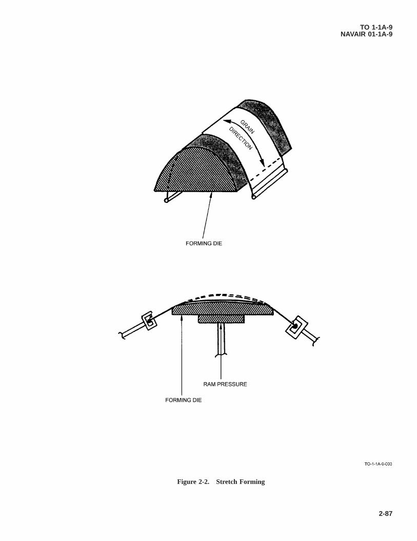
Figure 2-2. Stretch Forming
TO 1-1A-9NAVAIR 01-1A-9
2-87
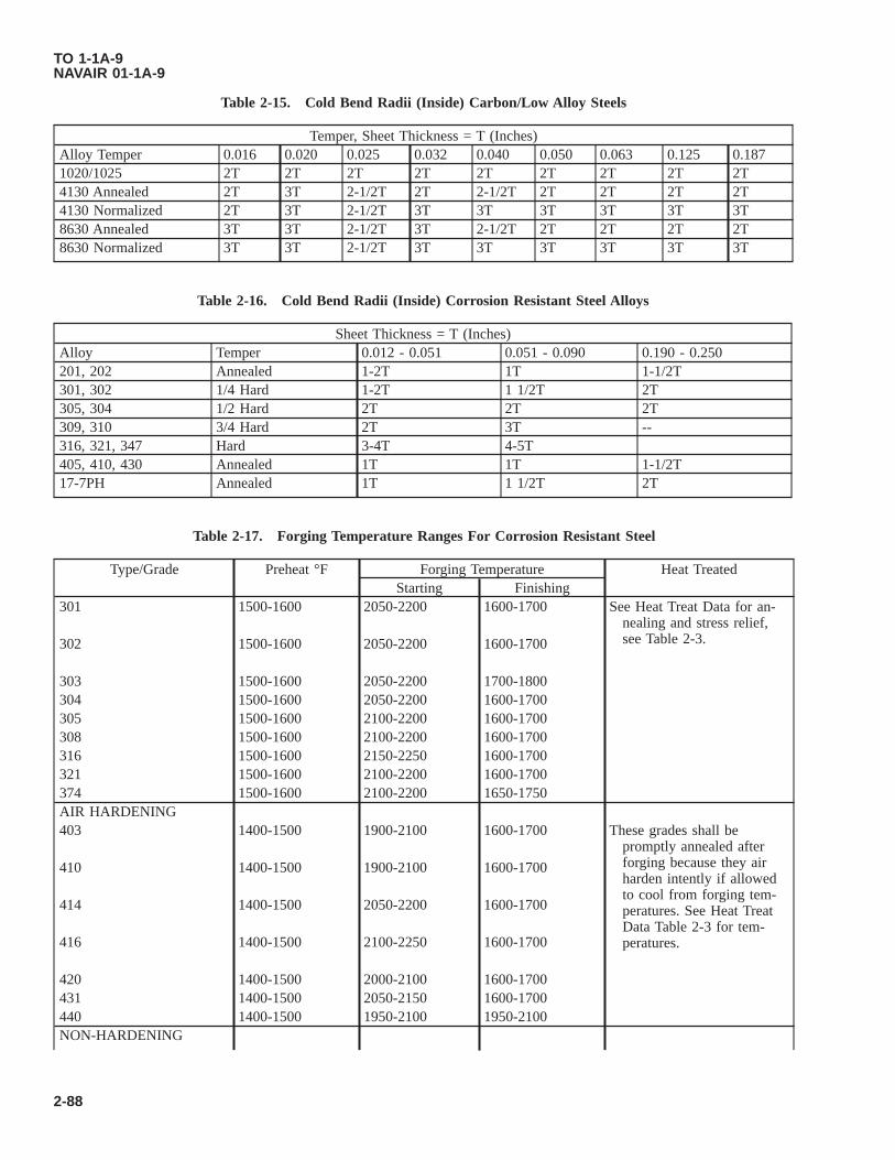
Table 2-15. Cold Bend Radii (Inside) Carbon/Low Alloy Steels
Temper, Sheet Thickness = T (Inches)Alloy Temper 0.016 0.020 0.025 0.032 0.040 0.050 0.063 0.125 0.1871020/1025 2T 2T 2T 2T 2T 2T 2T 2T 2T4130 Annealed 2T 3T 2-1/2T 2T 2-1/2T 2T 2T 2T 2T4130 Normalized 2T 3T 2-1/2T 3T 3T 3T 3T 3T 3T8630 Annealed 3T 3T 2-1/2T 3T 2-1/2T 2T 2T 2T 2T8630 Normalized 3T 3T 2-1/2T 3T 3T 3T 3T 3T 3T
Table 2-16. Cold Bend Radii (Inside) Corrosion Resistant Steel Alloys
Sheet Thickness = T (Inches)Alloy Temper 0.012 - 0.051 0.051 - 0.090 0.190 - 0.250201, 202 Annealed 1-2T 1T 1-1/2T301, 302 1/4 Hard 1-2T 1 1/2T 2T305, 304 1/2 Hard 2T 2T 2T309, 310 3/4 Hard 2T 3T --316, 321, 347 Hard 3-4T 4-5T405, 410, 430 Annealed 1T 1T 1-1/2T17-7PH Annealed 1T 1 1/2T 2T
Table 2-17. Forging Temperature Ranges For Corrosion Resistant Steel
Type/Grade Preheat °F Forging Temperature Heat TreatedStarting Finishing
301 1500-1600 2050-2200 1600-1700 See Heat Treat Data for an-nealing and stress relief,see Table 2-3.302 1500-1600 2050-2200 1600-1700
303 1500-1600 2050-2200 1700-1800304 1500-1600 2050-2200 1600-1700305 1500-1600 2100-2200 1600-1700308 1500-1600 2100-2200 1600-1700316 1500-1600 2150-2250 1600-1700321 1500-1600 2100-2200 1600-1700374 1500-1600 2100-2200 1650-1750AIR HARDENING403 1400-1500 1900-2100 1600-1700 These grades shall be
promptly annealed afterforging because they airharden intently if allowedto cool from forging tem-peratures. See Heat TreatData Table 2-3 for tem-peratures.
410 1400-1500 1900-2100 1600-1700
414 1400-1500 2050-2200 1600-1700
416 1400-1500 2100-2250 1600-1700
420 1400-1500 2000-2100 1600-1700431 1400-1500 2050-2150 1600-1700440 1400-1500 1950-2100 1950-2100NON-HARDENING
TO 1-1A-9NAVAIR 01-1A-9
2-88

Table 2-17. Forging Temperature Ranges For Corrosion Resistant Steel - Continued
Type/Grade Preheat °F Forging Temperature Heat TreatedStarting Finishing
405 1400-1500 1900-2100 1750-1850 Post annealing required. SeeHeat Treat Data Table 2-3for temperatures.430 1400-1500 1900-2100 1350-1450
442 1400-1500 1900-2000 1300-1400446 1400-1500 1800-2000 1300-1500
2.29 STEEL SURFACE FINISHES.
Metal plating is a process where an item is coated with one or more thin layers of some other metal. This is the type offinishes generally used on ferrous parts, other than organic finishes. It is usually specified when there is a need for surfacecharacteristics that the basic metal does not possess. The most commonly used types of plating are: Cadmium plate; zincplate; nickel plate; chromium plate; copper plate; tin plate; and phosphate coatings. The thickness of the plated coating isimportant since its protective value is primarily dependent on its thickness. The type of plated coatings is generally depen-dent on the characteristics desired. For protection against corrosion when appearance is unimportant, either cadmium or zinccoatings is usually used. For appearance, nickel, chromium, and silver plating are the most commonly used. For hardness,wear resistance, and buildup of worn parts, nickel and chromium plating are used. Effectiveness of most other metalliccoatings depends on their ability to provide envelope or anodic protection. Porous coatings of the more noble metals such assilver, copper, platinum and gold, tend to accelerate the corrosion of steel. For processing instructions, refer to TO 42C2-1-7.The following galvanic series table and dissimiliar metal definition in accordance with MS33586 are for use as a guide in theselection of the most suitable plating for parts subject to uses where galvanic corrosion would be a prime factor.
2.30 DEFINITION OF DISSIMILIAR METALS.
Dissimiliar metals and alloys, for the purpose of aircraft and aircraft parts construction are separated into four groups inaccordance with MS33586. Metals classified in the same group are considered similar to one another and materials classifiedin different groups are considered dissimilar to one another. The metal/material referred to in the groups is the metal on thesurface of the part; e.g., zinc includes all zinc parts such as castings as well as zinc coated parts, whether the zinc is electrodeposited, applied by hot dipping, or by metal spraying over similar or dissimiliar metal parts. The four groups are asfollows:
a. GROUP I - Magnesium and its alloys. Aluminum alloys 5052, 5056, 5356, 6061 and 6063.
b. GROUP II - Cadmium, zinc, and aluminum and their alloys (including the aluminum alloys in Group I).
c. GROUP III - Iron, lead, and tin and their alloys (except stainless steels).
d. GROUP IV - Copper, chromium, nickel, silver, gold, platinum, titaniam, cobalt, rhodium and rhodium alloys; stainlesssteels; and graphite.
NOTE
The above groups do not apply to standard attaching parts such as rivets, bolts, nuts and washers which arecomponent parts of assemblies, which will be painted prior to being placed in service unless other wise specifiedby specifications MIL-F-7179, or other approved data.
2.31 TYPES OF PLATING.
2.31.1 Cadmium Plating (AMS-QQ-P-416). The primary purpose of cadmium plating is to retard or prevent surfacecorrosion of parts. Unless otherwise specified, the plating shall be applied after all machining, brazing, welding, forming andperforating of the item has been completed. Proper safety precautions shall be observed in the event any welding or
TO 1-1A-9NAVAIR 01-1A-9
Change 8 2-89
• Threaded fasteners between 150-220 ksi (33-46 HRC) shall be baked for 23 hours minimum at 375±25 °F.
• Steel components between 160-180 ksi (36-40 HRC) shall be baked for 8 hours minimum at 375±25 °F.
• Steel components with a minimum tensile strength of 220 ksi (46 HRC) shall be baked for 23 hours minimum at375±25 °F.
2.31.1.1 All steel parts having an ultimate tensile strength of 220,000 PSI or above shall not be plated, unless otherwise specified. When permission is granted, a low embrittlement cadmium plating bath shall be used. Unless otherwise specified, Aerospace Material Specification AMS-QQ-P-416 shall be used for cadmium plate requirements. Critical parts should be magnafluxed after plating. The following alloys are not considered susceptible to hydrogen embrittlement from cadmium plating process, and therefore do not require hydrogen embrittlement relief.
• UNS S66286, UNS N07718, UNS R30159, UNS R30035, UNS N04400, UNS N06600, UNS N07750.
• 300 Series austenitic stainless steels.
2.31.2 Zinc Plating (QQ-Z-325).
Chromium and nickel electro deposits severely reduce the fatigue strength of high strength steels. All steel partshaving a tensile strength of 180,000 PSI or above should be shot-peened prior to electro plating. In addition highstrength steels are susceptible to detrimental hydrogen embrittlement when electro plated. All steel having anultimate strength of 220,000 PSI or above shall not be electro plated without specific approval of the procuringservice or responsible engineering activity. Failure to comply could result in damage to, or destruction of, equip-ment or loss of mission.
The primary purpose of zinc coatings is to retard or prevent the formation of corrosion products on exposed surfaces. Unlessotherwise specified, the plating shall be applied after all machining, brazing. welding, forming and perforating have beencompleted. All parts having a hardness greater than Rockwell C40 and higher shall be baked at 375±25 °F for 3 hours afterplating for hydrogen embrittlement relief. Zinc shall be deposited directly on the basic metal without a preliminary plating ofother metal, except in the case of parts made from corrosion resisting steels on which a preliminary plating of nickel ispermissible. Zinc plating (Type 1) should not be used in the following applications:
a. Parts which in service are subjected to a temperature of 700 °F or higher.
b. Parts in contact with structural fabric structure.
c. Parts in functional contact where gouging or binding may be a factor or where corrosion might interfere with normalfunctions.
d. Grounding contacts where the increased electrical resistance of zinc plated surfaces would be objectional.
e. Surfaces where free circulation of air does not exist and condensation of moisture is likely to occur. For additionalinformation, refer to QQ-Z-325.
2.31.3 Nickel Plating (QQ-N-290). This coating is divided into two classes. Class I, plating is intended for decorativeplating, and Class II, plating is intended for wear and abrasion resistance. Unless otherwise specified, the plating shall beapplied after all base metal heat treatments and mechanical operations such as machining, brazing, welding, forming andperforating on the article have been completed, all steel parts shall be given a stress relief at 375±25 °F (191±14 °C) for 3hours or more prior to cleaning and plating, as required, to relieve residual tensile caused by machining, grinding or coldforming. Steel parts having a hardness of Rockwell C40 and higher shall be baked at 375±25 °F for 3 hours or more and
TO 1-1A-9NAVAIR 01-1A-9
soldering operations are required on cadmium plated parts because of danger from toxic vapors during such operations. Cadmium coatings should not be used on components for space applications, high vacuum applications, or on components subjected to temperatures of 450 °F or higher. All components shall be baked within 4 hours after the plating operation for hydrogen embrittlement relief.
2-90 Change 8

within eight (8) hours after plating to provide embrittlement relief. Parts shall not be reworked flexed or subjected to anyform of stress loads after placing and prior to the hydrogen embrittlement relief treatment. The general requirements fornickel plating are specified in QQ-N-290. Nickel shall be used for the following application only in accordance withMIL-S-5002:
a. Where temperatures do not exceed 1,000 °F and other coating would not be adequate or suitable.
b. To minimize the effect of dissimilar metal contacts, such as mild steel with unplated corrosion resisting steel.
c. As an undercoat for other functional coatings.
d. To restore dimensions.
2.31.4 Chromium Plating (QQ-C-320). This coating is of two classes; Class I, intended for use as a decorative coating;and Class II, for wear resistance and corrosion protection. Heavy chromium electro deposits (0-1-10 MILS) are often used tosalvage under machine parts. Unless otherwise specified, the plating shall be applied after all basic metal heat treatments andmechanical operations such as machining, brazing, welding, forming and perforating have been completed. Hydrogen em-brittlement relief shall be in accordance with blue prints and/or applicable speciefications. All plated parts which are
TO 1-1A-9NAVAIR 01-1A-9
Change 8 2-90.1/(2-90.2 blank)


designed for unlimited life under dynamic loads shall be shot peened in accordance with military Specification MIL-S-13165prior to plating. All parts with a hardness of Rockwell C40 (180,000 PSI), after shot peening and plating, shall be baked at375±25 °F for 3 hours for hydrogen embrittlement relief. It is extensively used as an undercoating for nickel and chromiumplating.
2.31.5 Tin Plating (QQ-T-425). Tin plating is used where a neat appearance, protective coating and easy solderability areof prime importance. The base metal for tinplate shall be low carbon cold steel.
2.31.6 Phosphate Coating (MIL-P-16232). The description of phosphate coatings herein is specified as “heavy” coat-ings. Light phosphate coatings used as a paint base are covered by specification TT-C-490. Type “M” (Magnesium) coatingsare resistant to alkaline environments and should not be exposed to temperatures in excess of 250 °F. Except for specialpurpose applications, phosphate coatings should be used with a suitable supplementary treatment. Type “Z” (Zinc) coatingsshould not be used in contact with alkaline materials or temperature in excess of 200 °F. For the different classes of coatingsand required supplemental treatments, refer to MIL-P-16232. This coating should be applied after all machining, forming,welding and heat treatment have been completed. Parts having a hardness of Rockwell C40 or higher shall be given asuitable heat treat stress relief prior to plating and shall be baked subsequent to coating as follows:
a. Type “M” shall be baked at 210-225 °F for 1 hour.
b. Type “Z” shall be baked at 200-210 °F for 15 minutes (embrittlement relief).
2.31.7 Silver Plating (QQ-S-635). Silver plating (electro deposits) has high chemical and oxidation resistance, highelectrical conductivity and good bearing properties. Silver is often used as an antisieze and for preventing fretting corrosionat elevated temperatures. Silver plating shall be of the following types and grades:
a. Type I, Matte. Deposits without luster, normally obtained from silver-cyanide plating solutions operated without theuse of brighteners.
b. Type II, Semi-Bright. Semi-lustrous deposits normally obtained from silver-cyanide plating solutions operated withbrightener.
c. Type M, Bright. Sometimes obtained by polishing or by use of “brighteners”.
d. Grade A. With supplementary tarnish resistant treatment (chromate treated).
e. Grade B. Without supplementary tarnish resistant treatment.
2.31.8 Intended Use. The following applications of thicknesses are for information purposes only:
a. 0.0005 - for corrosion protection of nonferrous base metal.
b. 0.0003 - for articles such as terminals which are to be soldered.
c. 0.0005 to 0.010 - for electrical contacts, depending on pressure, friction and electrical load.
d. 0.0005 - for increasing the electrical conductivity of base metals.
e. On ferrous surfaces, the total plated thickness shall not be less than 0.001 inch. After all base-metal heat treatmentsand mechanical operations such as machining, brazing, welding, forming and perforating of the article have beencompleted, if the type is not specified, any type is acceptable. All steel parts subject to constant flexure or impacthaving a Rockwell hardness of RC40 or greater shall be heated at 375±25 °F for 3 hours for stress relief prior tocleaning and plating.
2.31.8.1 Hardened parts which have been heat treated at less than 375 °F shall not be heated as noted above, but shall betreated by any method approved by the contracting agency.
2.31.8.2 For complete information pertaining to silver plating, refer to Federal Specification QQ-S-365.
TO 1-1A-9NAVAIR 01-1A-9
2-91
2.32 SURFACE TREATMENTS FOR CORROSION AND HEAT-RESISTING STEELS AND ALLOYS.
Normally the corrosion-resisting and heat resisting alloys are unplated unless a coating is necessary to minimize the effect ofdissimiliar metal contacts. When a plating is required it shall be in accordance with specification MIL-S-5002A or otherapproved technical engineering data. Where a plating is required, steel parts plated with hard coating, such as nickel andchromium or combinations thereof, shall be processed as follows in accordance with MIL-S-5002A:
a. Plated parts below Rockwell C40 hardness and subject to static loads or designed for limited life under dynamic loads,or combinations thereof, need not be shot peened prior to plating or baked after plating.
b. Plated parts below Rockwell C40 hardness which are designed for unlimited life under dynamic loads shall be shotpeened in accordance with specification MIL-S-13165 prior to plating. Unless otherwise specified, the shot peeningshall be accomplished on all surfaces for which the coating is required and on all immediately adjacent surfaces whenthey contain notches, fillets or other abrupt changes of section size where stresses will be concentrated.
c. Plated parts which have a hardness of Rockwell C40, or above, and are subject to static loads or designed for limitedlife under dynamic loads or combination thereof, shall be baked at 375±25 °F for not less than three (3) hours afterplating.
d. Plated parts which have a hardness of Rockwell C40, or above, and are designed for unlimited life under dynamicloads, shall be shot peened in accordance with specification MIL-S-13165 prior to plating. Unless otherwise specified,the shot peening shall be accomplished on all surfaces for which the coating is required and all immediately adjacentsurfaces when they contain notches, fillets, or other abrupt changes of section size where stresses will be concentrated.After plating, the parts shall be baked at 375±25 °F for not less than 3 hours.
2.33 PASSIVATION OF STAINLESS STEELS.
The stainless steels are usually passivated after fabricating into parts to remove surface contaminates, which may causediscoloration or corrosive attack after the parts are placed in use. The process is primarily a cleaning operation whichremoves the contamination and speeds up the formation of the protective (invisible) oxide film which would occur naturallybut slower in the presence of oxygen in a normal atmosphere. The protective film formation is inherent with the stainlesssteels in normal air when they are clean. The foreign materials are removed from stainless to provide for uniform surfacecontact with oxidizing agents (Air or Acid) which forms the protective film or passive surface. In this case after the film hasformed the material is placed in a condition approaching that of maximum corrosion resistance. Any areas to which oxygencontact is prevented by contaminants or other means tends to remain activated and subject to corrosion attack.
2.33.1 Prior to Accomplishing the Passivation.
Excessive time shall not be used, as damage to parts may occur. In addition the times and temperatures shall beselected according to the alloy involved. Failure to comply could result in damage to, or destruction of, equipmentor loss of mission effectiveness.
Prior to accomplishing the passivation treatments the parts shall be cleaned, all grease, oil, wax, which might contaminatethe passivation solution and be a detriment to the passivation treatment shall be removed. Surfaces will be consideredsufficiently clean when a wetted surface is free of water breaks. After cleaning the parts will be passivated by immersing ina solution of 20-25% (Volume) nitric acid (Sp.gr 1.42) plus 1.5-2.5% (Weight) sodium dichromate with process times andtemperatures as follows:
Types Of Process Temperature Time (Minutes Minimum)I 70-90 30II 120-130 20III 145-155 10
TO 1-1A-9NAVAIR 01-1A-9
2-92

2.33.1.1 For parts made of ferritic or austenitic stainless use process Type I, II or III. For parts made of martensiticstainless steel, use process Type II or III. Within 15 minutes after above treatment, thoroughly rinse in hot water (140-160°F). Within 1 hour after hot water rinse, immerse in an agueous solution containing 4-6% sodium dichromate (by weight) at140-160 °F for 30 minutes, and rinse thoroughly with water and dry.
NOTE
After the parts are passivated they shall be handled the minimum necessary consistant with packaging, assembly/installation. Parts for installations in high temperature areas shall not be handled with bare hands because fingerprints will cause carburization and pitting of surface when heated.
2.34 VAPOR DEPOSITED COATING.
Vapor deposited coating’s are applied by exposing the base metal to a heated vaporized metallic coating such as cadmiumand aluminum in a high vacuum. The metal coating forms by condensation of the vaporized coating metal on all exposedsurfaces of the base metal. Vapor-deposited coatings can be obtained by processes in which a volatile compound of thecoating is reduced or thermally decomposed upon the heated surface of the base metal. Vapor deposited coatings are used toprovide good corrosion resistance for steel and eliminate sources of hydrogen embrittlement. Specific requirements forcoating, aluminum vacuum deposited, are cited in specification MIL-C-23217A; and for coating, cadmium vacuum depos-ited, in specification MIL-C-8837.
2.35 MECHANICAL-SURFACE FINISH.
The following paragraphs are concerned with mechanical surface finish of the geometrical irregularities of surfaces of solidmaterials and established classification for various degrees of roughness and waviness. The surface roughness of a part is ameasurement rating of the finely spaced irregularities, such as the surfaces produced by machining and abrading (abrasivehoning, grinding, filing, sanding, etc). The roughness height ratings are specified in microinches as the arithmetic average ofthe absolute deviations from the mean surface. Profilometers and other instruments used to measure surface height ifcalibrated in RMS (Root Mean Square) average will read approximately 11% higher on a given surface than those calibratedfor arithmetic average. Also associated with roughness high is roughness width, usually specified in inches and the maxi-mum permissible spacing of surface irregularities. As the arithmetic average of the absolute diviations from the meansurface. Waviness height rating (when required) may be specified in inches as the vertical distance from peaks to valleys ofthe waves, whereas waviness width is the distance in inches from peak to peak of the waves. Figure 2-3 shows the meaningof each symbol defined. The symbol used to designate surface irregularities is the check mark as shown below.
• *When waviness width value is required, the value may be placed to the right of the waviness height value.
• **Roughness width cutoff value, when required, is placed immediately below the right-hand extension.
2.35.1 Designation of Surface Finish. Surface finish should be specified for production parts only on those surfaceswhich must be under functional control. For all other surfaces the finish resulting from the machining method required toobtain dimensional accuracy is generally satisfactory. The surface chosen (unless already designated) for a specific applica-tion will be determined by its required function. Figure 2-4 gives the typical normal ranges of surface roughness of
functional parts. The values cited are microinches, for example = 63 Microinches or 0.000063 inches average devia-tion from mean.
TO 1-1A-9NAVAIR 01-1A-9
2-93
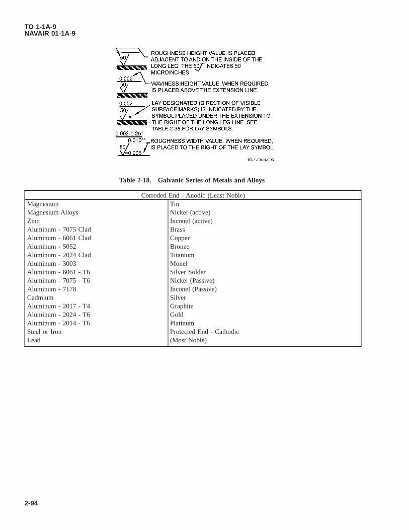
Table 2-18. Galvanic Series of Metals and Alloys
Corroded End - Anodic (Least Noble)Magnesium TinMagnesium Alloys Nickel (active)Zinc Inconel (active)Aluminum - 7075 Clad BrassAluminum - 6061 Clad CopperAluminum - 5052 BronzeAluminum - 2024 Clad TitaniumAluminum - 3003 MonelAluminum - 6061 - T6 Silver SolderAluminum - 7075 - T6 Nickel (Passive)Aluminum - 7178 Inconel (Passive)Cadmium SilverAluminum - 2017 - T4 GraphiteAluminum - 2024 - T6 GoldAluminum - 2014 - T6 PlatinumSteel or Iron Protected End - CathodicLead (Most Noble)
TO 1-1A-9NAVAIR 01-1A-9
2-94

Figure 2-3. Surface Roughness
TO 1-1A-9NAVAIR 01-1A-9
2-95

Figure 2-4. Surface Roughness and Lay Symbols
TO 1-1A-9NAVAIR 01-1A-9
2-96

CHAPTER 3ALUMINUM ALLOYS
3.1 CLASSIFICATION.
Aluminum alloys are produced and used in many shapes and forms. The common forms are casting, sheet, plate, bar, rod(round, hex, etc.), angles (extruded and rolled or drawn), channels and forgings. The inherent advantages of this material arelightweight, corrosion resistance to the atmosphere and many varieties of chemicals, thermal and electrical conductivity,reflectivity for radiant energy of all wave lengths and ease of fabrication. The above factors plus the fact that some alloys ofthis material can be formed in a soft condition and heat treated to a temper comparable to structural steel make it veryadaptable for fabricating various aircraft and missile parts.
3.2 COMMERCIAL AND MILITARY DESIGNATIONS.
NOTE
Cladding which is a sacrificial aluminum coating applied to an aluminum alloy core for the purpose of increasingcorrosion resistance is designated as alclad 2024, alclad 2014, alclad 7075, etc.
The present system utilized to identify aluminum alloys is the 4 digit designation system. The major alloy element for eachtype is indicated by the first digit (see Table 3-1) i.e., 1XXX indicates aluminum of 99.00% minimum, 2XXX indicates analuminum alloy in which copper is the main alloying element, etc. Although most aluminum alloys contain several alloyingelements only one group the 6XXX designate more than one alloying element. See Table 3-1 for complete listing. Thesecond digit of the destination indicates modification in impurity limits. If the second digit is 0 it indicates that there is nospecial control on the impurities, while numbers 1-9 which are assigned consecutively as needed indicates special control ofone individual impurity. Thus 1040 indicates 99.40% minimum aluminum without special control on individual impuritiesand 1140, 1240 etc. indicate same purity with special control on one or more impurities. The last two of the four digits inalloy groups 2XXX through 8XXX have no special significance except that they serve to designate the alloy by its formernumber, i.e., 243, 525, 758, etc. Experimental alloys are, also, designated by this system except that the 4 digit number isprefixed by an X. Aluminum alloys for military use are identified by military and federal specifications which are compa-rable to commercial specifications and designations. The following table is a general list of the commonly used military andfederal specifications according to the commercial designation and forms of material.
Table 3-1. Designations for Alloy Groups
Type Alloy1XXX - - - Aluminum 99.00% of minimum and greater2XXX - - - Copper3XXX - - - Mangenese4XXX - - - Silicon5XXX - - - Magnesium6XXX - - - Magnesium and Silicon7XXX - - - Zinc8XXX - - - Other element9XXX - - - Unused series
Table 3-2. Aluminum Alloy Designation and Conversions to 4 Digit System
Old New Major Alloying Element2S 1100 None (Aluminum 99.00X)3S 3003 Magnesium4S 3004 Magnesium
TO 1-1A-9NAVAIR 01-1A-9
3-1

Table 3-2. Aluminum Alloy Designation and Conversions to 4 Digit System - Continued
Old New Major Alloying Element11S 2011 Copper14S R301 Core 2014 Copper17S 2017 CopperA17S 2117 Copper (Special control of impurities)18S 2018 Copper24S 2024 Copper19S 2219 Copper32S 4032 Silicon50S 5050 Magnesium52S 5052 Magnesium56S 5056 Magnesium61S 6061 Magnesium and Silicon62S 6062 Magnesium and Silicon63S 6063 Magnesium and SiliconMA15 7050 Zinc- - 7475 Zinc72S 7072 Zinc75S 7075 Zinc78S 7178 Zinc79S 7079 Zinc
3.3 MECHANICAL PROPERTIES.
Prior to presenting factual data on mechanical properties the tempers (hardness) and methods of designation should beexplained. For nominal mechanical properties see Table 3-4.
3.3.1 Tempers of Aluminum Alloys. The tempers of aluminum alloys are produced essentially by three methods. Thesemethods are cold working (strain hardening), heat treatment and a combination of the two. The various alloys of aluminumare either classed as heat-treatable or non-heat-treatable. Alloys 1100, 3003, alclad 3003, 3004, alclad 3004, 5050 and 5052are classed as non-heat-treatable. The tempers of these alloys are designated by symbols H1, H2, H3, H4, F and O.
3.3.1.1 A second number added to the above indicates the degree of strain hardening-actual temper.
Example: 2 = 1/4 hard (2/8) - H12, H22, H324 = 1/2 hard (4/8) - H14, H24, H346 = 3/4 hard (6/8) - H16, H26, H368 = Full Hard (8/8) - H18, H28, H38
NOTE
Attempt should not be made to alter the temper characteristics of the “H” series of aluminum alloys other than inemergencies. This shall be limited to annealing operation only.
3.3.1.2 As previously pointed out the above tempers designation symbols are hyphen (-dash) suffixed to the 4 digit alloydesignation. Example: 1000-H12, 5052-H24, 3004-H34 etc. The general symbols used for the non-heat-treatable alloys areas follows:
• -F As fabricated
• -O Annealed
• -H21 Strain hardened only
TO 1-1A-9NAVAIR 01-1A-9
3-2
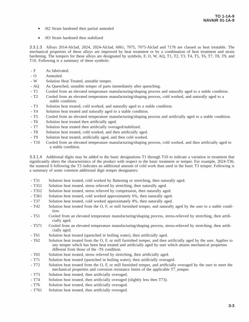
• -H2 Strain hardened then partial annealed
• -H3 Strain hardened then stabilized
3.3.1.3 Alloys 2014-Alclad, 2024, 2024-Alclad, 6061, 7075, 7075-Alclad and 7178 are classed as heat treatable. Themechanical properties of these alloys are improved by heat treatment or by a combination of heat treatment and strainhardening. The tempers for these alloys are designated by symbols, F, O, W, AQ, T1, T2, T3, T4, T5, T6, T7, T8, T9, andT10. Following is a summary of these symbols:
- F As fabricated.- O Annealed.- W Solution Heat Treated, unstable temper.- AQ As Quenched, unstable temper of parts immediately after quenching.- T1 Cooled from an elevated temperature manufacturing/shaping process and naturally aged to a stable condition.- T2 Cooled from an elevated temperature manufacturing/shaping process, cold worked, and naturally aged to a
stable condition.- T3 Solution heat treated, cold worked, and naturally aged to a stable condition.- T4 Solution heat treated and naturally aged to a stable condition.- T5 Cooled from an elevated temperature manufacturing/shaping process and artificially aged to a stable condition.- T6 Solution heat treated then artificially aged.- T7 Solution heat treated then artificially overaged/stabilized.- T8 Solution heat treated, cold worked, and then artificially aged.- T9 Solution heat treated, artificially aged, and then cold worked.- T10 Cooled from an elevated temperature manufacturing/shaping process, cold worked, and then artificially aged to
a stable condition.
3.3.1.4 Additional digits may be added to the basic designations T1 through T10 to indicate a variation in treatment thatsignificantly alters the characteristics of the product with respect to the basic treatment or temper. For example, 2024-T36,the numeral 6 following the T3 indicates an additional amount of cold work than used in the basic T3 temper. Following isa summary of some common additional digit temper designators:
- T31 Solution heat treated, cold worked by flattening or stretching, then naturally aged.- T351 Solution heat treated, stress relieved by stretching, then naturally aged.- T352 Solution heat treated, stress relieved by compression, then naturally aged.- T361 Solution heat treated, cold worked approximately 6%, then naturally aged.- T37 Solution heat treated, cold worked approximately 8%, then naturally aged.- T42 Solution heat treated from the O, F, or mill furnished temper, and naturally aged by the user to a stable condi-
tion.- T51 Cooled from an elevated temperature manufacturing/shaping process, stress-relieved by stretching, then artifi-
cially aged.- T571 Cooled from an elevated temperature manufacturing/shaping process, stress-relieved by stretching, then artifi-
cially aged.- T61 Solution heat treated (quenched in boiling water), then artificially aged.- T62 Solution heat treated from the O, F, or mill furnished temper, and then artificially aged by the user. Applies to
any temper which has been heat treated and artificially aged by user which attains mechanical propertiesdifferent from those of the -T6 condition.
- T65 Solution heat treated, stress relieved by stretching, then artificially aged.- T71 Solution heat treated (quenched in boiling water), then artificially overaged.- T72 Solution heat treated from the O, F, or mill furnished temper, and artificially overaged by the user to meet the
mechanical properties and corrosion resistance limits of the applicable T7_temper.- T73 Solution heat treated, then artificially overaged.- T74 Solution heat treated, then artificially overaged (slightly less then T73).- T76 Solution heat treated, then artificially overaged.- T761 Solution heat treated, then artificially overaged.
TO 1-1A-9NAVAIR 01-1A-9
3-3

- T81 Solution heat treated, cold worked, then artificially aged. Applies to 2024-T3 artificially aged to T81.- T851 Solution heat treated, stress-relieved by stretching, then artificially aged. Applies to 2024-T351 artificially aged
to T851.- T852 Solution heat treated, stress-relieved by compression, then artificially aged. Applies to 2024-T352 artificially
aged to T852.- T861 Solution heat treated, cold worked approximately 6%, then artificially aged. Applies to 2024-T361 artificially
aged to T861.- T87 Solution heat treated, cold worked approximately 8%, then artificially aged. Applies to 2024-T37 artificially
aged to T87.
3.3.1.5 For additional information on aluminum alloy tempers and to locate numerous others not listed in this TechnicalOrder (TO), see SAE-AS-1990.
3.3.1.6 For additional information on heat treating aluminum alloys, see Paragraph 3.4.
3.3.1.7 Chemical composition nominal plus general use data are given in Table 3-4 and nominal mechanical properties atroom temperature are given in Table 3-5. The values cited are general and intended for use as comparisons values. Forspecific values the specification for the alloy should be utilized.
3.3.2 Physical Properties. Commercially pure aluminum weights 0.098 pounds per cubic inch, corresponding to aspecific gravity of 271. Data for standard alloys are shown in Table 3-6. The approximate weight for aluminum, including itsalloys, is one-tenth of a pound per cubic inch (see Table 3-6).
Table 3-3. Aluminum Alloy Material Specifications
Alloy FormSAE AeronauticalMaterial Specifi-
cation (AMS)ASTM Federal/Military Superseded/Rescinded
1060Pipe and Tubing B210, B241Extrusions B221Plate and Sheet B209
1100
Pipe and Tubing B210, B241 AMS 4102, AMS 4062Extrusions B221 QQ-A-411, QQ-A-561, MIL-
A-12545Forgings AMS-QQ-A-225/1, AMS-
QQ-A-250/1Rolled or Drawn B211 WW-T-783, WW-T-700/1Plate and Sheet QQ-A-250 B209 QQ-A-1876 AMS 4001, AMS 4003
1230 Plate and Sheet B2092004 Plate and Sheet 4208, 42092011 Rolled or Drawn B211 QQ-A-365, AMS-QQ-A-
225/3
2014
Pipe and Tubing B210, B241 QQ-A-261, QQ-A-266,Extrusions QQ-A-200/2,
4153B221 MIL-A-12545
Forgings QQ-A-367, 4133,4134
AMS 4135
Rolled or Drawn QQ-A-225/4,4121
B211
Plate and Sheet QQ-A-250/3 B209 QQ-A-2552017 Rolled or Drawn QQ-A-225/5,
4118B211 QQ-A-430 QQ-A-351, MIL-W-7986
2018 Forgings QQ-A-367, 41402020 Plate and Sheet QQ-A-250/16, MIL-A-8882
TO 1-1A-9NAVAIR 01-1A-9
3-4

Table 3-3. Aluminum Alloy Material Specifications - Continued
Alloy FormSAE AeronauticalMaterial Specifi-
cation (AMS)ASTM Federal/Military Superseded/Rescinded
2024(Bare)
Pipe and Tubing 4086, 4087, 4088 B210, B241 WW-T-785, WW-T-700/3Extrusions QQ-A-200/3,
4152B221 QQ-A-267
Rolled or Drawn QQ-A-225/6,4120
B211 QQ-A-268
Plate and Sheet QQ-A-250/4,4035, 4037,4477, 4268,4269, 4193
B209 QQ-A-355
2024 (Al-clad)
Plate and Sheet QQ-A-250/5,4040, 4041,4461, 4462,4475, 4478,4466, 4193
B209 QQ-A-362, AMS 4042
2025 Forgings QQ-A-367, 41302098 Plate and Sheet 4327, 44572117 Rivets *SAE AS72222124 Plate and Sheet QQ-A-250/29,
4101, 4221B209
2218 Forgings QQ-A-367 AMS 4142
2219
Pipe and Tubing 4066, 4068 B241Extrusions 4162, 4163 B221Forgings QQ-A-367 MIL-DTL-46118Rolled or Drawn B211 MIL-DTL-46118Plate and Sheet QQ-A-250/30,
4031, 4094,4095, 4096,4295, 4599,4600, 4601,4613
B209 MIL-A-8720
2618 Forgings QQ-A-367, 4132 AMS 4006, AMS 4008
3003
Pipe and Tubing B210, B241 AMS 4065, AMS 4067,WW-T-700/2
Extrusions B221 AMS-QQ-A-200/1, QQ-A-357
Rolled or Drawn B211 AMS-QQ-A-225/2, QQ-A-356
Plate and Sheet B209, B632 AMS-QQ-A-250/2, QQ-A-359
3004Extrusions B221Sheet and Plate B209
3005 Sheet and Plate B209
3102Tubing B210Extrusions B221
3105 Sheet and Plate B209
4032Forgings QQ-A-367 AMS 4145Rolled or Drawn 4319 B211 AMS 4318
5005Tubing B210Sheet and Plate B209
5010 Sheet and Plate B209
TO 1-1A-9NAVAIR 01-1A-9
3-5

Table 3-3. Aluminum Alloy Material Specifications - Continued
Alloy FormSAE AeronauticalMaterial Specifi-
cation (AMS)ASTM Federal/Military Superseded/Rescinded
5050Tubing B210Sheet and Plate B209
5052
Pipe and Tubing WW-T-700/4,4069, 4070,4071
B210, B241 WW-T-787
Extrusions B221Rolled or Drawn B211 AMS-QQ-A-225/7, QQ-A-
315, AMS 4114Plate and Sheet QQ-A-250/8,
4015, 4016,4017
B209 QQ-A-318
5056 Rolled or Drawn 4182 B2115059 Sheet and Plate B209 MIL-DTL-46027
5083
Pipe and Tubing B210, B241 MIL-T-52234Extrusions QQ-A-200/4 B221 MIL-A-19005Forgings QQ-A-367Plate and Sheet 4056 B209 MIL-DTL-46027,
MIL-A-17358AMS-QQ-A-250/6, MIL-A-
8701
5086
Pipe and Tubing WW-T-700/5 B210, B241 MIL-T-52234Extrusions QQ-A-200/5 B221Plate and Sheet B209 AMS-QQ-A-250/7, AMS-
QQ-A-250/19, MIL-A-19070
5154
Pipe and Tubing B210Extrusions B221Rolled or Drawn B211Plate and Sheet B209 MIL-A-17357 AMS 4018, AMS 4019
5252 Plate and Sheet B2095254 Plate and Sheet B209
5454Pipe and Tubing B241Extrusions QQ-A-200/6 B221Plate and Sheet QQ-A-250/10 B209
5456
Pipe and Tubing B210, B241Extrusions QQ-A-200/7 B221Plate and Sheet B209 MIL-DTL-46027 AMS-QQ-A-250/9, AMS-
QQ-A-250/205457 Plate and Sheet B2095657 Plate and Sheet B2095754 Plate and Sheet B2096003 Plate and Sheet B209
6005Pipe and Tubing B241Extrusions B221
6013
Pipe and Tubing B241Extrusions B221Rolled or Drawn B211Plate and Sheet 4216, 4347 B209
6020Extrusions B221Rolled or Drawn B211
TO 1-1A-9NAVAIR 01-1A-9
3-6

Table 3-3. Aluminum Alloy Material Specifications - Continued
Alloy FormSAE AeronauticalMaterial Specifi-
cation (AMS)ASTM Federal/Military Superseded/Rescinded
6041Pipe and Tubing B241Extrusions B221
6042Pipe and Tubing B241Extrusions B221
6060 Extrusions B221
6061(Bare)
Pipe and Tubing WW-T-700/6,4079, 4080,4081, 4082,4083, 4480
B210, B241 MIL-T-7081, AMS-T-7081,WW-T-789
Extrusions QQ-A-200/8,4113, 4150,4160, 4161,4172, 4173
B221, B308 AMS-QQ-A-200/16, QQ-A-270
Forgings QQ-A-367, 4127,4146, 4248
Rolled or Drawn 4115, 4116, 4117,4128
B211 AMS-QQ-A-225/8, QQ-A-325
Plate and Sheet 4025, 4026, 4027 B209, B632 MIL-DTL-32262 AMS-QQ-A-250/11, QQ-A-327
6061 (Al-clad)
Plate and Sheet 4021, 4023 B209 AMS 4022
6063Pipe and Tubing B210, B241Extrusions 4156 B221 AMS-QQ-A-200/9, QQ-A-
274
6064Pipe and Tubing B241Extrusions B221
6066Pipe and Tubing B241Extrusions B221 MIL-A-25493 AMS-QQ-A-200/10Forgings QQ-A-367
6070Pipe and Tubing B241Extrusions B221
6082Pipe and Tubing B241Extrusions B221
6105Pipe and Tubing B241Extrusions B221
6110 Rolled or Drawn B2116151 Forgings QQ-A-367, 4125
6162Pipe and Tubing B241Extrusions B221 AMS-QQ-A-200/17
6262Pipe and Tubing B210, B241Extrusions B221Rolled or Drawn B211 AMS-QQ-A-225/10
6351Pipe and Tubing B241Extrusions B221
6360 Extrusions B2216463 Extrusions B2216560 Extrusions B2217005 Extrusions B2217011 Plate and Sheet QQ-A-250/28 B209 QQ-A-250/26
TO 1-1A-9NAVAIR 01-1A-9
3-7
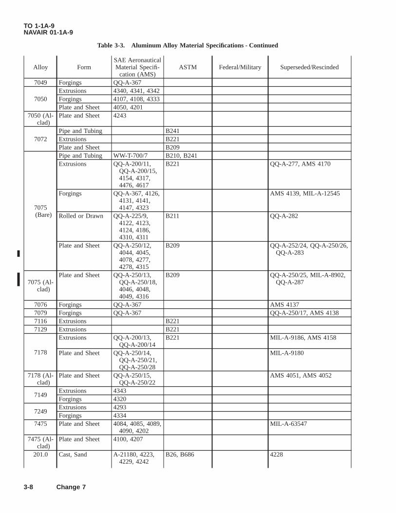
Table 3-3. Aluminum Alloy Material Specifications - Continued
Alloy FormSAE AeronauticalMaterial Specifi-
cation (AMS)ASTM Federal/Military Superseded/Rescinded
7049 Forgings QQ-A-367
7050Extrusions 4340, 4341, 4342Forgings 4107, 4108, 4333Plate and Sheet 4050, 4201
7050 (Al-clad)
Plate and Sheet 4243
7072Pipe and Tubing B241Extrusions B221Plate and Sheet B209
7075(Bare)
Pipe and Tubing WW-T-700/7 B210, B241Extrusions QQ-A-200/11,
QQ-A-200/15,4154, 4317,4476, 4617
B221 QQ-A-277, AMS 4170
Forgings QQ-A-367, 4126,4131, 4141,4147, 4323
AMS 4139, MIL-A-12545
Rolled or Drawn QQ-A-225/9,4122, 4123,4124, 4186,4310, 4311
B211 QQ-A-282
Plate and Sheet QQ-A-250/12,4044, 4045,4078, 4277,4278, 4315
B209 QQ-A-252/24, QQ-A-250/26,QQ-A-283
7075 (Al-clad)
Plate and Sheet QQ-A-250/13,QQ-A-250/18,4046, 4048,4049, 4316
B209 QQ-A-250/25, MIL-A-8902,QQ-A-287
7076 Forgings QQ-A-367 AMS 41377079 Forgings QQ-A-367 QQ-A-250/17, AMS 41387116 Extrusions B2217129 Extrusions B221
7178
Extrusions QQ-A-200/13,QQ-A-200/14
B221 MIL-A-9186, AMS 4158
Plate and Sheet QQ-A-250/14,QQ-A-250/21,QQ-A-250/28
MIL-A-9180
7178 (Al-clad)
Plate and Sheet QQ-A-250/15,QQ-A-250/22
AMS 4051, AMS 4052
7149Extrusions 4343Forgings 4320
7249Extrusions 4293Forgings 4334
7475 Plate and Sheet 4084, 4085, 4089,4090, 4202
MIL-A-63547
7475 (Al-clad)
Plate and Sheet 4100, 4207
201.0 Cast, Sand A-21180, 4223,4229, 4242
B26, B686 4228
TO 1-1A-9NAVAIR 01-1A-9
3-8 Change 7
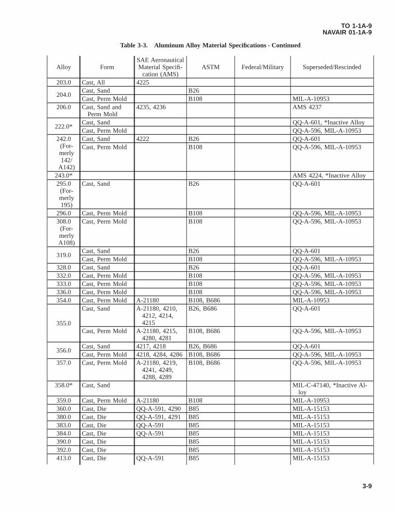
Table 3-3. Aluminum Alloy Material Specifications - Continued
Alloy FormSAE AeronauticalMaterial Specifi-
cation (AMS)ASTM Federal/Military Superseded/Rescinded
203.0 Cast, All 4225
204.0Cast, Sand B26Cast, Perm Mold B108 MIL-A-10953
206.0 Cast, Sand andPerm Mold
4235, 4236 AMS 4237
222.0*Cast, Sand QQ-A-601, *Inactive AlloyCast, Perm Mold QQ-A-596, MIL-A-10953
242.0(For-merly142/
A142)
Cast, Sand 4222 B26 QQ-A-601Cast, Perm Mold B108 QQ-A-596, MIL-A-10953
243.0* AMS 4224, *Inactive Alloy295.0
(For-merly195)
Cast, Sand B26 QQ-A-601
296.0 Cast, Perm Mold B108 QQ-A-596, MIL-A-10953308.0
(For-merlyA108)
Cast, Perm Mold B108 QQ-A-596, MIL-A-10953
319.0Cast, Sand B26 QQ-A-601Cast, Perm Mold B108 QQ-A-596, MIL-A-10953
328.0 Cast, Sand B26 QQ-A-601332.0 Cast, Perm Mold B108 QQ-A-596, MIL-A-10953333.0 Cast, Perm Mold B108 QQ-A-596, MIL-A-10953336.0 Cast, Perm Mold B108 QQ-A-596, MIL-A-10953354.0 Cast, Perm Mold A-21180 B108, B686 MIL-A-10953
355.0
Cast, Sand A-21180, 4210,4212, 4214,4215
B26, B686 QQ-A-601
Cast, Perm Mold A-21180, 4215,4280, 4281
B108, B686 QQ-A-596, MIL-A-10953
356.0Cast, Sand 4217, 4218 B26, B686 QQ-A-601Cast, Perm Mold 4218, 4284, 4286 B108, B686 QQ-A-596, MIL-A-10953
357.0 Cast, Perm Mold A-21180, 4219,4241, 4249,4288, 4289
B108, B686 QQ-A-596, MIL-A-10953
358.0* Cast, Sand MIL-C-47140, *Inactive Al-loy
359.0 Cast, Perm Mold A-21180 B108 MIL-A-10953360.0 Cast, Die QQ-A-591, 4290 B85 MIL-A-15153380.0 Cast, Die QQ-A-591, 4291 B85 MIL-A-15153383.0 Cast, Die QQ-A-591 B85 MIL-A-15153384.0 Cast, Die QQ-A-591 B85 MIL-A-15153390.0 Cast, Die B85 MIL-A-15153392.0 Cast, Die B85 MIL-A-15153413.0 Cast, Die QQ-A-591 B85 MIL-A-15153
TO 1-1A-9NAVAIR 01-1A-9
3-9

Table 3-3. Aluminum Alloy Material Specifications - Continued
Alloy FormSAE AeronauticalMaterial Specifi-
cation (AMS)ASTM Federal/Military Superseded/Rescinded
443.0(For-merly43)
Cast, Sand B26 QQ-A-601Cast, Perm Mold B108 QQ-A-596, MIL-A-10953Cast, Die QQ-A-591 B85 MIL-A-15153
444.0 Cast, Perm Mold B108 MIL-A-10953512.0 Cast, Sand B26 QQ-A-601513.0 Cast, Perm Mold B108 QQ-A-596, MIL-A-10953514.0
(For-merly214)
Cast, Sand B26 QQ-A-601
518.0 Cast, Die QQ-A-591 B85 MIL-A-15153520.0
(For-merly220)
Cast, Sand B26 QQ-A-601
535.0Cast, Sand B26 QQ-A-601, AMS 4238, AMS
4239Cast, Perm Mold B108 MIL-A-10953
705.0Cast, Sand B26 QQ-A-601Cast, Perm Mold B108 QQ-A-596, MIL-A-10953
707.0Cast, Sand B26 QQ-A-601Cast, Perm Mold B108 QQ-A-596, MIL-A-10953
710.0 Cast, Sand B26 QQ-A-601711.0 Cast, Perm Mold B108 MIL-A-10953712.0 Cast, Sand B26 QQ-A-601
713.0Cast, Sand B26 QQ-A-601Cast, Perm Mold B108 QQ-A-596, MIL-A-10953
771.0 Cast, Sand B26 QQ-A-601850.0
(For-merly750)
Cast, Sand B26 QQ-A-601Cast, Perm Mold B108 QQ-A-596, MIL-A-10953
851.0Cast, Sand B26 QQ-A-601Cast, Perm Mold B108 QQ-A-596, MIL-A-10953
852.0Cast, Sand B26 QQ-A-601Cast, Perm Mold B108 QQ-A-596, MIL-A-10953
TO 1-1A-9NAVAIR 01-1A-9
3-10

Table 3-4. Chemical Composition Nominal and General Use Data
1 Nominal Composition - %Flat andCoiledSheet
PlateShapesRods
and BarsTube Pipe Characteristics
Alloy Sili-con
Cop-per
Man-ga-nese
Mag-ne-
sium
Chro-mium Zinc Alumi-
num
EC -- -- -- -- -- -- 99.45 X Electrical conductor
1060 0.25 0.05 0.03 0.03 -- 0.05 99.60 XGood corrosion resistance, electricalconductivity, formability and weld-ability.
1100 1.0 0.20 0.05 -- 0.10 0.10 99.0 X X X X Excellent formability, readily weldedand brazed, corrosion resistant.
1145 0.55 0.05 0.05 -- -- -- 99.45 XExcellent formability combined withhigh electrical and thermal conduc-tivity and corrosion resistant.
2014 0.8 4.5 0.8 0.4 0.10 0.25 REM X X XHigh strength alloy. Electric resis-tance weldability excellent fusionweldability limited.
2024 0.5 4.5 0.6 1.5 0.10 0.25 REM X X X Popular sheet alloy for aircraft simi-lar to 2014.
2219 0.1 6.2 0.3 0.01 - 0.05 REM X X X XStrutural uses requiring high strengthup to 600 degrees Fahrenheit (°F);high strength weldments.
3003 0.6 0.20 1.2 -- -- 0.10 REM X X X XStronger than 1100 with good weld-ability and formability, high resis-tance to corrosion.
3004 0.30 0.25 1.2 1.0 -- 0.25 REM X XStronger than 1100 and 3003 withfair workability and good corrosionresistance.
5005 0.40 0.20 0.20 0.8 0.10 0.25 REM X XSimilar to 3003 in strength. Goodanodizing characteristics, formabilityand resistance to corrosion.
5050 0.40 0.20 0.10 1.4 0.10 0.25 REM X XGood anodizing strength, formabil-ity, weldability, and corrosion resis-tance.
5052 0.45 0.10 0.10 2.5 0.25 0.10 REM X XHighest strength of non-heat-treat-able alloys. Good corrosion resis-tance and finishing characteristics.
5083 0.40 0.10 0.8 4.5 0.15 0.25 REM X XHigh weld joint efficiency with basicgood strength and resistance com-bined with good formability.
TO1-1A
-9N
AVA
IR01-1A
-9
3-11
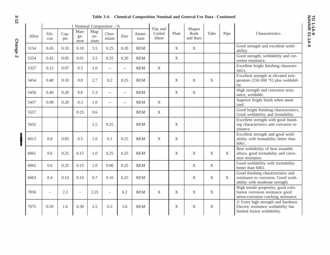
Table 3-4. Chemical Composition Nominal and General Use Data - Continued
1 Nominal Composition - %Flat andCoiledSheet
PlateShapesRods
and BarsTube Pipe Characteristics
Alloy Sili-con
Cop-per
Man-ga-nese
Mag-ne-
sium
Chro-mium Zinc Alumi-
num
5154 0.45 0.10 0.10 3.5 0.25 0.20 REM X X Good strength and excellent weld-ability.
5254 0.45 0.05 0.01 3.5 0.25 0.20 REM X Good strength, weldability and cor-rosion resistance.
5357 0.12 0.07 0.3 1.0 -- -- REM X Excellent bright finishing character-istics.
5454 0.40 0.10 0.8 2.7 0.2 0.25 REM X X XExcellent strength at elevated tem-perature (150-300 °F) plus weldabil-ity.
5456 0.40 0.20 0.8 5.3 -- -- REM X X High strength and corrosion resis-tance, weldable.
5457 0.08 0.20 0.3 1.0 -- -- REM X Superior bright finish when anod-ized.
5557 0.25 0.6 REM X Good bright finishing characteristics.Good weldability and formability.
5652 2.5 0.25 REM XExcellent strength with good finish-ing characteristics and corrosion re-sistance.
6013 0.8 0.85 0.5 1.0 0.1 0.25 REM X XExcellent strength and good weld-ability with formability better than6061.
6061 0.6 0.25 0.15 1.0 0.25 0.25 REM X X X XBest weldability of heat treatablealloys, good formability and corro-sion resistance.
6062 0.6 0.25 0.15 1.0 0.06 0.25 REM X X Good weldability with formabilitybetter than 6061.
6063 0.4 0.10 0.10 0.7 0.10 0.25 REM X X XGood finishing characteristics andresistance to corrosion. Good work-ability with moderate strength.
7050 - 2.3 - 2.25 - 6.2 REM X X X XHigh tensile properties, good exfo-liation corrosion resistance goodstress-corrosion cracking resistance.
7075 0.50 1.6 0.30 2.5 0.3 5.6 REM X X X2/ Extra high strength and hardness.Electric resistance weldability butlimited fusion weldability.
TO1-1A
-9N
AVA
IR01-1A
-9
3-12C
han
ge
2

Table 3-4. Chemical Composition Nominal and General Use Data - Continued
1 Nominal Composition - %Flat andCoiledSheet
PlateShapesRods
and BarsTube Pipe Characteristics
Alloy Sili-con
Cop-per
Man-ga-nese
Mag-ne-
sium
Chro-mium Zinc Alumi-
num
7079 0.30 0.6 0.2 3.3 0.2 4.3 REM X Similar to 7075 but maximumstrength in thick sections.
7178 2.0 0.30 2.7 0.3 6.8 REM X XHigh strength alloy for Air Cooled(AC) applications, however it isnotch sensitive.
7475 0.05 1.5 0.03 2.25 2.1 5.7 REM X X
Aerospace applications requiringhigh strength, toughness up to 300°F resistance to stress-corrosioncracking.
SI = Silicon MN = Magnesium CR = Chromium AL = Aluminum CU = Copper Magnesium = Magnesium ZN = Zinc1/ Nominal Composition Does Not Include All Alloying Elements That May Pertain, Specification Should Be Utilized When Specific Data Required.2/ 7075 - T73 Is Completely Resistant To Stress Corrosion Cracking.
TO1-1A
-9N
AVA
IR01-1A
-9
Ch
ang
e2
3-13
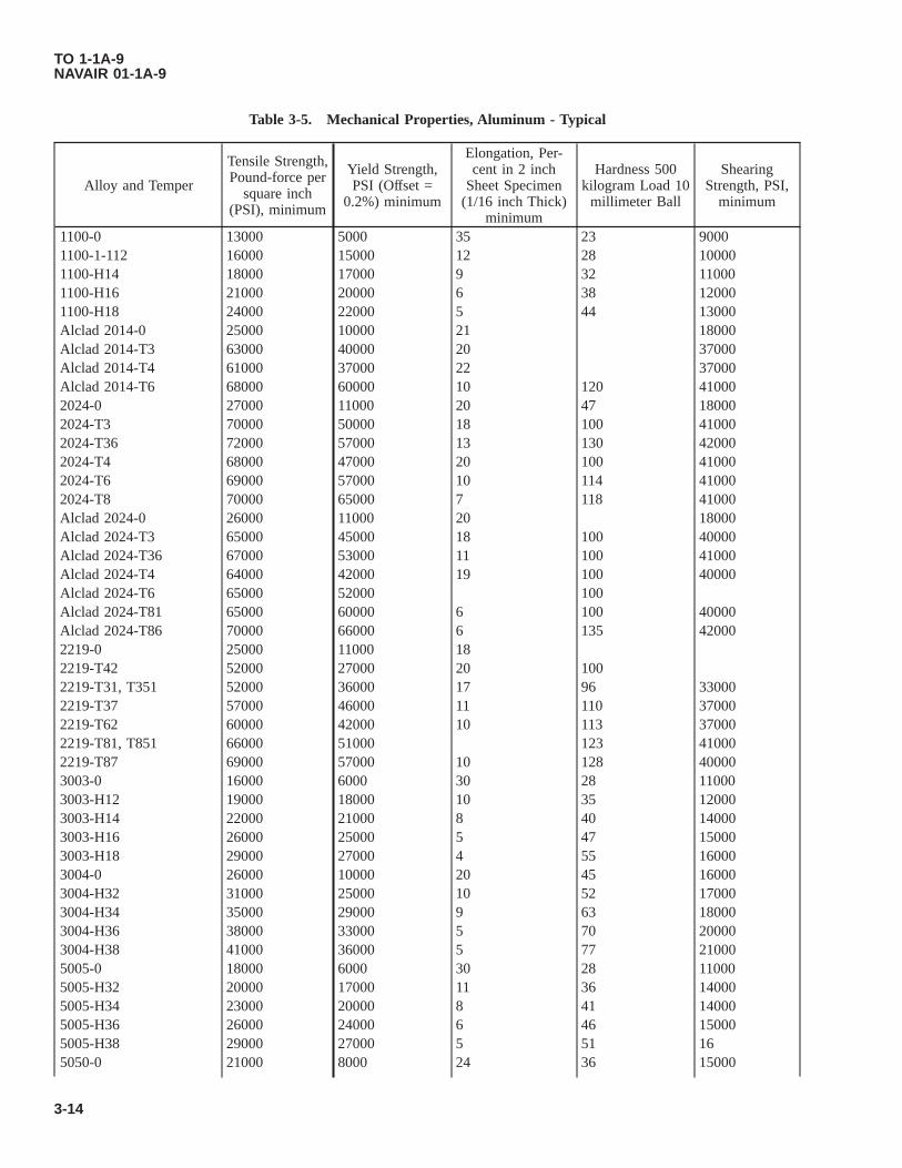
Table 3-5. Mechanical Properties, Aluminum - Typical
Alloy and Temper
Tensile Strength,Pound-force per
square inch(PSI), minimum
Yield Strength,PSI (Offset =
0.2%) minimum
Elongation, Per-cent in 2 inch
Sheet Specimen(1/16 inch Thick)
minimum
Hardness 500kilogram Load 10
millimeter Ball
ShearingStrength, PSI,
minimum
1100-0 13000 5000 35 23 90001100-1-112 16000 15000 12 28 100001100-H14 18000 17000 9 32 110001100-H16 21000 20000 6 38 120001100-H18 24000 22000 5 44 13000Alclad 2014-0 25000 10000 21 18000Alclad 2014-T3 63000 40000 20 37000Alclad 2014-T4 61000 37000 22 37000Alclad 2014-T6 68000 60000 10 120 410002024-0 27000 11000 20 47 180002024-T3 70000 50000 18 100 410002024-T36 72000 57000 13 130 420002024-T4 68000 47000 20 100 410002024-T6 69000 57000 10 114 410002024-T8 70000 65000 7 118 41000Alclad 2024-0 26000 11000 20 18000Alclad 2024-T3 65000 45000 18 100 40000Alclad 2024-T36 67000 53000 11 100 41000Alclad 2024-T4 64000 42000 19 100 40000Alclad 2024-T6 65000 52000 100Alclad 2024-T81 65000 60000 6 100 40000Alclad 2024-T86 70000 66000 6 135 420002219-0 25000 11000 182219-T42 52000 27000 20 1002219-T31, T351 52000 36000 17 96 330002219-T37 57000 46000 11 110 370002219-T62 60000 42000 10 113 370002219-T81, T851 66000 51000 123 410002219-T87 69000 57000 10 128 400003003-0 16000 6000 30 28 110003003-H12 19000 18000 10 35 120003003-H14 22000 21000 8 40 140003003-H16 26000 25000 5 47 150003003-H18 29000 27000 4 55 160003004-0 26000 10000 20 45 160003004-H32 31000 25000 10 52 170003004-H34 35000 29000 9 63 180003004-H36 38000 33000 5 70 200003004-H38 41000 36000 5 77 210005005-0 18000 6000 30 28 110005005-H32 20000 17000 11 36 140005005-H34 23000 20000 8 41 140005005-H36 26000 24000 6 46 150005005-H38 29000 27000 5 51 165050-0 21000 8000 24 36 15000
TO 1-1A-9NAVAIR 01-1A-9
3-14

Table 3-5. Mechanical Properties, Aluminum - Typical - Continued
Alloy and Temper
Tensile Strength,Pound-force per
square inch(PSI), minimum
Yield Strength,PSI (Offset =
0.2%) minimum
Elongation, Per-cent in 2 inch
Sheet Specimen(1/16 inch Thick)
minimum
Hardness 500kilogram Load 10
millimeter Ball
ShearingStrength, PSI,
minimum
5050-H32 25000 21000 9 46 170005050-H34 28000 24000 8 53 180005050-H36 30000 26000 7 58 190005050-H38 32000 29000 6 63 200005052-0 28000 13000 25 47 180005052-H32 33000 28000 12 60 200005052-H34 38000 31000 10 68 210005052-H36 40000 35000 8 73 230005052-H38 42000 37000 7 77 240005154-0 35000 17000 27 58 220005154-H112 35000 17000 25 635154-H32 39000 30000 15 67 220005154-H34 42000 33000 13 78 240005154-H36 45000 36000 12 83 260005154-H38 48000 39000 10 87 280005357-0 19000 7000 25 32 120005357-H32 22000 19000 9 40 130005357-H34 25000 22000 8 45 150005357-H36 28000 26000 7 51 170005357-H38 32000 30000 6 55 180006013-T4 47000 27000 246013-T6 59000 54000 96061-0 18000 8000 25 30 120006061-T4 35000 21000 22 65 240006061-T6 45000 35000 12 95 300007050-T74, T7451, T7452 74000 65000 13 1427075-0 33000 15000 17 60 220007075-T6 83000 73000 11 150 48000Alclad 7075-0 32000 14000 17 22000Alclad 7075-T6 76000 67000 11 125 46000Alclad 7079-T6 70000 600007178-0 40000 21000 107178-T6 83000 72000 6 1457079-T6 72000 620007475-T7351 73000 63000 14201.0-T6 60000 50000 5 115-145201.0-T7 60000 50000 3 115-145206.0-T4 40000 24000 8222.0-T6 (Sand) 30000 100-130222.0-T65 (Perm Mold) 40000 125-155242.0-T571 29000 90-120242.0-T61 (Sand) 32000 20000 90-120242.0-T61 (Perm Mold) 40000 95-125295.0-T4 29000 13000 6 45-75295.0-T6 32000 20000 3 60-90
TO 1-1A-9NAVAIR 01-1A-9
Change 2 3-15

Table 3-5. Mechanical Properties, Aluminum - Typical - Continued
Alloy and Temper
Tensile Strength,Pound-force per
square inch(PSI), minimum
Yield Strength,PSI (Offset =
0.2%) minimum
Elongation, Per-cent in 2 inch
Sheet Specimen(1/16 inch Thick)
minimum
Hardness 500kilogram Load 10
millimeter Ball
ShearingStrength, PSI,
minimum
295.0-T62 36000 28000 80-110295.0-T7 29000 16000 3 55-85296.0-T4 33000 15000 4.5 60-90296.0-T6 35000 2 75-105296.0-T7 (Perm Mold) 33000 16000 3 65-95319.0-F (Sand) 23000 13000 1.5 55-85319.0-T6 (Sand) 31000 20000 1.5 65-95319.0-F (Perm Mold) 28000 14000 1.5 70-100319.0-T6 (Perm Mold) 34000 2 75-105319.0-T61 (Perm Mold) 40000 24000 1 80-110328.0-F 25000 14000 1 45-75328.0-T6 34000 21000 1 65-95333.0-F 28000 65-100333.0-T5 30000 70-105333.0-T6 35000 85-115333.0-T7 31000 75-105336.0-T65 40000 115-130354.0-T61 48000 37000 3354.0-T62 52000 42000 2355.0-T51 (Sand) 25000 18000 2 50-80355.0-T6 (Sand) 32000 20000 2 65-95355.0-T7 (Sand) 35000355.0-T71 (Sand) 30000 22000 60-90355.0-T51 (Perm Mold) 27000 60-90355.0-T6 (Perm Mold) 37000 1.5 75-105355.0-T62 (Perm Mold) 42000 90-120355.0-T7 (Perm Mold) 36000 70-100355.0-T71 (Perm Mold) 34000 27000 65-95C355.0-T6 36000 25000 2.5C355.0-T61 (Sand) 36000 30000 1 70-100C355.0-T61 (Perm Mold) 40000 30000 3 75-105356.0-F (Sand) 19000 2 40-70356.0-T51 (Sand) 23000 16000 45-75356.0-T6 (Sand) 30000 20000 3 55-85356.0-T7 (Sand) 31000 29000 60-90356.0-T71 (Sand) 25000 18000 3 45-75356.0-F (Perm Mold) 21000 3 40-70356.0-T51 (Perm Mold) 25000 22000 3 55-85356.0-T6 (Perm Mold) 33000 22000 3 65-95356.0-T7 (Perm Mold) 25000 3 60-90356.0-T71 (Perm Mold) 25000 3 60-90A356.0-T6 (Sand) 34000 24000 3.5 55-85A356.0-T61 (Sand) 35000 26000 1A356.0-T71 (Sand) 26000 19000 4A356.0-T6 (Perm Mold) 33000 22000 5 65-95
TO 1-1A-9NAVAIR 01-1A-9
3-16 Change 2

Table 3-5. Mechanical Properties, Aluminum - Typical - Continued
Alloy and Temper
Tensile Strength,Pound-force per
square inch(PSI), minimum
Yield Strength,PSI (Offset =
0.2%) minimum
Elongation, Per-cent in 2 inch
Sheet Specimen(1/16 inch Thick)
minimum
Hardness 500kilogram Load 10
millimeter Ball
ShearingStrength, PSI,
minimum
A356.0-T61 (Perm Mold) 37000 26000 5 70-100A357.0-T6, D357.0-T6 45000 36000 3 80-110A357.0-T61 45000 36000 3 85-115359.0-T61 45000 34000 4 75-105359.0-T62 47000 38000 3 80-100520.0-T4 42000 22000 12 60-90705.0-T5 (Sand) 42000 17000 5 50-80705.0-T5 (Perm) 42000 17000 10 55-85707.0-T5 (Sand) 42000 22000 2 60-90707.0-T7 (Sand) 42000 30000 1 65-95707.0-T5 (Perm Mold) 42000 25000 4 80-110707.0-T7 (Perm Mold) 42000 35000 3 80-110712.0-T5 (Sand) 42000 25000 4 60-90713.0-T5 (Sand) 42000 22000 3 60-90850.0-T5 42000 5 45851.0-T5 42000 3 45852.0-T5 42000 18000 3 60
NOTE
To convert hardness readings between scales, see ASTM E140-07: Standard Hardness Conversion Tables. For alumi-num alloys with no hardness value provided in this technical order, refer to AMS 2658: Hardness and ConductivityInspection of Wrought Aluminum Alloy Parts.
Table 3-6. Physical Properties - Standard Aluminum Alloys
AlloySpecific Grav-
ityWeights PerCubic Inch.
Approximate MeltingRange - °F
Electrical Conductivity(%IACS)
1100-0 2.71 0.098 1,190-1,215 57-621100-H18 572014-0 2.8 0.101 950-1,180 43.5-51.52014-T3 31.5-352014-T4 31.5-35.02014-T6 35-41.5Alclad 2014-T6 35.5-442024-0 2.77 0.1 935-1,180 46-512024-T3 27.5-32.52024-T4 27.5-342024-T6 34-442024-T8 35-42.5Alclad 2024-T3 28.5-35Alclad 2024-T4 28.5-35Alclad 2024-T6 35-45Alclad 2024-T8 35-452048-T8 35-42.5
TO 1-1A-9NAVAIR 01-1A-9
Change 2 3-17

Table 3-6. Physical Properties - Standard Aluminum Alloys - Continued
AlloySpecific Grav-
ityWeights PerCubic Inch.
Approximate MeltingRange - °F
Electrical Conductivity(%IACS)
2124-T3 27.5-32.52124-T8 35-42.52219-0 2.84 0.102 1010-1190 44-492219-T3 26-312219-T37 27-312219-T4 28-322219-T6 32-362219-T8 31-352219-T87 31-35Alclad 2219-T6 32-37Alclad 2219-T8 31-373003-0 44.5-50.53003-H12 2.73 0.099 1,190-1,210 37.8-51.53003-H14 37.8-51.53003-H18 403004-0 2.72 0.098 1,165-1,205 423004-H38 425050-0 2.69 0.097 1,160-1,205 505050-H38 505052-0 2.68 0.097 1,100-1,200 34-375052-H38 355357-0 2.7 0.098 1,165-1,210 435357-H38 436013-T4 0.098 37-396013-T6 40-436061-0 2.7 0.098 1,080-1,200 42-496061-T4 35.5-436061-T6 40-47Alclad 6061-T6 40-536063-0 57-656063-T1 48-586063-T4 48-586063-T5 50-606063-T6 50-606066-0 42-476066-T4 34-416066-T6 38-507049-0 44-507049-T73 38-447049-T76 38-447050-0 2.83 0.102 890-1175 44-507050-T73 41-447050-T736 40-447050-T76 39-447075-0 2.8 0.101 890-1180 44-487075-T6 30.5-367075-T73 38-437075-T76 38-42
TO 1-1A-9NAVAIR 01-1A-9
3-18 Change 2

Table 3-6. Physical Properties - Standard Aluminum Alloys - Continued
AlloySpecific Grav-
ityWeights PerCubic Inch.
Approximate MeltingRange - °F
Electrical Conductivity(%IACS)
Alclad 7075-T6 30.5-36Alclad 7075-T76 38-427178-0 43-477178-T6 29-347178-T76 38-42Alclad 7178-T6 29-347475-0 2.8 0.101 890-1175 467475-T651 367475-T761 40201.0-T6 995-1200 29-31201.0-T7 29-31206.0-T4 1010-1200222.0-T61 965-1155 32-34242.0-T571 990-1175 34242.0-T61 32-34295.0-T62 970-1190 36-38296.0-T4, T6 970-1170 33-36319.0-T6 960-1120 27-28328.0-T4 1025-1105 29-31328.0-T6333.0-F 960-1085 25-27333.0-T5 28-30333.0-T6 28-30333.0-T7 34-36336.0-T551 1000-1050 29336.0-T65 28-30354.0-T61 1000-1105 31-33355.0-T6 1015-1150 35-37355.0-T61 35-37355.0-T7 41-43355.0-T71 38-40C355.0-T6 1015-1150 35-37C355.0-T61 36-38356.0-T51 1035-1135 42-44356.0-T6 38-40356.0-T7 39-41356.0-T71 40-41A356.0-T6A356.0-T61 38-40A356.0-T71A357.0-T6 38-40A357.0-T61 38-40D357.0-T6 38-40359.0-T61 1045-1115 34-36359.0-T62 34-36520.0-T4 840-1120 20-22705.0-T5 1105-1180 24-26707.0-T5 1085-1165 24-26
TO 1-1A-9NAVAIR 01-1A-9
Change 2 3-19

Table 3-6. Physical Properties - Standard Aluminum Alloys - Continued
AlloySpecific Grav-
ityWeights PerCubic Inch.
Approximate MeltingRange - °F
Electrical Conductivity(%IACS)
707.0-T7712.0-T5 1135-1200 34-36713.0-T5 1110-1180 29-31850.0-T5 440-1200 46-48
Other Base AlloysBrass 8.4-8.8 0.304-0.319 26-43Copper 8.94 0.322 1981 100Monel 8.8 0.318 4Nickel 8.84 0.319 2645 16Steel (low alloy) 7.6-7.8 0.276-0.282 2800 3-15Steel (18.8 stainless) 7.92 0.283 2500-2650 2-4Tin 7.3 0.265 449 15Zinc 7.1 0.258 787 30
NOTE
To convert hardness readings between scales, see ASTM E140-07: Standard Hardness Conversion Tables. For alu-minum alloys with no hardness value provided in this technical order, refer to AMS 2658: Hardness and Conductiv-ity Inspection of Wrought Aluminum Alloy Parts.
TO 1-1A-9NAVAIR 01-1A-9
3-20 Change 2

Table 3-7. Properties of Common Aluminum Alloys - Minimum
Alloy TemperProductForm
Tensile Strength, Kipsper Square Inch (KSI)
Yield Strength @2%Offset
Rockwell BScale
Rockwell EScale %IACS
Minimum Maximum Minimum Maximum Minimum Maximum Minimum Maximum Minimum Maximum
2024
O 32 14 22 70 46 51T3 63 52 63 94 27.5 32.5
T4, T42 62 38 63 94 27.5 34T6 64 50 72 98 34 44T72 60 46 72 98 38 45T8 67 58 74 99 35 42.5T86 71 66 83 37 41
Alclad2024
O 32 14 22 70 46 51
T3≤0.063 59 39 57 91 28.5 35≥0.063 61 40 60 93 28.5 35
T4, T42≤0.063 58 36 57 91 28.5 35≥0.063 61 38 60 93 28.5 35
T6≤0.063 60 47 60 93 35 45≥0.063 62 49 62 94 35 45
T8 65 56 65 97 35 45T86 69 64 83 37 41
6061O 22 12T4 30 16 60T6 42 35 47 85
Alclad6061 T6 38 32 84
7050
O 22 70 44 50T73 81 41 44T74 <0.501 82 88 38 44T76 84 39 44
7075
O 40 21 22 70 44 48T6 78 68 84 30.5 36T73 67 56 78 38 43T76 73 62 82 38 42
Alclad7075
O 38 20 22 70 44 48T6 74 64 76 30.5 36 TO
1-1A-9
NA
VAIR
01-1A-9
Ch
ang
e2
3-21

Table 3-7. Properties of Common Aluminum Alloys - Minimum - Continued
Alloy TemperProductForm
Tensile Strength, Kipsper Square Inch (KSI)
Yield Strength @2%Offset
Rockwell BScale
Rockwell EScale %IACS
Minimum Maximum Minimum Maximum Minimum Maximum Minimum Maximum Minimum Maximum
NOTE
For aluminum alloys not provided in this technical order, refer to AMS 2658, Hardness and Conductivity Inspection of Wrought Aluminum Alloy Parts,and ASTM E140, Standard Hardness Converstion Tables.
TO1-1A
-9N
AVA
IR01-1A
-9
3-22C
han
ge
2
3.4 HEAT TREATMENT OF ALUMINUM ALLOYS.
NOTE
Society of Automotive Engineers (SAE) SAE-AMS-2770, Heat Treatment of wrought aluminum alloy parts, andSAE-AMS-2771, Heat Treatment of aluminum alloy castings, are the control documents for heat treatment ofaluminum alloys used on aerospace equipment. For complete description of aluminum alloy heat treat require-ments, refer to the latest issues of SAE-AMS-2770 and SAE-AMS-2771. In case of conflict with this manual, thediscrepancy will be negotiated with the responsible technical/engineering activity for resolution and updating.
3.4.1 General. There are two types of heat treatment applicable to aluminum alloys. They are known as solution andprecipitation heat treatment. Some alloys such as 2024 and 6061 will naturally develop stronger mechanical properties as aresult of solution heat treatment and quenching, followed by 96 hours (natural aging) at room temperature. Yet, those samealloys and others, such as 7050 and 7075 require solution heat treatment, quenching, and precipitation heat treatment(artificial aging) for specific lengths of time at elevated temperatures to develop even stronger mechanical properties.
3.4.1.1 Parts requiring heat treatment to produce a final “T” temper shall be solution heat treated, immediately quenched,refrigerated if necessary to delay aging, and aged (natural or artificial) as required. Heat treatment shall be performed onlyon entire parts, never on a portion or section of a part.
3.4.1.2 For the purposes of this manual, the term “wrought” aluminum alloys will consist of sheet, plate, rod, bar,extrusions, and forgings or parts made from these materials. The term “cast” aluminum alloys will consist of sand castings,permanent mold castings, and parts machined from castings. If an exact nomenclature or specification is required, it will becalled out in applicable paragraphs, tables, or figures.
NOTE
Additional Heat Treatment information is discussed in Chapter 9.
3.5 NEWLY FABRICATED PARTS.
NOTE
Results of conductivity testing on 6061, 6063, 6066, and 6951 aluminum alloy parts shall not be used as a basis ofpart acceptance or rejection. Conductivity testing on these aluminum alloys shall be for reference use only.
Newly fabricated parts that require heat treatment shall be accompanied by a coupon, whenever possible. Coupons must beheat treated along with the manufactured part to ensure both pieces undergo the same metallurgical changes. A coupon is apiece of metal that is taken from the same stock as the fabricated part. Its thickness should match that of the part with anoverall size that provides adequate room for hardness and conductivity testing. After completion of heat treatment, all heattreated aluminum alloy parts and coupons shall be conductivity tested. In addition, perform required hardness testing on thecoupon to prevent damage to the fabricated part. See Chapter 8 of this technical order for proper hardness testing procedures.When batch processing, simultaneously heat treating multiple parts of the same material and thickness, the parts with thelowest and highest conductivity readings shall also be hardness tested to validate metallurgical changes of the batch. Partsthat fail to meet hardness or conductivity standards shall be rejected and reworked as appropriate.
3.6 RECORDS.
Air Force (AF) and government personnel shall document heat treatment procedures performed on aluminum alloy aircraftand missile weapon systems and support equipment by utilizing AFTO Form 8, Heat Treatment Procedure Record. On-siteAF contractors shall also use the Air Force Technical Order (AFTO) Form 8 unless their contract specifies a different methodof heat treatment documentation. The results of heat treatment performed on aluminum alloys shall be verified throughhardness and conductivity testing. Minimum hardness conductivity readings for commonly used aluminum alloys are speci-fied in Table 3-7. Additional conductivity data can be found in Table 3-6. Personnel performing hardness testing shalldocument results on AFTO Form 8, Blocks 21-25. Conductivity shall be tested by qualified Non-Destructive Inspection(NDI) personnel using TO 33B-1-2, WP 407 00, or qualified heat treat personnel, using direct reading instruments inaccordance with MIL-STD-1537, “Electrical Conductivity Test for Verification of Heat Treatment of Aluminum Alloys,Eddy Current Method.” Results shall be documented on AFTO Form 8, Blocks 27 - 32 and signed by performing personnel.A paper or digital copy of the completed record shall be retained by the facility performing the heat treatment process inaccordance with applicable Air Force Records Disposition Schedule guidelines.
TO 1-1A-9NAVAIR 01-1A-9
Change 1 3-22.1/(3-22.2 blank)


3.7 SOLUTION HEAT TREATMENT.
Solution heat treatment is a process where the alloying elements enter into a solid solution in the aluminum at criticaltemperatures. It has been found that those alloying elements, which increase the strength and hardness of the material, aremore soluble in solid aluminum at high temperature than at low. To manipulate the alloy into a solid solution, the metal isheld at high temperatures for sufficient time; it is then quenched rapidly in water to retain this condition. Immediately afterquenching, the alloy is in an unstable condition because it consists of a supersaturated solid solution of the hardening agent.Upon standing at room temperature the hardening constituent in excess of that which is soluble at room temperature beginsto precipitate. This precipitation is in effect a natural method where the molecules of the aluminum and alloying elements arerealigned to increase the strength and hardness of some aluminum alloys. The precipitate is in the form of extremely fineparticles, which due to their “keying” action, greatly increases their strength.
3.7.1 Heating Temperature. It is necessary that solution heat treatment of aluminum alloys be accomplished withinspecific limits in reference to temperature control and quenching. The temperature for heat treating is usually chosen as highas possible without danger of exceeding the melting point of any element of the alloy. This is necessary to obtain themaximum improvement in mechanical properties. If the maximum specified temperature is exceeded, eutectic melting willoccur. The consequence will be inferior physical properties, and usually a severely blistered surface. If the temperature ofheat treatment is low, maximum strength will not be obtained.
3.7.1.1 Obtaining the designated solution heat treating temperature is required to put all of the soluble elements into asolid solution. The required solution heat treating temperatures for various wrought and cast aluminum alloys can be foundin Table 3-8 and Table 3-10.
3.7.2 Heating (Soak) Time.
NOTE
With Alclad materials, strict conformance is required with regards to the maximum soak time. Prolonged heatingwill defeat the purpose of the cladding by allowing the copper and other soluble elements to diffuse into thecladding.
The heating time, commonly called the “soak time”, required to establish a solid solution increases with the thickness of thesection or part to be heat treated. Solution heat treatment should be held to the minimum time required to obtain the desiredphysical properties. In some instances the above will require sample testing to determine the exact solution time.
3.7.2.1 The mandatory soaking times for air furnace solution heat treatment of wrought and cast alloys are based on usingfurnace/oven control sensors (thermocouples) reflecting furnace air temperature. They include an allowance for the lagbetween air temperature and metal temperature. Therefore, basing the soak start time on a load sensor (thermocoupleattached to part) temperature and soaking for the times listed in Table 3-9 and Table 3-10 will result in excess soak time. Inthe case of solution heat treatment, it will increase clad diffusion. In the case of aging, this may result in reduced propertiesor parts not meeting required specifications. Use of load sensors should be limited to confirming that parts reached therequired temperature range, i.e., the range defined by applying the furnace temperature uniformity tolerance to the specifiedtemperature, and remained within the allowable range until the parts were quenched. See Table 3-9 and Table 3-10 for theminimum required solution heat treat soaking time for wrought and cast aluminum alloys. Although required soak time isstated as a minimum time, the time stated should be adhered to as closely as possible to prevent over soaking.
3.7.2.2 The soak time (time at temperature) starts after a successful recovery time; when all temperature control, record-ing, and monitoring sensors, measuring furnace air temperature, reach the minimum of the uniformity tolerance range for theoperation being performed. Load sensors should not be used to determine the start of soaking time. See Table 3-19 fortemperature uniformity tolerance ranges of applicable heat treat processes.
3.7.3 Interruptions. During solution heat treatment, soaking shall be performed without interruption.
3.7.4 Oven/Part Loading. Ovens used to heat treat all aluminum alloys shall be stabilized at the set point temperaturebefore loading parts. Aluminum parts and raw materials shall not be loaded into a cold oven and brought to temperature withthe oven. In the case where temperature ramping is required for a specific material, the oven shall be stabilized at the initialtemperature prior to part loading and soaking. Upon completion of the initial soak, the part and oven shall be rampedtogether to the next temperature set point, as required.
TO 1-1A-9NAVAIR 01-1A-9
3-23
3.7.4.1 When necessary, batch materials or parts should be racked to allow adequate heat transfer and airflow. Nesting isnot permitted. To prevent distortion it is necessary, in some cases, to provide jig or fixture support for complex contoured(formed) parts. However, the jig used shall be constructed so that it will not restrict the contact required (airflow) with theheating medium of the part being treated. The jig should also permit unobstructed access to the part to enable a rapid quench.
3.7.4.2 Parts having a minimum thickness of the heaviest section equal to 0.250 inch or less shall be separated by no lessthan 1 inch. Parts having a minimum thickness of the heaviest section larger than 0.250 inch will be separated by no lessthan 1 inch plus the thickness of the part. Complex parts or parts that have a large surface area, sheet or plate, may requiregreater separation to facilitate even and complete heating.
3.7.4.3 Load thermocouples/sensors, if used, shall be placed on or as close to the part as possible to measure ambient airtemperature immediately around the part/load. They shall also be placed in such a way that they will not interfere with rapidpart quenching.
3.7.4.4 Expendable base metal thermocouples may be used up to 90 calendar days after first use and for no more than 30uses when used at or below 1200 °F. For the life cycle requirements of non-expendable base metal thermocouples, seeAMS2750.
3.7.5 Oven Recovery Time. Recovery time is the time required for the oven to return to the set temperature within theuniformity allowance of the process being performed, after loading parts, but prior to the start of soak time. Recovery timefor all non-alclad aluminum parts shall not exceed 40 minutes. Recovery time for parts made from alclad material under0.125 inch thick, shall not exceed 30 minutes. Parts made from alclad material thicker than 0.125 shall not exceed 60minutes.
3.8 QUENCHING.
To obtain optimum physical properties of aluminum alloys, rapid quenching is required. The basic purpose of quenching isto prevent the immediate re-precipitation of the soluble constituents after heating the material to a solid solution. Allowingthe metal to cool before quenching promotes intergranular corrosion and negatively affects the hardness. This is caused byre-precipitation along grain boundaries and in certain slip planes. After quenching, wrought parts are in the AQ (as quenched)or W (unstable) temper condition. After quenching, cast parts are in the AQ condition. After 45 minutes at room temperatureor after the maximum refrigerated storage time has elapsed, cast parts are in the W temper condition.
3.8.1 Quench Equipment. Equipment shall be provided for quenching in water and for measuring quenchant tempera-ture. Provisions shall be made for mechanical or hydraulic agitation of the quenching medium and/or parts. Air agitationshall not be used. Quench tanks shall be located in close proximity to solution heat treating furnaces so the quench delayrequirements of Table 3-11 can be met. The quenchant volume shall be sufficient enough to prevent the quenchant tempera-ture from rising more than permitted in Paragraph 3.8.4 during quenching of a maximum load.
3.8.2 Quench Delay. Following completion of the required soak period, wrought parts shall be quenched by completeimmersion in water. Castings shall be quenched by complete immersion in water or oil, as required. All parts shall bequenched within the maximum quench delay time, based on part thickness. For maximum quench delay times, see Table3-11.
3.8.3 Quenchant Temperature. At the start of the quench, quenchant temperature shall not exceed 90 °F, except whenquenching parts made from forgings or castings. When quenching parts made from forgings or castings, the starting tem-perature of quenchant shall conform to Table 3-12. Provisions shall be provided to maintain quenchant temperature, asrequired.
3.8.4 Quenchant Temperature Rise. The quenchant temperature shall not exceed the maximum start-of-quench tem-perature specified in Paragraph 3.8.3 by more than 10 °F at any time during quenching. Additionally, for forgings andcastings, the quenchant temperature shall not increase more than 25 °F from the starting temperature as a result of quenchingany single load.
NOTE
Small parts heated and soaked in baskets such as rivets, fasteners, washers, spacers, etc., should be quenched bydumping when the basket load is too heavy/thick to allow adequate quenchant contact and rapid cooling of partsin the center of the load, provided the parts will not be damaged by dumping.
TO 1-1A-9NAVAIR 01-1A-9
3-24

3.8.5 Agitation. Parts and/or quenchant shall be agitated during quenching. For thin parts, under 0.105 inch, movementinto the quenchant during immersion is sufficient. Agitation shall continue until all evidence of boiling ceases, or uponcompletion of the required immersion time stated in Paragraph 3.8.6.
3.8.6 Immersion Time. Wrought parts 0.125 inch thick, or less, may be removed from the quenchant as soon as boilingceases. Wrought parts thicker than 0.125 inch, parts that have been racked, or parts in baskets shall be kept immersed in thequenchant for not less than 1 minute per inch of maximum thickness, or for not less than 1 minute after all evidence ofboiling ceases, whichever is longer. Cast parts shall be kept immersed for not less than 2 minutes per inch of thickness, orfraction thereof the thickest section, or for not less than 2 minutes after all evidence of boiling ceases, whichever is longer.Castings quenched in boiling water shall remain immersed for not less than 2 minutes.
3.9 STRAIGHTENING OF PARTS AFTER QUENCHING.
NOTE
Formed parts that have been unavoidably distorted should be reformed immediately after quenching.
Prior to aging, it may be necessary to straighten some parts due to warping produced by the quenching process. Warped partscan be straightened by hand manipulation, restriking, or reforming. If straightening cannot be immediately performed afterquenching, it is necessary to place the parts in refrigeration immediately after quenching to retard natural aging until suchtime straightening is accomplished.
3.10 REFRIGERATION.
Refrigeration is defined as the act of cooling or freezing. A temperature of 10 °F or below will delay or retard natural agingfor approximately 24 hours. Lower temperatures will delay natural aging longer. See Table 3-13 for refrigeration require-ments and aging delays.
3.11 PRECIPITATION HEAT TREATING (ARTIFICIAL AGING).
Precipitation heat treating is the process of soaking previously solution heat treated parts at a moderately elevated tempera-ture for a specific period of time, to enhance strength and corrosion resistance properties, and allowing to air cool. Thestrengthening of the material is due to the uniform alignment or formation of the molecular structure of the aluminum andalloying elements. Aging a material at an elevated temperature is known as artificial aging. During precipitation heattreating/artificial aging, the alloying constituents suspended in a solid solution begin to precipitate out. As the precipitationprogresses, the material strength increases until the maximum is reached. Further aging (over-aging) causes the strength todecline until a stable condition is obtained. Aging material at room temperature, although not technically a heat treatingprocess but does produce similar results, is known as natural aging. The alloying constituents naturally precipitate out andthe material gains strength as a result, but material properties of natural aging are limited. To obtain higher materialproperties, precipitation heat treatment or artificial aging must occur.
3.11.1 Artificial Aging. Artificial aging of many aluminum alloys is necessary to refine the material and obtain therequired properties. Heating most aluminum alloys, bare, alclad or cast, at an elevated temperature, usually between 225-450°F, following solution heat treatment will result in tensile and yield strengths well above those obtained by natural aging.However, this process will reduce the elongation factor of the material and increase resistance to forming. Therefore, mostforming or straightening operations should be performed prior to this stage of treatment.
NOTE
Straightening or forming of parts in the following natural and artificially aged tempers is prohibited unlessapproved by the responsible technical/engineering authority: T4 and T4X (which have sufficiently aged at roomtemperature to meet the hardness or conductivity minimum), T6, T6X, T7, T7X, and T8X.
3.11.1.1 If a T8XX condition is desired, material in a T3XX condition must be selected, formed if necessary, andprecipitation heat treated (artificially aged) to achieve the desired final temper. The tempers listed in Paragraph 3.11.1.2 arenormally furnished by mills/producers and cannot be produced by field users. Consequently, if parts or material in one ofthese tempers is specified, it should not be user solution heat treated or annealed to the O condition as you will not be ableto achieve a T3XX or T8XXX temper again.
TO 1-1A-9NAVAIR 01-1A-9
3-25

3.11.1.2 Typical mill furnished tempers: T3, T31, T351, T3510, T3511, T36, T361, T37, T451, T4510, T4511, T651,T6510, T6511, T652, T654, T7351, T73510, T73511, T7352, T7354, T73651, T736510, T7365111, T73652, T73654, T7451,T74510, T74511, T7452, T7454, T7651, T76510, T81, T851, T8510, T8511, T86, T861, T87.
3.11.1.3 Artificially aged alloys are usually slightly “over-aged” to increase their resistance to corrosion and increasechances of reaching a stabilized condition. Soak times for precipitation heat treating/artificial aging are not difficult tocontrol due to the broad tolerances for the specified times. The greatest hazard to proper aging is under soaking. Undersoaking is primarily due to not properly accounting for heavy loads, improperly racked or nested parts, and excessiveinterruptions. To properly age parts, ensure they are soaked for the specific amount of time listed in the precipitation heattreating process tables for wrought and cast aluminum alloys and follow the procedures of Paragraph 3.11.2 throughParagraph 3.11.4.1.
3.11.2 Soak Time. Soak time starts when all temperature control, recording, and monitoring sensors, measuring furnaceair temperature, reach the minimum of the uniformity tolerance range for the process being performed. Load sensors shouldnot be used to determine the start of soaking time. See Table 3-19 for temperature uniformity tolerance ranges of applicableheat treat processes. See Paragraph 3.7.5 for recovery time requirements.
3.11.3 Part Loading. Entrapped water shall be prevented from entering the furnace. The loading of wet parts directly afterbeing water/liquid quenched, into a furnace is prohibited. To allow adequate contact with the heating medium/air flow, partsshall be properly racked or spaced. Parts 0.500 inch or thicker shall be separated by not less than 1 inch. Thin parts, less than0.500, may be nested providing thickness of nested stacks does not exceed 0.500 inch and stacks are at least 1 inch apart.Furnaces shall be stabilized at the set temperature before loading parts.
3.11.3.1 Load thermocouples/sensors, if used, shall be placed on or as close to the part as possible to measure ambient airtemperature immediately around the part/load.
3.11.3.2 For the life cycle requirements of load thermocouples, see Paragraph 3.7.4.4.
3.11.4 Interruptions. During aging and annealing, a maximum of four interruptions, with doors not open for more than 2minutes during each, is permissible for the loading and removing of parts. Door opening durations greater than 2 minutes arepermitted provided the time between the door opening and the recovery of the furnace temperature is not included in thetotal soak time.
3.11.4.1 For precipitation heat treatment (artificial aging) temperature and times of wrought and cast aluminum alloys, seeTable 3-14 and Table 3-15.
3.11.5 Annealing.
Annealed aluminum parts shall not be used for parts or fittings on aircraft or missiles unless specified by drawingsor other approved engineering data. Failure to comply could result in damage to, or destruction of, equipment orloss of mission effectiveness.
Annealing is a thermal treatment used to soften metal. A full anneal will soften aluminum alloys to develop maximumformability and ductility. Aluminum alloys are annealed to remove the effects of previous heat treatments and strain hard-ening, and make the material easier to form without cracking.
3.11.5.1 Annealing and subsequent forming of material previously heat treated should be avoided. The recommendedmethod for aircraft parts is to repeat the solution heat treatment and immediately perform the forming or drawing operation.
3.11.5.2 When annealing, a full anneal shall be used unless a partial anneal or stress relief is specified in manufactureblueprints or approved by the responsible technical/engineering authority. Wrought and cast parts requiring annealing shallbe heated, soaked, and cooled as specified in Table 3-16 or Table 3-17. Subsequent solution and precipitation heat treatmentsof annealed material will result in T-6 condition, provided the material is not worked outside of the W condition prior toaging.
TO 1-1A-9NAVAIR 01-1A-9
3-26

3.11.5.3 For annealing oven temperature uniformity, part loading, recovery time, start of soak time, and interruptions, seeParagraph 3.11.2 through Paragraph 3.11.4.
3.11.6 Cold Working.
NOTE
Field accomplishment of the cold work required to produce the higher strength conditions is considered imprac-tical. This is due to the amount of control and types of equipment necessary to stretch or roll the material in orderto produce these conditions.
During prolonged forming or stamping operations metal becomes strain hardened, commonly called “work hardened”, andupon the performance of additional work it will split or crack. Parts work hardened during fabrication are annealed atvarious stages of the forming operation so that complicated shapes can be formed. Annealing will remove any propertiesdeveloped as a result of strain hardening, cold working, or other induced stresses as a result of forming the material.
3.11.6.1 Mechanical properties obtained from precipitation heat treating (artificial aging) of cold worked materials aredependent on the amount of cold work present in the material at the time of aging. Conditions T-81 or T-86 wouldnecessitate a cold work percentage of approximately 1% for T-81 and 6% for T-86 after solution heat treatment but prior toaging. The selection of material for various uses will therefore be governed by the severity of the cold work to be performedor strength and condition of the material required. The higher strength conditions can only be obtained by a controlledamount of cold work by a material producer prior to aging.
3.11.6.2 Tempers identified as cold worked and not producible at field level are T3, T8 (with the exception of artificiallyaging, without solution heat treating, T3XX to T8XX), T9 and T10. See Paragraph 3.11.1.1 and Paragraph 3.11.1.2.
3.11.7 Re-Solution Heat Treatment. Sometimes parts need to be re-solution heat treated in order to remove workinduced hardening/stress, return a part back to the W condition for additional forming or bending, post-annealing heattreatment, or simply to make a second attempt at a previous heat treatment process that did not meet hardness and conduc-tivity specifications. When re-solution heat treatment is necessary, follow the steps as detailed for solution and precipitationheat treatment, as necessary, to obtain the desired final properties of the material. There are some exceptions for re-solutionheat treatment as detailed in the paragraphs below.
3.11.7.1 Bare heat treatable wrought and cast aluminum alloys can be solution heat treated repeatedly without harmfuleffects other than high temperature oxidation. The oxidation can be retarded by ensuring that no water/fluids enter the heattreating chamber. If oxidation is occurring, ammonium fluoborate, or equivalent, should be used in air furnaces, as necessary,to absorb moisture. However, purging the furnace with fresh air may be necessary to prevent discoloration of subsequentloads of parts made from alclad product.
3.11.7.2 For alclad product, the number of solution heat treatments is limited due to the increased diffusion of the core andcladding. Parts made from alclad product over 0.125 inch in nominal thickness shall be limited to two solution heattreatments in addition to any by the material producer. Parts made from product 0.020 inch to 0.125 inch in nominalthickness, shall be limited to one additional solution heat treatment in addition to any performed by the raw materialproducer. For parts made from product under 0.020 inch in nominal thickness, additional solution heat treatments areprohibited. See Table 3-18 for the maximum re-solution heat treatments for alclad parts.
3.11.7.3 Example for multiple solution heat treatments of alclad parts; a 0.062 inch thick part made from alclad 2024-T3,formed, solution heat treated, quenched, and artificially aged to -T6 would not be allowed any further solution heat treat-ments if the material properties did not meet specs. If that same part was over 0.125 inch thick, it would be able to besolution heat treated one more time.
3.12 HEAT TREATMENT OF RIVETS.
The heat-treatable alloys commonly used for rivets are 2117, 2017, and 2024.
3.12.1 2117 (AD) Rivets. Supplied in the T-4 temper and used in the condition received. No further treatment is required.The rivet is identified by a dimple in the center of the head (see Figure 3-1, item AD for head identification).
TO 1-1A-9NAVAIR 01-1A-9
3-27
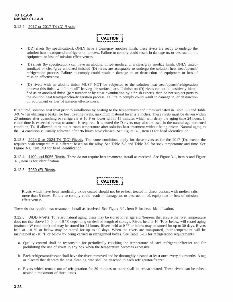
3.12.2 2017 or 2017-T4 (D) Rivets.
• (DD) rivets (by specification), ONLY have a clear/gray anodize finish; these rivets are ready to undergo thesolution heat treat/quench/refrigeration process. Failure to comply could result in damage to, or destruction of,equipment or loss of mission effectiveness.
• (D) rivets (by specification) can have an alodine, tinted-anodize, or a clear/gray anodize finish. ONLY tinted-anodized or clear/gray anodized finished (D) rivets are acceptable to undergo the solution heat treat/quench/refrigeration process. Failure to comply could result in damage to, or destruction of, equipment or loss ofmission effectiveness.
• (D) rivets with an alodine finish MUST NOT be subjected to the solution heat treat/quench/refrigerationprocess: this finish will “burn-off” leaving the surface bare. If finish on (D) rivets cannot be positively identi-fied as an anodized finish (part number or by close examination by a finish expert), then do not subject parts tothe solution heat treat/quench/refrigeration process. Failure to comply could result in damage to, or destructionof, equipment or loss of mission effectiveness.
If required, solution heat treat prior to installation by heating to the temperatures and times indicated in Table 3-8 and Table3-9. When utilizing a basket for heat treating rivets, maximum material layer is 2 inches. These rivets must be driven within20 minutes after quenching or refrigerate at 10 F or lower within 15 minutes which will delay the aging time 24 hours. Ifeither time is exceeded reheat treatment is required. It is noted the D rivets may also be used in the natural age hardenedcondition, T4, if allowed to sit out at room temperature after solution heat treatment without being driven. Natural aging tothe T4 condition is usually achieved after 96 hours have elapsed. See Figure 3-1, item D for head identification.
3.12.3 2024-0 or 2024-T4 (DD) Rivets. The same conditions apply for these rivets as for the 2017 (D), except therequired soak temperature is different based on the alloy. See Table 3-8 and Table 3-9 for soak temperature and time. SeeFigure 3-1, item DD for head identification.
3.12.4 1100 and 5056 Rivets. These do not require heat treatment, install as received. See Figure 3-1, item A and Figure3-1, item B for identification.
3.12.5 7050 (E) Rivets.
Rivets which have been anodically oxide coated should not be re-heat treated in direct contact with molten saltsmore than 5 times. Failure to comply could result in damage to, or destruction of, equipment or loss of missioneffectiveness.
These do not require heat treatment, install as received. See Figure 3-1, item E for head identification.
3.12.6 D/DD Rivets. To retard natural aging, these may be stored in refrigerator/freezers that ensure the rivet temperaturedoes not rise above 10, 0, or -10 °F, depending on desired length of storage. Rivets held at 10 °F, or below, will retard aging(maintain W condition) and may be stored for 24 hours. Rivets held at 0 °F or below may be stored for up to 30 days. Rivetsheld at -10 °F or below may be stored for up to 90 days. When the rivets are transported, their temperature will bemaintained at -10 °F or below by being carried in refrigerated boxes. See Table 3-13 for refrigeration requirements.
a. Quality control shall be responsible for periodically checking the temperature of each refrigerator/freezer and forprohibiting the use of rivets in any box when the temperature becomes excessive.
b. Each refrigerator/freezer shall have the rivets removed and be thoroughly cleaned at least once every six months. A tagor placard that denotes the next cleaning date shall be attached to each refrigerator/freezer.
c. Rivets which remain out of refrigeration for 30 minutes or more shall be reheat treated. These rivets can be reheattreated a maximum of three times.
TO 1-1A-9NAVAIR 01-1A-9
3-28

Table 3-8. Solution Heat Treating Temperatures for Wrought Aluminum Alloys
Alloy Form Set Temperature °F Notes2004 Sheet 985
2014, 2017, 2117 All 9352024, 2124, 2224 All 920
2098 All 9702219 All 995
6013Sheet 1000 7
Rod/Bar 9856061 All 985 56063 All 9856066 All 9856951 All 985 9
7049, 7149, 7249 All 875 1, 2
7050Forgings 880 2, 4, 8All Other 890 2, 4, 8
7075 All 870 67178 All 870
7475Sheet, Plate under 0.500 inch 880 3
Plate, 0.500 inch and over 890 3NOTES:1. The aging treatment for 7049, 7149, and 7249 alloys shall not be initiated until at least 48 hours at room tempera-
ture have elapsed after quenching.2. To avoid stress corrosion cracking of thick 7049, 7149, 7249, and 7050 parts, delay between quenching and start of
aging should not exceed 72 hours.3. After normal soaking, increase temperature to 920 °F for alclad and 955 °F for non-clad; minimum soaking time at
higher temperature, 15 minutes and 60 minutes, respectively.4. Solution heat treat temperatures as low as 870 °F may be used to control recrystalization and surface cracking prob-
lems.5. For 6061, an alternate solution heat treating temperature of 995 °F may be used.6. Rivets, which are to be aged to the T73 temper may be solution heat treated at 875 °F.7. Should not be solution heat treated after forming because it has a tendency to develop a large grain structure due to
recrystalization.8. Eutectic melting may occur at the specified temperature if the raw material was not properly homogenized or
worked.9. Applies to clad brazing sheet No. 21 and No. 22 - core is 6951 alloy.
Figure 3-1. Head to Alloy Identification Method
TO 1-1A-9NAVAIR 01-1A-9
3-29

Table 3-9. Solution Heat Treat Soaking Times for Wrought Aluminum Alloys
Thickness, Inches (1)
Minimum Soaking Time (2)(3)(4)(Hours:Minutes)
Salt/Fluidized Bed Air FurnaceUp to 0.020, incl 0:10 0:20
Over 0.020 to 0.032 0:15 0:25Over 0.032 to 0.063 0:20 0:30Over 0.063 to 0.090 0:25 0:35Over 0.090 to 0.125 0:30 0:40Over 0.125 to 0.250 0:35 0:50Over 0.250 to 0.500 0:45 1:00Over 0.500 to 1.0 1:00 1:30Over 1.0 to 1.5 1:30 2:00Over 1.5 to 2.0 1:45 2:30Over 2.0 to 2.5 2:00 3:00Over 2.5 to 3.0 2:15 3:30Over 3.0 to 3.5 2:30 4:00Over 3.5 to 4.0 2:45 4:30
Over 4.0 Add 0:15 per 0.500 inch Add 0:30 per 0.500 inchNotes:1. The thickness is the minimum dimension of the heaviest section at the time of heat treatment.2. For alclad product, the maximum soaking time is is 10 minutes longer than the minimum.3. Minimum soaking times for the second step of 7475 solution heat treatment are 15 minutes for alclad and 60
minutes for non-clad.4. Soak time for rivets and other small parts in baskets or on moving belts shall either be based on the full
thickness of the layer or the heat treater may determine the time required to heat the parts to the soak tem-perature range by test with load sensors and establish a soak time based on the part thickness using the deter-mined heat up time to soak.
Table 3-10. Solution Heat Treating Temperatures and Soak Times for Cast Aluminum Alloys
Alloy Temperature °F (1)Minimum SoakTime, Hours (5)
Temper After Solution Heat TreatmentAfter 45 Minimum
At Room Tem-perature
After Appropriate Delay At RoomTemperature (6)
201.0 980 (2) 14 W T4A201.0 985 (2) 14 W T4203.0 1010 (2) 5 W T4
A206.0 980 (2) 12 W T4222.0 945 6 W T4242.0 970 2 W T41243.0 965 2 W T41295.0 955 6 W T4296.0 950 4 W T4319.0 935 6 W T4328.0 960 12 W T4333.0 940 2 W T4336.0 955 6 W T45
354.0 (3) 980 10 W T41
355.0 980 6 WT4
TO 1-1A-9NAVAIR 01-1A-9
3-30

Table 3-10. Solution Heat Treating Temperatures and Soak Times for Cast Aluminum Alloys - Continued
Alloy Temperature °F (1)Minimum SoakTime, Hours (5)
Temper After Solution Heat TreatmentAfter 45 Minimum
At Room Tem-perature
After Appropriate Delay At RoomTemperature (6)
C355 985 6 W T4356.0 1000 (4) 6 W T4A356 1000 (4) 6 W T4A357 1010 (4) 8 W T4D357 1010 (4) 8 W T4
358.0 (3) 1005 20 W T4359.0 1000 10 W T4520.0 810 12 W T4712.0 990 2 W T4
NOTES:1. Unless otherwise noted, the same temperature and time apply to the other alloy modifications.2. A step solution treatment at 955 °F, for not less than 2 hours prior to the noted solution treatment, is recommended.3. For a final temper of T60 (see Table 3-15) the delay between solution treatment and aging shall be 4 to 6 hours.4. Final solution heat treatment above 1010 °F may require an intermediate solution heat treatment of 1 hour, minimum,
at 1000-1010 °F to prevent eutectic melting of magnesium-rich phases during final solution heat treatment.5. Once castings have been solution treated for the required time, re-solution treatment time may be shortened to 3
hours, minimum, unless a shorter solution heat treat time is specified above.6. Appropriate delay at room temperature is determined by hardness and conductivity testing to verify T4 temper. If
higher final temper is desired, artificial aging may take place after material is in the W condition.
Table 3-11. Maximum Quench Delay Times
Minimum Thickness, Inches (1) Maximum Time, Seconds (2)Up 0.016, Wrought 5
Over 0.016 to 0.031, Wrought 7Over 0.031 to 0.090, Wrought 10
Over 0.090, Wrought 15Castings, All 15
NOTES:1. Minimum thickness is the minimum dimension of the thinnest section of any part in the load.2. The delay time is measured from the time the furnace door of an air furnace starts to open, or the first portion of
the load emerges from a fluidized bed or salt bath or the heating zone of a continuous furnace, to complete immer-sion of the load in the quenchant.
Table 3-12. Quenching Temperature for Aluminum Forgings and Castings
Forging Casting Quenchant Temperature2014 Water 150-180 °F
2024, 2219, 6061, 7075 Water 140-160 °F7049, 7149, 7249, 7050 Water 130-160 °F
All (1) Water or Oil 150-212 °F520 Oil 300 °F
Notes:1. Unless otherwise specified.
TO 1-1A-9NAVAIR 01-1A-9
3-31

Table 3-13. Refrigeration Requirements
AlloyMaximum Delay Time Between Quench
And Refrigeration (Minutes)
Maximum Storage Temperature10 °F 0 °F -10 °F
Maximum Storage Days2XXX 15 1 30 90
All Others 30 7 30 90
Table 3-14. Precipitation Heat Treating (Aging) Process for Wrought Aluminum Alloys
FormStartingTemper(4) (5)
FinalTemper
(2)
Mand,Pref, or
Alternate(1)
1st Step 2nd Step (14) (15)
NotesAlloy Tem-perature
Time (12) Tem-perature
Time (12)
°F Hours °F Hours2XXX Sheet AQ, W T4 M Room 96 10
Other AQ, W T42 M Room 96 102004 Sheet T4 T6 M 320 17 to 19 52014 Sheet T3 T6 M 320 18 to 20 5
AllT4 T6
M 350 8 to 9 5T42 T62
2024 All AQ, W T42 M Room 96 102024
Sheet, Plate,Drawn Tube
T3 T81M 375 12 to 13
T351 T851T361 T861 M 375 8 to 9T42 T62 M 375 9 to 12 5T42 T72 M 375 16 to 18 5
ForgingsT4 T62
M 375 12 to 13 5T352 T852
Wire, RolledBar
T351 T851M 375 12 to 13
T4 T6
Extruded Barand Shapes
T351X T851XM 375 12 to 13T4 T6 5
T42 T62 52098
AllT351X T851 M 320 17 to 19
T42 T62 M 320 17 to 19 52124 Plate T351 T851 M 375 12 to 132219 Alclad Sheet T42 T62 M 375 17 to 19 5
Forgings T42 T62 M 375 25 to 27 5All Other T42 T62 M 375 35 to 37 5
SheetT31 T81 M 350 17 to 19T37 T87 M 325 23 to 25
ForgingsT352 T852 M 350 17 to 19T4 T6 M 375 25 to 27 5
PlateT351 T851 M 350 17 to 19T37 T87 M 325 17 to 19
Rivets T31 T81 M 350 17 to 19Extruded Bar
and ShapesT31 T81
M 375 17 to 19T351X T851X
6013Sheet
AQ, W T4, T42 M Room 96 10T4, T42 T6, T62 M 375 4 to 5 5
TO 1-1A-9NAVAIR 01-1A-9
3-32

Table 3-14. Precipitation Heat Treating (Aging) Process for Wrought Aluminum Alloys - Continued
FormStartingTemper(4) (5)
FinalTemper
(2)
Mand,Pref, or
Alternate(1)
1st Step 2nd Step (14) (15)
NotesAlloy Tem-perature
Time (12) Tem-perature
Time (12)
°F Hours °F Hours6061
AllAQ, W T4, T42 M Room 96 10
6063 T4 T6 P 350 8 to 10 56066 T42 T62 A 320 18 to 34 5
6951 Sheet (11)AQ, W T4, T42 M Room 96 10T4, T42 T6, T62 M 320 17 to 19 5
7049 Extruded Barand Shapes
W T73 M 250 23 to 25 330 21 to 22 6, 7, 8W T76 M 250 23 to 25 330 14 to 15 6, 8
7149 Forgings W T73 M 250 23 to 25 330 13 to 14 6, 87050 Rivets AQ, W T73 M 250 4 minimum 355 8 minimum
Plate, ExtrudedBar andShapes
AQ, W T73 M 250 6 to 8 350 11.5 to 12.5 6, 8
Plate AQ, W T76 M 250 6 to 8 350 6.5 to 7 6, 8All Except
Plate AQ, W T76 M 250 6 to 8 350 3.5 to 4.5 6, 8All AQ, W T74 (9) M 250 6 to 8 350 6 to 8 6, 8
7075
All AQ, W T6, T62 M 250 23 to 25
Sheet, Plate AQ, WT73
P 225 6 to 7 325 26 to 28 3, 8A 250 4 to 5 350 8 to 10 3, 8
T76P 225 6 to 7 325 16 to 18 8A 250 4 to 6 350 5 to 7 8
Wire, RolledBar, andForgings
AQ, WT73
P 225 6 to 7 350 8 to 10 8, 15A 250 4 to 5 350 8 to 10 8, 15
T76P 250 3 to 4 325 16 to 18 8A 225 6 to 7 325 16 to 18 8
Extruded Barand Shapes AQ, W
T73P 225 6 to 7 350 6 to 8 8A 250 4 to 5 350 6 to 8 8
T76P 250 3 to 4 320 19 to 21 8A 225 6 to 7 320 19 to 21 8
7178
All AQ, W T62 M 250 23 to 25
Sheet, Plate AQ, W T76P 250 23 to 25 325 16 to 18 8A 250 4 to 6 325 16 to 18 8
Extruded Barand Shapes AQ, W T76
P 250 23 to 25 320 18 to 20 8A 250 4 to 6 320 18 to 20 8
7249Forgings W T73 M 250 10 to 12 325 6.5 to 7.5 6, 8
Extrusions W T76 M 250 4 to 28 325 4 to 10 6, 8
7475
SheetAQ, W T61 M 250 3 to 5 315 3 to 3.25 8AQ, W T761 M 250 3 to 5 325 10 to 12 8
PlateAQ, W T6 M 250 23 to 25AQ, W T76 M 250 3 to 5 325 12 to 18 8AQ, W T73 M 250 3 to 5 325 24 to 30 8
NOTES:1. (M) Mandatory, (P) Preferred, or (A) Alternate Aging Treatment2. Digits added to these basic temper designations to denote stress relief treatments, etc. should appear identical before
and after aging. T42 and T62 are the technical designations for aging treatment performed by entities other than theoriginal material producer; previously T4 and T6 were sometimes used to designate these final tempers.
3. Either second step age may be used with either first step age interchangeably.
TO 1-1A-9NAVAIR 01-1A-9
3-33
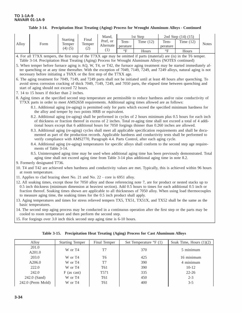
Table 3-14. Precipitation Heat Treating (Aging) Process for Wrought Aluminum Alloys - Continued
FormStartingTemper(4) (5)
FinalTemper
(2)
Mand,Pref, or
Alternate(1)
1st Step 2nd Step (14) (15)
NotesAlloy Tem-perature
Time (12) Tem-perature
Time (12)
°F Hours °F Hours4. For all T7XX tempers, the first step of the T7XX age may be omitted if parts (material) are (is) in the T6 temper.
Table 3-14. Precipitation Heat Treating (Aging) Process for Wrought Aluminum Alloys (NOTES continued)5. When temper before furnace aging is AQ, W, T4, or T42, the furnace aging treatment may be started immediately af-
ter quenching or at any time thereafter. With the exception of 7049, 7149, 7249, and 7249 alloys, natural aging is notnecessary before initiating a T6XX or the first step of the T7XX age.
6. The aging treatment for 7049, 7149, and 7249 parts shall not be initiated until at least 48 hours after quenching. Toavoid stress corrosion cracking of thick 7049, 7149, 7249, and 7050 parts, the elapsed time between quenching andstart of aging should not exceed 72 hours.
7. 14 to 15 hours if thicker than 2 inches.8. Aging times at the specified second step temperature are permissible to reduce hardness and/or raise conductivity of
T7XX parts in order to meet AMS2658 requirements. Additional aging times allowed are as follows:8.1. Additional aging (re-aging) is permitted only for parts which exceed the specified minimum hardness for
the alloy and temper by two points HRB or equivalent.8.2. Additional aging (re-aging) shall be performed in cycles of 2 hours minimum plus 0.5 hours for each inch
of thickness or fraction thereof in excess of 2 inches. Total re-aging time shall not exceed a total of 4 addi-tional hours except that 6 additional hours for 7050 forgings thinner than 0.260 inches are allowed.
8.3. Additional aging (re-aging) cycles shall meet all applicable specification requirements and shall be docu-mented as part of the production records. Applicable hardness and conductivity tests shall be performed toverify compliance with AMS2770, Paragraph 4.4. Parts Control, after each aging cycle.
8.4. Additional aging (re-aging) temperatures for specific alloys shall conform to the second step age require-ments of Table 3-14.
8.5. Uninterrupted aging time may be used when additional aging time has been previously demonstrated. Totalaging time shall not exceed aging time from Table 3-14 plus additional aging time in note 8.2.
9. Formerly designated T736.10. T4 and T42 are achieved when hardness and conductivity values are met. Typically, this is achieved within 96 hours
at room temperature.11. Applies to clad brazing sheet No. 21 and No. 22 - core is 6951 alloy.12. All soaking times, except those for 7050 alloy and those referencing note 7, are for product or nested stacks up to
0.5 inch thickness (minimum dimension at heaviest section). Add 0.5 hours to times for each additional 0.5 inch orfraction thereof. Soaking times shown are applicable to all thicknesses of 7050 alloy. When using load thermocouplesto measure aging time, the soaking times for the 0.5 inch product shall apply.
13. Aging temperatures and times for stress relieved tempers TX5, TX51, TX51X, and TX52 shall be the same as thebasic temperatures.
14. The second step aging process may be conducted in a continuous operation after the first step or the parts may becooled to room temperature and then perform the second step.
15. For forgings over 3.0 inch thick second step aging time is 6-10 hours.
Table 3-15. Precipitation Heat Treating (Aging) Process for Cast Aluminum Alloys
Alloy Starting Temper Final Temper Set Temperature °F (1) Soak Time, Hours (1)(2)201.0
W or T4 T7 370 5 minimumA201.0203.0 W or T4 T6 425 16 minimum
A206.0 W or T4 T7 390 4 minimum222.0 W or T4 T61 390 10-12242.0 F (as cast) T571 335 22-26
242.0 (Sand) W or T4 T61 450 2-3242.0 (Perm Mold) W or T4 T61 400 3-5
TO 1-1A-9NAVAIR 01-1A-9
3-34

Table 3-15. Precipitation Heat Treating (Aging) Process for Cast Aluminum Alloys - Continued
Alloy Starting Temper Final Temper Set Temperature °F (1) Soak Time, Hours (1)(2)243.0 W or T41 T61 425 2-3295.0 W or T4 T62 310 12-20296.0 W or T4 T6 310 2-8319.0 W or T4 T6 310 2-6328.0 W or T4 T6 310 2-5333.0 F (as cast) T5 400 7-9333.0 W or T4 T6 310 2-5333.0 W or T4 T7 500 4-6336.0 W or T45 T65 340 14-18354.0 W or T41 T61 310 10-12354.0 W or T41 T62 340 6-10355.0 W or T4 T6 310 2-6355.0 W or T4 T61 310 6-10355.0 W or T4 T7 440 3-5355.0 W or T4 T71 475 3-6
C355.0 W or T4 T6 310 3-6C355.0 W or T4 T61 310 10-12356.0 F (as cast) T51 440 6-12356.0 W or T4 T6 310 1-6356.0 W or T4 T7 400 3-6356.0 W or T4 T71 475 3 minimum
A356.0 W or T4 T6 310 2-6A356.0 W or T4 T61 310 6-10A356.0 W or T4 T71 475 3-6A357.0 W or T4 T61 320 6-10A357.0
W or T4 T6 320 2-12D357.0358.0 W or T4 T6 325 2-8358.0 W T60 (3) 330 2-4359.0 W or T4 T61 310 8-12359.0 W or T4 T62 340 6-10705.0 F (as cast) T5 210 10 minimum707.0 F (as cast) T5 310 3-5712.0 F (as cast) T5 355 9-11713.0 F (as cast) T5 250 16 minimum850.0
F (as cast) T5 4305 minimum
851.07-9
852.0NOTES:1. Unless otherwise noted, the same temperature and time may be used for the aother alloy modifications to arrive at
the same temper. Ex., A357.0, B357.0, C357.0, D357.0, etc.2. Soak times are recommendations that produce the desired temper with a high rate of accuracy. Other times may be
required depending upon casting configuration and property requirements.3. See Table 3-10 for delay between solution heat treating and aging.
TO 1-1A-9NAVAIR 01-1A-9
3-35

Table 3-16. Annealing - Wrought Aluminum Alloys
Alloy Full Anneal Partial Anneal (Stress Relief ) (5)Temperature °F
(1)Soak Time,Hours (2)
Cooling Me-dium
Temperature °F (1) Soak Time,Hours (2)
Cooling Me-dium
1100630-660
0.5 Air50523003 720-770 0.5 Air
2XXX750-800
1Furnace (3) or
(4)630-660
0.5 Air6XXX7XXX 750-800 2 Furnace (4) 630-660 2 Air
NOTES:1. Any temperature within the set temperature range may be used.2. Soak times listed are for up to 0.5 inch maximum thickness. Add 0.5 hour for each additional 0.5 inch of product or
nested stack thickness of fraction thereof over 0.5 inch.3. Furnace cool at 50 °F per hour, maximum, to 500 °F. Air cool to room temperature.4. Furnace cool at 50 °F per hour, maximum, to 450 °F. Hold at 450 °F for 6 hours. Furnace or air cool to room tem-
perature.5. Prior to solution heat treatment, in-process parts needing additional forming operations or needing control of grain
size may receive an interim stress relief treatment in a controlled temperature liquid bath per AMS2750 as an alter-nate to a furnace stress relief. The temperature shall not be less than 645 °F and shall not exceed the solution heattreating temperaure for the alloy being processed. Immersion time shall not exceed 10 minutes.
Table 3-17. Annealing - Cast Aluminum Alloys
Alloy Temperature °F Soak Time, Hours (1) Cooling Medium200 Series 800 1 Air300 Series 825 1 Air500 Series 725 5 Air
NOTE:1. Soak times listed are for sections up to 0.5 inch maximum thickness. Add 0.5 hour for each additional 0.5 inch of
product or nested stack thickness or fraction thereof.
Table 3-18. Re-Solution Heat Treatment of Alclad Alloys
Thickness, Inches (1) Number Of Solution Heat Treats, Maximum (2)Under 0.020 0
0.020 to 0.125 1Over 0.125 2
Notes:1. The thickness is the minimum dimension of the heaviest section at the time of heat treatment.2. In addition to any performed by the raw material producer. Annealing and precipitation treatments are not considered
solution heat treatments.
3.13 HEAT TREATING EQUIPMENT.
In order to properly heat treat aerospace metals, you will need thermal processing equipment capable of precisely anduniformly controlling temperature, and independent temperature measuring equipment to perform system checks in betweenPMEL calibration intervals. The thermal processing equipment used in the heat treatment of metals is divided into twodistinct groups. They are liquid baths and atmosphere ovens. Both groups are heated by gas, electricity or oil, and havecertain advantages over the other. It is generally advisable to weigh the advantages, disadvantages, and consider environ-mental impacts and safety conditions before deciding on one. Regardless of the method utilized it must be demonstrated that
TO 1-1A-9NAVAIR 01-1A-9
3-36

heat treated material is not degraded by the process and satisfactory results are obtained. Additionally, independent testinstrumentation/temperature measuring devices, also called field test instruments, come in many configurations and accuracylevels. A substantial amount of the difficulties encountered in heating aluminum alloys is due to improper or inadequatetemperature control and circulation of the heating medium. When difficulties arise, the function of these systems should bechecked prior to performing other system checks. Basic heat treatment equipment requirements are detailed below.
3.13.1 Air Furnaces/Ovens.
NOTE
SAE-AMS-2750, Pyrometry, is the control document for equipment used to heat treat aerospace materials. AMS-2750 covers temperature sensors, instrumentation, system accuracy tests, and temperature uniformity surveys. Fora complete description of pyrometry requirements for heat treating equipment, refer to the latest issue of SAE-AMS-2750. In case of conflict with this manual, the discrepancy will be negotiated with the responsible technical/engineering activity for resolution and updating.
The term furnace and oven are interchangeable terms when talking about heat treating equipment. Generally, furnacesoperate at higher temperatures and ovens operate at lower temperatures. Air furnaces/ovens are ideal for precipitation(aging), thermal treatments and annealing. These furnaces are also very good for solution heat treating. The initial cost ofthese type furnaces is higher than for the salt bath types, but they are usually safer, cleaner, more flexible, and moreeconomical to operate. If gas or oil fired, the products of combustion must be excluded from the furnace atmosphere to helpavoid high temp oxidation and atmosphere contamination. This is not an issue with electric furnaces and ovens, however, ifthe atmosphere is intentionally altered or inerted, care must be taken when the operator off-gasses the chamber prior to partremoval. Air furnaces also come in two forms with regards to air movement inside the heating chamber; still air andrecirculating air (convection). The still air type is capable of achieving higher temperatures than the circulating air type, butit also suffers greater temperature uniformity variances. Still air furnaces are generally designed to operate above 1000 °Fand are better suited for ferrous alloy heat treating operations. The circulating air furnace is ideal for aluminum heat treatoperations as it is generally capable, depending on build quality and process controls, of holding very tight temperatureuniformity as a result of the convection process. The primary limitation of this type of furnace is the maximum effectiveoperating temperature of around 1200 °F.
3.13.1.1 Air furnaces/ovens used for heat treatment of aluminum alloys used on aircraft shall be of the convection orrecirculating air type. The heated air in this type furnace is recirculated at high velocities to obtain a rapid heating cycle anduniform temperatures. The ideal set up for an aerospace maintenance facility that performs solution and precipitation heattreatment is a dual chamber oven with both chambers capable of independent operation and circulating air, or two separatecirculating air ovens. This set up helps reduce overall heat treat time by eliminating the wait time required for equipment tostabilize at different temperatures for various heat treat processes.
3.13.1.2 Ovens used for solution and precipitation heat treatments of aircraft parts shall be a minimum of class 2, capableof maintaining ±10 °F temperature uniformity with Type D controlling, monitoring, and recording instrumentation. Theseovens can also be inherently used for annealing and stress relieving. See Table 3-19 and Table 3-22 for other aluminum heattreat process temperature uniformity and instrumentation requirements.
3.13.2 Salt Bath Furnace. The salt bath method has certain advantages over the air furnace. However, the advantages areusually confined to solution heat treatment only. Associated advantages are uniform temperature without excess danger ofhigh temperature oxidation and more efficient heat transfer which reduces the time required to bring the load to temperature.This method is adaptable for solution heat treating varying part thickness and complex shapes. The above advantages may becompletely nullified by the slower quench caused by the necessary arrangement of equipment, molten liquid burn hazards,explosion hazards, increased hazmat footprint, and decomposition of the sodium nitrate which when dissolved in quenchingwater forms a compound that attacks aluminum alloys.
3.13.2.1 Salt baths must be operated with caution to prevent explosions or spatter as any water on the material beingtreated is instantly transformed to steam upon immersion in the salt bath.
3.13.2.2 Hollow core castings or wrought machined parts where the salts are likely to be difficult or impossible to removeshall not be heat treated in a salt bath.
3.13.2.3 Nitrate charged salt baths should not be used to heat-treat aluminum alloys types 5056 and 220 due to the factthat the bath compounds will attack the alloy.
TO 1-1A-9NAVAIR 01-1A-9
3-37

3.13.3 Field Test Instruments. Field test instruments are used in conjunction with thermocouples to measure the operat-ing temperature inside the oven chamber. They are used to monitor load thermocouples (TCs), perform System AccuracyTests (SAT), and temperature uniformity surveys (TUS). They range from hand held single input units to suitcase stylemulti-input units. Many modern units come with software to log and record data. Field test instruments used to performSATs and monitor load TC shall have a minimum of 1 input channel, a calibration accuracy of ±1 °F or ±0.1% of thereading, whichever is greater, and the ability to log/record data. Field test instruments used to perform TUSs shall have aminimum of 9 input channels, a calibration accuracy of ±1 °F or ±0.1% of the reading, whichever is greater, and the abilityto log/record data. National Stock Number (NSN) 6625-01-649-1136 is an example of a multi-point field test unit that logsdata and can be used for multiple heat treatment process test, measuring, and recording applications such as SATs and TUSs.
3.13.4 Controlling, Monitoring, and Recording Equipment. Instrumentation type for controlling, monitoring, and re-cording equipment is broken down into five categories. Each category is based on how many controlling, monitoring, andrecording TCs are operational in an oven chamber. The most common instrumentation type is Type D. Oven controllers,monitoring, and process recording equipment shall be digital and have a calibration accuracy of ±2 °F or 0.2% of thereading, whichever is greater. Field test instruments can temporarily be used as monitoring/recording equipment to monitorand record heat treatment processes when on-board oven equipment is inoperable or non-digital, ie; paper chart recorders.See Table 3-22 for oven instrumentation types.
3.13.5 TC. A TC is a thermoelectric device used to accurately measure temperatures. TCs consist of a wire with two leadsof dissimilar metal. The leads are joined at one end by welding or tightly twisting the ends together. Heating the jointproduces an electric current. This current is converted to a temperature reading with a field test instrument or other TCmonitoring unit.
3.13.5.1 TCs may be purchased individually or as a spool and constructed to form a measuring junction. The measuringjunction, i.e. hot junction, can be formed by welding or twisting the TC wire elements together. Welded TCs (Figure 3-2) areless prone to problems and should be used when available. Twisted TCs (Figure 3-3) do not form as reliable a junction as awelded TC and their reliability decreases with repeated use. If necessary, a twisted TC may be made by overlapping the bareends of the two TC wires 1/4 inch and at 90 degrees to each other. Tightly twist the wire four to five times and cut off theexcess wire; safety wire pliers are an ideal tool for producing a tight twist. The temperature reading will be measured at thetwist closest to the field test instrument.
3.13.5.2 The most common type of TC used in SATs, TUSs, and load TC monitoring is Type K expendable with a hightemperature insulation, such as Silica or Nextel fiber. TCs that are insulated with either fiberglass, plastic, hard fired ceramicbeads, or metal over braid are classified as Expendable TCs. Type K TCs are nickel based. The wire color coding conformsto ANSI MC 96.1. The positive (+) lead is nickel-chromium (Nickel-Chromium) and has yellow insulation. The negative (-)lead is nickel-aluminum (Nickel-Aluminum) and has red insulation. In some cases, TCs are required to be within a specifiedrange of length to ensure their accuracy; consult the temperature monitoring equipment owner’s manual for guidance. If noguidance exists, TCs should be between 10 and 50 feet long. See Table 3-20 for more information about base metal TCs.
Figure 3-2. Welded Thermocouple Wire
TO 1-1A-9NAVAIR 01-1A-9
3-38 Change 6

3.13.5.3 Inspection, Prior to Use. Perform the following inspection steps prior to each use:
a. Inspect the junction for breaks or looseness. If the TC junction is questionable, test for continuity with a thermocoupletester or multi-meter to measure the resistance between the two ends on the connector plug or bare wire ends; if theresistance is greater than 1 ohm (Ω), repair or replace as necessary.
b. Inspect insulation for tears or abrasions that expose bare wire. If bare wire is exposed, trim or replace TC as necessary.
c. Ensure TCs are compatible with the units reading them (e.g., a Type-k thermocouple should be attached to a Type-kmonitoring unit). The monitor should be as close as practical to the end of the TC. For standard 24-gauge wire, thedistance shall not exceed 100 feet. Distances greater than 100 feet can produce incorrect readings.
d. Plug the TCs into the monitor and ensure they read ambient temperature. If your hands are warmer than the ambienttemperature, place each TC tip between your fingers and observe the temperature rise. If it does not respond properly,replace the TC.
3.13.5.4 TC usage shall be tracked and documented. A simple method is a tag attached to the TC or set of TCs, near thecold junction, that can be annotated with each use. A “use” is defined as one cycle of heating and cooling.
3.13.5.4.1 Base metal expendable TCs used solely for SAT and TUS below 1200 °F and is not damaged can be reused upto 5 times or 3 months, whichever comes first. TC used above 1200 °F shall be limited to a single use.
3.13.5.4.2 Base metal expendable TCs used for load monitoring below 500 °F may be used for up to 90 calendar daysafter first use or for no more than 10 uses, whichever comes first. Load TCs used between 500-1200 °F shall be limited to90 calendar days or five uses, whichever comes first. Load TCs used above 1200 °F are limited to one use.
Figure 3-3. Twisted Thermocouple Wire
TO 1-1A-9NAVAIR 01-1A-9
Change 7 3-39

3.13.5.5 Thermocouple calibration and accuracy. TCs that are to be used with calibrated indicators do not require calibra-tion, other than manufacture’s calibration, if they bear the designation E, J, K, R, S, or T. These designations show that thethermocouple or wire has been manufactured in accordance with one or more of the following standards for the wire typeindicated, ANSI/MC96.1, BS 1843, DIN 43714, JIS C 1610-1981 or NF C 42-323. Thermocouple wires manufactured tothese specifications have been certified by the manufacturer and do not require special initial or subsequent calibration.
3.13.5.5.1 TCs must be supplied with the manufacturer’s initial calibration certificate or deviation limits certification. Thecalibration or deviation limits supplied with each individual TC or TC spool must be entered into to the field test instrumentfor proper temperature offset and indication each time TCs are changed or replaced.
3.13.5.5.2 Maximum allowable error for TUS, load, and SAT TCs are ±2 °F.
3.14 TEMPERATURE CONTROL AND UNIFORMITY TESTING.
Precise temperature control is essential to produce the exact material properties and temper requirements necessary formodern aviation manufacturing and maintenance. Periodic surveys and tests of the internal chamber temperatures must beconducted, documented and compared to the set point temperatures of the oven/furnace controller to ensure accurate equip-ment operation. The two methods used to ensure accurate operation of heat treating equipment are the SAT and the TUS.The SAT is a quick and simple user test to ensure the oven temperature remains accurate in between TUSs. The TUS is amore thorough user test to ensure temperature accuracy and uniformity in the entire oven chamber as compared to the ovencontrol sensor and SAT. These two tests work in conjunction with each other as a checks and balance system to ensureaccurate and uniform oven operation. If one is accurate and the other is not, that is a sign that your oven needs trouble-shooting or maintenance to correct a deficiency.
3.14.1 System Accuracy Test (SAT). A SAT is performed to assess the accuracy of the heat treat oven’s residentthermocouple and controller. This is done through the use of an independently calibrated field test instrument and thermo-couple. By placing the test thermocouple within 3 inches of the resident thermocouple and taking a reading with the field testinstrument, the accuracy of the oven’s controller and resident thermocouple is validated. If the difference between the fieldtest instrument and the oven controller is greater than ±3 °F, then that is an indication of required maintenance or adjustmentof the oven, oven controller, and/or resident thermocouple.
3.14.1.1 A SAT shall be performed and documented using a field test instrument that meets the requirements of Paragraph3.13.3 and a TC that meets the requirements of Paragraph 3.13.5.5.2, on each oven chamber used to perform aluminum heattreating, at the following intervals/situations:
a. Initial. Upon initial oven installation, prior to first operational use.
b. Periodic. SAT frequency is based on frequency of aluminum heat treating operations and oven instrumentation type.See Table 3-22 for instrumentation types.
(1) Shops that perform daily heat treating operations, utilizing Type D instrumentation, shall perform SATs on aweekly basis, not to exceed 7 calendar days. If utilizing Type B or Type C instrumentation, the SAT interval maybe extended to biweekly, not to exceed 14 calendar days.
(2) Shops performing weekly to biweekly heat treating operations, every 5 to 14 calendar days, utilizing Type Dinstrumentation, shall perform SATs on a biweekly basis, not to exceed 14 calendar days. If utilizing Type B orType C instrumentation, the SAT interval may be extended to monthly, not to exceed 31 calendar days.
(3) Shops performing biweekly to monthly heat treating operations, every 15 to 30 calendar days, utilizing Type Dinstrumentation, shall perform SATs on a monthly basis, not to exceed 31 calendar days. Use of Type B or TypeC instrumentation is recommended, but the SAT interval will not be extended.
(4) Shops performing heat treating operations less frequent than every 30 calendar days, regardless of instrumenttype, will perform a SAT prior to use/heat treating operation.
(5) If utilizing Type A instrumentation, refer to AMS2750 for SAT interval.
c. After any maintenance to the oven, ie; replacement of a sensor/TC, heating element, or controlling, monitoring, orrecording instrument.
TO 1-1A-9NAVAIR 01-1A-9
3-40 Change 6

d. Recalibration of the controlling, monitoring, or recording instrument, or when parameter/rheostat adjustments havebeen made.
3.14.1.2 SAT Procedure: A successful SAT reading must be within ±3 °F of oven controller set-point.
a. Set oven controller to 300-500 °F and allow to stabilize. If oven has a dedicated SAT port, higher temperatures can betested.
b. Insert TC into oven with tip (measuring junction) as close to practical to the controlling, monitoring, or recordingsensor tip. The tip to tip distance shall not exceed 3 inches.
c. Allow oven to recover, not to exceed 20 minutes.
d. Record temperature reading.
e. Document and file report.
3.14.1.3 SAT Report Requirements: A paper or digital copy of the completed record shall be retained by the facilityperforming the SAT and disposed of in accordance with applicable Records Disposition Schedule guidelines. The report willcontain, at a minimum:
1. Identification of oven/sensor (if multi-zone) being tested.
2. Date and time of the test.
3. Identification of the test sensor.
4. Test sensor correction factors.
5. Identification of the test instrument.
6. Identification of test instrument correction factors.
7. Set point of oven during the test.
8. Observed oven controller instrument reading.
9. Observed test instrument reading.
10. Corrected test instrument reading [will be same as (i) if (d) and (f) are programmed into test unit, if not, (j = i +d + f)].
11. Calculated system accuracy difference (k = h - j).
12. Indication of test pass or fail.
13. Identification of technician performing test.
14. Identification of supervisor performing review.
3.14.1.4 If SAT failure occurs, corrective action may include, but is not limited to replacement of the out of tolerancesensor, rheostat adjustment, or recalibration of the out of tolerance instrument/controller. After any corrective actions, a SATmust be performed prior to any production heat treatments in accordance with Paragraph 3.14.1.1.
3.14.1.5 Modification Offset. Manual modification offset of the control instrument to facilitate desired chamber tempera-tures based on most recent SAT results are not permitted.
TO 1-1A-9NAVAIR 01-1A-9
Change 6 3-41

3.14.2 TUS. A TUS is performed to ensure an oven chamber’s operating temperature is accurate and uniform, withingiven tolerance standards, throughout the entire volume or qualified work zone in relation to the oven set point. This is donethrough the use of an independently calibrated field test instrument (multi-point data logger) and multiple TC all simultane-ously measuring temperature from multiple points in the oven chamber over a period of at least 30 minutes.
3.14.2.1 A TUS shall be performed and documented using a field test instrument that meets the requirements of Paragraph3.13.3 and a TC that meets the requirements of Paragraph 3.13.5.5.2, on each oven chamber used to perform aluminum heattreating, at the following intervals/situations:
a. Upon initial oven installation, prior to first operational use. See Paragraph 3.14.2.2.
b. Periodically. See Paragraph 3.14.2.3.
c. Annually. See Paragraph 3.14.2.4.
d. After any maintenance to the oven, ie; replacement of a sensor/TC, heating element, controlling, monitoring, orrecording instrument, airflow pattern/velocity, replacement of refractory material.
e. Recalibration of the controlling, monitoring, or recording instrument, or when parameter/rheostat adjustments havebeen made.
f. Work zone volume increase, larger than previously qualified area.
g. Work zone location change, outside of previously qualified area.
3.14.2.2 Initial TUS Requirement. Initial survey temperatures shall be the minimum and maximum temperatures of thequalified operating temperature range. Additional temperatures shall be added as required to ensure that no two adjacentsurvey temperatures are greater than 600 °F apart. For example, if an oven operating range is 200-1200 °F, then surveytemps of 200 °F, 700 °F, and 1200 °F would meet this requirement.
3.14.2.3 Periodic TUS Requirement. For single operating ranges greater than 600 °F, TUS temperatures shall be se-lected so that one temperature is within 300 °F of the minimum and another temperature is within 300 °F of the maximumqualified operating range and there is no more than 600 °F in between. For example, if an oven operating range is 200-1200°F, then the oven must be surveyed anywhere between 200-500 °F and again between 900-1200 °F, and the selectedtemperatures must not be more than 600 °F apart. For example, periodic TUSs conducted at temperatures of 375 °F and 925°F would meet this requirement. Periodic TUS frequency is based on frequency of heat treating operations.
a. Shops performing daily heat treating operations, utilizing Type D instrumentation, shall perform TUSs on a monthlybasis, not to exceed 31 calendar days. After eight consecutive passing TUSs, the interval may be extended to bi-monthly, not to exceed 61 calendar days. If utilizing Type B or Type C instrumentation, after 4 consecutive passingTUSs, the interval may be extended to quarterly, not to exceed 91 calendar days.
b. Shops performing weekly heat treating operations, every 5 to 14 calendar days, utilizing Type D instrumentation, shallperform TUSs on a bimonthly basis, not to exceed 61 calendar days. After eight consecutive passing TUSs, the intervalmay be extended to quarterly, not to exceed 91 calendar days. If utilizing Type B or Type C instrumentation, after 4consecutive passing TUSs, the interval may be extended to quarterly, not to exceed 91 calendar days.
c. Shops performing biweekly to monthly heat treating operations, every 15 to 30 calendar days or less frequently, shallperform TUSs on a quarterly basis, not to exceed 91 calendar days regardless of instrumentation type used. Use ofType B or Type C instrumentation is recommended, but the SAT interval will not be extended.
d. If at any time a TUS fails, the interval resorts back to standard and the count starts again.
e. If utilizing Type A instrumentation, refer to AMS2750 for TUS interval.
TO 1-1A-9NAVAIR 01-1A-9
3-42 Change 6

3.14.2.4 Annual TUS Requirement. In addition to the periodic test requirement, at least once per year, not to exceed 365calendar days, surveys shall also be performed at the minimum and maximum of the qualified operating temperature range.Additional temperatures shall be added as required to ensure that no two adjacent survey temperatures are greater than 600°F apart. For example, if an oven operating range is 200-1200 °F, then survey temps of 200 °F, 700 °F, and 1200 °F wouldmeet this requirement.
3.14.3 TUS Procedure.
NOTE
If, for any reason, a TUS cannot be performed, load thermocouple monitoring shall be used for all aircraft heattreating operations, not to exceed two periodic TUS cycles. If a TUS still cannot be performed after two periodicTUS cycles have elapsed, consult the responsible technical/engineering activity for aircraft heat treating processauthorization.
During each TUS, the survey parameters shall reflect the normal operation of the equipment used in production. That is, ifnormal procedure is to load parts into a temperature stabilized oven, then the survey shall be initiated by placing the rackwith TCs into an oven stabilized at the survey temperature. Common TUS procedure would be to bring the oven to desiredset point, allow to stabilize, load survey rack with TCs into chamber, begin capturing data on data logger, allow oven torecover, mark official start TUS, allow TUS to run for at least 30 minutes, terminate TUS and data capture, interpret results,generate and file report.
3.14.3.1 Number of Required Thermocouples. The number of required sensors varies based on volume of the ovenchamber to be surveyed. If the oven chamber volume is less than:
a. 3 cubic feet, 5 sensors are required.
b. 225 cubic feet, 9 sensors are required.
c. 300 cubic feet, 14 sensors are required.
d. 400 cubic feet, 16 sensors are required.
e. 600 cubic feet, 19 sensors are required.
f. Chamber volumes 600 cubic feet or more, refer to AMS2750.
3.14.3.2 Location of TUS Sensors. Sensor location varies based on the volume of the chamber.
a. Volumes less than 3 cubic feet, four sensors shall be located at the lower four corners and the fifth sensor shall beplaced in the center. TUS sensors shall be placed to best represent the qualified work zone.
b. Volumes of 3 to 225 cubic feet shall have a sensor placed at each of the eight corners and the ninth sensor shall beplaced in the center. TUS sensors shall be placed to best represent the qualified work zone.
c. Volumes greater than 225 cubic feet, sensor placement shall be the same as indicated in Step b with the additionalrequired sensors in Paragraph 3.14.3.1 uniformly distributed to best represent the qualified working zone.
3.14.3.3 Qualified Working Zone. A qualified work zone is the defined portion of the oven/furnace volume wheretemperature variation conforms to the required uniformity tolerance. If an entire oven chamber cannot meet TUS standards,then it is acceptable to perform a TUS and qualify a working zone. The qualified work zone can be any location in theoven/furnace the operator chooses. The qualified work zone location and volume tested shall be such that no heat treatedmaterial extends beyond the defined/qualified work zone boundaries. If the qualified work zone changes, for example if apart or material to be heat treated will not fit inside the currently qualified work zone boundaries, a TUS of the new requiredzone/volume shall be performed prior to material heat treatment.
TO 1-1A-9NAVAIR 01-1A-9
Change 6 3-43
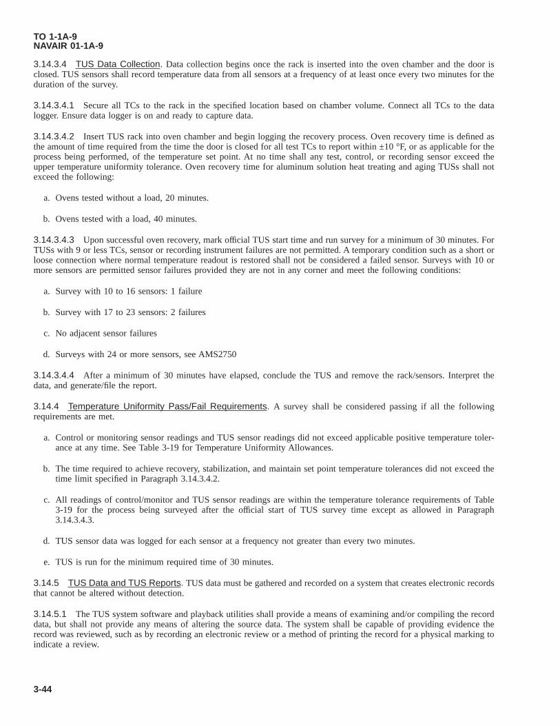
3.14.3.4 TUS Data Collection. Data collection begins once the rack is inserted into the oven chamber and the door isclosed. TUS sensors shall record temperature data from all sensors at a frequency of at least once every two minutes for theduration of the survey.
3.14.3.4.1 Secure all TCs to the rack in the specified location based on chamber volume. Connect all TCs to the datalogger. Ensure data logger is on and ready to capture data.
3.14.3.4.2 Insert TUS rack into oven chamber and begin logging the recovery process. Oven recovery time is defined asthe amount of time required from the time the door is closed for all test TCs to report within ±10 °F, or as applicable for theprocess being performed, of the temperature set point. At no time shall any test, control, or recording sensor exceed theupper temperature uniformity tolerance. Oven recovery time for aluminum solution heat treating and aging TUSs shall notexceed the following:
a. Ovens tested without a load, 20 minutes.
b. Ovens tested with a load, 40 minutes.
3.14.3.4.3 Upon successful oven recovery, mark official TUS start time and run survey for a minimum of 30 minutes. ForTUSs with 9 or less TCs, sensor or recording instrument failures are not permitted. A temporary condition such as a short orloose connection where normal temperature readout is restored shall not be considered a failed sensor. Surveys with 10 ormore sensors are permitted sensor failures provided they are not in any corner and meet the following conditions:
a. Survey with 10 to 16 sensors: 1 failure
b. Survey with 17 to 23 sensors: 2 failures
c. No adjacent sensor failures
d. Surveys with 24 or more sensors, see AMS2750
3.14.3.4.4 After a minimum of 30 minutes have elapsed, conclude the TUS and remove the rack/sensors. Interpret thedata, and generate/file the report.
3.14.4 Temperature Uniformity Pass/Fail Requirements. A survey shall be considered passing if all the followingrequirements are met.
a. Control or monitoring sensor readings and TUS sensor readings did not exceed applicable positive temperature toler-ance at any time. See Table 3-19 for Temperature Uniformity Allowances.
b. The time required to achieve recovery, stabilization, and maintain set point temperature tolerances did not exceed thetime limit specified in Paragraph 3.14.3.4.2.
c. All readings of control/monitor and TUS sensor readings are within the temperature tolerance requirements of Table3-19 for the process being surveyed after the official start of TUS survey time except as allowed in Paragraph3.14.3.4.3.
d. TUS sensor data was logged for each sensor at a frequency not greater than every two minutes.
e. TUS is run for the minimum required time of 30 minutes.
3.14.5 TUS Data and TUS Reports. TUS data must be gathered and recorded on a system that creates electronic recordsthat cannot be altered without detection.
3.14.5.1 The TUS system software and playback utilities shall provide a means of examining and/or compiling the recorddata, but shall not provide any means of altering the source data. The system shall be capable of providing evidence therecord was reviewed, such as by recording an electronic review or a method of printing the record for a physical marking toindicate a review.
TO 1-1A-9NAVAIR 01-1A-9
3-44

3.14.5.2 TUS Survey Report Requirements. A paper or digital copy of the completed record shall be retained by thefacility performing the TUS and disposed of in accordance with applicable Records Disposition Schedule guidelines. Thereport will contain, at a minimum:
a. Oven identification name or serial number.
b. Survey temperature.
c. Required temperature uniformity.
d. Oven chamber dimensions or qualified working zone dimensions and location in chamber.
e. TUS sensor and location identification including a detailed diagram, description or photograph of any load or rackused.
f. Time and temperature data from all TUS sensors.
g. TC spool correction factor or correction factors for each TUS sensor at each calibration temperature.
h. Corrected or uncorrected readings of all TUS sensors. Reading shall be identified as corrected or uncorrected.
i. As found and as left TUS offsets (if used in production).
j. Survey start date and time.
k. Survey end date and time.
l. Survey test instrument identification or serial number.
m. Survey test instrument calibration agency.
n. Survey test instrument calibration date.
o. Survey test sensor failures, if any.
p. Indication of test pass or fail.
q. Identification of technician performing survey.
r. Identification of supervisor approving survey.
3.14.6 Failed TUS Procedures. If the temperature uniformity is not within the tolerances of Table 3-19, the cause of thedeviation shall be determined, documented, and corrected. The equipment shall not be used for additional processing untilthe deviation has been corrected and the TUS has been performed successfully.
3.14.6.1 For ovens being tested at an extended interval, failure of a TUS shall cause the extended TUS interval to revertback to the standard periodic interval as applicable in Paragraph 3.14.2.3.
3.14.6.2 Modification Offset. Manual modification offset of the control instrument to facilitate the desired chambertemperature based on the most recent TUS results are permissible, provided it does not exceed ±5 °F. Temperature offsetsshall be documented, approved/signed by the section supervisor or NCOIC, and used in production heat treatments, i.e.controller is offset to 380 °F to obtain accurate uniform internal chamber temperature uniformity of 375±10 °F, controller isoffset to 916 °F to obtain accurate uniform internal chamber temperature uniformity of 920±10 °F, etc. The signed tempera-ture offset chart shall be posted next to the furnace controller or a similar location where the operator will see it and notoverlook it. Temperature offsets greater than ±5 °F shall be troubleshot and corrected by a qualified technician within 90days.
TO 1-1A-9NAVAIR 01-1A-9
Change 6 3-45

Table 3-19. Temperature Uniformity Allowance for Heat Treat Operations
Process Alloy Uniformity Allowance NotesSolution Heat Treating Aluminum, All Class 2 (±10 °F)
Aging Aluminum, All Class 2 (±10 °F) 1Annealing Aluminum, All Class 5 (±25 °F)
Stress Relieving Aluminum, All Class 5 (±25 °F)Hardening/Solution Heat Treating Steel, All Class 5 (±25 °F)
Tempering/Aging Steel, AllClass 2 (±10 °F) 2Class 3 (±15 °F) 3
Annealing Steel, All Class 5 (±25 °F)All Other Processes Steel, All Class 5 (±25 °F)
NOTES:1. For alloys 7049, 7149, 7249, and 7050, aging ovens operating above 300 °F shall be a minimum of Class 1 (±5 °F)2. Temperatures below 1300 °F.3. Temperatures 1300 °F and above.
Table 3-20. Expendable Base Metal Thermocouples
TypeAlloy Combination
Color Code (±) Calibrated Temperature Range °FPositive (+) Negative (-)
E Nickel/Chromium Copper/Nickel Purple/Red -328 to 1652J Iron Copper/Nickel White/Red 32 to 1382K Nickel/Chromium Nickel/Aluminum Yellow/Red -328 to 2282N Nicrosil Nisil Orange/Red -454 to 2372T Copper Copper/Nickel Blue/Red -328 to 662
Insulation Material Temperature Rating °FTeflon, Extruded up to 500
Fiberglass, Braided up to 900Silica, Braided up to 1990Nextel, Braided up to 2200
Table 3-21. Oven/Furnace Instrumentation Type, Sensor Requirements
Required Sensors By Instrumentation TypeInstrumentation Type
A B C D EOne control sensor per zone that controls and displays temperature. X X X X XEach control zone shall have over-temperature protection. X X X XThe temperature indicated by the control sensor in each control zone
shall be recorded by a recording instrument. X X X X
At least 1 load thermocouple/sensor in each zone that logs/recordstemperature. X X
At least two additional recording sensors in each control zone shallbe located to best represent the coldest and hottest temperaturesbased on the results from the most recent TUS.
X X
TO 1-1A-9NAVAIR 01-1A-9
3-46

3.15 FABRICATION.
This portion is intended to provide some of the information required to fabricate the various aluminum products into partsand assemblies. Aluminum is one of the most workable of all the common metals. It can be fabricated into a variety ofshapes by conventional methods. The formability varies considerably with alloy and temper. Specific application usuallydepends on the shape, strength and temper of the alloy. The preceeding will necessitate that the mechanic be well trained tocope with the variables associated with this material especially when the end use of the item is an aircraft or a missile.
3.16 FORMING SHEET METAL.
3.16.1 General. The forming of aluminum (1100) is relatively easy, using approximately the same procedures as thoseused for common steel except that care must be taken to prevent scratching. Do not mark on any metal surface to be used asa structural component with a graphite pencil or any type of sharp pointed instrument. Use pencil, Aircraft Marking,Specification MIL-P-83953, NSN 7510-00-537-6928 (Black), 7510-00-537-6930 (Yellow), and 7510-00-537-6935 (Red). Allshop equipment, tools and work area should be kept smooth, clean and free of rust and other foreign matter.
3.16.1.1 Alloyed aluminum (2024, 7075, 7178, etc.) are more difficult to form, and extensive control is required toprevent scratching and radii cracking. Scratching will make forming more difficult plus it provides an easy path for corrosionattack, especially on clad materials. The clad coating referenced is usually a sacrificial corrosion resisting aluminum alloycoating sandwiched metalurgically to an alloyed core material. The thickness of the coating will depend on the thickness ofthe sheet or plate. The nominal cladding thickness is 4% of composite thickness for material under 0.063 inch; 2.5% formaterial in the range of 0.063-0.187 inch and 1.5% for material 0.188 inch and thicker.
3.16.1.2 The following general rules should be employed in the handling and forming operation:
a. Provide clean area; free of chips, grit and dirt and other foreign material.
b. Provide clean smooth (rust free) and adaptable forming equipment.
c. Sheared or cut edges shall be sanded and filed or polished, prior to bending or forming.
d. Use only straight and smooth forming dies or brake leafs of the correct radius which are free of nicks, burrs and sharpedges.
e. Form material across the direction of grain flow when possible.
f. Material should be of the correct temper, thickness and alloy in the range of “formable” material.
3.16.1.3 For intricate forming operations it is necessary to use annealed (Condition “O”) material and final strengthdeveloped by heat treating after the forming has been accomplished. Heat-treated alloys can also be formed at roomtemperature immediately after quenching (“W” temper), which is much more formable than the fully heat-treated temper.The part is then aged to develop full strength. The forming operation should be performed as soon after quenching aspossible, in view of the natural aging that occurs at room temperature on all the heat treatable alloys. The natural aging canbe delayed to a certain extent by placing the part in a cold storage area of 32 degrees or lower. The lower the temperature thelonger the delay to a point where maximum delay is obtained.
3.16.2 Bending. Bending is classified as single curvature forming. Upon bending sheet metal, bar or rod, the material atthe bends flows or deforms i.e., the material adjacent to the other surface of the bend is under tension and the length isincreased due to stretching and the material adjacent to and on the inner surface is under compression and the length isdecreased.
3.16.2.1 The most common problems encountered in practice are springback and cracking within the bend area. Problemsassociated with bend cracking are usually a result of improper bend radii, rough edges of material being formed or formingequipment and bending parallel to direction of grain flow. Actual practice may reveal that a larger or a smaller radius may beused in some instances. Consult TO 1-1A-1 for minimum bend radii.
3.16.2.2 Difficulties encountered with springback are most commonly associated with bending of the stronger alloys,especially those having high yield strength. Springback problem associated with this material can be overcome to a certaindegree by overforming. The amount of overforming utilized will depend on the temper and the alloy; the softer the material
TO 1-1A-9NAVAIR 01-1A-9
3-47

the less springback compensation required. Other means of reducing springback is to bend the material in the soft condition(Condition “O”) or immediately after quenching and reducing the thickness or the radius if allowed. Avoid reducing radii tothe point that grain separation or bend cracking results.
3.16.3 Draw Forming. Draw forming is defined as a method where a male die (punch) and a female die is used to forma sheet blank into a hollow shell. Draw forming is accomplished by forcing the male die and the metal blank into the femaledie. Generally mechanical press either single or double action and hydraulic presses are used to perform the drawingoperation. Results will depend on die design, radii of die forming surfaces, finish of die, surface clearance between punchand female die, blank hold down pressure, shape of blank, material allowance on blank, elongation factor of material,temper, shape of part being formed, drawing speed, and lubricant. Optium results usually requires experimentation andadjustment of one or more of these factors. Drawing of very deep shells require more experimentation and the utilization ofa succession of limit draws. Because of the work hardening resulting from each draw, reduction in successive draws must beless. In severe conditions an intermediate anneal is sometimes used. Condition “O” material of the heat treatable alloys canbe heat treated after drawing to obtain higher strength and to relieve the effect of work hardening. However, the non-heattreatable alloys can only be annealed to relieve the effect of work hardening. This material should not be annealed if highstrength is the major requirement.
3.16.3.1 The recommended material to manufacture drawing dies is hardened tool steel for large scale production; kirksiteand plastic for medium or short run production; and phenolic and hardwood for piece production.
3.16.4 Stretch Forming. This process involves stretching a sheet or strip to just beyond the elastic limit where permanentset will take place with a minimum amount of springback. Stretch forming is usually accomplished by gripping two oppositeedges fixed vises and stretching by moving a ram carrying the form block against the sheet. The ram pressure beingsufficient to cause the material to stretch and wrap to the contour of the form block.
3.16.4.1 Stretch forming is normally restricted to relatively large parts with large radii of curvature and shallow depth,such as contoured skin. The advantage is uniform contoured parts at faster speed than can be obtained by hand forming witha yoder hammer or other means. Also, the condition of the material is more uniform than that obtained by hand forming. Thedisadvantage is high cost of initial equipment, which is limited to Automatic Message Accounting level repair facilities.
3.16.4.2 Material used for stretch forming should be limited to alloys with fairly high elongation and good spread betweenyield and tensile strength. Most of the common alloys are formed in the annealed condition. It is possible to stretch form theheat treatable alloys in tempers T4 or T6, where the shape is not too deep or where narrow width material is used. For thedeeper curved shapes, the material is formed in the annealed “O” temper, heat treated and reformed, to eliminate distortionresulting from heat treatment. As previously stated the material should be reformed as fast as possible after heat treatment.In some instances the material is formed immediately after heat treating and quenching. Selection of a system or conditionof material to be utilized will require experimentation and the subsequent utilization of the system that gives the best results.
3.16.5 Hydraulic Press Forming. The rubber pad hydropress can be utilized to form many varieties of parts fromaluminum and its alloys with relative ease. Phenolic, masonite, kirksite and some types of hard setting molding plastic havebeen used successfully as form blocks to press sheet metal parts such as ribs, spars, fans, etc. The press forming operationsare usually accomplished by setting the form block (normally male) on the lower press platen and placing a prepared sheetmetal blank on the block. The blank is located on the block with locating pins, to prevent shifting of blank when the pressureis applied (the sheet metal blank should be cut to size and edges deburred prior to pressing). The rubber pad filled press headis then lowered or closed over the form block and the rubber envelope, the form block forcing the blank to conform to theform blocks contour. This type forming is usually limited to relatively flat parts having flanges, beads and lightening holes.However, some types of large radii contoured parts can be formed with a combination of hand forming and pressingoperations. It is recommended that additional rubber be supplemented in the form of sheets when performing the above toprevent damage to the rubber press pad. The rubber sheet used should have a shore hardness of 50-80 durometers. Thedesign of foam block for hydropress forming require compensation for springback even through the material normally usedis Condition “O” or annealed. Normal practice is to under cut the form block 2-7 degrees depending on the alloy and radiiof the form block.
3.16.6 Drop Hammer Forming. The drop hammer can be used to form deep pan shaped and beaded type parts. Kirksitewith a plastic surface insert is satisfactory for male and female dies. The surface of kirksite dies used without plastic insertshould be smooth to prevent galling and scratching of the aluminum surface. When forming deep pans and complicatedshaped parts it is often necessary to use drawings rings, pads or 2-3 stage dies. An intermediate anneal is sometimes used torelieve the hardened condition (cold work) resulting from the forming operation.
TO 1-1A-9NAVAIR 01-1A-9
3-48

3.16.7 Joggling. A joggle is an offset formed to provide for an overlap of a sheet or angle which is projecting in the sameplain. The inside joggle radii should be approximately the same as used for straight bending. Joggle run out or length as anormal rule should be three times the depth of the joggle for the medium strength alloys (2024, 2014, etc.) and approxi-mately four times the depth for the higher strength alloys (7075, 7178, 7079 etc). Where deep and tight joggles are required,annealed material should be used with heat treatment to follow.
3.16.8 Hot-Forming. Hot forming is not generally recommended, however, it is sometimes used where it is not possibleto form an article by other methods. Accomplishment shall not be attempted unless adequate facilities are available tocontrol temperature requirements. Actual formability will depend on the temperature that various alloys are heated. Thehigher the temperature the easier formed. Excessively high temperature shall not be used, as considerable loss in strengthand corrosion resistance will occur. Frequent checks should be made using an accurate contact pyrometer. Table 3-19 citesthe recommended times and temperature (accumulative) for the various alloys. The losses in strength as a result of re-heatingat the temperature cited by this table will not exceed 5%. Equal formability will be obtained with shorter periods of heatingin most cases and the minimum times should be used. It should be understood that this table cited the maximum accumu-lative times at cited temperature.
3.16.9 Spinning. Spinning is an art and makes exacting demands upon the skill and experience of the mechanic perform-ing the operation. For this reason mass production of parts is impractical. However, it can be used to advantages where onlya few parts are required and to assist in the removal of buckles and wrinkles in drawn shell shaped objects.
3.16.9.1 Forming by spinning is a fairly simple process, an aluminum disc (circle) is placed in a lathe in conjunction witha form block usually made of hardwood; as the disc and form block are revolved, the disc is molded to the form block byapplying pressure with a spinning stick or tool. Aluminum soap, tallow or ordinary soap can be used as a lubricant.
3.16.9.2 The best adapted materials for spinning are the softer alloys i.e., 1100, 3003, 5052, 6061, etc. Other alloys can beused where the shape to be spun is not excessively deep or where the spinning is done in stages and intermediate annealingis utilized to remove the effect of strain hardening (work hardening) resulting from the spinning operation. Hot forming isused in some instances when spinning the heavier gauge materials and harder alloys.
3.16.10 Blanking and Shearing. Accurate shearing will be affected by the thickness of material, type of shear or knifeblades, condition of material, adjustment and sharpness of blades, size of cut and the relationship of the width of the cut tosheet thickness.
3.16.10.1 Normally most aluminum alloys can be sheared 1/2 inch and less in thickness except for the harder alloys i.e.,7075-T6 and 7178-T6. These alloys have a tendency to crack in the vicinity of the cut especially if the sheer blades are dullor nicked. The above will naturally require that tooling used be designed to handle the thickness of material to be cut.Correct clearance between shear blades is important for good shearing. Too little clearance will quickly dull or otherwisedamage the blades or knives; too much will cause the material to be burred, or even to fold between blades. Normalclearance is from one-tenth to one-eighth the sheet thickness. Blade life will be prolonged by occasionally lubricating. Whenthe capacity of shear is doubtful the shear manufacturer should be consulted.
3.16.11 Blanking. Blanking is usually accomplished utilizing a blanking die in almost any type of punch press equipment.The essential factors requiring control are die clearance, shearing edge lead, and stripping action. The shearing principle isprimarily the same as that encountered with the squaring shear. However, the method of grinding punch dies will varyaccording to the results required and in such manner that will reduce load on equipment. Commonly two or more high pointsare ground on die to keep side thrust on the punch at a minimum. Lubrication is essential in blanking operations. Suitablelubricants are engine oil, kerosene and lard oil which are normally used in mixed form.
Table 3-22. Maximum Accumulative Reheat Times for Hot Forming Heat Treatable Alloys at Different Tempera-tures
Alloy 450 °F 425 °F 400 °F 375 °F 350 °F 325 °F 300 °F2014-T6 To Tempera-
tureTo Tempera-
ture5-15 Mini-
mum30-60 Mini-
mum2-4 Hours 8-10 Hours 20-50 H
2024-T81 5 Minimum 15 Minimum 30 Minimum 1 Hour 2-4 Hours 20-40 H2024-T86 5 Minimum 15 Minimum 30 Minimum 1 Hour 2-4 Hours 10-20 H6061-T6 5 Minimum 15 Minimum 30 Minimum 1-2 Hours 8-10 Hours 5-100 Hours 100-200 H
TO 1-1A-9NAVAIR 01-1A-9
3-49

Table 3-22. Maximum Accumulative Reheat Times for Hot Forming Heat Treatable Alloys at Different Temperatures- Continued
Alloy 450 °F 425 °F 400 °F 375 °F 350 °F 325 °F 300 °F7075-T6 No No Tempera-
ture5-10 Mini-
mum30-60 Mini-
mum1-2 Hours 2-4 Hours 10-12 H
*2014-T4, 2014-T3 No No No No No No No*2024-T4, 2024-T3 No No No No No No No
* These materials should not be hot formed unless subsequently artificially aged.
3.16.12 Riveting. Riveting is the most common method of assembling components fabricated from aluminum. Typicaladvantages of this method of mechanical fastening are simplicity of application, consistent joint uniformity, easily inspected(X Ray and other type equipment no required.), low cost, and in many cases lighter weight.
3.16.12.1 The rivets used in United States Air Force Weapon System structures require that the alloys and shapes beclosely controlled by specifications/standards, to assure structural integrity and uniformity. These rivets are presently classi-fied as solid shank, hishear, blind (structural-non-structural) explosive/chemical expanded. They are available in a variety ofshapes, alloys, sizes, lengths and types. The most common utilized are aluminum because the structure alloys are normallyaluminum. In addition some of the aluminum rivet characteristics can be changed by heat treating which facilitates applica-tion (see Paragraph 3.12).
3.16.12.2 All of the aluminum alloys could be used to manufacture rivets; however, due to some alloys having superiorproperties they have been selected as standard. See Table 3-23 for alloys head, identification, MS/AN standard crossreferences, etc., for general rivets used on AF weapons systems.
3.16.12.3 Rivets in aluminum alloys 1100(A), 5056(B), 2117(AD) are used in the condition received Alloys 2017 (D) and2024(DD) often referred to as “Ice Box Rivets” require heat treatment prior to use (see Paragraph 3.12). Rivets in alloy 2017and 2024 should be driven immediately after quenching with a maximum delay of 20 minutes or refrigerated to delay aging.The customary procedure (unless only a few rivets are involved) is to place the rivets under refrigeration immediately afterheat treatment. The time the rivets may be used will depend on refrigeration equipment available. Cooling to 10 °F willretard natural aging to the extent that the rivets may be driven up to 24 hours. Cooling rivets 0 °F will retard natural agingand may be stored for 30 days, -10 °F enables up to 90 days of storage.
3.16.12.4 Rivets utilized with extended driving time should be closely inspected after upsetting for cracks. If inspectionreveals that rivets are cracked, discontinue use, remove defective rivets and obtain reheat treated rivets prior to continuingthe assembly operation.
3.16.12.5 If for some reason it is necessary to determine if a rivet has been heat treated this may be done by RockwellHardness testing. Test by supporting rivets in a vee block and harness reading taken with a 1/16 inch ball 60 kilogram load.A harness of over 75 will indicate a heat treated rivet.
TO 1-1A-9NAVAIR 01-1A-9
3-50

Heat treatment and most other operations requiring use of heat will be accomplished prior to installing rivets,since heating after rivets are installed will cause warping and possible corrosion if salt bath is used. The salt fromthe bath will contaminate cracks and crevices of the assembly and complete removal can not be assured. Failure tocomply could result in damage to, or destruction of, equipment or loss of mission effectiveness.
3.16.12.6 Shear strength (ultimate) of a driven rivet can be determined by the formula Ps = SsAN. Ps = ultimate shearstrength (pounds), Ss = specified shear strength of the driven rivet (PSI), A = cross sectional (area of the driven rivet,normally equal to hole cross section (square inch) and N = number of shear planes. For shear strength of protruding andflush head rivets see Table 3-25.
3.16.12.7 The load required to cause tensile failure of a plate in a rivet joint can be determined by the formula Ts = P+(D-A) Tp. Ts = ultimate tensile strength (pounds), PT = specified ultimate tensile strength of the plate (PSI), D = pitch of therivets (inch) - pitch is the distance between the center of two adjacent rivets on the same gauge line, A = diameter of hole(inch) and Tp = thickness of plate.
3.16.12.8 Rivet Selection. Unless otherwise specified rivets should be selected that have comparable strength and alloyas material being assembled. This is an important factor in preventing corrosion from dissimilar metal contact and to assurestructurely sound assemblies. The following tables are provided as a general guide for selection of rivet alloy vs assemblyalloy.
3.16.12.9 The formula Ps = Sb Air-Cooled (AC) can be used to determine failure in bearing strength. Ps = ultimatebearing strength of the joints pounds, Sb = specified ultimate bearing strength of the plate (PSI) and AC = projected crushingarea (bearing area) of rivet, or diameter (square inch) see Table 3-26 for typical bearing properties of aluminum alloy platesand shapes.
3.16.12.10 Rivet hole preparation is one of the key factors in controlling successful upsetting of rivet head, materialseparation and buckling which weakens the structural strength of the rivet joint, and corrosion attack of rivets and materialafter equipment is placed in service/use. The rivet hole should be drilled, punched/reamed to size that allows the minimumclearance (approximately 0.003 for thin sheet and up to about 0.020 for 0.750-1.000 inch thick material) required to insertrivet without forcing. Theoretical rivets holes should be completed i.e., drilled, reamed to size, deburred, chips removed that
Figure 3-4. Rivet ID Information
TO 1-1A-9NAVAIR 01-1A-9
3-51

may lodge or be trapped in between surface of metal and treated (anodized etc.) before starting to rivet assembly. The abovecannot always be accomplished especially where the assembly is large and requires the application of a large amount ofrivets due to hole tolerance and variations in holding clamping/pressures. To overcome these problems requires that holes bepilot drilled end reamed to size at time rivet is to be installed. This method has a twofold purpose: (1) allows easy insertionof rivets, (2) prevents elongation of rivet holes and resulting weakening of rivet joint.
3.16.12.11 Rivet holes drilled/reamed after assembly is started should be treated by coating with zinc chromate primer orother approved material. Two methods for coating rivets and improving protection of hole surfaces from corrosion are:
a. Coat holes/bare metal with primer after drilling and allow to cure. Coat rivets with primer and install while still wet.
b. Coat holes/bare metal with primer after drilling and allow to cure. Coat rivet with sealant and install while still wet.
3.16.12.12 For additional information on rivets (strengths, factors. etc.) see MIL-HDBK-5, TO 1-1A-8 and TO 1-1A-1.
Table 3-23. General Rivet (Alum) Identification Chart
Old AN/STD SupersedingMS STD Form Material
Head And Nu-merical Ident
CodeCondition Heat Treat
AN456 MS20470 Brazier Head Solid Modi-fied
See AN470
NOTE
See Paragraph 3.12 for heat treat data.
USAF460 See MS20601 1000 Flush Head BlindType II Class 2 See MS20601
USAF461 See MS20600 Protruding Head Type IIClass I Blind See MS20601
USAF463 See MS20600 Same SameNAF1195 See MS20600 Same SameAN470 MS20470 Universal Head Solid 1100 A-Plain F No
5056 B-RaisedCross
F No
2117 AD-Dimple T-4 No2017 D-Raised Dot T-4 Yes2024 DD-Raised
DashT-4 Yes
MS20600 Protruding Head-Blind TypeII, Class I
5056 B F No2117 AD T-4 NoMonel M No
MS20601 100° Flash Head Blind TypeII, Class 2
5056 B F No2117 AD T-4 NoMonel M No
MS20602 Protruding Head BlindChemically ExpandedType I, Class I, Styles Aand B
5056 B F No2017 D T-4 No
MS20604 Universal Head Blind ClassI Non Struct
5056 B F No2117 AD T-4 NoMonel M or MP (MP = Monel
Plated)No
TO 1-1A-9NAVAIR 01-1A-9
3-52

Table 3-23. General Rivet (Alum) Identification Chart - Continued
Old AN/STD SupersedingMS STD Form Material
Head And Nu-merical Ident
CodeCondition Heat Treat
MS20605 100° Flash Head BlindClass 2, Non Struct
5056 B F No2117 AD T-4 NoMonel M or MP (MP = Monel
Plated)No
MS20606 Modified Trusshead BlindClass 3 Non-Struct
5056 B F No2117 AD T-4 NoMonel M or MP (MP = Monel
Plated)No
MS20613 Universal Head Solid 1010 Recessed Tri-angle An-nealed
No
302 C-None Annealed NoMS20615 Universal Head Solid Copper CW Annealed No
Monel Raised Dots Class A No
NOTE
Copper, steel, and monel listed for information purposes only. For special rivets see manufacturing drawing, data,specification, etc. For other information on rivets see TO 1-1A-8 and TO 1-1A-1.
AN426 MS20426 Countersunk 100° 1100 A-Plain F No5056 B-Raised
CrossF No
2117 AD-Dimple T-4 No2017 D-Raised Dot T-4 Yes2024 DD-Raised
DashesT-4 Yes
NOTE
See Paragraph 3.12 for heat treat data.
AN427 MS20427 Countersunk 100° 1006/1010 Recessed Tri-angle
A No
Copper 302/304 C-None A NoF-Recessed A No
Monel M Dash M-NoneAN430 MS20470 Round Head replaced by universal See AN470 + M520470AN435 MS20435 Round Head Solid 1006 Head Ident
RecessedTriangle
A No
NOTE
Listed for Reference only.Copper 302/304 C-None A No
F-Head IdentNone
A No
Monel M-NoneAN441 Use MS20435 See AN435AN442 Use MS20470 See AN70 + MS20470
TO 1-1A-9NAVAIR 01-1A-9
3-53

Table 3-23. General Rivet (Alum) Identification Chart - Continued
Old AN/STD SupersedingMS STD Form Material
Head And Nu-merical Ident
CodeCondition Heat Treat
AN450 MS20450 Countersunk and oval tubu-lar
1006/1010/1015 Blank/None A No
NOTE
Listed for Reference only.Copper C-None A No
2117 AD-None T-4 NoBrass B-None Grade B NoMONEL M-None A No
AN455 MS20470 Brazier Head Solid Super-seded by Universal.
See AN470
Table 3-24. General Aluminum Rivet Selection Chart (Rivet Alloy vs Assembly Alloy)
Rivet Alloy Assembly Alloy1100 1100, 3003, 3004, 50522117-T4 (AD) 3003 -H16 and H-18, 5052 -H16 and H18, 2014, 2017, 2024, 6061, 7075, and 71782017-T4 (D), 2024T4 (DD) 2014, 2017, 2024, 5052, 6061, 7075 and 71785056-H32 (B) 5052 and magnesium alloys, AZ31B, etc.
3.16.13 Machining. The resistance encountered in cutting aluminum alloys is low in comparison to other metals. In factmost of the aluminum alloys will machine approximately 10 times faster than steel. This factor combined with otherproperties, i.e. strength, heat treatability, weight, corrosion resistance, etc. makes aluminum a preferred material in manyinstances for fabrication of parts by machining. Brass (free machining) is the only other material with comparable machiningproperties.
3.16.13.1 Personnel accomplishing the work should be properly trained in machining aluminum as with other types ofmetals. Due to various circumstances personnel familiar with machining steel products are required to machine aluminumwithout proper training/information on speeds, feeds, tools etc., required to effectively accomplish a specific task. Thepurpose of this section is to provide a general guide for selection of tools machining speeds, etc.
3.16.13.2 The tools used for machining aluminum will normally require more rake side-top and operation at higher/feedsthan used for steel. The amount of rake required will depend on composition, physical form (cast or wrought) and temper.The more ductile or softer the alloy the more rake required. The following general practices are recommended for shafing,grinding and maintaining tools for cutting aluminum:
a. Allow more space for chips to be formed and expelled from tool than allowed for steel.
b. Design tools (grind tool) so that chips and cuttings are expelled away from the work piece.
c. Keep cutting edges of tools sharp, smooth, free of burrs, wire edges and scratches.
d. Use high machining speeds, moderate feeds and depths of cut.
e. Apply lubricant/coolant in large quantities to tool when cutting.
3.16.13.3 The higher speeds utilized for machining aluminum requires:
a. Machines be free of vibration and lost motion.
TO 1-1A-9NAVAIR 01-1A-9
3-54
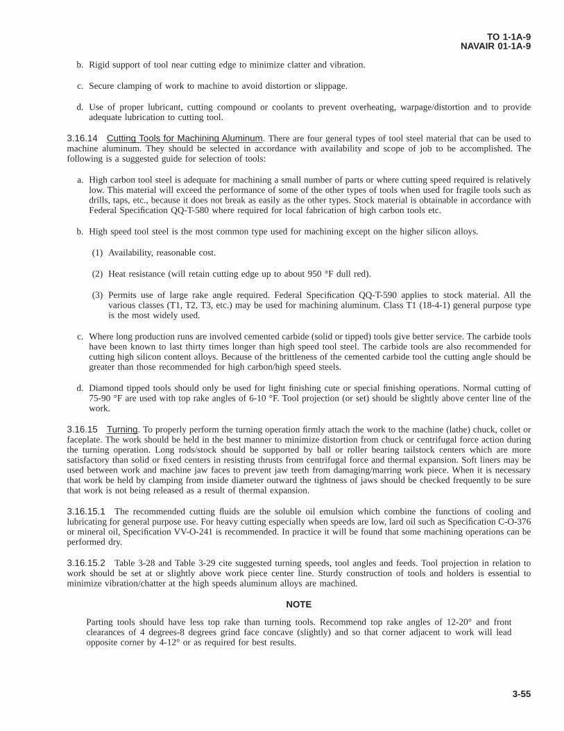
b. Rigid support of tool near cutting edge to minimize clatter and vibration.
c. Secure clamping of work to machine to avoid distortion or slippage.
d. Use of proper lubricant, cutting compound or coolants to prevent overheating, warpage/distortion and to provideadequate lubrication to cutting tool.
3.16.14 Cutting Tools for Machining Aluminum. There are four general types of tool steel material that can be used tomachine aluminum. They should be selected in accordance with availability and scope of job to be accomplished. Thefollowing is a suggested guide for selection of tools:
a. High carbon tool steel is adequate for machining a small number of parts or where cutting speed required is relativelylow. This material will exceed the performance of some of the other types of tools when used for fragile tools such asdrills, taps, etc., because it does not break as easily as the other types. Stock material is obtainable in accordance withFederal Specification QQ-T-580 where required for local fabrication of high carbon tools etc.
b. High speed tool steel is the most common type used for machining except on the higher silicon alloys.
(1) Availability, reasonable cost.
(2) Heat resistance (will retain cutting edge up to about 950 °F dull red).
(3) Permits use of large rake angle required. Federal Specification QQ-T-590 applies to stock material. All thevarious classes (T1, T2, T3, etc.) may be used for machining aluminum. Class T1 (18-4-1) general purpose typeis the most widely used.
c. Where long production runs are involved cemented carbide (solid or tipped) tools give better service. The carbide toolshave been known to last thirty times longer than high speed tool steel. The carbide tools are also recommended forcutting high silicon content alloys. Because of the brittleness of the cemented carbide tool the cutting angle should begreater than those recommended for high carbon/high speed steels.
d. Diamond tipped tools should only be used for light finishing cute or special finishing operations. Normal cutting of75-90 °F are used with top rake angles of 6-10 °F. Tool projection (or set) should be slightly above center line of thework.
3.16.15 Turning. To properly perform the turning operation firmly attach the work to the machine (lathe) chuck, collet orfaceplate. The work should be held in the best manner to minimize distortion from chuck or centrifugal force action duringthe turning operation. Long rods/stock should be supported by ball or roller bearing tailstock centers which are moresatisfactory than solid or fixed centers in resisting thrusts from centrifugal force and thermal expansion. Soft liners may beused between work and machine jaw faces to prevent jaw teeth from damaging/marring work piece. When it is necessarythat work be held by clamping from inside diameter outward the tightness of jaws should be checked frequently to be surethat work is not being released as a result of thermal expansion.
3.16.15.1 The recommended cutting fluids are the soluble oil emulsion which combine the functions of cooling andlubricating for general purpose use. For heavy cutting especially when speeds are low, lard oil such as Specification C-O-376or mineral oil, Specification VV-O-241 is recommended. In practice it will be found that some machining operations can beperformed dry.
3.16.15.2 Table 3-28 and Table 3-29 cite suggested turning speeds, tool angles and feeds. Tool projection in relation towork should be set at or slightly above work piece center line. Sturdy construction of tools and holders is essential tominimize vibration/chatter at the high speeds aluminum alloys are machined.
NOTE
Parting tools should have less top rake than turning tools. Recommend top rake angles of 12-20° and frontclearances of 4 degrees-8 degrees grind face concave (slightly) and so that corner adjacent to work will leadopposite corner by 4-12° or as required for best results.
TO 1-1A-9NAVAIR 01-1A-9
3-55

3.16.16 Milling - Aluminum. Milling of aluminum alloys should be accomplished at high cutter speeds. The limitationswill usually depend on the machine and type cutters used. The reason for the higher cutter speeds is that at low speeds thecutters will have a tendency to load and gum. This will normally clear as the speed is increased.
3.16.16.1 The tooling for milling should be selected according to the operation and duration/size of job to be performed.The cutters should have fewer teeth and should be ground with more top and side rake than those used for milling steels.Most operations can be accomplished with spiral cutters. Nick tooth cutters are used when reduction in size of chips isrequired. Solid-tooth cutters with large helix angles are used where free-cutting tools are required. When cutters with largehelix angles are used it is often necessary that two interlocking cutters of opposite helixes be employed to alleviate axialthrust.
3.16.16.2 Tool alloys should be selected for milling aluminum as follows:
a. For short runs high carbon steel is normally satisfactory.
b. For production runs of extended duration high speed steel is recommended.
c. Where climb milling/high speeds are utilized, carbide tipped tools are recommended for extended runs.
3.16.16.3 Milling cutters should be inclined to work and beveled on leading corner (least bevel for finish cuts) tominimize clatter.
3.16.16.4 The cutting fluids for milling aluminum should combine cooling and lubrication properties. Coolant lubricationshould be applied under pressure (atomized spray if available) in large quantities to tool and work. The recommended cuttingfluids are water base cutting fluids such as soluble oils and emulsions, mixed 1 part to 15 for high speeds and 1 part to 30 forlow speed cutting.
3.16.16.5 Table 3-30 and Table 3-31 cite suggested speeds, contour and tool angles, for milling aluminum. The bestcombination of cutting speeds, feed and cut for a given job will depend on design of tool/cutter, kind of tool material,condition of machine, machine power, size, clamping method and type material being worked.
Table 3-25. Shear Strength of Protruding and Flush Head Aluminum Alloy Rivets, Inch Pounds
Size of Rivet (Inch Diameter) 1/16 3/32 1/8 5/32 3/16 1/4 5/16 3/8Alloy + driven temper 5056 FSU = 28
KSI 99 203 363 556 802 1450 2290 3280
2117-T321, FSU = 30 KSI 106 217 388 596 862 1550 2460 35102017-T31, FSU = 34 KSI 120 297 442 675 977 1760 2970 39702017-T3, FSU = 38 KSI 135 275 494 755 1090 1970 3110 44502024-T31, FSU = 41 KSI 145 296 531 815 1180 2120 3360 4800FSU = Average Shear Strength of alloy in specified temper.KSI = 1000 PSI example: 34 KSI = 34,000 PSI.Single shear rivet strength correction factor (resulting from use in thin plates and shapes).Sheet thickness (inch)0.016 0.09640.018 0.09840.020 0.09960.025 1.000 0.9720.032 1.000 0.9640.036 0.9800.040 0.996 0.9640.045 1.000 0.9800.050 0.996 0.9720.063 1.000 1.000 0.9640.071 0.980 0.964
TO 1-1A-9NAVAIR 01-1A-9
3-56

Table 3-25. Shear Strength of Protruding and Flush Head Aluminum Alloy Rivets, Inch Pounds - Continued
Size of Rivet (Inch Diameter) 1/16 3/32 1/8 5/32 3/16 1/4 5/16 3/80.080 0.996 0.9740.090 1.000 0.9840.100 0.996 0.9720.125 1.000 1.0000.1600.1900.250Double shear rivet strength correction factor (resulting from use in thin plates and shapes)
SIZE OF RIVETSSheet Thick Inch 1/16 3/32 1/8 5/32 3/16 1/4 5/16 3/80.016 0.6880.018 0.7530.020 0.7920.025 0.870 0.7140.032 0.935 0.818 0.6880.036 0.974 0.857 0.7400.040 0.987 0.896 0.792 0.6880.045 1.000 0.922 0.831 0.7400.050 0.961 0.870 0.792 0.7140.063 1.000 0.935 0.883 0.818 0.6880.071 0.974 0.919 0.857 0.7400.080 1.000 0.948 0.896 0.792 0.6880.090 0.974 0.922 0.831 0.7530.100 1.000 0.961 0.870 0.792 0.7140.125 1.000 0.935 0.883 0.8180.160 0.987 0.835 0.8830.190 1.000 0.974 0.9350.250 1.000 1.000
NOTE
Values (pounds) of shear strength should be multiplied by the correction factor whenever the D/T = rivet diameter/plates sheet or shape thickness ratio is large enough to require correction. Example: Rivet diameter 1/8 (alloy 2117- T3) installed in 0.040 sheet, shear factor is 388 pounds correction factor 0.996 =
3880.996232834923492386.448 corrected shear pounds
Table 3-26. Bearing Properties, Typical, of Aluminum Alloy Plates and Shapes
Edge Distance = 1.5 X Rivet Diameter Edge Distance = 2.0X X Rivet DiameterAlloy Yield Strength Ultimate Strength Yield Strength Ultimate Strength
1100 - 0 10,000 21,000 12,000 27,0001100 - H12 18,000 23,000 21,000 29,0001100 - H14 22,000 24,000 23,000 31,0001100 - H16 23,000 16,000 26,000 34,000
TO 1-1A-9NAVAIR 01-1A-9
3-57

Table 3-26. Bearing Properties, Typical, of Aluminum Alloy Plates and Shapes - Continued
Edge Distance = 1.5 X Rivet Diameter Edge Distance = 2.0X X Rivet DiameterAlloy Yield Strength Ultimate Strength Yield Strength Ultimate Strength
1100 - H18 27,000 19,000 32,000 38,0003003 - 0 12,000 22,000 15,000 34,0003003 - H12 21,000 27,000 24,000 36,0003003 - H16 28,000 34,000 33,000 42,0003003 - H18 32,000 38,000 38,000 46,0002014 - T4 56,000 93,000 64,000 118,0002014 - T6 84,000 105,000 96,000 133,0002024 - T3 64,000 102,000 74,000 129,000Alclad 2024-T-3 60,000 96,000 69,000 122,0002024 - T36 80,000 110,000 91,000 139,000Alclad 2024-T36 74,000 100,000 85,000 127,0005052 - 0 25,000 46,000 30,000 61,0005052 - H32 37,000 54,000 42,000 71,0005052 - H34 41,000 59,000 47,000 78,0005052 - H36 47,000 62,000 54,000 82,0005052 - H38 50,000 66,000 58,000 86,0006061 - T4 29,000 56,000 34,000 73,0006061 - T6 56,000 72,000 64,000 94,0007075 - T6 101,000 123,000 115,000 156,000Alclad 7075-T6 94,000 114,000 107,000 144,000
3.16.17 Shaping and Planing. The speed at which aluminum alloys can be cut by planing and shaping is somewhatslower in comparison to other machining methods, due to equipment design and limitations. The slower cutting speeds canbe overcome to some extent by securely anchoring the work to the machine and using heavy rough cutting feeds. The toolsused for rough cut should be (round nose) of heavy construction and properly ground to operate efficiently. Rough cut toolsshould be ground with moderate amount of rake to provide maximum cutting edge support. Finish tool should have more toprake and an extra large amount of side rake. Finishing tool shall be used with fine feeds only due to the additional side andtop rake (finish cut should not exceed 0.018 inch).
3.16.17.1 Most cutting operations by shaping and planning can be accomplished without cutting fluids, however finefinishing can be improved by lubrication. Recommended cutting compounds are kerosene, mixture of 50-50 lard-oil andsoluble oil.
3.16.17.2 Table 3-32 and Table 3-33 cite suggested turning speeds, tool angles and feeds. Secure clamping of work isre-emphasized especially when heavy cutting feeds are to be used.
TO 1-1A-9NAVAIR 01-1A-9
3-58

Table 3-27. Standard Rivet Hole Sizes with Corresponding Shear and Bearing Areas for Cold Driven Aluminum Alloy Rivets
Rivet Size, Inch 1/16 3/32 1/8 5/32 3/16 1/4 5/16 3/8Drill Size, Number 51 41 30 21 11 F P WNom hole diameter, Inch 0.067 0.096 0.1285 0.159 0.191 0.257 0.323 0.386Single Shear Area Square
Inch 0.01296 0.01986 0.02865 0.05187 0.08194 0.1170
Bearing AreaSquare Inchfor variousShear Sheetand PlateThickness
0.032
Not Normallyused forStructuralApplication
Not Normallyused forStructuralApplication
0.00411 0.005090.040 0.00514 0.00636 0.007640.051 0.00655 0.00811 0.00974 0.013110.064 0.00822 0.0108 0.01222 0.01645 0.02070.081 0.01041 0.01288 0.01547 0.02082 0.262 0.03130.102 0.01311 0.01622 0.01948 0.02621 0.0369 0.03940.125 0.01606 0.01988 0.02388 0.03213 0.0404 0.04830.156 0.02480 0.02980 0.04016 0.0505 0.06030.187 0.3581 0.04819 0.0606 0.07240.2187 0.04178 0.05622 0.0707 0.08440.250 0.06425 0.0808 0.09650.3125 0.1009 0.12060.3750 0.14480.500
TO1-1A
-9N
AVA
IR01-1A
-9
3-59

3.16.18 Drilling Aluminum Alloy. Standard type twist drills may be used satisfactorily for many drilling operations inaluminum alloys. However, better results can be obtained with improved designed drills where soft material and drilling ofthick material or deep holes are involved. These drills are usually designed having more spiral twists per inch (see Figure3-5). The additional spiral twist gives more worm action or force to drill causing the drill to cut/feed faster and is helpful inremoving chips, especially in deep hole drilling operations.
3.16.18.1 Generally a drill for a given job should be selected according to the thickness, type alloy and machine/drillmotor to be utilized. The following is a general guide for the selection of drills and recommended speeds:
3.16.18.1.1 Drill Press.
• Point Angle: 118-140° for general work and 90-120° for high silicon.
• Spiral Angle: 24-28° for thin stock and medium depth holes up to 6 times drill diameters, 24-48° for deep holesover 6 times drill diameter.
• Lip Clearance (lip relief): 17° for soft alloys 15° for medium and hard alloys, 12° for silicone alloys.
• Speed: 600 FPM, with high speed drills and up to 2000 FPM with carbide tipped drills.
• Feed: 0.004 - 0.012 inch per revolution for drills 3/8 inch diameter, 0.006-0.020 inch per revolution for 3/8 - 1-1/4inch diameter and 0.016 to 0.035 inch per revolution for drills over 1-1/4 inch diameter. When using carbide tippeddrill, feed should be slightly less. Feed also may be determined by the formular feeds = square root of drill diameter(inches) divided by 60 feet = Drill diameter (inches) + 0.002.
3.16.18.1.2 Lathe/Screw-Machine.
• Point Angle: 118-140°
• Spiral Angle: 0-28°
• Lip Clearance (lip relief): 15-20°
• Speed FPM up to 1500
• Feed inches per revolution 0.004-0.016.
3.16.18.1.3 Portable Drills Electric/Air Driven. Due to variables involved no set factors can be given. However, factorsgiven for drill press should be used as a guide. Feed should be adjusted in accordance with speed of motor to prevent tipheating and also to satisfy operation/operator.
When operating any machinery all safety precautions must be observed, i.e., safety goggles shall be worn whengrinding/drilling. Machinery shall be inspected to ensure that safety guards are in place for safe operation etc.,prior to operating. Work shall be securely clamped to prevent slippage. Consult safety officer when in doubt aboutthe safety of an operation. Failure to comply could result in injury to, or death of, personnel or long term healthhazards.
3.16.18.2 The drilling of thin material normally does not require coolant/lubrication however adequate lubrication isessential to drill life and hole quality when drilling holes of 1/4 inch depth or more. Soluble oil emulsions and lard oilmixtures are satisfactory for general drilling. The lubrication should be applied by forced feed spray/flow where possible andthe drill should be withdrawn at intervals to be sure lubricant flows to the drill tip (fill holes completely) when drill iswithdrawn.
TO 1-1A-9NAVAIR 01-1A-9
3-60
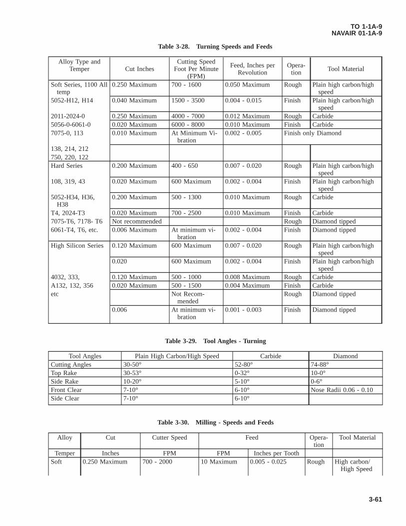
Table 3-28. Turning Speeds and Feeds
Alloy Type andTemper Cut Inches
Cutting SpeedFoot Per Minute
(FPM)
Feed, Inches perRevolution
Opera-tion Tool Material
Soft Series, 1100 Alltemp
0.250 Maximum 700 - 1600 0.050 Maximum Rough Plain high carbon/highspeed
5052-H12, H14 0.040 Maximum 1500 - 3500 0.004 - 0.015 Finish Plain high carbon/highspeed
2011-2024-0 0.250 Maximum 4000 - 7000 0.012 Maximum Rough Carbide5056-0-6061-0 0.020 Maximum 6000 - 8000 0.010 Maximum Finish Carbide7075-0, 113 0.010 Maximum At Minimum Vi-
bration0.002 - 0.005 Finish only Diamond
138, 214, 212750, 220, 122Hard Series 0.200 Maximum 400 - 650 0.007 - 0.020 Rough Plain high carbon/high
speed108, 319, 43 0.020 Maximum 600 Maximum 0.002 - 0.004 Finish Plain high carbon/high
speed5052-H34, H36,
H380.200 Maximum 500 - 1300 0.010 Maximum Rough Carbide
T4, 2024-T3 0.020 Maximum 700 - 2500 0.010 Maximum Finish Carbide7075-T6, 7178- T6 Not recommended Rough Diamond tipped6061-T4, T6, etc. 0.006 Maximum At minimum vi-
bration0.002 - 0.004 Finish Diamond tipped
High Silicon Series 0.120 Maximum 600 Maximum 0.007 - 0.020 Rough Plain high carbon/highspeed
0.020 600 Maximum 0.002 - 0.004 Finish Plain high carbon/highspeed
4032, 333, 0.120 Maximum 500 - 1000 0.008 Maximum Rough CarbideA132, 132, 356 0.020 Maximum 500 - 1500 0.004 Maximum Finish Carbideetc Not Recom-
mendedRough Diamond tipped
0.006 At minimum vi-bration
0.001 - 0.003 Finish Diamond tipped
Table 3-29. Tool Angles - Turning
Tool Angles Plain High Carbon/High Speed Carbide DiamondCutting Angles 30-50° 52-80° 74-88°Top Rake 30-53° 0-32° 10-0°Side Rake 10-20° 5-10° 0-6°Front Clear 7-10° 6-10° Nose Radii 0.06 - 0.10Side Clear 7-10° 6-10°
Table 3-30. Milling - Speeds and Feeds
Alloy Cut Cutter Speed Feed Opera-tion
Tool Material
Temper Inches FPM FPM Inches per ToothSoft 0.250 Maximum 700 - 2000 10 Maximum 0.005 - 0.025 Rough High carbon/
High Speed
TO 1-1A-9NAVAIR 01-1A-9
3-61
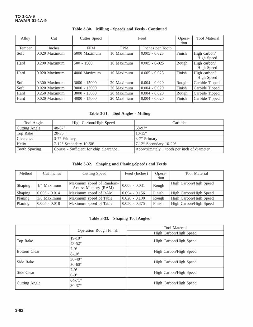
Table 3-30. Milling - Speeds and Feeds - Continued
Alloy Cut Cutter Speed Feed Opera-tion
Tool Material
Temper Inches FPM FPM Inches per ToothSoft 0.020 Maximum 5000 Maximum 10 Maximum 0.005 - 0.025 Finish High carbon/
High SpeedHard 0.200 Maximum 500 - 1500 10 Maximum 0.005 - 0-025 Rough High carbon/
High SpeedHard 0.020 Maximum 4000 Maximum 10 Maximum 0.005 - 0.025 Finish High carbon/
High SpeedSoft 0.300 Maximum 3000 - 15000 20 Maximum 0.004 - 0.020 Rough Carbide TippedSoft 0.020 Maximum 3000 - 15000 20 Maximum 0.004 - 0.020 Finish Carbide TippedHard 0.250 Maximum 3000 - 15000 20 Maximum 0.004 - 0.020 Rough Carbide TippedHard 0.020 Maximum 4000 - 15000 20 Maximum 0.004 - 0.020 Finish Carbide Tipped
Table 3-31. Tool Angles - Milling
Tool Angles High Carbon/High Speed CarbideCutting Angle 48-67° 68-97°Top Rake 20-35° 10-15°Clearance 3-7° Primary 3-7° PrimaryHelix 7-12° Secondary 10-50° 7-12° Secondary 10-20°Tooth Spacing Course - Sufficient for chip clearance. Approximately 1 tooth per inch of diameter.
Table 3-32. Shaping and Planing-Speeds and Feeds
Method Cut Inches Cutting Speed Feed (Inches) Opera-tion
Tool Material
Shaping 1/4 Maximum Maximum speed of Random-Access Memory (RAM) 0.008 - 0.031 Rough High Carbon/High Speed
Shaping 0.005 - 0.014 Maximum speed of RAM 0.094 - 0.156 Finish High Carbon/High SpeedPlaning 3/8 Maximum Maximum speed of Table 0.020 - 0.100 Rough High Carbon/High SpeedPlaning 0.005 - 0.018 Maximum speed of Table 0.050 - 0.375 Finish High Carbon/High Speed
Table 3-33. Shaping Tool Angles
Operation Rough FinishTool Material
High Carbon/High Speed
Top Rake19-10°
High Carbon/High Speed43-52°
Bottom Clear7-9°
High Carbon/High Speed8-10°
Side Rake30-40°
High Carbon/High Speed50-60°
Side Clear7-9°
High Carbon/High Speed0-0°
Cutting Angle64-71°
High Carbon/High Speed30-37°
TO 1-1A-9NAVAIR 01-1A-9
3-62

Figure 3-5. Drill Designs and Recommended Cutting Angles
TO 1-1A-9NAVAIR 01-1A-9
3-63

Table 3-34. Thread Constant for Various Standard Thread Forms
Percent of Full Thread DesiredThread Form 75% 80% 85% 90%American Standard Course Series C = 0.9743 1.0392 1.1042 1.1691Whitworth C = 0.9605 1.0245 1.0886 1.1526British Association Standard C = 0.9000 0.9600 1.0200 1.0800American Standard 60° Stub C = 0.6525 0.6960 0.7395 0.7830American Standard Square C = 0.7500 0.8000 0.8500 0.9000American Standard 10° modified Square
Square C =0.7500 0.8000 0.8500 0.9000
3.16.19 Tapping. The taps used for threading aluminum alloys should be of the spiral fluted type for best results. Straightfluted tape can be used but have a tendency to clog and tear the threads during the tapping operation. Spiral fluted taps forcutting right-handed threads should have a right-hand spiral of about 40 degree angle with a generous back off taper andhighly polished flutes.
3.16.19.1 Spiral - Pointed or “Gun Taps” (straight fluted except they have a short spiral on the starting end) cut aluminummore freely than the other types. With this type tap the major portion of cutting occurs at the spiral end and curls ahead ofthe tap. The use of the “Gun Tap” is therefore limited to tapping holes which have room for the cuttings ahead of the tool.This spiral pointed tap should not be used for cutting tapered thread or for bottoming taps.
3.16.19.2 The following procedures and tools are recommended for tapping aluminum alloys:
a. Cutting Speed: 40 to 130 FPM use lower speed for hard alloys and higher speed for soft alloys.
b. Tap Type Selection: For blind holes and bottoming use spiral fluted; for semi-blind use spiral pointed (gun taps); andfor hole through work use spiral pointed (gun taps).
c. Thread Type: Rounded or flattened (turn coated) thread contour for general use.
d. Tool Angles: Spiral flute-grind a lead spiral extending one full thread beyond chamfer on straight fluted tap. To makegun tap and spiral flute tap should be 28 degrees to 40 degrees; cutting angel 40 degrees to 45 degrees; top rake 45degrees to 50 degrees; back rake 4 - 8 degrees; cutter area (included angles); 2 flute 36 degrees to 72 degrees and 3flutes 24 degrees to 48 degrees.
e. Tapping Allowance: Drill diameter for general tapping should be from 0.005 to 0.006 inches per inch larger thanstandard for the same thread in steel or in accordance with the following.
C = Thread constant for various thread forms and percentages of thread depth required as given in Table 3-34.
f. Lubrication: For high speed tapping use lard oil/mineral oil and for hand tapping a more viscous lubricant is recom-mended such as heavy grease/oil, white lead, etc.
3.16.20 Filing. Hand files of the single cut type having milled teeth usually give the best results for filing aluminum. Themain consideration in file design/selection for aluminum is to provide ample chip space clearance. The cuttings generated arelarge and have a tendency to powder, pack and clog between file teeth. To overcome clogging problem chip space isincreased, grooves are cut deeper and teeth are cut with generous side and top rake.
3.16.20.1 For finish filing a long angle mill file (single) (cut) with tooth spacing of 14-24 teeth per inch with side rakeangle of 45-55° is recommended. In absence of the preferred file the same effect can be obtained using standard mill cut filesby adjusting angle of filing incidence to the metal worked. The file is often adjusted until force or motion applied is parallelto the work piece for best results. A good general purpose file is the curved tooth type (often called “vixen”) having aboutten deeply cut teeth per inch. It can be used for heavy and finish cuts. Lightly double cut files having tooth spacing of 14-20
TO 1-1A-9NAVAIR 01-1A-9
3-64

per inch can be used for light duty rough cutting and finishing when working the harder alloys. User should be careful notto drag file across work on back stroke as with any filling operation. Files shall be kept clean and free of rust. Clogged filescan be cleaned by wire brushing. The use of chalk or talc on file will help prevent clogging.
3.16.20.2 Machine filing using rotary files (miniature milling cutters having spiralled sharp teeth with smooth deeply cutflutes) are operated at high speed. The rotary files are operated up to 10,000 Revolutions Per Minute (RPM) for smalldiameter and to 2,000 maximum peripheral FPM for the larger diameter. The teeth should be coarse (about 14 teeth per inch)with deep polished flute and spiral notched design.
3.16.21 Reaming.
Wear goggles or face shield when filing with rotary files to protect eyes. Failure to comply could result in injuryto, or death of, personnel or long term health hazards.
Generally most of the different type reamers may be used for aluminum, but for best results the spiral fluted reamers arerecommended - solid, expansion or adjustable. The spiral should be opposite to the rotation to prevent reamer from feedingand hogging into the hole. Holes to be finished by reaming should be drilled sufficiently under-size to assure positive cuttingrather than scraping and swedging (indication of oversize drilled holes and improper feed is the projection of a lip aroundhole diameter after the reaming operation is accomplished). Finish reamers should be maintained with exceptionally keencutting edges and highly polished flutes for smooth work.
3.16.21.1 The following procedures and tools are recommended for reaming aluminum alloys:
• Tool material: High carbon steel for general use; high speed steel/or carbide tipped for durability and continuedproduction jobs.
• Tool type: Straight/spiral with 10 degree spiral flute and solid teeth.
• Clearance and rake angles: Top rake 5-8°; clearance angle primary 4-7°, secondary angle 15-20°; cutting angle84-90°.
• Machine speed and hole reaming allowance: Cutting speeds up to 400 FPM for straight holes, tapered hole shouldbe somewhat slower about 300-350. The desired feed in inches/revolution is 0.003 to 0.010. Hole to be reamedshould be undersize 0.005-0.015 inch diameter (reaming allowance).
• Cutting fluids: Soluble oil/mixture of kerosene and lard oil, light weight machine oil.
3.16.22 Sawing. It should be emphasized that the same principles which govern the shape of cutting tools for aluminumshould be applied, as far as practicable to saws for aluminum.
3.16.22.1 Band Saws. Band saw blades of spring temper steel having a tooth spacing from 4 to 11 teeth per inch andwith amply radiused gullets are recommended for aluminum alloys. Curved or copying cuts are made with band saws. In anytype of work, high blade speed are desirable with a speed range from 1,500 to 5,000 FPM. For heavy sections the saw teethshould be fairly coarse with a slight set and a slight amount of front rake, the restricted chip space requires the use of coarsertooth spacing of about four teeth per inch to avoid clogging and binding. Also the flexible back type of saw with teethhardened to the bottom of the gullet is used for heavy work. Blades having as many as 14 teeth per inch are satisfactory forthin materials. A good and simple general rule to follow when sawing aluminum is that the spacing of the teeth on band sawsfor aluminum should be as coarse as is consistent with the thickness of the material being sawed. The softer alloys requireappreciably more blade set than do the harder, heat treated alloys. Usually an alternate side rake of about 15 degrees and atop rake or “hook” of 10-20° proves quite satisfactory. This amount of hook, however, requires a power feed and securelyclamped work. For hand feeds the top rake must be reduced considerably to avoid overfeeding.
3.16.22.1.1 The band saw blades must be well supported by side rollers and back support both immediately below thesaw table and about 2 or 3 inches above the work. The top blade supports are placed slightly in advance of those below thetables and the blade should be allowed to vibrate freely to eliminate excessive saw breakage. As a general rule, a noisy band
TO 1-1A-9NAVAIR 01-1A-9
3-65
saw is cutting more efficiently than the saw that cuts quietly. Quiet smooth cutting band saws usually produce smoothburnished surfaces accompanied by excessive heat and consequently decreased blade life.
3.16.22.2 Hack Saws. Hack saw blades of the wavy set type are well suited for cutting aluminum by hand. The wavy settype of blade having 5 to 15 teeth per inch has sufficient chip space to avoid clogging and binding on aluminum alloys. Forextremely fine work a jewelers blade may be used.
3.16.22.2.1 Special routing machines are available which cut varied profiles from aluminum sheet or plate rapidly andefficiently.
3.16.22.3 Lubricants and Coolants. Power hacksaws and hand saws require a cutting lubricant for most operationsinvolving thick sections. Soluble oil cutting compounds and neutral mineral-base lubricating oils applied to the sides of theblade aid in minimizing friction and gullet clogging. Light applications of heavy grease or paraffin wax will provide amplelubrication for some work. A wide selection of lubricants exists, ranging from tallow or grease stick to kerosene-thinnedmineral base lubricating oil. Stick type lubricants should be applied very frequently. Experience has revealed in most casesit is more convenient and adaptable to use the fluid type lubricant applied freely through a recycling system directly to theblade and work stock.
3.16.23 Grinding. The grinding characteristics of the various aluminum alloys vary in many instances. The harder free-cutting aluminum alloys may be ground satisfactorily with free cutting commercial silicon carbide grinding wheels, such ascrystalon, carborundum and natalon. Rough grinding operations are usually performed by use of resin bonded wheels ofmedium hardeners and grit sizes of 24 to 30. Also the aluminum abrasives from number 14 to number 36 have been foundto be satisfactory for rough grindings.
3.16.23.1 Common alloys, particularly in their softer tempers have a tendency to clog the wheels and do not finish to asbright and smooth a surface as the harder materials.
3.16.23.1.1 Caution should be taken in selecting the proper grade of each commercial make of wheel. Once the grindingwheel has been selected there are three variables that affect the quality of a finish; these are the wheel speed, work speed andgrinding compound. Experienced operators have proven that their own good judgement is a determining factor as to thecorrect wheel and work speeds, however, wheel speeds of about 6,000 FPM have given good results.
3.16.23.1.2 For finish work, a soft silicon carbide wheel of 30 to 40 grit in a vitrified bond have proven to be verysatisfactory. A grinding compound of soluble cutting oil and water works well. However, the fine grindings of aluminummust be strained from the compound before reusing in order to prevent deep scratches on the finished surface.
3.16.23.1.3 Special care should be exercised when grinding castings and wrought alloy products that have been heattreated, since their greater resistance to cutting or grinding generates a considerable amount of heat which may causewarping and damage to the material.
3.16.23.2 Lubricants and Coolants. Generous applications of stick grease are recommended to prevent clogging of thegrinding wheels during rough grinding, while copious quantities of a low viscosity coolant type grinding compound areessential and recommended for finish grinding. Soluble oil emulsions of the proportions of 30 or 40 to 1 are most suitable.
3.16.24 Polishing. Polishing or finishing aluminum and most of its alloys, by the application of proper machiningprocedures, gives it a smooth lustrous finish. Aluminum and its alloys are polished in the same manner as other metals, buta lower wheel-to-metal pressure is used for aluminum.
3.16.24.1 Polishing is the act of removing marks, scratches or abrasion on the metal resulting from previous handling andoperations; it must be understood that a more gentle cutting action or finer abrasives are used for polishing aluminum thanused for steel. The various operations covered under the polishing category include roughing, greasing or oiling, buffing andcoloring. These operations are briefly described in the following paragraph.
3.16.25 Roughing. This is a term used to describe the preliminary finishing operation or process, used to prepare alumi-num surfaces having deep scratches gouges or unusually rough surfaces, for subsequent polishing procedures. Roughing isnot required on smooth undented or unscratched surfaces. The preliminary finishing or roughing process usually employs aflexible aluminum oxide paper disc, a semi flexible bonded muslin or canvas wheel, faced with suitable abrasives. Usually
TO 1-1A-9NAVAIR 01-1A-9
3-66

50-100 grit abrasives are for this process and are set in an adhesive in accordance with standard practice. The peripheralspeed of these discs runs around 6,000 FPM; faster wheel speeds would cause heating or ridging of the soft metal surface.Heating is also reduced by small applications of tallow or a tallow oil mixture.
3.16.26 Greasing or Oiling. This is a refined or gentle roughing procedure for finishing aluminum surfaces. Applicationis visually employed by a soft wheel faced with 100 to 200 grit aluminum oxide emery, plus a light coat of tallow orbeeswax lubricant to prevent excessive heating. Here again, peripheral speeds of about 6,000 FPM are used.
3.16.26.1 Greasing or oiling is a necessary operation in finishing coatings and other fabricated work which has beenmarred by previous operations. Excess aluminum pick-up on the wheels as results from overheating will cause deep scratchesin the metal.
3.16.27 Buffing. This is a term used to describe a finishing procedure employed to obtain a smooth high luster on analuminum surface. This high luster finish is obtained by use of a fine abrasive, such as tripole powder mixed with a greasebinder, which is applied to the face of the wheel. These wheels usually consist of muslin discs sewed together, turned at aperipheral speed of 7,000 FPM.
3.16.27.1 Many factors, such as, the thread count of the buff, the pressure applied to the buff against the work, the buffingcompound used, the speed of the buff or wheel and the skill and experience of the operator must be considered in obtaininga satisfactory and quality type finish.
3.17 HARDNESS TESTING.
Hardness is the resistance of a metal to deformation by scratching penetration or indentation, and is usually a good indica-tion of strength. Metal hardness can be measured accurately by the Brinell, Rockwell or Vickers Process.
3.17.1 Brinell Hardness. The Brinell technique is usually used to obtain the hardness of aluminum and aluminum alloys.This hardness value is obtained by applying a load through a ball indenter and measuring the permanent impression in thematerial. To obtain the hardness value of a material, divide the applied load in kilograms by the spherical area of theimpression in square millimeters. Hardness value of aluminum alloy is tested by applying a load of 500 kilograms to a ballten millimeters in diameter for 30 seconds.
3.18 NON-DESTRUCTIVE TESTING/INSPECTION.
Aluminum and aluminum alloys are susceptible to stress risers resulting from notching, nicking or scratching. A very closevisual inspection is required of all raw material prior to any forming or machining operations. Before any fabricationcommences it is necessary that all scratches, nicks and notches be removed by sanding, polishing and filing.
3.18.1 Anodizing Process for Inspection of Aluminum Alloy Parts. Parts for which anodic coating is applicable inaccordance with MIL-A-8625 Type I, can be anodized for the inspection of defects as cited in Specification MIL-1-8474.
3.18.1.1 The parts are examined visually for indications of cracks, forging laps or other defects. Parts inspected by thismethod shall be limited to sheet stock and surface defect of forgings. This method of inspection is not acceptable forinspection of parts subject to internal defects, i.e. inclusion in castings and forging or any part subject to internal stress, etc.
3.18.1.2 Defects are indicated by darkening of cracked or void areas after the anodic treatment. Insufficient rinsing in coldwater after anodizing produces stains which may be confused with defects. In case of doubt strip film from part andreanodize. If the indications do not reappear the defects shall be considered absent and part should not be rejected for thatreason.
NOTE
For additional general information on inspection and testing see Chapter 8 of this TO.
3.18.2 Aluminum Alloy Effects on Scratches on Clad Aluminum Alloy. The purpose of the following information onthe effects of scratches on aluminum alloys is to assist in eliminating controversy in depots and field inspection, regardingserviceability of aluminum alloy, sheet, skin and aircraft structural parts which have been scratched, abraded or discoloredfrom the stand point of corrosion resistance and fatigue strength.
TO 1-1A-9NAVAIR 01-1A-9
3-67

3.18.2.1 In some instances, serviceable aluminum alloy parts and sheets, have been disposed of due to lack of knowledgeby inspection personnel as to the effect of various depth scratches on the strength and corrosion resistance of the clad alloy.Also, attempts have been made to remove scratches from aircraft skin by sanding, buffing, or polishing resulting in removalof much of the cladding material and causing decrease in strength and corrosion resistance.
3.18.3 Allowable Defects. The following surface defects are those which do not affect the strength or corrosion resis-tance.
• Scratches which penetrate the surface layer of clad aluminum alloy sheets or parts but do not extend beneath thecladding are not serious or detrimental.
• The presence of small corroded areas will not materially affect the strength of clad unless the corroded pitted areaextends through the cladding down to or into the bare metal. Clean corroded areas thoroughly by authorizedmethods (see Paragraph 3.20).
• Stains are not grounds for rejection since they affect neither the strength nor the corrosion resistance.
3.18.4 Harmful Scratches.
No attempt will be made to remove scratches or other surface defects by sanding or buffing since the protectivelayer of cladding will be removed by such operations. Failure to comply could result in damage to, or destructionof, equipment or loss of mission effectiveness.
Scratches which extend through the cladding and penetrate the core material act as notches and create stress concentrationswhich will cause fatigue failure if the part is highly stressed or subjected to repeated small stress reversals. However, sheetsso scratched may be utilized for non-stressed applications.
3.18.5 Inspection. Assemblies fabricated from clad aluminum-alloy sheets will not be rejected by inspection personnel,unless the defect is of sufficient depth to adversely affect the mechanical properties or cover sufficient area to impair thecorrosion resistance of the assembly. Scratches or abrasions which penetrate the cladding will not affect corrosion resistance.Scratches resulting from the normal handling and processing of clad aluminum-alloy sheet rarely extend through the clad-ding and penetrate the core.
3.18.6 Test for Depth of Scratches. Since it is very difficult to measure the depth of a scratch on a sheet without crosssectioning the sheet, it has been found convenient (on clad material) to use a “spot” test to determine whether or not ascratch extends through the cladding.
3.18.6.1 On alloys except 7075 and 7178 the “spot” test is made by placing a drop of caustic solution (10% by weight ofsodium hydroxide, in water) on a portion of the scratch, and allowing it to react for 5 minutes. The caustic solution will thenbe rinsed off the sheet with water, and the spot allowed to dry. If a black residue remains in the base of the scratch at the spottested, it indicates that the scratch extends to the core. If no black color is visible and only a white residue remains in thebase of the scratch, it indicates that the scratch does not penetrate through the cladding. For alloys 7075 and 7178 a drop of10% cadmium chloride solution will produce a dark discoloration within two minutes if the scratch penetrates the clad. Thecadmium chloride applied as above will not cause 2024 to discolor within two minutes.
3.18.6.2 When making the “spot” test to determine whether a scratch extends to the core, it is advisable for comparisonpurposes to spot test an adjacent area in which there are no scratches. It is then easier to determine whether the residuewhich remains is black or white.
3.18.6.3 Before making the “spot” test, the sheet area will be cleaned and degreased with solvent MIL-PRF-680C (re-placed Federal Specification P-D-680), or other suitable solvent, so that the caustic solution will react properly.
3.18.6.4 Caution will be exercised to make sure that all of the caustic solution is removed from the sheet by thoroughrinsing, since the caustic solution is very corrosive to aluminum and aluminum alloys. Care will be taken not to useexcessive amounts of the caustic solution for the same reason and it is preferable that only one drop be used for each test.The caustic solution will be prepared fresh for each series of tests to be made.
TO 1-1A-9NAVAIR 01-1A-9
3-68

3.19 DISPOSITION OF SCRATCHED SHEETS/PARTS.
All scratched clad aluminum-alloy sheets will be utilized to the fullest extent. Serviceable portions of damaged sheets will beused in the manufacture of smaller parts and assemblies. Only that portion of sheet that is scratched and otherwise damagedbeyond serviceability will be administratively condemned.
3.19.1 Air Weapon Parts. Parts (air weapon) shall be closely inspected as cited and if they do not meet specifiedrequirement shall be condemned and replaced as directed.
3.20 CLEANING OF ALUMINUM ALLOY SHEET (STOCK).
3.20.1 Dry Cleaning Solvent.
DRY CLEANING SOLVENT, MIL-PRF-680C 3
Stubborn or exceptionally oily sheets may be cleaned by using solvent, MIL-PRF-680C or Commercial Item Description(CID) A-A-59601 or MIL-PRF-32095, before cleaning with alkali solution. The cleaning will be accomplished by brushing,soaking, scrubbing and wiping. Material or equipment that would scratch or abrade the surface shall not be used. Alsomaterial shall not be stored after solvent cleaning and prior to alkaline cleaning, unless solvent is completely removed fromthe surfaces of the metal.
3.20.2 Alkali Cleaning Solution.
Do not use strong alkali solution because it will etch the aluminum. Failure to comply could result in damage to,or destruction of, equipment or loss of mission effectiveness.
Composition of solution is 4 to 6 ounce of cleaner specification MIL-C-5543 to one gallon of water. The material is cleanedby immersing in the solution (as prepared by instructions cited in Paragraph 3.20.3) for 4-6 minutes, thoroughly rinsing inwater (fresh tap) and then completely drying. Never pile/store material while damp, wet or moist. Refer to TO 00-85A-23-1for packaging and storage.
3.20.3 Preparation.
Do not use strong alkali solution because it will etch the aluminum. Failure to comply could result in damage to,or destruction of, equipment or loss of mission effectiveness.
Use water heated to a temperature of 170 °F (77 degree Celsius (°C)). Add not more than one pound of cleaner at a time.Prepare the solution in the following manner:
a. Fill the task 1/2 to 2/3 full of water.
b. Carefully dissolve the alkaline cleaner.
c. Add water to operating level and stir thoroughly with a wooden paddle or other means.
3.20.3.1 Maintain solution in the following manner:
a. Add tap water to balance-up solution loss.
TO 1-1A-9NAVAIR 01-1A-9
Change 6 3-69

b. Make addition as required to maintain the active alkali concentration between 4 and 6 ounces alkaline cleaner for eachgallon of water added and stir thoroughly.
c. Prepare a new solution when contamination impares the cleaning ability of the solution.
d. Clean the tank thoroughly before preparing a new solution.
3.20.4 Nitric-Hydrofluoric Acid Cleaning. The solution shall consist of 1 gallon technical nitric acid (58-62% Nitric-Hydrofluoric) (39.5° Beryllium).
a. 1/2 pint technical hydrofluoric acid (48 °HF) (1.15 Sp), 9 gallons of water.
b. Parts shall be immersed for 3 to 5 minutes in cold acid (50-105 °F).
NOTE
The sheet will stain when rinsed with sodium dichromate. The stronger the solution the darker the stain. A lightdetectable stain is desired on corroded areas. If the stain is dark reduce the amount of sodium dichromate added torinse water.
3.20.4.1 After removing from the acid, the parts shall be washed in fresh hot or cold running water for a sufficient lengthof time to thoroughly remove the acid. Diluted solution of sodium dichromate) 12 to 14 ounces per gallon of water, shall beadded to the rinse water as a corrosion inhibitor. The rinsing time depends upon the freshness of the solution, size of the partand the amount of solution circulated. One half hour or less should be sufficient. Parts shall then be completely dried byblasting with compressed air or other approved method.
3.20.4.2 Corrosion Removal and Treatment of Aluminum Sheets When Immersion Is Not Practical.
ALKALINE WATER BASE CLEANING COMPOUND, MIL-PRF-87937D 1
3.20.4.3 The surface shall be cleaned with water base cleaner, Specification MIL-PRF-87937D.
3.20.4.3.1 Heavily Soiled Areas. Dissolve the contents of two 5-pound packages in 10 gallons of water. Stir with awooden paddle until fully dissolved.
3.20.4.3.2 Lightly Soiled Areas. Dissolve four 5-pound packages in 50 gallons of water (a 55 gallon drum is suitable forthis purpose). Agitate thoroughly with wooden paddle to ensure proper mixture.
3.20.4.3.3 Application. Apply the solution by spraying, or with a mop, sponge, or brush. Allow to remain on the surfacefor several minutes while agitating with a brush. Rinse thoroughly with a spray or stream of water. Do not allow solution todry before rinsing as less effective cleaning will result.
TO 1-1A-9NAVAIR 01-1A-9
3-70

3.20.5 Corrosion Removal.
CORROSION REMOVING COMPOUND, SAE AMS-1640B 2
Metal conditioner and brightener is for use only on aluminum alloys, and it shall not be used just for the sake ofimproving the appearance of material. Material in storage shall not be treated with this material more than onetime. Failure to comply could result in damage to, or destruction of, equipment or loss of mission effectiveness.
To remove corrosion products use a metal conditioner and brightener, Specification SAE AMS-1640B.
a. Prepare the brightening solution by mixing Specification SAE AMS-1640B compound with an equal amount of water,in a rubber pail.
b. Apply enough diluted brightener to completely cover the area being treated with a nonmetallic bristle brush.
c. Agitate the brightener by scrubbing with a non-metallic bristle brush. Depending on the ambient temperature andamount of corrosion deposits present, allow approximately 5 to 10 minutes from application of brightener beforerinsing. When using brightener at high ambient temperature (above 80 °F) leave brightener on for shorter periods oftime. Do not leave brightener on the surface longer than necessary to dissolve the corrosion.
d. Rinse the brightener from the surface (using approximately 50 gallons of water per minute. Insure that all traces ofbrightener have been removed (shown by no foaming or bubbles while rinsing).
3.20.6 Chromate Conversion Coating.
IRIDITE NO. 14-2 CHEMICAL FILM, MIL-DTL-5541F 4
TO 1-1A-9NAVAIR 01-1A-9
3-71

• Any absorbent material used in applying or wiping up MIL-DTL-5541F material shall be rinsed in water beforediscarding. They are extreme fire hazards if allowed to dry otherwise. Failure to comply could result in injuryto, or death of, personnel or long term health hazards.
• Do not permit Specification MIL-DTL-5541F material to contact paint thinner, acetone or other combustiblematerials. Fire may result. Failure to comply could result in injury to, or death of, personnel or long term healthhazards.
Avoid brushing or rubbing the newly applied chemical conversion coating, since it is soft and can be easily rubbedoff the surface before completely drying. Failure to comply could result in damage to, or destruction of, equipmentor loss of mission effectiveness.
NOTE
• A light (just visible to the naked eye) evenly dispersed conversion coating is all that is required. It is recom-mended that a test panel be prepared and subjected to complete cleaning/treating procedure before applyingmaterial to a sheet. The test panel shall be used to determine the dwell time of MIL-DTL-5541F material.When clear material is being used, no control of discoloration is necessary.
• After the procedures cited in Paragraph 3.20.6 through Paragraph 3.20.8.1 have been complied with, an AFForm 50A will be attached to each sheet with a statement that, “This material has been cleaned and treated forcorrosion in accordance with TO 1-1A-9 Chapter 3, date ......” If original markings are removed as a result ofthe cleaning and treatment process, the material shall be remarked (staggered) at each end and in the middlewith the Specification, size/thickness, temper and type or grade. The marking may be applied with Black paintSpecification TT-L-50, MIL-E-7729 or “Magic Marker” manufactured by Speeddry Products Inc., RichmondHill, New York or “Equal”. A felt tip pen may also be used.
Chromate Conversion Coating Specification MIL-DTL-5541F, for aluminum alloys. Aluminum alloys which are treated withSpecification SAE AMS-1640B shall be treated with Specification MIL-DTL-5541F. Most solutions conforming to Specifi-cation MIL-DTL-5541F leave a stain. A clear Specification MIL-DTL-5541F coating is available (reference QPL 5541) andshould be used when a bright metal finish is desired.
a. Mix the solution in a stainless steel, rubber or plastic container; not in lead, copper alloy or glass.
b. Mix in accordance with manufacturers instructions.
c. Apply the conversion coating (light) by using a fiber bristle brush or a clean, soft cloth. Keep the surface wet with thesolution until a coating is formed which may take from 1 to 5 minutes depending on the surface condition of the metal.
NOTE
Do not permit excess conversion coating to dry on the metal surface because the residue is difficult to flush offwith water.
d. Rinse with clear water, or sponge the area with a clean, moist cloth, frequently rinsing the cloth in clear water.Thorough rinsing is required.
e. Allow the surface to air dry. To speed drying the surface may be blown dry with warm clean air (140 °F maximum).
3.20.7 Packaging, Packing and Storage of Aluminum Alloy Sheets. For Packaging, Packing, and Storage of Alumi-num Alloy Sheets and Plates, refer to TO 00-85A-23-1.
TO 1-1A-9NAVAIR 01-1A-9
3-72

3.20.8 Anodic Coatings for Aluminum. Anodizing is the anodic process of treating aluminum alloys; a thin film ofartificially produced oxide is formed on the surface of the metal by electrochemical reaction. Military Specification MIL-A-8625 lists the requirements of aluminum anodizing, and TO 42C2-1-7 gives the anodizing process.
3.20.8.1 Military Specification MIL-DTL-5541F lists the requirements for corrosion protection and paint base of alumi-num by the use of chemical film. These chemical films are substitutes that may be used in lieu of anodic films, and may beapplied by spray, brush, or immersion as specified by QPL-5541. The anodizing method is preferrable to chemical films onaluminum parts where facilities are available. For process procedures applying to chemical films, refer to TO 1-1-8 and TO1-1-2.
TO 1-1A-9NAVAIR 01-1A-9
3-73/(3-74 blank)


CHAPTER 4MAGNESIUM ALLOYS
4.1 CLASSIFICATION.
Magnesium alloys are produced and used in many shapes and forms, i.e.. castings, extruded bars, rods, tubing, sheets andplate and forgings. They are suitable for varied stress and non-stress aerospace applications. Their inherent strength, light-weight, shock and vibration resistance are factors which make their use advantageous. The weight for an equal volume ofmagnesium is approximately two-thirds of that for aluminum and one-fifth of that for steel. The current system used toidentify magnesium alloys, is a two letter, two or three digit number designation in that order. The letters designate the majoralloying elements, (arranged in decreasing percentage order, or in alphabetical order if the elements are of equal amounts),followed by the respective digital percentages of these elements. The percentage is rounded off to the nearest whole numberor if a tolerance range of the alloy is specified, the mean of the range (rounded off to nearest whole number) is used. A suffixletter following the percentage digits, denotes the latest qualified revision of the alloy. For example: Alloy DesignationAZ92A would consist of 9% (mean value) aluminum and 2% (mean value) zinc as the major alloying elements. The suffix“A” indicates this is the first qualified alloy of this type. One exception to the use of the suffix letter is that an “X” denotesthat impurity content is controlled to a low limit. Some of the letters used to designate various alloying elements are:
1. A - Aluminum
2. E - Rare Earth
3. H - Thorium
4. K - Zirconium
5. M - Magnesium
6. Z - Zinc
4.2 DEFINITIONS.
4.2.1 Hardness. Is the resistance of a metal to plastic deformation from penetration, indentation, or scratching. Thedegree of hardness is usually a good indication of the metals strength. The hardness of a metal can be accurately measuredusing the Brinell on Rockwell process of testing. Table 4-4, Table 4-5 and Table 4-6 list the nominal hardness of variousmagnesium alloys. Brinell hardness testing is explained in Chapter 8 of this manual.
4.2.2 Tensile Strength. The useful tensile strength of a metal is the maximum stress it can sustain in tension or compres-sion without permanent deformation. The yield strength is that point of stress, measured in pounds per square inch, at whichpermanent deformation results from material failure. The data in Table 4-4, Table 4-5 and Table 4-6 lists the nominal yieldstrengths of various alloys. The yield point in magnesium is not reached abruptly, but rather a gradual yielding when themetal is stressed above the proportional limit. Tensile and yield strengths decrease at elevated temperatures.
4.2.3 Temper. Is the condition produced in the alloy by mechanically or thermally treating it to alter its mechanicalproperties. Mechanical includes cold rolling, cold working, etc.; thermal includes annealing, solution and precipitation heattreat and stabilization treating. See Paragraph 4.2.8 for temper designations.
4.2.4 Shear Strength. Is the maximum amount (in pound-force per square inch (PSI)) in cross sectional stress that amaterial will sustain before permanent deformation or rupture occurs.
4.2.5 Elongation. Is the linear stretch of a material during tensile loading measured before and after rupture. In magne-sium it is the increase in distance which occurs when stretch is applied between two gage marks placed 2 inches apart on thetest specimen. After rupture the two pieces are fitted together and remeasured. The elongation is the percentile difference ofthe amount of stretch in ratio to the original 2 inches.
TO 1-1A-9NAVAIR 01-1A-9
4-1

4.2.6 Physical Properties. Magnesium, in its pure state, has a specific gravity of 1.74, weighing 0.063 pounds per cubicinch. Similar data for magnesium alloys are included in Table 4-6 as well as other physical property information.
4.2.7 Chemical Properties. Chemically bare magnesium is resistant to attack by alkalis, chromic and hydrofluoric acidsand many organic chemicals including hydrocarbons, aldehydes, alcohols, phenols, amines, esters and most oils. It issusceptible to attack by salts and by galvanic corrosion from contact with dissimilar metals and other materials. Adequateprotection of the metal against unfavorable conditions can be maintained generally, by using proper surface finish andassembly protection. The chemical property constituents of the various alloys are listed in Table 4-3.
4.2.8 Temper Designation System. The hyphenated suffix symbol which follows an alloy designation denotes thecondition of temper, (heat treat or strain hardening), to which the alloy has been processed. These symbols and theirmeanings are listed below: (Heat treating itself is discussed in subsequent paragraphs of this section of the manual). Addedsuffix digits 2, 4, 6, 8, to the Hl, H2, H3 symbols indicate the degree of strain hardening, i.e., 2 = 1/4 hard, 4 = 1/2 hard, 6= 3/4 hard, and 8 = full hard.
-AC As-Cast-F As-fabricated-O Annealed-W Solution heat treated - unstable temper-T Treated to produce stable tempers other than for -O-T2 Annealed (cast products only)-T3 Solution heat treated and then cold worked-T4 Solution heat treated-T5 Artificially aged only-T6 Solution heat treated and then artificially aged-T7 Solution heat treated and stabilized-T8 Solution heat treated, cold worked and then artificially aged-T9 Solution heat treated, artificially aged and then cold worked-T10 Artificially aged and then cold worked-H1 Strain hardened only-H2 Strain hardened and partially annealed-H3 Strain hardened and stabilized
4.3 SAFETY REQUIREMENTS FOR HANDLING AND FABRICATION OF MAGNESIUM ALLOYS.
Magnesium thorium alloys shall be handled, stored and disposed of through applicable disposal procedures.Failure to comply could result in injury to, or death of, personnel or long term health hazards.
There are two special major areas of safety precautions to observe in proceeding of magnesium alloys other than generalshop safety practices. One is the fact some alloys contain thorium, a radioactive element (e.g., HK31A, HM21A, HM31A)and the other is the low melting point/rapid oxidation (fire hazard) characteristics of the metal. Where the application of heatis to be made to a thorium alloy, both of these areas must be considered.
4.3.1 Magnesium-Thorium Alloys (HK31, HM21, HM31, HZ32, ZH42, ZH62). Magnesium-Thorium Alloys (HK31,HM21, HM31, HZ32, ZH42, ZH62) are mildly radioactive but are within the safe limits set by the Atomic Energy Com-mission (AEC) and represent no hazard to personnel under normal conditions. A standard of 0.1 milligrams per cubic meterof thorium in air is a safe limit for continuous atmospheric exposure and is readily met in processing magnesium alloyscontaining up to 10% thorium, For example: Stirring alloy melt of 5% thorium content resulted in 0.002 milligrams percubic meter atmospheric contamination and grinding air alloy of 3% thorium content gave thorium contamination in thebreathing zone ranging from 0.008 to 0.035 milligrams per cubic meter. Only long exposure to fine dust or fumes need causeconcern as to radioactive toxicity of magnesium-thorium. Normal dust control precautions, followed to avoid fire hazards,can be expected to control any health hazards that might result from fine dust in grinding the low thorium content alloys. Inwelding these alloys without local exhaust, concentrations of thorium above the tentative limit of 0.1 milligrams per cubic
TO 1-1A-9NAVAIR 01-1A-9
4-2

meter of air were found in the breathing zone. Use of local exhaust reduced thorium concentrations to well within acceptablelimits. If ventilation is such that the visible fumes flow away from the welder, it is adequate, providing such fumes are notpermitted to accumulate in the immediate vicinity. An alternate practice involves use of ventilated welder’s hood, if there isnot sufficient room ventilation to control contamination of the general atmosphere. Thorium containing scrap and wetgrinding sludge may be disposed of by burning providing an AEC ammendment is secured for the basic AEC license. Ifburned, the ashes which will then contain the thorium, must be disposed of in accordance with AEC Standards for ProtectionAgainst Radiation 10 CFR Part 20. As an alternative the ashes or scrap may be turned over to an AEC licensed scrap dealer,through applicable disposal procedures.
4.3.1.1 For indoor storage of thorium alloy sheets and plates, the size of stacks should be limited to 1000 cubic feet withan aisle width not less than one-half the stack’s height. Such storage is within the normal recommendations for fire safety.
4.3.1.2 Radiation surveys have shown that exposure of workers handling the referenced thorium alloys is well within thesafe limits set by the AEC. Assuming hand contact, the body one foot away from the alloy for an entire 40 hour work week,the exposure would be 168 millirems to the hands and 72 millirems to the whole body. These are maximum values whichprobably would not be approached in actual practice. The corresponding AEC permissible safe limits are 1500 millirems/week for the hands and 300 millirems/week for the whole body.
4.3.1.3 Despite the relative safety present in the handling, to rage and processing of thorium containing alloys, it ismandatory that all such actions be made according to the requirements and restrictions of the 00-100 series technical orders,as applicable, and AEC regulations. As previously stated, the normal precautions taken in the shop processing of magnesiumwill suffice for safe handling of thorium alloys. These precautions are noted in the following paragraphs on safety precau-tions.
4.3.2 Safety Precautions for All Alloys (Including Fire Hazards). Since magnesium will ignite and burn fiercely whenheated to a point near its melting temperature, certain precautions should be taken during working of it.
4.3.2.1 Machining Safety Rules. During machining operations, observance of the following rules will control any potentialfire hazard:
a. Keep all cutting tools sharp and ground with adequate relief and clearance angles.
b. Use heavy feeds to produce thick chips.
c. Machine the metal dry whenever possible, avoiding fine feeds and keeping speeds below 500 - 700 surface feet perminute (SFM) during turning and boring. If a coolant is definitely required use a mineral oil.
d. Keep work areas clean.
e. Store magnesium chips in clean, plainly labeled, covered, non-combustible containers where they will remain dry. Donot allow chips to accumulate on machines or operator’s clothing. Machinists should not wear textured or fuzzyclothing and chips and sawdust should not be allowed to accumulate in cuffs or pockets.
f. Do not permit tools to rub on the work after a cut has been made.
g. Keep an adequate supply of a recommended magnesium fire extinguisher within reach of the operators. If chips shouldbecome ignited, extinguish them as follows:
Water or any of the common liquid or foam type extinguishers will intensify a magnesium chip fire and may causean explosion and shall not be used. Failure to comply could result in injury to , or death of, personnel or long termhealth hazards.
(1) Cover with a layer of G-1 or Met-L-X powder. Clean, dry unrusted cast iron chips, graphite powder, clean drysand, talc and pitch may also be used.
TO 1-1A-9NAVAIR 01-1A-9
4-3

(2) Actively burning fires on combustible surfaces should be covered with a 1/2 inch layer or more of extinguishingpowder; then the entire mass shoveled into an iron container or onto a piece of iron plate. Alternately, a one ortwo inch layer of powder can be spread on the floor or surface nearby and the burning metal transferred to it, thenadd more powder as required.
(3) High cutting speeds, extremely fine feeds, dull, chipped or improperly designed tools, tool dwell on work afterfeed is stopped, tool rub, or tool hitting a steel or iron insert increase the chances of chip ignition. Keeping thecutting speed below 700 feet per minute (FPM) will greatly reduce the fire possibilities even with a dull or poorlydesigned tool and fine feeds.
4.3.2.2 Grinding and Polishing Safety Practices. During grinding and polishing operations a proper dust collection systemmust be used. Figure 4-1 illustrates acceptable type collectors. The dust produced during grinding and polishing of magne-sium must be removed immediately from the working area with a properly designed wet type dust collection system. Propersystems precipitate the magnesium dust by a heavy spray of water and must be so designed that dust or sludge cannotaccumulate and dry out to a flammable state. Small collectors as shown in Figure 4-1, Detail A serving one or two grindersare the best. The grinder-to-collector ducts should be short and straight. The self opening vents illustrated prevent hydrogencollection during shut down. The grinder’s power supply, air exhaust blower and liquid level controller should be electricallywater connected so cessation or failure of the dust collector operation will shut the grinder off. In addition a suitable deviseshould be installed in the system that will ensure the collector system is in full operation and has changed the air in theducts, etc., several times before the grinder begins running. Dry type filter collectors or central collector systems which carrythe dust through long dry ducts should not be used for magnesium. The collector portrayed in Figure 4-1, Detail B is usedwith booth type portable grinding and polishing where the dust passes through the grate with the air being circulated into aliquid spray which removes the dust. Design the booth to catch all the dust possible. On individual grinders for small scalework, as shown in Figure 4-1, Detail C, the hood design and the oil pan combine to afford a satisfactory dust collection. Anydust escaping the hood should be kept swept up and properly disposed of.
4.3.2.3 The following specific safety rules pertain to the grinding and polishing of magnesium:
a. Magnesium grinding should be done on equipment set aside and labeled for that purpose. Do not grind sparkingmaterial on these grinders unless the magnesium dust has been completely removed from the equipment system. Inaddition, the grinding wheel or belt must be replaced prior to grinding of any other metal.
b. If chrome pickled magnesium is to be ground, sparks may result. Therefore, dust and air-dust mixtures must not beallowed to accumulate within spark range.
c. Maintain adequate supplies of plainly labeled approved fire extinguishing powder and suitable dispensing tools readilyavailable to operators. Fire control is the same as detailed in Paragraph 4.3.2.1 for machine chips.
d. Keep dust from accumulating on surrounding floors, benches, windows, etc. If such accumulation is evident thecollector system is not operating properly and must be checked and repaired. Periodically and no less than once amonth, completely clean the entire collector systems. Inspect and clean the grinder to collector ducts daily or movefrequently if the volume of collection is high.
e. Dispose of grinding sludge as soon as it is removed from the equipment. Do not store or allow to even partially drysince it is extremely flammable. This may be done by spreading it on a layer of fire brick or hard burned paving brickto a maximum depth of 3-4 inches, then placing a combustible material on top of it and burning the entire lot. Thesludge will burn with intense heat, therefore, a safe location must be used. A method of rendering magnesium sludgechemically inactive and non-combustible by reacting it with a 5% solution of ferrous chloride (Fe C122H20) isdetailed in the National Fire Protection Association’s Bulletin Number 48, Standards for Magnesium.
f. The clothing of operators should be smooth and fire retardant without pockets and cuffs. Caps should be worn. Allclothing should be easy to remove and kept free of dust accumulations.
4.3.3 Heat Treating Safety Practices. Heat treating of magnesium alloys requires the exercising of certain definite rules,if safe and good quality workmanship is to result. The following rules should be closely followed:
a. Use furnace equipment having two sets of temperature controls, operating independently of each other.
b. Standardize checking procedures and adjustments of all equipment and of operating cycles.
TO 1-1A-9NAVAIR 01-1A-9
4-4

c. Load the furnace with castings of one identical alloy only. Insure the castings are clean.
d. Use Sulfur Dioxide atmosphere to control oxidation.
e. Use the recommended time and temperature operating ranges at all times.
f. Provide approved fire extinguishing equipment.
Water and other extinguishers for Class A, B, and C fires shall not be used. Failure to comply could result in injuryto, or death of, personnel or long term health hazards.
4.3.3.1 If a fire should occur for any reason, as evidenced by excessive furnace temperature and omission of a lightcolored smoke, proceed as follows:
a. Shut off all power, fuel and Sulfur Dioxide feed lines to the furnace.
b. Notify fire marshal control crew at once.
c. Begin fire extinguishing procedures using one of the following methods:
(1) Using G-1 Powder Method. Where it can be safely done, a small fire should be removed from the furnace,dumped into an iron container and then extinguished by covering with G-1 powder which is a graphite basepowder of the Pyrene Carbon Dioxide Company. Metal Fyr Powder of the Fyr Fyter Company is the samematerial. In large furnaces or with fires of high intensity, the powder can be applied to the burning parts with ashovel (assuming the furnace door can be opened safely). Paper bags filled with the powder can be used if the fireis so located that such bags can be thrown in effectively. Remove parts not burning with long handled hooks.After all burning parts have been covered with the powder, the furnace load should be allowed to cool with thedoor open. For the handling of large quantities of G-1 powder, pumps have been constructed which can throw75-100 pounds per minute onto the fire through a 30 foot hose and nozzle.
BORON TRIFLUORIDE 6
Boron trifluoride vapor or gas is toxic in the proportion of more than 1 part per million by volume of air when exposures areprolonged or frequently repeated. Five parts per million by volume of air or more are usually present in visible clouds ofmaterial resulting from the release of the gas to atmosphere. Therefore, personnel must not enter such clouds or any areawhere there is reason to believe the safe level is exceeded unless wearing a gas mask with an acid gas canister containing adust filler. Analysis of atmosphere in the worker’s breathing zone will be accomplished to assure personnel safety. Failure tocomply could result in injury to, or death of, personnel or long term health hazards.
(2) Using Boron Trifluoride Gas Method. This is an effective gaseous means of extinguishing magnesium fires inheat treating furnaces. The gas is introduced into the furnace from a storage cylinder through an entry portpreferably located near floor level. Connect the gas feed line to this port, open the feed line valve to provideabout 2 pounds per minute (depending on furnace size and number of gas cylinders) and maintain gas flow untilfurnace temperature drops to 700 °F indicating the fire is out. The furnace door should be kept closed during thisaction and until a definite temperature drop below 700 degrees Fahrenheit (°F) is evident. Running the furnacecirculating fans for about 1 minute after the gas is first introduced will assist in gas dispersal, then shut the fanoff. The gas cylinder used should be fitted with a Monel needle valve and a “tee” for attaching a 0-160 PSIpressure gauge. A suitable gas transfer system uses a 5/16 inch flexible bronze hose to carry the gas to the furnacewhere it enters through a 114 inch steel pipe entry port. Using 10 feet of hose and feed of pipe, a gauge pressureof 15-30 PSI will deliver 1-2 pounds of Boron Trifluoride per minute. The cylinders may be permanentlyconnected or brought to the furnace, when needed, on a suitable dolly. This gas does not require heating in orderto flow. The cylinders should be weight checked for contents every 6 months.
TO 1-1A-9NAVAIR 01-1A-9
4-5

(3) Using Boron Trichloride Gaseous Method. This material has been successfully used to extinguish magnesiumheat treat furnace fires. However, there are several factors involved with its use which makes it less preferred thanboron trifluoride, these include: ten times more concentration than the 0.04% of boron trifluoride, the gas must beheated to flow freely; it is more expensive than trifluoride; the liquid is corrosive and the fumes irritating with ahealth hazard similar to hydrochloric acid fumes. Workmen should not occupy areas where noticeable vapors arepresent unless wearing a gas mask with an acid gas canister containing a dust filter. If this agent must be used, theliquid containing cylinders should be heated with infrared lights to provide the heat necessary to ensure adequategas flow. The cylinder outlet should be fitted with a special valve and gauge to control gas flow. Flexible 5/8 inchinside diameter neoprene hose may be used to connect the cylinder to a steel pipe for insertion into the furnaceport. Otherwise its use in extinguishing a furnace fire is similar to the procedures for boron trifluoride.
4.3.4 Identification of Alloy. Positive identification of an alloy, from a constituency standpoint, can only be determined bylaboratory analysis. However, whether a light metal is magnesium or not can be generally determined by a simple testconsisting of placing the test metal in contact with an 0.5% solution of silver nitrate, and observing the reaction for 1 minute.The solution is made by dissolving 0.5 grams of silver nitrate in 100 milliliter of water. Formation of a black deposit ofmetallic silver on the metal indicates magnesium or high-magnesium alloy. Then immerse the metal in a chrome picklechemical solution, Type I Specification MIL-M-3171 (Commercially known as DOW Number 1). The solution should befreshly prepared and the test operator familiar with the colors of chemical treatment. If the metal assumes a very brightbrassy coating, it indicates it is aluminum free alloy. If a greyish iridescent coating forms the alloy contains aluminum. Thesolution is made in the proportions of 24 ounces sodium dichromate and 24 fluid ounces concentrated nitric acid to enoughwater to make one gallon. Prior to the test the metal should be thoroughly cleaned down to the base metal, if necessary, bygrinding or filing a clean area on the surface.
4.4 HEAT TREATING MAGNESIUM ALLOYS - GENERAL.
NOTE
• SAE-AMS-M-6857, Heat Treatment of I Magnesium Alloy Castings, will be the control for heat treatment ofmagnesium alloy castings used on aerospace equipment. For complete description of magnesium alloy castingsheat treat requirements, refer to latest issue of SAE-AMS-M-6857.
• Additional Heat Treatment information is discussed in Chapter 9.
4.4.1 Precautions During Heating. Of first importance in the heat processing of these alloys is a clear understanding ofthe characteristics of the metal relative to heat. Pure magnesium will melt at approximately 1202 °F. The alloys meltingpoints range from 830-204 °F, approximately, according to their element constituency. Therefore, during any heating of alloyitems, specified temperature maximums must be closely adhered to, particularly during solution heat treating. The metal iseasily burned and overheating will also cause formation of molten pools within it, either condition resulting in ruining of themetal. Certain alloys such as AZ63A Type 1, or AZ92A Type 1, are subject to eutectic melting of some of its elements ifheated too rapidly. They must be brought up to heat treating temperature slowly enough to prevent this. In the case of thesetwo examples, no less than two hours should be consumed in bringing them from 640 °F to treating temperature.
4.4.1.1 An additional and no less important characteristic of the metal relative to heat treatment, is that it is subject toexcessive surface oxidation at 750 °F and higher temperatures. In an oxidizing atmosphere, this characteristic can result inignition and fierce burning. To prevent such occurrences, a protective atmosphere containing sufficient sulphur dioxide,carbon dioxide or other satisfactory oxidation inhibitor shall be used when heating to 750 °F and over. When oxidationinhibitors are used, their concentration percentage in the furnace atmosphere should be periodically checked for correctamounts. The particular requirements for various alloys are detailed in Paragraph 4.5 in this section. These requirements andthose of other pertinent specifications and instructions should be consulted and strictly adhered to in processing the metal.The safety measures defined in Paragraph 4.1 must be rigidly practiced.
4.4.2 Heat Treating Equipment. Furnaces used for solution heat treatment shall be of the air chamber type with forcedair circulation. Heating provisions can be gas, electricity or oil. Their design must be such as to make impossible, directheating element radiation or flame impingement on the articles being treated. The furnaces shall be installed with thenecessary control, temperature measuring and recording instrument equipment to assure complete and accurate control. Thetemperature control shall be capable of maintaining a given temperature to within ±10 °F at any point in the working zone,after the charge has been brought up to this temperature. Each furnace used shall be equipped with a separate manual resetsafety cut-out which will turn off the heat source in the event of any malfunction or failure of the regular automatic controls.The safety cut-outs shall be set as close as practicable above the maximum solution heat treating temperature for the alloy
TO 1-1A-9NAVAIR 01-1A-9
4-6

being treated. This will be above the variation expected but shall not be more than 10 °F above the maximum heat treattemperature of the alloy being processed. There shall also be protective devices to shut off the heat source in case ofcirculation air stoppage. These devices shall be interconnected with a manual reset control.
4.4.2.1 Upon initial furnace installation and after any maintenance on the furnace or its equipment which might affect itsoperational characteristics, a temperature survey shall be made to test its TO 1-1A-9 capability of maintaining the minimumand maximum temperatures required for the various treatments it will be used for. A minimum of 9 test locations within thefurnace load area should be checked. One in each corner, one in the center and one for each 25 cubic feet of furnace volumeup to the maximum of 400 cubic feet. A monthly survey should be made after the initial survey, unless separate loadThermocouples (TCs) are employed, to record actual metal temperatures. The monthly survey should consist of one test fora solution heat treat temperature and one test for a precipitation heat treat temperature, one for each 40 cubic feet of heattreating volume with a minimum, of 9 test locations required regardless of the volume. In addition, a periodic survey shouldbe made, using the test criteria of the initial survey. For all surveys, the furnaces should be allowed to heat to a pointstabilization before taking any readings. The temperature of all test locations should be determined at 5 to 10 minuteintervals after insertion of the temperature sensing elements in the furnace. The maximum temperature variation of allelements shall not exceed 20 °F and shall not exceed the solution or precipitation heat treating range at any time afterequilibrium is reached.
4.4.2.2 Furnace control temperature measuring instruments shall not be used as test instruments during any survey. Thethermocouple and sensing elements should be replaced periodically because of the in-service incurred effects of oxidationand deterioration.
4.4.2.3 Pyrometers used with the automatic control system to indicate, maintain and record the furnace temperatures,should preferably be of the potentiometer type.
4.4.2.4 Suitable jigs, fixtures, trays, hangers, racks, ventilators and other equipment shall be used in processing thearticles.
4.4.3 Heat Treatment Solution. Solution for heat treating of magnesium alloyed articles is accomplished by heating at anelevated temperature in an air furnace for a specific length of time (holding period); during which certain alloying elementsenter into uniform solid solution, since the alloys tend to become plastic at high heat treat temperatures, it is mandatory thatsuitable support be provided for articles being processed to prevent warping. Table 4-8 lists the recommended soaking andholding time for solution heat treating alloys. The holding periods given are for castings up to 2 inches thick. Items thickerthan 2 inches will require longer periods.
4.4.3.1 AZ92A (Type 2), AZ91C and QE22A sand castings and AM100A permanent mold castings may be charged intothe furnace which is at the heat treating temperature. Since magnesium castings are subject to excessive surface oxidation attemperatures of 750 °F and over, a protective atmosphere containing sufficient sulphur dioxide, carbon dioxide or othersatisfactory oxidation inhibitor shall be used when solution heat treating at 750 °F and over. The whole casting must be heattreated, not just part of it.
4.4.3.2 Precipitation heat treatment or artificial aging of alloys is accomplished at temperature lower than those of thesolution treatment. Suggested aging treatments for various alloys are as cited in Table 4-9.
4.4.3.3 Stabilization heat treating an alloy increases its creep strength and retards growth at service encountered elevatedtemperatures. The same general procedure of heating to temperature, holding for a time and cooling to room temperature isused as in the other two types, only the temperature and time elements are different. When applied to a solution treat treatedalloy, it increases the alloy’s yield strength. Actually stabilization treatment is a high temperature aging treatment accom-plished quickly rather than allowing an alloy to age naturally over a period of time.
4.4.3.4 Annealing of magnesium alloys is accomplished to relieve internal stresses, generally resulting from formingoperations; soften the material for forming; improve the ductility; and/or refine the grain structure. The alloy is heated to theproper temperature, soaked or held at that temperature for a specified time and cooled to room temperature. The desiredeffects are gained by controlling the temperature, hold time and cooling medium exposure. Avoid excessive time at tempera-ture to prevent unwanted grain growth. Conversely, no attempt should be made to shorten the time at temperature and overall annealing time by increasing the temperature, since elements of the alloy subject to melting points lower then the alloyitself can go into solution.
TO 1-1A-9NAVAIR 01-1A-9
4-7
4.4.4 Heat Treating Procedures. Placing of articles to be treated in the furnace, (generally referred to as charging thefurnace), should not be done in a haphazard fashion. Individual pieces should be racked or supported to prevent distortingwithout interfering with the free flow of the heated atmosphere around the article. Distortion or warping can occur due to thesemi-plastic qualities of the alloys at the furnace elevated temperatures during solution heat treat. Distortion is not aparticular problem during precipitation or stabilization treatment or annealing. However, it is good practice to handlemagnesium alloy articles with care at all times under elevated heat conditions. In the case of complicated formed parts, itmay be necessary to utilize a specially contoured jig or fixture to adequately protect the design contour of the item at hightemperatures.
4.5 ALLOY GENERAL CHARACTERISTIC INFORMATION.
In the following paragraphs are brief summaries of the general characteristics of the various alloys.
a. AM100-A - Used in pressure tight sand end permanent mold castings with good combination of tensile strength, yieldstrength and elongation. Solution heat treat in 0.5% Sulfur Dioxide atmosphere 20 hours at 790 °F; cool in strong airblast. Partially artificial aging -12 hours at 325 °F; cool in still air. Completely artificial age 5 hours at 450 °F; cool instill air or oven. Aging increases basic yield strength and hardness and decreases toughness and elongation.
b. AZ31B and C - Used in low cost extruded bars, rods, shapes, structural sections and tubing with moderate mechanicalproperties and high elongation sheet and plate; good formability and strength, high resistance to corrosion, goodweldability. Liquid temperature 1170 °F; solid 1120 °F. Hot working temperature is 450-800 °F. Annealing temperature650 °F. Stress relief of extrusions and annealed sheet = 500 °F for 15 minutes; hard rolled sheet = 300 °F for 60minutes. Foreign equivalents are: British DTD 120A Sheet, 1351350 forgings; German and Italian, Electron AZ31;French - SOC Gen Air Magnesium, F3 and T8.
c. AZ61A - Use in general purpose extrusions with good properties, intermediate cost; press forgings with good mechani-cal properties. Rarely used in sheet form. Hot working temperature 350-750 °F; shortness temperature above 780 °F.Anneal 650 °F. Heat treat annealed sheet extrusions and forgings 15 minutes at 500 °F rolled sheet 400 °F for 15minutes. Foreign equivalents are British BS 1351 (forgings) BS 1354 (extrusions); German AZM.
d. AZ63A - Used in sand castings for good strength properties with best ductility and toughness. Solution heat treat at740 °F in a 0.5% Sulfur Dioxide2 atmosphere for 10 hours then cool in air. Aging is done at 450 °F for 5 hours andcooled in air or furnace. Stabilize at 300 °F at 4 hours and cool in air. Foreign equivalents are Elektron AZG, BritishDTD59A (as cast) and DTD-289 (heat treated). Good salt water anti-corrosion properties.
e. AZ80A - Used for extruded and press forged products. Heat treatable. Hot working temperature 600-750 °F. Shortnesstemperature above 775 °F, annealing temperature 725 °F. Stress relief: as extruded, 500 °F for 15 minutes, extrudedand artificially aged 400 °F for 60 minutes; forgings 500 °F for 15 minutes. Foreign equivalents are British 1351(forgings); German AZ855 Helium or Argon-arc weldable using AZ92A welding rod or may be resistance welded.Stress relieve after welding.
f. AZ81A - Used in sand or permanent mold castings for good strength, excellent ductility, pressure tightness andtoughness. Readily castable with low micro-shrinkage tendency. Solution heat treat 775 °F for 18 hours, cool in air orby fan. Stabilizing treatment 500 °F, 4 hours and air cool. To prevent germination (grain growth) an alternate heat treatof 775 °F for 6 hours, 2 hours at 665 °F and 10 hours at 775 °F may be used.
g. AZ91A, AZ91B - AZ91A - used for die castings generally.
h. AZ91 C - AZ91B - is also die cast alloy but has higher impurity content. AZ91C is used for pressure tight sand andpermanent mold castings having high tensile and weld strength. Shortness temperatures are above 750 °F. Heat treat:T-4 condition, 16 hours at 780 °F, cool in air blast and then age at 400 °F for 4 hours; T-7 condition, 5 hours at 450 °F.Foreign equivalents are Elektron AZ91 and British DTD136A. Good impact resistance in T-4 temper. T-6 has goodyield strength and, ductility.
i. AZ92A - Used in pressure tight sand and permanent mold castings. Has high tensile and yield strengths. Solution heattreat 20 hours at 760 °F in an atmosphere of 0.5% Sulfur Dioxide. Cool in strong air blast. Artificial aging is done at420 °F for 14 hours. Cool in air or oven. Stabilize for 4 hours at 500 °F, then cool in air. Equal to AX63A in salt watercorrosion resistance.
TO 1-1A-9NAVAIR 01-1A-9
4-8

j. EK30A - Used in sand casting for elevated temperature applications. Has good strength properties in temperature range300-500 °F. Solution heat treat at 1060 °F maximum 16 hours then cool in air by fan. Age at 400 °F then air cool.
k. EK41A - Used as pressure tight sand casting alloy. Good strength at 300 -500 °F. Solution heat treat at 1060 °Fmaximum 16 hours then cool in air or with fan. Age at 400 °F 16 hours, air cool.
l. EZ33A - Used for pressure tight, good strength sand and permanent mold castings where temperatures may reach 500°F in use. Age at 420 °F for 5 hours. Foreign equivalent British ZRE1.
m. HK31A - Used in sand castings for elevated temperature use up to 650 °F and sheet and plate applications. Hasexcellent weld and forming characteristics in sheet/plate form and retains good strength up to 650 °F. Hot workingtemperature is 800-1050 °F. Anneal at 750 °F. Solution heat treat sand castings by loading into a 1050 °F furnace andholding for 2 hours, then fan or air cool. Age for 16 hours at 400 °F. H23 sheet may be stress relieved after welding at650 °F for 1 hour or 675 °F for 20 minutes. Sheet may be resistance welded.
n. HM31A - Used in extruded bars, rods, shapes and tubing for elevated temperature service. Exposure to temperaturesthrough 600 °F for periods of 1000 hours caused practically no change in short time room and elevated temperatureproperties. Superior modulus of elasticity particularly at elevated temperatures. Hot work at 700-1000 °F.
o. HZ32A - Used for sand castings. It is of properties for medium and long range exposure at temperatures above 500 °Fand is pressure tight.
p. KIQA - Casting alloy with comparatively low strength has excellent damping characteristics.
q. MIA - Used for wrought products and provides for moderate mechanical properties with excellent weldability, corro-sion resistance and hot formability. Hot work at 560-1000 °F. Anneal at 700 °F. Stress relieve annealed sheet at 500 °F,in 15 minutes; hard rolled sheet at 400 °F in 60 minutes; and extrusions at 500 °F in 15 minutes. Foreign equivalentsare British BS1352 (forgings) and German AM503.
r. QE22A - Castings have high yield strength at elevated temperatures. Solution heat treat at 970-990 °F 4 to 8 hours.Quench in 150 °F water bath.
s. TA54A - Best hammer forging alloy.
t. ZE10A - Used for low cost, moderate strength sheet and plate. No stress relief required after welding. Hot work at500-900°F. Anneal 400 °F. AZ61A or EX33A rod is preferred for welding.
u. ZE41A - A good strength, pressure tight, weldable alloy, where temperatures are below 200 °F. Age 2 hours at 625 °F,air cool; 16 hours at 350 °F air cool. Foreign equivalent - British RZ5.
v. ZH42A - Used in sand castings for aircraft engines and airframe structures where high strength at room temperaturesand moderate longtime creep resistance at temperatures up to 480 °F are required. The alloy is a precipitation hard-ening one from the as-cast condition and requires no solution heat treatment. Maximum hardness is developed at 480°F in 24 hours. More ductility and better shock resistance may be obtained by over aging at temperatures such as 750°F. For T51 condition treat at 480 °F for 24 hours; T4 condition 750 °F for 24 hours.
w. ZH62A - Used as a high strength good ductility structural alloy at normal temperatures and has the highest yieldstrength of any alloy except ZK61A-T6. Heat treat at 480 °F for 12 hours. Foreign equivalent is British T26.
x. ZK21A - An alloy of moderate strength for extrusion fabrication. Good weldability using shielded arc and AZ61A orAZ92A, rod. Resistance welding also satisfactory. ZK51A - Used for high yield strength, good ductility, sand castings.Heat treat for 12 hours at 350 °F. Foreign equivalent is British Z52.
y. ZK60A - Used as a wrought alloy for extruded shapes and press forgings. Has high strength and good ductilitycharacteristics. Hot work at 600-750 °F. Shortness temperature is 950 °F. Age at 300 °F for 24 hours, air cool. Foreignequivalent is German ZW6.
z. ZK61A - Casting Alloy. Solution heat treat at 925-935 °F for 2 hours or 895-905 °F for 10 hours.
TO 1-1A-9NAVAIR 01-1A-9
4-9

Figure 4-1. Typical Dust Collectors for Magnesium
TO 1-1A-9NAVAIR 01-1A-9
4-10

Table 4-1. Cross-Reference, Alloy Designation to Specifications
Alloy Fed Spec. Mil Spec. Hnbk
Society of Auto-motive Engi-neers (SAE)Aeronautical
Material Specifi-cation (AMS)
ASTM(ASME) Use
AM100A QQ-M-56 B80 Sand CastingQQ-M-55 502 4483 B199 Permanent Mold Casting
AZ31B QQ-M-31 52 B107 Extruded Bars, Rods,Shapes
QQ-M-40 510 B91 ForgingsWW-T-825 52 B217 Extruded TubesQQ-M-44 510 4375 B90 Sheet and PlateQQ-M-44 510 4376 B90 Sheet and PlateQQ-M-44 510 4377 B90 Sheet and Plate
MIL-R-6944 B260 Welding RodAZ31C B107 Extruded Bars, Rods,
ShapesB217 Extruded TubesB90 Sheet and Plate
AZ61A QQ-M-31 520 4350 B107 Extruded Bars, Rods,Shapes
QQ-M-40 530 4358 B91 ForgingsWW-T-825 520 4350 B217 Extruded Tubes
MIL-R-6944 B260 Welding RodAZ63A QQ-M-56 MIL-C-19163 50 4420, 4422 B80 Sand Castings
QQ-M-56 MIL-C-19163 50 4424 B80 Sand CastingsQQ-M-55 MIL-C-19163 B199 Permanent Mold Castings
MIL-R-6944 B260 Welding RodAZ80A QQ-M-31 523 B107 Extruded Bars, Rods,
ShapesQQ-M-40 532 4360 B91 Forgings
AZ81A QQ-M-56 505 B80 Sand CastingsQQ-M-40 505 B199 Permanent Mold Castings
AZ91A QQ-M-55 B199 Permanent Mold CastingsQQ-M-38 501 4490 B94 Die Castings
AZ91B QQ-M-38 501 B94 Die CastingsAZ91C QQ-M-56 504 4437 B80 Sand Castings
QQ-M-55 B199 Permanent Mold CastingsAZ92A QQ-M-56 MIL-C-19163 500 4434 B80 Sand Castings
QQ-M-55 MIL-C-19163 503 4484 B199 Permanent Mold CastingsMIL-R-6944 B260 Welding Rod
EK30A QQ-M-56 B80 Sand CastingsEK41A QQ-M-56 4440, 4441 B80 Sand Castings
QQ-M-55 B199 Permanent Mold CastingsEZ33A QQ-M-56 506 4442 B80 Sand Castings
QQ-M-55 506 B199 Permanent Mold CastingsMIL-R-6944 B260 Welding Rod
HK31A* QQ-M-56 507 4445 B80 Sand CastingsMIL-M-26075 507 4384 B90 Sheet and PlateMIL-M-26075 4385
TO 1-1A-9NAVAIR 01-1A-9
4-11

Table 4-1. Cross-Reference, Alloy Designation to Specifications - Continued
Alloy Fed Spec. Mil Spec. Hnbk
Society of Auto-motive Engi-neers (SAE)Aeronautical
Material Specifi-cation (AMS)
ASTM(ASME) Use
* MIL-R-6944 B260 Welding RodHK21A* QQ-M-40 Forgings
MIL-M-8917 4390 B90 Sheet and PlateHM31A* MIL-H-8916 4388 B107 Extruded Bars, Rods,
ShapesMIL-H-8916 4389 Extruded Bars, Rods,
ShapesHZ32A* QQ-M-56 4447 B80 Sand CastingsKIA QQ-M-56 MIL-M-45207 B80 Sand CastingsMIA QQ-M-31 522 B107 Extruded Bars, Rods,
ShapesQQ-M-40 533 ForgingsWW-T-825 522 B217 Extruded TubesQQ-M-44 51 B90 Sheet and Plate
MIL-R-6944 B260 Welding RodQE22A QQ-M-56 Sand Castings
QQ-M-55 Permanent Mold CastingsTA54A QQ-M-40 53 B91 ForgingsZE10A 534 B90 Sheet and PlateZE41A QQ-M-56 Sand CastingsZH42* Sand CastingsZH62* QQ-M-56 508 4438 B80 Sand CastingsZK21A MIL-M-46039 4387 ExtrusionsZK51A QQ-M-56 509 4443 B80 Sand CastingsZK60A QQ-M-31 524 4352 B107 Extruded Bars, Rods,
ShapesQQ-M-40 4362 B91 ForgingsWW-T-825 524 4352 B217 Extruded Tubes
ZK60B MIL-M-26696 Extruded Bars, Rods,Shapes
ZK61A QQ-M-56 513 4444 B80 Sand Castings*These alloys contain radioactive thorium element. See Paragraph 4.3.1 for precautionary instructions.
MISC SPECIFICATIONMIL-M-3171 Magnesium alloy, processes for corrosion protection of
SAE-AMS-M-6857 Magnesium alloy casting, heat treatment of
Table 4-2. Alloy Designation Cross-Reference
New Designa-tor
FormerDow Re-
vere
Former Ameri-can Magne-
sium
Former * Mili-tary
New Federal Use
AZ63A H AM265 QQ-M-56 Castings, SandMIA M AM3S AN-M-26 QQ-M-31 Extruded Bars, Rods, ShapesMIB M AM403 AN-M-30 QQ-M-56 Castings, SandMIA M AM3S AN-T-73 WW-T-825 Extruded Tube
TO 1-1A-9NAVAIR 01-1A-9
4-12

Table 4-2. Alloy Designation Cross-Reference - Continued
New Designa-tor
FormerDow Re-
vere
Former Ameri-can Magne-
sium
Former * Mili-tary
New Federal Use
MIA M AM3S AN-M-22 QQ-M-40 ForgingsMIA M AM3S AN-M-30 QQ-M-44 SheetA292A C AM260 QQ-M-56 Castings, SandAZ92A C AM260 QQ-M-55 Castings, Perm MoldAM100A G AM240 QQ-M-55 Castings, Perm MoldAZ91A R AM263 AN-M-16 QQ-M-38 Castings, DieAZ31B FS-1 AM52S AN-M-27 QQ-M-31 Extruded Bar, Rod, ShapeAZ31B FS-1 AM52S AN-T-72 WW-T-825 Extruded TubeAZ31B FS-1 AM52S ForgingsAZ31B FS-1 AM52S AN-M-29 QQ-M-44 SheetAZ61A J-1 AMC57S AN-M-24 QQ-M-31 Extruded Bar, Rod, ShapeAZ61A J-1 AMC57S AN-T-71 WW-T-825 Extruded TubesAZ61A J-1 AMC57S AN-M-20 QQ-M-40 ForgingsAZ80A 0-1 AMC58S AN-M-25 QQ-M-31 Extruded Bar, Rod, ShapeAZ80A 0-1 AMC58S AN-M-21 QQ-M-40 ForgingsZK60A AMA76S QQ-M-31 Extruded Bar, Rod, ShapeEX41A AMA130 Castings, Perm MoldEZ33A AMA131 Castings, Perm MoldTA54A AM65S QQ-M-40 Forgings
NOTE
* These “AN” Specifications have been superseded by the listed Federal Specifications.
TO 1-1A-9NAVAIR 01-1A-9
4-13
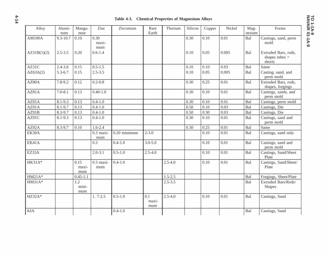
Table 4-3. Chemical Properties of Magnesium Alloys
Alloy Alumi-num
Manga-nese
Zinc Zirconium RareEarth
Thorium Silicon Copper Nickel Mag-nesium
Forms
AM100A 9.3-10.7 0.10 0.30maxi-mum
0.30 0.10 0.01 Bal Castings, sand, permmold
AZ31B(1)(2) 2.5-3.5 0.20 0.6-1.4 0.10 0.05 0.005 Bal Extruded Bars, rods,shapes tubes =sheets
AZ31C 2.4-3.6 0.15 0.5-1.5 0.10 0.10 0.03 Bal SameAZ63A(2) 5.3-6.7 0.15 2.5-3.5 0.10 0.05 0.005 Bal Casting, sand, and
perm moldAZ80A 7.8-9.2 0.12 0.2-0.8 0.30 0.25 0.01 Bal Extruded Bars, rods,
shapes, forgingsAZ81A 7.0-8.1 0.13 0.40-1.0 0.30 0.10 0.01 Bal Castings, sands, and
perm moldAZ91A 8.1-9.3 0.13 0.4-1.0 0.30 0.10 0.01 Bal Castings, perm moldAZ91A 8.1-9.7 0.13 0.4-1.0 0.50 0.10 0.03 Bal Castings, DieAZ91B 8.3-9.7 0.13 0.4-1.0 0.50 0.30 0.03 Bal Castings, DieAZ91C 8.1-9.3 0.13 0.4-1.0 0.30 0.10 0.01 Bal Castings, sand and
perm moldAZ92A 8.3-9.7 0.10 1.6-2.4 0.30 0.25 0.01 Bal SameEK30A 0.3 maxi-
mum0.20 minimum 2-3.0 0.10 0.01 Bal Castings, sand only
EK41A 0.3 0.4-1.0 3.0-5.0 0.10 0.01 Bal Castings, sand andperm mold
EZ33A 2.0-3.1 0.5-1.0 2.5-4.0 0.10 0.01 Bal Castings, Sand/SheetPlate
HK31A* 0.15maxi-mum
0.3 maxi-mum
0.4-1.0 2.5-4.0 0.10 0.01 Bal Castings, Sand/Sheet/Plate
HM21A* 0.45-1.1 1.5-2.5 Bal Forgings, Sheet/PlateHM31A* 1.2
mini-mum
2.5-3.5 Bal Extruded Bars/Rods/Shapes
HZ32A* 1. 7-2.5 0.5-1.0 0.1maxi-mum
2.5-4.0 0.10 0.01 Bal Castings, Sand
KIA 0.4-1.0 Bal Castings, Sand
TO1-1A
-9N
AVA
IR01-1A
-9
4-14

Table 4-3. Chemical Properties of Magnesium Alloys - Continued
Alloy Alumi-num
Manga-nese
Zinc Zirconium RareEarth
Thorium Silicon Copper Nickel Mag-nesium
Forms
MIA(l) 1.2 0.10 0.05 0.01 Bal Extruded Bars, rods,shapes tube-sheets-forgings
QE22A(3) 0.4-1.0 1.8-2.5 0.10 0.01 Bal Castings, sandTA54A(4) 3.0-4.0 0.20 0.3 maxi-
mum0.30 0.05 0.01 Bal Forgings
ZE10A 1.0-1.5 0.12-0.22 Bal Sheet and PlateZE41A 4.25 0.5 1.25 Bal Castings, SandZH42* 3.0-4.5 0.5 1.5-2.5 Bal Castings, SandZH62A* 5.2-6.2 0.5-1.0 1.4-2.2 0.10 0.01 Bal Castings, SandZK20A 2.0-2.6 0.45 minimum Bal ExtrusionsZK51A 3.6-5.5 0.5-1.0 0.10 0.01 Bal Castings, SandZK60A 4.8-6.2 0.45 Bal Extruded Bars/Rods/
Shapes Tube-Forg-ings
ZK60B 4.8-6.8 0.45 0.10 0.01 Bal
NOTE
*These alloys contain radioactive thorium. See Paragraph 4.3.1
(1) Calcium, AZ31B, 0.04---MIA, 0.4.0.14(2) Iron, AZ31B, 0.005---AZ61A, 0.005---AZ63A, 0.005.(3) Silver, QE22A, 2.5-3.0.(4) Tin, TA54A, 4.6-6.0.
TO1-1A
-9N
AVA
IR01-1A
-9
4-15

Table 4-4. Mechanical Properties Magnesium Extrusions and Forgings at Room Temperature - Typical
Alloy andCondition
Form (Diameter Thickness:Wall Thickness-
Inches)
Cross SectionalArea (Inches)
Minimum Ten-sile Str (1000
PSI)
Minimum TenYld Str (1000
PSI)
MinimumElongation(2 inch %)
MinimumShear Str
(1000 PSI)
Hardness(Brinell)
AZ31B-F Bars, Rods,shapes
0.249 and under All areas 35 21 7 17
AZ31C-F 0.250-1.499 All areas 35 22 7 17 490.500-2.499 All areas 34 22 7 172.500-4.999 All areas 32 20 7
Hollow shapes All dimensions All areas 32 16 8 17 49AZ61A-F Bars, Rods,
shapes0.249 and under All areas 38 21 8
0.250-1.499 All areas 39 24 9 18 600.250-4.999 All areas 40 22 7
Hollow shapes All dimensions All areas 36 16 7 18 60AZ80A-F Bars, Rods,
shapes0.249 and under All areas 43 28 9 19 60
0.250-1.499 All areas 43 28 8 19 601.500-2.499 All areas 43 28 6 19 602.500-4.999 All areas 42 27 4 60
T-5 Same 0.249 and under All areas 47 30 4 820.250-2.499 All areas 48 33 4 21 822.500-4.999 All areas 45 30 2 82
HM31A-T5*
Bars, Rods,shapes
Not applicable Under 4.000 37 26 4
MIA-F Bars, Rods,shapes
0.249 and under All areas 30 not required 2 44
0.250-1.499 All areas 32 not required 3 15 441.500-2.499 All areas 32 not required 2 15 442.500-4.999 All areas 29 not required 2 44
Hollow shapes All dimensions All areas 28 not required 2 15 44ZK60A-F Bars, Rods,
shapesAll dimensions 4.999 and un-
der43 31 5 22 75
5.000-29.999 43 31 4 22 75Hollow shapes All dimensions All areas 40 28 5Bars, Rods,
shapesAll dimensions 4. 999 and un-
der45 36 4 22 82
Hollow shapes All dimensions All areas 46 38 4 22 82
TO1-1A
-9N
AVA
IR01-1A
-9
4-16
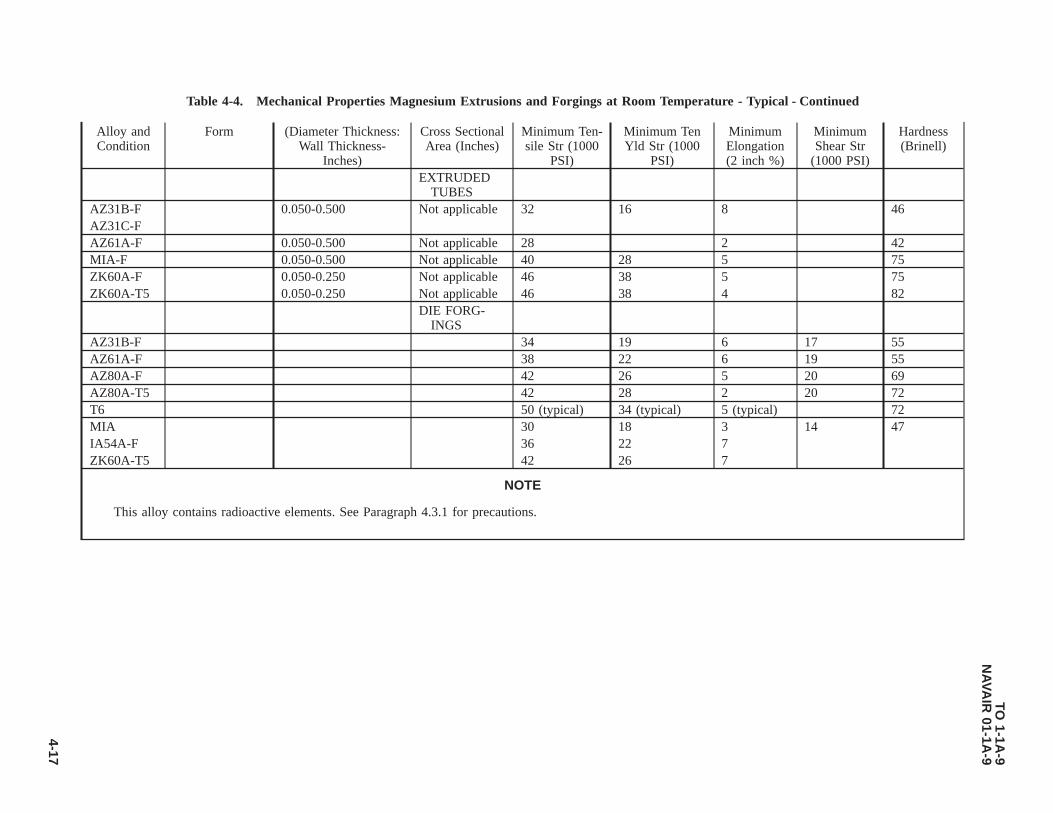
Table 4-4. Mechanical Properties Magnesium Extrusions and Forgings at Room Temperature - Typical - Continued
Alloy andCondition
Form (Diameter Thickness:Wall Thickness-
Inches)
Cross SectionalArea (Inches)
Minimum Ten-sile Str (1000
PSI)
Minimum TenYld Str (1000
PSI)
MinimumElongation(2 inch %)
MinimumShear Str
(1000 PSI)
Hardness(Brinell)
EXTRUDEDTUBES
AZ31B-F 0.050-0.500 Not applicable 32 16 8 46AZ31C-FAZ61A-F 0.050-0.500 Not applicable 28 2 42MIA-F 0.050-0.500 Not applicable 40 28 5 75ZK60A-F 0.050-0.250 Not applicable 46 38 5 75ZK60A-T5 0.050-0.250 Not applicable 46 38 4 82
DIE FORG-INGS
AZ31B-F 34 19 6 17 55AZ61A-F 38 22 6 19 55AZ80A-F 42 26 5 20 69AZ80A-T5 42 28 2 20 72T6 50 (typical) 34 (typical) 5 (typical) 72MIA 30 18 3 14 47IA54A-F 36 22 7ZK60A-T5 42 26 7
NOTE
This alloy contains radioactive elements. See Paragraph 4.3.1 for precautions.
TO1-1A
-9N
AVA
IR01-1A
-9
4-17

Table 4-5. Mechanical Properties of Magnesium Alloy Sheet and Plate at Room Temperature - Typical
Alloy and Condi-tion
Dimension Thick-ness (Inches)
Minimum**TensileStrength
(1000 PSI)
Minimum**Tensile Yield
Str (1000 PSI)
MinimumElongation (2
inch - -%)
MinimumShear
Strength(1000 PSI)
Hardness(Brinell)
Use
AZ31B-F All gauges 35 (typical) 19 (typical) 12 (typical) Tooling PlateAZ31B-H10 0.251-2.000 30 12 10 Standard Plate
-H11 0.016-0.250 32 12 12 Standard Plate and Sheet-H23 0.016-0.064 39 25 4 Standard Sheet
0.065-0.064 39 25 4 and Plate-H24 0.016-0.063 39 29 4 18 73 Specification Sheet and Plate
0.065-0.250 39 29 4 18 73 Same0.251-0.500 37 24 10 Same0.501-1.000 38 22 10 Same
-H26 0.501-0.750 37 25 8 Specification Sheet and Plate0.751-1.000 37 23 81.001-1.500 35 22 8
-0 0.016-0.060 32 18 12 17 56 Specification Sheet and Plate0.061-0.250 32 15 12 17 56 Same0.251-0.500 32 15 12 Same0.501-2.000 30 15 10 Same
AZ31C-F All gauges 32 15 8 52 Tread plateHK31A-0* 0.016-0.250 30 16 12 Sheet
0.251-0.500 30 16 12 Sheet0.501-1.000 30 15 12 Sheet1.001-3.000 29 14 12 Sheet
-H24* 0.016-0.125 34 26 4 21 (typical) 57 Sheet0.126-0.250 31 22 4 21 (typical) 57 Sheet0.251-1.000 34 25 4 20 (typical) Sheet1.001-3.000 33 25 4 20 (typical) Sheet
HM21A-T8 0.016-0.250 31 18 4 Sheet and Plate0.251-0.500 32 21 6 Sheet and Plate0.501-1.000 30 19 6 Sheet and Plate1.001-2.000 29 18 6 Sheet and Plate
MIA-O All gauges 33 (typical) 18 (typical) 17 (typical) 17 (typical) 48 Sheet and PlateH All gauges 35 (typical) 26 (typical) 7 (typical) 7 (typical) 54
ZE10-0 0.016-0.060 30 18 15 Sheet and Plate0.061-0.250 30 15 15
TO1-1A
-9N
AVA
IR01-1A
-9
4-18

Table 4-5. Mechanical Properties of Magnesium Alloy Sheet and Plate at Room Temperature - Typical - Continued
Alloy and Condi-tion
Dimension Thick-ness (Inches)
Minimum**TensileStrength
(1000 PSI)
Minimum**Tensile Yield
Str (1000 PSI)
MinimumElongation (2
inch - -%)
MinimumShear
Strength(1000 PSI)
Hardness(Brinell)
Use
0.251-0.500 29 12 12H24 0.016-0.125 36 25 4 Sheet and Plate
0.126-0.188 34 22 40.189-0.250 31 20 4
* Contains radioactive thorium element. See Paragraph 4.3.2 for precautionary data.** Values given are all minimum unless otherwise noted beside value.
TO1-1A
-9N
AVA
IR01-1A
-9
4-19

Table 4-6. Mechanical Properties of Magnesium Alloy Castings at Room Temperatures
Alloy and Con-dition
Tensile Strength (1000PSI)
Tensile Strength Yield(1A000 PSI)
Typical Elongation Inch2 --%
Shear Strength(1000 PSI)
Hardness(Brinell)
Type Minimum Type Minimum Type MinimumAM100-F 22 20 12 10 2 18 54-T4 40 34 13 10 10 6 20 52-T6 40 34 16 15 4 2 21 69-T61 40 34 22 17 1 21 69AZ63A-F 29 24 14 10 6 4 16 50-T4 40 34 14 10 12 7 17 55-T5 30 24 16 10 4 2 17 55-T6 40 34 19 16 5 3 19 73AZ81A-T4 40 34 14 10 12 7 17 55AZ91C-F 24 18 14 10 2.5 16 52-T4 20 34 14 10 11 7 17 55-T5 23 23 12 12 2-T6 40 34 19 16 5 3 19 73AZ92A-F 24 20 14 10 2 1 16 65-T4 40 34 14 10 10 6 17 63-T5 26 20 17 11 1 16 80-T6 40 34 21 18 2 1 20 84EK30A-T6 23 20 16 14 3 2 18 45EK41A-T5 23 20 16 14 1 18.7 45-T6 25 22 18 16 3 1 19.4 50EZ33A-T5 23 20 15 14 3 2 19.8 50HK31A-T6* 30 27 15 13 8 4 21 55HZ32A-T5* 29 27 14 13 7 4 20 57KIA-F 24 24 6 6 14 14QE22A-T6 35 35 25 25 2 2ZE41A-T5 28 28 19 19 2.5 2.5 23 62ZH42-T51 * 32.5 21.6 4.5ZH42-T4* 33.6 35 12ZH62A-T5 35.0 35 22 22 4 5 24 70ZK51A-T5 40 34 24 20 8 5 22 65ZK61A-T6 39 39 26 26 5 5 26 68
DIECAST-INGS
AZ91A-F 33 22 3 20 67AZ91B-F 33 22 3 20 67
NOTE
*This alloy contains radioactive thorium element. See Paragraph 4.3.2 precautionary instructions.
TO 1-1A-9NAVAIR 01-1A-9
4-20
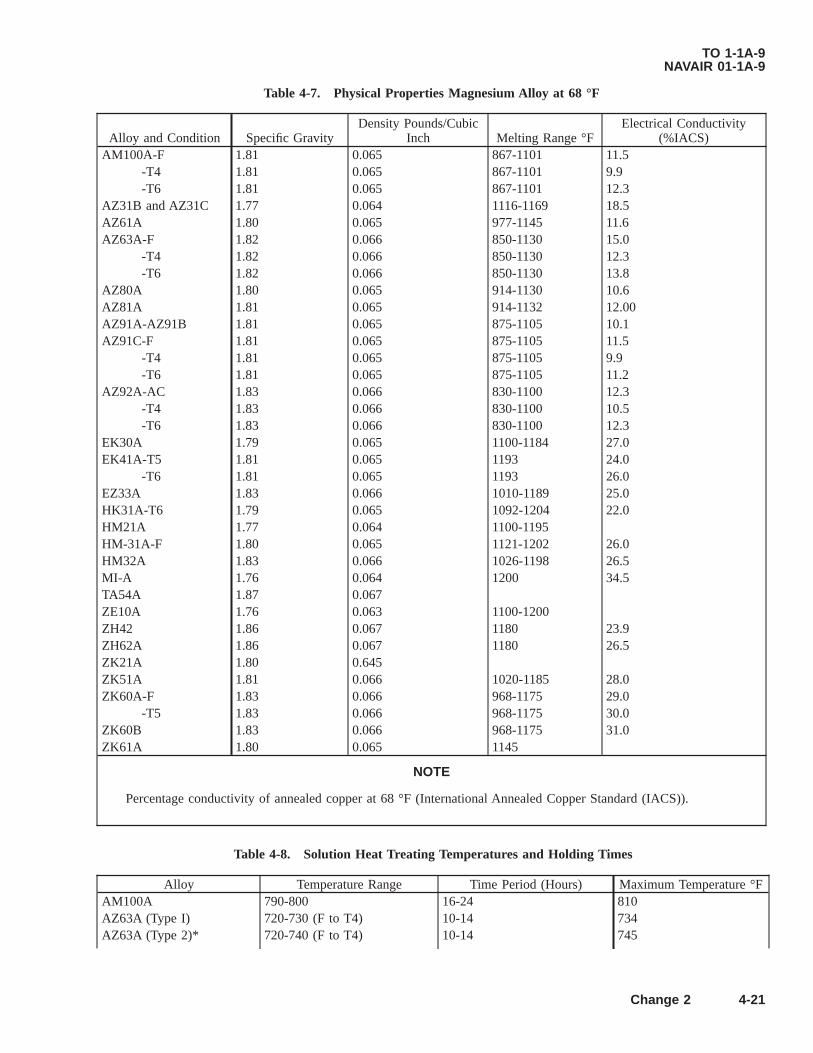
Table 4-7. Physical Properties Magnesium Alloy at 68 °F
Alloy and Condition Specific GravityDensity Pounds/Cubic
Inch Melting Range °FElectrical Conductivity
(%IACS)AM100A-F 1.81 0.065 867-1101 11.5
-T4 1.81 0.065 867-1101 9.9-T6 1.81 0.065 867-1101 12.3
AZ31B and AZ31C 1.77 0.064 1116-1169 18.5AZ61A 1.80 0.065 977-1145 11.6AZ63A-F 1.82 0.066 850-1130 15.0
-T4 1.82 0.066 850-1130 12.3-T6 1.82 0.066 850-1130 13.8
AZ80A 1.80 0.065 914-1130 10.6AZ81A 1.81 0.065 914-1132 12.00AZ91A-AZ91B 1.81 0.065 875-1105 10.1AZ91C-F 1.81 0.065 875-1105 11.5
-T4 1.81 0.065 875-1105 9.9-T6 1.81 0.065 875-1105 11.2
AZ92A-AC 1.83 0.066 830-1100 12.3-T4 1.83 0.066 830-1100 10.5-T6 1.83 0.066 830-1100 12.3
EK30A 1.79 0.065 1100-1184 27.0EK41A-T5 1.81 0.065 1193 24.0
-T6 1.81 0.065 1193 26.0EZ33A 1.83 0.066 1010-1189 25.0HK31A-T6 1.79 0.065 1092-1204 22.0HM21A 1.77 0.064 1100-1195HM-31A-F 1.80 0.065 1121-1202 26.0HM32A 1.83 0.066 1026-1198 26.5MI-A 1.76 0.064 1200 34.5TA54A 1.87 0.067ZE10A 1.76 0.063 1100-1200ZH42 1.86 0.067 1180 23.9ZH62A 1.86 0.067 1180 26.5ZK21A 1.80 0.645ZK51A 1.81 0.066 1020-1185 28.0ZK60A-F 1.83 0.066 968-1175 29.0
-T5 1.83 0.066 968-1175 30.0ZK60B 1.83 0.066 968-1175 31.0ZK61A 1.80 0.065 1145
NOTE
Percentage conductivity of annealed copper at 68 °F (International Annealed Copper Standard (IACS)).
Table 4-8. Solution Heat Treating Temperatures and Holding Times
Alloy Temperature Range Time Period (Hours) Maximum Temperature °FAM100A 790-800 16-24 810AZ63A (Type I) 720-730 (F to T4) 10-14 734AZ63A (Type 2)* 720-740 (F to T4) 10-14 745
TO 1-1A-9NAVAIR 01-1A-9
Change 2 4-21

Table 4-8. Solution Heat Treating Temperatures and Holding Times - Continued
Alloy Temperature Range Time Period (Hours) Maximum Temperature °FAZ81A 770-785 16-24 785AZ91C 770-785 16-24 785AZ92A (Type 1) 760-770 16-24 775AZ92A (Type 2) 775-785 14-22 785HK31A 1045-1055 2 1060QE22A** 970-990 4-8 1000ZK61A 925-935 2 935
or895-905 10 935
* Contains calcium.** Quench in 150 °F water bath within 30 seconds after opening of furnace.
Table 4-9. Artificial Aging (Precipitation Treatment)
Alloy and Temper Aging TreatmentAM100A-T6 5 hours at 450 °F or 24 hours at 400 °FAM100A-T5* 5 hours at 450 °FAZ63A-T6 5 hours at 425 °F or 5 hours at 450 °FAZ63A-T5* 4 hours at 500 °F or 5 hours at 450 °FAZ91C-T6 16 hours at 335 °F or 4 hours at 420 °FAZ92A-T6 (Type 1) 4 hours at 500 °F or 5 hours at 425 °FAZ92A-T6 (Type 2) 5 hours at 450 °F or 16 hours at 400 °F or 20 hours at 350 °FAZ92A-T5* (Type 2) 5 hours at 450 °FEZ33A-T5* 2 hours at 650 °F or 5 hours at 420 °F or 5 hours at 420 °FHK31A-T6 16 hours at 400 °FHZ32A-T5* 16 hours at 600 °FQE22A-T6 8 hours at 400 °FZH62A-T5* 2 hours at 625 °F or 16 hours at 350 °FZK51A-T5* 8 hours at 424 °F or 12 hours at 350 °FZK61A-T5* 48 hours at 300 °FZK61A-T6 48 hours at 265 °F*T5 is aged from as-cast condition. Others are aged from T4 condition.
TO 1-1A-9NAVAIR 01-1A-9
4-22
CHAPTER 5TITANIUM AND TITANIUM ALLOYS
5.1 CLASSIFICATION.
Titanium is produced in pure form as well as in various alloys. Pure titanium is commonly known as unalloyed. It can becast, formed, joined, and machined with relative ease as compared to the various alloy grades. Unalloyed titanium cannot beheat treated. Therefore, its uses are limited to end items not requiring the higher strengths obtained from the heat treatablealloys. Titanium is a very active metal, and readily dissolves carbon, oxygen, and nitrogen. The most pronounced effects areobtained from oxygen and nitrogen. For this reason, any heating process must be performed in a closely controlled atmo-sphere to prevent the absorption of oxygen and nitrogen to a point of brittleness.
5.2 GENERAL.
5.2.1 Military and Commercial Designations. There are presently two military specifications in existence (see Table5-1) covering alloyed and unalloyed titanium in classes established to designate various chemical compositions. For theselection of the proper class and form of stock required for a particular purpose, reference will be made to Table 5-1.
5.2.2 Physical Properties. Limited physical properties are available on the titanium compositions covered by existingmilitary specifications. Compared to other materials, the melting point of titanium is higher than that of any of the otherconstruction materials currently in use. The density of titanium is intermediate to aluminum and steel. Electrical resistivitiesof titanium are similar to those of corrosion-resistant steel. The modulus of elasticity is somewhat more than half that of thealloy steels and the coefficient of expansion is less than half that of austenitic stainless steels.
5.2.3 Mechanical Properties. As previously pointed out, titanium is a very active metal and readily dissolves carbon,oxygen and nitrogen. All three elements tend to harden the metal; oxygen and nitrogen having the most pronounced effect.
5.2.3.1 The control of these elements causes considerable difficulty in obtaining correct mechanical properties during thefabrication of titanium. This variation in mechanical properties is the cause of difficulties encountered in the fabrication ofparts, since the absorption of small amounts of oxygen or nitrogen makes vast changes in the characteristics of this metalduring welding, heat treatment, or any application of heat in excess of 800 degrees Fahrenheit °F.
5.2.3.2 Operations involving titanium requiring the application of heat in excess of 800 °F must be performed in a closelycontrolled atmosphere by methods explained in future paragraphs. The nominal mechanical properties are listed in Table 5-2.
5.2.4 Methods of Identification. Methods of distinguishing titanium alloys from other metals are simple and definite. Onequick method is to contact the titanium with a grinding wheel. This results in a pure white trace ending in a brilliant whiteburst. Also, identification can be accomplished by moistening the titanium and marking the surface with a piece of glass.This leaves a dark line similar in appearance to a pencil mark. Titanium is non-magnetic. To positively identify the variousalloys, a chemical or spectographic analysis is necessary.
5.2.5 Hardness Testing. Hardness is the resistance of a metal to plastic deformation by penetration, indentation, orscratching, and is usually a good indication of strength. This property can be measured accurately by the Brinell, Rockwellor Vickers Technique. The hardness to be expected from the various alloys and unalloyed titanium is listed in Table 5-2.
5.2.6 Tensile Testing. The useful strength of a metal is the maximum load which can be applied without permanentdeformation. This factor is commonly called yield strength. The tensile strength of a metal is that load, in pounds per squareinch, at which complete failure occurs. In the case of titanium the yield strength is the most important factor and is thereforeused by industry to designate the various types of unalloyed titanium.
5.2.7 Non-Destructive Testing. Titanium and titanium alloys are highly susceptible to stress risers resulting from scratch-ing, nicking, and notching. For this reason, close visual inspection is required of all raw stock prior to any forming ormachining operations. All scratches, nicks and notches must be removed, before fabrication, by sanding and polishing.
TO 1-1A-9NAVAIR 01-1A-9
5-1

5.2.8 Fire Damage. Fire damage to titanium and titanium alloys becomes critical above 1000 °F due to the absorption ofoxygen and nitrogen from the air which causes surface hardening to a point of brittleness. However, an over-temperaturedcondition is indicated by the formation of an oxide coating and can be easily detected by a light green to white color. If thisindication is apparent following fire damage to titanium aircraft parts, the affected parts will be removed and replaced withserviceable parts.
Table 5-1. Specification Cross Reference Titanium Alloys
Composition/Alloy Designa-
tionForm/Commodity
Specification Data
AeronauticalMaterial Speci-fication (AMS)
MilitaryOther
COMMERCIALLY PURE (UNALLOYED)40KS1 (A-40
55A) YIELDSheet, Strip Plate 4902 ( MIL-T-9046 Type I,
COMP. AA-40; HA1940; MST-40; RS-
40; Ti-55ATubing Welded 4941 A40; 55ATubing Seamless 4942
55KS1 (A55;65A) Yield
Sheet, Strip Plate 4900 MIL-T-9046 Type I, COMP.C
A55; HA-1950; MST 55RS55; Ti-65A; NA2-7123B
70KS1 (A70;75A) Yield
Forgings MIL-F-83142 Comp. 1Sheet Strip Plate 4901 MIL-T-9046 Type I, COMP.
BA70; HA-1970; MST70
RS70; Ti-75A, NA2-7126G70KS1 (A70;
100A)Bars, Forgings and
Forging Stock4921 MIL-T-9046 Type I, COMP.
AA70; HA-1970; MST70
RS70; Ti-75AALPHA TITANIUM ALLOY
5AL-2.5Sn(A110AT)
Sheet Strip, Plate 4910 MIL-T-9046 Type II,COMP. A
A-110AT; HA5137; 0.01 014;MST 5AL-2.5Sn; RS110C;Ti-5AL-2.5Sn; NA2-71269
Bars and Forgings 4926 4966 MIL-T-9047 Comp. 2 A-110AT; HA5137; MST5AL-2.5Sn; RS110C; Ti-5AL-2.5Sn; NA2-7149A
5AL-2.5SnEL1
Sheet Strip Plate 4909 MIL-T-9046 Type II,COMP. B
Bars and Forgings 4924 MIL-T-9047 Comp. 35AL-SZr-5Sn Sheet, Strip Plate MIL-T-9046 Type II,
COMP. C7AL-12Zr Sheet, Strip Plate MIL-T-9046 Type II,
COMP. D7AL-2Cb-1Ta Sheet, Strip Plate MIL-T-9046 Type II,
COMP. E8AL-1MO-IV Sheet, Strip, Plate 4915 (Single
annealed)MIL-T-9046 Type II,
COMP. FBars and Forgings MIL-T-9047 Comp. 5Bars, Rings 4972Forgings (Solution
heat treated and sta-bilized)
4973
BETA TITANIUM ALLOYS13V-11Cr-3AL Forgings MIL-F-83142 Comp. 14
Bars and Forgings MIL-T-9047 Comp. 1213.5V-11Cr-
3AL(B120VCA)
Plate, Sheet and StripsSolution HeatTreated
4917 B-120VCA; MST 13V-11Cr-3AL; R120B; Ti-13V-11C4-3AL
TO 1-1A-9NAVAIR 01-1A-9
5-2

Table 5-1. Specification Cross Reference Titanium Alloys - Continued
Composition/Alloy Designa-
tionForm/Commodity
Specification Data
AeronauticalMaterial Speci-fication (AMS)
MilitaryOther
11.5 Molybde-num-6Zr-
Bars and Forgings MIL-T-9047 Comp. 13Bars and Wire (Solu-
tion Heat Treated)4977
8Mn (C110M) Sheet, Strip Plate 4908 MIL-T-9046 Type III,COMP. A
C110M, MST 8Mn; RS110A;Ti-8Mn; 0.01002
Forgings MIL-T-83142 Comp. 124AL-3Mo-IV Sheet, Strip, Plate 4912 MIL-T-9046 Type III
COMP. BMST 4AL-3MO-IV; RS115;
Ti-3AL 3MO-IV; LB-0170-104
Sheet, Strip, Plate (So-lution and Pre-treated)
4913
6AL-4V(C120AV)
Sheet, Strip, Plate 4911 MIL-T-9046 Type III,COMP. C
C-120AV; HA6510; MST6AL-4V; RS120A; Ti-6AL-4V; LB0170-110
Bars and Forgings 4928 MIL-T-9047 Comp. 6 C120AV; HA6510; MST-6AL-4V; RS120A; Ti-6AL-4V;LB0170-110; 0.01037
Bars and Forgings(Solution and Pre-cipitation HeatTreated)
4965
Extrusions 4935 C120AV; HA6510; MST-6AL-4V; RS120A; Ti-6AL-4V;LB0170-147
Wire, Welding 4954 C120AVForgings MIL-F-83142 Comp. 6
6AL-4VEL1 Sheet, Strip, Plate MIL-T-9046 Type III,COMP. D
Bars and Forgings 4930 MIL-T-9047 Comp. 7Forgings MIL-F-83142 Comp. FWire, Welding (Extra
low intertital envi-ronment controlled)
4956
6AL-6V-2Sn Forgings MIL-F-83142 Comp. 8Sheet, Strip, Plate 4918 MIL-T-9046 Type III,
COMP. EBars and Forgings 4973 (An-
nealed) 4979(HeatTreated)
MIL-T-9046 Comp. B
Forgings MIL-T-83142 Comp. 97AL-4Mo
(C135MO)Sheet, Strip, Plate MIL-T-9046 Type III,
COMP. FC135MO; HA-7146; MST
7AL-4MO; RS 135; Ti-7AL-4MO; LB0170-122
Bars and Forgings 4970 (HeatTreated)
MIL-T-9047 Comp. 9
Forgings MIL-F-83142 Comp. 13
TO 1-1A-9NAVAIR 01-1A-9
5-3

Table 5-1. Specification Cross Reference Titanium Alloys - Continued
Composition/Alloy Designa-
tionForm/Commodity
Specification Data
AeronauticalMaterial Speci-fication (AMS)
MilitaryOther
6AL-2SN-4Zr-2Mo
Sheet, Strip, Plate MIL-T-9046 Type III,COMP. G
Bars and Forgings 4979 (HeatTreated) 4976(Annealed)
MIL-T-9047 Comp. II
6AL-2Sn-4Zr-6Mo
Bars and Forgings MIL-T-9047 Comp. 14
MISCELLANEOUS SPECIFICATIONSHeat Treatment
of Titaniumand TitaniumAlloys
Society of Automotive Engi-neers (SAE) SAE-AMS-H- 81200
There may be controlled requirements applicable to some specifications listed in the same alloy typeor series. Validate any difference and assure that selected specification material(s) will comply withend item specification requirements before specifying or using.
The following manufactures names apply to designations listed under other:
a. For designation beginning with A, B, C (example - A-40) Crucible Steel Co.b. For designation beginning with HA (example HA-1940) Harvey Aluminum Co.c. For designation beginning with MST (example MST-70) Reactive Metal Corp.d. For designation beginning with RS (example RS-40) Republic Steel Co.e. For designation beginning with T1 (example T1-8Mn) Titanium Metal Corp.f. For designation beginning with LB or NA (example LB170-110 or NA2-7123B) North American
Aviation Inc.g. For designation beginning with 0.0 (example 0.01015) Convair Or General Dynamics Corp.
5.3 HEAT TREATMENT - GENERAL.
NOTE
• SAE-AMS-H-81200, Heat Treatment of Titanium and Titanium Alloys, will be the control document for heattreatment of titanium and titanium alloys used on aerospace equipment. For complete description of titaniumheat treat requirements, refer to latest issue of SAE-AMS-H-81200.
• Additional Heat Treatment information is discussed in Chapter 9.
A majority of the titanium alloys can be effectively heat treated to strengthen, anneal and stress relieve. The heating mediafor accomplishing the heat treatment can be air, combusted gases, protective atmosphere, inert atmosphere, or vacuumfurnace. However, protective, inert atmospheres or vacuum shall be used as necessary to protect all parts (titanium ortitanium alloy), etc., which comprise the furnace load to prevent reaction with the elements hydrogen, carbon, nitrogen andoxygen.
TO 1-1A-9NAVAIR 01-1A-9
5-4
5.3.1 Furnaces.
Cracked ammonia or hydrogen shall not be used as a protective atmosphere for titanium and titanium alloys in anyheat treating operations. Failure to comply could result in damage to, or destruction of, equipment or loss ofmission effectiveness.
Air-chamber furnaces are more flexible and economical for large volumes of work and for low temperature heat treatments;but at high temperatures where surface oxidation (above 1000 °F) is significant, a muffle furnace utilizing external heatinggives more protection, especially if gas heated. For general use, electric furnaces are preferred since heating can be accom-plished internally or externally with a minimum of contamination. Furnaces which have given satisfactory results arevacuum furnaces capable of supplying pressures of one micron or less; and inert gas furnaces which control the atmosphereto 1% or less of oxygen and nitrogen combined.
NOTE
Avoid direct flame impengement to prevent severe localized oxidation and contamination. Also avoid contact withscale or dirt.
5.3.1.1 Alternately direct resistance heating may be used where extremely short heat up cycle on nearly finished parts isrequired to minimize surface oxidation.
5.3.1.2 The commercially pure, or unalloyed titanium, can only be hardened/strengthened by cold work. Stress relief andannealing are the only heat treatments applicable to these alloys. These processes of heat treatment are employed to removeresidual stress resulting from grinding, work hardening, welding, etc. For recommended temperatures and times see Table5-3.
5.3.1.3 The soaking period for heat treatment of titanium alloys shall be the minimum necessary to develop the requiredmechanical properties. The minimum soaking period (when unknown) shall be determined by teat samples run prior to heattreating the finished material or part. Excessive heat treat soaking periods shall be avoided to prevent diffusion of oxygenhydrogen and nitrogen. Oxygen and nitrogen diffusion will take the form of a hard brittle surface layer which is difficult todistinguish from the base metal. The brittle layer must be removed by mechanical or chemical means prior to forming orapplication in stressed components. For the recommended soaking periods and temperatures see Table 5-3.
5.3.1.4 Scaling (oxidation) of titanium and titanium alloys starts at about 900 °F. Light scaling which forms from exposureto temperatures up to 1000 °F has little or no detrimental effect on mechanical properties. Heating to temperatures 5-8 above1000 °F under oxidizing conditions results in severe surface scaling as well as diffusion of oxygen.
5.3.2 Hydrogen Embrittlement. Hydrogen embrittlement is a major problem with titanium and titanium alloys. Hydrogenis readily absorbed from pickling, cleaning and scale removal solution at room temperature and from the atmosphere atelevated temperatures. Hydrogen embrittlement in the basically pure and alpha alloys is evident by a reduction in ductilityand a slight increase in strength. This is associated with a decrease in impact strength at temperatures below 200 °F and ashift in the temperature range where the change from ductile to brittle occurs. With alpha-beta alloys, embrittlement is foundat slow speeds of testing and under constant or “sustained” loads as demonstrated by tests on notched specimens. This typeof embrittlement, which is similar to the embrittlement of steel, only becomes evident above a certain strength level.Solution heat treating and aging the alpha-beta alloys to high strength levels increases sensitivity to hydrogen embrittlement.
5.3.2.1 Quenching from solution heat treating for temperature wrought titanium alloys, except for alloy 3AL-13V-11Crless than 2 inches thick, which maybe air cooled, shall be by total immersion in water. The water shall be of sufficientvolume or circulation or both so that the water temperature upon completion of the quenching operation will not be morethan 100 °F. The quenching baths shall be located and arranged to permit rapid transfer of the load from the furnace to thebath. Maximum quench delay for immersion-type quenching shall be 4 seconds for wrought alloys up to 0.091 nominalthickness and 7 seconds for 0.091 and over. Quench delay time begins when furnace doors begin to open and ends when thelast corner of the load is immersed. With extremely large loads or long lengths quench delay may be exceeded if perfor-mance test indicates that all parts comply with specification requirements.
TO 1-1A-9NAVAIR 01-1A-9
5-5

5.3.3 Aging and Stress Relieving. For aging, the material shall be held within temperature range for sufficient time,depending on section size, for the necessary aging to take place and to ensure that specified properties are developed.Wrought alloys should be fully quenched by air cooling from the aging temperature. The same applies for stress relievingexcept the time at temperature will depend on section size plus amount of cold work hardening present in the material. Thematerial is also quenched by air cooling from the stress relieving temperature.
NOTE
All heat treating operations shall be performed uniformly on the whole part, etc., never on a portion thereof.
TO 1-1A-9NAVAIR 01-1A-9
5-6

Table 5-2. Nominal Mechanical Properties at Room Temperature
Annealed Condition Solution Treated Condition Solution Treated and Aged
Material Type
Yield Str(0.2% Offset) 1000Pound-force persquareinch (PSI)Minimum
TensilStrength(Ultimateminimum)1000 PSI
Elong %in 2 inch
Rock-wellHard-ness
Yield Str(0.2% Offset) 1000PSI Mini-mum
Tensil Str(Ultimateminimum)1000 PSI
Elong% in 2inch
Rock-wellHard-ness
YieldStrength Tensil Elong %
in 2 inch
MIL-T-9046 1/TYPE I, Comp A
(Unalloyed 40 Kips perSquare Inch (KSI))
40-65 50 20 B88
Comp B(Unalloyed 70 KSI) 70-95 80 15 C23Comp C(Unalloyed 6S KSI) 55-80 65 18 B95
TYPE II, Comp A (5AL-2.5SN)
110 120 10 C35
Comp B (5AL-2.5SnE11)
95 100 8–10
Comp C (5AL-5Zr-5Sn) 110 120 10 C35 Not recommendedComp D (7AL-23Zr) 120 130 10Comp E (7AL-2Cb-1Ta) 110 115 10 C35Comp F (8AL-1Mo-IV) 135 145 8–10 C38
TYPE III, Comp A (8Mn) 110 120 10 Not recommendedComp B (4AL-3Mo-IV) 115 125 10 130 8 155 5.0Comp C (6AL-4C) 120 130 8 C36 150 160 5 145 5.0Comp D (6AL-4V-EL1) 120 130 10 C36Comp E (6AL-6V-2Sn) 140 150 10 160 170 10 160 8.0Comp F (7AL-4Mo) 135 145 10 C38 160 10 160 8.0
TYPE IV, Comp A (13V-11Cr-3A1)
120 125 10 120 125 10 160 170 10.0
MIL-T-9047, Class 1 (Unal-loyed)
70 80 15 C23
Class 2 (5AL, 2.5Sn) 110 115-120 10 C36Class 3 (3AL, 5Cr) 130 140 10Class 4 (2Fe, 2Cr, 2Mo) 120 130 15 C36
TO1-1A
-9N
AVA
IR01-1A
-9
5-7

Table 5-2. Nominal Mechanical Properties at Room Temperature - Continued
Annealed Condition Solution Treated Condition Solution Treated and Aged
Material Type
Yield Str(0.2% Offset) 1000Pound-force persquareinch (PSI)Minimum
TensilStrength(Ultimateminimum)1000 PSI
Elong %in 2 inch
Rock-wellHard-ness
Yield Str(0.2% Offset) 1000PSI Mini-mum
Tensil Str(Ultimateminimum)1000 PSI
Elong% in 2inch
Rock-wellHard-ness
YieldStrength Tensil Elong %
in 2 inch
Class 5 (6AL, 4V) 120 130 8 C36 145 160 5 150 160 5.0Class 6 (6AL, 4V) 130 140 10 C40 150 160 5 160 175 5.0Class 7 (5AL, 1.5Fe,
15Cr, 1.5Mo)135 145 10 C39
NOTE
1/ Comp A, B and C are classified as commercially pure.
TO1-1A
-9N
AVA
IR01-1A
-9
5-8
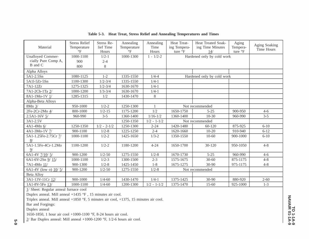
Table 5-3. Heat Treat, Stress Relief and Annealing Temperatures and Times
MaterialStress ReliefTemperature
°F
Stress Re-lief Time
Hours
AnnealingTemperature
°F
AnnealingTimeHours
Heat Treat-ing Tempera-
ture °F
Heat Treated Soak-ing Time Minutes
14/
AgingTempera-ture °F
Aging SoakingTime Hours
Unalloyed Commer-cially Pure Comp A,B and C
1000-1100 1/2-1 1000-1300 1 - 1/2-2 Hardened only by cold work900 2-4800 8
Alpha Alloys5A1-2.5Sn 1080-1125 1-2 1335-1550 1/4-4 Hardened only by cold work5A1l-5Zr-5Sn 1100-1300 1/2-3/4 1335-1550 1/4-17A1-12Zr 1275-1325 1/2-3/4 1630-1670 1/4-17A1-2Cb-1Ta 2/ 1000-1200 1/3-3/4 1630-1670 1/4-18A1-1Mo-1V 1/ 1285-1315 1/2 1430-1470 8Alpha-Beta Alloys8Mn 3/ 950-1000 1/2-2 1250-1300 1 Not recommended2Fe-2Cr-2Mo 4/ 800-1000 1/2-15 1175-1200 1/2 1650-1750 5-25 900-950 4-62.5A1-16V 5/ 960-990 3-5 1360-1400 1/16-1/2 1360-1400 10-30 960-990 3-53A1-2.5V 1250-1350 1/2 - 1-1/2 Not recommended4A1-4Mn 6/ 1250-1350 1/2 - 2-1/2 1250-1300 2-24 1420-1480 60-120 875-925 6-104A1-3Mo-1V 7/ 900-1100 1/2-8 1225-1250 2-4 1620-1660 10-20 910-940 6-125A1-1.25Fe-2.75Cr 7/
8/1000-1100 1/2-2 1425-1650 1/3-2 1350-1550 10-60 900-1000 6-10
5A1-1.5Fe-4Cr-1.2Mo9/
1100-1200 1/2-2 1180-1200 4-24 1650-1700 30-120 950-1050 4-8
6A1-4V 7/10/ 5/ 900-1200 1/2-50 1275-1550 1/2-8 1670-1730 5-25 960-990 4-66A1-6V-2Sn 9/ 15/ 1000-1100 1/2-3 1300-1500 2-3 1575-1675 30-60 875-1175 4-87A1-4Mo 11/ 900-1300 1/2-8 1425-1450 1-8 1675-1275 30-90 975-1175 4-86A1-4V (low o) 10/ 5/ 900-1200 1/2-50 1275-1550 1/2-8 Not recommendedBeta Alloy3A1-13V-11Cr 12/ 900-1000 1/4-60 1430-1470 1/4-1 1375-1425 30-90 880-920 2-601A1-8V-5Fe 13/ 1000-1100 1/4-60 1200-1300 1/2 - 1-1/2 1375-1470 15-60 925-1000 1-31/ Sheet: Regular anneal furnace coolDuplex anneal. Mill anneal +1435 °F , 15 minutes air cool.Triplex anneal. Mill anneal +1850 °F, 5 minutes air cool, +1375, 15 minutes air cool.Bar and Forgings:Duplex anneal1650-1850, 1 hour air cool +1000-1100 °F, 8-24 hours air cool.2/ Bar Duplex anneal: Mill anneal +1000-1200 °F, 1/2-6 hours air cool.
TO1-1A
-9N
AVA
IR01-1A
-9
5-9

Table 5-3. Heat Treat, Stress Relief and Annealing Temperatures and Times - Continued
MaterialStress ReliefTemperature
°F
Stress Re-lief Time
Hours
AnnealingTemperature
°F
AnnealingTimeHours
Heat Treat-ing Tempera-
ture °F
Heat Treated Soak-ing Time Minutes
14/
AgingTempera-ture °F
Aging SoakingTime Hours
3/ Anneal furnace cool at 300 °F per hour maximum to 1000-1050 °F.4/ Stress relief may be accomplished at 800 °F - 15 hours, 850 °F - 5 hours, at 900 °F - 1 hour and 950 °F - 1/2 hour.5/ For 100% stress relief, 1000 °F - 50 hours or 1200 °F - 5 hours. For 50% relief, 1000 °F - 5 hours or 1100 °F - 1/2 hour.6/ Furnace cool at 300 °F maximum from anneal temperature for maximum formability, also, formability may be improved by holding at annealing tempera-
ture 24 hours.7/ Slow cool to 1000-1050 °F maximum from upper annealing temperature.8/ Anneal sheet at temperature for 20 minutes. For bar hold at anneal temperature 2 hours.9/ Air cool from annealing temperature.10/ For sheet anneal, heat 1300-1350 °F, 1 hour, furnace cool at a rate of 50 °F per hour maximum to 800 °F. Air cool may be used for lower ductility re-
quirements. For bar and forging anneal, heat at 1275-1325 °F for 2 hours, air cool. For hydrogen removal by vacuum annealing, heat at 1300-1500 °F for1/2-2 hours, then furnace cool to 1100 °F maximum.
11/ Furnace cool from annealing temp (1425-1450 °F) to 1000-1050 °F maximum at 300 °F per hour (maximum) for maximum formability. For maximumcreep properties (after lowering from upper annealing) temperature hold at 1050° for 24 hours.
12/ Solution heat treatment recommended for annealing. Stress relieve at temperature cited during aging. If aging not employed, heat treat at 1000 °F for 15minutes. Aging time will depend on strength level required/desired.
13/ Furnace cool from upper annealing temperature at 300 °F per hour maximum to 900 °F.14/ Longer soaking times may be necessary for specific forgings. Shorter times are satisfactory when soak time is accurately determined by thermocouples
(TCs) attached to the load. Soaking time shall be measured from the time all furnace control instruments indicate recovery to the required (minimum) pro-cess range.
15/ Age at 1050-1150 °F air cool for best combination of mechanical properties and thermal stability.
TO1-1A
-9N
AVA
IR01-1A
-9
5-10
5.4 FABRICATION.
5.4.1 Forming Sheet Metal-General. The forming of the unalloyed titanium can be accomplished at room temperatureusing approximately the same procedures as those established for 18-8 stainless steel. The basic difficulties encountered aresheet thickness, property variations, direction of grain flow and flatness. The above factors combined with high yieldstrength, high tensile strength and low uniform elongation of commercial titanium alloys makes forming difficult. Thecurrent equipment available was designed for material of uniform quality and considerable work is required for adaptation toform titanium.
5.4.2 Bending. Straight-Edge Bending of titanium using power brake on hand forming equipment can be accomplished toa limited degree using the methods developed for stainless steel. The factors which require control are the compensation forspringback and the bend radii. Springback is comparable to that of hard stainless steel when formed at room temperature.The bend radii will depend on the type of material or alloy and whether forming is accomplished hot or cold. The formingof material requiring tight bends or small radii necessitates the application of heat in the range of 500 °F. The heat should beapplied for only short periods of time to avoid excessive oxygen and nitrogen contamination which causes embrittlement.For approximate cold bend radii of sheet titanium see Table 5-4. Actual practice may reveal that smaller bend radii can beused.
5.4.3 Draw Forming. Deep draw forming should not be attempted unless adequate equipment and facilities are available.This will require that facilities be maintained for heating and controlling temperatures of the blanks to be formed and thedies used in the forming operation.
5.4.4 Hydraulic Press Forming. Rubber pad hydropress forming can be accomplished either hot or cold depending onthe type tooling employed and the press pressures used. This type of forming is used on parts that are predominately flat andhave flanges, beads, and lightening holes. A male form block is set on the lower press platen and the blank held in place onthe block by locating pins. A press-contained rubber pad (45 to 55 Shore Durometer hardness and about 8 inches thick) islocated over the form block and blank. The press is then closed. As the ram is lowered, the rubber pad envelops the formblock forcing the sheet metal blank to conform to its contour.
5.4.4.1 Many parts can be formed at room temperature on the hydropress if flange clips, wedges and hinge-type dies areused. When cold forming is employed, it is usually desirable to partially form the parts, stress-relieve at 1000 °F for 20minutes, then finish form. Hot forming for severely contoured parts or when only low-forming pressures are available isaccomplished between 600 °F and 800 °F. For this procedure, the form block is heated to the required temperature, the blankpositioned and covered with powdered or shredded asbestos; then a rubber pad 70 to 80 Durometer hardness is placed ontop. This extra pad of rubber serves two purposes: First, it provides additional rigidity for forming; and second, it protectsthe press-contained rubber from the hot form block.
5.4.4.2 Tooling for hydropress form blocks, if elevated temperature forming is to be used, requires that pressure plates anddies be made somewhat thicker than in normal practice. If long runs are anticipated, it is recommended that form blocks bemade from a good grade of hot-work tool steel due to the galling action of titanium at elevated temperatures.
5.4.5 Stretch Forming. Stretch forming has been used on titanium primarily to bend angles, hat sections, Z-sections andchannels and to stretch form skins so that they will fit the contour of the airplane fuselage. This type of forming isaccomplished by gripping the section to be formed in knurled jaws, loading until plastic deformation begins, then wrappingthe part around a female die. This operation is performed at room temperature and should be done at a very slow rate. Springback is equivalent to that of 1/4 hard 18-8 stainless steel. All blanks for stretch-forming should have the edges polished toremove any notch effects. Approximately 0.025 inch of sheared edges should be removed.
5.4.6 Drop-Hammer Forming. Drop-hammer forming of titanium has been very successful and has been accomplishedboth at room and at elevated temperatures. Kirksite is satisfactory for male and female dies where only a few parts arerequired. If long runs are to be made, ductile iron or laminated steel dies are usually necessary. In drop-hammer forming, thebest results have been obtained by warning the female die to a temperature of 200-300 °F to remove the chill and heating theblank to a temperature of 800-1000 °F for 10 to 15 minutes. The part is then struck and set in the die. Usually a stress reliefoperation at 1000 °F for 20 minutes is necessary, then a restrike operation. In most instances, a finished part requiring nohand work is obtained.
5.4.7 Joggling. Joggling of titanium can be accomplished without any particular difficulty provided the following rulesare adhered to:
a. The joggle die corner radius should not be less than 3T-8T.
TO 1-1A-9NAVAIR 01-1A-9
5-11

b. Joggle run-out should be the determining factors whether joggles are formed hot or cold. Joggles should be formed hotwhere a ratio of joggle run-out to joggle depth is less than 8.1.
c. Minimum joggle run-outs should be as follows:
• Hot joggling - four times the joggle depth.
• Cold joggling - eight times the joggle depth.
5.4.8 Blanking and Shearing. These operations compare to those of 18-8 stainless steel in the 1/4 hard condition forcommercially pure, and the alloys compare to 1/2 hard 18-8 stainless steel. The force required for titanium and its alloys isgreater and the dies wear faster. Materials up to 0.125 inch in thickness have been sheared on 1/2 inch capacity flat bedshears designed for steel. If this capacity is to be exceeded, the shear designer should be consulted.
5.4.8.1 Before any forming or other operations are performed 0.025 inch of the sheared, blanked, sawed, or nibbed edgesshould be removed to prevent stress risers that will cause a tear in the part during forming operations.
5.4.9 Soldering. Limited information is available on soldering. It is possible to successfully solder titanium where littlestrength is required, by precoating with a thin film of silver, copper or tin from their chloride salts. This can be accomplishedby heating the chloride salts-coated titanium in an atmosphere controlled furnace as previously mentioned in Paragraph5.3.1.1. The resultant film should be made wet with either a 60% tin-40% lead or a 50%-50% tin and lead solder. Since thedeposited film may dissolve in the liquid solder and dewet the surface, it is important that the time and temperature be heldto a minimum.
5.4.10 Riveting. Riveting of titanium can be accomplished using conventional equipment with rivets manufactured fromcommercially pure material; however, the rivet holes require close tolerances to ensure good gripping. The driving time isTO 1-1A-9 increased about 65% over that required for high strength aluminum rivets. Better results can be obtained by usingthe squeeze method rather than the rivet gun and bucking bar. When it is necessary to have flush-head rivets, dimpling canbe accomplished at temperatures of 500-700 °F. Other types of rivets such as high strength aluminum, stainless steel andmonel are also used to join titanium.
5.4.10.1 Due to difficulties involved, the above mentioned method will probably be replaced in most cases with rivets ofthe high shear series, i.e., pin rivets such as NAS1806 through NAS1816, tension rivet NAS-2006 through NAS-2010, andshear rivet NAS-2406 through NAS-2412.
5.4.10.2 As with other metals, it is necessary to take precautions to avoid galvanic corrosion when titanium is riveted toother metals. This can be accomplished by coating the titanium with zinc chromate primer Specification MIL-P-8585.
Table 5-4. Recommended Minimum Constant Current Line Drive (CCLD) Bend Radii
Minimum Bend Radius (90 Degree Bend) 1/Type/Composition 0.070 and Under Thickness Over 0.070 to 0.187
Type I - Commercially PureComp A (unalloyed 40,000 PSI) 2T 2.5TComp B (unalloyed 70,000 PSI) 2.5T 3TComp C (unalloyed 55,000 PSI) 2T 2.5TType II - Alpha Titanium AlloyComp A (5AL02.5Sn) 4T 4.5TComp B (5AL-2.5Sn EL1) 4T 4.5TComp C (5AL-5Zr-5Sn) 4.5T 5TComp D (7AL-12Zr) 5T 5TComp E (7AL-2Cb-1Ta)Comp F (8AL-1Mo-1V) 4.5T 5TType III - Alpha-BetaComp A (8Mn) 3T 3.5TComp B (4AL-3Mo-1V) 3.5T 4T
TO 1-1A-9NAVAIR 01-1A-9
5-12

Table 5-4. Recommended Minimum Constant Current Line Drive (CCLD) Bend Radii - Continued
Minimum Bend Radius (90 Degree Bend) 1/Type/Composition 0.070 and Under Thickness Over 0.070 to 0.187
Comp C (6AL-4V) 4.5T 5TComp D (6AL-4V) 4.5T 5TComp E (6AL-6V-2Sn)Comp F (7AL-4Mo)Type IV - BetaComp A (13V-11Cr-3AL) 3T 3-5T1/ T = Thickness of material. Example: A piece of 0.040 MIL-T-9046, Type II, Composition A, would require a bend
radii of 4 X 0.040 = 0.160 bend radii (minimum).
5.5 MACHINING AND GRINDING.
5.5.1 Machining. Commercially pure, unalloyed titanium machines similarly to 18-8 stainless steel, but the alloy gradesare somewhat harder. Variations in actual practice will depend on the type of work, equipment, and finish, so the followinginformation is only intended as a guide.
5.5.1.1 The basic requirements are: rigid machine setups, use of a good cutting fluid that emphasizes cooling rather thanlubrication, sharp and proper tools, slow speeds and heavy feeds. Since titanium has a tendency to gall and seize on othermetals, the use of sharp tools is very important. Sliding contact, and riding of the tool on the work must be avoided.
5.5.2 Turning. Commercially pure and alloy titanium is not difficult to turn. Carbide tools such as metal carbides C91 andCarboloy 44A and other similar types give the best results for turning titanium. Cobalt-type high speed steels give the bestresults of the many types available. Cast alloy tools such as Stellite, Lantung, Rexalloy, etc., may be used when carbide isnot available, or when the high speed steels, are not satisfactory.
5.5.2.1 The recommended cutting fluids are waterbase cutting fluids such as soluble oils or chemical type fluids.
5.5.2.2 Table 5-5 and Table 5-7 show suggested turning speeds, tool angles and feeds. All work should be accomplishedwith live centers since galling or seizing will occur on dead centers. Tool sharpness is again emphasized because a nick ora seized chip on a tool increases temperature and will cause rapid tool failures.
5.5.3 Milling. Considering the type of tool which is required in milling operations, it can be readily seen that this type ofmachining is more difficult than turning. The difficulty encountered is that chips remain tightly welded to the cutter’s edge atthe end of cut or during the portion of the revolution that it does not cut. As the cutter starts the next machining portion thechips are knocked off. This damages the cutting edge and the tool fails rapidly.
5.5.3.1 One method that can be utilized to relieve this difficulty to a great extent is climb milling. The cutter machines thethinnest portion of the chip as it leaves the cut. Thus, the area of contact between chip and tool is at a minimum when thechip is removed at the start of the next cutting portion of the revolution. This will reduce the danger of chipping the tool. Themachine used for climb milling should be in good condition because TO 1-1A-9 if there is any lost motion in the feedmechanism of the table, the piece being cut will be pulled into the cutter. This may damage the cutter or the work piece.
5.5.3.2 For effective milling, the work feed should move in the same direction as the cutting teeth, and for face milling theteeth should emerge from the cut in the same direction that the work is fed.
5.5.3.3 To select the appropriate tool material it is advisable to try both cast alloy and carbide tools to determine the betterof the two for large milling jobs. This should be done since the cutter usually fails because of chipping, and the results arenot as satisfactory with carbide as they are with cast-alloy tools. The increase in cutting speeds (20 to 30%) possible byusing carbide rather than cast (all alloy tools) does not always compensate for the additional tool grinding cost.
5.5.3.4 The same water-base cutting fluids used for turning are recommended for milling; however, carbide tools may givebetter results when dry.
5.5.3.5 See Table 5-7 for recommended speed and feeds. For tool grinding information see Table 5-8.
TO 1-1A-9NAVAIR 01-1A-9
5-13

5.5.4 Drilling. Drilling of titanium can be accomplished successfully with ordinary high speed steel drills. Low speeds andheavy positive feeds are required. The unsupported portion of the drill should be as short as possible to provide maximumrigidity and to prevent drill running. All holes should be drilled without pilot holes if possible. As with other materials, chipremoval is one of the principal problems and the appearance of the chip is an indication of the sharpness and correctgrinding of the drill. In drilling deep holes, intermittent drilling is recommended. That is, the drill is removed from the holeat intervals to remove the chips.
5.5.4.1 The cutting fluids recommended are sulfurized and chlorinated coolants for drills with diameters of less than 1/4inch and mixtures of mineral oil or soluble oil with water for hole sizes larger than 1/4 inch diameter.
5.5.4.2 The cutting speed should be 50 to 60 Foot Per Minute (FPM) for the pure grade of titanium and 30 to 50 FPM foralloy grades. Feeds should be 0.005 to 0.009 inch for 1/4 to 1/2 inch diameter drills; 0.002 to 0.005 inch for smaller drills.Point angle, 90° for drills 1/4 inch diameter and larger and 140° for drills 1/8 inch diameter or less; but 90°, 118° and 140°should be tried on large jobs to determine the angle that will give the best result. Helix angle 28° to 35° and lip relief 10°.Additional information on drills may be obtained from NAS907.
5.5.5 Tapping. Due to the galling and seizing that are characteristic of titanium, tapping is one of the more difficultmachining operations. Chip removal is one of the problems that will require considerable attention in an effort to taptitanium. Another problem will be the smear of titanium. Build up from smear will cause the tap to freeze or bind in the hole.These problems can be alleviated to some extent by the use of an active cutting fluid such as sulphurized and chlorinated oil.
5.5.5.1 Power equipment should be used when possible and a hole to be tapped should be drilled with a sharp drill toprevent excessive hardening of the hole wall. In the attempt to tap titanium, difficulties involved can be minimized byreducing the thread to 55% or 65% from the standard 78%.
5.5.5.2 The following are procedures and material recommended for tapping titanium:
a. Cutting speed: 40 to 50 FPM for unalloyed and 20 to 30 FPM for the alloy grades.
b. Type of Tap: Gun or spiral point, 2 fluted in sizes 1/4-20 or less; 3 fluted in sizes greater than 1/4-20.
c. Cutting fluid; Active cutting oil such as oil, cutting, sulfurized mineral, Specification VV-O-283, Grade 1.
5.5.6 Reaming. Preparation of the hole to be reamed and the type of reamer used is the keynote to successful reamingoperations. As with tapping operations, the hole to be reamed should be drilled with a sharp drill. A straight-fluted reamercan be used, but spiral-fluted reamers with carbide tips usually produce the best results. Speeds of 40-200 FPM and feeds of0.005 to 0.008 inch are satisfactory; however, these factors depend on the size of the hole. Feeds should increase inproportion to the size of the hole. The removal of larger amounts lessens the degree of concentricity. If the degree ofconcentricity is an important factor, smaller amounts should be removed.
5.5.7 Grinding. The essential requirements for grinding are the selection and use of grinding fluids and abrasive wheels.Grinding of titanium is different from grinding steel in that the abrasive grain of the wheel wears or is dissolved by a surfacereaction, rather than wheel wear which is caused by breakage. To overcome this problem, lower wheel speeds and the use ofaluminum oxide or soft bonded silicone carbide wheels employing wet grinding methods are recommended. Recommendedwheel speeds are; 1500-2000 Surface Feet Per Minute (SFM) and table feeds of 400 to 500 inches per minute with downfeed of 0.001 inch maximum per pass and using 0.05 inch cross feed for highest grinding ratios.
Table 5-5. Turning Speeds for Titanium Alloys
Type Military MIL-T-9047C
Cutting Speed FPM Feed, Inch perRevolution
Tool Material
Unalloyed 70,000 PSI Class 1 250-300 0.010-0.020 Carbide150-170 0.004-0.007 Hi-Speed Steel170-200 0.005-0.010 Cast Alloy
5A1, 2.5 Tin Classes 2, 3, 4, 120-160 0.008-0.015 Carbide3A1, 5Cr 5, and 6 30-60 0.004-0.007 Bi-Speed Steel
TO 1-1A-9NAVAIR 01-1A-9
5-14

Table 5-5. Turning Speeds for Titanium Alloys - Continued
Type Military MIL-T-9047C
Cutting Speed FPM Feed, Inch perRevolution
Tool Material
2Fe, Chromium 2 Molyb-denum
50-80 0.005-0.010 Cast Alloy
6A1, 4V4A1, 4Mn5A1, 1.5 Iron Class 7 110-150 0.005-0.012 Carbide1.5 Chromium, 1.5 Molyb-
denum20-40 0.003-0.006 Hi-Speed Steel
40-70 0.004-0.008 Cast Alloy
NOTE
For cutting forging skin speed 1/4 of that above and feeds about 1/2.
Table 5-6. Tool Angles for Alloys
Tool Angles Carbide High Speed Steel Cast AlloyBack Rake 0° 5° Position 5 PositionSide Rake 6° 5 - 15° 5 - 15°Side Cutting 6° 5 - 15° 5 - 15°Edge AngleEnd Cutting 6° 5° 5°Edge AngleRelief 6° 5° 5°Nose Radius 0.040 inch 0.010 inch 0.005 to 0.010 inch
Table 5-7. Speeds and Feeds for Milling
Type Military Milling Speed FPM Feed, Input in Inches Tool MaterialUnalloyed MIL-T-9047C 160-180 0.004-0.008 Carbide70,000 PSI Class 1 120-140 0.004-0.008 Cast Alloy5A1, 2.5Sn Class 2, 3, 4, 80-120 0.004-0.008 Carbide3A1, 5CR 5, 6 80-100 0.004-0.008 Cast Alloy2Fe, 2Cr, 2Mo,6A1, 4V4A1, 4Mn5A1, 1.5Fe, 1.5Cr Class 7 70-110 0.004-0.008 Carbide1.5Mo 70-90 0.004-0.008 Cast Alloy
Table 5-8. Angles for Tool Grinding
Angles Cast Alloy Tool Carbide ToolAxial Rake 0° 0°Radial Rake 0° 0°Corner Angle 30° 60°End Cutting 6° 6°Edge Angle
TO 1-1A-9NAVAIR 01-1A-9
5-15

Table 5-8. Angles for Tool Grinding - Continued
Angles Cast Alloy Tool Carbide Tool
Relief 12° 6-10°
TO 1-1A-9NAVAIR 01-1A-9
5-16

CHAPTER 6COPPER AND COPPER BASE ALLOYS
6.1 COPPER AND COPPER BASE ALLOYS.
Most of the commercial coppers are refined to a purity of 99.90%, minimum copper plus silver. The two principal copperbase alloys are brass and bronze, containing zinc and tin respectively, as the major alloying element. Alloy designations forwrought copper and copper alloys are listed in Table 6-1, with the corresponding specification and common trade names.
6.2 COPPER ALLOYING ELEMENTS.
6.2.1 Zinc. Added to copper to form a series of alloys known as brasses. They are ductile, malleable, corrosion resistantand have colors ranging from pink to yellow.
6.2.2 Tin. Added to copper to form a series of alloys known as bronzes. Bronzes are a quality spring material, and arestrong, ductile and corrosion resistant.
6.2.3 Lead. Added to copper in amounts up to 1% to form a machinable, high-conductivity copper rod. It is added tobrasses or bronzes in amounts of 0.5 to 4% to improve machinability and in the range of 2-4% to improve bearingproperties.
6.2.4 Aluminum. Added to copper as a predominating alloy element to form a series known as aluminum bronzes. Thesealloys are of high strength and corrosion resistance.
6.2.5 Iron. Added to copper along with aluminum in some aluminum bronzes and with manganese in some manganesebronzes.
6.2.6 Phosphorous. Added to copper principally as a deoxidizer and in some bronzes to improve spring properties.
6.2.7 Nickel. Added to copper for higher strength without loss of ductility. They have excellent corrosion resistance.
6.2.8 Silicon. Added to copper to form the copper - silicon series having high corrosion resistance combined with strengthand superior welding qualities. Small amounts are used as deoxidizers.
6.2.9 Beryllium. Added to copper to form a series of age hardenable alloys. In the fully treated condition, it is thestrongest of the copper base alloys and has an electrical conductivity of 20%. Berryllium-coppers are widely used for toolswhere nonsparking qualities are desired.
6.2.10 Manganese. Added primarily as a desulfurizing and de-gassifying element for alloys containing nickel.
6.3 CHEMICAL COMPOSITION.
The chemical composition of the copper alloys (listed by commercial trade name) is listed in Table 6-1.
6.4 HEAT TREATMENT AND NOT WORKING TEMPERATURE OF COPPER ALLOYS.
NOTE
Additional Heat Treatment information is discussed in Chapter 9.
During production and fabrication, copper alloys may be heated for homogenizing, hot working, stress relief for solutiontreatment, and precipitation hardening. The temperatures commonly used for heating, hot working and annealing after coldworking are given in Table 6-2.
TO 1-1A-9NAVAIR 01-1A-9
Change 6 6-1
6.5 STRESS RELIEF OF COPPER ALLOYS.
Table 6-3 below gives a list of typical stress relief treatments commonly used in industry. This table is listed in terms ofchemical composition percents, and should be used as representing average stress relieving temperatures.
6.5.1 Machining Copper and Copper Alloys. Free cutting brass is one of the most easily machined metals and serves asa standard for machinability ratings of copper alloys. The following table gives the machinability ratings and recommendedspeeds and feeds for use with high speed steel tools.
6.5.2 Wrought-Copper-Beryllium Alloys. The beryllium copper alloys are frequently used due to their ability to respondto precipitation or age hardening treatments and other beneficial characteristics. Some of the characteristics are; goodelectrical and thermal conductivity, high strength hardness, corrosion resistance, good wear resistance, non-magnetic quali-ties and very good fatigue strength.
6.5.2.1 Typical Engineering properties of alloys 170, Specification QQ-C-530 and 172, Specification QQ-C-533 are citedin Table 6-5.
6.6 HEAT TREATING PROCEDURES AND EQUIPMENT REQUIREMENTS.
NOTE
SAE-AMS-H-7199, Heat Treatment of Wrought Copper-Beryllium Alloys, Process for (Copper Alloy numbers170, 172 and 175), will be the control document for heat treatment of wrought copper-beryllium alloy, numbers170, 172 and 175. For complete description of heat treat requirements for these alloys, refer to the latest issue ofSAE-AMS-H-7199.
Furnaces for solution heat treating of copper-beryllium items/parts may be heated by electricity, gas or oil, with eithercontrolled gas atmosphere or air (static or forced), used in the chamber, continuous or induction types. Molten salt bathsshall not be used because of corrosive attack of beryllium alloys by the molten salts at solution heat treatment temperatures.Air atmosphere furnaces shall not be used when the loss of material due to excessive scaling is detrimental to the finishedpart. The furnace alloy shall be capable of maintaining a temperature in working zone with a normal load, of ±20 °F forsolution heat treatment, or ±5 °F for aging, or precipitation heat treatment. In addition, the temperature in working zone shallnot vary above the maximum or below the minimum specified for the alloy being treated, during the holding portion of thetreatment cycles (See Table 6-6).
6.6.1 Solution Heat Treatment Copper-Beryllium. Normally solution heat treatment is not required because the materialis furnished in a condition suitable for accomplishing forming operations and then precipitation heat treating. An exceptionis when the material has been rendered unsuitable for precipitation or age hardening as result of welding, brazing or otherfabrication operations or when, cold working requirements demand intermediate softening (annealing) treatment.
6.6.1.1 The solution heat treatment temperatures for alloys 170 and 172 shall be 1425-1460 °F. The time the material isheld at the temperature will determine the potential properties of the material. Insufficient time will make it impossible toachieve maximum strength after precipitation hardening, while excessive time may cause grain growth with attendantharmful possibilities. Once the parts are brought up to temperature it is recommended that material be held at temperaturefor 1 hour per inch of thickness. For parts less than 1/2 inch in thickness, 1/6-1/2 hour may be sufficient. Test sample shouldbe used to determine specific time or if laboratory facilities are available an examination of microstructure will confirm theadequacy of the time selected. The part/material should be rapidly (10 seconds or under) quenched in water from theannealing temperature. An agitated quench should be used. Some oxidation will occur as a result of the annealing tempera-tures and it should be removed by pickling or other suitable cleaning process.
6.6.2 Precipitation or Age Hardening. Appreciable changes can be produced in both mechanical and physical by thistreatment. The actual changes can be controlled by the time and temperature of hardening. Table 6-6 gives times andtemperatures for obtaining various tempers.
TO 1-1A-9NAVAIR 01-1A-9
6-2
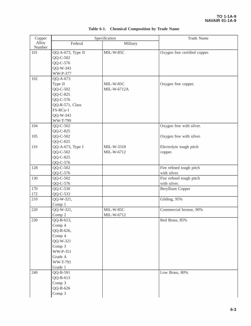
Table 6-1. Chemical Composition by Trade Name
CopperAlloy
Number
Specification Trade NameFederal Military
101 QQ-A-673, Type II MIL-W-85C Oxygen free certified copper.QQ-C-502QQ-C-576QQ-W-343WW-P-377
102 QQ-A-673Type II MIL-W-85C Oxygen free copper.QQ-C-502 MIL-W-6712AQQ-C-825QQ-C-576QQ-R-571, ClassFS-RCu-1QQ-W-343WW-T-799
104 QQ-C-502 Oxygen free with silver.QQ-C-825
105 QQ-C-502 Oxygen free with silver.QQ-C-825
110 QQ-A-673, Type I MIL-W-3318 Electrolyte tough pitchQQ-C-502 MIL-W-6712 copper.QQ-C-825QQ-C-576
128 QQ-C-502 Fire refined tough pitchQQ-C-576 with silver.
130 QQ-C-502 Fire refined tough pitchQQ-C-576 with silver.
170 QQ-C-530 Beryllium Copper172 QQ-C-533210 QQ-W-321, Gilding, 95%
Comp 1220 QQ-W-321, MIL-W-85C Commercial bronze, 90%
Comp 2 MIL-W-6712230 QQ-B-613, Red Brass, 85%
Comp 4QQ-B-626,Comp 4QQ-W-321Comp 3WW-P-351Grade AWW-T-791Grade 1
240 QQ-B-591 Low Brass, 80%QQ-B-613Comp 3QQ-B-626Comp 3
TO 1-1A-9NAVAIR 01-1A-9
6-3

Table 6-1. Chemical Composition by Trade Name - Continued
CopperAlloy
Number
Specification Trade NameFederal Military
QQ-B-650Comp DQQ-W-321 JAN-W-472Comp 4
260 QQ-B-613 *MIL-S-22499 Cartridge brass, 70%Comp 2 and 11QQ-B-626 MIL-T-6945Comp 2 and 11 Comp IIQQ-B-650 MIL-T-20219Comp CQQ-W-321Comp 6
*Laminated Shim Stock261 Same as 260262 QQ-B-613
Comp 11QQ-B-626Comp 11
268 QQ-B-613 Yellow brass, 66% (Sheet)Comp 1 and 11QQ-B-626Comp 1 and 11
270 QQ-B-613 Yellow brass, 65% (rod and wire)Comp 11QQ-B-626Comp 11QQ-W-321Comp 7
274 QQ-B-613 Yellow brass 63%Comp 11QQ-B-626Comp 11QQ-W-321Comp 8
280 QQ-B-613 Muntz metal, 60%Comp 11QQ-B-626Comp 11WW-P-351Grade CWW-T-791Grade 3
298 QQ-B-650 Brazing AlloyComp A
330 QQ-B-613 Low leaded brassComp 11 MIL-T-6945QQ-B-626 Comp III
TO 1-1A-9NAVAIR 01-1A-9
6-4

Table 6-1. Chemical Composition by Trade Name - Continued
CopperAlloy
Number
Specification Trade NameFederal Military
Comp 11WW-P-351Grade BWW-T-791Grade 2
331 QQ-B-613Comp 11QQ-B-626Comp 11
110 QQ-R-571, ClassFS-RW-1QQ-W-343WW-P-377
111 QQ-C-502 Electrolytic touch pitchQQ-C-825 anneal resist copperQQ-C-576QQ-W-343
114 QQ-C-502 Tough pitch with silverQQ-C-825QQ-C-576
116 QQ-C-502 Tough pitch with silverQQ-C-825QQ-C-576
120 QQ-C-502 MIL-W-85C Phosphorous deoxidized lowQQ-C-576 residual phosphorus copperWW-P-377WW-T-797WW-T-799
121 QQ-C-502QQ-C-576
122 QQ-A-674, Type III Phosphorus deoxidized high residual phos-phorus copper
QQ-C-502122 QQ-C-576
WW-P-377WW-T-797
123 QQ-C-502QQ-C-576
125 QQ-C-502 Fire refined tough pitchQQ-C-576 copper
127 QQ-C-502 Fire refined tough pitchQQ-C-576 with silver
332 QQ-B-613 High leaded brassComp 11QQ-B-626Comp 11
340 QQ-B-613 Comp 11 Medium leaded brass 64 1/2%
TO 1-1A-9NAVAIR 01-1A-9
6-5

Table 6-1. Chemical Composition by Trade Name - Continued
CopperAlloy
Number
Specification Trade NameFederal Military
QQ-B-626Comp 11
335 QQ-B-613 Low leaded brassComp 11QQ-B-626Comp 11
342 QQ-B-613 High leaded brass 64 1/2%Comp 11 and 24QQ-B-626Comp 11 and 24
344 QQ-B-613Comp 11QQ-B-626Comp 11
347 QQ-B-613Comp 11QQ-B-626Comp 11
348 QQ-B-613Comp 11QQ-B-626Comp 11
350 QQ-B-613 Medium leaded brass 62%Comp 11QQ-B-626Comp 11
353 QQ-B-613 Extra High leaded brassComp 11QQ-B-626Comp 11
356 QQ-B-613 Extra High leaded brassComp 11QQ-B-626Comp 11 and 22
370 QQ-B-613 Free cutting Muntz metalComp 11QQ-B-626Comp 11
360 QQ-B-613 Free cutting brassComp 11QQ-B-626Comp 11 and 22
377 QQ-B-626 Forging brassComp 21
443 WW-T-756 Admiralty, Arsenical444 WW-T-756 Admiralty, Antimonial445 WW-T-756 Admiralty, Phosphorized
TO 1-1A-9NAVAIR 01-1A-9
6-6

Table 6-1. Chemical Composition by Trade Name - Continued
CopperAlloy
Number
Specification Trade NameFederal Military
462 QQ-B-626 Naval Brass, 63 1/2%Comp 11QQ-B-637Comp 4
464 QQ-B-613 Naval BrassComp 11 MIL-W-6712QQ-B-626Comp 11 MIL-T-6945QQ-B-637 Comp 1Comp 1
465 QQ-B-613 MIL-W-6712 Naval brass, ArsenicalComp 11QQ-B-626 MIL-T-6945Comp 11QQ-B-637 Comp 1Comp 1
466 QQ-B-613 Comp 11 MIL-W-6712 Naval Brass, AntimonialQQ-B-626Comp 11 MIL-T-6945QQ-B-637Comp 1 Comp 1
467 QQ-B-613 MIL-W-6712 Naval Brass, PhosphorizedComp 11 MIL-T-6945QQ-B-626Comp 11QQ-B-637Comp 1
470 QQ-R-571 Naval brass, welding and brazing rodClass FS-RWZn-1
472 QQ-B 650 Brazing alloyComp B
482 QQ-B-626 MIL-W-6712 Naval Brass, medium leadedComp 11 MIL-T-6945QQ-B-637 Comp 1Comp 2
485 QQ-B-626 MIL-W-6712 Naval Brass, High leadedComp 1 MIL-T-6945QQ-B-637 Comp 1Comp 3
510 QQ-B-750 Phosphor Bronze AComp AQQ-W-401QQ-R-571,Class FS-RCuSm-2
518 QQ-R-571 Phosphor BronzeClass FS-RCu Sm-2
521 QQ-R-571 Phosphor Bronze C
TO 1-1A-9NAVAIR 01-1A-9
6-7

Table 6-1. Chemical Composition by Trade Name - Continued
CopperAlloy
Number
Specification Trade NameFederal Military
Class FS-Rcu Sm-2524 QQ-B-750 Phosphor Bronze D
Comp D544 QQ-B-750 MIL-B-13501 Phosphor Bronze B-2606 QQ-C-450
Comp 3612 QQ-C-450
Comp 4614 QQ-C-450 Aluminum Bronze D
Comp 5618 MIL-W-6712
MIL-R-18818MIL-RUA1-2
622 MIL-R-18818 classMIL-RCA-B
651 QQ-C-591 Low Silicon Bronze BComp B
655 QQ-C-591 MIL-T-8231 High Silicon Bronze AComp A
656 QQ-R-571Class FS-RCuS1 MIL-E13191 class
MIL-EcuSi-A658 MIL-E-13191 class
MIL-ECuSi-A661 QQ-C-591
Comp D670 QQ-B-728 Magnesium Bronze B
Class B675 QQ-B-728 Magnesium Bronze A
Class A680 QQ-R-571 Bronze Low Fuming (Nickel)
Class FS-RCu-Zinc-3681 QQ-R-571 class Bronze, Low Fuming
FS-RCuZn-2692 QQ-C-591 Silicon Brass
Comp E715 QQ-R-571 Class Copper Nickel 30%
FS-RCuNi735 QQ-C-585
Comp 6745 QQ-C-585 Nickel Silver 65-10
Comp 5QQ-C-586comp 5QQ-W-340Comp 5
752 QQ-C-585 Nickel Silver 65-18
TO 1-1A-9NAVAIR 01-1A-9
6-8
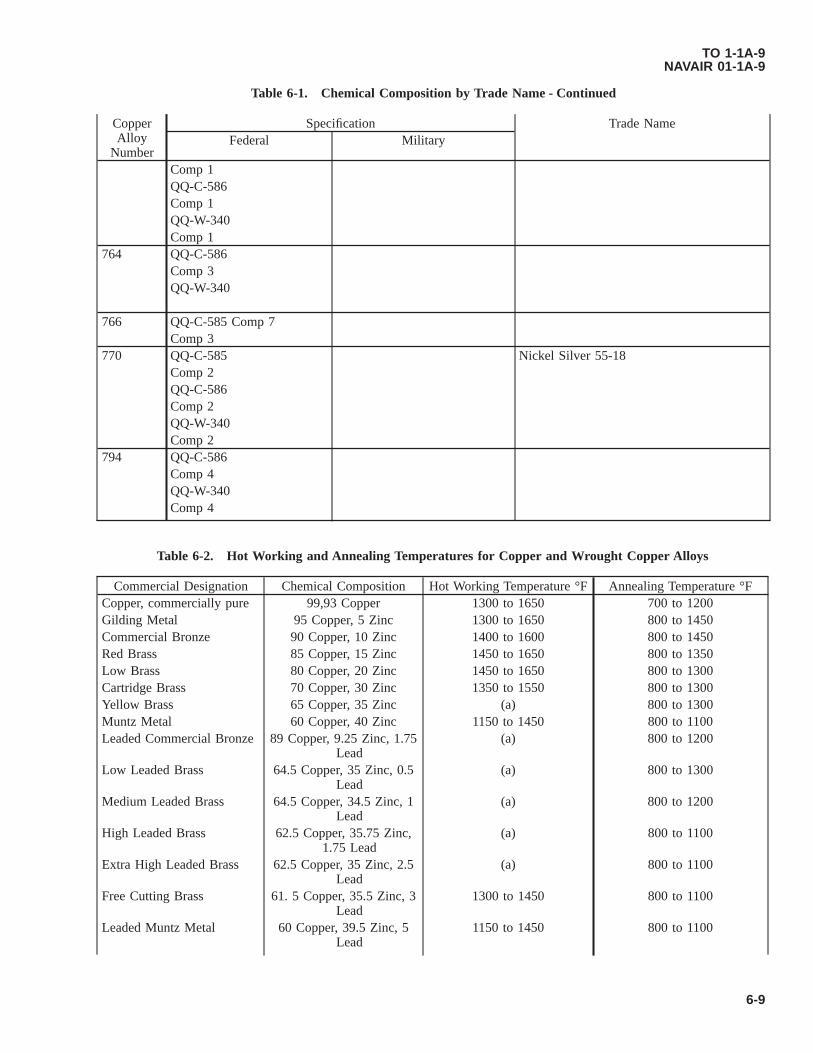
Table 6-1. Chemical Composition by Trade Name - Continued
CopperAlloy
Number
Specification Trade NameFederal Military
Comp 1QQ-C-586Comp 1QQ-W-340Comp 1
764 QQ-C-586Comp 3QQ-W-340
766 QQ-C-585 Comp 7Comp 3
770 QQ-C-585 Nickel Silver 55-18Comp 2QQ-C-586Comp 2QQ-W-340Comp 2
794 QQ-C-586Comp 4QQ-W-340Comp 4
Table 6-2. Hot Working and Annealing Temperatures for Copper and Wrought Copper Alloys
Commercial Designation Chemical Composition Hot Working Temperature °F Annealing Temperature °FCopper, commercially pure 99,93 Copper 1300 to 1650 700 to 1200Gilding Metal 95 Copper, 5 Zinc 1300 to 1650 800 to 1450Commercial Bronze 90 Copper, 10 Zinc 1400 to 1600 800 to 1450Red Brass 85 Copper, 15 Zinc 1450 to 1650 800 to 1350Low Brass 80 Copper, 20 Zinc 1450 to 1650 800 to 1300Cartridge Brass 70 Copper, 30 Zinc 1350 to 1550 800 to 1300Yellow Brass 65 Copper, 35 Zinc (a) 800 to 1300Muntz Metal 60 Copper, 40 Zinc 1150 to 1450 800 to 1100Leaded Commercial Bronze 89 Copper, 9.25 Zinc, 1.75
Lead(a) 800 to 1200
Low Leaded Brass 64.5 Copper, 35 Zinc, 0.5Lead
(a) 800 to 1300
Medium Leaded Brass 64.5 Copper, 34.5 Zinc, 1Lead
(a) 800 to 1200
High Leaded Brass 62.5 Copper, 35.75 Zinc,1.75 Lead
(a) 800 to 1100
Extra High Leaded Brass 62.5 Copper, 35 Zinc, 2.5Lead
(a) 800 to 1100
Free Cutting Brass 61. 5 Copper, 35.5 Zinc, 3Lead
1300 to 1450 800 to 1100
Leaded Muntz Metal 60 Copper, 39.5 Zinc, 5Lead
1150 to 1450 800 to 1100
TO 1-1A-9NAVAIR 01-1A-9
6-9

Table 6-2. Hot Working and Annealing Temperatures for Copper and Wrought Copper Alloys - Continued
Commercial Designation Chemical Composition Hot Working Temperature °F Annealing Temperature °FFree Cutting Muntz Metal 60.5 Copper, 38.4 Zinc, 1.1
Lead1150 to 1450 800 to 1100
Forging Brass 60 Copper, 38 Zinc, 2Lead
1200 to 1500 800 to 1100
Architectural Bronze 57 Copper, 40 Zinc, 3Lead
1200 to 1400 800 to 1100
Admiralty 71 Copper, 28 Zinc, 1 Tin 1200 to 1500 800 to 1100Naval Brass 60 Copper, 39.25 Zinc,
0.75 Tin1200 to 1400 800 to 1100
Leaded Naval Brass 60 Copper, 37.5 Zinc, 1.75Tin
1200 to 1450 800 to 1100
Magnesium Bronze 58.5 Copper, 39.2 Zinc1 Tin, 3 Maganese, 1 Iron 1250 to 1450 800 to 1100
Aluminum Brass 76.Copper, 22 Zinc, ZincAluminum
1450 to 1550 800 to 1100
Phosphor Bronze “A” 95 Copper, 5 Tin (a) 900 to 1250Phosphor Bronze “C” 92 Copper, 8 Tin (a) 900 to 1250Phosphor Bronze “D”’ 90 Copper, 10 Tin (a) 900 to 1250Phosphor Bronze “E” 98- 75 Copper, 1.25 Tin 1450 to 1600 900 to 1200Cupro-Nickel 30% 70 Copper, 30 Nickel 1700 to 2000 1200 to 1600Nickel Silver 18% (A) 65 Copper, 17 Zinc, 18
Nickel(a) 1100 to 1500
Nickel Silver 18% 55 Copper, 27 Zinc, 18Nickel
(a) 1100 to 1400
High-Silicon Bronze (A) 94.8 Copper, 3 Silicon, 1.5Magnesium, 0.7 Zinc
1300 to 1650 900 to 1300
Low Silicon Bronze 96. Copper, 2 Silicon, 1.5Zinc, 0.5 Magnesium
1300 to 1650 900 to 1250
(A) These alloys are usually hot extruded after casting, further hot working is uncommon.
Table 6-3. Typical Stress-Relief Treatments for Certain Copper Alloys
Alloy Composition Temperature °F Time, HoursCopper, commercially pure 300 1/290 Copper - 10 Zinc 400 180 Copper - 20 Zinc 500 170 Copper - 30 Zinc 500 163 Copper - 37 Zinc 475 160 Copper - 40 Zinc 375 1/270 Copper - 29 Zinc - 1 Tin 575 185 Copper - 15 Nickel 475 170 Copper - 30 Nickel 475 164 Copper - 18 Zinc - 18 Nickel 475 195 Copper - 5 Tin 375 190 Copper - 10 Tin 375 1
TO 1-1A-9NAVAIR 01-1A-9
6-10

Table 6-4. Standard Machinability Rating of Copper Alloys
Alloy Designation MachinabilityRating
Surface Speed FPM Roughing Feed, Inch Finishing Feed, Inch
Leaded Copper 80 300 to 700 0.006 to 0.020 0.003 to 0.015Leaded CommercialBronze
80 300 to 700 0.006 to 0.020 0.003 to 0.015
Low Leaded Brass 60 300 to 700 0.006 to 0.020 0.003 to 0.015Medium Leaded Brass 70 300 to 700 0.006 to 0.020 0.003 to 0.015High Leaded Brass 90 300 to 700 0.006 to 0.020 0.003 to 0.015Free Cutting Brass* 100 300 to 700 0.006 to 0.020 0.003 to 0.015Forging Brass 80 300 to 700 0.006 to 0.020 0.003 to 0.015Leaded Naval Brass 70 300 to 700 0.006 to 0.020 0.003 to 0.015Architectural Bronze 90 300 to 700 0.006 to 0.020 0.003 to 0.015Red Brass, 85% 30 150 to 300 0.015 to 0.035 0.005 to 0.015Low Brass, 80% 30 150 to 300 0.015 to 0.035 0.005 to 0.015Muntz Metal 40 150 to 300 0.015 to 0.035 0.005 to 0.015Naval Brass 30 150 to 300 0.015 to 0.035 0.005 to 0.015Magnesium Bronze (A) 30 150 to 300 0.015 to 0.035 0.005 to 0.015Leaded Nickel Silver, 12% 50 150 to 300 0.015 to 0.035 0.005 to 0.015Leaded Nickel Silver 18% 50 150 to 300 0.015 to 0.035 0.005 to 0.015High Silicon Bronze (A) 30 150 to 300 0.015 to 0.035 0.005 to 0.015Leaded Silicon Bronze (d) 60 150 to 300 0.015 to 0.035 0.005 to 0.015Aluminum Silicon Bronze 60 150 to 300 0.015 to 0.035 0.005 to 0.015Electrolytic Tough pitchcopper
20 75 to 150 0.015 to 0.040 0.005 to 0.020
Commercial Bronze 20 75 to 150 0.015 to 0.040 0.005 to 0.020Phosphor Bronze 20 75 to 150 0.015 to 0.040 0.005 to 0.020Nickel Silver 20 75 to 150 0.015 to 0.040 0.005 to 0.020Cupro-Nickel 20 75 to 150 0.015 to 0.040 0.005 to 0.020Aluminum Bronze 20 75 to 150 0.015 to 0.040 0.005 to 0.020Beryllium Copper 20 75 to 150 0.015 to 0.040 0.005 to 0.020Chromium Copper 20 75 to 150 0.015 to 0.040 0.005 to 0.020
*Table based on machining characteristics in comparison to this alloy.
Table 6-5. Typical Engineering Properties
TensileStrengthKips per
Square Inch(KSI)
Yield Strength0.2% Offset
% ElongationIn 2 Inches
Fatigue (1)Strength KSI
RockwellHardness
Electrical Conductivity(%IACS)
A-Annealed 60-78 28-36,000 35-60 30-35 B45-78 17-191/4 Hard 75-88 60-80,000 10-35 31-36 B68-90 16-181/2 Hard 85-100 55-70,000 5-25 32-38 B88-96 15-17Hard 100-120 90-112,000 2-8 35-39 B96-102 15-17AnnealedTreated
165-190 100-125,000 4-10 34-38 C36-Mini-mum
22-25
1/4 HeatTreated
175-200 110-135,000 3-6 35-39 C38-Mini-mum
22-25
1/2 HeatTreated
785-210 160-195,000 2-5 39-43 C39-Mini-mum
22-25
TO 1-1A-9NAVAIR 01-1A-9
Change 2 6-11

Table 6-5. Typical Engineering Properties - Continued
TensileStrengthKips per
Square Inch(KSI)
Yield Strength0.2% Offset
% ElongationIn 2 Inches
Fatigue (1)Strength KSI
RockwellHardness
Electrical Conductivity(%IACS)
Heat Treated 190-215 165-205,000 1-4 41-46 C40-Mini-mum
22-25
(1) Based on 100,000,000 load cycles.
Table 6-6. Age Hardening Time-Temperature Conditions and Material Temper Designations
Material Form Temper Designa-tion Before Age
Hardening
Age Hardening Temper Designation After AgeHardeningTime Hours Temperature (°F)
Plate, Sheet Annealed 3 600±5 Annealed Treated1/4 Hard 2-1/2 600±5 1/4 Heat Treated
or Strip 1/2 Hard 2 600±5 1/2 Heat TreatedHard 2 600±5 Heat Treated
Forgings Rod Annealed 3 600±5 Annealed Treatedand Bar 3/4 Hard 2 600±5 Heat TreatedInch or Less Hard 3 600±5 Heat TreatedOver 3/4 InchWire Annealed 3 600±5 Annealed Treated
1/4 Hard 2 600±5 1/4 Heat Treated1/2 Hard 1-1/2 600±5 1/2 Heat Treated3/4 Hard 1 600±5 3/4 Heat Treated
NOTE
For additional data see Specification SAE-AMS-H-7199.
TO 1-1A-9NAVAIR 01-1A-9
6-12 Change 2

CHAPTER 7TOOL STEELS
7.1 GENERAL.
Tool steels are essential to the fabrication of aircraft parts. It is therefore necessary to provide guidance in the handling ofthese important metals. Tool steels are produced and used in a variety of forms. The more common forms are bars, (round,square, hexagonal. or octagonal), drill rods, (round, square, or rectangular), flats, and forged shapes.
7.2 ALLOYING ELEMENTS IN TOOL STEELS.
See Table 7-2, Chemical Composition Table.
7.2.1 Carbon. Carbon is the most important single element in tool steel. Changing the carbon content a specific amountwill change the physical properties a greater degree than the same amount of any other element. Degree of hardness of toolsteel quenched from a suitable temperature is a function of carbon content alone.
7.2.2 Chromium. In amounts up to 1.80% the addition of chromium produced a marked increase in the hardenability(depth of hardness) of steels. Small amounts of chromium toughens the steel (greater impact strength), and increases itsstrength. Machine ability decreases as chromium increases. The addition of 5 to 15% chromium imparts hardening qualitiesto the steel. A degree of red hardness and resistance to wear and abrasion results from the addition of chromium to steel.
7.2.3 Cobalt. Cobalt is sometimes used in high speed tools. Addition of 5 to 8% increase the red hardness of these steels.
7.2.4 Manganese. This element is present in all steels. In amounts of less than 1/2%, it acts as a deoxidizer anddesulfurizer. In amounts greater than 15% it gives steel air hardening tendencies. In intermediate amounts it is necessary tohave other alloying agents present with manganese because of its tendency to make the steel brittle.
7.2.5 Molybdenum. Always used in conjunction with other alloying elements, molybdenum acts as an intensifier. Itimproves the deep hardening and elevated temperature properties of steel.
7.2.6 Nickel. Nickel makes the steel more ductile. It is used in only a few applications and only in small amounts.
7.2.7 Silicon. This element is present in all steels. In amounts of 1/4 to 1% it acts as a deoxidizer. Silicon is added toshock resisting and hot work steels to improve their impact characteristics and hardenability. It has a graphitizing influenceand usually requires the addition of carbide stabilizing elements such as molybdenum and chromium.
7.2.8 Tungsten. One of the most important features of tungsten steels is their high red hardness. Tungsten steels are finegrained and high strength, which means they hold good cutting edges. Tungsten content is usually 5 - 12% in heat resistingtool steels, 4 - 9% in tungsten - molybdenum high speed steels, and 14 - 20% in straight tungsten high speed steel.
7.2.9 Vanadium. This element forms stable carbides and has considerable effect on the hardenability of steels. Undis-solved vanadium carbides inhibit grain growth and reduce hardenability. Dissolved carbides increase hardenability. Vana-dium is also used as a deoxidizer. It is added to plain carbon tool steels to make them fine grained and tough. It is added tohigh speed and hot working steels to resist grain growth and help maintain their hardness at elevated temperatures.
7.3 SPECIFICATIONS.
The armed services procure tool steels under three different Federal Specifications, dependent upon its intended use. Table7-1 lists these specifications, and present and past classification of the tool steels. Army Specification 57-108A was super-seded by three Army Ordnance Specifications, QQ-S-778, QQ-S-779, and QQ-S-780, which were then superseded byFederal Specification’s QQ-T-570, QQ-T-580 and QQ-T-590 respectively.
• D - High carbon-high chromium types
TO 1-1A-9NAVAIR 01-1A-9
7-1

• H - Hot work tool steels
• T - High speed tool steels
• M - Molybdenum Base types
• L - Special purpose, low alloy types
• F - Carbon tungsten tool steels
Table 7-1. Tool Steel Specifications
Society of AutomotiveEngineers (SAE) Designa-
tion
Federal Specification Superseded SpecificationNumber Class Number Classification
W1-0.80 Carbon QQ-T-580 W1-08 57-108A A1W1-0.90 Carbon QQ-T-580 W1-09 57-108A A2Wl-1.0 Carbon QQ-T-580 W1-10 57-108A A3Wl-1.2 Carbon QQ-T-580 W1-12 57-108A A4/A5W2-0.9 Carbon V QQ-T-580 W2-09 57-108A B1W2-1.0 Carbon V QQ-T-580 W2-10 57-108A B1W3-1.0 Carbon VV QQ-T-580 W3-10 QQ-S-00779 (Army) FS-W3-10A2 QQ-T-570 A2 57-108A C1A6 QQ-T-570 A6D2 QQ-T-570 D2 57-108A C2D3 QQ-T-570 D3 57-108A C3D5 QQ-T-570 D5 QQ-S-00778 (Army) FS-D5D7 QQ-T-570 D7F3 QQ-T-570 F3 57-108A D1H11 QQ-T-570 H11H12 QQ-T-570 H12 QQ-S-00778 (Army) FS-H12H13 QQ-T-570 H13H21 QQ-T-570 H21 QQ-S-00778 (Army) FS-H21T1 QQ-T-590 T1 QQ-S-00780 (Army) FS-T1T2 QQ-T-590 T2 QQ-S-00780 (Army) FS-T2T3 QQ-T-590 T3T4 QQ-T-590 T4 QQ-S-00780 (Army) FS-T4T5 QQ-T-590 T5 QQ-S-00780 (Army) FS-T5T6 QQ-T-590 T6 MIL-S-15046 (Ships) T6T7 QQ-T-590 T7 QQ-S-00780 (Army) FS-T7T8 QQ-T-590 T8 QQ-S-00780 (Army) FS-T8M1 QQ-T-590 M1 QQ-S-00780 (Army) FS-M1M2 QQ-T-590 M2 QQ-S-00780 (Army) FS-M2M3 QQ-T-590 M3 QQ-S-00780 (Army) FS-M3M4 QQ-T-590 M4M10 QQ-T-590 M-10 57-108A F1M15 QQ-T-590 M15M30 QQ-T-590 M30 57-108A F3M34 QQ-T-590 M34 QQ-S-00780 (Army) FS-M3401 QQ-T-570 01 57-108A.QQ-T-778 B402 QQ-T-570 02 57-108A B306 QQ-T-570 06L6 QQ-T-570 L6
TO 1-1A-9NAVAIR 01-1A-9
7-2

Table 7-1. Tool Steel Specifications - Continued
Society of AutomotiveEngineers (SAE) Designa-
tion
Federal Specification Superseded SpecificationNumber Class Number Classification
L7 QQ-T-570 L7 QQ-S-00778 (Army) FS-L7T15 QQ-T-590 T15S1 QQ-T-570 S1 QQ-S-00778 (Army) FS-S1S2 QQ-T-570 S2 QQ-S-00778 (Army) FS-S2S5 QQ-T-570 S5 QQ-S-00778 (Army) FS-S5W5 QQ-T-570 W5 QQ-S-00778 (Army) FS-W5
TO 1-1A-9NAVAIR 01-1A-9
7-3
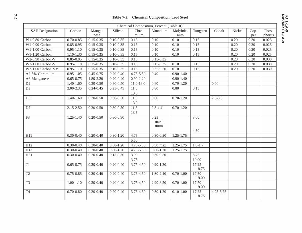
Table 7-2. Chemical Composition, Tool Steel
Chemical Composition, Percent (Table II)SAE Designation Carbon Manga-
neseSilicon Chro-
miumVanadium Molybde-
numTungsten Cobalt Nickel Cop-
perPhos-phorus
W1-0.80 Carbon 0.70-0.85 0.15-0.35 0.10-0.35 0.15 0.10 0.10 0.15 0.20 0.20 0.025W1-0.90 Carbon 0.85-0.95 0.15-0.35 0.10-0.35 0.15 0.10 0.10 0.15 0.20 0.20 0.025W1-1.00 Carbon 0.95-1.10 0.15-0.35 0.10-0.35 0.15 0.10 0.10 0.15 0.20 0.20 0.025W1-1.20 Carbon 1.10-1.30 0.15-0.35 0.10-0.35 0.15 0.10 0.10 0.15 0.20 0.20 0.025W2-0.90 Carbon-V 0.85-0.95 0.15-0.35 0.10-0.35 0.15 0.15-0.35 0.20 0.20 0.030W2-1.00 Carbon-V 0.95-1.10 0.15-0.35 0.10-0.35 0.15 0.15-0.35 0.10 0.15 0.20 0.20 0.030W3-1.00 Carbon VV 0.95-1.10 0.15-0.35 0.10-0.35 0.15 0.35-0.50 0.10 0.15 0.20 0.20 0.030A2-5% Chromium 0.95-1.05 0.45-0.75 0.20-0.40 4.75-5.50 0.40 0.90-1.40A6-Manganese 0.65-0.75 1.80-2.20 0.20-0.40 0.90-1.20 0.90-1.40D2 1.40-1.60 0.30-0.50 0.30-0.50 11.0-13.0 0.80 0.70-1.20 0.60D3 2.00-2.35 0.24-0.45 0.25-0.45 11.0 0.80 0.80 0.15
13.0D5 1.40-1.60 0.30-0.50 0.30-0.50 11.0 0.80 0.70-1.20 2.5-3.5
13.0D7 2.15-2.50 0.30-0.50 0.30-0.50 11.5 2.8-4.4 0.70-1.20
13.5F3 1.25-1.40 0.20-0.50 0.60-0.90 0.25
maxi-mum
3.00
4.50H11 0.30-0.40 0.20-0.40 0.80-1.20 4.75 0.30-0.50 1.25-1.75
5.50H12 0.30-0.40 0.20-0.40 0.80-1.20 4.75-5.50 0.50 max 1.25-1.75 1.0-1.7H13 0.30-0.40 0.20-0.40 0.80-1.20 4.75-5.50 0.80-1.20 1.25-1.75H21 0.30-0.40 0.20-0.40 0.15-0.30 3.00 0.30-0.50 8.75
3.75 10.00T1 0.65-0.75 0.20-0.40 0.20-0.40 3.75-4.50 0.90-1.30 17.25-
18.75T2 0.75-0.85 0.20-0.40 0.20-0.40 3.75-4.50 1.80-2.40 0.70-1.00 17.50-
19.00T3 1.00-1.10 0.20-0.40 0.20-0.40 3.75-4.50 2.90-3.50 0.70-1.00 17.50-
19.00T4 0.70-0.80 0.20-0.40 0.20-0.40 3.75-4.50 0.80-1.20 0.10-1.00 17.25-
18.754.25 5.75
TO1-1A
-9N
AVA
IR01-1A
-9
7-4

Table 7-2. Chemical Composition, Tool Steel - Continued
Chemical Composition, Percent (Table II)SAE Designation Carbon Manga-
neseSilicon Chro-
miumVanadium Molybde-
numTungsten Cobalt Nickel Cop-
perPhos-phorus
T5 0.75-0.85 0.20-0.40 0.20-0.40 3.75-4.75 1.80-2.40 0.70-1.00 17.50-19.00
7.00 9.50
T6 0.75-0.85 0.20-0.40 0.20-0.40 4.00-4.75 1.50-2.10 0.70-1.00 18.50-21.25
10.25
13.75T7 0.70-0.76 0.20-0.40 0.20-0.40 3.75-4.25 1.80-2.20 0.70-1.00 13.50-
14.50T8 0.75-0.85 0.20-0.40 0.20-0.40 3.75-4.50 1.80-2.40 0.70-1.00 13.25-
14.754.25
5.75M1 0.75-0.85 0.20-0.40 0.20-0.40 3.75-4.50 0.90-1.30 7.75-9.25 1.15-1.85M2 0.78-0.88 0.20-0.40 0.20-0.40 3.75-4.50 1.60-2.20 4.50-5.50 5.50-6.75M3 1.00-1.25 0.20-0.40 0.20-0.40 3.75-4.50 2.35-3.25 4.75-6.25 5.50-6.75M4 1.25-1.40 0.20-0.40 0.20-0.40 4.00-4.75 3.90-4.50 4.50-5.50 5.25-6.50M10 0.85-0.95 0.20-0.40 0.20-0.40 3.75-4.50 1.80-2.20 7.75-9.00M15 1.50-1.60 0.20-0.40 0.20-0.40 4.00-5.00 4.50-5.25 2.75-3.50 6.00-6.75 4.75-
5.25M30 0.77-0.85 0.20-0.40 0.20-0.40 3.50-4.25 1.00-1.40 7.75-9.00 1.30-2.30 4.50-
5.50M34 0.85-0.92 0.20-0.30 0.20-0.30 3.50-4.25 1.90-2.30 8.00-9.20 1.30-2.30 1.75
8.7501 0.85-0.95 1.00-1.30 0.20-0.40 0.40-0.60 0.30 max 0.40-0.6002 0.85-0.95 1.40-1.80 0.20-0.40 0.35 0.20 0.3006 1.35-1.55 0.30-1.00 0.80-1.20 0.20-0.30L6 0.65-0.75 0.30-0.80 0.20-0.40 0.65-0.85 0.20-0.35 0.20-0.35 1.25
1.75L7 0.95-1.05 0.25-0.45 0.20-0.40 1.25-1.75 0.30-0.50T15 1.50-1.60 3.75-4.50 4.75-5.25 12.00-
13.004.75-5.25
S1 0.45-0.55 0.20-0.40 0.25-0.45 1.25-1.75 0.15-0.30 0.40 1.0-3.0S2 0.45-0.55 0.30-0.50 0.80-1.20 0.25 0.40-0.60S5 0.50-0.60 0.60-0.90 1.80-2.20 0.30 0.25 0.30-0.50W5 1.05-1.25 0.15-0.35 0.10-0.40 0.40-0.60 0.25 max 0.30-0.50 TO
1-1A-9
NA
VAIR
01-1A-9
7-5

Table 7-3. Tool Steel Selection
Material To Be Cut Total Quantity Of Parts To Be Made1,000 10,000 100,000
Aluminum, copper and magnesium alloys W1, AIS14140 W1, 01, A2 01, A2Carbon and alloy steels, ferritic stainless W1, AIS14140 W1, 01, A2 01, A2Stainless steel, austenitic W1, A2 W1, A2, D2 A2, D2Spring steel, hardened, Rockwell C52 max A2 A2, D2 D2Electrical sheet, transformer grade A2 A2, D2 D2Paper, gaskets, and similar soft material W1 W1 W1, A2Plastic sheet, not reinforced 01 01 01, A2Table 7-3 is listed for use as a guide reference in the selection of tool steel types for specific applications.
Table 7-4. Tool Steel Hardening and Tempering Temperatures
Steel Hardening Treatment Tempering Treatment Size Change, In/InW 1450 °F, Water 300 °F 0.0017 - 0.0025O 1450 °F, Oil 300 °F 0.0014 - 0.0021L 1550 °F, Oil 300 °F 0.0014 - 0.0024F 1600 °F, Oil 300 °F 0.0011 - 0.0021S 1750 °F, Oil 500 °F 0.0010 - 0.0025A 1775 °F, Oil 500 °F 0.0005 - 0.0015D 1875 °F, Oil 500 °F 0.0005 - 0.0005T 2350 °F, Oil 1050 °F 0.0006 - 0.0014M 2225 °F, Oil 1025 °F 0.0016 - 0.0024
7.4 CLASS DESIGNATIONS.
• W - Water hardening tool steels
• S - Shock resisting tool steels
• O - Cold work tool steels, oil hardening types
• A - Cold work tool steels, air hardening types
7.5 APPLICATIONS OF TOOL STEELS.
The majority of tool steel applications can be divided into a small number of groups: cutting, shearing, forming, drawing,extrusion, rolling and battering. Cutting tools include drills, taps, broaches, hobs, lathe tools, etc.. Shearing tools includeshears, blanking and trimming dies, punches, etc.. Forming tools include draw, forging, cold heading and die casting dies.Battering tools include chisels and all forms of shock tools. Most cutting tools require high hardness, high resistance to thesoftening effect of heat, and high wear resistance. Shearing tools require high wear resistance and fair toughness. Formingtools must possess high wear resistance or high toughness and strength. In battering tools, high toughness is most important.
7.6 SELECTION OF MATERIAL FOR A CUTTING TOOL.
The selection of material for a cutting tool depends on several factors: the metal being machined, nature of cutting operation,condition of the machine tool, machining practice, size and design of tool, coolant to be used, and cost of tool material.Selection is usually based more on previous experience or applications than on an engineering or metallurgical analysis.
TO 1-1A-9NAVAIR 01-1A-9
7-6
7.6.1 High Speed Cutting Tools. High speed cutting tools are usually manufactured from the class “T” or class “M”alloys. Four classes, T1, M1, M2 and M10 make up nearly 90% of the general purpose high speed steels. Certain specialpurpose steels in each class, such as T6, T7, T8 and T15 are advantageous for operations like milling cutters and prehard-ened forging die blocks.
7.6.2 High Speed Drills. High speed drills should possess high strength and toughness, notably M1, M2, M10 and T1.Classes T1 and M1 are used for tools subject to shock, while M2 and M10 are generally used where tools require lesstoughness and more abrasion resistance.
7.6.3 Material for Reamers. Material for reamers should be of high hardness and abrasion resistance, such as M1, M2,M10 and T1. The M3 and M15 and T15 classes possess greater abrasion resistance than the lower vanadium grades.
7.6.4 Material for Taps. Material for taps is generally of the M1, M2 or M10 types. In tapping heat-resisting alloys orsteels harder than Rockwell C35, M15 or T15 may be justified.
7.6.5 Milling Cutters. Milling cutters are usually made from the high speed steels. As the hardness of the workpieceincreases beyond Rockwell C35, the cobalt high speed steels should be used.
7.6.6 Punch and Die Material. Recommended punch and die material for blanking parts from 0.050 inch sheet materialsare shown in following table. This table does not cover all operations, and is a sample table intended for use as a guide only.
7.7 HEAT TREAT DATA.
NOTE
Additional Heat Treatment information is discussed in Chapter 9.
The thermal treatments listed in Table 7-5 cover the generally used treatments for the forgings, normalizing, and annealingof tool and die steels. The thermal treatments listed in Table 7-7 cover the usual ranges of temperatures for hardening andtempering tool and die steels. These tables are listed for use as a guide only, and test samples should be checked prior to use.
7.8 DISTORTION IN TOOL STEELS.
Distortion is a general term encompassing all dimensional changes; the two main types being volume change or change ingeometrical form. Volume change is defined as expansion or contraction and geometric change is defined as changes incurvature or angular relations. Table 7-4 shows an approximate range of size changes depending upon the type of tool steel,and also dependent on specific tempering and heat treatments. If a very close tolerance is required for a finished tool, specificdata covering this item should be obtained from a detailed source.
TO 1-1A-9NAVAIR 01-1A-9
7-7

Table 7-5. Forging, Normalizing and Annealing Treatments of Tool and Die Steels
SAE Desig-nation
Forging/A Normalizing/B Annealing/CHeat Slowly
ToStart Forg-
ing AtDo Not
Forge Be-low
Heat SlowlyTo
Hold At Temperature MaximumRate OfCoolingF/Hour
Brinell Hard-ness Approxi-
mate
Rockwell B,Approximate
W1 (0.8C) 1450 1800 1950 1500 1450 1500 1400-1450 75 159-202 84-94W1 (0.9C) 1450 1800 1950 1500 1450 1500 1375-1425 75 159-202 84-94W1 (1.0C) 1450 1800 1900 1500 1450 1550 1400-1450 75 159-202 84-94W1 (1.2C) 1450 1800 1900 1500 1450 1625 1400-1450 75 159-202 84-94W2 (0.9C) 1450 1800 1900 1500 1450 1500 1375-1425 75 159-202 84-94W2 (1.0C) 1450 1800 1900 1500 1450 1550 1400-1450 75 159-202 84-94W3 (1.0C) 1450 1800 1900 1500 1450 1550 1400-1450 75 159-202 84-94A2 1600 1850 2000 1650 Do Not Normalize 1550-1600 40 202-229 94-98A6 1200-1300 Do Not Normalize 248 102D2 1650 1850 2000 1650 Do Not Normalize 1600-1650 40 207-255 95-102D3 1650 1850 2000 1650 Do Not Normalize 1600-1650 50 212-255 96-102D5 1650 1850 2000 1650 Do Not Normalize 1600-1650 40 207-255 95-102D7 1650 2050 2125 1800 Do Not Normalize 1600-1650 50 235-262 99-103F3 1550 1800 2000 1600 Do Not Normalize 1475 50 235 99H11 1650 1950 2100 1650 Do Not Normalize 1550-1600 50 192-229 92-98H12 1650 1950 2100 1650 Do Not Normalize 1600-1650 50 192-229 92-98H13 1650 1950 2100 1650 Do Not Normalize 1550-1600 50 192-229 92-98H21 1600 2000 2150 1650 Do Not Normalize 1600-1650 50 202-235 94-99T1 1600 1950 2100 1750 Do Not Normalize 1600-1650 50 217-255 96-102T2 1600 2000 2150 1750 Do Not Normalize 1600-1650 50 223-255 97-102T3 1925 2025 1750 Do Not Normalize 1650 50T4 1600 2000 2150 1750 Do Not Normalize 1600-1650 50 229-255 98-102T5 1600 2000 2150 1800 Do Not Normalize 1600-1650 50 248-293 102-106T6 1600 1950 2150 1700 Do Not Normalize 1600-1650 50 248-293 102-106T7 1600 1950 2150 1700 Do Not Normalize 1550-1625 50 217-250 96-102T8 1600 2000 2150 1750 Do Not Normalize 1600-1650 50 229-255 98-102Ml 1500 1900 2050 1700 Do Not Normalize 1525-1600 50 207-248 95-102M2 1500 1950 2100 1700 Do Not Normalize 1550-1625 50 217-248 96-102M3 1500 2000 2150 1700 Do Not Normalize 1550-1625 50 223-255 97-102M4 1500 2000 2150 1700 Do Not Normalize 1550-1625 50 229-255 98-102M10 1400 1900 2100 1700 Do Not Normalize 1600-1650 50 235-262 99-103M15 1400 1900 2100 1700 Do Not Normalize 1600-1650 50 235-262 99-103
TO1-1A
-9N
AVA
IR01-1A
-9
7-8

Table 7-5. Forging, Normalizing and Annealing Treatments of Tool and Die Steels - Continued
SAE Desig-nation
Forging/A Normalizing/B Annealing/CHeat Slowly
ToStart Forg-
ing AtDo Not
Forge Be-low
Heat SlowlyTo
Hold At Temperature MaximumRate OfCoolingF/Hour
Brinell Hard-ness Approxi-
mate
Rockwell B,Approximate
M30 1400 1900 2100 1600 Do Not Normalize 1600-1650 50 235-262 99-103M34 1400 1900 2100 1600 Do Not Normalize 1600-1650 50 235-262 99-10301 1500 1750 1900 1550 1500 1600 1425-1475 50 183-212 90-9602 1500 1750 1900 1550 1500 1550 1375-1425 50 183-212 90-9606 1500 1750 1900 1500 1500 1625 1425-1275 50 183-212 90-96L6 1500 1800 2000 1600 1550 1650 1400-1450 50 183-212 90-96L7 1500 1800 2000 1550 1550 1650 1450-1500 50 174-212 88-96T15 1500 2000 2100 1600 Do Not Normalize 1600-1650 35 241-269 100-104S1 1500 1800 2000 1600 Do Not Normalize 1450-1500 50 192-235 92-99S2 1500 1900 2100 1600 1500 1650 1400-1450 50 192-229 92-98S5 1500 1900 2050 1600 1500 1600 1400-1450 50 192-229 92-98W5 1200 1700 1900 1500 Do Not Normalize 1400-1425 50 192-212 92-96a. The temperature at which to start forging is given as a range, the higher side of which should be used for large sections and heavy or rapid reductions, and
the lower side for smaller sections and lighter reductions, as the alloy content of the steel increases, the time of soaking at forging temperature increasesproportionately. Likewise, as the alloy content increases, it becomes more necessary to cool slowly from the forging temperature. With the very high alloysteels, such as high speed or air hardening steels, this slow cooling is imperative in order to prevent cracking and to leave the steel in a semi-soft condition.Either furnace cooling or burying in an insulating medium such as lime, mica, or silocel is satisfactory.
b. The length of time the steel is held after being uniformly heated through at the normalizing temperature, varies from about 15 minutes for a small sectionto about 1 hour for larger sizes. Cooling from the normalizing temperatures is done in still air. The purpose of normalizing after forging is to refine thegrain structure and to produce a uniform structure throughout the forging. Normalizing should not be confused with low temperature (about 1200°F) anneal-ing used for the relief of residual stresses resulting from heavy machining, bending and forming.
c. The annealing temperature is given as a range, the upper limit of which should be used for large sections, and the lower limit for smaller sections. Thetemperature varies from about 1 hour for light sections and small furnace charges of carbon or low alloy steel, to about 4 hours for heavy sections andlarge furnace charges of high alloy steel.
TO1-1A
-9N
AVA
IR01-1A
-9
7-9

Table 7-6. Thermal Treatment for Hardening and Tempering Tool Steel - General
Class Quench Me-dium
Preheat Tempera-ture °F
Hardening Tem-perature Range
°F
Hardness AfterQuenching Rock-
well °C
TemperingTemperature
Range °F
Hardness AfterTempering Rock-
well °C
Decarburization(Prevention OfDuring HeatTreatment)
Wl-08 Water a 1420-1450 65-67 350-525 65-56 bWl-09 Water a 1420-1450 65-67 350-525 65-56 bWl-10 Water a 1420-1450 65-67 350-525 65-56 bWl-12 Water a 1420-1500 65-67 350-525 65-56 bW2-09 Water a 1420-1500 65-67 350-525 65-56 bW2-10 Water a 1420-1500 65-67 350-525 65-56 bW3-10 Water a 1420-1500 65-67 350-525 65-56 bA2 Air 1200-1300 1725-1775 61-63 400-700 60-57 cA6 Air 1200-1300 1525-1600 60D2 Air 1200-1300 1800-1875 61-63 400-700 60-58 cD3 Oil 1200-1300 1750-1800 62-64 400-700 62-58 cD5 Air 1200-1300 1800-1875 60-62 400-700 59-57 cD7 Air 1200-1300 1850-1950 63-65 300-500 65-63 c
850-1000 62-58F3 Water a 1550 62-66 300-500 66-62 cH11 Air 1450-1500 1825-1875 53-55 1000-1100 51-43 cH12 Oil-Air 1450-1500 1800-1900 53-55 1000-1100 51-43 cH13 Air 1400-1450 1825-1575 53-55 1000-1100 51-43 cH21 Oil-Air 1500-1550 2100-2150 50-52 950-1150 50-47 cT1 Oil-Air-Salt 1500-1550 2300-2375 63-65 1025-1100 65-63 cT2 Oil-Air-Salt 1500-1550 2300-2375 63-65 1025-1100 63-65 cT3 Oil-Air 1500-1550 2275-2325 1000-1050 67-60 cT4 Oil-Air-Salt 1500-1550 2300-2375 63-65 1026-1100 65-63 cT5 Oil-Air-Salt 1500-1550 2300-2400 63-65 1050-1100 65-63 cT6 Oil 1600 2350 60-65 1000-1100 65-60 cT7 Oil 1600 2325 60-65 1000-1100 65-60 cT8 Oil-Air-Salt 1500-1550 2300-2375 63-65 1025-1100 65-63 cM1 Oil-Air-Salt 1400-1500 2150-2250 63-65 1025-1100 65-63 cM2 Oil-Air-Salt 1450-1500 2175-2250 63-65 1025-1075 65-63 cM3 Oil-Air-Salt 1450-1500 2150-2225 63-65 1025-1075 65-63 cM4 Oil-Air-Salt 1450-1500 2150-2225 63-65 1025-1075 65-63 cM10 Oil 1400 2220 60-65 1000-1100 65-60 cM15 Oil 1400 2220 60-65 1000-1100 65-60 c
TO1-1A
-9N
AVA
IR01-1A
-9
7-10

Table 7-6. Thermal Treatment for Hardening and Tempering Tool Steel - General - Continued
Class Quench Me-dium
Preheat Tempera-ture °F
Hardening Tem-perature Range
°F
Hardness AfterQuenching Rock-
well °C
TemperingTemperature
Range °F
Hardness AfterTempering Rock-
well °C
Decarburization(Prevention OfDuring HeatTreatment)
M30 Oil 1400 2220 60-65 1000-1100 65-60 cM34 Oil 1400 2220 60-65 1000-1100 65-60 c01 Oil a 1450-1500 63-65 300-800 62-50 b02 Oil a 1420-1450 63-65 375-500 62-57 b06 Oil a 1450-1500 63-65 300-800 63-50 bL6 Oil a 1500-1600 62-64 400-800 62-48 bL7 Oil a 1525-1550 63-65 350-500 62-60 bT15 Oil-Air 1500-1600 2250-2300 65-66 1025-1100 66-68 cS1 Oil 1200-1300 1650-1800 57-59 300-1000 57-45 cS2 Water-oil a 1550-1575 60-62 300-500 60-54 b
1660-1625 58-60 300-500 58-54 bS5 Water 1550-1600 60-62 300-650 60-54 b
Oil 1600-1675 58-60 300-650 58-54 bW5 Water 1100-1200 1400-1550 65-66 300-400 62-65 ba. For large tools and tools having intricate sections, preheating at 1050 to 1200 °F is recommended.b. Use moderately oxidizing atmosphere in furnace or a suitable neutral salt bath.c. Use protective pack from which volatile matter has been removed, carefully balanced neutral salt bath or atmosphere controlled furnaces. In the latter case,
the furnace atmosphere should be in equilibrium with the carbon content of the steel being treated. Furnace atmosphere dew point is considered a reliablemethod of measuring and controlling this equilibrium.
TO1-1A
-9N
AVA
IR01-1A
-9
7-11

Table 7-7. Comparison of Tool Steel Properties
Class Non DeformingProperties Toughness
Resistance To Soft-ening Effect Of
HeatWear Resistance Machine Ability
W1-08 Poor Good Poor Fair BestW1-09 Poor Good Poor Fair BestW1-10 Poor Good Poor Good BestW1-12 Poor Good Poor Good BestW2-09 Poor Good Poor Fair BestW2-10 Poor Good Poor Good BestW3-10 Poor Good Poor Good BestA2 Best Fair Fair Good FairA6 Good Fair Poor Good FairD2 Best Fair Fair Best PoorD3 Good Poor Fair Best PoorD5 Best Fair Fair Best PoorD7 Best Poor Fair Best PoorF3 Poor Poor Poor Best FairH11 Good Good Good Fair FairH12 Good Good Good Fair FairH13 Good Good Good Fair FairH21 Good Good Good Fair FairT1 Good Poor Good Good FairT2 Good Poor Good Good FairT3 Good Poor Good Good FairT4 Good Poor Best Good FairT5 Good Poor Best Good FairT6 Good Fair Good Best FairT7 Good Poor Good Best FairT8 Good Poor Best Good FairM1 Good Poor Good Good FairM2 Good Poor Good Good FairM3 Good Poor Good Best FairM4 Good Poor Good Best FairM10 Good Poor Good Best FairM15 Good Poor Good Best FairM30 Good Poor Good Best FairM34 Good Poor Good Best Fair01 Good Fair Poor Good Good02 Good Fair Poor Good Good06 Fair Fair Poor Good BestL6 Fair Fair Poor Fair FairL7 Fair Fair Poor Good FairT15 Good Poor Best Best FairS1 Fair Good Fair Fair FairS2 W-Poor Best Fair Fair Good
O-FairS5 W-Poor Good Poor Fair Best
O-FairW5 Poor Good Poor Fair Best
TO 1-1A-9NAVAIR 01-1A-9
7-12
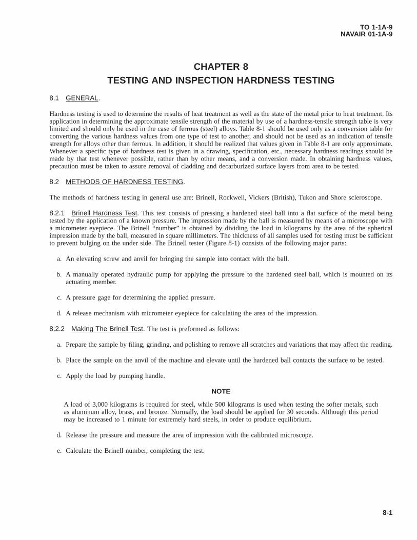
CHAPTER 8TESTING AND INSPECTION HARDNESS TESTING
8.1 GENERAL.
Hardness testing is used to determine the results of heat treatment as well as the state of the metal prior to heat treatment. Itsapplication in determining the approximate tensile strength of the material by use of a hardness-tensile strength table is verylimited and should only be used in the case of ferrous (steel) alloys. Table 8-1 should be used only as a conversion table forconverting the various hardness values from one type of test to another, and should not be used as an indication of tensilestrength for alloys other than ferrous. In addition, it should be realized that values given in Table 8-1 are only approximate.Whenever a specific type of hardness test is given in a drawing, specification, etc., necessary hardness readings should bemade by that test whenever possible, rather than by other means, and a conversion made. In obtaining hardness values,precaution must be taken to assure removal of cladding and decarburized surface layers from area to be tested.
8.2 METHODS OF HARDNESS TESTING.
The methods of hardness testing in general use are: Brinell, Rockwell, Vickers (British), Tukon and Shore scleroscope.
8.2.1 Brinell Hardness Test. This test consists of pressing a hardened steel ball into a flat surface of the metal beingtested by the application of a known pressure. The impression made by the ball is measured by means of a microscope witha micrometer eyepiece. The Brinell “number” is obtained by dividing the load in kilograms by the area of the sphericalimpression made by the ball, measured in square millimeters. The thickness of all samples used for testing must be sufficientto prevent bulging on the under side. The Brinell tester (Figure 8-1) consists of the following major parts:
a. An elevating screw and anvil for bringing the sample into contact with the ball.
b. A manually operated hydraulic pump for applying the pressure to the hardened steel ball, which is mounted on itsactuating member.
c. A pressure gage for determining the applied pressure.
d. A release mechanism with micrometer eyepiece for calculating the area of the impression.
8.2.2 Making The Brinell Test. The test is preformed as follows:
a. Prepare the sample by filing, grinding, and polishing to remove all scratches and variations that may affect the reading.
b. Place the sample on the anvil of the machine and elevate until the hardened ball contacts the surface to be tested.
c. Apply the load by pumping handle.
NOTE
A load of 3,000 kilograms is required for steel, while 500 kilograms is used when testing the softer metals, suchas aluminum alloy, brass, and bronze. Normally, the load should be applied for 30 seconds. Although this periodmay be increased to 1 minute for extremely hard steels, in order to produce equilibrium.
d. Release the pressure and measure the area of impression with the calibrated microscope.
e. Calculate the Brinell number, completing the test.
TO 1-1A-9NAVAIR 01-1A-9
8-1

8.3 ROCKWELL HARDNESS TEST.
The Rockwell hardness test is based on the degree of penetration of a specifically designed indentor into a material under agiven static load. The indentor/penetrator used may be either a diamond or hardened steel ball. The diamond indentor calleda “brale” is precision ground and polished and the shape is spheroconica. The steel ball for normal use is 1/16 inch diameter,however, other larger diameter steel balls such as 1/8, 1/4 or 1/2 inch may be used for testing soft metals. The selection ofthe ball is based on the hardness range of the type of material to be tested.
8.3.1 Rockwell Machine/Tester. The Rockwell machine/tester for accomplishing the hardness test applies two loads toobtain the controlled penetration and indicates results on a graduated dial (see Figure 8-2). A minor load of 10 kilograms isfirst applied to seat the penetrator in the surface of the test specimen. The actual penetration is then produced by applying amajor load, subsequently, releasing and then reading hardness number from the dial. The dial reading is related to the depthof penetration, load and the penetrator used. The shallower the penetration, the higher the hardness value number for givenindentor and load. The normal major load is 150 kilograms (“C” Scale) when using the diamond penetrator and 100kilograms (“B” Scale) when using a 1/16 inch steel ball. A hardness value indicated by a number alone is incomplete. Thenumber must be prefixed with a letter to indicate the load and indentor used to obtain the number. There is a variety ofcombinations of indentors and loads used to obtain a hardness value in accordance with hardness range of various material.The combinations are listed in Table 8-2 which is based on Specification ASTM E-18.
8.3.1.1 Review of Table 8-2 will reveal that the Red Dial Numerals “B” scale are used for steel ball indentors regardlessof size of ball or load and Black Figure “C” scales are used for the diamond penetrator. When the readings fall below thehardness value, C20 (B98) the material is considered too soft for the diamond cone and 1/16 inch or larger hardened ballshould be used. The diamond cone must be used for all hard materials (those above 100 on the “B” scale) as the steel ballmay be deformed by the test. If in doubt about the hardness of a material start with the diamond penetrator and switch to thesteel ball if the material is below C20-C22.
8.3.2 Rockwell Test Procedure. The procedure for making the Rockwell test is outlined as follows: (See Figure 8-2 formachine illustrations.)
a. Prepare the sample by removing (file, grind and polish) scale, oxide films, pits, variations and foreign material thatmay affect the reading. The surface should be flat, of one thickness and no bludge should be opposite the indentation.
NOTE
Do not perform test closer than 1/8 inch from edge of specimen to assure accurate reading.
b. Select the proper anvil and penetrator and place proper weight on the weight pan.
c. Check trip lever for proper location. Lever should be located in the OFF LOAD position.
d. Place the test specimen on the anvil and by turning the hand wheel, raise it slowly (do not crash) until contact is madewith the penetrator. On the older model continue turning until pointer of the indicator has made three revolutions andis within five divisions (plus or minus) of the upright position. On the newer model after contact, continue turninghand wheel until the small pointer is nearly vertical and slightly to right of the dot. Then watching the long pointer,raise specimen until long pointer is approximately upright within three degrees (plus or minus) of C-0. K the C = +3degrees position is overshot, lower the specimen and start over. When the pointer is within three divisions of C-0, setdial to zero. After this step is complete, the minor load has been applied.
e. Apply the major load by tripping the trip lever. Trip the lever, do not push.
f. When the trip lever comes to rest and there is no further movement of pointer, return lever to the original position andread the hardness number indicated by the dial. When dial pointer indicates a fraction, use next lower whole numberfor the reading.
8.3.2.1 All hardness tests should be made on a single thickness to obtain accurate results. In testing curved specimens, theconcave side should face the indentor; if reversed, an inaccurate reading will result due to flattening of the piece on the anvil.Specimens that do not balance on the anvil because of overhang should be properly supported to obtain accurate readingsand to prevent damaging the penetrator. Also to obtain a true indication of hardness of a given part, several readings (3-6 isusually sufficient) at different points should be taken and averaged. If it is necessary to determine the condition of theinterior, parts should be cut by some method that does not appreciably change the temper/condition, such as using a
TO 1-1A-9NAVAIR 01-1A-9
8-2
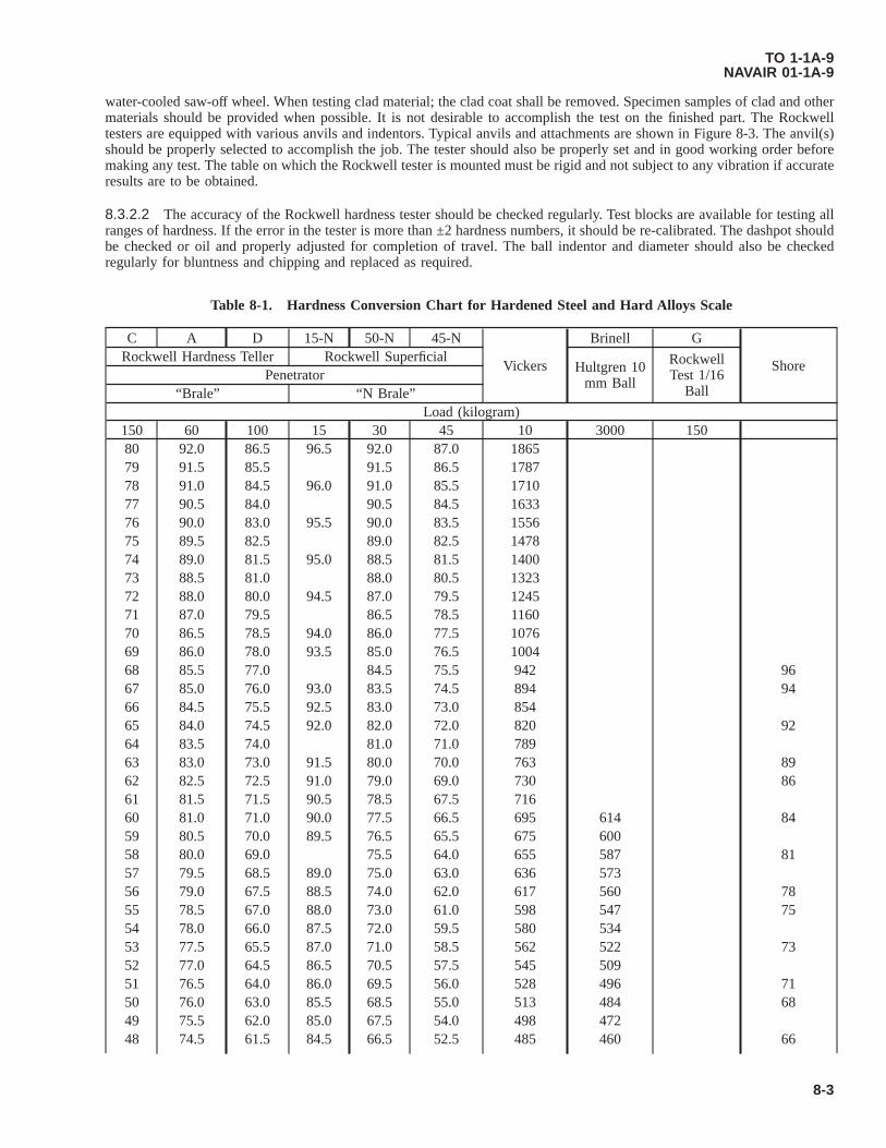
water-cooled saw-off wheel. When testing clad material; the clad coat shall be removed. Specimen samples of clad and othermaterials should be provided when possible. It is not desirable to accomplish the test on the finished part. The Rockwelltesters are equipped with various anvils and indentors. Typical anvils and attachments are shown in Figure 8-3. The anvil(s)should be properly selected to accomplish the job. The tester should also be properly set and in good working order beforemaking any test. The table on which the Rockwell tester is mounted must be rigid and not subject to any vibration if accurateresults are to be obtained.
8.3.2.2 The accuracy of the Rockwell hardness tester should be checked regularly. Test blocks are available for testing allranges of hardness. If the error in the tester is more than ±2 hardness numbers, it should be re-calibrated. The dashpot shouldbe checked or oil and properly adjusted for completion of travel. The ball indentor and diameter should also be checkedregularly for bluntness and chipping and replaced as required.
Table 8-1. Hardness Conversion Chart for Hardened Steel and Hard Alloys Scale
C A D 15-N 50-N 45-N
Vickers
Brinell G
ShoreRockwell Hardness Teller Rockwell Superficial
Hultgren 10mm Ball
RockwellTest 1/16
BallPenetrator
“Brale” “N Brale”Load (kilogram)
150 60 100 15 30 45 10 3000 15080 92.0 86.5 96.5 92.0 87.0 186579 91.5 85.5 91.5 86.5 178778 91.0 84.5 96.0 91.0 85.5 171077 90.5 84.0 90.5 84.5 163376 90.0 83.0 95.5 90.0 83.5 155675 89.5 82.5 89.0 82.5 147874 89.0 81.5 95.0 88.5 81.5 140073 88.5 81.0 88.0 80.5 132372 88.0 80.0 94.5 87.0 79.5 124571 87.0 79.5 86.5 78.5 116070 86.5 78.5 94.0 86.0 77.5 107669 86.0 78.0 93.5 85.0 76.5 100468 85.5 77.0 84.5 75.5 942 9667 85.0 76.0 93.0 83.5 74.5 894 9466 84.5 75.5 92.5 83.0 73.0 85465 84.0 74.5 92.0 82.0 72.0 820 9264 83.5 74.0 81.0 71.0 78963 83.0 73.0 91.5 80.0 70.0 763 8962 82.5 72.5 91.0 79.0 69.0 730 8661 81.5 71.5 90.5 78.5 67.5 71660 81.0 71.0 90.0 77.5 66.5 695 614 8459 80.5 70.0 89.5 76.5 65.5 675 60058 80.0 69.0 75.5 64.0 655 587 8157 79.5 68.5 89.0 75.0 63.0 636 57356 79.0 67.5 88.5 74.0 62.0 617 560 7855 78.5 67.0 88.0 73.0 61.0 598 547 7554 78.0 66.0 87.5 72.0 59.5 580 53453 77.5 65.5 87.0 71.0 58.5 562 522 7352 77.0 64.5 86.5 70.5 57.5 545 50951 76.5 64.0 86.0 69.5 56.0 528 496 7150 76.0 63.0 85.5 68.5 55.0 513 484 6849 75.5 62.0 85.0 67.5 54.0 498 47248 74.5 61.5 84.5 66.5 52.5 485 460 66
TO 1-1A-9NAVAIR 01-1A-9
8-3
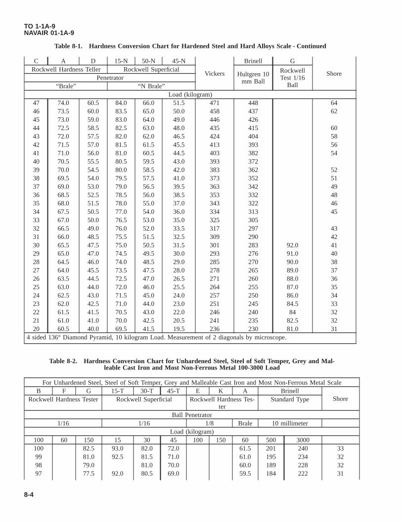
Table 8-1. Hardness Conversion Chart for Hardened Steel and Hard Alloys Scale - Continued
C A D 15-N 50-N 45-N
Vickers
Brinell G
ShoreRockwell Hardness Teller Rockwell Superficial
Hultgren 10mm Ball
RockwellTest 1/16
BallPenetrator
“Brale” “N Brale”Load (kilogram)
47 74.0 60.5 84.0 66.0 51.5 471 448 6446 73.5 60.0 83.5 65.0 50.0 458 437 6245 73.0 59.0 83.0 64.0 49.0 446 42644 72.5 58.5 82.5 63.0 48.0 435 415 6043 72.0 57.5 82.0 62.0 46.5 424 404 5842 71.5 57.0 81.5 61.5 45.5 413 393 5641 71.0 56.0 81.0 60.5 44.5 403 382 5440 70.5 55.5 80.5 59.5 43.0 393 37239 70.0 54.5 80.0 58.5 42.0 383 362 5238 69.5 54.0 79.5 57.5 41.0 373 352 5137 69.0 53.0 79.0 56.5 39.5 363 342 4936 68.5 52.5 78.5 56.0 38.5 353 332 4835 68.0 51.5 78.0 55.0 37.0 343 322 4634 67.5 50.5 77.0 54.0 36.0 334 313 4533 67.0 50.0 76.5 53.0 35.0 325 30532 66.5 49.0 76.0 52.0 33.5 317 297 4331 66.0 48.5 75.5 51.5 32.5 309 290 4230 65.5 47.5 75.0 50.5 31.5 301 283 92.0 4129 65.0 47.0 74.5 49.5 30.0 293 276 91.0 4028 64.5 46.0 74.0 48.5 29.0 285 270 90.0 3827 64.0 45.5 73.5 47.5 28.0 278 265 89.0 3726 63.5 44.5 72.5 47.0 26.5 271 260 88.0 3625 63.0 44.0 72.0 46.0 25.5 264 255 87.0 3524 62.5 43.0 71.5 45.0 24.0 257 250 86.0 3423 62.0 42.5 71.0 44.0 23.0 251 245 84.5 3322 61.5 41.5 70.5 43.0 22.0 246 240 84 3221 61.0 41.0 70.0 42.5 20.5 241 235 82.5 3220 60.5 40.0 69.5 41.5 19.5 236 230 81.0 31
4 sided 136° Diamond Pyramid, 10 kilogram Load. Measurement of 2 diagonals by microscope.
Table 8-2. Hardness Conversion Chart for Unhardened Steel, Steel of Soft Temper, Grey and Mal-leable Cast Iron and Most Non-Ferrous Metal 100-3000 Load
For Unhardened Steel, Steel of Soft Temper, Grey and Malleable Cast Iron and Most Non-Ferrous Metal ScaleB F G 15-T 30-T 45-T E K A Brinell
ShoreRockwell Hardness Tester Rockwell Superficial Rockwell Hardness Tes-ter
Standard Type
Ball Penetrator1/16 1/16 1/8 Brale 10 millimeter
Load (kilogram)100 60 150 15 30 45 100 150 60 500 3000100 82.5 93.0 82.0 72.0 61.5 201 240 3399 81.0 92.5 81.5 71.0 61.0 195 234 3298 79.0 81.0 70.0 60.0 189 228 3297 77.5 92.0 80.5 69.0 59.5 184 222 31
TO 1-1A-9NAVAIR 01-1A-9
8-4

Table 8-2. Hardness Conversion Chart for Unhardened Steel, Steel of Soft Temper, Grey and Mal-leable Cast Iron and Most Non-Ferrous Metal 100-3000 Load - Continued
For Unhardened Steel, Steel of Soft Temper, Grey and Malleable Cast Iron and Most Non-Ferrous Metal ScaleB F G 15-T 30-T 45-T E K A Brinell
ShoreRockwell Hardness Tester Rockwell Superficial Rockwell Hardness Tes-ter
Standard Type
Ball Penetrator1/16 1/16 1/8 Brale 10 millimeter
Load (kilogram)96 76.0 80.0 68.0 59.0 179 216 3095 74.0 91.5 79.0 67.0 58.0 175 210 3094 72.5 78.5 66.0 57.5 171 205 2993 71.0 91.0 78.0 65.5 57.0 167 200 2892 69.0 90.5 77.5 64.5 100 56.5 163 195 2891 67.5 77.0 63.5 99.5 56.0 160 190 2790 66.0 90.0 76.0 62.5 98.5 55.5 157 185 2789 64.0 89.5 75.5 61.5 98.0 55.0 154 180 2588 62.5 75.0 60.5 97.0 54.0 151 176 2587 61.0 89.0 74.5 59.5 96.5 53.5 148 172 2486 59.0 88.5 74.0 58.5 95.5 53.0 145 169 2485 57.5 73.5 58.0 94.5 52.5 142 165 2384 56.0 88.0 73.0 57.0 94.0 52.0 140 162 2383 54.0 87.5 72.0 56.0 93.0 51.0 137 159 2382 52.5 71.5 55.0 92.0 50.5 135 156 2381 51.0 87.0 71.0 54.0 91.0 50.0 133 153 2280 49.0 86.5 70.0 53.0 90.5 49.5 130 150 2279 47.5 69.5 52.0 89.5 49.0 128 147 2178 46.0 86.0 69.0 51.0 88.5 48.5 126 144 2177 44.0 85.5 68.0 50.0 88.0 48.0 124 141 2076 42.5 67.5 49.0 87.0 47.0 122 13975 99.5 41.0 85.0 67.0 48.5 86.0 46.5 120 13774 99.0 39.0 66.0 47.5 85.0 46.0 118 13573 98.5 37.5 84.5 65.5 46.5 84.5 45.5 116 13272 98.0 36.0 84.0 65.0 45.5 83.5 45.0 114 13071 97.5 34.5 64.0 44.5 100 82.5 44.5 112 12770 97.0 32.5 83.5 63.5 43.5 99.5 81.5 44.0 110 12569 96.0 31.0 83.0 62.5 42.5 99.0 81.0 43.5 109 12368 95.5 29.5 62.0 41.5 98.0 80.0 43.0 107 12167 95.0 28.0 82.5 61.5 40.5 97.5 79.0 42.5 106 11966 94.5 26.5 82.0 60.5 39.5 97.0 78.0 42.0 104 11765 94.0 25.0 60.0 38.5 96.0 77.5 102 11664 93.5 23.5 81.5 59.5 37.5 95.5 76.5 41.5 101 11463 93.0 22.0 81.0 58.5 36.5 95.0 75.5 41.0 99 11262 92.0 20.5 58.0 35.5 94.5 74.5 40.5 98 11061 91.5 19.0 80.5 57.0 34.5 93.5 74.0 40.0 96 10860 91.0 17.5 56.5 33.5 93.0 73.0 39.5 95 10759 90.5 16.0 80.0 56.0 32.0 92.5 72.0 39.0 94 10658 90.0 14.5 79.5 55.0 31.0 92.0 71.0 38.5 92 10457 89.5 13.0 54.5 30.0 91.0 70.5 38.0 91 10356 89.0 11.5 79.0 54.0 29.0 90.5 69.5 90 10155 88.0 10.0 78.5 53.0 28.0 90.0 68.5 37.5 89 100
TO 1-1A-9NAVAIR 01-1A-9
8-5
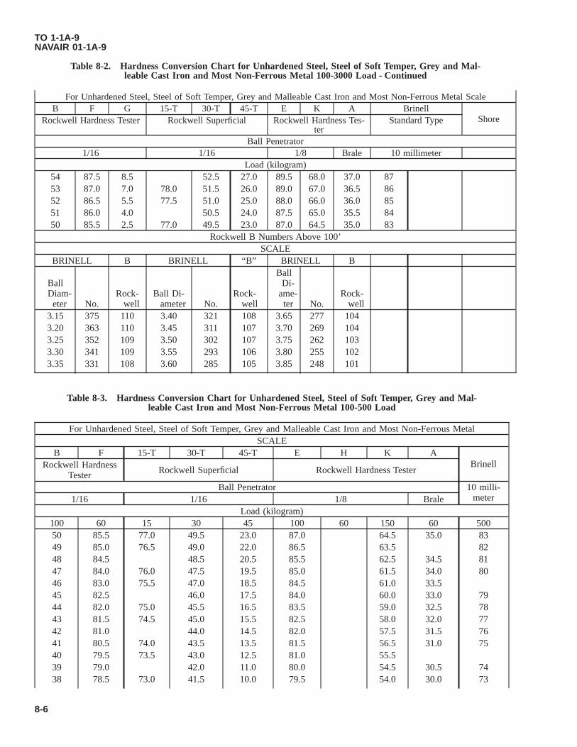
Table 8-2. Hardness Conversion Chart for Unhardened Steel, Steel of Soft Temper, Grey and Mal-leable Cast Iron and Most Non-Ferrous Metal 100-3000 Load - Continued
For Unhardened Steel, Steel of Soft Temper, Grey and Malleable Cast Iron and Most Non-Ferrous Metal ScaleB F G 15-T 30-T 45-T E K A Brinell
ShoreRockwell Hardness Tester Rockwell Superficial Rockwell Hardness Tes-ter
Standard Type
Ball Penetrator1/16 1/16 1/8 Brale 10 millimeter
Load (kilogram)54 87.5 8.5 52.5 27.0 89.5 68.0 37.0 8753 87.0 7.0 78.0 51.5 26.0 89.0 67.0 36.5 8652 86.5 5.5 77.5 51.0 25.0 88.0 66.0 36.0 8551 86.0 4.0 50.5 24.0 87.5 65.0 35.5 8450 85.5 2.5 77.0 49.5 23.0 87.0 64.5 35.0 83
Rockwell B Numbers Above 100’SCALE
BRINELL B BRINELL “B” BRINELL B
BallDiam-eter No.
Rock-well
Ball Di-ameter No.
Rock-well
BallDi-
ame-ter No.
Rock-well
3.15 375 110 3.40 321 108 3.65 277 1043.20 363 110 3.45 311 107 3.70 269 1043.25 352 109 3.50 302 107 3.75 262 1033.30 341 109 3.55 293 106 3.80 255 1023.35 331 108 3.60 285 105 3.85 248 101
Table 8-3. Hardness Conversion Chart for Unhardened Steel, Steel of Soft Temper, Grey and Mal-leable Cast Iron and Most Non-Ferrous Metal 100-500 Load
For Unhardened Steel, Steel of Soft Temper, Grey and Malleable Cast Iron and Most Non-Ferrous MetalSCALE
B F 15-T 30-T 45-T E H K ABrinellRockwell Hardness
Tester Rockwell Superficial Rockwell Hardness Tester
Ball Penetrator 10 milli-meter1/16 1/16 1/8 Brale
Load (kilogram)100 60 15 30 45 100 60 150 60 50050 85.5 77.0 49.5 23.0 87.0 64.5 35.0 8349 85.0 76.5 49.0 22.0 86.5 63.5 8248 84.5 48.5 20.5 85.5 62.5 34.5 8147 84.0 76.0 47.5 19.5 85.0 61.5 34.0 8046 83.0 75.5 47.0 18.5 84.5 61.0 33.545 82.5 46.0 17.5 84.0 60.0 33.0 7944 82.0 75.0 45.5 16.5 83.5 59.0 32.5 7843 81.5 74.5 45.0 15.5 82.5 58.0 32.0 7742 81.0 44.0 14.5 82.0 57.5 31.5 7641 80.5 74.0 43.5 13.5 81.5 56.5 31.0 7540 79.5 73.5 43.0 12.5 81.0 55.539 79.0 42.0 11.0 80.0 54.5 30.5 7438 78.5 73.0 41.5 10.0 79.5 54.0 30.0 73
TO 1-1A-9NAVAIR 01-1A-9
8-6
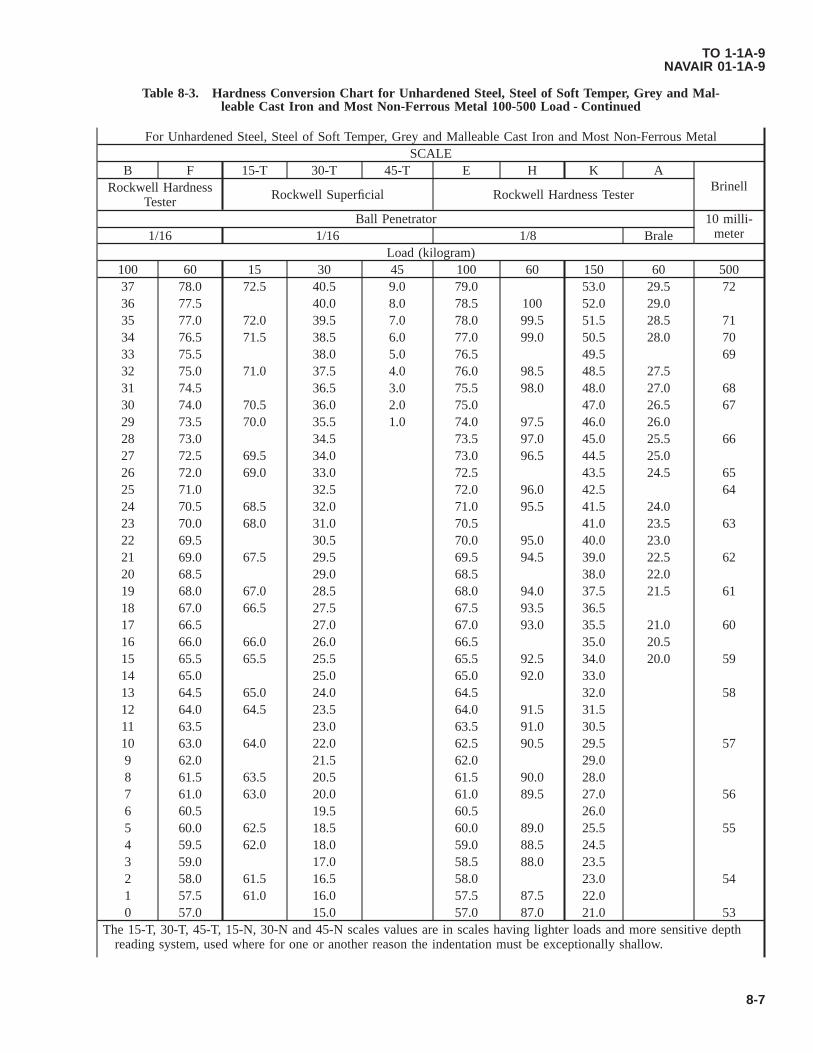
Table 8-3. Hardness Conversion Chart for Unhardened Steel, Steel of Soft Temper, Grey and Mal-leable Cast Iron and Most Non-Ferrous Metal 100-500 Load - Continued
For Unhardened Steel, Steel of Soft Temper, Grey and Malleable Cast Iron and Most Non-Ferrous MetalSCALE
B F 15-T 30-T 45-T E H K ABrinellRockwell Hardness
Tester Rockwell Superficial Rockwell Hardness Tester
Ball Penetrator 10 milli-meter1/16 1/16 1/8 Brale
Load (kilogram)100 60 15 30 45 100 60 150 60 50037 78.0 72.5 40.5 9.0 79.0 53.0 29.5 7236 77.5 40.0 8.0 78.5 100 52.0 29.035 77.0 72.0 39.5 7.0 78.0 99.5 51.5 28.5 7134 76.5 71.5 38.5 6.0 77.0 99.0 50.5 28.0 7033 75.5 38.0 5.0 76.5 49.5 6932 75.0 71.0 37.5 4.0 76.0 98.5 48.5 27.531 74.5 36.5 3.0 75.5 98.0 48.0 27.0 6830 74.0 70.5 36.0 2.0 75.0 47.0 26.5 6729 73.5 70.0 35.5 1.0 74.0 97.5 46.0 26.028 73.0 34.5 73.5 97.0 45.0 25.5 6627 72.5 69.5 34.0 73.0 96.5 44.5 25.026 72.0 69.0 33.0 72.5 43.5 24.5 6525 71.0 32.5 72.0 96.0 42.5 6424 70.5 68.5 32.0 71.0 95.5 41.5 24.023 70.0 68.0 31.0 70.5 41.0 23.5 6322 69.5 30.5 70.0 95.0 40.0 23.021 69.0 67.5 29.5 69.5 94.5 39.0 22.5 6220 68.5 29.0 68.5 38.0 22.019 68.0 67.0 28.5 68.0 94.0 37.5 21.5 6118 67.0 66.5 27.5 67.5 93.5 36.517 66.5 27.0 67.0 93.0 35.5 21.0 6016 66.0 66.0 26.0 66.5 35.0 20.515 65.5 65.5 25.5 65.5 92.5 34.0 20.0 5914 65.0 25.0 65.0 92.0 33.013 64.5 65.0 24.0 64.5 32.0 5812 64.0 64.5 23.5 64.0 91.5 31.511 63.5 23.0 63.5 91.0 30.510 63.0 64.0 22.0 62.5 90.5 29.5 579 62.0 21.5 62.0 29.08 61.5 63.5 20.5 61.5 90.0 28.07 61.0 63.0 20.0 61.0 89.5 27.0 566 60.5 19.5 60.5 26.05 60.0 62.5 18.5 60.0 89.0 25.5 554 59.5 62.0 18.0 59.0 88.5 24.53 59.0 17.0 58.5 88.0 23.52 58.0 61.5 16.5 58.0 23.0 541 57.5 61.0 16.0 57.5 87.5 22.00 57.0 15.0 57.0 87.0 21.0 53
The 15-T, 30-T, 45-T, 15-N, 30-N and 45-N scales values are in scales having lighter loads and more sensitive depthreading system, used where for one or another reason the indentation must be exceptionally shallow.
TO 1-1A-9NAVAIR 01-1A-9
8-7

Table 8-3. Hardness Conversion Chart for Unhardened Steel, Steel of Soft Temper, Grey and Mal-leable Cast Iron and Most Non-Ferrous Metal 100-500 Load - Continued
For Unhardened Steel, Steel of Soft Temper, Grey and Malleable Cast Iron and Most Non-Ferrous MetalSCALE
B F 15-T 30-T 45-T E H K ABrinellRockwell Hardness
Tester Rockwell Superficial Rockwell Hardness Tester
Ball Penetrator 10 milli-meter1/16 1/16 1/8 Brale
Load (kilogram)100 60 15 30 45 100 60 150 60 500
The Rockwell B numbers above 100, as shown, are somewhat above the practical range of usefulness, as the RockwellB versus Brinell hardness curve is very steep in this section, making the Brinell differences per unit change in Rock-well B reading quite large and subject to appreciable inaccuracy.
TO 1-1A-9NAVAIR 01-1A-9
8-8
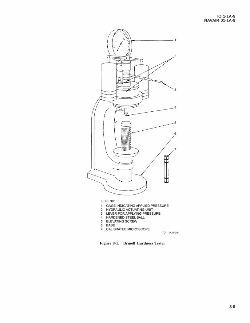
Figure 8-1. Brinell Hardness Tester
TO 1-1A-9NAVAIR 01-1A-9
8-9

Figure 8-2. Rockwell Hardness Tester
TO 1-1A-9NAVAIR 01-1A-9
8-10

8.4 VICKERS PYRAMID HARDNESS TEST.
The Vickers pyramid hardness test (Figure 8-4) covers a normal range of loading from 2.5 to 127.5 kilograms. However, forspecial applications such as the hardness testing of thin, soft materials, loads as low as 50 to 100 grams may be used. Thistest is made by pressing a square base diamond indentor into a flat surface of the metal being tested by the application ofknown pressure. The indentation left by the indentor is a square, the diagonal of which remains the hardness of the metal.The diagonal of the square impression is measured by a microscope which reads directly to 0.001 millimeters on a largemicrometer drum. With the standard pyramidal diamond indentor (Figure 8-5) having an angle of 136° between oppositeface of the pyramid, the pyramidal hardness number is determined by dividing the applied load in kilograms by thepyramidal area of the impression in square millimeters by the formula, or from correlation tables accompanying the tester.
Hardness 1.854 applied load in kilogramssquare of the diagonal of impression
Rapid readings may be taken by means of three knife edges in the field of the eye-piece. The first knife edge is fixed;the second knife is movable through a micrometric screw connected to a counter. The third knife edge, moved bymeans of a special screw, may be used if rapid reading of values to specified limits is desired. This method of testing ishighly flexible and permits testing for very high hardness values. In the Amsler-Vickers variation of this hardness testerthe surface of the material to be tested, at which the indentor contacts may be thrown on a ground-glass screen directlyin front of the operator, allowing the length of the diagonals to be read directly.
8.4.1 Vickers Tester. The Vickers tester consists of the following major parts:
a. Table for supporting the metal to be tested.
b. A lever with a 20 to 1 ratio through which a load is applied through a rod to an indentor at the end of a tube movingup and down in a vertical position.
c. A frame containing a control in which a plunger moves up and down vertically under the influence of a cam whichapplies and releases the test load. The cam is mounted on a drum and when the starting handle is depressed, the wholeis rotated by a weight attached to a flexible cable, the speed of rotation being controlled by a piston and dashpot of oil.The mechanism provides for a slow and diminishing rate of application for the last portion of the load.
d. A foot pedal, which when depressed, returns the cam, drum and weight to their original positions, thus cocking themechanism and preparing the instrument for another test.
e. A tripper, which supports the beam during the return of the cam, weight and drum. The tripper also released the leverfor load applications.
f. A medium-power compound microscope for measuring the indentation across the diagonal of a square.
8.4.2 Making The Vickers Test. The test is applied as follows (See Figure 8-4):
Figure 8-3. Attachments for Rockwell Tester
TO 1-1A-9NAVAIR 01-1A-9
8-11

a. Prepare the sample by smooth grinding or polishing to remove all scratches and variations that may affect the read-ability of the indentation.
b. Place the test piece (6) on the testing table (5) and turn the table elevating wheel (1) until the indentor (7) fails tocontact the metal being tested.
Sudden contact of the indentor and the material under test should be avoided to prevent possible injury to thediamond point. Failure to comply could result in damage to, or destruction of, equipment or loss of missioneffectiveness.
c. Depress the load trip level (8) applying the load. The duration of the load application is fixed by the manufacturers at10 to 30 seconds, the time being determined by the rate at which oil is allowed to bleed out of the dashpot. The loadis fully applied, the indentor is automatically released.
d. Elevate the indentor by turning the wheel. Lower the testing table by reversing the table elevating wheel.
e. Swing the microscope (10) into place until locked.
f. View the impression of the indentation in the form of a square in the field shown by the eyepiece.
g. Bring the left corner of the impression, by means of the centering screws (13) to a point where it touches the left handfixed knife edge. Adjust the right hand movable knife edge by means of the micrometric screw connected to thecounter until it touches the right hand corner of the impression. The counter (15) will then show an ocular readingwhich is transposed to the Vickers pyramid numeral by use of correlation tables accompanying the tester.
h. Where specified hardness limits are desired the third knife edge is used. This is moved by means of special screws tocorrespond to the smaller dimension or maximum hardness, while the micrometer-controlled knife edge is adjusted tocorrespond to the minimum hardness or larger dimension. When the settings of the second and third knife edges aremade, it is only necessary when taking readings to set the fixed knife edge to the left hand corner of the impression inthe usual way. If the right hand corner of the impression appears between the second and third knife edges, thematerial has the proper hardness for the range desired.
TO 1-1A-9NAVAIR 01-1A-9
8-12


Figure 8-4. Vickers Pyramid Hardness Tester
TO 1-1A-9NAVAIR 01-1A-9
(8-13 blank)/8-14

Legend for Figure 8-4:1 Table Elevating Wheel2 Flexible Cable3 Foot Pedal4 Testing Table5 Test Piece6 Indentor7 Load Trip Level8 Microscope9 Centering Screws10 Counter
8.5 SHORE SCLEROSCOPE HARDNESS TEST.
The Shore Scleroscope is not a precision instrument as the others discussed in preceding paragraphs. It is used to giveapproximate values for comparative hardness readings. Testing hardness with the scleroscope consists of dropping a dia-mond tipped hammer upon the test specimen from a definite height and measuring the rebound produced. In one type oftester, the height of the rebound must be measured directly on the scale of the machine, while on another the amount isindicated on a dial.
8.5.1 The Scleroscope Tester. The tester (Figure 8-6) consists of the following major parts:
a. A base, provided with leveling screws, end a clamping arrangement to hold the sample to be tested.
b. A vertical glass tube, mounted to the base and containing the cylindrical diamond point hammer.
c. A suction heat and bulb for lifting and releasing the hammer.
Figure 8-5. Standard Pyramid Diamond Indentor
TO 1-1A-9NAVAIR 01-1A-9
8-15
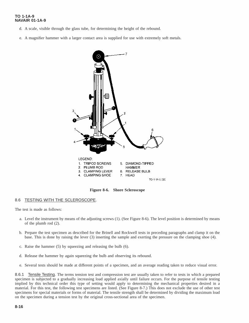
d. A scale, visible through the glass tube, for determining the height of the rebound.
e. A magnifier hammer with a larger contact area is supplied for use with extremely soft metals.
8.6 TESTING WITH THE SCLEROSCOPE.
The test is made as follows:
a. Level the instrument by means of the adjusting screws (1). (See Figure 8-6). The level position is determined by meansof the plumb rod (2).
b. Prepare the test specimen as described for the Brinell and Rockwell tests in preceding paragraphs and clamp it on thebase. This is done by raising the lever (3) inserting the sample and exerting the pressure on the clamping shoe (4).
c. Raise the hammer (5) by squeezing and releasing the bulb (6).
d. Release the hammer by again squeezing the bulb and observing its rebound.
e. Several tests should be made at different points of a specimen, and an average reading taken to reduce visual error.
8.6.1 Tensile Testing. The terms tension test and compression test are usually taken to refer to tests in which a preparedspecimen is subjected to a gradually increasing load applied axially until failure occurs. For the purpose of tensile testingimplied by this technical order this type of setting would apply to determining the mechanical properties desired in amaterial. For this test, the following test specimens are listed. (See Figure 8-7.) This does not exclude the use of other testspecimens for special materials or forms of material. The tensile strength shall be determined by dividing the maximum loadon the specimen during a tension test by the original cross-sectional area of the specimen.
Figure 8-6. Shore Scleroscope
TO 1-1A-9NAVAIR 01-1A-9
8-16

a. Diameter of the reduced section may be smaller at center than at ends. Difference shall not exceed 1% of diameter atends.
b. When an extensometer is required to determine elastic properties, dimensions C and L may be modified. In all casesthe percentage of elongation shall be based on dimension G.
c. The Type R1 test specimen is circular in cross section and is used for bars, rods, forgings, plates, shapes, heavy-walledtubing, and castings. Types R2, R3, R4, and R5 are circular in cross-section and are used for material of dimensionsinsufficient for Type R1.
(1) The ends of the reduced section shall not differ in width by more than 0.004 inch.
(2) The ends of the specimen shall be symmetrical with the center line of the reduced section within 0.10 inch.
(3) When material is over 2 inches thick, machine to 3/4 inch or use Type Rl test specimen. For more detailedinformation, refer to Federal Test Method Standard Number 151.
8.7 DECARBURIZATION MEASUREMENT.
Decarburization is the loss of carbon at the surface of ferrous materials which have been heated for fabricating, welding, etc.,or when heated to modify mechanical properties. Effective decarburization is any measurable loss of carbon content whichresults in mechanical properties below the minimum acceptable specifications for hardened materials. The most commonmethods used to measure decarburization are microscopic, hardness and chemical. The microscopic method is sufficientlyaccurate for most annealed and hot rolled material for small amounts of decarburization in high carbon (over 0.60%), highhardness steels. The hardness method is insensitive in this case, and recourse must be taken to chemical analysis. In thistechnical order, only the hardness method is covered. When precise measurements are required, publications giving detailedmeasurements must be consulted.
Table 8-4. Rockwell Scales, Loads and Prefix Letters
Scale Prefix Letters Indentor/Penetrator Major Load Kilograms Dial NumbersA Diamond 60 BlackB* 1/16 in Steel Ball 100 RedC* Diamond 150 BlackD Diamond 100 BlackE 1/8 inch Ball 100 RedF 1/16 inch Ball 60 RedG 1/16 inch Ball 150 RedH 1/8 inch Ball 60 RedK 1/8 inch Ball 150 RedL 1/4 inch Ball 60 RedM 1/4 inch Ball 100 RedP 1/4 inch Ball 150 RedR 1/2 inch Ball 60 RedS 1/2 inch Ball 100 RedV 1/2 inch Ball 150 Red
* Most commonly Used Scales.
8.8 HARDNESS METHOD.
8.8.1 Taper or Step Grind. The specimen containing the surface on which decarburization is to be measured is preparedso that it can be manipulated on a Rockwell superficial or Vickers hardness tester. If the specimen is not in the hardenedcondition, it is recommended that it be hardened by quenching from heating equipment under conditions which avoid furtherchange in carbon distribution. For the taper grind procedure, a shallow taper is ground through the case, and hardnessmeasurements are made along the surface. The angle is chosen so that readings spaced equal distances apart will represent
TO 1-1A-9NAVAIR 01-1A-9
8-17

the hardness at the desired increments below the surface of the case. The step grind procedure is essentially the same as thetaper grind, except that hardness readings are made on steps which are known distances below the surface. These stepsshould be ground at pre-determined depths below the surfaces, and of sufficient areas to allow several hardness readings oneach flat.
8.8.2 File Method. The file method is often suitable for detecting decarburization of hardened materials during shopprocessing, but not for accurate measurement. Base metals expected to harden above RC60 and found to be file soft areprobably decarburized. Decarburization of base metal that will not harden to RC60 can not be detected by this method unlessspecially prepared files are used. The extent and severity of any decarburization detected by this method should be verifiedby either of the other methods.
TO 1-1A-9NAVAIR 01-1A-9
8-18

Figure 8-7. Test Specimens
TO 1-1A-9NAVAIR 01-1A-9
8-19
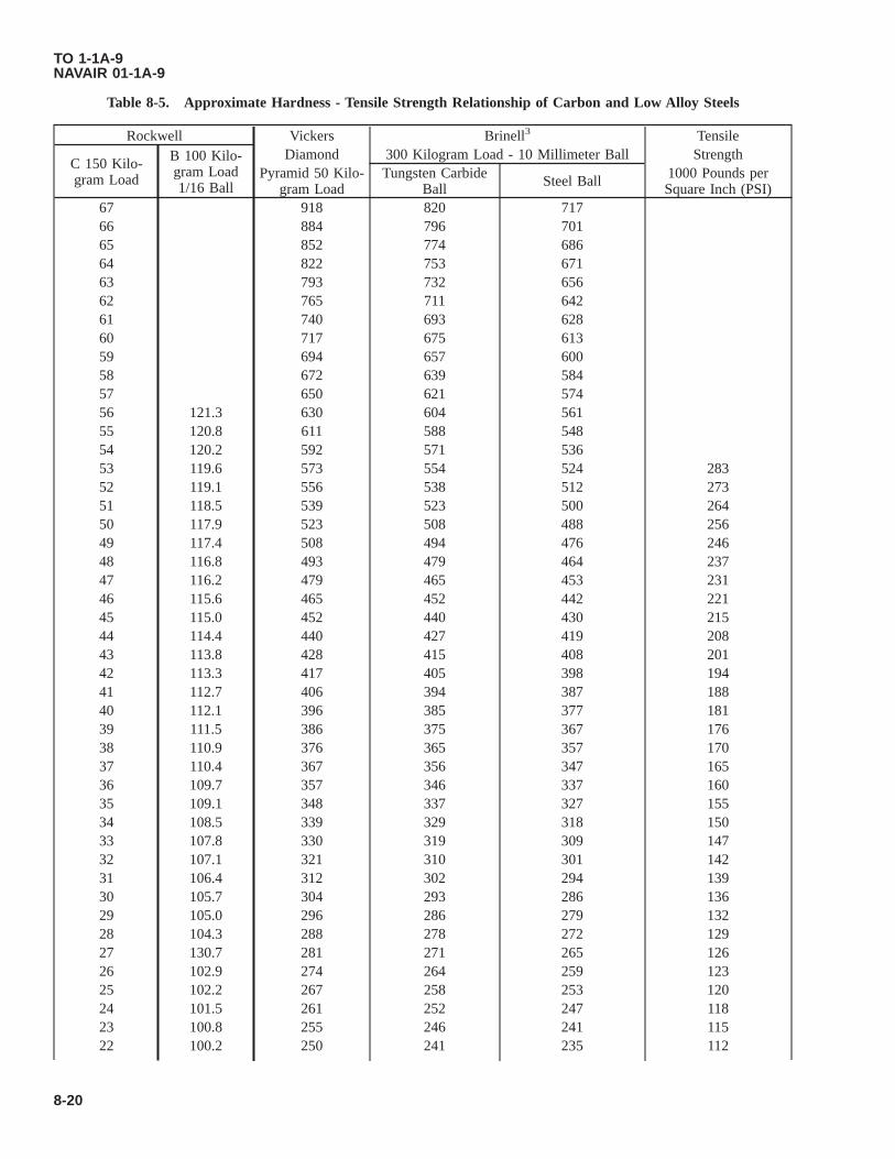
Table 8-5. Approximate Hardness - Tensile Strength Relationship of Carbon and Low Alloy Steels
Rockwell Vickers Brinell3 Tensile
C 150 Kilo-gram Load
B 100 Kilo-gram Load1/16 Ball
Diamond 300 Kilogram Load - 10 Millimeter Ball StrengthPyramid 50 Kilo-
gram LoadTungsten Carbide
Ball Steel Ball 1000 Pounds perSquare Inch (PSI)
67 918 820 71766 884 796 70165 852 774 68664 822 753 67163 793 732 65662 765 711 64261 740 693 62860 717 675 61359 694 657 60058 672 639 58457 650 621 57456 121.3 630 604 56155 120.8 611 588 54854 120.2 592 571 53653 119.6 573 554 524 28352 119.1 556 538 512 27351 118.5 539 523 500 26450 117.9 523 508 488 25649 117.4 508 494 476 24648 116.8 493 479 464 23747 116.2 479 465 453 23146 115.6 465 452 442 22145 115.0 452 440 430 21544 114.4 440 427 419 20843 113.8 428 415 408 20142 113.3 417 405 398 19441 112.7 406 394 387 18840 112.1 396 385 377 18139 111.5 386 375 367 17638 110.9 376 365 357 17037 110.4 367 356 347 16536 109.7 357 346 337 16035 109.1 348 337 327 15534 108.5 339 329 318 15033 107.8 330 319 309 14732 107.1 321 310 301 14231 106.4 312 302 294 13930 105.7 304 293 286 13629 105.0 296 286 279 13228 104.3 288 278 272 12927 130.7 281 271 265 12626 102.9 274 264 259 12325 102.2 267 258 253 12024 101.5 261 252 247 11823 100.8 255 246 241 11522 100.2 250 241 235 112
TO 1-1A-9NAVAIR 01-1A-9
8-20

Table 8-5. Approximate Hardness - Tensile Strength Relationship of Carbon and Low Alloy Steels - Continued
Rockwell Vickers Brinell3 Tensile
C 150 Kilo-gram Load
B 100 Kilo-gram Load1/16 Ball
Diamond 300 Kilogram Load - 10 Millimeter Ball StrengthPyramid 50 Kilo-
gram LoadTungsten Carbide
Ball Steel Ball 1000 Pounds perSquare Inch (PSI)
21 99.5 245 236 230 11020 98.9 240 231 225 10719 98.1 235 226 220 10418 97.5 231 222 215 10317 96.9 227 218 210 10216 96.2 223 214 206 10015 95.5 219 210 201 9914 94.9 215 206 197 9713 94.1 211 202 193 9512 93.4 207 199 190 9311 92.6 203 195 186 9110 91.8 199 191 183 909 91.2 196 187 180 898 90.3 192 184 177 887 89.7 189 180 174 876 89 186 177 171 855 88.3 183 174 168 844 87.5 179 171 165 833 87 177 169 162 822 86 173 165 160 811 85.5 171 163 158 800 84.5 167 159 154 78
83.2 162 153 150 7682 157 148 145 74
80.5 153 144 140 7279 149 140 136 70
77.5 143 134 131 6876 139 130 127 6674 135 126 122 6472 129 120 117 6270 125 116 113 6068 120 111 108 5866 116 107 104 5664 112 104 100 5461 108 100 96 5258 104 95 92 5055 99 91 87 4851 95 86 83 4647 91 83 79 4444 88 80 76 4239 84 76 72 4035 80 72 68 3830 76 67 64 3624 72 64 60 3420 69 61 57 3211 65 57 53 30
TO 1-1A-9NAVAIR 01-1A-9
8-21

Table 8-5. Approximate Hardness - Tensile Strength Relationship of Carbon and Low Alloy Steels - Continued
Rockwell Vickers Brinell3 Tensile
C 150 Kilo-gram Load
B 100 Kilo-gram Load1/16 Ball
Diamond 300 Kilogram Load - 10 Millimeter Ball StrengthPyramid 50 Kilo-
gram LoadTungsten Carbide
Ball Steel Ball 1000 Pounds perSquare Inch (PSI)
0 62 54 50 28
8.9 NONDESTRUCTIVE INSPECTION METHODS.
8.9.1 Radiographic Inspection. Radiographic inspection will show internal and external structural details of all types ofparts and materials. It is accomplished by passing penetrating radiation (usually X or gamma rays) through the part orassembly being inspected to expose a film. After developing, interpretation of the radiograph will indicate defects or damage.All radiographic inspections shall be accomplished in accordance with TO 33B-l-l, MIL-STD-453, and MIL-STD-410.
8.9.2 Penetrant Inspection. Penetrant inspection is a nondestructive inspection method that is used to detect discontinui-ties open to the surface of nonporous material. It is accomplished by treating the inspection area with a fluid (penetrant) thatpenetrates the surface discontinuity. Surplus penetrant remaining on the surface is removed and an absorbent material(developer) is applied to the surface. The developer acts as a blotter and draws some of the penetrant from the discontinuityto the surface. Discontinuities are visible due to color contrast between the penetrant drawn out and the background surface.Only fluorescent penetrants are approved for Air Force use. All penetrant inspection materials shall conform to MIL-I-25135.All penetrant inspections shall be accomplished in accordance with TO 33B-1-1 and MIL-STD-410.
8.9.3 Ultrasonic Inspection. Ultrasonic inspection uses a high frequency sound wave to detect discontinuities in materi-als. The pulser in the ultrasonic instrument sends an electrical impulse to a piezoelectric material in the search unit (trans-ducer). The transducer changes the electrical impulse into mechanical vibrations (sound) and transmits them into the materialbeing inspected. Any marked change in acoustic properties, such as a flaw or interface in the material, reflects the soundback to the transducer. Examination of the reflections on a cathode ray tube will reveal discontinuities in the material. Allultrasonic inspections shall be accomplished in accordance with TO 33B-l-l, MIL-I-8950, and MIL-STD-410.
8.9.4 Magnetic Particle Inspection. Magnetic particle inspection is used to detect discontinuities in ferromagnetic ma-terials, principally iron and steel. Magnetic particle inspection is accomplished by inducing a magnetic field into the materialbeing inspected. A discontinuity will interrupt this field, creating north and 8-14 south poles which will attract magneticparticles applied to the material. Discontinuities are visible due to color contrast between the magnetic particles and thebackground surface. All magnetic particle inspections shall be accomplished in accordance with TO 33B-1-1 and MIL-STD-410.
8.9.5 Eddy Current Inspection. Eddy current inspection is used to detect discontinuities in materials that are conductorsof electricity. An eddy current is the circulating electrical current induced in a conductor by an alternating magnetic field,which is produced by a small test coil in contact with or close to the material being inspected. Discontinuities in the materialbeing tested cause variations in the induced eddy current. The test coil measures the variations which reveal discontinuitiesin the material. All eddy current inspections shall be in accordance with TO 33B-1-1 and MIL-STD-410.
8.10 CHEMICAL ANALYSIS.
Chemical analysis methods are those in which the elements present in metals are determined by the use of reagents insolution, by combustion methods, or by other none-mission methods. Sample metal from any piece shall be such that itrepresents as nearly as possible the metal of the entire piece. Drilling, milling and other machining operations for samplemetal shall be performed without the use of water, oil, or other lubricants, and cutting speeds shall be such that no burningtakes place to cause alternation of the chemical composition of the test metal. Method 112.1 of Federal Method Standard151A is the controlling document for chemical analysis.
8.11 SPECTROCHEMICAL ANALYSIS.
Spectrochemical analysis includes all methods in which measurements of electromagnetic radiations produced by a samplemetal are employed to determine the chemical composition. Samples shall be so selected as to be representative of the entirequantity of metal under inspection. Cutting speeds in all machining operations shall be such that no burning takes place tocause alteration of the chemical composition of the test metal. Method 112.1 of Federal Test Method Standard 151A governs
TO 1-1A-9NAVAIR 01-1A-9
8-22

this type of analysis. The result of spectrochemical analysis shall be determined to the number of decimal places shown inthe chemical requirements for the material.
TO 1-1A-9NAVAIR 01-1A-9
8-23/(8-24 blank)

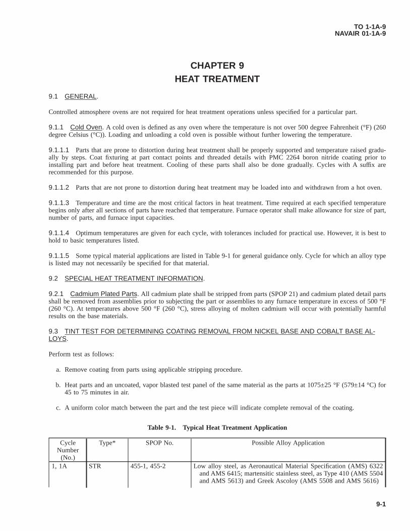
CHAPTER 9HEAT TREATMENT
9.1 GENERAL.
Controlled atmosphere ovens are not required for heat treatment operations unless specified for a particular part.
9.1.1 Cold Oven. A cold oven is defined as any oven where the temperature is not over 500 degree Fahrenheit (°F) (260degree Celsius (°C)). Loading and unloading a cold oven is possible without further lowering the temperature.
9.1.1.1 Parts that are prone to distortion during heat treatment shall be properly supported and temperature raised gradu-ally by steps. Coat fixturing at part contact points and threaded details with PMC 2264 boron nitride coating prior toinstalling part and before heat treatment. Cooling of these parts shall also be done gradually. Cycles with A suffix arerecommended for this purpose.
9.1.1.2 Parts that are not prone to distortion during heat treatment may be loaded into and withdrawn from a hot oven.
9.1.1.3 Temperature and time are the most critical factors in heat treatment. Time required at each specified temperaturebegins only after all sections of parts have reached that temperature. Furnace operator shall make allowance for size of part,number of parts, and furnace input capacities.
9.1.1.4 Optimum temperatures are given for each cycle, with tolerances included for practical use. However, it is best tohold to basic temperatures listed.
9.1.1.5 Some typical material applications are listed in Table 9-1 for general guidance only. Cycle for which an alloy typeis listed may not necessarily be specified for that material.
9.2 SPECIAL HEAT TREATMENT INFORMATION.
9.2.1 Cadmium Plated Parts. All cadmium plate shall be stripped from parts (SPOP 21) and cadmium plated detail partsshall be removed from assemblies prior to subjecting the part or assemblies to any furnace temperature in excess of 500 °F(260 °C). At temperatures above 500 °F (260 °C), stress alloying of molten cadmium will occur with potentially harmfulresults on the base materials.
9.3 TINT TEST FOR DETERMINING COATING REMOVAL FROM NICKEL BASE AND COBALT BASE AL-LOYS.
Perform test as follows:
a. Remove coating from parts using applicable stripping procedure.
b. Heat parts and an uncoated, vapor blasted test panel of the same material as the parts at 1075±25 °F (579±14 °C) for45 to 75 minutes in air.
c. A uniform color match between the part and the test piece will indicate complete removal of the coating.
Table 9-1. Typical Heat Treatment Application
CycleNumber
(No.)
Type* SPOP No. Possible Alloy Application
1, 1A STR 455-1, 455-2 Low alloy steel, as Aeronautical Material Specification (AMS) 6322and AMS 6415; martensitic stainless steel, as Type 410 (AMS 5504and AMS 5613) and Greek Ascoloy (AMS 5508 and AMS 5616)
TO 1-1A-9NAVAIR 01-1A-9
9-1

Table 9-1. Typical Heat Treatment Application - Continued
CycleNumber
(No.)
Type* SPOP No. Possible Alloy Application
2 STR 456 Aluminum3 STR 457 -4, 4A STR 458-1, 458-2 Inconel X5, 5A STR 459-1, 459-2 Nickel alloys: B-1900 (Printed Wiring Assembly (PWA) 663 and PWA
1455); Inconel 713 (PWA 655) Cobalt alloys: Stellite 31 (AMS5382); WI-52 (PWA 653); MAR-M509 (PWA 647)
6, 6A STR 460-1, 460-2 Greek Ascoloy (AMS 5508 and AMS 5616) (martensitic stainlesssteel)
7 STR 461 Waspaloy, Udimet 7008 STR 455-3 -9 STR 459-3 Inconel 600 (nickel alloy); Nimonic 75 (PWA 673) (nickel alloy);
stainless steel, as Types 310, 316, 321, and 34711 STR 464 Titanium12, 12A PRE 471, 465 Inconel 718 (nickel alloy), as AMS 5596, AMS 5662, and AMS
566313 STR 466 17-7PH (stainless steel - austenite conditioning); Type 430 (ferritic
stainless steel), welded with Type 430 filler metal14 STR 467 Type 430 (ferritic stainless steel), welded with AMS 5680 (Type 347
stainless steel)15 PRE 468 A-286 (modified Tinidur) stainless steel, as AMS 5525, AMS 5731,
AMS 5732, and AMS 573717 PRE 470 Incoloy 901 (nickel alloy), as AMS 5660 and AMS 566120 SOL 480 HASTELLOY X (nickel alloy)21 SOL 481 Nickel alloy: HASTELLOY X (AMS 5536 and AMS 5754) Cobalt
alloys: STELLITE 31 (AMS5382); Haynes 188 (AMS 5608, AMS5772, and PWA 1042); L-605 (AMS 5537 and AMS 5759)
22 STR 482 Nickel alloys: Inconel 600 (AMS 5540 and AMS 5665); Inconel625 (AMS 5599 and AMS 5666); HASTELLOY N; HASTEL-LOY X (AMS 5536, AMS 5754, and PWA 1038); HASTELLOYW Cobalt alloys: STELLITE 31 (AMS 5382); Haynes 188 (AMS5608, AMS 5772, and PWA 1042); L-605 (AMS 5537 and AMS5759); MAR-M509 (PWA 647)
101 SOL 761 Waspaloy (nickel alloy), as AMS 5544, AMS 5706, and AMS 5707102 SOL 762 Waspaloy (nickel alloy), as AMS 5544, AMS 5706, and AMS 5707103 STA 763 Waspaloy (nickel alloy), as AMS 5544, AMS 5706, AMS 5707,
AMS 5708, and AMS 5709104 PRE 764 Waspaloy (nickel alloy), as AMS 5596, AMS 5706, AMS 5707,
AMS 5708, and AMS 5709105 SOL 765 Inconel 718 (nickel alloy), as AMS 5596, AMS 5662, and AMS
5663106 SOL 766 Inconel 718 (nickel alloy, as AMS 5596, AMS 5662, and AMS 566310 PRE 767 Nickel alloys: Inconel 718, as AMS 5596, AMS 5662, and AMS 5663;
Inconel X-750, as AMS 5598, AMS 5670, and AMS 5671* PRE = PrecipitationSOL = SolutionSTA = StabilizationSTR = Stress-relief
TO 1-1A-9NAVAIR 01-1A-9
9-2

9.4 TITANIUM ALLOY PARTS.
NOTE
AMS 4901 and 4921 are the only commercially pure titanium material types used widely in the fabrication ofPandW engine parts. Virtually all other titanium materials used are titanium alloys and are subject to theseinstructions.
9.4.1 General. All titanium alloy parts shall be cleaned by the following procedure prior to stress-relief. Otherwise,certain impurities that may be present on the parts during the heating cycle could cause stress alloying of the parts. The thin,hard, blue-gray oxide coating sometimes occurring on titanium alloy surfaces and unaffected by this cleaning procedure isharmless in this respect and may be disregarded.
METHYL ETHYL KETONE, ASTM D740 5
NOTE
Since only light films of oil or grease will be removed by the cleaning solution, it is essential that as much surfacecontamination as possible be removed before immersing parts into the cleaning solution.
a. Remove any visible concentrations of oil, grease, dirt, and any other contaminants by wiping with a clean, lint-freecloth dampened with methyl ethyl ketone ASTM D740 or acetone O-A-51.
Alkaline rust remover causes burns. Protect eyes and skin from contact. Failure to comply could result in injury to,or death of, personnel or long term health hazards.
NOTE
Parts shall be immersed only long enough to obtain optimum results.
b. Soak in alkaline rust remover (SPS 2, SPS 5, SPS 7, SPS 12, SPS 25, SPS 27, or PS 240) at 180-200 °F (82-93 °C) for1 to 4 minutes maximum.
c. Pressure rinse over tank with cold water, then dip rinse in cold water, following with a cold water pressure rinse.
d. Rinse in hot PMC 1737 deionized water at 150-200 °F (66-93 °C). Air dry; do not use compressed air.
e. Immediately after completing step d., protect the parts from all contamination, such as dirt, dust, oil mist, fingerprints,etc. Cover parts with clear plastic sheet or store them in clear plastic bags until furnace or other operation is begun.Use clean white gloves for all handling.
9.4.1.1 Type 6A1-4V Titanium Alloy Parts (AMS 4911, 4928, 4930, 4935, 4954, 4956, 4967, and PWA 1213, 1215,1262). Parts fabricated of these titanium alloys may be stress-relieved in air only to 1015±15 °F (546±8 °C). See Cycles 1and 1A. At any higher temperatures, an inert atmosphere shall be used regardless of any contrary instructions stipulated in aparticular repair.
9.5 SOLUTION, STABILIZATION, OR PRECIPITATION HEAT TREATMENT.
9.5.1 General. Solution heat treatment of material (particularly HASTELLOY X) is performed to improve ductility andweldability prior to resizing and repair. Long-time exposure to high temperature engine operating environment causesprecipitation of carbides into the grain boundaries. Carbides, particularly chromium carbides, are thus precipitated into thegrain boundaries of parts fabricated of HASTELLOY X material and subjected for long periods to temperatures of 1200-1700 °F (649-927 °C). The solution treatment dissolves these carbides and puts them back into metallic solution. The
TO 1-1A-9NAVAIR 01-1A-9
9-3
cooling cycle, therefore, shall be rapid enough to maintain carbides or precipitation hardeners in solution. Replication andmetallurgical examination may be necessary to verify whether fixturing and cooling rate are adequate to obtain desiredmicrostructure and prevent cracking.
9.5.2 Stabilization Heat Treatment. Stabilization heat treatment is maintaining a part at a selected temperature longenough to rearrange the atoms into an improved structure.
9.5.3 Precipitation Heat Treatment. Precipitation heat treatment is a selected temperature and duration that producesbeneficial hardening in certain alloys. It is sometimes referred to as Aging, or Age Hardening.
9.5.4 Sequence of Solution, Stabilization, or Precipitation Heat Treatment. When a sequence of solution, stabiliza-tion, or precipitation heat treatment is applied to a given part, various temperatures are used. The final condition obtained isa combined effect of this sequence.
9.5.5 Air Cool and Air Cool or Faster. The expressions AIR COOL and AIR COOL OR FASTER mean that parts shallbe cooled quickly enough to prevent metal structure changes that can happen in certain alloys if cooling is too slow. It doesnot mean to quench in a liquid. Circulating fans may be used, but fixturing may be required if distortion is a problem.
9.5.5.1 Air Cool. AIR COOL is defined as rate of cooling of part obtained by removing that part from furnace atprescribed temperature and allowing it to cool in room temperature still air. Definition has been broadened to include thefollowing situations.
• In vacuum furnace, by force cooling in protective atmosphere.
• In protective atmosphere furnace, by shutting off heat and maintaining atmospheric flow rates.
• In retort furnace, by removing retort from furnace and fan cooling.
• In pit furnace, by removing parts from furnace and cooling in room temperature still air.
9.5.5.2 Air Cool or Faster. AIR COOL OR FASTER is defined as cooling not less than 40 °F (22 °C) per minute to 1100°F (593 °C) and not less than 15 °F (8 °C) from 1100-1000 °F (538 °C).
9.6 CYCLE NUMBER, TYPE OF HEAT TREATMENT, SPOP NUMBER, AND MAXIMUM TEMPERATURE.
NOTE
These cycles apply only to the repair of HASTELLOY X parts that require using one of the following solutionheat treatments. The specific cycle required will be included in the repair procedure.
See Table 9-2. Solution heat treatment Cycles 20 and 21 are used for various HASTELLOY X parts. Reference to thesecycles will be made in the repair instructions, as necessary, by cycle or SPOP number.
9.6.1 Cycle 20 (SPOP 480).
Do not use this cycle for solution heat treating PWA 1038 HASTELLOY X material. This material was solutiontreated at 1950 °F (1066 °C) at its manufacture. The beneficial properties derived from this lower temperaturetreatment could be lost permanently if subjected to a temperature higher than 1800 °F (982 °C). For otherHASTELLOY alloys, solution heat treat shall be performed per this cycle unless otherwise directed by a specificrepair procedure. Failure to comply could result in damage to, or destruction of, equipment or loss of missioneffectiveness.
Perform as follows:
TO 1-1A-9NAVAIR 01-1A-9
9-4 Change 6
a. Heat part to 2050±25 °F (1121±14 °C) and hold for 7 to 10 minutes.
NOTE
Hydrogen, argon, or air are acceptable atmospheres; however, when solution treating is to be followed by weldrepair that requires complete prior removal of oxides, hydrogen is preferred because of its characteristic andbeneficial cleaning action over the entire part. Hydrogen cleaning removes oxides from all surfaces, includingthose difficult to clean mechanically, and to some extent, from the inside of cracks to be welded.
b. Air cool or faster.
9.6.2 Cycle 21 (SPOP 481). Perform as follows:
Do not use this cycle for solution heat treating PWA 1038 HASTELLOY X material. This material was solutiontreated at 1950 °F (1066 °C) at its manufacture. The beneficial properties derived from this lower temperaturetreatment could be lost permanently if subjected to a temperature higher than 1800 °F (982 °C). For regularHastelloy material, solution heat treat shall be performed in accordance with Cycle 20 (SPOP 480), unless other-wise directed by a specific repair procedure. Failure to comply could result in damage to, or destruction of,equipment or loss of mission effectiveness.
a. Heat part to 2150±25 °F (1177±14 °C) and hold for 7 to 10 minutes.
NOTE
Hydrogen, argon, or air are acceptable atmospheres. However, when solution treating is to be followed by weldrepair that requires complete prior removal of oxides, hydrogen is preferred because of its characteristic andbeneficial cleaning action over the entire part. Hydrogen cleaning removes oxides from all surfaces includingthose difficult to clean mechanically, and to some extent, from the inside of cracks to be welded.
b. Air cool or faster.
9.6.2.1 The following solution, stabilization, or precipitation heat treatment cycles apply primarily to certain age-harden-able alloys such as WASPALOY and INCONEL materials, for stress-relief, and to dissolve precipitated carbides and inter-metallics (hardeners).
9.6.3 Cycle 12 (SPOP 471).
NOTE
This is a short-term precipitation (aging) heat treatment for INCONEL 718 or other part material specified inengine publication.
Perform as follows:
a. Place part in oven and heat to 1350±15 °F (732±8 °C).
b. Hold at 1350 °F (732 °C) for 4 hours.
c. Cool to 1200±15 °F (649±8 °C) at approximately 100 °F (56 °C) per hour. Hold at temperature for a total of 3 hours,including cool-down time from 1350 °F (732 °C).
d. Air cool to room temperature.
TO 1-1A-9NAVAIR 01-1A-9
9-5

9.6.4 Cycle 12A (SPOP 465).
NOTE
This is a short-term precipitation (aging) heat treatment for INCONEL 718 or other part material specified inengine publication.
Perform as follows:
a. Place part in cold oven.
b. Heat to 600 °F (316 °C) and hold for 30 minutes.
c. Increase to 800 °F (427 °C) and hold for 30 minutes.
d. Increase to 1000 °F (538 °C) and hold for 30 minutes.
e. Increase to 1200 °F (649 °C) and hold for 30 minutes.
f. Increase to 1350±15 °F (732±8 °C) and hold for 4 hours.
g. Cool to 1200±15 °F (649±8 °C) at approximately 100 °F (56 °C) per hour. Hold at temperature for a total of 3 hours,including cool-down time from 1350 °F (732 °C).
h. Air cool to room temperature.
9.6.5 Cycle 15 (SPOP 468).
NOTE
Heating and cooling rates are optional. Air is an acceptable atmosphere.
Perform as follows:
a. Heat part to 1325±25 °F (718±14 °C) and hold for 4 hours.
b. Air cool.
9.6.6 Cycle 17 (SPOP 470).
NOTE
Hydrogen, argon, or a blend of hydrogen and argon, or vacuum, are acceptable atmospheres.
Perform as follows:
a. Heat part to 1450±15 °F (788±8 °C) and hold for 4 hours.
b. Cool to 500 °F (260 °C) at a rate equivalent to air cool.
c. Heat part to 1325±15 °F (718±8 °C) and hold for 14 hours.
d. Cool at a rate equivalent to air cool.
TO 1-1A-9NAVAIR 01-1A-9
9-6

9.6.7 Cycle 101 (SPOP 761).
Heating or cooling rate between 1000 °F (538 °C) and 1850 °F (1010 °C) shall be at least 40 °F (22 °C) perminute to prevent cracking and to control aging characteristics. Failure to comply could result in damage to, ordestruction of, equipment or loss of mission effectiveness.
NOTE
This is a solution heat treatment using an argon atmosphere.
Perform as follows:
a. Place part with thermocouples (TCs) in retort, and seal retort.
b. Purge retort at approximately 150 cubic feet per hour argon until dew point reaches -40 °F (-40 °C) or lower at retortexhaust.
c. Insert retort into furnace.
NOTE
Furnace may initially be set higher than 1850 °F (1010 °C).
d. Heat to 1825±25 °F (996±14 °C) using lower thermocouple for controlling. Do not exceed 1850 °F (1010 °C) onhigher thermocouple. Hold at temperature for 2 hours unless otherwise specified.
e. Remove retort from furnace and cool with forced argon to 1000 °F (538 °C) in no longer than 18 minutes; thencomplete cooling with argon or air.
9.6.8 Cycle 102 (SPOP 762).
Heating or cooling rate between 1000 °F (538 °C) and 1850 °F (1010 °C) shall be at least 40 °F (22 °C) perminute to prevent cracking and to control aging characteristics. Failure to comply could result in damage to, ordestruction of, equipment or loss of mission effectiveness.
NOTE
• This is a solution heat treatment using vacuum. Heat cycle shall be completed in the 0.010 torr range or lower.
• Furnace system shall provide for argon forced cooling, in order to satisfy cooling rate requirement.
Perform as follows:
a. Place part, with TC, in furnace.
b. Evacuate to 0.009 torr or lower. Static leak rate shall not exceed 50 microns per hour.
NOTE
Furnace may initially be set higher than 1850 °F (1010 °C).
c. Heat to 1825±25 °F (996±14 °C) using lower thermocouple for controlling. Do not exceed 1850 °F (1010 °C) onhigher thermocouple. Hold at temperature for 2 hours unless otherwise specified.
TO 1-1A-9NAVAIR 01-1A-9
9-7

d. Cool at required rate using forced argon.
9.6.9 Cycle 103 (SPOP 763). Perform as follows:
NOTE
This is a stabilization heat treatment using air, argon, or vacuum.
a. Place part in cold furnace.
b. Heat to 1550±15 °F (843±8.3 °C) for 4 hours.
c. Air cool.
9.6.10 Cycle 104 (SPOP 764). Perform as follows:
NOTE
This is a precipitation heat treatment using air, argon, or vacuum.
a. Place part in cold furnace.
b. Heat to 1400±15 °F (760±8.3 °C) for 16 hours.
c. Air cool.
9.6.11 Cycle 105 (SPOP 765).
Heating or cooling rate between 1000 °F (538 °C) and 1775 °F (968 °C) shall be at least 40 °F (22 °C) per minuteto prevent cracking and to control aging characteristics.
NOTE
This is a solution heat treatment using an argon atmosphere.
Perform as follows:
a. Place part with TC in retort, and seal retort.
b. Purge retort at approximately 150 CFH argon until dew point reaches -40 °F (-40 °C) or lower, at retort exhaust.
c. Insert retort into furnace.
NOTE
Furnace may initially be set higher than 1775 °F (968 °C).
d. Heat to 1750±25 °F (954±14 °C), using lower thermocouple for controlling. Do not exceed 1775 °F (968 °C) onhigher thermocouple. Hold at temperature for 1 hour unless otherwise specified.
e. Remove retort from furnace and cool with forced argon to 1000 °F (538 °C) in no longer than 16 minutes; thencomplete cooling with argon or air.
TO 1-1A-9NAVAIR 01-1A-9
9-8

9.6.12 Cycle 106 (SPOP 766).
Heating or cooling rate between 1000 °F (538 °C) and 1775 °F (968 °C) shall be at least 40 °F (22 °C) per minuteto prevent cracking and to control aging characteristics.
NOTE
• This is a solution heat treatment using vacuum. Heat cycle shall be completed in the 0.010 torr range or lower.
• Furnace system shall provide for argon forced cooling, in order to satisfy cooling rate requirement.
Perform as follows:
a. Place part, with TC, in furnace.
b. Evacuate to 0.009 torr or lower. Static leak rate shall not exceed 0.05 torr per hour.
NOTE
Furnace may initially be set higher than 1775 °F (968 °C)
c. Heat to 1750±25 °F (954±14 °C), using lower thermocouple for controlling. Do not exceed 1775 °F (968 °C) onhigher thermocouple. Hold at temperature for 1 hour unless otherwise specified.
d. Cool at required rate using forced argon.
9.6.13 Cycle 107 (SPOP 767).
NOTE
This is a precipitation heat treatment using air or argon.
Perform as follows:
a. Place part in cold furnace.
b. Heat to 1325±15 °F (718±8.3 °C) for 8 hours.
c. Furnace cool at a rate not to exceed 100 °F (56 °C) per hour to 1150±15 °F (621±8.3 °C); hold for 8 hours.
d. Air cool.
Table 9-2. Cross-Index for Solution, Stabilization, or Precipitation Heat Treatments
Cycle Number Type SPOP Number Peak Temperature, °F (°C)*12 Precipitation 471 1350 (732)12A Precipitation 465 1350 (732)15 Precipitation 468 1325 (718)17 Precipitation 470 1450 (788)20 Solution 480 2050 (1121)21 Solution 481 2150 (1177)101 Solution 761 1825 (996)102 Solution 762 1825 (996)103 Stabilization 763 1550 (843)
TO 1-1A-9NAVAIR 01-1A-9
9-9

Table 9-2. Cross-Index for Solution, Stabilization, or Precipitation Heat Treatments - Continued
Cycle Number Type SPOP Number Peak Temperature, °F (°C)*104 Precipitation 764 1400 (760)105 Solution 765 1750 (954)106 Solution 766 1750 (954)107 Precipitation 767 1325 (718)* (disregarding tolerance)
9.7 STRESS-RELIEF AFTER WELDING.
NOTE
Local stress-relief of engine parts following minor repairs is authorized only if procedure has been developed tobe compatible with applicable parts, material, size, and operating environment, and is approved by the cognizantengineering authority.
9.7.1 General.
The required stress-relief (Cycle 1 or Cycle 1A) after welding or brazing Type 410 or Greek Ascoloy materialseliminates the brittleness in the joint areas. To avoid cracking, parts shall be handled carefully until stress-relief isaccomplished. Failure to comply could result in damage to, or destruction of, equipment or loss of mission oreffectiveness.
Parts that have been repaired by fusion welding shall ordinarily be stress-relieved.
NOTE
On certain parts, experience has indicated that stress-relief is not required. This permissible omission will beincluded in appropriate manual repair section for such parts.
9.8 CYCLE NUMBER, SPOP NUMBER, AND MAXIMUM TEMPERATURE.
NOTE
• Parts may require a cycle different from one of the following. This will result in cycle being included inspecific repair procedure.
• Parts that are susceptible to distortion during heat treatment shall be adequately supported, and temperatureraised and lowered stepwise. The Suffix A following a cycle number indicates a stepwise cycle.
See Table 9-3. The following stress-relief cycles are used throughout manual for various parts. Reference to these cycles willbe made, as necessary, by cycle or SPOP number.
9.8.1 Cycle 1 (SPOP 455-1). Heat part to 1015±15 °F (546±8 °C) and hold for 2 hours.
9.8.2 Cycle 1A (SPOP 455-2).
NOTE
To minimize distortion, use Cycle 1A as an alternate. Other cycles are permissible provided stress-relief require-ment of 1015±15 °F (546±8 °C) for 2 hours is met.
Perform as follows:
a. Put part in cold oven.
TO 1-1A-9NAVAIR 01-1A-9
9-10 Change 6

b. Heat to 600 °F (316 °C) and hold for 30 minutes.
c. Increase to 800 °F (427 °C) and hold for 30 minutes.
d. Increase to 1015±15 °F (546±8 °C) and hold for 2 hours.
e. Cool to 500 °F (260 °C) not faster than 100 °F (56 °C) every 15 minutes.
9.8.3 Cycle 2 (SPOP 456). Heat part to 350±10 °F (177±6 °C) and hold for 1 hour.
9.8.4 Cycle 3 (SPOP 457). Perform as follows:
a. Put part in cold oven.
b. Heat to 600 °F (316 °C) and hold for 30 minutes.
c. Increase to 900±15°F (482±8 °C) and hold for 4 hours.
d. Cool to 500 °F (260 °C) not faster than 100 °F (56 °C) every 15 minutes.
9.8.5 Cycle 4 (SPOP 458-1). Heat part to 1300±25 °F (704±14 °C) and hold for 2 hours.
9.8.6 Cycle 4A (SPOP 458-2).
NOTE
To minimize distortion, temperature may be raised and cooled gradually in accordance with Cycle 4A. Othercycles are permissible provided stress-relief requirement of 1300±25 °F (704±14 °C) for 2 hours is met.
Perform as follows:
a. Put part in cold oven.
b. Heat to 600 °F (316 °C) and hold for 30 minutes.
c. Increase to 800 °F (427 °C) and hold for 30 minutes.
d. Increase to 1100 °F (593 °C) and hold for 30 minutes.
e. Increase to 1300±25 °F (704±15 °C) and hold for 2 hours.
f. Cool to 500 °F (260 °C) not faster than 100 °F (56 °C) every 15 minutes.
9.8.7 Cycle 5 (SPOP 459-1). Heat part to 1600±25 °F (871±14 °C) and hold for 2 hours.
9.8.8 Cycle 5A (SPOP 459-2).
NOTE
To minimize distortion, temperature may be raised and lowered gradually in accordance with Cycle 5A. Othercycles are permissible provided stress-relief requirement of 1600±25 °F (871±14 °C) for 2 hours is met.
Perform as follows:
a. Put part in cold oven.
b. Heat to 700 °F (371 °C) and hold for 30 minutes.
c. Increase to 1000 °F (538 °C) and hold for 30 minutes.
TO 1-1A-9NAVAIR 01-1A-9
9-11

d. Increase to 1300 °F (704 °C) and hold for 30 minutes.
e. Increase to 1600±25 °F (871±14 °C) and hold for 2 hours.
f. Cool to 500 °F (260 °C) not faster than 100 °F (56 °C) every 15 minutes.
9.8.9 Cycle 6 (SPOP 460-1). Heat part to 1050±15 °F (566±8 °C) for 2 hours.
9.8.10 Cycle 6A (SPOP 460-2).
NOTE
To minimize distortion, temperature may be raised and lowered gradually in accordance with Cycle 6A. Othercycles are permissible provided stress-relief requirement of 1050±15 °F (566±8 °C) for 2 hours is met.
Perform as follows:
a. Put part in cold oven.
b. Heat to 600 °F (316 °C) and hold for 30 minutes.
c. Increase to 800 °F (427 °C) and hold for 30 minutes.
d. Increase to 1050±15 °F (566±8 °C) and hold for 2 hours.
e. Cool to 500 °F (260 °C) not faster than 100 °F (56 °C) every 15 minutes.
9.8.11 Cycle 7 (SPOP 461). Heat part to 1500±25 °F (815±14 °C) and hold for 4 hours.
9.8.12 CYCLE 8 (SPOP 455-3). Perform as follows:
a. Put part in cold oven.
b. Heat to 600 °F (316 °C) and hold for 30 minutes.
c. Increase to 800 °F (427 °C) and hold for 30 minutes.
d. Increase to 1010 °F (543±8 °C) and hold for 30 minutes.
e. Cool to 500 °F (260 °C) not faster than 100 °F (56 °C) every 15 minutes.
9.8.13 Cycle 9 (SPOP 459-3). Heat part to 1600±25 °F (871±14 °C) and hold for 1 hour.
TO 1-1A-9NAVAIR 01-1A-9
9-12

9.8.14 Cycle 11 (SPOP 464).
• For titanium parts, a vacuum of 0.5 microns mercury, maximum, or argon or helium with a dew point no higherthan -60 °F (-51 °C) shall be used. Failure to comply could result in damage to, or destruction of, equipment orloss of mission effectiveness.
• Longer heat treatment at specified temperature, or shorter heat treatment at higher temperature may be requiredby engine publication for certain parts. Failure to comply could result in damage to, or destruction of, equip-ment or loss of mission effectiveness.
NOTE
For materials other than titanium, air or argon may be used.
Perform as follows:
a. Heat part to 1150±15 °F (621±8 °C) and hold for 1 hour.
b. Air cool.
9.8.15 Cycle 13 (SPOP 466). Perform as follows:
a. Heat part to 1400±25 °F (760±14 °C) in air and hold for 2 hours.
b. Air cool, or faster.
9.8.16 Cycle 14 (SPOP 467). Perform as follows:
NOTE
A protective atmosphere is suggested.
a. Heat part to 1500±25 °F (816±14 °C) and hold for 30 minutes.
b. Furnace cool at a rate of 50 °F (28 °C) per hour to 1100° (593 °C), then air cool or faster.
9.8.17 Cycle 22 (SPOP 482).
Parts shall be thoroughly cleaned before entering oven. Failure to comply could result in damage to, or destructionof, equipment or loss of mission effectiveness.
NOTE
Hydrogen, argon, vacuum, or air are acceptable atmospheres; however, when heat treatment is to be followed byweld repair, hydrogen is preferable because of its cleaning action on oxides and impurities difficult to cleanmechanically, as within cracks or cavities.
Previously designated Cycle 10.
a. Place part in cold oven; however, this step may be omitted for thin sheet metal parts.
b. Heat part to 1800±25 °F (982±14 °C) and hold for 1 hour.
c. Air cool.
TO 1-1A-9NAVAIR 01-1A-9
9-13

Table 9-3. Cross-Index for Stress-Relief Heat Treatments
Cycle Number SPOP Number Peak Temperature, °F (°C)1 455-1 1015 (546)
1A 455-2 1015 (546)2 456 350 (177)3 457 900 (482)4 458-1 1300 (704)
4A 458-2 1300 (704)5 459-1 1600 (871)
5A 459-2 1600 (871)6 460-1 1050 (566)
6A 460-2 1050 (566)7 461 1500 (816)8 455-3 1010 (543)9 459-3 1600 (871)11 464 1150 (621)13 466 1400 (760)14 467 1500 (816)22 482 1800 (982)
*(Disregarding tolerance)
9.9 LOCAL STRESS-RELIEF.
9.9.1 General. Local stress-relief is the application of a heat treatment cycle, using a portable heating system, to a partthat has been weld repaired, usually without disassembly. Elaborate fixturing is avoided when stress-relieving minor areas oflarge components.
9.9.1.1 Approval for local stress-relief is governed in part by accessibility, temperature requirement, and configuration andmaterial of part.
9.9.1.2 Local stress-relief is especially useful when applied to parts on a mounted or partly disassembled engine.
9.9.1.3 Besides avoiding disassembly, local stress-relief provides significant cost and time savings.
Gas burner shall not be used to stress-relieve titanium parts. Exhaust gases can produce harmful surface reaction.Failure to comply could result in damage to, or destruction of, equipment or loss of mission effectiveness.
9.9.1.4 Typical local stress-relief methods include the following:
• Resistance
• Induction
• Quartz lamp
• Gas burner radiant heater.
9.9.1.5 Choice of method depends upon size and shape of joint, part configuration, and accessibility. Resistance blanketsand quartz lamps can be used to 1350 °F (732 °C); induction heaters and radiant gas burners can be used to 1825 °F (996°C).
TO 1-1A-9NAVAIR 01-1A-9
9-14

TCs shall not be tack welded to titanium parts. Failure to comply could result in damage to, or destruction of,equipment or loss of mission effectiveness.
9.9.1.6 Temperature profile shall be monitored with tack welded TC to provide accurate readout for manual or automaticcontrol during heat treat cycle. Thermocouples shall be located every 2 inches of area that is to be stress-relieved. Followingthe cycle, TC are broken or ground off, and part blended to original contour.
9.9.1.7 Stress-relief duration and temperature shall be the same as for a corresponding furnace heat treat, unless otherwisespecified in applicable engine technical orders.
9.10 DESCRIPTION OF METHODS.
Local stress-relief methods are defined in the following paragraphs.
9.10.1 Resistance. Heaters consist of nichrome wire elements insulated with ceramic fiber and contained within aflexible wire jacket. These components are woven into a thermal blanket, which shall be held in close contact with surfaceto be stress-relieved. Supplementary flexible heaters may be added to ensure that adjacent parts do not conduct heat away insuch a manner as to make heat distribution non-uniform.
9.10.2 Induction. Requirements include a high frequency generator, with a water-cooled copper induction coil of suffi-cient number of turns to be positioned over entire area to be heat treated, such as a welded patch. Coils shall be insulatedfrom metal contact, which will produce electrical arcing. Typical applications include small weld repair of holes or bosses,or replacement of small detail parts.
9.10.3 Quartz Lamp. Radiant lamp provides intense infrared heat, which can be easily directed toward part being stress-relieved. Temperature can be controlled by pulsing lamp on and off. Typical applications include inlet guide vanes, exhauststruts, intermediate cases, door assemblies, accessory housing, and thrust reversers.
9.10.4 Radiant Gas Burner.
Gas burner shall not be used to stress-relieve titanium parts. Exhaust gases can produce harmful surface reaction.Failure to comply could result in damage to, or destruction of, equipment or loss of mission effectiveness.
Good heating patterns and temperature control are permitted by using as burners. Heat treat of several areas can be accom-plished simultaneously. Radiant gas burners are fueled with a mixture of air and natural gas.
TO 1-1A-9NAVAIR 01-1A-9
9-15/(9-16 blank)

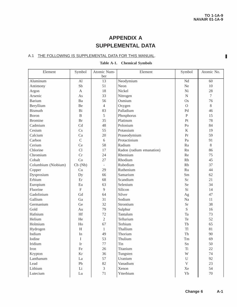
APPENDIX ASUPPLEMENTAL DATA
A.1 THE FOLLOWING IS SUPPLEMENTAL DATA FOR THIS MANUAL.
Table A-1. Chemical Symbols
Element Symbol Atomic Num-ber
Element Symbol Atomic No.
Aluminum Al 13 Neodymium Nd 60Antimony Sb 51 Neon Ne 10Argon A 18 Nickel Ni 28Arsenic As 33 Nitrogen N 7Barium Ba 56 Osmium Os 76Beryllium Be 4 Oxygen O 8Bismuth Bi 83 Palladium Pd 46Boron B 5 Phosphorus P 15Bromine Br 35 Platinum Pt 78Cadmium Cd 48 Polonium Po 84Cesium Cs 55 Potassium K 19Calcium Ca 20 Praseodymium Pr 59Carbon C 6 Protactinium Pa 91Cerium Ce 58 Radium Ra 8Chlorine Cl 17 Radon (radium emanation) Rn 86Chromium Cr 24 Rhemium Re 75Cobalt Co 27 Rhodium Rh 45Columbium (Niobium) Cb (Nb) - Rubedium Rb 37Copper Cu 29 Ruthenium Ru 44Dysprosium Dy 66 Samarium Sm 62Erbium Er 68 Scandium Sc 21Europium Eu 63 Selenium Se 34Fluorine F 9 Silicon Si 14Gadolinium Gd 64 Silver Ag 47Gallium Ga 31 Sodium Na 11Germanium Ge 32 Strontium Sr 38Gold Au 79 Sulphur S 16Hafnium Hf 72 Tantalum Ta 73Helium He 2 Tellurium Te 52Holmium Ho 67 Terbium Tb 65Hydrogen H 1 Thallium Tl 81Indium In 49 Thorium Th 90Iodine I 53 Thulium Tm 69Iridium Ir 77 Tin Sn 50Iron Fe 26 Titanium Ti 22Krypton Kr 36 Tungsten W 74Lanthanum La 57 Uranium U 92Lead Pb 82 Vanadium V 23Lithium Li 3 Xenon Xe 54Lutecium Lu 71 Ytterbium Yb 70
TO 1-1A-9NAVAIR 01-1A-9
Change 6 A-1
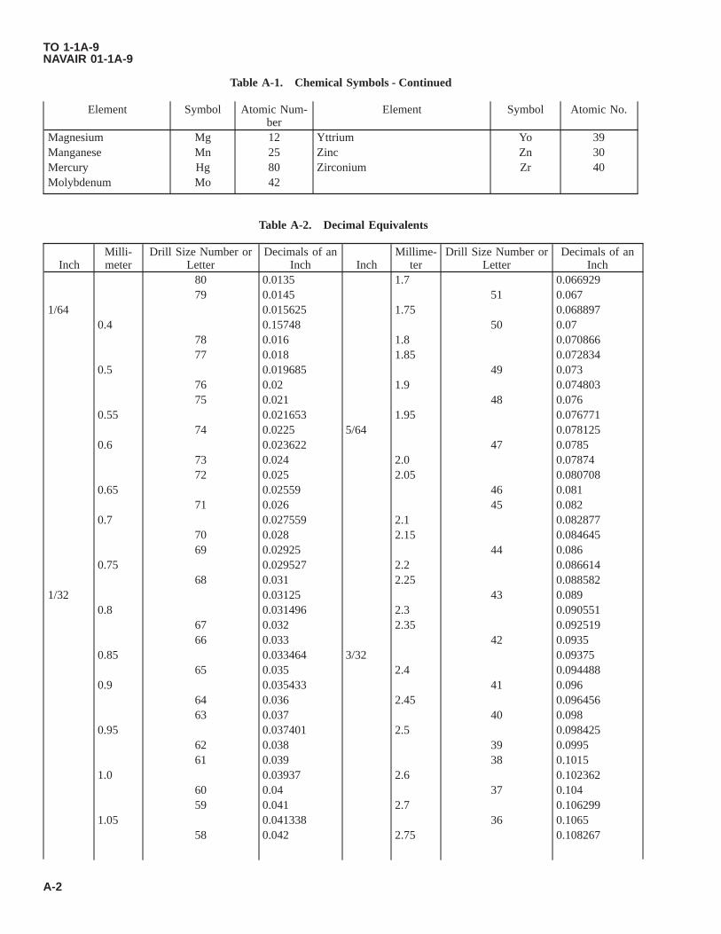
Table A-1. Chemical Symbols - Continued
Element Symbol Atomic Num-ber
Element Symbol Atomic No.
Magnesium Mg 12 Yttrium Yo 39Manganese Mn 25 Zinc Zn 30Mercury Hg 80 Zirconium Zr 40Molybdenum Mo 42
Table A-2. Decimal Equivalents
InchMilli-meter
Drill Size Number orLetter
Decimals of anInch Inch
Millime-ter
Drill Size Number orLetter
Decimals of anInch
80 0.0135 1.7 0.06692979 0.0145 51 0.067
1/64 0.015625 1.75 0.0688970.4 0.15748 50 0.07
78 0.016 1.8 0.07086677 0.018 1.85 0.072834
0.5 0.019685 49 0.07376 0.02 1.9 0.07480375 0.021 48 0.076
0.55 0.021653 1.95 0.07677174 0.0225 5/64 0.078125
0.6 0.023622 47 0.078573 0.024 2.0 0.0787472 0.025 2.05 0.080708
0.65 0.02559 46 0.08171 0.026 45 0.082
0.7 0.027559 2.1 0.08287770 0.028 2.15 0.08464569 0.02925 44 0.086
0.75 0.029527 2.2 0.08661468 0.031 2.25 0.088582
1/32 0.03125 43 0.0890.8 0.031496 2.3 0.090551
67 0.032 2.35 0.09251966 0.033 42 0.0935
0.85 0.033464 3/32 0.0937565 0.035 2.4 0.094488
0.9 0.035433 41 0.09664 0.036 2.45 0.09645663 0.037 40 0.098
0.95 0.037401 2.5 0.09842562 0.038 39 0.099561 0.039 38 0.1015
1.0 0.03937 2.6 0.10236260 0.04 37 0.10459 0.041 2.7 0.106299
1.05 0.041338 36 0.106558 0.042 2.75 0.108267
TO 1-1A-9NAVAIR 01-1A-9
A-2

Table A-2. Decimal Equivalents - Continued
InchMilli-meter
Drill Size Number orLetter
Decimals of anInch Inch
Millime-ter
Drill Size Number orLetter
Decimals of anInch
57 0.043 7/64 0.1093751.1 0.043307 35 0.111.15 0.045275 2.8 0.110236
56 0.0465 34 0.1113/64 0.046875 33 0.113
1.2 0.047244 2.9 0.1141731.25 0.049212 32 0.1161.3 0.051181 3.0 0.11811
55 0.052 31 0.121.35 0.053149 3.1 0.122047
54 0.055 1/8 0:1251.4 0.055118 3.2 0.1259841.45 0.057086 3.25 0.1279521.5 0.059055 30 0.1285
53 0.0595 3.3 0.1299211.55 0.061023 3.4 0.133858
1/16 0.0625 29 0.1361.6 0.062992 3.5 0.137795
52 0.635 28 0.14051.65 0.06496 9/64 0.1406253.6 0.141732 A 0.234
27 0.144 15/64 0.2343753.7 0.145669 6.0 0.23622
26 0.147 B 0.2383.75 0.147637 6.1 0.240157
25 0.1495 C 0.2423.8 0.149606 6.2 0.244094
24 0.152 D 0.2463.9 0.153543 6.25 0.246062
23 0.154 6.3 0.2480315/32 0.15625 1/4 E 0.25
22 0.157 6.4 0.2519684.0 0.15748 6.5 0.255905
21 0.159 F 0.25720 0.161 6.6 0.259842
4.1 0.161417 G 0.2614.2 0.165354 6.7 0.263779
19 0.166 17/64 0.2656254.25 0.167322 6.75 0.2657474.3 0.169291 H 0.266
18 0.1695 6.8 0.26771611/64 0.171875 6.9 0.271653
17 0.173 I 0.2724.4 0.173228 7.0 0.27559
16 0.177 J 0.2774.5 0.177165 7.1 0.279527
15 0.18 K 0.2814.6 0.181102 9/32 0.28125
TO 1-1A-9NAVAIR 01-1A-9
A-3

Table A-2. Decimal Equivalents - Continued
InchMilli-meter
Drill Size Number orLetter
Decimals of anInch Inch
Millime-ter
Drill Size Number orLetter
Decimals of anInch
14 0.182 7.2 0.28346413 0.185 7.25 0.285432
4.7 0.185039 7.3 0.2874014.75 0.187007 L 0.29
3/16 0.1875 7.4 0.2913384.8 0.188976 M 0.295
12 0.189 7.5 0.29527511 0.191 19/64 0.296875
4.9 0.192913 7.6 0.29921210 0.1935 N 0.3029 0.196 7.7 0.303149
5.0 0.19685 7.75 0.3051178 0.199 7.8 0.307086
5.1 0.200787 7.9 0.3110237 0.201 5/16 0.3125
13/64 0.203125 8.0 0.314966 0.204 0 0.316
5.2 0.204724 8.1 0.3188975 0.2055 8.2 0.322834
5.25 0.206692 P 0.3235.3 0.208661 8.25 0.324802
4 0.209 8.3 0.3267715.4 0.212598 21/64 0.328125
3 0.213 8.4 0.3307085.5 0.216535 Q 0.332
7/32 0.21875 8.5 0.3346455.6 0.220472 8.6 0.338582
2 0.221 R 0.3395.7 0.224409 8.7 0.3425195.75 0.226377 11/32 0.34375
1 0.228 8.75 0.3444875.8 0.228346 8.8 0.3464565.9 0.232283 S 0.3488.9 0.350393 23/32 0.718759.0 0.35433 18.5 0.728345
T 0.358 47/64 0.7343759.1 0.358267 19.0 0.74803
23/64 0.359375 3/4 0.759.2 0.362204 49/64 0.7656259.25 0.364172 19.5 0.7677159.3 0.366141 25/32 0.78125
U 0.368 20.0 0.78749.4 0.370078 51/64 0.7968759.5 0.374015 20.5 0.807085
3/8 0.375 13/16 0.8125V 0.377 21.0 0.82677
9.6 0.377952 53/64 0.8281259.7 0.381889 27/32 0.84375
TO 1-1A-9NAVAIR 01-1A-9
A-4

Table A-2. Decimal Equivalents - Continued
InchMilli-meter
Drill Size Number orLetter
Decimals of anInch Inch
Millime-ter
Drill Size Number orLetter
Decimals of anInch
9.75 0.383857 21.5 0.8464559.8 0.385826 55/64 0.859375
W 0.386 22.0 0.866149.9 0.389763 7/8 0.875
25/64 0.390625 22.5 0.88582510.0 0.3937 57/64 0.890625
X 0.397 23.0 0.90551Y 0.404 29/32 0.90625
13/32 0.40625 59/64 0.921875Z 0.413 23.5 0.925195
10.5 0.413385 15/16 0.937527/64 0.421875 24.0 0.94488
11.0 0.43307 61/64 0.9531257/16 0.4375 24.5 0.964565
11.5 0.452755 31/32 0.9687529/64 0.453125 25.0 0.9842515/32 0.46875 63/64 0.984375
12.0 0.47244 1 1.031/64 0.484375
12.5 0.4921251/2 0.5
13.0 0.5118133/64 0.51562517/32 0.53125
13.5 0.53149535/64 0.546875
14.0 0.551189/16 0.5625
14.5 0.57086537/64 0.578125
15.0 0.5905519/32 0.5937539/64 0.609375
15.5 0.6102355/8 0.625
16.0 0.6299241/64 0.640625
16.5 0.64960521/32 0.65625
17.0 0.6692943/64 0.67187511/16 0.6875
17.5 0.68897545/64 0.703125
18.0 0.70866
TO 1-1A-9NAVAIR 01-1A-9
A-5

Table A-3. Engineering Conversion Factors
LENGTH1 Inch = 2.54 Centimeters = 0.0833 Foot = 0.0278 Yard1 Foot = 0.305 Meter = 0.333 Yard1 Yard = 0.914 Meter = 3 Feet1 Rod = 16 1/2 Feet = 5 1/2 Yards1 Mile = 1.609 Kilometers = 5280 Feet = 1760 Yards1 Centimeter = 0.3937 Inch = 0.0328 Foot1 Meter = 39.37 Inches = 3.281 Feet = 1.094 Yards1 Kilometer = 1000 Meters = 3280.83 Feet = 1093.61 Yards = 0.62137 MileAREA1 Square Inch = 6.452 Square Centimeters1 Square Foot = 144 Square Inches = 929.032 Square Centimeters1 Square Yard = 1296 Square Inches = 9 Square Feet = 0.836 Square Meter1 Square Rod = 272 1/4 Square Feet = 30 1/4 Square Yards1 Acre = 43,560 Square Feet = 160 Square Rods1 Square Mile = 640 Acres1 Square Centimeter = 0.155 Square Inch1 Square Meter = 1550 Square Inches = 10.764 Square Feet = 1.196 Square
Yards1 Square Kilometer = 0.3861 Square Miles = 247.104 AcresVOLUME1 Cubic Inch = 16.39 Cubic Centimeters = 0.00433 Gallons*1 Cubic Foot = 1728 Cubic Inches = 7.48 Gallons* = 28.317 Liters = 0.037
Cubic Yards1 Cubic Yard = 27 Cubic Feet = 0.7646 Cubic Meter = 202 Gallons*1 Cubic Centimeter = 0.001 Liter = 0.061 Cubic Inch1 Cubic Meter = 35.31 Cubic Feet = 1.308 Cubic Yards = 264.2 Gallons*1 Quart* = 0.25 Gallons* = 57.75 Cubic Inches = 0.946 Liter = 2 Pints*1 Gallon* = 0.832702 Imperial Gallon = 231 Cubic Inches = 0.1377 Cubic
Feet = 3.785 Liters = 3785 Cubic Centimeters1 Gallon, Imperial = 1.20091 U.S. Gallons1 Barrel (Standard) = 31 1/2 Gallons1 Barrel (Oil) = 42 Gallons*U.S. MeasureWEIGHT1 Ounce = 16 Drams = 437.5 Grains = 0.0625 Pound = 28.35 Grams =
0.9155 Ounce (Troy)1 Pound = 16 Ounces = 453.593 Grams = 0.453593 Kilogram1 Ton (Short) = 2000 Pounds = 907.185 Kilograms = 0.892857 Long Ton =
0.907185 Metric Ton1 Ton (Metric) = 2204.62 Pounds = 0.98421 Long Ton = 1.10231 Short Tons1 Ton (Long) = 2240 Pounds = 1016.05 Kilograms = 1.120 Short Tons =
1.01605 Metric Tons1 Gram = 15.43235 Grains = 0.001 Kilogram1 Kilogram = 2.20462 PoundsCOMPOUND UNITS1 Gram per Square Millimeter = 1.422 Pounds per Square Inch1 Kilogram per Square Millimeter = 1.422.32 Pounds per Square Inch1 Kilogram per Square Centimeter = 14.2232 Pounds per Square Inch1 Kilogram per Square Meter = 0.2048 Pound per Square Foot
TO 1-1A-9NAVAIR 01-1A-9
A-6

Table A-3. Engineering Conversion Factors - Continued
= 1.8433 Pounds perSquare YardCOMPOUND UNITS1 Kilogram Meter = 7.2330 Foot Pounds1 Kilogram per Meter = 0.6720 Pound per Foot1 Pound per Square Inch = 0.07031 Kilogram per Square Centimeter1 Pound per Square Foot = 0.0004882 Kilogram per Square Centimeter1 Pound per Square Foot = 0.006944 Pound per Square Inch1 Pound per Cubic Inch = 27679.7 Kilograms per Cubic Meter1 Pound per Cubic Foot = 16.0184 Kilograms per Cubic Meter1 Kilogram per Cubic Meter = 0.06243 Pound per Cubic Foot1 Foot per Second = 0.30480 Meter per Second1 Meter per Second = 3.28083 Feet per Second1 Meter per Second = 2.23693 Miles per HourMULTIPLESCircumference of Circle = Diameter x 3.1416Area of Circle = Square of Diameter x 0.7854, or
Square of Radius x 3.1416, orSquare of Circumference x 0.07958
Area of Triangle = Base x One-Half AltitudeSurface of Sphere = Circumference x Diameter, or
Square of Diameter x 3.1416Volume of Sphere = Surface x One-Sixth Diameter, or
Cube of Diameter x 0.5236Area of Hexagon = Square of Diameter of Inscribed Circle x 0.866Area of Octagon = Square of Diameter of Inscribed Circle x 0.828ENGINEERING UNITS1 Horsepower = 1 Kilowatt Hour =33,000 Foot Pounds per Minute 1,000 Watt Hours550 Foot Pounds per Second 1.34 Horsepower Hours746 Watts 2,655,220 Foot Pounds0.746 Kilowatts 3,412 Heat Units British Thermal Unit (BTU)1 Horsepower Hour = 1 (BTU) =0.746 Kilowatt Hours 1,055 Watt Seconds1,980,000 Foot Pounds 778 Foot Pounds2,545 Heat Units (BTU) 0.000293 Kilowatt Hour
0.000393 Horsepower Hour1 Kilowatt = 1 Watt =1,000 Watts 1 Joule per Second1.34 Horsepower 0.00134 Horsepower737.3 Foot Pounds per Second 3.3412 Heat Units (BTU) per Hour44.240 Foot Pounds per Minute 0.7373 Foot Pounds per Second56.9 Heat Units (BTU) per minute 44.24 Foot Pounds per Minute
Table A-4. Table of Weights - Aluminum and Aluminum Alloy (Length)
Size Pounds Per Linear FeetBars-Flat
1/2 x 1 0.578
TO 1-1A-9NAVAIR 01-1A-9
A-7

Table A-4. Table of Weights - Aluminum and Aluminum Alloy (Length) - Continued
Size Pounds Per Linear Feet1/2 x 2 1.1743/4 x 2 1.76043/4 x 3 2.64081 x 2 2.34721 x 3 3.52081-1/2 x 2 3.520813/4 x 3-1/2 7.18832 x 3 7.04162-3/4 x 4 12.90963 x 4 14.350
Bars-Hexagon3/8 0.1477/16 0.201/2 0.2629/16 0.3315/8 0.4093/4 0.6391 1.0471-1/4 1.6201-1/2 2.340
Rods-Round3/16 0.0321/4 0.0585/16 0.0903/8 0.1297/16 0.1761/2 0.2309/16 0.2915/8 0.36011/14 0.4353/4 0.51813/16 0.6087/8 0.70515/16 0.8091 0.9211-1/4 1.43913/8 1.7411-1/2 2.07213/4 2.822 3.6832-1/2 5.7552-3/4 6.9643 8.2873-1/2 11.5504 15.200
Tubing-Streamline1.500 x 0.250 x 0.020 0.0821.500 x 0.375 x 0.020 0.0851.625 x 0.375 x 0.025 0.115
TO 1-1A-9NAVAIR 01-1A-9
A-8

Table A-4. Table of Weights - Aluminum and Aluminum Alloy (Length) - Continued
Size Pounds Per Linear Feet1.875 x 0.375 x 0.035 0.162.00 x 0.875 x 0.049 0.272.01563 x 0.375 x 0.025 0.122.625 x 0.375 x 0.035 0.223.00 x 0.375 x 0.035 0.253.125 x 0.375 x 0.032 0.253.350 x 1.50 x 0.065 0.614.0625 x 1.71 x 0.065 0.73
Tubing-Round1/4 x 0.028 0.0251/4 x 0.032 0.0271/4 x 0.035 0.031/4 x 0.049 0.0361/4 x 0.058 0.0441/4 x 0.065 0.0475/16 x 0.025 0.0275/16 x 0.028 0.0325/16 x 0.035 0.0395/16 x 0.065 0.0613/8 x 0.025 0.0333/8 x 0.028 0.0373/8 x 0.035 0.04353/8 x 0.042 0.0533/8 x 0.049 0.0637/16 x 0.035 0.0547/16 x 0.049 0.0751/2 x 0.032 0.0561/2 x 0.035 0.0631/2 x 0.042 0.0731/2 x 0.049 0.0861/2 x 0.065 0.119/16 x 0.032 0.0675/8 x 0.035 0.085/8 x 0.042 0.0935/8 x 0.049 0.115/8 x 0.058 0.135/8 x 0.065 0.1411/16 x 0.049 0.1053/4 x 0.035 0.0963/4 x 0.049 0.12453/4 x 0.058 0.153/4 x 0.065 0.173/4 x 0.083 0.2113/16 x 0.032 0.09513/16 x 0.049 0.137/8 x 0.028 0.097/8 x 0.035 0.117/8 x 0.049 0.1615/16 x 0.032 0.11
TO 1-1A-9NAVAIR 01-1A-9
A-9
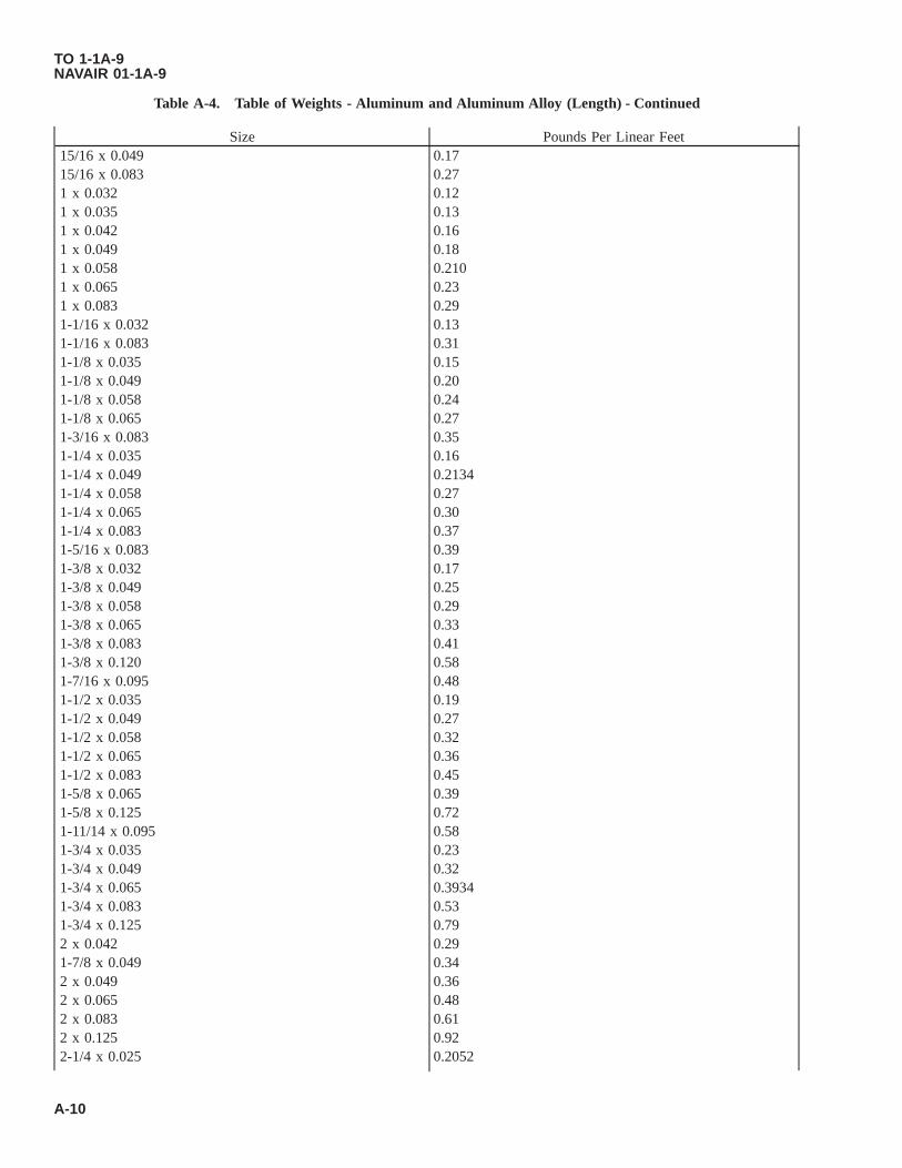
Table A-4. Table of Weights - Aluminum and Aluminum Alloy (Length) - Continued
Size Pounds Per Linear Feet15/16 x 0.049 0.1715/16 x 0.083 0.271 x 0.032 0.121 x 0.035 0.131 x 0.042 0.161 x 0.049 0.181 x 0.058 0.2101 x 0.065 0.231 x 0.083 0.291-1/16 x 0.032 0.131-1/16 x 0.083 0.311-1/8 x 0.035 0.151-1/8 x 0.049 0.201-1/8 x 0.058 0.241-1/8 x 0.065 0.271-3/16 x 0.083 0.351-1/4 x 0.035 0.161-1/4 x 0.049 0.21341-1/4 x 0.058 0.271-1/4 x 0.065 0.301-1/4 x 0.083 0.371-5/16 x 0.083 0.391-3/8 x 0.032 0.171-3/8 x 0.049 0.251-3/8 x 0.058 0.291-3/8 x 0.065 0.331-3/8 x 0.083 0.411-3/8 x 0.120 0.581-7/16 x 0.095 0.481-1/2 x 0.035 0.191-1/2 x 0.049 0.271-1/2 x 0.058 0.321-1/2 x 0.065 0.361-1/2 x 0.083 0.451-5/8 x 0.065 0.391-5/8 x 0.125 0.721-11/14 x 0.095 0.581-3/4 x 0.035 0.231-3/4 x 0.049 0.321-3/4 x 0.065 0.39341-3/4 x 0.083 0.531-3/4 x 0.125 0.792 x 0.042 0.291-7/8 x 0.049 0.342 x 0.049 0.362 x 0.065 0.482 x 0.083 0.612 x 0.125 0.922-1/4 x 0.025 0.2052
TO 1-1A-9NAVAIR 01-1A-9
A-10

Table A-4. Table of Weights - Aluminum and Aluminum Alloy (Length) - Continued
Size Pounds Per Linear Feet2-1/2 x 0.065 0.61
Table A-5. Table of Weights - Aluminum and Aluminum Alloy (Area)
Thickness Pounds Per Square FeetSheets
0.0126 0.17970.016 0.22530.020 0.28170.0253 0.3570.032 0.45010.0359 0.50550.0403 0.56760.0508 0.71580.0641 0.90260.0808 1.13820.0907 1.27810.128 1.80990.156 2.2020.1875 2.64810.250 3.52150.375 5.28220.500 7.212
Table A-6. Table of Weights - Brass
Size Pounds per Linear FeetBars-Flat
1/8 x 1/2 0.2381/8 x 3/4 0.3581/8 x 1 0.4751/8 x 1-3/4 0.8151/8 x 2 0.9356/32 x 1 0.6253/16 x 3/4 0.5353/16 x 1 0.7153/16 x 1-1/4 0.8953/16 x 1-1/2 13/16 x 1-3/4 1.1753/16 x 2 1.3853/16 x 2-1/2 1.7853/16 x 3 2.0551/4 x 1 0.95751/4 x 1-1/8 1.0751/4 x 1-1/4 1.1851/4 x 1-3/4 1.5851/4 x 2 1.8851/4 x 2-1/2 2.375
TO 1-1A-9NAVAIR 01-1A-9
A-11

Table A-6. Table of Weights - Brass - Continued
Size Pounds per Linear Feet1/4 x 3 2.8151/4 x 6 5.655/16 x 3/4 0.9575/16 x 1 1.0755/16 x 1-1/4 1.4755/16 x 1-1/2 1.9755/16 x 1-3/4 2.0755/16 x 2 2.3755/16 x 2-1/2 3.0755/16 x 3 3.8755/16 x 4 5.1255/16 x 6 8.753/8 x 1 1.2853/8 x 1-1/4 1.5753/8 x 1-1/2 2.003/8 x 1-3/4 2.2753/8 x 2 2.6753/8 x 2-1/2 3.4753/8 x 3 4.1753/8 x 4 5.7253/8 x 6 8.3251/2 x 1 1.7951/2 x 1-1/2 2.6851/2 x 2 3.6751/2 x 2-1/2 4.6751/2 x 3 5.6751/2 x 4 7.7051/2 x 6 11.105/8 x 1 2.1565/8 x 2 4.2503/4 x 1 2.8753/4 x 2 5.7507/8 x 2-1/2 8.3251 x 1-1/4 4.5251 x 2 7.705
Bars-Hexagon3/16 0.11231/4 0.19975/16 0.31203/8 0.44937/16 0.61151/2 0.79879/16 1.0015/8 1.24811/16 1.5103/4 1.79712/16 2.1097/8 2.44615/16 2.808
TO 1-1A-9NAVAIR 01-1A-9
A-12

Table A-6. Table of Weights - Brass - Continued
Size Pounds per Linear Feet1 3.1951-1/8 4.0431-3/16 4.5051-1/4 4.9921-5/16 5.5031-3/8 6.0401-1/2 7.1881-9/16 7.8001-5/8 8.4361-11/14 9.0971-3/4 9.7841-13/16 10.501-7/8 11.231-15/16 11.992 12.782-1/2 19.973 26.41
Bars-Square3/16 0.12971/4 0.23069/16 0.36023/8 0.51887/16 0.70611/2 0.92225/8 1.4413/4 2.0751 3.6891-1/4 5.7641-1/2 8.3002 14.76
Rods-Round1/16 0.011323/32 0.036251/8 0.045276/32 0.09153/16 0.10197/32 0.14751/4 0.18119/32 0.23759/14 0.282911/32 0.34803/8 0.407428/64 0.418512/32 0.48667/16 0.55461/2 0.72439/16 0.91675/8 1.13211/14 1.369
TO 1-1A-9NAVAIR 01-1A-9
A-13

Table A-6. Table of Weights - Brass - Continued
Size Pounds per Linear Feet3/4 1.63013/16 1.9137/8 2.21818/14 2.5461 2.8971-1/8 3.6671-3/14 4.0861-1/4 4.5271-5/16 4.9911-3/8 5.4781-7/16 5.9871-1/2 6.5191-9/16 7.0731-5/8 7.6511-11/16 8.2501-3/4 8.8731-13/14 9.5181-7/8 10.191-15/16 10.882 11.592-1/4 14.672-1/2 18.112-3/4 21.912-7/8 23.953 26.083-1/2 36.754 46.935 74.256 108.25
Tubing-Round1/8 x 0.020 0.0241/8 x 0.032 0.0343/16 x 0.028 0.0521/4 x 0.032 0.0811/4 x 0.049 0.1145/16 x 0.032 0.1043/8 x 0.028 0.1123/8 x 0.032 0.1273/8 x 0.042 0.1623/8 x 0.065 0.2337/14 x 0.028 0.1331/2 x 0.032 0.1731/2 x 0.035 0.1881/2 x 0.065 0.3275/8 x 0.032 0.2205/8 x 0.049 0.3275/8 x 0.065 0.4213/4 x 0.025 0.2103/4 x 0.032 0.266
TO 1-1A-9NAVAIR 01-1A-9
A-14

Table A-6. Table of Weights - Brass - Continued
Size Pounds per Linear Feet3/4 x 0.049 0.3977/8 x 0.032 0.3127/8 x 0.049 0.4687/8 x 0.065 0.6091 x 0.032 0.3581 x 0.035 0.3911 x 0.049 0.5671 x 0.065 0.7031-1/8 x 0.032 0.4041-1/8 x 0.049 0.6101-1/8 x 0.058 0.7161-1/8 x 0.065 0.7971-1/8 x 0.095 1.1321-1/8 x 0.134 1.15371-1/4 x 0.020 0.2851-1/4 x 0.032 0.4511-1/4 x 0.049 0.6811-1/4 x 0.058 0.8001-1/4 x 0.065 0.8911-1/4 x 0.072 0.9811-3/8 x 0.035 0.5431-3/8 x 0.049 0.7521-3/8 x 0.065 0.9351-1/2 x 0.032 0.5441-1/2 x 0.049 0.8231-1/2 x 0.065 1.081-5/8 x 0.032 0.591-5/8 x 0.049 0.8931-5/8 x 0.065 1.1731-3/4 x 0.032 0.6361-3/4 x 0.049 0.9641-3/4 x 0.065 1.2671-7/8 x 0.049 1.0352 x 0.032 0.7292 x 0.035 0.7962 x 0.065 1.4552-1/4 x 0.049 1.2482-1/4 x 0.065 1.6432-3/8 x 0.035 0.92752-1/2 x 0.035 0.9982-1/2 x 0.065 1.8312-7/8 x 0.1875 5.8753 x 0.032 1.200
Wire0.0010 0.0000028840.0031 0.000028520.0035 0.000035960.004 0.000045350.0045 0.00005718
TO 1-1A-9NAVAIR 01-1A-9
A-15

Table A-6. Table of Weights - Brass - Continued
Size Pounds per Linear Feet0.005 0.000072100.0056 0.000090920.0063 0.00011460.0071 0.00014460.008 0.00018230.0089 0.00022990.010 0.00028980.0113 0.00036550.0126 0.00046090.0142 0.00058120.0159 0.00073280.0179 0.00092410.0201 0.0011650.0226 0.0014690.0254 0.0018530.0285 0.0023360.032 0.0029460.0359 0.0037150.0403 0.0046840.0453 0.0059070.0508 0.0074490.0571 0.0093930.0641 0.011840.072 0.014930.0800 0.018830.0907 0.023750.1019 0.029940.1144 0.037760.1285 0.047610.1443 0.060040.162 0.075710.1819 0.095470.2043 0.12040.2294 0.15180.2576 0.19140.2893 0.24140.3249 0.30440.3648 0.38380.4096 0.48390.460 0.6102
Table A-7. Table of Weights - Brass (Area)
Thickness Pounds per Square FeetSheet
0.0031 0.13930.0035 0.15640.004 0.1756
TO 1-1A-9NAVAIR 01-1A-9
A-16

Table A-7. Table of Weights - Brass (Area) - Continued
Thickness Pounds per Square Feet0.0045 0.19720.005 0.22140.0056 0.24860.0063 0.27920.0071 0.31350.008 0.35210.0089 0.39530.010 0.44390.0113 0.49850.0126 0.55980.0142 0.62860.0159 0.70590.0179 0.79270.0201 0.89010.0226 0.99950.0253 1.1220.0285 1.2600.032 1.4150.0359 1.5890.0403 1.7850.0453 2.0040.0508 5.0600.0571 5.0610.0641 5.0620.072 5.0630.0808 5.0640.0907 5.0650.1019 5.0660.1144 5.0670.1285 5.6900.1443 6.3890.162 7.1750.1819 8.0570.2043 9.0470.2294 10.160.2576 11.410.2893 12.810.3249 14.390.3648 16.150.4096 18.140.460 20.37
Table A-8. Table of Weights - Brass Shim Stock
Thickness Number Of Ounces per Square Feet0.002 1.400.004 2.750.006 4.50
TO 1-1A-9NAVAIR 01-1A-9
A-17
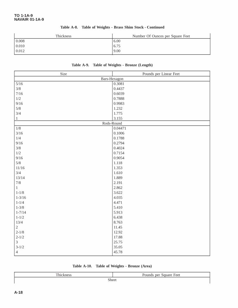
Table A-8. Table of Weights - Brass Shim Stock - Continued
Thickness Number Of Ounces per Square Feet0.008 6.000.010 6.750.012 9.00
Table A-9. Table of Weights - Bronze (Length)
Size Pounds per Linear FeetBars-Hexagon
5/16 0.30813/8 0.44377/16 0.60391/2 0.78889/16 0.99835/8 1.2323/4 1.7751 3.155
Rods-Round1/8 0.044713/16 0.10061/4 0.17889/16 0.27943/8 0.40241/2 0.71549/16 0.90545/8 1.11811/16 1.3533/4 1.61013/14 1.8897/8 2.1911 2.8621-1/8 3.6221-3/16 4.0351-1/4 4.4711-3/8 5.4101-7/14 5.9131-1/2 6.43813/4 8.7632 11.452-1/8 12.922-1/2 17.883 25.753-1/2 35.054 45.78
Table A-10. Table of Weights - Bronze (Area)
Thickness Pounds per Square FeetSheet
TO 1-1A-9NAVAIR 01-1A-9
A-18

Table A-10. Table of Weights - Bronze (Area) - Continued
Thickness Pounds per Square Feet0.010 0.44060.012 0.55520.0159 0.70060.0201 0.88570.0253 1.1150.032 1.4100.0359 1.5820.0403 1.7760.050 2.2380.0641 2.8250.0808 3.5670.0907 3.9970.1285 5.662
Table A-11. Table of Weights - Copper
Size Pounds per Linear FeetBars-Flat
1/16 x 3/4 0.18091/8 x 1 0.48231/8x2 0.96461/4 x 1 0.96461/4 x 2 1.9291/4x3 3.8941/4x4 3.8583/8x1 1.4473/8x2 2.8941/2 x 3/4 1.4251/2 x 1 1.9295/8 x 1-1/2 3.675
Rods-Round1/4 0.18949/16 0.29593/8 0.42617/16 0.5801/2 0.75765/8 1.1843/4 1.7057/8 2.3201 3.0301-1/8 3.8351-1/4 4.7351-1/2 6.8181-3/4 9.2812 12.122-1/2 18.943 27.27
Tubing-Round
TO 1-1A-9NAVAIR 01-1A-9
A-19
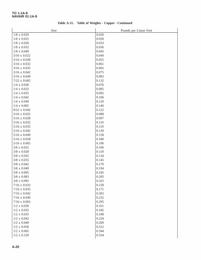
Table A-11. Table of Weights - Copper - Continued
Size Pounds per Linear Feet1/8 x 0.020 0.0261/8 x 0.025 0.0301/8 x 0.028 0.0331/8 x 0.032 0.0361/8 x 0.049 0.0453/16 x 0.022 0.0443/16 x 0.028 0.0553/16 x 0.032 0.0613/16 x 0.035 0.0653/16 x 0.042 0.0753/16 x 0.049 0.0837/22 x 0.065 0.1321/4 x 0.028 0.0761/4 x 0.032 0.0851/4 x 0.035 0.0921/4 x 0.042 0.1061/4 x 0.049 0.1201/4 x 0.065 0.1469/22 x 0.042 0.1223/16 x 0.025 0.0885/16 x 0.028 0.0975/16 x 0.032 0.1105/16 x 0.035 0.1195/16 x 0.042 0.1395/16 x 0.049 0.1585/16 x 0.058 0.1805/16 x 0.065 0.1963/8 x 0.025 0.1063/8 x 0.028 0.1183/8 x 0.032 0.1343/8 x 0.035 0.1453/8 x 0.042 0.1703/8 x 0.049 0.1943/8 x 0.065 0.2453/8 x 0.083 0.2953/8 x 0.095 0.3257/16 x 0.032 0.1587/16 x 0.035 0.1717/16 x 0.042 0.2027/16 x 0.049 0.2327/16 x 0.065 0.2951/2 x 0.028 0.1611/2 x 0.032 0.1821/2 x 0.035 0.1981/2 x 0.042 0.2341/2 x 0.049 0.2691/2 x 0.058 0.3121/2 x 0.065 0.3441/2 x 0.120 0.554
TO 1-1A-9NAVAIR 01-1A-9
A-20

Table A-11. Table of Weights - Copper - Continued
Size Pounds per Linear Feet1/2 x 0.134 0.5969/16 x 0.032 0.2079/16 x 0.035 0.2259/16 x 0.042 0.2669/16 x 0.049 0.3069/16 x 0.120 0.6459/16 x 0.134 0.7045/8 x 0.032 0.2315/8 x 0.035 0.2515/8 x 0.042 0.2985/8 x 0.049 0.3435/8 x 0.065 0.4435/8 x 0.083 0.5475/8 x 0.120 0.73711/14 x 0.120 0.8123/4 x 0.025 0.2203/4 x 0.028 0.2463/4 x 0.032 0.2803/4 x 0.035 0.3043/4 x 0.042 0.3623/4 x 0.049 0.4183/4 x 0.058 0.4883/4 x 0.065 0.5423/4 x 0.083 0.6733/4 x 0.120 0.9203/4 x 0.134 1.0013/16 x 0.042 0.39613/16 x 0.049 0.4527/8 x 0.028 0.2897/8 x 0.032 0.3287/8 x 0.035 0.3587/8 x 0.049 0.4927/8 x 0.058 0.5767/8 x 0.095 0.9017/8 x 0.109 1.027/8 x 0.120 1.101 x 0.025 0.2971 x 0.028 0.3311 x 0.032 0.3771 x 0.035 0.4111 x 0.042 0.4891 x 0.049 0.5671 x 0.065 0.7391 x 0.120 1.291-1/16 x 0.032 0.4031-1/16 x 0.035 0.4381-1/8 x 0.032 0.4251-1/8 x 0.042 0.5531-1/8 x 0.049 0.641
TO 1-1A-9NAVAIR 01-1A-9
A-21

Table A-11. Table of Weights - Copper - Continued
Size Pounds per Linear Feet1-1/8 x 0.065 0.8381-1/8 x 0.148 1.7591-3/16 x 0.032 0.4531-1/4 x 0.032 0.4741-1/4 x 0.035 0.5171-1/4 x 0.049 0.7161-1/4 x 0.065 0.9371-1/4 x 0.072 1.031-1/4 x 0.148 1.981-5/16 x 0.032 0.4981-5/16 x 0.042 0.6481-5/16 x 0.049 0.7581-3/8 x 0.028 0.4591-3/8 x 0.032 0.5231-3/8 x 0.035 0.5701-3/8 x 0.042 0.6811-3/8 x 0.049 0.7901-3/8 x 0.065 1.0361-3/8 x 0.148 2.2091-7/16 x 0.035 0.5971-1/2 x 0.032 0.5711-1/2 x 0.042 0.7451-1/2 x 0.049 0.8651-1/2 x 0.058 1.0171-1/2 x 0.065 1.1351-1/2 x 0.148 2.4341-5/8 x 0.032 0.6201-5/8 x 0.042 0.8091-5/8 x 0.049 0.9391-5/8 x 0.058 1.1061-5/8 x 0.065 1.2381-5/8 x 0.148 2.6591-3/4 x 0.032 0.6691-3/4 x 0.042 0.8731-3/4 x 0.049 1.0141-3/4 x 0.065 1.3321-3/4 x 0.148 2.8841-7/8 x 0.032 0.7171-7/8 x 0.042 0.9371-7/8 x 0.049 1.0881-7/8 x 0.065 1.4311-7/8 x 0.148 3.1092 x 0.032 0.7662 x 0.035 0.8372 x 0.042 1.002 x 0.049 1.1632 x 0.065 1.5302 x 0.083 1.9362 x 0.095 2.202
TO 1-1A-9NAVAIR 01-1A-9
A-22

Table A-11. Table of Weights - Copper - Continued
Size Pounds per Linear Feet2-1/4 x 0.049 1.312-1/4 x 0.065 1.732-1/2 x 0.065 1.932-3/4 x 0.095 3.073 x 0.120 4.20
Table A-12. Table Of Weights - Copper (Area)
Thickness Pounds per Square FeetSheet
0.002 0.1250.003 0.14340.005 0.23120.006 0.29140.010 0.46250.0126 0.58270.0142 0.65670.0159 0.73530.0201 0.92960.0226 1.04520.0253 1.1700.032 1.47990.0359 1.66020.0403 1.86370.0453 2.0950.0508 2.34930.0571 2.64070.0641 2.96440.0808 3.73670.0907 4.19460.1285 5.9427
Table A-13. Table of Weights - Copper Wire
Size Number of Feet per PoundWire
0.020 826.90.0253 516.70.032 323.00.0359 256.60.0403 203.70.0508 128.20.0625 84.670.064 80.750.072 63.800.0808 50.660.0907 40.210.1019 31.85
TO 1-1A-9NAVAIR 01-1A-9
A-23
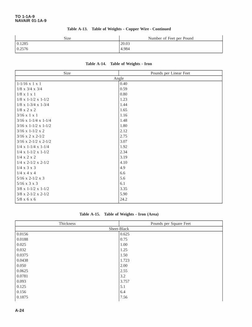
Table A-13. Table of Weights - Copper Wire - Continued
Size Number of Feet per Pound0.1285 20.030.2576 4.984
Table A-14. Table of Weights - Iron
Size Pounds per Linear FeetAngle
1-1/16 x 1 x 1 0.401/8 x 3/4 x 3/4 0.591/8 x 1 x 1 0.801/8 x 1-1/2 x 1-1/2 1.231/8 x 1-3/4 x 1-3/4 1.441/8 x 2 x 2 1.653/16 x 1 x 1 1.163/16 x 1-1/4 x 1-1/4 1.483/16 x 1-1/2 x 1-1/2 1.803/16 x 1-1/2 x 2 2.123/16 x 2 x 2-1/2 2.753/16 x 2-1/2 x 2-1/2 3.071/4 x 1-1/4 x 1-1/4 1.921/4 x 1-1/2 x 1-1/2 2.341/4 x 2 x 2 3.191/4 x 2-1/2 x 2-1/2 4.101/4 x 3 x 3 4.91/4 x 4 x 4 6.65/16 x 2-1/2 x 3 5.65/16 x 3 x 3 6.13/8 x 1-1/2 x 1-1/2 3.353/8 x 2-1/2 x 2-1/2 5.905/8 x 6 x 6 24.2
Table A-15. Table of Weights - Iron (Area)
Thickness Pounds per Square FeetSheet-Black
0.0156 0.6250.0188 0.750.025 1.000.032 1.250.0375 1.500.0438 1.7230.050 2.000.0625 2.550.0781 3.20.093 3.7570.125 5.10.156 6.40.1875 7.56
TO 1-1A-9NAVAIR 01-1A-9
A-24

Table A-15. Table of Weights - Iron (Area) - Continued
Thickness Pounds per Square Feet0.250 10.20.375 15.1780.500 20.4
Sheet-Galvanized0.0156 0.7810.0188 0.9060.025 1.1560.032 1.4060.0375 1.6560.0438 1.90640.050 2.1560.0625 2.620.0938 3.96030.125 5.1563
Sheet-Terne Plate0.0156 0.63770.0186 0.76850.025 1.0220.0313 1.27950.037 1.53290.050 2.044
Table A-16. Table of Weights - Lead
Thickness Pounds per Square Feet1/32 2.101/16 4.253/52 6.0311/8 7.8123/16 11.720
Table A-17. Table of Weights - Magnesium and Magnesium Alloy
Size Pounds per Linear FeetBars-Flat
1/2 x 1 0.3721/2 x 2 0.7563/4 x 2 1.1353/4 x 3 1.7001 x 2 1.5131 x 3 2.2701-1/2 x 2 2.2901-3/4 x 3-1/2 4.6302 x 3 4.5352-3/4 x 4 8.3203 x 4 9.240
Bars-Hexagon3/8 0.095
TO 1-1A-9NAVAIR 01-1A-9
A-25
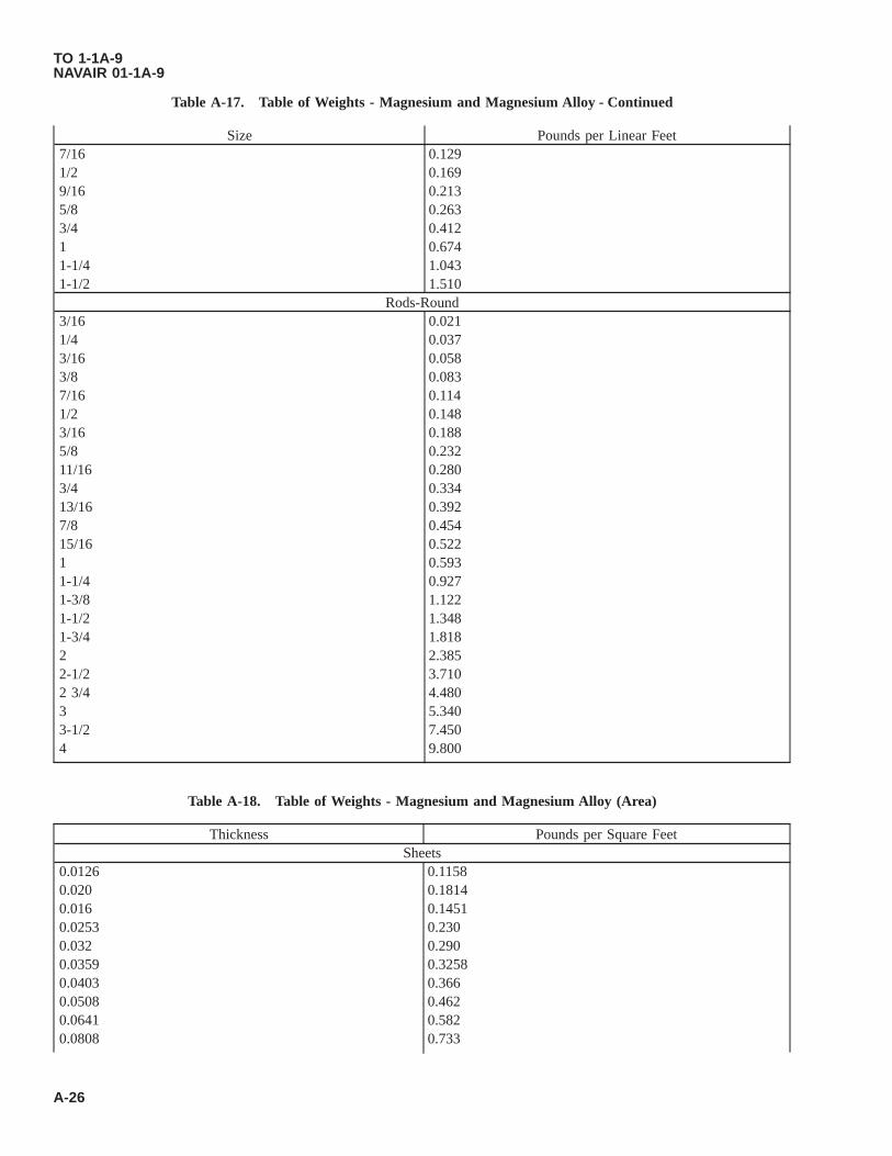
Table A-17. Table of Weights - Magnesium and Magnesium Alloy - Continued
Size Pounds per Linear Feet7/16 0.1291/2 0.1699/16 0.2135/8 0.2633/4 0.4121 0.6741-1/4 1.0431-1/2 1.510
Rods-Round3/16 0.0211/4 0.0373/16 0.0583/8 0.0837/16 0.1141/2 0.1483/16 0.1885/8 0.23211/16 0.2803/4 0.33413/16 0.3927/8 0.45415/16 0.5221 0.5931-1/4 0.9271-3/8 1.1221-1/2 1.3481-3/4 1.8182 2.3852-1/2 3.7102 3/4 4.4803 5.3403-1/2 7.4504 9.800
Table A-18. Table of Weights - Magnesium and Magnesium Alloy (Area)
Thickness Pounds per Square FeetSheets
0.0126 0.11580.020 0.18140.016 0.14510.0253 0.2300.032 0.2900.0359 0.32580.0403 0.3660.0508 0.4620.0641 0.5820.0808 0.733
TO 1-1A-9NAVAIR 01-1A-9
A-26

Table A-18. Table of Weights - Magnesium and Magnesium Alloy (Area) - Continued
Thickness Pounds per Square Feet0.128 1.1670.0907 1.8230.156 1.4180.1875 1.7080.250 2.2700.375 3.4050.500 4.650
Table A-19. Table of Weights - Nickel Chromium Iron Alloy (Inconel)
Size Pounds per Linear FeetRods-Round
1/4 0.1823/16 0.2853/8 0.4091/2 0.7283/4 1.6381 2.9121-1/4 4.551-1/2 6.5532 11.6512-1/2 18.203
Tubing1/4 x 0.028 0.0711/4 x 0.035 0.0881/4 x 0.049 0.1131/4 x 0.065 0.1395/16 x 0.028 0.0915/16 x 0.035 0.1135/16 x 0.049 0.1505/16 x 0.065 0.1883/8 x 0.028 0.1133/8 x 0.035 0.1393/8 x 0.049 0.1883/8 x 0.058 0.2173/8 x 0.065 0.2361/2 x 0.035 0.1911/2 x 0.049 0.2571/2 x 0.058 0.2991/2 x 0.065 0.3295/8 x 0.049 0.3295/8 x 0.065 0.4243/4 x 0.035 0.2923/4 x 0.049 0.4003/4 x 0.058 0.4683/4 x 0.065 0.5197/8 x 0.035 0.3437/8 x 0.049 0.472
TO 1-1A-9NAVAIR 01-1A-9
A-27

Table A-19. Table of Weights - Nickel Chromium Iron Alloy (Inconel) - Continued
Size Pounds per Linear Feet7/8 x 0.058 0.5527/8 x 0.065 0.6131 x 0.035 0.3931 x 0.049 0.5431 x 0.058 0.6361 x 0.065 0.7081-1/4 x 0.049 0.6861-1/4 x 0.065 0.8971-3/8 x 0.049 0.7571-3/8 x 0.065 0.9881-1/2 x 0.035 0.5971-1/2 x 0.049 0.8281-1/2 x 0.065 1.091-3/4 x 0.049 0.9691-3/4 x 0.065 1.282 x 0.049 1.112 x 0.065 1.462-1/4 x 0.049 1.262-1/4 x 0.065 1.652-1/2 x 0.049 1.402-1/2 x 0.065 1.843-1/4 x 0.120 4.38
Table A-20. Table of Weights - Nickel Chromium Iron Alloy (Inconel) (Area)
Thickness Pounds per Square FeetSheets
0.018 0.840.025 1.110.032 1.390.037 1.650.043 1.910.050 2.220.0625 2.760.093 4.140.125 5.560.156 6.940.1875 8.320.250 11.12
Table A-21. Table of Weights - Nickel Copper Alloy
Size Pounds per Linear FeetRods-Round
1/4 0.1903/16 0.3093/8 0.4281/2 0.761
TO 1-1A-9NAVAIR 01-1A-9
A-28

Table A-21. Table of Weights - Nickel Copper Alloy - Continued
Size Pounds per Linear Feet3/4 1.1721 3.0441-1/4 4.7561-1/2 6.8492 12.1782-1/2 19.027
Table A-22. Table of Weights - Nickel Copper Alloy (Area)
Thickness Pounds per Square FeetSheets
0.018 0.860.025 1.150.032 1.440.037 1.720.125 5.75
Table A-23. Table of Weights - Steel
Size Pounds per Linear FeetBars-Flat
1/14 x 1/2 0.1061/14 x 3/4 0.15941/14 x 1 0.2121/14 x 1-1/2 0.3191/14 x 2 0.4251/14 x 2-1/2 0.5311/14 x 3 0.6381/8 x 1/2 0.21251/8 x 3/4 0.31881/8 x 1 0.4251/8 x 1-1/2 0.6381/8 x 2 0.8501/8 x 2-1/2 1.061/8 x 3 1.273/16 x 1/2 0.3193/16 x 3/4 0.4783/16 x 1 0.6383/16 x 1-1/4 0.7973/16 x 1-1/2 0.9563/16 x 2 1.283/16 x 2-1/2 1.593/16 x 3 1.911/4 x 1/2 0.4251/4 x 3/4 0.6361/4 x 1 0.8501/4 x 1-1/4 1.061/4 x 1-1/2 1.28
TO 1-1A-9NAVAIR 01-1A-9
A-29

Table A-23. Table of Weights - Steel - Continued
Size Pounds per Linear Feet1/4 x 1-3/4 1.491/4 x 2 1.701/4 x 2 1/2 2.131/4 x 3 2.553/16 x 1/2 0.5313/16 x 3/4 0.7975/16 x 1 1.065/16 x 1-1/4 1.335/16 x 1-1/2 1.595/16 x 1-3/4 1.865/16 x 2 2.135/16 x 2-1/4 2.395/16 x 2-1/2 2.665/16 x 2-3/4 2.925/16 x 3 3.193/8 x 1/2 0.6383/8 x 1 1.283/8 x 1-1/4 1.593/8 x 1-1/2 1.913/8 x 2 2.553/8 x 2-1/2 3.193/8 x 3 3.833/8 x 3-1/2 4.463/8 x 4 5.103/8 x 6 7.651/2 x 1 1.701/2 x 1-1/4 2.131/2 x 1-1/2 2.551/2 x 2 3.401/2 x 2-1/2 4.251/2 x 3 5.101/2 x 3-1/2 5.951/2 x 4 6.801/2 x 4-1/2 7.651/2 x 5 8.501/2 x 6 10.205/8 x 2 4.255/8 x 2-1/2 5.315/8 x 3 6.385/8 x 3-1/2 7.445/8 x 4 8.505/8 x 6 12.753/4 x 1 2.553/4 x 1-1/2 3.853/4 x 2 5.103/4 x 2-1/2 6.383/4 x 3 7.653/4 x 4 10.203/4 x 5 12.75
TO 1-1A-9NAVAIR 01-1A-9
A-30

Table A-23. Table of Weights - Steel - Continued
Size Pounds per Linear Feet3/4 x 6 15.301 x 2 6.801 x 2-1/2 8.501 x 3 10.201 x 4 13.601 x 5 17.001 x 6 20.401-1/4 x 2 8.501-1/4 x 3 12.751-1/4 x 4 17.001-1/2 x 2 10.201-1/2 x 3 15.301-1/2 x 5 25.502 x 2-1/2 17.002 x 3 20.402 x 4 27.202-1/2 x 3 25.503 x 4 40.80
Bars-Hexagon1/4 0.1955/16 0.293/8 0.437/16 0.561/2 0.739/16 0.935/8 1.1511/16 1.403/4 1.6613/16 1.917/8 2.2513/16 2.581 2.941-1/16 3.331-1/8 3.731-1/4 4.601-5/16 5.071-3/8 5.571-1/2 6.621-3/4 9.002 11.78
Bars-Square1/8 0.0533/16 0.1201/4 0.2125/16 0.3323/8 0.4787/16 0.6511/2 0.8509/16 1.076
TO 1-1A-9NAVAIR 01-1A-9
A-31

Table A-23. Table of Weights - Steel - Continued
Size Pounds per Linear Feet5/8 1.3283/4 1.9137/8 2.6031 3.401-1/8 4.3031-1/4 5.3131-5/16 5.8571-3/8 6.4281-1/2 7.6501-3/4 10.412 13.602-1/4 17.212-1/2 21.253 30.60
Rods-Rounds1/16 0.0103/32 0.0231/8 0.0425/32 0.0653/16 0.0947/32 0.1281/4 0.1679/32 0.2115/16 0.26111/22 0.3163/8 0.3767/16 0.5111/2 0.6689/16 0.8455/8 1.04311/16 1.2623/4 1.50213/16 1.7637/8 2.04415/16 2.3471 2.6701-1/16 3.0151-1/8 3.3801-3/16 3.7661-1/4 4.1721-3/8 5.0491-7/16 5.5181-1/2 6.0081-5/8 7.0511-3/4 8.1781-7/8 9.3882 10.682-1/4 13.522-5/16 14.28
TO 1-1A-9NAVAIR 01-1A-9
A-32
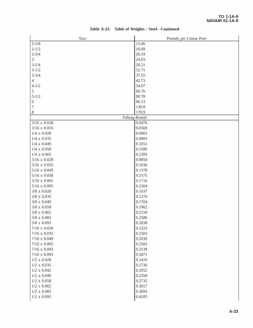
Table A-23. Table of Weights - Steel - Continued
Size Pounds per Linear Feet2-3/8 15.062-1/2 16.692-3/4 20.193 24.033-1/4 28.213-1/2 32.713-3/4 37.554 42.734-1/2 54.075 66.765-1/2 80.786 96.137 130.88 170.9
Tubing-Round3/16 x 0.028 0.04763/16 x 0.035 0.05691/4 x 0.028 0.06631/4 x 0.035 0.08031/4 x 0.049 0.10511/4 x 0.058 0.11881/4 x 0.065 0.12835/16 x 0.028 0.08505/16 x 0.035 0.10365/16 x 0.049 0.13785/16 x 0.058 0.15755/16 x 0.065 0.17165/16 x 0.095 0.22043/8 x 0.028 0.10373/8 x 0.035 0.12703/8 x 0.049 0.17043/8 x 0.058 0.19623/8 x 0.065 0.21503/8 x 0.083 0.25863/8 x 0.095 0.28387/16 x 0.028 0.12237/16 x 0.035 0.15037/16 x 0.049 0.20307/16 x 0.065 0.25837/16 x 0.083 0.31397/16 x 0.095 0.34711/2 x 0.028 0.14101/2 x 0.035 0.17361/2 x 0.042 0.20521/2 x 0.049 0.23581/2 x 0.058 0.27351/2 x 0.065 0.30171/2 x 0.083 0.36931/2 x 0.095 0.4105
TO 1-1A-9NAVAIR 01-1A-9
A-33

Table A-23. Table of Weights - Steel - Continued
Size Pounds per Linear Feet9/16 x 0.035 0.19699/16 x 0.049 0.26849/16 x 0.065 0.34509/16 x 0.095 0.47385/8 x 0.028 0.17835/8 x 0.035 0.22035/8 x 0.049 0.30115/8 x 0.058 0.35095/8 x 0.065 0.38835/8 x 0.083 0.4805/8 x 0.095 0.53725/8 x 0.120 0.646511/14 x 0.035 0.243711/14 x 0.049 0.333811/14 x 0.065 0.431711/14 x 0.095 0.60053/4 x 0.028 0.21573/4 x 0.035 0.26703/4 x 0.049 0.36653/4 x 0.058 0.42823/4 x 0.065 0.47503/4 x 0.083 0.59063/4 x 0.095 0.66393/4 x 0.120 0.806613/14 x 0.035 0.290313/16 x 0.049 0.399113/16 x 0.058 0.466913/16 x 0.065 0.51847/8 x 0.028 0.25307/8 x 0.035 0.31377/8 x 0.049 0.43187/8 x 0.058 0.50567/8 x 0.065 0.56177/8 x 0.095 0.79067/8 x 0.120 0.966615/16 x 0.035 0.337015/16 x 0.049 0.464515/16 x 0.065 0.605115/16 x 0.083 0.75671 x 0.028 0.29041 x 0.035 0.36031 x 0.049 0.49721 x 0.058 0.58291 x 0.065 0.64841 x 0.083 0.81201 x 0.095 0.91731 x 0.120 1.1271-1/16 x 0.035 0.38371-1/16 x 0.049 0.5298
TO 1-1A-9NAVAIR 01-1A-9
A-34

Table A-23. Table of Weights - Steel - Continued
Size Pounds per Linear Feet1-1/16 x 0.065 0.69171-1/8 x 0.035 0.40701-1/8 x 0.049 0.56251-1/8 x 0.058 0.66031-1/8 x 0.065 0.73511-1/8 x 0.083 0.92271-1/8 x 0.095 1.0441-1/8 x 0.120 1.2871-3/16 x 0.035 0.43041-3/16 x 0.049 0.59521-3/16 x 0.065 0.77841-3/16 x 0.095 1.1071-3/16 x 0.120 1.3671-1/4 x 0.028 0.36501-1/4 x 0.035 0.45371-1/4 x 0.049 0.62791-1/4 x 0.058 0.73761-1/4 x 0.065 0.82181-1/4 x 0.083 1.0341-1/4 x 0.095 1.1711-1/4 x 0.120 1.4471-1/4 x 0.125 1.5001-1/4 x 0.134 1.5951-5/16 x 0.035 0.47701-5/16 x 0.049 0.66051-5/16 x 0.065 0.86511-5/16 x 0.095 1.2341-5/16 x 0.120 1.5271-3/8 x 0.035 0.50041-3/8 x 0.049 0.69321-3/8 x 0.058 0.81501-3/8 x 0.065 0.90851-3/8 x 0.083 1.1441-3/8 x 0.120 1.6071-7/16 x 0.049 0.72591-7/16 x 0.065 0.95181-7/16 x 0.095 1.3611-1/2 x 0.035 0.5471-1/2 x 0.040 0.75851-1/2 x 0.058 0.89231-1/2 x 0.065 0.99511-1/2 x 0.083 1.2551-1/2 x 0.095 1.4241-1/2 x 0.120 1.7671-1/2 x 0.1875 2.6261-9/16 x 0.049 0.79121-9/16 x 0.065 1.0381-9/16 x 0.095 1.4871-5/8 x 0.049 0.8239
TO 1-1A-9NAVAIR 01-1A-9
A-35

Table A-23. Table of Weights - Steel - Continued
Size Pounds per Linear Feet1-5/8 x 0.058 0.96971-5/8 x 0.065 1.0821-5/8 x 0.083 1.3651-5/8 x 0.095 1.5511-5/8 x 0.120 1.9271-11/16 x 0.049 0.85661-11/16 x 0.065 1.1251-11/16 x 0.095 1.6141-3/4 x 0.035 0.64041-3/4 x 0.049 0.88921-3/4 x 0.058 1.0471-3/4 x 0.065 1.1691-3/4 x 0.083 1.4761-3/4 x 0.095 1.6771-3/4 x 0.120 2.0871-3/4 x 0.125 2.1671-3/4 x 0.1875 3.1261-13/16 x 0.049 0.92191-13/16 x 0.065 1.2121-13/16 x 0.095 1.7411-7/8 x 0.049 0.95461-7/8 x 0.058 1.1241-7/8 x 0.065 1.2551-7/8 x 0.095 1.8041-7/8 x 0.120 2.2471-15/16 x 0.049 0.98731-15/16 x 0.065 1.2991-15/16 x 0.095 1.8672 x 0.035 0.73382 x 0.049 1.0202 x 0.058 1.2022 x 0.065 1.3402 x 0.083 1.6982 x 0.095 1.9312 x 0.120 2.4072 x 0.125 2.5012 x 0.1875 3.6262-1/8 x 0.035 0.78042-1/8 x 0.049 1.0852-1/8 x 0.058 1.2792-1/8 x 0.065 1.4292-1/8 x 0.095 2.0572-1/8 x 0.120 2.5672-1/4 x 0.035 0.82712-1/4 x 0.049 1.1512-1/4 x 0.058 1.3562-1/4 x 0.065 1.5152-1/4 x 0.083 1.9192-1/4 x 0.095 2.184
TO 1-1A-9NAVAIR 01-1A-9
A-36
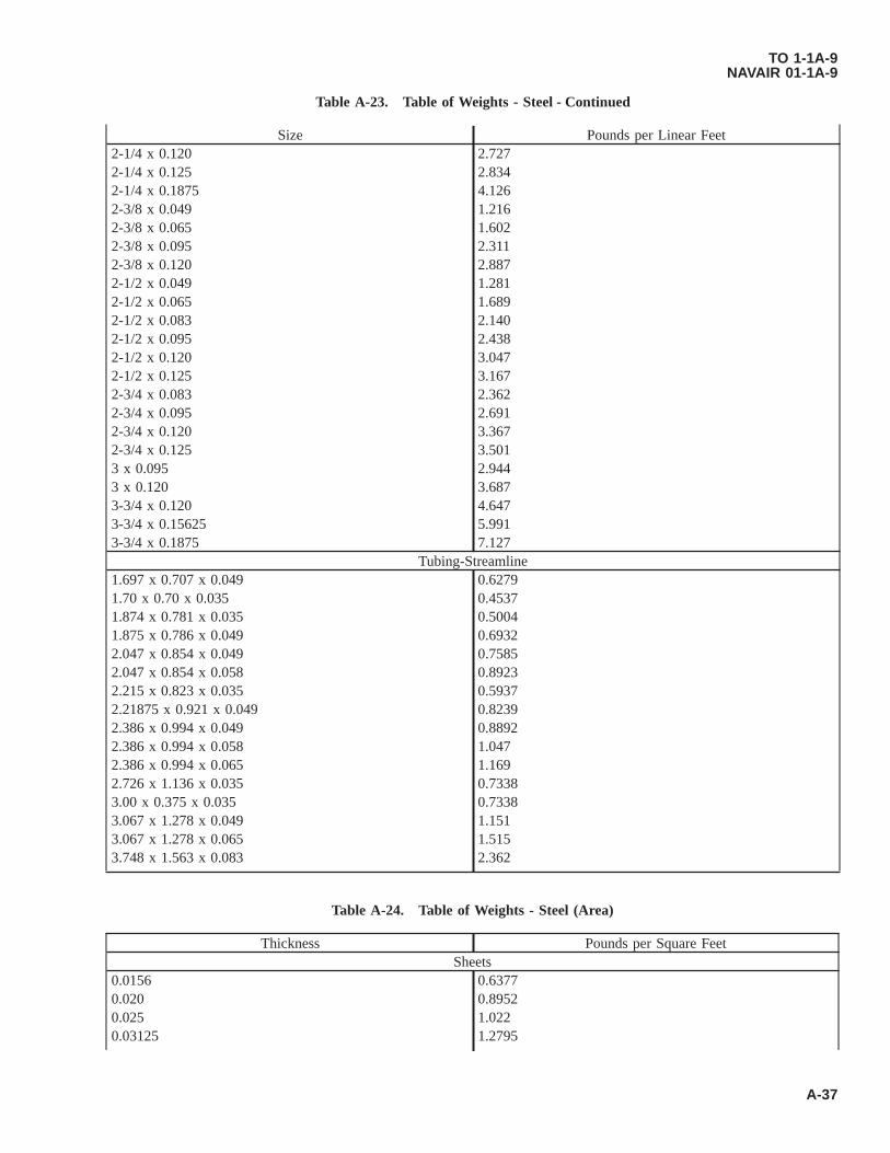
Table A-23. Table of Weights - Steel - Continued
Size Pounds per Linear Feet2-1/4 x 0.120 2.7272-1/4 x 0.125 2.8342-1/4 x 0.1875 4.1262-3/8 x 0.049 1.2162-3/8 x 0.065 1.6022-3/8 x 0.095 2.3112-3/8 x 0.120 2.8872-1/2 x 0.049 1.2812-1/2 x 0.065 1.6892-1/2 x 0.083 2.1402-1/2 x 0.095 2.4382-1/2 x 0.120 3.0472-1/2 x 0.125 3.1672-3/4 x 0.083 2.3622-3/4 x 0.095 2.6912-3/4 x 0.120 3.3672-3/4 x 0.125 3.5013 x 0.095 2.9443 x 0.120 3.6873-3/4 x 0.120 4.6473-3/4 x 0.15625 5.9913-3/4 x 0.1875 7.127
Tubing-Streamline1.697 x 0.707 x 0.049 0.62791.70 x 0.70 x 0.035 0.45371.874 x 0.781 x 0.035 0.50041.875 x 0.786 x 0.049 0.69322.047 x 0.854 x 0.049 0.75852.047 x 0.854 x 0.058 0.89232.215 x 0.823 x 0.035 0.59372.21875 x 0.921 x 0.049 0.82392.386 x 0.994 x 0.049 0.88922.386 x 0.994 x 0.058 1.0472.386 x 0.994 x 0.065 1.1692.726 x 1.136 x 0.035 0.73383.00 x 0.375 x 0.035 0.73383.067 x 1.278 x 0.049 1.1513.067 x 1.278 x 0.065 1.5153.748 x 1.563 x 0.083 2.362
Table A-24. Table of Weights - Steel (Area)
Thickness Pounds per Square FeetSheets
0.0156 0.63770.020 0.89520.025 1.0220.03125 1.2795
TO 1-1A-9NAVAIR 01-1A-9
A-37

Table A-24. Table of Weights - Steel (Area) - Continued
Thickness Pounds per Square Feet0.0375 1.53290.050 2.0440.0625 2.55490.0781 3.19280.093 3.83440.109 4.45570.125 5.10960.156 6.3770.1875 7.68510.250 10.219
Table A-25. Table of Weights - Steel (Length)
Thickness Number of Feet Per PoundWire
0.006 10415.00.008 5858.00.009 4629.00.010 3749.00.011 2936.00.012 2604.00.013 2218.00.014 1913.00.016 1465.00.018 1157.00.020 937.30.024 650.90.025 599.90.028 478.20.031 383.90.032 366.10.035 306.10.036 289.30.040 234.30.041 223.00.045 182.70.047 166.20.049 156.20.0508 145.30.054 128.60.058 111.50.0625 95.980.0641 91.250.071 72.320.080 58.580.0907 45.580.101 36.110.118 26.04
TO 1-1A-9NAVAIR 01-1A-9
A-38

Table A-25. Table of Weights - Steel (Length) - Continued
Thickness Number of Feet Per Pound0.1285 22.710.162 14.29
Table A-26. Table of Weights - Zinc
Thickness Pounds per Square FeetSheet
0.018 0.670.032 1.200.045 1.680.049 1.870.0508 1.870.109 3.98
TO 1-1A-9NAVAIR 01-1A-9
A-39
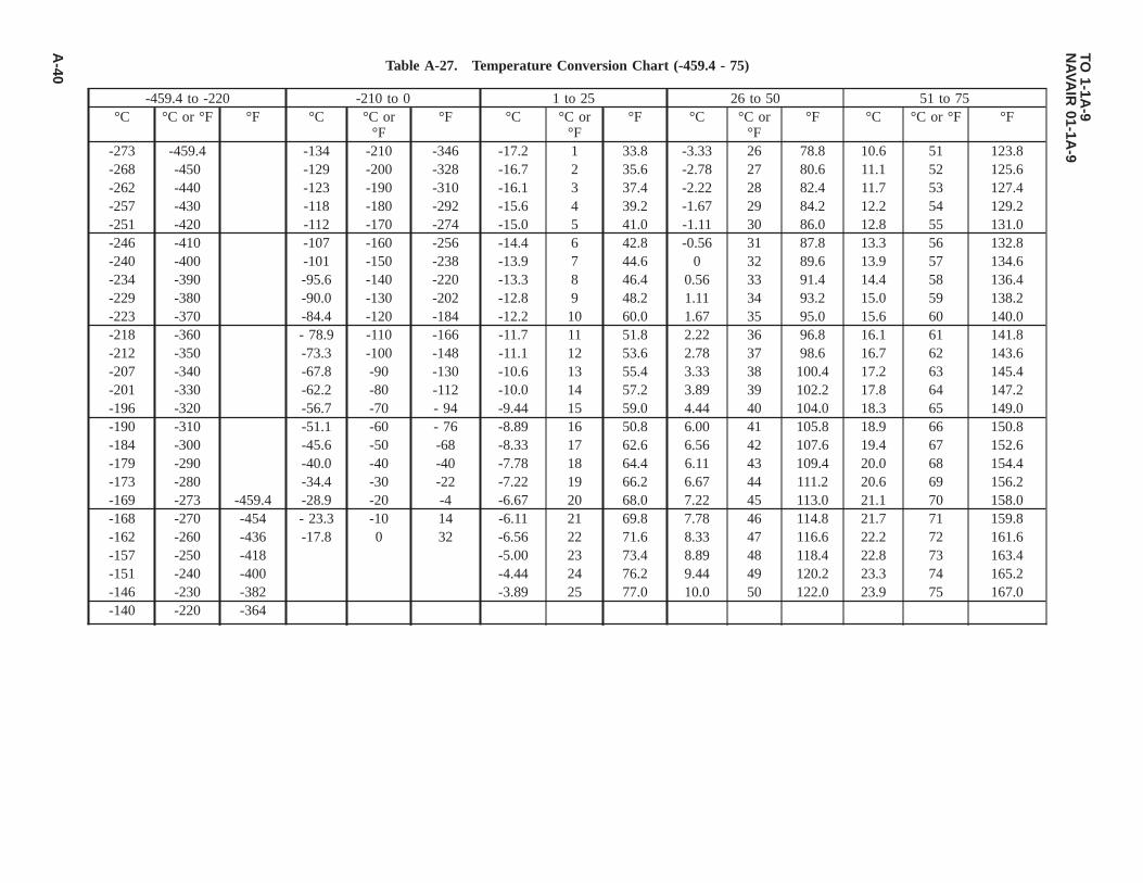
Table A-27. Temperature Conversion Chart (-459.4 - 75)
-459.4 to -220 -210 to 0 1 to 25 26 to 50 51 to 75°C °C or °F °F °C °C or
°F°F °C °C or
°F°F °C °C or
°F°F °C °C or °F °F
-273 -459.4 -134 -210 -346 -17.2 1 33.8 -3.33 26 78.8 10.6 51 123.8-268 -450 -129 -200 -328 -16.7 2 35.6 -2.78 27 80.6 11.1 52 125.6-262 -440 -123 -190 -310 -16.1 3 37.4 -2.22 28 82.4 11.7 53 127.4-257 -430 -118 -180 -292 -15.6 4 39.2 -1.67 29 84.2 12.2 54 129.2-251 -420 -112 -170 -274 -15.0 5 41.0 -1.11 30 86.0 12.8 55 131.0-246 -410 -107 -160 -256 -14.4 6 42.8 -0.56 31 87.8 13.3 56 132.8-240 -400 -101 -150 -238 -13.9 7 44.6 0 32 89.6 13.9 57 134.6-234 -390 -95.6 -140 -220 -13.3 8 46.4 0.56 33 91.4 14.4 58 136.4-229 -380 -90.0 -130 -202 -12.8 9 48.2 1.11 34 93.2 15.0 59 138.2-223 -370 -84.4 -120 -184 -12.2 10 60.0 1.67 35 95.0 15.6 60 140.0-218 -360 - 78.9 -110 -166 -11.7 11 51.8 2.22 36 96.8 16.1 61 141.8-212 -350 -73.3 -100 -148 -11.1 12 53.6 2.78 37 98.6 16.7 62 143.6-207 -340 -67.8 -90 -130 -10.6 13 55.4 3.33 38 100.4 17.2 63 145.4-201 -330 -62.2 -80 -112 -10.0 14 57.2 3.89 39 102.2 17.8 64 147.2-196 -320 -56.7 -70 - 94 -9.44 15 59.0 4.44 40 104.0 18.3 65 149.0-190 -310 -51.1 -60 - 76 -8.89 16 50.8 6.00 41 105.8 18.9 66 150.8-184 -300 -45.6 -50 -68 -8.33 17 62.6 6.56 42 107.6 19.4 67 152.6-179 -290 -40.0 -40 -40 -7.78 18 64.4 6.11 43 109.4 20.0 68 154.4-173 -280 -34.4 -30 -22 -7.22 19 66.2 6.67 44 111.2 20.6 69 156.2-169 -273 -459.4 -28.9 -20 -4 -6.67 20 68.0 7.22 45 113.0 21.1 70 158.0-168 -270 -454 - 23.3 -10 14 -6.11 21 69.8 7.78 46 114.8 21.7 71 159.8-162 -260 -436 -17.8 0 32 -6.56 22 71.6 8.33 47 116.6 22.2 72 161.6-157 -250 -418 -5.00 23 73.4 8.89 48 118.4 22.8 73 163.4-151 -240 -400 -4.44 24 76.2 9.44 49 120.2 23.3 74 165.2-146 -230 -382 -3.89 25 77.0 10.0 50 122.0 23.9 75 167.0-140 -220 -364
TO1-1A
-9N
AVA
IR01-1A
-9
A-40
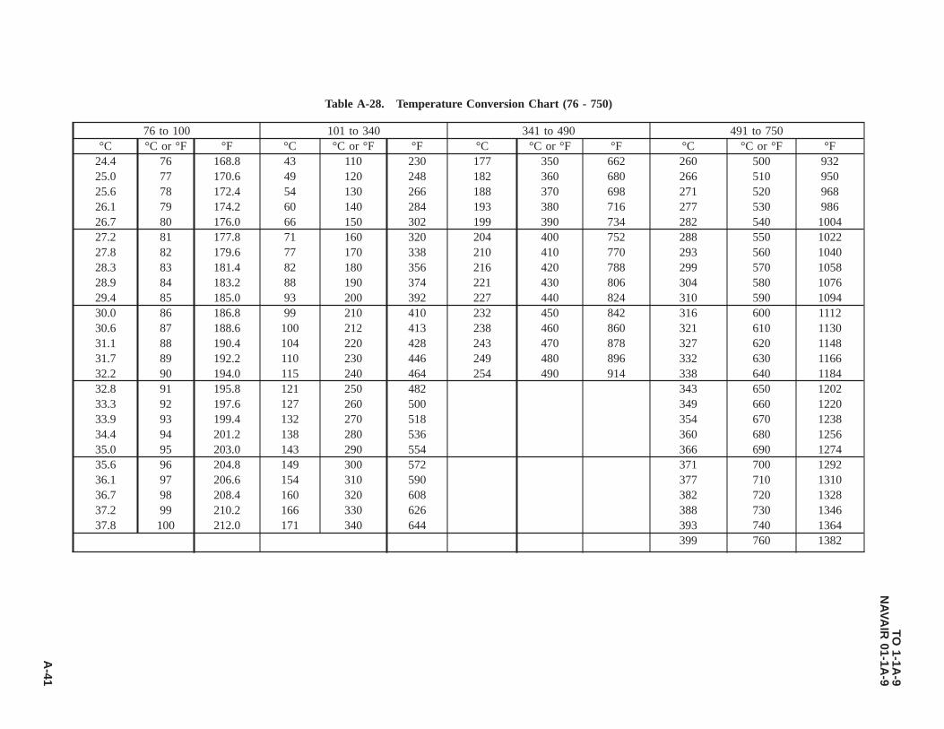
Table A-28. Temperature Conversion Chart (76 - 750)
76 to 100 101 to 340 341 to 490 491 to 750°C °C or °F °F °C °C or °F °F °C °C or °F °F °C °C or °F °F
24.4 76 168.8 43 110 230 177 350 662 260 500 93225.0 77 170.6 49 120 248 182 360 680 266 510 95025.6 78 172.4 54 130 266 188 370 698 271 520 96826.1 79 174.2 60 140 284 193 380 716 277 530 98626.7 80 176.0 66 150 302 199 390 734 282 540 100427.2 81 177.8 71 160 320 204 400 752 288 550 102227.8 82 179.6 77 170 338 210 410 770 293 560 104028.3 83 181.4 82 180 356 216 420 788 299 570 105828.9 84 183.2 88 190 374 221 430 806 304 580 107629.4 85 185.0 93 200 392 227 440 824 310 590 109430.0 86 186.8 99 210 410 232 450 842 316 600 111230.6 87 188.6 100 212 413 238 460 860 321 610 113031.1 88 190.4 104 220 428 243 470 878 327 620 114831.7 89 192.2 110 230 446 249 480 896 332 630 116632.2 90 194.0 115 240 464 254 490 914 338 640 118432.8 91 195.8 121 250 482 343 650 120233.3 92 197.6 127 260 500 349 660 122033.9 93 199.4 132 270 518 354 670 123834.4 94 201.2 138 280 536 360 680 125635.0 95 203.0 143 290 554 366 690 127435.6 96 204.8 149 300 572 371 700 129236.1 97 206.6 154 310 590 377 710 131036.7 98 208.4 160 320 608 382 720 132837.2 99 210.2 166 330 626 388 730 134637.8 100 212.0 171 340 644 393 740 1364
399 760 1382
TO1-1A
-9N
AVA
IR01-1A
-9
A-41

Table A-29. Temperature Conversion Chart (751 - 2000)
751 to 1000 1001 to 1250 1251 to 1490 1491 to 1750 1751 to 2000°C °C or
°F°F °C °C or °F °F °C °C or
°F°F °C °C or
°F°F °C °C or °F °F
404 760 1400 543 1010 1850 682 1260 2300 816 1500 2732 960 1760 3200410 770 1418 549 1020 1868 688 1270 2318 821 1510 2750 966 1770 3218416 780 1436 554 1030 1886 693 1280 2336 827 1520 2768 971 1780 3236421 790 1454 560 1040 1904 699 1290 2354 832 1530 2786 977 1790 3254427 800 1472 566 1050 1922 704 1300 2372 838 1540 2804 982 1800 3272432 810 1490 571 1060 1940 710 1310 2390 843 1550 2822 988 1810 3290438 820 1508 577 1070 1958 716 1320 2408 849 1560 2840 993 1820 3308443 830 1526 582 1080 1976 721 1330 2426 854 1570 2858 999 1830 3326449 840 1544 588 1090 1994 727 1340 2444 860 1580 2876 1004 1840 3344454 850 1562 593 1100 2012 732 1350 2462 866 1590 2894 1010 1850 3362460 860 1580 599 1110 2030 738 1360 2480 871 1600 2912 1016 1860 3380466 870 1598 604 1120 2048 743 1370 2498 877 1610 2930 1021 1870 3398471 880 1616 610 1130 2066 749 1380 2516 882 1620 2948 1027 1880 3416477 890 1634 616 1140 2084 754 1390 2534 888 1630 2966 1032 1890 3434482 900 1662 621 1150 2102 760 1400 2552 893 1640 2984 1038 1900 3462488 910 1670 627 1160 2120 766 1410 2570 899 1650 3002 1043 1910 3470493 920 1688 632 1170 2138 771 1420 2588 904 1660 3020 1049 1920 3488499 930 1706 638 1180 2156 777 1430 2606 910 1670 3038 1054 1930 3506504 940 1724 643 1190 2174 782 1440 2624 916 1680 3056 1060 1940 3524510 950 1742 649 1200 2192 788 1450 2642 921 1690 3074 1066 1950 3542516 960 1760 654 1210 2210 793 1460 2660 927 1700 3092 1071 1960 3560521 970 1778 660 1220 2228 799 1470 2678 932 1710 3110 1077 1970 3578527 980 1796 666 1230 2246 804 1480 2696 938 1720 3128 1082 1980 3596532 990 1814 671 1240 2264 810 1490 2714 943 1730 3146 1088 1990 3614538 1000 1832 677 1250 2282 949 1740 3164 1093 2000 3632
954 1750 3182
NOTE
The numbers in bold face type refer to the temperature either in degrees Centigrade or Fahrenheit which it is desired to convert into the other scale. Ifconverting from Fahrenheit degrees to Centigrade degrees the equivalent temperature will be found in the left column, while if converting from degreesCentigrade to degrees Fahrenheit, the answer will be found in the column on the right.
TO1-1A
-9N
AVA
IR01-1A
-9
A-42

Table A-29. Temperature Conversion Chart (751 - 2000) - Continued
751 to 1000 1001 to 1250 1251 to 1490 1491 to 1750 1751 to 2000°C °C or
°F°F °C °C or °F °F °C °C or
°F°F °C °C or
°F°F °C °C or °F °F
TO1-1A
-9N
AVA
IR01-1A
-9
A-43

Table A-30. Temperature Conversion Chart (2001 - 3000)
2001 to 2250 2251 to 2490 2491 to 2750 2751 to 3000°C °C or °F °F °C °C or °F °F °C °C or °F °F °C °C or °F °F
1099 2010 3650 1238 2260 4100 1371 2500 4532 1516 2760 50001104 2020 3668 1243 2270 4118 1377 2510 4550 1521 2770 50181110 2030 3686 1249 2280 4136 1382 2520 4568 1527 2780 50361116 2040 3704 1254 2290 4154 1388 2530 4586 1532 2790 50541121 2050 3722 1260 2300 4172 1393 2540 4604 1538 2800 50721127 2060 3740 1266 2310 4190 1399 2550 4622 1543 2810 50901132 2070 3758 1271 2320 4208 1404 2560 4640 1549 2820 51081138 2080 3776 1277 2330 4226 1410 2570 4658 1554 2830 51251143 2090 3794 1282 2340 4244 1416 2580 4676 1560 2840 51441149 2100 3812 1288 2350 4262 1421 2590 4694 1566 2850 51621154 2110 3830 1293 2360 4280 1427 2600 4712 1571 2860 51801160 2120 3848 1299 2370 4298 1432 2610 4730 1577 2870 51981166 2130 3866 1304 2380 4316 1438 2620 4748 1582 2880 52161171 2140 3884 1310 2390 4334 1443 2630 4766 1588 2890 52341177 2150 3902 1316 2400 4352 1449 2640 4784 1593 2900 52521182 2160 3920 1321 2410 4370 1454 2650 4802 1599 2910 52701188 2170 3938 1327 2420 4388 1460 2660 4820 1604 2920 52881193 2180 3956 1332 2430 4406 1466 2670 4838 1610 2930 53061199 2190 3974 1338 2440 4424 1471 2680 4856 1616 2940 53241204 2200 3992 1343 2450 4442 1477 2690 4874 1621 2950 53421210 2210 4010 1349 2460 4460 1482 2700 4892 1627 2960 53601216 2220 4028 1354 2470 4478 1488 2710 4910 1632 2970 53781221 2230 4046 1360 2480 4496 1493 2720 4928 1638 2980 53961227 2240 4064 1366 2490 4514 1499 2730 4946 1643 2990 54141232 2250 4082 1504 2740 4964 1649 3000 5432
1510 2750 4982°C °F °C °F
INTERPOLATIONFACTORS
0.56 1 1.8 3.33 6 10.81.11 2 3.6 3.89 7 12.61.67 3 5.4 4.44 8 14.42.22 4 7.2 5.00 9 16.22.78 5 9.0 5.56 10 18.0
TO1-1A
-9N
AVA
IR01-1A
-9
A-44

Table A-31. Standard Bend Radii for 90° Cold Forming-Flat Sheet (0.008 - 0.050)
Material Material Con-dition
Forming Tem-perature
Gauge0.008 0.012 0.016 0.020 0.025 0.032 0.040 0.050
ALUMINUM
3003-0,5052-0,6061-0
Noted Room 0.03 0.03 0.03 0.03 0.03 0.06 0.06
2014-0,2024-0,5052-H34,6061-T4,7075-0,7178-0
Noted Room 0.03 0.03 0.03 0.03 0.06 0.06 0.06
2014-T4, 2024-T3, 2024-T4,6061-T6,7075-W,7178-W
Noted Room 0.03 0.03 0.03 0.06 0.09 0.09 0.12
2014-T6, 2024-T36, 7075-T6, 7178-T6
Noted Room 0.06 0.06 0.08 0.09 0.12 0.19 0.25
2024-W Noted Room 0.03 0.03 0.03 0.03 0.06 0.06 0.097075-T6 Noted Hot 300±25 °F 0.06 0.06 0.06 0.06 0.06 0.06 0.097178-T6 Noted Hot 275 ±25 °F 0.06 0.06 0.06 0.06 0.06 0.06 0.09
MAGNESIUM
AZ31A(SPEC.QQ-M-44)
A Hot 400-625 °F 0.03 0.06 0.06 0.06 0.09 0.09
AZ31A(SPEC.QQ-M-44)
A Room 0.09 0.09 0.12 0.16 0.19 0.25
AZ31A(SPEC.QQ-M-44)
H Hot 325±25 °F 0.06 0.09 0.12 0.12 0.22 0.25
AZ31A(SPEC.QQ-M-44)
H Room 0.19 0.19 0.25 0.31 0.38 0.50
TO1-1A
-9N
AVA
IR01-1A
-9
A-45
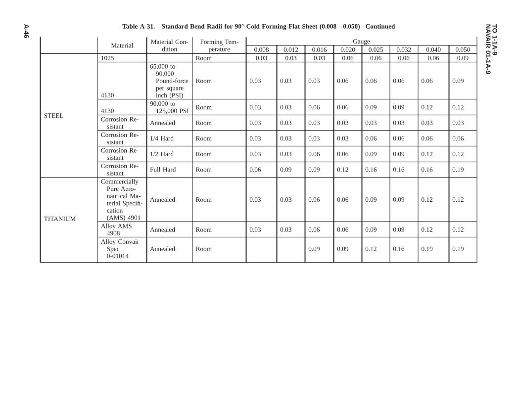
Table A-31. Standard Bend Radii for 90° Cold Forming-Flat Sheet (0.008 - 0.050) - Continued
Material Material Con-dition
Forming Tem-perature
Gauge0.008 0.012 0.016 0.020 0.025 0.032 0.040 0.050
STEEL
1025 Room 0.03 0.03 0.03 0.06 0.06 0.06 0.06 0.09
4130
65,000 to90,000Pound-forceper squareinch (PSI)
Room 0.03 0.03 0.03 0.06 0.06 0.06 0.06 0.09
413090,000 to
125,000 PSI Room 0.03 0.03 0.06 0.06 0.09 0.09 0.12 0.12
Corrosion Re-sistant Annealed Room 0.03 0.03 0.03 0.03 0.03 0.03 0.03 0.03
Corrosion Re-sistant 1/4 Hard Room 0.03 0.03 0.03 0.03 0.06 0.06 0.06 0.06
Corrosion Re-sistant 1/2 Hard Room 0.03 0.03 0.06 0.06 0.09 0.09 0.12 0.12
Corrosion Re-sistant Full Hard Room 0.06 0.09 0.09 0.12 0.16 0.16 0.16 0.19
TITANIUM
CommerciallyPure Aero-nautical Ma-terial Specifi-cation(AMS) 4901
Annealed Room 0.03 0.03 0.06 0.06 0.09 0.09 0.12 0.12
Alloy AMS4908 Annealed Room 0.03 0.03 0.06 0.06 0.09 0.09 0.12 0.12
Alloy ConvairSpec0-01014
Annealed Room 0.09 0.09 0.12 0.16 0.19 0.19
TO1-1A
-9N
AVA
IR01-1A
-9
A-46

Table A-32. Standard Bend Radii for 90° Cold Forming-Flat Sheet (0.063 - 0.250)
Material MaterialCondition
FormingTemperature
Gauge0.063 0.071 0.080 0.090 0.100 0.125 0.160 0.190 0.250
ALUMINUM
3003-0,5052-0,6061-0 Noted Room 0.06 0.09 0.09 0.12 0.12 0.16 0.16 0.19 0.25
2014-0,2024-0,5052-H34,6061-T4,7075-0,7178-0 Noted Room 0.09 0.09 0.12 0.16 0.16 0.19 0.25 0.31 0.44
2014-T4,2024-T3,2024-T4,6061-T6,7075-W,7178-W Noted Room 0.16 0.19 0.22 0.25 0.31 0.38 0.44 0.69 1.00
2014-T6,2024-T36,7075-T6,7178-T6 Noted Room 0.31 0.36 0.44 0.50 0.56 0.69 0.88 1.00 1.50
2024-W Noted Room 0.12 0.12 0.16 0.18 0.22 0.25 0.31 0.44 0.69
7075-T6 NotedHot
300±25°F 0.14 0.15 0.15 0.18 0.22 0.31 0.38 0.50 0.69
7178-T6 NotedHot
275±25°F 0.14 0.15 0.15 0.18 0.22 0.31 0.38 0.50 0.69
MAGNESIUM
AZ31A(SPEC.QQ-M-44) A
Hot 400-625°F 0.12 0.16 0.19 0.19 0.22 0.25 0.31 0.38 0.50
AZ31A(SPEC.QQ-M-44) A Room 0.31 0.38 0.44 0.44 0.50 0.62 0.75 1.00 1.25
AZ31A(SPEC.QQ-M-44) H
Hot325±25°F 0.38 0.44 0.44 0.44 0.44 0.50 0.62 0.81 1.00
AZ31A(SPEC.QQ-M-44) H Room 0.62 0.81 0.81 0.88 1.00 1.25 1.50 2.00 2.50
TO1-1A
-9N
AVA
IR01-1A
-9
A-47

Table A-32. Standard Bend Radii for 90° Cold Forming-Flat Sheet (0.063 - 0.250) - Continued
Material MaterialCondition
FormingTemperature
Gauge0.063 0.071 0.080 0.090 0.100 0.125 0.160 0.190 0.250
STEEL
1025 Room 0.09 0.12 0.16 0.19 0.22 0.25 0.31 0.38 0.50
413065,000 to
90,000 PSI Room 0.09 0.12 0.16 0.19 0.22 0.25 0.31 0.38 0.50
4130
90,000 to125,000PSI Room 0.16 0.19 0.25 0.31 0.38 0.44 0.50 0.62 0.75
CorrosionResistant
Annealed Room 0.06 0.06 0.09 0.12 0.12 0.16 0.16 0.19 0.25
CorrosionResistant
1/4 Hard Room 0.09 0.09 0.12 0.16 0.19 0.22 0.25 0.31 0.38
CorrosionResistant
1/2 Hard Room 0.16 0.16 0.19 0.25 0.31 0.38 0.50 0.62 0.75
CorrosionResistant
Full Hard Room 0.19 0.25 0.31 0.38 0.44 0.50 0.62 0.75 1.00
TITANIUM
Commer-cially PureAMS 4901
Annealed Room 0.16 0.19 0.25 0.31 0.38 0.38 0.44 0.56 0.75
Alloy AMS4908
Annealed Room 0.16 0.19 0.25 0.31 0.38 0.38 0.44 0.56 0.75
Alloy Con-vair Spec0-01014
Annealed Room 0.25 0.31 0.38 0.44 0.56 0.62 0.78 0.94 1.25
TO1-1A
-9N
AVA
IR01-1A
-9
A-48

Table A-33. Metal Bending and Bend Radii Bend Allowances Sheet Metal Bend Allowances per De-gree of Bend Aluminum Alloys
Bend RadiusStock Thickness
0.022 0.032 0.040 0.051 0.064 0.091 0.128 0.187Bend Allowance per One Degree
1/32 0.00072 0.00079 0.00086 0.00094 0.00104 0.00125 0.00154 0.002001/16 0.00126 0.00135 0.00140 0.00149 0.00159 0.00180 0.00209 0.002553/32 0.00180 0.00188 0.00195 0.00203 0.00213 0.00234 0.00263 0.003091/8 0.00235 0.00243 0.00249 0.00258 0.00268 0.00289 0.00317 0.003645/32 0.00290 0.00297 0.00304 0.00312 0.00322 0.00343 0.00372 0.004183/16 0.00344 0.00352 0.00358 0.00367 0.00377 0.00398 0.00426 0.004737/32 0.00398 0.00406 0.00412 0.00421 0.00431 0.00452 0.00481 0.005271/4 0.00454 0.00461 0.00467 0.00476 0.00486 0.00507 0.00535 0.005829/32 0.00507 0.00515 0.00521 0.00530 0.00540 0.00561 0.00590 0.006365/16 0.00562 0.00570 0.00576 0.00584 0.00595 0.00616 0.00644 0.0069111/32 0.00616 0.00624 0.00630 0.00639 0.00649 0.00670 0.00699 0.007453/8 0.00671 0.00679 0.00685 0.00693 0.00704 0.00725 0.00753 0.0080013/32 0.00725 0.00733 0.00739 0.00748 0.00758 0.00779 0.00808 0.008547/16 0.00780 0.00787 0.00794 0.00802 0.00812 0.00834 0.00862 0.0090815/32 0.00834 0.00842 0.00848 0.00857 0.00867 0.00888 0.00917 0.009631/2 0.00889 0.00896 0.00903 0.00911 0.00921 0.00943 0.00971 0.0101717/32 0.00943 0.00951 0.00957 0.00966 0.00976 0.00997 0.01025 0.010729/16 0.00998 0.01005 0.01012 0.01020 0.01030 0.01051 0.01080 0.0112619/32 0.01051 0.01058 0.01065 0.01073 0.01083 0.01105 0.01133 0.011795/8 0.01107 0.01114 0.01121 0.01129 0.01139 0.01160 0.01189 0.0123521/32 0.01161 0.01170 0.01175 0.01183 0.01193 0.01214 0.01245 0.0128911/16 0.01216 0.01223 0.01230 0.01238 0.01248 0.01268 0.01298 0.0134423/32 0.01269 0.01276 0.01283 0.01291 0.01301 0.01322 0.01351 0.013973/4 0.01324 0.01332 0.01338 0.01347 0.01357 0.01378 0.01407 0.01453Example: To determine bend allowanceGiven: Stock = 0.064 aluminum alloy, Bend Radius = 1/8, Bend Angle = 50°Find bend allowance for 1° in column for 0.064 Aluminum opposite 1/8 in column “Bend Radius”.Multiply this bend allowance (0.00268 in this case) by the number of degrees of the desired bend angle: 0.00268 x 50 =
0.1340 = total bend allowance to be added to the length of the straight sides of the part to determine the total lengthof the material needed.
TO 1-1A-9NAVAIR 01-1A-9
A-49

Figure A-1. Bend Set Back Chart
TO 1-1A-9NAVAIR 01-1A-9
A-50
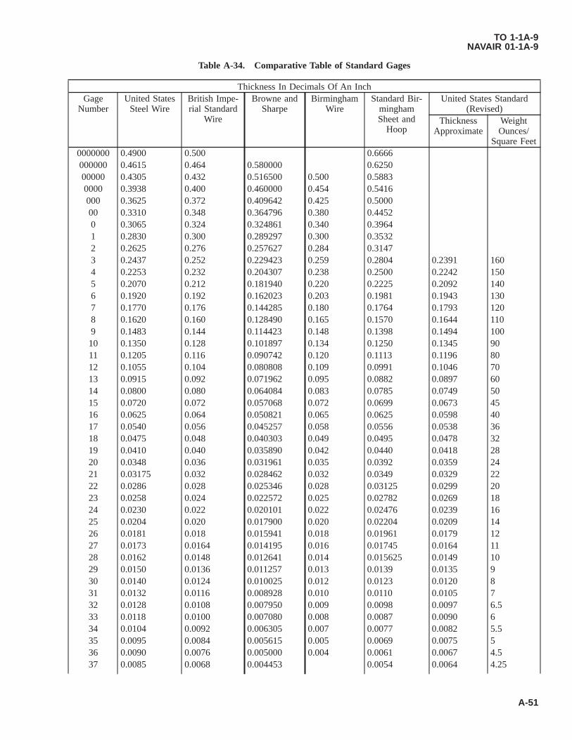
Table A-34. Comparative Table of Standard Gages
Thickness In Decimals Of An InchGage
NumberUnited States
Steel WireBritish Impe-rial Standard
Wire
Browne andSharpe
BirminghamWire
Standard Bir-minghamSheet and
Hoop
United States Standard(Revised)
ThicknessApproximate
WeightOunces/
Square Feet0000000 0.4900 0.500 0.6666000000 0.4615 0.464 0.580000 0.625000000 0.4305 0.432 0.516500 0.500 0.58830000 0.3938 0.400 0.460000 0.454 0.5416000 0.3625 0.372 0.409642 0.425 0.500000 0.3310 0.348 0.364796 0.380 0.44520 0.3065 0.324 0.324861 0.340 0.39641 0.2830 0.300 0.289297 0.300 0.35322 0.2625 0.276 0.257627 0.284 0.31473 0.2437 0.252 0.229423 0.259 0.2804 0.2391 1604 0.2253 0.232 0.204307 0.238 0.2500 0.2242 1505 0.2070 0.212 0.181940 0.220 0.2225 0.2092 1406 0.1920 0.192 0.162023 0.203 0.1981 0.1943 1307 0.1770 0.176 0.144285 0.180 0.1764 0.1793 1208 0.1620 0.160 0.128490 0.165 0.1570 0.1644 1109 0.1483 0.144 0.114423 0.148 0.1398 0.1494 10010 0.1350 0.128 0.101897 0.134 0.1250 0.1345 9011 0.1205 0.116 0.090742 0.120 0.1113 0.1196 8012 0.1055 0.104 0.080808 0.109 0.0991 0.1046 7013 0.0915 0.092 0.071962 0.095 0.0882 0.0897 6014 0.0800 0.080 0.064084 0.083 0.0785 0.0749 5015 0.0720 0.072 0.057068 0.072 0.0699 0.0673 4516 0.0625 0.064 0.050821 0.065 0.0625 0.0598 4017 0.0540 0.056 0.045257 0.058 0.0556 0.0538 3618 0.0475 0.048 0.040303 0.049 0.0495 0.0478 3219 0.0410 0.040 0.035890 0.042 0.0440 0.0418 2820 0.0348 0.036 0.031961 0.035 0.0392 0.0359 2421 0.03175 0.032 0.028462 0.032 0.0349 0.0329 2222 0.0286 0.028 0.025346 0.028 0.03125 0.0299 2023 0.0258 0.024 0.022572 0.025 0.02782 0.0269 1824 0.0230 0.022 0.020101 0.022 0.02476 0.0239 1625 0.0204 0.020 0.017900 0.020 0.02204 0.0209 1426 0.0181 0.018 0.015941 0.018 0.01961 0.0179 1227 0.0173 0.0164 0.014195 0.016 0.01745 0.0164 1128 0.0162 0.0148 0.012641 0.014 0.015625 0.0149 1029 0.0150 0.0136 0.011257 0.013 0.0139 0.0135 930 0.0140 0.0124 0.010025 0.012 0.0123 0.0120 831 0.0132 0.0116 0.008928 0.010 0.0110 0.0105 732 0.0128 0.0108 0.007950 0.009 0.0098 0.0097 6.533 0.0118 0.0100 0.007080 0.008 0.0087 0.0090 634 0.0104 0.0092 0.006305 0.007 0.0077 0.0082 5.535 0.0095 0.0084 0.005615 0.005 0.0069 0.0075 536 0.0090 0.0076 0.005000 0.004 0.0061 0.0067 4.537 0.0085 0.0068 0.004453 0.0054 0.0064 4.25
TO 1-1A-9NAVAIR 01-1A-9
A-51

Table A-34. Comparative Table of Standard Gages - Continued
Thickness In Decimals Of An InchGage
NumberUnited States
Steel WireBritish Impe-rial Standard
Wire
Browne andSharpe
BirminghamWire
Standard Bir-minghamSheet and
Hoop
United States Standard(Revised)
ThicknessApproximate
WeightOunces/
Square Feet38 0.0080 0.0060 0.003965 0.0048 0.0060 439 0.0075 0.0052 0.003531 0.004340 0.0070 0.0048 0.003144 0.0038
1. United States Steel Wire Gage (STLWG) Also known as: National Wire, Standard Steel Wire, Steel Wire, AmericanSteel and Wire Company, Roebling, Washburn and Moen Gages. Used for bare wire of galvanized, black annealed,bright basic tinned or copper coated, iron or steel, spring steel wire. Not used for telephone and telegraph wire.
2. British Imperial Standard Wire Gage (ISWG) or (NBS) Also known as British Imperial Wire or English Legal Stan-dard Gages. Used for bare copper telephone wires in the U.S. and for all wires and aluminum sheets in England.
3. Browne and Sharpe Gage (BandSG) Also known as American or American Wire Gages. Used for bare wire of brass,phosphor bronze, German silver, aluminum, zinc and copper (not for copper telephone or telegraph wire). Also resis-tance wire of German silver and other alloys, and for insulated wire of aluminum and copper. Also for rods of brass,copper, phosphor bronze and aluminum; sheets of copper, brass, phosphor bronze, aluminum and German silver;brazed brass and brazed copper tubing.
4. Birmingham Wire Gage (BWG) Also known as Birmingham, Stubs or Studs Iron Wire Gages. Used for iron and steeltelephone and telegraph wire and strip steel, steel bands, hoop steel, crucible spring steel, round-edged flat wire, andwith limited usage for copper sheets. Also for seamless brass, seamless copper, seamless steel, stainless steel and alu-minum tubes, and for boiler tubes.
5. Standard Birmingham Sheet and Hoop Gage (BG) Used in England for iron and steel sheets and hoops.6. United States Standard (Revised) (USSG) Also known as U.S. Standard Sheet Metal or U.S. Standard for Steel and
Iron Sheets and Plates Gages. This is a gage based on the weight per square foot of sheets rather than on thickness. Itis used for commercial iron and steel sheets and plates including planished, galvanized, tinned and terne plates, blacksheet iron, blue annealed soft steel, steel plate, hot-rolled sheet steel, cold-rolled sheet steel, hot-rolled monel metal,cold-rolled monel metal.
Other gages in use:Trenton Iron Company Gage.Zinc gage for sheet zinc only.Birmingham Metal Gage-in England for brass sheets. American Steel and Wire Company’s music wire gage. Twist Drill
and Steel Wire Gage for twist drill and steel drill rods.
Table A-35. Melting Points Approximate
ElementsDegrees
°C °FAluminum 660 1220Antimony 631 1167Barium 850 1562Beryllium 1350 2462Bismuth 271 520Cadmium 321 610Calcium 810 1490Carbon 3500 6332Chromium 1765 3209Cobalt 1480 2696Copper 1083 1981Gold 1063 1945Iron 1535 2795
TO 1-1A-9NAVAIR 01-1A-9
A-52

Table A-35. Melting Points Approximate - Continued
ElementsDegrees
°C °FLead 327 621Lithium 186 367Magnesium 651 1204Magnesium 1260 2300Mercury -39 -38Molybdenum 2620 4748Nickel 1446 2635Phosphorous (Yellow) 44 111Platinum 1773 3223Silicon 1420 2588Silver 961 1761Tin 232 449Tungsten 3400 6152Vanadium 1710 3110Zinc 420 787
TO 1-1A-9NAVAIR 01-1A-9
A-53/(A-54 blank)


GLOSSARY
A
ACID BRITTLENESS — Brittleness of steel resulting from use of acid solutions to remove scale, clean and electroplate.Brittleness is caused by the absorption of hydrogen into the metal from the acid solutions (also called hydrogen embrittle-ment).
AGING — (a) Generally any change in properties with time which occurs at relatively low temperature (room or elevated)after a final heat treatment of a cold marking operation. Aging is a process in which the trend is toward restoration of realequilibrium and away from an unstable condition induced by a prior operation. (b) Specifically the formation of a new phaseby cooling a solid solution to super saturated state and allowing the super saturated solution to partially return to equilibriumby the formation of a less concentrated solid solution and a new phase.
AIR HARDENING — An alloy which does not require quenching from a high temperature to harden. Hardening of thematerial occurs simply by cooling in air from above critical temperature. The term refers only to the ability of the materialto harden in air and does not imply any definite analysis or composition.
AIR COOLING/QUENCHING — Cooling from an elevated temperature in air, still or forced.
ALLOY — A mixture with metallic properties composed of two or more elements of which at least one is a metal.However, a metal is not designated an ″alloy″ based on elements incidental to its manufacture. For example; iron, carbon,manganese, silicon, phosphorus, sulphur, oxygen, nitrogen and hydrogen are incidental to the manufacture of plain carbonsteel. It does not become an ″alloy steel″ until the elements are increased beyond regular composition or until other elements(metal) are added in significant amounts for a specific purpose.
ALLOY ELEMENTS — Chemical elements comprising an alloy, usually limited to the metallic elements added to modifythe basic metal properties.
AMORPHOUS — Non-crystalline.
ANNEALING — Generally it is a controlled heating procedure which leads to maximum softness, ductility and formability.The annealing procedure is utilized for the following: (a) Remove stresses. (b) Induce softness. (c) After ductility, toughness,electrical, magnetic, or physical properties. (d) Refine crystalline structure. (e) Remove gases. (f) Produce a definite micro-structure.
ANNEALING FULL — A controlled heating procedure which leads to maximum softness, ductility and formability.
ANNEALING, ISOTHERMAL — Heating of a ferritic steel to a austenitic structure (fully or partial) followed by coolingto and holding at a temperature that causes transformation of the austenite to a relatively soft ferrite and carbide structure.
ANODIC OXIDE COATING — A thin film of aluminum oxide formed on the surface of aluminum and aluminum alloyparts by electro-chemical means.
AS CAST — Condition of a casting as it leaves the mold with no heat treatment.
AUSTENITE — A solid solution of iron carbide in gamma iron. It forms when the metal solidifies and remains a solutionuntil it cools to about 732 °C (1350 °F). Theoretically the solution would remain if the iron or steel were cooled instanta-neously from a bright red heat to atmospheric temperature, but in practice, this degree of rapidity is impracticable, and only
TO 1-1A-9NAVAIR 01-1A-9
Glossary 1

a portion of the austenite is preserved by rapid cooling. Addition of certain alloying elements such as nickel and manganeseperserves austenite below - 17 °C (0 °F).
B
BARK — The decarburized skin or layer just beneath the scale found after heating steel in an oxidizing atmosphere.
BASE METAL — The metal to which other elements are added to form an alloy possessing specific properties.
BESSEMER PROCESS — A process for making steel by blowing air through molten pig iron contained in a suitablevessel. The process is one of rapid oxidation primarily of silicon and carbon.
BILLET — An ingot or bloom that has been reduced through rolling or hammering to an approximate square ranging from1 1/2 inches square to 6 inches square, or to an approximate rectangular cross-section of equivalent area. Billets areclassified as semi-finished products for re-rolling or forging.
BINARY ALLOY — An alloy containing two elements, apart from minor impurities.
BLACK ANNEALING — A process of box annealing of sheets prior to tinning whereby a black color is imparted to thesurface of the product.
BLUE ANNEALING — A process of annealing sheets after rolling. The sheets, if fairly heavy, are allowed to cool slowlyafter the hot rolling; if of lighter gage, as is usually the case, they are passed singly through an open furnace for heating tothe proper annealing temperature. The sheets have a bluish-black appearance.
BLUE BRITTLENESS — Brittleness occurring in steel when in the temperature range of 149 °C to 371 °C (300-700 °F),or when cold after being worked within this temperature range.
BOX ANNEALING — Softening steel by heating it, usually at a sub-critical temperature, in a suitable closed metal box orpot to protect it from oxidation, employing a slow heating and cooling cycle; also called closed annealing or pot annealing.
BRIGHT ANNEALING — A process of annealing, usually with reducing gases, such that surface oxidation is reduced to aminimum, thereby yielding a relatively bright surface.
BRITTLENESS — Brittleness is the property of a material which permits little bending or deformation without fracture.Brittleness and hardness are closely associated.
BURNING — The heating of a metal to temperatures sufficiently close to the melting point to cause permanent injury. Suchinjury may be caused by the melting of the more fusible constituents, by the penetration of gases such as oxygen into themetal with consequent reactions, or perhaps by the segregation of elements already present in the metal.
BUTT-WELD — The welding of two abutting edges.
C
CARBON FREE — Metals and alloys which are practically free from carbon.
CARBURIZING (CEMENTATION) — Adding carbon to the surface of iron-base alloys by heating the metal below itsmelting point in contact with carbonaceous solids, liquids, or gases.
TO 1-1A-9NAVAIR 01-1A-9
Glossary 2

CASE — The surface layer of an iron-base alloy which has been made substantially harder than the interior by the processof case hardening.
CASE HARDENING — A heat treatment of a combination of heat treatments in which the surface layer of an iron-basealloy is made substantially harder than the interior by altering its composition by carburizing, cyaniding, or nitriding.
CHAPMANIZING — A process for hardening steel by bubbling ammonia through a cyaniding salt bath and holding thefinished part in the gas stream. This method produces a case almost as hard as nitriding at a time factor of slightly longerthan required for cyaniding.
CHARPY IMPACT — An impact test made by measuring in a Charpy machine the energy required to fracture a standardnotched specimen in bending. The values so obtained are merely comparative between different materials tested by the samemethod.
COLD DRAWING — The permanent deformation of metal below its recrystallization temperature, by drawing the baythrough one or more dies.
COLD ROLLING — The permanent deformation of metal below its recrystallization temperature by rolling. This processis frequently applied in finishing rounds, sheets, strip, and tin plate.
COLD TREATING — Cooling to sub-zero temperature for various purposes, but primarily to promote transformation ofaustenite.
COLD WORKING — Plastic deformation of a metal at a temperature low enough to ensure strain hardening.
CORE — The interior portion of an iron-base alloy which is substantially softer than the surface layer as the result of casehardening. Also, that portion of a forging removed by trepanning; the inner part of a rolled section of rimmed steel as distinctfrom the rimmed portion or rim; a body of sand or other material placed in a mold to produce a cavity in a casting.
CONVERSION COATING (CHEMICAL) — A film intentionally produced on a metal by subjection to a selected chemi-cal solution for the purpose of providing improved corrosion resistance or to improve the adhesion of subsequently appliedorganic coating.
CYANIDING — Surface hardening by carbon and nitrogen absorption of an iron-base alloy article or portion of it byheating at a suitable temperature in contact with a cyanide salt, followed by quenching.
COOLING — Any decrease in temperature; however, specific term usually applies to reducing metal temperature in agaseous environment rather than quenching in a liquid.
D
DECALESCENCE — When a piece of steel is heated, the temperature rises uniformly until it reaches a point between 718°C and 732 °C (1,325 °F and 1,350 °F). At this point the rise in temperature suddenly halts due to the fact that the metalabsorbs the heat necessary for the change of state. After this halt the temperature will continue its normal rate of increase. Itis the halting in the temperature range that is termed decalescence. At the point of decalesence, the carbon and iron areforming a solid solution and the steel is passing from its annealed condition into its hardened condition.
DECARBURIZATION — The removal of carbon (usually refers to the surface of solid steel) by the (normally oxidizing)action of media which reacts with carbon. The decarburized area is sometimes referred to as the bark.
TO 1-1A-9NAVAIR 01-1A-9
Glossary 3
DEFECTS IN METALS — Damage occurring to metal during manufacture/fabrication process. Some typical defects are asfollows: (a) Blister - a defect in metal produced by gas bubbles either on the surface or formed beneath the surface. Very fineblisters are called pinhead or pepper blisters. (b) Blow hole - a hole produced during the solidification of metal by evolvedgas which in falling to escape, is held in pockets. (c) Bursts - ruptures made in forging or rolling. (d) Fin (Flash) - a thin finof metal formed at the side of a forging or weld where a small portion of the metal is forced out between the edges of theforging or welding case. (e) Flake -Internal fissures (cracks or clefts) in large steel forgings or large (MASS) rolled shapes.In a factured surface or test piece, they appear as sizable areas of silvery brightness and coarser grain size than theirsurroundings. Sometimes known as ″chrome checks″ and ″hairline cracks.″ (f) Ghost - (Ferrite ghost) a faint band of ferrite.(g) Lap - a surface defect appearing as a seam caused from folding over hot metal, fins, or sharp corners and then rolling orforging, but not welding, them into the surface. (h) Pipe - a cavity formed in metal (especially ingots) during solidificationof the last portion of liquid metal causes the cavity or pipe. (i) Scab - a rough projection on a casting caused by the moldbreaking or being washed by the molten metal; or occurring where the skin from a blowhole has partly burned away and isnot welded. (j) Seam - a crack on the surface of metal which has been closed but not welded; usually produced by blowholeswhich have become oxidized. If very fine, a seam may be called a hair crack or hair seam. (k) Segregation a mixture ofcompounds and elements, which, when cooled from the molten state, solidify at different temperatures. (I) Ductility theability of a metal to withstand plastic deformation without rupture. Ductility is usually determined by tension test using astandard test (2″ gauge length) specimen. The test specimen is loaded in tension to rupture. The specimen is then assembledand measured for length and diameter at the fracture. The increase in length is expressed as per cent elongation and thedecrease in diameter as per cent reduction of area. The above terms measure ductility and since they are comparative,considerable experience is required for proper evaluation of material for the purpose intended.
DUCTILITY — The property that permits permanent deformation before fracture by stress in tension.
E
ELASTIC LIMIT — The elastic limit of a material is the greatest load per unit area which will not produce a measurablepermanent deformation after complete release of load.
ELECTRICAL CONDUCTIVITY — A material property of a metal that indicates its ability to conduct electricity; theinverse of resistivity. It is used to verify proper heat treatment in non-ferrous alloys. Commonly measured as a percentage ofthe International Annealed Copper Standard (%IACS).
ELONGATION — The amount of permanent extension at any stage in any process which continuously elongates a body.
EMBRITTLEMENT — Loss of ductility of a metal, which may result in premature failure. (See acid brittleness).
ENDURANCE LIMIT — The highest unit stress at which a material can be subjected to a very large number of repetitionsof loading and still show no evidence of failure. Above this limit failure occurs by the generation and growth of cracks untilfracture results in the remaining section.
ENDURANCE RATIO — The ratio of the endurance limit for cycles of reversed flexural stress to the tensile strength.
EQUALIZING — Intermediate heat treatment (special) which assists in developing desired properties, primary use is forequalizing/relieving stresses resulting from cold working.
EUTECTIC ALLOY — An alloy which has a lower melting point than neighboring compositions. More then one eutecticcomposition may occur in a given alloy system.
EXFOLIATION — The cracking or flaking off of the outer layer of an object.
EXPOSURE — Heating to or subjecting to an elevating temperature or environment for a certain period of time.
TO 1-1A-9NAVAIR 01-1A-9
Glossary 4 Change 2

ETCHING — Attack of metals structure by reagents. In metallography, the process of revealing structural details by thepreferential attack of reagents on a metal surface. (a) Micro-etching is for the examination of the sample under a microscopeand for this purpose the sample must be very carefully polished (by an experienced person) prior to etching. (b) Macro-etching is for the examination of the sample under a low power magnifying glass or by unaided eye. High polishing for thispurpose is not absolutely essential; however, a good polish is necessary. (c) Deep-etching is a form of macro-etching inwhich the sample with regular cut surface may be immersed in hot hydrochloric acid (50% acqueous solution) and thenexamined for major defects such as inclusions, segregations, cracks; etc.
F
FATIGUE — The phenomenon of the progressive fracture of a metal by means of a crack which spreads under repeatedcycles of stress.
FATIGUE LIMIT — Usually used as synonymous with endurance limit.
FERRITE — A solution in which alpha iron is the solvent, and which is characterized by a body centered cubic crystalstructure.
FILLET — A concave junction of two surfaces usually perpendicular.
FLAME HARDENING — A process of hardening a ferrous alloy by heating it above the transformation range by means ofa high-temperature flame and then cooling as required.
FORGING STRAINS — Elastic strains resulting from forging or from cooling from the temperature.
FORMING — To shape or fashion with hand/tools or by a shape or mold.
FRACTURE TESTING — A test used to determine type of structure, carbon content and the presence of internal defects.The test specimen is broken by any method that will produce a clean sharp fracture. The fracture is then examined by eye orwith the aid of a low former magnifying glass. A trained/experienced observer will determine grain size; approximate depthof carburized or decarburized surface area; the presence of inclusions of dirty steel; and defects such as seams, cracks, pipesbursts and flakes.
FULLY HARDENED — Applies generally to the maximum hardness obtainable. (In particular, applies to materials that arehardened by a strain and/or age hardening process).
FUSIBLE ALLOYS — A group of nonferrous alloys which melt at relatively low temperatures. They usually consist ofbismuth, lead, tin, etc., in various proportions, and iron only as an impurity.
G
GALVANIC SERIES — A list of metals and alloys arranged in order of their relative potentials in a given environment.The galvanic series indicates the tendency of the serval metals and alloys to set up galvanic corrosion. The relative positionwithin a group sometimes changes with external conditions, but it is only rarely that changes occur from group to group.
GRAINS — Individual crystals in metal. When metal is in molten state, the atoms have no uniform grouping. However,upon solidification they arrange themselves in a geometric pattern.
GRAIN GROWTH — An increase in the grain size of metal.
TO 1-1A-9NAVAIR 01-1A-9
Change 2 Glossary 5

H
HARDENABILITY — The ability of an alloy to harden fully throughout the entire section thickness either by cold workingor heat treatment. The maximum thickness at which this may be accomplished can be used as a measure of hardenability.
HARDENING — Hardening accomplished by heating the metal to a specified temperature, then rapidly cooling by quench-ing in oil, water, or brine. This treatment produces a fine grain structure, extreme hardness, maximum tensile strength, andminimum ductility.
HARDNESS — Hardness refers to the ability of a material to resist abrasion, penetration, indentation, or cutting action. Thewearing qualities of a material are in part dependent upon its hardness. Hardness and strength are properties which areclosely related for wrought alloys.
HARDNESS TESTING — Test used to determine the ability of a metal to resist penetration. The test results are usuallydirectly related to tensile and yield strength of the metal involved. An exception would be case hardness. See Chapter 8 fortypical testing methods.
HEAT TINTING — Heating a specimen with a suitable surface in air for the purpose of developing the structure byoxidizing or otherwise affecting the different constituents.
HEAT TREATMENT — An operation, or combination of operations, involving the heating and cooling of a metal or alloyin the solid state for the purpose of obtaining certain desirable conditions or properties. Heating and cooling for the solepurpose of mechanical working are excluded from the meaning of this definition.
HOMOGENIZING — Annealing or soaking at very high temperatures in order to reduce alloy segregation by diffusion.
HOT SHORTNESS — Brittleness in metal when hot. In iron when sulphur is in excess of the manganese necessary tocombine with it to form manganese sulfide the excess sulphur combines with the iron to form iron sulfide. This constituenthas a lower melting point than the iron and the result can be that steel may crack during hot working.
HYDROGEN EMBRITTLEMENT — See Acid Brittleness.
I
IMPACT TEST — A test in which one or more blows are suddenly applied to a specimen. The results are usually expressedin terms of energy absorbed or number of blows (of a given intensity) required to break the specimen. See Charpy Impactand Izod Impact
INCLUSION — Particles of impurities, usually oxides, sulfides, silicates, and such which are mechanically held duringsolidification or which are formed by subsequent reaction of the solid metal.
INDUCTION HARDENING — A process of hardening a ferrous alloy by heating above the transformation range bymeans of electrical induction and then cooling as required.
INTERNATIONAL ANNEALED COPPER STANDARD (IACS) — An established standard for the electrical conductiv-ity of commercially pure annealed copper. At 68 °F (20 °C), commercially pure, annealed copper has an electrical conduc-tivity of 0.58 x 10^7 S/m (Siemens/meter). This is considered 100 %IACS.
TO 1-1A-9NAVAIR 01-1A-9
Glossary 6 Change 2

M
MACHINABILITY — The cutting characteristic of metal and resulting surface finish using standard cutting tools andcoolant/lubricants. There are various factors that effect the machinability of a metal such as hardness, grain size, alloyconstituents, structure, inclusions; shape, type, condition of tool and coolant. The standard machinability ratings are usuallybased on comparison to SAE 1112/Aisi B 1112 Bessemer screw stock which is rated at 100% machinability.
MAGNA FLUX TESTING — A method of inspection used to detect/locate defects such as cavities, cracks or seams insteel parts at or very close to the surface. The test is accomplished by magnetizing the part with equipment speciallydesigned for the purpose and applying magnetic powder, wet or dry. Flaws are then indicated by the powder clinging to them(see Chapter 8 for additional data).
TO 1-1A-9NAVAIR 01-1A-9
Change 2 Glossary 6.1/(Glossary 6.2 blank)


MALLEABILITY — Malleability is the property of a material which enables it to be hammered, rolled, or to be pressedinto various shapes without fracture. Malleability refers to compression deformation as contrasted with ductility where thedeformation is tensile.
MARTEMPERING — This is a method of hardening steel by quenching from the austenitizing temperature into a mediumat a temperature in the upper part of or slightly above the martensite range and holding it in the medium until temperature issubstantially uniform throughout the alloy is then allowed to cool in air through the martensite range.
MARTENSITE — It is the decomposition product which results from very rapid cooling of austenite. The lower the carboncontent of the steel, the faster it must be cooled to obtain martensite.
MECHANICAL HARDNESS — See Hardness.
MECHANICAL PROPERTIES — Those properties that reveal the reaction, elastic and inelastic, of a material to anapplied force, or that involve the relationship between stress and strain; for example, tensile strength, yield strength, andfatigue limit.
MECHANICAL TESTING — Testing methods by which mechanical properties are determined.
MECHANICAL WORKING — Subjecting metal to pressure exerted by rolls, presses, or hammers, to change its form, orto affect the structure and therefore the mechanical and physical properties.
MODULUS OF ELASTICITY — The ratio, within the limit of elasticity, of the stress in the corresponding strain. Thestress in pounds per square inch is divided by the elongation in fractions of an inch for each inch of the original gage lengthof the specimen.
N
NITRIDING — Adding nitrogen to iron-base alloys by heating the metal in contact with ammonia gas or other suitablenitrogenous material. Nitriding is conducted at a temperature usually in the range 502-538 °C (935-1000 °F) and producessurface hardening of the metal without quenching.
NORMALIZING — Heating iron-base alloys to approximately 55 °C (100 °F) above the critical temperature range, fol-lowed by cooling to below that range in still air at ordinary temperatures. This process is used to remove stresses caused bymachining, forging, bending, and welding.
O
OVERHEATING — Heating to such high temperatures that the grains have become coarse, thus impairing the properties ofthe metal.
P
PATENTING — Heating iron-base alloys above the critical temperature range followed by cooling below that range in air,or in molten lead, or a molten mixture of nitrate or nitrites maintained at a temperature usually between 427-566 °C(800-1050 °F) ,depending on the carbon content of the steel and the properties required of the finished product. Thistreatment is applied to wire and to medium or high carbon steel as a treatment to precede further wire drawing.
PHYSICAL PROPERTIES — Those properties exclusive of those described under mechanical properties; for example,density, electrical conductivity, coefficient of thermal expansion. This term has often been used to describe mechanicalproperties, but this usage is not recommended.
TO 1-1A-9NAVAIR 01-1A-9
Glossary 7
PHYSICAL TESTING — Testing methods by which physical properties are determined. This term is also unadvisedly usedto mean the determination of the mechanical properties.
PICKLING — Removing scale from steel by immersion in a diluted acid bath.
PLASTIC DEFORMATION — The permanent change in size or shape of a material under stress.
POTENTIOMETER — Potentiometer is an instrument used to measure thermocouple voltage by balancing a known bat-tery voltage against it.
PROCESS ANNEALING — Heating iron-base alloys to a temperature below or close to the lower limit of the criticaltemperature range, followed by cooling desired. This treatment is commonly applied to sheet and wire and the temperaturesgenerally used are from 549-649 °C (1020-1200 °F)
PROOF STRESS — The proof stress of a material is that load per unit area which a material is capable of withstandingwithout resulting in a permanent deformation of more than a specified amount per unit of gage length after complete releaseof load.
PROPORTIONAL LIMIT — The proportional limit of a material is the load per unit area beyond which the increases instrain cease to be directly proportional to the increases in stress.
PYROMETER — An instrument for measuring temperature.
Q
QUENCHING — Rapid cooling by immersion in liquids or gases.
QUENCHING MEDIA — Quenching media are liquids or gases in which metals are cooled by immersion. Some of themore common are brine (10% sodium chloride solution), water 18 °C (65 °F), fish oil, paraffin base petroleum oil, machineoil, air, engine oil, and commercial quenching oil.
R
RECALESCENCE — When steel is slowly cooled from a point above the critical temperature, the cooling proceeds at auniform rate until the piece reaches a point between 677 °C and 704 °C (1,250 °F and 1,300 °F). At this time, the cooling isnoticeably arrested and the metal actually rises in temperature as the change of state again takes place. This change is theopposite of decalescence and is termed recalescence.
REDUCTION OF AREA — The difference between the original cross-sectional area and that of the smallest area at thepoint of rupture. It is usually stated as a percentage of the original area; also called ″contraction of area.″
REFINING TEMPERATURE OR HEAT — A temperature employed in case hardening to refine the case and core. Thefirst quench is from a high temperature to refine the core and the second quench is from a lower temperature to further refineand harden the case.
S
SCALE — A coating of metallic oxide that forms on heated metal.
TO 1-1A-9NAVAIR 01-1A-9
Glossary 8

SENSITIZING — Developing a condition in stainless steels, which is susceptible to intergranular corrosion. The conditionis usually formed by heating the steel above 800 °F and cooling slowly, e.g., welding.
SHEETS COLD ROLLED — The flat products resulting from cold rolling of sheets previously produced by hot rolling.
SHEETS HOT ROLLED — The flat-rolled products resulting from reducing sheet bars on a sheet mill, or slabs, blooms,and billets on a continuous strip-sheet mill.
SOAKING — Holding steel at an elevated temperature for the attainment of uniform temperature throughout the piece.
SOLIDIFICATION RANGE — The temperature range through which metal freezes or solidifies.
SPALLING — The cracking and flaking of small particles of metal from the surface.
SPHEROIDAL OR SPHEROIDIZED CEMETITE — The globular condition of iron carbide resulting from a spheroidiz-ing treatment. The initial structure may be either pearlitic or martensitic.
SPHEROIDIZING — Any process of heating and cooling steel that produces a rounded or globular form of carbide. Thespheroidizing methods generally used are: (a) Prolonged heating at a temperature just below the lower critical temperature,usually followed by relatively slow cooling. (b) In the case of small objects of high carbon steels, the spheroidizing result isachieved more rapidly by prolonged heating to temperatures alternately within and slightly below the critical temperaturerange. (c) Tool steel is generally spheroidized by heating to a temperature of 749-804 °C (1380-1480 °F) for carbon steelsand higher for many alloy tool steels, holding at heat from 1 to 4 hours, and cooling slowly in the furnace.
STRAIN — The elongation per unit length.
STRESS — The internal load per unit area.
STRESS-RELIEF — This is annealing process which removes or reduces residual stresses retained after forming, heattreating, welding or machining. The anneal is accomplished at rather low temperatures for the primary purposes of reducingresidual stresses, without material affecting other properties.
T
TEMPERING (ALSO TERMED DRAWING) — Reheating hardened steel to some temperature below the lower criticaltemperature, followed by any desired rate of cooling. Although the terms ″tempering″ and ″drawing″ are practically synony-mous as used in commercial practice, the term ″tempering″ is preferred.
TENSILE STRENGTH — The tensile strength is the maximum load per unit area which a material is capable of with-standing before failure. It is computed from the maximum load carried during a tension test and the original cross-sectionalarea of the specimen.
TENSION — That force tending to increase the dimension of a body in the direction of the force.
THERMOCOUPLE — Thermocouple consists of a pair of wires of dissimilar metals connected at both ends. When thetwo junctions are subjected to different temperatures an electric potential is set up between them. This voltage is almost indirect proportion to the temperature difference, and hence, a voltage measuring instrument inserted in the circuit willmeasure temperature. The voltage measuring instrument is usually calibrated in °C or °F.
TOLERANCES — Slight deviations in dimensions or weight or both, allowable in the various products.
TO 1-1A-9NAVAIR 01-1A-9
Glossary 9

V
VISCOSITY — Viscosity is the resistance offered by a fluid to relative motion of its parts.
W
WIRE — The product obtained by drawing rods through a series of dies.
WORK HARDNESS — Hardness developed in metal resulting from mechanical working, particularly cold working.
Y
YIELD POINT — The load per unit of original cross section at which a marked increase in deformation occurs withoutincrease in load.
YIELD STRENGTH — Stress arbitrarily defined as the stress at which the material has a specified permanent set (the valueof 0.2% is widely accepted).
YOUNG’S MODULUS — See Modulus of Elasticity.
TO 1-1A-9NAVAIR 01-1A-9
Glossary 10