technical leaflet thermostats, type kp · danfoss a/s, 05 - 2002 rd.5d.c3.02 5 technical leaflet...
TRANSCRIPT
Technical leaflet
Thermostats,Type KP
R E F R I G E R AT I O N A N D A I R C O N D I T I O N I N G
Refrigeration and Air Conditioning Controls
2 RD.5D.C3.02 Danfoss A/S, 05 - 2002
Technical leaflet Thermostats, type KP
Contents Page
Introduction ....................................................................................................................................................... 3
Features ....................................................................................................................................... 3
Approvals ..................................................................................................................................... 3
Regulating range .......................................................................................................................... 4
Technical data .............................................................................................................................. 4
Contact system ............................................................................................................................ 5
Ordering .................................................................................................................................... 5-6
Design/ Function ....................................................................................................................... 7-8
Terminology .................................................................................................................................. 8
Setting .......................................................................................................................................... 9
Charges ....................................................................................................................................... 9
Dimensions and weight ............................................................................................................. 10
Danfoss A/S, 05 - 2002 RD.5D.C3.02 3
Technical leaflet Thermostats, type KP
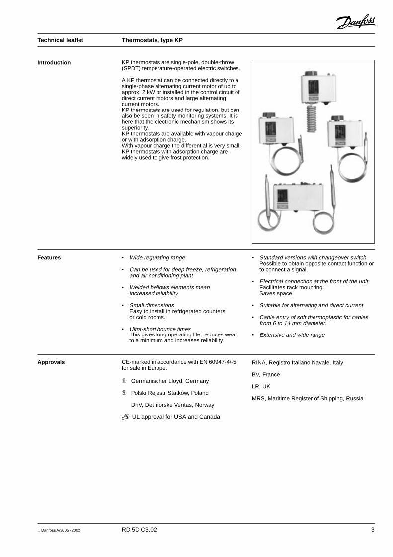
KP thermostats are single-pole, double-throw(SPDT) temperature-operated electric switches.
A KP thermostat can be connected directly to asingle-phase alternating current motor of up toapprox. 2 kW or installed in the control circuit ofdirect current motors and large alternatingcurrent motors.KP thermostats are used for regulation, but canalso be seen in safety monitoring systems. It ishere that the electronic mechanism shows itssuperiority.KP thermostats are available with vapour chargeor with adsorption charge.With vapour charge the differential is very small.KP thermostats with adsorption charge arewidely used to give frost protection.
Introduction
• Wide regulating range
• Can be used for deep freeze, refrigerationand air conditioning plant
• Welded bellows elements meanincreased reliability
• Small dimensionsEasy to install in refrigerated countersor cold rooms.
• Ultra-short bounce timesThis gives long operating life, reduces wearto a minimum and increases reliability.
Features • Standard versions with changeover switchPossible to obtain opposite contact function orto connect a signal.
• Electrical connection at the front of the unitFacilitates rack mounting.Saves space.
• Suitable for alternating and direct current
• Cable entry of soft thermoplastic for cablesfrom 6 to 14 mm diameter.
• Extensive and wide range
Approvals CE-marked in accordance with EN 60947-4/-5for sale in Europe.
F Germanischer Lloyd, Germany
P Polski Rejestr Statków, Poland
DnV, Det norske Veritas, Norway
CS UL approval for USA and Canada
RINA, Registro Italiano Navale, Italy
BV, France
LR, UK
MRS, Maritime Register of Shipping, Russia
4 RD.5D.C3.02 Danfoss A/S, 05 - 2002
Technical leaflet Thermostats, type KP
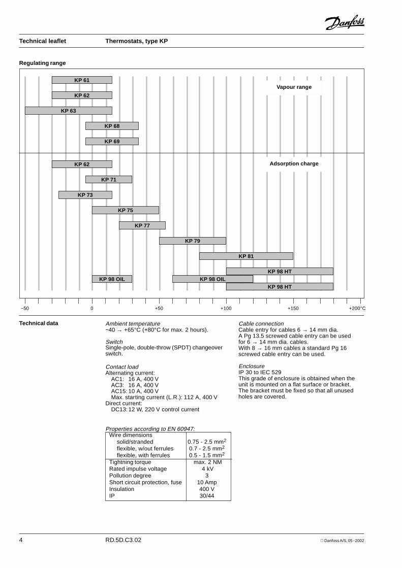
KP 61
KP 62
KP 63
KP 68
KP 69
KP 62
KP 71
KP 73
KP 75
KP 77
KP 79
KP 81
KP 98 HT
KP 98 HT
−50 0 +50 +100 +150 +200°C
KP 98 OILKP 98 OIL
Ambient temperature−40 → +65°C (+80°C for max. 2 hours).
SwitchSingle-pole, double-throw (SPDT) changeoverswitch.
Contact loadAlternating current:
AC1: 16 A, 400 VAC3: 16 A, 400 VAC15: 10 A, 400 VMax. starting current (L.R.): 112 A, 400 V
Direct current:DC13:12 W, 220 V control current
Technical data Cable connectionCable entry for cables 6 → 14 mm dia.A Pg 13.5 screwed cable entry can be usedfor 6 → 14 mm dia. cables.With 8 → 16 mm cables a standard Pg 16screwed cable entry can be used.
EnclosureIP 30 to IEC 529This grade of enclosure is obtained when theunit is mounted on a flat surface or bracket.The bracket must be fixed so that all unusedholes are covered.
Regulating range
Adsorption charge
Vapour range
Properties according to EN 60947:Wire dimensions
solid/stranded 0.75 - 2.5 mm2
flexible, w/out ferrules 0.7 - 2.5 mm2
flexible, with ferrules 0.5 - 1.5 mm2
Tightning torque max. 2 NMRated impulse voltage 4 kVPollution degree 3Short circuit protection, fuse 10 AmpInsulation 400 VIP 30/44

Danfoss A/S, 05 - 2002 RD.5D.C3.02 5
Technical leaflet Thermostats, type KP
Contact systems
KP thermostats KP 98
Ordering
1) Bulb must always be placed colder than the thermostat housing and capillary tube. The thermostat will then regulateindependent of ambient temperature.
2) Bulb can be placed warmer or colder than thermostat housing and capillary tube, but variations from +20°C ambienttemperature will influence the scale accuracy.
3) With manual switch, not isolating switch.4) Panel mounting model with top plate.
Charge Type Bulb Setting Differential ∆t Reset Max. Capillary- Code no.
type range Lowest Highest bulb tubetemperature temperature temp. length
°C °C °C °C m
KP 61 A – 30 → 15 5.5 → 23 1.5 → 7 Aut. 120 2 060L1100
KP 61 A – 30 → 15 5.5 → 23 1.5 → 7 Aut. 120 5 060L1101
KP 61 B – 30 → 13 4.5 → 23 1.2 → 7 Aut. 120 2 060L1102
KP 61 B – 30 → 15 5.5 → 23 1.5 → 7 Aut. 120 2 060L1103 3)
KP 61 B – 30 → 15 5.5 → 23 1.5 → 7 Aut. 120 2 060L1128 3) 4)
KP 61 A – 30 → 15 Fixed 6 Fixed 2 Min. 120 5 060L1104
Vapour 1) KP 61 B – 30 → 15 Fixed 6 Fixed 2 min. 120 2 060L1105
KP 62 C 1 – 30 → 15 6.0 → 23 1.5 → 7 Aut. 120 060L1106
KP 63 A – 50 → – 10 10.0 → 70 2.7 → 8 Aut. 120 2 060L1107
KP 63 B – 50 → – 10 10.0 → 70 2.7 → 8 Aut. 120 2 060L1108
KP 68 C 1 – 5 → 35 4.5 → 25 1.8 → 7 Aut. 120 060L1111
KP 69 B – 5 → 35 4.5 → 25 1.8 → 7 Aut. 120 2 060L1112
KP 62 C 2 – 30 → 15 5.0 → 20 2.0 → 8 Aut. 80 060L1110 3) 4)
KP 71 E 2 – 5 → 20 3.0 → 10 2.2 → 9 Aut. 80 2 060L1113
KP 71 E 2 – 5 → 20 Fixed 3 Fixed 3 min. 80 2 060L1115
KP 73 E 1 – 25 → 15 12.0 → 70 8.0 → 25 Aut. 80 2 060L1117
KP 73 D 1 – 25 → 15 4.0 → 10 3.5 → 9 Aut. 80 2 060L1118 3)
KP 73 D 1 – 25 → 15 Fixed 3.5 Fixed 3.5 min. 80 2 060L1138
KP 73 D 2 – 20 → 15 4.0 → 15 2.0 → 13 Aut. 55 3 060L1140
KP 73 D 1 – 25 → 15 3.5 → 20 3.25 → 18 Aut. 80 2 060L1143
KP 75 F 0 → 35 3.5 → 16 2.5 → 12 Aut. 110 2 060L1120
KP 75 E 2 0 → 35 3.5 → 16 2.5 → 12 Aut. 110 2 060L1137
KP 77 E 3 20 → 60 3.5 → 10 3.5 → 10 Aut. 130 2 060L1121
KP 77 E 3 20 → 60 3.5 → 10 3.5 → 10 Aut. 130 3 060L1122
KP 77 E 2 20 → 60 3.5 → 10 3.5 → 10 Aut. 130 5 060L1168
KP 79 E 3 50 → 100 5.0 → 15 5.0 → 15 Aut. 150 2 060L1126
KP 81 E 3 80 → 150 7.0 → 20 7.0 → 20 Aut. 200 2 060L1125
KP 81 E 3 80 → 150 Fixed 8 Fixed 8 Max. 200 2 060L1155
KP 98E 2 OIL: 60 → 120 OIL: Fixed 14 OIL: Fixed 14 Max. 150 1
060L1131E 2 HT: 100 → 180 HT: Fixed 25 HT: Fixed 25 Max. 250 2
Adsorb-tion 2)
6 RD.5D.C3.02 Danfoss A/S, 05 - 2002
Technical leaflet Thermostats, type KP
Ordering(continued)
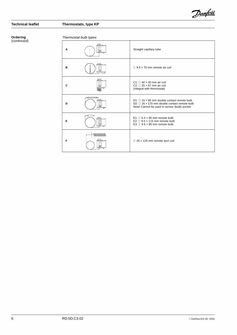
Thermostat bulb types
A Straight capillary tube
B ∅ 9.5 × 70 mm remote air coil
C1: ∅ 40 × 30 mm air coilC C2: ∅ 25 × 67 mm air coil
(integral with thermostat)
D1: ∅ 10 × 85 mm double contact remote bulbD D2: ∅ 16 × 170 mm double contact remote bulb
Note! Cannot be used in sensor (bulb) pocket
F ∅ 25 × 125 mm remote duct coil
E1: ∅ 6.4 × 95 mm remote bulbE E2: ∅ 9.5 × 115 mm remote bulb
E3: ∅ 9.5 × 85 mm remote bulb

Danfoss A/S, 05 - 2002 RD.5D.C3.02 7
Technical leaflet Thermostats, type KP
DesignFunction
The switch in the KP has a snap-action functionand the bellows move only when the cut-in orcut-out value is reached.
The design of the KP thermostat affords thefollowing advantages:− high contact load− ultra-short bounce time− vibration resistance up to 4 g
in the range 0-1000 Hz− long mechanical and electrical life.
1. Temperature setting spindle2. Differential setting spindle3. Main arm7. Main spring8. Differential spring9. Bellows
12. Switch13. Terminals14. Earth terminal15. Cable entry16. Tumbler17. Sensor
Key sketch of KP thermostats Adsorption charge
Vapour charge
Adsorption charge Vapour charge

8 RD.5D.C3.02 Danfoss A/S, 05 - 2002
Technical leaflet Thermostats, type KP
DesignFunction(continued)
KP 98, dual thermostat
1. Temperature setting spindle, OIL3. Main arm5. Temperature setting spindle, HT7. Main spring9. Bellows
10. Capillary tube, OIL11. Capillary tube, HT12. Switch13. Terminals14. Earth terminal15. Cable entry16. Tumbler17. Sensor (bulb)18. Locking plate
Dual thermostat KP 98 is used to provideprotection against excessively high dischargegas temperature and to ensure a suitable oiltemperature in the compressor.To avoid the temperature of the hot gasexceeding the maximum permissible value dur-ing extreme operating conditions (low evaporat-ing pressure, high condensing pressure, highsuction vapour superheat) a KP 98 thermostatcan be used on the high temperature side (HT).If the temperature of the hot gas becomes toohigh the refrigerant will break down and thecompressor discharge valve will become dam-aged.
DifferentialThe differential is the difference between themake and break temperatures.A differential is necessary for satisfactoryautomatic operation of the plant.
Mechanical differential (intrinsic differential)The mechanical differential is the differential setby the differential spindle.
Operating differential (thermal differential)The operating differential is the differentialthe plant operates on. Operating differential isthe sum of the mechanical differential and thedifferential produced by the time constant.
Reset1. Manual reset:
Units with manual reset can only be restartedafter the reset button has been activated.On min. reset units the set value is equal tothe cut-out value for falling temperature.On max. reset units the set value is equal tothe cut-out value for rising temperature.
2. Automatic reset:These units are automatically reset afteroperational stop.
Terminology
The risk is greatest in refrigeration systems thatoperate on a high compression ratio (e.g. insystems with NH3 or R 22) and in applicationswith hot gas bypass.This unit has two separate thermostat functions.The HT sensor that controls the discharge gastemperature is fitted on the discharge tubeimmediately after the compressor.For larger compressors, the sensor can be builtinto the discharge line.The OIL sensor that controls the oil temperatureis located in the compressor oil sump.
Danfoss A/S, 05 - 2002 RD.5D.C3.02 9
Technical leaflet Thermostats, type KP
Setting Thermostats with automatic resetSet the upper activating temperature on therange scale.Set the differential on the "DIFF" scale.The temperature setting on the range scale willthen correspond to the temperature at which therefrigeration compressor will be started on risingtemperature. The compressor will be stoppedwhen the temperature has fallen in relation to thedifferential setting.Note that the differential depends on the rangesetting. Therefore, the differential scalemust only be used as guideline.If with low stop temperature settings thecompressor will not stop, check whether thedifferential is set at too high a value!
Thermostats with minimum resetSet the stop temperature on the range scale.The differential is a fixed setting.The compressor can be restarted by pressingthe "Reset button" after the temperature on thethermostat sensor has risen by a value equal tothe fixed differential setting.
Thermostats with maximum resetSet the stop temperature on the range scale.The differential is a fixed setting.The compressor can be restarted by pressingthe "Reset button" after the temperature on thethermostat sensor has fallen to a value equal tothe fixed differential setting.
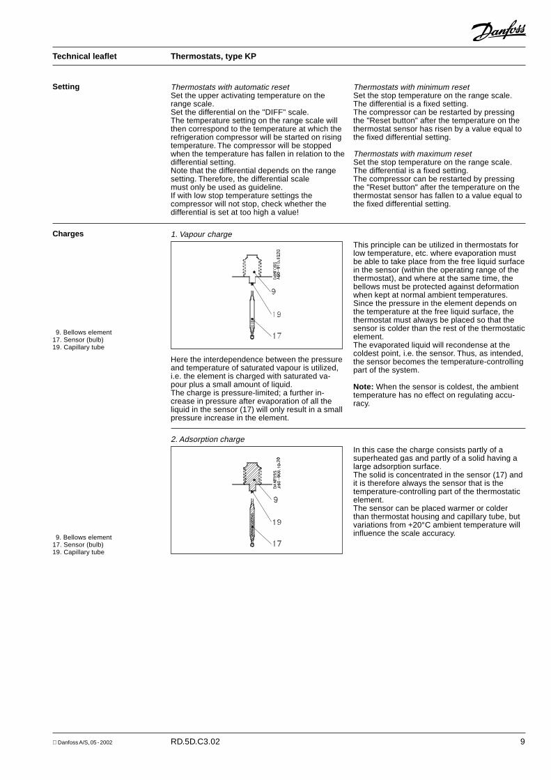
1. Vapour charge
Here the interdependence between the pressureand temperature of saturated vapour is utilized,i.e. the element is charged with saturated va-pour plus a small amount of liquid.The charge is pressure-limited; a further in-crease in pressure after evaporation of all theliquid in the sensor (17) will only result in a smallpressure increase in the element.
ChargesThis principle can be utilized in thermostats forlow temperature, etc. where evaporation mustbe able to take place from the free liquid surfacein the sensor (within the operating range of thethermostat), and where at the same time, thebellows must be protected against deformationwhen kept at normal ambient temperatures.Since the pressure in the element depends onthe temperature at the free liquid surface, thethermostat must always be placed so that thesensor is colder than the rest of the thermostaticelement.The evaporated liquid will recondense at thecoldest point, i.e. the sensor. Thus, as intended,the sensor becomes the temperature-controllingpart of the system.
Note: When the sensor is coldest, the ambienttemperature has no effect on regulating accu-racy.
9. Bellows element17. Sensor (bulb)19. Capillary tube
2. Adsorption chargeIn this case the charge consists partly of asuperheated gas and partly of a solid having alarge adsorption surface.The solid is concentrated in the sensor (17) andit is therefore always the sensor that is thetemperature-controlling part of the thermostaticelement.The sensor can be placed warmer or colderthan thermostat housing and capillary tube, butvariations from +20°C ambient temperature willinfluence the scale accuracy.9. Bellows element
17. Sensor (bulb)19. Capillary tube
10 RD.5D.C3.02 Danfoss A/S, 05 - 2002
Technical leaflet Thermostats, type KP
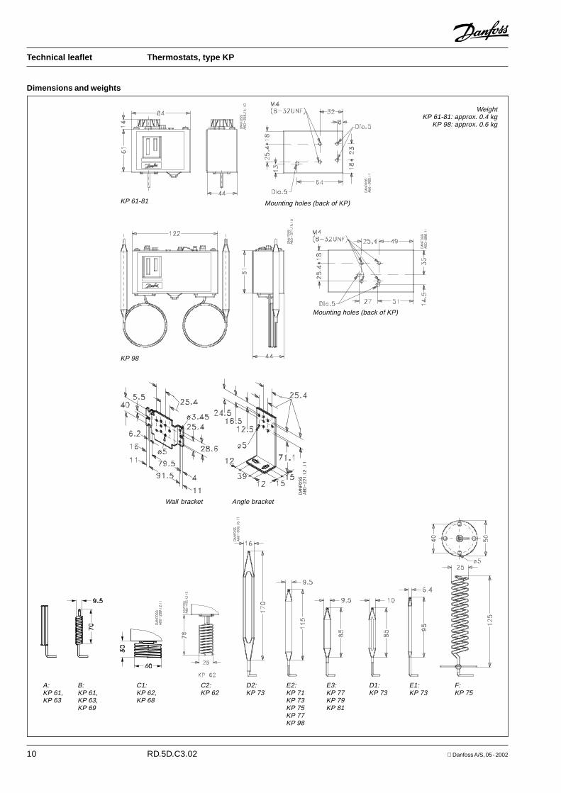
Dimensions and weights
WeightKP 61-81: approx. 0.4 kg
KP 98: approx. 0.6 kg
KP 61-81 Mounting holes (back of KP)
A: B: C1:KP 61, KP 61, KP 62,KP 63 KP 63, KP 68
KP 69
C2:KP 62
D2: E2: E3: D1: E1: F:KP 73 KP 71 KP 77 KP 73 KP 73 KP 75
KP 73 KP 79KP 75 KP 81KP 77KP 98
Wall bracket Angle bracket
KP 98
Mounting holes (back of KP)
Danfoss A/S, 05 - 2002 RD.5D.C3.02 11
Technical leaflet Thermostats, type KP
12 RD.5D.C3.02 Danfoss A/S, 05 - 2002
Technical leaflet Thermostats, type KP