technical information in detail - jupojos technika stabdziu/textar/textar_technine...67 installation...
TRANSCRIPT
In DetailTechnical Information
Copyright 2007 © TMD Friction
All rights reserved. This brochure must not be duplicated, photocopied, reproduced or converted into an electronically or mechanically legible form in full or in part without the previous written permission of TMD Friction.
technIcal InformatIon / 02
TMD Friction Services GmbHSchlebuscher Str. 9951381 LeverkusenTel.: 02171 703-0Fax: 02171 703-388E-Mail: [email protected]
05 Friction Lining Requirements
07 Safety Part Brake Friction Product
08 Brake Friction Product Approval Under German Road Traffic Law
11 Principles Governing Liability for Faulty Products
13 Quality Assurance When Manufacturing Disc Brake Pads
15 EC Safety Data Sheets
16 Disposal
17 Definition of "Friction"
18 Maximum Braking Torque
19 Transmittable Braking Force
20 Disc Brakes in Passenger Cars
27 Fixed Caliper Brake
29 Floating Caliper Brake
31 Fist Caliper Brake
33 Service Life of Brake Friction Products
34 Wear Indicators for Brake Friction Products
36 Brake Friction Product Replacement
37 Brake System Maintenance Instructions
38 Maintenance Instructions
40 Reference to Fitting Instructions
41 Special Fitting Instructions for Disc Brake Pads
43 Brake Fluid Change
45 Deficiencies in Commercial Vehicle Drum Brakes
47 Deficiencies in Commercial Vehicle Disc Brakes
49 Over-Braking/Noise
50 Inadequate Braking Effect
51 Commercial Vehicle Drum Brake Linings - Wear Edge
52 Commercial Vehicle Drum Brake Linings - Wear Pocket
53 Drum Brake Lining Damage Assessment
55 Dismantling Commercial Vehicle Drum Brake Linings
56 Brake Shoe Inspection
57 Fitting Commercial Vehicle Drum Brake Linings
59 Lining Measurements (thickness), Commercial Vehicle Drum Brake Linings
60 Pre-stressed Rivets
61 Recommended Rivets and Riveting Force
62 Installation Drawing for Tapered Linings
63 Turning-off Instructions for Commercial Vehicle Drum Brake Linings
64 Pre-Ground Drum Brake Linings
Contents
65 Fitting Instructions, Drum Brake Linings, WVA No. 19758
66 Adjustments, Drum Brake Linings, WVA No. 19758
67 Installation Drawing for Rockwell Brake - Drum Brake Lining
68 General Fitting Instructions - Commercial Vehicle Disc Brake Pads
69 Omission of Thermal Insulation Plates in Lucas D 3 and Elsa Brakes
70 Secondary Measures
71 Bonding Procedure for Commercial Vehicle Disc Brake Pads
72 Turn-off and Thickness Data for Commercial Vehicle Brake Discs and Pads
73 Friction Material Overview, Commercial Vehicle Drum Brake Linings
74 Friction Material Overview, Commercial Disc Brake Pads
75 Notes
Contents
Technical InformationIn Detail
03 / technIcal InformatIon technIcal InformatIon / 04
In the book "Brake Friction Products for Road Vehicles" issued by Textar it states: "Friction lining formulations always represent a compromise between desirable and achievable characteristics". Regarding the formulation it is therefore imperative to find an acceptable compromise between the customers demands and the respective production technology. Experience and instinct are required to solve this problem.
In light of this, it is understandable that such a formulation ranks among the best kept secrets of any manufacturer. However, the “stuff”, from which brake friction products are made, is no secret. It can be composed of the following raw materials: bonding agents (in the form of resin and rubber), organic and anorganic fillers (like chalk or iron oxide), lubricants (of graphite or coke powder) and metals (of steel wool or powder).
Thus only now do the various additives and the matrix, with a total of up to 25 substances, produce the actual brake friction material.
It can of course be done in a more simple manner. A brake friction product, with a high friction coefficient, can be produced from just three components, 30% steel wool, 55% petroleum coke and 15% binding resin. Such brake friction products are however void of any comfort. This comfort can only be achieved by making the complex calculations required for the ideal brake friction formula. This requires a high degree of specialist knowledge.
The practical process of blending, pressing and hardening also places high demands on know-how. Apart from this, an even distribution and compaction of the raw materials during the blending and pressing processes is of vital importance for the brake friction characteristics. The choice of a suitable mixing machine as well as the blending sequence are amongst the manufacturers best guarded "secrets".
Here are some of the criteria, which are of vital importance when manufacturing brake friction products:
Approval procedure
Friction materials are split into five main groups. Each has its own history, stands for an individual product philosophy and satisfies the needs of a particular market.
A) Semi-metallic friction materials are mainly used in the US American domestic market. As the name implies, these contain a high proportion of steel fibers. The friction coefficient is approx. 0.35, is not very heat resistant but has a low wear value, which preserves the disc. The low friction coefficient normally produces a good noise characteristic. The high proportion of steel fibers guarantees a favorable pricing.
B) Steel-free friction materials are typically for the Japanese market. The characteristics of this category are comparable to category A. The material does not, however, contain any steel fibers and the material mix is very expensive.
C) NAO (Non-Asbestos Organics) conforms with the European friction material philosophy. Depending upon the area of application, these materials have a friction coefficient of between 0.35 and 0.5 and contain a small percentage of steel fibers. With regard to the manufacturing costs, the materials lie between categories A) and B) but offer the highest performance braking characteristics. Unlike categories A) and B), European legal standards are always fulfilled by NAO materials.
D) Ceramic friction materials contain a certain proportion of ceramic fibers, as the name implies but do not normally contain steel fibers.
The materials tested by us displayed an extreme lack of pedal feel and braking power and for this reason were rejected by our customers. Over and above this, they would not fulfil the legal requirements in Europe and already had trouble gaining acceptance of the US American standard FMVSS135. TMD will no longer pursue this family of materials.
E) Sintered friction materials are manufactured for special applications like motor cycles, industrial applications and rail vehicles.
TMD offers material groups A) to C) for the passenger and commercial vehicle sectors, depending upon application area and market requirements.
For safety1. Bedding properties
2. Cold friction coefficient
3. Speed friction coefficient
4. Friction coefficient under temperature load
5. Friction coefficient after temperature load
6. Friction coefficient under wet conditions
7. Friction coefficient under the effects of thawing salt
8. Friction coefficient under pressure
9. Static friction coefficient
10. Friction coefficient when reversing
11. Expansion and shrinkage
12. Compressibility
13. Heat transfer
14. Strength (cracks, tear-off)
15. Flammability
16. Corrosion resistance
17. Bending strength
For comfort18. Noise
19. Vehicle vibrations
20. Pedal feel
21. Smell
22. Smoke development
23. Application force
24. Wheel fouling
25. Environmental pollution by abrasive wear
For economic efficiency26. Lining wear
27. Counter material wear
28. Weight
29. Production costs
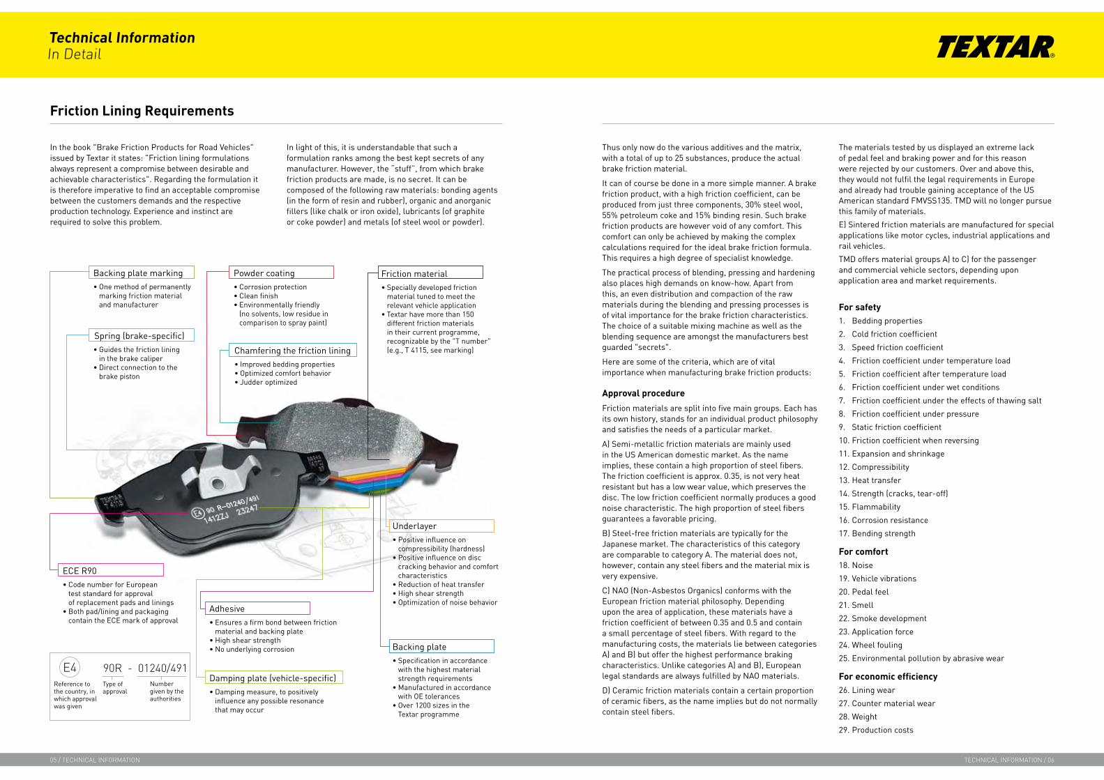
Reference to the country, in which approval was given
Type of approval
Number given by the authorities
e4 90r - 01240/491
Technical InformationIn Detail
05 / technIcal InformatIon technIcal InformatIon / 06
Friction Lining Requirements
Backing plate markingOne method of permanently marking friction material and manufacturer
•
Spring (brake-specific)Guides the friction lining in the brake caliperDirect connection to the brake piston
•
•
Powder coatingCorrosion protectionClean finishEnvironmentally friendly (no solvents, low residue in comparison to spray paint)
•••
ECE R90Code number for European test standard for approval of replacement pads and liningsBoth pad/lining and packaging contain the ECE mark of approval
•
•
Friction materialSpecially developed friction material tuned to meet the relevant vehicle application Textar have more than 150 different friction materials in their current programme, recognizable by the "T number" (e.g., T 4115, see marking)
•
•
Chamfering the friction liningImproved bedding propertiesOptimized comfort behaviorJudder optimized
•••
AdhesiveEnsures a firm bond between friction material and backing plateHigh shear strengthNo underlying corrosion
•
••
UnderlayerPositive influence on compressibility (hardness)Positive influence on disc cracking behavior and comfort characteristicsReduction of heat transferHigh shear strengthOptimization of noise behavior
•
•
•••
Damping plate (vehicle-specific)Damping measure, to positively influence any possible resonance that may occur
•
Backing plateSpecification in accordance with the highest material strength requirements Manufactured in accordance with OE tolerances Over 1200 sizes in the Textar programme
•
•
•

Technical InformationIn Detail
00 / technIcal InformatIon
Brake friction products are structural components of a brake. They already play a role as factor µ (friction coefficient) in the calculation of the braking power. The counter material used for the brake friction product is generally grey cast iron, which must fulfil the requirements of the applicable standards.
Brake friction products with differing friction coefficients are available for selection. These behave differently under the relative conditions, depending upon the material (e.g., brake drum temperature, rubbing speed, contact pressures, etc.). The performance of the brake will thus alter with differing friction coefficients.
The axle load and friction coefficient are taken into account when calculating the design of brakes for a passenger car.
In addition to the friction coefficient, the self-reinforcement of the brake is also a decisive factor for the braking performance. The greater the self-reinforcement of a brake, the greater the effect of friction coefficient variations of the brake friction products. Whilst the self-reinforcement of drum brakes varies depending upon the design, this is an insignificant factor in the case of disc brakes.
Approval procedure
As a fundamental part of the brake system, the brake friction product is a safety part of vehicle. As such, brake friction products are subject to legal regulations and require a certificate of approval under traffic law.
If a vehicle is to be registered for the first time for use in road traffic, it must first be issued with a certificate of vehicle type approval. This usually takes the form of a GENERAL VEHICLE TYPE APPROVAL (ALLGEMEINE BETRIEBSERLAUBNIS - ABE) in accordance with § 20 StVZO (in Germany), which is issued by the Federal Office for Motor Traffic (Kraftfahrt-Bundesamt - KBA). This is preceded by obtaining a type approval from a Technical Control Association (TÜV) which verifies compliance with all legal requirements for the particular vehicle type. The tested brake friction products are listed in the type approval report and thus approved of for use in this type of vehicle.
Vehicles, which are produced in small numbers, are approved of individually in accordance with § 21 StVZO (in Germany). For this purpose, they must be taken to a TÜV vehicle testing center for inspection. As a basis for inspection, the same regulations apply as for type approval. The type of brake friction products fitted for the acceptance test is approved of for this type of vehicle.
Brake friction product replacement
If the brake friction products need to be replaced after a certain service period of the vehicle, they may not replaced by any brake friction product fitting the brake. The gist of § 19, Section 2, StVZO (in Germany) states that the type approval of a vehicle is rendered null and void, if certain parts are modified or unauthorized spare parts have been fitted. Brake friction products in particular are parts of a vehicle that are subject to authorization.
If the vehicle manufacturers original equipment (OE) parts are used, the vehicle type approval will remain intact, as these parts are approved. Original brake friction products are marked with the vehicle manufacturers brand name and the brake friction type designation as a rule. Original replacement friction products do not bear an official testing mark or approval number as a rule.
If in doubt, as to whether a certain brake friction product has been approved of as original spare part for a vehicle, information can be requested from the vehicle manufacturer or an TÜV testing center.
Approved brake friction products are not specified in the vehicle title document.
Technical InformationIn Detail
07 / technIcal InformatIon technIcal InformatIon / 08
Safety Part Brake Friction Product
!Consequently, only tested and approved brake friction products may be fitted!
Brake Friction Product Approval Under German Road Traffic Law
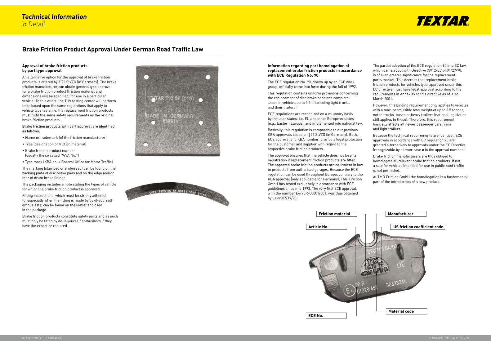
Approval of brake friction products by part type approval
An alternative option for the approval of brake friction products is offered by § 22 StVZO (in Germany). The brake friction manufacturer can obtain general type approval for a brake friction product (friction material and dimensions will be specified) for use in a particular vehicle. To this effect, the TÜV testing center will perform tests based upon the same regulations that apply to vehicle type tests, i.e. the replacement friction products must fulfil the same safety requirements as the original brake friction products.
Brakefrictionproductswithpartapprovalareidentifiedasfollows:
• Name or trademark (of the friction manufacturer)
• Type (designation of friction material)
• Brake friction product number (usually the so called "WVA No.")
• Type mark (KBA no. = Federal Office for Motor Traffic)
The marking (stamped or embossed) can be found on the backing plate of disc brake pads and on the edge and/or rear of drum brake linings.
The packaging includes a note stating the types of vehicle for which the brake friction product is approved.
Fitting instructions, which must be strictly adhered to, especially when the fitting is made by do-it-yourself enthusiasts, can be found on the leaflet enclosed in the package.
Brake friction products constitute safety parts and as such must only be fitted by do-it-yourself enthusiasts if they have the expertise required.
Information regarding part homologation of replacement brake friction products in accordance with ECE Regulation No. 90
The ECE regulation No. 90, drawn up by an ECE work group, officially came into force during the fall of 1992.
This regulation contains uniform provisions concerning the replacement of disc brake pads and complete shoes in vehicles up to 3.5 t (including light trucks and their trailers).
ECE regulations are recognized on a voluntary basis by the user states, i.e. EU and other European states (e.g., Eastern Europe), and implemented into national law.
Basically, this regulation is comparable to our previous KBA approvals based on §22 StVZO (in Germany). Both, ECE approval and KBA number, provide a legal protection for the customer and supplier with regard to the respective brake friction products.
The approval ensures that the vehicle does not lose its registration if replacement friction products are fitted. The approved brake friction products are equivalent in law to products from authorised garages. Because the ECE regulation can be used throughout Europe, contrary to the KBA approval (only applicable for Germany), TMD Friction GmbH has tested exclusively in accordance with ECE guidelines since mid 1993. The very first ECE approval, with the number E4-90R-00001/001, was thus obtained by us on 07/19/93.
The partial adoption of the ECE regulation 90 into EC law, which came about with Directive 98/12/EC of 01/27/98, is of even greater significance for the replacement parts market. This decrees that replacement brake friction products for vehicles type-approved under this EC directive must have legal approval according to the requirements in Annex XV to this directive as of 31st March 2001.
However, this binding requirement only applies to vehicles with a max. permissible total weight of up to 3.5 tonnes, not to trucks, buses or heavy trailers (national legislation still applies to these). Therefore, this requirement basically affects all newer passenger cars, vans and light trailers.
Because the technical requirements are identical, ECE approvals in accordance with EC regulation 90 are granted alternatively to approvals under the EC Directive (recognizable by a lower case e in the approval number.)
Brake friction manufacturers are thus obliged to homologate all relevant brake friction products. If not, a sale for vehicles intended for use in public road traffic is not permitted.
At TMD Friction GmbH the homologation is a fundamental part of the introduction of a new product.
Brake Friction Product Approval Under German Road Traffic Law
Technical InformationIn Detail
09 / technIcal InformatIon technIcal InformatIon / 10
Friction material
Article No. US friction coefficient code
Manufacturer
Material codeECE No.
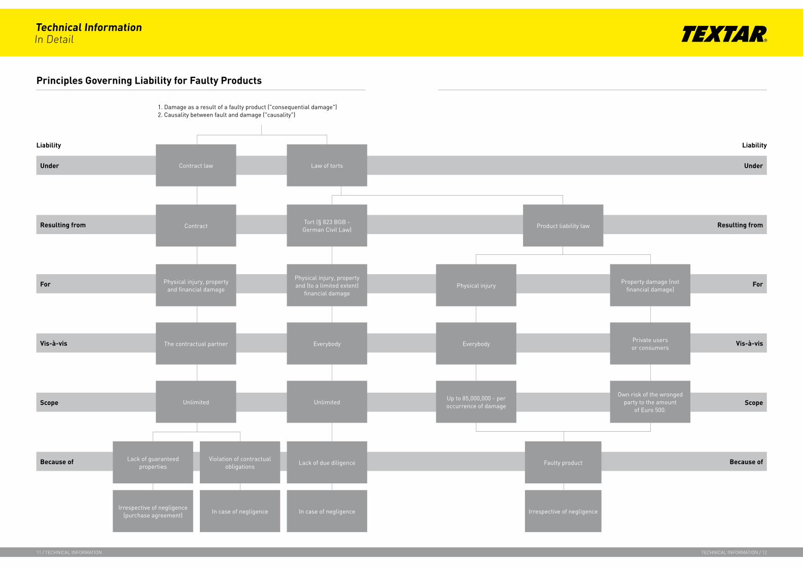
Principles Governing Liability for Faulty Products
1. Damage as a result of a faulty product ("consequential damage")2. Causality between fault and damage ("causality")
Liability
Under
Because of
Scope
Vis-à-vis
For
Resulting from
Under
Because of
Scope
Vis-à-vis
For
Resulting from
Law of torts
Liability
Contract law
Physical injury, property and financial damage
Contract
The contractual partner
Unlimited
Lack of guaranteed properties
Violation of contractual obligations
Irrespective of negligence (purchase agreement)
In case of negligence
Product liability law
Up to 85,000,000 - per occurrence of damage
Physical injury
Everybody
Own risk of the wronged party to the amount
of Euro 500.
Property damage (not financial damage)
Private users or consumers
Lack of due diligence
Unlimited
Physical injury, property and (to a limited extent)
financial damage
Everybody
In case of negligence
Tort (§ 823 BGB - German Civil Law)
Faulty product
Irrespective of negligence
Technical InformationIn Detail
11 / technIcal InformatIon technIcal InformatIon / 12
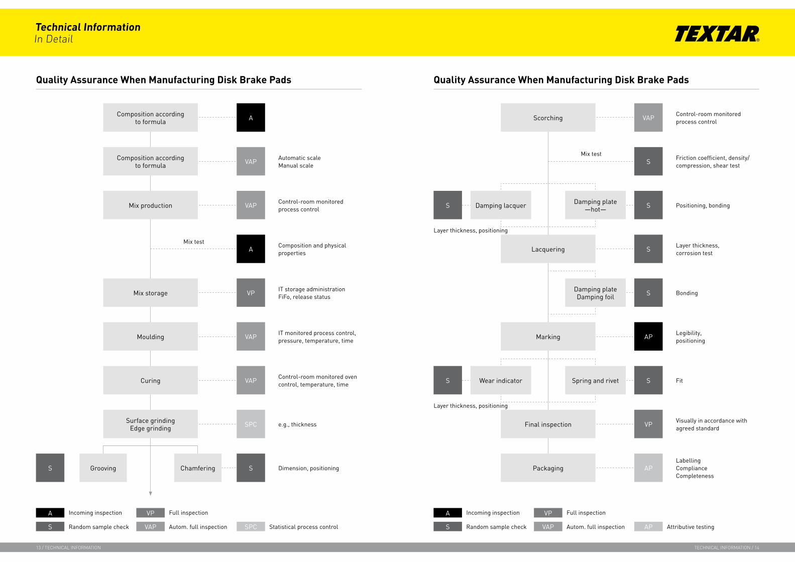
Quality Assurance When Manufacturing Disk Brake Pads
A
Grooving
Surface grindingEdge grinding
Curing
Moulding
Mix storage
Mix production
Composition according to formula
Composition according to formula
A
VAP
VAP
VP
SPC
VAP
VAP
S Chamfering S
A
S
Mix test
Automatic scaleManual scale
Control-room monitoredprocess control
Composition and physicalproperties
IT storage administration FiFo, release status
IT monitored process control, pressure, temperature, time
Control-room monitored oven control, temperature, time
e.g., thickness
Dimension, positioning
Incoming inspection
Random sample check
VP
VAP
Full inspection
Autom. full inspection SPC Statistical process control
Quality Assurance When Manufacturing Disk Brake Pads
Control-room monitored process controlScorching VAP
S
Lacquering S
Marking AP
SDamping lacquer Damping plate—hot—S
SDamping plateDamping foil
SWear indicatorS Spring and rivet
Packaging
A
S
Incoming inspection
Random sample check
VP
VAP
Full inspection
Autom. full inspection AP Attributive testing
Final inspection VP
AP
Friction coefficient, density/ compression, shear test
Positioning, bonding
Layer thickness,corrosion test
Bonding
Legibility, positioning
Fit
Visually in accordance with agreed standard
LabellingComplianceCompleteness
Mix test
Layer thickness, positioning
Layer thickness, positioning
Technical InformationIn Detail
13 / technIcal InformatIon technIcal InformatIon / 14
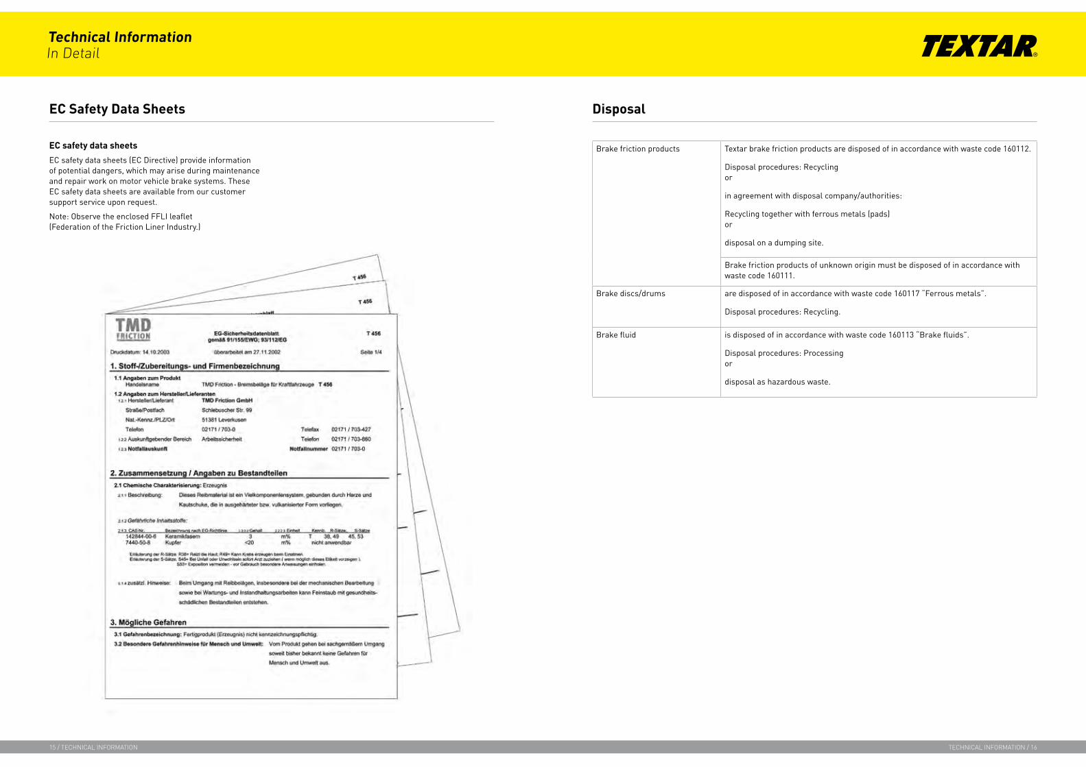
EC safety data sheets
EC safety data sheets (EC Directive) provide information of potential dangers, which may arise during maintenance and repair work on motor vehicle brake systems. These EC safety data sheets are available from our customer support service upon request.
Note: Observe the enclosed FFLI leaflet (Federation of the Friction Liner Industry.)
EC Safety Data Sheets Disposal
Brake friction products Textar brake friction products are disposed of in accordance with waste code 160112.
Disposal procedures: Recycling or
in agreement with disposal company/authorities:
Recycling together with ferrous metals (pads) or
disposal on a dumping site.
Brake friction products of unknown origin must be disposed of in accordance with waste code 160111.
Brake discs/drums are disposed of in accordance with waste code 160117 “Ferrous metals”.
Disposal procedures: Recycling.
Brake fluid is disposed of in accordance with waste code 160113 “Brake fluids”.
Disposal procedures: Processing or
disposal as hazardous waste.
Technical InformationIn Detail
15 / technIcal InformatIon technIcal InformatIon / 16
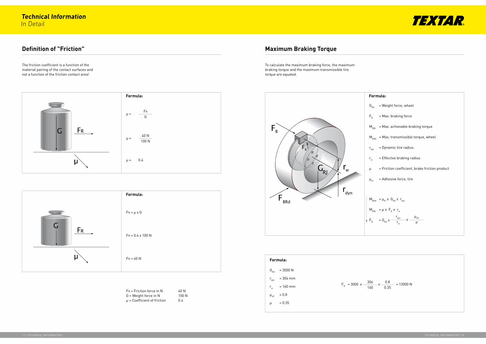
Definition of "Friction"
The friction coefficient is a function of the material pairing of the contact surfaces and not a function of the friction contact area!
Formula:
µ =FR
G
µ =40 N
100 N
µ = 0.4
Formula:
FR = µ x G
FR = 0.4 x 100 N
FR = 40 N
FR = Friction force in N 40 NG = Weight force in N 100 Nµ = Coefficient of friction 0.4
To calculate the maximum braking force, the maximum braking torque and the maximum transmissible tire torque are equated.
Maximum Braking Torque
Formula:
GRd = Weight force, wheel
FB = Max. braking force
MBBr = Max. achievable braking torque
MBRd = Max. transmissible torque, wheel
rdyn = Dynamic tire radius
rw = Effective braking radius
µ = Friction coefficient, brake friction product
µhf = Adhesive force, tire
MBRd = µhf x GRd x rdyn
MBBr = µ x FB x rw
FB = GRd xrdyn
rw
µHF
µx
Formula:
GRd = 3000 N
rdyn = 304 mm
rw = 160 mm
µHF = 0.8
µ = 0.35
304160
0.80.35
FB = 3000 x = 13000 Nx
Technical InformationIn Detail
17 / technIcal InformatIon technIcal InformatIon / 18

Requirements of a brake system
Because of the differing load cases which occur in practice, the brake equipment of the individual classes of vehicle differs in design. Although fulfilling the same function, the same parts may have different dimensions and look completely different. Brake components are classed as safety parts, in the same way as the steering system and tires of a vehicle. Particularly stringent requirements are placed on all such parts, not only by legislation but also by the manufacturers of these parts.
All vehicles must be equipped with dual-circuit brake systems, i.e. the brake system must comprise 2 independent brake circuits, each of which must be effective even if the other fails (e.g., 1st circuit: front axle, 2nd circuit: rear axle).
The brake system is split into three groups, which must fulfil the following requirements:
1. Service brake system
The service brake system is the main brake system and acts simultaneously on all four wheels, when the brake pedal is operated. It must be capable of decelerating the vehicle under all operating conditions.
2. Parking brake system
The function of this brake system is, e.g., to hold the vehicle at a permanent standstill.
3. Emergency brake system
If the service brake system fails partially or totally, the emergency brake system must be able to bring the vehicle to a standstill after a specific delay.
The legal regulations apply to the total brake system as an entity. Therefore, the requirements must also be fulfilled when the individual brake components are interacting.
Basic conditions are that the wheel brakes will not suffer stability problems, even under high thermal loads and that the brake system will not fail due to excessively high brake fluid temperatures. The strain placed on the wheel brakes by successive stops from high speeds and during long downhill runs is extremely high. Brake disc temperatures of over 750 °C can be reached during such situations. Neither the braking effect nor the braking comfort must, however, be impaired to an unacceptable degree.
The applicable regulations, the extreme operating conditions and last but not least the effects of weather (moisture, dirt, conditions and thawing salt) and signs of ageing demand careful maintenance and servicing of the brake system.
Transmittable Braking Force
µHF dry µHF wet µHF iced
Asphalt 0.8 0.5 ‹0.2
Concrete 0.6 0.4 ‹0.2
Small pavement 0.6 0.3 ‹0.2
!The braking force can not be increased infinitely, the adhesive force of the wheels must not be exceeded!
Formula:
FB = Highest possible braking force
µHF = Adhesion
FU = Circumferential wheel force
FB = FB
µHF
Disc Brakes in Passenger Cars
Technical InformationIn Detail
19 / technIcal InformatIon technIcal InformatIon / 20

Function of the hydraulic disc brake
It is common knowledge that "hydraulic transmission" will achieve the best results with regard to response time, pressure build-up time and the uniform transmission of force whilst still allowing sensitive application of the brakes.
The simultaneous braking of all wheels (provided with brakes) is given due to Pascal´s law, which states: "Pressure applied at any point of an enclosed fluid is transmitted without loss to all other parts of the fluid."
The hydraulic pressure is built up in the brake master cylinder by operating the brake pedal and acts (in a closed system) on the wheel cylinders and caliper pistons. The pressure acting on the caliper pistons thus generates the clamping force, with which the brake pads are pressed simultaneously against the rotating brake disc.
Conventional brake system
With conventional brake systems, the braking procedure is initiated exclusively by applying pressure to the brake pedal. This pressure applied is converted to hydraulic pressure in the brake master cylinder.
The brake fluid serves as a transmission medium between the brake master cylinder and the wheel brakes.
Electronic brake system
Anti-lock braking system (ABS): The first electronic brake system was introduced at the end of the 1970's.
The main purpose of ABS is to prevent the wheels from locking when full braking, thus ensuring that the vehicle remains steerable.
As with conventional brake systems, the ABS also has a mechanical/hydraulic connection from the brake pedal to the wheel brakes.
The ABS merely has an additional hydraulic unit, which electronically controls solenoid valves. The task of these valves is to selectively limit the brake pressure in case of excessive wheel slip in order to prevent wheel locking.
The ABS has undergone development since its introduction and development is ongoing. It is now a standard equipment on almost all vehicles.
Electro-hydraulic brake SBC
SBC (Sensotronic Brake Control) represents a new generation of brake systems.
The SBC electronically detects pedal travel by means of sensors and evaluates these in a control module. The term "brake by wire" is derived from this. The hydraulic unit controls via solenoid valves the brake pressure of each wheel brake individually, depending upon the driving situation. Brake fluid serves as the hydraulic transmission medium.
Contrary to the conventional brake system with ABS, the mechanical/hydraulic connection between the brake pedal and the wheel brake only exists if the electronics fail. In this case, considerably more pedal force is required.
Electro-mechanical brake EMB
The future holds a further brake system: The EMB (Electro-Mechanical Brake) no longer functions hydraulically but electro-mechanically, without brake fluid. In this case, high-power actuators are used to clamp the wheel brake and thus take care of the braking procedure. With this system, the connection between pedal and wheel brake is always electronic.
Electronic, dynamic driving systems with brake intervention
The further development of the ABS led to ASR (traction control system). In this case, the wheels are prevented from spinning (even on different road surfaces), by the left- and right-hand side wheel brakes, during acceleration. This improves the driving dynamics. The ASR is not a braking system in the true sense of the word. It can however intervene in the braking system, if a wheel tends to spin.
A further driving dynamics system is the ESP (Electronic Stability Program), which, within the physical limits, prevents a vehicle from skidding. This system also intervenes in the braking system, in order to stabilize the vehicle.
Disc Brakes in Passenger Cars
Formula:
Fluid pressure (P) =Force (t)
Cross section area (s)
Technical InformationIn Detail
21 / technIcal InformatIon technIcal InformatIon / 22
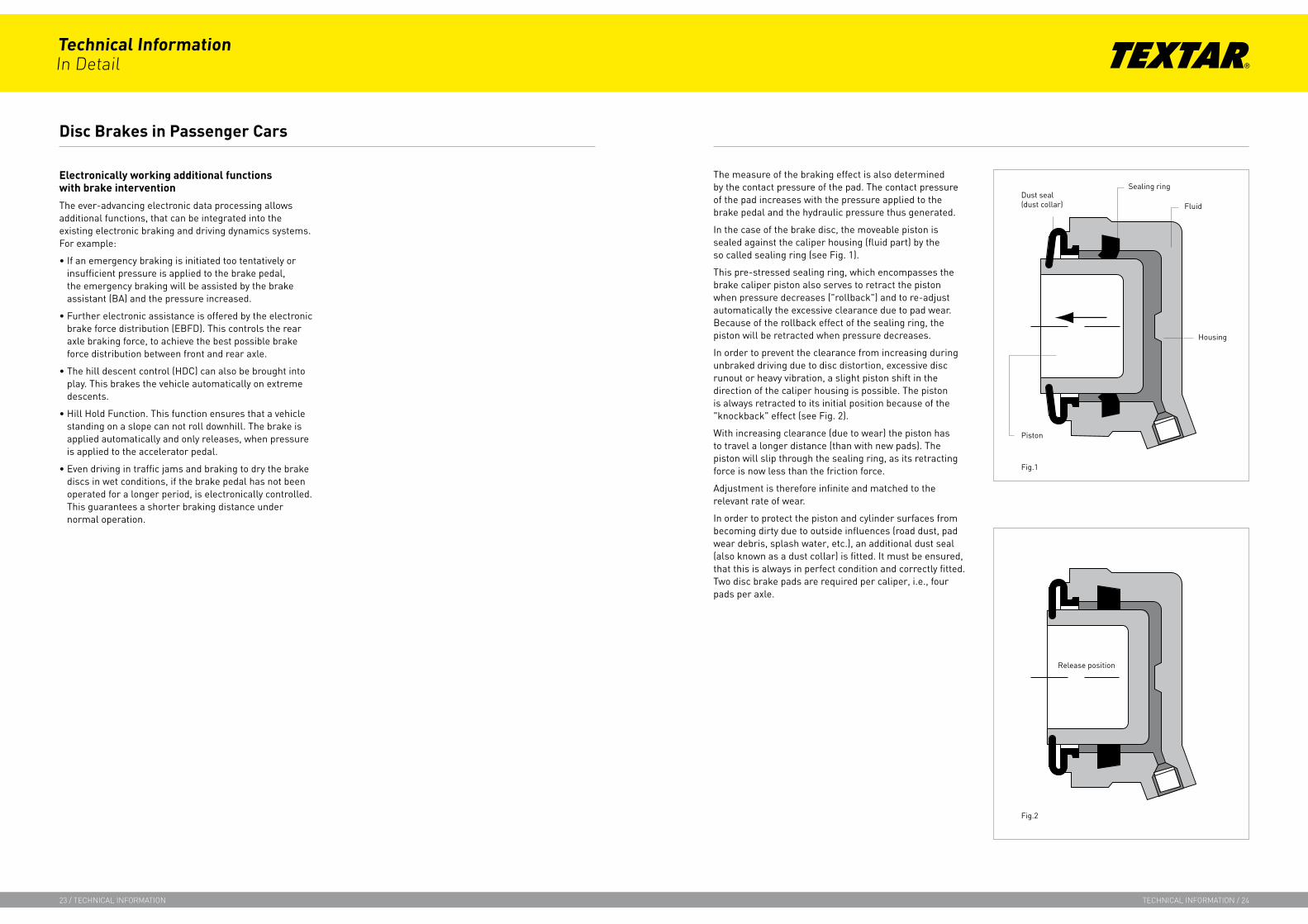
The measure of the braking effect is also determined by the contact pressure of the pad. The contact pressure of the pad increases with the pressure applied to the brake pedal and the hydraulic pressure thus generated.
In the case of the brake disc, the moveable piston is sealed against the caliper housing (fluid part) by the so called sealing ring (see Fig. 1).
This pre-stressed sealing ring, which encompasses the brake caliper piston also serves to retract the piston when pressure decreases ("rollback") and to re-adjust automatically the excessive clearance due to pad wear. Because of the rollback effect of the sealing ring, the piston will be retracted when pressure decreases.
In order to prevent the clearance from increasing during unbraked driving due to disc distortion, excessive disc runout or heavy vibration, a slight piston shift in the direction of the caliper housing is possible. The piston is always retracted to its initial position because of the "knockback" effect (see Fig. 2).
With increasing clearance (due to wear) the piston has to travel a longer distance (than with new pads). The piston will slip through the sealing ring, as its retracting force is now less than the friction force.
Adjustment is therefore infinite and matched to the relevant rate of wear.
In order to protect the piston and cylinder surfaces from becoming dirty due to outside influences (road dust, pad wear debris, splash water, etc.), an additional dust seal (also known as a dust collar) is fitted. It must be ensured, that this is always in perfect condition and correctly fitted. Two disc brake pads are required per caliper, i.e., four pads per axle.
Disc Brakes in Passenger Cars
Fig. 2
Electronically working additional functions with brake intervention
The ever-advancing electronic data processing allows additional functions, that can be integrated into the existing electronic braking and driving dynamics systems. For example:
If an emergency braking is initiated too tentatively or insufficient pressure is applied to the brake pedal, the emergency braking will be assisted by the brake assistant (BA) and the pressure increased.
Further electronic assistance is offered by the electronic brake force distribution (EBFD). This controls the rear axle braking force, to achieve the best possible brake force distribution between front and rear axle.
The hill descent control (HDC) can also be brought into play. This brakes the vehicle automatically on extreme descents.
Hill Hold Function. This function ensures that a vehicle standing on a slope can not roll downhill. The brake is applied automatically and only releases, when pressure is applied to the accelerator pedal.
Even driving in traffic jams and braking to dry the brake discs in wet conditions, if the brake pedal has not been operated for a longer period, is electronically controlled. This guarantees a shorter braking distance under normal operation.
•
•
•
•
•
Technical InformationIn Detail
23 / technIcal InformatIon technIcal InformatIon / 24
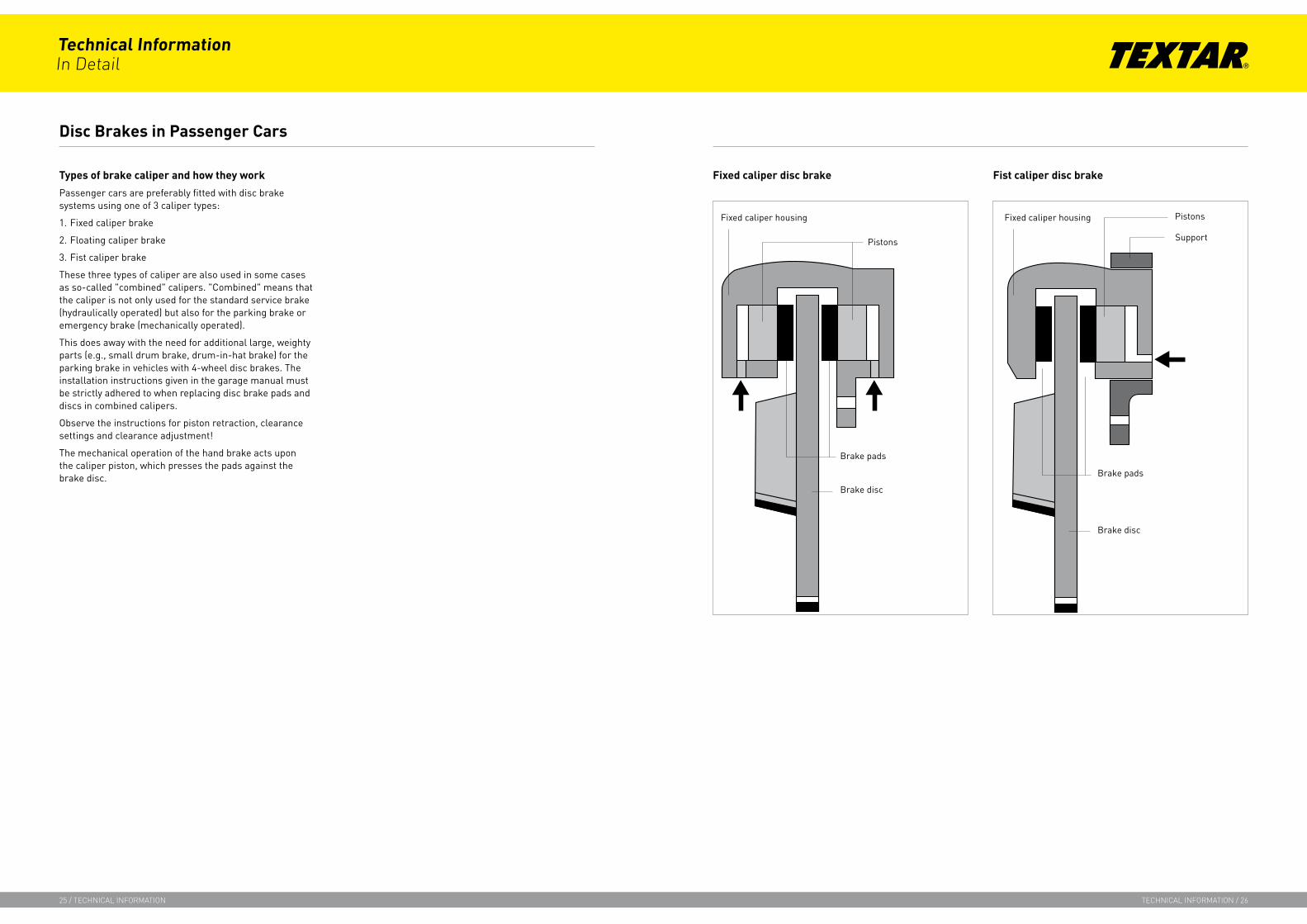
Types of brake caliper and how they work
Passenger cars are preferably fitted with disc brake systems using one of 3 caliper types:
1. Fixed caliper brake
2. Floating caliper brake
3. Fist caliper brake
These three types of caliper are also used in some cases as so-called "combined" calipers. "Combined" means that the caliper is not only used for the standard service brake (hydraulically operated) but also for the parking brake or emergency brake (mechanically operated).
This does away with the need for additional large, weighty parts (e.g., small drum brake, drum-in-hat brake) for the parking brake in vehicles with 4-wheel disc brakes. The installation instructions given in the garage manual must be strictly adhered to when replacing disc brake pads and discs in combined calipers.
Observe the instructions for piston retraction, clearance settings and clearance adjustment!
The mechanical operation of the hand brake acts upon the caliper piston, which presses the pads against the brake disc.
Disc Brakes in Passenger Cars
Fixed caliper disc brake Fist caliper disc brake
Technical InformationIn Detail
25 / technIcal InformatIon technIcal InformatIon / 26

The fixed caliper comprises two half calipers (flange and cover), each of which have one or two brake pistons). Both parts, firmly screwed together (expansion screws) and connected by the so-called channel bore, make up the "fixed caliper".
This is bolted to the wheel suspension of the vehicle (kingpin, axle flange) or in the case of inboard brakes, to the gearbox.
When the brake is operated (build-up of hydraulic pressure), two or four brake pistons respectively force the pads to simultaneously make contact with the rotating brake discs on each side (braking position). The brake pads are guided and supported in the so-called caliper housing.
The caliper housing must be clean and undamaged, in order to prevent the brake pads from jamming or seizing up due to rust. If this happened, it would be impossible to press the pads against the brake discs (no braking effect).
When the pressure falls (upon completion of braking) the brake pistons are retracted due to the "rollback" - as described under "Function of the disc brake" - and the brake pads are forced against the piston by the expansion spring. The brake disc can now rotate freely because of the clearance.
To compensate for tapered brake pad wear on the leading edge, some fixed calipers have a "piston shoulder". This piston shoulder must always be in its specified position with respect to the leading edge (observe garage manual instructions).
If this is not the case, it can not fulfil its function and it can lead to unpleasant brake noise.
If the piston is not aligned correctly, it must be returned to the specified position using piston turning pliers and the prescribed piston gauge.
When replacing the brake pads, the pad retaining pins and expansion springs must be removed after the wheels have been dismounted.
As the pistons are in an advanced position due to pad wear, they have to be pushed back using a piston retraction device (the pushed back brake fluid will cause the fluid level in the reservoir to rise).
After fitting the new brake pads, expansion springs and pad retaining pins, the brake pedal must be operated several times to optimize the caliper clearance, before taking the vehicle for a test drive.
Fixed Caliper Brake
Technical InformationIn Detail
27 / technIcal InformatIon technIcal InformatIon / 28

Floatingcaliperbrakeshavethefollowingadvantagesoverthefixedcaliper:
1. Less fitting space required at the wheel side
2. This allows a negative kingpin offset
3. No highly stressed screw connections (expansion screws) required
4. Weight advantage (e.g., only one brake piston)
5. Lower temperature generation in the brake fluid due to only one contact surface between piston and brake pad
Thefloatingcaliperbrakecomprisesthefollowingcomponents:
1. Cylinder housing including piston and sealing ring
2. Guide spring
3. Frame
4. Support
5. Brake pads
6. Pad retaining pins
7. Expansion spring
The support, as with the fixed caliper, is firmly screwed to the wheel suspension. It holds the brake pads in place and guides the frame in 2 grooves (linear support, to keep sliding forces as low as possible).
The circumferential wheel forces resulting from the braking torque are absorbed by the stationary support. The floating frame therefore only transmits the clamping forces. In contrast to the fixed caliper, the floating caliper has only one hydraulic cylinder. The piston acts directly on the inner pads facing the center of the vehicle.
As soon as the piston presses the pad against the disc because of the hydraulic pressure built up in the main cylinder, and has overcome the clearance S2 the cylinder housing starts shifting against the frame, in the opposite direction to the piston. The frame now pulls the outer pad, located in the support, against the rotating disc, at the same time overcoming the clearance S1 ; in this condition, all pads are in braking position.
Clearance adjustment after completing the braking action and the adjustment to compensate for pad wear are the same as for the fixed caliper. The locating spring provides for a spring-loaded contact between frame and support thereby preventing noise development.
As with the fixed caliper, the pads can be changed while the floating caliper brake remains installed in the vehicle.
After the lower pad retaining pin has been carefully driven out, the expansion spring can be removed.
The piston-side brake pad must now be removed first. In order to remove the pad on the frame side, the frame with the cylinder housing must be pushed outwards. This will cause the frame spigot to be pushed out of the backing plate, and the pad can be pulled out of the support housing. The dust seal (dust collar) and the position of the piston shoulder should then be inspected, as previously described for the fixed caliper.
If repair work is necessary, the instructions given in both the workshop manual and the fitting instructions must be strictly adhered to.
Before the new pads are installed, the caliper piston must be carefully pushed back (check the brake fluid level in the reservoir, if necessary drain fluid off, to prevent an overflow).
After the new pads have been fitted, the brake pedal should be operated several times to optimize the caliper clearance!
Floating Caliper Brake
! Accordingly, repairs must only be carried out by specialist personnel
Technical InformationIn Detail
29 / technIcal InformatIon technIcal InformatIon / 30

In contrast to the floating caliper brake, the fist caliper brake comprises only two main components. Because it comprises few components, it weighs less. The fist caliper has minimum space requirement thus allowing the use of axle structures with negative kingpin offset, without the necessity of fitting bulging rims. The guide system is less sensitive to dirt and corrosion than that of the floating caliper.
The way it functions, i.e., build up of pressure, overcoming the clearance and pressing the brake pad against the rotating disc, is similar to that of the floating caliper brake.
Clearance adjustment and compensation for wear are the same as with the fixed caliper and the floating caliper.
During braking, the pad is supported by the support and by the housing (fist).
Several fist caliper variations are available from different manufacturers using different guide systems, pad supports and pad removal options.
Instructions for replacing the pads and maintenance work can be found in the garage manuals. Because of the great variety of fist calipers available, we will not go into more detail here.
Fist caliper brake with integrated parking brake (combined brake caliper)
With this type of caliper, the service brake is operated as usual by the hydraulic pressure created in the brake master cylinder. For the parking brake, the force applied to the brake lever is transmitted to a mechanical linkage by the brake cable, whereby the brake piston is brought to the braking position mechanically.
Since the automatic adjustment for these systems is effected by mechanics inside the caliper, it is of the utmost importance, when working on this type of brake (e.g., pad replacement), that the fitting instructions provided by the vehicle or system manufacturer are strictly adhered to. In most cases, it is only possible to return the piston by usingspecialtools . With some vehicles, the direction of turn required to return the piston varies, depending upon which side of the vehicle the brake caliper is fitted to. In addition to this, some of these combination calipers require a basic setup upon completion of work, in order to ensure trouble-free automatic adjustment.
Electro-mechanical parking brake (EPB)
The principle of these calipers is almost the same as the previously mentioned fist caliper brake with integrated parking brake. In this case, the service brake is also hydraulically operated. The way in which the parking brake functions however differs. It is applied by means of an electrically operated servo motor integrated into the caliper. To operate the brake, an electrical impulse transmits the command to brake. This command is then executed by the servo motor. The command to brake can either be given by the driver, by operating a switch or initiated by one of the vehicles control systems (e.g., electronic approach system).
If the brake piston must be moved back for maintenance or repair work, the corresponding fitting instructions given by the brake or vehicle manufacturer must be observed.
Fist Caliper Brake
Technical InformationIn Detail
31 / technIcal InformatIon technIcal InformatIon / 32

The service life of brake friction products and their wear behavior is only one, albeit important factor in their assessment. The formula and requirement conception of each brake friction product is a compromise between the following fundamental assessment criteria:
• Friction coefficient stability under all operating conditions
• Comfort behavior (squealing, judder, responding behavior, etc.)
• Wear behavior
Extreme and one-sided requirements generally have a negative influence on the other factors involved.
Physically, the braking procedure itself is a process of dry friction and needs specific friction lining and countermaterial wear to maintain the effectiveness of the braking. An ongoing regeneration of the friction surfaces is achieved through this. Brake friction products are therefore typical wear parts, although their wear rate is influenced by many factors. These can be differentiated between and regarded as follows:
1. Friction-material-related properties
The primary influence on the wear rate is the temperature range of the brake disc or drum as well as the speed range and thus the energy conversion during braking. Wear greatly increases at higher temperature ranges. Production or batch-related differences in wear behavior are negligible compared to the other influencing factors.
2. Operating conditions
Driving style (braking frequency, speed ranges), traffic conditions and topographical and climatic conditions have the greatest influence on wear behavior. Experience shows that it is mainly the driving style that decisively influences the service life of a brake friction product.
3. Condition of the brake system
The brake system is exposed to the effects of dirt, moisture, chemical substances (e.g. salt) as well as high temperatures and mechanical forces. As it comprises functionally important sliding parts, it requires regular maintenance. Seized or sluggishly moving parts can have a highly adverse effect on the functionality of the brake and on brake friction and counter-material wear. The condition of the brake disc or drum (surface, minimum thickness, geometrical form) is an equally decisive factor with regard to the function and wear behavior.
In view of the above and assuming that the brake friction product is fully functional, service life of the brake friction product is in practice a statistical factor, whereby the distribution function for passenger cars shows that the upper service life values exceed the lower ones by a factor of 10-15.
This means a statistical mileage range of between
10,000and150,000km
whereby in individual cases, the mileage may, of course, be below or above these limit values. For this reason, the manufacturers of brake friction products are unable to specify a definitive service life guarantee.
Brake friction wear indicators provide an important contribution to the safety aspect. They inform the driver that he is driving with fully functioning brakes.
Wear indicators serve as a control device, to detect when brake friction products need to be replaced. These days, wear indicators can be embedded in either the caliper or in the brake friction product and ensure that the actual condition of a brake friction product is monitored with the aid of an electronic evaluation system.
In commercial vehicles, they primarily serve to control advanced service and brake control electronics and harmonize lining wear on all axles. Strictly speaking, differentiation is made between wear end indicators and wear indicators. Wear end indicators do not provide information regarding remaining resources. The terms are not differentiated between in practice.
In the case of disc brake pads differentiation is made between two types of wear indicators: Mechanical and electronic wear indicators.
The mechanical wear indicators are riveted or push-fitted onto the backing plate (see Fig. 1a). They are positioned so that the wear indicator makes contact with the brake disc when the remaining thickness of the friction material reaches approx. 2 mm. This contact triggers a warning in the form of an audible vibration.
With electronic wear indicators (see Fig 1b) the warning indication is given by an indicator lamp in the dashboard. These wear indicators, embedded in the friction material, also make contact with the brake disc when the pad is worn and make or break a circuit, which then indicates the wear limit (approx. 2 mm) by means of a warning lamp. Different types of warning indicators can be combined, depending upon the vehicle type.
Service Life of Brake Friction Products Wear Indicators for Brake Friction Products
Technical InformationIn Detail
33 / technIcal InformatIon technIcal InformatIon / 34

Drum brake linings and thus the majority of commercial vehicles use visual wear inspection aids in addition to electronic wear indicators. One differentiates between wear edges, wear pockets or wear grooves (see Fig. 2).
Inspection is usually in the form of a visual inspection through an inspection hole provided in the vehicle. The brake lining must be replaced as soon as the lower edge (wear limit) is reached.
Wear pockets are used most frequently, whilst wear grooves have become rare because of high production costs.
When the basic setting is correct, mechanical indicators mounted on brake shafts and/or on the ASA (automatic slack adjuster) also indicate the approximate amount of wear of the drum brake linings.
Brake friction products are always replaced axle-wise, i.e. the brake friction products on the left- and right-hand caliper are replaced at the same time. If not, there is a risk that the vehicle will not brake uniformly (e.g. brake pull).
However, only “type-approved” brake friction products must be used, as these were specifically selected for the vehicle and tested under extreme conditions.
This will ensure that the required friction coefficient level and comfort behavior is available under all operating conditions.
Brake friction product replacement is different for the various brake calipers as described in part earlier.
The wide variety of fist caliper brakes requires strict adherence to instructions given in garage manuals and fitting instructions.
The manuals specify the dismantling sequence of parts to be removed, the tightening torque values for screws and the other parts to be replaced in addition to the linings.
It is recommended to always have brake friction products replaced at specialist garages.
Wear Indicators for Brake Friction Products
Fig. 2
Brake Friction Product Replacement
!The brake friction products must be replaced at the latest, when the friction material has reached the minimum thickness of 2 mm.
Technical InformationIn Detail
35 / technIcal InformatIon technIcal InformatIon / 36
A brake system that does not function correctly not only presents a danger for the driver but also for other road users. One should thus not only replace wear parts but also strictly follow the instructions given by the vehicle or brake manufacturer. Here is some data, that can serve as the minimum requirement:
Disc brake maintenance
No adjustment is necessary but the pads should be checked for wear every 10,000 kilometers and replaced by new Textar pads as soon as they are worn down to their minimum thickness. The condition of the brake discs should be checked at the same time. If scoring, cracks, distortion or other damage is detected, the only thing to do, is to replace the brake discs to be on the safe side. The calipers should also be inspected for damage or hydraulic fluid leaks. The pistons must move freely. Corrosion or damaged dust seals can cause the pistons to become sluggish or seize. If in doubt, re-seal the caliper or replace it. For fixed calipers and calipers with open sliding guides, a major caliper overhaul should be carried out every 3 years or 60,000 km. For calipers with enclosed sliding guides, this should be done every 3 years or 90,000 km.
Drum brake maintenance
Drum brake linings should be inspected every 20,000 km for wear. Riveted linings must be renewed, before the friction lining has worn down to the heads of the rivets. Bonded linings must be replaced, when the remaining lining thickness reaches 2 mm. The complete brake should be inspected, whenever the drums are removed. Worn drums must be replaced by new drums. The manual adjustment system must be undamaged and must move freely. Wheel cylinders must be checked for damage and leaks and replaced if necessary. The return springs should be replaced every time the shoes are replaced. When carrying out cleaning work, use only brake cleaning fluid or pure methyl alcohol. Never use petrol or paraffin.
Control valve maintenance
It is recommended to replace these hydraulic control valves after 3 years or 90,000 km at the latest. This recommendation should be strictly observed due to the safety-critical nature of the valves. Even after this period of time, many valves no longer function correctly and a detailed inspection after maintenance requires the use of special equipment. Important: Control valves must only be fitted to vehicles that were originally equipped with valves of identical construction.
Master cylinder and brake booster maintenance
The brake fluid level must remain constant and must be checked on a weekly basis. Any drop in the fluid level below the expected level (due to lining wear) indicates a leakage in the system. The cause of the loss of fluid must be investigated immediately and remedied. Fluid loss can cause the brakes to fail. If the master cylinder is leaking, it must be removed and closely inspected. If the inner surface is in perfect condition, new seals can be fitted but if the bore shows signs of wear or corrosion, the cylinder must be replaced. New air filters and dust collars are generally available as replacement parts for mechanical brake boosters and should be renewed every three years or 60,000 km. It is not possible to carry out maintenance on brake boosters but the condition of the vacuum hose must be checked at regular intervals.
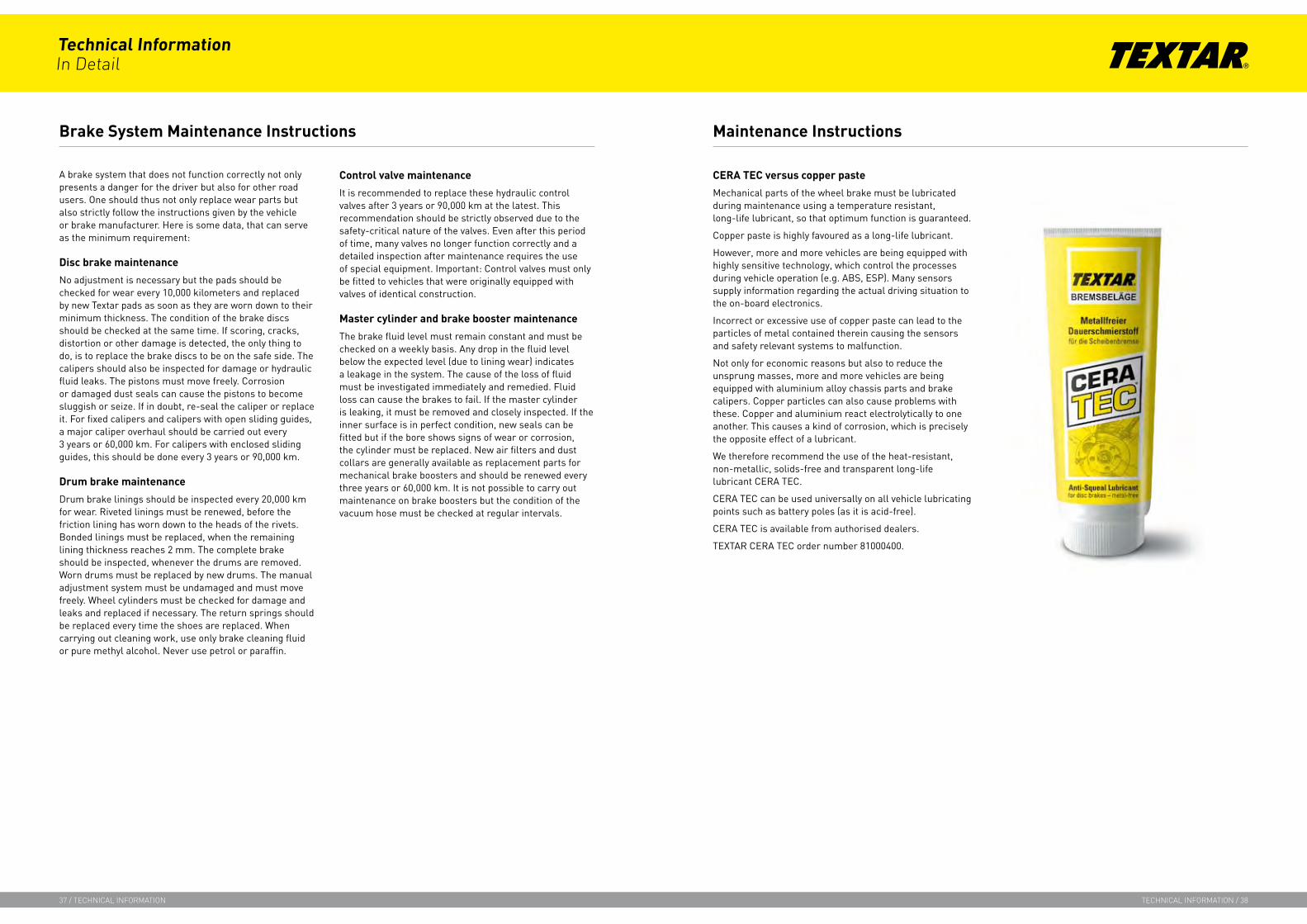
CERA TEC versus copper paste
Mechanical parts of the wheel brake must be lubricated during maintenance using a temperature resistant, long-life lubricant, so that optimum function is guaranteed.
Copper paste is highly favoured as a long-life lubricant.
However, more and more vehicles are being equipped with highly sensitive technology, which control the processes during vehicle operation (e.g. ABS, ESP). Many sensors supply information regarding the actual driving situation to the on-board electronics.
Incorrect or excessive use of copper paste can lead to the particles of metal contained therein causing the sensors and safety relevant systems to malfunction.
Not only for economic reasons but also to reduce the unsprung masses, more and more vehicles are being equipped with aluminium alloy chassis parts and brake calipers. Copper particles can also cause problems with these. Copper and aluminium react electrolytically to one another. This causes a kind of corrosion, which is precisely the opposite effect of a lubricant.
We therefore recommend the use of the heat-resistant, non-metallic, solids-free and transparent long-life lubricant CERA TEC.
CERA TEC can be used universally on all vehicle lubricating points such as battery poles (as it is acid-free).
CERA TEC is available from authorised dealers.
TEXTAR CERA TEC order number 81000400.
Brake System Maintenance Instructions Maintenance Instructions
Technical InformationIn Detail
37 / technIcal InformatIon technIcal InformatIon / 38

Wheel cleaner - a brake’s best friend?
The same care must be taken when handling wheel cleaner as with all cleaning agents. Contact with the brake disc and brake system will be prevented if applied sparingly and precisely.
The substances contained in these cleaning agents can cause damage to the brake system, affect braking efficiency and lead to permanent loss of comfort.
Recommendation:
Dose this product with care. Less is sometimes more.
Use wheel cleaners that can be applied with a brush or sponge. Aerosols have too great a spread.
If wheel cleaning agent gets onto the brake disc, it must be thoroughly rinsed off with a jet of cold water. The brake disc can be cleaned by braking repeatedly when driving normally.
The same applies after a visit to the car wash. The car wash should be used immediately after cleaning the wheels.
The concentration of cleaning agent will be diluted by the water and will thus have little affect on braking behavior. Wet brakes usually operate perfectly normally after braking only a few times.
Fitting instructions
Every set of brake friction products supplied by TMD Friction is accompanied by general fitting instructions provided by the FFLI (Federation of the Friction Liner Industry) or FEMFM (Federation of European Manufacturers of Friction Materials).
These fitting instructions must be followed in the same way as the special repair instructions given by the vehicle, axle and brake manufacturers.
Pursuant to the Kraftfahrtbundesamt (Federal Office for Motor Traffic), failure to comply with these fitting and repair instructions will render the approval certificate null and void and thus the type approval of the vehicle in question.
According to this, specifications like, e.g., turning-off drum brake linings, adherence to riveting forces, running direction of brake linings and numerous other instructions must be meticulously adhered to.
Special brake friction product fitting instructions are often used, to inform of special damping measures, e.g., adhesive foil, additional grease packings, overgreasing, fixed running direction brake friction products, warning notes (SBC) and many others.
It goes without saying, that this information must also be observed as only brake friction products that have been perfectly fitted can operate perfectly.
Maintenance Instructions Reference to Fitting Instructions
Technical InformationIn Detail
39 / technIcal InformatIon technIcal InformatIon / 40
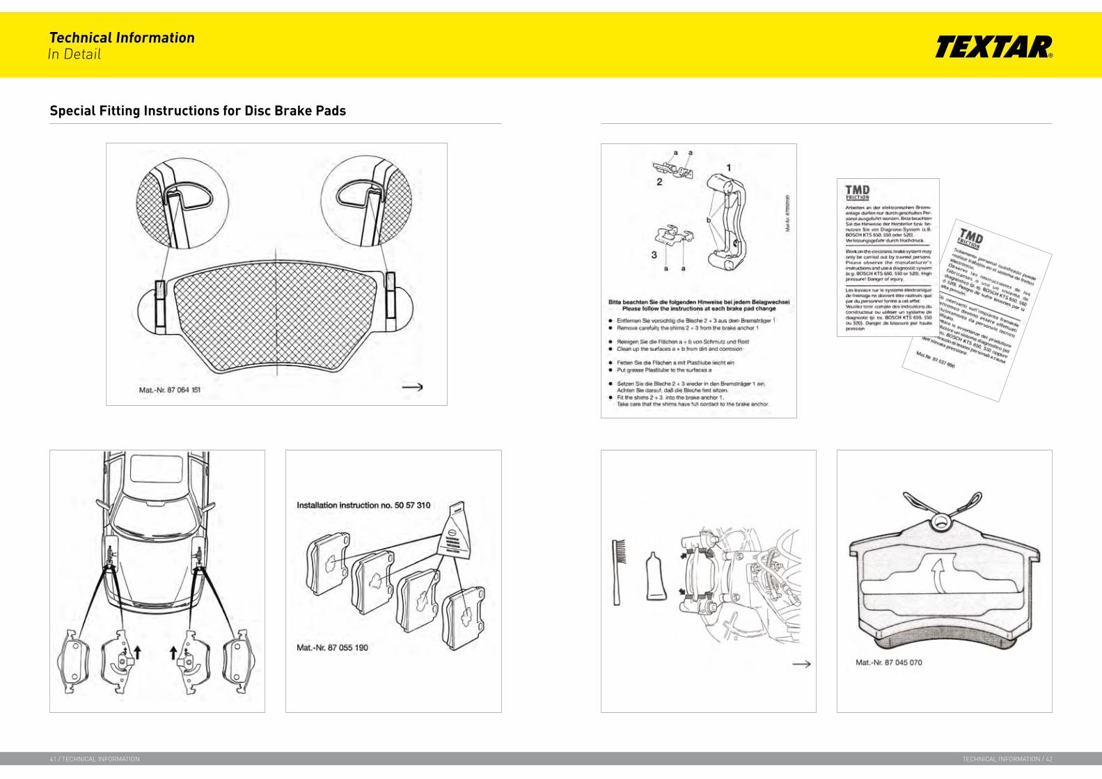
Special Fitting Instructions for Disc Brake Pads
Technical InformationIn Detail
41 / technIcal InformatIon technIcal InformatIon / 42

The majority of modern brake systems use synthetic brake fluids to transmit the hydraulic pressure generated in the brake master cylinder to the calipers and brake cylinders. The properties of brake fluids are therefore of vital importance to the overall brake system.
Brake fluids should not be referred to as "brake oil", as the slightest contamination with oil will destroy the rubber parts in the brake system and could cause complete failure of the brake system.
The chemical and physical properties of brake fluids are defined in regulation SAE J 1703 (Society of Automotive Engineers), which applies internationally. This regulation specifies criteria such as boiling point, chemical neutrality, water compatibility, rubber swelling, corrosion and lubricity, which must neither be exceeded nor fallen short of. A very important point in the SAE regulation is the requirement of miscibility and compatibility of brake fluids among one other. The safety standard FMVSS No. 116 from the American Department of Transport for glycol based brake fluids DOT 3 and DOT 4 based on SAE regulation J1703 is even more significant. The requirements defined for DOT 5 apply to silicone-based brake fluids.
Standard DOT 5.1 also deals with conventional brake fluids, which meet these requirements and were developed for particularly high demands on safety. As DOT 5.1 brake fluids do not contain any silicone, they are miscible with others of the same specification (DOT 3, DOT 4 and DOT 5.1).
1. BF standards
• SAE J 1703/1704
• ISO 4925
• FMVSS 116
• JIS K 2233
2. Explanation of standard designations
• SAE: Society of Automotive Engineers
• FMVSS: Federal Motor Vehicle Safety Standard
• DOT: Department of Transportation
• ISO: International Standardization Organization
• JIS: Japanese Industrial Standard
Brake fluid specifications should be used for a specific vehicle or brake system, depending upon specification and approval of the vehicle or brake system manufacturer. In order to prevent misapplication, it is recommended to seek the vehicle manufacturer's advice. Classification ISO 4925 class 6 represents a new development, which has a low viscosity even at the lowest temperatures. This permits a higher degree of safety and quicker brake response in vehicles equipped with ABS, ASR and ESP/DSC systems.
Brake fluids
Glycol-based brake fluids are hygroscopic and even accumulate water when merely exposed to the atmosphere. This property assures that water constituents will disperse in the brake fluid. At the same time, no isolated water spots can occur which freeze at 0 °C and boil at 100 °C. However, even the slightest water content will lower the boiling point of the brake fluid.
Brake fluid change
It is, therefore, recommended to change the brake fluid every year but not later than every 2 years, irrespective of the mileage.
All references to health hazards when handling brake fluids must be strictly observed. Brake fluid has a highly solvent and discolouring nature. Because of this, any paintwork, shoes or clothes contaminated by brake fluid must be rinsed immediately with copious quantities of water.
Brake Fluid Change
SAE J 1703
DOT 3 DOT 4 DOT 5 DOT 5.1
FMVSS 116 FMVSS 116 FMVSS 116
Silicone base
FMVSS 116
ISO 4925Class 3 SAE J 1704 ISO 4925
Class 4ISO 4925Class 6
ISO 4925Class 5-1
JIS K 2233Class 3
JIS K 2233Class 4
Equilibrium boiling point = 205 °C = 205 °C = 230 °C = 230 °C = 250 °C = 260 °C › 260 °C
Wet boiling point = 140 °C = 140 °C = 155 °C = 155 °C = 165 °C = 180 °C = 180 °C
Viscosity at -40 °C (cSt) = 1800 = 1500 = 1800 = 1500 = 750 = 900 = 900
Technical InformationIn Detail
43 / technIcal InformatIon technIcal InformatIon / 44

Unfavorable brake force distribution across the individual axles frequently leads to untypical wear or failures apparently linked to the brake linings.
The following points must be checked and remedied without fail
• Inadmissible friction pairing on front and rear axle
• Incorrect loading, e.g. rear axle overloaded, center of gravity of the load too high
• Incorrect manual control or ALB setting
• Newly fitted axle may not yet be sufficiently bedded in
• Linings and drum not turned off
• Incorrect cylinders, incorrect lever lengths
• Loss of pressure in the circuit in question
Tractor and trailer compatibility
• Friction coefficients in trailer or tractor are too high or too low
• Pressure lead is not ok
• Brake defect in any one of the vehicles
Axle pull
• One-sided lining replacement on an axle
• Differing makes of drum on the same axle
• Defective steering geometry
• Incorrect return springs on one side
• Worn brake (e.g., worn out brake shaft, shoe pivots, cams)
• Automatic adjustment defective, e.g., in a wedge brake
• Brake shoes heavily corroded
• Oil-contaminated brake with hydraulic clamping
• Ingress of foreign matter on one side, e.g., in construction site vehicles
Violent noises and vibrations
• Insufficient bedding-in (e.g., not cleanly turned off)
• Drum heavily striated
• Linings heavily worn
• Worn out brake and possibly steering
• Out of true drums
• Incorrect rivet material or incorrect riveting
• Bad or improper contact between lining and brake shoe
Heavy lining wear
• Excessive trailer run-up
• Bad brake drums (striated, not turned off)
• Foreign matter in the drum during cross country operation
• Wrong valve setting (ALB, load/no load valve)
• Cracks in the drum
• Erratic driving (too many brakings in high temperature ranges)
• Overloading the vehicle (wrong position of gravity center)
• Inadequate drum material
• Imbalanced tractor/trailer braking
Heavy drum wear, damage
• Crack formation through frequent braking in low pressure range with cold brakes (approx. 1 bar)
• Wear through fish-scaling, also due to above reasons
• Burn marks caused by out of true drums and thermal overload
• Parking brake operated when brakes were hot (ovality)
• Brake heavily worn (lack of proper shoe guidance)
• Drums not machined properly
• Linings not turned off
• Ingress of foreign matter (promoted by not adjusting the brakes regularly)
• Drum material too soft
• Crown-shaped and uneven wear due to excessive wheel bearing clearance, worn pin guidance or insufficient play (especially in the presence of ovality)
• Bright spots with crack formation due to extremely high temperatures
• Transverse fracture of brake surface without crack formation due to blowholes in the cast drum or the introduction of forces caused by loosened and structurally unstable star wheels
• Defective overload protection of service and parking brake
Inadequate braking effect
• Regulator valves set wrongly, defective control or brake valves
• Excessive drum turn-out
• Wrong brake cylinders or levers fitted
• Inadequate dynamic effect of brake cylinder/lever (clearance too large)
• Oil contaminated brake linings due to leaking seals in hydraulic systems
• Brake linings not turned off and linings badly bedded in
• Swelling drums caused by too many cracks
• Wrong friction pairing (insufficient drum material)
• Vitrified linings caused by constant braking in the lowest pressure range
• Erosion of brake shoes due to heavy corrosion
• Vehicle overload
• Thermal overload, especially during prolonged downhill driving
• Trailer axles fitted the wrong way round (turned by 180°)
• Incorrect brake installation
Deficiencies in Commercial Vehicle Drum Brakes
Technical InformationIn Detail
45 / technIcal InformatIon technIcal InformatIon / 46

Typical deficiencies, complaints and their cause.
The following points must be checked and remedied without fail:
• Check the brake system prior to repair
• Inadmissible friction pairing on front/rear axle and trailing and lifting axles
• Incorrect loading, e.g., rear axle overloaded, center of gravity of the load too high
• Incorrect manual control or ALB setting for semi-trailer with unequal pairing, tractor with drum brakes trailer with disc brakes or vice-versa
• Newly fitted axle may not yet be sufficiently bedded in or used brake disc not turned off
• Incorrect cylinder fitted
• Fault in the compressed air part, e.g., loss of pressure
• Check the caliper bearing (play/freedom of movement)
• Check the adjusting device
Tractor and trailer compatibility
• Adverse pairing: tractor with disc brakes and trailer with drum brakes
• Adverse pairing: tractor with drum brakes and trailer with disc brakes
• Pressure lead (compressed air supply) is not ok
• Brake defect, tractor and trailer
Axle pull
• One-sided pad/disc replacement on an axle
• Differing makes of pads/discs on one axle
• Defective steering geometry
• Defective caliper on one side
• Adjusting unit is defective on one side
• Thrust element seized or worn out
• Incorrect (differing) clearance settings on one axle
• Brake worn out on one side
• Cracks in the brake disc
• Striated brake discs
• Uneven machining during repair or fault when turning off used brake discs
• Foreign matter ingress on one side, e.g., with construction site vehicles
• Defective cylinder on one side
• Loss of pressure on one side
Violent noises and vibrations
• Not embedded sufficiently, e.g., after being turned off
• Surface finish of the brake disc too rough after turning off, caused by worn turning steel
• Striated brake disc
• Excessive brake disc axial runout (lateral trueness)
• Differences in thickness in the rubbing ring area to great
• Martensite formation in the brake disc casting material after thermal overload, particularly in the embedding phase
• Worn out pad/brake disc
• Foreign matter between pad and brake disc with construction site vehicles
• Cracks in the brake disc
• Unsuitable pad or brake disc material
• Incorrect or old accessories used
• Defective caliper or caliper bearing
• Side plungers not synchronous; adjuster defective
• Brake thermally overloaded
• Brake inadequately cleaned during repair
• Pad edge deterioration due to inadequate, defective hold-down springs, run-in brake discs, etc.
Heavy pad wear
• Imbalanced braking
• Adverse pairing of towing vehicle and trailer, e.g., disc/drum or drum/disc
• Striated brake disc
• Brake disc incorrectly machined, e.g., when turning off
• Foreign matter between pad and brake disc
• Cracks in the brake disc
• Erratic driving (two many brakings in high temperatures)
• Overloading the tractor/trailer combination
• Inadequate brake disc or pad material
• Mixed brakes on the axles of a tractor/trailer combination
• Clearance too small
• Defective caliper/caliper guide/adjuster
• Non-use of wear-free brakes fitted, e.g., retarder, motor brake
• In contrast to drum brakes, overheating is not noticed by the driver in the form of a diminishing braking effect (fading)
Heavy brake disc wear
• Unsuitable pad or brake disc material
• Hot spots, thermal overloading
• Clearance too small
• Defective caliper/caliper guide/
• Bad/inadequate ventilation because of modifications
• Ingress of foreign matter
• Erratic driving (too many brakings in high temperatures)
• Non-use of wear-free brakes fitted, e.g., retarder, motor brake
• In contrast to drum brakes, overheating is not noticed by the driver in the form of a diminishing braking effect (fading)
Inadequate braking effect
• Defects in the compressed air part
• Unsuitable pad or brake disc material
• Mixed brakes on the axles of a vehicle/trailer combination
• Mixed brakes on one axle
• Worn out pad/brake disc
• Caliper/caliper guide defective
• Adjuster defective
• Cracks in the brake disc
• Imbalanced braking
• Adverse pairing of tractor and trailer
• Brakes not yet bedded in, especially brake discs that have been driven but not turned off
• Pad without friction surface coating with anti-corrosion brake discs fitted, bedding in time is increased considerably by this.
• Striated brake discs not turned off
• Incorrect cylinder fitted
• Vitrified pad surface due to persistent braking in the lowest pressure range
Deficiencies in Commercial Vehicle Disc Brakes
Technical InformationIn Detail
47 / technIcal InformatIon technIcal InformatIon / 48

Overbraking/Noise
Causes of noise/judder The main cause is that one or more brakes overbrake
Investigation Diagnosing overbrakingOn the roller test bench ... By measuring the temperature ...
... with a braking force indicator ... with a thermometer
Symptoms Causes Troubleshooting
All brakes/axles
... only tractors, trailers, semi-trailers
... only on one axle
... only one wheel brake
Influence of driving style and road condition
Check of the balanced braking between tractor and trailer or semi-trailer
Fault in the pneumatic system
Fault in the pneumatic systemFault in both wheel brakes
Fault in this wheel brake
Causeanalysis
1. Brake friction products bedded in under high temperatures and loads
2. Loose rivets, drums out of true, wrong friction products, worn out bearings, weak return springs etc.
3. Brake friction contact pattern incorrect
Inadequate Braking Effect
Investigation Diagnose inadequate braking effectOn the roller test bench ... By measuring the temperature ...
... with a braking force indicator ... with a thermometer
Symptoms Causes Troubleshooting
All brakes/axles
... only tractors, trailers, semi-trailers
... only on one axle
Influence of driving style and road condition
Check of the balanced braking between tractor and trailer or semi-trailer
Fault in the pneumatic system
Fault in both wheel brakes
Fault in this wheel brake
Causeanalysis
1. Inadequate brake friction product quality
2. Adjusting device defective
3. Unsatisfactory brake friction contact pattern
4. Brake friction products not bedded in/missing friction surface coating
5. Sluggishly moving parts of the wheel brake, like brake shaft, bolts, etc.
6. Dirty brake friction products
7. (Oil, grease, etc.)
Technical InformationIn Detail
49 / technIcal InformatIon technIcal InformatIon / 50
other drawing
0510
15 20253035
40 0510
15 20253035
40
0510
15 20253035
40 0510
15 20253035
40
250
200
150
100
50
0
250
200
150
100
50
0
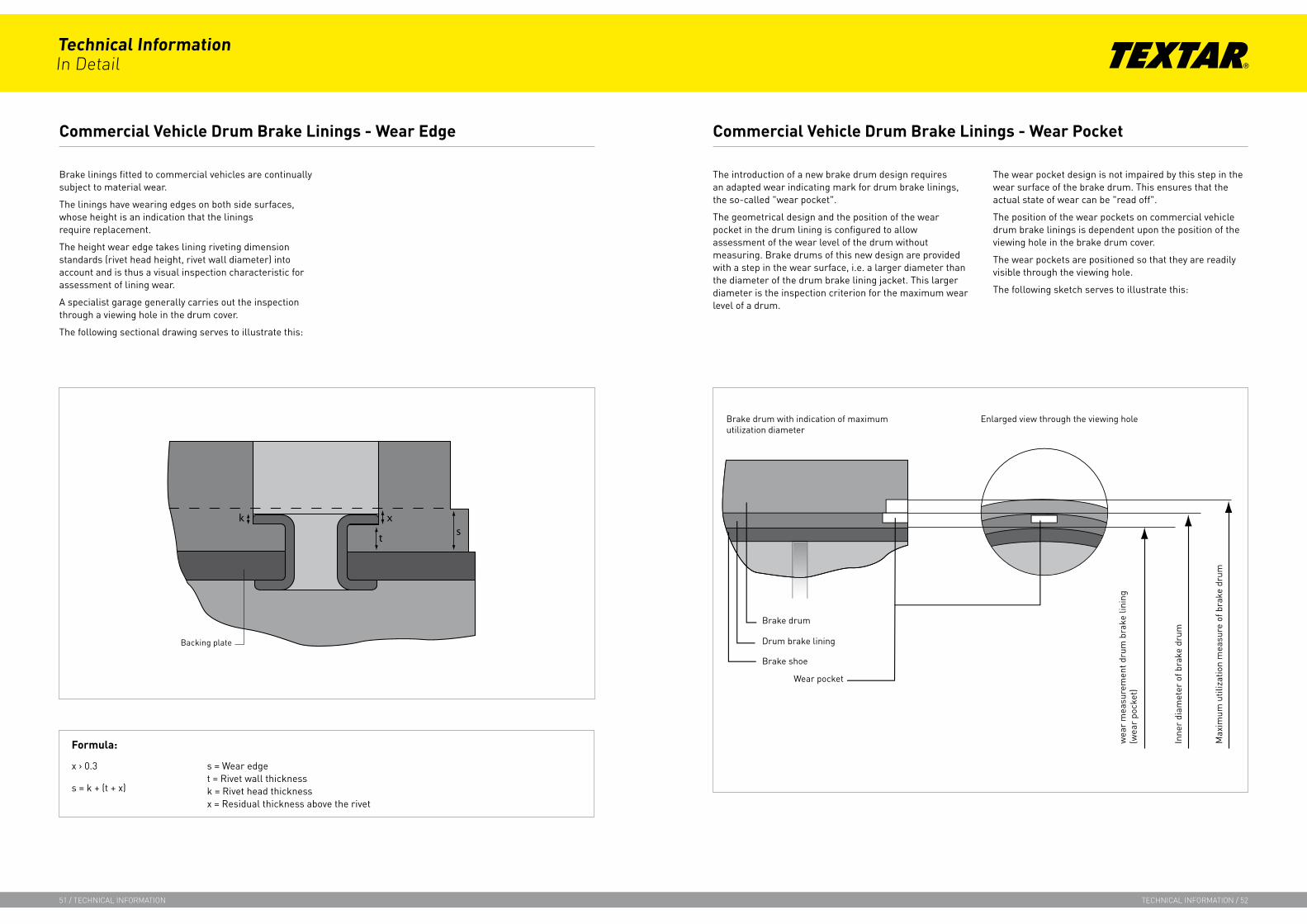
Brake linings fitted to commercial vehicles are continually subject to material wear.
The linings have wearing edges on both side surfaces, whose height is an indication that the linings require replacement.
The height wear edge takes lining riveting dimension standards (rivet head height, rivet wall diameter) into account and is thus a visual inspection characteristic for assessment of lining wear.
A specialist garage generally carries out the inspection through a viewing hole in the drum cover.
The following sectional drawing serves to illustrate this:
The introduction of a new brake drum design requires an adapted wear indicating mark for drum brake linings, the so-called "wear pocket".
The geometrical design and the position of the wear pocket in the drum lining is configured to allow assessment of the wear level of the drum without measuring. Brake drums of this new design are provided with a step in the wear surface, i.e. a larger diameter than the diameter of the drum brake lining jacket. This larger diameter is the inspection criterion for the maximum wear level of a drum.
The wear pocket design is not impaired by this step in the wear surface of the brake drum. This ensures that the actual state of wear can be "read off".
The position of the wear pockets on commercial vehicle drum brake linings is dependent upon the position of the viewing hole in the brake drum cover.
The wear pockets are positioned so that they are readily visible through the viewing hole.
The following sketch serves to illustrate this:
Commercial Vehicle Drum Brake Linings - Wear Edge
x k s
t
Formula:
x › 0.3
s = k + (t + x)
Commercial Vehicle Drum Brake Linings - Wear Pocket
Technical InformationIn Detail
51 / technIcal InformatIon technIcal InformatIon / 52
s = Wear edget = Rivet wall thicknessk = Rivet head thicknessx = Residual thickness above the rivet
Assessment of material break-off and cracks in the friction material
The service information should provide the expert inspector with a basis for assessing brake linings for drum brakes.
Area of application:
The assessment, as to whether a brake lining should be replaced, is still incumbent on the inspector, who must also take the optical condition of the linings and the overall impression of the vehicle and its area of operation into consideration. If the causes leading to the deficiencies or damage described are not remedied, further deterioration in the condition must be assumed. The lining should then be re-inspected at regular intervals in time. Possible warranty claims are always dependent upon the individual case and its specific conditions.
Break-offs:
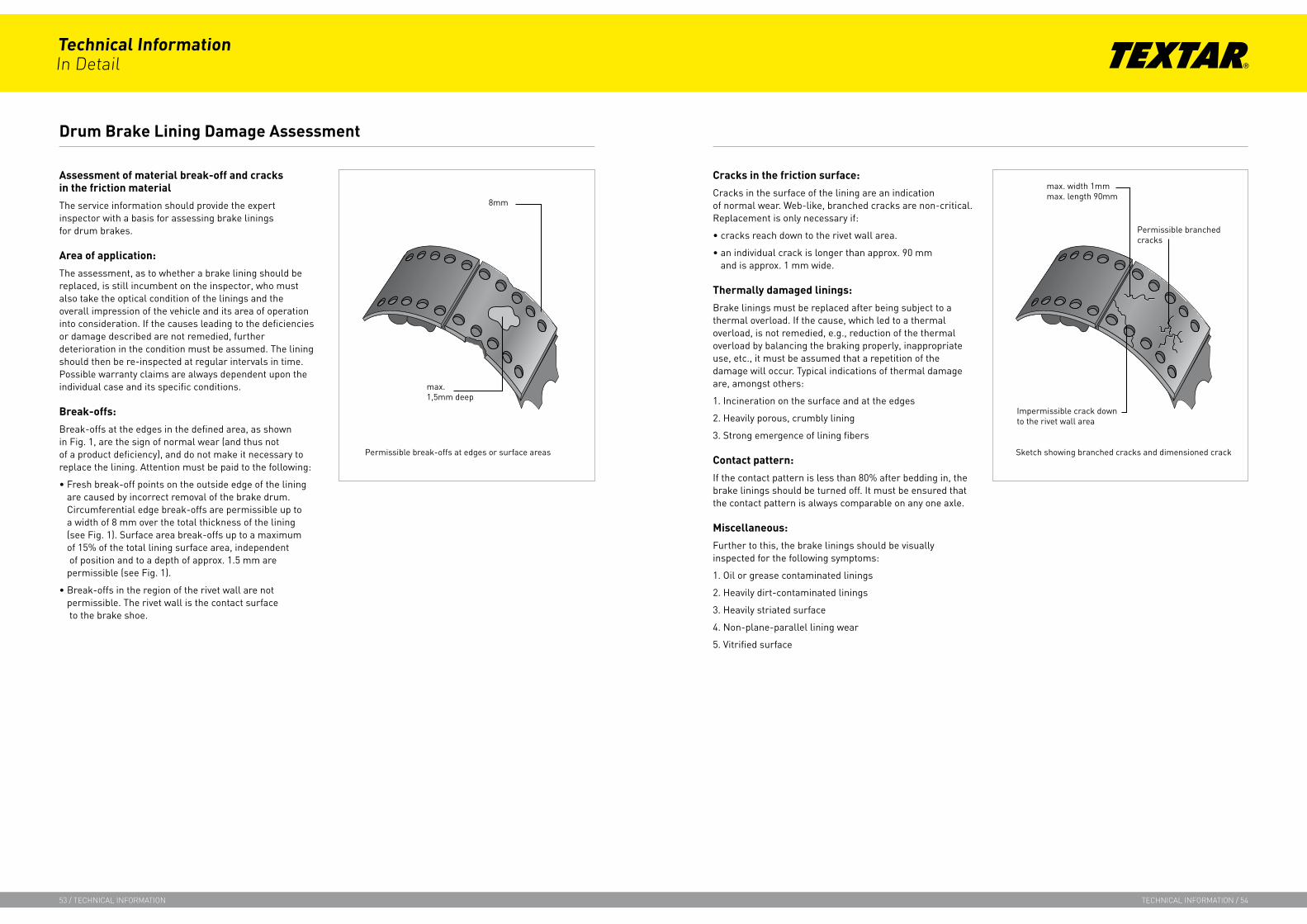
Break-offs at the edges in the defined area, as shown in Fig. 1, are the sign of normal wear (and thus not of a product deficiency), and do not make it necessary to replace the lining. Attention must be paid to the following:
• Fresh break-off points on the outside edge of the lining are caused by incorrect removal of the brake drum. Circumferential edge break-offs are permissible up to a width of 8 mm over the total thickness of the lining (see Fig. 1). Surface area break-offs up to a maximum of 15% of the total lining surface area, independent of position and to a depth of approx. 1.5 mm are permissible (see Fig. 1).
• Break-offs in the region of the rivet wall are not permissible. The rivet wall is the contact surface to the brake shoe.
Cracks in the friction surface:
Cracks in the surface of the lining are an indication of normal wear. Web-like, branched cracks are non-critical. Replacement is only necessary if:
• cracks reach down to the rivet wall area.
• an individual crack is longer than approx. 90 mm and is approx. 1 mm wide.
Thermally damaged linings:
Brake linings must be replaced after being subject to a thermal overload. If the cause, which led to a thermal overload, is not remedied, e.g., reduction of the thermal overload by balancing the braking properly, inappropriate use, etc., it must be assumed that a repetition of the damage will occur. Typical indications of thermal damage are, amongst others:
1. Incineration on the surface and at the edges
2. Heavily porous, crumbly lining
3. Strong emergence of lining fibers
Contact pattern:
If the contact pattern is less than 80% after bedding in, the brake linings should be turned off. It must be ensured that the contact pattern is always comparable on any one axle.
Miscellaneous:
Further to this, the brake linings should be visually inspected for the following symptoms:
1. Oil or grease contaminated linings
2. Heavily dirt-contaminated linings
3. Heavily striated surface
4. Non-plane-parallel lining wear
5. Vitrified surface
Drum Brake Lining Damage Assessment
Technical InformationIn Detail
53 / technIcal InformatIon technIcal InformatIon / 54
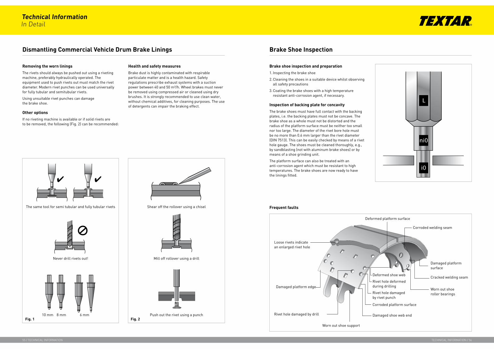
Removing the worn linings
The rivets should always be pushed out using a riveting machine, preferably hydraulically operated. The equipment used to push rivets out must match the rivet diameter. Modern rivet punches can be used universally for fully tubular and semitubular rivets.
Using unsuitable rivet punches can damage the brake shoe.
Other options
If no riveting machine is available or if solid rivets are to be removed, the following (Fig. 2) can be recommended:
Health and safety measures
Brake dust is highly contaminated with respirable particulate matter and is a health hazard. Safety regulations prescribe exhaust systems with a suction power between 40 and 50 m³/h. Wheel brakes must never be removed using compressed air or cleaned using dry brushes. It is strongly recommended to use clean water, without chemical additives, for cleaning purposes. The use of detergents can impair the braking effect.
Brake shoe inspection and preparation
1. Inspecting the brake shoe
2. Cleaning the shoes in a suitable device whilst observing all safety precautions
3. Coating the brake shoes with a high temperature resistant anti-corrosion agent, if necessary.
Inspection of backing plate for concavity
The brake shoes must have full contact with the backing plates, i.e. the backing plates must not be concave. The brake shoe as a whole must not be distorted and the radius of the platform surface must be neither too small nor too large. The diameter of the rivet bore hole must be no more than 0.6 mm larger than the rivet diameter (DIN 7513). This can be easily checked by means of a rivet hole gauge. The shoes must be cleaned thoroughly, e.g., by sandblasting (not with aluminum brake shoes) or by means of a shoe grinding unit.
The platform surface can also be treated with an anti-corrosion agent which must be resistant to high temperatures. The brake shoes are now ready to have the linings fitted.
Dismantling Commercial Vehicle Drum Brake Linings
The same tool for semi tubular and fully tubular rivets
Never drill rivets out!
10 mm 8 mm 6 mm
Shear off the rollover using a chisel
Mill off rollover using a drill
Push out the rivet using a punch
Brake Shoe Inspection
Frequent faults
Loose rivets indicate an enlarged rivet hole
Deformed platform surface
Corroded welding seam
Damaged platform surface
Cracked welding seam
Worn out shoe roller bearings
Deformed shoe web
Rivet hole deformed during drilling
Rivet hole damaged by rivet punch
Corroded platform surface
Damaged shoe web end
Worn out shoe support
Rivet hole damaged by drill
Damaged platform edge
Fig. 1 Fig. 2
Technical InformationIn Detail
55 / technIcal InformatIon technIcal InformatIon / 56

Riveting
It is mandatory to always use the lining material specified by the OE manufacturer or a material approved by the Federal Office for Motor Traffic (KBA). Textar brake linings are available in a wide variety of designs for practically any application.
Riveting material: the most common materials are steel, brass and copper.
Choice of rivet
Rivets must be chosen, whose shape correspond to the shape of the rivet hole.
The length of the rivet can be calculated by the following rule of thumb:
German standard 3575, semitubular
A = 0.5 - 0.75 x d DIN 7338, fully tubularA = 0.8 - 1.0 x d
Example: For a brake shoe rivet in accordance with DIN 7338 and a diameter of d = 8 mm, the rivet shaft A should protrude by not less than 0.8 x 8 mm = 6.4 mm and not more than 8 mm out of the brake shoe bore hole.
Important:
With semitubular rivets, the bore hole bottom must be at the level of position "A", to allow the formation of a satisfactory rollover.
Riveting tools
Select the correct rivet head formers and anvils. The riveting machine manufacturers instructions must be followed.
Some vehicle manufacturers specify that the linings have to be pressed onto the shoes with a pre-stressing force of 300 N prior to riveting. The special rivet head formers, with pre-stressing device supplied by Textar, fulfil this requirement and fit in virtually all conventional riveting machines. The riveting forces differ greatly with the rivets and materials used and the pressures indicated by the manufacturers must be strictly adhered to, in order to achieve the riveting forces specified by the brake manufacturers. The relation between the pressure applied and the resultant riveting force varies with the individual machine type.
Riveting should be done from the center outwards, i.e. from the center of the shoe out to the edges.
Final inspection
Checking the riveting: Light taps with a hammer allow appraisal of good or bad riveting: A dull sound indicates a loose lining. A high-pitched sound indicates that the riveting is correct.
A valve gauge can be used to check for cavities under the lining. A cavity of more than 0.15 mm beyond the first row of rivet holes can lead to noise problems.
Finally, the linings should be inspected for cracks. If these occur in the area of the rivets, this is an indication that the work has not been carried out correctly.
Fitting Commercial Vehicle Drum Brake Linings
Technical InformationIn Detail
57 / technIcal InformatIon technIcal InformatIon / 58
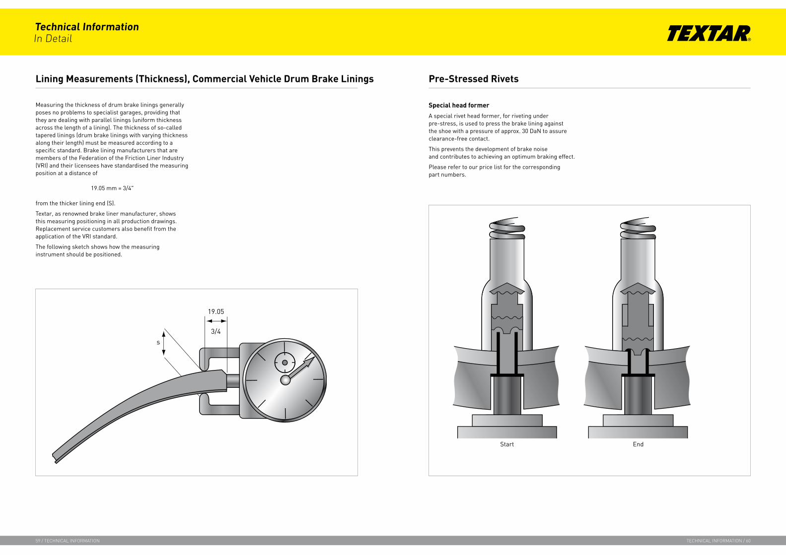
Measuring the thickness of drum brake linings generally poses no problems to specialist garages, providing that they are dealing with parallel linings (uniform thickness across the length of a lining). The thickness of so-called tapered linings (drum brake linings with varying thickness along their length) must be measured according to a specific standard. Brake lining manufacturers that are members of the Federation of the Friction Liner Industry (VRI) and their licensees have standardised the measuring position at a distance of
19.05 mm = 3/4"
from the thicker lining end (S).
Textar, as renowned brake liner manufacturer, shows this measuring positioning in all production drawings. Replacement service customers also benefit from the application of the VRI standard.
The following sketch shows how the measuring instrument should be positioned.
Special head former
A special rivet head former, for riveting under pre-stress, is used to press the brake lining against the shoe with a pressure of approx. 30 DaN to assure clearance-free contact.
This prevents the development of brake noise and contributes to achieving an optimum braking effect.
Please refer to our price list for the corresponding part numbers.
Lining Measurements (Thickness), Commercial Vehicle Drum Brake Linings Pre-Stressed Rivets
Technical InformationIn Detail
59 / technIcal InformatIon technIcal InformatIon / 60
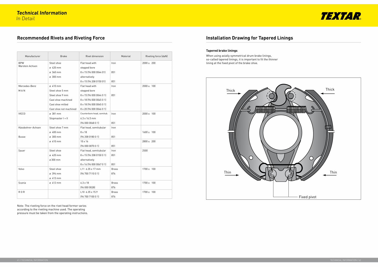
Tapered brake linings
When using axially symmetrical drum brake linings, so-called tapered linings, it is important to fit the thinner lining at the fixed pivot of the brake shoe.
Manufacturer Brake Rivet dimension Material Riveting force (daN)
BPWWarstein Achsen
Steel shoe Flat head with Iron 2000 ± 200
ø 420 mm stepped bore
ø 360 mm 8 x 15 (96 000 0044 01) 851
ø 300 mm alternatively
8 x 15 (96 208 0150 01) 851
Mercedes-Benz ø 410 mm Flat head with Iron 2000 ± 100
M A N Steel shoe 5 mm stepped bore
Steel shoe 9 mm 8 x 15 (96 000 0044 0 1) 851
Cast shoe machined 8 x 18 (96 000 0045 0 1)
Cast shoe milled 8 x 18 (96 000 0045 0 1)
Cast shoe not machined 8 x 20 (96 000 0046 0 1)
IVECO ø 381 mm Counterbore head, semitub. Iron 2000 ± 100
Stopmaster I + II 6.3 x 16.5 mm
(96 000 0068 0 1) 851
Kässbohrer-Achsen Steel shoe 7 mm Flat head, semitubular Iron
ø 400 mm 8 x 18 1600 ± 100
Busse ø 300 mm (96 208 0180 0 1) 851
ø 410 mm 10 x 16 2800 ± 200
(96 000 0070 0 1) 851
Sauer Steel shoe Flat head, semitubular Iron 2500
ø 420 mm 8 x 15 (96 208 0150 0 1) 851
ø 300 mm alternatively
8 x 16 (96 000 0067 0 1) 851
Volvo Steel shoe L11 6.35 x 17 mm Brass 1700 ± 100
ø 394 mm (96 700 7110 0 1) 876
ø 413 mm
Scania ø 412 mm 6.3 x 18 Brass 1700 ± 100
(96 000 0028) 876
R O R L10 6.35 x 15.9 Brass 1700 ± 100
(96 700 7100 0 1) 876
Note: The riveting force on the rivet head former varies according to the riveting machine used. The operating pressure must be taken from the operating instructions.
Recommended Rivets and Riveting Force Installation Drawing for Tapered Linings
Technical InformationIn Detail
61 / technIcal InformatIon technIcal InformatIon / 62

Turning-off instructions for CV drum brake linings
1. In order to be able to ensure satisfactory functioning of the wheel brake, the brake linings must always be turned off after assembly.
2. Before turning off, the drum diameter must be measured (also for new drums) or defined. If drums are turned off, the maximum turn-off measure must be observed and the same value set on the right and left.
3. Select lining thickness and, if necessary, use oversized linings. Spread the shoes to braking position and turn off using a conventional machine (observe instructions given by axle or brake manufacturers for expansion). The turn-off measure used should be 0.5 mm less than the drum diameter determined earlier.
4. A cutting thickness of 0.3 mm should not be exceeded and the lining thickness should not be reduced by more than 1.5 mm.
The turn-off thickness should be checked during or immediately after turning off. After re-setting of the clamping device, the thickness can no longer be checked, at least not without great difficulty.
Pre-ground drum brake linings
Drum brake linings for wheel brakes with sliding shoe platforms (e.g., Z-cam, various wedge brakes) are pre-ground.
The purpose of the special shape is to guarantee a defined contact point for the linings on the friction surface of the brake drum thereby ensuring self-centring in case of repair.
Such drum brake linings are only turned off in exceptional cases.
Apart from this, the drum diameters have to be matched to the repair level of the brake linings.
Turning-off Instructions for Commercial Vehicle Drum Brake Linings Pre-ground Drum Brake Linings
Technical InformationIn Detail
63 / technIcal InformatIon technIcal InformatIon / 64

Volvo Simplex wedge brake
Volvo Simplex wedge brakes use brake linings of various lengths and thicknesses. This is due to the varying wear characteristics of the primary and secondary linings.
Because the primary lining produces considerably more braking power (approx. 75%), it is provided with correspondingly more lining material, i.e. the longer / thicker lining (19758) is fitted to the leading shoe.
It is always important to observe the special fitting and adjustment instructions supplied by the vehicle manufacturer.
To remove the brake drums and to position the brake shoes, the toothed adjustment screws must be turned anticlockwise.
All adjustment screws have a right-hand thread.
Carry out an initial adjustment after re-lining the brakes. To do this, unscrew the adjusting screw to approx. 2.5 - 3 mm from the end stop, in order to ensure that the adjusting device can function correctly.
Also, set the clearance between lining and drum to approx. 1.00 - 1.5 mm.
The return spring should be replaced as it has a great influence on the adjusting device.
Volvo wedge brake 360 x 170
Automatic clearance adjustment
0.35 - 1.55 mm
Setting dimension after fitting 1.00 - 1.55 mm
Initial adjustmentadjusting screw
Turn out by 2.5 - 3 turns (right-hand thread)
Material DON 7131
Volvo wedge brake 360 x 170
WVA-No. PrimarySecondary
1st oversize Primary 1st oversize Secondary
4 x 19758 14.804 x 19759 09.70
18.8010.70
Material DON 7131
Number of rivets
PrimarySecondary
22 pcs.20 pcs.
Fitting Instructions, Drum Brake Linings, WVA No. 19758 Adjustments, Drum Brake Linings, WVA No. 19758
Technical InformationIn Detail
65 / technIcal InformatIon technIcal InformatIon / 66
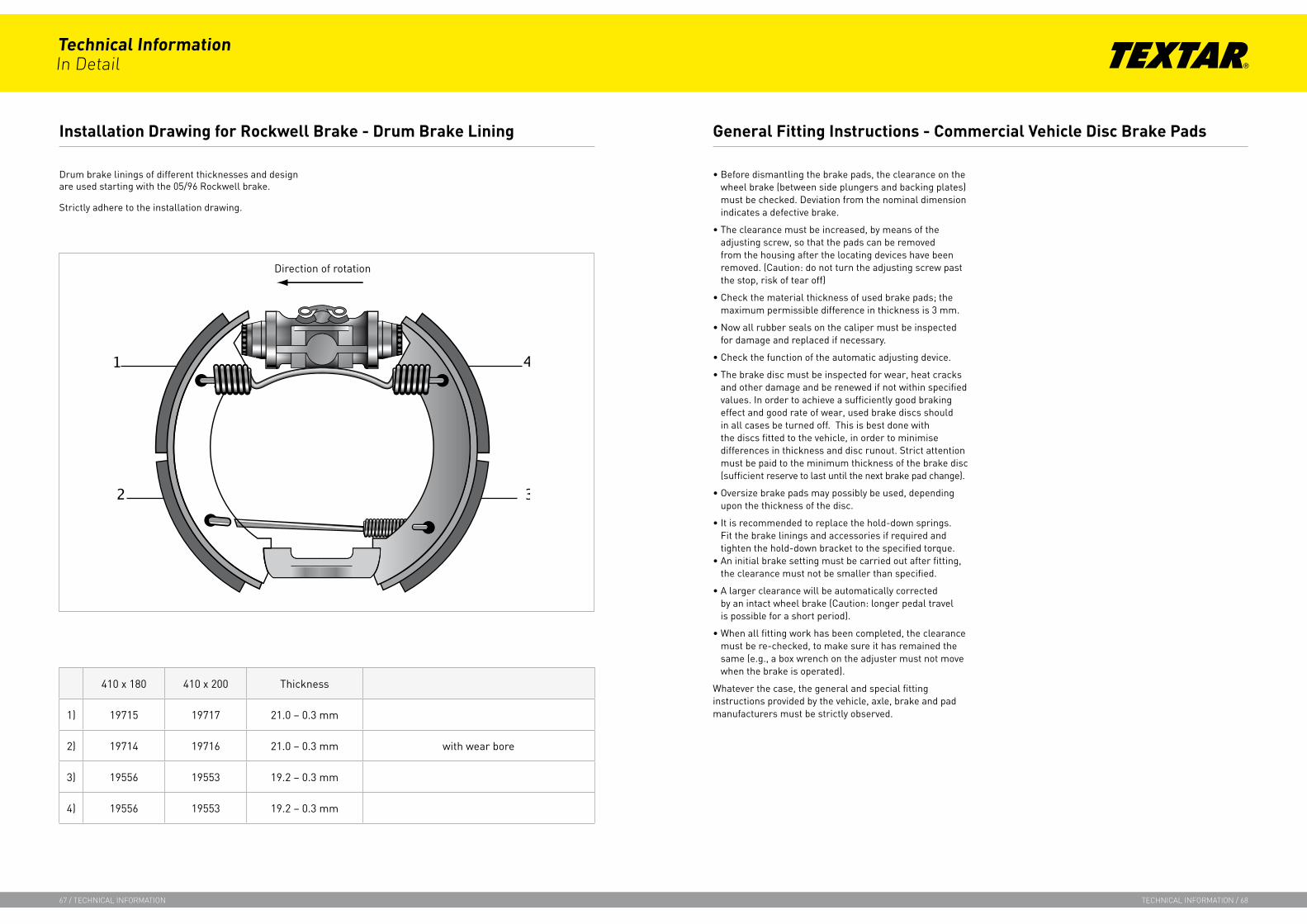
Drum brake linings of different thicknesses and design are used starting with the 05/96 Rockwell brake.
Strictly adhere to the installation drawing.
• Before dismantling the brake pads, the clearance on the wheel brake (between side plungers and backing plates) must be checked. Deviation from the nominal dimension indicates a defective brake.
• The clearance must be increased, by means of the adjusting screw, so that the pads can be removed from the housing after the locating devices have been removed. (Caution: do not turn the adjusting screw past the stop, risk of tear off)
• Check the material thickness of used brake pads; the maximum permissible difference in thickness is 3 mm.
• Now all rubber seals on the caliper must be inspected for damage and replaced if necessary.
• Check the function of the automatic adjusting device.
• The brake disc must be inspected for wear, heat cracks and other damage and be renewed if not within specified values. In order to achieve a sufficiently good braking effect and good rate of wear, used brake discs should in all cases be turned off. This is best done with the discs fitted to the vehicle, in order to minimise differences in thickness and disc runout. Strict attention must be paid to the minimum thickness of the brake disc (sufficient reserve to last until the next brake pad change).
• Oversize brake pads may possibly be used, depending upon the thickness of the disc.
• It is recommended to replace the hold-down springs. Fit the brake linings and accessories if required and tighten the hold-down bracket to the specified torque.
• An initial brake setting must be carried out after fitting, the clearance must not be smaller than specified.
• A larger clearance will be automatically corrected by an intact wheel brake (Caution: longer pedal travel is possible for a short period).
• When all fitting work has been completed, the clearance must be re-checked, to make sure it has remained the same (e.g., a box wrench on the adjuster must not move when the brake is operated).
Whatever the case, the general and special fitting instructions provided by the vehicle, axle, brake and pad manufacturers must be strictly observed.
410 x 180 410 x 200 Thickness
1) 19715 19717 21.0 – 0.3 mm
2) 19714 19716 21.0 – 0.3 mm with wear bore
3) 19556 19553 19.2 – 0.3 mm
4) 19556 19553 19.2 – 0.3 mm
Installation Drawing for Rockwell Brake - Drum Brake Lining General Fitting Instructions - Commercial Vehicle Disc Brake Pads
Technical InformationIn Detail
67 / technIcal InformatIon technIcal InformatIon / 68
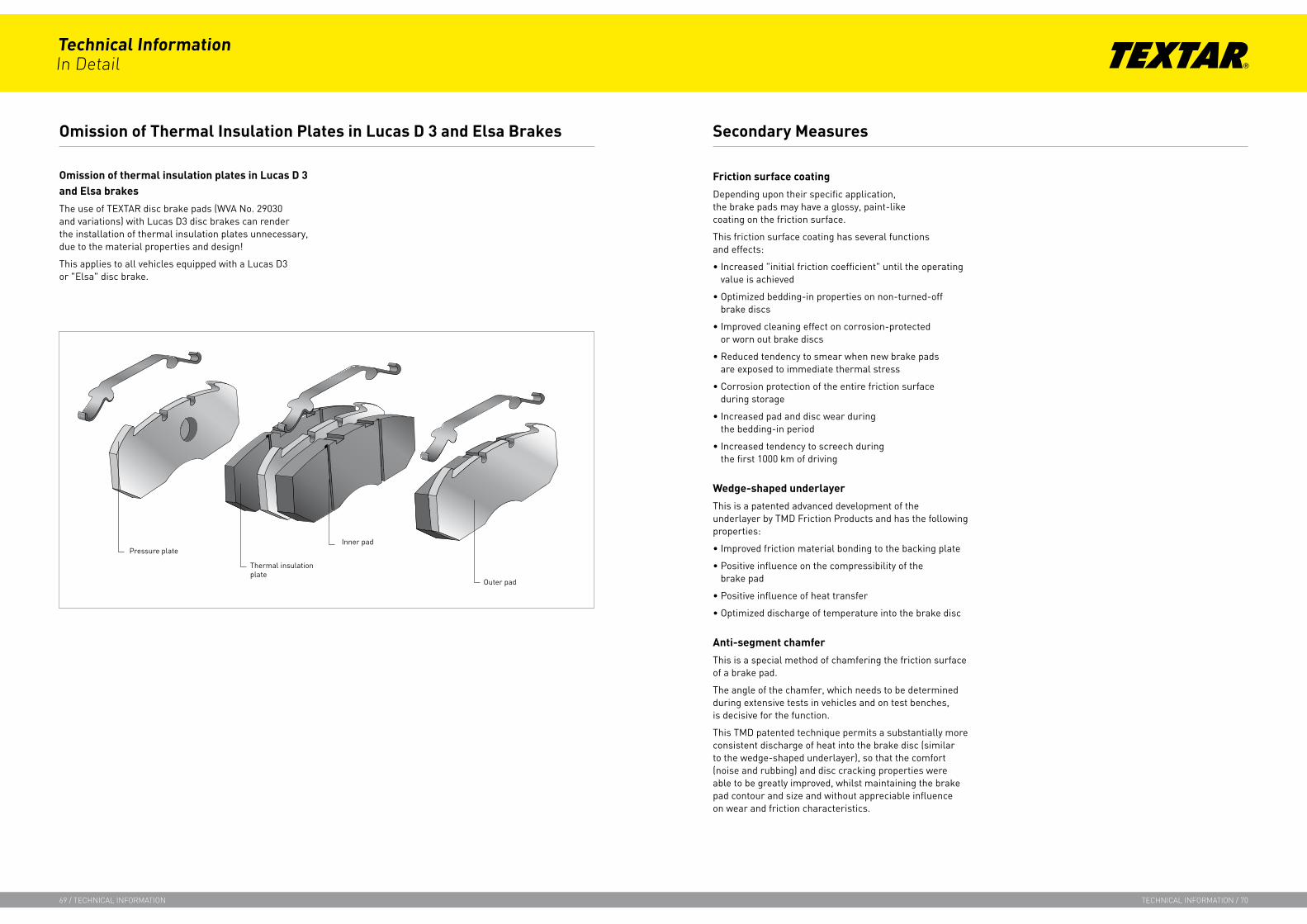
Omission of thermal insulation plates in Lucas D 3 and Elsa brakes
The use of TEXTAR disc brake pads (WVA No. 29030 and variations) with Lucas D3 disc brakes can render the installation of thermal insulation plates unnecessary, due to the material properties and design!
This applies to all vehicles equipped with a Lucas D3 or "Elsa" disc brake.
Friction surface coating
Depending upon their specific application, the brake pads may have a glossy, paint-like coating on the friction surface.
This friction surface coating has several functions and effects:
• Increased "initial friction coefficient" until the operating value is achieved
• Optimized bedding-in properties on non-turned-off brake discs
• Improved cleaning effect on corrosion-protected or worn out brake discs
• Reduced tendency to smear when new brake pads are exposed to immediate thermal stress
• Corrosion protection of the entire friction surface during storage
• Increased pad and disc wear during the bedding-in period
• Increased tendency to screech during the first 1000 km of driving
Wedge-shaped underlayer
This is a patented advanced development of the underlayer by TMD Friction Products and has the following properties:
• Improved friction material bonding to the backing plate
• Positive influence on the compressibility of the brake pad
• Positive influence of heat transfer
• Optimized discharge of temperature into the brake disc
Anti-segment chamfer
This is a special method of chamfering the friction surface of a brake pad.
The angle of the chamfer, which needs to be determined during extensive tests in vehicles and on test benches, is decisive for the function.
This TMD patented technique permits a substantially more consistent discharge of heat into the brake disc (similar to the wedge-shaped underlayer), so that the comfort (noise and rubbing) and disc cracking properties were able to be greatly improved, whilst maintaining the brake pad contour and size and without appreciable influence on wear and friction characteristics.
Omission of Thermal Insulation Plates in Lucas D 3 and Elsa Brakes Secondary Measures
Technical InformationIn Detail
69 / technIcal InformatIon technIcal InformatIon / 70
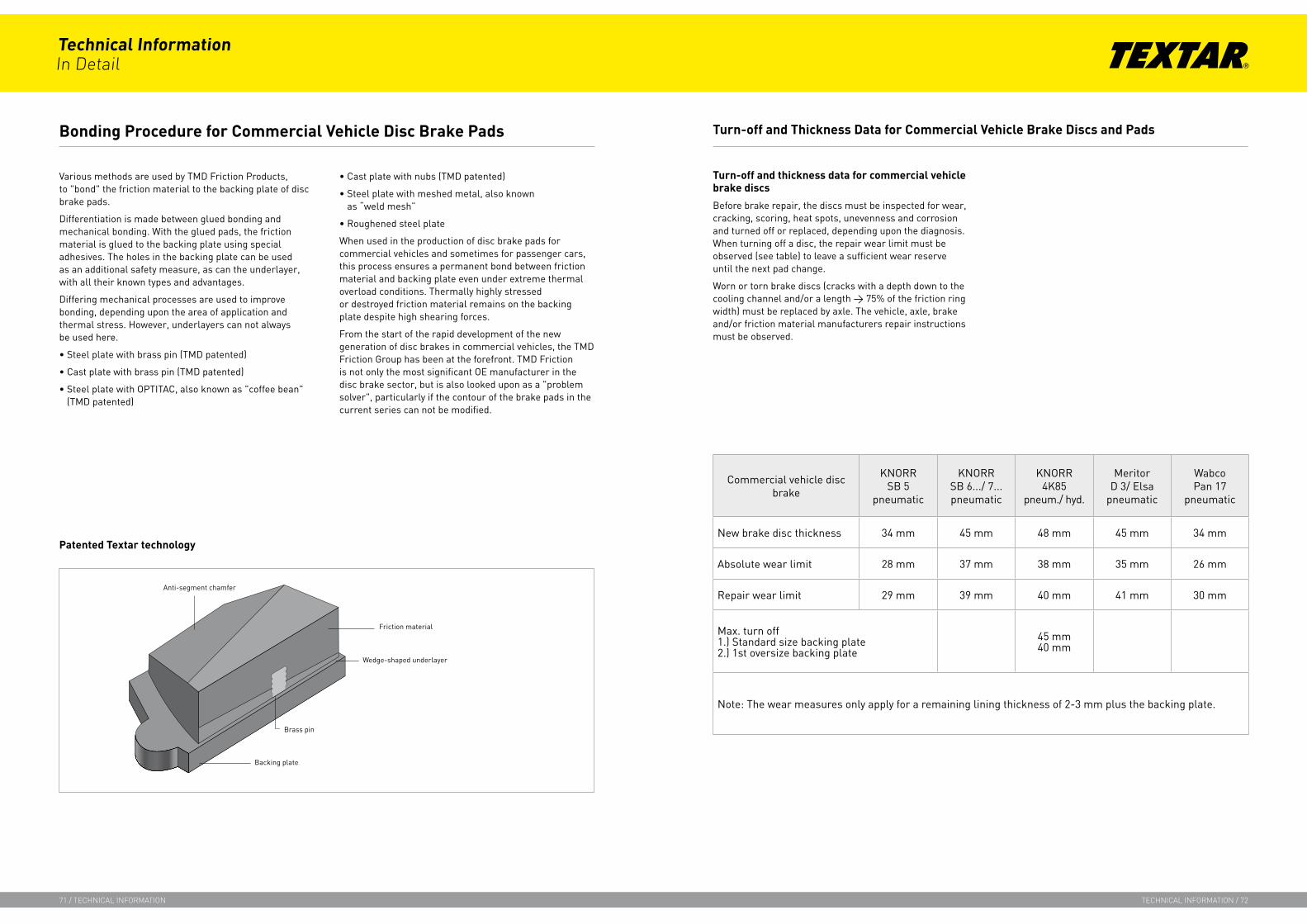
Various methods are used by TMD Friction Products, to "bond" the friction material to the backing plate of disc brake pads.
Differentiation is made between glued bonding and mechanical bonding. With the glued pads, the friction material is glued to the backing plate using special adhesives. The holes in the backing plate can be used as an additional safety measure, as can the underlayer, with all their known types and advantages.
Differing mechanical processes are used to improve bonding, depending upon the area of application and thermal stress. However, underlayers can not always be used here.
• Steel plate with brass pin (TMD patented)
• Cast plate with brass pin (TMD patented)
• Steel plate with OPTITAC, also known as "coffee bean" (TMD patented)
• Cast plate with nubs (TMD patented)
• Steel plate with meshed metal, also known as “weld mesh”
• Roughened steel plate
When used in the production of disc brake pads for commercial vehicles and sometimes for passenger cars, this process ensures a permanent bond between friction material and backing plate even under extreme thermal overload conditions. Thermally highly stressed or destroyed friction material remains on the backing plate despite high shearing forces.
From the start of the rapid development of the new generation of disc brakes in commercial vehicles, the TMD Friction Group has been at the forefront. TMD Friction is not only the most significant OE manufacturer in the disc brake sector, but is also looked upon as a "problem solver", particularly if the contour of the brake pads in the current series can not be modified.
Turn-off and thickness data for commercial vehicle brake discs
Before brake repair, the discs must be inspected for wear, cracking, scoring, heat spots, unevenness and corrosion and turned off or replaced, depending upon the diagnosis. When turning off a disc, the repair wear limit must be observed (see table) to leave a sufficient wear reserve until the next pad change.
Worn or torn brake discs (cracks with a depth down to the cooling channel and/or a length > 75% of the friction ring width) must be replaced by axle. The vehicle, axle, brake and/or friction material manufacturers repair instructions must be observed.
Commercial vehicle disc brake
KNORRSB 5
pneumatic
KNORRSB 6.../ 7...pneumatic
KNORR4K85
pneum./ hyd.
MeritorD 3/ Elsa
pneumatic
WabcoPan 17
pneumatic
New brake disc thickness 34 mm 45 mm 48 mm 45 mm 34 mm
Absolute wear limit 28 mm 37 mm 38 mm 35 mm 26 mm
Repair wear limit 29 mm 39 mm 40 mm 41 mm 30 mm
Max. turn off1.) Standard size backing plate2.) 1st oversize backing plate
45 mm40 mm
Note: The wear measures only apply for a remaining lining thickness of 2-3 mm plus the backing plate.
Turn-off and Thickness Data for Commercial Vehicle Brake Discs and PadsBonding Procedure for Commercial Vehicle Disc Brake Pads
Technical InformationIn Detail
71 / technIcal InformatIon technIcal InformatIon / 72
Patented Textar technology

Friction material OE AM Vehicle manufacturer Bus Tractor Trailer
T 263 OE Perlini x
T 402 OE KBA /ECE90R Mercedes x
T 450 OE Perlini x
T 456 OE Neoplan/IVECO/Evobus Setra x x
T 457 OE WABCO x
T 471 OE Mercedes x
T 3010 OE DAF/MAN x x
T 3011 OE Mercedes x
T 3016 OE Renault Trucks/Mercedes x x
T 3018 KBA /ECE90R Ford/IVECO/Renault Trucks/ Volvo x
T 3023 OE MAN/Van Hool x
T 3030 OE KBA /ECE90R BPW x
T 3050 OE KBA /ECE90R Mercedes/Scania/IVECO/MAN x
T 3060 KBA /ECE90R SAF/Fruehauf Achsen x
T 7400 OE KBA /ECE90R DAF/Evobus Setra/Neoplan/Mercedes/Scania x x
D 7500 OE VOLVO x
T 3029 OE MAN x
T 3032 OE Renault Trucks/Volvo x
T 3033 OE MAN x
T 3034 OE Volvo x x
Friction material OE AM Vehicle manufacturer Bus Tractor Trailer
T 0005 OE IKARUS-Bus/RABA-Achsen x x
T 10 OE KBA /ECE90R Mercedes x
T 0104 OE Renault Trucks x
T 0115 OE Renault Trucks x
T 011 OE IVECO/WABCO x
T 012 OE KBA /ECE90R Mercedes x
T 013 OE KBA /ECE90R Kässbohrer/Warstein/SAF x x
T 016 OE KBA /ECE90R DAF/ Mercedes/ Evobus Setra/ Auwärter x
T 017 OE Mercedes/IVECO x x
T 018 KBA /ECE90R IKARUS x
T 020 OE KBA /ECE90R MAN x
T 021 OE KBA /ECE90R VW x
T 022 OE KBA /ECE90R IVECO x
T 024 KBA /ECE90R IVECO x
T 026 OE KBA /ECE90R MAN/VOLVO x x
T 030 OE Auwärter/ IVECO x
T 053 OE KBA /ECE90R BPW/Knott-Achsen x
T 066 OE VW x
T 088 ECE90R Mercedes/MAN x x
T 090 OE KBA /ECE90R BPW/SAF x
T 099 KBA /ECE90R BPW/SAF/Frühauf Achsen/ROR x
DON 7113 OE KBA /ECE90R Mercedes/MAN x
DON 7115 OE KBA /ECE90R Scania /Volvo x
DON 7203 OE DAF x
DON G 110 KBA /ECE90R Scania /Volvo x
DON G 115 OE KBA /ECE90R Scania /Volvo x
DON 7141 OE IVECO/ROR x x
DON 7151 OE IVECO x
Friction Material Overview, Commercial Vehicle Drum Brake Linings Friction Material Overview, Commercial Vehicle Disc Brake Pads
Technical InformationIn Detail
73 / technIcal InformatIon technIcal InformatIon / 74