technical information flow measuring system
TRANSCRIPT

TechnicalInformationTI 027D/06/enNo. 50063743
Flexible System
• Wide choice of materials for processconnections and measuring tubelinings, compatible to the fluid
• Transmitter housing and display canbe rotated to fit the orientation
Operational Security
• ISO 9001 manufacturer• High electromagnetic compatibility
(EMC)• High operating integrity through
self-monitoring with alarm function• Data protection with EEPROM
on power failure (without batteries)• Empty Pipe Detection (EPD)
Easy to Operate
• Illuminated, double-spaced display• Touch control: Operation from outside
without opening the housing• E+H operating matrix – menudriven
operation for all instrument parameters• Interfaces: HART, PROFIBUS-PA,
PROFIBUS-DP, Rackbus RS 485
Measure Precisely
• Measured error: ± 0.5% or ± 0.2%• 1000:1 operable flow range• Excellent repeatability
Install Anywhere
• Robust, shock-resistant aluminiumhousing, resistant to acids andcaustics
• IP 67 protection for compact andremote versions (optional IP 68 sensor)
• Wide size range DN 2...2000 (1/12...78")• Flanged version with ISO meter lengths• Hygienic sensor for food and pharma-
ceutical applications• Ex versions for use in Ex Zones 1 and 2
ElectromagneticFlow Measuring System
promag 33
Hauser+EndressNothing beats know-how

Measuring System Fields of Application
With the Promag 33 flowmeter mostliquids can be measured providedthey have a minimum conductivity of≥ 5 µS/cm, e.g.– acids, alkalis, pastes, pulps,– drinking water, wastewater,
sewage sludge,– milk, beer, wine, mineral water,
yoghurt, molasses, etc.
A minimum conductivity of ≥ 20 µS/cmis required for measuring demineralisedwater.
Ex Versions
Promag 33 is available in a number ofEx versions for use in Ex Zone 1 and 2.More information is given in theappropriate Ex documentation. YourE+H representative will be pleased tohelp you.
Measuring System
The measuring system consists of:• Promag 33 transmitter• Promag A, H or F sensor
The Promag 33 measuring system ismechanically and electronicallydesigned for maximum flexibility withthe transmitters and sensors being
combined in any variation. The widerange of materials and processconnections (fittings; flanges DIN, ANSI,JIS; Tri-Clamp, etc.) ensure that themeasuring point can adjust to both plantand process conditions.
Sensor Transmitter
Promag 33
Compact version
Remote version(with wall mounting)
Promag ADN 2...25
Promag HDN 25...100
ti027
y02
Promag FDN 15...300
Promag FDN 350...2000
Electronics versions (communication):– HART– PROFIBUS-PA– PROFIBUS-DP– Rackbus RS 485– EEx i
2

Function Measuring Principle
According to Faraday's Law of MagneticInduction, a voltage is induced into aconductor which moves in a magneticfield. With the electromagnetic measur-ing principle, the flowing fluid is themoving conductor. The induced voltageis proportionally related to the flowvelocity and is fed to the measuringamplifier by a pair of electrodes. Usingthe pipe cross-sectional area, the flowvolume is calculated.
The DC magnetic field is generated bya switched direct current of alternatingpolarity. Together with the patented“Integrated Autozero Circuit”, this guar-antees a stable zero point, and makesthe measurement fluid-independent andinsensitive to entrained solid particles.Every meter is factory calibrated withthe most modern calibration rigs, trace-able to national standards.
Function of the Promag 33
The Promag transmitter converts themeasured values coming from thesensor into standardised output signals.The following outputs are available forthese signals:• Current output• Pulse / Frequency output• Alarm output (Relay 1)• Status output (Relay 2)
Promag 33 also has the followingfeatures:• Relay 1 and 2 are freely configurable• Auxiliary input (positive zero return,
totalizer reset, batching, dual rangemode)
• Empty Pipe Detection (EPD) detectsand indicates partially filled or emptymeasuring tubes.
• The special electrode cleaning cir-cuitry (EEC) ensures accurate flowmeasurement even with conductivebuild-up in the measuring tube(e.g. magnetite).
ti027
y01
Ue = B ⋅ L ⋅ vQ = v ⋅ A
Ue = induced voltageB = magnetic induction (magnetic field)L = distance between measuring electrodesv = flow velocityQ = volume flowA = pipe cross-section
3

Operation Display and Operation
The Promag 33 measuring system isequipped with an illuminated, double-spaced LC display. This ensures that allimportant variables can be read off andcontrolled directly at the measuringpoint:• Technical units• Current output functions• Totalizer functions• Pulse and frequency output functions• Relay functions• Limit values• Batching functions with integral preset
counter• Display parameters
• Creep suppression• Empty pipe detection (EPD)• Single and bidirectional measurement• Auxiliary input
Three operating keys are used forselecting and setting all functions of theinstrument. The E+H operating matrixallows quick and easy access to allindividual functions.12 languages are selectable for thedisplay text. A help function (diagnosisfunction) is available during program-ming.
Communication
Depending on which module is fitted,Promag 33 has different interfaces forcommunication ability with higher levelsystems:• HART protocol (SMART technology)
is possible on the current output.• Direct communication to a personal
computer and the E+H Rackbus worldis possible via the RS 485 interface.
• The PROFIBUS-PA version providesan indirect connection to processcontrol systems via segment couplers.
• Promag 33 is also available as aPROFIBUS-DP version for connectingto a PROFIBUS-DP network.
This communication feature enablesoperation and configuration ofinstruments which have no local display.
E - +
ENDRESS+HAUSERPROMAG
>3s
ti027
y03
Infraredreceiving diode
3 optical keypads (“Touch Control”):• Access / leave operating matrix• Select functions• Set / store parameters
LC display:illuminated,double-spaced
Function symbols(from left to right)• Access to the
operating matrix• Returning to HOME
position• Diagnosis function
Infrared trans-mitting diode
4

Diameter Selection As a rule, the pipe diameter determinesthe sensor nominal diameter.
A necessary increase in velocity can beachieved through a reduction of thesensor diameter (see page 8).The higher installation expense isnormally balanced by the lower sensorcost.
The flow velocity (v) is also to be deter-mined by the fluid's physical properties:• v < 2 m/s: with abrasive fluids, e.g.
potter's clay, lime milk, ore slurry• v > 2 m/s: with fluids causing build up,
e.g. wastewater slurry etc.
The table below summarizes the mini-mum and maximum full scale values forthe current output (incl. factory settings).
DN Full scale values [m 3/h]
[mm] [inch]Minimum full scale
at v = 0.3 m/sFactory settingat v ~ 2.5 m/s
Maximum full scaleat v = 10 m/s
248
15253240506580
100125150
200250
300350
400450
500600700750800900
100010501200135014001500160017001800
2000
1/12"5/
32"5/16"1/2"1"
11/4"11/2"
2"21/2"
3"
4"5"6"
8"10"
12"14"
16"18"
20"24"28"30"32"36"
40"42"48"54"56"60"64"66"72"
78"
0.00340.01360.05430.19080.53010.86851.3572.1213.5845.429
8.48213.2519.09
33.9353.01
76.34103.9
135.7171.8
212.1305.4415.6477.1542.9687.1
848.2935.2
1222154616631909217224512748
3393
0.02830.11310.45241.5904.4187.238
11.3117.6729.8745.24
70.69110.5159.0
282.7441.8
636.2865.9
11311431
176725453464397645245726
70697793
10179128821385415904180962042822902
28274
0.11310.45241.8106.362
17.6728.9545.2470.69
119.5181.0
282.7441.8636.2
11301767
25453464
45245726
70691017913854159041809622902
282743117240715515305541863617723828171391609
113097
5

Mounting
Mounting Position
Vertical mounting:This is the recommended position withthe flow upwards. Entrained solidparticles sink and fatty components inthe stationary fluid rise away from themeasuring electrodes. This is theoptimal position in empty pipe systemand when using Empty Pipe Detection.
Horizontal mounting:The axis of the electrodes must behorizontal, thus preventing brief insula-tion of the electrodes by entrained airbubbles.
Electrode axis:The plane in which the electrode axislies with regard to the transmitter isidentical for the Promag A, H and Fsensors.
Inlet and Outlet Sections
The sensor should be mounted awayfrom fittings such as valves, T-pieces,elbows, etc.
Inlet section: ≥ 5 x DNOutlet section: ≥ 2 x DN
The inlet and outlet sections must beobserved in order to maintain accuracy.
Vibration
The piping before and after the sensorshould be securely fastened if thereis excessive vibration. Information onshock and vibration resistance is foundon page 25.Excessive vibration necessitatesseparate mounting of the sensor andtransmitter.
Mechanical support of the sensor isrecommended for free runs of pipingover 10 m long.
In order to measure correctly and to prevent damage, please observe the followinginstallation instructions.
ti027
y05
ti027
y06
≥ 5 x DN ≥ 2 x DN
ti027
y07
> 10 m
Measuring electrodes
Electrode axis
(Example Promag F)
ti027
y04
6

Mounting Location
Correct measurement is only possiblewhen the pipe is full. The followinglocations should therefore be avoided:
• No installation at the highest point(air accumulation).
• No installation immediately beforean open pipe outlet in a downwardline.
The alternative installation, however,permits a correct measurement.
Partly Filled Pipes
For inclines a mounting similar to a drainshould be adopted. Added security isoffered by Empty Pipe Detection (EPD)in order to detect empty or partly filledpipes.
Note!Danger of solids accumulation!Do not mount the sensor at the lowestpoint of the drain. A cleaning valveshould also be installed.
Downward Pipe
With the installation suggested opposite,partial vacuum is avoided even with adownward pipe > 5 m long (siphon, ventvalve downstream of the sensor).
Installation of Pumps
Do not mount the sensors on thesuction side of pumps.This prevents low pressure and preventspossible damage to the lining of themeasuring tube.
Pulse dampers should be installedwhen using reciprocal, diaphragm orperistaltic pumps.
h 2 x DN≥
ti027
y08
alternatively
ti027
y09
≥ 2 x DN
≥ 5 x DN
>5
m
Venting valve
ti027
y10
ti027
y11
7

Mounting Adapters
The sensor can also be mounted in apipe with a larger nominal diameterwhen suitable adapters (reducers andexpanders) to DIN 28545 are fitted.The resultant increase in the rate of flowincreases the accuracy of measurementwith slowly moving fluids.
The adjacent nomogram can be used todetermine the pressure loss caused:
1. Determine the ratio of thediameter d/D.
2. From the nomogram read off thepressure loss at the flow velocityand d/D ratio.
Note!The nomogram applies to fluids with aviscosity similar to that of water.
Remote Version
Two different versions are available forthe remote version:
FS version• The permissible cable length greater
than 10 meters is governed by thefluid conductivity (see Figure).
• Permissible cable length of max.10 meters if the instrument is equippedwith an Empty Pipe Detection (EPD)electrode.
• The FS cable is recommended only fordistances smaller than 20 m.
FL version• All fluids with a minimum conductivity
of ≥ 5 µS/cm (demineralised water≥ 20 µS/cm) can be measuredindependent of the cable length.
• Empty Pipe Detection (EPD) is notavailable with this version.
Please also note the following:• Fasten the cable gland or lay it in a
conduit. When the fluid conductivity islow, cable movements can causeserious changes in capacitance andthereby falsify the measuring signal.
• Do not run the cable in the vicinity ofelectrical machines or switchingelements.
• Ensure potential equalisation betweenthe transmitter and the sensor.
Diameter ratio d/D
Pre
ssur
elo
ss[m
bar]
ti027
y12
200
100
5
10 100 200 [m]
FL
FS
Cable length Lmax
Conductivity[µS/cm]
Lmax
ti027
y13
Permissiblerange
Remote version has to bemounted when:– access is difficult– space is restricted– extreme process and ambient
temperatures prevail(see page 24)
– there is severe vibration(see page 25)
8

Electrical ConnectionTransmitter
3
28
2021
2324252627
12
22
ti027
y14The input and outputs are galvanically separated from the power supply
and from each other.
Fuse• Power supply 20...55 V AC / 16...62 V DC:
2.5 A slow-blow / 250 V; 5.2 x 20 mm• Power supply 85...260 V AC:
1 A slow-blow / 250 V; 5.2 x 20 mm
Supply cable
Ground terminal forprotective conductor
Ground terminal forsignal cable shield
Signal cable
“HART” version
3 Ground connection (protective earth)
12
L1 for AC power supply L+ for DC power supplyN L–
20 (+)21 (–)
Pulse / Frequency output active/passive, fmax = 10 kHzactive: 24 V DC, 25 mA (max. 250 mA/20 ms)passive: 30 V DC, 250 mA
22 (+)23 (–)
Alarm output (Relay 1) can be configuredmax. 60 V AC / 0.5 A AC; max. 30 V DC / 0.1 A DC
24 (+)25 (–)
Status output (Relay 2) can be configuredmax. 60 V AC / 0.5 A AC; max. 30 V DC / 0.1 A DC
26 (+)27 (–) Current output active, 0/4...20 mA, RL < 700 Ω (with HART: RL ≥ 250 Ω)
28 Ground connection (screening of signal cable)
“PROFIBUS-PA” version
3 Ground connection (protective earth)
12
L1 for AC power supply L+ for DC power supplyN L–
20 / 21 not used
22 (+)23 (–)
Current output active, 0/4...20 mARL < 350 Ω
24 / 25 not used
26 (+)27 (–) PROFIBUS-PA EN 50170 Volume 2, IEC 1158-2
28 Ground connection (screening of signal cable)
“PROFIBUS-DP” version
3 Ground connection (protective earth)
12
L1 for AC power supply L+ for DC power supplyN L–
20–25 not used
26 (+)27 (–)
Data B PROFIBUS-DP (RS 485 interface)Data A
28 Ground connection (screening of signal cable)
9

Electrical ConnectionTransmitter
3
28
2021
2324252627
12
22
ti027
y14
Fuse• Power supply 20...55 V AC / 16...62 V DC:
2.5 A slow-blow / 250 V; 5.2 x 20 mm• Power supply 85...260 V AC:
1 A slow-blow / 250 V; 5.2 x 20 mm
Supply cable
Ground terminal forprotective conductor
Ground terminal forsignal cable shield
Signal cable
The input and outputs are galvanically separated from the power supplyand from each other.
“Rackbus RS 485” version
3 Ground connection (protective earth)
12
L1 for AC power supply L+ for DC power supplyN L–
20 (+)21 /–)
RS 485 interface or Auxiliary inputA + / – 3...30 V DCB – / +
22 (+)23 (–)
Alarm output (Relay 1) can be configuredmax. 60 V AC / 0.5 A AC; max. 30 V DC / 0.1 A DC
24 (+)25 (–)
Status output (Relay 2) can be configuredmax. 60 V AC / 0.5 A AC; max. 30 V DC / 0.1 A DC
26 (+)27 (–)
Current output active, 0/4...20 mA, RL < 700 ΩorPulse/frequency output active/passive, fmax = 10 kHz
active: 24 V DC, 25 mA (max. 250 mA/20 ms)passive: 30 V DC, 250 mA
28 Ground connection (screening of signal cable)
“EEx i” version
3 Ground connection PE (protective earth)
12
L1 for AC power supply L+ for DC power supplyN L–
20 / 21 not used
22 (+)23 (–)
Current output active, 0/4...20 mA, RL < 350 Ω(with HART: RL ≥ 250 Ω)
24 / 25 not used
26 (+)27 (–)
Pulse/frequency output passive, fmax = 10 kHzCan be used as NAMUR contact acc. to DIN 19234
28 Ground connection (screening of signal cable)
Terminal compartment with:– a special terminal block for intrinsically safe outputs and– an IP 40 cover for power supply terminals.
10

Electrical ConnectionRemote Version
6
6
5
5
7
7
8
8
4
4
37
37
36
36
23
23
22
22
42
42
41
41
S1
S1
E1
E1
E2
E2
S2
S2
GND
GND
E
E
S
S
EPD
EPD
Coils
Coils
2 1bro
wn
whi
te
gre
en
yello
w
6
64
5
5
7
7
8
8
4 37
37
36
36
23 22 42
42
41
41
S1
S1
E1
E1
E2
E2
S2
S2
GND
GND
E
E
S
S
EPD
EPD
Coils
Coils
2 1bro
wn
whi
te
gre
en
yello
w
6 5
5
7
7
8 4
4
37
37
36
36
23
23
22
22
42
42
41
41
E1
E1
E2
E2
GND
GND Coils
Coils
2 1
whi
te
V+ V-
V+ V-
gre
y
gre
en
bro
wn
yello
w
6 5
7
7
5
8 4
4
37 36 23
23
22
22
42
42
41
41
E1
E1
E2
E2
GND
GND Coils
Coils
2 1
V+ V-
V+ V-
gre
y
bro
wn
whi
te
yello
w
gre
en
out-out+
ti027
e01
FL Version
Promag 33 H / F
Transmitter
Promag 33 A
Transmitter
Sensor Sensor
Promag 33 H / F
Transmitter
Promag 33 A
Transmitter
Sensor Sensor
FS Version
11

Cable Specifications Remote Version FS
Coil cable: 2 x 0.75 mm2 PVC cable with common screen *Conductor resistance ≤ 37 Ω/kmCapacitance: core/core, screen grounded ≤ 120 pF/mPermanent operating temperature: –20...+70 °C
Signal cable: 3 x 0.38 mm2 PVC cable with common screen *and separately screened coresWith EPD (Empty Pipe Detection) 4 x 0.38 mm2 PVC cableConductor resistance ≤ 50 Ω/kmCapacitance: core/screen ≤ 420 pF/mPermanent operating temperature: –20...+70 °C
* braided copper screen: ∅ ~ 7 mm
Remote Version FL
Coil cable: 2 x 0.75 mm2 PVC cable with common screen *Conductor resistance ≤ 37 Ω/kmCapacitance: core/core, screen grounded ≤ 120 pF/mPermanent operating temperature: –20...+70 °C
Signal cable: 5 x 0.5 mm2 PVC cable with common screen *Conductor resistance ≤ 37 Ω/kmCapacitance: core/core, screen grounded ≤ 120 pF/mPermanent operating temperature: –20...+70 °C
* braided copper screen:coil cable ∅ ~ 7 mm; signal cable ∅ ~ 9 mm
Operation in Areas with Severe Electrical Interference
The Promag 33 measuring system fulfils all general safety requirements accordingto EN 61010 and electromagnetic compatibility (EMC) according to EN 50081 Part 1and 2 / EN 50082 Part 1 and 2 when installed in accordance with the NAMURrecommendations.
Note!• To comply with the certificate of conformity, the signal and coil cables between
the sensor and transmitter of the remote version must always be screened andgrounded at both ends. Grounding is made using the ground terminals especiallyfor this purpose on the inside of the connection housings. Keep stripped andtwisted cable shield section to the ground terminal as short as possible.
• The cable must be resistant to an ambient temperature of max. +80 °C if thePromag H sensor is operated at a process temperature of +150 °C.
12

Potential Equalisation The sensor and the fluid must haveroughly the same electrical potential toensure that measurement is accurateand no galvanic corrosion takes placeat the electrode.
Normally the reference electrode in thesensor or the metal pipe ensures thatthe potentials are equalised.
Reference electrodes:
Promag A:Always with reference electrode
Promag F:Optional, depending on material
Promag H:No reference electrode, as there isalways a metallic connection to thefluid.
If the reference electrode is correctlygrounded and the fluid flows throughmetallic, non-lined and groundedpiping, then it is sufficient to connect thegrounding terminal of the Promag 33transmitter housing to the potentialequalisation line in order to preventcorrosion. The connection with theremote-mounted version is made atthe ground terminal of the connectionhousing.
Caution!Danger of permanent damage tothe instrument! If the fluid cannot begrounded for operational reasons,ground disks are to be used.
Potential Equalisation for Lined
Pipes with Cathodic Protection
When the fluid cannot be grounded foroperational reasons, the measuring unitmust be installed that it is potential-free.Ensure that components of the pipingare connected to one another (copperwire, 6 mm2).
All national regulations regardingpotential free installation are to beobserved (e.g. VDE 0100).Ensure that the mounting material useddoes not result in a conductive bondwith the measuring unit and that thematerial can withstand the tighteningtorque used.
6 mm² Cu
ti027
y17
Isolating transformerPower supply
1 Empty pipe detection electrode2 Measuring electrodes3 Reference electrode(s)
1
2
3
2
ti027
y16
13

Potential Equalisation Plastic or Lined Piping
Ground disks must always be usedwith non-conductive piping materials ifcompensation currents flow through thefluid. They can irreparably damage thereference electrode within a short timedue to electrochemical corrosion.
Such conditions occur especially if:• the piping is insulated with electrically
non-conductive materials and• the piping is made of fibreglass or
PVC through which flow highly concen-trated acids and alkalis.
Equalising Currents in Ungrounded
Metal Pipes / Grounding in an Area
with Severe Interference
The fluid may be grounded. In order tomake the most of the electromagneticcompatibility (EMC) of the Promag 33,it is advisable to provide two flange-to-flange links and to connect them jointlywith the transmitter housing to groundpotential.
6 mm² Cu
ti027
y18Ground disks: appr. 3 mm thick
6 mm² Cu
ti027
y19
Caution!Danger from damage due to electrochemical corrosion!• Note the corrosion resistance of the ground disks.• Note the electrochemical potential series in cases where the ground disks
and the measuring electrodes are made of different material.
ti027
y44
Promag A sensorWall mounting kit
A = 105 mmB = 105 mmC = 115 mm
Wall mounting kitPromag A
14

DimensionsPromag 33 A Compact version
ti027
y20
ti027
y21
Weight:Compact version 5 kg (without process connections)Promag 33 transmitter 3 kg (5 kg for wall mounted version)Promag A sensor 2 kg
* with blind version
Remote versionFS version
FL version
ti027
y23
Can be ordered separately as mounting set:Internal thread, external thread, PVC adhesivecoupling, hose connection, welded nipples
Flange joints(mounted when delivered)
Tri-Clamp(mounted when delivered)
DN 2...25
DN 2...25
B
A
1" threaded stub (ISO 228)
Process connections Promag A(Dimensions: see page 16)
A Mounting set:coupling nut on a 1" threadedstub
B Screw-in process connections(instead of threaded stub)
15

Process Connections Promag A
Internal threadstandard thread:ISO 228/DIN 2999
External threadstandard thread:ISO 228/DIN 2999
PVC adhesive coupling
Hose connection
Welded nippleDN 2...15
Welded nippleDN 25
Tri-ClampStainless steel1.4404/316L
FlangeStainless steel 1.4404/316Lwith joint dimensions toDIN 2501/ANSI B16.5/JIS B2210
DN 2...15:with DN 15 or 1/2" flanges
DN 25:with DN 25 or 1" flanges
FlangePVDF with joint dimensions toDIN 2501/ANSI B16.5/JIS B2210
DN 2...15:with DN 15 or 1/2" flanges
DN 25:with DN 25 or 1" flanges
Length:2 x L + 143 mm2 x L + 95 mm (for flanged orTri-Clamp version) All dimensions in [mm]
y22-
01...
10
DN L L1 Thread2...152...15
2525
20204545
18182222
1/2"1/2" NPT
1"1" NPT
Flange to DIN 2501/ANSI B16.5/JIS B2210PN 16/Class 150/10K
DN L L1 D d di DINLK
ANSILK
JISLK
2...81525
52.752.752.7
667
9595
115
343450
16.216.227.2
656585
60.560.579.2
707090
Face-to-face length to DVGW (200 mm)
DN L L1 di Thread2...152...15
2525
35425060
13.220.016.825.0
16.116.122.022.0
1/2"1/2" NPT
1"1" NPT
DN L D Pipe connection2...152...15
252525
1920666969
20.021.525.032.033.5
20 ⋅ 21/2"
25 ⋅ 232 ⋅ 2.5
1"
DN L D di LW2...152...152...15
303030
14.517.521.0
8.912.616.1
131619
LW = Internal diameter hose
DN L D s Pipe connection2..152..15
2020
21.321.3
2.62.6
1/2"18 ⋅ 1
DN L D di Pipe connection252525
303020
33.733.725.4
26.026.022.1
1"28 ⋅ 1
25.4 ⋅ 1.6 / 1"
DN L D di Pipe connection2..815
2...81525
2424242424
25.025.050.450.450.4
9.516.022.122.122.1
1/2"3/4"1"1"1"
Flange to DIN 2501, PN 40
DN L D di LK2...81525
51.851.851.8
9595
115
17.317.328.5
656585
Flange to ANSI B16.5
Class 150 Class 300DN L D LK di L D LK2...81525
61.661.667.4
88.988.9
108.0
60.560.579.2
15.815.826.6
61.661.673.8
95.295.2
123.9
66.566.588.9
Flange to JIS B2210
DN L D di LK2...81525
62.562.562.5
9595
115
151625
707090
Face-to-face length to DVGW (200 mm)
16

DimensionsPromag 33 H Compact version
ti027
y24
ti027
y25
Remote version * with blind version
ti027
y26
Process connections Promag H
Welded nipple
Flat gasketSilicone / EPDM
Tri-Clamp ISO 2853
DN 11851 SMS
ISO 2852
Process connectionsPromag H(Dimensions: see page 18)
DN DI 1) PN L A B B1 C K H M Weight 2)
[mm] [inch] [mm]DIN[bar] [mm] [mm] [mm] [mm] [mm] [mm] [mm] [mm] [kg]
25 DIN2540506580
100
–1"
11/2"2"
21/2"3"4"
26.022.635.348.159.972.697.5
16161616161616
140140140140140200200
318318318343343393393
254.0254.0254.0266.5266.5291.5291.5
158.5158.5158.5171.0171.0196.0196.0
64.064.064.076.576.5
101.5101.5
128128128153153203203
222.5222.5222.5247.5247.5297.5297.5
M 6x4M 6x4M 6x4M 8x4M 8x4M 12x4M 12x4
6.06.06.59.09.0
19.018.5
1) Internal diameter of tube
Weight:Compact version 2) see table abovePromag 33 transmitter 3 kg (5 kg for wall mounted version)Sensor connection housing approx. 1 kg
17
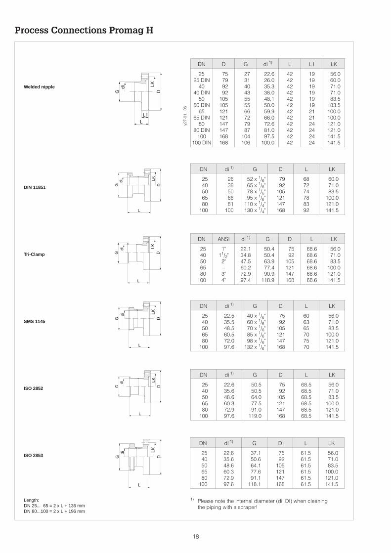
Process Connections Promag H
Welded nipple
DIN 11851
Tri-Clamp
SMS 1145
ISO 2852
ISO 2853
Length:DN 25... 65 = 2 x L + 136 mmDN 80...100 = 2 x L + 196 mm
1) Please note the internal diameter (di, DI) when cleaningthe piping with a scraper!
y27-
01...
06
DN D G di 1) L L1 LK
2525 DIN
4040 DIN
5050 DIN
6565 DIN
8080 DIN
100100 DIN
75799292
105105121121147147168168
27314043555566727987
104106
22.626.035.338.048.150.059.966.072.681.097.5
100.0
424242424242424242424242
191919191919212124242424
56.060.071.071.083.583.5
100.0100.0121.0121.0141.5141.5
DN di 1) G D L LK
2540506580
100
2638506681
100
52 x 1/6"65 x 1/6"78 x 1/6"95 x 1/6"
110 x 1/4"130 x 1/4"
7992
105121147168
687274788392
60.071.083.5
100.0121.0141.5
DN ANSI di 1) G D L LK
2540506580
100
1"11/2"
2"–3"4"
22.134.847.560.272.997.4
50.450.463.977.490.9
118.9
7592
105121147168
68.668.668.668.668.668.6
56.071.083.5
100.0121.0141.5
DN di 1) G D L LK
2540506580
100
22.535.548.560.572.097.6
40 x 1/6"60 x 1/6"70 x 1/6"85 x 1/6"98 x 1/6"
132 x 1/6"
7592
105121147168
606365707570
56.071.083.5
100.0121.0141.5
DN di 1) G D L LK
2540506580
100
22.635.648.660.372.997.6
50.550.564.077.591.0
119.0
7592
105121147168
68.568.568.568.568.568.5
56.071.083.5
100.0121.0141.5
DN di 1) G D L LK
2540506580
100
22.635.648.660.372.997.6
37.150.664.177.691.1
118.1
7592
105121147168
61.561.561.561.561.561.5
56.071.083.5
100.0121.0141.5
18

Dimensions
Promag 33 FDN 15...300
Compact version
Remote version
ti027
y28
ti027
y29
* with blind version
DN PN L1) A B C K E F H B1 Weight2)
[mm] [inch]DIN ANSI
ClassJIS
[mm] [mm] [mm] [mm] [mm] [mm]DIN
[mm]ANSI[mm] [mm] [mm] [kg]
15253240506580
100125150200250300
1/2"1"–
11/2"2"–3"4"–6"8"
10"12"
40404040401616161616101010
150150
–150150
–150150
–150150150150
20K20K20K20K10K10K10K10K10K10K10K10K10K
200200200200200200200250250300350450500
340.5340.5340.5340.5340.5390.5390.5390.5471.5471.5526.5576.5626.5
256.5256.5256.5256.5256.5281.5281.5281.5321.5321.5346.5371.5396.5
8484848484
109109109150150180205230
120120120120120180180180260260324400460
9494949494949494
140140156156166
14161818201820222424262828
11.214.2
–17.519.1
–23.923.9
–25.428.430.231.8
286286286286286336336336417417472522572
202202202202202227227227267267292317342
6.57.38.09.4
10.612.014.016.021.525.535.348.557.5
1) The length is always identical independently of the chosen pressure rating.
Weight:Compact version 2) see table abovePromag 33 transmitter 3 kg (5 kg for wall mounted version)Sensor connection housing approx. 1 kg
19

Dimensions
Promag 33 FDN 350...2000
ti027
y30
ti027
y31
Compact version
Remote version
* with blind version
DN PN L 1) A B C K E F H B1 Weight2)
[mm] [inch]DIN[bar]
ANSI[Class]
AWWA[Class] [mm] [mm] [mm] [mm] [mm] [mm]
DIN[mm]
ANSI[mm]
AWWA[mm] [mm] [mm] [kg]
350400450500600700750800900
1000105012001350140015001600165018002000
14"16"18"20"24"28"30"32"36"40"42"48"54"–
60"–
66"72"78"
1010–
101010–
101010–6–6–6–66
150150150150150
––––––––––––––
–––––DDDDDDDD–D–DDD
550600650650780910975
104011701300136515601755182019502080214523402600
738790840891995
11981198124113941546159817961998214821962286236025502650
456.0482.0507.0532.5584.5686.0686.0707.5784.0860.0886.0985.0
1086.01161.01185.01230.01267.01362.01412.0
282.0308.0333.0358.5410.5512.0512.0533.5610.0686.0712.0811.0912.0987.0
1011.01056.01093.01188.01238.0
564616666717821
10241024106712201372142416221824197420222112218623762476
276276292292402589626647785862912992
1252125213921482148216321732
2626–
282830–
323434–
28–
32–
34–
3638
34.936.539.742.947.6
––––––––––––––
–––––
33.334.938.141.341.344.544.554.0
–57.2
–63.566.769.9
683.5735.5785.5836.5940.5
1143.51143.51186.51339.51491.51543.51741.51943.52093.52141.52231.52305.52495.52595.5
401.5427.5452.5478.0530.0631.5631.5653.0729.5805.5831.5930.5
1031.51106.51130.51175.51212.51307.51357.5
110130240170230350450450600720
105012002150180026002500370033004100
1) Thickness of the flange face includes sealing strip. The length is always identical independently of the chosen pressure rating.
Weight:Compact version 2) see table abovePromag 33 transmitter 3 kg (5 kg for wall mounted version)Sensor connection housing approx. 1 kg
20

-60 -40 -20 0 20 40 60 80 100 120 140 160
0
5
10
15
20
PN 161.4435
[bar]
[°C]
Promag H
Welded nipple material: Steel 1.4404/316L
-60 -40 -20 0 20 40 60 80 100 120 140 160
0
5
10
15
20
25
35
30
40PN401.4404/14435
PN16PVDF
PN16PVC
[bar]
[°C]
Promag A
DIN 2413 and 2505Flange material: Steel 1.4404/1.4435, PVDF, PVC
Material Load Curves (p-T-Diagrams)
-60 -40 -20 0 20 40 60 80 100 120 140 160
0
2
7
8
9
10
11
[bar]
0
29
101.5
116
130.5
145
159.5
[psi]
[°C]
AWWA C 207, Class DFlange material: Steel A105
-60 -40 -20 0 20 40 60 80 100 120 140 160 [° C]
0
10
20
10K
20K
30
[bar]
JIS B2210Flange material: S20C / SUS 316L
-60 -40 -20 0 20 40 60 80 100 120 140 160
0
10
20
30
40
50Class300
Class150
60
[bar]
0
145
290
435
580
725
870
[psi]
[°C]
ANSI B16.5Flange material: Steel A105
-60 -40 -20 0 20 40 60 80 100 120 140 160
0
5
10
15
20
25PN25
PN16
PN10
35
30
40PN40
[bar]
[°C]
PN 6
DIN 2413 and 2505Flange material: Stainless steel 1.4571
-60 -40 -20 0 20 40 60 80 100 120 140 160
0
5
10
15
20
25PN25
PN16
PN10
PN 6
35
30
40PN40
[bar]
[°C]
Promag F
DIN 2413 and 2505Flange material: Steel 37.2
-60 -40 -20 0 20 40 60 80 100 120 140 160
0
10
20
30
40
50
Class300
Class150
60
[bar]
0
145
290
435
580
725
870
[psi]
[°C]
ANSI B16.5Flange material: Steel 316L
ti027
y35.
..43
21

Technical Data Application
Instrument name Flow measuring system “Promag 33”
Instrumentfunction
Flow measurement of liquids in closed piping.Applications in measurement, control and regulation processes,for e.g. batching and dosing (> 10 s), etc.
Function and system design
Measuringprinciple
Electromagnetic flow measurement according to Faraday’s law(generation of a voltage by induction in a magnetic field).
Measuring system Instrument family “Promag 33” consisting of:• Transmitter: Promag 33 (with electronics versions HART,
PROFIBUS-PA, PROFIBUS-DP, Rackbus RS 485or EEx i)
• Sensor: Promag A (DN 2, 4, 8, 15, 25)Promag H (DN 25, 40, 50, 65, 80, 100)Promag F (DN 15...2000)
Two versions are available:• Compact version• Remote version (FS or FL version)
Input variables
Measuringvariable
Flow velocity (proportional to induced voltage, measured by twoelectrodes in the measuring tube)
Measuring range Measuring range of electronics within v = 0...12.5 m/s
The full scale value for the current output can be selected withinthe following limits (see also page 5):– Minimum full scale value at v = 0.3 m/s– Maximum full scale value at v = 10 m/s
Operable flowrange
Over 1000 : 1When the flow is pulsating, the amplifier is not overloaded above itsset full scale value even with peak velocities of 12.5 m/s.Flow is measured between 0.01...>10 m/s at the stated accuracy.
Auxiliary input The auxiliary input is only available with a “RS 485” communicationsmodule.
U = 3...30 V DC, Ri = 1.8 kΩ, galvanically isolatedConfigurable for: Positive zero return, totalizer reset, starting a batchcycle or dual range mode.
Output variables
Output signal • Current output:active, 0/4...20 mA, galvanically isolated, RL (see page 23),time constant selectable (0.01...100 s),full scale value freely selectable, temperature coefficient:typical 0.005% o.r./°C; resolution: 10 µA
• Pulse / frequency output:active/passive selectable, galvanically isolatedactive: 24 V DC, 25 mA (max. 250 mA during 20 ms), RL > 100 Ωpassive: Open Collector, 30 V DC, 250 mA
Frequency output:full scale frequency 2...10000 Hz, pulse/pause ratio 1:1,pulse width max. 2 s
Pulse output:pulse value and pulse polarity selectable,pulse width adjustable (0.05...2 s)above a frequency of 1 / (2 x pulse width) the pulse/pauseratio is 1:1
(continued on next page)
22

Output variables (continued)
Output signal(continued)
• Alarm output (Relay 1):Either NC or NO via a jumper available (factory setting: NO contact)max. 60 V AC / 30 V DC; max. 0.5 A AC / 0.1 A DC, galvanicallyisolated. Configurable for: error message (failure), empty pipedetection (EPD), failure + EPD, full scale switching, batch precontact,direction of flow, limit value 1 and overflow (v > 12.5 m/s)
• Status output (Relay 2):Either NC or NO via a jumper available (factory setting: NC contact)max. 60 V AC / 30 V DC; max. 0.5 A AC / 0.1 A DC, galvanicallyisolated. Configurable for: empty pipe detection (EPD), full scaleswitching, batch contact, direction of flow, limit value 2 and overflow(v > 12.5 m/s)
Signal on alarm • Current output → failsafe mode selectable• Pulse/frequency output → failsafe mode selectable• Relay 1 output → de-energised on failure or power supply failure• Relay 2 output → de-energised on power supply failure
Load(current output)
RL < 700 Ω (HART current output and Rackbus RS 485 version)RL < 350 Ω (PROFIBUS-PA and EEx i version)RL ≥ 250 Ω (with HART)
Creepsuppression
• Switching points selectable• Max. creepage depending on the nominal diameter at v = 1 m/s• Hysteresis: 50% of set creepage
Accuracy
Referenceconditions
According to DIN 19200 and VDI/VDE 2641:
Fluid temperature +28 °C ± 2 KAmbient temperature +22 °C ± 2 KWarm up period 30 minutes
Mounting:– Inlet section > 10 x DN– Outlet section > 5 x DN– Transmitter and sensor are grounded.– The sensor is build-in centered into the piping.
Measured error Pulse output: ± 0.5% o.r. ± 0.01% o.f.s. (full scale value = 10 m/s)Current output: additionally ± 5 µA (typical)
o.r. = of reading o.f.s. = of max. full scale value
Option:Promag 33 A and F: ± 0.2% o.r. ± 0.005% of QkQk = desired reference flow quantity for calibration (v = 2...10 m/s).Qk has to be noted for ordering.
Deviations in power supply voltage have no influence on the specifiedranges.
Repeatability ± 0.1% o.r. ± 0.005% o.f.s.
o.r. = of readingo.f.s. = of max. full scale value (see table on page 5)
0
2,5
2,0
1,5
1,0
0,5
02 4 6 8 10
Measured error [% o.r.]0.5%
Fluid velocity [m/s]
0.2% (Option)
ti027
y32
23

Technical Data Operating conditions
Installation conditions
Installationinstructions
Orientation: vertical or horizontalRestrictions and other recommendations → see page 6 ff.
Inlet and outletsections
Inlet section: ≥ 5 x DNOutlet section: ≥ 2 x DN
Connection cablelength
Remote FS version:0... 10 m → min. conductivity ≥ 5 µS/cm (for liquids in general)0... 10 m → min. conductivity ≥ 20 µS/cm (for demineralised water)
10...200 m → min. conductivity = f (Lmax)
Remote FL version:0...200 m → min. conductivity ≥ 5 µS/cm (for liquids in general)0...200 m → min. conductivity ≥ 20 µS/cm (for demineralised water)
Instrument equipped with empty pipe detection (EPD):max. cable length = 10 m
Ambient conditions
Ambienttemperature
–25...+60 °C (Transmitter and sensor)
• An all-weather cover should be used to protect the housing fromdirect sunlight when mounting in the open. This is especiallyimportant in warmer climates and with high ambient temperatures.
• Due to the danger of the transmitter electronics overheating,the transmitter and sensor are to be mounted separately with highambient and fluid temperatures (see Figure).
Storagetemperature
–10...+50 °C (preferably at +20 °C)
CIP cleanable Promag A, H, F → Yes (observe maximum temperature)
200
100
5
10 100 200 [m]
FL
FS
L max
Conductivity [µS/cm]
Cable length Lmax
ti027
y33
Permissiblerange
-40 -20 0 20 40 60 80
0
20
40
60
80
100
120
-20
-40
140
Flui
dte
mp
erat
ure
[°C
] Temperature rangeonly for the remoteversion available.
PTFE (Teflon)
Soft rubber (EPDM)
Hard rubber
ti027
y34
Ambient temperature [°C]
24

Operating conditions (continued)
Ambient conditions
SIP cleanable Promag A → NoPromag H → Yes (observe maximum temperature)Promag F → No
Degree ofprotection(EN 60529)
IP 67 (NEMA 4X)Option: IP 68 (NEMA 6P) for sensor A and F
Shock andvibrationresistance
Accelleration up to 2 g / 2 h per day; 10...100 Hz
Electromagneticcompatibility(EMC)
According to EN 50081 Part 1 and 2 (interference emission) /EN 50082 Part 1 and 2 (interference immunity) as well as to NAMURrecommendations
Process conditions
Fluid temperature The fluid temperature range depends on the sensor lining:
Promag A –20...+130 °C PFA
Promag H –20...+130 °C PFA with EPDM gasket–20...+150 °C PFA with Silicone gasket
Promag F –40...+130 °C PTFE (Teflon), DN 15...600–20...+120 °C Soft rubber (EPDM), DN 25...2000
0...+ 80 °C Hard rubber, DN 65...2000(see Fig. on page 24)
Nominal pressure Promag A PN 16 for Tri-Clamp, PVC couplingsPN 40 for all other connections
Promag H PN 16
Promag F DIN PN 6 (DN 1200...2000)PN 10 (DN 200...1000)PN 16 (DN 65...150)PN 40 (DN 15...50)
PN 10 (DIN 1200...2000, optional)PN 16/25 (DN 200...1000, optional)PN 40 (DN 65...150, optional)
ANSI Class 150 (1/2...24")Class 300 (1/2...6", optional)
AWWA Class D (28...48")
JIS 10K (DN 50...300)20K (DN 15...40)20K (DN 50...300, optional)
Material load curves (p-T-load diagrams) → see page 21
Conductivity Minimum conductivity:≥ 5 µS/cm → for liquids in general≥ 20 µS/cm → for demineralised water
With the remote “FS” version the conductivity required also dependson the length of the cable → see page 24 “Connection cable length”
Pressure loss • No pressure loss if sensor and piping have the same nominaldiameter.
• Pressure loss specifications when using adapters e.g. reducersor expanders → see page 8
25

Technical Data Mechanical construction
Design /Dimensions
Dimensions → see pages 15–20
Weight See pages 15–20
Materials Transmitter housing:Powder-coated die-cast aluminium
Sensor housing:Promag A 1.4435 incl. threaded stubPromag H 1.4301Promag F DN 15...300: Powder-coated die-cast aluminium
DN 350...2000: Coated steel
Process connections:Promag A DIN → Stainless steel 1.4404, PVDF
ANSI → 316L, PVDFJIS → 316L, PVDFThreaded stub: 1.4435, PVC
Promag H 1.4404 / 316LPromag F DIN → Stainless steel 1.4571, St. 37-2
ANSI → A 105, 316LAWWA → A 105, A 36JIS → S20C, SUS 316L
Electrodes:Promag A 1.4435; Platinum/Rhodium 80/20; Titanium;
Hastelloy C-22; TantalumPromag H 1.4435Promag F 1.4435; Platinum/Rhodium 80/20;
Hastelloy C-22; Tantalum
Gasket material:Promag A Viton, Kalrez (optional), Silicone (aseptic version)Promag H EPDM, SiliconePromag F no gaskets (lining = 'gasket')
Electrodes fitted Promag A Measuring, reference and empty pipe detectionelectrodes.As standard with: 1.4435, Hastelloy C-22, TantalumOption with: Platinum/Rhodium
Promag H Measuring and empty pipe detection electrodesPromag F Measuring, reference and empty pipe detection
electrodes.As standard with: 1.4435, Hastelloy C-22, Tantalum
Processconnections
Promag A:Internal and external thread, PVC adhesive coupling, hoseconnection, welded nipple, aseptic welded nipples for pipelinesaccording to DIN 11850, Tri-Clamp, flange connection (DIN,ANSI, JIS).
Promag H:Welded nipples for OD tube, SMS, JIS, ISO and DIN 11850 tubes,DIN 11851 thread, SMS thread, ISO 2853 thread, Tri-Clamp,ISO 2852 connection.
Promag F:Flange connection (DIN, ANSI, JIS)
Electricalconnection
• Wiring diagrams: see page 9 ff.• Cable specifications: see page 12• Galvanic isolation:
All circuits for inputs, outputs, power supply and sensors aregalvanically isolated from one another.
Cable entries Power supply and signal cable (outputs):Cable glands PG 13.5 (5...15 mm) or threads for cable glands1/2" NPT, M20 x 1.5 (8...15 mm), G 1/2"
Coil current cable and signal cable (remote version)Promag A: Cable glands PG 11 (5...12 mm) or threads for cable
glands 1/2" NPT, M20 x 1.5 (8...15 mm), G 1/2"Promag H: Cable glands PG 13.5 (5...15 mm) or threads for cable
glands 1/2" NPT, M20 x 1.5 (8...15 mm), G 1/2"Promag F: Cable glands PG 13.5 (5...15 mm) or threads for cable
glands 1/2" NPT, M20 x 1.5 (8...15 mm), G 1/2"
26

User interface
Operation • On-site operation with three optical keypads (E, –, +)• E+H operating matrix for all instrument functions
Display • LC display: illuminated, double-spaced with 16 characters each• Damping of flow display can be adjusted: 0...99 s
Communication • SMART protocol (HART protocol via current output)• PROFIBUS-PA / PROFIBUS-DP• Rackbus RS 485 interface (Rackbus protocol)
Power supply
Supply voltage /Frequency
85...260 V AC, 45...65 Hz20... 55 V AC, 45...65 Hz16... 62 V DC
Powerconsumption
AC: <15 VA (incl. sensor)DC: <15 W (incl. sensor)
Current at make (Promag 33 X / 24 V DC):– max. 13.5 A (< 100 µs)– max. 6 A (< 5 ms)
Power supplyfailure
Bridges minimum 1 power cycle (22 ms)• EEPROM saves measuring system data on power failure
(no batteries required).• DAT = replaceable data memory in which basic data of the sensor
are stored: nominal diameter, SAPS (actual values), serial number,calibration factor, zero point, status EPD (yes/no), EPD calibrationvalues.
Certificates and approvals
Ex approvals Information on Ex versions (e.g. ATEX/CENELEC, FM, CSA) can besupplied by your E+H sales center on request. All explosionprotection data are given in separate documentation available onrequest.
Sanitary version • Sensor Promag A: 3A approval• Sensor Promag H (hygienic version): 3A approval and EHEDG tested
CE mark By attaching the CE mark, Endress+Hauser confirms that thePromag 33 measurement system has been successfully tested andfulfils all legal requirements of the relevant CE directives.
Order information
Accessories • Post mounting set for transmitter (remote version):Order No. 50076905
• Wall mounting kit for Promag A sensor:Order No. 50064550
Supplementarydocumentation
System Information Promag (SI 010D/06/en)Operating Manual Promag 33 (BA 009D/06/en)Supplementary Ex documentation: ATEX/CENELEC, FM, CSA
Other standards and guidelines
EN 60529 Degree of protection by housing (IP code)EN 61010 Protection Measures for Electronic Equipment for Measurement, Control,
Regulation and Laboratory ProceduresEN 50081 Part 1 and 2 (interference emission)EN 50082 Part 1 and 2 (interference immunity)NAMUR Association of Standards for Control and Regulation in the Chemical Industry
27

Subject to modification
Hauser+EndressNothing beats know-how
TI 027D/06/en/04.99CV 5.0
Endress+HauserGmbH+Co.Instruments InternationalP.O. Box 2222D-79574 Weil am RheinGermany
Tel. (07621) 975-02Tx 773926Fax (07621) 975345http://www.endress.com