technical information cabledata collector · pdf filecable type restrictions in cable types...
TRANSCRIPT

CableData Collector™
For detecting & locating Partial Discharge (PD) activity in LIVE MV cables
www.eatechnology.com
TECHNICAL INFORMATION
DECEMBER 2014

Background and IntroductionAsset managers around the world have a very real need to understand the condition of their ageing Medium and High
Voltage (MV/HV) cables, to help with the management of these assets and ultimately improve network reliability.
There is a growing concern about the increasing age and reliability of MV/HV distribution networks: and considerable
pressure to implement the most cost–effective management of network assets.
The strategy of moving towards maintaining and replacing assets only when strictly necessary (Condition Based
Maintenance) can help considerably in meeting these needs. Implemented correctly, this approach can deliver significant
cost savings, whilst keeping reliability and quality at the required level for electrical assets.
Replacing and maintaining underground cable circuits, particularly with the need for excavation, can be very expensive,
hence network managers need evidence to justify maintenance/replacement actions.
The Value of Partial Discharge (PD) TestingDetection and measurement of Partial Discharges (PD) is
a highly effective technique for assessing the condition of
MV/HV cable systems. PD is the most common cause of
failure of insulation on
MV/HV equipment and cables: and the detection of PD can
indicate the presence of harmful defects, thus helping to
identify potential future faults.
Testing of large parts of the network can help in the
assessment of its overall condition, show how the assets
are ageing, predict future failure rates and help assess the
level of on-going expenditure (Capex and Opex) needed to
meet requirements for future network reliability.
The CableData Collector™ SolutionEA Technology has developed an online solution for the
collection of partial discharge information in
MV/HV cables, called the CableData Collector™ (CDC).
This solution allows companies to:
1. Introduce a simple-to-use, effective tool for the
collection of Partial Discharge (PD) signals on live
Medium Voltage cables
2. Quickly assess large numbers of cable and build up
a total view of the condition of the distribution cable
network
3. Collect accurate cable PD data without the need for
deployment of specialist engineers and expensive
off-line test equipment on all circuits
This document provides information on the CableData
Collector™ Solution.

The CableData Collector™Partial discharge is the most common cause of failure of insulation on MV/HV equipment and cables, and provides
an accurate indication on the health of assets. Through the collection and analysis of partial discharge information,
electricity companies can ascertain the health of their cable networks and assess requirements for capital and operational
expenditure and intervention (whether maintenance or replacement).
However, traditional techniques for partial discharge measurements in cables involved taking the cables out of service and
energising them via a discharge-free power supply, using a Very Low Frequency (VLF), Oscillating Wave Test Set (OWTS) or
resonant test set.
By contrast, the CableData Collector™ has been developed as a simple-to-use, effective tool for collecting PD signals in LIVE
Medium Voltage cables.
Advantages of Online Partial Discharge (PD) TestingPD testing without the need to take cables off-line has the obvious benefit of being safer to undertake and allows many
more cables to be tested in a shorter time. Testing off-line generally takes 3–4 hours per cable, whereas the CableData
Collector™ captures the data for a single circuit (single phase or three phase) in 5–10 minutes.
The CableData Collector™ has the added benefit of greatly de-skilling the data collection process, compared with other
available live testing techniques. The technician collecting the data does not need to read and assess oscilloscopes or
determine what filtering is required to separate discharge signals from noise sources. This frees up engineering resource
for the analysis and management of the data, and enables the condition of cable networks to be undertaken at a lower
cost.
The disadvantage of testing with the cables live is that PD signals may be affected by electrical noise signals on the earth
sheath, which can also somewhat limit the length of cable that can be tested.
The CableData Collector™ combats these problems by capturing raw unfiltered signal data, then automatically applies
filters, without the need for selecting and plugging in external filtering units. This helps to eliminate noise and identify PD
signals accurately.
The huge time saving that results from using this online technique means that it is possible to test complete cable
networks quickly and cost-effectively. Remedial actions or off-line cable testing can subsequently be applied where
necessary.

CableData Collector™ HardwareThe CableData Collector™ is a portable and a very rugged solution for determining the condition of cables online. The
instrument contains sophisticated Digital Signal Processing and Filtering, which enable PD to be detected even when
obscured by large levels of noise.
It can be used to capture PD in single core cables or 3-core cables using one or 3 RFCTs simultaneously, depending upon
the configuration of the circuit. The RFCTs plug into the CableData Collector™ central unit, which itself connects via USB
connectors to a laptop computer. The laptop is used to drive the collector and capture and store the data. Figure 1 shows a
schematic of the equipment setup to capture data from three single core cables.
The CableData CollectorTM kit includes: 1 x Protective Case and Foam Insert
1 x CDC
1 x Data And Power USB Cable
4 x 5M BNC Cables
3 x RFCT
1 x Phase Reference Transformer
1 x Phase Reference Transformer Mains Cable
1 x Software USB Stick
1 x User Manual
Figure 1: Setup for three phase data capture
Cable ground straps (shields)
Line Conductors
GroundConductors
PartialDischarge
USBCable
LaptopComputer CableData
CollectorTM
RFCTs
Cable ground straps (shields)
Current Pulse
Figure 2: The CableData Collector™ Kit

Figure 4: Connecting an RFCT to the earth of cable terminations
Figure 5: RFCT on earth braid of MV cable
Figure 6: RFCT on earth braid of MV cable – 3 core measurement
Central UnitOn the front panel, there are four BNC connectors that will be used during testing. Three of the connectors
are for use with the supplied RFCTs for capturing data. The fourth connector is the auxiliary input, which can
be used to provide a phase reference.
A phase reference is required by the CableData Collector™ to improve the data analysis and allows
classification of events based on the phase position. A phase reference can be supplied to the CableData
Collector™ by one of two sources: either by a phase reference transformer or one of the measurement RFCTs.
The phase reference transformer is the default source for the phase reference, but the instrument can also
detect the phase reference from the connected RFCTs when possible.
Channel 1 – user configurable for phase
Channel 2 – user configurable for phase
Channel 3 – user configurable for phase
Power frequency phase reference – configure to eliminate noise
Figure 7: CableData Collector™ central unit
Figure 3: RFCT Connections
RFCTsThe supplied RFCTs are connected to the earth braid
of the cable as shown in Figure 3 and the examples
of Figures 4–6.

CableData Collector™ PD Data Capture Process
PD Testing: Practical Considerations
Access and EarthingWhen carrying out an online PD test, the plant item must allow access to the earth strap and there must be insulation
between the switchgear earth and the cable earth.
With XLPE cable installations, the user can normally get access to the cable earth strap or the core of the cables. The earth
strap can be looped out of the termination box to give better access.
With paper insulated cables, difficulty may arise attaching the RFCT unit, as the cable earth and switchgear earth can be
bonded together. This is more usual on older paper insulated cables using compound filled cable boxes. The placement
of the RFCT is then not possible until an insulated gland has been installed with an earth strap bridging the gland. This
provides a single earth connection between the cable and the switchgear allowing capture of the PD signals.
Cable Type RestrictionsIn cable types like the XLPE, the phase cores are separately screened. On belted cables, there is a common screen around
the three phases.
On the 3-phase MV belted cable types, the RFCT will not see a PD occurring between phases when placed over the earth
strap, as the discharge current flows only in the phase conductor.
The implications for online PD tests of belted cables is that only phase-to-ground PD measurements can be taken, with the
phase-to-phase measurements not being possible unless access to the individual cores is obtained.
Figure 8: CableData Collector™ data capture process
The CableData Collector™ connects to a laptop PC via a USB cable. The laptop is used to drive the software and collect the
data.
The technician collecting the data simply has to input a prompted series of information on the cable under test and then
press the start button. The instrument will automatically acquire the cable PD data on the circuit under test, applying the
series of filters in turn. Within 5 minutes the data has been collected and the testing is complete.
The sequence of data capture screen shots is show in figure 8.
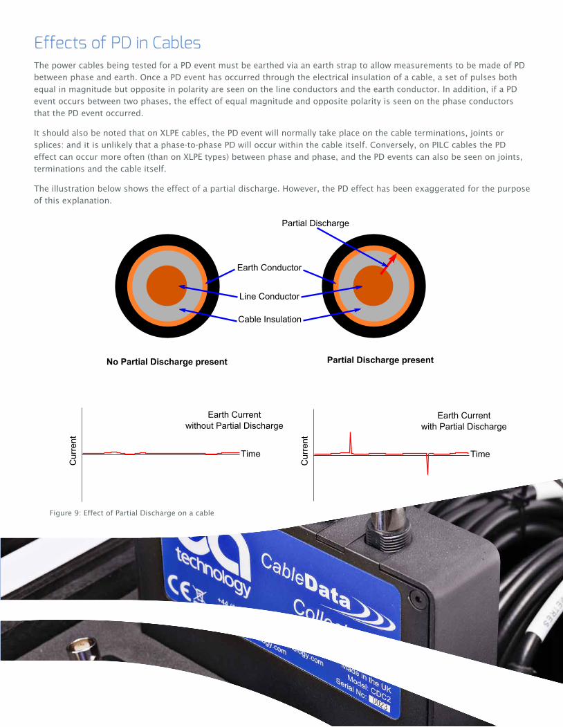
Effects of PD in CablesThe power cables being tested for a PD event must be earthed via an earth strap to allow measurements to be made of PD
between phase and earth. Once a PD event has occurred through the electrical insulation of a cable, a set of pulses both
equal in magnitude but opposite in polarity are seen on the line conductors and the earth conductor. In addition, if a PD
event occurs between two phases, the effect of equal magnitude and opposite polarity is seen on the phase conductors
that the PD event occurred.
It should also be noted that on XLPE cables, the PD event will normally take place on the cable terminations, joints or
splices: and it is unlikely that a phase-to-phase PD will occur within the cable itself. Conversely, on PILC cables the PD
effect can occur more often (than on XLPE types) between phase and phase, and the PD events can also be seen on joints,
terminations and the cable itself.
The illustration below shows the effect of a partial discharge. However, the PD effect has been exaggerated for the purpose
of this explanation.
Earth Conductor
Line Conductor
Cable Insulation
Partial Discharge
No Partial Discharge present Partial Discharge present
Time
Cur
rent
Earth Currentwith Partial Discharge
Time
Cur
rent
Earth Currentwithout Partial Discharge
Figure 9: Effect of Partial Discharge on a cable

RFCT Connection RequirementsThe RFCT detects the occurrence of a partial discharge between the line conductor and earth, by monitoring the condition
of either of the three connection methods below. The connection methods are illustrated in Figure 10. Connections can be
made:
i. By monitoring the earth cable only (Figure C) - the preferred connection method
ii. By monitoring the line conductor without the earth (Figure D)
iii. By monitoring the line conductor and earth within the sheathing and the earth cable external to the sheathing, when
passed back through the RFCT (Figure F, close up Figure 11).
If the RFCT is placed over both the line conductor and earth cable at the same time, the discharge currents are cancelled.
This is illustrated in Figure E. The method to counter this effect is shown in Figure F, and
Figure 11. Figure C shows the preferred connection method, as the other connection methods should only be used for
three phase cables, or single phase cables with a light load.
Figure 10: Cable Connection Methods
Figure 11: Close up - Overcoming cancellation of discharge currents by looping back earth strap
SwitchgearHousing
Power Cable
RFCT
Earth Cable
SwitchgearHousing
Power Cable
RFCT
Earth Cable
Termination
To Earth
Cable Sheath
Cable Core
Fig C Fig D
Fig FFig E
SwitchgearHousing
Power Cable
RFCT
Earth Cable
SwitchgearHousing
Power Cable
RFCT
Earth Cable
Termination
To Earth
Cable Sheath
Cable Core
Fig C Fig D
Fig FFig E
Termination
To Earth
Cable Sheath
Cable Core

CableData Analysis™With the data from the cable safely collected and stored on the laptop computer, it is a simple task to transfer the files
and analyse the data on the CableData Analysis Suite™. This software suite can be installed onto the most appropriate
computer to perform the analysis e.g. on the engineer’s desktop PC, rather than the laptop used to collect the data.
The data can be analysed individually in single phase mode or, for ease of interpretation, if three phases of the same
circuit have been captured simultaneously, the data can be processed and analysed together.
Figure 12 shows screen shots of the analysis windows of the software suite.
PD Classification & LocationThe data that has been collected in the substations is processed by the CableData Analysis Suite™ software. Both filtered
and unfiltered data can be analysed to determine the level of noise on the cable and identify partial discharge activity.
If reflected pulses are detected from the far end of the cable, it is possible with assumed signal propagation speeds to
estimate the location of any detected partial discharge activity.
Figure 12: CableData Analysis Suite™ screenshot
Map showing multiple PD events at around 56% of the cable length.
Figure 13: PD Location using CableData Analysis Suite™
Waveform showing PD location at 56% from the measurement position.

PD Activity ReportsIt is relatively simple for an operator to identify local discharges, together with discharges on joints and splices along the
cable and start classifying the type of discharge detected.
The data can be easily exported from the software suite, in a standard report template that can be modified to meet local
company requirements.
Figure 15: Sample report page from the CableData Analysis Suite™
Figure 14 : Print Sample report page from the CableData Analysis Suite™

CableData Collector™ Technical Specification
CABLE PD INPUTS
Sensor RFCT
Channels 3
Max Conversion Rate 160 MS/s (Mega Samples per second)
Conversion Resolution 12 Bit
Cable Length Cable Construction Dependent
Unfiltered Frequency Range 0-80MHz
Filter 1 Frequency Range 500kHz-80MHz
Filter 2 Frequency Range 1.8MHz-80MHz
Gain Range 4 (Auto Ranging)
Measurement Range Range Dependent (25,000pC, 50,000pC, 100,000pC, 200,000pC)
ResolutionRange Dependent (14pC, 28pC, 56pC, 112pC)
Capture Windows 153µs, 76µs or 38µs
HARDWARE
Enclosure Machined Aluminium
Indicators 3 x Tri Colour LEDs
Connectors USB, SD Card, Ethernet
ENVIRONMENTAL
Operating Temperature 0 – 60 ºC
Humidity 0 – 90% RH non-condensing
IP Rating 31
DIMENSIONS
Size 177mm x 119mm x 28mm
Weight 0.6kg
POWER SUPPLIES
Power Source
Powered over USB connection from laptop, requires laptop with 2 x USB ports

Global SupportThe UltraTEV Detector™ can be supplied and supported anywhere in the world, through our network of
international sales offices and distribution partners. We provide excellent lifetime support for this system,
including:
Installation and commissioning
Training
Make smarter investment decisions
Build smarter grids
Achieve the latest standards
Develop their power skills
Lifetime technical support
Online data analysis and reports
Distributors
Global Offices
Safer, Stronger,Smarter Networks
+1 (862) 261-2759EA Technology LLC, 400 Morris Avenue, Suite 240, Denville, NJ 07834
www.eatechnologyusa.com
Our ExpertiseWe provide world-leading asset management solutions for power plant and networks.
Our customers include electricity generation, transmission and distribution companies,
together with major power plant operators in the private and public sectors.
Our products, services, management systems and knowledge enable customers to:
Prevent outages
Assess the condition of assets
Understand why assets fail
Optimise network operations