technical documentation local protection system ... local protection system ofms 3000 can be...
TRANSCRIPT

OPERATING MANUAL LOCAL PROTECTION SYSTEM OFMS-3000
Tel.: +49 (0)4105 / 65 60 – 0 * DECKMA GmbH * Fax: +49 (0)4105 / 65 60 – 25
E-mail: [email protected] * Internet: www.deckma-gmbh.de
Page 1 of 44
Technical Documentation
Local Protection System FWBLAFFS OFMS-3000
for sea-going vessels
Revisions
Version Date Author Approved Remarks
01 30.06.2008 STO HN 1st issue
OPERATING MANUAL LOCAL PROTECTION SYSTEM OFMS-3000
Tel.: +49 (0)4105 / 65 60 – 0 * DECKMA GmbH * Fax: +49 (0)4105 / 65 60 – 25
E-mail: [email protected] * Internet: www.deckma-gmbh.de
Page 2 of 44
Table of contents 1. Introduction 3 2. Construction 4
2.1 Example of the 10 Line main cabinet 5 2.2 Example of the Release Panel 6 2.3 Components of the OFMS 3000 6 2.4 Different applications 7 2.4.1 OFMS3000 Stand Alone System 7 2.4.2 OFMS3000 combination with FMS/AFMS300 7
3. Description of Modules
3.1 Pump/Fanmodule LM01-E 8-10 3.2 Pump display LD01-E 11 3.3 Fire detector module FM01-E 12-13 3.4 Output module AM01-E 14-15 3.5 Printer module DM01-E 16 3.6 VDR-Module VM01-E 17 3.7 Repeater Panel HT01-E 18 3.8 Release Panel AT01-E 19
4. Operation of the OFMS-3000 4.1 Overview 20 4.2 Indicator and operation elements 21 4.2.1 Normalmode 21 4.2.2 Fire alarm 22-23 4.2.3 Fault alarm 24 4.3 Operator functions 25 4.3.1 Menu functions Pump status 25-26 4.3.2 Operation of Release panel 27-30 5. Start up of the OFMS 3000 31 6.0 Mechanical Specification 32 6.1 Construction Main Cabinet up to 10 Objects 32 6.2 Construction man release button 32 6.3 Construction man release panel AT-01E 33 6.4 Repeater Panel 33 7.0 Overview Fault and Fire messages 34
7.1 Module Definition 34 8.0 Spare parts 8.1 Spare parts main cabinet 35 9.0 Angle of view Flame detector HF-24 36 10.0 Drawings 10.1 Connection drawing pump module LM01-E 37 10.2-10.4 Connection drawing loop module 1-3 FM01-E 38-40 10.5 Connection drawing loop module SM01-E 41
10.6 Connection drawing Repeater panel HT01-E 42 10.7 Connection drawing release panel AT01-E 43
10.8 Connection drawing man release button 44

OPERATING MANUAL LOCAL PROTECTION SYSTEM OFMS-3000
Tel.: +49 (0)4105 / 65 60 – 0 * DECKMA GmbH * Fax: +49 (0)4105 / 65 60 – 25
E-mail: [email protected] * Internet: www.deckma-gmbh.de
Page 3 of 44
1. Introduction On modern ships is the engine room often driven unmanned. Therefore, a water spray-on fire extinguisher FWBLAFFS risk objects contain flammable liquids such as Main engines, boilers and separators, as automatic fire-extinguishing system. Each object is protected by 2 Fire detectors, which are specially designed ultraviolet radiation as they flickering flames to be seen. If one of these flame detectors detects a fire, then by sirens and signal light alerted the crew. This has the possibility to see what the reason of the fire is and do the required action to extinguish the fire. In the vicinity of each object is a local release button is installed to release the extinguishing manually. It is also possible with the external installed release panel to activate and deactivate the extinguishing process. If the second detector of an object simultaneously detects a fire, then automatically the corresponding magnetic valve activated and the burning object is sprayed with water mist to the fire. On the possible transfer of the alarms is usually on the bridge a Repeater panel installed, which by a 4-wire data line Local protection system in Engine room is connected. All functions of the Local protection system can also operate from this panel. . As an option, the Local protection system OFMS 3000 can combine with the conventional fire alarm system FMS3000 or addressable fire alarm system AFMS 3000. In this case, the repeater panel is not necessary and the OFMS 3000 can be monitored and controlled by the Fire detection system FMS or AFMS 3000. It is also possible to connect of a printer with a parallel interface and / or a VDR recorder (NMEA 0183) and to all alarms and other business-relevant data to transmit or print.

OPERATING MANUAL LOCAL PROTECTION SYSTEM OFMS-3000
Tel.: +49 (0)4105 / 65 60 – 0 * DECKMA GmbH * Fax: +49 (0)4105 / 65 60 – 25
E-mail: [email protected] * Internet: www.deckma-gmbh.de
Page 4 of 44
2 x
2 x
0,7
5
2 x
2 x
0,7
5
SEPARATOR
RELEASE INCINERATOR
FIRE EXTINGUISHING
WATER BASED LOCAL APPLICATION
FIRE FIGHTING SYSTEM
2 x
2 x
0,7
5
EMERGENCYGENERATOR
2 x
2 x
0,7
5
RELEASE GENERATOR
FIRE EXTINGUISHING
WATER BASED LOCAL APPLICATION
FIRE FIGHTING SYSTEM
RELEASE BOILER
FIRE EXTINGUISHING
MAIN ENGINE BOILER
WATER BASED LOCAL APPLICATION
FIRE FIGHTING SYSTEM
1 x
2 x
0,7
5
1 x
2 x
0,7
5
1 x
2 x
0,7
5
1 x
2 x
0,7
5
PUMP ROOM
4 x 2 x 0,75
4 x 2 x 0,75
4 x 2 x 0,75
4 x 2 x 0,75
M
3 x
2,5
WATER BASED LOCAL APPLICATION
FIRE FIGHTING SYSTEM
ENGINE ROOMBRIDGE
FIRE WATCH STATION
ENGINE CONTROL ROOM
RS 485 Datenbus
RS 485 Datenbus
RS 485 Datenbus
Power Supply Pump 440V /60Hz
Power Supply 110V-230V AC
2 x 2 x 0,75
2 x 2 x 0,75
2 x 2 x 0,75
3x2,5
3x1,5
1 x
2 x
0,7
5
1 x
2 x
0,7
51 x
2 x
0,7
5
1 x
2 x
0,7
5
FIRE DIS CHARGE
DIS CHARGE
DIS CHARGE
DIS CHARGE
FIRE
FIRE
FIRE
LÖS CHEN OBJEKT 10
LÖS CHEN OBJEKT 7
LÖS CHEN OBJEKT 9
LÖS CHEN OBJEKT 8
DIS CHARGE
DIS CHARGE
DIS CHARGE
DIS CHARGE
DIS CHARGE
DIS CHARGEFIRE
FIRE
FIRE
FIRE
FIRE
FIRE
LÖS CHEN OBJEKT 4
LÖS CHEN OBJEKT 6
LÖS CHEN OBJEKT 5
LÖS CHEN OBJEKT 1
LÖS CHEN OBJEKT 3
LÖS CHEN OBJEKT 2
1.1 Overview of the OFMS-3000
1.1 Example overview of a typical arrangement for a 4 Line Local protection system

OPERATING MANUAL LOCAL PROTECTION SYSTEM OFMS-3000
Tel.: +49 (0)4105 / 65 60 – 0 * DECKMA GmbH * Fax: +49 (0)4105 / 65 60 – 25
E-mail: [email protected] * Internet: www.deckma-gmbh.de
Page 5 of 44
4 T2
1 0
6 T34 T22 T1 2 T1
1 0
6 T3
2. Construction
The Local protection system is constructed for a modular design. All modules are connected via a internal RS 485 bus. The modules with exception the panels are designs for TS 35 rail mounting, the panels are designs for recess mounting. All modules and modules are installed into on Steel cabinet which are designs for wall mounting. 2.1 Example construction of the main cabinet for 10 Objects

OPERATING MANUAL LOCAL PROTECTION SYSTEM OFMS-3000
Tel.: +49 (0)4105 / 65 60 – 0 * DECKMA GmbH * Fax: +49 (0)4105 / 65 60 – 25
E-mail: [email protected] * Internet: www.deckma-gmbh.de
Page 6 of 44
2.2 View of the Release Panel
2.3 Components from the OFMS3000
OFMS 3000/2 Main cabinet for up to 2 Objects Drawing S OFMS 3000/6 Main cabinet for up to 2 Objects Drawing S OFMS 3000/10 Main cabinet for up to 2 Objects Drawing S AT01-E Release Panel for up to 10 Objects Drawing S 3994 Release button Local release button Drawing S 3996 HT-01E Repeater Panel Drawing S 3466 HF-24 UV-Flame detector with base
HF-24+YBN+YBF/RL/4H5+MBB-1 For more technical details see the depending drawing

OPERATING MANUAL LOCAL PROTECTION SYSTEM OFMS-3000
Tel.: +49 (0)4105 / 65 60 – 0 * DECKMA GmbH * Fax: +49 (0)4105 / 65 60 – 25
E-mail: [email protected] * Internet: www.deckma-gmbh.de
Page 7 of 44
LÖSCHEN OBJEKT 10FIRE DISCHARGE
LÖSCHEN OBJEKT 1
LÖSCHEN OBJEKT 2
LÖSCHEN OBJEKT 3
LÖSCHEN OBJEKT 4
LÖSCHEN OBJEKT 5
LÖSCHEN OBJEKT 8
LÖSCHEN OBJEKT 9
LÖSCHEN OBJEKT 6
LÖSCHEN OBJEKT 7
FIRE
FIRE
FIRE
FIRE
DISCHARGE
DISCHARGE
DISCHARGE
DISCHARGE
FIRE
FIRE
FIRE
FIRE
FIRE
DISCHARGE
DISCHARGE
DISCHARGE
DISCHARGE
DISCHARGE
2.4 Different applications 2.4.1 OFMS 3000 „Stand alone“ Stand alone system with 2 release panels
The local protection system can be connected via the internal RS 485 connection with maximum 2 release panels AT01E and one repeater Panel. Controlling and indication of alarms are from each panel available.
2.4.2 OFMS 3000 „Combination“ Combined system with FMS/AFMS 3000
The Local protection system OFMS 3000 can be connected to the Fire alarm system FMS/AFMS 3000 via a RS 485 bus connection. The whole Local protection system can be controlled and operated from this Fire alarm system.
OPERATING MANUAL LOCAL PROTECTION SYSTEM OFMS-3000
Tel.: +49 (0)4105 / 65 60 – 0 * DECKMA GmbH * Fax: +49 (0)4105 / 65 60 – 25
E-mail: [email protected] * Internet: www.deckma-gmbh.de
Page 8 of 44
3.0 Description of modules
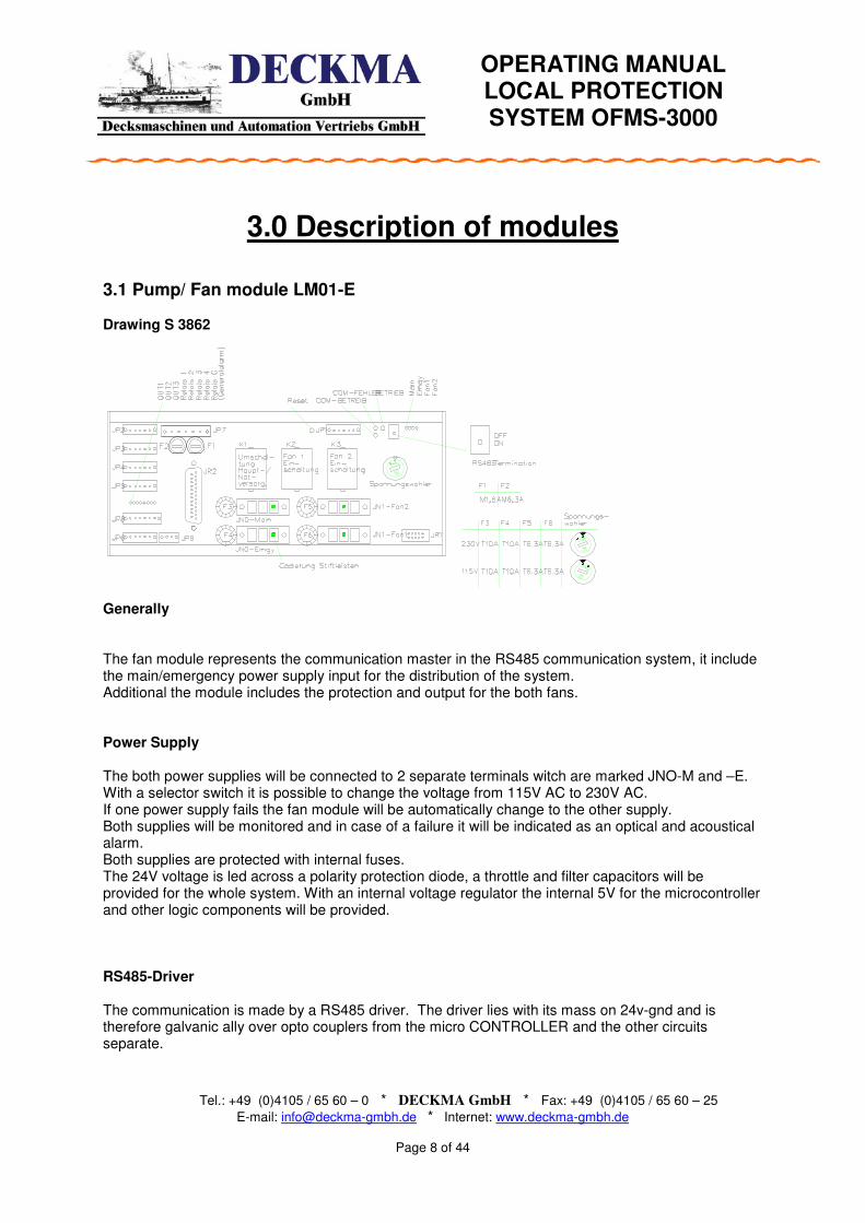
3.1 Pump/ Fan module LM01-E Drawing S 3862 Generally The fan module represents the communication master in the RS485 communication system, it include the main/emergency power supply input for the distribution of the system. Additional the module includes the protection and output for the both fans. Power Supply The both power supplies will be connected to 2 separate terminals witch are marked JNO-M and –E. With a selector switch it is possible to change the voltage from 115V AC to 230V AC. If one power supply fails the fan module will be automatically change to the other supply. Both supplies will be monitored and in case of a failure it will be indicated as an optical and acoustical alarm. Both supplies are protected with internal fuses. The 24V voltage is led across a polarity protection diode, a throttle and filter capacitors will be provided for the whole system. With an internal voltage regulator the internal 5V for the microcontroller and other logic components will be provided. RS485-Driver The communication is made by a RS485 driver. The driver lies with its mass on 24v-gnd and is therefore galvanic ally over opto couplers from the micro CONTROLLER and the other circuits separate.
OPERATING MANUAL LOCAL PROTECTION SYSTEM OFMS-3000
Tel.: +49 (0)4105 / 65 60 – 0 * DECKMA GmbH * Fax: +49 (0)4105 / 65 60 – 25
E-mail: [email protected] * Internet: www.deckma-gmbh.de
Page 9 of 44
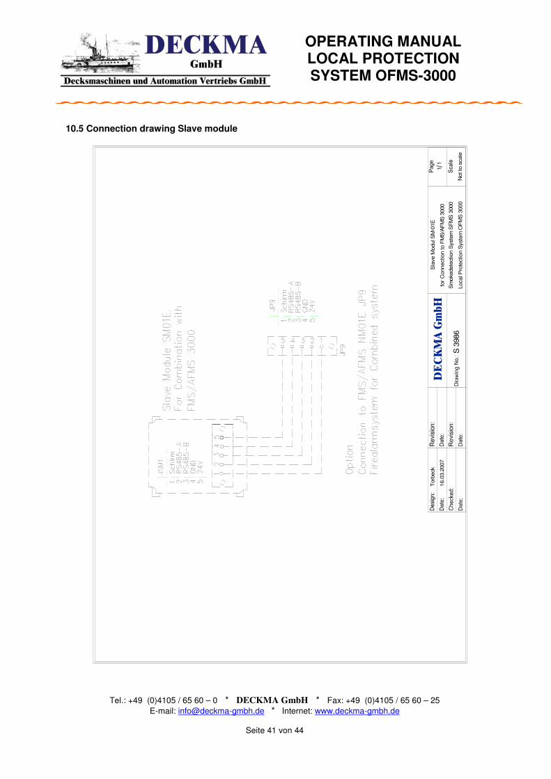
Relay Outputs 5x potential free relay outputs max of 250V 2A for the following possibilities programmable: Fire alarm, Fault alarm, Power Supply failure and delayed Fire alarm. All outputs are free programmable according the ships requirement. 24V DC Output 3x 24V DC outputs for fire bells max 1A for each output fire alarm programmable. Quiescent current supervised by an end of line resistor 3 KΩ. Connection to Pump relays It is possible to connect 2 pumps via separate terminals marked with JN-1 and JN-2. Connection Pump display To operate the smoke detection system locally the Fan display is installed into the Front door of the smoke detection cabinet. This Fan display is connected directly via an I2 C- port to the fan module. The necessary 5V supply will be also provided by this connection. Connection data module The communication with the data module can be done via a RS 232 driver. This plug also provides the 5V supply for the memory. In a standard smoke detection system it is not required to use this data module. This will be provided from the internal memory into the Fan module. Connection Slave module with combination to AFMS/FMS 3000 On the port of the data module it is also possible to connect the slave module in order to connect the Local protection system to the Fire alarm system FMS 3000 or AFMS 3000. With this connection it is possible to control and indicate the whole Local protection system from the installed Fire alarm system FMS 3000 or AFMS 3000. No repeater panel is required. Buzzer The Buzzer is switched over a driver transistor and over a haven line of the micro CONTROLLER. For an external Buzzer a 24V interface is intended.
OPERATING MANUAL LOCAL PROTECTION SYSTEM OFMS-3000
Tel.: +49 (0)4105 / 65 60 – 0 * DECKMA GmbH * Fax: +49 (0)4105 / 65 60 – 25
E-mail: [email protected] * Internet: www.deckma-gmbh.de
Page 10 of 44
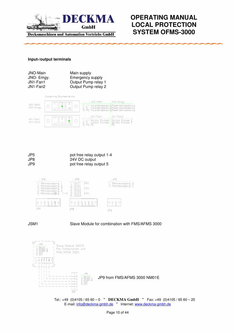
Input-/output terminals JNO-Main Main supply JNO- Emgy. Emergency supply JN1-Fan1 Output Pump relay 1 JN1-Fan2 Output Pump relay 2
JP5 pot free relay output 1-4 JP8 24V DC output JP9 pot free relay output 5
JSM1 Slave Module for combination with FMS/AFMS 3000
JP9 from FMS/AFMS 3000 NM01E
OPERATING MANUAL LOCAL PROTECTION SYSTEM OFMS-3000
Tel.: +49 (0)4105 / 65 60 – 0 * DECKMA GmbH * Fax: +49 (0)4105 / 65 60 – 25
E-mail: [email protected] * Internet: www.deckma-gmbh.de
Page 11 of 44
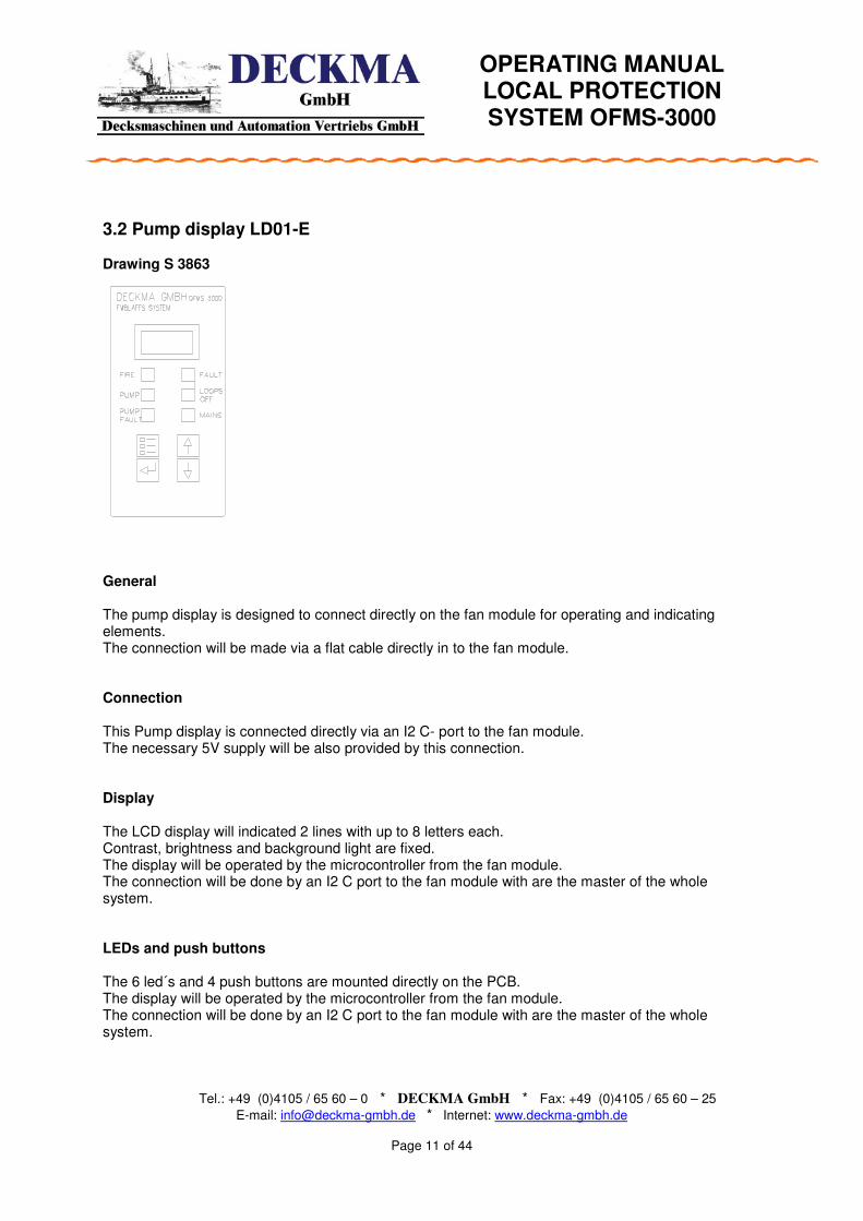
3.2 Pump display LD01-E Drawing S 3863 General The pump display is designed to connect directly on the fan module for operating and indicating elements. The connection will be made via a flat cable directly in to the fan module. Connection This Pump display is connected directly via an I2 C- port to the fan module. The necessary 5V supply will be also provided by this connection. Display The LCD display will indicated 2 lines with up to 8 letters each. Contrast, brightness and background light are fixed. The display will be operated by the microcontroller from the fan module. The connection will be done by an I2 C port to the fan module with are the master of the whole system. LEDs and push buttons The 6 led´s and 4 push buttons are mounted directly on the PCB. The display will be operated by the microcontroller from the fan module. The connection will be done by an I2 C port to the fan module with are the master of the whole system.

OPERATING MANUAL LOCAL PROTECTION SYSTEM OFMS-3000
Tel.: +49 (0)4105 / 65 60 – 0 * DECKMA GmbH * Fax: +49 (0)4105 / 65 60 – 25
E-mail: [email protected] * Internet: www.deckma-gmbh.de
Page 12 of 44
3.3 Fire detector module FM01-E (Conventional) Drawing S 3461, S 3462, S 3463
Inputs of up to 8 fire detection lines according to the quiescent current principle. 8 pot free relays outputs, they are programmed with the special function for the OFMS that they have a combination of 2 loops. Relay 1 is for activating the external sounder; relay 2 is for activation of the external release valves. Expandable up to 3 modules (10 Objects and 4 switching inputs) General The module contains eight fire detection loops and eight pot. free outputs witch can be programmed for fire- fault alarm or both. Two micro CONTROLLERS operate and supervise the fire detection loops and outputs and communicate with the Power supply module. Voltage supply The 24V input voltage is led across a polarity protection diode, a throttle and filter capacitors on an electrically isolating DC/DC transducer. The transducer supplies ±5V for the micro CONTROLLER, the controlling, current measurement and monitoring of the fire detecting loops and OPC outputs. The 24V supply voltage is connected with the ground connection of the DC/DC transducer. The digital ground of the circuit lies thereby on the 24V-supply voltage. The tensions, related to 24V GND, are 19V for the -5V-supply and 29V for the +5V-supply. The RS485 driver and the associated circuit are supplied via a step down automatic controller with 5V. RS485-Driver The communication is made by a RS485 driver. The driver lies with its measures on 24v-gnd and is therefore galvanically separately over opto couplers from the micro CONTROLLER and the other circuits separate.

OPERATING MANUAL LOCAL PROTECTION SYSTEM OFMS-3000
Tel.: +49 (0)4105 / 65 60 – 0 * DECKMA GmbH * Fax: +49 (0)4105 / 65 60 – 25
E-mail: [email protected] * Internet: www.deckma-gmbh.de
Page 13 of 44
Detection loops Terminals JLN and JNP In normal operation the quiescent currant will be measured the in the last detector installed 3 KΩ end of line resistor and in case of failure will be report this to the power supply module. In case of a fire alarm on one connected detector the system measure the 470 Ω alarm resistor of this depending detector and will report the fire alarm to the power supply module. All detection loops will be protected against short circuit. In case of a short circuit the loop will be disconnected and after 30 sec reconnected. The maximal currant on each loop is 400mA. The sum of all detection loops do not exceed more than 1,6A. If the currant is higher than 1,6A the controller will be disconnect the loop with the highest currant and report this to the power supply module.
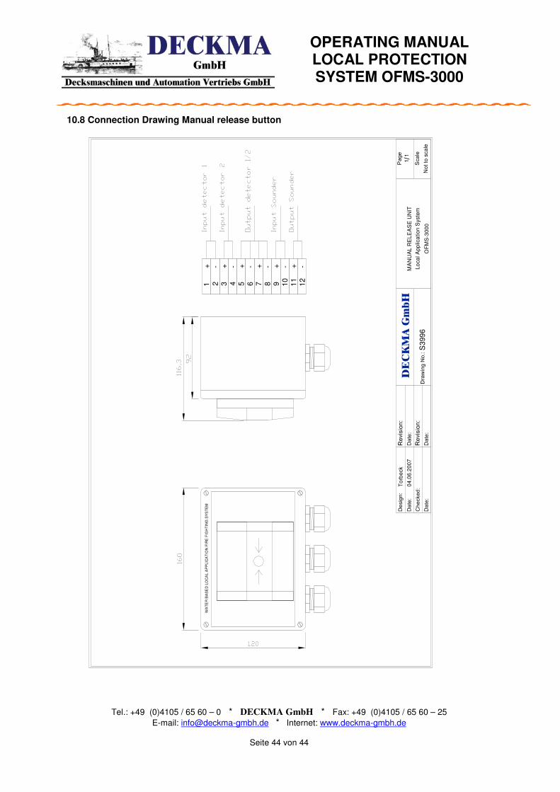
Connection for Flame detectors and manual release button In these examples was shown the connection of one Object with 2 Flame detectors and one release button. The wiring will be made thru the manual release button. For further detail see drawing S3996 .
OPERATING MANUAL LOCAL PROTECTION SYSTEM OFMS-3000
Tel.: +49 (0)4105 / 65 60 – 0 * DECKMA GmbH * Fax: +49 (0)4105 / 65 60 – 25
E-mail: [email protected] * Internet: www.deckma-gmbh.de
Page 14 of 44
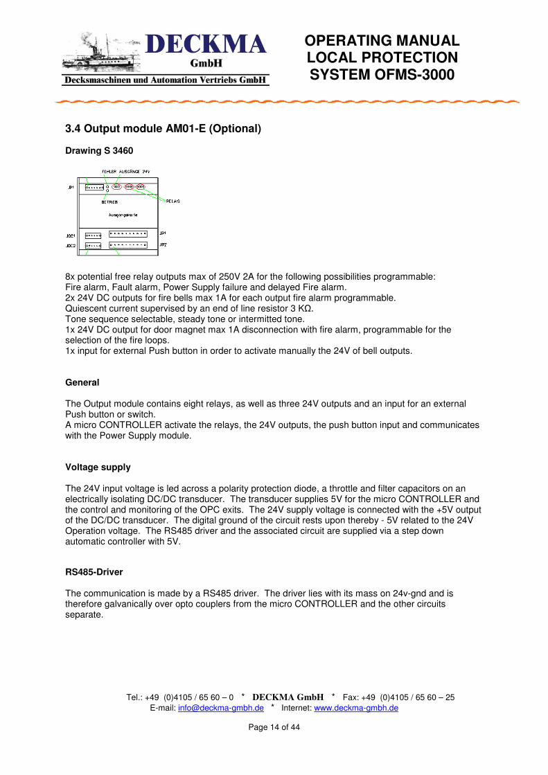
3.4 Output module AM01-E (Optional) Drawing S 3460
8x potential free relay outputs max of 250V 2A for the following possibilities programmable: Fire alarm, Fault alarm, Power Supply failure and delayed Fire alarm. 2x 24V DC outputs for fire bells max 1A for each output fire alarm programmable. Quiescent current supervised by an end of line resistor 3 KΩ. Tone sequence selectable, steady tone or intermitted tone. 1x 24V DC output for door magnet max 1A disconnection with fire alarm, programmable for the selection of the fire loops. 1x input for external Push button in order to activate manually the 24V of bell outputs. General The Output module contains eight relays, as well as three 24V outputs and an input for an external Push button or switch. A micro CONTROLLER activate the relays, the 24V outputs, the push button input and communicates with the Power Supply module. Voltage supply The 24V input voltage is led across a polarity protection diode, a throttle and filter capacitors on an electrically isolating DC/DC transducer. The transducer supplies 5V for the micro CONTROLLER and the control and monitoring of the OPC exits. The 24V supply voltage is connected with the +5V output of the DC/DC transducer. The digital ground of the circuit rests upon thereby - 5V related to the 24V Operation voltage. The RS485 driver and the associated circuit are supplied via a step down automatic controller with 5V.
RS485-Driver The communication is made by a RS485 driver. The driver lies with its mass on 24v-gnd and is therefore galvanically over opto couplers from the micro CONTROLLER and the other circuits separate.

OPERATING MANUAL LOCAL PROTECTION SYSTEM OFMS-3000
Tel.: +49 (0)4105 / 65 60 – 0 * DECKMA GmbH * Fax: +49 (0)4105 / 65 60 – 25
E-mail: [email protected] * Internet: www.deckma-gmbh.de
Page 15 of 44
Relais Terminal JR1 and JR2 The relays are normal open contact with 2A permanent current and a rated voltage of 220V and are programmable for fire alarm, fault alarm, voltage failure and/or general alarm (2min delayed). Output interfaces Terminals JOC1 and JOC 2
The 24V DC outputs are design as a short circuit proof output with a maximal currant of 1A and are programmable for fire alarm, fault alarm, voltage failure and/or general alarm (2min delayed). Two outputs (1 and 2) are assign for Firearm witch are connected to the Push button input and can activated by this input. One output (3) is assign for Door magnets and has no connection with the push button input. In case of a short circuit the loop will be disconnected for up to 3 sec and than automatically reconnected. Additional each loop has a switchable connection max 8mA to check 3 KΩ Ohm end of line resistor. Push button input Terminals JOC2
The module contains an input for the connection an external push button. The voltage supply for the input becomes secured against short-circuits. The voltage amounts to in the no-load operation 24V. The input switches the bell outputs on manually. With pressed key the bell outputs are switched on. After disconnection of the button the outputs are again turned off.

OPERATING MANUAL LOCAL PROTECTION SYSTEM OFMS-3000
Tel.: +49 (0)4105 / 65 60 – 0 * DECKMA GmbH * Fax: +49 (0)4105 / 65 60 – 25
E-mail: [email protected] * Internet: www.deckma-gmbh.de
Page 16 of 44
3.5 Printer Module DM01-E (Optional) Drawing S 3464 Interface module for the connection of a Centronics of printer that the messages, as in the display are indicated, prints. Alarm text, time, date, status General The printer connection is made by a 25pol. SubD plug (Socket). To the Centronics printer module can be attached a compatible printer. Important messages such as alarms or disturbances are spent automatically on. Example: Date Time Status Alarm text 30.12.06 15:33:02 NEW FIRE loop 1 section 4 30.12.06 15:34:12 ACCP FIRE loop 1 section 4
Voltage supply The 24V input voltage is led across a polarity protection diode, a throttle and filter capacitors on an electrically isolating DC/DC transducer. The transducer supplies 5V for the micro CONTROLLER and the drivers of the printer exits. The 24V GND connection is connected with the 5V-GND connection of the DC/DC transducer. The digital mass of the circuit lies thereby on 24v-gnd.
Printer drivers The printer drivers are implemented as CMOS LINE Driver. RC filters in the connecting cables protect the drivers. A micro CONTROLLER (ATmega16) receives the printer data over the RS485 interface and heads for the printer drivers.
OPERATING MANUAL LOCAL PROTECTION SYSTEM OFMS-3000
Tel.: +49 (0)4105 / 65 60 – 0 * DECKMA GmbH * Fax: +49 (0)4105 / 65 60 – 25
E-mail: [email protected] * Internet: www.deckma-gmbh.de
Page 17 of 44
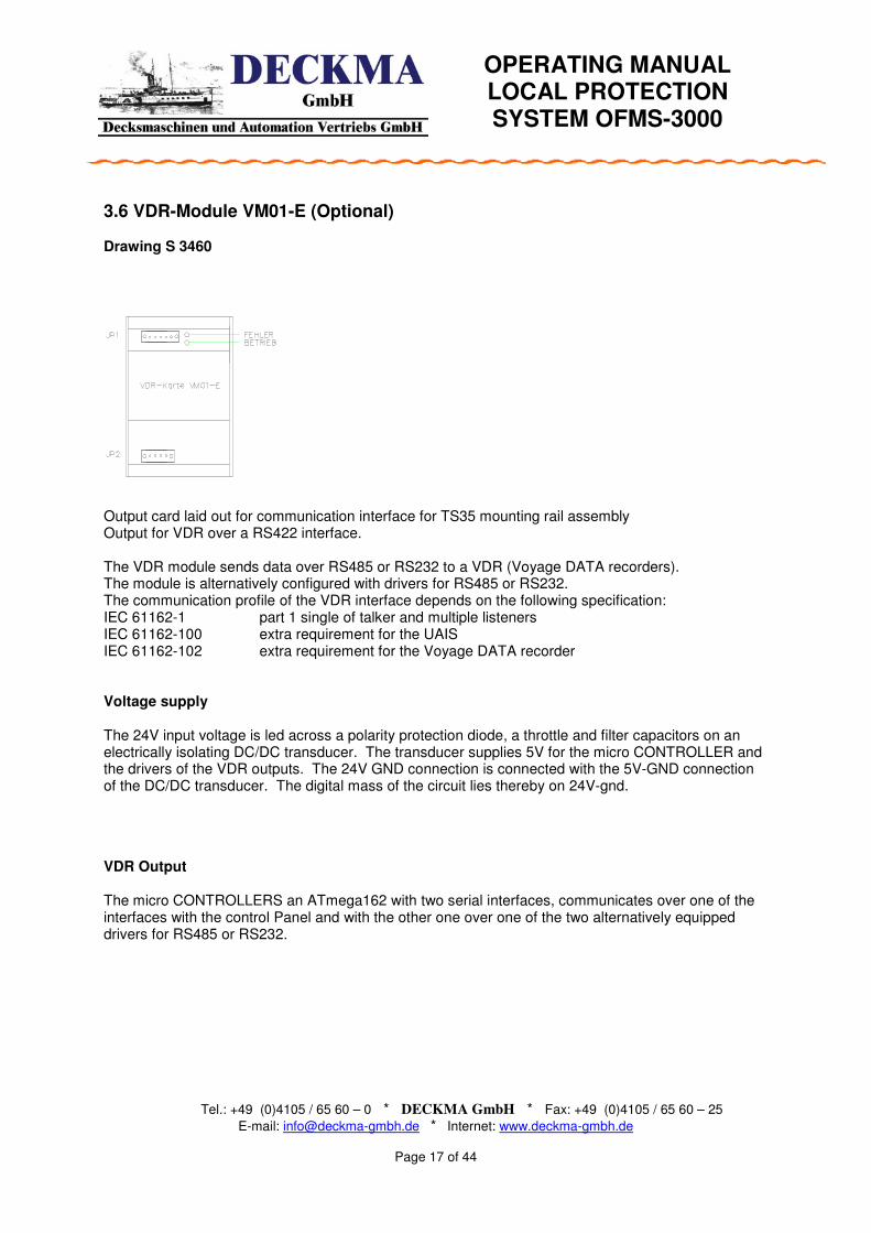
3.6 VDR-Module VM01-E (Optional) Drawing S 3460 Output card laid out for communication interface for TS35 mounting rail assembly Output for VDR over a RS422 interface. The VDR module sends data over RS485 or RS232 to a VDR (Voyage DATA recorders). The module is alternatively configured with drivers for RS485 or RS232. The communication profile of the VDR interface depends on the following specification: IEC 61162-1 part 1 single of talker and multiple listeners IEC 61162-100 extra requirement for the UAIS IEC 61162-102 extra requirement for the Voyage DATA recorder Voltage supply The 24V input voltage is led across a polarity protection diode, a throttle and filter capacitors on an electrically isolating DC/DC transducer. The transducer supplies 5V for the micro CONTROLLER and the drivers of the VDR outputs. The 24V GND connection is connected with the 5V-GND connection of the DC/DC transducer. The digital mass of the circuit lies thereby on 24V-gnd.
VDR Output The micro CONTROLLERS an ATmega162 with two serial interfaces, communicates over one of the interfaces with the control Panel and with the other one over one of the two alternatively equipped drivers for RS485 or RS232.
OPERATING MANUAL LOCAL PROTECTION SYSTEM OFMS-3000
Tel.: +49 (0)4105 / 65 60 – 0 * DECKMA GmbH * Fax: +49 (0)4105 / 65 60 – 25
E-mail: [email protected] * Internet: www.deckma-gmbh.de
Page 18 of 44
144
14
4
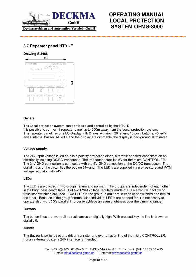
3.7 Repeater panel HT01-E Drawing S 3466 General The Local protection system can be viewed and controlled by the HT01E It is possible to connect 1 repeater panel up to 500m away from the Local protection system. This repeater panel has one LC-Display with 2 lines with each 20 letters, 10 push buttons, 40 led´s and a internal buzzer. All led´s and the display are dimmable, the display is background illuminated. Voltage supply The 24V input voltage is led across a polarity protection diode, a throttle and filter capacitors on an electrically isolating DC/DC transducer. The transducer supplies 5V for the micro CONTROLLER. The 24V GND connection is connected with the 5V-GND connection of the DC/DC transducer. The digital mass of the circuit lies thereby on 24v-gnd. The LED´s are supplied via pre-resistors and PWM voltage regulator with 24V. LEDs The LED´s are divided in two groups (alarm and normal). The groups are independent of each other in the brightness controllable. But two PWM voltage regulator made of RC element with following transistor switching are used. Two LED´s in the group "alarm" are in each case switched one behind the other. Because in the group "normal" also individual LED´s are headed for, it is necessary to operate also two LED´s parallel in order to achieve an even brightness over the dimming range. Buttons The button lines are over pull up resistances on digitally high. With pressed key the line is drawn on digitally 0. Buzzer The Buzzer is switched over a driver transistor and over a haven line of the micro CONTROLLER. For an external Buzzer a 24V interface is intended.
OPERATING MANUAL LOCAL PROTECTION SYSTEM OFMS-3000
Tel.: +49 (0)4105 / 65 60 – 0 * DECKMA GmbH * Fax: +49 (0)4105 / 65 60 – 25
E-mail: [email protected] * Internet: www.deckma-gmbh.de
Page 19 of 44
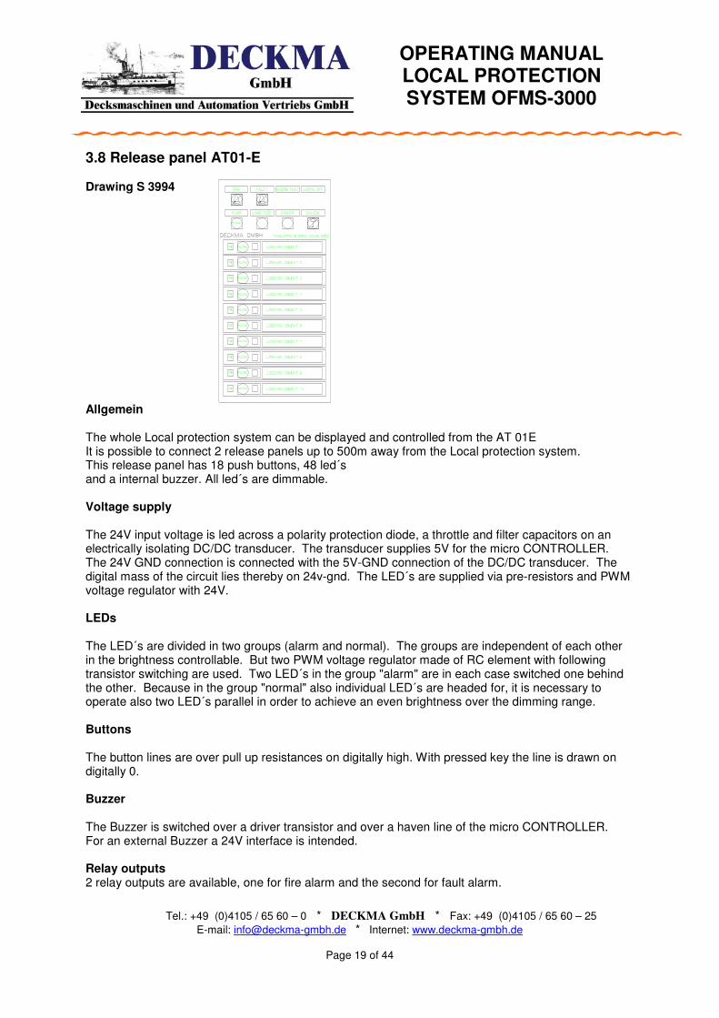
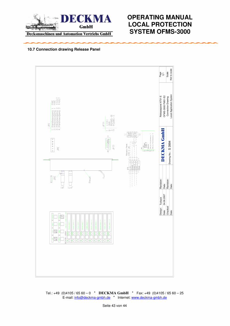
3.8 Release panel AT01-E Drawing S 3994 Allgemein The whole Local protection system can be displayed and controlled from the AT 01E It is possible to connect 2 release panels up to 500m away from the Local protection system. This release panel has 18 push buttons, 48 led´s and a internal buzzer. All led´s are dimmable. Voltage supply The 24V input voltage is led across a polarity protection diode, a throttle and filter capacitors on an electrically isolating DC/DC transducer. The transducer supplies 5V for the micro CONTROLLER. The 24V GND connection is connected with the 5V-GND connection of the DC/DC transducer. The digital mass of the circuit lies thereby on 24v-gnd. The LED´s are supplied via pre-resistors and PWM voltage regulator with 24V. LEDs The LED´s are divided in two groups (alarm and normal). The groups are independent of each other in the brightness controllable. But two PWM voltage regulator made of RC element with following transistor switching are used. Two LED´s in the group "alarm" are in each case switched one behind the other. Because in the group "normal" also individual LED´s are headed for, it is necessary to operate also two LED´s parallel in order to achieve an even brightness over the dimming range. Buttons The button lines are over pull up resistances on digitally high. With pressed key the line is drawn on digitally 0. Buzzer The Buzzer is switched over a driver transistor and over a haven line of the micro CONTROLLER. For an external Buzzer a 24V interface is intended.
Relay outputs 2 relay outputs are available, one for fire alarm and the second for fault alarm.
OPERATING MANUAL LOCAL PROTECTION SYSTEM OFMS-3000
Tel.: +49 (0)4105 / 65 60 – 0 * DECKMA GmbH * Fax: +49 (0)4105 / 65 60 – 25
E-mail: [email protected] * Internet: www.deckma-gmbh.de
Page 20 of 44
4. 0 Operating of the OFMS-3000
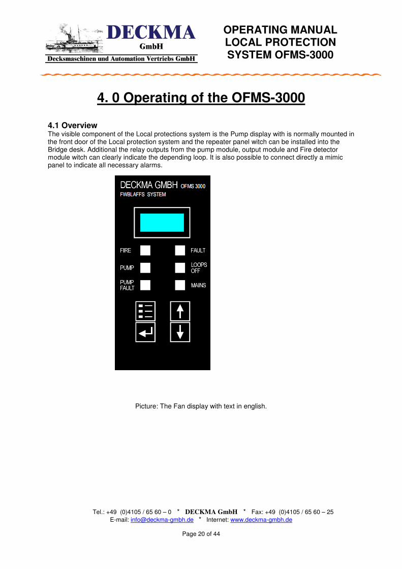
4.1 Overview The visible component of the Local protections system is the Pump display with is normally mounted in the front door of the Local protection system and the repeater panel witch can be installed into the Bridge desk. Additional the relay outputs from the pump module, output module and Fire detector module witch can clearly indicate the depending loop. It is also possible to connect directly a mimic panel to indicate all necessary alarms.
Picture: The Fan display with text in english.

OPERATING MANUAL LOCAL PROTECTION SYSTEM OFMS-3000
Tel.: +49 (0)4105 / 65 60 – 0 * DECKMA GmbH * Fax: +49 (0)4105 / 65 60 – 25
E-mail: [email protected] * Internet: www.deckma-gmbh.de
Page 21 of 44
OFMS3000
Stand by
OFMS3000 Stand by
4.2. Indicating and control elements The Pump display which is normally mounted into the front door of the main cabinet. The start up message is normally: From the Pump display it is possible to switch on/off the pump, connect and disconnect different objects and accept/reset Fire and Fault alarms. In case of an alarm it can be accepted and reset from the fan display. The indication of an new alarm is he letter „N“and for an accepted alarm is „A“ In order to get a clear indication the alarm will be displayed by an internal buzzer, an LCD display and 2 illuminated fields with Fire or Fault. In case of one or more alarms the led’s Fire and/or Fault will flashing.
4.2.1 Normal condition no Alarms In the normal operation of the Local protection system, the green Led „Mains“will light up. The LCD display shows “SFMS stand by“ and in a continues change “Stand alone” or “Combination” -“Stand alone” means: that the local protection system works independently with no connection to other systems. -“Combination” means: that the local protection system works in connection with the Fire detection system FMS 3000 or AFMS 3000.
OPERATING MANUAL LOCAL PROTECTION SYSTEM OFMS-3000
Tel.: +49 (0)4105 / 65 60 – 0 * DECKMA GmbH * Fax: +49 (0)4105 / 65 60 – 25
E-mail: [email protected] * Internet: www.deckma-gmbh.de
Page 22 of 44
Loop 2
Fire N
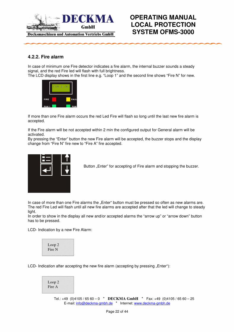
4.2.2. Fire alarm In case of minimum one Fire detector indicates a fire alarm, the internal buzzer sounds a steady signal, and the red Fire led will flash with full brightness. The LCD display shows in the first line e.g. “Loop 1” and the second line shows “Fire N” for new. If more than one Fire alarm occurs the red Led Fire will flash so long until the last new fire alarm is accepted. If the Fire alarm will be not accepted within 2 min the configured output for General alarm will be activated. By pressing the “Enter” button the new Fire alarm will be accepted, the buzzer stops and the display change from “Fire N” fire new to “Fire A” fire accepted.
Button „Enter” for accepting of Fire alarm and stopping the buzzer. In case of more than one Fire alarms the „Enter“ button must be pressed so often as new alarms are. The red Fire Led will flash until all new fire alarms are accepted after that the led will change to steady light. In order to show in the display all new and/or accepted alarms the “arrow up” or “arrow down” button has to be pressed. LCD- Indication by a new Fire Alarm: LCD- Indication after accepting the new fire alarm (accepting by pressing „Enter“):
Loop 2
Fire A
OPERATING MANUAL LOCAL PROTECTION SYSTEM OFMS-3000
Tel.: +49 (0)4105 / 65 60 – 0 * DECKMA GmbH * Fax: +49 (0)4105 / 65 60 – 25
E-mail: [email protected] * Internet: www.deckma-gmbh.de
Page 23 of 44
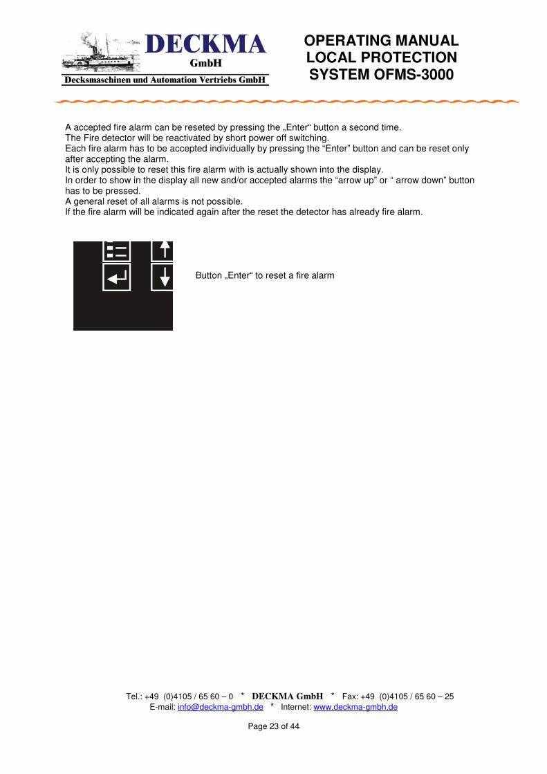
A accepted fire alarm can be reseted by pressing the „Enter“ button a second time. The Fire detector will be reactivated by short power off switching. Each fire alarm has to be accepted individually by pressing the “Enter” button and can be reset only after accepting the alarm. It is only possible to reset this fire alarm with is actually shown into the display. In order to show in the display all new and/or accepted alarms the “arrow up” or “ arrow down” button has to be pressed. A general reset of all alarms is not possible. If the fire alarm will be indicated again after the reset the detector has already fire alarm.
Button „Enter“ to reset a fire alarm

OPERATING MANUAL LOCAL PROTECTION SYSTEM OFMS-3000
Tel.: +49 (0)4105 / 65 60 – 0 * DECKMA GmbH * Fax: +49 (0)4105 / 65 60 – 25
E-mail: [email protected] * Internet: www.deckma-gmbh.de
Page 24 of 44
Loop 2
Fault A
Loop 2
Fault N
4.2.3 Fault alarm In case of a fault alarm, the internal buzzer sounds with a intermitted signal, the yellow Fault led will flash with full brightness. The LCD display shows in the first line e.g. “Loop 1” and the second line shows “ Fire N” for new.
LCD- Indication by a new Fault Alarm:
Button „Enter“ for accepting of Fault alarm and stopping the buzzer. .
By pressing the “Enter” button the new Fault alarm will be accepted, the buzzer stops and the display change from “Fault N” fault new to “Fault A” fault accepted. In case of more than one Fire alarms the „Enter“ button must be pressed so often as new alarms are. The yellow Fault Led will flash until all new fault alarms are accepted after that the led will change to steady light. In order to show in the display all new and/or accepted alarms the “arrow up” or “ arrow down” button has to be pressed. LCD- Indication after accepting the new fault alarm (accepting by pressing „Enter“): A accepted fault alarm can be rested by pressing the „Enter“ button a second time. The Fire detector will be reactivated by short power off switching. Each fault alarm has to be accepted individually by pressing the “Enter” button and can be reset only after accepting the alarm. It is only possible to reset this fault alarm with is actually shown into the display. In order to show in the display all new and/or accepted alarms the “arrow up” or “arrow down” button has to be pressed. A general reset of all alarms is not possible. If the fault alarm shows again after reset the origin of the fault is not solved.
Button „Enter“ to reset a fault alarm
OPERATING MANUAL LOCAL PROTECTION SYSTEM OFMS-3000
Tel.: +49 (0)4105 / 65 60 – 0 * DECKMA GmbH * Fax: +49 (0)4105 / 65 60 – 25
E-mail: [email protected] * Internet: www.deckma-gmbh.de
Page 25 of 44
Pump
Status
Pump
standby
Pump
running
Pump
Start
Pump
running
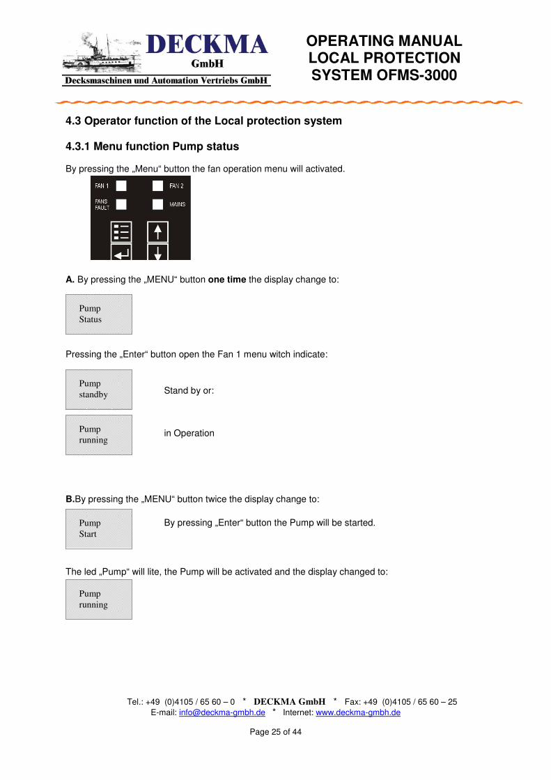
4.3 Operator function of the Local protection system 4.3.1 Menu function Pump status By pressing the „Menu“ button the fan operation menu will activated.
A. By pressing the „MENU“ button one time the display change to:
Pressing the „Enter“ button open the Fan 1 menu witch indicate:
Stand by or:
in Operation
B.By pressing the „MENU“ button twice the display change to:
By pressing „Enter“ button the Pump will be started.
The led „Pump“ will lite, the Pump will be activated and the display changed to:

OPERATING MANUAL LOCAL PROTECTION SYSTEM OFMS-3000
Tel.: +49 (0)4105 / 65 60 – 0 * DECKMA GmbH * Fax: +49 (0)4105 / 65 60 – 25
E-mail: [email protected] * Internet: www.deckma-gmbh.de
Page 26 of 44
Pump
Stop
Lamptest
Set Loop
ON/OFF
Objekt 02
S on A off
RESET
OFMS
12345M
001
C.By pressing the „MENU“ button third time the display change to:
By pressing „Enter“ button the pump will be stopped. D.By pressing the „MENU“ button fourth time the display change to:
By pressing „Enter“ button the disconnection page will opend.
Object 02
S= configured as on A= actual off With the arrow up and down button the depending object can be selected. Disconnection will be done by the Enter button E.By pressing the „MENU“ button fifth time the display change to:
By pressing „Enter“ button the lamp test will be activated. F.By pressing the „MENU“ button sixth time the display change to:
By pressing „Enter“ button the system will be reset. G.By pressing the „MENU“ button seventh time the display change to:
This indication shows the project number. If within 30 sec no operator input will be made the system change automatically to main menu. By pressing the “Menu” button again the main menu will be reached.

OPERATING MANUAL LOCAL PROTECTION SYSTEM OFMS-3000
Tel.: +49 (0)4105 / 65 60 – 0 * DECKMA GmbH * Fax: +49 (0)4105 / 65 60 – 25
E-mail: [email protected] * Internet: www.deckma-gmbh.de
Page 27 of 44
4.4 Operating of the Repeater panel Normal case In the normal case no alarm all led are indicating in white color. In case of an communication failure with the master module, the „Fault „ led will flashes, the buzzer sounds and the internal fault contact will be activated.
OPERATING MANUAL LOCAL PROTECTION SYSTEM OFMS-3000
Tel.: +49 (0)4105 / 65 60 – 0 * DECKMA GmbH * Fax: +49 (0)4105 / 65 60 – 25
E-mail: [email protected] * Internet: www.deckma-gmbh.de
Page 28 of 44
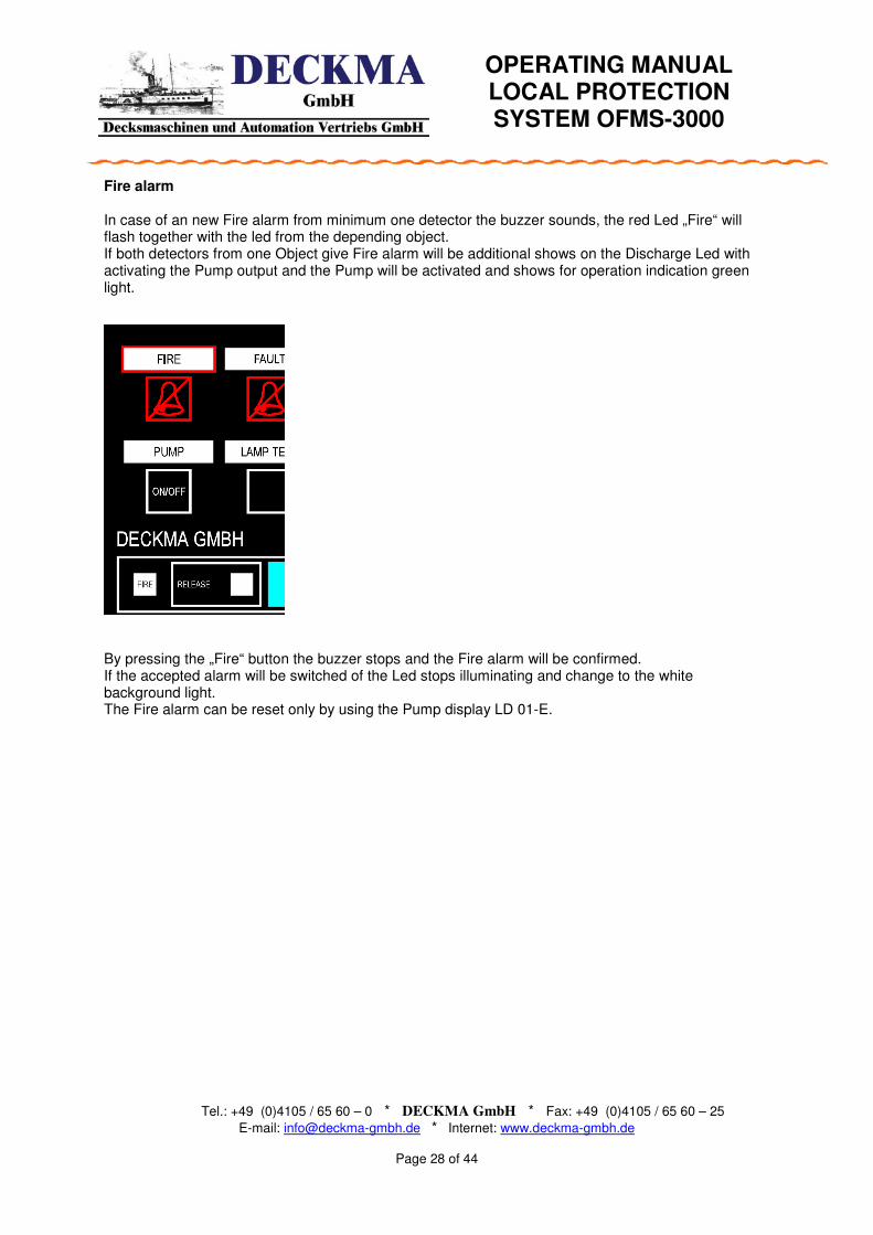
Fire alarm In case of an new Fire alarm from minimum one detector the buzzer sounds, the red Led „Fire“ will flash together with the led from the depending object. If both detectors from one Object give Fire alarm will be additional shows on the Discharge Led with activating the Pump output and the Pump will be activated and shows for operation indication green light. By pressing the „Fire“ button the buzzer stops and the Fire alarm will be confirmed. If the accepted alarm will be switched of the Led stops illuminating and change to the white background light. The Fire alarm can be reset only by using the Pump display LD 01-E.
OPERATING MANUAL LOCAL PROTECTION SYSTEM OFMS-3000
Tel.: +49 (0)4105 / 65 60 – 0 * DECKMA GmbH * Fax: +49 (0)4105 / 65 60 – 25
E-mail: [email protected] * Internet: www.deckma-gmbh.de
Page 29 of 44
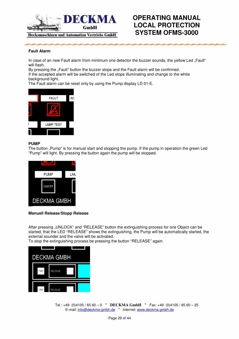
Fault Alarm In case of an new Fault alarm from minimum one detector the buzzer sounds, the yellow Led „Fault“ will flash. By pressing the „Fault“ button the buzzer stops and the Fault alarm will be confirmed. If the accepted alarm will be switched of the Led stops illuminating and change to the white background light. The Fault alarm can be reset only by using the Pump display LD 01-E. PUMP The button „Pump“ is for manual start and stopping the pump. If the pump in operation the green Led ”Pump” will light. By pressing the button again the pump will be stopped. Manuell Release/Stopp Release After pressing „UNLOCK“ and “RELEASE” button the extinguishing process for one Object can be started, that the LED “RELEASE” shows the extinguishing, the Pump will be automatically started, the external sounder and the valve will be activated. To stop the extinguishing process be pressing the button “RELEASE” again.
OPERATING MANUAL LOCAL PROTECTION SYSTEM OFMS-3000
Tel.: +49 (0)4105 / 65 60 – 0 * DECKMA GmbH * Fax: +49 (0)4105 / 65 60 – 25
E-mail: [email protected] * Internet: www.deckma-gmbh.de
Page 30 of 44
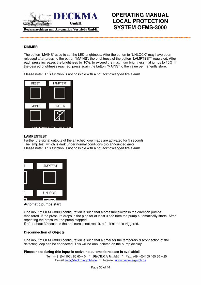
DIMMER The button “MAINS” used to set the LED brightness. After the button to “UNLOCK” may have been released after pressing the button “MAINS”, the brightness of the button “LAMPTEST” regulated. After each press increases the brightness by 10%, to exceed the maximum brightness that jumps to 10%. If the desired brightness reached, press again the button “MAINS” to the value permanently store. Please note: This function is not possible with a not acknowledged fire alarm! LAMPENTEST Further the signal outputs of the attached loop maps are activated for 5 seconds. The lamp test, which is dark under normal conditions (no announced error). Please note: This function is not possible with a not acknowledged fire alarm!
Automatic pumps start One input of OFMS-3000 configuration is such that a pressure switch in the direction pumps monitored. If the pressure drops in the pipe for at least 3 sec from the pump automatically starts. After repeating the pressure, the pump stopped. If after about 30 seconds the pressure is not rebuilt, a fault alarm is triggered. Disconnection of Objects One input of OFMS-3000 configuration is such that a timer for the temporary disconnection of the detecting loop can be connected. This will be annunciated on the pump display. Please note during this input is active no automatic release is available!!!

OPERATING MANUAL LOCAL PROTECTION SYSTEM OFMS-3000
Tel.: +49 (0)4105 / 65 60 – 0 * DECKMA GmbH * Fax: +49 (0)4105 / 65 60 – 25
E-mail: [email protected] * Internet: www.deckma-gmbh.de
Page 31 of 44
5.0 Start up of the OFMS-3000

OPERATING MANUAL LOCAL PROTECTION SYSTEM OFMS-3000
Tel.: +49 (0)4105 / 65 60 – 0 * DECKMA GmbH * Fax: +49 (0)4105 / 65 60 – 25
E-mail: [email protected] * Internet: www.deckma-gmbh.de
Seite 32 von 44
WATER BASED LOCAL APPLICATION FIRE FIGHTING SYSTEM
6.0 Mechanical Spezification The main cabinet includes the Power supply, Pump module, Printer module, VDR Module, Fire detector module and the output module. This cabinet is typically installed into the engine room with a buss connection up to 500m to the repeater panel and the release panels. The main cabinet is one standard Steel housing from Rittal series AE… with have an IP 66 class according DIN EN 60529. 6.1 Typical Arrangement for main cabinet for up to 10 Objects. 6.2 Manual release button
The manual release button will be installed into standard polycarbonate housing with IP 65 according DIN EN 60529.

OPERATING MANUAL LOCAL PROTECTION SYSTEM OFMS-3000
Tel.: +49 (0)4105 / 65 60 – 0 * DECKMA GmbH * Fax: +49 (0)4105 / 65 60 – 25
E-mail: [email protected] * Internet: www.deckma-gmbh.de
Seite 33 von 44
6.3 Release Panel recess mounting AT01-E Outside dimensions 288x144mm, depth 53m plus the SUB-D plug. Panel cut out 280x137mm IP protection class IP 44 if recess mounted according DIN EN 60 529.
6. Repeater Panel recess mounting HT01-E
Outside dimensions 144x144mm, depth 53m plus the SUB-D plug. Panel cut out 137x137mm IP protection class IP 44 if recess mounted according DIN EN 60 529.

OPERATING MANUAL LOCAL PROTECTION SYSTEM OFMS-3000
Tel.: +49 (0)4105 / 65 60 – 0 * DECKMA GmbH * Fax: +49 (0)4105 / 65 60 – 25
E-mail: [email protected] * Internet: www.deckma-gmbh.de
Seite 34 von 44
7.0 Overview Fire and Fault alarms This chapter describes the internal messages and alarm texts. In the first line of the display the fault header will be indicated e.g. Fire N. The second line describes the location of the alarm e.g. Loop 4. The below marked list shows all available fire and fault messages. Header Text Line 2 Deskription
FIRE N Specific location e.g. Loop 4 A Firealarm will be detected by the Fire detector module
FIRE A Specific location e.g. Loop 4 A accepted Firealarm
FAULT N Specific location e.g. Loop 4 A Faultalarm will be detected by the Fire detector module
FAULT A Specific location e.g. Loop 4 A accepted Fault alarm
Tablet: Overview of Fault and Fire alarm messages
7.1 Module definition: The OFMS3000 contains a monitoring of all configured modules. The following fault messages will be indicate additional to ”MODUL ERR” : LM01 Fan module AM01 Output module FM01, FM02, FM03, FM04 Fire detector module 1 to 4 VM01 VDR-module DM01 Printer module HT01 Operating panel – Main panel PT01, PT02 Repeater panel 1 and 2
OPERATING MANUAL LOCAL PROTECTION SYSTEM OFMS-3000
Tel.: +49 (0)4105 / 65 60 – 0 * DECKMA GmbH * Fax: +49 (0)4105 / 65 60 – 25
E-mail: [email protected] * Internet: www.deckma-gmbh.de
Seite 35 von 44
4 T2
1 0
6 T34 T22 T1 2 T1
1 0
6 T3
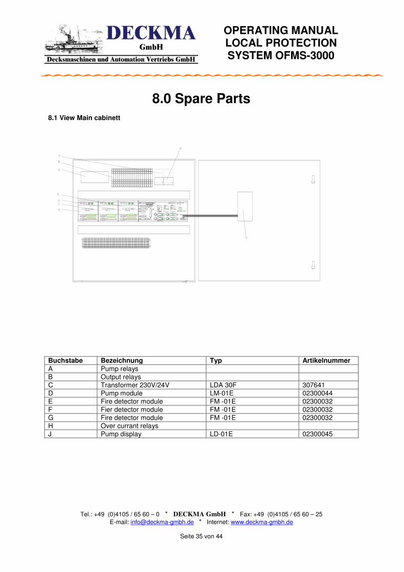
8.0 Spare Parts 8.1 View Main cabinett Buchstabe Bezeichnung Typ Artikelnummer A Pump relays
B Output relays
C Transformer 230V/24V LDA 30F 307641
D Pump module LM-01E 02300044
E Fire detector module FM -01E 02300032
F Fier detector module FM -01E 02300032
G Fire detector module FM -01E 02300032
H Over currant relays
J Pump display LD-01E 02300045

OPERATING MANUAL LOCAL PROTECTION SYSTEM OFMS-3000
Tel.: +49 (0)4105 / 65 60 – 0 * DECKMA GmbH * Fax: +49 (0)4105 / 65 60 – 25
E-mail: [email protected] * Internet: www.deckma-gmbh.de
Seite 36 von 44
Torbeck
22.08.2007
Angle of view Flamdetector
HF-24 for Local Apprication System 1 1
Not to scale
1,0 m
3,0
m
8,0
m
1,0
m
23°
30°
43°
77°
120°
Flame from Candle,lighter
Flame from wad of Newspaper, burning flame
Angle 23° with reducer L= 40mm
Angle 30° with reducer L=30mm
Angle 43° with reducer L= 20mm
Angle 77° with reducer L= 10mm
Angle 120° without reducer
9.0 Angle of view Flame detector HF 24
OPERATING MANUAL LOCAL PROTECTION SYSTEM OFMS-3000
Tel.: +49 (0)4105 / 65 60 – 0 * DECKMA GmbH * Fax: +49 (0)4105 / 65 60 – 25
E-mail: [email protected] * Internet: www.deckma-gmbh.de
Seite 37 von 44
To
rbe
ck
04
.06
.20
07
S 3
98
9
Pu
mp
Mo
du
le O
FM
S3
00
0 L
M0
1-E
Co
nn
ectio
n D
raw
ing
Lo
ca
l A
pp
lica
tio
n s
yste
m O
FM
S 3
00
0
11
No
t to
sca
le
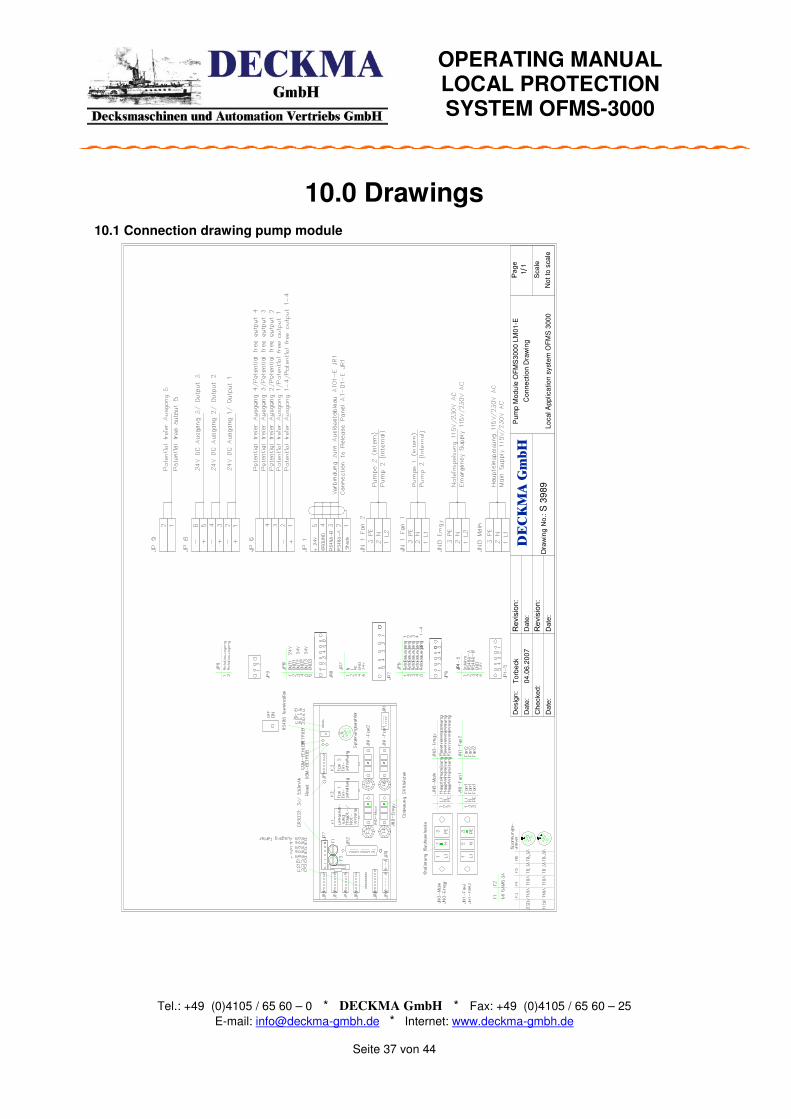
10.0 Drawings 10.1 Connection drawing pump module
OPERATING MANUAL LOCAL PROTECTION SYSTEM OFMS-3000
Tel.: +49 (0)4105 / 65 60 – 0 * DECKMA GmbH * Fax: +49 (0)4105 / 65 60 – 25
E-mail: [email protected] * Internet: www.deckma-gmbh.de
Seite 38 von 44
To
rbeck
04
.06
.20
07
S 3
991
Fire
de
tecto
r L
oo
pca
rd O
bje
ct 1
-2
OF
MS
-30
00
FM
01
-E2
Con
ne
ctio
n D
raw
ing
Lo
ca
l A
pp
lica
tion
Sys
ten
11
No
t to
sca
le
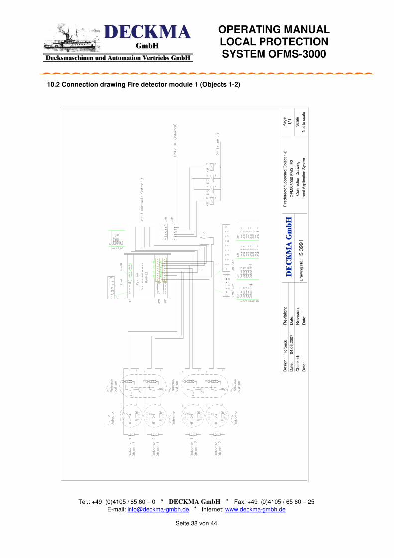
10.2 Connection drawing Fire detector module 1 (Objects 1-2)
OPERATING MANUAL LOCAL PROTECTION SYSTEM OFMS-3000
Tel.: +49 (0)4105 / 65 60 – 0 * DECKMA GmbH * Fax: +49 (0)4105 / 65 60 – 25
E-mail: [email protected] * Internet: www.deckma-gmbh.de
Seite 39 von 44
To
rbe
ck
04
.06
.20
07
S 3
99
2
Fir
ed
ete
cto
r L
oo
pca
rd O
bje
ct
3-6
OF
MS
-30
00
FM
01
-E2
Co
nn
ectio
n D
raw
ing
Lo
ca
l A
pp
lica
tio
n S
yste
n
11
No
t to
sca
le
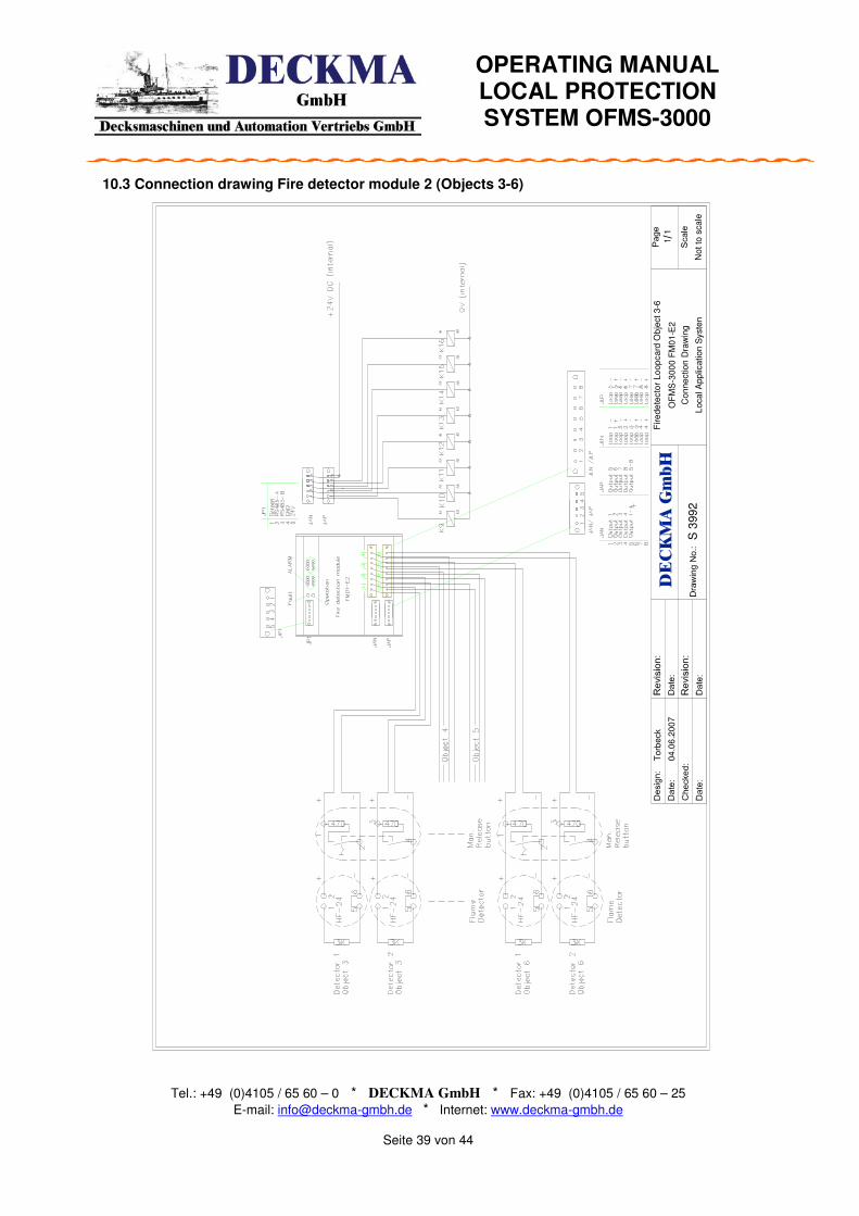
10.3 Connection drawing Fire detector module 2 (Objects 3-6)

OPERATING MANUAL LOCAL PROTECTION SYSTEM OFMS-3000
Tel.: +49 (0)4105 / 65 60 – 0 * DECKMA GmbH * Fax: +49 (0)4105 / 65 60 – 25
E-mail: [email protected] * Internet: www.deckma-gmbh.de
Seite 40 von 44
Torb
eck
04.0
6.2
007
S 3
993
Fir
ed
ete
cto
r Lo
op
card
Obje
ct 7-1
0
OF
MS
-3000
FM
01-E
2
Co
nn
ection D
raw
ing
Lo
ca
l A
pp
lica
tion S
yste
n
11
No
t to
scale
10.4 Connection drawing Fire detector module 3 (Objects 7-10)
OPERATING MANUAL LOCAL PROTECTION SYSTEM OFMS-3000
Tel.: +49 (0)4105 / 65 60 – 0 * DECKMA GmbH * Fax: +49 (0)4105 / 65 60 – 25
E-mail: [email protected] * Internet: www.deckma-gmbh.de
Seite 41 von 44
Torb
eck
16.0
3.2
007
S 3
986
Sla
ve M
odul S
M-0
1E
for
Connection to F
MS
/AF
MS
3000
Sm
okedete
ction S
yste
m S
FM
S 3
000
Local P
rote
ction S
yste
m O
FM
S 3
000
11
Not to
scale
10.5 Connection drawing Slave module

OPERATING MANUAL LOCAL PROTECTION SYSTEM OFMS-3000
Tel.: +49 (0)4105 / 65 60 – 0 * DECKMA GmbH * Fax: +49 (0)4105 / 65 60 – 25
E-mail: [email protected] * Internet: www.deckma-gmbh.de
Seite 42 von 44
Desig
n:
Date
:
Che
cked:
Date
:
Re
vis
ion:
Date
:
Re
vis
ion:
Date
:D
raw
ing N
o.:
Page
Sca
le
DECKMA GmbH
/T
orb
eck
20.0
3.2
00
7
S 3
98
7
Re
pea
ter
Pa
nel S
FM
S3
000 H
T01
-E
Co
nn
ectio
n D
raw
ing
Dim
ensio
n D
raw
ing
Sm
oke
de
tectio
n S
yste
m S
FM
S 3
000
11
Not
to s
cale
53
14
4
144
10.6 Connection drawing Repeater Panel
OPERATING MANUAL LOCAL PROTECTION SYSTEM OFMS-3000
Tel.: +49 (0)4105 / 65 60 – 0 * DECKMA GmbH * Fax: +49 (0)4105 / 65 60 – 25
E-mail: [email protected] * Internet: www.deckma-gmbh.de
Seite 43 von 44
Torb
eck
04.0
6.2
007
S 3
99
4
Rele
asepa
nel A
T01-E
OF
MS
-30
00 F
M01-E
2
Co
nne
ction
Dra
win
g
Local A
pp
lica
tion S
yste
n
11
Not
to s
cale
10.7 Connection drawing Release Panel
OPERATING MANUAL LOCAL PROTECTION SYSTEM OFMS-3000
Tel.: +49 (0)4105 / 65 60 – 0 * DECKMA GmbH * Fax: +49 (0)4105 / 65 60 – 25
E-mail: [email protected] * Internet: www.deckma-gmbh.de
Seite 44 von 44
WA
TE
R B
AS
ED
LO
CA
L A
PP
LIC
AT
ION
FIR
E F
IGH
TIN
G S
YS
TE
M
To
rbe
ck
04
.06
.20
07
S3
99
6
MA
NU
AL
RE
LE
AS
E U
NIT
Lo
ca
l A
pp
lica
tio
n S
yste
m
OF
MS
-30
00
11
No
t to
sca
le
1 2 3 4 5 6 7 8 9 10
11
12
+ - + - + - + - + - + -
10.8 Connection Drawing Manual release button