technical data - khűtős_rendszerek/2... · pdf file• air handling unit connection...
TRANSCRIPT
EEDEN08-205
technical dataventilation
Control box

EEDEN08-205
technical dataventilation
Control box
• Ventilation • Air Handling Unit Connection 1
• Air Handling Unit Connection • Control box EKEXDCBA_FCBA_MCBV3
TABLE OF CONTENTSEKEXDCBA_FCBA_MCBV3
1 Features . . . . . . . . . . . . . . . . . . . . . . . . . . . . . . . . . . . . . . . . . . . . . . . . . . . . . . . . . . . . . 2
2 Specifications . . . . . . . . . . . . . . . . . . . . . . . . . . . . . . . . . . . . . . . . . . . . . . . . . . . . . . . 3 Technical Specifications . . . . . . . . . . . . . . . . . . . . . . . . . . . . . . . . . . . . . . . . . . . . . 3 Electrical Specifications . . . . . . . . . . . . . . . . . . . . . . . . . . . . . . . . . . . . . . . . . . . . . 3
3 Options . . . . . . . . . . . . . . . . . . . . . . . . . . . . . . . . . . . . . . . . . . . . . . . . . . . . . . . . . . . . . . 5
4 Capacity tables . . . . . . . . . . . . . . . . . . . . . . . . . . . . . . . . . . . . . . . . . . . . . . . . . . . . . 6Combination table . . . . . . . . . . . . . . . . . . . . . . . . . . . . . . . . . . . . . . . . . . . . . . . . . . . . 6Cooling capacity tables . . . . . . . . . . . . . . . . . . . . . . . . . . . . . . . . . . . . . . . . . . . . . . 7Capacity correction factor . . . . . . . . . . . . . . . . . . . . . . . . . . . . . . . . . . . . . . . . . . . . 8
5 Dimensional drawing & centre of gravity . . . . . . . . . . . . . . . . . . . . . . . . 9Dimensional drawing . . . . . . . . . . . . . . . . . . . . . . . . . . . . . . . . . . . . . . . . . . . . . . . . . 9
6 Wiring diagram. . . . . . . . . . . . . . . . . . . . . . . . . . . . . . . . . . . . . . . . . . . . . . . . . . . . . 11Wiring diagram . . . . . . . . . . . . . . . . . . . . . . . . . . . . . . . . . . . . . . . . . . . . . . . . . . . . . . 11External connection diagram . . . . . . . . . . . . . . . . . . . . . . . . . . . . . . . . . . . . . . . . 13

• Air Handling Unit Connection • Control box EKEXDCBA_FCBA_MCBV3
2
1 Features
3
tilation Handlin trol box Handlin
Ven Air Con Air • The ERX system provides optimized air conditions such as fresh air and humidity control etc and can be used in small warehouses, showrooms and offices.• Wide range of Daikin units offers maximum application potential plus flexible control options.
• Control box and expansion valve kit are required for each combination plus an air handling unit.
• Both options are designed for indoor and outdoor installation and can be wall mounted.
• Ventilation • Air Handling Unit Connection
• Air Handling Unit Connection • Control box EKEXDCBA_FCBA_MCBV3
2 Specifications
3
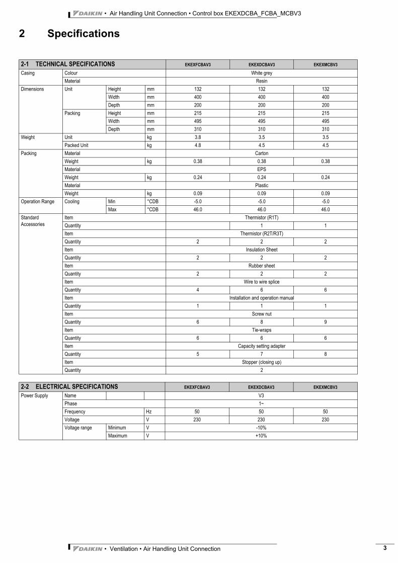
2-1 TECHNICAL SPECIFICATIONS EKEXFCBAV3 EKEXDCBAV3 EKEXMCBV3
Casing Colour White greyMaterial Resin
Dimensions Unit Height mm 132 132 132Width mm 400 400 400Depth mm 200 200 200
Packing Height mm 215 215 215Width mm 495 495 495Depth mm 310 310 310
Weight Unit kg 3.8 3.5 3.5Packed Unit kg 4.8 4.5 4.5
Packing Material CartonWeight kg 0.38 0.38 0.38Material EPSWeight kg 0.24 0.24 0.24Material PlasticWeight kg 0.09 0.09 0.09
Operation Range Cooling Min °CDB -5.0 -5.0 -5.0Max °CDB 46.0 46.0 46.0
Standard Accessories
Item Thermistor (R1T)Quantity 1 1Item Thermistor (R2T/R3T)Quantity 2 2 2Item Insulation SheetQuantity 2 2 2Item Rubber sheetQuantity 2 2 2Item Wire to wire spliceQuantity 4 6 6Item Installation and operation manualQuantity 1 1 1Item Screw nutQuantity 6 8 9Item Tie-wrapsQuantity 6 6 6Item Capacity setting adapterQuantity 5 7 8Item Stopper (closing up)Quantity 2
2-2 ELECTRICAL SPECIFICATIONS EKEXFCBAV3 EKEXDCBAV3 EKEXMCBV3
Power Supply Name V3Phase 1~Frequency Hz 50 50 50Voltage V 230 230 230Voltage range Minimum V -10%
Maximum V +10%
• Ventilation • Air Handling Unit Connection 3

• Air Handling Unit Connection • Control box EKEXDCBA_FCBA_MCBV3
4
2 Specifications
3
Wiring connections For Power Supply Quantity 3 3 3Remark Earth wire includedFor connection with indoor
Quantity 2 2 2Remark F1-F2
For remote control Quantity 2 2 2Remark P1,P2 (for service) P1,P2 P1,P2
For expansion valve kit
Quantity 6 6 6Remark Y1~Y6
Thermistors liquid pipe
Quantity 2 2 2Remark R1,R2
Thermistors gas pipe
Quantity 2 2 2Remark R3,R4
Thermistor air Quantity 2 2Remark R5,R6 R5,R6
ON/OFF Remark T1,T2Error signal Quantity 2
Remark C1,C2Operation signal Quantity 2
Remark C3,C4Capacity step Quantity 2
Remark C5,C6Power Supply Intake Bottom
2-2 ELECTRICAL SPECIFICATIONS EKEXFCBAV3 EKEXDCBAV3 EKEXMCBV3
• Ventilation • Air Handling Unit Connection
• Air Handling Unit Connection • Control box EKEXDCBA_FCBA_MCBV3
3 Options
3
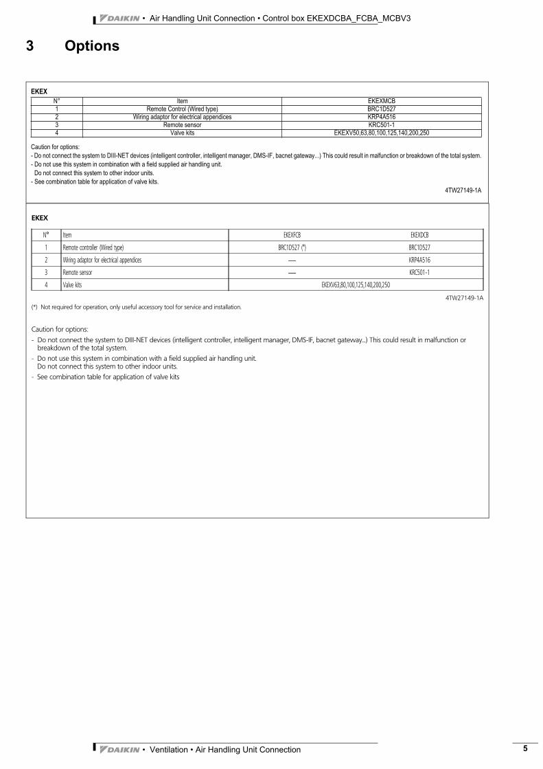
EKEX
Caution for options:
- Do not connect the system to DIII-NET devices (intelligent controller, intelligent manager, DMS-IF, bacnet gateway...) This could result in malfunction or breakdown of the total system.
- Do not use this system in combination with a field supplied air handling unit.
Do not connect this system to other indoor units.
- See combination table for application of valve kits.
4TW27149-1A
N° Item EKEXMCB
1 Remote Control (Wired type) BRC1D527
2 Wiring adaptor for electrical appendices KRP4A516
3 Remote sensor KRC501-1
4 Valve kits EKEXV50,63,80,100,125,140,200,250
EKEX
N° Item EKEXFCB EKEXDCB
1 Remote controller (Wired type) BRC1D527 (*) BRC1D527
2 Wiring adaptor for electrical appendices } KRP4A516
3 Remote sensor } KRC501-1
4 Valve kits EKEXV63,80,100,125,140,200,250
4TW27149-1A(*) Not required for operation, only useful accessory tool for service and installation.
Caution for options:
- Do not connect the system to DIII-NET devices (intelligent controller, intelligent manager, DMS-IF, bacnet gateway...) This could result in malfunction orbreakdown of the total system.
- Do not use this system in combination with a field supplied air handling unit.Do not connect this system to other indoor units.
- See combination table for application of valve kits
• Ventilation • Air Handling Unit Connection 5

• Air Handling Unit Connection • Control box EKEXDCBA_FCBA_MCBV3
6
4 Capacity tables
3
4 - 1 Combination table
EKEX
N° Item EKEXFCB EKEXDCB
1 Remote controller (Wired type) BRC1D527 (*) BRC1D527
2 Wiring adaptor for electrical appendices } KRP4A516
3 Remote sensor } KRC501-1
4 Valve kits EKEXV63,80,100,125,140,200,250
4TW27149-1A(*) Not required for operation, only useful accessory tool for service and installation.
Caution for options:
- Do not connect the system to DIII-NET devices (intelligent controller, intelligent manager, DMS-IF, bacnet gateway...) This could result in malfunction orbreakdown of the total system.
- Do not use this system in combination with a field supplied air handling unit.Do not connect this system to other indoor units.
- See combination table for application of valve kits
Control box Valve kitClass Outdoor EKEXDCBAV3 EKEXFCBAV3 EKEXV63 EKEXV80 EKEXV100 EKEXV125 EKEXV140 EKEXV200 EKEXV250100 ERX100A8V3B P P P P P P - - -125 ERX125A8V3B P P P P P P P - -140 ERX140A8V3B P P - P P P P - -125 ERX125A7W1B - - P P P P P - -200 ERX200A7W1B P P - - P P P P P250 ERX250A7W1B P P - - - P P P P
P: Pair: Combination depending on AHU coil volume (details see manual and capacity table)3TW27179-1A
• Ventilation • Air Handling Unit Connection
• Air Handling Unit Connection • Control box EKEXDCBA_FCBA_MCBV3
4 Capacity tables
3
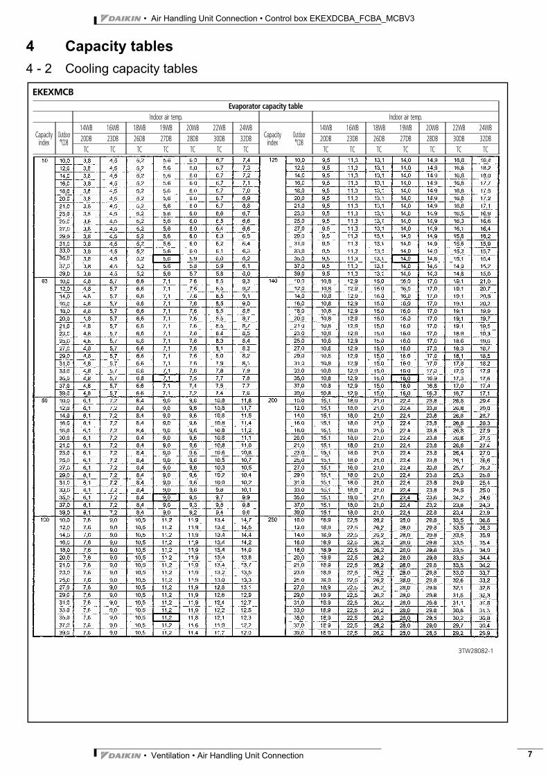
4 - 2 Cooling capacity tables
3TW28082-1
EKEXMCBEvaporator capacity table
Indoor air temp. Indoor air temp.
Capacityindex
Outdoor°CDB
14WB 16WB 18WB 19WB 20WB 22WB 24WBCapacityindex
Outdoor°CDB
14WB 16WB 18WB 19WB 20WB 22WB 24WB20DB 23DB 26DB 27DB 28DB 30DB 32DB 20DB 23DB 26DB 27DB 28DB 30DB 32DBTC TC TC TC TC TC TC TC TC TC TC TC TC TC
• Ventilation • Air Handling Unit Connection 7
• Air Handling Unit Connection • Control box EKEXDCBA_FCBA_MCBV3
8
4 Capacity tables
3
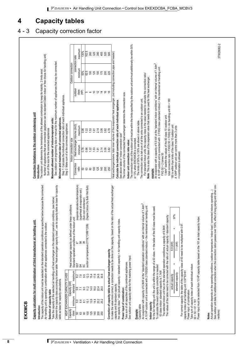
4 - 3 Capacity correction factorC
apac
ity
calc
ula
tio
n f
or
mu
lti c
om
bin
atio
n o
f th
ird
man
ufa
ctu
rer
air
han
dlin
g u
nit
.
Intr
od
uct
ion
Th
e c
ap
acity o
f th
e in
do
or
un
it m
ust b
e s
ele
cte
d o
n th
e s
tan
da
rd o
pe
ratio
n c
on
ditio
ns a
s s
pe
cifie
d b
elo
w b
eca
use
th
e c
on
ne
cte
d
Air
ha
nd
ling
un
it is o
pe
ratin
g in
co
mb
ina
tio
n w
ith
oth
er
ap
plia
nce
s c
on
ne
cte
d to
th
e o
utd
oo
r.
Sel
ecti
on
of
cap
acit
y ta
ble
Ta
ke
th
e c
ap
acity o
f th
e s
ele
cte
d a
ir h
an
dlin
g u
nit h
ea
t e
xch
an
ge
r o
n t
he
sta
nd
ard
op
era
tio
n c
on
ditio
ns.
(se
e b
elo
w)
De
term
in th
e c
ap
acity c
lass a
cco
rdin
g to
be
low
ta
ble
“H
ea
t e
xch
an
ge
r ca
pa
city c
lass”,
use
its c
ap
acity ta
ble
as b
ase
fo
r ca
pa
city
tab
le a
s b
ase
fo
r ca
pa
city c
alc
ula
tio
ns.
Co
rrec
tio
n o
f ca
pac
ity
tab
le t
o a
ctu
al h
eat
exch
ang
er c
apac
ity
to m
ake
th
e v
alu
e m
ore
co
rre
ct,
a c
orr
ectio
n n
ee
ds to
be
do
ne
on
th
e c
ap
acity,
ba
se
d o
n th
e r
atio
of th
e a
ctu
al h
ea
t e
xch
an
ge
r
ca
pa
city a
nd
th
sta
nd
ard
ca
pa
city.
the
ca
pa
city c
lass *
ra
tio
(a
ctu
al ca
pa
city /
sta
nd
ard
ca
pa
city)
= A
ir h
an
dlin
g u
nit c
ap
acity in
de
x.
Po
wer
inp
ut
of
com
bin
atio
n:
Ta
ke
su
m o
f a
ll ca
pa
citie
s o
f th
e c
om
bin
ed
ap
plia
nce
s.
Se
e o
utd
oo
r u
nit c
ap
acity t
ab
le f
or
the
ma
tch
ing
po
we
r in
pu
t.
Exa
mp
le:
Ca
pa
city ta
ble
An
eva
po
rato
r w
ith
ca
pa
city o
f 6
,9kW
at
the
“sta
nd
ard
op
era
tio
n c
on
ditio
ns”
with
an
in
tern
al vo
lum
e o
f 1
.4d
m3.
A 1
0 H
P o
utd
oo
r u
nit is c
on
ne
cte
d w
ith
2 F
XS
Q5
0 c
lass (
sta
nd
ard
in
do
or)
+ t
he
me
ntio
ne
d a
ir h
an
dlin
g u
nit:
Ind
oo
r ca
pac
ity
for
the
Air
ha
nd
ling
un
it:
the
un
it is w
ith
in t
he
ra
ng
e o
f a
63
cla
ss. =
> th
e t
ab
le o
f th
e 6
3 c
lass m
ust
be
use
d.
To
ca
lcu
late
th
e e
xa
ct
ca
pa
city c
orr
ectio
n is n
ee
de
d
63
cla
ss in
do
or:
sta
nd
ard
ca
pa
city is 7
,1kW
Th
e s
ele
cte
d in
do
or
un
it h
as o
n t
he
sta
nd
ard
op
era
tio
n c
on
ditio
ns a
ca
pa
city o
f 6
,9kW
.
Th
e v
alu
es o
f th
e t
ab
le n
ee
d to
be
co
rre
cte
d w
ith
th
e r
atio
of:
actu
al ca
pa
city / s
tan
da
rd c
ap
acity
Fo
r co
rre
ct
ca
pa
city: th
e ta
ble
of th
e c
ap
acity c
lass o
f 6
3 n
ee
d t
o b
e m
ultip
lied
with
0.9
7.
ca
pa
city in
de
x o
f a
ir h
an
dlin
g u
nit:
0.9
7*6
3=
61
Po
we
r in
pu
t o
f co
mb
ina
tio
n
Ta
ke
su
m o
f ca
pa
city in
de
x o
f e
ach
in
div
idu
al in
do
or.
50
+ 5
0 +
61
= 1
61
Po
we
r in
pu
t m
ust
be
se
lecte
d f
rom
10
HP
ca
pa
city ta
ble
ba
se
d o
n th
e 1
61
as to
tal ca
pa
city in
de
x.
No
tes
Actu
al o
pe
ratio
n d
ep
en
ds o
n t
he
op
era
tin
g c
on
ditio
ns (
ou
tdo
or
tem
pe
ratu
re /
in
do
or
loa
d / c
on
ne
cte
d in
do
ors
op
era
tin
g ...
)
Se
e o
utd
oo
r u
nit d
ata
fo
r a
dd
itio
na
l co
rre
ctio
n w
he
n th
e c
on
ne
ctio
n r
atio
n p
asse
s o
ve
r 1
00
%, e
ffe
ct o
f lo
ng
pip
ing
an
d o
the
r con
-
ne
ctio
ns)
Co
nn
ecti
on
lim
itat
ion
s to
th
e o
utd
oo
r co
nd
ensi
ng
un
it
Intr
od
uct
ion
Th
e o
utd
oo
r u
nit d
ete
rmin
s t
he
lim
mita
tio
ns o
f th
e a
llow
ed
co
mb
ina
tio
n t
o k
ee
p its
rlia
bili
ty. 2
lim
its e
xis
t.
Nu
mb
er
of
ap
plia
nce
s th
at a
re c
on
ne
cte
d (
ap
plia
nce
ca
n b
e s
tan
da
rd D
aik
in in
do
or
or
fre
e c
ho
ice
Air
ha
nd
ling
un
it)
Su
m o
f th
e s
ize
fo
r th
e c
on
ne
cte
d a
pp
lian
ce
s
Max
imu
m a
llow
ed n
um
ber
of
ind
oo
r/ev
apo
rato
r u
nit
s:S
ee
ou
tdo
or
un
it e
ng
ine
eri
ng
da
ta o
r m
an
ua
l fo
r th
e m
axim
um
nu
mb
er
of
ap
plia
nce
s th
at
ma
y b
e c
on
ne
cte
d.
Min
imu
m a
nd
max
imu
m s
ize
of
con
nec
ted
ap
plia
nce
s.S
tep
1:
Ca
lcu
late
th
e in
div
idu
al co
nn
ectio
n r
atio
of
ea
ch
in
div
idu
al a
pp
lian
ce
.
Ste
p 2
: M
ake
su
m o
f a
l th
e c
on
ne
cte
d a
pp
lian
ce
s
He
at
exch
an
ge
rvo
lum
e:
tota
l in
ne
r vo
lum
e o
f th
e e
va
po
rato
r h
ea
t e
xcg
an
ge
r. (
no
t in
clu
din
g c
on
ne
ctio
n p
ipe
an
d h
ea
de
r)
Cal
cula
te t
he
ind
ivid
ual
co
nn
ecti
on
rat
io o
f ea
ch in
div
idu
al a
pp
lian
ce.
Se
e a
bo
ve
ta
ble
of
“in
do
or
co
nn
ectio
n s
ize
”
Th
e in
ne
r vo
lum
e o
f th
e c
on
ne
cte
d h
ea
t e
xch
an
ge
r d
ete
rmin
s t
he
co
nn
ectio
n s
ize
.
Ind
oo
r u
nit
co
nn
ecti
on
rat
io v
alu
e:T
he
co
nn
ectio
n ra
tio
of th
e o
utd
oo
r u
nit m
ust b
e w
ith
in th
e li
mits s
pe
cifie
d b
y th
e o
utd
oo
r u
nit a
nd
mu
st a
dd
itiio
na
lly b
e w
ith
in 5
0%
or
13
% w
he
n E
KE
XM
CB
is c
on
ne
cte
d.
Th
e lim
its o
f 5
0%
to
13
0%
are
sh
ow
n in
ab
ove
ta
ble
.
Th
e c
on
ne
ctio
n r
atio
is t
eh
su
m o
f a
ll th
e u
nits c
on
ne
cte
d t
o a
n o
utd
oo
r u
nit.
Fo
r sta
nd
ard
in
do
or
un
its:
the
ca
pa
city c
lass is th
e v
alu
e n
ee
de
d t
o c
alc
ula
te t
he
co
nn
ectio
n r
atio
/
No
te:
Th
is is a
lso
th
e c
lass o
f th
e e
xp
an
sio
n v
alv
e t
ha
t n
ee
ds to
be
use
d f
or
this
he
at
exch
an
ge
r.
exam
ple
:A
n e
va
po
rato
r w
ith
a c
ap
acity o
f 6
.9 k
W a
t th
e “
sta
nd
ard
in
do
or
co
nd
itio
ns”
with
an
in
tern
al vo
lum
e o
f 1
.4d
m3.
A 1
0 H
P o
utd
oo
r u
nit is c
on
ne
cte
d w
ith
: 2
FX
SQ
cla
ss (
sta
nd
ard
in
do
or)
+ th
e m
en
tio
ne
d a
ir h
an
dlin
g u
nit:
FX
Q 5
0 =
2 to
me
s 5
0
1.4
dm
3 isw
ith
in t
he
va
lue
s o
f th
e 8
0 c
lass 1
0 o
utd
oo
r u
nit.
tota
l co
nn
ectio
n r
atio
= F
XS
Q 5
0 +
FX
SQ
50
+ A
ir h
an
dlin
g u
nit 8
0 =
18
0
18
0 is w
ith
in t
hye
lim
its o
f th
e c
lass 1
0 o
utd
oo
r u
nit
A 1
0H
P o
utd
oo
r u
nit c
an
co
ntr
ol m
ore
th
an
3 u
nits
=>
co
mb
ina
tio
n is a
llow
ed
.
3T
W28082-2
HE
AT
EX
CH
AN
GE
R C
AP
AC
ITY
CL
AS
S
Ca
pa
city
cla
ss
Ca
pa
city (
kW
)
min
imu
msta
nd
ard
ma
xim
um
50
5.0
5.6
6.2
63
6.4
7.1
7.8
80
8.1
9.0
9.9
10
01
0.1
11
.21
2.3
12
51
2.6
14
.01
5.4
14
01
4.4
16
.01
7.6
20
02
0.2
22
.42
4.6
25
02
5.2
28
.03
0.8
actu
al ca
pa
city
=6
.9 (
kW
)=
97
%sta
nd
ard
ca
pa
city
7.1
(kW
)
Ind
oo
r co
nn
ectio
n s
ize
Ou
tdo
or
co
nn
ectio
n
Co
nn
ectio
n
ratio
He
at e
xch
an
ge
r V
olu
me
(d
m3
)o
utd
oo
r
cla
ss
(HP
)
co
nn
ectio
n r
atio
min
imum
maxim
um
min
imum
ma
xim
um
50
0.7
60.9
650%
130%
63
0.9
61.2
25
62.5
16
2.5
80
1.2
21.5
38
100
260
10
01
.53
1.9
11
01
25
32
5
12
51
.91
2.1
41
21
50
39
0
14
02
.14
3.0
61
41
75
45
5
20
03
.06
3.8
21
62
00
52
0
25
03
.82
4.7
81
82
25
58
5
He
at
exch
an
ge
r ca
pa
city a
s d
efin
ed
un
de
r th
ese
co
nd
itio
ns
Sta
nd
ard
op
era
tio
n c
on
ditio
ns o
f th
e in
do
or
un
it:
SS
T6
°(e
vapo
rato
r sat
urat
ed s
uctio
n te
mpe
ratu
re)
SH
5K
(su
pe
rhe
at
at
eva
po
rato
r e
xit.)
SC
3K
(Su
b c
oo
l co
nd
en
so
r)
suctio
n a
ir t
em
pera
ture
27
/19
(°C
WB
/°C
DB
)(D
egre
e C
elc
ius
Dry
Bulb
/ W
et
Bulb
)
EKXMCB
• Ventilation • Air Handling Unit Connection

• Air Handling Unit Connection • Control box EKEXDCBA_FCBA_MCBV3
5 Dimensional drawing & centre of gravity
3
5 - 1 Dimensional drawing
3TW27144-1
j1 4 holes to fix control boxj2 Control box lidj3 Screw nut for power supply cablej4 Screw nut for expansion valve cablej5 Screw nut for thermistor cable (liquid) R2Tj6 Screw nut for thermistor cable (gas) R3Tj7 Screw nut for communication cable to outdoor unitj8 Screw nut for thermistor cable (air) R1Tj9 Screw nut for remote controllerj10 Screw nut for connection cable to controller
600 or more
EKEXDCBA
Notes:1 Installation:
Make sure that the control box is installed horizontal, screw nuts positiondownwards.The option boxes (expansion valve and electrical control box) can be installedinside and outside.Do not install the option boxes in or on the outdoor unit.Do not put the option boxes in direct sunlight. Direct sunlight will increase thetemperature inside the option boxes and may reduce its lifetime and influence itsoperation.Choose a flat and strong mounting surface.
2 Service space:Keep enough free for future maintenance.
Service space(Notes 2)
Service space(Notes 2)
200
orm
ore
3TW27154-1
j1 4 holes to fix control boxj2 Control box lidj3 Screw nut for power supply cablej4 Screw nut for expansion valve cablej5 Screw nut for thermistor cable (liquid) R2Tj6 Screw nut for thermistor cable (gas) R3Tj7 j8 Stopper (closing cup)j9 Screw nut for communication cable to outdoor unitj10 Screw nut for connection cable to controller
600 or more
EKEXFCBA
Notes:1 Installation:
Make sure that the control box is installed horizontal, screw nuts positiondownwards.The option boxes (expansion valve and electrical control box) can be installedinside and outside.Do not install the option boxes in or on the outdoor unit.Do not put the option boxes in direct sunlight. Direct sunlight will increase thetemperature inside the option boxes and may reduce its lifetime and influenceits operation.Choose a flat and strong mounting surface.
2 Service space:Keep enough free for future maintenance.
Service space(Notes 2)
Service space(Notes 2)
200
orm
ore
• Ventilation • Air Handling Unit Connection 9

• Air Handling Unit Connection • Control box EKEXDCBA_FCBA_MCBV3
10
5 Dimensional drawing & centre of gravity
3
5 - 1 Dimensional drawing
3TW28084-1
j1 4 holes to fix control boxj2 Control box lidj3 Screw nut for power supply cablej4 Screw nut for expansion valve cablej5 Screw nut for thermistor cable (liquid) R2Tj6 Screw nut for thermistor cable (gas) R3Tj7 Screw nut for communication cablej8 Screw nut for thermistor cable (air) R1Tj9 Screw nut for remote controllerj10 Screw nut for connection cable to controller
600 or more
EKEXMCB
Notes:1 Installation:
Make sure that the control box is installed horizontal, screw nuts positiondownwards.The option boxes (expansion valve and electrical control box) can be installedinside and outside.Do not install the option boxes in or on the outdoor unit.Do not put the option boxes in direct sunlight. Direct sunlight will increase thetemperature inside the option boxes and may reduce its lifetime and influence itsoperation.Choose a flat and strong mounting surface.
2 Service space:Keep enough free for future maintenance.
Service space(Note 2)
Service space(Note 2) 20
0or
mor
e
• Ventilation • Air Handling Unit Connection
• Air Handling Unit Connection • Control box EKEXDCBA_FCBA_MCBV3
6 Wiring diagram
3
6 - 1 Wiring diagram
2TW27146-2A
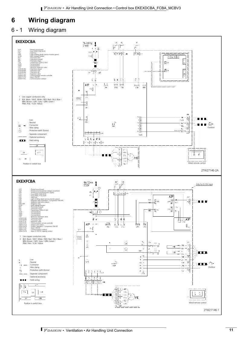
EKEXDCBA
A1P : Printed circuit boardF1U : Fuse (250V, F5A) (A1P)F3U : Field fuseHAP : Light emitting diode (service monitor green)Q1DI : Earth leakage breakerR1T : Thermistor (Air)R2T : Thermistor (Liquid)R3T : Thermistor (Gas)T1R : Transformer (220V/21.8V)X1M : Terminal blockX3M : Terminal blockY1E : Electronic expansion valveX1M-R1/R2 : Thermistor LiquidX1M-R3/R4 : Thermistor GasX1M-R5/R6 : Thermistor AirX1M-Y1∼6 : Expansion valveX2M-P1/P2 : Communication remote controllerX2M-T1/T2 : Input: ON/OFFX2M-F1/F2 : Communication outdoor
: Live: Neutral: Connector: Wire clamp: Protective earth (Screw)
: Seperate component
: Optional accessory
: Field wiring
Wired remote control
Outdoor
See KRP4 (optional connection)
1 Use copper conductors only.2 BLK: Black / WHT: White / RED: Red / BLU: Blue /
BRN: Brown / GRY: Grey / GRN: Green /PINK: Pink / YLW: Yellow
Position in switch box
2TW27146-1
EKEXFCBA
A1P : Printed circuit boardA2P : Printed circuit board (for voltage conversion)A3P : Printed circuit board (Power supply)F1U : Fuse (250V, F5A) (A1P)F2U : Fuse (250V, T1A) (A3P)F3U : Field fuseHAP : Light emitting diode (service monitor green)K1R : Magnetic relay (Operation / Compressor ON/OFF)K2R : Magnetic relay (error status)KAR, KPR : Magnetic relayQ1DI : Earth leakage breakerR2T : Thermistor (Liquid)R3T : Thermistor (Gas)T1R : Transformer (220V/21.8V)X1M : Terminal blockX2M : Terminal blockX3M : Terminal blockY1E : Electronic expansion valveX1M-R1/R2 : Thermistor LiquidX1M-R3/R4 : Thermistor GasX1M-Y1∼6 : Expansion valveX2M-P1/P2 : Communication remote controllerX2M-C1/C2 : Output: error statusX2M-C3/C4 : Output: Operation / Compressor ON/OFFX2M-T1/T2 : Input: ON/OFFX2M-F1/F2 : Communication outdoorX2M-C5/C6 : Input: 0-10V DC capacity control
: Live: Neutral: Connector: Wire clamp: Protective earth (Screw)
: Seperate component
: Optional accessory
: Field wiring
Wired remote control
Outdoor
Only for 0-10V input
1 Use copper conductors only.2 BLK: Black / WHT: White / RED: Red / BLU: Blue /
BRN: Brown / GRY: Grey / GRN: Green /PINK: Pink / YLW: Yellow
Position in switch box
• Ventilation • Air Handling Unit Connection 11
• Air Handling Unit Connection • Control box EKEXDCBA_FCBA_MCBV3
12
6 Wiring diagram
3
6 - 1 Wiring diagram
2TW28086-1
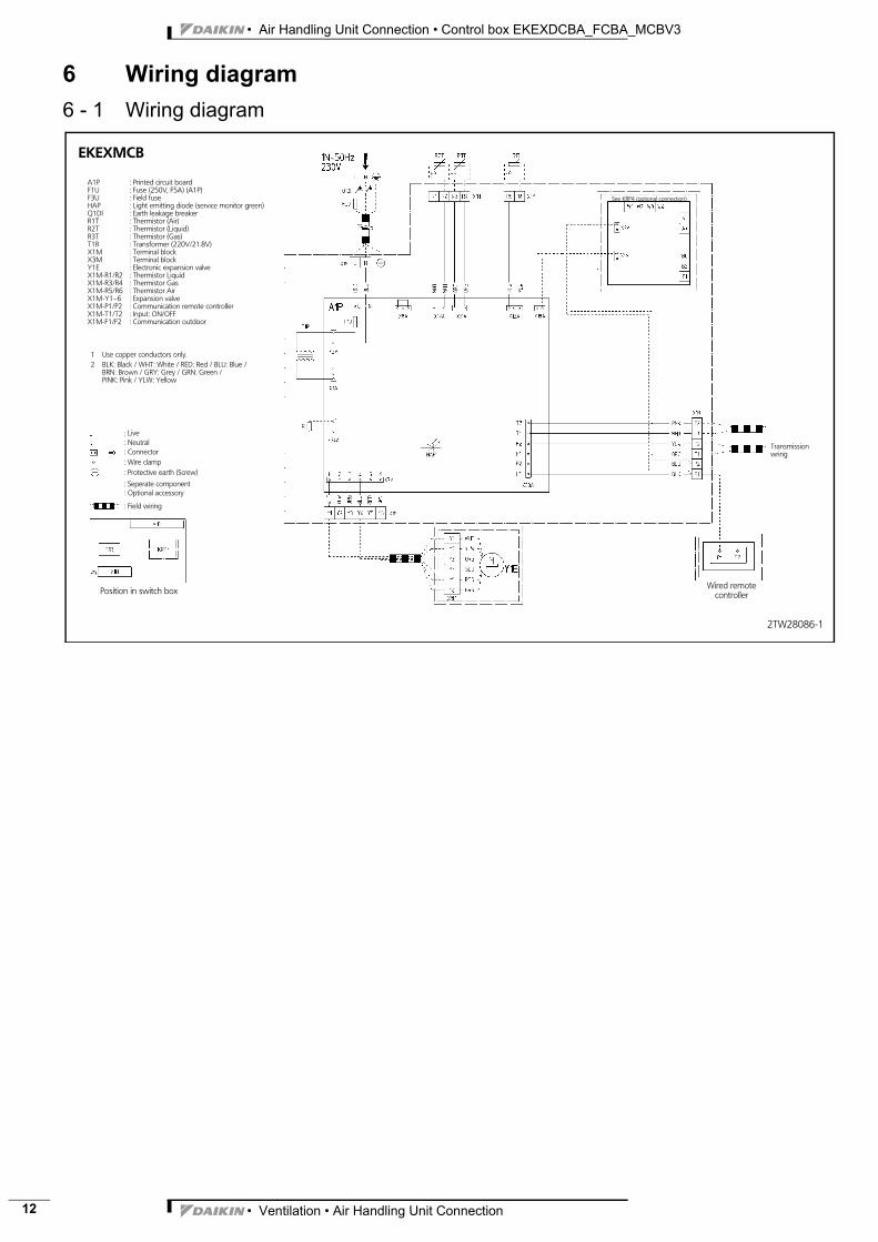
EKEXMCB
A1P : Printed circuit boardF1U : Fuse (250V, F5A) (A1P)F3U : Field fuseHAP : Light emitting diode (service monitor green)Q1DI : Earth leakage breakerR1T : Thermistor (Air)R2T : Thermistor (Liquid)R3T : Thermistor (Gas)T1R : Transformer (220V/21.8V)X1M : Terminal blockX3M : Terminal blockY1E : Electronic expansion valveX1M-R1/R2 : Thermistor LiquidX1M-R3/R4 : Thermistor GasX1M-R5/R6 : Thermistor AirX1M-Y1∼6 : Expansion valveX1M-P1/P2 : Communication remote controllerX1M-T1/T2 : Input: ON/OFFX1M-F1/F2 : Communication outdoor
: Live: Neutral: Connector: Wire clamp: Protective earth (Screw)
: Seperate component: Optional accessory
: Field wiring
Wired remotecontroller
Transmissionwring
See KRP4 (optional connection)
1 Use copper conductors only.2 BLK: Black / WHT: White / RED: Red / BLU: Blue /
BRN: Brown / GRY: Grey / GRN: Green /PINK: Pink / YLW: Yellow
Position in switch box
• Ventilation • Air Handling Unit Connection

• Air Handling Unit Connection • Control box EKEXDCBA_FCBA_MCBV3
6 Wiring diagram
3
6 - 2 External connection diagram
3TW27069-1
1 All wiring, components and materials to be produced on the site mustcomply with the applicable local and national codes.
2 Use copper conductors only.3 For more details, see wiring diagram.4 Install a circuit breaker for safety.5 All field wiring and components must be installed by a licensed electrician.6 The unit shall be grounded in compliance with the applicable local and
national codes.7 Wiring shown are general points-of-connection guides only and are not
intended for or to include all details for a specific installation.8 Be sure to install the switch and the fuse to the power line of each
equipment.9 Install the main switch that can interrupt all power sources in an integrated
manner because this system consists of the equipment utilizing themultiple power sources.
10 For detailed control box side connection, see control box manual andwiring diagram.
11 For detailed pipe connections and limitations, see manuals.
EKEXFCBA
Power supply
Main switch
Switch
Fuse
Switch
Fuse Power line
Transmission lineL (Max. 100m)
Control box
Digital controller
Wiring
Refrigerant piping
L (Standard 2.5m)(Max. 20m)
Thermistor lines
Expansion valveconnector
L (Max. 20m)
L1 (Min. 5m)(Max. 50m)
Filter Filter
Electronic expansionvalve
Valve kit
L2 (Max. 5m)
Max.
Max.
Field supplied air handlingunit
Air handling unit
Outdoor unit
Field supplied digitalcontroller
L (Depend on digital controller)
3TW28079-2
1 All wiring, components and materials to be produced on the site mustcomply with the applicable local and national codes.
2 Use copper conductors only.3 For more details, see wiring diagram.4 Install a circuit breaker for safety.5 All field wiring and components must be installed by a licensed electrician.6 All field wiring and components must be provided by a licensed electrician
and must comply with the relevant local and national codes.7 Wiring shown are general points-of-connection guides only and are not
intended for or to include all details for a specific installation.8 Be sure to install the switch and the fuse to the power line of each
equipment.9 Install the main switch that can interrupt all power sources in an integrated
manner because this system consists of the equipment utilizing themultiple power sources.
10 For detailed control box side connection, see control box manual andwiring diagram.
11 For detailed pipe connections and limitations, see manuals.
EKEXDCBAPower supply
Main switch
Switch
Fuse
Switch
Fuse Power line
Transmission lineL (Max. 100m)
Control box
Remote controller
Wiring
Refrigerantpiping
L (Standard 2.5m)(Max. 20m)
Thermistor lines (3x)
Expansion valveconnector
L (Max. 20m)
L1 (Min. 5m)(Max. 50m)
Filter Filter
Electronic expansionvalve
Valve kit
L2 (Max. 5m)
Max.
Max.
Field supplied air handlingunit
Air handling unit
Air handling unit controller
Power supply
• Ventilation • Air Handling Unit Connection 13
• Air Handling Unit Connection • Control box EKEXDCBA_FCBA_MCBV3
14
6 Wiring diagram
3
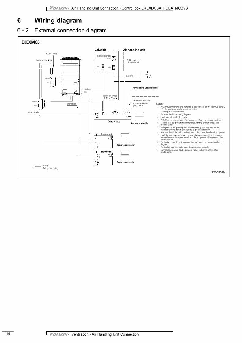
6 - 2 External connection diagram
3TW28089-1
EKEXMCB
Notes:1 All wiring, components and materials to be produced on the site must comply
with the applicable local and national codes.2 Use copper conductors only.3 For more details, see wiring diagram.4 Install a circuit breaker for safety.5 All field wiring and components must be provided by a licensed electrician.6 The unit shall be grounded in compliance with the applicable local and
national codes.7 Wiring shown are general points-of-connection guides only and are not
intended for or to include all details for a specific installation.8 Be sure to install the switch and the fuse to the power line of each equipment.9 Install the main switch that can interrupt all power sources in an integrated
manner because this system consists of the equipment utilizing the multiplepower sources.
10 For detailed control box side connection, see control box manual and wiringdiagram.
11 For detailed pipe connections and limitations, see manuals.12 Connection appliance can be standard indoor unit or free choice of air
handling unit.
Power supply
Indoor unit
Main switch
Switch
Fuse
Switch
FuseTransmission
Filter Filter
Electronic expansionvalve
Valve kit
Expansion valve ConnectorL (Max. 20m)
Control box
Field supplied airhandling unit
Air handling unitPower supply
Air handling unit controller
(Max. 5m)Max.
Indoor unit
Remote controller
Remote controller
Remote controller
WiringRefrigerant piping
Gas pipe
Liquid pipe
Thermistor lines (3x)L (Standard 2.5m)(Max. 20m)
• Ventilation • Air Handling Unit Connection
ÈEEDEN08-205lËÍ
Daikin Europe N.V. is approved by LRQA for itsQuality Management System in accordance with theISO9001 standard. ISO9001 pertains to qualityassurance regarding design, development,manufacturing as well as to services related to theproduct.
Daikin units comply with the European regulations that guarantee the safety of the product.
EED
EN08
-205
• 0
4/20
08 •
Cop
yrig
ht ©
Dai
kin
The
pres
ent
publ
icat
ion
supe
rsed
es E
EDEN
07-2
01Pr
epar
ed in
Bel
gium
by
Lann
oo (
ww
w.la
nnoo
prin
t.be)
, a c
ompa
ny w
hose
con
cern
for
th
e en
viro
nmon
t is
set
in t
he E
MA
S an
d IS
O 1
4001
sys
tem
s.R
espo
nsib
le E
dito
r: D
aiki
n Eu
rope
N.V
., Za
ndvo
orde
stra
at 3
00, B
- 840
0 O
oste
nde
The present publication is drawn up by way of information only anddoes not constitute an offer binding upon Daikin Europe N.V.. DaikinEurope N.V. has compiled the content of this publication to the bestof its knowledge. No express or implied warranty is given for thecompleteness, accuracy, reliability or fitness for particular purpose ofits content and the products and services presented therein.Specifications are subject to change without prior notice. DaikinEurope N.V. explicitly rejects any liability for any direct or indirectdamage, In the broadest sense, arising from or related to the useand/or interpretation of this publication. All content is copyrightedby Daikin Europe N.V..
VRV® products are not within the scope of theEurovent certification programme.
Naamloze VennootschapZandvoordestraat 300B-8400 Oostende, Belgiumwww.daikin.euBTW: BE 0412 120 336RPR Oostende
Daikin’s unique position as a manufacturer of airconditioning equipment, compressors andrefrigerants has led to its close involvement inenvironmental issues. For several years Daikinhas had the intension to become a leader in theprovision of products that have limited impacton the environment. This challenge demandsthe eco design and development of a widerange of products and an energy managementsystem, resulting in energy conservation and areduction of waste. ISO14001 assures an effective environmental
management system in order to help protect humanhealth and the environment from the potentialimpact of our activities, products and services and toassist in maintaining and improving the quality of theenvironment.
Ventilation