technical characteristics for search and rescue radar ...!pdf-e.pdf · technical characteristics...
TRANSCRIPT
Recommendation ITU-R M.628-5(03/2012)
Technical characteristics for searchand rescue radar transponders
M SeriesMobile, radiodetermination, amateur
and related satellite services
ii Rec. ITU-R M.628-5
Foreword
The role of the Radiocommunication Sector is to ensure the rational, equitable, efficient and economical use of the radio-frequency spectrum by all radiocommunication services, including satellite services, and carry out studies without limit of frequency range on the basis of which Recommendations are adopted.
The regulatory and policy functions of the Radiocommunication Sector are performed by World and Regional Radiocommunication Conferences and Radiocommunication Assemblies supported by Study Groups.
Policy on Intellectual Property Right (IPR)
ITU-R policy on IPR is described in the Common Patent Policy for ITU-T/ITU-R/ISO/IEC referenced in Annex 1 of Resolution ITU-R 1. Forms to be used for the submission of patent statements and licensing declarations by patent holders are available from http://www.itu.int/ITU-R/go/patents/en where the Guidelines for Implementation of the Common Patent Policy for ITU-T/ITU-R/ISO/IEC and the ITU-R patent information database can also be found.
Series of ITU-R Recommendations
(Also available online at http://www.itu.int/publ/R-REC/en)
Series Title
BO Satellite delivery
BR Recording for production, archival and play-out; film for television
BS Broadcasting service (sound)
BT Broadcasting service (television)
F Fixed service
M Mobile, radiodetermination, amateur and related satellite services
P Radiowave propagation
RA Radio astronomy
RS Remote sensing systems
S Fixed-satellite service
SA Space applications and meteorology
SF Frequency sharing and coordination between fixed-satellite and fixed service systems
SM Spectrum management
SNG Satellite news gathering
TF Time signals and frequency standards emissions
V Vocabulary and related subjects
Note: This ITU-R Recommendation was approved in English under the procedure detailed in Resolution ITU-R 1.
Electronic Publication Geneva, 2013
ITU 2013
All rights reserved. No part of this publication may be reproduced, by any means whatsoever, without written permission of ITU.
Rec. ITU-R M.628-5 1
RECOMMENDATION ITU-R M.628-51
Technical characteristics for search and rescue radar transponders
(1986-1990-1992-1994-2006-2012)
Scope
This Recommendation contains technical characteristics for search and rescue radar transponders (SART). A SART is used for locating a ship or survival craft at sea when it is in distress.
A ship or survival craft at sea can use a SART to indicate that it is in distress. The SART can be detected by radars operating in the frequency band 9 200-9 500 MHz.
The ITU Radiocommunication Assembly,
considering
a) that there is a need to locate vessels or their survival craft in distress at sea;
b) that part of that need can be fulfilled by the Global Maritime Distress Safety System;
c) that the location of vessels and survival craft in distress at sea is enhanced by the carriage of radar transponders;
d) that a locating system is more effective if the radar transponder was in conformity with internationally agreed technical and operating characteristics;
e) that the International Maritime Organization (IMO) has adopted a Recommendation on performance standards for survival craft radar transponders for use in search and rescue operations,
recognizing
that the International Convention for the Safety of Life at Sea (SOLAS) requires the carriage of one or more radar transponders operating in the 9 200 to 9 500 MHz frequency band,
recommends
1 that the technical characteristics of search and rescue radar transponders (SART) operating in the frequency range 9 200-9 500 MHz should be in accordance with Annex 1;
2 that the maximum detection range of a SART having technical characteristics in accordance with Annex 1 by a radar conforming with the latest relevant IMO Resolution should be assessed using its measured technical characteristics in conjunction with the theoretical method given in Annex 2;
3 Notes 1 and 2 should be considered as part of this Recommendation.
NOTE 1 – The propagation losses of a SART signal caused by a survival craft and its occupants are explained in Annex 3.
NOTE 2 – The technical characteristics of circular polarization SARTs are described in Annex 4.
1 The Director, Radiocommunication Bureau, is requested to bring this Recommendation to the attention of the International Maritime Organization (IMO), the International Civil Aviation Organization (ICAO), the International Electrotechnical Commission (IEC) and the International Association of Lighthouse Authorities (IALA).
2 Rec. ITU-R M.628-5
Annex 1
Technical characteristics for search and rescue radar transponders operating over the band 9 200-9 500 MHz
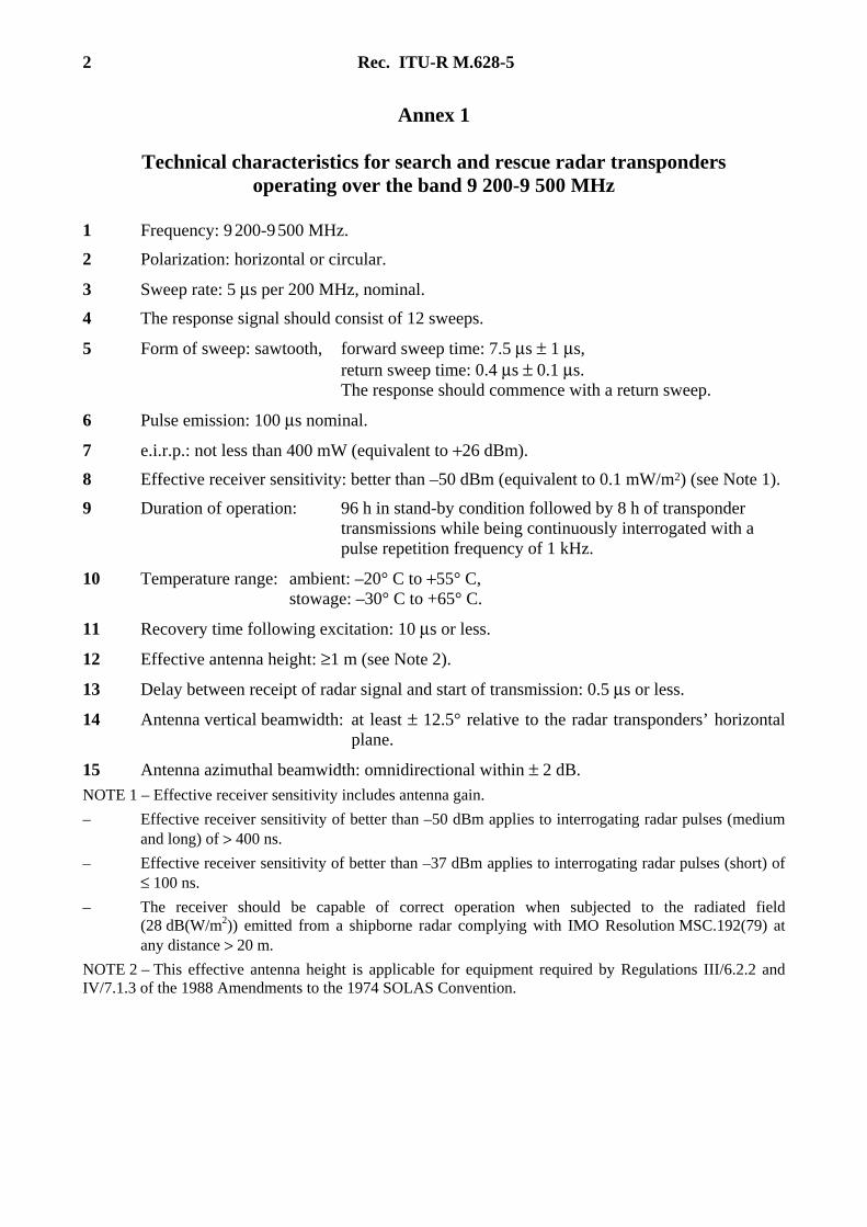
1 Frequency: 9 200-9 500 MHz.
2 Polarization: horizontal or circular.
3 Sweep rate: 5 μs per 200 MHz, nominal.
4 The response signal should consist of 12 sweeps.
5 Form of sweep: sawtooth, forward sweep time: 7.5 μs ± 1 μs, return sweep time: 0.4 μs ± 0.1 μs. The response should commence with a return sweep.
6 Pulse emission: 100 μs nominal.
7 e.i.r.p.: not less than 400 mW (equivalent to +26 dBm).
8 Effective receiver sensitivity: better than –50 dBm (equivalent to 0.1 mW/m2) (see Note 1).
9 Duration of operation: 96 h in stand-by condition followed by 8 h of transponder transmissions while being continuously interrogated with a pulse repetition frequency of 1 kHz.
10 Temperature range: ambient: –20° C to +55° C, stowage: –30° C to +65° C.
11 Recovery time following excitation: 10 μs or less.
12 Effective antenna height: ≥1 m (see Note 2).
13 Delay between receipt of radar signal and start of transmission: 0.5 μs or less.
14 Antenna vertical beamwidth: at least ± 12.5° relative to the radar transponders’ horizontal plane.
15 Antenna azimuthal beamwidth: omnidirectional within ± 2 dB.
NOTE 1 – Effective receiver sensitivity includes antenna gain.
– Effective receiver sensitivity of better than –50 dBm applies to interrogating radar pulses (medium and long) of > 400 ns.
– Effective receiver sensitivity of better than –37 dBm applies to interrogating radar pulses (short) of ≤ 100 ns.
– The receiver should be capable of correct operation when subjected to the radiated field (28 dB(W/m2)) emitted from a shipborne radar complying with IMO Resolution MSC.192(79) at any distance > 20 m.
NOTE 2 – This effective antenna height is applicable for equipment required by Regulations III/6.2.2 and IV/7.1.3 of the 1988 Amendments to the 1974 SOLAS Convention.
Rec. ITU-R M.628-5 3
Annex 2
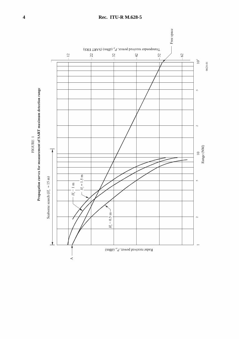
The maximum detection range of a SART of given or measured e.i.r.p. and effective receiver sensitivity when deployed with a radar conforming with IMO Resolution MSC.192(79) may be assessed using Fig. 1.
The essential parameters of the radar are:
– transmitter power 25 kW,
– antenna gain 30 dBi,
– antenna height 15 m,
– receiver sensitivity –94 dBm.
Figure 1 shows the propagation curves for SARTs of height 0.5 m, 1 m and 1.5 m in a fairly calm sea (wave height 0.3 m). For rougher seas, the sea reflection coefficient is reduced and the propagation curves move back towards the free space line depending on atmospheric refraction. For an SART of 1 m height, the maximum detection range is at least 5 NM.
The method of using Fig. 1 is as follows:
– calculate the radar received power (Pr) at range 1 NM using the formula:
Pr = SART e.i.r.p. × radar antenna gain × (λ/4 π R)2
that is Pr (dBm) = SART e.i.r.p. (dBm) –87 dB;
– set the calculated Pr against point A on the radar received power scale and complete the scale (10 dB per division);
– set the SART effective receiver sensitivity (ERS) on the transponder received power scale and read the intercept with the appropriate propagation curve at that level to obtain the radar to SART maximum detection range;
– take the –94 dBm level on the radar received power scale and read the intercept with the appropriate propagation curve at that level to obtain the SART to radar maximum detection range.
The smaller of the two maximum detection ranges so obtained is the required assessment of SART maximum detection range, which should be at least 5 NM as required by IMO Resolution A.802(19).
4 Rec. ITU-R M.628-5
Rec. ITU-R M.628-5 5
Annex 3
Effects of antenna height and obstruction of the signal path by a survival craft and its occupants on the detection range of SARTs
1 Introduction
This Annex discusses the effects on the propagation path of SART signals, taking into account the height of the SART antenna above the surface of the sea and also the attenuation caused by the materials of the survival craft and its occupants.
2 Effects of SART antenna height on detection range
This Recommendation requires that the height of the installed SART antenna should be at least 1 m above the sea surface in order to obtain the five nautical mile detection range required by IMO Resolution A.802(19). Practical tests have confirmed this performance. Tests on a sample of six SARTs from different manufacturers gave detection ranges between 8.2 NM and 9.2 NM with an antenna height of 1 m.
2.1 Tests have also shown the importance of maintaining a SART antenna height of at least 1 m. The following results were obtained with a SART in a survival craft:
– SART lying flat on the floor: range 1.8 NM
– SART standing upright on the floor: range 2.5 NM
– SART floating in the water: range 2.0 NM
3 Effects of survival craft on SART signal
Tests have been made with a SART mounted on a survival craft to give a 1 m antenna height, in order to determine whether the body of the survival craft and its occupants may cause an obstruction.
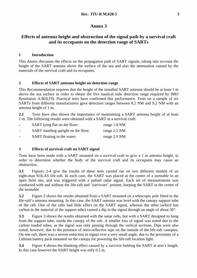
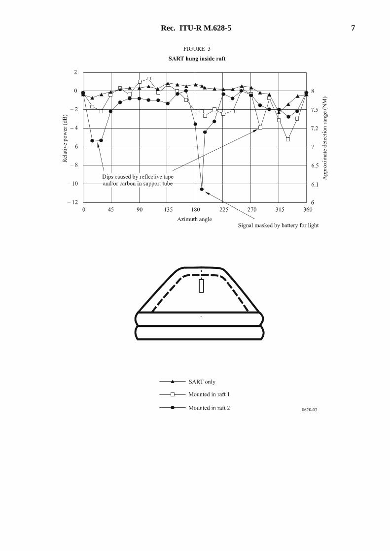
3.1 Figures 2-4 give the results of these tests carried out on two different models of an eight-man SOLAS life-raft. In each case, the SART was placed at the centre of a turntable in an open field site, and was triggered with a pulsed radar signal. Each set of measurements was conducted with and without the life-raft and "survivors" present, keeping the SART at the centre of the turntable.
3.2 Figure 2 shows the results obtained from a SART mounted on a telescopic pole fitted to the life-raft’s antenna mounting. In this case, the SART antenna was level with the canopy support tube of the raft. One of the rafts had little effect on the SART signal, whereas the other (which has carbon in the material of the support tube) caused a dip in the signal through an angle of about 30°.
3.3 Figure 3 shows the results obtained with the same rafts, but with a SART designed to hang from the support tube, inside the canopy of the raft. A smaller loss of signal was noted due to the carbon loaded tubes, as the signal was only passing through the vertical sections. Dips were also noted, however, due to the presence of retro-reflective tape on the outside of the life-raft canopies. On one raft, there was a severe reduction in signal over a very small angle, due to the proximity of a Lithium battery pack mounted on the canopy for powering the life-raft location light.
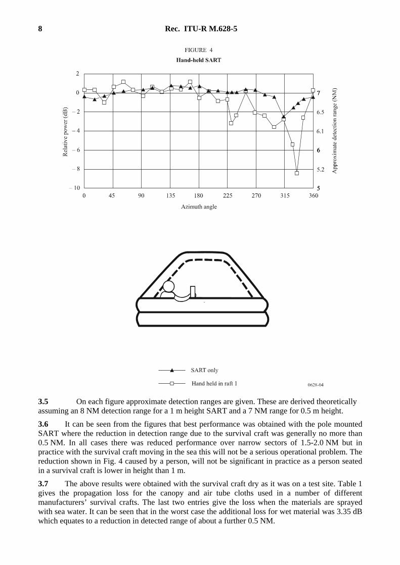
3.4 Figure 4 shows the blanking effect caused by a survivor holding the SART at arm’s length. In this case however the SART height was only 0.5 m.
6 Rec. ITU-R M.628-5
Rec. ITU-R M.628-5 7
8 Rec. ITU-R M.628-5
3.5 On each figure approximate detection ranges are given. These are derived theoretically assuming an 8 NM detection range for a 1 m height SART and a 7 NM range for 0.5 m height.
3.6 It can be seen from the figures that best performance was obtained with the pole mounted SART where the reduction in detection range due to the survival craft was generally no more than 0.5 NM. In all cases there was reduced performance over narrow sectors of 1.5-2.0 NM but in practice with the survival craft moving in the sea this will not be a serious operational problem. The reduction shown in Fig. 4 caused by a person, will not be significant in practice as a person seated in a survival craft is lower in height than 1 m.
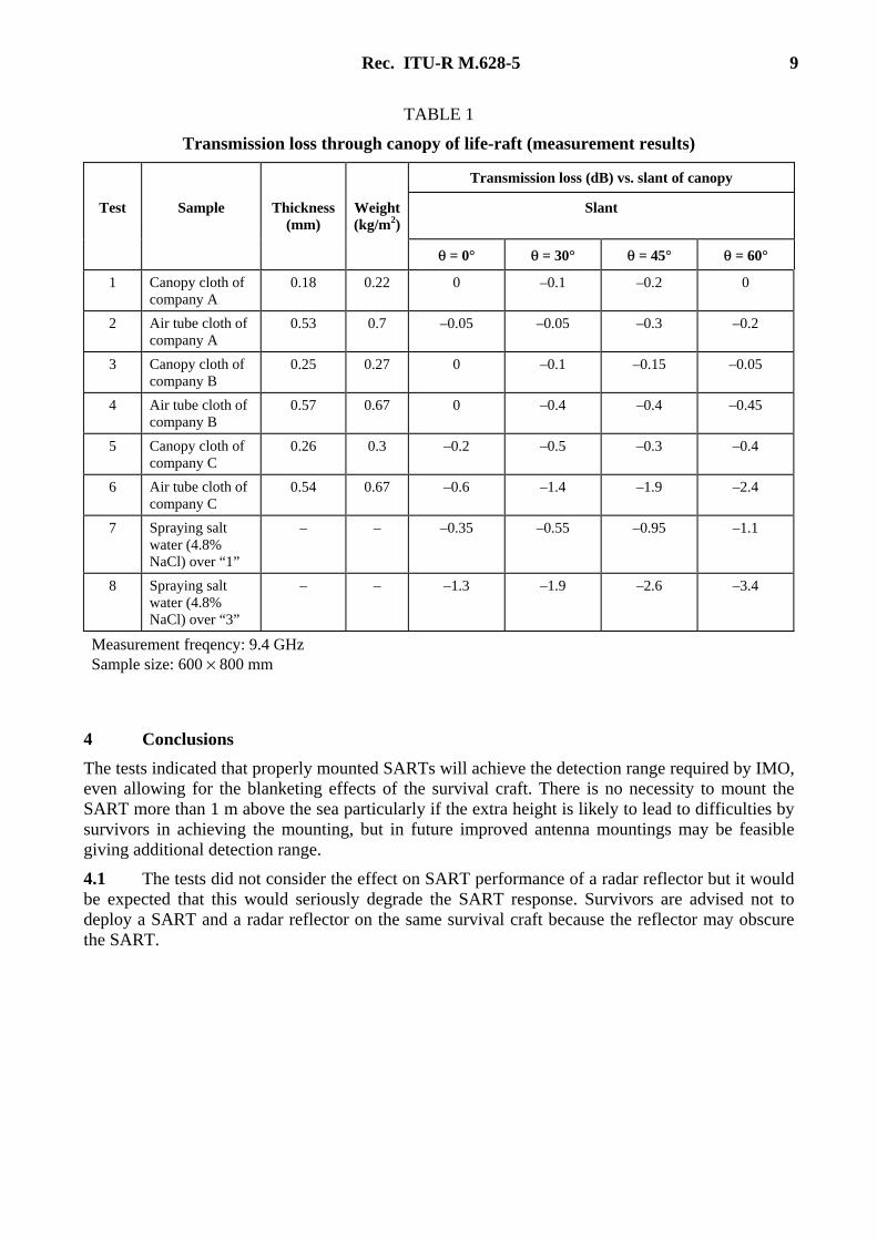
3.7 The above results were obtained with the survival craft dry as it was on a test site. Table 1 gives the propagation loss for the canopy and air tube cloths used in a number of different manufacturers’ survival crafts. The last two entries give the loss when the materials are sprayed with sea water. It can be seen that in the worst case the additional loss for wet material was 3.35 dB which equates to a reduction in detected range of about a further 0.5 NM.
Rec. ITU-R M.628-5 9
TABLE 1
Transmission loss through canopy of life-raft (measurement results)
Transmission loss (dB) vs. slant of canopy
Test Sample Thickness (mm)
Weight(kg/m2)
Slant
θ = 0° θ = 30° θ = 45° θ = 60°
1 Canopy cloth of company A
0.18 0.22 0 –0.1 –0.2 0
2 Air tube cloth of company A
0.53 0.7 –0.05 –0.05 –0.3 –0.2
3 Canopy cloth of company B
0.25 0.27 0 –0.1 –0.15 –0.05
4 Air tube cloth of company B
0.57 0.67 0 –0.4 –0.4 –0.45
5 Canopy cloth of company C
0.26 0.3 –0.2 –0.5 –0.3 –0.4
6 Air tube cloth of company C
0.54 0.67 –0.6 –1.4 –1.9 –2.4
7 Spraying salt water (4.8% NaCl) over “1”
– – –0.35 –0.55 –0.95 –1.1
8 Spraying salt water (4.8% NaCl) over “3”
– – –1.3 –1.9 –2.6 –3.4
Measurement freqency: 9.4 GHz Sample size: 600 × 800 mm
4 Conclusions
The tests indicated that properly mounted SARTs will achieve the detection range required by IMO, even allowing for the blanketing effects of the survival craft. There is no necessity to mount the SART more than 1 m above the sea particularly if the extra height is likely to lead to difficulties by survivors in achieving the mounting, but in future improved antenna mountings may be feasible giving additional detection range.
4.1 The tests did not consider the effect on SART performance of a radar reflector but it would be expected that this would seriously degrade the SART response. Survivors are advised not to deploy a SART and a radar reflector on the same survival craft because the reflector may obscure the SART.

10 Rec. ITU-R M.628-5
Annex 4
Performance of circular polarization SARTs
Foreword Horizontal polarization has been used as the method of polarization for SARTs. Recent examinations in Japan have shown that circular polarization would be suitable for use with SARTs. A SART using circular polarization with a helical antenna was made for trial purposes, and water tank experiments and sea trials were conducted. The results showed the superiority of circular polarization used with SARTs and it was concluded that this will enable a reduction in the size of SARTs.
1 Characteristics of SART signal in the tank tests
Measurements of the received power of the SART signal and observations of visibility of the signal on radar PPI were carried out in an artificial waves water tank at a research laboratory in Japan. The results showed that circular polarization was superior to horizontal polarization for SARTs.
2 Characteristics of SART signal in the on-sea trial
This experiment was conducted in 2000, in cooperation with ships and aircraft of the maritime authorities of Japan in Sagami Bay, by observing the visibility of the SART signal on the radars on board the ships and aircraft. In the meantime, the received power of the SART signal was measured by a land-based radar. The following results were obtained:
a) With aircraft radar, the maximum visible distance of the SART signal of circular polarization was 37 NM, while that of horizontal polarization was 30 NM. This confirms the superiority of circular polarization.
b) With marine radar, the maximum visible distance of the SART signal of circular polarization was 14 NM, while that of horizontal polarization was 11.5 NM. These results confirm the superiority of circular polarization.
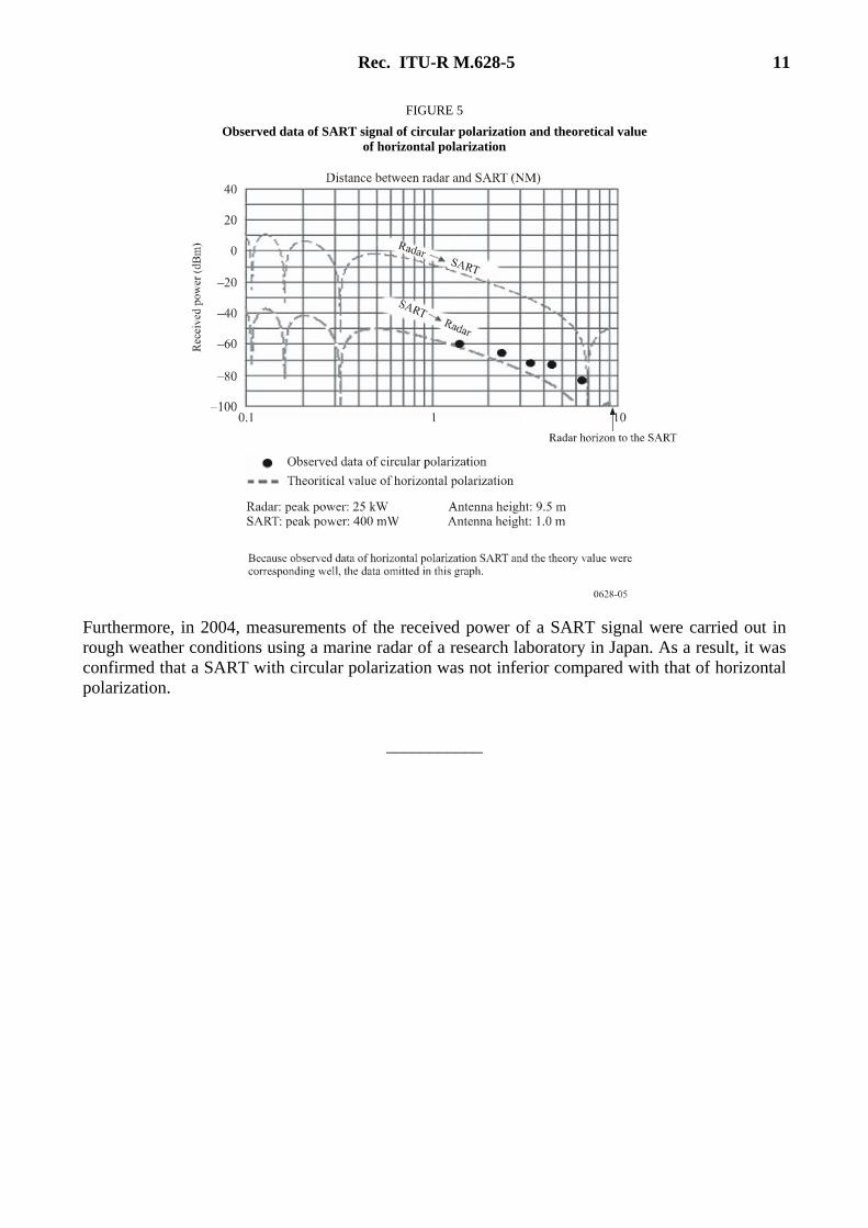
c) With land-based marine radar, the result shown in Fig. 5 was obtained. The SART of circular polarization was moved on the sea by an escorting small vessel. The distance between the radar and the SART was changed. The received power of the SART was measured by the land-based marine radar. In Fig. 5, the black dots show the actually measured SART signal of circular polarization, and dotted lines show the theoretical value of SART signal of horizontal polarization. The measured data always appears above the theoretical value curve for “SART to radar”. The appearance of the SART signal of circular polarization on the radar PPI was stronger and clearer than that of horizontal polarization. These results confirm the superiority of circular polarization. The reason is as follows: Because the electric field revolves, circular polarization is resolved in the horizontal polarization element and the vertical polarization element. For these two composition elements, the reflection characteristic of the surface of the sea is different. Therefore the curve of reception strength when the direct wave and the surface of the sea reflection wave interfere changes with distance. This phenomenon leads to the detectable distance of a circular polarization wave SART increasing over horizontal polarization SART by 30% or more.
Rec. ITU-R M.628-5 11
FIGURE 5
Observed data of SART signal of circular polarization and theoretical value of horizontal polarization
Furthermore, in 2004, measurements of the received power of a SART signal were carried out in rough weather conditions using a marine radar of a research laboratory in Japan. As a result, it was confirmed that a SART with circular polarization was not inferior compared with that of horizontal polarization.
___________