technical catalog formula ul new low voltage molded … · power and productivity for a better...
TRANSCRIPT

Power and productivityfor a better world TM
Technical catalog
FORMULA ULNew low voltage molded case circuit breakers up to 250A


UL FORMULA Molded Case Circuit Breakers - I
Main characteristics 1
Circuit breakers for power distribution 2
Accessories 3
Technical information 4
Wiring diagrams 5
Overall dimensions 6
Index

II - UL FORMULA Molded Case Circuit Breakers
FORMULA. Simplicity and Quality in a Single Product.
FORMULA is the cumulation of ABB SACE’s long history of developing effective circuit breakers. It was developed to be simple, but amazes with its extreme quality and versatility. The highlights of the new line of molded case circuit breakers include:• Quick and easy selection and ordering with few, but essential, versions of circuit breakers• Multiple polarities, dedicated to various applications• Accompanying accessory line• Reduced circuit breaker depths

UL FORMULA Molded Case Circuit Breakers - III
The new FORMULA family consists of two frames, A1 and A2, which reach up to 100A and 250A respectively. Both frames are available in the fixed version, with front terminals.
The protection trip unit has fixed thermal and magnetic threshold values for putting the circuit breaker into service more rapidly. This way selection becomes precise. A reduced number of sales codes simplifies selection and makes ordering easier. Installation is easy and the circuit breaker is ready for use immediately.

IV - UL FORMULA Molded Case Circuit Breakers
FORMULA. The Easy and Precise Choice.
How simple and functional can a range of molded case circuit breakers be? By asking this elementary question, ABB conceived the idea for a new family of circuit breakers. The result is FORMULA, the perfect synthesis between ABB SACE’s recognized quality, reliability and simplicity. Simple, with regard to installation, sizing and fitting of accessories.
Reducing dimensions without compromising on performance and reliability is an ABB SACE trademark that helps with installation and increases the work space inside switchboards and panels. FORMULA’s compact design is a great advantage, especially for OEMs, panel builders and installers.

UL FORMULA Molded Case Circuit Breakers - V
FORMULA. Quality in All Applications.
Quality is great versatility. In addition to the availability of both frames in the three-pole version, for the first time ABB SACE now possesses single-pole and two-pole versions up to 250A, opening the door to the most varied application fields.
Quality is compact overall dimensions. The FORMULA A1 and A2 depth of under 2.5” is the lowest on the market up to 250A.

VI - UL FORMULA Molded Case Circuit Breakers

UL FORMULA Molded Case Circuit Breakers - 1.1
Main characteristics
Content
General information ............................................................................................. 1.2
Regulations and reference Standards ................................................................ 1.3
Identification of the FORMULA circuit breakers ................................................ 1.4

1.2 - UL FORMULA Molded Case Circuit Breakers
Construction characteristics General information
All the molded case circuit breakers in the FORMULA family are constructed in accordance with the follow-ing construction characteristics:
• Double insulation
• Positive operation
• Isolation behavior
• Electromagnetic compatibility
• Topicalization
• Reverse feedable power supply
• Versatility of the installation. It is possible to mount the circuit breaker either in the horizontal, vertical, or lying down position without undergoing any derating of the rated characteristics;
• No nominal performance derating for use up to an altitude of 6562 ft. Above 6562 ft, the properties of the atmosphere (composition of the air, dielectric strength, cooling power and pressure) change, having an impact on the main parameters which define the circuit breaker. The table below gives the changes to the main performance parameters.
• Circuit breaker weights
• FORMULA circuit breakers can be used in ambient with a temperature between -25°C to 70°C (-13°F to 158°F) and stored in a room with atmospheric temperature between -40°C to 70°C (-40°F to 158°F).
• All FORMULA circuit breakers are fitted with a Test pushbutton which allows the release test to be done. This test must be carried out with the circuit breaker closed.
Altitude 6600 ft 8500 ft 13000 ft
A1 A2 A1 A2 A1 A2
Rated service voltage, Ue [V] 240 240 228 228 192 192
Rated uninterrupted current % 100 100 99 99 96 96
Weights A1 [Lbs] A2 [Lbs]
Circuit breaker 1 pole 0.54 0.82
Circuit breaker 2 poles 1.04 1.61
Circuit breaker 3 poles 1.54 2.43
Installation positions
Double insulation
Positive operation
Test pushbutton

UL FORMULA Molded Case Circuit Breakers - 1.3
Conformity with Standards
• Standards – IEC 60947-2 - UL 489 (Underwriters Laboratories Incorporated)• Directives – EC directive: “Low Voltage Directives” (LVD) no. 2006/95/CE (in replacement of 73/23/CEE and sub-
sequent amendments); – EC directive: “Electromagnetic Compatibility Directive” (EMC) no. 89/336 EEC.
Certification of conformity with the product standards is carried out in the ABB SACE test room (accredited by SINAL - certificate No. 062/1997-) in respect of the EN 45011 European Standard, by the Italian certifi-cation body ACAE (Association for Certification of Electrical Apparatus), member of the European LOVAG organization (Low Voltage Agreement Group) and by the Swedish certification body SEMKO belonging to the international IECEE organization.
The FORMULA series has a hologram on the front, obtained using special anti-forgery techniques, as a guarantee of the quality and genuineness of the circuit breaker as an ABB SACE product.
Company Quality SystemThe ABB SACE Quality System conforms with the following Standards:• ISO 9001 International Standard;• EN ISO 9001 (equivalent) European Standards;• UNI EN ISO 9001 (equivalent) Italian Standards.
The ABB SACE Quality System attained its first certification with the RINA certification body in 1990.
Environmental Management System, Social Responsibility and EthicsAttention to protection of the environment is a priority commitment for ABB SACE. Confirmation of this is the realization of an Environmental Management System certified by RINA in conformity with the Inter-national ISO14001 Standard. ABB SACE was the first industry in the electromechanical sector in Italy to obtain this recognition. In 1999, the Environmental Management System was integrated with the Occupa-tional Health and Safety Management System according to the OHSAS 18001 Standard and later, in 2005, with the SA 8000 (Social Accountability 8000) Standard, committing itself to respect of business ethics and working conditions.
The commitment to environmental protection becomes concrete through:• Selection of materials, processes and packaging which optimize the true environmental impact of the
product;• Use of recyclable materials; • Voluntary respect of the RoHS directive
Hologram
Construction characteristics Regulations and reference standards
FORMULA circuit breakers and their accessories are constructed in conformity with:
1.4 - UL FORMULA Molded Case Circuit Breakers
3
4
567
11
1228
13
10
9
1
14
15
Construction characteristics Identification of the FORMULA circuit breakers
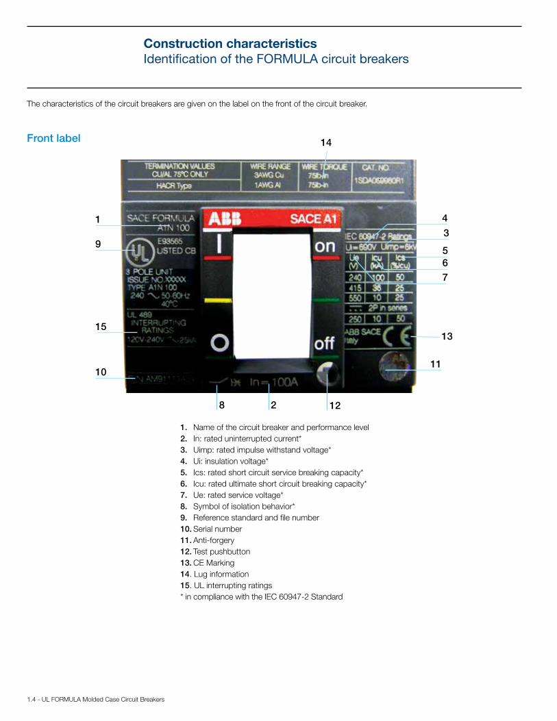
The characteristics of the circuit breakers are given on the label on the front of the circuit breaker.
Front label
1. Name of the circuit breaker and performance level2. In: rated uninterrupted current*3. Uimp: rated impulse withstand voltage*4. Ui: insulation voltage*5. Ics: rated short circuit service breaking capacity*6. Icu: rated ultimate short circuit breaking capacity* 7. Ue: rated service voltage*8. Symbol of isolation behavior*9. Reference standard and file number10. Serial number11. Anti-forgery12. Test pushbutton13. CE Marking14. Lug information15. UL interrupting ratings* in compliance with the IEC 60947-2 Standard

UL FORMULA Molded Case Circuit Breakers - 2.1
Circuit breakers for power distribution
Content
General characteristics ...................................................................................................... 2.2
Thermomagnetic trip units .................................................................................................... 2.3
Technical data ........................................................................................................................ 2.4
Part number scheme ............................................................................................................. 2.5
A1 and A2 Ordering information ...................................................................................2.6 - 2.7
2.2 - UL FORMULA Molded Case Circuit Breakers
FORMULA A1
FORMULA A2
Circuit breakers for power distributionGeneral characteristics
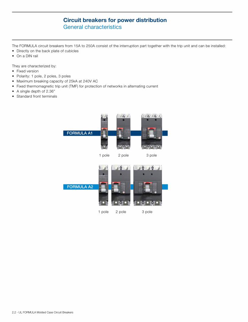
The FORMULA circuit breakers from 15A to 250A consist of the interruption part together with the trip unit and can be installed:• Directly on the back plate of cubicles• On a DIN rail
They are characterized by: • Fixed version• Polarity: 1 pole, 2 poles, 3 poles• Maximum breaking capacity of 25kA at 240V AC• Fixed thermomagnetic trip unit (TMF) for protection of networks in alternating current• A single depth of 2.36”• Standard front terminals
1 pole 2 pole 3 pole
1 pole 2 pole 3 pole

UL FORMULA Molded Case Circuit Breakers - 2.3
The thermomagnetic trip units TMF, with fixed thermal and magnetic threshold, are generally used in power distribution plants. They allow protection against overloads thanks to the thermal device and protection against short circuit thanks to the magnetic device:
• Thermal protection (L): fixed threshold I1= 1x1In, with long inverse time trip curve
• Magnetic protection (I): fixed threshold I3= 10xIn, with instantaneous trip curve
Circuit breakers for power distributionThermomagnetic trip unit
FORMULA A1 with trip unit TMFTMF
I1= 1xIn
In [A] 15 20 25 30 40 50 60 70 80 90 100
Neutral [A] - 100% 15 20 25 30 40 50 60 70 80 90 100
I3= 10xIn
I3 [A] 300 300 300 300 400 500 600 700 800 900 1000
Neutral [A] - 100% 300 300 300 300 400 500 600 700 800 900 1000
FORMULA A2 with trip unit TMFTMF
I1= 1xIn
In [A] 125 150 175 200 225 250
Neutral [A] - 100% 125 150 175 200 225 250
I3= 10xIn
I3 [A] 1250 1500 1750 2000 2250 2500
Neutral [A] - 100% 1250 1500 1750 2000 2250 2500
Magnetic protection symbol
Magnetic protection value
Thermal protection value
Thermal protection symbol
Fixed thermomagnetic trip unit TMFAn example with FORMULA A2 In=125A

2.4 - UL FORMULA Molded Case Circuit Breakers
Circuit breakers for power distributionTechnical data
A1 A2
Frame size A 100 250
Rated current, In A 15...100 125...250
Poles [Nr] Nr 1, 2, 3 1, 2, 3
Rated service voltage, Ue (AC) 50-60 Hz V 240 (1p, 2p, 3p) 240 (1p, 2p, 3p)
(DC) V 125 (1p), 250 (2p,3p) 125 (1p), 250 (2p,3p)
Versions Fixed Fixed
Performance Level A N A N
Poles Nr 1 2, 3 1 2, 3 1 2, 3 1 2, 3
Rated ultimate short circuit breaking capacity, Icu
Interrupting rating @ 240 V 50-60 Hz (AC) kA 10 10 18 25 10 10 14 25
Interrupting rating @ 125 V (DC) 1 pole (in 2012) kA 5 - 10 - 5 - 10 -
Interrupting rating @ 250 V (DC) 2 poles in series (2p, 3p) (in 2012) kA - 5 - 10 - 10 - 25
Reference Standard UL 489 UL 489
Isolation behavior Yes Yes
Fixing onto DIN rail DIN EN 50022 DIN EN 50022
Dimensions (Width x Depth x Height)
1 pole in 1.00 x 2.36 x 5.12 1.38 x 2.36 x 5.91
2 poles in 2.00 x 2.36 x 5.12 2.76 x 2.36 x 5.91
3 poles in 3.00 x 2.36 x 5.12 4.13 x 2.36 x 5.91
Weight
1 pole lbs 0.54 0.82
2 poles lbs 1.04 1.61
3 poles lbs 1.54 2.43
Trip Unit - Thermomagnetic TMF Yes Yes
UL FORMULA Molded Case Circuit Breakers - 2.5
Circuit breakers for power distributionPart number scheme
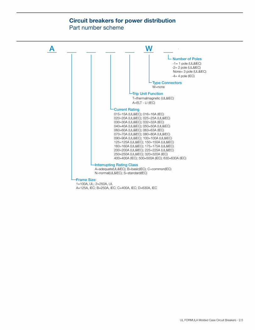
A W Number of Poles -1= 1 pole (UL&IEC) -2= 2 pole (UL&IEC) None= 3 pole (UL&IEC) -4= 4 pole (IEC)
Type Connectors W=none
Trip Unit Function T=thermalmagnetic (UL&IEC) A=ELT - LI (IEC)
Current Rating 015=15A (UL&IEC); 016=16A (IEC) 020=20A (UL&IEC); 025=25A (UL&IEC) 030=30A (UL&IEC); 032=32A (IEC) 040=40A (UL&IEC); 050=50A (UL&IEC) 060=60A (UL&IEC); 063=63A (IEC) 070=70A (UL&IEC); 080=80A (UL&IEC) 090=90A (UL&IEC); 100=100A (UL&IEC) 125=125A (UL&IEC); 150=150A (UL&IEC) 160=160A (UL&IEC); 175=175A (UL&IEC) 200=200A (UL&IEC); 225=225A (UL&IEC) 250=250A (UL&IEC); 320=320A (IEC) 400=400A (IEC); 500=500A (IEC); 630=630A (IEC)
Interrupting Rating Class A=adequate(UL&IEC); B=basic(IEC); C=common(IEC) N=normal(UL&IEC); S=standard(IEC)
Frame Size: 1=100A, UL; 2=250A, UL A=125A, IEC; B=250A, IEC; C=400A, IEC; D=630A, IEC

2.6 - UL FORMULA Molded Case Circuit Breakers
Circuit breakers for power distributionA1 Ordering information
A1 100A - Fixed (F) 1 pole - Front terminals (F) Thermomagnetic trip unit - TMF Icu (240 V)
In I3 A (10kA) N (18kA)15 400 A1A015TW-1 A1N015TW-120 400 A1A020TW-1 A1N020TW-125 400 A1A025TW-1 A1N025TW-130 400 A1A030TW-1 A1N030TW-140 400 A1A040TW-1 A1N040TW-150 500 A1A050TW-1 A1N050TW-160 600 A1A060TW-1 A1N060TW-170 700 A1A070TW-1 A1N070TW-180 800 A1A080TW-1 A1N080TW-190 900 A1A090TW-1 A1N090TW-1
100 1000 A1A100TW-1 A1N100TW-1
A1 100A - Fixed (F) 2 pole - Front terminals (F)Thermomagnetic trip unit - TMF Icu (240 V)
In I3 A (10kA) N (25kA)15 400 A1A015TW-2 A1N015TW-220 400 A1A020TW-2 A1N020TW-225 400 A1A025TW-2 A1N025TW-230 400 A1A030TW-2 A1N030TW-240 400 A1A040TW-2 A1N040TW-250 500 A1A050TW-2 A1N050TW-260 600 A1A060TW-2 A1N060TW-270 700 A1A070TW-2 A1N070TW-280 800 A1A080TW-2 A1N080TW-290 900 A1A090TW-2 A1N090TW-2
100 1000 A1A100TW-2 A1N100TW-2
A1 100A - Fixed (F) 3 pole - Front terminals (F)Thermomagnetic trip unit - TMF Icu (240 V)
In I3 A (10kA) N (25kA)15 300 A1A015TW A1N015TW20 300 A1A020TW A1N020TW25 300 A1A025TW A1N025TW30 300 A1A030TW A1N030TW40 400 A1A040TW A1N040TW50 500 A1A050TW A1N050TW60 600 A1A060TW A1N060TW70 700 A1A070TW A1N070TW80 800 A1A080TW A1N080TW90 900 A1A090TW A1N090TW
100 1000 A1A100TW A1N100TW

UL FORMULA Molded Case Circuit Breakers - 2.7
Circuit breakers for power distributionA2 Ordering information
A2 250A - Fixed (F) 1 pole - Front terminals (F)Thermomagnetic trip unit - TMF Icu (240 V)
In I3 A (10kA) N (14kA)125 1250 A2A125TW-1 A2N125TW-1150 1500 A2A150TW-1 A2N150TW-1175 1750 A2A175TW-1 A2N175TW-1200 2000 A2A200TW-1 A2N200TW-1225 2250 A2A225TW-1 A2N225TW-1250 2500 A2A250TW-1 A2N250TW-1
A2 250A - Fixed (F) 2 pole - Front terminals (F)Thermomagnetic trip unit - TMF Icu (240 V)
In I3 A (10kA) N (25kA)125 1250 A2A125TW-2 A2N125TW-2150 1500 A2A150TW-2 A2N150TW-2175 1750 A2A175TW-2 A2N175TW-2200 2000 A2A200TW-2 A2N200TW-2225 2250 A2A225TW-2 A2N225TW-2250 2500 A2A250TW-2 A2N250TW-2
A2 250A - Fixed (F) 3 pole - Front terminals (F)Thermomagnetic trip unit - TMF Icu (240 V)
In I3 A (10kA) N (25kA)125 1250 A2A125TW A2N125TW150 1500 A2A150TW A2N150TW175 1750 A2A175TW A2N175TW200 2000 A2A200TW A2N200TW225 2250 A2A225TW A2N225TW250 2500 A2A250TW A2N250TW

2.8 - UL FORMULA Molded Case Circuit Breakers
Notes

UL FORMULA Molded Case Circuit Breakers - 3.1
Content
Panorama of accessories ............................................................................................3.2 - 3.3
Mechanical accessories
Connection terminals .......................................................................................................3.4 - 3.5
Ordering codes ................................................................................................................. 3.6
Terminal covers, phase separators and sealable screws .......................................................... 3.7
Ordering codes ................................................................................................................. 3.7
Rotary handle operating mechanism ........................................................................................ 3.8
Ordering codes ................................................................................................................. 3.8
Locks ...................................................................................................................................... 3.9
Ordering codes ............................................................................................................... 3.10
Bracket for fixing onto DIN rail ............................................................................................... 3.11
Ordering codes ............................................................................................................... 3.11
Electrical accessories
Service releases ..................................................................................................................... 3.12
Ordering codes ............................................................................................................... 3.13
Auxiliary contacts for electric signals ...................................................................................... 3.14
Ordering codes ............................................................................................................... 3.15
Accessories

3.2 - UL FORMULA Molded Case Circuit Breakers
AccessoriesPanorama of the accessories
FORMULA A1 - A2 1 pole accessories
FORMULA A1 - A2 2 pole accessories
10
3
1
4
4
12
7
10
3
1
2
4
4
12
8
9
7
1
Caption
EF: extended front terminals 1)
ES: extended spread terminals 1)
FCCuAl: front terminals for copper and aluminium cables
PS: phase separators
HTC: hight terminal cover
LTC: low terminal cover
Sealable screw 1)
AUX-C/AUE-C: auxiliary contact
SOR-C/UVR-C: service releases
DIN: Din rail 1)
PLL: padlocks
RHD: rotary handle direct
RHE: extended rotary handle
Key lock 1)
1) IEC rated only.
2
3
4
5
6
7
8
9
10
12
14
15
16
All FORMULA accessories are sold separately to be field installed.

UL FORMULA Molded Case Circuit Breakers - 3.3
6
5
7
3
2
1
10
9
8
4
4
4
4
7
12
12
12
8
15
14
1616
All FORMULA accessories are sold separately to be field installed.
FORMULA A1 - A2 3 pole accessories
1
Caption
EF: extended front terminals 1)
ES: extended spread terminals 1)
FCCuAl: front terminals for copper and aluminium cables
PS: phase separators
HTC: high terminal cover
LTC: low terminal cover Sealable screw 1)
AUX-C/AUE-C: auxiliary contact
SOR-C/UVR-C: service releases
DIN: Din rail 1)
PLL: padlocks
RHD: rotary handle direct
RHE: extended rotary handle
Key lock 1)
1) IEC only.
2
3
4
5
6
7
8
9
10
12
14
15
16
AccessoriesPanorama of the accessories

3.4 - UL FORMULA Molded Case Circuit Breakers
AccessoriesMechanical accessories
Connection terminalsThe connection terminals allow the circuit breaker to be connected in the most suitable way for the desired application. Various termination options are available in both UL and IEC rated formats. The front terminals allow cables or busbars to be connected directly from the front of the circuit breaker (cable lugs are not included). Different types of terminals can be combined (for example, one type for the line and a different type for the load side).
The standard version of the circuit breaker is supplied with front terminals (F). Alternative terminal options are sold separately.
NA = Not availableW = WidthH = Hole heightD = Depthø = DiameterS = StandardR = On request
Terminal EF Terminal EF with busbar
Terminal F Terminal F with cable lug Terminal F with busbar
Front terminals - F
Busbar dimensions [mm/in]
Cable lug
[mm/in]Tightening torques
Terminal covers [mm/in]
Separators [mm/in]
Type Poles W H D ø W ø Terminal Cable or busbar 2/.07 7.5/.29 50/1.96 60/2.36 50/1.96 80/3.14 100/3.93 200/7.87
A1 1 2 3 15/.59 6/.23 5/.19 6.5/.25 15/.59 6.5/.25 - - M6 4 - - R - S [1] - R -
A2 1 2 3 25/.98 8/.31 6/.23 8.5/.33 24/.94 8.5/.33 - - M8 8 - - - R - S [1] R -
[1] Separators are supplied on line side
Front Extended Terminals - EF (IEC only)
Busbar dimensions [mm/in]
Cable lug
[mm/in]Tightening torques
Terminal covers[mm/in]
Separators [mm/in]
Type Poles W D ø W ø Terminal Cable or busbar 2/.07 7.5/.29 50/1.96 60/2.36 50/1.96 80/3.14 100/3.93 200/7.87
A1 1 2 3 15/.59 5/.19 8.5/.33 15/.59 8.5/.33 M6 3 M8 9 - - R - S - R -
A2 1 2 3 25/.98 6/.23 9/.35 NA NA M8 8 M8 9 - - - R - [1] R -
[1] In EF terminal kit the phase separators are not provided, but for a correct installation it is necessary to use the phase separators already provided with the circuit breakers base.
H
WD
UL FORMULA Molded Case Circuit Breakers - 3.5
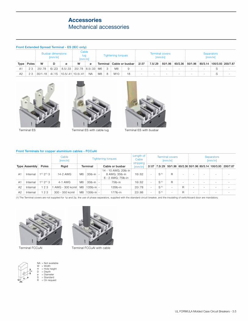
NA = Not availableW = WidthH = Hole heightD = Depthø = DiameterS = StandardR = On request
Terminal ES Terminal ES with cable lug Terminal ES with busbar
Terminal FCCuAl Terminal FCCuAl with cable
Front Extended Spread Terminal - ES (IEC only)
Busbar dimensions [mm/in]
Cable lug
[mm/in]Tightening torques
Terminal covers[mm/in]
Separators[mm/in]
Type Poles W D ø W ø Terminal Cable or busbar 2/.07 7.5/.29 50/1.96 60/2.36 50/1.96 80/3.14 100/3.93 200/7.87
A1 2 3 20/.78 6/.23 8.5/.33 20/.78 8.5/.33 M6 3 M8 9 - - - - - - S -
A2 2 3 30/1.18 4/.15 10.5/.41 10.5/.41 NA M8 8 M10 18 - - - - - - S -
Front Terminals for copper aluminium cables - FCCuAl
Cable [mm/in]
Tightening torquesLength of
Cable stripping [mm/in]
Terminal covers [mm/in]
Separators [mm/in]
Type Assembly Poles Rigid Terminal Cable or busbar 2/.07 7.5/.29 50/1.96 60/2.36 50/1.96 80/3.14 100/3.93 200/7.87
A1 Internal 1(1) 2(1) 3 14-2 AWG M6 35lb-in -14 - 10 AWG; 20lb-in
8 AWG; 35lb-in6 - 2 AWG; 75lb-in
16/.62 - S (1) R - - - - -
A1 Internal 1(1) 2(1) 3 4-1 AWG M6 35lb-in - 75lb-in 16/.62 - S (1) R - - - - -
A2 Internal 1 2 3 1 AWG - 300 kcmil M8 135lb-in - 135lb-in 20/.78 - S (1) - R - - - -
A2 Internal 1 2 3 300 - 350 kcmil M8 135lb-in - 177lb-in 22/.86 - S (1) - R - - - -
(1) The Terminal covers are not supplied for 1p and 2p, the use of phase separators, supplied with the standard circuit breaker, and the insulating of switchboard door are mandatory.
H
WD
AccessoriesMechanical accessories

3.6 - UL FORMULA Molded Case Circuit Breakers
AccessoriesMechanical accessories
Front Terminals
1 piece 2 pieces 3 pieces 4 pieces 6 pieces
KIT F A1 KA1F-1 KA1F-2 KA1F-3 KA1F-4 KA1F-6
KIT F A2 KA2F-1 KA2F-2 KA2F-3 KA2F-4 KA2F-6
Front Extended Terminals (IEC only)
KIT EF A1 KA1EF-1 KA1EF-2 KA1EF-3 KA1EF-4 KA1EF-6
KIT EF A2 KA2EF-1 KA2EF-2 KA2EF-3 KA2EF-4 KA2EF-6
Front Extended Spread Terminals (IEC only)
KIT ES A1 KA1ES-1 KA1ES-2 KA1ES-3 KA1ES-4 KA1ES-6
KIT ES A2 KA2ES-1 KA2ES-2 KA2ES-3 KA2ES-4 KA2ES-6
Front Terminals for copper aluminium cables - FCCuAl
KIT FC CuAl A1 80A KA1080-1 KA1080-2 KA1080-3 KA1080-4 KA1080-6
KIT FC CuAl A1 100A KA1100-1 KA1100-2 KA1100-3 KA1100-4 KA1100-6
KIT FC CuAL A2; 250A Cu cables and 225A Al cables KA2225-1 KA2225-2 KA2225-3 KA2225-4 KA2225-6
KIT FC CuAl A2 250A KA2250-1 KA2250-2 KA2250-3 KA2250-4 KA2250-6

UL FORMULA Molded Case Circuit Breakers - 3.7
Terminal covers, phase separators and sealable screwsThe terminal both high (HTC) and low (LTC) covers are applied to the circuit breaker to avoid ac-cidental contact with live parts and, in this way, to guarantee protection against direct contact. The terminal covers are pre-punched for knock-out on the front to facilitate installation of busbars and/or cables, guaranteeing correct insulation.
The phase separator partitions (PS) allow the insulation characteristics between phases to be increased near the connections. They are mounted on the front by inserting them into the corre-sponding slots and can be applied either prior to or when the circuit breaker is already installed. The phase separators are incompatible with both the high and the low terminal covers.
The lead sealing kit consists of screws which, when applied onto the terminal covers or onto the circuit breaker front, prevent their removal, acting as a protection against direct contacts and tampering. The screws can be locked with a wire and sealed with lead.
The compulsory and optional phase separators and terminal covers needed for correct installa-tion and insulation of the circuit breaker are indicated in the “Connection terminals” section of the Accessories chapter and in the “Overall dimension” chapter, in correspondence with each usable terminal.
High terminal cover (HTC)
Low terminal cover (LTC)
Sealable screw
Phase separators (PS)
Sealable screw onto the circuit breaker front
Sealable screw ontothe terminal covers
AccessoriesMechanical accessories
Terminal Covers
A1 A2
HTC 3p 2pcs KA1HTC-3 KA2HTC-3
LTC 3p 2pcs KA1LTC-3 KA2LTC-3
Sealable screws for terminal covers KA2SSW-T --
Sealable screws for front KA2SSW-F --
Phase Separators
A1 A2
2 pieces 4 pieces 2 pieces 4 pieces
PB 50mm KA1PBL-2 KA1PBL-3 -- --
PB 80mm -- -- KA2PBL-2 KA2PBL-3
PB 100mm KA2PBH-2 KA2PBH-3 KA2PBH-2 KA2PBH-3
Sealable screws for front (IEC only) KA2SSW-F -- -- --

3.8 - UL FORMULA Molded Case Circuit Breakers
AccessoriesMechanical accessories
Rotary handle operating mechanismA rotary handle operating mechanism is a control device that allows the circuit breaker to be comfortably operated by means of a rotary handle.
There are two types of handles: • Direct (RHD): installed directly on the front of the circuit breaker• Extended (RHE): installed through the switchboard door, it interacts with the circuit
breaker that is behind the door by means of a transmission rod
The rotary handles, in the direct and extended version, are available for the three-pole A1 and A2 circuit breakers both in the standard version (grey) and in the emergency version (red on a yellow background).
Information/settings visible and accessible to the user: • Circuit breaker nameplate• Indication of the 3 positions: open (OFF), closed (ON), tripped (TRIP)• Access to the test pushbutton of rotary handle release (only RHD)
The rotary handle operating mechanisms can be ordered: • By using the pre configured “kit” code (RHD and RHE)• By ordering the following three devices (only RHE) – Rotary handle on door of the compartment: standard (RHE_H) or emergency (RHE_H_EM); – Transmission rod of 500mm (RHE_S). The minimum and maximum distances between
the fixing surface and the door are 62.5mm/2.46in and 479.5mm/18.88in – Base for circuit breaker (RHE_B)
It is possible to accessorize the handles with a vast range of key locks and padlocks. Each rotary handle takes up to 3 padlocks (7mm/.28in Ø stem). [See the “Locks” paragraph in the Accessories chapter].
The direct and extended rotary handle allows use of the early auxiliary contacts on closing in order to supply the undervoltage release with power early in relation to closing of the main cir-cuit breaker contacts [see the “Early auxiliary contacts” paragraph in the Accessories chapter].
Direct handle (RHD)
Extended handle (RHE)
Rotary Handle Component
A1-A2
RHD A1-A2 STAND. DIRECT KA2RHD
RHD_EM A1-A2 EMER. DIRECT KA2RHDEM
RHE A1-A2 STAND. RETURNED KA2RHE
RHE_EM A1-A2 EMER. RETURNED KA2RHEEM
RHE_B A1-A2 SIDEB.R.DIST.ADJ.ROT.HAND KA2RHE-B
RHE_S A1-A2 ROD R.D.ADJ.ROT.HAN KA2RHE-S
RHE_H A1-A2 HANDLE R.D.ADJ.ROT.HAN KA2RHE-H
RHE_H A1-A2 HAND.EME.R.D.ADJ.ROT.HAN KA2RHE-HEM

UL FORMULA Molded Case Circuit Breakers - 3.9
LocksLocks are devices (with padlocks or keys) that prevent the circuit breaker from closing or opening. They can be applied: • Directly onto the front of the circuit breaker• Onto the direct/extended rotary handle operating mechanism;• Onto the front for lever operating mechanismsCircuit breaker locks in the open position ensure isolation of the circuit according to the IEC 60947-2 Standard. The locks in closed position do not prevent release of the mechanism following a fault.
Type of lockCircuit breaker
PolarityOptional/Standard Supply
CB lock position
Type of Lock Withdraw-
ability of Key
Circuit breaker
PLL- Fixed padlock A1-A2 3 OptionalOPEN-
CLOSEDpadlocks-max 3 padlocks
Ø stem 7mm/0.28in (not supplied)-
PLL- Fixed padlock A1-A2 3 Optional OPENpadlocks-max 3 padlocks
Ø stem 7mm/0.28in (not supplied)-
PLL- Removable padlock
A1-A2 1,2,3 Optional OPENpadlocks-max 3 padlocks
Ø stem 7mm/0.28in (not supplied)-
Rotary Handle
Direct and Extended
Padlock in open position
A1-A2 3 Standard OPENpadlocks-max 3 padlocks
Ø stem 7mm/0.28in (not supplied)-
Compartment door lock A1-A2 3 Standard CLOSED Door lock(1) -
RHL-S Lock with key in open pos.
A1-A2 3 Optional OPEN Same Ronis keys OPEN
RHL-D Lock with key in open pos.
A1-A2 3 Optional OPEN Different Ronis keys OPEN
RHL-D Lock with key in open and closed position
A1-A2 3 OptionalOPEN-
CLOSEDDifferent Ronis keys
OPEN/CLOSED
(1) Function can be completely excluded by the Customer during assembly of the handle [A1 and A2].
Fixed padlock in open position (PLL)
Removable padlock in open position (PLL)
Fixed padlock in open and closed position (PLL)
AccessoriesMechanical accessories

3.10 - UL FORMULA Molded Case Circuit Breakers
Key lock for extended handle
Key lock for direct handle
Padlocks for lever operating mechanism of the circuit breakerA1-A2
PLL - Padlocks removable in open position KA2LDOR
PLL - Padlocks fixed in open position KA2LDO
PLL - Padlocks fixed in open and closed position KA2LD
Key lock on Handle and front for lever operating mechanism (IEC only)A1-A2
RHL-D Lock in open position, different keys KA2RHLO
RHL-S Lock in open position, same keys type A KA2RHLO-A
RHL-S Lock in open position, same keys type B KA2RHLO-B
RHL-S Lock in open position, same keys type C KA2RHLO-C
RHL-S Lock in open position, same keys type D KA2RHLO-D
RHL-D Lock in open/closed position different keys KA2RHL
Circuit breaker with fixed padlock in open position
Circuit breaker with fixed pad-lock in open and closed position
Fixed padlock in open/closed position
Fixed padlock in open/closed position
Fixed padlock in open position
Removable padlock in open position
AccessoriesMechanical accessories

UL FORMULA Molded Case Circuit Breakers - 3.11
Bracket for fixing on DIN rail (IEC only)The bracket, applied on the back of the circuit breakers, allows installation on a standard DIN EN 50022 rail to simplify mounting in standard switchboards.
The bracket for fixing on DIN rail can be used with all the circuit breakers in the FORMULA family, with the exception of A3:• A1 in 1p, 2p, 3p, version; • A2 in 1p, 2p, 3p, version.
Bracket for fixing on DIN rail (IEC only) A1-A2
Bracket for 1p, 2p, 3p KA2DIN
Bracket for DIN rail
Bracket for DIN rail for 1p circuit breaker
Bracket for DIN rail for 2p circuit breaker
Bracket for DIN rail for 3p circuit breaker
AccessoriesMechanical accessories
3.12 - UL FORMULA Molded Case Circuit Breakers
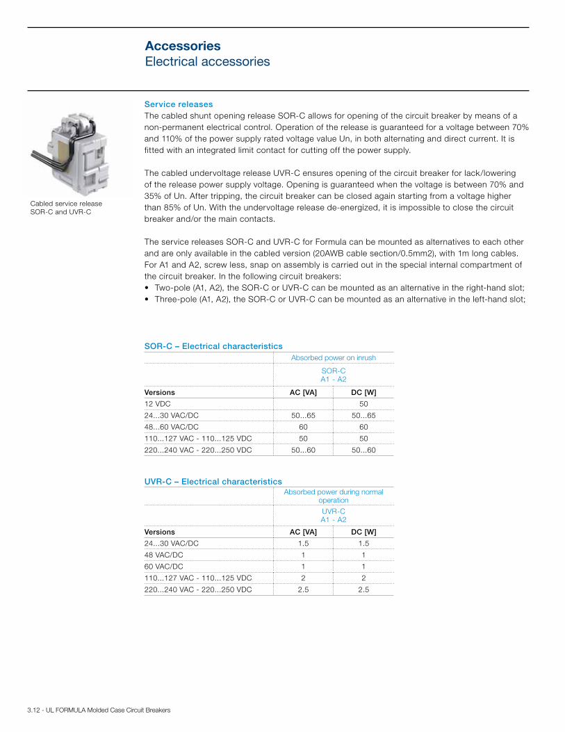
Service releases The cabled shunt opening release SOR-C allows for opening of the circuit breaker by means of a non-permanent electrical control. Operation of the release is guaranteed for a voltage between 70% and 110% of the power supply rated voltage value Un, in both alternating and direct current. It is fitted with an integrated limit contact for cutting off the power supply.
The cabled undervoltage release UVR-C ensures opening of the circuit breaker for lack/lowering of the release power supply voltage. Opening is guaranteed when the voltage is between 70% and 35% of Un. After tripping, the circuit breaker can be closed again starting from a voltage higher than 85% of Un. With the undervoltage release de-energized, it is impossible to close the circuit breaker and/or the main contacts.
The service releases SOR-C and UVR-C for Formula can be mounted as alternatives to each other and are only available in the cabled version (20AWB cable section/0.5mm2), with 1m long cables. For A1 and A2, screw less, snap on assembly is carried out in the special internal compartment of the circuit breaker. In the following circuit breakers: • Two-pole (A1, A2), the SOR-C or UVR-C can be mounted as an alternative in the right-hand slot; • Three-pole (A1, A2), the SOR-C or UVR-C can be mounted as an alternative in the left-hand slot;
Cabled service release SOR-C and UVR-C
SOR-C – Electrical characteristicsAbsorbed power on inrush
SOR-C A1 - A2
Versions AC [VA] DC [W]
12 VDC 50
24...30 VAC/DC 50...65 50...65
48...60 VAC/DC 60 60
110...127 VAC - 110...125 VDC 50 50
220...240 VAC - 220...250 VDC 50...60 50...60
UVR-C – Electrical characteristicsAbsorbed power during normal
operation
UVR-C A1 - A2
Versions AC [VA] DC [W]
24...30 VAC/DC 1.5 1.5
48 VAC/DC 1 1
60 VAC/DC 1 1
110...127 VAC - 110...125 VDC 2 2
220...240 VAC - 220...250 VDC 2.5 2.5
AccessoriesElectrical accessories

UL FORMULA Molded Case Circuit Breakers - 3.13
SOR-C/UVR-C SOR-C/UVR-C
Two-pole circuit breaker Three-pole circuit breaker
AccessoriesElectrical accessories
Shunt Opening Release - SOR-C
A1-A2
SOR-C 12 Vdc KA2S9
SOR-C 24-30 Vac/dc KA2S8
SOR-C 48-60 Vac/dc KA2S7
SOR-C 110-127Vac-110-125Vdc KA2S4
SOR-C 220-240Vac-220-250Vdc KA2S2
Undervoltage Release - UVR-C
A1-A2
UVR-C 12 Vdc KA2U9
UVR-C 24-30 Vac/dc KA2U8
UVR-C 48 Vac/dc KA2U7
UVR-C 60 Vac/dc KA2U5
UVR-C 110-127Vac-110-125Vdc KA2U4
UVR-C 220-240Vac-220-250Vdc KA2U2

3.14 - UL FORMULA Molded Case Circuit Breakers
2Q+1SY (A1,A2)
1Q+1SY (A1,A2)
2Q+1SY (A2)
1Q+1SY (A1)
Auxiliary contacts for the electrical signalsThe auxiliary contacts allow information about the state of the circuit breaker to be available through an electronic signal to another apparatus.
The signals available are as follows:
• Form C (open/closed): signalling the position of the circuit breaker power contacts (Q);
• Bell alarm (release trip): signalling circuit breaker opening due to tripping of the thermomagnetic or electronic trip unit (due to overload or short circuit), of the opening of the shunt opening release or undervoltage release (SOR-C or UVR-C), or by activation of the test pushbutton (SY).
Auxiliary contacts AUX-C Q, AUX-C SYInstallation of the auxiliary contacts for A1 and A2 snap-on in the special slot of the circuit breaker without the of use any screws. All the auxiliary contacts are supplied in the cabled version (20 AWG cable section/0.5mm2), with loose cables 1 m long.
An AUX-C contact is also available as spare part and it can be used as Q or SY according to the slot of the circuit breaker in which it is inserted.
Cabled auxiliary contact
AUX-C – Electrical characteristics
Category of use [IEC 60947-5-1]
Voltage Current[V] [A]
AC-12/AC-13/AC-14 125 6AC-15 125 5
AC-12/AC-13/AC-14 250 6AC-15 250 4DC-12 110 0.5DC-14 110 0.05DC-12 250 0.3DC-14 250 0.03
Two pole circuit breaker Three pole circuit breaker
AccessoriesElectrical accessories

UL FORMULA Molded Case Circuit Breakers - 3.15
Early auxiliary contacts AUE-C (IEC only)
The cabled early auxiliary contacts (AUE-C) are normally open contacts, early in relation to closing, which allow the undervoltage release to be supplied in advance prior to the closing of the main contacts in conformity with the IEC 60204-1, VDE 0113 Standards.
It is possible to insert up to two early auxiliary contacts on closing inside the direct and extended rotary handle operating mechanism for three pole circuit breakers. The contacts, supplied in the cabled version with cables 1 m long (20 AWG cable section/0.5mm2), must be ordered in combination with an undervoltage release.
AUE -C – Electrical characteristics
Voltage [V]Current [A]
AC DC125 DC - 0.5
250 AC/DC 12 0.3
Early auxiliary contact
Early auxiliary contacts – AUE-C (IEC Only)A1-A2
AUE-C KA2RH-EM
AccessoriesElectrical accessories
Auxiliary Contacts - AUX-C
A1 A2
2 poles 3 poles 2 poles 3 poles
Cabled version (numbered cables)
AUX-C 1Q+1SY 250 Vac/dc KA2AS-2 KA2AS KA2AS
AUX-C 2Q+1SY 250 V A2 2p KA2AS2 KA2AS2-2 KA2AS2
AUX-C 1Q+1SY 24 Vdc KA2ASAU-2 KA2ASAU KA2ASAU
AUX-C 2Q+1SY 24 Vdc KA2AS2AU KA2AS2AU-2 KA2AS2AU
Cabled version (spare parts) (IEC only)
AUX-C 250 V 1 CONT. A1-A2 KA2ASSP

3.16 - UL FORMULA Molded Case Circuit Breakers
Notes

UL FORMULA Molded Case Circuit Breakers - 4.1
Technical information
Content
Temperature performance ................................................................................................ 4.2
Technical Information
Dissipated powers ............................................................................................................... 4.3

4.2 - UL FORMULA Molded Case Circuit Breakers
All FORMULA circuit breakers can be used under the following environmental conditions:• -25°C to 70°C (-13°F to 158°F): range of temperature where the circuit breaker is installed• -40°C to 70°C (-40°F to 158°F): range of temperature where the circuit breaker is stored
To determinate tripping time using time/current curves, use I t°C values indicated in the tables below.
Temperature performances
FORMULA A1 circuit breaker with thermomagnetic trip unit TMF In [A] 10°C 20°C 30°C 40°C 50°C 60°C 70°C
5 6.5 6.1 5.8 5.4 5 4.8 4.510 12.9 12.2 11.5 10.8 10 9.6 9.015 19.4 18.4 17.3 16.2 15 14.4 13.520 24.6 23.5 22.4 21.2 20 19.2 18.025 29.2 28.2 27.2 25.9 25 24.0 22.530 36.8 35.3 33.6 31.8 30 28.8 27.040 46.7 45.2 43.5 41.5 40 38.3 36.050 58.3 56.5 54.3 51.9 50 47.9 45.060 70.0 67.8 65.2 62.2 60 57.5 54.070 81.7 79.1 76.1 72.6 70 67.1 63.080 91.0 88.5 85.6 82.1 80 76.7 72.090 102.4 99.6 96.3 92.4 90 86.3 81.0
100 116.7 113.0 108.7 103.7 100 95.9 90.0
FORMULA A2 circuit breaker with thermomagnetic trip unit TMFIn [A] 10°C 20°C 30°C 40°C 50°C 60°C 70°C125 161 153 144 135 125 114 102150 184 176 168 159 150 138 126160 196 188 179 169 160 148 135175 215 206 196 185 175 160 144200 246 235 224 212 200 183 165225 290 276 260 243 225 205 184250 323 306 289 270 250 228 204
NOTE: Temperature ratings and performances above are per IEC standard test results.

UL FORMULA Molded Case Circuit Breakers - 4.3
For each circuit breaker, the table gives the dissipated power values for a single pole circuit breaker. The maximum total dissipated power of a two-pole or three-pole circuit breaker used at 50/60Hz is equal to the dissipated power for the single pole multiplied by the number of poles.
Technical information Dissipated powers
Power [w/pole] TMFIn [A] A1 A2
15 2.5 -
20 3 -
25 3 -
30 4 -
40 4.5 -
50 5.5 -
60 6 -
70 8 -
80 9 -
90 7 -
100 8 -
125 - 7
150 - 8
175 - 10
200 - 12
225 - 14
250 - 16
NOTE: Dissipated powers above are per IEC standard test results.

4.4 - UL FORMULA Molded Case Circuit Breakers
Notes

UL FORMULA Molded Case Circuit Breakers - 5.1
Wiring diagrams
Content
Information for reading and graphic symbols ......................................................................5.2
Wiring diagrams of the circuit breakers ................................................................................5.3
Electrical accessories ................................................................................................... 5.4 - 5.5

5.2 - UL FORMULA Molded Case Circuit Breakers
Information for reading and graphic symbols
Graphic Symbols (IEC 60617 and CEI 3-14…3-26 Standards)
Thermal effect
Electromagnetic effect
Mechanical connection (link)
Operated by pushing
Plug and socket(male and female)
Resistor (general symbol)
Make contact
Break contact
Terminal
Circuit breaker with automatic release
Operating device(general symbol)
Change-over break before make contact
Connection of conductors
State of operation representedThe diagram is shown under the following conditions:•Circuitbreakeropen•Circuitswithoutvoltage•Tripunitnottripped
Incompatibility A1 A2Accessory circuits cannot be supplied with single-pole circuit breakers. The applications indicated in figures 1-2-6, which are sup-plied as an alternative, can be supplied with two-pole circuit breakers. All the applications indicated in the figures can be supplied with three-pole circuit breakers. Figures 1-2-3-4 are provided as an alternative. Figures 5-6 are provided as an alternative. See pages 5.4 and 5.5.
Operated by turning
Current transformerInstantaneous overcurrent or rate-of-rise relay
Overcurrent relay with inverse long time-lag characteristic

UL FORMULA Molded Case Circuit Breakers - 5.3
Wiring diagrams of the circuit breakers
Operating status A1 A2
Single pole circuit breaker with thermomagnetic trip unit
Two pole circuit breaker with thermomagnetic trip unit
Three pole circuit breaker with thermomagnetic trip unit
CaptionQ = Main circuit breaker

5.4 - UL FORMULA Molded Case Circuit Breakers
Electrical accessories
Shunt opening and undervoltage releases A1 A2
Figure: 1) Shunt opening release (SOR-C o YO)2) Undervoltage release (UVR-C o YU)3) Instantaneous undervoltage release with an early contact in series (AUE-C+UVR-C)4) Instantaneous undervoltage release with two early contacts in series (AUE-C+UVR-C)
Notes B) The undervoltage release is supplied for power supply branched on the supply side of the circuit breaker or from an independent source: circuit
breaker closing is only allowed with the release energised (the lock on closing is made mechanically).C) The S4/1 and S4/2 contacts shown in figures 3-4 open the circuit with circuit breaker open and close it when a manual closing command is given
by means of the rotary handle in accordance with the Standards regarding machine tools (closing does not take place if the undervoltage release is not supplied).
F) Additional external undervoltage resistor supplied at 250V DC.
CaptionQ/0 = Circuit breaker auxiliary contactsR = Resistor (see note F)S4/1-2 = Early auxiliary contacts activated by the rotary handle of the circuit breaker (see note C)SO = Pushbutton or contact for opening the circuit breakerV1 = Circuit breaker applicationsV4 = Indicative apparatus and connections for control and signalling, outside the circuit breakerXV = Terminal boards of the applicationsYO = Shunt opening release (SOR-C)YU = Undervoltage release (UVR-C) (see notes B and C)

UL FORMULA Molded Case Circuit Breakers - 5.5
Electrical accessories
Auxiliary contacts A1 A2
Figure: 5) Two changeover contacts for electrical signalling of circuit breaker open/closed and one changeover
contact for signalling circuit breaker in tripped position due to thermomagnetic trip unit or SOR-C or UVR-C intervention (2Q+1SY)
6) One changeover contact for electrical signalling of circuit breaker open/closed and one changeover contact for signalling circuit breaker in tripped position due to thermomagnetic trip unit or SOR-C or UVR-C intervention (1Q+1SY)
CaptionQ/1, 2 = Circuit breaker auxiliary contactsSY = Contact for electrical signalling circuit breaker open due to trip of the thermomagnetic trip
unit YO (SOR-C), YU (UVR-C) (tripped position) V1 = Circuit breaker applicationsV4 = Indicative apparatus and connections for control and signalling, outside the circuit breakerXV = Terminal boards of the applications

5.6 - UL FORMULA Molded Case Circuit Breakers
Notes

UL FORMULA Molded Case Circuit Breakers - 6.1
Content
FORMULA A1
Circuit breaker and terminals .......................................................................................... 6.2 - 6.7
Accessories .............................................................................................................................6.8
FORMULA A2
Circuit breaker and terminals ........................................................................................ 6.9 - 6.14
Accessories ...........................................................................................................................6.15
Distances to be respected ..................................................................................................6.16
Approximate dimensions

6.2 - UL FORMULA Molded Case Circuit Breakers
1.5038.1
0.9825
0.9825
2.56 65
5.12
130
1.2632
2.8071
3.0076.2
2.0050.8
1.4937.9
0.9825
0.92
23.4
5.12
130
2.56 65
2.56 65
5.12
130
1.025.4
2.8773
2.6868
2.3660
0.55 14 0.63 16
1.77 45
1.61 41
3.5490
0.123
.082
2.56 65
5.12
130
1.5038.1
0.9825
0.9825
1.2632
2.8071
3.0076.2
5.12
130
2.56 65
2.0050.8
1.4937.9
0.9825
5.12
130
2.56 65
2.0050.81.025.4
0.9223.4
0.9223.4
3.5490
.307.5
2.8773
2.6868
2.3660
.061.5
1.38 35
0.22 5.5
0.63 16
1.77 45
1.61 41
0.55 14
0.92
23.4
1.5038.1
0.9825
0.9825
2.56 65
5.12
130
1.2632
2.8071
3.0076.2
2.0050.8
1.4937.9
0.9825
0.92
23.4
5.12
130
2.56 65
2.56 65
5.12
130
1.025.4
2.8773
2.6868
2.3660
0.55 14 0.63 16
1.77 45
1.61 41
3.5490
0.123
.082
2.56 65
5.12
130
1.5038.1
0.9825
0.9825
1.2632
2.8071
3.0076.2
5.12
130
2.56 65
2.0050.8
1.4937.9
0.9825
5.12
130
2.56 65
2.0050.81.025.4
0.9223.4
0.9223.4
3.5490
.307.5
2.8773
2.6868
2.3660
.061.5
1.38 35
0.22 5.5
0.63 16
1.77 45
1.61 41
0.55 14
0.92
23.4
Approximate dimensionsA1 - Circuit breaker and terminals
Fixing onto the back plate
Fixing onto DIN 50022 rail
Distance between compartment door and back of switchboard
A [mm/in]
Without flange1, 2, & 3 pole 69/2.72
1, 2, & 3 pole 61/2.40
Caption
1 Fixing bracket
3 pole 2 pole 1 pole
3 pole 2 pole 1 pole
The circuit breaker installed at:- A = 69mm/2.72in has the face around the operating lever extending from
the compartment door;- A = 61mm/2.40in has the face around the operating lever and steel with
construction characteristics extending from the compartment door.

UL FORMULA Molded Case Circuit Breakers - 6.3
0.98250.4912.5
0.18 - M44.5
4.21
107
2.11
53.5
0.4912.5 0.18 - M4
4.5
2.11
53.5
4.21
107
0.9825
0.4912.5
0.59 15
1.69 43
1.0627
0.5313.5
0.66 17
1.85 47
1.3434
0.59 15
1.69 43
0.6717
1.85 47
0.66 17
2.0752.5
1.5439
2.8773
1.4436.5
1.85 47
0.66 17
0.98250.4912.5
0.18 - M44.5
4.21
107
2.11
53.5
0.4912.5 0.18 - M4
4.5
2.11
53.5
4.21
107
0.9825
0.4912.5
0.59 15
1.69 43
1.0627
0.5313.5
0.66 17
1.85 47
1.3434
0.59 15
1.69 43
0.6717
1.85 47
0.66 17
2.0752.5
1.5439
2.8773
1.4436.5
1.85 47
0.66 17
0.98250.4912.5
0.18 - M44.5
4.21
107
2.11
53.5
0.4912.5 0.18 - M4
4.5
2.11
53.5
4.21
107
0.9825
0.4912.5
0.59 15
1.69 43
1.0627
0.5313.5
0.66 17
1.85 47
1.3434
0.59 15
1.69 43
0.6717
1.85 47
0.66 17
2.0752.5
1.5439
2.8773
1.4436.5
1.85 47
0.66 17
0.98250.4912.5
0.18 - M44.5
4.21
107
2.11
53.5
0.4912.5 0.18 - M4
4.5
2.11
53.5
4.21
107
0.9825
0.4912.5
0.59 15
1.69 43
1.0627
0.5313.5
0.66 17
1.85 47
1.3434
0.59 15
1.69 43
0.6717
1.85 47
0.66 17
2.0752.5
1.5439
2.8773
1.4436.5
1.85 47
0.66 17
0.98250.4912.5
0.18 - M44.5
4.21
107
2.11
53.5
0.4912.5 0.18 - M4
4.5
2.11
53.5
4.21
107
0.9825
0.4912.5
0.59 15
1.69 43
1.0627
0.5313.5
0.66 17
1.85 47
1.3434
0.59 15
1.69 43
0.6717
1.85 47
0.66 17
2.0752.5
1.5439
2.8773
1.4436.5
1.85 47
0.66 17
Drilling templates for support sheet
Drilling templates for compartment door
1-3 pole 2 pole
A = 69mm/2.72in1-2 pole
A = 69mm/2.72in3 pole
A = 61mm/2.40in1 pole
A = 61mm/2.40in2 pole
A = 61mm/2.40in3 pole
Approximate dimensionsA1 - Circuit breaker and terminals
0.98250.4912.5
0.18 - M44.5
4.21
107
2.11
53.5
0.4912.5 0.18 - M4
4.5
2.11
53.5
4.21
107
0.9825
0.4912.5
0.59 15
1.69 43
1.0627
0.5313.5
0.66 17
1.85 47
1.3434
0.59 15
1.69 43
0.6717
1.85 47
0.66 17
2.0752.5
1.5439
2.8773
1.4436.5
1.85 47
0.66 17

6.4 - UL FORMULA Molded Case Circuit Breakers
0.5514
1.97 50 2.56
6.5
1.97 50
0.5514
2.566.5
0.5514
2.566.5
1.97 50
0.9825
2.25
57.25
2.05
0.5915
0.5915
0.5915
0.9825
0.9825
0.6115.5
1.97 50
5.12
130
1.97 50
0.338.5
0.9825
0.125
6.04
153.5
1.97 50
0.6115.5
0.9825
0.338.5 1.
97 50
0.6115.5
1.0025.4
0.338.5
0.24
MA
X6
0.24
MA
X6
0.24
MA
X6
0.28
MA
X7
0.28
MA
X7
0.28
MA
X7
0.5514
1.97 50 2.56
6.5
1.97 50
0.5514
2.566.5
0.5514
2.566.5
1.97 50
0.9825
2.25
57.25
2.05
0.5915
0.5915
0.5915
0.9825
0.9825
0.6115.5
1.97 50
5.12
130
1.97 50
0.338.5
0.9825
0.125
6.04
153.5
1.97 50
0.6115.5
0.9825
0.338.5 1.
97 50
0.6115.5
1.0025.4
0.338.5
0.24
MA
X6
0.24
MA
X6
0.24
MA
X6
0.28
MA
X7
0.28
MA
X7
0.28
MA
X7
F Terminals
EF Terminals
Caption
1 50mm insulating barriers between the terminals (compulsory) not supplied with EF terminals kit, but with the circuit breaker in base version
2 Top terminal covers with IP40 degree of protection (on request)
3 Front extended terminals
Caption
1 50mm insulating barriers between the terminals (compulsory) supplied
3 pole 2 pole 1 pole
3 pole 2 pole 1 pole
Approximate dimensionsA1 - Circuit breaker and terminals
UL FORMULA Molded Case Circuit Breakers - 6.5
3.94100
0.7920
0.7920
0.7920
0.338.5
3.79
96.25
4.14
105.25
4.14
105.25
3.79
96.25
0.338.5
3.94
100
3.94
100
1.5740
1.5740
2.1755
1.38350.205
0.7920
0.7920
0.9825
0.205
3.0076.2
2.85
72.5
2.25
57.25
1.3835 0.41
10.5
1.97 50
2.56 65
1.0025.4 2.00
50.8
1.97 50
2.56 65
1.3835
2.17 55
2.17 55
1.38 35
1.38 35
2.25
57.25
0.55 14
0.287
1.4436.5
1.4436.5
0.287
2.25
57.25
2.25
57.25
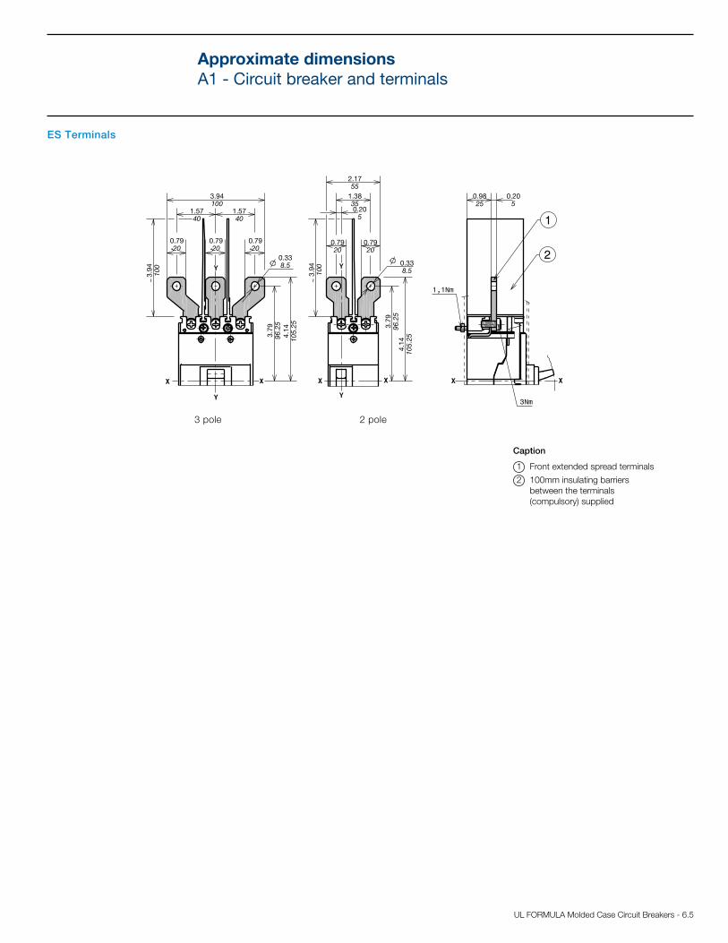
Caption
1 Front extended spread terminals
2 100mm insulating barriers between the terminals (compulsory) supplied
3 pole 2 pole
ES Terminals
Approximate dimensionsA1 - Circuit breaker and terminals

6.6 - UL FORMULA Molded Case Circuit Breakers
3.94100
0.7920
0.7920
0.7920
0.338.5
3.79
96.25
4.14
105.25
4.14
105.25
3.79
96.25
0.338.5
3.94
100
3.94
100
1.5740
1.5740
2.1755
1.38350.205
0.7920
0.7920
0.9825
0.205
3.0076.2
2.85
72.5
2.25
57.25
1.3835 0.41
10.5
1.97 50
2.56 65
1.0025.4 2.00
50.8
1.97 50
2.56 65
1.3835
2.17 55
2.17 55
1.38 35
1.38 35
2.25
57.25
0.55 14
0.287
1.4436.5
1.4436.5
0.287
2.25
57.25
2.25
57.25
FCCuAl 4-1 AWG Terminals
Caption
3 Bottom terminal covers with IP40 degree of protection (compulsory)
4 FCCuAl 4-1 AWG terminals
6 50mm insulating barriers between the terminals (compulsory) not supplied with FCCuAl terminals kit, but with the circuit breaker in base version
7 Compartment door drilling template and fixing insulation (provided by customer)
8 Compulsory internal 1 pole - 2 pole insulation plates (provided by customer)
3 pole 3 pole
1-2 pole 1-2 pole
1-2 pole 1-2 pole
A [mm/in] B [mm/in] C [mm/in]
Without flange
69/2.72 33/1.30 66/2.60 1 POLE
69/2.72 58/2.28 91/3.58 2 POLE
61*/2.40* 33/1.30 66/2.60 1 POLE
61*/2.40* 58/2.28 91/3.58 2 POLE
* Distance only possible with insulation plate max 1mm / 0.04in thick
Approximate dimensionsA1 - Circuit breaker and terminals

UL FORMULA Molded Case Circuit Breakers - 6.7
3.94100
0.7920
0.7920
0.7920
0.338.5
3.79
96.25
4.14
105.25
4.14
105.25
3.79
96.25
0.338.5
3.94
100
3.94
100
1.5740
1.5740
2.1755
1.38350.205
0.7920
0.7920
0.9825
0.205
3.0076.2
2.85
72.5
2.25
57.25
1.3835 0.41
10.5
1.97 50
2.56 65
1.0025.4 2.00
50.8
1.97 50
2.56 65
1.3835
2.17 55
2.17 55
1.38 35
1.38 35
2.25
57.25
0.55 14
0.287
1.4436.5
1.4436.5
0.287
2.25
57.25
2.25
57.25
FCCuAl 14 - 2 AWG Terminals
Caption
3 Bottom terminal covers with IP40 degree of protection (compulsory)
5 FCCuAl 14-2 AWG terminals
6 50mm insulating barriers between the terminals (compulsory) not supplied with FCCuAl terminals kit, but with the circuit breaker in base version
7 Compartment door drilling template and fixing insulation (provided by customer)
8 Compulsory internal 1 pole - 2 pole insulation plates (provided by customer)
3 pole 3 pole
1-2 pole 1-2 pole
1-2 pole 1-2 pole
A [mm/in] B [mm/in] C [mm/in]
Without flange
69/2.72 33/1.30 66/2.60 1 POLE
69/2.72 58/2.28 91/3.58 2 POLE
61*/2.40* 33/1.30 66/2.60 1 POLE
61*/2.40* 58/2.28 91/3.58 2 POLE
* Distance only possible with insulation plate max 1mm/0.039in thick
Approximate dimensionsA1 - Circuit breaker and terminals

6.8 - UL FORMULA Molded Case Circuit Breakers
3.0076.2
1.5038.1
1.84
46.80.
5714.5
5.12
130
1.5038.1
1.84
46.8
5.12
130
0.57
14.5
.082
3.0076.2
5.86149.5
4.09104
2.3660
5.12
130
3.8698
.082
0.123
0.14 3.5
2.8071
0.5714.5
1.4035.5
0.5514
2.34
59.5
0.143.5
1.85 47
3.00 76
7.87200
minimum rotation radius for door fulcrum
.082
0.93
23.5
7.87200
0.8922.5 0.08
2
0.93
23.5
0.57
14.5
0.205
minimum rotation radius for door fulcrum
22.01559
1.50134.2
5.12
130
0.123
1.2030.5
2.3660
.57
14.5
1.8146
2.13 54
0.082
5.87149
0.123
1.8146
5.28134.2
2.3660
1.2030.5
0.082
2.13 54
5.12
130
.57
14.5
heights for door with maximum distance
heights for door with maximum distance
0.205
2.1755
3.0076.2
1.5038.1
1.84
46.80.
5714.5
5.12
130
1.5038.1
1.84
46.8
5.12
130
0.57
14.5
.082
3.0076.2
5.86149.5
4.09104
2.3660
5.12
130
3.8698
.082
0.123
0.14 3.5
2.8071
0.5714.5
1.4035.5
0.5514
2.34
59.5
0.143.5
1.85 47
3.00 76
7.87200
minimum rotation radius for door fulcrum
.082
0.93
23.5
7.87200
0.8922.5 0.08
2
0.93
23.5
0.57
14.5
0.205
minimum rotation radius for door fulcrum
22.01559
1.50134.2
5.12
130
0.123
1.2030.5
2.3660
.57
14.5
1.8146
2.13 54
0.082
5.87149
0.123
1.8146
5.28134.2
2.3660
1.2030.5
0.082
2.13 54
5.12
130
.57
14.5
heights for door with maximum distance
heights for door with maximum distance
0.205
2.1755
Rotary handle operating mechanism on circuit breaker and compartment door drilling template (RHD)
Rotary handle operating mechanism on compartment door and compartment door drilling template (RHE)
Caption
3 Rotary handle operating mechanism on circuit breaker
5 Template for drilling compartment with direct handle
Caption
1 Transmission group
2 Extended rotary handle operating mechanism
4 Template for drilling compartment with extended rotary handle
3 pole
3 pole
3 pole
Approximate dimensionsA1 - Accessories
UL FORMULA Molded Case Circuit Breakers - 6.9
5.91
150
2.0752.5
1.3835
1.3835
2.95 75
4.13105
3.9399.8
1.2632
2.7670
2.0752.5
1.3835
2.95 75
1.2632
5.91
150
5.91
150
2.95 75
1.3835
1.2632
2.8773
2.6868 2.36
60
3.5490
1.77 45
1.61 41
0.57
14.5
0.49
12.5
3.94
100
3.94
100
5.91
150
2.95 75
2.0752.5
1.3835
1.3835
1.2632
4.13105
2.76702.0752.5
1.3835
1.3835
2.7670
5.91
150
2.95 75
5.91
150
2.95 75
1.2632
1.2632
2.8773
2.6868
2.3660
3.5490
0.307.5
1.38 35
0.49
12.5
0.57
14.5
1.61 41 1.77 45
0.31 8
1.26 32
1.26 32
0.061.5
5.91
150
2.0752.5
1.3835
1.3835
2.95 75
4.13105
3.9399.8
1.2632
2.7670
2.0752.5
1.3835
2.95 75
1.2632
5.91
150
5.91
150
2.95 75
1.3835
1.2632
2.8773
2.6868 2.36
60
3.5490
1.77 45
1.61 41
0.57
14.5
0.49
12.5
3.94
100
3.94
100
5.91
150
2.95 75
2.0752.5
1.3835
1.3835
1.2632
4.13105
2.76702.0752.5
1.3835
1.3835
2.7670
5.91
150
2.95 75
5.91
150
2.95 75
1.2632
1.2632
2.8773
2.6868
2.3660
3.5490
0.307.5
1.38 35
0.49
12.5
0.57
14.5
1.61 41 1.77 45
0.31 8
1.26 32
1.26 32
0.061.5
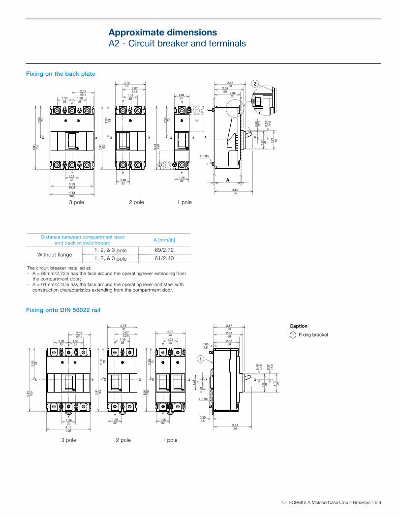
Fixing on the back plate
Fixing onto DIN 50022 rail
Distance between compartment door and back of switchboard
A [mm/in]
Without flange1, 2, & 3 pole 69/2.72
1, 2, & 3 pole 61/2.40
Caption
1 Fixing bracket
3 pole 2 pole 1 pole
3 pole 2 pole 1 pole
The circuit breaker installed at:- A = 69mm/2.72in has the face around the operating lever extending from
the compartment door;- A = 61mm/2.40in has the face around the operating lever and steel with
construction characteristics extending from the compartment door.
Approximate dimensionsA2 - Circuit breaker and terminals

6.10 - UL FORMULA Molded Case Circuit Breakers
0.98250.4912.5
0.18 - M44.5
4.21
107
2.11
53.5
0.4912.5 0.18 - M4
4.5
2.11
53.5
4.21
107
0.9825
0.4912.5
0.59 15
1.69 43
1.0627
0.5313.5
0.66 17
1.85 47
1.3434
0.59 15
1.69 43
0.6717
1.85 47
0.66 17
2.0752.5
1.5439
2.8773
1.4436.5
1.85 47
0.66 17
1.3835
0.6917.5
5.04
128
2.52 64
0.6917.5
0.18 - M44.5
5.04
128
2.52 64
0.18 - M44.5
1.4637
0.7318.5
1.85 47
0.61
15.5
1.3434
0.6717
1.69 43
0.53
13.5
2.8372
2.1153.5
0.61
15.5
1.85 47
4.02102
2.0151
1.85 47
0.61
15.5
1.3835
0.6917.5
5.04
128
2.52 64
0.6917.5
0.18 - M44.5
5.04
128
2.52 64
0.18 - M44.5
1.4637
0.7318.5
1.85 47
0.61
15.5
1.3434
0.6717
1.69 43
0.53
13.5
2.8372
2.1153.5
0.61
15.5
1.85 47
4.02102
2.0151
1.85 47
0.61
15.5
1.3835
0.6917.5
5.04
128
2.52 64
0.6917.5
0.18 - M44.5
5.04
128
2.52 64
0.18 - M44.5
1.4637
0.7318.5
1.85 47
0.61
15.5
1.3434
0.6717
1.69 43
0.53
13.5
2.8372
2.1153.5
0.61
15.5
1.85 47
4.02102
2.0151
1.85 47
0.61
15.5
1.3835
0.6917.5
5.04
128
2.52 64
0.6917.5
0.18 - M44.5
5.04
128
2.52 64
0.18 - M44.5
1.4637
0.7318.5
1.85 47
0.61
15.5
1.3434
0.6717
1.69 43
0.53
13.5
2.8372
2.1153.5
0.61
15.5
1.85 47
4.02102
2.0151
1.85 47
0.61
15.5
1.3835
0.6917.5
5.04
128
2.52 64
0.6917.5
0.18 - M44.5
5.04
128
2.52 64
0.18 - M44.5
1.4637
0.7318.5
1.85 47
0.61
15.5
1.3434
0.6717
1.69 43
0.53
13.5
2.8372
2.1153.5
0.61
15.5
1.85 47
4.02102
2.0151
1.85 47
0.61
15.5
Drilling templates for support sheet
Compartment door drilling templates
A = 69mm/2.72in
1-2-3 poleA = 61mm/2.40in
1 pole
A = 61mm/2.40in
2 pole
A = 61mm/2.40in
3 pole
1-3 pole 2 pole
Approximate dimensionsA2 - Circuit breaker and terminals

UL FORMULA Molded Case Circuit Breakers - 6.11
8
8
8
3.15 80
0.338.5
0.31 8
0.98 MAX25
0.98 MAX25
3.15 80
0.31
MA
X8
0.338.5
0.24 MAX6
0.9825
2.52 64
1.3835
1.3835
0.3593.
15 805.
91150
2.36 60
7.64
194
0.9825
0.24 MAX6
1.3835
1.3835
0.24 MAX6
0.9825
3.82 97
0.79
20
3.15 80
3.15 80
0.359
0.359
0.79
20
0.7920
8
8
8
3.15 80
0.338.5
0.31 8
0.98 MAX25
0.98 MAX25
3.15 80
0.31
MA
X8
0.338.5
0.24 MAX6
0.9825
2.52 64
1.3835
1.3835
0.3593.
15 805.
91150
2.36 60
7.64
194
0.9825
0.24 MAX6
1.3835
1.3835
0.24 MAX6
0.9825
3.82 97
0.79
20
3.15 80
3.15 80
0.359
0.359
0.79
20
0.7920
F Terminals
EF Terminals
Caption
1 80mm insulating barriers between the terminals (compulsory) not supplied with EF terminals kit, but with the circuit breaker in base version
2 Top terminal covers with IP40 degree of protection (on request)
3 Front extended terminals
Caption
1 80mm insulating barriers between the terminals (compulsory) supplied
2-3 pole 1 pole
3 pole
2 pole 1 pole
Approximate dimensionsA2 - Circuit breaker and terminals

6.12 - UL FORMULA Molded Case Circuit Breakers
5.12130
1.9750
1.9750
1.1830
1.1830
1.1830
4.96
126
4.49
114
3.94
100
0.4110.5
2.95751.5740
0.205
1.1830
1.1830
0.4110.5
3.94
100
4.49
114
4.96
126
0.24 MAX6
0.98
25
4.13105
3.25
82.5
1.5639.5
0.7118
3.15 80
2.95 75
1.3835
3.15 80
2.95 75
2.7670
1.5639.5
0.7118
2.52 64
0.82
20.8
2.76 70
2.76 70
1.26 32
1.26 32
2.52 64 0.82
20.8
0.7118
0.7118
1.5038
0.6717
2.52 64 0.71 18
1.5038
0.6717
2.52 64
0.71 18
135lb-in
30lb-in177lb-in
135lb-in
30lb-in177lb-in
177lb-in177lb-in
177lb-in
ES Terminals
Caption
1 Front extended spread terminals
2 100mm insulating barriers between the terminals (compulsory) supplied
3 pole 2 pole
Approximate dimensionsA2 - Circuit breaker and terminals

UL FORMULA Molded Case Circuit Breakers - 6.13
5.12130
1.9750
1.9750
1.1830
1.1830
1.1830
4.96
126
4.49
114
3.94
100
0.4110.5
2.95751.5740
0.205
1.1830
1.1830
0.4110.5
3.94
100
4.49
114
4.96
126
0.24 MAX6
0.98
25
4.13105
3.25
82.5
1.5639.5
0.7118
3.15 80
2.95 75
1.3835
3.15 80
2.95 75
2.7670
1.5639.5
0.7118
2.52 64
0.82
20.8
2.76 70
2.76 70
1.26 32
1.26 32
2.52 64 0.82
20.8
0.7118
0.7118
1.5038
0.6717
2.52 64 0.71 18
1.5038
0.6717
2.52 64
0.71 18
135lb-in
30lb-in177lb-in
135lb-in
30lb-in177lb-in
177lb-in177lb-in
177lb-in
FCCuAl 300kcmil - 350kcmil Terminals
Caption
3 Terminal covers (compulsory)
5 Terminals FCCuAl 300kcmil - 350kcmil
6 80mm insulating barriers between the terminals (compulsory) not supplied with FCCuAl terminals kit, but with the circuit breaker in base version
7 Compartment door drilling template and fixing insulation (provided by customer) 1 pole
8 Compulsory internal insulation plates (provided by customer) max 1mm/0.039in thick
3 pole 3 pole
1 pole 2 pole 1-2 pole
1-2 pole 1-2 pole
Approximate dimensionsA2 - Circuit breaker and terminals
5.12130
1.9750
1.9750
1.1830
1.1830
1.1830
4.96
126
4.49
114
3.94
100
0.4110.5
2.95751.5740
0.205
1.1830
1.1830
0.4110.5
3.94
100
4.49
114
4.96
126
0.24 MAX6
0.98
25
4.13105
3.25
82.5
1.5639.5
0.7118
3.15 80
2.95 75
1.3835
3.15 80
2.95 75
2.7670
1.5639.5
0.7118
2.52 64
0.82
20.8
2.76 70
2.76 70
1.26 32
1.26 32
2.52 64 0.82
20.8
0.7118
0.7118
1.5038
0.6717
2.52 64 0.71 18
1.5038
0.6717
2.52 64
0.71 18
135lb-in
30lb-in177lb-in
135lb-in
30lb-in177lb-in
177lb-in177lb-in
177lb-in
A [mm/in] B [mm/in] C [mm/in]
Without flange
69/2.72 37.5/1.48 75/2.95 1 POLE
69/2.72 – – 2 POLE
61/2.40 37.5/1.48 75/2.95 1 POLE
61/2.40 – – 2 POLE

6.14 - UL FORMULA Molded Case Circuit Breakers
5.12130
1.9750
1.9750
1.1830
1.1830
1.1830
4.96
126
4.49
114
3.94
100
0.4110.5
2.95751.5740
0.205
1.1830
1.1830
0.4110.5
3.94
100
4.49
114
4.96
126
0.24 MAX6
0.98
25
4.13105
3.25
82.5
1.5639.5
0.7118
3.15 80
2.95 75
1.3835
3.15 80
2.95 75
2.7670
1.5639.5
0.7118
2.52 64
0.82
20.8
2.76 70
2.76 70
1.26 32
1.26 32
2.52 64 0.82
20.8
0.7118
0.7118
1.5038
0.6717
2.52 64 0.71 18
1.5038
0.6717
2.52 64
0.71 18
135lb-in
30lb-in177lb-in
135lb-in
30lb-in177lb-in
177lb-in177lb-in
177lb-in
1 pole 2 pole 1-2 pole
5.12130
1.9750
1.9750
1.1830
1.1830
1.1830
4.96
126
4.49
114
3.94
100
0.4110.5
2.95751.5740
0.205
1.1830
1.1830
0.4110.5
3.94
100
4.49
114
4.96
126
0.24 MAX6
0.98
25
4.13105
3.25
82.5
1.5639.5
0.7118
3.15 80
2.95 75
1.3835
3.15 80
2.95 75
2.7670
1.5639.5
0.7118
2.52 64
0.82
20.8
2.76 70
2.76 70
1.26 32
1.26 32
2.52 64 0.82
20.8
0.7118
0.7118
1.5038
0.6717
2.52 64 0.71 18
1.5038
0.6717
2.52 64
0.71 18
135lb-in
30lb-in177lb-in
135lb-in
30lb-in177lb-in
177lb-in177lb-in
177lb-in
FCCuAl 1 AWG - 300kcmil Terminals
Caption
3 Terminal covers (compulsory)
4 Terminals FCCuAl 1 AWG - 300kcmil
6 80mm insulating barriers between the terminals (compulsory) not supplied with FCCuAl terminals kit, but with the circuit breaker in base version
7 Compartment door drilling template and fixing insulation (provided by customer) 1 pole
8 Compulsory internal insulation plates (provided by customer)max 1mm/0.039in thick
3 pole 3 pole
1-2 pole 1-2 pole
A [mm/in] B [mm/in] C [mm/in]
Without flange
69/2.72 42.5/1.67 85/3.35 1 POLE
69/2.72 – – 2 POLE
61/2.40 42.5/1.67 85/3.35 1 POLE
61/2.40 – – 2 POLE
Approximate dimensionsA2 - Circuit breaker and terminals

UL FORMULA Molded Case Circuit Breakers - 6.15
4.13105
2.0752.5
4.13105
0.082 2.07
52.5
5.91
150
1.78
45.30.
51 13
5.89149.5
4.09104
2.3660
5.91
150
3.8698
0.14 3.5
2.8071
1.4035.5
0.5714.5
0.5514
0.143.5
7.87 R. min.200
2.28 58
1.79
45.5
2.99 76
minimum radius for door fulcrum
heights for door with maximum distance
heights for door with maximum distance
2.16
54.80.51 13
0.082
22.76578
5.28134.2
2.3660
5.91
150
0.123
18.84478.5
0.8321
2.13 54
0.082
1.2030.5
minimum rotation radius for door fulcrum
0.51 13
0.8922.5 0.08
2
0.93
23.5
0.93
23.5
0.51 13
0.205
2.1755
0.205
5.91
150
6.301605.28134.2
1.8146
0.082
0.123
1.2030.5
0.83
21
2.13 54
1.8146
7.87 R. min.200
0.89
22.5
2.3660
2.4662.5
4.13105
2.0752.5
4.13105
0.082 2.07
52.5
5.91
150
1.78
45.30.
51 13
5.89149.5
4.09104
2.3660
5.91
150
3.8698
0.14 3.5
2.8071
1.4035.5
0.5714.5
0.5514
0.143.5
7.87 R. min.200
2.28 58
1.79
45.5
2.99 76
minimum radius for door fulcrum
heights for door with maximum distance
heights for door with maximum distance
2.16
54.80.51 13
0.082
22.76578
5.28134.2
2.3660
5.91
150
0.123
18.84478.5
0.8321
2.13 54
0.082
1.2030.5
minimum rotation radius for door fulcrum
0.51 13
0.8922.5 0.08
2
0.93
23.5
0.93
23.5
0.51 13
0.205
2.1755
0.205
5.91
150
6.301605.28134.2
1.8146
0.082
0.123
1.2030.5
0.83
21
2.13 54
1.8146
7.87 R. min.200
0.89
22.5
2.3660
2.4662.5
Rotary handle operating mechanism on compartment door and compartment door drilling template (RHD)
Rotary handle operating mechanism on circuit breaker and compartment door drilling template (RHE)
Caption
1 Transmission group
2 Extended rotary handle operating mechanism
4 Template for drilling compartment with extended rotary handle
Caption
3 Rotary handle operating mechanism on circuit breaker
5 Template for compartment drilling with direct handle
3 pole
heights for door with maximum distance
heights for door with maximum distance
3 pole
Approximate dimensionsA2 - Accessories

6.16 - UL FORMULA Molded Case Circuit Breakers
Insulation distances to be respected for installation in cubicles
A
[mm/in]
B
[mm/in]
C
[mm/in]
A1 - 1p, 2p, 3p 50/1.97 50/1.97 50/1.97
A2 - 1p, 2p, 3p 50/1.97 50/1.97 50/1.97
Minimum center distance between two side by side circuit breakers
Circuit breaker width[mm/in]
Center distance I[mm/in]
1 pole 2 pole 3 pole 1 pole 2 pole 3 pole
A1 25.4/1.00 50.8/2.00 76.2/3.00 25.4/1.00 50.8/2.00 76.2/3.00
A2 36/1.42 70/2.76 105/4.13 36/1.42 70/2.76 105/4.13
Minimum center distance between two stacked circuit breakers
H[mm/in]
A1 80/3.15
A2 400/15.75
Caption
1 Connection not insulated
2 Insulated cable
3 Cable terminal
Approximate dimensionsDistances to be respected

UL FORMULA Molded Case Circuit Breakers - 6.17
Notes

6.18 - UL FORMULA Molded Case Circuit Breakers
Notes

UL FORMULA Molded Case Circuit Breakers - 6.19
Notes

6.20 - UL FORMULA Molded Case Circuit Breakers
Notes


Contact us
ABB Inc.Low Voltage Control Products 16250 W. Glendale DriveNew Berlin, WI 53151Phone: 888-385-1221Fax: 800-726-1441
USA Technical Support & Customer Service: 888-385-1221, Option 4 7:30AM to 5:30PM, CST, Monday - Friday [email protected]
Web: www.abb.us/lowvoltage
1SX
U21
0022
D02
01 S
epte
mb
er 2
011