technical book ver - produktinfo.conrad.com · (esr), excellent noise reduction capability and...
TRANSCRIPT

w w w . e d c . s a n y o . c o m
Aluminum Solid Capacitors with Conductive PolymerAluminum Solid Capacitors with Organic Semiconductive Electrolyte 2007-10
T E C H N I C A L B O O K V e r . 1 5

The contents of this catalog are current as of September 2007. They may change without prior notice. When ordering products, please be sure to request a delivery specifications form and read it carefully.
Do not use the OS-CON for life-threatening applications (space equipment, aerial equipment, nuclear equipment, life-threatening medical equipment, vehicle control equipment, etc.).However, SVP, SVQP, SVPD, SEP and SEQP are adaptable with our special levels, be sure to consult with us and exchange delivery specification before use.The performance, characteristics, and features of the products described in this catalog are based on the
products working alone under prescribed conditions. Data listed here is not intended as a guarantee of performance when working as part of any other product or device. In order to detect problems and situations that cannot be predicted beforehand by evaluation of supplied data, please always perform necessary performance evaluations with these devices as part of the product that they will be used in.
When using the products listed in this catalog, please always be sure to try to prevent any possible accidents or injury by designing products in a careful and safe manner. If you have any questions concerning the use of these products, please contact any of our sales representatives.
For any products listed in this catalog that may constitute restricted trade goods under overseas exchange or service trade laws, permission to deliver according to law may be required before importing.
Unauthorized duplication of this catalog in part or in whole is forbidden.
Please understand that we cannot be held responsible for any damages to the industrial properties of any third party that arise from the use or application of the products listed in this catalog, with the exception of those items directly related to method of construction.
①Since the following models of the SC, SA, SL, SH, SVP and SVQP series have been integrated into models with
a higher voltage rating, please consider these higher voltage rating models for new adoption or model changes.
②Production of the SG and SV series has been discontinued. Therefore, customers using these series at present
are kindly requested to substitute the SP series for the SG series, and the SVP series for the SV series.
③Production of the SM, SN and SPA series is scheduled to be discontinued upon receiving customers’ approval. Please use
the SVP series for the SM and SN series, and the SP series instead of the SPA series for new board design.
Information and wish
Aluminum solid capacitors with Conductive polymerAluminum solid capacitors with Organic semiconductive electrolyte
About this catalog
Size CodeSeries Applicable model Alternative modelA5
B6
C6
E7
F8
E7
6SVP15M4SVP22M10SVP22M6SVP33M6SVP56M4SVP82M10SVP82M6SVP120M6SVP150M4SVP150M4SVP220M4SVP470M6SVQP150M4SVQP220M
10SVP15M6SVP22M16SVP22M10SVP33M10SVP56M6SVP82M16SVP82M10SVP120M10SVP150MX10SVP150MX6SVP220MX6SVP470MX10SVQP150M6SVQP220M
SVP
SVQP
Size CodeSeries Applicable model Alternative modelA
B
C
D
C
E
B'
C'
A
C
16SC1M16SC1R5M6SC10M16SC10M6SC22M6SC47M10SA33M10SA100M6SL10M6SL22M6SL33M6SL47M16SH1M16SH1R5M16SH10M
25SC1M25SC1R5M10SC10M25SC10M10SC22M10SC47M16SA33M16SA100M10SL10M10SL22M10SL33M10SL47M25SH1M25SH1R5M25SH10M
SC
SA
SL
SH

INDEXSerise ListSummarySeries System Diagram 1.System Diagram
2.Sketch of Case Size
3.Size・ESR Matrix List(SMD type・Radial lead type)
Guidelines and Precautions for Use Precautions for circuit designing
Crucial precautions [Important]
1.Prohibited circuits 2.Polarity 3.Over rated voltage
4.Operating temperature and ripple current 5.Applied voltage on design
6.Sudden charge and discharge 7.Failure and life-span
Other precautions
1.Leakage current 2.Capacitor insulation 3.Operating environmental restrictions
4.PCB design 5.Parallel connection 6.Others
Precautions for mounting on-board
1.Considerations when soldering 2.Things to be noted before mounting
3.Mounting-1 4.Mounting-2
5.Soldering with a soldering iron
6.Flow soldering 7.Reflow soldering
8.Handling after soldering
9.Cleaning PCB 10.Fixatives and coatings materials
Precautions for storage and disposal
1.Storage conditions
2.Disposal
Measures to Protect the EnvironmentSpecifications for each seriesPacking Specifications Specifications for radial lead type
1.Part number system
2.Lead terminal process
3.Minimum Packing Quantity
Specifications for SMD type
1.Part number system
2.Taping
3.Minimum Packing Quantity
Construction 1.Basic structure of OS-CON
2.Differences of electrolyte and in characteristics between OS-CON and an electrolytic capacitor
3.OS-CON Manufacturing Method
Characteristics 1.OS-CON Electrical Characteristics
Reliability 1.Organic semiconductor (TCNQ complex salt) type (16SH33M)
2.Conductive polymer type (16SVP39M)
3.Temperature Acceleration Test (Endurance)
4.Reliability Presumption of life
5.Factors of Short Circuit Mode
Precautions when using OS-CON in circuits 1.Explanation of the excessive surge current suppression methods
2.Example of surge current suppression methods
3.Sudden discharge current suppression
4.Precautions when connecting an OS-CON and an aluminum electrolytic capacitor in parallel
Application 1.Voltage reduction capability of OS-CON
2.OS-CON high speed back-up performance(Back-up capacitor for dynamic load)
3.Application to low-pass filter circuits
4.Application of switching power supply for smoothing capacitor
5.Influence of output ripples from switching power supply on actual images
Capacitors Selection Sheet
23456-9
101011
1212
131313141415
161617
18-53
5454-5555
5656-5757
585859
60-63
646566
66-6767
68697071
72-7879-8081-8283-878889
・The data listed here is only representative of OS-CON, and does NOT show any guaranteed value.
・Change in product specifications, dimensions, etc. may occur without prior notice. Be sure that when placing order, please ask for specifications of each series in delivery, and read them well before use.
Aluminum solid capacitors with Conductive polymerAluminum solid capacitors with Organic semiconductive electrolyte
5.Sudden charge and discharge 6.Failure and life-span

2
Serise L
ist
Aluminum solid capacitors with Conductive polymerAluminum solid capacitors with Organic semiconductive electrolyteSerise List
UPGRADE
N E W
UPGRADE
SVPE
SVPS
SVPD
SVPC
SVPB
SVPA
SVQP
SVP
SEPC
SEQP
SEP
SF
SP
SC
SA
SL
SH
SS
Guaranteed at 125,rated 35V max.
Long life
Super low ESR,large capacitance
Large capacitance,super low ESR
Low profile
Low ESR,large ripple current
Guaranteed at125
Standard
Super low ESR,large capacitance,miniaturization and low profile
Guaranteed at 125,high voltage
Guaranteed for3,000h
5mm height max.
Large capacitance &low ESR for audio
Standard
Large capacitance,miniaturization
Low profile
Long life
Miniaturization
Purple
Purple
Purple
Purple
Purple
Purple
Purple
Purple
Purple
Purple
Purple
White
White
White
White
White
White
White
18
19〜
20
21〜
22
23〜
24
25〜
26
27〜
28
29〜
30
31〜
32
33〜
34
35〜
36
37〜
38
39〜
40
41〜
42
43〜
44
45〜
46
47〜
48
49〜
50
51〜
52
53〜
-
-
-
-
-
-
-
-
-
-
-
Purple
Purple
Purple
Purple
Purple
Purple
Purple
10~
8.2~
39~
15~
10~
22~
3.3~
180~
6.8~
6.8~
150~
6.8~
1.0~
15~
1.0~
1.0~
2.2~
680
82
2700
120
820
220
1500
2700
1200
1500
220
2200
47
2200
220
330
470
4~
10~
2.5~
2.5~
2.5~
4~
2.5~
2.5~
4~
2.5~
4~
2~
6.3~
6.3~
4~
6.3~
4~
25
35
16
20
20
20
25
16
32
25
6.3
25
30
20
25
25
20
2.5 390-55~+105
-55~+105
-55~+125
-55~+105
-55~+105
-55~+105
-55~+125
-55~+105
-55~+105
-55~+125
-55~+105
-55~+105
-55~+105
-55~+105
-55~+105
-55~+105
-55~+105
-55~+105
Conductive polymer electrolyte
SMD type
Radial
lead type
Organic semiconductor electrolyte
Radial lead type
Classification
Large capacitance
Low ESR
High voltage
Long lifeFeaturesSeries
Category
Temperature
Range()
Rated Voltage
Range(V.DC)
Capacitance
Range(μF)
External
Appearance
Marking
Color
Page

Low ESR obtained by using conductive polymer electrolyte・Suitable as a decoupling capacitor, because its impedance has ideal frequency characteristics.・Suitable as a smoothing capacitor, enabling miniaturizing switching power supplies, because it allows large ripple current.・Suitable as a backup capacitor for the circuits that consume large current at a high speed.Pb-free CompliantAll the models are completely Pb-free and RoHS compliant products.Long life50000h life at 85 can be expected (SVQP, SVPD, SEQP, SH series), suitable for long-operating industrial equipments.
Superior temperature characteristicsIts ESR has stable characteristics at a temperature from -55 to 105 (partly 125), suitable for applications used at low temperatures (under 0).Wide capacitance range from 1μF to 2700μFAn array of various series covers wide capacitance range.High voltage, high reliabilityHigh reliability products have achieved the highest rated voltage 35V and the guarantee of 85x85%RH (SVPD series), suitable for automotive and industrial equipments.
As a smoothing, backup, and bypass capacitor used in various fields such as digital equipments, household appliances, computer-related hardware, and industrial equipments.
OS-CON is an aluminum solid capacitor with
high conductive polymer or organic
semiconductor electrolyte material. OS-CON
acquires low Equivalent Series Resistance
(ESR), excellent noise reduction capability
and frequency characteristics. In addition,
OS-CON has a long life span and its ESR has
little change even at low temperatures since
the electrolyte is solid.
Features
Applications
3
Su
mm
ary
Aluminum solid capacitors with Conductive polymerAluminum solid capacitors with Organic semiconductive electrolyteSummary

4
SMD typeAluminum solid capacitors with Conductive polymer
Radial lead typeAluminum solid capacitors with Conductive polymer
Radial lead typeAluminum solid capacitors with Organic semiconductive electrolyte
1.System Diagram
P28~29
SVPALow ESR and large ripple current
P26~27
SVPBLow profile
P24~25
SVPCLarge capacitance and Super low ESR
P32~33
SVPStandard
P20~21
SVPSLong life
P30~31
SVQPGuaranteed at 125
P18~19
SVPESuper low ESR and Large capacitance
P38~39
SEPGuaranteed for 3,000h
P36~37
SEQPGuaranteed at 125 and High voltage resistant
P34~35
SEPCSuper low ESR and Large capacitance
P22~23
SVPDGuaranteed at 125 and High voltage resistant
P46~47
SALarge capacitance and miniaturization
P50~51
SHLong life
P44~45
SCStandard
P48~49
SLLow profile
P40~41
SF5mm height (max.)
P42~43
SPLarge capacitance and low ESR
P52~53
SSMiniaturization
Series S
ystemD
iagram
Aluminum solid capacitors with Conductive polymerAluminum solid capacitors with Organic semiconductive electrolyteSeries System Diagram
UP GRADE
NEW
UP GRADE

※Profile of case size are all expressed in maximum values.
2. Sketch of Case Size (unit : mm)
SMD type with conductive polymer electrolyte
Radial lead type with conductive polymer electrolyte
Radial lead type with Organic semiconductive electrolyte
(Size code)
(Size code)
φ4.0
5.5
4.3
4.3
φ5.0
6.0
5.3
5.3
φ8.0
7.0
8.3
8.3
φ8.0
12.0
8.3
8.3
φ10.0
8.0
10.3
10.3
φ10.0
12.7
10.3
10.3
φ6.3
6.0
6.6
6.6
φ6.3
5.5
6.6
6.6
φ6.3
5.0
6.6
6.6
A5 B6 C6 E7 F8C5 C55 E12 F12
(Size code)C6 E7 F8 C9 E12 E13
6.0
φ6.3
7.0
φ8.0
8.0
φ10.0
12.0
φ8.0
13.0
φ8.0
F13
13.0
φ10.0
E9
9.0
9.0
φ8.0φ6.3
7.8
φ4.0
7.8
φ5.0
7.8
φ6.3
10.8
φ6.3
11.5
φ8.0
11.5
φ10.0
21.0
φ10.0
26.0
φ16.0
23.0
φ12.5
A B C D E F
F0 HG (Size code)
6.0
φ4.0
6.0
φ5.0
6.0
φ6.3
6.0
φ8.0
6.0
φ10.0
A' B' C' E'
5.0
φ8.0
E1F'
5
Series S
ystemD
iagram
Aluminum solid capacitors with Conductive polymerAluminum solid capacitors with Organic semiconductive electrolyteSeries System Diagram

…Conductive polymer type
3. Size・ESR Matrix List SMD Type
SVP
Example
A5 (240)
SizeSeries name ESR value(unit:mΩ)
How to read the lists in P6-9・The name, sizes and ESR values of each series are found where the voltage (V) and
capacitance (µ F) intersect each other. (Refer to the example.)・Please confirm the details in the list of each series from P18 to P53.・When you find two or more series names in one section, they have different part
numbers. Please confirm the number in the Series Characteristics List of each series.
3.3
4.7
6.8
8.2
10
15
18
22
27
33
39
47
56
68
82
100
120
150
180
220
270
330
390
470
560
680
820
1200
1500
2700
VμF
SVPA
SVPB
SVPC
SVPC
SVPC
SVPA
SVP
SVPA
SVPE
SVPC
SVPC
SVPC
SVPC
SVP
SVPC
SVPA
SVPC
SVP
SVPC
B6(30)
C5(40)
B6(30)
B6(24)
B6(19)
C6(20)
C6(23)
E7(20)
C6(10)
C6(25)
C6(15)
C6(16)
E7(20)
E12(13)
E12(9)
F8(19)
E12(10)
F12(12)
F12(12)
SVPS
SVP
SVPS
SVPA
SVPB
SVPS
SVPC
SVPC
SVPC
SVPS
SVPC
SVPC
SVPC
SVPC
SVPS
SVPA
SVPC
SVPC
A5(200)
B6(70)
B6(30)
B6(30)
C5(40)
C6(22)
B6(30)
B6(23)
B6(20)
E7(22)
C6(27)
C6(21)
E7(22)
E12(9)
F8(20)
F8(20)
E12(12)
E12(12)
SVP
SVP
SVPA
SVQP
SVP
SVPA
SVPC
SVP
SVP
SVP
SVP
A5(200)
B6(60)
C6(22)
C6(40)
C6(40)
E7(22)
C6(15)
E7(35)
E12(13)
F8(25)
F12(12)
SVPS
SVP
SVPS
SVPA
SVPB
SVQP
SVP
SVPC
SVPC
SVPS
SVPC
SVPS
SVPC
SVPC
SVPA
SVPC
SVP
SVPC
SVPS
SVPA
SVPC
SVP
A5(200)
A5(200)
B6(30)
B6(30)
C5(40)
C6(45)
C6(45)
B6(30)
B6(25)
C6(22)
B6(21)
E7(22)
C6(27)
C6(15)
E7(22)
C6(17)
F8(25)
E7(22)
F8(20)
F8(20)
E12(12)
F12(12)
SVP
SVQP
SVP
SVPA
SVP
SVQP
SVP
SVP
SVP
SVP
B6(70)
C6(40)
C6(40)
C6(22)
C6(17)
E7(35)
E7(35)
F8(25)
F8(25)
E12(15)
SVP
SVP
SVPS
SVP
SVPS
SVPS
SVP
SVPD
SVPB
SVPS
SVPC
SVPC
SVPC
SVPS
SVPS
SVPA
SVQP
SVPC
SVPS
SVPA
SVP
A5(240)
A5(240)
A5(220)
A5(220)
A5(200)
B6(70)
C6(50)
C6(45)
C5(40)
C6(30)
B6(30)
C6(27)
C6(22)
E7(30)
F8(30)
E7(30)
E7(35)
E7(22)
F8(24)
F8(24)
F12(13)
SVP
SVP
SVQP
SVP
SVPC
SVPA
SVQP
SVP
SVP
SVP
SVP
SVP
SVP
A5(200)
B6(70)
C6(45)
C6(45)
B6(23)
C6(30)
E7(35)
E7(35)
E7(35)
F8(30)
F8(25)
F8(25)
E12(17)
2.5 4 6.3 10
6
Series S
ystemD
iagram
Aluminum solid capacitors with Conductive polymerAluminum solid capacitors with Organic semiconductive electrolyteSeries System Diagram

3. Size・ESR Matrix List SMD Type
…Conductive polymer type
Standard sizes (Conductive polymer type) (unit : mm)
A5B6C5C55C6
φ4.0×L5.5φ5.0×L6.0φ6.3×L5.0φ6.3×L5.5φ6.3×L6.0
E7F8E12F12
φ8.0×L7.0φ10.0×L8.0φ8.0×L12.0φ10.0×L12.7
3.3
4.7
6.8
8.2
10
15
18
22
27
33
39
47
56
68
82
100
120
150
180
220
270
330
390
470
560
680
820
1200
1500
2700
VμF
SVP
SVP
SVPS
SVP
SVPB
SVPS
SVPC
SVPC
SVPA
SVP
SVPC
SVPC
SVPS
SVPD
SVPA
SVPS
SVPC
SVPC
SVPC
SVP
SVPS
SVPA
SVP
SVPC
SVP
A5(260)
B6(120)
B6(90)
B6(90)
C5(40)
C6(24)
B6(35)
B6(27)
C6(35)
E7(45)
C6(30)
C6(25)
E7(30)
E7(40)
E7(30)
F8(35)
C6(24)
E7(27)
E7(22)
F8(30)
F8(29)
F8(29)
F8(30)
E12(16)
F12(16)
SVPA
SVQP
SVP
SVQP
SVP
SVP
SVP
C6(24)
C6(50)
C6(50)
E7(40)
E7(40)
F8(35)
E12(20)
SVPA
SVP
SVPB
SVPS
SVPB
SVPA
SVP
SVP
SVPS
SVPA
SVP
SVP
SVP
SVP
B6(40)
B6(120)
C5(45)
C6(60)
C55(35)
C6(35)
C6(60)
E7(45)
E7(45)
E7(33)
F8(40)
F8(40)
E12(24)
F12(20)
SVQP
SVP
SVQP
SVP
C6(60)
C6(60)
E7(45)
E7(45)
SVP
SVPS
SVPD
SVP
SVPD
SVP
SVP
SVPD
SVPD
SVP
SVPD
C6(80)
E7(60)
C6(65)
E7(60)
E7(48)
F8(50)
E12(30)
F8(45)
E12(30)
F12(28)
F12(28)
SVPD
SVPD
SVPD
SVPD
E7(70)
F8(60)
E12(50)
F12(30)
16 20 25 35
7
Series S
ystemD
iagram
Aluminum solid capacitors with Conductive polymerAluminum solid capacitors with Organic semiconductive electrolyteSeries System Diagram

…Conductive polymer type …Organic semiconductor type
3. Size・ESR Matrix List Radial Lead Type
11.52.23.3
4.76.810
151822
333947
566882100120
150
180220270330390
470560
680820
100012001500180022002700
V
SPSP
F(11)F0(8)
C9(7)E9(8)E12(13)E9(5)E9(7)E13(7)E9(7)F(12)F13(12)F13(10)
SSSEPSPSEQPSEPSPSLSEPSFSPSEQPSEPSEPSSSEPCSEPCSEQPSEPCSEQPSEPCSPSPSEQPSPSP
C'(70)C6(40)C'(40)C6(40)C6(40)C(35)E'(60)E7(35)E1(30)D(20)E7(35)E7(35)F8(25)F(25)E9(7)E13(7)E12(13)E13(7)F8(25)F13(7)F(12)F(12)F13(12)F0(8)G(9)
SSSPSLSPSEPSPSEPSEP
D(40)E'(28)F'(55)F'(24)E12(13)E(14)F8(25)F13(12)
SCSLSHSCSLSCSSSASHSPSEQPSLSPSEQPSEPSFSPSPSPSEQPSEPSPSEPCSEPCSEPCSEPCSPSEQPSEPSEPCSA
A(250)A'(350)A(250)B(120)B'(120)C(70)B'(150)C(60)C(60)C'(40)C6(45)E'(65)C(35)E7(35)E7(35)E1(32)E'(30)F'(28)D(20)F8(25)F8(25)E(16)E9(8)E13(8)E9(7)F13(7)F(13)F13(12)F13(12)F13(10)H(15)
SHSSSEPSASLSHSSSASHSEQPSEP
B(120)A'(350)C6(45)E(30)F'(60)E(30)E(30)F(25)F(25)E12(15)E12(15)
SCSLSCSLSHSCSLSSSLSCSLSEQPSEPSASLSHSPSPSLSSSEQPSPSSSPSASHSEQPSEPSEQPSEPSPSEQPSEP
A(280)A'(400)B(150)B'(150)B(150)C(70)C'(80)B'(150)C'(80)D(60)C'(70)C6(45)C6(45)D(50)E'(65)D(50)C(40)E'(32)F'(60)D(40)E7(35)D(25)E(30)F'(29)F(27)F(27)F8(25)F8(25)E12(17)E12(17)F(15)F13(13)F13(13)
SHSSSPSEPSPSS
A(280)A'(350)C'(45)E7(35)E(18)F(25)
2 2.5 4 6.3 10μFSEPCSEPCSEPSEPCSEPCSEPCSEPCSPSEPSEPC
8
Series S
ystemD
iagram
Aluminum solid capacitors with Conductive polymerAluminum solid capacitors with Organic semiconductive electrolyteSeries System Diagram

3. Size・ESR Matrix List Radial Lead Type
…Conductive polymer type …Organic semiconductor type
Standard sizes (Conductive polymer type) (unit : mm) Standard sizes (Organic semiconductor type) (unit : mm)HA'B'C'
φ16.0XL26.0φ4.0XL6.0φ5.0XL6.0φ6.3XL6.0
ABCD
φ4.0XL7.8 φ5.0XL7.8 φ6.3XL7.8 φ6.3XL10.8
EFF0G
φ8.0XL11.5φ10.0XL11.5φ10.0XL21.0φ12.5XL23.0
E'F'E1
φ8.0XL6.0φ10.0XL6.0φ8.0XL10.0
C6C9E7F8
φ6.3×L6.0φ6.3×L9.0φ8.0×L7.0φ10.0×L8.0
E9E12E13F13
φ8.0×L9.0φ8.0×L12.0φ8.0×L13.0φ10.0×L13.0
11.52.23.3
4.76.810
151822333947
566882100120
150
180
220270330390
470560
680820
100012001500180022002700
V
SCSCSCSCSCSCSCSC
A(350)B(300)B(250)C(200)D(120)D(120)E(110)F(80)
SEQPSEQPSEQP
E7(100)F8(80)E12(50)
SC SL SC SL SC SL SLSHSSSL SSSCSLSCSCSP SASEQP SP SA SLSP SL SSSEQP SEPCSEPC SP SEQP SEP SASHSEQPSEPC SEPC SPSEQP SEPSEPC SASA
A(280) A'(400)A(280) A'(400)B(180) B'(250)B'(180)B(150)A'(400)C'(100) B'(150)C(90)C'(100)D(70)D(70)C'(50) C(70)C6(50)C(45) D(60) E'(70)E'(34) F'(65) D(50)E7(40)C6(24)C9(10) F'(32) F8(30) F8(30) F(28)F(28)E12(20)E9(10) E12(11) F(18)F13(16) F13(16)F13(10) G(20)H(15)
SHSHSHSSSSSH SSSEPSHSEPSPSASHSEPCSEPSP
A(280)A(280)B(180)A'(400)B'(150)C(70) C'(100)C6(50)D(60)E7(40)D(25)E(30)E(30)E12(16)E12(20)E(20)
SSSSSSSSSSSASHSEQP SEPSPSEP SPSASEQP SEPSPSEPSEQP SEPSPSEQP SEPSEPSPSEQPSEP SSSP
A'(400)A'(400)B'(250)B'(180)C'(100)C(90) C(90) C6(60) C6(60) C'(50)E7(45) C(45)D(70)E7(45) E7(45) E'(36)F8(40)F8(40) F8(40)F'(34) E12(24) F8(35) E12(24)E(24)F13(20) F13(20)F(30)F(20)
SSSA SHSSSHSA SHSSSPSASHSA SHSS
C'(100)C(70) C(70)C'(100)D(70)E(40) E(40) D(60)D(30)E(36)E(36)F(30) F(30) E(30)
SCSLSCSLSCSLSCSLSCSLSEPSPSCSEPSPSCSCSLSPSEP SCSLSEPSPSCSCSEPSP
A(350) A'(450)A(300) A'(400)B(200) B'(250)B(200) B'(250)C(100) C'(100)C6(80)C'(60) C(100)E7(60) C(55) C(90)D(70) E'(75)D(40)F8(50) E(40) F'(70)E12(30) E(30)F(35)F(35)F13(28) F(25)
SHSHSHSHSHSLSH SHSH
A(350)A(300)B(200)B(200)C(100)C'(100)C(100)C(90)D(70)
16 20 25 30 32 μF
9
Series S
ystemD
iagram
Aluminum solid capacitors with Conductive polymerAluminum solid capacitors with Organic semiconductive electrolyteSeries System Diagram

Please read the following in order to take full advantage of your OS-CON performance and to ensure the most stable quality possible.Please confirm the use environment and the circuit conditions, then use your OS-CON within the specifications.
Crucial precautions [ Important]1. Prohibited circuits
(a) OS-CON leakage current may become larger as the following conditions.(1) Soldering(2) High temperature no-load test, high temperature and high humidity no-load test, rapidly changing
temperature test, etc.(b) Avoid the use of OS-CON in the following type of circuits because leakage current may increase.
(1) High-impedance circuits (2) Coupling circuits(3) Time constant circuits(4) Other circuits that are significantly affected by leakage current ※ If you plan to use 2 or more OS-CONs in a series connection, please contact us before use.
2. PolarityOS-CON is a polarized solid aluminum electrolytic capacitor with positive and negative electrodes.Please confirm the polarity prior to use. Using reversed voltage may cause leakage current increased or life span decreased.
3. Over rated voltageDo not apply voltages exceeding the full rated voltage.
4. Operating temperature and ripple current(a) Operating temperature (ambient of OS-CON) must be under the category temperature range of specification.(b) Do not apply currents that excess the rated ripple current.
When excessive ripple current is applied, the OS-CON may result in shorter life due to the internal heat increase.In case the frequency is less than 100kHz, the ripple current is need to be used under frequency coefficient.
5. Applied voltage on design
(a) Sum of DC voltages and ripple voltages peak value must not exceed the full rated voltage.(b) Do not apply reverse voltages to your OS-CON.
Please contact us when there is a concern that circuit operation may cause reverse voltage.
Precautions for circuit designing
25V productsexcept for SVPD
All except for the above
Operating environmentalTemperature
85 below
85 above
Less than the rated voltage
Applied the voltage shown right figure
Less than the rated voltage
Applied voltage
-
10
Gu
idelin
es and
P
recautio
ns fo
r Use
Aluminum solid capacitors with Conductive polymerAluminum solid capacitors with Organic semiconductive electrolyteGuidelines and Precautions for Use

6. Sudden charge and dischargeAn excessive surge current by sudden charge or discharge may result in a short circuit or a large leakage current. Protection circuits are recommended to retain high reliability in case of the following conditions.
(1) The surge current value exceeds 10A(2) The value exceeds 10 times of the rated ripple current※ When you measure leakage current, a protection resistor of approximately 1kΩ must be inserted to the circuit before charge and discharge.
7. Failure and life-spanThe failure rate is 0.5% / 1000h (with a 60% reliability standard) based on JIS C 5003.The mainly failure modes are as follows. 7-1. Contingency failureThe main causes of failure are thermal stresses cause by the soldering or thermal use environment, along with heat stresses, electrical stresses or mechanical stresses. The most common failure mode is a short circuit.(a) Phenomenon after a short circuit
(1) Organic semiconductive type (resin sealing)・In case of a short circuit, if the pass-through current is 3A or less onφ10 and 1A or less onφ6.3, the OS- CON becomes heated but no effects are visible even when the current is continuously carried.・If the short circuit currents exceed the mentioned value above.
The temperature inside will increase and the internal press raise. The liquefied organic semiconductor and odorous gas are released from the space of sealant. In this case, keep your face and hands away from the area.
(2) Conductive polymer type (rubber sealing)・In case of a short circuit, if the pass-through current is 1A or less onφ10, 0.5A or less onφ8 and 0.2A or
less on φ6.3, the OS-CON becomes heated, but no effects are visible even when the current is continuously carried.・If the short circuit currents exceed the mentioned value above.
The temperature inside the OS-CON will increase. The rubber sealing is turned over and odorous gas is released. In this case, keep your face and hands away from the area.
(b) In case a short circuit occurs, ensure safety by fully considering the followings.(1) If odorous gas is released, turn off the main power of the equipment.(2) It may take a few seconds to a few minutes before the organic semiconductor liquefies and an odorous gas
produces by the situation. Increase safety by using in conjunction with a protective circuit.(3) If the gas comes in contact with eyes, rinse immediately. If the gas is inhaled, gargle immediately.(4) Do not lick the electrolyte. If the electrolyte comes in contact with skin, wash it off with soap immediately.(5) OS-CON contains combustible substances. In case a large current continues to flow after a short circuit, in
the worst case, the shorted-out section may ignite. For safety, install a redundant circuit or a protective circuit, etc.
7-2. Wear-out failure (life-span)When life span exceeded the specified guarantee time of Endurance and Damp heat, electrolyte might insulate and cause electric characteristic changed. This is called an open circuit.The electric characteristics of capacitance and ESR may possibly change within the specified range in specifications when it is used under the condition of the rated voltage, electric and mechanical performance. Please note it when design.
11
Gu
idelin
es and
P
recautio
ns fo
r Use
Aluminum solid capacitors with Conductive polymerAluminum solid capacitors with Organic semiconductive electrolyteGuidelines and Precautions for Use

1. Leakage currentMechanical stress may cause OS-CON leakage current increased.In such a case, leakage current will gradually decrease by applying voltage within the category voltage and the upper category temperature. Then, self-healing speed of leakage current is faster when it is near to the upper category temperature and the category voltage.
2. Capacitor insulationBe sure to completely separate the case, negative lead terminal, positive lead terminal and PC board patterns with each other as follows.(a) Insulation in the marking sleeve and the laminate resin is not guaranteed.(b) The space between the case and the negative electrode terminal is not insulated and has some resistance.
3. Operating environmental restrictionsDo not use the OS-CON in the following environments.(a) Places where water, salt water or oil can directly fall on it, and places where condensation may form.(b) Places filled with noxious gas (hydrogen sulfide, sulfurous acid, nitrous acid, chlorine, ammonia, etc.).(c) Places susceptible to ozone, ultraviolet rays and radiation.
4. PCB design(a) Avoid locating heat-generating components around theOS-CON and on the underside of the PC board.(b) For the surface mount capacitor, design the copper pads on the PC board in according with the recommended land pattern or dimensions in the series specifications. (c) For radial capacitor, design the terminal pitch and hole size after conforming the dimensional tolerance in the series specifications.
5. Parallel connectionA large amount of ripple current may be applied to the OS-CON when it is used in parallel with another capacitor. Carefully select the type of capacitor.
6. OthersDesign circuits after checking the following items.(a) Electric characteristics are affected by temperature or frequency fluctuations. Design circuits after checking the changes.(b) When mounting an OS-CON on a double-sided PC board, extra PC board holes or the through holes for connecting the front and back of the PCB must not exist underneath the OS-CON.
Other precautions
100
10
1
0.1
(Hrs.)
Leak
age
cur
rent
(µA
)
OS-CON leakage current restoration characteristics10µF/16V (16V DC applied)
OS-CON leakage current restoration characteristics33µF/10V (Ambient temperature:65°C) (Measured voltage:10V)
1 10 100
1000
1000
100
1000
10
1
0.1
(Hrs.)Le
akag
e c
urre
nt (
µA)
1 10 100 1000
5V applied
8V applied
10V applied
*A sample that had stress intentionally applied to make the leakage current larger was used to make leakage current recovery easy to understand.
12
Gu
idelin
es and
P
recautio
ns fo
r Use
Aluminum solid capacitors with Conductive polymerAluminum solid capacitors with Organic semiconductive electrolyteGuidelines and Precautions for Use

1. Considerations when soldering(a) The soldering conditions as soldering iron, flow soldering, reflow soldering should be under the range prescribed in specifications.(b) If the specifications are not followed, there is a possibility of the cosmetic defection, the intensive increase of leakage current or the capacitance reduction.(c) Soldering heat stress to OS-CON varies depending on temperature, duration time, mounting condition as size, material and component population of PC board. Please check the heat durability in your actual soldering condition before mass use.
2. Things to be noted before mounting(a) Do not reuse OS-CONs that have been assembled in a set and energized. Excluding OS-CONs that have been removed for measuring electrical characteristics during a periodic inspection, OS-CONs cannot be reused.(b) Leakage current may increase when OS-CONs are stored for long term. In this case, we recommend that you apply the rated voltage for 1 hour at 60~70 with a resistor load of 1kΩ.
3. Mounting -1(a) Mount after checking the capacitance and the rated voltage.(b) Do not drop OS-CON on the floor and do not use it that is dropped.(c) Do not mount OS-CON that is deformed.
4. Mounting -2(a) When an automatic inserter is used to clinch the OS-CON lead terminal, make sure it is not set too strong. (b) Be careful to the stock force that can be produced by absorbers, product checkers and centers on automatic inserters and installers.(c) Do not apply excessive external force to the lead terminal or the OS-CON itself.
5. Soldering with a soldering iron(a) Soldering condition should be under the following ranges.
※ Refer to item 1. Considerations when soldering(b) When the lead terminal for radial lead type must be processed because the lead pitch and the PCB holes in spacing do not match, process it without any stresses to OS-CON before soldering.(c) Solder without any excessive stresses to OS-CON itself.(d) When an OS-CON has been soldered once and needs to be removed, remove it after the solder has been completely melted.(e) Do not let the tip of the soldering iron touch the OS-CON itself.
Precautions for mounting on-board
Soldering iron temperature
400±10Soldering condition
time
within 5s.
13
Gu
idelin
es and
P
recautio
ns fo
r Use
Aluminum solid capacitors with Conductive polymerAluminum solid capacitors with Organic semiconductive electrolyteGuidelines and Precautions for Use

6. Flow soldering(a) Soldering condition should be under the following ranges.
Recommended flow soldering condition
※ 1 When soldering 2 times, immersion time should be 10 + 1 sec. or less.※ 2. Refer to item 1. Considerations when soldering
(b) Do not apply flow soldering to SMD type.(c) Do not solder OS-CON itself by submerging it in melted solder. Solder the opposite side that the OS-CON is mounted on.(d) Note that flux does not adhere to anywhere expect the lead terminal.(e) Note that other components do not fall over and touch the OS-CON when soldering.
7. Reflow soldering (a) Soldering condition should be under the following ranges.
Recommended reflow soldering condition
(b) Do not apply reflow soldering to Radial Lead type.(c) Please contact SANYO for setting VPS condition.
8. Handling after soldering Do not subject the OS-CON to excessive stress as follows.(a) Do not tilt, bend or twist OS-CON.(b) Do not move the PCB with catching OS-CON itself.(c) Do not dump the OS-CON with objects.(d) When stacking PCBs, make sure that the OS-CON does not touch other PCBs or components.
250
300
200
150
100
50
00 30 60 90 120 150 180 210 240
(Seconds)
Duration at 230°C or higher
Preheating 150°C to 180°C
Peak temperature
Recommended reflow profile
Duration at 220°C or higherDuration at 200°C or higher
Sur
face
of e
xtem
al c
ase/
term
inal
[°C
]
※All temperatures are measured on the topside of the Al-can and terminal surface.
Series
250
60 sec.
50 sec.
40 sec.
twice or less
260
60 sec.
50 sec.
40 sec.
Only 1 time
150 to 180 90 ± 30 sec.
SVP, SVQP, SVPA, SVPB, SVPC, SVPD, SVPS, SVPE Series
Peak temperature (MAX.)
Preheat
200 over time (MAX.)
220 over time (MAX.)
230 over time (MAX.)
Reflow number
Item
※
Temperature
Preheating
Soldering conditions 260 + 5°C or less 10 + 1 sec. or less 2 times or less ※1
120 sec. or less 1 time120°C or less (ambient temperature)
Time Flow number
14
Gu
idelin
es and
P
recautio
ns fo
r Use
Aluminum solid capacitors with Conductive polymerAluminum solid capacitors with Organic semiconductive electrolyteGuidelines and Precautions for Use

9. Cleaning PCBCheck the following items before washing PC board with these detergents: high quality alcohol-based cleaning fluid such as Pine-α ST-100S, clean thru 750H, 750L, 710M, 750K or Techno Care FRW 14 through 17 or detergents including substitute freon as AK-225AES or IPA. (a) Use immersion or ultrasonic waves to clean within 2 minutes on Polymer conductive type and within 5 minutes on Organic semiconductive type.(b) The temperature of the cleaning fluid should be less than 60.(c) Watch the contamination of the detergent as conductivity, pH, specific gravity, water content, etc.(d) Do not store the OS-CON in a location subject to gases from the cleaning fluid or in an airtight container after cleaning.(e) Dry the PCB or OS-CON with hot air that should be less than the maximum operating temperature.( f ) Please note that Indication may disappear when rubbing print side after washing as a cleaner.(g) Please contact SANYO for details about detergents, cleaning methods and about detergents other than those listed above.
10. Fixatives and coating materials(a) Select the appropriate covering and sealant materials for OS-CONs. In particular, make sure the fixative, coating and thinner do not contain acetone.(b) Before applying a fixative or coating, completely remove any flux residue and foreign matter from the area where the board and OS-CON will be jointed together.(c) Allow any detergent to dry before applying the fixative or coating.(d) Please contact SANYO for fixative and coating heat curing conditions.
15
Gu
idelin
es and
P
recautio
ns fo
r Use
Aluminum solid capacitors with Conductive polymerAluminum solid capacitors with Organic semiconductive electrolyteGuidelines and Precautions for Use

※ The JEDEC J-STD-020 Rve.C standard is not applicable.
1. Storage conditions(a) Store OS-CONs in a location that is not subject to direct sunlight and that has lower temperature and lower humidity. Store at a temperature between 5 to 35, with humidity of 75%RH or less.(b) OS-CON sets the storage period to prevent the increase of leakage current through the long-term storage before opening. When make a long-term storage, please storage its as follows.(c) Open the bags just before mounting and use up all products once opened. For keeping a good solderability, store the OS-CON as follows.
(d) Store in a location free from direct contact with water, salt spray or oil spray and high humidity.(e) Store in a location where the OS-CON is not exposed to noxious gas as hydrogen sulfide, sulfurous acid, nitrous acid, chlorine, ammonia, etc.( f ) Store in a location where the OS-CON is not exposed to ozone, ultraviolet radiation, or other radiation.
2. Disposal(a) OS-CON comprises solid organic compounds, various metals, resin, rubber, etc. Treat it as industrial waste when disposing of it.(b) In case of disposing a large amount of OS-CON, SANYO can dispose on behalf.
Precautions for storage and disposal
Before unseal After seal
※1
Radial lead type
SMD type Within 6 months after deliveryWithin 30 days from opening(Packaged with carrier tape)
Within 7 days from openingWithin 1 year after delivery
Within 6 months after delivery
Bag packing product
Taping product
16
Gu
idelin
es and
P
recautio
ns fo
r Use
Aluminum solid capacitors with Conductive polymerAluminum solid capacitors with Organic semiconductive electrolyteGuidelines and Precautions for Use

1. Measures for RoHS DirectiveOS-CON complies with RoHS directive of 2002/95/EC.
2. Measure for Pb-freeOS-CON is completely Pb-free products including any materials of the sub-components and internal connections. (Corresponding to Phase 3 of JEITA)
3. Measurement of OS-CON
Polymer conductive type
Organic semiconductive type
Cadmium and Cadmium Compounds
Lead and Lead Compounds
Mercury and Mercury Compounds
Hexavalent Chromium Compounds
Polybrominated Biphenyls (PBBs)
Polybrominated Diphenyl ethers (PBDEs)
RoHS directive
Pb-free
RoHS directive
Pb-free
Measures status
Already
Already
Already
Already
Regulated substance
17
Aluminum solid capacitors with Conductive polymerAluminum solid capacitors with Organic semiconductive electrolyteMeasures to Protect the Environment
Measu
res to P
rotect
the E
nviro
nm
ent

Specifications
Marking and dimensions
※1 When measured values are questionable, measure after voltage processing mentioned below. Voltage processing: Apply voltage for 120 minutes at 105°C. ※2 Refer to P14 for reflow soldering conditions.
(unit : mm)
Size List
※For the minimum packing quantity, please refer to page 57.
C6
φD±0.5
6.3
L W±0.2
5.9
H±0.2
6.66.6
C±0.2
7.3
R
0.6 to 0.8
P±0.2
2.1
Size Code +0.1-0.4
390 C6
RV : Rated voltage(SV) : Surge voltage (Room temperature)
RV(SV)µF
2.5(3.3)
Items Conditions Characteristics-55°C to +105°C
M : ±20%Less than or equal to the value of Table1Less than or equal to the value of Table1Less than or equal to the value of Table1
Within ±20%1.5 times or less than an initial standard1.5 times or less than an initial standard
Below an initial standardWithin ±20%
1.5 times or less than an initial standard1.5 times or less than an initial standardBelow an initial standard (after voltage processing)
Within ±10%1.3 times or less than an initial standard1.3 times or less than an initial standard
Below an initial standard (after voltage processing)
Category temperature rangeTolerance on rated capacitance Tangent of loss angle Leakage current ESR
Endurance
Damp heat (Steady state)
Characteristics of impedanceratio at high temp. and low temp.
-55°C+105°C
∆C/CtanδESR
Leakage current∆C/CtanδESR
Leakage current∆C/CtanδESR
Leakage current
Resistance tosoldering heat
Z / Z 20°C
Z / Z 20°C
0.75 to 1.250.75 to 1.25
120Hz 120Hz
Based the value at100KHz,+20°C
105°C, 2,000h, Ratedvoltage applied
60°C, 90 to 95% RH,1,000h,
No-applied voltage
VPS (230°C X 75s)
After 2 minutes100KHz to 300KHz
※1
※2
003PE3902.5
Case No.
Polarity marking(Cathode)
Series
Rated capacitance
Rated voltage
φD
L
P
R
C
W0.2max.
H
(+)
18
SV
PE
Aluminum solid capacitors with Conductive polymerRoHS compliance
SVPE Series
The SVPE series capacitor has lower ESR than SVPC series.Adopt this series to reduce the size of equipment and circuits.This product can support lead free-reflow.(※2).
Large capacitance
Super low ESR

C6 2R5SVPE390M 2.5 390 10 9 3870 0.12 500
※1 After 2 minutes. ※2 at 105.※3 The ESR value at 300kHz is a reference one.
c
a
b
Recommended land pattern dimension of PWB
Size CodeC6
a b c2.1 9.1 1.6
(unit : mm)
Table1 SVPE Series Characteristics ListSizeCode Part Number
ESR (mΩ) (max.) Ratedripple current
100kHz (mArms) at 105°C※2
Tangent ofloss angle
(max.)
Leakagecurrent (µA)
(max.)※1100kHz 300kHz ※3
Rated voltage
(V)
Rated capacitance
(μF)
Frequency coefficient for ripple current
FrequencyCoefficient
120Hz≦ f <1kHz0.05
1kHz≦ f <10kHz0.3
10kHz≦ f <100kHz0.7
100kHz≦ f ≦500kHz1
19
SV
PE
Aluminum solid capacitors with Conductive polymerRoHS compliance

Specifications
Marking and dimensions
※1 When measured values are questionable, measure after voltage processing mentioned below. Voltage processing: Apply voltage for 120 minutes at 105°C. The voltage to be applied is the rated voltage for 4-20V products, and 20V for 25V products.※2 Refer to P14 for reflow soldering conditions.
(unit : mm)
Size List
※For the minimum packing quantity, please refer to page 57.
A5B6C6E7F8
φD±0.5
4.0
5.0
6.3
8.0
10.0
L W±0.2
5.4
5.9
5.9
6.9
7.9
H±0.2
4.3
5.3
6.6
8.3
10.3
4.3
5.3
6.6
8.3
10.3
C±0.2
5.0
6.0
7.3
9.0
11.0
R
0.6 to 0.8
0.6 to 0.8
0.6 to 0.8
0.6 to 0.8
0.6 to 0.8
P±0.2
1.0
1.4
2.1
3.2
4.6
Size Code +0.1-0.4
1015223339476882
100120150180220270330470680
A5
B6
C6
E7
F8
A5A5
B6
C6
E7、F8
F8
B6
C6
E7F8
F8
C6
E7
E7
A5
B6
C6
E7
F8
RV : Rated voltage (SV) : Surge voltage (Room temperature)RV(SV)µF
4(5.2)
6.3(8.2)
10(12)
16(18.4)
20(23)
25(25)
Items Conditions Characteristics-55°C to +105°C
M : ±20%Less than or equal to the value of Table2Less than or equal to the value of Table2Less than or equal to the value of Table2
Within ±20%1.5 times or less than an initial standard1.5 times or less than an initial standard
Below an initial standardWithin ±20%
1.5 times or less than an initial standard1.5 times or less than an initial standardBelow an initial standard (after voltage processing)
Within ±10%1.3 times or less than an initial standard1.3 times or less than an initial standard
Below an initial standard (after voltage processing)
Category temperature rangeTolerance on rated capacitance Tangent of loss angle Leakage current ESR
Endurance
Damp heat (Steady state)
Characteristics of impedanceratio at high temp. and low temp.
-55°C+105°C
∆C/CtanδESR
Leakage current∆C/CtanδESR
Leakage current∆C/CtanδESR
Leakage current
Resistance tosoldering heat
Z / Z 20°C
Z / Z 20°C
0.75 to 1.250.75 to 1.25
120Hz 120Hz
Based the value at100KHz,+20°C
105°C, 5,000h, Ratedvoltage applied
(25V→20V applied)
60°C, 90 to 95% RH,1,000h,
No-applied voltage
VPS (230°C X 75s)
After 2 minutes100KHz to 300KHz
※1
※2
003SVPS18016
Case No.
Polarity marking(Cathode)
Series
Rated capacitance
Rated voltage
B6, C6, E7, F8 size is SVPS※A5 is S on the side of rated capacitance
φD
L
P
R
C
W0.2max.
H
(+)
20
SV
PS
Aluminum solid capacitors with Conductive polymerRoHS compliance
SVPS SeriesLong Life
The SVPS series has longer lifespan than the SVP series. They are a good choice to extend the life of flat panel television sets and others.Lead free-reflow is supported.(※2).

A5
B6
C6
E7
F8
10SVPS10M
10SVPS15M
6SVPS22M
4SVPS33M
16SVPS22M
10SVPS33M
6SVPS47M
4SVPS68M
20SVPS22M
16SVPS39M
10SVPS68M
6SVPS120M
4SVPS150M
25SVPS10M
20SVPS47M
16SVPS82M
10SVPS150MX
6SVPS220M
4SVPS270M
16SVPS100M
16SVPS180M
10SVPS150M
10SVPS330M
6SVPS470M
4SVPS680M
10
10
6.3
4
16
10
6.3
4
20
16
10
6.3
4
25
20
16
10
6.3
4
16
16
10
10
6.3
4
10
15
22
33
22
33
47
68
22
39
68
120
150
10
47
82
150
220
270
100
180
150
330
470
680
220
200
200
200
90
70
30
30
60
24
30
22
22
60
45
30
30
22
22
35
29
30
24
20
20
700
740
740
740
1060
1100
1970
1970
1450
2460
2200
2570
2570
1500
1890
2760
2760
3220
3220
2670
3430
3020
3770
4130
4130
0.10
0.10
0.12
0.15
0.10
0.12
0.12
0.12
0.10
0.12
0.12
0.12
0.12
0.10
0.12
0.12
0.12
0.12
0.12
0.12
0.12
0.12
0.12
0.12
0.12
50
75
69.3
66
176
165
300
300
88
300
300
300
300
125
188
262
500
500
500
320
576
300
660
592
544
Table2 SVPS Series Characteristics List
※1 After 2 minutes※2 The surface temperature of aluminum case top must not exceed 105. A rise in temperature due to self-heating by ripple current should be factored in.
Recommended land pattern dimension of PWB
(unit : mm)
c
a
b
Frequency coefficient for ripple current
FrequencyCoefficient
120Hz≦ f <1kHz0.05
1kHz≦ f <10kHz0.3
10kHz≦ f <100kHz0.7
100kHz≦ f ≦500kHz1
A5B6C6E7F8
a b c1.0
1.4
2.1
2.8
4.3
6.2
7.4
9.1
11.1
13.1
1.6
1.6
1.6
1.9
1.9
Size Code
SizeCode
Part NumberRated voltage
(V)
Ratedcapacitance
(µF)
ESR 100kHz to 300kHz
(mΩ) (max.)
Allowableripple current
100kHz(mArms)※2
Tangent ofloss angle
(max.)
Leakagecurrent (µA)
(max.)※1
21
SV
PS
Aluminum solid capacitors with Conductive polymerRoHS compliance

Specifications
Marking and dimensions
※1 In case of some problems for measured values, measure after applying rated voltage for 120 minutes at 125°C .※2 Refer to Page 14 for reflow soldering conditions.
(unit : mm)
Size List
RV : Rated voltage(SV) : Surge voltage (125°C)
※For the minimum packing quantity, please refer to page 57.
C6E7F8
E12F12
φD±0.5
6.3
8.0
10.0
8.0
10.0
L W±0.2
5.9
6.9
7.9
11.9
12.6
H±0.2
6.6
8.3
10.3
8.3
10.3
6.6
8.3
10.3
8.3
10.3
C±0.2
7.3
9.0
11.0
9.0
11.0
R
0.6 to 0.8
0.6 to 0.8
0.6 to 0.8
0.8 to 1.1
0.8 to 1.1
P±0.2
2.1
3.2
4.6
3.2
4.6
Size Code
RV(SV)µF
10.0(12)
16.0(18.4)
25.0(29.0)
35.0(40.0)
8.210 18 22 39 47 56 82 E7
C6
E7F8
E12
F12
E7
F8E12
F12C6
+0.1-0.4
Items Conditions Characteristics-55°C to +125°C
M : ±20%Less than or equal to the value of Table3Less than or equal to the value of Table3Less than or equal to the value of Table3
Within ±20%2 times or less than an initial standard2 times or less than an initial standard
Below an initial standardWithin ±20%
2 times or less than an initial standard2 times or less than an initial standard
Below an initial standardWithin ±10%
1.3 times or less than an initial standard1.3 times or less than an initial standardBelow an initial standard (after voltage processing)
Category temperature rangeTolerance on rated capacitance Tangent of loss angle Leakage current ESR
Endurance
Damp heat (Steady state)
Characteristics of impedanceratio at high temp. and low temp.
-55°C+125°C
∆C/CtanδESR
Leakage current∆C/CtanδESR
Leakage current∆C/CtanδESR
Leakage current
Resistance tosoldering heat
Z / Z 20°C
Z / Z 20°C
0.75 to 1.250.75 to 1.25
120Hz 120Hz
Based the value at100KHz,+20°C
125°C, 2,000h, Ratedvoltage applied
85°C, 85 to 90% RH,1,000h,
Rated voltage applied
VPS (230°C X 75s)
After 2 minutes※1
※2
100KHz to 300KHz
φD
L
P
R
C
W0.2max.
H
(+)
003SVPD4735
Case No.
Polarity marking(Cathode)
Series
Rated capacitance
Rated voltage
C6 size is PDE7, F8, E12, F12 size is SVPD
22
SV
PD
Aluminum solid capacitors with Conductive polymerRoHS compliance
The SVQP series guaranteed 125°C high voltage resistance was improved to a rated maximum of 35V.This product is very reliable, guaranteeing 85°C×85% performance. Suitable for use in smoothing circuits of vehicle-mounted equipment, industrial equipment, etc. This product can support lead free-reflow.(※2).
SVPDSeriesGuaranteed at 125°C85°C×85% guaranteed,Rated 35V
Rated 35V max.

Table3 SVPD Series Characteristics List
※1 After 2 minutes※2 Tx : Ambient temperature
25SVPD10M
10SVPD56M
35SVPD8R2M
25SVPD22M
16SVPD82M
35SVPD18M
25SVPD39M
35SVPD22M
25SVPD47M
35SVPD47M
25SVPD82M
25
10
35
25
16
35
25
35
25
35
25
10
56
8.2
22
82
18
39
22
47
47
82
65
45
70
48
40
60
45
50
30
30
28
474
538
400
580
670
550
664
700
943
1150
1202
1500
1700
1300
1835
2120
1800
2100
2300
2980
3650
3800
0.10
0.12
0.10
0.10
0.12
0.10
0.10
0.12
0.12
0.12
0.12
50
112
57
110
262
126
195
154
235
329
410
SizeCode
Part NumberTangent ofloss angle
(max.)
Leakagecurrent (µA)
(max.)※1
Ratedvoltage
(V)
Ratedcapacitance
(µF)
ESR100kHz to 300kHz(mΩ) (max.)
100kHz (mArms)
Rated ripple current Allowable ripple current
105<Tx≦125 Tx≦105
Recommended land pattern dimension of PWB
(unit : mm)
c
a
b
※2
Frequency coefficient for ripple current
FrequencyCoefficient
120Hz≦ f <1kHz0.05
1kHz≦ f <10kHz0.3
10kHz≦ f <100kHz0.7
100kHz≦ f ≦500kHz1
E7
F8
E12
F12
C6
C6E7F8
E12F12
a b c2.1
2.8
4.3
2.8
4.3
9.1
11.1
13.1
11.1
13.1
1.6
1.9
1.9
1.9
1.9
Size Code
23
SV
PD
Aluminum solid capacitors with Conductive polymerRoHS compliance

Marking and dimensions
※For the minimum packing quantity, please refer to page 57.
B6C6E7E12F12
φD±0.5
5.0
6.3
8.0
8.0
10.0
W±0.2
5.9
5.9
6.9
11.9
12.6
5.3
6.6
8.3
8.3
10.3
H±0.2
5.3
6.6
8.3
8.3
10.3
C±0.2
6.0
7.3
9.0
9.0
11.0
R
0.6 to 0.8
0.6 to 0.8
0.6 to 0.8
0.8 to 1.1
0.8 to 1.1
P±0.2
1.4
2.1
3.2
3.2
4.6
Size Code
(unit : mm)
Size ListRV : Rated voltage (SV) : Surge voltage (Room temperature)
Specifications
※1 In case of some problems for measured values, measure after applying rated voltage for 120 minutes at 105°C .※2 Refer to Page 14 for reflow soldering conditions.
RV(SV) 2.5
(3.3)4
(5.2)6.3
(8.2)10.0(12)
16.0(18.4)
3968
100120150180220270330390560680820
120015002700
B6
C6C6E7
E12
E12F12
B6
C6
E7,E12
E12E12
B6B6
C6
C6E7
E12
B6
C6
E7
B6C6C6E7E7
E12
µF
L+0.1-0.4
Items Characteristics-55°C to +105°C
M: ±20%Less than or equal to the value of Table4Less than or equal to the value of Table4Less than or equal to the value of Table4
Within ±20%1.5 times or less than an initial standard1.5 times or less than an initial standard
Below an initial standardWithin ±20%
1.5 times or less than an initial standard1.5 times or less than an initial standardBelow an initial standard (after voltage processing)
Within ±10% (±15% for 2.5V)1.3 times or less than an initial standard1.3 times or less than an initial standardBelow an initial standard (after voltage processing)
Category temperature rangeTolerance on rated capacitance Tangent of loss angle Leakage current ESR
Endurance
Damp heat (Steady state)
Characteristics of impedanceratio at high temp. and low temp.
-55°C+105°C
∆C/CtanδESR
Leakage current∆C/CtanδESR
Leakage current∆C/CtanδESR
Leakage current
Resistance tosoldering heat
Z / Z 20°C
Z / Z 20°C
0.75 to 1.250.75 to 1.25
120Hz 120Hz
Based the value at100KHz,+20°C
105°C, 2,000h, Ratedvoltage applied
60°C, 90 to 95%RH, 1,000h,
No-applied voltage
VPS (230°C X 75s)
After 2 minutes※1
※2
Conditions
100KHz
φD
L
P
R
C
W0.2max.
H
(+)
003SVPC12016
Case No.
Polarity marking(Cathode)
Series
Rated capacitance
Rated voltage
B6, C6 size is PC, E7, E12, F12 size is SVPC
24
SV
PC
Aluminum solid capacitors with Conductive polymerRoHS compliance
The SVPC series capacitor has larger capacitance than SVPA series.Adopt this series to reduce the size of equipment and circuits.This product can support lead free-reflow. (※2).
SVPCSeriesLarge capacitance
Super low ESR

B6
16SVPC39M
16SVPC39MV
10SVPC68M
10SVPC68MV
6SVPC100M
6SVPC100MY
6SVPC120MV
4SVPC150M
4SVPC150MY
4SVPC150MV
2R5SVPC180M
2R5SVPC180MY
2R5SVPC180MV
16SVPC68M
16SVPC68MV
16SVPC100M
10SVPC120M
10SVPC120MV
6SVPC220M
6SVPC220MV
6SVPC330M
4SVPC330M
4SVPC330MY
4SVPC330MV
2R5SVPC390M
2R5SVPC390MV
2R5SVPC560M
16SVPC120M
16SVPC150M
10SVPC270M
6SVPC390M
4SVPC560M
2R5SVPC680M
16SVPC270M
6SVPC820M
4SVPC560MX
4SVPC1200M
4SVPC1500M
2R5SVPC820M
2R5SVPC1500M
2R5SVPC2700M
16
16
10
10
6.3
6.3
6.3
4
4
4
2.5
2.5
2.5
16
16
16
10
10
6.3
6.3
6.3
4
4
4
2.5
2.5
2.5
16
16
10
6.3
4
2.5
16
6.3
4
4
4
2.5
2.5
2.5
39
39
68
68
100
100
120
150
150
150
180
180
180
68
68
100
120
120
220
220
330
330
330
330
390
390
560
120
150
270
390
560
680
270
820
560
1200
1500
820
1500
2700
35
27
30
23
30
25
21
30
23
20
30
24
19
30
25
24
27
22
27
15
17
27
21
15
25
15
16
27
22
22
22
22
20
16
12
9
12
12
9
10
12
30
23
26
20
26
21
18
26
20
17
26
20
16
26
22
23
23
19
23
13
15
23
18
13
22
13
14
23
21
19
19
19
17
14
10
8
10
10
8
9
10
1820
2350
1970
2540
1970
2150
2660
1970
2240
2730
1970
2200
2800
2200
2440
2490
2320
2600
2320
3160
3390
2320
2630
3160
2410
3160
3500
2900
3220
3220
3220
3220
3370
4070
4700
5380
4700
4700
5380
5150
5070
0.12
0.12
0.12
0.12
0.12
0.12
0.12
0.12
0.12
0.12
0.12
0.12
0.12
0.12
0.12
0.12
0.12
0.12
0.12
0.12
0.12
0.12
0.12
0.12
0.12
0.12
0.12
0.12
0.12
0.12
0.12
0.12
0.12
0.15
0.15
0.15
0.15
0.15
0.15
0.15
0.15
300
300
300
300
300
300
300
300
300
300
300
300
300
300
300
300
300
300
300
300
415
300
300
300
300
300
300
500
500
500
491
500
500
864
1033
500
960
1200
500
750
1350
C6
E7
E12
F12※1 After 2 minutes※2 The ESR value in 300kHz is a reference one.
c
a
b
Recommended land pattern dimension of PWB
Size CodeB6C6E7E12F12
a b c1.4
2.1
2.8
2.8
4.3
7.4
9.1
11.1
11.1
13.1
1.6
1.6
1.9
1.9
1.9
(unit : mm)
Table4 SVPC Series Characteristics ListSizeCode Part Number
ESR (mΩ) (max.) Ratedripple current
100kHz (mArms) at 105°C
Tangent ofloss angle
(max.)
Leakagecurrent (µA)
(max.)※1100kHz 300kHz ※2
Ratedvoltage
(V)
Ratedcapacitance
(µF)
Frequency coefficient for ripple current
FrequencyCoefficient
120Hz≦ f <1kHz0.05
1kHz≦ f <10kHz0.3
10kHz≦ f <100kHz0.7
100kHz≦ f ≦500kHz1
25
SV
PC
Aluminum solid capacitors with Conductive polymerRoHS compliance

Specifications
Marking and dimensions
※1 In case of some problems for measured values, measure after applying rated voltage for 120 minutes at 105°C .※2 Refer to Page 14 for reflow soldering conditions.
C5C55
φD±0.5
6.3
6.3
W±0.2
4.9
5.4
6.6
6.6
H±0.2
6.6
6.6
C±0.2
7.3
7.3
R
0.6 to 0.8
0.6 to 0.8
P±0.2
2.1
2.1
Size Code
(unit : mm)
Size ListRV : Rated voltage (SV) : Surge voltage (Room temperature)
※For the minimum packing quantity, please refer to page 57.
RV(SV)µF
1522335682
100120 C5
2.5(3.3)
C5
4.0(5.2)
C5
6.3(8.2)
C5
10.0(12)
C5
16.0(18.4)
C5C55
20.0(23.0)
L+0.1-0.4
Items Characteristics-55°C to +105°C
M :±20%Less than or equal to the value of Table5Less than or equal to the value of Table5Less than or equal to the value of Table5
Within ±20% (±30% for C5 size)1.5 times or less than an initial standard1.5 times or less than an initial standard
Below an initial standardWithin ±20%
1.5 times or less than an initial standard1.5 times or less than an initial standardBelow an initial standard (after voltage processing)
Within ±10% (±20% for C5 size)1.3 times or less than an initial standard1.3 times or less than an initial standardBelow an initial standard (after voltage processing)
Category temperature rangeTolerance on rated capacitance Tangent of loss angle Leakage current ESR
Endurance
Damp heat (Steady state)
Characteristics of impedanceratio at high temp. and low temp.
-55°C+105°C
∆C/CtanδESR
Leakage current∆C/CtanδESR
Leakage current∆C/CtanδESR
Leakage current
Resistance tosoldering heat
Z / Z 20°C
Z / Z 20°C
0.75 to 1.250.75 to 1.25
120Hz 120Hz
105°C, 1,000h, Ratedvoltage applied
60°C, 90 to 95% RH,1,000h,
No-applied voltage
VPS (230°C X 75s)
※1
※2
Conditions
Based the value at100KHz,+20°C
After 2 minutes100KHz to 300KHz
φD
L
P
R
C
W0.2max.
H
(+)
003PB5610
Case No.
Polarity marking(Cathode)
Series
Rated capacitance
Rated voltage
(PB)
26
SV
PB
Aluminum solid capacitors with Conductive polymerRoHS compliance
This is a low profile series based on the SVPA series. Suitable for miniaturizing devices and circuits.This product can support lead free-reflow(※2).
SVPBSeriesLow profile

Table5 SVPB Series Characteristics ListRated
voltage(V)
Ratedcapacitance
(µF)
※1 After 2 minutes
The C5 size is also available upon request as a radial lead type. Please contact us if this type is required. Maximum height for radial lead types is 4.5 mm.The C55 size is also available upon request as 4V and 6.3V products.
C5
20SVPB15M
16SVPB33M
10SVPB56M
6SVPB82M
4SVPB100M
2R5SVPB120M
20SVPB22M
20
16
10
6.3
4
2.5
20
15
33
56
82
100
120
22
45
40
40
40
40
40
35
2000
1670
1670
1670
1670
1670
2000
0.12
0.12
0.12
0.12
0.12
0.12
0.12
120
211
224
207
160
120
88
SizeCode
C55
Part NumberTangent ofloss angle
(max.)
Leakagecurrent (µA)
(max.)※1
Ratedripple current
100kHz (mArms)at 105°C
ESR100kHz to 300kHz
(mΩ) (max.)
Recommended land pattern dimension of PWB
(unit : mm)
c
a
b
Size CodeC5C55
a b c2.1
2.1
9.1
9.1
1.6
1.6
Frequency coefficient for ripple current
FrequencyCoefficient
120Hz≦ f <1kHz0.05
1kHz≦ f <10kHz0.3
10kHz≦ f <100kHz0.7
100kHz≦ f ≦500kHz1
27
SV
PB
Aluminum solid capacitors with Conductive polymerRoHS compliance

Specifications
Marking and dimensions
※ 1 In case of some problems for measured values, measure after applying rated voltage for 120 minutes at 105°C .※ 2 Refer to Page 14 for reflow soldering conditions.
B6C6E7F8
φD±0.5
5.0
6.3
8.0
10.0
W±0.2
5.9
5.9
6.9
7.9
5.3
6.6
8.3
10.3
H±0.2
5.3
6.6
8.3
10.3
C±0.2
6.0
7.3
9.0
11.0
R
0.6 to 0.8
0.6 to 0.8
0.6 to 0.8
0.6 to 0.8
P±0.2
1.4
2.1
3.2
4.6
Size Code
(unit : mm)
Size List
102239476882
120150180220270330470680820
B6
C6
E7
F8
B6
C6
E7
F8
B6
C6
E7
F8
C6
E7
F8
C6
E7
F8
RV(SV)
µF2.5
(3.3)4
(5.2)6.3
(8.2)10
(12)16
(18.4)B6C6
E7
20(23.0)
RV : Rated voltage (SV) : Surge voltage (Room temperature)
※ For the minimum packing quantity, please refer to page 57.
L+0.1-0.4
Items Characteristics-55°C to +105°C
M : ±20%Less than or equal to the value of Table6Less than or equal to the value of Table6Less than or equal to the value of Table6
Within ±20%1.5 times or less than an initial standard1.5 times or less than an initial standard
Below an initial standardWithin ±20%
1.5 times or less than an initial standard1.5 times or less than an initial standardBelow an initial standard (after voltage processing)
Within ±10%1.3 times or less than an initial standard1.3 times or less than an initial standardBelow an initial standard (after voltage processing)
Category temperature rangeTolerance on rated capacitance Tangent of loss angle Leakage current ESR
Endurance
Damp heat (Steady state)
Characteristics of impedanceratio at high temp. and low temp.
-55°C+105°C
∆C/CtanδESR
Leakage current∆C/CtanδESR
Leakage current∆C/CtanδESR
Leakage current
Resistance tosoldering heat
Z / Z 20°C
Z / Z 20°C
0.75 to 1.250.75 to 1.25
120Hz 120Hz
105°C, 2,000h, Ratedvoltage applied
60°C, 90 to 95%RH, 1,000h,
No-applied voltage
VPS (230°C X 75s)
※ 1
※ 2
Conditions
Based the value at100KHz,+20°C
After 2 minutes100KHz
φD
L
P
R
C
W0.2max.
H
(+)
003SVPA4720
Case No.
Polarity marking(Cathode)
Series
Rated capacitance
Rated voltage
B6, C6 size is PA, E7, F8 size is SVPA
28
SV
PA
Aluminum solid capacitors with Conductive polymerRoHS compliance
This is a low ESR series based on the SVP series. Suitable for miniaturizing devices and circuits.This product can support lead free-reflow(※2).
SVPASeriesLow ESR
Large ripple current

Table6 SVPA Series Characteristics List
※1 After 2 minutes※2 The ESR value at 300kHz is a reference one.
B6
20
6.3
4
2.5
20
16
16
10
6.3
4
2.5
20
16
10
6.3
4
2.5
16
10
6.3
4
2.5
10
47
68
82
22
39
39
68
120
150
180
47
82
150
220
270
330
180
330
470
680
820
40
30
30
30
35
35
24
30
22
22
20
33
30
30
22
22
20
29
24
20
20
19
35
26
26
26
31
31
20
26
19
19
18
29
25
25
19
19
18
28
23
19
19
18
1700
1970
1970
1970
2040
2040
2460
2200
2570
2570
2690
2630
2760
2760
3220
3220
3370
3430
3770
4130
4130
4240
0.12
0.12
0.12
0.12
0.12
0.12
0.12
0.12
0.12
0.12
0.12
0.12
0.12
0.12
0.12
0.12
0.12
0.12
0.12
0.12
0.12
0.12
80
300
300
300
88
300
300
300
300
300
300
188
262
500
500
500
500
576
660
592
544
500
SizeCode Part Number
ESR (mΩ) (max.)
C6
E7
F8
Ratedripple current
100kHz (mArms) at 105°C
Tangent ofloss angle
(max.)
Leakagecurrent (µA)
(max.)※1100kHz 300kHz ※2
Recommended land pattern dimension of PWB
Size CodeB6C6E7F8
a b c1.4
2.1
2.8
4.3
7.4
9.1
11.1
13.1
1.6
1.6
1.9
1.9
(unit : mm)
Ratedvoltage
(V)
Ratedcapacitance
(µF)
c
a
b
Frequency coefficient for ripple current
FrequencyCoefficient
120Hz≦ f <1kHz0.05
1kHz≦ f <10kHz0.3
10kHz≦ f <100kHz0.7
100kHz≦ f ≦500kHz1
20SVPA10M
6SVPA47MAA
4SVPA68MAA
2R5SVPA82MAA
20SVPA22M
16SVPA39MAA
16SVPA39MAAY
10SVPA68MAA
6SVPA120MAA
4SVPA150MAA
2R5SVPA180MAA
20SVPA47M
16SVPA82MAA
10SVPA150MAA
6SVPA220MAA
4SVPA270MAA
2R5SVPA330MAA
16SVPA180M
10SVPA330M
6SVPA470M
4SVPA680M
2R5SVPA820M
29
SV
PA
Aluminum solid capacitors with Conductive polymerRoHS compliance

※1 In case of some problems for measured values, measure after applying rated voltage for 120 minutes at 125°C .※2 Refer to Page 14 for reflow soldering conditions.
C6E7
6.3
8.0
W±0.2φD±0.5
5.9
6.9
6.6
8.3
H±0.2
6.6
8.3
C±0.2
7.3
9.0
R
0.6 to 0.8
0.6 to 0.8
P±0.2
2.1
3.2
Size Code
(unit : mm)
Size List
22
39
47
56
82
100
120
150
220
C6
RV(SV)µF
4(5.2)
6.3(8.2)
10(12)
16(18.4)
20(23)
C6
C6
E7
C6
E7
E7
C6
E7
C6
E7
RV : Rated voltage (SV) : Surge voltage (Room temperature)
Marking and dimensions
※For the minimum packing quantity, please refer to page 57.
Specifications
L+0.1-0.4
Items Characteristics-55°C to +125°C
M : ±20%Less than or equal to the value of Table7Less than or equal to the value of Table7Less than or equal to the value of Table7
Within ±20%2 times or less than an initial standard2 times or less than an initial standard
Below an initial standardWithin ±20%
1.5 times or less than an initial standard1.5 times or less than an initial standardBelow an initial standard (after voltage processing)
Within ±10%1.3 times or less than an initial standard1.3 times or less than an initial standardBelow an initial standard (after voltage processing)
Category temperature rangeTolerance on rated capacitance Tangent of loss angle Leakage current ESR
Endurance
Damp heat (Steady state)
Characteristics of impedanceratio at high temp. and low temp.
-55°C+125°C
∆C/CtanδESR
Leakage current∆C/CtanδESR
Leakage current∆C/CtanδESR
Leakage current
Resistance tosoldering heat
Z / Z 20°C
Z / Z 20°C
0.75 to 1.250.75 to 1.25
120Hz 120Hz
125°C, 1,000h, Ratedvoltage applied
60°C, 90 to 95%RH,1,000h,
No-applied voltage
VPS (230°C X 75s)
※1
※2
Conditions
Based the value at100KHz,+20°C
After 2 minutes100KHz to 300KHz
φD
L
P
R
C
W0.2max.
H
(+)
003QP2220
Case No.
Polarity marking(Cathode)
Series
Rated capacitance
Rated voltage
(QP)
30
SV
QP
Aluminum solid capacitors with Conductive polymerRoHS compliance
This series has advanced characteristics in resistance to heat compared with the SVP series. The SVQP series is best suited for devices that require enhanced reliability.This product can support lead free-reflow.(※2)
SVQPSeriesGuaranteed at 125°C

※1 After 2 minutes※2 Tx : Ambient temperature
20SVQP22M
16SVQP39M
10SVQP56M
6SVQP82M
6SVQP100M
4SVQP150M
20SVQP47M
16SVQP82M
10SVQP120M
10SVQP150M
6SVQP220M
20
16
10
6.3
6.3
4
20
16
10
10
6.3
Recommended land pattern dimension of PWB
C6
E7
22
39
56
82
100
150
47
82
120
150
220
60
50
45
45
40
40
45
40
35
35
35
459
512
538
538
572
572
598
670
810
810
810
1450
1620
1700
1700
1810
1810
1890
2120
2560
2560
2560
0.10
0.10
0.12
0.12
0.12
0.12
0.12
0.12
0.12
0.12
0.12
220
312
280
258
315
300
470
656
600
750
693
Size CodeC6E7
a b c2.1
2.8
9.1
11.1
1.6
1.9
(unit : mm)
c
a
b
SizeCode
Table7 SVQP Series Characteristics List
Part NumberTangent ofloss angle
(max.)
Leakagecurrent (µA)
(max.)※1
Ratedvoltage
(V)
Ratedcapacitance
(µF)
ESR100kHz to 300kHz
(mΩ) (max.)100kHz (mArms) ※2
Rated ripple current Allowable ripple current
105<Tx≦125 Tx≦105
Frequency coefficient for ripple current
FrequencyCoefficient
120Hz≦ f <1kHz0.05
1kHz≦ f <10kHz0.3
10kHz≦ f <100kHz0.7
100kHz≦ f ≦500kHz1
31
SV
QP
Aluminum solid capacitors with Conductive polymerRoHS compliance

Marking and dimensionsA5B6C6E7F8
E12F12
φD±0.5
4.05.06.38.0
10.08.0
10.0
W±0.2
5.45.95.96.97.9
11.912.6
4.35.36.68.3
10.38.3
10.3
H±0.2
4.35.36.68.3
10.38.3
10.3
C±0.2
5.06.07.39.0
11.09.0
11.0
R
0.6 to 0.80.6 to 0.80.6 to 0.80.6 to 0.80.6 to 0.80.8 to 1.10.8 to 1.1
P±0.2
1.01.42.13.24.63.24.6
Size Code
(unit : mm)
Size List
3.3 4.7 6.8
10 15 22 27 33 39 47 56 68 82 100 120 150 180 220 270 330 470 560 680 82012001500
C6
E12
F12
RV(SV)µF
2.5(3.3)
4(5.2)
6.3(8.2)
10(12)
16(18.4)
20(23.0)
25(25.0)
A5B6
B6
C6
E7
E12F8
F12
A5
B6
C6C6C6
E7,F8
F8F8,E12
F12
A5A5A5A5
B6
C6C6
E7E7,F8
F8F8,E12
F12
A5
B6B6
C6
E7
E7F8
F8F8,E12
F12
B6
C6C6E7
E7F8F8
E12
F12
C6E7
F8
E12
F12
RV : Rated voltage (SV) : Surge voltage (Room temperature)
※For the minimum packing quantity, please refer to page 57.
Specifications
※1 In case of some problems for measured values, measure after applying rated voltage for 2.5 to 20V products or 20V for 25V products for 120 minutes at 105°C .※2 Refer to Page 14 for reflow soldering conditions.
Recommended land pattern dimension of PWB
c
a
b
Size CodeA5B6C6E7F8
E12F12
a b c1.0
1.4
2.1
2.8
4.3
2.8
4.3
6.2
7.4
9.1
11.1
13.1
11.1
13.1
1.6
1.6
1.6
1.9
1.9
1.9
1.9
(unit : mm)
L+0.1-0.4
Items Characteristics-55°C to +105°C
M: ±20%Less than or equal to the value of Table8Less than or equal to the value of Table8Less than or equal to the value of Table8
Within ±20%1.5 times or less than an initial standard1.5 times or less than an initial standard
Below an initial standardWithin ±20%
1.5 times or less than an initial standard1.5 times or less than an initial standardBelow an initial standard (after voltage processing)
Within ±10%1.3 times or less than an initial standard1.3 times or less than an initial standardBelow an initial standard (after voltage processing)
Category temperature rangeTolerance on rated capacitance Tangent of loss angle Leakage current ESR
Endurance
Damp heat (Steady state)
Characteristics of impedanceratio at high temp. and low temp.
-55°C+105°C
∆C/CtanδESR
Leakage current∆C/CtanδESR
Leakage current∆C/CtanδESR
Leakage current
Resistance tosoldering heat
Z / Z 20°C
Z / Z 20°C
0.75 to 1.250.75 to 1.25
120Hz 120Hz
105°C, 2,000h, Ratedvoltage applied
(25V→20V applied)
60°C, 90 to 95%RH,1,000h,
No-applied voltage
VPS (230°C X 75s)
※1
※2
Conditions
Based the value at100KHz,+20°C
After 2 minutes100KHz to 300KHz
φD
L
P
R
C
W0.2max.
H
(+)
003SVP8216
Case No.
Polarity marking(Cathode)
Series
Rated capacitance
Rated voltage
A5, B6, C6 size has no markingE7, F8, E12, F12 size is SVP
32
SV
P
Aluminum solid capacitors with Conductive polymerRoHS compliance
SVPSeriesStandard SMD type
Standard SMD type productUse for surface mounted type switching power supplies.This product can support lead free-reflow.(※2).

※1 After 2 minutes※2 The surge voltage of 25V products is 25V. Please consider SVPD series 25V products (whose surge voltage is 29V) in placing a new order.
A5
16SVP3R3M10SVP4R7M10SVP6R8M10SVP10M10SVP15M6SVP22M4SVP33M20SVP10M16SVP15M16SVP22M10SVP33M6SVP47M4SVP39M4SVP68M25SVP6R8M20SVP22M20SVP27M16SVP39M10SVP47M10SVP56M6SVP82M6SVP100M6SVP120MV4SVP150MX2R5SVP220M25SVP10M20SVP33M20SVP47M16SVP56M16SVP82M10SVP120M10SVP150MX6SVP220MX4SVP330M25SVP22M20SVP56M20SVP68M16SVP100M16SVP150M16SVP180MX10SVP150M10SVP270M10SVP330MX6SVP220M6SVP330M6SVP470MX4SVP680M25SVP33M20SVP100M16SVP180M10SVP330M6SVP470M4SVP560M2R5SVP680M25SVP56M20SVP150M16SVP330M10SVP560M6SVP820M4SVP1200M2R5SVP1500M
1610101010
6.3 420161610
6.3 4 4252020161010
6.3 6.3 6.3
4 2.5
25202016161010
6.3 4252020161616101010
6.3 6.3 6.3
425201610
6.3 4
2.525201610
6.3 4
2.5
B6
C6
E7
F8
E12
F12
3.3 4.7 6.8
1015223310152233473968
6.8222739475682
100 120 150 220 1033475682
120 150 220 330 225668
100 150 180 150 270 330 220 330 470 680 33
100 180 330 470 560 680 56
150 330 560 820
1200 1500
260 240 240 220 200 200 200 120 120 90707070608060605050454540174023604545454035353535504040353030302525252525253024201715131328201613121212
660 670 670 700 740 740 740102010201060110011001100140012001450145016201620170017001810278018102390150018901890189021202560256025602560200024002400267030203020302037003700370037003700370029803320364039504210452045203800432047205230544054405440
0.070.080.090.100.100.120.150.100.100.100.120.120.120.120.100.100.100.100.120.120.120.120.120.120.120.100.120.120.120.120.120.120.120.120.100.120.120.120.120.120.120.120.120.120.120.120.120.120.150.150.150.150.150.150.120.150.150.150.150.180.18
26.4 23.5 34.0 50.0 75.0 69.3 66.0
100120176165148 78136 85 88108125 94112103126151120110125132188179262240300277264275224272320480576300540660277416592544413400576660592448340700600792840775960750
SizeCode Part Number
Table8 SVP Series Characteristics ListRated
voltage(V)
RatedCapacitance
(µF)
ESR 100kHz to 300kHz
(mΩ) (max.)
Ratedripple current
(mArms)
Tangent ofloss angle
(max.)
Leakagecurrent (µA)
(max.)※1
Frequency coefficient for ripple current
FrequencyCoefficient
120Hz≦ f <1kHz0.05
1kHz≦ f <10kHz0.3
10kHz≦ f <100kHz0.7
100kHz≦ f ≦500kHz1
※2
※2
※2
※2
※2
33
SV
P
Aluminum solid capacitors with Conductive polymerRoHS compliance

Specifications
Marking and dimensions
※1 In case of some problems for measured values, measure after applying rated voltage for 120 minutes at 105°C .
(unit : mm)
Size ListRV : Rated voltage
(SV) : Surge voltage (Room temperature)
φd
L
F
15min.
19min.
φD
4min.
※For the minimum packing quantity, please refer to page 55.
C6C9E9E12E13F13
φD±0.5
6.3
6.3
8.0
8.0
8.0
10.0
Lmax. F
6.0
9.0
9.0
12.0
13.0
13.0
φd±0.05
0.45
0.6
0.6
0.6
0.6
0.6
2.5±0.5
2.5±0.5
3.5±0.5
3.5±0.5
3.5±0.5
5.0±0.5
Size CodeRV(SV)
µF2.5
(3.3)4.0
(5.2)6.3
(8.2)16.0
(18.4)100180270470560680820
100015002700
C9,E9
E9, E13E9
F13
E9 , E13E13F13
E9, E13E9F13
F13
C6, C9E9, E12
E12F13
φd
L
15min. 4min.
19min.
φD F
C6.E12.E13.F13 Size C9.E9 Size
C9.E9 size flat rubber is used.
(+)(+)
003SEPC27002.5
Case No.
Polarity marking(Cathode)
Series
Rated capacitance
Rated voltage
(SEPC)
Items Characteristics-55°C to +105°C
M : ±20%Less than or equal to the value of Table9Less than or equal to the value of Table9Less than or equal to the value of Table9
Within ±20%1.5 times or less than an initial standard1.5 times or less than an initial standard
Below an initial standardWithin ±20%
1.5 times or less than an initial standard1.5 times or less than an initial standardBelow an initial standard (after voltage processing)
Within ±5%Below an initial standardBelow an initial standard
Below an initial standard (after voltage processing)
Category temperature rangeTolerance on rated capacitance Tangent of loss angle Leakage current ESR
Endurance
Damp heat (Steady state)
Characteristics of impedanceratio at high temp. and low temp.
-55°C+105°C
∆C/CtanδESR
Leakage current∆C/CtanδESR
Leakage current∆C/CtanδESR
Leakage current
Resistance tosoldering heat
Z / Z 20°C
Z / Z 20°C
0.75 to 1.250.75 to 1.25
120Hz 120Hz
105°C, 2,000h, Ratedvoltage applied
60°C, 90% RH,1,000h,
No-applied voltage
Flow method (260±5°C X 10s)
※1
Conditions
Based the value at100KHz,+20°C
After 2 minutes100KHz to 300KHz
34
SE
PC
Aluminum solid capacitors with Conductive polymerRoHS compliance
This is an even lower ESR series based on our SEP series. Suitable for use with motherboards, servers, VGA, etc.Lead free-flow is supported.
SEPCSeries Large capacitance
Super low ESR Miniaturization and Low profile

Table9 SEPC Series Characteristics List
※1 After 2 minutes
16SEPC100M
16SEPC100MW
2SEPC560MW
16SEPC180MX
6SEPC470MX
6SEPC560MX
4SEPC560MX
2SEPC560MX
2SEPC820MX
2SEPC820MY
2SEPC1000MX
16SEPC180M
16SEPC270M
6SEPC470M
4SEPC560M
4SEPC680M
2R5SEPC820M
16SEPC470M
6SEPC680M
6SEPC1500M
4SEPC820M
2SEPC2700M
16
16
2.5
16
6.3
6.3
4
2.5
2.5
2.5
2.5
16
16
6.3
4
4
2.5
16
6.3
6.3
4
2.5
100
100
560
180
470
560
560
560
820
820
1000
180
270
470
560
680
820
470
680
1500
820
2700
24
10
7
10
8
7
7
8
7
5
7
16
11
8
7
7
7
10
7
10
7
10
2400
4500
5600
5000
5700
6100
6100
4700
6100
7200
6100
4360
5000
5700
6100
6100
6100
6100
6640
5560
6640
5560
0.10
0.10
0.10
0.10
0.10
0.10
0.10
0.10
0.10
0.10
0.10
0.10
0.10
0.10
0.10
0.10
0.10
0.10
0.10
0.10
0.10
0.10
320
500
500
576
592
705
500
280
500
500
500
576
864
592
500
544
500
1504
857
1890
656
1350
SizeCode Part Number
Ratedripple current100kHz (mArms) at 105°C
Tangent ofloss angle
(max.)
Leakagecurrent (µA)
(max.)※1
Ratedvoltage
(V)
Ratedcapacitance
(µF)
ESR100kHz to 300kHz
(mΩ) (max.)
FrequencyCoefficient
120Hz≦ f <1kHz0.05
1kHz≦ f <10kHz0.3
10kHz≦ f <100kHz0.7
100kHz≦ f ≦500kHz1
E9
C9
C6
E12
E13
F13
Frequency coefficient for ripple current
35
SE
PC
Aluminum solid capacitors with Conductive polymerRoHS compliance

Marking and dimensions
※For the minimum packing quantity, please refer to page 55.
Size List
6.81518223947566882
100120150180270330470560680820
1200
C6
E7
E12F8
F13
RV(SV)µF
4.0(5.2)
C6
E7
F8E12
F13
6.3(8.4)
C6
E7
F8E12
F13
10(12)
C6
E7
F8E12
F13
16(18.4)
C6
E7
F8
E12
F13
20(23)
E7F8
E12
32(37)
RV : Rated voltage (SV) : Surge voltage (Room temperature)
Specifications
※1 In case of some problems for measured values, measure after applying rated voltage for 120 minutes at 125°C .
C6E7F8
E12F13
φD±0.5
6.38.0
10.08.0
10.0
Lmax.
6.07.08.0
12.013.0
F
2.5±0.53.5±0.55.0±0.53.5±0.55.0±0.5
φd±0.05
0.450.450.500.600.60
Size Code
(unit : mm)
φd
L
15min. 4min.
19min.
φD
F
(+)
003SEQP1532
Case No.
Polarity marking(Cathode)
Series
Rated capacitance
Rated voltage
(SEQP)
Items Characteristics-55°C to +125°C
M : ±20%Less than or equal to the value of Table10Less than or equal to the value of Table10Less than or equal to the value of Table10
Within ±20%2 times or less than an initial standard2 times or less than an initial standard
Below an initial standardWithin ±20%
1.5 times or less than an initial standard1.5 times or less than an initial standardBelow an initial standard (after voltage processing)
Within ±5%Below an initial standardBelow an initial standard
Below an initial standard (after voltage processing)
Category temperature rangeTolerance on rated capacitance Tangent of loss angle Leakage current ESR
Endurance
Damp heat (Steady state)
Characteristics of impedanceratio at high temp. and low temp.
-55°C+125°C
∆C/CtanδESR
Leakage current∆C/CtanδESR
Leakage current∆C/CtanδESR
Leakage current
Resistance tosoldering heat
Z / Z 20°C
Z / Z 20°C
0.75 to 1.250.75 to 1.25
120Hz 120Hz
125°C, 1,000h, Ratedvoltage applied
60°C, 90 to 95% RH,1,000h,
No-applied voltage
Flow method (260±5°C X 10s)
※1
Conditions
Based the value at100KHz,+20°C
After 2 minutes100KHz to 300KHz
36
SE
QP
Aluminum solid capacitors with Conductive polymerRoHS compliance
This series has advanced characteristics in resistance to heat compared with the SEP series, and adds a rated voltage of 32V. Suitable for use in increasing device reliability, 32V products may be used on 16 to 24V line industrial devices.Lead free-flow is supported.
SEQPSeries125°C guaranteed
32V product

※1 After 2 minutes※2 Tx : Ambient temperature
20SEQP22M
16SEQP39M
10SEQP56M
6SEQP82M
4SEQP150M
32SEQP6R8M
20SEQP47M
16SEQP82M
10SEQP120M
6SEQP150M
4SEQP330M
32SEQP15M
20SEQP68M
16SEQP150M
10SEQP270M
6SEQP330M
4SEQP680M
32SEQP18M
20SEQP100M
16SEQP180M
10SEQP330M
6SEQP470M
4SEQP560M
20SEQP150M
16SEQP330M
10SEQP560M
6SEQP820M
4SEQP1200M
20
16
10
6.3
4
32
20
16
10
6.3
4
32
20
16
10
6.3
4
32
20
16
10
6.3
4
20
16
10
6.3
4
22
39
56
82
150
6.8
47
82
120
150
330
15
68
150
270
330
680
18
100
180
330
470
560
150
330
560
820
1200
60
50
45
45
40
100
45
40
35
35
35
80
40
30
25
25
25
50
24
20
17
15
13
20
16
13
12
12
458
512
537
537
572
440
598
670
810
810
810
560
759
955
1170
1170
1170
790
1050
1151
1250
1332
1430
1367
1493
1655
1721
1721
1450
1620
1700
1700
1810
1400
1890
2120
2560
2560
2560
1800
2400
3020
3700
3700
3700
2500
3320
3640
3950
4210
4520
4320
4720
5230
5440
5440
220
312
280
258
300
44
470
656
600
472
660
96
272
480
540
416
544
115
400
576
660
592
448
600
792
840
775
960
C6
E7
F8
E12
F13
Table10 SEQP Series Characteristics List
SizeCode Part Number
Ratedvoltage
(V)
Ratedcapacitance
(µF) 105°C<Tx≦125°C Tx≦105°C
Leakagecurrent (µA)
(max.)※1
0.10
0.10
0.12
0.12
0.12
0.10
0.12
0.12
0.12
0.12
0.12
0.10
0.12
0.12
0.12
0.12
0.12
0.12
0.15
0.15
0.15
0.15
0.15
0.15
0.15
0.15
0.15
0.18
Tangent ofloss angle
(max.)
ESR100kHz to 300kHz(mΩ) (max.)
100kHz (mArms) ※2
Rated ripple current Allowable ripple current
Frequency coefficient for ripple current
FrequencyCoefficient
120Hz≦ f <1kHz0.05
1kHz≦ f <10kHz0.3
10kHz≦ f <100kHz0.7
100kHz≦ f ≦500kHz1
37
SE
QP
Aluminum solid capacitors with Conductive polymerRoHS compliance

Size List
6.8 10 22 33 39 47 56 68 82 100 120 150 180 220 270 330 470 560 680 82012001500
E12
F13
RV(SV)µF
2.5(3.3)
4(5.2)
6.3(8.2)
10(12)
16(18.4)
20(23.0)
25(25.0)
C6
C6
E7
E7F8
E12F8
F13
C6
E7
F8E12
F13
C6
E7
F8E12
F13
C6
E7
F8E12
F13
C6E7
E7F8F8
F8,E12
F13
C6E7F8
E12
F13
(unit : mm)
※1 In case of some problems for measured values, measure after applying rated voltage for 2.5 to 20V products or temperature derating voltage for 25V products for 120 minutes at 105°C .
Marking and dimensions
RV : Rated voltage (SV) : Surge voltage (Room temperature)
※For the minimum packing quantity, please refer to page 55.
Specifications
φd
L
F
15min.
19min.
φD
4min.
6.3
8.0
10.0
8.0
10.0
6.0
7.0
8.0
12.0
13.0
2.5±0.5
3.5±0.5
5.0±0.5
3.5±0.5
5.0±0.5
0.45
0.45
0.50
0.60
0.60
C6
E7
F8
E12
F13
Size Code φD±0.5 Lmax. F φd±0.05(+)
003SEP8206
Case No.
Polarity marking(Cathode)
Series
Rated capacitance
Rated voltage
(SEP)
Items Characteristics-55°C to +105°C
M :±20%Less than or equal to the value of Table11Less than or equal to the value of Table11Less than or equal to the value of Table11
Within ±20%1.5 times or less than an initial standard1.5 times or less than an initial standard
Below an initial standardWithin ±20%
1.5 times or less than an initial standard1.5 times or less than an initial standardBelow an initial standard (after voltage processing)
Within ±5%Below an initial standardBelow an initial standard
Below an initial standard (after voltage processing)
Category temperature rangeTolerance on rated capacitance Tangent of loss angle Leakage current ESR
Endurance
Damp heat (Steady state)
Characteristics of impedanceratio at high temp. and low temp.
-55°C+105°C
∆C/CtanδESR
Leakage current∆C/CtanδESR
Leakage current∆C/CtanδESR
Leakage current
Resistance tosoldering heat
Z / Z 20°C
Z / Z 20°C
0.75 to 1.250.75 to 1.25
120Hz 120Hz
105°C, 3,000h, Ratedvoltage applied (2.5V→2,000h),
(25V→20V applied)
60°C, 90 to 95%RH,1,000h,
No-applied voltage
Flow method(260±5°C X 10s)
※1
Conditions
Based the value at100KHz,+20°C
After 2 minutes100KHz to 300KHz
38
SE
P
Aluminum solid capacitors with Conductive polymerRoHS compliance
SEPSeries
This is a radial lead type using conductive polymer based on the SVP series.Lead free-flow is supported.
Standard radial lead type
Guaranteed at 105°C for 3,000h

C6
25SEP6R8M
20SEP22M
16SEP39M
10SEP56M
6SEP82M
4SEP100M
4SEP150M
25SEP10M
20SEP33M
20SEP47M
16SEP82M
10SEP120M
6SEP150M
4SEP220M
4SEP330M
25SEP22M
20SEP56M
20SEP68M
20SEP100MX
16SEP150M
10SEP270M
6SEP330M
4SEP470M
4SEP680M
25SEP33M
20SEP100M
16SEP180M
10SEP330M
6SEP470M
4SEP560M
2R5SEP680M
25SEP56M
20SEP150M
16SEP330M
10SEP560M
6SEP820M
4SEP1200M
2R5SEP1500M
25
20
16
10
6.3
4
4
25
20
20
16
10
6.3
4
4
25
20
20
20
16
10
6.3
4
4
25
20
16
10
6.3
4
2.5
25
20
16
10
6.3
4
2.5
6.8
22
39
56
82
100
150
10
33
47
82
120
150
220
330
22
56
68
100
150
270
330
470
680
33
100
180
330
470
560
680
56
150
330
560
820
1200
1500
80
60
50
45
45
40
40
60
45
45
40
35
35
35
35
50
40
40
35
30
25
25
25
25
30
24
20
17
15
13
13
28
20
16
13
12
12
12
1200
1450
1620
1700
1700
1810
1810
1500
1890
1890
2120
2560
2560
2560
2560
2000
2400
2400
2570
3020
3700
3700
3700
3700
2980
3320
3640
3950
4210
4520
4520
3800
4320
4720
5230
5440
5440
5440
0.10
0.10
0.10
0.12
0.12
0.12
0.12
0.10
0.12
0.12
0.12
0.12
0.12
0.12
0.12
0.10
0.12
0.12
0.12
0.12
0.12
0.12
0.12
0.12
0.12
0.15
0.15
0.15
0.15
0.15
0.15
0.12
0.15
0.15
0.15
0.15
0.18
0.18
170
220
312
280
258
200
300
250
330
470
656
600
472
440
660
275
224
272
400
480
540
416
376
544
413
400
576
660
592
448
340
700
600
792
840
775
960
750
SizeCode
E7
F8
E12
F13
Table11 SEP Series Characteristics List
Part NumberRated
voltage(V)
Ratedcapacitance
(µF)
ESR 100kHz to 300kHz
(mΩ) (max.)
Tangent ofloss angle
(max.)
Leakagecurrent (µA)
(max.)※1
Ratedripple current100kHz (mArms) at 105°C
※1 After 2 minutes※2 The surge voltage of 25V products is 25V. Please consider SVPD series 25V products (whose surge voltage is 29V) in placing a new order.
Frequency coefficient for ripple current
FrequencyCoefficient
120Hz≦ f <1kHz0.05
1kHz≦ f <10kHz0.3
10kHz≦ f <100kHz0.7
100kHz≦ f ≦500kHz1
※2
※2
※2
※2
※2
39
SE
P
Aluminum solid capacitors with Conductive polymerRoHS compliance

Specifications
※1 In case of some problems for measured values, measure after applying rated voltage for 30 minutes at 105°C .
Size ListRV : Rated voltage(SV) : Surge voltage (Room temperature)
Dimensions
※For the minimum packing quantity, please refer to page 55.
F
G
A'
C
K
AB
B'
Standards of terminal lead positionSleeve
φd
L
15min. 4min.
19min.
φD
F
(+)
Mark ; ideal terminal lead position C;the middle point of A-A'
150220 E1
4.0(5.2)
E1
6.3(8.2)µF
RV(SV)
-55°C to +105°CM : ±20%
Less than or equal to the value of Table12Less than or equal to the value of Table12Less than or equal to the value of Table12
-55°C+105°C
∆C/Ctanδ
Leakage current∆C/Ctanδ
Leakage current∆C/Ctanδ
Leakage current
Z / Z 20°C
Z / Z 20°C
0.75 to 1.250.75 to 1.25
Within ±20%1.5 times or less than an initial standard
Below an initial standardWithin ±20%
2 times or less than an initial standardBelow an initial standard
Within ±5%1.5 times or less than an initial standardBelow an initial standard (after voltage processing)
Items Characteristics
Endurance
Damp heat (Steady state)
Resistance tosoldering heat
Characteristics of impedanceratio at high temp. and low temp.
Conditions
8.0 5.0 3.5±0.5 0.6E1
Size Code
(unit : mm)
φD+0.5max. Lmax. F φd±0.05
Category temperature rangeTolerance on rated capacitance Tangent of loss angle Leakage current ESR
120Hz 120Hz
105°C, 2,000h, Ratedvoltage applied
Flow method (260±5°C X 10s)
※1
Based the value at100KHz,+20°C
After 2 minutes
60°C, 90 to 95% RH,No-applied voltage
500h,
100KHz to 300KHz
40
SF
Aluminum solid capacitors with Organic semiconductive electrolyteRoHS compliance
The SF series is low-profile, having a maximum height of 5mm. Use this series for smooth power supply of notebook PCs.Lead free-flow is supported.
SF SeriesRadial lead type.5mm height (max.)

E16SF150M
4SF220M
6.3
4
150
220
32
30
0.07
0.07
189
176
2420
2510
Table12 SF Series Characteristics List
※1 After 2 minutes※2 100kHz, +45°C
SizeCode Part Number
Ratedvoltage
(V)
Ratedcapacitance
(µF)
ESR 100kHz to 300kHz
(mΩ) (max.)
Allowableripple current(mArms)※2
Tangent ofloss angle
(max.)
Leakagecurrent (µA)
(max.)※1
Temperature coefficient for allowable ripple current
Ambient Temp.Coefficient
Tx≦45°C1
45°C<Tx≦65°C0.85
65°C<Tx≦85°C0.7
85°C<Tx≦95°C0.4
95°C<Tx≦105°C0.25
Frequency coefficient for allowable ripple current
120Hz≦ f <1kHz0.05
1kHz≦ f <10kHz0.2
10kHz≦ f <100kHz0.5
100kHz≦ f ≦500kHz1
FrequencyCoefficient
41
SF
Aluminum solid capacitors with Organic semiconductive electrolyteRoHS compliance

Specifications
Dimensions (unit : mm)
※1 Please reduce 0.25V per 1°C from over 85°C for 25V products.※2 In case of some problems for measured values, measure after applying rated voltage for 2 to 20V products or temperature derating voltage for 25V products for 30 minutes at 105°C .※3 C', E', F', C, D size : 1,000h. E, F, F0, G size : 2,000h. (2V, 25V, 4SP1000M, 2R5SP1200M : 1,000h)
Size ListµF
1018223347566882
100120150180220270330390470560680820
10001200150018002200
6.8
C'
CE'
F',D
E
F
C'
CE'
DF'
E
F
C'C
E'
F',D
E
F
C'CE'
F',D
E
F
F
RV(SV)
2.5(3.3)
F
F0
2(2.6)
C'
C
E'DF'
E
FF
F0
G
4(5.2)
6.3(8.2)
10(12)
16(18.4)
20(23.0)
C'CD
E
F
25(25.0)
RV : Rated voltage (SV) : Surge voltage (Room temperature)
※For the minimum packing quantity, please refer to page 55.
Size CodeC'
φD+0.5max. Lmax. F φd±0.05 Gmax. Kmax.6.38.0
10.06.36.38.0
10.010.012.5
6.06.06.07.8
10.811.511.521.023.0
2.5±0.53.5±0.55.0±0.52.5±0.52.5±0.53.5±0.55.0±0.55.0±0.55.0±1.0
0.600.600.600.600.600.600.600.800.80
0.50.80.80.50.50.80.80.80.8
0.50.80.80.50.50.80.80.80.8
E'F'CDEFF0
G
(+)
F
G
A'
C K
AB
B'
Standards of terminal lead positionSleeve
L
15min. 4min.
19min.
φD
F
Mark ; ideal terminal lead position C;the middle point of A-A'
-55°C to +105°CM : ±20%
Less than or equal to the value of Table13Less than or equal to the value of Table13Less than or equal to the value of Table13
-55°C+105°C
∆C/Ctanδ
Leakage current∆C/Ctanδ
Leakage current∆C/Ctanδ
Leakage current
Z / Z 20°C
Z / Z 20°C
0.75 to 1.250.75 to 1.25
Within ±20%1.5 times or less than an initial standard
Below an initial standardWithin ±20%
2 times or less than an initial standardBelow an initial standard
Within ±5%1.5 times or less than an initial standardBelow an initial standard (after voltage processing)
Items Characteristics
Endurance
Damp heat (Steady state)
Resistance tosoldering heat
Characteristics of impedanceratio at high temp. and low temp.
ConditionsCategory temperature rangeTolerance on rated capacitance Tangent of loss angle Leakage current ESR
120Hz 120Hz
105°C, 1,000 to 2,000hRated voltage
applied (25V→20V applied) ※1
60°C, 90 to 95%RH 1,000h,
No-applied voltage
Flow method (260±5°C X 10s)
※2
※3
Based the value at100KHz,+20°C
After 2 minutes100KHz to 300KHz
42
SP
Aluminum solid capacitors with Organic semiconductive electrolyteRoHS compliance
The characteristics of SP series are large capacitance (about 2 times of previous value) and low ESR (about half of previous value). It is optimum to use around MPU of computer equipment. Also, suitable for audio because OFC is used as the lead wires.Lead free-flow is supported.
SPSeriesLarge Capacitance
Low ESR
Optimum for Audio etc

Table13 SP Series Characteristics List
※1 After 2 minutes ※2 100kHz, +45°C※3 D size is indicated to SPS series.
E'
D
C
E
F
F0
G
F'
C'
25SP6R8M
20SP22M
16SP33M
10SP56M
6SP68M
4SP100M
20SP47M
16SP68M
10SP100M
6SP150M
4SP220M
20SP68M
16SP100M
10SP180M
6SP220M
4SP330M
25SP10M
20SP33M
16SP47M
10SP82M
6SP120M
4SP150M
25SPS18M
20SPS68M
16SPS100M
10SPS150M
6SPS220M
4SPS270M
25SP33M
20SP120M
16SP180M
10SP270M
6SP390M
4SP560M
25SP56M
20SP180M
16SP270M
10SP470M
6SP680M
4SP820M
4SP1000M
2R5SP1200M
2SP1000M
4SP1500M
2SP1800M
4SP2200M
25
20
16
10
6.3
4
20
16
10
6.3
4
20
16
10
6.3
4
25
20
16
10
6.3
4
25
20
16
10
6.3
4
25
20
16
10
6.3
4
25
20
16
10
6.3
4
4
2.5
2
4
2
4
22
33
56
68
100
47
68
100
150
220
68
100
180
220
330
10
33
47
82
120
150
18
68
100
150
220
270
33
120
180
270
390
560
56
180
270
470
680
820
1000
1200
1000
1500
1800
2200
60
50
50
45
40
40
36
34
32
30
28
34
32
29
28
24
55
45
45
40
35
35
40
30
25
25
20
20
30
24
20
18
16
14
25
20
18
15
13
12
12
12
11
8
8
9
1510
1580
1580
1710
1850
1850
2210
2280
2350
2420
2510
2800
2890
2990
3100
3230
1560
1710
1710
1850
1930
1930
2230
2580
2820
2820
3160
3160
2780
3110
3410
3600
3810
4080
3260
4280
4400
4510
4840
5040
5040
5040
5260
6500
6500
7100
0.06
0.06
0.06
0.06
0.06
0.06
0.07
0.07
0.07
0.07
0.07
0.07
0.07
0.07
0.07
0.07
0.07
0.07
0.07
0.07
0.07
0.07
0.08
0.08
0.08
0.08
0.08
0.08
0.08
0.08
0.08
0.08
0.08
0.08
0.08
0.08
0.08
0.08
0.08
0.08
0.08
0.08
0.08
0.10
0.10
0.12
17.00
44.00
52.80
56.00
42.84
40.00
94.00
108.80
100.00
94.50
88.00
136.00
160.00
180.00
138.60
132.00
25.00
66.00
75.20
82.00
75.60
60.00
45.00
136.00
160.00
150.00
138.60
108.00
82.50
240.00
288.00
270.00
245.70
224.00
140.00
360.00
432.00
470.00
428.40
328.00
400.00
450.00
400.00
600.00
720.00
880.00
6.8
※3
Temperature coefficient for allowable ripple current
SizeCode
Part NumberRated
voltage(V)
Ratedcapacitance
(µF)
ESR 100kHz to 300kHz
(mΩ) (max.)
Allowableripple current (mArms) ※2
Tangent ofloss angle
(max.)
Leakagecurrent (µA)
(max.)※1
Ambient Temp.Coefficient
Tx≦45°C1
45°C<Tx≦65°C0.85
65°C<Tx≦85°C0.7
85°C<Tx≦95°C0.4
95°C<Tx≦105°C0.25
Frequency coefficient for allowable ripple current
120Hz≦ f <1kHz0.05
1kHz≦ f <10kHz0.2
10kHz≦ f <100kHz0.5
100kHz≦ f ≦500kHz1
FrequencyCoefficient
43
SP
Aluminum solid capacitors with Organic semiconductive electrolyteRoHS compliance

Size List
Specifications
Dimensions(unit : mm)
※1 Please reduce 0.25V per 1°C from over 85°C for 25V products.※2 In case of some problems for measured values, measure after applying rated voltage for 6.3 to 16 and 30V products or temperature derating voltage for 25V products for 30 minutes at 105°C.
RV : Rated voltage(SV) : Surge voltage (Room temperature)
※For the minimum packing quantity, please refer to page 55.
Size CodeA
B
C
DE
F
4.0
5.0
6.3
6.3
8.0
10.0
φD+0.5max. Lmax.
7.8
7.8
7.8
10.8
11.5
11.5
0.45
0.45
0.45
0.60
0.60
0.60
0.5
0.5
0.5
0.5
0.8
0.8
0.5
0.5
0.5
0.5
0.8
0.8
2.0±0.5
2.0±0.5
2.5±0.5
2.5±0.5
3.5±0.5
5.0±0.5
F φd±0.05 Gmax. Kmax.
(+)
F
G
A'
C K
AB
B'
Standards of terminal lead positionSleeve
φd
L
15min. 4min.
19min.
φD
F
Mark ; ideal terminal lead position C;the middle point of A-A'
1.01.52.23.34.76.8
1015223347
A
B
C
A
B
C
D
AABB
CDD
AABBCCCDEFF
ABBCDDE
F
RV
µF6.3
(7.2)16
(18.4)25
(25.0)10
(12)30
(34.5)(SV)
-55°C to +105°CM : ±20%
Less than or equal to the value of Table14Less than or equal to the value of Table14Less than or equal to the value of Table14
-55°C+105°C
∆C/Ctanδ
Leakage current∆C/Ctanδ
Leakage current∆C/Ctanδ
Leakage current
Z / Z 20°C
Z / Z 20°C
0.75 to 1.250.75 to 1.25
Within ±20%1.5 times or less than an initial standard
Below an initial standardWithin ±10%
1.5 times or less than an initial standardBelow an initial standard
Within ±5%Below an initial standard
Below an initial standard (after voltage processing)
Items Characteristics
Endurance
Damp heat (Steady state)
Resistance tosoldering heat
Characteristics of impedanceratio at high temp. and low temp.
ConditionsCategory temperature rangeTolerance on rated capacitance Tangent of loss angle Leakage current ESR
120Hz 120Hz
105°C, 2,000h, Ratedvoltage applied
(25V→20V applied) ※1
60°C, 90 to 95%RH,1,000h,
No-applied voltage
Flow method (260±5°C X 10s)
※2
Based the value at100KHz,+20°C
After 2 minutes100KHz to 300KHz
44
SC
Aluminum solid capacitors with Organic semiconductive electrolyteRoHS compliance
Suitable for noise limiters and switching power supplies that make a point of high frequency characteristics. Also, make use of it when needed long life span and high reliability.Lead free-flow is supported.
SCSeriesStandard radial lead type

※1 After 2 minutes※2 100kHz, +45°C
Temperature coefficient for allowable ripple current
30SC1M
25SC1M
25SC1R5M
16SC2R2M
16SC3R3M
10SC4R7M
6SC6R8M
30SC1R5M
30SC2R2M
25SC2R2M
25SC3R3M
16SC4R7M
16SC6R8M
10SC10M
6SC15M
30SC3R3M
25SC4R7M
25SC6R8M
25SC10M
16SC15M
10SC22M
6SC33M
30SC4R7M
30SC6R8M
25SC15M
16SC22M
16SC33M
10SC47M
30SC10M
25SC22M
30SC22M
25SC33M
25SC47M
30
25
25
16
16
10
6.3
30
30
25
25
16
16
10
6.3
30
25
25
25
16
10
6.3
30
30
25
16
16
10
30
25
30
25
25
1.0
1.0
1.5
2.2
3.3
4.7
6.8
1.5
2.2
2.2
3.3
4.7
6.8
10
15
3.3
4.7
6.8
10
15
22
33
4.7
6.8
15
22
33
47
10
22
22
33
47
350
350
300
280
280
280
250
300
250
200
200
180
150
150
120
200
100
100
90
90
70
70
120
120
70
70
70
60
110
40
80
35
35
430
430
435
450
500
540
560
435
695
695
700
720
745
780
815
820
1130
1140
1150
1230
1270
1320
1300
1340
1650
1800
1900
2020
1380
2330
1830
2900
2980
0.03
0.03
0.03
0.04
0.04
0.05
0.05
0.03
0.03
0.03
0.03
0.04
0.04
0.05
0.05
0.03
0.03
0.03
0.03
0.04
0.05
0.05
0.04
0.04
0.04
0.05
0.06
0.06
0.06
0.06
0.06
0.06
0.06
1.00
0.50
0.50
0.50
0.53
0.50
0.50
1.00
1.32
0.55
0.83
0.75
1.09
1.00
0.95
1.98
1.18
1.70
2.50
2.40
2.20
2.08
2.82
4.08
3.75
3.52
5.28
4.70
6.00
5.50
13.20
8.25
11.75
A
B
C
D
E
F
Table14 SC Series Characteristics ListSizeCode Part Number
Ratedvoltage
(V)
Ratedcapacitance
(µF)
ESR 100kHz to 300kHz
(mΩ) (max.)
Allowableripple current(mArms) ※2
Tangent ofloss angle
(max.)
Leakagecurrent (µA)
(max.)※1
Ambient Temp.Coefficient
Tx≦45°C1
45°C<Tx≦65°C0.85
65°C<Tx≦85°C0.7
85°C<Tx≦95°C0.4
95°C<Tx≦105°C0.25
Frequency coefficient for allowable ripple current
120Hz≦ f <1kHz0.05
1kHz≦ f <10kHz0.2
10kHz≦ f <100kHz0.5
100kHz≦ f ≦500kHz1
FrequencyCoefficient
45
SC
Aluminum solid capacitors with Organic semiconductive electrolyteRoHS compliance

Size List
Specifications
Dimensions
※1 In case of some problems for measured values, measure after applying rated voltage for 30 minutes at 105°C.
(unit : mm)
RV : Rated voltage(SV) : Surge voltage (Room temperature)
※For the minimum packing quantity, please refer to page 55.
Size CodeC
D
E
F
G
H
6.3
6.3
8.0
10.0
12.5
16.0
φD+0.5max. Lmax.
7.8
10.8
11.5
11.5
23.0
26.0
0.45
0.60
0.60
0.60
0.80
0.80
0.5
0.5
0.8
0.8
0.8
0.8
0.5
0.5
0.8
0.8
0.8
0.8
2.5±0.5
2.5±0.5
3.5±0.5
5.0±0.5
5.0±1.0
7.5±1.0
F φd±0.05 Gmax. Kmax.
(+)
F
G
A'
C K
AB
B'
Standards of terminal lead positionSleeve
φd
L
15min. 4min.
19min.
φD
F
Mark ; ideal terminal lead position C;the middle point of A-A'
1522334768
100150220330470
10002200
C
E
F
H
D
F
CD
EF
GH
CCDEEF
RV(SV)
µF6.3
(7.2)16
(18.4)20
(23.0)10
(12)
-55°C to +105°CM : ±20%
Less than or equal to the value of Table15Less than or equal to the value of Table15Less than or equal to the value of Table15
-55°C+105°C
∆C/Ctanδ
Leakage current∆C/Ctanδ
Leakage current∆C/Ctanδ
Leakage current
Z / Z 20°C
Z / Z 20°C
0.75 to 1.250.75 to 1.25
Within ±20%1.5 times or less than an initial standard
Below an initial standardWithin ±10%
1.5 times or less than an initial standardBelow an initial standard
Within ±5%Below an initial standard
Below an initial standard (after voltage processing)
Items Characteristics
Endurance
Damp heat (Steady state)
Resistance tosoldering heat
Characteristics of impedanceratio at high temp. and low temp.
ConditionsCategory temperature rangeTolerance on rated capacitance Tangent of loss angle Leakage current ESR
120Hz 120Hz
105°C, 2,000h, Rated voltage applied
60°C, 90 to 95%RH,1,000h,
No-applied voltage
Flow method (260±5°C X 10s)
※1
Based the value at100KHz,+20°C
After 2 minutes100KHz to 300KHz
46
SA
Aluminum solid capacitors with Organic semiconductive electrolyteRoHS compliance
SA series is miniaturized SC series with large capacitance. Suitable for high frequency switching power supplies, etc.Lead free-flow is supported.
SASeriesLarge capacitance
Miniaturization

Table15 SA Series Characteristics List
20SA15M
20SA22M
16SA33M
6SA47M
20SA33M
16SA47M
10SA68M
20SA47M
20SA68M
16SA100M
6SA150M
20SA100M
16SA150M
10SA220M
6SA330M
16SA470M
16SA1000M
6SA2200M
20
20
16
6.3
20
16
10
20
20
16
6.3
20
16
10
6.3
16
16
6.3
15
22
33
47
33
47
68
47
68
100
150
100
150
220
330
470
1000
2200
90
70
70
60
70
60
50
40
36
30
30
30
28
27
25
20
15
15
1200
1300
1370
1430
1710
1830
2000
2450
2600
2740
2780
3210
3260
3370
3500
6080
9750
9750
0.06
0.06
0.06
0.07
0.06
0.06
0.07
0.06
0.06
0.06
0.07
0.06
0.06
0.07
0.07
0.08
0.09
0.13
6.00
8.80
10.56
5.92
13.20
15.04
13.60
18.80
27.20
32.00
18.90
40.00
48.00
44.00
41.58
300.80
640.00
554.40
※1 After 2 minutes※2 100kHz, +45°C
C
D
E
F
G
H
Temperature coefficient for allowable ripple current
SizeCode
Part NumberRated
voltage(V)
Ratedcapacitance
(µF)
ESR 100kHz to 300kHz
(mΩ) (max.)
Allowableripple current(mArms) ※2
Tangent ofloss angle
(max.)
Leakagecurrent (µA)
(max.)※1
Ambient Temp.Coefficient
Tx≦45°C1
45°C<Tx≦65°C0.85
65°C<Tx≦85°C0.7
85°C<Tx≦95°C0.4
95°C<Tx≦105°C0.25
Frequency coefficient for allowable ripple current
120Hz≦ f <1kHz0.05
1kHz≦ f <10kHz0.2
10kHz≦ f <100kHz0.5
100kHz≦ f ≦500kHz1
FrequencyCoefficient
47
SA
Aluminum solid capacitors with Organic semiconductive electrolyteRoHS compliance

Size ListµF
1.0 1.5 2.2 3.3 4.7 6.8
10 15 22 33 47 68
100 150 220
Dimensions
※1 Please reduce 0.25V per 1°C from over 85°C for 25V products.※2 In case of some problems for measured values, measure after applying rated voltage for 4 to 16V products or temperature derating voltage for 25V products for 30 minutes at 105°C.
RV(SV)
A'
B'
E'F'
A'
B'
C'C'C'E'F'
A'A'B'B'C'C'
E'F'
A'A'B'B'C'C'
E'F'
E'F'
4(4.6)
6.3(7.2)
10(12)
16(18.4)
25(25.0)
(unit : mm)
RV : Rated voltage(SV) : Surge voltage (Room temperature)
※For the minimum packing quantity, please refer to page 55.
Specifications
(+)
F
G
A'
C K
AB
B'
Standards of terminal lead positionSleeve
φd
L
15min. 4min.
19min.
φD
F
Mark ; ideal terminal lead position C;the middle point of A-A'
Size CodeA'
B'
C'
E'
F'
4.0
5.0
6.3
8.0
10.0
φD+0.5max. Lmax.
6.0
6.0
6.0
6.0
6.0
0.45
0.45
0.45
0.50
0.50
0.5
0.5
0.5
0.8
0.8
0.5
0.5
0.5
0.8
0.8
1.5±0.5
2.0±0.5
2.5±0.5
3.5±0.5
5.0±0.5
F φd±0.05 Gmax. Kmax.
-55°C to +105°CM : ±20%
Less than or equal to the value of Table16Less than or equal to the value of Table16Less than or equal to the value of Table16
-55°C+105°C
∆C/Ctanδ
Leakage current∆C/Ctanδ
Leakage current∆C/Ctanδ
Leakage current
Z / Z 20°C
Z / Z 20°C
0.75 to 1.250.75 to 1.25
Within ±20%1.5 times or less than an initial standard
Below an initial standardWithin ±20%
2 times or less than an initial standardBelow an initial standard
Within ±5%1.5 times or less than an initial standardBelow an initial standard (after voltage processing)
Items Characteristics
Endurance
Damp heat (Steady state)
Resistance tosoldering heat
Characteristics of impedanceratio at high temp. and low temp.
ConditionsCategory temperature rangeTolerance on rated capacitance Tangent of loss angle Leakage current ESR
120Hz 120Hz
105°C, 2,000h, Rated voltage applied
(E', F' size ; 1,000h) (25V→20V applied) ※1
60°C, 90 to 95%RH1,000h,
No-applied voltage
Flow method (260±5°C X 10s)
※2
Based the value at100KHz,+20°C
After 2 minutes100KHz to 300KHz
48
SL
Aluminum solid capacitors with Organic semiconductive electrolyteRoHS compliance
The SL series is low profile with a category upper limit temperature of 105°C. Use the SL series for compact and slim designs, such as VTRs, video cameras, car stereos, etc.Lead free-flow is supported.
SL SeriesLow-profile products

25SL1M
25SL1R5M
16SL2R2M
16SL3R3M
10SL4R7M
6SL6R8M
25SL2R2M
25SL3R3M
16SL4R7M
16SL6R8M
10SL10M
6SL15M
25SL4R7M
25SL6R8M
16SL10M
16SL15M
10SL22M
10SL33M
10SL47M
25SL15M
16SL47M
10SL68M
6SL100M
4SL150M
25SL22M
16SL68M
10SL100M
6SL150M
4SL220M
25
25
16
16
10
6.3
25
25
16
16
10
6.3
25
25
16
16
10
10
10
25
16
10
6.3
4
25
16
10
6.3
4
1
1.5
2.2
3.3
4.7
6.8
2.2
3.3
4.7
6.8
10
15
4.7
6.8
10
15
22
33
47
15
47
68
100
150
22
68
100
150
220
450
400
400
400
400
350
250
250
250
180
150
120
100
100
100
100
80
80
70
75
70
65
65
60
70
65
60
60
55
430
435
450
500
540
560
695
700
720
745
780
815
1130
1140
1150
1230
1270
1350
1430
1400
1550
1600
1600
2000
1600
1850
2100
2100
2400
0.05
0.05
0.05
0.06
0.06
0.06
0.05
0.05
0.05
0.05
0.05
0.06
0.06
0.06
0.06
0.06
0.06
0.06
0.06
0.07
0.07
0.07
0.07
0.07
0.07
0.07
0.07
0.07
0.07
0.50
0.75
0.70
1.06
0.94
0.86
1.10
1.65
1.50
2.18
2.00
1.89
2.35
3.40
3.20
4.80
4.40
6.60
9.40
7.50
15.04
13.60
12.60
12.00
11.00
21.76
20.00
18.90
17.60
※1 After 2 minutes※2 100kHz, +45°C
A'
B'
C'
E'
F'
Temperature coefficient for allowable ripple current
Table16 SL Series Characteristics ListSizeCode Part Number
Ratedvoltage
(V)
Ratedcapacitance
(µF)
ESR 100kHz to 300kHz
(mΩ) (max.)
Allowableripple current(mArms) ※2
Tangent ofloss angle
(max.)
Leakagecurrent (µA)
(max.)※1
Ambient Temp.Coefficient
Tx≦45°C1
45°C<Tx≦65°C0.85
65°C<Tx≦85°C0.7
85°C<Tx≦95°C0.4
95°C<Tx≦105°C0.25
Frequency coefficient for allowable ripple current
120Hz≦ f <1kHz0.05
1kHz≦ f <10kHz0.2
10kHz≦ f <100kHz0.5
100kHz≦ f ≦500kHz1
FrequencyCoefficient
49
SL
Aluminum solid capacitors with Organic semiconductive electrolyteRoHS compliance

Category temperature rangeTolerance on rated capacitance Tangent of loss angle Leakage current ESR
120Hz 120Hz
105°C, 5,000h, Ratedvoltage applied
(25V→20V applied) ※1
60°C, 90 to 95%RH1,000h,
No-applied voltage
Flow method (260±5°C X 10s)
※2
Based the value at100KHz,+20°C
After 2 minutes100KHz to 300KHz
Size List
1.0 1.5 2.2 3.3 4.7 6.8
10 15 22 33 47 68
100 150 220 330
Specifications
Dimensions
A
B
C
E
F
※1 Please reduce 0.25V per 1°C from over 85°C for 25V products.※2 In case of some problems for measured values, measure after applying rated voltage for 6.3 to 20V products or temperature derating voltage for 25V products for 30 minutes at 105°C .
RV(SV)µF
6.3(7.2)
16(18.4)
10(12)
20(23.0)
25(25.0)
A
B
D
F
AABB
CD
EF
CCDEEF
AABBCCCD
(unit : mm)
RV : Rated voltage(SV) : Surge voltage (Room temperature)
※For the minimum packing quantity, please refer to page 55.
(+)
F
G
A'
C K
AB
B'
Standards of terminal lead positionSleeve
φd
L
15min. 4min.
19min.
φD
F
Mark ; ideal terminal lead position C;the middle point of A-A'
Size CodeA
B
C
DE
F
4.0
5.0
6.3
6.3
8.0
10.0
φD+0.5max. Lmax.
7.8
7.8
7.8
10.8
11.5
11.5
0.45
0.45
0.45
0.60
0.60
0.60
0.5
0.5
0.5
0.5
0.8
0.8
0.5
0.5
0.5
0.5
0.8
0.8
2.0±0.5
2.0±0.5
2.5±0.5
2.5±0.5
3.5±0.5
5.0±0.5
F φd±0.05 Gmax. Kmax.
-55°C to +105°CM : ±20%
Less than or equal to the value of Table17Less than or equal to the value of Table17Less than or equal to the value of Table17
-55°C+105°C
∆C/Ctanδ
Leakage current∆C/Ctanδ
Leakage current∆C/Ctanδ
Leakage current
Z / Z 20°C
Z / Z 20°C
0.75 to 1.250.75 to 1.25
Within ±30%1.5 times or less than an initial standard 5 times or less than an initial standard
Within ±10%1.5 times or less than an initial standard
Below an initial standardWithin ±5%
Below an initial standardBelow an initial standard (after voltage processing)
Items Characteristics
Endurance
Damp heat (Steady state)
Resistance tosoldering heat
Characteristics of impedanceratio at high temp. and low temp.
Conditions
50
SH
Aluminum solid capacitors with Organic semiconductive electrolyteRoHS compliance
SH series has a long life (guaranteed at 105°C for 5,000h) with keeping high frequency characteristics.Please use the SH series for industrial equipment that requires high reliability. Lead free-flow is supported.
SHSeriesLong Life (105 X 5,000h)

※1 After 2 minutes※2 100kHz, +45°C
A
B
C
D
E
F
25SH1M
25SH1R5M
16SH2R2M
16SH3R3M
10SH4R7M
6SH6R8M
25SH2R2M
25SH3R3M
16SH4R7M
16SH6R8M
10SH10M
6SH15M
25SH4R7M
25SH6R8M
25SH10M
20SH15M
20SH22M
16SH33M
6SH47M
25SH15M
20SH33M
16SH47M
10SH68M
20SH47M
20SH68M
16SH100M
6SH150M
20SH100M
16SH150M
10SH220M
6SH330M
25
25
16
16
10
6.3
25
25
16
16
10
6.3
25
25
25
20
20
16
6.3
25
20
16
10
20
20
16
6.3
20
16
10
6.3
1.0
1.5
2.2
3.3
4.7
6.8
2.2
3.3
4.7
6.8
10
15
4.7
6.8
10
15
22
33
47
15
33
47
68
47
68
100
150
100
150
220
330
350
300
280
280
280
250
200
200
180
150
150
120
100
100
90
90
70
70
60
70
70
60
50
40
36
30
30
30
28
27
25
430
435
450
500
540
560
695
700
720
745
780
815
1130
1140
1150
1200
1300
1370
1430
1650
1710
1830
2000
2450
2600
2740
2780
3210
3260
3370
3500
0.03
0.03
0.04
0.04
0.05
0.05
0.03
0.03
0.04
0.04
0.05
0.05
0.03
0.03
0.03
0.05
0.05
0.06
0.07
0.04
0.06
0.06
0.07
0.06
0.06
0.06
0.07
0.06
0.06
0.07
0.07
0.50
0.75
0.70
1.06
0.94
0.86
1.10
1.65
1.50
2.18
2.00
1.89
2.35
3.40
5.00
6.00
8.80
10.56
5.92
7.50
13.20
15.04
13.60
18.80
27.20
32.00
18.90
40.00
48.00
44.00
41.58
Temperature coefficient for allowable ripple current
Table17 SH Series Characteristics ListSizeCode Part Number
Ratedvoltage
(V)
Ratedcapacitance
(µF)
ESR 100kHz to 300kHz
(mΩ) (max.)
Allowableripple current(mArms)※2
Tangent ofloss angle
(max.)
Leakagecurrent (µA)
(max.)※1
Ambient Temp.Coefficient
Tx≦45°C1
45°C<Tx≦65°C0.85
65°C<Tx≦85°C0.7
85°C<Tx≦95°C0.4
95°C<Tx≦105°C0.25
Frequency coefficient for allowable ripple current
120Hz≦ f <1kHz0.05
1kHz≦ f <10kHz0.2
10kHz≦ f <100kHz0.5
100kHz≦ f ≦500kHz1
FrequencyCoefficient
51
SH
Aluminum solid capacitors with Organic semiconductive electrolyteRoHS compliance

※For the minimum packing quantity, please refer to page 55.
Size List RV
µF 2.2 3.3 4.7 6.8
101522334768
100 150 220 330 470
A'
B'
DE
F
A'A'B'B'
C'
D
4(4.6)
10(12)
16(18.4)
6.3(7.2)
Dimensions
20(23.0)
(unit : mm)
(SV)
C'
D
F
A'
B'
E
A'A'B'B'C'C'C'
D
EF
※1 In case of some problems for measured values, measure after applying rated voltage for 30 minutes at 105°C .
RV : Rated voltage(SV) : Surge voltage (Room temperature)
Specifications
(+)
F
G
A'
C K
AB
B'
Standards of terminal lead position
Mark ; ideal terminal lead position C;the middle point of A-A'
Sleeve
φd
L
15min. 4min.
19min.
φD
FSize Code
A'
B'
C'
DE
F
4.0
5.0
6.3
6.3
8.0
10.0
φD+0.5max. Lmax.
6.0
6.0
6.0
10.8
11.5
11.5
0.45
0.45
0.45
0.60
0.60
0.60
0.5
0.5
0.5
0.5
0.8
0.8
0.5
0.5
0.5
0.5
0.8
0.8
1.5±0.5
2.0±0.5
2.5±0.5
2.5±0.5
3.5±0.5
5.0±0.5
F φd±0.05 Gmax. Kmax.
-55°C to +105°CM : ±20%
Less than or equal to the value of Table18Less than or equal to the value of Table18Less than or equal to the value of Table18
-55°C+105°C
∆C/Ctanδ
Leakage current∆C/Ctanδ
Leakage current∆C/Ctanδ
Leakage current
Z / Z 20°C
Z / Z 20°C
0.75 to 1.250.75 to 1.25
Within ±20%1.5 times or less than an initial standard
Below an initial standardWithin ±20%
2 times or less than an initial standardBelow an initial standard
Within ±5%1.5 times or less than an initial standardBelow an initial standard (after voltage processing)
Items Characteristics
Endurance
Damp heat (Steady state)
Resistance tosoldering heat
Characteristics of impedanceratio at high temp. and low temp.
ConditionsCategory temperature rangeTolerance on rated capacitance Tangent of loss angle Leakage current ESR
120Hz 120Hz
After 2 minutes
Based the value at100KHz,+20°C
105°C, 1,000h, Ratedvoltage applied
(E, F size : 2,000h)
60°C, 90 to 95%RH1,000h,
No-applied voltage
Flow method (260±5°C X 10s)
※1100KHz to 300KHz
52
SS
Aluminum solid capacitors with Organic semiconductive electrolyteRoHS compliance
SS series is a miniaturized version of SC, SA and SL series. Suitable for switching power supplies, etc. to make more compact.Lead free-flow is supported.
SSSeriesMiniaturization of SC, SA and SL series

Temperature coefficient for allowable ripple current
20SS2R2M
20SS3R3M
16SS4R7M
16SS6R8M
10SS10M
6SS15M
20SS4R7M
20SS6R8M
16SS10M
16SS15M
10SS22M
6SS33M
20SS10M
20SS15M
20SS22M
16SS33M
4SS68M
20SS47M
16SS68M
10SS100M
4SS150M
20SS100M
10SS150M
6SS220M
20SS150M
10SS330M
4SS470M
20
20
16
16
10
6.3
20
20
16
16
10
6.3
20
20
20
16
4
20
16
10
4
20
10
6.3
20
10
4
2.2
3.3
4.7
6.8
10
15
4.7
6.8
10
15
22
33
10
15
22
33
68
47
68
100
150
100
150
220
150
330
470
400
400
400
400
350
350
250
180
150
150
150
150
100
100
100
100
70
60
50
40
40
30
30
30
30
25
25
450
500
540
540
560
560
720
745
780
780
780
780
1150
1230
1230
1230
1430
1830
2000
2100
2100
2740
2780
3000
3200
3500
3500
0.05
0.06
0.06
0.06
0.06
0.06
0.05
0.05
0.05
0.05
0.05
0.05
0.06
0.06
0.06
0.06
0.06
0.06
0.07
0.07
0.08
0.07
0.07
0.07
0.07
0.07
0.07
2.20
3.30
3.76
5.44
5.00
4.73
4.70
6.80
8.00
12.00
11.00
10.40
10.00
15.00
22.00
26.40
13.60
47.00
54.40
50.00
30.00
100.00
75.00
69.30
150.00
165.00
94.00
※1 After 2 minutes※2 100kHz, +45°C
A'
B'
C'
D
E
F
Table18 SS Series Characteristics ListSizeCode Part Number
Ratedvoltage
(V)
Ratedcapacitance
(µF)
ESR 100kHz to 300kHz
(mΩ) (max.)
Allowableripple current(mArms) ※2
Tangent ofloss angle
(max.)
Leakagecurrent (µA)
(max.)※1
Ambient Temp.Coefficient
Tx≦45°C1
45°C<Tx≦65°C0.85
65°C<Tx≦85°C0.7
85°C<Tx≦95°C0.4
95°C<Tx≦105°C0.25
Frequency coefficient for allowable ripple current
120Hz≦ f <1kHz0.05
1kHz≦ f <10kHz0.2
10kHz≦ f <100kHz0.5
100kHz≦ f ≦500kHz1
FrequencyCoefficient
53
SS
Aluminum solid capacitors with Organic semiconductive electrolyteRoHS compliance

Specifications for radial lead type 1. Part number system
Rated voltage
Rated volt.2.02.54.06.3
101620253032
Code2
2R546
101620253032
Series name Rated Capacitance
Rated Cap.(mF)Example
12.24.71022
100220
10002700
12R24R7
1022
100220
10002700
Code
±20%
Cap.tolerance
M
Code
Capacitancetolerance
Taping or forming ofterminal code
SC SeriesSA SeriesSL SeriesSH SeriesSP SeriesSS Series
SEP SeriesSEQP SeriesSEPC Series
SF Series
2. Lead terminal process
* The following table is a standard specification. Please contact us concerning other specifications.
Taping or lead terminal
wire process code
None suffix for regular
Iength lead type products
※1
A
2.0
B, B'
2.0
C,C',C6,C9,D
2.5
E,E',E7,E9,E12,E13
3.5
F, F', F8, F135.0
Lead space :2.5mmforming cut
Lead space :5mmforming cut
Straight cut
Process names Size code (fD)Lead terminalcutting code Dimensions (unit : mm)
A, A'(f4)B, B'(f5)
+CA
+CC
+CD
+F
+F1
+F2
+C3
A, A'(f4)B, B'(f5)C, C', D(f6.3)E, E'(f8)
A(f4)B, B'(f5)C, C', C6, C9, D(f6.3)E, E', E7, E9, E12, E13(f8)F, F', F8, F13(f10)
2.5±
1
L±0.5
5±1
2.5max. L±0.5
F±1
L±0.5
L
CA
5.5
CC
4.0
CD
2.5
L
F
5.5
F1
4.5
F2
3.0
L
C3
3.5
Size Code
F
Series Size code Not processed Straight cutForming cut TapingBag-packed products (lead terminal cutting)
SEP,SEQP
SEPC
SF
SP
SC,SH
SA
SL
SS
C6,E7,E12F8,F13C6,C9,E9,E12E13F13E1C',E',C,D,EF',FF0,GA,BC,D,EFC,D,EFG,HA'B'C',E'F'A'B'C',D,EF
×××××××××
+CA,+CC,+CD,+F,+F1,+F2+F,+F1,+F2
×+F,+F1,+F2
××
+CA,+CC,+CD,+F,+F1,+F2+CA,+CC,+CD,+F,+F1,+F2
+F,+F1,+F2×
+CA,+CC,+CD,+F,+F1,+F2+CA,+CC,+CD,+F,+F1,+F2
+F,+F1,+F2×
+TSS+T
+TSS+TS+T
+T,+TS+T,+TS+T×
+T,+TS+T,+TS+T
+T,+TS+T×
+T,+TS+T,+TS+T,+TS+T
+T,+TS+T,+TS+T,+TS+T
+C3+C3+C3+C3+C3××××+C3+C3+C3+C3+C3××+C3+C3+C3×+C3+C3+C3
Organic
semiconductor
Conductive
polymer
*1 Code 2 is used for 2.5V products of E9 and F13 size in SEPC series.
2-1. Applications
2-2. Lead terminal cutting
54
Packin
gS
pecificatio
ns
Aluminum solid capacitors with Conductive polymerAluminum solid capacitors with Organic semiconductive electrolytePacking Specifications

3. Minimum Packing QuantityPacking quantities standard • Processed type discrete lead terminals
500
500
500
200
200
100
50
25
Zig-zag pack taping type
Size Code
※Ordering information
f10(Fo), f12.5 and f16 are packing type only.
CodeTolerance
f4
f5
f6.3
f8
f10
f4
f5
f6.3
f8
f6.3
f8
+T
+TS
+TSS
F
F Taping code
P P0 P1 P2 h W W0 W1 W2 H H0 fD0 t L(unit : mm)
5.0
5.0
5.0
5.0
5.0
2.5
2.5
2.5
3.5
2.5
3.5
12.7
12.7
12.7
12.7
12.7
12.7
12.7
12.7
12.7
12.7
12.7
12.7
12.7
12.7
12.7
12.7
12.7
12.7
12.7
12.7
12.7
12.7
3.85
3.85
3.85
3.85
3.85
5.10
5.10
5.10
4.60
5.10
4.60
6.35
6.35
6.35
6.35
6.35
6.35
6.35
6.35
6.35
6.35
6.35
0
0
0
0
0
0
0
0
0
0
0
18.0
18.0
18.0
18.0
18.0
18.0
18.0
18.0
18.0
18.0
18.0
9.5
9.5
9.5
9.5
9.5
9.5
9.5
9.5
9.5
9.5
9.5
9.0
9.0
9.0
9.0
9.0
9.0
9.0
9.0
9.0
9.0
9.0
2.5
2.5
2.5
2.5
2.5
2.5
2.5
2.5
2.5
2.5
2.5
18.5
18.5
18.5
20.0
18.5
17.5
17.5
17.5
17.5
17.5
17.5
16.0
16.0
16.0
16.0
-
-
-
-
-
-
-
4.0
4.0
4.0
4.0
4.0
4.0
4.0
4.0
4.0
4.0
4.0
0.6
0.6
0.6
0.6
0.6
0.6
0.6
0.6
0.6
0.6
0.6
0
0
0
0
0
0
0
0
0
0
0
11.0
11.0
11.0
11.0
11.0
11.0
11.0
11.0
11.0
11.0
11.0
± ±1.0 ±0.2 ±0.5 ±1.0 ±1.0 ±0.5 min. ±0.5 max. ±0.75 ±0.5 ±0.2 ±0.3 max. max.0.80.2
a
-
-
-
-
-
1.5
1.5
-
-
-
-
max.
2-3. Lead terminal Taping
Size Code Case SizeCase Size
pcs./Bagpcs./Box
f 4f 5f 6.3f 8f10f10 f12.5f16
2,000
2,000
1,500
1,000
500
f 4f 5f 6.3f 8f10
A,A'B,B'C,C',C6,C9,DE,E',E7,E9,E12,E13,E1F,F',F8,F13F0
GH
A,A'B,B'C,C',C6,C9,DE,E',E7,E9,E12,E13,E1F,F',F8,F13
55
F=5.0mm
A,A' (f4)
B,B' (f5)
C,C',D (f6.3)
E,E' (f8)
F,F',F8,F13 (f10)
+T
F=2.5mm
F=3.5mm
A,A' (f4)
B,B' (f5)
C,C',D (f6.3)
E,E',E1,E13 (f8)
C6,C9 (f8)
E7,E9,E12 (f8)
+TS
F=2.5mm
F=3.5mm+TSS
R
W2
a
W1
H
P0φD0
P2 P
L P1 F
W0
W
h
t
R
W2
W1
W0 W
H
P0φD0
P2 P
L P1 F
h
R
W2
W1
W0
W
H0H
P0φD0
P2 P
L P1 F
h
tR
W2
W1
H
P0φD0
P2 P
L P1 F
W0
W
h
tR
W2
W1
W0 W
H
P0φD0
P2 P
L P1 F
h
Size code (fD) Taping
Hold-down TapeCarrier Tape
Hold-down TapeCarrier Tape
Hold-down Tape Carrier Tape
Hold-down TapeCarrier Tape
Hold-down TapeCarrier Tape
Packin
gS
pecificatio
ns
Aluminum solid capacitors with Conductive polymerAluminum solid capacitors with Organic semiconductive electrolytePacking Specifications

1. Part number system
2. Taping
(unit : mm)
4.7±0.2
5.6±0.2
6.9±0.2
8.6±0.2
10.7±0.2
4.7±0.2
5.6±0.2
6.9±0.2
8.6±0.2
10.7±0.2
12.0±0.3
16.0±0.3
16.0±0.3
24.0±0.3
24.0±0.3
5.5±0.1
7.5±0.1
7.5±0.1
11.5±0.1
11.5±0.1
1.75±0.1
1.75±0.1
1.75±0.1
1.75±0.1
1.75±0.1
8.0±0.1
8.0±0.1
12.0±0.1
12.0±0.1
16.0±0.1
0.4±0.1
0.4±0.1
0.4±0.1
0.4±0.1
0.4±0.1
5.8±0.2
6.2±0.2
6.2±0.2
6.9±0.2
6.9±0.2
16.0±0.3
7.5±0.1
1.75±0.1
12.0±0.1
0.4±0.1
6.2±0.2
6.9±0.2
6.9±0.2
16.0±0.3
7.5±0.1
1.75±0.1
12.0±0.1
0.4±0.1
5.3±0.2
7.2±0.2
8.2±0.2
8.6±0.2
10.7±0.2
8.6±0.2
10.7±0.2
24.0±0.3
24.0±0.3
11.5±0.1
11.5±0.1
1.75±0.1
1.75±0.1
16.0±0.1
16.0±0.1
0.5±0.1
0.4±0.1
12.3±0.2
13.0±0.2
A5
B6
C5
C55
C6
E7
F8
E12
F12
A B EFW t TPSize code
Dimension
Specifications for SMD type
Rated voltage
Rated volt.
2.5
4.0
6.3
10
16
20
25
35
Code
2R5
4
6
10
16
20
25
35
Series name Rated capacitance
Rated Cap.(mF)3R3
4R7
10
22
100
220
470
1500
3.3
4.7
10
22
100
220
470
1500
Code
±20%
Cap.tolerance
M
Code
Capacitance tolerance
S V P SeriesSVQP SeriesSVPA SeriesSVPB SeriesSVPC SeriesSVPD SeriesSVPS SeriesSVPE Series
2-1. Carrier tape
Mounting parts
T
t
B
2.0±0.14.0±0.1
EF
W
AP
Direction of unreeling
f1.5± 0.10
Example
56
Packin
gS
pecificatio
ns
Aluminum solid capacitors with Conductive polymerAluminum solid capacitors with Organic semiconductive electrolytePacking Specifications

2-2. Reel
2-3. Polarity
3. Minimum Packing Quantity
Taping typeSize Code
A5B6C5C55C6E7F8
E12F12
pcs./Reel (f380)2,000
1,500
1,300
1,000
1,000
1,000
500
400
400
(unit : mm)
Dire
ctionof
unreeling
Size Code W1
13.0±0.5
17.0±0.5
25.0±0.5
W2
17.5±1.0
21.5±1.0
29.5±1.0
A5
B6, C5, C55, C6
E7, F8, E12, F12
57
f21±0.8
R1.0
f13±0.2
2±0.5
Direction of unreeling
f380±2.0 W1
W2
f80±1.0
Packin
gS
pecificatio
ns
Aluminum solid capacitors with Conductive polymerAluminum solid capacitors with Organic semiconductive electrolytePacking Specifications

1. Basic structure of OS-CON
2. Differences of electrolyte and in characteristics between OS-CON and an electrolytic capacitor
OS-CON has a basic construction similar to an aluminum electrolytic capacitor.A distinctive difference lies in electrolyte.
Aluminum electrolytic capacitor
OS-CON (Organic semiconductor Type)
OS-CON (Conductive polymer Type)
Separator sheet (electrolyte) impregnated with electrolytic solution.
Separator sheet (electrolyte) impregnated with organic semiconductor.
Separator sheet (electrolyte) impregnated with conductive polymer.
Liquid electrolyte
Solid electrolyte
Solid electrolyte
Sealing rubber/ Conductive polymer Type
( Resin sealing / Organic semiconductor Type)
Separator sheet
Anode Aluminum foil
Cathode Aluminum foil
Element
Plastic spacer
Increased surface area of the aluminum electrode foil (high-speed processing to form rough surface)
results in larger capacitance (greater charge density).
Electrolyte is impregnated so that the rough dielectric aluminum oxide film at the anode aluminum foil sticks
close to the cathode aluminum foil.
Higher conductivity electrolyte is ideal.
3(mS/cm)
Conductivity
(See P60,61)
Reliability, lifespan
(See P64,65)
Temperature coefficient(See P66)
Aluminum electrolytic capacitorOrganic semiconductor Type Conductive polymer Type
300(mS/cm) 3,000(mS/cm)
105¡C/2,000h→85¡C/8,000h
2 times by 10¡C reduction 10 times by 20¡C reduction 10 times by 20¡C reduction
105¡C/2,000h→85¡C/20,000h 105¡C/2,000h→85¡C/20,000h
Aluminum caseAluminum case
Sealing rubber
Cathode terminal
Cathodeterminal
Sleeve casing
Dielectric oxidization leather film
(aluminum oxide)
Section diagram
of the element
Enlarged section diagram of the element
Electrolyte impregnating separator sheet(Electrolyte serves as the actual cathode.)
Sealing resin
Anode terminal
Anode terminal
Cathode terminalAnode terminal
Aluminum case / Conductive polymer Type
(Aluminum case + Sleeve / Organic semiconductor Type)
OS-CON
・Difficult to lower ESR due toionic conduction・ESR augments, in particular, in low temperature conditions
・Liquid electrolyte is evaporableat high temperature・Static capacitance is on thedecline at high temperature・Limited lifespan resulting fromdry-up・Major fluctuations intemperature characteristics
・High electronic conductivityfacilitate to achieve low ESR・ESR is stable in lowtemperature conditions
・Solid electrolyte with littleevaporation・Less decrease in staticcapacitance・Long lifespan even at hightemperature・Minor fluctuations intemperature characteristics
・The highest electronic conductivity,realizing super low ESR.・ESR is stable in lowtemperature conditions
・Solid electrolyte with littleevaporation・Little decrease in staticcapacitance・Long lifespan even at hightemperature・Very minor fluctuations intemperature characteristics
Separatorsheet
Anode
aluminum
foil
Cathode
aluminum
foil
1-1. Basic construction
(Conductive polymer Type) (Organic semiconductor Type)
58
Co
nstru
ction
Aluminum solid capacitors with Conductive polymerAluminum solid capacitors with Organic semiconductive electrolyteConstruction

3. OS-CON Manufacturing Method
Type :Organic semiconductor ( TCNQ complex salt )
Type : Conductive polymer
Forming
Synthesis of TCNQ complex salt
Lead wire
Separator Sheet
Aluminum etching foil
Foil slitter
Winding
Forming and carbonization
Sleeve covering
Aging and inspection
SP series and others
Radial lead type
impregnation
Resin sealing
Epoxy resin
Stuff TCNQ complex salt in a case
Sleeve
Forming
Lead wire
Separator Sheet
Aluminum etching foil
Foil slitter
Winding
Forming and carbonization
Aging and Inspection
Forming and Marking
SVP, SVQP, SVPA, SVPB,
SVPC, SVPD,SVPS and SVPE series
SMD type
impregnation and polymerization
Rubber sealing (curl)
Rubber ¥ Case
Plastic Spacer
Conductive polymer
Forming
Lead wire
Separator Sheet
Aluminum etching foil
Foil slitter
Winding
Forming and carbonization
Aging and Inspection
Marking
SEP, SEQP and SEPC series
Radial lead type
impregnation and polymerization
Rubber sealing (curl)
Rubber ¥ Case
Conductive polymer
59
Co
nstru
ction
Aluminum solid capacitors with Conductive polymerAluminum solid capacitors with Organic semiconductive electrolyteConstruction

OS-CON is an electrolytic capacitor that has excellent frequency characteristics. It improves ESR greatly, and
provides the excellent frequency characteristics because OS-CON use a high conductive polymer as
electrolyte.
Fig.A: The OS-CONÕs frequency characteristic shows a nearly ideal curve. When compared at 100kHz, OS-CON 56μ F, and low impedance aluminum electrolytic capacitor 1,000μ F nearly have the same feature.
Fig.B: The resonance point of the OS-CON is at 100kHz to 10MHz. The ESR is an extremely small value
approximately 5mΩ at 100kHz of 560μF.
Fig.A Impedance frequency characteristics compares OS-CON with the competitors.
Fig.B Impedance & ESR frequency characteristics of OS-CONs
1. OS-CON Electrical Characteristics
1-1. Frequency Characteristics
Frequency (Hz)
100
10
1
0.1
0.011K 10K 100K 1M 10M 20M
A : OS-CON
B : AI-E (Low Impedance)56mF/16V (f8X6.9L:347I)
47mF/16V (f6.3X7L:218I)C : Ta-cap
47mF/16V (f6.3X11L:311I)D : AI-E (Low Impedance)
1000mF/16V (f16X25L:5024I)
A
D
C
B
(at 25(at 25¡C)(at 25¡C)
Frequency(Hz)
100
10
1
0.1
0.01
0.0011K 10K 100K 1M 10M 20M
Impedance(W
)
ESR(W
)
ESR
60
OS-CON
A→35SVPD8R2MB→16SVPA82MAAC→4SEPC560MXD→2SEPC2700M
Impedance
ESR
Impedance
(Im
pedance
(W)
(at 25(at 25¡C)
Impedance
(W)
(at 25¡C)
A B
B
D
A
C
C
D
Ch
aracteristics
Aluminum solid capacitors with Conductive polymerAluminum solid capacitors with Organic semiconductive electrolyteCharacteristics

OS =OS-CON Purple
AI =AL-E. Cap Blue
Ta =Tantalum Cap. Green
CR(X5P) =Cera Cap. Red
(X5P Type)
CR(X5U) =Cera Cap. Pink
(X5U Type)
OS-CON s Characteristics at high temperature and low temperature is that it features little change in temperature for the ESR.What ESR changes a little against temperature means that noise clearing ability changes a little against temperature as well. The OS-CON is suitable for outdoor apparatus.
1-2. Characteristics at high temperature and low temperature
Temperature (¡C) -55 -20 20 85 1050
ES
R (
Ω)
20
10
0
-10
-20
-30
-40
-50
Temperature Characteristics
Capacitance Changeat 120kHz
Temperature (¡C)
10µF
-55 -20 20 85 1050
Al
Ta
CR(X5U)
CR(X5P)
Cap
acita
nce
Cha
nge
(%
)
0
Temperature Characteristics
OS
100Temperature Characteristics
Equivalent Series Resistanceat 100kHz
10μF10
1
0.1
0.01
0.001
Al
Ta
OS
61
CR(X5U)
CR(X5P)
Ch
aracteristics
Aluminum solid capacitors with Conductive polymerAluminum solid capacitors with Organic semiconductive electrolyteCharacteristics

When voltage is applied to ceramic
capacitors, they show a bias
characteristics where static capacitance
is reduced. Our OS-CON product,
however, will show no reduction in
capacitance for applied voltage within its
rating (Note: our 25V product utilized
temperature derated voltage).
ESR & impedance of ceramic capacitors change largely between 300kHz to 1MHz. As for OS-CON, neither
ESR nor impedance changes.
OS.1 =OS-CON(10SVP10M) Purple
OS.2 =OS-CON(25SVPD10M) Light Purple
CR(X5P) =Cera Cap. Red
(X5P Type ; 10V-10mF)
CR(X5U) =Cera Cap. Pink
(X5U Type ; 50V-10mF)
1-3. Bias Characteristics(a) Capacitance
(b) Impedance, ESR
Multi-layer Ceramic capacitor (25V, 4.7mF)
Bias characteristics of OS-CON & Ceramic capacitors
0V bias 0V bias
20V bias20V bias
OS-CON (25SVPD10M)
Multi-layer Ceramic capacitor (25V, 4.7mF) OS-CON (25SVPD10M)
0
-10
-20
-300 10 20 30 35
Bias Voltage Characteristics
Capacitance Changeat 120Hz
10mF
CR(X5P)CR(X5U)
OS.1OS.2
CapacitanceChange
(%)
Bias Voltage (V)
ESR、Im
pedance(W
)
10 100
Frequency(kHz)
1000 10000
0.01
0.001
0.1
1
10
100
Z
ESR
ESR、Im
pedance(W
)
10 100
Frequency(kHz)
1000 10000
0.01
0.001
0.1
1
10
100
Z
ESR ESR、Im
pedance(W
)
10 100
Frequency(kHz)
1000 10000
0.01
0.001
0.1
1
10
100
Z
ESR
ESR、Im
pedance(W
)
10 100
Frequency(kHz)
1000 10000
0.01
0.001
0.1
1
10
100
Z
ESR
62
Ch
aracteristics
Aluminum solid capacitors with Conductive polymerAluminum solid capacitors with Organic semiconductive electrolyteCharacteristics

When selecting smoothing capacitors for power supply,
the allowable ripple current of the capacitor is one of the
standard selections.
The allowable value of ripple current is decided by the
generated heat of the capacitor, this heating is due to the
ESR. Since a large ESR capacitor generates larger heat
value, it can not make the flow of ripple current greater.
Compared to other electorolytic capacitors, ESR of OS-CON is so small that it can allow far more ripple
currents.
OS-CON (SVP series) Light Purple
OS-CON (SA series) Purple
AI-E. Cap. (Low Impedance) Blue
Ta.Cap. (Low ESR) Green
※SVP, SA series is almost same as
the regulation.
1-4. Allowable Ripple Current
OS-CON is a capacitor of high performance with low ESR and large capacitance.
Recently in circuit technologies, the constituent of ESL is important in the domain of the high frequency with
that of electronic equipment.
1-5. ESL Characteristics
(a) Eqivalent series circuit of capacitor
(b)Approximate ESL values of SEPC series
※Measuring position: root of lead terminal
※Measuring method: Based on JEITA RC-2003
※All values on left figure are not guaranteed but reference.
Please contact SANYO for details of measurement.
3.5 3.5
4
3
2.5
2
1.5
1
0.5
0
Allowable Ripple Current (100kHz45¡C)
33mF
16V
RippleCurrent(Arm
s)
1.37
0.45
0.74
47mF
16V
1.83
0.45
0.84
100mF
10V
2.67
0.45
1.10
220mF
10V
3.37
1.39
1.80
2.67
3.74
0.48
1.15
4
3
2.5
2
1.5
1
0.5
0
Allowable Ripple Current (100kHz85¡C)
33mF
16V
RippleCurrent(Arm
s)
0.96
0.45
0.74
47mF
16V
1.28
0.45
0.84
100mF
10V
1.87
0.45
1.10
220mF
10V
2.36
1.39
1.80
2.67
3.74
0.48
1.15
ESL
SizeCode
C6C9E9E12E13F13
at 10 MHz at 40 MHz
2.6
2.2
2.7
4.3
4.3
6.0
2.5
2.1
2.6
4.1
4.1
5.8
(unit:nH)
63
Ch
aracteristics
Aluminum solid capacitors with Conductive polymerAluminum solid capacitors with Organic semiconductive electrolyteCharacteristics

The tendency of capacitance change
shows the same as an aluminum
electrolytic capacitor.
An aluminum electrolytic capacitor
has yield point time for dry-up of
electrolytic solution, but OS-CONdoes not. Its capacitance decreases
gradually which is semi-permanent.
These changes are little different
whether voltage is applied or not
except for leakage current.
The characteristics have a little
change compared with endurance.
It is necessary to note using OS-CONwhen it is damp heat environment
such as outdoors.
1-1. Endurance (105°C, applied 16V)
1-2. Damp heat (60°C90% RH, without load)
1
10
100
0.10 5000 10000
0 5000 10000
0 5000 10000
0 5000 10000
Leakag
ecurren
t(μA
at16
V30
s)
20
40
80
60
100
0
ESR(mΩ
at10
0kHz)
0.02
0.04
0.08
0.06
0.1
0
tanδ(at
120H
z)
-10
0
10
20
-20
Cap
acitance
chan
ge(%)
1
10
100
0.10 5000 10000
0 5000 10000
0 5000 10000
0 5000 10000
Leakag
ecurren
t(μA
at16
V30
s)
20
40
80
60
100
0
ESR(mΩ
at10
0kHz)
0.02
0.04
0.08
0.06
0.1
0
tanδ(at
120H
z)
-10
0
10
20
-20
Cap
acitance
chan
ge(%)
64
Characteristics on Endurance
Characteristics on damp heat
1. Organic semiconductor (TCNQ complex salt) type (16SH33M)
Reliab
ility
Aluminum solid capacitors with Conductive polymerAluminum solid capacitors with Organic semiconductive electrolyteReliability

Little change in characteristics can be seen after 10,000 hours because of adoption of conductive polymer that excels in thermal stability. The change in characteristic is very little compared with Organic semiconductor type.
2. Conductive polymer type (16SVP39M)
Little change in characteristics can be seen after 10,000h hours in a high temperature and damp heat environment because of the excellent thermal stability of conductive polymer.The change in characteristics is very little compared with Organic semiconductor type.
2-1. Endurance (105°C, 16V applied)
2-2. Damp heat (60°C90% RH, without load)
1
10
100
0.10 5000 10000
0 5000 10000
0 5000 10000
0 5000 10000
Leak
age
cur
rent
(μ
A a
t 16
V30s)
20
40
80
60
100
0ESR(
mΩ
at
100k
Hz)
0.02
0.04
0.08
0.06
0.1
0
tanδ(
at 1
20H
z)
-10
0
10
20
-20
Cap
acita
nce
cha
nge(
%)
1
10
100
0.10 5000 10000
0 5000 10000
0 5000 10000
0 5000 10000
Leak
age
cur
rent
(μ
A a
t 16
V30s)
20
40
80
60
100
0ESR(
mΩ
at
100k
Hz)
0.02
0.04
0.08
0.06
0.1
0
tanδ(
at 1
20H
z)
-10
0
10
20
-20
Cap
acita
nce
cha
nge(
%)
65
Characteristics on Endurance
Characteristics on damp heat
Reliab
ility
Aluminum solid capacitors with Conductive polymerAluminum solid capacitors with Organic semiconductive electrolyteReliability

4. Reliability Presumption of life
3. Temperature Acceleration Test (Endurance)
The decrease in capacitance of OS-CON depends on temperature.
The left figure shows the speed of
capacitance decrease at each
temperature. This graph indicates
that temperature coefficient of OS-CON lifetime is 10 times by 20¡C
reduction.
Compare with this, aluminum capacitor
lifetime is 2 times by 10¡C reduction.
Even if OS-CON and an aluminum
electrolytic capacitor are guaranteed
on 2,000 hours at 105¡C, The life
span results in differences as
temperature drops.
OS-CON has a longer life span
compared with an aluminum
electrolytic capacitor.※Guarantee temperature of OS-CON is 105¡C,
except for SEQP, SVQP and SVPD series.
※The following life time are not guaranteed but
presumptive values.
The capacitance of OS-CON is getting smaller as time goes by on Endurance described on P.62, 63,.
This means wear-failure of OS-CON is open mode, which is a main failure factor.
The life time is different by each operating temperature and self-heating by ripple current.
The following formula outline could make it possible to estimate the presumptive lifetime of OS-CON at
ambient temperature Tx (¡C).
The result of the following page estimation is not guaranteed but presumptive values based on actual
measurement. The estimated life-span is limited up to 15 years.
OS-CON
105¡C
95¡C
85¡C
75¡C
2,000h
6,324h
20,000h
63,245h
105¡C
95¡C
85¡C
75¡C
2,000h
4,000h
8,000h
16,000h
Aluminum electrolytic capacitor
66
-10
-1
100Time (h)
10 1000
Cap
acit
ance
Ch
ang
e (%)
Capacitance Changeat 120Hz22μF/10V
155
145 135125
105
85
70
Estimation of life time
Reliab
ility
Aluminum solid capacitors with Conductive polymerAluminum solid capacitors with Organic semiconductive electrolyteReliability

Lx : Life expectance (h) in actual use (temperature Tx)
Lo : Guaranteed (h) at maximum temperature in use
To : Maximum operating temperature
Tx : Temperature in actual use (ambient temperature of OS-CON) (¡C)
DTx : Self-heating temperature by Ripple current (¡C)
DTx=(Ix/Io)2 X DT Ix≦Io
Io : Allowable ripple current at 45¡C or less (Arms)
Ix : Actual flow of ripple current (Arms)
Note : The value of Ix should be below the value of Io with the coefficient
To-(Tx+DTx)
20
Lx : Life expectance (h) in actual use (temperature Tx)
Lo : Guaranteed (h) at maximum temperature in use
To : Maximum operating temperature
Tx : Temperature in actual use (ambient temperature of OS-CON) (¡C)
Please contact us about the presumptive lifetime of OS-CON used at the ambient temperature of 105¡C or
higher, when the heat-proof characteristics of sealing rubber have to be factored in.
There is no need to apply a temperature-compensating coefficient for the ripple current in the conductive
polymer electrolyte type.
To-Tx
20
Ambient Temp. (¡C)
Coefficient
≦45
1.0
45<Tx≦65
0.85
65<Tx≦85
0.7
85<Tx≦95
0.4
95<Tx≦105
0.25
4-1. Conductive polymer electrolyte type
4-2. Organic Semiconductive electrolyte type
The self-heating temperature under application of the rated ripple current
※The estimated life expectancy of conductive polymer electrolyte type can be calculated without consideration
of self-heating under application of the ripple current
Case size
DT (¡C)
A, A'
8
B, B'
10
C, C'
15
D
16
E, E', E1
18
F, F', F0, G, H
20
(1) Applying voltage over the rated voltage.
(2) Applying reverse voltage
(3) Excessive mechanical stress
(4) Applying an excessive surge current by sudden charge or discharge over the specification.
Please refer to ÔÕGuidelines and Precaution for UseÕÕ on Page 10 to 16.
5. Factors of Short Circuit Mode
Self-heating value DT by maximum allowable ripple current (45¡C or less) varies according to case
size. Refer to the rough values in the chart below :
67
Lx=LoX10
Lx=LoX10
SVP,SVPA,SVPB,SVPC,SVPS,SVPE,SEP,SEPC
SVP,SVPA,SVPC,SVPS
SVQP,SEQP,SVPD
Except for A5, B6
A5,B6
All
approx. 20¡C
approx. 10¡C
approx. 2¡C
sizeseries Self-heating
(a) The factors of short circuit are as follows.
Reliab
ility
Aluminum solid capacitors with Conductive polymerAluminum solid capacitors with Organic semiconductive electrolyteReliability

When the OS-CON is used in the following circuit as figure 1, an excessive surge current may flow because
the ESR is extremely small. Maintain the surge current at 10A or less.
If as long as 10 times of the allowable ripple current of the OS-CON exceeds 10A, reconfigure so that the
ripple current does not exceed 10 times.
1. Explanation of the excessive surge current suppression methods
1-1. DC-DC converter input circuits
DC-DC converter circuits are usually
a PCB block shape and use a low
ESR capacitor in the input section
for high performance and miniaturi-
zation.
Consideration must be given to the
excessive surge current that flows
from the equipment when the DC-DC
converter is adjusted and inspected.
※There is the possibility that an extremely large amount ofan excessive surge current will flow through the OS-CONduring voltage adjustment or inspection of the DC-DCconverterÔs circuit block when the power impedancesupplied from the equipment being adjusted or inspectedis exceedingly low and the current suppression functionof the current limiter and such is provided. (Refer toFigure 1)※An excessive surge current suppression measures mustbe taken for DC-DC converter adjustment and inspectionequipment.(Refer to P. 69)
1-2. Circuits driven by chargeable batteries
Circuit power lines equipped with
batteries or rechargeable batteries use
capacitors such as the OS-CON with
extremely low ESR to increase
performance and facilitate miniaturization.
※There is the possibility of an extremely large amountof an excessive surge current flowing through the lowESR capacitors arranged along the power line whenthe power is turned on for circuits driven by nickelcadmium chargeable batteries etc. that have a very lowinternal resistance.(Refer to Figure 1.)
※A protection circuit like that is shown left is usuallyused to suppress surge current of charging battery.
※The main points.The peak current value of the diode whenabsorbing counter electromotive force.
When there is no protection resistor Z as shown inFigure 1 and the power supply has Re nearly = 0W,The OS-CON surge current is as follows.
An excessivesurge current (A) =
Supplied DC voltage (E)ESR+Re+Z (W)
Example : For 25SC10M
ESR=90mW, or less and/Supplied DC voltage=20V,
20V
less than 0.09W= 222A or more
1-3. An excessive surge current without protection resistor
Inductance coil
Diode for absorbing counter electromotive force
Direction of current flow
Z (Protection resistor)
Capacitor
ESR
Capacitance
Loadresistance
Power supply
Power supplyvoltage E
internal resistanceRe
Fig. 1
68
(b)
(a)
(a)
Precau
tion
s wh
en u
sing
OS
-CO
N in
circuits
Aluminum solid capacitors with Conductive polymerAluminum solid capacitors with Organic semiconductive electrolytePrecautions when using OS-CON in circuits
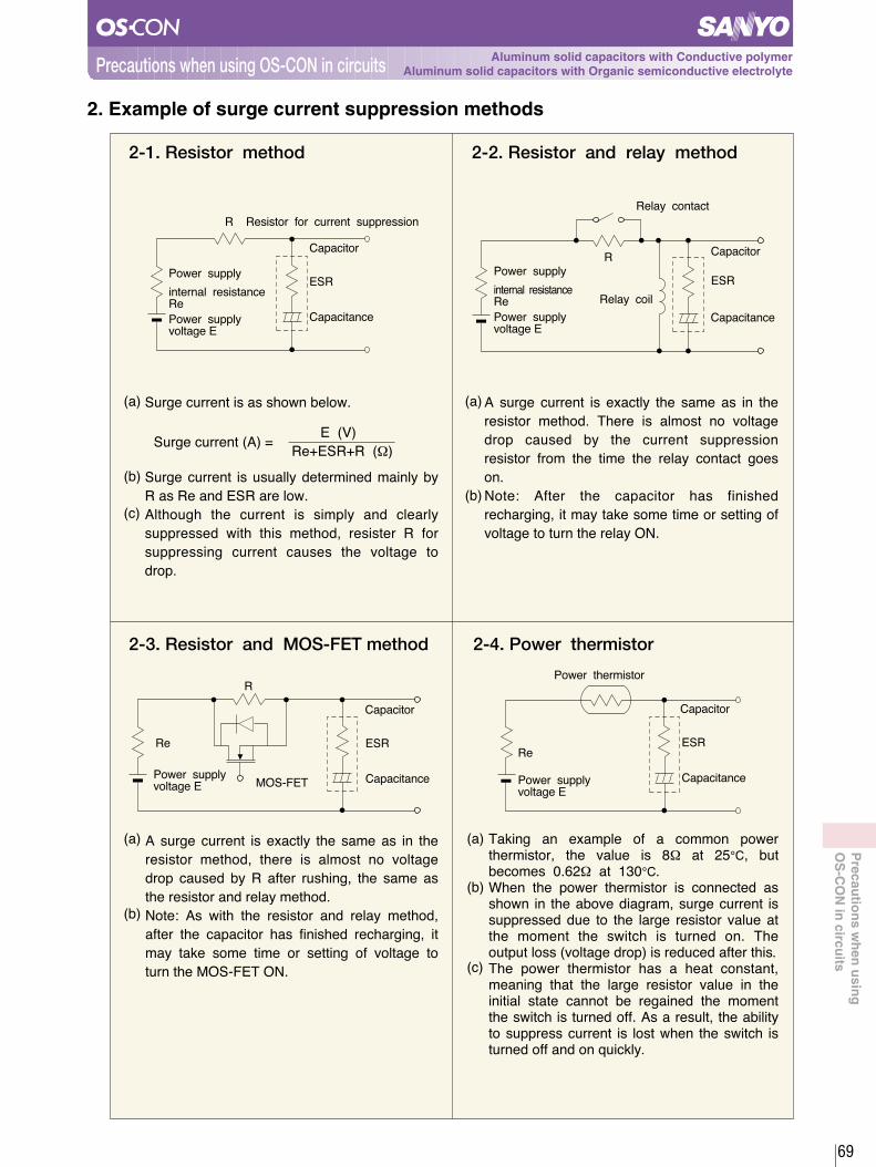
2. Example of surge current suppression methods
2-1. Resistor method
Surge current is as shown below.
Surge current is usually determined mainly by
R as Re and ESR are low.
Although the current is simply and clearly
suppressed with this method, resister R for
suppressing current causes the voltage to
drop.
A surge current is exactly the same as in the
resistor method. There is almost no voltage
drop caused by the current suppression
resistor from the time the relay contact goes
on.
Note: After the capacitor has finished
recharging, it may take some time or setting of
voltage to turn the relay ON.
2-2. Resistor and relay method
2-3. Resistor and MOS-FET method 2-4. Power thermistor
E (V)
Re+ESR+R (W)
A surge current is exactly the same as in the
resistor method, there is almost no voltage
drop caused by R after rushing, the same as
the resistor and relay method.
Note: As with the resistor and relay method,
after the capacitor has finished recharging, it
may take some time or setting of voltage to
turn the MOS-FET ON.
Taking an example of a common powerthermistor, the value is 8W at 25¡C, butbecomes 0.62W at 130¡C.When the power thermistor is connected asshown in the above diagram, surge current issuppressed due to the large resistor value atthe moment the switch is turned on. Theoutput loss (voltage drop) is reduced after this.The power thermistor has a heat constant,meaning that the large resistor value in theinitial state cannot be regained the momentthe switch is turned off. As a result, the abilityto suppress current is lost when the switch isturned off and on quickly.
Surge current (A) =
MOS-FET
R
Capacitor
ESR
CapacitancePower supplyvoltage E
Re
Power thermistor
Capacitor
ESR
CapacitancePower supplyvoltage E
Re
Relay contact
R
Relay coil
Power supply
Capacitor
ESR
CapacitancePower supplyvoltage E
internal resistanceRe
R Resistor for current suppression
Power supply
Capacitor
ESR
CapacitancePower supplyvoltage E
internal resistanceRe
69
(a)
(b)
(a)
(b)
(a)
(b)
(c)
(a)
(b)
(c)
Precau
tion
s wh
en u
sing
OS
-CO
N in
circuits
Aluminum solid capacitors with Conductive polymerAluminum solid capacitors with Organic semiconductive electrolytePrecautions when using OS-CON in circuits

OS-CON has an exceedingly low ESR. When the load impedance during discharge is extremely low,
there is the chance that it allows a large amount of discharge current to flow for an instant.
There is the chance an extremely large amount of discharge current will flow when electric charge is
discharged with 0W loading.
3. Sudden discharge current suppression
※The discharge equivalent circuit is as shown to
the left.
※The formula for estimating discharge current is
given below.
When the OS-CON is to be used in sudden discharge operations, configure the circuit so that the
peak discharge current becomes 10A or less, using the above mentioned rough estimate expression
as a guide. However, if 10 times the allowable ripple current of the OS-CON exceeds 10A,
reconfigure so that 10 times the allowable ripple current is not exceeded.
Discharge current (A) =Charging voltage (V)
ESR+Z1+Z2 (W)
Example : For 25SC10M
ESR=90mW or less
Charging voltage=20V is set, then
Z1, Z2=0W
Charging voltage 20V
ESR 0.09W or less
= 222A or more
Discharge current (A) =
70
Capacitor
ESR
Capacitance
Z 2
Z 1
Protection resistor
Load
circuit
Precau
tion
s wh
en u
sing
OS
-CO
N in
circuits
Aluminum solid capacitors with Conductive polymerAluminum solid capacitors with Organic semiconductive electrolytePrecautions when using OS-CON in circuits

Aluminum electrolytic capacitors and OS-CON are often connected in parallel to improve circuit density an
cost performance of ripple absorbing capacitors as follows.
4. Precautions when connecting an OS-CON and an aluminum electrolytic capacitor in parallel
Ir :Total ripple current
ESR:Capacitor's equivalent series resistance
Zc :Impedance of the capacitor's capacitive
components
Fig.1
Ripple current flowing through each parallelly connected capacitor can be found by using the
values symbolized in the reference equivalent circuit in Figure 1.
The equivalent circuit in Figure 1 can be simplified as shown in Figure 2 when it is to be used
for frequencies between 100kHz and a few MHz. (Assuming the capacitor's capacitance is more
than 10mF.)
Fig.2
Since impedance becomes exceedingly
low when the capacity is more than
10mF. And frequencies higher than
100kHz, each Zc in Figure 1 can be
omitted changing the actual ripple current
value to that shown in Figure 2.
Ir1 = Ir XESR2
ESR1 + ESR2= 1000mA X ≒727mArms
80mW30mW + 80mW
As shown here, although the OS-CON has 1/10th of the capacitance that of the mated capacitor, it allows
73% of the total ripple current to flow.
When OS-CON and an aluminum electrolytic capacitor are to be used in parallel connection, select the
appropriate type of OS-CON that has an extra margin of capacity since a large amount of ripple current
flows through it.
Formula for calculating the ripple current value
30mW
ESR1
80mW
ESR2
OS-CON100mF AI-E1000mF
lr=1000mArms
lr1 lr2
71
Zc1
C1 C2
ESR1
Zc2
ESR2
lr
lr1 lr2
(a)
(b)
(c)
(d)
Precau
tion
s wh
en u
sing
OS
-CO
N in
circuits
Aluminum solid capacitors with Conductive polymerAluminum solid capacitors with Organic semiconductive electrolytePrecautions when using OS-CON in circuits

While there is a tendency to downsize switching power supplies capacitors still remain one of the parts
occupying large areas of circuit boards. The working temperature is an important consideration when selecting
a capacitor, since it generally results in widely varying capacitor characteristics. The following experiment
shows the superior ripple removal capability of the OS-CON at higher frequencies in wide range of working
temperature.
A general chopper switching power supply was used to test the OS-CON against two alternatives.
SANYO OS-CON, low-impedance aluminum electrolytic capacitor, and low-ESR tantalum capacitors
were each connected as the capacitor in the output side smoothing circuit at working temperature range
of -20¡C, 25¡C and 70¡C to compare the output ripple voltage.
(1) Initially SANYO OS-CON・100uF/6.3V (6SVP100M・φ6.3mm×L6.0mm) was used as the output side
smoothing capacitor (C) in the above test circuit, the ripple voltage was measured at ambient
temperature of each temperature. Refer to table 3.
(2) Low-impedance aluminum electrolytic capacitors and Low-ESR tantalum capacitors were selected for
measurement at each temperature so that the ripple voltage became equal to that achieved when the
OS-CON・100uF/6.3V was used. Refer to table 3.
(3) The ripple voltage was measured at each temperature (-20¡C to 70¡C) with an equal number of side
smoothing capacitors to the 25 conditions, and the rates of change in the ESR of the smoothing
capacitors were calculated from the amounts of change. Refer to table 2.
1. Voltage reduction capability of OS-CON
(a) Experiment content
(b) Experiment result
Ambient temperature
25¡C
-20¡C
70¡C
OS-CON
1
1
1
Aluminum Electrolytic capacitor
7.15
16.7
4.77
Tantalum capacitor
1.46
1.46
1.46
Ambient temperature
25¡C
- 20¡C
70¡C
※Rate of change in ESR=
From the above results, it can be seen that SANYO OS-CON excels in temperature characteristics.
Ripple voltage at ambient temperature X Oscillation frequency at ambient temperature
Ripple voltage at 25¡C X Oscillation frequency at 25¡C
OS-CON
1
1.14
0.952
Aluminum Electrolytic capacitor
1
3.03
0.587
Tantalum capacitor
1
1.27
0.85
VIN =
5V
200kHz
C
+
Specimen
L VOUT = 3.3V, IOUT = 3A
RL
Osilloscope
72
Table1 On-board area ratios of capacitors at each temperature (when the ripple voltage is on the same level)
Table2 Rates of change in ESR on the basis of 25°C(※)
SW IC
1-1. The number of capacitors needed to keep the same ripple voltage level
Ap
plicatio
n
Aluminum solid capacitors with Conductive polymerAluminum solid capacitors with Organic semiconductive electrolyteApplication

Table3 Measurement comparison at 25°C, -20°C and 70°C
Ambient temperature 25°C
Ambient temperature -20°C
※1 The base plate dimensions were taken as the maximum dimensions except for Ta.
Ambient temperature 70°C
73
Ap
plicatio
n
Aluminum solid capacitors with Conductive polymerAluminum solid capacitors with Organic semiconductive electrolyteApplication
200kHz
OS-CON
100µF/6.3V
22.8mV
6.6 X 6.6
1
Fig1
Aluminum Electrolytic capacitor
680µF/6.3V
23.8mV
10.5 X 10.5
7.15
Fig2
Tantalum capacitor
100µF/10V
24.8mV
7.5 X 4.5
1.46
Fig3
Capacitor type
capacitance/voltage
ripple voltage
Size(※1)(mm)
On-board area ratio
Oscillation frequency
Fig
Quantity
250kHz
OS-CON
100µF/6.3V
20.8mV
6.6 X 6.6
1
Fig4
Aluminum Electrolytic capacitor
680µF/6.3V
24.4mV
10.5 X 10.5
16.7
Fig5
Tantalum capacitor
100µF/10V
25.2mV
7.5 X 4.5
1.46
Fig6
Capacitor type
capacitance/voltage
ripple voltage
Size(※1)(mm)
On-board area ratio
Oscillation frequency
Fig
Quantity
170kHz
OS-CON
100µF/6.3V
25.6mV
6.6 X 6.6
1
Fig7
Aluminum Electrolytic capacitor
680µF/6.3V
24.0mV
10.5 X 10.5
4.77
Fig8
Tantalum capacitor
100µF/10V
24.8mV
7.5 X 4.5
1.46
Fig9
Capacitor type
capacitance/voltage
ripple voltage
Size(※1)(mm)
On-board area ratio
Oscillation frequency
Fig
Quantity

Fig 1 (1pc) Fig 2 (3pc) Fig 3 (2pc)
Table1 Comparison at 25
74
Fig 4 (1pc) Fig 5 (7pc) Fig 6 (2pc)
Fig 7 (1pc) Fig 8 (2pc) Fig 9 (2pc)
aluminum electrolytic capacitor 680mF/6.3V
Tantalum capacitor100mF/10V
OS-CON100mF/6.3V
aluminum electrolytic capacitor 680mF/6.3V
Tantalum capacitor100mF/10V
OS-CON100mF/6.3V
aluminum electrolytic capacitor 680mF/6.3V
Tantalum capacitor100mF/10V
OS-CON100mF/6.3V
CH1=20mVAC 1:1
(2us/div)
200kHz
22.8mV
CH1=20mVAC 1:1
(2us/div)
200kHz
23.8mV
CH1=20mVAC 1:1
(2us/div)
200kHz
24.8mV
(2us/div)
250kHz
20.8mV
CH1=20mVAC 1:1
(2us/div)
250kHz
24.4mV
CH1 = 20mVAC 1:1
(2us/div)
250kHz
25.2mV
CH1=20mVAC 1:1
CH1=20mVAC 1:1
(2us/div)
170kHz
25.6mV
CH1=20mVAC 1:1
(2us/div)
170kHz
24.0mV
CH1=20mVAC 1:1
(2us/div)
170kHz
24.8mV
Table2 Comparison at -20
Table3 Comparison at 70
Ap
plicatio
n
Aluminum solid capacitors with Conductive polymerAluminum solid capacitors with Organic semiconductive electrolyteApplication

75
VIN =12V
SW IC
200kHz
C
+
Specimen
L VOUT = 3.3V, IOUT = 1A
RL
Osilloscope
25
0
-20
38mΩ
39mΩ
38mΩ
40mΩ
41mΩ
40mΩ
180mΩ
369mΩ
907mΩ
231mΩ
663mΩ
2,212mΩ
OS-CON
Ambient temperature
in measuring
Value after
125¡C×10V applied×1,000hInitial value
Value after
125¡C×10V applied×1,000hInitial value
capacitance/voltage
ESR
Category temperature
range
Endurance
Size(mm)
56μF/10V
45mΩ
-55~+125
125×2,000h
330μF/10V
300mΩ
-40~+125
125×2,000h
φ6.3×L6 φ10×L10
Aluminum electrolytic capacitor
Aluminum electrolytic capacitor
OS-CON
OS-CON and low-impedance aluminum electrolytic capacitors were respectively connected to the output
side of chopper switching power supply, as soothing capacitors. Output ripple voltage made by the two
kinds of capacitor was respectively measured before and after endurance tests (125¡C×1000h, rated
voltage applied) of the capacitors.
The ripple voltage measurement was done at the ambient temperatures of 25¡C, 0¡C, and -20¡C.
OS-CON 56μ F/10V(10SVPD56M φ6.3mm×L6mm) and low-impedance aluminum electrolytic capacitor
330μ F /10V (φ10mm×L10mm) were used for this experiment. Measured ESR value of the OS-CONwas 38mΩ, while that of the aluminum electrolytic capacitor was 180mΩ. To match the equivalent ripple
voltage one OS-CON brings, four pieces of the aluminum electrolytic capacitor were used.
(a) Experiment content1-2. Ripple voltage removal capability before and after endurance test
Output ripple voltage(outline) =Ripple current through coil
ESR of capacitor
(1) Specifications of test samples
(2) ESR change of test samples
Ap
plicatio
n
Aluminum solid capacitors with Conductive polymerAluminum solid capacitors with Organic semiconductive electrolyteApplication

10
100
0 200 500 1000 2000
Time (h)
25
0
-20
-40
100
1000
10000
100000
0 200 500 1000 2000
Time (h)
―40
―30
―20
―10
0
10
20
―40
―30
―20
―10
010
20
0 200 500 1000 2000
0 200 500 1000 2000
Time (h)
Time (h)
25
0
-20
-40
25
0
-20
-40
25
0
-20
-40
(3) Endurance(125×10V applied)
〔ESR〕
〔Capacitance〕
Ap
plicatio
n
Aluminum solid capacitors with Conductive polymerAluminum solid capacitors with Organic semiconductive electrolyteApplication
Aluminum electrolytic capacitor 330μF/10V
OS-CON(10SVPD56M)56μF/10V
OS-CON(10SVPD56M)56μF/10V
Aluminum electrolytic capacitor 330μF/10V
ESR(mΩ
at100kHz)
ESR(mΩ
at100kHz)
CapacitanceChange
(%at120Hz)
CapacitanceChange
(%at120Hz)
76

77
OS-CON(10SVPD56M) 56μF/10V
31.0mV
CH1=50mV
AC 1:1
(2us/div)
42.0mV
CH1=50mV
AC 1:1
(2us/div)
30.0mV
CH1=50mV
AC 1:1
(2us/div)
78.0mV
CH1=50mV
AC 1:1
(2us/div)
30.0mV
CH1=50mV
AC 1:1
(2us/div)
167.0mV
CH1=50mV
AC 1:1
(2us/div)
25
0
-20
25
0
-20
Aluminum electrolytic capacitor330μF/10V
25
0
-20
Aluminum electrolytic capacitorOS-CON
31mVp-p
30mVp-p
30mVp-p
(1pc) (4pc)
(1pc) (4pc)
(1pc) (4pc)
42mVp-p
78mVp-p
167mVp-p
(b) Experiment result
(1) Initial ripple voltage waveform
(2) Result
Ap
plicatio
n
Aluminum solid capacitors with Conductive polymerAluminum solid capacitors with Organic semiconductive electrolyteApplication

78
0
25
-20
0
25
-20
(1pc)
(1pc)
(1pc)
(4pc)
(4pc)
(1pc)
25
0
-20
Aluminum electrolytic capacitor
51mVp-p
128mVp-p
399mVp-p
OS-CON
31mVp-p
32mVp-p
31mVp-p
31.0mV
CH1=50mV AC 1:1
(2us/div)
51.0mV
CH1=50mV AC 1:1
(2us/div)
32.0mV
CH1=50mV AC 1:1
(2us/div)
128.0mV
CH1=50mV AC 1:1
(2us/div)
31.0mV
CH1=50mV AC 1:1
(2us/div)
399.0mV
CH1=50mV AC 1:1
(2us/div)
OS-CON(10SVPD56M) 56μF/10V
Aluminum electrolytic capacitor330μF/10V
(3) Ripple voltage waveform after endurance test (125×10V applied×1000h)
(4) Result
Ap
plicatio
n
Aluminum solid capacitors with Conductive polymerAluminum solid capacitors with Organic semiconductive electrolyteApplication

IC, especially MPU that are lately used in electronic devices operate at very high processing speed.
PCB s are able to be more densely populated by lowering voltage and getting narrow pattern space.
Involved in changing to lower voltage, load current is increasing with a development of new MPU. A sudden
change of load current with larger dynamic load at high speed causes the voltage fluctuation of power supply
line, and it makes MPU work wrong.
Capacitors with low ESR and large capacitance are necessary for high-speed load current transients. The OS-
CON can provide the largest capacitance among low ESR capacitors, and in this regard, the OS-CON is a
suitable back-up capacitor.
Let us explain the excellent back-up performance of OS-CON compared to that of other electrolytic capacitors.
2. OS-CON high speed back-up performance (Back-up capacitor for dynamic load)
2-1. Test condition
(a) Switching wave form
Item Condition
5µs12.5µs20ns
2A
4V
1Ω
Load conditionTest circuit
Whole wave form Rising wave form
Load width
Cycle
Rising time
Dynamic load current
Voltage
Power supply
impedance
2V/div5µs/div
2V/div20ns/div
Suitable back-up capacitor for an AC volt tolerance can be estimated from the following equation:
V=
C : Capacitance (F)
ESR : ESR (Ω)
T : Cycle (s)
∆V : AC Volt tolerance (V)
∆ I : Dynamic load current (A)
∆ t : Load width (s)
CH3=2V AC 10 : 1
CH3=2V AC 10 : 1
Dynamic load current
Backup waveform
Oscilloscope
Sample
1Ω
2Ω
Powersupply
SW
V
5us/div 20ns/div
79
× + I×ESRI× t
C
T- t
T
Ap
plicatio
n
Aluminum solid capacitors with Conductive polymerAluminum solid capacitors with Organic semiconductive electrolyteApplication

2-2. Result
Compared with same capacitance, OS-CON voltage drop of supply line is 104mV, but low-
impedance Aluminum electrolytic capacitor indicates 548mV (5.3times of OS-CON), and low ESR
Tantalum electrolytic capacitor indicates 212mV (2times of OS-CON).
(a) Comparison between OS-CON and other capacitors with same capacitance
OS-CON10SP100M, ESR : 21mW
Low Z Aluminum capacitor10V100mF, ESR : 245mW
Low ESR Tantalum capacitor10V100mF, ESR : 85mW
DV=104mV DV=548mV DV=212mV200mV/div
5ms/div
200mV/div
5ms/div
200mV/div
5ms/div
DV=104mV DV=128mV DV=116mV200mV/div
5ms/div
200mV/div
5ms/div
200mV/div
5ms/div
DV=104mV DV=404mV DV=144mV200mV/div
5ms/div
200mV/div
5ms/div
200mV/div
5ms/div
To obtain similar level of voltage drop to 10SP100M, Low Z Aluminum electrolytic capacitor
needs 1,500mF or more. Low ESR Tantalum electrolytic capacitor needs 220mF X 2pcs or more.
Compared them under the lower temperature, OS-CON is able to keep stable, while the low Z
aluminum capacitor has 3.2 times larger drop of the voltage and the low ESR tantalum capacitor
has 1.2 times larger drop of the voltage.
(b) Examination of same level variable load
(C) Comparison with lower temperature (-20) of (b)
OS-CON10SP100M
Low Z Aluminum capacitor10V1,500mF
Low ESR Tantalum capacitor10V220mF×2
OS-CON10SP100M
Low Z Aluminum capacitor10V1,500mF
Low ESR Tantalum capacitor10V220mF X 2
CH2=200mVAC 1 : 1
CH2=200mVAC 1 : 1
5us/div 5us/div CH2=200mVAC 1 : 1
5us/div
CH2=200mVAC 1 : 1
CH2=200mVAC 1 : 1
5us/div 5us/div CH2=200mVAC 1 : 1
5us/div
CH2=200mVAC 1 : 1
CH2=200mVAC 1 : 1
5us/div 5us/div CH2=200mVAC 1 : 1
5us/div
80
Ap
plicatio
n
Aluminum solid capacitors with Conductive polymerAluminum solid capacitors with Organic semiconductive electrolyteApplication

As a means of removing noise from power supply lines, a low-pass filter such as shown below may be used.
In recent years, switching power supplies have been become a main power sources, that are compact and
highly efficient, but its make a large noise sources. Also, digital circuits make noise easily, and in most of the
devices with mixed noise-sensitive analog circuits, entry of high-frequency noise into the analog circuits is
prevented by connecting these low-pass filters to the power supply lines of the analog circuits.
(a) The damping effect of the filter gets closer to an ideal damping rate as capacitor has lower ESR.
(b) Capacitance and ESR have 0 point frequency (fz), when the frequency is higher than 0 point frequency,
+20dB/dec cancel the damping effect.
(c) LC filter : -40dB/dec is to be -20dB/dec
RC filter : -20dB/dec is to be 0 (non-damping effect)
(d) Even if capacitance is increased, there has no effect of noise cutting, it is influenced by the 0 point frequency. OS-CON is most effective in low-pass filter because of low ESR.
Compare the actual damping factor of the following OS-CON with an aluminum electrolyte capacitor on the
next page
3. Application to low-pass filter circuits
Fig.1 LC Filter Fig.2 RC Filter
81
The capacitors used for comparison are as follows
OS-CON (16SA33M)
16V/33uF, ESR=37m½ (The actual measurement)
Aluminum electrolytic capacitor
10V/33uF, ESR=1410m½ (The actual measurement)
Fig.3 Actual damping factorfzfc (Frequency at 0 point) (Frequency at 0 point)
(a) LC Filter (b) RC Filter
Attenuation
0dB
Actualdamping factor
Damping factorwhen ESR is lower
Damping factorwhen ESR is lower
In case Capacitanceincreased
In case Capacitanceincreased
Idealdamping factor
Ideal damping factor
fzfcFrequencyFrequency
Attenuation
0dB
Actualdamping factor
-20dB/dec
-40dB/dec
-20dB/dec
Ap
plicatio
n
Aluminum solid capacitors with Conductive polymerAluminum solid capacitors with Organic semiconductive electrolyteApplication

OS-CON shows a damping effect in higher frequency regions comparing with an aluminum electrolytic
capacitor.
These measurements were made at room temperature. The difference in damping effect will be larger when
the temperature is under 0, because ESR of an aluminum electrolytic capacitor will extremely increase.
Oppositely OS-CON has little increase that does not affect the damping effect of the filter.
OS-CON
3-1. LC Filter (L=10uH)
Aluminum electrolytic capacitor
OS-CON
3-2. RC Filter (R=5.6‰)
Aluminum electrolytic capacitor
82
Frequency [Hz] Frequency [Hz]
Frequency [Hz] Frequency [Hz]
80
60
40
20
0
-20
-40
-60
-8010 100 1k 10k 100k 1M
80
60
40
20
0
-20
-40
-60
-8010 100 1k 10k 100k 1M
80
60
40
20
0
-20
-40
-60
-8010 100 1k 10k 100k 1M
80
60
40
20
0
-20
-40
-60
-8010 100 1k 10k 100k 1M
Gain [dB]
Gain [dB]
Gain [dB]
Gain [dB]
Ap
plicatio
n
Aluminum solid capacitors with Conductive polymerAluminum solid capacitors with Organic semiconductive electrolyteApplication

For restraining output ripple current, the output smoothing capacitor of the switching power supply is need to
use low ESR capacitor. However the lower ESR capacitor makes the phenomenon sometimes occurs, which
is called the abnormal oscillation of output voltage.
The abnormal oscillation of output voltage varies depending on the regulator method or the topology such as
buck type, boost type, etc. We explain the mechanism and the treatment method of output voltage oscillation
with the sample of the Buck style switching regulator under the voltage control mode.
4-1. Abnormal oscillation of output voltageThe switching power supply usually has the negative feed-back circuit to stabilize output voltage.
The difference between output voltage and standard voltage Vref are amplified with the error amplifier and
convert to the digital signal with the PWM
comparator and flip on and flip off switch Q1.
Input voltage Vin becomes a square wave form by
Q1, and you obtain DC output voltage Vout by
make it smooth with coil L and capacitor Cout. L
and also Cout assumed that they form the second
low pass filters.
The frequency characteristics of the output LC
filter is expressed with the Bode diagram like
Figure 2.
The phase is delayed 180 degrees originally,
because the error amplifier is a negative feedback
circuit. Therefore, the phase delay of the output
LC filter and the error amplifier occur at the same
time, and when 360 degrees delay occur, the
output voltage oscillates.
The damping rate of the LC filter is -40dB/dec and the cut-off frequency becomes , and become
Gain and Phase like the dotted line of Figure 2.
With an ideal filter the output voltage oscillates because it is delayed 180 degrees. But more than some
frequency that is called zero frequency, damping rate of Gain becomes -40dB/dec to -20dB/dec. Furthermore
the Phase returns to delay 90 degrees from delay 180 degrees. This is because the first order Phase lead
network is formed by the capacitance value and ESR of Cout. Because, after the zero point frequency
, the Gain damping rate goes on the Phase of +20dB, +90 degrees. However, when the low
ESR capacitor is used, it works as a
LC filter up to high frequency band,
and the phase delay to nearly 180
degrees and it becomes easy to
oscillate.
30 degrees to 40 degrees or more of
Phase margin is thought as a
necessity to inhibit the oscillation of
output voltage with a general negative
feed-back circuit. The Phase margin
is numerical value how much the
minimum value of the Phase is distant
from-180 degrees. The smaller the
Phase margin gets, the higher the
possibility to oscillate by the
characteristic dispersion and
temperature change of the component
will be.
4. Application of switching power supply for smoothing capacitor
2p LC1
Fig.1 Control block of switching power supply
83
Vin
Cin D
L
Vout
Cout
Q1
Vref
Zi
Zc
Error Amp.
OSC
PWM Comparator
Gain
180160140120100806040200-20-40-60-80-100-120-140-160-180
9080706050403020100
-10
Gain [dB]
Phase [deg]
-20-30-40-50-60-70-80-90
1 10 100 1000
Frequency [Hz]
10000 100000 1000000
Phase
ESR
Fig.2 Frequency characteristic of LC filter
Cut-off frequency
Zero point frequency
12p Cout ESR
Large
Small
Ap
plicatio
n
Aluminum solid capacitors with Conductive polymerAluminum solid capacitors with Organic semiconductive electrolyteApplication

4-2. Inhibition method of oscillationBy doing Phase compensation with the feed-back circuit of the error amplifier the oscillation of output voltage can be inhibited.There are various kinds in Phase compensation. It is most effective to use the Phase compensation circuit like the following in the switch power supply of the voltage control mode.
Figure 3 : ② & ④ form first order Phase lead network. ① & ③ form first order Phase lag network. By adjusting these values, it does the Phase compensation by which Phase will occur and improve Phase delay of the whole negative feed-back circuit by the frequency characteristic of output LC filter at the frequency band which the Phase indicates the lowest.
Figure 4 : Example. As the Phase of the output LC filter of Figure 2 becomes a lowest point at around 10kHz, it has about 30 degrees of Phase lead around that frequency. Because of this, it can secure the Phase margin of 30 degrees even if the Phase delay of LC filter becomes 180 degree nearly, the oscillation of output voltage can inhibited.Related in detail, please inquire it to us.
Fig.4 Frequency characteristic of Phase Compensation Network
Fig.3 Phase compensation network of Voltage Control Mode
84
Vref
ZiZc
① ②③
④
from Vout
Error Amp.
PWMComparator
-90
-80
-70
-60
-50
-40
-30
-20
-10
0
10
20
30
40
50
60
70
80
90
1 10 100 1000 10000 100000 1000000
Frequency[Hz]
Gai
n[dB
]
-180
-160
-140
-120
-100
-80
-60
-40
-20
0
20
40
60
80
100
120
140
160
180
Pha
se[d
eg]
Gain
Phase
Ap
plicatio
n
Aluminum solid capacitors with Conductive polymerAluminum solid capacitors with Organic semiconductive electrolyteApplication

[Specification]
¥ Input voltage (Vin) : 5V
¥ Output voltage (Vout) : 3.3V
¥ Output current (Iout) : 3.2A
¥ Output ripple voltage (Vripple) : 20mVp-p
The ESR of the output capacitor necessary to make an output ripple voltage of 20mVp-p can be
obtained as follows:
ESR < Vripple / ((Vin-Vout) / L*Vout / Vin / fosc) = 35.7m½
Consequently, the following capacitors have been selected.
(a) OS-CON6SVP100M 1-parallel f6.3×L6mm ESR = 32m½ ※ESR is an actual measurement.
(b) Aluminum electrolytic capacitor6V/680uF 3-parallel f10×L8mm ESR = 128m½/p. Total ESR = 43m½
Photograph 1: Measuring evaluation board using the above capacitorsWe can downsize by using the OS-CON compared with aluminum electrolytic capacitors if the most favorable
phase compensating circuit is provided as follows.
Fig.5 Step-down DC-DC converter design example
OS-CON
Aluminum electrolytic capacitor
Photo 1 Evaluated circuit boards
4-3. Concrete design examples of prevention oscillation
85
Ap
plicatio
n
Aluminum solid capacitors with Conductive polymerAluminum solid capacitors with Organic semiconductive electrolyteApplication
+-
+DV
D
Q1 10uH
Vout
C out
Vin
C in
Vref
-
Zi
Zc
Erroramplifier
PWMcomparator
Triangular wave generator
200kHz

When the aluminum electrolytic capacitors are used, the frequency characteristics of the output LC
filter are as shown in Fig.6, and there is a sufficient phase margin to such an extent that there is
no need to make phase compensation. Therefore, the phase compensating circuit in Fig.7 is
sufficient.
With the phase compensation network is Fig. 7 (properly speaking, phase compensation is not made), the
total frequency characteristics are as shown in Fig. 8, and there is a sufficient phase margin.
When the aluminum electrolytic capacitors used
in power supply circuits are replaced with the
OS-CON without changing the phase compensation
network, the output voltage oscillates. (Fig.10)
As a reason, we can say that the phase margin
is lost because the phase compensation network
is not changed despite the fact that the frequency
characteristics of the output LC filter change as
shown in Fig.6, where the aluminum electrolytic
capacitors are used, to Fig.11, where they are
replaced with the low ESR OS-CON.
4-5. Examples of design with the OS-CON
Fig.6 Frequency characteristics of the LC filter with the AL-E
Fig8 Total frequency characteristics with the AL-E Fig.9 Output ripple voltage waveform with the AL-E
Fig.10 Oscillating output voltage waveform
Fig.7 Phase compensating circuit with the AL-E
4-4. Examples of design with aluminum electrolytic capacitors
Error amplifier
PWM To PWMcomparator
86
-90
-80
-70
-60
-50
-40
-30
-20
-10
0
10
20
10 100 1000 10000 100000
Frequency[Hz]
Gain[dB]
-180
-160
-140
-120
-100
-80
-60
-40
-20
0
20
40
Phase[deg]
Gain
Phase
-60
-50
-40
-30
-20
-10
0
10
20
30
40
50
60
100 1000 10000 100000
Frequency[Hz]
Gain[dB]
-180
-150
-120
-90
-60
-30
0
30
60
90
120
150
180
Phase[deg]
Gain
Phase
-+
Vout
Rin:20kΩRc:33kΩCc:10000pF
Vref
Rc
Rin
Cc
Zi
Zc
CH2=5mVAC 1:1
22m Vp-p
CH4=100mVAC 10:1
(20us/div)
(2us/div)
Ap
plicatio
n
Aluminum solid capacitors with Conductive polymerAluminum solid capacitors with Organic semiconductive electrolyteApplication

When the LC filter has little phase margin as shown in Fig.11, appropriate phase compensation can
be made by using such a phase compensation network as shown in Fig.12.
This is to cancel the deepened phase lag by forming phase leads at Zi and Zc in Fig.12.
Because of this, the total frequency characteristics are as shown in Fig.13; the phase margin is
sufficient; and the output ripple voltage waveform (Fig.14) is almost the same as is the case with
the aluminum electrolytic capacitors.
Fig.11 Frequency characteristics of the LC filter with the OS-CON
Fig.13 Total frequency characteristics with the OS-CON
Fig.14 Output ripple voltage waveform with the OS-CON
Fig.12 Phase compensating circuit with the OS-CON
19m Vp-p
(2us/div)CH2 = 5mV
AC 1:1
Error amplifier
PWM To PWMcomparator
87
-60
-50
-40
-30
-20
-10
0
10
20
30
40
50
60
100 1000 10000 100000
Frequency[Hz]
Gain[dB]
-180
-150
-120
-90
-60
-30
0
30
60
90
120
150
180
Phase[deg]
Gain
Phase
-90
-80
-70
-60
-50
-40
-30
-20
-10
0
10
20
10 100 1000 10000 100000
Frequency[Hz]
Gain[dB]
-180
-160
-140
-120
-100
-80
-60
-40
-20
0
20
40
Phase[deg]
Gain
Phase
Rin1:20kΩRin2:680Ω
-+
Vout
Vref
RcRin1
Cc2
Cc1Zi
Zc
Rin2 Cin
Cc1:330pFCc2:33000pF
Cin:4700pFRc:3.3kΩ
Ap
plicatio
n
Aluminum solid capacitors with Conductive polymerAluminum solid capacitors with Organic semiconductive electrolyteApplication

5. Influence of output ripples from switching power supply on actual images
Comparison of the output ripple current among OS-CON, aluminum electrolytic capacitors and tantalum
capacitors on P.72 to P.74. The result showed that the OS-CON provided an excellent filter effect, superior to
those of other capacitors. This section discusses the influence of such ripples on images. You may understand
how digital noise affects analog signals.
Images when use OS-CON : There were quite normal when the temperature is from 25¡C to -20¡C.
Images when use low impedance aluminum electrolytic capacitors: Images started to become white like
misting around 0¡C as a whole, and images hardly appeared at all at -20¡C.
OS-CON and low impedance aluminum
electrolytic capacitors are connected
respectively as output filter in DC-DC
converter of a digital camera, and we
compare the influences on actual
images changing temperature.
AI-E is usedOS-CON is used
OS-CON ; SL series Low impedance Aluminum electrolytic capacitor
Photo l at 25¡C
Photo 3 at 0¡C
Photo 5 at -20¡C
Photo 2 at 25¡C
Photo 4 at 0¡C
Photo 6 at -20¡C
Parts mounting circuit
88
Ap
plicatio
n
Aluminum solid capacitors with Conductive polymerAluminum solid capacitors with Organic semiconductive electrolyteApplication
(a) Influence to images by a digital camera
(b) Result
10V/47μF×2Psize:φ6.3×L5.0
10V/330μF×2Psize:φ6.3×L11.0
(1)
(2)

mm
FAX
Company
Dept.
Name
TEL
Application
Equipment
Height limit
Item Symbol Value UnitSwitching Frequency
Input VoltageOutput VoltageOutput CurrentRipple Voltage
Ambient TemperaturePrimary Inductance
InductanceWinding ratio
Current ChangeVoltage Drop
Control IC
Mount type Radial SMD
Indispensable item
Please enclose the use circuit in a circle.
Power Supply / Filter / By-pass Capacitor / Coupling Circuits / Others ( )
PC / PC Peripheral Unit / Audio / Communication / Automobile / Other ( )
Iout
Vout
①BUCKVin > Vout
④FORWARD
⑤FLYBACK
③BUCK-BOOST 0 > Vout
fosc
Vin
Vout
Iout
∆Vripple
Ta
L1
L
n1 : n2 :
kHz
V
V
A
mVp-p
°CµH
µH
∆I
∆Vdrop
A
mV
②BOOST Vin < Vout
Option
I
Vdrop∆
∆
∆
Vripple
0V
0A
Iout
Vinfosc
Vout+ +
L
Iout
VoutVin fosc+ +
L
Iout
VoutVinfosc
++L
Vin
n1L1
n2
fosc
IoutL
Vout+
+
Vin
n1L1
n2
fosc
Iout
Vout+
+
89
http://www.sanyo.co.jp/compo/webcctool/jp/html/The design support tool is available at the following URL on the Internet.
Cap
acitors
Selectio
n S
heet
Aluminum solid capacitors with Conductive polymerAluminum solid capacitors with Organic semiconductive electrolyteCapacitors Selection Sheet

Modifying the subjects and specifications in this catalogue without any notice.
SANYO Electric Co., Ltd.Electronic Device CompanySales division(Japan)
1-1 SANYO-cho, Daito, Osaka, 574-8534Phone: (072)870-6375/6377 FAX: (072)870-1174
SANYO Component Europe GmbHStahlgruberring 4, 81829 Munich GermanyPhone: 49-(0)89-460095-284 FAX: 49-(0)89-460095-275
Korea office9th Floor, Han-Lim Building 146-7, Ssanglim-Dong, Chung-Gu Seoul, KoreaPhone: 82-2-2273-5861 FAX: 82-2-2273-6053
SANYO Electronic Device (U.S.A.) CorporationSan Diego Headquarter
2055 SANYO Ave., San Diego, CA 92154, U.S.A.Phone: 1-619-661-6835 FAX: 1-619-661-1055
San Jose sales office1230 Oakmead Parkway, Ste. #314, Sunnyvale, CA 94085, U.S.A.Phone: 1-408-749-9714 FAX: 1-408-749-0212
Dallas sales office2600 Network Blvd. 6F. Frisco TX. 75034, U.S.A.Phone: 1-469-362-5465 FAX: 1-469-362-5463
Detroit sales office27000 Meadowbrook Rd., Suite 210 Novi, MI 48377, U.S.A.Phone:1-248-344-1245 FAX: 1-248-479-0428
Hartford sales officeP.O.Box 76 Waterford. CT 06385, U.S.A.Phone:1-860-447-9553 FAX1-860-447-9573
Atlanta sales officeP.O. Box 70666, Marietta, GA 30007, U.S.A.Phone:1-770-650-5654 FAX: 1-770-640-5081
http://www.sanyodevice.com
SANYO Electronic Components (Singapore) Pte., Ltd.70 Anson Road #19-01 To 08, Apex Tower Singapore/079905/SingaporePhone: 65-6223-0225 FAX: 65-6223-0986
http://www.edc.sanyo.com
http://www.sanyochina.comSANYO Electronic Components (H.K.) Ltd.Hong Kong Headquarter
Suite 3601-06, 36/F, Tower 6, The Gateway, Harbour City, 9 Canton Road, T.S.T., Kowloon, Hong Kong.Phone: 852-2366-2577 FAX: 852-2301-2255
Shanghai officeRoom2107, Ruijin Building, 205 Mao Min Rd.(S), Shanghai, ChinaPhone: 86-21-6415-6669 FAX: 86-21-6445-8543
Shenzhen officeRoom301, East Building, High-Tech Plaza, Phase 2, Tian An Cyberpark Futian, Shenzhen, GuangdongChina 518040Phone: 86-755-8835-2319 FAX: 86-755-8835-2324
Beijing officeRoom708, China Life Tower No.16 Chaoyangmenwai Ave., Beijing, ChinaPhone: 86-10-8525-2600 FAX: 86-10-8525-2602
Taiwan Branch(Taiwan)10F., No.101, Sec.2, Nanjing E. Rd., Jhongshan District, Taipei City 104, Taiwan (R.O.C.)
Phone:886-2-2536-1855 FAX: 886-2-2536-6168