tech data 11
TRANSCRIPT
7/31/2019 Tech Data 11
http://slidepdf.com/reader/full/tech-data-11 1/8
7/31/2019 Tech Data 11
http://slidepdf.com/reader/full/tech-data-11 2/8
SHAPA Technical Bulletin No. 11The Protection of Silos From Over Pressurisation During Filling
Page 2 of 8 August 2005
The Prot ect ion of Silos From OverPressur isat ion Durin g Fill ing
By James Duggleby, Portasilo Ltd.Tel +44 1904 624872
E-mail: [email protected]
Abstract
Within the construction industry there have been a number of serious accidents involving
silos, which have been over-pressurised by tankers, this has resulted in the Health & Safety
Executive (HSE) issuing a guidance note on this subject. These recommendations have
largely been reflected in the process guidance note for bulk Cement silos, PG 3/1 (2001),
issued by the Secretary of State.
Although directed at the Cement, Concrete and Quarrying industries, these guidelines have
obvious implications for all other industries, which utilise tanker filled silos.
This paper will discuss the five key recommendations made by the HSE and identify the test
work undertaken by Portasilo to support these recommendations – with some alarming
results.
The paper will also look at the implications of the guidance notes with regards to the design
and operation of tanker filled silos. Whilst tackling these five key points to ensure that all silos,
new and existing, can be supplied or modified to meet the current standards by putting into
place measures to prevent the over pressurisation of silos and by providing an ultimate basis
of safety… a pressure/vacuum relief valve (PRV).
Background to the Guidance Notes
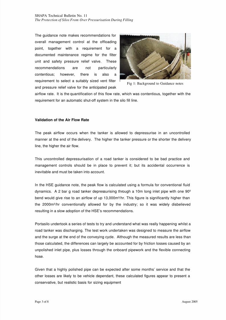
In the case of each of these accidents, the silos became pressurised during pneumatic filling
by a road tanker. The connection between the reverse jet filter and the silo roof was found to
be the weak link and resulted in the 250kg filter unit being dislodged from the silo roof. In at
least one case, this filter seriously injured the tanker driver.
The underlying problem in each case was found to be the pressure relief valve, which was
undersized for the maximum airflow entering the silo. The problem was also exacerbated bya significant lack of maintenance and by the overfilling of the silo.
7/31/2019 Tech Data 11
http://slidepdf.com/reader/full/tech-data-11 3/8
SHAPA Technical Bulletin No. 11The Protection of Silos From Over Pressurisation During Filling
Page 3 of 8 August 2005
The guidance note makes recommendations for
overall management control at the offloading
point, together with a requirement for a
documented maintenance regime for the filterunit and safety pressure relief valve. These
recommendations are not particularly
contentious; however, there is also a
requirement to select a suitably sized vent filter
and pressure relief valve for the anticipated peak
airflow rate. It is the quantification of this flow rate, which was contentious, together with the
requirement for an automatic shut-off system in the silo fill line.
Validation of the Air Flow Rate
The peak airflow occurs when the tanker is allowed to depressurise in an uncontrolled
manner at the end of the delivery. The higher the tanker pressure or the shorter the delivery
line, the higher the air flow.
This uncontrolled depressurisation of a road tanker is considered to be bad practice and
management controls should be in place to prevent it; but its accidental occurrence is
inevitable and must be taken into account.
In the HSE guidance note, the peak flow is calculated using a formula for conventional fluid
dynamics. A 2 bar g road tanker depressurising through a 10m long inlet pipe with one 90º
bend would give rise to an airflow of up 13,000m³/hr. This figure is significantly higher than
the 2000m³/hr conventionally allowed for by the industry; so it was widely disbelieved
resulting in a slow adoption of the HSE’s recommendations.
Portasilo undertook a series of tests to try and understand what was really happening whilst aroad tanker was discharging. The test work undertaken was designed to measure the airflow
and the surge at the end of the conveying cycle. Although the measured results are less than
those calculated, the differences can largely be accounted for by friction losses caused by an
unpolished inlet pipe, plus losses through the onboard pipework and the flexible connecting
hose.
Given that a highly polished pipe can be expected after some months’ service and that the
other losses are likely to be vehicle dependant, these calculated figures appear to present a
conservative, but realistic basis for sizing equipment
Fig 1: Background to Guidance notes

7/31/2019 Tech Data 11
http://slidepdf.com/reader/full/tech-data-11 4/8
SHAPA Technical Bulletin No. 11The Protection of Silos From Over Pressurisation During Filling
Page 4 of 8 August 2005
The surge in flow experienced at the end of the cycle is clearly not a transient peak; therefore,
it cannot be disregarded due to its short duration. Flow rates in excess of 2000m³/hr, the
figure conventionally used for design, are sustained for many minutes. The results of these
tests and a comparison with calculated figures are shown in Fig 2.
Implications on silo design and operationSilo vent filter
The implications for filter sizing are not as onerous as might be expected, despite this large
airflow – because… nothing has changed! Filters are conventionally sized on empirical rules
that take into account the large surge in airflow on completion of the tanker’s discharge.
Although the numbers have changed, they have changed on both sides of the equation.
Portasilo surveyed a large number of OPC silo installations and the results indicated that filter
size was not so important as might be first thought. Bag filters as small as 10m² were giving
excellent performance after 20 years service, whilst much larger filters less than a year old
were performing badly. Filter media area is obviously important, but the filter must also be
well engineered, well maintained and installed on a generously sized silo.
Fig 2: Airflow rate from a depressurising tanker
Air flow from a depressurising t anker

7/31/2019 Tech Data 11
http://slidepdf.com/reader/full/tech-data-11 5/8
SHAPA Technical Bulletin No. 11The Protection of Silos From Over Pressurisation During Filling
Page 5 of 8 August 2005
Pressure/vacuum relief valve
Unlike a silo filter, pressure relief valves are typically sized by calculation. If the maximum
airflow is under estimated, then even the best quality valve will be undersized and will fail toprovide adequate protection for the silo to which it is fitted.
As part of the tests undertaken by Portasilo, direct tests were conducted on a number of
pressure relief valves.
These trials consisted of a road tanker with a pressure relief valve coupled directly to the end
of the filling pipe. The tanker was depressurised and the pressure accumulation was
measured. Although this was an extreme test, this scenario is similar to a full silo with a
blocked filter; which was a common factor on all the damaged silos.
It quickly became evident from these tests that the valves’ capacities were significantly less
than those claimed by the manufacturer. Further investigations revealed that both calculation
errors and an effect known as pressure piling were to blame. The shape of the valve seat
and proximity of the weather cover are critical and can give rise to a very significant reduction
in valve capacity. These test results are shown in Fig 3 along with the manufacturer’s
claimed capacity.
Perfor mance t est for a spring operat ed PRV
Fig 3: Performance test for a spring operated pressure relief valve
7/31/2019 Tech Data 11
http://slidepdf.com/reader/full/tech-data-11 6/8
SHAPA Technical Bulletin No. 11The Protection of Silos From Over Pressurisation During Filling
Page 6 of 8 August 2005
It was also evident that the spring loaded valves have a limited opening, due to short springs;
which severely restricts the out breathing capacity and gives them a poor tolerance to powder
build up. At first the dead weight valves seemed to fare better as pressure relief valves, but as
their name suggests they use dead weight to provide the correct pressure relief setting.
Therefore, the inertia required to lift the weight is great, resulting in transient pressure peaksgreater that the silo’s design pressure, which can be potentially damaging. They also suffer a
similar problem of powder build up when utilised for vacuum relief.
From the results obtained, it was concluded that an ideal valve should be spring-loaded for
both pressure and vacuum relief with long travel springs to maximise the valve’s opening. A
weather cover should be designed to prevent powder build up, which should also minimise
the effects of ‘isokinetic’ crashing and facilitate the weekly test required by the HSE.
Therefore, It should also be fitted and easily removed without tools.
Most importantly, the valve must be tested at peak flow rates and certified to confirm this!
Certificates should be carefully scrutinised to ensure that tests were conducted at the peak
flow rate and at specified pressure set points. Finally the pressure accumulation of the valve
must be taken into account. The valve must relief the maximum flow rate whilst ensuring that
the pressure build up within the silo is less than that of the silo’s design pressure.
Automatic shut off system
The automatic shut-off system stipulated by the guidance note comprises of an actuated
valve in the fill pipe, operated by both pressure and level sensors. In addition, to preventing
damage to the silo filter, such a system can prevent nuisance operation of the pressure relief
valve and hence, emission of dust to the atmosphere.
It is conceivable that such a system could be used as the basis of safety for the silo, instead
of the relief valve. However, all components and circuitry need to be arranged to fail-safe and
the level of risk involved would justify duplicate instrumentation with cross checking safetycircuitry.
It is therefore, more realistic to use a suitably sized pressure relief valve for protection of the
silo, and to provide a simpler version of this shut-off system to protect the silo filter from the
damaging surges and to prevent dust release to atmosphere. In order to give the tanker
driver a chance to carry out a controlled shutdown prior to the automatic closing of the shut off
valve, a two-stage alarm system for both silo level and pressure should be provided.

7/31/2019 Tech Data 11
http://slidepdf.com/reader/full/tech-data-11 7/8
SHAPA Technical Bulletin No. 11The Protection of Silos From Over Pressurisation During Filling
Page 7 of 8 August 2005
Management Control at the unloading point
It is important that clear instructions are provided for the tanker driver at the offloading point.
These should prohibit uncontrolled venting of the tanker through the silo and instruct the
driver to carry out a controlled shut down in the event of an alarm prior to the automaticclosing of the shut off valve.
Documented maintenance
Weekly maintenance checks should include the operation of the pressure relief valve and to
confirm the operation of the reverse jet filter. The condition of the filter bags is easily
monitored by measuring the differential pressure across the filter; however, the reading must
be taken during the silo filling operation. An analogue gauge or digital display of silo filter’s
differential pressure is therefore, best mounted adjacent to the filling point rather than located
on the silo roof.
Summary
1) A reverse jet filter in the order of 20m² should be considered for new projects. Exact
area and filter media choice will depend on the dust being handled. Of equalimportance is the number of cleaning valves and a generously sized casing to allow
separation of the dust and air.
2) A combination pressure/vacuum relief valve sized for the peak flow rate needs to be
provided. The set pressure must be high enough to prevent accidental dust leakage
(typically around 500m WG) and the pressure accumulation must be less than the silo
design pressure. (Typically in the order of 1000mm WG). The valve must be certified
for this maximum airflow (13,000m³/hr) and must be tolerant of dusty air.
3) An automatic shut-off system should be provided, comprising of a control unit and an
actuated valve in the silo fill line. This is operated by both pressure and level
transducers installed in the silo. A digital/analogue display for the filter’s differential
pressure will indicate the condition of the reverse jet filter and facilitate its
maintenance. If this is supplied in addition to the pressure relief valve, fail-safe
circuits are not required.
4) Clear instructions should be provided at the offloading point for the tanker driver.

7/31/2019 Tech Data 11
http://slidepdf.com/reader/full/tech-data-11 8/8
SHAPA Technical Bulletin No. 11The Protection of Silos From Over Pressurisation During Filling
Page 8 of 8 August 2005
5) A documented maintenance regime should be introduced to ensure regular
inspection of the relief valve, the filter and the automatic shut-off system.
Fig 4: Summary