tecdis manual en rev 1 7 - telko.no manual en rev 1_7.pdf · tecdis manual page 0 a fully type...
TRANSCRIPT

TECDIS Manual Page 0
A fully type approved Electronic Chart and Display Information System (ECDIS), certified by DnV.
Operator’s Manual
Software edition: 4.6.0 Manual edition: 1.7

TECDIS Manual Page 1
DISCLAIMER.......................................................................................................................... 5
1.1. NOTICE, WARNING AND DISCLAIMER ................................................................................. 5
CHAPTER 1: GENERAL INFORMATION ........................................................................ 6
1.1. INTRODUCTION ................................................................................................................... 6 1.2. CHARTS ............................................................................................................................... 6 1. CHART DATABASES AND SIMPLIFIED ENC DISTRIBUTION ....................................................... 6 1.3. POSITION/CHART DATUM ................................................................................................... 7
CHAPTER 2: OVERVIEW .................................................................................................... 8
2.1. TOOLTIP .............................................................................................................................. 8 1. ACTIVATE OR DEACTIVATE TOOLTIP........................................................................................ 8 2.2. LANGUAGE .......................................................................................................................... 8 2.3. OPERATION ......................................................................................................................... 8 1. KEYBOARD OPERATION ........................................................................................................... 9 2. RCU-018 CONTROL UNIT OPERATION ................................................................................... 10 3. SET CHART CENTER, ZOOM IN/OUT......................................................................................... 11 4. MENUS AND COMMANDS ....................................................................................................... 12 5. DROP DOWN MENUS............................................................................................................... 12 6. POP UP WINDOWS................................................................................................................... 13 2.4. DISPLAY............................................................................................................................. 14 1. SIDEMENU ......................................................................................................................... 15 2. TOP MENU BAR ...................................................................................................................... 16 2.6. HIDE TOP MENU BAR AND/OR SIDE MENU ......................................................................... 16
CHAPTER 3: SYSTEM SETTINGS.................................................................................... 17
3.1. MENU FOLDERS/SYSTEM SETTINGS.................................................................................. 17 1. SHOW MENU FOLDERS ........................................................................................................... 17 2. HIDE MENU FOLDERS ............................................................................................................. 17 3.2. SETUP ................................................................................................................................ 17 1. NMEA DATA INPUTS:.............................................................................................................. 18 2. NAV. POSITION OFFSET: ......................................................................................................... 18 3. DEAD RECKONING MODE ....................................................................................................... 19 4. CHART LIBRARY .................................................................................................................... 20 5. IMPORT OF S57 DATA ............................................................................................................ 21 6. MANUAL CHART UPDATES..................................................................................................... 23 7. C-MAP CHART UPDATE.......................................................................................................... 26 8. CHART LICENSES ................................................................................................................... 27 9. INT-1 DICTIONARY................................................................................................................ 28 10. CHARTS INSTALLED ON THE SYSTEM ................................................................................... 28 11. RECALIBRATE SCREEN......................................................................................................... 28 12. CONNING HARBOUR MODE OG CONNING AFT / FOR .............................................................. 28 13. RADAR OVERLAY SETUP ...................................................................................................... 28 14. F1 F2 BUTTON SETUP........................................................................................................... 29

TECDIS Manual Page 2
3.3. CHART................................................................................................................................ 30 1. CHART LEGEND ..................................................................................................................... 30 2. A BRIEF DESCRIPTION OF CHART FEATURES/SETTINGS........................................................... 30 3.4. SHIP ................................................................................................................................... 31 1. OWN SHIP OFFCENTER ........................................................................................................... 31 2. AUTO SENITIVITY .................................................................................................................. 31 3. SHOW DOUBLE CIRLE............................................................................................................. 31 4. COURSE VECTORS.................................................................................................................. 31 4. AIS RANGE AND TRACK......................................................................................................... 31 5. WHEELOVER.......................................................................................................................... 31 3.5. DATA.................................................................................................................................. 32 1. BACKUP................................................................................................................................. 32 3.6. LOG.................................................................................................................................... 33 1. SCREENSHOTS ....................................................................................................................... 34 3.7. SAFETY: SAFETY SETTINGS .............................................................................................. 35 1. ENTER SAFETY DEPTH, DEPTH LEVELS. ................................................................................ 35 2. ENTER PARAMETER FOR ANTI GROUNDING FUNCTION. .......................................................... 35 3. DEFINE AND ENTER DANGEROUS CPA................................................................................... 35 4. USER SELECTABLE ALARMS................................................................................................... 36 3.8. IHO PRESENTATION LIBRARY INDEX............................................................................... 37 1. MONITOR CALIBRATION........................................................................................................ 37
KAPITTEL 4: CHART DISPLAY AREA........................................................................... 39
4.1. SET CHART CENTER .......................................................................................................... 39 1. SET CHART CENTER TO A SPECIFIC POSITION.......................................................................... 39 4.2. CHANGE OF CHART DISPLAY SCALE ................................................................................. 40 1. ZOOMING, WITH AUTOMATIC CHART SELECTION ................................................................... 40 2. MANUAL CHART SELECTION.................................................................................................. 40 3. ZOOMING WITHIOUT CHANGING CHART................................................................................. 40 4. NB! OVER SCALE .................................................................................................................. 40 5. EXTRA MARKING OF OVER SCALE .......................................................................................... 41 6. UNDER SCALE........................................................................................................................ 41 4.3. LIGHTING /SET PALETTES ................................................................................................. 42 4.4. CHART ORIENTATION ....................................................................................................... 42 4.5. OWN SHIP SYMBOL............................................................................................................ 43 4.6. AUTOMATIC CHART CENTER ............................................................................................ 43 4.7. CHART PRESENTATION ..................................................................................................... 44 1. STD....................................................................................................................................... 44 2. USER ..................................................................................................................................... 44 3. SAFE HAZARDS ...................................................................................................................... 44 4.8. SYMBOLS/MARINERS OBJECTS......................................................................................... 46 1. SELECT/SHOW OBJECTS ......................................................................................................... 46 2. ADD NEW, MODIFY OR DELETE OBJECTS ................................................................................ 46 3. ADD NEW, MODIFY OR DELETE LINES/AREAS ......................................................................... 48 4. M.O.B.: MAN OVER BOARD................................................................................................... 49 4.9. RADAR OVERLAY.............................................................................................................. 50
CHAPTER 5: NAVIGATION............................................................................................... 51

TECDIS Manual Page 3
5.1. BEARING EBL / VRM....................................................................................................... 51 1. RANGE AND BEARINGS .......................................................................................................... 51 2. CROSS BEARINGS................................................................................................................... 51 3. ”QUICK ROUTE”(2 WP) ......................................................................................................... 52 4. UNITS OF MEASURE FOR EBL/VRM...................................................................................... 52 5.2. ROUTE/VOYAGE PLANNING .............................................................................................. 53 1. DRAW A NEW ROUTE DIRECTLY IN THE CHART ...................................................................... 53 2. EDIT/MODIFY ROUTE ............................................................................................................. 54 3. LOAD/SELECT ROUTE............................................................................................................. 54 4. JOIN/MERGE ROUTES.............................................................................................................. 55 5. USE AN ACTIVE ROUTE AS A TEMPLATE FOR NEW ROUTE....................................................... 56 6. DELETE A ROUTE ................................................................................................................... 56 7. SAVE, CHANGE AND PRINT WAYPOINT LIST............................................................................ 56 8. VOYAGE PLANNING ............................................................................................................... 57 8.1. MANUAL REGISTRATION OF POSITION................................................................................. 57 8.2. WAYPOINT LIST .................................................................................................................. 58 8.3. ZONE .................................................................................................................................. 58 9. GREAT CIRCLE ROUTES.......................................................................................................... 58 5.3. ROUTE NAVIGATION.......................................................................................................... 59 1. PRIMARY AND SECONDARY/ALTERNATIVE ROUTE. ................................................................ 59 2. CRITICAL POINT – ROUTE WARNINGS..................................................................................... 60 3. ROUTE DANGERS AND WARNINGS.......................................................................................... 60 4. CALCULATE VOYAGE TIME .................................................................................................... 61 5. SAR: SEARCH AND RESCUE................................................................................................... 61 5.4. TRACK CONTROL.............................................................................................................. 62 1. ACTIVATING HEADING CONTROL MODE ................................................................................ 62 2. ACTIVATING TRACK CONTROL MODE.................................................................................... 62 3. EXTERNAL (REMOTE) MODE.................................................................................................. 63 5.5. WARNINGS AND ALARMS.................................................................................................. 64 1. ALARM LIST........................................................................................................................... 64 2. ALARM- AND WARNING MESSAGES........................................................................................ 65 5.6. ANTI GROUNDING.............................................................................................................. 67 1. SET SAFETY SECTOR .............................................................................................................. 67 5.7. PAST TRACK (HISTORY) ................................................................................................... 68 1. SELECT OR DELETE TRACKS:.................................................................................................. 68 5.8. MARITIME CALCULATIONS............................................................................................... 69 1. CALCULATE NEW, UNKNOWN POSITION WITH BEARING AND DISTANCE FROM A GIVEN POSITION. .................................................................................................................................. 69 2. CALCULATE BEARING AND DISTANCE BETWEEN TWO POSITIONS........................................... 69 3. CALCULATE TIME BETWEEN TWO POSITIONS WITH A GIVEN SPEED ........................................ 70 4. CHART DATUM CALCULATION ............................................................................................... 70
CHAPTER 6: CHART OBJECT INFORMATION, ETC................................................. 71
6.1. CHART OBJECT INSPECTOR .............................................................................................. 71 1. OWN OBJECT/MARINERS OBJECT INFORMATION .................................................................... 71 6.2. DOCKING CONNING DISPLAY............................................................................................ 72 6.3. TIDES INFO ........................................................................................................................ 72 1. SELECT TIDAL PREDICTION STATION...................................................................................... 73 6.4. SHOW ARPA (RADAR) TARGETS ...................................................................................... 73

TECDIS Manual Page 4
6.5. SHOW AIS TARGETS ......................................................................................................... 74 1. OWN SHIP AIS INFORMATION ................................................................................................ 75 2. AIS BROADCAST MESSAGE .................................................................................................... 76 3. WRITE A MESSAGE TO A VESSEL ............................................................................................ 76 4. AIS RANGE AND TRACKS ....................................................................................................... 76
CHAPTER 7: THE SETUP PROGRAM (NMEA SELECTION) .................................... 77
7.1. SERVICE MODE (WINDOWS) ............................................................................................. 77 7.2. NMEA DATA SETUP .......................................................................................................... 77 7.2.1 INPUTS.............................................................................................................................. 78 7.2.2 SPEED............................................................................................................................... 78 7.2.3 OUTPUTS .......................................................................................................................... 79 7.2.4 PORT ACTIVITY ................................................................................................................ 79 7.2.5 RECEIVED DATA ............................................................................................................... 80 7.2.6 MONITOR AND ALARM CTRL............................................................................................. 80 7.3 SPECIFICATION .................................................................................................................. 81 1. SAVE AND RESTORE SETUP DEFAULT VALUES........................................................................ 82 7.4 CHART INSTALLATION / MISC........................................................................................... 83 7.4.1 INSTALL, UPDATE OR REMOVE CHART DATABASES ........................................................... 83 7.4.2 ENTER VESSEL INFORMATION: .......................................................................................... 84 7.4.3 SEND REGISTRATION......................................................................................................... 84 7.4.4 START C-MAP GEODATABASE ADMINISTRATOR ............................................................. 85 7.4.5 INSTALL NEW COLOR CALIBRATION FILE ......................................................................... 85 7.5 LICENSING.......................................................................................................................... 86 7.5.1 TECDIS LICENSE ............................................................................................................. 86 7.5.2 C-MAP LICENSE .............................................................................................................. 87 7.6 TRACK CONTROL............................................................................................................... 88 7.6.1. STARTING REQUIREMENTS .............................................................................................. 88 7.6.2 DEFAULT VALUES NEW ROUTE ......................................................................................... 89 7.6.3 OTHER SETTINGS .............................................................................................................. 89
CHAPTER 8: OTHER........................................................................................................... 90
8.1. ERROR MESSAGES ............................................................................................................ 90 8.2. REVISION HISTORY ........................................................................................................... 91

TECDIS Manual Page 5
Disclaimer 1.1. Notice, warning and disclaimer
NOTICE, WARNING AND DISCLAIMER THE TECDIS SYSTEM AND ASSOCIATED NAVIGATION PRODUCTS INCLUDING THE ELECTRONIC CHART DISPLAY AND AUTOMATIC NAVIGATION AND TRACK KEEPING SYSTEM ARE AIDS TO SAFE MARINE NAVIGATION. ALL SUCH NAVIGATION AIDS ARE SUBJECT TO CERTAIN INACCURACIES AND DISCREPANCIES THAT, IF UNCONSIDERED, MAY RESULT IN A MARINE ACCIDENT OR INCIDENT, AND CONSEQUENT LOSS OF LIFE, VESSEL, CARGO AND ENVIRONMENTAL DAMAGE. ACCORDINGLY, THE MARINER WILL NOT RELY ON A SOLE NAVIGATION AID (INCLUDING THE TECDIS SYSTEM) FOR THE SAFE NAVIGATION OF THE VESSEL. THE PRUDENT MARINER WILL OBTAIN NAVIGATION INFORMATION FROM ADDITIONAL SOURCES, CROSS-CHECKING ALL INFORMATION FOR ANY INACCURACIES OR DISCREPANCIES WHILE DETERMINING THE VESSEL'S POSITION, COURSE, SPEED AND INTENDED TRACK.

TECDIS Manual Page 6
Chapter 1: General Information 1.1. Introduction TECDIS electronic chart and navigation system ECDIS (Electronic Chart and Display Information System) for safe navigation, voyage planning and voyage monitoring. TECDIS is designed and developed according to IMO specifications, weighting easy and user-friendly operation. High performance and a wide range of features are maintained at the same time. The system is connected to the ships navigation sensors, which provides information as: Position, course, heading, speed, wind, depth, AIS, radar. (ARPA, EBL, ROT) Own ship and other ships position are shown in real-time on the chart display, which is officially approved. (ENC) Danger query and Validation check provides that the displayed voyage plans are safe. The voyage is monitored, by controlling position according to plan, antigrounding and anti collision. 1.2. Charts TECDIS uses simultaneously seamless chart material from various vector chart databases. C-Map CM93/3 Professional (World) charts are usually used as base, as it provides global coverage in all scales. Officially approved charts (ENC) are compulsory for ECDIS when not using paper charts. ENC charts are loaded into the system directly as decrypted C-Map SENC or as S57 standard format and must be generated onboard. Using ECDIS as a substitute for paper charts following conditions must be fulfilled.
1. The system must display official ENC (Electronic Nautical Chart), published by an approved national hydrographic office. (Norway: Primar)
2. Charts must be updated according to SOLAS. TECDIS displays automatically best available chart. ENC (SENC) is priority and is displayed where available; otherwise charts from C-Map CM93/3 Professional (World) are used. 1. Chart databases and Simplified ENC distribution It must be noted that when ENCs are distributed they are not used directly in the ECDIS system. ENC files are compiled into a seamless database known as the SENC, System Electronic Navigational Chart, which incorporates all the required ENC's and is 'ready for use' on-board. All charts used by TECDIS are saved in C-Map SENC (System Electronic Navigational Chart) format. Charts can either be received in this format from the chart supplier or it will be generated onboard.

TECDIS Manual Page 7
The SENC can be generated onshore in a controlled environment, or offshore in the ECDIS. It is preferable that this process takes place onshore as the S-57 data format specifications can be interpreted differently and therefore there is a risk of using non-compliant data. This data should not be accepted into the ECDIS, as it could cause malfunctions, incorrect information or, in the extreme case, cause the ECDIS to crash. Therefore it is better if all ENCs are compiled into the SENC in a controlled office environment.
A further advantage of SENC distribution is that the navigator on-board does not have to spend considerable time and patience required to convert the ENC's to the SENC, a process that requires the ENC to be 100% compliant. The distribution of ENC in SENC format has been approved during the Athens CHRIS meeting in April 2002. A lot of HO's admit that it simplifies access to official digital cartography, and this does not have any affect on IMO performance C-MAP deliver official ENC data in SENC format in accordance with the IHO amendment to paragraph 3.3 of S-52 and a new Technical Resolution A3.11 adopted at IHO's 16th International Hydrographic Conference. The C-MAP CM-93/3 SENC distribution system was also successfully type approved by Det norske Veritas, DNV, in March 2003, as required by the IHO. The distribution system is supported with a Real Time Updating infrastructure, which allows users to access chart corrections directly online. The ENC data from countries that have not yet approved SENC distribution is distributed in S-57/3 format. 1.3. Position/Chart datum The chart datum is the mathematical model used by a chart maker to map the earth’s surface. In the TECDIS system, the Mercator grid is always displayed using the datum known as World Geodetic System 1984 (WGS-84). This is considered to be the latest and most accurate datum available. The electronic charts and all chart objects are also displayed using the WGS-84 datum. Datum conversion can be done by using ”Maritime calculations” (Chapter 5.6) All position inputs to TECDIS must be in WGS-84 format.

TECDIS Manual Page 8
Chapter 2: Overview 2.1. Tooltip If you are not familiar with TECDIS, the tooltip function can be usefull. Moving the mouse marker over the buttons on the meny bars, will make a brief description in a yellow frame to appear. 1. Activate or deactivate tooltip.
Press button for menu folders on the top menu bar. Menu folders will appear on your right hand side on the display.
Press ”Setup”. Tick on or off “Show Tooltip” (at the bottom) 2.2. Language Languge can be set in setup menu folder. Available languages can be selcted from the drop down folder. 2.3. Operation All features/functions expect text input can be done with a trackball/mouse which controls a screen marker. Functions/features can be activated/deactivated, charts zommed in/out and off centered. Various functions can be operated by mouse or keyboard as it suits user.

TECDIS Manual Page 9
1. Keyboard operation Keyboard can be used for system operation. For text input and own object info, keyboard is needed. F1: Info about keyboard functions. F2: Chart query at cursor F3: Geographical name database. (Option) F4: Chart Legend F5: Menu folders F6: Route planning F7: Symbol bar, ready to insert new symbol. F8: Symbol bar, ready to insert new line/area. F9: Timestamp on track F10: Man over board (MOB) F11: Mark own ship position (last color selected) F12: Mark event (last color selected) 1. Brighness settings 2. Display orientation. 3. STD S52 AUTO presentation 4. USER presentation 5. Conning display 6. Veather display (option) 7. Radar overlay (option) 8. Bearing 9. Arpa 0. AIS W-A-B-C-D-E-F-G: Chart levels S: simulated position and dead reakconing when nav. data is missing. Arrow keys: Set chart center (move chart) Page Up: Zoom out in fixed chart level Page Down: Zoom in fixed chart level - : Zomm out auto level + : Zoom in auto level Home: Auto activated, vessel displayed on chart in best scale. Ins: Cursor and chart to inserted position. Del: S52 chart pres. + auto pos. Enter: work as left mouse button in cursor pos. / or <: Darker screen colours * or >: Brighter screen colours Esc / mellomrom: Reset Alarm Ctrl+PrtScr: Save present display on disk. Shift + control + alt + T: Screen calibration test

TECDIS Manual Page 10
2. RCU-018 Control unit operation
If a Furuno RCU-018 control unit is connected, this can be used for operation of the system.
Key Description Power Turns the system on/off. (This control does not switch the display
on/off.) VRM rotary encoder
Adjusts active VRM.
VRM ON Activates and displays VRM1 if none is displayed or VRM2 is active. Activates and displays VRM2 if VRM1 is active.
VRM OFF Inactivates and erases VRM1 if both VRMs are displayed. Inactivates and erases VRM2 if VRM1 is active.
EBL rotary encoder
Adjusts active EBL.
EBL ON Activates and displays EBL1 if none is displayed or EBL2 is active. Activates and displays EBL2 if EBL1 is active.
EBL OFF Inactivates and erases EBL1 if both EBLs are displayed. Inactivates and erases EBL2 if EBL1 is active.
F1 Activates user-defined function or menu. (See 3.2.14) F2 Activates user-defined function or menu. (See 3.2.14) ALARM ACK Alarm acknowledgment for alarms generated by TECDIS. SYSTEM FAILURE
The red lamp behind the key lights and the buzzer sounds when system failure is found. Hit the ALARM ACK key to silence the buzzer. The key remains lit until the reason for the problem is removed.
RADAR Displays Radar Overlay and Radar Overlay dialog box, which provides functions for adjustment of the radar picture colour and transparency.
STD DSP Activates standard display presentation on TECDIS. 1/MARK Displays the Nav. Marks menu buttons, which provides maintenance
of various markers.

TECDIS Manual Page 11
2/ABC/P BRILL Toggles day-dusk-night display mode. 3/DEF/MODE Chooese presentation mode: NU, HU, CU, Radar 4/GHI/OFF CNT
Offcenter last selected VRM/EBL. If none offcenters chart.
5/JKL/SCROLL Show Scroll Chart box, select direction with one of the neighbouring number keys or by selecting with mouse. If pressed while scroll chart box is visible, activates auto mode.
6/MNO/ RECORD
Saves time stamp record on track.
7/PQRS/PLAN Opens Route planning menu buttons. 8/TUV/ MONITOR
Show/hide docking conning display.
9/WXYZ/NEXT “Enter” keyboard button, emulate left mouse button at cursor position. CANCEL/ SENSOR
Open sensors dialog box; Closes open dialog box or window.
0/space CU/TU R
Return chart display to own ship position and activate auto mode.
SHIFT / HELP SHIFT: Shifts between lower case and upper case alphabets. HELP: Displays information for object of interest at cursor position.
MENU Displays the main menu. + RANGE - Adjusts chart scale. MOB Inscribes MOB mark on the screen at own ship position. EVENT Records event mark at own ship position TARGET DATA
Shows target data for selected ARPA or AIS target.
GAIN Adjusts radar overlay transparency A/C RAIN A/C SEA
3. Set chart center, zoom in/out Place the mouse marker at desired chart center and press middle mouse button. New center will be the position where middle button was pressed. Use left button to zoom in and right
button to zoom out. When the cursor is moved to the edges of the map, it changes to an arrow. Every click will then move the charts.

TECDIS Manual Page 12
4. Menus and commands TECDIS operation and menu presentation complies with standard windows applications. Activate functions and commands: use left mouse button or use keyboard. This will activate the function directly (change scale or zomming); whilst other buttons on the menus will open a under menu or a pop up window. Functions can be deactivated by pressing the same button as used for activation. Grey colored function / button: Function not available or active. Check boxes: in some of the menues functions are activated/deactivated by by adding or removing the tick in the check boxes.
When opening a under menu bar on the left hand side on the chart display area press OK to end last used function/command. For instance if a route has been edited, OK has to be pressed to end the edit function. To close the under menu bar press OK or press the main function button on the top menu bar. The route menu bar vil automatically hide after one minute, if not used. 5. Drop down menus Drop down menus is opened by pressing the arrow on the right side of the window,where values desired changed.
In drop down menus where a date is to be changed, automatically a calendar appears, as illustrated over. Press year and adjust with appearing arrows. Change of month is done by pressing the two arrows in the blue top header, or by pressing on the text. A list will then appear and changes can be done directly.

TECDIS Manual Page 13
By pressing the bottom line, todays date is selected. 6. Pop up windows All windows which is opened in the chart display area are moveable.. Place the marker in the header field, keep the left mouse button down, dragging the window to desired location.
Windows with TECDIS icon ahead of header are also reziseable, pulling the edges using marker placed on.

TECDIS Manual Page 14
2.4. Display
TECDIS display has three main areas:
1. The vertical right side menu.
2. The horisontal top menu bar.
3. Chart display area covers most of the display. Here is charts with belonging, symbols, routes, past track and so on.
Vessel position is displayed as a double circle with fixed size or as vessel outline, scaled. The system automatically selects what to be displayed, depending on scale and vessel size. When vessel outline symbol is to small, the double cirkle is displayed, othervise vessel outline is displayed in right size according to scale and orientation.

TECDIS Manual Page 15
1. Sidemenu Side menu includes various fields containing:
1. Date and tim (top line)
2. Nav data (GPS, gyro, log data)
3. Marker info (position of marker, EBL/VRM data from own ship to marker) Pressing ”pos” charts can be centered in wanted position. Units can be changed by between Nm/meters by pressing ”Nm”
4. Depth, tidal info button (Tide) (see chapter 6.3)
5. True wind.
6. Anti grounding chart display. (see chapter 5.5)
7. When a route is active, information is shown in a separate field.
8. Alarm field (see chapter 5.4)
9. When pressing tool menu folder button in the top menu bar, menu folders will open up in the lower part of the side menu. (see chapter 3.1)
TECDIS Manual Page 16
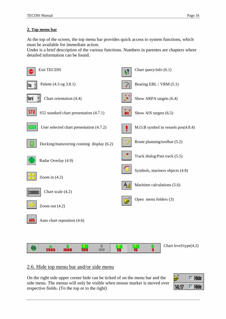
2. Top menu bar At the top of the screen, the top menu bar provides quick access to system functions, which must be available for immediate action. Under is a brief description of the various functions. Numbers in parentes are chapters where detailed information can be found.
Exit TECDIS Palette (4.3 og 3.8.1)
Chart orientation (4.4)
S52 standard chart presentation (4.7.1) User selected chart presentation (4.7.2)
Docking/manuvering conning display (6.2)
Radar Overlay (4.9)
Zoom in (4.2)
Chart scale (4.2)
Zoom out (4.2) Auto chart reposition (4.6)
Chart query/info (6.1) Bearing EBL / VRM (5.1) Show ARPA targets (6.4) Show AIS targets (6.5) M.O.B symbol in vessels pos(4.8.4) Route planning/toolbar (5.2) Track dialog/Past track (5.5) Symbols, mariners objects (4.8) Maritime calculations (5.6) Open menu folders (3)
Chart level/type(4.2)
2.6. Hide top menu bar and/or side menu On the right side upper corner hide can be ticked of on the menu bar and the side menu. The menus will only be visible when mouse marker is moved over respective fields. (To the top or to the right)

TECDIS Manual Page 17
Chapter 3: System settings 3.1. Menu folders/System settings 1. Show menu folders
When pressing menu folder in the top menu bar, menu folders vil open in the lower part of the side menu field. There are 6 different menu folders: data, logg, safety, setup, chart and ship. Folders are separated in a archive system and one of the folders is
displayed at time. Select desired folder by pressing a tag in the archive hieraky. 2. Hide menu folders Press menu folder button again in the top menu bar and the menu folders dissappear from the side menu.
3.2. Setup This folders contains.
1. Ship draught 2. Language selection 3. Time zone selection 4. Nmea input status 5. Nav. Position offset 6. Chart utilities 7. Chart library (installed chart databases) 8. Auxilary 9. Alarm volume (only shown when alarm bell is set to
pc speaker in the setup programme) 10. Hide/unhide tool tip.(see chapter 2.1)

TECDIS Manual Page 18
Ship draught: minimum and maximum ship draught is defined in the setup program (see chapter 7). When TECDIS starts, the maximum draught is used as default, but this can changed in the setup menu folder.
1. Nmea data inputs: Displaying a list describing which ports the various sensor information is recived from. Also displaying which Nmea sentences used and the data communication status. This is only a information window. Changes have to be made in the separate setup program. (see chapter 7). Position fixing: Displays 2 sources for positioning. Primary and secondary can be selected. Primary and secondary can be displayed simultaniously on the chart display. If primary position fixing system falls out, the system automatically uses secondary. If both positioning systems drops out, change over to dead reckoning is executed. (Log+Gyro)
2. Nav. position offset:
Opens a pop up window in the upper right corner on the chart display area. Certain position sensor devices may have good repeatable accuracy, but can have a fixed error for a given geographic area. It is possible to compensate for this type of error at the TECDIS system entering a position offset. To turn this off press nav position offset again.

TECDIS Manual Page 19
3. Dead reckoning mode
If secondary and primary positioning systems drops out dead reckoning mode is activated automatically. Input data from log and gyro are used when available, if not data must be entered manually. Use keyboard “S” to set position to chart center.

TECDIS Manual Page 20
4. Chart library Chart library displays av overview of all chart in a database. Selecting a database from the drop down menu a list with all charts in the database appears, sorted by publisher. Highlight a chart in the list to display further information (middle field). When double clicking on a chart in the list, it will appear if licens is present. When vessel is sailing, vessel is automatically centered. (if not auto function is disabled). NB: Chart library only displays databases selected in setup menu folder.
Chart boundaries: graphically presents coverage of all charts in the database at present level. (Levels comply with scale selected on the top menu bar) Licensed charts are displayed with magenta, non licensed charts are marked with black boundary. Chart names are presented in the bottom left hand corner of the square.

TECDIS Manual Page 21
Remove dataset: If a database contains imported S57 data is selected in the drop down menu, the button” Remove Dataset” will delete selected chart.
5. Import of S57 data NB: When two ECDIS machines are connected, make sure to make the same updates in the second ECDIS. Import of S57 data is done trough the chart library. Select database in the drop down menu and press “Import S57”. A database contains of datasets (charts). ENC data is sold as ENC cells in S57 format. Trough import to a database every ENC cell is converted to a dataset. This is a two step process: verification of data and conversion/compilation to a dataset. To import data, select drive in the field ”Import S57 data from…”. Data is imported to a database which name beginns with S57. However there are none S57 databases present, a new
one (S57) is created. Optional an own database can be created by pressing ”create new database”. S57 database is added automatically and can be highlighted for viewing in setup menu folder.
When drive is selected,the ”start” button is activated. Press the button to commence import. Data is automatically veryfied.

TECDIS Manual Page 22
If errors are discovered a ”S57 Import ERROR report” is shown. The error report contains name of import file and wheater the error are critical or non-critical. Files including critical errors are not imported. If non-critical errors occurs, files can be imported or excluded by pressing ”continue” or skip. If “stop” is pressed the import process is terminated. Disable error report: If this option is selected prior to dataimport, the process will run automatically. S57 importfiles including critical errors will be excluded and files with non-critical errors are imported. NB: When using ”disable error report”, it is impossible to view detailed information about the data import. Also errors reasoning ENC cells not to be imported due to critical errors, are not displayed.
A import log vil be created. This log can be viewed selecting actual dataset in the chart library, by scrolling down to S57 importlog in the information field. If import of chart corrections are done in S57 format, those can be viewed in C-Map chart update (see chapter 3.2.7) By pressing the right mouse button in the message field, log files with information/history about file verifying and compilation are displayed. This is a overview, not a detailed report/log (not displaying any deleted datasets).

TECDIS Manual Page 23
6. Manual chart updates NB: When two ECDIS machines are connected, make sure to make the same manual chart updates in the second ECDIS. One of the main features of the CM-93/3 Chart Database technology is the automatic updating of electronic charts. TECDIS fully supports this feature but manual updating is still important, as local reports about navigational aid changes may not be included in the Notice to Mariners that are used in updating the Chart database. For example, the SOLAS convention requires that all charts must be updated for the intended voyage. Before planning a new route or prior to updating an existing voyage it is strongly recommended that TECDIS be automatically updated and subsequently that any required manual updates have been added. . There are a wide variety of navigational objects listed within the Add New Object function under the menu. Features are sorted in an orderly manner and within each feature, object properties may be chosen. Once the desired object and type is selected, press OK. The object may now be placed onto the screen by clicking the left mouse button. At this time, it may be moved, modified, deleted, cancelled or saved from the Manual Update menu. Once the object has been saved, a graphical presentation of the object will be visible on the screen.
Remove chart corrections: If ”Reject” is pressed the entire update history for a selected object or all objects on the dataset is deleted. This function is only available in service mode. Edit/modify chart corrections: marker the actual object in the left hand list, and press “Modify metrics” (change position) or ”Modify attributes” (edit properties). See under for outfilling info for adding new corrections/objects.
Own objects: All manual corrections are displayed in the chart with orange marking (see pic.). When using chart query/info function, manual updates are marked yellow.
TECDIS Manual Page 24
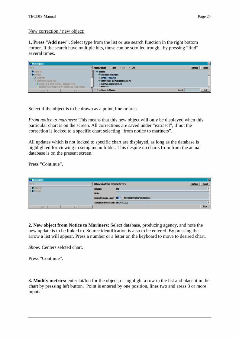
New correction / new object: 1. Press ”Add new”. Select type from the list or use search function in the right bottom corner. If the search have multiple hits, those can be scrolled trough, by pressing “find” several times.
Select if the object is to be drawn as a point, line or area. From notice to mariners: This means that this new object will only be displayed when this particular chart is on the screen. All corrections are saved under ”extrascl”, if not the correction is locked to a specific chart selecting “from notice to mariners”. All updates which is not locked to specific chart are displayed, as long as the database is highlighted for viewing in setup menu folder. This despite no charts from from the actual database is on the present screen. Press ”Continue”.
2. New object from Notice to Mariners: Select database, producing agency, and note the new update is to be linked to. Source identification is also to be entered. By pressing the arrow a list will appear. Press a number or a letter on the keyboard to move to desired chart. Show: Centers selcted chart. Press ”Continue”. 3. Modify metrics: enter lat/lon for the object, or highlight a row in the list and place it in the chart by pressing left button. Point is entered by one position, lines two and areas 3 or more inputs.

TECDIS Manual Page 25
Tab og shift+tab: Move marker between ’Lat’ og ’Lon’ to insert pos. Arrow up and down: Move marker up or down, to select positions. Enter: new pos after the marked pos. Insert: new pos. before marked pos. Delete: delete marked pos. Press ”Continue”.
4. Modify attribute enter/add info regarding choosen object. Select a item in the list, and enter settings in the value field. Use period as desimal symbol for numeric inputs. Scale maximum and minimum is used to select highest scale (lowest number) and the lowest scale (highest number) for the correction/object to be displayed.
For some objects the choosen attributes is selected from a drop down window.
For some objects the value can be one ore more, selected from a list.. Press ’Edit’ to select among these values.
Press ”save”.
5. Modified by: enter name of person who executed the correction. Select name from the drop down meny or enter new, and press OK to complete the manual chart update.

TECDIS Manual Page 26
7. C-Map chart update NB: When two ECDIS machines are connected, make sure to make the same chart updates in the second ECDIS.
Auto updating makes it possible for all subscribers to download updates from databases from the C-MAP internet server. All updates are registered in alog. File size can be checked prior to download by pressing ”size”.
SemiAuto updating is an alternative to auto updating, where download requests and download are done by e-mail. Select chart database to be updated (e.g. World), where the files are to be saved, and enter maximum file size. The update order must then be sent by email to [email protected]. This is an automatic service, and C-MAP will answer within 5 minuters. Answering files must be transferred to the chart system. Select where the files are stored and press “get updates from directory”.

TECDIS Manual Page 27
Updating log / Review updates: the list on the left side, ”updates log”, displaying a complete list of updates which has been received. Status, number og date for update are displayed. The ’Status’ column will either show ’Accepted’ or ’Rejected’. Rejected updates have been rejected or deleted. If the ’Remark’ button is activated, a note about the updates can be displayed by pressing this. The right part of the windows displays a branch-presentation of all the updates, sorted by publisher of the update, chart number and NTM number where the correction is issued. Information about the modified objects can be found under each book number. By double clicking an object in the list, the chart will center on the object, and object is marked with a red circle. (Point-objects are marked with a red circel , lines are displayed red, and areas are filled-in red.) When installing a new CD-rom from C-MAP, all previous updates will be deleted. Manual rejection of updates: choose the update you want to reject by left clicking the update in the “review” section. By right clicking the same update, a small pop up menu opens. Choose “reject update”, and close the updates window in order for the changes to take effect. 8. Chart licenses A list of all the chart lisence is opened in a pop up window. Lisences that are valid for more than 14 days are marked with a green background. Lisences that will expire within 14 days are marked with a yellow background. Expired lisences are marked with a red background.

TECDIS Manual Page 28
9. INT-1 dictionary Opens a list of all INT-1 chart object abbreviations.
10. Charts installed on the system At the bottom of the Setup menu folder there is a view showing which charts are installed on the system. Mark the charts to be used. NB! This field is not displayed if if only one chart database is installed. ENC: official ENC in C-Map sENC format World: non-official C-Map chart. (CD) Professional+: non-official C-Map chart (DVD) S57: official charts from S57 11. Recalibrate screen Restores display to correct calibrated settings.
12. Conning harbour mode og conning aft / for Controls conning manouvering display. 13. Radar overlay setup This selection will activate the radar overlay and bring up the radar overlay setup dialog. Note: The TECDIS Radar Overlay is designed to work with the Furuno FAR-2107/2807 radar series. The primary TECDIS system, the backup TECDIS system (if connected) and analog adapter (if connected) should be configued to the 172.31.3.xxx IP address range in order to receive data from the radar.

TECDIS Manual Page 29
Radar: This value specifies the radar number the system should connect to. This should correspond with the RADAR NO value in the INSTALLATION menu of the Furuno radar. Heading: This control should be used to adjust the orientation of the radar overlay so that it corresponds with the chart display. Range: This control should be used to adjust the radar echo range so that the radar overlay corresponds with the chart display. 14. F1 F2 button setup
This option will display the F1 F2 button setup dialog. If a Furuno RCU-018 control unit is connected to the system, this option allows the operator to specify the functions the F1 and F2 keys on the control unit should activate.
The F1 and F2 buttons can be used for the following functions: Function Description Scale W 1:100M Sets the chart scale to 1:100M Scale W 1:20M Sets the chart scale to 1:20M Scale A: 1:3M Sets the chart scale to 1:3M Scale B: 1:1M Sets the chart scale to 1:1M Scale C: 1:300.000 Sets the chart scale to 1:300.000 Scale D: 1:100.000 Sets the chart scale to 1:100.000 Scale E: 1:30.000 Sets the chart scale to 1:30.000 Scale F: 1:10.000 Sets the chart scale to 1:10.000 Scale G: 1:3.000 Sets the chart scale to 1:3.000 Chart Legend Displays the chart legend for the current chart display (See 3.3.1.) Chart Base Configures the chart display to ‘base’ mode (See 3.3.) Chart selection 1 Configures the chart display to mode ‘1’. (See 3.3.) Chart selection 2 Configures the chart display to mode ‘2’. (See 3.3.) Chart selection 3 Configures the chart display to mode ‘3’. (See 3.3.) ESCAPE function Emulates the ‘ESCAPE’ keyboard key. Enter Manual Position Allows the operator to move the chart display to a specified position.
(See 4.1.1.) Next menu page Switches to the next menu or folder.

TECDIS Manual Page 30
3.3. Chart This folder is described in detail in chapter 4.5 og 4.7. Settings for chart features is done in this window. In the line over the bottom line, 3 user settings can be stored. Select wanted feature by placing a tick in the box, or remove to disable/hide feature. On the bottom line settings for S52 presentation (standard colors and symbols) , INT 1 presentation and text/symbol size can be done. See chapter 4.7 for detailed information.
1. Chart legend Pressing the question mark at the bottom left corner in the chart menu folder, opens a chart information window. If many charts are presented on screen simultaniously a “tag” for each chart is opened. Info box is marked red for centered chart. If yellow text appears when moving the marker over the window, the text is not properly displayed. Version number for IHO presentation library is presented in the header.
2. A brief description of chart features/settings Text (generic): – When activated it allows the display of text that has the category “generic”. It can be names of countries, cities, islands etc. Text (other): other available information not mentioned above will be displayed. Safe hazards: displays hazards inside the safety contour and isolated dangers outside the safety contour, that are deeper than the safety depth. Shallow soundings: displays soundings shallower than safety depth. Deep soundings: displays soundings deeper than safety depth. All depth contours: displays all depth contours, also inside the safety contour.

TECDIS Manual Page 31
Danger symbol: When activated it applies the rule that all obstructions that are shallower than the safety contour should be displayed by a special UNDER WATER HAZARD symbol. Cables and pipes Bottom type Small craft info: display leisure/small craft info, such as information about small craft harbour, hotels, bunker stations etc. Grid lines: displays chart grid. Lights character: displays light character information in the chart. NB: for some lights, for example lights with periods that are longer than 15 seconds, text is shown instead of active blinking. Light cursor info: displays light character information in a textbox by cursor rollover. Active lights: displays lighthouses blinking with right sequence and color seen from own ship. Active lead sectors: extending leading sectors own ships are presently in Simplified symbols: displays simplified S52 standard chart symbols (not for INT1 presentation). Chart quality marks. Ticking of this will make official chart quality marks in the chart visible. Plain boundaries: displays all lines and boundaries as simple lines in the chart. National language: displays names of places in the language the chart was produced in. More info “!” sign: marks objects with a “!” when extra information is available. Unknown “?” sign: marks objects with a “?” when they are unknown or have unkown characteristics.
3.4. Ship 1. Own ship offcenter Location of own ship on the screen. High value: Vessel is placed more offcenter. Low value: vessel is placed closer to screen centre. This function is only active when auto function is enabled. 2. Auto senitivity How often chart to be centered/shifted in Auto mode. 3. Show double cirle The boat symbol can be displayed with or without circles. 4. Course vectors Sets vector length on own ship and targets. (One cross line on vector is one minute). 4. AIS range and track AIS area/coverage and track settings. All targets can be set to active.Detailed info about AIS in chapter 6.5.
5. Wheelover Wheel over line forward distance from Waypoint. Used for autopilot track control and route monitoring.

TECDIS Manual Page 32
3.5. Data 1. Backup Settings for backup/restore of additional data to/from floppy/harddrive or cd is done here. ”To second TECDIS” transfers selected objects to the second TECDIS unit (if connected and configured in Setup). The objects are automatically imported on the second TECDIS. (NB: In order to copy to second TECDIS, IP address must be specified in the setup programme, see chapter 7).
Primary and secondary route are automatically made availabe in the second TECDIS (when two machines are connected). In order to import the route, select “Copy IN from file”, select “import data” in the file type menu, and then select ”ReceivedPrimaryRoute” or ”ReceivedSecondaryRoute” from the list of files. Use ”selection” to selcect what to be copied from/to TECDIS. If ”all” is selcted eveything is copied. If ”limited area” is ticked, selection of data must be done. Press ”Execute” at the bottom to start copying. NB! Backup of own data as tracks, symbols, routes, info, etc. is very important. Make sure important data is backuped to a floppy disk or other media for safe storage.

TECDIS Manual Page 33
3.6. Log TECDIS saves important data (position, course, speed) for own ship, ARPA and AIS targets every minute. Log from a certain date can be displayed in different ways . 20 min.: shows a list with position,course and speed every 20 minute for a selected 24 hour period. Noon: shows a list with position, course and speed for every hour from 12:00 the previous day until 12:00 current day. Sailed distance is shown after every 4 hours, and the total sailed distance is shown at the bottom. By entering a time directly and press details, a detailed log from the selected hour will appear. The log list will contain details updated every minute. Additional to information regarding vessels position, course and speed, info about used charts at the present time is displayed. Scale and chart center is listed and if auto mode was activated it is marked with a cross.Other info is ENC / S52, primary position sensor and GPS status. Manual position offset
activated will also show. See picture. 12 h. ENC use: shows a log of the chart data that was shown on the screen for every minute during the last 12 hours. Logfiles can be saved or printed out..

TECDIS Manual Page 34
Visual playback:
Previous voyage: Logdata can be played back visually by pressing ”voyage replay”. Enter time and date in the window which opens. At the bottom line replay speed can be entered.However can dead reckoning between each minutes logged data be used. Tick ”Use DR” . Vessels will be displayed with a estimated position every second.
Press “STD” to stop the playback and return to current situation. 1. Screenshots Anytime screenshots/pictures from TECDIS can be saved by pressing Control (Ctrl) + Print Screen (Prt Scr). The picture is automatically saved with filename: year-month-date time-second. They will be saved and accessible in the folder c:/programfiles/tecdis/screen. AIS shipsdata opens a shipdatabase, where all received AIS targets are saved with name, MMSI, IMO, call sign and date for last reception from the vessel. By pressing the date button, the situation will be played back in last tracked position. Delete old data: By confirmation one year old date will be deleted.

TECDIS Manual Page 35
3.7. Safety: Safety settings 1. Enter Safety Depth, Depth levels.
After system startup the safe depth is automatically set to 30 meter, but it can be entered manually. All areas in the chart which is shallower than the
entered value, will be colored and critical contour empahized. According to this, depth for shallow and deep areas can be defined.. Dark color for shallow areas, and deep areas will by colored grey. In this manner coloring af various depth areas can be defined by user. NB! Where depthcontour for selected safety depth is not present, the next deeper one is selected. (Some charts/areas containing insuffient data, and non closed contours can not be used as safety contour.) 2. Enter parameter for anti grounding function. Enter settings for safety sector/guard zone for the vessel. (time and sector angle) 3. Define and enter dangerous CPA Use drop down menus to enter time and distance to define dangerous CPA. When a CPA situation arises, an alarm will be given, the target is coloured in red and flashes until the alarm has been turned off. Dangerous targets are shown regardless of
whether the AIS/ARPA functions are enabled, and they are shown in red until the danger is over. By ticking the box “Show danger Cpa”, the cpa is marked in the charts with a green circle on own course vector, and a green square on the target’s course vector (see illustration below). If TECDIS loses the signal from a ship that has an active CPA alarm, a NEW alarm is given: ”Lost CPA alarm” (a ”dangerous” ship has disappeared
from the system). The option to “supress CPA
alarm” is available when shiphandle mode is activated in the setup program. When this box is ticked, a warning is shown in the charts.

TECDIS Manual Page 36
4. User selectable alarms Some alarms and controls can be set by user. New WP / CTS: when approaching a new waypoint (WP) in the present navigation route an alarm can be triggered. (on wheelover line)
World route check: The antigrounding system and route checking always checks ENC data where ENC charts are available. Enabling this check box will activate checking of unofficial World chart data where ENC charts are not available in an area that is checked. Route checking will report alarms from both ENC and World chart data when this option is activated. Restricted areas: gives an alarm if and when the vessel enters a restricted area. Caution area: detects and alerts caution areas, eg Traffic Seperation Systems. The warning is given once, when entering the caution area, and it is selectable if it should be a audible alarm. In the right bottom corner in the side menu, there is a alarm list with all active alarms and warnings, which can be displayed anytime. (Read chapter 5.3.3 for detailed info). Possible danger: gives an alarm for other possible dangers.

TECDIS Manual Page 37
3.8. IHO Presentation library index IHO presentation library provides comprehensive information about vector chart symology (ECDIS), test images.Press Control + alt + shift + T to open library. By pressing numbers 0-9 on the keyboard the pages with sympols appears. For info about the symbols use chart query/info function on the menu bar. (Menu bar is hidden during library presentation, but it will appear moving the marker to the top). Press “Esc” on the keyboard to close library.. Versionnumber for presentation library is found under the menu folder ”chart” (see chapter 3.3)
1. Monitor Calibration All information in electronic chart displays must be highly visible. To ensure this monitor must be calibrated to display correct colors. This is very important, specially for night palettes, when monitor is dimmed. NB: Make sure to test the colours at evening and night colours as well (as for day colours).

TECDIS Manual Page 38
ECDIS colortest for monitor calibration is also placed in IHO presentation library. Open library by pressing Control + alt + shift + T, and select test diagram by pressing A – B – C- D- E eller T on the keyboard.
Brightness check: Open test diagram E and verify that the grey box is clearly visible.
Check colors: Open test diagram T. All diagonal lines to clearly separate from background:
• 3 Yellow diagonal lines • 4 orange diagonal lines • 3 magenta diagonal lines • 4 green diagonal lines • 3 blue diagonal lines • 3 grey diagonal lines
Check visibility of each color in the diagrams (A-E). If the monitor fails the test, it no longer meets the minimum requirements for display performance. It should be evaluated by a qualified engineer and be repaired or replaced it as necessary. NB. If monitor settings has been changed manually in the montor menu, or to make sure correct settings are used, go to ”setup” menufolder, press ”Auxilary” and select ”recalibrate screen”

TECDIS Manual Page 39
Kapittel 4: Chart display area
The following elements are always visible in the chart area:
• North arrow, indicating direction of north when the chart is rotated. • The vertical scale bar along the left edge of the chart area
The scale bar changes color according to the distance between each line (unit):
Scale Interval Colors Unit 1:1 – 1:5000 Yellow / White 0.1 Nm (0.1 ’) 1:5001 – 1:80 000 Red / White 1 Nm (1 ’) 1:80 001 – 1:2 000 000 Black / White 10 Nm (10 ’) 1:2 000 001 – 1:100 000 000 Blue / White 60 Nm (1 °)
If generation of a new chart display takes 6 seconds or more, an indicator appears in the upper left corner of the chart area showing how long in seconds the system has been working on the new chart display. This indicator will only appear when using charts with extremely high information density.
4.1. Set chart center Move marker to desired chart centre and press middle mouse button. Use left mouse button to zoom in and right to zoom out.
When the cursor is moved to the edges of the map, it changes to an arrow. Every click will then move the charts.
Keyboard arrows can also be used to move charts/set chart center. Use ”home” key to center own ship. 1. Set chart center to a specific position.
Chart centre can be moved to a specific dialed in position. In the marker data field in the side menu there is located a button ”Pos.” It opens a pop up box where position can be entered manually. Keyboard “Ins” also opens this box. Enter selected position and press ”chart centre” to centre chart and mark position. This is very handy when adding new objects as symbols, lines and waypoints.
When adding new symbol a second click on “Chart center” vil add the symbol/WP in entered position.

TECDIS Manual Page 40
4.2. Change of chart display scale 1. Zooming, with automatic chart selection Use left mouse button to zoom in and right to zoom out. Optional use keyboard + and – . Marker poition will be new chart centre. The system automatically selects suitable chart depending of selected scale.
2. Manual chart selection From the menu bar charts can be selected directly. The numbers present scale x1000. Select chart and scale by pressing one of the buttons. Optional keyboard can be used to give direct commands, by pressing the wanted scale level letter (W-A-B-C-D-E-F-G).
When letters on the scale buttons are emphasized with yellow text and green back ground, oficial charts are available in this scale.
Official charts always have priority. If system is in auto mode, the scale buttons indicates the scale values of the own ship position. At manual chart selection, they indicate scale for chart center. Grey button is present scale. Text warnings are also displayed in the following situations: Not official chart on screen, refer to paper chart Not official presentation, refer to paper charts or S52 presentation Better ENC is available No chart avaibale, refer to paper charts 3. Zooming withiout changing chart
Using these buttons, zooming in and out in the same chart is possible. The left button decreases the scale (more details), the right button increases the scale. The number in the middle displays present scale.
For keyboard operation use Page up to zoom out in the same chart, and Page Down to zoom in in the same chart.
When moving the marker over the middle fiel, a yellow tool tip line where the charts original scale is shown. By pressing the middle field, the chart is automatically scaled to this. NB! This function can be overruled by charts from another database. TECDIS uses several chart types, but gives
priority to official charts. 4. NB! Over scale

TECDIS Manual Page 41
When lowest scale available in the chart is reached, it is still possible to zoom in. However, be awere that this is only a graphic enlargement and no further details in chart will be available. Possible errors in the charts will be enhanced along with the chart. The middle field will turn
orange when working on overscale.
5. Extra marking of over scale Over scale warning can addittionaly be marked with vertical lines in the chart. This is an automatic function. When parts of the chart is over scaled, these parts will be marked. 6. Under scale When zooming the chart out, the chart can be displayed in under scale. Details can merge /
not be visible. The middle field is marked green when chart is under scaled.
TECDIS Manual Page 42
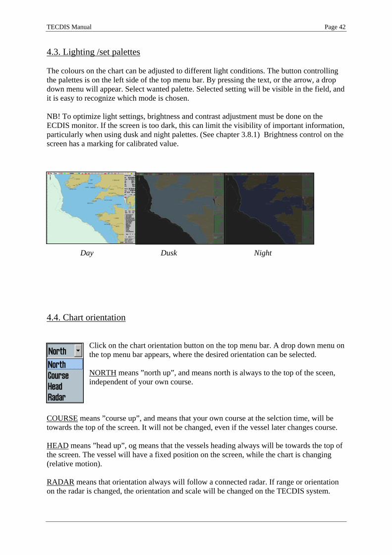
4.3. Lighting /set palettes The colours on the chart can be adjusted to different light conditions. The button controlling the palettes is on the left side of the top menu bar. By pressing the text, or the arrow, a drop down menu will appear. Select wanted palette. Selected setting will be visible in the field, and it is easy to recognize which mode is chosen. NB! To optimize light settings, brightness and contrast adjustment must be done on the ECDIS monitor. If the screen is too dark, this can limit the visibility of important information, particularly when using dusk and night palettes. (See chapter 3.8.1) Brightness control on the screen has a marking for calibrated value.
Day Dusk Night 4.4. Chart orientation
Click on the chart orientation button on the top menu bar. A drop down menu on the top menu bar appears, where the desired orientation can be selected. NORTH means ”north up”, and means north is always to the top of the sceen, independent of your own course.
COURSE means ”course up”, and means that your own course at the selction time, will be towards the top of the screen. It will not be changed, even if the vessel later changes course. HEAD means ”head up”, og means that the vessels heading always will be towards the top of the screen. The vessel will have a fixed position on the screen, while the chart is changing (relative motion). RADAR means that orientation always will follow a connected radar. If range or orientation on the radar is changed, the orientation and scale will be changed on the TECDIS system.

TECDIS Manual Page 43
4.5. Own ship symbol Vessels position is displayed as a double circle with fixed size or as vessel outline, scaled. The system automatically selects what to be displayed, depending on scale and vessel size. When vessel outline symbol is to small, the double cirkle is displayed, othervise vessel outline is displayed in right size according to scale and orientation.
By all chart orientation, except” head”, the chart is fixed to the screen, while the vessel is moving (true motion). By ”head” orientation, the vessel will have a fixed position on the screen, while the chart is changing (relative motion). Own ship offcenter Location of own ship on the screen. High value: Vessel is placed more offcenter. Low value: vessel is placed closer to screen centre. This function is only active when auto function is enabled. Show double circle draws the boat symbol with two circles. See illustrations to the right. Course vectors Sets vector length on own ship and targets. (One cross line on vector is one minute).
Wheelover line distance from Waypoint. New command to track pilot and route monitorin. 4.6. Automatic chart center
Press ”auto” on the top menu bar to activate, or ”home” on the keyboard, or by pressing anywhere in the nav. data field in the side menu. The system will then
automatically ensure that the charts are moved according to the vessel. How often chart to be centered/shifted in Auto mode can be selected in the “ship” menu folder. Select chart scale on the menu bar (this will not abort auto mode).

TECDIS Manual Page 44
4.7. Chart presentation
By using ”STD” and ”USER” it is easy to select chart presentation (or switch between) ECDIS standard or user defined.
1. STD
STD is the official standard ECDIS presentation, S52. This standard is set by IMO, with certain colours, symbols og content (see illustraton to the left. The right hand picture shows user selected INT 1 chart presentation). By pressing STD the auto mode is also activated.
2. User
User displays user defined chart presentation. Settings is done in the menufolder “chart”. (Press the menu folder button on the top menu bar and select “chart” tag.)
In this line (second from the bottom) 3 user defined information standards can be
stored/selected among. Base uses minimum chart information/features. Insert tick in the box to add info, or remove tick to reduce info. (not to be displayed). See chapter 3.3.2 for details. On the bottom line S52 or INT 1 presentation is selectable. (See pictures above) Selecting INT 1 a warning saying “not official presentation, select S52” will appear. The right button controls text and symbol size. By pressing STD text is set to 1.0.
3. Safe hazards Safe hazards displays hazards inside the safety contour and isolated dangers outside the safety contour that are deeper than the safety depth. In STD (standard) presentation, this function is deactivated, but it can also be switched on manually from the chart menu.

TECDIS Manual Page 45
NB: Safe hazards is automatically activated when anti grounding alarm is active. The setting danger symbols marks dangers with a danger symbol. This setting is active as a standard in STD modus, and when safe hazards is switched on in STD mode, all dangers (also inside the safety contours) are marked with danger symbols. When the danger symbols setting is deactivated, only isolated dangers outside the safety contour will be marked with danger symbols.
Standard presentation: STD with safe hazards: Safe hazards: Dangerous objects inside Dangerous objects inside All dangers are displayed, the safety countour, and the safety countour, and but only isolated dangers isolated dangers deeper isolated dangers deeper outside the safety contour than the safety depth, are than the safety depth, are are marked with danger not displayed. marked with danger symbols. symbols.

TECDIS Manual Page 46
4.8. Symbols/Mariners objects It is easy to insert own objects in TECDIS. By pressing the symbol button(keyboard F7 ) on the top menu a window which is named ”Mariners objects” is opened. From here following can be done:
1. Select/show objects
Objects to be displayed can be selected here. Select all, or enter a time window or time limitation for objects to be displayed. Adjust date in fields From, To, After. 2. Add new, modify or delete objects By pressing ”Edit Symbol” or ”Edit line/Area” a new vertical menu bar will open on the left hand side. The 3 top buttons controls following: Delete symbols, change/move symbols and add new symbol. The rest of the buttons in the bar is used to select type and color.
TECDIS Manual Page 47
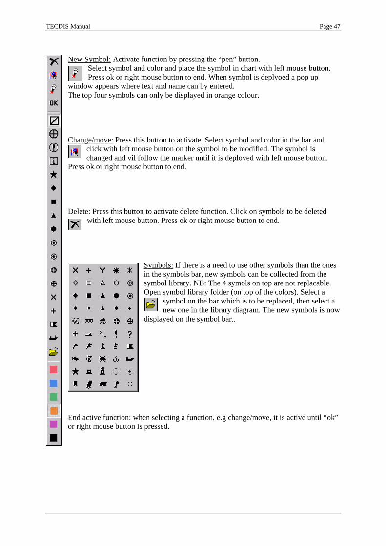
New Symbol: Activate function by pressing the “pen” button.
Select symbol and color and place the symbol in chart with left mouse button. Press ok or right mouse button to end. When symbol is deplyoed a pop up
window appears where text and name can by entered. The top four symbols can only be displayed in orange colour. Change/move: Press this button to activate. Select symbol and color in the bar and
click with left mouse button on the symbol to be modified. The symbol is changed and vil follow the marker until it is deployed with left mouse button.
Press ok or right mouse button to end. Delete: Press this button to activate delete function. Click on symbols to be deleted
with left mouse button. Press ok or right mouse button to end.
Symbols: If there is a need to use other symbols than the ones in the symbols bar, new symbols can be collected from the symbol library. NB: The 4 symols on top are not replacable. Open symbol library folder (on top of the colors). Select a
symbol on the bar which is to be replaced, then select a new one in the library diagram. The new symbols is now
displayed on the symbol bar..
End active function: when selecting a function, e.g change/move, it is active until “ok” or right mouse button is pressed.

TECDIS Manual Page 48
3. Add new, modify or delete lines/areas In TECDIS areas can be deployed in the chart, to mark a shoal for fishing or a dangerous area for voyage planning. Select ”edit area” in Mariners object window or press key board F8. As with the symbols a new bar will appear on the left hand side of the keyboard. Function and operation is similar with the symbol deployment.
Position line: when position line is deployed in the chart a small window appears, where bearing can be locked to observed value.
Position line is deployed with corresponding time mark.
Mark predicted current: enter current speed in knots in the info box which opens after deployment. See example 2 below. The current line is presented in
the chart with time and current speed.
Mark actual current: enter current speed in knots in the info box which opens after deployment. See example 2 abowe. The current line is presented in the chart with time and current speed.
Areas: can be deployed as a line, closed area, cirkle or a rectangular shape. When you begin to draw an area, a pop up windu is opened. By checking the box “fill”, the area will be filled.
When it is deployed in red color, it indicates danger. Red areas will go trough safety check and will be warned with an alarm. (See chapter 5.4) Red areas are always displayed.

TECDIS Manual Page 49
Illustrations for chapter 4.8.3: Lines and areas. 4. M.O.B.: Man over board
This symbol is on the top menu bar. Press once or keyboard F12, to deploy a MOB symbol in own ship position.

TECDIS Manual Page 50
4.9. Radar Overlay TECDIS can be configured to display a radar overlay supplied by the Furuno FAR-2107/2807 radar series. If configured and enabled, the radar overlay can be activated from the toolbar (See 2.4.2.). When activated, the chart display will include an overlay showing the radar image.
Configuration and adjustment of the radar overlay is accessed though the Chart Utilities dropdown in the Setup menu (See 3.2.13.). The radar overlay display is controlled with the radar overlay control dialog in the lower left corner of the chart display.
The first slider on this control (counting from top to bottom) allows the operator to select the color that should be used to draw the radar overlay. In S52 chart display mode, two colors are available; Light or dark green. In INT1 display mode, a additional multicolor mode is available with overlay color varying from green (faint echo) through yellow (intermediate echo) to red (strong echo). The radar overlay transparency can be adjusted with the second slider, with transparency levels ranging from 10 (relatively opaque) to 4 (relatively transparent).

TECDIS Manual Page 51
Chapter 5: Navigation 5.1. Bearing EBL / VRM
Press this button to activate/deactivate bearing function. An EBL/VRM will appear in own ships centre. Initially it is fixed to own ship, but can be moved using left mouse
button.
1. Range and bearings Place EBL in position where a relative bearing is wanted. EBL/VRM vil be centered in the chart where left mouse button is pressed. Bearing and distance is displayed in the marker field in the side menu. Relative Bearings: A small box appears on the screen when deploying EBL/VRM. By entering a value, bearing is locked, but VRM is adjustable
2. Cross bearings Deploy EBL/VRM on fixpoint for bearing. Optional the bearing can be locked by entering observed bearing in the small box. Press center mouse button to deploy a permanent bearing line in the chart.: The bearing line is present as a thicker line. Optional 3 such lines can be created. If more than 3 lines are added, the oldest one disappear. See illustration on next page. If chart is off centered or shifted/changed scale, the lines will disappear.

TECDIS Manual Page 52
Illustration for chapter 5.1.2: Crossbearings 3. ”Quick route”(2 WP) A temporary route can be created by fixing the EBL/VRM in the first waypoint position (WP 1), move the marker to the next desired position for a waypoint, and press right mouse button. (WP 2). This route can be used as a voyage plan for sailing, but it is not saved. To delete it, go to route menu, select and delete.
4. Units of measure for EBL/VRM Select unit in the side menu by pressing “Nm”. Press ”m”to reverse.

TECDIS Manual Page 53
5.2. Route/Voyage planning
A route is a planned voyage containing of numerous waypoints. Press this button to open the route menu bar on left side of the screen.
1. Draw a new route directly in the chart
Press this button for new route. Place the marker in the first waypoint position and press left mouse button. Waypoint 1 is marked W1. At the same time a pop up window
appears at the bottom of the screen. Name the route here an add additional text if necessary. Place marker where WP 2 is to be inserted and press left mouse button.. A line between the two points is deployed. Continue according to this procedure until a route is complete. End inserting of waypoints by pressing right mouse button or ok on the route menu bar. Maximum 500 wapoints can be inserted for a single route in TECDIS. If a turn radius on the route is invalid (for example too big), the turn will not be drawn, and a warning will be given every time the route is selected. Routes can also be made by entering coordinates, using the keyboard. See chapter 5.2.8 (Voyageplanning) To move chart during route planning use middle mouse button to set chart centre, or move the marker towards the limit/edges of the chart display. Use the top menu bar change scale. Key board can also be used to move/centre/change scale during voyage planning.. (see.2.3.1) When a route is drawn or edited, all other existing routes are shown in gray colour in the background. When “active lead sectors” is checked in the chart folder, lead sectors will be shown by the cursor position.
The route is displayed as a red line and the waypoints are displayed as circkles with numbers. The route leg is marked with planned course and speed. Speed value is inside a square shape. NB: when the last way point is within a distance of 0.1 Nm from the first
way point, the route will be sailed in a loop (repeated). When last waypoint is inserted, a safety check is performed automatically. To set the corridor/lane width or to perform safety check, use voyage planning function as described in chapter 5.2.8. The lane borders have different colors, which presents safety

TECDIS Manual Page 54
status. If the route is safe, and there is no warnings, the lane borders are green. If there is warnings the lane borders are yellow. Red indicate danger. If the borders are grey, it indicate that the safety check has failed. This can occur if the distance between two waypoints is too long. Fix it by dividing the leg.
Extend route This button allows you to continue drawing on the selected route from the last waypoint entered.
2. Edit/modify route When this button is active, following is possible:
Wanted action: Procedure: Move/repos. waypoint Click on the waypoint with left mouse button, place marker in new
pos. and press left button again. Delete waypoint Place marker over WP and press right mouse button. Add waypoint Click on leg between two waypoints with left mouse button. A new
waypoint is inserted. Move WP to wanted pos. and press left mouse button to confirm.
An active route can also be edited (while it is being used). When an active route is edited, it is not possible to edit the waypoints that are immediately before and after the ship.
3. Load/select route
Press this button. All saved routes
are displayed. If you intend to sail the route in the arrow direction, select the route using the left mouse button. If route is to be sailed in opposite direction (retour) use right button. Alternatively, routes can be selected by name/id using the pop up window on left side of the screen. Select route, press “ok” to sail in ”arrow direction” or “retour” for opposite direction.
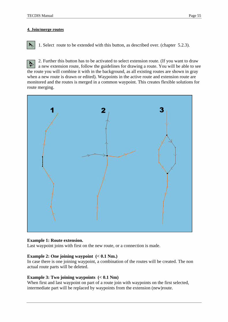
TECDIS Manual Page 55
4. Join/merge routes
1. Select route to be extended with this button, as described over. (chapter 5.2.3).
2. Further this button has to be activated to select extension route. (If you want to draw a new extension route, follow the guidelines for drawing a route. You will be able to see
the route you will combine it with in the background, as all existing routes are shown in gray when a new route is drawn or edited). Waypoints in the active route and extension route are monitored and the routes is merged in a common waypoint. This creates flexible solutions for route merging.
Example 1: Route extension. Last waypoint joins with first on the new route, or a connection is made. Example 2: One joining waypoint (< 0.1 Nm.) In case there is one joining waypoint, a combination of the routes will be created. The non actual route parts will be deleted. Example 3: Two joining waypoints (< 0.1 Nm) When first and last waypoint on part of a route join with waypoints on the first selected, intermediate part will be replaced by waypoints from the extension (new)route.

TECDIS Manual Page 56
The merged/joined route will be presented as a new route, and TECDIS will automatically renumber the waypoints. The joined/merged route can be saved as new route by pressing ”copy active route to new route” button.
5. Use an active route as a template for new route
Use this button to save active route as new route. (Save as)
To create a new route based on a old, without losing the old, a copy of it can be created. By pressing the”copy active route to new route” button, a box opens where it must be confirmed ok. The route now displayed on the screen is a copy which can be changed and modified, and will be saved as a new route. (The old route, is stored in its original). 6. Delete a route
Press this button to delete a route. Active routs can be deleted after confirmation. If there is no active routes, all routes are displayed. Select the route to be deleted. A pop
up windows will appear, requesting confirmation. (Klick OK or cancel). 7. Save, change and print waypoint list
By pressing this button the waypoint list will be opened as a text (txt) file in a pop up window. The list kan be saved or printed to a connected printer. Comments can be
added.

TECDIS Manual Page 57
8. Voyage planning
Voyage planning is activated by pressing this button. It opens a table with detailed waypoint information.
Speed, lane, turn, rate of turn (ROT), time, delay and text columns can be modified, also during a voyage. If 0 is used as value, standard value is used. The value will then be shown in grey. A standard setup for all waypoints, speed, turn radius, and lane width, can be made. By entering the table, and modify the cells for speed, lane, turn radius, delay or text, separate values for each leg can be entered. As an example, a waypoint delay at a port can be entered. This can be very useful for vessels operating in a regular route. In the column for text, comments or names for each waypoint can be filled in. For insertion of further comments and/or pictures/ documents/presentations etc, use waypoint object information. To modify the route itself, ”edit waypoint” must be ticked or activate “edit” button on the route bar (as described in point 5.2.2). When finished the route safety check will be activated automatically. The ‘Lane’ checkbox toggles display of route lanes in the chart display. The ‘Info’ checkbox toggles display of planned course and speed on route legs. NB! When voyage planning is in ”edit mode” the route monitoring function is OFF. (No track commands to auto pilot is given.) 8.1. Manual registration of position Click the position field in the side menu, and enter the first coordinates with keyboard. By pressing “enter” next waypoint is centered on the screen.
Column Explanation Wp Waypoint number GC Great circle Lat. Waypoint latitude Lon. Waypoint longitude Dist. Distance to the next waypoint Course Course to next waypoint Spd. Planned speed Lane Lane/corridor width Turn Turn radius ROT Rate Of Turn Time ETA waypoint Delay Waypoint delay Text Waypoint name and additional information

TECDIS Manual Page 58
8.2. Waypoint list By clicking a waypoint in the list which is not displayed on the present chart, the chart will be centered at chosen waypoint. NB! This function is disabled if auto mode is activated; the chart is then following the vessel. Waypoints can be added or deleted in the voyage planner. To add a new waypoint, select a waypoint in the list, and press keyboard ”insert”. A new waypoint is added in between the previous waypoints, which are moved to actual position. To delete a waypoint, select the waypoint on the list, and press keyboard “delete”. 8.3. Zone At the bottom left corner in the voyage planner, enter time zone for correct time presentation. 9. Great circle routes Great circle or rhumb can be selected for each leg in the voyage. This is selected/changed by clicking in GC field for the actual leg. If great circle is selected the line in this field will be curved. The color of the line in the field will as well indicate safety status ( red=danger, orange = warning, green = ok, grey = safety info not available).
When great circle is selected, extra waypoints are added in the list. They are intermediate waypoint on the great circle. The great circle voyage consist of numerous rhumb line legs.

TECDIS Manual Page 59
5.3. Route navigation See chapter 5.2.3 for information on how to select and activate a route. When you choose a route to use, and the ship is more than twice the corridor width away from the route, a message will request that you choose which waypoint to aim for first. After confirming this message, choose the waypoint by clicking on it. When the last waypoint is passed, the route will automatically be deactivated.
When navigating on a route (an active route is displayed on the screen), opens a info field in the lower part of the side menu. Here is following information displayed: distance (DTG) and Estimated time of arrival (ETA). In the field below bearing and distance to next waypoint is displayed. The bearing beetween next waypoints are also displayed (small char.) In the third field route deviation is displayed. Lane width is displayed by in the long horisontal field. Deviation is displayed graphically; deviation to port is marked red and green to starboard.. XTE is cross track error (i nautival miles or meter, depending on setting in position field) Dev. is course deviation compared to CTS (bearing to next waypoint)
1. Primary and secondary/alternative route. With the three top buttons in the route menu bar route selection can be done. Two routes can be displayed at the same time (1 and 2), and it is possible to switch between which to be primary and secondary. Active route is marked red and secondary route is displayed as dash line. To switch routes press the button ”1:2”.
Transfer of primary and secondary route to second TECDIS: When two TECDIS units are present in the installation and an IP address for the second unit has been configured in the Setup program, the current routes (primary and secondary) will automatically be transferred to the second TECDIS unit. These routes will be available
for import using the data import functions (See chapter 3.5: Data). The file names of the received routes are ReceivedPrimaryRoute.lst and ReceivedSecondaryRoute.lst.

TECDIS Manual Page 60
2. Critical point – route warnings.
You can enter your own route warnings or reminders anywhere on the route. Activate chart query/info function, on top menu bar, and click on the route at the point where you want to enter the warning. A info window opens and function ”Warning before point” in the bottom left corner can be activated. Tick this box and enter time or distanse before WP the warning/alarm shall be
triggered. The critical point will be marked with 4 red event symbols. NB: Critical points are calcuated and warned in a straight line from the vessel to the point. When the warning has been given and turned off, the critcial point symbols change to green colour, and disappear from the alarm list. To delete a critical point, click on it wit the chart query and remove the marking in the checkbox “Warning before point”. 3. Route dangers and warnings TECDIS is performing automatically a route safety check and generates a list containing dangers and warnings for the entire route. In the route menu bar there is a button with a
triangular symbol. On the triangel there is a question mark or a exclamation mark. If the question mark is displayed a list must be generated. Press the button and a new route
safety check is performed.
When the question mark is changed to a exclamation mark, there is a list presenting route dangers and warnings. Press the button to display the list.
The first number indicates for which waypoint the warning is issued. If it is followed by= mark it means the danger/warning is located between two. If the number is followed by a + mark it indicates that the danger is located close to a waypoint/turnradius.
Warnings are marked yellow, and listed first . They will be followed by the dangers which are marked red. By pressing on the yellow warnings, the chart object inspector window will open with a detailed information about the area/warning. All warning areas will be centered on the screen (automode must be disabled) with red markings when selected. This will also give visual over where the dangers are. .

TECDIS Manual Page 61
4. Calculate voyage time Change between ETA according to planned speed or ETA according to current speed. Move marker over the field displaying DTG and ETA and press left mouse button. ETA for a selected waypoint can be viewed by clicking on the actual waypoint with left mouse button. To return to display ETA for final WP press header in the field ”To wp xx …”. In the woage planner it can be calculated ETA by entering various speeds. NB! By selecting ETA for a waypoint and additionally enter a specific time, standard speed for ETA is calculated. Reduced leg speeds and delay times are considered in the calculation.
5. SAR: Search and rescue
SAR: TECDISs Search and Rescue function is able to generate different
SAR patterns as lines(Line) or as sailable routes (Route). A click on the ” SAR” button opens a pop up window. Here can search pattern (type), start position and futher settings be done. Select search pattern first and TECDIS is able to create the most common ones.: Sector, Extended Square and Parallel.
Sector Extended Square Parallel
These search patterns are easy to adjust, for the actual scenario. Length of lines, number of lines and distance between lines are adjustable using the menu settings. Set search direction by entering ”Start Course”. Select pattern origin in own ship or chart centre.

TECDIS Manual Page 62
5.4. Track Control Refer to Raytheon Anschütz AP2025 PLUS User Manual for operation of this autopilot.
If the system is connected to a Raytheon Anschütz AP 2025 Plus autopilot, an additional field is displayed above the alarm display area in the lower right corner of the display. In this field, the current operation mode of the autopilot is displayed.
The possible values for AP mode are: Offline No data is being received from the autopilot. Manual The autopilot is currently in manual steering mode. Heading ctrl The autopilot is currently in Heading control mode. ROT control The autopilot is currently in Rate of Turn control mode. Track Control The autopilot is currently in Track Control mode. External The autopilot is in External (Remote) mode and the autopilot remote Control dialog is shown in TECDIS (See below). Override Refer to autopilot manual 1. Activating Heading control mode The ‘Heading’ button will set the autopilot to heading control mode. 2. Activating Track Control mode
The ‘Track’ button will initiate Track Control mode. In order for this mode to be available to the operator, a number of preconditions must be satisfied:
• A route must be selected and activated for route monitoring. The ‘Track’ button is disabled if no route is selected and activated.
• The distance from the vessel position to the activated route leg must be within the distance limit specified by the ‘max lane deviation’ parameter in Setup (See 7.6.1.). (If the distance from the vessel position to the route is larger than this limit when the route is activated, the system will request the operator to specify the starting waypoint for route monitoring. When a waypoint is selected, the system will set up a temporary route leg from the vessel position to the starting point. This can be edited if needed.)
• The difference between vessel course over ground and planned heading must be less than the limit specified by the ‘max course deviation’ parameter in Setup. (See 7.6.1.)
• The vessel speed must be larger than the limit specified by the ‘Min speed’ parameter in Setup. (See 7.6.1.)
If any of these preconditions are not met, the problem will be communicated to the operator.

TECDIS Manual Page 63
3. External (Remote) mode
When the autopilot is set to External (remote) mode, a dialog is displayed in TECDIS, showing the current heading, the current Set Course and the current Set RoT (Rate of Turn). The current Set Course can be adjusted by either dragging on the rotational control immediately below the Set Course value display with the left mouse button depressed. The currnet Set Course can also be adjusted by clicking on the red and green arrows below the rotational control. The Set RoT can be adjusted by dragging the slider immediately below the Set RoT value display with the left mouse button depressed.

TECDIS Manual Page 64
5.5. Warnings and Alarms Various situations shall and will be alerted with alarms. Alarms are given with the chosen source (sound) in the setup programme. Warnings are only alerted with a sound alarm when this is specified in the safety menu folder (see chapter 3.7). All warnings and alarms are shown on the bottom right of the screen. The alarm field shows, in prioritized order, the next alarm that shall be acknowlegded:
• The oldest alarm that hasn’t been acknowledged • The oldest warning with sound that hasn’t been turned
acknowledged • The oldest warning that hasn’t been acknowledged
An alarm is acknowledged (the sound is stopped) by clicking anywhere in the chart or at the alarm field; by pressing space or escape on the keyboard, or from the connected alarm central. When there are several alarms that haven’t been acknowledged; the first click opens the alarm list. All alarms are acknowledged at the second click, and by the third click the list is closed again. Click directly in the alarm field or use space on the keyboard to acknowledge one alarm at the time. 1. Alarm list
The number of active alarms and warnings are indicated below the alarm field, and by pressing ”show”, a complete alarm list is opened. This list contains information about alarm type, time and status. Alarms that haven’t been acknowledged are marked with a red background, while unacknowledged warnings are marked with a yellow background.
When the alarms have been acknowledged, they are still shown in the alarm list as long as they are active. See the illustration to the left. By clicking on an antigrounding alarm or a “Possible danger” warning, a separate list is opened (see 5.5.). When the alarm “Ship CPA” is shown, the target AIS/ARPA information can be opened simply by clicking on the text in the alarm type field.

TECDIS Manual Page 65
2. Alarm- and warning messages The following alarm messages can be shown:
Text in the alarm field
Description
! DANGER ! Anti grounding. Click to open a separate list. Ship CPA Danger of collition. (see chapter 3.7.4). By clicking on Ship
CPA in the alarm list, AIS/ARPA target information is shown. Lost CPA Lost signals for a target that has an active CPA alarm. Point Info OFF TRACK When sailing a route, the vessel has moved outside the route
lanes. New WP New waypoint, when this has been defined to alerted with an
alarm. (see chapter 3.7.4) Lost Sensor! Position 1
TECDIS is no longer receiving data from sensor for posisjon 1.
LOST SENSOR! Position 2
TECDIS is no longer receiving data from sensor for posisjon 2.
Sensor Error! Pos.1 Wrong Datum
Sensor for posisjon 1 is sending in a different datum than WGS84.
Sensor Error! Pos.2 Wrong Datum
Sensor for posisjon 2 is sending in a different datum than WGS84.
Danger OBJ Own object with danger marks within the safety corridor. ALARM Other alarm situation, check alarm list. ALARMS Shown when there are 2 or more active alarms, and when all
alarms and warnings have been turned off. The following warnings can be shown:
Text in the alarm field
Description
new CAUTION The vessel is entering a new area with special conditions. By clicking on the text “new Caution” in the alarm list, it is marked with red colour in the chart.
Lost Sensor! COG/SOG 1
TECDIS is no longer receiving data from sensor for COG/SOG 1
Lost Sensor! COG/SOG 2
TECDIS is no longer receiving data from sensor for COG/SOG 2
Lost Sensor! Heading 1
TECDIS is no longer receiving data from sensor for Heading 1
Lost Sensor! Heading 2
TECDIS is no longer receiving data from sensor for Heading 2
Lost Sensor! Water Speed
TECDIS is no longer receiving data from sensor Water Speed
Lost Sensor! Radar Arpa 1
TECDIS is no longer receiving data from sensor Radar Arpa 1

TECDIS Manual Page 66
LOST SENSOR! Radar Arpa 2
TECDIS is no longer receiving data from sensor for Radar Arpa 2
Lost Sensor! Radar Cursor 1
TECDIS is no longer receiving data from sensor for Radar Cursor 1
Lost Sensor! Radar Cursor 2
TECDIS is no longer receiving data from sensor for Radar Cursor 2
Lost Sensor! AIS
TECDIS is no longer receiving data from sensor for AIS
Lost Sensor! Depth
TECDIS is no longer receiving data from sensor for Depth
Lost Sensor! Relative Wind
TECDIS is no longer receiving data from sensor for Relative Wind
Lost Sensor! Route
TECDIS is no longer receiving data from sensor for Route
Possible Danger Antigrounding; possible dangerous object within the safety zone.
Lost backup link to other TECDIS
Lost communication with other TECDIS (Error when transferring routes).
WARNING Other warning, check alarm list
The TECDIS system gives warning if there is a GPS position error. GPS status is displayed in the positionfield on top of the side menu. If GPS is missing ,”GPS missing” is showed in red (see illustration). If there is a GPS position error, ”GPS error” is showed in red. If primary position reference is out and secondary is used, ”GPS sens.2.” is displayed

TECDIS Manual Page 67
5.6. Anti grounding By use of anti grounding system TECDIS checks and monitors a sector ahead of the vessel and warns dangers and warning areas. This is done under certain conditions: A dash line displays the vessels guard/lookahead/safety sector in the chart. The system monitor/check/alarm warnings and dangers inside this sector. If vessels deviates out of lane/corridor this will also give an alarm..
Voyage anti grounding alarms When a danger is detected, TECDIS will automatically display the danger. The auto function is activated (chart centres on the vessel). The alarm field will show either ! DANGER ! or Possible danger. By opening the alarm list and clicking on one of these messages, a list of antigrounding alerts will be displayed. When a specific danger is selected, it will be shown with red markings in the chart, and the chart will be centered on the danger.
1. Set safety sector Use menu folder ”safety” to modify size of the safety/guard sector. (time and sector angle) (Press the menu folder button on the top menu bar and click on the tag ”safety” Other safety settings are executed in the same menu folder as written in chapter 3.9

TECDIS Manual Page 68
5.7. Past Track (History)
Press this button to display vessels track from earlier voyages. A pop up window opens, and tracks to be displayed, can be seleted. Select which information to be displayed by ticking the boxes. Name and time mark/interval can be selected for
displayed tracks. Interval for time mark is selected by pressing the arrow to the right of the time mark setting.
Select which tracks to be displayed. Use date settings to display former tracks or/in wanted periods. At the same time, tracks after a set date is displayed. 1. Select or delete tracks: Additionally a certain track can be selected with the boat hook button. Use delete function “cross” to delete tracks. (Click on the buttons first and activate, then click on the track to be selected or deleted). NB. Only tracks older than 3 months can be deleted! Tracks from secondary position sensor can also be presented in the chart. Use the bottom field in the track menu to set up. Tracks from primary position sensor are black and for secondary position sensor, grey.
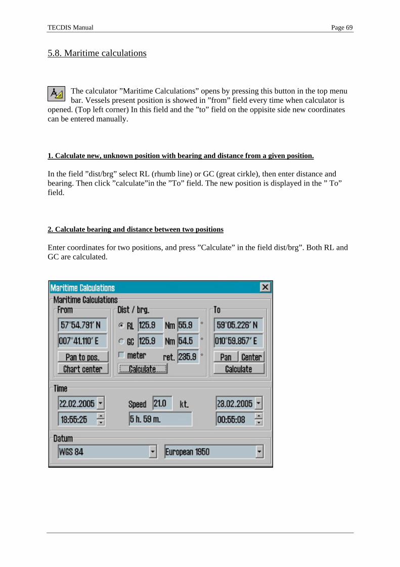
TECDIS Manual Page 69
5.8. Maritime calculations
The calculator ”Maritime Calculations” opens by pressing this button in the top menu bar. Vessels present position is showed in ”from” field every time when calculator is
opened. (Top left corner) In this field and the ”to” field on the oppisite side new coordinates can be entered manually. 1. Calculate new, unknown position with bearing and distance from a given position. In the field ”dist/brg” select RL (rhumb line) or GC (great cirkle), then enter distance and bearing. Then click ”calculate”in the ”To” field. The new position is displayed in the ” To” field. 2. Calculate bearing and distance between two positions Enter coordinates for two positions, and press ”Calculate” in the field dist/brg”. Both RL and GC are calculated.

TECDIS Manual Page 70
3. Calculate time between two positions with a given speed In the ”Time” field on the middle of the caculator, the sailing time between two positions (entered in from/to field) is estimated. Set speed value in the speed field. Sailing time is automatically calculated. Settings as departure, arrival and speed can be edited. 4. Chart datum calculation The TECDIS system uses WGS 84 for internal calculations. If positions from a other datum shall be used in WGS 84 they can be converted in the calculator. This is done on the bottom line. Use left datum field for “From” position and right for ”To” position. This is only a calculation and will have no effect on the system itself.

TECDIS Manual Page 71
Chapter 6: Chart object information, etc. 6.1. Chart object inspector
If detailed information about data in vector charts are to be displayed use the chart query/info button on the top menu bar. When this function is activated a marker with a question mark will appear. Use left mouse button to select object or click anywhere in
the chart to display detailed object information. A pop up window in bottom of the screen will appear. In the left column an item list is displayed. Detailed info for each item is displayed in the left column (as light charcteristics). Manual chart corrections are displayed yellow.
By clicking on a item in the list, detailed info will appear to the right. The chart object which is selected on the list is marked red in the chart. (as right hand pic.) (som vist til høyre). NB: Press Chart Query/Info button on the top menu bar one more time to deactivate. Or right mouse button.. 1. Own object/Mariners object information Chart info/query can also be used to inspect own objects. Description and additional information can be entered. By selecting a inserted object with the chart query/info function, a brief description up to 30 characters can be entered(left coulmn) in the appearing window. This text will be displayed in the chart. Additionally 4800 characters can be entered in the info field(right column) (will not be displayed). The screen keyboard can be used to type.

TECDIS Manual Page 72
6.2. Docking Conning display
By pressing this button on the top menu bar a small, but usefull conning information window
opens. Usefull for harbour and close to installation manouvering. Can be dragged and dropped using left mouse button. By clicking on the wind arrow, the display changes between “true” and “relative” wind. The active choice is marked with a “T” or “R” next to the wind speed. By clicking on the wind speed, the display changes between meters per second (m/s), knots (kn) and Beaufort (B).
6.3. Tides info
”Tide” button on the side menu opens a pop up window with tidal information from closest tidal prediction station.. Time for high and low water is displayed in the bottom of the window.
Present status information is displayed in the fields ”Time” and ”Tide” In the date field day can be selected. 24 hour tidal curve is also displayed. Range is adjustable for the graphical presentation.

TECDIS Manual Page 73
1. Select tidal prediction station
The system automatically displays data from closest station when using the ”Tide” button as described above. To select other station press on of the magenta diagonal squares symbol in the chart with left mouse button.
6.4. Show ARPA (radar) targets
Activate this button to display targets from radar on the chart.The
radar targets will be displayed as green ring with a vector. By clicking on a target with left mouse button, opens a pop up
window with detailed target info. (see right example). Additionally it is possible to save or delete target track (history); Tick the CPA selection and a CPA line will be displayed in the chart. NB! The ”Arpa” button only appears on the menu bar when targets are received from radar. If signals are received from two radars, two “Arpa”buttons is present on the top menu bar.

TECDIS Manual Page 74
6.5. Show AIS targets
AIS data is displayed in TECDIS by use of this button (NB: if no AIS data is received, it will not be possible to activate the button). AIS targets are presented as green triangles in the chart. An ”active” AIS target is presented by a larger symbol, course vector and track (history).. Non “active” targets is only presented with a smaller symbol as shown to the left. AIS targets are activated when placing the marker over or click on it with left mouse button. All targets can be set to be active. (see chapter 3.4) When placing the marker over a target, name of the vessel is displayed.
Each vessel can be seperate activated or not (sleeping target) by tick/untick the box in the target info window.

TECDIS Manual Page 75
A click with left mouse button on a AIS target, will open a pop up window (target window) with detailed target information. Target track can be saved or deleted; decide if CPA line to be displayed (tick CPA); send a AIS message to target or display detailed target info by pressing the ”AIS” button. In the first illustration in this chapter this is showed. Deactivate “AIS” button to hide additional data. Close target window by pressing “OK”. Selected AIS target will have a black rectangle around it.
Showing dotted rectangle around selected AIS target.
1. Own ship AIS information To display or edit own ship AIS info click with left mouse button on own ship in the chart. A target window as for target vil appear. This window is marked ”Own ship AIS data”. By pressing the “AIS” button in the own ship AIS window, present AIS data for own ship is displayed. By pressing “Change” a new window opens where information can be modified.. (Enter vessel type, status, destination, possible dangerous goods, number of persons and draught)

TECDIS Manual Page 76
2. AIS broadcast message Open ”own ship AIS data” window as described above. By pressing the ”Message” button a broadcast message can be transmitted. This will enlarge the window and new message can be written. Previous messages can also be retransmitted. (Drop down menu)
3. Write a message to a vessel To write a message to a specific vessel, click on the target on the screen. In the appeared target window press ”Message” button. This will enlarge the window and new message can be written. Previous messages can also be retransmitted. (Drop down menu). Messages older than 3 months are deleted automatically.
4. AIS range and tracks Use this setting to define range and tracks for AIS targets to be displayed. Go to the menu folder ”ship” in the side menu, by opening the menu folders from the top menu bar..

TECDIS Manual Page 77
Chapter 7: The Setup Program (NMEA selection) 7.1. Service mode (Windows) When you exit TECDIS (using the button at the upper left corner), the chart plotter will automatically be turned off after you confirm that you want to exit. In order to exit TECDIS without turning the chart plotter off, you must insert the USB service key (memory dongle) before you exit TECDIS. When this service key is connected to the chart plotter, the chart plotter will not be turned off when you exit TECDIS and you will be able to work in Windows (service mode) and open the Setup program by double clicking on the Setup icon on
the desktop. When service mode is available, a text indication is shown in the lower right corner of the chart.
7.2. NMEA data setup
Use this tab of the setup program to configure input and output signals. This is done by selecting the type of NMEA messages for each sensor type and the COM port where the signal is connected. There are four main areas of this tab: “Inputs”, “Outputs”, “Port Activity” and “Received data on port X”.

TECDIS Manual Page 78
7.2.1 Inputs Note: All position inputs to TECDIS from all external sensors must be in WGS-84 format. In the first area (“Inputs”), you can configure the message type and source of the different possible sensor inputs. In the first column, “Select sensor” you can select which sensor you want to configure. In the box next to “Sentence” you can select the type of NMEA sentence this input should be read from on a drop down menu. For more information about the different NMEA sentences, see the table below. In the third box, (“Port”) you can select the COM port the selected sensor data type should be read from by using the two arrow buttons at the bottom of the column (to the right of the drop down menu for speed/port). In the fourth column, “Sensor Description”, you can manually enter a text description that identifies the source instrument of the sensor data. NB: When there is a port collision (when there is an attempt to use the same port for multiple conflicting functions), the affected ports are marked with red colour.
IP ports: TECDIS has 10 COM ports and 4 IP ports. For each IP port, the IP address and port number must be entered. The
“Test” button establishes a connection to the IP server with the selected address/port number and the “Received data” area will show any data that is received. Example: In order to receive position data from a GPS, you need to:
1. Select “Position 1” or “Position 2” from the “Select sensor” column. 2. Select the COM port the GPS is connected to in the “Port” field. 3. Select the NMEA sentence type to be used. 4. Optionally (but recommended) enter a description identifying the sensor as a GPS in
the “Sensor Description” field. If the sensor signal is lost while the TECDIS is in operation, an alarm will be sounded. The alarm message will indicate the type of sensor lost as well as what port it is connected to and the sensor description you enter in this field. This way, you can quickly identify the failing instrument (instead of having to refer to the configuration in the Setup program). NMEA Sensor inputs and their status can also be displayed in TECDIS. (See chapter 3.1.3.1).
7.2.2 Speed In this field you select the data speed to be used for the COM port of the currently selected sensor. The NMEA standard is 4800 (low speed). Be aware though that some instruments require a different data speed selection. There is also a NMEA high speed standard (38400). AIS units typically use high speed in order to transmit as much data as possible. (Select AIS in the “Selected sensor” column and check that the “Speed” field indicates the high-speed setting). The speed is changed by selecting the speed from the drop down menu.

TECDIS Manual Page 79
NMEA sentence
Description
APB Heading/Track Controller (Autopilot) Sentence ”B” DBT Depth Below Transducer DPT Depth GGA Global Positioning System Fix Data GLL Geographic Position – Latitude / Longitude GNS GNSS Fix Data HDT Heading, True MWV Wind Speed and Angle OSD Own Ship Data RMB Recommended Minimum Navigation Information RMC Recommended Minimum Specific GNSS Data RSD Radar System Data RTE Routes RTE TTM Tracked Target Message VDO UAIS VHF Data-link Own-vessel report VBW Dual Ground/Water Speed VHW Water Speed and Heading VTG Course Over Ground and Ground Speed VWR Relative (Apparent) Wind Speed and Angle WPL Waypoint Location
7.2.3 Outputs In this area you can select which NMEA sentences you want TECDIS to output. In order to send a NMEA sentence type on a COM port, put a check mark in the box at the intersection of the desired sentence type row and COM port column. You can find descriptions of the different NMEA sentence types in the table above. Regarding the RTE route sentence; note that TECDIS will send up to 10 of the next waypoints of the currently active route. By selecting ”Activate conning IP server port 2001” you activate a TCP/IP server in TECDIS for data transfer to the TECDIS Conning program. This option should only be selected when a connected TECDIS Conning unit should use data from TECDIS. 7.2.4 Port Activity In this area you can see which ports that are receiving data. Whenever data is received on a COM port, the corresponding indicator in this area will flash green. The indicators are for COM ports 1-12 in increasing order from left to right.

TECDIS Manual Page 80
7.2.5 Received data In this area you can see the data that are being received from the COM port that is marked with green in the “Input” area. By clicking on one of the other COM ports in the “Input” area, the data shown in the “Received Data” area will change correspondingly. 7.2.6 Monitor and alarm ctrl Monitor Ctrl: Select the COM port that the monitor is connected to in this field. This connection will control the monitor background light and calibration settings, as well as the alarm sounder in the screen unit. (if used) Alarm ctrl: Select the COM port that should be used for the alarm central interface. (if used) RCU-018 ctrl: Select the COM port that the Furuno RCU-018 keyboard and trackball control unit is connected to. (if used)

TECDIS Manual Page 81
7.3 Specification On this tab, the dimensions of the vessel and the placement of sensors on the vessel is specified. Specifying the position of the sensors is important in order to get the highest possible accuracy in position (GPS antenna) and other data as possible.
• In the “Ship Size” area, enter the length, beam, draught and height of the vessel in meters. For length and beam, the largest extent of vessel length and beam should be used.
• For draught and height you enter the largest possible height and draught taking load
conditions into consideration. • When a second TECDIS unit is present in the installation (for example, bacup unit).
The IP address of the second TECDIS unit should be entered in the ”Data export IP” field. This will activate automatic transfer of active routes to the second TECDIS, and it will be possible to transfer data (objects, tracks, routes) to the second unit.
• Backward (gyro-180º): checking this box turns the heading value from gyro 180
degrees.
• In the “Alarm” area, you can select whether sound alarms should sound through the PC speaker in the chart plotter, or through the monitor buzzer.

TECDIS Manual Page 82
• If two positioning methods are in use, the button “Erase Secondary past track” allows
you to remove the past track line from the secondary position sensor.
• Arpa is conning referenced: when this checkbox is marked, it is assumed that target information from Arpa radar is already adjusted to the navigator position. If it is not marked, TECDIS will do the necessary adjustments.
• Raise alarm if HDT1-HDT2 > 2.5º: when this box is checked, an alarm will be given
if the heading from the two sensors ”Heading 1” and ”Heading 2” deviates with more than 2.5 degrees.
• Shiphandle mode (selectable CPA alarm): when this option is activated, it will be
possible to suppress CPA alarms (see chapter 3.7.3). 1. Save and restore setup default values By clicking the button “Save setup default values”, all settings in the “Nmea data” and “Size and sensors” tabs are saved as default settings. If temporary changes to the settings are made later, the default values can be restored by clicking the button “Restore saved default values”. For future use and to be certain that no misunderstandings may occur regarding the installation we recommend that the service engineer saves the default setup file to floppy disk or other media. He can then keep this file in his personal register of TECDIS installations. The file is located at: C:\Program files\TECDIS\dta4.setup

TECDIS Manual Page 83
7.4 Chart Installation / Misc
7.4.1 Install, update or remove chart databases By clicking “Copy”, a new area with an overview of installed chart databases is opened. Insert the CD for the chart database that is to be operated on and select the CD-ROM drive from the drop down menu below the database list. The Setup program will read the CD and display the available actions for the chart database. (Install, Update, Remove and ‘Set as Default’). Important: ‘Purchase’ chart licenses are locked to a specific edition of the chart database. If a different edition of the database is installed, new licenses must be acquired. ‘Subscription’ licenses remain valid when newer chart database editions are installed.

TECDIS Manual Page 84
If a CD is not available for the chart database (As would be the case for databases containing imported S57 data), these databases can be selected for modification by choosing a drive other than the CD-ROM drive from the drive drop down menu. (For example D:\). When Setup is unable to find a chart database on the selected drive, you get the option to manually select an installed database by pressing the button “Select an Installed DB”. You will get two options for the database you select from the list of installed databases: “Remove” and “Set as Default”. We recommend that the “World” database should be set as default, if installed.
Important: Some chart databases are protected and cannot be removed unless you have a CD for the database available.
7.4.2 Enter vessel information: In this area, information about the vessel and owner should be entered. This information is needed for chart licensing and warranty purposes.
7.4.3 Send registration When the vessel information has been entered and stored, the option to send registration will be enabled on the main area of this part of the Setup program. If “Send on Diskette” is selected, the registration file will be saved to an inserted diskette. If “Send Manually” is selected, the registration file will be saved on the hard drive and a message informing you about the file name and location of the file. Send this file to the specified email address whenever the “Vessel information” data is changed.

TECDIS Manual Page 85
7.4.4 Start C-Map GeoDatabase Administrator By selecting a chart database and clicking “Check Signature”, it is possible to verify that the database has not been corrupted and is in the same state as when provided by C-Map. 7.4.5 Install new Color Calibration file The “Install new Color Calibration file” button is used to load a new color calibration data file (Extension .czp) that will ensure that the colors used in the chart display are as accurate as possible. Such a file is either received with the monitor or obtained from Furuno Norway, Telko AS or the producer of the monitor.

TECDIS Manual Page 86
7.5 Licensing
7.5.1 TECDIS license By clicking “Show / edit license” information about the current system license is shown as illustrated below. This information includes the license number and version information, and a list of installed optional components in blue in the right part of the area. In order to activate additional optional components, a password for this should be entered in the “Password” field and the “Program” button should be clicked.

TECDIS Manual Page 87
7.5.2 C-MAP License Add licenses manually: Select the zone or area you have received a license for in the window to the right (under “Data set or Area name”). The 16-character license code is entered in the “License string” field. Finally, click on “Add License” to activate the license.
Add license from file: Use this option if you want to use a supplied password.usr file to activate chart licenses, browse to the location of this file and select it and press “OK”. The licenses contained in the file will be automatically activated.
In this area, it is also possible to get a list of licenses that are expired and no longer valid (“Get expired licenses”), to see a list of all valid licenses (“Licenses list”) and to generate an order file for new licenses (“License order”).

TECDIS Manual Page 88
7.6 Track Control
On this tab, settings for connection to Raytheon Anschütz AP2025 PLUS autopilot and Track Control can be set. Refer to Raytheon Anschütz AP2025 PLUS Installation Manual for installation and configuration of the autopilot. NB: The autopilot and TECDIS must be supplied with the same heading and log sensor inputs! 7.6.1. Starting Requirements The values in this area specify the conditions needed before Track Control mode can be activated. Max course deviation The maximum number of degrees the course over ground
(COG) of the vessel can differ from the planned course. Max lane deviation The maximum distance of the vessel position from the planned route leg, expressed as a multiplier of the planned route leg lane width. (For example, if the lane setting for the initial planned route leg is 100m, and ‘max lane deviation’ is set to x2, the
vessel position can be up to 200m from the planned route leg when Track Control is activated.)
Min. speed The minimum speed of the vessel in knots.

TECDIS Manual Page 89
7.6.2 Default values new route The values in this area will be used as the default values for the parameters specified when planning a new route. Speed kn The default planned speed in knots for new route legs. Lane x 0.01 NM The default planned lane width for new route legs, expressed as hundredths of a nautical mile. (For example, if the value
specified here is 10, the default lane width would be 0.1 NM.) Turn radius x 0.1 NM The default planned turn radius for new route legs, expressed as tenths of a nautical mile. (For example, if the value specified here is 5, the default turn radius would be 0.5 NM.) 7.6.3 Other settings Anschütz AP 20205 PLUS at COM Specify the COM port that the Raytheon Anschütz AP 2025 PLUS autopilot is connected to. Min. allowed turn radius x 0.01 NM This setting specifies the minimum turn radius allowed, expressed as hundredths of a nautical mile. This value should be determined during vessel sea trials. Max. allowed WOL distance x 0.01 NM This setting specifies the maximum value allowed for operator selected Wheelover Line (WOL) distance, expressed as hundredths of a nautical mile. Max Remote Control ROT This setting specifies the maximum rate of turn (ROT) value allowed in the autopilot remote control panel in TECDIS, expressed as degrees per minute. WP warning and alarm time This setting controls how long before a waypoint warnings and alarms are generated. Alarm limit difference primary and secondary heading This setting controls the number of degrees the primary and secondary heading sensor values can differ before an alarm is generated. If the two heading sensors differ by more than this value, an alarm is generated in TECDIS. Alarm limit difference primary and secondary position x 0.01 NM This setting controls the distance allowed between the two position sensors before an alarm is generated, expressed in hundredths of a nautical mile. If the distance between the positions reported by the two position sensors is larger than this value, an alarm is generated in TECDIS.

TECDIS Manual Page 90
Chapter 8: Other 8.1. Error Messages TECDIS includes automatic error detection in most functions. If it is possible, corrective measures will be taken without requiring operator intervention. In case of critical errors, the operator is notified. In addition to the possible error situations listed here, both the Windows operating system and support routines may in some instances display error messages not listed. Common to these error messages is that corrective measures (if possible) are initiated by restarting the ECDIS. In the case of a system failure any error messages should therefore be noted. If the ECDIS is not responding or appear to be malfunctioning, try restarting the ECDIS. If this does not correct the error situation, notify your support contact. 10=Init required too much space Memory full or error. Try restarting ECDIS. 11=Bad init parameters System error, should not normally occur. 12=Data files not found Old data file has been erased or destroyed.
New (empty) data file is automatically generated.
13=Open db can not determine type of file Installation error, use of invalid data. 14=Data files appear to be corrupted Try restarting ECDIS to generate new data
file. 16=Could not create index file Hard drive error or full, try erasing old data. 17=Could not create data file Hard drive error or full, try erasing old data. 18=Tried to create existing index file System error, should not normally occur. 19=Tried to create existing data file System error, should not normally occur. 24=Could not close file System error, probably memory error. 46=File number already in use System error, should not normally occur. 47=c-tree has not been initialized System error, should not normally occur. 101=C-Map system files not installed Incorrect or incomplete installation. 102=No C-Map charts installed! Incorrect or incomplete installation. 103=No chart database set as default! Incorrect or incomplete installation. 104=g_manager->Init() failed System error, should not normally occur. 105=g_map->Init() failed System error, should not normally occur. 106=g_mini->Init() failed System error, should not normally occur. 107=Update successfully completed Update confirmation. 108=g_map->SetZoom() failed System error, should not normally occur. 109=g_map->SetScale() failed System error, should not normally occur. 110=g_mini->SetScale() failed System error, should not normally occur. 111=g_map->SetRotation() failed System error, should not normally occur. 112=g_mini->SetRotation() failed System error, should not normally occur. 113=g_map->AddBase() failed System error, should not normally occur. 177=Not TECDIS dongle License dongle found but not approved. 188=Error in periodic ID check No license dongle found or approved. 189=File read failed Error in license dongle.

TECDIS Manual Page 91
190=Read of file length failed Error in license dongle. 191=File number out of bounds Error in license dongle. 192=CMap init error License dongle not C-Map approved. 193=Init has not been called Error in communication with license dongle. 194=Error parsing system ID Error in communication with license dongle. 195=CMap registry error Error in communication with license dongle. 196=Dongle is not Telko dongle License dongle not approved. 197=No eToken dongle present No license dongle found. 198=CMap init error Error in license dongle. 199=Init has not been called Error in communication with license dongle. 200=Unknown error Important! With errors relating to license
dongle, try removing then reinserting the license dongle, or try moving it to another USB port. Then try restarting the ECDIS.
8.2. Revision history Revision 1.0 (18.02.2005)
• First edition Revision 1.1 (23.02.2005)
• Most illustrations updated • Chapter 3.5: New function – Ship menu (“To Second TECDIS”) • Chapter 3.7.4: Revised text for ”Include World check”. • Chapter 4.0: Revised text • Chapter 5.2: New function – ”Extend route” • Chapter 5.3.1: New function – Transfer of primary and secondary route to second
TECDIS. • Chapter 7.3: Revised text, new function - ”Data export IP” • Chapter 7.3.1: Revised text • Chapter 7.5.2: Revised text
Revision 1.2 (24.02.2005)
• Front and Back Cover Page added Revision 1.3 (09.04.2005)
• Updated illustrations • Chapter 3.2.7: Text addition to “C-map chart updates”: manual rejection • Chapter 3.3.2: Description of new setting: safe hazards • Chapter 3.4: New checkbox: show the boat symbol with double circles. Define AIS
track settings. • Chapter 3.7.4: New alarm: 'restricted' area. • Chapter 4.5: Text and illustration of boat symbol with and without circles. • Chapter 4.7.3: New paragraph: safe hazards (illustrated). • Chapter 4.8.3: New function for areas: filling is now optional.
TECDIS Manual Page 92
• Chapter 5.2.1: Added text: when the last wp is within a distance of 0.1 Nm from the first wp, the route will be sailed in a loop (repeated).
• Chapter 5.5: In the track dialogue, the checkbox for track ”width” has been removed. • Chapter 6.5: Updated AIS symbols.
Revision 1.4 (24.05.2005)
• Updated illustrations • Chapter 3.2.1: Changed keyboard commands • Chapter 3.2: New setting for ship draught and for alarm volume. TECDIS version nr.
has been moved to the chart menu folder (”?” chart information) • Chapter 3.3: New chart settings • Chapter 3.5: Revised text about backup and copy to second TECDIS • Chapter 3.6: View screenshots has been removed; new logs: noon and 12h. ENC use • Chapter 3.7.3: Revised text about CPA • Chapter 3.7.4: New optional alarm: possible danger • Chapter 3.8.1: NB added: remember to test colours for evening and night presentation • Chapter 4.2: New text warnings regarding chart type • Chapter 4.7: Text about safe hazards has been revised • Chapter 5.2: When a route is drawn or edited, all other existing routes are shown in
gray colour in the background. • Chapter 5.3: Critical point can now also be entered on a route leg. (revised text) • Chapter 5.4: New chapter "Warnings and Alarms" • Chapter 5.5: Minimum alarm speed has been removed • Chapter 6.1: Infofile for own objects has been removed • Chapter 7.2: Nmea sentence DBS has been removed • Chapter 7.3: Size and sensors, new function: arpa is conning referenced • NB: The previous chapters 5.4 – 5.6 has changed numbers to 5.5 – 5.7.
Revision 1.5 (05.01.2006)
• Chapter 3.2: New function in setup menu chart utilities, updated illustration • Chapter 3.2.8: New function: Chart lisences • Chapter 3.6: Updated text. STD stops replay. • Chapter 3.7: New choice in safety menu: No LostCPA alarm • Chapter 4.6: Updated text. When AUTO is pressed, the scale is not changed. • Chapter 5.2.1: Updated text. Improved route drawing when turn radius is invalid. • Chapter 5.2.2: Updated text. Editing an active route. • Chapter 5.3: Updated text. Choose with waypoint to aim for, when ship position is
more than 2x corridor width from the chosen route. • Chapter 5.5: Updated text. Chart centers on specified antigrounding alerts. • Chapter 6.2: Updated text and illustration. Conning display now with both true and
relative wind, and different types of wind speed. • Chapter 7.3: Updated text and illustration. New choices: "backward (gyro-180º)" and
"Raise alarm if HDT1-HDT2 > 2.5º". • NB: The previous chapters 3.2.8 – 3.2.11 has changed numbers to 3.2.9 – 3.2.12.
Revision 1.6 (04.08.2006)
• Chapter 2.3.2: New function: cursor changes to an arrow in the edges (case 67, 19.94.06)

TECDIS Manual Page 93
• Chapter 3.2: New function: time zone selection (case 98, 22.05.06) • Chapter 3.7: Updated text and illustrations: new function – suppress CPA alarm (case
53, 30.03.06) • Chapter 4.1: New function: cursor changes to an arrow in the edges (case 67,
19.94.06) • Chapter 5.2.1: Updated text: Lead sectors are displayed by cursor position • Chapter 5.2.8: Updated text and illustrations. New: ROT • Chapter 6.1.1: Updated text and illustrations. New function: screen keyboard (case 22,
07.03.06) • Chapter 7.2.1: Updated text. Port collision warning (case 69, 19.04.06) • Chapter 7.3: Updated text and illustrations. New function: shiphandle mode (case 53,
30.03.06) Revision 1.7 (22.10.2006)
• Added Chapter 2.3.2, RCU-018 Control unit operation • Chapter 5.2.8: Updated illustration and added ROT column description • Chapter 7: Updated to correspond with installation manual rev. 1.5. • Added new chapter 5.4: Track Control. • Chapters following Chapter 5.4 renumbered. • Chapter 2.4: Updated illustration • Chapter 2.4.2: Added radar overlay button description • Added Chapter 4.9. Radar Overlay • Chapter 3.1.2: Updated illustrations • Added Chapters 3.2.13 Radar overlay setup and 3.2.14 F1 F2 button setup

TECDIS Manual Page 94
TECDIS Manual Page 95
M/F JULSUND
M/V BOURBON TOPAZ
Head Office, Aalesund Furuno Norge AS Visitor address/Shipment address:Sjømannsveien 19 N-6008 Aalesund Postal address: Servicebox 11 N-6025 Aalesund Telephone: +47 70 10 29 50 Telefax: +47 70 10 29 51 E-mail: [email protected] Web: www.furuno.no
Branch office, Deep Sea Furuno Norge AS Visitor address/Shipment address:Øvre Fyllingsvei 81 N-5162 Laksevåg Postal address: Øvre Fyllingsvei 81 N-5162 Laksevåg Telephone: +47 55 94 41 41 Telefax: +47 55 94 41 51
Service telephone - +47 992 16 950 Our service telephone is served when offices are closed.