team formation and steering algorithms for underwater ...pompili/paper/comcom_steering.pdf · team...
TRANSCRIPT
Computer Communications 35 (2012) 1017–1028
Contents lists available at SciVerse ScienceDirect
Computer Communications
journal homepage: www.elsevier .com/locate /comcom
Team formation and steering algorithms for underwater gliders usingacoustic communications q,qq
Baozhi Chen ⇑, Dario PompiliDepartment of Electrical and Computer Engineering, Rutgers University, New Brunswick, NJ, United States
a r t i c l e i n f o
Article history:Available online 14 January 2012
Keywords:Underwater acoustic sensor networksAutonomous underwater vehiclesUnderwater glidersTeam formationTeam steering
0140-3664/$ - see front matter � 2012 Elsevier B.V. Adoi:10.1016/j.comcom.2012.01.001
q A preliminary shorter version of this articleSymposium, Princeton, NJ, April 2010 [1].qq This work was supported by the NSF CAREER Aw⇑ Corresponding author.
E-mail addresses: [email protected] (Bs.edu (D. Pompili).
a b s t r a c t
In order to take measurements in space and time from the undersampled vast ocean, it is necessary toemploy multiple autonomous underwater vehicles, such as gliders, that communicate and coordinatewith each other. These vehicles need to form a team in a specific formation, steer through the 3D regionof interest, and take application-dependent measurements such as temperature and salinity. In this arti-cle, team formation and steering algorithms relying on underwater acoustic communications are pro-posed in order to enable glider swarming that is robust against ocean currents and acoustic channelimpairments (e.g., high propagation and transmission delay, and low communication reliability). Perfor-mance of the proposed algorithms is evaluated and compared against existing solutions, which do notrely on underwater communications, using different ocean current models.
� 2012 Elsevier B.V. All rights reserved.
1. Introduction
In the recent years, underwater acoustic sensor networks (UW-ASNs) [2,3] have been deployed to study dynamic oceanographicphenomena such as variations of salinity and temperature, fishmigration, and phytoplankton growth for environmental anddisaster monitoring (e.g., climate change, tsunami and seaquakes,pollution). In order to enable these applications, it is necessary totake measurements in space and time from the undersampled vastocean in such a way as to monitor the variations of these phenom-ena. For example, coral reef spatio-temporal variations are studiedin [4] to assess the ability of coral reefs to cope with acceleratinghuman impacts.
Current solutions for ocean sampling rely on existing integratedocean observing infrastructure, which is comprised of static plat-forms such as subsurface moorings, ocean-bottom sensors, surfacemoorings, and mobile platforms. Static platforms will connect tothe onshore sensing and high-performance computing resourcesthrough high-speed undersea cables, while mobile platforms willconnect through satellite and terrestrial links from the ocean sur-face. These solutions are limited with respect to their application do-main, their scalability, and their data quality (e.g., the accuracy ofsensed data). These limitations can be removed by using multiple
ll rights reserved.
is in Proc. of IEEE Sarnoff
ard No. OCI-1054234.
. Chen), [email protected]
autonomous underwater vehicles (AUVs) that communicate andcoordinate with each other and that swarm as a team. Moreover,as long-time measurement is generally needed to collect and derivethe spatio-temporal distribution of the data, it is necessary thatthese AUVs operate over prolonged time periods. Hence, in this arti-cle we focus on underwater gliders – a class of energy-efficient pro-peller-less AUVs. These vehicles can operate over months as they usebattery-powered hydraulic pumps to change buoyancy, whichpower their forward gliding along a sawtooth trajectory.
In order to efficiently take the measurements, it is necessarythat these vehicles communicate and coordinate with each otherto form a team in a specific formation and steer through the 3D re-gion of interest. Specifically, given the number of gliders to formthe team and the formation geometry, which depend on the mon-itoring application, the gliders need to decide and reach their posi-tions in the specified formation; then, once the formation has beenformed, they need to move through the region along a predefinedtrajectory while maintaining the formation. This problem can besplit into two subsequent subproblems: team formation (Phase I)and team steering (Phase II). In this article, we focus on providingrobust yet practical solutions to these two subproblems by propos-ing the use of underwater acoustic communications to facilitatethe coordination of the gliders. In this work, robustness refers tothe ability of the AUVs to maintain the specified formation in thepresence of ocean currents and communication errors.
In the underwater environment, because of the high mediumabsorption, radio frequency (RF) waves can propagate only a fewtens of meters and require high transmission power. Also, whileoptical transmissions do not suffer from such high absorption, theyscatter and require precise pointing of the narrow laser beams,
1018 B. Chen, D. Pompili / Computer Communications 35 (2012) 1017–1028
which makes them impractical for underwater communications.For these reasons, acoustic technology is used for underwater inter-vehicle communications. However, acoustic communications sufferfrom several impairments: they are influenced by path loss, noise,multi-path, Doppler spread, and high propagation delay. All thesefactors determine the temporal and spatial variability of the acous-tic channel, and make the available channel bandwidth and databit rates limited and dramatically dependent on both range andfrequency.
The problem of underwater vehicle coordination is generallydifficult due to its distributed nature and to the harsh communica-tion environment. Decentralized algorithms that are robust enoughto compensate for the communication errors caused by the acous-tic channel impairments need to be designed so that the gliders canself organize into a team and maintain the predefined formationalong the assigned trajectory. To support the coordination of mul-ti-agent systems, swarming intelligence has been introduced. Aswarm is typically made up of a number of agents interacting lo-cally with one another and with their environment. Throughswarm intelligence, the fleet of agents would be able to optimizethe mission and achieve a mutual goal. Numerous swarming algo-rithms such as particle swarm optimization (PSO) [5] have beenproposed for the coordination and control of the agents. However,many of these algorithms, several of which inspired by the biolog-ical swarms of ant colonies, bird flocking, bacterial growth, and fishschooling, assume a large number of agents and do not performwell when the number of agents is small, as is the case with expen-sive AUVs.
To address this problem, many solutions such as [6–9] havebeen proposed by underwater robotics researchers to steer a teamof autonomous vehicles along a specified path and thus performinga mission such as adaptive sampling. For many of these solutions,inter-vehicle communications are assumed to be ideal (i.e., nopacket loss, no delay, etc.) or are based on ideal graph theory mod-els. Therefore, it is not clear how well they perform using realunderwater communications. There are also some solutions suchas [10] that rely on air communication techniques (e.g., satellitecommunications) to exchange inter-vehicle information. In thiscase, these vehicles have to surface, thus wasting more energyand time (not to mention the risk that – as it has happened – thevehicle is stolen by pirates or damaged by vandals).
To overcome the limitation of using theoretical communicationmodels and relying on radio communication techniques, we intro-duce innovative coordination algorithms using underwater com-munication techniques to support swarming of a realisticallylimited number of underwater gliders (less than ten). Specifically,we propose: (1) a team formation algorithm to move the gliders intothe specified geometry in minimal time and without collisions, and(2) an attraction and repulsion swarming algorithm to steer gliderswhile maintaining the formation. Underwater acoustic communi-cation techniques are combined with these algorithms in orderto improve the performance of vehicle coordination. For team for-mation, a packet type that performs well for long-range communi-cations is used. For team steering, the relative locations of AUVs areestimated from the Doppler shifts extracted from ongoing opportu-nistic inter-vehicle communications.
The contribution of our solution is the following:
� Our team formation and team steering algorithms use real under-water acoustic modems and are combined with more realisticunderwater communication models. Therefore our solution isclosely integrated with realistic underwater communications.� We design novel underwater acoustic communication tech-
niques to improve the performance of inter-vehicle communi-cations. For example, reliable short FSK-modulated packetsare used for long-range communication during team formation.
� We propose a hybrid team steering scheme based on the Dopp-ler shifts extracted from ongoing opportunistic inter-vehiclecommunications. These Doppler shifts are then used to estimatethe relative locations of the AUVs, which are then fed back fordistributed steering control.
Our communication techniques are biologically inspired in thefollowing aspects: (i) long-range communication technique forteam formation is inspired by the low-frequency long-haul vocali-zation used by kill whales, (ii) team organization consisting ofrotating roles of a leader and multiple followers is inspired bymigratory bird flocking, and (iii) Doppler-based relative velocityestimation to maintain the geometry by exploiting local communi-cations is inspired by the echolocation adopted by bats.
The remainder of the article is organized as follows. In Section 2,we review the related work for UW-ASNs and AUV team formationand steering. In Section 4, we present the proposed algorithms forteam formation and steering, while in Section 5 their performanceis evaluated. Conclusions are then drawn in Section 6.
2. Related work
Cooperation of a team of AUVs to efficiently complete underwa-ter missions such as adaptive sampling [11,10] has attracted manyresearchers. For example, a solution was proposed for cooperativecontrol of multiple vehicles based on virtual bodies and artificialpotentials [10]. However, the control is achieved through satellitecommunication, which is not available underwater. Periodically,these AUVs have to surface to update their global positioning sys-tem (GPS) location and mission plan. The control of the AUVs is notin real time, therefore team formation and steering error due tounpredictable events such as variations of ocean currents cannotbe fixed in real time.
In [7], research work in the European Union project GREX,which focuses on the coordination and control of cooperating het-erogeneous autonomous marine vehicles (AMVs) in uncertainenvironments, is summarized. A general architecture for coopera-tive AMV control in the presence of time-varying communicationtopologies and communication losses is proposed. The simulationresults with the networked marine system simulator and the realsea-experiment results are presented and show the efficacy ofthe algorithms developed for cooperative motion control. Sometheoretical and practical implementation issues have, however,been raised.
A leader–follower approach is proposed in [9] for multi-AUVcoordination using underwater communications. Specifically, twocontrol algorithms are designed for two scenarios using two AUVs.The effectiveness of both algorithms are verified only in simulations.
In [8], a solution is proposed to address the problem of steeringa group of vehicles along given spatial paths while holding a de-sired geometrical formation pattern (i.e., the path following prob-lem). The solution is built on Lyapunov-based techniques andaddresses explicitly the constraints imposed by the topology ofthe inter-vehicle communications network. By decoupling thepath-following and coordinated control system, the dynamics ofeach AUV can be dealt with by each vehicle controller locally atthe path-following control level, while coordination can beachieved using a decentralized control law whereby the exchangeof data among the vehicles is kept at a minimum. The effectivenessof the proposed solution is verified by simulations. However, as thecommunication impairments are based on ideal graph theory mod-els, i.e., the network topology of the AUVs follows an ideal proba-bilistic graph without considering the performance of underlyingacoustic communication techniques or hardware constraints, theproposed solution needs to be extended to handle stringent
1 There are two kinds of geometric spreading: spherical (omni-directional pointsource, spreading coefficient j = 2), and cylindrical (horizontal radiation only,spreading coefficient j = 1). In-between cases show a spreading coefficient j in theinterval (1,2), depending on water depth and link length.
2 Note that, in underwater acoustics, power (or source level) is usually expressedusing decibel (dB) scale relative to the reference pressure level in underwateracoustics 1 lPa, i.e., the power induced by 1 lPa pressure. The conversion expressionfor the source level SL re lPa at the distance of 1 m of a compact source of P watts isSL = 170.77 + 10 log10P [17].
B. Chen, D. Pompili / Computer Communications 35 (2012) 1017–1028 1019
underwater communication constraints. Therefore, it is unclearhow well the proposed solution performs in real underwater com-munication environments.
In [12], the problem of team formation from initial to target for-mation positions under the influence of external disturbances isstudied. An event-based approach is proposed, which relies on anuncertainty model to trigger surfacing events so that AUVs canmeasure their own position and update their control signal. Amethod is also proposed to characterize the disturbance set usingthese events. Communications between AUVs are modeled withnetwork adjacency matrix and are limited to the time when theAUVs surface. Numerical examples on relevant scenarios are alsoprovided.
Many of the above approaches use ideal graph theory modelsfor underwater acoustic communications without considering thedifferent performance of underlying communication techniquesor hardware constraints. Therefore, it is not clear how well thesesolutions perform in real underwater acoustic communications.Conversely, in this article, we propose a solution that is based onrealistic underwater acoustic communication models and that usesreal underwater acoustic modems. In this way, we are able to as-sess the impact of the impairments of underwater communicationson the coordination of AUVs.
A few solutions using underwater acoustic communicationshave been proposed for coordination of AUVs. In [13], a leader–fol-lower algorithm is proposed to control the formation. It is assumedthat each vehicle follows a specific path and the formation algo-rithm changes the velocity of each vehicle to maintain a specifieddistance from the leader. The followers must adjust their velocityto maintain the desired distance to the leader according to a so-called force magnitude function that considers the velocity anddisplacement error. However, this algorithm is not suitable to keepthe 2D or 3D formation if no external constraints are enforced (e.g.,AUVs needs stay on their individual trajectories or depths accu-rately), as the AUVs only need to keep the relative distance tothe leader, which is obviously not enough to keep the 2D or 3D for-mation and the effectiveness of the algorithm depends on the accu-racy of the leader’s position and the ability of the vehicles to stayon their planned trajectories/depths. Therefore, this algorithm ismore suitable for the 1D linear formation control.
In [9], two coordination schemes using acoustic communica-tions are proposed to keep the relative distance between two het-erogenous vehicles. In the first scheme, called ‘‘wait on distance’’,when the leader finds the relative distance is over a threshold, itissues a message with position information to the follower andthen waits until the follower catches up. In the second scheme,called ‘‘survey and patrol’’, a set of meeting points are calculatedduring the mission planning, the leader enters the wait state untilthe follower catches up. After receiving the confirmation messageof the follower, the leader tells the follower the next meeting pointand both vehicles move towards that point using this coordinationscheme. These two schemes are proposed for the coordination oftwo heterogenous vehicles and hence is not suitable for the forma-tion of 3 or more vehicles. Time division medium access (TDMA) ischosen for the simplicity of its implementation for medium accesscontrol to avoid packet collisions during acoustic communication.
In contrast to [13] and [9], our solution is a general one thatworks with more complicated formations and steering tasks(which may be needed to extract temporal and spatial correlationfeatures from the sampled data). Moreover, our solution exploitsacoustic communication techniques to improve the communica-tion performance (e.g., 3 bio-inspired techniques are used and per-formance of different packet types is considered), while existingsolutions pay little attention to this. They use simple acoustic com-munication functions so communication performance may not beoptimized.
3. Network model
In this section we introduce the UW-ASN, which our solution isbased on, and state the assumptions we make. Let us assume thatthe network is composed of a number of gliders that communicatewith each other. Gliders are deployed in the ocean for long periodsof time (weeks or months) to collect surveillance data. For propul-sion, they change their buoyancy using a pump and use lift onwings to convert vertical velocity into forward motion as they riseand fall through the ocean. They travel at a fairly constant horizon-tal speed, typically 0.25 m/s [14]. Gliders control their heading to-ward predefined waypoints using a magnetic compass and mayoccasionally surface to acquire their location using GPS and com-municate with their handlers using a cellular or satellite connec-tion. When submerged, these gliders rely on localizationmethods – such as dead reckoning, long baseline navigation andshort baseline navigation [15] – to determine their own positions.
The Urick model is used to estimate the communication trans-mission loss TL(l, f)[dB] as [16],
TLðl; f Þ ¼ j � 10log10ðlÞ þ aðf Þ � l; ð1Þ
where l[m] is the distance between the transmitter/receiver andf[kHz] is the carrier frequency.
In (1), the first term accounts for geometric spreading,1 which isthe spreading of sound energy caused by the expansion of the wave-fronts. It increases with the propagation distance and is independentof frequency. Usually spreading factor j = 2 for spherical spreading,j = 1 for cylindrical spreading, and j = 1.5 for the so-called practicalspreading. The second term accounts for medium absorption, wherea(f0) [dB/m] represents an absorption coefficient that describes thedependency of the transmission loss on the frequency.
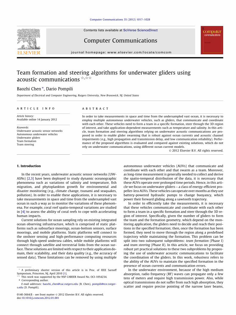
The Urick model is a coarse approximation for underwateracoustic wave transmission loss. In reality, sound propagationspeed varies with water temperature, salinity, and pressure (i.e.,depth), which causes wave paths to bend. Acoustic waves are alsoreflected from the surface and bottom. Such uneven propagation ofwaves results in convergence (or shadow) zones, which are charac-terized by lower (or higher) transmission loss than that predictedby the Urick model due to the uneven energy dispersion. The vari-ations of water temperature, salinity and pressure generally de-pend on location and time of year. Due to space limitation, wecannot give a detailed description, but more details can be foundin [17]. A shadow zone scenario is shown in Fig. 1, where node 3has very low signal power from node 1 than node 4, although node3 is closer.
We adopt the empirical ambient noise model presented in [16],where a ‘V’ structure of the power spectrum density (psd) isshown. The ambient noise power is obtained by integrating theempirical psd over the frequency band in use.2
4. Proposed solution
Solutions for both phases (team formation and steering) are de-signed considering practical constraints and limitations of realunderwater acoustic modems. Our solution is based on the func-tionalities of Woods Hole Oceanographic Institution (WHOI)acoustic Micro-modem [18], which is a state-of-the-art low-power
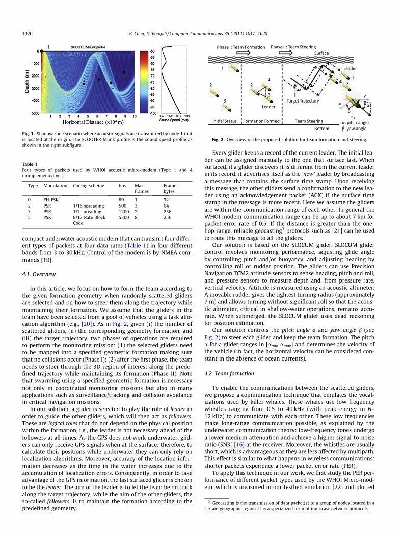
Fig. 1. Shadow zone scenario where acoustic signals are transmitted by node 1 thatis located at the origin. The SCOOTER-Munk profile is the sound speed profile asshown in the right subfigure.
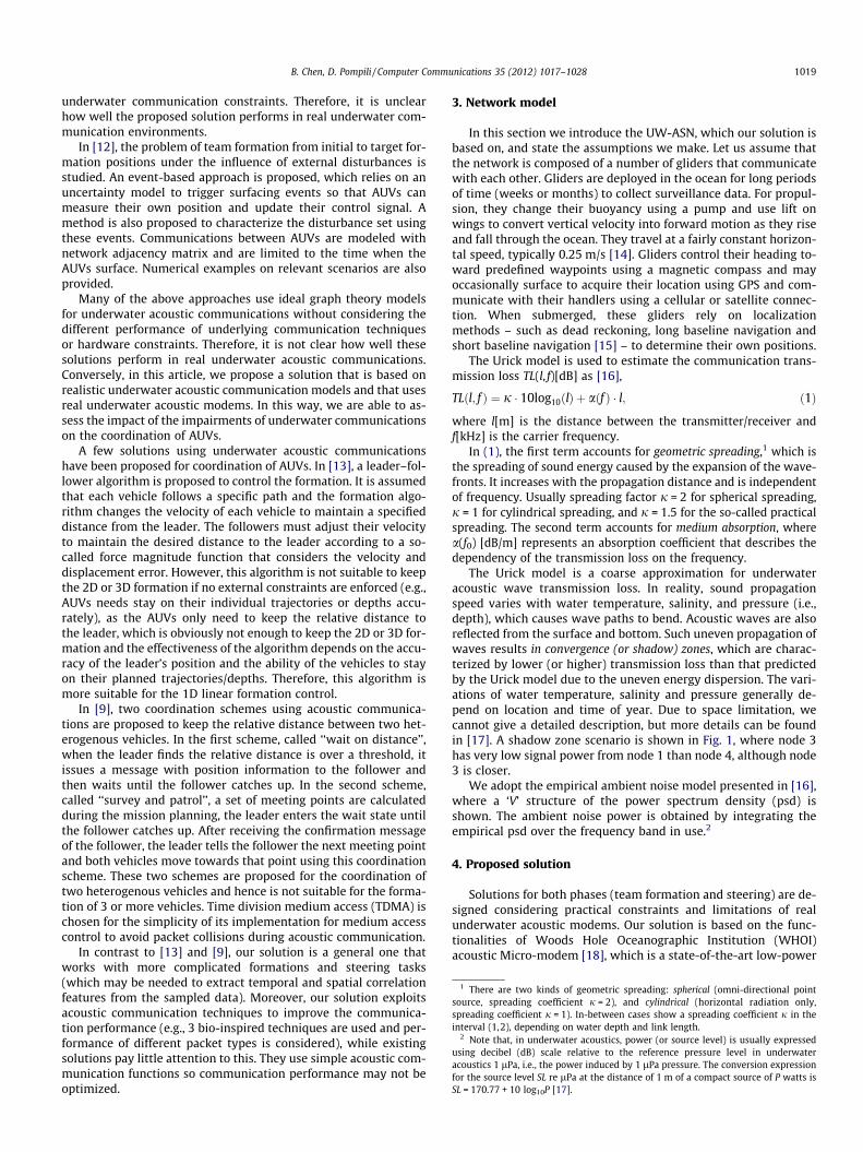
Table 1Four types of packets used by WHOI acoustic micro-modem (Type 1 and 4unimplemented yet).
Type Modulation Coding scheme bps Max.frames
Framebytes
0 FH-FSK 80 1 322 PSK 1/15 spreading 500 3 643 PSK 1/7 spreading 1200 2 2565 PSK 9/17 Rate Block
Code5300 8 256
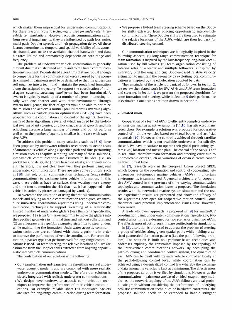
Fig. 2. Overview of the proposed solution for team formation and steering.
3 Geocasting is the transmission of data packet(s) to a group of nodes located in acertain geographic region. It is a specialized form of multicast network protocols.
1020 B. Chen, D. Pompili / Computer Communications 35 (2012) 1017–1028
compact underwater acoustic modem that can transmit four differ-ent types of packets at four data rates (Table 1) in four differentbands from 3 to 30 kHz. Control of the modem is by NMEA com-mands [19].
4.1. Overview
In this article, we focus on how to form the team according tothe given formation geometry when randomly scattered glidersare selected and on how to steer them along the trajectory whilemaintaining their formation. We assume that the gliders in theteam have been selected from a pool of vehicles using a task allo-cation algorithm (e.g., [20]). As in Fig. 2, given (i) the number ofscattered gliders, (ii) the corresponding geometry formation, and(iii) the target trajectory, two phases of operations are requiredto perform the monitoring mission: (1) the selected gliders needto be mapped into a specified geometric formation making surethat no collisions occur (Phase I); (2) after the first phase, the teamneeds to steer through the 3D region of interest along the prede-fined trajectory while maintaining its formation (Phase II). Notethat swarming using a specified geometric formation is necessarynot only in coordinated monitoring missions but also in manyapplications such as surveillance/tracking and collision avoidancein critical navigation missions.
In our solution, a glider is selected to play the role of leader inorder to guide the other gliders, which will then act as followers.These are logical roles that do not depend on the physical positionwithin the formation, i.e., the leader is not necessary ahead of thefollowers at all times. As the GPS does not work underwater, glid-ers can only receive GPS signals when at the surface; therefore, tocalculate their positions while underwater they can only rely onlocalization algorithms. Moreover, accuracy of the location infor-mation decreases as the time in the water increases due to theaccumulation of localization errors. Consequently, in order to takeadvantage of the GPS information, the last surfaced glider is chosento be the leader. The aim of the leader is to let the team be on trackalong the target trajectory, while the aim of the other gliders, theso-called followers, is to maintain the formation according to thepredefined geometry.
Every glider keeps a record of the current leader. The initial lea-der can be assigned manually to the one that surface last. Whensurfaced, if a glider discovers it is different from the current leaderin its record, it advertises itself as the ‘new’ leader by broadcastinga message that contains the surface time stamp. Upon receivingthis message, the other gliders send a confirmation to the new lea-der using an acknowledgement packet (ACK) if the surface timestamp in the message is more recent. Here we assume the glidersare within the communication range of each other. In general theWHOI modem communication range can be up to about 7 km forpacket error rate of 0.5. If the distance is greater than the one-hop range, reliable geocasting3 protocols such as [21] can be usedto route this message to all the gliders.
Our solution is based on the SLOCUM glider. SLOCUM glidercontrol involves monitoring performance, adjusting glide angleby controlling pitch and/or buoyancy, and adjusting heading bycontrolling roll or rudder position. The gliders can use PrecisionNavigation TCM2 attitude sensors to sense heading, pitch and roll,and pressure sensors to measure depth and, from pressure rate,vertical velocity. Altitude is measured using an acoustic altimeter.A movable rudder gives the tightest turning radius (approximately7 m) and allows turning without significant roll so that the acous-tic altimeter, critical in shallow-water operations, remains accu-rate. When submerged, the SLOCUM glider uses dead reckoningfor position estimation.
Our solution controls the pitch angle a and yaw angle b (seeFig. 2) to steer each glider and keep the team formation. The pitcha for a glider ranges in [amin,amax] and determines the velocity ofthe vehicle (in fact, the horizontal velocity can be considered con-stant in the absence of ocean currents).
4.2. Team formation
To enable the communications between the scattered gliders,we propose a communication technique that emulates the vocal-izations used by killer whales. These whales use low frequencywhistles ranging from 0.5 to 40 kHz (with peak energy in 6–12 kHz) to communicate with each other. These low frequenciesmake long-range communication possible, as explained by theunderwater communication theory: low-frequency tones undergoa lower medium attenuation and achieve a higher signal-to-noiseratio (SNR) [16] at the receiver. Moreover, the whistles are usuallyshort, which is advantageous as they are less affected by multipath.This effect is similar to what happens in wireless communications:shorter packets experience a lower packet error rate (PER).
To apply this technique in our work, we first study the PER per-formance of different packet types used by the WHOI Micro-mod-em, which is measured in our testbed emulation [22] and plotted
5 10 15 20 250
0.1
0.2
0.3
0.4
0.5
0.6
0.7
0.8
0.9
1
Region 1 Region 2 Region 3
SNR [dB]
Pack
et E
rror R
ate
Packet Error Rate vs SNR (PackeType, # Frames)
(0,1)(2,1)(2,2)(2,3)(3,1)(3,2)
Fig. 3. Packet error rate (PER) for Type 0, 2, 3 packet.
5 10 15 20 250
0.1
0.2
0.3
0.4
0.5
0.6
0.7
0.8
0.9
1
SNR [dB]
Pack
et E
rror R
ate
Packet Error Rate vs SNR (PackeType, # Frames)
Region 1 Region 2 Region 3
(5,1)(5,2)(5,3)(5,4)(5,5)(5,6)(5,7)(5,8)
Fig. 4. Packet error rate (PER) for Type 5 packet.
Fig. 5. Protocol for team formation (Type 0 packets).
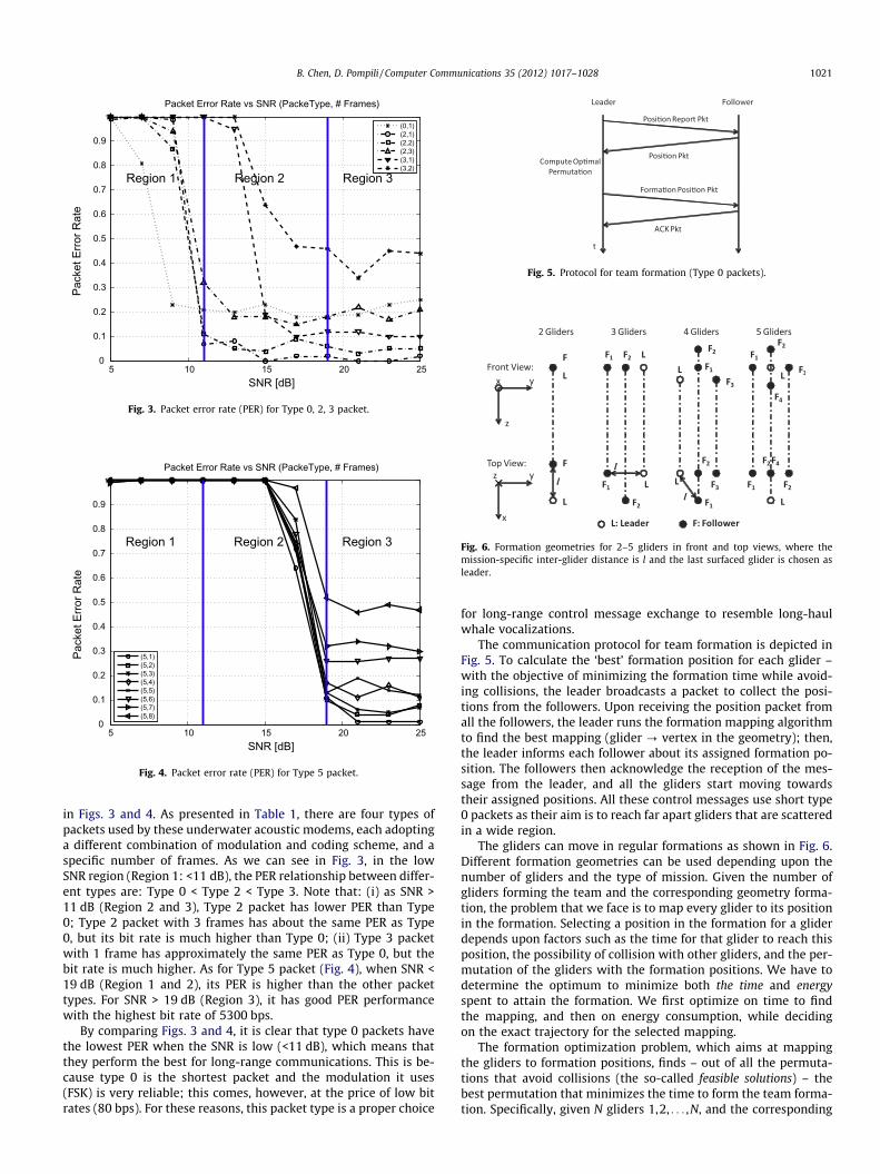
Fig. 6. Formation geometries for 2–5 gliders in front and top views, where themission-specific inter-glider distance is l and the last surfaced glider is chosen asleader.
B. Chen, D. Pompili / Computer Communications 35 (2012) 1017–1028 1021
in Figs. 3 and 4. As presented in Table 1, there are four types ofpackets used by these underwater acoustic modems, each adoptinga different combination of modulation and coding scheme, and aspecific number of frames. As we can see in Fig. 3, in the lowSNR region (Region 1: <11 dB), the PER relationship between differ-ent types are: Type 0 < Type 2 < Type 3. Note that: (i) as SNR >11 dB (Region 2 and 3), Type 2 packet has lower PER than Type0; Type 2 packet with 3 frames has about the same PER as Type0, but its bit rate is much higher than Type 0; (ii) Type 3 packetwith 1 frame has approximately the same PER as Type 0, but thebit rate is much higher. As for Type 5 packet (Fig. 4), when SNR <19 dB (Region 1 and 2), its PER is higher than the other packettypes. For SNR > 19 dB (Region 3), it has good PER performancewith the highest bit rate of 5300 bps.
By comparing Figs. 3 and 4, it is clear that type 0 packets havethe lowest PER when the SNR is low (<11 dB), which means thatthey perform the best for long-range communications. This is be-cause type 0 is the shortest packet and the modulation it uses(FSK) is very reliable; this comes, however, at the price of low bitrates (80 bps). For these reasons, this packet type is a proper choice
for long-range control message exchange to resemble long-haulwhale vocalizations.
The communication protocol for team formation is depicted inFig. 5. To calculate the ‘best’ formation position for each glider –with the objective of minimizing the formation time while avoid-ing collisions, the leader broadcasts a packet to collect the posi-tions from the followers. Upon receiving the position packet fromall the followers, the leader runs the formation mapping algorithmto find the best mapping (glider ? vertex in the geometry); then,the leader informs each follower about its assigned formation po-sition. The followers then acknowledge the reception of the mes-sage from the leader, and all the gliders start moving towardstheir assigned positions. All these control messages use short type0 packets as their aim is to reach far apart gliders that are scatteredin a wide region.
The gliders can move in regular formations as shown in Fig. 6.Different formation geometries can be used depending upon thenumber of gliders and the type of mission. Given the number ofgliders forming the team and the corresponding geometry forma-tion, the problem that we face is to map every glider to its positionin the formation. Selecting a position in the formation for a gliderdepends upon factors such as the time for that glider to reach thisposition, the possibility of collision with other gliders, and the per-mutation of the gliders with the formation positions. We have todetermine the optimum to minimize both the time and energyspent to attain the formation. We first optimize on time to findthe mapping, and then on energy consumption, while decidingon the exact trajectory for the selected mapping.
The formation optimization problem, which aims at mappingthe gliders to formation positions, finds – out of all the permuta-tions that avoid collisions (the so-called feasible solutions) – thebest permutation that minimizes the time to form the team forma-tion. Specifically, given N gliders 1,2, . . . ,N, and the corresponding
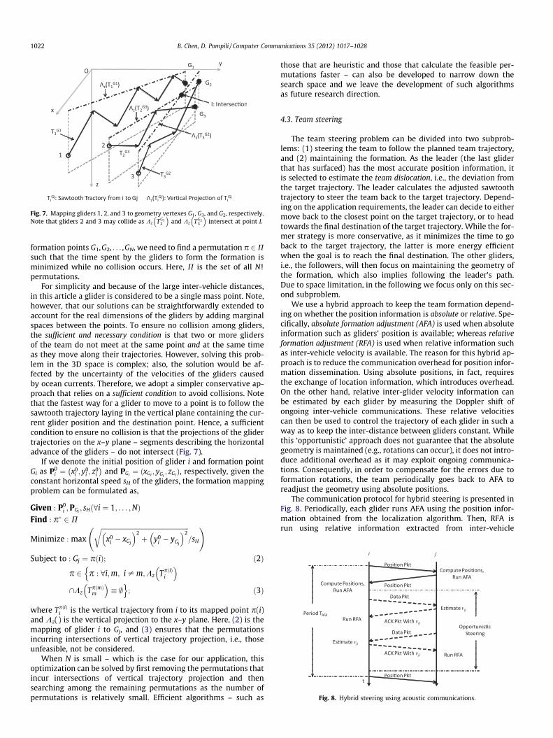
Fig. 7. Mapping gliders 1, 2, and 3 to geometry vertexes G1, G3, and G2, respectively.Note that gliders 2 and 3 may collide as Kz TG3
2
� �and Kz TG2
3
� �intersect at point I.
Fig. 8. Hybrid steering using acoustic communications.
1022 B. Chen, D. Pompili / Computer Communications 35 (2012) 1017–1028
formation points G1,G2, . . . ,GN, we need to find a permutation p 2Psuch that the time spent by the gliders to form the formation isminimized while no collision occurs. Here, P is the set of all N!permutations.
For simplicity and because of the large inter-vehicle distances,in this article a glider is considered to be a single mass point. Note,however, that our solutions can be straightforwardly extended toaccount for the real dimensions of the gliders by adding marginalspaces between the points. To ensure no collision among gliders,the sufficient and necessary condition is that two or more glidersof the team do not meet at the same point and at the same timeas they move along their trajectories. However, solving this prob-lem in the 3D space is complex; also, the solution would be af-fected by the uncertainty of the velocities of the gliders causedby ocean currents. Therefore, we adopt a simpler conservative ap-proach that relies on a sufficient condition to avoid collisions. Notethat the fastest way for a glider to move to a point is to follow thesawtooth trajectory laying in the vertical plane containing the cur-rent glider position and the destination point. Hence, a sufficientcondition to ensure no collision is that the projections of the glidertrajectories on the x–y plane – segments describing the horizontaladvance of the gliders – do not intersect (Fig. 7).
If we denote the initial position of glider i and formation pointGi as P0
i ¼ x0i ; y
0i ; z
0i
� �and PGi
¼ ðxGi; yGi
; zGiÞ, respectively, given the
constant horizontal speed sH of the gliders, the formation mappingproblem can be formulated as,
Given : P0i ;PGi
; sHð8i ¼ 1; . . . ;NÞFind : p� 2 P
Minimize : max
ffiffiffiffiffiffiffiffiffiffiffiffiffiffiffiffiffiffiffiffiffiffiffiffiffiffiffiffiffiffiffiffiffiffiffiffiffiffiffiffiffiffiffiffiffiffiffiffiffiffiffiffiffiffix0
i � xGj
� �2þ y0
i � yGj
� �2r
=sH
!
Subject to : Gj ¼ pðiÞ; ð2Þ
p 2 p : 8i;m; i – m;Kz TpðiÞi
� �n\Kz TpðmÞ
m
� �� ;o
; ð3Þ
where TpðiÞi is the vertical trajectory from i to its mapped point p(i)
and Kz( ) is the vertical projection to the x–y plane. Here, (2) is themapping of glider i to Gj, and (3) ensures that the permutationsincurring intersections of vertical trajectory projection, i.e., thoseunfeasible, not be considered.
When N is small – which is the case for our application, thisoptimization can be solved by first removing the permutations thatincur intersections of vertical trajectory projection and thensearching among the remaining permutations as the number ofpermutations is relatively small. Efficient algorithms – such as
those that are heuristic and those that calculate the feasible per-mutations faster – can also be developed to narrow down thesearch space and we leave the development of such algorithmsas future research direction.
4.3. Team steering
The team steering problem can be divided into two subprob-lems: (1) steering the team to follow the planned team trajectory,and (2) maintaining the formation. As the leader (the last gliderthat has surfaced) has the most accurate position information, itis selected to estimate the team dislocation, i.e., the deviation fromthe target trajectory. The leader calculates the adjusted sawtoothtrajectory to steer the team back to the target trajectory. Depend-ing on the application requirements, the leader can decide to eithermove back to the closest point on the target trajectory, or to headtowards the final destination of the target trajectory. While the for-mer strategy is more conservative, as it minimizes the time to goback to the target trajectory, the latter is more energy efficientwhen the goal is to reach the final destination. The other gliders,i.e., the followers, will then focus on maintaining the geometry ofthe formation, which also implies following the leader’s path.Due to space limitation, in the following we focus only on this sec-ond subproblem.
We use a hybrid approach to keep the team formation depend-ing on whether the position information is absolute or relative. Spe-cifically, absolute formation adjustment (AFA) is used when absoluteinformation such as gliders’ position is available; whereas relativeformation adjustment (RFA) is used when relative information suchas inter-vehicle velocity is available. The reason for this hybrid ap-proach is to reduce the communication overhead for position infor-mation dissemination. Using absolute positions, in fact, requiresthe exchange of location information, which introduces overhead.On the other hand, relative inter-glider velocity information canbe estimated by each glider by measuring the Doppler shift ofongoing inter-vehicle communications. These relative velocitiescan then be used to control the trajectory of each glider in such away as to keep the inter-distance between gliders constant. Whilethis ‘opportunistic’ approach does not guarantee that the absolutegeometry is maintained (e.g., rotations can occur), it does not intro-duce additional overhead as it may exploit ongoing communica-tions. Consequently, in order to compensate for the errors due toformation rotations, the team periodically goes back to AFA toreadjust the geometry using absolute positions.
The communication protocol for hybrid steering is presented inFig. 8. Periodically, each glider runs AFA using the position infor-mation obtained from the localization algorithm. Then, RFA isrun using relative information extracted from inter-vehicle
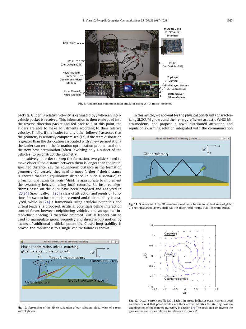
Fig. 9. Underwater communication emulator using WHOI micro-modems.
Fig. 11. Screenshot of the 3D visualization of our solution: individual view of glider2. The transparent sphere (halo) at the glider head means that it is team leader.
1.5
B. Chen, D. Pompili / Computer Communications 35 (2012) 1017–1028 1023
packets. Glider i’s relative velocity is estimated by j when an inter-vehicle packet is received. This information is then embedded intothe reverse direction packet and fed back to i. At this point, thegliders are able to make adjustments according to their relativevelocity. Finally, if the leader (or any other follower) assesses thatthe geometry is seriously compromised (i.e., if the team dislocationis greater than the dislocation associated with a new permutation),the leader can rerun the formation optimization problem and findthe new best permutation (often involving only a subset of thevehicles) to reconstruct the geometry.
Intuitively, in order to keep the formation, two gliders need tomove closer if the distance between them is longer than the initialspecified distance, i.e., the equilibrium distance in the formationgeometry. Conversely, they need to move farther if their distanceis shorter than the equilibrium distance. In such a scenario, anattraction and repulsion model (ARM) is appropriate to implementthe swarming behavior using local controls. Bio-inspired algo-rithms based on the ARM have been proposed and analyzed in[23,24]. Specifically, in [23] a class of attraction and repulsion func-tions for swarm formation is presented and their stability is ana-lyzed, while in [24] a framework using artificial potentials andvirtual leaders is proposed. Artificial potentials define interactioncontrol forces between neighboring vehicles and an optimal in-ter-vehicle spacing is therefore enforced. Virtual leaders can beused to manipulate group geometry and direct group motion bymeans of additional artificial potentials. Closed-loop stability isproved and robustness to a single vehicle failure is shown.
Fig. 10. Screenshot of the 3D visualization of our solution: global view of a teamwith 3 gliders.
In this article, we account for the physical constraints character-izing SLOCUM gliders and their energy-efficient acoustic WHOI Mi-cro-modems, and propose a novel distributed attraction andrepulsion swarming solution integrated with the communication
−1.5 −1 −0.5 0 0.5 1 1.5−1.5
−1
−0.5
0
0.5
1 Clockwise
Center
Counter−clockwise
x/D
y/D
Fig. 12. Ocean current profile [27]. Each thin arrow indicates ocean current speedand direction at that point, while each thick arrow indicates the starting positionand direction of the planned trajectory in Section 5.4. The position is relative to thegyre center and scales relative to reference distance D.
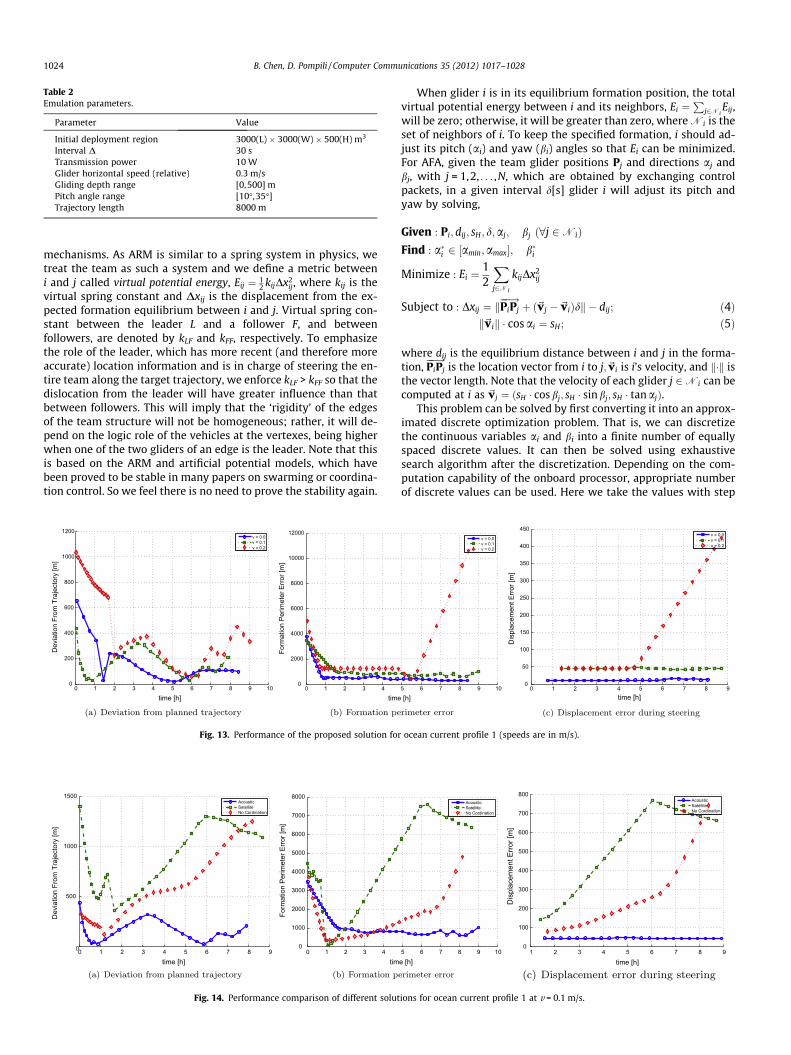
Table 2Emulation parameters.
Parameter Value
Initial deployment region 3000(L) � 3000(W) � 500(H) m3
Interval D 30 sTransmission power 10 WGlider horizontal speed (relative) 0.3 m/sGliding depth range [0,500] mPitch angle range [10�,35�]Trajectory length 8000 m
1024 B. Chen, D. Pompili / Computer Communications 35 (2012) 1017–1028
mechanisms. As ARM is similar to a spring system in physics, wetreat the team as such a system and we define a metric betweeni and j called virtual potential energy, Eij ¼ 1
2 kijDx2ij, where kij is the
virtual spring constant and Dxij is the displacement from the ex-pected formation equilibrium between i and j. Virtual spring con-stant between the leader L and a follower F, and betweenfollowers, are denoted by kLF and kFF, respectively. To emphasizethe role of the leader, which has more recent (and therefore moreaccurate) location information and is in charge of steering the en-tire team along the target trajectory, we enforce kLF > kFF so that thedislocation from the leader will have greater influence than thatbetween followers. This will imply that the ‘rigidity’ of the edgesof the team structure will not be homogeneous; rather, it will de-pend on the logic role of the vehicles at the vertexes, being higherwhen one of the two gliders of an edge is the leader. Note that thisis based on the ARM and artificial potential models, which havebeen proved to be stable in many papers on swarming or coordina-tion control. So we feel there is no need to prove the stability again.
0 1 2 3 4 5 6 7 8 9 100
200
400
600
800
1000
1200
time [h]
Dev
iatio
n Fr
om T
raje
ctor
y [m
]
v = 0.0v = 0.1v = 0.2
0 1 2 3 40
2000
4000
6000
8000
10000
12000
time
Form
atio
n Pe
rimet
er E
rror [
m]
Fig. 13. Performance of the proposed solution for
0 1 2 3 4 5 6 7 8 90
500
1000
1500
time [h]
Dev
iatio
n Fr
om T
raje
ctor
y [m
]
AcousticSatelliteNo Cordination
0 1 2 3 40
1000
2000
3000
4000
5000
6000
7000
8000
tim
Form
atio
n Pe
rimet
er E
rror [
m]
Fig. 14. Performance comparison of different solut
When glider i is in its equilibrium formation position, the totalvirtual potential energy between i and its neighbors, Ei ¼
Pj2Ni
Eij,will be zero; otherwise, it will be greater than zero, where Ni is theset of neighbors of i. To keep the specified formation, i should ad-just its pitch (ai) and yaw (bi) angles so that Ei can be minimized.For AFA, given the team glider positions Pj and directions aj andbj, with j = 1,2, . . . ,N, which are obtained by exchanging controlpackets, in a given interval d[s] glider i will adjust its pitch andyaw by solving,
Given : Pi; dij; sH; d;aj; bj ð8j 2NiÞFind : a�i 2 ½amin;amax�; b�i
Minimize : Ei ¼12
Xj2Ni
kijDx2ij
Subject to : Dxij ¼ kPiPj��!þ ð~vj �~viÞdk � dij; ð4Þ
k~vik � cos ai ¼ sH; ð5Þ
where dij is the equilibrium distance between i and j in the forma-tion, PiPj
��!is the location vector from i to j;~vi is i’s velocity, and k�k is
the vector length. Note that the velocity of each glider j 2Ni can becomputed at i as ~vj ¼ ðsH � cos bj; sH � sin bj; sH � tan ajÞ.
This problem can be solved by first converting it into an approx-imated discrete optimization problem. That is, we can discretizethe continuous variables ai and bi into a finite number of equallyspaced discrete values. It can then be solved using exhaustivesearch algorithm after the discretization. Depending on the com-putation capability of the onboard processor, appropriate numberof discrete values can be used. Here we take the values with step
5 6 7 8 9 10
[h]
v = 0.0v = 0.1v = 0.2
0 1 2 3 4 5 6 7 8 90
50
100
150
200
250
300
350
400
450
time [h]
Dis
plac
emen
t Erro
r [m
]
v = 0.0v = 0.1v = 0.2
ocean current profile 1 (speeds are in m/s).
5 6 7 8 9 10e [h]
AcousticSatelliteNo Cordination
1 2 3 4 5 6 7 8 90
100
200
300
400
500
600
700
800
time [h]
Dis
plac
emen
t Erro
r [m
]
AcousticSatelliteNo Cordination
ions for ocean current profile 1 at v = 0.1 m/s.
B. Chen, D. Pompili / Computer Communications 35 (2012) 1017–1028 1025
size of 0.1. Further improvement of the solution can be done afterconverting it into appropriate optimization that can be solved effi-ciently and we leave this as future work.
For RFA, we adopt a bio-inspired communication technique thatimitates the echolocation mechanism of the bat. A bat estimatesthe distance to an object by shouting and then measuring theacoustic echoing time from the object. Also, a bat relies on theDoppler effect, i.e., the frequency shift caused by the relative veloc-ity, to sense an object’s direction. Specifically, if the object is mov-ing away from the bat, the returning echo will have a lowerfrequency than the original sound; conversely, the echo from anobject moving towards the bat will have a higher frequency. Whenwe do not rely to absolute position information, we use a similartechnique to keep the swarm formation.
The WHOI Micro-modem can estimate the relative speed of thetransmitter exploiting the frequency shift caused by the Dopplereffect. Suppose that during steering glider i obtains its relativespeed sij (a scalar) with respect to another glider j. This can be ex-tracted from ongoing inter-vehicle communications without addi-tional overhead: upon receiving i’s packet, j can estimate theDoppler frequency shift Dfij; the relative speed sij of glider i to jalong the line connecting the two gliders is then calculated fromDfij = � sij � f0/c, where f0 is the current acoustic communicationcentral frequency and c is the average underwater acoustic wavespeed (1500 m/s). Glider j then sends sij back to i with its own loca-tion Pj, which can be estimated using the leader’s GPS position, andrelative location and velocity. Both sij and Pj can be embedded inthe ongoing communication packets to avoid additional overhead.In this way, i computes its relative speed vector with respect to j as
~vij ¼ sij �PiPj��!kPiPj��!
k.
Consequently, the expected virtual potential energy Ei aftertime d can be estimated as Ei ¼ 1
2
Pj2Ni
kijk~vijdk2. Hence, the prob-lem of steering i back into formation becomes the search for theoptimal pitch and yaw to obtain a correction velocity ~vi such thatEi can be minimized,
Given : ~vij; sHð8j 2NiÞFind : a�i 2 ½amin;amax�;b�i
Minimize : Ei ¼12
Xj2Ni
kijkð~vij þ~viÞdk2;
Subject to : k~vik � cos ai ¼ sH: ð6Þ
This RFA optimization can be solved in a similar way to that of AFA.By solving this problem, glider i is able to fix its own steering so thatthe formation error, i.e., the virtual potential energy, can be mini-mized. Note that this is a distributed solution as only local informa-tion from i’s neighbors is needed.
5. Performance evaluation
In this section, we first outline the objectives of our emulationand its setup; then, we discuss the results for representativescenarios.
5.1. Emulation overview and setup
We are interested in comparing the performance of our coordi-nation algorithms (which use underwater acoustic communica-tions) in terms of coordination errors with the solutions withoutusing underwater communications or coordination algorithms.Specifically, our solution is compared with the following two solu-tions. The first one is the solution using satellite to exchange coor-dination information instead of using acoustic communications. Inthis solution, all gliders surface for satellite communications every
2 h, while underwater they do not exchange coordinationinformation. Once they have exchanged the control information,they use the AFA algorithm to set their steering angles and thenkeep steering with the calculated angles until the next surfacetime. The second one is the solution where gliders do not coordi-nate at all. Each glider just steers itself to the destination withoutexchanging coordination information with other gliders. For con-venience, in the following figures, we denote our proposed solutionthat uses acoustic communications, the solution using only satel-lite communications, and the solution without coordination as‘‘Acoustic,’’ ‘‘Satellite,’’ and ‘‘No Coordination,’’ respectively.
Note that the surfacing frequency should consider the tradeoffbetween the mission time, energy consumption and the localiza-tion error. The gliders should not surface too frequently as surfac-ing slows down the mission and consumes energy (as of currenttechnology, surfacing takes up to tens of minutes to get a GPS fixand to communicate with satellites). On the other hand, largelocalization error may be introduced if a glider stays long under-water. Here we choose the surfacing time to be every 2 h for ‘‘Sa-tellite’’, which is close to the time that is generally usednowadays by oceanographic researchers in real glider deploy-ments. Also note that we do not compare our solution with solu-tions in [13] and [9] since these existing solutions can only dealwith simple geometry formations or only two vehicles and are dif-ficult to be extended to general solutions, as reviewed in Section 2.Therefore we do not feel appropriate comparing them with oursolution.
The team formation and steering solution is implemented andtested on our hybrid underwater communication emulator [22]as shown in Fig. 9. This underwater acoustic network emulator iscomposed of four WHOI Micro-modems [18] and a real-time audioprocessing card to emulate the underwater channel propagation.With the help of softwares such as MATLAB and a Matlab-basedaudio processing package Playrec [25], the multi-input multi-out-put audio interface can process real-time signals to adjust theacoustic signal gains, to introduce propagation delay, to mix theinterfering signals, and to add ambient/man-made noise and inter-ference. Propagation delay is emulated by dividing the inter-vehi-cle distance by the underwater sound speed, while ambient/man-made noise is added to the acoustic signal using the noise modelspresented in [16]. Note that due to the limited number of Micro-modems and audio processing channels, we can only mix signalsfrom up to 3 transmitters at the receiver modem. Therefore, wecalculate, select for transmission, and mix with ambient noise, onlythe three most powerful signals the receiver will encounter. Weleave the simulation of more than three simultaneously transmit-ted signals as a problem for further research.
We are interested in the performance of different solutions inthe presence of ocean currents. A 3D visualization demo is alsomade during the implementation of our solution as shown inFigs. 10 and 11, so that the movement and trajectories of the gliderscan be visualized. More details about the demo can be found at [26].
We simulated these solutions considering the following differ-ent ocean current profiles. (1) Current Profile 1: current along xdirection with constant velocity; (2) Current Profile 2: currentalong y direction with constant velocity; and (3) Current Profile3: ocean gyre current model as in Fig. 12, i.e., a circular eddy withcounter-clockwise tangential velocity profile sH � r � exp(�2r2),where r is the ratio of the distance from a point to gyre center toa reference distance D [27]. We assume the current profiles are ver-tically constant, i.e., the current velocities are the same if the hor-izontal locations are the same. More realistic ocean models will bestudied and solutions dealing with these models will be proposedin our future work.
Emulation parameters are listed in Table 2. The direction of theplanned trajectory is along the x-axis direction. In the beginning,
0 1 2 3 4 5 6 7 8 90
500
1000
1500
2000
2500
time [h]
Dev
iatio
n Fr
om T
raje
ctor
y [m
]
v = 0.05v = 0.07v = 0.1
0 1 2 3 4 5 6 7 8 9−500
0
500
1000
1500
2000
2500
3000
3500
4000
time [h]
Form
atio
n Pe
rimet
er E
rror [
m]
v = 0.05v = 0.07v = 0.1
0 1 2 3 4 5 6 7 8 90
20
40
60
80
100
120
140
160
180
time [h]
Dis
plac
emen
t Erro
r [m
]
v = 0.05v = 0.07v = 0.1
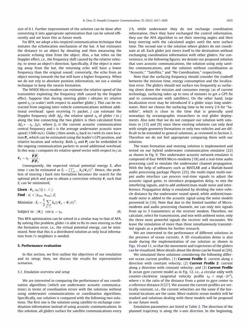
Fig. 15. Performance for ocean current profile 2 (speeds are in m/s).
0 1 2 3 4 5 6 7 8 9 100
500
1000
1500
time [h]
Dev
iatio
n Fr
om T
raje
ctor
y [m
]
AcousticSatelliteNo Cordination
0 1 2 3 4 5 6 7 8 9 10−500
0
500
1000
1500
2000
2500
3000
3500
4000
time [h]
Form
atio
n Pe
rimet
er E
rror [
m]
AcousticSatelliteNo Cordination
0 1 2 3 4 5 6 7 8 9 100
20
40
60
80
100
120
140
160
180
time [h]D
ispl
acem
ent E
rror [
m]
AcousticSatelliteNo Cordination
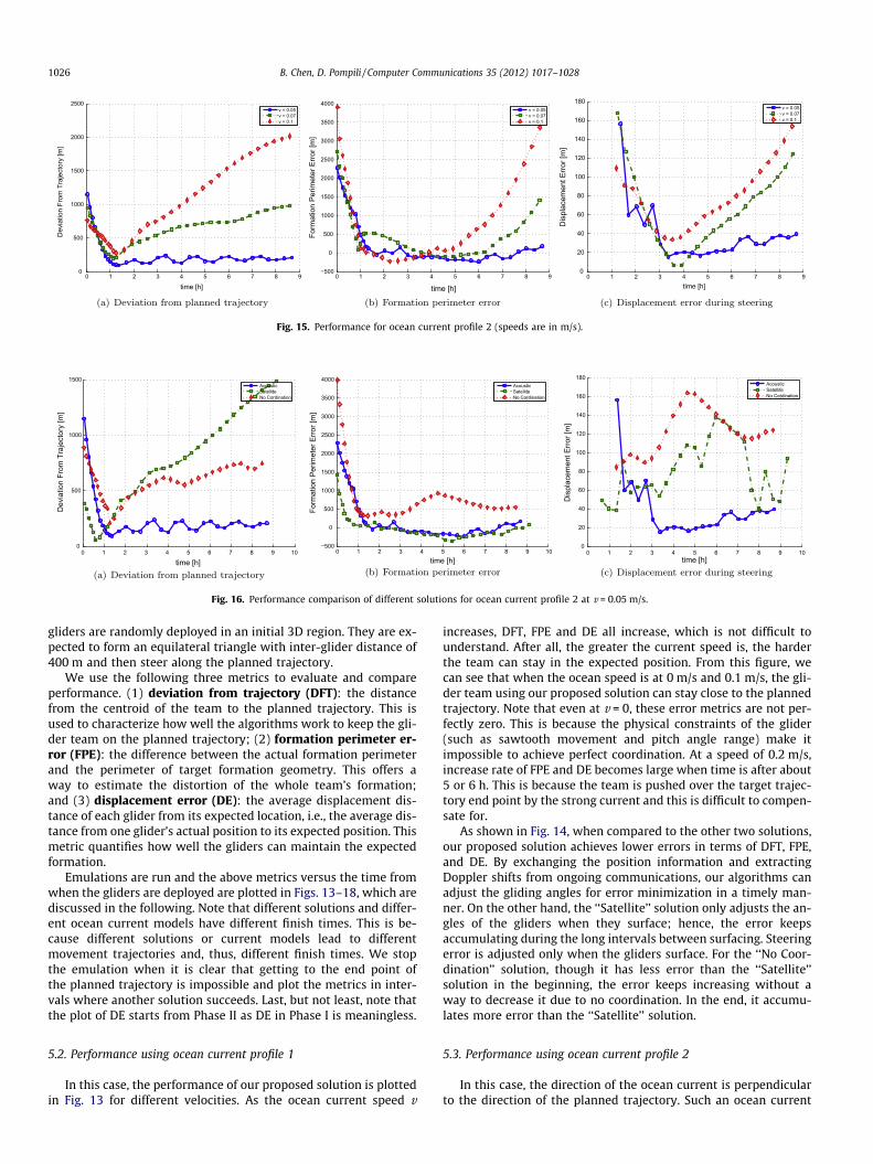
Fig. 16. Performance comparison of different solutions for ocean current profile 2 at v = 0.05 m/s.
1026 B. Chen, D. Pompili / Computer Communications 35 (2012) 1017–1028
gliders are randomly deployed in an initial 3D region. They are ex-pected to form an equilateral triangle with inter-glider distance of400 m and then steer along the planned trajectory.
We use the following three metrics to evaluate and compareperformance. (1) deviation from trajectory (DFT): the distancefrom the centroid of the team to the planned trajectory. This isused to characterize how well the algorithms work to keep the gli-der team on the planned trajectory; (2) formation perimeter er-ror (FPE): the difference between the actual formation perimeterand the perimeter of target formation geometry. This offers away to estimate the distortion of the whole team’s formation;and (3) displacement error (DE): the average displacement dis-tance of each glider from its expected location, i.e., the average dis-tance from one glider’s actual position to its expected position. Thismetric quantifies how well the gliders can maintain the expectedformation.
Emulations are run and the above metrics versus the time fromwhen the gliders are deployed are plotted in Figs. 13–18, which arediscussed in the following. Note that different solutions and differ-ent ocean current models have different finish times. This is be-cause different solutions or current models lead to differentmovement trajectories and, thus, different finish times. We stopthe emulation when it is clear that getting to the end point ofthe planned trajectory is impossible and plot the metrics in inter-vals where another solution succeeds. Last, but not least, note thatthe plot of DE starts from Phase II as DE in Phase I is meaningless.
5.2. Performance using ocean current profile 1
In this case, the performance of our proposed solution is plottedin Fig. 13 for different velocities. As the ocean current speed v
increases, DFT, FPE and DE all increase, which is not difficult tounderstand. After all, the greater the current speed is, the harderthe team can stay in the expected position. From this figure, wecan see that when the ocean speed is at 0 m/s and 0.1 m/s, the gli-der team using our proposed solution can stay close to the plannedtrajectory. Note that even at v = 0, these error metrics are not per-fectly zero. This is because the physical constraints of the glider(such as sawtooth movement and pitch angle range) make itimpossible to achieve perfect coordination. At a speed of 0.2 m/s,increase rate of FPE and DE becomes large when time is after about5 or 6 h. This is because the team is pushed over the target trajec-tory end point by the strong current and this is difficult to compen-sate for.
As shown in Fig. 14, when compared to the other two solutions,our proposed solution achieves lower errors in terms of DFT, FPE,and DE. By exchanging the position information and extractingDoppler shifts from ongoing communications, our algorithms canadjust the gliding angles for error minimization in a timely man-ner. On the other hand, the ‘‘Satellite’’ solution only adjusts the an-gles of the gliders when they surface; hence, the error keepsaccumulating during the long intervals between surfacing. Steeringerror is adjusted only when the gliders surface. For the ‘‘No Coor-dination’’ solution, though it has less error than the ‘‘Satellite’’solution in the beginning, the error keeps increasing without away to decrease it due to no coordination. In the end, it accumu-lates more error than the ‘‘Satellite’’ solution.
5.3. Performance using ocean current profile 2
In this case, the direction of the ocean current is perpendicularto the direction of the planned trajectory. Such an ocean current
0 1 2 3 4 5 6 7 8 90
100
200
300
400
500
600
700
time [h]
Dev
iatio
n Fr
om T
raje
ctor
y [m
]
ClockwiseCenterCounter−Clockwise
0 1 2 3 4 5 6 7 8 9−1000
0
1000
2000
3000
4000
5000
time [h]
Form
atio
n Pe
rimet
er E
rror [
m]
ClockwiseCenterCounter−Clockwise
0 1 2 3 4 5 6 7 8 90
20
40
60
80
100
120
140
time [h]
Dis
plac
emen
t Erro
r [m
]
ClockwiseCenterCounter−Clockwise
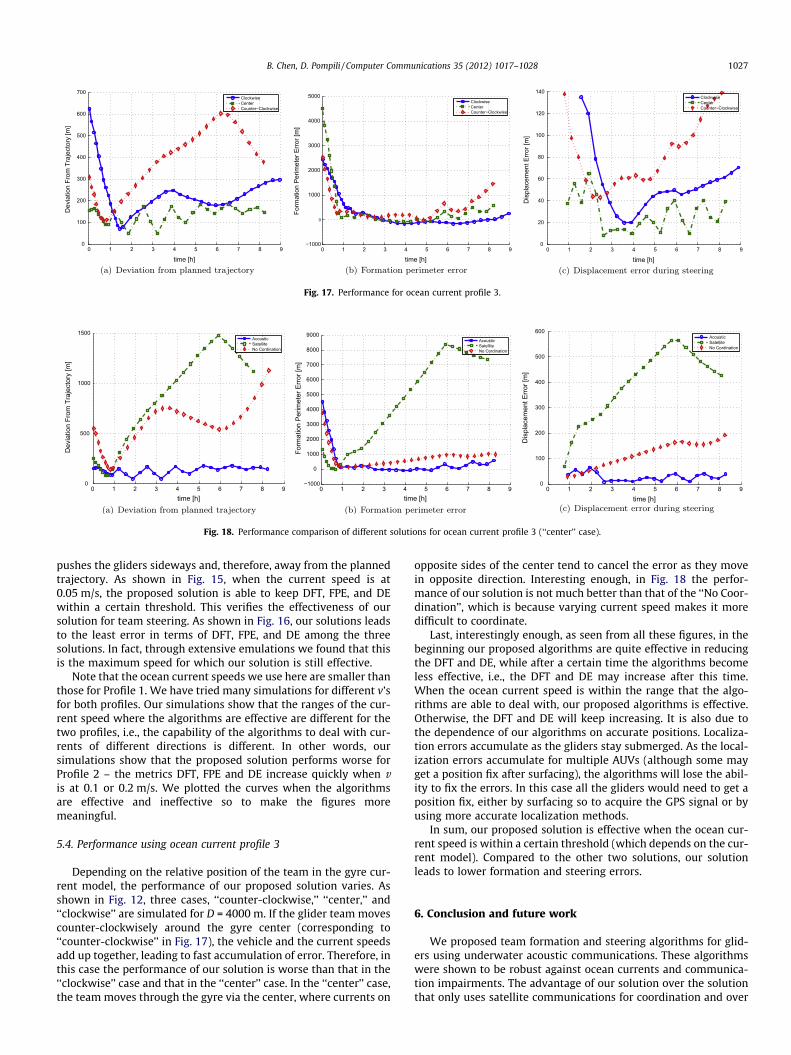
Fig. 17. Performance for ocean current profile 3.
0 1 2 3 4 5 6 7 8 90
500
1000
1500
time [h]
Dev
iatio
n Fr
om T
raje
ctor
y [m
]
AcousticSatelliteNo Cordination
0 1 2 3 4 5 6 7 8 9−1000
0
1000
2000
3000
4000
5000
6000
7000
8000
9000
time [h]
Form
atio
n Pe
rimet
er E
rror [
m]
AcousticSatelliteNo Cordination
0 1 2 3 4 5 6 7 8 90
100
200
300
400
500
600
time [h]
Dis
plac
emen
t Erro
r [m
]
AcousticSatelliteNo Cordination
Fig. 18. Performance comparison of different solutions for ocean current profile 3 (‘‘center’’ case).
B. Chen, D. Pompili / Computer Communications 35 (2012) 1017–1028 1027
pushes the gliders sideways and, therefore, away from the plannedtrajectory. As shown in Fig. 15, when the current speed is at0.05 m/s, the proposed solution is able to keep DFT, FPE, and DEwithin a certain threshold. This verifies the effectiveness of oursolution for team steering. As shown in Fig. 16, our solutions leadsto the least error in terms of DFT, FPE, and DE among the threesolutions. In fact, through extensive emulations we found that thisis the maximum speed for which our solution is still effective.
Note that the ocean current speeds we use here are smaller thanthose for Profile 1. We have tried many simulations for different v’sfor both profiles. Our simulations show that the ranges of the cur-rent speed where the algorithms are effective are different for thetwo profiles, i.e., the capability of the algorithms to deal with cur-rents of different directions is different. In other words, oursimulations show that the proposed solution performs worse forProfile 2 – the metrics DFT, FPE and DE increase quickly when vis at 0.1 or 0.2 m/s. We plotted the curves when the algorithmsare effective and ineffective so to make the figures moremeaningful.
5.4. Performance using ocean current profile 3
Depending on the relative position of the team in the gyre cur-rent model, the performance of our proposed solution varies. Asshown in Fig. 12, three cases, ‘‘counter-clockwise,’’ ‘‘center,’’ and‘‘clockwise’’ are simulated for D = 4000 m. If the glider team movescounter-clockwisely around the gyre center (corresponding to‘‘counter-clockwise’’ in Fig. 17), the vehicle and the current speedsadd up together, leading to fast accumulation of error. Therefore, inthis case the performance of our solution is worse than that in the‘‘clockwise’’ case and that in the ‘‘center’’ case. In the ‘‘center’’ case,the team moves through the gyre via the center, where currents on
opposite sides of the center tend to cancel the error as they movein opposite direction. Interesting enough, in Fig. 18 the perfor-mance of our solution is not much better than that of the ‘‘No Coor-dination’’, which is because varying current speed makes it moredifficult to coordinate.
Last, interestingly enough, as seen from all these figures, in thebeginning our proposed algorithms are quite effective in reducingthe DFT and DE, while after a certain time the algorithms becomeless effective, i.e., the DFT and DE may increase after this time.When the ocean current speed is within the range that the algo-rithms are able to deal with, our proposed algorithms is effective.Otherwise, the DFT and DE will keep increasing. It is also due tothe dependence of our algorithms on accurate positions. Localiza-tion errors accumulate as the gliders stay submerged. As the local-ization errors accumulate for multiple AUVs (although some mayget a position fix after surfacing), the algorithms will lose the abil-ity to fix the errors. In this case all the gliders would need to get aposition fix, either by surfacing so to acquire the GPS signal or byusing more accurate localization methods.
In sum, our proposed solution is effective when the ocean cur-rent speed is within a certain threshold (which depends on the cur-rent model). Compared to the other two solutions, our solutionleads to lower formation and steering errors.
6. Conclusion and future work
We proposed team formation and steering algorithms for glid-ers using underwater acoustic communications. These algorithmswere shown to be robust against ocean currents and communica-tion impairments. The advantage of our solution over the solutionthat only uses satellite communications for coordination and over
1028 B. Chen, D. Pompili / Computer Communications 35 (2012) 1017–1028
the solution without coordination is verified by simulations using ahybrid underwater acoustic communication emulator.
Future work will involve a thorough theoretical analysis of theproposed algorithms, implementing and testing the proposed algo-rithms on our SLOCUM glider platform and perform real-worldexperiments off the coast of New Jersey, and improvement of thealgorithms so that they can run efficiently and reliably in realgliders.
We will also consider to design an energy efficient solution forthe coordination of AUVs. Energy consumption is an important is-sue to consider for prolonged operation of the AUVs. To incorporateenergy considerations in the algorithm design, the applicationrequirements on (1) path to be followed, (2) geometry for the for-mation, and even (3) the number of vehicles in the team, should berelaxed. In this case, adaptive sampling can be performed in a loos-er sense, e.g., gliders can take some decisions on their own realtime not just to compensate for disturbances such as unpredictedocean currents but to trade off data quality/quantity for energysaving. Our final goal is to enable underwater inter-vehicle com-munication and autonomous coordination solutions aimed atenhancing the capabilities of the existing ocean observing cyber-infrastructure.
References
[1] B. Chen, D. Pompili, M. Parashar, Bio-inspired communications forcoordination among autonomous underwater vehicles, in: Proceedings ofIEEE Sarnoff Symposium, Princeton, NJ, 2010.
[2] D. Pompili, I.F. Akyildiz, Overview of networking protocols for underwaterwireless communications, IEEE Communications Magazine 47 (1) (2009) 97–102.
[3] D. Pompili, T. Melodia, I.F. Akyildiz, Three-dimensional and two-dimensionaldeployment analysis for underwater acoustic sensor networks, Ad HocNetworks (Elsevier) 7 (4) (2009) 778–790.
[4] D.R. Bellwood, T.P. Hughes, C. Folke, M. Nystrom, Confronting the coral reefcrisis, Nature 429 (2004) 827–833.
[5] R.C. Eberhart, Y. Shi, J. Kennedy, Swarm Intelligence, Morgan Kaufmann, 2001.[6] A. Aguiar, A. Pascoal, Coordinated path-following control for nonlinear systems
with logic-based communication, in: Proceedings of IEEE Conference onDecision and Control, New Orleans, Louisiana, 2007.
[7] A. Aguiary, J. Almeiday, M. Bayaty, B. Cardeiray, R. Cunhay, A. Hauslery, P.Mauryay, A. Oliveiray, A. Pascoaly, A. Pereira, M. Rufinoy, L. Sebastiaoy, C.Silvestrey, F. Vanniy, Cooperative autonomous marine vehicle motion controlin the scope of the EU GREX project: theory and practice, in: Proceedings ofIEEE OCEANS – Europe, Bremen, Germany, 2009.
[8] R. Ghabcheloo, A.P. Aguiar, A. Pascoal, C. Silvestre, I. Kaminer, J. Hespanha,Coordinated path-following in the presence of communication losses and timedelays, SIAM Journal on Control and Optimization 48 (2009) 234–265.
[9] R. Haraksim, L. Brignone, J. Opderbecke, Multiple AUV control in an operationalcontext: a leader – follower approach, in: Proceedings of IEEE/OES Oceans –Europe, Bremen, Germany, 2009.
[10] E. Fiorelli, N.E. Leonard, P. Bhatta, D. Paley, R. Bachmayer, D. Fratantoni, Multi-AUV control and adaptive sampling in monterey bay, IEEE Journal of OceanicEngineering 31 (4) (2006) 935–948.
[11] A. Alvarez, A. Caffaz, A. Caiti, G. Casalino, L. Gualdesi, A. Turetta, R. Viviani,Folaga: a low-cost autonomous underwater vehicle combining glider and AUVcapabilities, Ocean Engineering (Elsevier) 36 (1) (2009) 24–38.
[12] P.V. Teixeira, D.V. Dimarogonas, K.H. Johansson, J. Sousa, Event-based motioncoordination of multiple underwater vehicles under disturbances, in:Proceedings of IEEE OCEANS – Sydney, Sydney, Australia, 2010.
[13] D.B. Edwards, T. Bean, D. Odell, M. Anderson, A Leader-follower algorithm formultiple AUV formations, in: Proceedings of IEEE/OES AutonomousUnderwater Vehicles (AUV), Sebasco Estates, Maine, 2004.
[14] I.F. Akyildiz, D. Pompili, T. Melodia, Underwater acoustic sensornetworks: research challenges, Ad Hoc Networks (Elsevier) 3 (3) (2005)257–279.
[15] J.C. Kinsey, R.M. Eustice, L.L. Whitcomb, A survey of underwater vehiclenavigation: recent advances and new challenges, in: Proceedings ofInternational Federation of Automatic Control Conference on Manoeuvringand Control of Marine Craft (IFAC), Lisbon, Portugal, 2006.
[16] M. Stojanovic, On the Relationship between capacity and distance in anunderwater acoustic communication channel, in: Proceedings of ACMInternational Workshop on UnderWater Networks (WUWNet), Los Angeles,CA, 2006.
[17] W.S. Burdic, Underwater Acoustic System Analysis, in: A.V. Oppenheim (Ed.),Prentice-Hall Signal Processing Series, Prentice-Hall, 1984, p. 49. Ch. 2.
[18] L. Freitag, M. Grund, S. Singh, J. Partan, P. Koski, K. Ball, The WHOI micro-modem: an acoustic communications and navigation system for multipleplatforms, in: Proceedings of IEEE Oceans Conference, Washington DC, 2005.
[19] WHOI acoustic communications group, micro-modem software interfaceguide (Ver 2.98), <http://acomms.whoi.edu/documents/uModempdf>.
[20] I.S. Kulkarni, D. Pompili, Task allocation for networked underwater vehicles incritical missions, IEEE Journal of Selected Areas in Communications 28 (5)(2010) 716–727.
[21] B. Chen, D. Pompili, A Reliable geocasting solution for underwater acousticsensor networks, in: Proceedings of IEEE Conference on MilitaryCommunications (MILCOM), Baltimore, MD, 2011.
[22] B. Chen, P. Hickey, D. Pompili, Trajectory-aware communication solution forunderwater gliders using WHOI micro-modems, in: Proceedings of IEEECommunications Society Conference on Sensor, Mesh, and Ad HocCommunications and Networks (SECON), Boston, MA, 2010.
[23] V. Gazi, K. Passino,A class of attraction/repulsion functions for stable swarmaggregations, in: Proceedings of IEEE Conference on Decision and Control, LasVegas, NV, 2002.
[24] N.E. Leonard, E. Fiorelli, Virtual leaders, artificial potentials and coordinatedcontrol of groups, in: Proceedings of IEEE Conference on Decision and Control,Orlando, FL, 2001.
[25] R. Humphrey, Playrec Version 2.1.1, <http://www.playrec.co.uk/>.[26] B. Chen, D. Pompili, Demo: coordination of underwater gliders using acoustic
communications, <http://nsfcac.rutgers.edu/CPS/projects/underwater/index.php>.
[27] R.E. Davis, N.E. Leonard, D.M. Fratantoni, Routing strategies for underwatergliders, Deep-Sea Research II (Elsevier) 56 (3) (2009) 173–187.