teaching pl… · web viewthe motion may be uniform, and/or simple harmonic and/or uniform...
TRANSCRIPT

ENGINEERING GRAPHICS & DESIGN (EGD)PRESCRIBED CAPS CONTENT
Gr. 10 Gr. 11 Gr. 12
INTRODUCTION TO AND THE PURPOSE OF EGDThis content must, where applicable and in an appropriate way, be incorporated into the scenarios of assessment tasks.
• Discuss the scope, educational and career opportunities related to EGD. Include human rights, gender, and inclusivity and HIV/AIDS issues.
• Continuously incorporate discussion on the scope, educational and career opportunities related to EGD. Include human rights, gender, and inclusivity and HIV/AIDS issues.
• Continuously incorporate discussion on the scope, educational and career opportunities related to EGD. Include human rights, gender, and inclusivity and HIV/AIDS issues.
EXAMINABLE CONTENT
NB: The following two concepts must be applied to all relevant content!ANALYTICAL AND VISUALIZATION EXERCISES
The learner must be able to analyze and visualize prepared drawings and answer questions based on single, multi-view and pictorial drawings within the civil, mechanical and electrical contexts.
DRAWING PRINCIPLESGeneral drawing principles relevant to all types of drawings
• The correct use and care of drawing instruments
• The dangers of sharp instruments that could cause bleeding and the transfer of HIV/AIDS
• Continuously refer to the correct use and care of drawing instruments
• Continuously refer to the dangers of sharp instruments that could cause bleeding and the transfer of HIV/AIDS
• Continuously refer to the correct use and care of drawing instruments
• Continuously refer to the dangers of sharp instruments that could cause bleeding and the transfer of HIV/AIDS
11

• Relevant line types as contained in theSANS (SABS) 10111 and 10143Guidelines
• Continue the application of the relevant line types as contained in the SANS (SABS) 10111 and 10143 Guidelines
• Continue the application of the relevant line types as contained in the SANS (SABS) 10111 and 10143 Guidelines
G U I D E L IN E S f o r P E NCI L L I NE - W OR K : NOTE: A wooden pencil or a 0.3 / 0.5 clutch pencil with either a 2H, 3H or 4H lead should be used.A–type line (darkest line): Border & title/name block/panel; outlines & visible parts; answers of e.g. loci; projection symbol;
tablesB–type line (medium line): All writing & numbering; dimensions; projection planes; auxiliary views; hatching; screw
threads; folding lines, break linesC–type line (lightest line): Constructions; planning; projections; guidelines (for writing)Medium chain–line (B–type): Centre points of circles; centre lines (centre axis); section planes; assembly diagrams; building
lines/boundaries (servitudes)Dark chain–line (A–type): Plumbing, water pipes, drainage, services, irrigation systemsShort broken–line (B–type): Hidden detail; items to be removed on civil drawingsLong broken–line(B–-type): Contour lines on civil site plans
• General lettering (writing) and annotation requirements as contained in the SANS (SABS) 10111&10143Guidelines
• General dimensioning requirements as contained in the SANS (SABS)10111&10143 Guidelines.
• Continue the application of the general lettering (writing) and annotation requirements as contained in the SANS (SABS) 10111&10143 Guidelines
• Continue the application of the general dimensioning requirements as contained in the SANS (SABS)10111&10143 Guidelines.
• Continue the application of the general lettering (writing) and annotation requirements as contained in the SANS (SABS) 10111&10143 Guidelines
• Continue the application of the general dimensioning requirements as contained in the SANS (SABS)10111&10143 Guidelines.
FREE-HAND DRAWINGSIntroduce, practice and apply the basichand movements needed to draw proportional single, multi view and pictorial drawings on plain paper and/or gridsheets.
The Grade 10 content remainsapplicable to all Grade 11 topics
The Grade 10 content remainsapplicable to all Grade 12 topics
12

INSTRUMENT DRAWINGSSetting up of a Drawing Sheet
Set upA4 and A3 sized drawing sheets with a border and basis name/title blocks
Set up A4 and A3 drawing sheets with relevant civil and mechanical name/title blocks/panels
Set up A4 and A3 drawing sheets with relevant civil and mechanical name/title blocks/panels
Geometrical Constructions• Practice and apply the following
constructions: : bisecting lines and angles, perpendicular lines, angles, dividing a line, a circle through three points, circle divisions, inscribed and circumscribed circle to triangles, fillets, tangents, convex and concave tangential arcs
• Construct regular polygons with 3, 4,5, 6 & 8 sides. Determine the centre of the polygons.
• Construct an ellipse.
The Grade 10 content remainsapplicable to all relevant Grade 11 topics
The Grade 10 content remainsapplicable to all relevant Grade 12 topics
Scales• Practice and apply Different
scales, e.g. 5:1, 2:1, 1:2, 1:25, 1:50,1:75, 1:100 etc.
• The application of any scale to all types of drawing
Continue the application of any scale toall types of drawing
Continue the application of any scale toall types of drawing
13

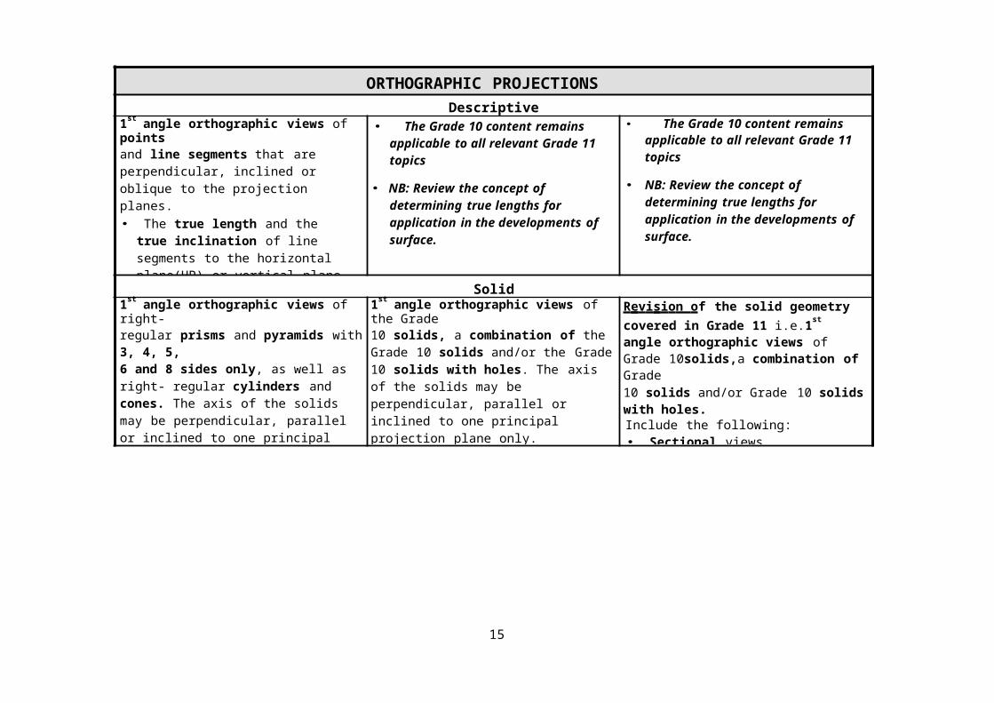
ORTHOGRAPHIC PROJECTIONSDescriptive Geometry
1st angle orthographic views of pointsand line segments that are perpendicular, inclined or oblique to the projection planes.• The true length and the true
inclination of line segments to the horizontal plane(HP) or vertical plane (VP) using different methods, e.g. projection or construction
• The true shapes of surfaces from given edge (side) views.
• The Grade 10 content remains applicable to all relevant Grade 11 topics
• NB: Review the concept of determining true lengths for application in the developments of surface.
• The Grade 10 content remainsapplicable to all relevant Grade 11 topics
• NB: Review the concept of determining true lengths for application in the developments of surface.
Solid Geometry1st angle orthographic views of right-regular prisms and pyramids with 3, 4, 5,6 and 8 sides only, as well as right- regular cylinders and cones. The axis of the solids may be perpendicular, parallel or inclined to one principal projection plane only.Include the following:• Sectional views• The true shape of the cut surface.
1st angle orthographic views of the Grade10 solids, a combination of the Grade 10 solids and/or the Grade 10 solids with holes. The axis of the solids may be perpendicular, parallel or inclined to one principal projection plane only.Include the following:• Sectional views• The true shape of the cut surface
R e v i s i o n of the solid geometry covered in Grade 11 i.e.1st angle orthographic views of Grade 10solids,a combination of Grade10 solids and/or Grade 10 solids with holes.Include the following:• Sectional views• The true shape of the cut surface.
14
Mechanical DrawingsAll mechanical drawings must be presented as 3rdangle orthographic working drawings.
3rd angle orthographic working drawingswith non-sectional and sectional views of mechanical c as t i ng s a n d ob j ec ts from industry.
Include the following:Title, scale, hidden detail, dimensioning, cutting planes, hatching detail, notes and symbol of projectionNOTE:ALL drawings have to comply with theSANS (SABS) 10111 Guidelines.
3rd angle orthographic working drawingswith non-sectional, sectional, half- sectional and part-sectional views of si m p l e mechanical as se m b lie s .Include the following:• Title, scale, hidden detail, dimensioning,
cutting planes, hatching detail, notes and symbol of projection
• Hexagonal bolts, nuts and lock nuts, washers/spacers. keys and types of section
• Conventional presentation of common features
• Format and content of working drawing name/title blocks
NOTE:ALL drawings have to comply with theSANS (SABS) 10111 Guidelines.
3rd angle orthographic working drawingswith non-sectional, sectional, half- sectional and part-sectional views of c o m p lex mechanical as s em b l ies .Include the following:• Title, scale, hidden detail, dimensioning,
cutting planes, hatching detail, notes and symbol of projection
• Hexagonal bolts, nuts and lock nuts, washers/spacers. keys and keyways and appropriate labels
• Different types of section• Conventional presentation of common
features• Format and content of working drawing
name/title blocks• Detailed drawings if individual
components• Basic welding, machining and
surface treatment symbols• TolerancesNOTE:ALL drawings have to comply with theSANS (SABS) 10111 Guidelines.
15

Civil DrawingsAll civil drawings, limited to SI N GL E - S T OR Y dwellings must be presented as 1 s t an g l e orthographic working drawings
Limited to single-storey dwellings,1st angle orthographic working drawings with floor plans, basic single lineelevations and sectional elevationsshowing the detail of the f o u nd a t i o n t o t h e s l a b .
Include the following:• Annotations, labels, dimensioning
and scales• Relevant abbreviations and
con ven tion s graphical symbols• On the floor plan only: windows and
doors• Hatching detail• Perimeters and floor areas
NOTE:ALL drawings have to comply with theSANS (SABS) 10143 Guidelines.
Limited to single-storey dwellings,1st
angle orthographic working drawings with floor plans, detailed elevations and sectional elevations showing the detail of the f o u nd a t i o n t o t h e c eil in g .
Include the following:• Annotation, labels, dimensioning, scales• Relevant abbreviations and
con vention s graphical symbols• On all relevant views/ elevations:
windows, doors and fixtures such as WC, bath, sink, shower, built-in cupboards etc.
• Hatching detail and the application of colours
• Perimeters and floor areas• Format and content of layout/working
drawing name/title panels
NOTE:ALL drawings have to comply with theSANS (SABS) 10143 Guidelines.
Limited to single-storey dwellings,1st
angle orthographic working drawings with floor plans, detailed elevations and sectional elevations showing the detail of the f o u n d at i o n t o t h e ro o f .
Include the following:• Annotation, labels, dimensioning, scales• Relevant abbreviations and
Con vent ion s graphical symbols• On all relevant views/elevations:detail
of g ab led pitched and lean -to flat r oo f s (trusses, buttons/purlins, covering,fascia, barge-board, ceiling, etc.), gutters and rain-water downpipes, plumbing and drainage detail, e le c t r i ca l fi xt u r es and w i rin g d i a g ra m s as well as all the other features and fixtures already covered in Grade 10 and Grade 11
• Hatching detail and the application of colours
• Format and content of layout/working drawing name/title panels
• Detailed s ite p l a n s showing electrical, plumbing and drainage services detail as well as relevant natural features
• Perimeters and areas of dwellings andsites.
NOTE:ALL drawings have to comply with theSANS (SABS) 10143 Guidelines.
16

PICTORIAL DRAWINGSIsometric Drawings
Simple isometric drawings with isometricand non-isometric lines as well asauxiliary views.
Simple to complex isometric drawingswith isometric and non-isometric lines as well as auxiliary views and circles.
Complex isometric drawings withisometric and non-isometric lines as well as auxiliary views, circles and sections.
Perspective Drawings1-Point perspective drawings of castings,dwellings and civil structures.• The position of the HL, PP and SP can
be varied to provide any desired view e.g. bird’s eye, a natural view, a worm’s eye view, etc.
2- Point perspective drawings of simplecastings, dwellings and civil structures• The HL, PP and SP can be varied
to provide any desired view.
2- Point perspective drawings of complexcastings, dwellings and civil structures with overhangs, depth detail, circles and arcs.• The HL, PP and SP can be varied
to provide any desired view.
ELECTRICAL DRAWINGSSimple circuit diagrams by using givenelectrical and electronic component symbols.
Parallel and series circuit diagrams,relevant to simple electrical appliancesand house wiring, by using given electrical and electronic component symbols. Include appropriate notes.
Draw the electrical fixtures and wiring diagrams on floor plans of civil drawings.
17

INTERPENETRATIONS AND DEVELOPMENTSInterpenetrations
1st angle orthographic views showing thecurve of interpenetration formed between two solids or pipes joined at either 30°, 45°,60° or 90°• The solids or pipes have to be right
regular geometrical prisms and/or cylinders only.
• The curves of interpenetration have to besymmetrical.
• The axes of the two solids or pipes have to be in line meet in a common plane.
• The focus should be on industrial examples.
1st angle orthographic views showing thecurve of interpenetration formed between two solids or pipes joined at either 30°, 45°,60° or 90°.• The solids or pipes have to be regular
geometrical prisms and/or cylinders only.
• The axes of the two solids or pipes could either be in line meet in a common plane or be offset.
• The focus should be on industrial examples.
DevelopmentsThe surface developments of:
o the parts of the interpenetrating solids or pipes
o containerso hopperso truncated pyramids and coneso simple transition pieces
• The focus should be on industrial examples.
The surface developments of:o the parts of the interpenetrating
solids or pipeso hopperso sectioned pyramids and coneso complex transition pieces
• The focus should be on industrial examples
• Seam allowances should be included where relevant.
18

LOCIHelix
The principles of the helix in simpleapplications of:o single-line augerso coil springso square thread
• Single start only• Right handed or left handed• The direction has to be emphasised.
The principles of the helix inComplex applications of:o augerso spiral chuteso coil springso different types of thread
• Single start only• Right handed or left handed• The direction has to be emphasised
CamsThe principles of the cam inSimple mechanical applications in which the following has to be shown:o the cam shaft and follower detail o the complete displacement graph o the complete cam profile
• The motion has to be u n i f o r m .• The direction has to be emphasised.• The follower has to be on the vertical
centre line.• The follower has to be wedge-shaped.
The principles of the cam in complexapplications in which the following has to be shown:o the cam shaft and follower detail o the complete displacement graph o the complete cam profile
• The motion may be u n i f o r m and/or s im p l e h a r m on i c and/or u n i f o r m a c c e ler at i o n a n d ret ar d a t i o n .
• The direction has to be emphasised.• The follower may be placed at any angle.• The follower may be wedge-shaped or a
roller.
MechanismsThe principles of the loci of a point(s) onschematic drawings of the movingcomponents of mechanisms.• Maximum THREE points
19

PRACTICAL ASSESSMENT TASK (PAT) CONTENTThis CONTENT must be formally assessed within the PAT only!
THE DESIGN PROCESSThe complete Design Process must be applied to the all the Practical Assessment Tasks (PATs) for all the grades.
The Design Process requires that the learner shows clear evidence of ALL of the following:• Problem identification and the formulation of a design brief with a list of specifications and/or constraints• Conducting research and generating graphical ideas/concepts• Selecting the best solution within the context of the design brief• Presenting the final solution as working and3D drawings• Evaluation of the whole process
COMPUTER-AIDED DRAWINGS/DESIGN (CAD)The PAT for EGD requires that some of the presentation drawings have to be generated by a CAD system. CAD is therefore a mandatory part of EGD. However, It is the responsibility of the school to provide a secure facility for CAD and to procure therequired computer hardware and CAD software, which has to be available for use by all the EGD learners.Although there is no prescribed CAD software programme that should to be used, it is advisable to procure a recognized CADsoftware programme that will benefit the learners once they leave school.A period of grace has been extended to schools that are still in the process of preparing a secure CAD facility and/or procuring the required computer hardware and/or CAD software. The learners of those schools have to in the interim, complete all the required presentation drawings of the PAT as instrument drawings.
Basic CAD requirements for all the grades:• Application and management of the specific CAD software.• To draw the required Presentation Drawings of the PAT.
General Suggested Content for all grades:
• Set up a CAD drawing environment• Activate toolbars• Set up and work with layers• Use tools, properties and settings• Draw orthographic and pictorial drawings• Save and retrieve a drawing• Print/plot• Optional: 3D CAD for the more advanced learners.
20

ENGINEERING GRAPHICS AND DESIGN 2016 THE ANNUAL TEACHING PLAN (WORK SCHEDULE) FOR GRADES 10 – 12
NOTE: This annual teaching plan is suitable for schools that will be teaching CAD either during one period per week/cycle or after normal school hours. It is the responsibility of each school’s EGD teacher(s) to do planning in 2016 TERMs of selecting the resourcematerial, activities and assessment tasks for the annual teaching plan. The hours in the duration column are an indication of the minimum time that should be spent on the specific topic. Thenumber of days, indicated in brackets in the same column, is an indication of the maximum number of school days forthe specific topic. All the assessment tasks for each topic have to be completed within the allocated week(s)/days for the topic. In order to successfully implement the annual teaching plan for EGD, the timetable has to be adjusted to allow for fourhours contact time during a five-day week.
NOTE:The sequencing and/or allocated week(s)/days of these annual teaching plans may be altered. However the altered sequencingand/or allocated week(s)/days have to be approved by an Engineering Graphics and Design Subject Advisor or Co-ordinatorbefore the end of 2015 and all the topics and prescribed content have to be contained.
21
Education
PROVINCE OF KWAZULU-NATAL

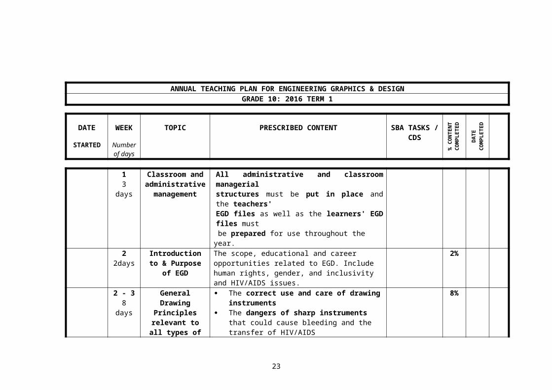
ANNUAL TEACHING PLAN FOR ENGINEERING GRAPHICS & DESIGNGRADE 10: 2016 TERM 1
DATE
STARTED
WEEK
Number of days
TOPIC PRESCRIBED CONTENT SBA TASKS / CDS
% C
ON
TEN
T C
OM
PLET
ED
DA
TEC
OM
PLET
ED
13 days
Classroom and administrative management
All administrative and classroom managerial structures must be put in place and the teachers' EGD files as well as the learners' EGD files must
be prepared for use throughout the year.2
2daysIntroduction to & Purpose of EGD
The scope, educational and career opportunities related to EGD. Include human rights, gender, and inclusivity and HIV/AIDS issues.
2%
2 - 38 days
General Drawing Principles
relevant to all types of drawing
The correct use and care of drawing instruments
The dangers of sharp instruments that could cause bleeding and the transfer of HIV/AIDS
Relevant line types as contained in the Guidelines for pencil line-work
General lettering (writing) requirements as contained in the SANS (SABS) 0111 & 0143 Guidelines
General dimensioning requirements as contained in the SANS (SABS) 0111 & 0143 Guidelines
8%
4 - 57 days
Free-hand Drawing
The basic hand movements needed to draw proportional single, multi view and pictorial drawings on plain paper and/or grid sheets.
CD 1: Freehand Drawing
13%
53 days
Setting up of a Drawing Sheet
A4 and A3 sized drawing sheets with borders and basic name/title blocks.
16%
22

ANNUAL TEACHING PLAN FOR ENGINEERING GRAPHICS & DESIGNGRADE 10: 2016 TERM 1
DATES WEEK
Number of days
TOPIC PRESCRIBED CONTENT SBA TASKS / CDS
% C
ON
TEN
T C
OM
PLET
ED
DA
TEC
OM
PLET
ED
6 -1020 days
Geometrical Construction
Geometrical constructions: bisecting lines and angles, perpendicular lines, angles, dividing a line, a circle through three points, circle divisions, inscribed and circumscribed circle to triangles, fillets, tangents, convex and concave tangential arcs;
Regular polygons with 3, 4, 5, 6 & 8 sides; Ellipse
CD 2: Geometrical Construction
CD 3: Construction of
Ellipse
32%
22days
Scales Different scales, e.g. 5:1, 2:1, 1:2, 1:25, 1:50, 1:75, 1:100 etc.
The application of any scale to all types of drawing.
34%
2 – 3
8 days
PAT The ‘Design Processo Problem identification and the formulation of a
design brief with a list of specifications and/or constraints
o Conducting research and generating
23
graphical ideas/concepts o Selecting the best solution within the context of
specifications/constraintso Presenting the final solution with working and
3D drawings o Evaluation of the whole processThe PAT scenarios must be given to the learners and each scenario must be explained and discussed.
ANNUAL TEACHING PLAN FOR ENGINEERING GRAPHICS & DESIGNGRADE 10: 2016 TERM 2
24

DATES WEEK
Number of days
TOPIC PRESCRIBED CONTENT SBA TASKS /
CDS
% C
ON
TEN
T C
OM
PLET
ED
DA
TEC
OM
PLET
ED
SIG
NA
TUR
E
1 - 3
14 days
Mechanical Drawing
3rd angle orthographic working drawings with non-sectional and sectional views of mechanical castings and objects from industry. Include the following:Title, scale, hidden detail techniques, dimensioning techniques, cutting planes, hatching detail, relevant conventions, notes and symbol of projectionAll drawings must comply with the SANS (SABS) 0111
CD 4: Mechanical
Casting
CD 5: Mechanical
casting
47%
4 - 6
14 days
Isometric Drawing Simple isometric drawings with isometric and non-isometric lines as well as auxiliary views.
CD 6: Isometric Drawing
58%
7
5 days
PAT Phase 1:The ‘Design Process’:
Problem identification and the formulation of a design brief with a list of specifications and/or constraints
Conducting research and generating graphical
Complete Phase 1
69%
of
PAT
25

ideas/concepts Selecting the best solution within the context of
the design brief Presenting the final solution as working and 3D
drawings Evaluation of the entire process
The PAT scenario has to be explained and discussed
ANNUAL TEACHING PLAN FOR ENGINEERING GRAPHICS & DESIGNGRADE 10: 2016 TERM 3
26

DATES WEEK
Number of days
TOPIC PRESCRIBED CONTENT SBA TASKS /
CDS
% C
ON
TEN
T C
OM
PLET
ED
DA
TEC
OM
PLET
ED
SIG
NA
TUR
E
1 - 3
15 days
Solid Geometry 1st angle orthographic views of right-regular prisms and pyramids with 3, 4, 5, 6 and 8 sides only, as well as cylinders and cones. The axis of the solids may be perpendicular, parallel or inclined to one principal projection plane only.Include the following: Sectional views The true shape of the cut surface
CD: 7 Solid Geometry
69%
4 - 59days
Descriptive Geometry
1st angle orthographic views of points and line segments that are perpendicular, inclined or oblique to the projection planes. The true length and the true inclination of line
segments to the horizontal plane(HP) or vertical plane (VP) using different methods, e.g. projection or construction.
The true shapes of surfaces from given edge (side) views.
CD : Descriptive Geometry
76%
6 - 8
13 days
Civil Drawings Limited to single-story dwellings, 1st angle orthographic working drawings with floor plans, basic single line elevations and sectional elevations showing the detail of the foundation to the slab. Include the following:
CD 9: Floor Plan
87%
27

Annotations, labels, dimensioning and scales - Relevant abbreviations and conventions - On the floor plan only: windows and doors - Hatching detail - Perimeters and floor areas- All drawings must comply with SANS (SABS) 0143
CD 10: Section View
8 - 10
12 days
Perspective Drawing
1- Point perspective drawings of castings and civil structures. The position of the HL, PP and SP can be
varied to provide any desired view e.g. bird's -, natural -, worm's eye view etc.
CD 11:
One - point Perspective
96%
11
4days
PAT Phase 2: Complete ALL the instrument and CAD presentation drawings as required by the selected scenario
Phase 3: Complete the 'PAT Portfolio'
Complete Phase 2
&Phase 3
100%Of
PAT
ANNUAL TEACHING PLAN FOR ENGINEERING GRAPHICS & DESIGNGRADE 10: 2016 TERM 4
28

DATES WEEK
Number of days
TOPIC PRESCRIBED CONTENT SBA TASKS /
CDS
% C
ON
TEN
T C
OM
PLET
ED
DA
TEC
OM
PLET
ED
SIG
NA
TUR
E
25 days
Electrical Drawing Simple circuit diagrams by using given electrical and electronic component symbols
CD 12: ElectricalDiagram
100%
All topics not completed during previous 2014 terms:
Revision Mechanical working drawings Civil drawings
ANNUAL TEACHING PLAN FOR ENGINEERING GRAPHICS & DESIGNGRADE 11: 2016 TERM 1
29

DATES WEEK
Number of days
TOPIC PRESCRIBED CONTENT SBA TASKS /
CDS
% C
ON
TEN
T C
OM
PLET
ED
DA
TEC
OM
PLET
ED
1
3 days
Classroom and
administrative
management
All administrative and classroom managerial structures must be put in place and the teachers' EGD files as well as the learners' EGD files must be prepared for use throughout the year.
13 days
Revision of the General Drawing
Principles
The use, care and dangers of sharp instruments. Line types, lettering (writing) and dimensioning. Free-hand drawing techniques. The principles of 1st angle and 3rd angle
orthographic projections.2 - 518
days
Mechanical Drawing
3rd angle orthographic working drawings with non-sectional, sectional, half-sectional and part-sectional views of simple mechanical assemblies. Include the following: Title, scale, hidden detail, dimensioning, cutting
planes, hatching details, notes and symbol of projection
Hexagonal bolts, nuts and lock nuts, washers/spacers, keys and keyways and appropriate labels
Different types of sections Conventional representation of common features Format and content of working drawing name/title
blocksAll drawings must comply with the SANS (SABS) 0111
CD 1: Mechanical Analytical exercise
CD 2: Mechanical Assembly
14%
5
2 days
PAT The ‘Design Process’:
Problem identification and the formulation of a design brief with a list of specifications and/or constraints
Conducting research and generating graphical
30

ideas/concepts Selecting the best solution within the context of the
design brief Presenting the final solution as working and 3D
drawings Evaluation of the entire processThe PAT scenario has to be explained and discussed
6 - 811
days
Isometric Drawing
Simple to complex isometric drawings with isometric and non-isometric lines as well as auxiliary views and circles.
CD 3: Isometric Drawing
24%
ANNUAL TEACHING PLAN FOR ENGINEERING GRAPHICS & DESIGNGRADE 11: 2016 TERM 1
DATES WEEK
Number of days
TOPIC PRESCRIBED CONTENT SBA TASKS /
CDS
% C
ON
TEN
T C
OM
PLET
ED
DA
TEC
OM
PLET
ED
SIG
NA
TUR
E
31

8 - 10
11 days
Perspective Drawing
2- Point perspective drawings of simple castings dwellings and civil structures
The HL, PP and SP can be varied to provide any desired view.
CD 4: Two - point
Perspective Drawing
33%
11
3days
PAT PAT: Phase 1: Complete the following ‘Design Process’ requirements:
Problem identification and the formulation of a design brief with a list of specifications and/or constraints
Evidence of the external research conducted Generate THREE ideas/concepts analytically and
graphically (Comprehensive free-hand drawings) - Selecting the best solution within the context of the
design brief.
Complete Phase 1
35%of
PAT
ANNUAL TEACHING PLAN FOR ENGINEERING GRAPHICS & DESIGNGRADE 11: 2016 TERM 2
DATES WEEK
Number of days
TOPIC PRESCRIBED CONTENT SBA TASKS /
CDS
% C
ON
TEN
T C
OM
PLET
ED
DA
TEC
OM
PLET
ED
1 - 314
Civil Drawing Limited to single-story dwellings, 1st angle orthographic working drawings with floor plans,
CD 5: Floor Plan &
46%
32

days elevations and sectional elevations showing the detail of the foundation to the ceiling. Include the following: Annotations, labels, dimensioning and scales Relevant abbreviations and graphical symbols
(conventions) - On all relevant views/elevations: windows, doors,
and fixtures such as WC, bath, sink, shower and built-in cupboards -
Hatching detail and the application of colours - Perimeters and floor areas - Format and content of working drawing name/title
blocksAll drawings must comply with SANS (SABS) 0143 Guidelines.
Elevations
CD 6: Sectional
View
4 - 6
14 days
Solid Geometry 1st angle orthographic views of the Grade 10 solids, a combination of the Grade 10 solids. The axis of the solids may be perpendicular, parallel or inclined to one principal projection plane only.Include the following: Sectional views The true shape of the cut surface
CD 7: Solid Geometry
57%
75 days
PAT Phase 2: Complete ALL the ‘Instrument and CAD presentation drawings’ as required by each specific scenario.
Complete Phase 2
73%Of
PAT
ANNUAL TEACHING PLAN FOR ENGINEERING GRAPHICS & DESIGNGRADE 11: 2016 TERM 3
DATES WEEK
Number of days
TOPIC PRESCRIBED CONTENT SBA TASKS /
CDS
% C
ON
TEN
T C
OM
PLET
ED
DA
TEC
OM
PLET
ED
33

1 - 6
29 days
Interpenetration
&
Devlopments
1st angle orthographic views showing the curve of interpenetration formed between two solids or pipes joined at either 30°, 45°, 60° or 90°. The solids or pipes must be right regular
geometrical prisms and/or cylinders only. The curves of interpenetration must be
symmetrical. The axes of the two solids or pipes must meet in a
common plane The focus should be on industrial examples.The surface developments of:
o the parts of the interpenetrating solids or pipeso containerso hopperso truncated pyramids and coneso simple transition pieces
The focus should be on industrial examples.
CD 8: Interpenetrati
on and Development
CD 9: Transition
Piece
68%
80%
7 - 810
days
Loci (Helix) The principles of the helix in simple applications of:o single-line augerso coil springso square thread
Single start only Right handed or left handed The direction must be emphasised
CD 10: Helix 88%
9 - 1010
days
Loci (Cam) The principles of the cam in simple mechanical applications in which the following must be shown:
o the cam shaft and follower detail o the complete displacement grapho the complete cam profile
The direction must be emphasised The motion must be uniform The follower must be wedge shaped The follower must be wedge-shaped
CD 11: Cam 96%
CD 12: Mechanical assembly
34

11
5 days
PAT Phase 3: Complete the PAT Complete Phase
100%of
PAT
ANNUAL TEACHING PLAN FOR ENGINEERING GRAPHICS & DESIGNGRADE 11: 2016 TERM 4
DATES WEEK
Number of days
TOPIC PRESCRIBED CONTENT SBA TASKS /
CDS
% C
ON
TEN
T C
OM
PLET
ED
DA
TEC
OM
PLET
ED
1 Electrical Parallel and circuit diagrams, relevant to simple CD 12:
35

5 days Drawing electrical appliances and house wiring, by using given electrical and electronic component symbols. Include
appropriate notes.
ElectricalDiagram
100%
All topics not completed during previous 2014 terms:
Revision Examinable content
ANNUAL TEACHING PLAN FOR ENGINEERING GRAPHICS & DESIGNGRADE 12: 2016 TERM 1
DATES WEEK
Number of days
TOPIC PRESCRIBED CONTENT SBA TASKS / CDS
% C
ON
TEN
T C
OM
PLET
ED
DA
TEC
OM
PLET
ED
SIG
NA
TUR
E
36

1 Classroom and administrative management
All administrative and classroom managerial structures must be put in place and the teachers' EGD files as well as the learners' EGD files must
be prepared for use throughout the year.
1
3 days
Revision of the General Drawing
Principles
The use, care and dangers of sharp instruments.
Line types, lettering (writing) and dimensioning.
Free-hand drawing techniques.
The principles of 1st angle and 3rd angle orthographic projections.
2%
2 - 413
days
Mechanical Drawing
3rd angle orthographic working drawings with non-sectional, sectional, half-sectional and part-sectional views of simple mechanical assemblies. Include the following: Title, scale, hidden detail, dimensioning, cutting
planes, hatching details, notes and symbol of projection
Hexagonal bolts, nuts and lock nuts, washers/spacers, keys and keyways and appropriate labels
Different types of sections Conventional representation of common features
CD 1: Mechanical Assembly
CD 2: Mechanical Analytical
14%
37

Format and content of working drawing name/title blocks
Detailed drawings of individual components Basic welding, machining & surface treatment
symbols TolerancesAll drawings must comply with the SANS (SABS) 0111
4
2 days
PAT The ‘Design Process’: Problem identification and the formulation of a
design brief with a list of specifications and/or constraints
Conducting research and generating graphical ideas/concepts
Selecting the best solution within the context of the design brief
Presenting the final solution as working and 3D drawings
Evaluation of the entire processThe PAT scenarios have to be given to the learners and each scenario has to be explained and discussed
5 - 8
19 days
Civil Drawing Limited to single-story dwellings, 1st angle orthographic working drawings with floor plans, detailed elevations and sectional elevations showing the detail of the foundation to the roof.
Include the following:
Annotations, labels, dimensioning and scales Relevant abbreviations and graphical symbols
(conventions) - On all relevant views/elevations: detail of
pitched and flat roofs (trusses, battons/purlins, covering, fascia, barge-board, ceiling, ect), gutters and rain-water downpipes, plumbing and drainage detail,electrical fixtures and wiring diagrams as well as all the other features and fixtures already covered in Grade
CD 3: Civil: sectional elevation
CD 4: Floor plan with elevations
33%
38

10 and 11doors Hatching detail and the application of colours - Perimeters and areas of dwellings and sites Format and content of layout/working drawing
name/title blocks Detailed site plans showing electrical,
plumbling and drainage services detail as well as relevant natural features
All drawings must comply with SANS (SABS) 0143 Guidelines.
CD 5: Site Plan
ANNUAL TEACHING PLAN FOR ENGINEERING GRAPHICS & DESIGNGRADE 12: 2016 TERM 1
DATES WEEK
Number of days
TOPIC PRESCRIBED CONTENT SBA TASKS / CDS
% C
ON
TEN
T C
OM
PLET
ED
DA
TEC
OM
PLET
ED
SIG
NA
TUR
E
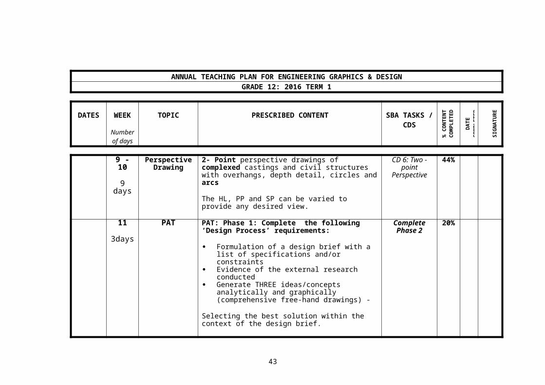
9 - 10
9 days
Perspective Drawing
2- Point perspective drawings of complexed castings and civil structures with overhangs, depth detail, circles and arcs
The HL, PP and SP can be varied to provide any desired view.
CD 6: Two - point
Perspective
44%
39

11
3days
PAT PAT: Phase 1: Complete the following ‘Design Process’ requirements:
Formulation of a design brief with a list of specifications and/or constraints
Evidence of the external research conducted Generate THREE ideas/concepts analytically and
graphically (comprehensive free-hand drawings) -
Selecting the best solution within the context of the design brief.
Complete Phase 2
20%
ANNUAL TEACHING PLAN FOR ENGINEERING GRAPHICS & DESIGNGRADE 12: 2016 TERM 2
DATES WEEK
Number of days
TOPIC PRESCRIBED CONTENT SBA TASKS / CDS
% C
ON
TEN
T C
OM
PLET
ED
DA
TEC
OM
PLET
ED
SIG
NA
TUR
E
1 - 29 days
Isometric Drawing
Complex isometric drawings with isometric and non-isometric lines as well as auxiliary views, circles and sections
Cd 7: Isometric 54%
3 - 4
5 days
Solid Geomtry Revision of the solid geometry covered in Grade11 i.e. 1st angle orthographic views of the Grade 10 solids, a combination of and/or solids with holes. The axis of the solids may be perpendicular, parallel or inclined to one principal projection plane only.Include the following: Sectional views
CD 8: Solid Geometry
60%
40

The true shape of the cut surface
4 - 6
15 days
Interpenetration
&
Developments
1st angle orthographic views showing the curve of interpenetration formed between two solids or pipes joined at either 30°, 45°, 60° or 90°. The solids or pipes must be regular geometrical
prisms and/or cylinders only. The axes of the two solids or pipes could either
meet in a common plane or be offset. The focus should be on industrial examples.The surface developments of:
o the parts of the interpenetrating solids or pipes
o hopperso sectioned/shaped pyramids and cones
The focus should be on industrial examples. Seam allowances should be included where
relevant
CD 9: Interpenetration & Development
68%
CD 10: Mechanical Assembly
41

7
5 days
PAT Phase 2: Complete ALL the ‘Instrument and CAD presentation drawings’ as required by each specific scenario.
Complete Phase 2
77%of
PAT
ANNUAL TEACHING PLAN FOR ENGINEERING GRAPHICS & DESIGNGRADE 12: 2016 TERM 3
DATES WEEK
Number of days
TOPIC PRESCRIBED CONTENT SBA TASKS / CDS
% C
ON
TEN
T C
OM
PLET
ED
DA
TEC
OM
PLET
ED
SIG
NA
TUR
E
1 - 27 days
Developments The surface development of:o complex transition pieces
The focus should be on industrial examples.
CD 11: Transition
Piece
73%
2
3 days
PAT Phase 3: Complete the PAT Complete 100%
PAT
3 - 4 Loci (Helix) The principles of the helix in simple applications of: CD 12: Helix 81%
42

7 days o augerso coil springso spiral chuteso different types of thread
Single start only Right handed or left handedThe direction must be emphasised
4 - 6
9 days
Loci (Cam) The principles of the cam in complex applications in which the following must be shown:
o the cam shaft and follower detail o the complete displacement grapho the complete cam profile
The direction has to be emphasised The motion may be uniform, and/or simple
harmonic and/or uniform acceleration and retardation
The follower may be wedge shaped or a roller The follower may be placed at any angle,
provided that it reciprocates on a centre line which passes through the centre of the cam shaft.
The follower must be wedge-shaped
CD 13: Cam 90%
6 - 78 days
Loci (Mechanisms)
The principles of a loci of a point(s) on schematic drawings of the moving components of mechanisms. Maximum of THREE points
CD 14: Point on a
Mechanism
100%
43
ANNUAL TEACHING PLAN FOR ENGINEERING GRAPHICS & DESIGNGRADE 12: 2016 TERM 3
DATES WEEK
Number of days
TOPIC PRESCRIBED CONTENT SBA TASKS / CDS
% C
ON
TEN
T C
OM
PLET
ED
DA
TEC
OM
PLET
ED
SIG
NA
TUR
E
CD 15: Mechanical Assembly
October Preparation for Previous grade 12 NCS question papers for EGD must be given to the Grade 12 EGD learners so that they
44

Holiday 'NSC' examination can answer the question papers as part of their preparations for NSC examination.
ANNUAL TEACHING PLAN FOR ENGINEERING GRAPHICS & DESIGNGRADE 12: 2016 TERM 4
DATES WEEK
Number of days
TOPIC PRESCRIBED CONTENT SBA TASKS / CDS
% C
ON
TEN
T C
OM
PLET
ED
DA
TEC
OM
PLET
ED
SIG
NA
TUR
E
All topics not completed during previous 2015 terms:
45

Revision Examinable content Preparation for
'NSC' examinationAll the previous Grade 12 NCS memorandums for EGD must be given to all the EGD learners and all the answers must be discussed with the learners as part of their preparations for the NSC examination.
ENGINEERING GRAPHICS & DESIGNA SUGGESTED ANNUAL TEACHING PLAN FOR CAD (Computer-Aided Drawing/Design)
2016 TERMS
TOPIC SUGGESTED CONTENT TASKS
DA
TEC
OM
PLET
ED
SIG
NA
TUR
E
GRADE 10CAD (Computer-
Aided Drawing/Design)
Set up a 2D CAD drawing environment Activate the basic toolbars Use basic tools that should include: drawing (lines and
circles), modify, erase, copy, dimension, text Set up and work with layers Produce orthographic and pictorial drawings Save and retrieve a drawing
GRADE 11CAD (Computer-
Aided Set up a CAD drawing environment Activate the advanced toolbars
46

Drawing/Design) Use advanced tools that such as: mirror, rotate, move, hatch, scale and properties
Set up and work with layers Draw orthographic and pictorial drawings Save and retrieve a drawing Print/plot
GRADE 12CAD (Computer-
Aided Drawing/Design)
Set up a CAD drawing environment Activate the more advanced toolbars Use more advanced tools, properties and settings Set up and work with layers Draw advanced orthographic and pictorial drawings Save and retrieve a drawing Print/plot
47

6.1 THE PROGRAMMES OF FORMAL ASSESSMENTThe programme of formal assessment is an overview of ALL the assessment components with their formal assessment tasks and the contribution of each towards the final promotion mark.
6.1.1 Grades 10 & 11
GRADES 10 & 11 FORMAL ASSESSMENT PROGRAMME
INTERNAL FORMAL ASSESSMENT: 100%
CONTINUOUS ASSESSMENT
25%(internally set and assessed)
PRACTICAL ASSESSMENT
TASK (PAT)
25%(externally set and internally assessed)
NOVEMBER
EXAMINATION
50%(internally or externally set
and internally assessed)LEARNER’S EGD FILE LEARNER’S PAT PORTFOLIO
T ests :
All the prescribed and other formal tests
30PA T Part A:
The Design Process
&
PA T Part B:
Presentation drawings of Part A
(Instrument & CAD)
NB: The final mark for each paper can be a mark that has been converted to 100.
Course drawings:
All the prescribed and other formally assessed and recorded tasks
30Paper 1 100
Paper 2 100Examination:
Mid-year (June)40
Total 100 Total 100 Total 200
6.1.2 Grade 12
GRADE 12 FORMAL ASSESSMENT PROGRAMME
INTERNAL FORMAL ASSESSMENT: 25% EXTERNAL FORMAL ASSESSMENT: 75%
CONTINUOUS ASSESSMENT
25%
(internally set and assessed)
PRACTICAL ASSESSMENT
TASK (PAT):
25%
(externally set and internally
assessed)
NOVEMBER
NSC EXAMINATION:
50%
(externally set and assessed)
LEARNER’S EGD FILE LEARNER’S PAT PORTFOLIO
T ests :
All the prescribed and other formal
tests
30PA T Part A:
The Design Process
&
PA T Part B:
Presentation drawings of Part A
(Instrument & CAD)
The final mark for each paper will
be a mark that has been converted
from 200 to 100.
Paper 1:
3 hrs
(200 marks ÷ 2 = 100)
100Course Drawings:
All the prescribed and other formally
assessed and recorded tasks
30
Paper 2:
3 hrs
(200 marks ÷ 2 = 100)
100
Examinations:
Mid-year (June) &
Preparatory (September)
40
Total 100 Total 100 Total 200
48

6.2 The EGD annual formal assessment plan
The annual formal assessment plan is an overview of each term’s minimum compulsory formal assessment tasks that have to be recorded for reporting purposes. All the compulsory formal assessment tasks have to contribute to the final promotion mark.
6.2.1 Grade 10
GRADE 10 ANNUAL FORMAL ASSESSMENT PLAN
ASSESSMENT TASkS TERM 1 TERM 2 TERM 3 TERM 4 PROMOTION MARk
Tests 1 1 30 (7.5%)
Mid-year examination 1 40 (10 %)
Course drawings 3 3 5 1 30 (7.5%)
PAT: Part A & Part B
Do over first 3 terms and record for the 4th.
1 100 (25%)
Final examination 1 200 (50%)
TOTAL 400 (100%)
6.2.2 Grade 11
GRADE 11 ANNUAL FORMAL ASSESSMENT PLAN
ASSESSMENT TASkS TERM 1 TERM 2 TERM 3 TERM 4 PROMOTION MARk
Tests 1 1 30 (7.5%)
Mid-year examination 1 40 (10 %)
Course drawings 4 3 5 30 (7.5%)
PAT: Part A & Part B
Do over first 3 terms and record for the 4th.
1 100 (25%)
Final examination 1 200 (50%)
TOTAL 400 (100%)
6.2.3 Grade 12
GRADE 12 ANNUAL FORMAL ASSESSMENT PLAN
ASSESSMENT TASkS TERM 1 TERM 2 TERM 3 TERM 4 PROMOTION MARk
Tests 1 15 (3.75%)
Internal examinations 1 1 55 (13.75 %)
Course drawings 6 4 5 30 (7.5%)
PAT: Part A & Part B
Do over first 3 terms and record for the 4th.
1 100 (25%)
NSC examination 1 200 (50%)
TOTAL 400 (100%)
49

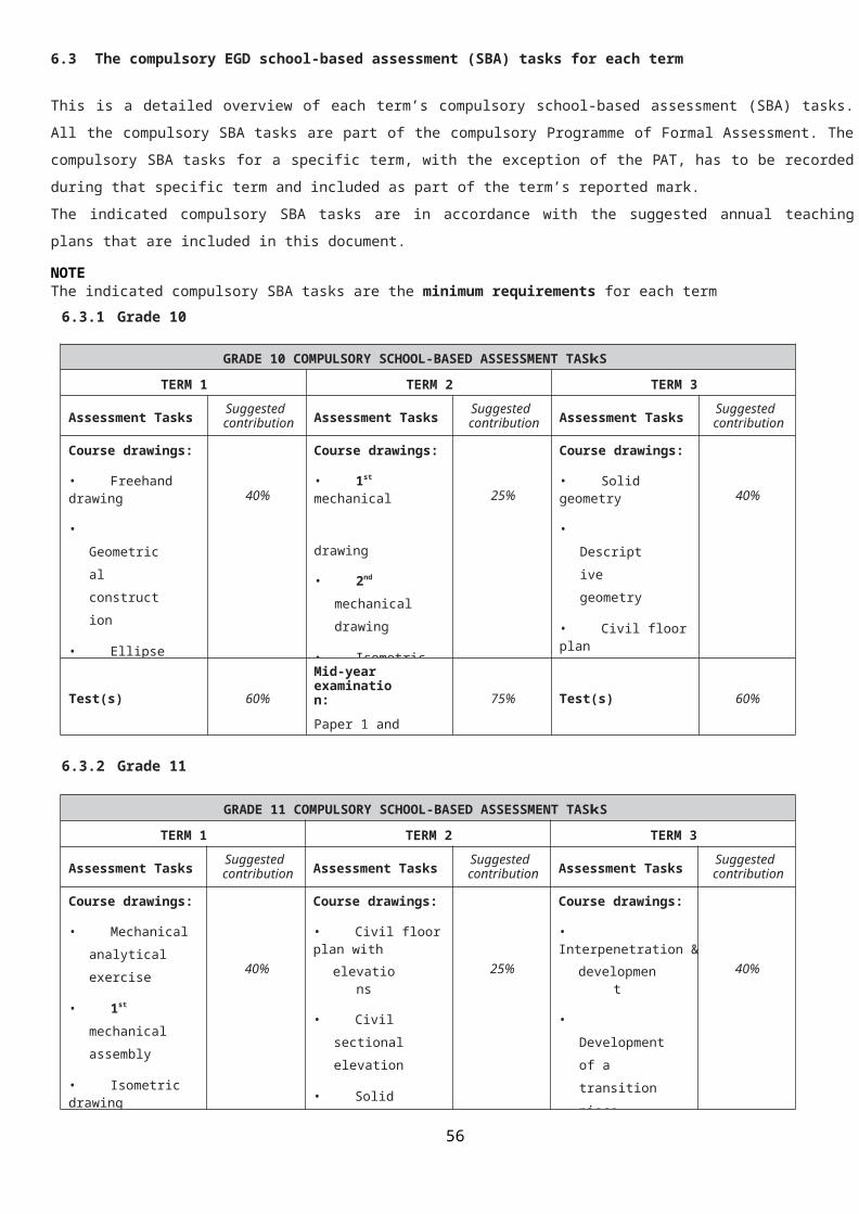
6.3 The compulsory EGD school-based assessment (SBA) tasks for each term
This is a detailed overview of each term’s compulsory school-based assessment (SBA) tasks. All the compulsory SBA tasks are part of the compulsory Programme of Formal Assessment. The compulsory SBA tasks for a specific term, with the exception of the PAT, has to be recorded during that specific term and included as part of the term’s reported mark.The indicated compulsory SBA tasks are in accordance with the suggested annual teaching plans that are included in this document.
NOTEThe indicated compulsory SBA tasks are the minimum requirements for each term
6.3.1 Grade 10
GRADE 10 COMPULSORY SCHOOL-BASED ASSESSMENT TASkS
TERM 1 TERM 2 TERM 3
Assessment Tasks Suggested contribution Assessment Tasks Suggested
contribution Assessment Tasks Suggested contribution
Course drawings:
• Freehand drawing
• Geometrical construction
• Ellipse
40%
Course drawings:
• 1st mechanical
drawing
• 2nd mechanical drawing
• Isometric drawing
25%
Course drawings:
• Solid geometry
• Descriptive geometry
• Civil floor plan
• Civil sectional elevation
• One-point perspective
40%
Test(s) 60%
Mid-year examination:Paper 1 andPaper 2
75% Test(s) 60%
6.3.2 Grade 11
GRADE 11 COMPULSORY SCHOOL-BASED ASSESSMENT TASkS
TERM 1 TERM 2 TERM 3
Assessment Tasks Suggested contribution Assessment Tasks Suggested
contribution Assessment Tasks Suggested contribution
Course drawings:
• Mechanical analytical exercise
• 1st mechanical assembly
• Isometric drawing
• Two-point perspective
40%
Course drawings:
• Civil floor plan withelevations
• Civil sectional elevation
• Solid geometry
25%
Course drawings:
• Interpenetration &development
• Development of a transition piece
• Loci (helix)
• Loci (cam)
• 2nd mechanical assembly
40%
Test(s) 60%
Mid-year examination:Paper 1 andPaper 2
75% Test(s) 60%
50

6.3.3 Grade 12
GRADE 12 COMPULSORY SCHOOL-BASED ASSESSMENT TASkS
TERM 1 TERM 2 TERM 3
Assessment Tasks Suggested contribution Assessment Tasks Suggested
contribution Assessment Tasks Suggested contribution
Course drawings:
• 1st mechanical assembly
• Mechanical analytical exercise
• Civil sectional elevation
• Civil floor plan withelevations
• Civil site plan
• Two-point perspective
40%
Course drawings:
• Isometric drawing
• Solid geometry
• Interpenetration &development
• 2nd mechanical assembly
25%
Course drawings:
• Development of a transition piece
• Loci (helix)
• Loci (cam)
• Loci (mechanisms)
• 3rd mechanical assembly
25%
Test(s) 60%
Mid-year examination:Paper 1 andPaper 2
75%
Preparatory examination:Paper 1 andPaper 2
75%
6.4 Examinations
The Engineering Graphics & Design examination papers should, in terms of format and content, be of a similar or higher standard than the DBE’s examination/exemplar papers. The mark allocations should also be similar to the DBE’s examination/exemplar papers.In order to ensure the validity of examination papers, all papers should consist of original questions. Complete previous EGD exam papers, whether internally or externally set, may therefore not be used again. However, individual questions from a previous question paper may, preferably with some changes, be used again.
Format and composition of the final EGD examination papers are as follows
GRADE 10 EXAMINATION PAPERS
PAPER 1 -CIVIL-(2 hours)
In first-angle orthographic projection
PAPER 2 -MECHANICAL-(2 hours)
In third-angle orthographic projection
Q 1A Civil analytical± 20%
Q 1 Mechanical analytical ± 20%
Q 1B Electrical circuits Q 2 Geometrical construction ± 25%
Q 2Descriptive geometry
and/or solid geometry± 25% Q 3 Isometric drawing ± 25%
Q 3 1-point perspective drawing ± 25%Q 4 Mechanical working drawing ± 30%
Q 4 Civil working drawing ± 30%
NOTE: For the June examination, the TWO 2-hour papers may be substituted by ONE 3-hour paper
51

GRADE 11 EXAMINATION PAPERS
PAPER 1 -CIVIL-(3 hours)
In first-angle orthographic projection
PAPER 2 -MECHANICAL-(3 hours)
In third-angle orthographic projection
Q 1A Civil analytical± 15% Q 1 Mechanical analytical ± 15%
Q 1B Electrical circuits
Q 2
Interpenetration and development
and/or development of a transition piece
and/or solid geometry
± 20% Q 2Loci of a helix
and/or loci of a cam
± 20%
Q 3 2-point perspective drawing ± 25% Q 3 Isometric drawing ± 25%
Q 4 Civil working drawing ± 40% Q 4 Mechanical assembly ± 40%
GRADE 12 EXAMINATION PAPERS
PAPER 1 -CIVIL-(3 hours)
In first-angle orthographic projection
PAPER 2 -MECHANICAL-(3 hours)
In third-angle orthographic projection
Q 1 Civil analytical ± 15% Q 1 Mechanical analytical ± 15%
Q 2
Interpenetration and development
and/or development of a transition piece
and/or solid geometry
± 20% Q 2
Loci of a helix
and/or loci of a cam
and/or loci of a point(s) of a mechanism
± 20%
Q 3 2-point perspective drawing ± 20% Q 3 Isometric drawing ± 20%
Q 4 Civil working drawing including electrical features ± 45%
Q 4 Mechanical assembly ± 45%
7.1 MARK SHEETS / MODERATION DOCUMENTS / LESSON PREPARATION / LETTER TO PARENTS
52

STANDARD & LENGTH OF QUESTION PAPER Comment: (positive, reinforcing comments or constructive criticism) Is the paper of an appropriate standard for the
grade? Is the time allocation fine Were candidates able to complete all questions? Is there a mark allocated to each question?LEVEL OF QUESTIONING Comment: (positive, reinforcing comments or constructive criticism) Does the question paper adequately cover the
different cognitive levels? Are all the questions suitable for the grade? Is the content questioned in-line with the work
schedule for that term?CLARITY OF INSTRUCTIONS & QUESTIONS Comment: (positive, reinforcing comments or constructive criticism) Are all the instructions to the learner clear and
unambiguous?
MODERATION OF MARKING PROCESS Comment: (positive, reinforcing comments or constructive criticism) Is the marking guideline (memo) accurate? Does the memo make allowance for alternative
responses? Is there any inaccurate or inconsistent marking? Has the teacher given written feedback with
regard to positive or reinforcing comments and constructive criticism?
Check additions and posting of marks onto the mark spread sheet? ARE THEY ALL CORRECT
POST MODERATION REPORT Comment: (positive, reinforcing comments or constructive criticism) Is the symbol distribution completed? Are the poorly answered questions listed are the
suggestions for the poor performance valid. The remedial recommendations. Do you feel they
are Adequate? The Intervention Strategies. Do you feel they are
adequate and will improve results?
CURRICULUM COVERAGE OF ATP Comment: (positive, reinforcing comments or constructive criticism) Please refer to the learner file and the ATP when
checking on the curriculum coverage. Have all aspects (Course drawings) thus far been well covered/taught
Rate the amount of coverage as a percentage % Please check on the amount of classwork
completed in each section of the ATP. In your opinion is it adequate
Name of Teacher Signature of Teacher Date:
Name of Moderator / Advisor Signature of Moderator Date:
53
SBA CLUSTER MODERATION
MECH EGD
CIVIL
ELECTNAME OF MODERATOR: GRADE:DATE OF MODERATION: TERM:DURATION OF PAPER / TASK:NAME OF SCHOOL:DISTRICT:

UGU DISTRICTSCHOOL – BASED ASSESSMENT – 2016
SUBJECT
SCHOOL STAMPGRADENAME OF SCHOOLNAME OF TEACHER / EXAMINERNAME OF HOD - MODERATOR
PRE-MODERATION OF QUESTION PAPER (before the learners write)
A – LEVELS (To be completed by examiner)Lower order – 30%
(Knowledge)Middle order – 50%
(Comprehension and application)Higher order – 20%
(Analysis, evaluation & synthesis)Cognitive levels
No B – ASPECTS OF PAPER (To be completed by moderator) Meets requirements Does not meet requirements Changes made
1.
STANDARD OF THE QUESTION PAPER Is the paper of an appropriate standard for the grade? Duration of paper – time Mark allocation per question
2.
LEVEL OF QUESTIONING Does the question paper adequately cover the different cognitive
levels Are questions suitable for the grade Is the content questioned in-line with the work schedule
3. CLARITY OF INSTRUCTIONS AND QUESTIONS Are instructions clear? Are questions clear and unambiguous
4. LENGTH AND NUMBERING OF QUESTION PAPER Will candidates be able to complete all questions in the stipulated
time Numbering of questions
Moderator sign: Date:No C – FINAL PAPER (PRINTING) (To be completed by HOD)
Approved(yes / no)
Make changes (yes / no)
Approved after changes made
1. Clarity of question paper2. Format and layout for printing3. Proof reading
HOD Sign Final Approval for Printing: Date:MODERATION OF MARKING PROCESS
1. Inaccurate or inconsistent marking2. Marking memo consistently applied3. Additions checked4. Posting of marks onto mark sheet HOD Sign moderation of marking process: Date:
54

POST MODERATION - Report on subject results and remedial strategiesREPORT BY EXAMINER AND MODERATORInstructions for completion1. Subject teacher must contribute towards the completion of this report.2. The content of this report should form the basis of any remedial / intervention strategies necessary3. The report must be completed in detail. Single word responses will not suffice.4. Where additional space may be required for comment, please do so on a separate page and append it to this report.SYMBOL DISTRIBUTION
SYMBOL PERCENTAGE
A 80-100 B 70-79 C 60-69 D 50-59 E 40-49 F 30-39 G 20-29 H0-19
LEARNER NUMBERS
STATISTICAL INFORMATIONNumber wrote: Number Passed: Percent failed:
RESPONSE TO THE QUESTION PAPER BY CANDIDATES List the questions in which candidates fared poorly and suggest possible reasons for poor performance What remedial measures do you plan on implementing?Problem
questions State problem or problem area Remedial Strategies
RECOMMENDATIONS AND INTERVENTION STRATEGIES ENVISAGED
EXAMINER SIGNATURE: DATE: MODERATOR SIGNATURE: DATE:
55

GRADE 10-12CIVIL Specialisation MECH Specialisation ELECT Specialisation EGD
First Moderation Second Moderation Final Moderation
GENERAL: YES NOMODERATION AT SCHOOL LEVEL REPORT COMPLETED?EDUCATORS FILE AVAILABLE AND UPDATED?QUESTION PAPER & MEMO AVAILABLE FOR ALL TASKS?LEARNER FILE(S) AVAILABLE AND UPDATED? INDICATE NO.CORRECT MARKSHEET USED AND COMPLETED?
PORTFOLIOS MODERATED:GRADE 12 GRADE 11 GRADE 10LEARNERS NAME LEARNERS NAME LEARNERS NAME1. 1. 1.2. 2. 2.3. 3. 3.4. 4. 4.5. 5. 5.CONTENT COVERAGEARE ALL THE TERMS TOPICS COMPLETED: YES NO PERCENTAGE
COMPLETED ____ %
TOPICS NOT COMPLETED / ASPECTS NEEDING ATTENTION:
TO THE PRINCIPAL: _____________________________ SECONDARY / HIGH SCHOOL
The records in the subject from your school have been examined. The results are as follows:
All records are in order. The work is accepted.
Some aspects require attention (see above). These should be corrected before the next moderation.
The records are NOT in order / The standard is not acceptable. Resubmission is required. Kindly make arrangements for resubmission.
Moderator’s Signature
Signature of Advisor / Co-ordinator
STAMP____________________
Educator’s Signature
____________Date
56
MANUFACTURING ENGINEERING & TECHNOLOGY SUBJECTS
CLUSTER MODERATION REPORT
57