tdc 460 advanced ethernet topics 1. outline 802.1d - spanning tree algorithm and protocol (stp)...
Post on 21-Dec-2015
265 views
TRANSCRIPT

TDC 460
Advanced Ethernet Topics
1

Outline• 802.1D - Spanning Tree Algorithm and
Protocol (STP)• 802.1w - Rapid STP• 802.1s – per VLAN STP• 802.3x - Full Duplex Flow Control• 802.3ad - Link Aggregation• 802.1Q – VLAN and VLAN Trunking• 802.1p – Quality of Service (QoS)
2

Spanning Tree Algorithm and Protocol (STP)
• Specified in IEEE 802.1D• A link management protocol that transforms a
loop topology (could be multiple loops) into a loop-free topology.
• STP forces redundant paths into stand-by paths, and provides a fault tolerant scheme.
• STP is transparent to end stations.
3

Redundant Topology
– Redundant topology eliminates single points of failure– Redundant topology causes (1) broadcast storms, (2) multiple
frame copies, and (3) MAC address table instability problems
4
Segment 1
Segment 2
Server/host X Router Y

5
Broadcast StormsBroadcast Storms
Segment 1
Segment 2
Server/host X Router Y
Broadcast
Bridges continue to propagate broadcast traffic over and over
Switch A Switch B

6
Multiple Frame CopiesMultiple Frame Copies
Segment 1
Segment 2
Server/host X Router Y
Unicast
Bridge A Bridge B
• Host X sends a unicast frame to Router Y• Router Y MAC Address has not been learned by
either bridge yet• Router Y will receive two copies of the same frame
Unicast
Unicast
7
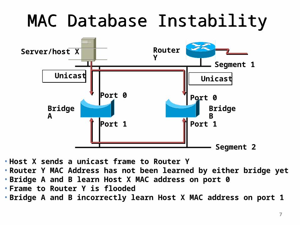
MAC Database InstabilityMAC Database Instability
Segment 1
Segment 2
Server/host X Router Y
Unicast Unicast
Bridge A Bridge B
• Host X sends a unicast frame to Router Y• Router Y MAC Address has not been learned by either bridge yet• Bridge A and B learn Host X MAC address on port 0• Frame to Router Y is flooded• Bridge A and B incorrectly learn Host X MAC address on port 1
Port 0
Port 1
Port 0
Port 1

The Solution Blocking certain ports to transform loop topology into tree
topology
8
B1 B2
WS1
Segment 1
Segment 2
blocked port
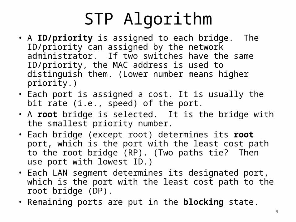
STP Algorithm• A ID/priority is assigned to each bridge. The ID/priority can
assigned by the network administrator. If two switches have the same ID/priority, the MAC address is used to distinguish them. (Lower number means higher priority.)
• Each port is assigned a cost. It is usually the bit rate (i.e., speed) of the port.
• A root bridge is selected. It is the bridge with the smallest priority number.
• Each bridge (except root) determines its root port, which is the port with the least cost path to the root bridge (RP). (Two paths tie? Then use port with lowest ID.)
• Each LAN segment determines its designated port, which is the port with the least cost path to the root bridge (DP).
• Remaining ports are put in the blocking state.
9

10
Spanning-Tree Protocol Port/Path Cost
Spanning-Tree Protocol Port/Path Cost
Link Speed Cost (reratify IEEE spec))-------------------------------------------------------------------10 Gbps 2 1 Gbps 4100 Mbps 19 10 Mbps 100
Ref: IEEE 802.1D p. 109
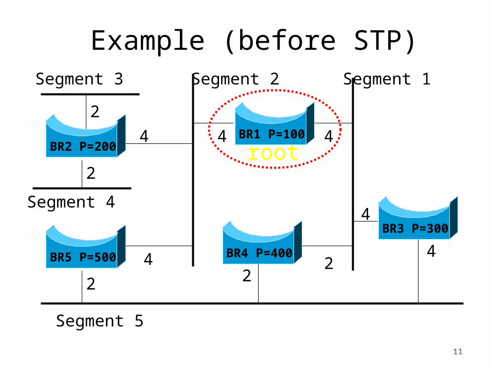
Example (before STP)
11
Segment 3
Segment 4
Segment 5
Segment 2 Segment 1
2
4 4 4
4
42
24
2
2
BR2 P=200BR1 P=100
BR5 P=500 BR4 P=400
BR3 P=300
root

Example (after STP)
12
Segment 3
Segment 4
Segment 5
Segment 2 Segment 1
2
4 4 4
4
42
24
2
2
BR2 P=200BR1 P=100
BR5 P=500 BR4 P=400
BR3 P=300
root
DPDP
RPRP
RP
RPDP
DP
DP

Bridge Protocol Data Unit (BPDU)
• All bridges regularly exchange information via a special frame called BPDU.
• Three types of BPDU packets:– Configuration (spanning tree computation)– Topology Change Notification– Topology Change Notification Ack
• BPDUs are exchanged every 2 secs by default
13
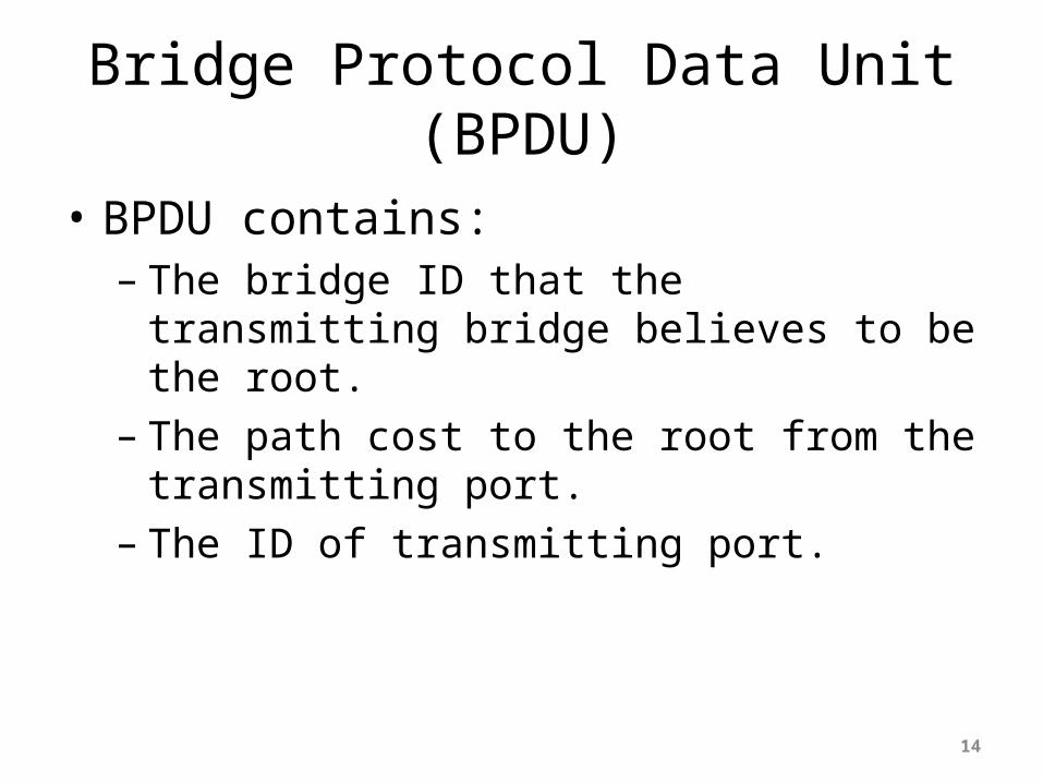
Bridge Protocol Data Unit (BPDU)
• BPDU contains:– The bridge ID that the transmitting bridge believes
to be the root.– The path cost to the root from the transmitting
port.– The ID of transmitting port.
14

15
802.3 Header
802.2 Header
802.1D BPDU
STP Control Address as the Destination

802.1D Protocol Stack
16
Physical Layer
802.3
Logical Link Control (802.2)
STP (802.1D)
Protocol information of STP. What are the STP timers?
What are the DA and SA of BPDU?
What is LLC?
LLC: it is designed as an interface between MAC and upper layer protocol . However, it is not used for IP packets, and it is used for layer-2, control and management frames.
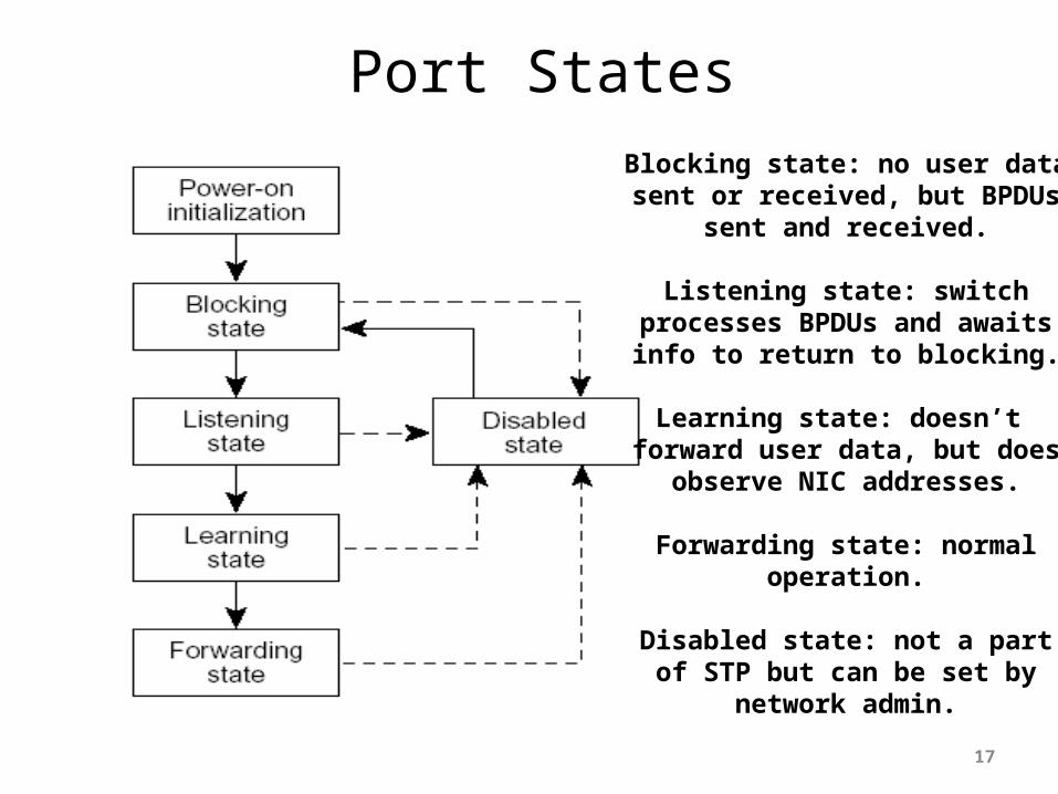
Port States
17
Blocking state: no user datasent or received, but BPDUs
sent and received.
Listening state: switchprocesses BPDUs and awaitsinfo to return to blocking.
Learning state: doesn’t forward user data, but does
observe NIC addresses.
Forwarding state: normaloperation.
Disabled state: not a partof STP but can be set by
network admin.

Notes on STP Ports• A port can be manually configured as an enabled
port or a disabled port. A disabled port does not accept BPDU, but could still accept management frame.
• An enabled port is configured by STP into the forwarding state or the blocking state where the listening and learning states are transient states.
• A port in the blocking state accepts and forwards BPDU, but does not accept or forward data frames.
• All ports on the root switch are in the forwarding state.
• All ports connected to end stations are in the forwarding state.
18
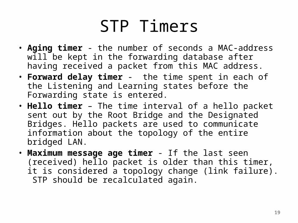
STP Timers• Aging timer - the number of seconds a MAC-address will be
kept in the forwarding database after having received a packet from this MAC address.
• Forward delay timer - the time spent in each of the Listening and Learning states before the Forwarding state is entered.
• Hello timer – The time interval of a hello packet sent out by the Root Bridge and the Designated Bridges. Hello packets are used to communicate information about the topology of the entire bridged LAN.
• Maximum message age timer - If the last seen (received) hello packet is older than this timer, it is considered a topology change (link failure). STP should be recalculated again.
19

STP Timer
Timer Default Value
Range
Aging Time 300 10 – 1,000,000
Hello Time 2 1 – 10
Max [Message]
Age
20 6 - 40
Forward Delay
15 4 - 30
20
Times in seconds
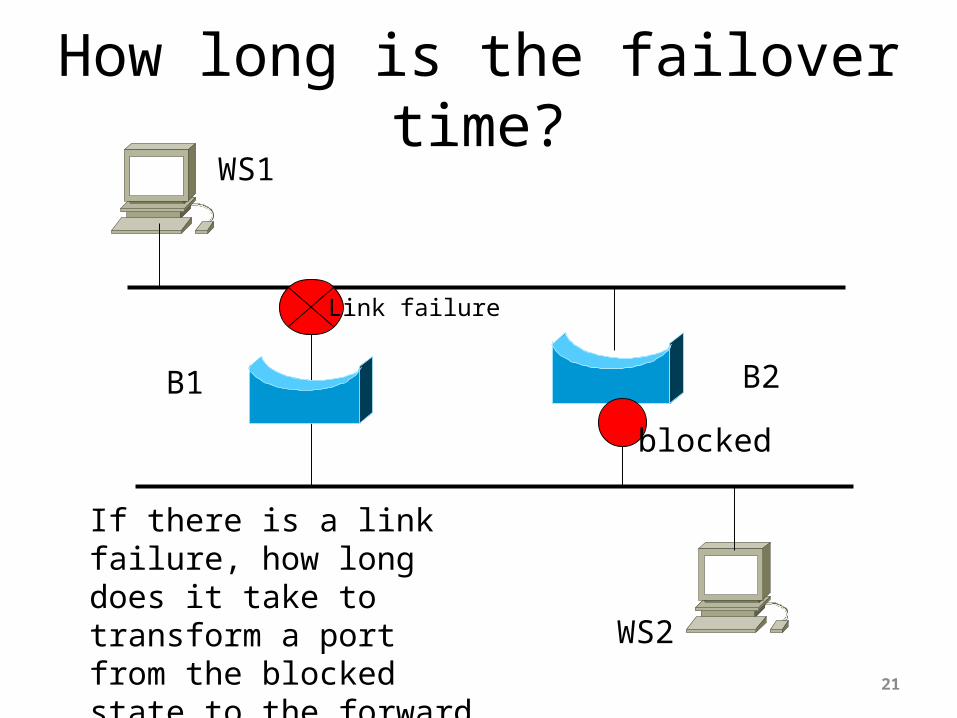
How long is the failover time?
21
B1 B2
WS1
WS2
blocked
Link failure
If there is a link failure, how long does it take to transform a port from the blocked state to the forward state? Too Long!
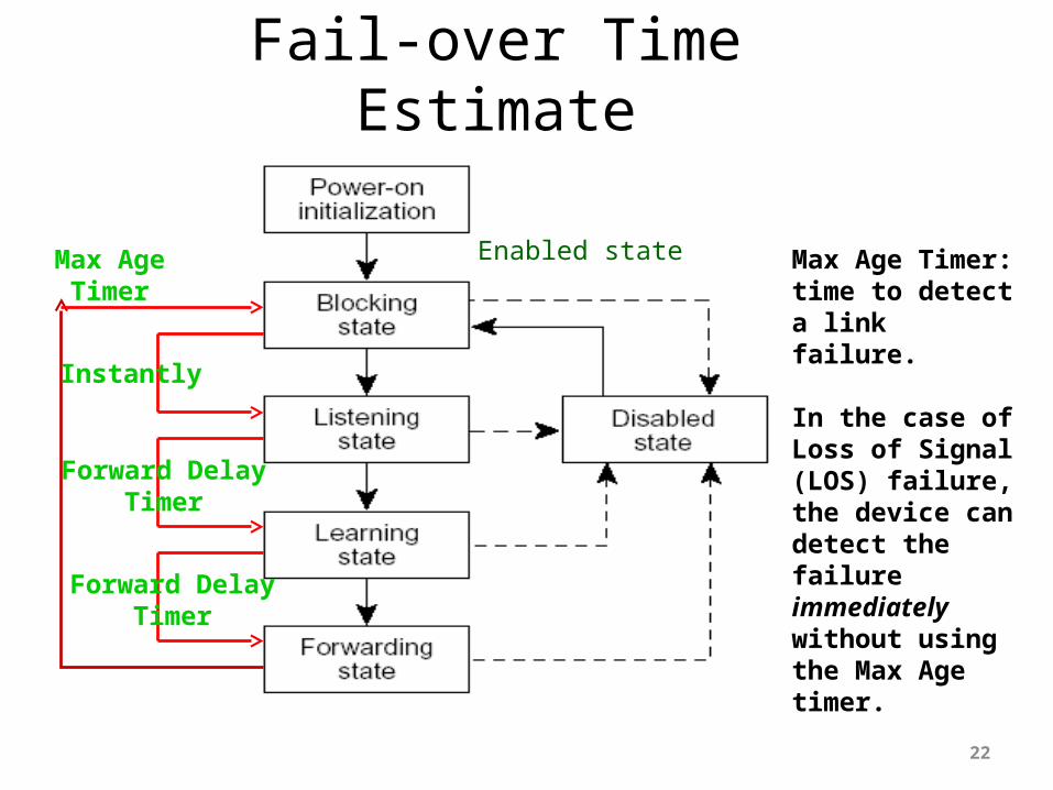
Fail-over Time Estimate
22
Enabled stateMax Age Timer
Forward DelayTimer
Forward DelayTimer
Instantly
Max Age Timer: time to detect a link failure.
In the case of Loss of Signal (LOS) failure, the device can detect the failure immediately without using the Max Age timer.

STP Configuration/Demo
23
SW01 192.168.1.1
SW02192.168.1.2
172.26.1.5172.26.1.14
Linux-14Linux-05 blocked
SW03 192.168.1.3
fa0/19
Q1: which switch is the root? Why?Q2: if the link on fa0/20 is unplugged, what is the fail-over time?Q3: if the link is plugged back, what is fall-back time?Q4: what is the relationship of the fail-over time and fall-back time to the STP timers?
fa0/20
Problems with STP• Long failover time: 45-60 seconds• When there is a network failure, STP must
be recalculated for the whole network. During the recalculation, all ports are in the blocked state which is a total network outage.
• General recommendation: do not use it.
24
STP problem is more often observed in an IP over ATM network (RFC 1483/2684) where one could accidentally create a virtual link to form a loop.

Possible Solutions to STP• Proprietary implementation: Cisco Uplink
Fast• Other proprietary implementation:
– Key concept: keep topology simple and use local intelligence to changes a port from blocking to forwarding without going through the learning process.
• New standard: Rapid Spanning Tree Algorithm and Protocol RSTP (802.1w)
25

RSTP Port States• STP port states of Disabled, Blocking, Listening
have been replaced with Discarding state• STP port states of Learning and Forwarding
remain the same
26

RSTP Port Roles• Root – a forwarding port that is the best port
from non-root bridge to root bridge• Designated – a forwarding port for every LAN
segment• Alternate – an alternate path to the root
bridge• Backup – a backup/redundant path to a
segment where another bridge port already connects
• Disabled – not strictly part of STP27

RSTP - BPDU• With STP, a non-root switch would only generate
BPDUs when it received one on its root port. In fact, a switch is simply relaying BPDUs rather than actually generating them.
• This is not the case anymore with RSTP. A switch now sends a BPDU with its current information every <hello-time> seconds (2 by default), even if it does not receive any from the root switch.
28
RSTP – Fast Failure Detection• On a given port, if hellos are not received for three
consecutive times, protocol information can be immediately aged out (or if max_age expires).
• BPDUs are now used as a keep-alive mechanism between switches. A switch considers that it has lost connectivity to its direct neighboring root or designated switch if it misses three BPDUs in a row.
• If a switch fails to receive BPDUs from a neighbor, it is certain that the connection to that neighbor has been lost, as opposed to 802.1D where the problem could have been anywhere on the path to the root.
• Failures are detected even much faster in case of physical link failures.
29

RSTP Failover Time
30
B1
B2
blocked
Link failure
When a link failure is detected (3 HelloTime), the port role is changed immediately. After that, the port is put in the forwarding state immediately.
B4
B3
If the failure is due to loss of signal (LOS), the detection time is << 1 sec.

Flow Control (CSMA/CD)• If a receiver has more data than it can handle,
incoming frames will be lost.• The flow control process is for a receiver to inform
the sender to slow down.• In a CSMA/CD network, collision is the built-in
mechanism to slow down the process.– If there are many stations on a shared media network
trying to send data, the network will see many collisions, which prevents the network from overloading. This is called saturation.
– If a station receives data faster than it can handle, the station could create collisions (pretending to send) and the sender will slow down. This is called back pressure.
31
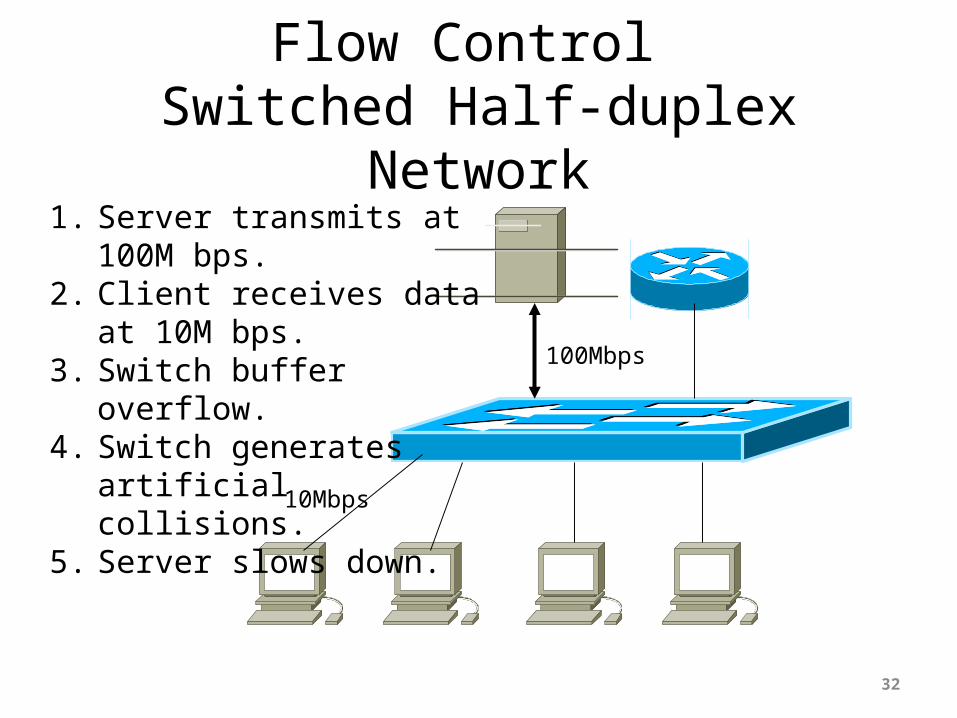
Flow Control Switched Half-duplex Network
32
1. Server transmits at 100M bps.
2. Client receives data at 10M bps.
3. Switch buffer overflow.4. Switch generates
artificial collisions.5. Server slows down.
100Mbps
10Mbps

Flow Control (Full Duplex)• A full-duplex connection is basically a point-to-
point configuration, switch-to-switch, switch-to-station, and station-to-station.
• The link carries separate transmit and receive channels. There is no contention for the use of shared media, so there are no collisions.
• In addition to BER (bit error rate), the primary cause of frame loss is buffer overflow at the receiver end. So we need to do flow control.
33

IEEE 802.3x Flow Control• A new frame, PAUSE, is specified in 802.3x to
slow down the transmitter temporarily.– It is similar to XOFF function in dial-up modems
34
Destination Address: a special address, 01-08-C2-00-00-01. This address is blocked by all switches, and does not forward. It is recognized by stations and switches implementing the new MAC control layer (802.3x) and ignored by others.
Payload(data)
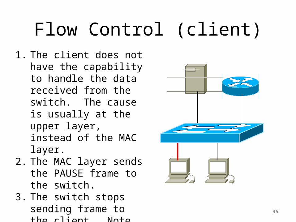
Flow Control (client)
35
1. The client does not have the capability to handle the data received from the switch. The cause is usually at the upper layer, instead of the MAC layer.
2. The MAC layer sends the PAUSE frame to the switch.
3. The switch stops sending frame to the client. Note that the PAUSE frame does not forward to anyone.

Flow Control (switch)
36
1. When the switch stops sending frame to the client, the frames are kept in the switch buffer. As a result, it causes a buffer overflow.
2. The switch sends the PAUSE frame to the server when the switch buffer overflows.
3. The server stops transmission.

Data Re-transmission• How and when does the sender resume data
transmission?• The PAUSE frame specifies the time to wait.• After the time to wait, the sender resume transmission.• The receiver can send a new PAUSE frame and reset the
timer.• If the timer=0, the sender resume transmission
immediately.• Many vendors suggest leaving this turned off.
37
Link Aggregation (802.3ad/ax)
38
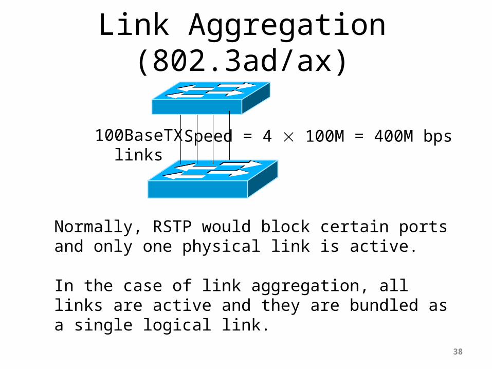
Normally, RSTP would block certain ports and only one physical link is active.
In the case of link aggregation, all links are active and they are bundled as a single logical link.
100BaseTXlinks
Speed = 4 100M = 400M bps

Link Aggregation• Multiple physical links are combined to form a fat logical
link. Many vendors support four links, and some up to 8 links, i.e., 8 times the speed.
• It provides load balancing by divided data flow evenly over different links.
• In the event of one link failure, it takes less than a second to recover from it.
• Some NICs support Link Aggregation, allowing multiple parallel links to a server.
• All packets associated with a given “conversation” are transmitted on the same link to prevent mis-ordering
39
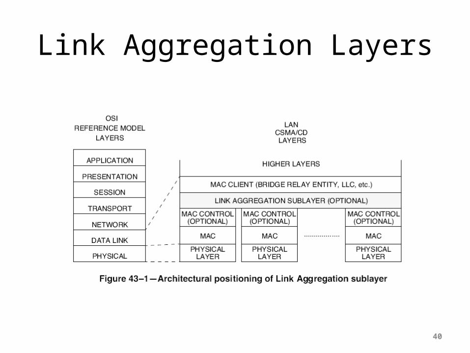
Link Aggregation Layers
40
How does Link Aggregation work?
41
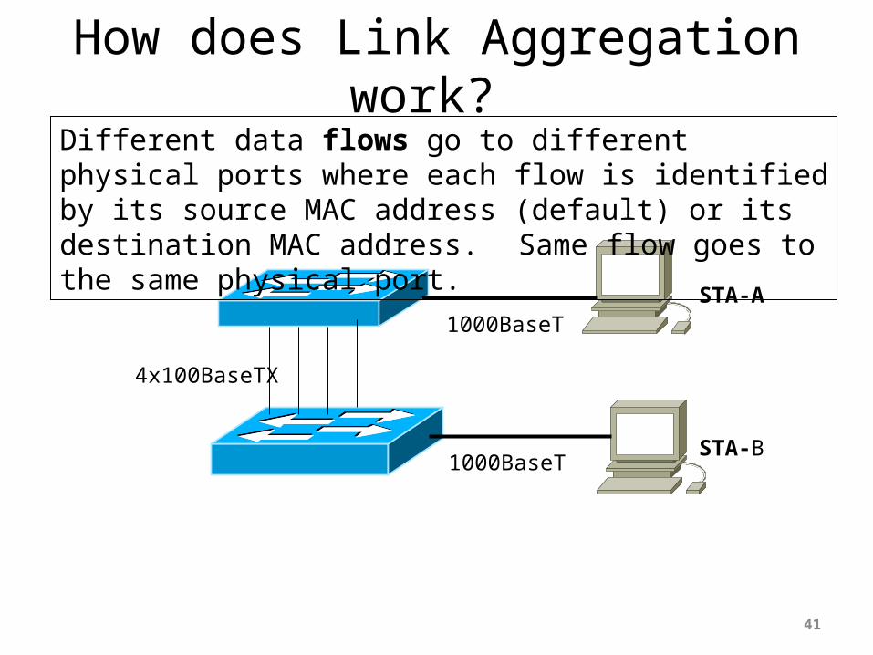
4x100BaseTX
1000BaseT
1000BaseT
Different data flows go to different physical ports where each flow is identified by its source MAC address (default) or its destination MAC address. Same flow goes to the same physical port.
STA-A
STA-B
How does Link Aggregation work?
42
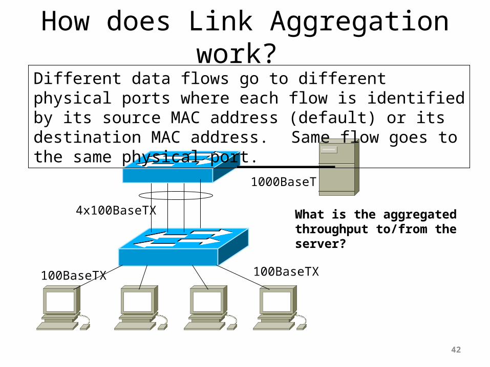
4x100BaseTX
1000BaseT
100BaseTX
Different data flows go to different physical ports where each flow is identified by its source MAC address (default) or its destination MAC address. Same flow goes to the same physical port.
100BaseTX
What is the aggregated throughput to/from the server?

Link Aggregation
• Just because you are combining two 100 Mbps links doesn’t mean you will get a 200 Mbps aggregated link
• Link aggregation works well, but is not as good as a fatter pipe
43

VLAN is a technology to resolve a problem.
What is the PROBLEM that VLAN is trying to address?
44

Collision DomainOne collision domain and two segments
45
Segment 2
WS1 WS2 WS3 WS4
Segment 1
hub hub

Broadcast DomainOne broadcast domain and
two collision domains
46
WS1 WS2 WS3 WS4
Collision Domain1
Collision Domain2
bridge
hub hub

Dividing a Broadcast Domain(old way)
47
WS1 WS2 WS3 WS4
Broadcast Domain1
Broadcast Domain2IP Subnet 1
IP Subnet 2
router
switch switch

Dividing a Broadcast Domain(new way: use switch instead of router)
48
WS1 WS2 WS3 WS4
VLAN 1 VLAN 2
switch
switch switch

What is VLAN?
49
VLAN is a networking technology that divides a network segment (broadcast domain) into multiple logical segments without rewiring the hardware
VLAN-1 VLAN-2 VLAN-3
One broadcast domain Multiple broadcast domains

VLAN Benefits
• More bandwidth• No physical limitations• Broadcast and multicast containment• Flexibility• Ease of resource sharing• Performance• Quality of Service (QoS)• Security
50

51
How does VLAN work? How does VLAN work?
server1WS11 WS12 server2WS21 WS22
VLAN-1 VLAN-2
All stations are physically connected to the same switch, but:
WS21 and WS22 cannot access Server1.WS11 and WS12 cannot access Server2.

52
MAC Forwarding TableEach VLAN has its own MAC
forwarding table.
MAC Forwarding TableEach VLAN has its own MAC
forwarding table.
MAC1 MAC2 MAC3 MAC4
VLAN-1 VLAN-2
P1 P2 P8 P3
P4
P1 MAC1P2 MAC2P9 MAC10
MAC20
P3 MAC3P4 MAC4P8 MAC20
MAC10
P9
VLAN Trunking Protocol (VTP)
• But what if you want to access one device from both multiple VLANs using only one port?
• You can use the VLAN Trunking Protocol designed by Cisco and available in pretty much all their routers
• VTP is a layer 2 protocol
53
54
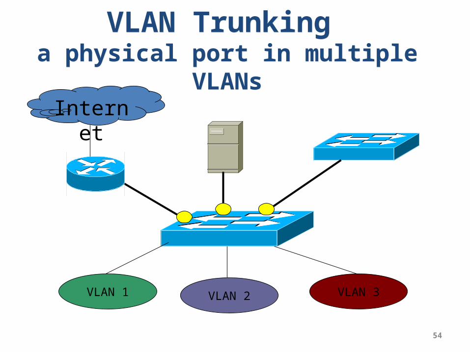
VLAN Trunking a physical port in multiple
VLANs
VLAN Trunking a physical port in multiple
VLANsInterne
t
VLAN 1 VLAN 2 VLAN 3
55
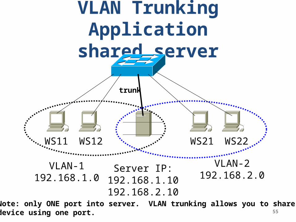
VLAN Trunking Application
shared server
VLAN Trunking Application
shared server
WS11 WS12 WS21 WS22
VLAN-1192.168.1.0
VLAN-2192.168.2.0
Server IP:192.168.1.10192.168.2.10
trunk
Note: only ONE port into server. VLAN trunking allows you to share adevice using one port.
56
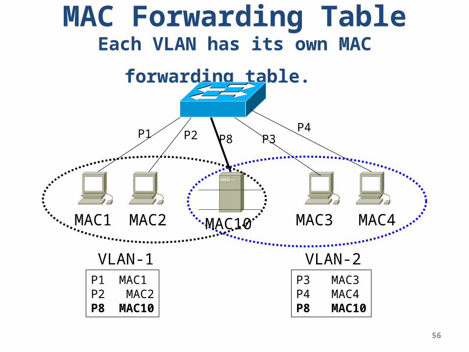
MAC Forwarding TableEach VLAN has its own MAC
forwarding table.
MAC Forwarding TableEach VLAN has its own MAC
forwarding table.
MAC1 MAC2 MAC3 MAC4
VLAN-1 VLAN-2
P1 P2 P8 P3P4
P1 MAC1P2 MAC2P8 MAC10
MAC10
P3 MAC3P4 MAC4P8 MAC10

One-Armed Router(inter-VLAN communication)
57
192.168.1.10
VLAN 2VLAN 1
192.168.1.11
192.168.2.10
192.168.2.11
192.168.1.1
192.168.2.1
trunk
Normally, devices on the VLANs can not intercommunicate. Need the router to inter-communicate. But how can both VLANs access router? Use VTP.
58
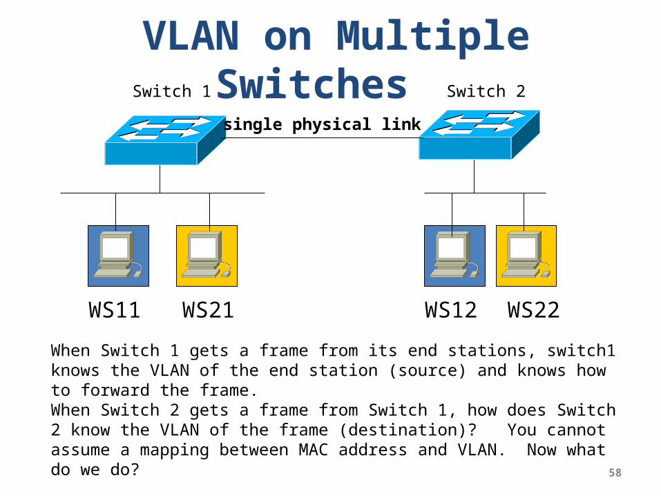
VLAN on Multiple Switches
VLAN on Multiple Switches
WS11 WS21 WS12 WS22
Switch 1 Switch 2
When Switch 1 gets a frame from its end stations, switch1 knows the VLAN of the end station (source) and knows how to forward the frame.When Switch 2 gets a frame from Switch 1, how does Switch 2 know the VLAN of the frame (destination)? You cannot assume a mapping between MAC address and VLAN. Now what do we do?
single physical link

VLAN Tagging
• IEEE 802.1Q standard (similar to Cisco’s VTP)• Used for sharing a physical Ethernet link or
device by multiple logical networks• A four-byte field is inserted into MAC frame
between source address and Type field• This field is inserted by one switch and then
removed by another switch, so individual workstations never see the tag
59

802.1Q Tagged Frame• Tag Protocol Identifier (2 bytes) – contains the value hex
8100; identifies this frame as being a tagged frame• User priority (3 bits) – indicates frame priority; values of
0 to 7; 0 means best fit, 1 is lowest priority, 7 is highest• Canonical Format Indicator (1 bit) – 0 indicates non-
canonical form (Ethernet), 1 indicates canonical (reversed address) form (token ring)
• VLAN ID (12 bits) – specifies the VLAN to which the frame belongs
• Some ISPs add a second tag to internal traffic
60

Tagged MAC Frame
61
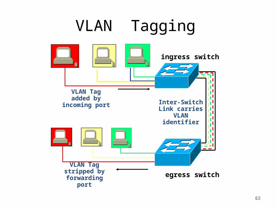
VLAN TaggingVLAN Tagging
62
VLAN Tag added by
incoming port
VLAN Tag stripped by
forwarding port
Inter-Switch Link carries
VLAN identifier
ingress switch
egress switch

VLAN Tagging (cont.)VLAN Tagging (cont.)
63
VLAN Tag added by
incoming port
VLAN Tag stripped by
forwarding port
ingress switchegress switch
tagged frames

In Class Discussion (A)Is it always a one-to-one mapping
between VLAN and IP subnet?
64
192.168.1.10/24
VLAN 2VLAN 1
192.168.1.11/24
192.168.1.101/24
192.168.1.102/24
192.168.1.254
Q1: is there any problem with this network configuration?Q2: What is the solution to the problem?
Internet
VLAN trunk

In Class Discussion (B)Is it always a one-to-one mapping
between VLAN and IP subnet?
65
192.168.1.10/24
192.168.1.11/24
192.168.2.10/24
192.168.2.11/24
192.168.1.254
192.168.2.254
Q: is there any problem with this network configuration?
Internet
no VLANconfiguration
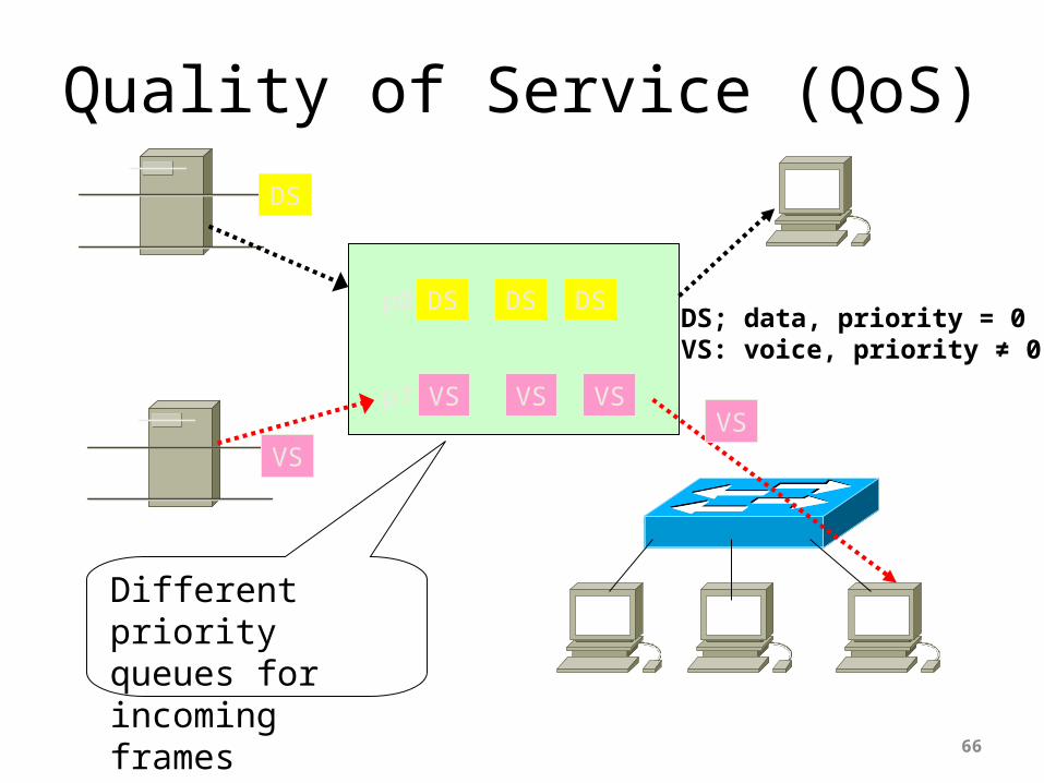
Quality of Service (QoS)
66
DS
DS DS DS
VS
VS VS VS
p0
p7VS
Different priority queues for incoming frames
DS; data, priority = 0VS: voice, priority ≠ 0
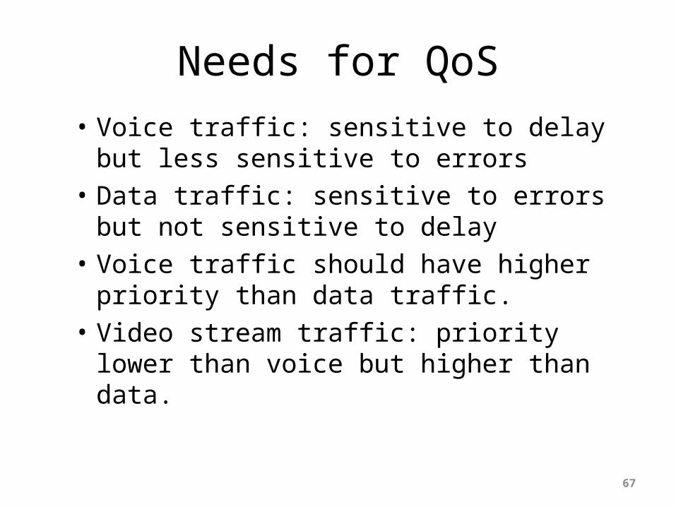
Needs for QoS
• Voice traffic: sensitive to delay but less sensitive to errors
• Data traffic: sensitive to errors but not sensitive to delay
• Voice traffic should have higher priority than data traffic.
• Video stream traffic: priority lower than voice but higher than data.
67

802.1Q and 802.1p
68
3 bits for priority: how many queues?

Multiple Priority Queues in Switch
69
GS GS
BS BS BS
VS VS
GSGS
BSBS
Voice Service
Gold Service (Data)
Best Effort (Data)
1st priority (p=100)
2nd priority (p=001)
no priority (p=000)
if [frames in the 1st priority queue]process Voice frames
else if [frames in the 2nd priority queue]process Gold Service Data frames
elseprocess frames with Best Effort
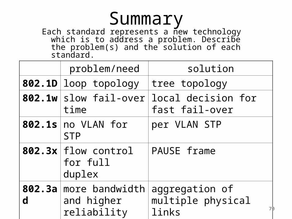
SummaryEach standard represents a new technology which is
to address a problem. Describe the problem(s) and the solution of each standard.
problem/need solution
802.1D
loop topology tree topology
802.1w
slow fail-over time
local decision for fast fail-over
802.1s
no VLAN for STP
per VLAN STP
802.3x
flow control for full duplex
PAUSE frame
802.3ad
more bandwidth and higher reliability
aggregation of multiple physical links
802.1Q
VLAN trunking VLAN Tagging: VLAN ID
802.1p
QoS VLAN Tagging: priority bits
70