tcs pneumatic hoist - planeta-hebetechnik.eu · 1) hoist components 1 upper hook 13 adjust screw...
TRANSCRIPT

TCS PNEUMATIC HOISTINTRODUCTIONThank you for choosing the TCS pneumatic hoist.
Provided that the hoist is used and maintained in accordance with this manual it will afford you many years of reliable service.
Before installing the unit, please ensure that both the personnel responsible for installation and maintenance and those responsible for itsuse are fully acquainted with the sections of this manual which are relevant to them.
Make sure that this manual is accessible at all times for any relevant person, in case of loss of this manual ask your dealer for new copy.
SECTIONS1) HOIST COMPONENTS
2) TECHNICAL SPECIFICATIONS
3) GETTING STARTED - Unpacking the hoist. Installing the hoist. Checks before use.
4) SAFE OPERATION - The do’s and don’ts of safe operation
5) LAYING UP THE HOIST - Preparing the hoist for lay-up of varying duration.
6) PERIODIC EXAMINATION, TESTING - Types and frequency
7) FITTING AND REPLACING LOAD CHAIN
8) SPEED AND MAXIMUM LOAD ADJUSTMENT
9) SILENCING
10) TROUBLE SHOOTING - Description, cause and remedy
11) SERVICE DATA, COMPONENT DIMENSIONS AND TOLERANCES.
12) DUTY RATING OF TCR HOIST
13) WARRANTY
Notations: The following notations are used throughout this manual.
(!) Failure to follow this instruction may result in a dangerous occurrence or serious injury.
(X) Failure to follow this instruction may result in premature wear of the hoist or a component part of the hoist.
Packaging materials should be recycled or disposed according to local regulations.

1) Hoist Components
1 Upper hook 13 Adjust screw for longer pendant hose set
2 Hook safety latch 14 Air inlet 1/2"
3 Gear box 15 Exhaust
4 Brake section 16 Speed adjust screw
5 Chain slack end mounting point 17 Valve section
6 Washer 18 Motor section
7 Spring 19 Hole for suspension wire for hanging the hoist
8 Chain 20 Limit lever
9 Underhook block 21 Emergency stop button
10 Hook safety latch 22 Pendant control
11 Underhook 23 Cord control
12 Pendant hose set 24 Chain basket
1 Upper hook 13 Air inlet 1/2"
2 Hook safety latch 14 Exhoust
3 Gear box 15 Speed adjust screw
4 Brake section 16 Valve section
5 Chain slack end mounting point 17 Motor section
6 Chain end stopper 18 Hole for suspension wire for hanging the hoist
7 Chain 19 Lifting chain end mounting poirt

7 Chain 19 Lifting chain end mounting poirt
8 Lower hook block 20 Limit lever
9 Hook safety latch 21 Emergency stop button
10 Lower hook 22 Pendant control
11 Pendant hose set 23 Cord control
12 Adjust screw for longer pendant hose set

2) Technical SpecificationsPERFORMANCE SPECIFICATION AND INSTALLATION DATA TCR HOIST RANGEToku model Max. S.W.L. kgs. Full load* mpm No load* mpm Chain falls Inlet air pressure bar
TCS-500 500 17 33 1 4-6
TCS-980 990 8,5 16,5 2 4-6
*Max speed (6 bar)
Toku Model Air cons. full load L/sec. Air inlet size Hose I.D. <10 m. mm. Hose I.D. >10 m. mm Air SVCE unit size mm.
TCS-500 33 PT 1/2" 13 16 1/2"
TCS-980/2 33 PT 1/2" 13 16 1/2"
Tokumodel
max noise dBa.1 m
Nom. Chain diammm
Nom. Chainpitch
Weight c/w 3mH.O.L.
Weight per add. m.H.O.L.
Bottom hookswivel
Closed heightmm
TCS-500 <83 6,3 19,1 15,9 kgs 0,9 Bearing 414
TCS-980/2 <83 6,3 19,1 16,8 kgs 1.8 kgs Bearing 414

3.) GETTING STARTED.3.1 ) DEBALLAGE DU PALAN.
Take care when unpacking, for weight details : see technical specifications. (!)
The hoist will have been packed into a cardboard box or palletised. When unpacking:
Ensure that both the hoist and any ancillary equipment are recovered from the packing. (Small or delicate items may have been packedseparately.) Check the contents against the Supplier’s delivery/advice note and advise the supplier immediately of any shortages.
Ensure that the hoist and ancillary equipment are undamaged. If the goods do not reach you in perfect condition, notify your supplierimmediately of any damage. Do not proceed with installation if the goods are damaged. (!)Ensure that a Certificate of test and thorough examination together with a CE Certificate of Conformity is included with the goods. Handthese to the responsible person’ for safe keeping. Check that the Identifying Mark (serial no.), the Safe Working Load (Lifting Capacity)and CE’. mark appear on the hoist. Throughout the E.C. these items are required by statute. A lack of any of the above may result in acaution or prosecution by the government health and safety authority, and may negate your insurance cover in the event of an accident.
3.2) INSTALLING THE HOIST
Air supply:(X) Vane type air motors are designed to function using clean, dry, lubricated air. The installation of an in line’ air service unit althoughessential cannot in itself compensate for serious contamination in the air supply. When operating the compressor in moist (humid) ordusty atmospheres seek the advice of your compressor supplier with regard to the fitting of a dryer and filter.
Air pressure:The hoist is designed to operate in the pressure range of 4 to 6 Bar (60 to 90 p.s.i.). The speeds quoted on the manufacturer’s literatureare obtainable only at 6 Bar (90 p.s.i.) inlet pressure. The hoist will operate at much reduced speed at pressures below this figure.
Air flow:Refer to the chart to select the hose diameter which ensures adequate air flow. Failure to provide adequate air flow will result in apressure drop in the supply line and cause the hoist to stall and the brake to apply until the pressure increases. In addition, the brake willnot release cleanly and will overheat.(Although not in itself a hazard [the brake fails safe] it may prove frustrating to the operator and ahazard may arise as a consequence.) (X)
Dos and don’ts:Do use exclusively correctly rated pneumatic hoses and fittings in the air supply line.
Do maintain the internal diameter of hose and fittings (as per the table throughout the supply length) or reduce from the larger diameter tothe smaller diameter in the direction of the hoist
Do shut-off the air supply when disconnecting air hoses from the hoist (!)Don’t create low points in the air supply line where water may be trapped (or if unavoidable install a drain tap).
Don’t rely on pneumatic fittings to support air lines; they are not designed for this purpose. (!)Don’t shorten the pendant by forming a loop or coil. This will prevent the strainer wire from supporting the pendant and will cause thehoses to become detached or kinked. (!)Air Service units:The correct size of air service unit for each hoist type is stated in the table. The air service unit must be installed with the lubricator unitdown line from the filter unit. The unit should be installed at the hoist inlet port or within three metres of the inlet port. (Siting the unit furtheraway will result in lubricant being deposited on the internal walls of the supply line and hence it will be necessary to increase thelubrication rate above the levels specified [see table] to ensure adequate lubrication of the hoist.)
Filter unit (Water trap):
These are available with manual drain or automatic drain.
Manual drain units. As the name implies, these units must be drained by the operator as the filter bowl becomes full of water. Thefrequency of draining is entirely dependent upon the usage of the hoist and the moisture level of the air supply and will soon beestablished by experience. It is recommended that a person be appointed to check and drain the filter unit at a specified frequency (X)In clean environments e.g. laboratories, paint spray booths, manual drain filters are essential to prevent contamination.
Automatic drain units. These units are automatically self purging. When the filter bowl is full it will automatically drain itself. Although veryconvenient to the user, the unit must be sited such that either the purged water is captured by a tray or it purges into an area away frompersonnel, equipment (particularly electrical equipment) and goods. If contamination from purged water is not a problem then automaticdrain units should be selected.
Failure to fit and drain the filter will result in excessive moisture being carried into the hoist valve, motor and brake actuator resulting ininternal corrosion and premature failure (!)Lubricator unit
Two types are available:
Oil mist Lubricator The preferred type, and essential where the lubricator must be sited some distance from the hoist. The unitproduces atomised oil particles which remain in suspension in the air longer.

Droplet lubricator Due to the larger particle size of the oil droplets, these may only be used where the lubricator is close coupled to thehoist.
Failure to fit a lubricator and maintain the correct oil flow will result in rapid wear of the rotor vanes within the motor, excessive heatgeneration and failure of the air motor within a very short period (!)Regulator Unit
Most compressors are supplied with a regulator on the output. However, where a number of different pneumatic tools are supplied fromthe same compressor it is good practice to maintain the supply line or ring main at a higher pressure and to fit a regulator to the supply ateach tool.
The operating pressures stated for the air hoist are the pressures required at the hoist inlet manifold. Subject to the type of air line, apressure drop in the line of between 0.1 and 0.35 Bar (2 and 5 p.s.i. ) per 10 metres of line should be anticipated (as a result of thefrictional resistance of the walls).
Before connecting the air supply line to the hoist, restrain the end and blow out’ the line to prevent any foreign’ material from entering thehoist motor.
Before connecting the air supply line to the hoist, pour 5 to 10 cc of Yokota airtool oil (order no. Atlub) directly into the airline to ensurethat oil is present in the motor at start up.
Festoon systems:
Where the hoist is to be mounted in a fixed position, then air supply installation is a simple matter. Flexible or rigid pipework may beused, temporary or permanent provided that the pipework is adequately supported and the last metre or so is flexible to allow the hoist tomove without fracturing the pipe.
Hoist and trolley systems:
The type of installation selected is dependent upon the distance which the hoist/trolley is to be required to move. As a general rule:
1 to 2 metres of movement Flexible hose suffices (the recoil type takes up less space.)
Up to 5 metres (on a runway) Flexible hose may be supported by a taut wire installed parallel to the runway along the travellength.
Over 5 metres (on a runway) A C’ track system with hose carrying trolleys or an automatic hose reeling drum should be selected.
FOR SPECIALIST ADVICE, CONSULT YOUR DEALER
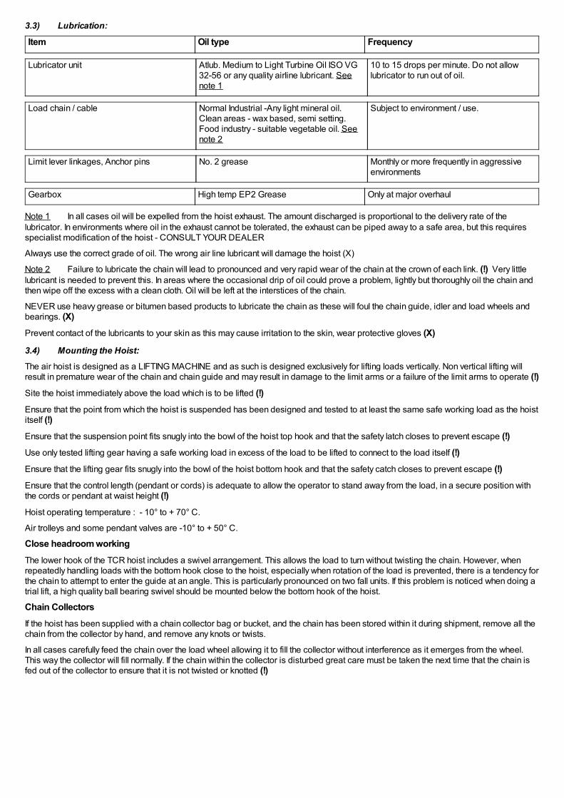
3.3) Lubrication:
Item Oil type Frequency
Lubricator unit Atlub. Medium to Light Turbine Oil ISO VG32-56 or any quality airline lubricant. Seenote 1
10 to 15 drops per minute. Do not allowlubricator to run out of oil.
Load chain / cable Normal Industrial -Any light mineral oil.Clean areas - wax based, semi setting.Food industry - suitable vegetable oil. Seenote 2
Subject to environment / use.
Limit lever linkages, Anchor pins No. 2 grease Monthly or more frequently in aggressiveenvironments
Gearbox High temp EP2 Grease Only at major overhaul
Note 1 In all cases oil will be expelled from the hoist exhaust. The amount discharged is proportional to the delivery rate of thelubricator. In environments where oil in the exhaust cannot be tolerated, the exhaust can be piped away to a safe area, but this requiresspecialist modification of the hoist - CONSULT YOUR DEALER
Always use the correct grade of oil. The wrong air line lubricant will damage the hoist (X)
Note 2 Failure to lubricate the chain will lead to pronounced and very rapid wear of the chain at the crown of each link. (!) Very littlelubricant is needed to prevent this. In areas where the occasional drip of oil could prove a problem, lightly but thoroughly oil the chain andthen wipe off the excess with a clean cloth. Oil will be left at the interstices of the chain.
NEVER use heavy grease or bitumen based products to lubricate the chain as these will foul the chain guide, idler and load wheels andbearings. (X)Prevent contact of the lubricants to your skin as this may cause irritation to the skin, wear protective gloves (X)
3.4) Mounting the Hoist:
The air hoist is designed as a LIFTING MACHINE and as such is designed exclusively for lifting loads vertically. Non vertical lifting willresult in premature wear of the chain and chain guide and may result in damage to the limit arms or a failure of the limit arms to operate (!)Site the hoist immediately above the load which is to be lifted (!)Ensure that the point from which the hoist is suspended has been designed and tested to at least the same safe working load as the hoistitself (!)Ensure that the suspension point fits snugly into the bowl of the hoist top hook and that the safety latch closes to prevent escape (!)Use only tested lifting gear having a safe working load in excess of the load to be lifted to connect to the load itself (!)Ensure that the lifting gear fits snugly into the bowl of the hoist bottom hook and that the safety catch closes to prevent escape (!)Ensure that the control length (pendant or cords) is adequate to allow the operator to stand away from the load, in a secure position withthe cords or pendant at waist height (!)Hoist operating temperature : - 10° to + 70° C.
Air trolleys and some pendant valves are -10° to + 50° C.
Close headroom workingThe lower hook of the TCR hoist includes a swivel arrangement. This allows the load to turn without twisting the chain. However, whenrepeatedly handling loads with the bottom hook close to the hoist, especially when rotation of the load is prevented, there is a tendency forthe chain to attempt to enter the guide at an angle. This is particularly pronounced on two fall units. If this problem is noticed when doing atrial lift, a high quality ball bearing swivel should be mounted below the bottom hook of the hoist.
Chain CollectorsIf the hoist has been supplied with a chain collector bag or bucket, and the chain has been stored within it during shipment, remove all thechain from the collector by hand, and remove any knots or twists.
In all cases carefully feed the chain over the load wheel allowing it to fill the collector without interference as it emerges from the wheel.This way the collector will fill normally. If the chain within the collector is disturbed great care must be taken the next time that the chain isfed out of the collector to ensure that it is not twisted or knotted (!)

1 Washer M6 7 Chain
2 Nut M6 8 Chain basket
3 Split pin 2 x 15 9 Washer M6
4 Washer M8 10 Hanger bolt M6
5 Nut M8 11 Washer M8
6 Split pin 2,5 x 20 12 Hanger bolt M8
Mounting on trolleysEnsure that the trolley is properly mounted on the beam and set correctly for the beam with adequate wheel clearance. (!)Ensure that the stops for the trolley mounted on the runway beam are correctly positioned and securely installed (!)Ensure that the top hook or link plate of the hoist fits properly on the suspension point of the trolley and is assembled properly with thehoist at the centre of the load bar (!)Ensure that the load bar and tie bar nut have been secured and the trolley side plates are set parallel to the beam web.(!)
Ensure that the tie bars are correctly adjusted in the slots with the anti tilt roller close under the beam with enough clearance to allow thetrolley to run along the beam (!)

Standard Hose Connenction:
3.5) Checks before use
These checks should be carried out after installation and on a frequent and regular basis thereafter. They require no specialistknowledge. If the hoist is used daily then it is recommended that they are carried out daily as the checks take only minutes to completeand not only help avoid repair bills but significantly reduce the possibility of an accident, or dangerous occurrence
Air supply checks:Inlet pressure 4 to 6 Bar (at hoist inlet there will be a pressure drop along the air hose and across the air set (!)
Lubricator topped up with oil and correctly adjusted.
Air line undamaged, without leaks, fittings sound. Hose connections wired or pinned.
Hoist checks (air supply switched off)Hook swivels satisfactory
Hook safety claws functional and undamaged
safety claw
Chain undamaged
Chain not twisted through (two fall models see sketch)
Chain moves freely around the pocket wheels
Chain anchor sound.
Hoist checks (air supply switched on)Test run the equipment prior to application of a load to ensure the equipment along with its control and safety devices work correctly
Pendant buttons, levers or cords smooth to operate, automatically return to neutral (hoist stops) on release. Ensure that the direction forlifting/lowering comply with the actual movement.
Emergency stop functional.
Upper limit operation satisfactory
Lower limit operation satisfactory
Chain runs smoothly over the pocket wheels.

Hoist stops immediately when pendant trigger, button or cord released.
The inclusion of the above checklist into the company safety procedures is recommended.
4) SAFE OPERATION.Hoist operators must read and understand the contents of this manual before operating the hoist (!)The contents of this section are designed for the guidance of personnel using the hoist. For the most part they are common-sense’procedures. Most dangerous occurrences involving lifting machines are not as a result of a defect developing in the machine itself but areas a result of an error or act of carelessness by the operator. As such, the vast majority of accidents or dangerous occurrences areavoidable.
It is further recommended that only authorised personnel should be permitted to use the hoist and that a prerequisite to authorisationshould be basic training in both safe use and visual examination (as per the safety checks above) of the hoist.
Hoist operators must be healthy and not under the influence of alcohol, drugs or medication when operating the hoist (!)Hoist operators should be trained in proper rigging procedures for the attachment of loads to the hoist (!)The operator is always responsible for his own safety and anybody else in the operating area (!)Ensure that the weight of the load to be lifted is less than the safe working load of the hoist(!)Ensure that the load is securely supported by it’s lifting gear (slings shackles etc.) and that it cannot escape’ whilst being lifted (!)Never apply the load to the tip of the hook or safety latch (!)Ensure that the lifting assembly (slings, shackles etc.) has a higher safe working load in the configuration used than the load to be lifted (!)Ensure that the point at which the hoist is to be suspended has a greater safe working load than the hoist (!)Never apply the load to the tip of the hook or safety latch (!)Plan every lift (!)Ensure that the load is free to move and will clear all obstructions (!)Avoid swinging the load or hook (!)Always start the lowering or lifting movement slowly and smoothly (!)Stand clear of the load when lifting or lowering, and ensure that the point at which you are standing is secure (!)Ensure that other personnel cannot enter the immediate area where the lift is taking place(!)Always keep your attention during operating the hoist, stay concentrated (!)Never lift the load higher than is necessary (!)When using the hoist jointly with another person, use signals agreed upon at the job site ( standardized signals) (!)Never leave a suspended load unattended (!)Never lift a load over persons (!)Do not use the hoist if the chain is damaged, twisted, kinked or worn (!)When using the hoist without chain collector, avoid the slack chain to fall, catch or impact as this can cause hazards (!)Ensure that the load is stable and in balance at starting lifting or setting down as tilting or falling loads can cause accidents (!)In case of air pressure loss, secure the load and area. Ensure that turning the air supply back on cannot result in a dangerous occurrence(!)Avoid shocks during lifting/lowering, start/stop the movement smoothly (!)Do not change the movement direction suddenly as this will shocks (!)Never allow loads to “fall” into the load chain (!)Never use the load chain as a sling or wrap the load chain around the load (!)Never use the Red Rooster hoists for lifting or transporting persons, they are not designed for this (!)Ensure that no vibrations are transmitted in any way to the hoist by either the load or supporting structure (!)Never lock the control elements of the pendant or cords (!)Stop using the hoist in case of abnormal sounds (!)Do not wear loose clothing (ties, scarves etc.) which may get dragged into the hoist or bottom block (!)Wear safety boots or shoes (together with a safety helmet if lifting overhead). (!)Never use the chain, hooks or hoist as an electrical ground for welding or electricity (!)Do not use the limits as a means of stopping the hoist (these are safety devices) (!)Do not use the controls as a means of moving the hoist (the pendant is designed to support it’s own self weight only). (X)

Do not hold onto the load chain when controlling a load (fit a tag line to the load if necessary to ensure that the load is controlled) (!)Do not hold onto the load cable when controlling a load (fit a tag line to the load if necessary to ensure that the load is controlled) (!)Do not use the hoist to lift / lower personnel (!) Only use the hoist to lift a load vertically (by siting the hoist directly above the load). It is not designed to pull or drag loads (!)Operate the hoist smoothly. Do not suddenly change direction as this may exert both shock loads and acceleration forces well in excessof the weight of the load being lifted (!)Do not touch the hoist body immediately after extensive use, as it might be hot (!)Wherever possible ensure that you are sited in a position to see the load at all stages of the lift (!)If it is not possible to site yourself in a position where you can see the load at all stages, appoint a second person as banksman’ to coverthe area which you cannot see and establish a reliable method of communication (verbal or hand signals) before starting the lift (!)If you suspect that the hoist may be defective in any way, do not use it. Either remove the hoist to an area where it cannot be used orclearly label the hoist Defective, Do not use’. Report the defect IMMEDIATELY to your Supervisor or the Safety Officer (!)If you suspect that a fault has developed during a lift, stop the lifting operation immediately, and seek the advice of your Supervisor or theSafety Officer. If the load is suspended ensure all personnel stay well clear of the area of operation (!)At all times think before you act (!)Note:Always follow the applicable European and local Regulations/Standards regarding lifting and in case of hoist with trolleytransporting hot molten masses. (!)
5) LAYING UP THE HOISTWhenever the hoist is unused for a period (weekends, holidays or in store), a little preparation will ensure that the hoist operates correctlyand safely when put back into service.
Short lay up periods ( 2 to 30 days):Turn up the oil delivery rate of the lubricator to maximum and run the hoist for two minutes, thereby ensuring that the hoist motor andcontrol valve are well lubricated. (This also helps to displace any water which may be lying in the hoist) (X)Longer lay up periods (in excess of 30 days):Heavily lubricate the hoist as specified above.
If the hoist is contaminated with dirt or chemicals, wash with a proprietary mild solvent or detergent and thoroughly rinse off with freshwater. Allow to dry, and spray lightly with penetrating fluid.
Lubricate the load chain, limit shafts, safety latches and hook swivels.
Disconnect the air supply and plug the inlet port.
Store in a dry ventilated area.
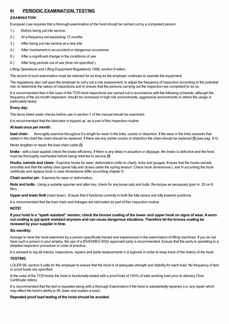
6) PERIODIC EXAMINATION, TESTINGEXAMINATION
European Law requires that a thorough examination of the hoist should be carried out by a competent person:
1.) Before being put into service.
2.) At a frequency not exceeding 12 months
3.) After being put into service at a new site
4.) After involvement in an accident or dangerous occurrence
5.) After a significant change in the conditions of use
6.) After long periods out of use (time not specified.)
Lifting Operations and Lifting Equipment Regulations 1998, section 9 refers.
The record of such examination must be retained for as long as the employer continues to operate the equipment.
The regulations also call upon the employer to carry out a risk assessment; to adjust the frequency of inspection according to the potentialrisk, to determine the nature of inspections and to ensure that the persons carrying out the inspection are competent to do so.
It is recommended that in the case of the TCR hoist inspections are carried out in accordance with the following schedule, although thefrequency of the six month inspection’ should be increased in high risk environments, aggressive environments or where the usage isparticularly heavy.
Every day:
The items listed under checks before use in section 1 of the manual should be examined.
It is recommended that the lubricator is topped up’ as a part of this inspection routine
At least once per month:
load chain - thoroughly examine throughout it’s length for wear in the links, cracks or distortion. If the wear in the links exceeds thatstated in the chart the chain should be replaced. If there are any visible cracks or distortion the chain should be replaced (!) (see pag. 9.4)
Never lengthen or repair the load chain cable (!)brake - with a load applied check the brake efficiency. If there is any delay in actuation or slippage, the brake is defective and the hoistmust be thoroughly overhauled before being returned to service (!)Hooks, swivels and claws - Examine hooks for wear, deformation (refer to chart), nicks and gouges. Ensure that the hooks swivelssmoothly and that the safety claw opens fully and closes under the spring tension. Check hook dimensions L and H according the hookcertificate and replace hook in case dimensions differ according chapter 9
Chain anchor pin - Examine for wear or deformation.
Nuts and bolts - Using a suitable spanner and allen key, check for any loose nuts and bolts. Re-torque as necessary (part nr. 25 on 9Nm)
Upper and lower limit (chain lever) - Ensure that it functions correctly in both the fully raised and fully lowered positions.
It is recommended that the load chain and linkages are lubricated as part of this inspection routine.
NOTE!If your hoist is a “spark resistant” version; check the bronze coating of the lower- and upper hook on signs of wear. A wornout coating is not spark resistant anymore and can cause dangerous situations. Therefore let the bronze coating berenewed by your supplier in time.Six monthly:Arrange to have the hoist examined by a person specifically trained and experienced in the examination of lifting machines. If you do nothave such a person in your employ, the use of a BS/EN/ISO 9002 approved party is recommended. Ensure that the party is operating to adetailed inspection procedure or code of practice.
It is advised to log all checks, inspections, repairs and parts replacements in a logbook in order to keep track of the history of the hoist
TESTINGLOLER 98, section 4 calls for the employer to ensure that the hoist is of adequate strength and stability for each load. No frequency of testor proof loads are specified.
In the case of the TCR hoists the hoist is functionally tested with a proof load of 150% of safe working load prior to delivery (TestCertificate refers).
It is recommended that the test is repeated along with a thorough Examination if the hoist is substantially repaired (i.e. any repair whichmay affect the hoist’s ability to lift, lower and sustain a load).
Repeated proof load testing of the hoist should be avoided.

7) FITTING / REPLACING LOAD CHAINTYPES OF CHAIN
Only the correct size and grade of load chain should be used (!)TCS-500 C / PE, TCS-980 C/PE
Chain material: Steel galvanised Stainless steel
Nominal diameter 6.3+0.10/-0.25 mm 6.3+0.10/-0.25 mm
Pitch 19.1+0.20/-0.10 mm 19.1+0.20/-0.10 mm
Max. diam at weld 6.80 mm 6.80 mm
Min. breaking force 49.9 kN 40.0 kN
Surface hardness 500-650 HV5 250 HV5
Quality grade EN 818-7 EN 818-7
Note: Spark resistant hoists may have been fitted with Grade 50 or 60 stainless steel chain. Please refer to supplier.
When supplied new, only quality chain from a reputable supplier has been fitted to the hoist. Your supplier will be able tooffer replacement chain of like quality.FITTING THE CHAIN
The hoist will require to be hung up with an airline connected.
The chain stopper will require to be fitted at least 8 links from the unloaded end of the chain.
The chain must be fed over the pocket wheel from the slack end anchor side with the weld of every second link facing away from thewheel axis i.e. weld outwards.
Care must be taken not to twist the chain during installation. This is best achieved by holding the live end of the chain as it emerges fromthe hoist, if the hoist is reeved on two parts of chain, feeding it through the free limit lock, through the bottom block wheel and againholding it as it emerges, thereafter feeding it up to the anchor pin. If the chain cannot be fitted to the anchor without rotating it through 90degrees, the end link should be removed.
Run the chain through the hoist, leaving a short tail at the slack’ end. Anchor the slack end without twisting the chain.
On single fall hoists the live end is fed through the limit lock, through the sleeve and secured in the bottom hook holder by the sleeve pin.(Thereafter the sleeve is pushed down over the holder to retain the pin and secured by a locking ring.)
Feeding the chain over the load wheel.It is very easy to trap or damage the chain if extreme care is not exercised. Always examine the first link of chain after passing it over theload wheel. If damaged, remove the damaged link(s) (!)Replacing existing chainCut away the centre portion of a link of the old chain to allow a chain diameter to pass through. Connect this spare link to the last link ofthe old chain and the first link of the replacement chain. Use the old chain to draw the replacement chain through the hoist. (Retain thespare link to be re-used)
Fitting chain to an unchained hoist.A handy tool comprises a length of either soft insulated wire (about 2 mm diameter) or a piece of flexible nylon tube of the same diameterapproximately 500 mm long. To the end of this is attached a similar length of strong twine.
The soft wire or tube is fed over the wheel, its flexibility allows it to follow the chain guide and re-emerge at the opposite side. The twine isattached to the end of the chain and drawn through, pulling the chain against the wheel. By applying power very slowly in the samedirection of winding, the load chain is dragged into the first pocket and over the load wheel. If any resistance is felt as the chain attemptsto enter the pocket it is imperative that the chain is released from the pocket before trying again. Otherwise the chain will become trappedand damaged.

1 Sprocket 7 Welded area
2 Bolt M8 8 Washer
3 Washer M8 9 Spring
4 Chain slack end 10 Under hook
5 Wire 11 Assemble at second chain link
6 Chain
1 Sprocket 7 Welded area
2 Bolt M8 8 Load chain mounting point
3 Washer M8 9 Bottom hook
4 Chain slack end 10 Assemble at second chainlink
5 Wire 11 Chain end stopper
6 Chain
8) SPEED AND MAXIMUM LOAD ADJUSTMENTSPEED ADJUSTMENT
Every TCR hoist is checked at the factory to ensure the maximum hoisting speed is in accordance with the specification.
Cord Control HoistThe speed of the hoist is proportional to the amount of downward movement in the control cord, which via the code lever controls theamount by which the valve is opened.

1 Slow 2
Fast
Pendant Control: the speed is proportional to the movement of the lever.
1 Slow 2
Fast

TCS series speed adjustment mechanism;
This hoist is equipped with a speed adjustment mechanism. If you feel the lifting or lowering speed is too fast, the speed can be adjustedslower as needed variably.
Also please note that the speed can be adjusted separately for lifting and lowering mode.
How to adjust the speed;
Referring to the diagram below, looking at the hoist from the valve side, the speed adjustment screw for lifting is on the RIGHT, and thelowering adjustment screw is on the LEFT. Both adjustment screws are covered with a red plastic cover and can be removed using a pairof pliers. Behind the plastic cover is a “ minus “ groove and can be adjusted using a standard flat screw driver. In relation to the air hoist,as shown in the drawing below, the vertical direction means the highest speed, and the horizontal position means the slowest speed.(Note; The hoist will stop) The adjustment can be made between these positions.Adjust the speed only when the hoist is in the stop mode. If the adjustment is made when he hoist is moving, it will be difficult to rotate thescrew since the air pressure increase the friction on the O-ring.
NOTE; When adjusting the speed adjustment screw, the O-ring friction may make rotation of the screw difficult, but this is not abnormal.
NOTE; The speed adjustment mechanism is set at the highest speed when shipped from the factory.
1 Adjust screw lowering speed 4 Cover
2 Adjust screw lifting speed 5 Highest speed setting
3 Cover 6 Lowest speed setting
Pendant hose extension adjustment mechanism (P, PE type) ;
The standard length for the pendant hose is 2 meters. When the pendant hose is lengthened, due to a pressure loss, the operation of thependant valve may become poor or non-functional.
This mechanism was developed to improve this situation
How to adjust;
Referring to the diagram below, looking at the hoist from the Hex nut side, adjustment screw for Lifting is on the RIGHT, and the loweringadjustment screw is on the LEFT.
When adjustment is needed, loosen the Hex Nut for the side you wish to adjust and using a 2.5 mm Hex wrench turn the hex screw in theright hand direction until the problem is solved. After the adjustment is made, tighten the Hex nut securely.
By tightening the pressure adjustment hole, this will allow better feathering and lengthening the pendant hose will help the pressure loss.Please note, if the screw is tightened too tight, you will loose the feathering capability for the hoist.
NOTE; When the hoist is shipped from the factory, the pressure adjustment hole is fully open to allow the hoist to have the featheringfeature. When the hoist is used under standard specifications, this mechanism does not need any adjustments.
1 Upper hook 13 Adjust screw for longer pendant hose set
2 Hook safety latch 14 Air inlet 1/2"

3 Gear box 15 Exhaust
4 Brake section 16 Speed adjust screw
5 Chain slack end mounting point 17 Valve section
6 Washer 18 Motor section
7 Spring 19 Hole for suspension wire for hanging the hoist
8 Chain 20 Limit lever
9 Underhook block 21 Emergency stop button
10 Hook safety latch 22 Pendant control
11 Under hook 24 Cord control
12 Pendant hose set 25 Chain basket

9) SILENCINGThe Red Rooster hoist is fitted with an internal silencer; the noise output being less than 83 dB(a) at one metre (this conforms to E.C.noise regulations).
TCS 250/500/980
The silencer comprises four nylon pads
CHANGING THE SILENCER (S)
TCS 250/500/980
Located at the end of the motor, the silencers are behind the exhaust plate.
TCS series : The exhaust air can be easily piped away from the hoist body. Disassemble the exhaust plate and silencer, there you willsee a threaded hole ( PT ¾) . Assemble a hose joint and connect a hose ( inner diameter 25 mm )
1 Exhaust plate 2 Threaded hole PT3/4" to pipe away the exhaustair

10) TROUBLE SHOOTINGWe list below a number of faults which may occur during use, together with the probable cause and the cure. If you experience a fault andcannot identify the cause or if you do not feel confident to remedy the fault, please revert to your hoist supplier.
Discription of fault noted Possible cause of fault Remedy
Hoist fails to start (when newlyinstalled)
Air supply switched.
Damage or kinked pendent hose(Type P hoists only)
Emergency stop actuated
Control valve sticking
Switch on air suply
Disconnect pendant from control valveand check whether there is pressurelReplace as necessary.
Re-set emergency stop
With air supply switched off, open andclose the valve using a spanner on thelimit lever. Do not use excessiveforce. If this fails, refer to dealer.
Hoist starts but slows down and stops(when newly installed)
Inadequate air supply
regulator set in excess of 7 Bar
Check compressor output againsthoist requirement
Check air hose size against table
Ensure fittings are matched to hosesize
Replace incorrect items
Reduce to 6 Bar
Hoist starts but will not stop Sticking valve on pendant
Contaminating within the control valve
Clean and lubricate valve. Replace ifnecessary
Dismantle, clean and lubricate
Hoist becomes progressivly slower over aperiod of time
Choked exhaust silencer
Inadequate lubrication
Replace silancer
Check if bolts in valve section havebeen fitted with 9 Nm
Adjust lubricator unit
Hoist sometimes refuses to start Worn vanes or damaged vanesprings
Dismantle and replace as necessary
Load chain jumps or makes a clickingsound
Worn load chain or guide
Chain twisted
Dismantle and replace as required
Incorrectly fitted, remove and refit(examine)
Bottom block twisted through chainparts (Two fall models only)
Motor 'stutters' and recovers periodically Excessive moisture in air supply Increase filtration or fit a dryer
Premature wear in load chain Inadequate lubrication of chain
Hoist conatantly operating at closeheadroom
Lubricate the chain
Fit a ball bearing swivel below thehook.
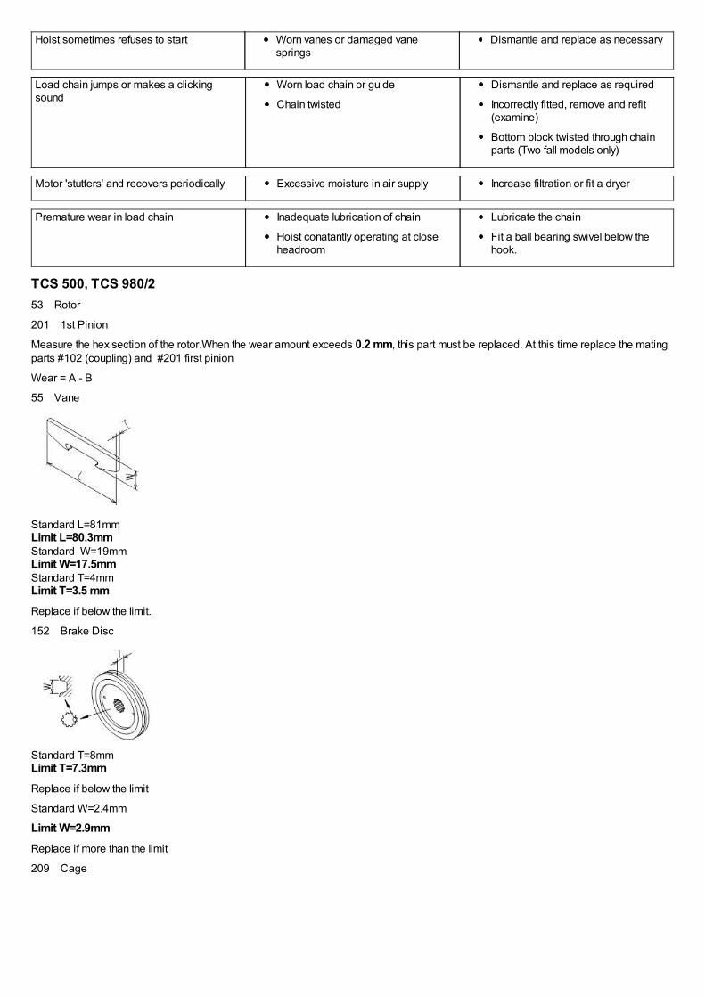
TCS 500, TCS 980/253 Rotor
201 1st Pinion
Measure the hex section of the rotor.When the wear amount exceeds 0.2 mm, this part must be replaced. At this time replace the matingparts #102 (coupling) and #201 first pinion
Wear = A - B
55 Vane
Standard L=81mm Limit L=80.3mm Standard W=19mm Limit W=17.5mm Standard T=4mm Limit T=3.5 mm
Replace if below the limit.
152 Brake Disc
Standard T=8mm Limit T=7.3mm
Replace if below the limit
Standard W=2.4mm
Limit W=2.9mmReplace if more than the limit
209 Cage

Insert the pin into the pin hole. If the clearance is too large, this part must be replaced.
201 1st Pinion
202 1st Star gear
204 1st Link gear
205 2nd Pinion
206 2nd Star gear
208 Ring gear
If a step or wear can be noticed on the gear face, the gear must be replaced.
203 1st Pin
207 2nd Pin
Check the O.D. for the pins. If a step can be noticed as wear, this part must be replaced.
When the pin is replaced, the needle bearing and star gear must be replaced
101 Load sheeve
If the load sheeve (sprocket) is damaged or worn, it must be replaced.
103 Chain Guide
Due to contact with the chain, if the wear exceeds 1mm, this part must be replaced.

104 Chain separator
Standard L=12.8mm Limit L=15mm Replace if more than the limit
Replace if damage or cracked.
250 Hook
260 Swivel Hook
It is best to measure the hook when the hook is brand new. This value will become the standard value and can be compared with themeasured value.TCS-250,500
Limit= L Measuremt L Std = 0.5mm Limit= H Std H Measuremt = 1mm TCS-1000-2Limit= L Measuremt L Std = 0.5mm Limit= H Std H Measuremt = 1mm Replace if exceeds the limit. If the hook will not rotate smoothly, repair or replace. Also make sure the safety hook claw is not damaged.
274 Sleeve pin
257 Sleeve pin
Measure the contact area of the pin and the chain
Wear Limit = 0.1 mmmmReplace ifthe it exceeds the wear limit.
111 Spring pin 8 x 60
Replace when the following limits are exceeded;Usage term of 10 years, operated for a period of 400 hours or has operated for 500,000 cycles, which ever comes first. If there is external wear, measure the wear and if the wear exceeds the limits it must be replaced.Wear limit; 0.1 mm114 Link chain

Standard value L=95mm
Limit L=96.9mm Replace if exceeds the limit Standard value d=6.3mm
Limit d=5.9mm Replace when below the above limit. Also, replace the chain if rust or damage is found.

12) DUTY RATINGSFEM 9.5.11 classifies the theoretical loading conditions and operating time in hours per day.
FEM 9.755 classifies the theoretical duration of service for safe operation.
APPLICATION OF FEM RULES TO PNEUMATIC HOISTS
With most mechanical equipment, the limiting factor with regard to operating time is that of HEAT GENERATION. For example, anelectric motor if not periodically allowed a rest period’ to allow it to cool down after each period of use will cease to function due toirreversible damage arising as a consequence of the heat.
Air motors perform differently. Although heat is generated, provided that the motor is properly lubricated, no damage will ensue. Theexpanding air at the outlet manifold also has a cooling effect on the motor.
As a result pneumatic motors are commonly referred to as 100% duty rated or continuous rated, which means simply that they may beused continuously without a cooling down period and without damage arising as a consequence.
Incorporated into the TCR hoist are three classes of components
Sacrificial components -These components are designed to incur wear to either protect other components or to function by means offriction generation. They require periodic inspection and replacement and comprise the Rotor Vanes and the Brake Disc. Inadequatelubrication seriously reduces the life expectancy of the vanes, whilst incorrect adjustment will severely reduce the life expectancy of thebrake disc.
Load Chain - Whilst adequate lubrication of the load chain will reduce friction and thereby limit the wear occurring between the bearingpoints of adjacent links, it will not totally eliminate it. Hence it will require regular inspection and will also require replacement within theservice life of the hoist.
Structural and mechanical components - These comprise all other parts of the hoist, including gearbox and bearings, rotor andhousing, valve, hooks, pins etc. A theoretical service life for every component has been calculated (available on request). For thepurposes of the summary, the shortest service life of any component has been included.

Table of Duties TCR HoistLoading conditions and operating time For all mentioned TCR-models
FEM 9.511Heavy loads
Medium butfrequently heavyloadsUsually small loads,
but often heavy loads
5Mup to 8 hours per day
up to 16 hours per day
Greater than 16 hours per day
Theoretical duration of service
FEM 9.755Sacrificial Components
Load Chain
Structural & Mechanical components*
1 Am (M4)
800 to 6300 hours
2M (M5)
1600 to 12500 hours
2M (M5)
1600 to 12500 hours
*Shortest duration stated.
IMPORTANT NOTESA hoist is deemed to be operating when it is in motion.
All ratings are based on a clean, dry, air supply and correct lubrication.
Load chain must be to manufacturer’s specification.
Special chains are excluded (consult your supplier).
Mode of use must be in accordance with manufacturer’s recommendation.
13) WARRANTYThe warranty period from the date of purchase is as follows:
12 months on Toku pneumatic chain hoists;
3 months on spare parts of hoists, which are repaired by us.
Warranty covers material or construction mistakes of the manufacturer, which are clearly definable. Replacement of parts or repair by anofficial Toku service workshop is free of charge, when the tool is covered by warranty. Freight or postage is for the account of buyer.
Damage attributable to a normal wear, overloading or incorrect use is excluded from warranty. Always consult this manual! Replacementof tools as a consequence of warranty claims is no part of the warranty arrangements.
Also claims for loss of production and/or other damages are excluded from this warranty. Repairs under warranty can only be considered,when the tool is in its original state and it is accompanied by a copy of the purchase invoice. Warranty claims have to be made throughthe dealer, who has supplied the tool concerned.
These warranty conditions are based on a 8 hours working day.
Do not modify or make any changes to the hoist. If modifications or changes are required, return the hoist to your dealer, Red Rooster(UK) or Rami Yokota B.V.
Intended use.
The Red Rooster Hoists are developed for lifting and lowering loads vertical as described in this manual, eventual in combination with atrolley for horizontal movement.
Any other use is prohibited.
The hoist should not be modified in any way, without contacting the manufacturer for approval.
If you have any question about the hoist or manual, please contact your dealer, Red Rooster (UK) or Rami Yokota B.V.