tcp pha-m10 - velocity-group.de file3 parts list tcp pha-m10 - anti-roll bar for panhard bar system,...
TRANSCRIPT
1
INSTALLATION GUIDE
TCP PHA-M10Sliding Link Anti-Roll Bar for Panhard Bar System
for 1964-73 Mustang and 1967-73 Cougar
READ ALL INSTRUCTIONS COMPLETELY AND THOROUGHLY UNDERSTAND THEM BEFORE DOING ANYTHING. CALL TOTAL CONTROL PRODUCTS TECH SUPPORT (916) 388-0288 IF YOU NEED ASSISTANCE.
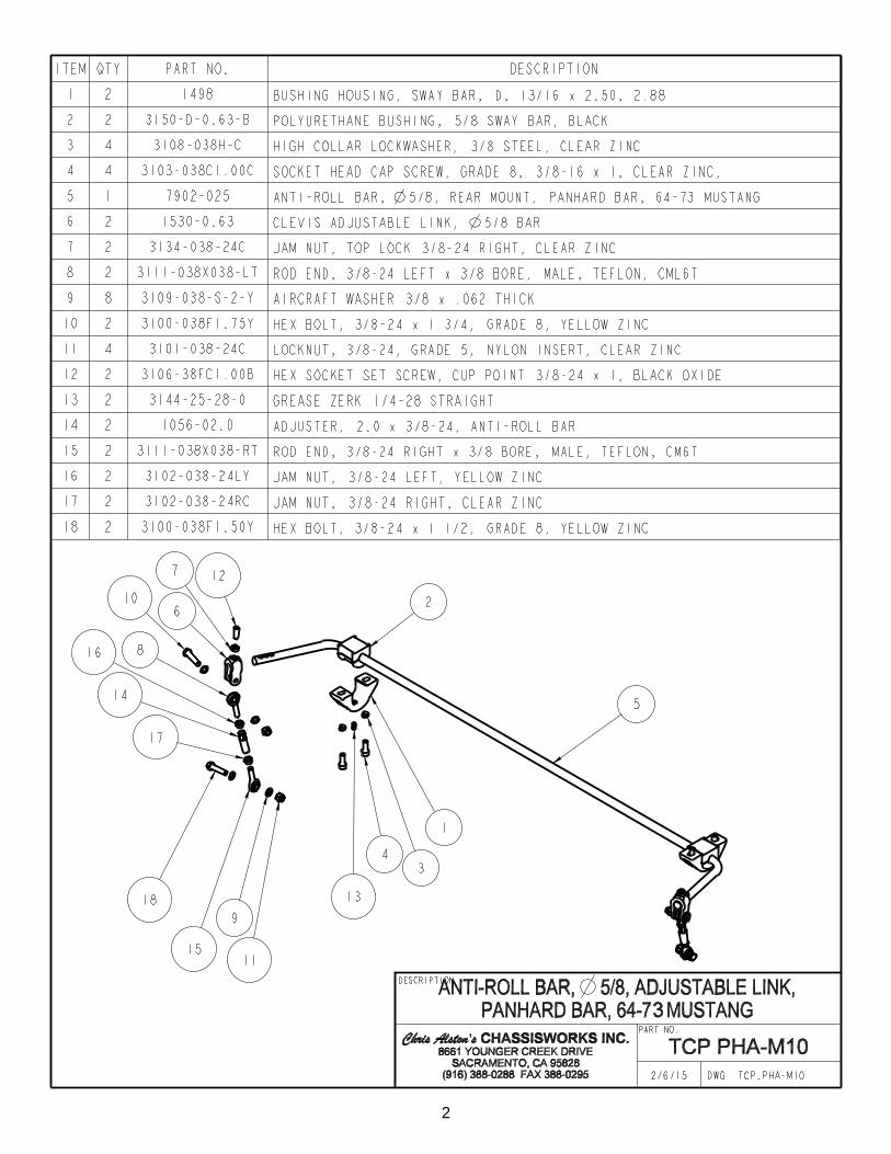
Description: Anti-roll bar with billet mounts for TCP Panhard Bar system. Features sliding endlink mount for anti-roll bar rate adjustment. Requires installation of TCP panhard bar system (TCP PHL-M10) and TCP driver-side leaf-spring plate (TCP PHS-M10).Applications: Cougar ‘67-73, Mustang ‘64-73Note: Exhaust system may require modifi cation.Fitment: Does not fi t with factory staggered shocks. Both shocks must mount forward of the rearend housing.
Shown with required components; sold separately.
2
3
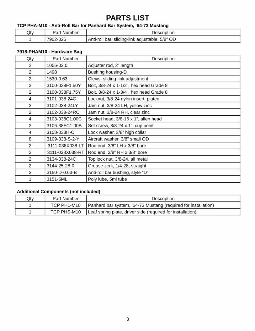
PARTS LISTTCP PHA-M10 - Anti-Roll Bar for Panhard Bar System, ‘64-73 Mustang
Qty Part Number Description1 7902-025 Anti-roll bar, sliding-link adjustable, 5/8” OD
7918-PHAM10 - Hardware BagQty Part Number Description2 1056-02.0 Adjuster rod, 2” length2 1498 Bushing housing-D2 1530-0.63 Clevis, sliding-link adjustment2 3100-038F1.50Y Bolt, 3/8-24 x 1-1/2”, hex head Grade 82 3100-038F1.75Y Bolt, 3/8-24 x 1-3/4”, hex head Grade 84 3101-038-24C Locknut, 3/8-24 nylon insert, plated2 3102-038-24LY Jam nut, 3/8-24 LH, yellow zinc2 3102-038-24RC Jam nut, 3/8-24 RH, clear zinc4 3103-038C1.00C Socket head, 3/8-16 x 1”, allen head2 3106-38FC1.00B Set screw, 3/8-24 x 1”, cup point4 3108-038H-C Lock washer, 3/8” high collar8 3109-038-S-2-Y Aircraft washer, 3/8” small OD2 3111-038X038-LT Rod end, 3/8” LH x 3/8” bore2 3111-038X038-RT Rod end, 3/8” RH x 3/8” bore2 3134-038-24C Top lock nut, 3/8-24, all metal2 3144-25-28-0 Grease zerk, 1/4-28, straight2 3150-D-0.63-B Anti-roll bar bushing, style “D”1 3151-5ML Poly lube, 5ml tube
Additional Components (not included)Qty Part Number Description1 TCP PHL-M10 Panhard bar system, ‘64-73 Mustang (required for installation)1 TCP PHS-M10 Leaf spring plate, driver side (required for installation)
4
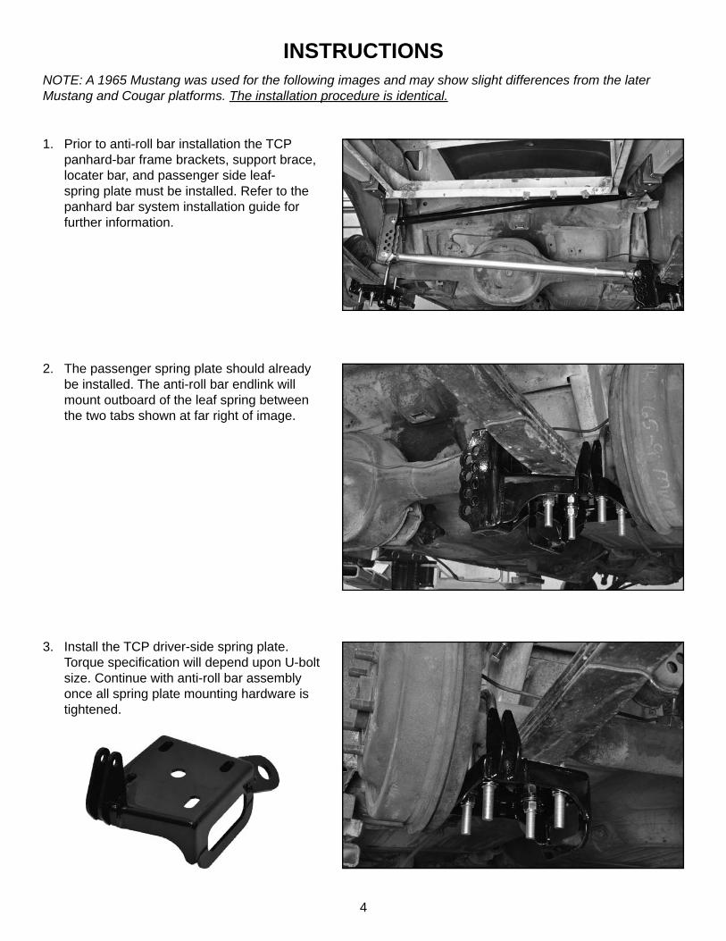
INSTRUCTIONSNOTE: A 1965 Mustang was used for the following images and may show slight differences from the later Mustang and Cougar platforms. The installation procedure is identical.
2. The passenger spring plate should already be installed. The anti-roll bar endlink will mount outboard of the leaf spring between the two tabs shown at far right of image.
1. Prior to anti-roll bar installation the TCP panhard-bar frame brackets, support brace, locater bar, and passenger side leaf-spring plate must be installed. Refer to the panhard bar system installation guide for further information.
3. Install the TCP driver-side spring plate. Torque specifi cation will depend upon U-bolt size. Continue with anti-roll bar assembly once all spring plate mounting hardware is tightened.
5
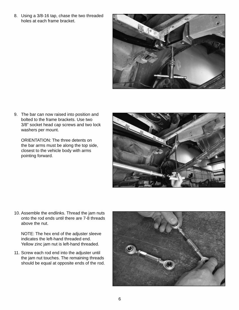
6. Slide the bushing over the bar and past the bend to the straight length between the two bends.
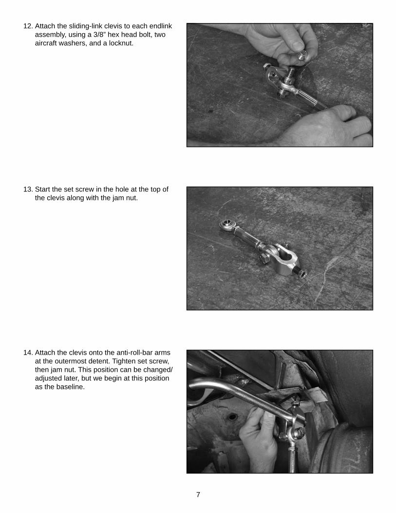
7. Place the billet housing over the bushing and screw in the grease zerk fi tting.
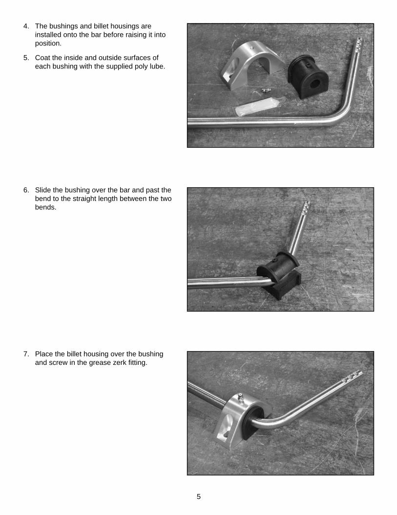
4. The bushings and billet housings are installed onto the bar before raising it into position.
5. Coat the inside and outside surfaces of each bushing with the supplied poly lube.
6
10. Assemble the endlinks. Thread the jam nuts onto the rod ends until there are 7-8 threads above the nut.
NOTE: The hex end of the adjuster sleeve indicates the left-hand threaded end.Yellow zinc jam nut is left-hand threaded.
11. Screw each rod end into the adjuster until the jam nut touches. The remaining threads should be equal at opposite ends of the rod.
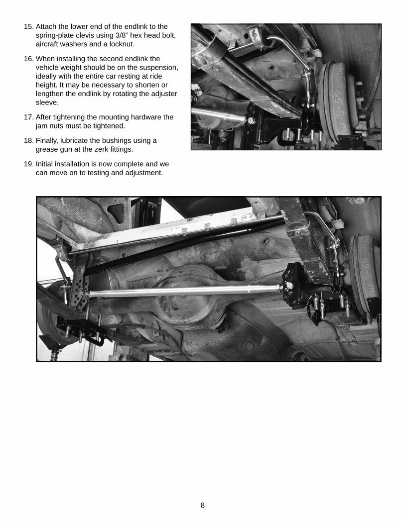
8. Using a 3/8-16 tap, chase the two threaded holes at each frame bracket.
9. The bar can now raised into position and bolted to the frame brackets. Use two 3/8” socket head cap screws and two lock washers per mount.
ORIENTATION: The three detents on the bar arms must be along the top side, closest to the vehicle body with arms pointing forward.
7
14. Attach the clevis onto the anti-roll-bar arms at the outermost detent. Tighten set screw, then jam nut. This position can be changed/adjusted later, but we begin at this position as the baseline.
13. Start the set screw in the hole at the top of the clevis along with the jam nut.
12. Attach the sliding-link clevis to each endlink assembly, using a 3/8” hex head bolt, two aircraft washers, and a locknut.
8
15. Attach the lower end of the endlink to the spring-plate clevis using 3/8” hex head bolt, aircraft washers and a locknut.
16. When installing the second endlink the vehicle weight should be on the suspension, ideally with the entire car resting at ride height. It may be necessary to shorten or lengthen the endlink by rotating the adjuster sleeve.
17. After tightening the mounting hardware the jam nuts must be tightened.
18. Finally, lubricate the bushings using a grease gun at the zerk fi ttings.
19. Initial installation is now complete and we can move on to testing and adjustment.
9
Testing and Adjustment
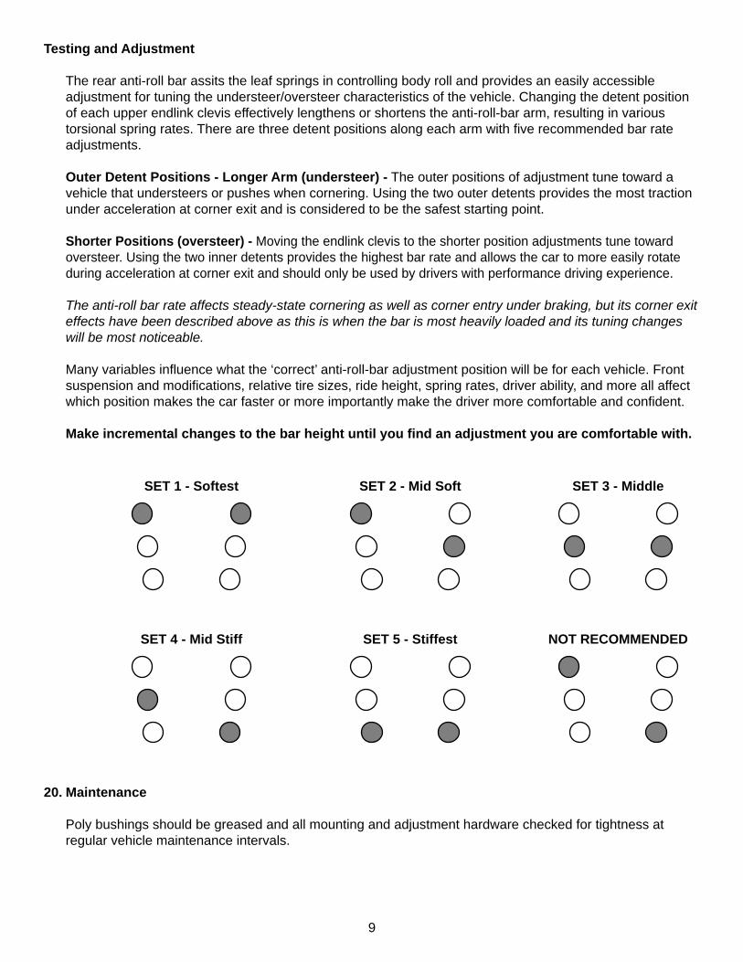
The rear anti-roll bar assits the leaf springs in controlling body roll and provides an easily accessible adjustment for tuning the understeer/oversteer characteristics of the vehicle. Changing the detent position of each upper endlink clevis effectively lengthens or shortens the anti-roll-bar arm, resulting in various torsional spring rates. There are three detent positions along each arm with fi ve recommended bar rate adjustments.
Outer Detent Positions - Longer Arm (understeer) - The outer positions of adjustment tune toward a vehicle that understeers or pushes when cornering. Using the two outer detents provides the most traction under acceleration at corner exit and is considered to be the safest starting point.
Shorter Positions (oversteer) - Moving the endlink clevis to the shorter position adjustments tune toward oversteer. Using the two inner detents provides the highest bar rate and allows the car to more easily rotate during acceleration at corner exit and should only be used by drivers with performance driving experience.
The anti-roll bar rate affects steady-state cornering as well as corner entry under braking, but its corner exit effects have been described above as this is when the bar is most heavily loaded and its tuning changes will be most noticeable.
Many variables infl uence what the ‘correct’ anti-roll-bar adjustment position will be for each vehicle. Front suspension and modifi cations, relative tire sizes, ride height, spring rates, driver ability, and more all affect which position makes the car faster or more importantly make the driver more comfortable and confi dent.
Make incremental changes to the bar height until you fi nd an adjustment you are comfortable with.
20. Maintenance
Poly bushings should be greased and all mounting and adjustment hardware checked for tightness at regular vehicle maintenance intervals.
SET 1 - Softest SET 2 - Mid Soft SET 3 - Middle
SET 4 - Mid Stiff SET 5 - Stiffest NOT RECOMMENDED

10
NOTES:

11
NOTES:
12
Total Control ProductsA Chris Alston’s Chassisworks, Inc. Brand8661 Younger Creek DriveSacramento, CA 95828Phone: 916-388-0288Technical Support: [email protected]
7903-PHAM10 REV 03/11/15
WARRANTY NOTICE:There are NO WARRANTIES, either expressed or implied. Neither the seller nor manufacturer will be liable for any loss, damage or injury, direct or indirect, arising from the use or inability to determine the appropriate use of any products. Before any attempt at installation, all drawings and/or instruction sheets should be completely reviewed to determine the suitability of the product for its intended use. In this connection, the user assumes all responsibility and risk. We reserve the right to change specifi cation without notice. Further, Chris Alston’s Chassisworks, Inc., makes NO GUARANTEE in reference to any specifi c class legality of any component. ALL PRODUCTS ARE INTENDED FOR RACING AND OFF-ROAD USE AND MAY NOT BE LEGALLY USED ON THE HIGHWAY. The products offered for sale are true race-car components and, in all cases, require some fabrication skill. NO PRODUCT OR SERVICE IS DESIGNED OR INTENDED TO PREVENT INJURY OR DEATH.