tcc-2 series - cesehsa.com.mxcesehsa.com.mx/cesehsa/catalogos/power_clamp_tcc-.pdf · • tolerance...
TRANSCRIPT

• Tolerance compensation for variable sheet metal thicknesses within three degrees of arm movement
• There is no need for shimming
TCC-2 03E 6A L800
Shown with U-Arm 8UM634-25-144 (order separately)
Clamp Arm Shaft Description
03 for U-Arms23 for Lateral Arms
See below for further details
Handle Description
00 No Hand lever
03
23
Size Shaft Length (L17)
40 9mm50 12mm63 12mm
Size Shaft Length (L17)
40 16mm50 21mm63 21mm
Clamp Arm Shaft
N
Mounting
E
E
E
B
Size 40
Size 50
Size 63
Size 40 Only
Size 63 Only
Mounting Description
E Standard Mounting
BCommon Front Mount for Size 40 only (same mount pattern as size 50 & 63)
N NAAMS Side Mounting for Size 63 only
Base Model
Tolerance compensation for variable part thicknesses
PC-PPC | 25
Pneumatic Power Clamps with Tolerance Compensation | Ordering Information
TCC-2 Series
cesehsa.com.mxtel: 01 800 237 3472
L9/N9L8/N8
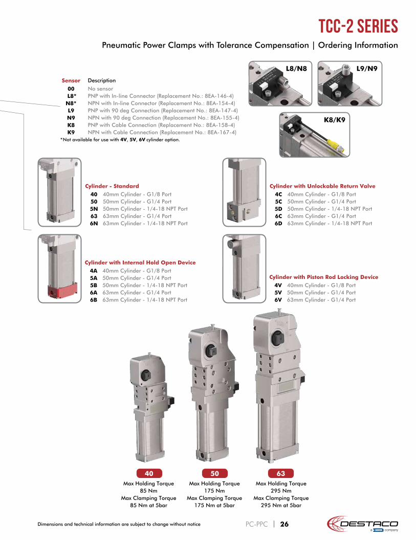
Sensor Description
00 No sensor L8* PNP with In-line Connector (Replacement No.: 8EA-146-4)N8* NPN with In-line Connector (Replacement No.: 8EA-154-4)L9 PNP with 90 deg Connection (Replacement No.: 8EA-147-4)N9 NPN with 90 deg Connection (Replacement No.: 8EA-155-4)K8 PNP with Cable Connection (Replacement No.: 8EA-158-4)K9 NPN with Cable Connection (Replacement No.: 8EA-167-4)
*Not available for use with 4V, 5V, 6V cylinder option.
Cylinder with Unlockable Return Valve
4C 40mm Cylinder - G1/8 Port5C 50mm Cylinder - G1/4 Port5D 50mm Cylinder - 1/4-18 NPT Port6C 63mm Cylinder - G1/4 Port6D 63mm Cylinder - 1/4-18 NPT Port
Cylinder with Piston Rod Locking Device
4V 40mm Cylinder - G1/8 Port5V 50mm Cylinder - G1/4 Port6V 63mm Cylinder - G1/4 Port
40 50 63Max Holding Torque
85 NmMax Clamping Torque
85 Nm at 5bar
Max Holding Torque175 Nm
Max Clamping Torque175 Nm at 5bar
Max Holding Torque295 Nm
Max Clamping Torque295 Nm at 5bar
K8/K9
PC-PPC | 26Dimensions and technical information are subject to change without notice
Pneumatic Power Clamps with Tolerance Compensation | Ordering Information
TCC-2 Series
Cylinder - Standard
40 40mm Cylinder - G1/8 Port50 50mm Cylinder - G1/4 Port5N 50mm Cylinder - 1/4-18 NPT Port63 63mm Cylinder - G1/4 Port6N 63mm Cylinder - 1/4-18 NPT Port
Cylinder with Internal Hold Open Device
4A 40mm Cylinder - G1/8 Port5A 50mm Cylinder - G1/4 Port5B 50mm Cylinder - 1/4-18 NPT Port6A 63mm Cylinder - G1/4 Port6B 63mm Cylinder - 1/4-18 NPT Port

ModelMax.
Holding Torque (Nm)
Clamping Torque at 5 bar
(Nm)
Cylinder Ø (mm)
Weight (kg)
Air Consumption per double stroke at 5 bar
(liter)
TCC-2E....50..
175 175 50
2,8
1,6
TCC-2E....5N..
TCC-2E....5A..
TCC-2E....5B..
TCC-2E....5C..3,0
TCC-2E....5D..
TCC-2E....5V.. 2,9
ModelMax.
Holding Torque (Nm)
Clamping Torque at 5 bar
(Nm)
Cylinder Ø (mm)
Weight (kg)
Air Consumption per double stroke at 5 bar
(liter)
TCC-2.....40..
85 85 40
1,6
0,9
TCC-2.....4A..
TCC-2.....4B..
TCC-2.....4C.. 1,7
TCC-2.....4V.. 1,6
Maximum Tooling Weight
Wei
ght
[kg]
Distance from pivot pointto center of mass [mm]
opening / closing time 2 sec
opening / closing time 1 sec
0
0.5
1.0
1.5
2.0
2.5
3.0
100 125 150 175 200
Control Flow
4A Cylinder Option
Air Consumption
0
1
0,5
1,5
2
2,5
3
15° 30° 45° 60° 135°120°105°90°75°
Opening angle (°)
Air
con
sum
ptio
n pe
r do
uble
str
oke
(N
l)
Length of the clamping arm (mm)
Cla
mpi
ng f
orce
(N
)
Maximum Clamping Force
1 0,5 sec
0
10,5 sec.
0
1
0
1
0
Open
Signal opened
Close
Signal closed
Internal Hold Open Device
0
200
400
600
800
1000
1200
100 125 150 175 200
5 bar
6 bar
4 bar
3 bar
ATTENTION: Calculation tool available. Please consult factory.
Maximum Tooling Weight
Wei
ght
[kg]
Distance from pivot pointto center of mass [mm]
Control Flow
5A/5B Cylinder Option
Air Consumption
Opening angle (°)
Air
con
sum
ptio
n pe
r do
uble
str
oke
(N
l)
1 0,5 sec
0
10,5 sec.
0
1
0
1
0
Open
Signal opened
Close
Signal closed
Internal Hold Open Device
0
1000
500
1500
2000
2500
100 125 150 175 200 225 250 275 3000
1
2
3
4
5
6
7
8
9
10
opening / closing time 2 sec
opening / closing time 1 sec0
1
0,5
1,5
2
2,5
3
15° 30° 45° 60° 135°120°105°90°75°
Length of the clamping arm (mm)
Cla
mpi
ng f
orce
(N
)
Maximum Clamping Force
100 125 150 175 200
5 bar
6 bar
4 bar
3 bar
ATTENTION: Calculation tool available. Please consult factory.
PC-PPC | 27 Dimensions and technical information are subject to change without notice
Pneumatic Power Clamps with Tolerance Compensation | Technical Specifications
TCC-2 Series

Center of Mass
ModelMax.
Holding Torque (Nm)
Clamping Torque at 5 bar
(Nm)
Cylinder Ø (mm)
Weight (kg)
Air Consumption per double stroke at 5 bar
(liter)
TCC-2.....63..
295 295 63
3,8
2,6
TCC-2.....6N..
TCC-2.....6A..4,0
TCC-2.....6B..
TCC-2.....6C..4,6
TCC-2.....6D..
TCC-2.....6V.. 4,2
closed position
B
A
closed position
B
A
opened position (135°)
B
A
opened position (135°)
B
A C
ModelA B
WeightClosed Open Closed Open
TCC-2E....40.. 2324
55 691,5
TCC-2B....40.. 24 54 68TCC-2E....4A.. 22
23 7286
1,6TCC-2B....4A.. 23 85TCC-2E....4C.. 25
2677 89
1,7TCC-2B....4C.. 26 76 88TCC-2E....4V..
24 24 6680
1,6TCC-2B....4V.. 79TCC-2E....50..
24 2570 87 2,6
TCC-2E....5N..TCC-2E....5A..
83 99 2,8TCC-2E....5B..TCC-2E....5C..
27 27 96 110 3,0TCC-2E....5D..TCC-2E....5V.. 25 26 84 99 2,9TCC-2.....63..
27 2889 105 3,7
TCC-2.....6N..TCC-2.....6A..
98 114 3,9TCC-2.....6B..TCC-2.....6C..
30 30 116 130 4,4TCC-2.....6D..TCC-2.....6V.. 28 28 103 119 3,9
Maximum Tooling Weight
Wei
ght
[kg]
Distance from pivot pointto center of mass [mm]
Control Flow
6A/6B Cylinder Option
Air Consumption
Opening angle (°)
Air
con
sum
ptio
n pe
r do
uble
str
oke
(N
l)
1 0,5 sec
0
10,5 sec.
0
1
0
1
0
Open
Signal opened
Close
Signal closed
Internal Hold Open Device100 125 150 175 200 225 250 275 3000
2
4
6
8
10
12
14
0
1000
500
1500
2000
2500
3000
3500
4000
opening / closingtime 2 sec
opening / closingtime 1 sec
Opening angle (°)
0
1
0,5
1,5
2
2,5
3
15° 30° 45° 60° 135°120°105°90°75°
Length of the clamping arm (mm)
Cla
mpi
ng f
orce
(N
)
Maximum Clamping Force
100 125 150 175 200
5 bar
6 bar
4 bar
3 bar
ATTENTION: Calculation tool available. Please consult factory.
PC-PPC | 28Dimensions and technical information are subject to change without notice
Pneumatic Power Clamps with Tolerance Compensation | Technical Specifications
TCC-2 Series
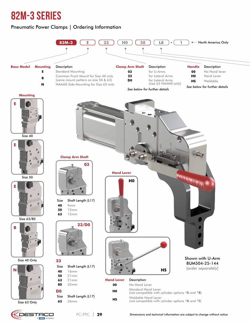
82M-3 23E 50 L8 1H0
Handle Description
00 No Hand leverH0 Hand Lever
HS Weldable
See below for further details
Hand Lever Description
00 No Hand Lever
H0 Standard Hand Lever (not compatible with cylinder options *A and *B)
HS Weldable Hand Lever (not compatible with cylinder options *A and *B)
Shown with U-Arm 8UM504-25-144 (order separately)
North America Only
Mounting Description
E Standard Mounting
BCommon Front Mount for Size 40 only (same mount pattern as size 50 & 63)
N NAAMS Side Mounting for Size 63 only
Base Model
03
23/D0
Size Shaft Length (L17)
40 9mm50 12mm63 12mm
Size Shaft Length (L17)
40 16mm50 21mm63 21mm80 32mm
Size Shaft Length (L17)
63 26mm
Clamp Arm Shaft
D0
23
H0
Hand Lever
HSN
Mounting
E
E
E
B
Size 40
Size 50
Size 63/80
Size 40 Only
Size 63 Only
Clamp Arm Shaft Description
03 for U-Arms23 for Lateral ArmsD0 for Lateral Arms
(size 63 NAAMS only)
See below for further details
PC-PPC | 29 Dimensions and technical information are subject to change without notice
82M-3 Series Pneumatic Power Clamps | Ordering Information
-

40 50 63 80Max Holding Torque
380 NmMax Clamping Torque
120 Nm at 5bar
Max Holding Torque1300 Nm
Max Clamping Torque270 Nm at 5bar
Max Holding Torque1800 Nm
Max Clamping Torque420 Nm at 5bar
Max Holding Torque3000 Nm
Max Clamping Torque850 Nm at 5bar
Sensor Description
00 No sensor L8 PNP with In-line Connector (Replacement No.: 8EA-146-4)N8 NPN with In-line Connector (Replacement No.: 8EA-154-4)L9 PNP with 90 deg Connection (Replacement No.: 8EA-147-4)N9 NPN with 90 deg Connection (Replacement No.: 8EA-155-4)K8 PNP with Cable Connection (Replacement No.: 8EA-158-4)K9 NPN with Cable Connection (Replacement No.: 8EA-167-4)
Cylinder - Standard
40 40mm Cylinder - G1/8 Port50 50mm Cylinder - G1/4 Port5N 50mm Cylinder - 1/4-18 NPT Port63 63mm Cylinder - G1/4 Port6N 63mm Cylinder - 1/4-18 NPT Port80 80mm Cylinder - G1/4 Port8N 80mm Cylinder - 1/4-18 NPT Port
Cylinder with Internal Hold Open Device
4A 40mm Cylinder - G1/8 Port5A 50mm Cylinder - G1/4 Port5B 50mm Cylinder - 1/4-18 NPT Port6A 63mm Cylinder - G1/4 Port6B 63mm Cylinder - 1/4-18 NPT Port8A 80mm Cylinder - G1/4 Port8B 80mm Cylinder - 1/4-18 NPT Port
L9/N9L8/N8
K8/K9
PC-PPC | 30Dimensions and technical information are subject to change without notice
82M-3 Series Pneumatic Power Clamps | Ordering Information
ModelMax.
Holding Torque (Nm)
Clamping Torque at 5 bar
(Nm)
Cylinder Ø (mm)
Weight (kg)
Air Consumption per double stroke at 5 bar
(liter)
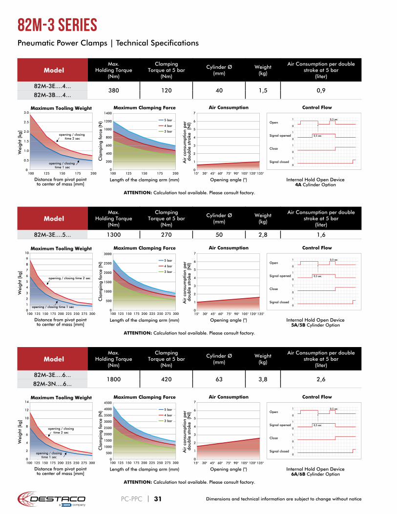
82M-3E....4...380 120 40 1,5 0,9
82M-3B....4...
Maximum Tooling Weight
Wei
ght
[kg]
Distance from pivot pointto center of mass [mm]
opening / closing time 2 sec
opening / closing time 1 sec
0
0.5
1.0
1.5
2.0
2.5
3.0
100 125 150 175 200
Control Flow
4A Cylinder Option
Air Consumption
0
2
1
3
4
5
6
7
15° 30° 45° 60° 135°120°105°90°75°
Opening angle (°)A
ir c
onsu
mpt
ion
per
doub
le s
trok
e (
Nl)
0
200
400
600
800
1000
1200
1400
100 125 150 175 200
Length of the clamping arm (mm)
Cla
mpi
ng f
orce
(N
)
Maximum Clamping Force
5 bar
4 bar
3 bar
1 0,5 sec
0
10,5 sec.
0
1
0
1
0
Open
Signal opened
Close
Signal closed
Internal Hold Open Device
ATTENTION: Calculation tool available. Please consult factory.
ModelMax.
Holding Torque (Nm)
Clamping Torque at 5 bar
(Nm)
Cylinder Ø (mm)
Weight (kg)
Air Consumption per double stroke at 5 bar
(liter)
82M-3E....5... 1300 270 50 2,8 1,6
Maximum Tooling Weight
Wei
ght
[kg]
Distance from pivot pointto center of mass [mm]
Control Flow
5A/5B Cylinder Option
Air Consumption
Opening angle (°)
Air
con
sum
ptio
n pe
r do
uble
str
oke
(N
l)
Length of the clamping arm (mm)
Cla
mpi
ng f
orce
(N
)
Maximum Clamping Force
1 0,5 sec
0
10,5 sec.
0
1
0
1
0
Open
Signal opened
Close
Signal closed
Internal Hold Open Device
0
1000
500
1500
2000
2500
3000
100 125 150 175 200 225 250 275 3000
2
1
3
4
5
6
7
15° 30° 45° 60° 135°120°105°90°75°100 125 150 175 200 225 250 275 3000
1
2
3
4
5
6
7
8
9
10
opening / closing time 2 sec
opening / closing time 1 sec
5 bar
4 bar
3 bar
ATTENTION: Calculation tool available. Please consult factory.
Maximum Tooling Weight
Wei
ght
[kg]
Distance from pivot pointto center of mass [mm]
Control Flow
6A/6B Cylinder Option
Air Consumption
Opening angle (°)
Air
con
sum
ptio
n pe
r do
uble
str
oke
(N
l)
Length of the clamping arm (mm)
Cla
mpi
ng f
orce
(N
)
Maximum Clamping Force
1 0,5 sec
0
10,5 sec.
0
1
0
1
0
Open
Signal opened
Close
Signal closed
Internal Hold Open Device100 125 150 175 200 225 250 275 3000
2
4
6
8
10
12
14
0
1000
500
1500
2000
2500
3000
3500
4000
4500
100 125 150 175 200 225 250 275 3000
2
1
3
4
5
6
7
15° 30° 45° 60° 135°120°105°90°75°
5 bar
4 bar
3 bar
opening / closingtime 2 sec
opening / closingtime 1 sec
ATTENTION: Calculation tool available. Please consult factory.
ModelMax.
Holding Torque (Nm)
Clamping Torque at 5 bar
(Nm)
Cylinder Ø (mm)
Weight (kg)
Air Consumption per double stroke at 5 bar
(liter)
82M-3E....6...1800 420 63 3,8 2,6
82M-3N....6...
PC-PPC | 31 Dimensions and technical information are subject to change without notice
Pneumatic Power Clamps | Technical Specifications
82M-3 Series

closed position
B
A
closed position
B
A
opened position (135°)
B
A
opened position (135°)
B
A C
closed position
B
A
closed position
B
A
opened position (135°)
B
A
opened position (135°)
B
A C
ModelMax.
Holding Torque (Nm)
Clamping Torque at 5 bar
(Nm)
Cylinder Ø (mm)
Weight (kg)
Air Consumption per double stroke at 5 bar
(liter)
82M-3E....80..
3000 850 80
8,7
6,382M-3E....8N..
82M-3E....8A..8,8
82M-3E....8B..
Center of Mass
Maximum Tooling Weight
Wei
ght
[kg]
Distance from pivot pointto center of mass [mm]
Control Flow
8A/8B Cylinder Option
Air Consumption
Opening angle (°)A
ir c
onsu
mpt
ion
per
doub
le s
trok
e (
Nl)
Length of the clamping arm (mm)
Cla
mpi
ng f
orce
(N
)
Maximum Clamping Force
1 0,5 sec
0
10,5 sec.
0
1
0
1
0
Open
Signal opened
Close
Signal closed
Internal Hold Open Device
0
2
1
3
4
5
6
7
15° 30° 45° 60° 135°120°105°90°75°0
5
10
15
20
25
100 150 200 250 300 350 4000
2000
1000
3000
4000
5000
6000
7000
8000
9000
100 150 200 250 350 400300
5 bar
4 bar
3 bar
opening / closingtime 2 sec
opening / closingtime 1 sec
ATTENTION: Calculation tool available. Please consult factory.
With Handle
ModelA B C
WeightClosed Open Closed Open
82M-3E....40.. 22 25 49 70
41,6
82M-3B....40.. 24 27 46 6782M-3E....50..
23 30 62 85 3,182M-3E....5N..82M-3.....63..
26 30 80 102 3 4,282M-3.....6N..82M-3E....80..
35 38 93 122 2 9,282M-3E....8N..
Without Handle
ModelA B
WeightClosed Open Closed Open
82M-3E....40.. 2324
55 691,5
82M-3B....40.. 24 54 6882M-3E....4A.. 22
23 7286
1,682M-3B....4A.. 23 8582M-3E....50..
24 2570 87
2,882M-3E....5N..82M-3E....5A..
83 9982M-3E....5B..82M-3.....63..
27 2888 103 3,8
82M-3.....6N..82M-3.....6A..
98 114 3,982M-3.....6B..82M-3E....80..
36 3798 123 8,7
82M-3E....8N..82M-3E....8A..
104 129 8,982M-3E....8B..
PC-PPC | 32Dimensions and technical information are subject to change without notice
Pneumatic Power Clamps | Technical Specifications
82M-3 Series

97 19 85
Dimensions of the driven shaft
SW
16
h9
L17
B2
3 m
ax.
3
3
5
0 ±
0,1
21 33
4
5 ±0
,1
2
5 ±0
,1
7,5
±0,1
82,5
Pivot point
±0
,02
for
Ø6
H7
±0,02 for Ø6H7
3,5
±0,1
15
60
10
M
6 4
10
±0
,1
2
5
9
8
±0
,1
38
,5
35
16
±0
,05
2
5
0+
0,1
±0,1
4
0
Ø6
H7
12 ±0,1
±0,02 for Ø8H7
View "X"
30 ±0,1
"X"
M
8 10
12
H7
Ø8
5
±0
,1
±0
,1
63
,5
±0
,1
32
1
1
10
4,5
0+
0,1
1,5
8
10
5
5
±0
,1
45
M
6±0
,1
7,5
H7
Ø6
2
5 ±0
,1
3
6,5
±
0,0
5
4
7 ±0
,1
±0,02 for Ø6H7
M
6
10
34,5
10
1
36
H7
Ø6
3,5
8
N9
35
8
,5
4
7 ±0
,1
8
N9
±0,1
Power by compressed air, max. 6 bar operation with oil-free air is permissible.The connector socket and the cable are not supplied with the unit.Safe “holding/clamping” only under pressurization (for TCC models only).
DImensions below for “B” mounting surfaces. See above for additional base unit dimensions.
THIRD ANGLEPROJECTION
mm [INCH]
FIRST ANGLEPROJECTION
mm [INCH]
82M-3E/TCC-2E....4.
82M-3B/TCC-2B....4.
TCC-2 Series -3° tolerance compensation.
PC-PPC | 33 Dimensions and technical information are subject to change without notice
Pneumatic Power Clamps | Dimensions
82M-3/TCC-2 Series 40mm
ModelB23 Max.
L17
82M-3.03/TCC-2.03..4... 54,5 982M-3.23/TCC-2.23..4... 66,5 16

2
65
25
1Internal OpenHolding Device:For manual unlocking this area has to be accessible.
74,5
3
0
G 1/8
65 34
34
G 1/8
11
5
1424
5 31
1
2
21
12
34
G 1/8
ManualUnlocking
To centerlineof pivot point
2
75
27
4,6
13
9
13
8,6
80 3465
G 1/8
M5
70,3
5
4
1
21214
3
2
12 14
12
9
82M-3/TCC-2.....40
TCC-2.....4C
82M-3/TCC-2.....4A
TCC-2.....4V
Standard Cylinder Cylinder with Internal Hold Open DeviceSecurely holds clamp in the open position.
Cylinder with Unlock-able Return ValvePneumatically holds clamp arm in the closed position when air is released.
Cylinder with Rod Locking DeviceUses friction to clamp rod at any point between open and closed positions.
PC-PPC | 34Dimensions and technical information are subject to change without notice
Pneumatic Power Clamps | Cylinder Options Dimension and Technical Specifications
82M-3/TCC-2 Series 40mm

95
107 26,5
32
6
3,5
9
1
1
111,5
7
1,5
B2
3 m
ax.
4
7,6
4
8
Dimensions of the driven shaft
L17
SW
19
5
4
0
4
5
45
Ø8
M
8
Pivot point
5
13
80
5
5
4
5
12
21,5
13 10
12
1
25
3
6,5
Ø8 50
25
5
5
5
1
70
48
10
30
3,5
1
2
9,5
Ø1
0
9
,5
±0
,1
±0
,1
±0
,1
±0
,1
±0
,1
h9
10 d
eep
±0,0
2 f
or Ø
8H
7
±0,02 for Ø8H7
10 d
eep
±0
,1
±0,1
±0
,1
H7
±0
,02
for
Ø10
H7
±0,02 for Ø10H7
±0,1
±0
,1±
0,1
±0,1
±0,1
M
8
±0
,05
H7
±0,1
+0
,10
±0,02 for Ø8H7
M
10
±0,1N
9
H7
ModelB23 Max.
L17
82M-3E03/TCC-2E03..5... 72 1282M-3E23/TCC-2E23..5... 90 21
Power by compressed air, max. 6 bar operation with oil-free air is permissible.The connector socket and the cable are not supplied with the unit.Safe “holding/clamping” only under pressurization (for TCC models only).
82M-3E/TCC-2E....5.
THIRD ANGLEPROJECTION
mm [INCH]
FIRST ANGLEPROJECTION
mm [INCH]
TCC-2 Series -3° tolerance compensation.
PC-PPC | 35 Dimensions and technical information are subject to change without notice
Pneumatic Power Clamps | Dimensions
82M-3/TCC-2 Series 50mm

72
14
6
15
5
3
16
C
44
44
C
3
25
14,2
78,5
Internal OpenHolding Device:For manual unlocking this area has to be accessible.
To centerlineof pivot point
89,5 44 44
C
17
2
34
2
ManualUnlocking
1424
5 31
1
2
21
125
4
1
21214
3
2
12 14
G1/8
72
G1/4
3
44
To centerlineof pivot point
88,8
17
4
Important! For optimal cushioning,external pneumatic
one-way flow control valves should be used.
Important! For optimal cushioning, external pneumatic one-way flow
control valves should be used.
Important! For optimal cushioning, external pneumatic one-way flow
control valves should be used.
82M-3E/TCC-2E....50/5N
TCC-2E....5C/5D
82M-3E/TCC-2E....5A/5B
TCC-2E....5V
Standard Cylinder Cylinder with Internal Hold Open DeviceSecurely holds clamp in the open position.
Cylinder with Unlock-able Return ValvePneumatically holds clamp arm in the closed position when air is released.
Cylinder with Rod Locking DeviceUses friction to clamp rod at any point between open and closed positions.
Ports C50 G1/45N 1/4-18 NPT
Ports C5C G1/45D 1/4-18 NPT
Ports C5A G1/45B 1/4-18 NPT
PC-PPC | 36Dimensions and technical information are subject to change without notice
Pneumatic Power Clamps | Cylinder Options Dimension and Technical Specifications
82M-3/TCC-2 Series 50mm

26,5 101,5
112,5
32
±0
,1
30±0,1
6
3,5
±0,1
1
1 ±0
,1
9
111,5
7
1,5
±0,1
12
N9
10
B2
3 m
ax.
5
4 ±0
,1
5
2
Dimensions of the driven shaft
L17
SW
22
h9
±0,0
2 for
Ø10
H7
±0,02 for Ø10H7
Pivot point
1
37
18
7
5
±0,1
B7a
80
10
±0,1
0
±0
,1
55
45
±0,1 8,5
±0,1
5
5
13
0,1
+
12
M
8 12
Ø8
H7
3
6,5
±0,0
5 5
±0,02 for Ø8H7
54
3,5
10
M
10
Ø
10
H7
1
1,5
70,5 (TCC Only)
Power by compressed air, max. 6 bar operation with oil-free air is permissible.The connector socket and the cable are not supplied with the unit.Safe “holding/clamping” only under pressurization (for TCC models only).
82M-3/TCC-2.....6.
THIRD ANGLEPROJECTION
mm [INCH]
FIRST ANGLEPROJECTION
mm [INCH]
Model B7a±0,1
B23 Max.
L17
82M-3E03/TCC-2E03..6... 5078 12
82M-3N03/TCC-2N03..6... 5582M-3E23/TCC-2E23..6... 50
96 2182M-3N23/TCC-2N23..6... 55
82M-3ND0..6... 55 106 26
TCC-2 Series -3° tolerance compensation.
PC-PPC | 37 Dimensions and technical information are subject to change without notice
Pneumatic Power Clamps | Dimensions
82M-3/TCC-2 Series 63mm

100
16
4
16
3
52 52
52
3
51
100
35
0
C
Internal OpenHolding Device:For manual unlocking this area has to be accessible.
Important! For optimal cushioning, external pneumatic one-way flow
control valves should be used.
Important! For optimal cushioning, external pneumatic one-way flow
control valves should be used.
C
ManualUnlocking
C
3
70
52
18
3
19
1,5
11714
24
5 31
1
2
21
12
100
93,3
G1/4
3
78
,5G1/8
To centerlineof pivot point
5
4
1
21214
3
2
12 14
Important! For optimal cushioning,external pneumatic
one-way flow control valves should be used.
82M-3/TCC-2.....63/6N
TCC-2.....6C/6D
82M-3/TCC-2.....6A/6B
TCC-2.....6V
Standard Cylinder Cylinder with Internal Hold Open DeviceSecurely holds clamp in the open position.
Cylinder with Unlock-able Return ValvePneumatically holds clamp arm in the closed position when air is released.
Cylinder with Rod Locking DeviceUses friction to clamp rod at any point between open and closed positions.
Ports C63 G1/46N 1/4-18 NPT
Ports C6C G1/46D 1/4-18 NPT
Ports C6A G1/46B 1/4-18 NPT
PC-PPC | 38Dimensions and technical information are subject to change without notice
Pneumatic Power Clamps | Cylinder Options Dimension and Technical Specifications
82M-3/TCC-2 Series 63mm

128
140
35Plan view
1
40
7
2
7
6 ±
0,1
Dimensions of the driven shaft
SW
28
h9
32
9
6,5
±0,1
±0,02 for Ø8H7
8
15
76
N9
±0,1 50
1
2
M
12
Ø
12
H7
15
3,5
2
45
9
0 ±0
,1
1
5 ±0
,1
50
±0,1
Pivot point
±0,02 for Ø12H7
±0,0
2 for
Ø12
H7
±0,1 113
153
5 5
±0,1
21
5
M
10
H7
Ø8
15
15
0±
0,0
5
50
±0,1 70
±0
,1
65
75
±0,1 1
75
8
0 +
0,1
15 ±0,1
5
Power by compressed air, max. 6 bar operation with oil-free air is permissible.The connector socket and the cable are not supplied with the unit.
THIRD ANGLEPROJECTION
mm [INCH]
FIRST ANGLEPROJECTION
mm [INCH]
82M-3E....8.
PC-PPC | 39 Dimensions and technical information are subject to change without notice
Pneumatic Power Clamps | Dimensions
82M-3 Series 80mm

Internal OpenHolding Device:For manual unlocking this area has to be accessible.
Important! For optimal cushioning, external pneumatic one-way flow
control valves should be used.
Important! For optimal cushioning, external pneumatic one-way flow
control valves should be used.
134 66 66
18
5
C
4
30
C
134
3
2
19
2
43
7 4,7
82M-3E....80/8N 82M-3E....8A/8BStandard Cylinder Cylinder with Internal Hold Open Device
Securely holds clamp in the open position.
Ports C80 G1/48N 1/4-18 NPT
Ports C8A G1/48B 1/4-18 NPT
PC-PPC | 40Dimensions and technical information are subject to change without notice
Pneumatic Power Clamps | Cylinder Options Dimension and Technical Specifications
82M-3 Series 80mm

82M-3 accessories
20° 20°
closed
open
Hand lever rightHand lever left
Ø38
B28
B21
Hand lever can bemounted in 3 positions
Pneumatic circuit required formanual and pneumatic actuation.
82M-3E**H040**
Ø38
11L2
0
±10°
~R1
~a2
~R1
~a2
20° 20°
closed
open
Hand lever rightHand lever left
Ø38
B28
B21
Hand lever can bemounted in 3 positions
L2
0
Pneumatic circuit required formanual and pneumatic actuation.
82M-3E**H040**
Ø38
11
~R1
~a2
20° 20°
closed
open
Hand lever rightHand lever left
Ø38
B28
B21
Hand lever can bemounted in 3 positions
L2
0
Pneumatic circuit required formanual and pneumatic actuation.
82M-3E**H040**
Ø38
11
Model No.Swivel Angle a2
(with reference to opening angle of clamp arm)
B21 B28 L20 ~R1 0° 15° 30° 45° 60° 75° 90° 105° 120° 135°82M-3...H040.. 27 24 48,5 160 0° 31° 41° 49° 58° 69° 88° 113° 134° 144°82M-3...H05... 52 20 70 218 -1° 30° 39° 46° 53° 61° 70° 81° 92° 103°82M-3...H06.. 52 20 70,5 218 0° 30° 39° 47° 56° 66° 79° 94° 108° 119°82M-3...H08.. 56 24 82 268 -1° 28° 37° 45° 53° 63° 75° 92° 107° 117°
Hand Lever
Hand lever position is adjustble to ±20 degrees for improved ergonomics.
Pneumatic Power Clamps | Dimensions | Technical Specifications
PC-PPC | 41 Dimensions and technical information are subject to change without notice

Limited Setting Options
Order No. For ModelB1 B2 B3 B4 B5
~B6 ØD1 R1
~R2 ~
R3 a2 ~
Height of the clamping arm: L5 max.
90° version 180° version45 75 00 15 25 45
82ZB-162-1 82M-3...H040.. 50 11 48,5 25 31 38,5 10,5 81 160 27 6 120° – 105° 120° 120° 120°82ZB-084-1 82M-3...H05... 48 7 70 30 36 55 11,5 107 218 32,5 6 120° – – 105° 120° –82ZB-039-1 82M-3...H06... 54 9 70,5 30 36 55 11,5 107 210 32,5 6 110° 105° – 105° 120° –
82M-3 accessories
B2B1
Pivot point
B4
B3
B5
Order No. For Model B1 B2 B3 B4 B5
8AB-151-1 82M-3.....40.. 53 66,5 89,5 65,5 210,58AB-152-1 82M-3.....5... 51 73 100 92,5 2718AB-153-1 82M-3.....6... 57 79 120 104,5 2968AB-154-1 82M-3.....8... 79 105,5 148 142,5 360
Order No. Description
8EL-002-1 M12x1, Straight, 5-pin Connector with 5m Cable8EL-003-1 M12x1, Angular, 4-pin Connector with 5m Cable
Anti-ramming device is only available for standard cylinder with 82M-3...00..00 and 82M-3...00..L8
8EL-003-18EL-002-1
Cable and Connector
Anti-Ramming Device
Locking Device for Hand Lever
~R1
~R2
L5
Situation of installation:handlever right-hand sidelocking device left-hand side
B4 B1
D
1
~B5
Situation of installation:handlever left-hand sidelocking device right-hand side
Order No. For Model B1 B2 B3 B4 B5 ~
B6 ØD1 R1 ~
R2~
R3 a1 max.
a2 ~
Limited setting options at 180° version! Height of the clamping arm: L5
00 15 2582ZB-162-1 82M-3E**H040** 50 11 48,5 25 31 38,5 10,5 81 160 27
135°6 max.105° max.120° max.120°
82ZB-084-1 82M-3E**H05*** 48 7 70 30 36 55 11,5 107 218 32,5 5 - max.105° max.120°82ZB-039-1 82M-3E**H06*** 54 9 70,5 30 36 55 11,5 107 210 32,5 5 - max.105° max.120°
180° version
135°
90° version
Adjustment of lockingdevice at openingangle 135°
~a2
R3
B3
B2 B6
Pneumatic Power Clamps | Dimensions | Technical Specifications
PC-PPC | 42Dimensions and technical information are subject to change without notice

U-Arms Center (aluminum)
~R7
0
Area of interference
90° version
Hold-down piecemust not protrudein the interior area "R70"due to the area of interference
U-Arms Center (Aluminium)
180° version
Opening
Pivot point
L5
±0,1
22
SW
16 + -0,
020
0,00
9
B2 L5
B26 B11
(7)
45
0
+
16
0,2
H7
7 6
20
34,
6
20 ±0,02
90°
180°
8UM404-00-1178UM404-15-1178UM404-25-1178UM404-45-107
90°
180°
8UM504-15-1448UM504-25-1448UM504-45-144
28
±0,1
~R7
5
180° version
Pivot point
Opening L5
144
SW
19 + -0,
020
0,00
9
L5 Hold-down piece
90° version
Area of interference
must not protrudein the interior area "R75"due to the area of interference.
90,5 105 ±0,1
(9)
±0,2
0
+
20
0,2
H7
9
64,5
6
30
48,
1
30 ±0,02
For Size 50mm
For Size 40mm
Arm Model No.
Max. Opening 90º Version
Max. Opening 180º Version
Weight (kg)
L5
8UM504-15-144135°
105º 0,44 158UM504-25-144 120º 0,45 258UM504-45-144 135° 0,48 45
Arm Model No.
Max. Opening 90º Version
Max. Opening 180º Version
Weight (kg)
B2 B11 ±0,1
B26 L5
8UM404-00-117135°
105º 0,23117 90 82
08UM404-15-117 120º 0,24 158UM404-25-117
135°0,25 25
8UM404-45-107 130° 0,24 107 80 72 45
Pneumatic Power Clamps | Dimensions | Technical Specifications
PC-PPC | 43 Dimensions and technical information are subject to change without notice

U-Arms Center (aluminum)
~R8
0
L4
Pivot point
B2
SW
22 + -0
,02
00
,00
9
L5
L5
U-Arms Center (Aluminium)
Dimensions are only for 8UM631-75-204
20 ±1,2
~19
B26
B11
(9)
±0,2
+
20 00
,2
H7
9
B4
6
30
54,1
30 ±0,02
180°version
90° versiondue to the area of interference.
the interior area "R80"must not protrude inHold-down piece
Opening
Area of interference
90°
180°
8UM634-15-1448UM634-25-1448UM634-45-1448UM631-75-204
90°
180°
8JG-169-2-018UM801-45-204
For Size 63mm
3,5
~R1
08
9
3,5
180° version
due to the area of interference.
90° version
in the interior area "R108"must not protrudeHold-down piece
Pivot point
Opening
Area of interference
B2
J7
SW
28
35 ±
0,1
L5
B26
B11309
64,5
)
0,2
30
+
H76
76,1
±0,02
0
±0,2
25±1
,2
(
9
±1,225
~ 23,7
For Size 80mm
Arm Model No.
Max. Opening 90º Version
Max. Opening 180º Version
Weight (kg)
B2 B4 B11 ±0,1
B26 L4 ±0,1
L5
8UM634-15-144
135°
105º 0,50144 64,5 105 90,5 28
15 8UM634-25-144 120º 0,53 25 8UM634-45-144
135°0,56 45
8UM631-75-204* 1,7 204 82 165 107 30 75
Arm Model No.
Max. Opening 90º Version
Max. Opening 180º Version
Weight (kg)
B2 B11 ±0,1
B26 L5**±0,2
8JG-169-2-01135°
105º 3,5 179 140 129 208UM801-45-204* 135º 4,1 204 165 154 45
*only steel version available. ** Tolerance measured 80mm from pivot point.
* only steel version available.
~R8
0
L4
Pivot point
B2
SW
22 + -0
,02
00
,00
9
L5
L5
U-Arms Center (Aluminium)
Dimensions are only for 8UM631-75-204
20 ±1,2
~19
B26
B11
(9)
±0,2
+
20 00
,2
H7
9
B4
6
30
54,1
30 ±0,02
180°version
90° versiondue to the area of interference.
the interior area "R80"must not protrude inHold-down piece
Opening
Area of interference
Pneumatic Power Clamps | Dimensions | Technical Specifications
PC-PPC | 44Dimensions and technical information are subject to change without notice

U-Arms Offset (aluminum)
~R7
0
U-Arms, left and right (Aluminium)
180° version
90° versionOpening
in the interior area "R70"due to the area of interference
Area of interference
Pivot point
Hold-down piecemust not protrude
B2
0,02
00,
009
SW
16 + -
22
±0,1
L5
L5
B26
B11
23 ±
0,1
U-clamp arm, right
U-clamp arm, left
45
(7) 00,
2
H7
7
6 + 20
34,
6 20 ±0,02
16
~R7
5
180° version
Opening
Area of interference
due to the area of interference
90°version
in the interior area "R75"must not protrudeHold-down piece
±0
,1
144
S
W19
+ -0,02
00,
009
28
L5
L5
Pivot point
U-Arms, left and right (Aluminium)
90,5
34
±0,1
105 ±0,1
U-clamp arm, left
U-clamp arm, right
00,
2
±0,2
9
+ 30 6
H7
20
(9)
48,
1
30 ±0,02
64,5
For Size 50mm
For Size 40mm 90° Left 90° Right
180° Right* 180° Left*
8UL404-00-1178UL404-15-1178UL404-25-1178UL404-45-107
8UR404-00-1178UR404-15-1178UR404-25-1178UR404-45-107
90° Left 90° Right
180° Right* 180° Left*
8UL504-15-1448UL504-25-1448UL504-45-144
8UR504-15-1448UR504-25-1448UR504-45-144
Arm Model No.
Max. Opening 90º Version
Max. Opening 180º Version
Weight (kg)
L5
8U(•)504-15-144135°
105º 0,45 158U(•)504-25-144 120º 0,46 258U(•)504-45-144 135° 0,49 45
* 90° left/180° right uses same clamp arm. 90° right/180° left uses same clamp arm.
* 90° left/180° right uses same clamp arm. 90° right/180° left uses same clamp arm.
Arm Model No.
Max. Opening 90º Version
Max. Opening 180º Version
Weight (kg)
B2 B11 ±0,1
B26 L5
8U(•)404-00-117135°
105º 0,23117 90 82
08U(•)404-15-117 120º 0,24 158U(•)404-25-117
135°0,25 25
8U(•)404-45-107 130° 0,25 107 80 72 45
Pneumatic Power Clamps | Dimensions | Technical Specifications
PC-PPC | 45 Dimensions and technical information are subject to change without notice

U-Arms Offset (aluminum)
~R8
0
L4
Opening
in the interior area "R80" due to the area of interference
Hold-down piece must not protrudeArea of interference
B2
SW
22 + -0,
020
0,00
9
L5
L5
180° version
Dimensions are only for 8U(.)631-75-204
20±1,2
~19
90°version
Pivot point
U-Arms, left and right (Aluminium)
B11
37 ±
0,1
B26
U-clamp arm,left
U-clamp arm, right
(9)
0
0,2
9
30 ±0,26 H7
20
+ 5
4,1
30 ±0,02
B4
~R8
0
L4
Opening
in the interior area "R80" due to the area of interference
Hold-down piece must not protrudeArea of interference
B2
SW
22 + -0,
020
0,00
9
L5
L5
180° version
Dimensions are only for 8U(.)631-75-204
20±1,2
~19
90°version
Pivot point
U-Arms, left and right (Aluminium)
B11
37 ±
0,1
B26
U-clamp arm,left
U-clamp arm, right
(9)
0
0,2
9
30 ±0,26 H7
20
+ 5
4,1
30 ±0,02
B4 For Size 63mm
3,5
~R1
08
9
3,5
20 ±0
,2
180° version
Opening
Hold-down pieceArea of interference
must not protrude
Pivot point
90°version
due to the area of interference.in the interior area "R108"
179
SW
28
J7
35 ±
0,1
U-Arms, left and right (Steel)
129
140±0,1
50,5
±0,1
U-Clamp arm, right
U-Clamp arm, left
)9(65
H7
±
1,2
+
0,2
0
±0,2
30 ±0,02
25
30
76,1
6
9
~23,7
25 ±1,2
For Size 80mm
180° Right* 180° Left*
8UL634-15-1448UL634-25-1448UL634-45-144 8UL631-75-204**
8UR634-15-1448UR634-25-1448UR634-45-144
**8UR631-75-204
90° Left 90° Right
90° Left 90° Right
180° Right* 180° Left*
8JG-170-2-01 8JG-171-2-01
Arm Model No.
Max. Opening 90º Version
Max. Opening 180º Version
Weight (kg)
8JG-17(•)-2-01** 135° 105º 3,5
Arm Model No.
Max. Opening 90º Version
Max. Opening 180º Version
Weight (kg)
B2 B4 B11 ±0,1
B26 L4 ±0,1
L5
8U(•)634-15-144
135°
105º 0,52144 64,5 105 90,5 28
158U(•)634-25-144 120º 0,54 258U(•)634-45-144
135°0,58 45
8U(•)631-75-204** 1,9 204 82 165 119 30 75
* 90° left/180° right uses same clamp arm. 90° right/180° left uses same clamp arm.
* 90° left/180° right uses same clamp arm. 90° right/180° left uses same clamp arm.
** only steel version available.
**only steel version available.
Pneumatic Power Clamps | Dimensions | Technical Specifications
PC-PPC | 46Dimensions and technical information are subject to change without notice

Lateral (Side) Arms
180° version
Pivot point
Opening
90° version
±0
,1
H8
side of the clamp arm.
hold-down pieceswhich must be fixedon the clamp armmust not exceedthe width "20" of the clamp arm inthe swivelling range"R75" on the inner
Area of interference
105±0,1
~R75
74
R28
144
L5
L5
Clamp arm on the right
Clamp arm on the left
Ø6
Ø9
±0,0230
±0,2
9
20
30
)
H7
( 1
0
28
SW1
9
90° Left 90° Right
180° Left 180° Right
8JG-070-1-018S501-25-144
22 ±
0,1
117
~R7
0
45
90±0,1 0
,25
180° version
Opening
Pivot point
side of the clamp arm.
hold-down pieceswhich must be fixedon the clamp armmust not exceedthe width "16" of the clamp arm inthe swivelling range"R70" on the inner
90° version
H
8
SW1
6
24R
1
5
15
Clamp arm on the right
Clamp arm on the left
Ø7 20
)7
16
±0,2
(
20 ±0,02
Ø6 H7
Area of interference
90° Left 90° Right
180° Left 180° Right
8S401-15-117
For Size 50mm
For Size 40mm
Arm Model No.
Max. Opening 90º Version
Max. Opening 180º Version
Weight (kg)
L5
8JG-070-1-01135° 135º
0,9 158S501-25-144 1,0 25
Models with 2 lateral clamp arms requires 2 clamp arm sets.
Arm Model No.
Max. Opening 90º Version
Max. Opening 180º Version
Weight (kg)
8S401-15-117 135° 120º 0,5
Models with 2 lateral clamp arms requires 2 clamp arm sets.
Pneumatic Power Clamps | Dimensions | Technical Specifications
PC-PPC | 47 Dimensions and technical information are subject to change without notice

90° Left 90° Right
180° Left 180° Right
8JG-1179-1-018S801-45-204
180° version
L5
~R80
L5
B11
1
0
Area of interference
the swivelling rangethe clamp arm in
Opening
Pivot point
"R80" on the innerside of the clamp arm
hold-down pieceswhich must be fixedon the clamp armmust not exceedthe width "20" of
90° version
L4
B4
R28
SW2
2H
8
B2
Clamp arm on the right
Clamp arm on the left
±0,02
Ø9
30
(
20
30
)9
±0,2 Ø6 H7
For Size 63mm
~
R108
±0,2
±0,02
H7
the clamp arm in the swivelling range"R108" on the inner
Area of interference
Pivot point
side of the clamp arm
Opening
hold-down pieceswhich must be fixedon the clamp armmust not exceedthe width "L10" of
180° version
90° version ±0
,1
H8
B11
30
30
(9) L1
0
Ø6
Ø9
3
5
L5
L21
L21
B4
D9
R2
B2
SW
28
L5
Arm Model No.
Max. Opening 90º Version
Max. Opening 180º Version
Weight (kg)
B2 B4 B11 ±0,1
L4 ±0,1
L5
8JG-080-1-01
135° 135º
0,9144 74 105 28
158S631-25-144 1,0 258S631-45-144 1,1 458S631-75-204 1,5 204 78 165 30 75
Models with 2 lateral clamp arms requires 2 clamp arm sets.
Models with 2 lateral clamp arms requires 2 clamp arm sets.
For Size 80mm
90° Left 90° Right
180° Left 180° Right
8JG-080-1-018S631-25-1448S631-45-1448S631-75-204
Arm Model No.
Max. Opening 90º Version
Max. Opening 180º Version
Weight (kg)
B2 B4 D9 B11 ±0,1
L5 L10 L21 R2
8JG-1179-1-01135° 135º 2,1
179 74 - 140 20 30 - 358S801-45-204 204 78 9 165 45 25 3,5 33
Pneumatic Power Clamps | Dimensions | Technical Specifications
PC-PPC | 48Dimensions and technical information are subject to change without notice
lateral (Side) arms
Lateral (Side) Arms, NAAMS-Style
XXX-XXXX-X
XXX-XXXX-X
XXX-XXXX-X
50 OFFSET SERIES
0 OFFSET SERIES
25 OFFSET SERIES
90.0
0
120.0
0
150.0
0
50.00
0.00
65.00
80.00
95.00
110.00
125.00
140.00
Ø8.00
F7 TYP
Ø11.00
THRU
TYP
20.00
A
R 20.00
75
.0050
.00
25
.00
15
.001
5.0
0
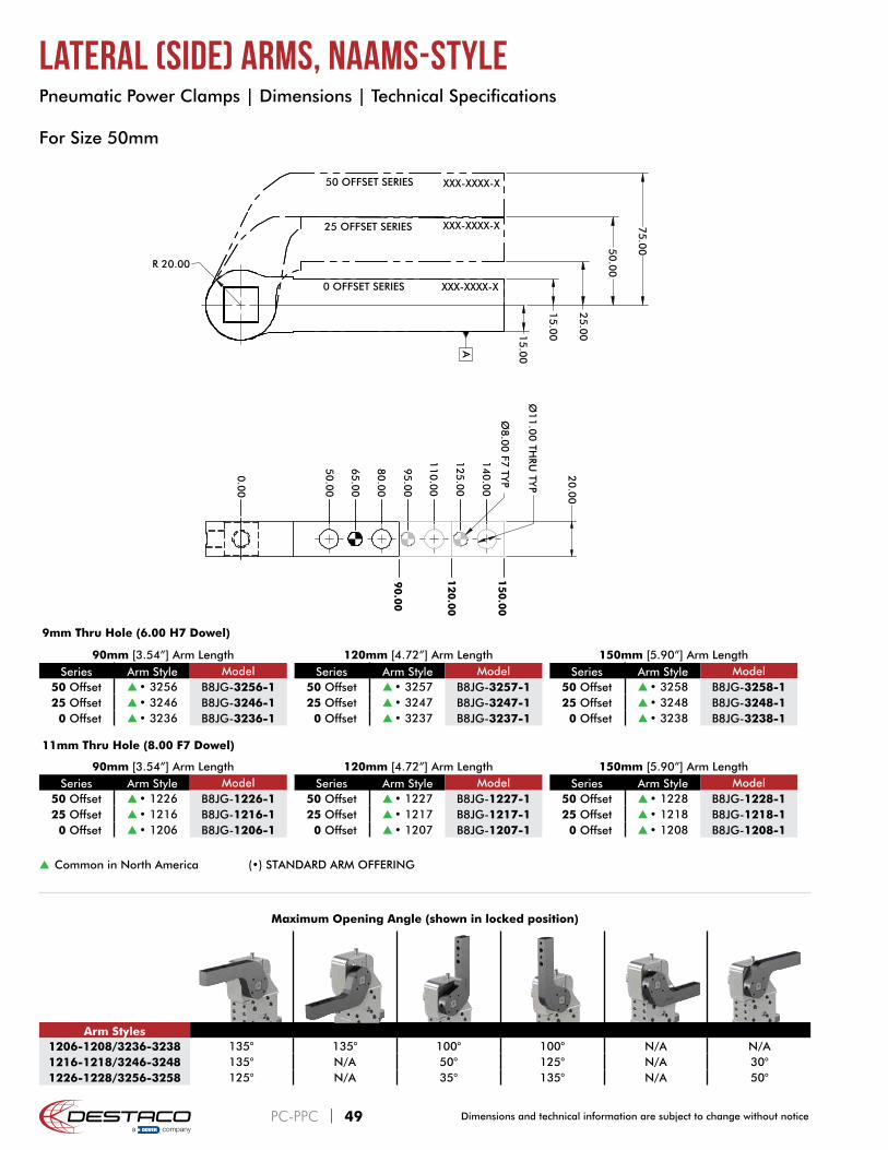
s Common in North America (•) STANDARD ARM OFFERING
Maximum Opening Angle (shown in locked position)
Arm Styles1206-1208/3236-3238 135° 135° 100° 100° N/A N/A1216-1218/3246-3248 135° N/A 50° 125° N/A 30°1226-1228/3256-3258 125° N/A 35° 135° N/A 50°
90mm [3.54”] Arm LengthSeries Arm Style Model
50 Offset s • 1226 B8JG-1226-125 Offset s • 1216 B8JG-1216-1 0 Offset s • 1206 B8JG-1206-1
120mm [4.72”] Arm LengthSeries Arm Style Model
50 Offset s • 1227 B8JG-1227-125 Offset s • 1217 B8JG-1217-1 0 Offset s • 1207 B8JG-1207-1
150mm [5.90”] Arm LengthSeries Arm Style Model
50 Offset s • 1228 B8JG-1228-125 Offset s • 1218 B8JG-1218-1 0 Offset s • 1208 B8JG-1208-1
For Size 50mm
11mm Thru Hole (8.00 F7 Dowel)
90mm [3.54”] Arm LengthSeries Arm Style Model
50 Offset s • 3256 B8JG-3256-125 Offset s • 3246 B8JG-3246-1 0 Offset s • 3236 B8JG-3236-1
120mm [4.72”] Arm LengthSeries Arm Style Model
50 Offset s • 3257 B8JG-3257-125 Offset s • 3247 B8JG-3247-1 0 Offset s • 3237 B8JG-3237-1
150mm [5.90”] Arm LengthSeries Arm Style Model
50 Offset s • 3258 B8JG-3258-125 Offset s • 3248 B8JG-3248-1 0 Offset s • 3238 B8JG-3238-1
9mm Thru Hole (6.00 H7 Dowel)
Pneumatic Power Clamps | Dimensions | Technical Specifications
PC-PPC | 49 Dimensions and technical information are subject to change without notice

Lateral (Side) Arms, NAAMS-Style
For Size 63mm with 23 Clamp Arm Shaft Option
25.00 [0.98]
55.00 [2.17]
18.00 [0..71]
15.00 [0.59]
95.00 [3
.74
]
80.00 [3
.15
]
65.00 [2
.56
]
0.00
110.00 [4
.33
]
125.00 [4
.92
]
140.00 [5
.51
]
155.00 [6
.10
]
170.00 [6
.69
]
185.00 [7
.28
]
200.00 [7
.87
]
215.00 [8
.46
]
230.00 [9
.06
]
245.00 [9
.65
]
260.00 [1
0.2
4]
275.00 [1
0.8
3]
Ø6
.00
[0.2
4] H
7 TYP
Ø9.00
[0.3
5] TH
RU TY
P
20.00[0.79]
[5.3
1]
[6.5
0]
[7.6
8]
[8.8
6]
[10
.04
]
[11
.22
]
135.0
0
165.0
0
195.0
0
225.0
0
255.0
0
285.0
0
OFFSET ARM STYLE PART NUMBER12070250
046•034 022 010
8JG-1046-18JG-1034-18JG-1022-18JG-1010-1
OFFSET ARM STYLE PART NUMBER12070250
047•035 023 011
8JG-1047-18JG-1035-18JG-1023-18JG-1011-1
OFFSET ARM STYLE PART NUMBER12070250
048 036 024 012
8JG-1048-18JG-1036-18JG-1024-18JG-1012-1
OFFSET ARM STYLE PART NUMBER12070250
045•033 021•009
8JG-1045-18JG-1033-18JG-1021-18JG-1009-1
OFFSET ARM STYLE PART NUMBER12070250
044•032•020•008
8JG-1044-18JG-1032-18JG-1020-18JG-1008-1
OFFSET ARM STYLE PART NUMBER12070250
•043•031•019•007
8JG-1043-18JG-1031-18JG-1019-18JG-1007-1
XXX-XXXX-X
XXX-XXXX-X 70
.00
10
0.0
0
12
0.0
0
15
0.0
0
[2.7
6]
[3.9
4]
[4.7
2]
[5.9
1]
R 28
.00
[1.1
0]
120 OFFSET SERIES
70 OFFSET SERIES
25 OFFSET SERIES
0 OFFSET SERIES
XXX-XXXX-X
XXX-XXXX-X
A
OFFSET
STANDARD BLANK ARM OFFERING
(•) STANDARD ARM OFFERINGARM STYLE PART NUMBER
20 •018 8JG-1018-1
Maximum Opening Angle (shown in locked position)
Arm Styles1510-1512/1507-1509 135° 135° 100° 100° N/A N/A1522-1524/1519-1521 135° N/A 50° 130° N/A 40°1534-1536/1531-1533 115° N/A 25° 135° N/A 75°1546-1548/1543-1545 110° N/A 20° 135° N/A 85°
s Common in North America
135mm [5.31”] Arm LengthSeries Arm Style Model
120 Offset s 1543 B8JG-1543-1 70 Offset s 1531 B8JG-1531-1 25 Offset s 1519 B8JG-1519-1 0 Offset s 1507 B8JG-1507-1
165mm [6.50”] Arm LengthSeries Arm Style Model
120 Offset s 1544 B8JG-1544-1 70 Offset s 1532 B8JG-1532-1 25 Offset s 1520 B8JG-1520-1 0 Offset s 1508 B8JG-1508-1
195mm [7.68”] Arm LengthSeries Arm Style Model
120 Offset s 1545 B8JG-1545-1 70 Offset s 1533 B8JG-1533-1 25 Offset s 1521 B8JG-1521-1 0 Offset s 1509 B8JG-1509-1
225mm [8.86”] Arm LengthSeries Arm Style Model
120 Offset s 1546 B8JG-1546-1 70 Offset s 1534 B8JG-1534-1 25 Offset s 1522 B8JG-1522-1 0 Offset s 1510 B8JG-1510-1
255mm [10.04”] Arm LengthSeries Arm Style Model
120 Offset s 1547 B8JG-1547-1 70 Offset s 1535 B8JG-1535-1 25 Offset s 1523 B8JG-1523-1 0 Offset s 1511 B8JG-1511-1
285mm [11.22”] Arm LengthSeries Arm Style Model
120 Offset s 1548 B8JG-1548-1 70 Offset s 1536 B8JG-1536-1 25 Offset s 1524 B8JG-1524-1 0 Offset s 1512 B8JG-1512-1
Pneumatic Power Clamps | Dimensions | Technical Specifications
PC-PPC | 50Dimensions and technical information are subject to change without notice

Lateral (Side) Arms, NAAMS-Style
For Size 63mm with D0 Clamp Arm Shaft Option
25.00 [0.98]
55.00 [2.17]
18.00 [0..71]
15.00 [0.59]
95.00 [3
.74]
80.00 [3
.15]
65.00 [2
.56]
0.00
110.00 [4
.33]
125.00 [4
.92]
140.00 [5
.51]
155.00 [6
.10]
170.00 [6
.69]
185.00 [7
.28]
200.00 [7
.87]
215.00 [8
.46]
230.00 [9
.06]
245.00 [9
.65]
260.00 [1
0.2
4]
275.00 [1
0.8
3]
Ø8.0
0 [0
.31] F7
TYP
Ø11.00
[0.4
3] TH
RU TY
P
25.00[0.98]
[5.3
1]
[6.5
0]
[7.6
8]
[8.8
6]
[10
.04
]
[11
.22
]
135.0
0
165.0
0
195.0
0
225.0
0
255.0
0
285.0
0
OFFSET ARM STYLE PART NUMBER12070250
046•034 022 010
8JG-1046-18JG-1034-18JG-1022-18JG-1010-1
OFFSET ARM STYLE PART NUMBER12070250
047•035 023 011
8JG-1047-18JG-1035-18JG-1023-18JG-1011-1
OFFSET ARM STYLE PART NUMBER12070250
048 036 024 012
8JG-1048-18JG-1036-18JG-1024-18JG-1012-1
OFFSET ARM STYLE PART NUMBER12070250
045•033 021•009
8JG-1045-18JG-1033-18JG-1021-18JG-1009-1
OFFSET ARM STYLE PART NUMBER12070250
044•032•020•008
8JG-1044-18JG-1032-18JG-1020-18JG-1008-1
OFFSET ARM STYLE PART NUMBER12070250
•043•031•019•007
8JG-1043-18JG-1031-18JG-1019-18JG-1007-1
XXX-XXXX-X
XXX-XXXX-X 70
.00
10
0.0
0
12
0.0
0
15
0.0
0
[2.7
6]
[3.9
4]
[4.7
2]
[5.9
1]
R 28
.00
[1.1
0]
120 OFFSET SERIES
70 OFFSET SERIES
25 OFFSET SERIES
0 OFFSET SERIES
XXX-XXXX-X
XXX-XXXX-X
A
OFFSET
STANDARD BLANK ARM OFFERING
(•) STANDARD ARM OFFERINGARM STYLE PART NUMBER
20 •018 8JG-1018-1
Maximum Opening Angle (shown in locked position)
Arm Styles1010-1012/1007-1009 135° 135° 100° 100° N/A N/A1022-1024/1019-1021 135° N/A 50° 130° N/A 40°1034-1036/1031-1033 115° N/A 25° 135° N/A 75°1046-1048/1043-1045 110° N/A 20° 135° N/A 85°
s Common in North America (•) STANDARD ARM OFFERING NON-STANDARD ARM OFFERING (extended leadtimes apply)
135mm [5.31”] Arm LengthSeries Arm Style Model
120 Offset s • 1043 B8JG-1043-1 70 Offset s • 1031 B8JG-1031-1 25 Offset s • 1019 B8JG-1019-1 0 Offset s • 1007 B8JG-1007-1
165mm [6.50”] Arm LengthSeries Arm Style Model
120 Offset s1044 B8JG-1044-1 70 Offset s • 1032 B8JG-1032-1 25 Offset s • 1020 B8JG-1020-1 0 Offset s • 1008 B8JG-1008-1
195mm [7.68”] Arm LengthSeries Arm Style Model
120 Offset s1045 B8JG-1045-1 70 Offset s • 1033 B8JG-1033-1 25 Offset s1021 B8JG-1021-1 0 Offset s • 1009 B8JG-1009-1
225mm [8.86”] Arm LengthSeries Arm Style Model
120 Offset s1046 B8JG-1046-1 70 Offset s • 1034 B8JG-1034-1 25 Offset s1022 B8JG-1022-1 0 Offset s1010 B8JG-1010-1
255mm [10.04”] Arm LengthSeries Arm Style Model
120 Offset s1047 B8JG-1047-1 70 Offset s • 1035 B8JG-1035-1 25 Offset s1023 B8JG-1023-1 0 Offset s1011 B8JG-1011-1
285mm [11.22”] Arm LengthSeries Arm Style Model
120 Offset s1048 B8JG-1048-1 70 Offset s1036 B8JG-1036-1 25 Offset s1024 B8JG-1024-1 0 Offset s1012 B8JG-1012-1
Pneumatic Power Clamps | Dimensions | Technical Specifications
PC-PPC | 51 Dimensions and technical information are subject to change without notice

Lateral (Side) Arms, NAAMS-Style
340.000
85.00
25.0
0
60.0
0
70.0
0
105.00
120.00
155.00
24.0
0
20.0
0
R35.0
0
120 OFFSET
70 OFFSET
25 OFFSET
0 OFFSET
100.00
115.00
130.00
145.00
160.00
175.00
190.00
205.00
220.00
235.00
250.00
265.00
280.00
295.00
310.00
325.00
355.00
370.00
395.00
385.00
185.00
245.00
275.00
305.00
335.00
Ø8.0
0F7
TYP
Ø11.0
0 TH
RU TY
P
365.00
32.0
0
215.00
155.00
A
Maximum Opening Angle (shown in locked position)
Arm Styles1110 - 1118 135° 135° 100° 100° N/A N/A1130 - 1138 135° N/A 60° 120° N/A 30°1150 - 1158 125° N/A 35° 135° N/A 55°1170 - 1178 115° N/A 25° 135° N/A 80°
s Common in North America (•) STANDARD ARM OFFERING NON-STANDARD ARM OFFERING (extended leadtimes apply)
For Size 80mm
155mm [4.53”] Arm LengthSeries Arm Style Model
120 Offset s 1170 B8JG-1170-1 70 Offset s • 1150 B8JG-1150-1 25 Offset s 1130 B8JG-1130-1 0 Offset s 1110 B8JG-1110-1
185mm [7.28”] Arm LengthSeries Arm Style Model
120 Offset s 1171 B8JG-1171-1 70 Offset s 1151 B8JG-1151-1 25 Offset s 1131 B8JG-1131-1 0 Offset s 1111 B8JG-1111-1
215mm [8.46”] Arm LengthSeries Arm Style Model
120 Offset s 1172 B8JG-1172-1 70 Offset s 1152 B8JG-1152-1 25 Offset s 1132 B8JG-1132-1 0 Offset s • 1112 B8JG-1112-1
245mm [9.65”] Arm LengthSeries Arm Style Model
120 Offset s 1173 B8JG-1173-1 70 Offset s 1153 B8JG-1153-1 25 Offset s 1133 B8JG-1133-1 0 Offset s 1113 B8JG-1113-1
275mm [10.83”] Arm LengthSeries Arm Style Model
120 Offset s 1174 B8JG-1174-1 70 Offset s 1154 B8JG-1154-1 25 Offset s • 1134 B8JG-1134-1 0 Offset s 1114 B8JG-1114-1
305mm [12.00”] Arm LengthSeries Arm Style Model
120 Offset s 1175 B8JG-1175-1 70 Offset s • 1155 B8JG-1155-1 25 Offset s 1135 B8JG-1135-1 0 Offset s 1115 B8JG-1115-1
335mm [13.19”] Arm LengthSeries Arm Style Model
120 Offset s 1176 B8JG-1176-1 70 Offset s 1156 B8JG-1156-1 25 Offset s 1136 B8JG-1136-1 0 Offset s 1116 B8JG-1116-1
365mm [14.37”] Arm LengthSeries Arm Style Model
120 Offset s 1177 B8JG-1177-1 70 Offset s 1157 B8JG-1157-1 25 Offset s 1137 B8JG-1137-1 0 Offset s 1117 B8JG-1117-1
395mm [15.55”] Arm LengthSeries Arm Style Model
120 Offset s 1178 B8JG-1178-1 70 Offset s • 1158 B8JG-1158-1 25 Offset s 1138 B8JG-1138-1 0 Offset s • 1118 B 8JG-1118-1
Pneumatic Power Clamps | Dimensions | Technical Specifications
PC-PPC | 52cesehsa.com.mx tel. 01 800 237 3472