tc55 integrator guide - zebra.com · pdf filemulti-user/applock configuration ... manual file...
TRANSCRIPT
TC55INTEGRATOR GUIDE


CopyrightsThe products described in this document may include copyrighted computer programs. Laws in the United States andother countries preserve for certain exclusive rights for copyrighted computer programs. Accordingly, anycopyrighted computer programs contained in the products described in this document may not be copied orreproduced in any manner without the express written permission.© 2015 Symbol Technologies, Inc. All Rights Reserved
No part of this document may be reproduced, transmitted, stored in a retrieval system, or translated into any languageor computer language, in any form or by any means, without the prior written permission.
Furthermore, the purchase of our products shall not be deemed to grant either directly or by implication, estoppel orotherwise, any license under the copyrights, patents or patent applications, except for the normal non-exclusive,royalty-free license to use that arises by operation of law in the sale of a product.
DisclaimerPlease note that certain features, facilities, and capabilities described in this document may not be applicable to orlicensed for use on a particular system, or may be dependent upon the characteristics of a particular mobile subscriberunit or configuration of certain parameters. Please refer to your contact for further information.
TrademarksZebra and the Zebra head graphic are registered trademarks of ZIH Corp. The Symbol logo is a registered trademarkof Symbol Technologies, Inc., a Zebra Technologies company.
3 | Copyrights
MN000017A03-B | February 2015


Revision HistoryChanges to the original guide are listed below:
Change Date Description
A01 Rev. A 10/15/2013 Initial release.
A01 Rev. B 12/12/13 Minor corrections.
A02 Rev A 04/02/14 Add support for configurations with Google Mobile Services (Standard Configu-ration) and TC55CH.
A03 Rev A 08/5/14 Add TC55CH with 3G Voice and Data configuration support.
A03 Rev B 02/15/15 Zebra rebranding.
5 | Revision History
MN000017A03-B | February 2015

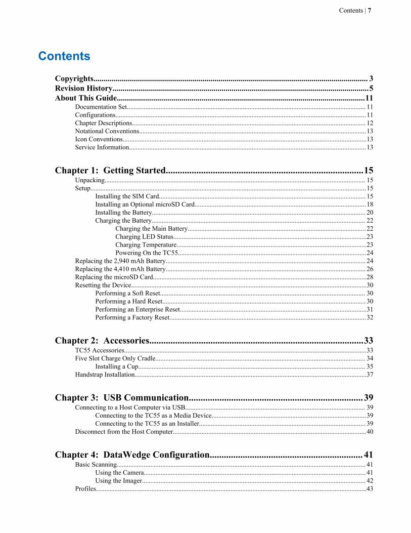
Contents
Copyrights........................................................................................................................................ 3Revision History...............................................................................................................................5About This Guide...........................................................................................................................11
Documentation Set.............................................................................................................................................. 11Configurations.....................................................................................................................................................11Chapter Descriptions........................................................................................................................................... 12Notational Conventions.......................................................................................................................................13Icon Conventions.................................................................................................................................................13Service Information.............................................................................................................................................13
Chapter 1: Getting Started....................................................................................15Unpacking........................................................................................................................................................... 15Setup....................................................................................................................................................................15
Installing the SIM Card........................................................................................................................... 15Installing an Optional microSD Card......................................................................................................18Installing the Battery............................................................................................................................... 20Charging the Battery............................................................................................................................... 22
Charging the Main Battery.......................................................................................................... 22Charging LED Status...................................................................................................................23Charging Temperature.................................................................................................................23Powering On the TC55................................................................................................................24
Replacing the 2,940 mAh Battery....................................................................................................................... 24Replacing the 4,410 mAh Battery....................................................................................................................... 26Replacing the microSD Card...............................................................................................................................28Resetting the Device............................................................................................................................................30
Performing a Soft Reset.......................................................................................................................... 30Performing a Hard Reset......................................................................................................................... 30Performing an Enterprise Reset...............................................................................................................31Performing a Factory Reset.....................................................................................................................32
Chapter 2: Accessories...........................................................................................33TC55 Accessories................................................................................................................................................33Five Slot Charge Only Cradle............................................................................................................................. 34
Installing a Cup....................................................................................................................................... 35Handstrap Installation..........................................................................................................................................37
Chapter 3: USB Communication..........................................................................39Connecting to a Host Computer via USB........................................................................................................... 39
Connecting to the TC55 as a Media Device............................................................................................39Connecting to the TC55 as an Installer................................................................................................... 39
Disconnect from the Host Computer...................................................................................................................40
Chapter 4: DataWedge Configuration................................................................. 41Basic Scanning.................................................................................................................................................... 41
Using the Camera.................................................................................................................................... 41Using the Imager..................................................................................................................................... 42
Profiles.................................................................................................................................................................43
Contents | 7

Plug-ins................................................................................................................................................................43Profiles Screen.....................................................................................................................................................44
Disabling DataWedge..............................................................................................................................46Creating a New Profile........................................................................................................................................ 46Profile Configuration...........................................................................................................................................47
Bar Code Input........................................................................................................................................ 47Keystroke Output.................................................................................................................................... 54Intent Output............................................................................................................................................55
Intent Overview...........................................................................................................................56IP Output................................................................................................................................................. 57
Generating Advanced Data Formatting Rules.....................................................................................................58Configuring ADF Plug-in........................................................................................................................58
Creating a Rule............................................................................................................................59Defining a Rule........................................................................................................................... 59Defining Criteria..........................................................................................................................60Defining an Action...................................................................................................................... 61Deleting a Rule............................................................................................................................62Order Rules List.......................................................................................................................... 62Deleting an Action.......................................................................................................................63ADF Example..............................................................................................................................63
DataWedge Settings............................................................................................................................................ 66Importing a Configuration File................................................................................................................67Exporting a Configuration File................................................................................................................67Importing a Profile File........................................................................................................................... 67Exporting a Profile.................................................................................................................................. 67Restoring DataWedge..............................................................................................................................68
Configuration and Profile File Management.......................................................................................................68Programming Notes.............................................................................................................................................69
Overriding Trigger Key in an Application.............................................................................................. 69Capture Data and Taking a Photo in the Same Application....................................................................69Disable DataWedge on TC55 and Mass Deploy.....................................................................................69Soft Scan Feature.....................................................................................................................................69
Chapter 5: Administrator Utilities....................................................................... 71Required Software...............................................................................................................................................71On-device Application Installation..................................................................................................................... 71Multi-user/AppLock Configuration.................................................................................................................... 71Enterprise Administrator Application................................................................................................................. 72
Creating Users......................................................................................................................................... 72Adding Packages..................................................................................................................................... 73Creating Groups...................................................................................................................................... 74Creating Remote Authentication............................................................................................................. 74Save Data.................................................................................................................................................75Exporting File..........................................................................................................................................75Importing User List................................................................................................................................. 75Importing Group List...............................................................................................................................76Importing Package List........................................................................................................................... 76Editing a User..........................................................................................................................................76Deleting a User........................................................................................................................................76Editing a Group....................................................................................................................................... 76Deleting a Group..................................................................................................................................... 76Editing a Package.................................................................................................................................... 77Deleting a Package.................................................................................................................................. 77
MultiUser Administrator..................................................................................................................................... 77Importing a Password..............................................................................................................................77
8 | Contents

Disabling the Multi-user Feature.............................................................................................................78Enabling Remote Authentication............................................................................................................ 78Disabling Remote Authentication........................................................................................................... 79Enabling Data Separation........................................................................................................................79Disabling Data Separation.......................................................................................................................79Delete User Data..................................................................................................................................... 80Capturing a Log File................................................................................................................................80
AppLock Administrator...................................................................................................................................... 80Installing Groups and White Lists...........................................................................................................80Enabling Application Lock..................................................................................................................... 81Disabling Application Lock.................................................................................................................... 81
Manual File Configuration.................................................................................................................................. 81Determining Applications Installed on the Device................................................................................. 83
Secure Storage.....................................................................................................................................................83Installing a Key....................................................................................................................................... 83Viewing Key List.................................................................................................................................... 84Deleting a Key.........................................................................................................................................84Volumes...................................................................................................................................................84
Creating Volume Using EFS File................................................................................................85Creating a Volume Manually...................................................................................................... 85Mounting a Volume.....................................................................................................................86Listing Volumes.......................................................................................................................... 86Unmounting a Volume................................................................................................................ 86Deleting a Volume.......................................................................................................................86Encrypting an SD Card................................................................................................................86
Creating an EFS File............................................................................................................................... 86Off-line Extraction Tool..........................................................................................................................87
Creating an Image....................................................................................................................... 87Mounting an Image..................................................................................................................... 88Unmounting an Image................................................................................................................. 88
Chapter 6: Settings.................................................................................................89Location Settings.................................................................................................................................................89Screen Unlock Settings....................................................................................................................................... 90
Single User Mode....................................................................................................................................90Set Screen Unlock Using PIN..................................................................................................... 90Set Screen Unlock Using Password............................................................................................ 91Set Screen Unlock Using Pattern................................................................................................ 92
Multiple User Mode................................................................................................................................ 93Passwords............................................................................................................................................................ 94Button Programming........................................................................................................................................... 94
Programming a Button............................................................................................................................ 94Exporting a Programmable Key Configuration File............................................................................... 95Importing a Programmable Key Configuration File............................................................................... 95
Accounts..............................................................................................................................................................96Language Usage.................................................................................................................................................. 96
Changing the Language Setting.............................................................................................................. 96Adding Words to the Dictionary............................................................................................................. 96
Keyboard Settings............................................................................................................................................... 97About Phone........................................................................................................................................................97
Chapter 7: Application Deployment.....................................................................99Security................................................................................................................................................................99
Secure Certificates...................................................................................................................................99
Contents | 9

Installing a Secure Certificate................................................................................................................. 99Configuring Credential Storage Settings...............................................................................................100
Development Tools........................................................................................................................................... 100ADB USB Setup................................................................................................................................................101Application Installation..................................................................................................................................... 101
Installing Applications Using the USB Connection..............................................................................101Installing Applications Using the Android Debug Bridge.................................................................... 102Uninstalling an Application...................................................................................................................102
Updating the System......................................................................................................................................... 103Enterprise Enable.............................................................................................................................................. 104Storage...............................................................................................................................................................105
Random Access Memory...................................................................................................................... 105Internal Storage..................................................................................................................................... 105External Storage.................................................................................................................................... 107Enterprise Folder................................................................................................................................... 107
Application Management.................................................................................................................................. 108Viewing Application Details................................................................................................................. 108Stopping an Application........................................................................................................................109Changing Application Location............................................................................................................ 109Managing Downloads............................................................................................................................110
RxLogger...........................................................................................................................................................110RxLogger Configuration....................................................................................................................... 110Enabling Logging..................................................................................................................................113Disabling Logging.................................................................................................................................113Extracting Log Files.............................................................................................................................. 114
MLog Manager..................................................................................................................................................114Exporting QXDM Logs.........................................................................................................................115
Chapter 8: Maintenance and Troubleshooting................................................. 117Maintaining the TC55....................................................................................................................................... 117Battery Safety Guidelines..................................................................................................................................117Cleaning Instructions.........................................................................................................................................118
Cleaning the TC55.................................................................................................................................119Connector Cleaning...................................................................................................................119Cleaning Cradle Connectors......................................................................................................119
Troubleshooting.................................................................................................................................................120Troubleshooting the TC55.....................................................................................................................120Five-Slot Charge Only Cradle CRDUNIV-55–5000R Troubleshooting.............................................. 122
Chapter 9: Technical Specifications................................................................... 123TC55 Technical Specifications......................................................................................................................... 123TC55 Decode Zone........................................................................................................................................... 126
SE-655 Decode Distances..................................................................................................................... 127TC55 Connector Pin-Outs.................................................................................................................................128Five-Slot Charge Only Cradle CRDUNIV-55-5000R Technical Specifications..............................................130
Chapter 10: Keypad Remap Strings.................................................................. 131
10 | Contents
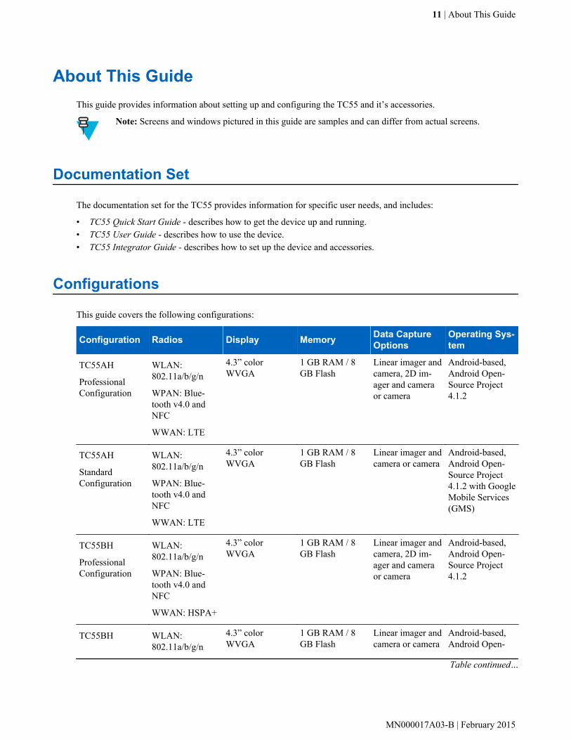
About This GuideThis guide provides information about setting up and configuring the TC55 and it’s accessories.
Note: Screens and windows pictured in this guide are samples and can differ from actual screens.
Documentation Set
The documentation set for the TC55 provides information for specific user needs, and includes:
• TC55 Quick Start Guide - describes how to get the device up and running.• TC55 User Guide - describes how to use the device.• TC55 Integrator Guide - describes how to set up the device and accessories.
Configurations
This guide covers the following configurations:
Configuration Radios Display Memory Data CaptureOptions
Operating Sys-tem
TC55AH
ProfessionalConfiguration
WLAN:802.11a/b/g/n
WPAN: Blue-tooth v4.0 andNFC
WWAN: LTE
4.3” colorWVGA
1 GB RAM / 8GB Flash
Linear imager andcamera, 2D im-ager and cameraor camera
Android-based,Android Open-Source Project4.1.2
TC55AH
Standard Configuration
WLAN:802.11a/b/g/n
WPAN: Blue-tooth v4.0 andNFC
WWAN: LTE
4.3” colorWVGA
1 GB RAM / 8GB Flash
Linear imager andcamera or camera
Android-based,Android Open-Source Project4.1.2 with GoogleMobile Services(GMS)
TC55BH
ProfessionalConfiguration
WLAN:802.11a/b/g/n
WPAN: Blue-tooth v4.0 andNFC
WWAN: HSPA+
4.3” colorWVGA
1 GB RAM / 8GB Flash
Linear imager andcamera, 2D im-ager and cameraor camera
Android-based,Android Open-Source Project4.1.2
TC55BH WLAN:802.11a/b/g/n
4.3” colorWVGA
1 GB RAM / 8GB Flash
Linear imager andcamera or camera
Android-based,Android Open-
Table continued…
11 | About This Guide
MN000017A03-B | February 2015

Configuration Radios Display Memory Data CaptureOptions
Operating Sys-tem
Standard Configuration
WPAN: Blue-tooth v4.0 andNFC
WWAN: HSPA+
Source Project4.1.2 with GMS
TC55CH withLTE Data
ProfessionalConfiguration
WLAN:802.11a/b/g/n
WPAN: Blue-tooth v4.0 andNFC
WWAN: CDMA/EvDO, LTE
4.3” colorWVGA
1 GB RAM / 8GB Flash
Linear imager andcamera or camera
Android-based,Android Open-Source Project4.1.2
TC55CH with 3GVoice & Data
ProfessionalConfiguration
WLAN:802.11a/b/g/n
WPAN: Blue-tooth v4.0 andNFC
WWAN: CDMA/EvDO
4.3” colorWVGA
1 GB RAM / 8GB Flash
Linear imager andcamera or camera
Android-based,Android Open-Source Project4.1.2
Software Versions
To determine the current software versions touch > > About phone.
• Serial number – Displays the serial number.• Model number – Displays the model number.• Android version – Displays the operating system version.• Kernel version – Displays the kernel version number.• Build number – Displays the software build number.
Chapter Descriptions
Topics covered in this guide are as follows:
• Getting Started on page 15 provides information on getting the TC55 up and running for the first time.• Accessories on page 33 describes the available accessories and how to use them with the TC55.• USB Communication on page 39 describes how to connect the TC55 to a host computer using USB.• DataWedge Configuration on page 41 describes how to use and configure the DataWedge application.• Administrator Utilities on page 71 provides information for using the suite of administrative tools for
configuring the TC55.• Settings on page 89 provides the settings for configuring the TC55.• Application Deployment on page 99 provides information for developing and managing applications.• Maintenance and Troubleshooting on page 117 includes instructions on cleaning and storing the TC55, and
provides troubleshooting solutions for potential problems during TC55 operation.• Technical Specifications on page 123 provides the technical specifications for the TC55.• Keypad Remap Strings on page 131 provides a list of remap strings used when remapping keys.
12 | About This Guide
February 2015 | MN000017A03-B
Notational Conventions
The following conventions are used in this document:
• Italics are used to highlight the following:
- Chapters and sections in this and related documents- Icons on a screen.
• Bold text is used to highlight the following:
- Dialog box, window, and screen names- Drop-down list and list box names- Check box and radio button names- Button names on a screen.
• Bullets (•) indicate:
- Action items- Lists of alternatives- Lists of required steps that are not necessarily sequential
• Sequential lists (for example, lists that describe step-by-step procedures) appear as numbered lists.
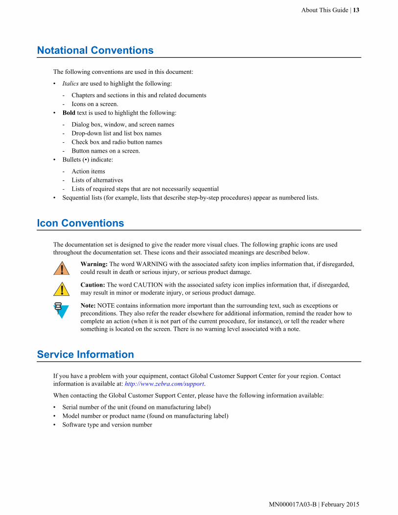
Icon Conventions
The documentation set is designed to give the reader more visual clues. The following graphic icons are usedthroughout the documentation set. These icons and their associated meanings are described below.
Warning: The word WARNING with the associated safety icon implies information that, if disregarded,could result in death or serious injury, or serious product damage.
Caution: The word CAUTION with the associated safety icon implies information that, if disregarded,may result in minor or moderate injury, or serious product damage.
Note: NOTE contains information more important than the surrounding text, such as exceptions orpreconditions. They also refer the reader elsewhere for additional information, remind the reader how tocomplete an action (when it is not part of the current procedure, for instance), or tell the reader wheresomething is located on the screen. There is no warning level associated with a note.
Service Information
If you have a problem with your equipment, contact Global Customer Support Center for your region. Contactinformation is available at: http://www.zebra.com/support.
When contacting the Global Customer Support Center, please have the following information available:
• Serial number of the unit (found on manufacturing label)• Model number or product name (found on manufacturing label)• Software type and version number
About This Guide | 13
MN000017A03-B | February 2015

Figure 1: Manufacturing Label Location
We responds to calls by email or telephone within the time limits set forth in support agreements.
If your problem cannot be solved by the Global Customer Support Center, you may need to return your equipment forservicing and will be given specific directions. We are not responsible for any damages incurred during shipment ifthe approved shipping container is not used. Shipping the units improperly can possibly void the warranty.
If you purchased your product from a business partner, contact that business partner for support.
14 | About This Guide
February 2015 | MN000017A03-B

Chapter
1Getting Started
This chapter provides the features of the TC55 and explains how to set it up for the first time.
Unpacking
Carefully remove all protective material from the TC55 and save the shipping container for later storage and shipping.
Verify the following items are in the box:
• TC55• Lithium-ion battery (2,940 mAh or 4,410 mAh)• Charge Cable• Quick Start Guide• Regulatory Guide.
Note: Power Supply, p/n PWRS-124306–01R, is required and must be purchased separately.
Inspect the equipment for damage. If any equipment is missing or damaged, contact the Zebra Support Centerimmediately. See Service Information on page 13 for contact information.
Setup
To start using the TC55 for the first time:
• Install the SIM Card.• Install microSD card (optional).• Install the battery.• Charge the TC55.• Power on the TC55.• Set up Google account.
Installing the SIM CardCaution:
For proper electrostatic discharge (ESD) precautions to avoid damaging the SIM card. Proper ESDprecautions include, but not limited to, working on an ESD mat and ensuring that the user is properlygrounded.
15 | Getting Started
MN000017A03-B | February 2015
Note:
The TC55 accepts a full size SIM card. If using a micro or nano SIM card, a third-party SIM adapter isrequired.
TC55AH, TC55BH and TC55CH with LTE Data devices require an activated SIM card. Obtain the cardfrom a service provider.TC55CH with 3G Voice & Data devices do not require a SIM card.
On TC55CH with LTE Data devices, if this is a new account, ensure that the account is set up for LTEdata. Obtain a SIM card from Verizon. If you have an existing LTE account that you want to move over tothis device, just install your currently active SIM card. No additional activation will be required. If this is anew account: provide the device IMEI number (located on the label under the battery) and the SIM cardnumber to your service provider. After the service provider activates your account, install the SIM card.The TC55CH must be in good LTE coverage for activation to take place. Following the on-screen process.
On TC55CH with 3G Voice & Data devices, if this is a new account,: provide the device IMEI number(located on the label under the battery) to your service provider. After the service provider activates youraccount, following the on-screen process for activation.
Procedure:
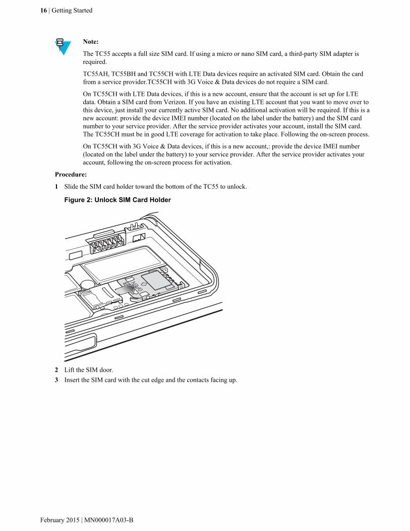
1 Slide the SIM card holder toward the bottom of the TC55 to unlock.
Figure 2: Unlock SIM Card Holder
2 Lift the SIM door.3 Insert the SIM card with the cut edge and the contacts facing up.
16 | Getting Started
February 2015 | MN000017A03-B

Figure 3: Install SIM Card
4 Close the SIM card holder.
Figure 4: Close SIM Card Holder
5 Slide the SIM card holder toward the top of the TC55 to lock into place.
Getting Started | 17
MN000017A03-B | February 2015
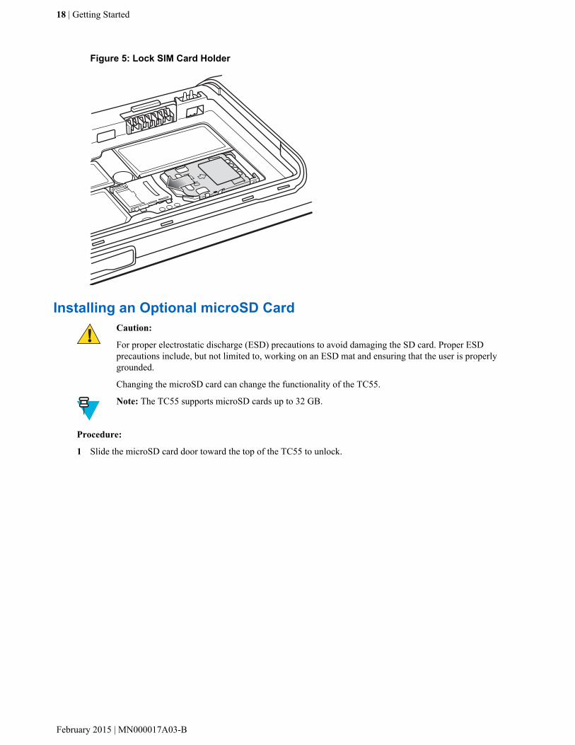
Figure 5: Lock SIM Card Holder
Installing an Optional microSD CardCaution:
For proper electrostatic discharge (ESD) precautions to avoid damaging the SD card. Proper ESDprecautions include, but not limited to, working on an ESD mat and ensuring that the user is properlygrounded.
Changing the microSD card can change the functionality of the TC55.
Note: The TC55 supports microSD cards up to 32 GB.
Procedure:
1 Slide the microSD card door toward the top of the TC55 to unlock.
18 | Getting Started
February 2015 | MN000017A03-B

Figure 6: Unlock microSD Card Door
OPEN LOCK
2 Lift the SD card door.3 Align the microSD card with the card holder. Ensure that the contacts on the card are facing down and toward the
card holder.4 Insert the microSD card into the card holder.
Figure 7: Insert microSD Card
5 Close the SD card door.6 Slide the SD card door toward the bottom of the TC55 to lock into place.
Getting Started | 19
MN000017A03-B | February 2015

Figure 8: Lock SD Card Door
OPEN LOCK
Installing the BatteryThere are two sizes of batteries available for the TC55; a 2,940 mAh battery and a 4,410 mAh battery.
Procedure:
1 Align the three tabs on the bottom of the battery with the three slots in the battery compartment.2 Press the battery down and then rotate until it locks into place.
Figure 9: Inserting the 2,940 mAh Battery
20 | Getting Started
February 2015 | MN000017A03-B
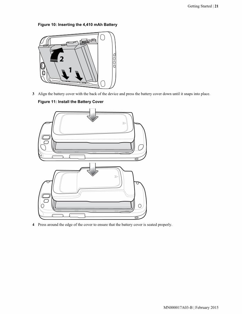
Figure 10: Inserting the 4,410 mAh Battery
3 Align the battery cover with the back of the device and press the battery cover down until it snaps into place.
Figure 11: Install the Battery Cover
4 Press around the edge of the cover to ensure that the battery cover is seated properly.
Getting Started | 21
MN000017A03-B | February 2015

Figure 12: Secure Cover
Charging the BatteryCaution: Ensure that you follow the guidelines for battery safety described in Battery Safety Guidelines onpage 117.
Charging the Main BatteryBefore using the TC55 for the first time, charge the main battery until the light emitting diode (LED) turns solid green(see Charging LED Status on page 23 for charge status indications). To charge the TC55, use the Rugged ChargeCable with the optional power supply.
Note: Only connect the Rugged Charge Cable to the optional power supply. Do not connect the RuggedCharge Cable to a host computer for charging.
22 | Getting Started
February 2015 | MN000017A03-B

Figure 13: Connect the Rugged Charge Cable
The TC55 begins charging. The LED blinks green while charging, then turns solid green when fully charged. The2,940 mAh battery charges in approximately three hours and the 4,410 mAh battery charges in approximately 4.5hours.
Charging LED StatusTable 1: Charging LED Status
Status Indications
Off TC55 is not inserted correctly in the cradle.
TC55 is not connected to a power source.
Cable or cradle is not powered.
Slow blinking green (1blink every two sec-onds)
TC55 is charging.
Solid green Charging complete.
Slow blinking red (1blink every two sec-onds)
Battery is in an extremely low power state (normal slow charging mode).
Fast blinking red (2blinks / per second)
Charging error:
• Temperature is too low or too high.• Charging has gone on too long without completion (typically eight hours).
Charging TemperatureCharge batteries in temperatures from 0 °C to 40 °C (32 °F to 104 °F). Note that charging is intelligently controlledby the TC55. To accomplish this, for small periods of time, the TC55 or accessory alternately enables and disables
Getting Started | 23
MN000017A03-B | February 2015

battery charging to keep the battery at acceptable temperatures. The TC55 or accessory indicates when charging isdisabled due to abnormal temperatures via its LED.
Powering On the TC55Note: Ensure that the battery cover is properly installed. Otherwise, the TC55 will not power on.
If the TC55 did not turn on when the battery was installed, press the Power button. The LED flashes green and thedevice vibrates. The splash screen displays for about a minute as the TC55 boots.
Replacing the 2,940 mAh Battery
Procedure:
1 Press the Power button until the menu displays.2 Touch Power off.3 Touch OK.4 Place thumbnail at notch and lift the battery cover.
Figure 14: Remove the Battery Cover
5 Note: Do not pull the battery tab straight out. Pull at a 45 degree angle.
Pull the battery tab down at a 45 degree angle.
24 | Getting Started
February 2015 | MN000017A03-B
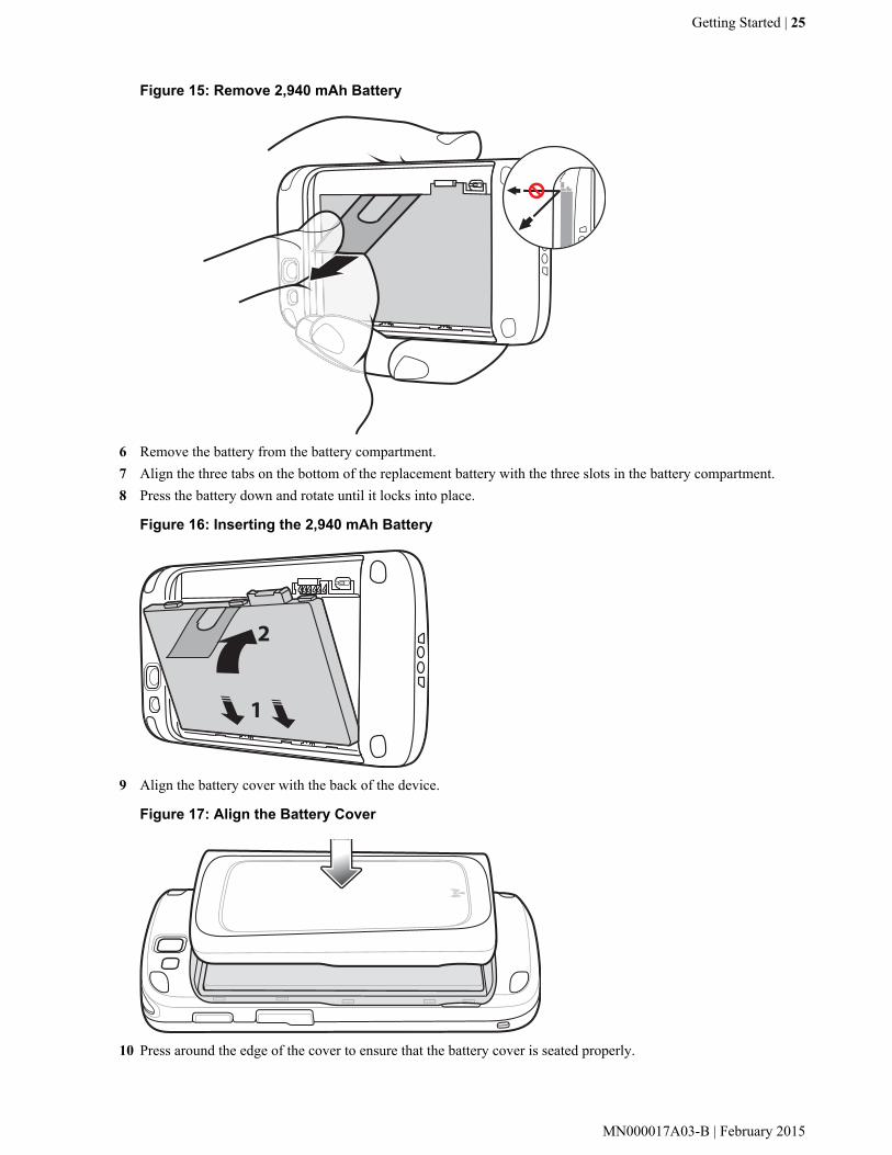
Figure 15: Remove 2,940 mAh Battery
6 Remove the battery from the battery compartment.7 Align the three tabs on the bottom of the replacement battery with the three slots in the battery compartment.8 Press the battery down and rotate until it locks into place.
Figure 16: Inserting the 2,940 mAh Battery
9 Align the battery cover with the back of the device.
Figure 17: Align the Battery Cover
10 Press around the edge of the cover to ensure that the battery cover is seated properly.
Getting Started | 25
MN000017A03-B | February 2015

Figure 18: Secure the Battery Cover
11 Press the Power button to turn on the TC55.
Replacing the 4,410 mAh Battery
Procedure:
1 Press the Power button until the menu displays.2 Touch Power off.3 Touch OK.4 Place thumbnail at notch and lift the battery cover.
Figure 19: Remove the Battery Cover
5 With two fingers, press the battery down.
26 | Getting Started
February 2015 | MN000017A03-B

Figure 20: Remove 4,410 mAh Battery
6 Rotate the battery out of the compartment.7 Align the three tabs on the bottom of the replacement battery with the three slots in the battery compartment.8 Press the battery down and rotate until it locks into place.
Figure 21: Inserting the 4,410 mAh Battery
9 Align the battery cover with the back of the device.
Figure 22: Align the Battery Cover
10 Press around the edge of the cover to ensure that the battery cover is seated properly.
Getting Started | 27
MN000017A03-B | February 2015

Figure 23: Secure the Battery Cover
11 Press the Power button to turn on the TC55.
Replacing the microSD Card
Caution:
For proper electrostatic discharge (ESD) precautions to avoid damaging the SD card. Proper ESDprecautions include, but not limited to, working on an ESD mat and ensuring that the user is properlygrounded.
Changing the microSD card can change the functionality of the TC55.
Ensure that you follow the procedures to shut down the TC55 before replacing the microSD card. Datacorruption can occur if reading or writing to the microSD card and power is removed.
Note: The TC55 supports microSD cards up to 32 GB.
To replace the microSD card:
Procedure:
1 Press the Power button until the menu displays.2 Touch Power off.3 Touch OK.4 Wait for the device to power off completely.5 Remove the battery cover.6 Remove the battery.7 Slide the microSD card cover up to unlock.
28 | Getting Started
February 2015 | MN000017A03-B
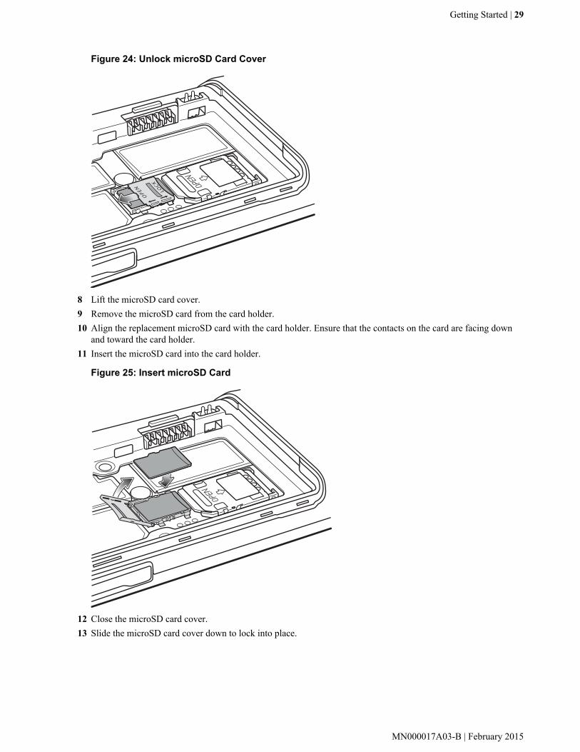
Figure 24: Unlock microSD Card Cover
OPEN LOCK
8 Lift the microSD card cover.9 Remove the microSD card from the card holder.10 Align the replacement microSD card with the card holder. Ensure that the contacts on the card are facing down
and toward the card holder.11 Insert the microSD card into the card holder.
Figure 25: Insert microSD Card
12 Close the microSD card cover.13 Slide the microSD card cover down to lock into place.
Getting Started | 29
MN000017A03-B | February 2015

Figure 26: Lock microSD Card Cover
OPEN LOCK
14 Replace the battery.15 Align the battery cover with the back of the device and press the battery cover down until it snaps into place.16 Press the Power button to turn on the device.
Resetting the Device
There are four reset functions:
• Soft Reset• Hard Reset• Enterprise Reset• Factory Reset.
Performing a Soft ResetPerform a soft reset if applications stop responding.
Procedure:
1 Press and hold the Power button until the menu appears.2 Touch Reset.3 The device reboots.
Performing a Hard ResetCaution: Performing a hard reset with a SD card installed in the TC55 may cause damage or datacorruption to the SD card.
Perform a hard reset if the TC55 stops responding.
Procedure:
1 Simultaneously press the Power, Programmable and Volume Up buttons.
30 | Getting Started
February 2015 | MN000017A03-B
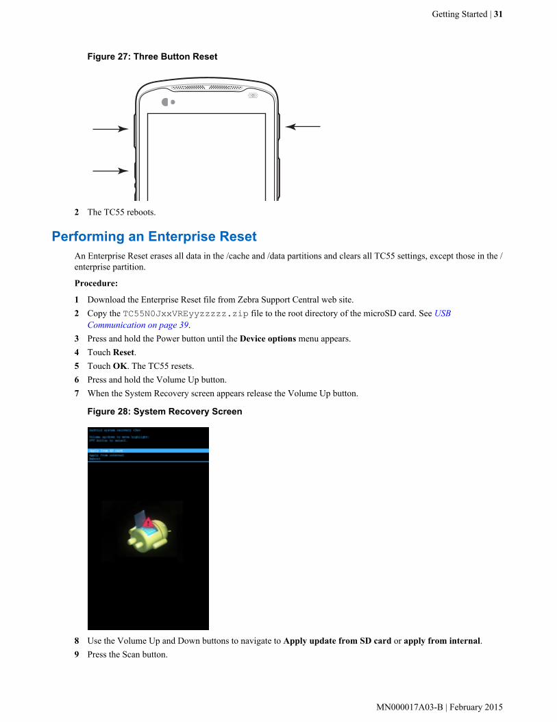
Figure 27: Three Button Reset
2 The TC55 reboots.
Performing an Enterprise ResetAn Enterprise Reset erases all data in the /cache and /data partitions and clears all TC55 settings, except those in the /enterprise partition.
Procedure:
1 Download the Enterprise Reset file from Zebra Support Central web site.2 Copy the TC55N0JxxVREyyzzzzz.zip file to the root directory of the microSD card. See USB
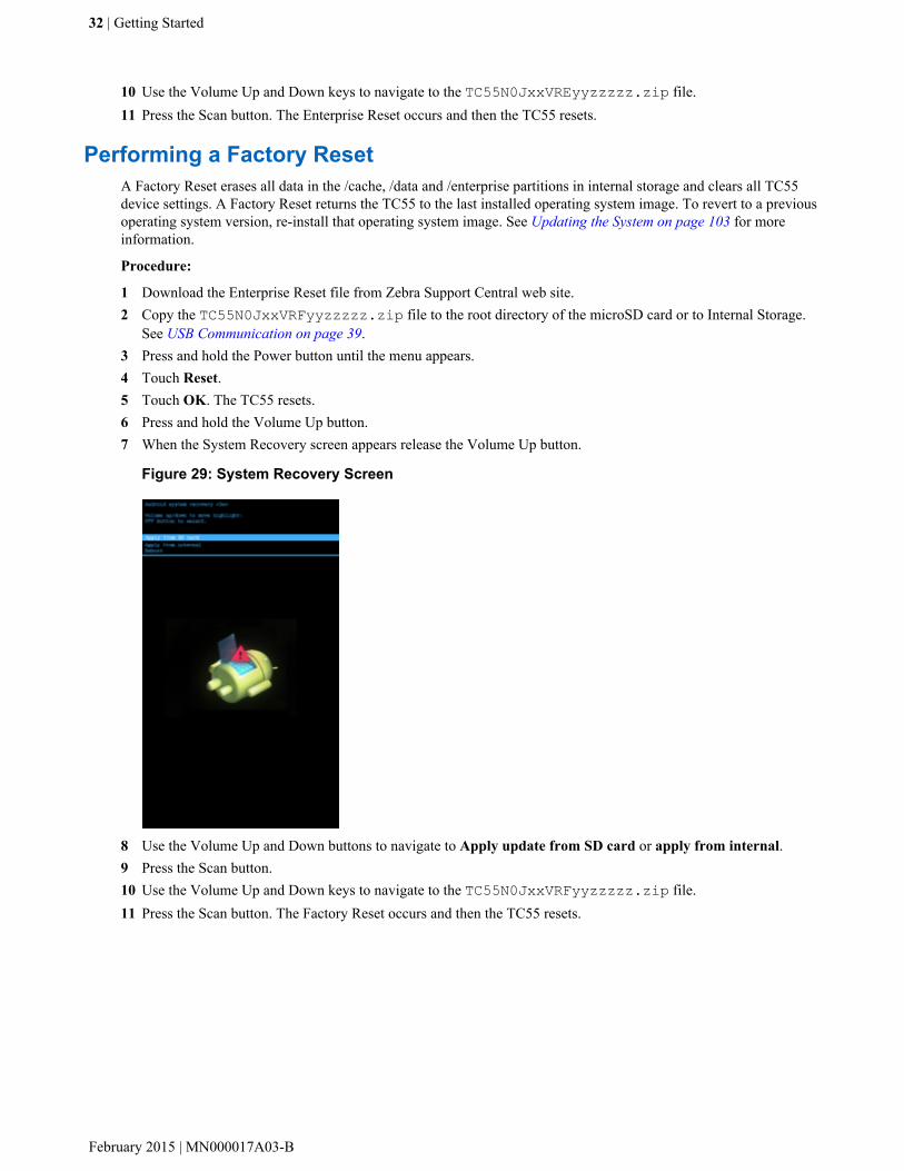
Communication on page 39.3 Press and hold the Power button until the Device options menu appears.4 Touch Reset.5 Touch OK. The TC55 resets.6 Press and hold the Volume Up button.7 When the System Recovery screen appears release the Volume Up button.
Figure 28: System Recovery Screen
8 Use the Volume Up and Down buttons to navigate to Apply update from SD card or apply from internal.9 Press the Scan button.
Getting Started | 31
MN000017A03-B | February 2015
10 Use the Volume Up and Down keys to navigate to the TC55N0JxxVREyyzzzzz.zip file.11 Press the Scan button. The Enterprise Reset occurs and then the TC55 resets.
Performing a Factory ResetA Factory Reset erases all data in the /cache, /data and /enterprise partitions in internal storage and clears all TC55device settings. A Factory Reset returns the TC55 to the last installed operating system image. To revert to a previousoperating system version, re-install that operating system image. See Updating the System on page 103 for moreinformation.
Procedure:
1 Download the Enterprise Reset file from Zebra Support Central web site.2 Copy the TC55N0JxxVRFyyzzzzz.zip file to the root directory of the microSD card or to Internal Storage.
See USB Communication on page 39.3 Press and hold the Power button until the menu appears.4 Touch Reset.5 Touch OK. The TC55 resets.6 Press and hold the Volume Up button.7 When the System Recovery screen appears release the Volume Up button.
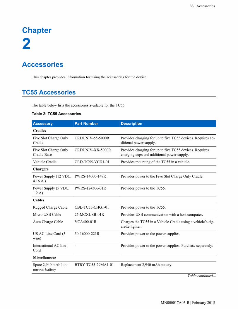
Figure 29: System Recovery Screen
8 Use the Volume Up and Down buttons to navigate to Apply update from SD card or apply from internal.9 Press the Scan button.10 Use the Volume Up and Down keys to navigate to the TC55N0JxxVRFyyzzzzz.zip file.11 Press the Scan button. The Factory Reset occurs and then the TC55 resets.
32 | Getting Started
February 2015 | MN000017A03-B
Chapter
2Accessories
This chapter provides information for using the accessories for the device.
TC55 Accessories
The table below lists the accessories available for the TC55.
Table 2: TC55 Accessories
Accessory Part Number Description
Cradles
Five Slot Charge OnlyCradle
CRDUNIV-55-5000R Provides charging for up to five TC55 devices. Requires ad-ditional power supply.
Five Slot Charge OnlyCradle Base
CRDUNIV-XX-5000R Provides charging for up to five TC55 devices. Requirescharging cups and additional power supply.
Vehicle Cradle CRD-TC55-VCD1-01 Provides mounting of the TC55 in a vehicle.
Chargers
Power Supply (12 VDC,4.16 A.)
PWRS-14000-148R Provides power to the Five Slot Charge Only Cradle.
Power Supply (5 VDC,1.2 A)
PWRS-124306-01R Provides power to the TC55.
Cables
Rugged Charge Cable CBL-TC55-CHG1-01 Provides power to the TC55.
Micro USB Cable 25-MCXUSB-01R Provides USB communication with a host computer.
Auto Charge Cable VCA400-01R Charges the TC55 in a Vehicle Cradle using a vehicle’s cig-arette lighter.
US AC Line Cord (3-wire)
50-16000-221R Provides power to the power supplies.
International AC lineCord
- Provides power to the power supplies. Purchase separately.
Miscellaneous
Spare 2,940 mAh lithi-um-ion battery
BTRY-TC55-29MA1-01 Replacement 2,940 mAh battery.
Table continued…
33 | Accessories
MN000017A03-B | February 2015

Accessory Part Number Description
Spare 4,410 mAh lithi-um-ion battery
BTRY-TC55-44MA1-01 Replacement 4,410 mAh battery.
2,940 mAh Battery Cov-er
KT-TC55-29BTYD1-01 Replacement battery cover for 2,940 mAh battery.
4,410 mAh Battery Cov-er
KT-TC55-44BTYD1-01 Replacement battery cover for 4,410 mAh battery.
Charging Cup CUPTC55XX-1000R Mounts onto the Multi Slot Charge Only Cradle Base andprovides TC55 charging slot.
Blank Slot Cover CUPUNICVR-5000R Mounts on the Five Slot Charge Only Cradle and covers aslot when a cup is not required (5-pack).
Protective Boot (Blue/Black)
SG-TC55-BOOT1-01 Provides additional protection for the TC55.
Protective Boot (Grey/Black)
SG-TC55-BOOT2-01 Provides additional protection for the TC55.
Stylus for ProtectiveBoot
KT-TC55-STYLUS1-01
KT-TC55–STYLUS1–03
Single stylus for Protective Boot with tether.
Stylus for Protective Boot with tether (3–pack).
Handstrap SG-TC55-HSTRPH-01 Attached to Protective boot.
Holster SG-TC55-HLSTR1-01 Mounts on belt and provides storage for the TC55.
Five Slot Charge Only Cradle
The Five Slot Charge Only cradle:
• Provides 5 VDC power for operating the TC55.• Simultaneously charges up to five TC55s.• Contains five removal cups.
Charging the TC55To charge the TC55, insert the TC55 into an open slot.
Figure 30: Five Slot Charge Only Cradle
34 | Accessories
February 2015 | MN000017A03-B

Power SetupFigure 31: Five Slot Charge Only Cradle Power Connections
Inserting a TC55 with Boot into CradleEach cradle cup has an insert that must be removed prior to inserting the TC55 with Protective Boot. Remove theinsert and then insert the TC55 into the cup.
Figure 32: Remove Cup Insert
Installing a CupCups on the Five Slot Charge Only Cradle can be removed and replaced with new cups or blank cups. To install thecradle cups:
Procedure:
1 Remove power from the cradle base before installing cups.2 Using a Phillips screwdriver, remove the two screws securing the cup to the base.3 Lift the front of the cup and then slide off the back of the base.4 Align the lip of the cup with the slot on the front of the cradle. Ensure that the cup is positioned within the Slot
Alignment Tabs.
Accessories | 35
MN000017A03-B | February 2015

Figure 33: Five Slot Charge Only Cradle Cup Installation
5 Slide the lip into the slot and rotate the cup until it is flat on the cradle base.6 Using a Phillips screwdriver, secure the cup to the charger base using the two screws provided with the cup.
Figure 34: Securing Cup to Base
36 | Accessories
February 2015 | MN000017A03-B

7 Each slot on the Cradle Base must have a cup installed.8 Repeat for each additional cup.
Handstrap Installation
The optional handstrap can be installed onto the optional protective boot for ease of holding the device.
Procedure:
1 If closed, lift ends of handstrap and extend away from main section.2 Insert the handstrap top end (near stylus holder) into the top opening of the boot and under the bottom cross-beam.
Figure 35: Insert Handstrap onto Boot
3 Fold the end to the center and press down on the hook and loop material.4 Turn the boot over.5 Insert the TC55 top first into the boot.
Figure 36: Insert Top of Device into Boot
6 Press bottom of TC55 into bottom.
Accessories | 37
MN000017A03-B | February 2015
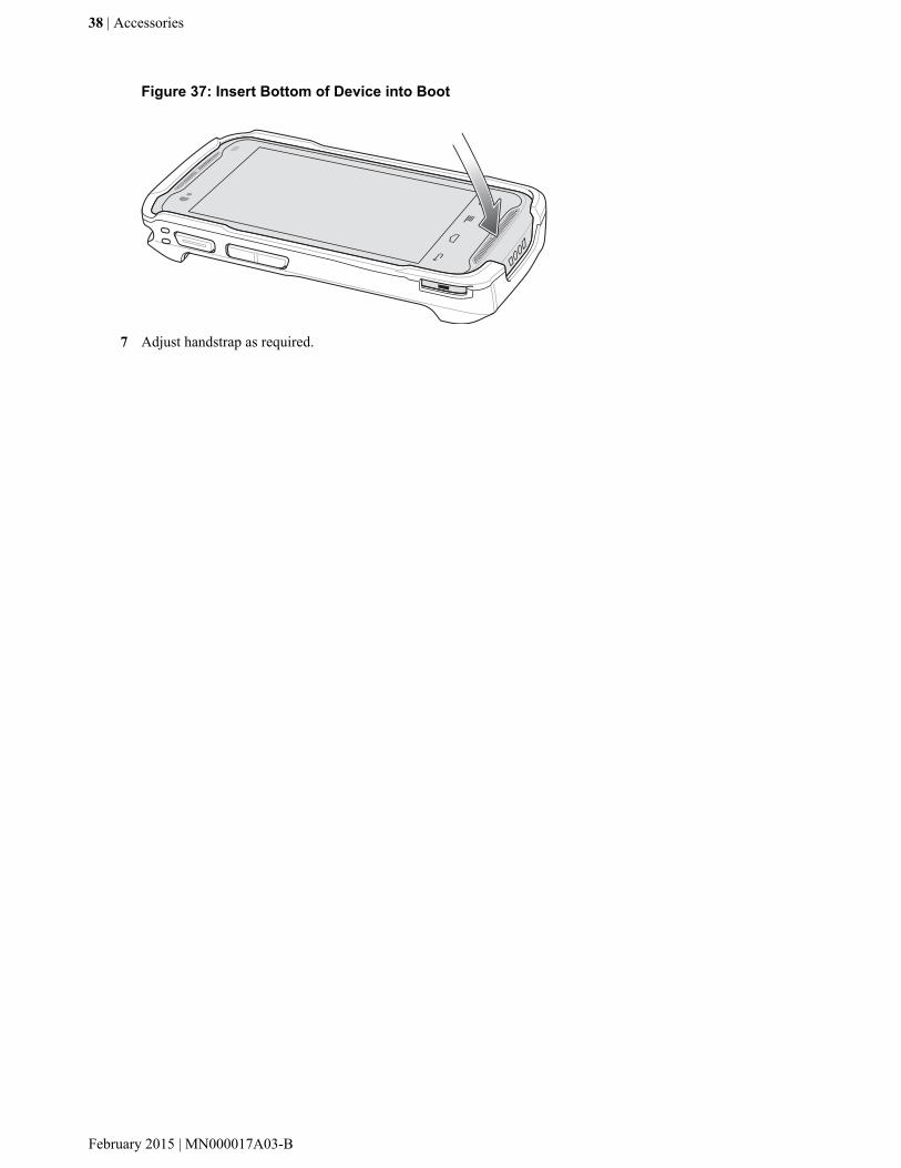
Figure 37: Insert Bottom of Device into Boot
7 Adjust handstrap as required.
38 | Accessories
February 2015 | MN000017A03-B
Chapter
3USB Communication
This chapter provides information for transferring files between the device and a host computer.
Connecting to a Host Computer via USB
Connect the TC55 to a host computer using the micro USB cable to transfer files between the TC55 and the hostcomputer.
Caution:
When connecting the TC55 to a host computer, follow the host computer’s instructions for connecting anddisconnecting USB devices, to avoid damaging or corrupting files.
Connecting to the TC55 as a Media DeviceProcedure:
1 Connect the micro USB cable to the TC55 and then to the host computer.Connected as a media device or Connected as an installer appears on the Status bar.
2 If Connected as an installer appears, pull down the Notification shade and touch Connected as an installer andthen touch Media device (MTP).
3 On the host computer, open a file explorer application.
4 Locate the TC55 as a portable device.If an external microSD card is installed, it displays as SD card. The internal memory appears as InternalStorage.
5 Open either SD card or Internal Storage.6 Copy or delete files as required.
Connecting to the TC55 as an InstallerProcedure:
1 Connect the micro USB cable to the TC55 and then to the host computer.Connected as a media device or Connected as an installer appears on the Status bar.
2 If Connected as media device appears, pull down the Notification shade and touch Connected as media deviceand then touch Media device (MTP) to de-select.
3 On the host computer, open a file explorer application.The TC55 storage appears as Removable Disks.
4 On the TC55, pull down the Notification shade and touch USB Connected.5 On the USB mass storage screen, touch Turn on USB storage.
39 | USB Communication
MN000017A03-B | February 2015

On the host computer, the TC55 Internal Storage appears as INTERNAL and the microSD card appears asRemovable Disk.
6 Locate the TC55 as a devices within Removable Storage.7 Open either INTERNAL or Removable Disk.8 Copy or delete files as required.9 Touch Turn off USB storage
Disconnect from the Host Computer
Caution:
Carefully follow the host computer’s instructions to unmount the microSD card and disconnect USBdevices correctly to avoid losing information.
Procedure:
1 On the host computer, unmount the microSD card.2 Remove the micro USB cable from the TC55.
40 | USB Communication
February 2015 | MN000017A03-B
Chapter
4DataWedge Configuration
DataWedge is an application that reads data, processes the data and sends the data to an application.
Basic Scanning
Scanning can be performed using either the linear imager or the rear-facing camera.
Using the CameraTo capture bar code data:
Procedure:
1 Ensure that an application is open on the TC55 and a text field is in focus (text cursor in text field).2 Aim the rear-facing camera at a bar code.3 Press and hold the Programmable button. By default, a preview window appears on the screen. The LED light red
to indicate that data capture is in process.
41 | DataWedge Configuration
MN000017A03-B | February 2015
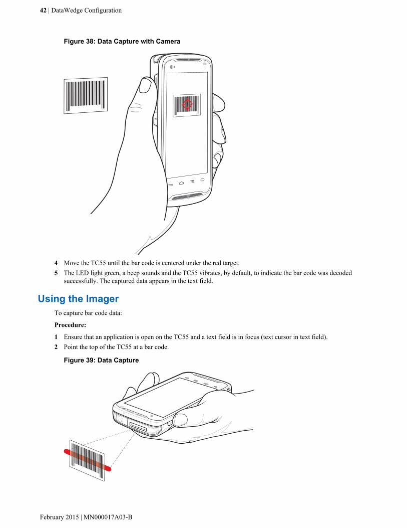
Figure 38: Data Capture with Camera
4 Move the TC55 until the bar code is centered under the red target.5 The LED light green, a beep sounds and the TC55 vibrates, by default, to indicate the bar code was decoded
successfully. The captured data appears in the text field.
Using the ImagerTo capture bar code data:
Procedure:
1 Ensure that an application is open on the TC55 and a text field is in focus (text cursor in text field).2 Point the top of the TC55 at a bar code.
Figure 39: Data Capture
42 | DataWedge Configuration
February 2015 | MN000017A03-B

3 Press and hold the Programmable button. The LED lights red to indicate that data capture is in process.4 Place the red aiming pattern across the bar code. The LED lights green and a beep sounds, by default, to indicate
the bar code was decoded successfully.5 The captured data appears in the text field.
Profiles
DataWedge is based on profiles and plug-ins. A profile contains information on how DataWedge should behave withdifferent applications.
Profile information consists of:
• Associated application• Input plug-in configurations• Output plug-in configurations• Process plug-in configurations.
Using profiles, each application can have a specific DataWedge configuration. For example, each user application canhave a profile which outputs scanned data in the required format when that application comes to the foreground.DataWedge can be configured to process the same set of captured data differently based on the requirements of eachapplication.
DataWedge includes the following visible and hidden pre-configured profiles which support specific built-inapplications:
• Visible profiles:
- Profile0 - created automatically the first time DataWedge runs. Generic profile used when there are no usercreated profiles associated with an application.
- Launcher - disables scanning when the Launcher is in foreground.- DWDemo - provides support for the DWDemo application.
• Hidden profiles (not shown to the device):
- RD Client - provides support for MSP.- MSP Agent - provides support for MSP.- MspUserAttribute - provides support for MSP.- Camera - disables scanning when the default camera application is in foreground.- RhoElements - disables scanning when RhoElements is in foreground.
Profile0Profile0 can be edited but cannot be associated with an application. That is, DataWedge allows manipulation ofplug-in settings for Profile0 but it does not allow assignment of a foreground application. This configuration allowsDataWedge to send output data to any foreground application other than applications associated with user-definedprofiles when Profile0 is enabled.
Profile0 can be disabled to allow DataWedge to only send output data to those applications which are associated inuser-defined profiles. For example, create a profile associating a specific application, disable Profile0 and then scan.DataWedge only sends data to the application specified in the user-created profile. This adds additional security toDataWedge enabling the sending of data only to specified applications.
Plug-ins
A plug-in is a software module utilized in DataWedge to extend its functionality to encompass technologies such asbar code scanning. The plug-ins can be categorized into three types based on their operations:
DataWedge Configuration | 43
MN000017A03-B | February 2015

• Input Plug-ins• Output Plug-ins• Process Plug-ins.
Input Plug-insAn Input Plug-in supports an input device, such as a bar code scanner contained in, or attached to the device.DataWedge contains base plug-ins for these input devices.
• Bar Code Scanner Input Plug-in – The Bar Code Scanner Input Plug-in is responsible for reading data from theintegrated bar code scanner and supports different types of bar code readers including laser, imager and internalcamera. Raw data read from the bar code scanner can be processed or formatted using Process Plug-ins asrequired. DataWedge has built-in feedback functionality for the bar code scanner to issue user alerts. Thefeedback settings can be configured according to user requirement.
Process Plug-insProcess Plug-ins are used in DataWedge to manipulate the received data according to the requirement, beforesending to the foreground application via the Output Plug-in.
• Basic Data Formatting Process Plug-in – The Basic Data Formatting Plug-in allows DataWedge to add a prefixand/or a suffix to the captured data before passing it to an Output Plug-in.
• Advanced Data Formatting Process Plug-in – The Advanced Data Formatting Plug-in allows DataWedge toapply rules (actions to be performed based on defined criteria) to the data received via an input plug-in beforepassing it to an Output Plug-in.
Output Plug-insOutput Plug-ins are responsible for sending the data from Input Plug-ins to a foreground application on the device.
• Keystroke Output Plug-in – The Keystroke Output Plug-in collects and sends data received from the Input Plug-in to the foreground applications by emulating keystrokes.
• Intent Output Plug-in – The Intent Output Plug-in collects and sends data received from the Input Plug-ins toforeground applications using the Android Intent mechanism.
• IP Output Plug-in – The IP Output Plug-in collects and sends data received from the Input Plug-ins to a hostcomputer via a network connection. Captured data can be sent over an IP network to a specified IP address andport using either TCP or UDP transport protocols.
Profiles Screen
To launch DataWedge, touch > DataWedge. By default, three profiles appear:
• Profile0• Launcher• DWDemo.
Profile0 is the default profile and is used when no other profile can be applied.
44 | DataWedge Configuration
February 2015 | MN000017A03-B

Figure 40: DataWedge Profiles Screen
Profile names are color coded. Enabled profiles are white and disabled profiles are gray.
To configure a profile touch the profile name.
Profile Context MenuTouch and hold a profile to open a context menu that allows additional actions to be performed on the selectedprofile.
Figure 41: Profile Context Menu
The profile context menu allows the profile to be edited (same as just tapping on a profile), renamed or deleted.
Options MenuTouch to open the options menu.
DataWedge Configuration | 45
MN000017A03-B | February 2015

Figure 42: DataWedge Options Menu
The menu provides options to create a new profiles, access to general DataWedge settings and DataWedge versioninformation.
Disabling DataWedgeProcedure:
1 Touch .2
Touch .3 Touch .4 Touch Settings.5 Touch DataWedge enabled.
The blue check disappears from the checkbox indicating that DataWedge is disabled.
Creating a New Profile
Procedure:
1 Touch .2
Touch .3 Touch .4 Touch New profile.5 In the New profile dialog box, enter a name for the new profile. It is recommended that profile names be unique
and made up of only alpha-numeric characters (A-Z, a-z, 0-9).
46 | DataWedge Configuration
February 2015 | MN000017A03-B

Figure 43: New Profile Name Dialog Box
6 Touch OK.The new profile name appears in the DataWedge profile screen.
Profile Configuration
To configure the Profile0 or a user-created profile, touch the profile name.
Figure 44: Profile Configuration Screen
The configuration screen lists the following sections:
• Profile enabled• Applications• Barcode Input• Keystroke output• Intent Output• IP Output.
Bar Code InputUse the Bar Code Input options to configure the Bar Code Scanner Input Plug-in for the profile.
EnabledEnables or disables this plug-in. A check in the checkbox indicates that the plug-in is enabled.
DataWedge Configuration | 47
MN000017A03-B | February 2015
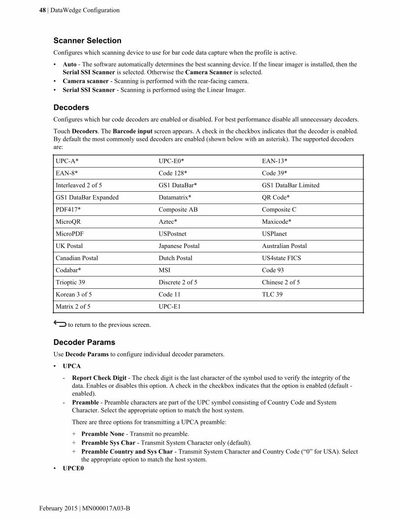
Scanner SelectionConfigures which scanning device to use for bar code data capture when the profile is active.
• Auto - The software automatically determines the best scanning device. If the linear imager is installed, then theSerial SSI Scanner is selected. Otherwise the Camera Scanner is selected.
• Camera scanner - Scanning is performed with the rear-facing camera.• Serial SSI Scanner - Scanning is performed using the Linear Imager.
DecodersConfigures which bar code decoders are enabled or disabled. For best performance disable all unnecessary decoders.
Touch Decoders. The Barcode input screen appears. A check in the checkbox indicates that the decoder is enabled.By default the most commonly used decoders are enabled (shown below with an asterisk). The supported decodersare:
UPC-A* UPC-E0* EAN-13*
EAN-8* Code 128* Code 39*
Interleaved 2 of 5 GS1 DataBar* GS1 DataBar Limited
GS1 DataBar Expanded Datamatrix* QR Code*
PDF417* Composite AB Composite C
MicroQR Aztec* Maxicode*
MicroPDF USPostnet USPlanet
UK Postal Japanese Postal Australian Postal
Canadian Postal Dutch Postal US4state FICS
Codabar* MSI Code 93
Trioptic 39 Discrete 2 of 5 Chinese 2 of 5
Korean 3 of 5 Code 11 TLC 39
Matrix 2 of 5 UPC-E1
to return to the previous screen.
Decoder ParamsUse Decode Params to configure individual decoder parameters.
• UPCA
- Report Check Digit - The check digit is the last character of the symbol used to verify the integrity of thedata. Enables or disables this option. A check in the checkbox indicates that the option is enabled (default -enabled).
- Preamble - Preamble characters are part of the UPC symbol consisting of Country Code and SystemCharacter. Select the appropriate option to match the host system.
There are three options for transmitting a UPCA preamble:
+ Preamble None - Transmit no preamble.+ Preamble Sys Char - Transmit System Character only (default).+ Preamble Country and Sys Char - Transmit System Character and Country Code (“0” for USA). Select
the appropriate option to match the host system.• UPCE0
48 | DataWedge Configuration
February 2015 | MN000017A03-B
- Report Check Digit - The check digit is the last character of the symbol used to verify the integrity of thedata. Enables or disables this option. A check in the checkbox indicates that the option is enabled (default -disabled).
- Preamble - Preamble characters are part of the UPC symbol consisting of Country Code and SystemCharacter. Select the appropriate option to match the host system.
There are three options for transmitting a UPCE0 preamble:
+ Preamble Sys Char - Transmit System Character only.+ Preamble Country and Sys Char - Transmit System Character and Country Code (“0” for USA).+ Preamble None - Transmit no preamble (default).
- Convert UPCE0 To UPCA - Enable to convert UPCE0 (zero suppressed) decoded data to UPC-A formatbefore transmission. After conversion, the data follows UPC-A format and is affected by UPC-A programmingselections. Disable to transmit UPCE0 decoded data as UPCE0 data, without conversion (default - disabled).
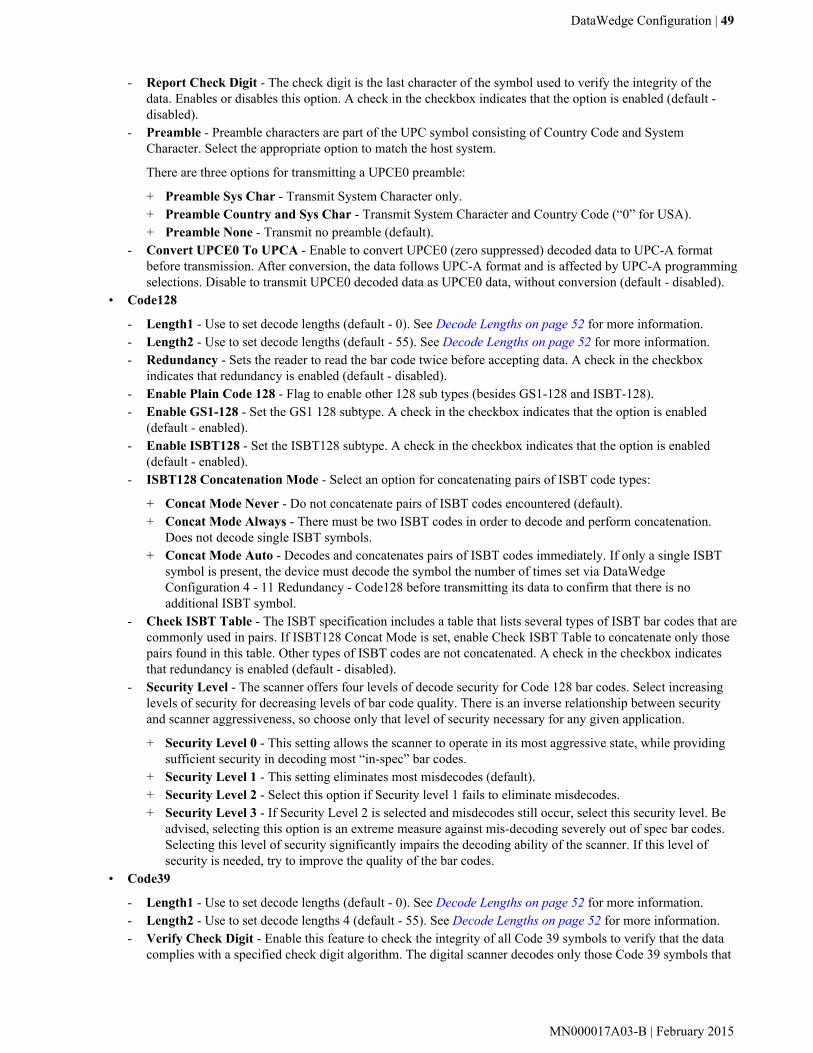
• Code128
- Length1 - Use to set decode lengths (default - 0). See Decode Lengths on page 52 for more information.- Length2 - Use to set decode lengths (default - 55). See Decode Lengths on page 52 for more information.- Redundancy - Sets the reader to read the bar code twice before accepting data. A check in the checkbox
indicates that redundancy is enabled (default - disabled).- Enable Plain Code 128 - Flag to enable other 128 sub types (besides GS1-128 and ISBT-128).- Enable GS1-128 - Set the GS1 128 subtype. A check in the checkbox indicates that the option is enabled
(default - enabled).- Enable ISBT128 - Set the ISBT128 subtype. A check in the checkbox indicates that the option is enabled
(default - enabled).- ISBT128 Concatenation Mode - Select an option for concatenating pairs of ISBT code types:
+ Concat Mode Never - Do not concatenate pairs of ISBT codes encountered (default).+ Concat Mode Always - There must be two ISBT codes in order to decode and perform concatenation.
Does not decode single ISBT symbols.+ Concat Mode Auto - Decodes and concatenates pairs of ISBT codes immediately. If only a single ISBT
symbol is present, the device must decode the symbol the number of times set via DataWedgeConfiguration 4 - 11 Redundancy - Code128 before transmitting its data to confirm that there is noadditional ISBT symbol.
- Check ISBT Table - The ISBT specification includes a table that lists several types of ISBT bar codes that arecommonly used in pairs. If ISBT128 Concat Mode is set, enable Check ISBT Table to concatenate only thosepairs found in this table. Other types of ISBT codes are not concatenated. A check in the checkbox indicatesthat redundancy is enabled (default - disabled).
- Security Level - The scanner offers four levels of decode security for Code 128 bar codes. Select increasinglevels of security for decreasing levels of bar code quality. There is an inverse relationship between securityand scanner aggressiveness, so choose only that level of security necessary for any given application.
+ Security Level 0 - This setting allows the scanner to operate in its most aggressive state, while providingsufficient security in decoding most “in-spec” bar codes.
+ Security Level 1 - This setting eliminates most misdecodes (default).+ Security Level 2 - Select this option if Security level 1 fails to eliminate misdecodes.+ Security Level 3 - If Security Level 2 is selected and misdecodes still occur, select this security level. Be
advised, selecting this option is an extreme measure against mis-decoding severely out of spec bar codes.Selecting this level of security significantly impairs the decoding ability of the scanner. If this level ofsecurity is needed, try to improve the quality of the bar codes.
• Code39
- Length1 - Use to set decode lengths (default - 0). See Decode Lengths on page 52 for more information.- Length2 - Use to set decode lengths 4 (default - 55). See Decode Lengths on page 52 for more information.- Verify Check Digit - Enable this feature to check the integrity of all Code 39 symbols to verify that the data
complies with a specified check digit algorithm. The digital scanner decodes only those Code 39 symbols that
DataWedge Configuration | 49
MN000017A03-B | February 2015

include a modulo 43 check digit. Enable this feature only if the Code 39 symbols contain a modulo 43 checkdigit (default - disabled).
- Report Check Digit - Transmit Code 39 data with or without the check digit. A check in the checkboxindicates to send Code 39 data with check digit (default - disabled).
- Full ASCII - Code 39 Full ASCII is a variant of Code 39 that pairs characters to encode the full ASCIIcharacter set. To enable or disable Code 39 Full ASCII (default - disabled),
- Redundancy - Sets the reader to read the bar code twice before accepting data. A check in the checkboxindicates that redundancy is enabled (default - disabled).
- Convert Code39 To Code32 - Code 32 is a variant of Code 39 used by the Italian pharmaceutical industry.Scan the appropriate bar code below to enable or disable converting Code 39 to Code 32 (default - disabled).
- Report Code32 Prefix - Scan the appropriate bar code to enable or disable adding the prefix character “A” toall Code 32 bar codes (default - disabled).
- Security Level - Options: Security level 0, Security Level 1, Security Level 2 and Security Level 3 (default- Security level 1).
• Interleaved 2 of 5
- Length1 - Use to set decode lengths (default - 14). See Decode Lengths on page 52 for more information.- Length2 - Use to set decode lengths (default - 10). See Decode Lengths on page 52 for more information.- Redundancy - Sets the reader to read the bar code twice before accepting data. A check in the checkbox
indicates that redundancy is enabled (default - enabled).- Check Digit
+ No Check Digit - A check digit is not used. (default)+ USS Check Digit - Select to check the integrity of all Interleaved 2 of 5 symbols to verify the data
complies with either the Uniform Symbology Specification (USS) check digit algorithm.+ OPCC Check Digit - Select to check the integrity of all Interleaved 2 of 5 symbols to verify the data
complies with either the Optical Product Code Council (OPCC) check digit algorithm.- Report Check Digit - Transmit Interleaved 2 of 5 data with or without the check digit. A check in the
checkbox indicates to send Interleaved 2 of 5 data with check digit (default - disabled).- Convert ITF-14 To EAN13 - Convert 14-character Interleaved 2 of 5 bar codes to EAN-13, and transmit as
EAN-13. The Interleaved 2 of 5 bar code must be enabled and must have a leading zero and a valid EAN-13check digit. A check in the checkbox indicates that the option is enabled (default - disabled).
- I2of5 Security Level - Options: I2of5 Security level 0, I2of5 Security Level 1, I2of5 Security Level 2 andI2of5 Security Level 3 (default - I2of5 Security level 1).
• Composite AB
- UCC Link Mode
+ Link Flag ignored - 1D component is transmitted regardless of whether a 2D component is detected.+ Always Linked - 1D and the 2D components are transmitted. If 2D is not present, the 1D component is not
transmitted.+ Auto Discriminate - the digital scanner determines if there is a 2D portion, then transmits the 1D
component, as well as the 2D portion if present. (default).• UK Postal
- Report Check Digit - Transmit UK Postal data with or without the check digit. A check in the checkboxindicates to send UK Postal data with check digit (default - disabled).
• Codabar
- Length1 - Use to set decode lengths (default - 6). See Decode Lengths on page 52 for more information.- Length2 - Use to set decode lengths (default - 55). See Decode Lengths on page 52 for more information.- Redundancy - Sets the reader to read the bar code twice before accepting data. A check in the checkbox
indicates that redundancy is enabled (default - enabled).- CLSI Editing - Enable this parameter to strip the start and stop characters and insert a space after the first,
fifth, and tenth characters of a 14-character Codabar symbol. Enable this feature if the host system requires thisdata format (default - disabled).
50 | DataWedge Configuration
February 2015 | MN000017A03-B

- NOTIS Editing - Enable this parameter to strip the start and stop characters from a decoded Codabar symbol.Enable this feature if the host system requires this data format (default - disabled).
• MSI
- Length 1 - Use to set decode lengths (default - 4). See Decode Lengths on page 52 for more information.- Length 2 - Use to set decode lengths (default - 55). See Decode Lengths on page 52 for more information.- Redundancy - Sets the reader to read the bar code twice before accepting data. A check in the checkbox
indicates that redundancy is enabled (default - enabled).- Check Digit - With MSI symbols, one check digit is mandatory and always verified by the reader. The second
check digit is optional.
+ One Check Digit - Verify one check digit (default).+ Two Check Digits - Verify two check digits.
- Check Digit Scheme - Two algorithms are possible for the verification of the second MSI check digit. Selectthe algorithm used to encode the check digit.
+ Mod-11-10 - First check digit is MOD 11 and second check digit is MOD 10 (default).+ Mod-10-10 - Both check digits are MOD 10.
- Report Check Digit - Transmit MSI data with or without the check digit. A check in the checkbox indicates tosend MSI data with check digit (default - disabled).
• Code93
- Length1 - Use to set decode lengths (default - 0). See Decode Lengths on page 52 for more information.- Length2 - Use to set decode lengths (default - 55). See Decode Lengths on page 52 for more information.- Redundancy - Sets the reader to read the bar code twice before accepting data. A check in the checkbox
indicates that redundancy is enabled (default - disabled).• Discrete 2 of 5
- Length1 - Use to set decode lengths (default - 0). See Decode Lengths on page 52 for more information.- Length2 - Use to set decode lengths (default - 14). See Decode Lengths on page 52 for more information.- Redundancy - Sets the reader to read the bar code twice before accepting data. A check in the checkbox
indicates that redundancy is enabled (default - enabled).• Code 11
- Length1 - Use to set decode lengths (default - 4). See Decode Lengths on page 52 for more information.- Length2 - Use to set decode lengths (default - 55). See Decode Lengths on page 52 for more information.- Redundancy - Sets the reader to read the bar code twice before accepting data. A check in the checkbox
indicates that redundancy is enabled (default - enabled).- Verify Check Digit - Check the integrity of all Code 11 symbols to verify that the data complies with the
specified check digit algorithm. This selects the check digit mechanism for the decoded Code 11 bar code.
+ No Check Digit - Do not verify check digit.+ 1 Check Digit - Bar code contains one check digit (default).+ 2 Check Digits - Bar code contains two check digits.
- Report Check Digit - Transmit Code 11 data with or without the check digit. A check in the checkboxindicates to send Code 11 data with check digit (default - disabled).
• Matrix 2 of 5
- Length1 - Use to set decode lengths (default - 10). See Decode Lengths on page 52 for more information.- Length2 - Use to set decode lengths (default - 0). See Decode Lengths on page 52 for more information.- Redundancy - Sets the reader to read the bar code twice before accepting data. A check in the checkbox
indicates that redundancy is enabled (default - disabled).- Report Check Digit - Transmit Matrix 2 of 5 data with or without the check digit. A check in the checkbox
indicates to send Matrix 2 of 5 data with check digit (default - enabled).- Verify Check Digit - Enable this feature to check the integrity of all Matrix 2 of 5 symbols to verify that the
data complies with a specified check digit algorithm (default - enabled).• UPCE1
DataWedge Configuration | 51
MN000017A03-B | February 2015

- Report Check Digit - The check digit is the last character of the symbol used to verify the integrity of thedata. Enables or disables this option. A check in the checkbox indicates that the option is enabled (default -disabled).
- Preamble - Preamble characters are part of the UPC symbol consisting of Country Code and SystemCharacter. Select the appropriate option to match the host system.
There are three options for transmitting a UPCE1 preamble:
+ Preamble Sys Char - Transmit System Character only.+ Preamble Country and Sys Char - Transmit System Character and Country Code (“0” for USA).+ Preamble None - Transmit no preamble (default).
- Convert UPCE1 To UPCA - Enable this to convert UPCE1 decoded data to UPC-A format beforetransmission. After conversion, the data follows UPC-A format and is affected by UPC-A programmingselections. Disable this to transmit UPCE1 decoded data as UPCE1 data, without conversion (default -disabled).
Decode LengthsThe allowable decode lengths are specified by options Length1 and Length2 as follows:
• Variable length: Decode symbols containing any number of characters.
- Set both Length1 and Length2 to 0.• Range: Decode a symbol with a specific length range (from a to b, including a and b).
- Set Length1 to a and set Length2 to b.• Two Discrete Lengths: Decode only symbols containing either of two selected lengths.
- Set both Length1 or Length2 to the specific lengths. Length1 must be greater than Length2.• One Discrete Length: Decode only symbols containing a specific length.
- Set both Length1 and Length2 to the specific length.
UPC EAN ParamsAllows the configuration of the parameters that apply to more than one UPC or EAN decoder.
• Security Level - The scanner offers four levels of decode security for UPC/EAN bar codes. Select higher securitylevels for lower quality bar codes. There is an inverse relationship between security and decode speed, so be sureto choose only that level of security necessary for the application.
- Level 0 - This default setting allows the scanner to operate fastest, while providing sufficient security indecoding “in-spec” UPC/EAN bar codes (default).
- Level 1 - As bar code quality levels diminish, certain characters become prone to misdecodes before others(i.e., 1, 2, 7, 8). If the scanner is misdecoding poorly printed bar codes, and the misdecodes are limited to thesecharacters, select this security level.
- Level 2 - If the scanner is misdecoding poorly printed bar codes, and the misdecodes are not limited tocharacters 1, 2, 7, and 8, select this security level.
- Level 3 - If the scanner is still misdecoding, select this security level. Be advised, selecting this option is anextreme measure against misdecoding severely out of spec bar codes. Selecting this level of security cansignificantly impair the decoding ability of the scanner. If this level of security is necessary, try to improve thequality of the bar codes.
• Supplemental2 - Enables or disables this option. A check in the checkbox indicates that the option is enabled.• Supplemental5 - Enables or disables this option. A check in the checkbox indicates that the option is enabled.• Supplemental Mode
- No Supplementals - the scanner is presented with a UPC/EAN plus supplemental symbol, the scannerdecodes UPC/EAN and ignores the supplemental characters (default).
- Supplemental Always - the scanner only decodes UPC/EAN symbols with supplemental characters, andignores symbols without supplementals.
52 | DataWedge Configuration
February 2015 | MN000017A03-B

- Supplements Auto - the scanner decodes UPC/EAN symbols with supplemental characters immediately. Ifthe symbol does not have a supplemental, the scanner must decode the bar code the number of times set viaUPC/EAN Supplemental Redundancy before transmitting its data to confirm that there is no supplemental.
- Supplemental Smart - Enables smart supplementals. In this mode the decoder returns the decoded value ofthe main block right away if it does not belong to one of the following supplemental types: 378, 379, 977, 978,979, 414, 419, 434 or 439. If the bar code starts with one of the prefixes it searches the image moreaggressively for a supplemental. Tries to scan the supplemental if it is present. If the supplemental scanningfailed, then the main bar code is returned.
- Supplemental 378-379 - Enables (auto-discriminate) supplemental for UPC/EAN codes starting with 378 or379. Disables reading of supplementals for any other UPC/EAN bar code not starting with 378 or 379. Tries toscan the supplemental if it is present. If the supplemental scanning failed, then the main bar code is returned.
- Supplemental 978-979 - Enables (auto-discriminate) supplemental for UPC/EAN codes starting with 978 or979. Disables reading of supplementals for another UPC/EAN bar code not starting with 978 or 979. Tries toscan the supplemental if it is present. If the supplemental scanning failed, then the main bar code is returned.
- Supplemental 414-419-434-439 - Enables (auto-discriminate) supplemental for UPC/EAN codes starting with414, 419, 434 or 439. Disables reading of supplementals for another UPC/EAN bar code 4 - 16 not startingwith 414, 419, 434 or 439. Tries to scan the supplemental if it is present. If the supplemental scanning failed,then the main bar code is returned.
- Supplemental 977 - Enables (auto-discriminate) supplemental for UPC/EAN codes starting with 977.Disables reading of supplementals for another UPC/EAN barcode not starting with 977. Tries to scan thesupplemental if it is present. If the supplemental scanning failed, then the main bar code is returned.
• Retry Count - Retry count for auto-discriminating for supplementals. Possible values are 2 to 20 inclusive. Notethat this flag is only considered if Supplemental Mode - UPC EAN is set to one of the following values:Supplementals Auto, Supplementals Smart, Supplementals 378-379, Supplementals 978-979, Supplementals977 or Supplementals 414-419-434-439 (2 to 20, default 10).
• Bookland - Enable Bookland decoding. A check in the checkbox indicates that the option is enabled.• Coupon - Enables Coupon code decoding. Note that in order to successfully decode Coupon codes, all of the
correct decoders must be enabled. A check in the checkbox indicates that the option is enabled.• Convert DataBar To UPC EAN - If this is set it converts DataBar bar codes to UPC/EAN format. For this
setting to work UPC/EAN symbologies must be enabled. A check in the checkbox indicates that the option isenabled.
Reader ParamsAllows the configuration of parameters specific to the selected bar code reader.
• Beam Timer - Sets the maximum amount of time that the reader remains on (0 - 60,000 ms in increments of 100ms). A value of 0 sets the reader to stay on indefinitely (default -15000).
• Power Mode - Set the linear imager power mode:
- Low Power Mode - Imager power is enabled only when scanning.- Optimized Power Mode - Imager power remains enabled after scanning and turns off after a timeout value.
(default)- High Power Mode - Imager power is enabled when scanning is enabled.- Always On - Imager power is enabled when the scanner object is opened.
• Linear Security Level - Sets the number of times a bar code is read to confirm an accurate decode.
- Security Short or Codabar - Two times read redundancy if short bar code or Codabar.- Security All Twice - Two times read redundancy for all bar codes (default).- Security Long and Short - Two times read redundancy for long bar codes, three times for short bar codes.- Security All Thrice - Three times read redundancy for all bar codes.
• Picklist - Allows the imager to decode only the bar code that is directly under the cross-hair/reticle (+) part of thepattern. This feature is useful in applications where multiple bar codes may appear in the field of view during adecode session and only one of them is targeted for decode.
- Disable – Disables Picklist mode. Any bar code within the field of view can be decoded (default).
DataWedge Configuration | 53
MN000017A03-B | February 2015
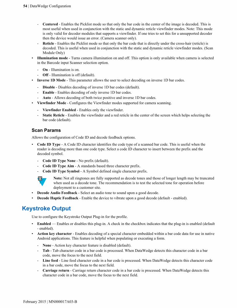
- Centered - Enables the Picklist mode so that only the bar code in the center of the image is decoded. This ismost useful when used in conjunction with the static and dynamic reticle viewfinder modes. Note: This modeis only valid for decoder modules that supports a viewfinder. If one tries to set this for a unsupported decoderthen the device would issue an error. (Camera scanner only).
- Reticle - Enables the Picklist mode so that only the bar code that is directly under the cross-hair (reticle) isdecoded. This is useful when used in conjunction with the static and dynamic reticle viewfinder modes. (ScanModule Only)
• Illumination mode - Turns camera illumination on and off. This option is only available when camera is selectedin the Barcode input Scanner selection option.
- On - Illumination is on.- Off - Illumination is off (default).
• Inverse 1D Mode - This parameter allows the user to select decoding on inverse 1D bar codes.
- Disable - Disables decoding of inverse 1D bar codes (default).- Enable - Enables decoding of only inverse 1D bar codes.- Auto - Allows decoding of both twice positive and inverse 1D bar codes.
• Viewfinder Mode - Configures the Viewfinder modes supported for camera scanning.
- Viewfinder Enabled - Enables only the viewfinder.- Static Reticle - Enables the viewfinder and a red reticle in the center of the screen which helps selecting the
bar code (default).
Scan ParamsAllows the configuration of Code ID and decode feedback options.
• Code ID Type - A Code ID character identifies the code type of a scanned bar code. This is useful when thereader is decoding more than one code type. Select a code ID character to insert between the prefix and thedecoded symbol.
- Code ID Type None - No prefix (default).- Code ID Type Aim - A standards based three character prefix.- Code ID Type Symbol - A Symbol defined single character prefix.
Note: Not all ringtones are fully supported as decode tones and those of longer length may be truncatedwhen used as a decode tone. The recommendation is to test the selected tone for operation beforedeployment to a customer site.
• Decode Audio Feedback - Select an audio tone to sound upon a good decode.• Decode Haptic Feedback - Enable the device to vibrate upon a good decode (default - enabled).
Keystroke OutputUse to configure the Keystroke Output Plug-in for the profile.
• Enabled — Enables or disables this plug-in. A check in the checkbox indicates that the plug-in is enabled (default- enabled).
• Action key character - Enables decoding of a special character embedded within a bar code data for use in nativeAndroid applications. This feature is helpful when populating or executing a form.
- None - Action key character feature is disabled (default).- Tab - Tab character code in a bar code is processed. When DataWedge detects this character code in a bar
code, move the focus to the next field.- Line feed - Line feed character code in a bar code is processed. When DataWedge detects this character code
in a bar code, move the focus to the next field.- Carriage return - Carriage return character code in a bar code is processed. When DataWedge detects this
character code in a bar code, move the focus to the next field.
54 | DataWedge Configuration
February 2015 | MN000017A03-B

• Advanced data formatting - is a way to customizing data before transmission. Use advanced data formatting(ADF) to edit scan data to suit requirements.
- Enable - Enables or disables ADF. A check in the checkbox indicates that ADF is enabled (default - disabled).- Rules - ADF uses rules to customize data. These rules perform detailed actions when the data meets certain
criteria. One rule may consist of single or multiple criteria applied to single or multiple actions. See Generating Advanced Data Formatting Rules on page 58 for more information.
• Basic data formatting - Allows the configuration of any data formatting for the related Output Plug-in. When theplug-in is disabled, any data is passed on without modification.
- Enabled - Enables or disables Basic Data Formatting. A check in the checkbox indicates that it is enabled(default - enabled).
- Prefix to data - Add characters to the beginning of the data when sent.- Suffix to data - Add characters to the end of the data when sent.- Send data - Set to transfer the captured data to the foreground application. Disabling this option prevents the
actual data from being transmitted. However, the prefix and suffix strings, if present, are still transmitted evenwhen this option is disabled (default - enabled).
- Send as hex - Set to send the data in hexadecimal format. A check in the checkbox indicates that the plug-in isenabled (default - disabled).
- Send TAB key - Set to append a tab character to the end of the processed data. A check in the checkboxindicates that the plug-in is enabled (default - disabled).
- Send ENTER key - Set to append an Enter character to the end of the processed data. A check in thecheckbox indicates that the plug-in is enabled (default - disabled).
Intent OutputAllows configuration of the Intent Output Plug-in for the profile. The Intent Output Plug-in allows the captured datato be sent to an application in the form of an implicit Intent. Refer to the Android Developer web site for moreinformation, http://developer.android.com.
• Enabled - Enables or disables this plug-in. A check in the checkbox indicates that the plug-in is enabled (default -disabled).
• Intent action - Enter the Intent Action name (required).• Intent category - Enter the Intent Category name (required).• Intent delivery - Select the method by which the intent is delivered:
- Send via StartActivity- Send via startService (default)- Broadcast intent
• Advanced data formatting - is a way to customizing data before transmission. Use advanced data formatting(ADF) to edit scan data to suit requirements.
- Enable - Enables or disables ADF. A check in the checkbox indicates that ADF is enabled (default - disabled).- Rules - ADF uses rules to customize data. These rules perform detailed actions when the data meets certain
criteria. One rule may consist of single or multiple criteria applied to single or multiple actions. See Generating Advanced Data Formatting Rules on page 58 for more information.
• Basic data formatting - Allows configuration of any data formatting for the related Output Plug-in. When theplug-in is disabled any data is passed on without modification.
- Enabled - Enables or disables Basic Data Formatting. A check in the checkbox indicates that it is enabled(default - enabled).
- Prefix to data - Add characters to the beginning of the data when sent.- Suffix to data - Add characters to the end of the data when sent.- Send data - Set to transfer the captured data to the foreground application. Disabling this option prevents the
actual data from being transmitted. However, the prefix and suffix strings, if present, are still transmitted evenwhen this option is disabled (default - enabled).
DataWedge Configuration | 55
MN000017A03-B | February 2015
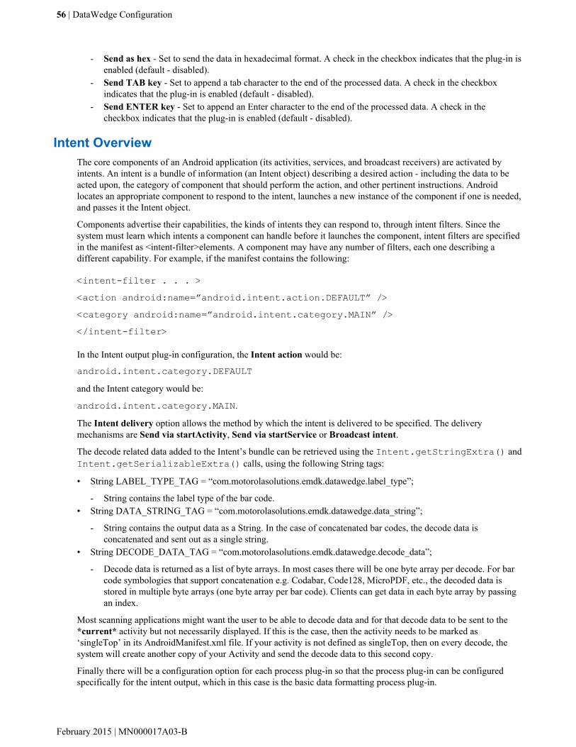
- Send as hex - Set to send the data in hexadecimal format. A check in the checkbox indicates that the plug-in isenabled (default - disabled).
- Send TAB key - Set to append a tab character to the end of the processed data. A check in the checkboxindicates that the plug-in is enabled (default - disabled).
- Send ENTER key - Set to append an Enter character to the end of the processed data. A check in thecheckbox indicates that the plug-in is enabled (default - disabled).
Intent OverviewThe core components of an Android application (its activities, services, and broadcast receivers) are activated byintents. An intent is a bundle of information (an Intent object) describing a desired action - including the data to beacted upon, the category of component that should perform the action, and other pertinent instructions. Androidlocates an appropriate component to respond to the intent, launches a new instance of the component if one is needed,and passes it the Intent object.
Components advertise their capabilities, the kinds of intents they can respond to, through intent filters. Since thesystem must learn which intents a component can handle before it launches the component, intent filters are specifiedin the manifest as <intent-filter>elements. A component may have any number of filters, each one describing adifferent capability. For example, if the manifest contains the following:
<intent-filter . . . ><action android:name=”android.intent.action.DEFAULT” /><category android:name=”android.intent.category.MAIN” /></intent-filter>
In the Intent output plug-in configuration, the Intent action would be:
android.intent.category.DEFAULTand the Intent category would be:
android.intent.category.MAIN.
The Intent delivery option allows the method by which the intent is delivered to be specified. The deliverymechanisms are Send via startActivity, Send via startService or Broadcast intent.
The decode related data added to the Intent’s bundle can be retrieved using the Intent.getStringExtra() andIntent.getSerializableExtra() calls, using the following String tags:
• String LABEL_TYPE_TAG = “com.motorolasolutions.emdk.datawedge.label_type”;
- String contains the label type of the bar code.• String DATA_STRING_TAG = “com.motorolasolutions.emdk.datawedge.data_string”;
- String contains the output data as a String. In the case of concatenated bar codes, the decode data isconcatenated and sent out as a single string.
• String DECODE_DATA_TAG = “com.motorolasolutions.emdk.datawedge.decode_data”;
- Decode data is returned as a list of byte arrays. In most cases there will be one byte array per decode. For barcode symbologies that support concatenation e.g. Codabar, Code128, MicroPDF, etc., the decoded data isstored in multiple byte arrays (one byte array per bar code). Clients can get data in each byte array by passingan index.
Most scanning applications might want the user to be able to decode data and for that decode data to be sent to the*current* activity but not necessarily displayed. If this is the case, then the activity needs to be marked as‘singleTop’ in its AndroidManifest.xml file. If your activity is not defined as singleTop, then on every decode, thesystem will create another copy of your Activity and send the decode data to this second copy.
Finally there will be a configuration option for each process plug-in so that the process plug-in can be configuredspecifically for the intent output, which in this case is the basic data formatting process plug-in.
56 | DataWedge Configuration
February 2015 | MN000017A03-B

IP OutputNote: IPWedge application is required on a host computer. Download the IPWedge application from theSupport Central web site: http://www.zebra.com/support.
IP Output allows DataWedge to send captured data to a host computer via a network connection. Captured data canbe sent over an IP network to a specified IP address and port using either TCP or UDP transport protocols.
• Enabled - Enables or disables this plug-in. A check in the checkbox indicates that the plug-in is enabled (default -disabled).
• Remote Wedge - Enable or disable the Remote Wedge option (default - enabled). Remote Wedge is used with theIPWedge application.
• Protocol - Select the protocol used by the remote application. Options: TCP (default) or UDP.• IP address - Enter the IP address used by the remote application (default - 0.0.0.0).• Port - Enter the port number used by the remote application (default - 58627).• Advanced data formatting - is a way of customizing data before transmission. Use advanced data formatting
(ADF) to edit scan data to suit requirements.
- Enable - Enables or disables ADF. A check in the checkbox indicates that ADF is enabled (default - disabled).- Rules - ADF uses rules to customize data. These rules perform detailed actions when the data meets certain
criteria. One rule may consist of single or multiple criteria applied to single or multiple actions. See Generating Advanced Data Formatting Rules on page 58 for more information.
• Basic data formatting - Allows configuration of any data formatting for the related Output Plug-in. When theplug-in is disabled any data is passed on without modification.
- Enabled - Enables or disables Basic Data Formatting. A check in the checkbox indicates that it is enabled(default - enabled).
- Prefix to data - Add characters to the beginning of the data when sent.- Suffix to data - Add characters to the end of the data when sent.- Send data - Set to transfer the captured data to the foreground application. Disabling this option prevents the
actual data from being transmitted. However, the prefix and suffix strings, if present, are still transmitted evenwhen this option is disabled (default - enabled).
- Send as hex - Set to send the data in hexadecimal format. A check in the checkbox indicates that the plug-in isenabled (default - disabled).
- Send TAB key - Set to append a tab character to the end of the processed data. A check in the checkboxindicates that the plug-in is enabled (default - disabled).
- Send ENTER key - Set to append an Enter character to the end of the processed data. A check in thecheckbox indicates that the plug-in is enabled (default - disabled).
UsageThis section provides information on how to configure IP Output using the DataWedge configuration user interface.To use IP Output in a particular DataWedge profile (for example: Profile0), scroll downward on IP Output.
DataWedge Configuration | 57
MN000017A03-B | February 2015

Figure 45: IP Output Screen
Generating Advanced Data Formatting Rules
The ADF plug-in applies rules (actions to be performed based on defined criteria) to the data received via an inputplug-in before sending it to the output plug-in.
• Rules - The ADF process plug-in consists of one or more rules. DataWedge formats the output data according tothe first matching rule. A rule is a combination of criteria and a set of actions to be performed, upon fulfillment ofthe criteria set in the rule.
• Criteria - Criteria can be set according to Input plug-in, symbology, matching string within the data (at thespecified position) and/or data length. Received data must match the defined criteria in order for the data to beprocessed.
• Actions - A set of procedures defined to format data. There are four types of actions which are for formattingcursor movement, data modification, data sending and delay specifications. An action can be defined to send thefirst number of characters to the Output plug-in, pad the output data with spaces or zeros, remove spaces in data,etc.
Configuring ADF Plug-inConfiguring the ADF plug-in consists of creating a rule, defining the criteria and defining the actions.
Procedure:
1 Touch .2
Touch .3 Touch a DataWedge profile.4 In Keystroke Output, touch Advanced data formatting.
58 | DataWedge Configuration
February 2015 | MN000017A03-B

Figure 46: Advanced Data Formatting Screen
5 Touch the Enable checkbox to enable ADF.
Creating a RuleNote: By default, Rule0, is the only rule in the Rules list.
Procedure:
1 Touch .2 Touch New rule.3 Touch the Enter rule name text box.4 In the text box, enter a name for the new rule.5 Touch Done.6 Touch OK.
Defining a RuleProcedure:
1 Touch the newly created rule in the Rules list.
DataWedge Configuration | 59
MN000017A03-B | February 2015
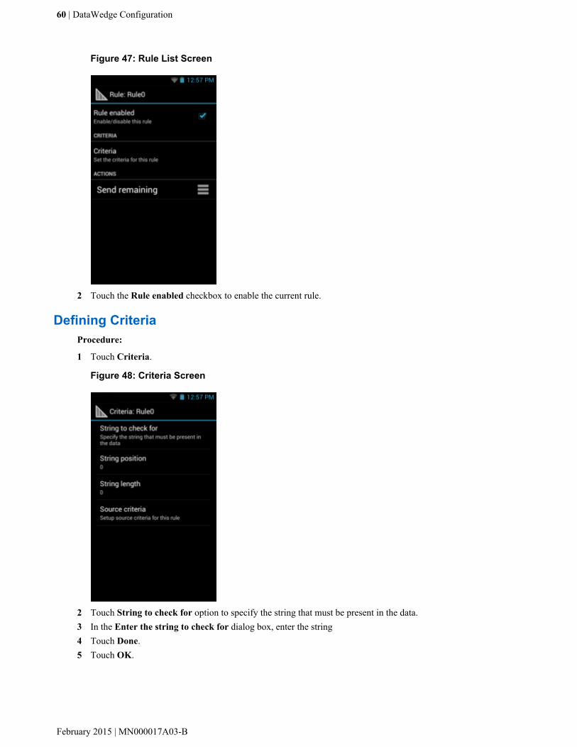
Figure 47: Rule List Screen
2 Touch the Rule enabled checkbox to enable the current rule.
Defining CriteriaProcedure:
1 Touch Criteria.
Figure 48: Criteria Screen
2 Touch String to check for option to specify the string that must be present in the data.3 In the Enter the string to check for dialog box, enter the string4 Touch Done.5 Touch OK.
60 | DataWedge Configuration
February 2015 | MN000017A03-B
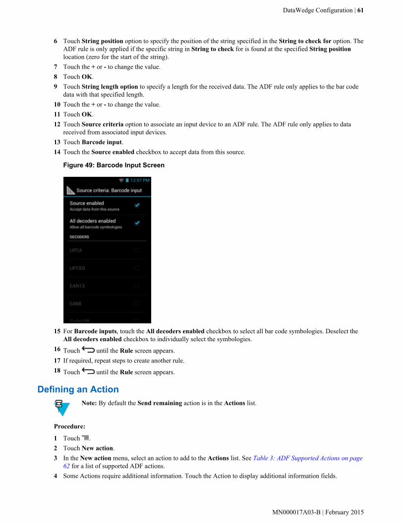
6 Touch String position option to specify the position of the string specified in the String to check for option. TheADF rule is only applied if the specific string in String to check for is found at the specified String positionlocation (zero for the start of the string).
7 Touch the + or - to change the value.8 Touch OK.9 Touch String length option to specify a length for the received data. The ADF rule only applies to the bar code
data with that specified length.10 Touch the + or - to change the value.11 Touch OK.12 Touch Source criteria option to associate an input device to an ADF rule. The ADF rule only applies to data
received from associated input devices.13 Touch Barcode input.14 Touch the Source enabled checkbox to accept data from this source.
Figure 49: Barcode Input Screen
15 For Barcode inputs, touch the All decoders enabled checkbox to select all bar code symbologies. Deselect theAll decoders enabled checkbox to individually select the symbologies.
16 Touch until the Rule screen appears.17 If required, repeat steps to create another rule.18 Touch until the Rule screen appears.
Defining an ActionNote: By default the Send remaining action is in the Actions list.
Procedure:
1 Touch .2 Touch New action.3 In the New action menu, select an action to add to the Actions list. See Table 3: ADF Supported Actions on page
62 for a list of supported ADF actions.4 Some Actions require additional information. Touch the Action to display additional information fields.
DataWedge Configuration | 61
MN000017A03-B | February 2015

5 Repeat steps to create more actions.6 Touch .7 Touch .
Deleting a RuleProcedure:
1 Touch and hold on a rule until the context menu appears.2 Touch Delete to delete the rule from the Rules list.
Note: When there is no rule available for ADF plug-in or all rules are disabled, DataWedge passesdecoded data to the output plug-in without processing the data.
Order Rules ListNote: When there are no rules defined, ADF passes the captured data through as is. In contrast, when rulesare defined but all are disabled, ADF does not pass any captured data through.
Rules are processed in top-down order. The rules that are on top of the list are processed first. Use the icon next to therule to move it to another position in the list.
Table 3: ADF Supported Actions
Type Actions Description
Cursor Move-ment
Skip ahead Moves the cursor forward by a specified number of characters. Enter thenumber of characters to move the cursor ahead.
Skip back Moves the cursor back by a specified number of characters. Enter thenumber of characters to move the cursor back.
Skip to start Moves the cursor to the beginning of the data.
Move to Moves the cursor forward until the specified string is found. Enter thestring in the data field.
Move past a Moves the cursor forward past the specified string. Enter the string inthe data field.
Data Modifi-cation
Crunch spaces Remove spaces between words to one and remove all spaces at the be-ginning and end of the data.
Stop space crunch Stops space crunching. This disables the last Crunch spaces action.
Remove all spaces Remove all spaces in the data.
Stop space removal Stop removing spaces. This disables the last Remove all spaces action.
Remove leading zeros Remove all zeros at the beginning of data.
Stop zero removal Stop removing zeros at the beginning of data. This disables the previousRemove leading zeros action.
Pad with zeros Left pad data with zeros to meet the specified length. Enter the numberzeros to pad.
Stop pad zeros Stop padding with zeros. This disables the previous Pad with zeros ac-tion.
Table continued…
62 | DataWedge Configuration
February 2015 | MN000017A03-B

Type Actions Description
Pad with spaces Left pad data with spaces to meet the specified length. Enter the numberspaces to pad.
Stop pad spaces Stop padding with spaces. This disables the previous Pad with spacesaction.
Replace string Replaces a specified string with a new string. Enter the string to replaceand the string to replace it with.
Stop all replace string Stop all Replace string actions.
Data Sending Send next Sends the specified number of characters from the current cursor posi-tion. Enter the number of characters to send.
Send remaining Sends all data that remains from the current cursor position.
Send up to Sends all data up to a specified string. Enter the string.
Send pause Pauses the specified number of milliseconds before continuing the nextaction. Enter the amount of time in milliseconds.
Send string Sends a specified string. Enter the string to send.
Send char Sends a specified ASCII/ Unicode character. Enter a character value.The maximum Unicode character value can be entered is U-10FFFF (=1114111 in decimal).
Deleting an ActionProcedure:
1 Touch and hold the action name.2 Select Delete action from the context menu.
ADF ExampleThe following illustrates an example of creating Advanced Data Formatting:
When a user scans a bar code with the following criteria:
• Code 39 bar code.• length of 12 characters.• contains 129 at the start position.
Modify the data as follows:
• Pad all sends with zeros to length 8.• send all data up to character X.• send a space character.
To create an ADF rule for the above example:
Procedure:
1 Touch .2 Touch DataWedge.3 Touch Profile0.4 Under Keystroke Output, touch Advanced data formatting.5 Touch Enable.
DataWedge Configuration | 63
MN000017A03-B | February 2015

6 Touch Rule0.7 Touch Criteria.8 Touch String to check for.9 In the Enter the string to check for text box, enter 129 and then touch OK.10 Touch String position.11 Change the value to 0.12 Touch OK.13 Touch String length.14 Change value to 12.15 Touch OK.16 Touch Source criteria.17 Touch Barcode input.18 Touch All decoders enabled to disable all decoders.19 Touch Code 39.20 Touch three times.21 Touch and hold on the Send remaining rule until a menu appears.22 Touch Delete action.23 Touch .24 Touch New action.25 Select Pad with zeros.26 Touch the Pad with zeros rule.27 Touch How many.28 Change value to 8 and then touch OK.29 Touch three times.30 Touch .31 Touch New action.32 Select Send up to.33 Touch Send up to rule.34 Touch String.35 In the Enter a string text box, enter X.36 Touch OK.37 Touch three times.38 Touch .39 Touch New action.40 Select Send char.41 Touch Send char rule.42 Touch Character code.43 In the Enter character code text box, enter 32.44 Touch OK.45 Touch .
64 | DataWedge Configuration
February 2015 | MN000017A03-B

Figure 50: ADF Sample Screen
46 Ensure that an application is open on the device and a text field is in focus (text cursor in text field).47 Aim the exit window at the bar code.
Figure 51: Sample Bar Code
48 Press and hold the scan button.The red laser aiming pattern turns on to assist in aiming. Ensure that the bar code is within the area formed by theaiming pattern. The LED light red to indicate that data capture is in process.
49 The LED lights green, a beep sounds and the device vibrates, by default, to indicate the bar code was decodedsuccessfully. The formatted data 000129X<space>appears in the text field.Scanning a Code 39 bar code of 1299X15598 does not transmit data (rule is ignored) because the bar code datadid not meet the length criteria.
DataWedge Configuration | 65
MN000017A03-B | February 2015

Figure 52: Formatted Data
DataWedge Settings
The DataWedge Settings screen provides access to general, non-profile related options. Touch > Settings.
Figure 53: DataWedge Settings Window
• DataWedge enabled - Enables or disables DataWedge. To disable DataWedge uncheck this option.• Enable logging - Enables or disables debug output file to logcat. To enable logging check this option.• Import - allows import of a DataWedge configuration file. The imported configuration replaces the current
configuration.• Export - allows export of the current DataWedge configuration to the microSD card.• Import Profile - allows import of a DataWedge profile file.• Export Profile - allows export of a DataWedge profile.
66 | DataWedge Configuration
February 2015 | MN000017A03-B

• Restore - return the current configuration back to factory defaults.
Importing a Configuration FileProcedure:
1 Copy the configuration file to the root of the microSD card.2 Touch .3
Touch .4 Touch .5 Touch Settings.6 Touch Import.7 Touch SD Card.8 Touch Import. The configuration file (datawedge.db) is imported and replaces the current configuration.
Exporting a Configuration FileProcedure:
1 Touch .2
Touch .3 Touch .4 Touch Settings.5 Touch Export.6 Touch SD Card.7 Touch Export. The configuration file (datawedge.db) is saved to the root of the microSD card.
Importing a Profile FileNote: Do not change the filename of the of the profile file. If the filename is changed, the file will not beimported.
Procedure:
1 Copy the profile file to the root of the microSD card.2 Touch .3
Touch .4 Touch .5 Touch Settings.6 Touch Import Profile.7 Touch the profile file to import.8 Touch Import. The profile file (dwprofile_x.db, where x = the name of the profile) is imported and appears
in the profile list.
Exporting a ProfileProcedure:
1 Touch .
DataWedge Configuration | 67
MN000017A03-B | February 2015

2Touch .
3 Touch .4 Touch Settings.5 Touch Export Profile.6 Touch the profile to export.7 Touch Export.8 Touch Export. The profile file (dwprofile_x.db, where x = name of the profile) is saved to the root of the
microSD card.
Restoring DataWedgeTo restore DataWedge to the factory default configuration:
Procedure:
1 Touch .2
Touch .3 Touch .4 Touch Settings.5 Touch Restore.6 Touch Yes.
Configuration and Profile File Management
The configuration or profile settings for DataWedge can be saved to a file for distribution to other devices.
After making configuration or profile changes, export the new configuration or profile to the root of the microSDcard. The configuration file created is automatically named datawedge.db. The profile file created isautomatically named dwprofile_x.db, where x is the profile name. The files can then the copied to the microSDcard of other devices and imported into DataWedge on those devices. Importing a configuration or profile replacesthe existing settings.
Enterprise FolderInternal storage contains the Enterprise folder (/enterprise). The Enterprise folder is persistent and maintainsdata after an Enterprise reset. After an Enterprise Reset, DataWedge checks folder /enterprise/device/settings/datawedge/enterprisereset/ for a configuration file, datawedge.db or a profile file,dwprofile_x.db. If the file is found, it imports the file to replace any existing configuration or profile.
Note: A Factory Reset deletes all files in the Enterprise folder.
Auto ImportDataWedge supports remote deployment of a configuration to a device, using tools such as MSP. DataWedgemonitors the /enterprise/device/settings/datawedge/autoimport folder for the DataWedgeconfiguration file (datawedge.db) or a profile file (dwprofile_x.db). When DataWedge launches it checksthe folder. If a configuration or profile file is found, it imports the file to replace any existing configuration or profile.Once the file has been imported it is deleted from the folder.
68 | DataWedge Configuration
February 2015 | MN000017A03-B

While DataWedge is running it receives a notification from the system that a file has been placed into the /enterprise/device/settings/datawedge/autoimport folder. When this occurs, DataWedge importsthis new configuration or profile, replacing the existing one and delete the file. DataWedge begins using the importedconfiguration immediately.
Note:
A Factory Reset deletes all files in the Enterprise folder.
It is strongly recommended that the user exits DataWedge before remotely deploying any configuration orprofile. It is required that the file permissions are set to 666.
Programming Notes
The following paragraphs provide specific programming information when using DataWedge.
Overriding Trigger Key in an ApplicationTo override the trigger key in an application, create a profile for the application that disables the Barcode input. In theapplication, use standard APIs, such as onKeyDown() to listen for the KEYCODE_BUTTON_L1 andKEYCODE_BUTTON_R1 presses.
Capture Data and Taking a Photo in the Same ApplicationTo be able to capture bar code data and take a photo in the same application:
• Create a Datawedge profile pertaining to the picture taking Activity in your application that disables scanning anduse standard Android SDK APIs to control the Camera.
• The default Datawedge profile takes care of the scanning in the application. You might want to create anotherDataWedge profile that caters to any specific scanning needs, associated to your Application's Activity pertainingto scanning.
Disable DataWedge on TC55 and Mass DeployTo disable DataWedge and deploy onto multiple TC55 devices:
Procedure:
1 Touch .2 Touch DataWedge.3 Touch .4 Touch Settings.5 Unselect the DataWedge enabled check box.6 Export the DataWedge configuration. See Exporting a Configuration File on page 67 for instructions. See
Configuration and Profile File Management on page 68 for instructions for using the auto import feature.
Soft Scan FeatureDataWedge allows a native Android application to programmatically start, stop, or toggle the scan trigger state. Theapplication can issue an Android Broadcast Intent, to control the scanner, without requiring the scan button to bepressed. The active DataWedge profile is required to control all the parameters during a scan operation.
The structure of the broadcast intent that resolves to the soft scan is:
action: “com.motorolasolutions.emdk.datawedge.api.ACTION_SOFTSCANTRIGGER”
extras: This is a String name/value pair that contains trigger state details.
DataWedge Configuration | 69
MN000017A03-B | February 2015

name: “com.motorolasolutions.emdk.datawedge.api.EXTRA_PARAMETER”
value: “START_SCANNING” or “STOP_SCANNING” or “TOGGLE_SCANNING”
SampleIntent sendIntent = new Intent();
sendIntent.setAction(“com.motorolasolutions.emdk.datawedge.api.ACTION_SOFTSCANTRIGGER”);
sendIntent.putExtra(“com.motorolasolutions.emdk.datawedge.api.EXTRA_PARAMETER”,“TOGGLE_SCANNING”);
sendBroadcast(sendIntent);
70 | DataWedge Configuration
February 2015 | MN000017A03-B
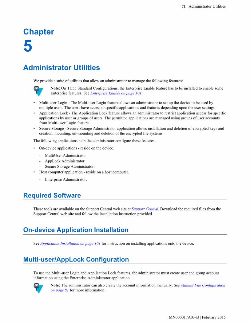
Chapter
5Administrator Utilities
We provide a suite of utilities that allow an administrator to manage the following features:
Note: On TC55 Standard Configurations, the Enterprise Enable feature has to be installed to enable someEnterprise features. See Enterprise Enable on page 104.
• Multi-user Login - The Multi-user Login feature allows an administrator to set up the device to be used bymultiple users. The users have access to specific applications and features depending upon the user settings.
• Application Lock - The Application Lock feature allows an administrator to restrict application access for specificapplications by user or groups of users. The permitted applications are managed using groups of user accountsfrom Multi-user Login feature.
• Secure Storage - Secure Storage Administrator application allows installation and deletion of encrypted keys andcreation, mounting, un-mounting and deletion of the encrypted file systems.
The following applications help the administrator configure these features.
• On-device applications - reside on the device.
- MultiUser Administrator- AppLock Administrator- Secure Storage Administrator.
• Host computer application - reside on a host computer.
- Enterprise Administrator.
Required Software
These tools are available on the Support Central web site at Support Central. Download the required files from theSupport Central web site and follow the installation instruction provided.
On-device Application Installation
See Application Installation on page 101 for instruction on installing applications onto the device.
Multi-user/AppLock Configuration
To use the Multi-user Login and Application Lock features, the administrator must create user and group accountinformation using the Enterprise Administrator application.
Note: The administrator can also create the account information manually. See Manual File Configurationon page 81 for more information.
71 | Administrator Utilities
MN000017A03-B | February 2015

Enterprise Administrator Application
Note: .Net Compact Framework 4 or later is required to run the Enterprise Administrator. To download, goto www.microsoft.com.
Use the Enterprise Administrator application to setup user and group accounts and create the required (Password,Group and White List) files for using the Multi-user and Application Lock features.
On the host computer launch the Enterprise Administrator application.
Figure 54: Enterprise Administrator Window
Creating UsersEach person that uses the device has to have a user name and password. To create a user:
Procedure:
1 Click + above the Users list box.
72 | Administrator Utilities
February 2015 | MN000017A03-B

Figure 55: User Manager Window
2 In the Username text box, enter a user name. The text is case sensitive and required.3 In the Password text box, enter a password for the user. The text is case sensitive and required.4 In the Retype Password text box, re-enter the user password.5 Select the Admin checkbox to set the user to have administrator rights.6 Select the Enabled checkbox to enable the user.7 Click OK.8 Repeat steps 1 through 7 for each additional user.
Adding PackagesNote: All system applications that are on the default image are available to all users.
Create a list of installed applications (packages) on the device that are available for use by all the users.
Procedure:
1 Click + next to Packages.
Note: To get a list of all the applications (packages) on the device see Determining ApplicationsInstalled on the Device on page 83.
Figure 56: Package Information Window
2 In the Package name text box, enter the name of an application.3 Click OK.
Administrator Utilities | 73
MN000017A03-B | February 2015
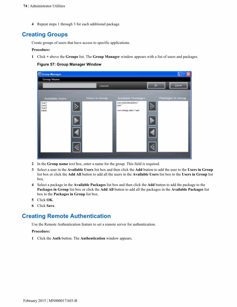
4 Repeat steps 1 through 3 for each additional package.
Creating GroupsCreate groups of users that have access to specific applications.
Procedure:
1 Click + above the Groups list. The Group Manager window appears with a list of users and packages.
Figure 57: Group Manager Window
2 In the Group name text box, enter a name for the group. This field is required.3 Select a user in the Available Users list box and then click the Add button to add the user to the Users in Group
list box or click the Add All button to add all the users in the Available Users list box to the Users in Group listbox.
4 Select a package in the Available Packages list box and then click the Add button to add the package to thePackages in Group list box or click the Add All button to add all the packages in the Available Packages listbox to the Packages in Group list box.
5 Click OK.6 Click Save.
Creating Remote AuthenticationUse the Remote Authentication feature to set a remote server for authentication.
Procedure:
1 Click the Auth button. The Authentication window appears.
74 | Administrator Utilities
February 2015 | MN000017A03-B
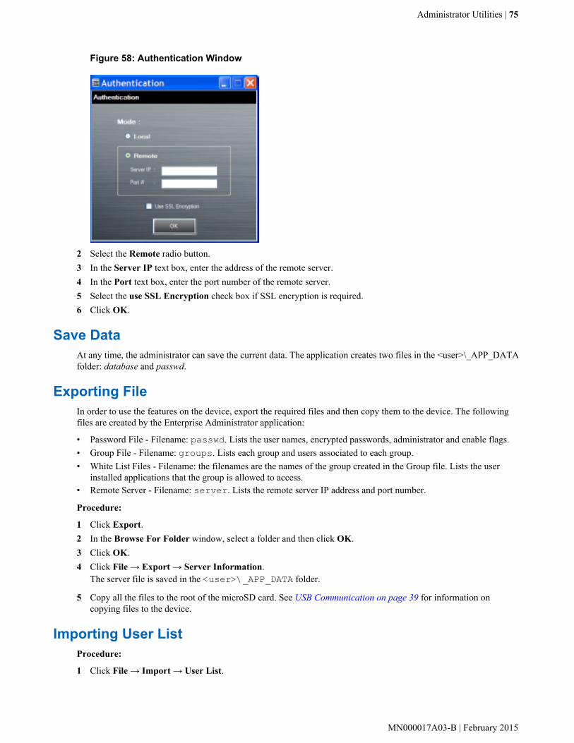
Figure 58: Authentication Window
2 Select the Remote radio button.3 In the Server IP text box, enter the address of the remote server.4 In the Port text box, enter the port number of the remote server.5 Select the use SSL Encryption check box if SSL encryption is required.6 Click OK.
Save DataAt any time, the administrator can save the current data. The application creates two files in the <user>\_APP_DATAfolder: database and passwd.
Exporting FileIn order to use the features on the device, export the required files and then copy them to the device. The followingfiles are created by the Enterprise Administrator application:
• Password File - Filename: passwd. Lists the user names, encrypted passwords, administrator and enable flags.• Group File - Filename: groups. Lists each group and users associated to each group.• White List Files - Filename: the filenames are the names of the group created in the Group file. Lists the user
installed applications that the group is allowed to access.• Remote Server - Filename: server. Lists the remote server IP address and port number.
Procedure:
1 Click Export.2 In the Browse For Folder window, select a folder and then click OK.3 Click OK.4 Click File → Export → Server Information.
The server file is saved in the <user>\_APP_DATA folder.
5 Copy all the files to the root of the microSD card. See USB Communication on page 39 for information oncopying files to the device.
Importing User ListProcedure:
1 Click File → Import → User List.
Administrator Utilities | 75
MN000017A03-B | February 2015
2 Navigate to the location when the passwd file is stored.3 Select the passwd file.4 Click Open.
The user information is populated into the Users list.
Importing Group ListProcedure:
1 Click File → Import → Group List.2 Navigate to the location when the group file is stored.3 Select the group file.4 Click Open.
The group and package information is populated into the Groups and Packages list.
Importing Package ListTo import a package list (see Package List File on page 82 for instructions for creating a Package List file):
Procedure:
1 Click File → Import → Package List.2 Navigate to the location when the package file is stored.3 Select the package text file.4 Click Open.
The package information is populated into the Packages list.
Editing a UserProcedure:
1 Select a user in the Users list.2 Click Edit User.3 Make changes and then click OK.
Deleting a UserProcedure:
1 Select a user in the Users list.2 Click -. The user name is removed from the list.
Editing a GroupProcedure:
1 Select a user in the Groups list.2 Click Edit Group.3 Make changes and then click OK.
Deleting a GroupProcedure:
1 Select a group in the Groups list.
76 | Administrator Utilities
February 2015 | MN000017A03-B

2 Click -.3 Click Yes. The group name is removed from the list.
Editing a PackageProcedure:
1 Select a package in the Packages list.2 Click Edit Package.3 Make changes and then click OK.
Deleting a PackageProcedure:
1 Select a package in the Packages list.2 Click -. The package name is removed from the list.
MultiUser Administrator
Use the MultiUser Administrator application to allow an administrator to enable, disable and configure the MultiuserLogin feature.
Importing a PasswordWhen the MultiUser Administrator is used for the first time, the password file must be imported.
Procedure:
1 Touch .2
Touch .
Figure 59: MultiUser Administrator Screen
Administrator Utilities | 77
MN000017A03-B | February 2015
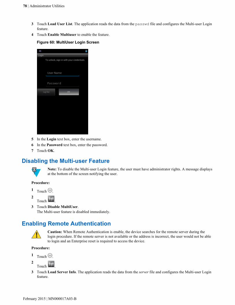
3 Touch Load User List. The application reads the data from the passwd file and configures the Multi-user Loginfeature.
4 Touch Enable Multiuser to enable the feature.
Figure 60: MultiUser Login Screen
5 In the Login text box, enter the username.6 In the Password text box, enter the password.7 Touch OK.
Disabling the Multi-user FeatureNote: To disable the Multi-user Login feature, the user must have administrator rights. A message displaysat the bottom of the screen notifying the user.
Procedure:
1 Touch .2
Touch .3 Touch Disable MultiUser.
The Multi-user feature is disabled immediately.
Enabling Remote AuthenticationCaution: When Remote Authentication is enable, the device searches for the remote server during thelogin procedure. If the remote server is not available or the address is incorrect, the user would not be ableto login and an Enterprise reset is required to access the device.
Procedure:
1 Touch .2
Touch .3 Touch Load Server Info. The application reads the data from the server file and configures the Multi-user Login
feature.
78 | Administrator Utilities
February 2015 | MN000017A03-B

4 Touch .5 Touch Enable Remote Authentication.
The device accesses the remote server and then Login screen appears.
Disabling Remote AuthenticationCaution: When Remote Authentication is enable, the device searches for the remote server during thelogin procedure. If the remote server is not available or the address is incorrect, the user would not be ableto login and an Enterprise reset is required to access the device.
Procedure:
1 Touch .2
Touch .3 Touch .4 Touch Disable Remote Authentication.
The remote authentication feature is disabled immediately. The device suspends. When resumed, the login screenappears.
Enabling Data SeparationNote: To enable Data Separation, the user must have administrator rights. A message displays at thebottom of the screen notifying the user.
Data Separation feature allows each user of the device to have separate isolated data area for installed application. Toenable data separation:
Procedure:
1 Touch .2
Touch .3 Touch .4 Touch Enable Data Separation. The current user is logged out to prepare the data space for each user as they log
in.
Disabling Data SeparationNote: To disable Data Separation, the user must have administrator rights. A message displays at thebottom of the screen notifying the user.
Procedure:
1 Touch .2
Touch .3 Touch .4 Touch Disable Data Separation. The current user is logged out to restore the system to common data space for
all users.
Administrator Utilities | 79
MN000017A03-B | February 2015

Delete User DataNote: To delete user data, the user must have administrator rights. A message displays at the bottom of thescreen notifying the user.
Procedure:
1 Touch .2
Touch .3 Touch .4 Touch Delete Individual User Data. A dialog box displays with all of the users that currently have data
associated with their log in.5 Select each user to delete or Select All to delete all user data.6 Touch Delete to delete the data.
Capturing a Log FileProcedure:
1 Touch .2
Touch .
Note: To capture a log file, the user must have administrator rights. A message displays at the bottomof the screen notifying the user.
3 Touch Export Log to copy the log file to the microSD card. The log file can be captured when the multi-userfeature is in either the enabled or disabled mode.
4 The log file and a backup log file are named multiuser.log and multiuser.log.bak, respectively.
AppLock Administrator
The Application Lock feature allows the system administrator to restrict application access for specific applicationsby user or groups of users. The permitted applications are managed using groups of user accounts from Multi-userfeature.
The permitted application names are built into an application White List that is used to know which applications aremanaged by the system.
The Application Lock feature does not prevent execution of native code or plug-ins and it does not preventapplications from accessing public classes within non-permitted applications. The AppLock Administrator applicationtakes advantage of the Application Lock feature allowing an administrator to enable, disable and install White Listsand Groups files.
Note: To use the AppLock Administrator application, the user must have administrator rights. A messagedisplays at the bottom of the screen notifying the user.
Installing Groups and White ListsProcedure:
1 Touch 2
Touch
80 | Administrator Utilities
February 2015 | MN000017A03-B

Note:
When the application launches the current status of the Application Lock feature displays (enabled ordisabled).
Log off and then log in again for the feature to take affect.3 Touch Install Groups and White Lists to read the contents of the Groups and White List files from the root of
the microSD card and push its contents into the AppLock framework.
Once the Group and White List files are imported and the feature enabled, the next time a user logs in, the device willbe configured accordingly.
Enabling Application LockProcedure:
1 Touch .2
Touch .3 Touch Enable Application Lock.
Disabling Application LockProcedure:
1 Touch .2
Touch .3 Touch Disable Application Lock.
Manual File Configuration
Groups FileA Groups file is a text file that provides a list of groups and assigns users to each group.
The text file contains one line for each group. Each line is formatted as follows:
<groupname>:<user1>,<user2>,...<usern>where:
<groupname> = the name for a group. This is also the name of the White List file for this group. This field uses anyalphanumeric character.
<user1> through <userN> = the name of the user assigned to this group. The user name is the same as that definedfor the MultiUser feature. See MultiUser Administrator on page 77 for more information.
Note:
If the same user is assigned to multiple groups, then that user’s White List will be a logical union of theWhite Lists for all of the groups that user is assigned.
A line starting with the # character is considered a comment and is ignored.
Examples:
• AdminGroup:alpha- The Group name is AdminGroup and assigns user alpha to the group.
• ManagersGroup:beta,gamma
Administrator Utilities | 81
MN000017A03-B | February 2015
- The Group name is ManagerGroup and assigns users beta and gamma to the group.
White List FileA White List file is a text file that provides a list of allowed packages from that group. The text file contains one linefor each allowed package for that user group. Each line is format as follows:
<package1name>...<packageNname>where:
<package1Name> = the package name allowed for this group. Wild cards are allowed for this field.
Example:
Refer to the example of the Groups file above. A White List file of the name AdminGroup could have the followinglines:
com.companyname.applicationcom.motorolasolutions.*where:
com.companyname.application = the specific application with the package name
com.companyname.application will be permitted for this group.
com.motorolasolutions.* = any application that has a package name that starts with
com.motorolasolutions will be permitted for this group.
Note:
The wildcard “.*” is allowed and indicates that this group is permitted to run any package.
A default White List for use when the MultiUser feature is disabled takes the same form as above but innamed default.
To assure that administrative users have access to all device functionality, the White List for the administrative usersgroup should use the wildcard.
At a minimum, the White List for the administrative users group should contain com.motorolasolutions.fusion toallow administrative users the ability to configure Wi-Fi advanced settings.
Package List FileA Package List file is a text file that lists package names that can be imported into the Packages list. The file makes iteasier to enter package name into the application. The text file contains one line for each package name.
Example:
com.motorolasolutions.example1com.motorolasolutions.example2com.motorolasolutions.example3com.motorolasolutions.example4
82 | Administrator Utilities
February 2015 | MN000017A03-B

Determining Applications Installed on the DeviceTo determine the names of applications installed on the device for use with the Enterprise Administrator application:
Procedure:
1 Connect the device to the host computer.
Note: See Development Tools on page 100 for information on installing the USB driver for use withadb.
2 On the host computer, open a command prompt (or a terminal in Ubuntu) and run the following:adb devices. This returns the device id.adb shell$pm list packages -f > sdcard/pkglist.txt$exit
3 A pkglist.txt file is created in the root of the microSD card. The file lists all the .apk files installed with theirpackage names.
Secure Storage
Secure Storage Administrator application allows:
• installation and deletion of encrypted keys• creation, mounting, un-mounting and deletion of the encrypted file systems.
Installing a KeyProcedure:
1 Touch .2
Touch .3 Touch Install Key.4 Touch Manual.5 Touch OK.
Administrator Utilities | 83
MN000017A03-B | February 2015

Figure 61: Enter Key Dialog Box
6 In the Enter key text box, enter the key name followed by the key value obtained in step 1, using the followingformat:<Key Name> <Key value in Hex String>Example: key2 1234567890abcdef1234567890abcdef1234567890abcdef1234567890abcdefThe key value must be a 64 hexadecimal character string.
7 Touch OK. The key is imported into the device. The message successfully installed the key appears on thescreen.
Viewing Key ListProcedure:
1 Touch Key List.
2 Touch OK.
Deleting a KeyProcedure:
1 Touch Revoke Key.2 Touch the key to deleted.3 Touch OK.
Note: If a key is deleted then all the volumes created using that key are un-mounted. The same key isrequired to re-mount the volume.
VolumesCreates an encrypted file system (volume) on the device. The user must have Administrative privileges to create avolume.
84 | Administrator Utilities
February 2015 | MN000017A03-B

Creating Volume Using EFS FileProcedure:
1 Create an efs file. See Creating an EFS File on page 86 for instruction on creating the efs file.2 Copy the keyfile and efsfile files to root of the microSD card. See USB Communication on page 39.3 Touch Create Volume.4 Touch Import.5 Touch OK. The message Successfully Created the Volume appears briefly.
Creating a Volume ManuallyProcedure:
1 Touch Create Volume.2 Touch Manual.3 Touch OK.4 In the Enter Parameters To Create Volume text box, enter the parameters in the follow format:
<Volume Name> <Volume Storage Type> Key Name> <Mount Path> <Auto Mount> <Volume size>where:
• <Volume Name> = name of the volume.• <Volume Storage Type> = storage location. Options: internal or sdcrad.• <Key Name> = name of the key to use when creating the volume.• <Mount Path> = path where the volume will be located.• <Auto Mount> = Options: 1 = yes, 0 = no.• <Volume size> = size of the volume in Megabytes.
Figure 62: Enter Parameter To Create Volume Dialog Box
5 Touch OK. The message Successfully Created the Volume appears briefly. If the size of the volume is verylarge, a progress bar displays.
Administrator Utilities | 85
MN000017A03-B | February 2015

Mounting a VolumeProcedure:
1 Touch Mount Volume.2 Touch sdcard or internal.3 Touch OK.4 Select a volume.5 Touch OK.
Listing VolumesProcedure:
1 Touch Volume List.2 Touch sdcard to list volumes on the microSD card or internal to list volumes on internal storage.3 Touch OK. The List of EFS Volumes dialog box appears with all the volumes of the selected storage location.4 Touch OK.
Unmounting a VolumeProcedure:
1 Touch Unmount Volume.2 Touch sdcard to list the mounted volumes on the microSD card or internal to list the mounted volumes on
internal storage.3 Touch OK.4 Select the volume to un-mount.5 Touch OK.
Deleting a VolumeProcedure:
1 If the encrypted volume is mounted, unmount it.2 Touch Delete Volume.3 Touch sdcard to list the unmounted volumes on the microSD card or internal to list the unmounted volumes on
internal storage.4 Select the volume to delete.5 Touch OK.
Encrypting an SD CardCaution: All data will be erased from the microSD card when this is performed.
Procedure:
1 Touch Encrypt SD card. A warning message appears.2 Touch Yes. The Key List dialog box appears.3 Select a key from the list and then touch Ok.
The encryption process begins and when completed, displays a successfully completed message.
Creating an EFS File
86 | Administrator Utilities
February 2015 | MN000017A03-B
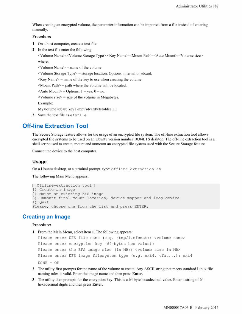
When creating an encrypted volume, the parameter information can be imported from a file instead of enteringmanually.
Procedure:
1 On a host computer, create a text file.2 In the text file enter the following:
<Volume Name> <Volume Storage Type> <Key Name> <Mount Path> <Auto Mount> <Volume size>where:<Volume Name> = name of the volume<Volume Storage Type> = storage location. Options: internal or sdcard.<Key Name> = name of the key to use when creating the volume.<Mount Path> = path where the volume will be located.<Auto Mount> = Options: 1 = yes, 0 = no.<Volume size> = size of the volume in Megabytes.Example:MyVolume sdcard key1 /mnt/sdcard/efsfolder 1 1
3 Save the text file as efsfile.
Off-line Extraction ToolThe Secure Storage feature allows for the usage of an encrypted file system. The off-line extraction tool allowsencrypted file systems to be used on an Ubuntu version number 10.04LTS desktop. The off-line extraction tool is ashell script used to create, mount and unmount an encrypted file system used with the Secure Storage feature.
Connect the device to the host computer.
UsageOn a Ubuntu desktop, at a terminal prompt, type: offline_extraction.sh.
The following Main Menu appears:
[ Offline-extraction tool ]1) Create an image2) Mount an existing EFS image3) Unmount final mount location, device mapper and loop device4) QuitPlease, choose one from the list and press ENTER:
Creating an ImageProcedure:
1 From the Main Menu, select item 1. The following appears:Please enter EFS file name (e.g. /tmp/1.efsmot): <volume name>Please enter encryption key (64-bytes hex value):Please enter the EFS image size (in MB): <volume size in MB>Please enter EFS image filesystem type (e.g. ext4, vfat...): ext4DONE - OK
2 The utility first prompts for the name of the volume to create. Any ASCII string that meets standard Linux filenaming rules is valid. Enter the image name and then press Enter.
3 The utility then prompts for the encryption key. This is a 64 byte hexadecimal value. Enter a string of 64hexadecimal digits and then press Enter.
Administrator Utilities | 87
MN000017A03-B | February 2015

4 The utility then prompts for the image size. Enter the size of the volume in MB. A number must be enteredwithout the units. It is understood that MB. A value of 2000, is 2 GB. Note that 4 GB is the largest volume that issupported on the device.
5 The utility lastly prompts for the filesystem type. Enter ext4 and then press Enter.The utility then creates the volume in the current working directory.The utility then finishes the creation process and then prompts to whether the volume should be mounted.Press [1] if you want to mount or press [2] if you want to exit
6 Press 1 will prompt for the mount point. For example, /mnt is prompted. Press Enter to mount the encryptedvolume at the selected point. After mounting, an option to return to the Main Menu or Exit is provided.Press 2 to exit the utility without mounting.
7 If the volume is mounted on the desktop, then that volume can be provisioned with files for deployment.8 Unmounted volumes can then be copied to the device and subsequently mounted using the Secure Storage
Administrator by providing the encryption key used.
Mounting an ImageProcedure:
1 From the Main Menu, select item 2. The following appears:Please enter EFS file name (e.g. /tmp/1.efsmot): <volume name>Please enter encryption key (64-bytes hex value):Please enter mount path (e.g. /mnt): <existing mount point>DONE - OK
2 Enter the name of the volume and then press Enter.3 The utility then prompts for the encryption key. This is a 64 byte hexadecimal value. Enter a string of 64
hexadecimal digits and then press Enter.4 Enter the mount point where to connect the volume into the file system and then press Enter. The example
of /mnt is provided.
Unmounting an ImageProcedure:
1 From the Main Menu, select item 3. The following appears:Please enter EFS file name (e.g. /tmp/1.efsmot): <volume name>DONE - OK
2 Enter the name of the volume to unmount.3 Press Enter.
88 | Administrator Utilities
February 2015 | MN000017A03-B
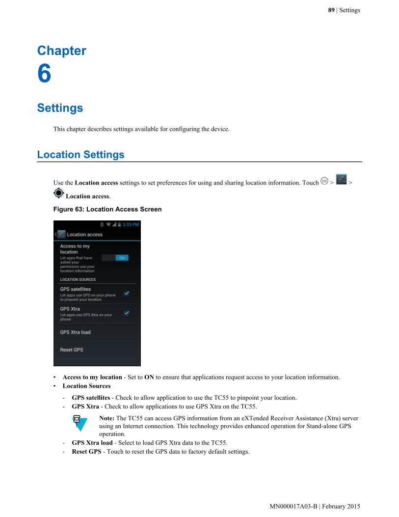
Chapter
6Settings
This chapter describes settings available for configuring the device.
Location Settings
Use the Location access settings to set preferences for using and sharing location information. Touch > >
Location access.
Figure 63: Location Access Screen
• Access to my location - Set to ON to ensure that applications request access to your location information.• Location Sources
- GPS satellites - Check to allow application to use the TC55 to pinpoint your location.- GPS Xtra - Check to allow applications to use GPS Xtra on the TC55.
Note: The TC55 can access GPS information from an eXTended Receiver Assistance (Xtra) serverusing an Internet connection. This technology provides enhanced operation for Stand-alone GPSoperation.
- GPS Xtra load - Select to load GPS Xtra data to the TC55.- Reset GPS - Touch to reset the GPS data to factory default settings.
89 | Settings
MN000017A03-B | February 2015

Screen Unlock Settings
Use the Security settings to set preferences for locking the screen. Touch > Security.
Note: Options vary depending upon the application’s policy, for example, email.
• Screen lock - Touch to configure the device to require a slide, pattern, PIN, or password to unlock the screen.
- None - Disable screen unlock security.- Slide - Slide the lock icon to unlock the screen.- Pattern - Draw a pattern to unlock screen. See Set Screen Unlock Using Pattern on page 92 for more
information.- PIN - Enter a numeric PIN to unlock screen. See Set Screen Unlock Using PIN on page 90 for more
information.- Password - Enter a password to unlock screen. See Set Screen Unlock Using Password on page 91 for more
information.
Lock the screen to protect access to data on the device. Some email accounts require locking the screen. The Lockingfeature functions differently in Single-user versus Multiple-user mode.
Single User ModeWhen locked, a slide, pattern, PIN or password is required to unlock the device. Press the Power button to lock thescreen. The device also locks after a pre-defined time-out.
Press and release the Power button to wake the device. The Lock screen displays.
Slide up to unlock the screen. If the Pattern screen unlock feature is enabled, the Pattern screen appears instead of theLock screen.
If the PIN or Password screen unlock feature is enabled, enter the PIN or password after unlocking the screen.
Set Screen Unlock Using PINProcedure:
1 Touch .2
Touch .3 Touch Security.4 Touch Screen lock.5 Touch PIN.6 Touch in the text field.7 Enter a PIN (between 4 and 16 characters) then touch Next.8 Re-enter PIN and then touch Next.9 Touch . The next time the device goes into suspend mode a PIN is required upon waking.
90 | Settings
February 2015 | MN000017A03-B
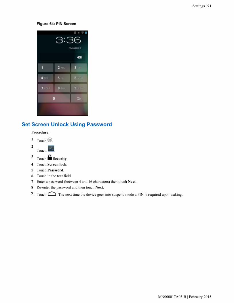
Figure 64: PIN Screen
Set Screen Unlock Using PasswordProcedure:
1 Touch .2
Touch .3 Touch Security.4 Touch Screen lock.5 Touch Password.6 Touch in the text field.7 Enter a password (between 4 and 16 characters) then touch Next.8 Re-enter the password and then touch Next.9 Touch . The next time the device goes into suspend mode a PIN is required upon waking.
Settings | 91
MN000017A03-B | February 2015

Figure 65: Password Screen
Set Screen Unlock Using PatternProcedure:
1 Touch .2
Touch .3 Touch Security.4 Touch Screen lock.5 Touch Pattern.6 Watch pattern example and then touch Next.7 Draw a pattern connecting at least four dots.
92 | Settings
February 2015 | MN000017A03-B

Figure 66: Choose Your Pattern Screen
8 Touch Continue.9 Re-draw the pattern.10 Touch Confirm.11 On the Security screen, touch Make pattern visible to show pattern when you draw the pattern.12 Touch Vibrate on touch to enable vibration when drawing the pattern.13 Touch .
The next time the device goes into suspend mode a Pattern is required upon waking.
Figure 67: Pattern Screen
Multiple User ModeFor Multi-user Mode configuration, see Administrator Utilities on page 71.
Settings | 93
MN000017A03-B | February 2015

Passwords
To set the device to briefly show password characters as the user types, set this option. Touch > > Security. Touch Make passwords visible. A check in the checkbox indicates that the option is enabled.
Button Programming
Two of the TC55’s buttons can be programmed to perform different functions or shortcuts to installed applications.
• Programmable button - Side Programmable button set to scanning by default.• Search button - Oval button below display.
Programming a ButtonProcedure:
1 Touch .2
Touch .3
Touch Programmable keys.
Figure 68: Programmable Keys Screen
4 Select the button to remap.
• Programmable Side Key - Side Programmable button set to scanning by default.• Programmable Front Key - .Oval button below display.
5 Touch the KEYS tab or the APPS tab that lists the available functions and applications.6 Touch a function or application shortcut to map to the button.
94 | Settings
February 2015 | MN000017A03-B

Note: If you select an application shortcut, the application icon appears next to the button on the KeyProgrammer screen.
Figure 69: Remapped Button
7 If setting the Programmable Side Key, check the Enable wakeup checkbox to wake the TC55 if theProgrammable key is pressed.
8 Touch Apply to set the new key function.9 Touch .
Exporting a Programmable Key Configuration FileThe Programmable Key configuration can be exported to an xml file and imported into other TC55 devices.
Procedure:
1 Touch .2
Touch .3
Touch Programmable Keys.4 Touch .5 Touch Export.
The configuration file (key_config.xml) is saved in the folder: /enterprise/device/settings/keyboard.
6 Copy the xml file from the folder to a host computer. See USB Communication on page 39 for more information.
Importing a Programmable Key Configuration FileProcedure:
1 Copy the configuration file (key_config.xml) from a host computer to the TC55. See USB Communicationon page 39 for more information.
2 On the TC55, use File Browser to move the file to the folder: /enterprise/device/settings/keyboard.
Settings | 95
MN000017A03-B | February 2015

3 Touch .4
Touch .5
Touch Programmable Keys.6 Touch .7 Touch Import.8 Touch /enterprise/device/settings/keyboard/keys_config.xml to import the configuration file or touch Factory
Settings to reset the key settings back to the factory default.9 Touch .
Accounts
Use the Accounts to add, remove, and manage accounts. Use these settings to control how applications send, receive,and sync data on their own schedules, and whether applications can synchronize user data automatically.
Applications may also have their own settings to control how they synchronize data; see the documentation for thoseapplications for details.
• General sync settings
- Background data - Check to permit applications to synchronize data in the background. Unchecking thissetting can save battery power.
- Auto-sync - Check to permit applications to synchronize data on their own schedule. If unchecked, > Syncnow to synchronize data for that account. Synchronizing data automatically is disabled if Background data isunchecked. In that case, the Auto-sync checkbox is dimmed.
• Manage accounts - Lists accounts added to the device. Touch an account to open its account screen.
Language Usage
Use the Language & input settings to change the language that display for the text and including words added to itsdictionary.
Changing the Language SettingProcedure:
1 Touch Language.2 In the Language screen, select a language from the list of available languages.
The operating system text changes to the selected language.
Adding Words to the DictionaryProcedure:
1 In the Language & input screen, touch Personal dictionary.2 Touch + to add a new word or phrase to the dictionary.3 In the Phrase text box, enter the word or phrase.4 In the Shortcut text box, enter a shortcut for the word or phrase.5 In the Language drop-down list, select the language that this word or phase is stored.
96 | Settings
February 2015 | MN000017A03-B
6 Touch Add to dictionary in the top left corner of the screen to add the new word.
Keyboard Settings
Use the Language & input settings for configuring the on-screen keyboards. The device contains the followingkeyboard settings:
• Android Keyboard• Chinese keyboard
About Phone
Use About phone settings to view information about the TC55. Touch > > About device.
• Status - Touch to display the following:
- Battery status - Indicates if the battery is charging (on AC power) or discharging (on battery power).- Battery level - Indicates the battery charge level.- Network - Indicates the current network carrier.- Signal strength - Indicates the radio signal strength.- Mobile network type - Indicates the mobile network type.- Service state - Indicates the state of service.- Roaming - Indicates if the device is roaming outside the network.- Mobile network state - Indicates the mobile network state.- My phone number - Displays the phone number associated with the device.- MIN - Displays the phone number assigned to the device.- PRL Version - Displays the Preferred Roaming List (PRL) version.- ESN - Displays the Electronic Serial Number (ESN) of the device.- MEID - Displays the Mobile Equipment Identifier (MEID) for the device.- IMEI - Displays the IMEI number for the device.- IMEI SV - Displays the IMEI SV number for the device.- ICCID - Displays the ICCID number.- IP address - Displays the IP address of the device.- Wi-Fi MAC address - Displays the Wi-Fi radio MAC address.- Bluetooth address - Displays the Bluetooth radio Bluetooth address.- Serial number - Displays the serial number of the device.- Up time - Displays the time that the TC55 has been running since being turned on.
• SW components - Lists filenames and versions for various software on the TC55.• Legal information - Opens a screen to view legal information about the software included on the TC55.• Battery Management - Displays information about the battery.• SE 13 version - Displays date of SE13 table.• QCN version - Displays the QCN version number.• HW version - Displays the hardware version.• TP FW Version - Displays the touch panel firmware version.• WCNSS INI Version - Displays the version number of the WCNSS INI file.• S/N - Displays the device serial number.• Model number - Displays the device model number.• Android version - Displays the operating system version.• Baseband version - Displays WAN radio firmware version.
Settings | 97
MN000017A03-B | February 2015

• Kernel version - Displays the kernel version.• Build number - Displays the software build number.
98 | Settings
February 2015 | MN000017A03-B
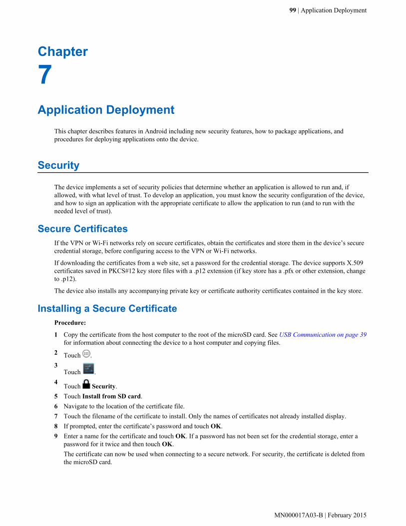
Chapter
7Application Deployment
This chapter describes features in Android including new security features, how to package applications, andprocedures for deploying applications onto the device.
Security
The device implements a set of security policies that determine whether an application is allowed to run and, ifallowed, with what level of trust. To develop an application, you must know the security configuration of the device,and how to sign an application with the appropriate certificate to allow the application to run (and to run with theneeded level of trust).
Secure CertificatesIf the VPN or Wi-Fi networks rely on secure certificates, obtain the certificates and store them in the device’s securecredential storage, before configuring access to the VPN or Wi-Fi networks.
If downloading the certificates from a web site, set a password for the credential storage. The device supports X.509certificates saved in PKCS#12 key store files with a .p12 extension (if key store has a .pfx or other extension, changeto .p12).
The device also installs any accompanying private key or certificate authority certificates contained in the key store.
Installing a Secure CertificateProcedure:
1 Copy the certificate from the host computer to the root of the microSD card. See USB Communication on page 39for information about connecting the device to a host computer and copying files.
2 Touch .3
Touch .4 Touch Security.5 Touch Install from SD card.6 Navigate to the location of the certificate file.7 Touch the filename of the certificate to install. Only the names of certificates not already installed display.8 If prompted, enter the certificate’s password and touch OK.9 Enter a name for the certificate and touch OK. If a password has not been set for the credential storage, enter a
password for it twice and then touch OK.The certificate can now be used when connecting to a secure network. For security, the certificate is deleted fromthe microSD card.
99 | Application Deployment
MN000017A03-B | February 2015

Configuring Credential Storage SettingsProcedure:
1 Touch .2
Touch .3 Touch Security.
• Trusted credentials - Touch to display the trusted system and user credentials.• Install from SD card - Touch to install a secure certificate from the microSD card.• Clear credentials - Deletes all secure certificates and related credentials.
Development Tools
Android development tools are available at http://developer.android.com.
To start developing applications for the device, download the development SDK and the Eclipse IDE. Developmentcan take place on a Microsoft® Windows®, Mac® OS X®, or Linux® operating system.
Applications are written in the Java language, but compiled and executed in the Dalvik VM (a non-Java virtualmachine). Once the Java code is compiled cleanly, the developer tools make sure the application is packagedproperly, including the AndroidManifest.xml file.
The development SDK is distributed as a ZIP file that unpacks to a directory on the host computer hard drive. TheSDK includes:
• android.jar
- Java archive file containing all of the development SDK classes necessary to build an application.• documention.html and docs directory
- The SDK documentation is provided locally and on the Web. It's largely in the form of JavaDocs, making iteasy to navigate the many packages in the SDK. The documentation also includes a high-level DevelopmentGuide and links to the broader community.
• Samples directory
- The samples subdirectory contains full source code for a variety of applications, including ApiDemo, whichexercises many APIs. The sample application is a great place to explore when starting applicationdevelopment.
• Tools directory
- Contains all of the command-line tools to build applications. The most commonly employed and useful tool isthe adb utility.
• usb_driver
- Directory containing the necessary drivers to connect the development environment to an enabled device.These files are only required for developers using the Windows platform.
Open the Developer options screen to set development related settings.
On the Home screen, touch > > Developer options. Slide the switch to the ON position to enabledeveloper options.
100 | Application Deployment
February 2015 | MN000017A03-B

ADB USB Setup
To use the ADB, install the USB driver. This assumes that the development SDK has been installed on the hostcomputer. Go to http://developer.android.com/sdk/index.html for details on setting up the development SDK.
ADB driver for Windows and Linux are available on the Zebra Support Central web site at http://www.zebra.com/support. Download the ADB and USB Driver Setup package. Following the instructions with the package to installthe ADB and USB drivers for Windows and Linux.
Application Installation
After an application is developed, install the application onto the device using one of the following methods:
• USB connection, see Installing Applications Using the USB Connection on page 101.• Android Debug Bridge, see Installing Applications Using the Android Debug Bridge on page 102.• Mobile device management (MDM) platforms that have application provisioning. Refer to the MDM software
documentation for details.
Installing Applications Using the USB ConnectionCaution:
When connecting the device to a host computer and mounting its microSD card, follow the host computer’sinstructions for connecting and disconnecting USB devices, to avoid damaging or corrupting files.
Procedure:
1 Connect the device to a host computer using USB. See USB Communication on page 39.2 On the host computer, copy the application .apk file from the host computer to the device.3 Disconnect the device from the host computer. See USB Communication on page 39.4 On the device, touch .5
Touch to view files on a microSD card or Internal Storage.6 Locate the application .apk file.7 Touch the application file to begin the installation process.8 To confirm installation and accept what the application affects, touch Install otherwise touch Cancel.
Application Deployment | 101
MN000017A03-B | February 2015

Figure 70: Accept Installation Screen
9 Touch Open to open the application or Close to exit the installation process. The application appears in the Applist.
Installing Applications Using the Android Debug BridgeUse ADB commands to install application onto the device.
Caution:
When connecting the device to a host computer and mounting its microSD card, follow the host computer’sinstructions for connecting and disconnecting USB devices, to avoid damaging or corrupting files.
Prerequisites: Ensure that the ADB drivers are installed on the host computer. See ADB USB Setup on page 101.
Procedure:
1 Connect the device to a host computer using USB. See USB Communication on page 39.2 Touch .3
Touch .4
Touch Developer options.5 Slide the switch to the ON position.6 Touch USB Debugging. A check appears in the check box. The Allow USB debugging? dialog box appears.7 Touch OK.8 On the host computer, open a command prompt window and use the adb command:
adb install <application>where: <application> = the path and filename of the apk file.
9 Disconnect the device from the host computer. See USB Communication on page 39.
Uninstalling an ApplicationProcedure:
1 Touch .
102 | Application Deployment
February 2015 | MN000017A03-B

2Touch .
3Touch Apps.
4 Swipe left or right until the Downloaded screen displays.
Figure 71: Downloaded Screen
5 Touch the application to uninstall.6 Touch Uninstall.7 Touch OK to confirm.
Updating the System
System Update packages can contain either partial or complete updates for the operating system. Zebra distributes theSystem Update packages on the Support Central web site.
Note:
A TC55 Professional Configuration can be upgraded to a TC55 Standard Configuration. Go to the ZebraSupport web site for information on upgrading information.
Procedure:
1 Download the system update package:a Go to the Zebra Support Central web site, http://www.zebra.com/support.b Download the appropriate System Update package to a host computer.
2 Copy the TC55N0JxxVRUyyxxxxx.zip file to the root directory of the microSD card or Internal Storage. See USB Communication on page 39 for more information.
3 Press and hold the Power button until the menu appears.4 Touch Reset.5 Press and hold the Volume Up button.6 When the System Recovery screen appears, release the button.
Application Deployment | 103
MN000017A03-B | February 2015

Figure 72: System Recovery Screen
7 Press the Volume Up and Volume Down buttons to navigate to apply from SD card or apply from internal.8 Press the Scan button.9 Press the Volume Up and Volume Down buttons to navigate to the TC55N0JxxVRUyyxxxxx.zip file.10 Press the Scan button. The System Update installs and then the TC55 resets.
Enterprise Enable
TC55 Standard Configuration does not support some Zebra Enterprise features to ensure compliance with Google.The Enterprise Enable software:
• Changes /enterprise permissions to 777 throughout the directory tree.• Changes the directory permission for /data/tmp to read/writeable.• Sets the SUID bit for /system/bin/super.• Removes the Factory Reset option from the Settings >Backup and Restore UI.• Enables the Unknown Sourcesoption in Developer Options but it will not gray out the selection.• Adds Enterprise Enabled to the SW Components list in the About phone settings.
The Enterprise Enable software is available on the Zebra Support Central web site (http://www.zebra.com/support).On the TC55 page, select the Enterprise Enable package and follow the instructions provided. The Enterprise Enablesoftware can also be installed from the App Gallery application on the TC55.
The Enterprise Enable feature can be enabled on the TC55 Standard Configuration by one of the following methods:
• USB – Install the Enterprise Enable application on the TC55 and use the application to enable the Enterprisefeatures.
• ADB – Use ADB to install the Enterprise Enable application on the TC55 and use the application to enable theEnterprise features.
• MDM – Use a third-party MDM to install the Enterprise features without user intervention (silent mode).• AppGalley – Download the Enterprise Enable application to the TC55 and use the application to enable the
Enterprise features.
104 | Application Deployment
February 2015 | MN000017A03-B
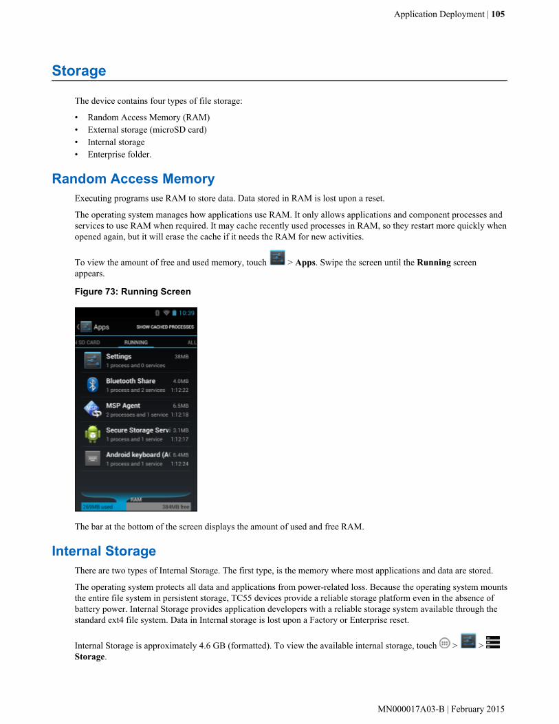
Storage
The device contains four types of file storage:
• Random Access Memory (RAM)• External storage (microSD card)• Internal storage• Enterprise folder.
Random Access MemoryExecuting programs use RAM to store data. Data stored in RAM is lost upon a reset.
The operating system manages how applications use RAM. It only allows applications and component processes andservices to use RAM when required. It may cache recently used processes in RAM, so they restart more quickly whenopened again, but it will erase the cache if it needs the RAM for new activities.
To view the amount of free and used memory, touch > Apps. Swipe the screen until the Running screenappears.
Figure 73: Running Screen
The bar at the bottom of the screen displays the amount of used and free RAM.
Internal StorageThere are two types of Internal Storage. The first type, is the memory where most applications and data are stored.
The operating system protects all data and applications from power-related loss. Because the operating system mountsthe entire file system in persistent storage, TC55 devices provide a reliable storage platform even in the absence ofbattery power. Internal Storage provides application developers with a reliable storage system available through thestandard ext4 file system. Data in Internal storage is lost upon a Factory or Enterprise reset.
Internal Storage is approximately 4.6 GB (formatted). To view the available internal storage, touch > > Storage.
Application Deployment | 105
MN000017A03-B | February 2015
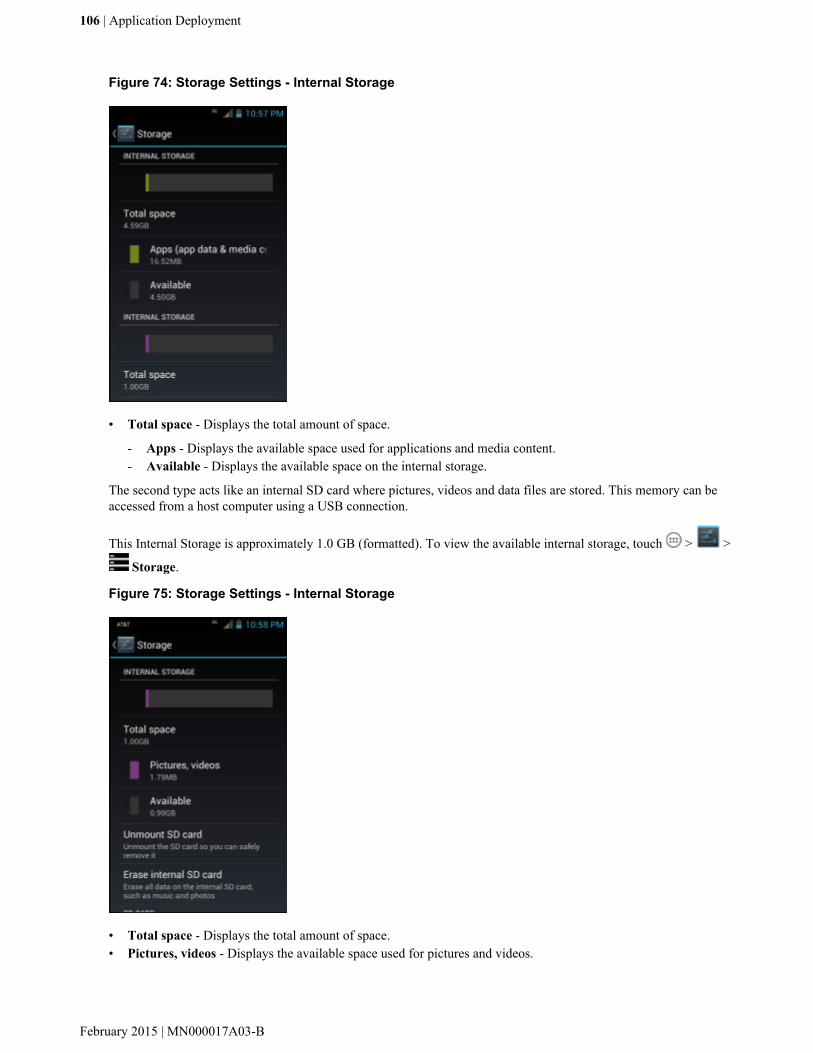
Figure 74: Storage Settings - Internal Storage
• Total space - Displays the total amount of space.
- Apps - Displays the available space used for applications and media content.- Available - Displays the available space on the internal storage.
The second type acts like an internal SD card where pictures, videos and data files are stored. This memory can beaccessed from a host computer using a USB connection.
This Internal Storage is approximately 1.0 GB (formatted). To view the available internal storage, touch > >
Storage.
Figure 75: Storage Settings - Internal Storage
• Total space - Displays the total amount of space.• Pictures, videos - Displays the available space used for pictures and videos.
106 | Application Deployment
February 2015 | MN000017A03-B

• Available - Displays the available space on the internal storage.• Unmount SD card - Unmounts the internal SD card.• Erase internal SD card - Permanently erases everything on the Internal Storage (internal SD card).
External StorageThe TC55 can have a removable microSD card. The microSD card content can be viewed and files copied to andfrom when the TC55 is connected to a host computer. Some applications are designed to be stored on the microSDcard rather than in internal memory.
To view the used and available space on the microSD card, touch > > Storage.
Figure 76: Storage Settings
• Total space - Displays the total amount of space on the installed microSD card.• Apps - Displays the available space used for applications and media content on the installed microSD card.• Pictures, videos - Displays the available space used for pictures and videos on the installed microSD card.• Available - Displays the available space on the installed microSD card.• Unmount SD card - Unmounts the installed microSD card from the TC55 so that it can be safely removed. This
setting is dimmed if there is no microSD card installed, if it has already been unmounted or if it has been mountedon a host computer.
• Erase external SD card - Permanently erases everything on the installed microSD card.
Enterprise FolderThe Enterprise folder (within internal flash) is a super-persistent storage that is persistent after a reset and anEnterprise Reset. The Enterprise folder is erased during a Factory Reset. The Enterprise folder is used for deploymentand device-unique data. The Enterprise folder is approximately 128 MB (formatted). Applications can persist dataafter an Enterprise Reset by saving data to the enterprise/user folder. The folder is ext4 formatted and is onlyaccessible from a host computer using ADB or from an MDM.
Application Deployment | 107
MN000017A03-B | February 2015
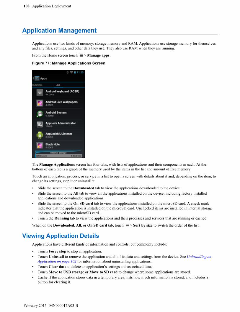
Application Management
Applications use two kinds of memory: storage memory and RAM. Applications use storage memory for themselvesand any files, settings, and other data they use. They also use RAM when they are running.
From the Home screen touch > Manage apps.
Figure 77: Manage Applications Screen
The Manage Applications screen has four tabs, with lists of applications and their components in each. At thebottom of each tab is a graph of the memory used by the items in the list and amount of free memory.
Touch an application, process, or service in a list to open a screen with details about it and, depending on the item, tochange its settings, stop it or uninstall it
• Slide the screen to the Downloaded tab to view the applications downloaded to the device.• Slide the screen to the All tab to view all the applications installed on the device, including factory installed
applications and downloaded applications.• Slide the screen to the On SD card tab to view the applications installed on the microSD card. A check mark
indicates that the application is installed on the microSD card. Unchecked items are installed in internal storageand can be moved to the microSD card.
• Touch the Running tab to view the applications and their processes and services that are running or cached
When on the Downloaded, All, or On SD card tab, touch > Sort by size to switch the order of the list.
Viewing Application DetailsApplications have different kinds of information and controls, but commonly include:
• Touch Force stop to stop an application.• Touch Uninstall to remove the application and all of its data and settings from the device. See Uninstalling an
Application on page 102 for information about uninstalling applications.• Touch Clear data to delete an application’s settings and associated data.• Touch Move to USB storage or Move to SD card to change where some applications are stored.• Cache If the application stores data in a temporary area, lists how much information is stored, and includes a
button for clearing it.
108 | Application Deployment
February 2015 | MN000017A03-B

• Launch by default clears If you have configured an application to launch certain file types by default, you canclear that setting here.
• Permissions lists the areas on the device that the application has access to.
Procedure:
1 Touch > Manage apps.2 Touch an application, process, or service.
The App Info screen lists the application name and version number, and details about the application. Dependingon the application and where it came from, it may also include buttons for managing the application’s data,forcing the application to stop, and uninstalling the application. It also lists details about the kinds of informationabout your phone and data that the application has access to.
Stopping an ApplicationTo monitor how much RAM running applications and cached processes are using and if necessary, stop them.
Procedure:
1 Touch > Manage apps.2 Swipe the screen to display the Running tab.3 Touch Show cached processes or Show running services to switch back and forth. The Running tab lists the
applications, processes, and services that are currently running or that have cached processes and how much RAMthey are using.
Figure 78: Running Applications
4 The graph at the bottom of the screen displays the total RAM in use and the amount free. Touch an application,process, or service.
5 Note: Stopping an application or operating system processes and services disables one or moredependant functions on the device. The device may need to be reset to restore full functionality.
Touch Stop.
Changing Application LocationSome applications are designed to be stored on a microSD card, rather than in internal storage. Others are designed soyou can change where they are stored. You may find it helpful to move large applications off of your internal storage,
Application Deployment | 109
MN000017A03-B | February 2015

to make more room for other applications that don’t offer the option. Many large applications are designed this wayfor exactly this reason.
Procedure:
1 Touch > Manage apps.2 Swipe the screen to display the On SD card tab.
The tab lists the applications that must be or can be stored on the microSD card. Each application lists the amountof storage it uses on internal storage (even when not stored there, all applications use at least a small amount ofinternal storage).Applications that are stored on the microSD card are checked.The graph at the bottom shows the amount of memory used and free of the microSD card: the total includes filesand other data, not just the applications in the list.
3 Touch an application in the list.The Storage section of the application’s details screen shows details about the memory used by the application. Ifthe application can be moved, the Move button is active.
4 Touch Move to SD card to move the bulk of the application from the device’s internal storage to the microSDcard.
5 Touch Move to phone to move the application back to the device’s internal storage.
Managing DownloadsFiles and applications downloaded using the Browser or Email are stored on the microSD card in the Downloaddirectory. Use the Downloads application to view, open, or delete downloaded items.
Procedure:
1 Touch .2
Touch .3 Touch an item to open it.4 Touch headings for earlier downloads to view them.5
Check items to delete; then touch . The item is deleted from storage.6 Touch Sort by size or Sort by time to switch back and forth.
When an application is opened, the other applications being used do not stop. The operating system andapplications work together to ensure that applications not being used do not consume resources unnecessarily,stopping and starting them as needed. For this reason, there’s no need to stop applications unless it is notfunctioning properly.
RxLogger
RxLogger is a comprehensive diagnostic tool that provides application and system metrics. It allows for custom plug-ins to be created and work seamlessly with this tool. RxLogger is used to diagnose device and application issues. Itsinformation tracking includes the following: CPU load, memory load, memory snapshots, battery consumption, powerstates, wireless logging, cellular logging, TCP dumps, Bluetooth logging, GPS logging, logcat, FTP push/pull, ANRdumps, etc. All logs and files generated are saved onto flash storage on the device (internal or external).
RxLogger ConfigurationRxLogger is built with an extensible plug-in architecture and comes packaged with a number of plugins already built-in. The included plug-ins are described below. Touch Settings to open the configuration screen.
110 | Application Deployment
February 2015 | MN000017A03-B

Main Log Plug-inThe Main log presents a high level timeline view of the device health in an easy to read comma-separated values(CSV) format. The log contains many of the key parameters of various subsystems and is meant to be used as a firstlevel triage that can potentially point to a range of specific detailed logs to look at. The two rightmost columns in theCSV file allow the log modules and plug-ins to insert asynchronous event based messages into the log. This is usefulso that by looking at the CSV log you can see when snapshots have been created or when the tool has detected anapplication to be unresponsive. It is also used to show power events such as AC/DC power transitions.
• Log Interval - Specifies the interval, in milliseconds, to poll the collected parameters and write the data to theCSV log file.
• Log path - Specifies the base log path to store the CSV log file. The default to use the default external storagedirectory which is queried from the Android system.
• Log base filename - The base filename to use for the CSV file before appending the index number of thatparticular log file. For example, if the base filename is Resource and we are rotating through two log files, theactual filename will be: Resource0.csvand Resource1.csv.
• Log file count - Specifies the number of files to rotate through. Each file is constrained by the Log max sizeoption.
• Log max size - Specifies the maximum size, in kilobytes, of each log file for the main CSV log.• Power- Enables logging of power related parameters and events. These include battery stats (capacity, current,
voltage, etc) and AC/DC power notification events.• System resources - Enables logging of CPU and memory related items (Avg/current CPU load, program memory,
storage memory, process count, etc).• Wifi - Enables logging of wireless LAN items (WLAN power, signal strength, essid, connected AP, etc).• Cellular - Enables logging of wireless WAN items (WAN power, network type, signal strength, connected cell
tower, etc).• Network - Enables logging of network items (IP address, default gateway, etc).• Bluetooth - Enables logging of Bluetooth items (Bluetooth power, discoverable, connected, etc).• GPS - Enables logging of GPS data (position, speed, etc).• GPS update frequency - Specifies the frequency of GPS updates requested from the system. This setting can
greatly affect battery life when using the tool. Frequent GPS updates will use a lot of power and the effects aregreater if the device is indoors where a position cannot be obtained.
• Output - The output is a set of comma separated files containing the requested data. The number of files and thefile size is determined by the configuration. These files can be viewed using Microsoft Excel.
Snapshot Plug-in• Log path - Specifies the base path to use to store the snapshot files• Log filename - Specifies the base filename for all the snapshot files. This file number will be appended to this
base filename when saving the snapshot.• Log interval - Specifies the interval, in milliseconds, on which to invoke a detailed snapshot.• Log file count - The number of snapshot files to keep on the filesystem. Once the maximum number of files is
reached, the existing files will start to be overwritten.• Log CPU usage - Enables detailed per process CPU logging in the snapshot.• Log memory usage - Enables logging of detailed per process memory usage in the snapshot.• Log power info - Enables logging of detailed power information including battery life, on time, charging, and
wake locks.• Log processes - Enables dumping the complete process list in the snapshot.• Log threads - Enables dumping all processes and their threads in the snapshot.• Log system properties - Enables dumping of all system properties on the device. This includes build/version
information as well as state information.• Log network info - Enables dumping of all available network interfaces and the routing table.• Log filesystem info - Enables dumping of the available volumes on the file system and the free storage space for
each.
Application Deployment | 111
MN000017A03-B | February 2015

• Log usage stats - Enables dumping of detailed usage information for each package on the device. This includesthe number of starts and duration of each run.
• Output - The snapshot plug-in outputs a series of individual snapshot files. Every snapshot creates a new file andeach file is not limited in size. The disk usage is managed by keeping a pool of log files with a configurable size.
Logcat Plug-inLogcat is an essential debugging tool on Android devices. RxLogger provides the ability to record data from all fourof the available logcat buffers. The Logcat plug-in has the ability to collect data from multiple logcat buffers providedby the system. Currently these are the main, event, radio, and system buffers. Each of the settings are available foreach buffer independently unless otherwise noted.
• Log path - Specifies the high level log path for storage of all logcat logs. This setting applies globally to all logcatbuffers.
• Enable logcat - Enables logging for this logcat buffer.• Log interval - Sets the interval, in milliseconds, on which to flush the log buffer to the file.• Log filename - Specifies the base log filename for this logcat buffer. The current file count is appended to this
name.• Log file count - Specifies the number of log files to keep and rotate through. Each log file is subject to the max
log size option.• Max log size - Specifies the maximum size, in kilobytes, of an individual log file.• Output - The logcat plug-in outputs a series of text files in accordance with the configuration. The files contain
the output of the logcat buffer flushed at the specified interval.
PushPullClient Plug-inThe PushPullClient plug-in is designed to automatically push log files to a remote FTP server on a regular basis. Italso has the capability to pull a remote file from the FTP server to a local directory on the device to automatically pulldown a new configuration file so that the configuration of the tool can be set and updated remotely. The tool uses aflag file on the FTP site (based on device serial number) to ensure the file is only pulled once. By removing the flagfile for a particular device you can force it to download the file again.
• Hostname - Specifies the ftp server to connect to.• Username - Specifies the username to use to log onto the FTP server.• Password - Specifies the password to use to log onto the FTP server.• Enable push - Enables pushing of file to the specified FTP server.• Push interval - Specifies the amount of time, in milliseconds, in between pushes to the FTP server.• Local push directory - Specifies the local directory to push files from.• Remote push directory - Specifies the remote directory to push files to. A separate folder will be created for each
device using the device serial number.• Wakeup for push time - If the pull interval is set to 0, this will specify a specific time to initiate an FTP push.• Do push on start - Enable an FTP push upon startup of the plug-in.• Enable pull - Enable FTP pull functionality.• Pull interval - Specifies the amount of time, in milliseconds, in between pulls from the FTP server.• Remote pull directory - Specifies the directory on the FTP server where the filed to be pulled will be located.• Remote pull filename - Specifies the file to be pulled from the FTP server.• Local pull directory - Specifies the local directory to store the file pulled from the FTP server.
TCPDump Plug-inThe TCPDump plug-in facilitates the capturing of network traces to be viewed in Wireshark or a similar tool that candecode .cap files.
• Log path - Specifies the location to store the TCPDump output log files.• Base filename - Specifies the base filename to use when storing the TCPDump files. The index number of the
current log file will be appended to this filename.
112 | Application Deployment
February 2015 | MN000017A03-B

• Log file count - Specifies the number of log files to cycle through when storing the network traces.• Max file size - Specifies the maximum file size, in megabytes, for each log file created.• Output - The TCPDump plug-in outputs a set of .cap files according to the configurable options. These are binary
files and can be opened with Wireshark tool.
ANR PluginApplication Not Responsive (ANR) indicates that a running application’s UI thread is not responding for a specifiedtime period. RxLogger is able to detect this condition and trigger a copy of the call stack trace of the unresponsiveapplication into the log directory. The event will also be indicated in the high level CSV log.
• Log path - Specifies the default log path to store the ANR log files.• Max file size - Specifies the maximum file size, in killobytes, of the ANR trace to be copied. If the file is too
large, the copy will be skipped. On older devices that append each ANR event to the same trace file the size canget very large. In this case we will avoid expending resources to copy the large file every time.
• Output - The ANR plug-in creates text files in the specified log directory that contain the call stacks ofapplication’s that have been shut down by the system due to an ANR event.
Kernal Plug-in• Enable Plugin - Enables logging for this kernal buffer.• Log path - Specifies the high level log path for storage of all kernal logs. This setting applies globally to all kernal
buffers.• Kernal Log filename - Specifies the base log filename for this kernal buffer. The current file count is appended to
this name.• Max Kernal log size - Specifies the maximum size, in kilobytes, of an individual log file.• Kernal Log interval - Sets the interval, in milliseconds, on which to flush the log buffer to the file.• Kernal Log file count - Specifies the number of log files to keep and rotate through. Each log file is subject to the
max log size option.• Output - The kernal plug-in outputs a series of text files in accordance with the configuration. The files contain
the output of the kernal buffer flushed at the specified interval.
Configuration FileRxLogger configuration can be set using an XML file. The config.xml configuration file is located on themicroSD card in the RxLogger\config folder. Copy the file from the device to a host computer using a USBconnection. Edit the configuration file and the replace the .XML file on the device. There is no need to stop andrestart the RxLogger service since the file change is automatically detected.
Enabling LoggingProcedure:
1 Touch .2
Touch .3 Touch Start.4 Touch .
Disabling LoggingProcedure:
1 Touch .2
Touch .
Application Deployment | 113
MN000017A03-B | February 2015

3 Touch Stop.4 Touch .
Extracting Log FilesProcedure:
1 Connect the device to a host computer using an USB connection.2 Using a file explorer, navigate to the RxLogger folder.3 Copy the file from the device to the host computer.4 Disconnect the device from the host computer.
MLog Manager
The MLog Manager allows the user to export operating system and modem logs. Analyzing the exported logs canprovide visibility into the system internal behavior and may help determining root causes of the system faults andissues.
Sub-systems
• MLog Manager
- Built-in user interface (UI) application for users.- Exports logs using UI button requests.- Supports B2M Elemez client requests.- Sets MLog parameters (e.g. Persisting-Logs and Export-Logs-Upon-Boot).
• MLog Services
- Built-in daemon service.- Synchronizes access to the MLog service functions.- Reads incoming logs messages from the Android (kernel/firmware) drivers and the modem sub-system.- Writes the Android logs circularly into a secured ‘logs’ partition (only when the ‘Persisting Logs’ mode is
active).- Exports logs data automatically to a microSD card (only when Export Logs upon Boot mode is active).
Log DescriptionsThe MLog system provides the ability to export Android and modem logs using the MLog Manager
• Android
- Framework/Kernel Logs - captures standard Android system messages, including errors, warnings andinformational messages that have been written from Android applications, services and drivers.
- TombStones/ANRs Logs - captures important information of native crashed process, which includeterminated signal and fault address, CPU registers, and the crashed process call-stack.
- AbnormalResets/Recovery/FWL Logs
+ captures all the abnormal resets that occur on the TC55, e.g. reset that occur to the TC55 as result of batteryreplacement.
+ captures all the upgrades and downgrades that are done to the TC55 via the recovery mechanism.+ captures the Flash health values any time it changes.
- AppNoRespond Logs - captures Java level stack traces of an Android crashed application.- Export All Logs - captures all of the above logs at once.
• QXDM
114 | Application Deployment
February 2015 | MN000017A03-B

- captures baseband system messages, which include errors, warnings and informational messages. Choose thefilter by what you did on the WAN function. The filter are voice call (CS), data call (PS), GPS (GNSS),network (NW), SIM card, SMS and STK issue. If you cannot recognize where the issue is, use 234G filter tocapture the log before your testing.
Exporting QXDM LogsProcedure:
1 Touch .2
Touch .3 On the QXDM tab, touch Start Qxdm Logging.4 On the Choose log filter dialog box, select one of the options:
• 234G• CS (Voice call)• GNSS (GPS)• NW (network)• PS (Data call)• SIM (SIM card)• SMS• STK• User Defined
5 Select a filter.The TC55 starts collecting the select data.
Application Deployment | 115
MN000017A03-B | February 2015


Chapter
8Maintenance and Troubleshooting
This chapter includes instructions on cleaning and storing the device, and provides troubleshooting solutions forpotential problems during operation.
Maintaining the TC55
For trouble-free service, observe the following tips when using the TC55:
• Do not scratch the screen of the TC55. When working with the TC55, use a finger, glove or approved stylus orpen intended for use with a capacitive touch-sensitive screen. Never use an actual pen or pencil or other sharpobject on the surface of the TC55 screen.
• The touch-sensitive screen of the TC55 is glass. Do not to drop the TC55 or subject it to strong impact.• Protect the TC55 from temperature extremes. Do not leave it on the dashboard of a car on a hot day, and keep it
away from heat sources.• Do not store or use the TC55 in any location that is dusty, damp, or wet.• Use a soft lens cloth to clean the TC55. If the surface of the TC55 screen becomes soiled, clean it with a soft cloth
moistened with isopropyl alcohol.• Periodically replace the rechargeable battery to ensure maximum battery life and product performance. Battery
life depends on individual usage patterns.
Battery Safety Guidelines
• The area in which the units are charged should be clear of debris and combustible materials or chemicals.Particular care should be taken where the device is charged in a non commercial environment.
• Follow battery usage, storage, and charging guidelines found in this guide.• Improper battery use may result in a fire, explosion, or other hazard.• To charge the mobile device battery, the battery and charger temperatures must be between +32 ºF and +104 ºF (0
ºC and +40 ºC)• To charge the mobile device battery, the battery and charger temperatures must be between 0 ºC and +45 ºC (+32
ºF and +113 ºF)• Do not use incompatible batteries and chargers. Use of an incompatible battery or charger may present a risk of
fire, explosion, leakage, or other hazard. If you have any questions about the compatibility of a battery or acharger, contact the Global Customer Support Center.
• For devices that utilize a USB port as a charging source, the device shall only be connected to products that bearthe USB-IF logo or have completed the USB-IF compliance program.
• To enable authentication of an approved battery, as required by IEEE1725 clause 10.2.1, all batteries will carry ahologram. Do not fit any battery without checking it has the authentication hologram.
• Do not disassemble or open, crush, bend or deform, puncture, or shred.• Severe impact from dropping any battery-operated device on a hard surface could cause the battery to overheat.• Do not short circuit a battery or allow metallic or conductive objects to contact the battery terminals.
117 | Maintenance and Troubleshooting
MN000017A03-B | February 2015
• Do not modify or remanufacture, attempt to insert foreign objects into the battery, immerse or expose to water orother liquids, or expose to fire, explosion, or other hazard.
• Do not leave or store the equipment in or near areas that might get very hot, such as in a parked vehicle or near aradiator or other heat source. Do not place battery into a microwave oven or dryer.
• Battery usage by children should be supervised.• Please follow local regulations to properly dispose of used re-chargeable batteries.• Do not dispose of batteries in fire.• In the event of a battery leak, do not allow the liquid to come in contact with the skin or eyes. If contact has been
made, wash the affected area with large amounts of water and seek medical advice.• If you suspect damage to your equipment or battery, contact the Global Customer Support Center to arrange for
inspection.
Cleaning Instructions
Caution:
Always wear eye protection.
Read warning label on compressed air and alcohol product before using.
If you have to use any other solution for medical reasons please contact Zebra for more information.
Warning: Avoid exposing this product to contact with hot oil or other flammable liquids. If such exposureoccurs, unplug the device and clean the product immediately in accordance with these guidelines.
Approved Cleanser Active Ingredients100% of the active ingredients in any cleaner must consist of one or some combination of the following: isopropylalcohol, or mild dish soap.
Harmful IngredientsThe following chemicals are known to damage the plastics on the device and should not come in contact with thedevice: ammonia solutions, compounds of amines or ammonia; acetone; ketones; ethers; aromatic and chlorinatedhydrocarbons; acqueous or alcoholic alkaline solutions; ethanolamine; toluene; trichloroethylene; benzene; carbolicacid and TB-lysoform.
Cleaning InstructionsDo not apply liquid directly to the device. Dampen a soft cloth or use pre-moistened wipes. Do not wrap the device inthe cloth or wipe, but gently wipe the unit. Be careful not to let liquid pool around the display window or other places.Allow the unit to air dry before use.
Special Cleaning NotesMany vinyl gloves contain phthalate additives, which are often not recommended for medical use and are known tobe harmful to the housing of the device. The device should not be handled while wearing vinyl gloves containingphthalates, or before hands are washed to remove contaminant residue after gloves are removed. If productscontaining any of the harmful ingredients listed above are used prior to handling the device, such as hand sanitizerthat contain ethanolamine, hands must be completely dry before handling the device to prevent damage to the plastics.
Cleaning Materials Required• Alcohol wipes• Lens tissue• Cotton-tipped applicators
118 | Maintenance and Troubleshooting
February 2015 | MN000017A03-B

• Isopropyl alcohol• Can of compressed air with a tube.
Cleaning FrequencyThe cleaning frequency is up to the customer’s discretion due to the varied environments in which the mobile devicesare used. They may be cleaned as frequently as required, but it is advisable to clean the camera window periodicallywhen used in dirty environments to ensure optimum performance.
Cleaning the TC55
HousingUsing the alcohol wipes, wipe the housing including buttons.
DisplayThe display can be wiped down with the alcohol wipes, but care should be taken not to allow any pooling of liquidaround the edges of the display. Immediately dry the display with a soft, non-abrasive cloth to prevent streaking.
Camera and Exit WindowWipe the camera and exit window periodically with a lens tissue or other material suitable for cleaning opticalmaterial such as eyeglasses.
Connector CleaningTo clean the connectors:
Procedure:
1 Remove the main battery from mobile computer.2 Dip the cotton portion of the cotton-tipped applicator in isopropyl alcohol.3 Rub the cotton portion of the cotton-tipped applicator back-and-forth across the connector. Do not leave any
cotton residue on the connector.4 Repeat at least three times.5 Use the cotton-tipped applicator dipped in alcohol to remove any grease and dirt near the connector area.6 Use a dry cotton-tipped applicator and repeat steps 4 through 6.
Caution: Do not point nozzle at yourself and others, ensure the nozzle or tube is away from your face.
7 Spray compressed air on the connector area by pointing the tube/nozzle about ½ inch away from the surface.8 Inspect the area for any grease or dirt, repeat if required.
Cleaning Cradle ConnectorsTo clean the connectors on a cradle:
Procedure:
1 Remove the DC power cable from the cradle.2 Dip the cotton portion of the cotton-tipped applicator in isopropyl alcohol.3 Rub the cotton portion of the cotton-tipped applicator along the pins of the connector. Slowly move the applicator
back-and-forth from one side of the connector to the other. Do not leave any cotton residue on the connector.4 All sides of the connector should also be rubbed with the cotton-tipped applicator.
Maintenance and Troubleshooting | 119
MN000017A03-B | February 2015

Caution: Do not point nozzle at yourself and others, ensure the nozzle or tube is pointed away fromyour face.
5 Spray compressed air in the connector area by pointing the tube/nozzle about ½ inch away from the surface.6 Remove any lint left by the cotton-tipped applicator.7 If grease and other dirt can be found on other areas of the cradle, use a lint-free cloth and alcohol to remove.8 Allow at least 10 to 30 minutes (depending on ambient temperature and humidity) for the alcohol to air dry before
applying power to cradle.If the temperature is low and humidity is high, longer drying time is required. Warm temperature and dry humidityrequires less drying time.
Troubleshooting
The following tables provides typical problems that might arise and the solution for correcting the problem.
Troubleshooting the TC55Table 4: Troubleshooting the TC55
Problem Cause Solution
When the user pressesthe Power button, theTC55 does not turn on.
Battery is com-pletely dis-charged.
Re-charge or replace the battery.
Battery not instal-led properly.
Install the battery properly. See Installing the Battery.
Power button notheld down longenough.
Press the Power button until the LED lights green.
TC55 not re-sponding.
Perform a hard reset. See Resetting the TC55.
When the user pressesthe Power button theTC55 does not turn onbut a charge battery iconappears on the screen.
Battery chargelevel is very low.
Re-charge or replace the battery.
After connecting theTC55 to the RuggedCharge Cable, a batterycharging icon appears onthe screen.
Battery is deplet-ed but is charg-ing.
Press and hold the Power button to turn on the TC55.
When charging, the LEDslowly blinks red.
The TC55 is at anextremely lowpower state.
Charge the TC55 for a few minutes. The LED will change to flashinggreen then press the Power button to turn on the TC55. If LED con-tinuously blinks red, check power connections. Disconnect and recon-nect connections.
Battery did not charge. Battery failed. Replace battery. If the TC55 still does not operate, perform a hard-ware reset.
Table continued…
120 | Maintenance and Troubleshooting
February 2015 | MN000017A03-B

Problem Cause Solution
TC55 was re-moved from pow-er while batterywas charging.
Insert TC55 in cradle or attach Charge Cable. The 2940 mAh batteryfully charges in approximately three hours and the 4410 mAh batterycharges in approximately 4.5 hours.
Extreme batterytemperature.
Battery does not charge if ambient temperature is below 0 °C (32 °F)or above 40 °C (104 °F).
During data communica-tion with a host comput-er, no data transmitted,or transmitted data wasincomplete.
TC55 removedfrom USB cableor disconnectedfrom host com-puter during com-munication.
Reattach the communication cable and re-transmit.
Incorrect cableconfiguration.
See the system administrator.
During data communica-tion over Wi-Fi, no datatransmitted, or transmit-ted data was incomplete.
Wi-Fi radio is noton.
Turn on the Wi-Fi radio.
You moved outof range of an ac-cess point.
Move closed to an access point.
During data communica-tion over Bluetooth, nodata transmitted, ortransmitted data was in-complete.
Bluetooth radio isnot on.
Turn on the Bluetooth radio.
You moved outof range of anoth-er Bluetooth de-vice.
Move without 10 m (32.8 ft.) of the other device.
During data communica-tion over WAN, no datatransmitted, or transmit-ted data was incomplete.
You are in anarea of poor cel-lular service.
Move into an area that has better service.
APN is not set upcorrectly.
See system administrator for APN setup information.
SIM card not in-stalled properly.
Remove and re-install the SIM card. See Installing the SIM Card onpage 15.
Data plan not ac-tivated.
Contact your service provider and ensure that your data plan is ena-ble.
No sound. Volume setting islow or turned off.
Adjust the volume.
TC55 turns off. TC55 is inactive. The display turns off after a period of inactivity. Set this period to 15seconds, 30 seconds, 1, 2, 5, 10, or 30 minutes.
Battery is deplet-ed.
Recharge or replace the battery.
Extreme batterytemperature.
Move device to an area where the ambient temperature is between -10°C (+14 °F) and +60 °C (+140 °F).
Table continued…
Maintenance and Troubleshooting | 121
MN000017A03-B | February 2015
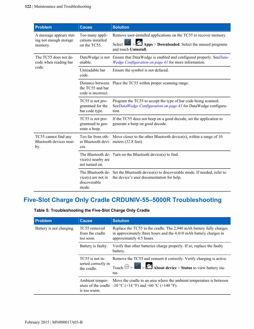
Problem Cause Solution
A message appears stat-ing not enough storagememory.
Too many appli-cations installedon the TC55.
Remove user-installed applications on the TC55 to recover memory.
Select > Apps > Downloaded. Select the unused programsand touch Uninstall.
The TC55 does not de-code when reading barcode.
DataWedge is notenable.
Ensure that DataWedge is enabled and configured properly. SeeData-Wedge Configuration on page 41 for more information.
Unreadable barcode.
Ensure the symbol is not defaced.
Distance betweenthe TC55 and barcode is incorrect.
Place the TC55 within proper scanning range.
TC55 is not pro-grammed for thebar code type.
Program the TC55 to accept the type of bar code being scanned.SeeDataWedge Configuration on page 41 for DataWedge configura-tion.
TC55 is not pro-grammed to gen-erate a beep.
If the TC55 does not beep on a good decode, set the application togenerate a beep on good decode.
TC55 cannot find anyBluetooth devices near-by.
Too far from oth-er Bluetooth devi-ces.
Move closer to the other Bluetooth device(s), within a range of 10meters (32.8 feet).
The Bluetooth de-vice(s) nearby arenot turned on.
Turn on the Bluetooth device(s) to find.
The Bluetooth de-vice(s) are not indiscoverablemode.
Set the Bluetooth device(s) to discoverable mode. If needed, refer tothe device’s user documentation for help.
Five-Slot Charge Only Cradle CRDUNIV-55–5000R TroubleshootingTable 5: Troubleshooting the Five-Slot Charge Only Cradle
Problem Cause Solution
Battery is not charging. TC55 removedfrom the cradletoo soon.
Replace the TC55 in the cradle. The 2,940 mAh battery fully chargesin approximately three hours and the 4,410 mAh battery charges inapproximately 4.5 hours.
Battery is faulty. Verify that other batteries charge properly. If so, replace the faultybattery.
TC55 is not in-serted correctly inthe cradle.
Remove the TC55 and reinsert it correctly. Verify charging is active.
Touch > > About device > Status to view battery sta-tus.
Ambient temper-ature of the cradleis too warm.
Move the cradle to an area where the ambient temperature is between-10 °C (+14 °F) and +60 °C (+140 °F).
122 | Maintenance and Troubleshooting
February 2015 | MN000017A03-B

Chapter
9Technical Specifications
The following sections provide technical specification for the device.
TC55 Technical Specifications
The following table summarize the TC55’s intended operating environment and technical hardware specifications.
Table 6: TC55 Technical Specifications
Item Description
Physical Characteristics
Dimensions Height: 137 mm (5.4 in.)
Width: 69 mm (2.7 in.)
Depth (with 2,940 mAh battery): 15.9 mm (0.63 in.)
Depth (with 4,410 mAh battery): 22.5 mm (0.89 in.)
Weight TC55 with linear imager 2,940 mAh battery: 218 g (7.7 oz)
TC55 with linear imager 4,410 mAh battery: 254 g (9.0 oz)
TC55 with 2D imager 2,940 mAh battery: 222 g (7.8 oz)
TC55 with 2D imager 4,410 mAh battery: 258 g (9.1 oz)
Display 4.3 in. color WVGA; 800 x 480, 700 NITs
Touch Panel Gorilla Glass® 2
Backlight LED backlight
Battery Pack Rechargeable Lithium Ion 3.7V, 2,940 or 4,410 mAh Smart battery
Expansion Slot User accessible microSD slot, up to 32 GB.
Connectivity USB 2.0 (Host/Client)
Notification LED, audio and vibration.
Keypad Options On-screen keyboard and 4 capacitive front panel keys.
Audio Speakers, dual noise cancelling microphones and headset connector (3.5 mm jackwith microphone).Three speakers, including two front facing speakers; dual noise-cancelling microphones; high-quality speaker phone; 3.5 mm headset jack andBluetooth wireless headset support.
Table continued…
123 | Technical Specifications
MN000017A03-B | February 2015

Item Description
Performance Characteristics
CPU 1.5 GHz Dual Core Processor
Operating System Professional Configuration – Android-based, Android Open-Source Project(AOSP) 4.1.2 or 4.4.3
Standard Configuration – Android-based, Android Open-Source Project (AOSP)4.1.2 with Google Mobile Services.
Memory 1 GB RAM, 8 GB Flash
Output Power (USB) 300 mA
User Environment
Operating Temperature –10 °C to 50 °C (14 °F to 122 °F)
Storage Temperature -40 °C to 70 °C (-40 °F to 158 °F)
Charging Temperature 0° C to 40° C (32 °F to 104 °F)
Humidity 5% to 85% RH non-condensing
Drop Specification Multiple 1.2 m (4 ft.) drops per MIL-STD 810G specifications.
With protective boot: Multiple 1.2 m (4 ft.) drops to concrete across the operatingtemperature range.
Tumble Specification 150 0.5 m (1.5 ft.) tumbles (300 drops);
With protective boot: 300 0.5 m (1.5 ft.) tumbles (600 drops); per applicable IECtumble specifications.
Sealing IP67 per applicable IEC sealing specifications.
Wireless WAN Data and Voice Communications
Wireless Wide Area Network(WWAN) radio
4G LTE, HSPA+, DC-HSPA, EDGE/GPRS/GSM
Frequency band TC55AH:
GSM/EDGE: 850/900/1800/1900 MHz
WCDMA: FDD2, FDD4, FDD5, FDD17
LTE Americas:LTE Band 2, LTE Band 5, LTE Band 17
TC55BH:
GSM/EDGE: 850/900/1800/1900 MHz
WCDMA: FDD1, FDD2, FDD5, FDD8
TC55CH:
CDMA/EVDO: 850/1900 MHz (BC0/BC1)
LTE: Band 13
GPS Integrated, Autonomous, Assisted-GPS (A-GPS), GLONASS
Wireless LAN Data CommunicationsTable continued…
124 | Technical Specifications
February 2015 | MN000017A03-B
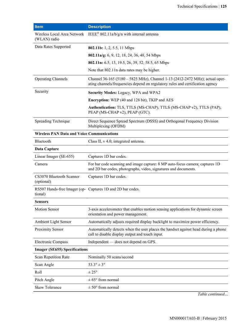
Item Description
Wireless Local Area Network(WLAN) radio
IEEE® 802.11a/b/g/n with internal antenna
Data Rates Supported 802.11b: 1, 2, 5.5, 11 Mbps
802.11a/g: 6, 9, 12, 18, 24, 36, 48, 54 Mbps
802.11n: 6.5, 13, 19.5, 26, 39, 52, 58.5, 65 Mbps
Note that 802.11n data rates may be higher.
Operating Channels Channel 36-165 (5180 – 5825 MHz), Channel 1-13 (2412-2472 MHz); actual oper-ating channels/frequencies depend on regulatory rules and certification agency
Security Security Modes: Legacy, WPA and WPA2
Encryption: WEP (40 and 128 bit), TKIP and AES
Authentication: TLS, TTLS (MS-CHAP), TTLS (MS-CHAP v2), TTLS (PAP),PEAP (MS-CHAP v2), PEAP (GTC).
Spreading Technique Direct Sequence Spread Spectrum (DSSS) and Orthogonal Frequency DivisionMultiplexing (OFDM)
Wireless PAN Data and Voice Communications
Bluetooth Class II, v 4.0; integrated antenna.
Data Capture
Linear Imager (SE-655) Captures 1D bar codes.
Camera For bar code scanning and image capture: 8 MP auto-focus camera; captures 1Dand 2D bar codes, photographs, video, signatures and documents.
CS3070 Bluetooth Scanner(optional)
Captures 1D bar codes.
RS507 Hands-free Imager (op-tional)
Captures 1D and 2D bar codes.
Sensors
Motion Sensor 3-axis accelerometer that enables motion sensing applications for dynamic screenorientation and power management.
Ambient Light Sensor Automatically adjusts required display backlight to maximize power efficiency.
Proximity Sensor Automatically detects when the user places the handset against head during a phonecall to disable display output and touch input.
Electronic Compass Independent — does not depend on GPS.
Imager (SE655) Specifications
Scan Repetition Rate Nominally 50 scans/second
Scan Angle 53.3° ± 3°
Roll ± 25°
Pitch Angle ± 65° from normal
Skew Tolerance ± 50° from normalTable continued…
Technical Specifications | 125
MN000017A03-B | February 2015
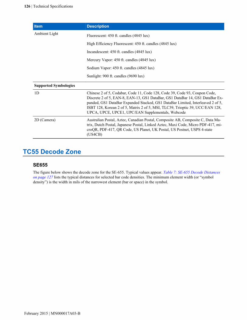
Item Description
Ambient Light Fluorescent: 450 ft. candles (4845 lux)
High Efficiency Fluorescent: 450 ft. candles (4845 lux)
Incandescent: 450 ft. candles (4845 lux)
Mercury Vapor: 450 ft. candles (4845 lux)
Sodium Vapor: 450 ft. candles (4845 lux)
Sunlight: 900 ft. candles (9690 lux)
Supported Symbologies
1D Chinese 2 of 5, Codabar, Code 11, Code 128, Code 39, Code 93, Coupon Code,Discrete 2 of 5, EAN-8, EAN-13, GS1 DataBar, GS1 DataBar 14, GS1 DataBar Ex-panded, GS1 DataBar Expanded Stacked, GS1 DataBar Limited, Interleaved 2 of 5,ISBT 128, Korean 2 of 5, Matrix 2 of 5, MSI, TLC39, Trioptic 39, UCC/EAN 128,UPCA, UPCE, UPCE1, UPC/EAN Supplementals, Webcode
2D (Camera) Australian Postal, Aztec, Canadian Postal, Composite AB, Composite C, Data Ma-trix, Dutch Postal, Japanese Postal, Linked Aztec, Maxi Code, Micro PDF-417, mi-croQR, PDF-417, QR Code, US Planet, UK Postal, US Postnet, USPS 4-state(US4CB)
TC55 Decode Zone
SE655The figure below shows the decode zone for the SE-655. Typical values appear. Table 7: SE-655 Decode Distanceson page 127 lists the typical distances for selected bar code densities. The minimum element width (or “symboldensity”) is the width in mils of the narrowest element (bar or space) in the symbol.
126 | Technical Specifications
February 2015 | MN000017A03-B
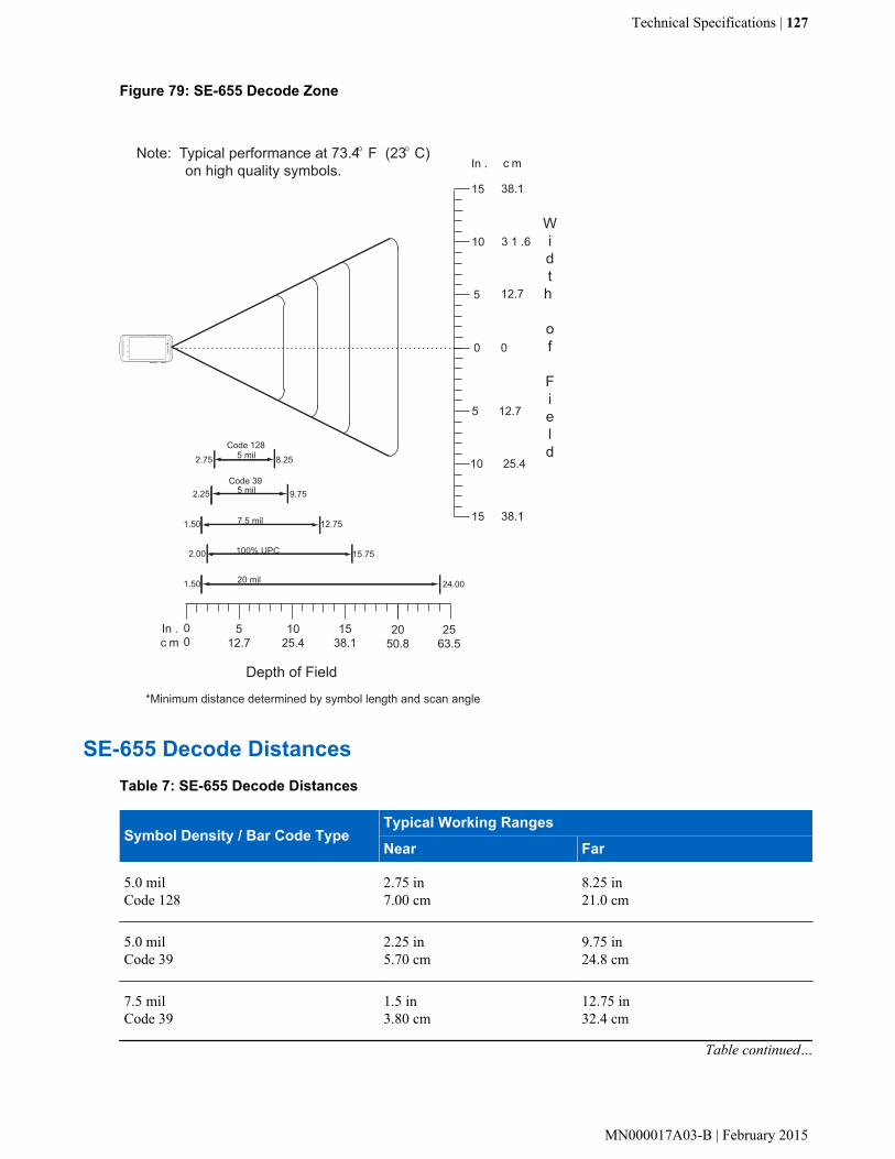
Figure 79: SE-655 Decode Zone
In .c m
00
0
5
5
In . c m
Width
of
Field
10
10
0
12.7
12.7
25.4
3 1 .6
15 38.1
15 38.1
Note: Typical performance at 73.4 F (23 C) on high quality symbols.
*Minimum distance determined by symbol length and scan angle
Depth of Field
512.7
1025.4
1538.1
2050.8
O O
2563.5
5 mil 9.75
7.5 mil
100% UPC
12.75
15.75
24.00
2.00
20 mil
2.25
1.50
1.50
5 mil 8.252.75Code 128
Code 39
SE-655 Decode DistancesTable 7: SE-655 Decode Distances
Symbol Density / Bar Code TypeTypical Working Ranges
Near Far
5.0 milCode 128
2.75 in7.00 cm
8.25 in21.0 cm
5.0 milCode 39
2.25 in5.70 cm
9.75 in24.8 cm
7.5 milCode 39
1.5 in3.80 cm
12.75 in32.4 cm
Table continued…
Technical Specifications | 127
MN000017A03-B | February 2015
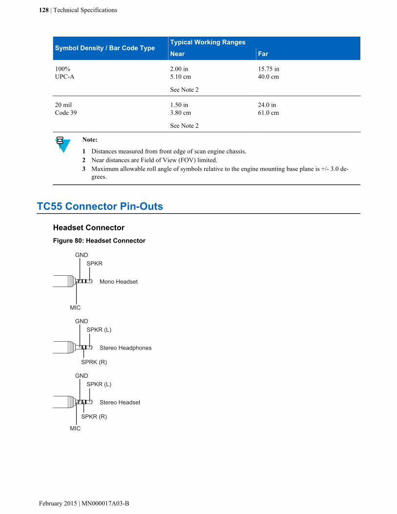
Symbol Density / Bar Code TypeTypical Working Ranges
Near Far
100%UPC-A
2.00 in5.10 cm
See Note 2
15.75 in40.0 cm
20 milCode 39
1.50 in3.80 cm
See Note 2
24.0 in61.0 cm
Note:
1 Distances measured from front edge of scan engine chassis.2 Near distances are Field of View (FOV) limited.3 Maximum allowable roll angle of symbols relative to the engine mounting base plane is +/- 3.0 de-
grees.
TC55 Connector Pin-Outs
Headset ConnectorFigure 80: Headset Connector
SPKRGND
MIC
Mono Headset
SPKR (L)GND
SPRK (R)
Stereo Headphones
SPKR (L)GND
SPKR (R)
MIC
Stereo Headset
128 | Technical Specifications
February 2015 | MN000017A03-B

Table 8: Headset Connector Pin-Outs
Signal name Description
MIC Microphone positive
SPKR Speaker (mono)
SPKR (R) Right Speaker
SPKR (L) Left Speaker
GND Ground
Power ConnectorFigure 81: Power Connector
1 2
Table 9: Power Connector Pin-Outs
Pin Description
1 +5 VDC input power.
2 Ground
USB ConnectorFigure 82: micro-B USB Connector
Pin 1 Pin 5
Table 10: micro-B USB Connector Pin-Outs
Pin Description
1 +5 VDCTable continued…
Technical Specifications | 129
MN000017A03-B | February 2015

Pin Description
2 Data -
3 Data +
4 Permits distinction of host connection from slave
5 Signal ground
Five-Slot Charge Only Cradle CRDUNIV-55-5000R TechnicalSpecifications
Table 11: Five-Slot Charge Only Cradle Technical Specifications
Item Description
Dimensions Height: 90.1 mm (3.5 in.)
Width: 449.6 mm (17.7 in.)
Depth: 120.3 mm (4.7 in.)
Weight 1.31 kg (2.89 lbs.)
Input Voltage 12 VDC
Power Consumption 37.5 watts
Operating Temperature 0 °C to 50 °C (32 °F to 122 °F)
Storage Temperature -40 °C to 70 °C (-40 °F to 158 °F)
Charging Temperature 0 °C to 40 °C (32 °F to 104 °F)
Humidity 0% to 95% non-condensing
Drop 76.2 cm (30.0 in.) drops to vinyl tiled concrete at room temperature.
Electrostatic Discharge (ESD) +/- 15 kV air
+/- 8 kV contact
130 | Technical Specifications
February 2015 | MN000017A03-B

Chapter
10Keypad Remap Strings
Table 12: Remap Key Event/Scancodes
Key Event Scancode
SOFT_LEFT 105
SOFT_RIGHT 106
HOME 102
BACK 158
CALL 231
ENDCALL 107
0 11
1 2
2 3
3 4
4 5
5 6
6 7
7 8
8 9
9 10
STAR227 227
POUND 228
DPAD_UP 103
DPAD_DOWN 108
DPAD_LEFT 105
DPAD_RIGHT 106
DPAD_CENTER 232
VOLUME_UP 115
VOLUME_DOWN 114
CAMERA 212Table continued…
131 | Keypad Remap Strings
MN000017A03-B | February 2015

Key Event Scancode
A 30
B 48
C 46
D 32
E 18
F 33
G 34
H 35
I 23
J 36
K 37
L 38
M 50
N 49
O 24
P 25
Q 16
R 19
S 31
T 20
U 22
V 47
W 17
X 45
Y 21
Z 44
COMMA 51
PERIOD 52
ALT_LEFT 56
ALT_RIGHT 100
SHIFT_LEFT 42
SHIFT_RIGHT 54
TAB 15
SPACE 57
EXPLORER 150Table continued…
132 | Keypad Remap Strings
February 2015 | MN000017A03-B

Key Event Scancode
ENVELOPE 155
ENTER 28
DEL 111
GRAVE 399
MINUS 12
EQUALS 13
LEFT_BRACKET 26
RIGHT_BRACKET 27
BACKSLASH 43
SEMICOLON 39
APOSTROPHE 40
SLASH 53
AT 215
PLUS 78
MENU 139
SEARCH 217
PAGE_UP 59
PAGE_DOWN 60
PICTSYMBOLS 61
SWITCH_CHARSET 62
BUTTON_A 63
BUTTON_B 64
BUTTON_C 65
BUTTON_X 66
BUTTON_Y 67
BUTTON_Z 68
BUTTON_L1 183
BUTTON_R1 184
BUTTON_L2 185
BUTTON_R2 186
BUTTON_THUMBL 187
BUTTON_THUMBR 188
BUTTON_START 189
BUTTON_SELECT 190
BUTTON_MODE 191
Keypad Remap Strings | 133
MN000017A03-B | February 2015


Index
Aandroid version 12approved cleanser 118
Bbattery
charging 22installation 20
build number 12
Ccamera 11, 12charge cable 33charging error 23charging indications 23charging temperature 23cleaning 118cleaning instructions 118configuration 11, 12cradle
connector cleaning 119
Ddisplay
cleaning 119
Ffive slot charge only cradle 34five-slot charge only cradle 33five-slot charge only cradle base 33
Hharmful ingredients 118
Iinstalling the battery 20
Mmain battery charging 22memory 11, 12micro USB cable 33
Ooperating system 11, 12
Ppower on 24
Rradios 11, 12
Sserial number 12service information 13setup 15SIM card installation 16soft reset 30spare battery 33
Ttroubleshooting 120
Vvehicle cradle 33
Index | 135

136 | Index


MN000017A03 Revision B - February 2015
Zebra Technologies CorporationLincolnshire IL, U.S.A.http://www.zebra.com
Zebra and the Zebra head graphic are registered trademarks of ZIH Corp. The Symbol logo is a registered trademark of Symbol Technologies, Inc., a Zebra Technologies company. © 2015 Symbol Technologies, Inc.