tbv cryogenic ball valves - texpetrol · bsi bs 6364 bechtel 3ps-pv-f001 chevron low-temp. and cryo...
TRANSCRIPT

A
TBV Cryogenic Ball ValvesCameron’s quarter-turn valve product portfolio for cold service and cryogenic solutions, around the world

Cameron is a leading provider of valves, valve automation, and measurement systems to the oil and
gas industry. Its products are used primarily to control, direct, and measure the flow of oil and gas
as it is moved from individual wellheads through flowlines, gathering lines, and transmission systems
to refineries, petrochemical plants, and industrial centers for processing.
Cameron provides critical service valves for refinery, chemical, and petrochemical processing businesses,
and for associated storage terminal applications, particularly through its ORBIT® and GENERAL VALVE®
product lines. These brands are complimented by WKM® and TBV™ valve products, and considerably
expand the scope of Cameron’s product offerings.
TBV valve products are manufactured and assembled at Cameron’s facility in Millbury, Mass. The TBV
facility offers 100,000 sq ft of space, of which, 80,000 sq ft is dedicated to manufacturing, assembling,
testing, shipping, and quality assurance. This manufacturing space allows Cameron the opportunity
to expand its product offerings and size range. Cameron’s TBV valves are competitive in the LNG,
mining, and petrochemical markets with the ability to offer larger size ranges in its line of product.
Millbury, Mass., USA
Facility Features
• Clean room for oxygen, chlorine, and phosgene assembly and testing
• Painting room
• Dedicated cryogenic testing area
• State-of-the-art CNC machining
TBV Cryogenic Ball Valves

1
TBV CRYOGENIC BALL VALVES
Technical Summary ............................................................................... 2
TBV Cryogenic Ball Valves Chart ............................................................ 3
Features ................................................................................................ 4
Series 21/11 .......................................................................................... 9
Series 21/51 .......................................................................................... 10
Series 21/51A ....................................................................................... 11
Series 21/18 .......................................................................................... 12
Series 21/20 .......................................................................................... 13
Series 21/28 .......................................................................................... 14
Series 21/80 .......................................................................................... 15
How to Order ....................................................................................... 16
Table of Contents

2
Size Range1/2” through 18” (15 mm through 450 mm)
DN15 through DN450
Porting Configurations Standard port and full port
Applications
Air separation
Liquefaction (export terminals)
Liquefied petroleum gas (LPG)
Pharmaceutical (blanketing, pH control, pipe freezing, process chilling, water treatment, and shrink fitting)
Infrastructure (pipelines and refueling)
Transport (trucking, marine, rail)
FLNG (floating LNG) production
High-purity gases for semi-conductor applications
Food freezing
Aerospace
Cold Service Applications
Ammonia -28° F (-33° C) Helium -452° F (-269° C)
Argon -303° F (-186° C) Hydrogen -423° F (-253° C)
Carbon dioxide -109° F (-78° C) Krypton -244° F (-153° C)
Carbon monoxide -312° F (-191° C) Methane -259° F (-162° C)
Chlorine -30° F (-34° C) Neon -410° F (-246° C)
Deuterium -417° F (-249° C) Nitric oxide -241° F (-152° C)
Ethylene -155° F (-104° C) Nitrogen -320° F (-196° C)
Fluorine -307° F (-188° C) Oxygen -297° F (-183° C)
Freon -18° F (-28° C) Propane -44° F (-42° C)
Pressure Range Vacuum through ASME 900
Temperature Range -452° F to 250° F (-269° C to 121° C)
Materials(All materials used are fully traceable)
316/316L stainless steel .............................................. ASTM A351 CF3M – casting
316/316 stainless steel ............................................... ASTM A182 F316L – forging
316/316 stainless steel ............................................... ASTM A276 or A479 316L – bar
Monel® .......................................................................ASTM B164
Brass ...........................................................................ASTM B584
End Connections
Flange Extended welded ends
Socket weld Threaded
Butt weld
Specifications
ASME B1.20.1 ..............................................................NPT pipe thread
ASME B16.10 .............................................................. Face-to-face dimensions
ASME B16.11 .............................................................. Socket-weld ends (diameter and depth)
ASME B16.25 ...............................................................Butt-weld ends
ASME B16.34 ...............................................................Steel valves (performance and design)
ASME B31.3 .................................................................Process piping (application)
ASME B16.5 .................................................................Pipe flanges and fittings
MSS SP25 .....................................................................Valve marking
MSS SP61 .....................................................................Pressure testing
BS 6364 ........................................................................ British standard cryo leak test standard
API 607 6th Ed. ............................................................ Fire safe
Bechtel 3PC-PV00-F0001. ..............................................Low-temp. and cryo-service testing
Chevron Low-Temp. and Cryo-Service Testing..................Low-temp. and cryo-service testing
Operation
OH – Oval handle AP – Prepared for actuation
LH – Lever handle AI – Actuator installed
LG – Locking gear operator 90-degrees and 180-degrees rotations
Cryogenic Testing
BSI BS 6364
Bechtel 3PS-PV-F001
Chevron low-temp. and cryo testing
FE Testing ISO 15848
TECHNICAL SUMMARY

3
ModelSize Range
in. (mm)Description
Series 21/111/4 to 2(6 to 50)
Three-piece cryogenic ball valve, floating
Series 21/181/2 to 12
(15 to 300)Split-body, two-piece, flanged, standard or full-port cryogenic ball valve, floating
Series 21/201/2 to 8
(15 to 200)Standard-port, end-entry (unibody), flanged cryogenic ball valve, floating
Series 21/281/2 to 8
(15 to 200)Full-port, split body, flanged cryogenic ball valve
Series 21/511/2 to 2
(15 to 50)Three-piece cryogenic diverter ball valve, floating
Series 21/51A1 to 1-1/2(25 to 40)
High-flow cryogenic safety-relief valve, floating
Series 21/8010 to 18
(250 to 450)Large-bore, split body, cryogenic ball valve, trunnion ball support
Port ASME Rating End Connections Materials
Full
Port
Stan
dard
Por
t
150
300
600
900
RF RTJ
BW SW
Thre
ad
316L
SS/3
16SS
Mon
el
Bras
s
• • • • • • • • • •
• • • • • • • • • • •
• • • • • • • •
• • • • • • • •
• • • • • • • • •
Consult Cameron
600 psi • • • •
• • • • • •
TBV CRYOGENIC BALL VALVES CHART

4
Live loading
Upper Bonnet Stem Seal Configuration
* “Blowout-proof” refers to the stem being retained in the body. This term applies as long as the valve is used within its design parameters.
Stem Seal Design
The valve’s stem sealing capability is further enhanced by a welded bonnet design and V-ring packing that can be adjusted by a simple turn of the stem nut. The rings of the PTFE V-ring or graphoil packing, which sit on a shoulder machined on the stem. This allows the packing and stem to move as a unit during thermal cycles. In addition, the packing is live-loaded, retained by self-compensating Belleville spring washers, and a packing adjustment nut. These features, coupled with close-tolerance machining and finish of the packing bore, provide long stem seal life with reduced maintenance.
Blowout-Proof One-Piece Stem*
Cameron’s TBV line of cryogenic valves utilize a one-piece stem that engages the ball and is secured in the valve cavity with a large, threaded stem collar that is set-screwed for safety.
A retaining ring threads to the bottom of the stem, which resists from blowing out.
Once the retaining ring is threaded to the bottom of the stem, it is set-screwed in place to prevent rotation.
Fire Tested and Certified to API 607
The design includes a fire lip in the innermost diameter of the endplate.
FEATURES

5
Option 2: Unidirectional Relief, Available on Flanged Valves (Upstream Relief Hole in Ball)
Option 3: Bi-Directional Flow (Cavity Pressure-Relieving Seats)
Cavity Pressure Relief
Cameron offers a variety of options in handling cavity pressure relief. The options listed depend on whether unidirectional or bi-directional flow is required, as well as the type of valve configuration used.
Option 1: Unidirectional Relief, Available on Three-Piece Valves (Center Section with Two End Plates)
This photo shows a slot in the upstream end plate, which provides the cavity pressure relief. The seat sits on the raised-face surface. When the ball is in the closed position, internal cavity pressure is reduced around the OD of the seat, through the slot, and to the upstream pipe.

6
Flow Direction
When there is flow in a unidirectional valve, flow arrows are positioned on the valve in three areas to illustrate the direction the flow needs to go through the valve. When there is flow, the flow arrow points downstream. Most importantly, when the valve is in the closed position, the ball needs to vent to the high-pressure side. In other words, in the closed position, the cavity needs to relieve to the high-pressure side. It must be determined what the high-pressure side is when closed. For valves that have a vented slot in the upstream endplate (in lieu of a vented ball), that also has to vent to the high-pressure side. The areas that indicate the flow direction include:
• Bottom base of center section
• Top plate of the cryo extension
• Stainless steel tag on body
30 Degrees
Inclination Limitations
It is recommended that TBV valves be installed with an extended bonnet within 30 degrees of true vertical. Valves with graphite packing can be oriented in any direction.
FEATURES (CONT.)

7
Cleaning Procedures
• In accordance with Praxair ® GS 38 specifications
• Clean room environment only
• All components detergent washed and rinsed
• White- and ultraviolet-light visual inspection to detect lint, oils, and greases
• Inaccessible surfaces to be cleaned using wipe method
• All oxygen and cryogenic valves are assembled dry
• Valves are double bagged and sealed in two-ply polyethylene bags
Seats
TBV valves can use Cryofil, Kel-F®, Ultrafil™, or JLON™ seats, specifically designed to provide industry-accepted leak rates down to -452° F (-269° C).
The valve rating is the lesser of the body rating and the seat rating. Cameron manufactures an extensive line of high-pressure TBV valves capable of the full seat ratings shown. Consult Cameron for details.
CRYO SEAT RATING CHART
4000 (276)
3500 (241)
3000 (207)
2500 (172)
1500 (103)
1000 (69)
500 (34)
0 (0)-500 -400
(-296) (-240)
-452
(-269)
-300
(-184)
-200
(-129)
-100
(-73)
0
(-18)
100
(38)
200
(93)
300
(149)
400
(204)
500
(260)
2000 (138)
CRYOFIL KEL-F ULTRAFIL/JLON
Pres
sure
psi
g (
bar
)
Temperature ° F (° C)

8
Cryogenic Boiling Points at 1 atm
(-18º C) 0º F
(-46º C) -50º F
(-73º C) -100º F
(-101º C) -150º F
(-129º C) -200º F
(-157º C) -250º F
(-184º C) -300º F
(-212º C) -350º F
(-240º C) -400º F
(-268º C) -450º F
Freon -18º F (-28º C)Ammonia -28º F (-33º C)
Propane -44º F (-42º C)
Carbon Dioxide -109º F (-78º C)
Ethylene -155º F (-104º C)
Methane -259º F (-162º C)Oxygen -297º F (-183º C)Fluorine -307º F (-188º C)Nitrogen -320º F (-196º C)
Neon -411º F (-246º C)Hydrogen -423º F (-253º C)
Helium -452º F (-269º C)Absolute Zero -459º F (-273º C)
Argon -303º F (-186º C)
Chlorine -30º F (-34º C)
FEATURES (CONT.)

9
Size Range 1/4” to 2” (6 mm to 50 mm)
Pressure Range ASME Classes 150 to 900
End Connections
Raised-face end plates for positive component alignment and reduction of radial pipe stresses; socket, butt-weld or threaded connections are available
Standard Cavity Pressure Relief Method
Upstream end plate slot or cavity pressure-relieving seats (for bi-directionality)
Ball /Seat Configuration Floating ball
Body Seal Design
Totally encapsulated body seals to resist cold flow of PTFE; high performance over wide temperature and pressure range; spiral-wound body seals above ASME Class 600
Casting Type Investment cast or sand cast; size and pressure class dependent
Unique Features Versatile design with numerous end connections available
Bill of Materials Part Item
Body A
End Plates B
Ball C
Stem D
Follower E
Seats F
Stem Seals G
Body Seals H
Stop I
Stem Nuts J
Handle K
Thrust Bearing L
Body Bolts M
Body Nuts with Lock Washers N
Lock Washer O
Stem Collar P
Set Screw for Collar Q
Stem Seal Washer R
Stem Belleville Springs S
Stop Pins/Bolts T
N
BH
FA
CF
HB
M
P
LQ
D
T
R
G
E
I
J
K
O
J
S
THREE-PIECE, CAST AND BARSTOCK CRYOGENIC BALL VALVE
Series 21/11

10
Size Range 1/2” to 2” (15 mm to 50 mm)
Pressure Range ASME Classes 150 to 900
End Connections
Raised-face end plates for positive component alignment and reduction of radial pipe stresses; socket, butt-weld or threaded connections are available
Standard Cavity Pressure Relief Method
Does not apply because flow is diverted at all times
Ball/Seat Configuration Floating ball
Body Seal Design
Totally encapsulated body seals to resist cold flow of PTFE; high performance over wide temperature and pressure range; spiral-wound body seals ASME Class 600 and above
Casting Type Investment cast or sand cast; size and pressure class dependent
Unique Features
Available in two porting arrangements: 90-degree and 180-degree operation; the 90-degree operation allows flow from a bottom port to be diverted to either of two outlet ports over a 90-degree turn of the handle, but never shutting off; the 180-degree operation also diverts from the bottom port to the outlet ports, but uses a 180-degree turn of the handle, allowing flow to be completely shut off at the 90-degree position
Bill of Materials Part Item
Body A
End Plates B
Ball C
Stem D
Follower E
Seats F
Stem Seals G
Body Seals H
Stop I
Handle J
Thrust Bearing K
Body Bolts L
Body Nuts with Lock Washers M
Stem Nuts N
Lock Washer O
Stem Collar P
Set Screw for Collar Q
Stem Seal Washer R
Stem Belleville Springs S
Stop Pins/Bolts T
L
B
H
FC
F
A
H B
M
KP Q
D
TR
G
E
I
N
S
J
O
N
THREE-PIECE, DIVERTING CAST AND BARSTOCK CRYOGENIC DIVERTER BALL VALVE
Series 21/51

11
Size Range1” (25 mm) standard port1” full port1-1/2” (40 mm) full port
Pressure Range 600 psi
End ConnectionsSmooth transition, high-flow end plates; male and female threaded connections are available
Standard Cavity Pressure Relief Method
Symmetrical valve for dual relief; each side has redundant safety relief with both a rupture disc and safety relief valve available
Ball/Seat Configuration Floating ball
Body Seal DesignTotally encapsulated body seals to resist cold flow of PTFE; high performance over wide temperature and pressure range
Casting Type Investment body, sand cast ends
Unique Features
High flow capacity protects vessels from overpressurization; consistent high flow ensures safe operation; tanks are protected even during operation of the valve
Bill of Materials Part Item
Body A
End Plates B
Ball C
Stem D
Follower E
Seats F
Stem Seals G
Body Seals H
Stop I
Handle J
Thrust Bearing K
Body Bolts L
Body Nuts with Lock Washers M
Stem Nuts N
Lock Washer O
Set Screw for Collar P
Stem Collar Q
Stem Seal Washer R
Stem Belleville Springs S
L
B
FC
FH
A
H B
M
D
R
G
E
I
N
J
O
N
S
PK
Q
THREE-PIECE, HIGH-FLOW DUAL SAFETY RELIEF, CAST CRYOGENIC BALL VALVE
Series 21/51A
12
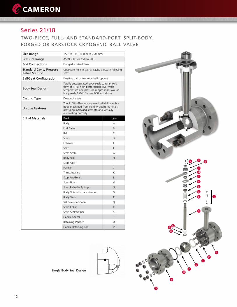
Single Body Seal Design
Size Range 1/2” to 12” (15 mm to 300 mm)
Pressure Range ASME Classes 150 to 900
End Connections Flanged – raised face
Standard Cavity Pressure Relief Method
Upstream hole in ball or cavity pressure-relieving seats
Ball/Seat Configuration Floating ball or trunnion ball support
Body Seal Design
Totally encapsulated body seals to resist cold flow of PTFE; high performance over wide temperature and pressure range; spiral-wound body seals ASME Classes 600 and above
Casting Type Does not apply
Unique Features
The 21/18 offers unsurpassed reliability with a body machined from solid wrought materials, providing increased strength and virtually eliminating porosity
Bill of Materials Part Item
Body A
End Plates B
Ball C
Stem D
Follower E
Seats F
Stem Seals G
Body Seal H
Stop Plate I
Handle J
Thrust Bearing K
Stop Pins/Bolts L
Stem Nuts M
Stem Belleville Springs N
Body Nuts with Lock Washers O
Body Studs P
Set Screw for Collar Q
Stem Collar R
Stem Seal Washer S
Handle Spacer T
Retaining Washer U
Handle Retaining Bolt V
V UT
J
M
I
N
E
G
S L
D
KR
Q
A
P
F
C
FH
B
O
TWO-PIECE, FULL- AND STANDARD-PORT, SPLIT-BODY, FORGED OR BARSTOCK CRYOGENIC BALL VALVE
Series 21/18

13
Dual Body Seal Design
Size Range 1/2” to 8” (15 mm to 200 mm)
Pressure Range ASME Classes 150 to 600
End Connections Flanged – raised face
Standard Cavity Pressure Relief Method
Upstream hole in ball or cavity pressure-relieving seats
Ball/Seat Configuration Floating ball
Body Seal DesignTotally encapsulated body seals to resist cold flow of PTFE; high performance over wide temperature and pressure range
Casting Type Investment cast 1/2” to 3” (15 mm to 75 mm); sand cast 4” (100 mm) and above
Unique Features Unibody construction; no external leak paths through valve body; dual body seal design
Bill of Materials Part Item
Body A
End Plug B
Ball C
Stem D
Follower E
Seats F
Stem Seals G
Body Seal – Inner H
Body Seal – Outer I
Stop Plate J
Handle K
Thrust Bearing L
Stem Nuts M
Stop Pins/Bolts N
Lock Washer O
Stem Belleville Springs P
Stem Seal Washer Q
Stem Screw for Collar R
Stem Collar S
B
IF
CF
H
S
L
D
Q
G
EP
M
O K
MJ
N
R
S
END-ENTRY, STANDARD-PORT, CAST, FLANGED CRYOGENIC BALL VALVE
Series 21/20

14
Size Range 1/2” to 8” (15 mm to 200 mm)
Pressure Range ASME Classes 150 to 600
End Connections Flanged – raised face
Standard Cavity Pressure Relief Method
Upstream hole in ball or cavity pressure-relieving seats
Ball/Seat Configuration Floating ball
Body Seal DesignTotally encapsulated body seals to resist cold flow of PTFE; high performance over wide temperature and pressure range
Casting Type Investment cast 1” to 3” (15 mm to 75 mm); sand cast 4” to 8” (100 mm to 200 mm)
Unique Features Now available in ASME Class 600: 3” to 8” (75 mm to 200 mm)
Bill of Materials Part Item
Body A
End Plate B
Ball C
Stem D
Follower E
Seats F
Stem Seals G
Stem Seal Washer H
Stem Collar I
Body Seal J
Body Studs K
Body Nuts L
Thrust Bearing M
Stop Pins/Bolts N
Stem Belleville Springs O
Stop Plate P
Handle Q
Handle Spacer R
Retaining Washers S
Handle Retaining Bolt T
T
SQ
S
R
P
O
E
G
G
H
N
D
MI
A
F
CF
J
B
KL
TWO-PIECE, FULL-PORT, SPLIT-BODY, CAST, FLANGED CRYOGENIC BALL VALVE
Series 21/28

15
Size Range 10” to 18” (250 mm to 450 mm)
Pressure Range ASME Classes 150 to 600
End Connections Flanged – raised face
Standard Cavity Pressure Relief Method
Unidirectional flow with pressure relief upstream
Ball/Seat Configuration Trunnion mounted
Body Seal Design Spiral-wound gaskets
Casting Type Sand cast
Unique Features Trunnion mounted design with pressure-activated seats with cavity pressure relief in the ball
Bill of Materials Part Item
Body A
Trunnion B
Stem C
Body Gasket D
Seats E
Ball F
Upper Bushing G
Lower Bushing H
Bonnet Assembly I
End Flange J
Trunnion Flange K
Body Studs L
Body Nuts M
Bonnet Gasket N
Thrust Bearing O
Trunnion Gasket P
Bonnet Studs Q
Bonnet Nuts R
Follower S
Packing Flange T
Bracket U
Bracket Studs V
Bracket Nuts W
Packing Flange Nuts X
Packing Flange Bolts Y
M
D
J
E
F
E
A
Q
N
R
I
Y
W
X
U
VO
C
L
G
S
T
B
H
P
K
R
TWO-PIECE, FULL-PORT, SPLIT-BODY, CAST, FLANGED CRYOGENIC BALL VALVE
Series 21/80

16
Size
01 = 1/8”
02 = 1/4”
03 = 3/8”
05 = 1/2”
07 = 3/4”
10 = 1”
12 = 1-1/4”
15 = 1-1/2”
20 = 2”
30 = 3”
40 = 4”
60 = 6”
80 = 8”
X0 = 10”
X2 = 12”
X4 = 14”
X6 = 16”
X8 = 18”
Porting
S = Standard Port
F = Full Port
Series
21 = 21/11 Cryogenic Three-Piece
2B = 21/20 Cryogenic Unibody Flanged
2D = 21/51 Cryogenic Diverter
2F = 21/51/20 Cryogenic Unibody Flanged Diverter
2G = 21/18 Cryogenic Two-Piece ASME Flanged
2P = 21/51/18 Series Split-Body Flanged Cryogenic Diverter
2R = 2151A Switching Diverter Non-Extended Stem Bottom Port
2S = 2151A Switching Diverter Extended Stem Side Port
2T = 2151A Switching Diverter Non-Extended Stem Side Port
2V = 2800 Cryogenic Cast Full Port
2W = 21/80 Cryogenic Large Bore
9C = Cryogenic Top-Entry
End Connections
BWT = Butt-Weld Ext. and Tube Ends*
B_ _= Butt-Weld + Schedule (ex: B40 = Schedule 40)
FSE = NPT Female Threaded
FSW = Female Socket Weld
GRE = Graylok Ends
MSE = NPT Male Thread
MSW = Male Socket Weld
MWE = Male Weld End
TE_ = Tube End (K, L, M) Socket Weld
150 = ASME 150# Flanged RF
15L = 150 Lap Joint Flange
15R = Class 150 RTJ
300 = ASME 300# Flanged RF
30R = Class 300 RTJ
600 = ASME 600# Flanged RF
60R = Class 600 RTJ
900 = ASME 900# Flanged RF
90R = Class 900 RTJ
005 = ASME 1500# Flanged RF
1 = MSE
2 = MSW
3 = FSE
4 = FSW
6 = BW80
7 = BW40
8 = BW160
05R = Class 1500 RTJ
Example: 1 x 3 = MSW x FSE
1 0 0 0 3 6 6 C T3S 2 B 3
Size
Sample:
Port Series End Connections
Body/End Material
Ball Material
Stem Material
Stem blocks are optional if the ball and stem are made from the same material.
Seat Material
Seal Material
For Mixed Combination of Endplate
*Specify OD, wall thickness, and length
Example: 1” standard port, series 21/20 cryogenic unibody flanged valve with ASME 300# flanged RF end connections, 316 stainless steel body/end, ball/stem, and stem material, Cryofil seat material with Virgin PTFE seal material, no bolting. Fire-safe with a grounding spring.
How to Order
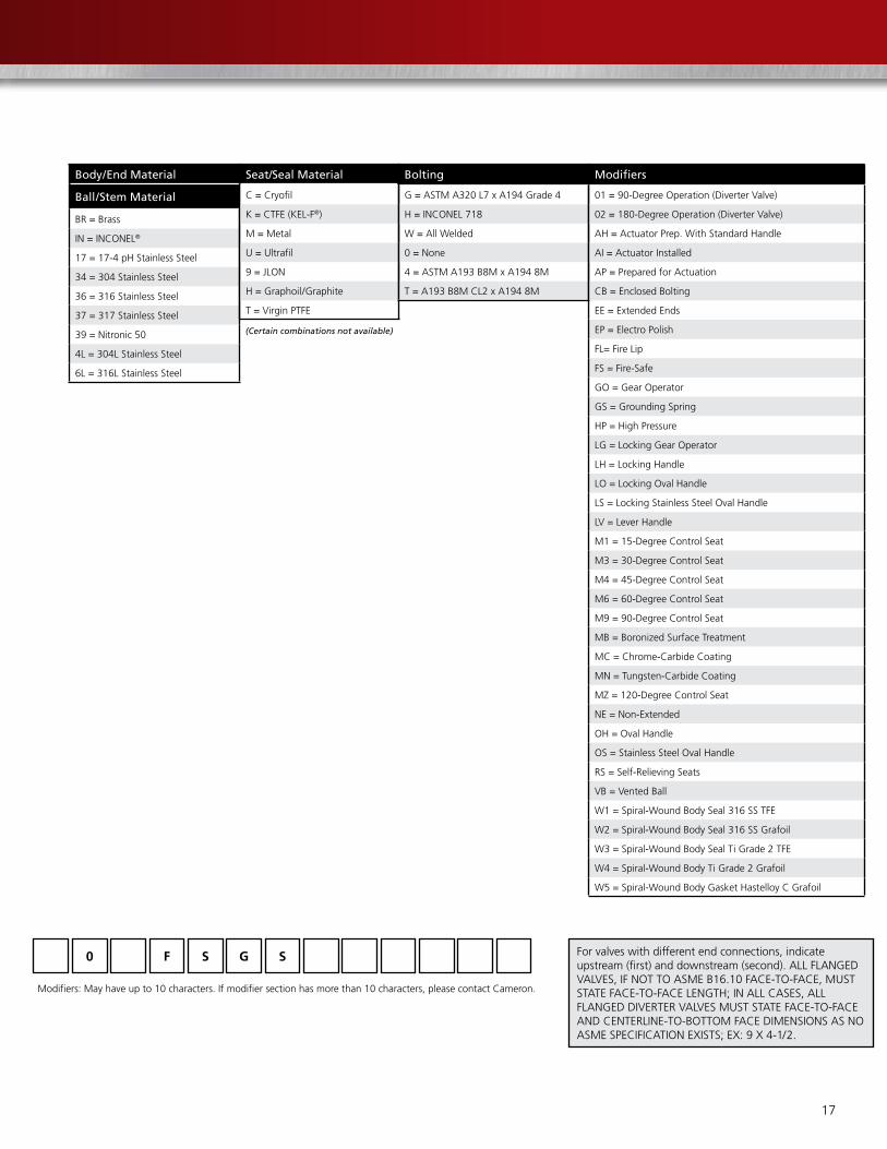
17
Body/End Material
Ball/Stem Material
BR = Brass
IN = INCONEL®
17 = 17-4 pH Stainless Steel
34 = 304 Stainless Steel
36 = 316 Stainless Steel
37 = 317 Stainless Steel
39 = Nitronic 50
4L = 304L Stainless Steel
6L = 316L Stainless Steel
Seat/Seal Material
C = Cryofil
K = CTFE (KEL-F®)
M = Metal
U = Ultrafil
9 = JLON
H = Graphoil/Graphite
T = Virgin PTFE
Bolting
G = ASTM A320 L7 x A194 Grade 4
H = INCONEL 718
W = All Welded
0 = None
4 = ASTM A193 B8M x A194 8M
T = A193 B8M CL2 x A194 8M
Modifiers
01 = 90-Degree Operation (Diverter Valve)
02 = 180-Degree Operation (Diverter Valve)
AH = Actuator Prep. With Standard Handle
AI = Actuator Installed
AP = Prepared for Actuation
CB = Enclosed Bolting
EE = Extended Ends
EP = Electro Polish
FL= Fire Lip
FS = Fire-Safe
GO = Gear Operator
GS = Grounding Spring
HP = High Pressure
LG = Locking Gear Operator
LH = Locking Handle
LO = Locking Oval Handle
LS = Locking Stainless Steel Oval Handle
LV = Lever Handle
M1 = 15-Degree Control Seat
M3 = 30-Degree Control Seat
M4 = 45-Degree Control Seat
M6 = 60-Degree Control Seat
M9 = 90-Degree Control Seat
MB = Boronized Surface Treatment
MC = Chrome-Carbide Coating
MN = Tungsten-Carbide Coating
MZ = 120-Degree Control Seat
NE = Non-Extended
OH = Oval Handle
OS = Stainless Steel Oval Handle
RS = Self-Relieving Seats
VB = Vented Ball
W1 = Spiral-Wound Body Seal 316 SS TFE
W2 = Spiral-Wound Body Seal 316 SS Grafoil
W3 = Spiral-Wound Body Seal Ti Grade 2 TFE
W4 = Spiral-Wound Body Ti Grade 2 Grafoil
W5 = Spiral-Wound Body Gasket Hastelloy C Grafoil
0 F S SG
Modifiers: May have up to 10 characters. If modifier section has more than 10 characters, please contact Cameron.
(Certain combinations not available)
For valves with different end connections, indicate upstream (first) and downstream (second). ALL FLANGED VALVES, IF NOT TO ASME B16.10 FACE-TO-FACE, MUST STATE FACE-TO-FACE LENGTH; IN ALL CASES, ALL FLANGED DIVERTER VALVES MUST STATE FACE-TO-FACE AND CENTERLINE-TO-BOTTOM FACE DIMENSIONS AS NO ASME SPECIFICATION EXISTS; EX: 9 X 4-1/2.

18
3250 Briarpark Drive, Suite 300
Houston, TX 77042
USA
Tel 1 281 499 8511
For more information about TBV cryogenic ball valves:
www.c-a-m.com/TBV
HSE Policy StatementAt Cameron, we are committed ethically, financially and personally to a working environment where no one gets hurt and nothing gets harmed.
HEALT
H S
AFE
TY A
ND ENVIRONMENTAL EX
CELLEN
CE
CAMERON
©2015 Cameron | GENERAL VALVE, INCONEL, ORBIT, and WKM are registered trademarks of Cameron. CAMSERV, TBV, and Ultrafil are trademarks of Cameron. Total Valve Care is a service trademark of Cameron. All other brands are registered trademarks or trademarks of their respective entities. | 3/15 AD01746V