tb f1 mp v6 - building control ni
TRANSCRIPT

General
This Technical Booklet has been prepared by the Department of Financeand Personnel and provides for certain methods and standards of buildingwhich, if followed, will satisfy the requirements of the Building Regulations(Northern Ireland) 2000 (“the Building Regulations”).
There is no obligation to follow the methods or comply with the standardsset out in this Technical Booklet.
If you prefer you may adopt another way of meeting the requirements of theBuilding Regulations but you will have to demonstrate that you havesatisfied those requirements by other means.
Other regulations
This Technical Booklet relates only to the requirements of regulationsF2, F3 and F4. The work will also have to comply with all other relevantBuilding Regulations.
British Standards and European Technical Specifications
In this introduction and throughout this Technical Booklet any reference to aBritish Standard shall be construed as a reference to –
(a) a British Standard or British Standard Code of Practice;
(b) a harmonised standard or other relevant standard of a nationalstandards body of any Member State of the European EconomicArea;
(c) an international standard recognised for use in any Member State ofthe European Economic Area;
(d) any appropriate, traditional procedure of manufacture of a MemberState of the European Economic Area which has a technicaldescription sufficiently detailed to permit an assessment of the goodsor materials for the use specified; or
(e) a European Technical Approval issued in accordance with theConstruction Products Directive,
provided that the proposed standard, code of practice, specification,technical description or European Technical Approval provides, in use,equivalent levels of safety, suitability and fitness for purpose as thatprovided by the British Standard.
Products conforming with a European Council Directive
Any product designed and manufactured to comply with the requirements ofa European Council Directive does not have to comply with any otherstandard or part of a standard, whether British, International or other, whichrelates to the same characteristic or specific purpose as the EC Directive.
1
Introduction

CE marked construction products
Any construction product (within the meaning of the Construction ProductsDirective) which bears a CE marking shall be treated as if it satisfied therequirements of any appropriate British Board of Agrément Certificate,British Standard or British Standard Code of Practice relating to such aproduct, where the CE marking relates to the same characteristic or specificpurpose as the Certificate, Standard or Code of Practice.
Testing of materials and construction
Where for the purposes of this Technical Booklet testing is carried out itshall be carried out by an appropriate organisation offering suitable andsatisfactory evidence of technical and professional competence andindependence. This condition shall be satisfied where the testingorganisation is accredited in a Member State of the European EconomicArea in accordance with the relevant parts of the EN 45000 series ofstandards for the tests carried out.
Materials and workmanship
Any work to which a requirement of the Building Regulations applies must,in accordance with Part B of the Building Regulations, be carried out withsuitable materials and in a workmanlike manner. You can comply with therequirements of Part B by following an appropriate British Standard or youmay demonstrate that you have complied with those requirements by othersuitable means, such as an acceptable British Board of AgrémentCertificate, Quality Assurance Scheme, Independent Certification Schemeor Accredited Laboratory Test Certificate.
References
Any references in this Technical Booklet to a publication shall, unlessotherwise stated, be construed as a reference to the edition quoted,together with any amendments, supplements or addenda thereto current at7 August 2006.
2

Page
Section 1 Common items 5
Section 2 New dwellings 7
General 7
Target carbon dioxide Emissions Rate (TER) 8
Calculating the notional CO2 emissions and the TER 8
Criterion 1 – Achieving the TER 10
Criterion 2 – Minimum acceptable standards 12
Criterion 3 – Limiting the effects of solar gains 15
Criterion 4 – Quality of design, construction and commissioning 15
Criterion 5 – Operating and maintenance instructions 19
Section 3 Existing dwellings 20
General 20
Extension to dwellings 21
Standards Based Approach 21
Calculated Trade-off Approach 26
Equivalent Carbon Target Approach 27
Material change of use 27
Standards Based Approach 27
Equivalent Carbon Target Approach 28
Controlled services 28
Operating and maintenance instructions 31
3
Contents

Page
Appendix A Compliance checklist 32
Appendix B Simple payback 34
Appendix C Cost effective target U-values 35
Appendix D General guidance on renovation 38
Appendix E Important features of the design 40
Appendix F Model designs 41
Appendix G SAP energy rating notice 42
Appendix H Publications referred to 43
4

Definitions
1.1 In this Technical Booklet the following definitions apply –
Air permeability – the air leakage rate in cubic metres per hour per squaremetre of envelope area {m3/(h.m2)} at a pressure difference of 50 Pascals.
Conservatory – a part or extension of a dwelling attached to and having adoor giving access from the attached dwelling and having not less thanthree-quarters of the area of its roof and not less than one-half of the areaof its external wall area made of translucent material and which is thermallyseparated from the dwelling by walls, windows and doors having U-valuesnot greater than and draught-proofing provisions not less than those ofsimilar exposed elements elsewhere in the dwelling.
DER – the Dwelling carbon dioxide Emissions Rate measured in kilogramsof carbon dioxide per square metre of floor area per year {kg/(m2.year)}.
Design air permeability – the value for air permeability selected by thedesigner for calculating the DER.
Dwelling – a house, flat or maisonette which is a self-contained unitdesigned to be used solely to accommodate a single household.
Dwelling type – for the purposes of airtightness testing, a number ofdwellings of the same generic form (detached, semi-detached, end-terrace,mid-terrace, mid-floor flat, ground-floor flat, top-floor flat) where the sameconstruction is used for the main exposed elements. Small variations infloor area do not constitute a different dwelling type.
Envelope area – the total internal area of all wall, floor and ceilingelements that enclose the internal volume subject to an air permeabilitytest. This includes elements below external ground level. Overall internaldimensions shall be used to calculate this area. No subtractions shall bemade for the area at junctions of internal elements (partitions andintermediate floors) with external elements (exterior walls, floors andceilings).The envelope area of a terraced house includes the party wall(s). The envelope area of a flat in a multiple storey building includes the floors,walls and ceilings to adjacent apartments.
Low or zero carbon energy sources – includes biofuels, micro-hydro,photovoltaics, solar hot water and wind power.
Room for residential purposes – means a room or suite of rooms whichis not a dwelling, and which is used by one or more persons to live andsleep and includes a room in a hostel, hotel, boarding house, hall ofresidence or a residential home, whether or not the room is separated fromor arranged in a cluster group with other rooms. It excludes a room in ahospital or similar establishment used for patient accommodation. For thepurposes of this definition, a “cluster” is a group of rooms for residentialpurposes which is not designed to be occupied by a single household andwhich is separated from the rest of the building by a door which is designedto be locked.
5
Section 1 Common items

TER – the Target carbon dioxide Emissions Rate measured in kilograms ofcarbon dioxide per square metre of floor area per year {kg/(m2.year)}.
General rules
Area of elements
1.2 The area of a building element shall be that of its internal surface measuredbetween the finished internal faces of the enclosing fabric of the buildingand, in the case of a roof, shall be measured in the plane of the ceiling.The area shall include the areas where internal elements abut the internalsurface of the wall, floor or roof.
Area of windows, doors and rooflights
1.3 The area of window, door and rooflight openings in a wall or roof shall bemeasured internally between reveals and from head to sill.
Service openings in walls and roofs
1.4 An opening in a wall to accommodate building services, such as a wastepipe or ventilator, shall be regarded as part of the wall and assumed tohave the same U-value as the wall.
1.5 An opening in a roof to accommodate building services, such as a flue pipeor passive stack ventilator, shall be regarded as part of the roof andassumed to have the same U-value as the roof.
Technical risks
1.6 Building work must satisfy all of the requirements of the buildingregulations, however the requirements of Part C (Preparation of site andresistance to moisture), Part G (Sound insulation of dwellings), Part K(Ventilation) and Part L (Combustion appliances and fuel storage systems)are particularly interrelated in the whole building approach adopted by thisPart.
1.7 The incorrect application of energy efficiency measures can cause technicalproblems such as an increased risk of rain penetration or interstitialcondensation. Measures to avoid the risks that might arise are given inBRE Report BR 262: “Thermal insulation: avoiding risks”.
Calculation of U-values
1.8 U-values shall be calculated in accordance with the methods andconventions given in BRE Report BR 443: “Conventions for U-valuecalculations”.
6

GENERAL
This Section gives the methodology and limiting values used by the nationalcalculation software (SAP) to calculate the Target carbon dioxide Emissions Rate(TER) and Dwelling carbon dioxide Emissions Rate (DER). In practice, designers areunlikely to find it necessary to refer to all of this Section as the calculation softwarewill automatically calculate the TER and DER when the details of a dwelling are inputinto the approved SAP software. The SAP software will automatically flagout-of-range values and check that the DER is equal to or less than the TER asdesigned.
On completion of the dwelling, details of the dwelling as built must be entered into thesoftware to confirm that the DER for the dwelling as built is equal to or less than theTER to confirm compliance. The software will also generate the SAP Energy RatingNotice required for the dwelling.
Whilst the software covers the calculation aspects of the compliance criteria it will stillbe necessary to demonstrate that all of the criteria in Section 2 are met.
This Section should be read in conjunction with Section 1 – Common items.
Types of work covered by this Section
2.1 This Section gives provisions for the erection of a new dwelling.
2.2 Section 3 shall apply to work to an existing dwelling or where a dwelling isbeing created as the result of a material change of use.
2.3 A building containing rooms for residential purposes, such as a nursinghome, student accommodation and similar are not considered as dwellingsand, in such cases, the provisions in Technical Booklet F2 apply.
2.4 Where a building contains living accommodation and also contains space tobe used for professional, industrial or commercial purposes (e.g. a doctor’ssurgery, a workshop or office) it shall be treated as a dwelling if thebusiness part could revert to domestic use.
This would be the case where –
(a) there is direct access between the living accommodation and thebusiness part;
(b) both are contained within the same thermal envelope; and
(c) the living accommodation occupies the greater proportion of the totalfloor area of the building.
2.5 When constructing a dwelling as part of a larger building that contains othertypes of accommodation, this Technical Booklet applies solely to thedwelling. Technical Booklet F2 applies to the non-dwelling parts of thebuilding such as heated common areas and, in the case of mixed-usedevelopments, the commercial or retail space.
7
Section 2 New dwellings

Common areas in buildings with multiple dwellings
2.6 The common areas of buildings containing multiple dwellings are notclassified as dwellings. These common areas shall –
(a) where they are heated, comply with the provisions of Technical Booklet F2; and
(b) where they are not heated, comply with the provisions of paragraphs 2.26 and 2.27.
Conservatories and other highly glazed spaces
2.7 Where a conservatory is built as part of a new dwelling, the thermalperformance of the dwelling shall be assessed excluding the conservatory.
2.8 Where a highly glazed space is not thermally separated from a dwelling itshall be included as an integral part of the dwelling.
TARGET CARBON DIOXIDE EMISSIONS RATE (TER)
2.9 The Target carbon dioxide Emissions Rate (TER) is the minimumacceptable energy performance for new dwellings. It is the targetestablished for the mass of carbon dioxide (CO2) produced by the buildingand is given in units of kg per m2 of floor area per year. This target is forthe provision of heating, hot water, ventilation and fixed internal lighting fora standardised household.
2.10 To demonstrate that an acceptable CO2 emissions rate has been achieved,the dwelling as constructed shall have a calculated Dwelling carbon dioxideEmissions Rate (DER) equal to or less than the TER calculated inaccordance with paragraphs 2.13 to 2.17.
2.11 For individual dwellings the emissions rate shall be calculated usingapproved SAP software.
2.12 The TER and DER shall be calculated using the same SAP software.
CALCULATING THE NOTIONAL CO2 EMISSIONS AND THE TER
Calculating the notional CO2 emissions
2.13 Calculate the CO2 emissions for a notional dwelling of the same shape andsize as the proposed dwelling using the reference values given in Appendix R of The Government’s Standard Assessment Procedure forEnergy Rating of Dwellings (SAP).
2.14 The SAP software will output the CO2 emissions resulting from –
(a) the provision of ventilation, heating and hot water (CH), (which shallinclude the energy used by pumps and fans); and
(b) the provision of fixed internal lighting (CL).
8

Calculating the Target carbon dioxide Emissions Rate (TER)
2.15 Calculate the Target carbon dioxide Emissions Rate (TER) using theappropriate formula –
For mains gas, renewable energy and solid multi-fuels –
TER = ((CH x fuel factor) + CL) x (1 – improvement factor).
For all other fuels –
TER = ((1.14 x CH x fuel factor) + CL) x (1 – improvement factor).
The fuel factor shall be taken from Table 2.1 and the improvement factorshall be 0.2 (i.e. 20%).
2.16 The fuel factor used to calculate the TER shall be derived as follows –
(a) where all heating appliances are served by the same fuel, the fuelused in those appliances;
(b) where the dwelling has more than one heating appliance and theseare served by different fuels, the fuel shall be taken to be mains gas ifany of the heating appliances are served by mains gas; or in anyother circumstances, the fuel used in the main heating system;
(c) where the dwelling is served by a community heating scheme, theprincipal fuel used by the community heating scheme;
(d) where an appliance is classed as multi-fuel, the multi-fuel factor shallbe used, except where the dwelling is in a smoke control zone wherethe solid mineral fuel figure shall be used.
Table 2.1 Fuel factors
Heating fuel Fuel factor
Mains gas 1.00
LPG 1.10
Oil 1.17
Grid electricity (for direct acting, storage and electric heat pumpsystems) 1.47
Solid mineral fuel (1) 1.28
Renewable energy (including bio-fuels such as wood pellets)(1) 1.00
Solid multi-fuel (1) 1.00
Notes –1 The specific fuel factor shall be used solely for those appliances that can only burn
that particular fuel.
9
Building containing multiple dwellings
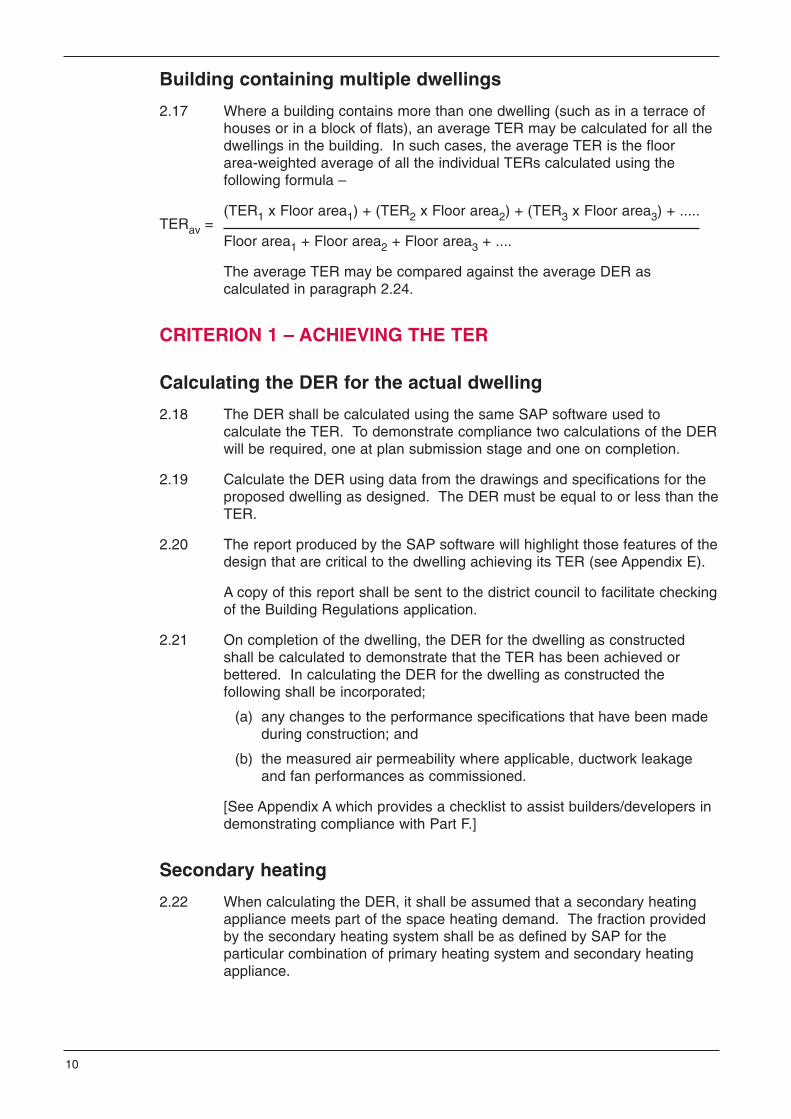
2.17 Where a building contains more than one dwelling (such as in a terrace ofhouses or in a block of flats), an average TER may be calculated for all thedwellings in the building. In such cases, the average TER is the floorarea-weighted average of all the individual TERs calculated using thefollowing formula –
TERav =(TER1 x Floor area1) + (TER2 x Floor area2) + (TER3 x Floor area3) + .....
Floor area1 + Floor area2 + Floor area3 + ....
The average TER may be compared against the average DER ascalculated in paragraph 2.24.
CRITERION 1 – ACHIEVING THE TER
Calculating the DER for the actual dwelling
2.18 The DER shall be calculated using the same SAP software used tocalculate the TER. To demonstrate compliance two calculations of the DERwill be required, one at plan submission stage and one on completion.
2.19 Calculate the DER using data from the drawings and specifications for theproposed dwelling as designed. The DER must be equal to or less than theTER.
2.20 The report produced by the SAP software will highlight those features of thedesign that are critical to the dwelling achieving its TER (see Appendix E).
A copy of this report shall be sent to the district council to facilitate checkingof the Building Regulations application.
2.21 On completion of the dwelling, the DER for the dwelling as constructedshall be calculated to demonstrate that the TER has been achieved orbettered. In calculating the DER for the dwelling as constructed thefollowing shall be incorporated;
(a) any changes to the performance specifications that have been madeduring construction; and
(b) the measured air permeability where applicable, ductwork leakageand fan performances as commissioned.
[See Appendix A which provides a checklist to assist builders/developers indemonstrating compliance with Part F.]
Secondary heating
2.22 When calculating the DER, it shall be assumed that a secondary heatingappliance meets part of the space heating demand. The fraction providedby the secondary heating system shall be as defined by SAP for theparticular combination of primary heating system and secondary heatingappliance.
10

One of the following secondary heating appliances shall be assumed whencalculating the DER –
(a) where a secondary heating appliance is installed, the efficiency of theinstalled appliance with its appropriate fuel shall be used incalculating the DER;
(b) where a chimney or flue is provided but no appliance is installed, thepresence of the following appliances shall be assumed –
(i) where a gas point is located adjacent to a hearth, a decorativefuel effect gas fire open to the chimney or flue, with a grossefficiency of 20%; or
(ii) where there is no gas point, an open multi-fuel fire with a grossefficiency of 37%, unless the dwelling is in a smoke controlzone when the fuel shall be taken as smokeless solid mineralfuel; or
(c) where none of the above is provided it shall be assumed thatsecondary heating is provided by an electric room heater.
Lighting
2.23 In all cases the DER shall be calculated assuming a standard provision oflow energy lighting in 30% of fixed lighting fittings.
Buildings containing multiple dwellings
2.24 Where a building contains more than one dwelling (such as in a terrace ofhouses or in a block of flats), either –
(a) each individual dwelling shall have a DER that is equal to or less thanits corresponding TER; or
(b) the average DER shall be equal to or less than the average TER. Theaverage DER is the floor area-weighted average of all the individualDERs and shall be calculated in a similar manner to paragraph 2.17.
[When adopting the average DER approach, it will still be necessary toprovide the information for each dwelling so that individual energy ratingscan be produced.]
Low or zero carbon energy sources
2.25 In certain circumstances, low or zero carbon (LZC) energy sources canmake a substantial and cost-effective contribution to meeting the TER. Lowcarbon systems include heat pumps and combined heat and power (atindividual dwelling, block or community levels), and zero carbon systemsinclude biofuels (e.g. wood fuels and oil blends), micro-hydro, photovoltaics,solar hot water and wind power.
[The Department for Communities and Local Government (DCLG)publication “Low or zero carbon energy sources – Strategic guide”describes a range of potential systems and how their contribution to theDER can be assessed.]
11

CRITERION 2 – MINIMUM ACCEPTABLE STANDARDS
U-values
2.26 The maximum U-values for each of the elements of the building fabric thatseparate a normally conditioned space from an unconditioned space or theexternal environment are given in Table 2.2 –
(a) column (a) gives the area-weighted average U-value for eachelement. The area-weighted average is calculated using the followingformula –
Uav =(U1 x A1) + (U2 x A2) + (U3 x A3) + ...
A1 + A2 + A3 + ...
(b) column (b) gives the maximum U-value of any individual element orpart of an individual element such as a meter cupboard recess.
2.27 When comparing against the values in Table 2.2, the U-value of a window,roof window, rooflight or door unit shall be taken as the value for –
(a) the standard configuration given in BRE Report BR 443; or
(b) the particular size and configuration of the actual unit.
In either case, the U-value shall be with the unit in the vertical position.
Where a roof window or rooflight has been assessed in a plane other thanthe vertical, the U-value shall be modified by making a U-value adjustmentin accordance with BR 443: “Conventions for U-value calculations”.
SAP Table 6e gives values for different window configurations that can beused in the absence of test data or calculated values.
Table 2.2 Limiting U-values {W/(m2.K)}
Element(a)
Area-weighted average U-value
(b) Maximum U-value
Wall 0.35 0.70
Floor 0.25 0.70
Roof 0.25 0.35
Windows, roof windows,rooflights and doors 2.20 3.30
12

Air permeability
2.28 The maximum acceptable air permeability is 10 m3/(h.m2) @ 50 Pa (exceptwhere paragraph 2.54 applies).
[Information on some ways of achieving an acceptable air permeability isgiven in the Department for Communities and Local Government (DCLG)publication “Accredited construction details for Part L*”.
*Note that “Part L” in the title refers to the part in England & Wales that isequivalent to Part F in Northern Ireland.]
2.29 Where the conditions given in paragraph 2.54 apply, the air permeabilitymay be varied from the value given in paragraph 2.28 provided thatcompensating provisions are made such that the TER is achieved orbettered.
Minimum acceptable standards for fixed building servicesystems
Heating and hot water systems
2.30 The heating and hot water system shall have –
(a) in the case of an appliance fired by mains gas or LPG, a boiler withan efficiency of not less than 86%;
(b) in the case of an appliance fired by oil, a boiler with an efficiency ofnot less than 86% (in the period up to 1 April 2007 a boiler having anefficiency of not less than 82% may be installed provided thatcompensating provisions are made);
(c) in the case of any other appliance, an appliance with an efficiency notless than that recommended for its type in the Department forCommunities and Local Government (DCLG) publication “DomesticHeating Compliance Guide”; and
(d) controls that meet the minimum control requirements given in theDCLG publication “Domestic Heating Compliance Guide” for thatparticular type of appliance and heat distribution system.
Insulation of pipes, ducts and hot water storage vessels
2.31 Pipes, ducts and hot water storage vessels shall be insulated to standardsnot less than those given in the DCLG publication “Domestic HeatingCompliance Guide”.
Mechanical ventilation systems
2.32 Mechanical ventilation systems shall be designed and installed to standardsnot less than those given in Good Practice Guide GPG 268 and shall alsohave a specific fan power not greater than, and a heat recovery efficiencynot less than, those given in Table 2.3.
[GPG 268 “Energy efficient ventilation in dwellings – a guide to specifiers”also includes recommendations on appropriate air permeability standardsfor different ventilation strategies.]
13

Mechanical cooling systems
2.33 Fixed air coolers shall have an energy efficiency classification of not lessthan Class C in Schedule 3 of the labelling scheme adopted under “TheEnergy Information (Household Air Conditioners) (No.2) Regulations 2005”.
Fixed internal lighting
2.34 Fixed energy efficient light fittings shall be installed in the most frequentedareas in a dwelling, and there shall be not less than –
(a) one per 25 m2 of dwelling floor area (excluding garages) or partthereof; or
(b) one per four light fittings,
whichever is the greater.
A light fitting may contain one or more lamps.
2.35 Light fittings in less frequented areas such as cupboards, storage areasand garages shall not count towards the total. “GIL 20 Low energydomestic lighting” gives recommendations on identifying suitable locations.
2.36 For the purposes of paragraph 2.34 an energy efficient light fitting (includingthe lamp, control gear and an appropriate housing, reflector, shade or otherdevice for controlling the light output) is a light fitting that can only be fittedwith lamps having a luminous efficacy greater than 40 lumens percircuit-Watt.
[Circuit-Watt means the power consumed in lighting circuits by lamps, theirassociated control gear and power factor correction equipment.]
[Fluorescent and dedicated compact fluorescent light fittings would meetthis requirement, but those accommodating GLS tungsten lamps andcompact fluorescent lamps (CFLs) with a bayonet cap or Edison screwbase, or tungsten halogen lamps would not.]
Table 2.3 Limiting performance values for mechanical ventilationsystems
System type Performance
Specific Fan Power (SFP) for continuous supply only andcontinuous extract only
not greater than0.8 W/(l/s)
SFP for balanced systems not greater than2.0 W/(l/s)
Heat recovery efficiency not less than66%
14

Fixed external lighting
2.37 Fixed external lighting means lighting permanently fixed to an externalsurface of the dwelling and under the direct control of the occupant byhaving an electricity supply from the dwelling.
2.38 External lighting shall –
(a) have a maximum output of 150W per fitting and automatically switchoff –
(i) when there is adequate daylight; and
(ii) when not required at night; or
(b) have sockets that can only be fitted with lamps having a luminousefficacy greater than 40 lumens per circuit-Watt.
[Fluorescent and dedicated compact fluorescent light fittings would meetthis requirement, but those accommodating GLS tungsten lamps andcompact fluorescent lamps with a bayonet cap or Edison screw base, ortungsten halogen lamps would not.]
CRITERION 3 – LIMITING THE EFFECTS OF SOLAR GAINS
2.39 Provisions shall be made to limit internal temperatures due to excessivesolar gains. This shall be achieved by an appropriate combination ofwindow size and orientation, solar protection by shading or other solarcontrol measures, ventilation (day and night) and high thermal capacity.
[CE 129 “Reducing overheating – a designers guide” givesrecommendations on strategies to limit overheating.]
2.40 SAP contains a procedure to enable designers to check whether solargains are excessive. The designer shall ensure that the calculation doesnot indicate a high risk of high internal temperatures during hot weather.
2.41 When seeking to limit solar gains, consideration should be given to theprovision of adequate levels of daylighting.
[“BS 8206 - 2:1992 Lighting for buildings. Code of practice for daylighting”gives recommendations on maintaining adequate levels of daylighting.]
CRITERION 4 – QUALITY OF DESIGN, CONSTRUCTION ANDCOMMISSIONING
2.42 Every dwelling shall be designed and constructed such that the thermal andair permeability properties of the building envelope, and the buildingservices and controls achieve a calculated Dwelling carbon dioxideEmissions Rate (DER) equal to or less than the TER.
15

Building fabric
2.43 The building fabric shall be constructed such that there are no readilyavoidable thermal bridges in the insulation layers caused by gaps within thevarious elements, at joints between elements, and at the edges of elementssuch as those around door and window openings.
2.44 The dwelling shall be constructed –
(a) to details given in the Department for Communities and LocalGovernment (DCLG) publication “Accredited construction details forPart L*”; or
(b) to details that give an equivalent level of performance when assessedin accordance with BRE IP 1/06: “Assessing the effects of thermalbridging at junctions and around openings in the external elements ofbuildings”.
[*Note that “Part L” in the title refers to the part in England & Wales that isequivalent to Part F in Northern Ireland.]
2.45 The builder shall demonstrate that an appropriate system of site inspectionis in place to ensure that the construction standards achieve the requiredlevel of consistency. Where the accredited design details approach isadopted (paragraph 2.44(a)), a report shall be provided showing that theconstruction checklists given in the DCLG publication “Accreditedconstruction details for Part L*” have been completed and show satisfactoryresults and a copy shall be forwarded to the district council.
[*Note that “Part L” in the title refers to the part in England & Wales that isequivalent to Part F in Northern Ireland.]
Air permeability and air pressure testing
2.46 The DER is calculated using the design air permeability specified by thedesigner. Where testing is required to demonstrate that the design airpermeability has been achieved (see paragraphs 2.48 and 2.49) thedwelling shall be air pressure tested in accordance with the Air TightnessTesting and Measurement Association (ATTMA) publication “Measuring AirPermeability of Building Envelopes”. The manner approved for recordingthe results and the data on which they are based is given in section 4 ofthat document. The tests shall be carried out by a suitably qualified personsuch as a tester who is registered with or approved by the British Instituteof Non-destructive Testing in respect of pressure testing for the air tightnessof buildings.
2.47 A block of flats shall be treated as a separate development irrespective ofthe number of blocks of flats on the site.
Most larger developments will include many types of unit including terraced(end and centre), semi-detached, flats, etc. and at least one of each typeshall be tested to confirm the robustness of the designs and theconstruction procedures.
16

Dwellings built to accredited construction details
2.48 On each development built to accredited construction details an airpressure test shall be carried out on a unit of each dwelling type selectedby the district council.
Dwellings NOT built to accredited construction details
2.49 Air pressure tests shall be carried out on each dwelling type not built toaccredited construction details in the development to the number given inTable 2.4.
2.50 The dwellings selected for test shall be chosen by the district council inconsultation with the builder. They shall be selected so that about half ofthe tests on each dwelling type are carried out during the construction ofthe first 25% of the dwellings of that type.
Demonstrating compliance
2.51 Compliance with the air permeability requirements shall be demonstratedwhere –
(a) the measured air permeability is not greater than 10 m3/(h.m2) @ 50 Pa; and
(b) the DER on completion, calculated using the measured airpermeability, is equal to or less than the TER.
Table 2.4 Tests for dwellings NOT built to accredited constructiondetails
Number of dwellings of the dwellingtype
Number of dwellings tested of thedwelling type
4 or less One
More than 4 but not more than 40 Two
More than 40
At least 5% of the dwelling type unless thefirst 5 dwellings of that type achieve thedesign air permeability in which case thetesting frequency may be reduced to 2%
17

Consequences of failing a pressure test
2.52 Where a dwelling fails to achieve its design air permeability, remedialmeasures shall be carried out, such that on retest the design airpermeability is achieved.
However, in the period up to 31 October 2007, if the initial test result on adwelling is unsatisfactory, provision shall be made to –
(a) carry out remedial measures such that on re-test a result is achievedthat shows either –
(i) an improvement of 75% on the difference between the initialtest result and the design air permeability; or
(ii) if more easily achieved, a test result within 15% of the designair permeability; or
(b) revise the TER by substituting the measured air permeability for thevalue given in Appendix R of SAP and demonstrate that the DER forthe building as built is equal to or less than the revised TER.
Example – following an initial failure where the test result is 18.0 and thedesign air permeability target is 8.0, the revised pass level followingremedial works would be –
Using (a)(i); Using (a)(ii);
18.0 - {0.75 x (18.0 - 8.0) } = 10.5 8 x 1.15 = 9.2
Therefore, option (a)(i) is easier to achieve.
However, if the initial test result is 9.5 it would be less demanding to usethe alternative option in (a)(ii). The revised pass level following remedialworks would be –
Using (a)(i); Using (a)(ii);
9.5 - {0.75 x (9.5 - 8.0) } = 8.375 8 x 1.15 = 9.2
Therefore, option (a)(ii) is easier to achieve.
After 31 October 2007 paragraph 2.51 will be the only method ofdemonstrating compliance.
2.53 In addition to the remedial work on the dwelling that failed to achieve itsdesign air permeability, one additional dwelling of the same type shall betested to increase the overall sample size.
Alternative to pressure testing on small developments
2.54 Where a development contains not more than two dwellings, the developermay avoid pressure testing by –
(a) demonstrating that a similar dwelling constructed by the same builderin Northern Ireland within the preceding 12 month period had beentested in accordance with paragraphs 2.46 to 2.51 and had achievedits design air permeability; or
(b) using a value of 15 m3/(h.m2) @ 50 Pa for the air permeability whencalculating the DER, in which case compensating measures will benecessary to achieve the TER.
18

Design, installation and commissioning of heating and hotwater systems
2.55 The heating and hot water systems shall be designed, installed andcommissioned such that, for the purposes of the conservation of fuel andpower, the system and its controls are handed over in efficient workingorder.
2.56 All fixed building services shall be commissioned in accordance with theprocedure given in the DCLG publication “Domestic Heating ComplianceGuide” for the relevant fuel type(s), and in accordance with themanufacturer’s commissioning procedures.
2.57 A notice confirming that all fixed building services have been properlycommissioned shall be provided and a copy shall be given to the districtcouncil and the building owner. The notice shall be signed by a suitablyqualified person.
CRITERION 5 – OPERATING AND MAINTENANCEINSTRUCTIONS
2.58 The building owner shall be given sufficient information, includingoperational and maintenance instructions, to enable the dwelling and itsfixed building services to be operated and maintained in an energy efficientmanner. The instructions shall be directly related to the specific system(s)installed in the dwelling and shall be readily understandable by theoccupier.
2.59 Without compromising health and safety requirements, the instructions shallexplain to the occupier of the dwelling how to operate the systemsefficiently. These shall include –
(a) how to make adjustments to the timing and temperature controlsettings; and
(b) what routine maintenance is necessary to enable the systems to bemaintained at a reasonable efficiency throughout their service life.
2.60 An energy rating shall be calculated for the dwelling as built and a noticestating the energy rating shall be fixed in the dwelling.
An example of this notice can be found in Appendix G.
The energy rating shall be calculated using the same SAP software used tocalculate the TER and DER.
[It would be appropriate to fix this notice adjacent to the electricaldistribution board such as on the inside of the cupboard door housing thisunit.]
19

GENERAL
This Section should be read in conjunction with Section 1 – Common items.
Types of work covered by this Section
3.1 This Section gives provisions for altering or extending an existing dwellingor creating a dwelling through a material change of use.
3.2 This Section gives provisions relating to the following building works –
(a) extensions (see paragraphs 3.6 to 3.9 and 3.23 to 3.29);
(b) when creating a dwelling or part of a dwelling through a materialchange of use (see paragraphs 3.30 to 3.36);
(c) the provision or extension of a controlled service (see paragraphs 3.37 to 3.50);
(d) the provision or extension of a controlled fitting (see paragraphs 3.10 and 3.11); and
(e) the replacement or renovation of a thermal element (see paragraphs 3.12 to 3.22).
3.3 When the building works are in relation to a dwelling as part of a mixed usebuilding this Technical Booklet applies solely to the dwelling. Technical Booklet F2 applies to the non-dwelling parts of the building suchas heated common areas and, in the case of mixed-use developments, the commercial or retail space.
Historic buildings
3.4 Special considerations apply where the building on which the work is to becarried out has historic or architectural value and compliance with thisTechnical Booklet would unacceptably alter the character or appearance ofthe building.
3.5 When undertaking work on or in connection with a building of historic orarchitectural merit, the aim should be to improve energy efficiency to theextent that it is practicable. Particular issues in relation to work in historicbuildings that warrant sympathetic treatment and where specialist advicefrom conservation experts would be beneficial include –
(a) restoring the historic character of a building that has been subject toinappropriate alteration e.g. replacement windows, doors androoflights;
(b) rebuilding a building e.g. following a fire or filling in a gap site in anhistoric terrace; and
(c) making provisions for the fabric of historic buildings to “breathe” tocontrol moisture and long term decay problems.
20
Section 3 Existing dwellings

The guidance given in the DOE Environment and Heritage Servicepublication “Historic buildings and energy efficiency. A guide to Part F ofthe Northern Ireland Building Regulations” shall be taken into account indetermining appropriate energy efficiency improvements.
EXTENSION TO DWELLINGS
3.6 For the extension of a dwelling three alternative approaches are given; theyare –
(a) the Standards Based Approach;
(b) the Calculated Trade-off Approach; and
(c) the Equivalent Carbon Target Approach.
Standards Based Approach
Fabric standards
3.7 An extension to a dwelling shall achieve the following performancestandards –
(a) controlled fittings that comply with the provisions given in paragraphs 3.10 and 3.11;
(b) newly constructed thermal elements that comply with the provisionsgiven in paragraphs 3.12 to 3.17; and
(c) existing opaque fabric that becomes part of the thermal envelope ofthe dwelling where previously it was not, shall comply with theprovisions given in paragraphs 3.18 to 3.22.
Area of openings
3.8 The total area of windows, roof windows, rooflights and doors in anextension shall be limited such that it does not exceed the sum of –
(a) 25% of the floor area of the extension; plus
(b) the area of any windows, roof windows, rooflights or doors which, asa result of the extension, no longer exist or are no longer exposed.
Heating and lighting
3.9 Where a fixed building service is provided or extended as part ofconstructing the extension, it shall comply with the provisions given inparagraphs 3.37 to 3.50.
Controlled fittings
3.10 Where windows, roof windows, rooflights or doors are to be provided, theyshall be draught-proofed units whose area-weighted average performanceis not greater than that given in Table 3.1.
Column (a) applies to new fittings provided as part of constructing theextension. Column (b) applies to replacement fittings or new fittingsinstalled in the existing building.
21
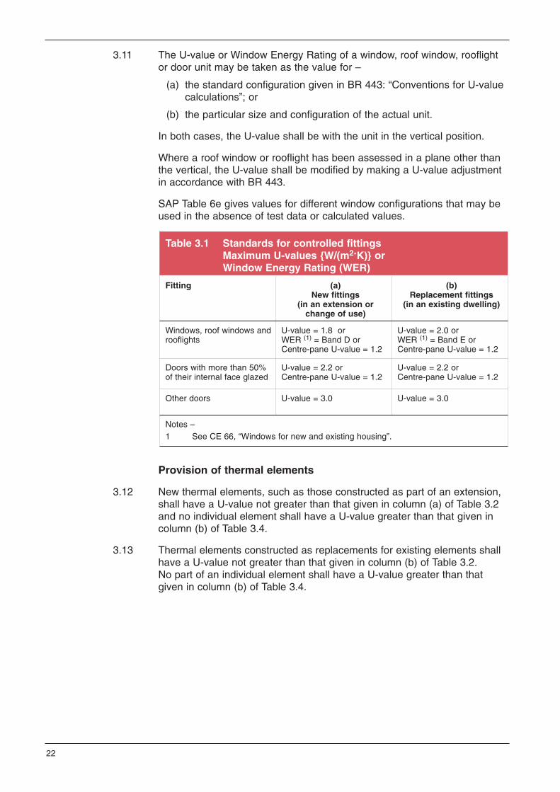
3.11 The U-value or Window Energy Rating of a window, roof window, rooflightor door unit may be taken as the value for –
(a) the standard configuration given in BR 443: “Conventions for U-valuecalculations”; or
(b) the particular size and configuration of the actual unit.
In both cases, the U-value shall be with the unit in the vertical position.
Where a roof window or rooflight has been assessed in a plane other thanthe vertical, the U-value shall be modified by making a U-value adjustmentin accordance with BR 443.
SAP Table 6e gives values for different window configurations that may beused in the absence of test data or calculated values.
Provision of thermal elements
3.12 New thermal elements, such as those constructed as part of an extension,shall have a U-value not greater than that given in column (a) of Table 3.2and no individual element shall have a U-value greater than that given incolumn (b) of Table 3.4.
3.13 Thermal elements constructed as replacements for existing elements shallhave a U-value not greater than that given in column (b) of Table 3.2. No part of an individual element shall have a U-value greater than thatgiven in column (b) of Table 3.4.
Table 3.1 Standards for controlled fittingsMaximum U-values {W/(m2.K)} orWindow Energy Rating (WER)
Fitting (a) New fittings
(in an extension orchange of use)
(b) Replacement fittings
(in an existing dwelling)
Windows, roof windows androoflights
U-value = 1.8 or WER (1) = Band D or Centre-pane U-value = 1.2
U-value = 2.0 or WER (1) = Band E or Centre-pane U-value = 1.2
Doors with more than 50%of their internal face glazed
U-value = 2.2 orCentre-pane U-value = 1.2
U-value = 2.2 orCentre-pane U-value = 1.2
Other doors U-value = 3.0 U-value = 3.0
Notes –1 See CE 66, “Windows for new and existing housing”.
22

Continuity to limit thermal bridging and air leakage
3.14 The building fabric shall be constructed such that there are no readilyavoidable thermal bridges in the insulation layers caused by gaps within thevarious elements, at joints between elements, and at the edges of elementssuch as those around door and window openings.
3.15 The building fabric shall be constructed to minimise air leakage through thenew or replacement parts of the thermal element.
3.16 The building fabric shall be constructed –
(a) in accordance with the accredited construction details given in theDCLG publication “Accredited construction details for Part L*”; or
(b) to details that give an equivalent level of performance when assessedin accordance with BRE IP 1/06: “Assessing the effects of thermalbridging at junctions and around openings in the external elements ofbuildings”.
[*Note that “Part L” in the title refers to the part in England & Wales that isequivalent to Part F in Northern Ireland.]
3.17 The builder shall demonstrate that an appropriate system of site inspectionis in place to ensure that the construction standards achieve the requiredlevel of consistency. Where the accredited design details approach isadopted (paragraph 3.16(a)), a report shall be provided showing that theconstruction checklists given in the DCLG publication “Accreditedconstruction details for Part L*” have been completed and show satisfactoryresults and a copy shall be forwarded to the district council.
[*Note that “Part L” in the title refers to the part in England & Wales that isequivalent to Part F in Northern Ireland.]
Table 3.2 U-values for thermal elements {W/(m2.K)}
Element (a)New elements
(in an extension orchange of use)
(b) Replacement elements (in an existing dwelling)
Wall 0.30 0.35 (1)
Pitched roof (horizontalinsulation at ceiling level) 0.16 0.16
Pitched roof (inclinedinsulation at rafter level) 0.20 0.20
Flat roof or roof with integralinclined insulation 0.20 0.25
Floors (1) 0.22 0.25 (1)
Notes –1 Where meeting the above standards would cause a significant (5%) reduction in
floor area or cause problems in relation to adjoining floor levels these values maybe exceeded provided that compensating provisions are made.
23

Renovation of thermal elements
3.18 Where more than 25% of the surface area of a thermal element is beingrenovated, the whole of that element shall be upgraded to the improvedU-value given in column (b) of Table 3.3.
3.19 Where upgrading to the standards required by paragraph 3.18 is nottechnically or functionally feasible, the element shall be upgraded to thebest practicable standard that can be achieved within a simple paybackperiod of 15 years. Appendix B gives the information necessary to assessthe simple payback of the proposed works. Appendix C gives provisionsthat will satisfy this requirement.
Retained thermal elements
3.20 Where an existing thermal element becomes part of a dwelling as a resultof a material change of use or an existing element becomes part of thethermal envelope where previously it was not, and where it has a U-valuegreater than that given in column (a) of Table 3.3, the element shall beupgraded to the standard given in column (b) of Table 3.3.
3.21 Where upgrading to the standards required by paragraph 3.20 is nottechnically or functionally feasible, the element shall be upgraded to thebest practicable standard that can be achieved within a simple paybackperiod of 15 years. Appendix B gives the information necessary to assessthe simple payback of the proposed works. Appendix C gives provisionsthat will satisfy this requirement.
3.22 Examples of where a lesser provision than that required by paragraph 3.20might apply are, where the thickness of the additional insulation wouldreduce the usable floor area by more than 5%, or where the additionalinsulation would create difficulties with adjoining floor levels, or where theadditional insulation could not be supported by the existing structure.
24

Conservatories and highly glazed extensions
3.23 Where the extension is a conservatory that is not exempt from the BuildingRegulations, it shall have –
(a) effective thermal separation from the dwelling by having separatingwalls, doors and windows between the dwelling and the conservatorythat are insulated and draught-proofed to at least the same standardas the same elements in the existing dwelling;
(b) glazed elements that comply with the standards given in column (b) ofTable 3.1 and thermal elements that have U-values that are nogreater than those given in column (b) of Table 3.2; and
(c) where a heating system is installed, the heating appliance shallcomply with the provisions of paragraphs 3.37 to 3.40 and the heatingsystem in the conservatory shall have independent on/off andtemperature controls separate from those of the existing dwelling.
Table 3.3 U-values for retained thermal elements {W/(m2.K)}
Element (1) (a)Threshold U-value
(b) Improved U-value
Cavity wall (2) 0.70 0.55 (3)
Other wall types 0.70 0.35
Pitched roof – insulation atceiling level
0.35 0.16
Pitched roof – insulation atrafter level
0.35 0.20
Pitched roof with integralinsulation or flat roof 0.35 0.25
Floor (4) 0.70 0.25 (5)
Notes –1 “Roof” includes the roof parts of dormer windows and “wall” includes the cheeks of
dormer windows 2 Where a cavity wall is unsuitable for cavity insulation it shall be treated as “Other
wall type”.3 A lesser provision may be appropriate where meeting such a standard would result
in a reduction of more than 5% in the internal floor area of the room bounded bythe wall.
4 The U-value of the floor may be calculated using the exposed perimeter and floorarea of the enlarged building.
See BR 443 and either “CIBSE Guide A: Environmental Design - Section A3: Thermal properties of building structures”, or BS EN ISO 13370:1998 “Thermal performance of buildings - Heat transfer via the ground - Calculation methods”.
5 A lesser provision may be appropriate where meeting the standard would createsignificant problems in relation to adjoining floors.
25

3.24 Where a highly glazed extension is not a conservatory (because it has lessthan the minimum qualifying amounts of translucent material) but otherwisecomplies with the requirements of paragraph 3.23, it may be treated in asimilar manner to a conservatory. The area-weighted U-value of theelements in the highly glazed extension shall not be greater than that of aconservatory of the same shape and size that complies withparagraph 3.23.
3.25 Where a highly glazed extension is not thermally separated from thedwelling it shall be treated as a conventional extension and complianceshall be demonstrated using one of the approaches given in paragraphs 3.6 to 3.9 and 3.26 to 3.29.
Calculated Trade-off Approach
3.26 The fabric standards referred to in paragraph 3.7 and the opening areasreferred to in paragraph 3.8 may be varied provided that –
(a) the area-weighted U-value of all the elements in the extension is nogreater than that of an extension of the same shape and size thatcomplies with the U-value standards referred to in paragraph 3.7 andthe opening areas referred to in paragraph 3.8;
(b) the area-weighted U-value for each element type is not greater than the relevant value given in column (a) of Table 3.4; and
(c) the maximum U-value of an individual element or part of an individual element is not greater than the relevant value given in column (b) ofTable 3.4.
The area-weighted U-value is calculated using the following formula –
Uav =(U1 x A1) + (U2 x A2) + (U3 x A3) + .....
A1 + A2 + A3 +.....
3.27 For the purposes of the above paragraph, an individual element meansthose areas of a given element type that have the same constructiondetails. In the case of windows, doors, roof windows and rooflights, theassessment shall be based on the unit as a whole i.e. for windows thecombined performance of the glazing and frame.
26

Equivalent Carbon Target Approach
3.28 SAP shall be used to demonstrate that the calculated carbon dioxideemissions rate from the dwelling and proposed extension is no greater thanfor the dwelling with a notional extension of the same shape and sizecomplying with the standards referred to in paragraphs 3.7 to 3.9.The procedures in SAP Appendix S shall be used to estimate theperformance of the elements of the existing building where these areunknown. When using this approach the area-weighted average U-value ofeach element type in the extension shall be no greater than the value givenin column (a) of Table 3.4 and the U-value of any individual element shallbe no greater than the relevant value given in column (b) of Table 3.4.
3.29 Where additional upgrades are proposed to the existing dwelling tocompensate for lower performance in the extension, the upgrades shallcomply with the relevant provisions given in this Technical Booklet.The standards for upgrading retained thermal elements are given incolumn (b) of Table 3.3.
MATERIAL CHANGE OF USE
3.30 Where a dwelling is created by a material change of use, two alternativeapproaches are given; they are –
(a) the Standards Based Approach; and
(b) the Equivalent Carbon Target Approach.
Standards Based Approach
3.31 Where controlled services or fittings are being provided or extended, theyshall comply with the provisions of paragraphs 3.37 to 3.50.
3.32 Where the work involves the provision of a thermal element, it shall complywith the provisions of paragraphs 3.12 to 3.17.
Table 3.4 Limiting U-values {W/(m2.K)}
Element(a)
Area-weighted averageU-value
(b) Maximum U-value
Wall 0.35 0.70
Floor 0.25 0.70
Roof 0.25 0.35
Windows, roof windows (1),rooflights (1) and doors
2.20 3.30
Notes –1 Where a roof window or rooflight has been assessed in a plane other than the
vertical, the U-value shall be modified by making a U-value adjustment in accordance with BR 443: “Conventions for U-value calculations”.
27

3.33 Where a thermal element is to be renovated, it shall comply with theprovisions of paragraphs 3.18 to 3.19.
3.34 Where a thermal element is to be retained, it shall comply with theprovisions of paragraphs 3.20 to 3.22.
3.35 Where any existing window (including roof windows or rooflights) or doorthat separates a conditioned space from an unconditioned space (or theexternal air), has a U-value greater than 3.3 W/(m2.K), it shall be replacedin accordance with the provisions of paragraphs 3.10 and 3.11.
Equivalent Carbon Target Approach
3.36 SAP shall be used to demonstrate that the calculated carbon dioxideemissions rate from the proposed dwelling is no greater than that for anotional dwelling of the same shape and size complying with the standardsreferred to in paragraphs 3.31 to 3.35. The procedure may also be appliedto a group of dwellings such that the total carbon dioxide emissions fromthe group of dwellings shall not be greater than if each individual dwellingcomplied with paragraphs 3.31 to 3.35. The U-value of any individualelement shall be not greater than the maximum U-value given in column (b)of Table 3.4.
CONTROLLED SERVICES
Heating and hot water systems
3.37 Where the work involves the provision or extension of a heating or hotwater system or part thereof, and a heating appliance is to be installed –
(a) the appliance shall have an efficiency of not less than thatrecommended for its type in the DCLG publication “Domestic HeatingCompliance Guide” and, where a primary heating appliance is beingreplaced, the replacement appliance shall have an efficiency not lessthan two percentage points lower than the appliance being replaced;and
(b) the appliance shall have controls that meet the minimum controlrequirements given in the DCLG publication “Domestic HeatingCompliance Guide” for the installed appliance and its heat distributionsystem.
3.38 When checking compliance with 3.37(a), and the replacement applianceuses a different fuel to that of the original appliance, the efficiency of thenew appliance shall be multiplied by the ratio of the CO2 emission factor ofthe fuel used in the appliance being replaced to that of the fuel used in thereplacement appliance. The CO2 emissions factor shall be taken fromTable 12 of SAP. In the absence of specific information, efficiency valuesmay be taken from Table 4a or 4b of SAP as appropriate.
28

[When fuel switching, where an existing oil fired boiler with an efficiency of72% is to be replaced by a dual solid fuel boiler with an efficiency of 65%,the equivalent efficiency of the dual solid fuel boiler would be65% x (0.265/0.187) = 92.1% which is greater than the efficiency of theexisting system (72%) which therefore satisfies the requirement. The valuesof 0.265 and 0.187 kg/kWh are the CO2 emissions factors for oil and dualsolid fuel appliances respectively.]
3.39 The heating and hot water system(s) shall be designed, installed andcommissioned such that, for the purposes of the conservation of fuel andpower, the system and its controls are handed over in efficient workingorder.
3.40 The heating and hot water system(s) shall be commissioned in accordancewith the procedure given in the DCLG publication “Domestic HeatingCompliance Guide” for the relevant fuel type(s).
3.41 A notice confirming that all the heating and hot water system(s) have beenproperly commissioned shall be provided by the builder and a copy shall begiven to the district council and the building owner. The notice shall besigned by a suitably qualified person.
Insulation of pipes, ducts and hot water storage vessels
3.42 Pipes, ducts and hot water storage vessels shall be insulated to standardsnot less than those given in the DCLG publication “Domestic HeatingCompliance Guide”.
Mechanical ventilation systems
3.43 Any mechanical ventilation system shall be designed and installed tostandards not less than those given in GPG 268 “Energy efficient ventilationin dwellings, a guide to specifiers” and shall have specific fan powers notgreater than and a heat recovery efficiency not less than those given inTable 3.5.
[GPG 268 “Energy efficient ventilation in dwellings – a guide to specifiers”also includes recommendations on appropriate air permeability standardsfor different ventilation strategies.]
Table 3.5 Limiting performance values for mechanical ventilationsystems
System type Performance
Specific Fan Power (SFP) for continuous supply only andcontinuous extract only
not greater than0.8 W/(l/s)
SFP for balanced systems not greater than2.0 W/(l/s)
Heat recovery efficiency not less than66%
29

Mechanical cooling systems
3.44 Fixed air coolers shall have an efficiency classification of not less thanClass C in Schedule 3 of “The Energy Information (Household AirConditioners) (No. 2) Regulations 2005”.
Fixed internal lighting
3.45 The requirements of paragraphs 3.46 to 3.48 apply solely to an extensionto an existing dwelling, a dwelling created by a material change of use or toa replacement lighting system which forms part of re-wiring works.
3.46 Fixed energy efficient light fittings shall be installed in the most frequentedareas in a dwelling, and this shall be not less than –
(a) one per 25 m2 of dwelling floor area (excluding garages) or partthereof; or
(b) one per four light fittings,
whichever is the greater.
A light fitting may contain one or more lamps.
3.47 Light fittings in less frequented areas such as cupboards, storage areasand garages shall not count towards the total. “GIL 20 Low energydomestic lighting” gives recommendations on identifying suitable locations.
3.48 For the purposes of paragraph 3.46, an energy efficient light fitting(including the lamp, control gear and an appropriate housing, reflector,shade or other device for controlling the light output) is a light fitting thatcan only be fitted with lamps having a luminous efficacy greater than 40 lumens per circuit-Watt.
[Circuit-Watt means the power consumed in lighting circuits by lamps, theirassociated control gear and power factor correction equipment.]
[Fluorescent and dedicated compact fluorescent light fittings would meetthis requirement, but those accommodating GLS tungsten lamps andcompact fluorescent lamps (CFLs) with a bayonet cap or Edison screwbase, or tungsten halogen lamps would not.]
Fixed external lighting
3.49 Fixed external lighting means lighting permanently fixed to an externalsurface of the dwelling and under the direct control of the occupant byhaving an electricity supply from the dwelling.
3.50 External lighting shall –
(a) have a maximum output of 150 W per fitting and automatically switchoff –
(i) when there is adequate daylight; and
(ii) when not required at night; or
(b) have sockets that can be used solely with lamps having an efficacygreater than 40 lumens per circuit-Watt.
30

[Fluorescent and dedicated compact fluorescent light fittings would meetthis requirement, but those accommodating GLS tungsten lamps andcompact fluorescent lamps (CFLs) with a bayonet cap or Edison screwbase, or tungsten halogen lamps would not.]
OPERATING AND MAINTENANCE INSTRUCTIONS
3.51 The building owner shall be given sufficient information, includingoperational and maintenance instructions, to enable the dwelling to beoperated and maintained in an energy efficient manner. The instructionsshall be directly related to the specific system(s) installed in the dwellingand shall be readily understandable by the occupier.
3.52 Without compromising health and safety requirements, the instructions shallexplain to the occupier of the dwelling how to operate the systemsefficiently. These shall include –
(a) how to make adjustments to the timing and temperature controlsettings; and
(b) what routine maintenance is necessary to enable the systems to bemaintained at a reasonable efficiency throughout their service life.
3.53 Where a new dwelling is created by a material change of use, an energyrating shall be calculated for the dwelling as built and a notice stating theenergy rating shall be affixed in the dwelling.
The energy rating shall be calculated using the same software used tocalculate the TER and DER.
An example of this notice can be found in Appendix G.
[It would be appropriate to fix this notice adjacent to the electricaldistribution board such as on the inside of the cupboard door housing theunit.]
31

THIS APPENDIX IS NOT PART OF THE DEEMED - TO - SATISFY PROVISION
The following table provides a checklist to assist builders/developers in demonstrating compliance with Part F. Thechecklist shows the evidence that needs to be provided to allow the check to be made, and who should produce theevidence. For most criteria, the evidence can be provided by a suitably qualified person acting on behalf of thebuilder/developer.
No Check Evidence Produced by
Des
ign
com
plia
nt?
As
bu
iltco
mp
lian
t?
Criterion 1 Achieving the TER
1 TER {kg/(m2.year)} of CO2
Standard output from SAPcalculation
SAPassessment
N/A N/A
2 DER for dwelling as designed {kg/(m2.year)} of CO2
Standard output from SAPcalculation
SAPassessment
N/A N/A
3 Are the emissions from the dwelling asdesigned equal to or less than the target?
Compare TER and DER asdesigned
SAPassessment
N/A
4 DER for dwelling as constructed Standard output from SAPcalculation
SAPassessment
N/A N/A
5 Are the emissions from the dwelling asconstructed equal to or less than the target?
Compare TER and DER asconstructed
SAPassessment
N/A
Criterion 2 Minimum acceptable standards
U-values
6 Are all U-values within the minimumacceptable standards?
Schedule of U-values output bycalculation software
SAPassessment
Common areas in building with multiple dwellings
7 If the common areas are unheated are all U-values within the design limits given in Table 2.2?
Schedule of U-values output bycalculation software
Heating and hot water systems
8 Does the efficiency of the heating systemsmeet the minimum values given in theDomestic Heating Compliance Guide?
Schedule of appliance efficienciesoutput by calculation software
SAPassessment
9 Does the insulation of the hot water cylindermeet the standards given in the Domestic Heating Compliance Guide?
Cylinder insulation specificationas output by calculation software
10 Do the controls meet the minimumprovisions given in the Domestic Heating Compliance Guide?
Controls specification as outputfrom calculation software
SAPassessment
11 Does the heating and hot water system meetthe other minimum provisions given in theDomestic Heating Compliance Guide?
Schedule of complianceprovisions as output fromcalculation software
Builder orheatingengineer
32
Appendix A Compliance checklist
33
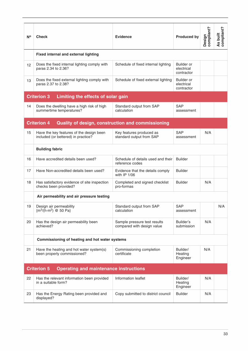
No Check Evidence Produced by
Des
ign
com
plia
nt?
As
bu
iltco
mp
lian
t?
Fixed internal and external lighting
12 Does the fixed internal lighting comply withparas 2.34 to 2.36?
Schedule of fixed internal lighting Builder orelectricalcontractor
13 Does the fixed external lighting comply withparas 2.37 to 2.38?
Schedule of fixed external lighting Builder orelectricalcontractor
Criterion 3 Limiting the effects of solar gain
14 Does the dwelling have a high risk of highsummertime temperatures?
Standard output from SAPcalculation
SAPassessment
Criterion 4 Quality of design, construction and commissioning
15 Have the key features of the design beenincluded (or bettered) in practice?
Key features produced asstandard output from SAP
SAPassessment
N/A
Building fabric
16 Have accredited details been used? Schedule of details used and theirreference codes
Builder
17 Have Non-accredited details been used? Evidence that the details complywith IP 1/06
Builder
18 Has satisfactory evidence of site inspectionchecks been provided?
Completed and signed checklistpro-formas
Builder N/A
Air permeability and air pressure testing
19 Design air permeability {m3/(h.m2) @ 50 Pa}
Standard output from SAPcalculation
SAPassessment
N/A
20 Has the design air permeability beenachieved?
Sample pressure test resultscompared with design value
Builder’ssubmission
N/A
Commissioning of heating and hot water systems
21 Have the heating and hot water system(s)been properly commissioned?
Commissioning completioncertificate
Builder/HeatingEngineer
N/A
Criterion 5 Operating and maintenance instructions
22 Has the relevant information been providedin a suitable form?
Information leaflet Builder/HeatingEngineer
N/A
23 Has the Energy Rating been provided anddisplayed?
Copy submitted to district council Builder N/A

THIS APPENDIX IS PART OF THE DEEMED - TO - SATISFY PROVISION
B1 Simple payback means the number of years it will take to recover the initialinvestment through energy savings, and is calculated by dividing themarginal additional cost of implementing an energy efficiency measure(excluding VAT) by the value of the annual energy savings (excluding VAT)achieved by that measure, where –
(a) the marginal additional cost is the additional cost (materials andlabour) of incorporating, for example, additional insulation, not thewhole cost of the work;
(b) the cost of implementing the measure shall be based on pricescurrent at the date on which the proposal is submitted to the districtcouncil and shall be confirmed in a report signed by a suitablyqualified person;
(c) the annual energy savings shall be estimated using approved energycalculation software; and
(d) for the purposes of this Technical Booklet the following energy pricesshall be used when evaluating the value of the annual energysavings –
Mains gas 1.63 p/kWh
Electricity 3.65 (1) p/kWh
Heating oil 2.17 p/kWh
LPG 3.71 p/kWh
1. This is a weighted combination of peak and off peak tariffs.
Energy efficiency measures are considered to be cost effective if theyachieve a simple payback within 15 years.
For example, if the cost of implementing a measure was £430 and thevalue of the annual energy savings was £38/year, the simple paybackwould be 430/38 = 11.3 years and the measure is therefore regarded ascost effective.
[Energy prices are increasing significantly, so designers may wish to usehigher values such as those current at the time of the Building Regulationapplication.]
34
Appendix B Simple payback

THIS APPENDIX IS PART OF THE DEEMED - TO - SATISFY PROVISION
C 1 Where the work involves the renovation of a thermal element such as thereplacement of surface finishes or coverings, an opportunity arises forinsulation improvements to be undertaken at marginal additional cost. This Appendix gives guidance on the cost effectiveness of insulationmeasures when undertaking various types of work on a thermal element.
C 2 Table C1 gives the circumstances and provisions that in most cases can beconsidered reasonable provisions when upgrading thermal elements.However, as renovation work is context dependent, some flexibility inapplying the provisions is necessary with the aim being as far as possibleto make a reasonable improvement to the thermal performance of theelement being renovated.
As part of this flexible approach it will be necessary to take account oftechnical risks, practicability and the impacts of such works on adjoiningbuildings.
C 3 In general terms the proposed works should take account of –
(a) other requirements of the building regulations;
(b) technical risks relating to insulation improvements as described inBR 262: “Thermal insulation: avoiding risks”; and
(c) where the building has historic value, guidance produced by DOE Environment and Heritage Service.
C 4 Where it is not practicable in the context of a specific scheme to achievethe performance standard given in Table C1, the level of performanceachieved shall be as close as possible thereto.
35
Appendix C Cost effective target U-values

Table C1 Cost effective target U-values when undertaking works to thermal elements
Improvement opportunityTarget
U-valueW/(m2.K)
Typical construction Main matters to be considered
Pitched roof constructions
Renewal of roof covering – No living accommodation in theroof void – existing insulation (ifany) horizontal at ceiling level.No existing insulation, existinginsulation less than 50 mm, inpoor condition and/or likely to besignificantly disturbed orremoved as part of the plannedwork.
0.16 Provide 250 mm loft insulationsuch as mineral or cellulose fibrelaid between and over the ceilingjoists.
Impact on boarded walkways orboarded roofspaces.Condensation risks.Impact of new insulation onaccess to and the insulation ofservices.
Renewal of roof covering –Existing insulation in goodcondition and will not besignificantly disturbed byproposed works. Existinginsulation 50 mm to 100 mm inthickness.
0.20 Top up insulation to at least200 mm with insulation such asmineral or cellulose fibre laidbetween and over the ceilingjoists.
Impact on boarded walkways orboarded roofspaces.Condensation risks.Impact of new insulation onaccess to and the insulation ofservices.
Renewal of the ceilingimmediately below a cold loftspace. Existing insulationremoved as part of the works.
0.16 Provide 250 mm loft insulation –such as mineral or cellulose fibrelaid between and over the ceilingjoists.
The impact on boarded walkwaysor boarded roofspaces.Condensation risks.Impact of new insulation onaccess to and the insulation ofservices.
Renewal of roof covering –Living accommodation in roofspace (room-in-the-roof).
0.20 Cold structure – Insulationbetween and below rafters.Warm structure – Insulationbetween and above rafters.
Condensation risks.Practical considerations in relationto the thickness of insulationinvolved.
Dormer construction
Renewal of cladding to dormercheeks.
0.35 Insulate between and over studsor externally.
Condensation risks.
Renewal of roof covering. - Refer to guidance on flat orpitched roofs as appropriate.
Condensation risks.
Flat roof constructions
Renewal of roof covering –Existing insulation, if any, lessthan 100 mm, or in poorcondition and likely to besignificantly disturbed orremoved as part of the plannedworks.
0.25 Insulation between and/or overjoists to achieve the targetU-value.
Condensation risks.Impact of BS 6229.
Renewal of the ceiling to flatroof area. Existing insulationremoved as part of the works.
0.25 Insulation between and/or belowjoists to achieve the targetU-value.
Condensation risks.Impact of BS 6229.Impact on ceiling height.
36

Improvement opportunityTarget
U-valueW/(m2.K)
Typical construction Main matters to be considered
Solid wall constructions
Renewal of internal finish toexternal wall or dry lining for thefirst time.
0.35 Dry lining of plasterboard to innerface of the external wall withinsulation between battens.Insulated wall board fixed tointernal surface.
Impact on reduced floor area.Condensation risks.Dampness risks.
Renewal of external finish orcladding or applying a new finishor cladding for the first time.
0.35 External insulation system withrender.Cladding with insulation behind.
Condensation risks.Dampness risks.Impact of increased wall thicknesson adjoining buildings.
Cavity wall constructions
Replace wall ties to at least oneelevation.
0.55 Blown cavity fill. Suitability for cavity fill.
Ground floor constructions
Renovation of a solid orsuspended floor involving thereplacement of screed or atimber deck.
0.25 Solid floor – replace screed withan insulated floor deck.Suspended timber floor – insulatebetween and/or over floor joists.
Impact on floor levels.Inherent U-value.Usually cost effective if existingU-value is greater than0.7 W/(m2.K).
37

THIS APPENDIX IS NOT PART OF THE DEEMED - TO - SATISFY PROVISION
D1 This Appendix lists general guidance documents that provide advice onrenovation options and their application. The listing of any guide, British Standard or other document does not mean that the guidance isapplicable to any particular scheme. It is the designer’s/builder’sresponsibility to assess the appropriateness of the guidance in relation to aparticular application.
D2 In a number of documents (particularly those produced by the EnergySaving Trust’s Energy Efficiency Best Practice in Housing programme) arecommended U-value is stated for different elements and forms ofconstruction. The inclusion of such a performance value does notconstitute a performance limit or target for the purposes of this TechnicalBooklet. The relevant Target U-values for the purposes of compliance withthis Technical Booklet are those given in Table C1 of Appendix C.
General guidance
D3 Thermal insulation: Avoiding risks, Building Research Establishment Report262, Watford, Construction Research Communications Ltd.
D4 EST (2004) Energy efficient refurbishment of existing housing: GoodPractice Guide 155, Energy Efficiency Best Practice in Housing, London,Energy Saving Trust.
D5 EST (2005) Advanced Insulation in Housing Refurbishment: CE 97, Energy Efficiency Best Practice in Housing, London, Energy Saving Trust.
D6 EST (2006) Refurbishing dwellings – a summary of best practice: CE189,Energy Efficiency Best Practice in Housing, London, Energy Saving Trust.
Roofs
D7 EST (2006) Practical refurbishment of solid walled houses: CE 184, Energy Efficiency Best Practice in Housing, London, Energy Saving Trust.
D8 Insulating roofs at rafter level: Sarking insulation, Good Building Guide 37,Watford, Building Research Establishment.
D9 Code of practice for loft insulation: National Insulation Association.
Walls
D10 EST (2006) External Insulation Systems for Walls of Dwellings: GPG 293,Energy Efficiency Best Practice in Housing, London, Energy Saving Trust.
D11 EST (2003) Internal Wall Insulation in Existing Housing: GPG 138, Energy Efficiency Best Practice in Housing, London, Energy Saving Trust.
D12 EST (2006) Practical refurbishment of solid walled houses: CE 184, Energy Efficiency Best Practice in Housing, London, Energy Saving Trust.
38
Appendix D General guidance on renovation
Floors
D13 EST (2006) Practical refurbishment of solid walled houses: CE 184,Energy Efficiency Best Practice in Housing, London, Energy Saving Trust.
International, European and British Standards
D14 BS 5250: 2002 Code of practice for the control of condensation in buildings.
D15 BS EN ISO 13788: 2001 Hygrothermal performance of building componentsand building elements. Internal surface temperature to avoid critical surfacehumidity and interstitial condensation. Calculation methods.
D16 BS 6229: 2003 Flat roofs with continuously supported coverings – Code ofpractice.
D17 BS 5803–5: 1985 Thermal Insulation for use in pitched roof spaces indwellings – Part 5: Specification for installation of man-made mineral fibreand cellulose fibre insulation. Amended 1999 incorporating AmendmentNo.1 1994.
39
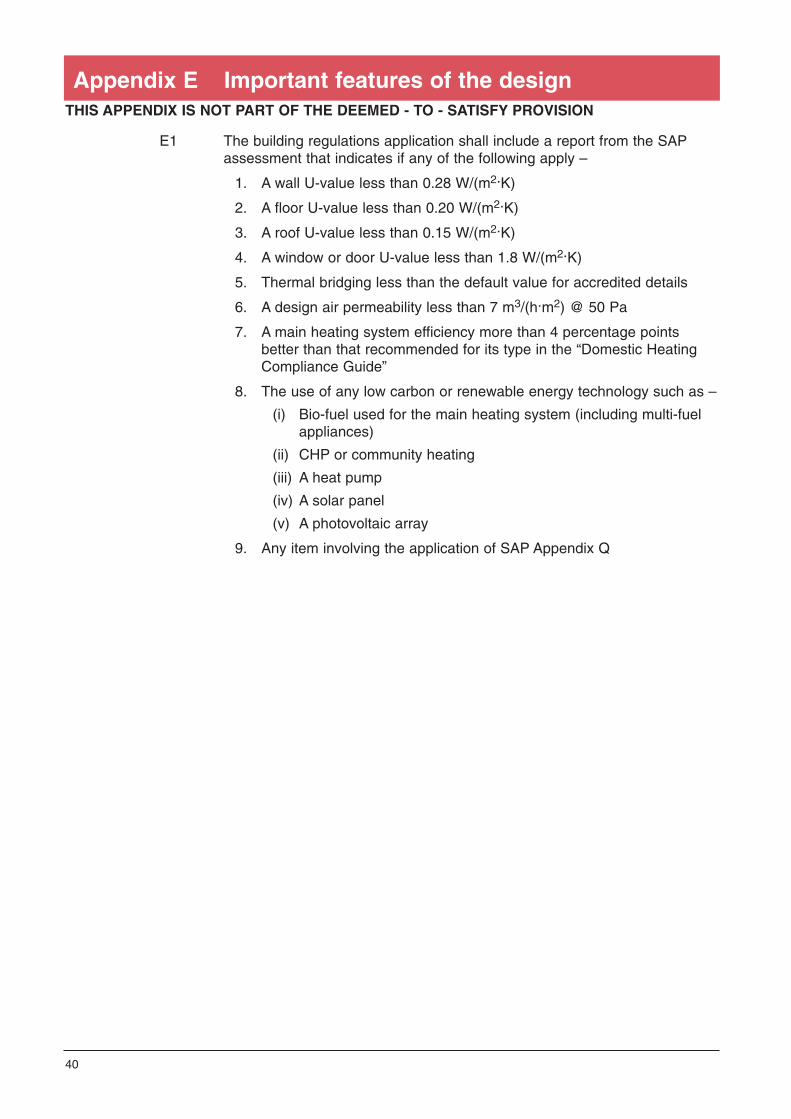
THIS APPENDIX IS NOT PART OF THE DEEMED - TO - SATISFY PROVISION
E1 The building regulations application shall include a report from the SAPassessment that indicates if any of the following apply –
1. A wall U-value less than 0.28 W/(m2.K)
2. A floor U-value less than 0.20 W/(m2.K)
3. A roof U-value less than 0.15 W/(m2.K)
4. A window or door U-value less than 1.8 W/(m2.K)
5. Thermal bridging less than the default value for accredited details
6. A design air permeability less than 7 m3/(h.m2) @ 50 Pa
7. A main heating system efficiency more than 4 percentage pointsbetter than that recommended for its type in the “Domestic HeatingCompliance Guide”
8. The use of any low carbon or renewable energy technology such as –
(i) Bio-fuel used for the main heating system (including multi-fuel appliances)
(ii) CHP or community heating
(iii) A heat pump
(iv) A solar panel
(v) A photovoltaic array
9. Any item involving the application of SAP Appendix Q
40
Appendix E Important features of the design

THIS APPENDIX IS NOT PART OF THE DEEMED - TO - SATISFY PROVISION
F1 Some builders may prefer to adopt model design solutions rather thandevelop their own. These model packages of fabric U-values, boilerseasonal efficiencies, window opening allowances etc will have been shownto achieve overall compliance within certain parameters.
The construction industry may develop model designs for this purpose andprovisions have been made to register the designs on the internet atwww.modeldesigns.info.
F2 Where a model design is used, it will still be necessary to demonstratecompliance to the satisfaction of the district council and to provide thebuilding owner with operational information and an Energy Rating whichshall be copied to the district council.
41
Appendix F Model designs
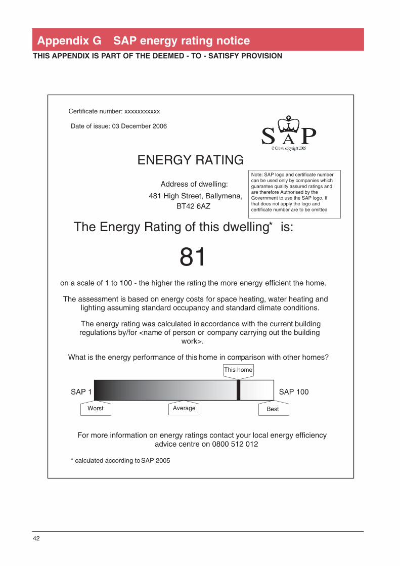
THIS APPENDIX IS PART OF THE DEEMED - TO - SATISFY PROVISION
42
Appendix G SAP energy rating notice
Certificate number: xxxxxxxxxxx Date of issue: 03 December 2006
ENERGY RATING
Address of dwelling:
481 High Street, Ballymena, BT42 6AZ
The Energy Rating of this dwelling* is:
81
on a scale of 1 to 100 - the higher the rating the more energy efficient the home.
The assessment is based on energy costs for space heating, water heating and lighting assuming standard occupancy and standard climate conditions.
The energy rating was calculated in accordance with the current building regulations by/for <name of person or company carrying out the building
work>.
What is the energy performance of this home in comparison with other homes? SAP 1 SAP 100
For more information on energy ratings contact your local energy efficiency advice centre on 0800 512 012
* calculated according to SAP 2005
Note: SAP logo and certificate number can be used only by companies which guarantee quality assured ratings and are therefore Authorised by the Government to use the SAP logo. If that does not apply the logo and certificate number are to be omitted
Worst Average
This home
Best

THIS APPENDIX IS NOT PART OF THE DEEMED - TO - SATISFY PROVISION
Air Tightness Testing and Measurement Association (ATTMA)
Measuring air permeability of building envelopes, 2006
BRE
BR 262: Thermal insulation: Avoiding risks, 2002
BR 443: Conventions for U-value calculations, 2006
Information Paper IP1/06 Assessing the effect of thermal bridging atjunctions and around openings in the external elements of buildings,2006
British Standards Institution (BSI)
BS 6229: 2003 Flat roofs with continuously supported coverings –Code of practice
BS 8206 - 2: 1992 Lighting for buildings. Code of Practice fordaylighting
BS EN ISO 13370: 1998 Thermal performance of buildings – Heattransfer via the ground – Calculation methods
Chartered Institution of Building Services Engineers (CIBSE)
CIBSE Guide A: Environmental Design, 2006. Section 3 – Thermalproperties of building structures
Department of the Environment, Food and Rural Affairs (DEFRA)
SAP 2005: The Government’s Standard Assessment Procedure forthe energy rating of dwellings, 2005
Department for Communities and Local Government (DCLG) (formerlyODPM)
Accredited construction details for Part L(Note that “Part L” in the title refers to the part in England & Wales that is equivalentto Part F in Northern Ireland. This document will not be printed but is published onthe DCLG website.)
Domestic heating compliance guide, 2006
Low or zero carbon energy sources: Strategic guide, 2006
43
Appendix H Publications referred to

Energy Saving Trust (EST)
CE 66 Windows for new and existing housing, 2006
CE 129 Reducing overheating – a designer’s guide, 2005
GIL 20 Low energy domestic lighting, 2006
GPG 268 Energy efficient ventilation in dwellings – a guide forspecifiers, 2006
DOE Environment and Heritage Service
Historic buildings and energy efficiency. A guide to Part F of theNorthern Ireland Building Regulations 2006This document will not be printed but is available on the website www.ehsni.gov.uk
Legislation
The Energy Information (Household Air Conditioners)(No.2) Regulations 2005
44